US11364387B2 - Heart rate calculator with reduced overcounting - Google Patents
Heart rate calculator with reduced overcountingDownload PDFInfo
- Publication number
- US11364387B2 US11364387B2US16/140,324US201816140324AUS11364387B2US 11364387 B2US11364387 B2US 11364387B2US 201816140324 AUS201816140324 AUS 201816140324AUS 11364387 B2US11364387 B2US 11364387B2
- Authority
- US
- United States
- Prior art keywords
- mean
- margin
- intervals
- less
- odd
- Prior art date
- Legal status (The legal status is an assumption and is not a legal conclusion. Google has not performed a legal analysis and makes no representation as to the accuracy of the status listed.)
- Active, expires
Links
Images


Classifications
- A—HUMAN NECESSITIES
- A61—MEDICAL OR VETERINARY SCIENCE; HYGIENE
- A61N—ELECTROTHERAPY; MAGNETOTHERAPY; RADIATION THERAPY; ULTRASOUND THERAPY
- A61N1/00—Electrotherapy; Circuits therefor
- A61N1/18—Applying electric currents by contact electrodes
- A61N1/32—Applying electric currents by contact electrodes alternating or intermittent currents
- A61N1/38—Applying electric currents by contact electrodes alternating or intermittent currents for producing shock effects
- A61N1/39—Heart defibrillators
- A61N1/3904—External heart defibrillators [EHD]
- A—HUMAN NECESSITIES
- A61—MEDICAL OR VETERINARY SCIENCE; HYGIENE
- A61B—DIAGNOSIS; SURGERY; IDENTIFICATION
- A61B5/00—Measuring for diagnostic purposes; Identification of persons
- A61B5/0002—Remote monitoring of patients using telemetry, e.g. transmission of vital signals via a communication network
- A61B5/0004—Remote monitoring of patients using telemetry, e.g. transmission of vital signals via a communication network characterised by the type of physiological signal transmitted
- A61B5/0006—ECG or EEG signals
- A—HUMAN NECESSITIES
- A61—MEDICAL OR VETERINARY SCIENCE; HYGIENE
- A61B—DIAGNOSIS; SURGERY; IDENTIFICATION
- A61B5/00—Measuring for diagnostic purposes; Identification of persons
- A61B5/02—Detecting, measuring or recording for evaluating the cardiovascular system, e.g. pulse, heart rate, blood pressure or blood flow
- A61B5/024—Measuring pulse rate or heart rate
- A61B5/02416—Measuring pulse rate or heart rate using photoplethysmograph signals, e.g. generated by infrared radiation
- A—HUMAN NECESSITIES
- A61—MEDICAL OR VETERINARY SCIENCE; HYGIENE
- A61B—DIAGNOSIS; SURGERY; IDENTIFICATION
- A61B5/00—Measuring for diagnostic purposes; Identification of persons
- A61B5/24—Detecting, measuring or recording bioelectric or biomagnetic signals of the body or parts thereof
- A61B5/316—Modalities, i.e. specific diagnostic methods
- A61B5/318—Heart-related electrical modalities, e.g. electrocardiography [ECG]
- A61B5/346—Analysis of electrocardiograms
- A61B5/349—Detecting specific parameters of the electrocardiograph cycle
- A—HUMAN NECESSITIES
- A61—MEDICAL OR VETERINARY SCIENCE; HYGIENE
- A61N—ELECTROTHERAPY; MAGNETOTHERAPY; RADIATION THERAPY; ULTRASOUND THERAPY
- A61N1/00—Electrotherapy; Circuits therefor
- A61N1/02—Details
- A61N1/04—Electrodes
- A61N1/0404—Electrodes for external use
- A61N1/0408—Use-related aspects
- A61N1/046—Specially adapted for shock therapy, e.g. defibrillation
- A—HUMAN NECESSITIES
- A61—MEDICAL OR VETERINARY SCIENCE; HYGIENE
- A61N—ELECTROTHERAPY; MAGNETOTHERAPY; RADIATION THERAPY; ULTRASOUND THERAPY
- A61N1/00—Electrotherapy; Circuits therefor
- A61N1/02—Details
- A61N1/04—Electrodes
- A61N1/0404—Electrodes for external use
- A61N1/0472—Structure-related aspects
- A61N1/0484—Garment electrodes worn by the patient
- A—HUMAN NECESSITIES
- A61—MEDICAL OR VETERINARY SCIENCE; HYGIENE
- A61B—DIAGNOSIS; SURGERY; IDENTIFICATION
- A61B5/00—Measuring for diagnostic purposes; Identification of persons
- A61B5/0002—Remote monitoring of patients using telemetry, e.g. transmission of vital signals via a communication network
- A61B5/0015—Remote monitoring of patients using telemetry, e.g. transmission of vital signals via a communication network characterised by features of the telemetry system
- A61B5/0022—Monitoring a patient using a global network, e.g. telephone networks, internet
- A—HUMAN NECESSITIES
- A61—MEDICAL OR VETERINARY SCIENCE; HYGIENE
- A61B—DIAGNOSIS; SURGERY; IDENTIFICATION
- A61B5/00—Measuring for diagnostic purposes; Identification of persons
- A61B5/02—Detecting, measuring or recording for evaluating the cardiovascular system, e.g. pulse, heart rate, blood pressure or blood flow
- A61B5/0205—Simultaneously evaluating both cardiovascular conditions and different types of body conditions, e.g. heart and respiratory condition
- A—HUMAN NECESSITIES
- A61—MEDICAL OR VETERINARY SCIENCE; HYGIENE
- A61B—DIAGNOSIS; SURGERY; IDENTIFICATION
- A61B5/00—Measuring for diagnostic purposes; Identification of persons
- A61B5/68—Arrangements of detecting, measuring or recording means, e.g. sensors, in relation to patient
- A61B5/6801—Arrangements of detecting, measuring or recording means, e.g. sensors, in relation to patient specially adapted to be attached to or worn on the body surface
- A61B5/6802—Sensor mounted on worn items
- A61B5/6804—Garments; Clothes
- A61B5/6805—Vests, e.g. shirts or gowns
- A—HUMAN NECESSITIES
- A61—MEDICAL OR VETERINARY SCIENCE; HYGIENE
- A61N—ELECTROTHERAPY; MAGNETOTHERAPY; RADIATION THERAPY; ULTRASOUND THERAPY
- A61N1/00—Electrotherapy; Circuits therefor
- A61N1/18—Applying electric currents by contact electrodes
- A61N1/32—Applying electric currents by contact electrodes alternating or intermittent currents
- A61N1/38—Applying electric currents by contact electrodes alternating or intermittent currents for producing shock effects
- A61N1/39—Heart defibrillators
- A61N1/3925—Monitoring; Protecting
- A—HUMAN NECESSITIES
- A61—MEDICAL OR VETERINARY SCIENCE; HYGIENE
- A61N—ELECTROTHERAPY; MAGNETOTHERAPY; RADIATION THERAPY; ULTRASOUND THERAPY
- A61N1/00—Electrotherapy; Circuits therefor
- A61N1/18—Applying electric currents by contact electrodes
- A61N1/32—Applying electric currents by contact electrodes alternating or intermittent currents
- A61N1/38—Applying electric currents by contact electrodes alternating or intermittent currents for producing shock effects
- A61N1/39—Heart defibrillators
- A61N1/3968—Constructional arrangements, e.g. casings
- A—HUMAN NECESSITIES
- A61—MEDICAL OR VETERINARY SCIENCE; HYGIENE
- A61N—ELECTROTHERAPY; MAGNETOTHERAPY; RADIATION THERAPY; ULTRASOUND THERAPY
- A61N1/00—Electrotherapy; Circuits therefor
- A61N1/18—Applying electric currents by contact electrodes
- A61N1/32—Applying electric currents by contact electrodes alternating or intermittent currents
- A61N1/38—Applying electric currents by contact electrodes alternating or intermittent currents for producing shock effects
- A61N1/39—Heart defibrillators
- A61N1/3993—User interfaces for automatic external defibrillators
Definitions
- SCASudden Cardiac Arrest
- ICDImplantable Cardioverter Defibrillator
- a WCD systemtypically includes a harness, vest, or other garment that the patient is to wear.
- the WCD systemfurther includes electronic components, such as a defibrillator and electrodes, coupled to the harness, vest, or other garment.
- the external electrodesmay then make good electrical contact with the patient's skin, and therefore can help sense the patient's ECG. If a shockable heart arrhythmia is detected, then the defibrillator delivers the appropriate electric shock through the patient's body, and thus through the heart.
- the patient's ECGincludes electrical noise, which can be created at the interface of the electrodes with the patient's skin. Such noise can make it difficult to diagnose the patient's condition accurately from the ECG and detect whether or not the patient is having a shockable arrhythmia.
- a WCDincludes a heart rate (HR) monitor function that measures the patient's HR using the patient's ECG.
- the HR monitor functioncan provide the HR as an indication of the patient's condition, and in some cases may also be used in determining whether the patient has a shockable rhythm.
- embodiments of a HR calculatorcan include one or more ECG sensors and a processor having a memory configured with: classification criteria to classify a received ECG signal into one of a plurality of ECG rhythm types; for each of the plurality of ECG rhythm types a corresponding algorithm or set of instructions to determine the patient's heart rate.
- the processoris configured to use the classification criteria to identify the ECG signal's type and determine a heart rate of the patient using the identified type's corresponding algorithm.
- embodiments of a HR calculatoruse a recurring interval of the patient's ECG to determine a HR.
- the HR monitoris configurable to avoid overcounting of erroneous measurements of the intervals that can result from large T-waves and/or bigeminy by comparing the mean of even intervals with the mean of odd intervals. If the means are significantly different double counting or bigeminy is indicated and the HR calculation is adjusted accordingly.
- embodiments of a HR calculatormeasure HR from the patient's ECG by detecting QRS complexes to determine an average R-R interval, which is then used to determine the patient's HR. Further, according to this aspect, the HR calculator is configured to avoid overcounting of QRS complexes and/or erroneous measurements of the R-R intervals that can result from the patient's heart generating “large” T-waves that can be erroneously detected as QRS complexes.
- embodiments of a HR calculatoralso measure HR from the patient's ECG by detecting QRS complexes to determine an average R-R interval, which is then used to determine the patient's HR. Further, according to this aspect, the HR calculator is configured to avoid overcounting of QRS complexes and/or erroneous measurements of the R-R intervals that can result from the patient having a heart rhythm in which every other heart beat is abnormal. This condition is sometimes referred to as bigeminy.
- embodiments of a HR calculator according to the present disclosureincorporate both aspects described above. That is, the embodiments are configured to detect bigeminy and are also configured to detect double counting of QRS complexes caused by large T-waves.
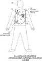
- FIG. 1is a diagram showing components of a WCD system, according to embodiments.
- FIG. 2is a diagram showing components of an external defibrillator, such as depicted in the system of FIG. 1 , according to embodiments.
- FIG. 3is a diagram illustrating a partial view of the components of an external defibrillator with a HR calculator with reduced overcounting, according to embodiments.
- FIG. 4Ais a diagram illustrating a portion of an ECG analyzed by a HR calculator resulting in no overcounting, according to embodiments.
- FIG. 4Bis a diagram illustrating a portion of an ECG analyzed by a HR calculator resulting in overcounting due to large T-waves, according to embodiments.
- FIG. 5Ais a diagram illustrating a portion of an ECG analyzed by a HR calculator resulting in no overcounting, according to embodiments.
- FIG. 5Bis a diagram illustrating a portion of an ECG analyzed by a HR calculator resulting in overcounting due to bigeminy, according to embodiments
- FIG. 6is a flow chart illustrating methods of calculating a HR with reduced overcounting, according to embodiments.
- FIG. 7is a flow chart illustrating methods of detecting double counting, for example caused by large T-waves, according to embodiments.
- FIG. 8is a flow chart illustrating methods of detecting bigeminy, according to embodiments.
- the present descriptiondiscloses several embodiments of a HR calculator with reduced overcounting, which can be used advantageously in WCD systems, media that store instructions, and methods.
- a wearable cardioverter defibrillator (WCD) systemmade according to embodiments has a number of components. These components can be provided separately as modules that can be interconnected, or can be combined with other components, etc.
- FIG. 1depicts a patient 82 .
- Patient 82may also be referred to as a person and/or wearer, since the patient is wearing components of the WCD system.
- Patient 82is ambulatory, which means patient 82 can walk around, and is not necessarily bed-ridden.
- FIG. 1also depicts components of a WCD system made according to embodiments.
- One such componentis a support structure 170 that is wearable by patient 82 .
- support structure 170is shown only generically in FIG. 1 , and in fact partly conceptually.
- FIG. 1is provided merely to illustrate concepts about support structure 170 and is not to be construed as limiting how support structure 170 is implemented, or how it is worn.
- Support structure 170can be implemented in many different ways, in accordance with various embodiments of the present disclosure.
- support structure 170can be implemented in a single component or a combination of multiple components.
- support structure 170could include a vest, a half-vest, a garment, etc. In such embodiments such items can be worn similarly to parallel articles of clothing.
- support structure 170could include a harness, one or more belts or straps, etc. In such embodiments, such items can be worn by the patient around the torso, hips, over the shoulder, etc.
- support structure 170can include a container or housing, which can even be waterproof.
- the support structurecan be worn by being attached to the patient by adhesive material, for example as shown in U.S. Pat. No. 8,024,037.
- Support structure 170can even be implemented as described for the support structure of US Pat. App. No. US2017/0056682, which is incorporated herein by reference.
- additional components of the WCD systemcan be in the housing of a support structure instead of being attached externally to the support structure, for example as described in the US2017/0056682 document. There can be other examples.
- a WCD systemis configured to defibrillate a patient who is wearing it, by delivering an electrical charge to the patient's body in the form of an electric shock delivered in one or more pulses.
- FIG. 1shows an illustrative external defibrillator 100 and defibrillation electrodes 104 , 108 , which are coupled to external defibrillator 100 via electrode leads 105 .
- Defibrillator 100 and defibrillation electrodes 104 , 108can be coupled to support structure 170 . As such, many of the components of defibrillator 100 could be therefore coupled to support structure 170 .
- defibrillator 100can administer, via electrodes 104 , 108 , a brief, strong electric pulse 111 through the body.
- Pulse 111is also known as shock, defibrillation shock, therapy and therapy shock. Pulse 111 is intended to go through and restart heart 85 , in an effort to save the life of patient 82 . Pulse 111 can further include one or more pacing pulses, and so on.
- Embodiments of external defibrillator 100are configured to decide whether to defibrillate or not based at least in part on an analysis of an ECG signal of the patient.
- external defibrillator 100in configured to initiate defibrillation (or hold-off defibrillation) based on a variety of inputs, with ECG being one of them.
- physiological signals containing physiological datacan be obtained from patient 82 .
- patientmay be considered also a “user” of the WCD system, this is not a requirement in some embodiments. That is, for example, a user of the WCD may include a clinician such as a doctor, nurse, emergency medical technician (EMT) or other similarly situated individual (or group of individuals).
- EMTemergency medical technician
- external defibrillator 100also includes a heart rate (HR) calculator (not shown) configured to determine the heart rate of patient 82 from the patient's ECG.
- HRheart rate
- Embodiments of the HR calculator described below in conjunction with FIGS. 3-8are configured to determine the HR with reduced overcounting.
- Some embodiments of the WCD systeminclude an outside monitoring device 180 .
- Device 180is referred to herein as an “outside” device because it could be provided as a standalone device, for example not within the housing of defibrillator 100 .
- Embodiments of device 180can be configured to sense or monitor at least one local parameter.
- a local parametercan be a parameter of patient 82 , or a parameter of the WCD system, or a parameter of the environment, as will be described later in this document.
- device 180may include one or more transducers or sensors that are configured to render one or more physiological inputs or signals from one or more patient parameters that they sense.
- device 180is physically coupled to support structure 170 .
- device 180can be communicatively coupled with other components, which are coupled to support structure 170 .
- Such communicationcan be implemented by a communication module, as deemed applicable in view of this description by a person skilled in the art.
- FIG. 2is a diagram showing components of an external defibrillator 200 , according to embodiments. These components can be, for example, included in external defibrillator 100 of FIG. 1 .
- the components shown in FIG. 2can be provided in a housing 201 , which may also be referred to as casing 201 .
- external defibrillator 200is configured for or adapted to a patient who would be wearing it, such as patient 82 of FIG. 1 .
- Embodiments of defibrillator 200may further include a user interface 280 for a user 282 .
- User 282can be patient 82 , also known as wearer 82 .
- user 282can be a local rescuer at the scene, such as a bystander who might offer assistance, or a trained person.
- user 282might be a remotely located trained caregiver in communication with the WCD system.
- user interface 280includes output devices that are visual, audible and/or tactile, for communicating to a user by outputting images, sounds and/or vibrations. Images, sounds, vibrations, and anything that can be perceived by user 282 are also human-perceptible indications according to embodiments.
- the output devicecan be a light source, or a screen to display what is sensed, detected and/or measured, and provide visual feedback to rescuer 282 for their resuscitation attempts, and so on.
- Another output devicecan be a speaker, which can be configured to issue voice prompts, beeps, alarm sounds and/or words to warn bystanders, etc.
- user interface 280includes input devices for receiving inputs from users.
- such input devicesinclude various controls, such as pushbuttons, keyboards, touchscreens, one or more microphones, and so on.
- An input devicecan be a cancel switch, which is sometimes called an “I am alive” switch or “live man” switch. In some embodiments, actuating the cancel switch can prevent the impending delivery of a shock.
- Defibrillator 200includes an internal monitoring device 281 in some embodiments.
- Device 281is referred to herein as an “internal” device because it is incorporated within housing 201 .
- monitoring device 281can sense or monitor patient parameters such as patient physiological parameters, system parameters and/or environmental parameters, all of which can be called patient data.
- internal monitoring device 281can be complementary or an alternative to outside monitoring device 180 of FIG. 1 . Allocating which of the parameters are to be monitored by which of monitoring devices 180 , 281 in various embodiments depending on the application.
- device 281may include one or more transducers or sensors that are configured to render one or more physiological inputs from one or more patient parameters that it senses.
- patient parametersinclude patient physiological parameters.
- Patient physiological parametersmay include, for example and without limitation, those physiological parameters that can be of any help in detecting by the wearable defibrillation system whether the patient is in need of a shock.
- patient parametersinclude the patient's medical history and/or event history. Examples of such parameters include the patient's ECG, blood oxygen level, blood flow, blood pressure, blood perfusion, pulsatile change in light transmission or reflection properties of perfused tissue, heart sounds, heart wall motion, breathing sounds and pulse.
- monitoring devices 180 , 281may include one or more sensors configured to acquire patient physiological signals.
- sensors or transducersexamples include electrodes to detect ECG data, a perfusion sensor, a pulse oximeter, a device for detecting blood flow (e.g. a Doppler device), a sensor for detecting blood pressure (e.g. a cuff), an optical sensor, illumination detectors and sensors perhaps working together with light sources for detecting color change in tissue, a motion sensor, a device that can detect heart wall movement, a sound sensor, a device with a microphone, an SpO 2 sensor, and so on.
- sensorscan help detect the patient's pulse, and can therefore also be called pulse detection sensors, pulse sensors, and pulse rate sensors. Pulse detection is also taught at least in Physio-Control's U.S. Pat.
- the transducerincludes an appropriate sensor, and the physiological input is a measurement by the sensor of that patient parameter.
- the appropriate sensor for a heart soundincludes a microphone, transducer, etc.
- the local parameteris a trend that can be detected in a monitored physiological parameter of patient 282 .
- a trendcan be detected by comparing values of parameters at various times.
- Parameters whose detected trends can particularly help a cardiac rehabilitation programinclude: a) cardiac function (e.g. ejection fraction, stroke volume, cardiac output, etc.); b) heart rate variability at rest or during exercise; c) heart rate profile during exercise and measurement of activity vigor, such as from the profile of an accelerometer signal and informed from adaptive rate pacemaker technology; d) heart rate trending; e) perfusion, such as from SpO 2 or CO 2 ; f) respiratory function, respiratory rate, etc.; g) motion, level of activity; and so on.
- cardiac functione.g. ejection fraction, stroke volume, cardiac output, etc.
- c) heart rate profile during exercise and measurement of activity vigorsuch as from the profile of an accelerometer signal and informed from adaptive rate pacemaker technology
- dheart
- Patient state parametersinclude recorded aspects of patient 282 , such as motion, posture, whether they have spoken recently, what they said, and so on, and optionally, the history of these parameters.
- One of these monitoring devicescould include a location sensor such as a Global Positioning System (GPS) location sensor. Such a sensor can detect the location, plus a speed can be detected as a rate of change of location over time.
- GPSGlobal Positioning System
- Many motion detectorsoutput a motion signal that is indicative of the motion of the detector, and thus of the patient's body.
- Patient state parameterscan be very helpful in narrowing down the determination of whether SCA is indeed taking place.
- a WCD system made according to embodimentsmay include a motion detector.
- a motion detectorcan be implemented within monitoring device 180 or monitoring device 281 .
- Such a motion detectorcan be made in many ways as is known in the art, for example by using an accelerometer.
- a motion detector 287is implemented within monitoring device 281 .
- a motion detector of a WCD systemcan be configured to detect a motion event.
- the motion detectormay render or generate, from the detected motion event or motion, a motion detection input that can be received by a subsequent device or functionality.
- a motion eventcan be defined as is convenient, for example a change in motion from a baseline motion or rest, etc. In such cases, a sensed patient parameter is motion.
- System parameters of a WCD systemcan include system identification, battery status, system date and time, reports of self-testing, records of data entered, records of episodes and intervention, and so on.
- Environmental parameterscan include ambient temperature and pressure. Moreover, a humidity sensor may provide information as to whether it is likely raining. Presumed patient location could also be considered an environmental parameter. The patient location could be presumed, if monitoring device 180 or 281 includes a GPS location sensor as per the above, and if it is presumed that the patient is wearing the WCD system.
- Defibrillator 200typically includes a defibrillation port 210 , such as a socket in housing 201 .
- Defibrillation port 210includes electrical nodes 214 , 218 .
- Leads of defibrillation electrodes 204 , 208can be plugged into defibrillation port 210 , so as to make electrical contact with nodes 214 , 218 , respectively. It is also possible that defibrillation electrodes 204 , 208 are connected continuously to defibrillation port 210 , instead.
- defibrillation port 210can be used for guiding, via electrodes, to the wearer the electrical charge that has been stored in an energy storage module 250 that is described more fully later in this document.
- the electric chargewill be the shock for defibrillation, pacing, and so on.
- defibrillator 200also has a sensor port 219 in housing 201 , which is also sometimes known as an ECG port.
- sensor port 219is adapted to enable the plugging in of sensing electrodes 209 , which are also known as ECG electrodes and ECG leads.
- sensing electrodes 209can be connected continuously to sensor port 219 , instead.
- Sensing electrodes 209are types of transducers that can help sense an ECG signal, e.g. a 12-lead signal, or a signal from a different number of leads, especially if they make good electrical contact with the body of the patient and in particular with the skin of the patient.
- Sensing electrodes 209can be attached to the inside of support structure 170 for making good electrical contact with the patient, similarly with defibrillation electrodes 204 , 208 .
- a WCD systemalso includes a fluid that it can deploy automatically between the electrodes and the patient's skin.
- the fluidcan be conductive, such as by including an electrolyte, for establishing a better electrical contact between the electrode and the skin. Electrically speaking, when the fluid is deployed, the electrical impedance between the electrode and the skin is reduced. Mechanically speaking, the fluid may be in the form of a low-viscosity gel, so that it does not flow away from the electrode, after it has been deployed.
- the fluidcan be used for both defibrillation electrodes 204 , 208 , and for sensing electrodes 209 .
- a WCD systemaccording to embodiments further includes a fluid deploying mechanism 274 .
- Fluid deploying mechanism 274is some embodiments is configured to cause at least some of the fluid to be released from the reservoir and be deployed near one or both of the patient locations, to which the electrodes are configured to be attached to the patient.
- fluid deploying mechanism 274is activated prior to the electrical discharge responsive to receiving activation signal AS from a processor 230 , which is described more fully later in this document.
- Embodiments of defibrillator 200also include a measurement circuit 220 , as one or more of its sensors or transducers. Measurement circuit 220 senses one or more electrical physiological signals of the patient from sensor port 219 , in embodiments where they are provided. Even in embodiments in which defibrillator 200 lacks sensor port 219 , some embodiments of measurement circuit 220 obtain physiological signals through nodes 214 , 218 instead, when defibrillation electrodes 204 , 208 are attached to the patient. In these cases, the physiological input reflects or is derived from an ECG measurement. In some embodiments a patient parameter is an ECG, which is sensed as a voltage difference between electrodes 204 , 208 .
- a patient parameteris an impedance, which can be sensed between electrodes 204 , 208 and/or the connections of sensor port 219 . Sensing the impedance can be useful for detecting, among other things, whether these electrodes 204 , 208 and/or sensing electrodes 209 are not making good electrical contact with the patient's body. These patient physiological signals are sensed in some embodiments.
- Embodiments of measurement circuit 220are configured to render or generate information about them as physiological inputs, data, other signals, etc. That is, the information rendered by measurement circuit 220 is output from it, but this information can be called an input because this information is received by a subsequent device or functionality as an input.
- Defibrillator 200also includes a processor 230 .
- Processor 230may be implemented in a number of ways in various embodiments. Such ways include, by way of example and not of limitation, digital and/or analog processors such as microprocessors and Digital Signal Processors (DSPs); controllers such as microcontrollers; software running in a machine; programmable circuits such as Field Programmable Gate Arrays (FPGAs), Field-Programmable Analog Arrays (FPAAs), Programmable Logic Devices (PLDs), Application Specific Integrated Circuits (ASICs), any combination of one or more of these, and so on.
- DSPsDigital Signal Processors
- FPGAsField Programmable Gate Arrays
- FPAAsField-Programmable Analog Arrays
- PLDsProgrammable Logic Devices
- ASICsApplication Specific Integrated Circuits
- Processor 230may include, or have access to, a non-transitory storage medium, such as memory 238 that is described more fully later in this document.
- a memorycan have a non-volatile component for storage of machine-readable and machine-executable instructions.
- a set of such instructionscan also be called a program.
- the instructionswhich may also referred to as “software,” generally provide functionality by performing methods as may be disclosed herein or understood by one skilled in the art in view of the disclosed embodiments.
- instances of the softwaremay be referred to as a “module” and by other similar terms.
- a moduleincludes a set of the instructions so as to offer or fulfill a particular functionality.
- Processor 230may, among other functions, set a flag, unset a flag, and so on.
- processor 230is includes a multi-core processor in which a particular core or cores are configured or “dedicated” to perform certain functions and/or implement selected modules, while other core or cores are configured to perform other functions and/or selected modules.
- processor 230is configured to have a number of modules.
- one such moduleis a detection module 232 .
- Detection module 232includes a Ventricular Fibrillation (VF) detector in some embodiments.
- VFVentricular Fibrillation
- the patient's sensed ECG from measurement circuit 220which is available as physiological inputs, data, or other signals, is used by the VF detector to determine whether the patient is experiencing VF. Detecting VF is useful, because VF typically results in SCA.
- detection module 232also includes a Ventricular Tachycardia (VT) detector, and so on.
- VTVentricular Tachycardia
- another such module in processor 230is an advice module 234 , which generates advice for what the system is to do.
- the advicecan be based on outputs of detection module 232 .
- the adviceis a shock/no shock determination that processor 230 makes, for example via advice module 234 .
- the shock/no shock determinationis made by executing a stored Shock Advisory Algorithm in some embodiments.
- a Shock Advisory Algorithmmakes a shock/no shock determination from one or more ECG signals that are captured according to embodiments and determining whether a shock criterion is met. The determination is made from a rhythm analysis of the captured ECG signal in some embodiments. In other embodiments, other physiological and/or environmental inputs are used by the Shock Advisory Algorithm in addition to or instead of the ECG signal.
- an electrical chargeis delivered to the patient. Delivering the electrical charge is also known as discharging. Shocking can be for defibrillation, pacing, and so on.
- processor 230includes additional modules, such as other module 236 , for other functions.
- additional modulessuch as other module 236 , for other functions.
- internal monitoring device 281may be operated in part by processor 230 , etc.
- defibrillator 200further includes a memory 238 , which is configured to work together with processor 230 .
- Memory 238is implemented in a number of ways according to various embodiments. Such ways include, by way of example and not of limitation, volatile memories, Nonvolatile Memories (NVM), Read-Only Memories (ROM), Random Access Memories (RAM), magnetic disk storage media, optical storage media, smart cards, flash memory devices, any combination of these, and so on.
- Memory 238is thus a non-transitory storage medium.
- the memoryincludes programs for processor 230 , which processor 230 is configured to read and execute.
- the programscan include sets of instructions in the form of code, which processor 230 is able to read and execute.
- Executingis performed by physical manipulations of physical quantities, and depending on the program, results in functions, operations, processes, actions and/or methods to be performed, and/or the processor to cause other devices or components or blocks to perform such functions, operations, processes, actions and/or methods.
- the programscan be operational for the inherent needs of processor 230 and can also include protocols and ways that decisions can be made by advice module 234 .
- memory 238is configurable to store prompts for user 282 , if this user is a local rescuer.
- memory 238is used in some embodiments to store data. This data can include patient data, system data and environmental data, for example as learned by internal monitoring device 281 and outside monitoring device 180 . The data can be stored in memory 238 before it is transmitted out of defibrillator 200 or stored there after it is received by defibrillator 200 .
- Defibrillator 200also includes a power source 240 , according to some embodiments of the present invention.
- power source 240includes a battery in some embodiments.
- the batteryis implemented as a rechargeable battery pack, while in other embodiments the battery pack is not rechargeable.
- Some embodimentsuse a combination of rechargeable and non-rechargeable battery packs.
- Other embodiments of power source 240include an AC power override, for where AC power will be available, and/or an energy-storing capacitor, and so on.
- power source 240is controlled by processor 230 . Appropriate components (not shown) are included to provide for charging or replacing power source 240 .
- Defibrillator 200may additionally include an energy storage module 250 .
- Energy storage module 250can be coupled to the support structure of the WCD system, for example either directly or via the electrodes and their leads. Module 250 is where some electrical energy can be stored temporarily in the form of an electrical charge, when preparing it for discharge to administer a shock. In embodiments, module 250 can be charged from power source 240 to the desired amount of energy, as controlled by processor 230 .
- module 250includes a capacitor 252 , which can be a single capacitor or a system of capacitors, and so on.
- energy storage module 250includes a device that exhibits high power density, such as an ultracapacitor. As described above, capacitor 252 can store the energy in the form of an electrical charge, for delivering to the patient.
- Defibrillator 200moreover includes a discharge circuit 255 .
- processor 230can be configured to control discharge circuit 255 to discharge through the patient the electrical charge stored in energy storage module 250 .
- circuit 255can permit the energy stored in module 250 to be discharged to nodes 214 , 218 , and from there also to defibrillation electrodes 204 , 208 , so as to cause a shock to be delivered to the patient.
- Circuit 255can include one or more switches 257 . Switches 257 can be made in a number of ways, such as by an H-bridge, and so on. Circuit 255 can also be controlled via user interface 280 .
- Defibrillator 200can optionally include a communication module 290 , for establishing one or more wired or wireless communication links with other devices of other entities, such as a remote assistance center, Emergency Medical Services (EMS), and so on.
- the datacan include patient data, event information, therapy attempted, CPR performance, system data, environmental data, and so on.
- communication module 290may transmit wirelessly, e.g. on a daily basis, heart rate, respiratory rate, and other vital signs data to a server accessible over the internet, for instance as described in US 20140043149. This data can be analyzed directly by the patient's physician and can also be analyzed automatically by algorithms designed to detect a developing illness and then notify medical personnel via text, email, phone, etc.
- Module 290may also include such interconnected sub-components as may be deemed necessary by a person skilled in the art, for example an antenna, portions of a processor, supporting electronics, outlet for a telephone or a network cable, etc. This way, data, commands, etc. can be communicated.
- Defibrillator 200can optionally include other components.
- FIG. 3is a diagram illustrating in more detail some of the components 301 of external defibrillator 200 ( FIG. 2 ) that are used in implementing a HR calculator with reduced overcounting, according to embodiments.
- the HR calculatoris configured to provide other information related to the patient's heart rhythm, as will be described below.
- the HR calculatorcan be implemented in devices other than a WCD.
- the HR calculatorcan be implemented in a monitor defibrillator, an AED, a vital signs monitor, a fitness tracker, or other device that monitors a patient's HR.
- measurement circuit 220includes a filter 325 to attenuate at least some of the noise that may be present on the ECG signal received from ECG port 219 and ECG electrodes 209 .
- filter 325is implemented as an analog filter, a digital filter, or combinations of both.
- filter 325is implemented in whole or in part in processor 230 rather than solely in measurement circuit 220 .
- defibrillator 200does not include filter 325 .
- processor 230includes modules 232 and 234 as described in conjunction with FIG. 2 , and in addition includes a HR module 336 configured to calculate and output a HR 333 that is determined from the ECG signal received from measurement circuit 220 .
- Computed heart rate 333can be used in additional ways in various embodiments.
- the HRmay be stored in memory 238 ( FIG. 2 ), downloaded later from memory 238 , transmitted wirelessly via communication module 290 ( FIG. 2 ), displayed by a screen of user interface 280 ( FIG. 2 ), and so on.
- HR module 336includes a HR calculator that avoids overcounting of R-R intervals that can lead to erroneous measurements of the R-R Intervals of the received ECG signal. For example, hearts rhythms such as bigeminy or rhythms with large T-waves can lead to overcounting of R-R intervals.
- the R-R interval measurementsare used in calculating the HR 333 by determining the equivalent of the inverse(s) of one or more averages of the measured R-R intervals.
- HR module 336is configured with: classification criteria to classify a received ECG signal into one of a plurality of ECG rhythm types (e.g., a T-wave double counting type, a bigeminy type, and a default type for all other types of rhythms). Further, for each of the plurality of ECG rhythm types, embodiments of HR module 336 are configured with a corresponding algorithm or set of instructions to determine the patient's heart rate. Embodiments of HR module 336 are configured to use the classification criteria to identify the ECG signal's type and determine a heart rate of the patient using the identified type's corresponding algorithm. In some embodiments, the classification is implemented using a rules-based system.
- classification criteriato classify a received ECG signal into one of a plurality of ECG rhythm types (e.g., a T-wave double counting type, a bigeminy type, and a default type for all other types of rhythms). Further, for each of the plurality of ECG rhythm types, embodiments of HR module 336 are configured
- the HR moduledetermines an average of the “even” Detected R-R intervals (also referred to herein as the EVEN MEAN) and an average of the “odd” Detected R-R intervals (also referred to herein as the ODD MEAN).
- an “average” as used in this contextcan be a mean, median, etc.
- the average of the “even” intervals and the average of the “odd” intervalscan be analyzed to detect potential overcounting as will be described below in conjunction with FIGS. 4A-5B .
- FIG. 4Ais a diagram schematically illustrating a portion of an ECG analyzed by a HR calculator resulting in no overcounting, according to embodiments.
- This example ECG portionhas “normal” QRS complexes and a “normal” T-wave.
- the R-R intervals 411 and 412are measured based on the detected peaks of each QRS complex (i.e., peaks of the R-waves).
- the mean of the R-R intervals over a 4.8 second segmentis used to calculate the HR for that segment, with the HR for that time segment being an inverse of the average R-R interval.
- averagecan be a mean, median, mode, a “trimmed mean” that eliminates outliers, or other measure that identifies the central tendency of the R-R interval.
- the inversecan be 60/median R-R interval to output a HR in beats per minute.
- the HRis calculated as an inverse of a running average of the R-R intervals over the most recent 10 seconds.
- the patient's “instantaneous” HRis calculated as an inverse of the mean of the most recent N R-R intervals, where N ranges from 5 to 20.
- FIG. 4Bis a diagram schematically illustrating a portion of an ECG analyzed by a HR calculator resulting in overcounting due to large T-waves, according to embodiments.
- the T-wave peaksare similar in height to the peaks of QRS complexes.
- a conventional HR monitorwould count each T wave as a QRS complex, resulting in double counting of R-R intervals.
- the first “true” R-R intervalis erroneously measured as two Detected R-R intervals 423 and 424 in this example ECG portion.
- the next “true” R-R interval in this exampleis erroneously measured as two Detected R-R intervals 433 and 434 , and so on. If both the QRS complexes and the T waves are counted, the situation is particularly problematic because this could lead to an erroneously high heart rate. In a WCD this could lead to an unnecessary shock.
- HR module 336implement one or more algorithms that determine: (a) an average of the “odd” intervals (e.g., Detected R-R intervals 423 , 433 , 443 , etc.); (b) an average of the “even” intervals (e.g., Detected R-R intervals 424 , 434 , etc.); (c) a margin M E for the “even” intervals; and (d) a margin M O for the “odd” intervals.
- margin M E and M Oare the same, but can be unequal in other embodiments.
- the “odd” intervalsmay begin with a T-wave rather than an R-wave.
- the averages of the “odd” and “even” intervalsare the medians of these intervals because medians tend to be insensitive to outliers. This can be helpful in some embodiments because if a beat is missed or a beat is double-counted, the heart rate is not significantly affected. On the other hand, if the patient has bigeminy the median tends to pick up on one of the two intervals when the real heart rate is the average of the two intervals.
- One of the advantages of “median” embodimentsis that it allows the use the median R-R interval for normal rhythms (i.e., for most patients) for reduced sensitivity to outliers, but can still detect bigeminy and return a correct heart rate.
- the algorithmuses the margins M E and M O in determining whether the ODD MEAN and EVEN MEAN are different enough to indicate double counting.
- the means of the “odd” and “even” intervalsare likely to be substantially equal.
- VFcould cause the patient's ECG to occasionally have portions that appear as a large T-wave rhythm, it is very unlikely that the EVEN MEAN will differ from the ODD MEAN by more than sum of the margins M E and M O .
- the values for M E and M Oare a scaled version of the standard deviation (a) of “even” intervals and the a of the “odd” intervals, respectively.
- standard deviations of the “even” and “odd” intervalsare calculated from the Detected R-R intervals used to calculate the mean of the “even” and “odd” intervals.
- the margin M Eis equivalent to three standard deviations (3 ⁇ ) of the “even” intervals, and M O is equivalent to 3 ⁇ of the “odd” intervals.
- the marginsmay be determined using other methods such as, for example, a different scaling factor of the standard deviations, a percentage of the mean of the Detected R-R intervals, measures of dispersion the Detected R-R intervals such as the variance, the inter-quartile range (and some combination thereof), or preselected values determined from statistical analysis, including values determined using artificial intelligence techniques.
- HR module 336implements a threshold (TH) used as part of the determination of whether a difference in the EVEN MEAN and the ODD MEAN is due to T-wave double counting. Stated another way, HR module 336 is configured to find whether a Detected R-R interval is actually an R-T interval. As previously mentioned, because the QRS detection may “begin” with a T-wave rather than the R-wave in this scenario, HR module 336 is configured to test both the “even” and “odd” intervals as being R-T intervals. To address these scenarios, in some embodiments HR module 336 is configured with criteria or rules or sets of instructions to determine whether the “even” and “odd” intervals are substantially different.
- THthreshold
- HR module 336are configured to compare the EVEN MEAN to the ODD MEAN and to detect that a potential T-wave double counting rhythm exists if both Equation (1) and Equation (2) are satisfied, or if both Equation (3) and Equation (4) are satisfied: (EVEN MEAN+ M E ) ⁇ (ODD MEAN ⁇ M O ) and (1) (EVEN MEAN) ⁇ TH (2)
- the value of THis set as a function of the refractory period that is a parameter of the QRS detection algorithm.
- the refractory periodstarts at the detection point on the QRS complex (usually near the peak) and lasts for a fixed duration of time.
- the refractory periodis 110 ms, but can range from 75 to 300 ms in other embodiments.
- the refractory perioddoes not refer to the vulnerable period, which is based on action potentials in the patient's heart muscle.
- the value of THis set to about twice the refractory period or 240 ms, but in other embodiments the value of TH can range from 100 to 300 ms.
- equations (2) and (4)can serve to confirm that EVEN MEAN or ODD MEAN corresponds to an average duration of the R-T intervals and, therefore, T-wave overcounting has been detected. As described earlier, T-wave overcounting can lead to an erroneous HR determination if a conventional HR algorithm is used.
- HR 333is substantially equal to the HR determined according to Equation (5) with rounding to the nearest integer or other selected accuracy.
- embodiments of HR module 336are configured to treat both “even” and “odd” intervals as normal R-R intervals as described above in conjunction with FIG. 4A .
- HR module 366will output HR 333 by determining the inverse of the mean of all the intervals used to determine EVEN MEAN and ODD MEAN.
- HR 333is substantially equal to the HR according inverse of the mean of all such intervals with rounding to the nearest integer or other selected accuracy.
- FIG. 5Ais a diagram schematically illustrating a portion of an ECG analyzed by a HR calculator resulting in no overcounting.
- FIG. 5Ais substantially similar to the ECG portion depicted in FIG. 4A and reproduced for easier comparison to a bigeminy ECG portion schematically shown in FIG. 5B .
- This example bigeminy ECG portionshows QRS complexes that are each followed by waves from an abnormal contraction that occurs relatively quickly after the QRS complex and before the next “normal” QPR complex.
- Conventional ECG-based HR monitorscan detect the abnormal contraction as a normal heartbeat, which will cause the HR monitor to output a HR that is too high if the segment includes one more abnormal heartbeat than normal heartbeat.
- a conventional HR monitorwould count as a “normal” R-R interval each of intervals 521 , 522 , 523 , 524 and so on.
- the HR for a bigeminy rhythmis determined using the mean of the intervals of complete pairs of normal and premature heartbeats.
- some embodiments of HR module 336implement one or more algorithms that determine: (a) the mean of the “odd” intervals (e.g., Detected R-R intervals 521 , 523 , 525 , etc.); (b) the mean of the “even” intervals (e.g., Detected R-R intervals 522 , 524 , etc.); (c) a margin M E for the “even” intervals; and (d) a margin M O for the “odd” intervals.
- the mean of the “odd” intervalse.g., Detected R-R intervals 521 , 523 , 525 , etc.
- the mean of the “even” intervalse.g., Detected R-R intervals 522 , 524 , etc.
- a margin M Efor the “even” intervals
- M Ofor the “odd” intervals.
- the “odd” intervalsmay be the “long” intervals, as opposed to the “short” intervals as shown in FIG. 5B when the segment begins with the R-wave of a normal QRS complex.
- the algorithmuses the margins M E and M O in determining whether the ODD MEAN and EVEN MEAN are different enough to indicate bigeminy.
- the values for M E and M Oare a scaled version of the standard deviation (a) of “even” intervals and the a of the “odd” intervals, respectively.
- standard deviations of the “even” and “odd” intervalsare calculated from the Detected R-R intervals used to calculate the mean of the “even” and “odd” intervals.
- the margin M Eis equivalent to three standard deviations (3 ⁇ ) of the “even” intervals, and M O is equivalent to 3 ⁇ of the “odd” intervals.
- the marginsmay be determined using other methods such as, for example, a different scaling factor of the standard deviations (e.g., two standard deviations, 3.5 standard deviations, etc.), a percentage of the means of the Detected R-R intervals, or preset values determined from statistical analysis, including values determined using artificial intelligence techniques.
- a different scaling factor of the standard deviationse.g., two standard deviations, 3.5 standard deviations, etc.
- a percentage of the means of the Detected R-R intervalse.g., a percentage of the means of the Detected R-R intervals
- preset values determined from statistical analysise.g., a percentage of the means of the Detected R-R intervals
- the values of the marginsare the same for both T-waves and bigeminy detection. In other embodiments, the values of the margins used for bigeminy detection are different from the values of the margins used in T-wave overcounting detection.
- HR module 336implements a threshold (TH) used as part of the determination of whether a difference in the EVEN MEAN and the ODD MEAN is due to bigeminy.
- HR module 336is configured with criteria or rules to determine whether the “even” and “odd” intervals are substantially different. For example, some embodiments of HR module 336 are configured to compare the EVEN MEAN to the ODD MEAN and to detect that a bigeminy rhythm exists if both Equation (6) and Equation (7) are satisfied, or if both Equation (8) and Equation (9) are satisfied: (EVEN MEAN+ M E ) ⁇ (ODD MEAN ⁇ M O ) and (6) (EVEN MEAN) ⁇ TH (7)
- the value of TH in equations (7) and (9)is set as a function of the refractory period that is a parameter of the QRS detection algorithm.
- the value of THis set to about twice the refractory period or 240 ms, but in other embodiments the value of TH can range from 100 to 300 ms. Because the abnormal heartbeat of bigeminy rhythms typically occur after the refractory period, equations (7) and (9) can serve to confirm that EVEN MEAN or ODD MEAN corresponds to an average duration of the shorter interval is longer than the refractory period so that the following heartbeat begins after the refractory period and, therefore, bigeminy has been detected. Stated another way, if the shorter interval is very short it is deemed to result from large T-waves being detected as an R-wave, and if not then it is deemed to result from bigeminy.
- HR 333is substantially equal to the HR according to Equation (10) with rounding to the nearest integer or other selected accuracy.
- embodiments of HR module 336are configured to treat both “even” and “odd” intervals as normal R-R intervals as described above in conjunction with FIG. 5A .
- HR module 366will output HR 333 by determining the inverse of the mean of all the intervals used to determine EVEN MEAN and ODD MEAN.
- HR 333is substantially equal to the HR according inverse of the mean of all such intervals with rounding to the nearest integer or other selected accuracy.
- the devices and/or systems mentioned in this documentperform functions, processes and/or methods. These functions, processes and/or methods may be implemented by one or more devices that include logic circuitry. Such a device can be alternately called a computer, a processor and so on. It may be a standalone device or computer, such as a general-purpose computer, special purpose computer, or part of a device that has one or more additional functions.
- the logic circuitrymay include a processor and non-transitory computer-readable storage media, such as memories, of the type described above in this document. Often, for the sake of convenience, it is preferred to implement and describe a program as various interconnected distinct software modules or features. These, along with data are individually and also collectively known as software. In some instances, software is combined with hardware, in a mix called firmware.
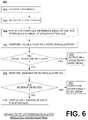
- FIG. 6is a flow chart illustrating embodiments of a method 600 for determining a user's HR with reduced overcounting.
- Method 600may be performed by software, programs, firmware, etc. used by computers, processors, controllers, or devices such as defibrillators (including external and internal defibrillators), heart rate monitors, pacemakers, etc. that incorporate computers, processors, controllers, etc.
- method 600is performed by WCDs when worn by a patient, such as the embodiments of WCDs described above in conjunction with FIGS. 1-5 .
- a portion of an ECGis received.
- operation 610performed by one or more components of a WCD such as, for example, processor 230 ( FIGS. 2 and 3 ) receiving ECG signals via ECG electrodes 209 and sensor port 219 .
- the WCDuses a segment-based Shock Advisory Algorithm and the portion of the ECG signal is a segment of length 4.8 seconds. In other embodiments, the segment length can range from 2.5 to 15 seconds.
- the R-R intervals in the received ECG portionare measured.
- the R-R intervalsare measured by a processor or HR monitor such as, for example, processor 230 with as HR module 336 ( FIG. 3 ).
- the R-R intervalsare measured in some embodiments by detecting peaks exceeding a predetermined or preset amplitude in the received ECG portion, which are deemed to be R-waves. But as previously described, these peaks may be caused by large T-waves or by abnormal bigeminy contractions rather than R-waves of a normal heartbeat. Thus, in some patients the measured R-R intervals may be erroneous as shown in FIG. 4B or 5B .
- Nis equal to 10 R-R interval measurements. In other embodiments, N can range from 5 to 20. In some embodiments, N is equal to the number of R-R interval measurements that occur in the most recently received 10 seconds of ECG signal. In other embodiments, N can range from 5 to 20 seconds. In some embodiments N is equal to the number of R-R interval measurements in the most recent segment or the 5 most recent segments.
- operation 625is performed by a processor such as, for example, processor 230 and HR module 336 ( FIG. 3 ).
- a double counting algorithmis performed.
- operation 645is performed by a processor or HR monitor such as, for example, processor 230 and HR module 336 ( FIG. 3 ).
- Embodiments of the double counting algorithmuse the means of the “odd” and “even” intervals determined in operation 625 , as described below in conjunction with FIG. 7 .
- the algorithmis based on previously described Equations (1)-(4) used to detect R-R interval overcounting in patients with large T-wave rhythms.
- method 600performs an operation 650 to analyze one or more results of operation 645 .
- operation 650is performed by a processor or HR monitor such as, for example, processor 230 with as HR module 336 ( FIG. 3 ). If a result of operation 645 is that double counting is detected, operation 650 proceeds to an operation 655 .
- operation 655is performed to determine the user's HR without inaccuracies due to R-R interval double counting.
- operation 655is performed by a processor or HR monitor such as, for example, processor 230 with as HR module 336 ( FIG. 3 ).
- the HRis calculated using Equation (6), described above.
- operation 650proceeds to an operation 665 to perform an algorithm to determine whether the patient has a bigeminy rhythm.
- operation 665is performed by a processor or HR monitor such as, for example, processor 230 and HR module 336 ( FIG. 3 ).
- Embodiments of the bigeminy algorithmuse the means of the “odd” and “even” intervals determined in operation 625 , as described below in conjunction with FIG. 8 .
- the bigeminy algorithmis based on previously described Equations (6)-(9).
- method 600performs an operation 670 to analyze one or more results of operation 665 .
- operation 670is performed by a processor or HR monitor such as, for example, processor 230 with as HR module 336 ( FIG. 3 ). If a result of operation 665 is that bigeminy is detected, operation 670 proceeds to an operation 675 .
- operation 675is performed to determine the user's HR without inaccuracies due to bigeminy.
- operation 675is performed by a processor or HR monitor such as, for example, processor 230 with as HR module 336 ( FIG. 3 ).
- the HRis calculated using Equation (10), described above.
- operation 680is performed to determine the user's HR.
- operation 680is performed by a processor or HR monitor such as, for example, processor 230 and HR module 336 ( FIG. 3 ). Because at this point neither double counting nor bigeminy has been detected, the user's R-R intervals are deemed “normal” and the user's HR can be determined in a conventional manner. For example, in some embodiments the HR is determined by taking the inverse of the mean of all of the R-R intervals measured in operation 615 described above.
- operations 645 , 650 and 655are not performed (i.e., method 600 does not detect double counting). Rather, after operation 625 , method 600 proceeds to operation 670 to determine whether the user has a bigeminy rhythm.
- operations 665 , 670 and 675are skipped (i.e., method 600 does not detect bigeminy). So, if double counting is not detected in operation 645 , method 600 proceeds to operation 680 to determine the user's HR.
- operation 670 and 675are performed before operations 650 and 655 so that bigeminy is tested before double counting.
- method 600is configurable into one of several modes, including a mode to detect double counting, a mode to detect bigeminy, and a mode to detect both bigeminy and double counting.
- the processor or device that can perform method 600is configured into a selected mode by a clinician, or the user, or
- FIG. 7is a flow chart illustrating methods of detecting double counting in operation 645 ( FIG. 6 ), according to embodiments.
- Operation 645may be performed by software, programs, firmware, etc. used by computers, processors, controllers, or devices such as defibrillators (including external and internal defibrillators), heart rate monitors, pacemakers, etc. that incorporate computers, processors, controllers, etc.
- method 600is performed by WCDs when worn by a patient, such as the embodiments of WCDs described above in conjunction with FIGS. 1-5 .
- one or more double counting marginsare determined.
- double counting marginsare used in embodiments in determining whether the ODD MEAN and EVEN MEAN are different enough to indicate double counting has occurred.
- the margin(s)are the margins M E and M O described above for use in Equations (1) and (3).
- this operation and the rest of the operations shown in FIG. 7are performed by a processor or HR monitor such as, for example, processor 230 with as HR module 336 ( FIG. 3 ).
- one or more double counting thresholdsare determined.
- a double counting thresholdis used as part of the determination of whether a difference in the EVEN MEAN and the ODD MEAN is due to T-wave double counting.
- the threshold(s)is the threshold TH described above for use in Equations (2) and (4). In a further refinement, there may be two thresholds to implement hysteresis.
- operation 700is performed after or concurrently (e.g., using multiple or multi-core processors) with operation 705 .
- the value of EVEN MEAN plus a margin determined in operation 700is compared to the value of ODD MEAN minus a margin determined in operation 700 .
- these marginsare the margins M E and M O described above for use in Equation (1).
- an operation 715is performed.
- EVEN MEANis then compared to the threshold determined in operation 705 to determine if the mean is less than the threshold (i.e., the short interval is short enough to indicate double counting).
- the thresholdis TH described above for use in Equation (2).
- operation 720If in operation 715 it is determined that EVEN MEAN is less than the threshold, then an operation 720 is performed. In operation 720 , an output is provided to indicate that double counting has been detected and operation 645 is exited to proceed to operation 650 ( FIG. 6 ).
- an operation 725is performed. in which an output is provided to indicate that double counting has not been detected and operation 645 is exited to proceed to operation 650 ( FIG. 6 ).
- the value of ODD MEAN plus a margin determined in operation 700is compared to the value of EVEN MEAN minus a margin determined in operation 700 .
- these marginsare the margins M E and M O described above for use in Equation (3).
- ODD MEAN plus marginis less than the value of EVEN MEAN minus margin
- an operation 735is performed.
- ODD MEANis then compared to the threshold determined in operation 705 to determine if the mean is less than the threshold (i.e., the short interval is short enough to indicate double counting).
- the thresholdis TH described above for use in Equation (4).
- operation 735proceeds to operation 720 to output that double counting has been detected and exit operation 645 , as previously described.
- operation 735determines whether ODD MEAN is greater than or equal to the threshold. If it is determined in operation 735 that ODD MEAN is greater than or equal to the threshold, then operation 725 is performed and operation 645 is exited, as previously described.
- operations 730 and 735are performed before or concurrently with operations 710 and 715 with appropriate changes in the flow in a way that satisfies Equations (1)-(4). Further, in some embodiments, operation 715 is performed before or concurrently with operation 710 , and in other embodiments operation 735 is performed before or concurrently with operation 730 , with appropriate changes in the flow to operations 720 and 725 .
- FIG. 8is a flow chart illustrating methods of detecting bigeminy in operation 665 ( FIG. 6 ), according to embodiments.
- Operation 665may be performed by software, programs, firmware, etc. used by computers, processors, controllers, or devices such as defibrillators (including external and internal defibrillators), heart rate monitors, pacemakers, etc. that incorporate computers, processors, controllers, etc.
- method 600is performed by WCDs when worn by a patient, such as the embodiments of WCDs described above in conjunction with FIGS. 1-5 .
- one or more bigeminy marginsare determined.
- bigeminy marginsare used in embodiments in determining whether the ODD MEAN and EVEN MEAN are different enough to indicate bigeminy has occurred.
- the bigeminy marginsare the same as the double counting margins determined in operation 700 ( FIG. 7 ), while in other embodiments they are different.
- the margin(s)are the margins M E and M O described above for use in Equations (6) and (8).
- this operation and the rest of the operations shown in FIG. 8are performed by a processor or HR monitor such as, for example, processor 230 with as HR module 336 ( FIG. 3 ).
- one or more thresholdsare determined.
- a thresholdis used as part of the determination of whether a difference in the EVEN MEAN and the ODD MEAN is due to bigeminy.
- the bigeminy threshold(s)are the same as the double counting threshold(s) determined in operation 700 ( FIG. 7 ), while in other embodiments they are different.
- the threshold(s)is the threshold TH described above for use in Equations (7) and (9). In a further refinement, there may be two thresholds to implement hysteresis.
- operation 800is performed after or concurrently (e.g., using multiple or multi-core processors) with operation 805 .
- the value of EVEN MEAN plus a margin determined in operation 800is compared to the value of ODD MEAN minus a margin determined in operation 800 .
- these marginsare the margins M E and M O described above for use in Equation (6).
- an operation 815is performed.
- EVEN MEANis then compared to the threshold determined in operation 705 to determine if the mean is greater than or equal to the threshold (i.e., the short interval is long to indicate bigeminy).
- the thresholdis equal to TH described above for use in Equation (7).
- operation 815If in operation 815 it is determined that EVEN MEAN is greater than or equal to the threshold, then an operation 820 is performed. In operation 820 , an output is provided to indicate that bigeminy has been detected and operation 665 is exited to proceed to operation 670 ( FIG. 6 ).
- an operation 825is performed. In which an output is provided to indicate that bigeminy has not been detected and operation 665 is exited to proceed to operation 670 ( FIG. 6 ).
- an operation 830is performed.
- the value of ODD MEAN plus a margin determined in operation 800is compared to the value of EVEN MEAN minus a margin determined in operation 800 .
- these marginsare the margins M E and M O described above for use in Equation (8).
- ODD MEAN plus marginis less than the value of EVEN MEAN minus margin
- an operation 835is performed.
- ODD MEANis then compared to the threshold determined in operation 805 to determine if the mean is greater than or equal to the threshold (i.e., the short interval is long enough to indicate bigeminy).
- the thresholdis equal to TH described above for use in Equation (9).
- operation 835proceeds to operation 820 to output that bigeminy has been detected and exit operation 665 , as previously described.
- operation 835determines whether ODD MEAN is less than the threshold. If it is determined in operation 835 that ODD MEAN is less than the threshold, then operation 825 is performed and operation 665 is exited, as previously described.
- operations 830 and 835are performed before or concurrently with operations 810 and 815 with appropriate changes in the flow in a way that satisfies Equations (6)-(9). Further, in some embodiments, operation 815 is performed before or concurrently with operation 810 , and in other embodiments operation 835 is performed before or concurrently with operation 830 , with appropriate changes in the flow to operations 820 and 825 .
- each operationcan be performed as an affirmative act or operation of doing, or causing to happen, the features of the operation. Such doing or causing to happen can be by the whole system or device, or just one or more components of it.
- the described methods and the operationsmay be implemented in a number of ways, including using systems, devices and implementations described above.
- the order of operationsis not constrained to what is shown, and different orders may be possible according to different embodiments. Examples of such alternate orderings may include overlapping, interleaved, interrupted, reordered, incremental, preparatory, supplemental, simultaneous, reverse, or other variant orderings, unless context dictates otherwise.
- new operationsmay be added, or individual operations may be modified or deleted. The added operations can be, for example, from what is mentioned while primarily describing a different system, apparatus, device or method.
- the phrases “constructed to” and/or “configured to”denote one or more actual states of construction and/or configuration that is fundamentally tied to physical characteristics of the element or feature preceding these phrases and, as such, reach well beyond merely describing an intended use. Any such elements or features can be implemented in a number of ways, as will be apparent to a person skilled in the art after reviewing the present disclosure, beyond any examples shown in this document.
- a single reference numeralmay be used consistently to denote a single item, aspect, component, or process.
- a further effortmay have been made in the drafting of this description to use similar though not identical reference numerals to denote other versions or embodiments of an item, aspect, component or process that are identical or at least similar or related. Where made, such a further effort was not required, but was nevertheless made gratuitously so as to accelerate comprehension by the reader. Even where made in this document, such a further effort might not have been made completely consistently for all of the versions or embodiments that are made possible by this description. Accordingly, the description controls in defining an item, aspect, component or process, rather than its reference numeral. Any similarity in reference numerals may be used to infer a similarity in the text, but not to confuse aspects where the text or other context indicates otherwise.
Landscapes
- Health & Medical Sciences (AREA)
- Life Sciences & Earth Sciences (AREA)
- Cardiology (AREA)
- Engineering & Computer Science (AREA)
- Animal Behavior & Ethology (AREA)
- Biomedical Technology (AREA)
- Veterinary Medicine (AREA)
- Public Health (AREA)
- General Health & Medical Sciences (AREA)
- Radiology & Medical Imaging (AREA)
- Nuclear Medicine, Radiotherapy & Molecular Imaging (AREA)
- Heart & Thoracic Surgery (AREA)
- Pathology (AREA)
- Surgery (AREA)
- Molecular Biology (AREA)
- Medical Informatics (AREA)
- Biophysics (AREA)
- Physics & Mathematics (AREA)
- Physiology (AREA)
- Pulmonology (AREA)
- Computer Networks & Wireless Communication (AREA)
- Electrotherapy Devices (AREA)
- Measurement And Recording Of Electrical Phenomena And Electrical Characteristics Of The Living Body (AREA)
Abstract
Description
(EVEN MEAN+ME)<(ODD MEAN−MO) and (1)
(EVEN MEAN)<TH (2)
(ODD MEAN+MO)<(EVEN MEAN−ME) and (3)
(ODD MEAN)<TH (4)
HR=60/(EVEN MEAN+ODD MEAN) (5)
(EVEN MEAN+ME)<(ODD MEAN−MO) and (6)
(EVEN MEAN)≥TH (7)
(ODD MEAN+MO)<(EVEN MEAN−ME) and (8)
(ODD MEAN)≥TH (9)
HR=120/(EVEN MEAN+ODD MEAN) (10)
Claims (16)
Priority Applications (2)
| Application Number | Priority Date | Filing Date | Title |
|---|---|---|---|
| US16/140,324US11364387B2 (en) | 2017-07-28 | 2018-09-24 | Heart rate calculator with reduced overcounting |
| US17/843,584US12179031B2 (en) | 2017-07-28 | 2022-06-17 | Heart rate calculator with reduced overcounting |
Applications Claiming Priority (2)
| Application Number | Priority Date | Filing Date | Title |
|---|---|---|---|
| US201762538172P | 2017-07-28 | 2017-07-28 | |
| US16/140,324US11364387B2 (en) | 2017-07-28 | 2018-09-24 | Heart rate calculator with reduced overcounting |
Related Child Applications (1)
| Application Number | Title | Priority Date | Filing Date |
|---|---|---|---|
| US17/843,584DivisionUS12179031B2 (en) | 2017-07-28 | 2022-06-17 | Heart rate calculator with reduced overcounting |
Publications (2)
| Publication Number | Publication Date |
|---|---|
| US20190175926A1 US20190175926A1 (en) | 2019-06-13 |
| US11364387B2true US11364387B2 (en) | 2022-06-21 |
Family
ID=66734944
Family Applications (2)
| Application Number | Title | Priority Date | Filing Date |
|---|---|---|---|
| US16/140,324Active2038-12-11US11364387B2 (en) | 2017-07-28 | 2018-09-24 | Heart rate calculator with reduced overcounting |
| US17/843,584ActiveUS12179031B2 (en) | 2017-07-28 | 2022-06-17 | Heart rate calculator with reduced overcounting |
Family Applications After (1)
| Application Number | Title | Priority Date | Filing Date |
|---|---|---|---|
| US17/843,584ActiveUS12179031B2 (en) | 2017-07-28 | 2022-06-17 | Heart rate calculator with reduced overcounting |
Country Status (1)
| Country | Link |
|---|---|
| US (2) | US11364387B2 (en) |
Families Citing this family (1)
| Publication number | Priority date | Publication date | Assignee | Title |
|---|---|---|---|---|
| CN114870259A (en)* | 2022-04-13 | 2022-08-09 | 苏州维伟思医疗科技有限公司 | Wearable cardiac medical equipment, control method and medical system |
Citations (141)
| Publication number | Priority date | Publication date | Assignee | Title |
|---|---|---|---|---|
| US3724355A (en) | 1970-06-12 | 1973-04-03 | K Schranz | Apparatus for processing exposed photographic film or the like |
| US4583524A (en) | 1984-11-21 | 1986-04-22 | Hutchins Donald C | Cardiopulmonary resuscitation prompting |
| US4619265A (en) | 1984-03-08 | 1986-10-28 | Physio-Control Corporation | Interactive portable defibrillator including ECG detection circuit |
| US4666432A (en) | 1985-09-13 | 1987-05-19 | Mcneish Kenneth | Catheter retaining means and method |
| US4698848A (en) | 1986-09-26 | 1987-10-13 | Buckley Mary C | Blouse for cardiac patients |
| US4928690A (en) | 1988-04-25 | 1990-05-29 | Lifecor, Inc. | Portable device for sensing cardiac function and automatically delivering electrical therapy |
| US4955381A (en) | 1988-08-26 | 1990-09-11 | Cardiotronics, Inc. | Multi-pad, multi-function electrode |
| US5078134A (en) | 1988-04-25 | 1992-01-07 | Lifecor, Inc. | Portable device for sensing cardiac function and automatically delivering electrical therapy |
| JPH04320257A (en) | 1991-04-19 | 1992-11-11 | Oji Paper Co Ltd | Support for photographic paper |
| US5228449A (en) | 1991-01-22 | 1993-07-20 | Athanasios G. Christ | System and method for detecting out-of-hospital cardiac emergencies and summoning emergency assistance |
| US5348008A (en) | 1991-11-25 | 1994-09-20 | Somnus Corporation | Cardiorespiratory alert system |
| US5394892A (en) | 1990-04-02 | 1995-03-07 | K J Mellet Nominees Pty Ltd | CPR prompting apparatus |
| US5405362A (en) | 1991-04-29 | 1995-04-11 | The Board Of Regents For The University Of Texas System | Interactive external defibrillation and drug injection system |
| US5429593A (en) | 1993-12-23 | 1995-07-04 | Matory; Yvedt L. | Post-surgical, drainage accommodating, compression dressing |
| US5474574A (en) | 1992-06-24 | 1995-12-12 | Cardiac Science, Inc. | Automatic external cardioverter/defibrillator |
| US5618208A (en) | 1994-06-03 | 1997-04-08 | Siemens Medical Systems, Inc. | Fully insulated, fully shielded electrical connector arrangement |
| US5662690A (en) | 1994-12-08 | 1997-09-02 | Heartstream, Inc. | Defibrillator with training features and pause actuator |
| US5708978A (en) | 1994-08-17 | 1998-01-20 | Johnsrud; Anna C. | Medical vest |
| US5741306A (en) | 1996-05-23 | 1998-04-21 | Lifecor, Inc. | Patient-worn energy delivery apparatus |
| US5782878A (en) | 1994-12-07 | 1998-07-21 | Heartstream, Inc. | External defibrillator with communications network link |
| US5792204A (en) | 1996-05-08 | 1998-08-11 | Pacesetter, Inc. | Methods and apparatus for controlling an implantable device programmer using voice commands |
| WO1998039061A2 (en) | 1997-03-07 | 1998-09-11 | Cadent Medical Corporation | Wearable defibrillation system |
| US5902249A (en) | 1995-03-03 | 1999-05-11 | Heartstream, Inc. | Method and apparatus for detecting artifacts using common-mode signals in differential signal detectors |
| US5913685A (en) | 1996-06-24 | 1999-06-22 | Hutchins; Donald C. | CPR computer aiding |
| US5944669A (en) | 1997-11-20 | 1999-08-31 | Lifecor, Inc. | Apparatus and method for sensing cardiac function |
| US6047203A (en) | 1997-03-17 | 2000-04-04 | Nims, Inc. | Physiologic signs feedback system |
| US6065154A (en) | 1998-04-07 | 2000-05-23 | Lifecor, Inc. | Support garments for patient-worn energy delivery apparatus |
| US6108197A (en) | 1992-05-15 | 2000-08-22 | Via, Inc. | Flexible wearable computer |
| US6201992B1 (en) | 1999-04-01 | 2001-03-13 | Agilent Technologies, Inc. | Defibrillator interface capable of generating video images |
| US6263238B1 (en) | 1998-04-16 | 2001-07-17 | Survivalink Corporation | Automatic external defibrillator having a ventricular fibrillation detector |
| US6280461B1 (en) | 1996-05-23 | 2001-08-28 | Lifecor, Inc. | Patient-worn energy delivery apparatus |
| US6287328B1 (en) | 1999-04-08 | 2001-09-11 | Agilent Technologies, Inc. | Multivariable artifact assessment |
| US6319011B1 (en) | 1995-04-06 | 2001-11-20 | Michael J. Motti | Automatic training defibrillator simulator and method |
| US6334070B1 (en) | 1998-11-20 | 2001-12-25 | Medtronic Physio-Control Manufacturing Corp. | Visual and aural user interface for an automated external defibrillator |
| US6356785B1 (en) | 1997-11-06 | 2002-03-12 | Cecily Anne Snyder | External defibrillator with CPR prompts and ACLS prompts and methods of use |
| US6437083B1 (en) | 2001-12-06 | 2002-08-20 | General Electric Company | Process for preparing branched aromatic polycarbonates |
| US6450942B1 (en) | 1999-08-20 | 2002-09-17 | Cardiorest International Ltd. | Method for reducing heart loads in mammals |
| US20020181680A1 (en) | 1999-10-05 | 2002-12-05 | Marshal Linder | Data collection and system management for patient-worn medical devices |
| US6529875B1 (en) | 1996-07-11 | 2003-03-04 | Sega Enterprises Ltd. | Voice recognizer, voice recognizing method and game machine using them |
| US20030120164A1 (en)* | 2001-12-20 | 2003-06-26 | Ge Medical Systems Information Technologies, Inc. | Patient monitor and method with non-invasive cardiac output monitoring |
| US20030158593A1 (en) | 2002-02-19 | 2003-08-21 | Heilman Marlin S. | Cardiac garment |
| US6762917B1 (en) | 2001-06-12 | 2004-07-13 | Novx Corporation | Method of monitoring ESC levels and protective devices utilizing the method |
| US6871089B2 (en)* | 2002-06-05 | 2005-03-22 | Card Guard Technologies, Inc. | Portable ECG monitor and method for atrial fibrillation detection |
| US20050107833A1 (en) | 2003-11-13 | 2005-05-19 | Freeman Gary A. | Multi-path transthoracic defibrillation and cardioversion |
| US7065401B2 (en) | 2002-05-08 | 2006-06-20 | Michael Worden | Method of applying electrical signals to a patient and automatic wearable external defibrillator |
| US20060173499A1 (en) | 2005-01-31 | 2006-08-03 | Medtronic Emergency Response Systems, Inc. | System and method for using diagnostic pulses in connection with defibrillation therapy |
| DE102005060985A1 (en) | 2005-12-20 | 2007-06-28 | Oestreich, Wolfgang, Dr.med. | System for mobile monitoring of heart functions has electrodes which are connected to central administrative unit through electrical conductors and these conductors are arranged in clothing |
| US20080312709A1 (en) | 2007-06-13 | 2008-12-18 | Volpe Shane S | Wearable medical treatment device with motion/position detection |
| US20090005827A1 (en) | 2007-06-26 | 2009-01-01 | David Weintraub | Wearable defibrillator |
| US7559902B2 (en) | 2003-08-22 | 2009-07-14 | Foster-Miller, Inc. | Physiological monitoring garment |
| US20090275849A1 (en)* | 2008-05-02 | 2009-11-05 | Donald-Bane Stewart | Methods for Detection of Cardiac Arrhythmias |
| US20100007413A1 (en) | 2006-11-10 | 2010-01-14 | Koninklijke Philips Electronics N.V. | Ecg electrode contact quality measurement system |
| US7753759B2 (en) | 2007-10-22 | 2010-07-13 | Tammy Pintor | Article of apparel for concealing objects |
| US20100298899A1 (en) | 2007-06-13 | 2010-11-25 | Donnelly Edward J | Wearable medical treatment device |
| US7865238B2 (en) | 2004-09-29 | 2011-01-04 | Koninklijke Philips Electronics N.V. | High-voltage module for an external defibrillator |
| US7870761B2 (en) | 2002-05-14 | 2011-01-18 | Koninklijke Philips Electronics N.V. | Garment and method for producing the same |
| WO2011146448A1 (en) | 2010-05-18 | 2011-11-24 | Zoll Medical Corporation | Wearable therapeutic device |
| US20110288605A1 (en) | 2010-05-18 | 2011-11-24 | Zoll Medical Corporation | Wearable ambulatory medical device with multiple sensing electrodes |
| US8135462B2 (en) | 2002-08-26 | 2012-03-13 | Physio-Control, Inc. | Pulse detection using patient physiological signals |
| US20120112903A1 (en) | 2010-11-08 | 2012-05-10 | Zoll Medical Corporation | Remote medical device alarm |
| US20120144551A1 (en) | 2010-12-09 | 2012-06-14 | Eric Guldalian | Conductive Garment |
| US20120150008A1 (en) | 2010-12-09 | 2012-06-14 | Kaib Thomas E | Electrode with redundant impedance reduction |
| US20120158075A1 (en) | 2010-12-16 | 2012-06-21 | Kaib Thomas E | Water resistant wearable medical device |
| US20120191476A1 (en) | 2011-01-20 | 2012-07-26 | Reid C Shane | Systems and methods for collection, organization and display of ems information |
| US20120265265A1 (en) | 2011-04-13 | 2012-10-18 | Mehdi Razavi | Automated External Defibrillator Pad System |
| US20120271185A1 (en)* | 2011-04-22 | 2012-10-25 | Rick Sanghera | Robust Rate Calculation in an Implantable Cardiac Stimulus or Monitoring Device |
| US20120283794A1 (en) | 2011-05-02 | 2012-11-08 | Kaib Thomas E | Patient-worn energy delivery apparatus and techniques for sizing same |
| US20120293323A1 (en) | 2011-03-25 | 2012-11-22 | Zoll Medical Corporation | System and method for adapting alarms in a wearable medical device |
| US20120302860A1 (en) | 2011-03-25 | 2012-11-29 | Zoll Medical Corporation | Selection of optimal channel for rate determination |
| US20120310315A1 (en) | 2009-03-17 | 2012-12-06 | Savage Walter T | Device and method for reducing patient transthoracic impedance for the purpose of delivering a therapeutic current |
| US20130012830A1 (en)* | 2011-07-05 | 2013-01-10 | Leininger James R | Method and apparatus for detecting seizures |
| US8369944B2 (en) | 2007-06-06 | 2013-02-05 | Zoll Medical Corporation | Wearable defibrillator with audio input/output |
| US20130085538A1 (en) | 2011-09-01 | 2013-04-04 | Zoll Medical Corporation | Wearable monitoring and treatment device |
| US8527028B2 (en) | 2007-05-16 | 2013-09-03 | Medicomp, Inc. | Harness with sensors |
| US20130231711A1 (en) | 2012-03-02 | 2013-09-05 | Thomas E. Kaib | Systems and methods for configuring a wearable medical monitoring and/or treatment device |
| US20130245388A1 (en) | 2011-09-01 | 2013-09-19 | Mc10, Inc. | Electronics for detection of a condition of tissue |
| US8548557B2 (en) | 2010-08-12 | 2013-10-01 | Covidien Lp | Medical electrodes |
| US8560044B2 (en) | 2007-05-16 | 2013-10-15 | Medicomp, Inc. | Garment accessory with electrocardiogram sensors |
| US20130274565A1 (en) | 2012-04-13 | 2013-10-17 | Alois Antonin Langer | Outpatient health emergency warning system |
| US20130317852A1 (en) | 2012-05-22 | 2013-11-28 | Geneva Healthcare, LLC | Medical device information portal |
| US20130325078A1 (en) | 2012-05-31 | 2013-12-05 | Zoll Medical Corporation | Medical monitoring and treatment device with external pacing |
| US8615295B2 (en) | 2009-03-17 | 2013-12-24 | Cardiothrive, Inc. | External defibrillator |
| US20140012144A1 (en) | 2012-07-09 | 2014-01-09 | William E. Crone | Perfusion detection system |
| US20140025131A1 (en) | 2012-07-20 | 2014-01-23 | Physio-Control, Inc. | Wearable defibrillator with voice prompts and voice recognition |
| US20140046391A1 (en) | 2012-08-10 | 2014-02-13 | Physio-Control, Inc. | Wearable defibrillator system communicating via mobile communication device |
| US20140070957A1 (en) | 2012-09-11 | 2014-03-13 | Gianluigi LONGINOTTI-BUITONI | Wearable communication platform |
| US8706255B2 (en) | 2006-04-28 | 2014-04-22 | Medtronic, Inc. | Holster for charging pectorally implanted medical devices |
| US8742349B2 (en) | 2011-09-21 | 2014-06-03 | Carestream Health, Inc. | Portable radiographic detector exterior battery latch and methods for using the same |
| US20140163663A1 (en) | 2012-12-11 | 2014-06-12 | Piyush Poddar | Method and system for switching shock vectors and decreasing transthoracic impedance for cardioversion and defibrillation |
| US8904214B2 (en) | 2010-07-09 | 2014-12-02 | Zoll Medical Corporation | System and method for conserving power in a medical device |
| US20140378812A1 (en) | 2011-12-20 | 2014-12-25 | Sensible Medical Innovatons | Thoracic garment of positioning electromagnetic (em) transducers and methods of using such thoracic garment |
| US20150039053A1 (en) | 2013-06-28 | 2015-02-05 | Zoll Medical Corporation | Systems and methods of delivering therapy using an ambulatory medical device |
| WO2015056262A1 (en) | 2013-10-18 | 2015-04-23 | Healthwatch Ltd. | Independent wearable health monitoring system, adapted to interface with a treatment device |
| US20150161554A1 (en) | 2013-12-11 | 2015-06-11 | Uber Technologies, Inc. | Intelligent dispatch system for selecting service providers |
| US9084583B2 (en) | 2007-09-14 | 2015-07-21 | Medtronic Monitoring, Inc. | Medical device with automatic start-up upon contact to patient tissue |
| US9089685B2 (en) | 2013-02-25 | 2015-07-28 | West Affum Holdings Corp. | Wearable defibrillator with a multivector shock waveform |
| US9119547B2 (en) | 2005-12-20 | 2015-09-01 | Cardiac Pacemakers, Inc. | Arrhythmia discrimination based on determination of rate dependency |
| US9132267B2 (en) | 2013-03-04 | 2015-09-15 | Zoll Medical Corporation | Flexible therapy electrode system |
| US20150297135A1 (en) | 2012-11-24 | 2015-10-22 | Healthwatch Ltd. | Float loop textile electrodes and methods of knitting thereof |
| US20150328472A1 (en) | 2014-05-13 | 2015-11-19 | Physio-Control, Inc. | Wearable cardioverter defibrillator components discarding ecg signals prior to making shock/no shock determination |
| US20160004831A1 (en) | 2014-07-07 | 2016-01-07 | Zoll Medical Corporation | Medical device with natural language processor |
| US9265432B2 (en) | 2008-05-07 | 2016-02-23 | Cameron Health, Inc. | Methods and devices for accurately classifying cardiac activity |
| US20160067514A1 (en)* | 2013-02-25 | 2016-03-10 | West Affum Holdings Corp. | Wearable cardioverter defibrillator (wcd) system making shock/no shock determinations from multiple patient parameters |
| US20160076176A1 (en) | 2014-09-17 | 2016-03-17 | Myant Capital Partners Inc. | Seamless silhouette with engineered insulation property |
| US20160076175A1 (en) | 2014-09-11 | 2016-03-17 | Myant Capital Partners Inc. | Compression fabrics with tailored comfort |
| US20160082277A1 (en) | 2013-02-25 | 2016-03-24 | West Affum Holdings Corp. | Wearable cardioverter defibrillator (wcd) system informing patient that it is validating just-detected cardiac arrhythmia |
| US20160106991A1 (en)* | 2014-10-21 | 2016-04-21 | Medtronic, Inc. | Recovery of cardiac event sensing and rhythm detection following electrical stimulation pulse delivery |
| US20160113581A1 (en) | 2013-06-07 | 2016-04-28 | Healthwatch Ltd. | Docking station for smart garments |
| US20160114169A1 (en)* | 2014-10-24 | 2016-04-28 | Medtronic, Inc. | Sensing and atrial-synchronized ventricular pacing in an intracardiac pacemaker |
| US9345898B2 (en) | 2013-01-23 | 2016-05-24 | West Affum Holdings Corp. | Wearable cardiac defibrillator system controlling conductive fluid deployment |
| US9445719B2 (en) | 2008-12-15 | 2016-09-20 | Medtronic Monitoring, Inc. | Patient monitoring systems and methods |
| US20160283900A1 (en) | 2015-03-24 | 2016-09-29 | Zoll Medical Corporation | Low-power signaling for medical devices and medical device personnel |
| US20170014073A1 (en) | 2014-03-09 | 2017-01-19 | Healthwatch Ltd. | Elastic conductive stripe and methods of utilizing thereof |
| US20170027469A1 (en) | 2014-04-17 | 2017-02-02 | Healthwatch Ltd. | Devices and methods for obtaining workable ecg signals using dry knitted electrodes |
| US20170036066A1 (en) | 2015-08-05 | 2017-02-09 | Tony CHAHINE | Garment with stretch sensors |
| US20170040758A1 (en) | 2014-04-18 | 2017-02-09 | Healthwatch Ltd | Connector and cable assembly for smart garments |
| US9579020B2 (en) | 2007-09-14 | 2017-02-28 | Medtronic Monitoring, Inc. | Adherent cardiac monitor with advanced sensing capabilities |
| US9598799B2 (en) | 2013-02-13 | 2017-03-21 | Healthwatch Ltd. | Methods for stabilizing physical dimensions and positioning of knitted electrodes of a knitted garment |
| US20170162840A1 (en) | 2011-04-28 | 2017-06-08 | Zoll Circulation, Inc. | Latch mechanism for battery retention |
| US20170238814A1 (en) | 2013-12-12 | 2017-08-24 | Alivecor, Inc. | Methods and systems for arrhythmia tracking and scoring |
| US20170319862A1 (en) | 2013-02-25 | 2017-11-09 | West Affum Holdings Corp. | Wcd system validating detected cardiac arrhythmias thoroughly so as to not sound loudly due to some quickly self-terminating cardiac arrhythmias |
| US20170367591A1 (en) | 2014-12-18 | 2017-12-28 | Koninklijke Philips N.V. | Wearable cardioverter defibrillator (wcd) apparatus and method for improved comfort and longer wear |
| US9895105B2 (en) | 2011-06-20 | 2018-02-20 | Healthwatch Ltd. | Independent non-interfering wearable health monitoring and alert system |
| US9901741B2 (en) | 2015-05-11 | 2018-02-27 | Physio-Control, Inc. | Wearable cardioverter defibrillator (WCD) system using sensor modules with reassurance code for confirmation before shock |
| US20180116537A1 (en) | 2014-07-07 | 2018-05-03 | Zoll Medical Corporation | System and Method for Distinguishing a Cardiac Event From Noise in an Electrocardiogram (ECG) Signal |
| US20180117299A1 (en) | 2016-11-03 | 2018-05-03 | West Affum Holdings Corp. | Wearable cardioverter defibrillator (wcd) system measuring patient's respiration |
| USRE46926E1 (en) | 2007-09-14 | 2018-07-03 | Medtronic Monitoring, Inc. | Adherent device with multiple physiological sensors |
| US20180185662A1 (en) | 2017-01-05 | 2018-07-05 | West Affum Holdings Corp. | Wearable cardioverter defibrillator having adjustable alarm time |
| US20180184933A1 (en) | 2017-01-05 | 2018-07-05 | West Affum Holdings Corp. | Wearable cardioverter defibrillator having reduced noise prompts |
| US10016613B2 (en) | 2013-04-02 | 2018-07-10 | West Affum Holdings Corp. | Wearable cardiac defibrillator system long-term monitoring alternating patient parameters other than ECG |
| US20180243578A1 (en) | 2017-02-27 | 2018-08-30 | Zoll Medical Corporation | Ambulatory medical device interaction |
| US10076656B2 (en) | 2005-11-16 | 2018-09-18 | Bioness Neuromodulation Ltd. | Gait modulation system and method |
| US20180361165A1 (en) | 2007-09-20 | 2018-12-20 | Boston Scientific Neuromodulation Corporation | Apparatus and Methods for Charging an Implanted Medical Device Power Source |
| US10192387B2 (en) | 2016-10-12 | 2019-01-29 | Uber Technologies, Inc. | Facilitating direct rider driver pairing for mass egress areas |
| US20190030352A1 (en) | 2017-07-28 | 2019-01-31 | West Affum Holdings Corp. | Wearable cardioverter defibrillator (wcd) system reacting to high-amplitude ecg noise |
| US20190076666A1 (en) | 2017-09-12 | 2019-03-14 | West Affum Holdings Corp. | Wearable cardioverter defibrillator (wcd) system warning ambulatory patient by weak alerting shock |
| US20190116896A1 (en) | 2013-10-25 | 2019-04-25 | Armour Technologies, Inc. | Apparatus, system, and method for reducing head or neck trauma |
| US10307133B2 (en) | 2013-06-26 | 2019-06-04 | Zoll Medical Corporation | Therapeutic device including acoustic sensor |
| US20190321650A1 (en) | 2013-06-14 | 2019-10-24 | Cardiothrive, Inc. | Wearable multiphasic cardioverter defibrillator system and method |
| US10589110B2 (en) | 2010-12-10 | 2020-03-17 | Zoll Medical Corporation | Wearable therapeutic device |
| US10599814B2 (en) | 2007-09-14 | 2020-03-24 | Medtronic Monitoring, Inc. | Dynamic pairing of patients to data collection gateways |
Family Cites Families (4)
| Publication number | Priority date | Publication date | Assignee | Title |
|---|---|---|---|---|
| US5313953A (en)* | 1992-01-14 | 1994-05-24 | Incontrol, Inc. | Implantable cardiac patient monitor |
| GB2362954A (en)* | 2000-06-02 | 2001-12-05 | Cardionetics Ltd | Blood pressure measurement |
| US7610090B1 (en)* | 2006-03-01 | 2009-10-27 | Pacesetter, Inc. | Implantable medical device with automatic sensing adjustment |
| US10105547B2 (en)* | 2015-11-02 | 2018-10-23 | West Affum Holdings Corp. | Wearable cardioverter defibrillator (WCD) causing patient's QRS width to be plotted against the heart rate |
- 2018
- 2018-09-24USUS16/140,324patent/US11364387B2/enactiveActive
- 2022
- 2022-06-17USUS17/843,584patent/US12179031B2/enactiveActive
Patent Citations (174)
| Publication number | Priority date | Publication date | Assignee | Title |
|---|---|---|---|---|
| US3724355A (en) | 1970-06-12 | 1973-04-03 | K Schranz | Apparatus for processing exposed photographic film or the like |
| US4619265A (en) | 1984-03-08 | 1986-10-28 | Physio-Control Corporation | Interactive portable defibrillator including ECG detection circuit |
| USRE34800E (en) | 1984-11-21 | 1994-11-29 | Hutchins; Donald C. | Cardiopulmonary resuscitation prompting |
| US4583524A (en) | 1984-11-21 | 1986-04-22 | Hutchins Donald C | Cardiopulmonary resuscitation prompting |
| US4666432A (en) | 1985-09-13 | 1987-05-19 | Mcneish Kenneth | Catheter retaining means and method |
| US4698848A (en) | 1986-09-26 | 1987-10-13 | Buckley Mary C | Blouse for cardiac patients |
| US4928690A (en) | 1988-04-25 | 1990-05-29 | Lifecor, Inc. | Portable device for sensing cardiac function and automatically delivering electrical therapy |
| US5078134A (en) | 1988-04-25 | 1992-01-07 | Lifecor, Inc. | Portable device for sensing cardiac function and automatically delivering electrical therapy |
| US4955381A (en) | 1988-08-26 | 1990-09-11 | Cardiotronics, Inc. | Multi-pad, multi-function electrode |
| US5394892A (en) | 1990-04-02 | 1995-03-07 | K J Mellet Nominees Pty Ltd | CPR prompting apparatus |
| US5228449A (en) | 1991-01-22 | 1993-07-20 | Athanasios G. Christ | System and method for detecting out-of-hospital cardiac emergencies and summoning emergency assistance |
| JPH04320257A (en) | 1991-04-19 | 1992-11-11 | Oji Paper Co Ltd | Support for photographic paper |
| US5405362A (en) | 1991-04-29 | 1995-04-11 | The Board Of Regents For The University Of Texas System | Interactive external defibrillation and drug injection system |
| US5348008A (en) | 1991-11-25 | 1994-09-20 | Somnus Corporation | Cardiorespiratory alert system |
| US5353793A (en) | 1991-11-25 | 1994-10-11 | Oishi-Kogyo Company | Sensor apparatus |
| US6108197A (en) | 1992-05-15 | 2000-08-22 | Via, Inc. | Flexible wearable computer |
| US5474574A (en) | 1992-06-24 | 1995-12-12 | Cardiac Science, Inc. | Automatic external cardioverter/defibrillator |
| US5429593A (en) | 1993-12-23 | 1995-07-04 | Matory; Yvedt L. | Post-surgical, drainage accommodating, compression dressing |
| US5618208A (en) | 1994-06-03 | 1997-04-08 | Siemens Medical Systems, Inc. | Fully insulated, fully shielded electrical connector arrangement |
| US5708978A (en) | 1994-08-17 | 1998-01-20 | Johnsrud; Anna C. | Medical vest |
| US5782878A (en) | 1994-12-07 | 1998-07-21 | Heartstream, Inc. | External defibrillator with communications network link |
| US5662690A (en) | 1994-12-08 | 1997-09-02 | Heartstream, Inc. | Defibrillator with training features and pause actuator |
| US5902249A (en) | 1995-03-03 | 1999-05-11 | Heartstream, Inc. | Method and apparatus for detecting artifacts using common-mode signals in differential signal detectors |
| US6319011B1 (en) | 1995-04-06 | 2001-11-20 | Michael J. Motti | Automatic training defibrillator simulator and method |
| US5792204A (en) | 1996-05-08 | 1998-08-11 | Pacesetter, Inc. | Methods and apparatus for controlling an implantable device programmer using voice commands |
| US5741306A (en) | 1996-05-23 | 1998-04-21 | Lifecor, Inc. | Patient-worn energy delivery apparatus |
| US6280461B1 (en) | 1996-05-23 | 2001-08-28 | Lifecor, Inc. | Patient-worn energy delivery apparatus |
| US5913685A (en) | 1996-06-24 | 1999-06-22 | Hutchins; Donald C. | CPR computer aiding |
| US6529875B1 (en) | 1996-07-11 | 2003-03-04 | Sega Enterprises Ltd. | Voice recognizer, voice recognizing method and game machine using them |
| US6148233A (en) | 1997-03-07 | 2000-11-14 | Cardiac Science, Inc. | Defibrillation system having segmented electrodes |
| US6427083B1 (en) | 1997-03-07 | 2002-07-30 | Cardiac Science, Inc. | Defibrillation system |
| US6546285B1 (en) | 1997-03-07 | 2003-04-08 | Cardiac Science, Inc. | Long term wear electrode for defibrillation system |
| US20110022105A9 (en) | 1997-03-07 | 2011-01-27 | Owen James M | Defibrillation system |
| WO1998039061A2 (en) | 1997-03-07 | 1998-09-11 | Cadent Medical Corporation | Wearable defibrillation system |
| US6671545B2 (en) | 1997-03-07 | 2003-12-30 | Cardiac Science, Inc. | Defibrillator with controller operating in a low power mode |
| US6304780B1 (en) | 1997-03-07 | 2001-10-16 | Cardiac Science Inc. | External defibrillator system with diagnostic module |
| US6047203A (en) | 1997-03-17 | 2000-04-04 | Nims, Inc. | Physiologic signs feedback system |
| EP2305110A1 (en) | 1997-03-17 | 2011-04-06 | Adidas AG | Physiologic signs feedback system |
| US6356785B1 (en) | 1997-11-06 | 2002-03-12 | Cecily Anne Snyder | External defibrillator with CPR prompts and ACLS prompts and methods of use |
| US5944669A (en) | 1997-11-20 | 1999-08-31 | Lifecor, Inc. | Apparatus and method for sensing cardiac function |
| US6065154A (en) | 1998-04-07 | 2000-05-23 | Lifecor, Inc. | Support garments for patient-worn energy delivery apparatus |
| US6263238B1 (en) | 1998-04-16 | 2001-07-17 | Survivalink Corporation | Automatic external defibrillator having a ventricular fibrillation detector |
| US6334070B1 (en) | 1998-11-20 | 2001-12-25 | Medtronic Physio-Control Manufacturing Corp. | Visual and aural user interface for an automated external defibrillator |
| US6201992B1 (en) | 1999-04-01 | 2001-03-13 | Agilent Technologies, Inc. | Defibrillator interface capable of generating video images |
| US6287328B1 (en) | 1999-04-08 | 2001-09-11 | Agilent Technologies, Inc. | Multivariable artifact assessment |
| US6450942B1 (en) | 1999-08-20 | 2002-09-17 | Cardiorest International Ltd. | Method for reducing heart loads in mammals |
| US6681003B2 (en) | 1999-10-05 | 2004-01-20 | Lifecor, Inc. | Data collection and system management for patient-worn medical devices |
| US20020181680A1 (en) | 1999-10-05 | 2002-12-05 | Marshal Linder | Data collection and system management for patient-worn medical devices |
| US6762917B1 (en) | 2001-06-12 | 2004-07-13 | Novx Corporation | Method of monitoring ESC levels and protective devices utilizing the method |
| US6437083B1 (en) | 2001-12-06 | 2002-08-20 | General Electric Company | Process for preparing branched aromatic polycarbonates |
| US20030120164A1 (en)* | 2001-12-20 | 2003-06-26 | Ge Medical Systems Information Technologies, Inc. | Patient monitor and method with non-invasive cardiac output monitoring |
| US20030158593A1 (en) | 2002-02-19 | 2003-08-21 | Heilman Marlin S. | Cardiac garment |
| US7065401B2 (en) | 2002-05-08 | 2006-06-20 | Michael Worden | Method of applying electrical signals to a patient and automatic wearable external defibrillator |
| US7870761B2 (en) | 2002-05-14 | 2011-01-18 | Koninklijke Philips Electronics N.V. | Garment and method for producing the same |
| US6871089B2 (en)* | 2002-06-05 | 2005-03-22 | Card Guard Technologies, Inc. | Portable ECG monitor and method for atrial fibrillation detection |
| US8135462B2 (en) | 2002-08-26 | 2012-03-13 | Physio-Control, Inc. | Pulse detection using patient physiological signals |
| US7559902B2 (en) | 2003-08-22 | 2009-07-14 | Foster-Miller, Inc. | Physiological monitoring garment |
| US20050107834A1 (en) | 2003-11-13 | 2005-05-19 | Freeman Gary A. | Multi-path transthoracic defibrillation and cardioversion |
| US20050107833A1 (en) | 2003-11-13 | 2005-05-19 | Freeman Gary A. | Multi-path transthoracic defibrillation and cardioversion |
| US7865238B2 (en) | 2004-09-29 | 2011-01-04 | Koninklijke Philips Electronics N.V. | High-voltage module for an external defibrillator |
| US20060173499A1 (en) | 2005-01-31 | 2006-08-03 | Medtronic Emergency Response Systems, Inc. | System and method for using diagnostic pulses in connection with defibrillation therapy |
| US10076656B2 (en) | 2005-11-16 | 2018-09-18 | Bioness Neuromodulation Ltd. | Gait modulation system and method |
| US9119547B2 (en) | 2005-12-20 | 2015-09-01 | Cardiac Pacemakers, Inc. | Arrhythmia discrimination based on determination of rate dependency |
| DE102005060985A1 (en) | 2005-12-20 | 2007-06-28 | Oestreich, Wolfgang, Dr.med. | System for mobile monitoring of heart functions has electrodes which are connected to central administrative unit through electrical conductors and these conductors are arranged in clothing |
| US8706255B2 (en) | 2006-04-28 | 2014-04-22 | Medtronic, Inc. | Holster for charging pectorally implanted medical devices |
| US20100007413A1 (en) | 2006-11-10 | 2010-01-14 | Koninklijke Philips Electronics N.V. | Ecg electrode contact quality measurement system |
| US8560044B2 (en) | 2007-05-16 | 2013-10-15 | Medicomp, Inc. | Garment accessory with electrocardiogram sensors |
| US8527028B2 (en) | 2007-05-16 | 2013-09-03 | Medicomp, Inc. | Harness with sensors |
| US8369944B2 (en) | 2007-06-06 | 2013-02-05 | Zoll Medical Corporation | Wearable defibrillator with audio input/output |
| US20140324112A1 (en) | 2007-06-06 | 2014-10-30 | Zoll Medical Corporation | Wearable defibrillator with audio input/output |
| US8965500B2 (en) | 2007-06-06 | 2015-02-24 | Zoll Medical Corporation | Wearable defibrillator with audio input/output |
| US20130144355A1 (en) | 2007-06-06 | 2013-06-06 | Zoll Medical Corporation | Wearable defibrillator with audio input/output |
| US20080312709A1 (en) | 2007-06-13 | 2008-12-18 | Volpe Shane S | Wearable medical treatment device with motion/position detection |
| US8676313B2 (en) | 2007-06-13 | 2014-03-18 | Zoll Medical Corporation | Wearable medical treatment device with motion/position detection |
| US20100298899A1 (en) | 2007-06-13 | 2010-11-25 | Donnelly Edward J | Wearable medical treatment device |
| US8140154B2 (en) | 2007-06-13 | 2012-03-20 | Zoll Medical Corporation | Wearable medical treatment device |
| US7974689B2 (en) | 2007-06-13 | 2011-07-05 | Zoll Medical Corporation | Wearable medical treatment device with motion/position detection |
| US20090005827A1 (en) | 2007-06-26 | 2009-01-01 | David Weintraub | Wearable defibrillator |
| US9579020B2 (en) | 2007-09-14 | 2017-02-28 | Medtronic Monitoring, Inc. | Adherent cardiac monitor with advanced sensing capabilities |
| US9084583B2 (en) | 2007-09-14 | 2015-07-21 | Medtronic Monitoring, Inc. | Medical device with automatic start-up upon contact to patient tissue |
| USRE46926E1 (en) | 2007-09-14 | 2018-07-03 | Medtronic Monitoring, Inc. | Adherent device with multiple physiological sensors |
| US10599814B2 (en) | 2007-09-14 | 2020-03-24 | Medtronic Monitoring, Inc. | Dynamic pairing of patients to data collection gateways |
| US20180361165A1 (en) | 2007-09-20 | 2018-12-20 | Boston Scientific Neuromodulation Corporation | Apparatus and Methods for Charging an Implanted Medical Device Power Source |
| US7753759B2 (en) | 2007-10-22 | 2010-07-13 | Tammy Pintor | Article of apparel for concealing objects |
| US20090275849A1 (en)* | 2008-05-02 | 2009-11-05 | Donald-Bane Stewart | Methods for Detection of Cardiac Arrhythmias |
| US9265432B2 (en) | 2008-05-07 | 2016-02-23 | Cameron Health, Inc. | Methods and devices for accurately classifying cardiac activity |
| US9445719B2 (en) | 2008-12-15 | 2016-09-20 | Medtronic Monitoring, Inc. | Patient monitoring systems and methods |
| US20120310315A1 (en) | 2009-03-17 | 2012-12-06 | Savage Walter T | Device and method for reducing patient transthoracic impedance for the purpose of delivering a therapeutic current |
| US8615295B2 (en) | 2009-03-17 | 2013-12-24 | Cardiothrive, Inc. | External defibrillator |
| US20110288605A1 (en) | 2010-05-18 | 2011-11-24 | Zoll Medical Corporation | Wearable ambulatory medical device with multiple sensing electrodes |
| US9008801B2 (en) | 2010-05-18 | 2015-04-14 | Zoll Medical Corporation | Wearable therapeutic device |
| WO2011146448A1 (en) | 2010-05-18 | 2011-11-24 | Zoll Medical Corporation | Wearable therapeutic device |
| US20110288604A1 (en) | 2010-05-18 | 2011-11-24 | Kaib Thomas E | Wearable therapeutic device |
| US8904214B2 (en) | 2010-07-09 | 2014-12-02 | Zoll Medical Corporation | System and method for conserving power in a medical device |
| US9454219B2 (en) | 2010-07-09 | 2016-09-27 | Zoll Medical Corporation | System and method for conserving power in a medical device |
| US8548557B2 (en) | 2010-08-12 | 2013-10-01 | Covidien Lp | Medical electrodes |
| US20120112903A1 (en) | 2010-11-08 | 2012-05-10 | Zoll Medical Corporation | Remote medical device alarm |
| WO2012064604A1 (en) | 2010-11-08 | 2012-05-18 | Zoll Medical Corporation | Remote medical device alarm |
| US20120144551A1 (en) | 2010-12-09 | 2012-06-14 | Eric Guldalian | Conductive Garment |
| JP5963767B2 (en) | 2010-12-09 | 2016-08-03 | ゾール メディカル コーポレイションZOLL Medical Corporation | Electrode assembly |
| US20120150008A1 (en) | 2010-12-09 | 2012-06-14 | Kaib Thomas E | Electrode with redundant impedance reduction |
| US10589110B2 (en) | 2010-12-10 | 2020-03-17 | Zoll Medical Corporation | Wearable therapeutic device |
| US20120158075A1 (en) | 2010-12-16 | 2012-06-21 | Kaib Thomas E | Water resistant wearable medical device |
| US10463867B2 (en) | 2010-12-16 | 2019-11-05 | Zoll Medical Corporation | Water resistant wearable medical device |
| US20120191476A1 (en) | 2011-01-20 | 2012-07-26 | Reid C Shane | Systems and methods for collection, organization and display of ems information |
| US20120293323A1 (en) | 2011-03-25 | 2012-11-22 | Zoll Medical Corporation | System and method for adapting alarms in a wearable medical device |
| US9408548B2 (en) | 2011-03-25 | 2016-08-09 | Zoll Medical Corporation | Selection of optimal channel for rate determination |
| US20120302860A1 (en) | 2011-03-25 | 2012-11-29 | Zoll Medical Corporation | Selection of optimal channel for rate determination |
| US8897860B2 (en) | 2011-03-25 | 2014-11-25 | Zoll Medical Corporation | Selection of optimal channel for rate determination |
| US20120265265A1 (en) | 2011-04-13 | 2012-10-18 | Mehdi Razavi | Automated External Defibrillator Pad System |
| US20120271185A1 (en)* | 2011-04-22 | 2012-10-25 | Rick Sanghera | Robust Rate Calculation in an Implantable Cardiac Stimulus or Monitoring Device |
| US20170162840A1 (en) | 2011-04-28 | 2017-06-08 | Zoll Circulation, Inc. | Latch mechanism for battery retention |
| US20120283794A1 (en) | 2011-05-02 | 2012-11-08 | Kaib Thomas E | Patient-worn energy delivery apparatus and techniques for sizing same |
| WO2012151160A1 (en) | 2011-05-02 | 2012-11-08 | Zoll Medical Corporation | Patient-worn energy delivery apparatus and techniques for sizing same |
| US9895105B2 (en) | 2011-06-20 | 2018-02-20 | Healthwatch Ltd. | Independent non-interfering wearable health monitoring and alert system |
| US20130012830A1 (en)* | 2011-07-05 | 2013-01-10 | Leininger James R | Method and apparatus for detecting seizures |
| US8644925B2 (en) | 2011-09-01 | 2014-02-04 | Zoll Medical Corporation | Wearable monitoring and treatment device |
| JP2014526282A (en) | 2011-09-01 | 2014-10-06 | ゾール メディカル コーポレイション | Wearable monitoring and treatment device |
| US20130245388A1 (en) | 2011-09-01 | 2013-09-19 | Mc10, Inc. | Electronics for detection of a condition of tissue |
| US20130085538A1 (en) | 2011-09-01 | 2013-04-04 | Zoll Medical Corporation | Wearable monitoring and treatment device |
| US9131901B2 (en) | 2011-09-01 | 2015-09-15 | Zoll Medical Corporation | Wearable monitoring and treatment device |
| US8742349B2 (en) | 2011-09-21 | 2014-06-03 | Carestream Health, Inc. | Portable radiographic detector exterior battery latch and methods for using the same |
| US20140378812A1 (en) | 2011-12-20 | 2014-12-25 | Sensible Medical Innovatons | Thoracic garment of positioning electromagnetic (em) transducers and methods of using such thoracic garment |
| US20130231711A1 (en) | 2012-03-02 | 2013-09-05 | Thomas E. Kaib | Systems and methods for configuring a wearable medical monitoring and/or treatment device |
| US9878171B2 (en) | 2012-03-02 | 2018-01-30 | Zoll Medical Corporation | Systems and methods for configuring a wearable medical monitoring and/or treatment device |
| US20130274565A1 (en) | 2012-04-13 | 2013-10-17 | Alois Antonin Langer | Outpatient health emergency warning system |
| US20130317852A1 (en) | 2012-05-22 | 2013-11-28 | Geneva Healthcare, LLC | Medical device information portal |
| US9675804B2 (en) | 2012-05-31 | 2017-06-13 | Zoll Medical Corporation | Medical monitoring and treatment device with external pacing |
| US20130325078A1 (en) | 2012-05-31 | 2013-12-05 | Zoll Medical Corporation | Medical monitoring and treatment device with external pacing |
| US20140012144A1 (en) | 2012-07-09 | 2014-01-09 | William E. Crone | Perfusion detection system |
| US20140025131A1 (en) | 2012-07-20 | 2014-01-23 | Physio-Control, Inc. | Wearable defibrillator with voice prompts and voice recognition |
| US20140046391A1 (en) | 2012-08-10 | 2014-02-13 | Physio-Control, Inc. | Wearable defibrillator system communicating via mobile communication device |
| US20140070957A1 (en) | 2012-09-11 | 2014-03-13 | Gianluigi LONGINOTTI-BUITONI | Wearable communication platform |
| US20150297135A1 (en) | 2012-11-24 | 2015-10-22 | Healthwatch Ltd. | Float loop textile electrodes and methods of knitting thereof |
| US20140163663A1 (en) | 2012-12-11 | 2014-06-12 | Piyush Poddar | Method and system for switching shock vectors and decreasing transthoracic impedance for cardioversion and defibrillation |
| US9345898B2 (en) | 2013-01-23 | 2016-05-24 | West Affum Holdings Corp. | Wearable cardiac defibrillator system controlling conductive fluid deployment |
| US9598799B2 (en) | 2013-02-13 | 2017-03-21 | Healthwatch Ltd. | Methods for stabilizing physical dimensions and positioning of knitted electrodes of a knitted garment |
| US9592403B2 (en) | 2013-02-25 | 2017-03-14 | West Affum Holdings Corp. | Wearable cardioverter defibrillator (WCD) system making shock/no shock determinations from multiple patient parameters |
| US20160082277A1 (en) | 2013-02-25 | 2016-03-24 | West Affum Holdings Corp. | Wearable cardioverter defibrillator (wcd) system informing patient that it is validating just-detected cardiac arrhythmia |
| US20160067514A1 (en)* | 2013-02-25 | 2016-03-10 | West Affum Holdings Corp. | Wearable cardioverter defibrillator (wcd) system making shock/no shock determinations from multiple patient parameters |
| US9089685B2 (en) | 2013-02-25 | 2015-07-28 | West Affum Holdings Corp. | Wearable defibrillator with a multivector shock waveform |
| US20170319862A1 (en) | 2013-02-25 | 2017-11-09 | West Affum Holdings Corp. | Wcd system validating detected cardiac arrhythmias thoroughly so as to not sound loudly due to some quickly self-terminating cardiac arrhythmias |
| US9132267B2 (en) | 2013-03-04 | 2015-09-15 | Zoll Medical Corporation | Flexible therapy electrode system |
| US10016613B2 (en) | 2013-04-02 | 2018-07-10 | West Affum Holdings Corp. | Wearable cardiac defibrillator system long-term monitoring alternating patient parameters other than ECG |
| US20160113581A1 (en) | 2013-06-07 | 2016-04-28 | Healthwatch Ltd. | Docking station for smart garments |
| US20190321650A1 (en) | 2013-06-14 | 2019-10-24 | Cardiothrive, Inc. | Wearable multiphasic cardioverter defibrillator system and method |
| US10307133B2 (en) | 2013-06-26 | 2019-06-04 | Zoll Medical Corporation | Therapeutic device including acoustic sensor |
| US20150039053A1 (en) | 2013-06-28 | 2015-02-05 | Zoll Medical Corporation | Systems and methods of delivering therapy using an ambulatory medical device |
| US20160256104A1 (en) | 2013-10-18 | 2016-09-08 | Healthwatch Ltd. | Independent wearable health monitoring system, adapted to interface with a treatment device |
| WO2015056262A1 (en) | 2013-10-18 | 2015-04-23 | Healthwatch Ltd. | Independent wearable health monitoring system, adapted to interface with a treatment device |
| US20190116896A1 (en) | 2013-10-25 | 2019-04-25 | Armour Technologies, Inc. | Apparatus, system, and method for reducing head or neck trauma |
| US20150161554A1 (en) | 2013-12-11 | 2015-06-11 | Uber Technologies, Inc. | Intelligent dispatch system for selecting service providers |
| US20170238814A1 (en) | 2013-12-12 | 2017-08-24 | Alivecor, Inc. | Methods and systems for arrhythmia tracking and scoring |
| US20170014073A1 (en) | 2014-03-09 | 2017-01-19 | Healthwatch Ltd. | Elastic conductive stripe and methods of utilizing thereof |
| US20170027469A1 (en) | 2014-04-17 | 2017-02-02 | Healthwatch Ltd. | Devices and methods for obtaining workable ecg signals using dry knitted electrodes |
| US20170040758A1 (en) | 2014-04-18 | 2017-02-09 | Healthwatch Ltd | Connector and cable assembly for smart garments |
| US20150328472A1 (en) | 2014-05-13 | 2015-11-19 | Physio-Control, Inc. | Wearable cardioverter defibrillator components discarding ecg signals prior to making shock/no shock determination |
| US20180116537A1 (en) | 2014-07-07 | 2018-05-03 | Zoll Medical Corporation | System and Method for Distinguishing a Cardiac Event From Noise in an Electrocardiogram (ECG) Signal |
| US20160004831A1 (en) | 2014-07-07 | 2016-01-07 | Zoll Medical Corporation | Medical device with natural language processor |
| US20160076175A1 (en) | 2014-09-11 | 2016-03-17 | Myant Capital Partners Inc. | Compression fabrics with tailored comfort |
| US20160076176A1 (en) | 2014-09-17 | 2016-03-17 | Myant Capital Partners Inc. | Seamless silhouette with engineered insulation property |
| US20160106991A1 (en)* | 2014-10-21 | 2016-04-21 | Medtronic, Inc. | Recovery of cardiac event sensing and rhythm detection following electrical stimulation pulse delivery |
| US20160114169A1 (en)* | 2014-10-24 | 2016-04-28 | Medtronic, Inc. | Sensing and atrial-synchronized ventricular pacing in an intracardiac pacemaker |
| US20170367591A1 (en) | 2014-12-18 | 2017-12-28 | Koninklijke Philips N.V. | Wearable cardioverter defibrillator (wcd) apparatus and method for improved comfort and longer wear |
| US20160283900A1 (en) | 2015-03-24 | 2016-09-29 | Zoll Medical Corporation | Low-power signaling for medical devices and medical device personnel |
| US9901741B2 (en) | 2015-05-11 | 2018-02-27 | Physio-Control, Inc. | Wearable cardioverter defibrillator (WCD) system using sensor modules with reassurance code for confirmation before shock |
| US20170036066A1 (en) | 2015-08-05 | 2017-02-09 | Tony CHAHINE | Garment with stretch sensors |
| US10192387B2 (en) | 2016-10-12 | 2019-01-29 | Uber Technologies, Inc. | Facilitating direct rider driver pairing for mass egress areas |
| US20180117299A1 (en) | 2016-11-03 | 2018-05-03 | West Affum Holdings Corp. | Wearable cardioverter defibrillator (wcd) system measuring patient's respiration |
| US20180184933A1 (en) | 2017-01-05 | 2018-07-05 | West Affum Holdings Corp. | Wearable cardioverter defibrillator having reduced noise prompts |
| US20180185662A1 (en) | 2017-01-05 | 2018-07-05 | West Affum Holdings Corp. | Wearable cardioverter defibrillator having adjustable alarm time |
| US20180243578A1 (en) | 2017-02-27 | 2018-08-30 | Zoll Medical Corporation | Ambulatory medical device interaction |
| US20190030352A1 (en) | 2017-07-28 | 2019-01-31 | West Affum Holdings Corp. | Wearable cardioverter defibrillator (wcd) system reacting to high-amplitude ecg noise |
| US20190076666A1 (en) | 2017-09-12 | 2019-03-14 | West Affum Holdings Corp. | Wearable cardioverter defibrillator (wcd) system warning ambulatory patient by weak alerting shock |
Non-Patent Citations (14)
| Title |
|---|
| Heartstart MRx and XL AED Algorithm—Application Note, Jul. 2001, Edition 2 Philips Healthcare, USA. |
| Heartstart MRx and XL AED Algorithm—Application Note, Jul. 2001, Edition 2, Philips Healthcare, USA, 10 pages. |
| International Search Report and Written Opinion for PCT Application No. PCT/US2015/051726, dated May 20, 2016, European Patent Office, Rijswijk, 11 pages. |
| Klein, H. U., Goldenberg, I., and Moss, A. J., "Risk Stratification for Implantable Cardioverter Defibrillator Therapy: The Role of the Wearable Cardioverter-Defibrillator, Clinical update," European Heart Journal, May 31, 2013, pp. 1-14, doi:10.1093/eurheartj/eht167, European Society of Cardiology. |
| Klein, H.U., et al., "Risk Stratification for Implantable Cardioverter Defibrillator Therapy: The Role of the Wearable Cardioverter-Defibrillator," Clinical Update, European Heart Journal, May 31, 2013, pp. 1-14, doi:10.1093/eurheartj/eht167, European Society of Cardiology. |
| Langendorf, R., et al., "Mechanisms of Intermittent Ventricular Bigeminy: I. Appearance of Ectopic Beats Dependent Upon Length of the Ventricular Cycle, the ‘Rule of Bigeminy,’" Circulation 11:422-430, Mar. 1955. |
| Lifecor LifeVest System Model WCD 3100 Operator's Manual, 2006, PN 20B0040 Rev FI, Zoll Lifecor Corporation, Pittsburgh, PA, 48 pages. |
| Lifecor LifeVest System Model WCD 3100 Operator's Manual, 2006, PN 20B0040 Rev FI, Zoll Lifecor Corporation, Pittsburgh, PA. |
| LifeVest Model 4000 Patient Manual, Zoll, 2009, PN 20B0047 Rev B, 108 pages. |
| LifeVest Model 4000 Patient Manual, Zoll, 2009, PN 20B0047 Rev B. |
| Pagan-Carlo, et al., "Encircling Overlapping Multipulse Shock Waveforms for Transthoracic Defibrillation," JACC Journals, Dec. 1998, vol. 32 Issue 7, p. 2065-2071. |
| The LifeVest Network/Patient Data Management System, Zoll, 2015, 2000503 Rev A. |
| The LifeVest Network/Patient Data Management System, Zoll, 2015, 20C0503 Rev A, 4 pages. |
| Zoll, LifeVest, Proven protection from Sudden Cardiac Death, issued Mar. 27, 2018, 4 pages. Pittsburgh PA, USA. |
Also Published As
| Publication number | Publication date |
|---|---|
| US20190175926A1 (en) | 2019-06-13 |
| US20220314011A1 (en) | 2022-10-06 |
| US12179031B2 (en) | 2024-12-31 |
Similar Documents
| Publication | Publication Date | Title |
|---|---|---|
| US11975185B2 (en) | Wearable cardioverter defibrillator (WCD) system measuring patient's respiration | |
| US11707632B2 (en) | Wearable cardioverter defibrillator (WCD) system reacting to high-amplitude ECG noise | |
| US12023510B2 (en) | Wearable cardioverter defibrillator (WCD) system reacting to high-frequency ECG noise | |
| US9592403B2 (en) | Wearable cardioverter defibrillator (WCD) system making shock/no shock determinations from multiple patient parameters | |
| US12434067B2 (en) | Wearable cardioverter defibrillator (WCD) system computing heart rate from noisy ECG signal | |
| US20230130416A1 (en) | Wearable cardioverter defibrillator (wcd) system logging events and broadcasting state changes and system status information to external clients | |
| US11351391B2 (en) | Wearable cardioverter defibrillator (WCD) system making shock/no shock determinations from multiple patient parameters | |
| US11865351B2 (en) | Medical device with enhanced electrocardiogram channel selection | |
| EP3570287A2 (en) | Wearable medical (wm) system monitoring ecg signal of ambulatory patient for heart condition | |
| US12179031B2 (en) | Heart rate calculator with reduced overcounting | |
| US12097379B2 (en) | Wearable cardioverter defibrillator (WCD) system making shock/no shock determinations from multiple patient parameters | |
| US11865354B1 (en) | Methods and systems for distinguishing VT from VF |
Legal Events
| Date | Code | Title | Description |
|---|---|---|---|
| FEPP | Fee payment procedure | Free format text:ENTITY STATUS SET TO UNDISCOUNTED (ORIGINAL EVENT CODE: BIG.); ENTITY STATUS OF PATENT OWNER: LARGE ENTITY | |
| STPP | Information on status: patent application and granting procedure in general | Free format text:DOCKETED NEW CASE - READY FOR EXAMINATION | |
| FEPP | Fee payment procedure | Free format text:PETITION RELATED TO MAINTENANCE FEES GRANTED (ORIGINAL EVENT CODE: PTGR); ENTITY STATUS OF PATENT OWNER: LARGE ENTITY | |
| STPP | Information on status: patent application and granting procedure in general | Free format text:RESPONSE TO NON-FINAL OFFICE ACTION ENTERED AND FORWARDED TO EXAMINER | |
| STPP | Information on status: patent application and granting procedure in general | Free format text:NON FINAL ACTION MAILED | |
| AS | Assignment | Owner name:WEST AFFUM HOLDINGS CORP., CAYMAN ISLANDS Free format text:ASSIGNMENT OF ASSIGNORS INTEREST;ASSIGNOR:PHYSIO-CONTROL, INC.;REEL/FRAME:053372/0966 Effective date:20200728 | |
| AS | Assignment | Owner name:PHYSIO-CONTROL, INC., WASHINGTON Free format text:ASSIGNMENT OF ASSIGNORS INTEREST;ASSIGNOR:SULLIVAN, JOSEPH L.;REEL/FRAME:054013/0025 Effective date:20180920 | |
| STPP | Information on status: patent application and granting procedure in general | Free format text:RESPONSE TO NON-FINAL OFFICE ACTION ENTERED AND FORWARDED TO EXAMINER | |
| STPP | Information on status: patent application and granting procedure in general | Free format text:FINAL REJECTION MAILED | |
| STPP | Information on status: patent application and granting procedure in general | Free format text:NON FINAL ACTION MAILED | |
| STPP | Information on status: patent application and granting procedure in general | Free format text:RESPONSE TO NON-FINAL OFFICE ACTION ENTERED AND FORWARDED TO EXAMINER | |
| STPP | Information on status: patent application and granting procedure in general | Free format text:FINAL REJECTION MAILED | |
| STPP | Information on status: patent application and granting procedure in general | Free format text:RESPONSE AFTER FINAL ACTION FORWARDED TO EXAMINER | |
| STPP | Information on status: patent application and granting procedure in general | Free format text:NOTICE OF ALLOWANCE MAILED -- APPLICATION RECEIVED IN OFFICE OF PUBLICATIONS | |
| STPP | Information on status: patent application and granting procedure in general | Free format text:PUBLICATIONS -- ISSUE FEE PAYMENT VERIFIED | |
| STCF | Information on status: patent grant | Free format text:PATENTED CASE | |
| AS | Assignment | Owner name:WEST AFFUM HOLDINGS DAC, IRELAND Free format text:ASSIGNMENT OF ASSIGNORS INTEREST;ASSIGNOR:WEST AFFUM HOLDINGS CORP.;REEL/FRAME:060389/0694 Effective date:20220427 | |
| AS | Assignment | Owner name:PERCEPTIVE CREDIT HOLDINGS IV, LP, NEW YORK Free format text:SECURITY AGREEMENT;ASSIGNOR:WEST AFFUM HOLDINGS DESIGNATED ACTIVITY COMPANY;REEL/FRAME:065116/0049 Effective date:20230929 |