US11364134B2 - Tapering stent - Google Patents
Tapering stentDownload PDFInfo
- Publication number
- US11364134B2 US11364134B2US15/897,673US201815897673AUS11364134B2US 11364134 B2US11364134 B2US 11364134B2US 201815897673 AUS201815897673 AUS 201815897673AUS 11364134 B2US11364134 B2US 11364134B2
- Authority
- US
- United States
- Prior art keywords
- region
- stent
- elongate tubular
- segment
- firm
- Prior art date
- Legal status (The legal status is an assumption and is not a legal conclusion. Google has not performed a legal analysis and makes no representation as to the accuracy of the status listed.)
- Active, expires
Links
Images


Classifications
- A—HUMAN NECESSITIES
- A61—MEDICAL OR VETERINARY SCIENCE; HYGIENE
- A61F—FILTERS IMPLANTABLE INTO BLOOD VESSELS; PROSTHESES; DEVICES PROVIDING PATENCY TO, OR PREVENTING COLLAPSING OF, TUBULAR STRUCTURES OF THE BODY, e.g. STENTS; ORTHOPAEDIC, NURSING OR CONTRACEPTIVE DEVICES; FOMENTATION; TREATMENT OR PROTECTION OF EYES OR EARS; BANDAGES, DRESSINGS OR ABSORBENT PADS; FIRST-AID KITS
- A61F2/00—Filters implantable into blood vessels; Prostheses, i.e. artificial substitutes or replacements for parts of the body; Appliances for connecting them with the body; Devices providing patency to, or preventing collapsing of, tubular structures of the body, e.g. stents
- A61F2/82—Devices providing patency to, or preventing collapsing of, tubular structures of the body, e.g. stents
- A61F2/86—Stents in a form characterised by the wire-like elements; Stents in the form characterised by a net-like or mesh-like structure
- A61F2/90—Stents in a form characterised by the wire-like elements; Stents in the form characterised by a net-like or mesh-like structure characterised by a net-like or mesh-like structure
- A61F2/91—Stents in a form characterised by the wire-like elements; Stents in the form characterised by a net-like or mesh-like structure characterised by a net-like or mesh-like structure made from perforated sheets or tubes, e.g. perforated by laser cuts or etched holes
- A61F2/915—Stents in a form characterised by the wire-like elements; Stents in the form characterised by a net-like or mesh-like structure characterised by a net-like or mesh-like structure made from perforated sheets or tubes, e.g. perforated by laser cuts or etched holes with bands having a meander structure, adjacent bands being connected to each other
- B—PERFORMING OPERATIONS; TRANSPORTING
- B24—GRINDING; POLISHING
- B24B—MACHINES, DEVICES, OR PROCESSES FOR GRINDING OR POLISHING; DRESSING OR CONDITIONING OF ABRADING SURFACES; FEEDING OF GRINDING, POLISHING, OR LAPPING AGENTS
- B24B5/00—Machines or devices designed for grinding surfaces of revolution on work, including those which also grind adjacent plane surfaces; Accessories therefor
- B24B5/18—Machines or devices designed for grinding surfaces of revolution on work, including those which also grind adjacent plane surfaces; Accessories therefor involving centreless means for supporting, guiding, floating or rotating work
- B24B5/22—Machines or devices designed for grinding surfaces of revolution on work, including those which also grind adjacent plane surfaces; Accessories therefor involving centreless means for supporting, guiding, floating or rotating work for grinding cylindrical surfaces, e.g. on bolts
- A—HUMAN NECESSITIES
- A61—MEDICAL OR VETERINARY SCIENCE; HYGIENE
- A61F—FILTERS IMPLANTABLE INTO BLOOD VESSELS; PROSTHESES; DEVICES PROVIDING PATENCY TO, OR PREVENTING COLLAPSING OF, TUBULAR STRUCTURES OF THE BODY, e.g. STENTS; ORTHOPAEDIC, NURSING OR CONTRACEPTIVE DEVICES; FOMENTATION; TREATMENT OR PROTECTION OF EYES OR EARS; BANDAGES, DRESSINGS OR ABSORBENT PADS; FIRST-AID KITS
- A61F2/00—Filters implantable into blood vessels; Prostheses, i.e. artificial substitutes or replacements for parts of the body; Appliances for connecting them with the body; Devices providing patency to, or preventing collapsing of, tubular structures of the body, e.g. stents
- A61F2/95—Instruments specially adapted for placement or removal of stents or stent-grafts
- A61F2/958—Inflatable balloons for placing stents or stent-grafts
- A—HUMAN NECESSITIES
- A61—MEDICAL OR VETERINARY SCIENCE; HYGIENE
- A61F—FILTERS IMPLANTABLE INTO BLOOD VESSELS; PROSTHESES; DEVICES PROVIDING PATENCY TO, OR PREVENTING COLLAPSING OF, TUBULAR STRUCTURES OF THE BODY, e.g. STENTS; ORTHOPAEDIC, NURSING OR CONTRACEPTIVE DEVICES; FOMENTATION; TREATMENT OR PROTECTION OF EYES OR EARS; BANDAGES, DRESSINGS OR ABSORBENT PADS; FIRST-AID KITS
- A61F2/00—Filters implantable into blood vessels; Prostheses, i.e. artificial substitutes or replacements for parts of the body; Appliances for connecting them with the body; Devices providing patency to, or preventing collapsing of, tubular structures of the body, e.g. stents
- A61F2/82—Devices providing patency to, or preventing collapsing of, tubular structures of the body, e.g. stents
- A61F2/86—Stents in a form characterised by the wire-like elements; Stents in the form characterised by a net-like or mesh-like structure
- A61F2/90—Stents in a form characterised by the wire-like elements; Stents in the form characterised by a net-like or mesh-like structure characterised by a net-like or mesh-like structure
- A61F2/91—Stents in a form characterised by the wire-like elements; Stents in the form characterised by a net-like or mesh-like structure characterised by a net-like or mesh-like structure made from perforated sheets or tubes, e.g. perforated by laser cuts or etched holes
- A61F2/915—Stents in a form characterised by the wire-like elements; Stents in the form characterised by a net-like or mesh-like structure characterised by a net-like or mesh-like structure made from perforated sheets or tubes, e.g. perforated by laser cuts or etched holes with bands having a meander structure, adjacent bands being connected to each other
- A61F2002/91516—Stents in a form characterised by the wire-like elements; Stents in the form characterised by a net-like or mesh-like structure characterised by a net-like or mesh-like structure made from perforated sheets or tubes, e.g. perforated by laser cuts or etched holes with bands having a meander structure, adjacent bands being connected to each other the meander having a change in frequency along the band
- A—HUMAN NECESSITIES
- A61—MEDICAL OR VETERINARY SCIENCE; HYGIENE
- A61F—FILTERS IMPLANTABLE INTO BLOOD VESSELS; PROSTHESES; DEVICES PROVIDING PATENCY TO, OR PREVENTING COLLAPSING OF, TUBULAR STRUCTURES OF THE BODY, e.g. STENTS; ORTHOPAEDIC, NURSING OR CONTRACEPTIVE DEVICES; FOMENTATION; TREATMENT OR PROTECTION OF EYES OR EARS; BANDAGES, DRESSINGS OR ABSORBENT PADS; FIRST-AID KITS
- A61F2/00—Filters implantable into blood vessels; Prostheses, i.e. artificial substitutes or replacements for parts of the body; Appliances for connecting them with the body; Devices providing patency to, or preventing collapsing of, tubular structures of the body, e.g. stents
- A61F2/82—Devices providing patency to, or preventing collapsing of, tubular structures of the body, e.g. stents
- A61F2/86—Stents in a form characterised by the wire-like elements; Stents in the form characterised by a net-like or mesh-like structure
- A61F2/90—Stents in a form characterised by the wire-like elements; Stents in the form characterised by a net-like or mesh-like structure characterised by a net-like or mesh-like structure
- A61F2/91—Stents in a form characterised by the wire-like elements; Stents in the form characterised by a net-like or mesh-like structure characterised by a net-like or mesh-like structure made from perforated sheets or tubes, e.g. perforated by laser cuts or etched holes
- A61F2/915—Stents in a form characterised by the wire-like elements; Stents in the form characterised by a net-like or mesh-like structure characterised by a net-like or mesh-like structure made from perforated sheets or tubes, e.g. perforated by laser cuts or etched holes with bands having a meander structure, adjacent bands being connected to each other
- A61F2002/9155—Adjacent bands being connected to each other
- A61F2002/91558—Adjacent bands being connected to each other connected peak to peak
- A—HUMAN NECESSITIES
- A61—MEDICAL OR VETERINARY SCIENCE; HYGIENE
- A61F—FILTERS IMPLANTABLE INTO BLOOD VESSELS; PROSTHESES; DEVICES PROVIDING PATENCY TO, OR PREVENTING COLLAPSING OF, TUBULAR STRUCTURES OF THE BODY, e.g. STENTS; ORTHOPAEDIC, NURSING OR CONTRACEPTIVE DEVICES; FOMENTATION; TREATMENT OR PROTECTION OF EYES OR EARS; BANDAGES, DRESSINGS OR ABSORBENT PADS; FIRST-AID KITS
- A61F2210/00—Particular material properties of prostheses classified in groups A61F2/00 - A61F2/26 or A61F2/82 or A61F9/00 or A61F11/00 or subgroups thereof
- A61F2210/0014—Particular material properties of prostheses classified in groups A61F2/00 - A61F2/26 or A61F2/82 or A61F9/00 or A61F11/00 or subgroups thereof using shape memory or superelastic materials, e.g. nitinol
- A—HUMAN NECESSITIES
- A61—MEDICAL OR VETERINARY SCIENCE; HYGIENE
- A61F—FILTERS IMPLANTABLE INTO BLOOD VESSELS; PROSTHESES; DEVICES PROVIDING PATENCY TO, OR PREVENTING COLLAPSING OF, TUBULAR STRUCTURES OF THE BODY, e.g. STENTS; ORTHOPAEDIC, NURSING OR CONTRACEPTIVE DEVICES; FOMENTATION; TREATMENT OR PROTECTION OF EYES OR EARS; BANDAGES, DRESSINGS OR ABSORBENT PADS; FIRST-AID KITS
- A61F2230/00—Geometry of prostheses classified in groups A61F2/00 - A61F2/26 or A61F2/82 or A61F9/00 or A61F11/00 or subgroups thereof
- A61F2230/0063—Three-dimensional shapes
- A61F2230/0067—Three-dimensional shapes conical
- A—HUMAN NECESSITIES
- A61—MEDICAL OR VETERINARY SCIENCE; HYGIENE
- A61F—FILTERS IMPLANTABLE INTO BLOOD VESSELS; PROSTHESES; DEVICES PROVIDING PATENCY TO, OR PREVENTING COLLAPSING OF, TUBULAR STRUCTURES OF THE BODY, e.g. STENTS; ORTHOPAEDIC, NURSING OR CONTRACEPTIVE DEVICES; FOMENTATION; TREATMENT OR PROTECTION OF EYES OR EARS; BANDAGES, DRESSINGS OR ABSORBENT PADS; FIRST-AID KITS
- A61F2240/00—Manufacturing or designing of prostheses classified in groups A61F2/00 - A61F2/26 or A61F2/82 or A61F9/00 or A61F11/00 or subgroups thereof
- A61F2240/001—Designing or manufacturing processes
- A—HUMAN NECESSITIES
- A61—MEDICAL OR VETERINARY SCIENCE; HYGIENE
- A61F—FILTERS IMPLANTABLE INTO BLOOD VESSELS; PROSTHESES; DEVICES PROVIDING PATENCY TO, OR PREVENTING COLLAPSING OF, TUBULAR STRUCTURES OF THE BODY, e.g. STENTS; ORTHOPAEDIC, NURSING OR CONTRACEPTIVE DEVICES; FOMENTATION; TREATMENT OR PROTECTION OF EYES OR EARS; BANDAGES, DRESSINGS OR ABSORBENT PADS; FIRST-AID KITS
- A61F2250/00—Special features of prostheses classified in groups A61F2/00 - A61F2/26 or A61F2/82 or A61F9/00 or A61F11/00 or subgroups thereof
- A61F2250/0014—Special features of prostheses classified in groups A61F2/00 - A61F2/26 or A61F2/82 or A61F9/00 or A61F11/00 or subgroups thereof having different values of a given property or geometrical feature, e.g. mechanical property or material property, at different locations within the same prosthesis
- A61F2250/0018—Special features of prostheses classified in groups A61F2/00 - A61F2/26 or A61F2/82 or A61F9/00 or A61F11/00 or subgroups thereof having different values of a given property or geometrical feature, e.g. mechanical property or material property, at different locations within the same prosthesis differing in elasticity, stiffness or compressibility
- A—HUMAN NECESSITIES
- A61—MEDICAL OR VETERINARY SCIENCE; HYGIENE
- A61F—FILTERS IMPLANTABLE INTO BLOOD VESSELS; PROSTHESES; DEVICES PROVIDING PATENCY TO, OR PREVENTING COLLAPSING OF, TUBULAR STRUCTURES OF THE BODY, e.g. STENTS; ORTHOPAEDIC, NURSING OR CONTRACEPTIVE DEVICES; FOMENTATION; TREATMENT OR PROTECTION OF EYES OR EARS; BANDAGES, DRESSINGS OR ABSORBENT PADS; FIRST-AID KITS
- A61F2250/00—Special features of prostheses classified in groups A61F2/00 - A61F2/26 or A61F2/82 or A61F9/00 or A61F11/00 or subgroups thereof
- A61F2250/0014—Special features of prostheses classified in groups A61F2/00 - A61F2/26 or A61F2/82 or A61F9/00 or A61F11/00 or subgroups thereof having different values of a given property or geometrical feature, e.g. mechanical property or material property, at different locations within the same prosthesis
- A61F2250/0036—Special features of prostheses classified in groups A61F2/00 - A61F2/26 or A61F2/82 or A61F9/00 or A61F11/00 or subgroups thereof having different values of a given property or geometrical feature, e.g. mechanical property or material property, at different locations within the same prosthesis differing in thickness
- A—HUMAN NECESSITIES
- A61—MEDICAL OR VETERINARY SCIENCE; HYGIENE
- A61F—FILTERS IMPLANTABLE INTO BLOOD VESSELS; PROSTHESES; DEVICES PROVIDING PATENCY TO, OR PREVENTING COLLAPSING OF, TUBULAR STRUCTURES OF THE BODY, e.g. STENTS; ORTHOPAEDIC, NURSING OR CONTRACEPTIVE DEVICES; FOMENTATION; TREATMENT OR PROTECTION OF EYES OR EARS; BANDAGES, DRESSINGS OR ABSORBENT PADS; FIRST-AID KITS
- A61F2250/00—Special features of prostheses classified in groups A61F2/00 - A61F2/26 or A61F2/82 or A61F9/00 or A61F11/00 or subgroups thereof
- A61F2250/0014—Special features of prostheses classified in groups A61F2/00 - A61F2/26 or A61F2/82 or A61F9/00 or A61F11/00 or subgroups thereof having different values of a given property or geometrical feature, e.g. mechanical property or material property, at different locations within the same prosthesis
- A61F2250/0039—Special features of prostheses classified in groups A61F2/00 - A61F2/26 or A61F2/82 or A61F9/00 or A61F11/00 or subgroups thereof having different values of a given property or geometrical feature, e.g. mechanical property or material property, at different locations within the same prosthesis differing in diameter
- A—HUMAN NECESSITIES
- A61—MEDICAL OR VETERINARY SCIENCE; HYGIENE
- A61F—FILTERS IMPLANTABLE INTO BLOOD VESSELS; PROSTHESES; DEVICES PROVIDING PATENCY TO, OR PREVENTING COLLAPSING OF, TUBULAR STRUCTURES OF THE BODY, e.g. STENTS; ORTHOPAEDIC, NURSING OR CONTRACEPTIVE DEVICES; FOMENTATION; TREATMENT OR PROTECTION OF EYES OR EARS; BANDAGES, DRESSINGS OR ABSORBENT PADS; FIRST-AID KITS
- A61F2250/00—Special features of prostheses classified in groups A61F2/00 - A61F2/26 or A61F2/82 or A61F9/00 or A61F11/00 or subgroups thereof
- A61F2250/0058—Additional features; Implant or prostheses properties not otherwise provided for
- A61F2250/0096—Markers and sensors for detecting a position or changes of a position of an implant, e.g. RF sensors, ultrasound markers
- A61F2250/0098—Markers and sensors for detecting a position or changes of a position of an implant, e.g. RF sensors, ultrasound markers radio-opaque, e.g. radio-opaque markers
Definitions
- stentsfor implantation within the body and methods for delivery and/or deployment. Certain embodiments disclosed herein may be used in procedures to treat May-Thurner syndrome and/or deep venous thrombosis and the resulting post-thrombotic syndrome.
- May-Thurner syndromealso known as iliac vein compression syndrome
- iliac vein compression syndromeis a condition in which compression of the common venous outflow tract of the left lower extremity may cause various adverse effects, including, but not limited to, discomfort, swelling, pain, and/or deep venous thrombosis (DVT) (commonly known as blood clots).
- May-Thurner syndromeoccurs when the left common iliac vein is compressed by the overlying right common iliac artery, leading to stasis of blood, which may cause the formation of blood clots in some individuals.
- Other, less common, variations of May-Thurner syndromehave been described, such as compression of the right common iliac vein by the right common iliac artery.
- May-Thurner syndromeis thought to represent between two to five percent of lower-extremity venous disorders, it frequently goes unrecognized. Nevertheless, it is generally accepted that May-Thurner syndrome is about three times more common in women than it is in men and typically manifests itself between the age of twenty and forty. Patients exhibiting both hypercoagulability and left lower extremity thrombosis may be suffering from May-Thurner syndrome. To confirm that diagnosis, it may be necessary to rule out other causes for hypercoagulable state, for example by evaluating levels of antithrombin, protein C, protein S, factor V Leiden, and prothrombin G20210A.
- the left common iliac veintakes a more transverse course. Along this course, it lies under the right common iliac artery, which may compress it against the lumbar spine. Iliac vein compression is a frequent anatomic variant—it is thought that as much as 50% luminal compression of the left iliac vein occurs in a quarter of healthy individuals. However, compression of the left common iliac vein becomes clinically significant only if such compression causes appreciable hemodynamic changes in venous flow or venous pressure, or if it leads to acute or chronic deep venous thrombosis, which will be discussed in more detail below. In addition to the other problems associated with compression, the vein may also develop intraluminal fibrous spurs from the effects of the chronic pulsatile compressive force from the overlying artery.
- the narrowed, turbulent channel associated with May-Thurner syndromemay predispose the afflicted patient to thrombosis.
- the compromised blood flowoften causes collateral blood vessels to form—most often horizontal transpelvis collaterals, connecting both internal iliac veins to create additional outflow possibilities through the right common iliac vein.
- vertical collateralsare formed, most often paralumbar, which can cause neurological symptoms, like tingling and numbness.
- May-Thurner syndromeCurrent best practices for the treatment and/or management of May-Thurner syndrome is proportional to the severity of the clinical presentation. Leg swelling and pain is best evaluated by vascular specialists, such as vascular surgeons, interventional cardiologists, and interventional radiologists, who both diagnose and treat arterial and venous diseases to ensure that the cause of the extremity pain is evaluated. Diagnosis of May-Thurner syndrome is generally confirmed one or more imaging modalities that may include magnetic resonance venography, and venogram, which, because the collapsed/flattened left common iliac may not be visible or noticed using conventional venography, are usually confirmed with intravascular ultrasound. To prevent prolonged swelling or pain as downstream consequences of the left common iliac hemostasis, blood flow out of the leg should be improved/increased.
- Late-stage or severe May-Thurner syndromemay require thrombolysis if there is a recent onset of thrombosis, followed by angioplasty and stenting of the iliac vein after confirming the diagnosis with a venogram or an intravascular ultrasound.
- a stentmay be used to support the area from further compression following angioplasty.
- currently available stenting optionssuffer from several complications—including severe foreshortening, lack of flexibility (which can force the vessel to straighten excessively), vessel wear and eventual performation, increased load on and deformation of the stent causing early fatigue failure, and/or impedence of flow in the overlying left iliac artery potentially causing peripheral arterial disease.
- the compressed, narrowed outflow channel present in May-Thurner syndromemay cause stasis of the blood, which an important contributing factor to deep vein thrombosis.
- May-Thurner syndromeSome patients suffering from May-Thurner syndrome may exhibit thrombosis while others may not. Nevertheless, those patients that do not experience thrombotic symptoms may still experience thrombosis at any time. If a patient has extensive thrombosis, pharmacologic and/or mechanical (i.e., pharmacomechanical) thrombectomy may be necessary.
- the hemostasis caused by May-Thurner syndromehas been positively linked to an increased incidence of deep vein thrombosis (“DVT”).
- Deep vein thrombosisor deep venous thrombosis
- thrombusblood clot
- the right and left common iliacare common locations for deep vein thrombosis, but other locations of occurrence are common.
- Non-specific symptoms associated with the conditionmay include pain, swelling, redness, warmness, and engorged superficial veins.
- Pulmonary embolisma potentially life-threatening complication of deep vein thrombosis, is caused by the detachment of a partial or complete thrombus that travels to the lungs.
- Post-thrombotic syndromeanother long-term complication associated with deep venous thrombosis, is a medical condition caused by a reduction in the return of venous blood to the heart and can include the symptoms of chronic leg pain, swelling, redness, and ulcers or sores.
- Deep vein thrombosis formationtypically begins inside the valves of the calf veins, where the blood is relatively oxygen deprived, which activates certain biochemical pathways.
- Several medical conditionsincrease the risk for deep vein thrombosis, including cancer, trauma, and antiphospholipid syndrome.
- Other risk factorsinclude older age, surgery, immobilization (e.g., as experienced with bed rest, orthopedic casts, and sitting on long flights), combined oral contraceptives, pregnancy, the postnatal period, and genetic factors.
- Those genetic factorsinclude deficiencies with antithrombin, protein C, and protein S, the mutation of Factor V Leiden, and the property of having a non-O blood type.
- the rate of new cases of deep vein thrombosisincreases dramatically from childhood to old age; in adulthood, about 1 in 1000 adults develops the condition annually.
- Deep vein thrombosisCommon symptoms of deep vein thrombosis include pain or tenderness, swelling, warmth, redness or discoloration, and distention of surface veins, although about half of those with the condition have no symptoms. Signs and symptoms alone are not sufficiently sensitive or specific to make a diagnosis, but when considered in conjunction with known risk factors can help determine the likelihood of deep vein thrombosis. Deep vein thrombosis is frequently ruled out as a diagnosis after patient evaluation: the suspected symptoms are more often due to other, unrelated causes, such as cellulitis, Baker's cyst, musculoskeletal injury, or lymphedema. Other differential diagnoses include hematoma, tumors, venous or arterial aneurysms, and connective tissue disorders.
- Anticoagulationwhich prevents further coagulation but does not act directly on existing clots, is the standard treatment for deep vein thrombosis.
- Other, potentially adjunct, therapies/treatmentsmay include compression stockings, selective movement and/or stretching, inferior vena cava filters, thrombolysis, and thrombectomy.
- the present inventionis directed to an intravascular stent that obviates one or more of the problems due to limitations and disadvantages of the related art.
- a stentin one embodiment, includes an elongate tubular wall structure including a firm region, a transition region and a flexible region.
- the firm regionhas a thicker wall structure than the transition region.
- the transition regionhas a thicker wall structure than the flexible region.
- the structure of the stentsuch as the density and number of interconnections of the struts, can be adapted to reduce the loss of radial strength resulting from the reduction of wall thickness (corresponding to strut thickness) in the distal direction.
- the stentcan achieve a “goldilocks” state of high flexibility without a concomitant loss of radial stiffness useful for a range of applications.
- the elongate tubular wall structure in another embodimentcan define a lumen extending therethrough.
- the elongate tubular wall structurehas a firm region, a transition region and a flexible region in that order, extending distally.
- the firm regionhas a first thickness, the transition region a second thickness and the flexible region a third thickness.
- the first thicknessis greater than the third thickness. This contributes to a radial stiffness of the firm region being greater than a radial stiffness of the flexible region.
- the second thicknessis less than the first thickness but greater than the third thickness. This contributes to a radial stiffness of the transition region being less than the firm region but greater than the flexible region.
- the elongate tubular wall structuremay also include an inside diameter, wherein the first thickness is between a first diameter and the inside diameter, the second thickness is between a second diameter and the inside diameter, and the third thickness is between a third diameter and the inside diameter.
- the radial stiffness of the firm regionis adapted to mediate May-Thurner Syndrome.
- the inside diametermay be a constant diameter.
- the flexible regioncan have a flexibility that is greater than a flexibility of the firm region.
- the transition regionmay have a flexibility that is greater than the flexibility of the firm region and less than the flexibility of the flexible region.
- a difference between the flexibility of the flexible region and the firm regionis greater than a difference between the radial stiffness of the firm region and the radial stiffness of the flexible region.
- the flexibility of the elongate tubular wall structurecan increase faster than radial stiffness drops progressing from the firm region toward the flexible region.
- the elongate tubular wall structuremay be defined by a plurality of interconnected struts.
- the interconnected strutsmay have a greater density in the flexible region than the firm region to mediate the loss of radial stiffness resulting from decreased wall thickness.
- the interconnected strutsmay have a greater frequency of interconnection in the flexible region than the firm region.
- a method of making a medical deviceincludes selecting an elongate tubular structure defining a lumen therethrough and having a constant inside diameter and outside diameter. Also, the method includes grinding an outside of an elongate tubular structure to create a third diameter of a flexible region that is less than a first diameter of a firm region. Further, cutting a plurality of struts out of the elongate tubular structure. The grinding and cutting contribute to the firm region having a radial stiffness greater than a radial stiffness of the flexible region and a flexibility lesser than a flexibility of the flexible region. Grinding may include centerless grinding, for example.
- grinding of the elongate tubular structureincludes grinding a second diameter of a transition region to be less than the first diameter of the firm region and greater than the third diameter of the flexible region.
- Cutting the plurality of the strutscan include cutting struts with more connections in the flexible region than in the firm region. Also, cutting the plurality of struts can include cutting struts with fewer connections in the transition region than the firm region and more connections in the transition region than the flexible region.
- Cutting the plurality of strutscan mediate a proportional loss of radial stiffness in a distal direction along the elongate tubular structure to be less than a proportional increase in flexibility in the distal direction.
- the methodcan also include stiffening a first and second free ends of the stent to have a radial stiffness greater than the firm, transition and flexible regions extending therebetween.
- the methodcan further include compression the medical device into a delivery catheter.
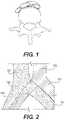
- FIG. 1shows an inferior-posterior view of the L5 lumbar and the bifurcations of the abdominal aorta and inferior vena cava;
- FIG. 2shows a schematic of the standard overlap of the right common iliac artery over the left common iliac vein
- FIG. 3shows a cross-sectional schematic of the arterio-venous system shown in FIG. 2 ;
- FIG. 4illustrates radial force as radial resistive force or chronic outward force
- FIG. 5illustrates crush resistance force and load on an exemplary stent
- FIG. 6illustrates an exemplary hybrid stent according to principles of the present disclosure
- FIG. 7illustrates an exemplary reinforcement ring according to principles of the present disclosure
- FIG. 8illustrates an exemplary embodiment of a hybrid stent according to principles of the present disclosure
- FIG. 9A , FIG. 9B and FIG. 9Cillustrate details of the embodiment of FIG. 8 .
- FIG. 10illustrates an exemplary placement of a hybrid stent according to principles of the present disclosure in the left common iliac vein
- FIG. 11illustrates an exemplary placement of a hybrid stent having a flared end according to principles of the present disclosure in the left common iliac vein;
- FIG. 12illustrates an exemplary extension stent according principles of the present disclosure
- FIG. 13illustrates an embodiment of an extension stent according to principles of the present disclosure
- FIG. 14illustrates an exemplary placement of a hybrid stent and an extension stent according to principles of the present disclosure in the left common iliac vein;
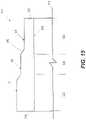
- FIG. 15illustrates an exemplary hybrid stent with a tapering wall thickness.
- Accurate placementis ideal in all medical interventions, but it is vital in areas where the end that is first deployed is critical. Such areas include at vessel bifurcations and branch vessels, so that the implant does not enter or interfere with the portion of the vessel that does not require treatment. Such a bifurcation is present at the inferior vena cava where it branches into right and left iliac veins, as described in more detail below.
- FIG. 1illustrates a vertebra, the right and left common iliac arteries near the bifurcation of the abdominal aorta, and the right and left common iliac arteries near the bifurcation of the inferior vena cava.
- the bifurcationsgenerally occur near the L5 lumbar vertebra.
- FIG. 1shows an inferior-posterior view of the L5 lumbar and the bifurcations of the abdominal aorta and inferior vena cava.
- venous insufficiencyi.e., a condition in which the flow of blood through the veins is impaired
- various deleterious pathologiesincluding, but not limited to, pain, swelling, edema, skin changes, and ulcerations.
- Venous insufficiencyis typically brought on by venous hypertension that develops as a result of persistent venous obstruction and incompetent (or subcompetent) venous valves.
- Current treatments for venous outflow obstructioninclude anticoagulation, thrombolysis, balloon angioplasty and stenting.
- FIG. 2illustrates the standard overlap of the right common iliac artery over the left common iliac vein.
- the arteries showninclude the abdominal aorta 1500 branching into the left common iliac artery 1501 and the right common iliac artery 1502 .
- the veins showninclude the inferior vena cava 1503 branching into the left common iliac vein 1504 and right common iliac vein 1505 .
- the rough diagram illustrated in FIG. 2represents the view looking down on a patient laying face-up (i.e., an anterior-poster view of the patient at the location of the bifurcation of the abdominal aorta 1500 and the inferior vena cava 1503 ).
- the overlap of the right common iliac artery 1502 , which is relatively strong and muscular, over the left common iliac vein 1504can cause May-Thurner syndrome by pressing down on the vein 1504 , crushing it against the spine, restricting flow, and, eventually, causing thrombosis and potentially partially or completely clotting off of the left common iliac vein 1504 and everything upstream of it (i.e., the venous system in the left leg, among others).
- FIG. 3illustrates a cross-section of the arterio-venous system shown in FIG. 2 taken along the gray dotted line. Shown in schematic are the right common iliac artery 1600 , the left common iliac vein 1601 , and a vertebra 1602 of the spine (possibly the L5 lumbar vertebra of the lumbar spine). As can be seen, the right common iliac artery 1600 is substantially cylindrical, due to its strong, muscular construction (among other potential factors). That strong, muscular artery has pressed down on the left common iliac vein 1601 , until it has almost completely lost patency, i.e., it is nearly completely pinched off.
- May-Thurner syndromemay indeed involve such severe pinching/crushing of the underlying left common iliac vein 1601 against the vertebra 1602 of the lumbar spine. However, it will also be understood that May-Thurner syndrome may involve much less pinching/crushing of the underlying left common iliac vein 1601 against the vertebra 1602 . Indeed, embodiments disclosed herein are appropriate for the treatment of various degrees of May-Thurner syndrome, including full crushing/pinching of the left common iliac vein 1602 by the right common iliac artery 1600 .
- FIG. 1601Other embodiments disclosed herein are appropriate for the treatment of various degrees of May-Thurner syndrome, including, but not limited to a crush/pinch of the underlying left common iliac vein 1601 of between about 10-95%, about 15-90%, about 20-85%, about 25-80%, about 30-75%, about 35-70%, about 40-65%, about 45-60%, and about 50-55%, or any other crush/pinch that could merit treatment using one or more of the devices disclosed herein.
- a crush/pinch of the underlying left common iliac vein 1601of between about 10-95%, about 15-90%, about 20-85%, about 25-80%, about 30-75%, about 35-70%, about 40-65%, about 45-60%, and about 50-55%, or any other crush/pinch that could merit treatment using one or more of the devices disclosed herein.
- stentsthat include circumferential rings of alternating interconnected struts connected by flexible connectors.
- the stentmay have open or closed cells of various configuration formed by an expandable material.
- the final expanded implanted configurationcan be achieved through mechanical expansion/actuation (e.g., balloon-expandable) or self-expansion (e.g., Nitinol).
- An exemplary embodiment of the stents described hereinare self-expanding implants comprising super elastic or shape memory alloy materials, but the stent is not so limited and may be formed of balloon-expandable material.
- an expandable stenthas varying magnitudes of radial force, crush resistance and flexibility at different locations along the length of the stent, while at the same time, the different locations have the same or similar diameter in an expanded configuration of the stent.
- an exemplary stent 10includes a high radial force segment 14 , a highly flexible segment 18 and a transition segment 22 between the high radial force segment 14 and the highly flexible segment 18 .
- the exemplary stent 10may include a reinforcement ring 26 at an end of the stent 10 , for example, adjacent the highly flexible segment 18 (configuration shown) or adjacent the high radial force segment 14 (configuration not shown).
- the stent 10 having a high radial force segment 14 and a highly flexible segment 18may be cut from a single tube, such as nitinol, for example, but could also be formed or cut from flat sheets that are welded together at long edges to form a tube-like structure. While a transition segment is illustrated herein, it should be noted that a hybrid stent that does not include a transition segment is considered to be within the scope of this disclosure.
- radial forcerefers to both or either Radial Resistive Force (RRF) and Chronic Outward Force (COF).
- RRFRadial Resistive Force
- COFChronic Outward Force
- radial resistive forceis an external force that acts around the circumference of a stent on the stent (toward the center of the stent).
- Chronic outward forceis the force the sent exerts outward from a direction of the center of the stent.
- Chronic outward force of a stentwill cause the stent to exert force on the vessel in which it is inserted to resist collapse and keep the vessel open.
- FIG. 5illustrates crush resistance, as used herein.
- Crush resistanceis a force of the stent when subject to a flat plate/focal crush load. While the radial force vector directions in FIG.
- the radial force according to principles of the present disclosuremay be radial resistive force, which is more related to crush resistance than a chronic outward force.
- Vectors illustrated in the figuresare meant to indicate direction, not magnitude.
- Radial Force and Crush Resistancecan be related they do not necessarily drive each other. So, a stent may be designed to have high crush resistance (flat plate/focal) but not high radial force. Such attributes can be tested independently in different test configurations.
- the reinforcement ringmay be an area of greater stiffness/crush resistance at an end portion of the stent. “Greater stiffness” here means having a stiffness/crush resistance greater than a portion of the stent adjacent the reinforcement ring. The reinforcement ring having greater stiffness may provide good inflow into the stent and through the vessel having the implant therein. While described herein as a “reinforcement ring,” the area of greater stiffness may be provided by an additional structure overlying the stent end (e.g., a “ring”) or may instead be an area where the strut structure is actually stronger, e.g., because the material forming the area of greater stiffness is inherently stiffer, a tighter cell structure, thicker struts or the like. For example, the reinforcement ring may have a different stent geometry, e.g., different strut width or is simply a fully-connected ring.
- FIG. 7An exemplary embodiment of the reinforcement ring is illustrated in FIG. 7 .
- more of the ring struts making up the reinforcement ringare connected by flexible connectors/bridges to the adjacent ring than in the neighboring highly flexible segment.
- a length of stent 10 having length L 0includes high radial force segment 14 having a radial force and/or crush resistance RF 1 and a flexibility F 1 along the length L 1 of the high radial force segment 14 . That is, a radial resistive force RF 1 of the high radial force segment 14 is relatively greater than the remainder of the stent 10 , and may be in the range of 0.75 to 1.00 N/mm, for example. The flexibility F 1 of the high radial force segment 14 may also be relatively lower than the remainder of the stent 10 . Flexibility is evaluated/measured through angle of deflection. According to principles described herein, the high radial force segment may be designed to withstand long term durability (fatigue) testing with a flexion range of 0-60 degrees.
- the relatively high radial force segment 14is intended to be placed in a vessel in the region of the vessel prone to compression or crushing, such as pinching/crushing of the underlying left common iliac vein 1601 against the vertebra 1602 caused by May-Thurner syndrome, as illustrated in FIG. 3 .
- the high radial force segmenthas a diameter D 1 .
- the length of stent L 0also includes a highly flexible segment 18 , which has relatively greater flexibility than the high radial force 14 segment along the length of the highly flexible segment 18 .
- the highly flexible segment 18has a length L 2 , a diameter D 2 and radial force, crush resistance RF 2 and flexibility F 2 , where RF 2 ⁇ RF 1 and F 2 >F 1 , such that the highly flexible segment is more flexible than the high radial force segment 14 .
- the highly flexible segmentmay be designed to withstand long term durability (fatigue) testing with a flexion range of 0-140 degrees.
- a radial resistive force RF 2 of the highly flexible segment 18may be in the range of 0.50 to 0.70 N/mm, for example.
- the length of stent 10may also include a transition segment 22 between the high radial force segment 14 and the highly flexible segment 18 , where the transition segment 22 has a length L 3 , a diameter D 3 and radial force or radial resistive force (crush resistance) RF 3 and flexibility F 3 , where RF 1 >RF 3 >RF 2 and F 1 and F 2 >F 3 >F 1 .
- the radial force or radial resistive force (crush resistance) RF 3 and flexibility F 3 of the transition segment 22may vary over the length L 3 of the transition segment 22 or may be constant along the length L 3 of the transition segment 22 .
- Each of the high radial force segment 14 , transition segment 22 and highly flexible segment 18has a different radial force, crush resistance and flexibility, which may be provided by different ring structures in each segment of the stent 10 .
- a high radial force segment 14may have a cell structure that has relatively greater periodicity, may be formed of stiffer ring struts and flexible connectors, and/or may have a more closed cell structure or other structure to impart the desired radial force or crush resistance relative to the radial force or crush resistance of the highly flexible segment.
- the strut geometry, thicker/wider strutsprovide more radial strength, number of apexes around the circumference of the stent/ring geometry can all drive radial force up or down, and the configuration/connection to the adjacent rings through the bridge connectors and more ring connectors can increase radial force.
- the highly flexible segment 18may have a cell structure that has relatively lesser periodicity, may be formed of relatively more flexible ring struts and flexible connectors, and/or have a more open cell structure.
- the transition segmentmay have a cell structure that transitions a geometry of the rings struts and flexible connectors of the high radial force segment to a geometry of the highly flexible segment, or the transition segment may have a different cell structure than the high radial force segment and the highly flexible segment.
- the stent having a high radial force segment, a transition segment and a highly flexible segmentmay be cut from a single tube, such as nitinol, for example, but may also be formed by any other suitable means.
- each of the segments of the stenthas substantially the same diameter, such that D 1 ⁇ D 2 ⁇ D 3 .
- the stentcould also have varying diameters that, when combined with the structural and material characteristics described above and below can achieve a flexible segment with a reduced loss in radial stiffness.
- one stentcan treat a range of vein vessel diameters.
- the present stent structuremay allow a single stent to treat multiple vessel sizes as the force exerted on the vessel remains fairly consistent over a range of diameters (3-4 mm).
- the length L 2 of the highly flexible segment 18will be greater than the length L 1 of the high radial force segment which will be greater than the length L 3 of the transition segment.
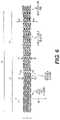
- FIG. 8An exemplary embodiment structure of a stent 110 according to principles of the present disclosure is shown in FIG. 8 .
- the diameter DS along the stent 110 at any given ring 112is substantially the same (D 1 ⁇ D 2 ⁇ D 3 ).
- each of the high radial force segment (May-Thurner Syndrome “MTS” Section) 114 , the transition segment (Transition Section) 122 and the highly flexible segment (Main Body Section) 118has a similar cell pattern.
- the radial force or crush resistance RF of the segmentsmay be varied by varying the thickness of the struts and/or flexible connectors 132 or the angular relationship of the struts with other struts and/or with the flexible connectors and/or the angulation of the flexible connectors themselves.
- perpendicular, thickness, same, similar, and other dimensional and geometric termsshould not be regarded as strict or perfect in their application. Instead, geometric and other dimensional reference terms should be interpreted based on their correspondence to accepted manufacturing tolerances and functional needs of the stent 110 on which they are employed. For example, the term “perpendicular” should be appreciated as affording a reasonable amount of angular variation due to manufacturing imperfections or the actual intentional curves cut or formed in the stent design 110 . Also, any thickness, width or other dimension should be assessed based on tolerances and functional needs of the design rather than idealized measurements.
- the thickness of the strut 128is its depth in the radial direction which is generally perpendicular to the strut width measurement, as shown in FIG. 8 .
- the strut thickness 128normally corresponds to the wall thickness (outside diameter minus inside diameter) of the tube from which the stent 110 is laser cut after etching, grinding and other processing.
- FIG. 15is a description of how varying wall thickness (and hence strut thickness) can alter stent radial stiffness and flexibility.
- embodiments of the stents disclosed hereinare not necessarily limited to being laser-cut from a cylindrical tube with a predetermined wall thickness. They could also be formed or cut from flat sheets that are welded together at long edges to form a tube-like structure.
- Each of the rings 112is comprised of a plurality of ring struts 128 interconnected to form alternating peaks or apexes 120 and troughs 124 . As shown in FIG. 8 , each of the ring struts 128 is generally straight.
- a stent 110includes a plurality of rings 112 connected by a plurality of flexible connectors 132 .
- the rings 112are arranged in a spaced relationship along a long axis 116 of the stent 110 .
- the connectors 132extend between adjacent pairs of the rings 112 .
- Each of the rings 112 and connectors 132are comprised of a plurality of interconnecting struts. The dimensions and orientation of these struts are designed to provide flexibility and radial stiffness according to principles of the present disclosure.
- the exemplary hybrid stent 110 illustrated in FIG. 8may be made of Nitinol tubing that is superelastic per ASTM F2063.
- the stent specificationmay further be as follows, post eletropolishing: AF temperature of parts to be 19+/ ⁇ 10 degrees Celsius.
- the hybrid stentmay be designed to treat a range of iliofemoral veins ranging in size from 12 mm to 20 mm. These dimensions are exemplary and a stent according to principles of the present disclosure are not so limited.
- FIGS. 9A, 9B and 9Cillustrate details of the strut and connector structure of the high radial force segment 114 ( FIG. 9A ) and the highly flexible segment 118 ( FIG. 9B ) of the embodiment FIG. 8 at the locations indicated in FIG. 8 .
- FIG. 9Cis showing detailed dimensions of the eyelet 119 geometry in which a radiopaque (RO) marker will be inserted to aid the doctor with deployment location of the stent under fluoroscopy.
- ROradiopaque
- FIG. 9Aillustrates ring struts 128 a of the high radial force segment 114 .
- FIG. 9Billustrates ring struts 128 b of the highly flexible segment 118 .
- stents with greater flexibilitytend to foreshorten more.
- accurate placementis ideal in all medical interventions, but it is of great interest in areas where the end that is first deployed is critical. Such areas include at vessel bifurcations and branch vessels, so that the implant does not enter or interfere with the portion of the vessel that does not require treatment.
- Such a bifurcationis present at the inferior vena cava where it branches into right and left iliac veins, as described in more detail below.
- a stent according to principles described hereinincludes a high radial force segment and a highly flexible segment.
- the high radial force segmentwith its stiffer structure, will foreshorten less than the highly flexible segment, and as a result, can allow for more accurate placement in the vessel into which it is implanted.
- FIG. 10illustrates a rough placement of a stent according to principles of the present disclosure.
- FIG. 10illustrates the inferior vena cava 1503 branching into the left common iliac vein 1504 and right common iliac vein 1505 . It will be understood that the rough diagram illustrated in FIG.
- FIG. 10represents the view looking down on a patient laying face-up (i.e., an anterior-poster view of the patient at the location of the bifurcation of the inferior vena cava 1503 ).
- face-upi.e., an anterior-poster view of the patient at the location of the bifurcation of the inferior vena cava 1503 .
- abdominal aorta and its branchingare not shown in FIG. 10 , but are shown in FIG. 2 , above.
- a multi-segment stent 10is placed in the left common iliac vein 1504 .
- the high radial force segment 14 of the stent 10may be allowed to extend into the iliac vein 1503 , although the end of the high radial force segment is intended to be placed to be at the junction of the left common iliac vein 1504 and the iliac vein 1503 .
- the highly flexible segment 18extends away from the high radial force segment 14 and the transition segment 22 between the highly flexible segment 18 and the high radial force segment 14 .
- the stent 10may have a flared end adjacent the high radial force segment 14 , as illustrated in FIG. 11 .
- the distal flared sectionis controlled by radius ‘r’.
- Exemplary flare sizesinclude 2.5 mm ⁇ 5.0 mm and 5.0 mm ⁇ 5.0 mm, but stent flares according to principles of the present disclosure are not so limited.
- the flared distal end of the stentmay be used for placement of the stent at a bifurcation of two vessels such as the common iliac vein 1504 and the iliac vein 1503 .
- the pre-loaded stent configuration on the delivery system described hereinallows the distal flared section of the stent to be partially deployed from the delivery system allowing the operator to position the flared section of the stent at the bifurcation of two vessels.
- the delivery catheteris advanced central to the vessel bifurcation to be treated, in this case the left common iliac vein 1504 . If radiopaque markers are provided on the implant, the operator can seat the partially deployed flare section of the stent at the bifurcation junction using the radiopaque markers. Once the central flared end of the partially deployed stent is in the appropriate deployment location and seated at the bifurcation junction the remainder of the stent can be deployed.
- a separate extension stent 50may be included along with the stent 10 .
- An embodiment of the separate extension stent 50is illustrated in FIG. 12 .
- the separate extension stent 50is tubular and may be a highly flexible segment similar to the highly flexible segment 18 in the hybrid stent 10 described above.
- the separate extension stent 50may comprise a plurality of rings 152 , which comprise a plurality of ring struts 158 interconnected to form alternating peaks or apexes 160 and troughs 164 . As shown in FIG. 12 , each of the ring struts 158 are generally straight.
- the ring struts 158may be connected to flexible connectors 162 .
- the rings 152are arranged in a spaced relationship along a long axis 116 of the stent 110 .
- the connectors 162extend between adjacent pairs of the rings.
- the separate extension stent 50may also include reinforcement rings on either or both ends of the tube. The dimensions and orientation of these struts are designed to provide flexibility and radial stiffness according to principles of the present disclosure.
- Each of the rings 152 and connectors 162comprises a plurality of interconnecting struts.
- the separate extension stentis made of an expandable material or a self-expandable material, such as Nitinol.
- the separate expansion stent 50may be cut from a single tube, such as nitinol, for example, but could also be formed or cut from flat sheets that are welded together at long edges to form a tube-like structure.
- FIG. 13An exemplary extension stent is illustrated in FIG. 13 .
- the extension stent illustrated in FIG. 13may be made of nitinol tubing that is superelastic per ASTM F2063.
- the stent specificationmay further be as follows, post electropolishing: AF temperature of parts to be 19+/ ⁇ 10 degrees Celsius.
- the extension stentmay be designed to treat a range of iliofemoral veins ranging in size from 8 mm to 16 mm. These dimensions, as well as dimensions illustrated in the figures, are exemplary and a stent according to principles of the present disclosure are not so limited.
- the separate extension stent 50is placed in the left iliac vein 1504 adjacent the highly flexible segment 18 of the hybrid stent 10 and may overlap the end of hybrid stent 10 , as illustrated in FIG. 14 .
- the region of overlap in the illustrationis indicted by reference number 200 .
- the placement of the hybrid stent 10 and the separate extension stent 50may be performed using the same delivery device at the same time.
- a second delivery catheter with pre-crimped extension stentmay be introduced into the treatment vessel and approximate the proximal end of the previously deployed hybrid stent.
- the catheter with crimped extension stentwould be inserted into the proximal end of the hybrid stent, positioned and the stent would be deployed utilizing the radiopaque markers on both stents to achieve appropriate overlap, e.g., 1 cm.
- the extension stentcan be implanted as a stand-alone stent.
- extension stentas described herein may be used in combination with other stents as a “main stent”, besides the hybrid stent 10 . In use, the extension stent can be used to allow for variation in placement.
- the extension stentmay include reinforcement rings where the reinforcement ring may be an area of greater stiffness/crush resistance at an end portion of the stent. “Greater stiffness” here means having a stiffness greater than a portion of the sent adjacent the reinforcement ring. The reinforcement ring having greater stiffness may provide good inflow into the stent and through the vessel having the implant therein. The reinforcement rings may make the extension stent easier to place with respect to the main stent, for example, by mitigating crushing of the ends as they are made to overlap.
- the ends of the extension stent and/or the stent to which it is to be placed adjacentcan be coated with a polymer, such as urethane or PTFE.
- the extension stentmay include anchors, eyelets, radiopaque markers or other features to assist in placement of the extension stent.
- the extension stentmay also be delivered with the main stent, or may be separately delivered to the vessel.
- the extension stentmay be delivered via an appropriate access site, (e.g. jugular, popliteal, etc.).
- the extension stentcan be made to be “bidirectional”, such that it could be preloaded onto a delivery catheter without specific regard to the direction of the delivery (e.g., jugular, popliteal, etc.).
- the deliverycan be made from above the treatment region or from below the treatment region.
- Such bidirectionalitycan be facilitated by the extensions stent geometry being symmetrical such that ends of the extension stent have the same geometry.
- the stentmay be delivered by a coaxial delivery catheter.
- a novel delivery devicemay include a cartridge that may be loaded onto a catheter and the hybrid sent also loaded on the catheter. The cartridge can be flipped by the operator for retrograde or anterograde.
- the stentmay be preloaded onto the delivery catheter for the direction of the delivery (e.g., jugular, popliteal, etc.)
- the actual stent ring geometrymay vary from that disclosed herein, as long as the stent 10 includes a first section with a relatively greater radial force or crush resistance than a second section of the stent that has a relatively greater flexibility than the first section. It is also contemplated that the separate extension stent 50 have a flexibility similar to the highly flexible segment of the hybrid stent 10 . Exemplary stent geometries for segments of the hybrid stent 10 and the extension stent 50 are taught in U.S. patent application Ser. Nos. 15/471,980 and 15/684,626, which are hereby incorporated by reference for all purposes as if fully set forth herein.
- the struts of the rings and flexible connectors with structuremay be used.
- an improved combination of high radial resistive force and increased flexibility extending distally down the stentcan be achieved by tapering the wall thickness of the nitinol tube used to fabricate the stent.
- the tube wall thicknesscould be tapered slightly, constantly or in steps, along its length. Tapering wall thickness could be combined with changes to the strut pattern to make the wall structure slightly more robust as you move distally. This reduces the typical decrease in radial resistive force associated with the thinning wall. This can create the “goldilocks” scenario of improving distal flexibility without giving up much radial resistive force.
- FIG. 15shows another embodiment of a hybrid stent 310 wherein the various segments or regions have varying radial stiffness and flexibility along an axis 312 of the stent.
- FIG. 15is a schematic of the wall thickness (and when struts are employed, strut thickness) of the tubular stent 310 having a constant inside diameter formed by inside surface 314 , an outside surface 316 with varying diameter and first and second free ends 318 , 320 , respectively.
- the material of the stent bodymay also include various structures, such as rings and connectors formed by struts as described elsewhere herein (although not shown in FIG. 15 ).
- the tapering wall structurecan be combined with modifications to the materials and strut pattern in the distal direction to have the “goldilocks” scenario of maintaining good resistive forces while still improving flexibility.
- the hybrid stent 310includes a firm region 322 , a transition region 324 and a flexible region 326 that correspond to a first diameter (D 1 ), a second diameter (D 2 ) and a third diameter (D 3 ), respectively. Due to the grinding, cutting, drawing or other operation the first diameter is greater than the second diameter which is greater than the third diameter.
- D 1first diameter
- D 2second diameter
- D 3third diameter
- the first diameteris greater than the second diameter which is greater than the third diameter.
- the reduction in wall thicknessmay be smooth and continuous—without an abrupt transition between the different regions. In such a case, regions may overlap with each other and/or have indistinct boundaries such that their function may depend on the application.
- the inside diameterremains, in the illustrated embodiment, relatively constant—for example when the stent is formed from stock tube and the inside is not selectively machined.
- the regionscould also be formed by a combination of reduced inner diameter and outer diameter, or just reductions in the inner diameter.
- the first and second free ends 318 , 320may be reinforced and/or flared for anchoring and maintaining patency to encourage blood flow as described above.
- the firm regionhas a greater stiffness (radial resistive and/or crush force) than the transition region which has a greater stiffness than the flexible region.
- the radial stiffness of the firm regionshould be sufficient to maintain sufficient venous patency to reduce or eliminate the MTS symptoms.
- the transition and flexible regions 324 , 326should have sufficient flexibility (for applications treating MTS) to withstand the high repetition, high bending loads described elsewhere herein.
- the hybrid stent 310can be formed, for example, by starting with a stock tube of constant inside and outside diameter and then using centerless grinding to form the regions. Other approaches can include step drawing the tube through dies with intervening annealing phases. Also, the tube can be preconditioned after modification or during intervening steps to prepare it for use.
- the radial stiffness and flexibility of the hybrid stent 310can be tailored using centerless grinding.
- Centerless grindingincludes use of a stationary wheel and a moving wheel with the workpiece (the nitinol tube) placed between the two wheels.
- the nitinol tubecan also be supported on a work rest to keep it in position between the two opposing wheels.
- the two wheelsrotate at different speeds.
- the stationary wheelor grinding wheel
- the stationary wheelor grinding wheel
- the other wheelor regulating wheel, translates in the direction of the stationary wheel and thus applies lateral pressure to the nitinol tube.
- the stationary wheelperforms a grinding action by having a higher tangential speed than the nitinol tube at the point of contact.
- the grinding wheelby turning faster, removes chips of material at the point of contact.
- the speed of the two wheels relative to each otherprovides the grinding action and determines the rate a which material is removed from the nitinol tube.
- Centerless grindingmay be applied to the inside of the tube also, by, for example, having the stationary or moving wheel inside the tube and the other wheel outside the tube.
- the stationary wheelis inside the nitinol tube
- the inside of the nitinol tubeis ground down to selectively decrease the wall thickness.
- centerless grindingcan be used at preselected axial lengths of the nitinol tube to create step changes in thickness, such as those shown and described in FIG. 15 , a tapered wall (which can be achieved through an end-feed—feeding the nitinol tube axially through the centerless grinding machine—for example) or even more complex shapes, like an hourglass.
- in-feed centerless grindingworks well for creating a hybrid stent 310 because the moving wheel can be moved in and out of contact with the nitinol tube within axial lengths of the tube larger than the width of the moving wheel.
- Varying wall thicknesscan be applied also to the extension stent 50 described hereinabove.
- Centerless grindingfor example, can be used to reduce the thickness of the reinforcement rings at the end of the extension stent 50 to improve the flexibility of the ends while retaining most of the stiffness imbued in the reinforcement rings.
- the reinforcement rings at the ends of the stent 50include a closed cell structure that is stiffer than the remaining structure between the ends. Reducing the wall thickness in these ends can improve flexibility without a concomitant loss in radial stiffness of the reinforcement rings.
- Reducing the outside wall diametermay also allow the extension stent ends to slip more easily within the hybrid stent 310 , such as is shown in FIG. 14 . Or, conversely, the inside diameter of the extension stent 50 can be reduced to better receive the hybrid stent 310 's end.
- the tapering wall thicknesscan be applied to a range of stent types and locations thereon. Generally, anywhere that a stent may benefit from improved flexibility without a proportionate loss in radial stiffness is a candidate for wall thickness variations.
- venous applicationsbenefit from configurations that improve flexibility (due to the greater elasticity of venous applications) while maintaining enough stiffness to resist pressure on the venous structure in selected areas (such as for the May-Thurner syndrome).
- the stents hereinare not necessarily limited to venous applications unless specifically required by the claims.
- the disclosed stentscould be employed in arterial and biliary applications, for example. But, are particularly suited for the demands of relatively soft structures defining lumens that are subject to much greater bending, twisting, stretching and other contortions and loads than are general arterial lumens.
- the implantmay be radially compressed/crimped to a smaller diameter for loading onto/into a delivery catheter.
- the implantmay be crimped over a balloon on the inner core of the delivery system which may be later inflated to expand the crimped implant to the desired diameter.
- Implants such as those described abovemay advantageously provide an adaptive diameter and/or flexibility to conform the dynamic movement of peripheral veins in leg/pelvis thereby facilitating treatment of both iliac vein compression syndrome and iliofemoral venous outflow obstructions.
- a stentthat will conform to the existing path of a vein instead of a straightening out of the vessel by the stent. It may also be desirable to have a high radial stiffness of the stent to resist collapse of the stent under crushing load and to maximize the resultant diameter of the treated vessel at the location of the stent deployment. With most stent constructions there is a direct relationship between radial stiffness and axial stiffness.
- Embodiments disclosed hereincan be used for both balloon expandable and self-expanding stent designs.
- the stent designscan be used for all stent interventions, including coronary, peripheral, carotid, neuro, biliary and, especially, venous applications. Additionally, this could be beneficial for stent grafts, percutaneous valves, etc.
- Implantsare typically loaded and retained onto a delivery system in a crimped configuration and then navigated and deployed in the desired anatomical location where they expand to the implanted configuration.
- the final implanted configurationcan be achieved through mechanical expansion/actuation (e.g., balloon-expandable) or self-expansion (e.g., Nitinol).
- Self-expanding implantsare manufactured from super elastic or shape memory alloy materials. Accurate and precise deployment of a self-expanding implant can be challenging due to a number of inherent design attributes associated with self-expanding implants.
- the implantmay jump/advance from the distal end of the delivery system during deployment due to the stored elastic energy of the material.
- the implantmay foreshorten during deployment due to the change in the implant diameter from the crimped configuration to the expanded configuration.
- physiological and anatomical configurationssuch a placement at or near bifurcations of body lumens, can affect accurate placement of implants. Once the implant is placed within the body lumen there is potential for uneven expansion or lack of circumferential implant apposition to the body lumen which can result in movement, migration or in certain severe cases implant embolization.
- a self-expanding implantdesigned with sufficient radial force or crush resistance to resist constant compression of the body lumen while providing optimal fatigue resistance, accurate placement, and in-vivo anchoring to prevent movement/migration is provided. Additionally, various methods for deployment and implantation for treating iliac vein compression syndrome and venous insufficiency disease are provided.
- the implantcomprises a purposely designed venous implant intended to focally treat iliac vein compression ( May-Thurner Syndrome).
- the implantmay be relatively short in length ( ⁇ 60 mm) and may be manufactured from self-expending Nitinol with integrated anchor features to aid in accurate placement and to mitigate migration following implantation.
- the implant and delivery systemare designed for precise deployment and placement at the bifurcation of the inferior vena cava into the right and left common iliac veins.
- the stents disclosed hereincan include anchor members, radiopaque markers, or eyelets, for example, set forth in pending U.S. patent application Ser. Nos. 15/471,980 and 15/684,626, which are hereby incorporated by reference for all purposes as if fully set forth herein.
Landscapes
- Health & Medical Sciences (AREA)
- Engineering & Computer Science (AREA)
- Biomedical Technology (AREA)
- Transplantation (AREA)
- Vascular Medicine (AREA)
- Physics & Mathematics (AREA)
- Cardiology (AREA)
- Oral & Maxillofacial Surgery (AREA)
- Mechanical Engineering (AREA)
- Heart & Thoracic Surgery (AREA)
- Optics & Photonics (AREA)
- Life Sciences & Earth Sciences (AREA)
- Animal Behavior & Ethology (AREA)
- General Health & Medical Sciences (AREA)
- Public Health (AREA)
- Veterinary Medicine (AREA)
- Prostheses (AREA)
- Media Introduction/Drainage Providing Device (AREA)
Abstract
Description
Claims (19)
Priority Applications (8)
| Application Number | Priority Date | Filing Date | Title |
|---|---|---|---|
| US15/897,673US11364134B2 (en) | 2018-02-15 | 2018-02-15 | Tapering stent |
| EP19708707.5AEP3752103A1 (en) | 2018-02-15 | 2019-02-08 | Tapering stent |
| CA3086025ACA3086025A1 (en) | 2018-02-15 | 2019-02-08 | Tapering stent |
| CN201980013856.3ACN111727023B (en) | 2018-02-15 | 2019-02-08 | Tapered stent |
| PCT/US2019/017218WO2019160758A1 (en) | 2018-02-15 | 2019-02-08 | Tapering stent |
| JP2020543626AJP7430142B2 (en) | 2018-02-15 | 2019-02-08 | tapered stent |
| AU2019222520AAU2019222520A1 (en) | 2018-02-15 | 2019-02-08 | Tapering stent |
| US17/831,564US20220287859A1 (en) | 2018-02-15 | 2022-06-03 | Tapering stent |
Applications Claiming Priority (1)
| Application Number | Priority Date | Filing Date | Title |
|---|---|---|---|
| US15/897,673US11364134B2 (en) | 2018-02-15 | 2018-02-15 | Tapering stent |
Related Child Applications (1)
| Application Number | Title | Priority Date | Filing Date |
|---|---|---|---|
| US17/831,564DivisionUS20220287859A1 (en) | 2018-02-15 | 2022-06-03 | Tapering stent |
Publications (2)
| Publication Number | Publication Date |
|---|---|
| US20190247209A1 US20190247209A1 (en) | 2019-08-15 |
| US11364134B2true US11364134B2 (en) | 2022-06-21 |
Family
ID=65635802
Family Applications (2)
| Application Number | Title | Priority Date | Filing Date |
|---|---|---|---|
| US15/897,673Active2038-07-05US11364134B2 (en) | 2018-02-15 | 2018-02-15 | Tapering stent |
| US17/831,564AbandonedUS20220287859A1 (en) | 2018-02-15 | 2022-06-03 | Tapering stent |
Family Applications After (1)
| Application Number | Title | Priority Date | Filing Date |
|---|---|---|---|
| US17/831,564AbandonedUS20220287859A1 (en) | 2018-02-15 | 2022-06-03 | Tapering stent |
Country Status (7)
| Country | Link |
|---|---|
| US (2) | US11364134B2 (en) |
| EP (1) | EP3752103A1 (en) |
| JP (1) | JP7430142B2 (en) |
| CN (1) | CN111727023B (en) |
| AU (1) | AU2019222520A1 (en) |
| CA (1) | CA3086025A1 (en) |
| WO (1) | WO2019160758A1 (en) |
Families Citing this family (9)
| Publication number | Priority date | Publication date | Assignee | Title |
|---|---|---|---|---|
| AU2007258592B2 (en)* | 2006-06-06 | 2012-10-25 | Cook Incorporated | Stent with a crush-resistant zone |
| US9750603B2 (en)* | 2014-01-27 | 2017-09-05 | Medtronic Vascular Galway | Stented prosthetic heart valve with variable stiffness and methods of use |
| US10940030B2 (en) | 2017-03-10 | 2021-03-09 | Serenity Medical, Inc. | Method and system for delivering a self-expanding stent to the venous sinuses |
| WO2019246268A1 (en)* | 2018-06-20 | 2019-12-26 | W. L. Gore & Associates, Inc. | Support structure for an implantable device with enhanced compressive stiffness region(s) |
| CN110368157A (en)* | 2019-08-22 | 2019-10-25 | 浙江归创医疗器械有限公司 | A kind of intravascular stent |
| AU2020407128B2 (en)* | 2019-12-20 | 2024-07-11 | W. L. Gore & Associates, Inc. | Support structure for an implantable device with enhanced compressive stiffness region(s) |
| US10881541B1 (en)* | 2020-05-01 | 2021-01-05 | Krishna Rocha-Singh | Systems and methods for treating venous compression/obstruction syndromes |
| WO2021253216A1 (en) | 2020-06-16 | 2021-12-23 | Suzhou Venmed Technology Co., Ltd. | Intravascular stent |
| PL442539A1 (en)* | 2022-10-17 | 2024-04-22 | Stentpoint P Spółka Z Ograniczoną Odpowiedzialnością | Self-expandable stent |
Citations (142)
| Publication number | Priority date | Publication date | Assignee | Title |
|---|---|---|---|---|
| US5449373A (en) | 1994-03-17 | 1995-09-12 | Medinol Ltd. | Articulated stent |
| US5827321A (en) | 1997-02-07 | 1998-10-27 | Cornerstone Devices, Inc. | Non-Foreshortening intraluminal prosthesis |
| US5836966A (en) | 1997-05-22 | 1998-11-17 | Scimed Life Systems, Inc. | Variable expansion force stent |
| US5843175A (en) | 1997-06-13 | 1998-12-01 | Global Therapeutics, Inc. | Enhanced flexibility surgical stent |
| US5843120A (en) | 1994-03-17 | 1998-12-01 | Medinol Ltd. | Flexible-expandable stent |
| US5868780A (en) | 1996-03-22 | 1999-02-09 | Lashinski; Robert D. | Stents for supporting lumens in living tissue |
| US5868782A (en) | 1996-12-24 | 1999-02-09 | Global Therapeutics, Inc. | Radially expandable axially non-contracting surgical stent |
| US5911754A (en) | 1998-07-24 | 1999-06-15 | Uni-Cath Inc. | Flexible stent with effective strut and connector patterns |
| US5922005A (en) | 1994-10-27 | 1999-07-13 | Medinol Ltd. | Stent fabrication method |
| US5938697A (en) | 1998-03-04 | 1999-08-17 | Scimed Life Systems, Inc. | Stent having variable properties |
| US5964798A (en) | 1997-12-16 | 1999-10-12 | Cardiovasc, Inc. | Stent having high radial strength |
| US6027526A (en)* | 1996-04-10 | 2000-02-22 | Advanced Cardiovascular Systems, Inc. | Stent having varied amounts of structural strength along its length |
| US6033433A (en) | 1997-04-25 | 2000-03-07 | Scimed Life Systems, Inc. | Stent configurations including spirals |
| US6042606A (en) | 1997-09-29 | 2000-03-28 | Cook Incorporated | Radially expandable non-axially contracting surgical stent |
| US6068656A (en) | 1997-05-15 | 2000-05-30 | Jomed Implantate Gmbh | Coronary stent |
| US6083259A (en) | 1998-11-16 | 2000-07-04 | Frantzen; John J. | Axially non-contracting flexible radially expandable stent |
| US6113627A (en) | 1998-02-03 | 2000-09-05 | Jang; G. David | Tubular stent consists of horizontal expansion struts and contralaterally attached diagonal-connectors |
| US6123721A (en) | 1998-02-17 | 2000-09-26 | Jang; G. David | Tubular stent consists of chevron-shape expansion struts and ipsilaterally attached M-frame connectors |
| US6179868B1 (en) | 1998-03-27 | 2001-01-30 | Janet Burpee | Stent with reduced shortening |
| US6190403B1 (en) | 1998-11-13 | 2001-02-20 | Cordis Corporation | Low profile radiopaque stent with increased longitudinal flexibility and radial rigidity |
| US6200334B1 (en) | 1998-02-03 | 2001-03-13 | G. David Jang | Tubular stent consists of non-parallel expansion struts and contralaterally attached diagonal connectors |
| US6203569B1 (en) | 1996-01-04 | 2001-03-20 | Bandula Wijay | Flexible stent |
| US6235053B1 (en) | 1998-02-02 | 2001-05-22 | G. David Jang | Tubular stent consists of chevron-shape expansion struts and contralaterally attached diagonal connectors |
| US6241762B1 (en) | 1998-03-30 | 2001-06-05 | Conor Medsystems, Inc. | Expandable medical device with ductile hinges |
| US6261319B1 (en) | 1998-07-08 | 2001-07-17 | Scimed Life Systems, Inc. | Stent |
| US20010014822A1 (en) | 1996-12-19 | 2001-08-16 | Simcha Milo | Stent combination |
| US6287336B1 (en) | 1995-10-16 | 2001-09-11 | Medtronic, Inc. | Variable flexibility stent |
| US6309414B1 (en) | 1997-11-04 | 2001-10-30 | Sorin Biomedica Cardio S.P.A. | Angioplasty stents |
| US20010047200A1 (en) | 1999-10-13 | 2001-11-29 | Raymond Sun | Non-foreshortening intraluminal prosthesis |
| US6325821B1 (en) | 1997-04-29 | 2001-12-04 | Sorin Biomedica Cardio S.P.A. | Stent for angioplasty |
| US6325825B1 (en)* | 1999-04-08 | 2001-12-04 | Cordis Corporation | Stent with variable wall thickness |
| US20020013616A1 (en) | 2000-05-05 | 2002-01-31 | Andrew Carter | Multilayer stents having enhanced flexibility and hoop strength |
| US20020042648A1 (en) | 2000-10-10 | 2002-04-11 | Biotronik Mess- Und Therapiegeraete Gmbh & Co. | Stent |
| US20020058990A1 (en) | 2000-09-23 | 2002-05-16 | Jang G. David | Intravascular stent consists of stairstep expansion strut pairs and double stairstep diagonal connecting struts contralaterally extended from expansion struts |
| US6402777B1 (en) | 1996-03-13 | 2002-06-11 | Medtronic, Inc. | Radiopaque stent markers |
| US6428570B1 (en) | 1995-10-16 | 2002-08-06 | Medtronic, Inc. | Medical stents, apparatus and method for making same |
| US6443982B1 (en) | 1994-03-17 | 2002-09-03 | Medinol, Ltd. | Flexible expandable stent |
| US6451049B2 (en) | 1998-04-29 | 2002-09-17 | Sorin Biomedica Cardio, S.P.A. | Stents for angioplasty |
| US6461380B1 (en) | 1998-07-28 | 2002-10-08 | Advanced Cardiovascular Systems, Inc. | Stent configuration |
| US6464722B2 (en) | 1994-03-17 | 2002-10-15 | Medinol, Ltd. | Flexible expandable stent |
| US6485508B1 (en) | 2000-10-13 | 2002-11-26 | Mcguinness Colm P. | Low profile stent |
| US6497723B1 (en) | 1997-09-09 | 2002-12-24 | Micro Science Medical Ag | Stent for transluminal implantation |
| US20030014102A1 (en) | 2001-06-27 | 2003-01-16 | James Hong | Intravascular Stent |
| US6540775B1 (en) | 2000-06-30 | 2003-04-01 | Cordis Corporation | Ultraflexible open cell stent |
| US20030105517A1 (en) | 2001-12-05 | 2003-06-05 | White Geoffrey Hamilton | Non-foreshortening stent |
| US20030105513A1 (en) | 2001-10-22 | 2003-06-05 | Yousuke Moriuchi | Stent to be implanted in human body and method of producing stent |
| US6679911B2 (en) | 2001-03-01 | 2004-01-20 | Cordis Corporation | Flexible stent |
| US6682554B2 (en) | 1998-09-05 | 2004-01-27 | Jomed Gmbh | Methods and apparatus for a stent having an expandable web structure |
| US6692522B1 (en) | 1996-12-26 | 2004-02-17 | Medinol, Ltd | Stent having lumen comprising welded engagement points and method of fabricating same |
| US6699281B2 (en) | 2001-07-20 | 2004-03-02 | Sorin Biomedica Cardio S.P.A. | Angioplasty stents |
| US20040054398A1 (en) | 2002-09-13 | 2004-03-18 | Cully Edward H. | Stent device with multiple helix construction |
| US20040054400A1 (en) | 1999-11-12 | 2004-03-18 | Granada Vuan Fernando | Conformable vascular stent |
| US6709453B2 (en) | 2000-03-01 | 2004-03-23 | Medinol Ltd. | Longitudinally flexible stent |
| US6730116B1 (en) | 1999-04-16 | 2004-05-04 | Medtronic, Inc. | Medical device for intraluminal endovascular stenting |
| US20040133265A1 (en) | 2001-09-12 | 2004-07-08 | Niall Duffy | Medical device for intraluminal endovascular stenting |
| US6761731B2 (en) | 2002-06-28 | 2004-07-13 | Cordis Corporation | Balloon-stent interaction to help reduce foreshortening |
| US6786922B2 (en) | 2002-10-08 | 2004-09-07 | Cook Incorporated | Stent with ring architecture and axially displaced connector segments |
| US6790227B2 (en) | 2001-03-01 | 2004-09-14 | Cordis Corporation | Flexible stent |
| US6818015B2 (en) | 1995-11-27 | 2004-11-16 | Schneider (Europe) Gmbh | Conical stent |
| US20040254627A1 (en) | 2003-04-04 | 2004-12-16 | Thompson Paul J. | Stent with end adapted for flaring |
| US20040267350A1 (en) | 2002-10-30 | 2004-12-30 | Roubin Gary S. | Non-foreshortening intraluminal prosthesis |
| US20050060024A1 (en) | 1995-07-25 | 2005-03-17 | Lee J. Michael | Expandible stent |
| US20050080479A1 (en) | 2003-09-29 | 2005-04-14 | Feng James Q. | Expandable endovascular stent |
| US6923829B2 (en) | 2002-11-25 | 2005-08-02 | Advanced Bio Prosthetic Surfaces, Ltd. | Implantable expandable medical devices having regions of differential mechanical properties and methods of making same |
| US6939373B2 (en) | 2003-08-20 | 2005-09-06 | Advanced Cardiovascular Systems, Inc. | Intravascular stent |
| EP1579824A2 (en) | 1999-06-30 | 2005-09-28 | Advanced Cardiovascular Systems, Inc. | Variable thickness stent and method of manufacture thereof |
| US20060025852A1 (en) | 2004-08-02 | 2006-02-02 | Armstrong Joseph R | Bioabsorbable self-expanding endolumenal devices |
| US7004968B2 (en) | 2002-12-20 | 2006-02-28 | Biotronik Gmbh & Co. Kg | Stent |
| US7029493B2 (en) | 2002-01-25 | 2006-04-18 | Cordis Corporation | Stent with enhanced crossability |
| US7037330B1 (en) | 2000-10-16 | 2006-05-02 | Scimed Life Systems, Inc. | Neurovascular stent and method |
| US7060090B2 (en) | 2003-10-15 | 2006-06-13 | Medtronic Vascular, Inc. | Stent with increased longitudinal flexibility and scaffolding |
| US20060129227A1 (en) | 2002-08-02 | 2006-06-15 | Auxetica Limited | Auxetic tubular liners |
| US7070614B1 (en) | 2000-05-22 | 2006-07-04 | Malte Neuss | Radially expandable vessel support |
| US20060173531A1 (en) | 1996-09-19 | 2006-08-03 | Jacob Richter | Stent with variable features to optimize support and method of making such stent |
| US7131993B2 (en) | 2003-06-25 | 2006-11-07 | Boston Scientific Scimed, Inc. | Varying circumferential spanned connectors in a stent |
| US7141062B1 (en) | 2000-03-01 | 2006-11-28 | Medinol, Ltd. | Longitudinally flexible stent |
| US20070010869A1 (en) | 2005-07-11 | 2007-01-11 | Nipro Corporation | Flexible stent with excellent expandability and trackability |
| US20070185563A1 (en) | 1999-11-16 | 2007-08-09 | Boston Scientific Corporation | Endoluminal stent having a matched stiffness region and/or a stiffness gradient |
| US20070219613A1 (en) | 2003-10-06 | 2007-09-20 | Xtent, Inc. | Apparatus and methods for interlocking stent segments |
| US7316710B1 (en) | 2002-12-30 | 2008-01-08 | Advanced Cardiovascular Systems, Inc. | Flexible stent |
| US20080009938A1 (en) | 2006-07-07 | 2008-01-10 | Bin Huang | Stent with a radiopaque marker and method for making the same |
| US20080051878A1 (en) | 2002-08-27 | 2008-02-28 | Advanced Cardiovascular Systems Inc. | Stent for treating vulnerable plaque |
| US7357813B2 (en) | 2001-03-01 | 2008-04-15 | Cordis Corporation | Flexible stent |
| US20080140181A1 (en) | 2004-10-25 | 2008-06-12 | Reynolds Jason M | Stent Removal and Repositioning Aid and Associated Method |
| US20090018641A1 (en) | 2005-03-25 | 2009-01-15 | Christoph Binkert | Large vessel stents |
| US20090062899A1 (en) | 2001-12-21 | 2009-03-05 | Nfocus Neuromedical, Inc. | Composite stent with polymeric covering and bioactive coating |
| US7527644B2 (en) | 2002-11-05 | 2009-05-05 | Alveolus Inc. | Stent with geometry determinated functionality and method of making the same |
| US7621947B2 (en) | 2000-03-01 | 2009-11-24 | Medinol, Ltd. | Longitudinally flexible stent |
| US7648526B2 (en) | 2003-04-30 | 2010-01-19 | Nipro Corporation | Extendable soft stent with excellent follow-up capability to blood vessel |
| US7686843B2 (en) | 2002-07-31 | 2010-03-30 | Unison Therapeutics, Inc. | Flexible and conformable stent |
| EP2174623A1 (en) | 2008-10-10 | 2010-04-14 | Veryan Medical Limited | A stent suitable for deployment in a blood vessel |
| US7806918B2 (en) | 2003-09-30 | 2010-10-05 | Merit Medical Systems, Inc. | Removable stent |
| US7862607B2 (en) | 2005-12-30 | 2011-01-04 | C. R. Bard, Inc. | Stent with bio-resorbable connector and methods |
| US20110106237A1 (en) | 2009-11-04 | 2011-05-05 | Craig Bonsignore | Alternating circumferential bridge stent design and methods for use thereof |
| US20110125251A1 (en) | 2009-05-14 | 2011-05-26 | Orbusneich Medical, Inc. | Self-Expanding Stent with Polygon Transition Zone |
| US20110152994A1 (en)* | 2009-12-22 | 2011-06-23 | William Cook Europe Aps | Implantable device |
| US8012196B2 (en) | 1999-07-02 | 2011-09-06 | Boston Scientific Scimed, Inc. | Flexible segmented stents |
| US8016874B2 (en) | 2007-05-23 | 2011-09-13 | Abbott Laboratories Vascular Enterprises Limited | Flexible stent with elevated scaffolding properties |
| US20110230957A1 (en) | 2009-11-04 | 2011-09-22 | Bonsignore Craig L | Alternating circumferential bridge stent design and methods for use thereof |
| US20120043703A1 (en) | 2010-04-14 | 2012-02-23 | Randolf Von Oepen | Method of fabricating an intraluminal scaffold with an enlarged portion |
| US8128679B2 (en) | 2007-05-23 | 2012-03-06 | Abbott Laboratories Vascular Enterprises Limited | Flexible stent with torque-absorbing connectors |
| US20120143312A1 (en) | 1995-03-01 | 2012-06-07 | Brown Brian J | Longitudinally flexible expandable stent |
| US8206427B1 (en) | 1994-06-08 | 2012-06-26 | Medtonic Vascular, Inc. | Apparatus and methods for endoluminal graft placement |
| US8211163B2 (en) | 2006-09-13 | 2012-07-03 | Boston Scientific Scimed, Inc. | Hybrid symmetrical stent designs |
| US8221489B2 (en) | 2009-08-20 | 2012-07-17 | Stentys | Device and method for treating a body lumen |
| US8257424B2 (en) | 1999-05-19 | 2012-09-04 | Eurocor Gmbh | Radially expandable vascular stent |
| US8267991B2 (en) | 2000-03-06 | 2012-09-18 | Boston Scientific Scimed, Inc. | Intraluminar perforated radially expandable drug delivery prosthesis and a method for the production thereof |
| US20120277844A1 (en) | 2006-08-22 | 2012-11-01 | Tim Wu | Biodegradable Drug Eluting stent Pattern |
| US8317859B2 (en) | 2004-06-28 | 2012-11-27 | J.W. Medical Systems Ltd. | Devices and methods for controlling expandable prostheses during deployment |
| US20120310327A1 (en) | 2011-05-31 | 2012-12-06 | Cook Medical Technologies Llc | Non-foreshortening, axial tension constrainable stent |
| US8337544B2 (en) | 2007-12-20 | 2012-12-25 | Abbott Laboratories Vascular Enterprises Limited | Endoprosthesis having flexible connectors |
| US8470021B2 (en) | 2007-12-28 | 2013-06-25 | Cook Medical Technologies Llc | Radially expandable stent |
| US20130178928A1 (en) | 2010-09-13 | 2013-07-11 | Rajnikant Gandalal Vyas | Stents with low strut thickness and variable strut geometry |
| US20130304192A1 (en) | 2012-05-14 | 2013-11-14 | C.R. Bard, Inc. | Uniformly Expandable Stent |
| US20130325141A1 (en) | 2012-06-05 | 2013-12-05 | Merit Medical Systems, Inc. | Esophageal stent |
| US8652196B2 (en) | 2004-03-16 | 2014-02-18 | Merit Medical Systems, Inc. | Stent |
| US20140277378A1 (en) | 2013-03-15 | 2014-09-18 | Atrium Medical Corporation | Stent device having reduced foreshortening and recoil and method of making same |
| US20140277365A1 (en) | 2013-03-14 | 2014-09-18 | University Of Rochester | Ultrasound-guided endograft system |
| US8888837B2 (en) | 2010-12-22 | 2014-11-18 | Bentley Innomed Gmbh | Stent graft |
| US8974514B2 (en) | 2007-03-13 | 2015-03-10 | Abbott Cardiovascular Systems Inc. | Intravascular stent with integrated link and ring strut |
| US20150105852A1 (en) | 2013-10-16 | 2015-04-16 | Covidien Lp | Vascular Stent |
| US20150209167A1 (en) | 2014-01-24 | 2015-07-30 | Q3 Medical Devices Limited | Bidirectional stent and method of use thereof |
| US20150250580A1 (en) | 1997-01-24 | 2015-09-10 | Celonova Stent, Inc. | Bistable spring construction for a stent and other medical apparatus |
| US20150265438A1 (en)* | 2014-03-18 | 2015-09-24 | Abbott Cardiovascular Systems Inc. | Tapered scaffolds |
| US20150305943A1 (en) | 2014-04-29 | 2015-10-29 | Abbott Cardiovascular Systems Inc. | Devices and Methods for Treatment of the Eustachian Tube and Sinus Cavity |
| EP3043754A1 (en) | 2013-09-12 | 2016-07-20 | Boston Scientific Scimed, Inc. | Stent with anti-migration connectors |
| US9408727B2 (en) | 2000-05-03 | 2016-08-09 | Abbott Cardiovascular Systems Inc. | Intravascular stent |
| US20160250052A1 (en) | 2013-11-04 | 2016-09-01 | Bentley Innomed Gmbh | Stent comprising a retaining element |
| US9498360B2 (en) | 2013-03-15 | 2016-11-22 | Stryker Corporation | Stent and method of use |
| US9554927B2 (en) | 2002-08-30 | 2017-01-31 | C.R. Bard, Inc. | Helical stent having improved flexibility and expandability |
| US9561123B2 (en) | 2002-08-30 | 2017-02-07 | C.R. Bard, Inc. | Highly flexible stent and method of manufacture |
| US20170035548A1 (en) | 2006-02-28 | 2017-02-09 | C. R. Bard, Inc. | Flexible stretch stent-graft |
| US20170071768A1 (en) | 2015-09-11 | 2017-03-16 | Cook Medical Technologies Llc | Variable radial stiffness and variable diameter intraluminal device |
| US9655998B2 (en) | 2014-08-07 | 2017-05-23 | Cook Medical Technologies Llc | Encapsulated drug compositions and methods of use thereof |
| US9668895B2 (en) | 2007-04-03 | 2017-06-06 | C.R. Bard, Inc. | Bendable stent |
| US9668898B2 (en) | 2014-07-24 | 2017-06-06 | Medtronic Vascular, Inc. | Stent delivery system having dynamic deployment and methods of manufacturing same |
| US9693860B2 (en) | 2014-12-01 | 2017-07-04 | Medtronic, Inc. | Segmented transcatheter valve prosthesis having an unsupported valve segment |
| US9724220B2 (en) | 2009-04-07 | 2017-08-08 | Cook Medical Technologies Llc | Introducer assembly and implantable medical device |
| US9770348B2 (en) | 2006-08-29 | 2017-09-26 | C.R. Bard, Inc. | Annular mesh |
| US9795496B2 (en) | 2011-01-14 | 2017-10-24 | W. L. Gore & Associates, Inc. | Stent |
| US20170340464A1 (en) | 2016-05-25 | 2017-11-30 | W. L. Gore & Associates, Inc. | Controlled endoprosthesis balloon expansion |
| US9839538B2 (en) | 2011-04-08 | 2017-12-12 | Cook Medical Technologies Llc | Method for making a flexible stent-graft |
Family Cites Families (13)
| Publication number | Priority date | Publication date | Assignee | Title |
|---|---|---|---|---|
| US8202312B2 (en)* | 2000-03-01 | 2012-06-19 | Medinol Ltd. | Longitudinally flexible stent |
| US7112216B2 (en)* | 2003-05-28 | 2006-09-26 | Boston Scientific Scimed, Inc. | Stent with tapered flexibility |
| US8961583B2 (en)* | 2004-09-08 | 2015-02-24 | Cordis Corporation | Optimized flex link for expandable stent |
| US20090105809A1 (en)* | 2007-10-19 | 2009-04-23 | Lee Michael J | Implantable and lumen-supporting stents and related methods of manufacture and use |
| EP2349129B1 (en)* | 2008-10-10 | 2016-05-04 | Veryan Medical Limited | A stent suitable for deployment in a blood vessel |
| KR101810379B1 (en)* | 2009-02-02 | 2017-12-20 | 코디스 코포레이션 | Flexible stent design |
| US8114149B2 (en)* | 2009-10-20 | 2012-02-14 | Svelte Medical Systems, Inc. | Hybrid stent with helical connectors |
| WO2011136963A1 (en)* | 2010-04-30 | 2011-11-03 | Boston Scientific Scimed, Inc. | Duodenal metabolic stent |
| WO2012078955A1 (en)* | 2010-12-10 | 2012-06-14 | Micropen Technologies Corporation | Stents and methods of making stents |
| US9636241B2 (en)* | 2012-03-30 | 2017-05-02 | Manli International Ltd | Coil bioabsorbable stents |
| EP3099274A4 (en)* | 2014-01-29 | 2017-08-09 | Concentric Medical, Inc. | Vascular and bodily duct treatment devices and methods |
| US10111741B2 (en)* | 2014-10-29 | 2018-10-30 | W. L. Gore & Associates, Inc. | Intralumenal stent graft fixation |
| CN105496614B (en)* | 2016-01-21 | 2017-06-23 | 浙江巴泰医疗科技有限公司 | A kind of medical self-expanding stent |
- 2018
- 2018-02-15USUS15/897,673patent/US11364134B2/enactiveActive
- 2019
- 2019-02-08EPEP19708707.5Apatent/EP3752103A1/enactivePending
- 2019-02-08CNCN201980013856.3Apatent/CN111727023B/enactiveActive
- 2019-02-08AUAU2019222520Apatent/AU2019222520A1/ennot_activeAbandoned
- 2019-02-08JPJP2020543626Apatent/JP7430142B2/enactiveActive
- 2019-02-08CACA3086025Apatent/CA3086025A1/enactivePending
- 2019-02-08WOPCT/US2019/017218patent/WO2019160758A1/ennot_activeCeased
- 2022
- 2022-06-03USUS17/831,564patent/US20220287859A1/ennot_activeAbandoned
Patent Citations (207)
| Publication number | Priority date | Publication date | Assignee | Title |
|---|---|---|---|---|
| US6443982B1 (en) | 1994-03-17 | 2002-09-03 | Medinol, Ltd. | Flexible expandable stent |
| US5972018A (en) | 1994-03-17 | 1999-10-26 | Medinol Ltd. | Flexible expandable stent |
| US5843120A (en) | 1994-03-17 | 1998-12-01 | Medinol Ltd. | Flexible-expandable stent |
| US6635084B2 (en) | 1994-03-17 | 2003-10-21 | Medinol, Ltd. | Flexible expandable stent |
| US20040102835A1 (en) | 1994-03-17 | 2004-05-27 | Israel Henry Marshall | Flexible expandable stent |
| US5449373A (en) | 1994-03-17 | 1995-09-12 | Medinol Ltd. | Articulated stent |
| US6059811A (en) | 1994-03-17 | 2000-05-09 | Medinol Ltd. | Articulated stent |
| US6464722B2 (en) | 1994-03-17 | 2002-10-15 | Medinol, Ltd. | Flexible expandable stent |
| US6461381B2 (en) | 1994-03-17 | 2002-10-08 | Medinol, Ltd. | Flexible expandable stent |
| US8317854B1 (en) | 1994-06-08 | 2012-11-27 | Medtronic Vascular, Inc. | Apparatus and methods for endoluminal graft placement |
| US8206427B1 (en) | 1994-06-08 | 2012-06-26 | Medtonic Vascular, Inc. | Apparatus and methods for endoluminal graft placement |
| US5922005A (en) | 1994-10-27 | 1999-07-13 | Medinol Ltd. | Stent fabrication method |
| US6156052A (en) | 1994-10-27 | 2000-12-05 | Medinol Ltd. | Stent fabrication method |
| US6660019B1 (en) | 1994-10-27 | 2003-12-09 | Medinol Ltd. | Stent fabrication method |
| US20120143312A1 (en) | 1995-03-01 | 2012-06-07 | Brown Brian J | Longitudinally flexible expandable stent |
| US20050060024A1 (en) | 1995-07-25 | 2005-03-17 | Lee J. Michael | Expandible stent |
| US6428570B1 (en) | 1995-10-16 | 2002-08-06 | Medtronic, Inc. | Medical stents, apparatus and method for making same |
| US6287336B1 (en) | 1995-10-16 | 2001-09-11 | Medtronic, Inc. | Variable flexibility stent |
| US6641609B2 (en) | 1995-10-16 | 2003-11-04 | Medtronic Ave, Inc. | Medical stents, apparatus and method for making same |
| US6818015B2 (en) | 1995-11-27 | 2004-11-16 | Schneider (Europe) Gmbh | Conical stent |
| US6203569B1 (en) | 1996-01-04 | 2001-03-20 | Bandula Wijay | Flexible stent |
| US6402777B1 (en) | 1996-03-13 | 2002-06-11 | Medtronic, Inc. | Radiopaque stent markers |
| US6183507B1 (en) | 1996-03-22 | 2001-02-06 | Medtronic Ave, Inc. | Stents for supporting lumens in living tissue |
| US5868780A (en) | 1996-03-22 | 1999-02-09 | Lashinski; Robert D. | Stents for supporting lumens in living tissue |
| US6027526A (en)* | 1996-04-10 | 2000-02-22 | Advanced Cardiovascular Systems, Inc. | Stent having varied amounts of structural strength along its length |
| US20060173531A1 (en) | 1996-09-19 | 2006-08-03 | Jacob Richter | Stent with variable features to optimize support and method of making such stent |
| US20010014822A1 (en) | 1996-12-19 | 2001-08-16 | Simcha Milo | Stent combination |
| US6638300B1 (en) | 1996-12-24 | 2003-10-28 | Cook Incorporated | Radially expandable non-contracting surgical stent |
| US5868782A (en) | 1996-12-24 | 1999-02-09 | Global Therapeutics, Inc. | Radially expandable axially non-contracting surgical stent |
| US6692522B1 (en) | 1996-12-26 | 2004-02-17 | Medinol, Ltd | Stent having lumen comprising welded engagement points and method of fabricating same |
| US20150250580A1 (en) | 1997-01-24 | 2015-09-10 | Celonova Stent, Inc. | Bistable spring construction for a stent and other medical apparatus |
| US20070213807A1 (en) | 1997-02-07 | 2007-09-13 | Endosystems Llc | Non-foreshortening intraluminal prosthesis |
| US6106548A (en) | 1997-02-07 | 2000-08-22 | Endosystems Llc | Non-foreshortening intraluminal prosthesis |
| US6475236B1 (en) | 1997-02-07 | 2002-11-05 | Endosystems, Llc | Non-foreshortening intraluminal prosthesis |
| US6764506B2 (en) | 1997-02-07 | 2004-07-20 | Endosystems Llc | Non-foreshortening intraluminal prosthesis |
| US20070213806A1 (en) | 1997-02-07 | 2007-09-13 | Endosystems Llc | Non-foreshortening intraluminal prosthesis |
| US5827321A (en) | 1997-02-07 | 1998-10-27 | Cornerstone Devices, Inc. | Non-Foreshortening intraluminal prosthesis |
| US6746479B2 (en) | 1997-04-25 | 2004-06-08 | Scimed Life Systems, Inc. | Stent cell configurations including spirals |
| US6033433A (en) | 1997-04-25 | 2000-03-07 | Scimed Life Systems, Inc. | Stent configurations including spirals |
| US20100241216A1 (en) | 1997-04-29 | 2010-09-23 | Sorin Biomedica Cardio S.R.L. | Stents for angioplasty |
| US6325821B1 (en) | 1997-04-29 | 2001-12-04 | Sorin Biomedica Cardio S.P.A. | Stent for angioplasty |
| US7273494B2 (en) | 1997-04-29 | 2007-09-25 | Sorin Biomedica Cardio S.R.L. | Stents for angioplasty |
| US20080288048A1 (en) | 1997-04-29 | 2008-11-20 | Sorin Biomedica Cardio S.R.L. | Stents for angioplasty |
| US6068656A (en) | 1997-05-15 | 2000-05-30 | Jomed Implantate Gmbh | Coronary stent |
| US5836966A (en) | 1997-05-22 | 1998-11-17 | Scimed Life Systems, Inc. | Variable expansion force stent |
| US6146403A (en) | 1997-05-22 | 2000-11-14 | Scimed Life Systems, Inc. | Variable expansion force stent |
| US7485130B2 (en) | 1997-05-22 | 2009-02-03 | Boston Scientific Scimed, Inc. | Variable expansion force stent |
| US5843175A (en) | 1997-06-13 | 1998-12-01 | Global Therapeutics, Inc. | Enhanced flexibility surgical stent |
| US6497723B1 (en) | 1997-09-09 | 2002-12-24 | Micro Science Medical Ag | Stent for transluminal implantation |
| US6299635B1 (en) | 1997-09-29 | 2001-10-09 | Cook Incorporated | Radially expandable non-axially contracting surgical stent |
| US6042606A (en) | 1997-09-29 | 2000-03-28 | Cook Incorporated | Radially expandable non-axially contracting surgical stent |
| US6309414B1 (en) | 1997-11-04 | 2001-10-30 | Sorin Biomedica Cardio S.P.A. | Angioplasty stents |
| US20100004736A1 (en) | 1997-11-04 | 2010-01-07 | Sorin Biomedica Cardio S.R.L. | Angioplasty stents |
| US5964798A (en) | 1997-12-16 | 1999-10-12 | Cardiovasc, Inc. | Stent having high radial strength |
| US8562665B2 (en) | 1998-02-02 | 2013-10-22 | Boston Scientific Scimed, Inc. | Tubular stent consists of chevron-shape expansion struts and contralaterally attached diagonal-connectors |
| US6235053B1 (en) | 1998-02-02 | 2001-05-22 | G. David Jang | Tubular stent consists of chevron-shape expansion struts and contralaterally attached diagonal connectors |
| US6113627A (en) | 1998-02-03 | 2000-09-05 | Jang; G. David | Tubular stent consists of horizontal expansion struts and contralaterally attached diagonal-connectors |
| US6200334B1 (en) | 1998-02-03 | 2001-03-13 | G. David Jang | Tubular stent consists of non-parallel expansion struts and contralaterally attached diagonal connectors |
| US6123721A (en) | 1998-02-17 | 2000-09-26 | Jang; G. David | Tubular stent consists of chevron-shape expansion struts and ipsilaterally attached M-frame connectors |
| US6485509B2 (en) | 1998-03-04 | 2002-11-26 | Scimed Life Systems, Inc. | Stent having variable properties and method of its use |
| US5938697A (en) | 1998-03-04 | 1999-08-17 | Scimed Life Systems, Inc. | Stent having variable properties |
| US7402169B2 (en) | 1998-03-04 | 2008-07-22 | Boston Scientific Scimed, Inc. | Stent having variable properties and method of its use |
| US6179868B1 (en) | 1998-03-27 | 2001-01-30 | Janet Burpee | Stent with reduced shortening |
| US6241762B1 (en) | 1998-03-30 | 2001-06-05 | Conor Medsystems, Inc. | Expandable medical device with ductile hinges |
| US7896912B2 (en) | 1998-03-30 | 2011-03-01 | Innovational Holdings, Llc | Expandable medical device with S-shaped bridging elements |
| US20030009214A1 (en) | 1998-03-30 | 2003-01-09 | Shanley John F. | Medical device with beneficial agent delivery mechanism |
| US6451049B2 (en) | 1998-04-29 | 2002-09-17 | Sorin Biomedica Cardio, S.P.A. | Stents for angioplasty |
| US6261319B1 (en) | 1998-07-08 | 2001-07-17 | Scimed Life Systems, Inc. | Stent |
| US6945993B2 (en) | 1998-07-08 | 2005-09-20 | Boston Scientific Scimed, Inc. | Stent |
| US8668731B2 (en) | 1998-07-08 | 2014-03-11 | Boston Scientific Scimed, Inc. | Stent |
| US7731746B2 (en) | 1998-07-08 | 2010-06-08 | Boston Scientific Scimed, Inc. | Stent |
| US20050021130A1 (en) | 1998-07-08 | 2005-01-27 | Scimed Life Systems, Inc. | Stent |
| US6478816B2 (en) | 1998-07-08 | 2002-11-12 | Scimed Life Systems, Inc. | Stent |
| US7326243B2 (en) | 1998-07-08 | 2008-02-05 | Boston Scientific Scimed, Inc. | Stent |
| US5911754A (en) | 1998-07-24 | 1999-06-15 | Uni-Cath Inc. | Flexible stent with effective strut and connector patterns |
| US6461380B1 (en) | 1998-07-28 | 2002-10-08 | Advanced Cardiovascular Systems, Inc. | Stent configuration |
| US6682554B2 (en) | 1998-09-05 | 2004-01-27 | Jomed Gmbh | Methods and apparatus for a stent having an expandable web structure |
| US6190403B1 (en) | 1998-11-13 | 2001-02-20 | Cordis Corporation | Low profile radiopaque stent with increased longitudinal flexibility and radial rigidity |
| US7060088B1 (en) | 1998-11-13 | 2006-06-13 | Cordis Corporation | Stent with improved flexible connecting links |
| US6083259A (en) | 1998-11-16 | 2000-07-04 | Frantzen; John J. | Axially non-contracting flexible radially expandable stent |
| US6325825B1 (en)* | 1999-04-08 | 2001-12-04 | Cordis Corporation | Stent with variable wall thickness |
| US6730116B1 (en) | 1999-04-16 | 2004-05-04 | Medtronic, Inc. | Medical device for intraluminal endovascular stenting |
| US8257424B2 (en) | 1999-05-19 | 2012-09-04 | Eurocor Gmbh | Radially expandable vascular stent |
| EP1579824A2 (en) | 1999-06-30 | 2005-09-28 | Advanced Cardiovascular Systems, Inc. | Variable thickness stent and method of manufacture thereof |
| US8012196B2 (en) | 1999-07-02 | 2011-09-06 | Boston Scientific Scimed, Inc. | Flexible segmented stents |
| US20010047200A1 (en) | 1999-10-13 | 2001-11-29 | Raymond Sun | Non-foreshortening intraluminal prosthesis |
| US20040054400A1 (en) | 1999-11-12 | 2004-03-18 | Granada Vuan Fernando | Conformable vascular stent |
| US20070185563A1 (en) | 1999-11-16 | 2007-08-09 | Boston Scientific Corporation | Endoluminal stent having a matched stiffness region and/or a stiffness gradient |
| US7621947B2 (en) | 2000-03-01 | 2009-11-24 | Medinol, Ltd. | Longitudinally flexible stent |
| US6709453B2 (en) | 2000-03-01 | 2004-03-23 | Medinol Ltd. | Longitudinally flexible stent |
| US7141062B1 (en) | 2000-03-01 | 2006-11-28 | Medinol, Ltd. | Longitudinally flexible stent |
| US8267991B2 (en) | 2000-03-06 | 2012-09-18 | Boston Scientific Scimed, Inc. | Intraluminar perforated radially expandable drug delivery prosthesis and a method for the production thereof |
| US9408727B2 (en) | 2000-05-03 | 2016-08-09 | Abbott Cardiovascular Systems Inc. | Intravascular stent |
| US20020013616A1 (en) | 2000-05-05 | 2002-01-31 | Andrew Carter | Multilayer stents having enhanced flexibility and hoop strength |
| US7070614B1 (en) | 2000-05-22 | 2006-07-04 | Malte Neuss | Radially expandable vessel support |
| US6706061B1 (en) | 2000-06-30 | 2004-03-16 | Robert E. Fischell | Enhanced hybrid cell stent |
| US6540775B1 (en) | 2000-06-30 | 2003-04-01 | Cordis Corporation | Ultraflexible open cell stent |
| US20030100941A1 (en) | 2000-06-30 | 2003-05-29 | Fischell Robert E. | Ultraflexible open cell stent |
| US20020058990A1 (en) | 2000-09-23 | 2002-05-16 | Jang G. David | Intravascular stent consists of stairstep expansion strut pairs and double stairstep diagonal connecting struts contralaterally extended from expansion struts |
| US20020042648A1 (en) | 2000-10-10 | 2002-04-11 | Biotronik Mess- Und Therapiegeraete Gmbh & Co. | Stent |
| US6485508B1 (en) | 2000-10-13 | 2002-11-26 | Mcguinness Colm P. | Low profile stent |
| US7037330B1 (en) | 2000-10-16 | 2006-05-02 | Scimed Life Systems, Inc. | Neurovascular stent and method |
| US20100222864A1 (en) | 2000-10-16 | 2010-09-02 | Boston Scientific Scimed, Inc. | Neurovascular stent and method |
| US20050004657A1 (en) | 2001-03-01 | 2005-01-06 | Robert Burgermeister | Flexible stent |
| US6790227B2 (en) | 2001-03-01 | 2004-09-14 | Cordis Corporation | Flexible stent |
| US6679911B2 (en) | 2001-03-01 | 2004-01-20 | Cordis Corporation | Flexible stent |
| US7357813B2 (en) | 2001-03-01 | 2008-04-15 | Cordis Corporation | Flexible stent |
| US20030014102A1 (en) | 2001-06-27 | 2003-01-16 | James Hong | Intravascular Stent |
| US7344563B2 (en) | 2001-07-20 | 2008-03-18 | Sorin Biomedica Cardio S.R.L. | Angioplasty stents |
| US6699281B2 (en) | 2001-07-20 | 2004-03-02 | Sorin Biomedica Cardio S.P.A. | Angioplasty stents |
| US20040133265A1 (en) | 2001-09-12 | 2004-07-08 | Niall Duffy | Medical device for intraluminal endovascular stenting |
| US20030105513A1 (en) | 2001-10-22 | 2003-06-05 | Yousuke Moriuchi | Stent to be implanted in human body and method of producing stent |
| US20030105517A1 (en) | 2001-12-05 | 2003-06-05 | White Geoffrey Hamilton | Non-foreshortening stent |
| US20090062899A1 (en) | 2001-12-21 | 2009-03-05 | Nfocus Neuromedical, Inc. | Composite stent with polymeric covering and bioactive coating |
| US7029493B2 (en) | 2002-01-25 | 2006-04-18 | Cordis Corporation | Stent with enhanced crossability |
| US6761731B2 (en) | 2002-06-28 | 2004-07-13 | Cordis Corporation | Balloon-stent interaction to help reduce foreshortening |
| US7686843B2 (en) | 2002-07-31 | 2010-03-30 | Unison Therapeutics, Inc. | Flexible and conformable stent |
| US20060129227A1 (en) | 2002-08-02 | 2006-06-15 | Auxetica Limited | Auxetic tubular liners |
| US20080051878A1 (en) | 2002-08-27 | 2008-02-28 | Advanced Cardiovascular Systems Inc. | Stent for treating vulnerable plaque |
| US9561123B2 (en) | 2002-08-30 | 2017-02-07 | C.R. Bard, Inc. | Highly flexible stent and method of manufacture |
| US20170086994A1 (en) | 2002-08-30 | 2017-03-30 | C. R. Bard, Inc. | Helical Stent Having Improved Flexibility and Expandability |
| US9554927B2 (en) | 2002-08-30 | 2017-01-31 | C.R. Bard, Inc. | Helical stent having improved flexibility and expandability |
| US20170100267A1 (en) | 2002-08-30 | 2017-04-13 | C. R. Bard, Inc. | Highly flexible stent and method of manufacture |
| US20040054398A1 (en) | 2002-09-13 | 2004-03-18 | Cully Edward H. | Stent device with multiple helix construction |
| US6786922B2 (en) | 2002-10-08 | 2004-09-07 | Cook Incorporated | Stent with ring architecture and axially displaced connector segments |
| US20040267350A1 (en) | 2002-10-30 | 2004-12-30 | Roubin Gary S. | Non-foreshortening intraluminal prosthesis |
| US7527644B2 (en) | 2002-11-05 | 2009-05-05 | Alveolus Inc. | Stent with geometry determinated functionality and method of making the same |
| US6923829B2 (en) | 2002-11-25 | 2005-08-02 | Advanced Bio Prosthetic Surfaces, Ltd. | Implantable expandable medical devices having regions of differential mechanical properties and methods of making same |
| US8348990B2 (en) | 2002-11-25 | 2013-01-08 | Advanced Bio Prosthetic Surfaces, Ltd. | Implantable expandable medical devices having regions of differential mechanical properties and methods of making same |
| US7004968B2 (en) | 2002-12-20 | 2006-02-28 | Biotronik Gmbh & Co. Kg | Stent |
| US7316710B1 (en) | 2002-12-30 | 2008-01-08 | Advanced Cardiovascular Systems, Inc. | Flexible stent |
| US20160287418A1 (en) | 2002-12-30 | 2016-10-06 | Abbott Cardiovascular Systems Inc. | Flexible stent |
| US20040254627A1 (en) | 2003-04-04 | 2004-12-16 | Thompson Paul J. | Stent with end adapted for flaring |
| US7648526B2 (en) | 2003-04-30 | 2010-01-19 | Nipro Corporation | Extendable soft stent with excellent follow-up capability to blood vessel |
| US7131993B2 (en) | 2003-06-25 | 2006-11-07 | Boston Scientific Scimed, Inc. | Varying circumferential spanned connectors in a stent |
| US6939373B2 (en) | 2003-08-20 | 2005-09-06 | Advanced Cardiovascular Systems, Inc. | Intravascular stent |
| US20050080479A1 (en) | 2003-09-29 | 2005-04-14 | Feng James Q. | Expandable endovascular stent |
| US7806918B2 (en) | 2003-09-30 | 2010-10-05 | Merit Medical Systems, Inc. | Removable stent |
| US20070219613A1 (en) | 2003-10-06 | 2007-09-20 | Xtent, Inc. | Apparatus and methods for interlocking stent segments |
| US7060090B2 (en) | 2003-10-15 | 2006-06-13 | Medtronic Vascular, Inc. | Stent with increased longitudinal flexibility and scaffolding |
| US8652196B2 (en) | 2004-03-16 | 2014-02-18 | Merit Medical Systems, Inc. | Stent |
| US9700448B2 (en) | 2004-06-28 | 2017-07-11 | J.W. Medical Systems Ltd. | Devices and methods for controlling expandable prostheses during deployment |
| US8317859B2 (en) | 2004-06-28 | 2012-11-27 | J.W. Medical Systems Ltd. | Devices and methods for controlling expandable prostheses during deployment |
| US20060025852A1 (en) | 2004-08-02 | 2006-02-02 | Armstrong Joseph R | Bioabsorbable self-expanding endolumenal devices |
| US20080140181A1 (en) | 2004-10-25 | 2008-06-12 | Reynolds Jason M | Stent Removal and Repositioning Aid and Associated Method |
| US20090018641A1 (en) | 2005-03-25 | 2009-01-15 | Christoph Binkert | Large vessel stents |
| US20070010869A1 (en) | 2005-07-11 | 2007-01-11 | Nipro Corporation | Flexible stent with excellent expandability and trackability |
| US7862607B2 (en) | 2005-12-30 | 2011-01-04 | C. R. Bard, Inc. | Stent with bio-resorbable connector and methods |
| US20170312105A1 (en) | 2005-12-30 | 2017-11-02 | C.R. Bard, Inc. | Stent with a Bio-Resorbable Connector |
| US20170312104A1 (en) | 2005-12-30 | 2017-11-02 | C.R. Bard, Inc. | Stent with a Bio-Resorbable Connector |
| US9707110B2 (en) | 2005-12-30 | 2017-07-18 | C. R. Bard, Inc. | Stent with a bio-resorbable connector |
| US8647379B2 (en) | 2005-12-30 | 2014-02-11 | C. R. Bard, Inc. | Stent with a bio-resorbable connector |
| US20170035548A1 (en) | 2006-02-28 | 2017-02-09 | C. R. Bard, Inc. | Flexible stretch stent-graft |
| US9622850B2 (en) | 2006-02-28 | 2017-04-18 | C.R. Bard, Inc. | Flexible stretch stent-graft |
| US20080009938A1 (en) | 2006-07-07 | 2008-01-10 | Bin Huang | Stent with a radiopaque marker and method for making the same |
| US20120277844A1 (en) | 2006-08-22 | 2012-11-01 | Tim Wu | Biodegradable Drug Eluting stent Pattern |
| US9770348B2 (en) | 2006-08-29 | 2017-09-26 | C.R. Bard, Inc. | Annular mesh |
| US8211163B2 (en) | 2006-09-13 | 2012-07-03 | Boston Scientific Scimed, Inc. | Hybrid symmetrical stent designs |
| US8974514B2 (en) | 2007-03-13 | 2015-03-10 | Abbott Cardiovascular Systems Inc. | Intravascular stent with integrated link and ring strut |
| US9668895B2 (en) | 2007-04-03 | 2017-06-06 | C.R. Bard, Inc. | Bendable stent |
| US9320627B2 (en) | 2007-05-23 | 2016-04-26 | Abbott Laboratories Vascular Enterprises Limited | Flexible stent with torque-absorbing connectors |
| US20160235562A1 (en) | 2007-05-23 | 2016-08-18 | Abbott Laboratories Vascular Enterprises Limited | Flexible stent with torque-absorbing connectors |
| US8128679B2 (en) | 2007-05-23 | 2012-03-06 | Abbott Laboratories Vascular Enterprises Limited | Flexible stent with torque-absorbing connectors |
| US8016874B2 (en) | 2007-05-23 | 2011-09-13 | Abbott Laboratories Vascular Enterprises Limited | Flexible stent with elevated scaffolding properties |
| US8337544B2 (en) | 2007-12-20 | 2012-12-25 | Abbott Laboratories Vascular Enterprises Limited | Endoprosthesis having flexible connectors |
| US8470021B2 (en) | 2007-12-28 | 2013-06-25 | Cook Medical Technologies Llc | Radially expandable stent |
| EP2174623A1 (en) | 2008-10-10 | 2010-04-14 | Veryan Medical Limited | A stent suitable for deployment in a blood vessel |
| US9724220B2 (en) | 2009-04-07 | 2017-08-08 | Cook Medical Technologies Llc | Introducer assembly and implantable medical device |
| US20110125251A1 (en) | 2009-05-14 | 2011-05-26 | Orbusneich Medical, Inc. | Self-Expanding Stent with Polygon Transition Zone |
| US8221489B2 (en) | 2009-08-20 | 2012-07-17 | Stentys | Device and method for treating a body lumen |
| US9649211B2 (en) | 2009-11-04 | 2017-05-16 | Confluent Medical Technologies, Inc. | Alternating circumferential bridge stent design and methods for use thereof |
| US20110230957A1 (en) | 2009-11-04 | 2011-09-22 | Bonsignore Craig L | Alternating circumferential bridge stent design and methods for use thereof |
| US20110106237A1 (en) | 2009-11-04 | 2011-05-05 | Craig Bonsignore | Alternating circumferential bridge stent design and methods for use thereof |
| US20110152994A1 (en)* | 2009-12-22 | 2011-06-23 | William Cook Europe Aps | Implantable device |
| US20120043703A1 (en) | 2010-04-14 | 2012-02-23 | Randolf Von Oepen | Method of fabricating an intraluminal scaffold with an enlarged portion |
| US20120046731A1 (en) | 2010-04-14 | 2012-02-23 | Abbott Vascular | Intraluminal scaffold with conforming axial strut |
| US20120046729A1 (en) | 2010-04-14 | 2012-02-23 | Abbott Vascular | Intraluminal scaffold having an enlarged portion |
| US20120046730A1 (en) | 2010-04-14 | 2012-02-23 | Abbott Vascular | Methods of treating a condition of a vessel in a patient |
| US20120046739A1 (en) | 2010-04-14 | 2012-02-23 | Randolf Von Oepen | Method of delivering a medical device across a plurality of valves |
| US20120046733A1 (en) | 2010-04-14 | 2012-02-23 | Randolf Von Oepen | Method of delivering a medical device across a valve |
| US8524132B2 (en) | 2010-04-14 | 2013-09-03 | Abbott Cardiovascular Systems Inc. | Method of fabricating an intraluminal scaffold with an enlarged portion |
| US20130178928A1 (en) | 2010-09-13 | 2013-07-11 | Rajnikant Gandalal Vyas | Stents with low strut thickness and variable strut geometry |
| US8888837B2 (en) | 2010-12-22 | 2014-11-18 | Bentley Innomed Gmbh | Stent graft |
| US9795496B2 (en) | 2011-01-14 | 2017-10-24 | W. L. Gore & Associates, Inc. | Stent |
| US9839540B2 (en) | 2011-01-14 | 2017-12-12 | W. L. Gore & Associates, Inc. | Stent |
| US9839538B2 (en) | 2011-04-08 | 2017-12-12 | Cook Medical Technologies Llc | Method for making a flexible stent-graft |
| US20120310327A1 (en) | 2011-05-31 | 2012-12-06 | Cook Medical Technologies Llc | Non-foreshortening, axial tension constrainable stent |
| US9066825B2 (en) | 2012-05-14 | 2015-06-30 | C.R. Bard, Inc. | Uniformly expandable stent |
| US20130304192A1 (en) | 2012-05-14 | 2013-11-14 | C.R. Bard, Inc. | Uniformly Expandable Stent |
| US20130325141A1 (en) | 2012-06-05 | 2013-12-05 | Merit Medical Systems, Inc. | Esophageal stent |
| US20140277365A1 (en) | 2013-03-14 | 2014-09-18 | University Of Rochester | Ultrasound-guided endograft system |
| US9498360B2 (en) | 2013-03-15 | 2016-11-22 | Stryker Corporation | Stent and method of use |
| US20140277378A1 (en) | 2013-03-15 | 2014-09-18 | Atrium Medical Corporation | Stent device having reduced foreshortening and recoil and method of making same |
| EP3043754A1 (en) | 2013-09-12 | 2016-07-20 | Boston Scientific Scimed, Inc. | Stent with anti-migration connectors |
| US20150105852A1 (en) | 2013-10-16 | 2015-04-16 | Covidien Lp | Vascular Stent |
| US20160250052A1 (en) | 2013-11-04 | 2016-09-01 | Bentley Innomed Gmbh | Stent comprising a retaining element |
| US20150209167A1 (en) | 2014-01-24 | 2015-07-30 | Q3 Medical Devices Limited | Bidirectional stent and method of use thereof |
| US9375810B2 (en) | 2014-01-24 | 2016-06-28 | Q3 Medical Devices Limited | Bidirectional stent and method of use thereof |
| US20150265438A1 (en)* | 2014-03-18 | 2015-09-24 | Abbott Cardiovascular Systems Inc. | Tapered scaffolds |
| US20150305943A1 (en) | 2014-04-29 | 2015-10-29 | Abbott Cardiovascular Systems Inc. | Devices and Methods for Treatment of the Eustachian Tube and Sinus Cavity |
| US9668898B2 (en) | 2014-07-24 | 2017-06-06 | Medtronic Vascular, Inc. | Stent delivery system having dynamic deployment and methods of manufacturing same |
| US20170224878A1 (en) | 2014-08-07 | 2017-08-10 | Cook Medical Technologies Llc | Encapsulated drug compositions and methods of use thereof |
| US9655998B2 (en) | 2014-08-07 | 2017-05-23 | Cook Medical Technologies Llc | Encapsulated drug compositions and methods of use thereof |
| US20170265998A1 (en) | 2014-12-01 | 2017-09-21 | Medtronic, Inc. | Segmented transcatheter valve prosthesis having an unsupported valve segment |
| US9693860B2 (en) | 2014-12-01 | 2017-07-04 | Medtronic, Inc. | Segmented transcatheter valve prosthesis having an unsupported valve segment |
| US20170071768A1 (en) | 2015-09-11 | 2017-03-16 | Cook Medical Technologies Llc | Variable radial stiffness and variable diameter intraluminal device |
| US20170340464A1 (en) | 2016-05-25 | 2017-11-30 | W. L. Gore & Associates, Inc. | Controlled endoprosthesis balloon expansion |
Non-Patent Citations (1)
| Title |
|---|
| International Search Report issued in PCT Application No. PCT/US2019/017218; dated May 3, 2019; 13 Pages. |
Also Published As
| Publication number | Publication date |
|---|---|
| JP2021513890A (en) | 2021-06-03 |
| JP7430142B2 (en) | 2024-02-09 |
| CN111727023B (en) | 2024-08-20 |
| US20220287859A1 (en) | 2022-09-15 |
| WO2019160758A1 (en) | 2019-08-22 |
| CN111727023A (en) | 2020-09-29 |
| US20190247209A1 (en) | 2019-08-15 |
| EP3752103A1 (en) | 2020-12-23 |
| AU2019222520A1 (en) | 2020-07-02 |
| CA3086025A1 (en) | 2019-08-22 |
Similar Documents
| Publication | Publication Date | Title |
|---|---|---|
| US12239554B2 (en) | Hybrid stent | |
| US20220287859A1 (en) | Tapering stent | |
| US11628076B2 (en) | Hybrid stent | |
| US12178726B2 (en) | Non-foreshortening stent | |
| US20220296397A1 (en) | Hybrid stent | |
| US11980555B2 (en) | Implantable stent | |
| HK40061218A (en) | Hybrid stent |
Legal Events
| Date | Code | Title | Description |
|---|---|---|---|
| FEPP | Fee payment procedure | Free format text:ENTITY STATUS SET TO UNDISCOUNTED (ORIGINAL EVENT CODE: BIG.); ENTITY STATUS OF PATENT OWNER: LARGE ENTITY | |
| FEPP | Fee payment procedure | Free format text:ENTITY STATUS SET TO SMALL (ORIGINAL EVENT CODE: SMAL); ENTITY STATUS OF PATENT OWNER: LARGE ENTITY | |
| AS | Assignment | Owner name:VESPER MEDICAL, INC., PENNSYLVANIA Free format text:ASSIGNMENT OF ASSIGNORS INTEREST;ASSIGNORS:LONGO, MICHAEL A.;SHOOK, BRUCE J.;HARRISON, WILLIAM JAMES;REEL/FRAME:045901/0414 Effective date:20180524 | |
| STPP | Information on status: patent application and granting procedure in general | Free format text:NON FINAL ACTION MAILED | |
| STPP | Information on status: patent application and granting procedure in general | Free format text:RESPONSE TO NON-FINAL OFFICE ACTION ENTERED AND FORWARDED TO EXAMINER | |
| STPP | Information on status: patent application and granting procedure in general | Free format text:NON FINAL ACTION MAILED | |
| STPP | Information on status: patent application and granting procedure in general | Free format text:NON FINAL ACTION MAILED | |
| STPP | Information on status: patent application and granting procedure in general | Free format text:FINAL REJECTION MAILED | |
| STPP | Information on status: patent application and granting procedure in general | Free format text:ADVISORY ACTION MAILED | |
| STCV | Information on status: appeal procedure | Free format text:NOTICE OF APPEAL FILED | |
| STCV | Information on status: appeal procedure | Free format text:EXAMINER'S ANSWER TO APPEAL BRIEF MAILED | |
| STCV | Information on status: appeal procedure | Free format text:APPEAL READY FOR REVIEW | |
| STCV | Information on status: appeal procedure | Free format text:ON APPEAL -- AWAITING DECISION BY THE BOARD OF APPEALS | |
| STCV | Information on status: appeal procedure | Free format text:BOARD OF APPEALS DECISION RENDERED | |
| STPP | Information on status: patent application and granting procedure in general | Free format text:NOTICE OF ALLOWANCE MAILED -- APPLICATION RECEIVED IN OFFICE OF PUBLICATIONS | |
| STPP | Information on status: patent application and granting procedure in general | Free format text:NOTICE OF ALLOWANCE MAILED -- APPLICATION RECEIVED IN OFFICE OF PUBLICATIONS | |
| FEPP | Fee payment procedure | Free format text:ENTITY STATUS SET TO UNDISCOUNTED (ORIGINAL EVENT CODE: BIG.); ENTITY STATUS OF PATENT OWNER: LARGE ENTITY | |
| STPP | Information on status: patent application and granting procedure in general | Free format text:PUBLICATIONS -- ISSUE FEE PAYMENT VERIFIED | |
| STCF | Information on status: patent grant | Free format text:PATENTED CASE |