US11364132B2 - Double walled fixed length stent like apparatus and methods of use thereof - Google Patents
Double walled fixed length stent like apparatus and methods of use thereofDownload PDFInfo
- Publication number
- US11364132B2 US11364132B2US16/616,465US201816616465AUS11364132B2US 11364132 B2US11364132 B2US 11364132B2US 201816616465 AUS201816616465 AUS 201816616465AUS 11364132 B2US11364132 B2US 11364132B2
- Authority
- US
- United States
- Prior art keywords
- tubular wall
- medical apparatus
- tubular
- sections
- walls
- Prior art date
- Legal status (The legal status is an assumption and is not a legal conclusion. Google has not performed a legal analysis and makes no representation as to the accuracy of the status listed.)
- Active, expires
Links
- 238000000034methodMethods0.000titleclaimsabstractdescription28
- 210000004204blood vesselAnatomy0.000claimsabstractdescription19
- 239000000463materialSubstances0.000claimsdescription17
- 239000011248coating agentSubstances0.000claimsdescription13
- 238000000576coating methodMethods0.000claimsdescription13
- 230000009467reductionEffects0.000claimsdescription8
- 239000003638chemical reducing agentSubstances0.000claimsdescription6
- 230000008569processEffects0.000claimsdescription6
- 229910001000nickel titaniumInorganic materials0.000claimsdescription4
- HLXZNVUGXRDIFK-UHFFFAOYSA-Nnickel titaniumChemical compound[Ti].[Ti].[Ti].[Ti].[Ti].[Ti].[Ti].[Ti].[Ti].[Ti].[Ti].[Ni].[Ni].[Ni].[Ni].[Ni].[Ni].[Ni].[Ni].[Ni].[Ni].[Ni].[Ni].[Ni].[Ni]HLXZNVUGXRDIFK-UHFFFAOYSA-N0.000claimsdescription4
- 229920000642polymerPolymers0.000claimsdescription4
- 229910001260Pt alloyInorganic materials0.000claimsdescription3
- 229910001362Ta alloysInorganic materials0.000claimsdescription3
- RTAQQCXQSZGOHL-UHFFFAOYSA-NTitaniumChemical compound[Ti]RTAQQCXQSZGOHL-UHFFFAOYSA-N0.000claimsdescription3
- WAIPAZQMEIHHTJ-UHFFFAOYSA-N[Cr].[Co]Chemical class[Cr].[Co]WAIPAZQMEIHHTJ-UHFFFAOYSA-N0.000claimsdescription3
- 238000006243chemical reactionMethods0.000claimsdescription3
- 230000008602contractionEffects0.000claimsdescription3
- 239000010935stainless steelSubstances0.000claimsdescription3
- 229910001220stainless steelInorganic materials0.000claimsdescription3
- 229910052719titaniumInorganic materials0.000claimsdescription3
- 239000010936titaniumSubstances0.000claimsdescription3
- 238000013519translationMethods0.000claimsdescription3
- 210000005240left ventricleAnatomy0.000description23
- 210000001147pulmonary arteryAnatomy0.000description16
- 206010019280Heart failuresDiseases0.000description15
- 210000005241right ventricleAnatomy0.000description13
- 206010007559Cardiac failure congestiveDiseases0.000description10
- 230000006870functionEffects0.000description7
- 239000007943implantSubstances0.000description7
- 230000000670limiting effectEffects0.000description6
- 230000006872improvementEffects0.000description5
- 230000017531blood circulationEffects0.000description4
- 208000032170Congenital AbnormalitiesDiseases0.000description3
- 239000008280bloodSubstances0.000description3
- 210000004369bloodAnatomy0.000description3
- 238000012986modificationMethods0.000description3
- 230000004048modificationEffects0.000description3
- 229920001343polytetrafluoroethylenePolymers0.000description3
- 239000004810polytetrafluoroethyleneSubstances0.000description3
- 239000004814polyurethaneSubstances0.000description3
- 238000001356surgical procedureMethods0.000description3
- 238000011282treatmentMethods0.000description3
- 208000003037Diastolic Heart FailureDiseases0.000description2
- 206010024119Left ventricular failureDiseases0.000description2
- 208000008253Systolic Heart FailureDiseases0.000description2
- 230000008901benefitEffects0.000description2
- 230000003247decreasing effectEffects0.000description2
- 230000001419dependent effectEffects0.000description2
- 229920000295expanded polytetrafluoroethylenePolymers0.000description2
- 230000002349favourable effectEffects0.000description2
- 239000012530fluidSubstances0.000description2
- 238000010438heat treatmentMethods0.000description2
- 210000004072lungAnatomy0.000description2
- 210000004165myocardiumAnatomy0.000description2
- 229920001692polycarbonate urethanePolymers0.000description2
- 229920002635polyurethanePolymers0.000description2
- 230000002685pulmonary effectEffects0.000description2
- 210000003102pulmonary valveAnatomy0.000description2
- 208000024891symptomDiseases0.000description2
- 210000001519tissueAnatomy0.000description2
- 208000004434CalcinosisDiseases0.000description1
- 208000002330Congenital Heart DefectsDiseases0.000description1
- 206010010356Congenital anomalyDiseases0.000description1
- 206010056370Congestive cardiomyopathyDiseases0.000description1
- 201000010046Dilated cardiomyopathyDiseases0.000description1
- JOYRKODLDBILNP-UHFFFAOYSA-NEthyl urethaneChemical compoundCCOC(N)=OJOYRKODLDBILNP-UHFFFAOYSA-N0.000description1
- 206010016803Fluid overloadDiseases0.000description1
- JVTAAEKCZFNVCJ-REOHCLBHSA-NL-lactic acidChemical compoundC[C@H](O)C(O)=OJVTAAEKCZFNVCJ-REOHCLBHSA-N0.000description1
- 241001465754MetazoaSpecies0.000description1
- 208000031481Pathologic ConstrictionDiseases0.000description1
- 238000013459approachMethods0.000description1
- 230000002146bilateral effectEffects0.000description1
- 230000008859changeEffects0.000description1
- 208000028831congenital heart diseaseDiseases0.000description1
- 210000004351coronary vesselAnatomy0.000description1
- 230000035487diastolic blood pressureEffects0.000description1
- 230000003205diastolic effectEffects0.000description1
- 201000010099diseaseDiseases0.000description1
- 208000037265diseases, disorders, signs and symptomsDiseases0.000description1
- 239000003814drugSubstances0.000description1
- 229940079593drugDrugs0.000description1
- 230000000694effectsEffects0.000description1
- 230000010247heart contractionEffects0.000description1
- 230000000004hemodynamic effectEffects0.000description1
- 238000002513implantationMethods0.000description1
- 238000003780insertionMethods0.000description1
- 230000037431insertionEffects0.000description1
- 238000003698laser cuttingMethods0.000description1
- 230000036244malformationEffects0.000description1
- 238000002483medicationMethods0.000description1
- 230000004220muscle functionEffects0.000description1
- 210000000107myocyteAnatomy0.000description1
- 230000008520organizationEffects0.000description1
- 230000036961partial effectEffects0.000description1
- 230000001575pathological effectEffects0.000description1
- 229920001432poly(L-lactide)Polymers0.000description1
- 229920000747poly(lactic acid)Polymers0.000description1
- 229920001606poly(lactic acid-co-glycolic acid)Polymers0.000description1
- 229920001296polysiloxanePolymers0.000description1
- -1polytetrafluoroethylenePolymers0.000description1
- 230000036316preloadEffects0.000description1
- 238000002360preparation methodMethods0.000description1
- 208000037821progressive diseaseDiseases0.000description1
- 238000005086pumpingMethods0.000description1
- 238000011084recoveryMethods0.000description1
- 230000002829reductive effectEffects0.000description1
- 238000007634remodelingMethods0.000description1
- 230000002441reversible effectEffects0.000description1
- 230000037390scarringEffects0.000description1
- 229920002379silicone rubberPolymers0.000description1
- 230000036262stenosisEffects0.000description1
- 208000037804stenosisDiseases0.000description1
- 230000002966stenotic effectEffects0.000description1
- 238000006467substitution reactionMethods0.000description1
- 230000009885systemic effectEffects0.000description1
- 230000001225therapeutic effectEffects0.000description1
- 238000002054transplantationMethods0.000description1
- 210000005166vasculatureAnatomy0.000description1
- 230000002861ventricularEffects0.000description1
- 238000003466weldingMethods0.000description1
Images


Classifications
- A—HUMAN NECESSITIES
- A61—MEDICAL OR VETERINARY SCIENCE; HYGIENE
- A61B—DIAGNOSIS; SURGERY; IDENTIFICATION
- A61B17/00—Surgical instruments, devices or methods
- A61B17/12—Surgical instruments, devices or methods for ligaturing or otherwise compressing tubular parts of the body, e.g. blood vessels or umbilical cord
- A61B17/12022—Occluding by internal devices, e.g. balloons or releasable wires
- A61B17/12027—Type of occlusion
- A61B17/12036—Type of occlusion partial occlusion
- A—HUMAN NECESSITIES
- A61—MEDICAL OR VETERINARY SCIENCE; HYGIENE
- A61F—FILTERS IMPLANTABLE INTO BLOOD VESSELS; PROSTHESES; DEVICES PROVIDING PATENCY TO, OR PREVENTING COLLAPSING OF, TUBULAR STRUCTURES OF THE BODY, e.g. STENTS; ORTHOPAEDIC, NURSING OR CONTRACEPTIVE DEVICES; FOMENTATION; TREATMENT OR PROTECTION OF EYES OR EARS; BANDAGES, DRESSINGS OR ABSORBENT PADS; FIRST-AID KITS
- A61F2/00—Filters implantable into blood vessels; Prostheses, i.e. artificial substitutes or replacements for parts of the body; Appliances for connecting them with the body; Devices providing patency to, or preventing collapsing of, tubular structures of the body, e.g. stents
- A61F2/82—Devices providing patency to, or preventing collapsing of, tubular structures of the body, e.g. stents
- A61F2/86—Stents in a form characterised by the wire-like elements; Stents in the form characterised by a net-like or mesh-like structure
- A61F2/90—Stents in a form characterised by the wire-like elements; Stents in the form characterised by a net-like or mesh-like structure characterised by a net-like or mesh-like structure
- A—HUMAN NECESSITIES
- A61—MEDICAL OR VETERINARY SCIENCE; HYGIENE
- A61F—FILTERS IMPLANTABLE INTO BLOOD VESSELS; PROSTHESES; DEVICES PROVIDING PATENCY TO, OR PREVENTING COLLAPSING OF, TUBULAR STRUCTURES OF THE BODY, e.g. STENTS; ORTHOPAEDIC, NURSING OR CONTRACEPTIVE DEVICES; FOMENTATION; TREATMENT OR PROTECTION OF EYES OR EARS; BANDAGES, DRESSINGS OR ABSORBENT PADS; FIRST-AID KITS
- A61F2/00—Filters implantable into blood vessels; Prostheses, i.e. artificial substitutes or replacements for parts of the body; Appliances for connecting them with the body; Devices providing patency to, or preventing collapsing of, tubular structures of the body, e.g. stents
- A61F2/82—Devices providing patency to, or preventing collapsing of, tubular structures of the body, e.g. stents
- A61F2/852—Two or more distinct overlapping stents
- A—HUMAN NECESSITIES
- A61—MEDICAL OR VETERINARY SCIENCE; HYGIENE
- A61B—DIAGNOSIS; SURGERY; IDENTIFICATION
- A61B17/00—Surgical instruments, devices or methods
- A61B17/12—Surgical instruments, devices or methods for ligaturing or otherwise compressing tubular parts of the body, e.g. blood vessels or umbilical cord
- A61B17/12022—Occluding by internal devices, e.g. balloons or releasable wires
- A61B17/12099—Occluding by internal devices, e.g. balloons or releasable wires characterised by the location of the occluder
- A61B17/12109—Occluding by internal devices, e.g. balloons or releasable wires characterised by the location of the occluder in a blood vessel
- A—HUMAN NECESSITIES
- A61—MEDICAL OR VETERINARY SCIENCE; HYGIENE
- A61B—DIAGNOSIS; SURGERY; IDENTIFICATION
- A61B17/00—Surgical instruments, devices or methods
- A61B17/12—Surgical instruments, devices or methods for ligaturing or otherwise compressing tubular parts of the body, e.g. blood vessels or umbilical cord
- A61B17/12022—Occluding by internal devices, e.g. balloons or releasable wires
- A61B17/12131—Occluding by internal devices, e.g. balloons or releasable wires characterised by the type of occluding device
- A61B17/1214—Coils or wires
- A61B17/12145—Coils or wires having a pre-set deployed three-dimensional shape
- A—HUMAN NECESSITIES
- A61—MEDICAL OR VETERINARY SCIENCE; HYGIENE
- A61F—FILTERS IMPLANTABLE INTO BLOOD VESSELS; PROSTHESES; DEVICES PROVIDING PATENCY TO, OR PREVENTING COLLAPSING OF, TUBULAR STRUCTURES OF THE BODY, e.g. STENTS; ORTHOPAEDIC, NURSING OR CONTRACEPTIVE DEVICES; FOMENTATION; TREATMENT OR PROTECTION OF EYES OR EARS; BANDAGES, DRESSINGS OR ABSORBENT PADS; FIRST-AID KITS
- A61F2/00—Filters implantable into blood vessels; Prostheses, i.e. artificial substitutes or replacements for parts of the body; Appliances for connecting them with the body; Devices providing patency to, or preventing collapsing of, tubular structures of the body, e.g. stents
- A61F2/02—Prostheses implantable into the body
- A61F2/04—Hollow or tubular parts of organs, e.g. bladders, tracheae, bronchi or bile ducts
- A61F2/06—Blood vessels
- A61F2/07—Stent-grafts
- A—HUMAN NECESSITIES
- A61—MEDICAL OR VETERINARY SCIENCE; HYGIENE
- A61F—FILTERS IMPLANTABLE INTO BLOOD VESSELS; PROSTHESES; DEVICES PROVIDING PATENCY TO, OR PREVENTING COLLAPSING OF, TUBULAR STRUCTURES OF THE BODY, e.g. STENTS; ORTHOPAEDIC, NURSING OR CONTRACEPTIVE DEVICES; FOMENTATION; TREATMENT OR PROTECTION OF EYES OR EARS; BANDAGES, DRESSINGS OR ABSORBENT PADS; FIRST-AID KITS
- A61F2/00—Filters implantable into blood vessels; Prostheses, i.e. artificial substitutes or replacements for parts of the body; Appliances for connecting them with the body; Devices providing patency to, or preventing collapsing of, tubular structures of the body, e.g. stents
- A61F2/82—Devices providing patency to, or preventing collapsing of, tubular structures of the body, e.g. stents
- A61F2/86—Stents in a form characterised by the wire-like elements; Stents in the form characterised by a net-like or mesh-like structure
- A61F2/90—Stents in a form characterised by the wire-like elements; Stents in the form characterised by a net-like or mesh-like structure characterised by a net-like or mesh-like structure
- A61F2/91—Stents in a form characterised by the wire-like elements; Stents in the form characterised by a net-like or mesh-like structure characterised by a net-like or mesh-like structure made from perforated sheets or tubes, e.g. perforated by laser cuts or etched holes
- A61F2/915—Stents in a form characterised by the wire-like elements; Stents in the form characterised by a net-like or mesh-like structure characterised by a net-like or mesh-like structure made from perforated sheets or tubes, e.g. perforated by laser cuts or etched holes with bands having a meander structure, adjacent bands being connected to each other
- A—HUMAN NECESSITIES
- A61—MEDICAL OR VETERINARY SCIENCE; HYGIENE
- A61B—DIAGNOSIS; SURGERY; IDENTIFICATION
- A61B17/00—Surgical instruments, devices or methods
- A61B2017/00831—Material properties
- A61B2017/00867—Material properties shape memory effect
- A—HUMAN NECESSITIES
- A61—MEDICAL OR VETERINARY SCIENCE; HYGIENE
- A61F—FILTERS IMPLANTABLE INTO BLOOD VESSELS; PROSTHESES; DEVICES PROVIDING PATENCY TO, OR PREVENTING COLLAPSING OF, TUBULAR STRUCTURES OF THE BODY, e.g. STENTS; ORTHOPAEDIC, NURSING OR CONTRACEPTIVE DEVICES; FOMENTATION; TREATMENT OR PROTECTION OF EYES OR EARS; BANDAGES, DRESSINGS OR ABSORBENT PADS; FIRST-AID KITS
- A61F2/00—Filters implantable into blood vessels; Prostheses, i.e. artificial substitutes or replacements for parts of the body; Appliances for connecting them with the body; Devices providing patency to, or preventing collapsing of, tubular structures of the body, e.g. stents
- A61F2/82—Devices providing patency to, or preventing collapsing of, tubular structures of the body, e.g. stents
- A—HUMAN NECESSITIES
- A61—MEDICAL OR VETERINARY SCIENCE; HYGIENE
- A61F—FILTERS IMPLANTABLE INTO BLOOD VESSELS; PROSTHESES; DEVICES PROVIDING PATENCY TO, OR PREVENTING COLLAPSING OF, TUBULAR STRUCTURES OF THE BODY, e.g. STENTS; ORTHOPAEDIC, NURSING OR CONTRACEPTIVE DEVICES; FOMENTATION; TREATMENT OR PROTECTION OF EYES OR EARS; BANDAGES, DRESSINGS OR ABSORBENT PADS; FIRST-AID KITS
- A61F2/00—Filters implantable into blood vessels; Prostheses, i.e. artificial substitutes or replacements for parts of the body; Appliances for connecting them with the body; Devices providing patency to, or preventing collapsing of, tubular structures of the body, e.g. stents
- A61F2/02—Prostheses implantable into the body
- A61F2/04—Hollow or tubular parts of organs, e.g. bladders, tracheae, bronchi or bile ducts
- A61F2/06—Blood vessels
- A61F2002/068—Modifying the blood flow model, e.g. by diffuser or deflector
- A—HUMAN NECESSITIES
- A61—MEDICAL OR VETERINARY SCIENCE; HYGIENE
- A61F—FILTERS IMPLANTABLE INTO BLOOD VESSELS; PROSTHESES; DEVICES PROVIDING PATENCY TO, OR PREVENTING COLLAPSING OF, TUBULAR STRUCTURES OF THE BODY, e.g. STENTS; ORTHOPAEDIC, NURSING OR CONTRACEPTIVE DEVICES; FOMENTATION; TREATMENT OR PROTECTION OF EYES OR EARS; BANDAGES, DRESSINGS OR ABSORBENT PADS; FIRST-AID KITS
- A61F2/00—Filters implantable into blood vessels; Prostheses, i.e. artificial substitutes or replacements for parts of the body; Appliances for connecting them with the body; Devices providing patency to, or preventing collapsing of, tubular structures of the body, e.g. stents
- A61F2/82—Devices providing patency to, or preventing collapsing of, tubular structures of the body, e.g. stents
- A61F2/86—Stents in a form characterised by the wire-like elements; Stents in the form characterised by a net-like or mesh-like structure
- A61F2/90—Stents in a form characterised by the wire-like elements; Stents in the form characterised by a net-like or mesh-like structure characterised by a net-like or mesh-like structure
- A61F2/91—Stents in a form characterised by the wire-like elements; Stents in the form characterised by a net-like or mesh-like structure characterised by a net-like or mesh-like structure made from perforated sheets or tubes, e.g. perforated by laser cuts or etched holes
- A61F2/915—Stents in a form characterised by the wire-like elements; Stents in the form characterised by a net-like or mesh-like structure characterised by a net-like or mesh-like structure made from perforated sheets or tubes, e.g. perforated by laser cuts or etched holes with bands having a meander structure, adjacent bands being connected to each other
- A61F2002/9155—Adjacent bands being connected to each other
- A61F2002/91575—Adjacent bands being connected to each other connected peak to trough
- A—HUMAN NECESSITIES
- A61—MEDICAL OR VETERINARY SCIENCE; HYGIENE
- A61F—FILTERS IMPLANTABLE INTO BLOOD VESSELS; PROSTHESES; DEVICES PROVIDING PATENCY TO, OR PREVENTING COLLAPSING OF, TUBULAR STRUCTURES OF THE BODY, e.g. STENTS; ORTHOPAEDIC, NURSING OR CONTRACEPTIVE DEVICES; FOMENTATION; TREATMENT OR PROTECTION OF EYES OR EARS; BANDAGES, DRESSINGS OR ABSORBENT PADS; FIRST-AID KITS
- A61F2230/00—Geometry of prostheses classified in groups A61F2/00 - A61F2/26 or A61F2/82 or A61F9/00 or A61F11/00 or subgroups thereof
- A61F2230/0002—Two-dimensional shapes, e.g. cross-sections
- A61F2230/0004—Rounded shapes, e.g. with rounded corners
- A61F2230/001—Figure-8-shaped, e.g. hourglass-shaped
- A—HUMAN NECESSITIES
- A61—MEDICAL OR VETERINARY SCIENCE; HYGIENE
- A61F—FILTERS IMPLANTABLE INTO BLOOD VESSELS; PROSTHESES; DEVICES PROVIDING PATENCY TO, OR PREVENTING COLLAPSING OF, TUBULAR STRUCTURES OF THE BODY, e.g. STENTS; ORTHOPAEDIC, NURSING OR CONTRACEPTIVE DEVICES; FOMENTATION; TREATMENT OR PROTECTION OF EYES OR EARS; BANDAGES, DRESSINGS OR ABSORBENT PADS; FIRST-AID KITS
- A61F2250/00—Special features of prostheses classified in groups A61F2/00 - A61F2/26 or A61F2/82 or A61F9/00 or A61F11/00 or subgroups thereof
- A61F2250/0058—Additional features; Implant or prostheses properties not otherwise provided for
- A61F2250/006—Additional features; Implant or prostheses properties not otherwise provided for modular
- A61F2250/0063—Nested prosthetic parts
Definitions
- the current inventionrelates to a medical device to be positioned within the main pulmonary artery and/or the pulmonary artery branches, and to methods of use thereof for treating, reducing the severity of, or reducing symptoms associated with, or any combination thereof, congestive heart failure, including left ventricular failure, wherein use may in certain embodiments, affect the position and function of the interventricular septum during systole.
- CHFCongestive heart failure
- systolic failurea reduced ability of the heart muscle to contract
- diastolic failurea mechanical problem that limits the ability of the heart's chambers to fill with blood
- LVleft ventricle
- CHFis a progressive disease. Failure of the left side of the heart (left-heart failure/left-sided failure/left-ventricle failure) is the most common form of the disease.
- CHFaffects people of all ages including children, but it occurs most frequently in those over age 60, and is the leading cause of hospitalization and death in that age group.
- Current treatments of CHFinclude lifestyle changes, medications, and surgery to bypass blocked blood vessels, replace regurgitant or stenotic valves, install stents to open narrowed coronary vessels, install pump assist devices or transplantation of the heart.
- Surgical pulmonary artery bandingis a technique that was described more than 60 years ago and is still in use today for children and infants with congenital heart defects, such as overflow of blood to the lungs and volume overload of the RV.
- PABis typically performed through a thoracotomy and involves wrapping a band around the exterior of the main pulmonary artery (MPA) and fixing the band in place, often with the use of sutures. Once applied, the band is tightened, narrowing the diameter of the MPA, increasing resistance to flow, reducing blood flow to the lungs, and reducing downstream pulmonary artery (PA) pressure.
- MPAmain pulmonary artery
- Surgical PAB proceduresinvolve the risks present with all surgical procedures.
- use of surgical PABhas a number of particular disadvantages and drawbacks.
- Primary among these drawbacksis the inability of the surgeon performing the procedure to accurately assess, from the hemodynamic standpoint, the optimal final diameter to which the PA should be adjusted.
- the surgeonmust rely upon his or her experience in adjusting the band to achieve acceptable forward flow while decreasing the blood flow sufficiently to protect the pulmonary vasculature.
- the bandIt is also not uncommon for the band to migrate towards one of the pulmonary artery branches (usually the left), resulting in stenosis of the other pulmonary artery branch (usually the right). There have also been reports of hardening of the vessels around the band due to buildup of calcium deposits and scarring of the PA wall beneath the band, which can also inhibit blood flow. Flow resistance due to PAB may change over time, and additional surgeries to adjust band tightness occur in up to one third of patients. The band is typically removed in a subsequent operation, for example, when a congenital malformation is corrected in the child or infant.
- PABleft ventricle dilated cardiomyopathy
- This methodincludes increasing the pressure load on the right ventricle by surgically placing a band around the pulmonary artery. The increased pressure in the right ventricle caused a leftward shift of the interventricular septum and improvement of left ventricle function. It was found that the optimal degree of constriction was achieved when the RV pressure was approximately 60% to 70% of the systemic level and so that the interventricular septum slightly moved to a midline position.
- the MPAis not a favorable location for positioning an implant due to its relatively large diameter ( ⁇ 30 mm) and short length ( ⁇ 50 mm).
- the full length of the MPAis not usable for an implant due to the proximity to the pulmonary valve on one end, and the bifurcation to the pulmonary branches on the other. It is estimated that the usable length of the MPA for the implant is approximately 30 mm. Implantation of a short, wide device into the MPA is very difficult, and there is significant danger that the device will rotate or otherwise not be placed concentric with the MPA, in which case near complete blockage of the MPA could occur. In addition, the device may erroneously be placed either too close to the pulmonary valve or to the bifurcation.
- the branch pulmonary arteriesare more favorable for placement of an implant due to their smaller diameter than the MPA and the longer available length for placement of an implant.
- implantsWhen implants are placed in the branch PAs, it is required to place two implants in a bilateral fashion, in order to cause an increase in RV pressure.
- the methods and apparatuses of the inventiondescribe a medical apparatus configured to reduce a diameter of a blood vessel for treating or at least reducing the severity of a congestive failure of the heart, such as but not limited to: systolic heart failure, diastolic heart failure, left ventricle (LV) heart failure, right ventricle (RV) heart failure, congenital defects of the heart for which surgical pulmonary artery banding (PAB) is used, and any other condition which requires pulmonary artery banding (PAB).
- systolic heart failureastolic heart failure
- diastolic heart failurediastolic heart failure
- left ventricle (LV) heart failureleft ventricle (LV) heart failure
- RVright ventricle
- PABpulmonary artery banding
- PABpulmonary artery banding
- the combination of the first and second tubular wallsforms a diametrical reducer.
- the second tubular wallcomprises plurality of section elements, wherein at least some of the sections elements are configured to allow a motion of at least some of the section elements one relative to another, when a constriction force is applied.
- At least some of the section elementsare configured to be deformed, when a constriction force is applied.
- the plurality of section elementscomprise strut elements and connecting elements; and wherein the connecting elements are configured to be deformed, when a constriction force is applied.
- At least some of the section elementsare arranged in rows or rings-like configuration.
- the section elements' motioncomprises at least one of: deformation, translation, rotation, twist, contraction, conversion and collapse.
- At least one of the first- and the second-tubular wallscomprises binding elements at its edges, configured for the connection of the first and the second tubular walls one to another.
- the apparatusfurther comprising a constricting element configured to constrict a circumference of a portion of the second tubular wall.
- the constrictionprovides the second tubular wall with a radial neck section, configured for reduction of the effective diameter of the anatomical blood vessel.
- At least a portion of the second tubular wallis coated with a coating material.
- the constrictionis provided, while the medical apparatus is within the anatomic vessel.
- first and second tubular wallsare concentric.
- material of the first and second tubular wallscomprises at least one of the group consisting of: Nitinol, stainless steel, Titanium, Cobalt-Chromium alloy, Tantalum alloy, polymer, Platinum alloy and any combination thereof.
- the first tubular wallis made of a first material and the second tubular wall is made of a second material.
- the first and second tubular wallsare manufactured by a laser cut process.
- the ratio between the medical apparatus's longitudinal length and diameter of the first tubular wallis smaller than three (3).
- the medical apparatusis reversibly collapsible and configured to be delivered into the anatomic vessel via a catheter.
- Some embodiments of the present inventionprovide a new method of use of an apparatus configured for reduction of effective diameter of an anatomic vessel, the method comprising:
- the step of providingcomprises partially constricting the second tubular wall.
- the step of providingcomprises at least partially coating the second tubular wall.
- the step of providingcomprises connecting both the first- and the second-tubular walls at their edges, thereby restricting the first- and the second-tubular walls to have the same overall longitudinal length.
- the step of deployingcomprises delivering the medical apparatus into an anatomical blood vessel via a catheter.
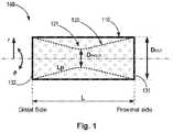
- FIG. 1conceptually depicts a stent like medical apparatus having first and second tubular walls, according to some embodiments of the invention
- FIGS. 2A and 2Bconceptually depict a flattened image and picture image of a second tubular wall, respectively, according to some embodiments of the invention
- FIG. 3conceptually depicts a first tubular wall, according to some embodiments of the invention.
- FIG. 4conceptually depicts a stent like medical apparatus, in a constricted configuration, according to some embodiments of the invention
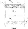
- FIG. 5Aconceptually depicts a medical apparatus crimped within a delivery system, according to some embodiments of the invention
- FIG. 5Bconceptually illustrates a crimped second tubular wall, according to some embodiments of the invention.
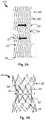
- FIGS. 6A and 6Bconceptually illustrate a non-limiting schematic example for a second tubular wall, according to some embodiments of the invention.
- FIGS. 6C and 6Dconceptually illustrate non-limiting flattened schematic examples for second tubular walls, according to some embodiments of the invention.
- FIG. 7conceptually depicts a stent like medical apparatus having a first tubular wall and a second coated tubular wall, according to some embodiments of the invention.
- FIG. 8conceptually demonstrates a method of use of an apparatus configured for a reduction of an effective diameter of an anatomic vessel, according to some embodiments of the invention.
- the term “about”,refers to a deviance of between 0.0001-5% from the indicated number or range of numbers. In one embodiment, the term “about”, refers to a deviance of between 1-10% from the indicated number or range of numbers. In one embodiment, the term “about”, refers to a deviance of up to 25% from the indicated number or range of numbers.
- the term “a” or “one” or “an”refers to at least one.
- the present inventionprovides a stent like medical apparatus for deployment within an anatomical blood vessel, as demonstrated at least in FIG. 1 , which is configured to reduce the effective diameter of an anatomical blood vessel.
- the medical apparatus 100comprises:
- the constriction processmay be applied after the deployment of the apparatus within an anatomical blood vessel.
- the constrictionis provided while the medical apparatus is within the anatomic vessel.
- the constrictionprovides the second tubular wall with a radial neck section, configured for reduction of the effective diameter of the anatomical blood vessel.
- at least a portion of the second tubular wallis coated with a coating material, as further demonstrated in FIG. 7, 760 .
- two bands of coating on the proximal and distal ends of the first tubular wallcan be applied, configured to create a fluid seal with the coating of the second tubular wall, as further demonstrated in FIG. 7, 770 .
- the coating materialcan be selected, for a non-limiting example, from: silicone elastomers, urethane containing polymers (such as polyurethane, silicone-polyurethane, polycarbonate urethanes, and silicone polycarbonate urethanes), PTFE (polytetrafluoroethylene), ePTFE (expanded PTFE), PLA (including PLGA, PLLA), xenograft or allograft tissue (such as pericardial tissue).
- silicone elastomerssuch as polyurethane, silicone-polyurethane, polycarbonate urethanes, and silicone polycarbonate urethanes
- PTFEpolytetrafluoroethylene
- ePTFEexpanded PTFE
- PLAincluding PLGA, PLLA
- xenograft or allograft tissuesuch as pericardial tissue.
- the second tubular wallcomprises a plurality of section elements, wherein at least some of the section elements are configured to allow a motion of at least some of the section elements one relative to another, when a constriction force is applied.
- FIGS. 2A and 2Bschematically demonstrate a second tubular wall, according to some embodiments of the invention.
- FIG. 2Aillustrates a flattened second tubular wall, shown after the process of laser cutting, according to some embodiments of the invention.
- FIG. 2Bdepicts a picture of a second tubular wall after constriction due to a constriction force (F), according to some embodiments of the invention.
- Fconstriction force
- the second tubular wall 220comprises, according to some embodiments, a plurality of connected section elements 221 , 222 , wherein at least some of the section elements are configured to be deformed when a force, for example a constriction force (F), is applied thereon.
- the deformed section elementsallow a motion of some of the section elements one relative to another, therefore configured to allow a constriction of at least a part of the second tabular wall. Consequently, the deformed section elements allow the second tubular wall to expand its path length (Lp), during the radial constriction, while maintaining its overall longitudinal length (L).
- the plurality of section elementscan all have a similar shape and/or configuration. According to other embodiments the plurality of section elements can have a variety of shapes and/or configurations.
- the plurality of section elementscan comprise strut elements 221 and connecting elements 222 , as demonstrated in FIGS. 2A and 2B .
- the connecting elementsare configured to be deformed when a constriction force (F) is applied, and thereby configured to allow an increase in the distance between the strut elements rows/rings.
- the deformation of the connecting elementsconsequently allows the constriction of at least a part of the second tubular wall, with an increased path length (Lp), while maintaining its overall longitudinal length (L).
- the strut elements 222can also be deformed by the constricting force, however in a much smaller deformation extent than of the connecting elements.
- the increased distance between the strut elementsis enabled by twisting of rows/rings of strut elements, one relative to the other via the connecting elements, as demonstrated by the marked arrows in the flattened schematic illustration in FIG. 2A .
- the increased distance between the strut elementsis enabled by extension of the connecting elements 622 , 632 .
- At least some of the section elementsare arranged in rows or rings-like configuration 223 .
- the rings 223are configured to move one relative to another, during the constriction.
- the motion of the section elementscomprises at least one of: translation, deformation, rotation, twist, contraction, conversion and collapse.
- At least one of the first and the second tubular wallscomprises binding elements 224 , 314 at its edges, configured for the connection of the first and the second tubular walls one to another.
- the connectioncan be by a suture, adhesion, welding, mechanical connection, or any other means of connection.
- FIG. 3demonstrates a first tubular wall, according to some embodiments of the invention.
- the first tubular wall 310as demonstrated comprises binding elements 314 at its edges, configured for the connection of the first and the second tubular walls one to another.
- the first tubular wallfurther comprises at least one grip element 340 (and 740 , FIG. 7 ), at least at one edge thereof.
- the grip elementis configured to be pulled and thereby assist in loading the medical apparatus, for its insertion into a delivery system, as further demonstrated in FIG. 5A , and/or for re-sheathing of the apparatus into the delivery system during the process of deployment into the target vessel.
- FIG. 4demonstrates a medical apparatus 400 comprising the first tubular wall 410 and the second tubular wall 420 bound together at both their proximal and distal ends via their binding elements 414 , 424 , and where the medical apparatus is shown in a partially constricted configuration.
- the apparatusfurther comprises a constricting element 430 configured to constrict a circumference of a portion of the second tubular wall 420 .
- the constriction of the second tubular wallcan be provided before- and/or after- the deployment of the apparatus within the vessel; therefore, can be provided with an initial constricted state and/or constricted in real time to a final constricted state, respectively.
- FIGS. 5A and 5Bdemonstrate a stent-like medical apparatus 500 , according to some embodiments of the invention.
- the stent-like medical apparatusis configured for a reversible collapse and therefore configured to be delivered into the anatomic vessel via a catheter tube.
- FIG. 5Ademonstrates the collapsed/crimped apparatus 500 within the delivery catheter 550
- FIG. 5Bdemonstrates only the collapsed second tubular wall 520 , within the delivery catheter 550 , which is hidden by the first tubular wall at FIG. 5A .
- the overall longitudinal length (Lc) of the collapsed/crimped apparatusis larger than the overall longitudinal length (L) of the non-collapsed apparatus, (Lc>L).
- first and second tubular wallsare the same whether in a crimped configuration (in a delivery catheter), a deployed configuration (in a vessel), or a constricted configuration (having an hourglass shape).
- At least one of the outer and inner tubular wallsis made of a collapsible memory shape material, therefore self-expanding material. According to some embodiments, at least one of the outer and inner tubular walls is manufactured by laser cut process.
- the first and second tubular wallsare concentric. According to some embodiments, the medical apparatus is axisymmetric.
- the material of the outer and inner tubular wallscomprises at least one from the group consisting of: Nitinol, stainless steel, Titanium, Cobalt-Chromium alloy, Tantalum alloy, polymer (ePTFB, PU, etc.), Platinum alloy and any combination thereof.
- the outer tubular wallis made of a first material and the inner tubular wall is made of a second material. According to some embodiments, the outer and inner tubular walls are made of the same material.
- FIGS. 6A and 6Bdemonstrate a non-limiting schematic example for a second tubular wall 620 before ( FIG. 6A ) and after ( FIG. 6B ) its constriction.
- the overall initial longitudinal length of the second tubular wallis 26 mm and its initial diameter before its constriction is 15 mm.
- a circumference constriction force (F)its minimal diameter is 10 mm, while its overall longitudinal length is kept 26 mm, such that the path length (L p ) of the second tubular wall has increased without an increase in its overall length (L).
- the second tubular wall 625 , 635comprises, according to some embodiments, a plurality of strut elements 621 , 631 and a plurality of connecting elements 622 , 632 .
- a constriction force (F)is applied, at least some of the connecting elements are configured to be deformed and cause an increase in the distance between the strut elements rows/rings, therefore allowing a constriction of at least a part of the second tabular wall, with an increased path length, while maintaining its overall longitudinal length.
- the rows or rings-like configurations 623 , 633are also demonstrated.
- FIG. 7conceptually depicts a stent like medical apparatus 700 having a first tubular wall and a second coated tubular wall.
- the medical apparatus 700comprises:
- first- and second-tubular wallsare firmly connected at their proximal and distal edges 714 , 724 , therefore restricted to have same overall longitudinal length;
- the second tubular wallis configured to be partially constricted 730 towards its inner radial axis, while maintaining its overall longitudinal length;
- FIG. 7further demonstrates that at least a portion of the second tubular wall 720 is coated with a coating material 760 , for example by an ePTFE, such that the flow through the vessel will be guided through the second tubular wall.
- a coating material 760for example by an ePTFE
- FIG. 7further demonstrates that in addition to the coating of the second tubular wall, the proximal and distal ends of the first tubular wall can be coated 770 , according to some embodiments of the invention, to create a fluid seal with the coating of the second tubular wall.
- FIG. 8conceptually demonstrates a method of use of an apparatus configured for a reduction of an effective diameter of an anatomic vessel, according to any of the above-mentioned embodiments.
- the method 800comprising:
- the step of providingfurther comprises partially constricting 811 the second tubular wall to an initial constricted state, which may be further constricted.
- the initial constrictionis provided via a heating process; for example, by heat treatment of the Nitinol of the second tubular wall to maintain a specific shape; for example, to have a shape of an hourglass.
- the step of providingfurther comprises at least partially coating 812 the second tubular wall.
- the step of providingfurther comprises connecting 813 both the first- and the second-tubular walls at their edges, thereby restricting the first- and the second-tubular walls to have the same overall longitudinal length.
- the step of deployingcomprises delivering 821 the medical apparatus into an anatomical blood vessel via a catheter, wherein the medical apparatus is provided in a crimped configuration, which is configured to expand back, once deployed out of the delivering catheter.
- a therapeutic result for the use of a medical apparatus as mentioned above, for patients with LV heart failurecan be at least one of the group consisting of:
Landscapes
- Health & Medical Sciences (AREA)
- Biomedical Technology (AREA)
- Engineering & Computer Science (AREA)
- Life Sciences & Earth Sciences (AREA)
- General Health & Medical Sciences (AREA)
- Animal Behavior & Ethology (AREA)
- Vascular Medicine (AREA)
- Heart & Thoracic Surgery (AREA)
- Veterinary Medicine (AREA)
- Public Health (AREA)
- Surgery (AREA)
- Cardiology (AREA)
- Oral & Maxillofacial Surgery (AREA)
- Transplantation (AREA)
- Reproductive Health (AREA)
- Molecular Biology (AREA)
- Medical Informatics (AREA)
- Nuclear Medicine, Radiotherapy & Molecular Imaging (AREA)
- Physics & Mathematics (AREA)
- Optics & Photonics (AREA)
- Gastroenterology & Hepatology (AREA)
- Pulmonology (AREA)
- Prostheses (AREA)
- Media Introduction/Drainage Providing Device (AREA)
Abstract
Description
- a first tubular wall; and
- a second tubular wall, placed within the first tubular wall;
- wherein the first and second tubular walls are firmly connected at their edges, therefore restricted to have same overall longitudinal length (L); and
- wherein the second tubular wall is configured to be partially constricted towards its inner radial axis, while maintaining its overall longitudinal length;
- providing a medical apparatus having a second tubular wall placed within a first tubular wall;
- deploying the medical apparatus within an anatomical blood vessel; and
- constricting at least a portion of the second tubular wall, thereby providing the second tubular wall with a radial neck section, while maintaining its overall longitudinal length.
- a first tubular wall110 (also noted as outer tubular wall); and
- a second tubular wall120 (also noted as inner tubular wall), placed within the first tubular wall;
- wherein the first- and second-tubular walls are firmly connected (one to another) at their proximal- and distal-
edges
- a first tubular wall710 (also noted as outer tubular wall); and
- a second tubular wall720 (also noted as inner tubular wall), placed within the first tubular wall;
- providing810 a medical apparatus having a second tubular wall placed within a first tubular wall;
- deploying820 the medical apparatus within an anatomical blood vessel; and
- constricting830 at least a portion of the second tubular wall, thereby providing the second tubular wall with a radial neck section, while maintaining its overall longitudinal length.
- an increase in the left ventricle ejection fraction (LVEF);
- a decrease in the left ventricle end diastolic pressure (LVEDP);
- improvement in the clinical symptoms of heart failure; and
- any combination thereof.
Claims (24)
Priority Applications (1)
| Application Number | Priority Date | Filing Date | Title |
|---|---|---|---|
| US16/616,465US11364132B2 (en) | 2017-06-05 | 2018-06-04 | Double walled fixed length stent like apparatus and methods of use thereof |
Applications Claiming Priority (3)
| Application Number | Priority Date | Filing Date | Title |
|---|---|---|---|
| US201762514984P | 2017-06-05 | 2017-06-05 | |
| PCT/IL2018/050604WO2018225059A1 (en) | 2017-06-05 | 2018-06-04 | Double walled fixed length stent like apparatus and methods of use thereof |
| US16/616,465US11364132B2 (en) | 2017-06-05 | 2018-06-04 | Double walled fixed length stent like apparatus and methods of use thereof |
Publications (2)
| Publication Number | Publication Date |
|---|---|
| US20200297516A1 US20200297516A1 (en) | 2020-09-24 |
| US11364132B2true US11364132B2 (en) | 2022-06-21 |
Family
ID=64566185
Family Applications (1)
| Application Number | Title | Priority Date | Filing Date |
|---|---|---|---|
| US16/616,465Active2038-07-08US11364132B2 (en) | 2017-06-05 | 2018-06-04 | Double walled fixed length stent like apparatus and methods of use thereof |
Country Status (5)
| Country | Link |
|---|---|
| US (1) | US11364132B2 (en) |
| EP (1) | EP3624704A4 (en) |
| CN (1) | CN110691554B (en) |
| IL (1) | IL271184B2 (en) |
| WO (1) | WO2018225059A1 (en) |
Cited By (4)
| Publication number | Priority date | Publication date | Assignee | Title |
|---|---|---|---|---|
| US20200289299A1 (en)* | 2014-07-20 | 2020-09-17 | Restore Medical Ltd. | Pulmonary artery implant apparatus and methods of use thereof |
| US11771434B2 (en) | 2016-09-28 | 2023-10-03 | Restore Medical Ltd. | Artery medical apparatus and methods of use thereof |
| US11883030B2 (en) | 2022-04-29 | 2024-01-30 | inQB8 Medical Technologies, LLC | Systems, devices, and methods for controllably and selectively occluding, restricting, and diverting flow within a patient's vasculature |
| US11974751B2 (en) | 2022-04-29 | 2024-05-07 | inQB8 Medical Technologies, LLC | Systems, devices, and methods for controllably and selectively occluding, restricting, and diverting flow within a patient's vasculature |
Families Citing this family (5)
| Publication number | Priority date | Publication date | Assignee | Title |
|---|---|---|---|---|
| WO2018225059A1 (en) | 2017-06-05 | 2018-12-13 | Restore Medical Ltd | Double walled fixed length stent like apparatus and methods of use thereof |
| EP3793490A4 (en)* | 2018-05-12 | 2021-10-06 | Venacore Inc. | CONTROL OF THE VELOCITY OF BLOOD FLOW TO THE RIGHT FRONT COURT |
| US20220287831A1 (en) | 2021-03-12 | 2022-09-15 | Troy Thornton | Device and method for variable blood flow occlusion |
| US20250041042A1 (en)* | 2021-07-07 | 2025-02-06 | Restore Medical Ltd. | Implantable device to form a constriction within a blood vessel lumen |
| EP4422562A1 (en)* | 2021-10-26 | 2024-09-04 | Edwards Lifesciences Corporation | Devices and methods related to pulmonary wave modification |
Citations (143)
| Publication number | Priority date | Publication date | Assignee | Title |
|---|---|---|---|---|
| US3730186A (en) | 1971-03-05 | 1973-05-01 | Univ California | Adjustable implantable artery-constricting device |
| US4183102A (en) | 1977-09-08 | 1980-01-15 | Jacques Guiset | Inflatable prosthetic device for lining a body duct |
| US4425908A (en) | 1981-10-22 | 1984-01-17 | Beth Israel Hospital | Blood clot filter |
| US4601718A (en) | 1982-12-13 | 1986-07-22 | Possis Medical, Inc. | Vascular graft and blood supply method |
| US4950276A (en) | 1988-02-25 | 1990-08-21 | Vince Dennis J | Prosthesis for banding of an artery capable of dilation by a balloon dilator |
| US5156620A (en) | 1991-02-04 | 1992-10-20 | Pigott John P | Intraluminal graft/stent and balloon catheter for insertion thereof |
| US5167628A (en) | 1991-05-02 | 1992-12-01 | Boyles Paul W | Aortic balloon catheter assembly for indirect infusion of the coronary arteries |
| US5330528A (en) | 1989-12-01 | 1994-07-19 | British Technology Group Limited | Vascular surgical devices |
| US5332403A (en) | 1992-08-17 | 1994-07-26 | Jack Kolff | LVAD with t-shape and unidirectional valve |
| US5383892A (en) | 1991-11-08 | 1995-01-24 | Meadox France | Stent for transluminal implantation |
| US5423851A (en) | 1994-03-06 | 1995-06-13 | Samuels; Shaun L. W. | Method and apparatus for affixing an endoluminal device to the walls of tubular structures within the body |
| US5554185A (en) | 1994-07-18 | 1996-09-10 | Block; Peter C. | Inflatable prosthetic cardiovascular valve for percutaneous transluminal implantation of same |
| US5554180A (en) | 1995-07-07 | 1996-09-10 | Aeroquip Corporation | Intraluminal stenting graft |
| US5683411A (en) | 1994-04-06 | 1997-11-04 | William Cook Europe A/S | Medical article for implantation into the vascular system of a patient |
| US5755779A (en) | 1995-12-07 | 1998-05-26 | Horiguchi; Sachio | Blood stream adjuster |
| US6120534A (en) | 1997-10-29 | 2000-09-19 | Ruiz; Carlos E. | Endoluminal prosthesis having adjustable constriction |
| WO2001035861A1 (en) | 1999-10-29 | 2001-05-25 | C.R. Bard, Inc. | Method of, and device for, installing a stent in a sleeve |
| US6312462B1 (en) | 1999-09-22 | 2001-11-06 | Impra, Inc. | Prosthesis for abdominal aortic aneurysm repair |
| US20010053330A1 (en) | 2000-06-20 | 2001-12-20 | Ntn Corporation | Magnetically levitated pump apparatus |
| US20020107536A1 (en) | 2001-02-07 | 2002-08-08 | Hussein Hany M. | Device and method for preventing kidney failure |
| US6471635B1 (en) | 2000-02-10 | 2002-10-29 | Obtech Medical Ag | Anal incontinence disease treatment with controlled wireless energy supply |
| DE10102045A1 (en) | 2001-01-17 | 2003-01-09 | Bionethos Holding Gmbh | Medical equipment useful as therapy catheter for introducing particles, cells, media or therapeutic substance into vessel, e.g. blood vessel, has treatment space formed by flexible wall between seals and open-ended duct for adjusting size |
| US20030032976A1 (en) | 2001-05-21 | 2003-02-13 | Boucek Mark M. | Catheter deployed partial occlusion devices and methods |
| US6533800B1 (en) | 2001-07-25 | 2003-03-18 | Coaxia, Inc. | Devices and methods for preventing distal embolization using flow reversal in arteries having collateral blood flow |
| WO2003028522A2 (en) | 2001-03-27 | 2003-04-10 | Neovasc Medical Ltd. | Flow reducing implant |
| US6562066B1 (en) | 2001-03-02 | 2003-05-13 | Eric C. Martin | Stent for arterialization of the coronary sinus and retrograde perfusion of the myocardium |
| US20030097172A1 (en) | 2000-03-27 | 2003-05-22 | Ilan Shalev | Narrowing implant |
| US6595980B1 (en) | 2001-02-23 | 2003-07-22 | Coaxia, Inc. | Devices and methods for preventing distal embolization using flow reversal by occlusion of the brachiocephalic artery |
| US20030144575A1 (en) | 2000-02-11 | 2003-07-31 | Peter Forsell | Urinary incontinence treatment apparatus |
| US20030149473A1 (en) | 1999-11-16 | 2003-08-07 | Chouinard Paul F. | Multi-section filamentary endoluminal stent |
| US20030167068A1 (en) | 2002-03-01 | 2003-09-04 | Aga Medical Corporation | Intravascular flow restrictor |
| US6616624B1 (en) | 2000-10-30 | 2003-09-09 | Cvrx, Inc. | Systems and method for controlling renovascular perfusion |
| US20030236568A1 (en) | 2002-05-10 | 2003-12-25 | Hikmat Hojeibane | Multi-lobed frame based unidirectional flow prosthetic implant |
| US20040077988A1 (en) | 1998-08-27 | 2004-04-22 | Heartstent Corporation | Healing transmyocardial implant |
| US20040111006A1 (en) | 2002-12-17 | 2004-06-10 | Scout Medical Technologies, Llc | System and method for regulating blood pressure |
| US6790230B2 (en) | 2001-04-30 | 2004-09-14 | Universitatsklinikum Freiburg | Vascular implant |
| US20040236412A1 (en) | 2003-05-23 | 2004-11-25 | Brar Balbir S. | Treatment of stenotic regions |
| US20050096734A1 (en) | 2003-10-31 | 2005-05-05 | Majercak David C. | Implantable valvular prosthesis |
| US20050148925A1 (en) | 2001-04-20 | 2005-07-07 | Dan Rottenberg | Device and method for controlling in-vivo pressure |
| US20050165344A1 (en) | 2003-11-26 | 2005-07-28 | Dobak John D.Iii | Method and apparatus for treating heart failure |
| US20050182483A1 (en) | 2004-02-11 | 2005-08-18 | Cook Incorporated | Percutaneously placed prosthesis with thromboresistant valve portion |
| US6936057B1 (en) | 1997-05-19 | 2005-08-30 | Cardio Medical Solutions, Inc. (Cms) | Device and method for partially occluding blood vessels using flow-through balloon |
| WO2005084730A1 (en) | 2004-03-02 | 2005-09-15 | Peter William Walsh | A vessel or sac wall treatment and a cardiac assist device |
| EP1576929A2 (en) | 2004-03-19 | 2005-09-21 | Aga Medical Corporation | Multi-layer braided structures for occluding vascular defects |
| US20050234388A1 (en) | 2004-03-23 | 2005-10-20 | Ray Amos | Agent eluting stent and catheter |
| US20050273160A1 (en) | 2004-04-23 | 2005-12-08 | Lashinski Randall T | Pulmonary vein valve implant |
| US20060025855A1 (en) | 2004-05-05 | 2006-02-02 | Lashinski Randall T | Translumenally implantable heart valve with multiple chamber formed in place support |
| US20060030920A1 (en) | 2002-12-30 | 2006-02-09 | Neo-Vasc Medical Ltd. | Varying-diameter vascular implant and balloon |
| US20060106449A1 (en) | 2002-08-08 | 2006-05-18 | Neovasc Medical Ltd. | Flow reducing implant |
| US20060106450A1 (en) | 2002-08-08 | 2006-05-18 | Neovasc Medical Ltd. | Geometric flow regulator |
| US20060122692A1 (en) | 2004-05-10 | 2006-06-08 | Ran Gilad | Stent valve and method of using same |
| US20060149360A1 (en) | 2003-07-08 | 2006-07-06 | Ventor Technologies Ltd. | Fluid flow prosthetic device |
| US20060178740A1 (en) | 2005-02-10 | 2006-08-10 | Sorin Biomedica Cardio S.R.L. | Cardiac-valve prosthesis |
| US20060241745A1 (en) | 2005-04-21 | 2006-10-26 | Solem Jan O | Blood flow controlling apparatus |
| US7128750B1 (en) | 1999-07-19 | 2006-10-31 | Endoart S.A. | Flow control method and device |
| WO2006131930A2 (en) | 2005-06-10 | 2006-12-14 | Sagax Inc. | Implant device particularly useful for implantation in the intravascular system for diverting emboli |
| US7158832B2 (en) | 2000-09-27 | 2007-01-02 | Cvrx, Inc. | Electrode designs and methods of use for cardiovascular reflex control devices |
| US20070038259A1 (en) | 2000-09-27 | 2007-02-15 | Cvrx, Inc. | Method and apparatus for stimulation of baroreceptors in pulmonary artery |
| US20070043435A1 (en) | 1999-11-17 | 2007-02-22 | Jacques Seguin | Non-cylindrical prosthetic valve system for transluminal delivery |
| US20070179590A1 (en) | 2005-12-29 | 2007-08-02 | Wenfeng Lu | Hybrid intraluminal device with varying expansion force |
| US20070198097A1 (en) | 2003-12-23 | 2007-08-23 | Laboratoires Perouse | Kit For Implanting In A Duct |
| US20070213813A1 (en) | 2005-12-22 | 2007-09-13 | Symetis Sa | Stent-valves for valve replacement and associated methods and systems for surgery |
| EP1849440A1 (en) | 2006-04-28 | 2007-10-31 | Younes Boudjemline | Vascular stents with varying diameter |
| EP1870057A1 (en) | 2006-06-21 | 2007-12-26 | Morel d'Arleux, Eric | Stent-type endoprosthesis |
| US7331993B2 (en) | 2002-05-03 | 2008-02-19 | The General Hospital Corporation | Involuted endovascular valve and method of construction |
| US20080097497A1 (en) | 2005-11-22 | 2008-04-24 | Assad Samy R | Pulmonary artery banding device |
| US20080208329A1 (en) | 2006-10-20 | 2008-08-28 | Gordon Bishop | Handle mechanism to adjust a medical device |
| US7497873B1 (en) | 1999-09-10 | 2009-03-03 | Rafael Medical Technologies Inc. | Intravascular device and method using it |
| US20090099653A1 (en) | 2007-10-12 | 2009-04-16 | Sorin Biomedica Cardio S.R.L. | Expandable valve prosthesis with sealing mechanism |
| US20090112312A1 (en) | 2007-02-26 | 2009-04-30 | Larose Jeffrey A | Intravascular ventricular assist device |
| US20090149950A1 (en) | 2006-05-31 | 2009-06-11 | Richard Wampler | Heart assist device |
| US20090270974A1 (en) | 2004-05-25 | 2009-10-29 | Chestnut Medical Technologies, Inc. | Vascular stenting for aneurysms |
| US20100057192A1 (en) | 2006-11-07 | 2010-03-04 | David Stephen Celermajer | Devices and methods for the treatment of heart failure |
| CN101687088A (en) | 2007-06-21 | 2010-03-31 | Aga医药有限公司 | Multi-layer braided structure for occluding vascular defects |
| US20100125288A1 (en) | 2008-11-17 | 2010-05-20 | G&L Consulting, Llc | Method and apparatus for reducing renal blood pressure |
| US20100185277A1 (en) | 2007-09-26 | 2010-07-22 | St. Jude Medical, Inc. | Collapsible prosthetic heart valves |
| US20100222633A1 (en) | 2009-02-27 | 2010-09-02 | Victor Poirier | Blood pump system with controlled weaning |
| US20100249911A1 (en) | 2007-11-05 | 2010-09-30 | St Jude Medical Inc. | Collapsible/expandable prosthetic heart valves with non-expanding stent posts and retrieval features |
| US20100286758A1 (en) | 2009-05-05 | 2010-11-11 | Medtronic Vascular, Inc. | Implantable Temporary Flow Restrictor Device |
| US7862502B2 (en) | 2006-10-20 | 2011-01-04 | Ellipse Technologies, Inc. | Method and apparatus for adjusting a gastrointestinal restriction device |
| US20110021864A1 (en) | 2009-07-22 | 2011-01-27 | The Texas A&M University System | Biphasic and Dynamic Adjustable Support Devices and Methods with Assist and Recoil Capabilities for Treatment of Cardiac Pathologies |
| US20110046710A1 (en) | 2009-08-24 | 2011-02-24 | Qualimed Gmbh | Implantation device with handle and method of use thereof |
| US20110054589A1 (en) | 2009-08-27 | 2011-03-03 | Boston Scientific Scimed, Inc. | Stent with variable cross section braiding filament and method for making same |
| US20110071624A1 (en) | 2006-11-07 | 2011-03-24 | Dc Devices, Inc. | Devices for retrieving a prosthesis |
| US20110098800A1 (en) | 2008-07-15 | 2011-04-28 | St. Jude Medical, Inc | Axially anchoring collapsible and re-expandable prosthetic heart valves for various disease states |
| US20110098802A1 (en) | 2008-07-15 | 2011-04-28 | St. Jude Medical, Inc. | Collapsible and re-expandable prosthetic heart valve cuff designs and complementary technological applications |
| US7935144B2 (en) | 2006-10-19 | 2011-05-03 | Direct Flow Medical, Inc. | Profile reduction of valve implant |
| US7983765B1 (en) | 2005-08-19 | 2011-07-19 | Pacesetter, Inc. | Left chamber pressure sensor lead delivery system |
| US20110213408A1 (en) | 2005-07-25 | 2011-09-01 | Vascular Dynamics Inc. | Devices and methods for control of blood pressure |
| WO2011156176A1 (en) | 2010-06-08 | 2011-12-15 | Regents Of The University Of Minnesota | Vascular elastance |
| US20110306916A1 (en) | 2009-05-04 | 2011-12-15 | Yaacov Nitzan | Device and method for regulating pressure in a heart chamber |
| US8091556B2 (en) | 2001-04-20 | 2012-01-10 | V-Wave Ltd. | Methods and apparatus for reducing localized circulatory system pressure |
| US20120123195A1 (en) | 2010-11-12 | 2012-05-17 | Woodruff Scott A | Gastric band with asymmetrical member |
| US20120123556A1 (en) | 2006-11-08 | 2012-05-17 | Boston Scientific Scimed, Inc. | Pyloric obesity valve |
| US20120165928A1 (en) | 2010-12-22 | 2012-06-28 | Yaacov Nitzan | Devices for reducing left atrial pressure, and methods of making and using same |
| CN102764170A (en) | 2012-07-18 | 2012-11-07 | 吕文峰 | Intravascular stent with complex functions |
| US20120310323A1 (en) | 2011-06-03 | 2012-12-06 | Cook Medical Technologies Llc | Introducer for deploying an implant |
| EP2567663A1 (en) | 2011-09-09 | 2013-03-13 | Occlutech Holding AG | A collapsible medical closing device, a method and a medical system for delivering an object |
| CN102961200A (en) | 2012-11-30 | 2013-03-13 | 宁波健世生物科技有限公司 | Pulmonary valve stent with anchor mechanism |
| US20130073026A1 (en) | 2011-09-20 | 2013-03-21 | Aga Medical Corporation | Device and method for treating vascular abnormalities |
| US20130096580A1 (en) | 2011-10-18 | 2013-04-18 | William E. Cohn | Method and apparatus for treating a patient by intentionally occluding a blood vessel, including method and apparatus for inducing weight loss in a patient by intentionally occluding the celiac artery |
| US20130103162A1 (en) | 2011-10-25 | 2013-04-25 | Kieran Costello | Coated stent |
| US20130172981A1 (en) | 2005-07-25 | 2013-07-04 | Vascular Dynamics, Inc. | Devices and methods for control of blood pressure |
| US20130178750A1 (en) | 2011-12-23 | 2013-07-11 | Volcano Corporation | Methods and Apparatus for Regulating Blood Pressure |
| CN103202735A (en) | 2013-04-01 | 2013-07-17 | 杭州启明医疗器械有限公司 | Pulmonary artery valve replacement device and support thereof |
| US20130261531A1 (en) | 2012-03-30 | 2013-10-03 | Medtronic Vascular, Inc. | Arteriovenous Shunt Having a Flow Control Mechanism |
| US20130274648A1 (en) | 2010-07-26 | 2013-10-17 | The Trustees Of Columbia University In The City Of New York | Blood flow controllers and methods |
| US20140039537A1 (en) | 2012-08-03 | 2014-02-06 | Harold Carrison | Vessel flow control devices and methods |
| US8663314B2 (en) | 2008-06-16 | 2014-03-04 | Boston Scientific Scimed, Inc. | Continuous double layered stent for migration resistance |
| US20140128957A1 (en) | 2012-11-06 | 2014-05-08 | Covidien Lp | Shaped occluding devices and methods of using the same |
| US20140155997A1 (en) | 2007-09-28 | 2014-06-05 | Peter Nicholas Braido | Collapsible-expandable prosthetic heart valves with structures for clamping native tissue |
| US20140277425A1 (en) | 2013-03-12 | 2014-09-18 | Aga Medical Corporation | Paravalvular leak occlusion device for self-expanding heart valves |
| US20140303710A1 (en) | 2011-10-25 | 2014-10-09 | The First Affiliated Hospital Of Nanjing Medical University | Recyclable and adjustable interventional stent for intravascular constriction |
| US20140350668A1 (en) | 2013-03-13 | 2014-11-27 | Symetis Sa | Prosthesis Seals and Methods for Sealing an Expandable Prosthesis |
| US20140364686A1 (en) | 2013-06-06 | 2014-12-11 | Coloplast A/S | Artificial urinary sphincter having a multi-compartment cuff |
| US8911489B2 (en) | 2003-11-19 | 2014-12-16 | Neovasc Medical Ltd | Vascular implant |
| CN204106100U (en) | 2014-09-15 | 2015-01-21 | 北京泰杰伟业科技有限公司 | Can be used for the turn system of hemangioma body embolotherapy |
| US8940040B2 (en) | 2011-12-06 | 2015-01-27 | Aortic Innovations, Llc | Device for endovascular aortic repair and method of using the same |
| US20150073544A1 (en) | 2012-03-05 | 2015-03-12 | The Trustees Of The University Of Pennsylvania | Superabsorbent coated stents for vascular reduction and for anchoring valve replacements |
| US20150148896A1 (en) | 2013-11-22 | 2015-05-28 | Edwards Lifesciences Corporation | Aortic insufficiency repair device and method |
| US20150174308A1 (en) | 2012-03-29 | 2015-06-25 | Bulent Oran | Transarterial heart assist device |
| WO2016013006A1 (en) | 2014-07-20 | 2016-01-28 | Elchanan Bruckheimer | Pulmonary artery implant apparatus and methods of use thereof |
| CN105392431A (en) | 2013-06-26 | 2016-03-09 | W.L.戈尔及同仁股份有限公司 | Medical device deployment system |
| US20160151153A1 (en) | 2014-12-01 | 2016-06-02 | Medtronic, Inc. | Segmented transcatheter valve prosthesis having an unsupported valve segment |
| CA2970237A1 (en) | 2014-12-18 | 2016-06-23 | Intellistent Ag | Stent and kit of stents for adjustable interventional reduction of blood flow |
| US9393384B1 (en) | 2015-08-17 | 2016-07-19 | Tufts Medical Center, Inc. | Systems and methods for treating acute and chronic heart failure |
| WO2017024357A1 (en) | 2015-08-13 | 2017-02-16 | The Brain Protection Company PTY LTD | Implantable damping devices for treating dementia and associated systems and methods of use |
| US20170065402A1 (en) | 2010-07-02 | 2017-03-09 | Myopowers Medical Technologies Sa | Medical device comprising an artificial contractile structure |
| US9603708B2 (en) | 2010-05-19 | 2017-03-28 | Dfm, Llc | Low crossing profile delivery catheter for cardiovascular prosthetic implant |
| US9629715B2 (en) | 2011-07-28 | 2017-04-25 | V-Wave Ltd. | Devices for reducing left atrial pressure having biodegradable constriction, and methods of making and using same |
| US9649480B2 (en) | 2012-07-06 | 2017-05-16 | Corvia Medical, Inc. | Devices and methods of treating or ameliorating diastolic heart failure through pulmonary valve intervention |
| US9681948B2 (en) | 2006-01-23 | 2017-06-20 | V-Wave Ltd. | Heart anchor device |
| US9713696B2 (en) | 2013-05-21 | 2017-07-25 | V-Wave Ltd. | Apparatus and methods for delivering devices for reducing left atrial pressure |
| US20170215885A1 (en) | 2016-02-01 | 2017-08-03 | Vivonics, Inc. | Transcatheter device and minimally invasive method for constricting and adjusting blood flow through a blood vessel |
| US9775636B2 (en) | 2013-03-12 | 2017-10-03 | Corvia Medical, Inc. | Devices, systems, and methods for treating heart failure |
| US20170325946A1 (en) | 2014-01-27 | 2017-11-16 | Medtronic Vascular Galway | Stented prosthetic heart valve with variable stiffness and methods of use |
| WO2017194437A1 (en) | 2016-05-12 | 2017-11-16 | Intellistent Ag, C/O A & G Revisions Ag | Device for adjustably restricting intravascular flow |
| US20170340460A1 (en) | 2016-05-31 | 2017-11-30 | V-Wave Ltd. | Systems and methods for making encapsulated hourglass shaped stents |
| US20170340441A1 (en) | 2003-10-02 | 2017-11-30 | Edwards Lifesciences Corporation | Implantable prosthetic valve with non-laminar flow |
| US9849006B2 (en) | 2013-03-15 | 2017-12-26 | Children's Medical Center Corporation | Methods and apparatuses for treating vessels |
| US20180036109A1 (en) | 2015-02-12 | 2018-02-08 | Hemodynamx-Technologies Ltd. | Aortic implant |
| US20180085128A1 (en) | 2016-09-28 | 2018-03-29 | Restore Medical Ltd | Artery medical apparatus and methods of use thereof |
| WO2018225059A1 (en) | 2017-06-05 | 2018-12-13 | Restore Medical Ltd | Double walled fixed length stent like apparatus and methods of use thereof |
- 2018
- 2018-06-04WOPCT/IL2018/050604patent/WO2018225059A1/ennot_activeCeased
- 2018-06-04EPEP18812772.4Apatent/EP3624704A4/enactivePending
- 2018-06-04CNCN201880036104.4Apatent/CN110691554B/enactiveActive
- 2018-06-04ILIL271184Apatent/IL271184B2/enunknown
- 2018-06-04USUS16/616,465patent/US11364132B2/enactiveActive
Patent Citations (183)
| Publication number | Priority date | Publication date | Assignee | Title |
|---|---|---|---|---|
| US3730186A (en) | 1971-03-05 | 1973-05-01 | Univ California | Adjustable implantable artery-constricting device |
| US4183102A (en) | 1977-09-08 | 1980-01-15 | Jacques Guiset | Inflatable prosthetic device for lining a body duct |
| US4425908A (en) | 1981-10-22 | 1984-01-17 | Beth Israel Hospital | Blood clot filter |
| US4601718A (en) | 1982-12-13 | 1986-07-22 | Possis Medical, Inc. | Vascular graft and blood supply method |
| US4950276A (en) | 1988-02-25 | 1990-08-21 | Vince Dennis J | Prosthesis for banding of an artery capable of dilation by a balloon dilator |
| US5330528A (en) | 1989-12-01 | 1994-07-19 | British Technology Group Limited | Vascular surgical devices |
| US5156620A (en) | 1991-02-04 | 1992-10-20 | Pigott John P | Intraluminal graft/stent and balloon catheter for insertion thereof |
| US5167628A (en) | 1991-05-02 | 1992-12-01 | Boyles Paul W | Aortic balloon catheter assembly for indirect infusion of the coronary arteries |
| US5383892A (en) | 1991-11-08 | 1995-01-24 | Meadox France | Stent for transluminal implantation |
| US5332403A (en) | 1992-08-17 | 1994-07-26 | Jack Kolff | LVAD with t-shape and unidirectional valve |
| US5423851A (en) | 1994-03-06 | 1995-06-13 | Samuels; Shaun L. W. | Method and apparatus for affixing an endoluminal device to the walls of tubular structures within the body |
| US5683411A (en) | 1994-04-06 | 1997-11-04 | William Cook Europe A/S | Medical article for implantation into the vascular system of a patient |
| US5554185A (en) | 1994-07-18 | 1996-09-10 | Block; Peter C. | Inflatable prosthetic cardiovascular valve for percutaneous transluminal implantation of same |
| US5554180A (en) | 1995-07-07 | 1996-09-10 | Aeroquip Corporation | Intraluminal stenting graft |
| US5755779A (en) | 1995-12-07 | 1998-05-26 | Horiguchi; Sachio | Blood stream adjuster |
| US6936057B1 (en) | 1997-05-19 | 2005-08-30 | Cardio Medical Solutions, Inc. (Cms) | Device and method for partially occluding blood vessels using flow-through balloon |
| US6120534A (en) | 1997-10-29 | 2000-09-19 | Ruiz; Carlos E. | Endoluminal prosthesis having adjustable constriction |
| US20040077988A1 (en) | 1998-08-27 | 2004-04-22 | Heartstent Corporation | Healing transmyocardial implant |
| US7128750B1 (en) | 1999-07-19 | 2006-10-31 | Endoart S.A. | Flow control method and device |
| US7497873B1 (en) | 1999-09-10 | 2009-03-03 | Rafael Medical Technologies Inc. | Intravascular device and method using it |
| US6312462B1 (en) | 1999-09-22 | 2001-11-06 | Impra, Inc. | Prosthesis for abdominal aortic aneurysm repair |
| WO2001035861A1 (en) | 1999-10-29 | 2001-05-25 | C.R. Bard, Inc. | Method of, and device for, installing a stent in a sleeve |
| US7670367B1 (en) | 1999-11-16 | 2010-03-02 | Boston Scientific Scimed, Inc. | Multi-section filamentary endoluminal stent |
| US20030149473A1 (en) | 1999-11-16 | 2003-08-07 | Chouinard Paul F. | Multi-section filamentary endoluminal stent |
| US20070043435A1 (en) | 1999-11-17 | 2007-02-22 | Jacques Seguin | Non-cylindrical prosthetic valve system for transluminal delivery |
| US6471635B1 (en) | 2000-02-10 | 2002-10-29 | Obtech Medical Ag | Anal incontinence disease treatment with controlled wireless energy supply |
| US20030144575A1 (en) | 2000-02-11 | 2003-07-31 | Peter Forsell | Urinary incontinence treatment apparatus |
| CN1430490A (en) | 2000-03-27 | 2003-07-16 | 内奥瓦斯克医疗有限公司 | shrink implant |
| US8858612B2 (en) | 2000-03-27 | 2014-10-14 | Neovasc Medical Inc. | Methods for treating abnormal growths in the body using a flow reducing implant |
| US20030097172A1 (en) | 2000-03-27 | 2003-05-22 | Ilan Shalev | Narrowing implant |
| US20180021156A1 (en) | 2000-03-27 | 2018-01-25 | Neovasc Medical Ltd. | Varying diameter vascular implant and balloon |
| US6953476B1 (en) | 2000-03-27 | 2005-10-11 | Neovasc Medical Ltd. | Device and method for treating ischemic heart disease |
| US20010053330A1 (en) | 2000-06-20 | 2001-12-20 | Ntn Corporation | Magnetically levitated pump apparatus |
| US20070038259A1 (en) | 2000-09-27 | 2007-02-15 | Cvrx, Inc. | Method and apparatus for stimulation of baroreceptors in pulmonary artery |
| US7158832B2 (en) | 2000-09-27 | 2007-01-02 | Cvrx, Inc. | Electrode designs and methods of use for cardiovascular reflex control devices |
| US6616624B1 (en) | 2000-10-30 | 2003-09-09 | Cvrx, Inc. | Systems and method for controlling renovascular perfusion |
| DE10102045A1 (en) | 2001-01-17 | 2003-01-09 | Bionethos Holding Gmbh | Medical equipment useful as therapy catheter for introducing particles, cells, media or therapeutic substance into vessel, e.g. blood vessel, has treatment space formed by flexible wall between seals and open-ended duct for adjusting size |
| US20020107536A1 (en) | 2001-02-07 | 2002-08-08 | Hussein Hany M. | Device and method for preventing kidney failure |
| US6595980B1 (en) | 2001-02-23 | 2003-07-22 | Coaxia, Inc. | Devices and methods for preventing distal embolization using flow reversal by occlusion of the brachiocephalic artery |
| US6562066B1 (en) | 2001-03-02 | 2003-05-13 | Eric C. Martin | Stent for arterialization of the coronary sinus and retrograde perfusion of the myocardium |
| WO2003028522A2 (en) | 2001-03-27 | 2003-04-10 | Neovasc Medical Ltd. | Flow reducing implant |
| US8091556B2 (en) | 2001-04-20 | 2012-01-10 | V-Wave Ltd. | Methods and apparatus for reducing localized circulatory system pressure |
| US9724499B2 (en) | 2001-04-20 | 2017-08-08 | V-Wave Ltd. | Device and method for controlling in-vivo pressure |
| US20050148925A1 (en) | 2001-04-20 | 2005-07-07 | Dan Rottenberg | Device and method for controlling in-vivo pressure |
| US6790230B2 (en) | 2001-04-30 | 2004-09-14 | Universitatsklinikum Freiburg | Vascular implant |
| US20030032976A1 (en) | 2001-05-21 | 2003-02-13 | Boucek Mark M. | Catheter deployed partial occlusion devices and methods |
| US6533800B1 (en) | 2001-07-25 | 2003-03-18 | Coaxia, Inc. | Devices and methods for preventing distal embolization using flow reversal in arteries having collateral blood flow |
| US6638257B2 (en) | 2002-03-01 | 2003-10-28 | Aga Medical Corporation | Intravascular flow restrictor |
| US20030167068A1 (en) | 2002-03-01 | 2003-09-04 | Aga Medical Corporation | Intravascular flow restrictor |
| US7001409B2 (en) | 2002-03-01 | 2006-02-21 | Aga Medical Corporation | Intravascular flow restrictor |
| US7331993B2 (en) | 2002-05-03 | 2008-02-19 | The General Hospital Corporation | Involuted endovascular valve and method of construction |
| US20030236568A1 (en) | 2002-05-10 | 2003-12-25 | Hikmat Hojeibane | Multi-lobed frame based unidirectional flow prosthetic implant |
| US20060106450A1 (en) | 2002-08-08 | 2006-05-18 | Neovasc Medical Ltd. | Geometric flow regulator |
| US20060106449A1 (en) | 2002-08-08 | 2006-05-18 | Neovasc Medical Ltd. | Flow reducing implant |
| US20040111006A1 (en) | 2002-12-17 | 2004-06-10 | Scout Medical Technologies, Llc | System and method for regulating blood pressure |
| US20060030920A1 (en) | 2002-12-30 | 2006-02-09 | Neo-Vasc Medical Ltd. | Varying-diameter vascular implant and balloon |
| US20040236412A1 (en) | 2003-05-23 | 2004-11-25 | Brar Balbir S. | Treatment of stenotic regions |
| US7442204B2 (en) | 2003-07-08 | 2008-10-28 | Ventor Technologies, Ltd. | Fluid flow prosthetic device |
| US20060149360A1 (en) | 2003-07-08 | 2006-07-06 | Ventor Technologies Ltd. | Fluid flow prosthetic device |
| US7201772B2 (en) | 2003-07-08 | 2007-04-10 | Ventor Technologies, Ltd. | Fluid flow prosthetic device |
| US20170340441A1 (en) | 2003-10-02 | 2017-11-30 | Edwards Lifesciences Corporation | Implantable prosthetic valve with non-laminar flow |
| US20050096734A1 (en) | 2003-10-31 | 2005-05-05 | Majercak David C. | Implantable valvular prosthesis |
| US9744059B2 (en) | 2003-11-19 | 2017-08-29 | Neovasc Medical Ltd. | Vascular implant |
| US8911489B2 (en) | 2003-11-19 | 2014-12-16 | Neovasc Medical Ltd | Vascular implant |
| US20050165344A1 (en) | 2003-11-26 | 2005-07-28 | Dobak John D.Iii | Method and apparatus for treating heart failure |
| US20070198097A1 (en) | 2003-12-23 | 2007-08-23 | Laboratoires Perouse | Kit For Implanting In A Duct |
| US8070708B2 (en) | 2004-02-03 | 2011-12-06 | V-Wave Limited | Device and method for controlling in-vivo pressure |
| US20050182483A1 (en) | 2004-02-11 | 2005-08-18 | Cook Incorporated | Percutaneously placed prosthesis with thromboresistant valve portion |
| US20080194905A1 (en) | 2004-03-02 | 2008-08-14 | Peter William Walsh | Vessel or Sac Wall Treatment and a Cardiac Assist Device |
| WO2005084730A1 (en) | 2004-03-02 | 2005-09-15 | Peter William Walsh | A vessel or sac wall treatment and a cardiac assist device |
| EP1576929A2 (en) | 2004-03-19 | 2005-09-21 | Aga Medical Corporation | Multi-layer braided structures for occluding vascular defects |
| CN1672644A (en) | 2004-03-19 | 2005-09-28 | Aga医药有限公司 | Multi-layer braided structures for occluding vascular defects |
| US20050234388A1 (en) | 2004-03-23 | 2005-10-20 | Ray Amos | Agent eluting stent and catheter |
| US20050273160A1 (en) | 2004-04-23 | 2005-12-08 | Lashinski Randall T | Pulmonary vein valve implant |
| US20200000582A1 (en) | 2004-05-05 | 2020-01-02 | Speyside Medical, LLC | Method of Treating a Patient Using a Retrievable Transcatheter Prosthetic Heart Valve |
| US20060025855A1 (en) | 2004-05-05 | 2006-02-02 | Lashinski Randall T | Translumenally implantable heart valve with multiple chamber formed in place support |
| US20060122692A1 (en) | 2004-05-10 | 2006-06-08 | Ran Gilad | Stent valve and method of using same |
| US20090270974A1 (en) | 2004-05-25 | 2009-10-29 | Chestnut Medical Technologies, Inc. | Vascular stenting for aneurysms |
| US20060178740A1 (en) | 2005-02-10 | 2006-08-10 | Sorin Biomedica Cardio S.R.L. | Cardiac-valve prosthesis |
| US20060241745A1 (en) | 2005-04-21 | 2006-10-26 | Solem Jan O | Blood flow controlling apparatus |
| WO2006131930A2 (en) | 2005-06-10 | 2006-12-14 | Sagax Inc. | Implant device particularly useful for implantation in the intravascular system for diverting emboli |
| US20110213408A1 (en) | 2005-07-25 | 2011-09-01 | Vascular Dynamics Inc. | Devices and methods for control of blood pressure |
| US9125567B2 (en) | 2005-07-25 | 2015-09-08 | Vascular Dynamics, Inc. | Devices and methods for control of blood pressure |
| US20130172981A1 (en) | 2005-07-25 | 2013-07-04 | Vascular Dynamics, Inc. | Devices and methods for control of blood pressure |
| US7983765B1 (en) | 2005-08-19 | 2011-07-19 | Pacesetter, Inc. | Left chamber pressure sensor lead delivery system |
| US20080097497A1 (en) | 2005-11-22 | 2008-04-24 | Assad Samy R | Pulmonary artery banding device |
| US20070213813A1 (en) | 2005-12-22 | 2007-09-13 | Symetis Sa | Stent-valves for valve replacement and associated methods and systems for surgery |
| US20070179590A1 (en) | 2005-12-29 | 2007-08-02 | Wenfeng Lu | Hybrid intraluminal device with varying expansion force |
| US9681948B2 (en) | 2006-01-23 | 2017-06-20 | V-Wave Ltd. | Heart anchor device |
| EP1849440A1 (en) | 2006-04-28 | 2007-10-31 | Younes Boudjemline | Vascular stents with varying diameter |
| US20090198315A1 (en) | 2006-04-28 | 2009-08-06 | Younes Boudjemline | Vascular Stents, Methods of Use and Methods of Manufacture |
| WO2007129220A2 (en) | 2006-04-28 | 2007-11-15 | Younes Boudjemline | Vascular stents, methods of use and methods of manufacture |
| WO2007144782A2 (en) | 2006-04-28 | 2007-12-21 | Younes Boudjemline | Vascular stents, methods of use and methods of manufacture |
| US20090149950A1 (en) | 2006-05-31 | 2009-06-11 | Richard Wampler | Heart assist device |
| EP1870057A1 (en) | 2006-06-21 | 2007-12-26 | Morel d'Arleux, Eric | Stent-type endoprosthesis |
| US7935144B2 (en) | 2006-10-19 | 2011-05-03 | Direct Flow Medical, Inc. | Profile reduction of valve implant |
| US9572661B2 (en) | 2006-10-19 | 2017-02-21 | Direct Flow Medical, Inc. | Profile reduction of valve implant |
| US7862502B2 (en) | 2006-10-20 | 2011-01-04 | Ellipse Technologies, Inc. | Method and apparatus for adjusting a gastrointestinal restriction device |
| US20080208329A1 (en) | 2006-10-20 | 2008-08-28 | Gordon Bishop | Handle mechanism to adjust a medical device |
| US20110071624A1 (en) | 2006-11-07 | 2011-03-24 | Dc Devices, Inc. | Devices for retrieving a prosthesis |
| US20100057192A1 (en) | 2006-11-07 | 2010-03-04 | David Stephen Celermajer | Devices and methods for the treatment of heart failure |
| US20120123556A1 (en) | 2006-11-08 | 2012-05-17 | Boston Scientific Scimed, Inc. | Pyloric obesity valve |
| US20090112312A1 (en) | 2007-02-26 | 2009-04-30 | Larose Jeffrey A | Intravascular ventricular assist device |
| CN101687088A (en) | 2007-06-21 | 2010-03-31 | Aga医药有限公司 | Multi-layer braided structure for occluding vascular defects |
| US20100185277A1 (en) | 2007-09-26 | 2010-07-22 | St. Jude Medical, Inc. | Collapsible prosthetic heart valves |
| US9532868B2 (en) | 2007-09-28 | 2017-01-03 | St. Jude Medical, Inc. | Collapsible-expandable prosthetic heart valves with structures for clamping native tissue |
| US20140155997A1 (en) | 2007-09-28 | 2014-06-05 | Peter Nicholas Braido | Collapsible-expandable prosthetic heart valves with structures for clamping native tissue |
| US20090099653A1 (en) | 2007-10-12 | 2009-04-16 | Sorin Biomedica Cardio S.R.L. | Expandable valve prosthesis with sealing mechanism |
| US20100249911A1 (en) | 2007-11-05 | 2010-09-30 | St Jude Medical Inc. | Collapsible/expandable prosthetic heart valves with non-expanding stent posts and retrieval features |
| US8597349B2 (en) | 2007-11-05 | 2013-12-03 | St. Jude Medical, Inc. | Collapsible/expandable prosthetic heart valves with non-expanding stent posts and retrieval features |
| US8663314B2 (en) | 2008-06-16 | 2014-03-04 | Boston Scientific Scimed, Inc. | Continuous double layered stent for migration resistance |
| US8808356B2 (en) | 2008-07-15 | 2014-08-19 | St. Jude Medical, Inc. | Collapsible and re-expandable prosthetic heart valve cuff designs and complementary technological applications |
| US20110098802A1 (en) | 2008-07-15 | 2011-04-28 | St. Jude Medical, Inc. | Collapsible and re-expandable prosthetic heart valve cuff designs and complementary technological applications |
| US20110098800A1 (en) | 2008-07-15 | 2011-04-28 | St. Jude Medical, Inc | Axially anchoring collapsible and re-expandable prosthetic heart valves for various disease states |
| US9681949B2 (en) | 2008-07-15 | 2017-06-20 | St. Jude Medical, Llc | Collapsible and re-expandable prosthetic heart valve cuff designs and complementary technological applications |
| US20100125288A1 (en) | 2008-11-17 | 2010-05-20 | G&L Consulting, Llc | Method and apparatus for reducing renal blood pressure |
| US20100222633A1 (en) | 2009-02-27 | 2010-09-02 | Victor Poirier | Blood pump system with controlled weaning |
| US9707382B2 (en) | 2009-05-04 | 2017-07-18 | V-Wave Ltd. | Device and method for regulating pressure in a heart chamber |
| US8696611B2 (en) | 2009-05-04 | 2014-04-15 | V-Wave Ltd. | Device and method for regulating pressure in a heart chamber |
| US20110306916A1 (en) | 2009-05-04 | 2011-12-15 | Yaacov Nitzan | Device and method for regulating pressure in a heart chamber |
| US20100286758A1 (en) | 2009-05-05 | 2010-11-11 | Medtronic Vascular, Inc. | Implantable Temporary Flow Restrictor Device |
| US20110021864A1 (en) | 2009-07-22 | 2011-01-27 | The Texas A&M University System | Biphasic and Dynamic Adjustable Support Devices and Methods with Assist and Recoil Capabilities for Treatment of Cardiac Pathologies |
| US20110046710A1 (en) | 2009-08-24 | 2011-02-24 | Qualimed Gmbh | Implantation device with handle and method of use thereof |
| US20110054589A1 (en) | 2009-08-27 | 2011-03-03 | Boston Scientific Scimed, Inc. | Stent with variable cross section braiding filament and method for making same |
| US9603708B2 (en) | 2010-05-19 | 2017-03-28 | Dfm, Llc | Low crossing profile delivery catheter for cardiovascular prosthetic implant |
| WO2011156176A1 (en) | 2010-06-08 | 2011-12-15 | Regents Of The University Of Minnesota | Vascular elastance |
| US20170065402A1 (en) | 2010-07-02 | 2017-03-09 | Myopowers Medical Technologies Sa | Medical device comprising an artificial contractile structure |
| US20130274648A1 (en) | 2010-07-26 | 2013-10-17 | The Trustees Of Columbia University In The City Of New York | Blood flow controllers and methods |
| US20120123195A1 (en) | 2010-11-12 | 2012-05-17 | Woodruff Scott A | Gastric band with asymmetrical member |
| US20120165928A1 (en) | 2010-12-22 | 2012-06-28 | Yaacov Nitzan | Devices for reducing left atrial pressure, and methods of making and using same |
| US9034034B2 (en) | 2010-12-22 | 2015-05-19 | V-Wave Ltd. | Devices for reducing left atrial pressure, and methods of making and using same |
| US20120310323A1 (en) | 2011-06-03 | 2012-12-06 | Cook Medical Technologies Llc | Introducer for deploying an implant |
| US20170216025A1 (en) | 2011-07-28 | 2017-08-03 | V-Wave Ltd. | Devices for reducing left atrial pressure having biodegradable constriction, and methods of making and using same |
| US9629715B2 (en) | 2011-07-28 | 2017-04-25 | V-Wave Ltd. | Devices for reducing left atrial pressure having biodegradable constriction, and methods of making and using same |
| CN103930042A (en) | 2011-09-09 | 2014-07-16 | 奥特鲁泰克控股有限公司 | A collapsible medical closing device, a method and a medical system for delivering an object |
| EP2567663A1 (en) | 2011-09-09 | 2013-03-13 | Occlutech Holding AG | A collapsible medical closing device, a method and a medical system for delivering an object |
| US20130073026A1 (en) | 2011-09-20 | 2013-03-21 | Aga Medical Corporation | Device and method for treating vascular abnormalities |
| US20130096580A1 (en) | 2011-10-18 | 2013-04-18 | William E. Cohn | Method and apparatus for treating a patient by intentionally occluding a blood vessel, including method and apparatus for inducing weight loss in a patient by intentionally occluding the celiac artery |
| US20130103162A1 (en) | 2011-10-25 | 2013-04-25 | Kieran Costello | Coated stent |
| US20140303710A1 (en) | 2011-10-25 | 2014-10-09 | The First Affiliated Hospital Of Nanjing Medical University | Recyclable and adjustable interventional stent for intravascular constriction |
| US8940040B2 (en) | 2011-12-06 | 2015-01-27 | Aortic Innovations, Llc | Device for endovascular aortic repair and method of using the same |
| US20130178750A1 (en) | 2011-12-23 | 2013-07-11 | Volcano Corporation | Methods and Apparatus for Regulating Blood Pressure |
| US20150073544A1 (en) | 2012-03-05 | 2015-03-12 | The Trustees Of The University Of Pennsylvania | Superabsorbent coated stents for vascular reduction and for anchoring valve replacements |
| US9474839B2 (en) | 2012-03-29 | 2016-10-25 | Bulent Oran | Transarterial heart assist device |
| US20150174308A1 (en) | 2012-03-29 | 2015-06-25 | Bulent Oran | Transarterial heart assist device |
| US20130261531A1 (en) | 2012-03-30 | 2013-10-03 | Medtronic Vascular, Inc. | Arteriovenous Shunt Having a Flow Control Mechanism |
| US9649480B2 (en) | 2012-07-06 | 2017-05-16 | Corvia Medical, Inc. | Devices and methods of treating or ameliorating diastolic heart failure through pulmonary valve intervention |
| CN102764170A (en) | 2012-07-18 | 2012-11-07 | 吕文峰 | Intravascular stent with complex functions |
| US20140039537A1 (en) | 2012-08-03 | 2014-02-06 | Harold Carrison | Vessel flow control devices and methods |
| US20140128957A1 (en) | 2012-11-06 | 2014-05-08 | Covidien Lp | Shaped occluding devices and methods of using the same |
| CN102961200A (en) | 2012-11-30 | 2013-03-13 | 宁波健世生物科技有限公司 | Pulmonary valve stent with anchor mechanism |
| US20140277425A1 (en) | 2013-03-12 | 2014-09-18 | Aga Medical Corporation | Paravalvular leak occlusion device for self-expanding heart valves |
| US9775636B2 (en) | 2013-03-12 | 2017-10-03 | Corvia Medical, Inc. | Devices, systems, and methods for treating heart failure |
| US20140350668A1 (en) | 2013-03-13 | 2014-11-27 | Symetis Sa | Prosthesis Seals and Methods for Sealing an Expandable Prosthesis |
| US9849006B2 (en) | 2013-03-15 | 2017-12-26 | Children's Medical Center Corporation | Methods and apparatuses for treating vessels |
| CN103202735A (en) | 2013-04-01 | 2013-07-17 | 杭州启明医疗器械有限公司 | Pulmonary artery valve replacement device and support thereof |
| US9713696B2 (en) | 2013-05-21 | 2017-07-25 | V-Wave Ltd. | Apparatus and methods for delivering devices for reducing left atrial pressure |
| US20140364686A1 (en) | 2013-06-06 | 2014-12-11 | Coloplast A/S | Artificial urinary sphincter having a multi-compartment cuff |
| CN105392431A (en) | 2013-06-26 | 2016-03-09 | W.L.戈尔及同仁股份有限公司 | Medical device deployment system |
| US20150148896A1 (en) | 2013-11-22 | 2015-05-28 | Edwards Lifesciences Corporation | Aortic insufficiency repair device and method |
| US20170325946A1 (en) | 2014-01-27 | 2017-11-16 | Medtronic Vascular Galway | Stented prosthetic heart valve with variable stiffness and methods of use |
| US20170172771A1 (en) | 2014-07-20 | 2017-06-22 | Elchanan Bruckheimer | Pulmonary artery implant apparatus and methods of use thereof |
| WO2016013006A1 (en) | 2014-07-20 | 2016-01-28 | Elchanan Bruckheimer | Pulmonary artery implant apparatus and methods of use thereof |
| US20200289299A1 (en) | 2014-07-20 | 2020-09-17 | Restore Medical Ltd. | Pulmonary artery implant apparatus and methods of use thereof |
| US20210338465A1 (en) | 2014-07-20 | 2021-11-04 | Restore Medical Ltd. | Pulmonary artery implant apparatus and methods of use thereof |
| US10667931B2 (en) | 2014-07-20 | 2020-06-02 | Restore Medical Ltd. | Pulmonary artery implant apparatus and methods of use thereof |
| CN204106100U (en) | 2014-09-15 | 2015-01-21 | 北京泰杰伟业科技有限公司 | Can be used for the turn system of hemangioma body embolotherapy |
| US20160151153A1 (en) | 2014-12-01 | 2016-06-02 | Medtronic, Inc. | Segmented transcatheter valve prosthesis having an unsupported valve segment |
| US20170367855A1 (en) | 2014-12-18 | 2017-12-28 | Intellistent Ag | Stent And Kit of Stents for Adjustable Interventional Reduction of Blood Flow |
| WO2016096529A1 (en) | 2014-12-18 | 2016-06-23 | Intellistent Ag | Stent and kit of stents for adjustable interventional reduction of blood flow |
| CA2970237A1 (en) | 2014-12-18 | 2016-06-23 | Intellistent Ag | Stent and kit of stents for adjustable interventional reduction of blood flow |
| US20180036109A1 (en) | 2015-02-12 | 2018-02-08 | Hemodynamx-Technologies Ltd. | Aortic implant |
| US20170042551A1 (en) | 2015-08-13 | 2017-02-16 | The Brain Protection Company PTY LTD | Implantable damping devices for treating dementia and associated systems and methods of use |
| WO2017024357A1 (en) | 2015-08-13 | 2017-02-16 | The Brain Protection Company PTY LTD | Implantable damping devices for treating dementia and associated systems and methods of use |
| US9393384B1 (en) | 2015-08-17 | 2016-07-19 | Tufts Medical Center, Inc. | Systems and methods for treating acute and chronic heart failure |
| US10568634B2 (en) | 2016-02-01 | 2020-02-25 | Vivonics, Inc. | Transcatheter device and minimally invasive method for constricting and adjusting blood flow through a blood vessel |
| US20170215885A1 (en) | 2016-02-01 | 2017-08-03 | Vivonics, Inc. | Transcatheter device and minimally invasive method for constricting and adjusting blood flow through a blood vessel |
| WO2017194437A1 (en) | 2016-05-12 | 2017-11-16 | Intellistent Ag, C/O A & G Revisions Ag | Device for adjustably restricting intravascular flow |
| US20170340460A1 (en) | 2016-05-31 | 2017-11-30 | V-Wave Ltd. | Systems and methods for making encapsulated hourglass shaped stents |
| EP3300672A1 (en) | 2016-09-28 | 2018-04-04 | Restore Medical Ltd | Artery medical apparatus and methods of use thereof |
| US20180085128A1 (en) | 2016-09-28 | 2018-03-29 | Restore Medical Ltd | Artery medical apparatus and methods of use thereof |
| US20200360024A1 (en) | 2016-09-28 | 2020-11-19 | Restore Medical Ltd. | Artery medical apparatus and methods of use thereof |
| WO2018225059A1 (en) | 2017-06-05 | 2018-12-13 | Restore Medical Ltd | Double walled fixed length stent like apparatus and methods of use thereof |
Non-Patent Citations (42)
| Title |
|---|
| Ahmadi et al. "Percutaneously Adjustable Pulmonary Artery Band", The Annals of the Thoracic Surgery, 60(6/Suppl.): S520-S522, Dec. 1995. |
| Amahzoune et al. "A New Endovascular Size Reducer for Large Pulmonary Outflow Tract", European Journal of Cardio-Thoracic Surgery, 37(3): 730-752, Available Online Oct. 2, 2009. |
| Bailey "Back to the Future! Bold New Indication for Pulmonary Artery Banding", The Journal of Heart and Lung Transplantation, 32(5): 482-483, May 1, 2013. |
| Basquin et al. "Transcatheter Valve Insertion in a Model of Enlarged Right Ventricular Outflow Tracts", The Journal of Thoracic and Cardiovascular Surgery, 139(1): 198-208, Jan. 2010. |
| Boudjemline et al. "Percutaneous Pulmonary Valve Replacement in a Large Right Ventricular Outflow Tract. An Experimental Study", Journal of the American College of Cardiology, 43(6): 1082-1087, Mar. 17, 2004. |
| Boudjemline et al. "Steps Toward the Peercutaneous Replacement of Atrioventricular Valves. An Experimental Study", Journal of the American College of Cardiology, 46(2): 360-365, Jul. 19, 2005. |
| Communication Pursuant to Article 94(3) EPC dated Jan. 3, 2020 From the European Patent Office Re. Application No. 17193799.8. (4 Pages). |
| Corno et al. "The Non-Circular Shape of FloWatch®-PAB Prvents the Need for Pulmonary Artery Reconstruction After Banding. Computational Fluid Dynamics and Clinical Correlations", European Journal of Cardio-Thoracic Surgery, 29(1): 93-99, Available Online Dec. 6, 2005. |
| DiBardino et al. "A Method of Transcutaneously Adjustable Pulmonary Artery Banding for Staged Left Ventricular Retraining", The Journal of Thoracic and Cardiovascular Surgery, 144(3): 553-556, Published Online Feb. 9, 2012. |
| English Summary dated Mar. 17, 2022 of Notification of Office Action and Search Report dated Mar. 9, 2022 From the State Intellectual Property Office of the People's Republic of China Re. Application No. 201880036104.4. (2 Pages). |
| European Search Report and the European Search Opinion dated Jan. 19, 2018 From the European Patent Office Re. Application No. 17193799.8. (9 Pages). |
| Final Official Action dated Feb. 22, 2022 from US Patent and Trademark Office Re. U.S. Appl. No. 15/716,667. (23 pages). |
| Final Official Action dated Jul. 2, 2020 from the US Patent and Trademark Office Re. U.S. Appl. No. 15/716,667. (16 pages). |
| Horita et al. "Development of a Reexpandable Covered Stent for Children", Catheterization and Cardiovascular Interventions. 68(5): 727-734, Published Online Oct. 12, 2006. |
| International Preliminary Report on Patentability dated Dec. 19, 2019 From the International Bureau of WIPO Re. Application No. PCT/IL2018/050604. (9 Pages). |
| International Preliminary Report on Patentability dated Jan. 24, 2017 From the International Bureau of WIPO Re. Application No. PCT/IL2015/050745. (8 Pages). |
| International Search Report and the Written Opinion dated Nov. 5, 2015 From the International Searching Authority Re. Application No. PCT/IL2015/050745. (14 Pages). |
| International Search Report and the Written Opinion dated Sep. 20, 2018 From the International Searching Authority Re. Application No. PCT/IL2018/050604. (12 Pages). |
| Interview Summary dated Apr. 13, 2022 from U.S. Patent and Trademark Office Re. U.S. Appl. No. 15/716,667. (2 pages). |
| Le Bret el al. "A New Percutaneously Adjustable, Thoracoscopically Implantable, Pulmonary Artery Banding: An Experimental Study", The Annals of Thoracic Surgery, 72(4): 1358-1361, Oct. 31, 2001. |
| Mollet et al. "Development of a Device for Transcatheter Pulmonary Artery Banding: Evaluation in Animals", European Heart Journal, 27(24): 3065-3072, Published Ahead of Print Oct. 31, 2006. |
| Mollet et al. "Off-Pump Replacement of the Pulmonary Valve in Large Right Ventricular Outflow Tracts: A Transcathctcr Approach Using an Intravascular Infundibulum Reducer", Pediatric Research, 62(4): 428-433, Oct. 2007. |
| Nakahata et al. "Percutaneous Bilateral Pulmonary Artery Banding Using a Re-Expandable Covered Stent: Preliminary Animal Study", The Kisato Medical Journal, 41(2): 165-169, Sep. 2011. |
| Notice of Allowance dated Jan. 24, 2020 From the US Patent and Trademark Office Re. U.S. Appl. No. 15/327,075. (8 pages). |
| Notification of Office Action and Search Report dated Mar. 9, 2022 From the State Intellectual Property Office of the People's Republic of China Re. Application No. 201880036104.4. (8 Pages). |
| Notification of Office Action and Search Report dated Nov. 30, 2021 From the State Intellectual Property Office of the People's Republic of China Re. Application No. 201710896715.3 together with an English Summary (12 Pages). |
| Office Action dated Jun. 7, 2021 From the Israel Patent Office Re. Application No. 250181 and Its Translation Into English. (7 Pages). |
| Office Action dated May 12, 2020 From the Israel Patent Office Re. Application No. 250181 and Its Translation Into English. (7 Pages). |
| Office Action dated Oct. 19, 2020 From the Israel Patent Office Re. Application No. 254791 and Its Translation Into English. (6 Pages). |
| Official Action dated Aug. 13, 2021 from the US Patent and Trademark Office Re. U.S. Appl. No. 15/716,667. (19 pages). |
| Official Action dated Dec. 20, 2018 From the US Patent and Trademark Office Re. U.S. Appl. No. 15/327,075. (12 pages). |
| Official Action dated Dec. 3, 2019 From the US Patent and Trademark Office Re. U.S. Appl. No. 15/716,667. (18 pages). |
| Official Action dated Feb. 2, 2018 From the US Patent and Trademark Office Re. U.S. Appl. No. 15/327,075. (15 pages). |
| Official Action dated Jun. 5, 2019 From the US Patent and Trademark Office Re. U.S. Appl. No. 15/327,075. (6 Pages). |
| Official Action dated Sep. 27, 2019 From the US Patent and Trademark Office Re. U.S. Appl. No. 15/327,075. (6 Pages). |
| Official Action dated Sep. 6, 2018 From the US Patent and Trademark Office Re. U.S. Appl. No. 15/327,075. (9 pages). |
| Schranz et al. "Pulmonary Artery Banding in Infants and Young Children With Left Ventricular Dilated Cardiomyopathy: A Novel Therapeutic Strategy Before Heart Transplantation", The Journal of Heart and Lung Transplantation, 32(5): 475-481, Published Online Feb. 12, 2013. |
| Schranz et al. "Pulmonary Artery Banding in Infants and Young Children With Lleft Ventricular Dilated Cardiomyopathy: A Novel Therapeutic Strategy Before Heart Transplantation", The Journal of Heart and Lung Transplantation, 32(5):475-481, May 31, 2013. |
| Supplementary European Search Report and the European Search Opinion dated Feb. 4, 2021 From the European Patent Office Re. Application No. 18812772.4. (7 Pages). |
| Supplementary European Search Report and the European Search Opinion dated Feb. 9, 2018 From the European Patent Office Re. Application No. 15825239.5. (7 Pages). |
| Talwar et al. "Changing Outcomes of Pulmonary Artery Banding With the Percutaneoulsy Adjustable Pulmonary Artery Band", The Annals of Thoracic Surgery, 85(2): 593-598, Feb. 2008. |
| Watanabe et al. "How to Clamp the Main Pulmonary Artery During Video-Assisted Thorascopic Surgery Lobectomy", European Journal of Cardio-Thoracic Surgery, 31(1): 129-131, Published Online Nov. 29, 2006. |
Cited By (8)
| Publication number | Priority date | Publication date | Assignee | Title |
|---|---|---|---|---|
| US20200289299A1 (en)* | 2014-07-20 | 2020-09-17 | Restore Medical Ltd. | Pulmonary artery implant apparatus and methods of use thereof |
| US20210338465A1 (en)* | 2014-07-20 | 2021-11-04 | Restore Medical Ltd. | Pulmonary artery implant apparatus and methods of use thereof |
| US11717425B2 (en)* | 2014-07-20 | 2023-08-08 | Restore Medical Ltd. | Pulmonary artery implant apparatus and methods of use thereof |
| US12138185B2 (en)* | 2014-07-20 | 2024-11-12 | Restore Medical Ltd. | Pulmonary artery implant apparatus and methods of use thereof |
| US11771434B2 (en) | 2016-09-28 | 2023-10-03 | Restore Medical Ltd. | Artery medical apparatus and methods of use thereof |
| US11890017B2 (en) | 2016-09-28 | 2024-02-06 | Restore Medical Ltd. | Artery medical apparatus and methods of use thereof |
| US11883030B2 (en) | 2022-04-29 | 2024-01-30 | inQB8 Medical Technologies, LLC | Systems, devices, and methods for controllably and selectively occluding, restricting, and diverting flow within a patient's vasculature |
| US11974751B2 (en) | 2022-04-29 | 2024-05-07 | inQB8 Medical Technologies, LLC | Systems, devices, and methods for controllably and selectively occluding, restricting, and diverting flow within a patient's vasculature |
Also Published As
| Publication number | Publication date |
|---|---|
| IL271184B1 (en) | 2023-12-01 |
| CN110691554A (en) | 2020-01-14 |
| EP3624704A1 (en) | 2020-03-25 |
| EP3624704A4 (en) | 2021-03-10 |
| IL271184B2 (en) | 2024-04-01 |
| IL271184A (en) | 2020-01-30 |
| WO2018225059A1 (en) | 2018-12-13 |
| CN110691554B (en) | 2022-11-01 |
| US20200297516A1 (en) | 2020-09-24 |
Similar Documents
| Publication | Publication Date | Title |
|---|---|---|
| US11364132B2 (en) | Double walled fixed length stent like apparatus and methods of use thereof | |
| US11890017B2 (en) | Artery medical apparatus and methods of use thereof | |
| KR102685933B1 (en) | heart valve prosthesis | |
| US8070800B2 (en) | Transcatheter heart valve prostheses | |
| US10166014B2 (en) | Heart valve prosthesis and method | |
| US20190282355A1 (en) | Vascular Prosthesis with Fenestration Ring and Methods of Use | |
| US20220323245A1 (en) | Radially self-expanding stents | |
| US20050177224A1 (en) | Vascular fixation device and method | |
| JP7609796B2 (en) | Aortic Dissection Implant | |
| JP2021525626A (en) | Stent loader | |
| US11672680B2 (en) | Growth adaptive expandable stent | |
| CN112638328A (en) | Stent loading device with fluid reservoir | |
| US20220008233A1 (en) | Self-growing heart valves | |
| Hascoët et al. | Stents in paediatric and adult congenital interventional cardiac catheterization | |
| EP3410982A1 (en) | Transcatheter device and minimally invasive method for constricting and adjusting blood flow through a blood vessel | |
| US20230285172A1 (en) | Growth adaptive expandable stent | |
| AU2020211601B2 (en) | Flow modifying implants | |
| US20230191093A1 (en) | Devices with dimensions that can be reduced and increased in vivo | |
| WO2016145391A1 (en) | Expansible cardiovascular graft system |
Legal Events
| Date | Code | Title | Description |
|---|---|---|---|
| FEPP | Fee payment procedure | Free format text:ENTITY STATUS SET TO UNDISCOUNTED (ORIGINAL EVENT CODE: BIG.); ENTITY STATUS OF PATENT OWNER: SMALL ENTITY | |
| FEPP | Fee payment procedure | Free format text:ENTITY STATUS SET TO SMALL (ORIGINAL EVENT CODE: SMAL); ENTITY STATUS OF PATENT OWNER: SMALL ENTITY | |
| AS | Assignment | Owner name:RESTORE MEDICAL LTD., ISRAEL Free format text:ASSIGNMENT OF ASSIGNORS INTEREST;ASSIGNORS:BELLOMO, STEPHEN F.;FRIESEM, BEN ADAM;FELD, TANHUM;REEL/FRAME:051155/0186 Effective date:20181024 | |
| STPP | Information on status: patent application and granting procedure in general | Free format text:DOCKETED NEW CASE - READY FOR EXAMINATION | |
| STPP | Information on status: patent application and granting procedure in general | Free format text:NON FINAL ACTION MAILED | |
| STPP | Information on status: patent application and granting procedure in general | Free format text:RESPONSE TO NON-FINAL OFFICE ACTION ENTERED AND FORWARDED TO EXAMINER | |
| STPP | Information on status: patent application and granting procedure in general | Free format text:FINAL REJECTION MAILED | |
| STPP | Information on status: patent application and granting procedure in general | Free format text:DOCKETED NEW CASE - READY FOR EXAMINATION | |
| STPP | Information on status: patent application and granting procedure in general | Free format text:NOTICE OF ALLOWANCE MAILED -- APPLICATION RECEIVED IN OFFICE OF PUBLICATIONS | |
| STPP | Information on status: patent application and granting procedure in general | Free format text:AWAITING TC RESP., ISSUE FEE NOT PAID | |
| STPP | Information on status: patent application and granting procedure in general | Free format text:NOTICE OF ALLOWANCE MAILED -- APPLICATION RECEIVED IN OFFICE OF PUBLICATIONS | |
| STPP | Information on status: patent application and granting procedure in general | Free format text:PUBLICATIONS -- ISSUE FEE PAYMENT RECEIVED | |
| STPP | Information on status: patent application and granting procedure in general | Free format text:AWAITING TC RESP, ISSUE FEE PAYMENT VERIFIED | |
| STPP | Information on status: patent application and granting procedure in general | Free format text:PUBLICATIONS -- ISSUE FEE PAYMENT VERIFIED | |
| STCF | Information on status: patent grant | Free format text:PATENTED CASE |