US11363690B2 - AC-driven light-emitting diode systems - Google Patents
AC-driven light-emitting diode systemsDownload PDFInfo
- Publication number
- US11363690B2 US11363690B2US17/372,821US202117372821AUS11363690B2US 11363690 B2US11363690 B2US 11363690B2US 202117372821 AUS202117372821 AUS 202117372821AUS 11363690 B2US11363690 B2US 11363690B2
- Authority
- US
- United States
- Prior art keywords
- led
- power
- stages
- stage
- power line
- Prior art date
- Legal status (The legal status is an assumption and is not a legal conclusion. Google has not performed a legal analysis and makes no representation as to the accuracy of the status listed.)
- Active
Links
Images


Classifications
- H—ELECTRICITY
- H05—ELECTRIC TECHNIQUES NOT OTHERWISE PROVIDED FOR
- H05B—ELECTRIC HEATING; ELECTRIC LIGHT SOURCES NOT OTHERWISE PROVIDED FOR; CIRCUIT ARRANGEMENTS FOR ELECTRIC LIGHT SOURCES, IN GENERAL
- H05B45/00—Circuit arrangements for operating light-emitting diodes [LED]
- H05B45/40—Details of LED load circuits
- H05B45/44—Details of LED load circuits with an active control inside an LED matrix
- H—ELECTRICITY
- H05—ELECTRIC TECHNIQUES NOT OTHERWISE PROVIDED FOR
- H05B—ELECTRIC HEATING; ELECTRIC LIGHT SOURCES NOT OTHERWISE PROVIDED FOR; CIRCUIT ARRANGEMENTS FOR ELECTRIC LIGHT SOURCES, IN GENERAL
- H05B45/00—Circuit arrangements for operating light-emitting diodes [LED]
- H05B45/30—Driver circuits
- H05B45/305—Frequency-control circuits
- H—ELECTRICITY
- H05—ELECTRIC TECHNIQUES NOT OTHERWISE PROVIDED FOR
- H05B—ELECTRIC HEATING; ELECTRIC LIGHT SOURCES NOT OTHERWISE PROVIDED FOR; CIRCUIT ARRANGEMENTS FOR ELECTRIC LIGHT SOURCES, IN GENERAL
- H05B45/00—Circuit arrangements for operating light-emitting diodes [LED]
- H05B45/50—Circuit arrangements for operating light-emitting diodes [LED] responsive to malfunctions or undesirable behaviour of LEDs; responsive to LED life; Protective circuits
- H05B45/54—Circuit arrangements for operating light-emitting diodes [LED] responsive to malfunctions or undesirable behaviour of LEDs; responsive to LED life; Protective circuits in a series array of LEDs
- Y—GENERAL TAGGING OF NEW TECHNOLOGICAL DEVELOPMENTS; GENERAL TAGGING OF CROSS-SECTIONAL TECHNOLOGIES SPANNING OVER SEVERAL SECTIONS OF THE IPC; TECHNICAL SUBJECTS COVERED BY FORMER USPC CROSS-REFERENCE ART COLLECTIONS [XRACs] AND DIGESTS
- Y02—TECHNOLOGIES OR APPLICATIONS FOR MITIGATION OR ADAPTATION AGAINST CLIMATE CHANGE
- Y02B—CLIMATE CHANGE MITIGATION TECHNOLOGIES RELATED TO BUILDINGS, e.g. HOUSING, HOUSE APPLIANCES OR RELATED END-USER APPLICATIONS
- Y02B20/00—Energy efficient lighting technologies, e.g. halogen lamps or gas discharge lamps
- Y02B20/30—Semiconductor lamps, e.g. solid state lamps [SSL] light emitting diodes [LED] or organic LED [OLED]
Definitions
- This disclosurerelates generally to light-emitting diode (LED) lighting systems and in particular, techniques for driving LEDs of an LED lighting system.
- LEDlight-emitting diode
- LED lighting systemsare becoming increasingly popular for use in buildings and homes as a next-generation lighting solution to replace less efficient incandescent and fluorescent lighting systems.
- LED lightingsuffers from energy conversion inefficiency, and bothersome flicker when used with dimmers.
- conventional LED lightingis powered using direct-current (DC) power, which requires the use of expensive, bulky, and electromagnetically noisy transformer-based power conversion from AC mains to DC power.
- DCdirect-current
- Embodiments of the disclosureinclude AC-driven LED systems and methods for driving LED devices (e.g., LED lighting) using AC power.
- LED devicese.g., LED lighting
- an embodiment of the disclosureincludes an integrated circuit which comprises: a first power line and a second power line configured for connection to AC power; a plurality of LED stages, wherein each LED stage comprises a plurality of serially-connected LED devices; a plurality of switches connected to inputs and outputs of the LED stages; and switch control circuitry configured to control the plurality of switches to selectively connect one or more of the LED stages to the first and second power lines to empower the LED stages with the AC power.
- Another embodiment of the disclosurecomprises a method for driving LEDs using AC power.
- the methodcomprises applying AC power to first and second power lines; and controlling a plurality of switches to selectively connect one or more LED stages of a plurality of LED stages to the first and second power lines to empower the LED stages with the AC power, wherein each LED stage comprises a plurality of serially-connected LED devices.
- the light generating devicecomprises a semiconductor wafer comprising a monolithic integrated circuit.
- the monolithic integrated circuitcomprises: AC power input terminals configured for connection to an AC power source, and a first power line and a second power line coupled to respective ones of the AC power input terminals; a plurality of LED stages, wherein each LED stage comprises a plurality of serially-connected LED devices; switching circuitry comprising a plurality of switches connected to inputs and outputs of the LED stages; and switch control circuitry configured to control the plurality of switches to selectively connect at least two LED stages to the first and second power lines to empower the LED stages with AC power from the AC power source.
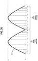
- FIG. 1schematically illustrates an exemplary AC waveform of utility supply power that is used to drive LED lighting.
- FIG. 2A-2Kschematically illustrate an LED circuit according to an exemplary embodiment of the disclosure, and various switching states of switches of the LED circuit.
- FIG. 3Aillustrates an exemplary AC voltage waveform which is applied to the LED circuit of FIGS. 2A-2K , wherein the AC voltage waveform is shown to be divided into a plurality of zones in positive and negative half-cycles of the AC waveform, according to an exemplary embodiment of the disclosure.
- FIG. 3Bschematically illustrates a rectified current waveform of the LED circuit of FIGS. 2A-2K , wherein the rectified current waveform is shown divided into the plurality of zones shown in FIG. 3A , according to an exemplary embodiment of the invention.
- FIG. 3Cschematically illustrates an exemplary process to achieve a constant brightness by activating a number of LEDs in each zone in a manner that is inversely proportional to the magnitude of the current shown in FIG. 3B .
- FIG. 4schematically illustrates an LED circuit according to an exemplary embodiment of the disclosure.
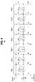
- FIG. 5Ais a table that illustrates various switching states of switches in the LED circuit of FIG. 4 over fourteen different and overlapping zones of an AC voltage waveform that is used to drive the LED circuit, according to an exemplary embodiment of the disclosure.
- FIG. 5Bshows one full cycle of an exemplary AC voltage waveform that is used to drive the LED circuit of FIG. 4 with overlapping zones as shown in the table of FIG. 5A .
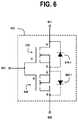
- FIG. 6schematically illustrates a solid-state bidirectional switch which can be used to implement the switches shown in the LED circuits of FIGS. 2A and 4 , according to an exemplary embodiment of the disclosure.
- FIG. 7schematically illustrates a light generating circuit according to an exemplary embodiment of the disclosure.
- FIG. 8schematically illustrates a light generating device which is implemented in a monolithic wafer form, according to an exemplary embodiment of disclosure.
- FIG. 9schematically illustrates a light generating device which is implemented in a monolithic wafer form, according to another exemplary embodiment of disclosure.
- FIG. 1schematically illustrates an exemplary AC waveform 100 of utility supply power (referred to herein as AC mains) that is used to drive LED lighting.
- the AC waveform 100comprises a sine wave with respective positive and negative half-cycles 101 and 102 .
- the AC waveformhas a positive peak voltage VP+ in the positive half-cycle 101 , and a negative peak voltage VP ⁇ in the negative half-cycle, and voltage zero-crossings (0V).
- the positive peak voltage VP+is about 170V
- the negative peak voltage VP ⁇is about ⁇ 170V.
- the exemplary AC waveform 100is illustratively a 60 Hz signal with a period of about 16.66 milliseconds, wherein each half-cycle 101 and 102 has a duration of about 8.33 milliseconds.
- FIG. 1schematically illustrates a conventional method for driving LED devices using AC-to-DC conversion of the peak portions 101 - 1 and 102 - 1 of the respective positive and negative half-cycles 101 and 102 of the AC waveform 100 .
- an AC-to-DC LED driveris used to drive LED devices with DC voltage which is derived from the peak portions of AC main signal 100 . This results in lengthy periods of darkness that may or may not be visible.
- conventional LED lightinginefficiently converts high-voltage AC mains to DC with unreliable, costly, heavy magnetics, transformers, and bulky unreliable capacitors, whereby the usable portion of the AC main cycle is limited resulting in relatively long periods of darkness, and added difficulty in providing low levels of dimming without flicker.
- LEDsare DC current-source driven devices that are seemingly incompatible with high-voltage AC such as 120 and 240 Vrms utility sources.
- voltage level or time from zero-crossing switched LED strings of correspondingly varied lengths in series and parallelcan be made to be directly compatible with high-voltage AC sources.
- DC devicessuch as low-voltage integrated circuits and diodes, have an operable range of input voltage and can survive connection to high voltage AC sources during the voltage window that corresponds to the allowable input voltage range.
- a typical LED used for lightinghas a nominal operating voltage of 3.5 Volts and an allowable operating range from 2.8 to 4.2 Volts.
- a string of 10 LEDscan be operable from 28 to 42 Volt levels of the AC source. Multiple strings of LEDs continually added in series gradually support correspondingly higher and higher voltages.
- the switching circuitscan be configured to shed energy during each zone such that the current is constant and the voltage variation is consumed by a switching current source instead of stressing the LEDs.
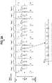
- FIG. 2Aschematically illustrates an LED circuit 200 comprising a plurality of LED stages, Stage 1-Stage 10, a plurality of switches S 1 -S 22 , a first power line 110 (denoted “Line Hot”) and a second power line 112 (denoted “Line Neutral”), which are connected to AC power (e.g., the AC waveform 100 of utility supply power of FIG. 1 ) that is used to drive the LED devices of the LED circuit 200 .
- AC powere.g., the AC waveform 100 of utility supply power of FIG. 1
- each LED stage, Stage 1-Stage 10comprises a respective block of serially-connected LED devices 201 - 210 .
- the LED circuit 200will have more than 10 stages.
- each LED stage, Stage 1-Stage 10comprises the same number of serially-connected LED devices, e.g., 10 LED devices, as shown in the exploded view of the LED stage, Stage 4, comprising the block 204 of 10 serially-connected LED devices.
- Each LED stage 201 - 210comprises (i) an input connected to a first switch and a second switch, wherein the first switch and second switches are configured to selectively connect the input of the LED stage to the first and second power lines 110 and 112 , respectively, under control of switch control circuitry, and (ii) an output connected to a third switch and a fourth switch, wherein the third and fourth switches are configured to selectively connect the output of the LED stage to the first and second power lines 110 and 112 , respectively.
- the first block of LEDs 201 in Stage 1has an input connected to switches S 1 and S 2 , and an output connected to switches S 3 and S 4 .
- the second block of LEDs 202has an input connected the switches S 3 and S 4 and to the output of the first block of LEDs 201 , and so on.
- the configuration of the LED circuit 200allows the LED devices to be driven directly from the AC power 100 applied to the first and second power lines 110 and 112 by selectively activating the switches S 1 -S 22 according to a switching protocol that is synchronized with the voltage level and phase of the AC power 100 .
- the switching schemeis configured to selectively connect one or more of the blocks of serially-connected LED devices 201 - 210 to the first and second power lines 110 and 112 to drive the LED stages with the AC power (as opposed to DC power).
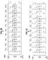
- FIGS. 2B-2Killustrate different switching states of the LED circuit 200 of FIG. 2A , wherein two or more of the blocks of serially-connected LED devices 201 - 210 are connected in series and/or in parallel between the first and second power lines 110 and 112 .
- FIGS. 2B-2Kwill be discussed in the context FIG. 3A , wherein FIG. 3A illustrates an exemplary AC voltage waveform 100 which is applied to the LED circuit 200 , and wherein the AC voltage waveform 100 is shown to be divided into a plurality of zones 300 (e.g., Zone 0, Zone 1, Zone 2, Zone 4, and Zone 5) in a positive-half cycle of the AC waveform 100 and a plurality of zones 310 (e.g., Zone 0, Zone 6, Zone 7, Zone 8, Zone 9, and Zone 10) in a negative half-cycle of the AC waveform 100 .
- FIG. 3Aillustrates an exemplary AC voltage waveform 100 which is applied to the LED circuit 200
- the AC voltage waveform 100is shown to be divided into a plurality of zones 300 (e.g., Zone 0, Zone 1, Zone 2, Zone 4, and Zone 5) in a positive-half cycle of the AC waveform 100 and a plurality of zones 310 (e.g., Zone 0, Zone 6, Zone 7, Zone 8, Zone 9, and Zone 10) in a negative half-cycle
- 3Aillustrates a method for driving the blocks of LED devices 201 - 210 at various times during the positive and negative half-cycles of the AC voltage waveform 100 to illuminate the LED devices during portions of positive and/or negative cycles of the AC voltage waveform 100 , with no periods of darkness except for Zone 0 just before and right after zero voltage crossings of the AC voltage waveform 100 where there is insufficient voltage level to drive any of the blocks of LED devices 201 - 210 .
- FIG. 2Aillustrates a switching state of the LED circuit 200 in which all the switches S 1 -S 22 are open (i.e., not activated) for Zone 0 of the AC voltage waveform 100 such that all LED stages Stage 1-Stage 10 are deactivated.
- this switching statenone of the blocks of serially-connected LED devices 201 - 210 are connected to the first and second power lines 110 and 112 .
- Zone 0represents the portions of the positive and negative half-cycles of the AC voltage waveform 100 in which the voltage is less than 30V.
- FIG. 2Billustrates a switching state of the LED circuit 200 in which the switches S 1 , S 4 , S 5 , S 8 , S 9 , S 12 , S 13 , S 16 , S 17 , and S 20 are activated for Zone 1 of the positive half-cycle of the AC voltage waveform 100 .
- the LED stages Stage 1, Stage 3, Stage 5, Stage 7, and Stage 9are activated such that the blocks of serially-connected LED devices 201 , 203 , 205 , 207 , and 209 are connected in parallel between the first and second power lines 110 and 112 .
- there is sufficient voltage in Zone 1 of the positive half-cycle of the AC voltage waveform 100e.g., greater than 30V
- FIG. 2Cillustrates a switching state of the LED circuit 200 in which the switches S 1 , S 6 , S 7 , S 12 , S 13 , and S 18 are activated for Zone 2 of the positive half-cycle of the AC voltage waveform 100 .
- the LED stages Stage 1, Stage 2, Stage 4, Stage 5, Stage 7, and Stage 8are activated, wherein (i) the blocks of serially-connected LED devices 201 and 202 are concatenated to form a first concatenated block of 20 serially-connected LED devices, (ii) the blocks of serially-connected LED devices 204 and 205 are concatenated to form a second concatenated block of 20 serially-connected LED devices, and (iii) the blocks of serially-connected LED devices 207 and 208 are concatenated to form a third concatenated block of 20 serially-connected LED devices.
- the first, second and third concatenated blocks of LED devicesare connected in parallel between the first and second power lines 110 and 112 .
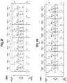
- FIG. 2Dillustrates a switching state of the LED circuit 200 in which the switches S 1 , S 8 , S 9 , and S 16 are activated for Zone 3 of the positive half-cycle of the AC voltage waveform 100 .
- the LED stages Stage 1, Stage 2, Stage 3, Stage 5, Stage 6 and Stage 7are activated, wherein (i) the blocks of serially-connected LED devices 201 , 202 , and 203 are concatenated to form a first concatenated block of 30 serially-connected LED devices, and (ii) the blocks of serially-connected LED devices 205 , 206 and 207 are concatenated to form a second concatenated block of 30 serially-connected LED devices.
- FIG. 2Dillustrates a switching state of the LED circuit 200 in which the switches S 1 , S 8 , S 9 , and S 16 are activated for Zone 3 of the positive half-cycle of the AC voltage waveform 100 .
- the LED stages Stage 1, Stage 2, Stage 3, Stage 5, Stage 6 and Stage 7are activated, wherein
- the first and second concatenated blocks of LED devicesare connected in parallel between the first and second power lines 110 and 112 .
- FIG. 2Eillustrates a switching state of the LED circuit 200 in which the switches S 1 , S 10 , S 11 , and S 20 are activated for Zone 4 of the positive half-cycle of the AC voltage waveform 100 .
- the LED stages Stage 1-Stage 4, and Stage 6-Stage 9are activated, wherein (i) the blocks of serially-connected LED devices 201 , 202 , 203 , and 204 are concatenated to form a first concatenated block of 40 serially-connected LED devices, and (ii) the blocks of serially-connected LED devices 206 , 207 , 208 , and 209 are concatenated to form a second concatenated block of 40 serially-connected LED devices.
- FIG. 1the switches S 1 , S 10 , S 11 , and S 20 are activated for Zone 4 of the positive half-cycle of the AC voltage waveform 100 .
- the LED stages Stage 1-Stage 4, and Stage 6-Stage 9are activated, wherein (i) the blocks of serially
- the first and second concatenated blocks of LED devicesare connected in parallel between the first and second power lines 110 and 112 .
- FIG. 2Fillustrates a switching state of the LED circuit 200 in which the switches S 1 and S 12 are activated for Zone 5 of the positive half-cycle of the AC voltage waveform 100 .
- the LED stages Stage 1-Stage 5are activated, wherein the blocks of serially-connected LED devices 201 , 202 , 203 , 204 , and 205 are concatenated to form a first concatenated block of 50 serially-connected LED devices, which is connected between the first and second power lines 110 and 112 .
- FIG. 3Aon the falling portion of the positive-half cycle, the Zone sequence Z4, Z3, Z3, Z1 and Z0 results in a repeated reverse sequence of the switching states shown in FIGS. 2A-2E .
- the waveformtransitions in a Zone sequence of Zone 0, Zone 6, Zone 7, Zone 8, Zone 9, Zone 10, Zone 9, Zone 8, Zone 7, Zone 6 and Zone 0.
- FIGS. 2G through 2Killustrate different switching states of the LED circuit 200 in sequence from Zone 6 through Zone 10.
- FIGS. 2G-2Killustrate LED stage activation configurations similar to those shown in FIGS. 2B-2F , but wherein the inputs to the LED stages are connected to the second power line 112 in the negative half-cycle of the AC voltage waveform 100 to place the LED devices in a forward-biased state.
- FIG. 2Gillustrates a switching state of the LED circuit 200 in which the switches S 2 , S 3 , S 6 , S 7 , S 10 , S 11 , S 14 , S 15 , S 18 and S 19 are activated for Zone 6 of the negative half-cycle of the AC voltage waveform 100 .
- the LED stages Stage 1, Stage 3, Stage 5, Stage 7, and Stage 9are activated such that the blocks of serially-connected LED devices 201 , 203 , 205 , 207 , and 209 are connected in parallel between the first and second power lines 110 and 112 .
- there is sufficient voltage in Zone 6 of the AC voltage waveforme.g., greater than 30V
- the input terminals of the blocks of serially-connected LED devices 201 , 203 , 205 , 207 , and 209are connected to the second power line 112 and the output terminals of the blocks of serially-connected LED devices 201 , 203 , 205 , 207 , and 209 are connected to the first power line 110 , which places the LED devices in a forward-biased state during the negative half-cycle of the AC voltage waveform 100 .
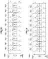
- FIG. 2Hillustrates a switching state of the LED circuit 200 in which the switches S 2 , S 5 , S 8 , S 11 , S 14 , and S 17 are activated for Zone 7 of the negative half-cycle of the AC voltage waveform 100 .
- the LED stages Stage 1, Stage 2, Stage 4, Stage 5, Stage 7 and Stage 8are activated, wherein (i) the blocks of serially-connected LED devices 201 and 202 are concatenated to form a first concatenated block of 20 serially-connected LED devices, (ii) the blocks of serially-connected LED devices 204 and 205 are concatenated to form a second concatenated block of 20 serially-connected LED devices, and (iii) the blocks of serially-connected LED devices 207 and 208 are concatenated to form a third concatenated block of 20 serially-connected LED devices.
- the first, second and third concatenated blocks of LED devicesare connected in parallel between the first and second power lines 110 and 112 .
- FIG. 2Iillustrates a switching state of the LED circuit 200 in which the switches S 2 , S 7 , S 10 , and S 15 are activated for Zone 8 of the negative half-cycle of the AC voltage waveform 100 .
- the LED stages Stage 1, Stage 2, Stage 3, Stage 5, Stage 6 and Stage 7are activated, wherein (i) the blocks of serially-connected LED devices 201 , 202 , and 203 are concatenated to form a first concatenated block of 30 serially-connected LED devices, and (ii) the blocks of serially-connected LED devices 205 , 206 , and 207 are concatenated to form a second concatenated block of 30 serially-connected LED devices.
- FIG. 2Iillustrates a switching state of the LED circuit 200 in which the switches S 2 , S 7 , S 10 , and S 15 are activated for Zone 8 of the negative half-cycle of the AC voltage waveform 100 .
- the LED stages Stage 1, Stage 2, Stage 3, Stage 5, Stage 6 and Stage 7are activated,
- the first and second concatenated blocks of LED devicesare connected in parallel between the first and second power lines 110 and 112 .
- FIG. 2Jillustrates a switching state of the LED circuit 200 in which the switches S 2 , S 9 , S 12 , and S 19 are activated for Zone 9 of the negative half-cycle of the AC voltage waveform 100 .
- the LED stages Stage 1-Stage 4, and Stage 6-Stage 9are activated, wherein (i) the blocks of serially-connected LED devices 201 , 202 , 203 , and 204 are concatenated to form a first concatenated block of 40 serially-connected LED devices, and (ii) the blocks of serially-connected LED devices 206 , 207 , 208 , and 209 are concatenated to form a second concatenated block of 40 serially-connected LED devices.
- FIG. 1illustrates a switching state of the LED circuit 200 in which the switches S 2 , S 9 , S 12 , and S 19 are activated for Zone 9 of the negative half-cycle of the AC voltage waveform 100 .
- the LED stages Stage 1-Stage 4, and Stage 6-Stage 9are
- the first and second concatenated blocks of LED devicesare connected in parallel between the first and second power lines 110 and 112 .
- FIG. 2Killustrates a switching state of the LED circuit 200 in which the switches S 2 and S 11 are activated for Zone 10 of the negative half-cycle of the AC voltage waveform 100 .
- the LED stages Stage 1-Stage 5are activated, wherein the blocks of serially-connected LED devices 201 , 202 , 203 , 204 , and 205 are concatenated to form a first concatenated block of 50 serially-connected LED devices, which is connected between the first and second power lines 110 and 112 .
- FIGS. 2A-2K and FIG. 3Acollectively illustrate an exemplary embodiment of the disclosure in which LED blocks of 10 serially-connected LED devices, which comprise LED devices with an operating range of about 2.8V to 4.2V, can support a working range of about 30V to about 40 V, and even higher voltages by concatenating the LED blocks, thereby allowing a relatively stable level of light to be generated by the LED devices for a majority of the positive and negative cycles of the AC mains power.
- the timing for activating the various switches S 1 -S 22 as shown in FIGS. 2A-2Kmay be implemented based on, e.g., detection of voltage level, phase, and/or time, e.g., based on line frequency and/or detection of zero-crossing events using one or more zero-crossing detector circuits, or other schemes as discussed in further detail below.
- FIG. 3Bschematically illustrates a current waveform 320 to show that positive current flows through the blocks of serially-connected LED devices 201 - 210 of the activated LED stages of the LED circuit 200 in FIGS. 2B-2K during both the positive and negative half-cycles of the AC voltage waveform 100 .
- the LED circuit 200 and associated switch fabric and switching configurations as discussed aboveenables a virtual rectification of the negative half-cycles of the AC voltage waveform 100 as a result of connecting the positive terminals of the blocks of serially-connected LED devices 201 - 210 to the second power line 112 (e.g., line neutral) during the negative half-cycle of the AC voltage waveform 100 .
- the second power line 112e.g., line neutral
- each switch S 1 -S 22is implemented as a bidirectional solid-state switch which can be controlled in bi-directional fashion with unidirectional current flow, such that the negative half-cycles of the AC mains waveform 100 have substantially the same illumination capability as positive half-cycles of the AC mains waveform 100 .
- the switching sequence and activation of the LED stages for each of the Zones 1-10is configured to provide a relatively constant illumination level over the various Zones 1-5 and 6-10 of the positive and negative half-cycles of the AC voltage waveform 100 .
- FIG. 3Cschematically illustrates an exemplary process to achieve a constant brightness by activating a number N of LEDs in each zone in a manner that is inversely proportional to the magnitude of the current.
- FIG. 3Cillustrates the current waveform 320 (of FIG. 3B ) superimposed with a first curve 330 and a second curve 340 .
- the first curve 330represents a number of LEDs (N) as function of 1/sin(wt) (based on the frequency, e.g., 60 Hz of the AC voltage waveform 100 ).
- the first and second curves 330 and 340represent functions that are utilized by a processor to control the switching in the LED circuitry to activate a given number N of LEDs for a given zone based on the magnitude of the current I. In this control process, as the AC power transitions through the Zones 300 and 310 in the positive and negative half-cycles, as the current I increases, the number N of LEDs activated will decrease, and vice versa.
- the desired brightness waveform 340provides a constant DC brightness level L over all Zones 1-10, while providing a short dark period for each Zone 0 in the positive and negative half-cycles of the AC power.
- any flickering due to such short period of darknesswill not be visible to the human eye.
- the various switching states of the LED circuit 200 shown in FIGS. 2B-2Kcan implement a switching function in accordance with the principles of FIG. 3C to achieve relatively constant brightness by the LEDs activated in each of the Zones 1-10.
- FIG. 2Bfor Zone 1 where the voltage reaches 30V, 15 stages of the 10 serially-connected LED blocks can be activated in parallel to turn on 150 LEDs.
- FIG. 2Cfor Zone 2 where the voltage increases to about 60V, the total number N of activated LEDs will be about 100.
- the total number N of activated LEDSwill be about 90.
- FIG. 2Bfor Zone 1 where the voltage reaches 30V, 15 stages of the 10 serially-connected LED blocks can be activated in parallel to turn on 150 LEDs.
- FIG. 2Cfor Zone 2 where the voltage increases to about 60V, the total number N of activated LEDs will be about 100.
- FIG. 2Dfor Zone 3 where the voltage increases to about 90, the total number N of activated LEDS will be about 90.
- FIG. 2B
- the total number N of activated LEDswill be about 80.
- the total number N of activated LEDswill be about 50.
- the same number of LEDs for each of Zones 6-10will be the same for Zones 1-5. In this manner, as the voltage increases in the sequential Zones (and thus the current I increases, FIG. 3B ), the number N of activated LEDs will be decreased to maintain a constant brightness level across the Zones, while as the voltage decreases in sequential Zones, the number N of activated LEDs will be increased to maintain a constant brightness level across the Zones.
- FIG. 4schematically illustrates an LED circuit 400 according to another embodiment of the disclosure.
- the LED circuit 400comprises a plurality of LED stages, Stage 1-Stage 7, a plurality of switches S 1 -S 16 , a first power line 110 (denoted “Line Hot”) and a second power line 112 (denoted “Line Neutral”), which are connected to AC power (e.g., the AC waveform 100 of utility supply power of FIG. 1 ) that is used to drive the LEDs stages of the LED circuit 400 .
- each LED stagecomprises a respective block of serially-connected LED devices 401 - 207 .
- the LED circuit 400will have more than 7 LED stages.
- the blocks of serially-connected LED devices 401 - 407have different numbers of serially-connected LED devices.
- the block of serially-connected LED device 401comprises 10 LED devices.
- the block of serially-connected LED devices 402comprises 3 LED devices.
- the block of serially-connected LED devices 403comprises 4 LED devices.
- the block of serially-connected LED devices 404comprises 5 LED devices.
- the block of serially-connected LED devices 405comprises 7 LED devices.
- the block of serially-connected LED devices 406comprises 9 LED devices.
- the block of serially-connected LED devices 407comprises 12 LED devices. In this configuration, the varied number of LED devices in each LED stage allows for a more fine-adjustment of the number of LED devices that are activated or deactivated during different Zones of the AC power cycles based on smaller increases or decreases in voltage over a large number of Zones.
- FIG. 5Ais a table that illustrates various switching states of the switches S 1 -S 16 in the LED circuit 400 of FIG. 4 over fourteen different and overlapping Zones.
- the LED devices of FIG. 4have a 3.5V nominal operating voltages, and the AC voltage waveform 100 comprises a 120 Vrms waveform.
- the number of activated LED devices for Zones 1 through 7 and Zones 8 through 14are shown as: 10, 13, 17, 22, 29, 38, and 50 LED devices, respectively, wherein the Zones are configured to overlap an eliminate potential short periods of darkness between Zones.
- the LED circuit 400can have an LED stage that is activated at 9V, rather than 30V (for the 10 LED stages shown in FIGS.
- the following LED stagescan be activated with the following voltage levels: (i) the 3-LED stage 402 can be enabled with the AC mains between 9 to 12 Volts; (ii) the 4-LED stage 403 can be enabled with the AC mains between 12V to 15V; (iii) the 5-LED stage 404 can be enabled with the AC mains between 15 to 20V; (iv) the 7-LED stage 405 can be enabled with the AC mains between 21V to 27V (or higher); (v) the 9-LED stage 406 zone can be enabled with the AC mains between 27V to 30 V (or higher); and (vi) the 10-LED stage can be enabled with the AC mains at around 35V (or higher), etc.
- FIG. 5Bshows one full cycle of an AC voltage waveform 100 with overlapping Zones 1-7 in the positive half-cycle 500 of the AC voltage waveform 100 , and overlapping zones 8-14 in the negative half-cycle 510 of the AC voltage waveform 100 .
- FIG. 5Billustrates an exemplary embodiment for providing time overlap for switching states in the various Zones, to thereby eliminate potential short periods of darkness between adjacent Zones.
- FIG. 6schematically illustrates a solid-state bidirectional switch 600 which can be used to implement the switches shown in the LED circuits 200 and 400 of FIGS. 2A and 4 .
- the solid-state bidirectional switch 600comprises first and second input/output terminals 601 and 602 , and a control terminal 603 .
- the solid-state bidirectional switch 600is configured to allow a bidirectional flow of current, when the solid-state bidirectional switch 600 is in “switched-on state” by operation of a control signal applied to the control terminal 603 .
- the solid-state bidirectional switch 600comprises a first MOSFET switch 610 and a second MOSFET switch 620 which are connected back-to-back in series.
- the first and second MOSFET switches 610 and 620comprise power MOSFET devices and, in particular, N-type enhancement MOSFET devices, having gate terminal (G), drain terminals (D), and source terminals (S) as shown.
- the solid-state bidirectional switch 600is implemented using two N-channel MOSFET switches 610 and 620 with commonly connected source terminals.
- the first and second MOSFET switches 610 and 620comprises intrinsic body diodes 610 - 1 and 620 - 1 , respectively, which represent the P-N junctions between the P-type substrate body to N-doped drain regions of the MOSFET devices.
- the body diodes 610 - 1 and 620 - 1are intrinsic elements of the MOSFET switches 610 and 620 (i.e., not discrete elements) and, thus, are shown with dashed-line connections. It is to be noted that the intrinsic body-to-source diodes of the MOSFET switches 610 and 620 are not shown as they are shorted out by the connections between the source regions and the substrate bodies (e.g., N+ source and P body junction are shorted through source metallization).
- the operation of the solid-state bidirectional switch 600is well known to those of ordinary skill in the art.
- FIG. 7schematically illustrates a light generating circuit 700 according to an exemplary embodiment of the disclosure.
- the light generating circuit 700is connected to a utility AC power supply 100 which is utilized by the light generating circuit 700 to drive LED devices using techniques as discussed herein.
- the light generating circuit 700is connected to a hot phase 110 (referred to as “line hot”) of the AC mains 100 and a neutral phase 112 (referred to as “line neutral”) of the AC mains 100 .
- the line neutral 112is shown bonded to earth ground 114 (GND), which provides added protections as is known in the art.
- GNDearth ground 114
- the light generating circuit 700comprises AC-to-DC converter circuitry 710 , zero-crossing detection circuitry 720 , switch control circuitry 730 , and an arrangement of LED circuit stages and switches 740 .
- the arrangement of LED circuit stages and switches 740implements an LED circuit which is the same or similar to the LED circuits 200 or 400 as shown in FIGS. 2A and 4 .
- the switch control circuitry 730implements switching protocols to selectively activate switches within the block of LED circuit stages and switches 740 to selectively connect individual and/or concatenated blocks of serially-connected LED devices to the AC power supply lines, to drive the LED switches using AC power.
- the switch control circuitry 730generates and outputs switch control signals on a plurality (n) of switch control lines SCL 1 , SCL 2 , SCLn, which are connected to control terminals of corresponding switches within the switching fabric that is utilized to selectively connect individual and/or concatenated blocks of serially-connected LED devices within the LED stages 740 to the AC power supply lines.
- the AC-to-DC converter circuitry 710is configured to provide DC supply power to various circuitry and elements of the light generating circuit 700 including the zero-crossing detection circuitry 720 and the switch control circuitry 730 . However, the AC-to-DC converter circuitry 710 is not configured to provide DC supply voltage for driving LED devices. In some embodiments, the AC-to-DC converter circuitry 710 can be implemented using the same or similar DC power conversion techniques as disclosed in the following co-pending applications: (1) U.S. patent application Ser. No. 16/092,263, filed on Oct. 9, 2018 (Pub. No.: US 2019/0165691), entitled High-Efficiency AC to DC Converter and Methods; and (2) U.S. patent application Ser. No. 16/340,672, filed on Apr. 9, 2019 (Pub. No.: US 2019/0238060), entitled High-Efficiency AC Direct to DC Extraction Converter and Methods, the disclosures of which are all fully incorporated herein by reference.
- the zero-crossing detection circuitry 720is configured to detect zero voltage crossings of the AC voltage waveform that drives the LEDs.
- the zero-crossing detection circuitry 720can be implemented using any suitable type of voltage zero-crossing detection circuitry that is configured to sense zero crossings of voltage of the AC power supply waveform and generate a detection signal which indicates a zero-crossing event and an associated transition direction of the zero-crossing event of the voltage waveform (e.g., the AC waveform transitioning from negative to positive (referred to as “positive transition direction”), or the AC waveform transitioning from positive to negative (referred to as a “negative transition direction”)).
- positive transition directionthe AC waveform transitioning from negative to positive
- negative transition directionthe AC waveform transitioning from positive to negative
- the zero-crossing detection circuitry 720is compare the AC voltage on the hot line to a zero reference voltage (e.g., line neutral voltage) to determine the polarity of the AC waveform on the hot line path, and detect a zero-crossing event and the associated transition direction of the zero-crossing of the AC waveform.
- the comparingis performed using a voltage comparator which has a non-inverting input connected to the hot line path, and an inverting input that receives a reference voltage. The output of the voltage comparator switches (i) from logic 1 to logic 0 when the input voltage transitions from positive to negative and (ii) from logic 0 to logic 1 when the input voltage transitions from negative to positive.
- the output of the zero-crossing detection circuitry 720will transition between a logic “1” and logic “0” output upon each detected zero crossing of the AC voltage waveform.
- the switch control circuitry 730utilizes the timing and polarity transition direction of the detected zero voltage crossings to control the timing and sequence of activating the switches with the block of LED circuit stages and switches and connect the LED devices to the AC supply lines to drive the LED stages, as discussed above.
- the switch control circuitry 730may comprise a central processing unit, a microprocessor, a microcontroller, an application-specific integrated circuit (ASIC), a field programmable gate array (FPGA), and other types of processors, as well as portions or combinations of such processors, which can perform switch control functions using hardware control, software/firmware control, and a combination thereof.
- ASICapplication-specific integrated circuit
- FPGAfield programmable gate array
- the switch control circuitry 730may implement modulation schemes, such as pulse-width modulation (PWM), to modulate the activation of the LED stages in the different zones to implement flicker-free levels of dimming with complete compatibility with the AC-Direct LED driving methods as discussed herein.
- PWMpulse-width modulation
- the modulationcan be configured to soften the transition between states when strings of LED devices are added or removed.
- the implementation of a computing devicesuch as CPU core, microcontroller, or other digital/analog device, can facilitate support for overall or local system reconfiguration, e.g., during manufacturing and/or operational use in the field to mitigate AC main transient events.
- the various combinations of LED strings, the number of LEDs, whether in series or parallel, and/or with varying switching configurations and LED operating voltagesmay be a linear and/or non-linear optimization problem that can be determined based on various design and/or cost constraints.
- the switch control methods that are implemented by, e.g., the switch control circuitry 730may be synchronized in time with the AC voltage waveform to divide the AC waveform into discrete Zones, as discussed above.
- the switch control processmay be synchronized with line frequency, with the incremented states beginning from zero voltage switching and zero crossing events as detected by the zero-crossing detection circuitry 720 .
- the LED switching Zonescan be determined form initial power-up 0 time/0Vs, optionally divided into multiple zones (e.g., 5 Zones) equally with equal time duration with slide variation.
- each switching zonemay be pulse width modulated (or other modulation technique) to provide illumination balance at each zone, during zone overlap, and for dimming control. Also, by steering to control current automatically under algorithmic control, additional LEDs may be added in parallel to increase light output per zone, and number of zones may be adjustable by design and/or configured initially in factory or field subsequently.
- state changesmay be timed using, e.g., resistor-capacitor time constant within each zone among the LEDs.
- each subsequent zonei.e., after initial zone
- each subsequent zonemay be controlled via a PWM scheme that enables a prior-to-previous zone disable operation, whereby the PWM starts with an increasing duty cycle on the rising portion of the AC mains waveform until a previous zone disables, and gradually decreases while the AC mains waveform continues to rise.
- the PWMgradually increases in duty cycle during a downward slope of AC mains waveform to maintain the intensity with a decreasing voltage level; hence, being possible for PWM at subsequent zones implemented with an intermediate connection to ground.
- FIG. 8schematically illustrates a light generating device 800 which is implemented in a monolithic wafer form, according to an exemplary embodiment of disclosure.
- the light generating device 800comprises a semiconductor wafer substrate 802 (e.g., silicon substrate), which comprises a monolithic integrated circuit.
- the monolithic integrated circuitcomprises an LED array 804 , switch circuitry 806 , AC power input terminals 808 , and control circuitry 810 .
- FIG. 8illustrates a monolithic wafer implementation of the light generating circuit 700 of FIG. 7 .
- the AC power input terminals 808are configured for connection to an AC power source.
- the AC power input terminals 808are coupled to first and second power lines that comprise metallization that is used to route and distribute the AC power to various regions of the wafer 802 .
- the LED array 804comprises a plurality of LED devices 820 that are connected to form a plurality of LED stages, wherein each LED stage comprises a plurality of serially-connected LED devices 820 , such as schematically illustrated in FIGS. 2A and 4 , for example.
- the switching circuitry 806comprises a plurality of switches (e.g., solid-state bi-directional switches) that are coupled to the LED array 804 using a wiring network to connect the switches to the inputs and outputs of the LED stages.
- the switch control circuitry 810is configured to control the plurality of switches of the switching circuitry 806 to selectively connect at LED stages to the first and second power lines to empower the LED stages with AC power from the AC power source connected to the AC input terminals 808 .
- the switches within the switching circuitry 806can be configured in a microcell arrangement, or a functional cell arrangement with well-defined tab positions.
- each LED device 820comprises an optical filter 822 disposed over the LED device 820 and a lens element 824 disposed over the LED device 820 .
- the optical filter 822comprise a phosphor layer to filter the light that is emitted by the LED device 820 .
- the lens element 824is configured to direct, focus, collimate, etc., or otherwise achieve a desired directionality of the light that is emitted by the LED device 820 .
- FIG. 8illustrates an exemplary embodiment wherein the light generating device 800 implemented in monolithic wafer form can be used to implement an LED lighting device or system without requiring wafer segmentation for repackaging in different form factors.
- the wafer substrate 802can be implemented using various standard wafer sizes to accommodate larger or smaller LED arrays to achieve a desired light output level. Larger wafers can be partitioned into smaller dies, wherein each die comprises an integrated light generating monolithic circuit.
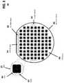
- FIG. 9schematically illustrates a light generating device 900 which is implemented in a monolithic wafer form, according to another exemplary embodiment of disclosure.
- the light generating device 900comprises a semiconductor wafer substrate 902 (e.g., silicon substrate), which comprises a monolithic integrated circuit.
- the monolithic integrated circuitcomprises an LED array 904 , switch circuitry 906 , AC power input terminals 908 , and control circuitry 910 .
- FIG. 9illustrates a monolithic wafer implementation of the light generating circuit 700 of FIG. 7 .
- the light generating device 900is similar to the light generating device 800 of FIG.
- the light generating device 900has a different arrangement of LED devices within the LED array 904 , wherein the LED array 904 comprises LED devices arranged in circular footprint regions, wherein each circular footprint region is surrounded by switch circuitry 906 which comprises an arrangement of switches that are utilized to connect the LED devices, or blocks of serially-connected LED devices, to power lines or otherwise concatenate blocks of serially-connected LED devices to form larger strings of serially-connected LED device, such as discussed above.
Landscapes
- Circuit Arrangement For Electric Light Sources In General (AREA)
- Led Devices (AREA)
Abstract
Description
Claims (20)
Priority Applications (1)
| Application Number | Priority Date | Filing Date | Title |
|---|---|---|---|
| US17/372,821US11363690B2 (en) | 2018-12-17 | 2021-07-12 | AC-driven light-emitting diode systems |
Applications Claiming Priority (5)
| Application Number | Priority Date | Filing Date | Title |
|---|---|---|---|
| US201862780377P | 2018-12-17 | 2018-12-17 | |
| US201962791014P | 2019-01-10 | 2019-01-10 | |
| US16/718,157US10834792B2 (en) | 2018-12-17 | 2019-12-17 | AC-driven light-emitting diode systems |
| US17/032,759US11064586B2 (en) | 2018-12-17 | 2020-09-25 | AC-driven light-emitting diode systems |
| US17/372,821US11363690B2 (en) | 2018-12-17 | 2021-07-12 | AC-driven light-emitting diode systems |
Related Parent Applications (1)
| Application Number | Title | Priority Date | Filing Date |
|---|---|---|---|
| US17/032,759ContinuationUS11064586B2 (en) | 2018-12-17 | 2020-09-25 | AC-driven light-emitting diode systems |
Publications (2)
| Publication Number | Publication Date |
|---|---|
| US20210345462A1 US20210345462A1 (en) | 2021-11-04 |
| US11363690B2true US11363690B2 (en) | 2022-06-14 |
Family
ID=71072067
Family Applications (3)
| Application Number | Title | Priority Date | Filing Date |
|---|---|---|---|
| US16/718,157ActiveUS10834792B2 (en) | 2018-12-17 | 2019-12-17 | AC-driven light-emitting diode systems |
| US17/032,759ActiveUS11064586B2 (en) | 2018-12-17 | 2020-09-25 | AC-driven light-emitting diode systems |
| US17/372,821ActiveUS11363690B2 (en) | 2018-12-17 | 2021-07-12 | AC-driven light-emitting diode systems |
Family Applications Before (2)
| Application Number | Title | Priority Date | Filing Date |
|---|---|---|---|
| US16/718,157ActiveUS10834792B2 (en) | 2018-12-17 | 2019-12-17 | AC-driven light-emitting diode systems |
| US17/032,759ActiveUS11064586B2 (en) | 2018-12-17 | 2020-09-25 | AC-driven light-emitting diode systems |
Country Status (7)
| Country | Link |
|---|---|
| US (3) | US10834792B2 (en) |
| EP (1) | EP3900487A4 (en) |
| JP (1) | JP7475351B2 (en) |
| KR (1) | KR102857286B1 (en) |
| CN (1) | CN113455105B (en) |
| CA (1) | CA3123586A1 (en) |
| WO (1) | WO2020131977A1 (en) |
Cited By (5)
| Publication number | Priority date | Publication date | Assignee | Title |
|---|---|---|---|---|
| US11764565B2 (en) | 2018-07-07 | 2023-09-19 | Intelesol, Llc | Solid-state power interrupters |
| US12015261B2 (en) | 2019-05-18 | 2024-06-18 | Amber Semiconductor, Inc. | Intelligent circuit breakers with solid-state bidirectional switches |
| US12113525B2 (en) | 2021-09-30 | 2024-10-08 | Amber Semiconductor, Inc. | Intelligent electrical switches |
| US12348028B2 (en) | 2021-10-22 | 2025-07-01 | Amber Semiconductor, Inc. | Multi-output programmable power manager |
| US12362646B2 (en) | 2022-01-26 | 2025-07-15 | Amber Semiconductor, Inc. | Controlling AC power to inductive loads |
Families Citing this family (12)
| Publication number | Priority date | Publication date | Assignee | Title |
|---|---|---|---|---|
| US11056981B2 (en) | 2018-07-07 | 2021-07-06 | Intelesol, Llc | Method and apparatus for signal extraction with sample and hold and release |
| US11671029B2 (en) | 2018-07-07 | 2023-06-06 | Intelesol, Llc | AC to DC converters |
| US11205011B2 (en) | 2018-09-27 | 2021-12-21 | Amber Solutions, Inc. | Privacy and the management of permissions |
| US11334388B2 (en) | 2018-09-27 | 2022-05-17 | Amber Solutions, Inc. | Infrastructure support to enhance resource-constrained device capabilities |
| US11349296B2 (en) | 2018-10-01 | 2022-05-31 | Intelesol, Llc | Solid-state circuit interrupters |
| US10985548B2 (en) | 2018-10-01 | 2021-04-20 | Intelesol, Llc | Circuit interrupter with optical connection |
| US10834792B2 (en) | 2018-12-17 | 2020-11-10 | Intelesol, Llc | AC-driven light-emitting diode systems |
| US11664741B2 (en)* | 2019-07-25 | 2023-05-30 | Susan Rhodes | System and method for AC power control |
| EP4088125A4 (en) | 2020-01-21 | 2024-03-06 | Amber Semiconductor, Inc. | INTELLIGENT CIRCUIT INTERRUPTION |
| DE102020208001A1 (en)* | 2020-01-27 | 2021-07-29 | Osram Gmbh | CIRCUIT ARRANGEMENT FOR A LIGHT SOURCE |
| DE102020206439A1 (en)* | 2020-01-27 | 2021-07-29 | Osram Gmbh | MODULE AND CIRCUIT ARRANGEMENT FOR A LIGHT SOURCE |
| EP4197086A4 (en) | 2020-08-11 | 2024-09-04 | Amber Semiconductor, Inc. | INTELLIGENT ENERGY SOURCE MONITORING AND SELECTION CONTROL SYSTEM |
Citations (344)
| Publication number | Priority date | Publication date | Assignee | Title |
|---|---|---|---|---|
| US3638102A (en) | 1966-10-20 | 1972-01-25 | Siemens Ag | Overload protection circuit |
| US3777253A (en) | 1972-10-24 | 1973-12-04 | Allen Bradley Co | Low power loss voltage supply circuit |
| US4074345A (en) | 1976-11-02 | 1978-02-14 | Ackermann Walter J | Electronic power supply |
| US4127895A (en) | 1977-08-19 | 1978-11-28 | Krueger Paul J | Charge-transfer voltage converter |
| EP0016646A1 (en) | 1979-03-23 | 1980-10-01 | Westinghouse Electric Corporation | AC Solid-state circuit breaker |
| US4245185A (en) | 1979-03-23 | 1981-01-13 | Westinghouse Electric Corp. | Solid state circuit breaker with three phase capability |
| US4245184A (en) | 1979-03-23 | 1981-01-13 | Westinghouse Electric Corp. | AC Solid-state circuit breaker |
| US4245148A (en) | 1979-09-14 | 1981-01-13 | Wisco Industries, Inc. | Optically sensitive control circuit for a food browning device |
| US4257081A (en) | 1977-10-24 | 1981-03-17 | Matsushita Electric Works Ltd. | Circuit arrangement for the control of a bistable relay |
| US4466071A (en) | 1981-09-28 | 1984-08-14 | Texas A&M University System | High impedance fault detection apparatus and method |
| US4487458A (en) | 1982-09-28 | 1984-12-11 | Eaton Corporation | Bidirectional source to source stacked FET gating circuit |
| US4581540A (en) | 1984-03-16 | 1986-04-08 | Teledyne Industries, Inc. | Current overload protected solid state relay |
| US4631625A (en) | 1984-09-27 | 1986-12-23 | Siemens Energy & Automation, Inc. | Microprocessor controlled circuit breaker trip unit |
| US4636907A (en) | 1985-07-11 | 1987-01-13 | General Electric Company | Arcless circuit interrupter |
| US4649302A (en) | 1984-07-30 | 1987-03-10 | Eaton Corporation | DC or AC solid state switch with improved line-derived control circuit power supply |
| US4653084A (en) | 1984-07-20 | 1987-03-24 | Om Ahuja | Remote actuated switch |
| US4682061A (en) | 1986-05-01 | 1987-07-21 | Honeywell Inc. | MOSFET transistor switch control |
| US4685046A (en) | 1985-10-03 | 1987-08-04 | The Scott & Fetzer Company | Low voltage direct current power supply |
| US4709296A (en) | 1985-06-18 | 1987-11-24 | Northern Telecom Limited | Protection arrangement for a telephone subscriber line interface circuit |
| US4760293A (en) | 1982-11-04 | 1988-07-26 | Siemens Aktiengesellschaft | Combined bipolar and MOSFET switch |
| US4766281A (en) | 1986-11-17 | 1988-08-23 | Ag Fur Industrielle Elektronik Agie Losone Bei Locarno | Pulse generator spark-erosive metal working |
| US4812995A (en) | 1987-05-19 | 1989-03-14 | Girgis Adly A | Adaptive Kalman Filtering in fault classification |
| US4888504A (en) | 1988-10-07 | 1989-12-19 | International Rectifier Corporation | Bidirectional MOSFET switching circuit with single gate bias |
| EP0398026A2 (en) | 1989-04-24 | 1990-11-22 | Motorola, Inc. | Semiconductor AC switch |
| US5121282A (en) | 1990-03-30 | 1992-06-09 | White Orval C | Arcing fault detector |
| US5276737A (en) | 1992-04-20 | 1994-01-04 | Silvio Micali | Fair cryptosystems and methods of use |
| JPH0653779A (en) | 1992-07-30 | 1994-02-25 | Hioki Ee Corp | Method for extracting DC signal from AC signal and method for removing DC signal |
| US5307257A (en) | 1991-02-22 | 1994-04-26 | Matsushita Electric Industrial Co., Ltd. | Transformerless power-supply unit for supplying a low DC voltage |
| US5371646A (en) | 1991-01-16 | 1994-12-06 | Felten & Guilleaume Austria Ag | Ground fault circuit interrupter |
| US5410745A (en) | 1993-05-20 | 1995-04-25 | Motorola, Inc. | Detector and video amplifier |
| US5559656A (en) | 1993-04-01 | 1996-09-24 | International Rectifier Corporation | IGBT switching voltage transient protection circuit |
| US5646514A (en) | 1993-11-01 | 1997-07-08 | Kabushiki Kaisha Toshiba | AC/DC converter using a non-latch type switching device |
| US5654880A (en) | 1996-01-16 | 1997-08-05 | California Institute Of Technology | Single-stage AC-to-DC full-bridge converter with magnetic amplifiers for input current shaping independent of output voltage regulation |
| US5731732A (en) | 1993-11-30 | 1998-03-24 | Siliconix Incorporated | Gate drive technique for a bidirectional blocking lateral MOSFET |
| US5793596A (en) | 1994-04-22 | 1998-08-11 | Unitrode Corp | Floating positive circuit breaker |
| US5796274A (en) | 1996-10-16 | 1998-08-18 | Lockheed Martin Corporation | Fault tolerant MOSFET driver |
| US5870009A (en) | 1996-11-07 | 1999-02-09 | Schneider Electronic Sa | Adjustable electromagnetic trip device and a circuit breaker comprising such a trip device |
| US5933305A (en) | 1998-06-02 | 1999-08-03 | Eaton Corporation | Arc fault detector comparing integrated interval to interval filtered load current and circuit breaker incorporating same |
| US6081123A (en) | 1996-11-18 | 2000-06-27 | Schneider Electric Sa | Device for preventive detection of faults with identification of the type of load |
| US6111494A (en) | 1996-08-03 | 2000-08-29 | Robert Bosch Gmbh | Adjustable voltage divider produced by hybrid technology |
| US6115267A (en) | 1998-06-09 | 2000-09-05 | Herbert; Edward | AC-DC converter with no input rectifiers and power factor correction |
| US6141197A (en) | 1998-03-10 | 2000-10-31 | General Electric Company | Smart residential circuit breaker |
| US6160689A (en) | 1997-10-09 | 2000-12-12 | Jay Stolzenberg | Two wire solid state AC/DC circuit breaker |
| US6167329A (en) | 1998-04-06 | 2000-12-26 | Eaton Corporation | Dual microprocessor electronic trip unit for a circuit interrupter |
| US6169391B1 (en) | 1999-07-12 | 2001-01-02 | Supertex, Inc. | Device for converting high voltage alternating current to low voltage direct current |
| US6188203B1 (en) | 1996-11-01 | 2001-02-13 | Lucas Aerospace Power Equipment Corporation | Ground fault detection circuit |
| US6300748B1 (en) | 2000-07-13 | 2001-10-09 | Tyco Electronics Corporation | Transformerless power supply circuit with a switchable capacitive element |
| US6369554B1 (en) | 2000-09-01 | 2002-04-09 | Marvell International, Ltd. | Linear regulator which provides stabilized current flow |
| US20020109487A1 (en) | 2001-01-10 | 2002-08-15 | Iwatt | Phase-controlled AC-DC power converter |
| US6483290B1 (en) | 1992-02-21 | 2002-11-19 | Abb Automation Inc. | Apparatus for metering electrical power that determines energy usage data based on downloaded information |
| US6515434B1 (en) | 1999-10-18 | 2003-02-04 | Patent-Treuhand-Gesellschaft Fuer Elektrische Gluehlampen Mbh | Control circuit for LED and corresponding operating method |
| US20030052544A1 (en) | 2000-03-08 | 2003-03-20 | Eiji Yamamoto | Pwm cycloconverter and power fault detector |
| US6538906B1 (en) | 2002-02-11 | 2003-03-25 | Delta Electronics, Inc. | Energy storage circuit for DC-DC converter |
| US20030063420A1 (en) | 2001-09-28 | 2003-04-03 | Eaton Corporation | Method and apparatus for detecting and suppressing a parallel ARC fault |
| US20030151865A1 (en) | 2002-02-14 | 2003-08-14 | Hitachi, Ltd. | Electrostatic discharge protection circuit |
| US20040032756A1 (en) | 2002-03-12 | 2004-02-19 | Stmicroelectronics N.V. | Transformerless AC/DC converter |
| US6756998B1 (en) | 2000-10-19 | 2004-06-29 | Destiny Networks, Inc. | User interface and method for home automation system |
| US6788512B2 (en) | 2002-04-16 | 2004-09-07 | General Electric Company | Electronic trip unit capable of analog and digital setting of circuit breaker setpoints |
| US6807035B1 (en) | 2000-11-28 | 2004-10-19 | Hubbell Incorporated | Fault interrupter using microcontroller for fault sensing and automatic self-testing |
| US6813720B2 (en) | 1999-12-14 | 2004-11-02 | Legrand | Method of and device for supplying electrical power to a load using a power modulation system including at least one controlled switch and overvoltage counting apparatus |
| US20040251884A1 (en) | 2003-06-10 | 2004-12-16 | Lutron Electronics Co., Ltd. | High efficiency off-line linear power supply |
| US6839208B2 (en) | 2000-02-17 | 2005-01-04 | Pass & Seymour, Inc | Arc fault circuit interrupter recognizing arc noise burst patterns |
| US6843680B2 (en) | 2002-05-23 | 2005-01-18 | Protectconnect | Electrical distribution terminal guard |
| US6906476B1 (en) | 2003-07-25 | 2005-06-14 | Asp Corporation | Power control system for reducing power to lighting systems |
| US20050162139A1 (en) | 2004-01-23 | 2005-07-28 | Mark Hirst | Alternating current switching circuit |
| US20050185353A1 (en) | 2003-06-06 | 2005-08-25 | Electronic Theatre Controls, Inc. | Overcurrent protection for solid state switching system |
| US20050286184A1 (en) | 2004-06-22 | 2005-12-29 | Steve Campolo | Electrical power outlet strip |
| US6984988B2 (en) | 2002-10-16 | 2006-01-10 | Yazaki Corporation | Ground-fault detecting device and insulation resistance measuring device |
| US7045723B1 (en) | 2005-09-27 | 2006-05-16 | Joti Projkovski | Fail safe electrical receptacle |
| US7053626B2 (en) | 2001-08-14 | 2006-05-30 | Robert Bosch Gmbh | Device and method for monitoring the connection of an electrical supply unit |
| US7110225B1 (en) | 2005-03-31 | 2006-09-19 | Leviton Manufacturing Co., Inc. | Arc-limiting switching circuit |
| US20060285366A1 (en) | 2005-05-23 | 2006-12-21 | Matthias Radecker | Control circuit for a switch unit of a clocked power supply circuit, and resonance converter |
| US20070008747A1 (en) | 2005-07-11 | 2007-01-11 | International Rectifier Corporation | Bridgeless bi-directional forward type converter |
| US7164238B2 (en) | 2001-11-14 | 2007-01-16 | Astral Communications, Inc. | Energy savings device and method for a resistive and/or an inductive load and/or a capacitive load |
| US20070143826A1 (en) | 2005-12-21 | 2007-06-21 | Sastry Manoj R | Method, apparatus and system for providing stronger authentication by extending physical presence to a remote entity |
| US20070159745A1 (en) | 2004-05-24 | 2007-07-12 | Sven Berberich | Circuit Element and Method for Protecting a Load Circuit |
| US20070188025A1 (en) | 2005-06-06 | 2007-08-16 | Keagy Jon M | Dimmer switch for use with lighting circuits having three-way switches |
| US20070236152A1 (en) | 2006-04-10 | 2007-10-11 | Lutron Electronics Co., Inc. | Load control device having a variable drive circuit |
| US7297603B2 (en) | 2005-03-31 | 2007-11-20 | Semiconductor Components Industries, L.L.C. | Bi-directional transistor and method therefor |
| US7304828B1 (en) | 2004-09-22 | 2007-12-04 | Shvartsman Vladimir A | Intelligent solid state relay/breaker |
| USD558683S1 (en) | 2006-01-20 | 2008-01-01 | Watlow Electric Manufacturing Company | Power controller base housing |
| US20080006607A1 (en) | 2006-07-04 | 2008-01-10 | Franz Boeder | Electrical circuit breaker |
| US7319574B2 (en) | 2005-05-23 | 2008-01-15 | Eaton Corporation | Arc fault detection apparatus, method and system for an underground electrical conductor |
| US7367121B1 (en) | 2000-01-05 | 2008-05-06 | Protectconnect | Electrical wiring method |
| USD568253S1 (en) | 2004-12-08 | 2008-05-06 | Protectconnect, Inc. | Electrical module |
| US20080136581A1 (en) | 2005-06-09 | 2008-06-12 | Whirlpool Corporation | smart current attenuator for energy conservation in appliances |
| US20080151444A1 (en) | 2006-12-20 | 2008-06-26 | John D Upton | Method and apparatus for protection against current overloads |
| US20080174922A1 (en) | 2007-01-19 | 2008-07-24 | Tellabs Bedford, Inc. | Method and apparatus for detecting ground fault current on a power line |
| US20080180866A1 (en) | 2007-01-29 | 2008-07-31 | Honor Tone, Ltd. | Combined arc fault circuit interrupter and leakage current detector interrupter |
| US20080204950A1 (en) | 2007-02-27 | 2008-08-28 | Xin Zhou | Arc fault circuit interrupter and series arc fault detection method using plural high frequency bands |
| US20080234879A1 (en) | 2007-03-21 | 2008-09-25 | Fuller Randy J | Ground fault interruption using dsp based sspc module |
| US20080253153A1 (en) | 2007-04-13 | 2008-10-16 | Wu Chin-Chang | Active Power Conditioner |
| US20080281472A1 (en) | 2007-03-01 | 2008-11-13 | Syracuse University | Open Web Services-Based Indoor Climate Control System |
| US20090034139A1 (en) | 2007-08-03 | 2009-02-05 | Linear Technology Corporation | Over-voltage protection circuit |
| US20090067201A1 (en) | 2007-09-06 | 2009-03-12 | Jun Cai | Isolated Switched-mode Power Supply With Output Regulation From Primary Side |
| US20090168273A1 (en) | 2008-01-02 | 2009-07-02 | Wenjiang Yu | Hybrid high voltage dc contactor with arc energy diversion |
| US20090195349A1 (en) | 2008-02-01 | 2009-08-06 | Energyhub | System and method for home energy monitor and control |
| US20090203355A1 (en) | 2008-02-07 | 2009-08-13 | Garrett Clark | Mobile electronic security apparatus and method |
| US20090213629A1 (en) | 2008-02-22 | 2009-08-27 | Macroblock, Inc. | Powering circuit of ac-dc converter |
| US7586285B2 (en) | 2006-03-09 | 2009-09-08 | Omron Corporation | Ground fault detection device for motor driving circuit |
| US7595680B2 (en) | 2007-01-25 | 2009-09-29 | Panasonic Corporation | Bidirectional switch and method for driving the same |
| GB2458699A (en) | 2008-03-28 | 2009-09-30 | Deepstream Technologies Ltd | Linear regulator with zero crossing coordination |
| US7610616B2 (en) | 2003-10-17 | 2009-10-27 | Fujitsu Limited | Pervasive security mechanism by combinations of network and physical interfaces |
| US20090284385A1 (en) | 2008-05-15 | 2009-11-19 | Lex Products Corp. | Apparatus and method of illuminating indicator lights |
| US7643256B2 (en) | 2006-12-06 | 2010-01-05 | General Electric Company | Electromechanical switching circuitry in parallel with solid state switching circuitry selectively switchable to carry a load appropriate to such circuitry |
| US7693670B2 (en) | 2007-08-14 | 2010-04-06 | General Electric Company | Cognitive electric power meter |
| US20100091418A1 (en) | 2008-10-15 | 2010-04-15 | Jian Xu | Solid state circuit protection system that works with arc fault circuit interrupter |
| US7729147B1 (en) | 2007-09-13 | 2010-06-01 | Henry Wong | Integrated circuit device using substrate-on-insulator for driving a load and method for fabricating the same |
| US7731403B2 (en) | 2001-01-23 | 2010-06-08 | Donnelly Corpoation | Lighting system for a vehicle, with high-intensity power LED |
| US20100145479A1 (en) | 2008-10-09 | 2010-06-10 | G2 Software Systems, Inc. | Wireless Portable Sensor Monitoring System |
| US20100145542A1 (en) | 2007-03-14 | 2010-06-10 | Zonit Structured Solutions, Llc | Smart electrical outlets and associated networks |
| US20100156369A1 (en) | 2008-12-18 | 2010-06-24 | Kularatna Nihal | High current voltage regulator |
| US7746677B2 (en) | 2006-03-09 | 2010-06-29 | Avago Technologies Wireless Ip (Singapore) Pte. Ltd. | AC-DC converter circuit and power supply |
| US20100188054A1 (en) | 2007-07-26 | 2010-07-29 | Jun Asakura | Battery internal short-circuit detecting device and method, battery pack, and electronic device system |
| US20100231135A1 (en) | 2009-07-17 | 2010-09-16 | Bridgelux,Inc. | Reconfigurable LED Array and Use in Lighting System |
| US20100231373A1 (en) | 2009-03-13 | 2010-09-16 | Greg Romp | Intelligent Vehicular Speed Control System |
| US20100235896A1 (en) | 2002-11-12 | 2010-09-16 | Millipore Corporation | Instrument access control system |
| WO2010110951A1 (en) | 2009-03-25 | 2010-09-30 | General Electric Company | Dimming interface for power line |
| US20100261373A1 (en) | 2009-04-11 | 2010-10-14 | Roneker Michael D | Switched receptacle device with led indication |
| US7821023B2 (en) | 2005-01-10 | 2010-10-26 | Cree, Inc. | Solid state lighting component |
| US20100284207A1 (en) | 2009-05-08 | 2010-11-11 | Sony Corporation | AC line signal detection device and method and power supply device |
| US20100296207A1 (en) | 2007-11-16 | 2010-11-25 | Eaton Industries Gmbh | Short-circuit limiting apparatus in a low-voltage installation |
| US20100309003A1 (en) | 2007-12-21 | 2010-12-09 | Eads Secure Networks | Method of producing a proof of presence or of operation of an entity in an identified zone for a duration greater than a given threshold, and monitoring system |
| US20100320840A1 (en) | 2009-06-18 | 2010-12-23 | Adsp Consulting, Llc | Method and Apparatus for Driving Low-Power Loads from AC Sources |
| US20110062936A1 (en) | 2009-09-01 | 2011-03-17 | Vetco Gray Controls Limited | Ac power switching module |
| USD638355S1 (en) | 2010-09-09 | 2011-05-24 | Cheng Uei Precision Industry Co., Ltd. | Power adapter |
| US20110121752A1 (en) | 2009-11-25 | 2011-05-26 | Lutron Electronics Co., Inc. | Two-wire dimmer switch for low-power loads |
| US20110127922A1 (en) | 2008-07-29 | 2011-06-02 | Koninklijke Philips Electronics N.V. | llumination device comprising multiple LEDs |
| US20110156610A1 (en) | 2009-12-30 | 2011-06-30 | Leviton Manufacturing Co., Inc. | Phase control with adaptive parameters |
| US20110273103A1 (en) | 2010-05-06 | 2011-11-10 | Tli Inc. | Led lamp with adjustable illumination intensity based on ac voltage amplitude |
| US20110292703A1 (en) | 2010-05-29 | 2011-12-01 | Cuks, Llc | Single-stage AC-to-DC converter with isolation and power factor correction |
| US20110299547A1 (en) | 2010-06-04 | 2011-12-08 | Wael William Diab | Method and system for managing energy costs utilizing a broadband gateway |
| US20110301894A1 (en) | 2010-06-04 | 2011-12-08 | Sensus Usa Inc. | Method and System for Non-Intrusive Load Monitoring and Processing |
| US20110305054A1 (en) | 2010-06-15 | 2011-12-15 | Yamagiwa Hiroto | Bi-directional switch, alternating-current two-wire switch, switching power source circuit, and method of driving bi-directional switch |
| US20110307447A1 (en) | 2010-06-09 | 2011-12-15 | Brocade Communications Systems, Inc. | Inline Wire Speed Deduplication System |
| US20120026632A1 (en) | 2010-07-28 | 2012-02-02 | General Electric Company | Systems, Methods, and Apparatus for Limiting Voltage Across a Switch |
| US8124888B2 (en) | 2008-06-25 | 2012-02-28 | Wire Wrangler, LLC | Concealed and flush dual phone and power outlet |
| US20120075897A1 (en) | 2010-09-27 | 2012-03-29 | Semiconductor Energy Laboratory Co., Ltd. | Rectifier circuit and semiconductor device using the same |
| US20120089266A1 (en) | 2009-12-18 | 2012-04-12 | Tomimbang Wendell E | System and integrated method for a parallel and series arc fault circuit interrupter |
| US20120095605A1 (en) | 2011-09-17 | 2012-04-19 | Tran Bao Q | Smart building systems and methods |
| US20120133289A1 (en) | 2011-04-11 | 2012-05-31 | David Hum | AC LED Light Source with Reduced Flicker |
| US8256675B2 (en) | 2007-11-21 | 2012-09-04 | Infineon Technologies Ag | Voltage converter, usage of a voltage converter, method for converting an AC voltage into a DC voltage, and contactless chip card |
| US20120275076A1 (en) | 2011-04-28 | 2012-11-01 | Fujitsu Semiconductor Limited | Bidirectional switch and charge/discharge protection device using same |
| US20120311035A1 (en) | 2011-06-06 | 2012-12-06 | Microsoft Corporation | Privacy-preserving matching service |
| US20130026925A1 (en)* | 2011-07-28 | 2013-01-31 | Ven Antony P Van De | Solid State Lighting Apparatus and Methods Using Integrated Driver Circuitry |
| EP2560063A1 (en) | 2011-08-15 | 2013-02-20 | Nxp B.V. | Voltage regulator circuit and method |
| US20130051102A1 (en) | 2011-08-25 | 2013-02-28 | North Carolina State University | Isolated soft-switch single-stage ac-dc converter |
| US20130057247A1 (en) | 2011-08-29 | 2013-03-07 | Control4 Corporation | Wall box device for managing energy |
| US20130066478A1 (en) | 2011-09-08 | 2013-03-14 | Schneider Electric USA, Inc. | Optimized protection coordination of electronic-trip circuit breaker by short circuit current availability monitoring |
| US20130063851A1 (en) | 2011-09-12 | 2013-03-14 | Honeywell International Inc. | Appartus and method for protecting signal and communication lines from very high voltage and transient pulses |
| US20130088160A1 (en) | 2011-10-05 | 2013-04-11 | Yan Chai | Reconfigurable Multi-LED Light Source |
| US20130104238A1 (en) | 2011-10-24 | 2013-04-25 | Nokia Corporation | Method and apparatus for verifying proof of presence |
| US20130119958A1 (en) | 2011-11-16 | 2013-05-16 | Michael Gasperi | Wide Input Voltage Range Power Supply Circuit |
| US20130128396A1 (en) | 2011-11-23 | 2013-05-23 | Metroic Limited | Current measurement |
| US8463453B2 (en) | 2009-11-13 | 2013-06-11 | Leviton Manufacturing Co., Inc. | Intelligent metering demand response |
| US20130170261A1 (en) | 2011-12-28 | 2013-07-04 | Richtek Technology Corporation | Self-discharge control for an emi filter capacitor |
| US20130174211A1 (en) | 2011-12-30 | 2013-07-04 | Nokia Corporation | Method And Apparatus Providing Privacy Setting And Monitoring User Interface |
| US8482885B2 (en) | 2009-09-14 | 2013-07-09 | Electronic Systems Protection, Inc. | Hybrid switch circuit |
| US20130187631A1 (en) | 2012-01-25 | 2013-07-25 | Control4 Corporation | Device for detecting a load type |
| US20130245841A1 (en) | 2010-06-26 | 2013-09-19 | Junho AHN | Method for controlling component for network system |
| US20130253898A1 (en) | 2012-03-23 | 2013-09-26 | Power Analytics Corporation | Systems and methods for model-driven demand response |
| US20130261821A1 (en) | 2011-10-04 | 2013-10-03 | Advanergy, Inc. | Power distribution system and method |
| US20130265041A1 (en) | 2012-04-04 | 2013-10-10 | Allegro Microsystems, Inc. | High accuracy differential current sensor for applications like ground fault interrupters |
| US8560134B1 (en) | 2010-09-10 | 2013-10-15 | Kwangduk Douglas Lee | System and method for electric load recognition from centrally monitored power signal and its application to home energy management |
| JP2013230034A (en) | 2012-04-26 | 2013-11-07 | Diamond Electric Mfg Co Ltd | Input voltage data formation device, and ac/dc converter including the same |
| US20130300534A1 (en) | 2006-06-08 | 2013-11-14 | Innohome Oy (Leitzinger Oy) | Automated control system for multi-level authority to operate electronic and electrical devices |
| US20130329331A1 (en) | 2012-06-11 | 2013-12-12 | Schneider Electric USA, Inc. | Wireless Branch Circuit Energy Monitoring System |
| US20140043732A1 (en) | 2012-07-20 | 2014-02-13 | Assembled Products, A Unit Of Jason Incorporated | Plug and Play Control Panel Module with Integrally Socketed Circuit Board |
| JP2014030355A (en) | 2013-10-28 | 2014-02-13 | Chuo Seisakusho Ltd | Dc power-supply device |
| US8664886B2 (en) | 2011-12-22 | 2014-03-04 | Leviton Manufacturing Company, Inc. | Timer-based switching circuit synchronization in an electrical dimmer |
| US20140067137A1 (en) | 2012-08-21 | 2014-03-06 | N2 Global Solutions Incorporated | System and apparatus for providing and managing electricity. |
| US20140074730A1 (en) | 2012-02-28 | 2014-03-13 | Emerson Climate Technologies, Inc. | Hvac system remote monitoring and diagnosis |
| US20140085940A1 (en) | 2012-09-24 | 2014-03-27 | Iwatt Inc. | Power System Switch Protection Using Output Driver Regulation |
| US20140096272A1 (en) | 2012-10-02 | 2014-04-03 | Disney Enterprises, Inc. | System and method for validating input by detecting and recognizing human presence |
| US20140097809A1 (en) | 2012-10-05 | 2014-04-10 | Schneider Electric Industries Sas | Reactive power compensator |
| US8717720B2 (en) | 2010-07-20 | 2014-05-06 | Siemens Industry, Inc. | Systems and methods for providing arc fault and/or ground fault protection for distributed generation sources |
| US20140164294A1 (en) | 2001-09-10 | 2014-06-12 | Strategic Design Federation W, Inc. | Energy Monitoring System and Method |
| US20140159593A1 (en) | 2012-12-07 | 2014-06-12 | Vastview Technology Inc. | Apparatus having universal structure for driving a plurality of led strings |
| US8781637B2 (en) | 2009-10-27 | 2014-07-15 | Voltserver Inc. | Safe exposed conductor power distribution system |
| US20140203718A1 (en) | 2013-01-11 | 2014-07-24 | Posco Led Company Ltd. | Ac led lighting apparatus using voltage edge detector |
| US8817441B2 (en) | 2010-08-04 | 2014-08-26 | Cree, Inc. | Circuit breaker |
| US20140246926A1 (en) | 2009-12-01 | 2014-09-04 | International Electrical Savings & Development, LLC | Systems and devices for reducing phantom load |
| US20140268935A1 (en) | 2013-03-18 | 2014-09-18 | Power Forest Technology Corporation | Ac/dc converting circuit and starting method thereof |
| US20140276753A1 (en) | 2013-03-14 | 2014-09-18 | Covidien Lp | Systems and methods for arc detection and drag adjustment |
| US20140266698A1 (en) | 2013-03-13 | 2014-09-18 | Qualcomm Incorporated | Systems and methods for monitoring a proximity of a personal item and automatically assigning safe and unsafe zones |
| US20140331278A1 (en) | 2013-05-01 | 2014-11-06 | Dmitri Tkachev | Systems and methods for verifying identities |
| US8890371B2 (en) | 2009-06-17 | 2014-11-18 | Panasonic Corporation | Alternating current/direct current two-way switch |
| USD720295S1 (en) | 2013-12-06 | 2014-12-30 | Cooper Technologies Company | Multi-port USB device |
| US8947838B2 (en) | 2010-08-31 | 2015-02-03 | Hitachi Automotive Systems, Ltd. | Overcurrent fault detection device for electrical drive control system |
| US20150042274A1 (en) | 2013-08-09 | 2015-02-12 | Samsung Electronics Co., Ltd. | Apparatus and method for wireless power reception |
| US20150055261A1 (en) | 2013-08-22 | 2015-02-26 | Varian Semiconductor Equipment Associates, Inc. | System and method of providing isolated power to gate driving circuits in solid state fault current limiters |
| US20150097430A1 (en) | 2011-06-20 | 2015-04-09 | BAE Systems Infornation and Electronic Systems Integration Inc. | Apparatus For Bi-Directional Power Switching In Low Voltage Vehicle Power Distribution Systems |
| US20150116886A1 (en) | 2013-10-25 | 2015-04-30 | Abb Technology Ag | Multiphase circuit breaker system having a short-circuit link |
| US20150154404A1 (en) | 2012-06-04 | 2015-06-04 | Koninklijke Philips N.V. | Method for providing privacy protection in networked lighting control systems |
| US20150155789A1 (en) | 2013-02-08 | 2015-06-04 | Advanced Charging Technologies, LLC | Power device |
| US9055641B2 (en) | 2009-06-04 | 2015-06-09 | Point Somee Limited Liability Company | Apparatus, method and system for providing AC line power to lighting devices |
| US9054587B2 (en) | 2012-08-08 | 2015-06-09 | Ixys Corporation | Non-isolated AC-to-DC converter having a low charging current initial power up mode |
| US20150180469A1 (en) | 2013-12-19 | 2015-06-25 | Nxp B.V. | Circuit and method for body biasing |
| US20150185262A1 (en) | 2013-12-28 | 2015-07-02 | James Y. Song | Electrical load identification during an on event using a support vector machine classifier |
| US20150216006A1 (en) | 2014-01-29 | 2015-07-30 | American Bright Lighting, Inc. | Multi-stage led lighting systems |
| US20150236587A1 (en) | 2014-02-20 | 2015-08-20 | Samsung Electro-Mechanics Co., Ltd. | Power supply apparatus |
| US20150256355A1 (en) | 2014-03-07 | 2015-09-10 | Robert J. Pera | Wall-mounted interactive sensing and audio-visual node devices for networked living and work spaces |
| US20150253364A1 (en) | 2012-09-27 | 2015-09-10 | Nitto Denko Corporation | Electric household appliance remote monitoring system |
| US20150282223A1 (en) | 2014-03-27 | 2015-10-01 | Gemtek Technology Co., Ltd. | Method and system for binding mobile device with intelligent apparatus |
| US20150309521A1 (en) | 2014-04-29 | 2015-10-29 | Yang Pan | Cloud Based Power Management System |
| US20150317326A1 (en) | 2014-05-02 | 2015-11-05 | Vmware, Inc. | Inline garbage collection for log-structured file systems |
| US20150355649A1 (en) | 2014-06-05 | 2015-12-10 | Wise Spaces Ltd. | Home automation control system |
| US20150362927A1 (en) | 2014-06-17 | 2015-12-17 | Magnum Energy Solutions, LLC | Thermostat and messaging device and methods thereof |
| US20160012699A1 (en) | 2012-05-24 | 2016-01-14 | Douglas H. Lundy | Threat detection system and method |
| WO2016010529A1 (en) | 2014-07-15 | 2016-01-21 | Leeo, Inc. | Selective electrical coupling based on environmental conditions |
| US20160018800A1 (en) | 2014-07-15 | 2016-01-21 | Leeo, Inc. | Selective electrical coupling based on environmental conditions |
| US20160035159A1 (en) | 2014-07-29 | 2016-02-04 | Aruba Networks, Inc. | Method for using mobile devices with validated user network identity as physical identity proof |
| US20160057841A1 (en) | 2014-08-22 | 2016-02-25 | Lutron Electronics Co., Inc. | Three-way switching circuit having delay for inrush current protection |
| US20160069933A1 (en) | 2012-12-31 | 2016-03-10 | Veris Industries, Llc | Power meter with automatic configuration |
| US9287792B2 (en) | 2012-08-13 | 2016-03-15 | Flextronics Ap, Llc | Control method to reduce switching loss on MOSFET |
| US20160077746A1 (en) | 2014-09-12 | 2016-03-17 | Netapp, Inc. | Optimized segment cleaning technique |
| US20160081143A1 (en) | 2014-09-15 | 2016-03-17 | Analog Integrations Corporation | AC LED LAMPS and control methods thereof |
| US20160110154A1 (en) | 2014-10-15 | 2016-04-21 | Umbrela Smart Inc. | Wall-Mounted Smart Switches and Outlets for Use in Building Wiring for Load Control, Home Automation, and/or Security Purposes |
| US20160117917A1 (en) | 2014-10-27 | 2016-04-28 | Honeywell International Inc. | Physical and Logical Threat Analysis in Access Control Systems Using BIM |
| US20160126031A1 (en) | 2014-11-04 | 2016-05-05 | Matthew Wootton | Intelligent Electrical Switch |
| US9366702B2 (en) | 2013-08-23 | 2016-06-14 | Green Edge Technologies, Inc. | Devices and methods for determining whether an electrical device or component can sustain variations in voltage |
| US20160181941A1 (en) | 2014-12-19 | 2016-06-23 | Distech Controls Inc. | Common zero volt reference ac / dc power supply with positive and negative rectification and method of operation thereof |
| US20160178691A1 (en) | 2014-12-19 | 2016-06-23 | Hubbell Incorporated | Gfci self test software for autonomous monitoring and fail safe power denial |
| US20160195864A1 (en) | 2014-12-04 | 2016-07-07 | Belkin International, Inc. | Autonomous, distributed, rule-based intelligence |
| WO2016110833A2 (en) | 2015-01-06 | 2016-07-14 | Cmoo Systems Itd. | A method and apparatus for power extraction in a pre-existing ac wiring infrastructure |
| US20160247799A1 (en) | 2015-02-23 | 2016-08-25 | Freescale Semiconductor, Inc. | Transistor body control circuit and an integrated circuit |
| US9439318B2 (en) | 2015-01-23 | 2016-09-06 | Liang Light Chen | Electrical receptacle controller |
| US20160260135A1 (en) | 2015-03-04 | 2016-09-08 | Google Inc. | Privacy-aware personalized content for the smart home |
| US20160259308A1 (en) | 2015-03-05 | 2016-09-08 | Google Inc. | Smart-home automation system that suggests or autmatically implements selected household policies based on sensed observations |
| US20160277528A1 (en) | 2015-03-16 | 2016-09-22 | Invensense, Inc. | Method and system for generating exchangeable user profiles |
| US20160294179A1 (en) | 2015-04-06 | 2016-10-06 | Atom Power, LLC | Dynamic coordination of protection devices in electrical distribution systems |
| US9502832B1 (en) | 2015-12-07 | 2016-11-22 | Mustafa Majeed Ullahkhan | Duplex receptacle having a plurality of LEDs to illuminate the sockets |
| US20160343083A1 (en) | 2015-05-18 | 2016-11-24 | Lookout, Inc. | Systems and methods for computing device protection |
| US9509083B2 (en) | 2013-12-11 | 2016-11-29 | Jiaming YANG | Waterproof socket having a waterproofing inner core movable between usage and non-usage positions |
| US9515560B1 (en) | 2014-08-08 | 2016-12-06 | Flextronics Ap, Llc | Current controlled resonant tank circuit |
| US20160360586A1 (en) | 2013-08-23 | 2016-12-08 | Sichuan Sunfor Light Co., Ltd. | Led ac drive circuit |
| US20160374134A1 (en) | 2015-06-22 | 2016-12-22 | Samsung Electronics Co., Ltd. | Method and apparatus for subscribing electronic device in mobile communication system |
| US20170004948A1 (en) | 2013-03-13 | 2017-01-05 | Google Inc. | Electrical circuit protector |
| US20170019969A1 (en) | 2015-07-17 | 2017-01-19 | EPtronics, Inc. | Ac led light engine |
| US20170026194A1 (en) | 2015-04-17 | 2017-01-26 | Facebook, Inc. | Home automation device |
| US20170033942A1 (en) | 2015-07-27 | 2017-02-02 | International Business Machines Corporation | Methods and systems for mindful home automation |
| US9577420B2 (en) | 2011-07-29 | 2017-02-21 | Leviton Manufacturing Company, Inc. | Arc fault circuit interrupter |
| US20170063225A1 (en) | 2015-08-27 | 2017-03-02 | Fairchild Semiconductor Corporation | Input ac line control for ac-dc converters |
| US20170067961A1 (en) | 2015-09-04 | 2017-03-09 | NewAE Technology Inc. | Method and Apparatus for Detection of Counterfeit, Defective or Damaged Devices |
| US20170099647A1 (en) | 2015-10-05 | 2017-04-06 | Nebulae LLC | Systems and Methods for Registering Devices in a Wireless Network |
| US9621053B1 (en) | 2014-08-05 | 2017-04-11 | Flextronics Ap, Llc | Peak power control technique for primary side controller operation in continuous conduction mode |
| US20170104325A1 (en) | 2015-09-24 | 2017-04-13 | Brainwave Research Corporation | Electrical receptacle fault protection |
| US20170170730A1 (en) | 2015-12-11 | 2017-06-15 | Sii Semiconductor Corporation | Amplifier circuit and voltage regulator |
| US20170171802A1 (en) | 2015-12-14 | 2017-06-15 | Xiaomi Inc. | Device binding methods and apparatuses |
| US20170179946A1 (en) | 2015-12-22 | 2017-06-22 | Rolls-Royce Plc | Solid state power control |
| US20170195130A1 (en) | 2015-12-30 | 2017-07-06 | Echostar Technologies L.L.C. | Personalized home automation control based on individualized profiling |
| US20170212653A1 (en) | 2016-01-27 | 2017-07-27 | Starry, Inc. | Premises Networking Device with Interactive Display and Method of Operation |
| US20170230193A1 (en) | 2012-07-17 | 2017-08-10 | The Procter & Gamble Company | Home network of connected consumer devices |
| US20170244241A1 (en) | 2016-02-19 | 2017-08-24 | Varian Semiconductor Equipment Associates, Inc. | Fault current limiter having self-checking power electronics and triggering circuit |
| US20170256934A1 (en) | 2016-03-01 | 2017-09-07 | Atom Power, Inc. | Hybrid air-gap / solid-state circuit breaker |
| US20170256941A1 (en) | 2016-03-01 | 2017-09-07 | International Business Machines Corporation | Analytic-based energy consumption control |
| US20170256956A1 (en) | 2016-03-04 | 2017-09-07 | Qualcomm Incorporated | Multi-impedance rectification for wireless power transfer |
| US9774182B2 (en) | 2015-06-09 | 2017-09-26 | The United States Of America As Represented By Secretary Of The Navy | Intelligent solid-state integrated crowbar/circuit breaker |
| US20170277709A1 (en) | 2016-03-25 | 2017-09-28 | Amazon Technologies, Inc. | Block allocation for low latency file systems |
| US20170314743A1 (en) | 2014-12-24 | 2017-11-02 | Bridgelux, Inc. | Serial and Parallel LED Configurations for Linear Lighting Modules |
| US20170322049A1 (en) | 2016-05-03 | 2017-11-09 | Ivani, LLC | Electrical monitoring and network enabled electrical faceplate |
| US20170322258A1 (en) | 2014-11-10 | 2017-11-09 | Eaton Corporation | Circuit interrupter and system for testing the same |
| WO2017196649A1 (en) | 2016-05-07 | 2017-11-16 | Mark Telefus | Solid-state line disturbance circuit interrupter |
| WO2017196571A1 (en) | 2016-05-07 | 2017-11-16 | Mark Telefus | High efficiency ac to dc converter and methods |
| WO2017196572A1 (en) | 2016-05-12 | 2017-11-16 | Mark Telefus | Electronic switch and dimmer |
| US20170338809A1 (en) | 2016-05-23 | 2017-11-23 | Nxp Usa, Inc. | Circuit arrangement for fast turn-off of bi-directional switching device |
| US20170347415A1 (en) | 2016-05-24 | 2017-11-30 | Nam Chin Cho | Switch Based Lighting Control |
| US9836243B1 (en) | 2016-03-31 | 2017-12-05 | EMC IP Holding Company LLC | Cache management techniques |
| US20170366950A1 (en) | 2016-06-16 | 2017-12-21 | Aol Inc. | Mobile content delivery optimization |
| US20180026534A1 (en) | 2016-07-19 | 2018-01-25 | Microchip Technology Incorporated | Controlled Adaptive Power Limiter |
| US9883554B2 (en)* | 2015-09-29 | 2018-01-30 | Microchip Technology Inc. | Commutation circuit for sequential linear LED drivers |
| US20180054862A1 (en) | 2015-03-20 | 2018-02-22 | Rohm Co., Ltd. | Switch driving device, light-emitting device, and vehicle |
| US20180054460A1 (en) | 2014-03-20 | 2018-02-22 | Microsoft Technology Licensing, Llc | Techniques to provide network security through just-in-time provisioned accounts |
| US20180061158A1 (en) | 2016-08-24 | 2018-03-01 | Echostar Technologies L.L.C. | Trusted user identification and management for home automation systems |
| USD814424S1 (en) | 2016-11-10 | 2018-04-03 | Thomas DeCosta | Duplex receptacle housing |
| WO2018075726A1 (en) | 2016-10-20 | 2018-04-26 | Intelesol, Llc | Building automation system |
| WO2018080604A1 (en) | 2016-10-28 | 2018-05-03 | Mark Telefus | High efficiency ac direct to dc extraction converter and methods |
| WO2018080614A1 (en) | 2016-10-28 | 2018-05-03 | Mark Telefus | Load identifying ac power supply with control and methods |
| US9965007B2 (en) | 2013-08-21 | 2018-05-08 | N2 Global Solutions Incorporated | System and apparatus for providing and managing electricity |
| US20180146369A1 (en) | 2016-11-18 | 2018-05-24 | Siemens Industry, Inc. | Secure access authorization method |
| US9991633B2 (en) | 2014-12-09 | 2018-06-05 | Legrand Snc | Electrical socket device including at least one locking and unlocking element |
| US9990786B1 (en) | 2014-01-17 | 2018-06-05 | Microstrategy Incorporated | Visitor credentials |
| US20180174076A1 (en) | 2016-12-21 | 2018-06-21 | Shuji Fukami | Automated Property Management, Authorized Entry, and Reservation System Platform |
| US20180196094A1 (en) | 2014-11-26 | 2018-07-12 | Sense Labs, Inc. | Identifying and categorizing power consumption with disaggregation |
| US20180201302A1 (en) | 2015-09-18 | 2018-07-19 | Mitsubishi Electric Corporation | Integrated electric power steering apparatus |
| US20180254959A1 (en) | 2015-09-04 | 2018-09-06 | Pcms Holdings, Inc. | User interface method and apparatus for networked devices |
| WO2018159914A1 (en) | 2017-03-02 | 2018-09-07 | 주식회사 웰림 | Complex multifunctional relay system and control method therefor |
| US10076006B2 (en)* | 2014-10-21 | 2018-09-11 | Philips Lighting Holding B.V. | Segmental driving of light emitting circuits |
| US20180285198A1 (en) | 2017-03-30 | 2018-10-04 | Pavilion Data Systems, Inc. | Recovery mechanism for low latency metadata log |
| US20180287802A1 (en) | 2017-03-31 | 2018-10-04 | Intel Corporation | Using A Trusted Execution Environment As A Trusted Third Party Providing Privacy For Attestation |
| US20180301006A1 (en) | 2015-10-20 | 2018-10-18 | Vivint, Inc. | System and methods for correlating sound events to security and/or automation system operations |
| US20180307609A1 (en) | 2017-04-25 | 2018-10-25 | Seagate Technology, Llc | Latency sensitive metadata object persistence operation for storage device |
| US20180342329A1 (en) | 2017-05-24 | 2018-11-29 | Happie Home, Inc. | Happie home system |
| US20180359039A1 (en) | 2015-11-18 | 2018-12-13 | PB, Inc | Radiobeacon Data Sharing by Forwarding Low Energy Transmissions to a Cloud Host |
| US20180359223A1 (en) | 2017-06-08 | 2018-12-13 | Microsoft Technology Licensing, Llc | Privacy as a service by offloading user identification and network protection to a third party |
| US20190020477A1 (en) | 2017-07-12 | 2019-01-17 | International Business Machines Corporation | Anonymous encrypted data |
| US10187944B2 (en) | 2015-09-04 | 2019-01-22 | Lutron Electronics Co., Inc. | Load control device for high-efficiency loads |
| US20190028869A1 (en) | 2016-01-08 | 2019-01-24 | Deutsche Telekom Ag | Enhanced machine type communication between mobile communication network and group of machine type communication devices |
| US20190036928A1 (en) | 2015-08-21 | 2019-01-31 | Arm Ip Limited | Data access and ownership management |
| US20190050903A1 (en) | 2015-05-21 | 2019-02-14 | Cloudtraq Llc | Identification, location, and authentication systems and methods |
| US20190052174A1 (en) | 2017-08-09 | 2019-02-14 | Infineon Technologies Austria Ag | Method and Apparatus for Measuring at least One of Output Current and Output Power for Isolated Power Converters |
| US20190068716A1 (en) | 2016-04-04 | 2019-02-28 | Gogo Llc | Presence-based network authentication |
| US20190087835A1 (en) | 2017-09-15 | 2019-03-21 | Sap Se | Secure data analysis in multitenant applications |
| US20190086979A1 (en) | 2017-09-18 | 2019-03-21 | Lite-On Electronics (Guangzhou) Limited | Monitoring apparatus, monitoring system and monitoring method |
| US20190104138A1 (en) | 2017-10-04 | 2019-04-04 | New Context Services, Inc. | Autonomous edge device for monitoring and threat detection |
| US20190122834A1 (en) | 2014-11-04 | 2019-04-25 | Ivani, LLC | Intelligent electrical switch |
| US20190207375A1 (en) | 2016-05-12 | 2019-07-04 | Intelesol, Llc | Solid-state line disturbance circuit interrupter |
| WO2019133110A1 (en) | 2017-12-28 | 2019-07-04 | Intelesol, Llc | Electronic switch and dimmer |
| US20190253243A1 (en) | 2018-02-12 | 2019-08-15 | Afero, Inc. | System and method for securely configuring a new device with network credentials |
| US20190268176A1 (en) | 2016-07-22 | 2019-08-29 | Overkiz | Method for configuring, monitoring or supervising a home automation installation |
| US20190280887A1 (en) | 2018-02-15 | 2019-09-12 | Intelesol, Llc | Multifunctional system integrator |
| US20190306953A1 (en) | 2012-08-27 | 2019-10-03 | The Watt Stopper, Inc. | Method and Apparatus for Controlling Light Levels to Save Energy |
| US20190334999A1 (en) | 2014-03-06 | 2019-10-31 | Verizon Patent And Licensing Inc. | Application environment for sensory networks |
| US20190355014A1 (en) | 2018-05-15 | 2019-11-21 | Amber Solutions, Inc. | Predictive analytics system |
| US20190372331A1 (en) | 2018-06-05 | 2019-12-05 | X2 Power Technologies Limited | Overvoltage Protection Device and Method Thereof |
| US20200014301A1 (en) | 2018-07-07 | 2020-01-09 | Intelesol, Llc | Method and Apparatus for Signal Extraction with Sample and Hold and Release |
| US20200014379A1 (en) | 2018-07-07 | 2020-01-09 | Intelesol, Llc | Solid State Power Interrupter |
| US10548188B2 (en)* | 2018-04-18 | 2020-01-28 | Diodes Incorporated | Constant current linear driver with high power factor |
| US20200053100A1 (en) | 2018-08-08 | 2020-02-13 | Amber Solutions, Inc. | Managing access rights of transferable sensor systems |
| USD879056S1 (en) | 2018-05-10 | 2020-03-24 | Mark Telefus | Electrical outlet dongle |
| US20200106260A1 (en) | 2018-10-01 | 2020-04-02 | Intelesol Llc | Solid-state circuit interrupters |
| US20200106259A1 (en) | 2018-10-01 | 2020-04-02 | Intelesol, Llc | Circuit interrupter with optical connection |
| US20200106637A1 (en) | 2018-09-27 | 2020-04-02 | Amber Solutions, Inc. | Methods and apparatus for determining preferences and events and generating associated outreach therefrom |
| USD881144S1 (en) | 2018-05-10 | 2020-04-14 | Mark Telefus | Electrical outlet dongle |
| US20200120202A1 (en) | 2018-10-10 | 2020-04-16 | Amber Solutions, Inc. | Configuration and management of smart nodes with limited user interfaces |
| US10645536B1 (en) | 2019-05-29 | 2020-05-05 | Royal Caribbean Cruises Ltd. | Object location and tracking |
| US20200145247A1 (en) | 2018-11-07 | 2020-05-07 | Amber Solutions, Inc. | Third party application enablement for node networks deployed in residential and commercial settings |
| US20200153245A1 (en) | 2018-11-13 | 2020-05-14 | Amber Solutions, Inc. | Managing power for residential and commercial networks |
| US20200159960A1 (en) | 2018-09-27 | 2020-05-21 | Amber Solutions, Inc. | Privacy enhancement using derived data disclosure |
| US20200196412A1 (en) | 2018-12-17 | 2020-06-18 | Intelesol, Llc | Ac-driven light-emitting diode systems |
| US20200196110A1 (en) | 2018-09-27 | 2020-06-18 | Amber Solutions, Inc. | Methods and apparatus for device location services |
| US20200193785A1 (en) | 2018-12-14 | 2020-06-18 | Invue Security Products Inc. | Wireless tracking system for merchandise security |
| US20200260287A1 (en) | 2017-10-27 | 2020-08-13 | Guy Hendel | Real-time monitored mobile device security |
| US10756662B2 (en) | 2017-06-09 | 2020-08-25 | Lutron Technology Company Llc | Motor control device |
| US20200275266A1 (en) | 2018-09-27 | 2020-08-27 | Amber Solutions, Inc. | Privacy control and enhancements for distributed networks |
| US20200314233A1 (en) | 2016-06-20 | 2020-10-01 | Telefonaktiebolaget Lm Ericsson (Publ) | Monitoring objects capable of wireless communications |
| US20200328694A1 (en) | 2019-04-09 | 2020-10-15 | Intelesol, Llc | Load identifying ac power supply with control and methods |
| US20200344596A1 (en) | 2017-12-05 | 2020-10-29 | Signify Holding B.V. | A method of and a system and node device for locating information available at a node device in a network of communicatively interconnected node devices |
| US20200366078A1 (en) | 2019-05-18 | 2020-11-19 | Amber Solutions, Inc. | Intelligent circuit breakers |
| US20200394332A1 (en) | 2018-09-27 | 2020-12-17 | Amber Solutions, Inc. | Privacy and the management of permissions |
| US20210119528A1 (en) | 2018-07-07 | 2021-04-22 | Intelesol, Llc | Solid-state power interrupters |
| US20210173364A1 (en) | 2019-04-08 | 2021-06-10 | Intelesol, Llc | Building automation system |
| WO2021112870A1 (en) | 2019-12-06 | 2021-06-10 | Amber Solutions, Inc. | Solid-state ground-fault circuit interrupter |
| US20210182111A1 (en) | 2018-09-27 | 2021-06-17 | Amber Solutions, Inc. | Infrastructure support to enhance resource-constrained device capabilities |
Family Cites Families (12)
| Publication number | Priority date | Publication date | Assignee | Title |
|---|---|---|---|---|
| JPH1116683A (en)* | 1997-06-23 | 1999-01-22 | Masanori Minato | Light emitting display device |
| WO2010013177A1 (en)* | 2008-07-29 | 2010-02-04 | Koninklijke Philips Electronics N.V. | Illumination device comprising multiple leds |
| US8625552B2 (en) | 2008-12-31 | 2014-01-07 | Microsoft Corporation | Wireless provisioning a device for a network using a soft access point |
| US8410717B2 (en)* | 2009-06-04 | 2013-04-02 | Point Somee Limited Liability Company | Apparatus, method and system for providing AC line power to lighting devices |
| CA2716022C (en)* | 2010-09-30 | 2019-03-12 | Light-Based Technologies Incorporated | Apparatus and methods for supplying power |
| EP2668828A4 (en)* | 2011-01-28 | 2016-09-28 | Seoul Semiconductor Co Ltd | Led driving circuit package |
| US8841862B2 (en)* | 2011-06-29 | 2014-09-23 | Chong Uk Lee | LED driving system and method for variable voltage input |
| KR20130078500A (en)* | 2011-12-30 | 2013-07-10 | 매그나칩 반도체 유한회사 | Led driver circuit and light apparatus having the same in |
| EP2683220A1 (en)* | 2012-07-04 | 2014-01-08 | Zentrum Mikroelektronik Dresden AG | Assembly and method for controlling light emitting diodes dependent on supply voltage amplitude, using shunting switch |
| TWI566639B (en)* | 2015-06-01 | 2017-01-11 | 立錡科技股份有限公司 | Led luminance device and related driver circuit |
| FR3040839B1 (en) | 2015-09-04 | 2019-10-25 | Commissariat A L'energie Atomique Et Aux Energies Alternatives | ELECTRONIC CONVERTER AND LIGHTING SYSTEM COMPRISING SUCH A CONVERTER |
| JP6734587B2 (en) | 2016-05-13 | 2020-08-05 | 株式会社ワイズテックファクトリー | Lighting device using LED, driving circuit of lighting device using LED, and driving method of lighting device using LED |
- 2019
- 2019-12-17USUS16/718,157patent/US10834792B2/enactiveActive
- 2019-12-17KRKR1020217022462Apatent/KR102857286B1/enactiveActive
- 2019-12-17CACA3123586Apatent/CA3123586A1/enactivePending
- 2019-12-17JPJP2021534638Apatent/JP7475351B2/enactiveActive
- 2019-12-17WOPCT/US2019/067004patent/WO2020131977A1/ennot_activeCeased
- 2019-12-17CNCN201980083885.7Apatent/CN113455105B/enactiveActive
- 2019-12-17EPEP19898861.0Apatent/EP3900487A4/enactivePending
- 2020
- 2020-09-25USUS17/032,759patent/US11064586B2/enactiveActive
- 2021
- 2021-07-12USUS17/372,821patent/US11363690B2/enactiveActive
Patent Citations (398)
| Publication number | Priority date | Publication date | Assignee | Title |
|---|---|---|---|---|
| US3638102A (en) | 1966-10-20 | 1972-01-25 | Siemens Ag | Overload protection circuit |
| US3777253A (en) | 1972-10-24 | 1973-12-04 | Allen Bradley Co | Low power loss voltage supply circuit |
| US4074345A (en) | 1976-11-02 | 1978-02-14 | Ackermann Walter J | Electronic power supply |
| US4127895A (en) | 1977-08-19 | 1978-11-28 | Krueger Paul J | Charge-transfer voltage converter |
| US4257081A (en) | 1977-10-24 | 1981-03-17 | Matsushita Electric Works Ltd. | Circuit arrangement for the control of a bistable relay |
| US4245184A (en) | 1979-03-23 | 1981-01-13 | Westinghouse Electric Corp. | AC Solid-state circuit breaker |
| US4245185A (en) | 1979-03-23 | 1981-01-13 | Westinghouse Electric Corp. | Solid state circuit breaker with three phase capability |
| EP0016646A1 (en) | 1979-03-23 | 1980-10-01 | Westinghouse Electric Corporation | AC Solid-state circuit breaker |
| US4245148A (en) | 1979-09-14 | 1981-01-13 | Wisco Industries, Inc. | Optically sensitive control circuit for a food browning device |
| US4466071A (en) | 1981-09-28 | 1984-08-14 | Texas A&M University System | High impedance fault detection apparatus and method |
| US4487458A (en) | 1982-09-28 | 1984-12-11 | Eaton Corporation | Bidirectional source to source stacked FET gating circuit |
| US4760293A (en) | 1982-11-04 | 1988-07-26 | Siemens Aktiengesellschaft | Combined bipolar and MOSFET switch |
| US4581540A (en) | 1984-03-16 | 1986-04-08 | Teledyne Industries, Inc. | Current overload protected solid state relay |
| US4653084A (en) | 1984-07-20 | 1987-03-24 | Om Ahuja | Remote actuated switch |
| US4649302A (en) | 1984-07-30 | 1987-03-10 | Eaton Corporation | DC or AC solid state switch with improved line-derived control circuit power supply |
| US4631625A (en) | 1984-09-27 | 1986-12-23 | Siemens Energy & Automation, Inc. | Microprocessor controlled circuit breaker trip unit |
| US4709296A (en) | 1985-06-18 | 1987-11-24 | Northern Telecom Limited | Protection arrangement for a telephone subscriber line interface circuit |
| US4636907A (en) | 1985-07-11 | 1987-01-13 | General Electric Company | Arcless circuit interrupter |
| US4685046A (en) | 1985-10-03 | 1987-08-04 | The Scott & Fetzer Company | Low voltage direct current power supply |
| US4682061A (en) | 1986-05-01 | 1987-07-21 | Honeywell Inc. | MOSFET transistor switch control |
| US4766281A (en) | 1986-11-17 | 1988-08-23 | Ag Fur Industrielle Elektronik Agie Losone Bei Locarno | Pulse generator spark-erosive metal working |
| US4812995A (en) | 1987-05-19 | 1989-03-14 | Girgis Adly A | Adaptive Kalman Filtering in fault classification |
| US4888504A (en) | 1988-10-07 | 1989-12-19 | International Rectifier Corporation | Bidirectional MOSFET switching circuit with single gate bias |
| EP0398026A2 (en) | 1989-04-24 | 1990-11-22 | Motorola, Inc. | Semiconductor AC switch |
| US5121282A (en) | 1990-03-30 | 1992-06-09 | White Orval C | Arcing fault detector |
| US5371646A (en) | 1991-01-16 | 1994-12-06 | Felten & Guilleaume Austria Ag | Ground fault circuit interrupter |
| US5307257A (en) | 1991-02-22 | 1994-04-26 | Matsushita Electric Industrial Co., Ltd. | Transformerless power-supply unit for supplying a low DC voltage |
| US6483290B1 (en) | 1992-02-21 | 2002-11-19 | Abb Automation Inc. | Apparatus for metering electrical power that determines energy usage data based on downloaded information |
| US5276737A (en) | 1992-04-20 | 1994-01-04 | Silvio Micali | Fair cryptosystems and methods of use |
| US5276737B1 (en) | 1992-04-20 | 1995-09-12 | Silvio Micali | Fair cryptosystems and methods of use |
| JPH0653779A (en) | 1992-07-30 | 1994-02-25 | Hioki Ee Corp | Method for extracting DC signal from AC signal and method for removing DC signal |
| US5559656A (en) | 1993-04-01 | 1996-09-24 | International Rectifier Corporation | IGBT switching voltage transient protection circuit |
| US5410745A (en) | 1993-05-20 | 1995-04-25 | Motorola, Inc. | Detector and video amplifier |
| US5646514A (en) | 1993-11-01 | 1997-07-08 | Kabushiki Kaisha Toshiba | AC/DC converter using a non-latch type switching device |
| US5731732A (en) | 1993-11-30 | 1998-03-24 | Siliconix Incorporated | Gate drive technique for a bidirectional blocking lateral MOSFET |
| US5793596A (en) | 1994-04-22 | 1998-08-11 | Unitrode Corp | Floating positive circuit breaker |
| US5654880A (en) | 1996-01-16 | 1997-08-05 | California Institute Of Technology | Single-stage AC-to-DC full-bridge converter with magnetic amplifiers for input current shaping independent of output voltage regulation |
| US6111494A (en) | 1996-08-03 | 2000-08-29 | Robert Bosch Gmbh | Adjustable voltage divider produced by hybrid technology |
| US5796274A (en) | 1996-10-16 | 1998-08-18 | Lockheed Martin Corporation | Fault tolerant MOSFET driver |
| US6188203B1 (en) | 1996-11-01 | 2001-02-13 | Lucas Aerospace Power Equipment Corporation | Ground fault detection circuit |
| US5870009A (en) | 1996-11-07 | 1999-02-09 | Schneider Electronic Sa | Adjustable electromagnetic trip device and a circuit breaker comprising such a trip device |
| US6081123A (en) | 1996-11-18 | 2000-06-27 | Schneider Electric Sa | Device for preventive detection of faults with identification of the type of load |
| US6160689A (en) | 1997-10-09 | 2000-12-12 | Jay Stolzenberg | Two wire solid state AC/DC circuit breaker |
| US6141197A (en) | 1998-03-10 | 2000-10-31 | General Electric Company | Smart residential circuit breaker |
| US6167329A (en) | 1998-04-06 | 2000-12-26 | Eaton Corporation | Dual microprocessor electronic trip unit for a circuit interrupter |
| US5933305A (en) | 1998-06-02 | 1999-08-03 | Eaton Corporation | Arc fault detector comparing integrated interval to interval filtered load current and circuit breaker incorporating same |
| US6115267A (en) | 1998-06-09 | 2000-09-05 | Herbert; Edward | AC-DC converter with no input rectifiers and power factor correction |
| US6169391B1 (en) | 1999-07-12 | 2001-01-02 | Supertex, Inc. | Device for converting high voltage alternating current to low voltage direct current |
| US6515434B1 (en) | 1999-10-18 | 2003-02-04 | Patent-Treuhand-Gesellschaft Fuer Elektrische Gluehlampen Mbh | Control circuit for LED and corresponding operating method |
| US6813720B2 (en) | 1999-12-14 | 2004-11-02 | Legrand | Method of and device for supplying electrical power to a load using a power modulation system including at least one controlled switch and overvoltage counting apparatus |
| US7367121B1 (en) | 2000-01-05 | 2008-05-06 | Protectconnect | Electrical wiring method |
| US6839208B2 (en) | 2000-02-17 | 2005-01-04 | Pass & Seymour, Inc | Arc fault circuit interrupter recognizing arc noise burst patterns |
| US20030052544A1 (en) | 2000-03-08 | 2003-03-20 | Eiji Yamamoto | Pwm cycloconverter and power fault detector |
| US6300748B1 (en) | 2000-07-13 | 2001-10-09 | Tyco Electronics Corporation | Transformerless power supply circuit with a switchable capacitive element |
| US6369554B1 (en) | 2000-09-01 | 2002-04-09 | Marvell International, Ltd. | Linear regulator which provides stabilized current flow |
| US6756998B1 (en) | 2000-10-19 | 2004-06-29 | Destiny Networks, Inc. | User interface and method for home automation system |
| US6807035B1 (en) | 2000-11-28 | 2004-10-19 | Hubbell Incorporated | Fault interrupter using microcontroller for fault sensing and automatic self-testing |
| US20020109487A1 (en) | 2001-01-10 | 2002-08-15 | Iwatt | Phase-controlled AC-DC power converter |
| US7731403B2 (en) | 2001-01-23 | 2010-06-08 | Donnelly Corpoation | Lighting system for a vehicle, with high-intensity power LED |
| US7053626B2 (en) | 2001-08-14 | 2006-05-30 | Robert Bosch Gmbh | Device and method for monitoring the connection of an electrical supply unit |
| US20140164294A1 (en) | 2001-09-10 | 2014-06-12 | Strategic Design Federation W, Inc. | Energy Monitoring System and Method |
| US20030063420A1 (en) | 2001-09-28 | 2003-04-03 | Eaton Corporation | Method and apparatus for detecting and suppressing a parallel ARC fault |
| US7164238B2 (en) | 2001-11-14 | 2007-01-16 | Astral Communications, Inc. | Energy savings device and method for a resistive and/or an inductive load and/or a capacitive load |
| US6538906B1 (en) | 2002-02-11 | 2003-03-25 | Delta Electronics, Inc. | Energy storage circuit for DC-DC converter |
| US20030151865A1 (en) | 2002-02-14 | 2003-08-14 | Hitachi, Ltd. | Electrostatic discharge protection circuit |
| US20040032756A1 (en) | 2002-03-12 | 2004-02-19 | Stmicroelectronics N.V. | Transformerless AC/DC converter |
| US6788512B2 (en) | 2002-04-16 | 2004-09-07 | General Electric Company | Electronic trip unit capable of analog and digital setting of circuit breaker setpoints |
| US6843680B2 (en) | 2002-05-23 | 2005-01-18 | Protectconnect | Electrical distribution terminal guard |
| US6984988B2 (en) | 2002-10-16 | 2006-01-10 | Yazaki Corporation | Ground-fault detecting device and insulation resistance measuring device |
| US20100235896A1 (en) | 2002-11-12 | 2010-09-16 | Millipore Corporation | Instrument access control system |
| US20050185353A1 (en) | 2003-06-06 | 2005-08-25 | Electronic Theatre Controls, Inc. | Overcurrent protection for solid state switching system |
| US20040251884A1 (en) | 2003-06-10 | 2004-12-16 | Lutron Electronics Co., Ltd. | High efficiency off-line linear power supply |
| US6906476B1 (en) | 2003-07-25 | 2005-06-14 | Asp Corporation | Power control system for reducing power to lighting systems |
| US7610616B2 (en) | 2003-10-17 | 2009-10-27 | Fujitsu Limited | Pervasive security mechanism by combinations of network and physical interfaces |
| US20050162139A1 (en) | 2004-01-23 | 2005-07-28 | Mark Hirst | Alternating current switching circuit |
| US20070159745A1 (en) | 2004-05-24 | 2007-07-12 | Sven Berberich | Circuit Element and Method for Protecting a Load Circuit |
| US20050286184A1 (en) | 2004-06-22 | 2005-12-29 | Steve Campolo | Electrical power outlet strip |
| US7304828B1 (en) | 2004-09-22 | 2007-12-04 | Shvartsman Vladimir A | Intelligent solid state relay/breaker |
| USD568253S1 (en) | 2004-12-08 | 2008-05-06 | Protectconnect, Inc. | Electrical module |
| US7821023B2 (en) | 2005-01-10 | 2010-10-26 | Cree, Inc. | Solid state lighting component |
| US7297603B2 (en) | 2005-03-31 | 2007-11-20 | Semiconductor Components Industries, L.L.C. | Bi-directional transistor and method therefor |
| US7110225B1 (en) | 2005-03-31 | 2006-09-19 | Leviton Manufacturing Co., Inc. | Arc-limiting switching circuit |
| US20060285366A1 (en) | 2005-05-23 | 2006-12-21 | Matthias Radecker | Control circuit for a switch unit of a clocked power supply circuit, and resonance converter |
| US7319574B2 (en) | 2005-05-23 | 2008-01-15 | Eaton Corporation | Arc fault detection apparatus, method and system for an underground electrical conductor |
| US20070188025A1 (en) | 2005-06-06 | 2007-08-16 | Keagy Jon M | Dimmer switch for use with lighting circuits having three-way switches |
| US20080136581A1 (en) | 2005-06-09 | 2008-06-12 | Whirlpool Corporation | smart current attenuator for energy conservation in appliances |
| US20070008747A1 (en) | 2005-07-11 | 2007-01-11 | International Rectifier Corporation | Bridgeless bi-directional forward type converter |
| US7045723B1 (en) | 2005-09-27 | 2006-05-16 | Joti Projkovski | Fail safe electrical receptacle |
| US20070143826A1 (en) | 2005-12-21 | 2007-06-21 | Sastry Manoj R | Method, apparatus and system for providing stronger authentication by extending physical presence to a remote entity |
| USD558683S1 (en) | 2006-01-20 | 2008-01-01 | Watlow Electric Manufacturing Company | Power controller base housing |
| US7586285B2 (en) | 2006-03-09 | 2009-09-08 | Omron Corporation | Ground fault detection device for motor driving circuit |
| US7746677B2 (en) | 2006-03-09 | 2010-06-29 | Avago Technologies Wireless Ip (Singapore) Pte. Ltd. | AC-DC converter circuit and power supply |
| US20070236152A1 (en) | 2006-04-10 | 2007-10-11 | Lutron Electronics Co., Inc. | Load control device having a variable drive circuit |
| US20130300534A1 (en) | 2006-06-08 | 2013-11-14 | Innohome Oy (Leitzinger Oy) | Automated control system for multi-level authority to operate electronic and electrical devices |
| US20080006607A1 (en) | 2006-07-04 | 2008-01-10 | Franz Boeder | Electrical circuit breaker |
| US7643256B2 (en) | 2006-12-06 | 2010-01-05 | General Electric Company | Electromechanical switching circuitry in parallel with solid state switching circuitry selectively switchable to carry a load appropriate to such circuitry |
| US20080151444A1 (en) | 2006-12-20 | 2008-06-26 | John D Upton | Method and apparatus for protection against current overloads |
| US20080174922A1 (en) | 2007-01-19 | 2008-07-24 | Tellabs Bedford, Inc. | Method and apparatus for detecting ground fault current on a power line |
| US7595680B2 (en) | 2007-01-25 | 2009-09-29 | Panasonic Corporation | Bidirectional switch and method for driving the same |
| US20080180866A1 (en) | 2007-01-29 | 2008-07-31 | Honor Tone, Ltd. | Combined arc fault circuit interrupter and leakage current detector interrupter |
| US7633727B2 (en) | 2007-02-27 | 2009-12-15 | Eaton Corporation | Arc fault circuit interrupter and series arc fault detection method using plural high frequency bands |
| US20080204950A1 (en) | 2007-02-27 | 2008-08-28 | Xin Zhou | Arc fault circuit interrupter and series arc fault detection method using plural high frequency bands |
| US20080281472A1 (en) | 2007-03-01 | 2008-11-13 | Syracuse University | Open Web Services-Based Indoor Climate Control System |
| US8374729B2 (en) | 2007-03-14 | 2013-02-12 | Zonit Structured Solutions, Llc | Smart electrical outlets and associated networks |
| US20100145542A1 (en) | 2007-03-14 | 2010-06-10 | Zonit Structured Solutions, Llc | Smart electrical outlets and associated networks |
| US20080234879A1 (en) | 2007-03-21 | 2008-09-25 | Fuller Randy J | Ground fault interruption using dsp based sspc module |
| US20080253153A1 (en) | 2007-04-13 | 2008-10-16 | Wu Chin-Chang | Active Power Conditioner |
| US20100188054A1 (en) | 2007-07-26 | 2010-07-29 | Jun Asakura | Battery internal short-circuit detecting device and method, battery pack, and electronic device system |
| US20090034139A1 (en) | 2007-08-03 | 2009-02-05 | Linear Technology Corporation | Over-voltage protection circuit |
| US7693670B2 (en) | 2007-08-14 | 2010-04-06 | General Electric Company | Cognitive electric power meter |
| US20090067201A1 (en) | 2007-09-06 | 2009-03-12 | Jun Cai | Isolated Switched-mode Power Supply With Output Regulation From Primary Side |
| US7729147B1 (en) | 2007-09-13 | 2010-06-01 | Henry Wong | Integrated circuit device using substrate-on-insulator for driving a load and method for fabricating the same |
| US20100296207A1 (en) | 2007-11-16 | 2010-11-25 | Eaton Industries Gmbh | Short-circuit limiting apparatus in a low-voltage installation |
| US8256675B2 (en) | 2007-11-21 | 2012-09-04 | Infineon Technologies Ag | Voltage converter, usage of a voltage converter, method for converting an AC voltage into a DC voltage, and contactless chip card |
| US20100309003A1 (en) | 2007-12-21 | 2010-12-09 | Eads Secure Networks | Method of producing a proof of presence or of operation of an entity in an identified zone for a duration greater than a given threshold, and monitoring system |
| US20090168273A1 (en) | 2008-01-02 | 2009-07-02 | Wenjiang Yu | Hybrid high voltage dc contactor with arc energy diversion |
| US20090195349A1 (en) | 2008-02-01 | 2009-08-06 | Energyhub | System and method for home energy monitor and control |
| US20150185261A1 (en) | 2008-02-01 | 2015-07-02 | Energyhub | System and method for home energy monitor and control |
| US20090203355A1 (en) | 2008-02-07 | 2009-08-13 | Garrett Clark | Mobile electronic security apparatus and method |
| US20090213629A1 (en) | 2008-02-22 | 2009-08-27 | Macroblock, Inc. | Powering circuit of ac-dc converter |
| US7715216B2 (en) | 2008-02-22 | 2010-05-11 | Macroblock, Inc. | Powering circuit of AC-DC converter |
| GB2458699A (en) | 2008-03-28 | 2009-09-30 | Deepstream Technologies Ltd | Linear regulator with zero crossing coordination |
| US7936279B2 (en) | 2008-05-15 | 2011-05-03 | Lex Products Corp. | Apparatus and method of illuminating indicator lights |
| US20090284385A1 (en) | 2008-05-15 | 2009-11-19 | Lex Products Corp. | Apparatus and method of illuminating indicator lights |
| US8124888B2 (en) | 2008-06-25 | 2012-02-28 | Wire Wrangler, LLC | Concealed and flush dual phone and power outlet |
| US20110127922A1 (en) | 2008-07-29 | 2011-06-02 | Koninklijke Philips Electronics N.V. | llumination device comprising multiple LEDs |
| US20100145479A1 (en) | 2008-10-09 | 2010-06-10 | G2 Software Systems, Inc. | Wireless Portable Sensor Monitoring System |
| US7948719B2 (en) | 2008-10-15 | 2011-05-24 | Masco Corporation | Solid state circuit protection system that works with arc fault circuit interrupter |
| US20100091418A1 (en) | 2008-10-15 | 2010-04-15 | Jian Xu | Solid state circuit protection system that works with arc fault circuit interrupter |
| US20100156369A1 (en) | 2008-12-18 | 2010-06-24 | Kularatna Nihal | High current voltage regulator |
| US20100231373A1 (en) | 2009-03-13 | 2010-09-16 | Greg Romp | Intelligent Vehicular Speed Control System |
| US20100244730A1 (en) | 2009-03-25 | 2010-09-30 | General Electric Company | Dimming interface for power line |
| WO2010110951A1 (en) | 2009-03-25 | 2010-09-30 | General Electric Company | Dimming interface for power line |
| US20100261373A1 (en) | 2009-04-11 | 2010-10-14 | Roneker Michael D | Switched receptacle device with led indication |
| US20100284207A1 (en) | 2009-05-08 | 2010-11-11 | Sony Corporation | AC line signal detection device and method and power supply device |
| US9055641B2 (en) | 2009-06-04 | 2015-06-09 | Point Somee Limited Liability Company | Apparatus, method and system for providing AC line power to lighting devices |
| US8890371B2 (en) | 2009-06-17 | 2014-11-18 | Panasonic Corporation | Alternating current/direct current two-way switch |
| US20100320840A1 (en) | 2009-06-18 | 2010-12-23 | Adsp Consulting, Llc | Method and Apparatus for Driving Low-Power Loads from AC Sources |
| US20100231135A1 (en) | 2009-07-17 | 2010-09-16 | Bridgelux,Inc. | Reconfigurable LED Array and Use in Lighting System |
| US20110062936A1 (en) | 2009-09-01 | 2011-03-17 | Vetco Gray Controls Limited | Ac power switching module |
| US8482885B2 (en) | 2009-09-14 | 2013-07-09 | Electronic Systems Protection, Inc. | Hybrid switch circuit |
| US8781637B2 (en) | 2009-10-27 | 2014-07-15 | Voltserver Inc. | Safe exposed conductor power distribution system |
| US8463453B2 (en) | 2009-11-13 | 2013-06-11 | Leviton Manufacturing Co., Inc. | Intelligent metering demand response |
| US20110121752A1 (en) | 2009-11-25 | 2011-05-26 | Lutron Electronics Co., Inc. | Two-wire dimmer switch for low-power loads |
| US20140246926A1 (en) | 2009-12-01 | 2014-09-04 | International Electrical Savings & Development, LLC | Systems and devices for reducing phantom load |
| US20120089266A1 (en) | 2009-12-18 | 2012-04-12 | Tomimbang Wendell E | System and integrated method for a parallel and series arc fault circuit interrupter |
| US20110156610A1 (en) | 2009-12-30 | 2011-06-30 | Leviton Manufacturing Co., Inc. | Phase control with adaptive parameters |
| US20110273103A1 (en) | 2010-05-06 | 2011-11-10 | Tli Inc. | Led lamp with adjustable illumination intensity based on ac voltage amplitude |
| US20110292703A1 (en) | 2010-05-29 | 2011-12-01 | Cuks, Llc | Single-stage AC-to-DC converter with isolation and power factor correction |
| US20110299547A1 (en) | 2010-06-04 | 2011-12-08 | Wael William Diab | Method and system for managing energy costs utilizing a broadband gateway |
| US20110301894A1 (en) | 2010-06-04 | 2011-12-08 | Sensus Usa Inc. | Method and System for Non-Intrusive Load Monitoring and Processing |
| US20110307447A1 (en) | 2010-06-09 | 2011-12-15 | Brocade Communications Systems, Inc. | Inline Wire Speed Deduplication System |
| US20110305054A1 (en) | 2010-06-15 | 2011-12-15 | Yamagiwa Hiroto | Bi-directional switch, alternating-current two-wire switch, switching power source circuit, and method of driving bi-directional switch |
| US20130245841A1 (en) | 2010-06-26 | 2013-09-19 | Junho AHN | Method for controlling component for network system |
| US8717720B2 (en) | 2010-07-20 | 2014-05-06 | Siemens Industry, Inc. | Systems and methods for providing arc fault and/or ground fault protection for distributed generation sources |
| US20120026632A1 (en) | 2010-07-28 | 2012-02-02 | General Electric Company | Systems, Methods, and Apparatus for Limiting Voltage Across a Switch |
| US8817441B2 (en) | 2010-08-04 | 2014-08-26 | Cree, Inc. | Circuit breaker |
| US8947838B2 (en) | 2010-08-31 | 2015-02-03 | Hitachi Automotive Systems, Ltd. | Overcurrent fault detection device for electrical drive control system |
| USD638355S1 (en) | 2010-09-09 | 2011-05-24 | Cheng Uei Precision Industry Co., Ltd. | Power adapter |
| US8560134B1 (en) | 2010-09-10 | 2013-10-15 | Kwangduk Douglas Lee | System and method for electric load recognition from centrally monitored power signal and its application to home energy management |
| US20120075897A1 (en) | 2010-09-27 | 2012-03-29 | Semiconductor Energy Laboratory Co., Ltd. | Rectifier circuit and semiconductor device using the same |
| US20120133289A1 (en) | 2011-04-11 | 2012-05-31 | David Hum | AC LED Light Source with Reduced Flicker |
| US20120275076A1 (en) | 2011-04-28 | 2012-11-01 | Fujitsu Semiconductor Limited | Bidirectional switch and charge/discharge protection device using same |
| US20120311035A1 (en) | 2011-06-06 | 2012-12-06 | Microsoft Corporation | Privacy-preserving matching service |
| US20150097430A1 (en) | 2011-06-20 | 2015-04-09 | BAE Systems Infornation and Electronic Systems Integration Inc. | Apparatus For Bi-Directional Power Switching In Low Voltage Vehicle Power Distribution Systems |
| US20130026925A1 (en)* | 2011-07-28 | 2013-01-31 | Ven Antony P Van De | Solid State Lighting Apparatus and Methods Using Integrated Driver Circuitry |
| US9577420B2 (en) | 2011-07-29 | 2017-02-21 | Leviton Manufacturing Company, Inc. | Arc fault circuit interrupter |
| EP2560063A1 (en) | 2011-08-15 | 2013-02-20 | Nxp B.V. | Voltage regulator circuit and method |
| US20130051102A1 (en) | 2011-08-25 | 2013-02-28 | North Carolina State University | Isolated soft-switch single-stage ac-dc converter |
| US20130057247A1 (en) | 2011-08-29 | 2013-03-07 | Control4 Corporation | Wall box device for managing energy |
| US20130066478A1 (en) | 2011-09-08 | 2013-03-14 | Schneider Electric USA, Inc. | Optimized protection coordination of electronic-trip circuit breaker by short circuit current availability monitoring |
| US8718830B2 (en) | 2011-09-08 | 2014-05-06 | Schneider Electric USA, Inc. | Optimized protection coordination of electronic-trip circuit breaker by short circuit current availability monitoring |
| US20130063851A1 (en) | 2011-09-12 | 2013-03-14 | Honeywell International Inc. | Appartus and method for protecting signal and communication lines from very high voltage and transient pulses |
| US20120095605A1 (en) | 2011-09-17 | 2012-04-19 | Tran Bao Q | Smart building systems and methods |
| US8649883B2 (en) | 2011-10-04 | 2014-02-11 | Advanergy, Inc. | Power distribution system and method |
| US20130261821A1 (en) | 2011-10-04 | 2013-10-03 | Advanergy, Inc. | Power distribution system and method |
| US20130088160A1 (en) | 2011-10-05 | 2013-04-11 | Yan Chai | Reconfigurable Multi-LED Light Source |
| US20130104238A1 (en) | 2011-10-24 | 2013-04-25 | Nokia Corporation | Method and apparatus for verifying proof of presence |
| US20130119958A1 (en) | 2011-11-16 | 2013-05-16 | Michael Gasperi | Wide Input Voltage Range Power Supply Circuit |
| US20130128396A1 (en) | 2011-11-23 | 2013-05-23 | Metroic Limited | Current measurement |
| US8664886B2 (en) | 2011-12-22 | 2014-03-04 | Leviton Manufacturing Company, Inc. | Timer-based switching circuit synchronization in an electrical dimmer |
| US20130170261A1 (en) | 2011-12-28 | 2013-07-04 | Richtek Technology Corporation | Self-discharge control for an emi filter capacitor |
| US20130174211A1 (en) | 2011-12-30 | 2013-07-04 | Nokia Corporation | Method And Apparatus Providing Privacy Setting And Monitoring User Interface |
| US20130187631A1 (en) | 2012-01-25 | 2013-07-25 | Control4 Corporation | Device for detecting a load type |
| US20140074730A1 (en) | 2012-02-28 | 2014-03-13 | Emerson Climate Technologies, Inc. | Hvac system remote monitoring and diagnosis |
| US20130253898A1 (en) | 2012-03-23 | 2013-09-26 | Power Analytics Corporation | Systems and methods for model-driven demand response |
| US20130265041A1 (en) | 2012-04-04 | 2013-10-10 | Allegro Microsystems, Inc. | High accuracy differential current sensor for applications like ground fault interrupters |
| JP2013230034A (en) | 2012-04-26 | 2013-11-07 | Diamond Electric Mfg Co Ltd | Input voltage data formation device, and ac/dc converter including the same |
| US20160012699A1 (en) | 2012-05-24 | 2016-01-14 | Douglas H. Lundy | Threat detection system and method |
| US20150154404A1 (en) | 2012-06-04 | 2015-06-04 | Koninklijke Philips N.V. | Method for providing privacy protection in networked lighting control systems |
| US20130329331A1 (en) | 2012-06-11 | 2013-12-12 | Schneider Electric USA, Inc. | Wireless Branch Circuit Energy Monitoring System |
| US20170230193A1 (en) | 2012-07-17 | 2017-08-10 | The Procter & Gamble Company | Home network of connected consumer devices |
| US20140043732A1 (en) | 2012-07-20 | 2014-02-13 | Assembled Products, A Unit Of Jason Incorporated | Plug and Play Control Panel Module with Integrally Socketed Circuit Board |
| US9054587B2 (en) | 2012-08-08 | 2015-06-09 | Ixys Corporation | Non-isolated AC-to-DC converter having a low charging current initial power up mode |
| US9287792B2 (en) | 2012-08-13 | 2016-03-15 | Flextronics Ap, Llc | Control method to reduce switching loss on MOSFET |
| US20140067137A1 (en) | 2012-08-21 | 2014-03-06 | N2 Global Solutions Incorporated | System and apparatus for providing and managing electricity. |
| US20190306953A1 (en) | 2012-08-27 | 2019-10-03 | The Watt Stopper, Inc. | Method and Apparatus for Controlling Light Levels to Save Energy |
| US20140085940A1 (en) | 2012-09-24 | 2014-03-27 | Iwatt Inc. | Power System Switch Protection Using Output Driver Regulation |
| US20150253364A1 (en) | 2012-09-27 | 2015-09-10 | Nitto Denko Corporation | Electric household appliance remote monitoring system |
| US20140096272A1 (en) | 2012-10-02 | 2014-04-03 | Disney Enterprises, Inc. | System and method for validating input by detecting and recognizing human presence |
| US20140097809A1 (en) | 2012-10-05 | 2014-04-10 | Schneider Electric Industries Sas | Reactive power compensator |
| US20140159593A1 (en) | 2012-12-07 | 2014-06-12 | Vastview Technology Inc. | Apparatus having universal structure for driving a plurality of led strings |
| US20160069933A1 (en) | 2012-12-31 | 2016-03-10 | Veris Industries, Llc | Power meter with automatic configuration |
| US20140203718A1 (en) | 2013-01-11 | 2014-07-24 | Posco Led Company Ltd. | Ac led lighting apparatus using voltage edge detector |
| US20150155789A1 (en) | 2013-02-08 | 2015-06-04 | Advanced Charging Technologies, LLC | Power device |
| US20170004948A1 (en) | 2013-03-13 | 2017-01-05 | Google Inc. | Electrical circuit protector |
| US20140266698A1 (en) | 2013-03-13 | 2014-09-18 | Qualcomm Incorporated | Systems and methods for monitoring a proximity of a personal item and automatically assigning safe and unsafe zones |
| US20140276753A1 (en) | 2013-03-14 | 2014-09-18 | Covidien Lp | Systems and methods for arc detection and drag adjustment |
| US20140268935A1 (en) | 2013-03-18 | 2014-09-18 | Power Forest Technology Corporation | Ac/dc converting circuit and starting method thereof |
| US20140331278A1 (en) | 2013-05-01 | 2014-11-06 | Dmitri Tkachev | Systems and methods for verifying identities |
| US20150042274A1 (en) | 2013-08-09 | 2015-02-12 | Samsung Electronics Co., Ltd. | Apparatus and method for wireless power reception |
| US9965007B2 (en) | 2013-08-21 | 2018-05-08 | N2 Global Solutions Incorporated | System and apparatus for providing and managing electricity |
| US20150055261A1 (en) | 2013-08-22 | 2015-02-26 | Varian Semiconductor Equipment Associates, Inc. | System and method of providing isolated power to gate driving circuits in solid state fault current limiters |
| US20160360586A1 (en) | 2013-08-23 | 2016-12-08 | Sichuan Sunfor Light Co., Ltd. | Led ac drive circuit |
| US9366702B2 (en) | 2013-08-23 | 2016-06-14 | Green Edge Technologies, Inc. | Devices and methods for determining whether an electrical device or component can sustain variations in voltage |
| US20150116886A1 (en) | 2013-10-25 | 2015-04-30 | Abb Technology Ag | Multiphase circuit breaker system having a short-circuit link |
| JP2014030355A (en) | 2013-10-28 | 2014-02-13 | Chuo Seisakusho Ltd | Dc power-supply device |
| USD720295S1 (en) | 2013-12-06 | 2014-12-30 | Cooper Technologies Company | Multi-port USB device |
| US9509083B2 (en) | 2013-12-11 | 2016-11-29 | Jiaming YANG | Waterproof socket having a waterproofing inner core movable between usage and non-usage positions |
| US20150180469A1 (en) | 2013-12-19 | 2015-06-25 | Nxp B.V. | Circuit and method for body biasing |
| US20150185262A1 (en) | 2013-12-28 | 2015-07-02 | James Y. Song | Electrical load identification during an on event using a support vector machine classifier |
| US9990786B1 (en) | 2014-01-17 | 2018-06-05 | Microstrategy Incorporated | Visitor credentials |
| US20150216006A1 (en) | 2014-01-29 | 2015-07-30 | American Bright Lighting, Inc. | Multi-stage led lighting systems |
| US20150236587A1 (en) | 2014-02-20 | 2015-08-20 | Samsung Electro-Mechanics Co., Ltd. | Power supply apparatus |
| US20190334999A1 (en) | 2014-03-06 | 2019-10-31 | Verizon Patent And Licensing Inc. | Application environment for sensory networks |
| US9325516B2 (en) | 2014-03-07 | 2016-04-26 | Ubiquiti Networks, Inc. | Power receptacle wireless access point devices for networked living and work spaces |
| US20150256665A1 (en) | 2014-03-07 | 2015-09-10 | Robert J. Pera | Power receptacle wireless access point devices for networked living and work spaces |
| US20150256355A1 (en) | 2014-03-07 | 2015-09-10 | Robert J. Pera | Wall-mounted interactive sensing and audio-visual node devices for networked living and work spaces |
| US20180054460A1 (en) | 2014-03-20 | 2018-02-22 | Microsoft Technology Licensing, Llc | Techniques to provide network security through just-in-time provisioned accounts |
| US20150282223A1 (en) | 2014-03-27 | 2015-10-01 | Gemtek Technology Co., Ltd. | Method and system for binding mobile device with intelligent apparatus |
| US20150309521A1 (en) | 2014-04-29 | 2015-10-29 | Yang Pan | Cloud Based Power Management System |
| US20150317326A1 (en) | 2014-05-02 | 2015-11-05 | Vmware, Inc. | Inline garbage collection for log-structured file systems |
| US20150355649A1 (en) | 2014-06-05 | 2015-12-10 | Wise Spaces Ltd. | Home automation control system |
| US20150362927A1 (en) | 2014-06-17 | 2015-12-17 | Magnum Energy Solutions, LLC | Thermostat and messaging device and methods thereof |
| WO2016010529A1 (en) | 2014-07-15 | 2016-01-21 | Leeo, Inc. | Selective electrical coupling based on environmental conditions |
| US20160018800A1 (en) | 2014-07-15 | 2016-01-21 | Leeo, Inc. | Selective electrical coupling based on environmental conditions |
| US20160035159A1 (en) | 2014-07-29 | 2016-02-04 | Aruba Networks, Inc. | Method for using mobile devices with validated user network identity as physical identity proof |
| US9621053B1 (en) | 2014-08-05 | 2017-04-11 | Flextronics Ap, Llc | Peak power control technique for primary side controller operation in continuous conduction mode |
| US9515560B1 (en) | 2014-08-08 | 2016-12-06 | Flextronics Ap, Llc | Current controlled resonant tank circuit |
| US20160057841A1 (en) | 2014-08-22 | 2016-02-25 | Lutron Electronics Co., Inc. | Three-way switching circuit having delay for inrush current protection |
| US20160077746A1 (en) | 2014-09-12 | 2016-03-17 | Netapp, Inc. | Optimized segment cleaning technique |
| US20160081143A1 (en) | 2014-09-15 | 2016-03-17 | Analog Integrations Corporation | AC LED LAMPS and control methods thereof |
| US20160110154A1 (en) | 2014-10-15 | 2016-04-21 | Umbrela Smart Inc. | Wall-Mounted Smart Switches and Outlets for Use in Building Wiring for Load Control, Home Automation, and/or Security Purposes |
| US10076006B2 (en)* | 2014-10-21 | 2018-09-11 | Philips Lighting Holding B.V. | Segmental driving of light emitting circuits |
| US20160117917A1 (en) | 2014-10-27 | 2016-04-28 | Honeywell International Inc. | Physical and Logical Threat Analysis in Access Control Systems Using BIM |
| US20160126031A1 (en) | 2014-11-04 | 2016-05-05 | Matthew Wootton | Intelligent Electrical Switch |
| US20190122834A1 (en) | 2014-11-04 | 2019-04-25 | Ivani, LLC | Intelligent electrical switch |
| US20170322258A1 (en) | 2014-11-10 | 2017-11-09 | Eaton Corporation | Circuit interrupter and system for testing the same |
| US20180196094A1 (en) | 2014-11-26 | 2018-07-12 | Sense Labs, Inc. | Identifying and categorizing power consumption with disaggregation |
| US10101716B2 (en) | 2014-12-04 | 2018-10-16 | Belkin International, Inc. | Autonomous, distributed, rule-based intelligence |
| US20160195864A1 (en) | 2014-12-04 | 2016-07-07 | Belkin International, Inc. | Autonomous, distributed, rule-based intelligence |
| US9991633B2 (en) | 2014-12-09 | 2018-06-05 | Legrand Snc | Electrical socket device including at least one locking and unlocking element |
| US20160178691A1 (en) | 2014-12-19 | 2016-06-23 | Hubbell Incorporated | Gfci self test software for autonomous monitoring and fail safe power denial |
| US20160181941A1 (en) | 2014-12-19 | 2016-06-23 | Distech Controls Inc. | Common zero volt reference ac / dc power supply with positive and negative rectification and method of operation thereof |
| US20170314743A1 (en) | 2014-12-24 | 2017-11-02 | Bridgelux, Inc. | Serial and Parallel LED Configurations for Linear Lighting Modules |
| US20170086281A1 (en) | 2015-01-06 | 2017-03-23 | Cmoo Systems Ltd. | Method and Apparatus for Power Extraction in a Pre-Existing AC Wiring Infrastructure |
| WO2016110833A2 (en) | 2015-01-06 | 2016-07-14 | Cmoo Systems Itd. | A method and apparatus for power extraction in a pre-existing ac wiring infrastructure |
| US9439318B2 (en) | 2015-01-23 | 2016-09-06 | Liang Light Chen | Electrical receptacle controller |
| US20160247799A1 (en) | 2015-02-23 | 2016-08-25 | Freescale Semiconductor, Inc. | Transistor body control circuit and an integrated circuit |
| US9443845B1 (en) | 2015-02-23 | 2016-09-13 | Freescale Semiconductor, Inc. | Transistor body control circuit and an integrated circuit |
| US20160260135A1 (en) | 2015-03-04 | 2016-09-08 | Google Inc. | Privacy-aware personalized content for the smart home |
| US20160259308A1 (en) | 2015-03-05 | 2016-09-08 | Google Inc. | Smart-home automation system that suggests or autmatically implements selected household policies based on sensed observations |
| US20160277528A1 (en) | 2015-03-16 | 2016-09-22 | Invensense, Inc. | Method and system for generating exchangeable user profiles |
| US20180054862A1 (en) | 2015-03-20 | 2018-02-22 | Rohm Co., Ltd. | Switch driving device, light-emitting device, and vehicle |
| US20160294179A1 (en) | 2015-04-06 | 2016-10-06 | Atom Power, LLC | Dynamic coordination of protection devices in electrical distribution systems |
| US20170026194A1 (en) | 2015-04-17 | 2017-01-26 | Facebook, Inc. | Home automation device |
| US20160343083A1 (en) | 2015-05-18 | 2016-11-24 | Lookout, Inc. | Systems and methods for computing device protection |
| US20190050903A1 (en) | 2015-05-21 | 2019-02-14 | Cloudtraq Llc | Identification, location, and authentication systems and methods |
| US9774182B2 (en) | 2015-06-09 | 2017-09-26 | The United States Of America As Represented By Secretary Of The Navy | Intelligent solid-state integrated crowbar/circuit breaker |
| US20160374134A1 (en) | 2015-06-22 | 2016-12-22 | Samsung Electronics Co., Ltd. | Method and apparatus for subscribing electronic device in mobile communication system |
| US20170019969A1 (en) | 2015-07-17 | 2017-01-19 | EPtronics, Inc. | Ac led light engine |
| US20170033942A1 (en) | 2015-07-27 | 2017-02-02 | International Business Machines Corporation | Methods and systems for mindful home automation |
| US20190036928A1 (en) | 2015-08-21 | 2019-01-31 | Arm Ip Limited | Data access and ownership management |
| US20170063225A1 (en) | 2015-08-27 | 2017-03-02 | Fairchild Semiconductor Corporation | Input ac line control for ac-dc converters |
| US20170067961A1 (en) | 2015-09-04 | 2017-03-09 | NewAE Technology Inc. | Method and Apparatus for Detection of Counterfeit, Defective or Damaged Devices |
| US20180254959A1 (en) | 2015-09-04 | 2018-09-06 | Pcms Holdings, Inc. | User interface method and apparatus for networked devices |
| US10187944B2 (en) | 2015-09-04 | 2019-01-22 | Lutron Electronics Co., Inc. | Load control device for high-efficiency loads |
| US20180201302A1 (en) | 2015-09-18 | 2018-07-19 | Mitsubishi Electric Corporation | Integrated electric power steering apparatus |
| US20170104325A1 (en) | 2015-09-24 | 2017-04-13 | Brainwave Research Corporation | Electrical receptacle fault protection |
| US9883554B2 (en)* | 2015-09-29 | 2018-01-30 | Microchip Technology Inc. | Commutation circuit for sequential linear LED drivers |
| US20170099647A1 (en) | 2015-10-05 | 2017-04-06 | Nebulae LLC | Systems and Methods for Registering Devices in a Wireless Network |
| US20180301006A1 (en) | 2015-10-20 | 2018-10-18 | Vivint, Inc. | System and methods for correlating sound events to security and/or automation system operations |
| US20180359039A1 (en) | 2015-11-18 | 2018-12-13 | PB, Inc | Radiobeacon Data Sharing by Forwarding Low Energy Transmissions to a Cloud Host |
| US9502832B1 (en) | 2015-12-07 | 2016-11-22 | Mustafa Majeed Ullahkhan | Duplex receptacle having a plurality of LEDs to illuminate the sockets |
| US20170170730A1 (en) | 2015-12-11 | 2017-06-15 | Sii Semiconductor Corporation | Amplifier circuit and voltage regulator |
| US20170171802A1 (en) | 2015-12-14 | 2017-06-15 | Xiaomi Inc. | Device binding methods and apparatuses |
| US20170179946A1 (en) | 2015-12-22 | 2017-06-22 | Rolls-Royce Plc | Solid state power control |
| US20170195130A1 (en) | 2015-12-30 | 2017-07-06 | Echostar Technologies L.L.C. | Personalized home automation control based on individualized profiling |
| US20190028869A1 (en) | 2016-01-08 | 2019-01-24 | Deutsche Telekom Ag | Enhanced machine type communication between mobile communication network and group of machine type communication devices |
| US20170212653A1 (en) | 2016-01-27 | 2017-07-27 | Starry, Inc. | Premises Networking Device with Interactive Display and Method of Operation |
| US20170244241A1 (en) | 2016-02-19 | 2017-08-24 | Varian Semiconductor Equipment Associates, Inc. | Fault current limiter having self-checking power electronics and triggering circuit |
| US20170256934A1 (en) | 2016-03-01 | 2017-09-07 | Atom Power, Inc. | Hybrid air-gap / solid-state circuit breaker |
| US20170256941A1 (en) | 2016-03-01 | 2017-09-07 | International Business Machines Corporation | Analytic-based energy consumption control |
| US20170256956A1 (en) | 2016-03-04 | 2017-09-07 | Qualcomm Incorporated | Multi-impedance rectification for wireless power transfer |
| US20170277709A1 (en) | 2016-03-25 | 2017-09-28 | Amazon Technologies, Inc. | Block allocation for low latency file systems |
| US9836243B1 (en) | 2016-03-31 | 2017-12-05 | EMC IP Holding Company LLC | Cache management techniques |
| US20190068716A1 (en) | 2016-04-04 | 2019-02-28 | Gogo Llc | Presence-based network authentication |
| US10072942B2 (en) | 2016-05-03 | 2018-09-11 | Ivani, LLC | Electrical monitoring and network enabled electrical faceplate |
| US20170322049A1 (en) | 2016-05-03 | 2017-11-09 | Ivani, LLC | Electrical monitoring and network enabled electrical faceplate |
| US20190003855A1 (en) | 2016-05-03 | 2019-01-03 | Ivani, LLC | Electrical monitoring and network enabled electrical faceplate |
| US20190165691A1 (en) | 2016-05-07 | 2019-05-30 | Intelesol, Llc | High efficiency ac to dc converter and methods |
| WO2017196649A1 (en) | 2016-05-07 | 2017-11-16 | Mark Telefus | Solid-state line disturbance circuit interrupter |
| WO2017196571A1 (en) | 2016-05-07 | 2017-11-16 | Mark Telefus | High efficiency ac to dc converter and methods |
| US10615713B2 (en) | 2016-05-07 | 2020-04-07 | Intelesol, Llc | High efficiency AC to DC converter and methods |
| CN109075551B (en) | 2016-05-07 | 2021-01-15 | 因特莱索有限责任公司 | Solid state line jamming circuit interrupter |
| CN109075551A (en) | 2016-05-07 | 2018-12-21 | 因特莱索有限责任公司 | Solid State Line Interrupter Circuit Interrupters |
| US11050236B2 (en) | 2016-05-12 | 2021-06-29 | Intelesol, Llc | Solid-state line disturbance circuit interrupter |
| US20190207375A1 (en) | 2016-05-12 | 2019-07-04 | Intelesol, Llc | Solid-state line disturbance circuit interrupter |
| US10469077B2 (en) | 2016-05-12 | 2019-11-05 | Intelesol, Llc | Electronic switch and dimmer |
| US20190140640A1 (en) | 2016-05-12 | 2019-05-09 | Intelesol, Llc | Electronic switch and dimmer |
| US20200007126A1 (en) | 2016-05-12 | 2020-01-02 | Intelesol, Llc | Electronic switch and dimmer |
| US10812072B2 (en) | 2016-05-12 | 2020-10-20 | Intelesol, Llc | Bidirectional electronic switch and dimmer comprising a light emitting device to illuminate a photo-activated electronic device |
| WO2017196572A1 (en) | 2016-05-12 | 2017-11-16 | Mark Telefus | Electronic switch and dimmer |
| US20170338809A1 (en) | 2016-05-23 | 2017-11-23 | Nxp Usa, Inc. | Circuit arrangement for fast turn-off of bi-directional switching device |
| US20170347415A1 (en) | 2016-05-24 | 2017-11-30 | Nam Chin Cho | Switch Based Lighting Control |
| US20170366950A1 (en) | 2016-06-16 | 2017-12-21 | Aol Inc. | Mobile content delivery optimization |
| US20200314233A1 (en) | 2016-06-20 | 2020-10-01 | Telefonaktiebolaget Lm Ericsson (Publ) | Monitoring objects capable of wireless communications |
| US20180026534A1 (en) | 2016-07-19 | 2018-01-25 | Microchip Technology Incorporated | Controlled Adaptive Power Limiter |
| US20190268176A1 (en) | 2016-07-22 | 2019-08-29 | Overkiz | Method for configuring, monitoring or supervising a home automation installation |
| US20180061158A1 (en) | 2016-08-24 | 2018-03-01 | Echostar Technologies L.L.C. | Trusted user identification and management for home automation systems |
| WO2018075726A1 (en) | 2016-10-20 | 2018-04-26 | Intelesol, Llc | Building automation system |
| US10931473B2 (en) | 2016-10-20 | 2021-02-23 | Intelesol, Llc | Building automation system |
| US20200044883A1 (en) | 2016-10-20 | 2020-02-06 | Intelesol, Llc | Building automation system |
| US10992236B2 (en) | 2016-10-28 | 2021-04-27 | Intelesol, Llc | High efficiency AC direct to DC extraction converter and methods |
| US20190238060A1 (en) | 2016-10-28 | 2019-08-01 | Intelesol, Llc | High efficiency ac direct to dc extraction converter and methods |
| WO2018081619A2 (en) | 2016-10-28 | 2018-05-03 | Intelesol, Llc | Electronic switch and dimmer |
| US20200052607A1 (en) | 2016-10-28 | 2020-02-13 | Intelesol, Llc | Electronic Switch and Dimmer |
| WO2018081619A3 (en) | 2016-10-28 | 2019-06-06 | Intelesol, Llc | Electronic switch and dimmer |
| WO2018080604A1 (en) | 2016-10-28 | 2018-05-03 | Mark Telefus | High efficiency ac direct to dc extraction converter and methods |
| WO2018080614A1 (en) | 2016-10-28 | 2018-05-03 | Mark Telefus | Load identifying ac power supply with control and methods |
| US20190245457A1 (en) | 2016-10-28 | 2019-08-08 | Intelesol, Llc | Load identifying ac power supply with control and methods |
| USD814424S1 (en) | 2016-11-10 | 2018-04-03 | Thomas DeCosta | Duplex receptacle housing |
| US20180146369A1 (en) | 2016-11-18 | 2018-05-24 | Siemens Industry, Inc. | Secure access authorization method |
| US20180174076A1 (en) | 2016-12-21 | 2018-06-21 | Shuji Fukami | Automated Property Management, Authorized Entry, and Reservation System Platform |
| WO2018159914A1 (en) | 2017-03-02 | 2018-09-07 | 주식회사 웰림 | Complex multifunctional relay system and control method therefor |
| US20180285198A1 (en) | 2017-03-30 | 2018-10-04 | Pavilion Data Systems, Inc. | Recovery mechanism for low latency metadata log |
| US20180287802A1 (en) | 2017-03-31 | 2018-10-04 | Intel Corporation | Using A Trusted Execution Environment As A Trusted Third Party Providing Privacy For Attestation |
| US20180307609A1 (en) | 2017-04-25 | 2018-10-25 | Seagate Technology, Llc | Latency sensitive metadata object persistence operation for storage device |
| US20180342329A1 (en) | 2017-05-24 | 2018-11-29 | Happie Home, Inc. | Happie home system |
| US20180359223A1 (en) | 2017-06-08 | 2018-12-13 | Microsoft Technology Licensing, Llc | Privacy as a service by offloading user identification and network protection to a third party |
| US10756662B2 (en) | 2017-06-09 | 2020-08-25 | Lutron Technology Company Llc | Motor control device |
| US20190020477A1 (en) | 2017-07-12 | 2019-01-17 | International Business Machines Corporation | Anonymous encrypted data |
| US20190052174A1 (en) | 2017-08-09 | 2019-02-14 | Infineon Technologies Austria Ag | Method and Apparatus for Measuring at least One of Output Current and Output Power for Isolated Power Converters |
| US20190087835A1 (en) | 2017-09-15 | 2019-03-21 | Sap Se | Secure data analysis in multitenant applications |
| US20190086979A1 (en) | 2017-09-18 | 2019-03-21 | Lite-On Electronics (Guangzhou) Limited | Monitoring apparatus, monitoring system and monitoring method |
| US20190104138A1 (en) | 2017-10-04 | 2019-04-04 | New Context Services, Inc. | Autonomous edge device for monitoring and threat detection |
| US20200260287A1 (en) | 2017-10-27 | 2020-08-13 | Guy Hendel | Real-time monitored mobile device security |
| US20200344596A1 (en) | 2017-12-05 | 2020-10-29 | Signify Holding B.V. | A method of and a system and node device for locating information available at a node device in a network of communicatively interconnected node devices |
| US10819336B2 (en) | 2017-12-28 | 2020-10-27 | Intelesol, Llc | Electronic switch and dimmer |
| WO2019133110A1 (en) | 2017-12-28 | 2019-07-04 | Intelesol, Llc | Electronic switch and dimmer |
| US20200287537A1 (en) | 2017-12-28 | 2020-09-10 | Intelesol, Llc | Electronic switch and dimmer |
| US20190253243A1 (en) | 2018-02-12 | 2019-08-15 | Afero, Inc. | System and method for securely configuring a new device with network credentials |
| US20190280887A1 (en) | 2018-02-15 | 2019-09-12 | Intelesol, Llc | Multifunctional system integrator |
| US10812282B2 (en) | 2018-02-15 | 2020-10-20 | Intelesol, Llc | Multifunctional system integrator |
| US10548188B2 (en)* | 2018-04-18 | 2020-01-28 | Diodes Incorporated | Constant current linear driver with high power factor |
| USD881144S1 (en) | 2018-05-10 | 2020-04-14 | Mark Telefus | Electrical outlet dongle |
| USD879056S1 (en) | 2018-05-10 | 2020-03-24 | Mark Telefus | Electrical outlet dongle |
| US20190355014A1 (en) | 2018-05-15 | 2019-11-21 | Amber Solutions, Inc. | Predictive analytics system |
| US20190372331A1 (en) | 2018-06-05 | 2019-12-05 | X2 Power Technologies Limited | Overvoltage Protection Device and Method Thereof |
| US20200014301A1 (en) | 2018-07-07 | 2020-01-09 | Intelesol, Llc | Method and Apparatus for Signal Extraction with Sample and Hold and Release |
| WO2020014161A1 (en) | 2018-07-07 | 2020-01-16 | Intelesol, Llc | Solid state power interrupter |
| US11056981B2 (en) | 2018-07-07 | 2021-07-06 | Intelesol, Llc | Method and apparatus for signal extraction with sample and hold and release |
| US20210119528A1 (en) | 2018-07-07 | 2021-04-22 | Intelesol, Llc | Solid-state power interrupters |
| US20200014379A1 (en) | 2018-07-07 | 2020-01-09 | Intelesol, Llc | Solid State Power Interrupter |
| WO2020014158A1 (en) | 2018-07-07 | 2020-01-16 | Intelesol, Llc | Method and apparatus for signal extraction with sample and hold and release |
| US20200053100A1 (en) | 2018-08-08 | 2020-02-13 | Amber Solutions, Inc. | Managing access rights of transferable sensor systems |
| US10936749B2 (en) | 2018-09-27 | 2021-03-02 | Amber Solutions, Inc. | Privacy enhancement using derived data disclosure |
| US20200394332A1 (en) | 2018-09-27 | 2020-12-17 | Amber Solutions, Inc. | Privacy and the management of permissions |
| US20210182111A1 (en) | 2018-09-27 | 2021-06-17 | Amber Solutions, Inc. | Infrastructure support to enhance resource-constrained device capabilities |
| US10993082B2 (en) | 2018-09-27 | 2021-04-27 | Amber Solutions, Inc. | Methods and apparatus for device location services |
| US20200196110A1 (en) | 2018-09-27 | 2020-06-18 | Amber Solutions, Inc. | Methods and apparatus for device location services |
| US10951435B2 (en) | 2018-09-27 | 2021-03-16 | Amber Solutions, Inc. | Methods and apparatus for determining preferences and events and generating associated outreach therefrom |
| US20200159960A1 (en) | 2018-09-27 | 2020-05-21 | Amber Solutions, Inc. | Privacy enhancement using derived data disclosure |
| US20200106637A1 (en) | 2018-09-27 | 2020-04-02 | Amber Solutions, Inc. | Methods and apparatus for determining preferences and events and generating associated outreach therefrom |
| US20200275266A1 (en) | 2018-09-27 | 2020-08-27 | Amber Solutions, Inc. | Privacy control and enhancements for distributed networks |
| WO2020072516A1 (en) | 2018-10-01 | 2020-04-09 | Intelesol Llc | Solid-state circuit interrupters |
| US10985548B2 (en) | 2018-10-01 | 2021-04-20 | Intelesol, Llc | Circuit interrupter with optical connection |
| US20200106260A1 (en) | 2018-10-01 | 2020-04-02 | Intelesol Llc | Solid-state circuit interrupters |
| US20200106259A1 (en) | 2018-10-01 | 2020-04-02 | Intelesol, Llc | Circuit interrupter with optical connection |
| US20200120202A1 (en) | 2018-10-10 | 2020-04-16 | Amber Solutions, Inc. | Configuration and management of smart nodes with limited user interfaces |
| US10887447B2 (en) | 2018-10-10 | 2021-01-05 | Amber Solutions, Inc. | Configuration and management of smart nodes with limited user interfaces |
| US20200145247A1 (en) | 2018-11-07 | 2020-05-07 | Amber Solutions, Inc. | Third party application enablement for node networks deployed in residential and commercial settings |
| US20200153245A1 (en) | 2018-11-13 | 2020-05-14 | Amber Solutions, Inc. | Managing power for residential and commercial networks |
| US20200193785A1 (en) | 2018-12-14 | 2020-06-18 | Invue Security Products Inc. | Wireless tracking system for merchandise security |
| US20210014947A1 (en) | 2018-12-17 | 2021-01-14 | Intelesol, Llc | Ac-driven light-emitting diode systems |
| US20200196412A1 (en) | 2018-12-17 | 2020-06-18 | Intelesol, Llc | Ac-driven light-emitting diode systems |
| WO2020131977A1 (en) | 2018-12-17 | 2020-06-25 | Intelesol, Llc | Ac-driven light-emitting diode systems |
| US10834792B2 (en) | 2018-12-17 | 2020-11-10 | Intelesol, Llc | AC-driven light-emitting diode systems |
| US20210173364A1 (en) | 2019-04-08 | 2021-06-10 | Intelesol, Llc | Building automation system |
| US20200328694A1 (en) | 2019-04-09 | 2020-10-15 | Intelesol, Llc | Load identifying ac power supply with control and methods |
| US20200365356A1 (en) | 2019-05-18 | 2020-11-19 | Amber Solutions, Inc. | Intelligent circuit breakers with visual indicators to provide operational status |
| US20200365346A1 (en) | 2019-05-18 | 2020-11-19 | Amber Solutions, Inc. | Intelligent circuit breakers with solid-state bidirectional switches |
| US20200366079A1 (en) | 2019-05-18 | 2020-11-19 | Amber Solutions, Inc. | Intelligent circuit breakers with detection circuitry configured to detect fault conditions |
| WO2020236726A1 (en) | 2019-05-18 | 2020-11-26 | Amber Solutions, Inc. | Intelligent circuit breakers |
| US20200365345A1 (en) | 2019-05-18 | 2020-11-19 | Amber Solutions, Inc. | Intelligent circuit breakers with air-gap and solid-state switches |
| US20200366078A1 (en) | 2019-05-18 | 2020-11-19 | Amber Solutions, Inc. | Intelligent circuit breakers |
| US10645536B1 (en) | 2019-05-29 | 2020-05-05 | Royal Caribbean Cruises Ltd. | Object location and tracking |
| WO2021112870A1 (en) | 2019-12-06 | 2021-06-10 | Amber Solutions, Inc. | Solid-state ground-fault circuit interrupter |
Non-Patent Citations (48)
| Title |
|---|
| A. Adams et al., "Users are Not the Enemy," Communications of the ACM, Dec. 1999, 6 pages. |
| A. Ayari et al., "Active Power Measurement Comparison Between Analog and Digital Methods," International Conference on Electrical Engineering and Software Applications, 2013, 6 pages. |
| A. Morton et al., "Privacy is a Process, Not a Pet: a Theory for Effective Privacy Practice," Proceedings of the 2012 New Security Paradigms Workshop, Sep. 2012, 18 pages. |
| A. Narayanan et al., "Robust De-anonymization of Large Sparse Datasets," IEEE Symposium on Security and Privacy, May 2008, 15 pages. |
| A. P. Felt et al., "Android Permissions: User Attention, Comprehension, and Behavior," Symposium on Usable Privacy and Security, Jul. 11-13, 2012, 14 pages. |
| B. Mrazovac et al., "Towards Ubiquitous Smart Outlets for Safety and Energetic Efficiency of Home Electric Appliances," 2011 IEEE International Conference on Consumer Electronics, Berlin, German, Sep. 6-8, 2011, 5 pages. |
| C. Dwork et al., "Differential Privacy and Robust Statistics," 41st ACM Symposium on Theory of Computing, 2009, 10 pages. |
| C. Dwork, "Differential Privacy," Encyclopedia of Cryptography and Security, 2011, 12 pages. |
| C. Restrepo, "Arc Fault Detection and Discrimination Methods," 2007 Proceedings of the 53rd IEEE Holm Conference on Electrical Contacts, IEEE Explore Sep. 24, 2007, 8 pages. |
| D. Irwin et al., "Exploiting Home Automation Protocols for Load Monitoring in Smart Buildings," BuildSys '11 Proceedings of the Third ACM Workshop on Embedded Sensing Systems for Energy-Efficiency in Buildings, Nov. 2011, 6 pages. |
| D. L. Chaum, "Untraceable Electronic Mail, Return Addresses, and Digital Pseudonyms," Communications of the ACM, vol. 24, No. 2, Feb. 1981, pp. 84-88. |
| E. Carvou et al., "Electrical Arc Characterization for Ac-Arc Fault Applications," 2009 Proceedings of the 55th IEEE Holm Conference on Electrical Contacts, IEEE Explore Oct. 9, 2009, 6 pages. |
| F. Stajano et al., "The Resurrecting Duckling: Security Issues for Ad-hoc Wireless Networks," International Workshop on Security Protocols, 1999, 11 pages. |
| G. D. Abowd et al., "Charting Past, Present and Future Research in Ubiquitous Computing," ACM Transactions on Computer-Human Interaction, vol. 7, No. 1, Mar. 2000, pp. 29-58. |
| G. D. Gregory et al., "The Arc-Fault Circuit Interrupter, an Emerging Product," IEEE, 1998, 8 pages. |
| G. M. Gray et al., "Dealing with the Dangers of Fear: The Role of Risk Communication," Health Affairs, Nov. 2002, 11 pages. |
| H. Siadati et al., "Mind your SMSes: Mitigating Social Engineering in Second Factor Authentication," Computers & Security, vol. 65, Mar. 2017, 12 pages. |
| H.-H. Chang et al., "Load Recognition for Different Loads with the Same Real Power and Reactive Power in a Non-intrusive Load-monitoring System," 2008 12th International Conference on Computer Supported Cooperative Work in Design, Apr. 16-18, 2008, 6 pages. |
| I. Clarke et al., "Freenet: A Distributed Anonymous Information Storage and Retrieval System," International Workshop on Designing Privacy Enhanching Technologies: Design Issues in Anonymity and Unobservability, 2001, 21 pages. |
| J. Camenisch et al., "An Efficient System for Nontransferable Anonymous Credentials With Optional Anonymity Revocation," International Conference on the Theory and Application of Cryptographic Techniques, May 6-10, 2001, 30 pages. |
| J. Camenisch et al., "Compact E-Cash," Eurocrypt, vol. 3494, 2005, pp. 302-321. |
| J. Camenisch et al., "Digital Payment Systems with Passive Anonymity-Revoking Trustees," Journal of Computer Security, vol. 5, No. 1, 1997, 11 pages. |
| J. Hollan et al., "Distributed Cognition: Toward a New Foundation for Human-Computer Interaction Research," ACM Transactions on Computer-Human Interaction, vol. 7, No. 2, Jun. 2000, pp. 174-196. |
| J. K. Becker et al., "Tracking Anonymized Bluetooth Devices," Proceedings on Privacy Enhancing Technologies, vol. 3, 2019, pp. 50-65. |
| J.-E. Park et al., "Design on Topologies for High Efficiency Two-Stage AC-DC Converter," 2012 IEEE 7th International Power Electronics and Motion Control Conference—ECCE Asia, Jun. 2-5, 2012, China, 6 pages. |
| K. Eguchi et al., "Design of a Charge-Pump Type AC-DC Converter for RF-ID Tags," 2006 International Symposium on Communications and Information Technologies, F4D-3, IEEE, 2006, 4 pages. |
| K. Mowery et al., "Pixel Perfect: Fingerprinting Canvas in HTML5," Proceedings of W2SP, 2012, 12 pages. |
| K. Yang et al. "Series Arc Fault Detection Algorithm Based on Autoregressive Bispecturm Analysis," Algorithms, vol. 8, Oct. 16, 2015, pp. 929-950. |
| L. Coney et al., "Towards a Privacy Measurement Criterion for Voting Systems," Proceedings of the 2005 National Conference on Digital Government Research, 2005, 2 pages. |
| L. Shengyuan et al., "Instantaneous Value Sampling AC-DC Converter and its Application in Power Quantity Detection," 2011 Third International Conference on Measuring Technology and Mechatronics Automation, Jan. 6-7, 2011, 4 pages. |
| L. Sweeney, "k-anonymity: A Model for Protecting Privacy," International Journal of Uncertainty, Fuzziness and Knowledge-Based Systems, vol. 1, No. 5, 2002, 14 pages. |
| L. Sweeney, "Simple Demographics Often Identify People Uniquely," Carnegie Mellon University, Data Privacy Working Paper 3, 2000, 34 pages. |
| M. Alahmad et al., "Non-Intrusive Electrical Load Monitoring and Profiling Methods for Applications in Energy Management Systems," IEEE Long Island Systems, Applications and Technology Conference, 2011, 7 pages. |
| M. K. Franklin et al., "Fair Exchange with a Semi-Trusted Third Party," Association for Computing Machinery, 1997, 6 pages. |
| M. K. Reiter et al., "Crowds: Anonymity for Web Transactions," ACM Transactions on Information and System Security, vol. 1, 1997, 23 pages. |
| M. Rubio, "Rubio Introduces Privacy Bill to Protect Consumers While Promoting Innovation," https://www.rubio.senate.gov/public/index.cfm/2019/1/rubio-introduces-privacy-bill-to-protect-consumers-while-promoting-innovation#:%7E:text=Washingt%E2%80%A6, Jan. 16, 2019, 2 pages. |
| P. Golle et al., "Universal Re-encryption for Mixnets," Lecture Notes in Computer Science, Feb. 2004, 15 pages. |
| R. Wyden, "Wyden Releases Discussion Draft of Legislation to Provide Real Protections for Americans' Privacy," https://www.wyden.senate.gov/news/press-releases/wyden-releases-discussion-draft-of-legislation-to-provide-real-protections-for-americans-privacy, Nov. 1, 2018, 3 pages. |
| S. Cuk, "98% Efficient Single-Stage AC/DC Converter Topologies," Power Electronics Europe, Issue 4, 2011, 6 pages. |
| S. Jerde, "The New York Times Can Now Predict Your Emotions and Motivations After Reading a Story," https://www.adweek.com/tv-video/the-new-york-times-can-now-predict-your-emotions-and-motivations-after-reading-a-story/, Apr. 29, 2019, 3 pages. |
| S. Kamkar, "Evercookie," https://samy.pl/evercookie/, Oct. 11, 2010, 5 pages. |
| S. Von Solms et al., "On Blind Signatures and Perfect Crimes," Computers & Security, vol. 11, No. 6, 1992, 3 pages. |
| U.S. Appl. No. 17/047,613 filed in the name of Mark Telefus et al. filed Oct. 14, 2020, and entitled "Intelligent Circuit Breakers." |
| U.S. Appl. No. 17/154,625 filed in the name of Mark Telefus et al. filed Jan. 21, 2021, and entitled "Intelligent Circuit Interruption." |
| U.S. Appl. No. 17/224,067 filed in the name of Mark Telefus et al. filed Apr. 6, 2021, and entitled "Solid-State Line Disturbance Circuit Interrupter." |
| U.S. Appl. No. 63/064,399 filed in the name of Mark Telefus et al. filed Aug. 11, 2020, and entitled "Energy Traffic Monitoring and Control System." |
| W. Mason et al., "Conducting Behavioral Research on Amazon's Mechanical Turk," Behavior Research Methods, Jun. 2011, 23 pages. |
| Y. Lindell et al., "Multiparty Computation for Privacy Preserving Data Mining," Journal of Privacy and Confidentiality, May 6, 2008, 39 pages. |
Cited By (5)
| Publication number | Priority date | Publication date | Assignee | Title |
|---|---|---|---|---|
| US11764565B2 (en) | 2018-07-07 | 2023-09-19 | Intelesol, Llc | Solid-state power interrupters |
| US12015261B2 (en) | 2019-05-18 | 2024-06-18 | Amber Semiconductor, Inc. | Intelligent circuit breakers with solid-state bidirectional switches |
| US12113525B2 (en) | 2021-09-30 | 2024-10-08 | Amber Semiconductor, Inc. | Intelligent electrical switches |
| US12348028B2 (en) | 2021-10-22 | 2025-07-01 | Amber Semiconductor, Inc. | Multi-output programmable power manager |
| US12362646B2 (en) | 2022-01-26 | 2025-07-15 | Amber Semiconductor, Inc. | Controlling AC power to inductive loads |
Also Published As
| Publication number | Publication date |
|---|---|
| US20210014947A1 (en) | 2021-01-14 |
| CN113455105B (en) | 2024-06-28 |
| US11064586B2 (en) | 2021-07-13 |
| WO2020131977A1 (en) | 2020-06-25 |
| US10834792B2 (en) | 2020-11-10 |
| US20210345462A1 (en) | 2021-11-04 |
| US20200196412A1 (en) | 2020-06-18 |
| CN113455105A (en) | 2021-09-28 |
| KR102857286B1 (en) | 2025-09-08 |
| EP3900487A4 (en) | 2022-09-21 |
| EP3900487A1 (en) | 2021-10-27 |
| KR20210104122A (en) | 2021-08-24 |
| JP2022513931A (en) | 2022-02-09 |
| JP7475351B2 (en) | 2024-04-26 |
| CA3123586A1 (en) | 2020-06-25 |
Similar Documents
| Publication | Publication Date | Title |
|---|---|---|
| US11363690B2 (en) | AC-driven light-emitting diode systems | |
| US11388796B2 (en) | Systems and methods for controlling color temperature and brightness of LED lighting using two wires | |
| TWI558268B (en) | Light emitting diode selection circuit | |
| US9380657B2 (en) | LED lighting device | |
| EP3030052B1 (en) | Dynamic configuration for subsection led driving device and led illumination device | |
| JP6048943B2 (en) | Drive circuit, illumination light source, and illumination device | |
| TWI587737B (en) | Dimming module and solid state lighting device | |
| TW201410070A (en) | Arrangement and method for driving light-emitting diodes | |
| CN104994625A (en) | Multi-string led current control system and method | |
| CN104540271B (en) | A kind of self-adaptation type LED drive circuit | |
| US8907569B2 (en) | Lighting device for an AC power supply | |
| TWI589181B (en) | Dimming module and solid state lighting device | |
| US8164273B1 (en) | Light emitting diode circuits for general lighting | |
| Shin et al. | Sine-reference band (SRB)-controlled average current technique for phase-cut dimmable AC–DC buck LED lighting driver without electrolytic capacitor | |
| EP3871469A2 (en) | System and method for repurposing 120vac wiring architecture to retrofitable low voltage dc power 2-wire led dimming | |
| CN202841658U (en) | Ten-pin LED intelligent driver chip | |
| US8896228B2 (en) | Light emitting diode circuits for general lighting | |
| US12058788B2 (en) | AC LED circuit with standard dimmer compatibility | |
| CN105636314A (en) | Dual mode operation light-emitting diode lighting device having multiple driving stages | |
| US10111286B1 (en) | Driver circuit for LED light |
Legal Events
| Date | Code | Title | Description |
|---|---|---|---|
| AS | Assignment | Owner name:INTELESOL, LLC, CALIFORNIA Free format text:ASSIGNMENT OF ASSIGNORS INTEREST;ASSIGNORS:TELEFUS, MARK;GERBER, STEPHEN C.;REEL/FRAME:056823/0208 Effective date:20191218 | |
| FEPP | Fee payment procedure | Free format text:ENTITY STATUS SET TO UNDISCOUNTED (ORIGINAL EVENT CODE: BIG.); ENTITY STATUS OF PATENT OWNER: SMALL ENTITY | |
| FEPP | Fee payment procedure | Free format text:ENTITY STATUS SET TO SMALL (ORIGINAL EVENT CODE: SMAL); ENTITY STATUS OF PATENT OWNER: SMALL ENTITY | |
| STPP | Information on status: patent application and granting procedure in general | Free format text:DOCKETED NEW CASE - READY FOR EXAMINATION | |
| STPP | Information on status: patent application and granting procedure in general | Free format text:NON FINAL ACTION MAILED | |
| STPP | Information on status: patent application and granting procedure in general | Free format text:RESPONSE TO NON-FINAL OFFICE ACTION ENTERED AND FORWARDED TO EXAMINER | |
| STPP | Information on status: patent application and granting procedure in general | Free format text:NOTICE OF ALLOWANCE MAILED -- APPLICATION RECEIVED IN OFFICE OF PUBLICATIONS | |
| STPP | Information on status: patent application and granting procedure in general | Free format text:PUBLICATIONS -- ISSUE FEE PAYMENT VERIFIED | |
| STCF | Information on status: patent grant | Free format text:PATENTED CASE |