US11362463B2 - Connectors and contacts for a single twisted pair of conductors - Google Patents
Connectors and contacts for a single twisted pair of conductorsDownload PDFInfo
- Publication number
- US11362463B2 US11362463B2US16/975,891US201916975891AUS11362463B2US 11362463 B2US11362463 B2US 11362463B2US 201916975891 AUS201916975891 AUS 201916975891AUS 11362463 B2US11362463 B2US 11362463B2
- Authority
- US
- United States
- Prior art keywords
- connector
- contact
- connector body
- conductor
- pin
- Prior art date
- Legal status (The legal status is an assumption and is not a legal conclusion. Google has not performed a legal analysis and makes no representation as to the accuracy of the status listed.)
- Active
Links
- 239000004020conductorSubstances0.000titleclaimsabstractdescription131
- 239000002184metalSubstances0.000claimsabstractdescription81
- 238000009413insulationMethods0.000claimsdescription14
- 238000000034methodMethods0.000claimsdescription10
- 238000006073displacement reactionMethods0.000claimsdescription8
- 238000005452bendingMethods0.000claims2
- 239000000835fiberSubstances0.000description19
- 230000008878couplingEffects0.000description12
- 238000010168coupling processMethods0.000description12
- 238000005859coupling reactionMethods0.000description12
- 238000003780insertionMethods0.000description11
- 230000037431insertionEffects0.000description10
- 230000007704transitionEffects0.000description9
- 239000003381stabilizerSubstances0.000description8
- 239000011888foilSubstances0.000description7
- 230000005540biological transmissionEffects0.000description5
- 238000000465mouldingMethods0.000description5
- 230000008901benefitEffects0.000description4
- 239000013307optical fiberSubstances0.000description4
- 230000000903blocking effectEffects0.000description3
- 238000004891communicationMethods0.000description3
- 238000013461designMethods0.000description3
- 230000033001locomotionEffects0.000description3
- 230000013011matingEffects0.000description3
- 230000001681protective effectEffects0.000description3
- 239000007787solidSubstances0.000description3
- 230000000087stabilizing effectEffects0.000description3
- 241000308582Gonostoma elongatumSpecies0.000description2
- -1e.g.Substances0.000description2
- 230000007246mechanismEffects0.000description2
- 238000012986modificationMethods0.000description2
- 230000004048modificationEffects0.000description2
- 230000008569processEffects0.000description2
- 238000012546transferMethods0.000description2
- 230000000712assemblyEffects0.000description1
- 238000000429assemblyMethods0.000description1
- 230000008859changeEffects0.000description1
- 230000000295complement effectEffects0.000description1
- 238000010276constructionMethods0.000description1
- 238000002788crimpingMethods0.000description1
- 230000004907fluxEffects0.000description1
- 230000001939inductive effectEffects0.000description1
- 230000003472neutralizing effectEffects0.000description1
- 230000011664signalingEffects0.000description1
Images


Classifications
- H—ELECTRICITY
- H01—ELECTRIC ELEMENTS
- H01R—ELECTRICALLY-CONDUCTIVE CONNECTIONS; STRUCTURAL ASSOCIATIONS OF A PLURALITY OF MUTUALLY-INSULATED ELECTRICAL CONNECTING ELEMENTS; COUPLING DEVICES; CURRENT COLLECTORS
- H01R13/00—Details of coupling devices of the kinds covered by groups H01R12/70 or H01R24/00 - H01R33/00
- H01R13/646—Details of coupling devices of the kinds covered by groups H01R12/70 or H01R24/00 - H01R33/00 specially adapted for high-frequency, e.g. structures providing an impedance match or phase match
- H01R13/6461—Means for preventing cross-talk
- H01R13/6463—Means for preventing cross-talk using twisted pairs of wires
- H—ELECTRICITY
- H01—ELECTRIC ELEMENTS
- H01R—ELECTRICALLY-CONDUCTIVE CONNECTIONS; STRUCTURAL ASSOCIATIONS OF A PLURALITY OF MUTUALLY-INSULATED ELECTRICAL CONNECTING ELEMENTS; COUPLING DEVICES; CURRENT COLLECTORS
- H01R12/00—Structural associations of a plurality of mutually-insulated electrical connecting elements, specially adapted for printed circuits, e.g. printed circuit boards [PCB], flat or ribbon cables, or like generally planar structures, e.g. terminal strips, terminal blocks; Coupling devices specially adapted for printed circuits, flat or ribbon cables, or like generally planar structures; Terminals specially adapted for contact with, or insertion into, printed circuits, flat or ribbon cables, or like generally planar structures
- H01R12/50—Fixed connections
- H01R12/51—Fixed connections for rigid printed circuits or like structures
- H01R12/55—Fixed connections for rigid printed circuits or like structures characterised by the terminals
- H01R12/58—Fixed connections for rigid printed circuits or like structures characterised by the terminals terminals for insertion into holes
- H—ELECTRICITY
- H01—ELECTRIC ELEMENTS
- H01R—ELECTRICALLY-CONDUCTIVE CONNECTIONS; STRUCTURAL ASSOCIATIONS OF A PLURALITY OF MUTUALLY-INSULATED ELECTRICAL CONNECTING ELEMENTS; COUPLING DEVICES; CURRENT COLLECTORS
- H01R13/00—Details of coupling devices of the kinds covered by groups H01R12/70 or H01R24/00 - H01R33/00
- H01R13/02—Contact members
- H01R13/10—Sockets for co-operation with pins or blades
- H01R13/11—Resilient sockets
- H01R13/112—Resilient sockets forked sockets having two legs
- H—ELECTRICITY
- H01—ELECTRIC ELEMENTS
- H01R—ELECTRICALLY-CONDUCTIVE CONNECTIONS; STRUCTURAL ASSOCIATIONS OF A PLURALITY OF MUTUALLY-INSULATED ELECTRICAL CONNECTING ELEMENTS; COUPLING DEVICES; CURRENT COLLECTORS
- H01R13/00—Details of coupling devices of the kinds covered by groups H01R12/70 or H01R24/00 - H01R33/00
- H01R13/46—Bases; Cases
- H01R13/502—Bases; Cases composed of different pieces
- H—ELECTRICITY
- H01—ELECTRIC ELEMENTS
- H01R—ELECTRICALLY-CONDUCTIVE CONNECTIONS; STRUCTURAL ASSOCIATIONS OF A PLURALITY OF MUTUALLY-INSULATED ELECTRICAL CONNECTING ELEMENTS; COUPLING DEVICES; CURRENT COLLECTORS
- H01R13/00—Details of coupling devices of the kinds covered by groups H01R12/70 or H01R24/00 - H01R33/00
- H01R13/648—Protective earth or shield arrangements on coupling devices, e.g. anti-static shielding
- H01R13/658—High frequency shielding arrangements, e.g. against EMI [Electro-Magnetic Interference] or EMP [Electro-Magnetic Pulse]
- H01R13/6581—Shield structure
- H—ELECTRICITY
- H01—ELECTRIC ELEMENTS
- H01R—ELECTRICALLY-CONDUCTIVE CONNECTIONS; STRUCTURAL ASSOCIATIONS OF A PLURALITY OF MUTUALLY-INSULATED ELECTRICAL CONNECTING ELEMENTS; COUPLING DEVICES; CURRENT COLLECTORS
- H01R13/00—Details of coupling devices of the kinds covered by groups H01R12/70 or H01R24/00 - H01R33/00
- H01R13/648—Protective earth or shield arrangements on coupling devices, e.g. anti-static shielding
- H01R13/658—High frequency shielding arrangements, e.g. against EMI [Electro-Magnetic Interference] or EMP [Electro-Magnetic Pulse]
- H01R13/6591—Specific features or arrangements of connection of shield to conductive members
- H01R13/65912—Specific features or arrangements of connection of shield to conductive members for shielded multiconductor cable
- H01R13/65915—Twisted pair of conductors surrounded by shield
- H—ELECTRICITY
- H01—ELECTRIC ELEMENTS
- H01R—ELECTRICALLY-CONDUCTIVE CONNECTIONS; STRUCTURAL ASSOCIATIONS OF A PLURALITY OF MUTUALLY-INSULATED ELECTRICAL CONNECTING ELEMENTS; COUPLING DEVICES; CURRENT COLLECTORS
- H01R13/00—Details of coupling devices of the kinds covered by groups H01R12/70 or H01R24/00 - H01R33/00
- H01R13/648—Protective earth or shield arrangements on coupling devices, e.g. anti-static shielding
- H01R13/658—High frequency shielding arrangements, e.g. against EMI [Electro-Magnetic Interference] or EMP [Electro-Magnetic Pulse]
- H01R13/6591—Specific features or arrangements of connection of shield to conductive members
- H01R13/6594—Specific features or arrangements of connection of shield to conductive members the shield being mounted on a PCB and connected to conductive members
- H—ELECTRICITY
- H01—ELECTRIC ELEMENTS
- H01R—ELECTRICALLY-CONDUCTIVE CONNECTIONS; STRUCTURAL ASSOCIATIONS OF A PLURALITY OF MUTUALLY-INSULATED ELECTRICAL CONNECTING ELEMENTS; COUPLING DEVICES; CURRENT COLLECTORS
- H01R31/00—Coupling parts supported only by co-operation with counterpart
- H01R31/06—Intermediate parts for linking two coupling parts, e.g. adapter
- H—ELECTRICITY
- H01—ELECTRIC ELEMENTS
- H01R—ELECTRICALLY-CONDUCTIVE CONNECTIONS; STRUCTURAL ASSOCIATIONS OF A PLURALITY OF MUTUALLY-INSULATED ELECTRICAL CONNECTING ELEMENTS; COUPLING DEVICES; CURRENT COLLECTORS
- H01R4/00—Electrically-conductive connections between two or more conductive members in direct contact, i.e. touching one another; Means for effecting or maintaining such contact; Electrically-conductive connections having two or more spaced connecting locations for conductors and using contact members penetrating insulation
- H01R4/24—Connections using contact members penetrating or cutting insulation or cable strands
- H01R4/2416—Connections using contact members penetrating or cutting insulation or cable strands the contact members having insulation-cutting edges, e.g. of tuning fork type
- H01R4/242—Connections using contact members penetrating or cutting insulation or cable strands the contact members having insulation-cutting edges, e.g. of tuning fork type the contact members being plates having a single slot
- H01R4/2425—Flat plates, e.g. multi-layered flat plates
- H01R4/2429—Flat plates, e.g. multi-layered flat plates mounted in an insulating base
- H01R4/2433—Flat plates, e.g. multi-layered flat plates mounted in an insulating base one part of the base being movable to push the cable into the slot
- H—ELECTRICITY
- H01—ELECTRIC ELEMENTS
- H01R—ELECTRICALLY-CONDUCTIVE CONNECTIONS; STRUCTURAL ASSOCIATIONS OF A PLURALITY OF MUTUALLY-INSULATED ELECTRICAL CONNECTING ELEMENTS; COUPLING DEVICES; CURRENT COLLECTORS
- H01R43/00—Apparatus or processes specially adapted for manufacturing, assembling, maintaining, or repairing of line connectors or current collectors or for joining electric conductors
- H01R43/01—Apparatus or processes specially adapted for manufacturing, assembling, maintaining, or repairing of line connectors or current collectors or for joining electric conductors for connecting unstripped conductors to contact members having insulation cutting edges
- H—ELECTRICITY
- H01—ELECTRIC ELEMENTS
- H01R—ELECTRICALLY-CONDUCTIVE CONNECTIONS; STRUCTURAL ASSOCIATIONS OF A PLURALITY OF MUTUALLY-INSULATED ELECTRICAL CONNECTING ELEMENTS; COUPLING DEVICES; CURRENT COLLECTORS
- H01R43/00—Apparatus or processes specially adapted for manufacturing, assembling, maintaining, or repairing of line connectors or current collectors or for joining electric conductors
- H01R43/20—Apparatus or processes specially adapted for manufacturing, assembling, maintaining, or repairing of line connectors or current collectors or for joining electric conductors for assembling or disassembling contact members with insulating base, case or sleeve
- H—ELECTRICITY
- H01—ELECTRIC ELEMENTS
- H01R—ELECTRICALLY-CONDUCTIVE CONNECTIONS; STRUCTURAL ASSOCIATIONS OF A PLURALITY OF MUTUALLY-INSULATED ELECTRICAL CONNECTING ELEMENTS; COUPLING DEVICES; CURRENT COLLECTORS
- H01R13/00—Details of coupling devices of the kinds covered by groups H01R12/70 or H01R24/00 - H01R33/00
- H01R13/62—Means for facilitating engagement or disengagement of coupling parts or for holding them in engagement
- H01R13/627—Snap or like fastening
- H01R13/6271—Latching means integral with the housing
- H01R13/6272—Latching means integral with the housing comprising a single latching arm
Definitions
- the present disclosureis directed to connectors and, more specifically, to connectors for use with a single-twisted pair of conductors.
- a single twisted pair of conductorscan be used to transmit data and/or power over a communications network that includes, for example, computers, servers, cameras, televisions, and other electronic devices including those on the internet of things (IoT), etc.
- IoTinternet of things
- thishas been performed through use of Ethernet cables and connectors that typically include four pairs of conductors that are used to transmit four differential signals.
- Differential signaling techniqueswhere each signal is transmitted over a balanced pair of conductors, are used because differential signals may be affected less by external noise sources and internal noises sources such as crosstalk as compared to signals that are transmitted over unbalanced conductors.
- Ethernet cablesIn Ethernet cables, the insulated conductors of each differential pair are tightly twisted about each other to form four twisted pairs of conductors, and these four twisted pairs may be further twisted about each other in a so-called “core twist.”
- a separatormay be provided that is used to separate (and hence reduce coupling between) at least one of the twisted pairs from at least one other of the twisted pairs.
- the four twisted pairs and any separatormay be enclosed in a protective jacket.
- Ethernet cablesare connectorized with Ethernet connectors; a single Ethernet connector is configured to accommodate all four twisted pairs of conductors. However, it is possible that data and/or power transfer can be effectively supported through a singled twisted pair of conductors with its own more compact connector and cable. Accordingly, a connector design different from a standard Ethernet connector is needed.
- a single twisted pair of conductorscan be used to transmit data and/or power over a communications network that includes, for example, computers, servers, cameras, televisions, and other electronic devices including those on the internet of things (IoT), etc.
- a family of connectors to accommodate a single twisted pair of conductorsis disclosed herein.
- the family of connectorsincludes a free connector, a fixed connector, and an adapter; the free and/or fixed connectors can be modified to accommodate the adapter configuration and/or modified to accommodate various patch cord configurations.
- the one or more of the family of connectorsadopts an LC fiber optic style connector configuration and an LC fiber optic footprint configuration.
- one or more of the family of connectorsadopts an LC fiber optic style connector configuration but in a footprint that is larger or smaller than the footprint of the LC fiber optic footprint. Other configurations may also be adopted.
- An aspect of the present disclosureis directed to a connector.
- the connectoris configured for exactly two conductors.
- the connectorincludes a forward connector body, a rear connector body, a metal frame and exactly two electrical contacts.
- the rear connector bodyinterfaces with the forward connector body.
- the metal framewhich includes a shielding interface, surrounds at least a portion of both the forward and rear connector bodies.
- the electrical contactsextend from the rear connector body into the forward connector body.
- a first of the electrical contactsis electrically coupled to a first conductor of a shielded cable and the second of the electrical contacts is electrically coupled to a second conductor of the shielded cable.
- the shield interface of the metal frameis electrically coupled to the shield of the shielded cable.
- Another aspect of the present disclosureis directed to an electrical contact for a two-conductor-only connector that houses exactly two of the electrical contacts.
- Each electrical contactcomprises a tuning fork receptacle contact at a first end of the electrical contact and an insulation displacement contact (IDC) at a second end of the electrical contact.
- the IDCis electrically coupled to one of the conductors.
- the tuning fork receptacle contactincludes a pair of opposing spring arms that define exactly two contact zones, e.g. a disengagement zone and a fully engaged zone. The disengagement zone permits an arc between the tuning fork receptacle contact and a pin contact received by the tuning fork receptacle contact without damaging a final contact point of the pin contact when received at the fully engaged zone.
- Another aspect of the present disclosureis directed to a method of connectorizing exactly one pair of conductors comprising a first and second conductor.
- the methodcomprises: (a) inserting a first and second electrical contact into a connector housing, wherein each of the first and second electrical contacts include a first end having a tuning fork receptacle contact and a second end having an insulation displacement contact (IDC); (b) securing a metal frame to the connector housing, the metal frame surrounding at least a portion of the connector housing; (c) electrically coupling the first conductor to the IDC of the first electrical contact and electrically coupling the second conductor to the IDC of the second electrical contact; and (d) electrically coupling a shielding element of the metal frame to a shield of the shielded cable.
- IDCinsulation displacement contact
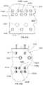
- FIGS. 1A-1Billustrate example embodiments of cables having single twisted pairs of conductors.
- FIGS. 2A and 2Bprovide a perspective view of an example embodiment of an unassembled and an assembled free connector, respectively.
- FIG. 3illustrates an example of LC connectors configured for use with optical fibers.
- FIGS. 4A-4Cprovide a forward perspective view of an unassembled fixed connector, a rearward perspective view of the unassembled fixed connector, and a perspective view of an assembled fixed connector, respectively.
- FIG. 5is a perspective view of an assembled fixed connector with a bulkhead mounting feature.
- FIG. 6is a perspective view of an assembled free connector and an assembled fixed connector.
- FIG. 7is a perspective view of an adapter and a pair of cables that have each been connectorized with a free connector.
- FIGS. 8A-8Cillustrate examples of patch cords that can be configured utilizing free connector and modified connectors.
- FIGS. 9A-9Eillustrate example configurations of socket contacts incorporating a socket spring configuration.
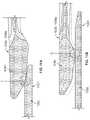
- FIGS. 10A-10Bare a side view and a perspective view, respectively, illustrating mating contacts including a pin contact and tuning fork receptacle contact.
- FIGS. 11A-11Hillustrate various side views of the pin contact and tuning fork receptacle contact of FIGS. 10A-10B .
- FIG. 12is a side view of an exemplary fixed connector mated employing the pin contacts of FIGS. 10A-10B with an exemplary free connector employing the tuning fork receptacle contacts of FIGS. 10A-10B .
- FIG. 13is a cross-sectional taken along line A-A of FIG. 12 .
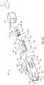
- FIG. 14is a perspective view of an example embodiment of a free connector.
- FIG. 15is a cross-sectional view taken along line C-C of FIG. 14 .
- FIG. 16is a perspective view of an example embodiment of an electrical contact.
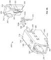
- FIG. 17is a forward perspective view of an example embodiment of a strain relief device.
- FIG. 18is a rear perspective view of the strain relief device of FIG. 17 .
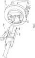
- FIG. 19is a perspective view of an example embodiment of a fixed connector; two alternative pin configurations are illustrated.
- FIG. 20is cross-sectional view taken along line B-B of FIG. 19 .
- FIG. 21is a perspective view of the fixed connector of FIG. 19 mated with the free connector of FIG. 14 .
- FIG. 22is a perspective view of the fixed connector of FIG. 19 unmated from the free connector of FIG. 14 .
- FIGS. 23A-23Cinclude an exploded perspective view of an embodiment of a free connector, an assembled perspective view of the free connector and a partially assembled perspective view of the free connector, respectively.
- FIGS. 24A-24Finclude a first side perspective view of a forward connector body for the free connector of FIGS. 23A-23C , a second side perspective view of the forward connector body, a front view of the forward connector body, a rear view of the forward connector body, a sectional view of the forward connector body and a rear perspective view of the forward connector body, respectively.
- FIGS. 25A-25Dinclude a perspective view of a metal frame of the free connector of FIGS. 23A-23C , a forward perspective view of the metal frame, a side view of the metal frame and a bottom perspective view of the metal frame, respectively.
- FIG. 26is a perspective view of a rear connector body of the free connector of FIGS. 23A-23C with electrical contacts.
- FIGS. 27A-27Dinclude a perspective view of the rear connector body FIG. 26 , a front view of the rear connector body, a rear view of the rear connector body and a bottom perspective view of the rear connector body, respectively.
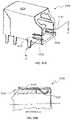
- FIGS. 28A-28Binclude a perspective view of an embodiment of a fixed connector and a front view of the fixed connector, respectively.
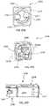
- FIGS. 29A-29Dinclude a perspective view of the housing body of the fixed connector of FIG. 28A , a front view of the housing body, a rear perspective view of the housing body, and a sectional view of the housing body taken along line D-D of FIG. 29C , respectively.
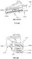
- FIGS. 30A-30Cinclude a forward side perspective view of a metal frame of the fixed connector of FIG. 28A , a front view of the metal frame and a rear side perspective view of the metal frame, respectively.
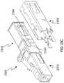
- FIGS. 31A-31Binclude a forward side perspective of an embodiment of a fixed connector and a sectional view of the fixed connector taken along line A-A of FIG. 31A .
- FIG. 32is a sectional view of an embodiment of free connector illustrating a tuning fork receptacle contact.
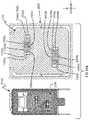
- FIGS. 33A-33Dprovide a side view of a fixed connector mounted to a circuit board, a front view of a plurality of fixed connectors mounted to the circuit board, a top view of the circuit board and a bottom view of the circuit board, respectively.
- FIGS. 34A-34Bprovide a forward and rearward perspective views, respectively, of a plurality of mated free and fixed connectors with the fixed connectors mounted to a circuit board and a forward face of the fixed connector being parallel to the circuit board.
- FIGS. 35A-35Billustrate a perspective view of the free connector contacts receiving the fixed connector in a partially inserted and a fully inserted position, respectively.
- FIGS. 36A-36Billustrate side-sectional views of a free connector and a fixed connector with the contacts of the fixed connector being received in the free connector in a partially inserted and fully inserted position, respectively.
- FIGS. 37A-37Billustrate front sectional views of a free connector and a fixed connector with contacts of the fixed connector being received in the free connector in a partially inserted and fully inserted position, respectively.
- a family of connectors to accommodate a single twisted pair of conductorsis disclosed herein.
- the family of connectorsincludes a free connector, a fixed connector, and an adapter; the free and/or fixed connectors can be modified to accommodate various patch cord and mounting configurations.
- the one or more of the family of connectorsadopts an LC fiber optic style connector configuration and an LC fiber optic footprint configuration.
- one or more of the family of connectorsadopts an LC fiber optic style connector configuration but in a footprint that is larger or smaller than the footprint of the LC fiber optic footprint. Other configurations may also be adopted.
- FIG. 1Aillustrates two example embodiments of cables containing one or more single twisted pairs of conductors.
- the first cable 10includes first and second conductors 12 , 14 that are twisted together to form a single twisted pair 16 .
- the conductors 12 , 14are enclosed by a protective jacket 18 .
- the second cable 20includes first through fourth conductors 22 , 24 , 26 , 28 .
- Conductors 22 and 24are twisted together to form a first single twisted pair 30
- conductors 26 and 28are twisted together to form a second single twisted pair 32 .
- the twisted pairs 30 and 32are separated by a separator 34 , and are encased in a protective jacket 36 .
- the cables 10 , 20include a number of twisted pairs greater than two.
- each single twisted pair of conductorse.g., 16 , 30 , 32
- Each single twisted pair of conductors, e.g., 16 , 30 , 32can be connectorized with the various embodiments or combination of embodiments of free connectors and fixed connectors as described herein.
- the connectorized twisted pairscan be coupled with an adapter as described herein.
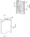
- FIG. 1Bis an example of a shielded cable 40 .
- the shielded cable 40includes an outer jacket 42 , a foil shield 44 , a drain wire 46 , and a single twisted pair 48 of conductors 50 and 52 ; each of the conductors 50 and 52 is provided with insulation 54 .
- the free connector 100is in the style of an LC connector that is used with optical fibers.
- the free connector 100can adopt the LC connector footprint, e.g. the shape and size of the LC connector.
- the free connector 100is of the LC style (e.g. similar in appearance, for example, a small form factor with a substantially square elongate connector body and a snap latch on the connector body) but in a larger or smaller footprint than the LC connector.
- the free connector 100varies in other dimensions and/or features from the LC connector style and/or footprint.
- a snap latch 210is used to maintain the coupling of a connector to an adapter.
- the LC family of connectors, adapters and active device receptaclesare generally known as small form factor connectors for use with optical fibers (1.25 mm ferrule) in high density applications, e.g., in-building communication systems.
- a front face 212 of a simplex LC connectoris generally square having outer dimensions of 4.42 mm by 4.52 mm.
- the IEC (International Electrotechnical Commission) standard for an LC connectorcan be identified as IEC 61754-20; the noted IEC standard is hereby incorporated by reference.
- the free connector 100generally includes a connector housing 102 , a connector insert 104 and a pair of socket contacts 106 a , 106 b.
- the connector housing 102 of the free connector 100includes an elongate body portion 110 having first and second side walls 112 , 114 connected by upper and lower walls 116 , 118 , respectively, to establish a square or substantially square forward face 120 .
- the connector housing 102further includes a rear portion 122 that extends rearward from the elongate body portion 110 .
- the rear portion 122has side walls 124 , 126 connected by upper and lower walls 128 , 130 , respectively, to establish a square or substantially square rear face 132 of the connector housing 102 .
- the outer dimensions of the rear portion 122are reduced from the outer dimensions of the elongate body portion 110 to accommodate a rear cover 131 or boot to enclose the rear face 132 of the connector housing 102 .
- the rear cover 131includes a strain-relief feature.
- a central channel 134 of a consistent or varying cross-sectionextends through the connector housing 102 from the forward face 120 to the rear face 132 .
- the exterior and/or interior cross-sections of the connector housing 102can assume a shape (e.g. round, oval, rectangular, triangular, hexagonal, etc.) that is different from a squared shape.
- the connector housing 102includes a snap latch 136 on the upper wall 116 of the elongate body portion 110 .
- the snap latch 136can be positioned proximate the forward face 120 of the connector housing 102 as illustrated or can be positioned further rearward along the upper wall 116 as appropriate to enable a releasable interface or coupling with a corresponding fixed connector or adapter, described below.
- at least one of the side walls 112 , 114includes a cantilevered latch 138 that interfaces with the connector insert 104 to retain the connector insert 104 within the central channel 134 when inserted therein.
- the connector housing 102includes a keying feature that is provided within the central channel 134 to ensure that the connector insert 104 is inserted into the connector housing 102 in a correct orientation.
- the keying featurecomprises a chamfer 140 that extends along a lengthwise portion, or the entire length, of a lower corner of the central channel 134 ; a complementary keying feature is provided on the connector insert 104 , described below.
- the connector housing 102includes a stop feature to help ensure proper forward positioning and/or prevent over-insertion of the connector insert 104 .
- the stop featureincludes a solid triangular portion 142 that interfaces with a stop feature of the connector insert 104 , described below.
- the connector housing 102may be of a unitary configuration and can be manufactured through an appropriate molding process, e.g. insert molding. Other keying and/or stop features may be used without departing from the spirit or scope of the disclosure.
- the connector insert 104includes a body portion 144 having first and second side walls 146 , 148 connected by upper and lower walls, 150 , 152 , respectively.
- a forward face 154 of the body portion 144includes two apertures 156 , 158 behind which extend first and second channels 160 , 162 , respectively.
- the first and second channels 160 , 162extend from the forward face 154 out through a rear face 164 .
- the body portion 144is configured to be received within the central channel 134 of the connector housing 102 such that the forward face 154 of the body portion 144 is proximate the forward face 120 of the connector housing. In certain examples, when inserted into the connector housing 102 , the entirety of the connector insert 104 is maintained within the elongate body portion 110 of the connector housing 102 .
- each of the first and second channels 160 , 162 of the connector insert 104includes one or more bosses 166 and a lip edge 168 proximate the rear face 164 .
- each boss 166operates to position the socket contacts 106 a , 106 b , so as to be axially aligned with the apertures 156 , 158 of the forward face 154 .
- the boss 166also operates to establish an interference fit between the socket contacts 106 a , 106 b and their respective first and channels 160 , 162 to help maintain the socket contacts 106 a , 106 b within the first and second channels.
- the lip edge 168also aids in positioning each socket contact 106 a , 106 b , so as to place each socket contact 106 a , 106 b forward most in their respective first and second channels 160 , 162 proximate the forward face 154 of the connector insert 104 , and to prevent the socket contacts 106 a , 106 b , from being pulled rearward out of their respective first and second channels 160 , 162 and out of the connector insert 104 itself.
- Other features and/or elementscan also, or alternatively, be used to retain the socket contacts 106 a , 106 b within the first and second channels 160 , 162 without departing from the spirit of the disclosure.
- the apertures 156 , 158 and respective first and second channels 160 , 162are stacked vertically or positioned side-by-side horizontally.
- the apertures 156 , 158 and respective first and second channels 160 , 162are provided in an offset configuration (see FIGS. 2A and 2B ) so as to present the inserted socket contacts 106 a , 106 b in a cross-talk neutralizing position relative to the other connectors (e.g. minimize or prevent cross-talk from adjacent connectors to the socket contacts 106 a , 106 b ).
- At least one of the side walls 146 , 148 of the connector insert 104includes a ramped tab 170 that protrudes outwardly therefrom.
- the ramped tab 170allows the connector insert 104 to pass the cantilevered latch 138 of the connector housing 102 for full insertion and subsequently engages the cantilevered latch 138 preventing rearward movement or removal of the connector insert 104 from the connector housing 102 .
- Other features and/or elementscan also, or alternatively, be used to retain the connector insert 104 within the connector housing 102 without departing from the spirit or scope of the disclosure.
- the connector insert 104includes a keying feature that is configured to interface with the keying feature of the connector housing 102 .
- the keying featurecomprises a chamfer 172 configured to interface with the chamfer 140 of the connector housing 102 .
- the chamfer 172can extend along a portion of the connector insert 104 or along a full length of the connector insert 104 .
- the keying featureensures proper orientation of the connector insert 104 within the connector housing 102 .
- the connector insert 104includes a stop feature.
- the stop featurecomprises a boss 174 recessed from the forward face 154 of the connector insert 104 and configured to interface with the stop feature of the connector housing 102 , e.g., the solid triangular portion 142 .
- the recession of the boss 174 from the forward face 154enables the forward face 154 of the connector insert 104 to be positioned flush with the stop feature, e.g., the solid triangular portion 142 , of the connector housing 102 thereby presenting the combined forward face 154 of the connector insert 104 and the stop feature of the connector housing 102 as a generally unified planar surface.
- the connector insert 104may be of a unitary configuration and can be manufactured through an appropriate molding process, e.g. insert molding. Other keying and/or stop features may be used without departing from the spirit or scope of the disclosure.
- Each of the socket contacts 106 a , 106 bincludes a tip contact 176 and a ring contact 178 .
- Each socket contact 106 a , 106 bcomprises a hollow cylinder having a rear end 180 and a forward end 182 .
- An internal diameter 184 of the rear end 180 of each socket contact 106 a , 106 bcan be sized to receive a respective one of the conductors 12 , 14 (or 22 , 24 , or 26 , 28 , see FIG. 1 ) of the twisted pair 16 (or 30 or 32 , see FIG. 1 ) extending from the cable 18 (or 36 , see FIG. 1 ).
- the internal diameter 184is such that an interference fit between conductor 12 , 14 and socket contact 106 a , 106 b is established to provide a good mechanical and electrical connection.
- the rear end 180 of the socket contacts 106 a , 106 bare crimped onto the conductors 12 , 14 .
- the conductors 12 , 14are soldered to the socket contacts 106 a , 106 b .
- the twist of the twisted pair 16can be maintained up to the point of the conductors 12 , 14 being coupled to the socket contacts 106 a , 106 b ; the ability to maintain the twist in the conductors 12 , 14 helps to minimize or prevent cross-talk from adjacent connectors to the socket contacts 106 a , 106 b improving operation of the connector 100 .
- the forward end 182 of each socket contact 106 a , 106 bis sized to receive the pin contacts or conductors of a mating connector, e.g. fixed connector 300 described below; and can include one or more longitudinal slits 186 .
- the free connectors 100can be configured in a simplex form or combined in a duplex form similar to that available with LC fiber optic connectors (see FIG. 1 ); forms including more than two free connectors 100 are also possible.
- FIGS. 4A-4C and FIG. 5illustrate example embodiments of fixed connectors 300 that are configured to interface with the free connectors 100 .
- the fixed connector 300is in the style of an LC connector that is used with optical fibers.
- the fixed connector 300can adopt the LC connector footprint, e.g. the shape and size of the LC connector (e.g. the LC adapter or LC active device receptacle).
- the fixed connector 300is of the LC style but in a larger or smaller footprint than LC connector.
- the fixed connector 300varies in other dimensions and/or features from the LC connector style and/or footprint.
- the fixed connector 300is a two-piece component comprising a body portion 302 and a rear panel 304 ; the rear panel 304 enables placement of pin conductors 306 a , 306 b within the body portion 302 .
- the body portion 302includes first and second side walls 308 , 310 connected by upper and lower walls 312 , 314 .
- the first and second side walls 308 , 310 , and the upper and lower walls 312 , 314frame an open forward portion 316 that presents a port 318 within the body portion 302 that is configured to receive the free connector 100 .
- a notch 320 proximate the upper wall 312is configured to interface with the snap latch 136 to removably retain the free connector 100 .
- a rear plate 322 of the body portion 302fills that gap between walls 308 , 310 , 312 , 314 save for a pin cavity 324 and pin channels 325 extending therefrom.
- the pin channels 325are configured to receive the pin conductors 306 a , 306 b while the pin cavity 324 is configured to house the portion of the pin conductors 306 a , 306 b not within the pin channels and to interface with the rear panel 304 .
- First and second notches 326 , 328extend through first and second side walls 308 , 310 , respectively, to the rear plate 322 and are configured to interface with the rear panel 304 .
- the lower wall 314 of the body portion 302includes first and second openings 330 , 332 through which the pin conductors 306 a , 306 b extend when the fixed connector 300 is assembled.
- One or more stabilizing pads 334 and/or mounting features 336can also be provided on the lower wall 314 enabling the mounting of the fixed connector 300 and the electrical coupling of the pin conductors 306 a 306 b to a circuit board or other circuit structure.
- FIG. 5further illustrates that the body portion 302 of the fixed connector can include one or more flanges, e.g. first flange 338 and second flange 340 proximate the open forward portion 316 .
- the flanges 338 , 340are for bulkhead mounting.
- the rear panel 304includes a forward face 342 and a planar rear face 344 .
- the forward face 342is provided with a pair of forward extending tabs 346 , 348 that are configured to interface with the first and second notches 326 , 328 to fixedly, or removably, secure the rear panel 304 to the body portion 302 through an interference fit.
- a latching mechanismcan be used additionally or alternatively to the interference fit to secure the rear panel 304 .
- the forward face 342is further provided with a forward extending upper stabilizer 350 curving toward a central location 352 and a forward extending lower stabilizer 354 curving toward the same central location 352 .
- a pin stabilizer 356is provided to either side of the upper stabilizer 350 .
- the pin conductors 306 a , 306 beach include a first end 358 and a second end 360 .
- Each pin conductor 306 a , 306 bis bent to approximate a right angle between the first and second ends 358 , 360 so that the first end 358 extends through the rear plate 322 and into the port 318 .
- the first ends 358are to be received in the forward end 182 of the socket contacts 106 a , 106 b to make an electrical connection therewith when the free connector 100 is inserted into the port 318 .
- the second end 360 of each of the pin conductors 306 a , 306 bextends through the lower wall 314 .
- the first ends 358 of the pin conductors 306 a , 306 bare arranged to be offset from one another consistent with the offset of the socket contacts 106 a , 106 b while that second ends 360 of the pin conductors 306 a , 306 b are crossed proximate the right angle bend; the offset and crossing of the pin conductors 306 a , 306 b helps to minimize, or prevent, cross-talk between the pin conductors 306 a , 306 b and the pin conductors of vertically or horizontally proximate like connectors.
- the pin conductors 306 a , 306 bcan be stacked horizontally or vertically to correspond to a placement of the socket contacts 106 a , 106 b .
- the pin conductors 306 a , 306 bare of equivalent lengths while in other embodiments the pin conductors 306 a , 306 b are of differing lengths.
- the first ends 358 of each of the pin conductors 306 a , 306 bare inserted into pin cavity 324 , and corresponding pin channels 325 , in their offset positions; a divider 362 , which comprises a portion of the rear plate 322 , separates the second ends 360 of the pin conductors 306 a , 306 b within the pin cavity 324 .
- the rear panel 304is then secured to the body portion 302 of the fixed connector 300 .
- the second ends 360 of the pin conductors 306 a , 306 bpass through the central location 352 at the rear panel 304 where the upper and lower stabilizers 350 , 354 help maintain/fix the position of the pin conductors 306 a , 306 b relative to the body portion 302 ; the upper and lower stabilizers 350 , 354 are received within the pin cavity 324 .
- an interference fitoccurs between the upper and lower stabilizers 350 , 354 and the pin cavity 324 to assist in securing the rear panel 304 to the body portion 302 of the fixed connector 300 .
- the pin stabilizers 356press against each of the pin conductors 306 a , 306 b to ensure that they are fully, forwardly positioned within the pin channels of the fixed connector 300 as well as to maintain/fix their position.
- the fixed connectors 300can be configured in a simplex form or combined in a duplex form similar to that available with LC fiber optic connectors (see FIG. 1 ); forms including more than two fixed connectors 300 are also possible.
- one or both of the connectors 100 , 300can be provided with a blocking/keying feature, to prevent the insertion of the free connector 100 into an actual LC fiber optic adapter or LC fiber optic active device receptacle and/or to prevent an actual LC fiber optic connector from being inserted into the fixed connector 300 .
- the free connector 100is provided with a blocking/keying feature in the form of rectangular protuberance 602 extending outward from the connector housing 102 ; the protuberance 602 will prevent insertion of the of the free connector 100 into LC fiber optic adapter or LC fiber optic active device receptacle.
- the free connector 100includes a chamfer 604 along a portion of a corner of the connector housing 102 that is accommodated by a blocking/keying feature in the form of a triangular panel 606 in a corner of the port 318 .
- the triangular panel 606 of the fixed connector 300allows the free connector 100 to enter the port 318 ; however, the squared housing configuration of an LC fiber optic connector will be blocked from entering the port 318 of the fixed connector 300 .
- FIG. 7illustrates a single twisted pair adapter 700 .
- the adapter 700is configured to enable an in-line connection between a first free connector 100 a and a second free connector 100 b .
- simplex and/or duplex adapters 700can be used in wall plate application (similar to standard electrical wall outlet) or a plurality of adapters 700 can be used in a bulkhead configuration for high density applications.
- the adapter 700generally comprises a pair of fixed connectors 300 that are modified to be electrically and mechanically coupled to one another rather than being individually coupled to a circuit board.
- the adapter 700comprises a two-piece component having a continuous body portion 702 that defines two ports 704 and an upper (or lower) panel 706 that is configured for coupling to the body portion 702 .
- the body portion 702defines an upper (or lower) channel 705 into which can be placed a single twisted pair of conductors 708 , 710 where each has a pin contact first end 712 and a pin contact second end 714 that can be inserted into corresponding pin channels 716 formed in the body portion 702 .
- the upper panel 706can be configured with various outward extending stabilizing features to help position and/or maintain the position of the pin contacts 712 , 714 in an offset orientation corresponding to the socket contacts 106 a , 106 b of the free connector 100 that will be received in each of the ports 704 .
- the upper panel 706can include outward extending tabs 718 or other type of mechanism for coupling the upper panel 706 to the body portion 702 .
- FIGS. 8A-8Cillustrate various patch cord configurations that can be manufactured using the free connector 100 and a modified fixed connector 300 .
- the fixed connector 300is configured for coupling with a cable having a single twisted pair of conductors rather than being configured for coupling to a circuit board.
- a patch cord 800includes a first end 802 with a first free connector 804 and a second end 806 with a second free connector 808 , see FIG. 8A .
- FIG. 8Billustrates a patch cord 810 having a first end 812 with a first free connector 814 and a second end 816 with a first fixed connector 818 .
- FIG. 8Cillustrates a patch cord 820 having a first end 822 with a first fixed connector 824 and a second end 826 with a second fixed connector 828 .
- FIGS. 9A-9Eillustrate various example embodiments of a socket contact 900 that can be used in the various configurations/embodiments described herein, for example, in place of socket 106 a , 106 b .
- a forward end 902 of the socket contact 900includes a socket spring configuration that has a leading entry angle, e.g. angle A, and a flat transition 904 such that when a pin 906 is fully mated with the socket contact 900 the final contact point X is in a different location as the insertion/withdrawal point of contact Y.
- a rearward portion, now shown, of the contact 900can include a ring contact (e.g., see ring 178 of socket contact 106 a in FIG. 2A ) or other appropriate contact configuration.
- the flat transition 904is replaced with a rounded transition 908 , see FIG. 9D .
- the socket contact 900is provided with a socket spring configuration wherein the forward end 902 is provided with a stepped surface 910 such that the final mated contact point X of the pin contact 906 is a in a different location as the insertion/withdrawal point Y of the pin contact 906 .
- FIGS. 10A-10Billustrate various example embodiments of pin contacts and mating tuning fork receptacle contacts that can be used in the various configurations/embodiments described herein.
- the pin contacts and tuning fork receptacle contactsare of the same or similar conductive material while in other embodiments the pin contacts and tuning fork receptacles are different conductive materials.
- tuning fork receptacle contact 1000can be used in place of sockets 106 a , 106 b while pin contact 1002 can be used in place of pin conductors 306 a , and 306 b . As shown in FIGS.
- the tuning fork receptacle contact 1000includes a rear portion 1004 connecting first and second spring arms 1006 a , 1006 b .
- Each of the spring arms 1006 a , 1006 bincludes a forward end 1010 having an entry portion 1012 that has a leading entry angle, e.g. angle B, and a tapering transition portion 1014 from the entry portion 1012 at a point C to a point D. Beyond point D, the forward end 1010 tapers to an open channel 1016 within a central portion 1018 of the tuning fork receptacle contact 1000 .
- tuning fork receptacle contacts 1000are used in the various connector embodiments described herein, wherein each of the tuning fork receptacle contacts 1000 can be electrically coupled to a conductor, e.g., conductors 10 , 12 , in any suitable manner.
- a conductore.g., conductors 10 , 12
- the pin contact 1002includes a forward portion 1020 and a rear portion 1022 that can be electrically coupled to a conductor, e.g. conductor 10 , in any suitable manner.
- the forward portion 1020includes a first tapered face 1024 and a second tapered face 1026 opposite the first tapered face 1024 .
- the forward portion 1020further includes first and second tapered sides 1028 , 1030 that connect the first tapered face 1024 and second tapered face 1026 to form a four-sided pyramid shape with a flattened apex 1027 ; the flattened apex 1027 having a rectangular or square cross-section; however other pin geometries, e.g., round, triangular, etc., are possible.
- first and second sides tapered sides 1028 , 1030have bases that are narrower or wider than the bases of the first and second tapered faces 1024 , 1026 thereby providing the rear portion 1022 of the pin contact 1002 with a rectangular cross-section while in other examples all sides and faces have equivalent bases providing the rear portion 1022 of the pin contact 1002 with a substantially square cross-section.
- a rectangular or square cross-sectionprovides the rear portion 1022 of the pin contact 1002 a broader surface to make contact with the tuning fork receptacle contact 1000 should either the pin contact 1002 or the tuning fork receptacle contact 1000 become bent or warped in some way that might alter their original alignment; note that in certain embodiments a width w 1 of the pin contact 1002 is wider than a width w 2 of each respective spring arm 1006 a , 1006 b .
- Two pin contacts 1002are used in the various connector embodiments describe herein.
- the position of the forward portion 1020 of the pin contact 1002is shown relative to the forward end 1010 of the spring arm 1006 a of the tuning fork receptacle contact 1000 .
- the tapered surfaces of the tuning fork receptacle connector 1000 and the pin contact 1002are designed such that the tuning fork receptacle contact 1000 is provided with two contact zones, e.g. a disengagement zone where the forward portion 1020 of the pin contact 1002 is in contact with point C of the tuning fork receptacle contact 1000 as illustrated in FIG.
- first and second spring arms 1006 a , 1006 bare illustrated as having aligned contact points C and D, in other embodiments the contact points C and D on the first spring arm 1006 a can be offset from the contact points C and D on the second spring arm 1006 b .
- the two contact zones, and particularly, the disengagement zonehelp to protect against an arcing “spark” that can occur when the plug, e.g., the pin contact 1002 , is inserted/removed from the receptacle, e.g.
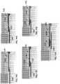
- FIG. 11Cprovides a side dimensioned view of the forward end 1010 of each of the spring arms 1006 a , 1006 b , with dimensions in mm and angles in degrees.
- the entry portions 1012 the spring arms 1006 a , 1006 bare present an opening separated by approximately 60° ⁇ 10° that narrows to an opening of approximately 10° ⁇ 8° whereby a distance between the spring arms, contact point C of the disengagement zone is approximately 0.43 mm ⁇ 0.08 mm to 0.43 mm ⁇ 0.13 mm.
- a distance between contact point C and contact point Dis approximately 1.0 mm ⁇ 0.6 mm to 1.0 mm ⁇ 2.0 mm.
- a contact point D of the fully engaged zone the spring arms 1006 a , 1006 bare separated by distance of approximately 0.25 mm ⁇ 0.03 mm.
- FIGS. 11D-11Hillustrate the deflections of spring arm 1006 a (with corresponding motions by spring arm 1006 a not shown) as pin contact 1002 in inserted into the tuning fork receptacle contact 1000 .
- FIG. 11Dillustrates the pin contact 1002 prior to contact with the tuning fork receptacle contact 1000 .
- FIG. 11Eillustrates the pin contact 1002 as it makes initial contact with the tuning fork receptacle contact 1000 at contact point C in the disengagement; notably the initial contact occurs on tapered face 1024 of the pin contact 1002 .
- FIG. 11Fillustrates the pin contact 1002 as it moves past initial contact point C with the spring arm 1006 a with the tapering transition portion 1014 of spring arm 1006 a moving along the tapered face 1024 of the pin contact 1002 .
- FIG. 11Gillustrates the pin contact 1002 reaching contact point D of the fully engaged zone wherein contact point D on the spring arm 1006 a rides on the planar upper surface 1025 of the pin contact 1002 .
- FIG. 11Hillustrates the pin contact 1002 fully inserted within the tuning fork receptacle contact 1000 with a single contact point maintained between the pin contact 1002 and the spring arm 1006 a at contact point D.
- a fixed connector 1200 employing two pin contacts 1002is mated with a free connector 1202 employing two tuning fork receptacle contacts 1000 wherein the pin contacts 1002 , one of which is illustrated in FIG. 13 , are fully engaged with the tuning fork receptacle contacts 1000 , one of which is illustrated in FIG. 13 .
- the pin contacts 1002 and/or tuning fork receptacle contacts 1000can also be used in an adapter configuration, patch cord configuration or any other connector configuration described herein.
- the free connector 1400includes a forward connector body 1402 , a metal frame 1404 , a pair of electrical contacts 1406 a , 1406 b , and a rear connector body 1408 .
- the free connector 1400additionally includes a strain relief device 1409 .
- the free connector 1400can be coupled to a single twisted pair of conductors, e.g. conductors 12 and 14 of the single twisted pair 16 of cable 10 .
- the forward connector body 1402includes an elongate forward portion 1410 and a rear receiving portion 1412 .
- the elongate forward portion 1410includes a first side face 1414 and a second side face 1416 as well as an upper face 1418 connecting the first side face 1414 and the second side face 1416 .
- a lower face 1420 connected to the first side face 1414is connected to the second side face 1416 via a chamfered face 1422 .
- a forward face 1422 of the forward connector body 1402includes a pair of openings 1424 a , 1424 b corresponding to contact receiving channels 1426 a , 1426 b ; the openings 1424 a , 1424 b receive pin contacts of the fixed connector 1500 (see FIG. 19 ).
- a recess 1428is provided on each side face 1414 , 1416 to interface with the metal frame 1404 ; however, other manners of interfacing with the metal frame 1404 can also be used.
- the forward connector body 1402also includes a cantilevered latch 1430 .
- the openings 1424 a , 1424 bhave a center-line to center-line horizontal spacing of 1.2 mm and a center-line to center-line vertical spacing of 2.7 mm, e.g. a vertical to horizontal ration of 2.25:1 or a horizontal to vertical ratio of 0.44 to 1.
- a vertical height of the elongate forward portion 1410is designed to be greater than the vertical height of a standard LC connector by an amount of greater than or equal to 1 mm; the change in vertical height preventing the free connector 1400 from being coupled with a standard LC fixed connector (jack/receptacle).
- a horizontal width of the elongate forward portion 1410is designed to be the same width of a standard LC connector enabling a density of a certain plurality of free connectors 1400 to be the same as the density of a same certain plurality of standard LC connectors such as in a panel setting where multiple connectors are provided in a single panel.
- a horizontal width of the free connector 1400is alternatively, or additionally, greater (e.g. ⁇ 1 mm) than the horizontal width of a standard LC connector to prevent the free connector 1400 from being coupled with a standard LC connector while the vertical height of the free connector 1400 is maintained as consistent with the vertical height of a standard LC connector.
- the chamfered face 1422also prevents the free connector 1400 from being inserted within a standard LC connector.
- the rear receiving portion 1412 of the forward connector body 1402is unitary (e.g., molded as single unit) with the elongate forward portion 1410 of the forward connector body 1402 .
- the rear receiving portion 1412defines a central cavity 1432 that provides rear access to the contact receiving channels 1426 a , 1426 b of the elongate forward portion 1410 .
- the central cavity 1432receives the rear connector body 1408 .
- the metal frame 1404 of the free connector 1400is a metal shell having a central cavity 1434 that is slideable over the rear receiving portion 1412 of the forward connector body 1402 .
- the metal frame 1404is held in place about the rear receiving portion 1412 through use of a pair of flex tabs 1436 that interface with the recesses 1428 of the elongate forward portion 1410 of the forward connector body 1402 .
- the metal frame 1404is not in contact with the pair of electrical contacts 1406 a , 1406 b .
- the metal frame 1404helps to prevent crosstalk between multiple free connectors 1400 that are in close proximity to one another, e.g. in a high density connector panel.
- the pair of electrical contacts 1406 a , 1406 bare illustrated in FIG. 14 with a single electrical contact illustrated in FIG. 16 .
- a forward portion of each of the electrical contacts 1406 a , 1406 bcomprises a tuning fork receptacle contact 1000 , which is illustrated and described in relation to FIGS. 10A-13 , while a rear portion of each of the electrical contacts 1406 a , 1406 b comprises an insulation displacement contact (IDC) 1440 .
- the IDC 1440includes a sharpened blade(s) that forces its way through insulation surrounding a conductor eliminating the need to strip the conductor while in other examples the conductor is stripped of insulation prior to placing the conductor in the IDC 1440 .
- Each of the electrical contacts 1406 a , 1406 bincludes a shoulder 1444 intermediate the tuning fork receptacle contact 1000 and the IDC 1440 .
- the shoulder 1444interfaces with a stop 1446 (see FIG. 15 ) within the elongate forward portion 1410 of the forward connector body 1402 .
- each of the electrical contacts 1406 a , 1406 bincludes one or more tangs 1442 to help retain each of the tuning fork receptacle contacts 1000 within their respective contact receiving channels 1426 a , 1426 b.
- the tuning fork receptacle contact 1000includes a rear portion 1004 connecting first and second spring arms 1006 a , 1006 b .
- Each of the spring arms 1006 a , 1006 bincludes a forward end 1010 having an entry portion 1012 that has a leading entry angle, e.g. angle B, and a tapering transition portion 1014 from the entry portion 1012 at a point C to a point D. Beyond point D, the forward end 1010 tapers to an open channel 1016 within a central portion 1018 of the tuning fork receptacle contact 1000 .
- the rear connector body 1408 of the free connector 1400serves to enclose the forward connector body 1402 .
- the rear connector body 1408seats against the forward connector body 1402 while, in other examples, the rear connector body 1408 seats against the metal frame 1404 .
- the rear perspective view of the rear connector body 1408illustrated in FIG. 18 , illustrates that first and second channel openings 1452 a , 1452 b are provided to receive first and second conductors 12 , 14 .
- the channel openings 1452 a , 1452 bare offset to accommodate the offset positioning of the contact receiving channels 1426 a , 1426 b and their respective electrical contacts 1406 a , 1406 b (e.g., a nominal center-line to center-line horizontal offset of 1.2 mm and a center-line to center-line vertical offset of 2.7 mm).
- the first and second channel openingsare countersunk to accommodate the flexing of conductors 10 , 12 when coupling/coupled to the electrical contacts 1406 a , 1406 b.
- the forward perspective view of the rear connector body 1408illustrated in FIG. 17 , illustrates that the rear connector body 1408 is essentially divided into a first half 1454 a , to accommodate the upper positioned electrical contact 1406 a and a second half 1454 b to accommodate the lower positioned electrical contact 1406 b .
- the first half 1454 a of the rear connector body 1408includes an upward channel 1456 that is contoured to direct the end of a conductor upward (e.g., a 90 deg. bend) to extend through a contact-receiving slot 1458 and beyond an upper recess 1460 .
- the IDC contact 1440 of the electrical contact 1406 acan then be inserted into the contact-receiving slot 1458 to establish an electrical interface with the conductor.
- the second half 1454 b of the rear connector body 1408includes a downward channel 1462 that is contoured to direct the end of a conductor downward (e.g., a 90 deg. bend) to extend through a contact-receiving slot 1464 and beyond a lower recess 1466 .
- the IDC contact 1440 of the electrical contact 1406 bcan then be inserted into the contact-receiving slot 1464 to establish an electrical interface with the conductor.
- the strain relief device 1409shown in FIGS. 14, 17 and 18 , includes an upper portion 1470 and a lower portion (not shown), which is essentially identical to the upper portion 1470 and interfaces with the upper portion 1470 to completely surround the cable 10 when the conductors 12 , 14 are coupled to the electrical contacts 1406 a , 1406 b .
- the strain relief device 1409comprises a component distinct from all other components of the free connector 1400 .
- the strain relief device 1409is molded unitary with the rear connector body 1408 .
- the strain relief device 1409is of metal and is manufactured unitary with the metal frame 1404 .
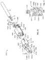
- FIGS. 19 and 20An example embodiment of a fixed connector 1500 , suitable to mate with the free connector 1400 (or other connectors described herein), is illustrated in FIGS. 19 and 20 .
- the fixed connector 1500generally includes a housing body 1502 , a metal frame 1504 , and a pair of pin contacts 1506 ;
- FIG. 19illustrates that the pin contacts 1506 can comprise straight pin contacts 1506 a , 1506 b , or, alternatively, can comprise bent pin contacts 1506 c , 1506 d , e.g. bent 90 degrees, to accommodate a board mounting of the fixed connector 1500 .
- the housing body 1502 of the fixed connectorincludes a forward central channel 1510 that receives the free connector 1400 .
- the forward central channel 1510includes a first side face 1514 and a second side face 1516 connected by an upper face 1518 .
- a lower face 1520 and chamfered face 1522serve to also connect the first side face 1514 and the second side face 1516 .
- the faces of the forward central channel 1510correspond to those of the elongate forward portion 1410 of the free connector 1400 .
- a notch 1524is provided within the housing body 1502 to interface with the cantilevered latch 1430 of the free connector 1400 . As shown in the FIG.
- the housing body 1502includes first and second openings 1526 , 1528 to channels into which the pin contacts 1506 are inserted; when fully inserted, the pin contacts 1506 extend into the forward central channel 1510 .
- the horizontal and vertical center-line-to-center-line spacing of the pin contacts and openings 1526 , 1528correspond to those found in the free connector 1400 , e.g. nominal 1.2 mm and 2.7 mm respectively.
- the pin contacts 1506are overmolded in the housing body 1502 .
- the pin contacts 1506are inserted after molding of the housing body 1502 ; a rear connector body (not shown) can be used to seal a rear face 1530 of the housing body 1502 if necessary.
- the metal frame 1504 of the fixed connector 1500is a metal shell having a central cavity 1534 that is slideable over the housing body 1502 .
- the metal frame 1504is held in place about the housing body 1502 through use of a pair clips 1536 that interface with side notches 1538 of the housing body 1502 . Note that the metal frame 1504 is not in contact with the electrical contacts 1506 .
- the metal frame 1504helps to prevent crosstalk between multiple fixed connectors 1500 that are in close proximity to one another, e.g. in a high density connector panel.
- each pin contact 1002includes a forward portion 1020 and a rear portion 1022 that can be electrically coupled to a conductor, e.g. conductor 10 , in any suitable manner.
- the forward portion 1020includes a first tapered face 1024 and a second tapered face 1026 opposite the first tapered face 1024 .
- the forward portion 1020further includes first and second tapered sides 1028 , 1030 that connect the first tapered face 1024 and second tapered face 1026 to form a four-sided pyramid shape with a flattened apex 1027 ; the flattened apex 1027 having a rectangular or square cross-section.
- first and second sides tapered sides 1028 , 1030have bases that are narrower or wider than the bases of the first and second tapered faces 1024 , 1026 thereby providing the rear portion 1022 of the pin contact 1002 with a rectangular cross-section while in other examples all sides and faces have equivalent bases providing the rear portion 1022 of the pin contact 1002 with a substantially square cross-section.
- a rectangular or square cross-sectionprovides the rear portion 1022 of the pin contact 1002 a broader surface to make contact with the tuning fork receptacle contact 1000 should either the pin contact 1002 or the tuning fork receptacle contact 1000 become bent or warped in some way that might alter their original alignment.
- the pin contact 1002is of a circular or oval cross-section.
- the pin contact 1002is provided with a bullet-nose forward portion 1020 rather than the pyramid-style forward portion 1020 that is illustrated.
- the position of the forward portion 1020 of the pin contact 1002is shown relative to the forward end 1010 of the spring arm 1006 a of the tuning fork receptacle contact 1000 .
- the tapered surfaces of the tuning fork receptacle connector 1000 and the pin contact 1002are designed such that the tuning fork receptacle contact 1000 is provided with two contact zones, e.g. a disengagement zone where the forward portion 1020 of the pin contact 1002 is in contact with point C of the tuning fork receptacle contact 1000 as illustrated in FIG.
- an introductory, or lead-in, angle of approximately 30 degreesis provided from the most forward portion of the tuning fork receptacle contact 1000 to point C while a transfer angle from point C to point D on the tuning fork receptacle contact 1000 is in the range of 10-15 degrees.
- the forward portion 1010 of the tuning fork receptacle contact 1000transitions from a first plane defined by the introductory angle and a second plane defined between points C and D.
- the pin contact 1002travels into the tuning fork receptacle contact 1000 the pin contact 1002 is in continuous contact with the tuning fork receptacle contact 1000 from the initial contact point C to the final contact point D causing the forward portion 1010 of the tuning fork receptacle contact 1000 to flex outward.
- contact points C and Dare radiused to provide a smooth and continuous transition.
- projectionse.g. bumps
- a single plane from the forward most portion of the tuning fork receptacle contact 1000 to contact point Dis provided, e.g. contact point C is eliminated.
- first and second spring arms 1006 a , 1006 bare illustrated as having aligned contact points C and D, in other embodiments the contact points C and D on the first spring arm 1006 a can be offset from the contact points C and D on the second spring arm 1006 b .
- the two contact zones, and particularly, the disengagement zonehelp to protect against an arcing “spark” that can occur when the plug, e.g., the pin contact 1002 , is inserted/removed from the receptacle, e.g. the tuning fork receptacle contact 1000 ; the disengagement zone enables an arc, should it occur prior to full insertion (or upon final withdrawal) of the pin contact 1002 such that the final contact point, e.g. point D, which is vital for transmission of data, is not damaged. Arcing, if not addressed within the contact design, can cause damage to the contact and prevent data transmission through the plug and receptacle.
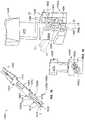
- FIGS. 21 and 22illustrate the free connector 1400 and the fixed connector 1500 in a mated configuration and an unmated configuration, respectively.
- Free connector 2300includes a forward connector body 2302 , a metal frame 2304 , a pair of electrical contacts 2306 a , 2306 b and a rear connector body 2308 .
- Free connector 2300can be coupled to a single twisted pair of conductors, e.g., conductors 12 and 14 of the single twisted pair 16 of cable 10 .
- the forward connector body 2302includes an elongate forward portion 2310 and a rear receiving portion 2312 that is separated by a shoulder 2311 .
- the elongate forward portion 2310includes a first side face 2314 and a second side face 2316 as well as an upper face 2418 connecting the first side face 2314 and the second side face 2316 .
- a lower face 2420additionally connects the first side face 2314 and the second side face 2316 .
- a forward face 2323 of the forward connector body 2302includes a pair of openings 2324 a , 2324 b corresponding to contact receiving channels 2326 a , 2326 b ; the openings 2324 a , 2324 b receive pin contacts that electrically interface with the tuning fork contacts 2306 a , 2306 b .
- a recess 2328is provided on each side face 2314 , 2316 of the elongate forward portion 2310 to interface with and retain the metal frame 2304 .
- Each recess 2328includes a recessed notch 2329 to receive an interfacing tab 2344 of the metal frame 2304 to further ensure that the metal frame 2304 remains secured to the forward connector body 2302 .
- the elongate forward portion 2310 of the forward connector body 2302also includes a cantilevered latch 2330 .
- the center of each opening 2324 a , 2324 bis offset from a vertical center line of the forward face 2323 by a distance A of 0.6 mm (center-to-center of 1.2 mm) and is offset from a horizontal center line of the forward face 2323 by a distance B of 1.35 mm (center-to-center of 2.7 mm).
- the elongate forward portion 2310 of the free connector 2300including the forward face 2323 , has a width W of ⁇ 4.5 mm and a height H of ⁇ 5.6 mm.
- a fiber optic LC connectorhas a square forward face with dimension s of 4.5 mm ⁇ 4.5 mm.
- the free connector 2300has a width similar to the LC connector but a slightly larger height, e.g., ⁇ 1 mm, to prevent the free connector 2300 from being inserted into an LC fixed connector (or LC adapter) yet provide a size similar to an LC connector enabling similar density of free connectors in virtually the same amount of space that can accommodate a corresponding density of LC connectors such as in connector panel setting.
- the rear receiving portion 2312 of the forward connector body 2302is unitary (e.g. molded as a single unit) with the elongate forward portion 2310 of the forward connector body 2302 .
- the rear receiving portion 2312defines a central cavity 2332 that provides rear access to the contact receiving channels 2326 a , 2326 b of the elongate forward portion 2310 ; the central cavity 2332 is provided with a chamfered keying feature 2329 to assist in the aligning the rear connector body 2308 .
- Each side face 2331 , 2333 of the rear receiving portion 2312includes a slot 2335 to interface with the rear connector body 2308 and an outward extending tab 2337 to interface with the metal frame 2304 .
- the metal frame 2304 of the free connector 2300comprises a metal shell body 2340 having a central cavity 2334 that is slideable over the rear receiving portion 2312 of the forward connector body 2302 .
- the metal frame 2304is held in place about the rear receiving portion 2312 through use of a pair of flex tabs 2342 that interface with corresponding recesses 2328 of the forward connector body 2302 .
- Each of the flex tabs 2342includes in inward facing tab 2344 to interface with recessed notch 2329 of the forward connector body 2302 .
- Each side face 2346 , 2348 of the metal frame 2304includes an opening 2350 to interface with outward extending tab 2337 of the forward connector body 2302 .
- Each point of interface between the metal frame 2304 and the forward connector body 2302assists in securing the metal frame 2304 to the forward connector body 2302 .
- Each side face 2346 , 2348 of the metal frame 2304is additionally equipped with an inward directed beam 2352 (e.g. shield beam) to establish an electrical interface with a cable shield (foil or drain wire) of the cable carrying the single pair of conductors (e.g., see FIG. 1B ).
- a bottom face 2354 of the metal frame 2304includes a cut-out 2356 to interface with a latch 2376 on the rear connector body 2308 .
- the metal frame 2304includes a shield beam for interfacing with a shield of a shielded cable
- the metal frame 2304can also be utilized in conjunction with a non-shielded cable.
- the metal frameprovides additional structural support to the connector 2300 .
- Electrical contacts 2306 a , 2306 b(see FIG. 23A and correspond to electrical contacts 1406 a , 1406 b of FIGS. 14 and 16 ; note that the forward portion of each of the electrical contacts 1406 a , 1406 b comprises a tuning fork receptacle contact 1000 , which is illustrated and described in relation to FIGS. 10A-13 , while the rear portion of each of the electrical contacts 1406 a , 1406 b comprises an insulation displacement contact (IDC) 1440 .
- the IDC 1440includes a sharpened blade(s) that forces its way through insulation surrounding a conductor eliminating the need to strip the conductor while in other examples the conductor is stripped of insulation prior to placing the conductor in the IDC 1440 .
- Each of the electrical contacts 1406 a , 1406 bincludes a shoulder 1444 that interfaces with a stop 2358 (see FIG. 24D ) within the elongate forward portion 2310 of the forward connector body 2302 .
- each of the electrical contacts 1406 a , 1406 bincludes one or more tangs 1442 to help retain each of the tuning fork receptacle contacts 1000 within their respective contact receiving channels 2326 a , 2326 b of the forward connector body 2302 .
- the tuning fork receptacle contact 1000includes a rear portion 1004 connecting first and second spring arms 1006 a , 1006 b .
- Each of the spring arms 1006 a , 1006 bincludes a forward end 1010 having an entry portion 1012 that has a leading entry angle, e.g., angle B, and a tapering transition portion 1014 from the entry portion 1012 at a point C to a point D. Beyond point D, the forward end 1010 tapers to an open channel 1016 within a central portion 1018 of the tuning fork receptacle contact 1000 . Details regarding the specific angles and dimensions of the forward end 1010 of the spring arms 1006 a , 1006 b are provided in FIG. 11C .
- the rear connector body 2308 of the free connector 2300is illustrated.
- the rear connector body 2308includes a rear body portion 2360 having a first side face 2362 and a second side face 2364 connected by an upper face 2366 and a lower face 2368 .
- a rear face 2370 of the rear body portion 2360includes an opening 2371 that defines a central cavity 2372 into which is inserted a pair of conductors (e.g., conductors 12 , 14 ).
- Each of the first and second side face 2362 , 2364is provided with an elongate opening 2374 ; when the rear connector body 2308 is interfaced with the metal frame 2304 the inward directed beams 2352 of the metal frame 2304 will extend through the respective elongate openings 2374 into the central cavity 2372 of the rear connector body 2308 to establish an electrical interface with the foil (or drain wire) of the conductor within.
- a latch 2376 on the lower face 2368 of the rear body portion 2360is provided to interface with cut-out 2356 of the metal frame 2304 to secure the rear connector body 2308 to the metal frame 2304 .
- a lip edge 2377 of the rear body portion 2360seats against a rear face 2357 of the metal frame 2304 .
- the rear connector body 2308 of the free connector 2300includes a contact receiving portion 2380 that extends forward from the rear body portion 2360 .
- the contact receiving portion 2380is essentially divided into a first half 2382 a to accommodate the upper positioned electrical contact 2306 a and a second half 2382 b to accommodate the lower positioned electrical contact 2306 b .
- the first half 2382 a of the contact receiving portion 2380includes an upward channel 2384 that is contoured to direct the end of a conductor upward (e.g., a 90 deg. bend) to extend through a contact receiving slot 2386 and beyond an upper recess 2388 . (See FIG. 17 for example of conductors in position).
- the second half 2382 b of the contact receiving portion 2380includes a downward channel 2390 that is contoured to direct the end of a conductor downward (e.g., a 90 deg. bend) to extend through a contact receiving slot 2392 and beyond a lower recess 2394 (.
- the IDC contact 1440 of the electrical contact 2306 acan then be inserted into contact receiving slot 2386 to establish an electrical interface with the conductor extending there through while the IDC contact 1440 of the electrical contact 2306 b can be inserted into contact receiving slot 2392 to establish an electrical interface with the conductor extending there through.
- the IDC contact 1440applies a normal force to the respective conductor and cuts through both the insulation of the conductor and a portion of the conductor itself to create the electrical interface.
- the upward channel 2384is, in part, defined by an upper outward extending arm 2394 while the downward channel 2390 is, in part, defined by a lower outward extending arm 2396 .
- Each of upper outward extending arm 2394 and lower outward extending arm 2396interface with respective corresponding slots 2335 of the forward connector body 2302 (best seen in FIG. 23C ) when the free connector 2300 is assembled to assist in aligning and stabilizing the rear connector body 2308 relative to the forward connector body.
- the rear connector body 2308 of the free connectorhas channels, e.g. upward channel 2384 and downward channel 2390 that are sized to accommodate a specific gauge of a conductor.
- a plurality of rear connector bodies 2308each designed to accommodate a different conductor gauge, may be used interchangeably with the forward connector body 2302 , metal frame 2304 and contacts 2306 a , 2306 b .
- the different rear connector bodies 2308are color-coded or otherwise designated to indicate which conductor gauge is suitable to the respective rear connector body 2308 .
- the metal frame 2304 of the free connector 2300includes inner directed beams 2352 that comprise shield beams.
- Each of the shield beams 2352one on each side of the metal frame 2304 of the free connector 2300 , apply a normal force to the foil and/or drain wire of a conductor; in certain embodiments the drain wire may only be on one conductor side or may be on both conductor sides.
- the cable jacket surrounding the pair of conductors coupled to the electrical contacts 2306 a , 2306 b of the free connector 2300will be within the rear connector body 2308 of the free connector 2300 and the foil shield of the cable (and/or the drain wire) will be folded back on the outside surface of the cable jacket such that the conductive surface of the foil (and/or the drain wire) will be facing the shield beams 2352 .
- the shield beams 2352may additionally function as a locking feature to prevent the rear connector body 2308 from moving rearward.
- the metal frame 2304serves as only as a structural element of the free connector 2300 in that, in certain applications, shielding of the connector is not required.
- the free connector 2300is designed to interface with a fixed connector or adapter, similar to those described herein, that incorporate cooperating dimensions and keying features. Further, the free connector 2300 can be incorporated in a patch cord and can be incorporated into any suitable configuration requiring the functionality of the free connector 2300 .
- a fixed connector and/or adapter suitable for interfacing with the free connector 2300preferably includes pin contacts 1002 (see FIGS. 10A-13 ), which are configured to interface with the tuning fork receptacle contact 1000 of the electrical contacts 2306 a , 2306 b of the free connector 2300 .
- the fixed connector 2500generally includes a housing body 2502 , a metal frame 2504 and a pair of pin contacts 2506 a , 2506 b (straight or bent for board mounting). A forward end 2503 and a rearward end 2505 further define the fixed connector 2500 .
- the housing body 2502 of the fixed connector 2500includes a forward face 2509 and a forward central channel 2510 that receives the free connector 2300 .
- the forward central channelincludes a first side face 2514 and a second side face 2516 connected by an upper face 2518 and a lower face 2520 .
- the extended height of the free connector 2300prevents it from being inserted into a fixed LC fiber optic connector.
- a chamfer 604 and a panel 606 as described abovecan be used as a key to prevent a free LC fiber optic connector from being inserted into a fixed connector 2500 .
- a notch 2523is provided within the housing body 2502 to interface with the cantilevered latch 2330 of the free connector 2300 .
- first side face 2514 and second side face 2516serve as an interface element for the metal frame 2504 ; the use of a recessed interface element in one or more of the faces enables the ability to maintain desired dimensions of the channel 2510 so as not to interfere with insertion of the free connector 2300 .
- a mounting pin 2527extends from the housing body 2502 and through the metal frame 2602 for circuit board mounting of the connector 2500 .
- the housing body 2502 of the fixed connector 2500includes first and second openings 2526 and 2528 to channels (e.g., channel 2526 a in FIG. 29D ) into which the pin contacts 2506 a , 2506 b are inserted; when fully inserted, the pin contacts 2506 a , 2506 b extend into the forward central channel 2510 .
- the horizontal and vertical center-line to center-line spacing of the first and second openings 2526 , 2528correspond to the spacing of the free connector 2300 (see FIG. 24C ).
- the metal frame 2504 of the fixed connector 2500is a metal shell having a forward face 2533 and a central cavity 2534 that is slideable over the housing body 2502 .
- the metal frame 2504includes a first side face 2508 and a second side face 2510 connected by an upper face 2512 and a lower face 2514 .
- the metal frame 2504is held in place about the housing body 2502 through use of a pair of clips 2536 that interface with the side recesses 2525 .
- the metal flex tabs 2342 of the metal frame 2304respectively interface with the metal clips 2536 of the fixed connector 2500 .
- a back face 2538 of the metal frameis enclosed with a back panel 2540 while in other embodiments that back face 2538 is left open.
- the metal frame 2504is provide with one or more shield pins 2542 that are insertable into vias in an application where the fixed connector 2500 is board mounted. The metal frame 2504 is not in contact with the electrical contacts 2506 a , 2506 b . The metal frame 2504 helps to prevent alien crosstalk between multiple fixed connectors 2500 that are in close proximity to one another, e.g., in a high density connector panel.
- each pin contact 1002includes a forward portion 1020 and a rear portion 1022 that can be electrically coupled to a conductor, e.g. conductor 10 , in any suitable manner.
- the forward portion 1020includes a first tapered face 1024 and a second tapered face 1026 opposite the first tapered face 1024 .
- the forward portion 1020further includes first and second tapered sides 1028 , 1030 that connect the first tapered face 1024 and second tapered face 1026 to form a four-sided pyramid shape with a flattened apex 1027 ; the flattened apex 1027 having a rectangular or square cross-section.
- the first and second sides tapered sides 1028 , 1030have bases that are narrower or wider than the bases of the first and second tapered faces 1024 , 1026 thereby providing the rear portion 1022 of the pin contact 1002 with a rectangular cross-section while in other examples all sides and faces have equivalent bases providing the rear portion 1022 of the pin contact 1002 with a substantially square cross-section.
- a rectangular or square cross-sectionprovides the rear portion 1022 of the pin contact 1002 a broader surface to make contact with the tuning fork receptacle contact 1000 should either the pin contact 1002 or the tuning fork receptacle contact 1000 become bent or warped in some way that might alter their original alignment.
- the pin contact 1002is of a circular or oval cross-section.
- the pin contact 1002is provided with a bullet-nose forward portion 1020 rather than the pyramid-style forward portion 1020 that is illustrated
- FIGS. 31A-31Billustrate another embodiment of a fixed connector 3100 .
- the fixed connector 3100includes a housing body 3102 , a metal frame 3104 and a pair of pin contacts (not shown).
- the side recesses 2525 of the fixed connector 2500comprise open slots 3126 in the fixed connector 3100 .
- the metal clips 2536 of the metal frame 2504instead comprise tension beams 3137 that flex outward to accommodate insertion of the free connector 2300 then return inward, through open slots 3126 , to contact the metal flex tabs 2342 of the metal frame 2304 of the free connector 2300 .
- tuning fork receptacle contact 2306 ahas a width w that is transverse (approximately perpendicular) to an elongate axis of the free connector 2300 , e.g. elongate axis A indicated by the dashed line.
- Tuning fork receptacle contact 2306 bsimilarly has a corresponding width w (not shown) that is transverse (approximately perpendicular) to another elongate axis of the free connector 2300 , e.g. elongate axis B indicated by the dashed line. Also illustrated in the sectional view of free connector 2300 is the pin contact opening 2324 a and the contact receiving channel 2326 a .
- the contact receiving channel 2326 aallows for width-wise expansion of the spring arms 1006 a , 1006 b to receive one of pin contacts 2506 a yet also provides side channels walls 3202 a , 3202 b that serve to contain and limit the maximum expansion of the spring arms 1006 a , 1006 b .
- the tuning fork receptacle contacts 2306 a , 2306 bare rotated by 90 deg. from that show in FIG. 32 , such that the width w of the tuning fork receptacle contacts 2306 a , 2306 b are perpendicular to the illustrated width (contact receiving channels 2326 a , 2326 b are modified to accommodate the rotated position).
- the tuning fork receptacle contacts 2306 a , 2306 bare rotated from the illustrated position to an angle less than 90 deg. such that the tuning fork receptacle contacts 2306 a , 2306 b provide a slanted presentation.
- FIGS. 33A-33Dillustrate the fixed connector 2500 in a board-mounted configuration with forward face 2503 and rearward face 2505 substantially perpendicular to a plane defined by the circuit board 3300 ; the forward face 2503 of the fixed connector 2500 extends beyond a forward face 3302 of the circuit board 3300 .
- Mounting pin 2527extends into the circuit board 3300 as do shielding pins 2542 .
- the fixed connector 2500includes three shielding pins 2542 along each elongate side for a total of six shielding pins 2542 per fixed connector 2500 . However, a greater or fewer number of shielding pins 2542 can be used as appropriate to the application.
- FIG. 33Billustrates two fixed connectors 2500 a and 2500 b in a side-by-side configuration such that shielding pins 2542 a and 2542 b share a common via.
- FIG. 33Cillustrates a top surface 3304 of the circuit board 3300 while FIG. 33D illustrates a bottom surface 3306 of the circuit board 3300 .
- the circuit board 3300includes a first forward via 3310 aligned with two rearward vias 3312 a , 3312 b to accommodate the three shielding pins 2542 along a first side 3316 of the fixed connector 2500 .
- a second forward via 3318(aligned in a first direction with forward via 3310 ) is aligned in a second direction with two rearward vias 3320 a , 3320 b (vias 3320 a , 3320 b are aligned in the first direction with vias 3312 a and 3312 b ).
- aligned with vias 3312 a and 3320 a in the first directionis a pin via 3322 a to receive pin contact 2506 a
- aligned with vias 3312 b and 3320 b in the first directionis a pin via 3322 b to receive pin contact 2506 b
- alignment of “a” vias and “b” vias, along with the alignment of their respective shielding pins 2542 and pin contacts 2506 a , 2506 bwork to cancel the magnetic flux generated by the current flowing though pin contacts 2506 a and 2506 b of the fixed connector 2500 when coupled with the free connector 2300 .
- each of the viascomprise a plated thru-hole.
- a non-plated thru hole 3324is additionally provided in the circuit board 3300 to receive mounting pin 2527 of the fixed connector 2500 .
- vias 3318 , 3320 a , 3320 bserve as vias for fixed connector 2500 b.
- Each of pin contacts 2506 a , 2506 bare designed to be of the same length and have a return loss that is maximized by being matched to the return loss of the conductors (e.g. conductors 12 , 14 ); in certain embodiments, this return loss is approximately 50 ohms. In certain preferred embodiments, there is a 6.6 mm pitch between side-by-side fixed connectors 2500 .
- FIGS. 34A-34Bprovide perspective views of a plurality of free connectors 2300 mated with fixed connectors 2500 in a plurality of rows and columns.
- the rows and columns of fixed connectorspresent their forward face 2503 in an orientation that is parallel, rather than perpendicular, to the circuit board 3300 .
- the rearward face 2505 of the fixed connectoris coupled to the circuit board through shielding pins 2542 and corresponding aligned plated vias 3402 a , 3404 a , 3406 a (aligned in the y-direction).
- Plated vias 3402 b , 3404 b , 3404 care also aligned in the y-direction and are shared with a neighboring fixed connector 2500 .
- Plated pin via 3410 areceives one of the pin contacts 2506 a and is aligned in the x-direction with vias 3404 a and 3404 b .
- Plated pin via 3410 breceives the other of the pin contacts 2506 b and is aligned in the x-direction with vias 3406 a and 3406 b .
- the shielding pins 2542 of the fixed connector 2500help to prevent alien crosstalk between adjacent mated connector pairs.
- FIGS. 35A-35B, 36A-36 b and 37 A- 37 Bhelp to illustrate the movement of the spring arms 1006 a , 1006 b of each of tuning fork receptacle contacts 2306 a , 2306 b as pin contacts 2506 a , 2506 b are inserted/withdrawn (i.e., the free connector 2300 is mated with the fixed connector 2500 ).
- Each “A” figureillustrates the pin contacts 2506 a , 2506 b , as they are partially inserted and each “B” figure illustrates the pin contacts 2506 a , 2506 b as being fully inserted within tuning fork receptacle contacts 2306 a , 2306 b .
- FIGS. 35A-35B, 36A-36 b and 37 A- 37 Bhelp to illustrate the movement of the spring arms 1006 a , 1006 b of each of tuning fork receptacle contacts 2306 a , 2306 b as pin contacts 2506 a ,
- FIGS. 35A-35Billustrate the tuning fork receptacle contacts 2306 a , 2306 b and pin contacts 2506 a , 2506 b with the structure of the free connector 2300 and fixed connector 2500 removed.
- FIGS. 36A-36 bprovide a top cross-sectional view of the free connector 2300 and fixed connector 2500 illustrating how the side walls 3202 a , 3202 b contain the spring arms 1006 a , 1006 b of the tuning fork receptacle contact 2306 a and force the spring arms 1006 a , 1006 b to maintain contact with pin contact 2506 a (see FIG. 36 b ).
- 37A-37Bprovide a forward cross-sectional view of the free connector 2300 and fixed connector 2500 .
- contact receiving channels 2326 a , 2326 bhave cross-shaped cross-section such that a central portion 3502 a , 3502 b of the cross-shape has a height in the y-direction that is greater than a height in the y-direction of an elongate portion 3504 a , 3504 b of the cross-shape.
- the greater height of the central portion 3502 a , 3502 baccommodates a height in the y-direction of the pin contact 2506 a , 2506 b which extends beyond (above and below) a height in the y-direction of the spring arms 1006 a , 1006 b of each of the tuning fork receptacle contacts 2306 a , 2306 b.
- free connector 2300is described as using a tuning fork receptacle contact 2306
- various other types of electrical contactsmay also be used to interface with the pin contacts 2506 of the fixed connector 2500 .
- a socket contact, a beam contact, an arched beam contact, a single spring arm contact, etc.might be used.
- spatially relative termssuch as “under”, “below”, “lower”, “over”, “upper”, “top”, “bottom” and the like, may be used herein for ease of description to describe one element or feature's relationship to another element(s) or feature(s) as illustrated in the figures. It will be understood that the spatially relative terms are intended to encompass different orientations of the device in use or operation in addition to the orientation depicted in the figures. For example, if the device in the figures is turned over, elements described as “under” or “beneath” other elements or features would then be oriented “over” the other elements or features. Thus, the exemplary term “under” can encompass both an orientation of over and under. The device may be otherwise oriented (rotated 90 degrees or at other orientations) and the spatially relative descriptors used herein interpreted accordingly.
Landscapes
- Engineering & Computer Science (AREA)
- Manufacturing & Machinery (AREA)
- Details Of Connecting Devices For Male And Female Coupling (AREA)
Abstract
Description
Claims (20)
Priority Applications (1)
| Application Number | Priority Date | Filing Date | Title |
|---|---|---|---|
| US16/975,891US11362463B2 (en) | 2018-02-26 | 2019-02-26 | Connectors and contacts for a single twisted pair of conductors |
Applications Claiming Priority (5)
| Application Number | Priority Date | Filing Date | Title |
|---|---|---|---|
| US201862635227P | 2018-02-26 | 2018-02-26 | |
| US201862671738P | 2018-05-15 | 2018-05-15 | |
| US201862693583P | 2018-07-03 | 2018-07-03 | |
| US16/975,891US11362463B2 (en) | 2018-02-26 | 2019-02-26 | Connectors and contacts for a single twisted pair of conductors |
| PCT/US2019/019660WO2019165466A1 (en) | 2018-02-26 | 2019-02-26 | Connectors and contacts for a single twisted pair of conductors |
Related Parent Applications (1)
| Application Number | Title | Priority Date | Filing Date |
|---|---|---|---|
| PCT/US2019/019660A-371-Of-InternationalWO2019165466A1 (en) | 2018-02-26 | 2019-02-26 | Connectors and contacts for a single twisted pair of conductors |
Related Child Applications (1)
| Application Number | Title | Priority Date | Filing Date |
|---|---|---|---|
| US17/838,530ContinuationUS12266892B2 (en) | 2018-02-26 | 2022-06-13 | Connectors and contacts for a single twisted pair of conductors |
Publications (2)
| Publication Number | Publication Date |
|---|---|
| US20210104843A1 US20210104843A1 (en) | 2021-04-08 |
| US11362463B2true US11362463B2 (en) | 2022-06-14 |
Family
ID=67687881
Family Applications (3)
| Application Number | Title | Priority Date | Filing Date |
|---|---|---|---|
| US16/975,891ActiveUS11362463B2 (en) | 2018-02-26 | 2019-02-26 | Connectors and contacts for a single twisted pair of conductors |
| US17/838,530ActiveUS12266892B2 (en) | 2018-02-26 | 2022-06-13 | Connectors and contacts for a single twisted pair of conductors |
| US19/094,541PendingUS20250309588A1 (en) | 2018-02-26 | 2025-03-28 | Connectors and contacts for a single twisted pair of conductors |
Family Applications After (2)
| Application Number | Title | Priority Date | Filing Date |
|---|---|---|---|
| US17/838,530ActiveUS12266892B2 (en) | 2018-02-26 | 2022-06-13 | Connectors and contacts for a single twisted pair of conductors |
| US19/094,541PendingUS20250309588A1 (en) | 2018-02-26 | 2025-03-28 | Connectors and contacts for a single twisted pair of conductors |
Country Status (7)
| Country | Link |
|---|---|
| US (3) | US11362463B2 (en) |
| EP (1) | EP3759765A4 (en) |
| CN (2) | CN115313074A (en) |
| AU (2) | AU2019223204B2 (en) |
| BR (1) | BR112020017356A2 (en) |
| MX (1) | MX2020008839A (en) |
| WO (1) | WO2019165466A1 (en) |
Cited By (7)
| Publication number | Priority date | Publication date | Assignee | Title |
|---|---|---|---|---|
| US20220360033A1 (en)* | 2019-09-30 | 2022-11-10 | Commscope Technologies Llc | Couplers for single pair connectors |
| US11652319B2 (en) | 2016-03-04 | 2023-05-16 | Commscope Technologies Llc | Two-wire plug and receptacle |
| US11652322B2 (en) | 2017-04-24 | 2023-05-16 | Commscope Technologies Llc | Connectors for a single twisted pair of conductors |
| US11894637B2 (en) | 2019-03-15 | 2024-02-06 | Commscope Technologies Llc | Connectors and contacts for a single twisted pair of conductors |
| US12199372B2 (en) | 2021-02-26 | 2025-01-14 | Commscope Technologies Llc | Couplers for single pair connectors |
| US12266892B2 (en) | 2018-02-26 | 2025-04-01 | Commscope Technologies Llc | Connectors and contacts for a single twisted pair of conductors |
| US12327948B2 (en) | 2019-09-30 | 2025-06-10 | Commscope Technologies Llc | High density coupling panel |
Families Citing this family (17)
| Publication number | Priority date | Publication date | Assignee | Title |
|---|---|---|---|---|
| US9407043B2 (en) | 2012-07-16 | 2016-08-02 | Commscope, Inc. Of North Carolina | Balanced pin and socket connectors |
| WO2023028369A1 (en)* | 2021-08-27 | 2023-03-02 | Commscope Technologies Llc | Single-pair ethernet connector jack |
| WO2018227057A1 (en) | 2017-06-08 | 2018-12-13 | Commscope Technologies Llc | Connectors for a single twisted pair of conductors |
| CN109256637B (en)* | 2017-07-13 | 2024-07-05 | 泰科电子(上海)有限公司 | Socket connector and method for plugging and unplugging plug connector |
| WO2019147774A1 (en)* | 2018-01-26 | 2019-08-01 | Commscope Technologies Llc | Connectors for a single twisted pair of conductors |
| US11552432B2 (en)* | 2019-08-12 | 2023-01-10 | High Speed Interconnects, Llc | Methods and apparatus for RF shield and cable attachment system |
| US20230238757A1 (en)* | 2020-06-12 | 2023-07-27 | Commscope Technologies Llc | Single-pair ethernet multi-way couplers |
| US11527839B2 (en) | 2020-07-07 | 2022-12-13 | Panduit Corp. | T-splice connector |
| WO2022066912A1 (en)* | 2020-09-24 | 2022-03-31 | Avx Corporation | Solderless wire-to-board single pair ethernet connection system |
| US20240079814A1 (en)* | 2021-01-21 | 2024-03-07 | Commscope Technologies Llc | Connector for a single twisted pair of conductors |
| IT202100002711A1 (en)* | 2021-02-08 | 2022-08-08 | Te Connectivity Solutions Gmbh | PROTECTIVE FOAM CASING FOR REFRIGERATOR CONNECTORS |
| WO2022225755A1 (en)* | 2021-04-21 | 2022-10-27 | Corning Research & Development Corporation | Connector for alignment of integrated waveguides and optical fibers |
| WO2022272306A1 (en)* | 2021-06-25 | 2022-12-29 | Commscope Technologies Llc | Security connector for a single twisted pair of conductors |
| CN115810958A (en)* | 2021-09-16 | 2023-03-17 | 中兴通讯股份有限公司 | Connector device and active antenna unit |
| TWI775717B (en)* | 2022-04-12 | 2022-08-21 | 曼堤司高位股份有限公司 | Connector guide device |
| US20240154345A1 (en)* | 2022-11-03 | 2024-05-09 | Te Connectivity India Private Limited | Terminal insert, connector and set |
| DE102022004461B4 (en) | 2022-11-23 | 2024-07-18 | Telegärtner Karl Gärtner GmbH | Connector core and connectors |
Citations (153)
| Publication number | Priority date | Publication date | Assignee | Title |
|---|---|---|---|---|
| GB628419A (en) | 1946-12-31 | 1949-08-29 | Jessie Blake Coates | Electrical plug and socket connectors |
| US2673968A (en) | 1949-11-25 | 1954-03-30 | Leviton Mfg Company | Self-piercing electrical connector plug |
| US2813257A (en) | 1955-11-04 | 1957-11-12 | Burndy Corp | Socket connector |
| US3199060A (en) | 1962-09-11 | 1965-08-03 | Nottingham & Co Inc J B | Cable connector assembly |
| US3827007A (en) | 1973-03-26 | 1974-07-30 | Bendix Corp | Hermaphroditic electrical connector with front releasable and rear removable electrical contacts |
| US3828706A (en) | 1973-01-02 | 1974-08-13 | Ideal Ind | Method of making a terminal |
| FR2290136A7 (en) | 1974-10-28 | 1976-05-28 | Belling & Lee Ltd | Two pin electrical supply connector - has side wall mounting ribs and recess receiving pins |
| US4054350A (en) | 1976-12-03 | 1977-10-18 | Western Electric Company, Inc. | Modular plug for terminating cord having non-planar array of conductors |
| US4449767A (en)* | 1982-08-30 | 1984-05-22 | Amp Incorporated | Connector assembly having improved keying and latching system |
| US4458971A (en) | 1982-06-14 | 1984-07-10 | Amp Incorporated | Electrical tab receptacle and connector |
| US4565416A (en) | 1984-04-11 | 1986-01-21 | Amp Incorporated | Latching means and locking means for retaining terminals in a connector |
| US4702538A (en) | 1985-09-20 | 1987-10-27 | Amphenol Corporation | Shielded modular connector for use with shielded twisted pair cable |
| US4743208A (en)* | 1985-09-19 | 1988-05-10 | Amp Incorporated | Pin grid array electrical connector |
| US4744774A (en) | 1987-01-20 | 1988-05-17 | Amp Incorporated | Electrical connector having conductive sheath-clamping means |
| US4824394A (en) | 1986-04-10 | 1989-04-25 | Ohio Associated Enterprises, Inc. | IDC connectors with rotated conductor pairs and strain relief base molded onto cable |
| US4917625A (en) | 1988-07-25 | 1990-04-17 | Ernest Haile | Snap-on electrical connector for electrical cord having mating plugs |
| US4932906A (en) | 1988-12-16 | 1990-06-12 | Amp Incorporated | Electrical contact terminal |
| US5013255A (en) | 1988-10-26 | 1991-05-07 | Itt Composants Et Instruments | Card connector and production method |
| US5240436A (en) | 1992-03-19 | 1993-08-31 | Adc Telecommunications, Inc. | BNC-RJ conversion connector |
| US5368499A (en) | 1990-04-04 | 1994-11-29 | Wabco Westinghouse Fahrzeugbremsen Gmbh | Multi-lead electric plug connector |
| US5385476A (en) | 1992-06-16 | 1995-01-31 | Vehicle Enhanced Systems Inc. | Magnetic circuits for communicating data |
| US5496184A (en) | 1994-07-05 | 1996-03-05 | General Motors Corporation | Header assembly for printed circuit board |
| US5533915A (en) | 1993-09-23 | 1996-07-09 | Deans; William S. | Electrical connector assembly |
| US5580264A (en) | 1994-08-09 | 1996-12-03 | Sumitomo Wiring Systems, Ltd. | Waterproofed connector |
| US5748819A (en) | 1995-04-05 | 1998-05-05 | Siecor Corporation | Field installable optical fiber connector and an associated method of fabrication |
| US5749755A (en) | 1993-10-18 | 1998-05-12 | Framatome Connectors International S.A. | Female electric terminal |
| US5833496A (en) | 1996-02-22 | 1998-11-10 | Omega Engineering, Inc. | Connector with protection from electromagnetic emissions |
| US5897404A (en) | 1996-09-30 | 1999-04-27 | The Whitaker Corporation | Socket terminal |
| US5915989A (en) | 1997-05-19 | 1999-06-29 | Lucent Technologies Inc. | Connector with counter-balanced crosswalk compensation scheme |
| US5989057A (en)* | 1996-10-15 | 1999-11-23 | Krone Aktiengesellschaft | Connector module with cutting clamping element |
| US6019521A (en) | 1998-02-09 | 2000-02-01 | The Whitaker Corporation | Optical fiber connector |
| US6045389A (en) | 1998-06-30 | 2000-04-04 | The Whitaker Corporation | Contact and connector for terminating a pair of individually insulated wires |
| US6050845A (en)* | 1997-11-20 | 2000-04-18 | The Whitaker Corporation | Electrical connector for terminating insulated conductors |
| US6065994A (en) | 1996-06-21 | 2000-05-23 | Lucent Technologies Inc. | Low-crosstalk electrical connector grouping like conductors together |
| US6135804A (en)* | 1997-12-03 | 2000-10-24 | Weidmuller Interface Gmbh & Co. | Electrical connector assembly including insulation piercing plug-in means |
| US6217230B1 (en) | 1999-09-16 | 2001-04-17 | Yazaki Corporation | Receptacle, manufacturing method for the same, and optical connector having the receptacle |
| US6254440B1 (en) | 1998-12-07 | 2001-07-03 | Hon Hai Precision Ind. Co., Ltd. | Terminal having contact portion with reduced thickness |
| US6270372B1 (en)* | 1996-09-26 | 2001-08-07 | Panduit Corp. | Patch cord connector |
| US6280230B1 (en)* | 1999-03-01 | 2001-08-28 | Molex Incorporated | Electrical terminal |
| EP1128494A2 (en) | 2000-02-24 | 2001-08-29 | Reichle & De-Massari AG | Adapter and connector for communications- and control technique |
| US6305950B1 (en) | 2000-01-14 | 2001-10-23 | Panduit Corp. | Low crosstalk modular communication connector |
| US20020055294A1 (en) | 2000-11-08 | 2002-05-09 | Yazaki Corporation | Wire connecting connector |
| US6390687B1 (en) | 1999-12-27 | 2002-05-21 | Yazaki Corporation | Optical ring network, optical connector, and hybrid connector |
| US6402571B1 (en) | 1999-09-15 | 2002-06-11 | Framatome Connectors International | Electrical socket contact with guide rail |
| US20020072275A1 (en) | 1998-09-11 | 2002-06-13 | Junichi Arai | Connector socket, connector plug and connector assembly |
| US20020151224A1 (en) | 2001-04-13 | 2002-10-17 | Liao Sheng Hsin | Signal connector capable of reducing attenuation |
| US6488550B1 (en) | 1999-06-25 | 2002-12-03 | Nec Corporation | Connector contact and method of manufacturing the same |
| US6499889B1 (en) | 1999-12-08 | 2002-12-31 | Yazaki Corporation | Method of assembling optical connector, optical connector and hybrid connector |
| CN1408135A (en) | 1999-12-10 | 2003-04-02 | 克罗内有限公司 | Connecting cable comprising an electric plug-and-socket connection |
| US6568967B2 (en) | 2000-07-06 | 2003-05-27 | Yazaki Corporation | Protective cover |
| US6572276B1 (en) | 2000-11-21 | 2003-06-03 | Euromicron Werkezeuge Gmbh | Plug for fiber optic cables with a plug housing |
| DE10216915A1 (en) | 2002-04-15 | 2003-10-30 | Taller Automotive Gmbh | Electrical contact system for flexible foil, has flexible arm made of piece of sheet metal folded to produce spring jaws which may grip foil and has housing surrounding arms |
| US6641431B2 (en) | 2000-12-14 | 2003-11-04 | Autonetworks Technologies, Ltd. | Connector for flat cables |
| US6702617B1 (en) | 2002-08-22 | 2004-03-09 | International Business Machines Corporation | Electrical connector with geometrical continuity for transmitting very high frequency data signals |
| US6729901B2 (en) | 2000-09-29 | 2004-05-04 | Ortronics, Inc. | Wire guide sled hardware for communication plug |
| US20040152360A1 (en) | 2003-01-31 | 2004-08-05 | Harris Shaun L. | Power connector having integral easy-access blade fuse receptacle |
| JP2004319196A (en) | 2003-04-15 | 2004-11-11 | Auto Network Gijutsu Kenkyusho:Kk | Shield connection structure |
| US20040266255A1 (en) | 2003-06-25 | 2004-12-30 | Geroge Lee | Cable end connecotr assembly with improved contact |
| US20050227545A1 (en) | 2004-04-07 | 2005-10-13 | Radiall | Connector for a cable comprising a plurality of twisted conductors |
| US20050232566A1 (en) | 2003-12-23 | 2005-10-20 | Adc Telecommunications, Inc. | High density optical fiber distribution frame with modules |
| US7004797B2 (en) | 2002-11-05 | 2006-02-28 | Yazaki Corporation | Female terminal with rattle prevention feature |
| WO2006048867A1 (en) | 2004-11-08 | 2006-05-11 | Powerdsine, Ltd. | System for providing power over ethernet through a patch panel |
| US20060116021A1 (en) | 2002-07-23 | 2006-06-01 | Adc Gmbh | Plug-in connector for a connector-ended cable |
| US20060134966A1 (en) | 2004-11-10 | 2006-06-22 | Jurgen Lappohn | Insulation displacement multipoint connector for electrical plug connectors |
| EP1783871A1 (en) | 2005-11-02 | 2007-05-09 | Tyco Electronics Corporation | Orthogonal connector |
| US7217162B2 (en) | 2002-03-07 | 2007-05-15 | Yazaki Corporation | Tabular terminal-use female terminal |
| US7291046B2 (en) | 2005-08-22 | 2007-11-06 | Illinois Tool Works Inc. | Electrical contact assembly |
| US20070270043A1 (en) | 2006-05-17 | 2007-11-22 | Tyco Electronics Corporation | Electrical connector having staggered contacts |
| US7325976B2 (en) | 2000-07-17 | 2008-02-05 | Tyco Electronics Corporation | Connector and receptacle containing a physical security feature |
| US20080057793A1 (en) | 2005-02-17 | 2008-03-06 | Reichle & De-Massari Ag | Plug-and-socket connector for data transmission via electrical conductors |
| US7537393B2 (en) | 2005-06-08 | 2009-05-26 | Commscope, Inc. Of North Carolina | Connectorized fiber optic cabling and methods for forming the same |
| US20090176415A1 (en) | 2004-01-09 | 2009-07-09 | Abughazaleh Shadi A | Dielectric insert assembly for a communication connector to optimize crosstalk |
| US7559789B2 (en) | 2005-06-03 | 2009-07-14 | Commscope, Inc. Of North Carolina | Communications connectors with self-compensating insulation displacement contacts |
| US7618297B2 (en) | 2007-07-12 | 2009-11-17 | Hon Hai Precision Ind. Co., Ltd. | Electrical connector with anti-mismating mechanism for preventing incorrect insertion of a smaller sized mating connector |
| US20100003863A1 (en) | 2006-12-01 | 2010-01-07 | The Siemon Company | Modular Connector With Reduced Termination Variability |
| US20100022112A1 (en) | 2008-07-22 | 2010-01-28 | Tyco Electronics Corporation | Electrical connector organizer |
| US20100035454A1 (en) | 2008-08-08 | 2010-02-11 | Chad William Morgan | Electrical connector having reversed differential pairs |
| US20100040332A1 (en) | 2008-08-12 | 2010-02-18 | Radiall | Multi-contact connector element |
| US20100120284A1 (en) | 2008-11-10 | 2010-05-13 | Hitachi Cable, Ltd. | Connector |
| US20100151740A1 (en) | 2007-03-14 | 2010-06-17 | Adc Gmbh | Electrical connector |
| US20100173528A1 (en) | 2007-05-07 | 2010-07-08 | Ortronics, Inc. | Connector Assembly And Related Methods of Use |
| JP4514356B2 (en) | 2001-04-20 | 2010-07-28 | 株式会社オートネットワーク技術研究所 | Shield connector |
| US20100221951A1 (en) | 2009-02-27 | 2010-09-02 | Tyco Electronics Corporation | Shielded cassette for a cable interconnect system |
| KR20100122766A (en) | 2009-05-13 | 2010-11-23 | 한국단자공업 주식회사 | connector |
| US20100304600A1 (en)* | 2007-10-23 | 2010-12-02 | Adc Gmbh | Pcb connector |
| US7867033B2 (en) | 2006-12-11 | 2011-01-11 | Autonetworks Technologies, Ltd | Branch connector |
| US8052482B1 (en) | 2010-10-28 | 2011-11-08 | Jyh Eng Technology Co., Ltd. | Female electrical connector |
| US20110294342A1 (en) | 2010-05-25 | 2011-12-01 | Tyco Electronics Corporation | Electrical connector with signal and power connections |
| US20120004655A1 (en) | 2010-06-30 | 2012-01-05 | Harrison Jay Kim | Bipolar Connector System |
| US8109789B2 (en) | 2008-12-12 | 2012-02-07 | Tyco Electronics Corporation | Connector assembly with strain relief |
| US8113889B2 (en) | 2009-05-14 | 2012-02-14 | Hon Hai Precision Ind. Co., Ltd. | Cable connector assembly with a unitary connector molded with another connector |
| US8172468B2 (en) | 2010-05-06 | 2012-05-08 | Corning Incorporated | Radio frequency identification (RFID) in communication connections, including fiber optic components |
| US8303337B2 (en) | 2007-06-06 | 2012-11-06 | Veedims, Llc | Hybrid cable for conveying data and power |
| US20130075149A1 (en) | 2010-05-28 | 2013-03-28 | Apple Inc. | Conductive frame for an electrical connector |
| US20130171885A1 (en) | 2012-01-04 | 2013-07-04 | Hon Hai Precision Industry Co., Ltd. | Shielded electrical connector with ground pins embeded in contact wafers |
| US20130252469A1 (en)* | 2010-12-22 | 2013-09-26 | Yazaki Corporation | Connection structure and connection unit of eletronic component |
| US20130288516A1 (en) | 2012-04-30 | 2013-10-31 | International Business Machines Corporation | An electrical adapter for identifying the connection state to a network |
| US8684763B2 (en) | 2011-06-21 | 2014-04-01 | Adc Telecommunications, Inc. | Connector with slideable retention feature and patch cord having the same |
| US8690596B2 (en) | 2011-06-03 | 2014-04-08 | Tyco Electronics Holdings (Bermuda) No. 7 Ltd. | Jack connector |
| US8757895B2 (en) | 2011-04-15 | 2014-06-24 | Adc Telecommunications, Inc. | Managed fiber connectivity systems |
| US8840424B2 (en)* | 2011-06-17 | 2014-09-23 | Yazaki Corporation | Shield connector |
| US8888535B2 (en) | 2012-09-10 | 2014-11-18 | Shur-Co, Llc | Corrosion resistant electrical assembly with connectors and multi-port junction block |
| US8915759B2 (en) | 2010-07-21 | 2014-12-23 | Autonetworks Technologies, Ltd. | Terminal connector with electric wire and method of manufacturing the same |
| US8979572B2 (en)* | 2010-12-22 | 2015-03-17 | Yazaki Corporation | Connection structure of electronic component |
| US20150083455A1 (en) | 2013-09-26 | 2015-03-26 | Commscope, Inc. Of North Carolina | Patch cords for reduced-pair ethernet applications having strain relief units that resist rotational loads and related strain relief units and connectors |
| US20150155670A1 (en) | 2012-07-23 | 2015-06-04 | Molex Incorporated | Electrical harness connector system with differential pair connection link |
| US9093807B2 (en) | 2013-03-14 | 2015-07-28 | Hubbell Incorporated | Plug relief for electrical jack |
| US20150214667A1 (en) | 2014-01-29 | 2015-07-30 | Yfc-Boneagle Electric Co., Ltd. | Network connector socket |
| US20150249295A1 (en)* | 2014-03-03 | 2015-09-03 | Heavy Power Co. Ltd. | Disconnect with enhanced electrical contact |
| US9136652B2 (en) | 2012-02-07 | 2015-09-15 | Fci Americas Technology Llc | Electrical connector assembly |
| GB2510490A8 (en) | 2011-11-07 | 2015-10-14 | Apple Inc | Techniques for configuring contacts of a connector |
| US9172169B2 (en) | 2012-11-28 | 2015-10-27 | Denso Corporation | Terminal arrangement device |
| US20150311646A1 (en) | 2014-04-23 | 2015-10-29 | Tyco Electronics Corporation | Electrical connector with shield cap and shielded terminals |
| US9209578B2 (en)* | 2010-11-19 | 2015-12-08 | Yazaki Corporation | Connecting structure for electronic devices |
| US20160028198A1 (en) | 2014-07-25 | 2016-01-28 | Japan Aviation Electronics Industry, Limited | Connector and connector assembly |
| US9293877B2 (en) | 2012-12-31 | 2016-03-22 | Mitel Networks Corporation | Interface adapter |
| US20160131858A1 (en) | 2010-02-12 | 2016-05-12 | Tyco Electronics Services Gmbh | Managed fiber connectivity systems |
| US9343822B2 (en) | 2013-03-15 | 2016-05-17 | Leviton Manufacturing Co., Inc. | Communications connector system |
| US20160164223A1 (en) | 2013-07-11 | 2016-06-09 | Rosenberger Hochfrequenztechnik Gmbh & Co. Kg | Plug connector |
| US9407043B2 (en) | 2012-07-16 | 2016-08-02 | Commscope, Inc. Of North Carolina | Balanced pin and socket connectors |
| WO2016132855A1 (en) | 2015-02-16 | 2016-08-25 | アルプス電気株式会社 | Connection terminal and terminal connection structure |
| US20160315436A1 (en) | 2015-04-24 | 2016-10-27 | Belden Canada Inc. | Keystone jack adaptor |
| EP3091614A1 (en) | 2015-05-05 | 2016-11-09 | Delphi Technologies, Inc. | Electrical shield connector |
| WO2017019370A1 (en) | 2015-07-29 | 2017-02-02 | Commscope, Inc. Of North Carolina | Low crosstalk printed circuit board based communications plugs and patch cords including such plugs |
| US9590339B2 (en) | 2013-05-09 | 2017-03-07 | Commscope, Inc. Of North Carolina | High data rate connectors and cable assemblies that are suitable for harsh environments and related methods and systems |
| US9634417B2 (en) | 2013-08-02 | 2017-04-25 | Molex, Llc | Power connector |
| US9685726B2 (en) | 2015-03-19 | 2017-06-20 | Molex, Llc | Terminal and connector assembly |
| US9692161B2 (en)* | 2013-09-13 | 2017-06-27 | HARTING Electronics GmbH | Wire and circuit board electrical connector |
| US20170184798A1 (en)* | 2014-03-28 | 2017-06-29 | Tyco Electronics Raychem Bvba | Fiber optic connection system |
| US20170207561A1 (en) | 2014-07-29 | 2017-07-20 | 3M Innovative Properties Company | Multiple row connector with zero insertion force |
| CN107104329A (en) | 2017-05-03 | 2017-08-29 | 番禺得意精密电子工业有限公司 | Electric connector combination |
| US20170264025A1 (en)* | 2014-12-15 | 2017-09-14 | Erni Production Gmbh & Co. Kg | Plug connector |
| US9799981B2 (en)* | 2013-07-08 | 2017-10-24 | Molex, Llc | Low profile latching connector |
| US20170322378A1 (en) | 2014-10-20 | 2017-11-09 | CommScope Connectivity Belgium BVBA | Sealing and retention plug for a hybrid cable |
| US9853388B2 (en) | 2013-11-27 | 2017-12-26 | Fci Americas Technology Llc | Electrical power connector |
| US20170373405A1 (en)* | 2014-12-15 | 2017-12-28 | Erni Production Gmbh & Co. Kg | Plug connector |
| US9917390B1 (en) | 2016-12-13 | 2018-03-13 | Carlisle Interconnect Technologies, Inc. | Multiple piece contact for an electrical connector |
| US9972932B2 (en)* | 2013-08-19 | 2018-05-15 | Fci Americas Technology Llc | Electrical connector with high retention force |
| US10164383B2 (en) | 2017-01-18 | 2018-12-25 | Hong Ru Connectors Co., Ltd. | Fast plug connector for use with copper wire |
| US20190154923A1 (en) | 2017-11-17 | 2019-05-23 | Commscope Technologies Llc | Fiber optic connectors |
| CN209167592U (en) | 2018-12-05 | 2019-07-26 | 深圳市比洋互联科技有限公司 | A kind of MPO optical fiber connector |
| WO2019165466A1 (en) | 2018-02-26 | 2019-08-29 | Commscope Technologies Llc | Connectors and contacts for a single twisted pair of conductors |
| US20190296491A1 (en) | 2016-10-12 | 2019-09-26 | Autonetworks Technologies, Ltd. | Connector structure |
| WO2020051340A1 (en) | 2018-09-05 | 2020-03-12 | Panduit Corp. | Field terminable single pair ethernet connector |
| US10727626B2 (en) | 2018-01-11 | 2020-07-28 | Dean Murray | 8P8C and 16P16C connectors, network switch, and system and method of racking and cabling switches and servers |
| US10768374B2 (en) | 2015-01-26 | 2020-09-08 | Commscope Technologies Llc | Indoor hybrid connectivity system for providing both electrical power and fiber optic service |
| US20200350730A1 (en) | 2018-01-26 | 2020-11-05 | Commscope Technologies Llc | Connectors for a single twisted pair of conductors |
| US20210083441A1 (en) | 2017-06-08 | 2021-03-18 | Commscope Technologies Llc | Connectors for a single twisted pair of conductors |
| US20210104842A1 (en)* | 2017-04-24 | 2021-04-08 | Commscope Technologies Llc | Connectors for a single twisted pair of conductors |
| US10998685B2 (en) | 2018-11-08 | 2021-05-04 | Cisco Technology, Inc. | Single pair ethernet connector system |
| US20210151905A1 (en) | 2019-11-19 | 2021-05-20 | Panduit Corp. | Field terminable single pair ethernet connector with angled contacts |
| US11031719B2 (en) | 2015-10-29 | 2021-06-08 | Molex, Llc | Power connector |
| US20210194179A1 (en) | 2016-03-04 | 2021-06-24 | Commscope Technologies Llc | Two-wire plug and receptacle |
Family Cites Families (75)
| Publication number | Priority date | Publication date | Assignee | Title |
|---|---|---|---|---|
| US5014407A (en) | 1989-09-28 | 1991-05-14 | Boughten Larry R | Tube expanding device |
| US5281163A (en) | 1991-09-23 | 1994-01-25 | Minnesota Mining And Manufacturing Company | Cross connect system for telecommunications systems |
| US5317663A (en) | 1993-05-20 | 1994-05-31 | Adc Telecommunications, Inc. | One-piece SC adapter |
| TW333616B (en) | 1995-06-29 | 1998-06-11 | Minnesota Mining & Mfg | Bare fiber connector |
| US5647119A (en) | 1995-07-25 | 1997-07-15 | Ben Hughes Communication Products Company | Cable terminating tool |
| US5692080A (en) | 1996-10-03 | 1997-11-25 | Adc Telecommunications, Inc. | Double ferrule SC connector and adapter |
| DE19704437C2 (en) | 1997-02-06 | 1999-06-10 | Neutrik Ag | Electrical connector for electrical lines |
| US6255593B1 (en) | 1998-09-29 | 2001-07-03 | Nordx/Cdt, Inc. | Method and apparatus for adjusting the coupling reactances between twisted pairs for achieving a desired level of crosstalk |
| US6272738B1 (en) | 2000-04-05 | 2001-08-14 | Randall A. Holliday | Hand operated press for installing cable connectors |
| JP2002343487A (en)* | 2001-05-22 | 2002-11-29 | Hirose Electric Co Ltd | Electrical connector |
| JP2003036902A (en)* | 2001-07-19 | 2003-02-07 | Hirose Electric Co Ltd | Electrical connector |
| US6988914B2 (en) | 2003-03-14 | 2006-01-24 | Tyco Electronics Corporation | Electrical coupler with splitting receptacle jack interfaces |
| US7207846B2 (en)* | 2003-11-24 | 2007-04-24 | Panduit Corp. | Patch panel with a motherboard for connecting communication jacks |
| JP2005346940A (en) | 2004-05-31 | 2005-12-15 | Yazaki Corp | Joint connector structure |
| US7083472B2 (en) | 2004-06-10 | 2006-08-01 | Commscope Solutions Properties, Llc | Shielded jack assemblies and methods for forming a cable termination |
| FR2872638A1 (en) | 2004-06-30 | 2006-01-06 | Fci Sa | VERY HIGH FREQUENCY ELECTRICAL CONNECTOR |
| WO2006081423A1 (en) | 2005-01-28 | 2006-08-03 | Commscope Inc. Of North Carolina | Controlled mode conversion connector for reduced alien crosstalk |
| JP4665030B2 (en) | 2005-04-14 | 2011-04-06 | パンデュイット・コーポレーション | T5 terminal mounting tool |
| US7318272B1 (en) | 2005-06-15 | 2008-01-15 | Rostra Tool Company | Universal end connector attachment tool and method of use |
| US7294024B2 (en)* | 2006-01-06 | 2007-11-13 | Adc Telecommunications, Inc. | Methods and systems for minimizing alien crosstalk between connectors |
| US7278854B1 (en) | 2006-11-10 | 2007-10-09 | Tyco Electronics Corporation | Multi-signal single pin connector |
| EP1953367B1 (en) | 2007-01-31 | 2019-08-14 | Yamaha Hatsudoki Kabushiki Kaisha | Vehicle engine idle speed control |
| US7618262B2 (en)* | 2007-10-09 | 2009-11-17 | Tyco Electronics Corporation | Modular electrical connector with enhanced jack interface |
| CN201142465Y (en)* | 2007-12-06 | 2008-10-29 | 富士康(昆山)电脑接插件有限公司 | electrical connector |
| GB2457982A (en) | 2008-03-04 | 2009-09-09 | Hellermanntyton Data Ltd | Tool to join electrical cable to jack |
| US20210378834A1 (en) | 2008-05-22 | 2021-12-09 | Spinal Surgical Strategies, Inc., A Nevada Corporation D/B/A Kleiner Device Labs | Spinal fusion cage system with inserter |
| US8157598B2 (en) | 2008-06-10 | 2012-04-17 | Molex Incorporated | Input/output connector with capacitive coupling mating interface |
| US7874865B2 (en) | 2008-06-20 | 2011-01-25 | Tyco Electronics Corporation | Electrical connector with a compliant cable strain relief element |
| US7892007B2 (en) | 2008-08-15 | 2011-02-22 | 3M Innovative Properties Company | Electrical connector assembly |
| ES2560802T3 (en) | 2008-08-27 | 2016-02-22 | Adc Telecommunications, Inc. | Fiber optic adapter with integrally molded bushing alignment structure |
| TWM350906U (en) | 2008-09-22 | 2009-02-11 | Dan Chief Entpr Co Ltd | Quick wire clamping tool for connectors |
| TWM361769U (en) | 2008-12-29 | 2009-07-21 | Hon Hai Prec Ind Co Ltd | Electrical connector plug and assembly |
| US7909656B1 (en) | 2009-10-26 | 2011-03-22 | Leviton Manufacturing Co., Inc. | High speed data communications connector with reduced modal conversion |
| US8993887B2 (en) | 2009-11-09 | 2015-03-31 | L-Com, Inc. | Right angle twisted pair connector |
| WO2011100613A1 (en) | 2010-02-12 | 2011-08-18 | Adc Telecommunications, Inc. | Communications bladed system |
| US9366829B2 (en) | 2010-03-16 | 2016-06-14 | Ofs Fitel, Llc | Multi-ferrule connector for multicore fiber terminations |
| EP2400312A1 (en) | 2010-06-14 | 2011-12-28 | Tyco Electronics AMP España S.A. | Termination and checking hand tool |
| CN103004035A (en) | 2010-06-21 | 2013-03-27 | 苹果公司 | External contact plug connector |
| AU2010241275B2 (en) | 2010-11-05 | 2017-03-02 | Commscope Technologies Llc | Wire termination tool |
| JP2012124149A (en)* | 2010-11-18 | 2012-06-28 | Yazaki Corp | Structure for connecting electronic component |
| US8533939B2 (en) | 2011-02-15 | 2013-09-17 | Tyco Electronics Corporation | Compression tool |
| TWI435129B (en) | 2011-06-14 | 2014-04-21 | Ezontek Technologies Co Ltd | Optical fiber adapter with shutter member |
| US8454378B2 (en) | 2011-08-31 | 2013-06-04 | Yazaki North America, Inc. | Connector |
| US8610000B2 (en) | 2011-10-07 | 2013-12-17 | Tyco Electronics Corporation | Circuit board for an electrical connector |
| US8449329B1 (en) | 2011-12-08 | 2013-05-28 | Tyco Electronics Corporation | Cable header connector having cable subassemblies with ground shields connected to a metal holder |
| US8968024B2 (en) | 2012-01-24 | 2015-03-03 | Panduit Corp. | Communication connector with wire containment cap for improved cable retention |
| US8987933B2 (en) | 2012-04-30 | 2015-03-24 | Broadcom Corporation | Power over one-pair Ethernet approach |
| DE102012214516A1 (en) | 2012-06-19 | 2013-12-19 | Tyco Electronics Amp Gmbh | Distribution connection module |
| WO2014022781A1 (en) | 2012-08-03 | 2014-02-06 | Joseph Christopher Coffey | Managed fiber connectivity systems |
| DE102012015581A1 (en) | 2012-08-07 | 2014-02-13 | Rosenberger Hochfrequenztechnik Gmbh & Co. Kg | Connectors |
| US8979574B2 (en) | 2012-08-15 | 2015-03-17 | Tyco Electronics Corporation | Modular plug |
| JP5790619B2 (en) | 2012-10-29 | 2015-10-07 | 住友電装株式会社 | connector |
| JP5783468B2 (en) | 2012-10-29 | 2015-09-24 | 住友電装株式会社 | connector |
| DE202012104999U1 (en) | 2012-12-20 | 2014-04-01 | Weidmüller Interface GmbH & Co. KG | adapter assembly |
| US8932084B2 (en) | 2013-01-25 | 2015-01-13 | Tyco Electronics Corporation | Connector system |
| JP6065228B2 (en) | 2013-11-27 | 2017-01-25 | 住友電装株式会社 | connector |
| US20150207254A1 (en) | 2014-01-22 | 2015-07-23 | Apple Inc. | Molded Plastic Structures With Graphene Signal Paths |
| JP6354208B2 (en) | 2014-02-28 | 2018-07-11 | 住友電気工業株式会社 | Optical coupling member |
| US9755670B2 (en) | 2014-05-29 | 2017-09-05 | Skyworks Solutions, Inc. | Adaptive load for coupler in broadband multimode multiband front end module |
| US10403996B2 (en) | 2014-07-23 | 2019-09-03 | Baotou Youran Network Technology Co., Ltd. | Mobile terminal fitting providing electric connection with mobile terminal |
| US9397455B2 (en) | 2014-09-04 | 2016-07-19 | Belden Canada Inc. | Coupler connector and cable terminator with side contacts |
| JP2016072067A (en) | 2014-09-30 | 2016-05-09 | ホシデン株式会社 | connector |
| JP5849166B1 (en) | 2014-12-12 | 2016-01-27 | イリソ電子工業株式会社 | Board to board connection structure |
| US10050383B2 (en) | 2015-05-19 | 2018-08-14 | Panduit Corp. | Communication connectors |
| US10535969B2 (en) | 2016-01-08 | 2020-01-14 | Ideal Industries, Inc. | Crimp tool having a receptacle element for receiving an electrical connector |
| CN105789965B (en) | 2016-04-28 | 2019-04-19 | 深圳市秦通科技有限公司 | Crystal head and communication cable that can reduce the damage of twist pitch |
| JP6480898B2 (en) | 2016-08-10 | 2019-03-13 | 矢崎総業株式会社 | connector |
| EP3643075A4 (en) | 2017-06-19 | 2021-03-17 | Commscope Technologies LLC | High density bezel for patch panel |
| DE102017127382A1 (en) | 2017-11-21 | 2019-05-23 | Lisa Dräxlmaier GmbH | ELECTRICAL CONNECTOR AND ELECTRICAL LINEAR ASSEMBLY EQUIPPED THEREwith |
| TWI677724B (en) | 2018-04-27 | 2019-11-21 | 楊沐晨 | Optical fiber adapter |
| WO2020190758A1 (en) | 2019-03-15 | 2020-09-24 | Commscope Technologies Llc | Connectors and contacts for a single twisted pair of conductors |
| WO2021067274A1 (en) | 2019-09-30 | 2021-04-08 | Commscope Technologies Llc | Couplers for single pair connectors |
| US12327948B2 (en) | 2019-09-30 | 2025-06-10 | Commscope Technologies Llc | High density coupling panel |
| US20230238757A1 (en) | 2020-06-12 | 2023-07-27 | Commscope Technologies Llc | Single-pair ethernet multi-way couplers |
| JP7074804B2 (en) | 2020-06-19 | 2022-05-24 | 矢崎総業株式会社 | Cable assembly |
- 2019
- 2019-02-26CNCN202210723161.8Apatent/CN115313074A/enactivePending
- 2019-02-26EPEP19758304.0Apatent/EP3759765A4/enactivePending
- 2019-02-26CNCN201980023438.2Apatent/CN111937243B/enactiveActive
- 2019-02-26MXMX2020008839Apatent/MX2020008839A/enunknown
- 2019-02-26USUS16/975,891patent/US11362463B2/enactiveActive
- 2019-02-26WOPCT/US2019/019660patent/WO2019165466A1/ennot_activeCeased
- 2019-02-26BRBR112020017356-8Apatent/BR112020017356A2/ennot_activeApplication Discontinuation
- 2019-02-26AUAU2019223204Apatent/AU2019223204B2/enactiveActive
- 2022
- 2022-06-13USUS17/838,530patent/US12266892B2/enactiveActive
- 2024
- 2024-09-04AUAU2024219362Apatent/AU2024219362A1/enactivePending
- 2025
- 2025-03-28USUS19/094,541patent/US20250309588A1/enactivePending
Patent Citations (167)
| Publication number | Priority date | Publication date | Assignee | Title |
|---|---|---|---|---|
| GB628419A (en) | 1946-12-31 | 1949-08-29 | Jessie Blake Coates | Electrical plug and socket connectors |
| US2673968A (en) | 1949-11-25 | 1954-03-30 | Leviton Mfg Company | Self-piercing electrical connector plug |
| US2813257A (en) | 1955-11-04 | 1957-11-12 | Burndy Corp | Socket connector |
| US3199060A (en) | 1962-09-11 | 1965-08-03 | Nottingham & Co Inc J B | Cable connector assembly |
| US3828706A (en) | 1973-01-02 | 1974-08-13 | Ideal Ind | Method of making a terminal |
| US3827007A (en) | 1973-03-26 | 1974-07-30 | Bendix Corp | Hermaphroditic electrical connector with front releasable and rear removable electrical contacts |
| FR2290136A7 (en) | 1974-10-28 | 1976-05-28 | Belling & Lee Ltd | Two pin electrical supply connector - has side wall mounting ribs and recess receiving pins |
| US4054350A (en) | 1976-12-03 | 1977-10-18 | Western Electric Company, Inc. | Modular plug for terminating cord having non-planar array of conductors |
| US4458971A (en) | 1982-06-14 | 1984-07-10 | Amp Incorporated | Electrical tab receptacle and connector |
| US4449767A (en)* | 1982-08-30 | 1984-05-22 | Amp Incorporated | Connector assembly having improved keying and latching system |
| US4565416A (en) | 1984-04-11 | 1986-01-21 | Amp Incorporated | Latching means and locking means for retaining terminals in a connector |
| US4743208A (en)* | 1985-09-19 | 1988-05-10 | Amp Incorporated | Pin grid array electrical connector |
| US4702538A (en) | 1985-09-20 | 1987-10-27 | Amphenol Corporation | Shielded modular connector for use with shielded twisted pair cable |
| US4824394A (en) | 1986-04-10 | 1989-04-25 | Ohio Associated Enterprises, Inc. | IDC connectors with rotated conductor pairs and strain relief base molded onto cable |
| US4744774A (en) | 1987-01-20 | 1988-05-17 | Amp Incorporated | Electrical connector having conductive sheath-clamping means |
| US4917625A (en) | 1988-07-25 | 1990-04-17 | Ernest Haile | Snap-on electrical connector for electrical cord having mating plugs |
| US5013255A (en) | 1988-10-26 | 1991-05-07 | Itt Composants Et Instruments | Card connector and production method |
| US4932906A (en) | 1988-12-16 | 1990-06-12 | Amp Incorporated | Electrical contact terminal |
| US5368499A (en) | 1990-04-04 | 1994-11-29 | Wabco Westinghouse Fahrzeugbremsen Gmbh | Multi-lead electric plug connector |
| US5240436A (en) | 1992-03-19 | 1993-08-31 | Adc Telecommunications, Inc. | BNC-RJ conversion connector |
| US5385476A (en) | 1992-06-16 | 1995-01-31 | Vehicle Enhanced Systems Inc. | Magnetic circuits for communicating data |
| US5533915A (en) | 1993-09-23 | 1996-07-09 | Deans; William S. | Electrical connector assembly |
| US5749755A (en) | 1993-10-18 | 1998-05-12 | Framatome Connectors International S.A. | Female electric terminal |
| US5496184A (en) | 1994-07-05 | 1996-03-05 | General Motors Corporation | Header assembly for printed circuit board |
| US5580264A (en) | 1994-08-09 | 1996-12-03 | Sumitomo Wiring Systems, Ltd. | Waterproofed connector |
| US5748819A (en) | 1995-04-05 | 1998-05-05 | Siecor Corporation | Field installable optical fiber connector and an associated method of fabrication |
| US5833496A (en) | 1996-02-22 | 1998-11-10 | Omega Engineering, Inc. | Connector with protection from electromagnetic emissions |
| US6065994A (en) | 1996-06-21 | 2000-05-23 | Lucent Technologies Inc. | Low-crosstalk electrical connector grouping like conductors together |
| US6270372B1 (en)* | 1996-09-26 | 2001-08-07 | Panduit Corp. | Patch cord connector |
| US5897404A (en) | 1996-09-30 | 1999-04-27 | The Whitaker Corporation | Socket terminal |
| US5989057A (en)* | 1996-10-15 | 1999-11-23 | Krone Aktiengesellschaft | Connector module with cutting clamping element |
| US5915989A (en) | 1997-05-19 | 1999-06-29 | Lucent Technologies Inc. | Connector with counter-balanced crosswalk compensation scheme |
| US6050845A (en)* | 1997-11-20 | 2000-04-18 | The Whitaker Corporation | Electrical connector for terminating insulated conductors |
| US6135804A (en)* | 1997-12-03 | 2000-10-24 | Weidmuller Interface Gmbh & Co. | Electrical connector assembly including insulation piercing plug-in means |
| US6019521A (en) | 1998-02-09 | 2000-02-01 | The Whitaker Corporation | Optical fiber connector |
| US6045389A (en) | 1998-06-30 | 2000-04-04 | The Whitaker Corporation | Contact and connector for terminating a pair of individually insulated wires |
| US20020072275A1 (en) | 1998-09-11 | 2002-06-13 | Junichi Arai | Connector socket, connector plug and connector assembly |
| US6254440B1 (en) | 1998-12-07 | 2001-07-03 | Hon Hai Precision Ind. Co., Ltd. | Terminal having contact portion with reduced thickness |
| US6280230B1 (en)* | 1999-03-01 | 2001-08-28 | Molex Incorporated | Electrical terminal |
| US6488550B1 (en) | 1999-06-25 | 2002-12-03 | Nec Corporation | Connector contact and method of manufacturing the same |
| US6402571B1 (en) | 1999-09-15 | 2002-06-11 | Framatome Connectors International | Electrical socket contact with guide rail |
| US6217230B1 (en) | 1999-09-16 | 2001-04-17 | Yazaki Corporation | Receptacle, manufacturing method for the same, and optical connector having the receptacle |
| US6499889B1 (en) | 1999-12-08 | 2002-12-31 | Yazaki Corporation | Method of assembling optical connector, optical connector and hybrid connector |
| CN1408135A (en) | 1999-12-10 | 2003-04-02 | 克罗内有限公司 | Connecting cable comprising an electric plug-and-socket connection |
| US6390687B1 (en) | 1999-12-27 | 2002-05-21 | Yazaki Corporation | Optical ring network, optical connector, and hybrid connector |
| US6305950B1 (en) | 2000-01-14 | 2001-10-23 | Panduit Corp. | Low crosstalk modular communication connector |
| EP1128494A2 (en) | 2000-02-24 | 2001-08-29 | Reichle & De-Massari AG | Adapter and connector for communications- and control technique |
| US20010018287A1 (en) | 2000-02-24 | 2001-08-30 | Hans Reichle | Adapter and plug for communications and control engineering |
| US6568967B2 (en) | 2000-07-06 | 2003-05-27 | Yazaki Corporation | Protective cover |
| US7325976B2 (en) | 2000-07-17 | 2008-02-05 | Tyco Electronics Corporation | Connector and receptacle containing a physical security feature |
| US6729901B2 (en) | 2000-09-29 | 2004-05-04 | Ortronics, Inc. | Wire guide sled hardware for communication plug |
| US6805577B2 (en) | 2000-11-08 | 2004-10-19 | Yazaki Corporation | Wire connecting connector |
| US20020055294A1 (en) | 2000-11-08 | 2002-05-09 | Yazaki Corporation | Wire connecting connector |
| US6572276B1 (en) | 2000-11-21 | 2003-06-03 | Euromicron Werkezeuge Gmbh | Plug for fiber optic cables with a plug housing |
| US6641431B2 (en) | 2000-12-14 | 2003-11-04 | Autonetworks Technologies, Ltd. | Connector for flat cables |
| US20020151224A1 (en) | 2001-04-13 | 2002-10-17 | Liao Sheng Hsin | Signal connector capable of reducing attenuation |
| JP4514356B2 (en) | 2001-04-20 | 2010-07-28 | 株式会社オートネットワーク技術研究所 | Shield connector |
| US7217162B2 (en) | 2002-03-07 | 2007-05-15 | Yazaki Corporation | Tabular terminal-use female terminal |
| DE10216915A1 (en) | 2002-04-15 | 2003-10-30 | Taller Automotive Gmbh | Electrical contact system for flexible foil, has flexible arm made of piece of sheet metal folded to produce spring jaws which may grip foil and has housing surrounding arms |
| US20060116021A1 (en) | 2002-07-23 | 2006-06-01 | Adc Gmbh | Plug-in connector for a connector-ended cable |
| US6702617B1 (en) | 2002-08-22 | 2004-03-09 | International Business Machines Corporation | Electrical connector with geometrical continuity for transmitting very high frequency data signals |
| US7004797B2 (en) | 2002-11-05 | 2006-02-28 | Yazaki Corporation | Female terminal with rattle prevention feature |
| US20040152360A1 (en) | 2003-01-31 | 2004-08-05 | Harris Shaun L. | Power connector having integral easy-access blade fuse receptacle |
| JP2004319196A (en) | 2003-04-15 | 2004-11-11 | Auto Network Gijutsu Kenkyusho:Kk | Shield connection structure |
| US20040266255A1 (en) | 2003-06-25 | 2004-12-30 | Geroge Lee | Cable end connecotr assembly with improved contact |
| US20050232566A1 (en) | 2003-12-23 | 2005-10-20 | Adc Telecommunications, Inc. | High density optical fiber distribution frame with modules |
| US20090176415A1 (en) | 2004-01-09 | 2009-07-09 | Abughazaleh Shadi A | Dielectric insert assembly for a communication connector to optimize crosstalk |
| US20050227545A1 (en) | 2004-04-07 | 2005-10-13 | Radiall | Connector for a cable comprising a plurality of twisted conductors |
| WO2006048867A1 (en) | 2004-11-08 | 2006-05-11 | Powerdsine, Ltd. | System for providing power over ethernet through a patch panel |
| US7201601B2 (en)* | 2004-11-10 | 2007-04-10 | Erni Elektroapparate Gmbh | Insulation displacement multipoint connector for electrical plug connectors |
| US20060134966A1 (en) | 2004-11-10 | 2006-06-22 | Jurgen Lappohn | Insulation displacement multipoint connector for electrical plug connectors |
| US20080057793A1 (en) | 2005-02-17 | 2008-03-06 | Reichle & De-Massari Ag | Plug-and-socket connector for data transmission via electrical conductors |
| US7559789B2 (en) | 2005-06-03 | 2009-07-14 | Commscope, Inc. Of North Carolina | Communications connectors with self-compensating insulation displacement contacts |
| US7537393B2 (en) | 2005-06-08 | 2009-05-26 | Commscope, Inc. Of North Carolina | Connectorized fiber optic cabling and methods for forming the same |
| US7291046B2 (en) | 2005-08-22 | 2007-11-06 | Illinois Tool Works Inc. | Electrical contact assembly |
| EP1783871A1 (en) | 2005-11-02 | 2007-05-09 | Tyco Electronics Corporation | Orthogonal connector |
| US20070270043A1 (en) | 2006-05-17 | 2007-11-22 | Tyco Electronics Corporation | Electrical connector having staggered contacts |
| US20100003863A1 (en) | 2006-12-01 | 2010-01-07 | The Siemon Company | Modular Connector With Reduced Termination Variability |
| US7867033B2 (en) | 2006-12-11 | 2011-01-11 | Autonetworks Technologies, Ltd | Branch connector |
| US20100151740A1 (en) | 2007-03-14 | 2010-06-17 | Adc Gmbh | Electrical connector |
| US20100173528A1 (en) | 2007-05-07 | 2010-07-08 | Ortronics, Inc. | Connector Assembly And Related Methods of Use |
| US8303337B2 (en) | 2007-06-06 | 2012-11-06 | Veedims, Llc | Hybrid cable for conveying data and power |
| US7618297B2 (en) | 2007-07-12 | 2009-11-17 | Hon Hai Precision Ind. Co., Ltd. | Electrical connector with anti-mismating mechanism for preventing incorrect insertion of a smaller sized mating connector |
| US20100304600A1 (en)* | 2007-10-23 | 2010-12-02 | Adc Gmbh | Pcb connector |
| US20100022112A1 (en) | 2008-07-22 | 2010-01-28 | Tyco Electronics Corporation | Electrical connector organizer |
| US20100035454A1 (en) | 2008-08-08 | 2010-02-11 | Chad William Morgan | Electrical connector having reversed differential pairs |
| US20100040332A1 (en) | 2008-08-12 | 2010-02-18 | Radiall | Multi-contact connector element |
| US20100120284A1 (en) | 2008-11-10 | 2010-05-13 | Hitachi Cable, Ltd. | Connector |
| US8109789B2 (en) | 2008-12-12 | 2012-02-07 | Tyco Electronics Corporation | Connector assembly with strain relief |
| US20100221951A1 (en) | 2009-02-27 | 2010-09-02 | Tyco Electronics Corporation | Shielded cassette for a cable interconnect system |
| KR20100122766A (en) | 2009-05-13 | 2010-11-23 | 한국단자공업 주식회사 | connector |
| US8113889B2 (en) | 2009-05-14 | 2012-02-14 | Hon Hai Precision Ind. Co., Ltd. | Cable connector assembly with a unitary connector molded with another connector |
| US20160131858A1 (en) | 2010-02-12 | 2016-05-12 | Tyco Electronics Services Gmbh | Managed fiber connectivity systems |
| US8172468B2 (en) | 2010-05-06 | 2012-05-08 | Corning Incorporated | Radio frequency identification (RFID) in communication connections, including fiber optic components |
| US8715016B2 (en) | 2010-05-25 | 2014-05-06 | Tyco Electronics Corporation | Electrical connector with signal and power connections |
| US20110294342A1 (en) | 2010-05-25 | 2011-12-01 | Tyco Electronics Corporation | Electrical connector with signal and power connections |
| US20130075149A1 (en) | 2010-05-28 | 2013-03-28 | Apple Inc. | Conductive frame for an electrical connector |
| US20120004655A1 (en) | 2010-06-30 | 2012-01-05 | Harrison Jay Kim | Bipolar Connector System |
| US8915759B2 (en) | 2010-07-21 | 2014-12-23 | Autonetworks Technologies, Ltd. | Terminal connector with electric wire and method of manufacturing the same |
| US8052482B1 (en) | 2010-10-28 | 2011-11-08 | Jyh Eng Technology Co., Ltd. | Female electrical connector |
| US9209578B2 (en)* | 2010-11-19 | 2015-12-08 | Yazaki Corporation | Connecting structure for electronic devices |
| US20130252469A1 (en)* | 2010-12-22 | 2013-09-26 | Yazaki Corporation | Connection structure and connection unit of eletronic component |
| US8979572B2 (en)* | 2010-12-22 | 2015-03-17 | Yazaki Corporation | Connection structure of electronic component |
| US8757895B2 (en) | 2011-04-15 | 2014-06-24 | Adc Telecommunications, Inc. | Managed fiber connectivity systems |
| US8690596B2 (en) | 2011-06-03 | 2014-04-08 | Tyco Electronics Holdings (Bermuda) No. 7 Ltd. | Jack connector |
| US8840424B2 (en)* | 2011-06-17 | 2014-09-23 | Yazaki Corporation | Shield connector |
| US8684763B2 (en) | 2011-06-21 | 2014-04-01 | Adc Telecommunications, Inc. | Connector with slideable retention feature and patch cord having the same |
| GB2510490A8 (en) | 2011-11-07 | 2015-10-14 | Apple Inc | Techniques for configuring contacts of a connector |
| US20130171885A1 (en) | 2012-01-04 | 2013-07-04 | Hon Hai Precision Industry Co., Ltd. | Shielded electrical connector with ground pins embeded in contact wafers |
| US9136652B2 (en) | 2012-02-07 | 2015-09-15 | Fci Americas Technology Llc | Electrical connector assembly |
| US20130288516A1 (en) | 2012-04-30 | 2013-10-31 | International Business Machines Corporation | An electrical adapter for identifying the connection state to a network |
| US10411409B2 (en) | 2012-07-16 | 2019-09-10 | Commscope, Inc. Of North Carolina | Balanced pin and socket connectors |
| US9407043B2 (en) | 2012-07-16 | 2016-08-02 | Commscope, Inc. Of North Carolina | Balanced pin and socket connectors |
| US20200106216A1 (en) | 2012-07-16 | 2020-04-02 | Commscope, Inc. Of North Carolina | Balanced pin and socket connectors |
| US20150155670A1 (en) | 2012-07-23 | 2015-06-04 | Molex Incorporated | Electrical harness connector system with differential pair connection link |
| US8888535B2 (en) | 2012-09-10 | 2014-11-18 | Shur-Co, Llc | Corrosion resistant electrical assembly with connectors and multi-port junction block |
| US9172169B2 (en) | 2012-11-28 | 2015-10-27 | Denso Corporation | Terminal arrangement device |
| US9293877B2 (en) | 2012-12-31 | 2016-03-22 | Mitel Networks Corporation | Interface adapter |
| US9093807B2 (en) | 2013-03-14 | 2015-07-28 | Hubbell Incorporated | Plug relief for electrical jack |
| US9343822B2 (en) | 2013-03-15 | 2016-05-17 | Leviton Manufacturing Co., Inc. | Communications connector system |
| US20200274273A1 (en) | 2013-05-09 | 2020-08-27 | Commscope Inc. Of North Carolina | High data rate connectors and cable assemblies that are suitable for harsh environments and related methods and systems |
| US9590339B2 (en) | 2013-05-09 | 2017-03-07 | Commscope, Inc. Of North Carolina | High data rate connectors and cable assemblies that are suitable for harsh environments and related methods and systems |
| US10665974B2 (en) | 2013-05-09 | 2020-05-26 | Commscope Inc. Of North Carolina | High data rate connectors and cable assemblies that are suitable for harsh environments and related methods and systems |
| US9799981B2 (en)* | 2013-07-08 | 2017-10-24 | Molex, Llc | Low profile latching connector |
| US20160164223A1 (en) | 2013-07-11 | 2016-06-09 | Rosenberger Hochfrequenztechnik Gmbh & Co. Kg | Plug connector |
| US10389062B2 (en) | 2013-07-11 | 2019-08-20 | Rosenberger Hochfrequenztechnik Gmbh & Co. Kg | Plug connector |
| US9634417B2 (en) | 2013-08-02 | 2017-04-25 | Molex, Llc | Power connector |
| US9972932B2 (en)* | 2013-08-19 | 2018-05-15 | Fci Americas Technology Llc | Electrical connector with high retention force |
| US9692161B2 (en)* | 2013-09-13 | 2017-06-27 | HARTING Electronics GmbH | Wire and circuit board electrical connector |
| US20150083455A1 (en) | 2013-09-26 | 2015-03-26 | Commscope, Inc. Of North Carolina | Patch cords for reduced-pair ethernet applications having strain relief units that resist rotational loads and related strain relief units and connectors |
| US10665985B2 (en) | 2013-09-26 | 2020-05-26 | Commscope, Inc. Of North Carolina | Patch cords for reduced-pair Ethernet applications having strain relief units that resist rotational loads and related strain relief units and connectors |
| US9356439B2 (en)* | 2013-09-26 | 2016-05-31 | Commscope, Inc. Of North Carolina | Patch cords for reduced-pair ethernet applications having strain relief units that resist rotational loads and related strain relief units and connectors |
| US9853388B2 (en) | 2013-11-27 | 2017-12-26 | Fci Americas Technology Llc | Electrical power connector |
| US20150214667A1 (en) | 2014-01-29 | 2015-07-30 | Yfc-Boneagle Electric Co., Ltd. | Network connector socket |
| US20150249295A1 (en)* | 2014-03-03 | 2015-09-03 | Heavy Power Co. Ltd. | Disconnect with enhanced electrical contact |
| US20170184798A1 (en)* | 2014-03-28 | 2017-06-29 | Tyco Electronics Raychem Bvba | Fiber optic connection system |
| US10061090B2 (en) | 2014-03-28 | 2018-08-28 | CommScope Connectivity Belgium BVBA | Fiber optic connection system |
| US20150311646A1 (en) | 2014-04-23 | 2015-10-29 | Tyco Electronics Corporation | Electrical connector with shield cap and shielded terminals |
| CN106415944A (en) | 2014-04-23 | 2017-02-15 | 泰科电子公司 | Electrical connector with shield cap and shielded terminals |
| US20160028198A1 (en) | 2014-07-25 | 2016-01-28 | Japan Aviation Electronics Industry, Limited | Connector and connector assembly |
| US9490591B2 (en)* | 2014-07-25 | 2016-11-08 | Japan Aviation Electronics Industry, Limited | Connector mateable with mating connector and having first and second members which are electrically separated |
| US20170207561A1 (en) | 2014-07-29 | 2017-07-20 | 3M Innovative Properties Company | Multiple row connector with zero insertion force |
| US20170322378A1 (en) | 2014-10-20 | 2017-11-09 | CommScope Connectivity Belgium BVBA | Sealing and retention plug for a hybrid cable |
| US20170373405A1 (en)* | 2014-12-15 | 2017-12-28 | Erni Production Gmbh & Co. Kg | Plug connector |
| US20170264025A1 (en)* | 2014-12-15 | 2017-09-14 | Erni Production Gmbh & Co. Kg | Plug connector |
| US10768374B2 (en) | 2015-01-26 | 2020-09-08 | Commscope Technologies Llc | Indoor hybrid connectivity system for providing both electrical power and fiber optic service |
| WO2016132855A1 (en) | 2015-02-16 | 2016-08-25 | アルプス電気株式会社 | Connection terminal and terminal connection structure |
| US9685726B2 (en) | 2015-03-19 | 2017-06-20 | Molex, Llc | Terminal and connector assembly |
| US20160315436A1 (en) | 2015-04-24 | 2016-10-27 | Belden Canada Inc. | Keystone jack adaptor |
| EP3091614A1 (en) | 2015-05-05 | 2016-11-09 | Delphi Technologies, Inc. | Electrical shield connector |
| WO2017019370A1 (en) | 2015-07-29 | 2017-02-02 | Commscope, Inc. Of North Carolina | Low crosstalk printed circuit board based communications plugs and patch cords including such plugs |
| US11031719B2 (en) | 2015-10-29 | 2021-06-08 | Molex, Llc | Power connector |
| US20210194179A1 (en) | 2016-03-04 | 2021-06-24 | Commscope Technologies Llc | Two-wire plug and receptacle |
| US20190296491A1 (en) | 2016-10-12 | 2019-09-26 | Autonetworks Technologies, Ltd. | Connector structure |
| US9917390B1 (en) | 2016-12-13 | 2018-03-13 | Carlisle Interconnect Technologies, Inc. | Multiple piece contact for an electrical connector |
| US10164383B2 (en) | 2017-01-18 | 2018-12-25 | Hong Ru Connectors Co., Ltd. | Fast plug connector for use with copper wire |
| US20210104842A1 (en)* | 2017-04-24 | 2021-04-08 | Commscope Technologies Llc | Connectors for a single twisted pair of conductors |
| CN107104329A (en) | 2017-05-03 | 2017-08-29 | 番禺得意精密电子工业有限公司 | Electric connector combination |
| US20210083441A1 (en) | 2017-06-08 | 2021-03-18 | Commscope Technologies Llc | Connectors for a single twisted pair of conductors |
| US20190154923A1 (en) | 2017-11-17 | 2019-05-23 | Commscope Technologies Llc | Fiber optic connectors |
| US10727626B2 (en) | 2018-01-11 | 2020-07-28 | Dean Murray | 8P8C and 16P16C connectors, network switch, and system and method of racking and cabling switches and servers |
| US20200350730A1 (en) | 2018-01-26 | 2020-11-05 | Commscope Technologies Llc | Connectors for a single twisted pair of conductors |
| WO2019165466A1 (en) | 2018-02-26 | 2019-08-29 | Commscope Technologies Llc | Connectors and contacts for a single twisted pair of conductors |
| WO2020051340A1 (en) | 2018-09-05 | 2020-03-12 | Panduit Corp. | Field terminable single pair ethernet connector |
| US10998685B2 (en) | 2018-11-08 | 2021-05-04 | Cisco Technology, Inc. | Single pair ethernet connector system |
| CN209167592U (en) | 2018-12-05 | 2019-07-26 | 深圳市比洋互联科技有限公司 | A kind of MPO optical fiber connector |
| US20210151905A1 (en) | 2019-11-19 | 2021-05-20 | Panduit Corp. | Field terminable single pair ethernet connector with angled contacts |
Non-Patent Citations (13)
| Title |
|---|
| 2 Pin Connectors, Wiring Specialties, 5 pages (May 31, 2017). |
| 2-Pin Connector w/Header, 10″, All Electronics Corporation, 3 pages, downloaded: http://www.allelctronics.com/item/con-242/2-pin-connector-w/header-10/html (May 31, 2017). |
| DiBiaso et al., "Designing a Connection System for Gigabit Automotive Ethernet," SAE International Journal of Passenger Cars—Electronic and Electrical Systems, vol. 9, No. 1, pp. 134-146 (May 2016). |
| Extended European Search Report for Application No. 18791421.3 dated Oct. 8, 2020. |
| Extended European Search Report for Application No. 19758304.0 dated Mar. 11, 2022. |
| International Search Report and Written Opinion for International Patent Application No. PCT/US2020/022731 dated Jul. 13, 2020, 9 pages. |
| International Search Report and Written Opinion of the International Searching Authority for International Patent Application No. PCT/US2018/029146 dated Aug. 9, 2018, 12 pages. |
| International Search Report and Written Opinion of the International Searching Authority for International Patent Application No. PCT/US2019/019660 dated Jun. 19, 2019, 17 pages. |
| Office Action from Chinese Application No. 201980023438.2 dated Jun. 3, 2021, 19 pages [English translation]. |
| Office Action in European Application No. 18791421.3 dated Nov. 30, 2021. |
| U.S. Final Office Action for U.S. Appl. No. 15/931,046 dated Jan. 19, 2022. |
| U.S. Final Office Action for U.S. Appl. No. 16/608,126 dated Sep. 1, 2021. |
| U.S. Non-Final Office Action for U.S. Appl. No. 16/608,126 dated Dec. 29, 2021. |
Cited By (9)
| Publication number | Priority date | Publication date | Assignee | Title |
|---|---|---|---|---|
| US11652319B2 (en) | 2016-03-04 | 2023-05-16 | Commscope Technologies Llc | Two-wire plug and receptacle |
| US11652322B2 (en) | 2017-04-24 | 2023-05-16 | Commscope Technologies Llc | Connectors for a single twisted pair of conductors |
| US12347973B2 (en) | 2017-04-24 | 2025-07-01 | Commscope Technologies Llc | Connectors for a single twisted pair of conductors |
| US12266892B2 (en) | 2018-02-26 | 2025-04-01 | Commscope Technologies Llc | Connectors and contacts for a single twisted pair of conductors |
| US11894637B2 (en) | 2019-03-15 | 2024-02-06 | Commscope Technologies Llc | Connectors and contacts for a single twisted pair of conductors |
| US20220360033A1 (en)* | 2019-09-30 | 2022-11-10 | Commscope Technologies Llc | Couplers for single pair connectors |
| US12316055B2 (en)* | 2019-09-30 | 2025-05-27 | Commscope Technologies Llc | Couplers for single pair connectors |
| US12327948B2 (en) | 2019-09-30 | 2025-06-10 | Commscope Technologies Llc | High density coupling panel |
| US12199372B2 (en) | 2021-02-26 | 2025-01-14 | Commscope Technologies Llc | Couplers for single pair connectors |
Also Published As
| Publication number | Publication date |
|---|---|
| US20210104843A1 (en) | 2021-04-08 |
| US20250309588A1 (en) | 2025-10-02 |
| AU2024219362A1 (en) | 2024-09-26 |
| US12266892B2 (en) | 2025-04-01 |
| CN111937243A (en) | 2020-11-13 |
| BR112020017356A2 (en) | 2020-12-15 |
| AU2019223204A1 (en) | 2020-09-17 |
| WO2019165466A1 (en) | 2019-08-29 |
| MX2020008839A (en) | 2020-12-11 |
| AU2019223204B2 (en) | 2024-06-06 |
| EP3759765A4 (en) | 2022-04-13 |
| US20230071501A1 (en) | 2023-03-09 |
| CN111937243B (en) | 2022-07-15 |
| EP3759765A1 (en) | 2021-01-06 |
| CN115313074A (en) | 2022-11-08 |
Similar Documents
| Publication | Publication Date | Title |
|---|---|---|
| US11362463B2 (en) | Connectors and contacts for a single twisted pair of conductors | |
| US11894637B2 (en) | Connectors and contacts for a single twisted pair of conductors | |
| US12347973B2 (en) | Connectors for a single twisted pair of conductors | |
| US12316055B2 (en) | Couplers for single pair connectors | |
| US7044752B2 (en) | Receptacle | |
| US8371861B1 (en) | Straddle mount connector for a pluggable transceiver module | |
| US12327948B2 (en) | High density coupling panel | |
| US20130034977A1 (en) | Receptacle connector for a pluggable transceiver module | |
| US8371882B1 (en) | Straddle mount connector for a pluggable transceiver module | |
| US12244104B2 (en) | High speed electrical connector with preassembled EMI shielding | |
| US20250233348A1 (en) | Couplers for single pair connectors | |
| US20240396256A1 (en) | Single-pair ethernet mount housing | |
| WO2023093098A1 (en) | Female connector, male connector and connector assembly | |
| US20240297462A1 (en) | Security connector for a single twisted pair of conductors |
Legal Events
| Date | Code | Title | Description |
|---|---|---|---|
| FEPP | Fee payment procedure | Free format text:ENTITY STATUS SET TO UNDISCOUNTED (ORIGINAL EVENT CODE: BIG.); ENTITY STATUS OF PATENT OWNER: LARGE ENTITY | |
| AS | Assignment | Owner name:COMMSCOPE TECHNOLOGIES LLC, NORTH CAROLINA Free format text:ASSIGNMENT OF ASSIGNORS INTEREST;ASSIGNORS:TOBEY, SHAWN PHILLIP;PEPE, PAUL JOHN;KEITH, SCOTT MARTIN;AND OTHERS;SIGNING DATES FROM 20190424 TO 20190429;REEL/FRAME:053611/0060 | |
| STPP | Information on status: patent application and granting procedure in general | Free format text:DOCKETED NEW CASE - READY FOR EXAMINATION | |
| STPP | Information on status: patent application and granting procedure in general | Free format text:NON FINAL ACTION MAILED | |
| AS | Assignment | Owner name:JPMORGAN CHASE BANK, N.A., NEW YORK Free format text:ABL SECURITY AGREEMENT;ASSIGNORS:ARRIS ENTERPRISES LLC;COMMSCOPE TECHNOLOGIES LLC;COMMSCOPE, INC. OF NORTH CAROLINA;REEL/FRAME:058843/0712 Effective date:20211112 Owner name:JPMORGAN CHASE BANK, N.A., NEW YORK Free format text:TERM LOAN SECURITY AGREEMENT;ASSIGNORS:ARRIS ENTERPRISES LLC;COMMSCOPE TECHNOLOGIES LLC;COMMSCOPE, INC. OF NORTH CAROLINA;REEL/FRAME:058875/0449 Effective date:20211112 | |
| AS | Assignment | Owner name:WILMINGTON TRUST, DELAWARE Free format text:SECURITY INTEREST;ASSIGNORS:ARRIS SOLUTIONS, INC.;ARRIS ENTERPRISES LLC;COMMSCOPE TECHNOLOGIES LLC;AND OTHERS;REEL/FRAME:060752/0001 Effective date:20211115 | |
| STPP | Information on status: patent application and granting procedure in general | Free format text:RESPONSE TO NON-FINAL OFFICE ACTION ENTERED AND FORWARDED TO EXAMINER | |
| STPP | Information on status: patent application and granting procedure in general | Free format text:NOTICE OF ALLOWANCE MAILED -- APPLICATION RECEIVED IN OFFICE OF PUBLICATIONS | |
| STPP | Information on status: patent application and granting procedure in general | Free format text:AWAITING TC RESP., ISSUE FEE NOT PAID | |
| STPP | Information on status: patent application and granting procedure in general | Free format text:NOTICE OF ALLOWANCE MAILED -- APPLICATION RECEIVED IN OFFICE OF PUBLICATIONS | |
| STPP | Information on status: patent application and granting procedure in general | Free format text:PUBLICATIONS -- ISSUE FEE PAYMENT VERIFIED | |
| STCF | Information on status: patent grant | Free format text:PATENTED CASE | |
| AS | Assignment | Owner name:APOLLO ADMINISTRATIVE AGENCY LLC, NEW YORK Free format text:SECURITY INTEREST;ASSIGNORS:ARRIS ENTERPRISES LLC;COMMSCOPE TECHNOLOGIES LLC;COMMSCOPE INC., OF NORTH CAROLINA;AND OTHERS;REEL/FRAME:069889/0114 Effective date:20241217 | |
| AS | Assignment | Owner name:COMMSCOPE TECHNOLOGIES LLC, NORTH CAROLINA Free format text:RELEASE OF SECURITY INTEREST AT REEL/FRAME 058875/0449;ASSIGNOR:JPMORGAN CHASE BANK, N.A., AS COLLATERAL AGENT;REEL/FRAME:069743/0057 Effective date:20241217 Owner name:COMMSCOPE, INC. OF NORTH CAROLINA, NORTH CAROLINA Free format text:RELEASE OF SECURITY INTEREST AT REEL/FRAME 058875/0449;ASSIGNOR:JPMORGAN CHASE BANK, N.A., AS COLLATERAL AGENT;REEL/FRAME:069743/0057 Effective date:20241217 Owner name:ARRIS ENTERPRISES LLC (F/K/A ARRIS ENTERPRISES, INC.), NORTH CAROLINA Free format text:RELEASE OF SECURITY INTEREST AT REEL/FRAME 058875/0449;ASSIGNOR:JPMORGAN CHASE BANK, N.A., AS COLLATERAL AGENT;REEL/FRAME:069743/0057 Effective date:20241217 |