US11362371B2 - Method for manufacturing electric vehicle battery cells with polymer frame support - Google Patents
Method for manufacturing electric vehicle battery cells with polymer frame supportDownload PDFInfo
- Publication number
- US11362371B2 US11362371B2US15/432,317US201715432317AUS11362371B2US 11362371 B2US11362371 B2US 11362371B2US 201715432317 AUS201715432317 AUS 201715432317AUS 11362371 B2US11362371 B2US 11362371B2
- Authority
- US
- United States
- Prior art keywords
- frame
- separator
- battery cell
- cell component
- recited
- Prior art date
- Legal status (The legal status is an assumption and is not a legal conclusion. Google has not performed a legal analysis and makes no representation as to the accuracy of the status listed.)
- Active, expires
Links
Images


Classifications
- H—ELECTRICITY
- H01—ELECTRIC ELEMENTS
- H01M—PROCESSES OR MEANS, e.g. BATTERIES, FOR THE DIRECT CONVERSION OF CHEMICAL ENERGY INTO ELECTRICAL ENERGY
- H01M10/00—Secondary cells; Manufacture thereof
- H01M10/05—Accumulators with non-aqueous electrolyte
- H01M10/058—Construction or manufacture
- H01M10/0585—Construction or manufacture of accumulators having only flat construction elements, i.e. flat positive electrodes, flat negative electrodes and flat separators
- H—ELECTRICITY
- H01—ELECTRIC ELEMENTS
- H01M—PROCESSES OR MEANS, e.g. BATTERIES, FOR THE DIRECT CONVERSION OF CHEMICAL ENERGY INTO ELECTRICAL ENERGY
- H01M10/00—Secondary cells; Manufacture thereof
- H01M10/04—Construction or manufacture in general
- H01M10/0486—Frames for plates or membranes
- H—ELECTRICITY
- H01—ELECTRIC ELEMENTS
- H01M—PROCESSES OR MEANS, e.g. BATTERIES, FOR THE DIRECT CONVERSION OF CHEMICAL ENERGY INTO ELECTRICAL ENERGY
- H01M50/00—Constructional details or processes of manufacture of the non-active parts of electrochemical cells other than fuel cells, e.g. hybrid cells
- H01M50/30—Arrangements for facilitating escape of gases
- H01M50/342—Non-re-sealable arrangements
- H—ELECTRICITY
- H01—ELECTRIC ELEMENTS
- H01M—PROCESSES OR MEANS, e.g. BATTERIES, FOR THE DIRECT CONVERSION OF CHEMICAL ENERGY INTO ELECTRICAL ENERGY
- H01M4/00—Electrodes
- H01M4/02—Electrodes composed of, or comprising, active material
- H01M2004/026—Electrodes composed of, or comprising, active material characterised by the polarity
- H01M2004/029—Bipolar electrodes
- H—ELECTRICITY
- H01—ELECTRIC ELEMENTS
- H01M—PROCESSES OR MEANS, e.g. BATTERIES, FOR THE DIRECT CONVERSION OF CHEMICAL ENERGY INTO ELECTRICAL ENERGY
- H01M2220/00—Batteries for particular applications
- H01M2220/20—Batteries in motive systems, e.g. vehicle, ship, plane
- H—ELECTRICITY
- H01—ELECTRIC ELEMENTS
- H01M—PROCESSES OR MEANS, e.g. BATTERIES, FOR THE DIRECT CONVERSION OF CHEMICAL ENERGY INTO ELECTRICAL ENERGY
- H01M50/00—Constructional details or processes of manufacture of the non-active parts of electrochemical cells other than fuel cells, e.g. hybrid cells
- H01M50/40—Separators; Membranes; Diaphragms; Spacing elements inside cells
- H01M50/409—Separators, membranes or diaphragms characterised by the material
- H01M50/431—Inorganic material
- Y—GENERAL TAGGING OF NEW TECHNOLOGICAL DEVELOPMENTS; GENERAL TAGGING OF CROSS-SECTIONAL TECHNOLOGIES SPANNING OVER SEVERAL SECTIONS OF THE IPC; TECHNICAL SUBJECTS COVERED BY FORMER USPC CROSS-REFERENCE ART COLLECTIONS [XRACs] AND DIGESTS
- Y02—TECHNOLOGIES OR APPLICATIONS FOR MITIGATION OR ADAPTATION AGAINST CLIMATE CHANGE
- Y02E—REDUCTION OF GREENHOUSE GAS [GHG] EMISSIONS, RELATED TO ENERGY GENERATION, TRANSMISSION OR DISTRIBUTION
- Y02E60/00—Enabling technologies; Technologies with a potential or indirect contribution to GHG emissions mitigation
- Y02E60/10—Energy storage using batteries
- Y—GENERAL TAGGING OF NEW TECHNOLOGICAL DEVELOPMENTS; GENERAL TAGGING OF CROSS-SECTIONAL TECHNOLOGIES SPANNING OVER SEVERAL SECTIONS OF THE IPC; TECHNICAL SUBJECTS COVERED BY FORMER USPC CROSS-REFERENCE ART COLLECTIONS [XRACs] AND DIGESTS
- Y02—TECHNOLOGIES OR APPLICATIONS FOR MITIGATION OR ADAPTATION AGAINST CLIMATE CHANGE
- Y02P—CLIMATE CHANGE MITIGATION TECHNOLOGIES IN THE PRODUCTION OR PROCESSING OF GOODS
- Y02P70/00—Climate change mitigation technologies in the production process for final industrial or consumer products
- Y02P70/50—Manufacturing or production processes characterised by the final manufactured product
Definitions
- the present inventionrelates generally to electric vehicles and more particularly to method for manufacturing batteries for electric vehicles.
- PCT Publication WO 2015/083825discloses a method for manufacturing a non-aqueous electrolyte battery.
- the non-aqueous process for producing an electrolyte batteryprepares a band-shaped first separator including a heat resistant layer and the non-heat-resistant layer, and a strip-like second separator comprising a heat-resistant layer and the non-heat-resistant layer.
- a separator preparation stepa positive electrode is arranged on the heat-resistant layer of the first separator, and there is a separator laminating step of disposing a second separator, the separator contacting the said first separator and said second separator along outer shape of the positive electrode of the separator.
- a separator welding step of forming a bag-like separatorparts are thermally welded by the contact portion between the first separator and the second separator, for example by impulse welding under pressure by the heating element.
- U.S. Patent Application No. 2016/0141623discloses a bipolar electrode having a solid electrolyte, an anode slurry and a cathode slurry, each of which may be provided on a first surface and a second surface of the solid electrolyte, respectively, spacers provided in the anode slurry and the cathode slurry, and a metal substrate provided on the anode slurry and the cathode slurry.
- the electrodecan be dried and pressed, and stacked to form an all-solid state battery.
- the present inventionprovides a method for manufacturing a battery component comprising:
- the present inventionadvantageously creates an easy manufacturing method for a battery component that then is well protected, easily handled and easy to assemble.
- the polymer foilcan be a dense foil, perforated foil, porous foil, adhesive tape or adhesive foil, and maybe for example be made of polyethylene, polypropylene or a mixture of the two.
- the polymer framepreferably is connected to either a separator or a bipolar current collector of the battery cell component, via for example an attachment with gluing, welding, heat bonding, lamination or with an additional adhesive tape to the separator, or via a friction fit.
- an attachmentwith gluing, welding, heat bonding, lamination or with an additional adhesive tape to the separator, or via a friction fit.
- a second polymer framemay be provided on another side of the separator, resulting in a polymer frame—separator—second polymer frame unit.
- a nickel-coated side of an aluminum bipolar current collectorcan be attached directly to the frame.
- the polymer frame windowcan have the shape of a rectangle, a rectangle with rounded edges, a circle, an oval or a triangle, and is preferably stamped out of the polymer foil.
- One advantage of the present inventionis the ability to use solid-state electrolytes as the separator.
- the methodthus preferably includes that at least one solid state electrolyte is used as the separator.
- the polymer framefor example may have at least one feed hole, most preferably four, that for example can fit over rods to aid in processing the stack.
- the present inventionadvantageously can increase the battery mechanical stability, especially at the battery cell edges, and also can enable a separation of anode and cathode compartments.
- the present inventionalso provides a method for manufacturing a battery stack comprising:
- the battery cell componentincluding a separator or a bipolar current collector
- the present inventionalso allows easy handling of the battery cell components, such as brittle electrolyte material used as the separator, and thus also provides a method for handling battery components comprising moving the battery component of the present invention as an individual component via the polymer frame.
- the battery cell componentssuch as brittle electrolyte material used as the separator
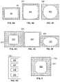
- FIG. 1shows a side view of a plurality of stacked battery components in a first embodiment of the present invention
- FIG. 2shows a side view of the embodiment of FIG. 1 with a housing connected to the polymer frames of the battery components to form a battery module cell;
- FIGS. 3 a , 3 b , 3 cshow a top view of creation of the embodiment of the battery component of the present invention, and FIG. 3 d shows an alternate embodiment of the battery component;
- FIGS. 4 a , 4 b , 4 c , 4 d , 4 e and 4 fshow various frame geometries of the polymer frame according to the present invention
- FIG. 4 gshows a frame with a plurality of windows.
- FIG. 5shows a polymer frame according to the present invention with feed holes for easing assembly
- FIG. 6shows a side view of a different embodiment of the battery component with two frames
- FIG. 7shows schematically a electric or hybrid vehicle with an electric battery made of the battery module cells
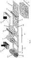
- FIG. 8shows one embodiment of the method of the present invention, using the rods and individual stacked components to manufacture battery cell modules as in FIG. 1 ;
- FIG. 9shows an alternate embodiment of the method of the present invention.
- FIG. 1shows a battery cell module 10 with five stackable battery components 11 , 12 , 13 , 14 , 15 having electrode components according to an embodiment of the present invention.
- Each battery component 11 , 12 , 13 , 14 , 15includes an anode 24 , a separator 28 , a cathode 26 and a bipolar current collector 22 .
- Each componentalso includes a polymer frame 20 , which on a planar side 124 has the bipolar current collector 22 and on an opposite planar side 128 has the separator 28 .
- Polymer frame 20 in this embodimentis a polymer foil, and the attachment of separator 28 to frame 20 will be described in more detail with respect to FIGS. 3 a , 3 b and 3 c.
- Separator 28can be a dielectric material, for example a porous polyethylene or polyethylene-polypropylene foil (typically 8 to 25 ⁇ m thickness).
- Polymer frame 20can be made for example of polypropylene (PP), polyethylene (PE), acrylnitrile butadiene-styrene (ABS), polyamide (PA), polylactic acid (PLA), poly (methyl methacrylate) (PMMA), polycarbonate (PC), polyethylene terephthalate (PET), polystyrene (PS), polyvinyl chloride (PVC), polyphenylene sulfide (PPS), polyphenylene oxide (PPO), Polyetherimide (PEI), polyether ether ketone (PEEK), polyether sulfone (PES), polybenzimidazole (PBI), nylon and composite foil or multilayer foil made of aluminum foil coated with a polymer for example polypropylene. Most preferably, the polymer frame is a PE/PP mixture.
- Bipolar current collector 22can be made of copper or aluminum or nickel-coated aluminum or nickel for example.
- Anode 24 and cathode 26can be deposited for example by vapor deposition or other film technology on separator 28 .
- Bipolar current collector 22can be connected to cathode 26 as described below.
- FIG. 2shows a side view of the embodiment of FIG. 1 with a housing 40 connected to the polymer frames 20 of the battery components 11 to 15 to form a battery module cell.
- the housingcan have for example four walls to cover each side of polymer frames 20 , which preferably have a rectangular outer shape.
- Housing 40may be made of the same material as polymer frames 20 for example, or of a different polymer material.
- a rod 99 as shown in FIG. 1can interact with feed holes in the polymer frames 20 as will be described, and can be removed after the stack is created and the housing is added.
- FIGS. 3 a , 3 b and 3 cshow a top view of creation of the embodiment of the battery component of the present invention
- FIG. 3 dshows an alternate battery component with the bipolar current collector 22 first connected to the polymer frame.
- FIG. 3 ashows a side 128 of a polymer frame 20 with a rectangular window 60 .
- frame 20can be placed over separator 28 , which can have an anode 24 on one side and cathode 26 on the other side as shown in FIG. 1 .
- Cathode 26protrudes through window 60 , as shown in FIG. 3 c .
- Bipolar current collector 22which can be a thin metal foil, then can be added over cathode 26 and attached to the frame 20 at its edges.
- Frame 20likewise is attached to separator 28 around window 60 .
- Bipolar current collector 22 , anode 24 and cathode 26can be connected to this stackable component as discussed above or also can added separately or later during assembly.
- the anode and the cathodeadvantageously can be made of polymer, glass, glass ceramic or ceramic solid-state materials, and the mechanical properties are improved and much of the mechanical stress during the cell assembly process can be retained by the polymer frame, which lowers the requirements on the assembly process. In addition, small imperfections at the solid-state material edges can be tolerated and the amount of defective goods can be decreased.
- the separatorcan be a solid state electrolyte, so that liquid or gels need not be added later as in polymer separators.
- FIG. 3 dshows an alternate embodiment which starts out with the same frame 20 as in FIG. 3 a .
- Bipolar current collector 22which can be a thin foil of aluminum coated with nickel, is placed nickel side down on the frame to overlap side 128 .
- Gluing or other bondingcan be used to attach the nickel coating to a PP/PE frame, which advantageously provides a stable connection compares to a PP/PE aluminum or copper connection.
- the thin foil of the current collector 22is also stabilized well, and then the cathode 26 , separator 28 and anode 24 can be added separately to the combined frame 20 /current collector 22 component.
- FIGS. 4 a , 4 b , 4 c , 4 d , 4 e and 4 fshow various frame geometries of the polymer frames according to the present invention, with FIG. 4 a being similar to FIG. 3 a , and frames 201 , 202 , 203 , 204 , 205 having a window 301 with rounded edges, a circular window 302 , a window 303 similar to window 301 but smaller for a same outer sized frame, a perfectly square window 304 and an oval window 305 , respectively.
- FIG. 4 gshows a polymer frame 206 with for example four windows 306 , 307 , 308 , 309 .
- FIG. 5shows a polymer frame 203 according to the present invention with feed holes 305 for easing assembly.
- Assembly of the FIG. 1 embodimentcan occur as follows: endplate anode current collector 92 is provided, and then battery component 11 is added so that frame 20 is slid over rod 99 via a feed hole 305 . Polymer frame 20 can be slid over further rods via feed holes 305 . Components 12 , 13 , 14 and 15 then can be stacked over the rod 99 as shown in FIG. 1 , and finally cathode top plate 90 added to create the battery module 10 . The anode 24 of a battery component 12 , 13 , 14 , 15 thus can rest on the bipolar current collector 22 of the battery component 11 , 12 , 13 , 14 , respectively, below.
- the rod 99can be removed and housing 40 sides can be added and attached to the polymer frames. If a liquid electrolyte/polymer separator is being used, liquid electrolyte can be added to the areas formed by the housing and two polymer frames if desirable to increase efficiency.
- FIG. 6shows a side view of a different embodiment of the battery component with an additional polymer frame 120 attached to the separator 28 opposite the polymer frame 20 . This embodiment provide additional stability and protection.
- the battery cell module or stack 110can be created for example with a much larger number of battery cells for providing power as an electric battery to an electric motor 200 for powering an electric vehicle 300 .
- FIG. 8shows one embodiment of a manufacturing method according to the present invention.
- a polymer foil roll 510is unwound so that a polymer foil 500 exits the roll stand 400 .
- a stamping station 420a die 520 stamps windows 60 into the foil 500 .
- feed holes 305if desired can also be stamped.
- the windows and/or feed holescould be laser cut or otherwise impart on foil 500 .
- the foil 500is cut into individual polymer frames 20 via for example a knife roller 530 and anvil 532 , the frames 20 with windows 60 exiting onto a conveyor 440 .
- Separators 28 from a stack 528which separators can be made of solid-state electrolyte material, can be placed on the frames 20 to form stackable components 98 which can be assembled in a housing 40 with the other battery cell components, such as the bipolar current collectors 22 , as described above. Alternately polymer separators could be used as described for example in FIG. 9 below. Rods 99 can be used and welding or other attachment processes described above can be used to complete the battery module.
- FIG. 9shows a different embodiment where separator material is added at a separator placement station 460 before cutting endless tape 198 so that an endless tape 198 of frame supported separators 28 is created.
- Solid-state separatorscan be used as in the FIG. 8 embodiment, or polymer separators cut off a roll 628 by a cutting device 630 could be used.
- the separators 28can be attached for example by a welding device 640 to the tape 198 .
- the bipolar current collectors 22also could replace the separator material in the FIG. 9 embodiment and be attached directly via for example welding to the foil 500 . In this case the separators and anodes and cathodes could be added later.
- the endless tape 198also could be used for zig-zag folding or a combination of zig-zag and stacking.
- the endless tape 198also could be cut into smaller units down to single units of a stackable component 98 via a cutting device (knife or laser cutter) 470 .
- the separator-polymer frame unitBy attaching the separator-polymer frame unit to the housing the separator can no longer move or slide inside the cell. Therefore, this unit is more resilient and can better tolerate vibrations or shocks as they occur when having batteries in cars or any transportable device, because the position of the whole cell stack is fixed inside the cell.
- the bipolar current collector-polymer frame unit embodimentis used, the bipolar current collector is well protected.
- the housing 40also could be dispensed with and the frames 60 simply welded together.
- the method of the present invention and resulting stable batteriesare especially useful for electric vehicle or hybrid vehicle batteries, which are subjected of significant vibrations.
Landscapes
- Chemical & Material Sciences (AREA)
- Chemical Kinetics & Catalysis (AREA)
- Electrochemistry (AREA)
- General Chemical & Material Sciences (AREA)
- Engineering & Computer Science (AREA)
- Manufacturing & Machinery (AREA)
- Secondary Cells (AREA)
- Battery Electrode And Active Subsutance (AREA)
- Sealing Battery Cases Or Jackets (AREA)
Abstract
Description
Claims (20)
Priority Applications (4)
| Application Number | Priority Date | Filing Date | Title |
|---|---|---|---|
| US15/432,317US11362371B2 (en) | 2017-02-14 | 2017-02-14 | Method for manufacturing electric vehicle battery cells with polymer frame support |
| PCT/IB2018/000252WO2018150274A1 (en) | 2017-02-14 | 2018-02-12 | Method for manufacturing electric vehicle battery cells with polymer frame support |
| EP18713338.4AEP3583640B1 (en) | 2017-02-14 | 2018-02-12 | Method for manufacturing electric vehicle battery cells with polymer frame support |
| CN201880011915.9ACN110521020B (en) | 2017-02-14 | 2018-02-12 | Method of making an electric vehicle battery cell with a polymer frame support |
Applications Claiming Priority (1)
| Application Number | Priority Date | Filing Date | Title |
|---|---|---|---|
| US15/432,317US11362371B2 (en) | 2017-02-14 | 2017-02-14 | Method for manufacturing electric vehicle battery cells with polymer frame support |
Publications (2)
| Publication Number | Publication Date |
|---|---|
| US20180233782A1 US20180233782A1 (en) | 2018-08-16 |
| US11362371B2true US11362371B2 (en) | 2022-06-14 |
Family
ID=61768345
Family Applications (1)
| Application Number | Title | Priority Date | Filing Date |
|---|---|---|---|
| US15/432,317Active2038-02-26US11362371B2 (en) | 2017-02-14 | 2017-02-14 | Method for manufacturing electric vehicle battery cells with polymer frame support |
Country Status (4)
| Country | Link |
|---|---|
| US (1) | US11362371B2 (en) |
| EP (1) | EP3583640B1 (en) |
| CN (1) | CN110521020B (en) |
| WO (1) | WO2018150274A1 (en) |
Families Citing this family (9)
| Publication number | Priority date | Publication date | Assignee | Title |
|---|---|---|---|---|
| US11362338B2 (en) | 2017-02-14 | 2022-06-14 | Volkswagen Ag | Electric vehicle battery cell with solid state electrolyte |
| US10797284B2 (en) | 2017-02-14 | 2020-10-06 | Volkswagen Ag | Electric vehicle battery cell with polymer frame for battery cell components |
| US11870028B2 (en) | 2017-02-14 | 2024-01-09 | Volkswagen Ag | Electric vehicle battery cell with internal series connection stacking |
| JP7014689B2 (en)* | 2018-08-22 | 2022-02-01 | 株式会社豊田自動織機 | Power storage module and manufacturing method of power storage module |
| US11888178B2 (en)* | 2018-09-10 | 2024-01-30 | Volkswagen Ag | Method for producing an electric battery with separator material on a current collector base |
| JP7088410B2 (en)* | 2019-03-29 | 2022-06-21 | 株式会社豊田自動織機 | Power storage module |
| JP7343419B2 (en)* | 2020-02-14 | 2023-09-12 | 本田技研工業株式会社 | Solid state battery cells and solid state battery modules |
| EP4113556B1 (en)* | 2021-06-30 | 2023-09-20 | Mindcaps Smart Supercapacitors SL | Lithium/sodium electrochemical device for storing electrical energy in rectangular geometric cells |
| CN115621564A (en)* | 2021-07-15 | 2023-01-17 | 通用汽车环球科技运作有限责任公司 | Method of manufacturing a bipolar solid state battery |
Citations (79)
| Publication number | Priority date | Publication date | Assignee | Title |
|---|---|---|---|---|
| US3819412A (en) | 1972-02-07 | 1974-06-25 | Tyco Laboratories Inc | Plates for lead acid batteries |
| US4164068A (en) | 1977-08-18 | 1979-08-14 | Exxon Research & Engineering Co. | Method of making bipolar carbon-plastic electrode structure-containing multicell electrochemical device |
| US4539268A (en) | 1981-07-02 | 1985-09-03 | California Institute Of Technology | Sealed bipolar multi-cell battery |
| US4576881A (en) | 1983-11-08 | 1986-03-18 | Brown, Boveri & Cie Ag | Electrochemical storage cell |
| US4737257A (en)* | 1985-04-18 | 1988-04-12 | Imperial Chemical Industries Plc | Electrode for electrochemical cell |
| WO1992010861A1 (en) | 1990-12-14 | 1992-06-25 | Arch Development Corporation | Bipolar battery |
| US5518839A (en) | 1995-04-12 | 1996-05-21 | Olsen; Ib I. | Current collector for solid electrochemical cell |
| US5618641A (en) | 1993-12-03 | 1997-04-08 | Bipolar Power Corporation | Bipolar battery construction |
| WO1997038461A1 (en) | 1996-04-10 | 1997-10-16 | National Power Plc | Process for the fabrication of electrochemical cell components |
| US5688615A (en) | 1995-11-03 | 1997-11-18 | Globe-Union, Inc. | Bipolar battery and method of making same |
| US6022642A (en) | 1996-12-26 | 2000-02-08 | Japan Storage Battery Co., Ltd. | Lithium ion battery containing an electrically insulative film |
| CN1303525A (en) | 1997-10-10 | 2001-07-11 | 美国3M公司 | Membrane electrode assemblies |
| CN1337757A (en) | 2000-06-16 | 2002-02-27 | 日清纺织株式会社 | Polymer cell and producing method thereof |
| US20020192542A1 (en) | 2001-06-18 | 2002-12-19 | Power Paper Ltd. | Flexible thin layer electrochemical cell and manufacturing of same |
| US20030013012A1 (en) | 2000-02-08 | 2003-01-16 | Soon-Ho Ahn | Stacked electrochemical cell |
| CN1408128A (en) | 1999-12-06 | 2003-04-02 | 阿维科斯公司 | Ultrathin electrochemical energy storage device |
| US20030194605A1 (en)* | 2002-04-10 | 2003-10-16 | Fauteux Denis G. | Rechargeable high power electrochemical device |
| US20040067417A1 (en) | 2002-10-08 | 2004-04-08 | Nissan Motor Co., Ltd. | Bipolar battery |
| US20040091771A1 (en) | 2002-11-07 | 2004-05-13 | Nissan Motor Co., Ltd. | Bipolar battery |
| US6743546B1 (en) | 1999-03-26 | 2004-06-01 | Matsushita Electric Industrial Co., Ltd. | Laminate sheath type battery |
| US20040241525A1 (en) | 2003-05-28 | 2004-12-02 | 3M Innovative Properties Company | Roll-good fuel cell fabrication processes, equipment, and articles produced from same |
| EP1487034A2 (en) | 2003-06-12 | 2004-12-15 | Nissan Motor Co., Ltd. | Bipolar battery and related method |
| US20050089751A1 (en) | 2003-10-10 | 2005-04-28 | Nissan Motor Co., Ltd. | Battery |
| JP2005259379A (en) | 2004-03-09 | 2005-09-22 | Nissan Motor Co Ltd | Bipolar battery |
| US20060134502A1 (en) | 2004-12-16 | 2006-06-22 | Patrick Garceau | Bipolar plate for a fuel cell |
| US7097937B2 (en) | 2001-09-19 | 2006-08-29 | Nilar International Ab | Bipolar battery and biplate assembly |
| CN1912522A (en) | 2005-08-10 | 2007-02-14 | 李建新 | Radiator suitable for aluminium alloy cavity nickel coated anti-corrosion |
| EP1841001A1 (en) | 2004-12-10 | 2007-10-03 | Nissan Motor Co., Ltd. | Bipolar battery |
| US20080003493A1 (en) | 2005-09-06 | 2008-01-03 | Bates John B | Getters for thin film battery hermetic package |
| KR20080036139A (en) | 2005-08-09 | 2008-04-24 | 폴리플러스 배터리 컴퍼니 | Compliant seal structure for protected active metal anodes |
| WO2009029746A1 (en) | 2007-08-29 | 2009-03-05 | Johnson Lonnie G | Low cost solid state rechargeable battery and method of manufacturing same |
| JP2009117052A (en) | 2007-11-01 | 2009-05-28 | Nissan Motor Co Ltd | Bipolar battery manufacturing method and manufacturing apparatus |
| WO2010049478A1 (en) | 2008-10-29 | 2010-05-06 | Ceramtec Ag | Separation layer for separating anode and cathode in lithium ion accumulators or batteries |
| WO2010124195A1 (en) | 2009-04-24 | 2010-10-28 | G4 Synergetics, Inc. | Energy storage devices having mono-polar and bi-polar cells electrically coupled in series and in parallel |
| JP2010277811A (en) | 2009-05-28 | 2010-12-09 | Abe Tomomi | Cell unit of redox flow battery and its cell stack structure |
| US20110014520A1 (en) | 2008-07-25 | 2011-01-20 | Tomohiro Ueda | Bipolar battery |
| GB2477552A (en) | 2010-02-08 | 2011-08-10 | Qinetiq Ltd | Thin Electrochemical Cell |
| US20110206974A1 (en)* | 2008-12-19 | 2011-08-25 | Nissan Motor Co., Ltd. | Electrode and production method thereof |
| DE102010013031A1 (en) | 2010-03-26 | 2011-09-29 | Daimler Ag | Battery e.g. lithium-ion high-voltage battery, used in e.g. hybrid car, has electrical isolating frame formed between metal sheets, and electrical isolating spacer element arranged at frame among deformed regions of sheets |
| WO2011134613A1 (en) | 2010-04-29 | 2011-11-03 | Li-Tec Battery Gmbh | Lithium-sulphur battery |
| US20110308935A1 (en)* | 2010-06-18 | 2011-12-22 | Semiconductor Energy Laboratory Co., Ltd. | Method of manufacturing power storage device |
| US20120115020A1 (en) | 2010-11-04 | 2012-05-10 | Samsung Sdi Co., Ltd. | Battery pack |
| DE102011003186A1 (en) | 2011-01-26 | 2012-07-26 | Evonik Degussa Gmbh | Thin, macroporous polymer films |
| CA2835915A1 (en) | 2011-05-13 | 2012-11-22 | East Penn Manufacturing Co. | Composite current collector and methods therefor |
| US20130065110A1 (en) | 2011-09-09 | 2013-03-14 | Thomas Faust | Bipolar Battery and Plate |
| US20130101878A1 (en) | 2010-07-20 | 2013-04-25 | Evonik Litarion Gmbh | Battery comprising cuboid cells which contain a bipolar electrode |
| US20130157111A1 (en) | 2010-08-24 | 2013-06-20 | Commissariat A L'enrgie Atomique Et Aux Ene Alt | Bipolar electrochemical battery with an improved casing |
| US20130162216A1 (en) | 2011-12-21 | 2013-06-27 | Aruna Zhamu | Stacks of internally connected surface-mediated cells and methods of operating same |
| WO2013127573A1 (en) | 2012-02-29 | 2013-09-06 | Robert Bosch Gmbh | All-solid-state cell |
| WO2013131624A1 (en) | 2012-03-05 | 2013-09-12 | Treofan Germany Gmbh & Co. Kg | Highly porous separator film having partial lamination |
| CN103334147A (en) | 2013-06-24 | 2013-10-02 | 沈阳化工大学 | Method for preparing nickel-coated aluminum powder composite coating by utilizing pulse plating |
| CN103443994A (en) | 2011-03-17 | 2013-12-11 | 丰田自动车株式会社 | Solid-state battery and solid-state battery manufacturing method |
| DE102012213110A1 (en) | 2012-07-26 | 2014-01-30 | Leichtbau-Zentrum Sachsen Gmbh | Method for manufacturing film battery e.g. lithium ion battery mounted in vehicle, involves forming frame by casting around edge region of film stack, and opening casting tool after removal of a frame which is provided film stack |
| US20140045040A1 (en) | 2011-04-26 | 2014-02-13 | Commissariat A L'energie Atomique Et Aux Ene Alt | Bipolar electrochemical li-ion battery having increased capacity |
| CN103730684A (en) | 2014-01-15 | 2014-04-16 | 广东亿纬赛恩斯新能源系统有限公司 | High-safety all-solid-state lithium ion battery and production method thereof |
| CN103840212A (en) | 2012-11-23 | 2014-06-04 | 海洋王照明科技股份有限公司 | Making method of solid-state lithium ion battery |
| US20140178745A1 (en) | 2012-08-30 | 2014-06-26 | Lg Chem, Ltd. | Packaging for cable-type secondary battery and cable-type secondary battery comprising the same |
| CN103959507A (en) | 2011-10-24 | 2014-07-30 | 高级电池概念有限责任公司 | Bipolar battery assembly |
| US20140329126A1 (en) | 2012-01-17 | 2014-11-06 | Ballast Energy, Inc. | Electrode and battery |
| US20140363748A1 (en) | 2013-06-10 | 2014-12-11 | Carl Freudenberg Kg | Electrode Module |
| US20150050537A1 (en) | 2013-08-15 | 2015-02-19 | Robert Bosch Gmbh | Li/Metal Battery with Composite Solid Electrolyte |
| EP2843734A2 (en) | 2006-07-19 | 2015-03-04 | Toyota Jidosha Kabushiki Kaisha | Secondary battery |
| EP1766716B1 (en) | 2004-12-07 | 2015-04-15 | Nissan Motor Company Limited | Bipolar electrode batteries and methods of manufacturing bipolar electrode batteries |
| WO2015083825A1 (en) | 2013-12-05 | 2015-06-11 | 日立マクセル株式会社 | Non-aqueous electrolyte secondary battery and production method therefor |
| US20150280177A1 (en) | 2014-03-28 | 2015-10-01 | Intel Corporation | Method for providing a sealing compound on a battery cell |
| US20160028134A1 (en) | 2014-07-22 | 2016-01-28 | Toyota Motor Engineering & Manufacturing North America, Inc. | Lithium-air battery with cathode separated from free lithium ion |
| US20160104913A1 (en) | 2013-05-21 | 2016-04-14 | Commissariat A L'energie Atomique Et Aux Energies Alternatives | Bipolar li-ion battery having improved sealing and associated method of production |
| WO2016057457A2 (en) | 2014-10-06 | 2016-04-14 | Eos Energy Storage, Llc | Zinc-halide electrochemical cell |
| DE102015210806A1 (en) | 2014-11-14 | 2016-05-19 | Hyundai Motor Company | Bipolar electrode, bipolar all-solid-state battery manufactured using same, and manufacturing method thereof |
| US20160156065A1 (en) | 2014-12-02 | 2016-06-02 | Polyplus Battery Company | Standalone sulfide based lithium ion-conducting glass solid electrolyte and associated structures, cells and methods |
| US9362547B2 (en) | 2010-12-02 | 2016-06-07 | Sony Corporation | Solid electrolyte cell and positive electrode active material |
| US20160329535A1 (en) | 2013-12-30 | 2016-11-10 | Gridtential Energy, Inc | Sealed bipolar battery assembly |
| US20170263951A1 (en) | 2015-08-21 | 2017-09-14 | Sumitomo Electric Industries, Ltd. | Frame body, cell frame for redox flow battery, and redox flow battery |
| US20170294662A1 (en) | 2016-04-07 | 2017-10-12 | Lockheed Martin Advanced Energy Storage, Llc | Electrochemical cells having designed flow fields and methods for producing the same |
| US20170294672A1 (en)* | 2016-04-07 | 2017-10-12 | Lockheed Martin Advanced Energy Storage, Llc | High-throughput manufacturing processes for making electrochemical unit cells and electrochemical unit cells produced using the same |
| US20180233752A1 (en) | 2017-02-14 | 2018-08-16 | Volkswagen Ag | Electric vehicle battery cell with solid state electrolyte |
| US20180233768A1 (en) | 2017-02-14 | 2018-08-16 | Volkswagen Ag | Electric vehicle battery cell with internal series connection stacking |
| US20180233721A1 (en) | 2017-02-14 | 2018-08-16 | Volkswagen Ag | Electric vehicle battery cell with polymer frame for battery cell components |
| US20190044129A1 (en) | 2016-02-02 | 2019-02-07 | Research Foundation Of The City University Of New York | Rechargeable Alkaline Manganese Dioxide-Zinc Bipolar Batteries |
- 2017
- 2017-02-14USUS15/432,317patent/US11362371B2/enactiveActive
- 2018
- 2018-02-12WOPCT/IB2018/000252patent/WO2018150274A1/ennot_activeCeased
- 2018-02-12EPEP18713338.4Apatent/EP3583640B1/enactiveActive
- 2018-02-12CNCN201880011915.9Apatent/CN110521020B/enactiveActive
Patent Citations (103)
| Publication number | Priority date | Publication date | Assignee | Title |
|---|---|---|---|---|
| US3819412A (en) | 1972-02-07 | 1974-06-25 | Tyco Laboratories Inc | Plates for lead acid batteries |
| US4164068A (en) | 1977-08-18 | 1979-08-14 | Exxon Research & Engineering Co. | Method of making bipolar carbon-plastic electrode structure-containing multicell electrochemical device |
| US4539268A (en) | 1981-07-02 | 1985-09-03 | California Institute Of Technology | Sealed bipolar multi-cell battery |
| US4576881A (en) | 1983-11-08 | 1986-03-18 | Brown, Boveri & Cie Ag | Electrochemical storage cell |
| US4737257A (en)* | 1985-04-18 | 1988-04-12 | Imperial Chemical Industries Plc | Electrode for electrochemical cell |
| WO1992010861A1 (en) | 1990-12-14 | 1992-06-25 | Arch Development Corporation | Bipolar battery |
| US5618641A (en) | 1993-12-03 | 1997-04-08 | Bipolar Power Corporation | Bipolar battery construction |
| US5518839A (en) | 1995-04-12 | 1996-05-21 | Olsen; Ib I. | Current collector for solid electrochemical cell |
| US5688615A (en) | 1995-11-03 | 1997-11-18 | Globe-Union, Inc. | Bipolar battery and method of making same |
| WO1997038461A1 (en) | 1996-04-10 | 1997-10-16 | National Power Plc | Process for the fabrication of electrochemical cell components |
| US6022642A (en) | 1996-12-26 | 2000-02-08 | Japan Storage Battery Co., Ltd. | Lithium ion battery containing an electrically insulative film |
| CN1303525A (en) | 1997-10-10 | 2001-07-11 | 美国3M公司 | Membrane electrode assemblies |
| US20030041444A1 (en) | 1997-10-10 | 2003-03-06 | 3M Innovative Properties Company | Membrane electrode assemblies |
| US6743546B1 (en) | 1999-03-26 | 2004-06-01 | Matsushita Electric Industrial Co., Ltd. | Laminate sheath type battery |
| CN1408128A (en) | 1999-12-06 | 2003-04-02 | 阿维科斯公司 | Ultrathin electrochemical energy storage device |
| US6576365B1 (en) | 1999-12-06 | 2003-06-10 | E.C.R. - Electro Chemical Research Ltd. | Ultra-thin electrochemical energy storage devices |
| EP1175709B1 (en) | 2000-02-08 | 2009-11-11 | LG Chemical Co. Ltd | Stacked electrochemical cell |
| US20030013012A1 (en) | 2000-02-08 | 2003-01-16 | Soon-Ho Ahn | Stacked electrochemical cell |
| CN1337757A (en) | 2000-06-16 | 2002-02-27 | 日清纺织株式会社 | Polymer cell and producing method thereof |
| US6696204B2 (en) | 2000-06-16 | 2004-02-24 | Nisshinbo Industries, Inc. | Polymer battery and method of manufacture |
| US20020192542A1 (en) | 2001-06-18 | 2002-12-19 | Power Paper Ltd. | Flexible thin layer electrochemical cell and manufacturing of same |
| US7097937B2 (en) | 2001-09-19 | 2006-08-29 | Nilar International Ab | Bipolar battery and biplate assembly |
| US20030194605A1 (en)* | 2002-04-10 | 2003-10-16 | Fauteux Denis G. | Rechargeable high power electrochemical device |
| US20040067417A1 (en) | 2002-10-08 | 2004-04-08 | Nissan Motor Co., Ltd. | Bipolar battery |
| US20040091771A1 (en) | 2002-11-07 | 2004-05-13 | Nissan Motor Co., Ltd. | Bipolar battery |
| CN1499664A (en) | 2002-11-07 | 2004-05-26 | �ղ��Զ�����ʽ���� | Bipolar cell |
| US20040241525A1 (en) | 2003-05-28 | 2004-12-02 | 3M Innovative Properties Company | Roll-good fuel cell fabrication processes, equipment, and articles produced from same |
| CN1795575A (en) | 2003-05-28 | 2006-06-28 | 3M创新有限公司 | Roll-good fuel cell fabrication processes, equipment, and articles produced from same |
| EP1487034A2 (en) | 2003-06-12 | 2004-12-15 | Nissan Motor Co., Ltd. | Bipolar battery and related method |
| US20040253512A1 (en) | 2003-06-12 | 2004-12-16 | Nissan Motor Co., Ltd. | Bipolar battery and related method |
| US7648538B2 (en) | 2003-10-10 | 2010-01-19 | Nissan Motor Co., Ltd. | Battery |
| CN1619859A (en) | 2003-10-10 | 2005-05-25 | 日产自动车株式会社 | Battery |
| US20050089751A1 (en) | 2003-10-10 | 2005-04-28 | Nissan Motor Co., Ltd. | Battery |
| JP2005259379A (en) | 2004-03-09 | 2005-09-22 | Nissan Motor Co Ltd | Bipolar battery |
| EP1766716B1 (en) | 2004-12-07 | 2015-04-15 | Nissan Motor Company Limited | Bipolar electrode batteries and methods of manufacturing bipolar electrode batteries |
| US20090233164A1 (en)* | 2004-12-10 | 2009-09-17 | Nissan Motor Co., Ltd. | Bipolar battery |
| CN101076915A (en) | 2004-12-10 | 2007-11-21 | 日产自动车株式会社 | Bipolar battery |
| EP1841001A1 (en) | 2004-12-10 | 2007-10-03 | Nissan Motor Co., Ltd. | Bipolar battery |
| US8415049B2 (en) | 2004-12-10 | 2013-04-09 | Nissan Motor Co., Ltd. | Bipolar battery |
| US20060134502A1 (en) | 2004-12-16 | 2006-06-22 | Patrick Garceau | Bipolar plate for a fuel cell |
| KR20080036139A (en) | 2005-08-09 | 2008-04-24 | 폴리플러스 배터리 컴퍼니 | Compliant seal structure for protected active metal anodes |
| US7824806B2 (en) | 2005-08-09 | 2010-11-02 | Polyplus Battery Company | Compliant seal structures for protected active metal anodes |
| CN1912522A (en) | 2005-08-10 | 2007-02-14 | 李建新 | Radiator suitable for aluminium alloy cavity nickel coated anti-corrosion |
| US20080003493A1 (en) | 2005-09-06 | 2008-01-03 | Bates John B | Getters for thin film battery hermetic package |
| EP2843734A2 (en) | 2006-07-19 | 2015-03-04 | Toyota Jidosha Kabushiki Kaisha | Secondary battery |
| WO2009029746A1 (en) | 2007-08-29 | 2009-03-05 | Johnson Lonnie G | Low cost solid state rechargeable battery and method of manufacturing same |
| JP2009117052A (en) | 2007-11-01 | 2009-05-28 | Nissan Motor Co Ltd | Bipolar battery manufacturing method and manufacturing apparatus |
| US20110014520A1 (en) | 2008-07-25 | 2011-01-20 | Tomohiro Ueda | Bipolar battery |
| WO2010049478A1 (en) | 2008-10-29 | 2010-05-06 | Ceramtec Ag | Separation layer for separating anode and cathode in lithium ion accumulators or batteries |
| US20110217595A1 (en) | 2008-10-29 | 2011-09-08 | Ceramtec Gmbh | Separation layer for separating anode and cathode in lithium ion accumulators or batteries |
| US20110206974A1 (en)* | 2008-12-19 | 2011-08-25 | Nissan Motor Co., Ltd. | Electrode and production method thereof |
| WO2010124195A1 (en) | 2009-04-24 | 2010-10-28 | G4 Synergetics, Inc. | Energy storage devices having mono-polar and bi-polar cells electrically coupled in series and in parallel |
| JP2010277811A (en) | 2009-05-28 | 2010-12-09 | Abe Tomomi | Cell unit of redox flow battery and its cell stack structure |
| GB2477552A (en) | 2010-02-08 | 2011-08-10 | Qinetiq Ltd | Thin Electrochemical Cell |
| DE102010013031A1 (en) | 2010-03-26 | 2011-09-29 | Daimler Ag | Battery e.g. lithium-ion high-voltage battery, used in e.g. hybrid car, has electrical isolating frame formed between metal sheets, and electrical isolating spacer element arranged at frame among deformed regions of sheets |
| WO2011134613A1 (en) | 2010-04-29 | 2011-11-03 | Li-Tec Battery Gmbh | Lithium-sulphur battery |
| US20130108899A1 (en) | 2010-04-29 | 2013-05-02 | Li-Tec Battery Gmbh | Lithium-sulphur battery |
| US20110308935A1 (en)* | 2010-06-18 | 2011-12-22 | Semiconductor Energy Laboratory Co., Ltd. | Method of manufacturing power storage device |
| US20130101878A1 (en) | 2010-07-20 | 2013-04-25 | Evonik Litarion Gmbh | Battery comprising cuboid cells which contain a bipolar electrode |
| EP2609643B1 (en) | 2010-08-24 | 2014-06-11 | Commissariat à l'Énergie Atomique et aux Énergies Alternatives | Bipolar electrochemical battery with an improved casing |
| US20130157111A1 (en) | 2010-08-24 | 2013-06-20 | Commissariat A L'enrgie Atomique Et Aux Ene Alt | Bipolar electrochemical battery with an improved casing |
| US20120115020A1 (en) | 2010-11-04 | 2012-05-10 | Samsung Sdi Co., Ltd. | Battery pack |
| US9362547B2 (en) | 2010-12-02 | 2016-06-07 | Sony Corporation | Solid electrolyte cell and positive electrode active material |
| DE102011003186A1 (en) | 2011-01-26 | 2012-07-26 | Evonik Degussa Gmbh | Thin, macroporous polymer films |
| US20130302695A1 (en) | 2011-01-26 | 2013-11-14 | Evonik Degussa Gmbh | Thin macroporous polymeric foils |
| US9818996B2 (en) | 2011-03-17 | 2017-11-14 | Toyota Jidosha Kabushiki Kaisha | Solid battery and method for manufacturing solid battery |
| CN103443994A (en) | 2011-03-17 | 2013-12-11 | 丰田自动车株式会社 | Solid-state battery and solid-state battery manufacturing method |
| US20140045040A1 (en) | 2011-04-26 | 2014-02-13 | Commissariat A L'energie Atomique Et Aux Ene Alt | Bipolar electrochemical li-ion battery having increased capacity |
| CA2835915A1 (en) | 2011-05-13 | 2012-11-22 | East Penn Manufacturing Co. | Composite current collector and methods therefor |
| US20130065110A1 (en) | 2011-09-09 | 2013-03-14 | Thomas Faust | Bipolar Battery and Plate |
| US20140349147A1 (en) | 2011-10-24 | 2014-11-27 | Advanced Battery Concepts, LLC | Bipolar battery assembly |
| CN103959507A (en) | 2011-10-24 | 2014-07-30 | 高级电池概念有限责任公司 | Bipolar battery assembly |
| US20130162216A1 (en) | 2011-12-21 | 2013-06-27 | Aruna Zhamu | Stacks of internally connected surface-mediated cells and methods of operating same |
| US20140329126A1 (en) | 2012-01-17 | 2014-11-06 | Ballast Energy, Inc. | Electrode and battery |
| EP2804697A1 (en) | 2012-01-17 | 2014-11-26 | Ballast Energy, Inc. | Electrode and battery |
| WO2013127573A1 (en) | 2012-02-29 | 2013-09-06 | Robert Bosch Gmbh | All-solid-state cell |
| US20150044576A1 (en) | 2012-02-29 | 2015-02-12 | Robert Bosch Gmbh | all-solid-state cell |
| WO2013131624A1 (en) | 2012-03-05 | 2013-09-12 | Treofan Germany Gmbh & Co. Kg | Highly porous separator film having partial lamination |
| US20150093627A1 (en) | 2012-03-05 | 2015-04-02 | Treofan Germany Gmbh & Co. Kg | Highly porous separator film having partial lamination |
| DE102012213110A1 (en) | 2012-07-26 | 2014-01-30 | Leichtbau-Zentrum Sachsen Gmbh | Method for manufacturing film battery e.g. lithium ion battery mounted in vehicle, involves forming frame by casting around edge region of film stack, and opening casting tool after removal of a frame which is provided film stack |
| US20140178745A1 (en) | 2012-08-30 | 2014-06-26 | Lg Chem, Ltd. | Packaging for cable-type secondary battery and cable-type secondary battery comprising the same |
| CN103840212A (en) | 2012-11-23 | 2014-06-04 | 海洋王照明科技股份有限公司 | Making method of solid-state lithium ion battery |
| US20160104913A1 (en) | 2013-05-21 | 2016-04-14 | Commissariat A L'energie Atomique Et Aux Energies Alternatives | Bipolar li-ion battery having improved sealing and associated method of production |
| US20140363748A1 (en) | 2013-06-10 | 2014-12-11 | Carl Freudenberg Kg | Electrode Module |
| CN103334147A (en) | 2013-06-24 | 2013-10-02 | 沈阳化工大学 | Method for preparing nickel-coated aluminum powder composite coating by utilizing pulse plating |
| US20150050537A1 (en) | 2013-08-15 | 2015-02-19 | Robert Bosch Gmbh | Li/Metal Battery with Composite Solid Electrolyte |
| WO2015083825A1 (en) | 2013-12-05 | 2015-06-11 | 日立マクセル株式会社 | Non-aqueous electrolyte secondary battery and production method therefor |
| US20160329535A1 (en) | 2013-12-30 | 2016-11-10 | Gridtential Energy, Inc | Sealed bipolar battery assembly |
| CN103730684A (en) | 2014-01-15 | 2014-04-16 | 广东亿纬赛恩斯新能源系统有限公司 | High-safety all-solid-state lithium ion battery and production method thereof |
| DE102015102688A1 (en) | 2014-03-28 | 2015-10-01 | Intel Corporation | METHOD FOR PROVIDING A GROUNDING MATERIAL ON A BATTERY CELL |
| US20150280177A1 (en) | 2014-03-28 | 2015-10-01 | Intel Corporation | Method for providing a sealing compound on a battery cell |
| US20160028134A1 (en) | 2014-07-22 | 2016-01-28 | Toyota Motor Engineering & Manufacturing North America, Inc. | Lithium-air battery with cathode separated from free lithium ion |
| WO2016057457A2 (en) | 2014-10-06 | 2016-04-14 | Eos Energy Storage, Llc | Zinc-halide electrochemical cell |
| DE102015210806A1 (en) | 2014-11-14 | 2016-05-19 | Hyundai Motor Company | Bipolar electrode, bipolar all-solid-state battery manufactured using same, and manufacturing method thereof |
| US20160141623A1 (en) | 2014-11-14 | 2016-05-19 | Hyundai Motor Company | Bipolar electrode, bipolar all-solid battery manufactured by using the same, and manufacturing method thereof |
| US20160156065A1 (en) | 2014-12-02 | 2016-06-02 | Polyplus Battery Company | Standalone sulfide based lithium ion-conducting glass solid electrolyte and associated structures, cells and methods |
| US20170263951A1 (en) | 2015-08-21 | 2017-09-14 | Sumitomo Electric Industries, Ltd. | Frame body, cell frame for redox flow battery, and redox flow battery |
| US20190044129A1 (en) | 2016-02-02 | 2019-02-07 | Research Foundation Of The City University Of New York | Rechargeable Alkaline Manganese Dioxide-Zinc Bipolar Batteries |
| US20170294662A1 (en) | 2016-04-07 | 2017-10-12 | Lockheed Martin Advanced Energy Storage, Llc | Electrochemical cells having designed flow fields and methods for producing the same |
| US20170294672A1 (en)* | 2016-04-07 | 2017-10-12 | Lockheed Martin Advanced Energy Storage, Llc | High-throughput manufacturing processes for making electrochemical unit cells and electrochemical unit cells produced using the same |
| US20180233752A1 (en) | 2017-02-14 | 2018-08-16 | Volkswagen Ag | Electric vehicle battery cell with solid state electrolyte |
| US20180233768A1 (en) | 2017-02-14 | 2018-08-16 | Volkswagen Ag | Electric vehicle battery cell with internal series connection stacking |
| US20180233721A1 (en) | 2017-02-14 | 2018-08-16 | Volkswagen Ag | Electric vehicle battery cell with polymer frame for battery cell components |
Non-Patent Citations (3)
| Title |
|---|
| Definition of connected, www.google.com, Oct. 23, 2018 (Year: 2018). |
| Definition of fixedly, www.dictionary.com, Oct. 23, 2018 (Year: 2018). |
| Key technologies for electric motorization, downloaded from http://www.toyota-global.com/innovation/environmental_technology/keytech/, 5 pages, downloaded on Feb. 14, 2017. |
Also Published As
| Publication number | Publication date |
|---|---|
| EP3583640A1 (en) | 2019-12-25 |
| CN110521020B (en) | 2022-08-09 |
| EP3583640B1 (en) | 2021-03-17 |
| US20180233782A1 (en) | 2018-08-16 |
| CN110521020A (en) | 2019-11-29 |
| WO2018150274A1 (en) | 2018-08-23 |
Similar Documents
| Publication | Publication Date | Title |
|---|---|---|
| US11362371B2 (en) | Method for manufacturing electric vehicle battery cells with polymer frame support | |
| EP3583652B1 (en) | Electric vehicle battery cell with polymer frame for battery cell components | |
| KR102241199B1 (en) | Electrochemical cell having a folded electrode and separator, battery including the same, and method of forming same | |
| CN110402502B (en) | Electric vehicle battery cell with solid state electrolyte | |
| KR101103499B1 (en) | Battery electrode assembly and manufacturing method | |
| US10135090B2 (en) | Method for manufacturing electrode assembly | |
| US9768440B2 (en) | Method of manufacturing electrode assembly | |
| EP2874225B1 (en) | Method for securing electrode assembly using tape | |
| US20150033547A1 (en) | Electrode assembly manufacturing method including separator cutting process | |
| EP3583651B1 (en) | Electric vehicle battery cell with internal series connection stacking | |
| CN101273426A (en) | Multilayer electrochemical energy storage device and method of manufacturing the same | |
| EP2866290B1 (en) | Electrode assembly for polymer secondary battery cell | |
| KR101799570B1 (en) | Electrode Assembly Folded in the Bi-Direction and Lithium Secondary Battery Comprising the Same | |
| US20190181493A1 (en) | Separator/Current Collector Unit for Galvanic Cells | |
| KR102511815B1 (en) | Method for manufacturing an electric battery with a separator material on a current collector base | |
| WO2018061971A1 (en) | Battery | |
| KR101806585B1 (en) | Notching method, manufacture method of electrode assembly, electrode assembly and secondary battery using the same | |
| JP2023003069A (en) | Battery electrode manufacturing device and method for manufacturing battery electrode | |
| KR20180094675A (en) | Unit Electrode Sheet Capable of Cutting and Stacking | |
| KR20160049748A (en) | Method for Preparing Unit Cell of Asymmetirc Structure and Unit Cell Prepared thereby |
Legal Events
| Date | Code | Title | Description |
|---|---|---|---|
| AS | Assignment | Owner name:DR. ING. H.C. F. PORSCHE AG, GERMANY Free format text:ASSIGNMENT OF ASSIGNORS INTEREST;ASSIGNORS:HERRMANN, MIRKO;SCHEFFLER, ROUVEN;SPEIDEL, ANGELA;SIGNING DATES FROM 20170329 TO 20170404;REEL/FRAME:042000/0317 Owner name:VOLKSWAGEN AG, GERMANY Free format text:ASSIGNMENT OF ASSIGNORS INTEREST;ASSIGNORS:HERRMANN, MIRKO;SCHEFFLER, ROUVEN;SPEIDEL, ANGELA;SIGNING DATES FROM 20170329 TO 20170404;REEL/FRAME:042000/0317 Owner name:AUDI AG, GERMANY Free format text:ASSIGNMENT OF ASSIGNORS INTEREST;ASSIGNORS:HERRMANN, MIRKO;SCHEFFLER, ROUVEN;SPEIDEL, ANGELA;SIGNING DATES FROM 20170329 TO 20170404;REEL/FRAME:042000/0317 | |
| STPP | Information on status: patent application and granting procedure in general | Free format text:NON FINAL ACTION MAILED | |
| STPP | Information on status: patent application and granting procedure in general | Free format text:RESPONSE TO NON-FINAL OFFICE ACTION ENTERED AND FORWARDED TO EXAMINER | |
| STPP | Information on status: patent application and granting procedure in general | Free format text:FINAL REJECTION MAILED | |
| STPP | Information on status: patent application and granting procedure in general | Free format text:DOCKETED NEW CASE - READY FOR EXAMINATION | |
| STPP | Information on status: patent application and granting procedure in general | Free format text:NON FINAL ACTION MAILED | |
| STPP | Information on status: patent application and granting procedure in general | Free format text:RESPONSE TO NON-FINAL OFFICE ACTION ENTERED AND FORWARDED TO EXAMINER | |
| STPP | Information on status: patent application and granting procedure in general | Free format text:FINAL REJECTION MAILED | |
| STPP | Information on status: patent application and granting procedure in general | Free format text:ADVISORY ACTION MAILED | |
| STPP | Information on status: patent application and granting procedure in general | Free format text:DOCKETED NEW CASE - READY FOR EXAMINATION | |
| STPP | Information on status: patent application and granting procedure in general | Free format text:NOTICE OF ALLOWANCE MAILED -- APPLICATION RECEIVED IN OFFICE OF PUBLICATIONS | |
| STPP | Information on status: patent application and granting procedure in general | Free format text:PUBLICATIONS -- ISSUE FEE PAYMENT VERIFIED | |
| STCF | Information on status: patent grant | Free format text:PATENTED CASE |