US11360003B2 - Apparatus and methods for controlling attention of a robot - Google Patents
Apparatus and methods for controlling attention of a robotDownload PDFInfo
- Publication number
- US11360003B2 US11360003B2US16/743,095US202016743095AUS11360003B2US 11360003 B2US11360003 B2US 11360003B2US 202016743095 AUS202016743095 AUS 202016743095AUS 11360003 B2US11360003 B2US 11360003B2
- Authority
- US
- United States
- Prior art keywords
- task
- robotic apparatus
- implementations
- interest
- robot
- Prior art date
- Legal status (The legal status is an assumption and is not a legal conclusion. Google has not performed a legal analysis and makes no representation as to the accuracy of the status listed.)
- Active, expires
Links
Images


Classifications
- B—PERFORMING OPERATIONS; TRANSPORTING
- B25—HAND TOOLS; PORTABLE POWER-DRIVEN TOOLS; MANIPULATORS
- B25J—MANIPULATORS; CHAMBERS PROVIDED WITH MANIPULATION DEVICES
- B25J9/00—Programme-controlled manipulators
- B25J9/16—Programme controls
- B25J9/1656—Programme controls characterised by programming, planning systems for manipulators
- G—PHYSICS
- G01—MEASURING; TESTING
- G01N—INVESTIGATING OR ANALYSING MATERIALS BY DETERMINING THEIR CHEMICAL OR PHYSICAL PROPERTIES
- G01N1/00—Sampling; Preparing specimens for investigation
- G01N1/02—Devices for withdrawing samples
- G01N1/22—Devices for withdrawing samples in the gaseous state
- G01N1/2273—Atmospheric sampling
- B—PERFORMING OPERATIONS; TRANSPORTING
- B25—HAND TOOLS; PORTABLE POWER-DRIVEN TOOLS; MANIPULATORS
- B25J—MANIPULATORS; CHAMBERS PROVIDED WITH MANIPULATION DEVICES
- B25J9/00—Programme-controlled manipulators
- B25J9/16—Programme controls
- B25J9/1628—Programme controls characterised by the control loop
- B25J9/163—Programme controls characterised by the control loop learning, adaptive, model based, rule based expert control
- B—PERFORMING OPERATIONS; TRANSPORTING
- B25—HAND TOOLS; PORTABLE POWER-DRIVEN TOOLS; MANIPULATORS
- B25J—MANIPULATORS; CHAMBERS PROVIDED WITH MANIPULATION DEVICES
- B25J9/00—Programme-controlled manipulators
- B25J9/16—Programme controls
- B25J9/1694—Programme controls characterised by use of sensors other than normal servo-feedback from position, speed or acceleration sensors, perception control, multi-sensor controlled systems, sensor fusion
- B—PERFORMING OPERATIONS; TRANSPORTING
- B60—VEHICLES IN GENERAL
- B60K—ARRANGEMENT OR MOUNTING OF PROPULSION UNITS OR OF TRANSMISSIONS IN VEHICLES; ARRANGEMENT OR MOUNTING OF PLURAL DIVERSE PRIME-MOVERS IN VEHICLES; AUXILIARY DRIVES FOR VEHICLES; INSTRUMENTATION OR DASHBOARDS FOR VEHICLES; ARRANGEMENTS IN CONNECTION WITH COOLING, AIR INTAKE, GAS EXHAUST OR FUEL SUPPLY OF PROPULSION UNITS IN VEHICLES
- B60K11/00—Arrangement in connection with cooling of propulsion units
- B60K11/02—Arrangement in connection with cooling of propulsion units with liquid cooling
- F—MECHANICAL ENGINEERING; LIGHTING; HEATING; WEAPONS; BLASTING
- F01—MACHINES OR ENGINES IN GENERAL; ENGINE PLANTS IN GENERAL; STEAM ENGINES
- F01P—COOLING OF MACHINES OR ENGINES IN GENERAL; COOLING OF INTERNAL-COMBUSTION ENGINES
- F01P3/00—Liquid cooling
- F01P3/20—Cooling circuits not specific to a single part of engine or machine
- G—PHYSICS
- G01—MEASURING; TESTING
- G01N—INVESTIGATING OR ANALYSING MATERIALS BY DETERMINING THEIR CHEMICAL OR PHYSICAL PROPERTIES
- G01N1/00—Sampling; Preparing specimens for investigation
- G01N1/28—Preparing specimens for investigation including physical details of (bio-)chemical methods covered elsewhere, e.g. G01N33/50, C12Q
- G01N1/44—Sample treatment involving radiation, e.g. heat
- G—PHYSICS
- G01—MEASURING; TESTING
- G01N—INVESTIGATING OR ANALYSING MATERIALS BY DETERMINING THEIR CHEMICAL OR PHYSICAL PROPERTIES
- G01N33/00—Investigating or analysing materials by specific methods not covered by groups G01N1/00 - G01N31/00
- G01N33/0004—Gaseous mixtures, e.g. polluted air
- G01N33/0009—General constructional details of gas analysers, e.g. portable test equipment
- G01N33/0011—Sample conditioning
- G01N33/0016—Sample conditioning by regulating a physical variable, e.g. pressure or temperature
- G—PHYSICS
- G05—CONTROLLING; REGULATING
- G05B—CONTROL OR REGULATING SYSTEMS IN GENERAL; FUNCTIONAL ELEMENTS OF SUCH SYSTEMS; MONITORING OR TESTING ARRANGEMENTS FOR SUCH SYSTEMS OR ELEMENTS
- G05B19/00—Programme-control systems
- G05B19/02—Programme-control systems electric
- G05B19/42—Recording and playback systems, i.e. in which the programme is recorded from a cycle of operations, e.g. the cycle of operations being manually controlled, after which this record is played back on the same machine
- B—PERFORMING OPERATIONS; TRANSPORTING
- B60—VEHICLES IN GENERAL
- B60Y—INDEXING SCHEME RELATING TO ASPECTS CROSS-CUTTING VEHICLE TECHNOLOGY
- B60Y2400/00—Special features of vehicle units
- B60Y2400/43—Engines
- B60Y2400/432—Diesel Engines
- B—PERFORMING OPERATIONS; TRANSPORTING
- B60—VEHICLES IN GENERAL
- B60Y—INDEXING SCHEME RELATING TO ASPECTS CROSS-CUTTING VEHICLE TECHNOLOGY
- B60Y2400/00—Special features of vehicle units
- B60Y2400/43—Engines
- B60Y2400/433—Gas Engines, e.g. using LPG, natural gas or gasifiers
- F—MECHANICAL ENGINEERING; LIGHTING; HEATING; WEAPONS; BLASTING
- F01—MACHINES OR ENGINES IN GENERAL; ENGINE PLANTS IN GENERAL; STEAM ENGINES
- F01P—COOLING OF MACHINES OR ENGINES IN GENERAL; COOLING OF INTERNAL-COMBUSTION ENGINES
- F01P11/00—Component parts, details, or accessories not provided for in, or of interest apart from, groups F01P1/00 - F01P9/00
- F01P11/14—Indicating devices; Other safety devices
- F01P11/16—Indicating devices; Other safety devices concerning coolant temperature
- F—MECHANICAL ENGINEERING; LIGHTING; HEATING; WEAPONS; BLASTING
- F01—MACHINES OR ENGINES IN GENERAL; ENGINE PLANTS IN GENERAL; STEAM ENGINES
- F01P—COOLING OF MACHINES OR ENGINES IN GENERAL; COOLING OF INTERNAL-COMBUSTION ENGINES
- F01P7/00—Controlling of coolant flow
- F01P7/14—Controlling of coolant flow the coolant being liquid
- F01P7/16—Controlling of coolant flow the coolant being liquid by thermostatic control
- G—PHYSICS
- G01—MEASURING; TESTING
- G01N—INVESTIGATING OR ANALYSING MATERIALS BY DETERMINING THEIR CHEMICAL OR PHYSICAL PROPERTIES
- G01N1/00—Sampling; Preparing specimens for investigation
- G01N1/02—Devices for withdrawing samples
- G01N1/22—Devices for withdrawing samples in the gaseous state
- G01N2001/2285—Details of probe structures
- G01N2001/2288—Filter arrangements
- G—PHYSICS
- G01—MEASURING; TESTING
- G01N—INVESTIGATING OR ANALYSING MATERIALS BY DETERMINING THEIR CHEMICAL OR PHYSICAL PROPERTIES
- G01N35/00—Automatic analysis not limited to methods or materials provided for in any single one of groups G01N1/00 - G01N33/00; Handling materials therefor
- G01N2035/00465—Separating and mixing arrangements
- G01N2035/00475—Filters
- G—PHYSICS
- G01—MEASURING; TESTING
- G01N—INVESTIGATING OR ANALYSING MATERIALS BY DETERMINING THEIR CHEMICAL OR PHYSICAL PROPERTIES
- G01N30/00—Investigating or analysing materials by separation into components using adsorption, absorption or similar phenomena or using ion-exchange, e.g. chromatography or field flow fractionation
- G01N30/02—Column chromatography
- G01N30/62—Detectors specially adapted therefor
- G01N30/72—Mass spectrometers
- G—PHYSICS
- G01—MEASURING; TESTING
- G01N—INVESTIGATING OR ANALYSING MATERIALS BY DETERMINING THEIR CHEMICAL OR PHYSICAL PROPERTIES
- G01N33/00—Investigating or analysing materials by specific methods not covered by groups G01N1/00 - G01N31/00
- G01N33/0004—Gaseous mixtures, e.g. polluted air
- G01N33/0009—General constructional details of gas analysers, e.g. portable test equipment
- G01N33/0027—General constructional details of gas analysers, e.g. portable test equipment concerning the detector
- G01N33/0036—General constructional details of gas analysers, e.g. portable test equipment concerning the detector specially adapted to detect a particular component
- G01N33/0047—Organic compounds
- G—PHYSICS
- G05—CONTROLLING; REGULATING
- G05B—CONTROL OR REGULATING SYSTEMS IN GENERAL; FUNCTIONAL ELEMENTS OF SUCH SYSTEMS; MONITORING OR TESTING ARRANGEMENTS FOR SUCH SYSTEMS OR ELEMENTS
- G05B2219/00—Program-control systems
- G05B2219/30—Nc systems
- G05B2219/31—From computer integrated manufacturing till monitoring
- G05B2219/31048—Project on workpiece, image of finished workpiece, info or a spot
- G—PHYSICS
- G05—CONTROLLING; REGULATING
- G05B—CONTROL OR REGULATING SYSTEMS IN GENERAL; FUNCTIONAL ELEMENTS OF SUCH SYSTEMS; MONITORING OR TESTING ARRANGEMENTS FOR SUCH SYSTEMS OR ELEMENTS
- G05B2219/00—Program-control systems
- G05B2219/30—Nc systems
- G05B2219/36—Nc in input of data, input key till input tape
- G05B2219/36447—Project light on path to be followed, keep also distance constant
- G—PHYSICS
- G05—CONTROLLING; REGULATING
- G05B—CONTROL OR REGULATING SYSTEMS IN GENERAL; FUNCTIONAL ELEMENTS OF SUCH SYSTEMS; MONITORING OR TESTING ARRANGEMENTS FOR SUCH SYSTEMS OR ELEMENTS
- G05B2219/00—Program-control systems
- G05B2219/30—Nc systems
- G05B2219/40—Robotics, robotics mapping to robotics vision
- G05B2219/40103—Show object with laser pointer, give oral command for action on, with object
- Y—GENERAL TAGGING OF NEW TECHNOLOGICAL DEVELOPMENTS; GENERAL TAGGING OF CROSS-SECTIONAL TECHNOLOGIES SPANNING OVER SEVERAL SECTIONS OF THE IPC; TECHNICAL SUBJECTS COVERED BY FORMER USPC CROSS-REFERENCE ART COLLECTIONS [XRACs] AND DIGESTS
- Y02—TECHNOLOGIES OR APPLICATIONS FOR MITIGATION OR ADAPTATION AGAINST CLIMATE CHANGE
- Y02P—CLIMATE CHANGE MITIGATION TECHNOLOGIES IN THE PRODUCTION OR PROCESSING OF GOODS
- Y02P90/00—Enabling technologies with a potential contribution to greenhouse gas [GHG] emissions mitigation
- Y02P90/02—Total factory control, e.g. smart factories, flexible manufacturing systems [FMS] or integrated manufacturing systems [IMS]
Definitions
- the present disclosurerelates to apparatus and methods for an external agent to control the attention of a robot.
- Controlling attention of autonomous robotic systemsmay be often required in a wide variety of applications, such as exploration, search and rescue, inspection, and/or navigation.
- Approaches for controlling attention that rely on a pre-programmed attention factorsmay not always perform adequately, particularly when operating in a dynamically changing real-world environment full of distractors.
- Manipulation of robots attentionis commonly performed by modifying the robots software state via remote commands.
- approachesare not often desirable because 1 ) it is idiosyncratic to the internal representational system of the robot, not always intuitive to the user.
- deploying a large number of remote operatorsmay be considered a problem.
- the present inventionsatisfies the foregoing needs by providing, inter alia, apparatus and methods for guiding the attention of robotic devices.
- a signalmay be transmitted using a carrier of first variety.
- the signalmay be configured to irradiate an object.
- An indicationmay be transmitted using a carrier of second variety to the robotic apparatus.
- the second varietymay be distinct from the first variety.
- the indicationmay convey whether detection of the first variety carrier is to be performed.
- the signal and the indicationmay provide the contextual instruction.
- the contextual instructionmay be configured to cause the robotic apparatus to commence a task associated with the context.
- the indicationmay be configured to inform the robotic apparatus of the signal transmission.
- the carrier of the first varietymay include one or more of a visible spectrum wave, an infrared spectrum wave, or an ultrasound wave.
- the carrier of the second varietymay include one or both of an audible sound wave or an electromagnetic wave.
- the carrier of the first varietymay include one or both of (i) a visible spectrum carrier having a bandwidth associated therewith or (ii) a radio spectrum carrier having a multiple access sub-channel associated therewith.
- the bandwidthmay be different from another bandwidth associated with another signal comprising the carrier of the first variety.
- the other signal and another indicationmay provide another context capable of causing another robotic apparatus to perform another task associated with the other context.
- the indicationmay be capable of being provided to the other robotic apparatus.
- the task and the other taskmay be each configured to accomplish an outcome.
- the carrier of the first varietymay be undetectable by a human.
- the taskmay be configured to accomplish a different outcome compared to another outcome accomplished by the other task.
- the multiple access sub-channelmay be configured to be distinct from another multiple access sub-channel associated with the other indication.
- the carrier of the first varietymay be characterized by a bandwidth.
- the bandwidthmay be configured to overlap another bandwidth associated with another signal comprising the carrier of the first variety.
- the other signal and another indicationmay be capable of providing the context to another robotic apparatus to cause the other robotic apparatus to commence the task.
- the overlapmay be based on a design criterion associated with the carrier of the first variety.
- the design criterionmay be configured to enable the robotic apparatus and the other robotic apparatus to engage in a competition for accomplishing the task.
- a confirmation associated with the commencing of the taskmay be received from the robotic apparatus.
- the apparatusmay comprise a transmitter, a tagging block, and a receiver.
- the transmittermay be capable of projecting a beam.
- the beammay be configured to form a footprint on at least a portion of the environment.
- the tagging blockmay be configured to send a tag associated with the portion to the environment.
- the receivermay be capable of receiving an indication from the robot, the indication being based on a receipt of the tag.
- One or more of the tag, the footprint, or an internal state of the robotmay provide a robotic context.
- the contextmay be configured to cause the robot to perform a task associated with the context.
- the beammay comprise a laser beam having a width that is smaller than a dimension of the footprint.
- the footprintmay be characterized by a perimeter.
- the transmittermay be configured to trace the perimeter with the beam.
- the beammay comprise a light beam having a beam width and a frequency associated therewith.
- the interface apparatusmay be configured to facilitate beam adjustment to modify at least one of the beam width and the frequency.
- the indicationmay be associated with the at least one robot.
- the indicationmay be further based on the at least one robot detecting at least a portion of the footprint.
- Still another aspect of the disclosurerelates to a method for use with an autonomous robotic inspection apparatus.
- a signalmay be projected onto an object to be inspected.
- the projected signalmay form a footprint on at least a portion of the object.
- the robotmay be caused to detect the footprint.
- the robotmay be caused to commence inspection of the portion of the object responsive to detecting the footprint.
- the signalmay comprise a waveform of a first variety.
- the inspectionmay comprise detection of waveforms of a second variety.
- the waveform of the first varietymay comprise an electromagnetic waveform.
- the waveforms of the second varietymay comprise a pressure wave.
- the waveform of the first varietymay comprise a visible light waveform.
- the waveforms of the second varietymay comprise an ultrasonic wave.
- an indicationmay be transmitted to the robot inspection apparatus using a carrier of a variety that is different from the first variety. Commencing the inspection may be triggered based on the indication.
- a confirmationmay be provided by the robot inspection apparatus.
- the confirmationmay be associated with commencing the inspection.
- the detectionmay be configured based on the indication.
- the indication and the signalmay form a context of a plurality of contexts.
- the contextmay be associated with the portion of the object.
- the robotic inspection apparatusmay be configured to store the plurality of contexts to enable the robotic inspection apparatus to commence the inspection upon encountering the portion of the object. The encountering may be subsequent to the storing.
- the detectionmay be configured independent of the indication.
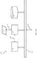
- FIG. 1is an illustration depicting a robot racing game comprising an attention spot light, according to some implementations.
- FIG. 2is an illustration depicting the attention spot light useful with the game of FIG. 1 , according to some implementations.
- FIG. 3is an illustration depicting guiding of robotic toys of FIG. 1 using the attention spot light, according to some implementations.
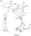
- FIG. 4is an illustration depicting a robotic aircraft inspection apparatus comprising attention spot light, according to some implementations.
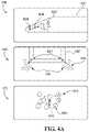
- FIG. 4Ais an illustration depicting impact of a feature on attention of a robotic device, according to some implementations.
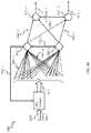
- FIG. 5is an illustration depicting exemplary trajectories of the robotic aircraft inspection apparatus of FIG. 4 , according to some implementations.
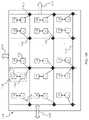
- FIG. 6Ais a block diagram illustrating robotic context of the disclosure, according to some implementations.
- FIG. 6Bis a graphical illustration depicting robotic context generation, according to some implementations.
- FIG. 7Ais a logical flow diagram illustrating operation of the robotic apparatus of FIG. 4 , in accordance with some implementations.
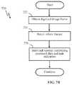
- FIG. 7Bis a logical flow diagram illustrating storing of task context by the robotic apparatus of FIG. 4 , in accordance with some implementations.
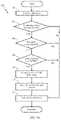
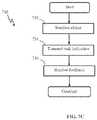
- FIG. 7Cis a logical flow diagram illustrating control of attention of the robotic apparatus of FIG. 4 , in accordance with some implementations.
- FIG. 8is a logical flow diagram illustrating transfer of context learned by the robotic apparatus of FIG. 4 , in accordance with some implementations.
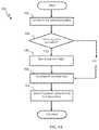
- FIG. 9Ais a logical flow diagram illustrating generalized method for life cycle management of learning network of a robotic apparatus, in accordance with some implementations.
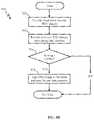
- FIG. 9Bis a logical flow diagram illustrating generalized method for cloud store of learned traits life cycle management, in accordance with some implementations.
- FIG. 9Cis a logical flow diagram illustrating provision of learned traits by the cloud store, in accordance with some implementations.
- FIG. 9Dis a logical flow diagram illustrating download of network image from cloud store, in accordance with some implementations.
- FIG. 10is a block diagram illustrating sensory processing apparatus configured to implement detection of salient features, in accordance with some implementations.
- FIG. 11Ais a block diagram illustrating a computerized system useful with the attention mapping methodology of the disclosure, according to some implementations.
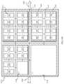
- FIG. 11Bis a block diagram illustrating a grid-type computerized system useful with the attention mapping methodology of the disclosure, according to some implementations.
- FIG. 11Cis a block diagram illustrating a hierarchical computerized system architecture useful with the attention mapping methodology of the disclosure, according to some implementations.
- FIG. 12is a functional block diagram illustrating a cloud server repository, according to some implementations.
- busis meant generally to denote all types of interconnection or communication architecture that is used to access the synaptic and neuron memory.
- the “bus”may be optical, wireless, infrared, and/or another type of communication medium.
- the exact topology of the buscould be for example standard “bus”, hierarchical bus, network-on-chip, address-event-representation (AER) connection, and/or other type of communication topology used for accessing, e.g., different memories in pulse-based system.
- the terms “computer”, “computing device”, and “computerized device”may include one or more of personal computers (PCs) and/or minicomputers (e.g., desktop, laptop, and/or other PCs), mainframe computers, workstations, servers, personal digital assistants (PDAs), handheld computers, embedded computers, programmable logic devices, personal communicators, tablet computers, portable navigation aids, J2ME equipped devices, cellular telephones, smart phones, personal integrated communication and/or entertainment devices, and/or any other device capable of executing a set of instructions and processing an incoming data signal.
- PCspersonal computers
- minicomputerse.g., desktop, laptop, and/or other PCs
- mainframe computersworkstations
- serverspersonal digital assistants
- handheld computershandheld computers
- embedded computersembedded computers
- programmable logic devicespersonal communicators
- tablet computerstablet computers
- portable navigation aidsJ2ME equipped devices
- J2ME equipped devicesJ2ME equipped devices
- cellular telephonescellular telephones
- smart phonespersonal integrated communication and
- ⁇may include any sequence of human and/or machine cognizable steps which perform a function.
- Such programmay be rendered in a programming language and/or environment including one or more of C/C++, C #, Fortran, COBOL, MATLABTM, PASCAL, Python, assembly language, markup languages (e.g., HTML, SGML, XML, VoXML), object-oriented environments (e.g., Common Object Request Broker Architecture (CORBA)), JavaTM (e.g., J2ME, Java Beans), Binary Runtime Environment (e.g., BREW), and/or other programming languages and/or environments.
- CORBACommon Object Request Broker Architecture
- JavaTMe.g., J2ME, Java Beans
- Binary Runtime Environmente.g., BREW
- connectionmay include a causal link between any two or more entities (whether physical or logical/virtual), which may enable information exchange between the entities.
- memorymay include an integrated circuit and/or other storage device adapted for storing digital data.
- memorymay include one or more of ROM, PROM, EEPROM, DRAM, Mobile DRAM, SDRAM, DDR/2 SDRAM, EDO/FPMS, RLDRAM, SRAM, “flash” memory (e.g., NAND/NOR), memristor memory, PSRAM, and/or other types of memory.
- integrated circuitAs used herein, the terms “integrated circuit”, “chip”, and “IC” are meant to refer to an electronic circuit manufactured by the patterned diffusion of trace elements into the surface of a thin substrate of semiconductor material.
- integrated circuitsmay include field programmable gate arrays (e.g., FPGAs), a programmable logic device (PLD), reconfigurable computer fabrics (RCFs), application-specific integrated circuits (ASICs), and/or other types of integrated circuits.
- FPGAsfield programmable gate arrays
- PLDprogrammable logic device
- RCFsreconfigurable computer fabrics
- ASICsapplication-specific integrated circuits
- microprocessorand “digital processor” are meant generally to include digital processing devices.
- digital processing devicesmay include one or more of digital signal processors (DSPs), reduced instruction set computers (RISC), general-purpose (CISC) processors, microprocessors, gate arrays (e.g., field programmable gate arrays (FPGAs)), PLDs, reconfigurable computer fabrics (RCFs), array processors, secure microprocessors, application-specific integrated circuits (ASICs), and/or other digital processing devices.
- DSPsdigital signal processors
- RISCreduced instruction set computers
- CISCgeneral-purpose
- microprocessorsgate arrays (e.g., field programmable gate arrays (FPGAs)), PLDs, reconfigurable computer fabrics (RCFs), array processors, secure microprocessors, application-specific integrated circuits (ASICs), and/or other digital processing devices.
- FPGAsfield programmable gate arrays
- RCFsreconfigurable computer fabrics
- ASICsapplication-specific integrated
- a network interfacerefers to any signal, data, and/or software interface with a component, network, and/or process.
- a network interfacemay include one or more of FireWire (e.g., FW400, FW800, etc.), USB (e.g., USB2), Ethernet (e.g., 10/100, 10/100/1000 (Gigabit Ethernet), 10-Gig-E, etc.), MoCA, Coaxsys (e.g., TVnetTM), radio frequency tuner (e.g., in-band or OOB, cable modem, etc.), Wi-Fi (802.11), WiMAX (802.16), PAN (e.g., 802.15), cellular (e.g., 3G, LTE/LTE-A/TD-LTE, GSM, etc.), IrDA families, and/or other network interfaces.
- FireWiree.g., FW400, FW800, etc.
- USBe.g., USB2
- Ethernete.g.,
- neurodeAs used herein, the terms “node”, “neuron”, and “neuronal node” are meant to refer, without limitation, to a network unit (e.g., a spiking neuron and a set of synapses configured to provide input signals to the neuron) having parameters that are subject to adaptation in accordance with a model.
- a network unite.g., a spiking neuron and a set of synapses configured to provide input signals to the neuron having parameters that are subject to adaptation in accordance with a model.
- stateand “node state” is meant generally to denote a full (or partial) set of dynamic variables used to describe node state.
- connectionAs used herein, the term “synaptic channel”, “connection”, “link”, “transmission channel”, “delay line”, and “communications channel” include a link between any two or more entities (whether physical (wired or wireless), or logical/virtual) which enables information exchange between the entities, and may be characterized by a one or more variables affecting the information exchange.
- Wi-Fiincludes one or more of IEEE-Std. 802.11, variants of IEEE-Std. 802.11, standards related to IEEE-Std. 802.11 (e.g., 802.11 a/b/g/n/s/v), and/or other wireless standards.
- wirelessmeans any wireless signal, data, communication, and/or other wireless interface.
- a wireless interfacemay include one or more of Wi-Fi, Bluetooth, 3G (3GPP/3GPP2), HSDPA/HSUPA, TDMA, CDMA (e.g., IS-95A, WCDMA, etc.), FHSS, DSSS, GSM, PAN/802.15, WiMAX (802.16), 802.20, narrowband/FDMA, OFDM, PCS/DCS, LTE/LTE-A/TD-LTE, analog cellular, CDPD, satellite systems, millimeter wave or microwave systems, acoustic, infrared (i.e., IrDA), and/or other wireless interfaces.
- an arbitrarily configured environmentsuch as, the environment which the robot may not be familiar with (e.g., a search and rescue robot) as opposed to the environment which the robot has a detailed knowledge of, e.g., assembly line robotic manipulator arm.
- Attracting attention of the robotmay be particularly useful without being required to have detailed knowledge of intricacies of the robot internal designs, continuing remote operation of the device, and/or develop specialized software applications for controlling robotic devices.
- Irradiatione.g., illumination
- an external agente.g., a human user, a pre-installed beacon, and/or an intelligent robotic controller
- may illuminatee.g., using a beam of light
- the agentmay modify the spectral power distribution of a portion of the environment in order to draw attention of the robot.
- the robotmay use these properties to guide its attention.
- the robot guidancemay be aided by way of an additional signal transmitted by the agent to the robot indicating that the object has been illuminated and attention switch may be required.
- the robotmay initiate a search for the signal reflected by the illuminated area requiring its attention. For example, a beam of light may be used in order to indicate the surface, object, and/or activity that should be attended to and/or acted upon by the robot.
- the additional signalmay be transmitted using a separate button function of the flashlight.
- the additional signalmay indicate to the robot a type of action that may need to be performed once the robot identifies the illuminated area.
- a single clickmay indicate a cursory examination and/or taking of a digital picture
- a double clickmay be indicative of a more thorough inspection, comprising, for example, recording of an ultrasonic and/or high resolution microscopic imagery.
- the robotmay develop an association between the two events and the inspection task.
- the task association datamay be stored by the robot for future use in order to be able to initiate the task in the future.
- a cloud-based repository 1206 of robotic device “brain images”(e.g., neural network state information) is introduced. Users may access the cloud repository (such as under a subscription, per-access, or other business model) and browse available brain images created by other users. Brain images may also be offered for purchase via the repository in an online “app” store model. Other related content such as user-created training related media (e.g., a video clip of “how I trained my robot” or the like) may be available through the repository and social forums and links.
- user-created training related mediae.g., a video clip of “how I trained my robot” or the like
- a cloud-based repositorymay store pairs of contexts and attended regions. These pairs may comprise signals provided to the robot for its learning in real time, and/or may be applied at other times to other robots. This implementation may allow another (or the same) robot with a different internal state (a different “brain image”) to apply the learning without overwriting its previously learned information.
- a robot racing gamemay be developed as entertainment, as illustrated in FIGS. 1-3 .
- Two (or more) players 102 , 104may compete in racing the toy cars 110 , 120 , using the attention spot light 106 _ 1 , 106 _ 2 .
- the attention spot light 106may comprise a flashlight configured to radiate light beams of light that comprise a different characteristic.
- the characteristicmay comprise wavelength, spectral composition, and/or polarization.
- the flashlight 106may employ a filter 202 in order to adjust spectral characteristics (e.g., color) of the beam 204 , of the spot-light device 206 , as shown in FIG. 2 .
- the spot light device 206may be utilized for guiding the moment in time, location, and/or size of region that ought to be attended to by the robot.
- the spot-light device 206may comprise a hand-held device configured similar to a laser pointer and/or flashlight.
- the device 206may comprise additional functionality, such as for example, one or more of (i) a programmatic pairing link with the attention block of the robot (e.g., the robotic car 110 of FIG.
- adjustable beam-widthin order to control the extent of the attended (target) region;
- one or more buttonsconfigured to provide supplementary contextual information to the robot;
- a wireless communication blockconfigured to communicate to the robot non-visual information (e.g., button presses);
- a feedback indicatorconfigured to providing a confirmation that the context was received by the robot; and/or other functionality.
- the context button 204may be paired with the beam 208 generation in order to convey to the robot “act now on this” and/or “reinforce this label right here and now” tasks.
- the feedback indicatormay comprise a vibration device, an audible indication, and/or a visual indication (LED a light and/or a mini-display).
- Beams of different lightmay be used, for example, to attract attention (e.g., guide) of a particular robotic cars 110 , 120 .
- Individual robots 110 , 120may be characterized by a sensing field of view 112 , associated, for example, with the aperture of the robot's sensor.
- the sensor(not shown) may comprise a digital camera comprising a lens and an imaging array. Examples of an imaging array may include one or more of a charge coupled device (CCD), CMOS device, an active-pixel sensor (APS), and/or other imaging array.
- the beam characteristicsmay be intentionally configured to be the same or similar to one another. Such configuration may enable the players to distract opponent's robot when the other player is not actively guiding it. However, when lights of both flashlights are present in the robot's visual field 112 , its own players light source may overpower the contribution by the opponent's flashlight.
- a sensing device of the robotmay process the data within the visual field 112 .
- datamay comprise a sequence of digitized image frames.
- Color processing algorithms implemented by the robots 110 , 120may be configured to identify a region within the frames that may be illuminated by the external attention-trigger apparatus (e.g., the flashlight 106 ).
- the detected beam footprint 114may be subtracted from the frame data so that the color merely allocates the region of interest.
- a playermay select a door at the far end of the room, instructing its robot (e.g., the robot 110 ) to proceed to that location.
- selecting an object within the environment by placing the flashlight beam onto the objectmay be referred to as providing structured spatial contextual information to the robot.
- the playermay shine the light on the opponent's robot (e.g., the robot 120 ).
- selecting the opponent's robotmay act as a command to that robot (e.g., the robot 120 ) follow the player's own robot ( 110 ).
- the robots 110 , 120may comprise processing apparatus operating computer executable code (i.e., program) implementing desired functionality.
- the processing apparatusmay comprise neuromorphic computerized apparatus configured to operate spiking neuron network, as described in detail with respect to FIGS. 11A-11C , below.
- the programmay use the union of the command (“light on robot”) and the detection of a visual feature in the attended region (e.g., “detect robot”), to initiate the following behavior. Shining a light on another object (e.g., the door) may not cause the robot to follow the door, because there is no robot detected in the selected region.
- FIG. 3illustrates one example of a track for use with the attention spot light and the car race game.
- the robots 310 , 320may follow the track 302 in front of them.
- Autonomous toy robotsmake random choices when the track forks 304 , 306 .
- the playermay bias the robot's choice to favor the guided route. In this manner a player may prevent a robot from getting stuck in a side loop 308 , or may lure an opponent's robot into such a loop.
- a robotic system 400may comprise a robotic apparatus 410 configured to inspect an aircraft airframe 402 and/or power plant (not shown) for cracks, as illustrated and described in detail with respect to FIG. 4 .
- the robot 410may be assigned a task of locating candidate regions 414 that may require repair and/or further inspection as a part of regular aircraft maintenance over time.
- an operatormay guide the robot 410 (e.g., position aperture 416 of the robot sensor 412 ) to a location 414 of known or suspected damage.
- the guidancemay be effectuated by using a spot-light device 406 (e.g., the device 206 of FIG. 2 ).
- the spot-light 406may illuminate a portion 404 of the area 414 that may require inspection.
- the operatormay be conveying to the robot the message “this kind of region is worth inspecting.”
- the spot-light 406may comprise one or more buttons (e.g., the buttons 204 in FIG. 2 ), and a wireless communications block configured to communicate a context indicator to the inspection robot 410 .
- the spot-light 406may comprise a feedback display configured to provide a confirmation to the operator that the inspection robot 410 has received task instructions and/or commenced task execution.
- the robot 410may assess the region in the vicinity of the beam footprint and/or provide a report to the operator.
- the reportmay indicate the outcome of the inspection, an intensity score, a pass or fail, a confidence score, a summary of key properties measured, or why the inspection was not performed, if it was not, and/or additional information.
- the robot 410may collect additional sensory information about the surrounding of the footprint.
- a robotmay have one or more cognitive channels associated with the same or different tasks (and/or sub-tasks).
- a given cognitive channelmay comprise mapping of a sensor state onto an action.
- the mappingmay be based on: 1) selecting sensor states that are more important 626 , 646 , 666 , 686 ; and/or 2) determining how to act on the contents of the selected sensor state 628 , 668 .
- an actionmay comprise an internal command (e.g., “keep searching”).
- the internal commandcomprises low dimensional signals (even discrete commands).
- the robot 410may generate a context associated with the region.
- the contextmay comprise information in its primary sensory domain (“ultrasound context”), other sensory domains (“camera context”), and/or other kinds of data. Examples of other kinds of data may include one or more of “recent actions initiated”, “recent commands received”, “my relative location with respect to this plane”, and/or other kinds of data.
- the contextmay comprise raw and/or processed (e.g., using contrast enhancement and/or edge tracing to detect cracks) portion of the frame 418 comprising the area of potential damage.
- the processed sensory datamay be stored as the activity of spiking sensory neurons represented as a vector of activity across regions and features by means of the aggregate impulse activity or a code based on relative timing of impulses.
- the spot-light 406 and the inspection 412may employ different technologies. Examples of such different technologies may include one or more of visible light, ultrasonic, infrared, ultraviolet, x-ray, and/or other technologies.
- the spotlightmay utilize visible light, while inspection sensor 412 may perform x-ray-based non-destructive test (NDT).
- NDTnon-destructive test
- the data(e.g., the digitized frame 416 ) obtained responsive to the spot-light operation, may be offloaded via a communications link to a remote processing resource (e.g., a remote server).
- a remote processing resourcee.g., a remote server
- the stored contextmay be subsequently used to train the other inspection systems and/or other robots 410 .
- the robot 410may be able to locate other potential areas of damage without relying on the human controller.
- Sufficient trainingmay include inspecting a number of features 414 for signature of damage and/or collecting contexts associated therewith.
- the robotic inspector 410may generalize and apply the knowledge gained upon inspecting one type of airplanes, to other same airplane types previously not serviced by the robot.
- the robotmay determine, based on the history record of inspected areas, that areas where wings couple to the fuselage, and/or areas surrounding windows and cockpit may require frequent inspection, that when it has found a problem at a particular window it should also check other windows that share common causes of wear, that when it is particularly cold, it should also check additional regions.
- FIG. 4Aillustrates an impact of a feature on attention of a robotic device.
- the panel 430depicts a view (from the robot's perspective) comprising the wing of an airplane 432 .
- the viewcomprises a learned feature 434 , which may have a strong response proximate the tip of the airplane wing and which may have been previously learned by the robot.
- the arrow 436indicates that the attention of the robot is directed to regions containing the circles, denoted 438 in FIG. 4A .
- the presence of strong activity at location 434 in the learned feature layermay increase the attention at location 438 , ultimately emphasizing the features of the image context that are located at 438 .
- the relative mapping from the feature 434 to the attended region 438may be learned by the robot from the previous robotic contexts.
- the panel 440illustrates a view from the robot's perspective comprising the bottom half 442 of a window.
- Features 444 disposed proximate the corners of the windowsmay have been learned by the robot.
- the arrows 446indicate that the attention of the robot is directed to regions containing the circles 448 .
- the relative mapping from learned feature to the attended regionmay have been learned from previous robotic contexts.
- the panel 450illustrates a view from the robot's perspective comprising texture pattern 452 .
- An arbitrary characteristic (feature) of the texture pattern 452 that has been learned by the robot, and its centroid,may be specified by the arrow 456 .
- the circles 458denote the locations of increased attention due to the presence of the feature 456 .
- the relative mapping from learned feature to the attended regionmay be learned from previous robotic contexts.
- attention spot-light methodologymay reduce inspection duration as illustrated in FIG. 5 .
- the panel 500 in FIG. 5represents a conventional grid-like search pattern that may be used by a pre-programmed inspection robot (e.g., the robot 510 of FIG. 4 ) configured to inspect an airplane wing. While the inspection may require evaluation of a few potential problem areas 504 , denoted by dark shapes, the route 502 of the robot camera may extensively cover other areas that may not require detailed inspection at this time. When the search grid is too coarse (e.g., space between adjacent survey path is wider than size of the defective area illustrated by the path 503 , 505 in FIG. 5 ), one or more areas of potential damage may be missed, as shown by the area 504 in the panel 500 . If a grid search is exhaustive, the duration of a complete search may render it infeasible to perform frequently and/or to identify new problems in a timely manner.
- the panel 510 in FIG. 5represents a spot-light-aided search pattern 512 obtained by the robot with the aid of the attention spot-light 406 of FIG. 4 .
- the context-aided inspection route 512may be shorter than the pre-programmed route 502 leading to a shorter inspection time and/or reduced inspection cost. The use of context aided route may help ensure that all of the potential areas of damage are covered by the inspection route 512 .
- the robotsmay learn to adjust their attention based on the mapping between the learned feature and a particular task at hand. Attention may serve one of more of the following purposes: (i) to determine which features to select in order to determine the next task, (ii) to determine which features to select in order to optimally complete the current task, and/or other purposes.
- attentionmay be described as the impact of learned features X, upon other robotic features F given a particular task state T. Learning may determine the function which generates a vector of scalars A, that adjusts the gain of every feature in F, typically, though not necessarily, based on its spatial position in the map.
- Af ( X,T ) (Eqn. 1)
- FA*F (Eqn. 2)
- mappingsmay include the mapping of attention during search which determines where the robot should look next, the mapping of attention when performing an x-ray which optimized the robots accurate assessment, and/or other mappings. Attention may be deployed by the robot when determining which task to perform next. In this example, it may be the choice of weather to keep searching or to image at the current location.
- a successful learning algorithmmay use the context to select the region of the image to attend to that a human expert would have indicated, had they been there to guide the robot at each task.
- FIG. 6Billustrates robotic attention guided by the robotic context on a trained robot, in accordance with one or more implementations.
- the flow of behavior of a robotmay include selecting a task to keep looking 628 , choosing to look at a particular region 646 , selecting to perform a task of doing an x-ray inspection 668 , choosing to perform the x-ray inspection a particular way 656 , and/or other operations.
- An attention signalmay be provided to the robot.
- the attention signalmay be effectuated using the spot-light 206 , 406 described above with respect to FIGS. 2 and 4 .
- FIG. 6Billustrates robotic attention guided by the robotic context on a trained robot, in accordance with one or more implementations.
- the flow of behavior of a robotmay include selecting a task to keep looking 628 , choosing to look at a particular region 646 , selecting to perform a task of doing an x-ray inspection 668 , choosing to perform the x-ray inspection a particular way 656 , and/
- the attention 626 , 646 , 666 , 686may be determined by the robot based on its context 630 , 640 , 660 , 680 before attention.
- the attention determinationmay be based on, for example, the learned feature and task indication.
- a taskmay be to select in the attention signal 626 of FIG. B.
- a scene 620may be provided to the robot.
- the scene 620may be related to the robot's environment and/or an object to be inspected.
- the robot context 630 at this stagemay include additional components 624 .
- additional components 624may include one or more of sensor data, command queue, clustered state of the robotic context, and/or other components.
- the clustered state of the context 624 , 644 , 654 , 684may comprise a single state variable derived from all other aspects of the robotic context.
- the clustered statemay be a low-dimensional representation of the robotic context, as computed by an unsupervised learning algorithm.
- the robotmay utilize scene data to derive one or more features (e.g., the feature 418 of FIG.
- the attention indication 626 , 646 , 666 , 686may be combined with the features to form an updated representation of the features 622 , 642 , 652 , 682 reflecting the impact of the attention.
- the robotic context 630 , 640 , 660 , 680 after the impact of attentionmay be used to select the next action 628 , 668 and/or to provide the best sensory data to guide the performance of a particular action 646 , 656 .
- a different cognitive channelmay be subscribed to for individual tasks, such as in a case where additional sensory channels are included.
- the different cognitive channelmay include 684 , which may comprise X-ray features within the robotic context 680 .
- learning by a robotmay be aided by an error signal.
- the error signalmay convey a difference in the robots internal attention algorithm, the region selected by the user, and/or other information.
- the error signalmay enable the robot to incrementally improve an estimation of the “correct” region to attend to in an online manner.
- Off-line learningmay be used to minimize attentional error across a database of actions and/or contexts associated with individual actions.
- a classification of the task to perform when selecting an actionmay be based on the current context.
- the taskmay comprise an N-way classification given labeled data.
- labelsmay be generated as follows:
- Some algorithmsmay group training samples into one of two groups: positive and negative examples. Some algorithms may treat passive and actively bound samples differently, for example, by ignoring passive training samples or weighting them differently. In task selection, both forms of learning may occur. That is, learning of which features to attend to in order to perform the task, as well as the mapping of the attended features to the selected task may occur, in some implementations.
- the learning storemay provide a format converter between robotic contexts of the same channel that differ by resolution of learned features and image features.
- the convertermay use interpolation, up-sampling and/or down-sampling, super resolution, density estimation techniques, and/or other operations to approximate the experience that another robot would have had, had it been in the same context of the robot that actually recorded the context action sample.
- interpolationmay be performed between different kinds of sensors and image features.
- Some implementationsrelate to a method that enables users of robotic devices to have the ability to share content related to the training of such robotic devices.
- a usermay extract the state of a neural network and/or other useful training-related information directly from the device. An artificial mind and its traits may be copied, stored, and later retrieved, as described in detail with respect to FIG. 12 below. This state information may be shared with other users. A user may download such stored state information (whether from networked or cloud storage, or in a peer-to-peer (P2P) fashion) and apply it to a second neural network, effectively duplicating the first neural network.
- P2Ppeer-to-peer
- the usermay apply the experience of learning by one robot to operation of another robot by transferring training examples in the form of pairs of context 600 and valid command 702 , where one particularly important command is paired with attentional allocation 734 .
- the robotmay update its internal function based on the concatenation of its previous training examples, and those obtained from the cloud, or it may be scheduled to stochastically update from its training samples in an online fashion, so that each exposure of a training example results in a small change in the robot's total learned state.
- a cloud-based repository 1200 of robotic device “brain images”may be introduced.
- the repositorymay comprise cloud server depository 1206 .
- one or more remote user devices 1210may connect via a remote link 1214 to the depository 1206 in order to save, load, update, and/or perform other operation on a network configuration.
- the one or more remote user devices 1210may further interface with a local user computerized device 1204 via a local link 1208 in order to facilitate learning configuration and software maintenance of the user device 1210 .
- the local link 1208may comprise a network (e.g., Ethernet), wireless (e.g., Wi-Fi, Bluetooth, infrared, radio, and/or other wireless), serial link (e.g., USB, Firewire, and/or other serial links), and/or other links.
- the local computerized device 1204may communicate with the cloud server depository 1206 via link 1212 .
- the local computerized device 1204may comprise a tablet and/or a smartphone device.
- the local computerized device 1204may comprise the indication providing device (e.g., the attention spot light 106 , 206 , described above with respect to FIGS. 1-2 ).
- links 1212 and/or 1214may comprise an internet connection effectuated via any of the applicable wired and/or wireless technologies.
- wired and/or wireless technologiesmay include one or more of Ethernet, WiFi, LTE, CDMA, GSM, and/or other technologies.
- the connectivity structure of the exemplary computerized apparatus 1150 , the user interface device 1202 , and/or the cloud server 1206 , described with respect to FIGS. 11C and 12 , respectively, below,may be designed to aid in fostering a social environment in which the computerized neuromorphic apparatus 1150 are trained.
- usersmay access content shared by other users.
- This contentmay include media related to the training of the computerized neuromorphic apparatus 1150 (e.g. videos, pictures, collected sensor data, wiki entries on training techniques/experiences, forum posts, and/or other media), brain images, third-party/homebrew modifications, and/or other information.
- Usersmay form user groups to collaborate on projects and/or focus on specific topics.
- Usersmay form user groups to focus on collective formation of a brain image (somewhat akin to extant distributed gaming interaction).
- a usermay cross-link to groups and content on third-party social media websites.
- Third-party social media websitesmay include one or more of Facebook®, Twitter®, and/or other third-party social media websites.
- notificationsmay be sent directly to the robot via a machine-readable format or RSS feed, with automatic updating according to the robotic owner's preferences.
- FIG. 6Aillustrates some implementations of robotic context comprising clustered state.
- the panel 600may comprise one or more information categories accessible to a robot (e.g., the inspection robot 410 of FIG. 4 ).
- the information 600may comprise context related to the imager 412 _ 1 , comprising, for example, raw pixel data, features detected within the image (e.g., the feature 418 , edges, etc.).
- the information 600may comprise context related to another imager (e.g., the X-ray imager 412 _ 2 ), sensor data, and/or one or more queues configured to store last several commands received, actions performed, and/or results stored by the robot.
- One realization of the command/action/result data portionis presented in Table 1, where commands/actions/results are denoted using respective identifier numbers.
- the information 600may be processed using, for example, a clustering technique 604 .
- the output of the clustering techniquemay comprise a clustered state data 608 , comprising either a single ID and a confidence of belonging to that state, or a low dimensional vector of values that are a more interpretable summary of the high dimensional robotic context.
- FIGS. 7A-9Ddescribe exemplary methods that illustrate various implementations of guiding attention of the disclosure.
- FIG. 7Aillustrates a method of operating a robotic apparatus (e.g., the apparatus 110 of FIG. 1 and/or inspection robot 410 of FIG. 4 ), in accordance with some implementations.
- a robotic apparatuse.g., the apparatus 110 of FIG. 1 and/or inspection robot 410 of FIG. 4
- a task indication and/or a commandmay be received.
- a task indicationmay include one that is similar to or the same as that described below with respect to step 734 of FIG. 7C .
- the robotmay verify that the indication comprises a known and/or a compatible task. Responsive to a compatible task indication being received, an acknowledgment feedback may be transmitted to the agent. If the task is deemed incompatible by the robot, the method may proceed to step 714 where a feedback indicative of the incompatible task may be communicate back to the agent. Responsive to receipt of a task notification, prior to performing the task, the robot may save the state of its recent context, which is passing through a circular memory buffer. This may be referred to as the “robotic context”.
- a robotic contextmay include one or more of the state of the robot sensors, other internal states of the robot, a recent history of commands given to the robot, actions taken by the robot, the result of those actions, and/or other robotic contexts.
- An exemplary robotic context 610is illustrated in FIG. 6A . Responsive to a user issuing a command (e.g., to pick up a particular object), a snapshot of the robotic cognitive state 600 may be saved. The cognitive state may be paired with the command thereby generating the context.
- the cognitive snapshot 600may comprise image context (e.g., pixels, features, and/or learned features), as illustrated in FIG. 6A .
- the image contextmay be mapped into a spatial image domain.
- Pixel contextmay comprise the RGB values of the last acquired digital image, prior to the command.
- the imagemay be shifted by a constant offset in time, according to the channel.
- two or more imagesmay be acquired to suit the needs of sampling the context at the moment that the user issues the command, and the moment that the secondary imaging device (e.g., x-ray, and/or device 412 _ 2 in FIG. 4 ) is activated.
- the image context 612may comprise features associated with the current state of the robots low-level image processing. These features may comprise, for example, the results of operating algorithms for edge finding and/or location extraction of the attention spotlight signaled by the user.
- the image context 612 componentmay comprise a spatial map that results from one of the learned features that are being dynamically updated by the robots.
- the mapmay be implemented via a template applied to the image features.
- the learned feature mapmay comprise a hierarchy of computed image features.
- An airplane-inspecting robotmay maintain a learned map for windows, wing edges, latches, and cracks.
- Robotic contextmay comprise the current state of activation for learned internal states that are not in the image domain, such as from an artificial cerebellum or an artificial hippocampus.
- the robotic context 610may comprise the spatial map of a secondary image domain (e.g., X-ray 614 in FIG. 6A ), which, in this example, may be an x-ray image.
- a secondary image domaine.g., X-ray 614 in FIG. 6A
- the x-ray imagemay be in register with image context 612 pixels.
- the robotic context 610may comprise a queue of most recent commands, actions, results 616 , and/or other contextual information.
- Table 1illustrates one example of such queue, which may comprise a current command, current action, current result, last command, last action, last result, and/or other information.
- a different instantiationmay use a queue of length 1, 2, 10, 100 or 1000.
- a commandmay include a particular discrete category of command issued by the user to the robot, and/or any associated metadata.
- Such metadatamay include a command x-ray a certain location.
- An actionmay be the response of the robot. Examples of an action may include one or more of moving to a new location, taking the x-ray, and/or other actions.
- a resultmay be the outcome of an x-ray analysis. Examples of an outcome may include one or more of whether or not a crack was found, and/or other outcomes.
- a robotic contextmay include the state of the relevant sensors 618 that are not in the image domain. Examples of relevant sensors 618 may include one or more of a GPS, an accelerometer, a thermometer, and/or other sensors.
- the sensorsmay have a historical queue, sampled along with the queue of commands, actions and results.
- the robotic contextmay comprise a summary of the entire contextual state which is a low dimensional description of the state 608 resulting from a pre-specified clustering or compression algorithm 604 .
- the algorithm 604may be shared across several robots in the same cognitive channel. Such a clustered state may improve an ability of learning algorithms to make use of common shared states, and/or may facilitate online human monitoring of all the robots belonging to a single cognitive channel.
- the robotic apparatusmay begin detection of the sensory input that was indicated by the attention signal.
- the attention signalmay comprise the object irradiation signal, such as the footprint 404 of FIG. 4 and/or the transmission of step 732 of FIG. 7A .
- the methodmay proceed to executing the task at step 708 of the method 700 . If no sensory input is detected due to, for example, the object being out of range of the robot sensor (e.g., the sensor 412 of FIG. 4 ) the task may be deemed incompatible by the robot, the method may proceed to step 714 where a feedback indicative of the undetectable sensor data may be communicate back to the agent.
- the robot sensore.g., the sensor 412 of FIG. 4
- the methodmay proceed to step 714 where a feedback indicative of the undetectable sensor data may be communicate back to the agent.
- the robotmay perform an association between the task indication (e.g., the indication received at step 702 ) and a portion of the data obtained during task execution, thereby augmenting the context action pair as containing a particular label pertaining to the outcome of the action.
- the outcome of the inspectionmay be included for subsequent learning algorithms that can make use of it, enabling the system to outperform human attention guidance in the future.
- a portion of the data obtained during task executionmay comprise a processed image taken in the vicinity of the area of attention (e.g., an edge-trace of area 418 of FIG. 4 comprising signature of defects).
- This post-action context featuremay have the capacity to be derived from a different sensor, which may be only conditionally deployed due to its cost in power, time, and/or other constraint.
- the robotmay subscribe to two or more cognitive channels.
- a first cognitive channelmay pertain to exploration, and may contain attention guided to a feature space of a low cost camera.
- a second cognitive channelmay pertain to the use of a costly or time consuming ultrasound imaging system, implementing the same system of context storing, data sharing, and learning.
- the first contextmay select between sensory regions to coordinate a search process based on standard image data.
- the second contextmay coordinate how long to keep performing a detailed ultrasound imaging process, or what to do if the results of the initial analysis are inconclusive.
- the context and (a sub-set) of the task output datamay be stored by the robot internally.
- the task datamay be off-loaded for storage at an external depository.
- a contextmay be stored without the user triggering an action.
- a labelmay be automatically associated with it, indicating no action was taken.
- These random samplesmay be modified or pruned if a user performs an action with a short temporal window. The sample may no longer indicate that no action should be performed, because the latency of sample to the action generation may be the cause of the human operator's latency in processing the world and calculating that the robot should act.
- the frequency of sampling the context of inactionmay be determined by the robots settings, which may be configured by a particular cognitive channel that the robot may subscribe to.
- a confirmation of successful task executionmay be transmitted to the agent.
- FIG. 7Billustrates one implementation of determining of the task context (e.g., the context described with respect to step 712 of method 700 ).
- a digitized image of the area(e.g., the area 414 surrounding the object of interest (e.g., the object 404 ) may be obtained.
- a salient featurewithin the image (e.g., the image 416 ) may be detected using a variety of processing techniques.
- processing techniquesmay include one or more of contrast enhancement, edge tracing, spectral and/or spatial transforms, and/or other processing techniques.
- the salient featuremay be detecting using spatio-temporal winner takes all (WTA) methodology described in detail in U.S. patent application Ser. No. 13/548,071, filed Jul. 12, 2012, entitled “SPIKING NEURON NETWORK SENSORY PROCESSING APPARATUS AND METHODS,” now U.S. Pat. No. 8,977,582, incorporated supra.
- the task contextcomprising for example the task ID of step 702 of FIG. 7 and data pertaining to the salient feature, e.g., the size and/or the location of the feature 414 in FIG. 4 .
- the context data(e.g., the context stored at step 726 of FIG. 7B ) may be subsequently used by the robotic device to perform the task associated with the context.
- the task execution aided by the stored contextmay be effectuated in absence of object irradiation by the agent.
- a new robotmay be deployed with no personalized training data.
- Initial state of the robot network(robotic brain) may be determined by an offline learning algorithm that was informed by one or more previously stored samples of contexts and/or actions performed by other robots.
- the offline learning algorithmmay include machine learning methods for supervised learning like regression, na ⁇ ve Bayes, random forests, boosting, support vector machines, genetic algorithms, classical artificial neural networks, spiking neural networks, and/or other statistical estimation techniques.
- the robotWhen the robot is set to explore or scan the environment, its image sensors may pick up new data that emphasizes components learned from this data. For example, the camera may happen to pass over a joint between the wing and body of the plane, which includes high frequency visual information indicative of a crack. An operator may not be required to indicate to the robot that this region deserves a detailed ultrasound image.
- the contextmay be invoked at two separate points in the robots control process: i) what region in the current context is worth attending to, and ii) if attending to a region that contains a known object type, what action to perform, in accordance with some implementations.
- the robotmay update its internal state using an online learning algorithm, and/or may send the context action pair back to the cloud storage.
- the present disclosurecontemplates ability of robotic devices to transfer and/or exchange the stored learned context(s) with other robotic devices in order to facilitate task execution.
- the transfermay be accomplished by upload/download of SNN image(s) comprising learned context.
- an inspection robotic apparatus Imay be operated in Seattle to inspect wings of the Boeing 737 aircraft, where it is trained to pay special attention to selected areas A-D.
- Another inspection robotic apparatus IImay be operated in Portland to inspect wings of a different the Boeing 737 aircraft, where it is trained to pay special attention to selected areas E-F.
- the SNN images of the two robots I, IImay be merged to generate a composite network that may be capable of performing inspection of the areas A-F.
- FIG. 7Cillustrates one exemplary implementation of a method for controlling attention of the robotic apparatus (e.g., the apparatus 110 of FIG. 1 and/or inspection robot 410 of FIG. 4 ).
- the methodcontemplates the use of an external agent for controlling attention of the robot, operable in an environment comprising one or more objects of interest (e.g., a portion of airframe, a race track, and/or other objects).
- objects of intereste.g., a portion of airframe, a race track, and/or other objects.
- an external agentmay irradiate the object of interest (e.g., the area 404 of the aircraft wing).
- the agentmay utilize a spot light 206 of FIG. 2 emitting a beam of visible, infrared, ultra violet, and/or other wavelengths of light.
- the agentmay utilize a radio frequency (RF) transmitter.
- the agentmay utilize a sound transmitter to insonify an object underwater when controlling an underwater robotic device. The irradiating of the object may serve as an indication to the robotic device of the area (e.g., the footprint 404 ) that may require its attention. As illustrated in FIG. 4 , the beam footprint 404 may cover a portion of the area of interest 414 .
- the robotic devicemay comprise sufficient built-in and/or learned intelligence in order to be able to explore the surrounding indicated by the agent.
- the agentmay further communicate to the robotic device an indication of a task to be performed that may be associated with the area/object of interest.
- the task indicationmay be communicated using the device used for irradiating the object (e.g., the spot light 206 comprising one or more buttons 204 ).
- the device used for irradiating the objecte.g., the spot light 206 comprising one or more buttons 204 .
- various tasksmay be performed, such as, for example, taking an image of the object, obtaining a physical sample, approaching the object, etc.
- the task indication of step 734may comprise task ID (e.g., single click, double click, etc.).
- task IDe.g., single click, double click, etc.
- Various task encoding methodologies exist in the artssuch as pulse width modulation, phase, frequency, amplitude modulation, and/or other methodologies.
- feedbackmay be received by the agent from the robotic device.
- the feedbackmay inform the agent that the robot has commenced task execution and/or has completed the task. If the robot is unable to execute the task due to a variety of reasons such as, unavailable resource (e.g., a low battery, and/or the selected region is beyond the sensor range, and/or full sample compartment and/or memory) and/or an obstacle in its path, the feedback may comprise a flag indicating that the task cannot be completed.
- unavailable resourcee.g., a low battery, and/or the selected region is beyond the sensor range, and/or full sample compartment and/or memory
- the failure flagmay be returned when the robotic device is unable to interpret the task notification, due to, for example, having an incompatible and/or outdated configuration (e.g., an inspection only robot receiving a task code to obtain core sample).
- a source and destinationmay be selected.
- the source and destinationmay each comprise the robotic device 410 of FIG. 4 .
- either the source or the destinationmay comprise an external depository described in detail with respect to FIGS. 9A-9D , below.
- the network imagecomprising one or more learned context, may be read from the target.
- the authorization of the transfermay be performed.
- the authorizationmay comprise image verification and/or validation in order to determine, for example, if the image is provided by a legitimate source; the target device is authorized and/or eligible to receive the image; and/or perform other certification tasks.
- the imagemay be downloaded to the target device at step 810 .
- the present disclosureenvisages the user ability to share content related to the training of such robotic devices.
- a usermay extract the state of a neural network (or other useful training-related information) directly from the device.
- the artificial mind and its traitsmay be copied, stored, and later retrieved.
- FIG. 9Aillustrates a generalized method for life cycle management of learning network of a robotic apparatus, in accordance with some implementations.
- a user of the robotic apparatusmay subscribe to network updates.
- the subscriptionmay comprise feature download or upload only.
- the subscriptionmay comprise both the download and upload options.
- the subscriptionmay provide user with subscription credit (monetary and/or points) for uploading new learned traits (e.g., the context described with respect to step 726 supra) into the depository.
- the usermay train the robotic apparatus to learn task association (e.g., context) in accordance with any of the methodologies described above with respect to FIGS. 1-6 .
- task associatione.g., context
- the usermay upload learned traits into the shared depository (e.g., the cloud store 1206 of FIG. 12 , described infra).
- the shared depositorye.g., the cloud store 1206 of FIG. 12 , described infra.
- the usermay check if network image(s) comprising new traits are available at the depository.
- the usermay download new traits at step 910 .
- FIGS. 9B-9Cillustrate generalized methods of cloud store operation configured to enable users of robotic devices to share learned traits, in accordance with one or more implementations.
- usersare provided with access to the cloud store (e.g., the depository 1206 of FIG. 12 ).
- the cloud storee.g., the depository 1206 of FIG. 12 .
- accessmay comprise a storefront being provided as a user interface to the cloud.
- purchasable contente.g. brain images, upgrades, alternate firmware packages.
- Purchasable contentmay allow users to conveniently obtain quality content to enhance their user experience. The quality may be controlled under any number of different mechanisms, such as peer review, user rating systems, functionality testing before the image is ‘uploadable’ and/or made accessible, and/or other mechanisms.
- usersmay prefer different starting points in training. Some users may generally prefer to begin with a clean slate, or to use only their own brain images as starting points. Users may generally prefer not to have to redo training that has already been (properly or suitably) performed. Users may appreciate having easy access to quality-controlled purchasable content.
- a subscription modelmay be used.
- a usergains access to content based on a periodic payment to the administrator of the networked service.
- a hybrid modelmay be used.
- An initial/periodic subscription feemay allow access to general material.
- Premium contentmay require a specific payment.
- the exemplary storefront implementationprovides a platform for such enterprise. Operators of storefronts may desire to encourage such enterprise both for revenue generation and for enhanced user experience.
- the storefront operatormay institute competitions with prizes for the most popular brain images, modifications, and/or media. Users may be motivated to create higher quality content.
- the operatormay (in or in lieu of a contest) instate a system of revenue and/or profit sharing for purchasable content. Hobbyists and casual developers may see a reasonable return on their efforts. Such a system may attract professional developers. Users as a whole may benefit from a wider array of content offerings from more skilled developers.
- a network image file(comprising, inter alia, new and/or improved learned traits) may be received from a user.
- the imagemay be verified for compatibility, consistency and/or presence of undesirable and/or malicious content (e.g., advertising and/or viruses).
- undesirable and/or malicious contente.g., advertising and/or viruses.
- FIG. 9Cillustrates provision of learned traits by the cloud store, in accordance with some implementations.
- the Storemay receive a user request to for an SNN image download.
- the requestmay be based on a purchase, peer-to-peer share, and or subscription-based service agreement with users of robotic devices.
- the requested datamay be provided to the user for download.
- the method of FIG. 9Dmay be used, for example, for operating the robotic apparatus 410 of FIG. 4 .
- the method FIG. 9Dmay be implemented for example in a robotic device configured for processing sensory data as described in FIG. 10 , infra, thereby advantageously aiding, inter alia, signal compression, and/or object recognition when processing visual sensory input.
- a source of the new network configurationmay be selected.
- the sourcecomprises another robotic device(s)
- a connection to the devicevia, e.g., USB, or a wireless link
- two (or more) robotic devicesmay be linked via a user computing device (e.g., a desktop, laptop, a smartphone, a tablet, and/or other computing device).
- a session with the Storemay be established.
- the method 960may proceed to step 966 , where the image type is selected.
- the imagemay correspond to the robotic brain image from another robotic device that has been previously trained, described in detail with respect to FIG. 4 , supra, while in some implementations, the image may correspond to the network merge described in detail in U.S. patent application Ser. No. 13/830,398, entitled “NEURAL NETWORK LEARNING AND COLLABORATION APPARATUS AND METHODS,” now U.S. Pat. No. 9,208,432, incorporated supra.
- the method 960may proceed to step 972 , where the individual traits and/or network blocks may be selected for download. Traits from multiple sources (multiple parents) may be selected and combined into a single image download via a network merge described in detail in detail in U.S. patent application Ser. No. 13/830,398, entitled “NEURAL NETWORK LEARNING AND COLLABORATION APPARATUS AND METHODS,” now U.S. Pat. No. 9,208,432, incorporated supra.
- the download imagemay be assembled.
- the assembled imagemay be configured in accordance with the architecture of the target device, which may be selected at step 968 .
- the target networkmay be selected.
- the targetmay comprise the off-spring (e.g., the network of the device being updated/transformed).
- the targetmay comprise a network image configured to be stored within a cloud server, and/or downloaded to one or more devices (e.g., the devices 1210 in FIG. 12 ).
- the target network configurationmay be generated.
- the target configurationmay comprise network weights downloaded into the target robotic device.
- the target configurationmay comprise network weights vector stored within the cloud server and available for subsequent downloads to one or more robotic devices (e.g., 1210 of FIG. 12 ).
- the illustrated processing apparatus 1000may comprise an input interface configured to receive an input sensory signal 1020 .
- this sensory inputcomprises electromagnetic waves (e.g., visible light, IR, UV, and/or other electromagnetic wages) entering an imaging sensor array (comprising RGCs, a charge coupled device (CCD), or an active-pixel sensor (APS)).
- the input signalin this case is a sequence of images (image frames) received from a CCD camera via a receiver apparatus, or downloaded from a file.
- the imagemay be a two-dimensional matrix of RGB values refreshed at a 24 Hz frame rate.
- image parametersare merely exemplary, and many other image representations (e.g., bitmap, CMYK, grayscale, and/or other image representations) and/or frame rates are equally useful with the present invention.
- the apparatus 1000may comprise an encoder 1024 configured to transform (encodes) the input signal into an encoded signal 1026 .
- the encoded signalcomprises a plurality of pulses (also referred to as a group of pulses) configured to model neuron behavior.
- the encoded signal 1026may be communicated from the encoder 1024 via multiple connections (also referred to as transmission channels, communication channels, or synaptic connections) 1004 to one or more neuronal nodes (also referred to as the detectors) 1002 .
- different detectors of the same hierarchical layermay be denoted by an “_n” designator, such that e.g., the designator 1002 _ 1 denotes the first detector of the layer 1002 .
- the encodercan be coupled to any number of detector nodes that is compatible with the detection apparatus hardware and software limitations.
- a single detector nodemay be coupled to any practical number of encoders.
- individual ones of the detectors 1002 _ 1 , 1002 _ nmay contain logic (which may be implemented as a software code, hardware logic, or a combination of thereof) configured to recognize a predetermined pattern of pulses in the encoded signal 1004 , using for example any of the mechanisms described in U.S. patent application Ser. No. 12/869,573, filed Aug. 26, 2010 and entitled “SYSTEMS AND METHODS FOR INVARIANT PULSE LATENCY CODING,” now U.S. Pat. No. 8,315,305, U.S. patent application Ser. No. 12/869,583, filed Aug. 26, 2010, entitled “INVARIANT PULSE LATENCY CODING SYSTEMS AND METHODS,” now U.S. Pat.
- the detection signalsare delivered to a next layer of the detectors 1012 (comprising detectors 1012 _ 1 , 1012 _ m , 1012 _ k ) for recognition of complex object features and objects, similar to the exemplary implementation described in commonly owned and co-pending U.S. patent application Ser. No. 13/152,084, filed Jun. 2, 2011, entitled “APPARATUS AND METHODS FOR PULSE-CODE INVARIANT OBJECT RECOGNITION”, now U.S. Pat. No. 9,405,975, incorporated supra.
- individual subsequent layers of detectorsmay be configured to receive signals from the previous detector layer, and/or to detect more complex features and objects (as compared to the features detected by the preceding detector layer). For example, a bank of edge detectors may be followed by a bank of bar detectors, followed by a bank of corner detectors to enable alphabet recognition.
- Individual ones of the detectors 1002may output detection (e.g., post-synaptic) signals on communication channels 1008 _ 1 , 1008 _ n (with appropriate latency) that may propagate with different conduction delays to the detectors 1012 .
- the detector cascade of the implementation of FIG. 10may contain any practical number of detector nodes and detector banks determined, inter alia, by the software/hardware resources of the detection apparatus and complexity of the objects being detected.
- the sensory processing apparatus implementation illustrated in FIG. 10may comprise lateral connections 1006 .
- the connections 1006may be configured to communicate post-synaptic activity indications between neighboring neurons of the same hierarchy level, as illustrated by the connection 1006 _ 1 in FIG. 10 .
- the apparatus 1000may comprise feedback connections 1014 , configured to communicate context information from detectors within one hierarchy layer to previous layers, as illustrated by the feedback connections 1014 _ 1 in FIG. 10 .
- the feedback connection 1014 _ 2may be configured to provide feedback to the encoder 1024 thereby facilitating sensory input encoding, as described in detail in commonly owned and co-pending U.S. patent application Ser. No. 13/152,084, filed Jun. 2, 2011, entitled “APPARATUS AND METHODS FOR PULSE-CODE INVARIANT OBJECT RECOGNITION,” now U.S. Pat. No. 9,405,975, incorporated supra.
- FIG. 11ASome implementations of the computerized neuromorphic processing system, for operating a computerized spiking network (and implementing the exemplary sensory processing methodology described supra), is illustrated in FIG. 11A .
- the computerized system 1100 of FIG. 11Amay comprise an input device 1110 , such as, for example, an image sensor and/or digital image interface.
- the input interface 1110may be coupled to the processing block (e.g., a single or multi-processor block) via the input communication interface 1114 .
- the interface 1114may comprise a wireless interface (cellular wireless, Wi-Fi, Bluetooth, and/or other wireless interface) that enables data transfer to the processor 1102 from remote I/O interface 1100 .
- One such implementationmay comprise a central processing apparatus coupled to one or more remote camera devices comprising salient feature detection apparatus of the disclosure.
- the system 1100further may comprise a random access memory (RAM) 1108 configured to store neuronal states and connection parameters and to facilitate synaptic updates.
- RAMrandom access memory
- synaptic updatesare performed according to the description provided in, for example, in U.S. patent application Ser. No. 13/239,255 filed Sep. 21, 2011, entitled “APPARATUS AND METHODS FOR SYNAPTIC UPDATE IN A PULSE-CODED NETWORK,” now U.S. Pat. No. 9,147,156, incorporated by reference in its entirety.
- the memory 1108may be coupled to the processor 1102 via a direct connection (memory bus) 1116 , and/or via a high-speed processor bus 1112 ). In some implementations, the memory 1108 may be embodied within the processor block 1102 .
- the system 1100may further comprise a nonvolatile storage device 1106 , comprising, inter alia, computer readable instructions configured to implement various aspects of spiking neuronal network operation (e.g., sensory input encoding, connection plasticity, operation model of neurons, and/or other aspects).
- the nonvolatile storage 1106may be used to store state information of the neurons and connections when, for example, saving/loading network state snapshot, or implementing context switching (e.g., saving current network configuration, which may comprise, inter alia, connection weights and update rules, neuronal states and learning rules, and/or other components) for later use and loading previously stored network configuration.
- the computerized apparatus 1100may be coupled to one or more external processing/storage/input devices via an I/O interface 1120 , such as a computer I/O bus (PCI-E), wired (e.g., Ethernet) and/or wireless (e.g., Wi-Fi) network connection.
- I/O interface 1120such as a computer I/O bus (PCI-E), wired (e.g., Ethernet) and/or wireless (e.g., Wi-Fi) network connection.
- PCI-Ecomputer I/O bus
- wirede.g., Ethernet
- wirelesse.g., Wi-Fi
- processing devicesmay be used with computerized system 1100 , including but not limited to, a single core/multicore CPU, DSP, FPGA, GPU, ASIC, combinations thereof, and/or other processors.
- Various user input/output interfacesare similarly applicable to implementations of the invention including, for example, an LCD/LED monitor, touch-screen input and display device, speech input device, stylus, light pen, trackball, end the likes.
- FIG. 11Billustrates some implementations of neuromorphic computerized system configured for use with salient feature detection apparatus described supra.
- the neuromorphic processing system 1130 of FIG. 11Bmay comprise a plurality of processing blocks (micro-blocks) 1140 , where each micro core may comprise logic block 1132 and memory block 1134 , denoted by ‘L’ and ‘M’ rectangles, respectively, in FIG. 11B .
- the logic block 1132may be configured to implement various aspects of salient feature detection, such as the latency encoding described in U.S. patent application Ser. No. 12/869,573, entitled “SYSTEMS AND METHODS FOR INVARIANT PULSE LATENCY CODING,” now U.S. Pat. No. 8,315,305, filed Aug.
- the logic blockmay implement connection updates (e.g., the connections 1014 , 1026 in FIG. 10A ) and/or other tasks relevant to network operation.
- the update rulesmay comprise rules spike time dependent plasticity (STDP) updates.
- STDPrules spike time dependent plasticity
- the memory block 1024may be configured to store, inter alia, neuronal state variables and connection parameters (e.g., weights, delays, I/O mapping) of connections 1138 .
- One or more micro-blocks 1140may be interconnected via connections 1138 and routers 1136 .
- the router 1136may be embodied within the micro-block 1140 .
- the connection layout in FIG. 11Bis exemplary and many other connection implementations (e.g., one to all, all to all, etc.) are compatible with the disclosure.
- the neuromorphic apparatus 1130may be configured to receive input (e.g., visual input) via the interface 1142 .
- inpute.g., visual input
- the apparatus 1130may be configured to provide feedback information via the interface 1142 to facilitate encoding of the input signal.
- the neuromorphic apparatus 1130may be configured to provide output (e.g., an indication of recognized object or a feature, or a motor command, e.g., to zoom/pan the image array) via the interface 1144 .
- outpute.g., an indication of recognized object or a feature, or a motor command, e.g., to zoom/pan the image array
- the apparatus 1130may interface to external fast response memory (e.g., RAM) via high bandwidth memory interface 1148 , thereby enabling storage of intermediate network operational parameters (e.g., spike timing, etc.).
- the apparatus 1130may also interface to external slower memory (e.g., flash, or magnetic (hard drive)) via lower bandwidth memory interface 1146 , in order to facilitate program loading, operational mode changes, and retargeting, where network node and connection information for a current task may be saved for future use and flushed, and previously stored network configuration may be loaded in its place, as described for example in co-pending and co-owned U.S. patent application Ser. No. 13/487,576 entitled “DYNAMICALLY RECONFIGURABLE STOCHASTIC LEARNING APPARATUS AND METHODS”, filed Jun. 4, 2012, now U.S. Pat. No. 9,015,092, incorporated supra.
- FIG. 11Cillustrates some implementations of cell-based hierarchical neuromorphic system architecture configured to implement salient feature detection.
- the neuromorphic system 1150 of FIG. 11Cmay comprise a hierarchy of processing blocks (cells block) 1140 .
- the lowest level L 1 cell 1152 of the apparatus 1150may comprise logic and memory, and may be configured similar to the micro block 1140 of the apparatus shown in FIG. 11B , supra.
- a number of cell blocks 1052may be arranges in a cluster 1154 and communicate with one another via local interconnects 1162 , 1164 . Individual ones of such clusters may form higher level cell, e.g., cell denoted L 2 in FIG. 11C .
- L 2 level clustersmay communicate with one another via a second level interconnect 1166 and form a super-cluster L 3 , denoted as 1156 in FIG. 11C .
- the super-clusters 1156may communicate via a third level interconnect 1168 and may form a higher-level cluster, and so on.
- hierarchical structure of the apparatus 1150comprising four cells-per-level, shown in FIG. 11C represents one exemplary implementation and other implementations may comprise more or fewer cells/level and/or fewer or more levels.
- Different cell levelse.g., L 1 , L 2 , L 3
- different L 1 cellsmay process in parallel different portions of the visual input (e.g., encode different frame macro-blocks), with the L 2 , L 3 cells performing progressively higher level functionality (e.g., edge detection, object detection).
- Different L 2 , L 3 , cellsmay perform different aspects of operating, for example, a robot, with one or more L 2 /L 3 cells processing visual data from a camera, and other L 2 /L 3 cells operating motor control block for implementing lens motion what tracking an object or performing lens stabilization functions.
- the neuromorphic apparatus 1150may receive visual input (e.g., the input 1002 in FIG. 10 ) via the interface 1160 .
- the apparatus 1150may provide feedback information via the interface 1160 to facilitate encoding of the input signal.
- the neuromorphic apparatus 1150may provide output (e.g., an indication of recognized object or a feature, or a motor command, e.g., to zoom/pan the image array) via the interface 1170 .
- the apparatus 1150may perform all of the I/O functionality using single I/O block (e.g., the I/O 1160 of FIG. 11C ).
- the apparatus 1150may interface to external fast response memory (e.g., RAM) via high bandwidth memory interface (not shown), thereby enabling storage of intermediate network operational parameters (e.g., spike timing, etc.).
- the apparatus 1150may also interface to a larger external memory (e.g., flash, or magnetic (hard drive)) via a lower bandwidth memory interface (not shown), in order to facilitate program loading, operational mode changes, and retargeting, where network node and connection information for a current task may be saved for future use and flushed, and previously stored network configuration may be loaded in its place, as described for example in co-pending and co-owned U.S. patent application Ser. No. 13/487,576, entitled “DYNAMICALLY RECONFIGURABLE STOCHASTIC LEARNING APPARATUS AND METHODS,” now U.S. Pat. No. 9,015,092, incorporated supra.
- Methodology described hereinmay advantageously allow for real-time control of the robots attention by an external smart agent.
- the external agentmay be better equipped for disregarding distractors, as well as rapidly changing strategies when the circumstances of the environment demand a new cost function (e.g. a switch in the task at hand.)
- the systemmay provide means to train up the robot's attention system. In other words, it learns that what it should (automatically) attend to for a particular context, is what the external operator has guided it to in the past.
- Exemplary implementationsmay be useful with a variety of devices including without limitation autonomous and robotic apparatus, and other electromechanical devices requiring attention guidance functionality.
- robotic devisesmay include one or more of manufacturing robots (e.g., automotive), military, medical (e.g. processing of microscopy, x-ray, ultrasonography, tomography), and/or other robots.
- autonomous vehiclesmay include one or more of rovers, unmanned air vehicles, underwater vehicles, smart appliances (e.g. ROOMBA®), inspection and/or surveillance robots, and/or other vehicles.
- Implementations of the principles of the disclosuremay be used for entertainment, such as one or more of multi-player games, racing, tag, fetch, personal sports coaching, chasing off crop scavengers, cleaning, dusting, inspection of vehicles and goods, cooking, object retrieval, tidying domestic clutter, removal of defective parts, replacement of worn parts, construction, roof repair, street repair, automotive inspection, automotive maintenance, mechanical debauchery, garden maintenance, fertilizer distribution, weeding, painting, litter removal, food delivery, drink delivery, table wiping, party tricks, and/or other applications.
- entertainmentsuch as one or more of multi-player games, racing, tag, fetch, personal sports coaching, chasing off crop scavengers, cleaning, dusting, inspection of vehicles and goods, cooking, object retrieval, tidying domestic clutter, removal of defective parts, replacement of worn parts, construction, roof repair, street repair, automotive inspection, automotive maintenance, mechanical debauchery, garden maintenance, fertilizer distribution, weeding, painting, litter removal, food delivery, drink delivery, table wiping, party tricks, and/or other applications
- Implementations of the principles of the disclosuremay be applicable to training coordinated operations of automated devices. For example, in applications such as unexploded ordinance/improvised explosive device location and removal, a coordinated search pattern between multiple autonomous learning devices leads to more efficient area coverage.
- Learning devicesmay offer the flexibility to handle wider (and dynamic) variety of explosive device encounters.
- Such learning devicesmay be trained to identify targets (e.g. enemy vehicles) and deliver similar explosives.
Landscapes
- Engineering & Computer Science (AREA)
- Chemical & Material Sciences (AREA)
- Health & Medical Sciences (AREA)
- Life Sciences & Earth Sciences (AREA)
- Mechanical Engineering (AREA)
- Physics & Mathematics (AREA)
- General Physics & Mathematics (AREA)
- Robotics (AREA)
- Biochemistry (AREA)
- Analytical Chemistry (AREA)
- Pathology (AREA)
- Combustion & Propulsion (AREA)
- Immunology (AREA)
- General Health & Medical Sciences (AREA)
- Automation & Control Theory (AREA)
- Medicinal Chemistry (AREA)
- Food Science & Technology (AREA)
- General Engineering & Computer Science (AREA)
- Transportation (AREA)
- Biomedical Technology (AREA)
- Molecular Biology (AREA)
- Manipulator (AREA)
Abstract
Description
A=f(X,T) (Eqn. 1)
F=A*F (Eqn. 2)
- 1) Robot is instructed by expert to do X. X and context are bound as a positive example.
- 2) Robot attempts to do X, and expert changes robots behavior. X and context are bound as negative example.
- 3) Robot attempts to do X, and expert does nothing, Expert is confirmed to be present and engaged. X and context are bound as a positive example with the passive flag.
- 4) Robot does not perform action, and random background sampling occurs during exploration. If expert is present and does nothing, then context is bound as a negative example to all task X, Y, Z with the passive flag. This is also referred to as the noise distribution for action detection.
| TABLE 1 | |||||
| n-4 | n-3 | n-2 | n-1 | N | |
| Command | 162 | 240 | 162 | 162 | 162 | |
| Action | 762 | 1041 | 767 | 762 | −1 | |
| Result | 314 | 315 | 314 | 315 | −1 | |
Claims (20)
Priority Applications (2)
| Application Number | Priority Date | Filing Date | Title |
|---|---|---|---|
| US16/743,095US11360003B2 (en) | 2012-08-31 | 2020-01-15 | Apparatus and methods for controlling attention of a robot |
| US17/749,863US11867599B2 (en) | 2012-08-31 | 2022-05-20 | Apparatus and methods for controlling attention of a robot |
Applications Claiming Priority (6)
| Application Number | Priority Date | Filing Date | Title |
|---|---|---|---|
| US13/601,721US9186793B1 (en) | 2012-08-31 | 2012-08-31 | Apparatus and methods for controlling attention of a robot |
| US14/625,464US9446515B1 (en) | 2012-08-31 | 2015-02-18 | Apparatus and methods for controlling attention of a robot |
| US15/269,761US9868208B2 (en) | 2012-08-31 | 2016-09-19 | Apparatus and methods for controlling attention of a robot |
| US15/852,821US10213921B2 (en) | 2012-08-31 | 2017-12-22 | Apparatus and methods for controlling attention of a robot |
| US16/231,762US10545074B2 (en) | 2012-08-31 | 2018-12-24 | Apparatus and methods for controlling attention of a robot |
| US16/743,095US11360003B2 (en) | 2012-08-31 | 2020-01-15 | Apparatus and methods for controlling attention of a robot |
Related Parent Applications (1)
| Application Number | Title | Priority Date | Filing Date |
|---|---|---|---|
| US16/231,762ContinuationUS10545074B2 (en) | 2012-08-31 | 2018-12-24 | Apparatus and methods for controlling attention of a robot |
Related Child Applications (1)
| Application Number | Title | Priority Date | Filing Date |
|---|---|---|---|
| US17/749,863ContinuationUS11867599B2 (en) | 2012-08-31 | 2022-05-20 | Apparatus and methods for controlling attention of a robot |
Publications (2)
| Publication Number | Publication Date |
|---|---|
| US20200150003A1 US20200150003A1 (en) | 2020-05-14 |
| US11360003B2true US11360003B2 (en) | 2022-06-14 |
Family
ID=54434461
Family Applications (7)
| Application Number | Title | Priority Date | Filing Date |
|---|---|---|---|
| US13/601,721Active2033-12-14US9186793B1 (en) | 2012-08-31 | 2012-08-31 | Apparatus and methods for controlling attention of a robot |
| US14/625,464ActiveUS9446515B1 (en) | 2012-08-31 | 2015-02-18 | Apparatus and methods for controlling attention of a robot |
| US15/269,761Active2032-09-11US9868208B2 (en) | 2012-08-31 | 2016-09-19 | Apparatus and methods for controlling attention of a robot |
| US15/852,821ActiveUS10213921B2 (en) | 2012-08-31 | 2017-12-22 | Apparatus and methods for controlling attention of a robot |
| US16/231,762ActiveUS10545074B2 (en) | 2012-08-31 | 2018-12-24 | Apparatus and methods for controlling attention of a robot |
| US16/743,095Active2033-04-02US11360003B2 (en) | 2012-08-31 | 2020-01-15 | Apparatus and methods for controlling attention of a robot |
| US17/749,863ActiveUS11867599B2 (en) | 2012-08-31 | 2022-05-20 | Apparatus and methods for controlling attention of a robot |
Family Applications Before (5)
| Application Number | Title | Priority Date | Filing Date |
|---|---|---|---|
| US13/601,721Active2033-12-14US9186793B1 (en) | 2012-08-31 | 2012-08-31 | Apparatus and methods for controlling attention of a robot |
| US14/625,464ActiveUS9446515B1 (en) | 2012-08-31 | 2015-02-18 | Apparatus and methods for controlling attention of a robot |
| US15/269,761Active2032-09-11US9868208B2 (en) | 2012-08-31 | 2016-09-19 | Apparatus and methods for controlling attention of a robot |
| US15/852,821ActiveUS10213921B2 (en) | 2012-08-31 | 2017-12-22 | Apparatus and methods for controlling attention of a robot |
| US16/231,762ActiveUS10545074B2 (en) | 2012-08-31 | 2018-12-24 | Apparatus and methods for controlling attention of a robot |
Family Applications After (1)
| Application Number | Title | Priority Date | Filing Date |
|---|---|---|---|
| US17/749,863ActiveUS11867599B2 (en) | 2012-08-31 | 2022-05-20 | Apparatus and methods for controlling attention of a robot |
Country Status (1)
| Country | Link |
|---|---|
| US (7) | US9186793B1 (en) |
Cited By (1)
| Publication number | Priority date | Publication date | Assignee | Title |
|---|---|---|---|---|
| US11867599B2 (en) | 2012-08-31 | 2024-01-09 | Gopro, Inc. | Apparatus and methods for controlling attention of a robot |
Families Citing this family (65)
| Publication number | Priority date | Publication date | Assignee | Title |
|---|---|---|---|---|
| US8775341B1 (en) | 2010-10-26 | 2014-07-08 | Michael Lamport Commons | Intelligent control with hierarchical stacked neural networks |
| US9015093B1 (en) | 2010-10-26 | 2015-04-21 | Michael Lamport Commons | Intelligent control with hierarchical stacked neural networks |
| US9566710B2 (en) | 2011-06-02 | 2017-02-14 | Brain Corporation | Apparatus and methods for operating robotic devices using selective state space training |
| US20150127154A1 (en)* | 2011-06-02 | 2015-05-07 | Brain Corporation | Reduced degree of freedom robotic controller apparatus and methods |
| US10423424B2 (en)* | 2012-09-28 | 2019-09-24 | Nvidia Corporation | Replicated stateless copy engine |
| US9764468B2 (en) | 2013-03-15 | 2017-09-19 | Brain Corporation | Adaptive predictor apparatus and methods |
| CN105210087B (en)* | 2013-05-07 | 2018-04-13 | 智坤(江苏)半导体有限公司 | A kind of new architecture for realizing neutral net |
| US9242372B2 (en) | 2013-05-31 | 2016-01-26 | Brain Corporation | Adaptive robotic interface apparatus and methods |
| US9792546B2 (en) | 2013-06-14 | 2017-10-17 | Brain Corporation | Hierarchical robotic controller apparatus and methods |
| US9314924B1 (en)* | 2013-06-14 | 2016-04-19 | Brain Corporation | Predictive robotic controller apparatus and methods |
| US9579789B2 (en) | 2013-09-27 | 2017-02-28 | Brain Corporation | Apparatus and methods for training of robotic control arbitration |
| US9597797B2 (en) | 2013-11-01 | 2017-03-21 | Brain Corporation | Apparatus and methods for haptic training of robots |
| US9463571B2 (en) | 2013-11-01 | 2016-10-11 | Brian Corporation | Apparatus and methods for online training of robots |
| US9358685B2 (en) | 2014-02-03 | 2016-06-07 | Brain Corporation | Apparatus and methods for control of robot actions based on corrective user inputs |
| US12075957B2 (en) | 2014-03-24 | 2024-09-03 | Intelligent Cleaning Equipment Holdings Co. Ltd. | Floor cleaning machines having intelligent systems, associated sub-assemblies incorporating intelligent systems, and associated methods of use |
| US9346167B2 (en) | 2014-04-29 | 2016-05-24 | Brain Corporation | Trainable convolutional network apparatus and methods for operating a robotic vehicle |
| EP2952300A1 (en)* | 2014-06-05 | 2015-12-09 | Aldebaran Robotics | Collision detection |
| DE102014218119B4 (en)* | 2014-09-10 | 2021-03-04 | Siemens Healthcare Gmbh | Patient transport system |
| US9630318B2 (en) | 2014-10-02 | 2017-04-25 | Brain Corporation | Feature detection apparatus and methods for training of robotic navigation |
| US9375853B1 (en)* | 2014-12-03 | 2016-06-28 | Google Inc. | Methods and systems to provide feedback based on a motion per path metric indicative of an effect of motion associated with components of a robotic device |
| US10618174B2 (en) | 2014-12-09 | 2020-04-14 | Aeolus Robotics, Inc. | Robotic Touch Perception |
| US9717387B1 (en) | 2015-02-26 | 2017-08-01 | Brain Corporation | Apparatus and methods for programming and training of robotic household appliances |
| CN106034029A (en) | 2015-03-20 | 2016-10-19 | 阿里巴巴集团控股有限公司 | Verification method and apparatus based on image verification codes |
| US10471594B2 (en)* | 2015-12-01 | 2019-11-12 | Kindred Systems Inc. | Systems, devices, and methods for the distribution and collection of multimodal data associated with robots |
| WO2017133781A1 (en)* | 2016-02-05 | 2017-08-10 | Abb Schweiz Ag | Controlling an industrial robot using interactive commands |
| US10168688B2 (en)* | 2016-04-29 | 2019-01-01 | Taylor BRUSKY | Systems and methods for implementing a pointer-guided tracking system and a pointer-guided mechanical movable device control system |
| EP3459018B1 (en)* | 2016-05-20 | 2021-10-20 | Deepmind Technologies Limited | Reinforcement learning using pseudo-counts |
| US11288789B1 (en)* | 2016-05-20 | 2022-03-29 | Ccc Intelligent Solutions Inc. | Systems and methods for repairing a damaged vehicle using image processing |
| US10372127B2 (en) | 2016-07-18 | 2019-08-06 | International Business Machines Corporation | Drone and drone-based system and methods for helping users assemble an object |
| JP6803607B2 (en)* | 2016-11-16 | 2020-12-23 | 株式会社エアレックス | Leak inspection support device and leak inspection method using this |
| US10782670B2 (en)* | 2016-12-14 | 2020-09-22 | The Boeing Company | Robotic task system |
| US10235565B2 (en) | 2016-12-21 | 2019-03-19 | Volkswagen Ag | System and methodologies for occupant monitoring utilizing digital neuromorphic (NM) data and fovea tracking |
| US10133944B2 (en) | 2016-12-21 | 2018-11-20 | Volkswagen Ag | Digital neuromorphic (NM) sensor array, detector, engine and methodologies |
| US10789495B2 (en) | 2016-12-21 | 2020-09-29 | Volkswagen Ag | System and method for 1D root association providing sparsity guarantee in image data |
| US10282615B2 (en) | 2016-12-21 | 2019-05-07 | Volkswagen Ag | System and method for root association in image data |
| US10229341B2 (en) | 2016-12-21 | 2019-03-12 | Volkswagen Ag | Vector engine and methodologies using digital neuromorphic (NM) data |
| CN107030691B (en)* | 2017-03-24 | 2020-04-14 | 华为技术有限公司 | Data processing method and device for nursing robot |
| US10682677B2 (en) | 2017-05-10 | 2020-06-16 | General Electric Company | System and method providing situational awareness for autonomous asset inspection robot monitor |
| PL3704551T3 (en) | 2017-11-03 | 2025-04-28 | Lightguide Inc. | Distributed production method |
| US10828790B2 (en) | 2017-11-16 | 2020-11-10 | Google Llc | Component feature detector for robotic systems |
| US11568236B2 (en) | 2018-01-25 | 2023-01-31 | The Research Foundation For The State University Of New York | Framework and methods of diverse exploration for fast and safe policy improvement |
| US10885727B2 (en)* | 2018-05-22 | 2021-01-05 | International Business Machines Corporation | Vehicular implemented inspection |
| GB2574205B (en)* | 2018-05-29 | 2021-06-16 | Sony Interactive Entertainment Inc | Robot interaction system and method |
| US11020858B2 (en)* | 2018-08-23 | 2021-06-01 | Toyota Researching Institute, Inc. | Lifting robot systems |
| CN111598117B (en)* | 2019-02-21 | 2023-06-30 | 成都通甲优博科技有限责任公司 | Image recognition method and device |
| CN110221608B (en)* | 2019-05-23 | 2021-10-01 | 中国银联股份有限公司 | A method and device for inspecting equipment |
| CN114072742B (en)* | 2019-06-27 | 2024-11-19 | 三菱电机株式会社 | Numerical control device, machine learning device and numerical control method |
| US11694432B2 (en)* | 2019-07-23 | 2023-07-04 | Toyota Research Institute, Inc. | System and method for augmenting a visual output from a robotic device |
| CN110202585B (en)* | 2019-07-30 | 2019-11-19 | 广东博智林机器人有限公司 | Spray painting control method, apparatus, spray robot and storage medium |
| US10922824B1 (en) | 2019-08-13 | 2021-02-16 | Volkswagen Ag | Object tracking using contour filters and scalers |
| US11657291B2 (en)* | 2019-10-04 | 2023-05-23 | Waymo Llc | Spatio-temporal embeddings |
| DE102020200295A1 (en)* | 2020-01-13 | 2021-07-15 | Festo Se & Co. Kg | Positioning system for positioning end effectors |
| US11731271B2 (en) | 2020-06-30 | 2023-08-22 | Microsoft Technology Licensing, Llc | Verbal-based focus-of-attention task model encoder |
| US11619935B2 (en)* | 2020-07-17 | 2023-04-04 | Blue Ocean Robotics Aps | Methods of controlling a mobile robot device from one or more remote user devices |
| CN112285299B (en)* | 2020-12-28 | 2021-05-11 | 浙江华正检测有限公司 | Environment-friendly building material formaldehyde check out test set |
| CN112651242B (en)* | 2021-01-20 | 2024-04-26 | 重庆大学 | Text classification method based on internal and external attention mechanism and variable scale convolution |
| US11132598B1 (en) | 2021-02-23 | 2021-09-28 | Neuraville, Llc | System and method for humanoid robot control and cognitive self-improvement without programming |
| US12090672B2 (en) | 2021-03-04 | 2024-09-17 | Google Llc | Joint training of a narrow field of view sensor with a global map for broader context |
| WO2023076694A1 (en)* | 2021-11-01 | 2023-05-04 | Alpha Reactor Corporation | Robotic assistance device using reduction of cognitive load of a user |
| US20220274251A1 (en)* | 2021-11-12 | 2022-09-01 | Intel Corporation | Apparatus and methods for industrial robot code recommendation |
| USD1054640S1 (en) | 2022-05-05 | 2024-12-17 | Intelligent Cleaning Equipment Holdings Co. Ltd. | Side brush |
| USD1060896S1 (en) | 2022-05-05 | 2025-02-04 | Intelligent Cleaning Equipment Holdings Co. Ltd. | Cleaning machine |
| US20230356404A1 (en)* | 2022-05-06 | 2023-11-09 | Plus One Robotics, Inc. | Observational support systems and methods for robotic picking and other environments |
| WO2024016101A1 (en) | 2022-07-18 | 2024-01-25 | Intelligent Cleaning Equipment Holdings Co., Ltd. | Systems and methods for robotic navigation, teaching and mapping |
| KR102750281B1 (en)* | 2024-01-17 | 2025-01-07 | 네이버 주식회사 | Method and system for determining robot's situation based on detection results for identifier stored in queue by the robot and controlling the robot based on the determined situation |
Citations (167)
| Publication number | Priority date | Publication date | Assignee | Title |
|---|---|---|---|---|
| US4687457A (en) | 1985-08-26 | 1987-08-18 | Axlon, Inc. | Hand-held puppet with pseudo-voice generation |
| US4820233A (en) | 1986-01-26 | 1989-04-11 | Weiner Avish J | Sound-producing amusement devices |
| US4853771A (en) | 1986-07-09 | 1989-08-01 | The United States Of America As Represented By The Secretary Of The Navy | Robotic vision system |
| US4889027A (en) | 1985-12-26 | 1989-12-26 | Nintendo Co., Ltd. | Rhythm recognizing apparatus and responsive toy |
| US5042807A (en) | 1989-05-22 | 1991-08-27 | Tomy Company, Ltd. | Boxer doll and boxing game apparatus employing same |
| US5063603A (en) | 1989-11-06 | 1991-11-05 | David Sarnoff Research Center, Inc. | Dynamic method for recognizing objects and image processing system therefor |
| JPH0487423A (en) | 1990-07-31 | 1992-03-19 | Toshiba Corp | decoding circuit |
| US5355435A (en) | 1992-05-18 | 1994-10-11 | New Mexico State University Technology Transfer Corp. | Asynchronous temporal neural processing element |
| US5369497A (en) | 1990-11-21 | 1994-11-29 | Allen; Janet A. | Apparatus and method for modulating the area of pixels for tone reproduction |
| US5378188A (en) | 1993-10-08 | 1995-01-03 | Clark; Dolores H. | Tendon and spring for toy actuation |
| US5638359A (en) | 1992-12-14 | 1997-06-10 | Nokia Telecommunications Oy | Method for congestion management in a frame relay network and a node in a frame relay network |
| US5652594A (en) | 1967-12-28 | 1997-07-29 | Lockheed Martin Corporation | Signal processor affording improved immunity to medium anomalies and interference in remote object detection system |
| US5673367A (en) | 1992-10-01 | 1997-09-30 | Buckley; Theresa M. | Method for neural network control of motion using real-time environmental feedback |
| RU2108612C1 (en) | 1994-09-14 | 1998-04-10 | Круглов Сергей Петрович | Adaptive control system with identifier and implicit reference model |
| US5875108A (en) | 1991-12-23 | 1999-02-23 | Hoffberg; Steven M. | Ergonomic man-machine interface incorporating adaptive pattern recognition based control system |
| US6009418A (en) | 1996-05-02 | 1999-12-28 | Cooper; David L. | Method and apparatus for neural networking using semantic attractor architecture |
| US6014653A (en) | 1996-01-26 | 2000-01-11 | Thaler; Stephen L. | Non-algorithmically implemented artificial neural networks and components thereof |
| US6253058B1 (en) | 1999-03-11 | 2001-06-26 | Toybox Corporation | Interactive toy |
| US6259988B1 (en) | 1998-07-20 | 2001-07-10 | Lockheed Martin Corporation | Real-time mission adaptable route planner |
| US20010045809A1 (en) | 2000-03-28 | 2001-11-29 | Yasushi Mukai | Teaching device for robots, robot using same, and robot operating method |
| US6338013B1 (en) | 1999-03-19 | 2002-01-08 | Bryan John Ruffner | Multifunctional mobile appliance |
| US20020038294A1 (en) | 2000-06-16 | 2002-03-28 | Masakazu Matsugu | Apparatus and method for detecting or recognizing pattern by employing a plurality of feature detecting elements |
| US20020072293A1 (en) | 2000-12-13 | 2002-06-13 | One2Link.Com Inc. | Personal computer system having and operating an external animated doll device |
| US20020081937A1 (en) | 2000-11-07 | 2002-06-27 | Satoshi Yamada | Electronic toy |
| US6429291B1 (en) | 1994-10-14 | 2002-08-06 | Eva Ann Turley | Hyaluronan receptor protein |
| US6435936B1 (en) | 2000-08-03 | 2002-08-20 | Rehco, Llc | Interactive role-playing posable toy |
| US6458157B1 (en) | 1997-08-04 | 2002-10-01 | Suaning Gregg Joergen | Retinal stimulator |
| US20020156556A1 (en) | 1999-07-12 | 2002-10-24 | Ruffner Bryan J. | Multifunctional mobile appliance |
| US20020158599A1 (en) | 2000-03-31 | 2002-10-31 | Masahiro Fujita | Robot device, robot device action control method, external force detecting device and external force detecting method |
| US20020183895A1 (en) | 2001-04-30 | 2002-12-05 | Frederic Kaplan | Training of autonomous robots |
| US20020198854A1 (en) | 2001-03-30 | 2002-12-26 | Berenji Hamid R. | Convergent actor critic-based fuzzy reinforcement learning apparatus and method |
| US20030050903A1 (en) | 1997-06-11 | 2003-03-13 | Jim-Shih Liaw | Dynamic synapse for signal processing in neural networks |
| US6545708B1 (en) | 1997-07-11 | 2003-04-08 | Sony Corporation | Camera controlling device and method for predicted viewing |
| US6546291B2 (en) | 2000-02-16 | 2003-04-08 | Massachusetts Eye & Ear Infirmary | Balance prosthesis |
| US6545705B1 (en) | 1998-04-10 | 2003-04-08 | Lynx System Developers, Inc. | Camera with object recognition/data output |
| US6547631B1 (en) | 2000-11-10 | 2003-04-15 | Suzonne L. Randall | Prayer doll |
| US6560511B1 (en) | 1999-04-30 | 2003-05-06 | Sony Corporation | Electronic pet system, network system, robot, and storage medium |
| US6565407B1 (en) | 2000-02-02 | 2003-05-20 | Mattel, Inc. | Talking doll having head movement responsive to external sound |
| US6581046B1 (en) | 1997-10-10 | 2003-06-17 | Yeda Research And Development Co. Ltd. | Neuronal phase-locked loops |
| US6600418B2 (en)* | 2000-12-12 | 2003-07-29 | 3M Innovative Properties Company | Object tracking and management system and method using radio-frequency identification tags |
| US6615108B1 (en) | 1998-05-11 | 2003-09-02 | F. Robotics Acquisitions Ltd. | Area coverage with an autonomous robot |
| US20030222987A1 (en) | 2002-05-30 | 2003-12-04 | Karazuba Paul M. | Line scan image recording device with internal system for delaying signals from multiple photosensor arrays |
| US20030232568A1 (en) | 2002-02-02 | 2003-12-18 | Engel Robert W. | Acrobatic doll and doll accessories capable of activation by air |
| US6682392B2 (en) | 2001-04-19 | 2004-01-27 | Thinking Technology, Inc. | Physically interactive electronic toys |
| US20040016638A1 (en) | 2001-04-05 | 2004-01-29 | Laconti Anthony B. | Proton exchange membrane (PEM) electrochemical cell having an integral, electrically-conductive, resiliently compressible, porous pad |
| US6697711B2 (en) | 2001-02-21 | 2004-02-24 | Sony Corporation | Operational control method, program, and recording media for robot device, and robot device |
| US20040153211A1 (en) | 2001-11-07 | 2004-08-05 | Satoru Kamoto | Robot system and robot apparatus control method |
| US6774908B2 (en) | 2000-10-03 | 2004-08-10 | Creative Frontier Inc. | System and method for tracking an object in a video and linking information thereto |
| US20040158358A1 (en) | 2003-02-06 | 2004-08-12 | Matsushita Electric Industrial Co., Ltd. | Method of teaching traveling path to robot and robot having function of learning traveling path |
| US20040162638A1 (en) | 2002-08-21 | 2004-08-19 | Neal Solomon | System, method and apparatus for organizing groups of self-configurable mobile robotic agents in a multi-robotic system |
| US20040193670A1 (en) | 2001-05-21 | 2004-09-30 | Langan John D. | Spatio-temporal filter and method |
| US20040212148A1 (en) | 2003-04-24 | 2004-10-28 | Wayne Losey | Battle system for assembleable toy figures and accessories |
| US20040220082A1 (en) | 2003-01-21 | 2004-11-04 | Northwestern University | Manipulation of neuronal ion channels |
| US20050015351A1 (en) | 2003-07-18 | 2005-01-20 | Alex Nugent | Nanotechnology neural network methods and systems |
| US20050022751A1 (en) | 2003-05-02 | 2005-02-03 | Nelson Roland D. | Interactive Animal |
| US20050036649A1 (en) | 2001-08-23 | 2005-02-17 | Jun Yokono | Robot apparatus, face recognition method, and face recognition apparatus |
| US20050049749A1 (en) | 2003-08-27 | 2005-03-03 | Fanuc Ltd | Robot program position correcting apparatus |
| US20050065651A1 (en) | 2003-07-24 | 2005-03-24 | Joseph Ayers | Process and architecture of robotic system to mimic animal behavior in the natural environment |
| US20050209749A1 (en) | 2004-03-17 | 2005-09-22 | Denso Corporation | Driving assistance system |
| US20050283450A1 (en) | 2004-06-11 | 2005-12-22 | Masakazu Matsugu | Information processing apparatus, information processing method, pattern recognition apparatus, and pattern recognition method |
| US20060069448A1 (en) | 2002-08-30 | 2006-03-30 | Honda Giken Kogyo Kabushiki Kaisha | Joint device for artificial leg, method and control unit for controlling the joint device |
| US7023833B1 (en) | 1999-09-10 | 2006-04-04 | Pulse-Link, Inc. | Baseband wireless network for isochronous communication |
| US20060161218A1 (en) | 2003-11-26 | 2006-07-20 | Wicab, Inc. | Systems and methods for treating traumatic brain injury |
| US20060195226A1 (en) | 2003-08-07 | 2006-08-31 | Matsushita Electric Industrial Co., Ltd. | Mobile robot system and program for controlling the same |
| US20070037475A1 (en) | 2005-08-11 | 2007-02-15 | Spear Darlene K | Sound responsive doll apparatus |
| US20070061041A1 (en)* | 2003-09-02 | 2007-03-15 | Zweig Stephen E | Mobile robot with wireless location sensing apparatus |
| US7235013B2 (en) | 2000-12-07 | 2007-06-26 | Konami Corporation | Game machine using self-propelled members |
| US20070150106A1 (en) | 2005-12-12 | 2007-06-28 | Honda Motor Co., Ltd. | Mobile robot |
| US20070176643A1 (en) | 2005-06-17 | 2007-08-02 | Alex Nugent | Universal logic gate utilizing nanotechnology |
| US20070208678A1 (en) | 2004-03-17 | 2007-09-06 | Canon Kabushiki Kaisha | Parallel Pulse Signal Processing Apparatus, Pattern Recognition Apparatus, And Image Input Apparatus |
| US20070239315A1 (en) | 2004-07-13 | 2007-10-11 | Matsushta Electric Industrial Co., Ltd. | Article holding system, robot, and method of controlling robot |
| US20070258329A1 (en) | 2005-01-27 | 2007-11-08 | Timothy Winey | Method and apparatus for the exploitation of piezoelectric and other effects in carbon-based life forms |
| US20080039974A1 (en) | 2006-03-17 | 2008-02-14 | Irobot Corporation | Robot Confinement |
| WO2008083335A2 (en) | 2006-12-29 | 2008-07-10 | Neurosciences Research Foundation, Inc. | Solving the distal reward problem through linkage of stdp and dopamine signaling |
| US20080201282A1 (en) | 2005-03-31 | 2008-08-21 | France Telecom | System and Method for Locating Points of Interest in an Object Image Implementing a Neural Network |
| US7418320B1 (en) | 2005-01-24 | 2008-08-26 | International Business Machines Corporation | Navigating a UAV having an on-board digital camera to capture desired geographic area |
| US20080294074A1 (en) | 2007-05-22 | 2008-11-27 | The Hong Kong Polytechnic University | Robotic training system with multi-orientation module |
| US20090014402A1 (en) | 2007-07-13 | 2009-01-15 | Wolf Michael P | Electro-mechanical coupler for use with model trains |
| US20090043722A1 (en) | 2003-03-27 | 2009-02-12 | Alex Nugent | Adaptive neural network utilizing nanotechnology-based components |
| US20090146795A1 (en)* | 2007-12-07 | 2009-06-11 | Honda Motor Co., Ltd. | Target object detection server |
| US20090153499A1 (en) | 2007-12-18 | 2009-06-18 | Electronics And Telecommunications Research Institute | Touch action recognition system and method |
| US7565203B2 (en) | 1999-03-24 | 2009-07-21 | Second Sight Medical Products, Inc. | Package for an implantable medical device |
| US20090287624A1 (en) | 2005-12-23 | 2009-11-19 | Societe De Commercialisation De Produits De La Recherche Applique-Socpra-Sciences Et Genie S.E.C. | Spatio-temporal pattern recognition using a spiking neural network and processing thereof on a portable and/or distributed computer |
| US20100086171A1 (en) | 2008-10-02 | 2010-04-08 | Silverbrook Research Pty Ltd | Method of imaging coding pattern having merged data symbols |
| US20100091286A1 (en) | 2008-07-10 | 2010-04-15 | Dahlgren Brett E | Filter Design for Colorimetric Measurement |
| US20100166320A1 (en) | 2008-12-26 | 2010-07-01 | Paquier Williams J F | Multi-stage image pattern recognizer |
| US7765029B2 (en) | 2005-09-13 | 2010-07-27 | Neurosciences Research Foundation, Inc. | Hybrid control device |
| US20100250022A1 (en) | 2006-12-29 | 2010-09-30 | Air Recon, Inc. | Useful unmanned aerial vehicle |
| US20100283853A1 (en) | 2007-11-14 | 2010-11-11 | Intergraph Software Technologies Company | Method and Apparatus of Taking Aerial Surveys |
| US20100292835A1 (en) | 2009-05-15 | 2010-11-18 | Honda Research Institute Europe Gmbh | Autonomous robots with planning in unpredictable, dynamic and complex environments |
| WO2010136961A1 (en) | 2009-05-29 | 2010-12-02 | Koninklijke Philips Electronics N.V. | Control device and method for controlling a robot |
| US7849030B2 (en) | 2006-05-31 | 2010-12-07 | Hartford Fire Insurance Company | Method and system for classifying documents |
| US20110016071A1 (en) | 2009-07-20 | 2011-01-20 | Guillen Marcos E | Method for efficiently simulating the information processing in cells and tissues of the nervous system with a temporal series compressed encoding neural network |
| US20110071675A1 (en)* | 2009-09-22 | 2011-03-24 | Gm Global Technology Operations, Inc. | Visual perception system and method for a humanoid robot |
| US20110119214A1 (en) | 2009-11-18 | 2011-05-19 | International Business Machines Corporation | Area efficient neuromorphic circuits |
| US20110119215A1 (en) | 2009-11-13 | 2011-05-19 | International Business Machines Corporation | Hardware analog-digital neural networks |
| US20110178658A1 (en) | 2010-01-20 | 2011-07-21 | Honeywell International Inc. | Systems and methods for monocular airborne object detection |
| US20110184556A1 (en) | 2004-04-15 | 2011-07-28 | Neurosciences Research Foundation, Inc. | Mobile brain-based device for use in a real world environment |
| US8015785B2 (en) | 2009-05-11 | 2011-09-13 | Honda Motor Co., Ltd. | Combination grass discharge and mulch plug insert apparatus and method for a lawnmower |
| US20110228742A1 (en) | 2008-06-13 | 2011-09-22 | Zhi-Chun Honkasalo | Sub Channel Generation for a Wireless Mesh Network |
| US20110235698A1 (en) | 2010-03-26 | 2011-09-29 | Csaba Petre | Systems and methods for invariant pulse latency coding |
| US20110245974A1 (en)* | 2010-03-31 | 2011-10-06 | Sony Corporation | Robot device, method of controlling robot device, and program |
| CN102226740A (en) | 2011-04-18 | 2011-10-26 | 中国计量学院 | Bearing Fault Detection Method Based on Stochastic Resonance Controlled by External Periodic Signal |
| US20120011090A1 (en) | 2010-07-07 | 2012-01-12 | Qualcomm Incorporated | Methods and systems for three-memristor synapse with stdp and dopamine signaling |
| US8140188B2 (en)* | 2008-02-18 | 2012-03-20 | Toyota Motor Engineering & Manufacturing North America, Inc. | Robotic system and method for observing, learning, and supporting human activities |
| US8145355B2 (en) | 2001-08-31 | 2012-03-27 | Board Of Regents Of The Nevada System Of Higher Education, On Behalf Of The University Of Nevada, Reno | Coordinated joint motion control system |
| US8145492B2 (en) | 2004-04-07 | 2012-03-27 | Sony Corporation | Robot behavior control system and method, and robot apparatus |
| US8154436B2 (en) | 2005-10-24 | 2012-04-10 | Mitsubishi Electric Information Technology Centre Europe B.V. | Object detection |
| US20120098933A1 (en) | 2010-10-20 | 2012-04-26 | Raytheon Company | Correcting frame-to-frame image changes due to motion for three dimensional (3-d) persistent observations |
| US20120109866A1 (en) | 2010-10-29 | 2012-05-03 | International Business Machines Corporation | Compact cognitive synaptic computing circuits |
| US20120117012A1 (en) | 2010-04-08 | 2012-05-10 | Neurosciences Research Foundation, Inc. | Spike-timing computer modeling of working memory |
| US20120143495A1 (en) | 2010-10-14 | 2012-06-07 | The University Of North Texas | Methods and systems for indoor navigation |
| US20120173021A1 (en) | 2009-09-28 | 2012-07-05 | Yuko Tsusaka | Control apparatus and control method for robot arm, robot, control program for robot arm, and robot arm control-purpose integrated electronic circuit |
| US20120185092A1 (en) | 2011-01-14 | 2012-07-19 | Hon Hai Precision Industry Co., Ltd. | Robotic arm position controlling device and robotic arm having same |
| US20120209428A1 (en) | 2010-07-27 | 2012-08-16 | Kenji Mizutani | Motion path search device and method of searching for motion path |
| US20120211923A1 (en) | 2011-02-18 | 2012-08-23 | Sean Matthew Garner | Laser cutting method |
| US8281997B2 (en) | 2008-02-19 | 2012-10-09 | Bilcare Technologies Singapore Pte. Ltd. | Reading device for identifying a tag or an object adapted to be identified, related methods and systems |
| US20120303091A1 (en) | 2010-03-26 | 2012-11-29 | Izhikevich Eugene M | Apparatus and methods for polychronous encoding and multiplexing in neuronal prosthetic devices |
| US20120308136A1 (en) | 2010-03-26 | 2012-12-06 | Izhikevich Eugene M | Apparatus and methods for pulse-code invariant object recognition |
| US20120308076A1 (en) | 2010-03-26 | 2012-12-06 | Filip Lukasz Piekniewski | Apparatus and methods for temporally proximate object recognition |
| US20120330872A1 (en) | 2010-06-30 | 2012-12-27 | International Business Machines Corporation | Canonical spiking neuron network for spatiotemporal associative memory |
| US20130030570A1 (en) | 2011-07-25 | 2013-01-31 | Sony Corporation | Robot device, method of controlling the same, computer program, and robot system |
| US20130046716A1 (en) | 2011-08-16 | 2013-02-21 | Qualcomm Incorporated | Method and apparatus for neural temporal coding, learning and recognition |
| US8386079B1 (en)* | 2011-10-28 | 2013-02-26 | Google Inc. | Systems and methods for determining semantic information associated with objects |
| US20130073500A1 (en) | 2011-09-21 | 2013-03-21 | Botond Szatmary | High level neuromorphic network description apparatus and methods |
| US20130073496A1 (en) | 2011-09-21 | 2013-03-21 | Botond Szatmary | Tag-based apparatus and methods for neural networks |
| US20130073491A1 (en) | 2011-09-21 | 2013-03-21 | Eugene M. Izhikevich | Apparatus and methods for synaptic update in a pulse-coded network |
| US20130077597A1 (en) | 2011-09-27 | 2013-03-28 | Apple Inc. | Wireless radio access network control channel capacity management |
| US20130103626A1 (en) | 2011-10-19 | 2013-04-25 | Qualcomm Incorporated | Method and apparatus for neural learning of natural multi-spike trains in spiking neural networks |
| US20130117212A1 (en) | 2011-11-09 | 2013-05-09 | Qualcomm Incorporated | Methods and apparatus for unsupervised neural replay, learning refinement, association and memory transfer: neural associative learning, pattern completion, separation, generalization and hierarchical replay |
| US20130116827A1 (en) | 2011-11-07 | 2013-05-09 | Seiko Epson Corporation | Robot control system, robot system, and sensor information processing apparatus |
| US20130151450A1 (en) | 2011-12-07 | 2013-06-13 | Filip Ponulak | Neural network apparatus and methods for signal conversion |
| US20130176423A1 (en) | 2012-01-05 | 2013-07-11 | Parrot | Method for piloting a rotary wing drone for taking an exposure through an onboard camera with minimization of the disturbing movements |
| US20130204820A1 (en) | 2012-02-08 | 2013-08-08 | Qualcomm Incorporated | Methods and apparatus for spiking neural computation |
| US20130204814A1 (en) | 2012-02-08 | 2013-08-08 | Qualcomm Incorporated | Methods and apparatus for spiking neural computation |
| US8515160B1 (en) | 2007-10-04 | 2013-08-20 | Hrl Laboratories, Llc | Bio-inspired actionable intelligence method and system |
| US20130216144A1 (en) | 2012-02-22 | 2013-08-22 | Raytheon Company | Method and apparatus for image processing |
| US20130218821A1 (en) | 2011-09-21 | 2013-08-22 | Botond Szatmary | Round-trip engineering apparatus and methods for neural networks |
| US8527094B2 (en) | 1998-11-20 | 2013-09-03 | Intuitive Surgical Operations, Inc. | Multi-user medical robotic system for collaboration or training in minimally invasive surgical procedures |
| US20130314502A1 (en) | 2012-05-22 | 2013-11-28 | Julian Michael Urbach | Portable mobile light stage |
| US20130325774A1 (en) | 2012-06-04 | 2013-12-05 | Brain Corporation | Learning stochastic apparatus and methods |
| US20130325773A1 (en) | 2012-06-04 | 2013-12-05 | Brain Corporation | Stochastic apparatus and methods for implementing generalized learning rules |
| US20130325775A1 (en) | 2012-06-04 | 2013-12-05 | Brain Corporation | Dynamically reconfigurable stochastic learning apparatus and methods |
| US20130325768A1 (en) | 2012-06-04 | 2013-12-05 | Brain Corporation | Stochastic spiking network learning apparatus and methods |
| US20130345872A1 (en) | 2012-06-21 | 2013-12-26 | Rethink Robotics, Inc. | User interfaces for robot training |
| US20140008496A1 (en) | 2012-07-05 | 2014-01-09 | Zhou Ye | Using handheld device to control flying object |
| US20140016858A1 (en) | 2012-07-12 | 2014-01-16 | Micah Richert | Spiking neuron network sensory processing apparatus and methods |
| US20140032021A1 (en) | 2011-04-14 | 2014-01-30 | Hexagon Technology Center Gmbh | System and method for controlling an unmanned air vehicle |
| US20140089232A1 (en) | 2012-06-01 | 2014-03-27 | Brain Corporation | Neural network learning and collaboration apparatus and methods |
| US8712941B2 (en) | 2011-09-21 | 2014-04-29 | Brain Corporation | Elementary network description for efficient link between neuronal models and neuromorphic systems |
| US8719199B2 (en) | 2011-09-21 | 2014-05-06 | Brain Corporation | Systems and methods for providing a neural network having an elementary network description for efficient implementation of event-triggered plasticity rules |
| US8725662B2 (en) | 2011-09-21 | 2014-05-13 | Brain Corporation | Apparatus and method for partial evaluation of synaptic updates based on system events |
| US8725658B2 (en) | 2011-09-21 | 2014-05-13 | Brain Corporation | Elementary network description for efficient memory management in neuromorphic systems |
| US8731295B2 (en) | 2009-07-01 | 2014-05-20 | Mtd Products Inc. | Visual segmentation of lawn grass |
| US8756183B1 (en) | 2010-06-14 | 2014-06-17 | Hrl Laboratories, Llc | System for representing, storing, and reconstructing an input signal |
| US20140175267A1 (en) | 2011-06-09 | 2014-06-26 | Montana State University | Method and Apparatus for Generation of Arbitrary Waveforms with Large Bandwidth and Long Time Apertures |
| US8775341B1 (en) | 2010-10-26 | 2014-07-08 | Michael Lamport Commons | Intelligent control with hierarchical stacked neural networks |
| US8793205B1 (en) | 2012-09-20 | 2014-07-29 | Brain Corporation | Robotic learning and evolution apparatus |
| US20140276951A1 (en) | 2013-03-15 | 2014-09-18 | Intuitive Surgical Operations, Inc. | Software Configurable Manipulator Degrees of Freedom |
| US8943008B2 (en) | 2011-09-21 | 2015-01-27 | Brain Corporation | Apparatus and methods for reinforcement learning in artificial neural networks |
| US8972315B2 (en) | 2012-10-25 | 2015-03-03 | Brain Corporation | Apparatus and methods for activity-based plasticity in a spiking neuron network |
| US20150073596A1 (en) | 2013-09-06 | 2015-03-12 | Panasonic Corporation | Control apparatus and control method for master slave robot, robot, control program for master slave robot, and integrated electronic circuit for control of master slave robot |
| US8990133B1 (en) | 2012-12-20 | 2015-03-24 | Brain Corporation | Apparatus and methods for state-dependent learning in spiking neuron networks |
| US8996177B2 (en) | 2013-03-15 | 2015-03-31 | Brain Corporation | Robotic training apparatus and methods |
| US20150378444A1 (en)* | 2011-08-12 | 2015-12-31 | The Research Foundation For The State University Of New York | Hand pointing estimation for human computer interaction |
| US20160179096A1 (en) | 2014-05-23 | 2016-06-23 | Lily Robotics, Inc. | Launching unmanned aerial copter from mid-air |
| US10427306B1 (en)* | 2017-07-06 | 2019-10-01 | X Development Llc | Multimodal object identification |
Family Cites Families (14)
| Publication number | Priority date | Publication date | Assignee | Title |
|---|---|---|---|---|
| US6699669B2 (en) | 1999-04-09 | 2004-03-02 | Space Hardware Optimization Technology, Inc. | Multistage electromagnetic separator for purifying cells, chemicals and protein structures |
| US6269988B1 (en) | 2000-07-27 | 2001-08-07 | Russell J. Kool | Shirt collar former |
| US9818136B1 (en)* | 2003-02-05 | 2017-11-14 | Steven M. Hoffberg | System and method for determining contingent relevance |
| JP3879848B2 (en)* | 2003-03-14 | 2007-02-14 | 松下電工株式会社 | Autonomous mobile device |
| JP4087423B2 (en) | 2006-10-17 | 2008-05-21 | 京セラミタ株式会社 | Portable communication device |
| US8147447B2 (en) | 2007-09-17 | 2012-04-03 | Satish Sundar | High precision infusion pump controller |
| FR2932895B1 (en) | 2008-06-20 | 2014-08-08 | Thales Sa | METHOD AND SYSTEM FOR AIDING AIR NAVIGATION TO MAINTAIN VERTICAL MARGINS |
| US8694162B2 (en)* | 2010-12-20 | 2014-04-08 | Mckesson Automation, Inc. | Methods, apparatuses and computer program products for utilizing near field communication to guide robots |
| US8731296B2 (en) | 2011-04-21 | 2014-05-20 | Seiko Epson Corporation | Contact text detection in scanned images |
| KR101825034B1 (en) | 2011-10-21 | 2018-02-06 | 에스프린팅솔루션 주식회사 | Print controlling terminal apparatus, image forming apparatus, print controlling method of the print controlling terminal apparatus and image forming method of the image forming apparatus |
| JP6104519B2 (en)* | 2012-05-07 | 2017-03-29 | シャープ株式会社 | Self-propelled electronic device |
| US9186793B1 (en) | 2012-08-31 | 2015-11-17 | Brain Corporation | Apparatus and methods for controlling attention of a robot |
| US20150283703A1 (en)* | 2014-04-03 | 2015-10-08 | Brain Corporation | Apparatus and methods for remotely controlling robotic devices |
| US9737988B2 (en)* | 2014-10-31 | 2017-08-22 | Intelligent Fusion Technology, Inc | Methods and devices for demonstrating three-player pursuit-evasion game |
- 2012
- 2012-08-31USUS13/601,721patent/US9186793B1/enactiveActive
- 2015
- 2015-02-18USUS14/625,464patent/US9446515B1/enactiveActive
- 2016
- 2016-09-19USUS15/269,761patent/US9868208B2/enactiveActive
- 2017
- 2017-12-22USUS15/852,821patent/US10213921B2/enactiveActive
- 2018
- 2018-12-24USUS16/231,762patent/US10545074B2/enactiveActive
- 2020
- 2020-01-15USUS16/743,095patent/US11360003B2/enactiveActive
- 2022
- 2022-05-20USUS17/749,863patent/US11867599B2/enactiveActive
Patent Citations (185)
| Publication number | Priority date | Publication date | Assignee | Title |
|---|---|---|---|---|
| US5652594A (en) | 1967-12-28 | 1997-07-29 | Lockheed Martin Corporation | Signal processor affording improved immunity to medium anomalies and interference in remote object detection system |
| US4687457A (en) | 1985-08-26 | 1987-08-18 | Axlon, Inc. | Hand-held puppet with pseudo-voice generation |
| US4889027A (en) | 1985-12-26 | 1989-12-26 | Nintendo Co., Ltd. | Rhythm recognizing apparatus and responsive toy |
| US4820233A (en) | 1986-01-26 | 1989-04-11 | Weiner Avish J | Sound-producing amusement devices |
| US4853771A (en) | 1986-07-09 | 1989-08-01 | The United States Of America As Represented By The Secretary Of The Navy | Robotic vision system |
| US5042807A (en) | 1989-05-22 | 1991-08-27 | Tomy Company, Ltd. | Boxer doll and boxing game apparatus employing same |
| US5063603A (en) | 1989-11-06 | 1991-11-05 | David Sarnoff Research Center, Inc. | Dynamic method for recognizing objects and image processing system therefor |
| JPH0487423A (en) | 1990-07-31 | 1992-03-19 | Toshiba Corp | decoding circuit |
| US5369497A (en) | 1990-11-21 | 1994-11-29 | Allen; Janet A. | Apparatus and method for modulating the area of pixels for tone reproduction |
| US5875108A (en) | 1991-12-23 | 1999-02-23 | Hoffberg; Steven M. | Ergonomic man-machine interface incorporating adaptive pattern recognition based control system |
| US5355435A (en) | 1992-05-18 | 1994-10-11 | New Mexico State University Technology Transfer Corp. | Asynchronous temporal neural processing element |
| US5673367A (en) | 1992-10-01 | 1997-09-30 | Buckley; Theresa M. | Method for neural network control of motion using real-time environmental feedback |
| US5638359A (en) | 1992-12-14 | 1997-06-10 | Nokia Telecommunications Oy | Method for congestion management in a frame relay network and a node in a frame relay network |
| US5378188A (en) | 1993-10-08 | 1995-01-03 | Clark; Dolores H. | Tendon and spring for toy actuation |
| RU2108612C1 (en) | 1994-09-14 | 1998-04-10 | Круглов Сергей Петрович | Adaptive control system with identifier and implicit reference model |
| US6429291B1 (en) | 1994-10-14 | 2002-08-06 | Eva Ann Turley | Hyaluronan receptor protein |
| US6014653A (en) | 1996-01-26 | 2000-01-11 | Thaler; Stephen L. | Non-algorithmically implemented artificial neural networks and components thereof |
| US6009418A (en) | 1996-05-02 | 1999-12-28 | Cooper; David L. | Method and apparatus for neural networking using semantic attractor architecture |
| US20030050903A1 (en) | 1997-06-11 | 2003-03-13 | Jim-Shih Liaw | Dynamic synapse for signal processing in neural networks |
| US6545708B1 (en) | 1997-07-11 | 2003-04-08 | Sony Corporation | Camera controlling device and method for predicted viewing |
| US6458157B1 (en) | 1997-08-04 | 2002-10-01 | Suaning Gregg Joergen | Retinal stimulator |
| US6581046B1 (en) | 1997-10-10 | 2003-06-17 | Yeda Research And Development Co. Ltd. | Neuronal phase-locked loops |
| US6545705B1 (en) | 1998-04-10 | 2003-04-08 | Lynx System Developers, Inc. | Camera with object recognition/data output |
| US6615108B1 (en) | 1998-05-11 | 2003-09-02 | F. Robotics Acquisitions Ltd. | Area coverage with an autonomous robot |
| US6259988B1 (en) | 1998-07-20 | 2001-07-10 | Lockheed Martin Corporation | Real-time mission adaptable route planner |
| US8527094B2 (en) | 1998-11-20 | 2013-09-03 | Intuitive Surgical Operations, Inc. | Multi-user medical robotic system for collaboration or training in minimally invasive surgical procedures |
| US6253058B1 (en) | 1999-03-11 | 2001-06-26 | Toybox Corporation | Interactive toy |
| US6338013B1 (en) | 1999-03-19 | 2002-01-08 | Bryan John Ruffner | Multifunctional mobile appliance |
| US7565203B2 (en) | 1999-03-24 | 2009-07-21 | Second Sight Medical Products, Inc. | Package for an implantable medical device |
| US6560511B1 (en) | 1999-04-30 | 2003-05-06 | Sony Corporation | Electronic pet system, network system, robot, and storage medium |
| US20020156556A1 (en) | 1999-07-12 | 2002-10-24 | Ruffner Bryan J. | Multifunctional mobile appliance |
| US7023833B1 (en) | 1999-09-10 | 2006-04-04 | Pulse-Link, Inc. | Baseband wireless network for isochronous communication |
| US6565407B1 (en) | 2000-02-02 | 2003-05-20 | Mattel, Inc. | Talking doll having head movement responsive to external sound |
| US6546291B2 (en) | 2000-02-16 | 2003-04-08 | Massachusetts Eye & Ear Infirmary | Balance prosthesis |
| US20010045809A1 (en) | 2000-03-28 | 2001-11-29 | Yasushi Mukai | Teaching device for robots, robot using same, and robot operating method |
| US20020158599A1 (en) | 2000-03-31 | 2002-10-31 | Masahiro Fujita | Robot device, robot device action control method, external force detecting device and external force detecting method |
| US20020038294A1 (en) | 2000-06-16 | 2002-03-28 | Masakazu Matsugu | Apparatus and method for detecting or recognizing pattern by employing a plurality of feature detecting elements |
| US7054850B2 (en) | 2000-06-16 | 2006-05-30 | Canon Kabushiki Kaisha | Apparatus and method for detecting or recognizing pattern by employing a plurality of feature detecting elements |
| US6435936B1 (en) | 2000-08-03 | 2002-08-20 | Rehco, Llc | Interactive role-playing posable toy |
| US6774908B2 (en) | 2000-10-03 | 2004-08-10 | Creative Frontier Inc. | System and method for tracking an object in a video and linking information thereto |
| US20020081937A1 (en) | 2000-11-07 | 2002-06-27 | Satoshi Yamada | Electronic toy |
| US6547631B1 (en) | 2000-11-10 | 2003-04-15 | Suzonne L. Randall | Prayer doll |
| US7235013B2 (en) | 2000-12-07 | 2007-06-26 | Konami Corporation | Game machine using self-propelled members |
| US6600418B2 (en)* | 2000-12-12 | 2003-07-29 | 3M Innovative Properties Company | Object tracking and management system and method using radio-frequency identification tags |
| US20020072293A1 (en) | 2000-12-13 | 2002-06-13 | One2Link.Com Inc. | Personal computer system having and operating an external animated doll device |
| US6697711B2 (en) | 2001-02-21 | 2004-02-24 | Sony Corporation | Operational control method, program, and recording media for robot device, and robot device |
| US20020198854A1 (en) | 2001-03-30 | 2002-12-26 | Berenji Hamid R. | Convergent actor critic-based fuzzy reinforcement learning apparatus and method |
| US20040016638A1 (en) | 2001-04-05 | 2004-01-29 | Laconti Anthony B. | Proton exchange membrane (PEM) electrochemical cell having an integral, electrically-conductive, resiliently compressible, porous pad |
| US6682392B2 (en) | 2001-04-19 | 2004-01-27 | Thinking Technology, Inc. | Physically interactive electronic toys |
| US6760645B2 (en) | 2001-04-30 | 2004-07-06 | Sony France S.A. | Training of autonomous robots |
| US20020183895A1 (en) | 2001-04-30 | 2002-12-05 | Frederic Kaplan | Training of autonomous robots |
| US20040193670A1 (en) | 2001-05-21 | 2004-09-30 | Langan John D. | Spatio-temporal filter and method |
| US20050036649A1 (en) | 2001-08-23 | 2005-02-17 | Jun Yokono | Robot apparatus, face recognition method, and face recognition apparatus |
| US8145355B2 (en) | 2001-08-31 | 2012-03-27 | Board Of Regents Of The Nevada System Of Higher Education, On Behalf Of The University Of Nevada, Reno | Coordinated joint motion control system |
| US20040153211A1 (en) | 2001-11-07 | 2004-08-05 | Satoru Kamoto | Robot system and robot apparatus control method |
| US20030232568A1 (en) | 2002-02-02 | 2003-12-18 | Engel Robert W. | Acrobatic doll and doll accessories capable of activation by air |
| US20030222987A1 (en) | 2002-05-30 | 2003-12-04 | Karazuba Paul M. | Line scan image recording device with internal system for delaying signals from multiple photosensor arrays |
| US20100286824A1 (en) | 2002-08-21 | 2010-11-11 | Neal Solomon | System for self-organizing mobile robotic collectives |
| US20040162638A1 (en) | 2002-08-21 | 2004-08-19 | Neal Solomon | System, method and apparatus for organizing groups of self-configurable mobile robotic agents in a multi-robotic system |
| US20060069448A1 (en) | 2002-08-30 | 2006-03-30 | Honda Giken Kogyo Kabushiki Kaisha | Joint device for artificial leg, method and control unit for controlling the joint device |
| US20040220082A1 (en) | 2003-01-21 | 2004-11-04 | Northwestern University | Manipulation of neuronal ion channels |
| US20040158358A1 (en) | 2003-02-06 | 2004-08-12 | Matsushita Electric Industrial Co., Ltd. | Method of teaching traveling path to robot and robot having function of learning traveling path |
| US20090043722A1 (en) | 2003-03-27 | 2009-02-12 | Alex Nugent | Adaptive neural network utilizing nanotechnology-based components |
| US20040212148A1 (en) | 2003-04-24 | 2004-10-28 | Wayne Losey | Battle system for assembleable toy figures and accessories |
| US20050022751A1 (en) | 2003-05-02 | 2005-02-03 | Nelson Roland D. | Interactive Animal |
| US20050015351A1 (en) | 2003-07-18 | 2005-01-20 | Alex Nugent | Nanotechnology neural network methods and systems |
| US20050065651A1 (en) | 2003-07-24 | 2005-03-24 | Joseph Ayers | Process and architecture of robotic system to mimic animal behavior in the natural environment |
| US20060195226A1 (en) | 2003-08-07 | 2006-08-31 | Matsushita Electric Industrial Co., Ltd. | Mobile robot system and program for controlling the same |
| US20050049749A1 (en) | 2003-08-27 | 2005-03-03 | Fanuc Ltd | Robot program position correcting apparatus |
| US20070061041A1 (en)* | 2003-09-02 | 2007-03-15 | Zweig Stephen E | Mobile robot with wireless location sensing apparatus |
| US20060161218A1 (en) | 2003-11-26 | 2006-07-20 | Wicab, Inc. | Systems and methods for treating traumatic brain injury |
| US20070208678A1 (en) | 2004-03-17 | 2007-09-06 | Canon Kabushiki Kaisha | Parallel Pulse Signal Processing Apparatus, Pattern Recognition Apparatus, And Image Input Apparatus |
| US20050209749A1 (en) | 2004-03-17 | 2005-09-22 | Denso Corporation | Driving assistance system |
| US8145492B2 (en) | 2004-04-07 | 2012-03-27 | Sony Corporation | Robot behavior control system and method, and robot apparatus |
| US20110184556A1 (en) | 2004-04-15 | 2011-07-28 | Neurosciences Research Foundation, Inc. | Mobile brain-based device for use in a real world environment |
| US20050283450A1 (en) | 2004-06-11 | 2005-12-22 | Masakazu Matsugu | Information processing apparatus, information processing method, pattern recognition apparatus, and pattern recognition method |
| US8015130B2 (en) | 2004-06-11 | 2011-09-06 | Canon Kabushiki Kaisha | Information processing apparatus, information processing method, pattern recognition apparatus, and pattern recognition method |
| US20070239315A1 (en) | 2004-07-13 | 2007-10-11 | Matsushta Electric Industrial Co., Ltd. | Article holding system, robot, and method of controlling robot |
| US7418320B1 (en) | 2005-01-24 | 2008-08-26 | International Business Machines Corporation | Navigating a UAV having an on-board digital camera to capture desired geographic area |
| US20070258329A1 (en) | 2005-01-27 | 2007-11-08 | Timothy Winey | Method and apparatus for the exploitation of piezoelectric and other effects in carbon-based life forms |
| US20080201282A1 (en) | 2005-03-31 | 2008-08-21 | France Telecom | System and Method for Locating Points of Interest in an Object Image Implementing a Neural Network |
| US20070176643A1 (en) | 2005-06-17 | 2007-08-02 | Alex Nugent | Universal logic gate utilizing nanotechnology |
| US20070037475A1 (en) | 2005-08-11 | 2007-02-15 | Spear Darlene K | Sound responsive doll apparatus |
| US8583286B2 (en) | 2005-09-13 | 2013-11-12 | Neurosciences Research Foundation, Inc. | Hybrid control device |
| US20120209432A1 (en) | 2005-09-13 | 2012-08-16 | Neurosciences Research Foundation, Inc. | Hybrid control device |
| US7765029B2 (en) | 2005-09-13 | 2010-07-27 | Neurosciences Research Foundation, Inc. | Hybrid control device |
| US8154436B2 (en) | 2005-10-24 | 2012-04-10 | Mitsubishi Electric Information Technology Centre Europe B.V. | Object detection |
| US20070150106A1 (en) | 2005-12-12 | 2007-06-28 | Honda Motor Co., Ltd. | Mobile robot |
| US20090287624A1 (en) | 2005-12-23 | 2009-11-19 | Societe De Commercialisation De Produits De La Recherche Applique-Socpra-Sciences Et Genie S.E.C. | Spatio-temporal pattern recognition using a spiking neural network and processing thereof on a portable and/or distributed computer |
| US8346692B2 (en) | 2005-12-23 | 2013-01-01 | Societe De Commercialisation Des Produits De La Recherche Appliquee-Socpra-Sciences Et Genie S.E.C. | Spatio-temporal pattern recognition using a spiking neural network and processing thereof on a portable and/or distributed computer |
| US20150234385A1 (en) | 2006-03-17 | 2015-08-20 | Irobot Corporation | Lawn Care Robot |
| US20080039974A1 (en) | 2006-03-17 | 2008-02-14 | Irobot Corporation | Robot Confinement |
| US9043952B2 (en) | 2006-03-17 | 2015-06-02 | Irobot Corporation | Lawn care robot |
| US8954193B2 (en) | 2006-03-17 | 2015-02-10 | Irobot Corporation | Lawn care robot |
| US7849030B2 (en) | 2006-05-31 | 2010-12-07 | Hartford Fire Insurance Company | Method and system for classifying documents |
| US20100250022A1 (en) | 2006-12-29 | 2010-09-30 | Air Recon, Inc. | Useful unmanned aerial vehicle |
| WO2008083335A2 (en) | 2006-12-29 | 2008-07-10 | Neurosciences Research Foundation, Inc. | Solving the distal reward problem through linkage of stdp and dopamine signaling |
| US20080294074A1 (en) | 2007-05-22 | 2008-11-27 | The Hong Kong Polytechnic University | Robotic training system with multi-orientation module |
| US20090014402A1 (en) | 2007-07-13 | 2009-01-15 | Wolf Michael P | Electro-mechanical coupler for use with model trains |
| US8515160B1 (en) | 2007-10-04 | 2013-08-20 | Hrl Laboratories, Llc | Bio-inspired actionable intelligence method and system |
| US20100283853A1 (en) | 2007-11-14 | 2010-11-11 | Intergraph Software Technologies Company | Method and Apparatus of Taking Aerial Surveys |
| US8466777B2 (en)* | 2007-12-07 | 2013-06-18 | Honda Motor Co., Ltd. | Target object detection server |
| US20090146795A1 (en)* | 2007-12-07 | 2009-06-11 | Honda Motor Co., Ltd. | Target object detection server |
| US20090153499A1 (en) | 2007-12-18 | 2009-06-18 | Electronics And Telecommunications Research Institute | Touch action recognition system and method |
| US8140188B2 (en)* | 2008-02-18 | 2012-03-20 | Toyota Motor Engineering & Manufacturing North America, Inc. | Robotic system and method for observing, learning, and supporting human activities |
| US8281997B2 (en) | 2008-02-19 | 2012-10-09 | Bilcare Technologies Singapore Pte. Ltd. | Reading device for identifying a tag or an object adapted to be identified, related methods and systems |
| US20110228742A1 (en) | 2008-06-13 | 2011-09-22 | Zhi-Chun Honkasalo | Sub Channel Generation for a Wireless Mesh Network |
| US20100091286A1 (en) | 2008-07-10 | 2010-04-15 | Dahlgren Brett E | Filter Design for Colorimetric Measurement |
| US20100086171A1 (en) | 2008-10-02 | 2010-04-08 | Silverbrook Research Pty Ltd | Method of imaging coding pattern having merged data symbols |
| US20100166320A1 (en) | 2008-12-26 | 2010-07-01 | Paquier Williams J F | Multi-stage image pattern recognizer |
| US8015785B2 (en) | 2009-05-11 | 2011-09-13 | Honda Motor Co., Ltd. | Combination grass discharge and mulch plug insert apparatus and method for a lawnmower |
| US20100292835A1 (en) | 2009-05-15 | 2010-11-18 | Honda Research Institute Europe Gmbh | Autonomous robots with planning in unpredictable, dynamic and complex environments |
| WO2010136961A1 (en) | 2009-05-29 | 2010-12-02 | Koninklijke Philips Electronics N.V. | Control device and method for controlling a robot |
| US8731295B2 (en) | 2009-07-01 | 2014-05-20 | Mtd Products Inc. | Visual segmentation of lawn grass |
| US20110016071A1 (en) | 2009-07-20 | 2011-01-20 | Guillen Marcos E | Method for efficiently simulating the information processing in cells and tissues of the nervous system with a temporal series compressed encoding neural network |
| US20110071675A1 (en)* | 2009-09-22 | 2011-03-24 | Gm Global Technology Operations, Inc. | Visual perception system and method for a humanoid robot |
| US20120173021A1 (en) | 2009-09-28 | 2012-07-05 | Yuko Tsusaka | Control apparatus and control method for robot arm, robot, control program for robot arm, and robot arm control-purpose integrated electronic circuit |
| US20110119215A1 (en) | 2009-11-13 | 2011-05-19 | International Business Machines Corporation | Hardware analog-digital neural networks |
| US20110119214A1 (en) | 2009-11-18 | 2011-05-19 | International Business Machines Corporation | Area efficient neuromorphic circuits |
| US20110178658A1 (en) | 2010-01-20 | 2011-07-21 | Honeywell International Inc. | Systems and methods for monocular airborne object detection |
| US20130251278A1 (en) | 2010-03-26 | 2013-09-26 | Eugene M. Izhikevich | Invariant pulse latency coding systems and methods |
| US8315305B2 (en) | 2010-03-26 | 2012-11-20 | Brain Corporation | Systems and methods for invariant pulse latency coding |
| US20120303091A1 (en) | 2010-03-26 | 2012-11-29 | Izhikevich Eugene M | Apparatus and methods for polychronous encoding and multiplexing in neuronal prosthetic devices |
| US20120308136A1 (en) | 2010-03-26 | 2012-12-06 | Izhikevich Eugene M | Apparatus and methods for pulse-code invariant object recognition |
| US20120308076A1 (en) | 2010-03-26 | 2012-12-06 | Filip Lukasz Piekniewski | Apparatus and methods for temporally proximate object recognition |
| US8983216B2 (en) | 2010-03-26 | 2015-03-17 | Brain Corporation | Invariant pulse latency coding systems and methods |
| US8467623B2 (en) | 2010-03-26 | 2013-06-18 | Brain Corporation | Invariant pulse latency coding systems and methods systems and methods |
| US20110235698A1 (en) | 2010-03-26 | 2011-09-29 | Csaba Petre | Systems and methods for invariant pulse latency coding |
| US20110245974A1 (en)* | 2010-03-31 | 2011-10-06 | Sony Corporation | Robot device, method of controlling robot device, and program |
| US8880222B2 (en)* | 2010-03-31 | 2014-11-04 | Sony Corporation | Robot device, method of controlling robot device, and program |
| US20120117012A1 (en) | 2010-04-08 | 2012-05-10 | Neurosciences Research Foundation, Inc. | Spike-timing computer modeling of working memory |
| US8756183B1 (en) | 2010-06-14 | 2014-06-17 | Hrl Laboratories, Llc | System for representing, storing, and reconstructing an input signal |
| US20120330872A1 (en) | 2010-06-30 | 2012-12-27 | International Business Machines Corporation | Canonical spiking neuron network for spatiotemporal associative memory |
| US20120011090A1 (en) | 2010-07-07 | 2012-01-12 | Qualcomm Incorporated | Methods and systems for three-memristor synapse with stdp and dopamine signaling |
| US20120209428A1 (en) | 2010-07-27 | 2012-08-16 | Kenji Mizutani | Motion path search device and method of searching for motion path |
| US20120143495A1 (en) | 2010-10-14 | 2012-06-07 | The University Of North Texas | Methods and systems for indoor navigation |
| US20120098933A1 (en) | 2010-10-20 | 2012-04-26 | Raytheon Company | Correcting frame-to-frame image changes due to motion for three dimensional (3-d) persistent observations |
| US8775341B1 (en) | 2010-10-26 | 2014-07-08 | Michael Lamport Commons | Intelligent control with hierarchical stacked neural networks |
| US20120109866A1 (en) | 2010-10-29 | 2012-05-03 | International Business Machines Corporation | Compact cognitive synaptic computing circuits |
| US20120185092A1 (en) | 2011-01-14 | 2012-07-19 | Hon Hai Precision Industry Co., Ltd. | Robotic arm position controlling device and robotic arm having same |
| US20120211923A1 (en) | 2011-02-18 | 2012-08-23 | Sean Matthew Garner | Laser cutting method |
| US20140032021A1 (en) | 2011-04-14 | 2014-01-30 | Hexagon Technology Center Gmbh | System and method for controlling an unmanned air vehicle |
| CN102226740A (en) | 2011-04-18 | 2011-10-26 | 中国计量学院 | Bearing Fault Detection Method Based on Stochastic Resonance Controlled by External Periodic Signal |
| US20140175267A1 (en) | 2011-06-09 | 2014-06-26 | Montana State University | Method and Apparatus for Generation of Arbitrary Waveforms with Large Bandwidth and Long Time Apertures |
| US20130030570A1 (en) | 2011-07-25 | 2013-01-31 | Sony Corporation | Robot device, method of controlling the same, computer program, and robot system |
| US20150378444A1 (en)* | 2011-08-12 | 2015-12-31 | The Research Foundation For The State University Of New York | Hand pointing estimation for human computer interaction |
| US20130046716A1 (en) | 2011-08-16 | 2013-02-21 | Qualcomm Incorporated | Method and apparatus for neural temporal coding, learning and recognition |
| US8943008B2 (en) | 2011-09-21 | 2015-01-27 | Brain Corporation | Apparatus and methods for reinforcement learning in artificial neural networks |
| US20130073491A1 (en) | 2011-09-21 | 2013-03-21 | Eugene M. Izhikevich | Apparatus and methods for synaptic update in a pulse-coded network |
| US8719199B2 (en) | 2011-09-21 | 2014-05-06 | Brain Corporation | Systems and methods for providing a neural network having an elementary network description for efficient implementation of event-triggered plasticity rules |
| US8712939B2 (en) | 2011-09-21 | 2014-04-29 | Brain Corporation | Tag-based apparatus and methods for neural networks |
| US20130073496A1 (en) | 2011-09-21 | 2013-03-21 | Botond Szatmary | Tag-based apparatus and methods for neural networks |
| US8712941B2 (en) | 2011-09-21 | 2014-04-29 | Brain Corporation | Elementary network description for efficient link between neuronal models and neuromorphic systems |
| US8725658B2 (en) | 2011-09-21 | 2014-05-13 | Brain Corporation | Elementary network description for efficient memory management in neuromorphic systems |
| US8725662B2 (en) | 2011-09-21 | 2014-05-13 | Brain Corporation | Apparatus and method for partial evaluation of synaptic updates based on system events |
| US20130073500A1 (en) | 2011-09-21 | 2013-03-21 | Botond Szatmary | High level neuromorphic network description apparatus and methods |
| US20130218821A1 (en) | 2011-09-21 | 2013-08-22 | Botond Szatmary | Round-trip engineering apparatus and methods for neural networks |
| US20130077597A1 (en) | 2011-09-27 | 2013-03-28 | Apple Inc. | Wireless radio access network control channel capacity management |
| US20130103626A1 (en) | 2011-10-19 | 2013-04-25 | Qualcomm Incorporated | Method and apparatus for neural learning of natural multi-spike trains in spiking neural networks |
| US8386079B1 (en)* | 2011-10-28 | 2013-02-26 | Google Inc. | Systems and methods for determining semantic information associated with objects |
| US20130116827A1 (en) | 2011-11-07 | 2013-05-09 | Seiko Epson Corporation | Robot control system, robot system, and sensor information processing apparatus |
| US20130117212A1 (en) | 2011-11-09 | 2013-05-09 | Qualcomm Incorporated | Methods and apparatus for unsupervised neural replay, learning refinement, association and memory transfer: neural associative learning, pattern completion, separation, generalization and hierarchical replay |
| US20130151450A1 (en) | 2011-12-07 | 2013-06-13 | Filip Ponulak | Neural network apparatus and methods for signal conversion |
| US20130176423A1 (en) | 2012-01-05 | 2013-07-11 | Parrot | Method for piloting a rotary wing drone for taking an exposure through an onboard camera with minimization of the disturbing movements |
| US20130204820A1 (en) | 2012-02-08 | 2013-08-08 | Qualcomm Incorporated | Methods and apparatus for spiking neural computation |
| US20130204814A1 (en) | 2012-02-08 | 2013-08-08 | Qualcomm Incorporated | Methods and apparatus for spiking neural computation |
| US20130216144A1 (en) | 2012-02-22 | 2013-08-22 | Raytheon Company | Method and apparatus for image processing |
| US20130314502A1 (en) | 2012-05-22 | 2013-11-28 | Julian Michael Urbach | Portable mobile light stage |
| US20140089232A1 (en) | 2012-06-01 | 2014-03-27 | Brain Corporation | Neural network learning and collaboration apparatus and methods |
| US20130325768A1 (en) | 2012-06-04 | 2013-12-05 | Brain Corporation | Stochastic spiking network learning apparatus and methods |
| US20130325775A1 (en) | 2012-06-04 | 2013-12-05 | Brain Corporation | Dynamically reconfigurable stochastic learning apparatus and methods |
| US20130325773A1 (en) | 2012-06-04 | 2013-12-05 | Brain Corporation | Stochastic apparatus and methods for implementing generalized learning rules |
| US20130325774A1 (en) | 2012-06-04 | 2013-12-05 | Brain Corporation | Learning stochastic apparatus and methods |
| US20130345872A1 (en) | 2012-06-21 | 2013-12-26 | Rethink Robotics, Inc. | User interfaces for robot training |
| US20140008496A1 (en) | 2012-07-05 | 2014-01-09 | Zhou Ye | Using handheld device to control flying object |
| US20140016858A1 (en) | 2012-07-12 | 2014-01-16 | Micah Richert | Spiking neuron network sensory processing apparatus and methods |
| US8977582B2 (en) | 2012-07-12 | 2015-03-10 | Brain Corporation | Spiking neuron network sensory processing apparatus and methods |
| US8793205B1 (en) | 2012-09-20 | 2014-07-29 | Brain Corporation | Robotic learning and evolution apparatus |
| US8972315B2 (en) | 2012-10-25 | 2015-03-03 | Brain Corporation | Apparatus and methods for activity-based plasticity in a spiking neuron network |
| US8990133B1 (en) | 2012-12-20 | 2015-03-24 | Brain Corporation | Apparatus and methods for state-dependent learning in spiking neuron networks |
| US8996177B2 (en) | 2013-03-15 | 2015-03-31 | Brain Corporation | Robotic training apparatus and methods |
| US20140276951A1 (en) | 2013-03-15 | 2014-09-18 | Intuitive Surgical Operations, Inc. | Software Configurable Manipulator Degrees of Freedom |
| US20150073596A1 (en) | 2013-09-06 | 2015-03-12 | Panasonic Corporation | Control apparatus and control method for master slave robot, robot, control program for master slave robot, and integrated electronic circuit for control of master slave robot |
| US20160179096A1 (en) | 2014-05-23 | 2016-06-23 | Lily Robotics, Inc. | Launching unmanned aerial copter from mid-air |
| US10427306B1 (en)* | 2017-07-06 | 2019-10-01 | X Development Llc | Multimodal object identification |
Non-Patent Citations (87)
| Title |
|---|
| Asensio et al., ‘Robot Learning Control Based on Neural Network Prediction’ ASME 8th Annual Dynamic Systems and Control Conference joint with the JSME 11th Motion and Vibration Conference 2012 [Retrieved on: Jun. 24, 2014]. Retrieved fro intemet: <http://msc.berkeley.edu/wjchen/publications/DSC12_8726._FI.pdf>. 11 pages. |
| Baluja, S., et al., ‘Expectation-based Selective Attention for Visual Monitoring and Control of a Robot Vehicle,’ Robotics and Autonomous Systems, 1997, pp. 329-344. |
| Bill Steele, The Human Touch Makes Robots Defter, Nov. 6, 2013, Cornell Chronicle. http://www.news.cornell.edu/stories/2013/11/human-touch-makes-robots-defter. 2 pages. |
| Bohte, ‘Spiking Nueral Networks’ Doctorate at the University of Leiden, Holland, Mar. 5, 2003, pp. 1-133 [retrieved on Nov. 14, 2012]. Retrieved from the internet: <URL: http://homepages.cwi.nl/-sbohte/publication/phdthesis.pdf>. 148 pages. |
| Bouganis et al., Training a Spiking Neural Network to Control a 4-DoF Robotic Arm based on Spiking Timing-Dependent Plasticity in WCCI 2010 IEEE World Congress on Computational Intelligence Jul. 2010 [Retrieved on Jun. 24, 2014] Retrieved from internet: <http://www.doc.ic.ac.uk/-mpsha/IJCNN10a.pdf. 8 pages. |
| Brette et al., Brian: a simple and flexible simulator for spiking neural networks, The Neuromorphic Engineer, Jul. 1, 2009, pp. 1-4, doi: 10.2417/1200906.1659. |
| Brette, et al., "Simulation of Networks of Spiking Neurons: A Review of Tools and Strategies", Received Nov. 29, 2006, Revised Apr. 2, 2007, Accepted Apr. 12, 2007, Springer Science, 50 pages. |
| Bush, Daniel, "STDP, Rate-coded Hebbian Learning and Auto-Associative Network Models of the Hippocampus", Sep. 2008, University of Sussex, pp. 1-109. |
| C. C. Kemp, C. D. Anderson, H. Nguyen, A. J. Trevor and Z. Xu, "A point-and-click interface for the real world: Laser designation of objects for mobile manipulation," 2008 3rd ACM/IEEE International Conference on Human-Robot Interaction (HRI), 2008, pp. 241-248, doi: 10.1145/1349822.1349854. (Year: 2008).* |
| Chistiakova, Marina, and Maxim Volgushev. "Heterosynaptic plasticity in the neocortex." Experimental brain research 199.3-4 (2009): 377-390. |
| Competitive behaviors of a spiking neural network with spike timing dependent plasticity, Chengmei Ruan ; Qingxiang Wu ; Lijuan Fan ; Zhiciiang Zhuo ; Xiaowei Wang, Biomedical Engineering and Informatics (BMEI), 2012 5th International Conference on DOI: 10.1109/BMEI.2012.6513088 Publication Year: 2012 , pp. 1015-1019. |
| Coupard, Pierre-Philippe, An Availabot-like computer-controlled push puppet for Linux, https://web.archive.org/web/20081106161941/http://myspace.voo.be/pcoupard/push_p uppet_to_y/, 2008. 7 pages. |
| Cuntz et al., ‘One Rule to Grow Them All: A General Theory of Neuronal Branching and Its Paractical Application’ PLOS Computational Biology, 6 (8), Published Aug. 5, 2010, pp. 1-14. |
| Davison et al., PyNN: a common interface for neuronal network simulators, Frontiers in Neuroinformatics, Jan. 2009, pp. 1-10, vol. 2, Article 11. |
| Djurfeldt, Mikael, The Connection-set Algebra: a formalism for the representation of connectivity structure in neuronal network models, implementations in Python and C++, and their use in simulators BMC Neuroscience Jul. 18, 2011 p. 1 12(Suppl 1):P80. |
| Fidjeland et al., Accelerated Simulation of Spiking Neural Networks Using GPUs [online], 2010 [retrieved on Jun. 15, 2013], Retrieved from the Internet: URL:http://ieexplore.iece.org/xpls/abs_all.jsp?arnmber=55-96678&tag=1. 8 pages. |
| Fidjeland, et al., ‘Accelerated Simulation of Spiking Neural Networks Using GPUs,’ WCCI 2010 IEEE World Congress on Computational Intelligience, Jul. 18-23, 2010—CCIB, Barcelona, Spain, pp. 536-543, [retrieved on Nov. 14, 2012]. Retrieved from the Internet: URL:http://www.doc.ic.ac.ukl-mpsha/IJCNN10b.pdf. |
| Fletcher, L., et al., "Correlating Driver Gaze with the Road Scene for Driver Assistance Systems," Robotics and Autonomous Systems, 2005, pp. 71-84. |
| Floreano et al., ‘Neuroevolution: from architectures to learning’ Evol. Intel. Jan. 1, 2008: pp. 47-62, [retrieved Dec. 30, 2013] [retrieved online from URL:<http://inforscience.epfl.ch/record/112676/files/FloreanoDuerrMattiussi2008. pdf>. |
| Gewaltig et al., ‘NEST (Neural Simulation Tool)’, Scholarpedia, 2007, pp. 1-15, 2(4): 1430, doi: 1 0.4249/scholarpedia.1430. |
| Glackin, C. et al., Feature Extraction from Spectra-temporal Signals using Dynamic Synapses, recurrency, and lateral inhibition, Neural Networks (IJCNN), The 2010 International Joint Conference on DOI: 10.1109/IJCNN.2010.5596818 Publication Year: 2010, pp. 1-6. |
| Gleeson et al., NeuroML: A Language for Describing Data Driven Models of Neurons and Networks with a High Degree of Biological Detail, PLoS Computational Biology, Jun. 2010, pp. 1-19 vol. 6 Issue 6. |
| Goodman et al, Brian: a simulator for spiking neural networks in Python, Frontiers in Neuroinformatics, Nov. 2008, pp. 1-10, vol. 2, Article 5. |
| Gorchetchnikov et al., NineML: declarative, mathematically-explicit descriptions of spiking neuronal networks, Frontiers in Neuroinformatics, Conference Abstract: 4th INCF Congress of Neuroinformatics, doi: 1 0.3389/conf.fninf.2011.08.00098, 2 pgs. |
| Graham, Lyle J., The Surf-Hippo Reference Manual, http://www.neurophys.biomedical.univparisS.fr/-graham/surf-hippo-files/Surf-Hippo% 20Reference%2QManual.pdf, Mar. 2002, pp. 1-128. |
| Hardware and Software Platform for Mobile Manipulation R&D, 2012, https://web.archive.org/web/20120128031010/http://www.willowgarage.com/pages/pr2 /design. 4 pages. |
| Huh et a!., ‘Real-Time Motor Control Using Recurrent Neural Networks’ IEEEE Apr. 2009, 7 pages. |
| Huh et al., ‘Generalized Power Law for Curve Movements’ 2011, pp. 1-2. |
| Huh, ‘Rethinking Optimal Control of Human Movements’ Thesis 2012, 115 pages. |
| Ishii K., et al., Designing Laser Gesture Interface for Robot Control, Springer Berlin Heidelberg, Proceedings, Part II 12th IFIP TC 13 International Conference, Uppsala, Sweden, Aug. 24-28, 2009, Proceedings, pp. 479-492. |
| Ishii, K, Designing laser gesture interface for robot control, 2009, . In Human-Computer Interaction—INTERACT 2009—12th IFIP TC 13 International Conference, Proceedings (Part 2 ed., pp. 479-492. (Year: 2009).* |
| Itti, Laurent, and Christof Koch. ‘Computational modelling of visual attention.’Nature reviews neuroscience 2.3 (2001): 194-203. |
| Izhikevich E.M., ‘Neural Excitability, Spiking and Bursting’, Neurosciences Institute, Received Jun. 9, 1999, Revised Oct. 25, 1999, 1171-1266, 96 pages. |
| Izhikevich et al., ‘Relating STDP to BCM’, Neural Computation (2003) 15, pp. 1511-1523. |
| Izhikevich, ‘Polychronization: Computation with Spikes’, Neural Computation, 25, 2006, 18, 245-282. |
| Izhikevich, ‘Simple Model of Spiking Neurons’IEEE Transactions on Neural Networks, vol. 14, No. 6, Nov. 2003, pp. 1569-1572. |
| Izhikevich, Eugene M., Dynamical systems in neuroscience: chapters 1 and 2, MIT press, 2007. 67 pages. |
| Jain, Learning Trajectory Preferences for Manipulators via Iterative Improvement, 2013, Advances in Neural Information Processing Systems 26 (NIPS 2013). 8 pages. |
| Judd, T., et al., "Learning to Predict where Humans look," 12th International Conference on Computer Vision, 2009, 8 pages. |
| Karbowski et al., ‘Multispikes and Synchronization in a Large Neural Network with Temporal Delays’, Neural Computation 12; (2000), pp. 1573-1606. |
| Kasabov, ‘Evolving Spiking Neural Networks for Spatio-and Spectro-Temporal Pattern Recognition’, IEEE 6th International Conference ‘Intelligent Systems’ 2012 [Retrieved on Jun. 24, 2014], Retrieved from internet: <http:// ncs.ethz.ch/projects/evospike/publications/evolving-spiking-neural-networks-for- spatio-and-spectro-temporal-pattem-recognition-plenary-talk-ieee-is> 6 pages. |
| Kazantsev, et al., ‘Active Spike Transmission in the Neuron Model With a Winding Threshold Maniford’, Jan. 3, 2012,205-211,7 pages. |
| Khotanzad, ‘Classification of invariant image representations using a neural network’ IEEF. Transactions on Acoustics, Speech, and Signal Processing, vol. 38, No. 6, Jun. 1990, pp. 1028-1038 [online], [retrieved on Dec. 10, 2013]. Retrieved from the Internet <URL: http://www-ee.uta.edu/eeweb/IP/Courses/SPR/Reference/Khotanzad.pdf>. |
| Kling-Petersen, PhD, "Sun and HPC: From Systems to PetaScale" Sun Microsystems, no date, 31 pages. |
| Knoblauch A., et al., ‘Memory Capacities for Synaptic and Structural Plasticity,’ Neural Computation, 2010, vol. 22 (2), pp. 289-341. |
| Laurent, ‘The Neural Network Query Language (NNQL) Reference’ [retrieved on Nov. 12, 2013]. 1 pg., Retrieved from the Internet: <URL https://code.google.com/p/nnql/issues/detail?id=1>. |
| Leydesdorff L., et al., ‘Classification and Powerlaws: The Logarithmic Transformation, Journal of the American Society for Information Science and Technology (forthcoming)’, 2006. 1 page. |
| Li, Zhaoping. "A saliency map in primary visual cortex." Trends in cognitive sciences 6.1 (2002): 9-16. |
| Lin, I-Shen, et al., "An Advanced Telerobotic Control System for a Mobile Robot with Multisensor Feedback," 1995, ResearchGate, Proc. of Intelligent Autonomous Systems(IAS-4), Mar. 1995, 365-372. (Year: 1995).* |
| Markram, Henry, et al. "Regulation of synaptic efficacy by coincidence of postsynaptic APs and EPSPs." Science 275.5297 (1997): 213-215. |
| Martinez-Perez, et al., "Automatic Activity Estimation Based on Object Behavior Signature", 2010, 10 pages. |
| Matsugu, et al., "Convolutional Spiking Neural Network for Robust Object Detection with Population Code Using Structured Pulse Packets", 2004, 39-55, 17 pages. |
| Medini. C., et al., Modeling Cerebellar Granular layer Excitability and Combinatorial Computation with Spikes, Bio-Inspired Computing: Theories and Applications (BIC-TA), 2010 IEEE Fifth International Conference on DOI: 10.1 109/BICTA.201 0.5645274, Publication Year: 2010, pp. 1495-1503. |
| Meinhardt, Hans, and Alfred Gierer. ‘Pattern formation by local self-activation and lateral inhibition.’ Bioessays 22.8 (2000): 753-760. |
| Mordatch et al, ‘Discovery of Complex Behaviors through Contract-Invariant Optimization’ ACM Transactions on Graphics (TOG)—SIGGRAPH 2012 Conference, 8 pages. |
| Munn, S., et al., "Fixation-identification in Dynamic Scenes: Comparing an Automated Algorithm to Manual Coding," Proceedings of the 5th symposium on Applied Perception in Graphics and Visualization, 2008, pp. 33-42. |
| Nichols, A Re configurable Computing Architecture for Implementing Artificial Neural Networks on FPGA, Master's Thesis, The University of Guelph, 2003, pp. 1-235. |
| Niv, et al., Evolution of Reinforcement Learning in Uncertain Environments: A Simple Explanation for Complex Foraging Behaviors, International Society for Adaptive Behavior, 2002, vol. 10(1), pp. 5-24. |
| Ostojic, Srdjan, Nicolas Brunel, From Spiking Neuron Models to Linear-Nonlinear Models, Jan. 2011, vol. 7 (1), e1001056. 1 page. |
| Paugam-Moisy et al., ‘Computing with spiking neuron networks’ G. Rozenberg T. Back, J. Kok (Eds.), Handbook of Natural Computing, Springer-Verlag (2010) [retrieved Dec. 30, 2013], [retrieved online from link.springer.com], 5 pgs. |
| Pavlidis et al. Spiking neural network training using evolutionary algorithms. In: Proceedings 2005 IEEE International Joint Conference on Neural Nelworkds, 2005. UCNN'05, vol. 4, pp. 2190-2194 Publication Date Jul. 31, 2005 [online] [Retrieved on Dec. 10, 2013] Retrieved from the Internet <URL: http://citeseerx.ist.psu.edu/ viewdoe/down!oad?doi=10.1.1.5.4346&rep=:rep1&type=pdf. |
| PCT International Search Report for PCT/US2014/026685 dated Oct. 3, 2014. 4 pages. |
| PCT International Search Report for PCT/US2014/026738 dated Jul. 21, 2014. 2 pages. |
| Pham et al, ‘Affine invariance of human hand movements: a direct test’ 2012, 23 pages. |
| PR2 User Manual, Oct. 5, 2012. 40 pages. |
| QingXiang Wu et al, Edge Detection Based on Spiking Neural Network Model, ICIC 2007, LNAI 4682, pp. 26-34,2007, Springer-Verlag, Berlin Heidelberg. |
| Ramachandran, et al., ‘The Perception of Phantom Limbs’, The D.O. Hebb Lecture, Center for Brain and Cognition, University of California, 1998, 121, 1603-1630,28 pages. |
| Schaal et al., An Example Application of Policy Improvement with Path Integrals (PI.sup.2), Jun. 9, 2010. 6 pages. |
| Schemmel, J., et al., Implementing Synaptic Plasticity in a VLSI Spiking Neural Network Model. In: Proceedings of the 2006 International Joint Conference on Neural Networks (IJCNN'06), IEEE Press (2006) Jul. 16-21, 2006, pp. 1-6 [online], [retrieved on Aug. 24, 2012]. Retrieved from the Internet <URL: http://www.kip.uniheidelberg. deNeroeffentlichungen/download.cgi/4620/ps/1774.pdf> Introduction. |
| Simulink.RTM. model [online], [Retrieved on Dec. 10, 2013] Retrieved from URL: http://www.mathworks.com/ products/simulink/index.html> (2 pgs). |
| Sinyavskiy et al. ‘Reinforcement learning of a spiking neural network in the task of control of an agent in a virtual discrete environment’ Rus, J. Nonlin. Dyn., 2011, vol. 7, No. 4 (Mobile Robots), pp. 859-875, chapters 1-8 (Russian Article with English Abstract). |
| Sjostrom et al., ‘Spike-Timing Dependent Plasticity’ Scholarpedia, 5(2):1362 (2010), pp. 1-18. |
| Stringer, et al., "Invariant Object Recognition in the Visual System with Novel Views of 3D Objects", 2002, 2585-2596, 12 pages. |
| Suzuki et al.,Operation Direction to a Mobile Robot by Projection Lights, 2005 IEEE Workshop on Advanced Robotics and its Social Impacts, Jun. 12-15, 2005, pp. 160-165. |
| Swat: A Spiking Neural Network Training Algorithm for Classification Problems, Wade, J.J. ; McDaid, L.J. ; Santos, J.A. ; Sayers, H.M., Neural Networks, IEEE Transactions on vol. 21 , Issue: 11 DOI: 10.1109/TNN.2010.2074212 Publication Year: 2010 , pp. 1817-1830. |
| Swiercz, Waldemar, et al. ‘A new synaptic plasticity rule for networks of spiking neurons.’ Neural Networks, IEEE Transactions on 17.1 (2006): 94-105. |
| Szatmary et al., ‘Spike-timing Theory of Working Memory’ PLoS Computational Biology, vol. 6, Issue 8, Aug. 19, 2010 [retrieved on Dec. 30, 2013]. Retrieved from the Internet: <URL: http://www.ploscompbiol.org/article/info%3Adoi%2F10.1371%2Fjournal.pcbi.10008 79#> (11 pgs). |
| Szatmary et al., ‘Spike-timing Theory of Working Memory’ PLoS Computational Biology, vol. 6, Issue 8, Aug. 19, 2010 [retrieved on Dec. 30, 2013]. Retrieved from the Internet: <URL: http://www.ploscompbiol.org/article/info%3Adoi%2F10.1371%2Fjournal.pcbi.10008 79#> (11 pgs). |
| Tank D.W., et al., ‘Neural Computation by Concentrating Information in Time,’ Proceedings of the National Academy of Sciences of the United States of America, 1987, vol. 84 (7), pp. 1896-1900. |
| Thorpe, S.J., Delorme, A. & VanRullen, R. (2001). Spike-based strategies for rapid processing. Neural Networks 14, pp. 715-725. |
| Thorpe, S.J., Guyonneau, R., Guilbaud, N Allegraud, J-M, & VanRullen, R. (2004), SpikeNet: real-time visual processing with one spike per neuron. Neurocomputing, 58-60, pp. 857-864. |
| Todorov ‘Direct Cortical Control of Muscle activation in voluntary arm movements: a model’ Nature America Inc. http://neurosci.nature.com 2000, 8 pages. |
| Victor, T., et al., "Sensitivity of Eye-movement Measurements to in-vehicle Task Difficulty," Transportation Research Part F: Traffic Psychology and Behavior, 2005, pp. 167-190. |
| Voutsas, K. ; Adamy, .J., A Biologically Inspired Spiking Neural Network for Sound Source Lateralization Neural Networks, IEEE Transactions on vol. 18, Issue: 6 DOI: 10.11 09/TNN.2007.899623, Publication Year: 2007, pp. 1785-1799. |
| Wennekers, T., Analysis of Spatia-temporal Patterns in Associative Networks of Spiking Neurons Artificial Neural Networks, 1999. 1CANN 99. Ninth International Conference on (Conf. Publ. No. 470) vol. 1 D01:10.1049/cp:19991116 Publication Year: 1999, vol. 1, pp. 245-250. |
| Won, W.J., et al., ‘Implementation of Road Traffic Signs Detection based on Saliency Map Model,’ IEEE Intelligent Vehicles Symposium, 2008, pp. 542-547. |
| Wu, QingXiang, et al. ‘Remembering Key Features of Visual Images based on Spike Timing Dependent Plasticity of Spiking Neurons.’ Image and Signal Processing, 2009. CISP'09. 2nd International Congress on. IEEE, 2009. 5 pages. |
Cited By (1)
| Publication number | Priority date | Publication date | Assignee | Title |
|---|---|---|---|---|
| US11867599B2 (en) | 2012-08-31 | 2024-01-09 | Gopro, Inc. | Apparatus and methods for controlling attention of a robot |
Also Published As
| Publication number | Publication date |
|---|---|
| US11867599B2 (en) | 2024-01-09 |
| US9186793B1 (en) | 2015-11-17 |
| US9446515B1 (en) | 2016-09-20 |
| US20180117761A1 (en) | 2018-05-03 |
| US20170080561A1 (en) | 2017-03-23 |
| US20190137366A1 (en) | 2019-05-09 |
| US10545074B2 (en) | 2020-01-28 |
| US9868208B2 (en) | 2018-01-16 |
| US20200150003A1 (en) | 2020-05-14 |
| US20220283060A1 (en) | 2022-09-08 |
| US10213921B2 (en) | 2019-02-26 |
Similar Documents
| Publication | Publication Date | Title |
|---|---|---|
| US11867599B2 (en) | Apparatus and methods for controlling attention of a robot | |
| US9440352B2 (en) | Apparatus and methods for robotic learning | |
| CN113392935B (en) | Multi-agent Deep Reinforcement Learning Policy Optimization Method Based on Attention Mechanism | |
| US9613310B2 (en) | Neural network learning and collaboration apparatus and methods | |
| US20210390653A1 (en) | Learning robotic tasks using one or more neural networks | |
| CN107851191B (en) | Context-based priors for object detection in images | |
| US10083523B2 (en) | Methods and apparatus for autonomous robotic control | |
| KR20180063189A (en) | Selective back propagation | |
| CN108028890A (en) | Manage crowdsourced photography on a wireless network | |
| JP2018531543A6 (en) | Managing cloud source photography in a wireless network | |
| DE102018129975A1 (en) | Coding of lidar signals to avoid interference | |
| Bondi et al. | Automatic detection of poachers and wildlife with UAVs | |
| Nadana Ravishankar et al. | White shark optimizer with optimal deep learning based effective unmanned aerial vehicles communication and scene classification | |
| CN113741461A (en) | Multi-robot obstacle avoidance method in complex scene facing limited communication | |
| Corrigan | An investigation into machine learning solutions involving time series across different problem domains | |
| Lei | Object Detection for Perceptually-Degraded Environments | |
| Zhang et al. | Automatic granary sweeping strategy using visual large language model | |
| Ronoh | Development of early warning system for human wildlife conflict using deep learning, IoT and SMS | |
| Singh | Ride Technology Wave for Career Success: Continuous Learning Newer Technologies, Innovating and Integrating are Keys to Success | |
| Dúc | Robotour with Laser Range Sensor | |
| Awesta et al. | Flapping-Wings Drones for Pests and Diseases Detection in Horticulture | |
| Han et al. | Event-Assisted Object Tracking on High-Speed Drones under Harsh Illumination Environment | |
| Tang et al. | Optimizing drone-based pollination method by using efficient target detection and path planning for complex durian orchards | |
| Malini et al. | Enhancing Autonomous Vehicle Navigation: Traffic Police Hand Gesture Recognition for Self-Driving Cars in India using MoveNet Thunder | |
| Pereira et al. | IoT, UAV, BCI Empowered Deep Learning models in Precision Agriculture |
Legal Events
| Date | Code | Title | Description |
|---|---|---|---|
| FEPP | Fee payment procedure | Free format text:ENTITY STATUS SET TO UNDISCOUNTED (ORIGINAL EVENT CODE: BIG.); ENTITY STATUS OF PATENT OWNER: LARGE ENTITY | |
| STPP | Information on status: patent application and granting procedure in general | Free format text:DOCKETED NEW CASE - READY FOR EXAMINATION | |
| AS | Assignment | Owner name:JPMORGAN CHASE BANK, N.A., AS ADMINISTRATIVE AGENT, NEW YORK Free format text:SECURITY INTEREST;ASSIGNOR:GOPRO, INC.;REEL/FRAME:054113/0594 Effective date:20201016 | |
| AS | Assignment | Owner name:GOPRO, INC., CALIFORNIA Free format text:RELEASE OF PATENT SECURITY INTEREST;ASSIGNOR:JPMORGAN CHASE BANK, N.A., AS ADMINISTRATIVE AGENT;REEL/FRAME:055106/0434 Effective date:20210122 | |
| STPP | Information on status: patent application and granting procedure in general | Free format text:NON FINAL ACTION MAILED | |
| STPP | Information on status: patent application and granting procedure in general | Free format text:NOTICE OF ALLOWANCE MAILED -- APPLICATION RECEIVED IN OFFICE OF PUBLICATIONS | |
| AS | Assignment | Owner name:GOPRO, INC., CALIFORNIA Free format text:ASSIGNMENT OF ASSIGNORS INTEREST;ASSIGNOR:BRAIN CORPORATION;REEL/FRAME:059600/0217 Effective date:20161028 Owner name:BRAIN CORPORATION, CALIFORNIA Free format text:ASSIGNMENT OF ASSIGNORS INTEREST;ASSIGNOR:MEIER, PHILIP;REEL/FRAME:059600/0166 Effective date:20121002 | |
| STPP | Information on status: patent application and granting procedure in general | Free format text:PUBLICATIONS -- ISSUE FEE PAYMENT RECEIVED | |
| STPP | Information on status: patent application and granting procedure in general | Free format text:PUBLICATIONS -- ISSUE FEE PAYMENT VERIFIED | |
| STCF | Information on status: patent grant | Free format text:PATENTED CASE | |
| AS | Assignment | Owner name:WELLS FARGO BANK, NATIONAL ASSOCIATION, AS AGENT, CALIFORNIA Free format text:SECURITY INTEREST;ASSIGNOR:GOPRO, INC.;REEL/FRAME:072358/0001 Effective date:20250804 Owner name:FARALLON CAPITAL MANAGEMENT, L.L.C., AS AGENT, CALIFORNIA Free format text:SECURITY INTEREST;ASSIGNOR:GOPRO, INC.;REEL/FRAME:072340/0676 Effective date:20250804 |