US11359865B2 - Dual Cooling Tower Time Share Water Treatment System - Google Patents
Dual Cooling Tower Time Share Water Treatment SystemDownload PDFInfo
- Publication number
- US11359865B2 US11359865B2US16/518,871US201916518871AUS11359865B2US 11359865 B2US11359865 B2US 11359865B2US 201916518871 AUS201916518871 AUS 201916518871AUS 11359865 B2US11359865 B2US 11359865B2
- Authority
- US
- United States
- Prior art keywords
- cooling
- water
- circuit
- solenoid valves
- cooling circuit
- Prior art date
- Legal status (The legal status is an assumption and is not a legal conclusion. Google has not performed a legal analysis and makes no representation as to the accuracy of the status listed.)
- Active, expires
Links
Images


Classifications
- F—MECHANICAL ENGINEERING; LIGHTING; HEATING; WEAPONS; BLASTING
- F28—HEAT EXCHANGE IN GENERAL
- F28D—HEAT-EXCHANGE APPARATUS, NOT PROVIDED FOR IN ANOTHER SUBCLASS, IN WHICH THE HEAT-EXCHANGE MEDIA DO NOT COME INTO DIRECT CONTACT
- F28D5/00—Heat-exchange apparatus having stationary conduit assemblies for one heat-exchange medium only, the media being in contact with different sides of the conduit wall, using the cooling effect of natural or forced evaporation
- F28D5/02—Heat-exchange apparatus having stationary conduit assemblies for one heat-exchange medium only, the media being in contact with different sides of the conduit wall, using the cooling effect of natural or forced evaporation in which the evaporating medium flows in a continuous film or trickles freely over the conduits
- H—ELECTRICITY
- H05—ELECTRIC TECHNIQUES NOT OTHERWISE PROVIDED FOR
- H05K—PRINTED CIRCUITS; CASINGS OR CONSTRUCTIONAL DETAILS OF ELECTRIC APPARATUS; MANUFACTURE OF ASSEMBLAGES OF ELECTRICAL COMPONENTS
- H05K7/00—Constructional details common to different types of electric apparatus
- H05K7/20—Modifications to facilitate cooling, ventilating, or heating
- H05K7/20218—Modifications to facilitate cooling, ventilating, or heating using a liquid coolant without phase change in electronic enclosures
- H05K7/20236—Modifications to facilitate cooling, ventilating, or heating using a liquid coolant without phase change in electronic enclosures by immersion
- F—MECHANICAL ENGINEERING; LIGHTING; HEATING; WEAPONS; BLASTING
- F28—HEAT EXCHANGE IN GENERAL
- F28F—DETAILS OF HEAT-EXCHANGE AND HEAT-TRANSFER APPARATUS, OF GENERAL APPLICATION
- F28F19/00—Preventing the formation of deposits or corrosion, e.g. by using filters or scrapers
- H—ELECTRICITY
- H05—ELECTRIC TECHNIQUES NOT OTHERWISE PROVIDED FOR
- H05K—PRINTED CIRCUITS; CASINGS OR CONSTRUCTIONAL DETAILS OF ELECTRIC APPARATUS; MANUFACTURE OF ASSEMBLAGES OF ELECTRICAL COMPONENTS
- H05K7/00—Constructional details common to different types of electric apparatus
- H05K7/20—Modifications to facilitate cooling, ventilating, or heating
- H05K7/20218—Modifications to facilitate cooling, ventilating, or heating using a liquid coolant without phase change in electronic enclosures
- H05K7/20272—Accessories for moving fluid, for expanding fluid, for connecting fluid conduits, for distributing fluid, for removing gas or for preventing leakage, e.g. pumps, tanks or manifolds
- H—ELECTRICITY
- H05—ELECTRIC TECHNIQUES NOT OTHERWISE PROVIDED FOR
- H05K—PRINTED CIRCUITS; CASINGS OR CONSTRUCTIONAL DETAILS OF ELECTRIC APPARATUS; MANUFACTURE OF ASSEMBLAGES OF ELECTRICAL COMPONENTS
- H05K7/00—Constructional details common to different types of electric apparatus
- H05K7/20—Modifications to facilitate cooling, ventilating, or heating
- H05K7/20218—Modifications to facilitate cooling, ventilating, or heating using a liquid coolant without phase change in electronic enclosures
- H05K7/20281—Thermal management, e.g. liquid flow control
- H—ELECTRICITY
- H05—ELECTRIC TECHNIQUES NOT OTHERWISE PROVIDED FOR
- H05K—PRINTED CIRCUITS; CASINGS OR CONSTRUCTIONAL DETAILS OF ELECTRIC APPARATUS; MANUFACTURE OF ASSEMBLAGES OF ELECTRICAL COMPONENTS
- H05K7/00—Constructional details common to different types of electric apparatus
- H05K7/20—Modifications to facilitate cooling, ventilating, or heating
- H05K7/20709—Modifications to facilitate cooling, ventilating, or heating for server racks or cabinets; for data centers, e.g. 19-inch computer racks
- H05K7/20763—Liquid cooling without phase change
- H05K7/20781—Liquid cooling without phase change within cabinets for removing heat from server blades
Definitions
- the present inventionis directed to cooling of electronic equipment.
- Typical commercially-available serversare designed for air cooling. Such servers usually comprise one or more printed circuit boards having a plurality of electrically coupled devices mounted thereto. These printed circuit boards are commonly housed in an enclosure having vents that allow external air to flow into the enclosure, as well as out of the enclosure after being routed through the enclosure for cooling purposes. In many instances, one or more fans are located within the enclosure to facilitate this airflow.
- An embodimentis drawn to a method of operating a cooling system including at least two water cooling circuits, an analyzer/controller configured to analyze water in the at least two water cooling circuits and solenoid valves operably connected to the at least two water cooling circuits.
- the methodcomprising opening solenoid valves associated with a first water cooling circuit of the at least two water cooling circuits to allow cooling water to flow to the analyzer/controller, detecting if the cooling water comprises one or more impurities above one or more predetermined thresholds and treating the cooling water if the analyzer/cooler detects one or more impurities in the cooling water above one or more predetermined thresholds.
- cooling systemincluding at least two water cooling circuits, an analyzer/controller configured to analyze water in the at least two water cooling circuits and solenoid valves operably connected to the at least two water cooling circuits.
- the cooling systemis configured such that opening solenoid valves associated with a first water cooling circuit of the at least two water cooling circuits allows cooling water to flow to the analyzer/controller and the cooling water to be treated if the analyzer/cooler detects one or more impurities in the cooling water above one or more predetermined thresholds.
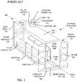
- FIG. 1is a perspective cut-away illustration of a conventional shipping container cooling system.
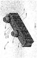
- FIG. 2is a perspective cut-away illustration of a cooling system according to an embodiment.
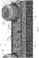
- FIG. 3is a perspective view of a portion of a cooling system according to an embodiment.
- FIG. 4is a perspective close-up view of the cooling system of FIG. 2 .
- FIG. 5is a schematic illustration of a cooling system according to an embodiment.
- FIG. 6is a flow chart illustrating a method of operating a cooling system according to an embodiment.
- the immersion cooling systemis located within shipping containers to facilitate transport of the cooling system.
- heat rejection from the datacenteris accomplished outside of the shipping container via evaporative cooling towers, which are the most energy efficient means to cool the computer equipment.
- water within the cooling tower loopcan pose significant risk to the cooling system as corrosion and scaling of plumbing and heat exchangers can occur. Further, there is risk of health issues due to the possibility diseases that may exist or are promoted in warm water environments.
- FIG. 1illustrates a typical conventional transportable immersion cooling system 100 located within a portable container, such as a shipping container 110 .
- the shipping container 110has a back wall 132 , opposing side walls 127 and 128 , a bottom wall 112 , a top wall 114 and a front opening 134 .
- the front opening 134is typically provided with a door(s) 120 .
- a plurality of tanks 122are provided, each tank 122 containing vertically mounted, independently removable and replaceable electronic components, such as data processing modules, hard drives etc.
- the system 100includes two rows of tanks 122 located adjacent the sidewalls 127 , 128 of the shipping container 110 .
- the two rows of tanks 122are separated from each other by an aisle 124 which allows access to the tanks 122 .
- the shipping container 110may also be provided with a forklift pocket located at the bottom of the shipping container to aid in loading and unloading the shipping container onto a truck, train bed or ship as desired.
- the conventional transportable immersion cooling system 100also includes pump/heat exchanger modules 135 , which each include a liquid-to-liquid heat exchanger configured to cool the dielectric coolant from the tanks 122 via first fluid circuits 170 with water from the cooling tower 150 via a second fluid circuit 175 .
- Hot dielectric coolant from the tanks 122is directed to the pump/heat exchanger modules 135 , which is then cooled by the cooling water from the cooling tower 150 located on top of the shipping container 110 via the second fluid circuit 175 .
- the cooling tower 150includes an evaporative heat exchanger 152 and a motor 153 driven fan 154 for forcing air flow through the evaporative heat exchanger 152 .
- the conventional transportable immersion cooling system 100may also include a removable lip 190 which is configured to keep any spilled coolant or coolant that may have leaked from the tanks 122 inside the shipping container 110 .
- the evaporative heat exchanger 152is replaced with a liquid-liquid heat exchanger.
- the liquid-liquid heat exchangermay be connected to a water line which provides cooling water to the liquid-liquid heat exchanger. Otherwise, in the pump/heat exchanger modules 135 , the cooling water can extract heat from the hot dielectric coolant provided from the tanks 122 .
- the conventional transportable immersion cooling system 100does not include any water treatment elements. That is, the convention transportable immersion cooling system 100 does not include any elements that provide the ability to treat liquid coolant (e.g., water) for metals which can form a scale in the plumbing or biological which can foul the plumbing. It would be desirable to have a cost efficient water treatment system to mitigate water concerns in a water cooled immersion cooling system.
- liquid coolante.g., water
- FIGS. 2-4illustrate a modular cooling system 200 according to an embodiment.
- the cooling system 200includes six cooling tanks 122 a , 122 b located in a portable container, such as a shipping container 110 .
- Each of the cooling tanks 122 a , 122 bmay include racks (not shown) configured to hold electronic equipment, such as servers, hard drives, etc.
- racksnot shown
- any number of racks/tanks 122 a , 122 bmay be located in the shipping container 110 , depending of the size of the shipping container 110 and the tanks 122 a , 122 b .
- the six tanks 122 a , 122 bare operatively configured on independent pump/heat exchanger loops.
- each of the six tanks 122 a , 122 bmay be independently supplied with dielectric coolant and the dielectric coolant independently removed from the each of the tanks 122 a , 122 b without effecting the supply or withdrawal of dielectric coolant from the other tanks 122 a , 122 b.
- a first three of the tanks 122 amay be operatively configured on a first independent pump/heat exchanger circuit 170 a , which circulates to and from a first pump/heat exchanger module 135 a
- the other three tanks 122 bmay be operatively configured on a second independent pump/heat exchanger circuit 170 b , which circulates to and from a second pump/heat exchanger module 135 b.
- cooling towers 150 a , 150 blocated on the top wall 114 of the shipping container 110 .
- the cooling towers 150 a , 150 binclude evaporative heat exchangers 152 a , 152 b .
- the first and second pump/heat exchanger modules 135 a , 135 buse liquid-liquid cooling with a first and second liquid.
- the first liquidis the dielectric coolant used to cool the servers and other electronic equipment in the tanks 122 a , 122 b .
- the second liquidis typically water which may be supplied from the local municipality and then treatment chemicals applied.
- Cool watermay be provided to the evaporative heat exchangers 152 a , 152 b via cooling water circuits 202 a , 202 b .
- the cooling water circuits 202 a , 202 bare divided into a first cooling water circuit 202 a which provides cooling water to the first evaporative heat exchanger 152 a in the first cooling tower 150 a and to a second cooling water circuit 202 b which provides cooling water to the second evaporative heat exchanger 152 b in the second cooling tower 150 b.
- the modular cooling system 200also includes a water treatment system 203 , illustrated in FIG. 5 , which includes a water treatment analyzer/controller 204 , an inhibitor dispenser 206 , an inhibiter feed pump 208 , a biocide dispenser 210 and solenoid valves 212 a , 212 b , 212 c .
- the solenoid valves 212 a , 212 b , 212 cmay be used to shunt the cooling water from the cooling towers 150 a , 150 b to the water treatment system 203 for inhibitor and biocide treatment and then back to the cooling towers 150 a , 150 b after treatment.
- a first set of pump/heat exchanger modules 135 amay be supplied with water via a first fluid supply circuit 175 a with a first pump module 214 a and a second set of pump/heat exchanger modules 135 b supplied with water via a second fluid supply circuit 175 b with a second pump module 214 b .
- Heated watermay be removed from the first set of pump/heat exchanger modules 135 a and sent to the first cooling tower 150 a to be cooled via the first fluid supply circuit 175 a
- heated water from the second set of pump/heat exchanger modules 135 bmay be sent to the second cooling tower 150 b to be cooled via the second fluid supply circuit 175 b.
- the first cooling tower 150 ais provided with cooling water, typically from a municipal water line 202 via a first cooling water circuit 202 a .
- the second cooling tower 150 bis provided with cooling water, typically from a municipal water line 202 via a second cooling water circuit 202 b .
- the first and second cooling towers 150 a , 150 binclude a respective first evaporative heat exchanger 152 a and second evaporative heat exchanger 152 b.
- the modular cooling system 200includes a third cooling water circuit 202 c .
- Operatively located on the third cooling water circuit 202 cis the water treatment system 203 .
- the water treatment system 203may include an inhibitor dispenser 206 and an inhibitor feed pump 208 .
- the inhibitor dispenser 206provides chemicals which reduce the formation of scale in the plumbing of the modular cooling system 200 .
- the water treatment system 203may include a biocide dispenser 210 .
- the biocide dispenser 210is configured to provide one or more chemicals which destroy, deter, render harmless, or exert a controlling effect on harmful biological organisms in the water from the cooling water system, such as bacteria, algae and other biological organisms which may clog the various cooling water circuits 202 , 202 a , 202 b , 202 c , if left unchecked. Sampling and control of the water treatment system 203 is managed by a water treatment analyzer/controller 204 .
- the water treatment system 200utilizes solenoid valves 212 a , 212 b to divert water from the first and second water cooling circuits 202 a , 202 b for a given time period, i.e. water treatment period.
- the water treatment analyzer/controller 204samples the water for pH, conductivity and bio-hazard materials. Based on the analysis of the water, the water treatment system 203 treats the water to rectify potentially hazardous conditions via the use of chemical treatment, biocide treatment or water blow-down.
- Water blow-downmay use a water blow-down solenoid valve 212 c that may be actuated to purge the water into a drain, which may be performed if a large amount of minerals or metals are found in the water. Water blow-down allows for the modular water cooling system 200 to be replenished with fresh water, rather than merely treating the existing water.
- the water treatment analyzer/controller 204closes first solenoid valves 212 a for the first water cooling circuit 202 a . Then, the water treatment analyzer/controller 204 opens second solenoid valves 212 b for the second water cooling circuit 202 b and completes the sampling and mitigation steps for the second water cooling circuit 202 b .
- the water treatment analyzer/controller 204can automatically switch back and forth between the first and second water cooling circuits 202 a , 202 b.
- FIGS. 3 and 4illustrate a portion of a cooling system according to an embodiment.
- solenoid and water blow-down valves 212 a , 212 b , 212 c and plumbingare constructed outside of the shipping container 110 to minimize water plumbing within the interior of modular cooling system 200 .
- the solenoid and water blow-down valves 212 a , 212 b , 212 c and plumbingare constructed outside of the shipping container 110 because plumbing breaks and leaks within the interior of the modular cooling system 200 can be very detrimental to the modular cooling system 200 .
- a single fresh city water input lineis introduced into the shipping container 110 to supply fresh water to the water treatment system (e.g., 203 ) to improve efficiency of the water treatment system 203 . This minimizes water plumbing ingress points to the shipping container 110 .
- FIG. 6is a flow chart illustrating a method 300 of operating a modular cooling system 200 according to an embodiment.
- FIG. 6illustrates an embodiment drawn to a method 300 of operating a cooling system 200 including at least two water cooling circuits 202 a , 202 b , an analyzer/controller 204 configured to analyze water in the at least two water cooling circuits 202 a , 202 b and the first and second solenoid valves 212 a , 212 b operably connected to the at least two water cooling circuits 202 a , 202 b .
- the method 300comprises a step 302 of opening first solenoid valves 212 a associated with a first water cooling circuit 202 a of the at least two water cooling circuits 202 a , 202 b to allow cooling water to flow to the analyzer/controller 204 and a step 306 of detecting if the cooling water comprises one or more impurities.
- the analyzer/controller 204determines whether a chemical impurity in the cooling water is above a predetermined threshold. Specifically, in an embodiment in determination step 308 , the analyzer/controller 204 determines whether particular chemicals are detected in the cooling water above a predetermined threshold, e.g., scale forming chemicals.
- the inhibitor dispenser 206may treat the cooling water with a chemical in step 310 .
- the analyzer/controller 204may determine whether the cooling water includes any biological impurity above a predetermined threshold (e.g., the concentration of a biological species are above the predetermined threshold).
- the biocide dispenser 210treats the cooling water with one or more biocides in step 314 .
- the analyzer/controller 204determines which valve is open.
- the determination step 312 of determining whether the biological impurities are above the predetermined thresholdmay be performed prior to the determination step 308 of determining whether the chemical impurities are above the predetermined threshold.
- the first solenoid valves 212 aWhen the first solenoid valves 212 a are closed, such as from step 318 , the cooling water is sent to the first evaporative heat exchanger 152 a in the first cooling tower 150 a in step 320 .
- step 322heated water from the first set of pump/heat exchanger modules 135 a , which is operably connected to the first fluid supply circuit 175 a is also sent to the first evaporative heat exchanger 152 a in the first cooling tower 150 a to be cooled (i.e., “Heat absorption”).
- the heated cooling water in the first water cooling circuite.g., 202 a
- Second solenoid valves 212 bassociated with the second cooling circuit 202 b may then be opened in step 324 , after which impurities may be detected in the water from the second cooling circuit 202 b in step 306 before returning to determination step 316 .
- Water in the second cooling circuit 202 bis thus sent to the analyzer/controller 204 in step 306 . Similar to the steps described above, in this way the concentration of chemicals and biologicals in the cooling water from the second cooling circuit 202 b is analyzed for one or more impurities in step 306 .
- the second solenoid valves 212 bare closed, such as from step 325 , the cooling water from the second cooling circuit 202 b is sent to the second evaporative heat exchanger 152 b in the second cooling tower 150 b in step 326 .
- step 328heated water from the second set of pump/heat exchanger modules 135 b , which is operably connected to the second fluid supply circuit 175 b , is also sent to the second evaporative heat exchanger 152 b in the second cooling tower 150 b to be cooled (i.e., “Heat absorption”).
- the methodcan be repeated as necessary after opening the first solenoid valves 212 a in step 302 or opening the second solenoid valves 212 b in step 324 .
- An embodimentis drawn to a cooling system 200 including at least two water cooling circuits 202 a , 202 b , an analyzer/controller 204 configured to analyze water in the at least two water cooling circuits 202 a , 202 b and solenoid valves 212 a , 212 b operably connected to the at least two water cooling circuits 202 a , 202 b .
- the cooling system 200is configured such that opening solenoid valves 212 a associated with a first water cooling circuit 202 a of the at least two water cooling circuits 202 a , 202 b allows cooling water to flow to the analyzer/controller 204 and the cooling water to be treated if the analyzer/controller 204 detects one or more impurities in the cooling water above one or more predetermined thresholds 306 .
- the cooling system 200is configured such that when the first solenoid valves 212 a associated with the first water cooling circuit 202 a are closed, cooling water flows to a first cooling tower 150 a .
- the first cooling tower 150 acomprises a first evaporative heat exchanger 152 a and the first cooling tower 150 a is located on top of a shipping container 110 .
- the cooling system 200further comprises an inhibitor dispenser 206 configured to dispense de-scaling chemicals into the cooling water and a biocide dispenser 210 configured to dispense a biocide into the cooling water.
- the analyzer/controller 204 , the inhibiter dispenser 206 and the biocide dispenser 210are located inside a shipping container 110 .
- the cooling system 200further comprises a plurality of tanks 122 a , 122 b located in the shipping container 110 , the plurality of tanks 122 a , 122 b containing electronic equipment and a dielectric fluid, wherein hot dielectric fluid from a first set of the plurality of tanks 122 a is provided to a first pump/heat exchanger module 135 a to be cooled by the cooling water from the first water cooling circuit 202 a .
- second solenoid valves 212 b associated with a second water cooling circuit 202 b of the at least two water cooling circuits 202 a , 202 bare closed when the first solenoid valves 212 a associated with the first cooling water circuit 202 a are open.
- the second solenoid valves 212 b associated with the second water cooling circuit 202 bmay be opened when the first solenoid valves 212 a associated with first cooling water circuit 202 a are closed.
- the cooling system 200further comprises a second cooling tower 150 b located on top to the shipping container 110 , the second cooling tower 150 b comprising a second evaporative heat exchanger 152 b and a second set of the plurality of tanks 122 b located in the shipping container 110 , the second set of the plurality of tanks 122 b also containing electronic equipment and a dielectric fluid, wherein hot dielectric fluid from the second set of the plurality of tanks 122 b is provided to a second pump/heat exchanger module 135 b to be cooled by the cooling water from the second water cooling circuit 202 b.
Landscapes
- Engineering & Computer Science (AREA)
- Microelectronics & Electronic Packaging (AREA)
- Physics & Mathematics (AREA)
- Thermal Sciences (AREA)
- General Engineering & Computer Science (AREA)
- Mechanical Engineering (AREA)
- Computer Hardware Design (AREA)
- Cooling Or The Like Of Electrical Apparatus (AREA)
Abstract
Description
Claims (16)
Priority Applications (1)
| Application Number | Priority Date | Filing Date | Title |
|---|---|---|---|
| US16/518,871US11359865B2 (en) | 2018-07-23 | 2019-07-22 | Dual Cooling Tower Time Share Water Treatment System |
Applications Claiming Priority (2)
| Application Number | Priority Date | Filing Date | Title |
|---|---|---|---|
| US201862702067P | 2018-07-23 | 2018-07-23 | |
| US16/518,871US11359865B2 (en) | 2018-07-23 | 2019-07-22 | Dual Cooling Tower Time Share Water Treatment System |
Publications (2)
| Publication Number | Publication Date |
|---|---|
| US20200025451A1 US20200025451A1 (en) | 2020-01-23 |
| US11359865B2true US11359865B2 (en) | 2022-06-14 |
Family
ID=69161701
Family Applications (1)
| Application Number | Title | Priority Date | Filing Date |
|---|---|---|---|
| US16/518,871Active2039-10-19US11359865B2 (en) | 2018-07-23 | 2019-07-22 | Dual Cooling Tower Time Share Water Treatment System |
Country Status (1)
| Country | Link |
|---|---|
| US (1) | US11359865B2 (en) |
Cited By (11)
| Publication number | Priority date | Publication date | Assignee | Title |
|---|---|---|---|---|
| USD982145S1 (en)* | 2020-10-19 | 2023-03-28 | Green Revolution Cooling, Inc. | Cooling system enclosure |
| USD998770S1 (en)* | 2020-10-19 | 2023-09-12 | Green Revolution Cooling, Inc. | Cooling system enclosure |
| US11805624B2 (en) | 2021-09-17 | 2023-10-31 | Green Revolution Cooling, Inc. | Coolant shroud |
| US11907029B2 (en) | 2019-05-15 | 2024-02-20 | Upstream Data Inc. | Portable blockchain mining system and methods of use |
| US11925946B2 (en) | 2022-03-28 | 2024-03-12 | Green Revolution Cooling, Inc. | Fluid delivery wand |
| US12089368B2 (en) | 2022-09-14 | 2024-09-10 | Green Revolution Cooling, Inc. | System and method for cooling computing devices using a primary circuit dielectric cooling fluid |
| US12150282B2 (en) | 2008-08-11 | 2024-11-19 | Green Revolution Cooling, Inc. | Liquid submerged, horizontal computer server rack and systems and method of cooling such a server rack |
| US12207433B2 (en) | 2020-03-21 | 2025-01-21 | Upstream Data Inc. | Portable blockchain mining system and methods of use |
| US12389566B2 (en) | 2020-11-12 | 2025-08-12 | Green Revolution Cooling, Inc. | Multi-rack immersion cooling distribution system |
| US12414273B2 (en) | 2023-01-25 | 2025-09-09 | Green Revolution Cooling, Inc. | Immersion cooling reservoir level control |
| US12437349B2 (en) | 2017-02-08 | 2025-10-07 | Upstream Data Inc. | Blockchain mining system with load modulation |
Families Citing this family (15)
| Publication number | Priority date | Publication date | Assignee | Title |
|---|---|---|---|---|
| US11492834B2 (en)* | 2019-02-25 | 2022-11-08 | Amoskeag Adv Llc | Apparatus, system and method for powered doors of an autonomous delivery vehicle |
| US11758682B2 (en)* | 2019-09-19 | 2023-09-12 | Baidu Usa Llc | Distributed infrastructure and mobile architecture for edge computing |
| US10750637B1 (en)* | 2019-10-24 | 2020-08-18 | Microsoft Technology Licensing, Llc | Immersion cooling infrastructure module having compute device form factor |
| CN112788914B (en)* | 2019-11-11 | 2022-08-12 | 富联精密电子(天津)有限公司 | Heat dissipation device and heat dissipation system |
| CA3152605A1 (en) | 2021-04-01 | 2022-10-01 | Ovh | Systems and methods for autonomously activable redundant cooling of a heat generating component |
| EP4068930B1 (en) | 2021-04-01 | 2024-03-13 | Ovh | A rack system for housing an electronic device |
| EP4068921B1 (en) | 2021-04-01 | 2024-07-17 | Ovh | Immersion cooling systems for electronic components |
| CA3153037A1 (en) | 2021-04-01 | 2022-10-01 | Ovh | Hybrid immersion cooling system for rack-mounted electronic assemblies |
| CA3151725A1 (en) | 2021-04-01 | 2022-10-01 | Ovh | Immersion cooling system with dual dielectric cooling liquid circulation |
| US20230050420A1 (en)* | 2021-08-15 | 2023-02-16 | Maslow Capital Management LLC | Modular Liquid Vending System |
| US11765866B2 (en)* | 2021-09-28 | 2023-09-19 | Baidu Usa Llc | Data center information technology cluster design |
| US12317450B1 (en) | 2021-11-08 | 2025-05-27 | Rhodium Technologies LLC | Fluid circulation systems and methods for cooling having a collector |
| US12196505B2 (en)* | 2021-12-16 | 2025-01-14 | Saudi Arabian Oil Company | Ecological system for cooling towers algae control |
| US20230247795A1 (en) | 2022-01-28 | 2023-08-03 | The Research Foundation For The State University Of New York | Regenerative preheater for phase change cooling applications |
| EP4572549A1 (en)* | 2023-12-15 | 2025-06-18 | Ovh | A depurating system for liquid-cooled rack-mounted processing assemblies |
Citations (162)
| Publication number | Priority date | Publication date | Assignee | Title |
|---|---|---|---|---|
| US3094133A (en)* | 1959-07-22 | 1963-06-18 | Earl E Treanor | Chemical feed and blowdown system |
| US3320762A (en)* | 1965-12-08 | 1967-05-23 | John P Murdoch | Air conditioning system with heating means |
| US3406244A (en) | 1966-06-07 | 1968-10-15 | Ibm | Multi-liquid heat transfer |
| US3450265A (en)* | 1967-05-11 | 1969-06-17 | Culligan Inc | Recirculating water treatment and control system |
| US3600636A (en) | 1968-11-14 | 1971-08-17 | Danfoss As | Electrical apparatus comprising a power section and a control section with fluid cooling |
| US3754741A (en)* | 1971-09-28 | 1973-08-28 | Parker Eng Chem Inc | Water treatment system |
| US3858090A (en) | 1972-11-14 | 1974-12-31 | Danfoss As | Oil-cooled electrical apparatus withdrawable from an outer casing for inspection and repairs |
| US4245668A (en) | 1978-02-28 | 1981-01-20 | Chemetics International Ltd. | Pressure regulator |
| US4302793A (en) | 1979-11-30 | 1981-11-24 | Submergible Oil Systems, Inc. | Electronic cooling |
| US4313310A (en)* | 1979-09-07 | 1982-02-02 | Fujitsu Limited | Cooling system |
| US4399501A (en) | 1980-04-21 | 1983-08-16 | Alsthom-Atlantique | Set of power semiconductors equipped with firing transformers and with protection circuits |
| US4460008A (en)* | 1982-12-23 | 1984-07-17 | Leary Richard P O | Indexing controller apparatus for cooling water tower systems |
| US4464315A (en)* | 1982-12-20 | 1984-08-07 | Betz Entec, Inc. | Indexing controller system and method of automatic control of cooling water tower systems |
| US4590538A (en) | 1982-11-18 | 1986-05-20 | Cray Research, Inc. | Immersion cooled high density electronic assembly |
| US4648043A (en)* | 1984-05-07 | 1987-03-03 | Betz Laboratories, Inc. | Computerized system for feeding chemicals into water treatment system |
| US4659459A (en)* | 1985-07-18 | 1987-04-21 | Betz Laboratories, Inc. | Automated systems for introducing chemicals into water or other liquid treatment systems |
| US4834257A (en) | 1987-12-11 | 1989-05-30 | Westinghouse Electric Corp. | Reinforced wall structure for a transformer tank |
| US5102503A (en)* | 1989-08-04 | 1992-04-07 | Environmental Technology Group Corporation | Mobile self-contained system for on-site recovery of solvents |
| US5145585A (en)* | 1990-02-09 | 1992-09-08 | Coke Alden L | Method and apparatus for treating water in a cooling system |
| US5260850A (en) | 1991-03-08 | 1993-11-09 | Cray Computer Corporation | Logic module assembly for confining and directing the flow of cooling fluid |
| US5294916A (en)* | 1992-01-23 | 1994-03-15 | Autotrol Corp. | Water treatment controller for an evaporative condenser |
| US5297621A (en) | 1989-07-13 | 1994-03-29 | American Electronic Analysis | Method and apparatus for maintaining electrically operating device temperatures |
| US5329418A (en) | 1991-11-18 | 1994-07-12 | Kabushiki Kaisha Toshiba | 3-D communication and interconnect technique for increased number of computational modules in large-scale electronic equipment |
| US5332494A (en)* | 1992-02-03 | 1994-07-26 | H.E.R.C. Incorporated | Water control system using oxidation reduction potential sensing |
| US5414591A (en) | 1991-04-15 | 1995-05-09 | Hitachi, Ltd. | Magnetic disk storage system |
| US5574627A (en) | 1995-07-24 | 1996-11-12 | At&T Global Information Solutions Company | Apparatus for preventing the formation of condensation on sub-cooled integrated circuit devices |
| US5851143A (en) | 1996-05-10 | 1998-12-22 | Thermal Industries | Disk drive test chamber |
| US6019167A (en) | 1997-12-19 | 2000-02-01 | Nortel Networks Corporation | Liquid immersion cooling apparatus for electronic systems operating in thermally uncontrolled environments |
| US20020014460A1 (en)* | 1999-03-05 | 2002-02-07 | Mckay Scott | Method and apparatus for treating water |
| US6374627B1 (en) | 2001-01-09 | 2002-04-23 | Donald J. Schumacher | Data center cooling system |
| US20020151799A1 (en) | 2000-04-13 | 2002-10-17 | Boston Scientific Corporation | Catheter drive shaft clutch |
| US20020185262A1 (en) | 2001-06-12 | 2002-12-12 | Baer Daniel B. | Single or dual buss thermal transfer system |
| US20020189173A1 (en)* | 1998-04-24 | 2002-12-19 | Staschik Udo Ingmar | Utilities container |
| US20030053293A1 (en) | 2001-09-14 | 2003-03-20 | Beitelmal Abdlmonem H. | Method and apparatus for individually cooling components of electronic systems |
| US20030127240A1 (en) | 2000-03-14 | 2003-07-10 | Kai Beckbissinger | Housing for an electrical device |
| US6600656B1 (en) | 2002-04-10 | 2003-07-29 | Sun Microsystems, Inc. | System structure for fast service access in a rack/cabinet |
| US6616851B1 (en)* | 1999-08-14 | 2003-09-09 | Cognis Deutschland Gmbh & Co. Kg | System and method for treating water circulating in open-circuit cooling systems |
| US6621707B2 (en) | 1998-08-11 | 2003-09-16 | Fujitsu Limited | Liquid-cooled electronic apparatus |
| US20040008490A1 (en) | 2002-07-13 | 2004-01-15 | Kioan Cheon | Water cooling type soft cooling jacket for electronic device and buffer jacket using the same |
| US20040013563A1 (en)* | 2000-05-19 | 2004-01-22 | Romer Edward Adolph | Cooling tower maintenance |
| US20040050491A1 (en) | 2002-09-13 | 2004-03-18 | Dainippon Screen Mfg. Co., Ltd. | Substrate processing apparatus |
| JP2004319628A (en) | 2003-04-14 | 2004-11-11 | Hitachi Ltd | System module |
| US20040223300A1 (en) | 2003-03-19 | 2004-11-11 | Fink James R. | Data center cooling |
| US20040246683A1 (en) | 2001-09-27 | 2004-12-09 | Martin Honsberg-Riedl | Electrical circuit arrangement comprised of a number of electrically interconnected circuit components |
| US20040254682A1 (en)* | 2001-12-27 | 2004-12-16 | Tim Kast | Apparatus, system and method for non-chemical treatment and management of cooling water |
| JP2004363308A (en) | 2003-06-04 | 2004-12-24 | Hitachi Ltd | Rack mount server system |
| US20050011839A1 (en)* | 2003-07-16 | 2005-01-20 | James Dart | Water treatment apparatus and method |
| US20050024826A1 (en) | 2003-07-29 | 2005-02-03 | Bash Cullen Edwin | Environmental condition measurement system |
| US20050052847A1 (en) | 2003-09-10 | 2005-03-10 | Hamman Brian A. | Liquid cooling system |
| US20050083657A1 (en) | 2003-10-18 | 2005-04-21 | Qnx Cooling Systems, Inc. | Liquid cooling system |
| US20050111184A1 (en) | 2003-10-31 | 2005-05-26 | Hewlett-Packard Development Company, L.P. | Cooling of a computer environment |
| US20050114876A1 (en) | 2003-11-21 | 2005-05-26 | Hitachi, Ltd. | Disc array apparatus |
| US6909606B2 (en) | 2003-08-08 | 2005-06-21 | Hewlett-Packard Development Company, L.P. | Electronic device cooling system and method of use |
| US20050152112A1 (en) | 2004-01-08 | 2005-07-14 | Apple Computer Inc. | Apparatus for air cooling of an electronic device |
| US20050259402A1 (en) | 2004-05-18 | 2005-11-24 | Denso Corporation | Power stack |
| US20060026610A1 (en) | 2004-08-02 | 2006-02-02 | Hitachi, Ltd. | Optical disk apparatus |
| US20060064709A1 (en) | 2004-08-20 | 2006-03-23 | Digital Site Management, Llc | Storage medium protection system |
| US20060123436A1 (en) | 2004-12-06 | 2006-06-08 | Hitachi, Ltd. | Disk array device and disk array device housing |
| US20060135042A1 (en) | 2004-12-17 | 2006-06-22 | Frost David T | Multi-station disk finishing apparatus and method |
| US7086247B2 (en) | 2004-08-31 | 2006-08-08 | International Business Machines Corporation | Cooling system and method employing auxiliary thermal capacitor unit for facilitating continuous operation of an electronics rack |
| US20060250755A1 (en) | 2005-01-18 | 2006-11-09 | Tilton Charles L | Globally cooled computer system |
| US20060274501A1 (en) | 2001-12-27 | 2006-12-07 | Formfactor, Inc. | Electronic package with direct cooling of active electronic components |
| US20070006599A1 (en) | 2003-03-11 | 2007-01-11 | Mayekawa Mfg. Co., Ltd. | Apparatus and method for cooling super conductive body |
| US20070025081A1 (en) | 2005-07-28 | 2007-02-01 | Berlin Carl W | Electronic package and method of cooling electronics |
| US20070034360A1 (en) | 2005-06-08 | 2007-02-15 | Hall Jack P | High performance cooling assembly for electronics |
| US7184269B2 (en) | 2004-12-09 | 2007-02-27 | International Business Machines Company | Cooling apparatus and method for an electronics module employing an integrated heat exchange assembly |
| WO2007023130A2 (en) | 2005-08-23 | 2007-03-01 | International Business Machines Corporation | Systems and methods for cooling electronics components employing vapor compression refrigeration |
| US7210304B2 (en) | 2005-02-09 | 2007-05-01 | General Motors Corporation | Cooling arrangements for integrated electric motor-inverters |
| US20070199340A1 (en) | 2003-08-25 | 2007-08-30 | Isothermal Systems Research, Inc. | Multi-chamber spray cooling system |
| WO2007098078A2 (en) | 2006-02-16 | 2007-08-30 | Cooligy, Inc. | Liquid cooling loops for server applications |
| US20070213000A1 (en) | 2002-03-28 | 2007-09-13 | American Power Conversion | Data Center Cooling |
| US20070227710A1 (en) | 2006-04-03 | 2007-10-04 | Belady Christian L | Cooling system for electrical devices |
| US7278273B1 (en) | 2003-12-30 | 2007-10-09 | Google Inc. | Modular data center |
| US20070267741A1 (en) | 2006-05-16 | 2007-11-22 | Hardcore Computer, Inc. | Liquid submersion cooling system |
| US20080002364A1 (en) | 2006-06-29 | 2008-01-03 | International Business Machines Corporation | Coolant control unit, and cooled electronics system and method employing the same |
| US7318322B2 (en) | 2003-02-14 | 2008-01-15 | Hitachi, Ltd. | Liquid cooling system for a rack-mount server system |
| US20080017355A1 (en) | 2006-05-16 | 2008-01-24 | Hardcore Computer, Inc. | Case for a liquid submersion cooled electronic device |
| US20080026509A1 (en) | 2005-10-25 | 2008-01-31 | International Business Machines Corporation | Cooling apparatuses and methods employing discrete cold plates compliantly coupled between a common manifold and electronics components of an assembly to be cooled |
| US20080029250A1 (en) | 2006-06-01 | 2008-02-07 | Andrew Carlson | Warm Water Cooling |
| US20080030945A1 (en) | 2002-03-21 | 2008-02-07 | Tempest Microsystems | High Density Storage System |
| US20080055845A1 (en) | 2006-08-31 | 2008-03-06 | Vance Murakami | System for hot swapping heat exchangers |
| WO2008027931A2 (en) | 2006-08-29 | 2008-03-06 | Isothermal Systems Research, Inc. | Manifold for a two-phase cooling system |
| US20080158818A1 (en) | 2006-12-29 | 2008-07-03 | Google Inc. | Motherboards with Integrated Cooling |
| US20080174954A1 (en) | 2007-01-24 | 2008-07-24 | Vangilder James W | System and method for evaluating equipment rack cooling performance |
| WO2008089322A2 (en) | 2007-01-19 | 2008-07-24 | Al-Khorayef Group Company Ltd. | Temperature control systems and methods |
| US20080180908A1 (en) | 2007-01-23 | 2008-07-31 | Peter Wexler | In-row air containment and cooling system and method |
| US7413394B2 (en) | 2001-07-02 | 2008-08-19 | Transol Corporation | Low headroom telescoping bridge crane system |
| US20080209931A1 (en) | 2007-03-01 | 2008-09-04 | Jason Stevens | Data centers |
| US20080273306A1 (en) | 2007-05-04 | 2008-11-06 | International Business Machines Corporation | System and method of facilitating cooling of electronics racks of a data center employing multiple cooling stations |
| US7511960B2 (en)* | 2006-09-13 | 2009-03-31 | Sun Microsystems, Inc. | Balanced chilled fluid cooling system for a data center in a shipping container |
| US7511959B2 (en)* | 2007-04-25 | 2009-03-31 | Hewlett-Packard Development Company, L.P. | Scalable computing apparatus |
| US7551971B2 (en)* | 2006-09-13 | 2009-06-23 | Sun Microsystems, Inc. | Operation ready transportable data center in a shipping container |
| US20090168345A1 (en) | 2006-06-15 | 2009-07-02 | Martini Valan R | Energy saving system and method for cooling computer data center and telecom equipment |
| US20090229194A1 (en) | 2008-03-11 | 2009-09-17 | Advanced Shielding Technologies Europe S.I. | Portable modular data center |
| US20090251860A1 (en) | 2008-04-02 | 2009-10-08 | Microsoft Corporation | Power-efficent data center |
| US20090262455A1 (en) | 2008-04-17 | 2009-10-22 | Teradyne, Inc. | Temperature Control Within Disk Drive Testing Systems |
| US20090260777A1 (en) | 2008-04-21 | 2009-10-22 | Hardcore Computer, Inc. | case and rack system for liquid submersion cooling of electronic devices connected in an array |
| US7609518B2 (en) | 2005-11-17 | 2009-10-27 | Iceotope Limited | Cooling computer components |
| US20090295167A1 (en)* | 2007-02-26 | 2009-12-03 | Jimmy Clidaras | Water-based data center |
| US20100027212A1 (en) | 2008-07-17 | 2010-02-04 | Advanced Shielding Technologies Europe S.L. | Environmental disaster data protection system |
| US20100030267A1 (en) | 2007-06-05 | 2010-02-04 | Spartek Medical, Inc. | Surgical tool and method for implantation of a dynamic bone anchor |
| WO2010019517A1 (en) | 2008-08-11 | 2010-02-18 | Green Revolution Cooling, Inc. | Liquid submerged, horizontal computer server rack and systems and methods of cooling such a server rack |
| US20100061057A1 (en) | 2008-09-10 | 2010-03-11 | American Power Conversion Corporation | Hot aisle containment panel system and method |
| US7686175B2 (en) | 2004-09-03 | 2010-03-30 | Mhe Technologies, Inc. | Container crane |
| US20100103618A1 (en) | 2008-10-23 | 2010-04-29 | International Business Machines Corporation | Apparatus and method for facilitating pumped immersion-cooling of an electronic subsystem |
| US7724513B2 (en)* | 2006-09-25 | 2010-05-25 | Silicon Graphics International Corp. | Container-based data center |
| US20100139887A1 (en)* | 2008-12-04 | 2010-06-10 | George Slessman | System and Method of Providing Computer Resources |
| US20100165565A1 (en)* | 2008-12-31 | 2010-07-01 | Hellriegal Stephen V R | Data center |
| US7757506B2 (en) | 2007-11-19 | 2010-07-20 | International Business Machines Corporation | System and method for facilitating cooling of a liquid-cooled electronics rack |
| US20100226094A1 (en) | 2009-03-09 | 2010-09-09 | Hardcore Computer, Inc. | Gravity assisted directed liquid cooling |
| US20100263885A1 (en) | 2009-04-21 | 2010-10-21 | 3M Innovative Properties Company | Protection systems and methods for electronic devices |
| US20100275441A1 (en) | 2001-03-20 | 2010-11-04 | American Power Conversion Corporation | Adjustable scalable rack power system and method |
| US20100290190A1 (en) | 2009-05-12 | 2010-11-18 | Iceotope Limited | Cooled electronic system |
| US7843298B2 (en) | 2004-12-27 | 2010-11-30 | Hitachi Industrial Equipment Systems Co., Ltd | Power distribution transformer and tank therefor |
| US7854652B2 (en)* | 2006-09-13 | 2010-12-21 | Oracle America, Inc. | Server rack service utilities for a data center in a shipping container |
| US7856838B2 (en)* | 2006-09-13 | 2010-12-28 | Oracle America, Inc. | Cooling air flow loop for a data center in a shipping container |
| US7934386B2 (en) | 2008-02-25 | 2011-05-03 | Raytheon Company | System and method for cooling a heat generating structure |
| US20110120885A1 (en)* | 2009-11-16 | 2011-05-26 | Earthwise Environmental Inc. | Cooling tower water management system |
| US20110151765A1 (en)* | 2009-12-17 | 2011-06-23 | Delta Electronics, Inc. | Operating condition adjusting system and method of portable data center |
| US20110157829A1 (en)* | 2009-12-28 | 2011-06-30 | Wormsbecher Paul A | Container-based data center having greater rack density |
| US20110240281A1 (en) | 2010-03-31 | 2011-10-06 | Industrial Idea Partners, Inc. | Liquid-Based Cooling System For Data Centers Having Proportional Flow Control Device |
| US8047904B2 (en)* | 2006-09-13 | 2011-11-01 | Oracle America, Inc. | Cooling method for a data center in a shipping container |
| US20110267775A1 (en) | 2010-04-29 | 2011-11-03 | Brocade Communications Systems, Inc. | Side-exhaust cooling system with extensible duct for rack mounted equipment |
| US20120026691A1 (en) | 2010-07-28 | 2012-02-02 | International Business Machines Corporation | Apparatus and method for facilitating dissipation of heat from a liquid-cooled electronics rack |
| US20120035773A1 (en) | 2010-08-04 | 2012-02-09 | Powerquest, LLC. | Efficient computer cooling methods and apparatus |
| US20120123595A1 (en) | 2010-11-15 | 2012-05-17 | International Business Machines Corporation | Controlling fluid coolant flow in cooling systems of computing devices |
| US20120155027A1 (en) | 2010-12-16 | 2012-06-21 | Broome John P | Portable computer server enclosure |
| US8213261B2 (en) | 2008-05-22 | 2012-07-03 | Exxonmobil Upstream Research Company | Method for geophysical and geological interpretation of seismic volumes in the domains of depth, time, and age |
| US20120171943A1 (en)* | 2010-12-30 | 2012-07-05 | Munters Corporation | Systems for removing heat from enclosed spaces with high internal heat generation |
| US20120236487A1 (en) | 2011-03-16 | 2012-09-20 | Lenovo (Singapore) Pte. Ltd. | Handle assembly configured for airflow |
| US8295047B1 (en)* | 2007-09-28 | 2012-10-23 | Exaflop Llc | Changing data center cooling modes |
| US8310829B2 (en) | 2008-05-05 | 2012-11-13 | Carrier Corporation | Integrated computer equipment container and cooling unit |
| US20120294737A1 (en)* | 2011-04-18 | 2012-11-22 | Singh Krishna P | Autonomous self-powered system for removing thermal energy from pools of liquid heated by radioactive materials, and method of the same |
| US20120300391A1 (en) | 2011-03-02 | 2012-11-29 | Earl Keisling | Modular it rack cooling assemblies and methods for assembling same |
| US20130025888A1 (en) | 2011-07-26 | 2013-01-31 | Firetrace Usa, Llc | Methods and apparatus for hot aisle/cold aisle data center fire suppression |
| US20130032217A1 (en) | 2011-08-05 | 2013-02-07 | Thomas Pesek | Methods and apparatus for level loop control |
| WO2013022805A1 (en) | 2011-08-05 | 2013-02-14 | Green Revolution Cooling, Inc. | Hard drive cooling for fluid submersion cooling systems |
| US20130075066A1 (en)* | 2011-09-23 | 2013-03-28 | Mikhail Pavlovich Reytblat | Advanced Multi-Purpose, Multi-stage Evaporative Cold Water/Cold Air Generating and Supply System |
| US20130105139A1 (en) | 2011-10-31 | 2013-05-02 | International Business Machines Corporation | Multi-rack assembly with shared cooling unit |
| US20140085817A1 (en) | 2012-09-26 | 2014-03-27 | International Business Machines Corporation | Immersion-cooling of selected electronic component(s) mounted to printed circuit board |
| US20140085821A1 (en) | 2012-09-25 | 2014-03-27 | Liquidcool Solutions, Inc. | Method and apparatus to manage coolant pressure and flow for an array of liquid submerged electronic devices |
| US20140109610A1 (en) | 2012-10-18 | 2014-04-24 | Port-A-Cool, Llc | Free-standing evaporative air cooling apparatus |
| US20140216686A1 (en) | 2013-02-01 | 2014-08-07 | Dell Products L.P. | Partitioned, Rotating Condenser Units to Enable Servicing of Submerged IT Equipment Positioned Beneath a Vapor Condenser Without Interrupting a Vaporization-Condensation Cycling of the Remaining Immersion Cooling System |
| US20140218858A1 (en) | 2013-02-01 | 2014-08-07 | Dell Products L.P. | Stand Alone Immersion Tank Data Center with Contained Cooling |
| US8817465B2 (en) | 2011-10-31 | 2014-08-26 | International Business Machines Corporation | Multi-rack assembly with shared cooling apparatus |
| US20140301037A1 (en)* | 2013-04-04 | 2014-10-09 | Green Revolution Cooling, Inc. | Liquid coolant-submersible node |
| US20140307384A1 (en)* | 2013-04-11 | 2014-10-16 | Green Revolution Cooling, Inc. | Integrated computing module with power and liquid cooling components |
| US20140362527A1 (en)* | 2013-05-06 | 2014-12-11 | Green Revolution Cooling, Inc. | System and method of packaging computing resources for space and fire-resistance |
| US20150048950A1 (en)* | 2013-08-16 | 2015-02-19 | Cisco Technology, Inc. | Liquid cooling of rack-mounted electronic equipment |
| US9049800B2 (en) | 2013-02-01 | 2015-06-02 | Dell Products L.P. | Immersion server, immersion server drawer, and rack-mountable immersion server drawer-based cabinet |
| US20150181762A1 (en)* | 2012-12-14 | 2015-06-25 | Midas Green Technology, Llc | Appliance Immersion Cooling System |
| US20150276292A1 (en)* | 2014-03-25 | 2015-10-01 | Samsung Electronics Co., Ltd. | Cooling apparatus and system including the same |
| US20150305209A1 (en)* | 2012-12-03 | 2015-10-22 | Nec Corporation | Cooling system for electronic device storing apparatus and cooling system for electronic device storing building |
| US20150334880A1 (en)* | 2014-05-13 | 2015-11-19 | Green Revolution Cooling, Inc. | System and method for air-cooling hard drives in liquid-cooled server rack |
| US20170142868A1 (en)* | 2015-11-13 | 2017-05-18 | Hon Hai Precision Industry Co., Ltd. | Heat-dissipation system |
| US20170303443A1 (en)* | 2016-04-13 | 2017-10-19 | Fujitsu Limited | Data center and control method of data center |
| US20180020572A1 (en) | 2016-07-15 | 2018-01-18 | Fujitsu Limited | Liquid immersion tank of electronic equipment |
| US20180288906A1 (en) | 2015-10-01 | 2018-10-04 | Iceotope Limited | An immersion cooling system |
| US20180368281A1 (en) | 2017-01-20 | 2018-12-20 | Guangdong HI-1 New Materials Technology Research I nstitute Co. Ltd Guangzhou | Data Centre Cabinet and Gravity Spray System Thereof |
| US20190090383A1 (en) | 2017-09-20 | 2019-03-21 | Liquidcool Solutions, Inc. | Liquid submersion cooled electronic systems and devices |
| US10743438B2 (en) | 2016-07-25 | 2020-08-11 | Fujitsu Limited | Liquid cooling device, liquid cooling system, and control method of liquid cooling device |
| US20200323108A1 (en) | 2017-12-26 | 2020-10-08 | "Scientific and Technical Center InnTech" Limited | A direct liquid cooling system for cooling of electronic components |
- 2019
- 2019-07-22USUS16/518,871patent/US11359865B2/enactiveActive
Patent Citations (187)
| Publication number | Priority date | Publication date | Assignee | Title |
|---|---|---|---|---|
| US3094133A (en)* | 1959-07-22 | 1963-06-18 | Earl E Treanor | Chemical feed and blowdown system |
| US3320762A (en)* | 1965-12-08 | 1967-05-23 | John P Murdoch | Air conditioning system with heating means |
| US3406244A (en) | 1966-06-07 | 1968-10-15 | Ibm | Multi-liquid heat transfer |
| US3450265A (en)* | 1967-05-11 | 1969-06-17 | Culligan Inc | Recirculating water treatment and control system |
| US3600636A (en) | 1968-11-14 | 1971-08-17 | Danfoss As | Electrical apparatus comprising a power section and a control section with fluid cooling |
| US3754741A (en)* | 1971-09-28 | 1973-08-28 | Parker Eng Chem Inc | Water treatment system |
| US3858090A (en) | 1972-11-14 | 1974-12-31 | Danfoss As | Oil-cooled electrical apparatus withdrawable from an outer casing for inspection and repairs |
| US4245668A (en) | 1978-02-28 | 1981-01-20 | Chemetics International Ltd. | Pressure regulator |
| US4313310A (en)* | 1979-09-07 | 1982-02-02 | Fujitsu Limited | Cooling system |
| US4302793A (en) | 1979-11-30 | 1981-11-24 | Submergible Oil Systems, Inc. | Electronic cooling |
| US4399501A (en) | 1980-04-21 | 1983-08-16 | Alsthom-Atlantique | Set of power semiconductors equipped with firing transformers and with protection circuits |
| US4590538A (en) | 1982-11-18 | 1986-05-20 | Cray Research, Inc. | Immersion cooled high density electronic assembly |
| US4464315A (en)* | 1982-12-20 | 1984-08-07 | Betz Entec, Inc. | Indexing controller system and method of automatic control of cooling water tower systems |
| US4460008A (en)* | 1982-12-23 | 1984-07-17 | Leary Richard P O | Indexing controller apparatus for cooling water tower systems |
| US4648043A (en)* | 1984-05-07 | 1987-03-03 | Betz Laboratories, Inc. | Computerized system for feeding chemicals into water treatment system |
| US4659459A (en)* | 1985-07-18 | 1987-04-21 | Betz Laboratories, Inc. | Automated systems for introducing chemicals into water or other liquid treatment systems |
| US4834257A (en) | 1987-12-11 | 1989-05-30 | Westinghouse Electric Corp. | Reinforced wall structure for a transformer tank |
| US5297621A (en) | 1989-07-13 | 1994-03-29 | American Electronic Analysis | Method and apparatus for maintaining electrically operating device temperatures |
| US5102503A (en)* | 1989-08-04 | 1992-04-07 | Environmental Technology Group Corporation | Mobile self-contained system for on-site recovery of solvents |
| US5145585A (en)* | 1990-02-09 | 1992-09-08 | Coke Alden L | Method and apparatus for treating water in a cooling system |
| US5260850A (en) | 1991-03-08 | 1993-11-09 | Cray Computer Corporation | Logic module assembly for confining and directing the flow of cooling fluid |
| US5414591A (en) | 1991-04-15 | 1995-05-09 | Hitachi, Ltd. | Magnetic disk storage system |
| US5329418A (en) | 1991-11-18 | 1994-07-12 | Kabushiki Kaisha Toshiba | 3-D communication and interconnect technique for increased number of computational modules in large-scale electronic equipment |
| US5294916A (en)* | 1992-01-23 | 1994-03-15 | Autotrol Corp. | Water treatment controller for an evaporative condenser |
| US5332494A (en)* | 1992-02-03 | 1994-07-26 | H.E.R.C. Incorporated | Water control system using oxidation reduction potential sensing |
| US5574627A (en) | 1995-07-24 | 1996-11-12 | At&T Global Information Solutions Company | Apparatus for preventing the formation of condensation on sub-cooled integrated circuit devices |
| US5851143A (en) | 1996-05-10 | 1998-12-22 | Thermal Industries | Disk drive test chamber |
| US6019167A (en) | 1997-12-19 | 2000-02-01 | Nortel Networks Corporation | Liquid immersion cooling apparatus for electronic systems operating in thermally uncontrolled environments |
| US20020189173A1 (en)* | 1998-04-24 | 2002-12-19 | Staschik Udo Ingmar | Utilities container |
| US6621707B2 (en) | 1998-08-11 | 2003-09-16 | Fujitsu Limited | Liquid-cooled electronic apparatus |
| US20020014460A1 (en)* | 1999-03-05 | 2002-02-07 | Mckay Scott | Method and apparatus for treating water |
| US6616851B1 (en)* | 1999-08-14 | 2003-09-09 | Cognis Deutschland Gmbh & Co. Kg | System and method for treating water circulating in open-circuit cooling systems |
| US20030127240A1 (en) | 2000-03-14 | 2003-07-10 | Kai Beckbissinger | Housing for an electrical device |
| US20020151799A1 (en) | 2000-04-13 | 2002-10-17 | Boston Scientific Corporation | Catheter drive shaft clutch |
| US20040013563A1 (en)* | 2000-05-19 | 2004-01-22 | Romer Edward Adolph | Cooling tower maintenance |
| US6374627B1 (en) | 2001-01-09 | 2002-04-23 | Donald J. Schumacher | Data center cooling system |
| US20100275441A1 (en) | 2001-03-20 | 2010-11-04 | American Power Conversion Corporation | Adjustable scalable rack power system and method |
| US20020185262A1 (en) | 2001-06-12 | 2002-12-12 | Baer Daniel B. | Single or dual buss thermal transfer system |
| US7413394B2 (en) | 2001-07-02 | 2008-08-19 | Transol Corporation | Low headroom telescoping bridge crane system |
| US20030053293A1 (en) | 2001-09-14 | 2003-03-20 | Beitelmal Abdlmonem H. | Method and apparatus for individually cooling components of electronic systems |
| US20040246683A1 (en) | 2001-09-27 | 2004-12-09 | Martin Honsberg-Riedl | Electrical circuit arrangement comprised of a number of electrically interconnected circuit components |
| US20060274501A1 (en) | 2001-12-27 | 2006-12-07 | Formfactor, Inc. | Electronic package with direct cooling of active electronic components |
| US20040254682A1 (en)* | 2001-12-27 | 2004-12-16 | Tim Kast | Apparatus, system and method for non-chemical treatment and management of cooling water |
| US20080030945A1 (en) | 2002-03-21 | 2008-02-07 | Tempest Microsystems | High Density Storage System |
| US20070213000A1 (en) | 2002-03-28 | 2007-09-13 | American Power Conversion | Data Center Cooling |
| US6600656B1 (en) | 2002-04-10 | 2003-07-29 | Sun Microsystems, Inc. | System structure for fast service access in a rack/cabinet |
| US20040008490A1 (en) | 2002-07-13 | 2004-01-15 | Kioan Cheon | Water cooling type soft cooling jacket for electronic device and buffer jacket using the same |
| US20040050491A1 (en) | 2002-09-13 | 2004-03-18 | Dainippon Screen Mfg. Co., Ltd. | Substrate processing apparatus |
| US7318322B2 (en) | 2003-02-14 | 2008-01-15 | Hitachi, Ltd. | Liquid cooling system for a rack-mount server system |
| US20070006599A1 (en) | 2003-03-11 | 2007-01-11 | Mayekawa Mfg. Co., Ltd. | Apparatus and method for cooling super conductive body |
| US20040223300A1 (en) | 2003-03-19 | 2004-11-11 | Fink James R. | Data center cooling |
| JP2004319628A (en) | 2003-04-14 | 2004-11-11 | Hitachi Ltd | System module |
| JP2004363308A (en) | 2003-06-04 | 2004-12-24 | Hitachi Ltd | Rack mount server system |
| US20050011839A1 (en)* | 2003-07-16 | 2005-01-20 | James Dart | Water treatment apparatus and method |
| US20050024826A1 (en) | 2003-07-29 | 2005-02-03 | Bash Cullen Edwin | Environmental condition measurement system |
| US6909606B2 (en) | 2003-08-08 | 2005-06-21 | Hewlett-Packard Development Company, L.P. | Electronic device cooling system and method of use |
| US20070199340A1 (en) | 2003-08-25 | 2007-08-30 | Isothermal Systems Research, Inc. | Multi-chamber spray cooling system |
| US20050052847A1 (en) | 2003-09-10 | 2005-03-10 | Hamman Brian A. | Liquid cooling system |
| US20050083657A1 (en) | 2003-10-18 | 2005-04-21 | Qnx Cooling Systems, Inc. | Liquid cooling system |
| US20050111184A1 (en) | 2003-10-31 | 2005-05-26 | Hewlett-Packard Development Company, L.P. | Cooling of a computer environment |
| US20050114876A1 (en) | 2003-11-21 | 2005-05-26 | Hitachi, Ltd. | Disc array apparatus |
| US7278273B1 (en) | 2003-12-30 | 2007-10-09 | Google Inc. | Modular data center |
| US20050152112A1 (en) | 2004-01-08 | 2005-07-14 | Apple Computer Inc. | Apparatus for air cooling of an electronic device |
| US20050259402A1 (en) | 2004-05-18 | 2005-11-24 | Denso Corporation | Power stack |
| US20060026610A1 (en) | 2004-08-02 | 2006-02-02 | Hitachi, Ltd. | Optical disk apparatus |
| US20060064709A1 (en) | 2004-08-20 | 2006-03-23 | Digital Site Management, Llc | Storage medium protection system |
| US7086247B2 (en) | 2004-08-31 | 2006-08-08 | International Business Machines Corporation | Cooling system and method employing auxiliary thermal capacitor unit for facilitating continuous operation of an electronics rack |
| US7686175B2 (en) | 2004-09-03 | 2010-03-30 | Mhe Technologies, Inc. | Container crane |
| US20060123436A1 (en) | 2004-12-06 | 2006-06-08 | Hitachi, Ltd. | Disk array device and disk array device housing |
| US7184269B2 (en) | 2004-12-09 | 2007-02-27 | International Business Machines Company | Cooling apparatus and method for an electronics module employing an integrated heat exchange assembly |
| US20060135042A1 (en) | 2004-12-17 | 2006-06-22 | Frost David T | Multi-station disk finishing apparatus and method |
| US7843298B2 (en) | 2004-12-27 | 2010-11-30 | Hitachi Industrial Equipment Systems Co., Ltd | Power distribution transformer and tank therefor |
| US20060250755A1 (en) | 2005-01-18 | 2006-11-09 | Tilton Charles L | Globally cooled computer system |
| US7210304B2 (en) | 2005-02-09 | 2007-05-01 | General Motors Corporation | Cooling arrangements for integrated electric motor-inverters |
| US20070034360A1 (en) | 2005-06-08 | 2007-02-15 | Hall Jack P | High performance cooling assembly for electronics |
| US20070025081A1 (en) | 2005-07-28 | 2007-02-01 | Berlin Carl W | Electronic package and method of cooling electronics |
| US7307841B2 (en) | 2005-07-28 | 2007-12-11 | Delphi Technologies, Inc. | Electronic package and method of cooling electronics |
| WO2007023130A2 (en) | 2005-08-23 | 2007-03-01 | International Business Machines Corporation | Systems and methods for cooling electronics components employing vapor compression refrigeration |
| US20080026509A1 (en) | 2005-10-25 | 2008-01-31 | International Business Machines Corporation | Cooling apparatuses and methods employing discrete cold plates compliantly coupled between a common manifold and electronics components of an assembly to be cooled |
| US7609518B2 (en) | 2005-11-17 | 2009-10-27 | Iceotope Limited | Cooling computer components |
| WO2007098078A2 (en) | 2006-02-16 | 2007-08-30 | Cooligy, Inc. | Liquid cooling loops for server applications |
| US20070227710A1 (en) | 2006-04-03 | 2007-10-04 | Belady Christian L | Cooling system for electrical devices |
| US7911782B2 (en) | 2006-05-16 | 2011-03-22 | Hardcore Computer, Inc. | Liquid submersion cooling system |
| US20070267741A1 (en) | 2006-05-16 | 2007-11-22 | Hardcore Computer, Inc. | Liquid submersion cooling system |
| US7403392B2 (en) | 2006-05-16 | 2008-07-22 | Hardcore Computer, Inc. | Liquid submersion cooling system |
| US8009419B2 (en) | 2006-05-16 | 2011-08-30 | Hardcore Computer, Inc. | Liquid submersion cooling system |
| US20110075353A1 (en) | 2006-05-16 | 2011-03-31 | Hardcore Computer, Inc. | Liquid submersion cooling system |
| US20080017355A1 (en) | 2006-05-16 | 2008-01-24 | Hardcore Computer, Inc. | Case for a liquid submersion cooled electronic device |
| US20080196870A1 (en) | 2006-05-16 | 2008-08-21 | Hardcore Computer, Inc. | Liquid submersion cooling system |
| US20080196868A1 (en) | 2006-05-16 | 2008-08-21 | Hardcore Computer, Inc. | Case for a liquid submersion cooled electronic device |
| US7724517B2 (en) | 2006-05-16 | 2010-05-25 | Hardcore Computer, Inc. | Case for a liquid submersion cooled electronic device |
| CN101443724A (en) | 2006-05-16 | 2009-05-27 | 固核电脑公司 | Liquid submersion cooling system |
| US20080029250A1 (en) | 2006-06-01 | 2008-02-07 | Andrew Carlson | Warm Water Cooling |
| US20090168345A1 (en) | 2006-06-15 | 2009-07-02 | Martini Valan R | Energy saving system and method for cooling computer data center and telecom equipment |
| US20080002364A1 (en) | 2006-06-29 | 2008-01-03 | International Business Machines Corporation | Coolant control unit, and cooled electronics system and method employing the same |
| WO2008027931A2 (en) | 2006-08-29 | 2008-03-06 | Isothermal Systems Research, Inc. | Manifold for a two-phase cooling system |
| US20080055845A1 (en) | 2006-08-31 | 2008-03-06 | Vance Murakami | System for hot swapping heat exchangers |
| US7511960B2 (en)* | 2006-09-13 | 2009-03-31 | Sun Microsystems, Inc. | Balanced chilled fluid cooling system for a data center in a shipping container |
| US7551971B2 (en)* | 2006-09-13 | 2009-06-23 | Sun Microsystems, Inc. | Operation ready transportable data center in a shipping container |
| US8047904B2 (en)* | 2006-09-13 | 2011-11-01 | Oracle America, Inc. | Cooling method for a data center in a shipping container |
| US7856838B2 (en)* | 2006-09-13 | 2010-12-28 | Oracle America, Inc. | Cooling air flow loop for a data center in a shipping container |
| US7854652B2 (en)* | 2006-09-13 | 2010-12-21 | Oracle America, Inc. | Server rack service utilities for a data center in a shipping container |
| US7724513B2 (en)* | 2006-09-25 | 2010-05-25 | Silicon Graphics International Corp. | Container-based data center |
| US20080158818A1 (en) | 2006-12-29 | 2008-07-03 | Google Inc. | Motherboards with Integrated Cooling |
| WO2008089322A2 (en) | 2007-01-19 | 2008-07-24 | Al-Khorayef Group Company Ltd. | Temperature control systems and methods |
| US20080180908A1 (en) | 2007-01-23 | 2008-07-31 | Peter Wexler | In-row air containment and cooling system and method |
| US20080174954A1 (en) | 2007-01-24 | 2008-07-24 | Vangilder James W | System and method for evaluating equipment rack cooling performance |
| US20090295167A1 (en)* | 2007-02-26 | 2009-12-03 | Jimmy Clidaras | Water-based data center |
| US20080209931A1 (en) | 2007-03-01 | 2008-09-04 | Jason Stevens | Data centers |
| US7511959B2 (en)* | 2007-04-25 | 2009-03-31 | Hewlett-Packard Development Company, L.P. | Scalable computing apparatus |
| US20080273306A1 (en) | 2007-05-04 | 2008-11-06 | International Business Machines Corporation | System and method of facilitating cooling of electronics racks of a data center employing multiple cooling stations |
| US20100030267A1 (en) | 2007-06-05 | 2010-02-04 | Spartek Medical, Inc. | Surgical tool and method for implantation of a dynamic bone anchor |
| US8295047B1 (en)* | 2007-09-28 | 2012-10-23 | Exaflop Llc | Changing data center cooling modes |
| US7757506B2 (en) | 2007-11-19 | 2010-07-20 | International Business Machines Corporation | System and method for facilitating cooling of a liquid-cooled electronics rack |
| US7934386B2 (en) | 2008-02-25 | 2011-05-03 | Raytheon Company | System and method for cooling a heat generating structure |
| US20090229194A1 (en) | 2008-03-11 | 2009-09-17 | Advanced Shielding Technologies Europe S.I. | Portable modular data center |
| US20090251860A1 (en) | 2008-04-02 | 2009-10-08 | Microsoft Corporation | Power-efficent data center |
| US7961463B2 (en)* | 2008-04-02 | 2011-06-14 | Microsoft Corporation | Power efficient data center |
| US20100302678A1 (en) | 2008-04-17 | 2010-12-02 | Teradyne, Inc. | Temperature Control Within Disk Drive Testing Systems |
| US20090262455A1 (en) | 2008-04-17 | 2009-10-22 | Teradyne, Inc. | Temperature Control Within Disk Drive Testing Systems |
| US20110134604A1 (en) | 2008-04-21 | 2011-06-09 | Hardcore Computer, Inc. | Case and rack system for liquid submersion cooling of electronic devices connected in an array |
| US20100246118A1 (en) | 2008-04-21 | 2010-09-30 | Hardcore Computer, Inc. | Case and rack system for liquid submersion cooling of electronic devices connected in an array |
| US7911793B2 (en) | 2008-04-21 | 2011-03-22 | Hardcore Computer, Inc. | Case and rack system for liquid submersion cooling of electronic devices connected in an array |
| US20090260777A1 (en) | 2008-04-21 | 2009-10-22 | Hardcore Computer, Inc. | case and rack system for liquid submersion cooling of electronic devices connected in an array |
| US7905106B2 (en) | 2008-04-21 | 2011-03-15 | Hardcore Computer, Inc. | Case and rack system for liquid submersion cooling of electronic devices connected in an array |
| US8654529B2 (en) | 2008-04-21 | 2014-02-18 | Liquidcool Solutions, Inc. | Liquid submersion cooled network electronics |
| US8310829B2 (en) | 2008-05-05 | 2012-11-13 | Carrier Corporation | Integrated computer equipment container and cooling unit |
| US8213261B2 (en) | 2008-05-22 | 2012-07-03 | Exxonmobil Upstream Research Company | Method for geophysical and geological interpretation of seismic volumes in the domains of depth, time, and age |
| US20100027212A1 (en) | 2008-07-17 | 2010-02-04 | Advanced Shielding Technologies Europe S.L. | Environmental disaster data protection system |
| WO2010019517A1 (en) | 2008-08-11 | 2010-02-18 | Green Revolution Cooling, Inc. | Liquid submerged, horizontal computer server rack and systems and methods of cooling such a server rack |
| US20110132579A1 (en) | 2008-08-11 | 2011-06-09 | Green Revolution Cooling, Inc. | Liquid Submerged, Horizontal Computer Server Rack and Systems and Method of Cooling such a Server Rack |
| US10123463B2 (en) | 2008-08-11 | 2018-11-06 | Green Revolution Cooling, Inc. | Liquid submerged, horizontal computer server rack and systems and method of cooling such a server rack |
| US20100061057A1 (en) | 2008-09-10 | 2010-03-11 | American Power Conversion Corporation | Hot aisle containment panel system and method |
| US20100103618A1 (en) | 2008-10-23 | 2010-04-29 | International Business Machines Corporation | Apparatus and method for facilitating pumped immersion-cooling of an electronic subsystem |
| US7983040B2 (en) | 2008-10-23 | 2011-07-19 | International Business Machines Corporation | Apparatus and method for facilitating pumped immersion-cooling of an electronic subsystem |
| US20100139887A1 (en)* | 2008-12-04 | 2010-06-10 | George Slessman | System and Method of Providing Computer Resources |
| US20100165565A1 (en)* | 2008-12-31 | 2010-07-01 | Hellriegal Stephen V R | Data center |
| US20100226094A1 (en) | 2009-03-09 | 2010-09-09 | Hardcore Computer, Inc. | Gravity assisted directed liquid cooling |
| US20100263885A1 (en) | 2009-04-21 | 2010-10-21 | 3M Innovative Properties Company | Protection systems and methods for electronic devices |
| US10306804B2 (en) | 2009-05-12 | 2019-05-28 | Iceotope Limited | Cooled electronic system |
| US20130146273A1 (en) | 2009-05-12 | 2013-06-13 | Daniel Chester | Cooled electronic system |
| US20100290190A1 (en) | 2009-05-12 | 2010-11-18 | Iceotope Limited | Cooled electronic system |
| US20110120885A1 (en)* | 2009-11-16 | 2011-05-26 | Earthwise Environmental Inc. | Cooling tower water management system |
| US20110151765A1 (en)* | 2009-12-17 | 2011-06-23 | Delta Electronics, Inc. | Operating condition adjusting system and method of portable data center |
| US20110157829A1 (en)* | 2009-12-28 | 2011-06-30 | Wormsbecher Paul A | Container-based data center having greater rack density |
| US20110240281A1 (en) | 2010-03-31 | 2011-10-06 | Industrial Idea Partners, Inc. | Liquid-Based Cooling System For Data Centers Having Proportional Flow Control Device |
| US20110267775A1 (en) | 2010-04-29 | 2011-11-03 | Brocade Communications Systems, Inc. | Side-exhaust cooling system with extensible duct for rack mounted equipment |
| US20120026691A1 (en) | 2010-07-28 | 2012-02-02 | International Business Machines Corporation | Apparatus and method for facilitating dissipation of heat from a liquid-cooled electronics rack |
| US20120035773A1 (en) | 2010-08-04 | 2012-02-09 | Powerquest, LLC. | Efficient computer cooling methods and apparatus |
| US20120123595A1 (en) | 2010-11-15 | 2012-05-17 | International Business Machines Corporation | Controlling fluid coolant flow in cooling systems of computing devices |
| US20120155027A1 (en) | 2010-12-16 | 2012-06-21 | Broome John P | Portable computer server enclosure |
| US20120171943A1 (en)* | 2010-12-30 | 2012-07-05 | Munters Corporation | Systems for removing heat from enclosed spaces with high internal heat generation |
| US20120300391A1 (en) | 2011-03-02 | 2012-11-29 | Earl Keisling | Modular it rack cooling assemblies and methods for assembling same |
| US20120236487A1 (en) | 2011-03-16 | 2012-09-20 | Lenovo (Singapore) Pte. Ltd. | Handle assembly configured for airflow |
| US20120294737A1 (en)* | 2011-04-18 | 2012-11-22 | Singh Krishna P | Autonomous self-powered system for removing thermal energy from pools of liquid heated by radioactive materials, and method of the same |
| US20130025888A1 (en) | 2011-07-26 | 2013-01-31 | Firetrace Usa, Llc | Methods and apparatus for hot aisle/cold aisle data center fire suppression |
| US20130032217A1 (en) | 2011-08-05 | 2013-02-07 | Thomas Pesek | Methods and apparatus for level loop control |
| WO2013022805A1 (en) | 2011-08-05 | 2013-02-14 | Green Revolution Cooling, Inc. | Hard drive cooling for fluid submersion cooling systems |
| US20140211412A1 (en) | 2011-08-05 | 2014-07-31 | Green Revolution Cooling, Inc. | Hard drive cooling for fluid submersion cooling systems |
| US20130075066A1 (en)* | 2011-09-23 | 2013-03-28 | Mikhail Pavlovich Reytblat | Advanced Multi-Purpose, Multi-stage Evaporative Cold Water/Cold Air Generating and Supply System |
| US8817465B2 (en) | 2011-10-31 | 2014-08-26 | International Business Machines Corporation | Multi-rack assembly with shared cooling apparatus |
| US20130105139A1 (en) | 2011-10-31 | 2013-05-02 | International Business Machines Corporation | Multi-rack assembly with shared cooling unit |
| US20140085821A1 (en) | 2012-09-25 | 2014-03-27 | Liquidcool Solutions, Inc. | Method and apparatus to manage coolant pressure and flow for an array of liquid submerged electronic devices |
| US20140085817A1 (en) | 2012-09-26 | 2014-03-27 | International Business Machines Corporation | Immersion-cooling of selected electronic component(s) mounted to printed circuit board |
| US20140109610A1 (en) | 2012-10-18 | 2014-04-24 | Port-A-Cool, Llc | Free-standing evaporative air cooling apparatus |
| US20150305209A1 (en)* | 2012-12-03 | 2015-10-22 | Nec Corporation | Cooling system for electronic device storing apparatus and cooling system for electronic device storing building |
| US20150181762A1 (en)* | 2012-12-14 | 2015-06-25 | Midas Green Technology, Llc | Appliance Immersion Cooling System |
| US10820446B2 (en) | 2012-12-14 | 2020-10-27 | Midas Green Technologies, Llc | Appliance immersion cooling system |
| US10405457B2 (en) | 2012-12-14 | 2019-09-03 | Midas Green Technologies, Llc | Appliance immersion cooling system |
| US9049800B2 (en) | 2013-02-01 | 2015-06-02 | Dell Products L.P. | Immersion server, immersion server drawer, and rack-mountable immersion server drawer-based cabinet |
| US20140218858A1 (en) | 2013-02-01 | 2014-08-07 | Dell Products L.P. | Stand Alone Immersion Tank Data Center with Contained Cooling |
| US20160234970A1 (en) | 2013-02-01 | 2016-08-11 | Dell Products, L.P. | Partitioned, Rotating Condenser Units to Enable Servicing of Submerged IT Equipment Positioned Beneath a Vapor Condenser Without Interrupting a Vaporization-Condensation Cycling of the Remaining Immersion Cooling System |
| US20140216686A1 (en) | 2013-02-01 | 2014-08-07 | Dell Products L.P. | Partitioned, Rotating Condenser Units to Enable Servicing of Submerged IT Equipment Positioned Beneath a Vapor Condenser Without Interrupting a Vaporization-Condensation Cycling of the Remaining Immersion Cooling System |
| US20140301037A1 (en)* | 2013-04-04 | 2014-10-09 | Green Revolution Cooling, Inc. | Liquid coolant-submersible node |
| US20140307384A1 (en)* | 2013-04-11 | 2014-10-16 | Green Revolution Cooling, Inc. | Integrated computing module with power and liquid cooling components |
| US20140362527A1 (en)* | 2013-05-06 | 2014-12-11 | Green Revolution Cooling, Inc. | System and method of packaging computing resources for space and fire-resistance |
| US20150048950A1 (en)* | 2013-08-16 | 2015-02-19 | Cisco Technology, Inc. | Liquid cooling of rack-mounted electronic equipment |
| US20150276292A1 (en)* | 2014-03-25 | 2015-10-01 | Samsung Electronics Co., Ltd. | Cooling apparatus and system including the same |
| US20150334880A1 (en)* | 2014-05-13 | 2015-11-19 | Green Revolution Cooling, Inc. | System and method for air-cooling hard drives in liquid-cooled server rack |
| US20180288906A1 (en) | 2015-10-01 | 2018-10-04 | Iceotope Limited | An immersion cooling system |
| US20170142868A1 (en)* | 2015-11-13 | 2017-05-18 | Hon Hai Precision Industry Co., Ltd. | Heat-dissipation system |
| US20170303443A1 (en)* | 2016-04-13 | 2017-10-19 | Fujitsu Limited | Data center and control method of data center |
| US20180020572A1 (en) | 2016-07-15 | 2018-01-18 | Fujitsu Limited | Liquid immersion tank of electronic equipment |
| US10743438B2 (en) | 2016-07-25 | 2020-08-11 | Fujitsu Limited | Liquid cooling device, liquid cooling system, and control method of liquid cooling device |
| US20180368281A1 (en) | 2017-01-20 | 2018-12-20 | Guangdong HI-1 New Materials Technology Research I nstitute Co. Ltd Guangzhou | Data Centre Cabinet and Gravity Spray System Thereof |
| US20190090383A1 (en) | 2017-09-20 | 2019-03-21 | Liquidcool Solutions, Inc. | Liquid submersion cooled electronic systems and devices |
| US20200323108A1 (en) | 2017-12-26 | 2020-10-08 | "Scientific and Technical Center InnTech" Limited | A direct liquid cooling system for cooling of electronic components |
Non-Patent Citations (57)
| Title |
|---|
| "Disruptive Technologies", Super Computing, Nov. 14-20, 2009, Oregon Convention Center, Portland, Oregon (2 pages). |
| "Green Revolution Cooling Named a Disruptive Technology of the Year at SC10," Press Release, Nov. 1, 2010, New Orleans, LA (1 page). |
| "Green Revolution Cooling Named Disruptive at SC09," Press Release, Aug. 3, 2009, Austin, TX (1 page). |
| "Inetl Core 2 Duo Processor on 65 nm process for Embedded Applications", Thermal Design Guide, Aug. 2007, Intel, pp. 1, 14, and 21. |
| "Intel Neon Processor E7-4800/8800 v3 Product Families", May 2015, p. 46 (1 page). |
| "The Green 500 List—Nov. 2013," The Green 500, Nov. 20, 2013, (3 pages) [http://www.green500.org] (3 pages). |
| Andre Bakker, "Modeling Flow Fields in Stirred Tanks," 2006, (40 pages). |
| Canadian Intellectual Property Office, Office Action dated Nov. 8, 2016, for Canadian Patent Application No. 2,731,994 related to National Phase of Application No. PCT/US2009/053305 filed Aug. 10, 2009. (4 Pages). |
| Canadian Intellectual Property Office, Office Action, Canadian Application No. 2,731,994, dated Dec. 3, 2015 (6 pages). |
| Canadian Office Action dated Nov. 8, 2016 for Canadian Patent Application No. 2,731,994 related to National Phase of Application No. PCT/US2009/053305 filed Aug. 10, 2009. 4 pages. |
| China National Intellectual Property Administration, Office Action, Chinese Application No. 201280049039.1, dated Oct. 27, 2015 (33 pages). |
| Danish Patent and Trademark Office Singapore, Written Opinion and Search Report for Application No. 201100595-6, dated Apr. 16, 2012, Singapore. (20 pages). |
| dated , Office Action from U.S. Appl. No. 13/057,881, dated Mar. 3, 2015 (20 pages). |
| European Patent Office, Supplemental Search Report, European Application No. 12821634.8, dated Jul. 15, 2015 (6 pages). |
| Examination Report, Communication pursuant to Article 94(3) EPC, dated Nov. 26, 2018, for European Patent Application No. 09807136.8 from the European Patent Office, 13 pages. |
| Hernandez, "Are Liquid-Cooled Servers Coming to a Data Center Near you?", Clean Tech, Dec. 4, 2009 (2 pages). |
| International Search Report and Written Opinion dated Oct. 14, 2009, Application No. PCT/US2009/053305, 10 pages. |
| International Search Report and Written Opinion from PCT/US12/49668, dated Oct. 19, 2012, Green Revolution Cooling Inc., pp. 1-10. |
| IP Australia, Notice of Acceptance, Australian Application No. 2009282170, dated Nov. 14, 2014 (2 pages). |
| Korean Intellectual Property Office, International Search Report and Written Opinion in International Application No. PCT/US2021/058991, dated Mar. 3, 2022 (10 pages). |
| Lee, Si Young, et al., "Hydraulics and Mixing Evaluations for NT-21/41 Tanks," Oct. 2014 (32 pages). |
| Markoff, "Data Centers' Power Use Less Than was Expected," The New York Times, Jul. 31, 2011, (3 pages). |
| Non-Final Office Action in U.S. Appl. No. 14/667,091, dated May 22, 2015, 16 pages. |
| Office Action from Chinese Application No. 200980131707.3, dated Apr. 18, 2014, English and Chinese versions, pp. 1-7. |
| Office Action from Chinese Application No. 200980131707.3, dated Apr. 3, 2014, English translation, pp. 1-13. |
| Office Action from Chinese Application No. 200980131707.3, dated Dec. 20, 2012, English and Chinese versions, pp. 1-17. |
| Office Action from Chinese Application No. 200980131707.3, dated Dec. 31, 2014, English and Chinese versions, pp. 1-10. |
| Office Action from Chinese Application No. 200980131707.3, dated Jul. 31, 2013, English and Chinese versions, pp. 1-8. |
| Office Action from Chinese Application No. 200980131707.3, dated Jul. 31, 2013, English translation, pp. 1-3. |
| Patent Examination Report No. 1 from Australian Application No. 2009282170, dated Nov. 15, 2013, pp. 1-4. |
| Patent Examination Report No. 2 from Australian Application No. 2009282170, dated Jun. 18, 2014, pp. 1-4. |
| People's Republic of China, Office Action issued in corresponding Chinese Application No. 200980131707.3 dated Dec. 20, 2013, incl. English Translation (8 pages). |
| Rich Miller, "Data Center Used to Heat Swimming Pool" dated Apr. 2, 2008, DataCenter Knowledge, URL: "https://www.datacenterknowledge.com/archives/2008/04/02/data-center-used-to-heat-swimming-pool", 2 pages. |
| Singapore Written Opinion and Search Report dated May 2, 2012, Application No. 201100595-6, 21 pages. |
| Substantive Examination Adverse Report, (section 301(1) / 30(2)). Malaysian Application No. PI 2011000494. dated May 15, 2015, 3 pages. |
| U.S. Appl. No. 14/338,013, filed Jul. 22, 2014, Christiaan Scott Best. |
| U.S. Appl. No. 14/338,020, filed Jul. 22, 2014, Christiaan Scott Best. |
| U.S. Appl. No. 14/338,026, filed Jul. 22, 2014, Christiaan Scott Best. |
| U.S. Appl. No. 14/338,035, filed Jul. 22, 2014, Christiaan Scott Best. |
| U.S. Appl. No. 14/667,091, filed Mar. 24, 2015, Christiaan Scott Best. |
| USPTO, Applicant-Initiated Interview Summary from U.S. Appl. No. 13/057,881, dated Feb. 25, 2014 (4 pages). |
| USPTO, Applicant-Initiated Interview Summary from U.S. Appl. No. 13/057,881, dated Jul. 1, 2014 (3 pages). |
| USPTO, Applicant-Initiated Interview Summary from U.S. Appl. No. 13/057,881, dated Oct. 9, 2014 (3 pages). |
| USPTO, Final Office Action from U.S. Appl. No. 13/057,881, dated Nov. 22, 2013 (13 pages). |
| USPTO, Final Office Action from U.S. Appl. No. 13/057,881, dated Nov. 3, 2014 (23 pages). |
| USPTO, Final Office Action in U.S. Appl. No. 13/057,881, dated Jun. 16, 2015, (30 Pages). |
| USPTO, International Search Report & Written Opinion, Application No. PCT/US2014/037005, dated Sep. 24, 2014 (18 pages). |
| USPTO, International Search Report & Written Opinion, Application No. PCT/US2014/17835, dated Jun. 13, 2014 (9 pages). |
| USPTO, International Search Report & Written Opinion, Application No. PCT/US2015/30618, dated Aug. 5, 2015, (12 pages). |
| USPTO, International Search Report & Written Opinion, Application No. PCT/US2015/43468, dated Oct. 30, 2015 (11 pages). |
| USPTO, Non-Final Office Action, U.S. Appl. No. 14/237,100, dated Sep. 30, 2015, (21 pages). |
| USPTO, Non-final Office Action, U.S. Appl. No. 14/245,978, dated Jan. 13, 2016 (33 pages). |
| USPTO, Non-final Office Action, U.S. Appl. No. 14/251,014, dated Dec. 4, 2015 (13 pages). |
| USPTO, Non-Final Office Action, U.S. Appl. No. 14/271,386, dated Dec. 17, 2015, (17 pages). |
| USPTO, Office Action from U.S. Appl. No. 13/057,881, dated Apr. 11, 2014 (16 pages). |
| USPTO, Office Action from U.S. Appl. No. 13/057,881, dated Jan. 9, 2015 (3 pages). |
| USPTO, Office Action from U.S. Appl. No. 13/057,881, dated Jun. 4, 2013, (13 pages). |
Cited By (13)
| Publication number | Priority date | Publication date | Assignee | Title |
|---|---|---|---|---|
| US12150282B2 (en) | 2008-08-11 | 2024-11-19 | Green Revolution Cooling, Inc. | Liquid submerged, horizontal computer server rack and systems and method of cooling such a server rack |
| US12437348B2 (en) | 2017-02-08 | 2025-10-07 | Upstream Data Inc. | Blockchain mine at oil or gas facility |
| US12437349B2 (en) | 2017-02-08 | 2025-10-07 | Upstream Data Inc. | Blockchain mining system with load modulation |
| US11907029B2 (en) | 2019-05-15 | 2024-02-20 | Upstream Data Inc. | Portable blockchain mining system and methods of use |
| US12207433B2 (en) | 2020-03-21 | 2025-01-21 | Upstream Data Inc. | Portable blockchain mining system and methods of use |
| USD982145S1 (en)* | 2020-10-19 | 2023-03-28 | Green Revolution Cooling, Inc. | Cooling system enclosure |
| USD998770S1 (en)* | 2020-10-19 | 2023-09-12 | Green Revolution Cooling, Inc. | Cooling system enclosure |
| US12389566B2 (en) | 2020-11-12 | 2025-08-12 | Green Revolution Cooling, Inc. | Multi-rack immersion cooling distribution system |
| US12309975B2 (en) | 2021-09-17 | 2025-05-20 | Green Revolution Cooling, Inc. | Coolant shroud |
| US11805624B2 (en) | 2021-09-17 | 2023-10-31 | Green Revolution Cooling, Inc. | Coolant shroud |
| US11925946B2 (en) | 2022-03-28 | 2024-03-12 | Green Revolution Cooling, Inc. | Fluid delivery wand |
| US12089368B2 (en) | 2022-09-14 | 2024-09-10 | Green Revolution Cooling, Inc. | System and method for cooling computing devices using a primary circuit dielectric cooling fluid |
| US12414273B2 (en) | 2023-01-25 | 2025-09-09 | Green Revolution Cooling, Inc. | Immersion cooling reservoir level control |
Also Published As
| Publication number | Publication date |
|---|---|
| US20200025451A1 (en) | 2020-01-23 |
Similar Documents
| Publication | Publication Date | Title |
|---|---|---|
| US11359865B2 (en) | Dual Cooling Tower Time Share Water Treatment System | |
| EP3706524B1 (en) | Cooling apparatus | |
| US12408308B2 (en) | Hydrofire rods for liquid immersion cooling platform | |
| US12389566B2 (en) | Multi-rack immersion cooling distribution system | |
| US11109516B2 (en) | Liquid-cooled server chassis | |
| CN111465257B (en) | System and method for immersion cooling thermal management | |
| US11277938B1 (en) | Robotics employed in processes and systems for liquid immersion cooling | |
| US8817465B2 (en) | Multi-rack assembly with shared cooling apparatus | |
| EP3985322A2 (en) | Air conditioning system with a liquid to air membrane energy exchanger | |
| EP3881658A1 (en) | Liquid immersion cooling platform | |
| US20150334880A1 (en) | System and method for air-cooling hard drives in liquid-cooled server rack | |
| CN115209685A (en) | rack system | |
| US11284535B2 (en) | Leak mitigation in a cooling system for computing devices | |
| KR20120012816A (en) | Cold row encapsulation for server farm cooling systems | |
| US11895804B2 (en) | Fluid breakdown detection systems and processes useful for liquid immersion cooling | |
| US20200236912A1 (en) | Device for cooling a livewell | |
| US10464822B1 (en) | Solar powered water purification kiosk | |
| US20250275526A1 (en) | Device for cooling a livewell | |
| US6186681B1 (en) | Method and apparatus for pasteurizing fluids | |
| DE202004003644U1 (en) | Cooling system for an electronic device, in particular a computer | |
| US20250056768A1 (en) | Cooling servers with velocity augmentation using partial by-pass air recirculation in rack plenum | |
| KR101246500B1 (en) | waste water treatment device using gas-lift anaerobic reactor | |
| WO2012162986A1 (en) | Container data center system and method | |
| JPH094990A (en) | Cooling device | |
| US6712975B1 (en) | Method for treating metal-working fluid |
Legal Events
| Date | Code | Title | Description |
|---|---|---|---|
| AS | Assignment | Owner name:GREEN REVOLUTION COOLING, INC., TEXAS Free format text:ASSIGNMENT OF ASSIGNORS INTEREST;ASSIGNORS:STONE, LARRY;MCMANIS, ALEX;MAYO, JASON;AND OTHERS;SIGNING DATES FROM 20190717 TO 20190718;REEL/FRAME:049824/0907 | |
| FEPP | Fee payment procedure | Free format text:ENTITY STATUS SET TO UNDISCOUNTED (ORIGINAL EVENT CODE: BIG.); ENTITY STATUS OF PATENT OWNER: LARGE ENTITY | |
| STPP | Information on status: patent application and granting procedure in general | Free format text:DOCKETED NEW CASE - READY FOR EXAMINATION | |
| STPP | Information on status: patent application and granting procedure in general | Free format text:NON FINAL ACTION MAILED | |
| STPP | Information on status: patent application and granting procedure in general | Free format text:RESPONSE TO NON-FINAL OFFICE ACTION ENTERED AND FORWARDED TO EXAMINER | |
| AS | Assignment | Owner name:GREEN REVOLUTION COOLNG, INC., TEXAS Free format text:ADDRESS CHANGE;ASSIGNOR:GREEN REVOLUTION COOLNG, INC.;REEL/FRAME:059218/0576 Effective date:20220124 | |
| STPP | Information on status: patent application and granting procedure in general | Free format text:DOCKETED NEW CASE - READY FOR EXAMINATION | |
| STPP | Information on status: patent application and granting procedure in general | Free format text:NOTICE OF ALLOWANCE MAILED -- APPLICATION RECEIVED IN OFFICE OF PUBLICATIONS | |
| STPP | Information on status: patent application and granting procedure in general | Free format text:AWAITING TC RESP., ISSUE FEE NOT PAID | |
| STPP | Information on status: patent application and granting procedure in general | Free format text:NOTICE OF ALLOWANCE MAILED -- APPLICATION RECEIVED IN OFFICE OF PUBLICATIONS | |
| AS | Assignment | Owner name:GREEN REVOLUTION COOLING, INC., TEXAS Free format text:CORRECTIVE ASSIGNMENT TO CORRECT THE ASSIGNOR AND ASSIGNEE NAMES PREVIOUSLY RECORDED AT REEL: 059218 FRAME: 0576. ASSIGNOR(S) HEREBY CONFIRMS THE CHANGE OF ADDRESS;ASSIGNOR:GREEN REVOLUTION COOLING, INC.;REEL/FRAME:059594/0067 Effective date:20220124 | |
| STPP | Information on status: patent application and granting procedure in general | Free format text:PUBLICATIONS -- ISSUE FEE PAYMENT RECEIVED | |
| STPP | Information on status: patent application and granting procedure in general | Free format text:PUBLICATIONS -- ISSUE FEE PAYMENT VERIFIED | |
| STCF | Information on status: patent grant | Free format text:PATENTED CASE | |
| AS | Assignment | Owner name:GREEN REVOLUTION COOLING, INC., TEXAS Free format text:CORRECTED ADDRESS CHANGE TO CORRECT SPELLING OF THE COVEYING &RECEIVING PARTIES; &THE ERRONEOUSLY RECORDED APPLICATION NO. 29775264 WHICH WAS A TYPOGRAPHICAL ERROR RECORDED AT REEL/FRAME 059218/0576;ASSIGNOR:GREEN REVOLUTION COOLING, INC.;REEL/FRAME:061086/0814 Effective date:20220124 | |
| AS | Assignment | Owner name:CFIP2 GRC LLC, NEW YORK Free format text:SECURITY INTEREST;ASSIGNOR:GREEN REVOLUTION COOLING, INC.;REEL/FRAME:066491/0188 Effective date:20240216 | |
| AS | Assignment | Owner name:GREEN REVOLUTION COOLING, INC., TEXAS Free format text:CORRECTIVE ASSIGNMENT TO CORRECT THE APPLICATION NUMBER INCORRECTLY LISTED AS 17253403 SHOULD BE LISTED AS 17523403 PREVIOUSLY RECORDED ON REEL 59594 FRAME 67. ASSIGNOR(S) HEREBY CONFIRMS THE CORRECTIVE ASSIGNMENT;ASSIGNOR:GREEN REVOLUTION COOLING, INC.;REEL/FRAME:070897/0290 Effective date:20220124 |