US11357648B2 - Systems and methods of using a braided implant - Google Patents
Systems and methods of using a braided implantDownload PDFInfo
- Publication number
- US11357648B2 US11357648B2US16/597,420US201916597420AUS11357648B2US 11357648 B2US11357648 B2US 11357648B2US 201916597420 AUS201916597420 AUS 201916597420AUS 11357648 B2US11357648 B2US 11357648B2
- Authority
- US
- United States
- Prior art keywords
- vessel
- braided
- diameter
- porosity
- implant
- Prior art date
- Legal status (The legal status is an assumption and is not a legal conclusion. Google has not performed a legal analysis and makes no representation as to the accuracy of the status listed.)
- Active
Links
Images


Classifications
- A—HUMAN NECESSITIES
- A61—MEDICAL OR VETERINARY SCIENCE; HYGIENE
- A61F—FILTERS IMPLANTABLE INTO BLOOD VESSELS; PROSTHESES; DEVICES PROVIDING PATENCY TO, OR PREVENTING COLLAPSING OF, TUBULAR STRUCTURES OF THE BODY, e.g. STENTS; ORTHOPAEDIC, NURSING OR CONTRACEPTIVE DEVICES; FOMENTATION; TREATMENT OR PROTECTION OF EYES OR EARS; BANDAGES, DRESSINGS OR ABSORBENT PADS; FIRST-AID KITS
- A61F2/00—Filters implantable into blood vessels; Prostheses, i.e. artificial substitutes or replacements for parts of the body; Appliances for connecting them with the body; Devices providing patency to, or preventing collapsing of, tubular structures of the body, e.g. stents
- A61F2/82—Devices providing patency to, or preventing collapsing of, tubular structures of the body, e.g. stents
- A61F2/86—Stents in a form characterised by the wire-like elements; Stents in the form characterised by a net-like or mesh-like structure
- A61F2/88—Stents in a form characterised by the wire-like elements; Stents in the form characterised by a net-like or mesh-like structure the wire-like elements formed as helical or spiral coils
- A—HUMAN NECESSITIES
- A61—MEDICAL OR VETERINARY SCIENCE; HYGIENE
- A61F—FILTERS IMPLANTABLE INTO BLOOD VESSELS; PROSTHESES; DEVICES PROVIDING PATENCY TO, OR PREVENTING COLLAPSING OF, TUBULAR STRUCTURES OF THE BODY, e.g. STENTS; ORTHOPAEDIC, NURSING OR CONTRACEPTIVE DEVICES; FOMENTATION; TREATMENT OR PROTECTION OF EYES OR EARS; BANDAGES, DRESSINGS OR ABSORBENT PADS; FIRST-AID KITS
- A61F2/00—Filters implantable into blood vessels; Prostheses, i.e. artificial substitutes or replacements for parts of the body; Appliances for connecting them with the body; Devices providing patency to, or preventing collapsing of, tubular structures of the body, e.g. stents
- A61F2/82—Devices providing patency to, or preventing collapsing of, tubular structures of the body, e.g. stents
- A61F2/86—Stents in a form characterised by the wire-like elements; Stents in the form characterised by a net-like or mesh-like structure
- A61F2/90—Stents in a form characterised by the wire-like elements; Stents in the form characterised by a net-like or mesh-like structure characterised by a net-like or mesh-like structure
- A—HUMAN NECESSITIES
- A61—MEDICAL OR VETERINARY SCIENCE; HYGIENE
- A61B—DIAGNOSIS; SURGERY; IDENTIFICATION
- A61B17/00—Surgical instruments, devices or methods
- A61B17/12—Surgical instruments, devices or methods for ligaturing or otherwise compressing tubular parts of the body, e.g. blood vessels or umbilical cord
- A61B17/12022—Occluding by internal devices, e.g. balloons or releasable wires
- A61B17/12131—Occluding by internal devices, e.g. balloons or releasable wires characterised by the type of occluding device
- A61B17/12168—Occluding by internal devices, e.g. balloons or releasable wires characterised by the type of occluding device having a mesh structure
- A—HUMAN NECESSITIES
- A61—MEDICAL OR VETERINARY SCIENCE; HYGIENE
- A61B—DIAGNOSIS; SURGERY; IDENTIFICATION
- A61B17/00—Surgical instruments, devices or methods
- A61B17/12—Surgical instruments, devices or methods for ligaturing or otherwise compressing tubular parts of the body, e.g. blood vessels or umbilical cord
- A61B17/12022—Occluding by internal devices, e.g. balloons or releasable wires
- A61B17/12099—Occluding by internal devices, e.g. balloons or releasable wires characterised by the location of the occluder
- A61B17/12109—Occluding by internal devices, e.g. balloons or releasable wires characterised by the location of the occluder in a blood vessel
- A61B17/12113—Occluding by internal devices, e.g. balloons or releasable wires characterised by the location of the occluder in a blood vessel within an aneurysm
- A—HUMAN NECESSITIES
- A61—MEDICAL OR VETERINARY SCIENCE; HYGIENE
- A61B—DIAGNOSIS; SURGERY; IDENTIFICATION
- A61B17/00—Surgical instruments, devices or methods
- A61B17/12—Surgical instruments, devices or methods for ligaturing or otherwise compressing tubular parts of the body, e.g. blood vessels or umbilical cord
- A61B17/12022—Occluding by internal devices, e.g. balloons or releasable wires
- A61B17/12027—Type of occlusion
- A61B17/12031—Type of occlusion complete occlusion
- A—HUMAN NECESSITIES
- A61—MEDICAL OR VETERINARY SCIENCE; HYGIENE
- A61B—DIAGNOSIS; SURGERY; IDENTIFICATION
- A61B17/00—Surgical instruments, devices or methods
- A61B17/12—Surgical instruments, devices or methods for ligaturing or otherwise compressing tubular parts of the body, e.g. blood vessels or umbilical cord
- A61B17/12022—Occluding by internal devices, e.g. balloons or releasable wires
- A61B17/12099—Occluding by internal devices, e.g. balloons or releasable wires characterised by the location of the occluder
- A61B17/12109—Occluding by internal devices, e.g. balloons or releasable wires characterised by the location of the occluder in a blood vessel
- A61B17/12113—Occluding by internal devices, e.g. balloons or releasable wires characterised by the location of the occluder in a blood vessel within an aneurysm
- A61B17/12118—Occluding by internal devices, e.g. balloons or releasable wires characterised by the location of the occluder in a blood vessel within an aneurysm for positioning in conjunction with a stent
- A—HUMAN NECESSITIES
- A61—MEDICAL OR VETERINARY SCIENCE; HYGIENE
- A61F—FILTERS IMPLANTABLE INTO BLOOD VESSELS; PROSTHESES; DEVICES PROVIDING PATENCY TO, OR PREVENTING COLLAPSING OF, TUBULAR STRUCTURES OF THE BODY, e.g. STENTS; ORTHOPAEDIC, NURSING OR CONTRACEPTIVE DEVICES; FOMENTATION; TREATMENT OR PROTECTION OF EYES OR EARS; BANDAGES, DRESSINGS OR ABSORBENT PADS; FIRST-AID KITS
- A61F2/00—Filters implantable into blood vessels; Prostheses, i.e. artificial substitutes or replacements for parts of the body; Appliances for connecting them with the body; Devices providing patency to, or preventing collapsing of, tubular structures of the body, e.g. stents
- A61F2/02—Prostheses implantable into the body
- A61F2/04—Hollow or tubular parts of organs, e.g. bladders, tracheae, bronchi or bile ducts
- A61F2/06—Blood vessels
- A61F2/07—Stent-grafts
- A—HUMAN NECESSITIES
- A61—MEDICAL OR VETERINARY SCIENCE; HYGIENE
- A61F—FILTERS IMPLANTABLE INTO BLOOD VESSELS; PROSTHESES; DEVICES PROVIDING PATENCY TO, OR PREVENTING COLLAPSING OF, TUBULAR STRUCTURES OF THE BODY, e.g. STENTS; ORTHOPAEDIC, NURSING OR CONTRACEPTIVE DEVICES; FOMENTATION; TREATMENT OR PROTECTION OF EYES OR EARS; BANDAGES, DRESSINGS OR ABSORBENT PADS; FIRST-AID KITS
- A61F2/00—Filters implantable into blood vessels; Prostheses, i.e. artificial substitutes or replacements for parts of the body; Appliances for connecting them with the body; Devices providing patency to, or preventing collapsing of, tubular structures of the body, e.g. stents
- A61F2/82—Devices providing patency to, or preventing collapsing of, tubular structures of the body, e.g. stents
- A61F2/844—Devices providing patency to, or preventing collapsing of, tubular structures of the body, e.g. stents folded prior to deployment
- A—HUMAN NECESSITIES
- A61—MEDICAL OR VETERINARY SCIENCE; HYGIENE
- A61F—FILTERS IMPLANTABLE INTO BLOOD VESSELS; PROSTHESES; DEVICES PROVIDING PATENCY TO, OR PREVENTING COLLAPSING OF, TUBULAR STRUCTURES OF THE BODY, e.g. STENTS; ORTHOPAEDIC, NURSING OR CONTRACEPTIVE DEVICES; FOMENTATION; TREATMENT OR PROTECTION OF EYES OR EARS; BANDAGES, DRESSINGS OR ABSORBENT PADS; FIRST-AID KITS
- A61F2/00—Filters implantable into blood vessels; Prostheses, i.e. artificial substitutes or replacements for parts of the body; Appliances for connecting them with the body; Devices providing patency to, or preventing collapsing of, tubular structures of the body, e.g. stents
- A61F2/82—Devices providing patency to, or preventing collapsing of, tubular structures of the body, e.g. stents
- A61F2/92—Stents in the form of a rolled-up sheet expanding after insertion into the vessel, e.g. with a spiral shape in cross-section
- A—HUMAN NECESSITIES
- A61—MEDICAL OR VETERINARY SCIENCE; HYGIENE
- A61F—FILTERS IMPLANTABLE INTO BLOOD VESSELS; PROSTHESES; DEVICES PROVIDING PATENCY TO, OR PREVENTING COLLAPSING OF, TUBULAR STRUCTURES OF THE BODY, e.g. STENTS; ORTHOPAEDIC, NURSING OR CONTRACEPTIVE DEVICES; FOMENTATION; TREATMENT OR PROTECTION OF EYES OR EARS; BANDAGES, DRESSINGS OR ABSORBENT PADS; FIRST-AID KITS
- A61F2/00—Filters implantable into blood vessels; Prostheses, i.e. artificial substitutes or replacements for parts of the body; Appliances for connecting them with the body; Devices providing patency to, or preventing collapsing of, tubular structures of the body, e.g. stents
- A61F2/95—Instruments specially adapted for placement or removal of stents or stent-grafts
- A—HUMAN NECESSITIES
- A61—MEDICAL OR VETERINARY SCIENCE; HYGIENE
- A61L—METHODS OR APPARATUS FOR STERILISING MATERIALS OR OBJECTS IN GENERAL; DISINFECTION, STERILISATION OR DEODORISATION OF AIR; CHEMICAL ASPECTS OF BANDAGES, DRESSINGS, ABSORBENT PADS OR SURGICAL ARTICLES; MATERIALS FOR BANDAGES, DRESSINGS, ABSORBENT PADS OR SURGICAL ARTICLES
- A61L31/00—Materials for other surgical articles, e.g. stents, stent-grafts, shunts, surgical drapes, guide wires, materials for adhesion prevention, occluding devices, surgical gloves, tissue fixation devices
- A61L31/14—Materials characterised by their function or physical properties, e.g. injectable or lubricating compositions, shape-memory materials, surface modified materials
- A61L31/146—Porous materials, e.g. foams or sponges
- A—HUMAN NECESSITIES
- A61—MEDICAL OR VETERINARY SCIENCE; HYGIENE
- A61L—METHODS OR APPARATUS FOR STERILISING MATERIALS OR OBJECTS IN GENERAL; DISINFECTION, STERILISATION OR DEODORISATION OF AIR; CHEMICAL ASPECTS OF BANDAGES, DRESSINGS, ABSORBENT PADS OR SURGICAL ARTICLES; MATERIALS FOR BANDAGES, DRESSINGS, ABSORBENT PADS OR SURGICAL ARTICLES
- A61L31/00—Materials for other surgical articles, e.g. stents, stent-grafts, shunts, surgical drapes, guide wires, materials for adhesion prevention, occluding devices, surgical gloves, tissue fixation devices
- A61L31/14—Materials characterised by their function or physical properties, e.g. injectable or lubricating compositions, shape-memory materials, surface modified materials
- A61L31/18—Materials at least partially X-ray or laser opaque
- D—TEXTILES; PAPER
- D04—BRAIDING; LACE-MAKING; KNITTING; TRIMMINGS; NON-WOVEN FABRICS
- D04C—BRAIDING OR MANUFACTURE OF LACE, INCLUDING BOBBIN-NET OR CARBONISED LACE; BRAIDING MACHINES; BRAID; LACE
- D04C1/00—Braid or lace, e.g. pillow-lace; Processes for the manufacture thereof
- D04C1/06—Braid or lace serving particular purposes
- D04C1/08—Tulle fabrics
- A—HUMAN NECESSITIES
- A61—MEDICAL OR VETERINARY SCIENCE; HYGIENE
- A61B—DIAGNOSIS; SURGERY; IDENTIFICATION
- A61B17/00—Surgical instruments, devices or methods
- A61B2017/00743—Type of operation; Specification of treatment sites
- A61B2017/00778—Operations on blood vessels
- A—HUMAN NECESSITIES
- A61—MEDICAL OR VETERINARY SCIENCE; HYGIENE
- A61F—FILTERS IMPLANTABLE INTO BLOOD VESSELS; PROSTHESES; DEVICES PROVIDING PATENCY TO, OR PREVENTING COLLAPSING OF, TUBULAR STRUCTURES OF THE BODY, e.g. STENTS; ORTHOPAEDIC, NURSING OR CONTRACEPTIVE DEVICES; FOMENTATION; TREATMENT OR PROTECTION OF EYES OR EARS; BANDAGES, DRESSINGS OR ABSORBENT PADS; FIRST-AID KITS
- A61F2/00—Filters implantable into blood vessels; Prostheses, i.e. artificial substitutes or replacements for parts of the body; Appliances for connecting them with the body; Devices providing patency to, or preventing collapsing of, tubular structures of the body, e.g. stents
- A61F2/95—Instruments specially adapted for placement or removal of stents or stent-grafts
- A61F2/9522—Means for mounting a stent or stent-graft onto or into a placement instrument
- A—HUMAN NECESSITIES
- A61—MEDICAL OR VETERINARY SCIENCE; HYGIENE
- A61F—FILTERS IMPLANTABLE INTO BLOOD VESSELS; PROSTHESES; DEVICES PROVIDING PATENCY TO, OR PREVENTING COLLAPSING OF, TUBULAR STRUCTURES OF THE BODY, e.g. STENTS; ORTHOPAEDIC, NURSING OR CONTRACEPTIVE DEVICES; FOMENTATION; TREATMENT OR PROTECTION OF EYES OR EARS; BANDAGES, DRESSINGS OR ABSORBENT PADS; FIRST-AID KITS
- A61F2/00—Filters implantable into blood vessels; Prostheses, i.e. artificial substitutes or replacements for parts of the body; Appliances for connecting them with the body; Devices providing patency to, or preventing collapsing of, tubular structures of the body, e.g. stents
- A61F2/02—Prostheses implantable into the body
- A61F2/04—Hollow or tubular parts of organs, e.g. bladders, tracheae, bronchi or bile ducts
- A61F2/06—Blood vessels
- A61F2002/068—Modifying the blood flow model, e.g. by diffuser or deflector
- A—HUMAN NECESSITIES
- A61—MEDICAL OR VETERINARY SCIENCE; HYGIENE
- A61F—FILTERS IMPLANTABLE INTO BLOOD VESSELS; PROSTHESES; DEVICES PROVIDING PATENCY TO, OR PREVENTING COLLAPSING OF, TUBULAR STRUCTURES OF THE BODY, e.g. STENTS; ORTHOPAEDIC, NURSING OR CONTRACEPTIVE DEVICES; FOMENTATION; TREATMENT OR PROTECTION OF EYES OR EARS; BANDAGES, DRESSINGS OR ABSORBENT PADS; FIRST-AID KITS
- A61F2/00—Filters implantable into blood vessels; Prostheses, i.e. artificial substitutes or replacements for parts of the body; Appliances for connecting them with the body; Devices providing patency to, or preventing collapsing of, tubular structures of the body, e.g. stents
- A61F2/82—Devices providing patency to, or preventing collapsing of, tubular structures of the body, e.g. stents
- A61F2002/823—Stents, different from stent-grafts, adapted to cover an aneurysm
- A—HUMAN NECESSITIES
- A61—MEDICAL OR VETERINARY SCIENCE; HYGIENE
- A61F—FILTERS IMPLANTABLE INTO BLOOD VESSELS; PROSTHESES; DEVICES PROVIDING PATENCY TO, OR PREVENTING COLLAPSING OF, TUBULAR STRUCTURES OF THE BODY, e.g. STENTS; ORTHOPAEDIC, NURSING OR CONTRACEPTIVE DEVICES; FOMENTATION; TREATMENT OR PROTECTION OF EYES OR EARS; BANDAGES, DRESSINGS OR ABSORBENT PADS; FIRST-AID KITS
- A61F2/00—Filters implantable into blood vessels; Prostheses, i.e. artificial substitutes or replacements for parts of the body; Appliances for connecting them with the body; Devices providing patency to, or preventing collapsing of, tubular structures of the body, e.g. stents
- A61F2/95—Instruments specially adapted for placement or removal of stents or stent-grafts
- A61F2002/9534—Instruments specially adapted for placement or removal of stents or stent-grafts for repositioning of stents
- A—HUMAN NECESSITIES
- A61—MEDICAL OR VETERINARY SCIENCE; HYGIENE
- A61F—FILTERS IMPLANTABLE INTO BLOOD VESSELS; PROSTHESES; DEVICES PROVIDING PATENCY TO, OR PREVENTING COLLAPSING OF, TUBULAR STRUCTURES OF THE BODY, e.g. STENTS; ORTHOPAEDIC, NURSING OR CONTRACEPTIVE DEVICES; FOMENTATION; TREATMENT OR PROTECTION OF EYES OR EARS; BANDAGES, DRESSINGS OR ABSORBENT PADS; FIRST-AID KITS
- A61F2230/00—Geometry of prostheses classified in groups A61F2/00 - A61F2/26 or A61F2/82 or A61F9/00 or A61F11/00 or subgroups thereof
- A61F2230/0063—Three-dimensional shapes
- A61F2230/0067—Three-dimensional shapes conical
- A—HUMAN NECESSITIES
- A61—MEDICAL OR VETERINARY SCIENCE; HYGIENE
- A61F—FILTERS IMPLANTABLE INTO BLOOD VESSELS; PROSTHESES; DEVICES PROVIDING PATENCY TO, OR PREVENTING COLLAPSING OF, TUBULAR STRUCTURES OF THE BODY, e.g. STENTS; ORTHOPAEDIC, NURSING OR CONTRACEPTIVE DEVICES; FOMENTATION; TREATMENT OR PROTECTION OF EYES OR EARS; BANDAGES, DRESSINGS OR ABSORBENT PADS; FIRST-AID KITS
- A61F2250/00—Special features of prostheses classified in groups A61F2/00 - A61F2/26 or A61F2/82 or A61F9/00 or A61F11/00 or subgroups thereof
- A61F2250/0058—Additional features; Implant or prostheses properties not otherwise provided for
- A61F2250/0096—Markers and sensors for detecting a position or changes of a position of an implant, e.g. RF sensors, ultrasound markers
- A61F2250/0098—Markers and sensors for detecting a position or changes of a position of an implant, e.g. RF sensors, ultrasound markers radio-opaque, e.g. radio-opaque markers
- D—TEXTILES; PAPER
- D10—INDEXING SCHEME ASSOCIATED WITH SUBLASSES OF SECTION D, RELATING TO TEXTILES
- D10B—INDEXING SCHEME ASSOCIATED WITH SUBLASSES OF SECTION D, RELATING TO TEXTILES
- D10B2401/00—Physical properties
- D10B2401/10—Physical properties porous
- D—TEXTILES; PAPER
- D10—INDEXING SCHEME ASSOCIATED WITH SUBLASSES OF SECTION D, RELATING TO TEXTILES
- D10B—INDEXING SCHEME ASSOCIATED WITH SUBLASSES OF SECTION D, RELATING TO TEXTILES
- D10B2509/00—Medical; Hygiene
- D10B2509/06—Vascular grafts; stents
Definitions
- the present disclosurerelates to implants within body vessels and more particularly to flow diverters, stents and related methods that included braided implants formed of strands of material.
- Vascular disorders and defects such as aneurysms and other arterio-venous malformationsare especially difficult to treat when located near critical tissues or where ready access to a malformation is not available. Both difficulty factors apply especially to cranial aneurysms. Due to the sensitive brain tissue surrounding cranial blood vessels and the restricted access, it is very challenging and often risky to surgically treat defects of the cranial vasculature.
- a stent-like vascular reconstruction deviceis first guided beneath the aneurysm to be treated using a delivery catheter.
- a delivery cathetersuch as a PROWLER® SELECT® Plus microcatheter, also commercially available from Cerenovous and as disclosed by Gore et al. in U.S. Pat. No.
- 5,662,622is first positioned intravascularly with its distal tip slightly beyond the neck of the aneurysm.
- the tapered distal tip of the introduceris mated with the proximal hub of the delivery catheter, and the delivery wire is then advanced through the delivery catheter.
- the CERENOVOUS ENTERPRISE® stent devicehas a highly flexible, self-expanding closed cell design with a number of coils of radiopaque wire to serve as markers at each flared end of the device. Manufacture of such markers is relatively time-consuming and expensive due to the small size of the stent and the need to wrap the radiopaque wire multiple times around struts on the stent, which is especially difficult within closed cells of the stent.
- Vascular aneurysmshave several methods of treatment available.
- One approachincludes flow diverting stents that can be intra-vascular stents dense enough so that blood flow is diverted from entering the aneurysm.
- Such flow divertersare a recent and growing treatment option. Otherwise, the majority of the current generation of flow diverters are composed of a tubular braid of metal wires that are operate similar to a finger trap toy. These tubular braids are then compressed radially, delivered through a small-bore catheter to the treatment site, and then expanded in place.
- An object of the present solutionis to provide one or more braided implants that are configured as flow diverters that provide longer vessel diameter ranges for tapering vessels and maintain the target porosity over a predetermined length (e.g., a 1 mm vessel diameter range).
- An object of the present solutionis to increase the applicable vessel diameter range for braided implants to minimize the number of devices necessary for practitioners when treating an aneurysm.
- the one or more braided implantscomprise a broad plateau area of the characteristic porosity curve, indicating the braided implant(s) for vessel diameters within the plateau (resulting in a 1.0 mm wide indicated range), and overlapping the device indicated ranges so the doctor has options for the best choice depending on the anatomy presented.
- a braided implantconfigured as a flow diverter for treating an aneurysm.
- the implantcan include a braided mesh configured to maintain a substantially consistent target porosity in a tapered vessel over at least a 1 mm vessel diameter range.
- the braided meshcan also be configured to maintain the substantially consistent target porosity between proximal and distal ends of the braided mesh while in the tapered vessel.
- the tapered vesselincludes a proximal end diameter and a distal end diameter that differ by up to 1 mm, wherein the up to 1 mm vessel diameter range is defined by comparing the proximal and distal end diameters.
- the diametercan differ by at least 0.5 mm or any other diameter differential as needed or required.
- the substantially consistent target porosityis approximately 70%.
- the predetermined length between proximal and distal ends of the braided mesh in the tapered vesselis at least 3 cm.
- the predetermined length between proximal and distal ends of the braided mesh in the tapered vesselis at least 2 cm.
- the predetermined length between proximal and distal ends of the braided mesh in the tapered vesselis at least 1 cm.
- the predetermined length between proximal and distal ends of the braided mesh in the tapered vesselis defined between the proximal cavernous internal carotid artery and the internal carotid artery terminus.
- a braided implantfor medical use.
- the implantcan include a mesh having a proximal end and a distal end, wherein the mesh comprises a porosity substantially consistent between the proximal and distal ends over a 1 mm radial range in vessel diameter.
- the porosityis approximately 70% over the 1 mm radial range in vessel diameter.
- the braided implantfurther comprises an indicated vessel diameter, and wherein the braided implant is configured such that the indicated vessel diameter coincides with a peak of a porosity curve of the braided implant.
- the braided implantcan include a porosity plateau that corresponds to the 1 mm radial range in vessel diameter that is disposed about the peak of the porosity curve.
- a porosity of the braided implantranges between 65% and 70%.
- a porosity of the braided implantranges between 65% and 70%.
- a porosity of the braided implantranges between 65% and 70%.
- a porosity of the braided implantranges between 65% and 70%.
- the braided implantis configured for a vessel diameter range of 3.5 to 4.5 mm, and wherein the braided implant includes a porosity of 69% at a vessel diameter of 3.5 mm; a porosity of 69% at a vessel diameter of 4.0 mm; and a porosity of 67% at a vessel diameter of 4.5 mm.
- a porosity of the braided implantranges between 65% and 70%.
- a pore density of the braided implantis 18 pores/mm 2 .
- a pore density of the braided implantis 23 pores/mm 2 .
- a pore density of the braided implantis 19 pores/mm 2 .
- a pore density of the braided implantis approximately 18 to 23 pores/mm 2 .
- a target vessel treated by the braided implantis tapered.
- the braided implantis a substantially cylindrical porous structure.
- the braided implantis a stent.
- the braided implantis a flow diverter.
- the braided implantis formed from a plurality of single strands composed of at least a first material and one or more radiopaque multi-strands.
- the braided implantis woven to include at least a second multi-strand.
- the braided implantis formed from a plurality of multi-formed of monofilaments each laid together with monofilaments, respectively.
- the braided implantfurther includes a pattern of that is woven, wherein the pattern comprises openings defined by a plurality of single strands oriented in a first direction and by a plurality of single strands oriented in a second direction transverse to the first direction.
- the braided implantfurther includes a pattern of that is braided, wherein the pattern comprises openings defined by a plurality of single strands oriented in a first direction and by a plurality of single strands oriented in a second direction transverse to the first direction.
- a system for treating an aneurysmcan include a plurality of braided implants, wherein each braided implant comprises a porosity substantially consistent over a different 1 mm radial range in vessel diameter, each braided implant configured to provide substantially consistent porosity over different 1 mm diameter ranges.
- the braided implantis configured for use in a tapered vessel.
- the tapered vesselcan include a proximal end diameter and a distal end diameter that differ by up to 1 mm.
- the different 1 mm radial range in vessel diametercan be defined by comparing the proximal and distal end diameters. However, the different 1 mm radial range in vessel diameter can be also determined by measuring the vessel diameter at two separate locations at the treatment site.
- the plurality of braided implants of the systemis configured to treat any vessel within a 1.5 mm to 6 mm diameter range.
- the plurality of braided implants of the systemincludes a first braided implant ( 10 ) configured to treat a vessel diameter range of 2 to 3 mm; a second braided implant ( 10 ) configured to treat a vessel diameter range of 2.5 to 3.5 mm; a third braided implant ( 10 ) configured to treat a vessel diameter range of 3.0 to 4.0 mm; a fourth braided implant ( 10 ) configured to treat a vessel diameter range of 3.5 to 4.5 mm; a fifth braided implant ( 10 ) configured to treat a vessel diameter range of 4.0 to 5.0 mm; and a sixth braided implant ( 10 ) configured to treat a vessel diameter range of 4.5 to 5.5 mm.
- each braided implant ( 10 )can range between 65% and 70% at the indicated vessel range for the respective implant. In some examples, the porosity of each braided implant is approximately 70%. In some examples, each braided implant further comprises an indicated vessel diameter, and wherein the braided implant is configured such that the indicated vessel diameter coincides with a peak of a porosity curve of the braided implant. In some examples, each braided implant further includes a porosity plateau that corresponds to the 1 mm range in vessel diameter that is disposed about the peak of the porosity curve. In some examples, each braided implant includes a pore density ranging approximately between 18 to 23 pores/mm 2 .
- a pore density of the first braided implantis 18 pores/mm 2 .
- a pore density of the second braided implantis 23 pores/mm 2 .
- a pore density of the third braided implantis 18 pores/mm 2 .
- a pore density of the fourth braided implantis 19 pores/mm 2 .
- a pore density of the fifth braided implantis 23 pores/mm 2 .
- a pore density of the sixth braided implantis 21 pores/mm 2 .
- the braided implantincludes radiopaque materials such as platinum, chromium, cobalt, tantalum, tungsten, gold, silver, and alloys thereof.
- a system for treating an aneurysmcan include a plurality of braided implants, wherein each braided implant a porosity substantially consistent over a different 0.5 mm radial range in vessel diameter, each braided implant ( 10 ) configured to provide substantially consistent porosity over different 0.5 mm radial diameter ranges.
- each braided implant10
- Other different radial rangescould be used as needed or required with the system, including different vessel diameter ranges of 0.3 mm, 0.4 mm, 0.6 mm, 0.7 mm, 0.8 mm, 0.9 mm, or the like.
- a methodfor treating an aneurysm.
- the methodcan include determining a vessel diameter associated with a vessel of the aneurysm; selecting one of a plurality of braided implants for treating the vessel (e.g., based on the determined vessel diameter), wherein each braided implant includes a porosity substantially consistent over at least a 1 mm vessel diameter range, each braided implant configured to provide substantially consistent porosity over different 1 mm diameter ranges; and treating the vessel with the one of the plurality of braided implants.
- the vesselis tapered and includes a proximal end diameter and a distal end diameter that differ by up to 1 mm, wherein the determining the vessel diameter includes comparing the proximal and distal end diameters or diameters.
- the vesselis tapered and has approximately 1 mm vessel diameter differential
- the methodfurther includes maintaining the substantially consistent porosity across the approximately 1 mm vessel diameter differential.
- the methodincludes configuring each braided implant to cover a vessel diameter range with 0.5 mm overlap between each respective other braided implant.
- the vessel diameteris tapered and ranges between approximately 3-4 mm.
- the vessel diameteris tapered and ranges between approximately 3.5-4.5 mm.
- the vessel diameteris tapered and ranges between approximately 4-5 mm.
- the vessel diameteris tapered and ranges between approximately 4.5-5.5 mm.
- the vessel diameteris tapered and ranges between approximately 5.0-6.0 mm.
- the vessel diameteris tapered and the plurality of braided implants is configured to treat vessel diameters ranging between 1.5-6 mm.
- the determining a vessel diameteris implemented by X-ray, fluoroscopy, MRI, or other visualization means
- the treating the vesselincludes advancing the braided implant to an aneurysm; and reconstructing blood flow in the vessel by excluding the aneurysm and diverting blood flow from the aneurysm using the one of the plurality of braided implants.
- FIG. 1is a schematic enlarged view of a portion of an implant body formed of single strands and one or more radiopaque multi-strands according to the present invention
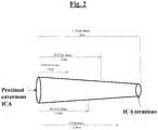
- FIG. 2depicts a side plan view of an example vessel contemplated for use with the braided implant of this disclosure
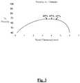
- FIG. 3is a graph that shows porosity versus vessel diameter for an example braided implant of this disclosure
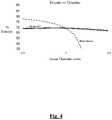
- FIG. 4is a graph that compares the porosity versus vessel diameter for an example braided implant of this disclosure versus a conventional device
- FIG. 5is a graph that shows the pore density and number of wires versus vessel diameter for a set of example braided implants of this disclosure
- FIG. 6is a graph that compares the porosity versus vessel diameter for a set of example braided implants of this disclosure versus a set of conventional devices;
- FIG. 7depicts a flow diagram outlining example method steps of this disclosure.
- FIG. 8depicts a flow diagram outlining example method steps of this disclosure.
- vasculature of a “subject” or “patient”may be vasculature of a human or any animal.
- an animalmay be a variety of any applicable type, including, but not limited thereto, mammal, veterinarian animal, livestock animal or pet type animal, etc.
- the animalmay be a laboratory animal specifically selected to have certain characteristics similar to a human (e.g., rat, dog, pig, monkey, or the like).
- the subjectmay be any applicable human patient, for example.
- doctormay include a doctor, surgeon, or any other individual or delivery instrumentation associated with delivery of a braid body to the vasculature of a subject.
- strandis intended in its broadest meaning to include a wire, a fiber, a filament, or other single elongated member.
- radiopaqueis utilized for its normal meaning of being radiodense, that is, formed of one or more materials which inhibit the passage of electromagnetic radiation to increase visibility during imaging.
- Suitable radiopaque materials for use according to the present inventioninclude platinum, chromium, cobalt, tantalum, tungsten, gold, silver, and alloys thereof.
- FIG. 1a schematic enlarged view of a portion of a braided implant 10 is shown according to an example of this disclosure.
- Braided implant 10can be formed of single strands 12 composed of at least a first material and one or more radiopaque multi-strands 14 .
- implant 10is woven to include at least a second multi-strand 16 .
- the implant 10further includes multi-strands 18 and 20 formed of monofilaments 22 and 24 each laid together with monofilaments 26 and 28 , respectively.
- the pattern of implant 10which is woven in some constructions and braided in other constructions, includes openings 30 defined by single strands 12 oriented in a first direction and by single strands 24 and 25 oriented in a second direction that is transverse to the first direction, for example.
- Implant 10further includes openings 32 and 34 defined on either side of multi-strand 14 by single strands 13 and 15 oriented in the same direction as multi-strand 14 and by single strands 24 , 25 and 27 oriented in a transverse direction.
- openings 32 and 34are slightly larger than openings 30 which are defined only by single strands; in other constructions, all openings 30 , 32 and 34 are substantially the same.
- Implant 10 constructions of this disclosureare considered to have substantially the same pattern as if implant 10 were formed solely from single strands of material. Since the multi-strands are braided, woven or otherwise laid in parallel to each other in the same manner as if single strands of radiopaque material were utilized, and especially when each filament of the multi-strand has the same diameter as the single strands, there is little or no mechanical impact to the performance of the implant, such as flexibility, ability to expand, and crimped profile.
- FIG. 2a side plan view of an example vessel is shown that is contemplated for use with implant 10 of this disclosure.
- the example vesseltapers along its longitudinal axis of the internal carotid artery (ICA).
- ICAinternal carotid artery
- the vessel taperwas calculated for the ICA as the change in caliber per unit length.
- the Rai studydetermined that the mean diameter at the cavernous ICA and the ICA terminus was 5 ⁇ 0.6 mm and 3.6 ⁇ 0.4 mm, respectively.
- the mean ICA taperwas 0.04 ⁇ 0.02 mm/1 mm.
- the diameter at the MCA and M2 originsmeasured 3.1 ⁇ 0.4 mm and 2.4 ⁇ 0.4 mm, respectively.
- FIG. 2provides non-limiting examples of diameter measurements at respective lengths taken from the proximal cavernous ICA towards the ICA terminus further exemplifying the tapering nature of the vessel.
- the Rai studyconfirmed that the ICA tapers from its proximal cavernous segment to the ICA terminus that implant 10 is configured to treat.
- FIG. 3a graph is provided that shows the percent porosity of an example braided implant 10 of this disclosure as compared to vessel diameter that were investigated for this disclosure.
- the braided implant 10 of this disclosureheld a relatively consistent pore size and porosity over a 1 mm vessel diameter range.
- this termmeans a range of diameters as measured between two separate locations in the vessel being treated by braided implant 10 .
- a practitioner using X-ray visualizationcould measure the vessel diameter of the proximal cavernous ICA as 4.2 mm whereas the vessel diameter towards the ICA terminus could be 3.2.
- the vessel diameter range in this example tapered vesselwould be 1 mm.
- the implants 10 of this disclosureare designed to accommodate such tapering vessels across these example vessel diameter ranges while also maintaining a substantially consistent target porosity. This is particularly advantageous since it means fewer implants are required to accommodate vessels that tapering greater than conventional devices (e.g., vessel diameter ranges of approximately 0.25 mm) or tortuosity typically seen in the neurovasculature.
- FIG. 3depicts an example vessel having a 1 mm vessel diameter range between 3.5 mm to 4.5 mm.
- the braided implant 10 of this disclosuremaintained approximately 70% porosity. Specifically, at a diameter of 3.5 mm, the porosity of the braid was approximately 69%. At a diameter of 4.0 mm, the porosity of the braid was approximately 69%. At a diameter of 4.5 mm, the porosity of the braid was approximately 67%.
- FIG. 4a graph is provided that summarizes a comparison carried out whereby the porosity versus vessel diameter is shown for an example implant 10 of this disclosure versus the PipelineTM Embolization Device (PED) by Medtronic across a 1 mm vessel diameter range.
- PEDPipelineTM Embolization Device
- braided implant 10 and the PED devicewere compared between a vessel diameter range of 3.5 mm to 4.5 mm.
- the braided implant 10 of this disclosureheld a relatively consistent pore size and porosity over a 1 mm vessel diameter range at about 70% across the same range previously shown in FIG. 3 .
- the PED device at 3.5 mm vessel diameterdemonstrated 80% porosity
- at 4 mm vessel diameterdemonstrated a 70% porosity
- at 4.5 mm vessel diameterdemonstrated less than 50% porosity.
- the porosity of the PED devicediminished appreciably as the diameter of the vessel increased across the 1 mm range
- the example braided implant 10 of this disclosuredemonstrated a substantially consistent porosity over the 1 mm diameter range.
- FIG. 4also shows the porosity of each device as it changes while expanding and it is characteristically the same.
- the braided implant 10is designed such that the indicated vessel diameter coincides with the peak of the porosity curve and the plateau area around it (which deviates from the target porosity very little).
- the braided implant 10 shownis indicated for an artery diameter range from 3.5 mm to 4.5 mm. This device remains very close to the target porosity of 70% throughout its expansion range, which has a width of 1.0 mm.
- the deviceWhen the device is compressed, for example, it is dense so its porosity is very low (see, e.g., the lower-left of FIG. 3 ). As the device expands, the porosity increases since the pores of the braided implant 10 are opening. At a certain point, the porosity reaches a peak, which is when the braiding angle is at 90 degrees since each pore can be a square, and as large as it can get, shown at the center arrow of FIG. 3 . Further expansion of the diameter past this peak then reduces the size of each pore and thus the porosity. When the braided implant 10 reaches maximum diameter at its expansion limit, then braided implant 10 is again very dense and porosity is correspondingly low (see, e.g., lower-right of FIG. 3 ).
- FIG. 5a graph is provided that summarizes the porosity versus vessel diameter for an example braided implant 10 of this disclosure.
- FIG. 5shows six separate braided implants ( 10 ) that each have approximately a 1 mm range in vessel diameter, and offset from one another by approximately half of that range (0.5 mm).
- the legendshows the range of vessel diameters from minimum to maximum and corresponding label for the applicable braided implant ( 10 ).
- a first braided implant ( 10 )is configured for a vessel diameter range between 2.0 mm and 3.0 mm with a label of 2.5 mm.
- the first braided implant ( 10 )has 48 wires with a pore density (mm 2 ) of 18.
- a second braided implant ( 10 )is configured for a vessel diameter range between 2.5 mm and 3.5 mm with a label of 3 mm.
- the second braided implant ( 10 )has 64 wires with a pore density (mm 2 ) of 23.
- a third braided implant ( 10 )is configured for a vessel diameter range between 3.0 mm and 4.0 mm with a label of 3.5 mm.
- the third braided implant ( 10 )has 64 wires with a pore density (mm 2 ) of 18.
- a fourth braided implant ( 10 )is configured for a vessel diameter range between 3.5 mm and 4.5 mm with a label of 4.0 mm.
- the fourth braided implant ( 10 )has 72 wires with a pore density (mm 2 ) of 19.
- a fifth braided implant ( 10 )is configured for a vessel diameter range between 4.0 mm and 5.0 mm with a label of 4.5 mm.
- the fifth braided implant ( 10 )has 96 wires with a pore density (mm 2 ) of 21.
- a sixth braided implant ( 10 )is configured for a vessel diameter range between 4.5 mm and 5.5 mm with a label of 5 mm.
- the sixth braided implant ( 10 )has 96 wires with a pore density (mm 2 ) of 21.
- FIG. 6a graph is provided that summarizes a comparison carried out whereby the porosity versus vessel diameter is shown for set of example implants ( 10 ) of this disclosure versus a set of PED devices across different vessel diameter ranges, including from 2 mm to 6 mm.
- the first braided implant 10 indicated as being configured for use across a vessel diameter of 2 mm to 3 mmbraided implant 10 was observed as providing approximately 70% porosity, whereas a comparable PED device was only able to maintain approximately 70% porosity across a vessel diameter of 2.5 mm to 2.75 mm (i.e. only a 0.25 mm vessel diameter range).
- the first braided implant ( 10 )was constructed from 48 strands of wire and the PED device was similarly constructed from 48 strands of wire.
- the PED deviceFor the 2.0 mm to 2.5 mm range, two more PED devices would also be required, since the PED device only demonstrated a 0.25 mm range capable of maintaining 70% porosity during use.
- FIG. 6also depicts that a second braided implant ( 10 ) indicated as being configured for use across a vessel diameter of 2.5 mm to 3.5 mm, braided implant ( 10 ) was observed as providing approximately 70% porosity, whereas a comparable PED device was only able to maintain approximately 70% porosity across a vessel diameter of 3.0 mm to 3.25 mm (i.e. only a 0.25 mm vessel diameter range).
- the second braided implant ( 10 ) in this examplewas constructed from 64 strands of wire while the PED device was constructed from 48 strands of wire.
- the second braided implant ( 10 )used approximately 21.3 strands/mm of vessel diameter while the PED device used 16 strands/mm of vessel diameter.
- the PED devicehas a porosity vs diameter curve that has a narrower plateau section than the second braided implant ( 10 ).
- another PED device in the relevant diameter rangewas necessary for said PED device just to complete the gap from 3.25 mm to 3.50 mm vessel diameter range, as shown.
- two more PED deviceswould also be required, since the PED device only demonstrated a 0.25 mm range capable of maintaining 70% porosity during use.
- FIG. 6also depicts that a third braided implant ( 10 ) indicated as being configured for use across a vessel diameter of 3.0 mm to 4.0 mm, braided implant ( 10 ) was observed as providing approximately 70% porosity, whereas a comparable PED device was only able to maintain approximately 70% porosity across a vessel diameter of 3.5 mm to 3.75 mm (i.e. only a 0.25 mm vessel diameter range).
- the third braided implant ( 10 ) in this examplewas constructed from 64 strands of wire while the PED device was constructed from 48 strands of wire.
- the third braided implant ( 10 )used approximately 18.3 strands/mm of vessel diameter while the PED device used 13.7 strands/mm of vessel diameter.
- the PED devicehas a porosity vs diameter curve that has a narrower plateau section than the third braided implant ( 10 ).
- another PED device in the relevant diameter rangewas necessary for said PED device just to complete the gap from 3.75 mm to 4.00 mm vessel diameter range, as shown.
- FIG. 6also depicts that a fourth braided implant ( 10 ) indicated as being configured for use across a vessel diameter of 3.5 mm to 4.5 mm, braided implant ( 10 ) was observed as providing approximately 70% porosity, whereas a comparable PED device was only able to maintain approximately 70% porosity across a vessel diameter of 4.0 mm to 4.25 mm (i.e. only a 0.25 mm vessel diameter range).
- the fourth braided implant ( 10 ) in this examplewas constructed from 72 strands of wire while the PED device was constructed from 48 strands of wire.
- the fourth braided implant ( 10 )used approximately 18 strands/mm of vessel diameter while the PED device used 12 strands/mm of vessel diameter.
- the PED devicehas a porosity vs diameter curve that has a narrower plateau section than the fourth braided implant ( 10 ).
- another PED device in the relevant diameter rangewas necessary for said PED device just to complete the gap from 4.25 mm to 4.50 mm vessel diameter range, as shown.
- FIG. 6also depicts that a fifth braided implant ( 10 ) indicated as being configured for use across a vessel diameter of 4.0 mm to 5.0 mm, braided implant ( 10 ) was observed as providing approximately 70% porosity, whereas a comparable PED device was only able to maintain approximately 70% porosity across a vessel diameter of 4.5 mm to 4.75 mm (i.e. only a 0.25 mm vessel diameter range).
- the fifth braided implant ( 10 ) in this examplewas constructed from 96 strands of wire while the PED device was constructed from 48 strands of wire.
- the fifth braided implant ( 10 )used approximately 21.3 strands/mm of vessel diameter while the PED device used 10.7 strands/mm of vessel diameter.
- the PED devicehas a porosity vs diameter curve that has a narrower plateau section than the fifth braided implant ( 10 ).
- another PED device in the relevant diameter rangewas necessary for said PED device just to complete the gap from 4.75 mm to 5.00 mm vessel diameter range, as shown.
- FIG. 6also depicts that a sixth braided implant ( 10 ) indicated as being configured for use across a vessel diameter of 4.5 mm to 5.5 mm, braided implant ( 10 ) was observed as providing approximately 70% porosity, whereas a comparable PED device was only able to maintain approximately 70% porosity across a vessel diameter of 5.0 mm to 5.25 mm (i.e. only a 0.25 mm vessel diameter range).
- the sixth braided implant ( 10 ) in this examplewas constructed from 96 strands of wire while the PED device was constructed from 48 strands of wire.
- the sixth braided implant ( 10 )used approximately 19.2 strands/mm of vessel diameter while the PED device used 9.6 strands/mm of vessel diameter.
- the PED devicehas a porosity vs diameter curve that has a narrower plateau section than the sixth braided implant ( 10 ).
- another PED device in the relevant diameter rangewas necessary for said PED device just to complete the gap from 5.25 mm to 5.50 mm vessel diameter range, as shown.
- Step 710includes determining a vessel diameter associated with a vessel having the aneurysm.
- Step 720includes selecting one of a plurality of braided implants ( 10 ) for treating the vessel, wherein each braided implant ( 10 ) comprises a porosity substantially consistent over up to a 1 mm vessel diameter range, each braided implant ( 10 ) configured to provide substantially consistent porosity over different 1 mm diameter ranges.
- Step 730includes treating the vessel with the one of the plurality of braided implants ( 10 ).
- Step 810includes determining a vessel diameter associated with a vessel containing the aneurysm.
- Step 820includes selecting one of a plurality of braided implants ( 10 ) for treating the vessel, wherein each braided implant ( 10 ) comprises a porosity substantially consistent over at least a 0.5 mm vessel diameter range, each braided implant ( 10 ) configured to provide substantially consistent porosity over different 0.5 mm diameter ranges.
- Step 830includes treating the vessel with the one of the plurality of braided implants ( 10 ).
- the braided implants ( 10 ) of this disclosureare particularly advantageous since a doctor can benefit from a wider indicated diameter range since it can afford some forgiveness for measurement inaccuracies and/or errors (e.g. an artery is measured on X-ray or any other visualization means to be 3.3 mm when it is actually 3.5 mm). Doctors can also benefit since a wider indicate diameter range can maintain consistent porosity close to the target porosity in tapering vessels, which is common.
- the implant ( 10 ) of this disclosureis also advantageous since the anatomical range of artery diameters can be treated with fewer devices, simplifying the device selection process and saving storage space for the inventory they must keep on hand.
- a set or family of implants ( 10 )is disclosed, each with a 1.0 mm wide indicated diameter range, are arranged such that they cover the anatomical range with 0.5 mm overlap, as shown in FIGS. 5-6 .
- the ranges depicted and described throughoutreference a vessel diameter range of up to 1 mm for a respective braided implant ( 10 ).
- the braided implant ( 10 )can be adapted for more than a 1 mm vessel diameter range.
- the braided implants ( 10 ) of this disclosureare s particularly advantageous since for any given artery diameter, there exists two different options of a device that can be selected.
- an artery with a diameter of 3.25 mmcan be at a desired treatment location in the vasculature. If the artery tapers down as you move away from the treatment location (i.e. becomes smaller), then the doctor could select the smaller implant from the set or family of implants by, for example, selecting an implant listed at 2.5 mm, rather than 3.5 mm. In this respect, the artery segment is exposed to target porosity over a longer length. Conversely, if the artery tapers up as you move away from the treatment location (i.e. becomes larger), then the doctor could select the larger implant from the set or family by, for example, selecting an implant listed at 3.0 mm to 4.0 mm. In this respect, similar to the previous example, the artery segment is exposed to the target porosity over a longer length.
- the advantages in the present disclosureresult from providing a braided implant with a broad plateau area of the characteristic porosity curve so that implant or the family or set of implants is capable of treating artery diameters within the plateau of an approximate 1.0 mm wide indicated range, and overlapping the indicated diameter ranges so the doctor has options for the best choice depending on the anatomy presented.
- each of the side-by-side filaments of the braided implants of this disclosureinclude a monofilament of radiopaque material.
- the carrier having the multi-strandis substantially the same as the carriers for the single strands.
- Each of the side-by-side filaments of the multi-strandis a monofilament of radiopaque material.
- the diameter of each side-by-side filamentis substantially the same as the diameter of the single strands.
- Forming the bodyincludes establishing a first spacing pattern, such as an open braid pattern or an open weave pattern, and a first wall thickness, and each multi-strand joins in the first spacing pattern without substantial deviation from that pattern and without substantially altering the first wall thickness.
- At least one multi-strand carrieris utilized for every dozen single-strand carriers.
- Some machineshave at least 42 carriers, such as 48 carriers, and at least 6 of the carriers, such as 8 carriers, are loaded with the multi-strands of radiopaque material. This still results in a 48-carrier braid but having double the number of radiopaque strands as when the 8 carriers are loaded with single strands of radiopaque material.
- Braided implants of this disclosurecan be designed for a specific percentage of coverage area per artery area or inversely, the percentage of open area remaining per artery area, known in this disclosure as “porosity”, after they have been delivered and expanded in place at the treatment site.
- the designed porositycan be adjusted by the braiding parameters, such as number of wires, width of wires, braided diameter, and braiding angle which can be alternatively measured as PPI or pitch. Once the target porosity is identified based on these factors, the braid design can be adjusted so that it reaches the target porosity when expanded to the indicated artery diameter.
- Braided implants of this disclosurecan have many variants within a set or family that reach the target porosity at different artery diameters. Therefore, the set or family of devices together allow the physician to treat any diameter artery within the anatomical range (1.5 mm to 6 mm is typical for neurovascular).
Landscapes
- Health & Medical Sciences (AREA)
- Engineering & Computer Science (AREA)
- Life Sciences & Earth Sciences (AREA)
- Biomedical Technology (AREA)
- Veterinary Medicine (AREA)
- Animal Behavior & Ethology (AREA)
- Public Health (AREA)
- Vascular Medicine (AREA)
- Heart & Thoracic Surgery (AREA)
- General Health & Medical Sciences (AREA)
- Surgery (AREA)
- Oral & Maxillofacial Surgery (AREA)
- Transplantation (AREA)
- Cardiology (AREA)
- Molecular Biology (AREA)
- Medical Informatics (AREA)
- Nuclear Medicine, Radiotherapy & Molecular Imaging (AREA)
- Reproductive Health (AREA)
- Epidemiology (AREA)
- Neurosurgery (AREA)
- Dispersion Chemistry (AREA)
- Chemical & Material Sciences (AREA)
- Manufacturing & Machinery (AREA)
- Textile Engineering (AREA)
- Gastroenterology & Hepatology (AREA)
- Pulmonology (AREA)
- Physics & Mathematics (AREA)
- Optics & Photonics (AREA)
- Prostheses (AREA)
- Surgical Instruments (AREA)
Abstract
Description
Claims (20)
Priority Applications (2)
| Application Number | Priority Date | Filing Date | Title |
|---|---|---|---|
| US16/597,420US11357648B2 (en) | 2018-08-06 | 2019-10-09 | Systems and methods of using a braided implant |
| US17/541,557US12004977B2 (en) | 2018-08-06 | 2021-12-03 | Systems and methods of using a braided implant |
Applications Claiming Priority (2)
| Application Number | Priority Date | Filing Date | Title |
|---|---|---|---|
| US16/056,135US10456280B1 (en) | 2018-08-06 | 2018-08-06 | Systems and methods of using a braided implant |
| US16/597,420US11357648B2 (en) | 2018-08-06 | 2019-10-09 | Systems and methods of using a braided implant |
Related Parent Applications (1)
| Application Number | Title | Priority Date | Filing Date |
|---|---|---|---|
| US16/056,135DivisionUS10456280B1 (en) | 2018-08-06 | 2018-08-06 | Systems and methods of using a braided implant |
Related Child Applications (1)
| Application Number | Title | Priority Date | Filing Date |
|---|---|---|---|
| US17/541,557DivisionUS12004977B2 (en) | 2018-08-06 | 2021-12-03 | Systems and methods of using a braided implant |
Publications (2)
| Publication Number | Publication Date |
|---|---|
| US20200046526A1 US20200046526A1 (en) | 2020-02-13 |
| US11357648B2true US11357648B2 (en) | 2022-06-14 |
Family
ID=67658446
Family Applications (4)
| Application Number | Title | Priority Date | Filing Date |
|---|---|---|---|
| US16/056,135ActiveUS10456280B1 (en) | 2018-08-06 | 2018-08-06 | Systems and methods of using a braided implant |
| US16/153,517ActiveUS10463510B1 (en) | 2018-08-06 | 2018-10-05 | Systems and methods of using a braided implant |
| US16/597,420ActiveUS11357648B2 (en) | 2018-08-06 | 2019-10-09 | Systems and methods of using a braided implant |
| US17/541,557ActiveUS12004977B2 (en) | 2018-08-06 | 2021-12-03 | Systems and methods of using a braided implant |
Family Applications Before (2)
| Application Number | Title | Priority Date | Filing Date |
|---|---|---|---|
| US16/056,135ActiveUS10456280B1 (en) | 2018-08-06 | 2018-08-06 | Systems and methods of using a braided implant |
| US16/153,517ActiveUS10463510B1 (en) | 2018-08-06 | 2018-10-05 | Systems and methods of using a braided implant |
Family Applications After (1)
| Application Number | Title | Priority Date | Filing Date |
|---|---|---|---|
| US17/541,557ActiveUS12004977B2 (en) | 2018-08-06 | 2021-12-03 | Systems and methods of using a braided implant |
Country Status (13)
| Country | Link |
|---|---|
| US (4) | US10456280B1 (en) |
| EP (1) | EP3607917A1 (en) |
| JP (1) | JP7467044B2 (en) |
| KR (1) | KR20200016189A (en) |
| CN (1) | CN110801257B (en) |
| AU (1) | AU2019213303A1 (en) |
| BR (1) | BR102019016196A2 (en) |
| CA (1) | CA3051086A1 (en) |
| CO (1) | CO2019008574A1 (en) |
| IL (1) | IL268459A (en) |
| MX (1) | MX2019009335A (en) |
| RU (1) | RU2019124732A (en) |
| TW (1) | TW202023496A (en) |
Families Citing this family (3)
| Publication number | Priority date | Publication date | Assignee | Title |
|---|---|---|---|---|
| CN113143555B (en)* | 2020-06-30 | 2025-09-12 | 微创神通医疗科技(上海)有限公司 | A vascular stent |
| CN112155814B (en)* | 2020-09-27 | 2022-05-13 | 艾柯医疗器械(北京)有限公司 | Low thrombus intracranial blood vessel braided stent and treatment method thereof |
| CN116172645B (en)* | 2023-05-04 | 2023-07-25 | 杭州脉流科技有限公司 | Model recommendation method of woven stent and computer equipment |
Citations (398)
| Publication number | Priority date | Publication date | Assignee | Title |
|---|---|---|---|---|
| US4332278A (en) | 1976-04-14 | 1982-06-01 | Titeflex Corporation | Braided-wire sheathing having bundled strands twisted to equalize tension |
| US4610688A (en) | 1983-04-04 | 1986-09-09 | Pfizer Hospital Products Group, Inc. | Triaxially-braided fabric prosthesis |
| US4754685A (en) | 1986-05-12 | 1988-07-05 | Raychem Corporation | Abrasion resistant braided sleeve |
| WO1989008433A1 (en) | 1988-03-09 | 1989-09-21 | Lazarus Harrison M | Artificial graft and implantation method |
| US5064435A (en) | 1990-06-28 | 1991-11-12 | Schneider (Usa) Inc. | Self-expanding prosthesis having stable axial length |
| US5275622A (en)* | 1983-12-09 | 1994-01-04 | Harrison Medical Technologies, Inc. | Endovascular grafting apparatus, system and method and devices for use therewith |
| US5282824A (en) | 1990-10-09 | 1994-02-01 | Cook, Incorporated | Percutaneous stent assembly |
| US5330500A (en) | 1990-10-18 | 1994-07-19 | Song Ho Y | Self-expanding endovascular stent with silicone coating |
| US5382259A (en) | 1992-10-26 | 1995-01-17 | Target Therapeutics, Inc. | Vasoocclusion coil with attached tubular woven or braided fibrous covering |
| US5387235A (en) | 1991-10-25 | 1995-02-07 | Cook Incorporated | Expandable transluminal graft prosthesis for repair of aneurysm |
| WO1995005132A1 (en) | 1993-08-18 | 1995-02-23 | W.L. Gore & Associates, Inc. | An intraluminal stent graft |
| US5423849A (en) | 1993-01-15 | 1995-06-13 | Target Therapeutics, Inc. | Vasoocclusion device containing radiopaque fibers |
| US5476508A (en) | 1994-05-26 | 1995-12-19 | Tfx Medical | Stent with mutually interlocking filaments |
| EP0701800A1 (en) | 1994-09-15 | 1996-03-20 | C.R. Bard, Inc. | Method and apparatus for recapture of hooked endoprosthesis |
| US5522881A (en) | 1994-06-28 | 1996-06-04 | Meadox Medicals, Inc. | Implantable tubular prosthesis having integral cuffs |
| US5549662A (en) | 1994-11-07 | 1996-08-27 | Scimed Life Systems, Inc. | Expandable stent using sliding members |
| US5556413A (en) | 1994-03-11 | 1996-09-17 | Advanced Cardiovascular Systems, Inc. | Coiled stent with locking ends |
| US5601593A (en) | 1995-03-06 | 1997-02-11 | Willy Rusch Ag | Stent for placement in a body tube |
| US5609627A (en) | 1994-02-09 | 1997-03-11 | Boston Scientific Technology, Inc. | Method for delivering a bifurcated endoluminal prosthesis |
| US5645558A (en) | 1995-04-20 | 1997-07-08 | Medical University Of South Carolina | Anatomically shaped vasoocclusive device and method of making the same |
| US5662622A (en) | 1995-04-04 | 1997-09-02 | Cordis Corporation | Intravascular catheter |
| US5702418A (en) | 1995-09-12 | 1997-12-30 | Boston Scientific Corporation | Stent delivery system |
| US5728131A (en) | 1995-06-12 | 1998-03-17 | Endotex Interventional Systems, Inc. | Coupling device and method of use |
| US5755772A (en) | 1995-03-31 | 1998-05-26 | Medtronic, Inc. | Radially expansible vascular prosthesis having reversible and other locking structures |
| US5769887A (en) | 1994-11-09 | 1998-06-23 | Endotex Interventional Systems, Inc. | Delivery catheter and graft for aneurysm repair |
| US5776161A (en) | 1995-10-16 | 1998-07-07 | Instent, Inc. | Medical stents, apparatus and method for making same |
| US5817126A (en) | 1997-03-17 | 1998-10-06 | Surface Genesis, Inc. | Compound stent |
| US5849037A (en) | 1995-04-12 | 1998-12-15 | Corvita Corporation | Self-expanding stent for a medical device to be introduced into a cavity of a body, and method for its preparation |
| US5851217A (en) | 1990-02-28 | 1998-12-22 | Medtronic, Inc. | Intralumenal drug eluting prosthesis |
| US5855601A (en) | 1996-06-21 | 1999-01-05 | The Trustees Of Columbia University In The City Of New York | Artificial heart valve and method and device for implanting the same |
| EP0894505A2 (en) | 1997-08-01 | 1999-02-03 | Schneider (Usa) Inc. | Bioabsorbable self-expanding stent |
| JPH1157010A (en) | 1997-08-19 | 1999-03-02 | Pola Chem Ind Inc | Sleep differentiation |
| JPH1157020A (en) | 1997-08-01 | 1999-03-02 | Schneider Usa Inc | In vivo absorbing type marker having radiation impermeable component, and its application |
| US5899935A (en) | 1997-08-04 | 1999-05-04 | Schneider (Usa) Inc. | Balloon expandable braided stent with restraint |
| US5916235A (en) | 1997-08-13 | 1999-06-29 | The Regents Of The University Of California | Apparatus and method for the use of detachable coils in vascular aneurysms and body cavities |
| US5916264A (en) | 1997-05-14 | 1999-06-29 | Jomed Implantate Gmbh | Stent graft |
| WO1999043379A1 (en) | 1998-02-26 | 1999-09-02 | Board Of Regents, The University Of Texas System | Delivery system and method for deployment and endovascular assembly of multi-stage stent graft |
| US5961546A (en) | 1993-04-22 | 1999-10-05 | C.R. Bard, Inc. | Method and apparatus for recapture of hooked endoprosthesis |
| US6010529A (en) | 1996-12-03 | 2000-01-04 | Atrium Medical Corporation | Expandable shielded vessel support |
| US6015432A (en) | 1998-02-25 | 2000-01-18 | Cordis Corporation | Wire reinforced vascular prosthesis |
| US6033436A (en) | 1998-02-17 | 2000-03-07 | Md3, Inc. | Expandable stent |
| US6036725A (en) | 1998-06-10 | 2000-03-14 | General Science And Technology | Expandable endovascular support device |
| US6051020A (en) | 1994-02-09 | 2000-04-18 | Boston Scientific Technology, Inc. | Bifurcated endoluminal prosthesis |
| US6099559A (en) | 1998-05-28 | 2000-08-08 | Medtronic Ave, Inc. | Endoluminal support assembly with capped ends |
| US6110198A (en) | 1995-10-03 | 2000-08-29 | Medtronic Inc. | Method for deploying cuff prostheses |
| US6152956A (en) | 1997-01-28 | 2000-11-28 | Pierce; George E. | Prosthesis for endovascular repair of abdominal aortic aneurysms |
| US6161399A (en) | 1997-10-24 | 2000-12-19 | Iowa-India Investments Company Limited | Process for manufacturing a wire reinforced monolayer fabric stent |
| US6165213A (en) | 1994-02-09 | 2000-12-26 | Boston Scientific Technology, Inc. | System and method for assembling an endoluminal prosthesis |
| US6168621B1 (en) | 1998-05-29 | 2001-01-02 | Scimed Life Systems, Inc. | Balloon expandable stent with a self-expanding portion |
| US6176875B1 (en) | 1996-01-05 | 2001-01-23 | Medtronic, Inc. | Limited expansion endoluminal prostheses and methods for their use |
| WO2001015632A1 (en) | 1999-08-31 | 2001-03-08 | Advanced Cardiovascular Systems, Inc. | Stent design with end rings having enhanced strength and radiopacity |
| WO2001035864A1 (en) | 1999-11-16 | 2001-05-25 | Boston Scientific Limited | Multi-section filamentary endoluminal stent |
| US6264683B1 (en) | 2000-03-17 | 2001-07-24 | Advanced Cardiovascular Systems, Inc. | Stent delivery catheter with bumpers for improved retention of balloon expandable stents |
| WO2001058384A1 (en) | 2000-02-14 | 2001-08-16 | Angiomed Gmbh & Co. Medizintechnik Kg | Stent matrix |
| US6280465B1 (en) | 1999-12-30 | 2001-08-28 | Advanced Cardiovascular Systems, Inc. | Apparatus and method for delivering a self-expanding stent on a guide wire |
| US20010025195A1 (en) | 1998-12-11 | 2001-09-27 | Shaolian Samuel M. | Flexible vascular graft |
| WO2001072240A1 (en) | 2000-03-27 | 2001-10-04 | Aga Medical Corporation | Repositionable and recapturable vascular stent/graft |
| US6319278B1 (en) | 2000-03-03 | 2001-11-20 | Stephen F. Quinn | Low profile device for the treatment of vascular abnormalities |
| US6325823B1 (en) | 1999-10-29 | 2001-12-04 | Revasc Corporation | Endovascular prosthesis accommodating torsional and longitudinal displacements and methods of use |
| US20010049554A1 (en) | 1998-11-18 | 2001-12-06 | Carlos E. Ruiz | Endovascular prosthesis and method of making |
| US6348066B1 (en)* | 1995-11-07 | 2002-02-19 | Corvita Corporation | Modular endoluminal stent-grafts and methods for their use |
| US6391037B1 (en) | 2000-03-02 | 2002-05-21 | Prodesco, Inc. | Bag for use in the intravascular treatment of saccular aneurysms |
| US6409755B1 (en) | 1997-05-29 | 2002-06-25 | Scimed Life Systems, Inc. | Balloon expandable stent with a self-expanding portion |
| US20020095205A1 (en) | 2001-01-12 | 2002-07-18 | Edwin Tarun J. | Encapsulated radiopaque markers |
| US20020111671A1 (en) | 2001-02-15 | 2002-08-15 | Stenzel Eric B. | Locking stent |
| US20020151953A1 (en) | 2001-04-11 | 2002-10-17 | Trivascular, Inc. | Delivery system and method for bifurcated endovascular graft |
| US20020151956A1 (en) | 2001-04-11 | 2002-10-17 | Trivascular, Inc. | Delivery system and method for endovascular graft |
| US6488702B1 (en) | 1997-01-24 | 2002-12-03 | Jomed Gmbh | Bistable spring construction for a stent and other medical apparatus |
| US20020198587A1 (en) | 2001-03-28 | 2002-12-26 | Cook Incorporated | Modular stent graft assembly and use thereof |
| US20030009211A1 (en) | 2001-07-03 | 2003-01-09 | Dicarlo Paul | Implant having improved fixation to a body lumen and method for implanting the same |
| US20030055493A1 (en) | 2001-09-19 | 2003-03-20 | Erin Carpenter | Enhancement of stent radiopacity using anchors and tags |
| US20030114922A1 (en) | 2001-10-30 | 2003-06-19 | Olympus Optical Co., Ltd. | Stent |
| US6612012B2 (en) | 2001-06-11 | 2003-09-02 | Cordis Neurovascular, Inc. | Method of manufacturing small profile medical devices |
| US6635080B1 (en) | 1997-06-19 | 2003-10-21 | Vascutek Limited | Prosthesis for repair of body passages |
| US6673106B2 (en) | 2001-06-14 | 2004-01-06 | Cordis Neurovascular, Inc. | Intravascular stent device |
| US6673107B1 (en) | 1999-12-06 | 2004-01-06 | Advanced Cardiovascular Systems, Inc. | Bifurcated stent and method of making |
| US20040015229A1 (en) | 2002-07-22 | 2004-01-22 | Syntheon, Llc | Vascular stent with radiopaque markers |
| US20040024416A1 (en) | 2000-07-17 | 2004-02-05 | Ofer Yodfat | Implantable braided stroke preventing device and method of manufacturing |
| US6699277B1 (en) | 2000-03-09 | 2004-03-02 | Diseno Y Desarrollo Medica, S.A. De C.V. | Stent with cover connectors |
| US20040044399A1 (en) | 2002-09-04 | 2004-03-04 | Ventura Joseph A. | Radiopaque links for self-expanding stents |
| US20040073291A1 (en) | 2002-10-09 | 2004-04-15 | Brian Brown | Intraluminal medical device having improved visibility |
| US6740113B2 (en) | 1998-05-29 | 2004-05-25 | Scimed Life Systems, Inc. | Balloon expandable stent with a self-expanding portion |
| US6770089B1 (en) | 2000-12-28 | 2004-08-03 | Advanced Cardiovascular Systems, Inc. | Hybrid stent fabrication using metal rings and polymeric links |
| US20040167619A1 (en) | 2003-02-26 | 2004-08-26 | Cook Incorporated | Prosthesis adapted for placement under external imaging |
| JP2004267750A (en) | 2002-09-23 | 2004-09-30 | Cordis Neurovascular Inc | Expandable stent and delivery system and method |
| US6818013B2 (en) | 2001-06-14 | 2004-11-16 | Cordis Corporation | Intravascular stent device |
| US20040254637A1 (en) | 2003-06-16 | 2004-12-16 | Endotex Interventional Systems, Inc. | Sleeve stent marker |
| US6833003B2 (en) | 2002-06-24 | 2004-12-21 | Cordis Neurovascular | Expandable stent and delivery system |
| US20050010281A1 (en) | 2001-07-09 | 2005-01-13 | Ofer Yodfat | Implantable intraluminal device and method of using same in treating aneurysms |
| US20050033406A1 (en) | 2003-07-15 | 2005-02-10 | Barnhart William H. | Branch vessel stent and graft |
| US20050043784A1 (en) | 2003-08-20 | 2005-02-24 | Ilya Yampolsky | Stent with improved resistance to migration |
| US20050049670A1 (en) | 2003-08-29 | 2005-03-03 | Jones Donald K. | Self-expanding stent and stent delivery system for treatment of vascular disease |
| US20050049669A1 (en) | 2003-08-29 | 2005-03-03 | Jones Donald K. | Self-expanding stent and stent delivery system with distal protection |
| US20050049668A1 (en) | 2003-08-29 | 2005-03-03 | Jones Donald K. | Self-expanding stent and stent delivery system for treatment of vascular stenosis |
| US6899914B2 (en) | 2000-12-18 | 2005-05-31 | Biotronik Mess-Und Therapiegeraete Gmbh Ingeniurbuero Berlin | Method of applying a marker element to an implant and an implant provided with a marker element |
| US20050125051A1 (en) | 2003-12-05 | 2005-06-09 | Scimed Life Systems, Inc. | Detachable segment stent |
| US20050131516A1 (en) | 2003-09-29 | 2005-06-16 | Secant Medical, Llc | Integral support stent graft assembly |
| US20050137682A1 (en) | 2003-12-22 | 2005-06-23 | Henri Justino | Stent mounted valve |
| US6911040B2 (en) | 2002-01-24 | 2005-06-28 | Cordis Corporation | Covered segmented stent |
| US20050148866A1 (en) | 2003-12-29 | 2005-07-07 | Scimed Life Systems, Inc. | Medical device with modified marker band |
| US6918928B2 (en) | 1999-04-16 | 2005-07-19 | Medtronic, Inc. | Medical device for intraluminal endovascular stenting |
| US6929659B2 (en) | 1995-11-07 | 2005-08-16 | Scimed Life Systems, Inc. | Method of preventing the dislodgment of a stent-graft |
| US6945994B2 (en) | 2001-12-05 | 2005-09-20 | Boston Scientific Scimed, Inc. | Combined balloon-expanding and self-expanding stent |
| WO2005087138A1 (en) | 2004-03-08 | 2005-09-22 | Cook Incorporated | Great retainer for a stent-graft |
| US20050228484A1 (en) | 2004-03-11 | 2005-10-13 | Trivascular, Inc. | Modular endovascular graft |
| US20050257674A1 (en) | 2003-12-29 | 2005-11-24 | Boaz Nishri | Mixed wire braided device with structural integrity |
| US6970734B2 (en) | 2002-12-02 | 2005-11-29 | Boston Scientific Scimed, Inc. | Flexible marker bands |
| US20050283220A1 (en) | 2004-06-22 | 2005-12-22 | Gobran Riad H | Blood flow diverters for the treatment of intracranial aneurysms |
| US20050288775A1 (en) | 2004-06-24 | 2005-12-29 | Scimed Life Systems, Inc. | Metallic fibers reinforced textile prosthesis |
| US20060015173A1 (en) | 2003-05-06 | 2006-01-19 | Anton Clifford | Endoprosthesis having foot extensions |
| US20060064156A1 (en) | 2004-09-21 | 2006-03-23 | Thistle Robert C | Atraumatic connections for multi-component stents |
| US20060064151A1 (en) | 2004-09-22 | 2006-03-23 | Guterman Lee R | Cranial aneurysm treatment arrangement |
| US20060069424A1 (en) | 2004-09-27 | 2006-03-30 | Xtent, Inc. | Self-constrained segmented stents and methods for their deployment |
| US20060195175A1 (en) | 2005-02-25 | 2006-08-31 | Abbott Laboratories Vascular Enterprises Limited | Modular vascular prosthesis having axially variable properties and improved flexibility and methods of use |
| US20060206202A1 (en) | 2004-11-19 | 2006-09-14 | Philippe Bonhoeffer | Apparatus for treatment of cardiac valves and method of its manufacture |
| US20060212113A1 (en) | 2005-02-24 | 2006-09-21 | Shaolian Samuel M | Externally adjustable endovascular graft implant |
| US20060271165A1 (en) | 2002-12-30 | 2006-11-30 | Yip Philip S | Drug-eluting stent cover and method of use |
| US20060271153A1 (en) | 2005-05-25 | 2006-11-30 | Chestnut Medical Technologies, Inc. | System and method for delivering and deploying an occluding device within a vessel |
| US20060287717A1 (en) | 2005-05-24 | 2006-12-21 | Rowe Stanton J | Methods for rapid deployment of prosthetic heart valves |
| US7153324B2 (en) | 2003-07-31 | 2006-12-26 | Cook Incorporated | Prosthetic valve devices and methods of making such devices |
| US20070043432A1 (en) | 2004-02-11 | 2007-02-22 | Eric Perouse | Tubular prosthesis |
| US20070060994A1 (en) | 2005-09-12 | 2007-03-15 | Gobran Riad H | Blood flow diverters for the treatment of intracranial aneurysms |
| US7208008B2 (en) | 2003-10-02 | 2007-04-24 | Medtronic Vascular, Inc. | Balloonless direct stenting device |
| US20070100427A1 (en) | 2005-11-02 | 2007-05-03 | Eric Perouse | Device for treating a blood vessel and associated treatment kit |
| US20070156230A1 (en) | 2006-01-04 | 2007-07-05 | Dugan Stephen R | Stents with radiopaque markers |
| US20070167955A1 (en) | 2005-01-10 | 2007-07-19 | Duke Fiduciary, Llc | Apparatus and method for deploying an implantable device within the body |
| US20070191922A1 (en) | 2006-01-18 | 2007-08-16 | William A. Cook Australia Pty. Ltd. | Self expanding stent |
| US20070203503A1 (en) | 2003-12-23 | 2007-08-30 | Amr Salahieh | Systems and methods for delivering a medical implant |
| US20070208373A1 (en) | 2006-02-22 | 2007-09-06 | Zaver Steven G | Embolic protection systems having radiopaque filter mesh |
| US20070208409A1 (en) | 2006-03-01 | 2007-09-06 | Boston Scientific Scimed, Inc. | Flexible stent-graft devices and methods of producing the same |
| US7267685B2 (en) | 2000-11-16 | 2007-09-11 | Cordis Corporation | Bilateral extension prosthesis and method of delivery |
| US20070213810A1 (en) | 2005-03-14 | 2007-09-13 | Richard Newhauser | Segmented endoprosthesis |
| US20070219613A1 (en) | 2003-10-06 | 2007-09-20 | Xtent, Inc. | Apparatus and methods for interlocking stent segments |
| US20070233228A1 (en) | 2006-03-28 | 2007-10-04 | Medtronic, Inc. | Prosthetic cardiac valve formed from pericardium material and methods of making same |
| US20070233223A1 (en) | 2006-04-04 | 2007-10-04 | Mikolaj Styrc | Device for treating a blood circulation canal and process for preparing this device |
| US20070233224A1 (en) | 2006-03-30 | 2007-10-04 | Alexander Leynov | Implantable medical endoprosthesis delivery system |
| US20070238979A1 (en) | 2006-03-23 | 2007-10-11 | Medtronic Vascular, Inc. | Reference Devices for Placement in Heart Structures for Visualization During Heart Valve Procedures |
| US7288111B1 (en) | 2002-03-26 | 2007-10-30 | Thoratec Corporation | Flexible stent and method of making the same |
| US20070255385A1 (en) | 2006-04-28 | 2007-11-01 | Dirk Tenne | Stent delivery system with improved retraction member |
| US7291167B2 (en) | 2000-10-26 | 2007-11-06 | Boston Scientific Scimed, Inc. | Stent having radiopaque markers and method of fabricating the same |
| US20080009934A1 (en) | 2006-07-07 | 2008-01-10 | Boston Scientific Scimed, Inc. | Endoprosthesis delivery system with stent holder |
| US20080009938A1 (en) | 2006-07-07 | 2008-01-10 | Bin Huang | Stent with a radiopaque marker and method for making the same |
| US7344559B2 (en) | 2003-08-25 | 2008-03-18 | Biophan Technologies, Inc. | Electromagnetic radiation transparent device and method of making thereof |
| US20080071307A1 (en) | 2006-09-19 | 2008-03-20 | Cook Incorporated | Apparatus and methods for in situ embolic protection |
| US20080140172A1 (en) | 2004-12-13 | 2008-06-12 | Robert Hunt Carpenter | Multi-Wall Expandable Device Capable Of Drug Delivery Related Applications |
| CN101234046A (en) | 2007-01-17 | 2008-08-06 | Aga医药有限公司 | Intravascular deliverable stent for reinforcement of vascular abnormalities |
| US20080221670A1 (en) | 2007-03-07 | 2008-09-11 | Claude Clerc | Radiopaque polymeric stent |
| US20080221664A1 (en) | 2007-03-08 | 2008-09-11 | Pst, Llc | Tapered helical stent and method for manufacturing the stent |
| US20080243227A1 (en) | 2007-03-30 | 2008-10-02 | Lorenzo Juan A | Radiopaque markers for implantable stents and methods for manufacturing the same |
| WO2008130530A1 (en) | 2007-04-16 | 2008-10-30 | Boston Scientific Scimed, Inc. | Radiopaque compositions, stents and methods of preparation |
| US20080281350A1 (en) | 2006-12-13 | 2008-11-13 | Biomerix Corporation | Aneurysm Occlusion Devices |
| US20080288046A1 (en) | 2007-05-16 | 2008-11-20 | Boston Scientific Scimed, Inc. | Method of Attaching Radiopaque Markers to Intraluminal Medical Devices, and Devices Formed Using the Same |
| US20090005848A1 (en) | 2005-02-25 | 2009-01-01 | Abbott Laboratories Vascular Enterprises Limited | Modular vascular prosthesis and methods of use |
| US7480973B2 (en) | 2004-03-01 | 2009-01-27 | Boston Scientific Scimed, Inc. | Automated marker band nest placement crimper |
| US20090030501A1 (en) | 2005-08-02 | 2009-01-29 | Reva Medical, Inc. | Axially nested slide and lock expandable device |
| DE202008014828U1 (en) | 2007-11-07 | 2009-02-12 | Acandis Gmbh & Co. Kg | Medical implant and device for producing such an implant |
| US20090076594A1 (en) | 2006-03-14 | 2009-03-19 | Patrick Sabaria | Method of monitoring positioning of polymer stents |
| US20090082844A1 (en) | 2007-09-26 | 2009-03-26 | Boston Scientific Corporation | System and method of pivoted stent deployment |
| US20090082847A1 (en) | 2007-09-26 | 2009-03-26 | Boston Scientific Corporation | System and method of securing stent barbs |
| US20090082845A1 (en) | 2007-09-26 | 2009-03-26 | Boston Scientific Corporation | Alignment stent apparatus and method |
| US20090163951A1 (en) | 2007-12-19 | 2009-06-25 | Sara Simmons | Medical devices including sutures with filaments comprising naturally derived collagenous material |
| US20090198315A1 (en) | 2006-04-28 | 2009-08-06 | Younes Boudjemline | Vascular Stents, Methods of Use and Methods of Manufacture |
| US20090234429A1 (en) | 2008-02-07 | 2009-09-17 | Lilip Lau | Self-restraining endoluminal prosthesis |
| US20090287145A1 (en) | 2008-05-15 | 2009-11-19 | Altura Interventional, Inc. | Devices and methods for treatment of abdominal aortic aneurysms |
| US20090297582A1 (en)* | 2004-11-26 | 2009-12-03 | Biomerix Corporation | Vascular occlusion devices and methods |
| US20090306761A1 (en) | 2008-06-06 | 2009-12-10 | Bay Street Medical | Prosthesis and delivery system |
| US7632302B2 (en) | 2005-11-14 | 2009-12-15 | Ev3 Inc. | Stent and stent delivery system for ostial locations in a conduit |
| US20090326640A1 (en) | 2007-02-01 | 2009-12-31 | Shinichi Yoshimura | Medical device for body cavity and method of producing the same |
| US20100010619A1 (en) | 2008-07-08 | 2010-01-14 | Boston Scientific Scimed, Inc. | Closed-Cell Flexible Stent Hybrid |
| US7655034B2 (en) | 2006-11-14 | 2010-02-02 | Medtronic Vascular, Inc. | Stent-graft with anchoring pins |
| US20100069948A1 (en) | 2008-09-12 | 2010-03-18 | Micrus Endovascular Corporation | Self-expandable aneurysm filling device, system and method of placement |
| US7708773B2 (en) | 2005-01-21 | 2010-05-04 | Gen4 Llc | Modular stent graft employing bifurcated graft and leg locking stent elements |
| FR2939637A1 (en) | 2008-12-17 | 2010-06-18 | Newco | Stent delivering device for use during sealing e.g. artery of cerebral aneurysm, has hollow impressions for receiving part of threads of stent such that part of threads are housed in hollow impressions |
| US20100161028A1 (en) | 2002-02-26 | 2010-06-24 | Endovascular Technologies, Inc. | Endovascular graft device and methods for attaching components thereof |
| US7761138B2 (en) | 2004-03-12 | 2010-07-20 | Boston Scientific Scimed, Inc. | MRI and X-ray visualization |
| CN101779992A (en) | 2009-01-19 | 2010-07-21 | 加奇生物科技(上海)有限公司 | Conveying device for retrievable self-eject nervi cerebrales stent |
| US20100249815A1 (en) | 2009-03-25 | 2010-09-30 | Cook Incorporated | Everted sheath thrombectomy device |
| US7806919B2 (en) | 2008-04-01 | 2010-10-05 | Medtronic Vascular, Inc. | Double-walled stent system |
| US7806923B2 (en) | 2008-04-11 | 2010-10-05 | Medtronic Vascular, Inc. | Side branch stent having a proximal split ring |
| US20100292777A1 (en) | 2009-05-13 | 2010-11-18 | Boston Scientific Scimed, Inc. | Stent |
| US20100298872A1 (en) | 2007-11-26 | 2010-11-25 | Aesculap Ag | Surgical suture material consisting of braided thread |
| US20100324651A1 (en) | 2006-10-18 | 2010-12-23 | Asher Holzer | Knitted Stent Jackets |
| US20100324649A1 (en) | 2009-06-18 | 2010-12-23 | Graftcraft I Goteborg Ab | Device and method for treating ruptured aneurysms |
| US20100331972A1 (en) | 2009-06-26 | 2010-12-30 | Edwards Lifesciences Corporation | Unitary Quick Connect Prosthetic Heart Valve and Deployment System and Methods |
| US20110004237A1 (en) | 2007-12-12 | 2011-01-06 | Peter Schneider | Minimal surface area contact device for holding plaque to blood vessel wall |
| US20110060400A1 (en) | 2005-03-14 | 2011-03-10 | Abbott Laboratories | Visible endoprosthesis |
| USRE42244E1 (en) | 1993-07-23 | 2011-03-22 | Cook Incorporated | Flexible stent having a pattern formed from biocompatible material |
| US7913371B2 (en) | 2007-07-20 | 2011-03-29 | Biotronik Vi Patent Ag | Medication depot for medical implants |
| US20110137397A1 (en) | 2009-12-04 | 2011-06-09 | Edwards Lifesciences Corporation | Prosthetic valve for replacing mitral valve |
| CN102100587A (en) | 2009-12-18 | 2011-06-22 | 微创医疗器械(上海)有限公司 | Blood vessel bracket prosthesis |
| US7985213B2 (en) | 2003-04-25 | 2011-07-26 | Cook Medical Technologies Llc | Delivery catheter and method of manufacture |
| US20110184508A2 (en) | 1994-05-19 | 2011-07-28 | Boston Scientific Scimed, Inc. | Improved tissue supporting devices |
| US7998187B2 (en) | 2004-09-21 | 2011-08-16 | William A. Cook Australia Pty. Ltd. | Stent graft connection arrangement |
| US8021418B2 (en) | 2003-06-19 | 2011-09-20 | Boston Scientific Scimed, Inc. | Sandwiched radiopaque marker on covered stent |
| US8043353B2 (en) | 2005-05-04 | 2011-10-25 | Jotec Gmbh | Delivery system having a self-expanding braided stent |
| US8043357B2 (en) | 2003-10-10 | 2011-10-25 | Cook Medical Technologies Llc | Ring stent |
| US20110264186A1 (en) | 2010-04-23 | 2011-10-27 | Medtronic Vascular, Inc. | Biodegradable Stent Having Non-Biodegradable End Portions and Mechanisms for Increased Stent Hoop Strength |
| US8048139B2 (en) | 2006-07-24 | 2011-11-01 | Cardiatis, S.A. | Reversible applicator for an intraluminal endoprosthesis |
| US8052741B2 (en) | 2009-03-23 | 2011-11-08 | Medtronic Vascular, Inc. | Branch vessel prosthesis with a roll-up sealing assembly |
| CN102271620A (en) | 2008-12-15 | 2011-12-07 | 阿勒根公司 | Prosthetic device and method of manufacturing prosthetic device |
| US20110307049A1 (en) | 2010-06-08 | 2011-12-15 | Stephen Kao | Bi-directional stent delivery system |
| US8092510B2 (en) | 2007-07-25 | 2012-01-10 | Cook Medical Technologies Llc | Retention wire for self-expanding stent |
| US20120035714A1 (en) | 2010-08-05 | 2012-02-09 | Cook Medical Technologies Llc | Stent Graft Having A Marker And A Reinforcing And Marker Ring |
| US20120041538A1 (en) | 2010-01-29 | 2012-02-16 | Sharon White | Collapsing structure for reducing the diameter of a stent end |
| US20120065728A1 (en) | 2010-05-10 | 2012-03-15 | Heart Leaflet Technologies, Inc. | Stentless Support Structure |
| US8142456B2 (en) | 2008-04-21 | 2012-03-27 | Nfocus Neuromedical, Inc. | Braid-ball embolic devices |
| US20120123529A1 (en) | 2010-10-05 | 2012-05-17 | Edwards Lifesciences Corporation | Prosthetic heart valve |
| US8187316B2 (en) | 2007-12-27 | 2012-05-29 | Cook Medical Technologies Llc | Implantable graft device having treated yarn and method for making same |
| WO2012082440A1 (en) | 2010-12-13 | 2012-06-21 | Microvention, Inc. | Stent |
| US20120168022A1 (en) | 2010-12-30 | 2012-07-05 | Cook Medical Technologies Llc | Woven fabric having composite yarns for endoluminal devices |
| WO2012096687A1 (en) | 2011-01-14 | 2012-07-19 | Idev Technologies, Inc | Stent delivery system with pusher assembly |
| US20120191176A1 (en) | 2009-09-14 | 2012-07-26 | Acandis Gmbh & Co. Kg | Medical implant |
| US20120197377A1 (en) | 2011-02-01 | 2012-08-02 | Micrus Endovascular Corporation | Wire with compliant sheath |
| DE102011015995A1 (en) | 2011-04-04 | 2012-10-04 | Acandis Gmbh & Co. Kg | Medical device and method for producing such a device |
| US20120271403A1 (en) | 2011-04-21 | 2012-10-25 | Aga Medical Corporation | Tubular structure and method for making the same |
| US20120283768A1 (en) | 2011-05-05 | 2012-11-08 | Sequent Medical Inc. | Method and apparatus for the treatment of large and giant vascular defects |
| US20120296418A1 (en) | 2011-05-20 | 2012-11-22 | Edwards Lifesciences Corporation | Encapsulated heart valve |
| EP2545887A1 (en) | 2010-03-30 | 2013-01-16 | Terumo Kabushiki Kaisha | Stent delivery system |
| US8357194B2 (en) | 2006-03-15 | 2013-01-22 | Cordis Corporation | Stent graft device |
| US8372133B2 (en) | 2009-10-05 | 2013-02-12 | 480 Biomedical, Inc. | Polymeric implant delivery system |
| US20130041454A1 (en) | 2011-02-09 | 2013-02-14 | Business Expectations Llc | Sensor Actuated Stent |
| US20130060323A1 (en) | 2011-09-01 | 2013-03-07 | Cook Medical Technologies Llc | Braided helical wire stent |
| US20130123901A1 (en) | 2011-11-14 | 2013-05-16 | Robert A. Connor | Stent with in situ determination of wall areas with differences in porosity |
| US8449604B2 (en) | 2005-12-16 | 2013-05-28 | Micardia Corporation | Adjustable prosthetic valve implant |
| US8449600B2 (en) | 2006-08-18 | 2013-05-28 | Cook Medical Technologies Llc | Iliac extension with flared cuff |
| US20130144375A1 (en) | 2007-12-12 | 2013-06-06 | Intact Vascular, Inc. | Endoluminal device and method |
| US8484120B2 (en) | 2001-05-25 | 2013-07-09 | Thomas W. Krause | Method and apparatus for generating and distributing creative works |
| WO2013126299A1 (en) | 2012-02-23 | 2013-08-29 | Covidien Lp | Methods and apparatus for luminal stenting |
| US20130245745A1 (en) | 2012-03-16 | 2013-09-19 | Microvention, Inc. | Stent and stent delivery device |
| US20130253572A1 (en) | 2012-03-23 | 2013-09-26 | Covidien Lp | Occlusive devices and methods of use |
| CN103330605A (en) | 2013-03-15 | 2013-10-02 | 杭州启明医疗器械有限公司 | Sheath core and interventional device conveying system comprising same |
| WO2013151793A1 (en) | 2012-04-06 | 2013-10-10 | Trivascular, Inc. | Low profile stent graft and delivery system |
| US8562666B2 (en) | 2005-09-28 | 2013-10-22 | Nitinol Development Corporation | Intraluminal medical device with nested interlocking segments |
| US8579959B2 (en) | 2008-09-12 | 2013-11-12 | Cook Medical Technologies Llc | Radiopaque reinforcing member |
| JP2013541358A (en) | 2010-09-08 | 2013-11-14 | フェノックス ゲゼルシャフト ミット ベシュレンクテル ハフツング | Implants affecting blood flow in areas of arteriovenous malformations |
| US8597276B2 (en) | 2005-05-12 | 2013-12-03 | Covidien Lp | Implant delivery system with interlocked RX port orientation |
| US20130345739A1 (en) | 2011-03-09 | 2013-12-26 | Neuravi Limited | Clot retrieval device for removing occlusive clot from a blood vessel |
| US20140025161A1 (en) | 2012-07-23 | 2014-01-23 | Abbott Cardiovascular Systems Inc. | Shape memory bioresorbable polymer peripheral scaffolds |
| US8641748B2 (en) | 2002-02-28 | 2014-02-04 | Bay Street Medical, Inc. | Guidewire loaded stent for delivery through a catheter |
| US8672992B2 (en) | 2008-12-18 | 2014-03-18 | Cook Medical Technologies Llc | Stent and stent-graft having one or more conformance struts |
| US8709065B2 (en) | 2001-12-20 | 2014-04-29 | Trivascular, Inc. | Advanced endovascular graft |
| US20140135812A1 (en) | 2012-11-13 | 2014-05-15 | Covidien Lp | Occlusive devices |
| US8734501B2 (en) | 2003-10-10 | 2014-05-27 | Cook Medical Technologies Llc | Composite stent graft |
| US20140200648A1 (en) | 2013-01-17 | 2014-07-17 | Covidien Lp | Methods and apparatus for luminal stenting |
| US20140200607A1 (en) | 2013-01-14 | 2014-07-17 | Microvention, Inc. | Occlusive Device |
| US8816247B1 (en) | 2013-07-29 | 2014-08-26 | Insera Therapeutics, Inc. | Methods for modifying hypotubes |
| CN104042376A (en) | 2013-03-13 | 2014-09-17 | 德普伊新特斯产品有限责任公司 | Braided stent with expansion ring and method of delivery |
| CN104042380A (en) | 2013-03-13 | 2014-09-17 | 德普伊新特斯产品有限责任公司 | Delivery system for expandable stents |
| EP2777642A1 (en) | 2013-03-13 | 2014-09-17 | DePuy Synthes Products, LLC | Braid expansion ring with markers |
| US20140277400A1 (en) | 2013-03-15 | 2014-09-18 | Covidien Lp | Coated medical devices and methods of making and using same |
| US8864811B2 (en) | 2010-06-08 | 2014-10-21 | Veniti, Inc. | Bi-directional stent delivery system |
| US20140336741A1 (en) | 2013-05-08 | 2014-11-13 | Robert A. Connor | Method of Radially-Asymmetric Stent Expansion |
| US20150018458A1 (en) | 2012-02-29 | 2015-01-15 | Sumitomo Bakelite Co., Ltd. | Method of packaging granular encapsulating resin composition, package and method of transporting package |
| US20150025625A1 (en) | 2013-07-18 | 2015-01-22 | The Trustees Of The University Of Pennsylvania | Cardiac repair prosthesis sets and methods |
| US20150045831A1 (en) | 2013-08-08 | 2015-02-12 | EverestMedica LLC | Surgical braids |
| CN104582643A (en) | 2012-02-23 | 2015-04-29 | 柯惠有限合伙公司 | Methods and devices for endoluminal stents |
| US20150119974A1 (en) | 2013-10-24 | 2015-04-30 | Medtronic, Inc. | Modular valve prosthesis with anchor stent and valve component |
| US20150148882A1 (en) | 2013-11-22 | 2015-05-28 | Covidien Lp | Anti-thrombogenic medical devices and methods |
| EP2915509A1 (en) | 2014-03-05 | 2015-09-09 | Cardiatis S.A. | Stent assembly for thoracoabdominal bifurcated aneurysm repair |
| US20150265400A1 (en) | 2014-03-18 | 2015-09-24 | St. Jude Medical, Cardiology Division, Inc. | Aortic insufficiency valve percutaneous valve anchoring |
| US20150320556A1 (en) | 2014-05-12 | 2015-11-12 | Edwards Lifesciences Corporation | Prosthetic heart valve |
| US9192462B2 (en) | 2012-04-06 | 2015-11-24 | Trivascular, Inc. | Low profile stent graft and delivery system |
| US20150374483A1 (en) | 2013-03-15 | 2015-12-31 | Insera Therapeutics, Inc. | Vascular treatment devices and methods |
| US9232992B2 (en) | 2008-07-24 | 2016-01-12 | Aga Medical Corporation | Multi-layered medical device for treating a target site and associated method |
| US20160030155A1 (en) | 2013-03-14 | 2016-02-04 | Inceptus Medical LLC | Aneurysm Graft With Stabilization |
| US20160038280A1 (en) | 2011-10-19 | 2016-02-11 | Twelve, Inc. | Prosthetic heart valve devices, prosthetic mitral valves and associated systems and methods |
| US20160058524A1 (en)* | 2014-08-27 | 2016-03-03 | DePuy Synthes Products, LLC | Multi-strand implant with enhanced radiopacity |
| DE102014113836A1 (en) | 2014-09-24 | 2016-03-24 | Acandis Gmbh & Co. Kg | A method of manufacturing a patient-specific endovascular implant and implant |
| US9339260B2 (en) | 2007-11-30 | 2016-05-17 | Boston Scientific Scimed, Inc. | Apparatus and method for sealing a vessel puncture opening |
| CN105592826A (en) | 2013-08-27 | 2016-05-18 | 柯惠有限合伙公司 | Thermoplastic cast having outstanding deformability and rigidity, and production method for same |
| CN105832452A (en) | 2015-01-31 | 2016-08-10 | 灵活支架解决方案股份有限公司 | Reconstrainable stent delivery system with an annular lock and method |
| US20160235561A1 (en) | 2015-02-12 | 2016-08-18 | Boston Scientific Scimed, Inc. | Stent with anti-migration feature |
| US9427343B2 (en) | 2007-06-22 | 2016-08-30 | David L. Bogert | Locked segments pushable stent-graft |
| JP2016202248A (en) | 2015-04-15 | 2016-12-08 | 株式会社Pentas | Pusher guide wire and delivery system including the pusher guide wire |
| US9532873B2 (en) | 2008-09-17 | 2017-01-03 | Medtronic CV Luxembourg S.a.r.l. | Methods for deployment of medical devices |
| US9533344B2 (en) | 2005-11-17 | 2017-01-03 | Microvention, Inc. | Three-dimensional complex coil |
| US9532792B2 (en) | 2008-07-14 | 2017-01-03 | Medtronic, Inc. | Aspiration catheters for thrombus removal |
| US9539382B2 (en) | 2013-03-12 | 2017-01-10 | Medtronic, Inc. | Stepped catheters with flow restrictors and infusion systems using the same |
| US9539022B2 (en) | 2012-11-28 | 2017-01-10 | Microvention, Inc. | Matter conveyance system |
| US9539011B2 (en) | 2013-03-14 | 2017-01-10 | Stryker Corporation | Vaso-occlusive device delivery system |
| US9539122B2 (en) | 2001-07-20 | 2017-01-10 | Microvention, Inc. | Aneurysm treatment device and method of use |
| US20170007265A1 (en) | 2013-03-14 | 2017-01-12 | Stryker Corporation | Vaso-occlusive device delivery system |
| US20170007264A1 (en) | 2007-12-21 | 2017-01-12 | Microvention, Inc. | Implantation devices including hydrogel filaments |
| US9549830B2 (en) | 2008-03-25 | 2017-01-24 | Medtronic Vascular, Inc. | Eversible branch stent-graft and deployment method |
| US20170020670A1 (en) | 2011-05-12 | 2017-01-26 | Medtronic, Inc. | Delivery Catheter System With Micro and Macro Movement Control |
| US20170020700A1 (en) | 2010-09-17 | 2017-01-26 | Medtronic Vascular, Inc. | Method of Forming a Drug-Eluting Medical Device |
| US9554805B2 (en) | 2008-07-15 | 2017-01-31 | Penumbra, Inc. | Embolic coil implant system and implantation method |
| US20170027640A1 (en) | 2005-06-20 | 2017-02-02 | Medtronic Ablation Frontiers Llc | Ablation catheter |
| US20170027725A1 (en) | 2013-05-30 | 2017-02-02 | Medtronic Vascular, Inc. | Delivery System Having a Single Handed Deployment Handle for a Retractable Outer Sheath |
| US9561125B2 (en) | 2010-04-14 | 2017-02-07 | Microvention, Inc. | Implant delivery device |
| US20170035436A1 (en) | 2015-08-07 | 2017-02-09 | Microvention, Inc. | Complex Coil And Manufacturing Techniques |
| US20170035567A1 (en) | 2015-08-07 | 2017-02-09 | Medtronic Vascular, Inc. | System and method for deflecting a delivery catheter |
| US20170042548A1 (en) | 2015-08-11 | 2017-02-16 | Microvention, Inc. | System And Method For Implant Delivery |
| US9572982B2 (en) | 2008-04-30 | 2017-02-21 | Medtronic, Inc. | Techniques for placing medical leads for electrical stimulation of nerve tissue |
| US20170049596A1 (en) | 2014-04-30 | 2017-02-23 | Stryker Corporation | Implant delivery system and method of use |
| US9579484B2 (en) | 2014-09-19 | 2017-02-28 | Medtronic Vascular, Inc. | Sterile molded dispenser |
| US9585642B2 (en) | 2012-12-07 | 2017-03-07 | Medtronic, Inc. | Minimally invasive implantable neurostimulation system |
| US20170079817A1 (en) | 2015-09-18 | 2017-03-23 | Microvention, Inc. | Implant Retention, Detachment, And Delivery System |
| US20170079813A1 (en) | 2006-11-22 | 2017-03-23 | Inspiremd, Ltd. | Methods of providing optimized drug-eluting stent assemblies |
| US20170079812A1 (en) | 2015-09-18 | 2017-03-23 | Microvention, Inc. | Vessel Prosthesis |
| US20170079767A1 (en) | 2015-09-21 | 2017-03-23 | Stryker Corporation | Embolectomy devices |
| US20170079671A1 (en) | 2015-09-22 | 2017-03-23 | Medtronic Vascular, Inc. | Occlusion Bypassing Apparatus With a Re-Entry Needle and a Stabilization Tube |
| US20170079819A1 (en) | 2015-09-18 | 2017-03-23 | Microvention, Inc. | Releasable Delivery System |
| US20170079820A1 (en) | 2015-09-18 | 2017-03-23 | Microvention, Inc. | Pushable Implant Delivery System |
| US20170079766A1 (en) | 2015-09-21 | 2017-03-23 | Stryker Corporation | Embolectomy devices |
| US20170086851A1 (en) | 2014-05-28 | 2017-03-30 | Stryker European Holdings I, Llc | Vaso-occlusive devices and methods of use |
| US20170086996A1 (en) | 2012-04-26 | 2017-03-30 | Medtronic Vascular, Inc. | Apparatus and methods for filling a drug eluting medical device via capillary action |
| US9615832B2 (en) | 2006-04-07 | 2017-04-11 | Penumbra, Inc. | Aneurysm occlusion system and method |
| US9615951B2 (en) | 2009-09-22 | 2017-04-11 | Penumbra, Inc. | Manual actuation system for deployment of implant |
| US20170100141A1 (en) | 2015-10-07 | 2017-04-13 | Medtronic Vascular, Inc. | Occlusion Bypassing Apparatus With A Re-Entry Needle and a Distal Stabilization Balloon |
| US20170100143A1 (en) | 2015-10-07 | 2017-04-13 | Stryker Corporation | Multiple barrel clot removal devices |
| US20170100183A1 (en) | 2015-10-09 | 2017-04-13 | Medtronic, Inc. | Method for closure and ablation of atrial appendage |
| US9622753B2 (en) | 2001-07-20 | 2017-04-18 | Microvention, Inc. | Aneurysm treatment device and method of use |
| US20170113023A1 (en) | 2015-10-26 | 2017-04-27 | Medtronic Vascular, Inc. | Sheathless Guide Catheter Assembly |
| US9636439B2 (en) | 2003-09-19 | 2017-05-02 | Medtronic Vascular, Inc. | Delivery of therapeutics to treat aneurysms |
| US9636115B2 (en) | 2005-06-14 | 2017-05-02 | Stryker Corporation | Vaso-occlusive delivery device with kink resistant, flexible distal end |
| US9642675B2 (en) | 2004-10-14 | 2017-05-09 | Medtronic Ablation Frontiers Llc | Ablation catheter |
| US9655645B2 (en) | 2011-05-27 | 2017-05-23 | Stryker Corporation | Assembly for percutaneously inserting an implantable medical device, steering the device to a target location and deploying the device |
| US9655633B2 (en) | 2004-09-10 | 2017-05-23 | Penumbra, Inc. | System and method for treating ischemic stroke |
| US9655989B2 (en) | 2012-10-15 | 2017-05-23 | Microvention, Inc. | Polymeric treatment compositions |
| US20170147765A1 (en) | 2015-11-19 | 2017-05-25 | Penumbra, Inc. | Systems and methods for treatment of stroke |
| US9662238B2 (en) | 2010-07-23 | 2017-05-30 | Medtronic, Inc. | Attachment mechanism for stent release |
| US9662425B2 (en) | 2013-04-22 | 2017-05-30 | Stryker European Holdings I, Llc | Method for drug loading hydroxyapatite coated implant surfaces |
| US20170151032A1 (en) | 2015-11-30 | 2017-06-01 | Penumbra, Inc. | System for endoscopic intracranial procedures |
| US9668898B2 (en) | 2014-07-24 | 2017-06-06 | Medtronic Vascular, Inc. | Stent delivery system having dynamic deployment and methods of manufacturing same |
| US20170156734A1 (en) | 2015-12-07 | 2017-06-08 | Cerus Endovascular Limited | Occlusion Device |
| US9676022B2 (en) | 2012-04-03 | 2017-06-13 | Medtronic Vascular, Inc. | Apparatus for creating formed elements used to make wound stents |
| US9675782B2 (en) | 2013-10-10 | 2017-06-13 | Medtronic Vascular, Inc. | Catheter pull wire actuation mechanism |
| US9675477B2 (en) | 2013-03-15 | 2017-06-13 | Medtronic Vascular, Inc. | Welded stent having a welded soluble core |
| US20170165062A1 (en) | 2015-12-14 | 2017-06-15 | Medtronic, Inc. | Delivery system having retractable wires as a coupling mechanism and a deployment mechanism for a self-expanding prosthesis |
| US20170165454A1 (en) | 2015-12-09 | 2017-06-15 | Medtronic Vascular, Inc. | Catheter with a lumen shaped as an identification symbol |
| US20170165065A1 (en) | 2015-12-14 | 2017-06-15 | Medtronic, Inc. | Delivery system having retractable wires as a coupling mechanism and a deployment mechanism for a self-expanding prosthesis |
| US20170172772A1 (en) | 2014-04-08 | 2017-06-22 | Stryker Corporation | Implant delivery system and method of use |
| US9692557B2 (en) | 2015-02-04 | 2017-06-27 | Stryker European Holdings I, Llc | Apparatus and methods for administering treatment within a bodily duct of a patient |
| US9693852B2 (en) | 2013-03-15 | 2017-07-04 | Microvention, Inc. | Embolic protection device |
| US20170189033A1 (en) | 2016-01-06 | 2017-07-06 | Microvention, Inc. | Occlusive Embolic Coil |
| US20170189035A1 (en) | 2015-12-30 | 2017-07-06 | Stryker Corporation | Embolic devices and methods of manufacturing same |
| US9700262B2 (en) | 2011-05-17 | 2017-07-11 | Stryker Corporation | Method of fabricating implantable medical devices from a polymer coupon that is bonded to rigid substrate |
| US9700399B2 (en) | 2012-04-26 | 2017-07-11 | Medtronic Vascular, Inc. | Stopper to prevent graft material slippage in a closed web stent-graft |
| US9717502B2 (en) | 2013-03-14 | 2017-08-01 | Stryker Corporation | Vaso-occlusive device delivery system |
| US9717500B2 (en) | 2009-04-15 | 2017-08-01 | Microvention, Inc. | Implant delivery system |
| US9717421B2 (en) | 2012-03-26 | 2017-08-01 | Medtronic, Inc. | Implantable medical device delivery catheter with tether |
| US9724526B2 (en) | 2004-06-10 | 2017-08-08 | Medtronic Urinary Solutions, Inc. | Implantable pulse generator systems and methods for operating the same |
| US9724103B2 (en) | 2006-06-15 | 2017-08-08 | Microvention, Inc. | Embolization device constructed from expansile polymer |
| US20170224355A1 (en) | 2016-02-10 | 2017-08-10 | Microvention, Inc. | Devices for Vascular Occlusion |
| US20170224953A1 (en) | 2016-02-10 | 2017-08-10 | Microvention, Inc. | Intravascular Treatment Site Access |
| US20170224467A1 (en) | 2016-02-09 | 2017-08-10 | Medtronic Vascular, Inc. | Endoluminal prosthetic assemblies, and associated systems and methods for percutaneous repair of a vascular tissue defect |
| US20170231749A1 (en) | 2016-02-12 | 2017-08-17 | Medtronic Vascular, Inc. | Stent graft with external scaffolding and method |
| US9750565B2 (en) | 2011-09-30 | 2017-09-05 | Medtronic Advanced Energy Llc | Electrosurgical balloons |
| US9757260B2 (en) | 2006-03-30 | 2017-09-12 | Medtronic Vascular, Inc. | Prosthesis with guide lumen |
| US9764111B2 (en) | 2012-10-01 | 2017-09-19 | Microvention, Inc. | Catheter markers |
| US20170265870A1 (en) | 2015-07-02 | 2017-09-21 | Nsvascular, Inc. | Thin-film micromesh medical devices and related methods |
| US9770251B2 (en) | 2012-08-13 | 2017-09-26 | Microvention, Inc. | Shaped removal device |
| US9770577B2 (en) | 2014-09-15 | 2017-09-26 | Medtronic Xomed, Inc. | Pressure relief for a catheter balloon device |
| US9775706B2 (en) | 2010-04-20 | 2017-10-03 | Medtronic Vascular, Inc. | Controlled tip release stent graft delivery system and method |
| US20170281909A1 (en) | 2016-04-05 | 2017-10-05 | Stryker Corporation | Medical devices and methods of manufacturing same |
| US20170281331A1 (en) | 2016-03-31 | 2017-10-05 | Medtronic Vascular, Inc. | Endoluminal prosthetic devices having fluid-absorbable compositions for repair of a vascular tissue defect |
| US20170281375A1 (en) | 2016-03-31 | 2017-10-05 | Vesper Medical, Inc. | Intravascular implants |
| US20170281912A1 (en) | 2016-04-04 | 2017-10-05 | Medtronic Vascular, Inc. | Drug coated balloon |
| US20170281344A1 (en) | 2016-03-31 | 2017-10-05 | Medtronic Vascular, Inc. | Expandable introducer sheath having a steering mechanism |
| US9787260B2 (en) | 2015-02-15 | 2017-10-10 | Skyworks Solutions, Inc. | Power amplifier having staggered cascode layout for enhanced thermal ruggedness |
| US20170290686A1 (en) | 2015-07-15 | 2017-10-12 | Elixir Medical Corporation | Uncaging stent |
| US20170290654A1 (en) | 2016-04-12 | 2017-10-12 | Medtronic Vascular, Inc. | Gutter filling stent-graft and method |
| US20170290653A1 (en) | 2016-04-11 | 2017-10-12 | Boston Scientific Scimed, Inc. | Implantable medical device with reduced migration capabilities |
| US9788800B2 (en) | 2012-07-17 | 2017-10-17 | Stryker Corporation | Notification system of deviation from predefined conditions |
| US20170296325A1 (en) | 2016-04-18 | 2017-10-19 | Medtronic Vascular, Inc. | Stent-graft prosthesis and method of manufacture |
| US20170296324A1 (en) | 2016-04-13 | 2017-10-19 | Medtronic Vascular, Inc. | Iliac branch device and method |
| US9795391B2 (en) | 2013-10-25 | 2017-10-24 | Medtronic Vascular, Inc. | Tissue compression device with tension limiting strap retainer |
| US20170304041A1 (en) | 2016-04-25 | 2017-10-26 | Medtronic Vascular, Inc. | Dissection prosthesis system and method |
| US20170303942A1 (en) | 2016-04-25 | 2017-10-26 | Stryker Corporation | Pre-loaded inverting tractor thrombectomy apparatuses and methods |
| US20170303948A1 (en) | 2016-04-25 | 2017-10-26 | Stryker Corporation | Anti-jamming and macerating thrombectomy apparatuses and methods |
| US20170303939A1 (en) | 2016-04-25 | 2017-10-26 | Stryker Corporation | Methods for advancing inverting mechanical thrombectomy apparatuses in the vasculature |
| US20170304097A1 (en) | 2016-04-21 | 2017-10-26 | Medtronic Vascular, Inc. | Stent-graft delivery system having an inner shaft component with a loading pad or covering on a distal segment thereof for stent retention |
| US20170304595A1 (en) | 2016-04-25 | 2017-10-26 | Medtronic Vascular, Inc. | Balloon catheter including a drug delivery sheath |
| US9801980B2 (en) | 2010-12-20 | 2017-10-31 | Microvention, Inc. | Polymer stents and methods of manufacture |
| US20170312484A1 (en) | 2016-04-28 | 2017-11-02 | Medtronic Vascular, Inc. | Drug coated inflatable balloon having a thermal dependent release layer |
| US20170316561A1 (en) | 2016-04-28 | 2017-11-02 | Medtronic Navigation, Inc. | Method and Apparatus for Image-Based Navigation |
| US20170312109A1 (en) | 2016-04-28 | 2017-11-02 | Medtronic Vascular, Inc. | Implantable medical device delivery system |
| US9808599B2 (en) | 2013-12-20 | 2017-11-07 | Microvention, Inc. | Device delivery system |
| US20170333228A1 (en) | 2016-05-17 | 2017-11-23 | Medtronic Vascular, Inc. | Tool and method for compressing a stented prosthesis |
| US9833604B2 (en) | 2013-12-20 | 2017-12-05 | Microvention, Inc. | Delivery adapter |
| US9833252B2 (en) | 2013-03-15 | 2017-12-05 | Microvention, Inc. | Multi-component obstruction removal system and method |
| US9833625B2 (en) | 2012-03-26 | 2017-12-05 | Medtronic, Inc. | Implantable medical device delivery with inner and outer sheaths |
| US20170348014A1 (en) | 2016-06-03 | 2017-12-07 | Stryker Corporation | Inverting thrombectomy apparatuses and methods |
| US20170348514A1 (en) | 2016-06-01 | 2017-12-07 | Microvention, Inc. | Reinforced Balloon Catheter |
| US20180092766A1 (en) | 2016-09-30 | 2018-04-05 | DePuy Synthes Products, Inc. | Self-expanding device delivery apparatus with dual function bump |
| EP3311782A1 (en) | 2016-10-21 | 2018-04-25 | DePuy Synthes Products, Inc. | An expansion ring design for braid attachment |
| US20180125649A1 (en) | 2016-11-04 | 2018-05-10 | Highlife Sas | Transcatheter valve prosthesis |
| US10004513B2 (en) | 2013-02-05 | 2018-06-26 | Artventive Medical Group, Inc. | Bodily lumen occlusion |
| US10076428B2 (en) | 2016-08-25 | 2018-09-18 | DePuy Synthes Products, Inc. | Expansion ring for a braided stent |
| US10143551B2 (en) | 2014-03-31 | 2018-12-04 | St. Jude Medical, Cardiology Division, Inc. | Paravalvular sealing via extended cuff mechanisms |
| US20190015229A1 (en) | 2016-01-19 | 2019-01-17 | Jms Co., Ltd. | Synthetic resin stent |
| US20190038405A1 (en) | 2017-08-03 | 2019-02-07 | Cardiovalve Ltd. | Prosthetic Heart Valve |
| US20190038404A1 (en) | 2017-08-03 | 2019-02-07 | Cardiovalve Ltd. | Prosthetic Heart Valve |
| US20190053895A1 (en) | 2017-08-18 | 2019-02-21 | Edwards Lifesciences Corporation | Pericardial sealing member for prosthetic heart valve |
| US20190053899A1 (en) | 2017-08-21 | 2019-02-21 | Edwards Lifesciences Corporation | Sealing member for prosthetic heart valve |
| US10232564B2 (en) | 2015-04-29 | 2019-03-19 | Edwards Lifesciences Corporation | Laminated sealing member for prosthetic heart valve |
| US10321991B2 (en) | 2013-06-19 | 2019-06-18 | St. Jude Medical, Cardiology Division, Inc. | Collapsible valve having paravalvular leak protection |
Family Cites Families (20)
| Publication number | Priority date | Publication date | Assignee | Title |
|---|---|---|---|---|
| US6241691B1 (en) | 1997-12-05 | 2001-06-05 | Micrus Corporation | Coated superelastic stent |
| GB0020491D0 (en) | 2000-08-18 | 2000-10-11 | Angiomed Ag | Stent with attached element and method of making such a stent |
| US6821291B2 (en) | 2001-06-01 | 2004-11-23 | Ams Research Corporation | Retrievable stent and method of use thereof |
| US20030225448A1 (en) | 2002-05-28 | 2003-12-04 | Scimed Life Systems, Inc. | Polar radiopaque marker for stent |
| JP4566988B2 (en) | 2003-04-02 | 2010-10-20 | ボストン サイエンティフィック リミテッド | Separable and recoverable stent assembly |
| US7235093B2 (en) | 2003-05-20 | 2007-06-26 | Boston Scientific Scimed, Inc. | Mechanism to improve stent securement |
| CA2565106C (en)* | 2004-05-25 | 2013-11-05 | Chestnut Medical Technologies, Inc. | Flexible vascular occluding device |
| US20070005127A1 (en) | 2005-06-17 | 2007-01-04 | Peter Boekstegers | Hinged tissue implant and related methods and devices for delivering such an implant |
| US20100010622A1 (en) | 2006-03-13 | 2010-01-14 | Abbott Laboratories | Hybrid segmented endoprosthesis |
| WO2007109621A2 (en) | 2006-03-20 | 2007-09-27 | Xtent, Inc. | Apparatus and methods for deployment of linked prosthetic segments |
| US8636791B1 (en) | 2006-11-21 | 2014-01-28 | Seshadri Raju | Venous stent |
| DE102007012964A1 (en)* | 2007-03-06 | 2008-09-11 | Phenox Gmbh | Implant for influencing blood flow |
| US20090192588A1 (en) | 2008-01-29 | 2009-07-30 | Taeoong Medical Co., Ltd | Biodegradable double stent |
| US8308798B2 (en) | 2008-12-19 | 2012-11-13 | Edwards Lifesciences Corporation | Quick-connect prosthetic heart valve and methods |
| CA2988667C (en) | 2009-04-27 | 2020-09-22 | Teleflex Medical Incorporated | Colored suture construction |
| CN103945793B (en)* | 2011-12-06 | 2016-05-04 | 俄奥梯科创新有限公司 | For device and the using method thereof of repairing in aorta lumen |
| CA2972620C (en) | 2015-01-20 | 2023-08-01 | Neurogami Medical, Inc. | Micrograft for the treatment of intracranial aneurysms and method for use |
| CA2995407A1 (en) | 2015-09-09 | 2017-03-16 | Frid Mind Technologies | Bifurcated 3d filter assembly for prevention of stroke |
| GB201616777D0 (en) | 2016-10-03 | 2016-11-16 | Univ Southampton | A frame for an implantable medical device and a method of manufacturing a frame for an implantable medical device |
| CN109662821A (en) | 2019-01-15 | 2019-04-23 | 李卫校 | Bracket quickly conveys release module and bracket quickly conveys release |
- 2018
- 2018-08-06USUS16/056,135patent/US10456280B1/enactiveActive
- 2018-10-05USUS16/153,517patent/US10463510B1/enactiveActive
- 2019
- 2019-08-02CACA3051086Apatent/CA3051086A1/ennot_activeAbandoned
- 2019-08-04ILIL268459Apatent/IL268459A/enunknown
- 2019-08-05JPJP2019143574Apatent/JP7467044B2/enactiveActive
- 2019-08-05RURU2019124732Apatent/RU2019124732A/enunknown
- 2019-08-05AUAU2019213303Apatent/AU2019213303A1/ennot_activeAbandoned
- 2019-08-05EPEP19190077.8Apatent/EP3607917A1/enactivePending
- 2019-08-05TWTW108127690Apatent/TW202023496A/enunknown
- 2019-08-05BRBR102019016196-5Apatent/BR102019016196A2/ennot_activeIP Right Cessation
- 2019-08-06MXMX2019009335Apatent/MX2019009335A/enunknown
- 2019-08-06KRKR1020190095563Apatent/KR20200016189A/ennot_activeWithdrawn
- 2019-08-06CNCN201910721222.5Apatent/CN110801257B/enactiveActive
- 2019-08-06COCONC2019/0008574Apatent/CO2019008574A1/enunknown
- 2019-10-09USUS16/597,420patent/US11357648B2/enactiveActive
- 2021
- 2021-12-03USUS17/541,557patent/US12004977B2/enactiveActive
Patent Citations (467)
| Publication number | Priority date | Publication date | Assignee | Title |
|---|---|---|---|---|
| US4332278A (en) | 1976-04-14 | 1982-06-01 | Titeflex Corporation | Braided-wire sheathing having bundled strands twisted to equalize tension |
| US4610688A (en) | 1983-04-04 | 1986-09-09 | Pfizer Hospital Products Group, Inc. | Triaxially-braided fabric prosthesis |
| US5275622A (en)* | 1983-12-09 | 1994-01-04 | Harrison Medical Technologies, Inc. | Endovascular grafting apparatus, system and method and devices for use therewith |
| US4754685A (en) | 1986-05-12 | 1988-07-05 | Raychem Corporation | Abrasion resistant braided sleeve |
| WO1989008433A1 (en) | 1988-03-09 | 1989-09-21 | Lazarus Harrison M | Artificial graft and implantation method |
| JPH03503246A (en) | 1988-03-09 | 1991-07-25 | エンドヴァスキュラー テクノロジーズ,インコーポレーテッド | Artificial grafts and endograft methods |
| US5851217A (en) | 1990-02-28 | 1998-12-22 | Medtronic, Inc. | Intralumenal drug eluting prosthesis |
| US5064435A (en) | 1990-06-28 | 1991-11-12 | Schneider (Usa) Inc. | Self-expanding prosthesis having stable axial length |
| US5282824A (en) | 1990-10-09 | 1994-02-01 | Cook, Incorporated | Percutaneous stent assembly |
| US5330500A (en) | 1990-10-18 | 1994-07-19 | Song Ho Y | Self-expanding endovascular stent with silicone coating |
| US5387235A (en) | 1991-10-25 | 1995-02-07 | Cook Incorporated | Expandable transluminal graft prosthesis for repair of aneurysm |
| US5382259A (en) | 1992-10-26 | 1995-01-17 | Target Therapeutics, Inc. | Vasoocclusion coil with attached tubular woven or braided fibrous covering |
| US5423849A (en) | 1993-01-15 | 1995-06-13 | Target Therapeutics, Inc. | Vasoocclusion device containing radiopaque fibers |
| US5961546A (en) | 1993-04-22 | 1999-10-05 | C.R. Bard, Inc. | Method and apparatus for recapture of hooked endoprosthesis |
| USRE42244E1 (en) | 1993-07-23 | 2011-03-22 | Cook Incorporated | Flexible stent having a pattern formed from biocompatible material |
| WO1995005132A1 (en) | 1993-08-18 | 1995-02-23 | W.L. Gore & Associates, Inc. | An intraluminal stent graft |
| US5609627A (en) | 1994-02-09 | 1997-03-11 | Boston Scientific Technology, Inc. | Method for delivering a bifurcated endoluminal prosthesis |
| US6051020A (en) | 1994-02-09 | 2000-04-18 | Boston Scientific Technology, Inc. | Bifurcated endoluminal prosthesis |
| US6165213A (en) | 1994-02-09 | 2000-12-26 | Boston Scientific Technology, Inc. | System and method for assembling an endoluminal prosthesis |
| US5556413A (en) | 1994-03-11 | 1996-09-17 | Advanced Cardiovascular Systems, Inc. | Coiled stent with locking ends |
| US5725549A (en) | 1994-03-11 | 1998-03-10 | Advanced Cardiovascular Systems, Inc. | Coiled stent with locking ends |
| US20110184508A2 (en) | 1994-05-19 | 2011-07-28 | Boston Scientific Scimed, Inc. | Improved tissue supporting devices |
| US5476508A (en) | 1994-05-26 | 1995-12-19 | Tfx Medical | Stent with mutually interlocking filaments |
| US5522881A (en) | 1994-06-28 | 1996-06-04 | Meadox Medicals, Inc. | Implantable tubular prosthesis having integral cuffs |
| EP0701800A1 (en) | 1994-09-15 | 1996-03-20 | C.R. Bard, Inc. | Method and apparatus for recapture of hooked endoprosthesis |
| US5549662A (en) | 1994-11-07 | 1996-08-27 | Scimed Life Systems, Inc. | Expandable stent using sliding members |
| US5769887A (en) | 1994-11-09 | 1998-06-23 | Endotex Interventional Systems, Inc. | Delivery catheter and graft for aneurysm repair |
| US5601593A (en) | 1995-03-06 | 1997-02-11 | Willy Rusch Ag | Stent for placement in a body tube |
| US5755772A (en) | 1995-03-31 | 1998-05-26 | Medtronic, Inc. | Radially expansible vascular prosthesis having reversible and other locking structures |
| US5662622A (en) | 1995-04-04 | 1997-09-02 | Cordis Corporation | Intravascular catheter |
| US5849037A (en) | 1995-04-12 | 1998-12-15 | Corvita Corporation | Self-expanding stent for a medical device to be introduced into a cavity of a body, and method for its preparation |
| US5645558A (en) | 1995-04-20 | 1997-07-08 | Medical University Of South Carolina | Anatomically shaped vasoocclusive device and method of making the same |
| US5728131A (en) | 1995-06-12 | 1998-03-17 | Endotex Interventional Systems, Inc. | Coupling device and method of use |
| US5702418A (en) | 1995-09-12 | 1997-12-30 | Boston Scientific Corporation | Stent delivery system |
| US6123722A (en) | 1995-10-03 | 2000-09-26 | Medtronics, Inc. | Stitched stent grafts and methods for their fabrication |
| US6110198A (en) | 1995-10-03 | 2000-08-29 | Medtronic Inc. | Method for deploying cuff prostheses |
| US5776161A (en) | 1995-10-16 | 1998-07-07 | Instent, Inc. | Medical stents, apparatus and method for making same |
| US6348066B1 (en)* | 1995-11-07 | 2002-02-19 | Corvita Corporation | Modular endoluminal stent-grafts and methods for their use |
| US6929659B2 (en) | 1995-11-07 | 2005-08-16 | Scimed Life Systems, Inc. | Method of preventing the dislodgment of a stent-graft |
| US6176875B1 (en) | 1996-01-05 | 2001-01-23 | Medtronic, Inc. | Limited expansion endoluminal prostheses and methods for their use |
| US5855601A (en) | 1996-06-21 | 1999-01-05 | The Trustees Of Columbia University In The City Of New York | Artificial heart valve and method and device for implanting the same |
| US6010529A (en) | 1996-12-03 | 2000-01-04 | Atrium Medical Corporation | Expandable shielded vessel support |
| US6488702B1 (en) | 1997-01-24 | 2002-12-03 | Jomed Gmbh | Bistable spring construction for a stent and other medical apparatus |
| US6152956A (en) | 1997-01-28 | 2000-11-28 | Pierce; George E. | Prosthesis for endovascular repair of abdominal aortic aneurysms |
| US5817126A (en) | 1997-03-17 | 1998-10-06 | Surface Genesis, Inc. | Compound stent |
| US5916264A (en) | 1997-05-14 | 1999-06-29 | Jomed Implantate Gmbh | Stent graft |
| US6409755B1 (en) | 1997-05-29 | 2002-06-25 | Scimed Life Systems, Inc. | Balloon expandable stent with a self-expanding portion |
| US6635080B1 (en) | 1997-06-19 | 2003-10-21 | Vascutek Limited | Prosthesis for repair of body passages |
| US20010021873A1 (en) | 1997-08-01 | 2001-09-13 | Stinson Jonathan S. | Bioabsorbable marker having radiopaque constituents and method of using same |
| EP0894505A2 (en) | 1997-08-01 | 1999-02-03 | Schneider (Usa) Inc. | Bioabsorbable self-expanding stent |
| US6626936B2 (en) | 1997-08-01 | 2003-09-30 | Boston Scientific Scimed, Inc. | Bioabsorbable marker having radiopaque constituents |
| JPH1157020A (en) | 1997-08-01 | 1999-03-02 | Schneider Usa Inc | In vivo absorbing type marker having radiation impermeable component, and its application |
| US5899935A (en) | 1997-08-04 | 1999-05-04 | Schneider (Usa) Inc. | Balloon expandable braided stent with restraint |
| US5916235A (en) | 1997-08-13 | 1999-06-29 | The Regents Of The University Of California | Apparatus and method for the use of detachable coils in vascular aneurysms and body cavities |
| JPH1157010A (en) | 1997-08-19 | 1999-03-02 | Pola Chem Ind Inc | Sleep differentiation |
| US6161399A (en) | 1997-10-24 | 2000-12-19 | Iowa-India Investments Company Limited | Process for manufacturing a wire reinforced monolayer fabric stent |
| US6033436A (en) | 1998-02-17 | 2000-03-07 | Md3, Inc. | Expandable stent |
| US6015432A (en) | 1998-02-25 | 2000-01-18 | Cordis Corporation | Wire reinforced vascular prosthesis |
| US6123723A (en) | 1998-02-26 | 2000-09-26 | Board Of Regents, The University Of Texas System | Delivery system and method for depolyment and endovascular assembly of multi-stage stent graft |
| WO1999043379A1 (en) | 1998-02-26 | 1999-09-02 | Board Of Regents, The University Of Texas System | Delivery system and method for deployment and endovascular assembly of multi-stage stent graft |
| US6099559A (en) | 1998-05-28 | 2000-08-08 | Medtronic Ave, Inc. | Endoluminal support assembly with capped ends |
| US6168621B1 (en) | 1998-05-29 | 2001-01-02 | Scimed Life Systems, Inc. | Balloon expandable stent with a self-expanding portion |
| US6740113B2 (en) | 1998-05-29 | 2004-05-25 | Scimed Life Systems, Inc. | Balloon expandable stent with a self-expanding portion |
| US6036725A (en) | 1998-06-10 | 2000-03-14 | General Science And Technology | Expandable endovascular support device |
| US20010049554A1 (en) | 1998-11-18 | 2001-12-06 | Carlos E. Ruiz | Endovascular prosthesis and method of making |
| US20010025195A1 (en) | 1998-12-11 | 2001-09-27 | Shaolian Samuel M. | Flexible vascular graft |
| US6918928B2 (en) | 1999-04-16 | 2005-07-19 | Medtronic, Inc. | Medical device for intraluminal endovascular stenting |
| WO2001015632A1 (en) | 1999-08-31 | 2001-03-08 | Advanced Cardiovascular Systems, Inc. | Stent design with end rings having enhanced strength and radiopacity |
| US6325823B1 (en) | 1999-10-29 | 2001-12-04 | Revasc Corporation | Endovascular prosthesis accommodating torsional and longitudinal displacements and methods of use |
| WO2001035864A1 (en) | 1999-11-16 | 2001-05-25 | Boston Scientific Limited | Multi-section filamentary endoluminal stent |
| US6673107B1 (en) | 1999-12-06 | 2004-01-06 | Advanced Cardiovascular Systems, Inc. | Bifurcated stent and method of making |
| US6280465B1 (en) | 1999-12-30 | 2001-08-28 | Advanced Cardiovascular Systems, Inc. | Apparatus and method for delivering a self-expanding stent on a guide wire |
| US7462190B2 (en) | 2000-02-14 | 2008-12-09 | Angiomed Gmbh & Co. Medizintechnik Kg | Stent matrix |
| WO2001058384A1 (en) | 2000-02-14 | 2001-08-16 | Angiomed Gmbh & Co. Medizintechnik Kg | Stent matrix |
| US20030144725A1 (en) | 2000-02-14 | 2003-07-31 | Sylvie Lombardi | Stent matrix |
| US6391037B1 (en) | 2000-03-02 | 2002-05-21 | Prodesco, Inc. | Bag for use in the intravascular treatment of saccular aneurysms |
| US6319278B1 (en) | 2000-03-03 | 2001-11-20 | Stephen F. Quinn | Low profile device for the treatment of vascular abnormalities |
| US6699277B1 (en) | 2000-03-09 | 2004-03-02 | Diseno Y Desarrollo Medica, S.A. De C.V. | Stent with cover connectors |
| US6264683B1 (en) | 2000-03-17 | 2001-07-24 | Advanced Cardiovascular Systems, Inc. | Stent delivery catheter with bumpers for improved retention of balloon expandable stents |
| WO2001072240A1 (en) | 2000-03-27 | 2001-10-04 | Aga Medical Corporation | Repositionable and recapturable vascular stent/graft |
| US20040024416A1 (en) | 2000-07-17 | 2004-02-05 | Ofer Yodfat | Implantable braided stroke preventing device and method of manufacturing |
| US7291167B2 (en) | 2000-10-26 | 2007-11-06 | Boston Scientific Scimed, Inc. | Stent having radiopaque markers and method of fabricating the same |
| US7267685B2 (en) | 2000-11-16 | 2007-09-11 | Cordis Corporation | Bilateral extension prosthesis and method of delivery |
| US6899914B2 (en) | 2000-12-18 | 2005-05-31 | Biotronik Mess-Und Therapiegeraete Gmbh Ingeniurbuero Berlin | Method of applying a marker element to an implant and an implant provided with a marker element |
| US6770089B1 (en) | 2000-12-28 | 2004-08-03 | Advanced Cardiovascular Systems, Inc. | Hybrid stent fabrication using metal rings and polymeric links |
| US20020095205A1 (en) | 2001-01-12 | 2002-07-18 | Edwin Tarun J. | Encapsulated radiopaque markers |
| US20020111671A1 (en) | 2001-02-15 | 2002-08-15 | Stenzel Eric B. | Locking stent |
| US20020198587A1 (en) | 2001-03-28 | 2002-12-26 | Cook Incorporated | Modular stent graft assembly and use thereof |
| US20020151956A1 (en) | 2001-04-11 | 2002-10-17 | Trivascular, Inc. | Delivery system and method for endovascular graft |
| US20020151953A1 (en) | 2001-04-11 | 2002-10-17 | Trivascular, Inc. | Delivery system and method for bifurcated endovascular graft |
| US8484120B2 (en) | 2001-05-25 | 2013-07-09 | Thomas W. Krause | Method and apparatus for generating and distributing creative works |
| US6612012B2 (en) | 2001-06-11 | 2003-09-02 | Cordis Neurovascular, Inc. | Method of manufacturing small profile medical devices |
| US6673106B2 (en) | 2001-06-14 | 2004-01-06 | Cordis Neurovascular, Inc. | Intravascular stent device |
| US6818013B2 (en) | 2001-06-14 | 2004-11-16 | Cordis Corporation | Intravascular stent device |
| US20050234536A1 (en) | 2001-06-14 | 2005-10-20 | Vladimir Mitelberg | Intravascular stent device |
| US6960228B2 (en) | 2001-06-14 | 2005-11-01 | Cordis Neurovascular, Inc. | Intravascular stent device |
| US7037331B2 (en) | 2001-06-14 | 2006-05-02 | Cordis Neurovascular, Inc. | Intravascular stent device |
| US20030009211A1 (en) | 2001-07-03 | 2003-01-09 | Dicarlo Paul | Implant having improved fixation to a body lumen and method for implanting the same |
| US20050010281A1 (en) | 2001-07-09 | 2005-01-13 | Ofer Yodfat | Implantable intraluminal device and method of using same in treating aneurysms |
| US9539122B2 (en) | 2001-07-20 | 2017-01-10 | Microvention, Inc. | Aneurysm treatment device and method of use |
| US9622753B2 (en) | 2001-07-20 | 2017-04-18 | Microvention, Inc. | Aneurysm treatment device and method of use |
| US20030055493A1 (en) | 2001-09-19 | 2003-03-20 | Erin Carpenter | Enhancement of stent radiopacity using anchors and tags |
| US20030114922A1 (en) | 2001-10-30 | 2003-06-19 | Olympus Optical Co., Ltd. | Stent |
| US6945994B2 (en) | 2001-12-05 | 2005-09-20 | Boston Scientific Scimed, Inc. | Combined balloon-expanding and self-expanding stent |
| US8709065B2 (en) | 2001-12-20 | 2014-04-29 | Trivascular, Inc. | Advanced endovascular graft |
| US6911040B2 (en) | 2002-01-24 | 2005-06-28 | Cordis Corporation | Covered segmented stent |
| US20100161028A1 (en) | 2002-02-26 | 2010-06-24 | Endovascular Technologies, Inc. | Endovascular graft device and methods for attaching components thereof |
| US8641748B2 (en) | 2002-02-28 | 2014-02-04 | Bay Street Medical, Inc. | Guidewire loaded stent for delivery through a catheter |
| US7758629B2 (en) | 2002-03-26 | 2010-07-20 | Thoratec Corporation | Flexible stent and method of making the same |
| US7288111B1 (en) | 2002-03-26 | 2007-10-30 | Thoratec Corporation | Flexible stent and method of making the same |
| US7201769B2 (en) | 2002-06-24 | 2007-04-10 | Cordis Neurovascular, Inc. | Expandable stent and delivery system |
| US6833003B2 (en) | 2002-06-24 | 2004-12-21 | Cordis Neurovascular | Expandable stent and delivery system |
| US6960227B2 (en) | 2002-06-24 | 2005-11-01 | Cordis Neurovascular, Inc. | Expandable stent and delivery system |
| US20040015229A1 (en) | 2002-07-22 | 2004-01-22 | Syntheon, Llc | Vascular stent with radiopaque markers |
| US20040044399A1 (en) | 2002-09-04 | 2004-03-04 | Ventura Joseph A. | Radiopaque links for self-expanding stents |
| US7001422B2 (en) | 2002-09-23 | 2006-02-21 | Cordis Neurovascular, Inc | Expandable stent and delivery system |
| US6955685B2 (en) | 2002-09-23 | 2005-10-18 | Cordis Neurovascular, Inc. | Expandable stent with radiopaque markers and stent delivery system |
| US7309351B2 (en) | 2002-09-23 | 2007-12-18 | Cordis Neurovascular, Inc. | Expandable stent with markers and stent delivery system |
| JP2004267750A (en) | 2002-09-23 | 2004-09-30 | Cordis Neurovascular Inc | Expandable stent and delivery system and method |
| US20040073291A1 (en) | 2002-10-09 | 2004-04-15 | Brian Brown | Intraluminal medical device having improved visibility |
| US6970734B2 (en) | 2002-12-02 | 2005-11-29 | Boston Scientific Scimed, Inc. | Flexible marker bands |
| US20060271165A1 (en) | 2002-12-30 | 2006-11-30 | Yip Philip S | Drug-eluting stent cover and method of use |
| US20040167619A1 (en) | 2003-02-26 | 2004-08-26 | Cook Incorporated | Prosthesis adapted for placement under external imaging |
| US7985213B2 (en) | 2003-04-25 | 2011-07-26 | Cook Medical Technologies Llc | Delivery catheter and method of manufacture |
| US20060015173A1 (en) | 2003-05-06 | 2006-01-19 | Anton Clifford | Endoprosthesis having foot extensions |
| EP1488763A2 (en) | 2003-06-16 | 2004-12-22 | Endotex Interventional Systems, Inc. | Stent with attached sleeve marker |
| US20040254637A1 (en) | 2003-06-16 | 2004-12-16 | Endotex Interventional Systems, Inc. | Sleeve stent marker |
| US8021418B2 (en) | 2003-06-19 | 2011-09-20 | Boston Scientific Scimed, Inc. | Sandwiched radiopaque marker on covered stent |
| US20050033406A1 (en) | 2003-07-15 | 2005-02-10 | Barnhart William H. | Branch vessel stent and graft |
| US7153324B2 (en) | 2003-07-31 | 2006-12-26 | Cook Incorporated | Prosthetic valve devices and methods of making such devices |
| US20050043784A1 (en) | 2003-08-20 | 2005-02-24 | Ilya Yampolsky | Stent with improved resistance to migration |
| US7628806B2 (en) | 2003-08-20 | 2009-12-08 | Boston Scientific Scimed, Inc. | Stent with improved resistance to migration |
| US7344559B2 (en) | 2003-08-25 | 2008-03-18 | Biophan Technologies, Inc. | Electromagnetic radiation transparent device and method of making thereof |
| US20050049670A1 (en) | 2003-08-29 | 2005-03-03 | Jones Donald K. | Self-expanding stent and stent delivery system for treatment of vascular disease |
| US20050049669A1 (en) | 2003-08-29 | 2005-03-03 | Jones Donald K. | Self-expanding stent and stent delivery system with distal protection |
| US20050049668A1 (en) | 2003-08-29 | 2005-03-03 | Jones Donald K. | Self-expanding stent and stent delivery system for treatment of vascular stenosis |
| US9636439B2 (en) | 2003-09-19 | 2017-05-02 | Medtronic Vascular, Inc. | Delivery of therapeutics to treat aneurysms |
| US20050131516A1 (en) | 2003-09-29 | 2005-06-16 | Secant Medical, Llc | Integral support stent graft assembly |
| US7122052B2 (en) | 2003-09-29 | 2006-10-17 | Stout Medical Group Lp | Integral support stent graft assembly |
| US7208008B2 (en) | 2003-10-02 | 2007-04-24 | Medtronic Vascular, Inc. | Balloonless direct stenting device |
| US20070219613A1 (en) | 2003-10-06 | 2007-09-20 | Xtent, Inc. | Apparatus and methods for interlocking stent segments |
| US8043357B2 (en) | 2003-10-10 | 2011-10-25 | Cook Medical Technologies Llc | Ring stent |
| US8734501B2 (en) | 2003-10-10 | 2014-05-27 | Cook Medical Technologies Llc | Composite stent graft |
| US20050125051A1 (en) | 2003-12-05 | 2005-06-09 | Scimed Life Systems, Inc. | Detachable segment stent |
| US20050137682A1 (en) | 2003-12-22 | 2005-06-23 | Henri Justino | Stent mounted valve |
| US20170196689A1 (en) | 2003-12-23 | 2017-07-13 | Boston Scientific Scimed, Inc. | Systems and methods for delivering a medical implant |
| US20070203503A1 (en) | 2003-12-23 | 2007-08-30 | Amr Salahieh | Systems and methods for delivering a medical implant |
| US7641647B2 (en) | 2003-12-29 | 2010-01-05 | Boston Scientific Scimed, Inc. | Medical device with modified marker band |
| US20050148866A1 (en) | 2003-12-29 | 2005-07-07 | Scimed Life Systems, Inc. | Medical device with modified marker band |
| US20050257674A1 (en) | 2003-12-29 | 2005-11-24 | Boaz Nishri | Mixed wire braided device with structural integrity |
| US20070043432A1 (en) | 2004-02-11 | 2007-02-22 | Eric Perouse | Tubular prosthesis |
| US7480973B2 (en) | 2004-03-01 | 2009-01-27 | Boston Scientific Scimed, Inc. | Automated marker band nest placement crimper |
| WO2005087138A1 (en) | 2004-03-08 | 2005-09-22 | Cook Incorporated | Great retainer for a stent-graft |
| US20050228484A1 (en) | 2004-03-11 | 2005-10-13 | Trivascular, Inc. | Modular endovascular graft |
| US7761138B2 (en) | 2004-03-12 | 2010-07-20 | Boston Scientific Scimed, Inc. | MRI and X-ray visualization |
| US9724526B2 (en) | 2004-06-10 | 2017-08-08 | Medtronic Urinary Solutions, Inc. | Implantable pulse generator systems and methods for operating the same |
| US20050283220A1 (en) | 2004-06-22 | 2005-12-22 | Gobran Riad H | Blood flow diverters for the treatment of intracranial aneurysms |
| US20050288775A1 (en) | 2004-06-24 | 2005-12-29 | Scimed Life Systems, Inc. | Metallic fibers reinforced textile prosthesis |
| US9655633B2 (en) | 2004-09-10 | 2017-05-23 | Penumbra, Inc. | System and method for treating ischemic stroke |
| US20060064156A1 (en) | 2004-09-21 | 2006-03-23 | Thistle Robert C | Atraumatic connections for multi-component stents |
| US7998187B2 (en) | 2004-09-21 | 2011-08-16 | William A. Cook Australia Pty. Ltd. | Stent graft connection arrangement |
| US20060064151A1 (en) | 2004-09-22 | 2006-03-23 | Guterman Lee R | Cranial aneurysm treatment arrangement |
| US20060069424A1 (en) | 2004-09-27 | 2006-03-30 | Xtent, Inc. | Self-constrained segmented stents and methods for their deployment |
| US9642675B2 (en) | 2004-10-14 | 2017-05-09 | Medtronic Ablation Frontiers Llc | Ablation catheter |
| US20170027692A1 (en) | 2004-11-19 | 2017-02-02 | Medtronic, Inc. | Apparatus for treatment of cardiac valves and method of its manufacture |
| US20060206202A1 (en) | 2004-11-19 | 2006-09-14 | Philippe Bonhoeffer | Apparatus for treatment of cardiac valves and method of its manufacture |
| US20090297582A1 (en)* | 2004-11-26 | 2009-12-03 | Biomerix Corporation | Vascular occlusion devices and methods |
| US20080140172A1 (en) | 2004-12-13 | 2008-06-12 | Robert Hunt Carpenter | Multi-Wall Expandable Device Capable Of Drug Delivery Related Applications |
| US20070167955A1 (en) | 2005-01-10 | 2007-07-19 | Duke Fiduciary, Llc | Apparatus and method for deploying an implantable device within the body |
| US7708773B2 (en) | 2005-01-21 | 2010-05-04 | Gen4 Llc | Modular stent graft employing bifurcated graft and leg locking stent elements |
| US20060212113A1 (en) | 2005-02-24 | 2006-09-21 | Shaolian Samuel M | Externally adjustable endovascular graft implant |
| US20060195175A1 (en) | 2005-02-25 | 2006-08-31 | Abbott Laboratories Vascular Enterprises Limited | Modular vascular prosthesis having axially variable properties and improved flexibility and methods of use |
| US20090005848A1 (en) | 2005-02-25 | 2009-01-01 | Abbott Laboratories Vascular Enterprises Limited | Modular vascular prosthesis and methods of use |
| US20110060400A1 (en) | 2005-03-14 | 2011-03-10 | Abbott Laboratories | Visible endoprosthesis |
| US20070213810A1 (en) | 2005-03-14 | 2007-09-13 | Richard Newhauser | Segmented endoprosthesis |
| US8043353B2 (en) | 2005-05-04 | 2011-10-25 | Jotec Gmbh | Delivery system having a self-expanding braided stent |
| US8597276B2 (en) | 2005-05-12 | 2013-12-03 | Covidien Lp | Implant delivery system with interlocked RX port orientation |
| US20060287717A1 (en) | 2005-05-24 | 2006-12-21 | Rowe Stanton J | Methods for rapid deployment of prosthetic heart valves |
| US20060271153A1 (en) | 2005-05-25 | 2006-11-30 | Chestnut Medical Technologies, Inc. | System and method for delivering and deploying an occluding device within a vessel |
| US9636115B2 (en) | 2005-06-14 | 2017-05-02 | Stryker Corporation | Vaso-occlusive delivery device with kink resistant, flexible distal end |
| US20170027640A1 (en) | 2005-06-20 | 2017-02-02 | Medtronic Ablation Frontiers Llc | Ablation catheter |
| US20090030501A1 (en) | 2005-08-02 | 2009-01-29 | Reva Medical, Inc. | Axially nested slide and lock expandable device |
| US20070060994A1 (en) | 2005-09-12 | 2007-03-15 | Gobran Riad H | Blood flow diverters for the treatment of intracranial aneurysms |
| US8562666B2 (en) | 2005-09-28 | 2013-10-22 | Nitinol Development Corporation | Intraluminal medical device with nested interlocking segments |
| US20070100427A1 (en) | 2005-11-02 | 2007-05-03 | Eric Perouse | Device for treating a blood vessel and associated treatment kit |
| US7632302B2 (en) | 2005-11-14 | 2009-12-15 | Ev3 Inc. | Stent and stent delivery system for ostial locations in a conduit |
| US20170072452A1 (en) | 2005-11-17 | 2017-03-16 | Microvention, Inc. | Three-dimensional complex coil |
| US9533344B2 (en) | 2005-11-17 | 2017-01-03 | Microvention, Inc. | Three-dimensional complex coil |
| US8449604B2 (en) | 2005-12-16 | 2013-05-28 | Micardia Corporation | Adjustable prosthetic valve implant |
| US20070156230A1 (en) | 2006-01-04 | 2007-07-05 | Dugan Stephen R | Stents with radiopaque markers |
| US8778008B2 (en) | 2006-01-13 | 2014-07-15 | Aga Medical Corporation | Intravascular deliverable stent for reinforcement of vascular abnormalities |
| US20070191922A1 (en) | 2006-01-18 | 2007-08-16 | William A. Cook Australia Pty. Ltd. | Self expanding stent |
| US20130274849A1 (en) | 2006-02-22 | 2013-10-17 | Covidien Lp | Stents having radiopaque mesh |
| US8394119B2 (en) | 2006-02-22 | 2013-03-12 | Covidien Lp | Stents having radiopaque mesh |
| US20070208373A1 (en) | 2006-02-22 | 2007-09-06 | Zaver Steven G | Embolic protection systems having radiopaque filter mesh |
| US8152833B2 (en) | 2006-02-22 | 2012-04-10 | Tyco Healthcare Group Lp | Embolic protection systems having radiopaque filter mesh |
| US9320590B2 (en) | 2006-02-22 | 2016-04-26 | Covidien Lp | Stents having radiopaque mesh |
| US20070208409A1 (en) | 2006-03-01 | 2007-09-06 | Boston Scientific Scimed, Inc. | Flexible stent-graft devices and methods of producing the same |
| US20090076594A1 (en) | 2006-03-14 | 2009-03-19 | Patrick Sabaria | Method of monitoring positioning of polymer stents |
| US8357194B2 (en) | 2006-03-15 | 2013-01-22 | Cordis Corporation | Stent graft device |
| US20070238979A1 (en) | 2006-03-23 | 2007-10-11 | Medtronic Vascular, Inc. | Reference Devices for Placement in Heart Structures for Visualization During Heart Valve Procedures |
| US20070233228A1 (en) | 2006-03-28 | 2007-10-04 | Medtronic, Inc. | Prosthetic cardiac valve formed from pericardium material and methods of making same |
| US10058421B2 (en) | 2006-03-28 | 2018-08-28 | Medtronic, Inc. | Prosthetic cardiac valve formed from pericardium material and methods of making same |
| US9757260B2 (en) | 2006-03-30 | 2017-09-12 | Medtronic Vascular, Inc. | Prosthesis with guide lumen |
| US20070233224A1 (en) | 2006-03-30 | 2007-10-04 | Alexander Leynov | Implantable medical endoprosthesis delivery system |
| US20170333236A1 (en) | 2006-03-30 | 2017-11-23 | Medtronic Vascular, Inc. | Prosthesis with guide lumen |
| US20070233223A1 (en) | 2006-04-04 | 2007-10-04 | Mikolaj Styrc | Device for treating a blood circulation canal and process for preparing this device |
| US20170172581A1 (en) | 2006-04-07 | 2017-06-22 | Penumbra, Inc. | Aneursym occlusion system and method |
| US9615832B2 (en) | 2006-04-07 | 2017-04-11 | Penumbra, Inc. | Aneurysm occlusion system and method |
| US7655031B2 (en) | 2006-04-28 | 2010-02-02 | Codman & Shurtleff, Inc. | Stent delivery system with improved retraction member |
| US20070255385A1 (en) | 2006-04-28 | 2007-11-01 | Dirk Tenne | Stent delivery system with improved retraction member |
| US8182523B2 (en) | 2006-04-28 | 2012-05-22 | Codman & Shurtleff, Inc. | Stent delivery system with improved retraction member |
| US20090198315A1 (en) | 2006-04-28 | 2009-08-06 | Younes Boudjemline | Vascular Stents, Methods of Use and Methods of Manufacture |
| US9724103B2 (en) | 2006-06-15 | 2017-08-08 | Microvention, Inc. | Embolization device constructed from expansile polymer |
| US20170290593A1 (en) | 2006-06-15 | 2017-10-12 | Microvention, Inc. | Embolization device constructed from expansile polymer |
| US20080009938A1 (en) | 2006-07-07 | 2008-01-10 | Bin Huang | Stent with a radiopaque marker and method for making the same |
| US20080009934A1 (en) | 2006-07-07 | 2008-01-10 | Boston Scientific Scimed, Inc. | Endoprosthesis delivery system with stent holder |
| US8048139B2 (en) | 2006-07-24 | 2011-11-01 | Cardiatis, S.A. | Reversible applicator for an intraluminal endoprosthesis |
| US8449600B2 (en) | 2006-08-18 | 2013-05-28 | Cook Medical Technologies Llc | Iliac extension with flared cuff |
| US20080071307A1 (en) | 2006-09-19 | 2008-03-20 | Cook Incorporated | Apparatus and methods for in situ embolic protection |
| US20100324651A1 (en) | 2006-10-18 | 2010-12-23 | Asher Holzer | Knitted Stent Jackets |
| US7655034B2 (en) | 2006-11-14 | 2010-02-02 | Medtronic Vascular, Inc. | Stent-graft with anchoring pins |
| US20170079813A1 (en) | 2006-11-22 | 2017-03-23 | Inspiremd, Ltd. | Methods of providing optimized drug-eluting stent assemblies |
| US20080281350A1 (en) | 2006-12-13 | 2008-11-13 | Biomerix Corporation | Aneurysm Occlusion Devices |
| CN101234046A (en) | 2007-01-17 | 2008-08-06 | Aga医药有限公司 | Intravascular deliverable stent for reinforcement of vascular abnormalities |
| US20090326640A1 (en) | 2007-02-01 | 2009-12-31 | Shinichi Yoshimura | Medical device for body cavity and method of producing the same |
| US20080221670A1 (en) | 2007-03-07 | 2008-09-11 | Claude Clerc | Radiopaque polymeric stent |
| US20080221664A1 (en) | 2007-03-08 | 2008-09-11 | Pst, Llc | Tapered helical stent and method for manufacturing the stent |
| US20080243227A1 (en) | 2007-03-30 | 2008-10-02 | Lorenzo Juan A | Radiopaque markers for implantable stents and methods for manufacturing the same |
| WO2008130530A1 (en) | 2007-04-16 | 2008-10-30 | Boston Scientific Scimed, Inc. | Radiopaque compositions, stents and methods of preparation |
| US20080288046A1 (en) | 2007-05-16 | 2008-11-20 | Boston Scientific Scimed, Inc. | Method of Attaching Radiopaque Markers to Intraluminal Medical Devices, and Devices Formed Using the Same |
| US9427343B2 (en) | 2007-06-22 | 2016-08-30 | David L. Bogert | Locked segments pushable stent-graft |
| US7913371B2 (en) | 2007-07-20 | 2011-03-29 | Biotronik Vi Patent Ag | Medication depot for medical implants |
| US8092510B2 (en) | 2007-07-25 | 2012-01-10 | Cook Medical Technologies Llc | Retention wire for self-expanding stent |
| US20090082847A1 (en) | 2007-09-26 | 2009-03-26 | Boston Scientific Corporation | System and method of securing stent barbs |
| US20090082844A1 (en) | 2007-09-26 | 2009-03-26 | Boston Scientific Corporation | System and method of pivoted stent deployment |
| US9713523B2 (en) | 2007-09-26 | 2017-07-25 | Trivascular, Inc. | System and method of pivoted stent deployment |
| US20090082845A1 (en) | 2007-09-26 | 2009-03-26 | Boston Scientific Corporation | Alignment stent apparatus and method |
| DE202008014828U1 (en) | 2007-11-07 | 2009-02-12 | Acandis Gmbh & Co. Kg | Medical implant and device for producing such an implant |
| US20100298872A1 (en) | 2007-11-26 | 2010-11-25 | Aesculap Ag | Surgical suture material consisting of braided thread |
| US9339260B2 (en) | 2007-11-30 | 2016-05-17 | Boston Scientific Scimed, Inc. | Apparatus and method for sealing a vessel puncture opening |
| US20110004237A1 (en) | 2007-12-12 | 2011-01-06 | Peter Schneider | Minimal surface area contact device for holding plaque to blood vessel wall |
| US20130144375A1 (en) | 2007-12-12 | 2013-06-06 | Intact Vascular, Inc. | Endoluminal device and method |
| US20090163951A1 (en) | 2007-12-19 | 2009-06-25 | Sara Simmons | Medical devices including sutures with filaments comprising naturally derived collagenous material |
| US20170007264A1 (en) | 2007-12-21 | 2017-01-12 | Microvention, Inc. | Implantation devices including hydrogel filaments |
| US8187316B2 (en) | 2007-12-27 | 2012-05-29 | Cook Medical Technologies Llc | Implantable graft device having treated yarn and method for making same |
| US20090234429A1 (en) | 2008-02-07 | 2009-09-17 | Lilip Lau | Self-restraining endoluminal prosthesis |
| US9549830B2 (en) | 2008-03-25 | 2017-01-24 | Medtronic Vascular, Inc. | Eversible branch stent-graft and deployment method |
| US7806919B2 (en) | 2008-04-01 | 2010-10-05 | Medtronic Vascular, Inc. | Double-walled stent system |
| US7806923B2 (en) | 2008-04-11 | 2010-10-05 | Medtronic Vascular, Inc. | Side branch stent having a proximal split ring |
| US8142456B2 (en) | 2008-04-21 | 2012-03-27 | Nfocus Neuromedical, Inc. | Braid-ball embolic devices |
| US9572982B2 (en) | 2008-04-30 | 2017-02-21 | Medtronic, Inc. | Techniques for placing medical leads for electrical stimulation of nerve tissue |
| US20090287145A1 (en) | 2008-05-15 | 2009-11-19 | Altura Interventional, Inc. | Devices and methods for treatment of abdominal aortic aneurysms |
| US20090306761A1 (en) | 2008-06-06 | 2009-12-10 | Bay Street Medical | Prosthesis and delivery system |
| US20100010619A1 (en) | 2008-07-08 | 2010-01-14 | Boston Scientific Scimed, Inc. | Closed-Cell Flexible Stent Hybrid |
| US9532792B2 (en) | 2008-07-14 | 2017-01-03 | Medtronic, Inc. | Aspiration catheters for thrombus removal |
| US9662129B2 (en) | 2008-07-14 | 2017-05-30 | Medtronic Inc. | Aspiration catheters for thrombus removal |
| US9775621B2 (en) | 2008-07-15 | 2017-10-03 | Penumbra, Inc. | Embolic coil implant system and implantation method |
| US20170095259A1 (en) | 2008-07-15 | 2017-04-06 | Penumbra, Inc. | Embolic coil implant system and implantation method |
| US9554805B2 (en) | 2008-07-15 | 2017-01-31 | Penumbra, Inc. | Embolic coil implant system and implantation method |
| US9232992B2 (en) | 2008-07-24 | 2016-01-12 | Aga Medical Corporation | Multi-layered medical device for treating a target site and associated method |
| US20100069948A1 (en) | 2008-09-12 | 2010-03-18 | Micrus Endovascular Corporation | Self-expandable aneurysm filling device, system and method of placement |
| US8579959B2 (en) | 2008-09-12 | 2013-11-12 | Cook Medical Technologies Llc | Radiopaque reinforcing member |
| US9532873B2 (en) | 2008-09-17 | 2017-01-03 | Medtronic CV Luxembourg S.a.r.l. | Methods for deployment of medical devices |
| US9078731B2 (en) | 2008-12-15 | 2015-07-14 | Allergan, Inc. | Method for making a knitted mesh |
| CN102271620A (en) | 2008-12-15 | 2011-12-07 | 阿勒根公司 | Prosthetic device and method of manufacturing prosthetic device |
| FR2939637A1 (en) | 2008-12-17 | 2010-06-18 | Newco | Stent delivering device for use during sealing e.g. artery of cerebral aneurysm, has hollow impressions for receiving part of threads of stent such that part of threads are housed in hollow impressions |
| US8672992B2 (en) | 2008-12-18 | 2014-03-18 | Cook Medical Technologies Llc | Stent and stent-graft having one or more conformance struts |
| CN101779992A (en) | 2009-01-19 | 2010-07-21 | 加奇生物科技(上海)有限公司 | Conveying device for retrievable self-eject nervi cerebrales stent |
| US8052741B2 (en) | 2009-03-23 | 2011-11-08 | Medtronic Vascular, Inc. | Branch vessel prosthesis with a roll-up sealing assembly |
| US20100249815A1 (en) | 2009-03-25 | 2010-09-30 | Cook Incorporated | Everted sheath thrombectomy device |
| US20170281192A1 (en) | 2009-04-15 | 2017-10-05 | Microvention, Inc. | Implant delivery system |
| US9717500B2 (en) | 2009-04-15 | 2017-08-01 | Microvention, Inc. | Implant delivery system |
| US20100292777A1 (en) | 2009-05-13 | 2010-11-18 | Boston Scientific Scimed, Inc. | Stent |
| US20100324649A1 (en) | 2009-06-18 | 2010-12-23 | Graftcraft I Goteborg Ab | Device and method for treating ruptured aneurysms |
| US20100331972A1 (en) | 2009-06-26 | 2010-12-30 | Edwards Lifesciences Corporation | Unitary Quick Connect Prosthetic Heart Valve and Deployment System and Methods |
| US20120191176A1 (en) | 2009-09-14 | 2012-07-26 | Acandis Gmbh & Co. Kg | Medical implant |
| US9615951B2 (en) | 2009-09-22 | 2017-04-11 | Penumbra, Inc. | Manual actuation system for deployment of implant |
| US8372133B2 (en) | 2009-10-05 | 2013-02-12 | 480 Biomedical, Inc. | Polymeric implant delivery system |
| US20110137397A1 (en) | 2009-12-04 | 2011-06-09 | Edwards Lifesciences Corporation | Prosthetic valve for replacing mitral valve |
| CN102100587A (en) | 2009-12-18 | 2011-06-22 | 微创医疗器械(上海)有限公司 | Blood vessel bracket prosthesis |
| US20120041538A1 (en) | 2010-01-29 | 2012-02-16 | Sharon White | Collapsing structure for reducing the diameter of a stent end |
| EP2545887A1 (en) | 2010-03-30 | 2013-01-16 | Terumo Kabushiki Kaisha | Stent delivery system |
| US20170100126A1 (en) | 2010-04-14 | 2017-04-13 | Microvention, Inc. | Implant delivery device |
| US9561125B2 (en) | 2010-04-14 | 2017-02-07 | Microvention, Inc. | Implant delivery device |
| US9775706B2 (en) | 2010-04-20 | 2017-10-03 | Medtronic Vascular, Inc. | Controlled tip release stent graft delivery system and method |
| US20110264186A1 (en) | 2010-04-23 | 2011-10-27 | Medtronic Vascular, Inc. | Biodegradable Stent Having Non-Biodegradable End Portions and Mechanisms for Increased Stent Hoop Strength |
| US20120065728A1 (en) | 2010-05-10 | 2012-03-15 | Heart Leaflet Technologies, Inc. | Stentless Support Structure |
| US9301864B2 (en) | 2010-06-08 | 2016-04-05 | Veniti, Inc. | Bi-directional stent delivery system |
| US8864811B2 (en) | 2010-06-08 | 2014-10-21 | Veniti, Inc. | Bi-directional stent delivery system |
| US20110307049A1 (en) | 2010-06-08 | 2011-12-15 | Stephen Kao | Bi-directional stent delivery system |
| US9662238B2 (en) | 2010-07-23 | 2017-05-30 | Medtronic, Inc. | Attachment mechanism for stent release |
| US20170224511A1 (en) | 2010-07-23 | 2017-08-10 | Medtronic, Inc. | Attachment mechanism for stent release |
| US20120035714A1 (en) | 2010-08-05 | 2012-02-09 | Cook Medical Technologies Llc | Stent Graft Having A Marker And A Reinforcing And Marker Ring |
| JP2013541358A (en) | 2010-09-08 | 2013-11-14 | フェノックス ゲゼルシャフト ミット ベシュレンクテル ハフツング | Implants affecting blood flow in areas of arteriovenous malformations |
| US20170020700A1 (en) | 2010-09-17 | 2017-01-26 | Medtronic Vascular, Inc. | Method of Forming a Drug-Eluting Medical Device |
| US20120123529A1 (en) | 2010-10-05 | 2012-05-17 | Edwards Lifesciences Corporation | Prosthetic heart valve |
| WO2012082440A1 (en) | 2010-12-13 | 2012-06-21 | Microvention, Inc. | Stent |
| US9801980B2 (en) | 2010-12-20 | 2017-10-31 | Microvention, Inc. | Polymer stents and methods of manufacture |
| US20120168022A1 (en) | 2010-12-30 | 2012-07-05 | Cook Medical Technologies Llc | Woven fabric having composite yarns for endoluminal devices |
| WO2012096687A1 (en) | 2011-01-14 | 2012-07-19 | Idev Technologies, Inc | Stent delivery system with pusher assembly |
| US20120197377A1 (en) | 2011-02-01 | 2012-08-02 | Micrus Endovascular Corporation | Wire with compliant sheath |
| US20130041454A1 (en) | 2011-02-09 | 2013-02-14 | Business Expectations Llc | Sensor Actuated Stent |
| US20130345739A1 (en) | 2011-03-09 | 2013-12-26 | Neuravi Limited | Clot retrieval device for removing occlusive clot from a blood vessel |
| DE102011015995A1 (en) | 2011-04-04 | 2012-10-04 | Acandis Gmbh & Co. Kg | Medical device and method for producing such a device |
| US20120271403A1 (en) | 2011-04-21 | 2012-10-25 | Aga Medical Corporation | Tubular structure and method for making the same |
| US20120283768A1 (en) | 2011-05-05 | 2012-11-08 | Sequent Medical Inc. | Method and apparatus for the treatment of large and giant vascular defects |
| US20170020670A1 (en) | 2011-05-12 | 2017-01-26 | Medtronic, Inc. | Delivery Catheter System With Micro and Macro Movement Control |
| US9700262B2 (en) | 2011-05-17 | 2017-07-11 | Stryker Corporation | Method of fabricating implantable medical devices from a polymer coupon that is bonded to rigid substrate |
| US20120296418A1 (en) | 2011-05-20 | 2012-11-22 | Edwards Lifesciences Corporation | Encapsulated heart valve |
| US20170252064A1 (en) | 2011-05-27 | 2017-09-07 | Stryker Corporation | Steerable introducer assembly for first percutaneously identifying target tissue and then defining a percutaneous path to the target tissue for an implantable medical device |
| US9655645B2 (en) | 2011-05-27 | 2017-05-23 | Stryker Corporation | Assembly for percutaneously inserting an implantable medical device, steering the device to a target location and deploying the device |
| US20130060323A1 (en) | 2011-09-01 | 2013-03-07 | Cook Medical Technologies Llc | Braided helical wire stent |
| US9750565B2 (en) | 2011-09-30 | 2017-09-05 | Medtronic Advanced Energy Llc | Electrosurgical balloons |
| US20170340383A1 (en) | 2011-09-30 | 2017-11-30 | Medtronic Advanced Energy Llc | Electrosurgical balloons |
| US20170215902A1 (en) | 2011-10-05 | 2017-08-03 | Penumbra, Inc. | System and method for treating ischemic stroke |
| US20160038280A1 (en) | 2011-10-19 | 2016-02-11 | Twelve, Inc. | Prosthetic heart valve devices, prosthetic mitral valves and associated systems and methods |
| US20130123901A1 (en) | 2011-11-14 | 2013-05-16 | Robert A. Connor | Stent with in situ determination of wall areas with differences in porosity |
| WO2013126299A1 (en) | 2012-02-23 | 2013-08-29 | Covidien Lp | Methods and apparatus for luminal stenting |
| CN104582643A (en) | 2012-02-23 | 2015-04-29 | 柯惠有限合伙公司 | Methods and devices for endoluminal stents |
| US20150018458A1 (en) | 2012-02-29 | 2015-01-15 | Sumitomo Bakelite Co., Ltd. | Method of packaging granular encapsulating resin composition, package and method of transporting package |
| US20170172766A1 (en) | 2012-03-16 | 2017-06-22 | Microvention, Inc. | Stent And Stent Delivery Device |
| US20130245745A1 (en) | 2012-03-16 | 2013-09-19 | Microvention, Inc. | Stent and stent delivery device |
| US20130253572A1 (en) | 2012-03-23 | 2013-09-26 | Covidien Lp | Occlusive devices and methods of use |
| US9717421B2 (en) | 2012-03-26 | 2017-08-01 | Medtronic, Inc. | Implantable medical device delivery catheter with tether |
| US9833625B2 (en) | 2012-03-26 | 2017-12-05 | Medtronic, Inc. | Implantable medical device delivery with inner and outer sheaths |
| US9676022B2 (en) | 2012-04-03 | 2017-06-13 | Medtronic Vascular, Inc. | Apparatus for creating formed elements used to make wound stents |
| WO2013151793A1 (en) | 2012-04-06 | 2013-10-10 | Trivascular, Inc. | Low profile stent graft and delivery system |
| US9192462B2 (en) | 2012-04-06 | 2015-11-24 | Trivascular, Inc. | Low profile stent graft and delivery system |
| US9700399B2 (en) | 2012-04-26 | 2017-07-11 | Medtronic Vascular, Inc. | Stopper to prevent graft material slippage in a closed web stent-graft |
| US20170086996A1 (en) | 2012-04-26 | 2017-03-30 | Medtronic Vascular, Inc. | Apparatus and methods for filling a drug eluting medical device via capillary action |
| US9788800B2 (en) | 2012-07-17 | 2017-10-17 | Stryker Corporation | Notification system of deviation from predefined conditions |
| US20140025161A1 (en) | 2012-07-23 | 2014-01-23 | Abbott Cardiovascular Systems Inc. | Shape memory bioresorbable polymer peripheral scaffolds |
| US9770251B2 (en) | 2012-08-13 | 2017-09-26 | Microvention, Inc. | Shaped removal device |
| US9764111B2 (en) | 2012-10-01 | 2017-09-19 | Microvention, Inc. | Catheter markers |
| US9655989B2 (en) | 2012-10-15 | 2017-05-23 | Microvention, Inc. | Polymeric treatment compositions |
| US20170216484A1 (en) | 2012-10-15 | 2017-08-03 | Microvention, Inc. | Polymeric treatment compositions |
| US20140135812A1 (en) | 2012-11-13 | 2014-05-15 | Covidien Lp | Occlusive devices |
| US20170079680A1 (en) | 2012-11-28 | 2017-03-23 | Microvention, Inc. | Matter conveyance system |
| US9539022B2 (en) | 2012-11-28 | 2017-01-10 | Microvention, Inc. | Matter conveyance system |
| US9585642B2 (en) | 2012-12-07 | 2017-03-07 | Medtronic, Inc. | Minimally invasive implantable neurostimulation system |
| US20140200607A1 (en) | 2013-01-14 | 2014-07-17 | Microvention, Inc. | Occlusive Device |
| US20140200648A1 (en) | 2013-01-17 | 2014-07-17 | Covidien Lp | Methods and apparatus for luminal stenting |
| US10004513B2 (en) | 2013-02-05 | 2018-06-26 | Artventive Medical Group, Inc. | Bodily lumen occlusion |
| US9539382B2 (en) | 2013-03-12 | 2017-01-10 | Medtronic, Inc. | Stepped catheters with flow restrictors and infusion systems using the same |
| US10561509B2 (en) | 2013-03-13 | 2020-02-18 | DePuy Synthes Products, Inc. | Braided stent with expansion ring and method of delivery |
| US20140277332A1 (en) | 2013-03-13 | 2014-09-18 | DePuy Synthes Products, LLC | Braided stent with expansion ring and method of delivery |
| US20140277360A1 (en) | 2013-03-13 | 2014-09-18 | DePuy Synthes Products, LLC | Delivery system for expandable stents |
| CN104042376A (en) | 2013-03-13 | 2014-09-17 | 德普伊新特斯产品有限责任公司 | Braided stent with expansion ring and method of delivery |
| CN104042380A (en) | 2013-03-13 | 2014-09-17 | 德普伊新特斯产品有限责任公司 | Delivery system for expandable stents |
| US20180263794A1 (en) | 2013-03-13 | 2018-09-20 | DePuy Synthes Products, Inc. | Braided stent with expansion ring and method of delivery |
| EP2777642A1 (en) | 2013-03-13 | 2014-09-17 | DePuy Synthes Products, LLC | Braid expansion ring with markers |
| US20140277376A1 (en) | 2013-03-13 | 2014-09-18 | DePuy Synthes Products, LLC | Braid expansion ring with markers |
| EP2777649A1 (en) | 2013-03-13 | 2014-09-17 | DePuy Synthes Products, LLC | Delivery system for expandable stents |
| EP2777638A1 (en) | 2013-03-13 | 2014-09-17 | DePuy Synthes Products, LLC | Braided stent with expansion ring and method of delivery |
| US20170007265A1 (en) | 2013-03-14 | 2017-01-12 | Stryker Corporation | Vaso-occlusive device delivery system |
| US9717502B2 (en) | 2013-03-14 | 2017-08-01 | Stryker Corporation | Vaso-occlusive device delivery system |
| US9539011B2 (en) | 2013-03-14 | 2017-01-10 | Stryker Corporation | Vaso-occlusive device delivery system |
| US20160030155A1 (en) | 2013-03-14 | 2016-02-04 | Inceptus Medical LLC | Aneurysm Graft With Stabilization |
| US9833252B2 (en) | 2013-03-15 | 2017-12-05 | Microvention, Inc. | Multi-component obstruction removal system and method |
| US20140277400A1 (en) | 2013-03-15 | 2014-09-18 | Covidien Lp | Coated medical devices and methods of making and using same |
| US20170265983A1 (en) | 2013-03-15 | 2017-09-21 | Microvention, Inc. | Embolic Protection Device |
| CN103330605A (en) | 2013-03-15 | 2013-10-02 | 杭州启明医疗器械有限公司 | Sheath core and interventional device conveying system comprising same |
| US20150374483A1 (en) | 2013-03-15 | 2015-12-31 | Insera Therapeutics, Inc. | Vascular treatment devices and methods |
| US9693852B2 (en) | 2013-03-15 | 2017-07-04 | Microvention, Inc. | Embolic protection device |
| US9675477B2 (en) | 2013-03-15 | 2017-06-13 | Medtronic Vascular, Inc. | Welded stent having a welded soluble core |
| US9662425B2 (en) | 2013-04-22 | 2017-05-30 | Stryker European Holdings I, Llc | Method for drug loading hydroxyapatite coated implant surfaces |
| US20140336741A1 (en) | 2013-05-08 | 2014-11-13 | Robert A. Connor | Method of Radially-Asymmetric Stent Expansion |
| US20170027725A1 (en) | 2013-05-30 | 2017-02-02 | Medtronic Vascular, Inc. | Delivery System Having a Single Handed Deployment Handle for a Retractable Outer Sheath |
| US10321991B2 (en) | 2013-06-19 | 2019-06-18 | St. Jude Medical, Cardiology Division, Inc. | Collapsible valve having paravalvular leak protection |
| US20150025625A1 (en) | 2013-07-18 | 2015-01-22 | The Trustees Of The University Of Pennsylvania | Cardiac repair prosthesis sets and methods |
| US8816247B1 (en) | 2013-07-29 | 2014-08-26 | Insera Therapeutics, Inc. | Methods for modifying hypotubes |
| US20150045831A1 (en) | 2013-08-08 | 2015-02-12 | EverestMedica LLC | Surgical braids |
| CN105592826A (en) | 2013-08-27 | 2016-05-18 | 柯惠有限合伙公司 | Thermoplastic cast having outstanding deformability and rigidity, and production method for same |
| US9675782B2 (en) | 2013-10-10 | 2017-06-13 | Medtronic Vascular, Inc. | Catheter pull wire actuation mechanism |
| US20150119974A1 (en) | 2013-10-24 | 2015-04-30 | Medtronic, Inc. | Modular valve prosthesis with anchor stent and valve component |
| US9795391B2 (en) | 2013-10-25 | 2017-10-24 | Medtronic Vascular, Inc. | Tissue compression device with tension limiting strap retainer |
| US20150148882A1 (en) | 2013-11-22 | 2015-05-28 | Covidien Lp | Anti-thrombogenic medical devices and methods |
| US9833604B2 (en) | 2013-12-20 | 2017-12-05 | Microvention, Inc. | Delivery adapter |
| US20170319826A1 (en) | 2013-12-20 | 2017-11-09 | Microvention, Inc. | Steerable guidewire system |
| US9808599B2 (en) | 2013-12-20 | 2017-11-07 | Microvention, Inc. | Device delivery system |
| US20170333678A1 (en) | 2013-12-20 | 2017-11-23 | Microvention, Inc. | Segmented embolic system |
| EP2915509A1 (en) | 2014-03-05 | 2015-09-09 | Cardiatis S.A. | Stent assembly for thoracoabdominal bifurcated aneurysm repair |
| US20150265400A1 (en) | 2014-03-18 | 2015-09-24 | St. Jude Medical, Cardiology Division, Inc. | Aortic insufficiency valve percutaneous valve anchoring |
| US10143551B2 (en) | 2014-03-31 | 2018-12-04 | St. Jude Medical, Cardiology Division, Inc. | Paravalvular sealing via extended cuff mechanisms |
| US20170172772A1 (en) | 2014-04-08 | 2017-06-22 | Stryker Corporation | Implant delivery system and method of use |
| US9775732B2 (en) | 2014-04-08 | 2017-10-03 | Stryker Corporation | Implant delivery system and method of use |
| US20170049596A1 (en) | 2014-04-30 | 2017-02-23 | Stryker Corporation | Implant delivery system and method of use |
| US20150320556A1 (en) | 2014-05-12 | 2015-11-12 | Edwards Lifesciences Corporation | Prosthetic heart valve |
| US20170086851A1 (en) | 2014-05-28 | 2017-03-30 | Stryker European Holdings I, Llc | Vaso-occlusive devices and methods of use |
| US9668898B2 (en) | 2014-07-24 | 2017-06-06 | Medtronic Vascular, Inc. | Stent delivery system having dynamic deployment and methods of manufacturing same |
| US20190021888A1 (en) | 2014-08-27 | 2019-01-24 | DePuy Synthes Products, Inc. | Multi-strand implant with enhanced radiopacity |
| US10206796B2 (en) | 2014-08-27 | 2019-02-19 | DePuy Synthes Products, Inc. | Multi-strand implant with enhanced radiopacity |
| US20180333281A1 (en) | 2014-08-27 | 2018-11-22 | DePuy Synthes Products, Inc. | Method of making a multi-strand implant with enhanced radiopacity |
| US20160058524A1 (en)* | 2014-08-27 | 2016-03-03 | DePuy Synthes Products, LLC | Multi-strand implant with enhanced radiopacity |
| US9770577B2 (en) | 2014-09-15 | 2017-09-26 | Medtronic Xomed, Inc. | Pressure relief for a catheter balloon device |
| US9579484B2 (en) | 2014-09-19 | 2017-02-28 | Medtronic Vascular, Inc. | Sterile molded dispenser |
| DE102014113836A1 (en) | 2014-09-24 | 2016-03-24 | Acandis Gmbh & Co. Kg | A method of manufacturing a patient-specific endovascular implant and implant |
| CN105832452A (en) | 2015-01-31 | 2016-08-10 | 灵活支架解决方案股份有限公司 | Reconstrainable stent delivery system with an annular lock and method |
| US9692557B2 (en) | 2015-02-04 | 2017-06-27 | Stryker European Holdings I, Llc | Apparatus and methods for administering treatment within a bodily duct of a patient |
| US20160235561A1 (en) | 2015-02-12 | 2016-08-18 | Boston Scientific Scimed, Inc. | Stent with anti-migration feature |
| US9787260B2 (en) | 2015-02-15 | 2017-10-10 | Skyworks Solutions, Inc. | Power amplifier having staggered cascode layout for enhanced thermal ruggedness |
| JP2016202248A (en) | 2015-04-15 | 2016-12-08 | 株式会社Pentas | Pusher guide wire and delivery system including the pusher guide wire |
| US10232564B2 (en) | 2015-04-29 | 2019-03-19 | Edwards Lifesciences Corporation | Laminated sealing member for prosthetic heart valve |
| US20170265870A1 (en) | 2015-07-02 | 2017-09-21 | Nsvascular, Inc. | Thin-film micromesh medical devices and related methods |
| US20170290686A1 (en) | 2015-07-15 | 2017-10-12 | Elixir Medical Corporation | Uncaging stent |
| US20170035567A1 (en) | 2015-08-07 | 2017-02-09 | Medtronic Vascular, Inc. | System and method for deflecting a delivery catheter |
| US20170035436A1 (en) | 2015-08-07 | 2017-02-09 | Microvention, Inc. | Complex Coil And Manufacturing Techniques |
| US20170042548A1 (en) | 2015-08-11 | 2017-02-16 | Microvention, Inc. | System And Method For Implant Delivery |
| US20170079817A1 (en) | 2015-09-18 | 2017-03-23 | Microvention, Inc. | Implant Retention, Detachment, And Delivery System |
| US20170079812A1 (en) | 2015-09-18 | 2017-03-23 | Microvention, Inc. | Vessel Prosthesis |
| US20170079820A1 (en) | 2015-09-18 | 2017-03-23 | Microvention, Inc. | Pushable Implant Delivery System |
| US20170079819A1 (en) | 2015-09-18 | 2017-03-23 | Microvention, Inc. | Releasable Delivery System |
| US20170079767A1 (en) | 2015-09-21 | 2017-03-23 | Stryker Corporation | Embolectomy devices |
| US20170079766A1 (en) | 2015-09-21 | 2017-03-23 | Stryker Corporation | Embolectomy devices |
| US20170079671A1 (en) | 2015-09-22 | 2017-03-23 | Medtronic Vascular, Inc. | Occlusion Bypassing Apparatus With a Re-Entry Needle and a Stabilization Tube |
| US20170100143A1 (en) | 2015-10-07 | 2017-04-13 | Stryker Corporation | Multiple barrel clot removal devices |
| US20170100141A1 (en) | 2015-10-07 | 2017-04-13 | Medtronic Vascular, Inc. | Occlusion Bypassing Apparatus With A Re-Entry Needle and a Distal Stabilization Balloon |
| US20170100183A1 (en) | 2015-10-09 | 2017-04-13 | Medtronic, Inc. | Method for closure and ablation of atrial appendage |
| US20170113023A1 (en) | 2015-10-26 | 2017-04-27 | Medtronic Vascular, Inc. | Sheathless Guide Catheter Assembly |
| US20170147765A1 (en) | 2015-11-19 | 2017-05-25 | Penumbra, Inc. | Systems and methods for treatment of stroke |
| US20170151032A1 (en) | 2015-11-30 | 2017-06-01 | Penumbra, Inc. | System for endoscopic intracranial procedures |
| US20170156734A1 (en) | 2015-12-07 | 2017-06-08 | Cerus Endovascular Limited | Occlusion Device |
| US20170165454A1 (en) | 2015-12-09 | 2017-06-15 | Medtronic Vascular, Inc. | Catheter with a lumen shaped as an identification symbol |
| US20170165065A1 (en) | 2015-12-14 | 2017-06-15 | Medtronic, Inc. | Delivery system having retractable wires as a coupling mechanism and a deployment mechanism for a self-expanding prosthesis |
| US20170165062A1 (en) | 2015-12-14 | 2017-06-15 | Medtronic, Inc. | Delivery system having retractable wires as a coupling mechanism and a deployment mechanism for a self-expanding prosthesis |
| US20170189035A1 (en) | 2015-12-30 | 2017-07-06 | Stryker Corporation | Embolic devices and methods of manufacturing same |
| US20170189033A1 (en) | 2016-01-06 | 2017-07-06 | Microvention, Inc. | Occlusive Embolic Coil |
| US20190015229A1 (en) | 2016-01-19 | 2019-01-17 | Jms Co., Ltd. | Synthetic resin stent |
| US20170224467A1 (en) | 2016-02-09 | 2017-08-10 | Medtronic Vascular, Inc. | Endoluminal prosthetic assemblies, and associated systems and methods for percutaneous repair of a vascular tissue defect |
| US20170224350A1 (en) | 2016-02-10 | 2017-08-10 | Microvention, Inc. | Devices for Vascular Occlusion |
| US20170224953A1 (en) | 2016-02-10 | 2017-08-10 | Microvention, Inc. | Intravascular Treatment Site Access |
| US20170224355A1 (en) | 2016-02-10 | 2017-08-10 | Microvention, Inc. | Devices for Vascular Occlusion |
| US20170231749A1 (en) | 2016-02-12 | 2017-08-17 | Medtronic Vascular, Inc. | Stent graft with external scaffolding and method |
| US20170281331A1 (en) | 2016-03-31 | 2017-10-05 | Medtronic Vascular, Inc. | Endoluminal prosthetic devices having fluid-absorbable compositions for repair of a vascular tissue defect |
| US20170281375A1 (en) | 2016-03-31 | 2017-10-05 | Vesper Medical, Inc. | Intravascular implants |
| US20170281344A1 (en) | 2016-03-31 | 2017-10-05 | Medtronic Vascular, Inc. | Expandable introducer sheath having a steering mechanism |
| US20170281912A1 (en) | 2016-04-04 | 2017-10-05 | Medtronic Vascular, Inc. | Drug coated balloon |
| US20170281909A1 (en) | 2016-04-05 | 2017-10-05 | Stryker Corporation | Medical devices and methods of manufacturing same |
| US20170290653A1 (en) | 2016-04-11 | 2017-10-12 | Boston Scientific Scimed, Inc. | Implantable medical device with reduced migration capabilities |
| US20170290654A1 (en) | 2016-04-12 | 2017-10-12 | Medtronic Vascular, Inc. | Gutter filling stent-graft and method |
| US20170296324A1 (en) | 2016-04-13 | 2017-10-19 | Medtronic Vascular, Inc. | Iliac branch device and method |
| US20170296325A1 (en) | 2016-04-18 | 2017-10-19 | Medtronic Vascular, Inc. | Stent-graft prosthesis and method of manufacture |
| US20170304097A1 (en) | 2016-04-21 | 2017-10-26 | Medtronic Vascular, Inc. | Stent-graft delivery system having an inner shaft component with a loading pad or covering on a distal segment thereof for stent retention |
| US20170303939A1 (en) | 2016-04-25 | 2017-10-26 | Stryker Corporation | Methods for advancing inverting mechanical thrombectomy apparatuses in the vasculature |
| US20170303947A1 (en) | 2016-04-25 | 2017-10-26 | Stryker Corporation | Clot-engulfing mechanical thrombectomy apparatuses |
| US20170304595A1 (en) | 2016-04-25 | 2017-10-26 | Medtronic Vascular, Inc. | Balloon catheter including a drug delivery sheath |
| US20170303948A1 (en) | 2016-04-25 | 2017-10-26 | Stryker Corporation | Anti-jamming and macerating thrombectomy apparatuses and methods |
| US20170303942A1 (en) | 2016-04-25 | 2017-10-26 | Stryker Corporation | Pre-loaded inverting tractor thrombectomy apparatuses and methods |
| US20170304041A1 (en) | 2016-04-25 | 2017-10-26 | Medtronic Vascular, Inc. | Dissection prosthesis system and method |
| US20170312484A1 (en) | 2016-04-28 | 2017-11-02 | Medtronic Vascular, Inc. | Drug coated inflatable balloon having a thermal dependent release layer |
| US20170316561A1 (en) | 2016-04-28 | 2017-11-02 | Medtronic Navigation, Inc. | Method and Apparatus for Image-Based Navigation |
| US20170312109A1 (en) | 2016-04-28 | 2017-11-02 | Medtronic Vascular, Inc. | Implantable medical device delivery system |
| US20170333228A1 (en) | 2016-05-17 | 2017-11-23 | Medtronic Vascular, Inc. | Tool and method for compressing a stented prosthesis |
| US20170348514A1 (en) | 2016-06-01 | 2017-12-07 | Microvention, Inc. | Reinforced Balloon Catheter |
| US20170348014A1 (en) | 2016-06-03 | 2017-12-07 | Stryker Corporation | Inverting thrombectomy apparatuses and methods |
| US10076428B2 (en) | 2016-08-25 | 2018-09-18 | DePuy Synthes Products, Inc. | Expansion ring for a braided stent |
| US10821008B2 (en) | 2016-08-25 | 2020-11-03 | DePuy Synthes Products, Inc. | Expansion ring for a braided stent |
| US10292851B2 (en) | 2016-09-30 | 2019-05-21 | DePuy Synthes Products, Inc. | Self-expanding device delivery apparatus with dual function bump |
| US20180092766A1 (en) | 2016-09-30 | 2018-04-05 | DePuy Synthes Products, Inc. | Self-expanding device delivery apparatus with dual function bump |
| US10182927B2 (en) | 2016-10-21 | 2019-01-22 | DePuy Synthes Products, Inc. | Expansion ring for a braided stent |
| EP3311782A1 (en) | 2016-10-21 | 2018-04-25 | DePuy Synthes Products, Inc. | An expansion ring design for braid attachment |
| US20180125649A1 (en) | 2016-11-04 | 2018-05-10 | Highlife Sas | Transcatheter valve prosthesis |
| US20190038405A1 (en) | 2017-08-03 | 2019-02-07 | Cardiovalve Ltd. | Prosthetic Heart Valve |
| US20190038404A1 (en) | 2017-08-03 | 2019-02-07 | Cardiovalve Ltd. | Prosthetic Heart Valve |
| US20190053895A1 (en) | 2017-08-18 | 2019-02-21 | Edwards Lifesciences Corporation | Pericardial sealing member for prosthetic heart valve |
| US20190053899A1 (en) | 2017-08-21 | 2019-02-21 | Edwards Lifesciences Corporation | Sealing member for prosthetic heart valve |
Non-Patent Citations (11)
| Title |
|---|
| Ansaar T. Rai et al., "Cerebrovascular geometry in the anterior circulation: an analysis of diameter, length and the vessel taper", J NeuroIntervent Surg 2013; 5: 371-375_ doi: 10_ 1136/neurintsurg-2012-010314; Apr. 4, 2012 cited in parent U.S. Appl. No. 16/056,135. |
| Ansaar T. Rai et al., "Cerebrovascular geometry in the anterior circulation: an analysis of diameter, length and the vessel taper", J NeuroIntervent Surg 2013; 5: 371-375_ doi: 10_ 1136/neurintsurg-2012-010314; Apr. 4, 2012. |
| Chinese Office Action and Search Report issued in corresponding Chinese Patent Application No. 201710981691.1 dated Feb. 22, 2021, with English translation of Search Report. |
| Extended European Search Report issued in corresponding European Patent Application No. 19 21 9438 dated Apr. 7, 2020. |
| Extended European Search Report issued in EP 19 19 0077 dated Dec. 13, 2019. |
| mig-welding.co.uk; Excerpt from with comment of Jun. 29, 2011 on pictures of welds. |
| mitcale.com; Welded connections excerpt, downloaded Dec. 6, 2012. |
| Navigate Tough Anatomy; brochure Copyright 2009; Codman & Shurtleff, Inc., 325 Paramount Drive, Raynham, Massachusetts. |
| Notification of Reasons for Refusal issued in corresponding Japanese Patent Application No. 2017-190589 dated Jun. 29, 2021, English translation only. |
| Notification of Reasons for Refusal issued in corresponding Japanese Patent Application No. 2020-024204 dated Feb. 2, 2021 (only English translation submitted). |
| Plug Weld Joining Two Plates; Excerpt from esabna.com, downloaded Dec. 6, 2012. |
Also Published As
| Publication number | Publication date |
|---|---|
| IL268459A (en) | 2020-02-27 |
| BR102019016196A2 (en) | 2020-03-03 |
| US10463510B1 (en) | 2019-11-05 |
| CA3051086A1 (en) | 2020-02-06 |
| JP7467044B2 (en) | 2024-04-15 |
| US20200046526A1 (en) | 2020-02-13 |
| US10456280B1 (en) | 2019-10-29 |
| MX2019009335A (en) | 2020-02-07 |
| EP3607917A1 (en) | 2020-02-12 |
| AU2019213303A1 (en) | 2020-02-20 |
| TW202023496A (en) | 2020-07-01 |
| US12004977B2 (en) | 2024-06-11 |
| RU2019124732A (en) | 2021-02-05 |
| JP2020022750A (en) | 2020-02-13 |
| KR20200016189A (en) | 2020-02-14 |
| CO2019008574A1 (en) | 2021-02-08 |
| US20220087837A1 (en) | 2022-03-24 |
| CN110801257B (en) | 2024-11-19 |
| CN110801257A (en) | 2020-02-18 |
Similar Documents
| Publication | Publication Date | Title |
|---|---|---|
| US12004977B2 (en) | Systems and methods of using a braided implant | |
| US10821010B2 (en) | Method of making a multi-strand implant with enhanced radiopacity | |
| JP6670871B2 (en) | Devices and methods for treating vascular abnormalities | |
| AU2018217310B2 (en) | Variable porosity intra vascular implant manufacturing method | |
| US9113890B2 (en) | Devices and methods for occluding vascular abnormalities | |
| US20240358376A1 (en) | Systems and methods for occluding vascular defects |
Legal Events
| Date | Code | Title | Description |
|---|---|---|---|
| AS | Assignment | Owner name:DEPUY SYNTHES PRODUCTS, INC., MASSACHUSETTS Free format text:ASSIGNMENT OF ASSIGNORS INTEREST;ASSIGNORS:SLAZAS, ROBERT;PETERS, GEOFF;SIGNING DATES FROM 20181019 TO 20181020;REEL/FRAME:050668/0303 | |
| FEPP | Fee payment procedure | Free format text:ENTITY STATUS SET TO UNDISCOUNTED (ORIGINAL EVENT CODE: BIG.); ENTITY STATUS OF PATENT OWNER: LARGE ENTITY | |
| STPP | Information on status: patent application and granting procedure in general | Free format text:APPLICATION DISPATCHED FROM PREEXAM, NOT YET DOCKETED | |
| STPP | Information on status: patent application and granting procedure in general | Free format text:DOCKETED NEW CASE - READY FOR EXAMINATION | |
| STPP | Information on status: patent application and granting procedure in general | Free format text:NON FINAL ACTION MAILED | |
| STPP | Information on status: patent application and granting procedure in general | Free format text:RESPONSE TO NON-FINAL OFFICE ACTION ENTERED AND FORWARDED TO EXAMINER | |
| STPP | Information on status: patent application and granting procedure in general | Free format text:NOTICE OF ALLOWANCE MAILED -- APPLICATION RECEIVED IN OFFICE OF PUBLICATIONS | |
| STPP | Information on status: patent application and granting procedure in general | Free format text:AWAITING TC RESP., ISSUE FEE NOT PAID | |
| STPP | Information on status: patent application and granting procedure in general | Free format text:NOTICE OF ALLOWANCE MAILED -- APPLICATION RECEIVED IN OFFICE OF PUBLICATIONS | |
| STPP | Information on status: patent application and granting procedure in general | Free format text:NOTICE OF ALLOWANCE MAILED -- APPLICATION RECEIVED IN OFFICE OF PUBLICATIONS | |
| STPP | Information on status: patent application and granting procedure in general | Free format text:DOCKETED NEW CASE - READY FOR EXAMINATION | |
| STPP | Information on status: patent application and granting procedure in general | Free format text:AWAITING TC RESP., ISSUE FEE NOT PAID | |
| STPP | Information on status: patent application and granting procedure in general | Free format text:NOTICE OF ALLOWANCE MAILED -- APPLICATION RECEIVED IN OFFICE OF PUBLICATIONS | |
| STPP | Information on status: patent application and granting procedure in general | Free format text:PUBLICATIONS -- ISSUE FEE PAYMENT VERIFIED | |
| STCF | Information on status: patent grant | Free format text:PATENTED CASE |