US11357494B2 - Expanding suture anchor having an actuator pin - Google Patents
Expanding suture anchor having an actuator pinDownload PDFInfo
- Publication number
- US11357494B2 US11357494B2US14/665,200US201514665200AUS11357494B2US 11357494 B2US11357494 B2US 11357494B2US 201514665200 AUS201514665200 AUS 201514665200AUS 11357494 B2US11357494 B2US 11357494B2
- Authority
- US
- United States
- Prior art keywords
- suture
- insert
- anchor
- sleeve
- suture anchor
- Prior art date
- Legal status (The legal status is an assumption and is not a legal conclusion. Google has not performed a legal analysis and makes no representation as to the accuracy of the status listed.)
- Expired - Lifetime
Links
Images


Classifications
- A—HUMAN NECESSITIES
- A61—MEDICAL OR VETERINARY SCIENCE; HYGIENE
- A61B—DIAGNOSIS; SURGERY; IDENTIFICATION
- A61B17/00—Surgical instruments, devices or methods
- A61B17/04—Surgical instruments, devices or methods for suturing wounds; Holders or packages for needles or suture materials
- A61B17/0401—Suture anchors, buttons or pledgets, i.e. means for attaching sutures to bone, cartilage or soft tissue; Instruments for applying or removing suture anchors
- A61B2017/0408—Rivets
- A—HUMAN NECESSITIES
- A61—MEDICAL OR VETERINARY SCIENCE; HYGIENE
- A61B—DIAGNOSIS; SURGERY; IDENTIFICATION
- A61B17/00—Surgical instruments, devices or methods
- A61B17/04—Surgical instruments, devices or methods for suturing wounds; Holders or packages for needles or suture materials
- A61B17/0401—Suture anchors, buttons or pledgets, i.e. means for attaching sutures to bone, cartilage or soft tissue; Instruments for applying or removing suture anchors
- A61B2017/0409—Instruments for applying suture anchors
- A—HUMAN NECESSITIES
- A61—MEDICAL OR VETERINARY SCIENCE; HYGIENE
- A61B—DIAGNOSIS; SURGERY; IDENTIFICATION
- A61B17/00—Surgical instruments, devices or methods
- A61B17/04—Surgical instruments, devices or methods for suturing wounds; Holders or packages for needles or suture materials
- A61B17/0401—Suture anchors, buttons or pledgets, i.e. means for attaching sutures to bone, cartilage or soft tissue; Instruments for applying or removing suture anchors
- A61B2017/0414—Suture anchors, buttons or pledgets, i.e. means for attaching sutures to bone, cartilage or soft tissue; Instruments for applying or removing suture anchors having a suture-receiving opening, e.g. lateral opening
- A—HUMAN NECESSITIES
- A61—MEDICAL OR VETERINARY SCIENCE; HYGIENE
- A61B—DIAGNOSIS; SURGERY; IDENTIFICATION
- A61B17/00—Surgical instruments, devices or methods
- A61B17/04—Surgical instruments, devices or methods for suturing wounds; Holders or packages for needles or suture materials
- A61B17/0401—Suture anchors, buttons or pledgets, i.e. means for attaching sutures to bone, cartilage or soft tissue; Instruments for applying or removing suture anchors
- A61B2017/042—Suture anchors, buttons or pledgets, i.e. means for attaching sutures to bone, cartilage or soft tissue; Instruments for applying or removing suture anchors plastically deformed during insertion
- A61B2017/0422—Suture anchors, buttons or pledgets, i.e. means for attaching sutures to bone, cartilage or soft tissue; Instruments for applying or removing suture anchors plastically deformed during insertion by insertion of a separate member into the body of the anchor
- A—HUMAN NECESSITIES
- A61—MEDICAL OR VETERINARY SCIENCE; HYGIENE
- A61B—DIAGNOSIS; SURGERY; IDENTIFICATION
- A61B17/00—Surgical instruments, devices or methods
- A61B17/04—Surgical instruments, devices or methods for suturing wounds; Holders or packages for needles or suture materials
- A61B17/0401—Suture anchors, buttons or pledgets, i.e. means for attaching sutures to bone, cartilage or soft tissue; Instruments for applying or removing suture anchors
- A61B2017/0446—Means for attaching and blocking the suture in the suture anchor
- A61B2017/0458—Longitudinal through hole, e.g. suture blocked by a distal suture knot
- A—HUMAN NECESSITIES
- A61—MEDICAL OR VETERINARY SCIENCE; HYGIENE
- A61B—DIAGNOSIS; SURGERY; IDENTIFICATION
- A61B17/00—Surgical instruments, devices or methods
- A61B17/04—Surgical instruments, devices or methods for suturing wounds; Holders or packages for needles or suture materials
- A61B17/0401—Suture anchors, buttons or pledgets, i.e. means for attaching sutures to bone, cartilage or soft tissue; Instruments for applying or removing suture anchors
- A61B2017/0464—Suture anchors, buttons or pledgets, i.e. means for attaching sutures to bone, cartilage or soft tissue; Instruments for applying or removing suture anchors for soft tissue
Definitions
- the present disclosurerelates generally to suture anchors, and particularly to a method and apparatus for an expanding suture anchor having an actuator pin.
- Various proceduresmay be performed to repair soft tissue in the body.
- fix the soft tissue to a selected area on the boneby providing a suture through a selected portion of the soft tissue while securing the other end of the suture to the selected area on the bone using a suture anchor.
- Suture anchorsmay be retained in the selected area of the bone via a feature of the suture anchor.
- the suture anchormay not fully engage the bone because the surgeon is not able to apply sufficient force to the suture.
- the suturemay become loose in the boney structure, which could lead to increased healing times or improper healing.
- some of the techniques used to lock the suture to the suture anchorcan be labor intensive. Therefore, it may be desirable to provide a method and apparatus for an expanding suture anchor, and a method and apparatus for locking a suture to such a suture anchor.
- a method for attaching a soft tissue to a boney structurecan include providing a suture anchor and forming a cavity in the boney structure for receipt of the suture anchor.
- the methodcan also include coupling the soft tissue to a suture and coupling the suture to the suture anchor.
- the methodcan further include deploying the suture anchor to fix the suture to the suture anchor and the suture anchor to the cavity.
- the methodcan include providing a suture anchor defining an aperture and forming a cavity in the boney structure for receipt of the suture anchor.
- the methodcan further include coupling the soft tissue to a suture and threading at least one end of the suture through the aperture of the suture anchor.
- the methodcan include disposing the suture anchor in the cavity and deploying the suture anchor to fix the suture anchor to the cavity. The deployment of the suture anchor can fix the suture to the suture anchor without the use of a knot.
- a method for attaching a soft tissue to a boney structurecan include providing a suture anchor and forming a cavity in the boney structure for receipt of the suture anchor.
- the methodcan also include coupling the soft tissue to a suture and coupling the suture to the suture anchor.
- the methodcan also include disposing the suture anchor in the cavity and applying a retractive force to the suture anchor. The retractive force can fix the suture in the suture anchor.
- a suture anchor for attaching soft tissue to a pre-selected area of a boney structureis further provided.
- the suture anchorcan include an expanding anchor for engaging the boney structure and an insert slideably coupled to the expanding anchor.
- the insertcan be moveable to cause the expanding anchor to expand and engage the boney structure.
- An aperturecan be defined in the insert, and a suture can be received in the aperture.
- the suturecan be adapted to be coupled to the soft tissue. The movement of the insert can fix the suture to the expanding anchor.
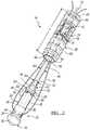
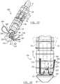
- FIG. 1is a perspective view of an expanding suture anchor having an actuator pin according to the present disclosure
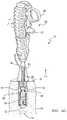
- FIG. 2is an exploded view of the suture anchor in FIG. 1 ;
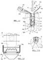
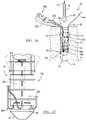
- FIG. 3is a cross-sectional view taken along line 3 - 3 of FIG. 1 ;
- FIG. 3Ais a detailed view of FIG. 3 ;
- FIG. 4Ais an environmental view of a use of the suture anchor shown in FIG. 1 ;
- FIG. 4Bis an environmental view of the suture anchor as the retractive force is applied to move the suture anchor into the fully expanded position
- FIG. 4Cis an environmental view illustrating the suture anchor in a fully expanded position
- FIG. 4Dis an environmental view illustrating an alternate actuator gun for use with the suture anchor shown in FIG. 1 ;
- FIG. 5Ais an environmental view illustrating an alternate use of the suture anchor of FIG. 1 after the application of a first retractive force
- FIG. 5Bis an environmental view of the suture anchor as a second retractive force is applied
- FIG. 6Ais an alternate environmental view of a use of the suture anchor of FIG. 1 ;
- FIG. 6Bis an environmental view of the suture anchor of FIG. 6A during the application of a retractive force
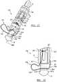
- FIG. 7is a perspective view of a first alternative expanding suture anchor having an actuator pin according to the present disclosure.
- FIG. 8is an environmental view of a first procedure associated with the suture anchor shown in FIG. 7 ;
- FIG. 9is an environmental view of a second procedure associated with the suture anchor shown in FIG. 7 ;
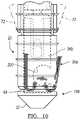
- FIG. 10is an environmental view of the suture anchor of FIG. 7 as the retractive force is applied to move the suture anchor into the fully expanded position;
- FIG. 11is an environmental view illustrating the suture anchor of FIG. 7 in a fully expanded position
- FIG. 11Ais an alternative environmental partial view illustrating the suture anchor of FIG. 7 in a fully expanded position
- FIG. 12is detailed front view of the suture anchor of FIG. 7 illustrating a suture fixed to the suture anchor;
- FIG. 13is a perspective view of a second alternative expanding suture anchor having an actuator pin according to the present disclosure.
- FIG. 14is an environmental view of a first procedure associated with the suture anchor shown in FIG. 13 ;
- FIG. 15is an environmental view of a second procedure associated with the suture anchor shown in FIG. 13 ;
- FIG. 16is detailed front view of the suture anchor of FIG. 13 illustrating a suture fixed to the suture anchor;
- FIG. 17is a perspective view of a third alternative expanding suture anchor having an actuator pin according to the present disclosure.
- FIG. 18is detailed front view of the suture anchor of FIG. 17 illustrating a suture fixed to the suture anchor;
- FIG. 19is a perspective view of a fourth alternative expanding suture anchor having an actuator pin according to the present disclosure.
- FIG. 20is detailed front view of the suture anchor of FIG. 19 illustrating a suture fixed to the suture anchor;
- FIG. 21is a perspective view of a fifth alternative expanding suture anchor having an actuator pin according to the present disclosure.
- FIG. 22is a cross-sectional view taken along line 22 - 22 of FIG. 21 ;
- FIG. 23is an environmental view of a first procedure associated with the suture anchor shown in FIG. 21 ;
- FIG. 24is an environmental view of a second procedure associated with the suture anchor shown in FIG. 21 ;
- FIG. 25is an environmental view of the suture anchor of FIG. 21 as the retractive force is applied to move the suture anchor into the fully expanded position;
- FIG. 26is an environmental view illustrating the suture anchor of FIG. 21 in a fully expanded position
- FIG. 27is detailed front view of the suture anchor of FIG. 21 illustrating a suture fixed to the suture anchor;
- FIG. 28is a perspective view of a sixth alternative expanding suture anchor having an actuator pin according to the present disclosure.
- FIG. 29is an environmental view of a first procedure associated with the suture anchor shown in FIG. 28 ;
- FIG. 30is an environmental view of a second procedure associated with the suture anchor shown in FIG. 28 ;
- FIG. 31is detailed front view of the suture anchor of FIG. 28 illustrating a suture fixed to the suture anchor;
- FIG. 32is a perspective view of a seventh alternative expanding suture anchor having an actuator pin according to the present disclosure.
- FIG. 33is detailed front view of the suture anchor of FIG. 32 illustrating a suture fixed to the suture anchor;
- FIG. 34is a perspective view of a eighth alternative expanding suture anchor having an actuator pin according to the present disclosure.
- FIG. 35is detailed front view of the suture anchor of FIG. 34 illustrating a suture fixed to the suture anchor;
- FIG. 36is a perspective view of a ninth alternative expanding suture anchor having an actuator pin according to the present disclosure.
- FIG. 36Ais another perspective view of a ninth alternative expanding suture anchor having an actuator pin according to the present disclosure.
- FIG. 37is detailed front view of the suture anchor of FIG. 36 illustrating a suture fixed to the suture anchor;
- FIG. 37Bis another detailed front view of the suture anchor of FIG. 36 illustrating a suture fixed to the suture anchor;
- FIG. 38is a perspective view of a tenth alternative expanding suture anchor having an actuator pin according to the present disclosure.
- FIG. 39is detailed front view of the suture anchor of FIG. 38 illustrating a suture fixed to the suture anchor;
- FIG. 40is a perspective view of a eleventh alternative expanding suture anchor having an actuator pin according to the present disclosure.
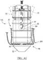
- FIG. 41is an environmental view of a procedure associated with the suture anchor shown in FIG. 40 ;
- FIG. 42is detailed front view of the suture anchor of FIG. 40 illustrating a suture fixed to the suture anchor.
- an expanding suture anchor 10 having an actuator pin 12is illustrated.
- the suture anchor 10is operable in a first configuration for insertion into a pre-drilled hole 14 in a boney structure 16 (as shown in FIG. 4A ) and operable in a second configuration to secure the suture anchor 10 in the pre-drilled hole 14 (as shown in FIG. 4C ).
- the suture anchor 10generally includes an insert 18 molded to the actuator pin 12 and partially disposed in a sleeve 20 .
- the insert 18includes a suture receiving portion 22 and an end section 24 displaced from the suture receiving portion 22 by a breakaway section 26 .
- the suture receiving portion 22 and end section 24have a tensile and a torsion strength that are greater than the tensile and torsion strength of the breakaway section 26 such that the suture receiving portion 22 and end section 24 will be severed by the breakaway section 26 without damage to the structural integrity of either section.
- the insert 18is generally insert molded from a resorbable material (such as, for example, Lactosorb®, available from Biomet Inc. of Warsaw, Ind.); however, it will be understood that other types of biocompatible materials and other methods of forming could be used.
- At least one groove 28extends throughout a length L 1 of the suture receiving portion 22 and the end section 24 for receipt of strands from a suture 30 therein.
- the suture receiving portion 22further has a tip 32 and a cylindrical body 34 .
- the tip 32is generally conical in shape; however, any other desired shape may be used.
- the cylindrical body 34has a diameter D 1 , which is sized to ensure a slip fit with the sleeve 20 such that the cylindrical body 34 can slide within the sleeve 20 .
- the cylindrical body 34includes a formed eyelet 36 extending through the cylindrical body 34 to provide an attachment point for the suture 30 , as shown in FIG. 3A .
- the diameter D 1 of the cylindrical bodycan provide an interference fit with regard to the suture 30 fitting between the cylindrical body 34 and the sleeve 20 .
- the cylindrical body 34may further include a tapered section 40 leading to the breakaway section 26 .
- the breakaway section 26has a diameter D 2 , which is generally one-half the size of the diameter D 1 of the cylindrical body 34 .
- the breakaway section 26may include two necked portions 42 , 44 , which facilitate the fracturing of the breakaway section 26 by reducing the fracture strength of the breakaway section 26 in torsion and tension as compared to the suture receiving portion 22 and the end section 24 .
- the diameter of the necked portions 42 , 44may vary to enable different fracture loads for various applications; however, generally the force required to fracture the necked portions 42 , 44 will be between 10-12 foot-pounds.
- the fracturing of the breakaway section 26detaches the suture receiving portion 22 from the end section 24 of the insert 18 (as illustrated in FIG. 4C ).
- the end section 24has a tapered portion 46 coupled to an annular body 48 .
- the tapered portion 46includes a first diameter D 3 at a first end 50 , which tapers to a second diameter D 4 at a second end 52 .
- the first diameter D 3 of the tapered portion 46is approximately equal to the diameter D 1 of the suture receiving portion 22 .
- the tapered portion 46operates to place the suture anchor 10 in the second position to engage the boney structure 16 as will be described in greater detail below.
- the second end 52 of the tapered portion 46is coupled to the annular body 48 .
- the annular body 48is generally cylindrical and has a constant diameter D 5 .
- the diameter D 5 of the annular body 48may be larger than or equal to the second diameter D 4 of the tapered portion 46 , yet smaller than the first diameter D 3 of the tapered portion 46 .
- the annular body 48can extend beyond the sleeve 20 when the suture anchor 10 is assembled to provide a locator 54 for an actuator gun 56 (as shown in FIG. 4A ) for the application of a retractive force F 1 ; however, this is not necessary, as will be discussed further below.
- the annular body 48 and tapered portion 46each further include a formed central bore 58 for receipt of the actuator pin 12 therein.
- the actuator pin 12is fixedly attached to the annular body 48 and tapered portion 46 via insert molding.
- the insert 18is formed around the actuator pin 12 , ensuring secure and precise attachment.
- the actuator pin 12is positioned in the formed central bore 58 of the annular body 48 and tapered portion 46 such that the actuator pin 12 is removed from the suture anchor 10 when the breakaway section 26 is fractured.
- the actuator pin 12can be made of any suitable biocompatible corrosive resistance material such as, for example, surgical steel. In this regard, the actuator pin 12 need not be made of the same material as the sleeve 20 .
- the actuator pin 12further includes a formed cavity 60 that retains the actuator pin 12 in the insert 18 through out the application of the retractive force F 1 . More specifically, as best shown in FIG. 3 , as the insert 18 is formed around the actuator pin 12 , material M is formed under the cavity 60 . Thus, this material M must be displaced in order to remove the actuator pin 12 from the insert 18 . Accordingly, the retractive force F 1 must be less than the fracture strength of the material M to ensure the actuator pin 12 is retained in the insert 18 . Similarly, the size of the cavity 60 can be modified to allow the accumulation of varying amounts of material M depending on the amount of retractive force F 1 required to secure the suture anchor 10 in a given boney structure.
- the sleeve 20is disposed about a substantial portion of the insert 18 . More specifically, the sleeve 20 includes a throughbore 62 for receipt of the insert 18 therein.
- the sleeve 20has a length L, which may be configured such that the suture receiving portion 22 and locator 54 are exposed when the suture anchor 10 is in the first position.
- a first end 64 of sleeve 20is shown covering the breakaway section 26 and approximately one half of the cylindrical body 34 of the suture receiving portion 22 and a second end 66 of the sleeve 20 covers the tapered portion 46 and approximately one half of the annular body 48 of the end section 24 .
- the sleeve 20is typically made from a resorbable material (such as, for example, Lactosorb®, available from Biomet Inc. of Warsaw, Ind.); however, other suitable materials could be employed.
- the sleeve 20is generally cylindrical in nature, and may include at least one ring or securement device 68 on an external surface 70 of the sleeve 20 .
- the sleeve 20is shown having a ring 68 , it is to be understood various other external features could be disposed on the sleeve 20 (such as, for example, barbs or threads).
- the at least one ring 68further aids in the engagement of the suture anchor 10 in the pre-drilled hole 14 .
- the sleeve 20also includes at least one expanding member 72 hingably coupled to the sleeve 20 to engage the pre-drilled hole 14 .
- the expanding member 72is defined by a slot 74 formed in the sleeve 20 and includes a hinge 76 .
- the sleeve 20includes two expanding members 72 located approximately 180 degrees apart. It shall be noted, however, that the expanding members 72 could be located at any position on the sleeve 20 that would engage the boney structure 16 .
- the expanding members 72are located at a midsection 78 of the sleeve 20 . The expanding members 72 expand to lock into the boney structure 16 when the retractive force F 1 is applied to the actuator pin 12 and, in turn, to a tapered interior bearing surface 80 on the expanding members 72 .
- the suture anchor 10can be inserted into the pre-drilled hole 14 as shown.
- the suture anchor 10is generally configured such that only the locator 54 of the end section 24 extends beyond a top surface 82 of the boney structure 16 .
- the actuator gun 56is applied to the suture anchor 10 as shown in FIGS. 4A and 4B .
- the actuator gun 56applies the retractive force F 1 to the actuator pin 12 .
- the actuator gun 56may not be the only actuating device capable of applying the retractive force F 1 to the suture anchor 10 .
- numerous other devicesmay be employed (such as, for example, a syringe-type actuator 88 , as shown in FIG. 4D ).
- the syringe-type actuator 88includes a cannula 90 that engages the actuator pin 12 .
- a lever 92can be used to retract the cannula 90 by the application of a force F to the lever 92 . More specifically, the lever 92 operates to retract the cannula 90 once it is engaged with the actuator pin 12 to provide the retractive force F 1 to the suture anchor 10 .
- a stop 94can also be provided to prevent the lever 92 from prematurely applying the retractive force F 1 .
- the application of the retractive force F 1causes the insert 18 to displace rearwardly with respect to the sleeve 20 , as illustrated in FIG. 4B .
- This rearward displacementcauses the tapered portion 46 to apply a force F 3 to the tapered interior bearing surface 80 of the expanding members 72 of the sleeve 20 .
- the tapered portion 46applies an increasingly greater force F 3 to the tapered interior bearing surface 80 of the expanding members 72 until the expanding members 72 are engaged with the boney structure 16 .
- the suture anchor 10is also adaptable for use in a curved pre-drilled hole 14 ′, as shown in FIG. 6A .
- the suture anchor 10may be positioned in the curved pre-drilled hole 14 ′ via the actuator pin 12 .
- the retractive force F 1may be applied to the actuator pin 12 by an actuating device, such as the actuator gun 56 , to cause the expanding members 72 to engage the boney structure 16 ′′′, as discussed previously.
- the first alternative insert 18 acan include a suture receiving portion 22 a , the breakaway section 26 and the end section 24 for use with a suture anchor 10 a substantially similar to that described with regard to FIGS. 1-6B .
- the remainder of the suture anchor 10 acan be generally similar to the suture anchor 10 that is illustrated in and described in conjunction with FIGS. 1-6B .
- the breakaway section 26 and end section 24 of the first alternative insert 18 aare substantially similar to the breakaway section 26 and end section 24 of the insert 18 of the suture anchor 10 , the breakaway section 26 and end section 24 will not be discussed in detail with regard to the first alternative insert 18 a .
- the same reference numeralswill be used to denote the same or similar components.
- the suture receiving portion 22 a and end section 24can have a tensile and a torsion strength that are greater than the tensile and torsion strength of the breakaway section 26 such that the suture receiving portion 22 a and end section 24 will be severed by the breakaway section 26 without damage to the structural integrity of either section.
- the first alternative insert 18 ais generally insert molded from a resorbable material (such as, for example, Lactosorb® available from Biomet Inc. of Warsaw, Ind.); however, it will be understood that other types of biocompatible materials and other methods of forming could be used.
- the suture receiving portion 22 acan include the tip 32 , a cylindrical body 34 a , and a suture 30 a .
- the tip 32can be generally conical in shape; however, any other desired shape may be used, such as rectangular.
- the cylindrical body 34 acan have a diameter D 1 a , which is sized to ensure a slip fit with the sleeve 20 such that the cylindrical body 34 a can slide within the sleeve 20 .
- the cylindrical body 34 acan define an aperture, which can be an eyelet 36 a , extending through the cylindrical body 34 a to provide an attachment point for the suture 30 a .
- the diameter D 1 a of the cylindrical body 34 acan also provide an interference fit between the cylindrical body 34 a , the suture 30 a and the sleeve 20 .
- the cylindrical body 34 acan further include the tapered section 40 leading to the breakaway section 26 .
- the suture 30 acan have a first end 200 , a midsection 201 and a second end 202 .
- the eyelet 36 acan be sized to receive both the first end 200 and the second end 202 of the suture 30 a .
- the suture 30 acan be fixed to the cylindrical body 34 a without the use of a knot by the sleeve 20 , as will be discussed herein.
- the midsection 201 of the suture 30 acan be coupled to a section of soft tissue 204 , as shown in FIG. 8 .
- the midsection 201 of the suture 30 acan be coupled to the soft tissue 204 through any appropriate technique, such as a mattress stitch 206 or by using a suture punch (not shown).
- the suture 30 acan be coupled to the soft tissue 204 . Then, the hand 86 of the operator can thread or insert the first end 200 and the second end 202 of the suture 30 a through the eyelet 36 a . With additional reference to FIG. 9 , once the first end 200 and the second end 202 of the suture 30 a are threaded through the eyelet 36 a , the suture anchor 10 a can be inserted into the pre-drilled hole 14 .
- the first end 200 and the second end 202 of the suture 30 acan extend beyond the pre-drilled hole 14 to enable the hand 86 of the operator to grasp either or both the first end 200 and the second end 202 .
- the hand 86 of the operatorcan be used to tighten the suture 30 a , and thus the soft tissue 204 , to the pre-drilled hole 14 by pulling the first end 200 and second end 202 of the suture 30 a that extends from the pre-drilled hole 14 . This further removes any slack from the suture 30 a .
- the expanding members 72 of the suture anchor 10 acan be expanded to engage the pre-drilled hole 14 .
- an alternative syringe-type actuator 88 ′can be coupled to the actuator pin 12 of the suture anchor 10 a as shown in FIGS. 9 and 10 .
- the alternative syringe-type actuator 88 ′can include a cannula 90 ′ that engages the actuator pin 12 .
- a lever 92 ′can be used to retract the cannula 90 ′ by the application of a force F to the lever 92 ′.
- the lever 92 ′can operate to retract the cannula 90 ′ once it is engaged with the actuator pin 12 to provide the retractive force F 1 to the suture anchor 10 a .
- a safety or stop 94 ′can also be provided to prevent the operator from prematurely applying the retractive force F 1 .
- the stop 94 ′can be pushed in and then the force F can be applied to the lever 92 ′ on the syringe-type actuator 88 ′, as shown in FIG. 10 .
- the alternative syringe-type actuator 88 ′can apply the retractive force F 1 to the actuator pin 12 via the cannula 90 ′.
- the alternative syringe-type actuator 88 ′is not the only actuating device capable of applying the retractive force F 1 to the suture anchor 10 a . Numerous other devices can be employed, such as, a syringe-type actuator 88 , as discussed with regard to FIG. 4D , or the actuator gun 56 discussed with regard to FIGS. 4A and 4B .
- the application of the retractive force F 1can cause the first alternative insert 18 a to be displaced or moved rearwardly with respect to the sleeve 20 , as illustrated in FIG. 10 .
- This rearward movementcan cause the tapered portion 46 of the first alternative insert 18 a to apply a force F 3 to the tapered interior bearing surface 80 of the expanding members 72 of the sleeve 20 .
- the first alternative insert 18 acan continue to move rearward, which can cause the tapered portion 46 to apply an increasingly greater force F 3 to the tapered interior bearing surface 80 of the expanding members 72 until the expanding members 72 are engaged with the boney structure 16 .
- the tip 32 of the suture receiving portion 22 acan be adjacent to the suture 30 a , while the suture 30 a is adjacent to the first end 64 of the sleeve 20 (as best shown in FIG. 12 ).
- the compression of the suture 30 a between the suture receiving portion 22 a and the tip 32can fix or lock the suture 30 a to the suture anchor 10 a , while preventing the first alternative insert 18 a from retracting further.
- the continued application of the retractive force F 1 to the first alternative insert 18 acan cause the breakaway section 26 to fracture, as shown in FIG. 11 .
- the pre-drilled hole 14can be sized with a depth D substantially equivalent to a length L of the suture anchor 10 a , if desired. If the pre-drilled hole 14 has the depth D substantially equivalent to the length L of the suture anchor 10 a , then the expanding members 72 can be deployed or expanded by the contact of the tip 32 of the suture receiving portion 22 a against a bottom 213 of the pre-drilled hole 14 . Generally, as the suture anchor 10 a is inserted, the tip 32 can be pushed against the bottom 213 of the pre-drilled hole 14 , forcing the first alternative insert 18 a to be displaced or moved rearwardly with respect to the sleeve 20 .
- This rearward movementcan cause the tapered portion 46 of the first alternative insert 18 a to apply a force F 3 to the tapered interior bearing surface 80 of the expanding members 72 of the sleeve 20 .
- the lever 92 ′ on the syringe-type actuator 88 ′can be pulled (with the stop 94 ′ pushed in) to apply the retractive force F 1 to the actuator pin 12 to fully engage the expanding members 72 in the pre-drilled hole 14 .
- the continued application of the retractive force F 1 to the first alternative insert 18 acan cause the breakaway section 26 to fracture, as shown in FIG. 11 .
- the sleeve 20 and suture receiving portion 22 aremain in the pre-drilled hole 14 to couple the soft tissue 204 to the boney structure 16 via the suture 30 a .
- the first end 200 and second end 202 of the suture 30 a that extends from the pre-drilled hole 14can then be trimmed if desired (not shown).
- the suture anchor 10 acan fix the suture 30 a to the suture anchor 10 a without the use of a knot.
- the application of the retractive force F 1causes the first alternative insert 18 a , and thus suture 30 a , to be withdrawn into the sleeve 20 .
- the movement of the first alternative insert 18 a within the sleeve 20can fix or lock the suture 30 a to the suture anchor 10 a due to the interference fit between the first alternative insert 18 a , the suture 30 a and the sleeve 20 .
- the interference fit between the first alternative insert 18 a , the suture 30 a and the sleeve 20can prevent the first alternative insert 18 a from moving after the deployment of the expanding members 72 due to the frictional lock created between the suture 30 a , the first alternative insert 18 a and the sleeve 20 .
- the second alternative insert 18 bcan include a suture receiving portion 22 b , the breakaway section 26 , and the end section 24 for use with a suture anchor 10 b substantially similar to that described with regard to FIGS. 7-12 .
- the breakaway section 26 and end section 24 of the second alternative insert 18 bare substantially similar to the breakaway section 26 and end section 24 of the insert 18 , the breakaway section 26 and end section 24 will not be discussed in detail with regard to the second alternative insert 18 b .
- the suture receiving portion 22 bis substantially similar to the suture receiving portion 22 a of the first alternative insert 18 a , as discussed with FIGS. 7-12 , only the modifications to the suture receiving portion 22 b will be discussed herein.
- the suture receiving portion 22 bcan include an aperture, for example, a groove or slot 250 , which can be for receipt of the suture 30 a .
- the slot 250can be formed longitudinally in a cylindrical body 34 b of the second alternative insert 18 b ; however, the slot 250 can be formed in any desired position, such as vertically or diagonally.
- the remainder of the cylindrical body 34 bcan be generally similar to the cylindrical body 34 a that is illustrated in and described in conjunction with FIG. 7 .
- the slot 250can extend for a length L and can have a height H configured to enable an operator to insert the first end 200 and second end 202 of the suture 30 a through the slot 250 , as shown in FIG. 14 .
- the hand 86 of the operatorcan thread or insert the first end 200 and second end 202 of the suture 30 a into the slot 250 .
- the suture anchor 10 bcan be inserted into the pre-drilled hole 14 .
- the hand 86 of the operatorcan be used to tighten the suture 30 a , and thus the soft tissue 204 , to the pre-drilled hole 14 by pulling the first end 200 and second end 202 of the suture 30 a that extends from the pre-drilled hole 14 .
- the suture anchor 10 bcan be deployed to engage the pre-drilled hole 14 through the use of the actuator gun 56 , syringe-type actuator 88 or syringe-type actuator 88 ′, for example, as discussed previously with reference to FIGS. 4A and 4B, 4D and 9-12 , respectively.
- the tip 32 of the suture receiving portion 22 bcan be adjacent to the suture 30 a , while the suture 30 a is adjacent to the first end 64 of the sleeve 20 (as best shown in FIG. 16 ).
- the compression of the suture 30 a between the suture receiving portion 22 b and the tip 32can fix or lock the suture 30 a to the suture anchor 10 b .
- the suture anchor 10 bcan also fix the suture 30 a to the suture anchor 10 b without the use of a knot, while providing greater access for the hand 86 of the operator to couple the first end 200 and the second end 202 to the second alternative insert 18 b prior to the placement of the suture anchor 10 b into the pre-drilled hole 14 .
- the first end 200 and second end 202 of the suture 30 a that extends from the pre-drilled hole 14can then be trimmed if desired (not shown).
- the third alternative insert 18 ccan include a suture receiving portion 22 c , the breakaway section 26 , and the end section 24 for use with a suture anchor 10 c substantially similar to that described with regard to FIGS. 7-12 .
- the breakaway section 26 and end section 24 of the third alternative insert 18 care substantially similar to the breakaway section 26 and end section 24 of the insert 18 , the breakaway section 26 and end section 24 will not be discussed in detail with regard to the third alternative insert 18 c .
- the suture receiving portion 22 cis substantially similar to the suture receiving portion 22 a of the first alternative insert 18 a , as discussed with FIGS. 7-12 , only the modifications to the suture receiving portion 22 c will be discussed herein.
- the suture receiving portion 22 ccan include a slot, for example, a C-shaped slot 260 , which can be for receipt of the suture 30 a .
- the slot 260can be defined in a cylindrical body 34 c of the third alternative insert 18 c .
- the remainder of the cylindrical body 34 ccan be generally similar to the cylindrical body 34 a that is illustrated in and described in conjunction with FIG. 7 .
- the slot 260can define a throughbore 262 and a necked portion 264 as shown in FIGS. 17 and 18 .
- the necked portion 264can define an aperture 266 for receipt of the first end 200 and second end 202 of the suture 30 a .
- the necked portion 264can be configured such that the first end 200 and second end 202 of the suture 30 a can be hooked behind and retained by the necked portion 264 .
- the assembly and deployment of the suture anchor 10 ccan be substantially similar to the assembly and deployment of the suture anchor 10 a discussed with regard to FIGS. 8-12 and the suture anchor 10 b discussed with regard to FIGS. 15 and 16 , the assembly and deployment of the suture anchor 10 c will not be discussed in detail herein. Briefly, however, once the midsection 201 of the suture 30 a is coupled to the soft tissue 204 via the mattress stitch 206 or any other technique, such as a suture punch (not shown), the hand 86 of the operator can thread or insert the first end 200 and second end 202 of the suture 30 a through the aperture 266 of the necked portion 264 and into the throughbore 262 (not shown).
- the suture anchor 10 ccan be inserted into the pre-drilled hole 14 .
- the hand 86 of the operatorcan be used to tighten the suture 30 a , and thus the soft tissue 204 , to the pre-drilled hole 14 by pulling the first end 200 and second end 202 of the suture 30 a that extends from the pre-drilled hole 14 (not shown). This further removes any slack from the suture 30 a .
- the expanding members 72 of the suture anchor 10 ccan be deployed or expanded to engage the pre-drilled hole 14 .
- the tip 32 of the suture receiving portion 22 ccan be adjacent to the suture 30 a , while the suture 30 a is adjacent to the first end 64 of the sleeve 20 (as best shown in FIG. 18 ).
- the compression of the suture 30 a between the suture receiving portion 22 c and the tip 32can fix or lock the suture 30 a to the suture anchor 10 c .
- the suture anchor 10 ccan also fix the suture 30 a to the suture anchor 10 c without the use of a knot.
- the first end 200 and second end 202 of the suture 30 a that extends from the pre-drilled hole 14can then be trimmed if desired (not shown).
- the fourth alternative insert 18 dcan include a suture receiving portion 22 d , the breakaway section 26 , and the end section 24 for use with a suture anchor 10 d substantially similar to that described with regard to FIGS. 7-12 .
- the breakaway section 26 and end section 24 of the fourth alternative insert 18 dare substantially similar to the breakaway section 26 and end section 24 of the insert 18 , the breakaway section 26 and end section 24 will not be discussed in detail with regard to the fourth alternative insert 18 d .
- the suture receiving portion 22 dis substantially similar to the suture receiving portion 22 a of the first alternative insert 18 a , as discussed with FIGS. 7-12 , only the modifications to the suture receiving portion 22 d will be discussed herein.
- the suture receiving portion 22 dcan include a hinged slot 270 which can be for receipt of the suture 30 a .
- the hinged slot 270can be defined in a cylindrical body 34 d of the fourth alternative insert 18 d .
- the remainder of the cylindrical body 34 dcan be generally similar to the cylindrical body 34 a that is illustrated in and described in conjunction with FIG. 7 .
- the hinged slot 270can define a throughbore 272 and can include a hinged portion 274 .
- the hinged portion 274can optionally include at least one or a plurality of barbs or projections 276 .
- the throughbore 272can be configured to retain the first end 200 and second end 202 of the suture 30 a .
- the hinged portion 274can be pivotably coupled to the cylindrical body 34 d and can rotate from an opened position to a closed position. In the opened position, as shown in FIG. 19 , the hinged portion 274 can define an aperture 278 for receipt of the first end 200 and second end 202 of the suture 30 a to enable the suture 30 a to enter the throughbore 272 of the hinged slot 270 .
- the hinged portion 274can seal or enclose the aperture 278 to retain the suture 30 a within the throughbore 272 , as shown in FIG. 20 .
- the hinged portion 274can be sized such that in the closed position the hinged portion 274 can substantially enclose the aperture 278 .
- the projections 276 of the hinged portion 274are optional and can be coupled to or formed with the hinged portion 274 if desired.
- the projections 276can extend into the throughbore 272 when the hinged portion 274 is in the closed position to further retain the suture 30 a within the throughbore 272 .
- the projections 276are illustrated as triangular, however, any appropriate shape, such as annular or hooked, could be employed.
- the assembly and deployment of the suture anchor 10 d in the pre-drilled hole 14is substantially similar to the assembly and deployment of the suture anchor 10 a discussed with regard to FIGS. 8-12 and the suture anchor 10 b discussed with regard to FIGS. 15 and 16 , the assembly and deployment of the suture anchor 10 d will not be discussed in detail herein. Briefly, however, once the midsection 201 of the suture 30 a is coupled to the soft tissue 204 via the mattress stitch 206 or any other technique, such as a suture punch, the hand 86 of the operator can thread or insert the first end 200 and second end 202 of the suture 30 a through the aperture 278 of the hinged portion 274 and into the throughbore 272 (not shown).
- the suture anchor 10 dcan be inserted into the pre-drilled hole 14 (not shown).
- the hand 86 of the operatorcan be used to tighten the suture 30 a , and thus the soft tissue 204 , to the pre-drilled hole 14 by pulling the first end 200 and second end 202 of the suture 30 a that extends from the pre-drilled hole 14 (not shown). This further removes any slack from the suture 30 a .
- the expanding members 72 of the suture anchor 10 dcan be deployed to engage the pre-drilled hole 14 .
- the hinged portion 274can be pushed closed by the sleeve 20 to lock the suture 30 a within the throughbore 272 of the suture receiving portion 22 d.
- the tip 32 of the suture receiving portion 22 dcan be adjacent to the suture 30 a , while the suture 30 a is adjacent to the first end 64 of the sleeve 20 (as best shown in FIG. 20 ).
- the compression of the suture 30 a between the suture receiving portion 22 d and the tip 32can fix or lock the suture 30 a to the suture anchor 10 d .
- the suture anchor 10 dcan also fix the suture 30 a to the suture anchor 10 d without the use of a knot.
- the first end 200 and second end 202 of the suture 30 a that extends from the pre-drilled hole 14can then be trimmed if desired (not shown).
- the fifth alternative insert 18 ecan include a suture receiving portion 22 e , the breakaway section 26 , and the end section 24 for use with a suture anchor 10 e substantially similar to that described with regard to FIGS. 1-6B .
- the remainder of the suture anchor 10 ecan be generally similar to the suture anchor 10 that is illustrated in and described in conjunction with FIGS. 1-6B .
- the breakaway section 26 and end section 24 of the fifth alternative insert 18 eare substantially similar to the breakaway section 26 and end section 24 of the insert 18 , the breakaway section 26 and end section 24 will not be discussed in detail with regard to the fifth alternative insert 18 e.
- the suture receiving portion 22 e and end section 24can have a tensile and a torsion strength that are greater than the tensile and torsion strength of the breakaway section 26 such that the suture receiving portion 22 e and end section 24 will be severed by the breakaway section 26 without damage to the structural integrity of either section.
- the fifth alternative insert 18 eis generally insert molded from a resorbable material (such as, for example, Lactosorb® available from Biomet Inc. of Warsaw, Ind.); however, it will be understood that other types of biocompatible materials and other methods of forming could be used.
- the suture receiving portion 22 ecan include the tip 32 , a cylindrical body 34 e and a suture 30 e .
- the tip 32can be generally conical in shape; however, any other desired shape may be used, such as rectangular.
- the cylindrical body 34 ecan have a diameter D 1 e , which is sized to ensure a slip fit with the sleeve 20 such that the cylindrical body 34 e can slide within the sleeve 20 .
- the cylindrical body 34 ecan define an aperture or eyelet 36 e extending through the cylindrical body 34 e to provide an attachment point for the suture 30 e .
- the cylindrical body 34 ecan further include the tapered section 40 leading to the breakaway section 26 .
- the suture 30 ecan have a first end 300 , a midsection 302 and a second end 304 .
- the first end 300 of the suture 30 ecan be coupled to the breakaway section 26 of the fifth alternative insert 18 e .
- the first end 300can be knotted about the breakaway section 26 at a midpoint 307 of the two necked portions 42 , 44 (FIG. 22 ).
- the midsection 302 of the suture 30 ecan be coupled to a section of soft tissue 306 ( FIG. 23 ).
- the second end 304 of the suture 30 ecan be received into the eyelet 36 e of the cylindrical body portion 34 e of the fifth alternative insert 18 e .
- the second end 304can be coupled to a needle 309 (shown in phantom) to facilitate the threading of the second end 304 into the eyelet 36 e ( FIG. 22 ).
- the second end 304once threaded, can pass through the eyelet 36 e to secure the soft tissue 306 to the pre-drilled hole 14 , as will be discussed in greater detail herein.
- the first end 300 of the suture 30 ecan be knotted to the midpoint 307 of the breakaway section 26 of the fifth alternative insert 18 e .
- the sleeve 20can be disposed over the breakaway section 26 of the fifth alternative insert 18 e , such that the second end 304 of the suture 30 e can extend out from the sleeve 20 .
- the midsection 302 of the suture 30 ecan be coupled to the soft tissue 306 .
- the suture 30 ecan be coupled to the soft tissue 306 through any appropriate technique, such as a mattress stitch 308 or a suture punch (not shown), for example. Then, the hand 86 of an operator can thread or insert the second end 304 of the suture 30 e through the eyelet 36 e with or without the use of the needle 309 .
- the suture anchor 10 ecan be inserted into the pre-drilled hole 14 .
- the second end 304 of the suture 30 ecan extend beyond the pre-drilled hole 14 to enable the hand 86 of the operator to grasp the second end 304 to tighten the suture 30 e , and thus the soft tissue 306 , to the pre-drilled hole 14 .
- the suture 30 ecan be tightened by pulling the second end 304 of the suture 30 e that extends beyond the pre-drilled hole 14 . This further removes any slack from the suture 30 e .
- the expanding members 72 of the suture anchor 10 ecan be deployed to engage the pre-drilled hole 14 .
- the alternative alternative syringe-type actuator 88 ′can be used to expand the expanding members 72 of the suture anchor 10 e ; however, any other activating device, such as the actuator gun 56 discussed with regard to FIGS. 4A and 4B , or the syringe-type actuator 88 discussed with regard to FIG. 4D , could be used. If the alternative alternative syringe-type actuator 88 ′ is used, then the lever 92 ′ on the alternative syringe-type actuator 88 ′ can be pulled, as shown in FIG. 25 , to apply the retractive force F 1 to the actuator pin 12 .
- the application of the retractive force F 1can cause the fifth alternative insert 18 e to be displaced or moved rearwardly with respect to the sleeve 20 and can cause the tapered portion 46 of the fifth alternative insert 18 e to apply a force F 3 to the tapered interior bearing surface 80 of the expanding members 72 of the sleeve 20 until the expanding members 72 are engaged with the boney structure 16 .
- the tip 32 of the suture receiving portion 22 ecan be adjacent to the suture 30 e , while the suture 30 e is adjacent to the first end 64 of the sleeve 20 (as best shown in FIG. 19 ).
- the compression of the suture 30 e between the suture receiving portion 22 e and the tip 32can fix or lock the suture 30 e to the suture anchor 10 e , while preventing the fifth alternative insert 18 e from retracting further.
- the continued application of the retractive force F 1 to the fifth alternative insert 18 ecan cause the breakaway section 26 to fracture, as shown in FIG. 26 .
- the sleeve 20 and suture receiving portion 22 eremain in the pre-drilled hole 14 to couple the soft tissue 306 to the boney structure 16 via the suture 30 e .
- the portion of the second end 304 that extends from the pre-drilled hole 14can then be trimmed if desired (not shown).
- the suture anchor 10 ecan fix or lock the second end 304 of the suture 30 e to the suture anchor 10 e without the use of a knot.
- the suture anchor 10 ecan ensure the first end 300 of the suture 30 e remains fixed to the fifth alternative insert 18 e .
- the application of the retractive force F 1causes the fifth alternative insert 18 e , and thus the portion of the first end 300 and the second end 304 extending from the eyelet 36 e , to be withdrawn into the sleeve 20 .
- the movement of the fifth alternative insert 18 e within the sleeve 20can fix or lock the portion of the first end 300 and the second end 304 to the suture anchor 10 e due to the interference fit between the fifth alternative insert 18 e , the suture 30 e , and the sleeve 20 , as discussed previously. Additionally, the frictional lock created between the suture 30 e , the fifth alternative insert 18 e and the sleeve 20 can prevent the fifth alternative insert 18 e from moving after the deployment of the expanding members.
- the sixth alternative insert 18 fcan include a suture receiving portion 22 f , the breakaway section 26 , and the end section 24 for use with a suture anchor 10 f substantially similar to the suture anchor 10 e described with regard to FIGS. 21-27 .
- the breakaway section 26 and end section 24 of the sixth alternative insert 18 fare substantially similar to the breakaway section 26 and end section 24 of the insert 18 , the breakaway section 26 and end section 24 will not be discussed in detail with regard to the sixth alternative insert 18 f .
- the suture receiving portion 22 fis substantially similar to the suture receiving portion 22 e of the fifth alternative insert 18 e , as discussed with reference to FIGS. 21-27 , only the modifications to the suture receiving portion 22 f will be discussed herein.
- the suture receiving portion 22 fcan include an aperture, for example, a groove or slot 350 , which can be for receipt of the suture 30 e .
- the slot 350can be formed longitudinally in a cylindrical body 34 f of the sixth alternative insert 18 f ; however, the slot 350 can be formed in any desired position, such as vertically or diagonally.
- the remainder of the cylindrical body 34 fcan be generally similar to the cylindrical body 34 e that is illustrated in and described in conjunction with FIG. 21 .
- the slot 350can extend for a length L and can have a height H configured to enable an operator to insert the second end 304 of the suture 30 e through the slot 350 , as shown in FIG. 29 .
- the hand 86 of the operatorcan thread or insert the second end 304 of the suture 30 e into the slot 350 .
- the suture anchor 10 fcan be inserted into the pre-drilled hole 14 formed in the boney structure 16 .
- the hand 86 of the operatorcan be used to tighten the suture 30 e , and thus the soft tissue 306 , to the pre-drilled hole 14 by pulling the second end 304 of the suture 30 e that extends from the pre-drilled hole 14 .
- the expanding members 72 of the suture anchor 10 fcan be expanded to engage the pre-drilled hole 14 through the use of the actuator gun 56 , syringe-type actuator 88 or syringe-type actuator 88 ′, for example, as discussed previously with reference to FIGS. 4A and 4B, 4D and 9-12 , respectively.
- the tip 32 of the suture receiving portion 22 fcan be adjacent to the suture 30 e , while the suture 30 e is adjacent to the first end 64 of the sleeve 20 , as best shown in FIG. 31 .
- the compression of the suture 30 e between the suture receiving portion 22 f and the tip 32can fix or lock the suture 30 e to the suture anchor 10 f .
- the suture anchor 10 fcan fix the second end 304 of the suture 30 e to the suture anchor 10 f without the use of a knot, while providing greater access for the operator to couple the second end 304 of the suture 30 e to the sixth alternative insert 18 f prior to the insertion of the suture anchor 10 f into the pre-drilled hole 14 .
- the portion of the second end 304 that extends from the pre-drilled hole 14can then be trimmed if desired (not shown).
- the seventh alternative insert 18 gcan include a suture receiving portion 22 g , the breakaway section 26 , and the end section 24 for use with a suture anchor 10 g substantially similar to the suture anchor 10 e described with regard to FIGS. 21-27 .
- the breakaway section 26 and end section 24 of the seventh alternative insert 18 gare substantially similar to the breakaway section 26 and end section 24 of the insert 18 , the breakaway section 26 and end section 24 will not be discussed in detail with regard to the seventh alternative insert 18 g .
- the suture receiving portion 22 gis substantially similar to the suture receiving portion 22 e of the fifth alternative insert 18 e , as discussed with FIGS. 21-27 , only the modifications to the suture receiving portion 22 g will be discussed herein.
- the suture receiving portion 22 gcan include a slot, for example, a C-shaped slot 360 , which can be for receipt of the suture 30 e .
- the slot 360can be defined in a cylindrical body 34 g of the seventh alternative insert 18 g .
- the remainder of the cylindrical body 34 gcan be generally similar to the cylindrical body 34 e that is illustrated in and described in conjunction with FIG. 21 .
- the slot 360can define a throughbore 362 and a necked portion 364 .
- the necked portion 364can define an aperture 366 for receipt of the first end 300 and second end 304 of the suture 30 e .
- the necked portion 364can be configured such that the first end 300 and second end 304 of the suture 30 e can be hooked behind and retained by the necked portion 364 .
- the assembly and deployment of the suture anchor 10 g in the pre-drilled hole 14is substantially similar to the deployment of the suture anchor 10 e discussed with regard to FIGS. 21-27 and the suture anchor 10 f discussed with regard to FIGS. 30 and 31 , the assembly and deployment of the suture anchor 10 g will not be discussed in detail herein.
- the first end 300 of the suture 30 ecan be tied to the breakaway section 26 and the midsection 302 of the suture 30 e can be coupled to the soft tissue 306 via the mattress stitch 308 or any other technique, such as a suture punch (not shown).
- the hand 86 of the operatorcan thread or insert the second end 304 of the suture 30 e into the slot 360 (not shown).
- the suture anchor 10 gcan be inserted into the pre-drilled hole 14 and the hand 86 of the operator can be used to tighten the suture 30 e , and thus the soft tissue 306 , to the pre-drilled hole 14 by pulling the second end 304 of the suture 30 e that extends from the pre-drilled hole 14 (not shown). This further removes any slack from the suture 30 e .
- the expanding members 72 of the suture anchor 10 gcan be deployed to engage the pre-drilled hole 14 .
- the tip 32 of the suture receiving portion 22 gcan be adjacent to the suture 30 e , while the suture 30 e is adjacent to the first end 64 of the sleeve 20 , as best shown in FIG. 33 .
- the compression of the suture 30 e between the suture receiving portion 22 g and the tip 32can fix or lock the suture 30 e to the suture anchor 10 g .
- the suture anchor 10 gcan fix the second end 304 of the suture 30 e to the suture anchor 10 g without the use of a knot, while providing greater access for the operator to couple the second end 304 of the suture 30 e to the seventh alternative insert 18 g prior to the insertion of the suture anchor 10 g into the pre-drilled hole 14 .
- the portion of the second end 304 that extends from the pre-drilled hole 14can then be trimmed if desired (not shown).
- the eighth alternative insert 18 hcan include a suture receiving portion 22 h , the breakaway section 26 , and the end section 24 for use with a suture anchor 10 h substantially similar to the suture anchor 10 e described with regard to FIGS. 21-27 .
- the breakaway section 26 and end section 24 of the eighth alternative insert 18 hare substantially similar to the breakaway section 26 and end section 24 of the insert 18 , the breakaway section 26 and end section 24 will not be discussed in detail with regard to the eighth alternative insert 18 h .
- the suture receiving portion 22 his substantially similar to the suture receiving portion 22 e of the fifth alternative insert 18 e , as discussed with FIGS. 21-27 , only the modifications to the suture receiving portion 22 h will be discussed herein.
- the suture receiving portion 22 hcan include a hinged slot 370 which can be for receipt of the suture 30 e .
- the hinged slot 370can be defined in a cylindrical body 34 h of the eighth alternative insert 18 h .
- the remainder of the cylindrical body 34 hcan be generally similar to the cylindrical body 34 e that is illustrated in and described in conjunction with FIG. 21 .
- the hinged slot 370can define a throughbore 372 and can include a hinged portion 374 .
- the hinged portion 374can optionally include at least one or a plurality of barbs or projections 376 .
- the throughbore 372can be configured to retain the first end 300 and second end 304 of the suture 30 e .
- the hinged portion 374can be pivotably coupled to the cylindrical body 34 h and can rotate from an opened position to a closed position. In the opened position, as shown in FIG. 34 , the hinged portion 374 can define an aperture 378 for receipt of the first end 300 and second end 304 of the suture 30 e to enable the suture 30 e to enter the throughbore 372 of the hinged slot 370 .
- the hinged portion 374can substantially enclose the aperture 378 to retain the suture 30 e within the throughbore 372 , as shown in FIG. 35 .
- the hinged portion 374can be sized such that in the closed position the hinged portion 374 can substantially enclose the aperture 378 .
- the projections 376are optional and can be coupled to or formed with the hinged portion 374 if desired. The projections 376 can extend into the throughbore 372 when the hinged portion 374 is in the closed position to further retain the suture 30 e within the throughbore 372 .
- the projections 376are illustrated as triangular, however, any appropriate shape, such as annular or hooked, could be employed.
- the assembly and deployment of the suture anchor 10 h in the pre-drilled hole 14is substantially similar to the assembly and deployment of the suture anchor 10 e discussed with regard to FIGS. 21-27 and the suture anchor 10 f discussed with regard to FIGS. 30 and 31 , the assembly and deployment of the suture anchor 10 h will not be discussed in detail herein.
- the first end 300 of the suture 30 ecan be tied to the breakaway section 26 and the midsection 302 of the suture 30 e can be coupled to the soft tissue 306 via the mattress stitch 308 or any other technique, such as a suture punch (not shown).
- the hand 86 of the operatorcan thread or insert the second end 304 of the suture 30 e into the hinged slot 370 (not shown).
- the suture anchor 10 hcan be inserted into the pre-drilled hole 14 and the hand 86 of the operator can be used to tighten the suture 30 e , and thus the soft tissue 306 , to the pre-drilled hole 14 by pulling the second end 304 of the suture 30 e that extends from the pre-drilled hole 14 (not shown). This further removes any slack from the suture 30 e .
- the expanding members 72 of the suture anchor 10 hcan be deployed to engage the pre-drilled hole 14 .
- the hinged portion 374can be pushed closed by the sleeve 20 to lock the suture 30 e within the throughbore 372 of the suture receiving portion 22 h.
- the tip 32 of the suture receiving portion 22 hcan be adjacent to the suture 30 e , while the suture 30 e is adjacent to the first end 64 of the sleeve 20 , as best shown in FIG. 35 .
- the compression of the suture 30 e between the suture receiving portion 22 h and the tip 32can fix or lock the suture 30 e to the suture anchor 10 h .
- the suture anchor 10 hcan also fix the second end 304 of the suture 30 e to the suture anchor 10 h without the use of a knot.
- the portion of the second end 304 that extends from the pre-drilled hole 14can then be trimmed if desired (not shown).
- the ninth alternative insert 18 ican include a suture receiving portion 22 i , the breakaway section 26 , and the end section 24 for use with a suture anchor 10 i substantially similar to the suture anchor 10 described with regard to FIGS. 1-7 .
- the breakaway section 26 and end section 24 of the ninth alternative insert 18 iare substantially similar to the breakaway section 26 and end section 24 of the insert 18 , the breakaway section 26 and end section 24 will not be discussed in detail with regard to the ninth alternative insert 18 i .
- the suture receiving portion 22 iis substantially similar to the suture receiving portion 22 of the insert 18 , as discussed with FIGS. 1-6B , only the modifications to the suture receiving portion 22 i will be discussed herein.
- the suture receiving portion 22 iincludes the eyelet 36 and a hinged slot 400 .
- the eyelet 36 and hinged slot 400can each be defined in a cylindrical body 34 i of the ninth alternative insert 18 i .
- the remainder of the cylindrical body 34 ican be generally similar to the cylindrical body 34 that is illustrated in and described in conjunction with FIGS. 1-6B .
- the eyelet 36can be configured for receipt of the suture 30 therein, as discussed herein, while the hinged slot 400 can be configured for receipt of a suture 30 i therein.
- the hinged slot 400can include a throughbore 402 , a first hinged portion 404 and a second hinged portion 406 .
- the throughbore 402defines a passageway for receipt of the suture 30 i therethrough and can include a first end 408 and a second end 410 .
- the first hinged portion 404can be pivotably coupled to the first end 408 of the throughbore 402 and the second hinged portion 406 can be pivotably coupled to the second end 410 of the throughbore 402 .
- the first hinged portion 404 and second hinged portion 406can generally be pivotable from an opened position to a closed position. In the opened position, as shown in FIG.
- the first hinged portion 404 and second hinged portion 406can enable the suture 30 i to be received into and through the throughbore 402 .
- the first hinged portion 404 and second hinged portion 406can generally pivot to enclose the first end 408 and second end 410 of the throughbore 402 , respectively, to secure or lock the suture 30 i within the throughbore 402 .
- the first hinged portion 404 and the second hinged portion 406can be sized to create an interference fit between the suture 30 i , the first and second hinged portion 404 , 406 and the throughbore 402 to lock the suture 30 i to the ninth alternative insert 18 i.
- the suture 30 ican include a first end 412 , a midsection 414 and a second end 416 .
- the suture 30 ican be used to couple multiple suture anchors 10 together, wherein the reference numeral “ 10 ” denotes all of the suture anchors 10 .
- the first end 412 of the suture 30 ican be coupled to an adjacent suture anchor 10 (not specifically shown) and the midsection 414 of the suture 30 i can pass through the throughbore 402 to secure the suture 30 i to the suture anchor 10 i .
- the second end 416 of the suture 30 ican then be coupled to another suture anchor 10 , or can be trimmed.
- the midsection 414 of the suture 30 ican be coupled to additional soft tissue (not shown). If the midsection 414 is coupled to additional soft tissue, then the first end 412 and second end 416 of the suture 30 i can pass through the throughbore 402 to couple the additional soft tissue to the suture anchor 10 , as shown in FIG. 36A .
- the assembly and deployment of the suture anchor 10 i in the pre-drilled hole 14is substantially similar to the deployment of the suture anchor 10 discussed with regard to FIGS. 4A-6B and the suture anchor 10 a discussed with regard to FIGS. 8-12 , the assembly and deployment of the suture anchor 10 i will not be discussed in detail herein. Briefly, however, in order to employ the suture anchor 10 i , the suture 30 can be threaded through the eyelet 36 of the ninth alternative insert 18 i and then the sleeve 20 can be disposed over the ninth alternative insert 18 i (not specifically shown).
- the suture 30 ican then be coupled to an adjacent suture anchor 10 or to the additional soft tissue via a mattress stitch or any other technique, such as a suture punch (not shown). If the suture 30 i is coupled to an adjacent suture anchor 10 , then the hand 86 of the operator can thread or insert the second end 416 of the suture 30 e into the throughbore 402 until the midsection 414 is received in the throughbore 402 of hinged slot 400 , and the second end 416 of the suture 30 i extends beyond the second end 410 of the throughbore 402 .
- the hand 86 of the operatorcan thread or insert the first end 412 and the second end 416 of the suture 30 i into the hinged slot 400 (not shown). Once the suture 30 i is threaded through the hinged slot 400 , the suture anchor 10 i can be inserted into the pre-drilled hole 14 .
- the hand 86 of the operatorcan be used to tighten the suture 30 i to the pre-drilled hole 14 by pulling the respective first end 414 and/or second end 416 of the suture 30 i that extends from the pre-drilled hole 14 . This further removes any slack from the suture 30 i (not shown). After the suture 30 i is tightened, the expanding members 72 of the suture anchor 10 i can be deployed to engage the pre-drilled hole 14 .
- the first hinged portion 404 and second hinged portion 406can be pushed closed by the sleeve 20 to lock the suture 30 i within the throughbore 402 of the suture receiving portion 22 i as shown in FIGS. 37 and 37B .
- the suture 30 coupled to the eyelet 36can be pulled by the hand 86 of the operator to fully expand the expanding members 72 in soft boney tissue, as discussed herein.
- the tip 32 of the suture receiving portion 22 ican be adjacent to the suture 30 i , while the suture 30 i is adjacent to the first end 64 of the sleeve 20 , as best shown in FIGS. 37 and 37B .
- the compression of the suture 30 i between the suture receiving portion 22 i and the tip 32can fix or lock the suture 30 i to the suture anchor 10 i .
- the suture anchor 10 ican fix the first end 412 ( FIG. 37 ), and the first end 412 and the second end 416 ( FIG. 37B ) of the suture 30 i to the suture anchor 10 i without the use of a knot.
- the portion of the first end 412 and/or second end 416 that extends from the pre-drilled hole 14can then be trimmed if desired (not shown).
- the tenth alternative insert 18 jcan include a suture receiving portion 22 j , the breakaway section 26 , and the end section 24 for use with a suture anchor 10 j substantially similar to the suture anchor 10 described with regard to FIGS. 1-6B .
- the breakaway section 26 and end section 24 of the tenth alternative insert 18 jare substantially similar to the breakaway section 26 and end section 24 of the insert 18 , the breakaway section 26 and end section 24 will not be discussed in detail with regard to the tenth alternative insert 18 j .
- the suture receiving portion 22 jis substantially similar to the suture receiving portion 22 of the insert 18 , as discussed with FIGS. 1-6B , only the modifications to the suture receiving portion 22 j will be discussed herein.
- the suture receiving portion 22 jincludes the eyelet 36 and a second formed eyelet 450 .
- the eyelet 36 and second formed eyelet 450can each be defined in a cylindrical body 34 j of the tenth alternative insert 18 j .
- the remainder of the cylindrical body 34 jcan be generally similar to the cylindrical body 34 that is illustrated in and described in conjunction with FIGS. 1-6B .
- the eyelet 36can be configured for receipt of the suture 30 therein, as discussed previously, while the second formed eyelet 450 can be configured for receipt of the suture 30 j therein.
- the second formed eyelet 450can generally be formed perpendicular to the eyelet 36 ; however, the second formed eyelet 450 could be formed in any appropriate orientation with regard to the eyelet 36 , such as parallel.
- the second formed eyelet 450defines a passageway for receipt of a suture 30 j therethrough.
- the suture 30 jcan be used to couple multiple suture anchors 10 together, wherein the reference numeral “ 10 ” denotes all of the suture anchors 10 , or the suture 30 j can be used to couple additional soft tissue to the suture anchor 10 j .
- the suture 30 jcan include a first end 418 , a midsection 420 and a second end 422 .
- the midsection 420can be coupled to either the suture anchor 10 or additional soft tissue, while the first end 418 and second end 422 can pass through the second formed eyelet 450 to couple the suture 30 j to the suture anchor 10 j.
- the suture 30can be threaded through the eyelet 36 of the tenth alternative insert 18 j and then the sleeve 20 can be disposed over the tenth alternative insert 18 j (not specifically shown).
- the suture 30 jcan then be coupled to an adjacent suture anchor 10 or to additional soft tissue via the mattress stitch or any other technique, such as a suture punch (not shown).
- the hand 86 of the operatorcan thread or insert the second end 416 of the suture 30 j into the second formed eyelet 450 until the midsection 414 is received in the second formed eyelet 450 , and the second end 416 of the suture 30 j extends beyond the suture anchor 10 j .
- the suture 30 iis coupled to the additional soft tissue, then the hand 86 of the operator can thread or insert the first end 412 and the second end 416 of the suture 30 j into the second formed eyelet 450 (not shown). Once the suture 30 j is threaded through the second formed eyelet 450 , the suture anchor 10 j can be inserted into the pre-drilled hole 14 .
- the hand 86 of the operatorcan be used to tighten the suture 30 j to the pre-drilled hole 14 by pulling the first end 418 and second end 416 of the suture 30 j that extends from the pre-drilled hole 14 (not shown). After the suture 30 j is tightened, the expanding members 72 of the suture anchor 10 j can be deployed to engage the pre-drilled hole 14 . It should be noted, however, that if necessary, the suture 30 coupled to the eyelet 36 can be pulled by a hand 86 of an operator to fully expand the expanding members 72 , as discussed herein.
- the tip 32 of the suture receiving portion 22 jcan be adjacent to the suture 30 j , while the suture 30 j is adjacent to the first end 64 of the sleeve 20 , as best shown in FIG. 39 .
- the compression of the suture 30 j between the suture receiving portion 22 j and the tip 32can fix or lock the suture 30 j to the suture anchor 10 j .
- the suture anchor 10 jcan fix the first end 412 and second end 416 of the suture 30 j to the suture anchor 10 j without the use of a knot.
- the portion of the first end 412 and second end 416 of the suture 30 j that extends from the pre-drilled hole 14can then be trimmed if desired (not shown).
- the eleventh alternative insert 18 kcan include a suture receiving portion 22 k , the breakaway section 26 , and the end section 24 for use with a suture anchor 10 k substantially similar to the suture anchor 10 e described with regard to FIGS. 21-27 .
- the breakaway section 26 and end section 24 of the eleventh alternative insert 18 kare substantially similar to the breakaway section 26 and end section 24 of the insert 18 , the breakaway section 26 and end section 24 will not be discussed in detail with regard to the eleventh alternative insert 18 k .
- the suture receiving portion 22 kis substantially similar to the suture receiving portion 22 e of the fifth alternative insert 18 e , as discussed with FIGS. 21-27 , only the modifications to the suture receiving portion 22 k will be discussed herein.
- the suture receiving portion 22 kcan include the eyelet 36 and a second formed eyelet 460 .
- the eyelet 36 and second formed eyelet 460can each be defined in a cylindrical body 34 k of the eleventh alternative insert 18 k .
- the remainder of the cylindrical body 34 kcan be generally similar to the cylindrical body 34 that is illustrated in and described in conjunction with FIGS. 1-6B .
- the eyelet 36can be configured for receipt of a suture 30 ′ therein, while the second formed eyelet 460 can be configured for receipt of the suture 30 k therein.
- the suture 30 ′can include a first end 454 , a midsection 456 and second end 458 .
- the first end 454 of the suture 30 ′can be coupled to a suture anchor 10 or additional soft tissue 462 and can pass through the second formed eyelet 460 to couple the suture 30 ′ to the suture anchor 10 k .
- the midsection 456can be received through the eyelet 36 to further retain the suture 30 ′ within the suture anchor 10 k .
- the second end 458can extend from the second end 66 of the sleeve 20 .
- the second formed eyelet 460can generally be formed perpendicular to the eyelet 36 ; however, the second formed eyelet 460 could be formed in any appropriate orientation with regard to the eyelet 36 , such as parallel.
- the second formed eyelet 460defines a passageway for receipt of the suture 30 k therethrough.
- the suture 30 kcan be used to couple multiple suture anchors 10 together, wherein the reference numeral “ 10 ” denotes all of the suture anchors 10 , or the suture 30 k can be used to couple additional soft tissue 462 to the suture anchor 10 k .
- the suture 30 kcan include a first end 464 , a midsection 466 , and a second end 468 .
- the first end 464can be coupled to the breakaway section 26 of the eleventh alternative insert 18 k .
- the midsection 466can be coupled to either the suture anchor 10 or to the additional soft tissue 462 .
- the second end 468 of the suture 30 kcan pass through the second formed eyelet 460 to couple the suture 30 k to the suture anchor 10 k.
- the suture 30 ′can be threaded through the eyelet 36 of the eleventh alternative insert 18 k and then the first end 412 of the suture 30 k can be tied to the breakaway section 26 .
- the sleeve 20can be disposed over the eleventh alternative insert 18 k such that the suture 30 ′ and the suture 30 k extend from the second end 66 of the sleeve 20 .
- the midsection 466 of the suture 30 k and a portion 470 of the first end 454 of the suture 30 ′can then be coupled to an adjacent suture anchor 10 (not shown) or to the additional soft tissue 462 via the mattress stitch 472 or any other technique, such as a suture punch. If the suture 30 ′ and the suture 30 k are coupled to an adjacent suture anchor 10 , then the hand 86 of the operator can thread or insert the first end 454 of the suture 30 ′ and the second end 468 of the suture 30 k into the second formed eyelet 460 until the first end 454 of the suture 30 ′ and the second end 468 of the suture 30 k extend beyond the suture anchor 10 k (not shown).
- the hand 86 of the operatorcan thread or insert the first end 454 of the suture 30 ′ and the second end 468 of the suture 30 k into the second formed eyelet 460 , as shown in FIG. 41 .
- the suture anchor 10 kcan be inserted into the pre-drilled hole 14 .
- the hand 86 of the operatorcan be used to tighten the additional soft tissue 462 to the pre-drilled hole 14 by pulling the suture 30 k and the first end 454 of the suture 30 ′ that extends from the pre-drilled hole 14 .
- the expanding members 72 of the suture anchor 10 kcan be deployed to engage the pre-drilled hole 14 .
- the deployment of the suture anchor 10 k in the pre-drilled hole 14is substantially similar to the deployment of the suture anchor 10 discussed with regard to FIGS. 4A-6B and the suture anchor 10 e discussed with regard to FIGS. 21-27 , the deployment of the suture anchor 10 k will not be discussed in detail herein.
- first end 454 and second end 458 of the suture 30 ′ coupled to the eyelet 36can be pulled by the hand 86 of the operator to fully expand the expanding members 72 in the case of soft boney tissue, as discussed herein.
- the tip 32 of the suture receiving portion 22 kcan be adjacent to the suture 30 ′ and the suture 30 k , while the suture 30 ′ and suture 30 k are adjacent to the first end 64 of the sleeve 20 , as best shown in FIG. 42 .
- the compression of the suture 30 ′ and the suture 30 k between the suture receiving portion 22 k and the tip 32can fix or lock the suture 30 ′ and the suture 30 k to the suture anchor 10 k .
- the suture anchor 10 kcan fix the suture 30 ′ and the suture 30 k to the suture anchor 10 k without the use of a knot.
- the portion of the second end 458 of the suture 30 ′ and the suture 30 k that extend from the pre-drilled hole 14can then be trimmed if desired (not shown).
Landscapes
- Health & Medical Sciences (AREA)
- Surgery (AREA)
- Life Sciences & Earth Sciences (AREA)
- Biomedical Technology (AREA)
- Nuclear Medicine, Radiotherapy & Molecular Imaging (AREA)
- Engineering & Computer Science (AREA)
- Rheumatology (AREA)
- Heart & Thoracic Surgery (AREA)
- Medical Informatics (AREA)
- Molecular Biology (AREA)
- Animal Behavior & Ethology (AREA)
- General Health & Medical Sciences (AREA)
- Public Health (AREA)
- Veterinary Medicine (AREA)
- Surgical Instruments (AREA)
Abstract
Description
Claims (25)
Priority Applications (3)
| Application Number | Priority Date | Filing Date | Title |
|---|---|---|---|
| US14/665,200US11357494B2 (en) | 2004-12-07 | 2015-03-23 | Expanding suture anchor having an actuator pin |
| US17/742,927US12396716B2 (en) | 2004-12-07 | 2022-05-12 | Expanding suture anchor having an actuator pin |
| US18/932,520US20250049430A1 (en) | 2004-12-07 | 2024-10-30 | Expanding suture anchor having an actuator pin |
Applications Claiming Priority (3)
| Application Number | Priority Date | Filing Date | Title |
|---|---|---|---|
| US11/006,398US7976565B1 (en) | 2004-12-07 | 2004-12-07 | Expanding suture anchor having an actuator pin |
| US11/451,250US8986345B2 (en) | 2004-12-07 | 2006-06-12 | Expanding suture anchor having an actuator pin |
| US14/665,200US11357494B2 (en) | 2004-12-07 | 2015-03-23 | Expanding suture anchor having an actuator pin |
Related Parent Applications (1)
| Application Number | Title | Priority Date | Filing Date |
|---|---|---|---|
| US11/451,250DivisionUS8986345B2 (en) | 2004-12-07 | 2006-06-12 | Expanding suture anchor having an actuator pin |
Related Child Applications (1)
| Application Number | Title | Priority Date | Filing Date |
|---|---|---|---|
| US17/742,927ContinuationUS12396716B2 (en) | 2004-12-07 | 2022-05-12 | Expanding suture anchor having an actuator pin |
Publications (2)
| Publication Number | Publication Date |
|---|---|
| US20150257749A1 US20150257749A1 (en) | 2015-09-17 |
| US11357494B2true US11357494B2 (en) | 2022-06-14 |
Family
ID=46324653
Family Applications (4)
| Application Number | Title | Priority Date | Filing Date |
|---|---|---|---|
| US11/451,250Active2029-11-21US8986345B2 (en) | 2004-12-07 | 2006-06-12 | Expanding suture anchor having an actuator pin |
| US14/665,200Expired - LifetimeUS11357494B2 (en) | 2004-12-07 | 2015-03-23 | Expanding suture anchor having an actuator pin |
| US17/742,927Active2026-05-17US12396716B2 (en) | 2004-12-07 | 2022-05-12 | Expanding suture anchor having an actuator pin |
| US18/932,520PendingUS20250049430A1 (en) | 2004-12-07 | 2024-10-30 | Expanding suture anchor having an actuator pin |
Family Applications Before (1)
| Application Number | Title | Priority Date | Filing Date |
|---|---|---|---|
| US11/451,250Active2029-11-21US8986345B2 (en) | 2004-12-07 | 2006-06-12 | Expanding suture anchor having an actuator pin |
Family Applications After (2)
| Application Number | Title | Priority Date | Filing Date |
|---|---|---|---|
| US17/742,927Active2026-05-17US12396716B2 (en) | 2004-12-07 | 2022-05-12 | Expanding suture anchor having an actuator pin |
| US18/932,520PendingUS20250049430A1 (en) | 2004-12-07 | 2024-10-30 | Expanding suture anchor having an actuator pin |
Country Status (1)
| Country | Link |
|---|---|
| US (4) | US8986345B2 (en) |
Families Citing this family (177)
| Publication number | Priority date | Publication date | Assignee | Title |
|---|---|---|---|---|
| US6319252B1 (en) | 1999-07-23 | 2001-11-20 | Mcdevitt Dennis | System and method for attaching soft tissue to bone |
| US6527794B1 (en) | 1999-08-10 | 2003-03-04 | Ethicon, Inc. | Self-locking suture anchor |
| US7993369B2 (en) | 2000-06-22 | 2011-08-09 | Arthrex, Inc. | Graft fixation using a plug against suture |
| US6733506B1 (en) | 2000-11-16 | 2004-05-11 | Ethicon, Inc. | Apparatus and method for attaching soft tissue to bone |
| US8641727B2 (en) | 2002-06-13 | 2014-02-04 | Guided Delivery Systems, Inc. | Devices and methods for heart valve repair |
| US20060122633A1 (en) | 2002-06-13 | 2006-06-08 | John To | Methods and devices for termination |
| US7883538B2 (en) | 2002-06-13 | 2011-02-08 | Guided Delivery Systems Inc. | Methods and devices for termination |
| US8257394B2 (en)* | 2004-05-07 | 2012-09-04 | Usgi Medical, Inc. | Apparatus and methods for positioning and securing anchors |
| AU2005310320B2 (en) | 2004-06-02 | 2012-02-09 | Kfx Medical Corporation | System and method for attaching soft tissue to bone |
| US8062334B2 (en) | 2004-06-02 | 2011-11-22 | Kfx Medical Corporation | Suture anchor |
| US9271766B2 (en) | 2004-10-26 | 2016-03-01 | P Tech, Llc | Devices and methods for stabilizing tissue and implants |
| US9463012B2 (en)* | 2004-10-26 | 2016-10-11 | P Tech, Llc | Apparatus for guiding and positioning an implant |
| US9173647B2 (en) | 2004-10-26 | 2015-11-03 | P Tech, Llc | Tissue fixation system |
| US7658751B2 (en) | 2006-09-29 | 2010-02-09 | Biomet Sports Medicine, Llc | Method for implanting soft tissue |
| US7749250B2 (en) | 2006-02-03 | 2010-07-06 | Biomet Sports Medicine, Llc | Soft tissue repair assembly and associated method |
| US9017381B2 (en) | 2007-04-10 | 2015-04-28 | Biomet Sports Medicine, Llc | Adjustable knotless loops |
| US7909851B2 (en) | 2006-02-03 | 2011-03-22 | Biomet Sports Medicine, Llc | Soft tissue repair device and associated methods |
| US8128658B2 (en) | 2004-11-05 | 2012-03-06 | Biomet Sports Medicine, Llc | Method and apparatus for coupling soft tissue to bone |
| US8361113B2 (en) | 2006-02-03 | 2013-01-29 | Biomet Sports Medicine, Llc | Method and apparatus for coupling soft tissue to a bone |
| US9801708B2 (en) | 2004-11-05 | 2017-10-31 | Biomet Sports Medicine, Llc | Method and apparatus for coupling soft tissue to a bone |
| US8303604B2 (en) | 2004-11-05 | 2012-11-06 | Biomet Sports Medicine, Llc | Soft tissue repair device and method |
| US8118836B2 (en) | 2004-11-05 | 2012-02-21 | Biomet Sports Medicine, Llc | Method and apparatus for coupling soft tissue to a bone |
| US8298262B2 (en) | 2006-02-03 | 2012-10-30 | Biomet Sports Medicine, Llc | Method for tissue fixation |
| US8137382B2 (en) | 2004-11-05 | 2012-03-20 | Biomet Sports Medicine, Llc | Method and apparatus for coupling anatomical features |
| US7905904B2 (en) | 2006-02-03 | 2011-03-15 | Biomet Sports Medicine, Llc | Soft tissue repair device and associated methods |
| US8088130B2 (en) | 2006-02-03 | 2012-01-03 | Biomet Sports Medicine, Llc | Method and apparatus for coupling soft tissue to a bone |
| US8840645B2 (en) | 2004-11-05 | 2014-09-23 | Biomet Sports Medicine, Llc | Method and apparatus for coupling soft tissue to a bone |
| US8998949B2 (en) | 2004-11-09 | 2015-04-07 | Biomet Sports Medicine, Llc | Soft tissue conduit device |
| US7572283B1 (en)* | 2004-12-07 | 2009-08-11 | Biomet Sports Medicine, Llc | Soft tissue rivet and method of use |
| US8986345B2 (en) | 2004-12-07 | 2015-03-24 | Biomet Sports Medicine, Llc | Expanding suture anchor having an actuator pin |
| US7976565B1 (en) | 2004-12-07 | 2011-07-12 | Biomet Sports Medicine, Llc | Expanding suture anchor having an actuator pin |
| US11844512B2 (en) | 2005-03-30 | 2023-12-19 | Arthrex, Inc. | Suture anchor for knotless fixation of tissue |
| US20090187216A1 (en) | 2006-05-18 | 2009-07-23 | Arthrex, Inc. | Fenestrated swivel anchor for knotless fixation of tissue |
| US20080208253A1 (en)* | 2006-05-18 | 2008-08-28 | Dreyfuss Peter J | Self-punching swivel anchor and method for knotless fixation of tissue |
| US9538998B2 (en) | 2006-02-03 | 2017-01-10 | Biomet Sports Medicine, Llc | Method and apparatus for fracture fixation |
| US8652172B2 (en) | 2006-02-03 | 2014-02-18 | Biomet Sports Medicine, Llc | Flexible anchors for tissue fixation |
| US11259792B2 (en) | 2006-02-03 | 2022-03-01 | Biomet Sports Medicine, Llc | Method and apparatus for coupling anatomical features |
| US8801783B2 (en) | 2006-09-29 | 2014-08-12 | Biomet Sports Medicine, Llc | Prosthetic ligament system for knee joint |
| US8597327B2 (en) | 2006-02-03 | 2013-12-03 | Biomet Manufacturing, Llc | Method and apparatus for sternal closure |
| US8968364B2 (en) | 2006-02-03 | 2015-03-03 | Biomet Sports Medicine, Llc | Method and apparatus for fixation of an ACL graft |
| US9078644B2 (en)* | 2006-09-29 | 2015-07-14 | Biomet Sports Medicine, Llc | Fracture fixation device |
| US9149267B2 (en) | 2006-02-03 | 2015-10-06 | Biomet Sports Medicine, Llc | Method and apparatus for coupling soft tissue to a bone |
| US9468433B2 (en) | 2006-02-03 | 2016-10-18 | Biomet Sports Medicine, Llc | Method and apparatus for forming a self-locking adjustable loop |
| US9271713B2 (en) | 2006-02-03 | 2016-03-01 | Biomet Sports Medicine, Llc | Method and apparatus for tensioning a suture |
| US10517587B2 (en) | 2006-02-03 | 2019-12-31 | Biomet Sports Medicine, Llc | Method and apparatus for forming a self-locking adjustable loop |
| US8506597B2 (en) | 2011-10-25 | 2013-08-13 | Biomet Sports Medicine, Llc | Method and apparatus for interosseous membrane reconstruction |
| US11311287B2 (en) | 2006-02-03 | 2022-04-26 | Biomet Sports Medicine, Llc | Method for tissue fixation |
| US8562645B2 (en) | 2006-09-29 | 2013-10-22 | Biomet Sports Medicine, Llc | Method and apparatus for forming a self-locking adjustable loop |
| US8251998B2 (en) | 2006-08-16 | 2012-08-28 | Biomet Sports Medicine, Llc | Chondral defect repair |
| US8574235B2 (en) | 2006-02-03 | 2013-11-05 | Biomet Sports Medicine, Llc | Method for trochanteric reattachment |
| US8652171B2 (en) | 2006-02-03 | 2014-02-18 | Biomet Sports Medicine, Llc | Method and apparatus for soft tissue fixation |
| US8562647B2 (en) | 2006-09-29 | 2013-10-22 | Biomet Sports Medicine, Llc | Method and apparatus for securing soft tissue to bone |
| US8771352B2 (en) | 2011-05-17 | 2014-07-08 | Biomet Sports Medicine, Llc | Method and apparatus for tibial fixation of an ACL graft |
| DE102006010116A1 (en)* | 2006-02-27 | 2007-08-30 | Karl Storz Gmbh & Co.Kg | Anchor element for knot-free fixation of tissue to a bone |
| US7828820B2 (en)* | 2006-03-21 | 2010-11-09 | Biomet Sports Medicine, Llc | Method and apparatuses for securing suture |
| AU2007202269B2 (en)* | 2006-05-18 | 2013-01-24 | Arthrex, Inc. | Swivel anchor and method for knotless fixation of tissue |
| US9750492B2 (en) | 2006-08-04 | 2017-09-05 | Depuy Mitek, Llc | Suture anchor system with tension relief mechanism |
| US9788825B2 (en) | 2006-08-04 | 2017-10-17 | Depuy Mitek, Llc | Suture anchor with relief mechanism |
| US8500818B2 (en) | 2006-09-29 | 2013-08-06 | Biomet Manufacturing, Llc | Knee prosthesis assembly with ligament link |
| US8672969B2 (en)* | 2006-09-29 | 2014-03-18 | Biomet Sports Medicine, Llc | Fracture fixation device |
| US9918826B2 (en) | 2006-09-29 | 2018-03-20 | Biomet Sports Medicine, Llc | Scaffold for spring ligament repair |
| US11259794B2 (en) | 2006-09-29 | 2022-03-01 | Biomet Sports Medicine, Llc | Method for implanting soft tissue |
| WO2008073588A2 (en) | 2006-10-24 | 2008-06-19 | Cayenne Medical, Inc. | Methods and systems for material fixation |
| US8617185B2 (en) | 2007-02-13 | 2013-12-31 | P Tech, Llc. | Fixation device |
| US8845685B2 (en)* | 2007-05-03 | 2014-09-30 | Biomet Sports Medicine, Llc | Anchor assembly and method of use |
| US7794484B2 (en)* | 2007-05-07 | 2010-09-14 | Biomet Sports Medicine, Llc | Fixation device for delivery of biological material between soft tissue and bone |
| US20080306510A1 (en)* | 2007-06-05 | 2008-12-11 | Stchur Robert P | Fixation suture device and method |
| WO2009039513A1 (en)* | 2007-09-20 | 2009-03-26 | Pivot Medical, Inc. | Method and apparatus for re-attaching the labrum of a hip joint |
| AU2008316604B2 (en) | 2007-10-25 | 2014-11-06 | Smith & Nephew, Inc. | Anchor assembly |
| CA2702952C (en) | 2007-10-27 | 2017-01-03 | Parcus Medical, Llc | Suture anchor |
| FR2925287B1 (en)* | 2007-12-21 | 2010-12-17 | B & G | DEVICE FOR ANCHORING A FABRIC INTO A BONE |
| US8409252B2 (en)* | 2008-03-25 | 2013-04-02 | Linvatec Corporation | Knotless suture anchor |
| US8162978B2 (en)* | 2008-03-25 | 2012-04-24 | Linvatec Corporation | Non-metallic knotless suture anchor |
| US8052719B2 (en) | 2008-04-01 | 2011-11-08 | Lonnie Paulos | Suture anchoring assemblies and methods of use |
| US9445804B2 (en) | 2008-04-01 | 2016-09-20 | The Lonnie And Shannon Paulos Trust (As Amended And Restated) | Suture anchoring assemblies and methods of use |
| US8974494B2 (en)* | 2008-07-17 | 2015-03-10 | Smith & Nephew, Inc. | Surgical devices |
| CN102098968B (en)* | 2008-07-17 | 2015-07-22 | 史密夫和内修有限公司 | Anchor |
| US12245759B2 (en) | 2008-08-22 | 2025-03-11 | Biomet Sports Medicine, Llc | Method and apparatus for coupling soft tissue to bone |
| US12419632B2 (en) | 2008-08-22 | 2025-09-23 | Biomet Sports Medicine, Llc | Method and apparatus for coupling anatomical features |
| US8790368B2 (en)* | 2008-09-18 | 2014-07-29 | Smith & Nephew, Inc. | Tenodesis implant |
| BRPI0920406A2 (en) | 2008-10-10 | 2019-09-24 | Guided Delivery Systems Inc | termination devices and related methods. |
| JP2012505049A (en) | 2008-10-10 | 2012-03-01 | ガイデッド デリバリー システムズ, インコーポレイテッド | Tether tensioning device and related methods |
| US20100121355A1 (en)* | 2008-10-24 | 2010-05-13 | The Foundry, Llc | Methods and devices for suture anchor delivery |
| WO2010088561A2 (en)* | 2009-01-30 | 2010-08-05 | Kfx Medical Corporation | System and method for attaching soft tissue to bone |
| DE102009018136A1 (en)* | 2009-04-15 | 2010-10-21 | Karl Storz Gmbh & Co. Kg | Anchoring device for knot-free fixation of tissue to a bone |
| WO2010123835A1 (en)* | 2009-04-19 | 2010-10-28 | Slobodan Tepic | Suture attachment method and apparatus |
| US8343227B2 (en) | 2009-05-28 | 2013-01-01 | Biomet Manufacturing Corp. | Knee prosthesis assembly with ligament link |
| US12096928B2 (en) | 2009-05-29 | 2024-09-24 | Biomet Sports Medicine, Llc | Method and apparatus for coupling soft tissue to a bone |
| US20110004242A1 (en)* | 2009-07-01 | 2011-01-06 | Stchur Robert P | Knotless suture fixation device and method |
| US10238379B2 (en) | 2009-07-17 | 2019-03-26 | Pivot Medical, Inc. | Method and apparatus for attaching tissue to bone, including the provision and use of a novel knotless suture anchor system |
| US10136884B2 (en) | 2009-07-17 | 2018-11-27 | Pivot Medical, Inc. | Method and apparatus for attaching tissue to bone, including the provision and use of a novel knotless suture anchor system, including a retractable sheath |
| US10058319B2 (en) | 2009-07-17 | 2018-08-28 | Pivot Medical, Inc. | Method and apparatus for attaching tissue to bone, including the provision and use of a novel knotless suture anchor system, including a novel locking element |
| US10426456B2 (en) | 2009-07-17 | 2019-10-01 | Pivot Medical, Inc. | Method and apparatus for re-attaching the labrum to the acetabulum, including the provision and use of a novel suture anchor system |
| US9149268B2 (en) | 2009-07-17 | 2015-10-06 | Pivot Medical, Inc. | Method and apparatus for attaching tissue to bone, including the provision and use of a novel knotless suture anchor system |
| US20220175367A1 (en)* | 2009-07-17 | 2022-06-09 | Stryker Puerto Rico Limited | Method and apparatus for attaching tissue to bone, including the provision and use of a novel knotless suture anchor system |
| US11246585B2 (en) | 2009-07-17 | 2022-02-15 | Stryker Puerto Rico Limited | Method and apparatus for attaching tissue to bone, including the provision and use of a novel knotless suture anchor system |
| US12232718B2 (en) | 2009-07-17 | 2025-02-25 | Stryker Puerto Rico Limited | Method and apparatus for attaching tissue to bone, including the provision and use of a novel knotless suture anchor system |
| US11197663B2 (en) | 2009-07-17 | 2021-12-14 | Stryker Puerto Rico Limited | Method and apparatus for attaching tissue to bone, including the provision and use of a novel knotless suture anchor system |
| US9179905B2 (en)* | 2009-07-17 | 2015-11-10 | Pivot Medical, Inc. | Method and apparatus for re-attaching the labrum to the acetabulum, including the provision and use of a novel suture anchor system |
| ES3036690T3 (en)* | 2009-10-13 | 2025-09-23 | Conmed Corp | System for securing tissue to bone |
| US8613756B2 (en) | 2009-10-30 | 2013-12-24 | Depuy Mitek, Llc | Knotless suture anchor |
| JP2013510659A (en) | 2009-11-10 | 2013-03-28 | スミス アンド ネフュー インコーポレーテッド | Tissue repair device |
| US10959840B2 (en) | 2010-01-20 | 2021-03-30 | Micro Interventional Devices, Inc. | Systems and methods for affixing a prosthesis to tissue |
| US9980708B2 (en) | 2010-01-20 | 2018-05-29 | Micro Interventional Devices, Inc. | Tissue closure device and method |
| US20110178537A1 (en)* | 2010-01-20 | 2011-07-21 | Whitman Michael P | Tissue repair implant and delivery device and method |
| US10743854B2 (en) | 2010-01-20 | 2020-08-18 | Micro Interventional Devices, Inc. | Tissue closure device and method |
| US10058314B2 (en) | 2010-01-20 | 2018-08-28 | Micro Interventional Devices, Inc. | Tissue closure device and method |
| FR2960763B1 (en)* | 2010-06-03 | 2013-08-02 | Tornier Sa | SUTURE IMPLANT |
| US20110218191A1 (en)* | 2010-03-03 | 2011-09-08 | Boehringer Ingelheim Vetmedica Gmbh | Use of meloxicam for the long term-treatment of kidney disorders in cats |
| US9168034B2 (en)* | 2010-03-12 | 2015-10-27 | Linvatec Corporation | Suture anchor |
| US20120083841A1 (en)* | 2010-09-30 | 2012-04-05 | Depuy Mitek, Inc. | Suture anchor with suture management |
| US9044313B2 (en) | 2010-10-08 | 2015-06-02 | Kfx Medical Corporation | System and method for securing tissue to bone |
| EP2452632B1 (en)* | 2010-11-11 | 2016-05-11 | Arthrex, Inc. | Wedge knotless suture anchor |
| EP2696780B1 (en)* | 2011-04-13 | 2018-08-01 | ConMed Corporation | System for securing tissue to bone |
| EP2699179B1 (en) | 2011-04-16 | 2023-06-07 | Kyon AG | Prosthetic system for orthopedic repair |
| US12329373B2 (en) | 2011-05-02 | 2025-06-17 | Biomet Sports Medicine, Llc | Method and apparatus for soft tissue fixation |
| CN103917183A (en) | 2011-06-29 | 2014-07-09 | 皮沃特医疗公司 | Method and apparatus for re-attaching the labrum to the acetabulum, including the provision and use of a novel suture anchor system |
| US20130035721A1 (en)* | 2011-08-04 | 2013-02-07 | John Eric Brunelle | Surgical anchor |
| US20130085528A1 (en)* | 2011-09-30 | 2013-04-04 | Depuy Mitek, Inc. | Knotless suture anchor |
| EP3791797B1 (en)* | 2011-10-04 | 2024-11-13 | ConMed Corporation | Dual expansion anchor |
| US9357991B2 (en) | 2011-11-03 | 2016-06-07 | Biomet Sports Medicine, Llc | Method and apparatus for stitching tendons |
| US9314241B2 (en) | 2011-11-10 | 2016-04-19 | Biomet Sports Medicine, Llc | Apparatus for coupling soft tissue to a bone |
| US9370350B2 (en) | 2011-11-10 | 2016-06-21 | Biomet Sports Medicine, Llc | Apparatus for coupling soft tissue to a bone |
| US9381013B2 (en) | 2011-11-10 | 2016-07-05 | Biomet Sports Medicine, Llc | Method for coupling soft tissue to a bone |
| US20130123809A1 (en) | 2011-11-11 | 2013-05-16 | VentureMD Innovations, LLC | Transosseous attachment instruments |
| US10470756B2 (en) | 2011-11-16 | 2019-11-12 | VentureMD Innovations, LLC | Suture anchor and method |
| US10548585B2 (en) | 2011-11-16 | 2020-02-04 | VentureMD Innovations, LLC | Soft tissue attachment |
| US10136883B2 (en) | 2011-11-16 | 2018-11-27 | VentureMD Innovations, LLC | Method of anchoring a suture |
| US10675014B2 (en) | 2011-11-16 | 2020-06-09 | Crossroads Extremity Systems, Llc | Knotless soft tissue attachment |
| US9138220B2 (en)* | 2011-12-19 | 2015-09-22 | Medos International Sarl | Knotless suture anchor |
| US12390258B2 (en) | 2012-07-18 | 2025-08-19 | Jmea Corporation | Methods and apparatus for implanting prostheses |
| US9198704B2 (en) | 2012-07-18 | 2015-12-01 | Jmea Corporation | Impact and drive system for prosthesis deployment device |
| US9486201B2 (en) | 2012-09-27 | 2016-11-08 | Depuy Mitek, Llc | Directionally specific bone anchors and method |
| US20160270902A1 (en)* | 2012-11-13 | 2016-09-22 | Universitat Zurich | Device for fixation of a flexible element, particularly a natural or synthetical ligament or tendon, to a bone |
| US10076377B2 (en) | 2013-01-05 | 2018-09-18 | P Tech, Llc | Fixation systems and methods |
| US9687221B2 (en) | 2013-02-13 | 2017-06-27 | Venture MD Innovations, LLC | Method of anchoring a suture |
| CN105188562B (en) | 2013-03-06 | 2019-02-26 | 史密夫和内修有限公司 | Micro Anchor |
| US9192371B2 (en) | 2013-03-08 | 2015-11-24 | Biomet Sports Medicine, Llc | Knotless suture anchor and method of using same |
| US9757119B2 (en) | 2013-03-08 | 2017-09-12 | Biomet Sports Medicine, Llc | Visual aid for identifying suture limbs arthroscopically |
| US9414834B2 (en)* | 2013-03-08 | 2016-08-16 | Biomet Sports Medicine, Llc | Knotless suture anchor and method of using same |
| US9918827B2 (en) | 2013-03-14 | 2018-03-20 | Biomet Sports Medicine, Llc | Scaffold for spring ligament repair |
| KR102391275B1 (en) | 2013-03-14 | 2022-04-27 | 케이에프엑스 메디컬, 엘엘씨 | Tissue capturing bone anchor |
| CA2904717C (en) | 2013-03-15 | 2021-05-11 | Malcolm Heaven | System and method for securing tissue to bone |
| US10292694B2 (en) | 2013-04-22 | 2019-05-21 | Pivot Medical, Inc. | Method and apparatus for attaching tissue to bone |
| US9936940B2 (en) | 2013-06-07 | 2018-04-10 | Biomet Sports Medicine, Llc | Method and apparatus for coupling soft tissue to bone |
| EP3060167B1 (en) | 2013-10-25 | 2022-05-04 | Kyon AG | Holding and adjustment mechanism for surgical tether |
| AU2014362199B2 (en) | 2013-12-12 | 2019-07-11 | Stryker Puerto Rico Limited | Method and apparatus for attaching tissue to bone, including the provision and use of a novel knotless suture anchor system |
| US10136886B2 (en) | 2013-12-20 | 2018-11-27 | Biomet Sports Medicine, Llc | Knotless soft tissue devices and techniques |
| WO2015171962A1 (en) | 2014-05-07 | 2015-11-12 | Bart Bracy | Multipart suture |
| US9615822B2 (en) | 2014-05-30 | 2017-04-11 | Biomet Sports Medicine, Llc | Insertion tools and method for soft anchor |
| US9700291B2 (en) | 2014-06-03 | 2017-07-11 | Biomet Sports Medicine, Llc | Capsule retractor |
| USD740418S1 (en)* | 2014-08-08 | 2015-10-06 | Dunamis, LLC | Suture anchor |
| USD740419S1 (en)* | 2014-08-08 | 2015-10-06 | Dunamis, LLC | Suture anchor |
| US10039543B2 (en) | 2014-08-22 | 2018-08-07 | Biomet Sports Medicine, Llc | Non-sliding soft anchor |
| US9955980B2 (en) | 2015-02-24 | 2018-05-01 | Biomet Sports Medicine, Llc | Anatomic soft tissue repair |
| US9974534B2 (en) | 2015-03-31 | 2018-05-22 | Biomet Sports Medicine, Llc | Suture anchor with soft anchor of electrospun fibers |
| US10820918B2 (en) | 2015-07-17 | 2020-11-03 | Crossroads Extremity Systems, Llc | Transosseous guide and method |
| US10258401B2 (en) | 2015-07-17 | 2019-04-16 | Kator, Llc | Transosseous guide |
| US9962174B2 (en) | 2015-07-17 | 2018-05-08 | Kator, Llc | Transosseous method |
| US10226243B2 (en) | 2015-08-04 | 2019-03-12 | Kator, Llc | Transosseous suture anchor |
| US12383253B2 (en) | 2015-08-04 | 2025-08-12 | Crossroads Extremity Systems, Llc | Suture anchor |
| US9924935B2 (en) | 2015-10-23 | 2018-03-27 | Smith & Nephew, Inc. | Suture anchor assembly with slip fit tip |
| US9526494B1 (en) | 2015-12-18 | 2016-12-27 | Valeris Medical, Llc | Bone anchor delivery system device and method |
| FR3048603B1 (en)* | 2016-03-10 | 2021-10-29 | Transysteme Sn | SET INCLUDING AN ANCHOR FOR MEDICAL USE AND AN INSTRUMENT FOR PLACING THIS ANCHOR IN A BONE WALL |
| WO2017210620A1 (en) | 2016-06-02 | 2017-12-07 | Bracy Barton | Suture tool and method of use |
| US11517301B2 (en) | 2016-06-02 | 2022-12-06 | Parcus Medical, Llc | Surgical tool and method of use |
| US10575841B1 (en) | 2016-11-29 | 2020-03-03 | The Lonnie and Shannon Paulos Trust | Soft locking suture anchor assembly and methods of use |
| US10426457B2 (en)* | 2017-02-07 | 2019-10-01 | Apollo Endosurgery Us, Inc. | Surgical fastener deployment system |
| US10722343B2 (en)* | 2017-02-22 | 2020-07-28 | Stryker Corporation | Fixation member with separate eyelet and methods of use thereof |
| US11116493B2 (en) | 2017-05-25 | 2021-09-14 | Biomet Manufacturing, Llc | Knotless lateral row implant |
| US10786236B2 (en)* | 2017-08-04 | 2020-09-29 | Tigon Medical | Knotless anchor |
| CN108403175B (en)* | 2018-07-12 | 2018-11-02 | 上海凯利泰医疗科技股份有限公司 | A kind of band line holdfast |
| US11672524B2 (en) | 2019-07-15 | 2023-06-13 | Ancora Heart, Inc. | Devices and methods for tether cutting |
| US11826038B2 (en)* | 2019-10-23 | 2023-11-28 | Biomet Manufacturing, Llc | Suture anchor construct |
| EP4142647A1 (en) | 2020-05-01 | 2023-03-08 | Harbor Medtech, Inc. | Port-accessible multidirectional reinforced minimally invasive collagen device for soft tissue repair |
| CN114176688B (en)* | 2021-12-29 | 2025-06-27 | 鹰利视医疗科技有限公司 | Ligament repair fixation nail around the ankle joint |
| AU2024215472A1 (en)* | 2023-02-03 | 2025-09-11 | Paragon 28, Inc. | Dynamic syndesmosis implant systems and methods |
Citations (88)
| Publication number | Priority date | Publication date | Assignee | Title |
|---|---|---|---|---|
| US3708883A (en) | 1971-01-04 | 1973-01-09 | S Flander | Dental implant and method for using the same |
| US4409974A (en) | 1981-06-29 | 1983-10-18 | Freedland Jeffrey A | Bone-fixating surgical implant device |
| US4653489A (en) | 1984-04-02 | 1987-03-31 | Tronzo Raymond G | Fenestrated hip screw and method of augmented fixation |
| US4738255A (en) | 1986-04-07 | 1988-04-19 | Biotron Labs, Inc. | Suture anchor system |
| US5013316A (en) | 1990-03-26 | 1991-05-07 | Marlowe Goble E | Soft tissue anchor system |
| US5087199A (en) | 1990-07-27 | 1992-02-11 | Sargon Lazarof | Dental implant and method of using same |
| US5167665A (en) | 1991-12-31 | 1992-12-01 | Mckinney William W | Method of attaching objects to bone |
| US5258016A (en) | 1990-07-13 | 1993-11-02 | American Cyanamid Company | Suture anchor and driver assembly |
| US5268001A (en) | 1990-09-25 | 1993-12-07 | Innovasive Devices, Inc. | Bone fastener |
| US5326205A (en) | 1992-05-27 | 1994-07-05 | Anspach Jr William E | Expandable rivet assembly |
| US5464427A (en) | 1994-10-04 | 1995-11-07 | Synthes (U.S.A.) | Expanding suture anchor |
| US5472452A (en) | 1994-08-30 | 1995-12-05 | Linvatec Corporation | Rectilinear anchor for soft tissue fixation |
| US5474572A (en) | 1993-01-07 | 1995-12-12 | Hayhurst; John O. | Clip for suture |
| US5480403A (en) | 1991-03-22 | 1996-01-02 | United States Surgical Corporation | Suture anchoring device and method |
| US5486197A (en) | 1994-03-24 | 1996-01-23 | Ethicon, Inc. | Two-piece suture anchor with barbs |
| US5501695A (en) | 1992-05-27 | 1996-03-26 | The Anspach Effort, Inc. | Fastener for attaching objects to bones |
| US5531792A (en) | 1994-06-14 | 1996-07-02 | Huene; Donald R. | Bone plug fixation assembly, expansible plug assembly therefor, and method of fixation |
| US5584835A (en) | 1993-10-18 | 1996-12-17 | Greenfield; Jon B. | Soft tissue to bone fixation device and method |
| US5601558A (en) | 1993-02-17 | 1997-02-11 | Smith & Nephew Endoscopy, Inc. | Soft tissue anchors and systems for implantation |
| US5643321A (en) | 1994-11-10 | 1997-07-01 | Innovasive Devices | Suture anchor assembly and methods |
| US5645589A (en) | 1994-08-22 | 1997-07-08 | Li Medical Technologies, Inc. | Anchor and method for securement into a bore |
| US5649963A (en) | 1994-11-10 | 1997-07-22 | Innovasive Devices, Inc. | Suture anchor assembly and methods |
| US5665110A (en) | 1995-09-21 | 1997-09-09 | Medicinelodge, Inc. | Suture anchor system and method |
| US5713903A (en) | 1991-03-22 | 1998-02-03 | United States Surgical Corporation | Orthopedic fastener |
| US5720753A (en) | 1991-03-22 | 1998-02-24 | United States Surgical Corporation | Orthopedic fastener |
| US5725529A (en) | 1990-09-25 | 1998-03-10 | Innovasive Devices, Inc. | Bone fastener |
| US5725541A (en) | 1996-01-22 | 1998-03-10 | The Anspach Effort, Inc. | Soft tissue fastener device |
| US5741282A (en) | 1996-01-22 | 1998-04-21 | The Anspach Effort, Inc. | Soft tissue fastener device |
| US5772672A (en) | 1993-10-19 | 1998-06-30 | W.L. Gore & Associates, Inc. | Endoscopic suture passer |
| US5814071A (en) | 1994-11-10 | 1998-09-29 | Innovasive Devices, Inc. | Suture anchor assembly and methods |
| US5928244A (en) | 1996-10-04 | 1999-07-27 | United States Surgical Corporation | Tissue fastener implantation apparatus and method |
| US5931844A (en) | 1998-03-31 | 1999-08-03 | Smith & Nephew, Inc. | Surgical drive tool |
| US5935129A (en)* | 1997-03-07 | 1999-08-10 | Innovasive Devices, Inc. | Methods and apparatus for anchoring objects to bone |
| US5941901A (en) | 1998-04-16 | 1999-08-24 | Axya Medical, Inc. | Bondable expansion plug for soft tissue fixation |
| US5948001A (en)* | 1996-10-03 | 1999-09-07 | United States Surgical Corporation | System for suture anchor placement |
| US5948000A (en)* | 1996-10-03 | 1999-09-07 | United States Surgical Corporation | System for suture anchor placement |
| US6022373A (en) | 1996-09-10 | 2000-02-08 | Li Medical Technologies, Inc. | Surgical anchor and package and cartridge for surgical anchor |
| US6048343A (en) | 1999-06-02 | 2000-04-11 | Mathis; John M. | Bone screw system |
| US6056751A (en) | 1998-04-16 | 2000-05-02 | Axya Medical, Inc. | Sutureless soft tissue fixation assembly |
| US6149669A (en) | 1997-10-30 | 2000-11-21 | Li Medical Technologies, Inc. | Surgical fastener assembly method of use |
| US6210376B1 (en) | 1999-04-08 | 2001-04-03 | New York University | Cannulated delivery pin |
| US6214012B1 (en) | 1998-11-13 | 2001-04-10 | Harrington Arthritis Research Center | Method and apparatus for delivering material to a desired location |
| US6227860B1 (en) | 1998-11-25 | 2001-05-08 | Twenty One Inc. | Dental implant |
| US6315787B1 (en) | 1998-11-24 | 2001-11-13 | Embol-X, Inc. | Sutureless vessel plug and methods of use |
| US6319269B1 (en) | 1995-04-21 | 2001-11-20 | Lehmann K. Li | Fixation device and method for installing same |
| US6328758B1 (en) | 1998-04-21 | 2001-12-11 | Tornier Sa | Suture anchor with reversible expansion |
| US20010051807A1 (en) | 2000-06-12 | 2001-12-13 | Arthrex, Inc. | Expandable tissue anchor |
| US20020013608A1 (en) | 2000-06-22 | 2002-01-31 | Arthrex, Inc. | Graft fixation using a screw or plug against suture or tissue |
| US20020095180A1 (en) | 2000-11-28 | 2002-07-18 | Linvatec Corporation | Knotless suture anchor and method for knotlessly securing tissue |
| US20020111653A1 (en) | 2001-02-12 | 2002-08-15 | Opus Medical, Inc. | Method and apparatus for attaching connective tissues to bone using a knotless suture anchoring device |
| US6447516B1 (en) | 1999-08-09 | 2002-09-10 | Peter M. Bonutti | Method of securing tissue |
| US20020128684A1 (en) | 2001-02-12 | 2002-09-12 | Opus Medical, Inc. | Method and apparatus for attaching connective tissues to bone using a knotless suture anchoring device |
| US20020147463A1 (en) | 2000-12-22 | 2002-10-10 | Jonathan Martinek | Suture screw |
| US6464706B1 (en) | 1999-06-10 | 2002-10-15 | Thomas F. Winters | Tissue fixation device and method |
| US20020188321A1 (en) | 2001-04-12 | 2002-12-12 | Scion International, Inc. | Suture lock, lock applicator and method therefor |
| US6517564B1 (en) | 1999-02-02 | 2003-02-11 | Arthrex, Inc. | Bioabsorbable tissue tack with oval-shaped head and method of tissue fixation using same |
| US6527794B1 (en) | 1999-08-10 | 2003-03-04 | Ethicon, Inc. | Self-locking suture anchor |
| US6554830B1 (en) | 2000-04-10 | 2003-04-29 | Sdgi Holdings, Inc. | Fenestrated surgical anchor and method |
| US6565572B2 (en) | 2000-04-10 | 2003-05-20 | Sdgi Holdings, Inc. | Fenestrated surgical screw and method |
| US6582453B1 (en) | 2000-07-14 | 2003-06-24 | Opus Medical, Inc. | Method and apparatus for attaching connective tissues to bone using a suture anchoring device |
| US6599295B1 (en) | 1998-04-21 | 2003-07-29 | Tornier Sa | Device for setting and removing an implant such as a suture anchor |
| US20030144667A1 (en) | 2002-01-25 | 2003-07-31 | Albert Enayati | Expandable bone fastener and installation tool |
| US6623492B1 (en) | 2000-01-25 | 2003-09-23 | Smith & Nephew, Inc. | Tissue fastener |
| US20030181986A1 (en) | 2000-07-29 | 2003-09-25 | Jurgen Buchholz | Surgical element |
| US20030187444A1 (en) | 2002-03-29 | 2003-10-02 | Ethicon, Inc. | Expandable cable anchor |
| US6641596B1 (en) | 2000-10-18 | 2003-11-04 | Ethicon, Inc. | Knotless bioabsorbable suture anchor system and method |
| US6645227B2 (en) | 2001-11-21 | 2003-11-11 | Stryker Endoscopy | Suture anchor |
| US6652561B1 (en) | 2000-10-13 | 2003-11-25 | Opus Medical, Inc | Method and apparatus for attaching connective tissues to bone using a perforated suture anchoring device |
| US20040133239A1 (en)* | 2002-11-15 | 2004-07-08 | Wanis Singhatat | Knotless suture anchor |
| US20040138707A1 (en) | 2003-01-14 | 2004-07-15 | Greenhalgh E. Skott | Anchor removable from a substrate |
| US20040138706A1 (en)* | 2003-01-09 | 2004-07-15 | Jeffrey Abrams | Knotless suture anchor |
| US6770073B2 (en) | 1999-07-23 | 2004-08-03 | Depuy Mitek, Inc. | System and method for attaching soft tissue to bone |
| US20040193167A1 (en) | 2002-04-16 | 2004-09-30 | Arthrocare Corporation | Transverse suspension device |
| US20040225292A1 (en) | 2003-05-05 | 2004-11-11 | Sasso Ricardo C. | Bone anchor and methods of using the same |
| US20040267265A1 (en) | 2003-04-29 | 2004-12-30 | Kyle Richard F. | Bone screw with fluid delivery structure |
| US20050015059A1 (en) | 2003-07-15 | 2005-01-20 | Spinal Generations | Method and device for delivering medicine to bone |
| US6863671B1 (en) | 1999-10-21 | 2005-03-08 | Storz Gmbh & Co. Kg | Biodegradable fixation element |
| US20050137707A1 (en) | 2003-12-18 | 2005-06-23 | Malek Michel H. | Systems and methods for agent delivery |
| US20060004364A1 (en) | 2004-06-02 | 2006-01-05 | Green Michael L | System and method for attaching soft tissue to bone |
| US6994725B1 (en) | 2000-10-03 | 2006-02-07 | Medicinelodge, Inc. | Method and apparatus for reconstructing a ligament |
| US7037324B2 (en)* | 2000-09-15 | 2006-05-02 | United States Surgical Corporation | Knotless tissue anchor |
| US20060235413A1 (en) | 2004-12-07 | 2006-10-19 | Arthrotek, Inc. | Expanding suture anchor having an actuator pin |
| US20070112352A1 (en) | 2005-11-14 | 2007-05-17 | Sorensen Peter K | Multiple offset eyelet suture anchor |
| US7250055B1 (en) | 2003-08-26 | 2007-07-31 | Biomet Manufacturing Corp. | Method and apparatus for cement delivering buttress pin |
| US20070265704A1 (en) | 2006-04-03 | 2007-11-15 | Woodwelding Ag | Surgical method, kit of parts, and implant |
| US20080281325A1 (en) | 2007-05-07 | 2008-11-13 | Biomet Sports Medicine, Inc. | Fixation Device for Delivery of Biological Material Between Soft Tissue and Bone |
| US7572283B1 (en) | 2004-12-07 | 2009-08-11 | Biomet Sports Medicine, Llc | Soft tissue rivet and method of use |
| US7976565B1 (en) | 2004-12-07 | 2011-07-12 | Biomet Sports Medicine, Llc | Expanding suture anchor having an actuator pin |
- 2006
- 2006-06-12USUS11/451,250patent/US8986345B2/enactiveActive
- 2015
- 2015-03-23USUS14/665,200patent/US11357494B2/ennot_activeExpired - Lifetime
- 2022
- 2022-05-12USUS17/742,927patent/US12396716B2/enactiveActive
- 2024
- 2024-10-30USUS18/932,520patent/US20250049430A1/enactivePending
Patent Citations (107)
| Publication number | Priority date | Publication date | Assignee | Title |
|---|---|---|---|---|
| US3708883A (en) | 1971-01-04 | 1973-01-09 | S Flander | Dental implant and method for using the same |
| US4409974A (en) | 1981-06-29 | 1983-10-18 | Freedland Jeffrey A | Bone-fixating surgical implant device |
| US4653489A (en) | 1984-04-02 | 1987-03-31 | Tronzo Raymond G | Fenestrated hip screw and method of augmented fixation |
| US4738255A (en) | 1986-04-07 | 1988-04-19 | Biotron Labs, Inc. | Suture anchor system |
| US5013316A (en) | 1990-03-26 | 1991-05-07 | Marlowe Goble E | Soft tissue anchor system |
| US5258016A (en) | 1990-07-13 | 1993-11-02 | American Cyanamid Company | Suture anchor and driver assembly |
| US5087199A (en) | 1990-07-27 | 1992-02-11 | Sargon Lazarof | Dental implant and method of using same |
| US5268001A (en) | 1990-09-25 | 1993-12-07 | Innovasive Devices, Inc. | Bone fastener |
| US5968044A (en) | 1990-09-25 | 1999-10-19 | Innovasive Devices, Inc. | Bone fastener |
| US6524316B1 (en) | 1990-09-25 | 2003-02-25 | Ethicon, Inc. | Bone fastener |
| US5911721A (en) | 1990-09-25 | 1999-06-15 | Innovasive Devices, Inc. | Bone fastener |
| US5725529A (en) | 1990-09-25 | 1998-03-10 | Innovasive Devices, Inc. | Bone fastener |
| US5713903A (en) | 1991-03-22 | 1998-02-03 | United States Surgical Corporation | Orthopedic fastener |
| US5480403A (en) | 1991-03-22 | 1996-01-02 | United States Surgical Corporation | Suture anchoring device and method |
| US5720753A (en) | 1991-03-22 | 1998-02-24 | United States Surgical Corporation | Orthopedic fastener |
| US5167665A (en) | 1991-12-31 | 1992-12-01 | Mckinney William W | Method of attaching objects to bone |
| US5326205A (en) | 1992-05-27 | 1994-07-05 | Anspach Jr William E | Expandable rivet assembly |
| US5501695A (en) | 1992-05-27 | 1996-03-26 | The Anspach Effort, Inc. | Fastener for attaching objects to bones |
| US5474572A (en) | 1993-01-07 | 1995-12-12 | Hayhurst; John O. | Clip for suture |
| US5601558A (en) | 1993-02-17 | 1997-02-11 | Smith & Nephew Endoscopy, Inc. | Soft tissue anchors and systems for implantation |
| US5584835A (en) | 1993-10-18 | 1996-12-17 | Greenfield; Jon B. | Soft tissue to bone fixation device and method |
| US5772672A (en) | 1993-10-19 | 1998-06-30 | W.L. Gore & Associates, Inc. | Endoscopic suture passer |
| US5486197A (en) | 1994-03-24 | 1996-01-23 | Ethicon, Inc. | Two-piece suture anchor with barbs |
| US5531792A (en) | 1994-06-14 | 1996-07-02 | Huene; Donald R. | Bone plug fixation assembly, expansible plug assembly therefor, and method of fixation |
| US6129762A (en) | 1994-08-22 | 2000-10-10 | Li Medical Technologies, Inc. | Anchor and method for securement into a bore |
| US5645589A (en) | 1994-08-22 | 1997-07-08 | Li Medical Technologies, Inc. | Anchor and method for securement into a bore |
| US5472452A (en) | 1994-08-30 | 1995-12-05 | Linvatec Corporation | Rectilinear anchor for soft tissue fixation |
| US5464427A (en) | 1994-10-04 | 1995-11-07 | Synthes (U.S.A.) | Expanding suture anchor |
| US5814071A (en) | 1994-11-10 | 1998-09-29 | Innovasive Devices, Inc. | Suture anchor assembly and methods |
| US5649963A (en) | 1994-11-10 | 1997-07-22 | Innovasive Devices, Inc. | Suture anchor assembly and methods |
| US5643321A (en) | 1994-11-10 | 1997-07-01 | Innovasive Devices | Suture anchor assembly and methods |
| US6319269B1 (en) | 1995-04-21 | 2001-11-20 | Lehmann K. Li | Fixation device and method for installing same |
| US5665110A (en) | 1995-09-21 | 1997-09-09 | Medicinelodge, Inc. | Suture anchor system and method |
| US5741282A (en) | 1996-01-22 | 1998-04-21 | The Anspach Effort, Inc. | Soft tissue fastener device |
| US5725541A (en) | 1996-01-22 | 1998-03-10 | The Anspach Effort, Inc. | Soft tissue fastener device |
| US6022373A (en) | 1996-09-10 | 2000-02-08 | Li Medical Technologies, Inc. | Surgical anchor and package and cartridge for surgical anchor |
| US5948001A (en)* | 1996-10-03 | 1999-09-07 | United States Surgical Corporation | System for suture anchor placement |
| US5948000A (en)* | 1996-10-03 | 1999-09-07 | United States Surgical Corporation | System for suture anchor placement |
| US5928244A (en) | 1996-10-04 | 1999-07-27 | United States Surgical Corporation | Tissue fastener implantation apparatus and method |
| US5935129A (en)* | 1997-03-07 | 1999-08-10 | Innovasive Devices, Inc. | Methods and apparatus for anchoring objects to bone |
| US6149669A (en) | 1997-10-30 | 2000-11-21 | Li Medical Technologies, Inc. | Surgical fastener assembly method of use |
| US5931844A (en) | 1998-03-31 | 1999-08-03 | Smith & Nephew, Inc. | Surgical drive tool |
| US5941901A (en) | 1998-04-16 | 1999-08-24 | Axya Medical, Inc. | Bondable expansion plug for soft tissue fixation |
| US6056751A (en) | 1998-04-16 | 2000-05-02 | Axya Medical, Inc. | Sutureless soft tissue fixation assembly |
| US6599295B1 (en) | 1998-04-21 | 2003-07-29 | Tornier Sa | Device for setting and removing an implant such as a suture anchor |
| US6328758B1 (en) | 1998-04-21 | 2001-12-11 | Tornier Sa | Suture anchor with reversible expansion |
| US6214012B1 (en) | 1998-11-13 | 2001-04-10 | Harrington Arthritis Research Center | Method and apparatus for delivering material to a desired location |
| US6315787B1 (en) | 1998-11-24 | 2001-11-13 | Embol-X, Inc. | Sutureless vessel plug and methods of use |
| US6227860B1 (en) | 1998-11-25 | 2001-05-08 | Twenty One Inc. | Dental implant |
| US6517564B1 (en) | 1999-02-02 | 2003-02-11 | Arthrex, Inc. | Bioabsorbable tissue tack with oval-shaped head and method of tissue fixation using same |
| US6210376B1 (en) | 1999-04-08 | 2001-04-03 | New York University | Cannulated delivery pin |
| US6048343A (en) | 1999-06-02 | 2000-04-11 | Mathis; John M. | Bone screw system |
| US6464706B1 (en) | 1999-06-10 | 2002-10-15 | Thomas F. Winters | Tissue fixation device and method |
| US6770073B2 (en) | 1999-07-23 | 2004-08-03 | Depuy Mitek, Inc. | System and method for attaching soft tissue to bone |
| US6447516B1 (en) | 1999-08-09 | 2002-09-10 | Peter M. Bonutti | Method of securing tissue |
| US6527794B1 (en) | 1999-08-10 | 2003-03-04 | Ethicon, Inc. | Self-locking suture anchor |
| US6660023B2 (en) | 1999-08-10 | 2003-12-09 | Ethicon, Inc. | Self-locking suture anchor |
| US6863671B1 (en) | 1999-10-21 | 2005-03-08 | Storz Gmbh & Co. Kg | Biodegradable fixation element |
| US6623492B1 (en) | 2000-01-25 | 2003-09-23 | Smith & Nephew, Inc. | Tissue fastener |
| US6554830B1 (en) | 2000-04-10 | 2003-04-29 | Sdgi Holdings, Inc. | Fenestrated surgical anchor and method |
| US6565572B2 (en) | 2000-04-10 | 2003-05-20 | Sdgi Holdings, Inc. | Fenestrated surgical screw and method |
| US6575976B2 (en) | 2000-06-12 | 2003-06-10 | Arthrex, Inc. | Expandable tissue anchor |
| US20010051807A1 (en) | 2000-06-12 | 2001-12-13 | Arthrex, Inc. | Expandable tissue anchor |
| US20020013608A1 (en) | 2000-06-22 | 2002-01-31 | Arthrex, Inc. | Graft fixation using a screw or plug against suture or tissue |
| US6582453B1 (en) | 2000-07-14 | 2003-06-24 | Opus Medical, Inc. | Method and apparatus for attaching connective tissues to bone using a suture anchoring device |
| US20030181986A1 (en) | 2000-07-29 | 2003-09-25 | Jurgen Buchholz | Surgical element |
| US7037324B2 (en)* | 2000-09-15 | 2006-05-02 | United States Surgical Corporation | Knotless tissue anchor |
| US6994725B1 (en) | 2000-10-03 | 2006-02-07 | Medicinelodge, Inc. | Method and apparatus for reconstructing a ligament |
| US6652561B1 (en) | 2000-10-13 | 2003-11-25 | Opus Medical, Inc | Method and apparatus for attaching connective tissues to bone using a perforated suture anchoring device |
| US20050075668A1 (en) | 2000-10-18 | 2005-04-07 | Lizardi Jose E. | Knotless bioabsorbable suture anchor system and method |
| US6641596B1 (en) | 2000-10-18 | 2003-11-04 | Ethicon, Inc. | Knotless bioabsorbable suture anchor system and method |
| US20020095180A1 (en) | 2000-11-28 | 2002-07-18 | Linvatec Corporation | Knotless suture anchor and method for knotlessly securing tissue |
| US6692516B2 (en)* | 2000-11-28 | 2004-02-17 | Linvatec Corporation | Knotless suture anchor and method for knotlessly securing tissue |
| US6840953B2 (en)* | 2000-12-22 | 2005-01-11 | United States Surgical Corporation | Suture screw |
| US20050119698A1 (en)* | 2000-12-22 | 2005-06-02 | Jonathan Martinek | Suture screw |
| US20020147463A1 (en) | 2000-12-22 | 2002-10-10 | Jonathan Martinek | Suture screw |
| US20020128684A1 (en) | 2001-02-12 | 2002-09-12 | Opus Medical, Inc. | Method and apparatus for attaching connective tissues to bone using a knotless suture anchoring device |
| US20020111653A1 (en) | 2001-02-12 | 2002-08-15 | Opus Medical, Inc. | Method and apparatus for attaching connective tissues to bone using a knotless suture anchoring device |
| US20040243179A1 (en) | 2001-02-12 | 2004-12-02 | Opus Medical, Inc. | Method and apparatus for attaching connective tissues to bone using a knotless suture anchoring device |
| US20020188321A1 (en) | 2001-04-12 | 2002-12-12 | Scion International, Inc. | Suture lock, lock applicator and method therefor |
| US6645227B2 (en) | 2001-11-21 | 2003-11-11 | Stryker Endoscopy | Suture anchor |
| US20030144667A1 (en) | 2002-01-25 | 2003-07-31 | Albert Enayati | Expandable bone fastener and installation tool |
| US20030187444A1 (en) | 2002-03-29 | 2003-10-02 | Ethicon, Inc. | Expandable cable anchor |
| US20040193167A1 (en) | 2002-04-16 | 2004-09-30 | Arthrocare Corporation | Transverse suspension device |
| US20040133239A1 (en)* | 2002-11-15 | 2004-07-08 | Wanis Singhatat | Knotless suture anchor |
| US20040138706A1 (en)* | 2003-01-09 | 2004-07-15 | Jeffrey Abrams | Knotless suture anchor |
| US20040138707A1 (en) | 2003-01-14 | 2004-07-15 | Greenhalgh E. Skott | Anchor removable from a substrate |
| US20040267265A1 (en) | 2003-04-29 | 2004-12-30 | Kyle Richard F. | Bone screw with fluid delivery structure |
| US20040225292A1 (en) | 2003-05-05 | 2004-11-11 | Sasso Ricardo C. | Bone anchor and methods of using the same |
| US20050015059A1 (en) | 2003-07-15 | 2005-01-20 | Spinal Generations | Method and device for delivering medicine to bone |
| US7250055B1 (en) | 2003-08-26 | 2007-07-31 | Biomet Manufacturing Corp. | Method and apparatus for cement delivering buttress pin |
| US20050137707A1 (en) | 2003-12-18 | 2005-06-23 | Malek Michel H. | Systems and methods for agent delivery |
| US20060004364A1 (en) | 2004-06-02 | 2006-01-05 | Green Michael L | System and method for attaching soft tissue to bone |
| US8057524B2 (en) | 2004-12-07 | 2011-11-15 | Biomet Sports Medicine, Llc | Soft tissue rivet and method of use |
| US7976565B1 (en) | 2004-12-07 | 2011-07-12 | Biomet Sports Medicine, Llc | Expanding suture anchor having an actuator pin |
| US8986345B2 (en) | 2004-12-07 | 2015-03-24 | Biomet Sports Medicine, Llc | Expanding suture anchor having an actuator pin |
| US20060235413A1 (en) | 2004-12-07 | 2006-10-19 | Arthrotek, Inc. | Expanding suture anchor having an actuator pin |
| US7572283B1 (en) | 2004-12-07 | 2009-08-11 | Biomet Sports Medicine, Llc | Soft tissue rivet and method of use |
| US20090299386A1 (en) | 2004-12-07 | 2009-12-03 | Biomet Sports Medicine, Llc | Soft Tissue Rivet and Method of Use |
| US20070112352A1 (en) | 2005-11-14 | 2007-05-17 | Sorensen Peter K | Multiple offset eyelet suture anchor |
| US20070265704A1 (en) | 2006-04-03 | 2007-11-15 | Woodwelding Ag | Surgical method, kit of parts, and implant |
| US20110004258A1 (en) | 2007-05-07 | 2011-01-06 | Biomet Sports Medicine, Llc | Fixation Device for Delivery of Biologic Material Between Soft Tissue and Bone |
| US20080281325A1 (en) | 2007-05-07 | 2008-11-13 | Biomet Sports Medicine, Inc. | Fixation Device for Delivery of Biological Material Between Soft Tissue and Bone |
| US8574275B2 (en) | 2007-05-07 | 2013-11-05 | Biomet Sports Medicine, Llc | Fixation device for delivery of biologic material between soft tissue and bone |
| US20140066982A1 (en) | 2007-05-07 | 2014-03-06 | Biomet Sports Medicine, Llc | Fixation Device For Delivery Of Biologic Material Between Soft Tissue And Bone |
| US8939983B2 (en) | 2007-05-07 | 2015-01-27 | Biomet Sports Medicine, Llc | Fixation device for delivery of biological material between soft tissue and bone |
| US20150134001A1 (en) | 2007-05-07 | 2015-05-14 | Biomet Sports Medicine, Llc | Fixation Device For Delivery Of Biologic Material Between Soft Tissue And Bone |
Non-Patent Citations (29)
Also Published As
| Publication number | Publication date |
|---|---|
| US20060235413A1 (en) | 2006-10-19 |
| US8986345B2 (en) | 2015-03-24 |
| US20250049430A1 (en) | 2025-02-13 |
| US20150257749A1 (en) | 2015-09-17 |
| US20220265263A1 (en) | 2022-08-25 |
| US12396716B2 (en) | 2025-08-26 |
Similar Documents
| Publication | Publication Date | Title |
|---|---|---|
| US12396716B2 (en) | Expanding suture anchor having an actuator pin | |
| US7976565B1 (en) | Expanding suture anchor having an actuator pin | |
| US12137895B2 (en) | Anchors and methods for securing suture to bone | |
| US11382618B2 (en) | Apparatus and method for securing tissue | |
| US7572275B2 (en) | System and method for anchoring suture to bone | |
| US11026674B2 (en) | Anchoring system and method for securing a suture to a pre-drilled hole | |
| US8512378B2 (en) | Suture anchor | |
| US9855028B2 (en) | Multi-suture knotless anchor for attaching tissue to bone and related method | |
| US5501683A (en) | Suture anchor for soft tissue fixation | |
| US20040267317A1 (en) | Methods for attaching tissue to bone | |
| JP2002511281A (en) | Tissue fixation device and method | |
| US20100016893A1 (en) | Method and apparatus for enhancing the fixation of bone and soft tissue anchors | |
| US20160302786A1 (en) | Apparatus And Method for Securing Flexible Member |
Legal Events
| Date | Code | Title | Description |
|---|---|---|---|
| AS | Assignment | Owner name:BIOMET SPORTS MEDICINE, LLC, INDIANA Free format text:CHANGE OF NAME;ASSIGNOR:BIOMET SPORTS MEDICINE, INC.;REEL/FRAME:035236/0575 Effective date:20080229 Owner name:ARTHROTEK, INC., INDIANA Free format text:ASSIGNMENT OF ASSIGNORS INTEREST;ASSIGNORS:DENHAM, GREGORY J.;STONE, KEVIN T.;KAISER, RYAN A.;REEL/FRAME:035236/0488 Effective date:20060609 Owner name:BIOMET SPORTS MEDICINE, LLC, INDIANA Free format text:ASSIGNMENT OF ASSIGNORS INTEREST;ASSIGNOR:MERIDEW, JASON D.;REEL/FRAME:035236/0653 Effective date:20101013 Owner name:BIOMET SPORTS MEDICINE, INC., INDIANA Free format text:CHANGE OF NAME;ASSIGNOR:ARTHROTEK, INC.;REEL/FRAME:035272/0701 Effective date:20061227 | |
| AS | Assignment | Owner name:BIOMET U.S. RECONSTRUCTION, LLC, INDIANA Free format text:ASSIGNMENT OF ASSIGNORS INTEREST;ASSIGNOR:BIOMET SPORTS MEDICINE, LLC;REEL/FRAME:045935/0497 Effective date:20171103 Owner name:BIOMET, INC., INDIANA Free format text:ASSIGNMENT OF ASSIGNORS INTEREST;ASSIGNOR:BIOMET U.S. RECONSTRUCTION, LLC;REEL/FRAME:045935/0557 Effective date:20171103 Owner name:BIOMET MANUFACTURING, LLC, INDIANA Free format text:ASSIGNMENT OF ASSIGNORS INTEREST;ASSIGNOR:ZB MANUFACTURING, LLC;REEL/FRAME:045935/0673 Effective date:20171103 Owner name:ZB MANUFACTURING, LLC, INDIANA Free format text:ASSIGNMENT OF ASSIGNORS INTEREST;ASSIGNOR:BIOMET, INC.;REEL/FRAME:045935/0570 Effective date:20171103 | |
| STPP | Information on status: patent application and granting procedure in general | Free format text:FINAL REJECTION MAILED | |
| STPP | Information on status: patent application and granting procedure in general | Free format text:DOCKETED NEW CASE - READY FOR EXAMINATION | |
| STPP | Information on status: patent application and granting procedure in general | Free format text:NON FINAL ACTION MAILED | |
| STPP | Information on status: patent application and granting procedure in general | Free format text:RESPONSE TO NON-FINAL OFFICE ACTION ENTERED AND FORWARDED TO EXAMINER | |
| STPP | Information on status: patent application and granting procedure in general | Free format text:NON FINAL ACTION MAILED | |
| STPP | Information on status: patent application and granting procedure in general | Free format text:NOTICE OF ALLOWANCE MAILED -- APPLICATION RECEIVED IN OFFICE OF PUBLICATIONS | |
| STPP | Information on status: patent application and granting procedure in general | Free format text:PUBLICATIONS -- ISSUE FEE PAYMENT VERIFIED | |
| STCF | Information on status: patent grant | Free format text:PATENTED CASE |