US11356800B2 - Method of estimating indoor location of a device - Google Patents
Method of estimating indoor location of a deviceDownload PDFInfo
- Publication number
- US11356800B2 US11356800B2US17/004,145US202017004145AUS11356800B2US 11356800 B2US11356800 B2US 11356800B2US 202017004145 AUS202017004145 AUS 202017004145AUS 11356800 B2US11356800 B2US 11356800B2
- Authority
- US
- United States
- Prior art keywords
- electronic device
- access point
- coordinates
- distances
- location
- Prior art date
- Legal status (The legal status is an assumption and is not a legal conclusion. Google has not performed a legal analysis and makes no representation as to the accuracy of the status listed.)
- Active, expires
Links
Images


Classifications
- H—ELECTRICITY
- H04—ELECTRIC COMMUNICATION TECHNIQUE
- H04W—WIRELESS COMMUNICATION NETWORKS
- H04W4/00—Services specially adapted for wireless communication networks; Facilities therefor
- H04W4/30—Services specially adapted for particular environments, situations or purposes
- H04W4/33—Services specially adapted for particular environments, situations or purposes for indoor environments, e.g. buildings
- G—PHYSICS
- G01—MEASURING; TESTING
- G01S—RADIO DIRECTION-FINDING; RADIO NAVIGATION; DETERMINING DISTANCE OR VELOCITY BY USE OF RADIO WAVES; LOCATING OR PRESENCE-DETECTING BY USE OF THE REFLECTION OR RERADIATION OF RADIO WAVES; ANALOGOUS ARRANGEMENTS USING OTHER WAVES
- G01S11/00—Systems for determining distance or velocity not using reflection or reradiation
- G01S11/02—Systems for determining distance or velocity not using reflection or reradiation using radio waves
- G01S11/06—Systems for determining distance or velocity not using reflection or reradiation using radio waves using intensity measurements
- G—PHYSICS
- G01—MEASURING; TESTING
- G01S—RADIO DIRECTION-FINDING; RADIO NAVIGATION; DETERMINING DISTANCE OR VELOCITY BY USE OF RADIO WAVES; LOCATING OR PRESENCE-DETECTING BY USE OF THE REFLECTION OR RERADIATION OF RADIO WAVES; ANALOGOUS ARRANGEMENTS USING OTHER WAVES
- G01S5/00—Position-fixing by co-ordinating two or more direction or position line determinations; Position-fixing by co-ordinating two or more distance determinations
- G01S5/02—Position-fixing by co-ordinating two or more direction or position line determinations; Position-fixing by co-ordinating two or more distance determinations using radio waves
- G01S5/14—Determining absolute distances from a plurality of spaced points of known location
- H—ELECTRICITY
- H04—ELECTRIC COMMUNICATION TECHNIQUE
- H04B—TRANSMISSION
- H04B17/00—Monitoring; Testing
- H04B17/30—Monitoring; Testing of propagation channels
- H04B17/309—Measuring or estimating channel quality parameters
- H04B17/318—Received signal strength
- H—ELECTRICITY
- H04—ELECTRIC COMMUNICATION TECHNIQUE
- H04W—WIRELESS COMMUNICATION NETWORKS
- H04W4/00—Services specially adapted for wireless communication networks; Facilities therefor
- H04W4/02—Services making use of location information
- H04W4/021—Services related to particular areas, e.g. point of interest [POI] services, venue services or geofences
- H—ELECTRICITY
- H04—ELECTRIC COMMUNICATION TECHNIQUE
- H04W—WIRELESS COMMUNICATION NETWORKS
- H04W4/00—Services specially adapted for wireless communication networks; Facilities therefor
- H04W4/02—Services making use of location information
- H04W4/029—Location-based management or tracking services
- G—PHYSICS
- G01—MEASURING; TESTING
- G01S—RADIO DIRECTION-FINDING; RADIO NAVIGATION; DETERMINING DISTANCE OR VELOCITY BY USE OF RADIO WAVES; LOCATING OR PRESENCE-DETECTING BY USE OF THE REFLECTION OR RERADIATION OF RADIO WAVES; ANALOGOUS ARRANGEMENTS USING OTHER WAVES
- G01S2205/00—Position-fixing by co-ordinating two or more direction or position line determinations; Position-fixing by co-ordinating two or more distance determinations
- G01S2205/01—Position-fixing by co-ordinating two or more direction or position line determinations; Position-fixing by co-ordinating two or more distance determinations specially adapted for specific applications
- G01S2205/02—Indoor
- G—PHYSICS
- G06—COMPUTING OR CALCULATING; COUNTING
- G06F—ELECTRIC DIGITAL DATA PROCESSING
- G06F3/00—Input arrangements for transferring data to be processed into a form capable of being handled by the computer; Output arrangements for transferring data from processing unit to output unit, e.g. interface arrangements
- G06F3/12—Digital output to print unit, e.g. line printer, chain printer
- G06F3/1201—Dedicated interfaces to print systems
- G06F3/1202—Dedicated interfaces to print systems specifically adapted to achieve a particular effect
- G06F3/1203—Improving or facilitating administration, e.g. print management
- G—PHYSICS
- G06—COMPUTING OR CALCULATING; COUNTING
- G06F—ELECTRIC DIGITAL DATA PROCESSING
- G06F3/00—Input arrangements for transferring data to be processed into a form capable of being handled by the computer; Output arrangements for transferring data from processing unit to output unit, e.g. interface arrangements
- G06F3/12—Digital output to print unit, e.g. line printer, chain printer
- G06F3/1201—Dedicated interfaces to print systems
- G06F3/1223—Dedicated interfaces to print systems specifically adapted to use a particular technique
- G06F3/1224—Client or server resources management
- G06F3/1226—Discovery of devices having required properties
- G—PHYSICS
- G06—COMPUTING OR CALCULATING; COUNTING
- G06F—ELECTRIC DIGITAL DATA PROCESSING
- G06F3/00—Input arrangements for transferring data to be processed into a form capable of being handled by the computer; Output arrangements for transferring data from processing unit to output unit, e.g. interface arrangements
- G06F3/12—Digital output to print unit, e.g. line printer, chain printer
- G06F3/1201—Dedicated interfaces to print systems
- G06F3/1278—Dedicated interfaces to print systems specifically adapted to adopt a particular infrastructure
- G06F3/1292—Mobile client, e.g. wireless printing
- H—ELECTRICITY
- H04—ELECTRIC COMMUNICATION TECHNIQUE
- H04W—WIRELESS COMMUNICATION NETWORKS
- H04W84/00—Network topologies
- H04W84/02—Hierarchically pre-organised networks, e.g. paging networks, cellular networks, WLAN [Wireless Local Area Network] or WLL [Wireless Local Loop]
- H04W84/10—Small scale networks; Flat hierarchical networks
- H04W84/12—WLAN [Wireless Local Area Networks]
Definitions
- Device locationcan be used to help a map application guide a user to a desired destination, to provide the device's user with local weather or safety alerts, or to provide the user with information that is relevant to the user's location.
- device location processeshave found new applications including social interaction by social networking apps, and contact tracing to help prevent the spread of infectious disease.
- GPSglobal positioning system
- a method of estimating indoor location of an electronic deviceis disclosed.
- a transceiver of an electronic device that is in the buildingwill detect multiple Wi-Fi signals, each of which originates from a unique Wi-Fi access point in the building.
- the systemwill process the signal to determine an access point device identifier and a received signal strength indicator (RSSI).
- RSSIreceived signal strength indicator
- the systemwill access a data set of access point data and retrieve location coordinates for the access point.
- the systemwill identify various candidate constants to apply to a distance calculation for determining a distance from the electronic device to each of the access points, and it will select one of the candidate constants.
- the systemwill estimate a location of the electronic device, and it will use the estimated location of the electronic device and the location coordinates in a first calculation for each access point to determine first distances between the electronic device and each of the access points.
- the systemwill use the selected constant and the RSSI for each of the signals in a second calculation to determine second distances from the electronic device to each of the access points.
- the systemwill applying an error calculation function to the first differences and the second differences to determine a loss value.
- the systemwill repeat the determining of first distances, the determining of second distances, and the determining of a loss value for a plurality of constants and estimated locations to return additional loss values.
- the systemwill use a multilateration function to identify a constant that minimize the loss values.
- the systemwill identify a set of coordinates of the electronic device that are associated with the constant that minimizes the loss value.
- the systemwill return the set of coordinates to the electronic device or a remote device for use in estimating a location of the electronic device within the building.
- the error calculation functionmay include determination of a mean square error.
- the second calculation to determine the second distancesmay include a free space path loss equation.
- Kis the constant
- fis the frequency of the detected signal
- RSSIis the signal strength indicator of the access point from which the detected signal was received.
- the multilateration functionmay include a non-linear least squares objective function.
- the systemalso may access a data store containing coordinates for equipment in the building.
- the systemmay use the returned set of coordinates of the electronic device to identify, from the data store, an item of equipment having coordinates that are proximate to the returned set of coordinates of the electronic device.
- the electronic device or a remote computing devicemay then send a command to the identified item of equipment to perform a function. For example, if the identified item of equipment is a print device, the system may command the identified print device to perform a print job.
- FIG. 1illustrates an example floor plan of a building having multiple wireless access points, with locations of multiple electronic devices in the building.
- FIG. 2illustrates data about a wireless access point that an electronic device may receive with a signal from the wireless access point.
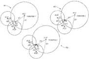
- FIG. 3illustrates an example of how multilateration may be used to determine a location of an electronic device.
- FIG. 4illustrates an example of how error can interfere with the accuracy of a multilateration calculation.
- FIG. 5illustrates an example of a multlateration function.
- FIG. 6illustrates an example location estimation process
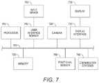
- FIG. 7illustrates components of an example electronic device.
- the methodcan be used to pinpoint the location of a mobile electronic device that a user is carrying around the building or that us automatically moving around a building.
- the methodcan also be used to quickly determine the location of stationary devices, such as print devices or other equipment, in order to help maintenance personnel and/or users quickly locate a particular device within a building.
- the methodcan leverage existing equipment and does not require the installation of additional location devices such as beacons or cameras positioned within the building, or tags that are attached to the electronic device.
- FIG. 1depicts an example floor map 100 of a floor of an office building.
- the buildingincludes various rooms and corridors, and various electronic devices are located within the facility.
- the electronic devicesmay include stationary devices such as print devices 101 and computer display devices 103 , and/or mobile devices 102 such as mobile phones, laptop computers, or tablet computing devices.
- the buildingis equipped with a wireless local area network (WLAN) having any number of access points 117 a - 117 c . While three access points are shown in this image, this number is only by way of example. Any number of wireless access points may be used, and the total building map may include multiple floors, each with multiple access points.
- Each access pointconnects to a router, switch or hub and transmits a Wi-Fi signal to a limited area so that electronic devices that are within the access point's area can communicatively connect to the WLAN via one of the access points.
- a systemmay store a digital representation of a floor map 100 such as that shown.
- the digital representationwill include coordinates for each access point (such as x-coordinates 202 and y-coordinates 203 ), along with a unique identifier for each access point such as an alphanumeric device identification code 201 and/or media access control (MAC) address 204 .
- the systemmay store this information in a table or other data structure.
- the systemmay refer to the access point, and optionally also to other map data (such as a room in which each access point is located), when estimating the location of an electronic device within the region of the map, as will be described below.
- Each electronic device that connects to the WLAN(such as electronic devices 101 - 103 of FIG. 1 ) will be equipped with a transceiver for wirelessly communicating with the WLAN and or other devices on the network.
- the transceivermay be configured for any suitable communication protocol, including any of the IEEE 802.11 family of standards, near-field or short range communication, Bluetooth or Bluetooth Low Energy, and/or other protocols.
- an electronic deviceWhen an electronic device is located within a building having multiple access points, its transceiver may detect more than one access point's signal. This is illustrated by way of example in FIG. 3 , in which an electronic device 305 is located within the communication ranges of access points 301 , 302 and 303 .
- the x, y coordinates of each access pointare known from the data set of FIG. 2 .
- the electronic device 305(or a remote server that is in wireless communication with the electronic device 305 ) may determine the location (x, y coordinates) of the electronic device 305 by determining the distances d 1 , d 1 , d 1 , between the electronic device 305 and each detected access point 301 , 302 and 303 for which the electronic device 305 detects a signal.
- the devicemay measure the signal strength of each access point's received signal and store the measurement as a received signal strength indicator (RSSI).
- RSSIreceived signal strength indicator
- Methods of determining a RSSI for an access point's signalare known and are common in devices that employ IEEE 802.11 communication standards. However, other methods of measuring signal strength may be used, such as known methods of determining a received channel power indicator (RCCI) or Rx level, all of which are intended to be included within the scope of this disclosure as a substitute for RSSI.
- RCCIreceived channel power indicator
- Rx levelall of which are intended to be included within the scope of this disclosure as a substitute for RSSI.
- Most signalshave a dynamic range, and signal strength is not a constant. Therefore, RSSI is typically not measured not as an instantaneous value, but instead as an average of signal strength received over a period of time.
- RSSImay be output as a DC analog level, represented in terms of milliwatts, decibels per milliwatt (dBM) or another unit of measure.
- RSSImay be a negative number, such as a range of ⁇ 100 to 0 with zero representing the highest possible signal strength; in others, RSSI may be a positive number, such as a range of 0 to 100 or 0 to 127 with zero representing the lowest possible signal strength.
- the systemmay use RSSI to determine the distance to each access point for which a signal is detected.
- Kis a constant
- fis the frequency of the detected signal
- RSSIis the signal strength indicator in dBm.
- each access point's coordinates(as retrieved from a data set using the access point's identifier) will serve as the center of a circle to be drawn around the access point.
- the diameter of the circlewill be a function of the RSSI, such that a larger circle reflects a larger signal strength.
- the electronic device's locationmay be determined at a location where the circles intersect. For example, the ideal situation of illustrated in FIG. 3 shows that the distances between the electronic device 305 and the access points 301 - 303 are approximately equal, and the circles overlap.
- FIG. 4illustrates that in some situations error can result in a “lone access point” 403 , in which the signal strength of the access point results in a circle that does not overlap with the circles for the other access points 401 , 402 .
- the electronic device 405should not have detected the signal of access point 403 .
- the electronic device 405actually did detect the signal of access point 403 , error has been introduced into the calculation.
- the error in a distance calculationcan be estimated as a mean square error (MSE), as follows:
- D1is the calculated distance from the electronic device to the access point based on the estimated location from the result of the multilateration calculation
- D2is the distance to each access point that is calculated using the free space path loss equation for a given K.
- the systemmay use a nonlinear least squares function as the multilateration calculation.
- the systemmay then determine a difference between D1 (distance from the electronic device's estimated possible location and each access point's actual location) and D2 (the distance to each access point that using the free space path loss equation for a given K and detected RSSI).
- the systemmay then determine MSE as the mean of the square of the differences for all access points (i.e., the MSE calculation above).
- the systemmay then repeat this for multiple candidate electronic device locations, varying the possible Xtest, Ytest coordinates of the electronic device as (until MSE is minimized, using any suitable minimization algorithm, such as Newton's method of gradient descent.
- any suitable minimization algorithmsuch as Newton's method of gradient descent.
- FIG. 5in which three iterations 501 , 502 and 503 of the algorithm are run. In each iteration, three access points are shown, with known coordinates xn, yn positioned in the center of a circle with a diameter d21, d22, d23 that is determined based on the detected RSSI of the access point.
- iteration 501initial coordinates x, y are estimated, distances d1, d12, d13 from those coordinates to each access point are determined, and the MSE is calculated.
- iteration 502this process is repeated for a different set of x, y coordinates are selected, and the MSE returned is less than that of iteration 501 , this continues until the MSE values converge after any suitable number of iterations (with convergence—representing loss minimization—shown as iteration 503 .
- the systemmay determine error using another function that relies on the distances, such as root mean square error, maximum error, mean error, or the like.
- the present systemimproves on prior techniques by varying the constant K in the free space loss equation within various constraints, rather than treating K as a fixed constant as in the prior art. This allows the system to determine an “optimized K” per access point that minimizes overall MSE.
- the systemselects various values of K that are in the range of approximately 24 to approximately 28, although other ranges may be used.
- the systemuses a random initial condition for K for each access point (though other initial conditions can be used, such as the resulting K from the last optimization run).
- the systemdetermines, for each access point, the K value that minimizes the MSE distance error between the RSSI calculated distance and the multilateration calculated distances. This may be illustrated in the following pseudocode, in which for any Xtest, Ytest and array of Ks:
- Xtest, Ytest and ArrayOfKsare inputs to the loss function that are varied to find minimum mse;
- APX, APYare known locations of the access point (AP).
- APRSSI and Apfrequencyare the signal strength and frequency from each AP.
- the systemselects, for each access point, the K that minimizes the loss, and it uses that K in the free space path loss equation to determine the distances to each access point.
- the term “minimize”is the minimization of a scalar function in which the MSEs for all access point distances are considered, and the K is selected for each access point that will optimize (i.e., most reduce on a collective basis) the loss function in all of the distance calculations.
- Various optimization algorithmsmay be used, such as Newton's method of gradient descent as mentioned above, the known Nelder-Mead minimization process (which uses the Simplex algorithm) and the algorithm known as CG, which uses a nonlinear conjugate gradient algorithm.
- a transceiver of an electronic devicedetecting a multiple of Wi-Fi signals, each of which originates from a unique Wi-Fi access point in a building.
- the electronic devicea processor of a remote computing device that is in wireless communication with the electronic device, or a combination of the two may execute programming instructions to analyze the signal and use results of the analysis to determine the coordinates of the electronic device.
- the one or more processorswill, for each of Wi-Fi signals, analyze the signal to determine an access point device identifier (such as a name and/or MAC address) and a RSSI (step 602 ).
- the processor(s)will access a data set of access point data and retrieve location coordinates for each access point.
- the systemwill identify multiple candidate constants (i.e., K-values) to apply to a distance calculation for determining a signal strength-based distance from the electronic device to each of the access points.
- the systemwill estimate a device location for the electronic device.
- the systemwill determine distances between the initial device location and each access point.
- the systemwill select a candidate constant to use in a signal strength-based distance calculation.
- the systemwill use the identified constant and the signal strength in a distance calculation to determine a distance from the electronic device to each of the access points.
- the systemwill determine the error between the coordinate-based distance (from step 606 ) and the signal strength based distance (from step 609 ).
- the systemwill repeat steps 605 - 609 using different estimated coordinate values and different constants until the error is minimized.
- the systemwill then identify the electronic device coordinates of the iteration in which error is minimized at 611 .
- the processorswill then return the set of coordinates to the electronic device or a remote device for use in estimating a location of the electronic device within the building.
- a remote servercan use the method to return a location of a missing or misplaced mobile electronic device, such as a mobile phone, tablet computing device or laptop.
- the systemcan also be used to identify equipment that is in the building so that the electronic device can send commands to operate that equipment (steps 613 and 614 )
- the buildingincludes a network of print devices, each having a known location stored in a data store, then when the mobile electronic device's location is returned the system can access the data store's coordinate data to identify the print device having coordinates that are closest to the electronic device's location, and the mobile electronic device or a remote computing device may then use a print driver to send a print job to the identified print device so that the print device can process and print the print job.
- FIG. 7depicts an example of internal hardware that may be included in any of the electronic components of the system, such as any of the electronic devices 101 - 103 of FIG. 1 , or of a remote server with which the electronic devices communicate.
- An electrical bus 700serves as an information highway interconnecting the other illustrated components of the hardware.
- Processor 705is a central processing device of the system, configured to perform calculations and logic operations required to execute programming instructions.
- the terms “processor” and “processing device”may refer to a single processor or any number of processors in a set of processors that collectively perform a set of operations, such as a central processing unit (CPU), a graphics processing unit (GPU), a remote server, or a combination of these.
- CPUcentral processing unit
- GPUgraphics processing unit
- remote serveror a combination of these.
- ROMRead only memory
- RAMrandom access memory
- flash memoryhard drives and other devices capable of storing electronic data constitute examples of memory devices 725 .
- a memory devicemay include a single device or a collection of devices across which data and/or instructions are stored.
- the memory devicemay store data, such as the data set of access point information described above.
- An optional display interface 730may permit information from the bus 700 to be displayed on a display device 735 in visual, graphic or alphanumeric format.
- An audio interface and audio output(such as a speaker) also may be provided.
- Communication with external devicesmay occur using various communication devices 740 such as a wireless antenna, an RFID tag and/or short-range or near-field communication transceiver, each of which may optionally communicatively connect with other components of the device via one or more communication system.
- the communication device 740may be configured to be communicatively connected to a communications network, such as the Internet, a local area network or a cellular telephone data network.
- the hardwaremay also include a user interface sensor 745 that allows for receipt of data from input devices 750 such as a keyboard, a mouse, a joystick, a touchscreen, a touch pad, a remote control, a pointing device and/or microphone.
- input devices 750such as a keyboard, a mouse, a joystick, a touchscreen, a touch pad, a remote control, a pointing device and/or microphone.
- the systemalso may include positional sensors 780 such as a global positioning system (GPS) sensor device that receives positional data from an external GPS network.
- GPSglobal positioning system
- Terminology that is relevant to this disclosureincludes:
- An “electronic device” or a “computing device”refers to a device or system that includes a processor and memory. Each device may have its own processor and/or memory, or the processor and/or memory may be shared with other devices as in a virtual machine or container arrangement.
- the memorywill contain or receive programming instructions that, when executed by the processor, cause the electronic device to perform one or more operations according to the programming instructions. Examples of electronic devices include personal computers, laptop computers, digital display devices, print devices, servers, mainframes, virtual machines, containers, gaming systems, televisions, digital home assistants and mobile electronic devices such as smartphones, fitness tracking devices, wearable virtual reality devices, Internet-connected wearables such as smart watches and smart eyewear, personal digital assistants, cameras, tablet computers, laptop computers, media players and the like.
- Electronic devicesalso may include appliances and other devices that can communicate in an Internet-of-things arrangement, such as smart thermostats, refrigerators, connected light bulbs and other devices.
- the client device and the serverare electronic devices, in which the server contains instructions and/or data that the client device accesses via one or more communications links in one or more communications networks.
- a servermay be an electronic device, and each virtual machine or container also may be considered an electronic device.
- a client device, server device, virtual machine or containermay be referred to simply as a “device” for brevity. Additional elements that may be included in electronic devices are discussed above in the context of FIG. 6 .
- print devicerefers to a machine having hardware capable of reading a digital document file and use the information from the file and associated print instructions to print of a physical document on a substrate.
- Components of a print devicetypically include a print engine, which includes print hardware such as a print head, which may include components such as a print cartridge containing ink, toner or another print material, as well as a document feeding system configured to pass a substrate through the print device so that the print head can print characters and/or images on the substrate.
- a print devicemay have additional capabilities such as scanning or faxing and thus may be a multifunction device.
- print jobrefers to a set of digital data that represents text, images and/or other content that a print device will print on a substrate
- processorand “processing device” refer to a hardware component of an electronic device that is configured to execute programming instructions. Except where specifically stated otherwise, the singular terms “processor” and “processing device” are intended to include both single-processing device embodiments and embodiments in which multiple processing devices together or collectively perform a process.
- memoryeach refer to a non-transitory device on which computer-readable data, programming instructions or both are stored. Except where specifically stated otherwise, the terms “memory,” “memory device,” “data store,” “data storage facility” and the like are intended to include single device embodiments, embodiments in which multiple memory devices together or collectively store a set of data or instructions, as well as individual sectors within such devices.
- communication linkand “communication path” mean a wired or wireless path via which a first device sends communication signals to and/or receives communication signals from one or more other devices.
- Devicesare “communicatively connected” if the devices are able to send and/or receive data via a communication link.
- Electrical communicationrefers to the transmission of data via one or more signals between two or more electronic devices, whether through a wired or wireless network, and whether directly or indirectly via one or more intermediary devices.
Landscapes
- Engineering & Computer Science (AREA)
- Computer Networks & Wireless Communication (AREA)
- Signal Processing (AREA)
- Physics & Mathematics (AREA)
- General Physics & Mathematics (AREA)
- Radar, Positioning & Navigation (AREA)
- Remote Sensing (AREA)
- Quality & Reliability (AREA)
- Electromagnetism (AREA)
- Position Fixing By Use Of Radio Waves (AREA)
Abstract
Description
Log(d)=(K−20 Log(f)−RSSI)/20
Log(d)=(K−20 Log(f)+abs(RSSI))/20
- sse=0; mse=0
- APX=Aps[index].X; APY=Aps[index].Y
- APRSSI=Aps[index].RSSI; Apfrequency=Aps[index].freq
- K=ArrayOfKs[index]
- dFromKandRSSI=10{circumflex over ( )}[[K−(20*log 10(Apfrequency))+abs(APRSSI)]/20]
- d=sqrt[(Xtest−APX){circumflex over ( )}2+(Ytest−APY){circumflex over ( )}2]
- sse=sse+(d−dFromKandRSSI){circumflex over ( )}2
- mse=sse/(Number of Aps in list of APs)
- return mse.
- sse=0; mse=0
Claims (19)
Log(d)=(K−20 Log(f)−(RSSI))/20
Log(d)=(K−20 Log(f)−(RSSI))/20
Log(d)=(K−20 Log(f)−(RSSI))/20
Priority Applications (1)
| Application Number | Priority Date | Filing Date | Title |
|---|---|---|---|
| US17/004,145US11356800B2 (en) | 2020-08-27 | 2020-08-27 | Method of estimating indoor location of a device |
Applications Claiming Priority (1)
| Application Number | Priority Date | Filing Date | Title |
|---|---|---|---|
| US17/004,145US11356800B2 (en) | 2020-08-27 | 2020-08-27 | Method of estimating indoor location of a device |
Publications (2)
| Publication Number | Publication Date |
|---|---|
| US20220070607A1 US20220070607A1 (en) | 2022-03-03 |
| US11356800B2true US11356800B2 (en) | 2022-06-07 |
Family
ID=80357662
Family Applications (1)
| Application Number | Title | Priority Date | Filing Date |
|---|---|---|---|
| US17/004,145Active2040-10-08US11356800B2 (en) | 2020-08-27 | 2020-08-27 | Method of estimating indoor location of a device |
Country Status (1)
| Country | Link |
|---|---|
| US (1) | US11356800B2 (en) |
Families Citing this family (2)
| Publication number | Priority date | Publication date | Assignee | Title |
|---|---|---|---|---|
| US20230345207A1 (en)* | 2022-03-25 | 2023-10-26 | Nec Laboratories America, Inc. | REALIZING ENTERPRISE-GRADE LOCALIZATION USING WIFI 802.11mc FINE TUNE MEASUREMENT |
| US12232074B2 (en)* | 2022-05-03 | 2025-02-18 | Cisco Technology, Inc. | Correcting for antennae spatial distortions in radio frequency (RF) localizations |
Citations (57)
| Publication number | Priority date | Publication date | Assignee | Title |
|---|---|---|---|---|
| US20040075861A1 (en) | 2002-06-21 | 2004-04-22 | Toshihiro Shima | Printer and print system, and data receiving device and data transmitting and receiving system |
| US20040264427A1 (en) | 2003-06-27 | 2004-12-30 | Nokia Corporation | Selection of connection settings |
| US20060221901A1 (en) | 2005-04-01 | 2006-10-05 | Toshiba America Research, Inc. | Autonomous and heterogeneous network discovery and reuse |
| US20070019670A1 (en) | 2005-07-22 | 2007-01-25 | Eric Falardeau | Mobile connectivity solution |
| US20080080458A1 (en) | 2006-09-29 | 2008-04-03 | Cole Terry L | Connection manager with deferred configuration |
| US20090028082A1 (en) | 2006-09-06 | 2009-01-29 | Devicescape Software, Inc. | Systems and Methods for Wireless Network Selection Based on Attributes Stored in a Network Database |
| JP2009187103A (en) | 2008-02-04 | 2009-08-20 | Sharp Corp | Mobile communication terminal, printing system |
| US20100040029A1 (en) | 2008-08-15 | 2010-02-18 | Nokia Corporation | Apparatus, system, and method for obtaining local connectivity settings |
| US20110063663A1 (en) | 2009-09-15 | 2011-03-17 | Samsung Electronics Co., Ltd. | Method for printing document of mobile terminal through printer, and mobile terminal therefor |
| US7958562B2 (en) | 2006-04-27 | 2011-06-07 | Xerox Corporation | Document access management system |
| US20110306364A1 (en) | 2010-06-15 | 2011-12-15 | Spectrum Bridge, Inc. | System and method for providing network access to electronic devices |
| US8086248B2 (en)* | 2008-05-16 | 2011-12-27 | International Business Machines Corporation | Estimating location using multi-antenna radio receiver |
| US20120075664A1 (en) | 2010-09-28 | 2012-03-29 | Wellala, Inc. | Systems and methods for configuring mobile devices for printing to wireless printers |
| US20120179737A1 (en) | 2010-05-27 | 2012-07-12 | Victor Baranov | System and method for searching for mobile devices, and for establishing connections and data exchange between the mobile devices |
| US8548738B1 (en) | 2011-07-08 | 2013-10-01 | Google Inc. | Constructing paths based on a particle model |
| US20130286942A1 (en) | 2005-06-29 | 2013-10-31 | Jumpstart Wireless Corporation | System and method for dynamic automatic communication path selection, distributed device synchronization and task delegation |
| US8583400B2 (en) | 2011-05-13 | 2013-11-12 | Google Inc. | Indoor localization of mobile devices |
| US20130346138A1 (en) | 2012-06-26 | 2013-12-26 | Xerox Corporation | Creation of production process workflow diagrams |
| US20140022587A1 (en)* | 2012-07-19 | 2014-01-23 | Xerox Corportation | Systems and methods for detecting a location of an image forming device using mobile device localization |
| CN103925923A (en) | 2014-05-07 | 2014-07-16 | 南京大学 | Geomagnetic indoor positioning system based on self-adaptive particle filter algorithm |
| US20140256286A1 (en) | 2013-03-08 | 2014-09-11 | Microsoft Corporation | Intelligent Protocol Selection |
| US8934112B1 (en) | 2013-10-02 | 2015-01-13 | Xerox Corporation | Methods and systems for allocating resources in a print production environment |
| US8982384B2 (en) | 2011-02-18 | 2015-03-17 | Xerox Corporation | Methods and systems for brokering printing device capacity |
| US8986867B2 (en) | 2010-11-11 | 2015-03-24 | Samsung Sdi Co., Ltd. | Battery pack with assembled light emitting portion |
| US20150189023A1 (en) | 2013-12-27 | 2015-07-02 | Brother Kogyo Kabushiki Kaisha | Communication system, communication device, and non-transitory computer-readable storage medium storing instructions for information processing device |
| US9201619B2 (en) | 2014-01-17 | 2015-12-01 | Xerox Corporation | Methods and systems for assigning a job source to a hub in a print production environment |
| US20150358790A1 (en) | 2012-11-12 | 2015-12-10 | ENORCOM Corporation | Automated mobile system |
| US20150363141A1 (en) | 2013-01-31 | 2015-12-17 | Hewlett-Packard Devlopment Company L.P. | Simplified woobe experience |
| US9367271B2 (en) | 2014-10-28 | 2016-06-14 | Xerox Corporation | System and method for achieving tap-to-print functionality on a mobile device |
| US20170006436A1 (en)* | 2015-07-02 | 2017-01-05 | Tata Consultancy Services Limited | Determining location of a user device |
| US20170008174A1 (en) | 2013-04-15 | 2017-01-12 | Alan Rosen | Intelligent visual humanoid robot and computer vision system programmed to perform visual artificial intelligence processes |
| US9549089B1 (en) | 2015-08-25 | 2017-01-17 | Xerox Corporation | System and method for network access discovery |
| US20170123737A1 (en) | 2015-10-30 | 2017-05-04 | Konica Minolta Laboratory U.S.A., Inc. | Managing print jobs based on planned routes |
| US20170142549A1 (en) | 2015-11-12 | 2017-05-18 | Trackr, Inc. | System and method for tracking items within a defined area |
| US20170171718A1 (en) | 2015-12-09 | 2017-06-15 | Research & Business Foundation Of Sungkyunkwan University | Location estimation method for indoor device |
| US9740447B1 (en) | 2016-07-28 | 2017-08-22 | Xerox Corporation | Method and apparatus for automatically printing documents from portable memory device |
| US20170289813A1 (en) | 2016-04-01 | 2017-10-05 | Acronis International Gmbh | System and method for geo-location-based mobile user authentication |
| US20170304732A1 (en) | 2014-11-10 | 2017-10-26 | Lego A/S | System and method for toy recognition |
| US20170347388A1 (en) | 2016-05-27 | 2017-11-30 | Wandering WiFi LLC | Transparently Connecting Mobile Devices to Multiple Wireless Local Area Networks |
| US9894604B1 (en) | 2015-03-23 | 2018-02-13 | Amazon Technologies, Inc. | Automated wireless access point selection |
| US20180083795A1 (en) | 2016-09-16 | 2018-03-22 | Xerox Corporation | System and method for network selection and service pairing using historical data mining |
| US20180172451A1 (en) | 2015-08-14 | 2018-06-21 | Beijing Evolver Robotics Co., Ltd | Method and system for mobile robot to self-establish map indoors |
| US20180237137A1 (en) | 2017-02-22 | 2018-08-23 | Wal-Mart Stores, Inc. | Voice Activated Unmanned Aerial Vehicle (UAV) Assistance System |
| US20180249298A1 (en) | 2017-01-20 | 2018-08-30 | Bmc Software, Inc. | Asset floor map |
| US10104247B2 (en) | 2016-07-28 | 2018-10-16 | Xerox Corporation | Method and apparatus for automatically tracking print history of documents stored on removable storage device |
| US10116826B1 (en) | 2017-04-26 | 2018-10-30 | Xerox Corporation | Method and apparatus for automatically resuming a print job from portable memory device |
| US20180316821A1 (en) | 2017-04-28 | 2018-11-01 | Xerox Corporation | Location tracking system for networked print devices in an environment |
| US20180367698A1 (en) | 2017-06-15 | 2018-12-20 | Xerox Corporation | Method and apparatus for instant secure scanning of a document |
| US20190014233A1 (en) | 2017-06-15 | 2019-01-10 | Xerox Corporation | Method and Apparatus for Instant Secure Scanning of a Document Using Biometric Information |
| US20190026052A1 (en) | 2017-07-19 | 2019-01-24 | Xerox Corporation | Method and apparatus for automatically processing job interruptions caused by a portable memory device with priority handling capabilities |
| US20190026051A1 (en) | 2017-07-19 | 2019-01-24 | Xerox Corporation | Method and apparatus for automatically processing job interruptions caused by a portable memory device in a print system |
| US20190114804A1 (en) | 2017-10-13 | 2019-04-18 | Qualcomm Incorporated | Object tracking for neural network systems |
| US20190304102A1 (en) | 2018-03-30 | 2019-10-03 | Qualcomm Incorporated | Memory efficient blob based object classification in video analytics |
| US10440221B2 (en) | 2017-04-28 | 2019-10-08 | Xerox Corporation | Location tracking system for networked print devices in an environment |
| US20190373407A1 (en) | 2018-06-01 | 2019-12-05 | Apple Inc. | Feature-Based Slam |
| US20200193609A1 (en) | 2018-12-18 | 2020-06-18 | Qualcomm Incorporated | Motion-assisted image segmentation and object detection |
| US10694053B1 (en) | 2019-01-22 | 2020-06-23 | Xerox Corporation | Wireless location tracking tag for monitoring real time location-tracking apparatus for an electronic device |
- 2020
- 2020-08-27USUS17/004,145patent/US11356800B2/enactiveActive
Patent Citations (58)
| Publication number | Priority date | Publication date | Assignee | Title |
|---|---|---|---|---|
| US20040075861A1 (en) | 2002-06-21 | 2004-04-22 | Toshihiro Shima | Printer and print system, and data receiving device and data transmitting and receiving system |
| US20040264427A1 (en) | 2003-06-27 | 2004-12-30 | Nokia Corporation | Selection of connection settings |
| US20060221901A1 (en) | 2005-04-01 | 2006-10-05 | Toshiba America Research, Inc. | Autonomous and heterogeneous network discovery and reuse |
| US20130286942A1 (en) | 2005-06-29 | 2013-10-31 | Jumpstart Wireless Corporation | System and method for dynamic automatic communication path selection, distributed device synchronization and task delegation |
| US20070019670A1 (en) | 2005-07-22 | 2007-01-25 | Eric Falardeau | Mobile connectivity solution |
| US7958562B2 (en) | 2006-04-27 | 2011-06-07 | Xerox Corporation | Document access management system |
| US20090028082A1 (en) | 2006-09-06 | 2009-01-29 | Devicescape Software, Inc. | Systems and Methods for Wireless Network Selection Based on Attributes Stored in a Network Database |
| US20080080458A1 (en) | 2006-09-29 | 2008-04-03 | Cole Terry L | Connection manager with deferred configuration |
| JP2009187103A (en) | 2008-02-04 | 2009-08-20 | Sharp Corp | Mobile communication terminal, printing system |
| US8086248B2 (en)* | 2008-05-16 | 2011-12-27 | International Business Machines Corporation | Estimating location using multi-antenna radio receiver |
| US20100040029A1 (en) | 2008-08-15 | 2010-02-18 | Nokia Corporation | Apparatus, system, and method for obtaining local connectivity settings |
| US20110063663A1 (en) | 2009-09-15 | 2011-03-17 | Samsung Electronics Co., Ltd. | Method for printing document of mobile terminal through printer, and mobile terminal therefor |
| US20120179737A1 (en) | 2010-05-27 | 2012-07-12 | Victor Baranov | System and method for searching for mobile devices, and for establishing connections and data exchange between the mobile devices |
| US20110306364A1 (en) | 2010-06-15 | 2011-12-15 | Spectrum Bridge, Inc. | System and method for providing network access to electronic devices |
| US20120075664A1 (en) | 2010-09-28 | 2012-03-29 | Wellala, Inc. | Systems and methods for configuring mobile devices for printing to wireless printers |
| US8986867B2 (en) | 2010-11-11 | 2015-03-24 | Samsung Sdi Co., Ltd. | Battery pack with assembled light emitting portion |
| US8982384B2 (en) | 2011-02-18 | 2015-03-17 | Xerox Corporation | Methods and systems for brokering printing device capacity |
| US8583400B2 (en) | 2011-05-13 | 2013-11-12 | Google Inc. | Indoor localization of mobile devices |
| US8548738B1 (en) | 2011-07-08 | 2013-10-01 | Google Inc. | Constructing paths based on a particle model |
| US20130346138A1 (en) | 2012-06-26 | 2013-12-26 | Xerox Corporation | Creation of production process workflow diagrams |
| US20140022587A1 (en)* | 2012-07-19 | 2014-01-23 | Xerox Corportation | Systems and methods for detecting a location of an image forming device using mobile device localization |
| US20150358790A1 (en) | 2012-11-12 | 2015-12-10 | ENORCOM Corporation | Automated mobile system |
| US20150363141A1 (en) | 2013-01-31 | 2015-12-17 | Hewlett-Packard Devlopment Company L.P. | Simplified woobe experience |
| US20140256286A1 (en) | 2013-03-08 | 2014-09-11 | Microsoft Corporation | Intelligent Protocol Selection |
| US20170008174A1 (en) | 2013-04-15 | 2017-01-12 | Alan Rosen | Intelligent visual humanoid robot and computer vision system programmed to perform visual artificial intelligence processes |
| US8934112B1 (en) | 2013-10-02 | 2015-01-13 | Xerox Corporation | Methods and systems for allocating resources in a print production environment |
| US20150189023A1 (en) | 2013-12-27 | 2015-07-02 | Brother Kogyo Kabushiki Kaisha | Communication system, communication device, and non-transitory computer-readable storage medium storing instructions for information processing device |
| US9201619B2 (en) | 2014-01-17 | 2015-12-01 | Xerox Corporation | Methods and systems for assigning a job source to a hub in a print production environment |
| CN103925923A (en) | 2014-05-07 | 2014-07-16 | 南京大学 | Geomagnetic indoor positioning system based on self-adaptive particle filter algorithm |
| CN103925923B (en) | 2014-05-07 | 2017-06-16 | 南京大学 | A kind of earth magnetism indoor locating system based on adaptive particle filter device algorithm |
| US9367271B2 (en) | 2014-10-28 | 2016-06-14 | Xerox Corporation | System and method for achieving tap-to-print functionality on a mobile device |
| US20170304732A1 (en) | 2014-11-10 | 2017-10-26 | Lego A/S | System and method for toy recognition |
| US9894604B1 (en) | 2015-03-23 | 2018-02-13 | Amazon Technologies, Inc. | Automated wireless access point selection |
| US20170006436A1 (en)* | 2015-07-02 | 2017-01-05 | Tata Consultancy Services Limited | Determining location of a user device |
| US20180172451A1 (en) | 2015-08-14 | 2018-06-21 | Beijing Evolver Robotics Co., Ltd | Method and system for mobile robot to self-establish map indoors |
| US9549089B1 (en) | 2015-08-25 | 2017-01-17 | Xerox Corporation | System and method for network access discovery |
| US20170123737A1 (en) | 2015-10-30 | 2017-05-04 | Konica Minolta Laboratory U.S.A., Inc. | Managing print jobs based on planned routes |
| US20170142549A1 (en) | 2015-11-12 | 2017-05-18 | Trackr, Inc. | System and method for tracking items within a defined area |
| US20170171718A1 (en) | 2015-12-09 | 2017-06-15 | Research & Business Foundation Of Sungkyunkwan University | Location estimation method for indoor device |
| US20170289813A1 (en) | 2016-04-01 | 2017-10-05 | Acronis International Gmbh | System and method for geo-location-based mobile user authentication |
| US20170347388A1 (en) | 2016-05-27 | 2017-11-30 | Wandering WiFi LLC | Transparently Connecting Mobile Devices to Multiple Wireless Local Area Networks |
| US9740447B1 (en) | 2016-07-28 | 2017-08-22 | Xerox Corporation | Method and apparatus for automatically printing documents from portable memory device |
| US10104247B2 (en) | 2016-07-28 | 2018-10-16 | Xerox Corporation | Method and apparatus for automatically tracking print history of documents stored on removable storage device |
| US20180083795A1 (en) | 2016-09-16 | 2018-03-22 | Xerox Corporation | System and method for network selection and service pairing using historical data mining |
| US20180249298A1 (en) | 2017-01-20 | 2018-08-30 | Bmc Software, Inc. | Asset floor map |
| US20180237137A1 (en) | 2017-02-22 | 2018-08-23 | Wal-Mart Stores, Inc. | Voice Activated Unmanned Aerial Vehicle (UAV) Assistance System |
| US10116826B1 (en) | 2017-04-26 | 2018-10-30 | Xerox Corporation | Method and apparatus for automatically resuming a print job from portable memory device |
| US20180316821A1 (en) | 2017-04-28 | 2018-11-01 | Xerox Corporation | Location tracking system for networked print devices in an environment |
| US10440221B2 (en) | 2017-04-28 | 2019-10-08 | Xerox Corporation | Location tracking system for networked print devices in an environment |
| US20180367698A1 (en) | 2017-06-15 | 2018-12-20 | Xerox Corporation | Method and apparatus for instant secure scanning of a document |
| US20190014233A1 (en) | 2017-06-15 | 2019-01-10 | Xerox Corporation | Method and Apparatus for Instant Secure Scanning of a Document Using Biometric Information |
| US20190026052A1 (en) | 2017-07-19 | 2019-01-24 | Xerox Corporation | Method and apparatus for automatically processing job interruptions caused by a portable memory device with priority handling capabilities |
| US20190026051A1 (en) | 2017-07-19 | 2019-01-24 | Xerox Corporation | Method and apparatus for automatically processing job interruptions caused by a portable memory device in a print system |
| US20190114804A1 (en) | 2017-10-13 | 2019-04-18 | Qualcomm Incorporated | Object tracking for neural network systems |
| US20190304102A1 (en) | 2018-03-30 | 2019-10-03 | Qualcomm Incorporated | Memory efficient blob based object classification in video analytics |
| US20190373407A1 (en) | 2018-06-01 | 2019-12-05 | Apple Inc. | Feature-Based Slam |
| US20200193609A1 (en) | 2018-12-18 | 2020-06-18 | Qualcomm Incorporated | Motion-assisted image segmentation and object detection |
| US10694053B1 (en) | 2019-01-22 | 2020-06-23 | Xerox Corporation | Wireless location tracking tag for monitoring real time location-tracking apparatus for an electronic device |
Non-Patent Citations (20)
| Title |
|---|
| Ashraf, I., Application of Deep Convolutional Neural Networks and Smartphone Sensors for Indoor Localization, Jun. 6, 2019, Applied Sciences, 2019, 9: 2337, p. 1-10. |
| Bhoi, A., "Monocular depth Estimation: A Survey", [cs.CV] Jan. 27, 2019. |
| Cotera P. et al., "Indoor Robot Positioning using an Enhanced Trilateration Algorithm", International Journal of Advanced Robotic Systems, 2016, 13:110 I doi: 10.5772/63246. |
| Godard, C. et al., "Digging Into Self-Supervised Monocular Depth Estimation". |
| Information about Related Patent and Patent Applications, see section 6 of the accompanying Information Disclosure Statement Letter, which concerns Related Patents and Patent Applications. |
| Kang, H., Obstacle Detection and Alert System for Smartphone AR Users, VRST '19, Nov. 12-15, 2019, Parramatta, NSW, Australia, 2019 Association for Computing Machinery. |
| KC, S., Obstacle Detection, Depth Estimation and Warning System for Visually Impaired People, Dec. 12, 2019, 2019 IEEE Region 10 Conference, pp. 863-865. |
| Maduskar, D. et al. , "RSSI based adaptive indoor location tracker", Maduskar and Tapaswi Scientific Phone Apps and Mobile Devices (2017) 3.3, DOI 10.1186/s41070-017-0015-z. |
| Murata M. et al., "Smartphone-based Indoor Localization for Blind Navigation across Building Complexes", 2018 IEEE International Conference on Pervasive Computing and Communications (PerCom). |
| Saleh, K. End-to-End Indoor Navigation Assistance for the Visually Impaired using Monocular Camera, Jan. 17, 2019, 2018 IEEE International Conference on Systems, Man, and Cybernetics (SMC), pp. 3504-3508. |
| Saxena, A. et al., "Learning Depth from Single Monocular Images". |
| Seco, F. et al., "Smartphone-Based Cooperative Indoor Localization with RFID Technology", Sensors 2018, 18, 266. |
| U.S. Appl. No. 16/809,901, filed Mar. 5, 2020, Methods and Systems for Sensing Obstacles in an Indoor Environment. |
| U.S. Appl. No. 16/878,753, filed May 20, 2020, Wireless Location Tracking Tag for Monitoring Real Time Location-Tracking Apparatus for an Electronic Device. |
| U.S. Appl. No. 17/088,786, filed Nov. 4, 2020, System and Method for Indoor Navigation. |
| U.S. Appl. No. 17/189,361, filed Mar. 2, 2021, System and Method to Manage Building Occupancy Based on Disease Risk, Location Capacity and Occupant Loading. |
| U.S. Appl. No. 17/326,477, filed May 21, 2021, Indoor Positioning System for a Mobile Electronic Device. |
| Wang, S. et al., Detecting Stairs and Pedestrian Crosswalks for the Blind by RGBD Camera, Feb. 25, 2013, 2012 IEEE International Conference on Bioinformatics and Biomedicine Workshops (BIBMW), pp. 732-736. |
| Wu, Y. et al., "HTrack: An Efficient Heading-Aided Map Matching for Indoor Localization and Tracking", IEEE Sensors Journal, vol. 19, No. 8, Apr. 15, 2019. |
| Yang, J. et al., "Indoor Localization Using Improved RSS-Based Lateration Methods", IEEE "GLOBECOM" 2009 Proceedings. |
Also Published As
| Publication number | Publication date |
|---|---|
| US20220070607A1 (en) | 2022-03-03 |
Similar Documents
| Publication | Publication Date | Title |
|---|---|---|
| CN103809153B (en) | Method and system for accurate straight line distance estimation between two communication devices | |
| CN103874191B (en) | A kind of localization method based on WiFi wireless networks | |
| US9936356B2 (en) | Location estimation method for indoor device | |
| KR101676571B1 (en) | Method and system for providing indoor positoning service | |
| CN107702717A (en) | For control indicated by the position of device location | |
| CN102395200B (en) | Node positioning method in wireless sensor network and apparatus thereof | |
| KR101691905B1 (en) | Building floor determination for a location based service | |
| JP2015531053A (en) | System, method, and computer program for dynamically creating a radio map | |
| CN111935820B (en) | Positioning implementation method based on wireless network and related equipment | |
| US9958533B2 (en) | Method and system for locating wireless devices within a local region | |
| JP2018519506A (en) | Device and method for tracking | |
| CN103155662A (en) | Signal strength profiling | |
| US10009733B2 (en) | Method and system for determining a position of a mobile device by an access point | |
| EP3140670B1 (en) | Location error radius determination | |
| US11356800B2 (en) | Method of estimating indoor location of a device | |
| US10492164B2 (en) | Method, device and system for estimating location | |
| TWI442078B (en) | Positioning apparatus, positioning method and computer program product thereof | |
| CN111148217B (en) | A positioning method, device and electronic device | |
| CN110672089A (en) | Method and device for navigation in indoor environment | |
| US11423584B2 (en) | Systems and methods for dynamically estimating real time signal strengths for a wireless router using augmented reality | |
| CN114979955B (en) | Floor positioning method and device, electronic equipment and storage medium | |
| KR101914922B1 (en) | Method and apparatus for estimating a position | |
| KR20140119333A (en) | Method and Apparatus for Location Determination to Improve the accuracy of the location | |
| US20160174147A1 (en) | Access point selection for mobile device positioning | |
| CN107529143A (en) | Method of locating terminal, system, device and computer-readable storage medium |
Legal Events
| Date | Code | Title | Description |
|---|---|---|---|
| AS | Assignment | Owner name:XEROX CORPORATION, CONNECTICUT Free format text:ASSIGNMENT OF ASSIGNORS INTEREST;ASSIGNORS:EBNER, FRITZ FRANCIS;GUNDA, RAVITEJA;REEL/FRAME:053611/0237 Effective date:20200824 | |
| FEPP | Fee payment procedure | Free format text:ENTITY STATUS SET TO UNDISCOUNTED (ORIGINAL EVENT CODE: BIG.); ENTITY STATUS OF PATENT OWNER: LARGE ENTITY | |
| STPP | Information on status: patent application and granting procedure in general | Free format text:RESPONSE TO NON-FINAL OFFICE ACTION ENTERED AND FORWARDED TO EXAMINER | |
| STPP | Information on status: patent application and granting procedure in general | Free format text:NOTICE OF ALLOWANCE MAILED -- APPLICATION RECEIVED IN OFFICE OF PUBLICATIONS | |
| STPP | Information on status: patent application and granting procedure in general | Free format text:PUBLICATIONS -- ISSUE FEE PAYMENT VERIFIED | |
| STCF | Information on status: patent grant | Free format text:PATENTED CASE | |
| AS | Assignment | Owner name:CITIBANK, N.A., AS AGENT, DELAWARE Free format text:SECURITY INTEREST;ASSIGNOR:XEROX CORPORATION;REEL/FRAME:062740/0214 Effective date:20221107 | |
| AS | Assignment | Owner name:XEROX CORPORATION, CONNECTICUT Free format text:RELEASE OF SECURITY INTEREST IN PATENTS AT R/F 062740/0214;ASSIGNOR:CITIBANK, N.A., AS AGENT;REEL/FRAME:063694/0122 Effective date:20230517 | |
| AS | Assignment | Owner name:CITIBANK, N.A., AS COLLATERAL AGENT, NEW YORK Free format text:SECURITY INTEREST;ASSIGNOR:XEROX CORPORATION;REEL/FRAME:064760/0389 Effective date:20230621 | |
| AS | Assignment | Owner name:JEFFERIES FINANCE LLC, AS COLLATERAL AGENT, NEW YORK Free format text:SECURITY INTEREST;ASSIGNOR:XEROX CORPORATION;REEL/FRAME:065628/0019 Effective date:20231117 | |
| AS | Assignment | Owner name:XEROX CORPORATION, CONNECTICUT Free format text:TERMINATION AND RELEASE OF SECURITY INTEREST IN PATENTS RECORDED AT RF 064760/0389;ASSIGNOR:CITIBANK, N.A., AS COLLATERAL AGENT;REEL/FRAME:068261/0001 Effective date:20240206 Owner name:CITIBANK, N.A., AS COLLATERAL AGENT, NEW YORK Free format text:SECURITY INTEREST;ASSIGNOR:XEROX CORPORATION;REEL/FRAME:066741/0001 Effective date:20240206 | |
| AS | Assignment | Owner name:U.S. BANK TRUST COMPANY, NATIONAL ASSOCIATION, AS COLLATERAL AGENT, CONNECTICUT Free format text:FIRST LIEN NOTES PATENT SECURITY AGREEMENT;ASSIGNOR:XEROX CORPORATION;REEL/FRAME:070824/0001 Effective date:20250411 | |
| AS | Assignment | Owner name:U.S. BANK TRUST COMPANY, NATIONAL ASSOCIATION, AS COLLATERAL AGENT, CONNECTICUT Free format text:SECOND LIEN NOTES PATENT SECURITY AGREEMENT;ASSIGNOR:XEROX CORPORATION;REEL/FRAME:071785/0550 Effective date:20250701 |