US11356752B2 - Telecommunications panel with grounding wire - Google Patents
Telecommunications panel with grounding wireDownload PDFInfo
- Publication number
- US11356752B2 US11356752B2US16/762,780US201816762780AUS11356752B2US 11356752 B2US11356752 B2US 11356752B2US 201816762780 AUS201816762780 AUS 201816762780AUS 11356752 B2US11356752 B2US 11356752B2
- Authority
- US
- United States
- Prior art keywords
- panel
- ground wire
- telecommunications
- panel frame
- frame
- Prior art date
- Legal status (The legal status is an assumption and is not a legal conclusion. Google has not performed a legal analysis and makes no representation as to the accuracy of the status listed.)
- Active
Links
- ATJFFYVFTNAWJD-UHFFFAOYSA-NTinChemical compound[Sn]ATJFFYVFTNAWJD-UHFFFAOYSA-N0.000claimsabstractdescription7
- 239000007769metal materialSubstances0.000claimsdescription6
- 238000000034methodMethods0.000claimsdescription4
- 238000005192partitionMethods0.000claimsdescription4
- 239000004020conductorSubstances0.000abstractdescription2
- 239000000463materialSubstances0.000description6
- 230000014759maintenance of locationEffects0.000description3
- RYGMFSIKBFXOCR-UHFFFAOYSA-NCopperChemical compound[Cu]RYGMFSIKBFXOCR-UHFFFAOYSA-N0.000description2
- 229910000831SteelInorganic materials0.000description2
- 229910052802copperInorganic materials0.000description2
- 239000010949copperSubstances0.000description2
- 239000003989dielectric materialSubstances0.000description2
- 238000009434installationMethods0.000description2
- 229910052751metalInorganic materials0.000description2
- 239000002184metalSubstances0.000description2
- 239000010959steelSubstances0.000description2
- 229910052782aluminiumInorganic materials0.000description1
- XAGFODPZIPBFFR-UHFFFAOYSA-NaluminiumChemical compound[Al]XAGFODPZIPBFFR-UHFFFAOYSA-N0.000description1
- 230000000712assemblyEffects0.000description1
- 238000000429assemblyMethods0.000description1
- 239000000835fiberSubstances0.000description1
- 150000002739metalsChemical class0.000description1
- 238000012986modificationMethods0.000description1
- 230000004048modificationEffects0.000description1
- 230000003287optical effectEffects0.000description1
- 238000009751slip formingMethods0.000description1
Images


Classifications
- H—ELECTRICITY
- H04—ELECTRIC COMMUNICATION TECHNIQUE
- H04Q—SELECTING
- H04Q1/00—Details of selecting apparatus or arrangements
- H04Q1/02—Constructional details
- H04Q1/14—Distribution frames
- H04Q1/142—Terminal blocks for distribution frames
- H—ELECTRICITY
- H04—ELECTRIC COMMUNICATION TECHNIQUE
- H04Q—SELECTING
- H04Q1/00—Details of selecting apparatus or arrangements
- H04Q1/02—Constructional details
- H04Q1/13—Patch panels for monitoring, interconnecting or testing circuits, e.g. patch bay, patch field or jack field; Patching modules
- H—ELECTRICITY
- H04—ELECTRIC COMMUNICATION TECHNIQUE
- H04Q—SELECTING
- H04Q1/00—Details of selecting apparatus or arrangements
- H04Q1/02—Constructional details
- H04Q1/14—Distribution frames
- H04Q1/145—Distribution frames with switches arranged in a matrix configuration
- H—ELECTRICITY
- H04—ELECTRIC COMMUNICATION TECHNIQUE
- H04Q—SELECTING
- H04Q1/00—Details of selecting apparatus or arrangements
- H04Q1/02—Constructional details
- H04Q1/14—Distribution frames
- H04Q1/149—Wireguides in connector blocks
Definitions
- Patching equipmentis used for connection between telecommunications apparatuses.
- Patching equipmenttypically includes one or more patch panels which are mounted to a distribution frame rack so as to generally define a patching side, where patch cords from another active device or another pat panel can be cross-connected or interconnected, and a distribution side, where cables from network equipment and/or work station areas are terminated.
- patch panelscan mount a number of electrical components, such as electrical connectors or jacks, in a dense configuration, and such multiple electrical components need to be grounded in an effective and cost-efficient manner.
- the present disclosurerelates to a patch panel with a grounding wire.
- the patch panelincludes a ground wire which is routed to ground all modular jacks mounted to the patch panel.
- Various aspectsare described in this disclosure, which include, but are not limited to, the following aspects.
- a telecommunications panelin one aspect, includes a panel frame and a ground wire secured to the panel frame.
- the panel framehas a front panel portion and opposite side panel portions.
- the front panel portionextends between the opposite side panel portions and configured to receive a plurality of modular jacks therethrough.
- the ground wireextends longitudinally along the panel frame.
- the ground wiremay be arranged such that the plurality of modular jacks presses against the ground wire when the plurality of modular jacks are received through the front panel portion of the panel frame.
- the ground wireis a tin plated conductive wire.
- the ground wiremay have a rounded cross section.
- the ground wiremay have a rectangular or square cross section.
- the ground wireis configured to engage with latching elements of the modular jacks for securing the modular jacks to the panel frame.
- At least one of the opposite side panel portionsincludes a panel grounding element configured to ground the telecommunications panel to an equipment rack.
- the ground wiremay be electrically connected to the panel grounding element.
- the panel grounding elementmay include a fastener that secures the ground wire to the at least one of the opposite side panel portions.
- the panel frameincludes a channel extending between the opposite side panel portions and configured to receive the ground wire.
- the panel framefurther may include opposite lateral flanges adjacent the opposite side panel portions.
- the lateral flangesinclude mounting elements configured to mount the telecommunications panel to an equipment rack.
- the telecommunications panelmay further include a plurality of receptacle modules secured to the panel frame and defining a plurality of jack receptacle openings for receiving the plurality of modular jacks, respectively.
- the plurality of modular jacksmay be secured to the panel frame in at least one row extending between the opposite side panel portions of the panel frame.
- the ground wiremay be routed in a direction parallel with the at least one row.
- the telecommunications panelincludes one or more of the plurality of modular jacks.
- a telecommunications panelin another aspect, includes a panel frame, a plurality of receptacle modules, and a ground wire.
- the panel frameincludes a front panel portion having a front face and an opposite rear face; a top panel portion extending from the rear face of the front panel portion; a bottom panel portion extending from the rear face of the front panel portion and arranged to be parallel with the top panel portion; and opposite side panel portions extending from the rear face of the front panel portion.
- the front panel portionmay longitudinally extends between the opposite side panel portions and have a plurality of receptacle module openings.
- the plurality of receptacle modulesmay be at least partially received in the plurality of receptacle module openings, respectively.
- the plurality of receptacle modulesmay be secured to the panel frame between the top panel portion and the bottom panel portion.
- Each of the plurality of receptacle modulesmay include a plurality of jack receptacle openings configured to receive a plurality of modular jacks therethrough, respectively.
- the ground wiremay route longitudinally along the panel frame.
- the ground wiremay be arranged such that the plurality of modular jacks presses against the ground wire when the plurality of modular jacks are received through the plurality of jack receptacle openings of the plurality of receptacle modules.
- the ground wiremay have a rounded cross section.
- the ground wiremay have a rectangular or square cross section.
- each of the plurality of receptacle modulesmay include a front part having a front face and an opposite rear face; a top part extending from the rear face and configured to arrange adjacent the top panel portion of the panel frame when the receptacle module is secured to the panel frame; a bottom part extending from the rear face and configured to arrange adjacent the bottom panel portion of the panel frame when the receptacle module is secured to the panel frame; and at least one partition wall extending between the top part and the bottom part and defining the plurality of jack receptacle openings.
- the bottom partmay include a channel configured to receive the ground wire.
- the plurality of jack receptacle openingsmay be arranged in at least one row.
- the channelmay extend in a direction parallel with the at least one row.
- the ground wireis a tin plated conductive wire.
- At least one of the opposite side panel portionsincludes a panel grounding element configured to ground the telecommunications panel to an equipment rack.
- the ground wiremay be electrically connected to the panel grounding element.
- the panel grounding elementincludes a fastener that secures the ground wire to the at least one of the opposite side panel portions.
- the panel framefurther includes opposite lateral flanges adjacent the opposite side panel portions.
- the lateral flangesmay include mounting elements configured to mount the telecommunications panel to an equipment rack.
- each of the plurality of modular jackshas a main body made of metallic material.
- the main bodymay be arranged to directly contact with the ground wire when the modular jack is secured to the panel frame.
- the panel frame and the plurality of receptacle modulesare integrally formed.
- the telecommunications panelincludes one or more of the plurality of modular jacks.
- Yet another aspectis a method for engaging a modular jack with a telecommunications panel.
- the methodincludes arranging a ground wire to a panel frame of the telecommunications panel to extend longitudinally along the panel frame; and securing a modular jack to the panel frame by directly pressing against the ground wire.
- FIG. 1Ais a front perspective view of an example patch panel system.
- FIG. 1Bis a rear perspective view of the patch panel system of FIG. 1A .
- FIG. 2Ais a front view of the patch panel system of FIG. 1A .
- FIG. 2Bis a rear view of the patch panel system of FIG. 1A .
- FIG. 3Ais a bottom view of the patch panel system of FIG. 1A .
- FIG. 3Bis a top view of the patch panel system of FIG. 1A .
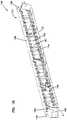
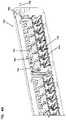
- FIG. 4Ais a rear perspective view of a patch panel without modular jacks mounted.
- FIG. 4Bis a rear perspective view of the patch panel of FIG. 4A with modular jacks mounted.
- FIG. 5is a rear perspective view of an example receptacle module.
- FIG. 6is a cross sectional view of the patch panel with a modular jack, taken along line A-A of FIG. 2A .
- FIG. 7is a perspective view of an example modular jack.
- FIG. 8is another perspective view of the modular jack of FIG. 7
- a patch panel system 100 in accordance with the present disclosureincludes a patch panel 102 and one or more modular jacks 104 (also referred to herein as jack modules).
- the patch panel 102which is an example of telecommunications panel
- the patch panel 102is configured to mount to a network rack (also referred to herein as a communications rack, equipment rack, or the like) (not shown).
- the modular jacks 104are configured to mount to the patch panel 102 .
- the modular jack 104is configured to include one or more types of cable termination interfaces. In some embodiments, such cable termination interfaces are configured for electrical jacks. In other embodiments, the modular jack 104 is configured to include various types of optical adapters or other media interfaces. Referring to FIGS. 7 and 8 , one example of the modular jack 104 is illustrated, which can be mounted to the patch panel 102 .
- the modular jack 104includes a main body 202 extending between a front end 204 and a rear end 206 .
- the modular jack 104further includes a jack receptacle 208 formed at the front end 204 .
- the jack receptacle 208is configured as an RJ-type jack receptacle.
- the modular jack 104includes a latching element 212 configured to mount the modular jack 104 to the patch panel 102 .
- the latching element 212is provided on the main body 202 at a location between the front end 204 and the rear end 206 .
- the latching element 212can be located closer to the front end 204 than the rear end 206 .
- Other locationsare also possible for the latching element 212 .
- the latching element 212includes a pair of projections 214 extending from one surface of the main body 202 and defining a slot 216 .
- the latching element 212includes a flexible latch 218 formed on the opposite surface of the main body 202 .
- the modular jack 104is engaged with (e.g., mounted to, inserted into, and/or secured to) the patch panel 102
- one or more other electrical devicescan also be engaged with the patch panel 102 in the same or similar manner as the modular jack 104 .
- Such other electrical devices including the modular jackcan be referred to herein as patching devices.
- the main body 202is made of metallic material. In other examples, the main body 202 is made from a dielectric material (e.g., a plastic material) which is shielded by a metallic material or a metalized plastic material, or by a metallic shield element. As described herein, when the modular jack 104 is mounted to the patch panel 102 , the main body 202 is arranged to directly contact with a grounding wire that is provided to the patch panel 102 for grounding the modular jack 104 .
- a dielectric materiale.g., a plastic material
- the modular jack 104is a shielded twisted pair (STP) cable jack.
- STPshielded twisted pair
- a ground wire 170 of the patch panel 102is used to ground such a STP jack in the patch panel 102 .
- STPshielded twisted pair
- the patch panel 102can also be used with unshielded twisted pair (UTP) cable jacks.
- the patch panel 102includes mechanical retaining features to enable an unshielded twisted pair (UTP) jack to be installed therein as necessary.
- modular jacks 104can also be used in the patch panel system 100 of the present disclosure. Examples of such modular jacks 104 are described in U.S. Pat. No. 7,874,865, titled Electrical Connector with a Compliant Cable Strain Relief Element, issued Jan. 25, 2011; PCT Publication No. WO 2016/156644, titled A CONNECTOR ASSEMBLY WITH A CONNECTOR, A LATCH MEMBER AND A PANEL, filed Mar. 26, 2016; U.S. Patent Application Ser. No. 62/521,885, titled HIGH DENSITY BENZEL FOR PATCH PANEL, filed Jun. 19, 2017; U.S. Patent Application Ser. No.
- FIGS. 1A, 1B, 2A, 2B, 3A, and 3Ba single modular jack 104 is shown as being inserted into the patch panel 102 . It is understood that the patch panel 102 can be either partially or fully loaded with a plurality of modular jacks 104 in the same or similar manner as the modular jack 104 shown in the illustrated example.
- the patch panel 102 of the present disclosureis configured to interchangeably mount various types of modular jacks, such as UTP jacks and STP jacks.
- the patch panel 102includes a panel frame 112 having retaining features for securing both UTP jacks and STP jacks.
- the patch panel 102includes a ground wire 170 that creates the patch panel 102 to jack grounding and/or bonding.
- the patch panel 102includes a panel frame 112 and one or more receptacle modules 114 mounted to the panel frame 112 .
- the panel frame 112is configured to receive a plurality of modular jacks 104 .
- the panel frame 112includes a front panel portion 122 , opposite side panel portions 124 , a top panel portion 128 , and a bottom panel portion 130 .
- the front panel portion 122 , the top panel portion 128 , and the bottom panel portion 130generally extend between the opposite side panel portions 124 .
- the front panel portion 122extends longitudinally between the side panel portions 124 . In the illustrated examples, the front panel portion 122 extends linearly between the opposite side panel portions 124 . In other examples, the front panel portion 122 can extend in different configurations, such as where the front panel portion 122 is bent at one or more locations, or where the front panel portion 122 is curved or angled.
- the front panel portion 122has a front face 132 and a rear face 134 opposite to the front face 132 .
- the top panel portion 128 and the bottom panel portion 130extend rearwards from the rear face 134 of the front panel portion 122 and are arranged to be parallel with each other.
- the side panel portions 124extend rearwards from the rear face 134 of the front panel portion 122 .
- the panel frame 112can further include opposite lateral flanges 136 adjacent the opposite side panel portions 124 .
- the lateral flanges 136including mounting elements 138 configured to mount the patch panel 102 to an equipment rack, chassis, cabinet, or other structures.
- the mounting elements 138include holes through which fasteners (e.g., screws or bolts) pass to secure the patch panel 102 to the rack.
- the lateral flanges 136extend laterally from the front panel portion 122 .
- the panel frame 112can be made of various materials.
- the panel frame 112is made of metallic materials, such as steel or other metals, although other materials may be used alternatively or in addition.
- the panel frame 112can include one or more receptacle module openings 140 for receiving the receptacle modules 114 .
- the front panel portion 122 of the panel frame 112includes a plurality of receptacle module openings 140 configured to at least partially receive the receptacle modules 114 .
- the receptacle modules 114can be at least partially inserted into the receptacle module openings 140 of the panel frame 112 and mounted to the panel frame 112 .
- the receptacle modules 114can be secured to the panel frame 112 in various manners. In some examples, the receptacle modules 114 are snap-fitted to the panel frame 112 .
- the receptacle module 114includes one or more latching elements 142 (e.g., projections or tabs) configured to engage with corresponding latching elements 144 (e.g., holes or recesses) of the panel frame 112 .
- latching elements 142e.g., projections or tabs
- latching elements 144e.g., holes or recesses
- the receptacle modules 114can be mounted to the panel frame 112 with fasteners.
- the receptacle module 114can be at least partially received in the receptacle module opening 140 and secured to the panel frame 112 .
- the receptacle module 114can be arranged between the top panel portion 128 and the bottom panel portion 130 when secured to the panel frame 112 .
- the receptacle module 114includes a plurality of jack receptacle openings 150 configured to at least partially receive the modular jacks 104 .
- the jack receptacle openings 150can be configured to fit various types of modular jacks.
- the jack receptacle openings 150can be sized to receive any of the following types of modular jacks: AMP-TWIST 6S, 6AS, 7AS, SL, and AMP-TWIST 6AUTP.
- the receptacle module 114includes a front part 152 having a front face 154 and a rear face 156 .
- the receptacle module 114further includes a top part 158 and a bottom part 160 , which extend from the rear face 156 of the front part 152 .
- the top part 158 and the bottom part 160are arranged to be generally parallel with each other.
- the top part 158 and the bottom part 160 of the receptacle module 114are configured to arrange adjacent the front panel portion 122 and the bottom panel portion 130 of the panel frame 112 , respectively, when the receptacle module 114 is secured to the panel frame 112 , as illustrated in FIG. 6 .
- the receptacle module 114further includes one or more partition walls 162 extending between the top part 158 and the bottom part 160 and defining the jack receptacle openings 150 .
- the receptacle module 114can further include jack mounting elements 164 for securing the modular jack 104 .
- the jack mounting elements 164can be configured to removably engage the latching element 212 of the modular jack 104 .
- the jack mounting elements 164include projections extending from the top part 158 of the receptacle module 114 and configured to engage the flexible latch 218 of the modular jack 104 .
- An example of the jack mounting elementsis described in U.S. Patent Application Ser. No. 62/584,524, filed on Nov. 10, 2017, titled TELECOMMUNICATIONS PANEL WITH PATCHING DEVICE INSTALLATION FEATURES, the disclosure of which is incorporated herein by reference in its entirety.
- the receptacle modules 114can be made of various materials. In some examples, the receptacle modules 114 are made of dielectric materials, such as a plastic material.
- the panel frame 112has four receptacle module openings 140 for receiving four receptacle modules 114 in a single row, and each receptacle modules 114 is configured to mount six modular jacks 104 in a single row.
- the panel frame 112is configured to secure a greater or lesser number of receptacle modules 114 in one or more rows, and each receptacle module 114 is configured to secure a greater or lesser number of modular jacks 104 in one or more rows.
- the receptacle modules 114are made separately from the panel frame 112 and mounted to the panel frame 112 , it is understood that the receptacle modules 114 are integrally formed with the panel frame 112 .
- the patch panel 102further includes a ground bus bar configured to provide grounding for the modular jacks 104 secured to the patch panel 102 .
- the ground bus bar of the patch panel 102is configured as a ground wire 170 , which is an electrically conductive wire.
- the ground wire 170is secured to the panel frame 112 and extends longitudinally along the panel frame 112 .
- the ground wire 170extends along the length of the panel frame 112 , and arranged adjacent the jack receptacle openings 150 .
- the ground wire 170is a separate element from the patch panel 102 and is mounted to the patch panel 102 .
- the ground wire 170is not an integral part of the patch panel 102 which is configured to form a spring member that provides ground or bonding features.
- the ground wire 170is arranged such that the modular jacks 104 directly contact with the ground wire 170 when the modular jacks 104 are secured to the patch panel 102 (e.g., when the modular jacks 104 are received at least partially through the front panel portion of the panel frame 112 ).
- the ground wire 170is configured and arranged such that the modular jacks 104 press against the ground wire 170 .
- the ground wire 170can be routed adjacent the bottom panel portion 130 of the panel frame 112 .
- the ground wire 170is routed along the bottom part 160 of the receptacle module 114 adjacent the row of jack receptacle openings 150 .
- a metal parte.g., the metallic main body 202
- the modular jacks 104can seat on, and thus contact with, the ground wire 170 , as illustrated in FIG. 6 .
- the patch panel 102is provided with a single ground wire 170 that extends across all of the plurality of receptacle modules 114 (and thus runs across all the modular jacks 104 secured to the receptacle modules 114 ).
- a plurality of ground wires 170are used for the patch panel 102 .
- each of the ground wires 170is routed to ground the modular jacks 104 mounted to one or more of the plurality of receptacle modules 114 .
- all the ground wires 170can be electrically connected to each other and one of the ground wires 170 is electrically connected to a panel grounding element 180 .
- at least some of the plurality of ground wires 170are individually, electrically connected to one or more panel grounding elements 180 in the patch panel 102 .
- the patch panel 102can be configured as an angled patch panel which defines generally a shallow V-shape (rather than being flat or planar) such that the vertex of the “V” protrudes in front of the rack to which it is mounted.
- the ground bus bar of the patch panel 102includes two ground wires 170 , each of which spans half of the entire length of the patch panel (or spans one of the two sections of the patch panel defined by the V shaped protrusion) and can be placed on opposite ends (e.g., the opposite side panel portions) of the patch panel, thereby avoiding a single, long ground wire with the middle of the ground wire bent to accommodate the V-shape of the patch panel.
- the ground wire 170can extend only partially along the full length of the patch panel.
- the ground wire 170can extend along a first portion of the panel frame and does not extend along a second portion of the panel frame.
- unshielded productse.g., fiber modules or UTP jacks
- shielded modular jackssuch as STP jacks
- At least one of such patch panelsmay utilize a ground wire which does not cover the full length of the patch panel, so that unshielded products can be installed into some of the panel openings (e.g., receptacle openings 150 ) where the ground wire is not routed while shielded modular jacks are mounted to the other panel openings (e.g., receptacle openings 150 ) of the patch panel for grounding or bonding.
- a ground wirewhich does not cover the full length of the patch panel, so that unshielded products can be installed into some of the panel openings (e.g., receptacle openings 150 ) where the ground wire is not routed while shielded modular jacks are mounted to the other panel openings (e.g., receptacle openings 150 ) of the patch panel for grounding or bonding.
- the ground wire 170can be of various configurations and dimensions.
- the ground wire 170is configured to have a rounded cross section.
- the ground wire 170has a circular cross section.
- the ground wire 170has an oval cross section.
- other cross sectionssuch as square, rectangular, or other polygonal cross sections, are also possible for the ground wire 170 .
- the ground wire 170can be made of various conductive materials.
- the ground wire 170is made as a tin plated conductive wire.
- the ground wire 170is made of steel-based copper with tin plated, or aluminum-based copper with tin plated.
- the receptacle module 114includes a channel 166 that at least partially receives the ground wire 170 .
- the channel 166can extend between the opposite side panel portions 124 of the panel frame 112 .
- the channel 166is formed on the bottom part 160 of the receptacle module 114 and adjacent the row of jack receptacle openings 150 .
- the channel 166can extend in a direction parallel with the row of jack receptacle openings 150 .
- the channel 166can be defined between pairs of tabs 168 A and 168 B.
- each pair of tabs 168 A and 168 Bis arranged to be spaced apart from adjacent pairs of tabs along the direction parallel with the row of jack receptacle openings 150 so that the channel 166 is generally defined along the same direction (e.g., the channel 166 can have open portions between adjacent pairs of tabs as illustrated in FIG. 5 ).
- the pairs of tabscan be provided at the bottom part 160 of the receptacle module 114 adjacent the partition walls 162 .
- the pairs of tabsare configured to partially receive the ground wire 170 and secure the ground wire 170 therein.
- tabs 168 A and 168 Bare also possible.
- the tabs 168 A and 168 Bare continuously formed along the direction parallel with the row of jack receptacle openings so that the channel 166 is completely formed therebetween along the entire length of the receptacle module 114 .
- the channel 166is positioned to align with the slot 216 ( FIG. 7 ) between the projections 214 of the latching element 212 of the modular jack 104 when the modular jack 104 is secured to the patch panel 102 .
- the ground wire 170 disposed in the channel 166can be used as a jack retention feature.
- the ground wire 170can function as a jack retention flange that is at least partially inserted into the slot 216 formed in the modular jack 104 when the modular jack 104 is mounted to the patch panel 102 .
- the ground wire 170is arranged in the channel 166 so as to directly engage the latching element (e.g., the projections 214 ) of the modular jack 104 being mounted to the receptacle module 114 .
- latching elemente.g., the projections 214
- An example of such a jack retention flangeis described in U.S. Patent Application Ser. No. 62/584,524, filed on Nov. 10, 2017, titled TELECOMMUNICATIONS PANEL WITH PATCHING DEVICE INSTALLATION FEATURES, the disclosure of which is incorporated herein by reference in its entirety.
- the patch panel 102includes a panel grounding element 180 that is used to ground the patch panel 102 .
- the panel grounding element 180is provided at either or both of the side panel portions 124 of the panel frame 112 .
- the panel grounding element 180can provide a location to which a conductive element 182 is connected for providing electrical connection for grounding between the patch panel 102 and the equipment rack to which the patch panel 102 is mounted.
- the conductive element 182can be a conductive wire that is routed between the panel grounding element 180 of the patch panel 102 and the equipment rack or any other structure suitable for grounding purposes.
- the panel grounding element 180includes a fastener 184 , such as a screw, which is used to couple the conductive element 182 .
- the panel grounding element 180can be made of metallic material.
- An end of the ground wire 170 of the patch panel 102can be fixed to the side panel portion 124 by the fastener 184 . Accordingly, the ground wire 170 can be electrically connected to the conductive element 182 through the panel grounding element 180 .
- the panel grounding element 180can include other types of elements (e.g., a connector) suitable to couple the conductive element 182 to the side panel portion 124 , couple the ground wire 170 to the side panel portion 124 , and/or the ground wire 170 to the conductive element 182 .
- elementse.g., a connector
- ground wire 170is arranged at or adjacent the bottom panel portion 130 of the panel frame 112 or the bottom part 160 of the receptacle module 114 , it is understood that, in other embodiments, the ground wire 170 can be routed at or adjacent the top panel portion 128 of the panel frame 112 or the top part 158 of the receptacle module 114 in the same or similar configurations as described herein.
Landscapes
- Engineering & Computer Science (AREA)
- Computer Networks & Wireless Communication (AREA)
- Details Of Connecting Devices For Male And Female Coupling (AREA)
- Structure Of Telephone Exchanges (AREA)
Abstract
Description
Claims (20)
Priority Applications (1)
| Application Number | Priority Date | Filing Date | Title |
|---|---|---|---|
| US16/762,780US11356752B2 (en) | 2017-11-10 | 2018-11-08 | Telecommunications panel with grounding wire |
Applications Claiming Priority (3)
| Application Number | Priority Date | Filing Date | Title |
|---|---|---|---|
| US201762584543P | 2017-11-10 | 2017-11-10 | |
| US16/762,780US11356752B2 (en) | 2017-11-10 | 2018-11-08 | Telecommunications panel with grounding wire |
| PCT/US2018/059780WO2019094560A1 (en) | 2017-11-10 | 2018-11-08 | Telecommunications panel with grounding wire |
Publications (2)
| Publication Number | Publication Date |
|---|---|
| US20200351573A1 US20200351573A1 (en) | 2020-11-05 |
| US11356752B2true US11356752B2 (en) | 2022-06-07 |
Family
ID=66439294
Family Applications (1)
| Application Number | Title | Priority Date | Filing Date |
|---|---|---|---|
| US16/762,780ActiveUS11356752B2 (en) | 2017-11-10 | 2018-11-08 | Telecommunications panel with grounding wire |
Country Status (4)
| Country | Link |
|---|---|
| US (1) | US11356752B2 (en) |
| EP (1) | EP3707915B1 (en) |
| CN (1) | CN111345046B (en) |
| WO (1) | WO2019094560A1 (en) |
Families Citing this family (9)
| Publication number | Priority date | Publication date | Assignee | Title |
|---|---|---|---|---|
| ES2583636B1 (en) | 2015-03-20 | 2017-06-29 | Te Connectivity Amp España, S.L.U. | Connector with detachable link box |
| ES2584540B1 (en) | 2015-03-27 | 2017-07-05 | Te Connectivity Amp España, S.L.U. | Latch for telecommunications connector |
| ES2584533B1 (en) | 2015-03-27 | 2017-08-04 | Te Connectivity Amp España, S.L.U. | Cover set for a telecommunications connector |
| ES2987308T3 (en) | 2016-08-15 | 2024-11-14 | Commscope Technologies Llc | Grounded connector assembly and method for assembling a connector assembly |
| EP3643075A4 (en) | 2017-06-19 | 2021-03-17 | Commscope Technologies LLC | High density bezel for patch panel |
| CN112652913A (en) | 2019-10-10 | 2021-04-13 | 康普技术有限责任公司 | Modular telecommunications panel system and telecommunications module |
| CN112652897A (en) | 2019-10-10 | 2021-04-13 | 康普技术有限责任公司 | Modular telecommunications panel and modular telecommunications system |
| TWI727549B (en)* | 2019-12-12 | 2021-05-11 | 好慶科技企業股份有限公司 | A support shelf for connector and patch panel system thereof |
| TWI839704B (en)* | 2022-03-31 | 2024-04-21 | 超邁工業股份有限公司 | Distributed frame |
Citations (180)
| Publication number | Priority date | Publication date | Assignee | Title |
|---|---|---|---|---|
| GB221872A (en) | 1923-06-21 | 1924-09-22 | Richard Whaley | Improvements in electric coupling devices |
| US3666996A (en) | 1970-09-03 | 1972-05-30 | Darr R Brown | Telephone line terminal block cover |
| US3739076A (en) | 1972-04-17 | 1973-06-12 | L Schwartz | Electrical cable terminating and grounding connector |
| US3830957A (en) | 1973-08-20 | 1974-08-20 | Amex Syst Inc | Grounding device for shielded electrical cable |
| US4284316A (en) | 1979-10-11 | 1981-08-18 | Cgee Alsthom | Terminal block |
| EP0073112A1 (en) | 1981-08-17 | 1983-03-02 | AMP INCORPORATED (a New Jersey corporation) | Kit for converting a panel opening to a shielded pin receptacle |
| US4537458A (en) | 1983-09-01 | 1985-08-27 | Continental-Wirt Electronics Corp. | Conductive shielding housing for flat cable connector |
| US4660912A (en) | 1986-02-18 | 1987-04-28 | Tomek Lawrence S | Protective cover for electrical outlet |
| US4679879A (en) | 1986-10-03 | 1987-07-14 | Molex Incorporated | Plug and receptacle connector assembly |
| US4721476A (en) | 1985-12-23 | 1988-01-26 | Interchangeable Hatches Inc. | Electrical connection box used in conjunction with raised floors |
| US4747785A (en) | 1987-03-17 | 1988-05-31 | Global Equipment Company, Div. Of Continental Dynamics | Shielding for connector hood |
| US4760215A (en) | 1987-11-06 | 1988-07-26 | Jeffrey J. Cook | Electrical outlet cover system |
| US4790765A (en) | 1987-10-05 | 1988-12-13 | Hubbell Incorporated | Connector shunt structure |
| US4810210A (en) | 1987-02-12 | 1989-03-07 | Hosiden Electronics Co., Ltd. | Multipin connector |
| US4824400A (en) | 1987-03-13 | 1989-04-25 | Georg Spinner | Connector for a coaxial line with corrugated outer conductor or a corrugated waveguide tube |
| US4830628A (en) | 1986-11-29 | 1989-05-16 | Kern Electric Components Limited | Screened multicore cable connectors |
| US4842553A (en) | 1988-02-26 | 1989-06-27 | W. L. Gore & Associates, Inc. | Method and assembly for terminating a conductive polymer-shielded coaxial electrical cable |
| US4857015A (en) | 1988-07-01 | 1989-08-15 | Molex Incorporated | Evironmentally sealed grounding backshell with strain relief |
| US5021610A (en) | 1990-01-04 | 1991-06-04 | Square D Company | Strain relief connection |
| US5169346A (en) | 1991-12-04 | 1992-12-08 | Johnston James J | Data connector/modular jack adapter and method for making |
| GB2260660A (en) | 1991-10-16 | 1993-04-21 | Nokia Telecommunications Oy | Cable feed-through and earthing unit |
| US5238416A (en) | 1991-08-05 | 1993-08-24 | Paige Manufacturing Corp. | Extension cord receptacle |
| US5240436A (en) | 1992-03-19 | 1993-08-31 | Adc Telecommunications, Inc. | BNC-RJ conversion connector |
| US5278352A (en) | 1991-07-03 | 1994-01-11 | The United States Of America As Represented By The Secretary Of The Navy | Grounding ring for ground adapters |
| US5310359A (en) | 1993-06-10 | 1994-05-10 | Molex Incorporated | Cable connector with strain relief |
| FR2701007A1 (en) | 1993-01-29 | 1994-08-05 | Legrand Sa | Package for device which is associated with a base, this package being able to form a protective cap for the base or the device |
| US5445538A (en) | 1993-11-17 | 1995-08-29 | Thomas & Betts Corporation | Electrical connector strain relief |
| WO1995034923A1 (en) | 1994-06-10 | 1995-12-21 | Telefonaktiebolaget Lm Ericsson | Electrical connection device |
| US5571023A (en) | 1995-05-17 | 1996-11-05 | Hubbell Incorporated | Electrical connector housing with lid |
| EP0775845A2 (en) | 1995-11-22 | 1997-05-28 | Danny Gold | External single handed closure and release mechanism |
| GB2308508A (en) | 1995-12-21 | 1997-06-25 | John Mortimer Lewis | Cable storage container |
| US5675126A (en) | 1995-08-11 | 1997-10-07 | Halvorsen; Gary | Outlet cover |
| US5691506A (en) | 1994-09-27 | 1997-11-25 | Sumitomo Wiring Systems Ltd. | Ground structure for shield wire and method for grounding wire |
| WO1997044862A1 (en) | 1996-05-23 | 1997-11-27 | The Siemon Company | Reduced crosstalk modular outlet |
| US5697806A (en) | 1995-07-06 | 1997-12-16 | The Whitaker Corporation | Stackable electrical connector |
| US5762517A (en) | 1995-02-09 | 1998-06-09 | Yazaki Corporation | Press-connecting joint connector |
| WO1999019944A1 (en) | 1997-10-09 | 1999-04-22 | Stewart Connector Systems | High frequency bi-level offset multi-port jack |
| US6015307A (en)* | 1998-10-21 | 2000-01-18 | Chiu; Pen-Fu | Electric outlet with rotary socket bodies |
| US6077122A (en) | 1997-10-30 | 2000-06-20 | Thomas & Bett International, Inc. | Electrical connector having an improved connector shield and a multi-purpose strain relief |
| US6086415A (en) | 1998-10-29 | 2000-07-11 | Hubbell Incorporated | High density modular patch panel |
| US6244908B1 (en) | 2000-08-04 | 2001-06-12 | Thomas & Betts International, Inc. | Switch within a data connector jack |
| US6247849B1 (en) | 1997-09-13 | 2001-06-19 | Alliance Fiber Optics Products, Inc. | Protection cap for fiber coupler |
| US6254403B1 (en) | 1999-07-30 | 2001-07-03 | Litton Systems, Inc. | Assembly for and method of selectively grounding contacts of a connector to a rear portion of the connector |
| JP2001244029A (en) | 2000-02-29 | 2001-09-07 | Hirose Electric Co Ltd | Floating connector |
| US6292564B1 (en) | 1999-02-09 | 2001-09-18 | Avaya Technology Corp. | Modular jack protective cover for harsh environmental conditions |
| KR20010100594A (en) | 2000-05-04 | 2001-11-14 | 이계철 | Faceplate for modular jack having a dust isolation door |
| US6354851B1 (en) | 2000-06-15 | 2002-03-12 | Egs Electrical Group Llc | Electrical connector for terminating armored cable |
| EP1189085A2 (en) | 2000-09-18 | 2002-03-20 | Molex Incorporated | Fiber optic receptacle with protective shutter |
| US6386915B1 (en) | 2000-11-14 | 2002-05-14 | Radio Frequency Systems, Inc. | One step connector |
| US20020058432A1 (en) | 2000-11-15 | 2002-05-16 | Qiang Chen | Modular jack connector having a dustproof cover |
| US6394853B1 (en) | 2000-08-04 | 2002-05-28 | Thomas & Betts International, Inc. | Data connector for selective switching between at least two distinct mating connector plugs |
| US20020119681A1 (en) | 1999-04-16 | 2002-08-29 | Adc Telecommunications, Inc. | High density patching system |
| DE10113230A1 (en) | 2001-03-19 | 2002-09-26 | Bsh Bosch Siemens Hausgeraete | Sensor unit for detecting thermal radiation has sheet metal panel earthing device with through opening larger than external metal housing dimension, clamped to housing by sprung strips |
| ES2178813T3 (en) | 1997-02-20 | 2003-01-01 | Gec Alsthom Transport Sa | DEVICE AND PROCEDURE FOR BUTT-UP MASSING OF SHIELDED CABLES. |
| US6520781B2 (en) | 2000-12-22 | 2003-02-18 | Sumitomo Wiring Systems, Ltd. | Connector and method for mounting a connector |
| US6537104B1 (en) | 1998-10-26 | 2003-03-25 | Hirschmann Electronics Gmbh & Co. Kg | Cable clamp |
| WO2003026076A1 (en) | 2001-09-19 | 2003-03-27 | Krone Gmbh | Strain-relief device for a plug-in connection in communications and data systems |
| US20030081907A1 (en) | 2001-10-29 | 2003-05-01 | International Business Machines Corporation | Device for blocking emitted light |
| US6612750B1 (en) | 1997-09-02 | 2003-09-02 | Exfo Electro-Optical Engineering Inc. | Adapter for interconnecting optical fiber connectors |
| US6652152B2 (en) | 2001-11-30 | 2003-11-25 | Hon Hai Precision Ind. Co., Ltd. | Optical fiber connector |
| US20040038582A1 (en) | 2002-08-22 | 2004-02-26 | International Business Machines Corporation | Strain relief device for an electrical connector for high frequency data signals |
| US6702477B1 (en) | 2002-09-23 | 2004-03-09 | Fci Americas Technology, Inc. | Adapter with cap for fiber optic connector |
| EP1422793A1 (en) | 2002-11-19 | 2004-05-26 | Tyco Electronics AMP Espanola S.A. | Cable terminating apparatus and method |
| EP1443608A2 (en) | 2003-01-17 | 2004-08-04 | Panduit Corporation | Connector door having overtravel stops |
| US20040229501A1 (en) | 2003-05-14 | 2004-11-18 | Caveney Jack E. | High density keystone jack patch panel |
| EP1484824A2 (en) | 2003-06-04 | 2004-12-08 | Tyco Electronics Corporation | Cable terminating apparatus and method |
| US6848833B1 (en) | 2003-07-09 | 2005-02-01 | Molex Incorporated | Replaceable fiber optic interface module |
| US6866541B2 (en) | 2001-07-26 | 2005-03-15 | Panduit Corp. | Angled patch panel with cable support bar for network cable racks |
| US20050103672A1 (en) | 2003-11-13 | 2005-05-19 | Yuan-Huei Peng | Dust cover with exchangable label emplacement for plug |
| US20050159036A1 (en)* | 2003-11-24 | 2005-07-21 | Caveney Jack E. | Communications patch panel systems and methods |
| US20050201071A1 (en) | 2004-03-03 | 2005-09-15 | Hubbell Incorporated | Midspan patch panel with circuit separation for data terminal equipment, power insertion and data collection |
| WO2005104300A1 (en) | 2004-04-23 | 2005-11-03 | Tyco Electronics Amp Espana Sa | A cap, a termination assembly and a housing assembly for a modular telecom connection jack |
| US7029182B2 (en) | 2002-03-01 | 2006-04-18 | Fci Americas Technology, Inc. | Angled optical connector adapter mounting assembly |
| US7033219B2 (en) | 2004-06-10 | 2006-04-25 | Commscope Solutions Properties, Llc | Modular plug assemblies, terminated cable assemblies and methods for forming the same |
| JP2006126807A (en) | 2004-09-29 | 2006-05-18 | Yazaki Corp | Optical outlet unit |
| US20060110986A1 (en) | 2004-11-20 | 2006-05-25 | Al-Cop Llc | Junction failure inhibiting connector |
| US7087840B2 (en) | 2004-12-03 | 2006-08-08 | Hubbell Incorporated | Cable management system with patch panel |
| US20060204200A1 (en) | 2005-03-10 | 2006-09-14 | Yazaki Corporation | Dust shutter for an optical adapter |
| US7156696B1 (en) | 2006-07-19 | 2007-01-02 | John Mezzalingua Associates, Inc. | Connector for corrugated coaxial cable and method |
| US20070054521A1 (en) | 2005-08-16 | 2007-03-08 | Peng John | Dust-proof cover for network jack |
| FR2893454A1 (en) | 2005-11-11 | 2007-05-18 | Infra & Sa | Low voltage connector`s e.g. RJ45 connector, socket opening protecting device for e.g. telephone, has snap-out hole plug including groove that engages with sliding shutter of socket opening, and closing plate with keyhole |
| US7220145B2 (en) | 2004-04-14 | 2007-05-22 | Tyco Electronics Corporation | Patch panel system |
| US7273383B1 (en) | 2004-11-26 | 2007-09-25 | Robert Bennett | RJ45 debris cover |
| US20070240902A1 (en) | 2004-02-25 | 2007-10-18 | Paul Tapper | Cable Entry Device Comprising Means for Adjustment |
| JP2007299620A (en) | 2006-04-28 | 2007-11-15 | Hirose Electric Co Ltd | Receptacle connector having a ground function and apparatus having the receptacle connector |
| JP2007313060A (en) | 2006-05-26 | 2007-12-06 | Altex:Kk | Connection terminal cutting device |
| CN101095264A (en) | 2004-11-24 | 2007-12-26 | 约翰·麦扎林格瓦联合股份有限公司 | Connector having conductive member and method of use thereof |
| US7329139B2 (en) | 2005-02-11 | 2008-02-12 | Winchester Electronics Corporation | Snap lock connector |
| US20080090461A1 (en) | 2006-10-16 | 2008-04-17 | Tyco Electronics Corporation | Interface module |
| US20080096438A1 (en) | 2006-10-19 | 2008-04-24 | Clark Gordon P | Rotatable connector modules with inverted jacks |
| WO2008059203A2 (en) | 2006-11-13 | 2008-05-22 | Tyco Electronics Amp Espana Sa | A connector |
| US7384298B2 (en) | 2005-08-08 | 2008-06-10 | Panduit Corp. | Wire containment cap |
| WO2008095830A1 (en) | 2007-02-07 | 2008-08-14 | Continental Automotive Gmbh | Ground connection comprising a vibrational damper for electronic devices |
| US7416448B2 (en) | 2003-01-23 | 2008-08-26 | Hirschmann Electronics Gmbh & Co. Kg | Cable plug |
| US20080268719A1 (en) | 2007-03-29 | 2008-10-30 | The Siemon Company | Modular Connector With Reduced Termination Variability And Improved Performance |
| US20080311800A1 (en) | 2007-06-18 | 2008-12-18 | Dinkle Enterprise Co., Ltd. | Quick-detachable terminal block assembly |
| US20090004913A1 (en) | 2003-04-03 | 2009-01-01 | Panduit Corp. | High Density Patch Panel |
| TWM349117U (en) | 2008-06-11 | 2009-01-11 | Surtec Ind Inc | Socket for communication cable |
| US7476120B2 (en) | 2004-12-17 | 2009-01-13 | Panduit Corp. | Wire containment cap with an integral strain relief clip |
| US20090034226A1 (en)* | 2007-08-02 | 2009-02-05 | Stephen Scott Herndon | Module assembly having interface module and insertable modular jack |
| US7510421B2 (en) | 2007-08-10 | 2009-03-31 | Panduit Corp. | Pivoting strain relief bar for data patch panels |
| CN101510649A (en) | 2009-03-26 | 2009-08-19 | 西蒙电气(中国)有限公司 | Novel information module |
| CN201303074Y (en) | 2008-09-26 | 2009-09-02 | 富港电子(东莞)有限公司 | Socket connector |
| GB2457982A (en) | 2008-03-04 | 2009-09-09 | Hellermanntyton Data Ltd | Tool to join electrical cable to jack |
| US20090243757A1 (en) | 2008-03-25 | 2009-10-01 | Hon Hai Precision Ind. Co., Ltd. | Modular jack having an improved magnetic module |
| US20090258545A1 (en) | 2008-04-15 | 2009-10-15 | Paul John Pepe | Electrical connector with compensation loops |
| US20090274422A1 (en)* | 2008-04-30 | 2009-11-05 | Henry Randall R | Connector assembly having a light pipe assembly |
| US7621772B1 (en) | 2008-06-20 | 2009-11-24 | Tyco Electronics Corporation | Electrical connector with a compliant cable strain relief element |
| US7628657B2 (en) | 2007-05-07 | 2009-12-08 | Ortronics, Inc. | Connector assembly for use with plugs and preterminated cables |
| US7628644B1 (en) | 2009-01-29 | 2009-12-08 | Commscope, Inc. Of North Carolina | Angled patch panel with removable forwardly-extending display |
| US20090318033A1 (en) | 2008-06-20 | 2009-12-24 | Tyco Electronics Corporation | Electrical connector with a compliant cable strain relief element |
| US7645160B2 (en) | 2007-08-09 | 2010-01-12 | Belden Cdt (Canada) Inc. | Telescoping connector assembly |
| US7727013B1 (en) | 2009-01-29 | 2010-06-01 | Andrew Llc | Low PIM rotatable connector |
| US20100151707A1 (en) | 2008-12-12 | 2010-06-17 | Abughazaleh Shadi A | Electrical connector with separate contact mounting and compensation boards |
| US20100216335A1 (en) | 2009-02-24 | 2010-08-26 | Terry Cobb | Communications Patching Devices that Include Integrated Electronic Static Discharge Circuits and Related Methods |
| KR20100008888U (en) | 2009-03-02 | 2010-09-10 | 동아베스텍 주식회사 | A cable gland assembly |
| GB2469123A (en) | 2009-04-03 | 2010-10-06 | Hager Engineering Ltd | Socket with two shutters |
| US20100255716A1 (en)* | 2009-04-02 | 2010-10-07 | The Siemon Company | Telecommunications Patch Panel |
| US7819698B2 (en) | 2007-08-22 | 2010-10-26 | Andrew Llc | Sealed inner conductor contact for coaxial cable connector |
| US7854624B1 (en)* | 2009-07-23 | 2010-12-21 | Tyco Electronics Corporation | Panel assembly for a connectivity management system |
| US7857663B2 (en) | 2009-01-16 | 2010-12-28 | Ortronics, Inc. | Connector assemblies, combinations and methods for use with foil-shielded twisted pair cables |
| US7871285B1 (en) | 2009-12-22 | 2011-01-18 | Tyco Electronics Corporation | Methods and apparatus for terminating electrical connectors to cables |
| CN201741918U (en) | 2010-05-27 | 2011-02-09 | 富士康(昆山)电脑接插件有限公司 | Electric connector |
| US20110030343A1 (en) | 2009-08-06 | 2011-02-10 | Caterpillar Inc. | Scr reductant deposit removal |
| US20110038581A1 (en) | 2009-08-13 | 2011-02-17 | Ronald Mudd | Shutter for a fiber optic component and a fiber optic component including the shutter |
| US7909622B2 (en)* | 2009-02-27 | 2011-03-22 | Tyco Electronics Corporation | Shielded cassette for a cable interconnect system |
| CN201774068U (en) | 2010-05-12 | 2011-03-23 | 上海耐威电气系统有限公司 | Integrated label dustproof system applied to RJ45 port |
| WO2011038387A1 (en) | 2009-09-28 | 2011-03-31 | Molex Incorporated | Shielded modular jack assembly |
| US20110097924A1 (en) | 2009-10-26 | 2011-04-28 | Surtec Industries Inc. | Patch panel assembly and patching module thereof |
| US7938680B1 (en) | 2010-04-13 | 2011-05-10 | Ezconn Corporation | Grounding electrical connector |
| US20110115494A1 (en)* | 2009-10-19 | 2011-05-19 | Adc Telecommunications | Managed electrical connectivity systems |
| CN202025948U (en) | 2011-02-25 | 2011-11-02 | 上海文依电器有限公司 | Water-proof connector of shielded metal cable |
| US8057249B1 (en) | 2010-07-19 | 2011-11-15 | Tyco Electronics Corporation | Electrical connector with slim-line cap |
| US8070506B2 (en) | 2006-12-15 | 2011-12-06 | Tyco Electronics Amp Espana Sa | Connector for use in terminating communications cables |
| US8075344B2 (en) | 2009-03-03 | 2011-12-13 | Commscope, Inc. Of North Carolina | Double hooked reverse mountable module and panel with opening for multiple modules mounting |
| US20110304343A1 (en) | 2010-06-14 | 2011-12-15 | Tyco Electronics Raychem Bvba | Termination and checking hand tool |
| US20120196472A1 (en) | 2011-01-27 | 2012-08-02 | Fitzpatrick Brian J | Modular Communications Jack With User-Selectable Mounting |
| US20120226807A1 (en)* | 2009-10-07 | 2012-09-06 | Molex Incorporated | System for and method of network asset identification |
| US20120244752A1 (en)* | 2011-03-22 | 2012-09-27 | Panduit Corp. | Communication Connector |
| US20120322307A1 (en) | 2011-06-17 | 2012-12-20 | Yazaki Corporation | Shield connector |
| US8376786B2 (en) | 2009-02-27 | 2013-02-19 | Tyco Electronics Amp Espana Sa | Releasable plug and jack having detent means |
| CN102957034A (en) | 2011-08-29 | 2013-03-06 | 鸿富锦精密工业(深圳)有限公司 | Socket combination |
| US8454383B2 (en) | 2008-11-05 | 2013-06-04 | Andrew Llc | Self gauging insertion coupling coaxial connector |
| WO2013090201A1 (en) | 2011-12-12 | 2013-06-20 | Michael Holland | Signal continuity connector |
| WO2013096279A1 (en) | 2011-12-22 | 2013-06-27 | Tyco Electronics Corporation | Telecommunications jack having offset stop latches and panel including the same |
| US20130203291A1 (en) | 2011-04-28 | 2013-08-08 | MCQ TECH GmbH | Shield Contact Spring |
| US20130210264A1 (en) | 2011-11-08 | 2013-08-15 | Ortronics, Inc. | Cable Assemblies, Methods and Systems |
| WO2013123154A1 (en) | 2012-02-14 | 2013-08-22 | Ortronics, Inc. | High density jack |
| US20130217249A1 (en)* | 2008-11-12 | 2013-08-22 | Panduit Corp. | Patch Cord Insertion Detection and Light Illumination Capabilities |
| CN203218574U (en) | 2013-02-22 | 2013-09-25 | 庆陞工业股份有限公司 | Dust cover structure of network connector |
| US20130260582A1 (en) | 2012-03-28 | 2013-10-03 | Adc Telecommunications, Inc. | Dust cap for a telecommunications connector |
| CN103384042A (en) | 2012-04-26 | 2013-11-06 | 泰科电子公司 | Receptacle assembly for a midplane connector system |
| JP2013235783A (en) | 2012-05-10 | 2013-11-21 | Fujikura Ltd | Connector |
| US20140080354A1 (en) | 2008-11-12 | 2014-03-20 | Panduit Corp. | Intelligent Patching System |
| US8747126B2 (en) | 2011-10-11 | 2014-06-10 | The United States Of America As Represented By The Secretary Of The Navy | Universal ground adapter for marine cables |
| US8758065B2 (en) | 2011-11-16 | 2014-06-24 | Panduit Corp. | High bandwidth jack with RJ45 backwards compatibility |
| US8791374B1 (en) | 2010-10-29 | 2014-07-29 | Bridgeport Fittings, Inc. | Snap-in electrical connector |
| WO2014167449A1 (en) | 2013-04-10 | 2014-10-16 | Tyco Electronics (Shanghai) Co. Ltd. | Communication cable termination assembly, tool and method for assembling the same |
| US20140335726A1 (en) | 2013-05-08 | 2014-11-13 | Hon Hai Precision Industry Co., Ltd. | Electrical connector having a spring tab for contacting with an external cabinet |
| ES1138538U (en) | 2015-03-31 | 2015-04-17 | Art-Fustpi, S.L. | Exhibitor modular furniture |
| US20150349468A1 (en) | 2014-05-28 | 2015-12-03 | Itt Manufacturing Enterprises Llc | Spring clip for shielding of electrical connectors |
| US20160080836A1 (en) | 2013-04-30 | 2016-03-17 | Te Connectivity Amp España, S.L.U. | Patch panel system and jack module attachment thereto |
| US20160248197A1 (en) | 2013-08-26 | 2016-08-25 | Panduit Corp. | Patch Cord Plug Organizer |
| ES2583636A1 (en) | 2015-03-20 | 2016-09-21 | Te Connectivity Amp España, S.L.U. | Connector with detachable link box (Machine-translation by Google Translate, not legally binding) |
| ES2584539A1 (en) | 2015-03-27 | 2016-09-28 | Te Connectivity Amp España, S.L.U. | Connector assembly with ground connection spring (Machine-translation by Google Translate, not legally binding) |
| WO2016151177A1 (en) | 2015-03-23 | 2016-09-29 | Albert Font Aranega | System and methods for the collection of wires |
| WO2016156643A1 (en) | 2015-03-27 | 2016-10-06 | De Dios Martín Longinos | Cover assembly for a jack receptacle |
| WO2016156644A1 (en) | 2015-03-27 | 2016-10-06 | De Dios Martín Longinos | A connector assembly with a connector, a latch member and a panel |
| ES2600968A1 (en) | 2015-08-13 | 2017-02-13 | Te Connectivity Amp España, S.L.U. | Connector assembly with elastic grounding system (Machine-translation by Google Translate, not legally binding) |
| US9627827B2 (en) | 2014-04-14 | 2017-04-18 | Leviton Manufacturing Co., Inc. | Communication outlet with shutter mechanism and wire manager |
| US9640898B1 (en) | 2015-02-11 | 2017-05-02 | NetSuite Inc. | System and method for efficient coupling of cabling in a multi-cable rack-mounted environment |
| US20170229825A1 (en)* | 2014-08-06 | 2017-08-10 | Molex, Llc | Patch panel frame for circuit board module |
| US9768556B2 (en) | 2013-03-15 | 2017-09-19 | Commscope Technologies Llc | Connector with capacitive crosstalk compensation to reduce alien crosstalk |
| US9847607B2 (en) | 2014-04-23 | 2017-12-19 | Commscope Technologies Llc | Electrical connector with shield cap and shielded terminals |
| WO2018009698A1 (en) | 2016-07-08 | 2018-01-11 | Commscope Technologies Llc | Connector assembly with grounding clamp system |
| WO2018034870A1 (en) | 2016-08-15 | 2018-02-22 | Commscope Technologies Llc | Connector assembly with grounding |
| WO2018236875A1 (en) | 2017-06-19 | 2018-12-27 | Commscope Technologies Llc | HIGH DENSITY DIAL FOR CONNECTION BOARD |
| WO2019094558A1 (en) | 2017-11-10 | 2019-05-16 | Commscope Technologies Llc | Telecommunications panel with patching device installation features |
| US10594088B2 (en) | 2017-11-21 | 2020-03-17 | Ortronics, Inc. | Shielded high density jack |
| US20200267862A1 (en) | 2017-11-08 | 2020-08-20 | Jvckenwood Corporation | Lid structure |
- 2018
- 2018-11-08USUS16/762,780patent/US11356752B2/enactiveActive
- 2018-11-08WOPCT/US2018/059780patent/WO2019094560A1/ennot_activeCeased
- 2018-11-08CNCN201880072621.7Apatent/CN111345046B/enactiveActive
- 2018-11-08EPEP18875839.5Apatent/EP3707915B1/enactiveActive
Patent Citations (220)
| Publication number | Priority date | Publication date | Assignee | Title |
|---|---|---|---|---|
| GB221872A (en) | 1923-06-21 | 1924-09-22 | Richard Whaley | Improvements in electric coupling devices |
| US3666996A (en) | 1970-09-03 | 1972-05-30 | Darr R Brown | Telephone line terminal block cover |
| US3739076A (en) | 1972-04-17 | 1973-06-12 | L Schwartz | Electrical cable terminating and grounding connector |
| US3830957A (en) | 1973-08-20 | 1974-08-20 | Amex Syst Inc | Grounding device for shielded electrical cable |
| US4284316A (en) | 1979-10-11 | 1981-08-18 | Cgee Alsthom | Terminal block |
| EP0073112A1 (en) | 1981-08-17 | 1983-03-02 | AMP INCORPORATED (a New Jersey corporation) | Kit for converting a panel opening to a shielded pin receptacle |
| US4537458A (en) | 1983-09-01 | 1985-08-27 | Continental-Wirt Electronics Corp. | Conductive shielding housing for flat cable connector |
| US4721476A (en) | 1985-12-23 | 1988-01-26 | Interchangeable Hatches Inc. | Electrical connection box used in conjunction with raised floors |
| US4660912A (en) | 1986-02-18 | 1987-04-28 | Tomek Lawrence S | Protective cover for electrical outlet |
| US4679879A (en) | 1986-10-03 | 1987-07-14 | Molex Incorporated | Plug and receptacle connector assembly |
| US4830628A (en) | 1986-11-29 | 1989-05-16 | Kern Electric Components Limited | Screened multicore cable connectors |
| US4810210A (en) | 1987-02-12 | 1989-03-07 | Hosiden Electronics Co., Ltd. | Multipin connector |
| US4824400A (en) | 1987-03-13 | 1989-04-25 | Georg Spinner | Connector for a coaxial line with corrugated outer conductor or a corrugated waveguide tube |
| US4747785A (en) | 1987-03-17 | 1988-05-31 | Global Equipment Company, Div. Of Continental Dynamics | Shielding for connector hood |
| US4790765A (en) | 1987-10-05 | 1988-12-13 | Hubbell Incorporated | Connector shunt structure |
| US4760215A (en) | 1987-11-06 | 1988-07-26 | Jeffrey J. Cook | Electrical outlet cover system |
| US4842553A (en) | 1988-02-26 | 1989-06-27 | W. L. Gore & Associates, Inc. | Method and assembly for terminating a conductive polymer-shielded coaxial electrical cable |
| US4857015A (en) | 1988-07-01 | 1989-08-15 | Molex Incorporated | Evironmentally sealed grounding backshell with strain relief |
| US5021610A (en) | 1990-01-04 | 1991-06-04 | Square D Company | Strain relief connection |
| US5278352A (en) | 1991-07-03 | 1994-01-11 | The United States Of America As Represented By The Secretary Of The Navy | Grounding ring for ground adapters |
| US5238416A (en) | 1991-08-05 | 1993-08-24 | Paige Manufacturing Corp. | Extension cord receptacle |
| GB2260660A (en) | 1991-10-16 | 1993-04-21 | Nokia Telecommunications Oy | Cable feed-through and earthing unit |
| US5169346A (en) | 1991-12-04 | 1992-12-08 | Johnston James J | Data connector/modular jack adapter and method for making |
| US5240436A (en) | 1992-03-19 | 1993-08-31 | Adc Telecommunications, Inc. | BNC-RJ conversion connector |
| FR2701007A1 (en) | 1993-01-29 | 1994-08-05 | Legrand Sa | Package for device which is associated with a base, this package being able to form a protective cap for the base or the device |
| US5310359A (en) | 1993-06-10 | 1994-05-10 | Molex Incorporated | Cable connector with strain relief |
| US5445538A (en) | 1993-11-17 | 1995-08-29 | Thomas & Betts Corporation | Electrical connector strain relief |
| WO1995034923A1 (en) | 1994-06-10 | 1995-12-21 | Telefonaktiebolaget Lm Ericsson | Electrical connection device |
| US5691506A (en) | 1994-09-27 | 1997-11-25 | Sumitomo Wiring Systems Ltd. | Ground structure for shield wire and method for grounding wire |
| US5762517A (en) | 1995-02-09 | 1998-06-09 | Yazaki Corporation | Press-connecting joint connector |
| US5571023A (en) | 1995-05-17 | 1996-11-05 | Hubbell Incorporated | Electrical connector housing with lid |
| US5697806A (en) | 1995-07-06 | 1997-12-16 | The Whitaker Corporation | Stackable electrical connector |
| US5675126A (en) | 1995-08-11 | 1997-10-07 | Halvorsen; Gary | Outlet cover |
| EP0775845A2 (en) | 1995-11-22 | 1997-05-28 | Danny Gold | External single handed closure and release mechanism |
| US5769647A (en) | 1995-11-22 | 1998-06-23 | The Siemon Company | Modular outlet employing a door assembly |
| GB2308508A (en) | 1995-12-21 | 1997-06-25 | John Mortimer Lewis | Cable storage container |
| WO1997044862A1 (en) | 1996-05-23 | 1997-11-27 | The Siemon Company | Reduced crosstalk modular outlet |
| ES2178813T3 (en) | 1997-02-20 | 2003-01-01 | Gec Alsthom Transport Sa | DEVICE AND PROCEDURE FOR BUTT-UP MASSING OF SHIELDED CABLES. |
| US6612750B1 (en) | 1997-09-02 | 2003-09-02 | Exfo Electro-Optical Engineering Inc. | Adapter for interconnecting optical fiber connectors |
| US6247849B1 (en) | 1997-09-13 | 2001-06-19 | Alliance Fiber Optics Products, Inc. | Protection cap for fiber coupler |
| WO1999019944A1 (en) | 1997-10-09 | 1999-04-22 | Stewart Connector Systems | High frequency bi-level offset multi-port jack |
| US6077122A (en) | 1997-10-30 | 2000-06-20 | Thomas & Bett International, Inc. | Electrical connector having an improved connector shield and a multi-purpose strain relief |
| US6015307A (en)* | 1998-10-21 | 2000-01-18 | Chiu; Pen-Fu | Electric outlet with rotary socket bodies |
| US6537104B1 (en) | 1998-10-26 | 2003-03-25 | Hirschmann Electronics Gmbh & Co. Kg | Cable clamp |
| US6086415A (en) | 1998-10-29 | 2000-07-11 | Hubbell Incorporated | High density modular patch panel |
| US6292564B1 (en) | 1999-02-09 | 2001-09-18 | Avaya Technology Corp. | Modular jack protective cover for harsh environmental conditions |
| US20020119681A1 (en) | 1999-04-16 | 2002-08-29 | Adc Telecommunications, Inc. | High density patching system |
| US6254403B1 (en) | 1999-07-30 | 2001-07-03 | Litton Systems, Inc. | Assembly for and method of selectively grounding contacts of a connector to a rear portion of the connector |
| JP2001244029A (en) | 2000-02-29 | 2001-09-07 | Hirose Electric Co Ltd | Floating connector |
| KR20010100594A (en) | 2000-05-04 | 2001-11-14 | 이계철 | Faceplate for modular jack having a dust isolation door |
| US6354851B1 (en) | 2000-06-15 | 2002-03-12 | Egs Electrical Group Llc | Electrical connector for terminating armored cable |
| US6244908B1 (en) | 2000-08-04 | 2001-06-12 | Thomas & Betts International, Inc. | Switch within a data connector jack |
| US6394853B1 (en) | 2000-08-04 | 2002-05-28 | Thomas & Betts International, Inc. | Data connector for selective switching between at least two distinct mating connector plugs |
| EP1189085A2 (en) | 2000-09-18 | 2002-03-20 | Molex Incorporated | Fiber optic receptacle with protective shutter |
| US6425694B1 (en) | 2000-09-18 | 2002-07-30 | Molex Incorporated | Fiber optic receptacle with protective shutter |
| US6386915B1 (en) | 2000-11-14 | 2002-05-14 | Radio Frequency Systems, Inc. | One step connector |
| US20020058432A1 (en) | 2000-11-15 | 2002-05-16 | Qiang Chen | Modular jack connector having a dustproof cover |
| US6520781B2 (en) | 2000-12-22 | 2003-02-18 | Sumitomo Wiring Systems, Ltd. | Connector and method for mounting a connector |
| DE10113230A1 (en) | 2001-03-19 | 2002-09-26 | Bsh Bosch Siemens Hausgeraete | Sensor unit for detecting thermal radiation has sheet metal panel earthing device with through opening larger than external metal housing dimension, clamped to housing by sprung strips |
| US6866541B2 (en) | 2001-07-26 | 2005-03-15 | Panduit Corp. | Angled patch panel with cable support bar for network cable racks |
| WO2003026076A1 (en) | 2001-09-19 | 2003-03-27 | Krone Gmbh | Strain-relief device for a plug-in connection in communications and data systems |
| US20030081907A1 (en) | 2001-10-29 | 2003-05-01 | International Business Machines Corporation | Device for blocking emitted light |
| US6652152B2 (en) | 2001-11-30 | 2003-11-25 | Hon Hai Precision Ind. Co., Ltd. | Optical fiber connector |
| US7029182B2 (en) | 2002-03-01 | 2006-04-18 | Fci Americas Technology, Inc. | Angled optical connector adapter mounting assembly |
| US20040038582A1 (en) | 2002-08-22 | 2004-02-26 | International Business Machines Corporation | Strain relief device for an electrical connector for high frequency data signals |
| US6702477B1 (en) | 2002-09-23 | 2004-03-09 | Fci Americas Technology, Inc. | Adapter with cap for fiber optic connector |
| EP1422793A1 (en) | 2002-11-19 | 2004-05-26 | Tyco Electronics AMP Espanola S.A. | Cable terminating apparatus and method |
| US6872090B2 (en) | 2002-11-19 | 2005-03-29 | Tyco Electronics Amp Espana, S.A. | Cable terminating apparatus and method |
| ES2257514T3 (en) | 2002-11-19 | 2006-08-01 | Tyco Electronics AMP Española S.A. | APPARATUS AND METHOD FOR THE TERMINATION OF A CABLE. |
| EP1443608A2 (en) | 2003-01-17 | 2004-08-04 | Panduit Corporation | Connector door having overtravel stops |
| US7416448B2 (en) | 2003-01-23 | 2008-08-26 | Hirschmann Electronics Gmbh & Co. Kg | Cable plug |
| US20090004913A1 (en) | 2003-04-03 | 2009-01-01 | Panduit Corp. | High Density Patch Panel |
| US7112090B2 (en) | 2003-05-14 | 2006-09-26 | Panduit Corp. | High density keystone jack patch panel |
| US20040229501A1 (en) | 2003-05-14 | 2004-11-18 | Caveney Jack E. | High density keystone jack patch panel |
| EP1484824A2 (en) | 2003-06-04 | 2004-12-08 | Tyco Electronics Corporation | Cable terminating apparatus and method |
| US6848833B1 (en) | 2003-07-09 | 2005-02-01 | Molex Incorporated | Replaceable fiber optic interface module |
| US20050103672A1 (en) | 2003-11-13 | 2005-05-19 | Yuan-Huei Peng | Dust cover with exchangable label emplacement for plug |
| US7207846B2 (en)* | 2003-11-24 | 2007-04-24 | Panduit Corp. | Patch panel with a motherboard for connecting communication jacks |
| US20050159036A1 (en)* | 2003-11-24 | 2005-07-21 | Caveney Jack E. | Communications patch panel systems and methods |
| US20070240902A1 (en) | 2004-02-25 | 2007-10-18 | Paul Tapper | Cable Entry Device Comprising Means for Adjustment |
| US20050201071A1 (en) | 2004-03-03 | 2005-09-15 | Hubbell Incorporated | Midspan patch panel with circuit separation for data terminal equipment, power insertion and data collection |
| US7220145B2 (en) | 2004-04-14 | 2007-05-22 | Tyco Electronics Corporation | Patch panel system |
| US7637769B2 (en) | 2004-04-23 | 2009-12-29 | Tyco Electronics Amp Espana Sa | Cap, a termination assembly and a housing assembly for a modular telecom connection jack |
| WO2005104300A1 (en) | 2004-04-23 | 2005-11-03 | Tyco Electronics Amp Espana Sa | A cap, a termination assembly and a housing assembly for a modular telecom connection jack |
| US20080102686A1 (en) | 2004-04-23 | 2008-05-01 | Tyco Electronics Amp Espana Sa | Cap, a Termination Assembly and a Housing Assembly for a Modular Telecom Connection Jack |
| US7033219B2 (en) | 2004-06-10 | 2006-04-25 | Commscope Solutions Properties, Llc | Modular plug assemblies, terminated cable assemblies and methods for forming the same |
| JP2006126807A (en) | 2004-09-29 | 2006-05-18 | Yazaki Corp | Optical outlet unit |
| US20060110986A1 (en) | 2004-11-20 | 2006-05-25 | Al-Cop Llc | Junction failure inhibiting connector |
| CN101095264A (en) | 2004-11-24 | 2007-12-26 | 约翰·麦扎林格瓦联合股份有限公司 | Connector having conductive member and method of use thereof |
| US7273383B1 (en) | 2004-11-26 | 2007-09-25 | Robert Bennett | RJ45 debris cover |
| US7087840B2 (en) | 2004-12-03 | 2006-08-08 | Hubbell Incorporated | Cable management system with patch panel |
| US7476120B2 (en) | 2004-12-17 | 2009-01-13 | Panduit Corp. | Wire containment cap with an integral strain relief clip |
| US8109784B2 (en) | 2004-12-17 | 2012-02-07 | Panduit Corp. | Wire containment cap with an integral strain relief clip |
| US7955120B2 (en) | 2004-12-17 | 2011-06-07 | Panduit Corp. | Wire containment cap with an integral strain relief clip |
| US7329139B2 (en) | 2005-02-11 | 2008-02-12 | Winchester Electronics Corporation | Snap lock connector |
| US7340146B2 (en) | 2005-03-10 | 2008-03-04 | Yazaki Corporation | Dust shutter for an optical adapter |
| US20060204200A1 (en) | 2005-03-10 | 2006-09-14 | Yazaki Corporation | Dust shutter for an optical adapter |
| US7676133B2 (en) | 2005-03-10 | 2010-03-09 | Yazaki Corporation | Dust shutter for an optical adapter |
| US7384298B2 (en) | 2005-08-08 | 2008-06-10 | Panduit Corp. | Wire containment cap |
| US20070054521A1 (en) | 2005-08-16 | 2007-03-08 | Peng John | Dust-proof cover for network jack |
| FR2893454A1 (en) | 2005-11-11 | 2007-05-18 | Infra & Sa | Low voltage connector`s e.g. RJ45 connector, socket opening protecting device for e.g. telephone, has snap-out hole plug including groove that engages with sliding shutter of socket opening, and closing plate with keyhole |
| JP2007299620A (en) | 2006-04-28 | 2007-11-15 | Hirose Electric Co Ltd | Receptacle connector having a ground function and apparatus having the receptacle connector |
| JP2007313060A (en) | 2006-05-26 | 2007-12-06 | Altex:Kk | Connection terminal cutting device |
| US7156696B1 (en) | 2006-07-19 | 2007-01-02 | John Mezzalingua Associates, Inc. | Connector for corrugated coaxial cable and method |
| US20080090461A1 (en) | 2006-10-16 | 2008-04-17 | Tyco Electronics Corporation | Interface module |
| US20080096438A1 (en) | 2006-10-19 | 2008-04-24 | Clark Gordon P | Rotatable connector modules with inverted jacks |
| US7766688B2 (en) | 2006-11-13 | 2010-08-03 | Tyco Electronics Amp Espana Sa | Connector |
| WO2008059203A2 (en) | 2006-11-13 | 2008-05-22 | Tyco Electronics Amp Espana Sa | A connector |
| US8070506B2 (en) | 2006-12-15 | 2011-12-06 | Tyco Electronics Amp Espana Sa | Connector for use in terminating communications cables |
| WO2008095830A1 (en) | 2007-02-07 | 2008-08-14 | Continental Automotive Gmbh | Ground connection comprising a vibrational damper for electronic devices |
| US20080268719A1 (en) | 2007-03-29 | 2008-10-30 | The Siemon Company | Modular Connector With Reduced Termination Variability And Improved Performance |
| US7628657B2 (en) | 2007-05-07 | 2009-12-08 | Ortronics, Inc. | Connector assembly for use with plugs and preterminated cables |
| US20080311800A1 (en) | 2007-06-18 | 2008-12-18 | Dinkle Enterprise Co., Ltd. | Quick-detachable terminal block assembly |
| US20090034226A1 (en)* | 2007-08-02 | 2009-02-05 | Stephen Scott Herndon | Module assembly having interface module and insertable modular jack |
| US7806721B2 (en) | 2007-08-02 | 2010-10-05 | Tyco Electronics Corporation | Patch panel modular jack assembly |
| US7645160B2 (en) | 2007-08-09 | 2010-01-12 | Belden Cdt (Canada) Inc. | Telescoping connector assembly |
| US7510421B2 (en) | 2007-08-10 | 2009-03-31 | Panduit Corp. | Pivoting strain relief bar for data patch panels |
| US7819698B2 (en) | 2007-08-22 | 2010-10-26 | Andrew Llc | Sealed inner conductor contact for coaxial cable connector |
| GB2457982A (en) | 2008-03-04 | 2009-09-09 | Hellermanntyton Data Ltd | Tool to join electrical cable to jack |
| US20090243757A1 (en) | 2008-03-25 | 2009-10-01 | Hon Hai Precision Ind. Co., Ltd. | Modular jack having an improved magnetic module |
| US20090258545A1 (en) | 2008-04-15 | 2009-10-15 | Paul John Pepe | Electrical connector with compensation loops |
| US20090274422A1 (en)* | 2008-04-30 | 2009-11-05 | Henry Randall R | Connector assembly having a light pipe assembly |
| TWM349117U (en) | 2008-06-11 | 2009-01-11 | Surtec Ind Inc | Socket for communication cable |
| US20090311904A1 (en) | 2008-06-11 | 2009-12-17 | Surtec Industries Inc. | Communication jack |
| EP2133957A1 (en) | 2008-06-11 | 2009-12-16 | Surtec Industries, Inc. | Communication Jack |
| US20090318033A1 (en) | 2008-06-20 | 2009-12-24 | Tyco Electronics Corporation | Electrical connector with a compliant cable strain relief element |
| US7874865B2 (en) | 2008-06-20 | 2011-01-25 | Tyco Electronics Corporation | Electrical connector with a compliant cable strain relief element |
| US7621772B1 (en) | 2008-06-20 | 2009-11-24 | Tyco Electronics Corporation | Electrical connector with a compliant cable strain relief element |
| CN201303074Y (en) | 2008-09-26 | 2009-09-02 | 富港电子(东莞)有限公司 | Socket connector |
| US8454383B2 (en) | 2008-11-05 | 2013-06-04 | Andrew Llc | Self gauging insertion coupling coaxial connector |
| US20130217249A1 (en)* | 2008-11-12 | 2013-08-22 | Panduit Corp. | Patch Cord Insertion Detection and Light Illumination Capabilities |
| US20140080354A1 (en) | 2008-11-12 | 2014-03-20 | Panduit Corp. | Intelligent Patching System |
| US20100151707A1 (en) | 2008-12-12 | 2010-06-17 | Abughazaleh Shadi A | Electrical connector with separate contact mounting and compensation boards |
| US7857663B2 (en) | 2009-01-16 | 2010-12-28 | Ortronics, Inc. | Connector assemblies, combinations and methods for use with foil-shielded twisted pair cables |
| US7727013B1 (en) | 2009-01-29 | 2010-06-01 | Andrew Llc | Low PIM rotatable connector |
| US7628644B1 (en) | 2009-01-29 | 2009-12-08 | Commscope, Inc. Of North Carolina | Angled patch panel with removable forwardly-extending display |
| US20100216335A1 (en) | 2009-02-24 | 2010-08-26 | Terry Cobb | Communications Patching Devices that Include Integrated Electronic Static Discharge Circuits and Related Methods |
| US8376786B2 (en) | 2009-02-27 | 2013-02-19 | Tyco Electronics Amp Espana Sa | Releasable plug and jack having detent means |
| US7909622B2 (en)* | 2009-02-27 | 2011-03-22 | Tyco Electronics Corporation | Shielded cassette for a cable interconnect system |
| KR20100008888U (en) | 2009-03-02 | 2010-09-10 | 동아베스텍 주식회사 | A cable gland assembly |
| US8075344B2 (en) | 2009-03-03 | 2011-12-13 | Commscope, Inc. Of North Carolina | Double hooked reverse mountable module and panel with opening for multiple modules mounting |
| CN101510649A (en) | 2009-03-26 | 2009-08-19 | 西蒙电气(中国)有限公司 | Novel information module |
| US20100255716A1 (en)* | 2009-04-02 | 2010-10-07 | The Siemon Company | Telecommunications Patch Panel |
| GB2469123A (en) | 2009-04-03 | 2010-10-06 | Hager Engineering Ltd | Socket with two shutters |
| US7854624B1 (en)* | 2009-07-23 | 2010-12-21 | Tyco Electronics Corporation | Panel assembly for a connectivity management system |
| US20110030343A1 (en) | 2009-08-06 | 2011-02-10 | Caterpillar Inc. | Scr reductant deposit removal |
| US20110038581A1 (en) | 2009-08-13 | 2011-02-17 | Ronald Mudd | Shutter for a fiber optic component and a fiber optic component including the shutter |
| US8834196B2 (en) | 2009-09-28 | 2014-09-16 | Molex Incorporated | Shielded modular jack assembly |
| WO2011038387A1 (en) | 2009-09-28 | 2011-03-31 | Molex Incorporated | Shielded modular jack assembly |
| US20120244736A1 (en) | 2009-09-28 | 2012-09-27 | Molex Incorporated | Shielded modular jack assembly |
| US20120226807A1 (en)* | 2009-10-07 | 2012-09-06 | Molex Incorporated | System for and method of network asset identification |
| US20170302040A1 (en)* | 2009-10-19 | 2017-10-19 | Commscope Technologies Llc | Managed electrical connectivity systems |
| US20110115494A1 (en)* | 2009-10-19 | 2011-05-19 | Adc Telecommunications | Managed electrical connectivity systems |
| US8241055B2 (en) | 2009-10-26 | 2012-08-14 | Surtec Industries Inc. | Patch panel assembly and patching module thereof |
| US20110097924A1 (en) | 2009-10-26 | 2011-04-28 | Surtec Industries Inc. | Patch panel assembly and patching module thereof |
| US7871285B1 (en) | 2009-12-22 | 2011-01-18 | Tyco Electronics Corporation | Methods and apparatus for terminating electrical connectors to cables |
| US7938680B1 (en) | 2010-04-13 | 2011-05-10 | Ezconn Corporation | Grounding electrical connector |
| CN201774068U (en) | 2010-05-12 | 2011-03-23 | 上海耐威电气系统有限公司 | Integrated label dustproof system applied to RJ45 port |
| CN201741918U (en) | 2010-05-27 | 2011-02-09 | 富士康(昆山)电脑接插件有限公司 | Electric connector |
| US20110304343A1 (en) | 2010-06-14 | 2011-12-15 | Tyco Electronics Raychem Bvba | Termination and checking hand tool |
| US8057249B1 (en) | 2010-07-19 | 2011-11-15 | Tyco Electronics Corporation | Electrical connector with slim-line cap |
| US8791374B1 (en) | 2010-10-29 | 2014-07-29 | Bridgeport Fittings, Inc. | Snap-in electrical connector |
| US20120196472A1 (en) | 2011-01-27 | 2012-08-02 | Fitzpatrick Brian J | Modular Communications Jack With User-Selectable Mounting |
| CN202025948U (en) | 2011-02-25 | 2011-11-02 | 上海文依电器有限公司 | Water-proof connector of shielded metal cable |
| US20120244752A1 (en)* | 2011-03-22 | 2012-09-27 | Panduit Corp. | Communication Connector |
| US9022792B2 (en) | 2011-04-28 | 2015-05-05 | MCQ TECH GmbH | Shield contact spring |
| US20130203291A1 (en) | 2011-04-28 | 2013-08-08 | MCQ TECH GmbH | Shield Contact Spring |
| US20120322307A1 (en) | 2011-06-17 | 2012-12-20 | Yazaki Corporation | Shield connector |
| CN102957034A (en) | 2011-08-29 | 2013-03-06 | 鸿富锦精密工业(深圳)有限公司 | Socket combination |
| US8747126B2 (en) | 2011-10-11 | 2014-06-10 | The United States Of America As Represented By The Secretary Of The Navy | Universal ground adapter for marine cables |
| US20130210264A1 (en) | 2011-11-08 | 2013-08-15 | Ortronics, Inc. | Cable Assemblies, Methods and Systems |
| US8758065B2 (en) | 2011-11-16 | 2014-06-24 | Panduit Corp. | High bandwidth jack with RJ45 backwards compatibility |
| US20140287609A1 (en) | 2011-11-16 | 2014-09-25 | Panduit Corp. | High Bandwidth Jack wtih RJ45 Backwards Compatibility |
| WO2013090201A1 (en) | 2011-12-12 | 2013-06-20 | Michael Holland | Signal continuity connector |
| WO2013096279A1 (en) | 2011-12-22 | 2013-06-27 | Tyco Electronics Corporation | Telecommunications jack having offset stop latches and panel including the same |
| WO2013123154A1 (en) | 2012-02-14 | 2013-08-22 | Ortronics, Inc. | High density jack |
| US20130260582A1 (en) | 2012-03-28 | 2013-10-03 | Adc Telecommunications, Inc. | Dust cap for a telecommunications connector |
| CN103384042A (en) | 2012-04-26 | 2013-11-06 | 泰科电子公司 | Receptacle assembly for a midplane connector system |
| JP2013235783A (en) | 2012-05-10 | 2013-11-21 | Fujikura Ltd | Connector |
| US20140242855A1 (en) | 2013-02-22 | 2014-08-28 | Kinsun Industries Inc. | Dust-proof cover structure for network connector |
| CN203218574U (en) | 2013-02-22 | 2013-09-25 | 庆陞工业股份有限公司 | Dust cover structure of network connector |
| US9768556B2 (en) | 2013-03-15 | 2017-09-19 | Commscope Technologies Llc | Connector with capacitive crosstalk compensation to reduce alien crosstalk |
| WO2014167449A1 (en) | 2013-04-10 | 2014-10-16 | Tyco Electronics (Shanghai) Co. Ltd. | Communication cable termination assembly, tool and method for assembling the same |
| US20160080836A1 (en) | 2013-04-30 | 2016-03-17 | Te Connectivity Amp España, S.L.U. | Patch panel system and jack module attachment thereto |
| US20140335726A1 (en) | 2013-05-08 | 2014-11-13 | Hon Hai Precision Industry Co., Ltd. | Electrical connector having a spring tab for contacting with an external cabinet |
| US20160248197A1 (en) | 2013-08-26 | 2016-08-25 | Panduit Corp. | Patch Cord Plug Organizer |
| US9627827B2 (en) | 2014-04-14 | 2017-04-18 | Leviton Manufacturing Co., Inc. | Communication outlet with shutter mechanism and wire manager |
| US10476212B2 (en) | 2014-04-23 | 2019-11-12 | Commscope Technologies Llc | Electrical connector with shield cap and shielded terminals |
| US9847607B2 (en) | 2014-04-23 | 2017-12-19 | Commscope Technologies Llc | Electrical connector with shield cap and shielded terminals |
| US20150349468A1 (en) | 2014-05-28 | 2015-12-03 | Itt Manufacturing Enterprises Llc | Spring clip for shielding of electrical connectors |
| US20170229825A1 (en)* | 2014-08-06 | 2017-08-10 | Molex, Llc | Patch panel frame for circuit board module |
| US9640898B1 (en) | 2015-02-11 | 2017-05-02 | NetSuite Inc. | System and method for efficient coupling of cabling in a multi-cable rack-mounted environment |
| WO2016151172A1 (en) | 2015-03-20 | 2016-09-29 | Albert Font Aranega | Connector with separable lacing fixture |
| US10784640B2 (en) | 2015-03-20 | 2020-09-22 | CommScope Connectivity Spain, S.L. | Connector with separable lacing fixture |
| ES2583636A1 (en) | 2015-03-20 | 2016-09-21 | Te Connectivity Amp España, S.L.U. | Connector with detachable link box (Machine-translation by Google Translate, not legally binding) |
| US20210143600A1 (en) | 2015-03-20 | 2021-05-13 | CommScope Connectivity Spain, S.L. | Connector with separable lacing fixture |
| WO2016151177A1 (en) | 2015-03-23 | 2016-09-29 | Albert Font Aranega | System and methods for the collection of wires |
| US9583885B2 (en) | 2015-03-27 | 2017-02-28 | Commscope Connectivity Spain, S.L | Connector assembly with grounding spring |
| US10522939B2 (en) | 2015-03-27 | 2019-12-31 | CommScope Connectivity Spain, S.L. | Cover assembly for a telecommunications connector |
| WO2016156644A1 (en) | 2015-03-27 | 2016-10-06 | De Dios Martín Longinos | A connector assembly with a connector, a latch member and a panel |
| WO2016156643A1 (en) | 2015-03-27 | 2016-10-06 | De Dios Martín Longinos | Cover assembly for a jack receptacle |
| US20210281009A1 (en) | 2015-03-27 | 2021-09-09 | CommScope Connectivity Spain, S.L. | Cover assembly for a telecommunications connector |
| US10958012B2 (en) | 2015-03-27 | 2021-03-23 | CommScope Connectivity Spain, S.L. | Cover assembly for a telecommunications connector |
| US20180287312A1 (en) | 2015-03-27 | 2018-10-04 | CommScope Connectivity Spain, S.L. | Latch for telecommunications connector |
| US20180358739A1 (en) | 2015-03-27 | 2018-12-13 | CommScope Connectivity Spain, S.L. | Cover assembly for a telecommunications connector |
| ES2584539A1 (en) | 2015-03-27 | 2016-09-28 | Te Connectivity Amp España, S.L.U. | Connector assembly with ground connection spring (Machine-translation by Google Translate, not legally binding) |
| US20200244003A1 (en) | 2015-03-27 | 2020-07-30 | CommScope Connectivity Spain, S.L. | Cover assembly for a telecommunications connector |
| US20160285205A1 (en) | 2015-03-27 | 2016-09-29 | CommScope Connectivity Spain, S.L. | Connector assembly with grounding spring |
| ES1138538U (en) | 2015-03-31 | 2015-04-17 | Art-Fustpi, S.L. | Exhibitor modular furniture |
| ES2600968A1 (en) | 2015-08-13 | 2017-02-13 | Te Connectivity Amp España, S.L.U. | Connector assembly with elastic grounding system (Machine-translation by Google Translate, not legally binding) |
| US10651608B2 (en) | 2016-07-08 | 2020-05-12 | Commscope Technologies Llc | Connector assembly with grounding clamp system |
| WO2018009698A1 (en) | 2016-07-08 | 2018-01-11 | Commscope Technologies Llc | Connector assembly with grounding clamp system |
| US10777953B2 (en) | 2016-08-15 | 2020-09-15 | Commscope Technologies Llc | Connector assembly with grounding |
| WO2018034870A1 (en) | 2016-08-15 | 2018-02-22 | Commscope Technologies Llc | Connector assembly with grounding |
| US20210104850A1 (en) | 2016-08-15 | 2021-04-08 | Commscope Technologies Llc | Connector assembly with grounding |
| US20200137465A1 (en) | 2017-06-19 | 2020-04-30 | Commscope Technologies Llc | High density bezel for patch panel |
| WO2018236875A1 (en) | 2017-06-19 | 2018-12-27 | Commscope Technologies Llc | HIGH DENSITY DIAL FOR CONNECTION BOARD |
| US20200267862A1 (en) | 2017-11-08 | 2020-08-20 | Jvckenwood Corporation | Lid structure |
| WO2019094558A1 (en) | 2017-11-10 | 2019-05-16 | Commscope Technologies Llc | Telecommunications panel with patching device installation features |
| US10594088B2 (en) | 2017-11-21 | 2020-03-17 | Ortronics, Inc. | Shielded high density jack |
Non-Patent Citations (23)
| Title |
|---|
| "Mini-Com All Metal Shielded Modular Patch Panels, Installation Instructions", Panduit, 2 pages (2010). |
| "Mini-Com® All Metal Shielded Modular Patch Panels, Installation Instructions, Specification Sheet", Panduit, 3 pages (2016). |
| Extended European Search Report for Application No. 17841856.2 dated Feb. 19, 2020. |
| Extended European Search Report for Application No. 18820793.0 dated Feb. 12, 2021. |
| Extended European Search Report for Application No. 18875839.5 dated Jul. 19, 2021. |
| Extended European Search Report for Application No. 20174844.9 dated Aug. 24, 2020. |
| First Office Action for Chinese Patent Application No. 201880072621.7 dated Aug. 17, 2021, 21 pages. |
| International Search Report and Written Opinion for Application No. PCT/EP2016/069310 dated Oct. 14, 2016. |
| International Search Report and Written Opinion for Application No. PCT/ES2016/070190 dated Jul. 5, 2016. |
| International Search Report and Written Opinion for Application No. PCT/ES2016/070204 dated Jun. 6, 2016. |
| International Search Report and Written Opinion for Application No. PCT/ES2016/070212 dated Jun. 2, 2016. |
| International Search Report and Written Opinion for Application No. PCT/ES2016/070213 dated Jun. 7, 2016. |
| International Search Report and Written Opinion for Application No. PCT/US2017/040947 dated Oct. 13, 2017. |
| International Search Report and Written Opinion for Application No. PCT/US2017/045539 dated Nov. 15, 2017. |
| International Search Report and Written Opinion for Application No. PCT/US2018/038295 dated Oct. 16, 2018. |
| International Search Report and Written Opinion of the International Searching Authority for International Patent Application No. PCT/US2018/059780 dated Mar. 4, 2019, 12 pages. |
| Product Specifications: 1-1479191-3, SL Series Speaker Post Insert, red stripe, alpine white, CommScope, Inc., 1 page (Sep. 6, 2017). |
| State of the Art Report for Application No. 201530372 dated Mar. 20, 2015. |
| State of the Art Report for Application No. 201530377 dated Mar. 23, 2015. |
| State of the Art Report for Application No. 201530417 dated Mar. 27, 2015. |
| State of the Art Report for Application No. 201530418 dated Mar. 27, 2015. |
| State of the Art Report for Application No. 201530419 dated Mar. 27, 2015. |
| State of the Art Report for Application No. 201531199 dated Aug. 13, 2015. |
Also Published As
| Publication number | Publication date |
|---|---|
| EP3707915A4 (en) | 2021-08-18 |
| CN111345046A (en) | 2020-06-26 |
| EP3707915A1 (en) | 2020-09-16 |
| US20200351573A1 (en) | 2020-11-05 |
| EP3707915B1 (en) | 2023-09-13 |
| CN111345046B (en) | 2022-10-11 |
| WO2019094560A1 (en) | 2019-05-16 |
Similar Documents
| Publication | Publication Date | Title |
|---|---|---|
| US11356752B2 (en) | Telecommunications panel with grounding wire | |
| US11683613B2 (en) | Telecommunications panel with patching device installation features | |
| US7278879B2 (en) | Connector isolation station system | |
| US5396405A (en) | Wiring cabinet having vertically aligned patch panels | |
| US9038973B2 (en) | Accessory bracket | |
| US7591676B2 (en) | Arcuate patch panel assembly | |
| US20050185912A1 (en) | Angled patch panel assembly | |
| US20100314943A1 (en) | Dual column gang outlets for minimizing installation space | |
| US20180123331A1 (en) | Support frame for structured cabling system | |
| US4752107A (en) | Forward facing wire wrap | |
| US5775956A (en) | Distribution panels especially for data transmission networks | |
| CN104717862A (en) | Cable backplane system | |
| GB2266198A (en) | Clipping cables to a bus-bar in a patch panel | |
| US6939153B1 (en) | Double “E” electrical distribution block | |
| US8404974B1 (en) | Stuffer cap for patch panel of rack system | |
| US12413028B2 (en) | Panel mount electrical connector | |
| CN216598056U (en) | Wire end connector and connector assembly | |
| EP2019580A2 (en) | Accessory Bracket | |
| EP0969562A1 (en) | Connecting system for the transmission of data and components for the system |
Legal Events
| Date | Code | Title | Description |
|---|---|---|---|
| AS | Assignment | Owner name:COMMSCOPE TECHNOLOGIES LLC, NORTH CAROLINA Free format text:ASSIGNMENT OF ASSIGNORS INTEREST;ASSIGNOR:SHIH, YI TEH;REEL/FRAME:052613/0458 Effective date:20190915 | |
| FEPP | Fee payment procedure | Free format text:ENTITY STATUS SET TO UNDISCOUNTED (ORIGINAL EVENT CODE: BIG.); ENTITY STATUS OF PATENT OWNER: LARGE ENTITY | |
| STPP | Information on status: patent application and granting procedure in general | Free format text:RESPONSE TO NON-FINAL OFFICE ACTION ENTERED AND FORWARDED TO EXAMINER | |
| STPP | Information on status: patent application and granting procedure in general | Free format text:NON FINAL ACTION MAILED | |
| STPP | Information on status: patent application and granting procedure in general | Free format text:RESPONSE TO NON-FINAL OFFICE ACTION ENTERED AND FORWARDED TO EXAMINER | |
| STPP | Information on status: patent application and granting procedure in general | Free format text:NOTICE OF ALLOWANCE MAILED -- APPLICATION RECEIVED IN OFFICE OF PUBLICATIONS | |
| STPP | Information on status: patent application and granting procedure in general | Free format text:DOCKETED NEW CASE - READY FOR EXAMINATION | |
| STPP | Information on status: patent application and granting procedure in general | Free format text:NOTICE OF ALLOWANCE MAILED -- APPLICATION RECEIVED IN OFFICE OF PUBLICATIONS | |
| AS | Assignment | Owner name:JPMORGAN CHASE BANK, N.A., NEW YORK Free format text:ABL SECURITY AGREEMENT;ASSIGNORS:ARRIS ENTERPRISES LLC;COMMSCOPE TECHNOLOGIES LLC;COMMSCOPE, INC. OF NORTH CAROLINA;REEL/FRAME:058843/0712 Effective date:20211112 Owner name:JPMORGAN CHASE BANK, N.A., NEW YORK Free format text:TERM LOAN SECURITY AGREEMENT;ASSIGNORS:ARRIS ENTERPRISES LLC;COMMSCOPE TECHNOLOGIES LLC;COMMSCOPE, INC. OF NORTH CAROLINA;REEL/FRAME:058875/0449 Effective date:20211112 | |
| AS | Assignment | Owner name:WILMINGTON TRUST, DELAWARE Free format text:SECURITY INTEREST;ASSIGNORS:ARRIS SOLUTIONS, INC.;ARRIS ENTERPRISES LLC;COMMSCOPE TECHNOLOGIES LLC;AND OTHERS;REEL/FRAME:060752/0001 Effective date:20211115 | |
| STPP | Information on status: patent application and granting procedure in general | Free format text:DOCKETED NEW CASE - READY FOR EXAMINATION | |
| STPP | Information on status: patent application and granting procedure in general | Free format text:NOTICE OF ALLOWANCE MAILED -- APPLICATION RECEIVED IN OFFICE OF PUBLICATIONS | |
| STPP | Information on status: patent application and granting procedure in general | Free format text:PUBLICATIONS -- ISSUE FEE PAYMENT RECEIVED | |
| STPP | Information on status: patent application and granting procedure in general | Free format text:AWAITING TC RESP, ISSUE FEE PAYMENT VERIFIED | |
| STPP | Information on status: patent application and granting procedure in general | Free format text:PUBLICATIONS -- ISSUE FEE PAYMENT VERIFIED | |
| STCF | Information on status: patent grant | Free format text:PATENTED CASE | |
| AS | Assignment | Owner name:APOLLO ADMINISTRATIVE AGENCY LLC, NEW YORK Free format text:SECURITY INTEREST;ASSIGNORS:ARRIS ENTERPRISES LLC;COMMSCOPE TECHNOLOGIES LLC;COMMSCOPE INC., OF NORTH CAROLINA;AND OTHERS;REEL/FRAME:069889/0114 Effective date:20241217 | |
| AS | Assignment | Owner name:COMMSCOPE TECHNOLOGIES LLC, NORTH CAROLINA Free format text:RELEASE OF SECURITY INTEREST AT REEL/FRAME 058875/0449;ASSIGNOR:JPMORGAN CHASE BANK, N.A., AS COLLATERAL AGENT;REEL/FRAME:069743/0057 Effective date:20241217 Owner name:COMMSCOPE, INC. OF NORTH CAROLINA, NORTH CAROLINA Free format text:RELEASE OF SECURITY INTEREST AT REEL/FRAME 058875/0449;ASSIGNOR:JPMORGAN CHASE BANK, N.A., AS COLLATERAL AGENT;REEL/FRAME:069743/0057 Effective date:20241217 Owner name:ARRIS ENTERPRISES LLC (F/K/A ARRIS ENTERPRISES, INC.), NORTH CAROLINA Free format text:RELEASE OF SECURITY INTEREST AT REEL/FRAME 058875/0449;ASSIGNOR:JPMORGAN CHASE BANK, N.A., AS COLLATERAL AGENT;REEL/FRAME:069743/0057 Effective date:20241217 |