US11353870B2 - Autonomous driving computing and storage expansion device with flexible host and client configuration - Google Patents
Autonomous driving computing and storage expansion device with flexible host and client configurationDownload PDFInfo
- Publication number
- US11353870B2 US11353870B2US16/237,192US201816237192AUS11353870B2US 11353870 B2US11353870 B2US 11353870B2US 201816237192 AUS201816237192 AUS 201816237192AUS 11353870 B2US11353870 B2US 11353870B2
- Authority
- US
- United States
- Prior art keywords
- processing
- host system
- host
- processing module
- expansion device
- Prior art date
- Legal status (The legal status is an assumption and is not a legal conclusion. Google has not performed a legal analysis and makes no representation as to the accuracy of the status listed.)
- Active, expires
Links
- 238000012545processingMethods0.000claimsabstractdescription176
- 230000004044responseEffects0.000claimsabstractdescription18
- 230000015654memoryEffects0.000claimsabstractdescription15
- 238000000034methodMethods0.000claimsdescription28
- 230000008569processEffects0.000claimsdescription23
- 238000001514detection methodMethods0.000claimsdescription6
- 230000002085persistent effectEffects0.000claimsdescription6
- 238000013144data compressionMethods0.000claimsdescription4
- 230000002093peripheral effectEffects0.000claimsdescription3
- 230000009471actionEffects0.000abstractdescription4
- 230000008447perceptionEffects0.000description33
- 238000010586diagramMethods0.000description16
- 238000004891communicationMethods0.000description12
- 230000004807localizationEffects0.000description9
- 230000001133accelerationEffects0.000description5
- 238000012517data analyticsMethods0.000description4
- 230000006870functionEffects0.000description3
- 230000005540biological transmissionEffects0.000description2
- 230000001419dependent effectEffects0.000description2
- 238000010801machine learningMethods0.000description2
- 230000010267cellular communicationEffects0.000description1
- 230000001413cellular effectEffects0.000description1
- 230000008859changeEffects0.000description1
- 238000007906compressionMethods0.000description1
- 230000006835compressionEffects0.000description1
- 238000004590computer programMethods0.000description1
- 238000007418data miningMethods0.000description1
- 238000013461designMethods0.000description1
- 238000011161developmentMethods0.000description1
- 238000009429electrical wiringMethods0.000description1
- 230000003993interactionEffects0.000description1
- 238000005259measurementMethods0.000description1
- 230000007246mechanismEffects0.000description1
- 238000012986modificationMethods0.000description1
- 230000004048modificationEffects0.000description1
- 230000003287optical effectEffects0.000description1
- 239000000047productSubstances0.000description1
- 239000007787solidSubstances0.000description1
- 239000000126substanceSubstances0.000description1
- 239000013589supplementSubstances0.000description1
- 230000008685targetingEffects0.000description1
- 238000012360testing methodMethods0.000description1
- 238000002379ultrasonic velocimetryMethods0.000description1
Images


Classifications
- G—PHYSICS
- G05—CONTROLLING; REGULATING
- G05D—SYSTEMS FOR CONTROLLING OR REGULATING NON-ELECTRIC VARIABLES
- G05D1/00—Control of position, course, altitude or attitude of land, water, air or space vehicles, e.g. using automatic pilots
- G05D1/02—Control of position or course in two dimensions
- G05D1/021—Control of position or course in two dimensions specially adapted to land vehicles
- G05D1/0231—Control of position or course in two dimensions specially adapted to land vehicles using optical position detecting means
- G05D1/0234—Control of position or course in two dimensions specially adapted to land vehicles using optical position detecting means using optical markers or beacons
- G05D1/0236—Control of position or course in two dimensions specially adapted to land vehicles using optical position detecting means using optical markers or beacons in combination with a laser
- G—PHYSICS
- G05—CONTROLLING; REGULATING
- G05D—SYSTEMS FOR CONTROLLING OR REGULATING NON-ELECTRIC VARIABLES
- G05D1/00—Control of position, course, altitude or attitude of land, water, air or space vehicles, e.g. using automatic pilots
- G05D1/0088—Control of position, course, altitude or attitude of land, water, air or space vehicles, e.g. using automatic pilots characterized by the autonomous decision making process, e.g. artificial intelligence, predefined behaviours
- B—PERFORMING OPERATIONS; TRANSPORTING
- B60—VEHICLES IN GENERAL
- B60W—CONJOINT CONTROL OF VEHICLE SUB-UNITS OF DIFFERENT TYPE OR DIFFERENT FUNCTION; CONTROL SYSTEMS SPECIALLY ADAPTED FOR HYBRID VEHICLES; ROAD VEHICLE DRIVE CONTROL SYSTEMS FOR PURPOSES NOT RELATED TO THE CONTROL OF A PARTICULAR SUB-UNIT
- B60W60/00—Drive control systems specially adapted for autonomous road vehicles
- B—PERFORMING OPERATIONS; TRANSPORTING
- B60—VEHICLES IN GENERAL
- B60R—VEHICLES, VEHICLE FITTINGS, OR VEHICLE PARTS, NOT OTHERWISE PROVIDED FOR
- B60R16/00—Electric or fluid circuits specially adapted for vehicles and not otherwise provided for; Arrangement of elements of electric or fluid circuits specially adapted for vehicles and not otherwise provided for
- B60R16/02—Electric or fluid circuits specially adapted for vehicles and not otherwise provided for; Arrangement of elements of electric or fluid circuits specially adapted for vehicles and not otherwise provided for electric constitutive elements
- B60R16/023—Electric or fluid circuits specially adapted for vehicles and not otherwise provided for; Arrangement of elements of electric or fluid circuits specially adapted for vehicles and not otherwise provided for electric constitutive elements for transmission of signals between vehicle parts or subsystems
- B60R16/0231—Circuits relating to the driving or the functioning of the vehicle
- G—PHYSICS
- G05—CONTROLLING; REGULATING
- G05D—SYSTEMS FOR CONTROLLING OR REGULATING NON-ELECTRIC VARIABLES
- G05D1/00—Control of position, course, altitude or attitude of land, water, air or space vehicles, e.g. using automatic pilots
- G05D1/02—Control of position or course in two dimensions
- G05D1/021—Control of position or course in two dimensions specially adapted to land vehicles
- G05D1/0212—Control of position or course in two dimensions specially adapted to land vehicles with means for defining a desired trajectory
- G05D1/0214—Control of position or course in two dimensions specially adapted to land vehicles with means for defining a desired trajectory in accordance with safety or protection criteria, e.g. avoiding hazardous areas
- G—PHYSICS
- G05—CONTROLLING; REGULATING
- G05D—SYSTEMS FOR CONTROLLING OR REGULATING NON-ELECTRIC VARIABLES
- G05D1/00—Control of position, course, altitude or attitude of land, water, air or space vehicles, e.g. using automatic pilots
- G05D1/02—Control of position or course in two dimensions
- G05D1/021—Control of position or course in two dimensions specially adapted to land vehicles
- G05D1/0212—Control of position or course in two dimensions specially adapted to land vehicles with means for defining a desired trajectory
- G05D1/0221—Control of position or course in two dimensions specially adapted to land vehicles with means for defining a desired trajectory involving a learning process
- G—PHYSICS
- G05—CONTROLLING; REGULATING
- G05D—SYSTEMS FOR CONTROLLING OR REGULATING NON-ELECTRIC VARIABLES
- G05D1/00—Control of position, course, altitude or attitude of land, water, air or space vehicles, e.g. using automatic pilots
- G05D1/02—Control of position or course in two dimensions
- G05D1/021—Control of position or course in two dimensions specially adapted to land vehicles
- G05D1/0212—Control of position or course in two dimensions specially adapted to land vehicles with means for defining a desired trajectory
- G05D1/0223—Control of position or course in two dimensions specially adapted to land vehicles with means for defining a desired trajectory involving speed control of the vehicle
- G—PHYSICS
- G05—CONTROLLING; REGULATING
- G05D—SYSTEMS FOR CONTROLLING OR REGULATING NON-ELECTRIC VARIABLES
- G05D1/00—Control of position, course, altitude or attitude of land, water, air or space vehicles, e.g. using automatic pilots
- G05D1/02—Control of position or course in two dimensions
- G05D1/021—Control of position or course in two dimensions specially adapted to land vehicles
- G05D1/0231—Control of position or course in two dimensions specially adapted to land vehicles using optical position detecting means
- G05D1/0238—Control of position or course in two dimensions specially adapted to land vehicles using optical position detecting means using obstacle or wall sensors
- G05D1/024—Control of position or course in two dimensions specially adapted to land vehicles using optical position detecting means using obstacle or wall sensors in combination with a laser
- G—PHYSICS
- G05—CONTROLLING; REGULATING
- G05D—SYSTEMS FOR CONTROLLING OR REGULATING NON-ELECTRIC VARIABLES
- G05D1/00—Control of position, course, altitude or attitude of land, water, air or space vehicles, e.g. using automatic pilots
- G05D1/02—Control of position or course in two dimensions
- G05D1/021—Control of position or course in two dimensions specially adapted to land vehicles
- G05D1/0231—Control of position or course in two dimensions specially adapted to land vehicles using optical position detecting means
- G05D1/0242—Control of position or course in two dimensions specially adapted to land vehicles using optical position detecting means using non-visible light signals, e.g. IR or UV signals
- G—PHYSICS
- G05—CONTROLLING; REGULATING
- G05D—SYSTEMS FOR CONTROLLING OR REGULATING NON-ELECTRIC VARIABLES
- G05D1/00—Control of position, course, altitude or attitude of land, water, air or space vehicles, e.g. using automatic pilots
- G05D1/02—Control of position or course in two dimensions
- G05D1/021—Control of position or course in two dimensions specially adapted to land vehicles
- G05D1/0231—Control of position or course in two dimensions specially adapted to land vehicles using optical position detecting means
- G05D1/0246—Control of position or course in two dimensions specially adapted to land vehicles using optical position detecting means using a video camera in combination with image processing means
- G—PHYSICS
- G05—CONTROLLING; REGULATING
- G05D—SYSTEMS FOR CONTROLLING OR REGULATING NON-ELECTRIC VARIABLES
- G05D1/00—Control of position, course, altitude or attitude of land, water, air or space vehicles, e.g. using automatic pilots
- G05D1/02—Control of position or course in two dimensions
- G05D1/021—Control of position or course in two dimensions specially adapted to land vehicles
- G05D1/0257—Control of position or course in two dimensions specially adapted to land vehicles using a radar
- G—PHYSICS
- G05—CONTROLLING; REGULATING
- G05D—SYSTEMS FOR CONTROLLING OR REGULATING NON-ELECTRIC VARIABLES
- G05D1/00—Control of position, course, altitude or attitude of land, water, air or space vehicles, e.g. using automatic pilots
- G05D1/02—Control of position or course in two dimensions
- G05D1/021—Control of position or course in two dimensions specially adapted to land vehicles
- G05D1/0276—Control of position or course in two dimensions specially adapted to land vehicles using signals provided by a source external to the vehicle
- G05D1/0278—Control of position or course in two dimensions specially adapted to land vehicles using signals provided by a source external to the vehicle using satellite positioning signals, e.g. GPS
- H—ELECTRICITY
- H04—ELECTRIC COMMUNICATION TECHNIQUE
- H04L—TRANSMISSION OF DIGITAL INFORMATION, e.g. TELEGRAPHIC COMMUNICATION
- H04L12/00—Data switching networks
- H04L12/28—Data switching networks characterised by path configuration, e.g. LAN [Local Area Networks] or WAN [Wide Area Networks]
- H04L12/40—Bus networks
- H04L12/40169—Flexible bus arrangements
- H04L12/40176—Flexible bus arrangements involving redundancy
- H04L12/40195—Flexible bus arrangements involving redundancy by using a plurality of nodes
- G05D2201/0213—
- H—ELECTRICITY
- H04—ELECTRIC COMMUNICATION TECHNIQUE
- H04L—TRANSMISSION OF DIGITAL INFORMATION, e.g. TELEGRAPHIC COMMUNICATION
- H04L12/00—Data switching networks
- H04L12/28—Data switching networks characterised by path configuration, e.g. LAN [Local Area Networks] or WAN [Wide Area Networks]
- H04L12/40—Bus networks
- H04L2012/40267—Bus for use in transportation systems
- H04L2012/40273—Bus for use in transportation systems the transportation system being a vehicle
Definitions
- Embodiments of the present disclosurerelate generally to data processing systems. More particularly, embodiments of the disclosure relate to computing and storage expansion devices having flexible host and client configuration for autonomous driving vehicles.
- Vehicles operating in an autonomous modecan relieve occupants, especially the driver, from some driving-related responsibilities.
- the vehiclecan navigate to various locations using onboard sensors, allowing the vehicle to travel with minimal human interaction or in some cases without any passengers.
- Autonomous driving developmentrequires scalable and dynamic configurable hardware computation and storage resources in the system.
- host and client configuration and data flowcan be different when targeting various functions and performance goals and architectures.
- a traditional methodis to build an expansion device with connections to a main system and added computation and/or storage devices. Such a method usually appoints the main system to be the host, and expansion devices are all clients, or requiring multiple different hardware devices to build a system satisfying different requirements.
- FIG. 1is a block diagram illustrating a networked system according to one embodiment.
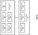
- FIG. 2is a block diagram illustrating an example of an autonomous vehicle according to one embodiment.
- FIGS. 3A-3Bare block diagrams illustrating an example of a perception and planning system used with an autonomous vehicle according to one embodiment.
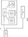
- FIG. 4is a block diagram illustrating an example of a data processing system according to one embodiment.
- FIG. 5Ais a block diagram illustrating an example of a data processing system according to one embodiment.
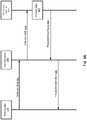
- FIG. 5Bis a processing diagram illustrating a process of processing data between a host system and an expansion device according to one embodiment.
- FIG. 6is a block diagram illustrating an example of a data processing system according to one embodiment.
- FIGS. 7A and 7Bare block diagrams illustrating an example of a data processing system according to one embodiment.
- FIG. 8is a processing diagram illustrating a process of processing data between a host system and an expansion device according to one embodiment.
- a compute and storage expansion devicefor example, as a part of autonomous driving system, is utilized to enable a flexible host and client configuration to function as a client device, a host device, or both.
- Such an expansion devicecan work as a client device supplement to a main system or work as a full system containing both host and client devices, and is able to perform host to host communication with another full system.
- Such changesonly require firmware update but works on the same hardware implementation, i.e., without having to modify the hardware.
- All computation and storage modulesare coupled to a switch device via various input and output ( 10 ) bus protocols, such as PCIe and Ethernet protocols.
- Such a switch deviceenables communications among the computation and storage modules, as well as communications with a main or host system external to the expansion device.
- a data processing systemwhich may be utilized in an autonomous driving vehicle (ADV), includes a host system and one or more expansion devices coupled to the host system over a bus.
- the host systemmay be a part of a perception and planning system of an ADV.
- the host systemmay include one or more processors and a memory storing instructions, which when executed, cause the processors to perform autonomous driving operations to drive the ADV.
- Each expansion deviceincludes a switch device and one or more processing modules coupled to the switch device.
- Each processing modulecan be configured to perform at least one of the autonomous driving operations offloaded from the host system.
- At least one of the processing modulescan be configured as a client node to perform an action in response to an instruction received from the host system. Alternatively, it can be configured as a host node to distribute a task to another client node within the expansion device.
- the firmware of the expansion deviceis configured to scan and detect that the host system is coupled to the expansion device. In response to such detection, the firmware configures at least one of the processing modules of the expansion device as a client device to the host system. In such a situation, the host system can offload at least one of the autonomous driving operations (e.g., perception, prediction, decision, and/or planning processes) to the processing modules that have been configured as a client device.
- the autonomous driving operationse.g., perception, prediction, decision, and/or planning processes
- the firmwareresponds to a bus enumeration process initiated from the host system (e.g., by assigning an appropriate bus number and a device number, in the PCI configuration registers), such that the processing module appears a client device to the host system.
- the firmware of the expansion deviceselects and configures at least one of the processing modules as a host node or host processing module, while the remaining processing modules are configured as a client device to the host node.
- the expansion deviceoperates as a standalone system or a peer system with respect to the external host system.
- a first portion of the processing modulesis configured as client nodes to the host system external to the expansion device.
- a second portion of the processing modulesis configured as a separate system, which includes at least one host node and one or more client nodes.
- the external host system(together with the first portion of processing modules of the expansion device) and the second portion of processing modules of the expansion device operate as peer data processing systems.
- a processing module of the expansioncan be configured as a client node to the external host system, while it is also configured a host node with respect to another processing module within the expansion device.
- the processing moduleperforms a data processing operation on the data (e.g., compression, encryption, data mining) as a client node to the host system.
- the processing modulenow operating as a host node, distributes the processed data to another processing module (e.g., a storage module) of the expansion device to perform another action on the data (e.g., storing the data in a storage device of the expansion device), either via routing via the switch device using a bus protocol or via a peer to peer transaction (e.g., direct memory access or DMA transaction).
- another processing modulee.g., a storage module
- the processing modulee.g., a storage module of the expansion device to perform another action on the data (e.g., storing the data in a storage device of the expansion device), either via routing via the switch device using a bus protocol or via a peer to peer transaction (e.g., direct memory access or DMA transaction).
- another processing modulee.g., a storage module of the expansion device to perform another action on the data (e.g., storing the data in a storage device of the expansion device), either via routing via the switch device using a bus protocol or via a
- an expansion devicewhich can be used to offload data processing operations from an external host system, includes a host interface capable of being coupled to an external host system, a switch device, and one or more processing modules coupled to the switch device.
- the host systemmay be a perception and planning system to autonomously drive an ADV.
- the host systemmay include one or more host processors and a memory storing instructions, which when executed by the host processors, cause the processors to perform autonomous driving operations.
- At least one of the processing modulescan be configured as a client device to perform at least one of the autonomous driving operations offloaded from the host system.
- At least one of the processing modulescan be configured as a host device to distribute tasks to other processing modules configured as client devices.
- the expansion devicemay further include the features or components described above.
- FIG. 1is a block diagram illustrating an autonomous vehicle network configuration according to one embodiment of the disclosure.
- network configuration 100includes autonomous vehicle 101 that may be communicatively coupled to one or more servers 103 - 104 over a network 102 .
- network 102may be any type of networks such as a local area network (LAN), a wide area network (WAN) such as the Internet, a cellular network, a satellite network, or a combination thereof, wired or wireless.
- LANlocal area network
- WANwide area network
- Server(s) 103 - 104may be any kind of servers or a cluster of servers, such as Web or cloud servers, application servers, backend servers, or a combination thereof.
- Servers 103 - 104may be data analytics servers, content servers, traffic information servers, map and point of interest (MPOI) servers, or location servers, etc.
- MPOImap and point of interest
- An autonomous vehiclerefers to a vehicle that can be configured to in an autonomous mode in which the vehicle navigates through an environment with little or no input from a driver.
- Such an autonomous vehiclecan include a sensor system having one or more sensors that are configured to detect information about the environment in which the vehicle operates. The vehicle and its associated controller(s) use the detected information to navigate through the environment.
- Autonomous vehicle 101can operate in a manual mode, a full autonomous mode, or a partial autonomous mode.
- autonomous vehicle 101includes, but is not limited to, perception and planning system 110 , vehicle control system 111 , wireless communication system 112 , user interface system 113 , infotainment system 114 , and sensor system 115 .
- Autonomous vehicle 101may further include certain common components included in ordinary vehicles, such as, an engine, wheels, steering wheel, transmission, etc., which may be controlled by vehicle control system 111 and/or perception and planning system 110 using a variety of communication signals and/or commands, such as, for example, acceleration signals or commands, deceleration signals or commands, steering signals or commands, braking signals or commands, etc.
- Components 110 - 115may be communicatively coupled to each other via an interconnect, a bus, a network, or a combination thereof.
- components 110 - 115may be communicatively coupled to each other via a controller area network (CAN) bus.
- CANcontroller area network
- a CAN busis a vehicle bus standard designed to allow microcontrollers and devices to communicate with each other in applications without a host computer. It is a message-based protocol, designed originally for multiplex electrical wiring within automobiles, but is also used in many other contexts.
- sensor system 115includes, but it is not limited to, one or more cameras 211 , global positioning system (GPS) unit 212 , inertial measurement unit (IMU) 213 , radar unit 214 , and a light detection and range (LIDAR) unit 215 .
- GPS system 212may include a transceiver operable to provide information regarding the position of the autonomous vehicle.
- IMU unit 213may sense position and orientation changes of the autonomous vehicle based on inertial acceleration.
- Radar unit 214may represent a system that utilizes radio signals to sense objects within the local environment of the autonomous vehicle. In some embodiments, in addition to sensing objects, radar unit 214 may additionally sense the speed and/or heading of the objects.
- LIDAR unit 215may sense objects in the environment in which the autonomous vehicle is located using lasers.
- LIDAR unit 215could include one or more laser sources, a laser scanner, and one or more detectors, among other system components.
- Cameras 211may include one or more devices to capture images of the environment surrounding the autonomous vehicle. Cameras 211 may be still cameras and/or video cameras. A camera may be mechanically movable, for example, by mounting the camera on a rotating and/or tilting a platform.
- Sensor system 115may further include other sensors, such as, a sonar sensor, an infrared sensor, a steering sensor, a throttle sensor, a braking sensor, and an audio sensor (e.g., microphone).
- An audio sensormay be configured to capture sound from the environment surrounding the autonomous vehicle.
- a steering sensormay be configured to sense the steering angle of a steering wheel, wheels of the vehicle, or a combination thereof.
- a throttle sensor and a braking sensorsense the throttle position and braking position of the vehicle, respectively. In some situations, a throttle sensor and a braking sensor may be integrated as an integrated throttle/braking sensor.
- vehicle control system 111includes, but is not limited to, steering unit 201 , throttle unit 202 (also referred to as an acceleration unit), and braking unit 203 .
- Steering unit 201is to adjust the direction or heading of the vehicle.
- Throttle unit 202is to control the speed of the motor or engine that in turn control the speed and acceleration of the vehicle.
- Braking unit 203is to decelerate the vehicle by providing friction to slow the wheels or tires of the vehicle. Note that the components as shown in FIG. 2 may be implemented in hardware, software, or a combination thereof.
- wireless communication system 112is to allow communication between autonomous vehicle 101 and external systems, such as devices, sensors, other vehicles, etc.
- wireless communication system 112can wirelessly communicate with one or more devices directly or via a communication network, such as servers 103 - 104 over network 102 .
- Wireless communication system 112can use any cellular communication network or a wireless local area network (WLAN), e.g., using WiFi to communicate with another component or system.
- Wireless communication system 112could communicate directly with a device (e.g., a mobile device of a passenger, a display device, a speaker within vehicle 101 ), for example, using an infrared link, Bluetooth, etc.
- User interface system 113may be part of peripheral devices implemented within vehicle 101 including, for example, a keyboard, a touch screen display device, a microphone, and a speaker, etc.
- Perception and planning system 110includes the necessary hardware (e.g., processor(s), memory, storage) and software (e.g., operating system, planning and routing programs) to receive information from sensor system 115 , control system 111 , wireless communication system 112 , and/or user interface system 113 , process the received information, plan a route or path from a starting point to a destination point, and then drive vehicle 101 based on the planning and control information.
- Perception and planning system 110may be integrated with vehicle control system 111 .
- Perception and planning system 110obtains the trip related data.
- perception and planning system 110may obtain location and route information from an MPOI server, which may be a part of servers 103 - 104 .
- the location serverprovides location services and the MPOI server provides map services and the POIs of certain locations.
- such location and MPOI informationmay be cached locally in a persistent storage device of perception and planning system 110 .
- perception and planning system 110may also obtain real-time traffic information from a traffic information system or server (TIS).
- TIStraffic information system
- servers 103 - 104may be operated by a third party entity.
- the functionalities of servers 103 - 104may be integrated with perception and planning system 110 .
- perception and planning system 110can plan an optimal route and drive vehicle 101 , for example, via control system 111 , according to the planned route to reach the specified destination safely and efficiently.
- Server 103may be a data analytics system to perform data analytics services for a variety of clients.
- data analytics system 103includes data collector 121 and machine learning engine 122 .
- Data collector 121collects driving statistics 123 from a variety of vehicles, either autonomous vehicles or regular vehicles driven by human drivers.
- Driving statistics 123include information indicating the driving commands (e.g., throttle, brake, steering commands) issued and responses of the vehicles (e.g., speeds, accelerations, decelerations, directions) captured by sensors of the vehicles at different points in time.
- Driving statistics 123may further include information describing the driving environments at different points in time, such as, for example, routes (including starting and destination locations), MPOIs, road conditions, weather conditions, etc.
- machine learning engine 122Based on driving statistics 123 , machine learning engine 122 generates or trains a set of rules, algorithms, and/or predictive models 124 for a variety of purposes.
- algorithms 124may include perception and planning algorithms to drive an ADV.
- Algorithms 124can then be uploaded on ADVs to be utilized during autonomous driving in real-time.
- FIGS. 3A and 3Bare block diagrams illustrating an example of a perception and planning system used with an autonomous vehicle according to one embodiment.
- System 300may be implemented as a part of autonomous vehicle 101 of FIG. 1 including, but is not limited to, perception and planning system 110 , control system 111 , and sensor system 115 .
- perception and planning system 110includes, but is not limited to, localization module 301 , perception module 302 , prediction module 303 , decision module 304 , planning module 305 , control module 306 , and routing module 307 .
- modules 301 - 307may be implemented in software, hardware, or a combination thereof. For example, these modules may be installed in persistent storage device 352 , loaded into memory 351 , and executed by one or more processors (not shown). Note that some or all of these modules may be communicatively coupled to or integrated with some or all modules of vehicle control system 111 of FIG. 2 . Some of modules 301 - 307 may be integrated together as an integrated module. For example, prediction module 303 , decision module 304 , planning module 305 , and/or control module 306 may be integrated into fewer modules or single module.
- Localization module 301determines a current location of autonomous vehicle 300 (e.g., leveraging GPS unit 212 ) and manages any data related to a trip or route of a user.
- Localization module 301(also referred to as a map and route module) manages any data related to a trip or route of a user.
- a usermay log in and specify a starting location and a destination of a trip, for example, via a user interface.
- Localization module 301communicates with other components of autonomous vehicle 300 , such as map and route information 311 , to obtain the trip related data.
- localization module 301may obtain location and route information from a location server and a map and POI (MPOI) server.
- MPOImap and POI
- a location serverprovides location services and an MPOI server provides map services and the POIs of certain locations, which may be cached as part of map and route information 311 .
- MPOI serverprovides map services and the POIs of certain locations, which may be cached as part of map and route information 311 .
- localization module 301may also obtain real-time traffic information from a traffic information system or server.
- a perception of the surrounding environmentis determined by perception module 302 .
- the perception informationmay represent what an ordinary driver would perceive surrounding a vehicle in which the driver is driving.
- the perceptioncan include the lane configuration, traffic light signals, a relative position of another vehicle, a pedestrian, a building, crosswalk, or other traffic related signs (e.g., stop signs, yield signs), etc., for example, in a form of an object.
- the lane configurationincludes information describing a lane or lanes, such as, for example, a shape of the lane (e.g., straight or curvature), a width of the lane, how many lanes in a road, one-way or two-way lane, merging or splitting lanes, exiting lane, etc.
- a shape of the lanee.g., straight or curvature
- a width of the lanehow many lanes in a road, one-way or two-way lane, merging or splitting lanes, exiting lane, etc.
- Perception module 302may include a computer vision system or functionalities of a computer vision system to process and analyze images captured by one or more cameras in order to identify objects and/or features in the environment of autonomous vehicle.
- the objectscan include traffic signals, road way boundaries, other vehicles, pedestrians, and/or obstacles, etc.
- the computer vision systemmay use an object recognition algorithm, video tracking, and other computer vision techniques.
- the computer vision systemcan map an environment, track objects, and estimate the speed of objects, etc.
- Perception module 302can also detect objects based on other sensors data provided by other sensors such as a radar and/or LIDAR.
- prediction module 303predicts what the object will behave under the circumstances. The prediction is performed based on the perception data perceiving the driving environment at the point in time in view of a set of map/rout information 311 and traffic rules 312 . For example, if the object is a vehicle at an opposing direction and the current driving environment includes an intersection, prediction module 303 will predict whether the vehicle will likely move straight forward or make a turn. If the perception data indicates that the intersection has no traffic light, prediction module 303 may predict that the vehicle may have to fully stop prior to enter the intersection. If the perception data indicates that the vehicle is currently at a left-turn only lane or a right-turn only lane, prediction module 303 may predict that the vehicle will more likely make a left turn or right turn respectively.
- decision module 304makes a decision regarding how to handle the object. For example, for a particular object (e.g., another vehicle in a crossing route) as well as its metadata describing the object (e.g., a speed, direction, turning angle), decision module 304 decides how to encounter the object (e.g., overtake, yield, stop, pass). Decision module 304 may make such decisions according to a set of rules such as traffic rules or driving rules 312 , which may be stored in persistent storage device 352 .
- rulessuch as traffic rules or driving rules 312
- Routing module 307is configured to provide one or more routes or paths from a starting point to a destination point. For a given trip from a start location to a destination location, for example, received from a user, routing module 307 obtains route and map information 311 and determines all possible routes or paths from the starting location to reach the destination location. Routing module 307 may generate a reference line in a form of a topographic map for each of the routes it determines from the starting location to reach the destination location. A reference line refers to an ideal route or path without any interference from others such as other vehicles, obstacles, or traffic condition. That is, if there is no other vehicle, pedestrians, or obstacles on the road, an ADV should exactly or closely follows the reference line.
- the topographic mapsare then provided to decision module 304 and/or planning module 305 .
- Decision module 304 and/or planning module 305examine all of the possible routes to select and modify one of the most optimal routes in view of other data provided by other modules such as traffic conditions from localization module 301 , driving environment perceived by perception module 302 , and traffic condition predicted by prediction module 303 .
- the actual path or route for controlling the ADVmay be close to or different from the reference line provided by routing module 307 dependent upon the specific driving environment at the point in time.
- planning module 305plans a path or route for the autonomous vehicle, as well as driving parameters (e.g., distance, speed, and/or turning angle), using a reference line provided by routing module 307 as a basis. That is, for a given object, decision module 304 decides what to do with the object, while planning module 305 determines how to do it. For example, for a given object, decision module 304 may decide to pass the object, while planning module 305 may determine whether to pass on the left side or right side of the object. Planning and control data is generated by planning module 305 including information describing how vehicle 300 would move in a next moving cycle (e.g., next route/path segment). For example, the planning and control data may instruct vehicle 300 to move 10 meters at a speed of 30 mile per hour (mph), then change to a right lane at the speed of 25 mph.
- driving parameterse.g., distance, speed, and/or turning angle
- control module 306controls and drives the autonomous vehicle, by sending proper commands or signals to vehicle control system 111 , according to a route or path defined by the planning and control data.
- the planning and control datainclude sufficient information to drive the vehicle from a first point to a second point of a route or path using appropriate vehicle settings or driving parameters (e.g., throttle, braking, steering commands) at different points in time along the path or route.
- the planning phaseis performed in a number of planning cycles, also referred to as driving cycles, such as, for example, in every time interval of 100 milliseconds (ms).
- driving cyclessuch as, for example, in every time interval of 100 milliseconds (ms).
- one or more control commandswill be issued based on the planning and control data. That is, for every 100 ms, planning module 305 plans a next route segment or path segment, for example, including a target position and the time required for the ADV to reach the target position.
- planning module 305may further specify the specific speed, direction, and/or steering angle, etc.
- planning module 305plans a route segment or path segment for the next predetermined period of time such as 5 seconds.
- planning module 305plans a target position for the current cycle (e.g., next 5 seconds) based on a target position planned in a previous cycle.
- Control module 306then generates one or more control commands (e.g., throttle, brake, steering control commands) based on the planning and control data of the current cycle.
- control commandse.g., throttle, brake, steering control commands
- Decision module 304 and planning module 305may be integrated as an integrated module.
- Decision module 304 /planning module 305may include a navigation system or functionalities of a navigation system to determine a driving path for the autonomous vehicle.
- the navigation systemmay determine a series of speeds and directional headings to affect movement of the autonomous vehicle along a path that substantially avoids perceived obstacles while generally advancing the autonomous vehicle along a roadway-based path leading to an ultimate destination.
- the destinationmay be set according to user inputs via user interface system 113 .
- the navigation systemmay update the driving path dynamically while the autonomous vehicle is in operation.
- the navigation systemcan incorporate data from a GPS system and one or more maps so as to determine the driving path for the autonomous vehicle.
- FIG. 4is a block diagram illustrating an example of architecture of a data processing system according to one embodiment.
- System 400may represent perception and planning system 110 of FIG. 1 or system 300 of FIG. 3 .
- system 400includes a host system 401 coupled to one or more expansion systems or devices 402 - 403 .
- the architecture of expansion systems 402 - 403may be identical or similar.
- Host system 401can be any kind of computers such as a client or a server.
- Host system 401includes one or more processors and a memory storing executable instructions, which when executed by the processors, cause the processors to perform at least a portion of the autonomous driving operations as described above with respect to FIGS. 1-3 .
- host system 401may host the components 301 - 307 executed therein.
- One or more expansion systems 402 - 403may be coupled to host system 401 , for example, via a bus such as a peripheral component interface express (PCIe) bus.
- PCIeperipheral component interface express
- each of the expansion systems (also referred to as expansion devices) 402 - 403can be configured to offload at least a portion of the autonomous driving operations from modules 301 - 307 from host system 401 .
- expansion device 402will be described in details; however, the same description can also be applied to other expansion devices such as expansion device 403 .
- expansion device 402includes a switch device 410 and one or more processing modules 411 - 413 coupled to switch device 410 .
- Each of the processing modules 411 - 413may include a processor, a memory, and/or a local storage, which can execute one or more instructions to perform a set of dedicated operations such as data processing intense operations on behalf of host system 401 or another host node within expansion device 402 .
- a processing modulecan also be a storage module having a storage device to store data.
- a processormay be a central processing unit (CPU), a general processing unit (GPU), a field programmable gate array (FPGA), a system on chip (SoC), a digital signal processor (DSP), a microcontroller (e.g., a storage controller), or an application specific integrated circuit (ASIC).
- These modules or processorscan be implemented in a variety of form factors such as COM Express (COMe), PCIe, or mobile PCIe Module (MXM) form factors. These form factors allow users to stack together a variety of products from customized design or from commercial off-the shelf manufacturers to build expansion devices.
- a storage device of a storage modulecan be a solid state device (SSD) in U.2 or M.2 form factors, multimedia card (MMC) and secure digital (SD) cards, universal serial bus (USB) flash drives.
- SSDsolid state device
- the data processing operations that can be offloaded or acceleratedmay include, as described above, a perception process of perceiving a driving environment of an ADV, a prediction process of predicting a movement of an obstacle perceived (e.g., image processing, LIDAR point cloud processing), a decision process what the ADV should do, and a planning process of planning a trajectory to drive the ADV accordingly.
- Any of these operationscan be distributed to one or more of the processing modules 411 - 413 for execution, in parallel, in series, or in a pipeline manner.
- a perception processmay be performed by a first processing module and the result may be routed to a second processing module that is configured to perform a prediction process, a decision process, and/or a planning process as shown in FIG. 3B .
- at least some of the processing modules 411 - 413may be configured as a client node, a host node, or both, dependent upon the specific needs.
- FIG. 5Ais a block diagram illustrating an expansion device configured in a client device according to one embodiment.
- all processing modules 411 - 415are configured as client devices to host system 401 .
- Such a configurationcan be performed during the initialization expansion device 402 .
- firmware of expansion device 402responds to the bus enumeration initiated from host system 401 .
- the firmwarethen configures the processing modules 411 - 415 are client devices or end point nodes with respect to host system 401 as a root node or root device, such that they can respond to the subsequent memory and IO cycles initiated from host system 401 .
- host system 401can distribute the tasks, especially the computation intense tasks, to processing modules 411 - 415 .
- the host system 401can distribute the tasks by specifying a bus number and a device number of a specific client processing module of the expansion device 402 .
- switch device 410routes the tasks to the target processing module.
- the results of the operationscan then be transmitted back to host system 401 .
- Host system 401can also utilizes storage devices maintained by expansion device 402 , for example, via storage modules 414 - 415 .
- FIG. 5Bis a flow diagram illustrating transactions between a host system and an expansion device as a client device according to one embodiment.
- processing module 411has been configured as a client device to host system 401 .
- host system 401sends a request for processing data to switch device 410 .
- the requestmay include data to be processed, an instruction regarding how to process, and a target device identifier (ID) (in this example, bus/device numbers of client processing module 411 ).
- IDtarget device identifier
- switch device 410routes the request to the target, processing module 411 via operation 502 .
- Processing module 411then performs the necessary operations on the data in response to the instruction at block 503 , generating a result of the operations.
- the resultmay simply be a return status or the processed data (e.g., compressed data, encrypted data).
- processing module 411transmits the result back to switch device 410 , which in turn routes the same result back to host system 401 via operation 505 .
- expansion device 402may also be configured and boot up as a standalone system.
- expansion device 402may boot up as a standalone system in response to determining that host system 401 is not coupled to expansion device 402 .
- at least one of the processing modules 411 - 415is configured as a host device (e.g., root complex), while the remaining processing modules are configured as client devices (e.g., end points).
- client devicese.g., end points
- variety of operations concerning the expansion devicecan be performed, such as, for example, internal testing operations.
- multiple processing modulesmay be configured as host nodes, each representing a separate standalone system within the expansion device 402 .
- expansion device 402can be configured in a hybrid mode, in which a first portion of the processing modules 411 - 415 can be configured as client devices to host system 401 , while a second portion of the processing modules 411 - 415 may be configured as a standalone system as a peer system with respect to host system 401 , as shown in FIG. 6 .
- processing module 413has been configured as a host node, while processing modules 411 - 412 and 414 - 415 are configured as client devices.
- processing modules 411 and 414are client devices to host system 401 , forming system 601 .
- Processing modules 412 and 415are client devices to processing module 413 as a host node, forming system 602 .
- Systems 601 and 602are peer systems that operate in parallel or independently.
- Host node 413may communicate with external host system 401 via a host-to-host connection.
- a processing modulecan be configured as a host node and a client node.
- a processing modulecan be configured as a client device to an external host system, and the same processing module is also configured as a host node to another processing module that has been configured as a client node.
- FIG. 7Ais a block diagram illustrating an example of system configuration of a data processing system according to one embodiment.
- processing module 412has been configured as both a client node and a host node.
- processing module 412is configured as a client node to external host system 401 .
- processing module 412is also configured as a host node with respect to other client nodes within expansion device 402 .
- processing module 412may receive instructions and data from host system 401 and perform a data processing operation on the data in response to the instructions.
- processing module 412may distribute a task to its client node such as processing module 415 .
- the data received from host system 401may be data of a data log captured and recorded during autonomous driving, which captures the driving statistics of an ADV (e.g., commands issued and responses of the vehicle at different points in time).
- the datais processed by processing module 412 (as a client node to host system 401 ) such as data compression and/or encryption.
- the processed datais then transmitted from processing module 412 (as a host node) to processing module 415 as a storage module (as a client node) to be stored in a storage device.
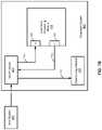
- FIG. 7Bshows an example of a specific configuration of the system as shown in FIG. 7A .
- processing module 412includes an endpoint port 701 and a root port 702 coupled to switch device 410 .
- host system 401sends data to its client device in expansion device 402 , i.e., processing module 412 .
- Processing module 412receives the data through path 711 from its endpoint port 701 .
- Processing module 412can then process the data such as data compression or data encryption.
- Processing module 412transmits the processed data to its client node, i.e., processing node 415 , via path 712 from its root port 702 and the corresponding uplink to switch device 410 .
- Switch device 410then routes the processed data to processing module 415 via path 713 .
- processing module 412may transmit the processed data to processing module 415 via a peer-to-peer connection, such as, a peer-to-peer DMA transaction.
- FIG. 8is a flow diagram illustrating a process of routing data between a host system and an expansion device according to one embodiment.
- host system 401transmits instructions and data to switch device 410 of expansion device 402 .
- Switch device 410reroutes the data via operation 802 to processing module 412 , which is configured as a host/client node.
- processing module 412performs a data processing operation on the data such as data compression or encryption.
- processing module 412transmits the processed data to switch device 410 , which in turn reroutes the processed data to processing module 415 via operation 805 , where processing module 415 has been configured as a client device to processing module 412 .
- processing module 415performs another data processing operation on the data (e.g., storing the data in a persistent storage device).
- components as shown and described abovemay be implemented in software, hardware, or a combination thereof.
- such componentscan be implemented as software installed and stored in a persistent storage device, which can be loaded and executed in a memory by a processor (not shown) to carry out the processes or operations described throughout this application.
- such componentscan be implemented as executable code programmed or embedded into dedicated hardware such as an integrated circuit (e.g., an application specific IC or ASIC), a digital signal processor (DSP), or a field programmable gate array (FPGA), which can be accessed via a corresponding driver and/or operating system from an application.
- an integrated circuite.g., an application specific IC or ASIC
- DSPdigital signal processor
- FPGAfield programmable gate array
- such componentscan be implemented as specific hardware logic in a processor or processor core as part of an instruction set accessible by a software component via one or more specific instructions.
- Embodiments of the disclosurealso relate to an apparatus for performing the operations herein.
- a computer programis stored in a non-transitory computer readable medium.
- a machine-readable mediumincludes any mechanism for storing information in a form readable by a machine (e.g., a computer).
- a machine-readable (e.g., computer-readable) mediumincludes a machine (e.g., a computer) readable storage medium (e.g., read only memory (“ROM”), random access memory (“RAM”), magnetic disk storage media, optical storage media, flash memory devices).
- processing logicthat comprises hardware (e.g. circuitry, dedicated logic, etc.), software (e.g., embodied on a non-transitory computer readable medium), or a combination of both.
- processing logiccomprises hardware (e.g. circuitry, dedicated logic, etc.), software (e.g., embodied on a non-transitory computer readable medium), or a combination of both.
- Embodiments of the present disclosureare not described with reference to any particular programming language. It will be appreciated that a variety of programming languages may be used to implement the teachings of embodiments of the disclosure as described herein.
Landscapes
- Engineering & Computer Science (AREA)
- Physics & Mathematics (AREA)
- Automation & Control Theory (AREA)
- Remote Sensing (AREA)
- Radar, Positioning & Navigation (AREA)
- Aviation & Aerospace Engineering (AREA)
- General Physics & Mathematics (AREA)
- Electromagnetism (AREA)
- Mechanical Engineering (AREA)
- Optics & Photonics (AREA)
- Signal Processing (AREA)
- Evolutionary Computation (AREA)
- Medical Informatics (AREA)
- Game Theory and Decision Science (AREA)
- Business, Economics & Management (AREA)
- Health & Medical Sciences (AREA)
- Artificial Intelligence (AREA)
- Computer Networks & Wireless Communication (AREA)
- Human Computer Interaction (AREA)
- Transportation (AREA)
- Computer Vision & Pattern Recognition (AREA)
- Multimedia (AREA)
- Traffic Control Systems (AREA)
- Control Of Driving Devices And Active Controlling Of Vehicle (AREA)
- Advance Control (AREA)
- Multi Processors (AREA)
Abstract
Description
Claims (20)
Priority Applications (3)
| Application Number | Priority Date | Filing Date | Title |
|---|---|---|---|
| US16/237,192US11353870B2 (en) | 2018-12-31 | 2018-12-31 | Autonomous driving computing and storage expansion device with flexible host and client configuration |
| CN201910859019.4ACN111399495B (en) | 2018-12-31 | 2019-09-11 | Autopilot computing and storage expansion device with flexible host and client configuration |
| JP2019190580AJP6928633B2 (en) | 2018-12-31 | 2019-10-17 | Self-driving computing and storage expansion devices with flexible host and client configurations |
Applications Claiming Priority (1)
| Application Number | Priority Date | Filing Date | Title |
|---|---|---|---|
| US16/237,192US11353870B2 (en) | 2018-12-31 | 2018-12-31 | Autonomous driving computing and storage expansion device with flexible host and client configuration |
Publications (2)
| Publication Number | Publication Date |
|---|---|
| US20200209856A1 US20200209856A1 (en) | 2020-07-02 |
| US11353870B2true US11353870B2 (en) | 2022-06-07 |
Family
ID=71121999
Family Applications (1)
| Application Number | Title | Priority Date | Filing Date |
|---|---|---|---|
| US16/237,192Active2039-07-31US11353870B2 (en) | 2018-12-31 | 2018-12-31 | Autonomous driving computing and storage expansion device with flexible host and client configuration |
Country Status (3)
| Country | Link |
|---|---|
| US (1) | US11353870B2 (en) |
| JP (1) | JP6928633B2 (en) |
| CN (1) | CN111399495B (en) |
Cited By (1)
| Publication number | Priority date | Publication date | Assignee | Title |
|---|---|---|---|---|
| US20220392013A1 (en)* | 2020-02-10 | 2022-12-08 | Zoox, Inc. | Vision architecture |
Families Citing this family (5)
| Publication number | Priority date | Publication date | Assignee | Title |
|---|---|---|---|---|
| US11520331B2 (en)* | 2018-12-28 | 2022-12-06 | Intel Corporation | Methods and apparatus to update autonomous vehicle perspectives |
| US11353870B2 (en)* | 2018-12-31 | 2022-06-07 | Baidu Usa Llc | Autonomous driving computing and storage expansion device with flexible host and client configuration |
| CN114327645A (en)* | 2020-10-12 | 2022-04-12 | 宝能汽车集团有限公司 | Capacity expansion method and device for vehicle computing capacity, vehicle and storage medium |
| KR102804020B1 (en)* | 2022-09-29 | 2025-05-12 | 윤재순 | top control system for supporting hydrogen engine optimizing control |
| TWI852607B (en)* | 2023-06-06 | 2024-08-11 | 緯創資通股份有限公司 | Live migration method and system for achieving seamless live migration |
Citations (89)
| Publication number | Priority date | Publication date | Assignee | Title |
|---|---|---|---|---|
| JP2007316859A (en) | 2006-05-24 | 2007-12-06 | Sony Computer Entertainment Inc | Multigraphics processor system, graphics processor and data transfer method |
| US20140032034A1 (en)* | 2012-05-09 | 2014-01-30 | Singularity University | Transportation using network of unmanned aerial vehicles |
| US20140070767A1 (en)* | 2008-07-01 | 2014-03-13 | Donald Morris | Charging stations for electric vehicles |
| US20140082238A1 (en)* | 2012-09-14 | 2014-03-20 | Nvidia Corporation | Method and system for implementing a control register access bus |
| US8849494B1 (en)* | 2013-03-15 | 2014-09-30 | Google Inc. | Data selection by an autonomous vehicle for trajectory modification |
| US20150142211A1 (en)* | 2012-05-04 | 2015-05-21 | Aeryon Labs Inc. | System and method for controlling unmanned aerial vehicles |
| US20160012465A1 (en)* | 2014-02-08 | 2016-01-14 | Jeffrey A. Sharp | System and method for distributing, receiving, and using funds or credits and apparatus thereof |
| US20160142211A1 (en)* | 2014-11-14 | 2016-05-19 | Motorola Solutions, Inc | Method and apparatus for deriving a certificate for a primary device |
| US20160200421A1 (en)* | 2014-05-01 | 2016-07-14 | Alakai Technologies Corporation | Clean fuel electric multirotor aircraft for personal air transportation and manned or unmanned operation |
| US9434267B2 (en)* | 2014-08-08 | 2016-09-06 | SZ DJI Technology Co., Ltd | Systems and methods for UAV battery power backup |
| US9494439B1 (en)* | 2015-05-13 | 2016-11-15 | Uber Technologies, Inc. | Autonomous vehicle operated with guide assistance of human driven vehicles |
| US9632502B1 (en)* | 2015-11-04 | 2017-04-25 | Zoox, Inc. | Machine-learning systems and techniques to optimize teleoperation and/or planner decisions |
| US9714012B1 (en)* | 2016-01-22 | 2017-07-25 | International Business Machines Corporation | Power source element replacement during vehicle operation |
| US9751476B2 (en)* | 2009-06-09 | 2017-09-05 | Harman Becker Automotive Systems Gmbh | Vehicle computing module |
| US9764703B2 (en)* | 2016-01-22 | 2017-09-19 | International Business Machines Corporation | Power source element detection and monitoring |
| US20170295458A1 (en)* | 2016-04-11 | 2017-10-12 | Qualcomm Incorporated | Access point mobility indication |
| US20170323572A1 (en)* | 2014-09-30 | 2017-11-09 | Elwha LLC, a limited liability company of the State of Delaware | System and method for management of airspace for unmanned aircraft |
| US9815633B1 (en)* | 2016-09-19 | 2017-11-14 | Amazon Technologies, Inc. | Automated fulfillment of unmanned aerial vehicles |
| US20170344023A1 (en)* | 2016-05-31 | 2017-11-30 | Peloton Technology, Inc. | Platoon controller state machine |
| US9950814B1 (en)* | 2017-03-16 | 2018-04-24 | Amazon Technologies, Inc. | Ground-based mobile maintenance facilities for unmanned aerial vehicles |
| US10023309B2 (en)* | 2016-04-15 | 2018-07-17 | James Brown | Remote controlled aircraft |
| US20180238698A1 (en)* | 2017-02-22 | 2018-08-23 | Robert D. Pedersen | Systems And Methods Using Artificial Intelligence For Routing Electric Vehicles |
| US20180285734A1 (en)* | 2017-04-01 | 2018-10-04 | Intel Corporation | Neural network calibration mechanism |
| US20180293102A1 (en)* | 2017-04-09 | 2018-10-11 | Intel Corporation | Efficient thread group scheduling |
| US20180293491A1 (en)* | 2017-04-09 | 2018-10-11 | Intel Corporation | Fast data operations and finite state machine for machine learning |
| US20180293490A1 (en)* | 2017-04-09 | 2018-10-11 | Intel Corporation | Neural network scheduling mechanism |
| US20180293691A1 (en)* | 2017-04-09 | 2018-10-11 | Intel Corporation | Machine learning sparse computation mechanism |
| US10108850B1 (en)* | 2017-04-24 | 2018-10-23 | Intel Corporation | Recognition, reidentification and security enhancements using autonomous machines |
| US20180308206A1 (en)* | 2017-04-24 | 2018-10-25 | Prasoonkumar Surti | Compute optimization mechanism for deep neural networks |
| US20180308256A1 (en)* | 2017-04-24 | 2018-10-25 | Intel Corporation | Compression mechanism |
| US20180308201A1 (en)* | 2017-04-24 | 2018-10-25 | Abhishek R. Appu | Compute optimization mechanism |
| US20180308203A1 (en)* | 2017-04-24 | 2018-10-25 | Intel Corporation | Efficient sharing and compression expansion of data across processing systems |
| US20180314250A1 (en)* | 2017-04-28 | 2018-11-01 | Intel Corporation | Autonomous machines through cloud, error corrections, and predictions |
| US20180314521A1 (en)* | 2017-04-28 | 2018-11-01 | Intel Corporation | Intelligent thread dispatch and vectorization of atomic operations |
| US20180335777A1 (en)* | 2017-05-18 | 2018-11-22 | Meter Feeder, Inc. | Autonomous Vehicle Parking System |
| CN109062833A (en) | 2017-06-30 | 2018-12-21 | 创义达科技股份有限公司 | Computing system operating method, computing system, vehicle and computer readable medium |
| US10195952B2 (en)* | 2014-11-21 | 2019-02-05 | SZ DJI Technology Co., Ltd. | System and method for managing unmanned aerial vehicles |
| US20190047579A1 (en)* | 2018-03-31 | 2019-02-14 | Intel Corporation | Core tightly coupled lockstep for high functional safety |
| US10332405B2 (en)* | 2013-12-19 | 2019-06-25 | The United States Of America As Represented By The Administrator Of Nasa | Unmanned aircraft systems traffic management |
| US20190205745A1 (en)* | 2017-12-29 | 2019-07-04 | Intel Corporation | Communication optimizations for distributed machine learning |
| US20190217735A1 (en)* | 2017-01-13 | 2019-07-18 | Uber Technologies, Inc. | Charge Control System for Mobile Energy Storage Fleet |
| US10363826B2 (en)* | 2014-08-08 | 2019-07-30 | SZ DJI Technology Co., Ltd. | Systems and methods for UAV battery exchange |
| US10369893B2 (en)* | 2017-08-07 | 2019-08-06 | Cisco Technology, Inc. | Intelligent vehicle control for wireless power transfer (WPT) |
| US10369892B2 (en)* | 2016-02-22 | 2019-08-06 | Ipt Technology Gmbh | Coil unit of a device for inductive transmission of electrical power |
| US10384692B2 (en)* | 2017-03-16 | 2019-08-20 | Amazon Technologies, Inc. | Demand-based distribution of items using intermodal carriers and unmanned aerial vehicles |
| US10421542B2 (en)* | 2017-03-16 | 2019-09-24 | Amazon Technologies, Inc. | Mobile fulfillment centers with intermodal carriers and unmanned aerial vehicles |
| US20190303822A1 (en)* | 2018-03-30 | 2019-10-03 | The Ago Companies LLC | Multi-User Asset Sharing and Risk Assessment System and Method |
| US10453348B2 (en)* | 2015-06-15 | 2019-10-22 | ImageKeeper LLC | Unmanned aerial vehicle management |
| US10452068B2 (en)* | 2016-10-17 | 2019-10-22 | Uber Technologies, Inc. | Neural network system for autonomous vehicle control |
| US20190324600A1 (en)* | 2018-04-24 | 2019-10-24 | Dial House, LLC | Vehicle Systems And Interfaces And Related Methods |
| US20190329877A1 (en)* | 2018-04-27 | 2019-10-31 | X Development Llc | Passively folding propeller blades for drag reduction |
| US10467685B1 (en)* | 2016-10-01 | 2019-11-05 | Stuart Brisson | System and device for rental dispensing of UAVs |
| US10474162B2 (en)* | 2016-07-01 | 2019-11-12 | Uatc, Llc | Autonomous vehicle localization using passive image data |
| US10493863B1 (en)* | 2018-06-14 | 2019-12-03 | Kitty Hawk Corporation | Charge related processing for a personal transportation system with removable battery |
| US10499446B1 (en)* | 2018-08-17 | 2019-12-03 | At&T Intellectual Property I, L.P. | Instantiating a slice of a 5G or other next generation service network in an underserved area |
| US20190366989A1 (en)* | 2018-05-31 | 2019-12-05 | Ford Global Technologies, Llc | Methods and apparatus for automatic calibration of electronic trailer brake gain |
| US10508756B1 (en)* | 2018-06-19 | 2019-12-17 | Super Sod, Llc | Wire guard device |
| US20190381903A1 (en)* | 2019-08-08 | 2019-12-19 | Lg Electronics Inc. | Method of providing vehicle charging service |
| US20190381860A1 (en)* | 2018-12-28 | 2019-12-19 | Intel Corporation | Techniques to optimize vehicular systems for occupant presence and condition |
| US20200012531A1 (en)* | 2017-04-01 | 2020-01-09 | Intel Corporation | Execution unit-shared hybrid technique for accelerated computing on graphics processors |
| US20200009982A1 (en)* | 2019-08-20 | 2020-01-09 | Lg Electronics Inc. | Method for charging battery of autonomous vehicle and apparatus therefor |
| US10532815B1 (en)* | 2018-06-14 | 2020-01-14 | Kitty Hawk Corporation | Two vehicle transportation system |
| US10600322B2 (en)* | 2017-06-21 | 2020-03-24 | International Business Machines Corporation | Management of mobile objects |
| US10614515B1 (en)* | 2016-10-01 | 2020-04-07 | Stuart Brisson | System for rental dispensing of UAVs |
| US10620011B2 (en)* | 2016-11-10 | 2020-04-14 | International Business Machines Corporation | Autonomous vehicle routing |
| US10627825B2 (en)* | 2017-11-22 | 2020-04-21 | Waymo Llc | Using discomfort for speed planning in autonomous vehicles |
| US10640111B1 (en)* | 2016-09-07 | 2020-05-05 | Waymo Llc | Speed planning for autonomous vehicles |
| US10662696B2 (en)* | 2015-05-11 | 2020-05-26 | Uatc, Llc | Detecting objects within a vehicle in connection with a service |
| US10661896B2 (en)* | 2014-10-29 | 2020-05-26 | Yanmar Co., Ltd. | Helicopter |
| US10679312B2 (en)* | 2017-04-25 | 2020-06-09 | Lyft Inc. | Dynamic autonomous vehicle servicing and management |
| US10678240B2 (en)* | 2016-09-08 | 2020-06-09 | Mentor Graphics Corporation | Sensor modification based on an annotated environmental model |
| US10684361B2 (en)* | 2015-12-16 | 2020-06-16 | Uatc, Llc | Predictive sensor array configuration system for an autonomous vehicle |
| US10694331B1 (en)* | 2019-09-24 | 2020-06-23 | International Business Machines Corporation | Mobile device navigation with counterpart device identification |
| US20200201328A1 (en)* | 2018-12-21 | 2020-06-25 | Mtd Products Inc | Outdoor power equipment machine with presence detection |
| US20200211265A1 (en)* | 2018-12-28 | 2020-07-02 | Intel Corporation | Cloud-based realtime raytracing |
| US20200209856A1 (en)* | 2018-12-31 | 2020-07-02 | Baidu Usa Llc | Autonomous driving computing and storage expansion device with flexible host and client configuration |
| US10703480B1 (en)* | 2018-06-14 | 2020-07-07 | Kitty Hawk Corporation | Modular personal transportation system |
| US10710633B2 (en)* | 2017-07-14 | 2020-07-14 | Nio Usa, Inc. | Control of complex parking maneuvers and autonomous fuel replenishment of driverless vehicles |
| US10712160B2 (en)* | 2015-12-10 | 2020-07-14 | Uatc, Llc | Vehicle traction map for autonomous vehicles |
| US10712742B2 (en)* | 2015-12-16 | 2020-07-14 | Uatc, Llc | Predictive sensor array configuration system for an autonomous vehicle |
| US10712750B2 (en)* | 2015-11-04 | 2020-07-14 | Zoox, Inc. | Autonomous vehicle fleet service and system |
| US20200269835A1 (en)* | 2019-02-27 | 2020-08-27 | Honda Motor Co., Ltd. | Vehicle control device, vehicle control method, and storage medium |
| US20200301445A1 (en)* | 2019-03-21 | 2020-09-24 | Wing Aviation Llc | Geo-fiducials for uav navigation |
| US20200317078A1 (en)* | 2019-04-02 | 2020-10-08 | Ming Zhang | Automatic charging system for intelligent driving electric vehicles and charging method thereof |
| US10899473B2 (en)* | 2017-07-17 | 2021-01-26 | Christopher Julian Scherz | Docking station for unmanned aerial vehicles |
| US20210081624A1 (en)* | 2014-11-12 | 2021-03-18 | Joseph E. Kovarik | Method and System for Charging Electric Autonomous Vehicles |
| US10953754B1 (en)* | 2019-09-05 | 2021-03-23 | Beta Air, Llc | Systems and methods for restricting power to a load to prevent engaging circuit protection |
| US10974911B2 (en)* | 2017-12-22 | 2021-04-13 | Wing Aviation Llc | Replenishment station for aerial vehicle with robotic device and conveyor |
| US20210129697A1 (en)* | 2019-10-30 | 2021-05-06 | Lg Electronics Inc. | System, apparatus and method for providing mobile charging service |
Family Cites Families (8)
| Publication number | Priority date | Publication date | Assignee | Title |
|---|---|---|---|---|
| CN101515178B (en)* | 2009-04-08 | 2010-07-21 | 南京航空航天大学 | Master-slave redundant unmanned aircraft autopilot based on CAN bus |
| KR101883475B1 (en)* | 2013-02-28 | 2018-07-31 | 한화지상방산 주식회사 | Mini Integrated-control device |
| CN103780697B (en)* | 2014-01-23 | 2017-07-21 | 广州睿嵌电子技术有限公司 | Vehicle electronics processing unit common platform system and its data communication method |
| CN104820424B (en)* | 2015-05-15 | 2017-12-01 | 山东省计算中心(国家超级计算济南中心) | Electric automobile automated driving system and its control method based on Beidou navigation |
| JP6650242B2 (en)* | 2015-10-16 | 2020-02-19 | 日立オートモティブシステムズ株式会社 | Automatic driving system, automatic driving control method, data ECU and automatic driving ECU |
| KR102395195B1 (en)* | 2016-01-07 | 2022-05-10 | 삼성전자주식회사 | Data storage device and data processing system having same |
| US10635621B2 (en)* | 2016-11-16 | 2020-04-28 | Baidu Usa Llc | Apparatus for controlling and operating an autonomous vehicle |
| CN107908186B (en)* | 2017-11-07 | 2021-07-02 | 驭势科技(北京)有限公司 | Method and system for controlling operation of unmanned vehicle |
- 2018
- 2018-12-31USUS16/237,192patent/US11353870B2/enactiveActive
- 2019
- 2019-09-11CNCN201910859019.4Apatent/CN111399495B/enactiveActive
- 2019-10-17JPJP2019190580Apatent/JP6928633B2/ennot_activeExpired - Fee Related
Patent Citations (89)
| Publication number | Priority date | Publication date | Assignee | Title |
|---|---|---|---|---|
| JP2007316859A (en) | 2006-05-24 | 2007-12-06 | Sony Computer Entertainment Inc | Multigraphics processor system, graphics processor and data transfer method |
| US20140070767A1 (en)* | 2008-07-01 | 2014-03-13 | Donald Morris | Charging stations for electric vehicles |
| US9751476B2 (en)* | 2009-06-09 | 2017-09-05 | Harman Becker Automotive Systems Gmbh | Vehicle computing module |
| US20150142211A1 (en)* | 2012-05-04 | 2015-05-21 | Aeryon Labs Inc. | System and method for controlling unmanned aerial vehicles |
| US20140032034A1 (en)* | 2012-05-09 | 2014-01-30 | Singularity University | Transportation using network of unmanned aerial vehicles |
| US20140082238A1 (en)* | 2012-09-14 | 2014-03-20 | Nvidia Corporation | Method and system for implementing a control register access bus |
| US8849494B1 (en)* | 2013-03-15 | 2014-09-30 | Google Inc. | Data selection by an autonomous vehicle for trajectory modification |
| US10332405B2 (en)* | 2013-12-19 | 2019-06-25 | The United States Of America As Represented By The Administrator Of Nasa | Unmanned aircraft systems traffic management |
| US20160012465A1 (en)* | 2014-02-08 | 2016-01-14 | Jeffrey A. Sharp | System and method for distributing, receiving, and using funds or credits and apparatus thereof |
| US20160200421A1 (en)* | 2014-05-01 | 2016-07-14 | Alakai Technologies Corporation | Clean fuel electric multirotor aircraft for personal air transportation and manned or unmanned operation |
| US9434267B2 (en)* | 2014-08-08 | 2016-09-06 | SZ DJI Technology Co., Ltd | Systems and methods for UAV battery power backup |
| US10363826B2 (en)* | 2014-08-08 | 2019-07-30 | SZ DJI Technology Co., Ltd. | Systems and methods for UAV battery exchange |
| US20170323572A1 (en)* | 2014-09-30 | 2017-11-09 | Elwha LLC, a limited liability company of the State of Delaware | System and method for management of airspace for unmanned aircraft |
| US10661896B2 (en)* | 2014-10-29 | 2020-05-26 | Yanmar Co., Ltd. | Helicopter |
| US20210081624A1 (en)* | 2014-11-12 | 2021-03-18 | Joseph E. Kovarik | Method and System for Charging Electric Autonomous Vehicles |
| US20160142211A1 (en)* | 2014-11-14 | 2016-05-19 | Motorola Solutions, Inc | Method and apparatus for deriving a certificate for a primary device |
| US10195952B2 (en)* | 2014-11-21 | 2019-02-05 | SZ DJI Technology Co., Ltd. | System and method for managing unmanned aerial vehicles |
| US10662696B2 (en)* | 2015-05-11 | 2020-05-26 | Uatc, Llc | Detecting objects within a vehicle in connection with a service |
| US9494439B1 (en)* | 2015-05-13 | 2016-11-15 | Uber Technologies, Inc. | Autonomous vehicle operated with guide assistance of human driven vehicles |
| US10453348B2 (en)* | 2015-06-15 | 2019-10-22 | ImageKeeper LLC | Unmanned aerial vehicle management |
| US9632502B1 (en)* | 2015-11-04 | 2017-04-25 | Zoox, Inc. | Machine-learning systems and techniques to optimize teleoperation and/or planner decisions |
| US10712750B2 (en)* | 2015-11-04 | 2020-07-14 | Zoox, Inc. | Autonomous vehicle fleet service and system |
| US10712160B2 (en)* | 2015-12-10 | 2020-07-14 | Uatc, Llc | Vehicle traction map for autonomous vehicles |
| US10684361B2 (en)* | 2015-12-16 | 2020-06-16 | Uatc, Llc | Predictive sensor array configuration system for an autonomous vehicle |
| US10712742B2 (en)* | 2015-12-16 | 2020-07-14 | Uatc, Llc | Predictive sensor array configuration system for an autonomous vehicle |
| US9714012B1 (en)* | 2016-01-22 | 2017-07-25 | International Business Machines Corporation | Power source element replacement during vehicle operation |
| US9764703B2 (en)* | 2016-01-22 | 2017-09-19 | International Business Machines Corporation | Power source element detection and monitoring |
| US10369892B2 (en)* | 2016-02-22 | 2019-08-06 | Ipt Technology Gmbh | Coil unit of a device for inductive transmission of electrical power |
| US20170295458A1 (en)* | 2016-04-11 | 2017-10-12 | Qualcomm Incorporated | Access point mobility indication |
| US10023309B2 (en)* | 2016-04-15 | 2018-07-17 | James Brown | Remote controlled aircraft |
| US20170344023A1 (en)* | 2016-05-31 | 2017-11-30 | Peloton Technology, Inc. | Platoon controller state machine |
| US10474162B2 (en)* | 2016-07-01 | 2019-11-12 | Uatc, Llc | Autonomous vehicle localization using passive image data |
| US10640111B1 (en)* | 2016-09-07 | 2020-05-05 | Waymo Llc | Speed planning for autonomous vehicles |
| US10678240B2 (en)* | 2016-09-08 | 2020-06-09 | Mentor Graphics Corporation | Sensor modification based on an annotated environmental model |
| US9815633B1 (en)* | 2016-09-19 | 2017-11-14 | Amazon Technologies, Inc. | Automated fulfillment of unmanned aerial vehicles |
| US10614515B1 (en)* | 2016-10-01 | 2020-04-07 | Stuart Brisson | System for rental dispensing of UAVs |
| US10467685B1 (en)* | 2016-10-01 | 2019-11-05 | Stuart Brisson | System and device for rental dispensing of UAVs |
| US10452068B2 (en)* | 2016-10-17 | 2019-10-22 | Uber Technologies, Inc. | Neural network system for autonomous vehicle control |
| US10620011B2 (en)* | 2016-11-10 | 2020-04-14 | International Business Machines Corporation | Autonomous vehicle routing |
| US20190217735A1 (en)* | 2017-01-13 | 2019-07-18 | Uber Technologies, Inc. | Charge Control System for Mobile Energy Storage Fleet |
| US20180238698A1 (en)* | 2017-02-22 | 2018-08-23 | Robert D. Pedersen | Systems And Methods Using Artificial Intelligence For Routing Electric Vehicles |
| US10384692B2 (en)* | 2017-03-16 | 2019-08-20 | Amazon Technologies, Inc. | Demand-based distribution of items using intermodal carriers and unmanned aerial vehicles |
| US9950814B1 (en)* | 2017-03-16 | 2018-04-24 | Amazon Technologies, Inc. | Ground-based mobile maintenance facilities for unmanned aerial vehicles |
| US10421542B2 (en)* | 2017-03-16 | 2019-09-24 | Amazon Technologies, Inc. | Mobile fulfillment centers with intermodal carriers and unmanned aerial vehicles |
| US20200012531A1 (en)* | 2017-04-01 | 2020-01-09 | Intel Corporation | Execution unit-shared hybrid technique for accelerated computing on graphics processors |
| US20180285734A1 (en)* | 2017-04-01 | 2018-10-04 | Intel Corporation | Neural network calibration mechanism |
| US20180293490A1 (en)* | 2017-04-09 | 2018-10-11 | Intel Corporation | Neural network scheduling mechanism |
| US20180293691A1 (en)* | 2017-04-09 | 2018-10-11 | Intel Corporation | Machine learning sparse computation mechanism |
| US20180293491A1 (en)* | 2017-04-09 | 2018-10-11 | Intel Corporation | Fast data operations and finite state machine for machine learning |
| US20180293102A1 (en)* | 2017-04-09 | 2018-10-11 | Intel Corporation | Efficient thread group scheduling |
| US20180308203A1 (en)* | 2017-04-24 | 2018-10-25 | Intel Corporation | Efficient sharing and compression expansion of data across processing systems |
| US20180308256A1 (en)* | 2017-04-24 | 2018-10-25 | Intel Corporation | Compression mechanism |
| US20180308201A1 (en)* | 2017-04-24 | 2018-10-25 | Abhishek R. Appu | Compute optimization mechanism |
| US20180308206A1 (en)* | 2017-04-24 | 2018-10-25 | Prasoonkumar Surti | Compute optimization mechanism for deep neural networks |
| US10108850B1 (en)* | 2017-04-24 | 2018-10-23 | Intel Corporation | Recognition, reidentification and security enhancements using autonomous machines |
| US10679312B2 (en)* | 2017-04-25 | 2020-06-09 | Lyft Inc. | Dynamic autonomous vehicle servicing and management |
| US20180314521A1 (en)* | 2017-04-28 | 2018-11-01 | Intel Corporation | Intelligent thread dispatch and vectorization of atomic operations |
| US20180314250A1 (en)* | 2017-04-28 | 2018-11-01 | Intel Corporation | Autonomous machines through cloud, error corrections, and predictions |
| US20180335777A1 (en)* | 2017-05-18 | 2018-11-22 | Meter Feeder, Inc. | Autonomous Vehicle Parking System |
| US10600322B2 (en)* | 2017-06-21 | 2020-03-24 | International Business Machines Corporation | Management of mobile objects |
| CN109062833A (en) | 2017-06-30 | 2018-12-21 | 创义达科技股份有限公司 | Computing system operating method, computing system, vehicle and computer readable medium |
| US10710633B2 (en)* | 2017-07-14 | 2020-07-14 | Nio Usa, Inc. | Control of complex parking maneuvers and autonomous fuel replenishment of driverless vehicles |
| US10899473B2 (en)* | 2017-07-17 | 2021-01-26 | Christopher Julian Scherz | Docking station for unmanned aerial vehicles |
| US10369893B2 (en)* | 2017-08-07 | 2019-08-06 | Cisco Technology, Inc. | Intelligent vehicle control for wireless power transfer (WPT) |
| US10627825B2 (en)* | 2017-11-22 | 2020-04-21 | Waymo Llc | Using discomfort for speed planning in autonomous vehicles |
| US10974911B2 (en)* | 2017-12-22 | 2021-04-13 | Wing Aviation Llc | Replenishment station for aerial vehicle with robotic device and conveyor |
| US20190205745A1 (en)* | 2017-12-29 | 2019-07-04 | Intel Corporation | Communication optimizations for distributed machine learning |
| US20190303822A1 (en)* | 2018-03-30 | 2019-10-03 | The Ago Companies LLC | Multi-User Asset Sharing and Risk Assessment System and Method |
| US20190047579A1 (en)* | 2018-03-31 | 2019-02-14 | Intel Corporation | Core tightly coupled lockstep for high functional safety |
| US20190324600A1 (en)* | 2018-04-24 | 2019-10-24 | Dial House, LLC | Vehicle Systems And Interfaces And Related Methods |
| US20190329877A1 (en)* | 2018-04-27 | 2019-10-31 | X Development Llc | Passively folding propeller blades for drag reduction |
| US20190366989A1 (en)* | 2018-05-31 | 2019-12-05 | Ford Global Technologies, Llc | Methods and apparatus for automatic calibration of electronic trailer brake gain |
| US10493863B1 (en)* | 2018-06-14 | 2019-12-03 | Kitty Hawk Corporation | Charge related processing for a personal transportation system with removable battery |
| US10703480B1 (en)* | 2018-06-14 | 2020-07-07 | Kitty Hawk Corporation | Modular personal transportation system |
| US10532815B1 (en)* | 2018-06-14 | 2020-01-14 | Kitty Hawk Corporation | Two vehicle transportation system |
| US10508756B1 (en)* | 2018-06-19 | 2019-12-17 | Super Sod, Llc | Wire guard device |
| US10499446B1 (en)* | 2018-08-17 | 2019-12-03 | At&T Intellectual Property I, L.P. | Instantiating a slice of a 5G or other next generation service network in an underserved area |
| US20200201328A1 (en)* | 2018-12-21 | 2020-06-25 | Mtd Products Inc | Outdoor power equipment machine with presence detection |
| US20200211265A1 (en)* | 2018-12-28 | 2020-07-02 | Intel Corporation | Cloud-based realtime raytracing |
| US20190381860A1 (en)* | 2018-12-28 | 2019-12-19 | Intel Corporation | Techniques to optimize vehicular systems for occupant presence and condition |
| US20200209856A1 (en)* | 2018-12-31 | 2020-07-02 | Baidu Usa Llc | Autonomous driving computing and storage expansion device with flexible host and client configuration |
| US20200269835A1 (en)* | 2019-02-27 | 2020-08-27 | Honda Motor Co., Ltd. | Vehicle control device, vehicle control method, and storage medium |
| US20200301445A1 (en)* | 2019-03-21 | 2020-09-24 | Wing Aviation Llc | Geo-fiducials for uav navigation |
| US20200317078A1 (en)* | 2019-04-02 | 2020-10-08 | Ming Zhang | Automatic charging system for intelligent driving electric vehicles and charging method thereof |
| US20190381903A1 (en)* | 2019-08-08 | 2019-12-19 | Lg Electronics Inc. | Method of providing vehicle charging service |
| US20200009982A1 (en)* | 2019-08-20 | 2020-01-09 | Lg Electronics Inc. | Method for charging battery of autonomous vehicle and apparatus therefor |
| US10953754B1 (en)* | 2019-09-05 | 2021-03-23 | Beta Air, Llc | Systems and methods for restricting power to a load to prevent engaging circuit protection |
| US10694331B1 (en)* | 2019-09-24 | 2020-06-23 | International Business Machines Corporation | Mobile device navigation with counterpart device identification |
| US20210129697A1 (en)* | 2019-10-30 | 2021-05-06 | Lg Electronics Inc. | System, apparatus and method for providing mobile charging service |
Non-Patent Citations (2)
| Title |
|---|
| Hisa Ando, "Technology That Supports GPUs Massively Parallel Hardware Breakthrough" [Technical Basics], Gijutsu-Hyoronsha Co., Ltd., Jul. 13, 2017, 1st edition, pp. 237-262. |
| Mayhew, D. et al., PCI express and advanced switching: evolutionary path to building next generation interconnects, Published in: 11th Symposium on High Performance Interconnects, 2003. Proceedings. Date of Conference: Aug. 20-22, 2003 Date Added to IEEEXplore: Sep. 15, 2003 Print ISBN: 0-7695-201.* |
Cited By (2)
| Publication number | Priority date | Publication date | Assignee | Title |
|---|---|---|---|---|
| US20220392013A1 (en)* | 2020-02-10 | 2022-12-08 | Zoox, Inc. | Vision architecture |
| US11798122B2 (en)* | 2020-02-10 | 2023-10-24 | Zoox, Inc. | Vision architecture |
Also Published As
| Publication number | Publication date |
|---|---|
| JP6928633B2 (en) | 2021-09-01 |
| US20200209856A1 (en) | 2020-07-02 |
| JP2020109619A (en) | 2020-07-16 |
| CN111399495A (en) | 2020-07-10 |
| CN111399495B (en) | 2023-10-10 |
Similar Documents
| Publication | Publication Date | Title |
|---|---|---|
| EP3633408B1 (en) | Planning driven perception system for autonomous driving vehicles | |
| US11073831B2 (en) | Autonomous driving using a standard navigation map and lane configuration determined based on prior trajectories of vehicles | |
| US11269352B2 (en) | System for building a vehicle-to-cloud real-time traffic map for autonomous driving vehicles (ADVS) | |
| EP3580625B1 (en) | Driving scenario based lane guidelines for path planning of autonomous driving vehicles | |
| US11353870B2 (en) | Autonomous driving computing and storage expansion device with flexible host and client configuration | |
| US11561546B2 (en) | Tunnel-based planning system for autonomous driving vehicles | |
| US11485353B2 (en) | Segmenting a parking trajectory to control an autonomous driving vehicle to park | |
| US10860868B2 (en) | Lane post-processing in an autonomous driving vehicle | |
| US11221405B2 (en) | Extended perception based on radar communication of autonomous driving vehicles | |
| KR102359497B1 (en) | A vehicle-platoons implementation under autonomous driving system designed for single vehicle | |
| US11591019B2 (en) | Control dominated three-point turn planning for autonomous driving vehicles | |
| CN113353005B (en) | System for handling communication delays between an autopilot system and a vehicle | |
| EP3697659B1 (en) | Method and system for generating reference lines for autonomous driving vehicles | |
| US12326513B2 (en) | Dynamic signal transfer configuration for driverless vehicle remote monitoring | |
| US12386773B2 (en) | Peripheral component interconnect express device reset for autonomous driving systems | |
| US20240083452A1 (en) | Autonomous driving vehicle as data center infrastructure | |
| CN113060159B (en) | Method, device and system for modifying acceleration characteristics of electric vehicle | |
| US20240045027A1 (en) | Adaptive lidar data processing for driverless vehicle |
Legal Events
| Date | Code | Title | Description |
|---|---|---|---|
| FEPP | Fee payment procedure | Free format text:ENTITY STATUS SET TO UNDISCOUNTED (ORIGINAL EVENT CODE: BIG.); ENTITY STATUS OF PATENT OWNER: LARGE ENTITY | |
| STPP | Information on status: patent application and granting procedure in general | Free format text:DOCKETED NEW CASE - READY FOR EXAMINATION | |
| AS | Assignment | Owner name:BAIDU USA LLC, CALIFORNIA Free format text:ASSIGNMENT OF ASSIGNORS INTEREST;ASSIGNORS:HUANG, DAVY;LI, JI;ZHANG, MANJIANG;AND OTHERS;SIGNING DATES FROM 20181221 TO 20190311;REEL/FRAME:049650/0468 | |
| STPP | Information on status: patent application and granting procedure in general | Free format text:NON FINAL ACTION MAILED | |
| STPP | Information on status: patent application and granting procedure in general | Free format text:RESPONSE TO NON-FINAL OFFICE ACTION ENTERED AND FORWARDED TO EXAMINER | |
| STPP | Information on status: patent application and granting procedure in general | Free format text:FINAL REJECTION MAILED | |
| STPP | Information on status: patent application and granting procedure in general | Free format text:RESPONSE AFTER FINAL ACTION FORWARDED TO EXAMINER | |
| STPP | Information on status: patent application and granting procedure in general | Free format text:ADVISORY ACTION MAILED | |
| STPP | Information on status: patent application and granting procedure in general | Free format text:DOCKETED NEW CASE - READY FOR EXAMINATION | |
| STPP | Information on status: patent application and granting procedure in general | Free format text:NON FINAL ACTION MAILED | |
| STPP | Information on status: patent application and granting procedure in general | Free format text:RESPONSE TO NON-FINAL OFFICE ACTION ENTERED AND FORWARDED TO EXAMINER | |
| STPP | Information on status: patent application and granting procedure in general | Free format text:NOTICE OF ALLOWANCE MAILED -- APPLICATION RECEIVED IN OFFICE OF PUBLICATIONS | |
| STPP | Information on status: patent application and granting procedure in general | Free format text:AWAITING TC RESP., ISSUE FEE NOT PAID | |
| STPP | Information on status: patent application and granting procedure in general | Free format text:NOTICE OF ALLOWANCE MAILED -- APPLICATION RECEIVED IN OFFICE OF PUBLICATIONS | |
| AS | Assignment | Owner name:BAIDU USA LLC, CALIFORNIA Free format text:ASSIGNMENT OF ASSIGNORS INTEREST;ASSIGNOR:ZOU, YOULING;REEL/FRAME:059392/0854 Effective date:20181221 | |
| AS | Assignment | Owner name:BAIDU USA LLC, CALIFORNIA Free format text:CORRECTIVE ASSIGNMENT TO CORRECT THE TITLE OF THE APPLICATION LISTED IN THE ASSIGNMENT DOCUMENT PREVIOUSLY RECORDED ON REEL 049650 FRAME 0468. ASSIGNOR(S) HEREBY CONFIRMS THE ASSIGNMENT;ASSIGNORS:HUANG, DAVY;LI, JI;ZHANG, MANJIANG;AND OTHERS;SIGNING DATES FROM 20181221 TO 20190311;REEL/FRAME:059510/0150 | |
| AS | Assignment | Owner name:BAIDU USA LLC, CALIFORNIA Free format text:CORRECTIVE ASSIGNMENT TO CORRECT THE TITLE OF THE APPLICATION LISTED IN THE ASSIGNMENT DOCUMENT PREVIOUSLY RECORDED ON REEL 059392 FRAME 0854. ASSIGNOR(S) HEREBY CONFIRMS THE ASSIGNMENT;ASSIGNOR:ZOU, YOULING;REEL/FRAME:060329/0904 Effective date:20181221 | |
| STPP | Information on status: patent application and granting procedure in general | Free format text:PUBLICATIONS -- ISSUE FEE PAYMENT VERIFIED | |
| STCF | Information on status: patent grant | Free format text:PATENTED CASE |