US11352812B2 - Door lock system coupled to an image capture device - Google Patents
Door lock system coupled to an image capture deviceDownload PDFInfo
- Publication number
- US11352812B2 US11352812B2US15/881,776US201815881776AUS11352812B2US 11352812 B2US11352812 B2US 11352812B2US 201815881776 AUS201815881776 AUS 201815881776AUS 11352812 B2US11352812 B2US 11352812B2
- Authority
- US
- United States
- Prior art keywords
- person
- facial
- images
- building
- devices
- Prior art date
- Legal status (The legal status is an assumption and is not a legal conclusion. Google has not performed a legal analysis and makes no representation as to the accuracy of the status listed.)
- Active, expires
Links
Images


Classifications
- E—FIXED CONSTRUCTIONS
- E05—LOCKS; KEYS; WINDOW OR DOOR FITTINGS; SAFES
- E05B—LOCKS; ACCESSORIES THEREFOR; HANDCUFFS
- E05B47/00—Operating or controlling locks or other fastening devices by electric or magnetic means
- E05B47/0001—Operating or controlling locks or other fastening devices by electric or magnetic means with electric actuators; Constructional features thereof
- E05B47/0012—Operating or controlling locks or other fastening devices by electric or magnetic means with electric actuators; Constructional features thereof with rotary electromotors
- E—FIXED CONSTRUCTIONS
- E05—LOCKS; KEYS; WINDOW OR DOOR FITTINGS; SAFES
- E05B—LOCKS; ACCESSORIES THEREFOR; HANDCUFFS
- E05B45/00—Alarm locks
- E05B45/06—Electric alarm locks
- E—FIXED CONSTRUCTIONS
- E05—LOCKS; KEYS; WINDOW OR DOOR FITTINGS; SAFES
- E05B—LOCKS; ACCESSORIES THEREFOR; HANDCUFFS
- E05B47/00—Operating or controlling locks or other fastening devices by electric or magnetic means
- E—FIXED CONSTRUCTIONS
- E05—LOCKS; KEYS; WINDOW OR DOOR FITTINGS; SAFES
- E05B—LOCKS; ACCESSORIES THEREFOR; HANDCUFFS
- E05B47/00—Operating or controlling locks or other fastening devices by electric or magnetic means
- E05B47/0001—Operating or controlling locks or other fastening devices by electric or magnetic means with electric actuators; Constructional features thereof
- E—FIXED CONSTRUCTIONS
- E05—LOCKS; KEYS; WINDOW OR DOOR FITTINGS; SAFES
- E05B—LOCKS; ACCESSORIES THEREFOR; HANDCUFFS
- E05B47/00—Operating or controlling locks or other fastening devices by electric or magnetic means
- E05B47/02—Movement of the bolt by electromagnetic means; Adaptation of locks, latches, or parts thereof, for movement of the bolt by electromagnetic means
- E05B47/026—Movement of the bolt by electromagnetic means; Adaptation of locks, latches, or parts thereof, for movement of the bolt by electromagnetic means the bolt moving rectilinearly
- E—FIXED CONSTRUCTIONS
- E05—LOCKS; KEYS; WINDOW OR DOOR FITTINGS; SAFES
- E05B—LOCKS; ACCESSORIES THEREFOR; HANDCUFFS
- E05B55/00—Locks in which a sliding latch is used also as a locking bolt
- E05B55/12—Locks in which a sliding latch is used also as a locking bolt the bolt being secured by the operation of a hidden parallel member ; Automatic latch bolt deadlocking mechanisms, e.g. using a trigger or a feeler
- G—PHYSICS
- G06—COMPUTING OR CALCULATING; COUNTING
- G06V—IMAGE OR VIDEO RECOGNITION OR UNDERSTANDING
- G06V40/00—Recognition of biometric, human-related or animal-related patterns in image or video data
- G06V40/10—Human or animal bodies, e.g. vehicle occupants or pedestrians; Body parts, e.g. hands
- G06V40/16—Human faces, e.g. facial parts, sketches or expressions
- G06V40/174—Facial expression recognition
- G—PHYSICS
- G07—CHECKING-DEVICES
- G07C—TIME OR ATTENDANCE REGISTERS; REGISTERING OR INDICATING THE WORKING OF MACHINES; GENERATING RANDOM NUMBERS; VOTING OR LOTTERY APPARATUS; ARRANGEMENTS, SYSTEMS OR APPARATUS FOR CHECKING NOT PROVIDED FOR ELSEWHERE
- G07C9/00—Individual registration on entry or exit
- G07C9/00174—Electronically operated locks; Circuits therefor; Nonmechanical keys therefor, e.g. passive or active electrical keys or other data carriers without mechanical keys
- G07C9/00309—Electronically operated locks; Circuits therefor; Nonmechanical keys therefor, e.g. passive or active electrical keys or other data carriers without mechanical keys operated with bidirectional data transmission between data carrier and locks
- G—PHYSICS
- G07—CHECKING-DEVICES
- G07C—TIME OR ATTENDANCE REGISTERS; REGISTERING OR INDICATING THE WORKING OF MACHINES; GENERATING RANDOM NUMBERS; VOTING OR LOTTERY APPARATUS; ARRANGEMENTS, SYSTEMS OR APPARATUS FOR CHECKING NOT PROVIDED FOR ELSEWHERE
- G07C9/00—Individual registration on entry or exit
- G07C9/00174—Electronically operated locks; Circuits therefor; Nonmechanical keys therefor, e.g. passive or active electrical keys or other data carriers without mechanical keys
- G07C9/00563—Electronically operated locks; Circuits therefor; Nonmechanical keys therefor, e.g. passive or active electrical keys or other data carriers without mechanical keys using personal physical data of the operator, e.g. finger prints, retinal images, voicepatterns
- G—PHYSICS
- G07—CHECKING-DEVICES
- G07C—TIME OR ATTENDANCE REGISTERS; REGISTERING OR INDICATING THE WORKING OF MACHINES; GENERATING RANDOM NUMBERS; VOTING OR LOTTERY APPARATUS; ARRANGEMENTS, SYSTEMS OR APPARATUS FOR CHECKING NOT PROVIDED FOR ELSEWHERE
- G07C9/00—Individual registration on entry or exit
- G07C9/00174—Electronically operated locks; Circuits therefor; Nonmechanical keys therefor, e.g. passive or active electrical keys or other data carriers without mechanical keys
- G07C9/00896—Electronically operated locks; Circuits therefor; Nonmechanical keys therefor, e.g. passive or active electrical keys or other data carriers without mechanical keys specially adapted for particular uses
- G07C9/00904—Electronically operated locks; Circuits therefor; Nonmechanical keys therefor, e.g. passive or active electrical keys or other data carriers without mechanical keys specially adapted for particular uses for hotels, motels, office buildings or the like
- G—PHYSICS
- G07—CHECKING-DEVICES
- G07C—TIME OR ATTENDANCE REGISTERS; REGISTERING OR INDICATING THE WORKING OF MACHINES; GENERATING RANDOM NUMBERS; VOTING OR LOTTERY APPARATUS; ARRANGEMENTS, SYSTEMS OR APPARATUS FOR CHECKING NOT PROVIDED FOR ELSEWHERE
- G07C9/00—Individual registration on entry or exit
- G07C9/00174—Electronically operated locks; Circuits therefor; Nonmechanical keys therefor, e.g. passive or active electrical keys or other data carriers without mechanical keys
- G07C9/00944—Details of construction or manufacture
- G—PHYSICS
- G08—SIGNALLING
- G08B—SIGNALLING OR CALLING SYSTEMS; ORDER TELEGRAPHS; ALARM SYSTEMS
- G08B13/00—Burglar, theft or intruder alarms
- G08B13/18—Actuation by interference with heat, light, or radiation of shorter wavelength; Actuation by intruding sources of heat, light, or radiation of shorter wavelength
- G08B13/189—Actuation by interference with heat, light, or radiation of shorter wavelength; Actuation by intruding sources of heat, light, or radiation of shorter wavelength using passive radiation detection systems
- G08B13/194—Actuation by interference with heat, light, or radiation of shorter wavelength; Actuation by intruding sources of heat, light, or radiation of shorter wavelength using passive radiation detection systems using image scanning and comparing systems
- G08B13/196—Actuation by interference with heat, light, or radiation of shorter wavelength; Actuation by intruding sources of heat, light, or radiation of shorter wavelength using passive radiation detection systems using image scanning and comparing systems using television cameras
- G08B13/19695—Arrangements wherein non-video detectors start video recording or forwarding but do not generate an alarm themselves
- G—PHYSICS
- G08—SIGNALLING
- G08B—SIGNALLING OR CALLING SYSTEMS; ORDER TELEGRAPHS; ALARM SYSTEMS
- G08B17/00—Fire alarms; Alarms responsive to explosion
- G08B17/10—Actuation by presence of smoke or gases, e.g. automatic alarm devices for analysing flowing fluid materials by the use of optical means
- G—PHYSICS
- G08—SIGNALLING
- G08B—SIGNALLING OR CALLING SYSTEMS; ORDER TELEGRAPHS; ALARM SYSTEMS
- G08B25/00—Alarm systems in which the location of the alarm condition is signalled to a central station, e.g. fire or police telegraphic systems
- G08B25/01—Alarm systems in which the location of the alarm condition is signalled to a central station, e.g. fire or police telegraphic systems characterised by the transmission medium
- G08B25/10—Alarm systems in which the location of the alarm condition is signalled to a central station, e.g. fire or police telegraphic systems characterised by the transmission medium using wireless transmission systems
- G—PHYSICS
- G08—SIGNALLING
- G08B—SIGNALLING OR CALLING SYSTEMS; ORDER TELEGRAPHS; ALARM SYSTEMS
- G08B29/00—Checking or monitoring of signalling or alarm systems; Prevention or correction of operating errors, e.g. preventing unauthorised operation
- G08B29/18—Prevention or correction of operating errors
- G08B29/185—Signal analysis techniques for reducing or preventing false alarms or for enhancing the reliability of the system
- H—ELECTRICITY
- H04—ELECTRIC COMMUNICATION TECHNIQUE
- H04N—PICTORIAL COMMUNICATION, e.g. TELEVISION
- H04N7/00—Television systems
- H04N7/18—Closed-circuit television [CCTV] systems, i.e. systems in which the video signal is not broadcast
- H04N7/183—Closed-circuit television [CCTV] systems, i.e. systems in which the video signal is not broadcast for receiving images from a single remote source
- H04N7/186—Video door telephones
- E—FIXED CONSTRUCTIONS
- E05—LOCKS; KEYS; WINDOW OR DOOR FITTINGS; SAFES
- E05B—LOCKS; ACCESSORIES THEREFOR; HANDCUFFS
- E05B45/00—Alarm locks
- E05B45/06—Electric alarm locks
- E05B2045/069—Timers therefor
- E—FIXED CONSTRUCTIONS
- E05—LOCKS; KEYS; WINDOW OR DOOR FITTINGS; SAFES
- E05B—LOCKS; ACCESSORIES THEREFOR; HANDCUFFS
- E05B47/00—Operating or controlling locks or other fastening devices by electric or magnetic means
- E05B47/0001—Operating or controlling locks or other fastening devices by electric or magnetic means with electric actuators; Constructional features thereof
- E05B2047/0014—Constructional features of actuators or power transmissions therefor
- E05B2047/0018—Details of actuator transmissions
- E05B2047/002—Geared transmissions
- E05B2047/0022—Planetary gears
- E—FIXED CONSTRUCTIONS
- E05—LOCKS; KEYS; WINDOW OR DOOR FITTINGS; SAFES
- E05B—LOCKS; ACCESSORIES THEREFOR; HANDCUFFS
- E05B47/00—Operating or controlling locks or other fastening devices by electric or magnetic means
- E05B2047/0048—Circuits, feeding, monitoring
- E—FIXED CONSTRUCTIONS
- E05—LOCKS; KEYS; WINDOW OR DOOR FITTINGS; SAFES
- E05B—LOCKS; ACCESSORIES THEREFOR; HANDCUFFS
- E05B47/00—Operating or controlling locks or other fastening devices by electric or magnetic means
- E05B2047/0048—Circuits, feeding, monitoring
- E05B2047/0057—Feeding
- E05B2047/0058—Feeding by batteries
- E—FIXED CONSTRUCTIONS
- E05—LOCKS; KEYS; WINDOW OR DOOR FITTINGS; SAFES
- E05B—LOCKS; ACCESSORIES THEREFOR; HANDCUFFS
- E05B47/00—Operating or controlling locks or other fastening devices by electric or magnetic means
- E05B2047/0072—Operation
- E—FIXED CONSTRUCTIONS
- E05—LOCKS; KEYS; WINDOW OR DOOR FITTINGS; SAFES
- E05B—LOCKS; ACCESSORIES THEREFOR; HANDCUFFS
- E05B47/00—Operating or controlling locks or other fastening devices by electric or magnetic means
- E05B2047/0091—Retrofittable electric locks, e.g. an electric module can be attached to an existing manual lock
- E—FIXED CONSTRUCTIONS
- E05—LOCKS; KEYS; WINDOW OR DOOR FITTINGS; SAFES
- E05B—LOCKS; ACCESSORIES THEREFOR; HANDCUFFS
- E05B47/00—Operating or controlling locks or other fastening devices by electric or magnetic means
- E05B2047/0094—Mechanical aspects of remotely controlled locks
- E05B2047/0095—Mechanical aspects of locks controlled by telephone signals, e.g. by mobile phones
- E—FIXED CONSTRUCTIONS
- E05—LOCKS; KEYS; WINDOW OR DOOR FITTINGS; SAFES
- E05C—BOLTS OR FASTENING DEVICES FOR WINGS, SPECIALLY FOR DOORS OR WINDOWS
- E05C1/00—Fastening devices with bolts moving rectilinearly
- E05C1/004—Fastening devices with bolts moving rectilinearly parallel to the surface on which the fastener is mounted
- G—PHYSICS
- G07—CHECKING-DEVICES
- G07C—TIME OR ATTENDANCE REGISTERS; REGISTERING OR INDICATING THE WORKING OF MACHINES; GENERATING RANDOM NUMBERS; VOTING OR LOTTERY APPARATUS; ARRANGEMENTS, SYSTEMS OR APPARATUS FOR CHECKING NOT PROVIDED FOR ELSEWHERE
- G07C2209/00—Indexing scheme relating to groups G07C9/00 - G07C9/38
- G07C2209/60—Indexing scheme relating to groups G07C9/00174 - G07C9/00944
- G07C2209/62—Comprising means for indicating the status of the lock
- Y—GENERAL TAGGING OF NEW TECHNOLOGICAL DEVELOPMENTS; GENERAL TAGGING OF CROSS-SECTIONAL TECHNOLOGIES SPANNING OVER SEVERAL SECTIONS OF THE IPC; TECHNICAL SUBJECTS COVERED BY FORMER USPC CROSS-REFERENCE ART COLLECTIONS [XRACs] AND DIGESTS
- Y10—TECHNICAL SUBJECTS COVERED BY FORMER USPC
- Y10T—TECHNICAL SUBJECTS COVERED BY FORMER US CLASSIFICATION
- Y10T292/00—Closure fasteners
- Y10T292/08—Bolts
- Y10T292/096—Sliding
- Y10T292/1014—Operating means
- Y10T292/1021—Motor
Definitions
- the present inventionis directed to an image capture devices, and more particularly to a door lock system coupled to an image capture device.
- Door lock assembliesoften include deadbolts.
- a latchwhich is depressed during closure of the door and, with substantially complete closure, extends into a recess of the door strike.
- a latchby itself is often easy to improperly depress-release by an unauthorized person, with a card-type element or even a pry bar.
- the outer knob assemblycan be torqued off with a wrench to gain access to the mechanism and thereby to the room closed by the door.
- Deadboltsare not as susceptible to these unauthorized activities. Doors having deadbolts typically use a latch mechanism.
- the latchholds the door snug against rattling whereas the deadbolt by necessity must have clearance between it and the strike plate recess edges (but because of the clearance, the door can rattle), and (2) the latch automatically holds the door shut since it is only momentarily depressed during door closure from its normally extended condition and then extends into a door strike recess when the door is fully closed.
- the deadboltExcept in rare devices where the deadbolt is operated by an electrical solenoid, the deadbolt, to be effective, must be manually thrown by a person inside the room or building, or if the deadbolt is actuatable by an external key, the person leaving the room or building must purposely engage the deadbolt by a key as the person leaves.
- an intruderneed only inactivate the latch mechanism in order to gain unauthorized entry. Motel and hotel rooms often do not even have a key actuated deadbolt and thus are particularly susceptible to unauthorized entry and theft when the person is not in the room.
- a deadboltis shift able between an extended lock position and a retracted position and means for shifting the deadbolt from the extended position to the retracted position which is characterized by biasing means for applying a bias on the deadbolt toward the extended lock position; restraining means for restraining the deadbolt in the retracted position against the bias of the biasing means and being actuatable to release the deadbolt to enable the biasing means to shift the deadbolt to the extended lock position; and trigger means. For actuating the restraining means to release the deadbolt and thereby allow the biasing means to shift the deadbolt to the extended lock position.
- Such a door lock assemblyis for use in a door frame and thus the invention extends to the door lock assembly of the present invention in cooperation with a door frame.
- Some deadbolt locksare automatically actuated with closure of the door, the deadbolt being mechanically actuated to the extended lock position.
- the deadbolt in its retracted positionis spring-biased toward the extended lock position, but is retained in a cocked condition by a deadbolt restraining and releasing device which is trigger actuatable to activate the deadbolt into its locked condition.
- the trigger mechanismmay have a portion that protrudes from the door to engage the door strike of the door frame upon closure of the door, thereby causing the deadbolt to be released and shifted to the locked condition.
- the protruding portion of the trigger mechanismcan also serve to hold the door snug against rattling.
- a deadboltis provided mounting in the door.
- the dead boltis shift able between a retracted non-lock position and an extended lock position. It includes a manually operable device for shifting the deadbolt from the extended lock position to the retracted non-lock position.
- a biasing deviceapplies a bias on the deadbolt toward the extended lock position.
- a restraining deviceis biased into a restraining relationship with the deadbolt in the retracted position. This restrains the deadbolt in the retracted position against the bias of the biasing device.
- a triggerreleases a restraining means when the trigger is actuated and includes a protruding portion for engaging a door strike for actuating the trigger.
- a door strikeincludes a surface to engage and depress the trigger protruding portion for actuation of the trigger and release of the deadbolt restraining means, and includes an opening to receive the deadbolt when extended.
- the use of electronic systems for the control and operation of locksis becoming increasingly common.
- the present inventionis directed to an arrangement that permits the electronic and manual control of the lock operation to be separated to allow manual operation of the lock independently of the electronic drive system for the lock.
- the lock of the present inventionis useful in situations where an electronic controller is temporarily unavailable, for example where a controller has been lost, misplaced or damaged.
- a lockhas a bolt movable between locked and unlocked conditions.
- the lockhas a manual control device that serves to operate the lock between locked and unlocked conditions.
- a power driveis coupled by a transmission to the manual control device.
- the lockis operated between the locked and unlocked conditions in response to operation of the power drive.
- a transmission mechanismcouples the manual control device and the power drive, whereby the lock moves between the locked and unlocked conditions.
- the transmission mechanismis operable to decouple the power drive from the manual control means to enable the lock to be operated by the manual control device independently of the power drive.
- most deadboltsrequire that a user manually use a metal key to lock or unlock the deadbolt.
- An object of the present inventionis to provide an image capture device at a building, configured to be in communication with the door lock system and capture an image of an object in the vicinity of the building;
- Another object of the present inventionis to provide an image capture device at a building with a light source assembly in communication with the image capture device.
- a further object of the present inventionis to provide a wireless access control system at a building in communication with an image capture device.
- a door lock systemincludes: a lock status device configured to be coupled to the drive shaft of a lock device, the lock status device assisting in locking and unlocking a lock of a lock device.
- a processoris coupled to the door lock system.
- An image capture device at the buildingis configured to be in communication with the door lock system and capture an image of an object in the vicinity of the building.
- a light source assemblyis in communication with the image capture device.
- FIG. 1( a )illustrates one embodiment of BLE/WiFi Bridge.
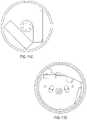
- FIG. 1( b )is an exploded view of a mounting assembly of an intelligent door lock device that can be used with the present invention.
- FIG. 1( c )illustrates various embodiments of a positioning sensing device coupled to a drive shaft.
- FIG. 1( d )illustrates one embodiment of a door lock device that can be used for retrofitting with an embodiment of an intelligent door lock device of the present invention.
- FIG. 1( e )illustrates coupling of a positioning sensing device with a drive shaft of a door lock device.
- FIG. 1( f )illustrates one embodiment of an intelligent door lock system of the present invention with an off-center drive.
- FIG. 1( g )illustrates a wireless bridge that can be used in one embodiment of the present invention.
- FIG. 1( h )illustrates one embodiment of elements coupled to a circuit in one embodiment of the present invention, including a haptic device.
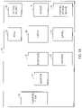
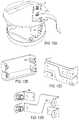
- FIGS. 2( a )-( c )illustrate embodiments of front and back surfaces of a main circuit that can be used and included in the intelligent door lock device of the present invention.
- FIGS. 2( d )-( j )illustrate an embodiment of non-wire, direct connection between PCBAs in one embodiment of the present invention, with position of a PCBA in intelligent door lock device.
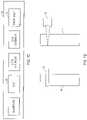
- FIGS. 3( a )-( b )illustrate embodiments of LED lighting that can be used with the present invention.
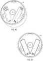
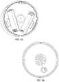
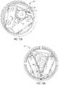
- FIGS. 4( a )-( d )illustrate one embodiment of a faceplate and views of a housing that can be used with the present invention.
- FIGS. 5( a ) and ( b )illustrate the rotation range, with a minimized slot length of a faceplate lock that can be used in one embodiment of the present invention.
- FIGS. 6( a ) and ( b )illustrate hook slots that can be used with the present invention.
- FIGS. 7( a ) through ( e )illustrate one embodiment of a mount, with attachment to the mounting plate that can be used with the present invention.
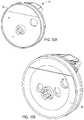
- FIGS. 8( a )-( b )illustrate embodiments of the present invention where magnets are utilized.
- FIGS. 9( a )-( e )illustrate embodiments of the present invention with wing latches.
- FIGS. 10( a )-( c ) and FIGS. 11( a )-( d )illustrate further details of wing latching that is used in certain embodiments of the present invention.
- FIGS. 12( a )-( d )illustrate embodiments of battery contacts that can be used with the present invention.
- FIGS. 13( a ) and ( b )illustrate embodiments of a motor and gears in one embodiment of the present invention.
- FIG. 14illustrates an embodiment of the plurality of motion transfer device, including but not limited to gears, used in one embodiment of the present invention.
- FIGS. 15( a )-( b )illustrate an embodiment of a speaker mounting.
- FIGS. 15( c )-( d )illustrate an embodiment of an accelerometer FPC service loop.
- FIG. 16illustrates one embodiment of a back-end associated with the intelligent door lock system.
- FIG. 17is a diagram illustrating an implementation of an intelligent door lock system.
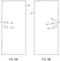
- FIGS. 18( a ) and ( b )illustrate one embodiment of the present invention with a front view and a back view of a door with a bolt and an intelligent door lock system.
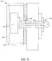
- FIG. 19illustrates more details of an embodiment of an intelligent door lock system of the present invention.
- FIG. 20illustrates one embodiment of the present invention showing a set of interactions between an intelligent door lock system, a mobile or computer and an intelligent door lock system back-end.
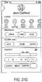
- FIGS. 21( a )-21( g )are examples of a user interface for an owner of a building that has an intelligent door lock system in one embodiment of the present invention.
- FIGS. 22( a )-22( e )are examples of a user interface for a guest of an owner of a building that has an intelligent door lock system in one embodiment of the present invention.
- FIGS. 23( a ) and ( b )illustrate one embodiment of an intelligent door lock system with an empty extension and extension gear adapters.
- FIG. 24illustrates one embodiment of a mobile device that is used with the intelligent door lock system.
- FIGS. 25( a )-( e )represent a logical diagram of a Cloud lock access services Infrastructure in accordance with one embodiment of the present invention.
- FIG. 26shows one embodiment of a flowchart illustrating an example of a process for tracking signal strength.
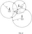
- FIG. 27is a flowchart illustrating another example of a process for tracking signal strength.
- FIG. 28illustrates one embodiment of a triangulation algorithm for location estimation that can be used with the bridge.
- FIG. 29illustrates one embodiment of a K-nearest neighbor averaging algorithm for location estimate that can be used with the bridge.
- the term enginerefers to software, firmware, hardware, or other component that can be used to effectuate a purpose.
- the enginewill typically include software instructions that are stored in non-volatile memory (also referred to as secondary memory).
- non-volatile memoryalso referred to as secondary memory
- the processorexecutes the software instructions in memory.
- the processormay be a shared processor, a dedicated processor, or a combination of shared or dedicated processors.
- a typical programwill include calls to hardware components (such as I/O devices), which typically requires the execution of drivers.
- the driversmay or may not be considered part of the engine, but the distinction is not critical.
- databaseis used broadly to include any known or convenient means for storing data, whether centralized or distributed, relational or otherwise.
- a mobile deviceincludes, but is not limited to, a cell phone, such as Apple's iPhone®, other portable electronic devices, such as Apple's iPod Touches®, Apple's iPads®, and mobile devices based on Google's Android® operating system, and any other portable electronic device that includes software, firmware, hardware, or a combination thereof that is capable of at least receiving the signal, decoding if needed, exchanging information with a server to verify information.
- Typical components of mobile devicemay include but are not limited to persistent memories like flash ROM, random access memory like SRAM, a camera, a battery, LCD driver, a display, a cellular antenna, a speaker, a Bluetooth® circuit, and WIFI circuitry, where the persistent memory may contain programs, applications, and/or an operating system for the mobile device.
- a mobile devicecan be a key fob.
- a key fobwhich can be a type of security token which is a small hardware device with built in authentication mechanisms. It is used to manage and secure access to network services, data, provides access, communicates with door systems to open and close doors and the like.
- the term “computer” or “mobile device or computing device”is a general purpose device that can be programmed to carry out a finite set of arithmetic or logical operations. Since a sequence of operations can be readily changed, the computer can solve more than one kind of problem.
- a computercan include of at least one processing element, typically a central processing unit (CPU) and some form of memory.
- the processing elementcarries out arithmetic and logic operations, and a sequencing and control unit that can change the order of operations based on stored information.
- Peripheral devicesallow information to be retrieved from an external source, and the result of operations saved and retrieved.
- the term “Internet”is a global system of interconnected computer networks that use the standard Internet protocol suite (TCP/IP) to serve billions of users worldwide. It is a network of networks that consists of millions of private, public, academic, business, and government networks, of local to global scope, that are linked by a broad array of electronic, wireless and optical networking technologies.
- the Internetcarries an extensive range of information resources and services, such as the inter-linked hypertext documents of the World Wide Web (WWW) and the infrastructure to support email.
- the communications infrastructure of the Internetconsists of its hardware components and a system of software layers that control various aspects of the architecture, and can also include a mobile device network, e.g., a cellular network.
- extranetis a computer network that allows controlled access from the outside.
- An extranetcan be an extension of an organization's intranet that is extended to users outside the organization that can be partners, vendors, and suppliers, in isolation from all other Internet users.
- An extranetcan be an intranet mapped onto the public Internet or some other transmission system not accessible to the general public, but managed by more than one company's administrator(s). Examples of extranet-style networks include but are not limited to:
- VPNVirtual private network
- LANs or WANs belonging to multiple organizationsand that extends usage to remote users using special “tunneling” software that creates a secure, usually encrypted network connection over public lines, sometimes via an ISP
- Intranetis a network that is owned by a single organization that controls its security policies and network management.
- Examples of intranetsinclude but are not limited to:
- a Wide-area networkthat is comprised of a LAN that extends usage to remote employees with dial-up access
- a WANthat is comprised of interconnected LANs using dedicated communication lines
- VPNVirtual private network
- ISPInternet Service Provider
- Network SystemsFor purposes of the present invention, the Internet, extranets and intranets collectively are referred to as (“Network Systems”).
- Bluetooth LE devices and peripheral devicesare Bluetooth low energy devices, marketed as Bluetooth Smart.
- a Bluetooth/WiFi bridge 11includes, a computing device 13 in an interior of a building 15 with an internet-facing radio 17 , and a second radio 19 communicating with one or more Bluetooth LE devices 21 .
- Bluetooth LE devices 21are Bluetooth LE devices 21 , Bluetooth LE peripheral devices 21 and the like, hereafter collectively “Bluetooth LE devices 21 .
- the Bluetooth LE devicescan have power from 40 mW hours to 40 W hours.
- Bluetooth devices 21include but are not limited to: mobile devices, wearable devices, wearable devices supporting BLE, including but not limited to: Smart Wristwatches, smart bracelets, smart jewelry, smart tags, smart fobs, smart clothing, shoes, glasses, any type of wearable device and the like.
- the computing device 13is configured to connect Bluetooth LE devices 21 to the Network Systems.
- the bridge 11is coupled to the intelligent door lock system 10 via secure digital keys distributed by Cloud lock access services Lock Access Services.
- the bridge 11allows BLE devices in the building to interact with the cloud lock access services and with other Internet-connected devices via the intermediary that is the cloud lock access services. It will be appreciated that the building includes all structures besides homes.
- the bridgedetermines signal strength between the bridge 11 , and the Bluetooth LE device 21 . In another embodiment the bridge 11 determines signal strength of between the bridge 11 , the Bluetooth LE device 21 and the intelligent door lock system 10 .
- the retrieved signal strength informationis sent to the cloud lock access services for processing. It one embodiment, as described below, a triangulation algorithm is applied between the bridge 11 , the Bluetooth LE device 21 and the intelligent door lock system.
- the bridge 11uses detection of known Bluetooth devices and peripheral devices, hereafter collectively Bluetooth devices 21 , tied to specific individual people in the interior or at an exterior of the building.
- the bridge 11tracks signal strength over time to: (i) determine if known or unknown people are inside or outside the building, (ii) if people are approaching the building, entering the building, exiting the building, moving away from the building and the like.
- the bridge 11 with the detection of the presence of a Bluetooth device 21relays lock operations of the intelligent door lock system (manual or via a mobile application), door 12 movements, door 12 knocks to allow making these determinations of presence and movement with an algorithm as set forth below.
- the bridge 11interacts with the cloud lock access services to gather and relay data.
- This datacan be gathered and stored locally, at the back-end 68 , and in a cloud lock access services based data layer. This is then used to determine the location and movement of people in and out the building.
- the bridge 11discovers the intelligent door lock system 10 over a Bluetooth device 21 networking. In one embodiment this is achieved by the bridge discovering lock devices 22 and their available services by scanning the Bluetooth LE 21 network for connected devices, advertising their presence and their services for obtaining lock device 22 status (secured or unsecured), communicates lock device 22 activity, communicates door 12 activity (door 12 opening and closing, door 12 knocks, and the like) and operates the lock to lock and unlock the bolt 24 to secure or unsecure the lock device 22 .
- the bridge 11provides communication to other Bluetooth devices 21 without the use of a mobile device.
- the bridge 11allows: WiFi-enabled devices in a building to interact with Bluetooth devices 21 in the building; WiFi-enabled devices in a building to interact with the intelligent door lock system 10 over Bluetooth; allows a Bluetooth device 21 in a building to interact with Internet-based services and API's using a building's home WiFi network and Network System connection; allows people to operate an intelligent door lock system and other Bluetooth devices over a Network System from anywhere outside a building; extend network coverage of Bluetooth devices in a building in order to understand who is in the building, who is away, who is coming and who is going when doors 12 and lock devices 22 are operated and the like.
- the bridge 11extends Network System coverage of Bluetooth devices 21 other than lock devices 22 to perform device-specific operations, including but not limited to: gathering information about the presence of the Bluetooth device 21 , the operational status of the Bluetooth device 21 , the operational history of the Bluetooth device 21 and performing Bluetooth device 21 specific operations including but not limited to: turning the Bluetooth device 21 off and on, changing the mode of operations of the Bluetooth device 21 , changing the operational settings of the Bluetooth device 21 and scheduling these device operations based on ad hoc, daily, weekly, monthly or other schedules.
- device-specific operationsincluding but not limited to: gathering information about the presence of the Bluetooth device 21 , the operational status of the Bluetooth device 21 , the operational history of the Bluetooth device 21 and performing Bluetooth device 21 specific operations including but not limited to: turning the Bluetooth device 21 off and on, changing the mode of operations of the Bluetooth device 21 , changing the operational settings of the Bluetooth device 21 and scheduling these device operations based on ad hoc, daily, weekly, monthly or other schedules.
- the intelligent door lock system 10trusts the bridge 11 for commands (remote status) after an intelligent door lock system owner or designee is registered at the back-end of the intelligent door lock system using a cloud lock access services-based access system that grants the bridge 11 access to the intelligent door lock system 10 .
- the intelligent door lock system 10owners or designee rants the bridge 11 access to the lock device 22 by using their digital credentials, which can be stored at the cloud lock access services or at the back-end 68 , to pair a specific bridge 11 with a specific intelligent door lock system 10 grant specific rights.
- the specific rightsinclude but are not limited to, gathering of status and operational history of the system 10 , triggering lock device 22 operations in real-time, as well as applications for interfacing with the bridge 11 and a Bluetooth device 21 .
- the bridge 11is used to determine if an intelligent door lock system 10 owners or designee with a non-internet connect device is at an interior or an exterior of a building.
- the bridge 11is used to determine if the person is approaching or moving away from the building. In one embodiment the bridge 11 measures the signal strength of the Bluetooth LE devices 21 .
- the signal strengthdecreases, as more fully discuss hereafter. Similarly, as the signal strength increases this indicates that a person with the Bluetooth LE device is approaching the building.
- each room of a building with the intelligent door lock systemhas a bridge 11 .
- the major rooms of the buildingeach have a bridge 11 .
- the bridge 11learns habits, movements, and the like of the intelligent door lock system 10 owners or designee.
- a triangulationis provided between the bridge 11 , the intelligent door lock system 10 and a Bluetooth LE device 21 , as more fully explained hereafter.
- the computing device 13provides for coordination of information flow between the two radios 15 and 17 .
- the computing device 13is configured to enable the two radios, 15 and 17 to communicate and take incoming and outgoing information from one radio into a format that the other radio can transmit and receive.
- the internet facing radio 15is configured to communicate through a router 25 to the Network Systems and the BLE LE devices 21 connect to Network Systems via one of the radios 15 , 17 through the computing device 13 through the internet facing radio 16 through the router 25 to Network Systems, with the bridge 11 communicating with a data center 27 .
- the internet facing radio 115is configured to communicate through the router 25 to Network Systems.
- the Bluetooth LE devices 21connect to Network Systems, via the computing device 13 , with the bridge 11 communicating with a data center 27 .
- the computing device 13provides for coordination of information flow between the two radios 15 and 17 . Because most radios speak in different frequencies or protocols, packet sizes, and the like, the computing device 13 enables the two radios 15 and 17 to communicate, takes incoming and outgoing information from one radio into the proper format that the other radio can transmit and receive. In one embodiment the computing device makes the first and second radios 16 and 18 the same thing.
- a logic circuit 27is in the computing device 13 .
- a wall wart in the buildingis configured to communicate with other Bluetooth devices, including but not limited to redundant or backup power supplies, redundant data communications connections, environmental controls (e.g., air conditioning, fire suppression) and various security devices, thermostats, audio systems, appliances, gates, outdoor electrical equipment and the like.
- other Bluetooth devicesincluding but not limited to redundant or backup power supplies, redundant data communications connections, environmental controls (e.g., air conditioning, fire suppression) and various security devices, thermostats, audio systems, appliances, gates, outdoor electrical equipment and the like.
- the internet facing radio 15is configured to communicate through the router 25 to Network Systems and Bluetooth LE devices 21 connected to Network Systems via the computing device 13 .
- the bridge 11communicates with the data center 27 .
- the computing device 13is a wall wart, and equivalent element, which is a power adapter that contains the plug for a wall outlet.
- the radios 15 and 17transmit radio waves for communication purposes.
- the bridge 11provides at least a partial probability analysis of where a person with a Bluetooth LE device 21 is located, as well as to the existence of an adverse condition including but not limited to entrance via a window or door to the building.
- system 10is an identification management system at a building 15 includes one or more bridges 11 in the building 15 .
- Each bridge 11includes a computing device 13 in an interior or exterior of a building 15 with the internet-facing radio 17 , and the second radio 19 communicating with one or more Bluetooth LE devices 21 or an equivalent device.
- Bluetooth devices or Bluetooth peripheral devices 21are in communication with the bridge 11 .
- the Bluetooth device 21is at an exterior of the building 15 .
- An intelligent door lock systemis in communication with the bridge 11 and the one or more Bluetooth devices 21 .
- the bridge 11uses detection of a Bluetooth device 21 that is associated with a person to track the person.
- a signal strength between the bridge 11 and the Bluetooth device 21is used to identify the person.
- the bridge 11is configured to provide real time conductivity to one or more servers, as more fully discussed hereafter.
- the one or more serverscan be located at a cloud infrastructure. In one embodiment the one or more servers are at a backend of the system 10 .
- the system 10is configured to provide an identify of a person entering or exiting the building 15 .
- the Bluetooth device 21can be any device that associates a person with a person's identify.
- facial/body motion recognitionis utilized for identification.
- the equivalent deviceis selected from at least one of a mobile device, a key fob, a wearable device.
- identificationis taken in order to determine intent. In one embodiment the identification is to determine an intent of the person entering or exiting from the building 15 .
- System 10 and/or the cloudcan continuously sniff the air for identification of one or more persons.
- the door lock system 10includes a vibration/tapping sensing device 11 configured to be coupled to intelligent lock system 10 .
- the intelligent door lock system 10is in communication with a mobile device 210 that includes a vibration/taping sensing device to lock or unlock a door associated with the intelligent door lock system.
- the vibration/tapping sensing device 11senses knocking on the door and locks or unlocks the door. In one embodiment the vibration/tapping sensing device 11 is not included as part of the actual intelligent door lock system 10 . In one embodiment the vibration/tapping sensing device 11 is coupled to the drive shaft 14 . It will be appreciated that the vibration/tapping sensing device 11 can be coupled to other elements of the intelligent door lock system 10 .
- the vibration/tapping sensing devicedetects vibration or knocking applied to a door that is used to unlock or lock the intelligent door lock system 10 . This occurs following programming the intelligent door lock system 10 .
- the programmingincludes a user's vibration code/pattern, and the like.
- a usercan give a third person a knock code/pattern to unlock the intelligent door lock system 10 of the door 12 .
- the knockingis one that is recognized as having been defined by a user of the door lock system 10 as a means to unlock the door.
- the knockingcan have a variety of different patterns, tempos, duration, intensity and the like.
- the vibration/tapping sensing device 11detects oscillatory motion resulting from the application of oscillatory or varying forces to a structure. Oscillatory motion reverses direction.
- the oscillationmay be continuous during some time period of interest or it may be intermittent. It may be periodic or nonperiodic, i.e., it may or may not exhibit a regular period of repetition. The nature of the oscillation depends on the nature of the force driving it and on the structure being driven.
- Motionis a vector quantity, exhibiting a direction as well as a magnitude.
- the direction of vibrationis usually described in terms of some arbitrary coordinate system (typically Cartesian or orthogonal) whose directions are called axes.
- the origin for the orthogonal coordinate system of axesis arbitrarily defined at some convenient location.
- the vibratory responses of structurescan be modeled as single-degree-of-freedom spring mass systems, and many vibration sensors use a spring mass system as the mechanical part of their transduction mechanism.
- the vibration/tapping sensing device 11can measure displacement, velocity, acceleration, and the like.
- vibration/tapping sensing devices 11can be utilized, including but not limited to accelerometers, optical devices, electromagnetic and capacitive sensors, contact devices, transducers, displacement transducers, piezoelectric sensors, piezoresistive devices, variable capacitance, servo devices, audio devices where transfer of the vibration can be gas, liquid or solid, including but not limited to microphones, geo-phones, and the like.
- Suitable accelerometersinclude but are not limited to: Piezoelectric (PE); high-impedance output; Integral electronics piezoelectric (IEPE); low-impedance output Piezoresistive (PR); silicon strain gauge sensor Variable capacitance (VC); low-level, low-frequency Servo force balance; and the like.
- PEPiezoelectric
- IEPEIntegral electronics piezoelectric
- PRlow-impedance output Piezoresistive
- VCsilicon strain gauge sensor Variable capacitance
- low-level, low-frequency Servo force balanceand the like.
- the vibration/tapping sensing device 11can be in communication with an intelligent door lock system back-end 68 , via Network Systems, as more fully described hereafter.
- the intelligent door lock system 10is configured to be coupled to a structure door 12 , including but not limited to a house, building and the like, window, locked cabinet, storage box, bike, automobile door or window, computer locks, vehicle doors or windows, vehicle storage compartments, and the like.
- the intelligent door lock system 10is coupled to an existing drive shaft 14 of a lock device 22 already installed and is retrofitted to all or a portion of the lock device 22 , which includes a bolt/lock 24 .
- the intelligent door lock system 10is attached to a door 12 , and the like, that does not have a pre-existing lock device.
- FIG. 1( b )illustrates door lock elements that can be at an existing door, to provide for the mounting of the intelligent door lock system 10 with an existing lock device 22 .
- FIG. 1( b )illustrates door lock elements that can be at an existing door, to provide for the mounting of the intelligent door lock system 10 with an existing lock device 22 .
- FIG. 1( b )illustrates one embodiment of a lock device 22 that can be pre-existing at a door 10 with the intelligent door lock system 10 retrofitted to it.
- Components of the lock device 22may be included with the intelligent door lock device 10 , as more fully discussed hereafter.
- the intelligent door lock system 10includes a positioning sensing device 16 , a motor 38 , an engine/processor 36 with a memory and one or more wireless communication devices 40 coupled to a circuit 18 .
- the motor 38converts any form of energy into mechanical energy.
- three more four wireless communications devices 40are in communication with circuit 18 .
- the vibration sensing devicecan be included with the positioning sensing device.
- the intelligent door lock system 10is provided with the position sensing device 16 configured to be coupled to the drive shaft 14 of the lock device 22 .
- the position sensing device 16senses position of the drive shaft 14 and assists in locking and unlocking the bolt/lock 24 of the lock device 22 .
- the engine 36is provided with a memory.
- the engine 36is coupled to the positioning sensing device 16 .
- a circuit 18is coupled to the engine 36 and an energy source 50 is coupled to the circuit.
- a device 38converts energy into mechanical energy and is coupled to the circuit 18 , positioning sensing device 16 and the drive shaft 14 .
- Device 38is coupled to the energy source 50 to receive energy from the energy source 50 , which can be via the circuit 18 .
- the intelligent door lock system 10includes any or all of the following, a face plate 20 , ring 32 , latches such as wing latches 37 , adapters 28 coupled to a drive shaft 14 , one or more mounting plates 26 , a back plate 30 , a power sensing device 46 , energy sources, including but not limited to batteries 50 , and the like.
- the intelligent door lock system 10retrofits to an existing lock device 22 already installed and in place at a door 12 , and the like.
- the existing lock device 12can include one or more of the following elements, drive shaft 14 , a lock device 22 with the bolt/lock 24 , a mounting plate 26 , one or more adapters 28 for different lock devices 22 , a back plate 30 , a plurality of motion transfer devices 34 , including but not limited to, gears 34 , and the like.
- the memory of engine/processor 36includes states of the door 12 .
- the statesare whether the door 12 is a left handed mounted door, or a right handed mounted door, e.g, opens from a left side or a right side relative to a door frame.
- the statesare used with the position sensing device 16 to determine via the engine/processor 36 if the lock device 22 is locked or unlocked.
- the engine/processor 36 with the circuit 18regulates the amount of energy that is provided from energy source 50 to the motor 38 . This thermally protects the motor 38 from receiving too much energy and ensures that the motor 38 does not overheat or become taxed.
- FIG. 1( d )illustrates various embodiments of the positioning sensing device 16 coupled to the drive shaft 14 .
- position sensing devices 16can be used, including but not limited to, accelerometers, optical encoders, magnetic encoders, mechanical encoders. Hall Effect sensors, potentiometers, contacts with ticks, optical camera encoders, and the like.
- an accelerometer 16detects acceleration.
- the accelerometer 16provides a voltage output that is proportional to a detected acceleration.
- Suitable accelerometers 16are disclosed in, U.S. Pat. Nos. 8,347,720, 8,544,326, 8,542,189, 8,522,596, EP0486657B1, EP 2428774 A1, incorporated herein by reference.
- the position sensing device 16is an accelerometer 16 .
- Accelerometer 16includes a flex circuit coupled to the accelerometer 16 .
- the accelerometerreports X, Y, and X axis information to the engine/processor 36 of the drive shaft 14 .
- the engine/processor 36determines the orientation of the drive shaft 14 , as well as door knocking, bolt/lock 24 position, door 12 close/open (action) sensing, manual key sensing, and the like, as more fully explained hereafter.
- Suitable optical encodersare disclosed in U.S. Pat. Nos. 8,525,102, 8,351,789, and 8,476,577, incorporated herein by reference.
- Suitable magnetic encodersare disclosed in U.S. Publication 20130063138, U.S. Pat. No. 8,405,387, EP2579002A1, EP2642252 A1, incorporated herein by reference.
- Suitable mechanical encodersare disclosed in, U.S. Pat. No. 5,695,048, and EP2564165A2, incorporated herein by reference.
- Suitable Hall Effect sensorsare disclosed in, EP2454558B1 and EP0907068A1, incorporated herein by reference.
- Suitable potentiometersare disclosed in, U.S. Pat. No. 2,680,177, EP1404021A3, CA2676196A1, incorporated herein by reference.
- the positioning sensing device 16is coupled to the drive shaft 14 by a variety of means, including but not limited to the adapters 28 .
- the position sensing device 16uses a single measurement, as defined herein, of drive shaft 14 position sensing which is used to determine movement in order the determine the location of the drive shaft 14 and the positioning sensing device 16 .
- the exact position of the drive shaft 14can be measured with another measurement without knowledge of any previous state.
- Single movement, which is one determination of position sensingis the knowledge of whether the door 12 is locked, unlocked or in between.
- One advantage of the acceleratoris that one can determine position, leave if off, come back at a later time, and the accelerometer 16 will know its current position even if it has been moved since it has been turned off. It will always know its current position.
- the position sensing device 16including but not limited to the accelerometer 16 , provides an acceleration signal to a controller coupled to the intelligent door lock system 10 and included as part of the intelligent door lock system, or positioned at the door 12 , in response to sensed acceleration.
- the positioning sensing device 16including but not limited to the accelerator 16 , provides an acceleration signal to a controller, at the intelligent door lock system 10 , in response to sensed acceleration.
- the intelligent door lock system 10includes an accelerometer 16 for determining movement, such as a knock or the door opening, in which the lock is disposed and controlling a radio or the intelligent door lock system 10 via a controller, as a function of the acceleration signal.
- the mobile device 201includes an accelerometer 1246 and outputs an acceleration signal to a controller 1218 upon acceleration of the mobile device 201 .
- the acceleration signalis output to the controller 1218 and a radio signal generator is triggered to begin generating a radio signal.
- a wireless access control system for a doorincludes a lock assembly 10 coupled at the door 10 and has a lock, wireless circuitry and a controller that in operation provides for a change in the lock for a locked and lock position, and further can have a proximity detector.
- a user mobile device 201is in communication with the lock assembly 10 .
- An accelerometer 16can be at the door, the lock system 10 and/or the mobile device 201 .
- the intelligent lock system 10is a wireless access control system is provided to lock or unlock a door 12 at a building.
- a remote access deviceincluding but not limited to a mobile device 210 , transmits a signal.
- the lock system 10includes a lock 22 , a processor 36 with a memory, one or more wireless communication device 40 coupled to a circuit 18 and one or more motion transfer device 34 coupled to a drive shaft 14 .
- the lock 22receives the signal, enabling the lock 22 to be one of locked or unlocked in response to the signal.
- the remote access device 210has a controller for generating the signal, and an accelerometer 16 providing an acceleration signal to the controller when the accelerometer 16 experiences an acceleration. The controller generates the signal in response to the acceleration signal.
- the memorystores an identifier associated with a respective remote access device
- the lock 22only provides access to a predetermined remote access device having an identifier stored in the memory during a respective predetermined time period associated in the memory with the remote access device.
- a proximity detectoris included and configured to determine a presence of a user upon receipt of a proximity detector input.
- the remote access deviceincludes a geo positioning system and the signal has a geo location of the remote access device.
- the lock 22exhibits a low power broadcast state and a high rate broadcast.
- a listening statecan also be provided.
- the processor 36causes the lock 22 to exhibit a high rate broadcast and the listening state as a function of the geo location of the remote access device.
- a proximity detectorthat detects a presence of a user.
- the proximity detectorsends a presence signal to the processor 36 when the presence of a user is detected.
- the processor 36causes the lock 22 to change a status of the lock 22 from one of locked to unlocked and unlocked to locked in response to the presence signal.
- the remote access deviceincludes a geo positioning system
- the signalincludes a geo location of the remote access device.
- the processor 36causes the lock 22 to change from one of locked to unlocked and unlocked to locked as a function of the geo location.
- At least one antennatransmits a signal
- an accelerometer 16detects acceleration of a door 12 in which the lock 22 is coupled to
- the processor 36receives an accelerometer signal that causes a signal to be transmitted by the antenna in response to the acceleration signal.
- the positioning sensing device 16is directly coupled to the drive shaft 14 , as illustrated in FIG. 1( d ) . Sensing position of the positioning sensing device 16 is tied to the movement of the drive shaft 14 .
- the accelerometer 16can detect X, Y and Z movements. Additional information is then obtained from the X, Y, and Z movements.
- the position of the drive shaft 14is determined; this is true even if the drive shaft 14 is in motion.
- the Z axisis used to detect a variety of things, including but not limited to, door 12 knocking, picking of the lock 22 , break-in and unauthorized entry, door 12 open and closing motion. If a mobile device 201 is used to open or close, the processor 36 determines the lock 22 state.
- the same positioning sensing device 16is able to detect knocks by detecting motion of the door 12 in the Z axis.
- position sensingis in the range of counter and clock wise rotation of up to 180 degrees for readings.
- the maximum rotation limitis limited by the position sensing device 16 , and more particularly to the accelerometer cable.
- the resultis sub 1 resolution in position sensing. This provides a higher lifetime because sampling can be done at a slower rate, due to knowing the position after the position sensing device 16 has been turned off for a time period of no great 100 milli seconds.
- accuracycan be enhanced taking repeated measurements.
- the positioning sensing device 16such as the accelerometer, does not need to consume additional power beyond what the knock sensing application already uses.
- the position sensing device 16is positioned on the drive shaft 14 , or on an element coupled to the drive shaft 14 .
- a position of the drive shaft 14 and power sensing device and/or a torque limited link 38are known. When the position of the drive shaft 14 is known, it is used to detect if the bolt/lock 24 of a door lock device 22 is in a locked or unlocked position, as well as a depth of bolt/lock 24 travel of lock device 22 , and the like.
- the intelligent door lock system 10can be interrogated via hardware, including but not limited to a key, a mobile device, a computer, key fob, key cards, personal fitness devices, such as Fitbit®, nike fuel, jawbone up, pedometers, smart watches, smart jewelry, car keys, smart glasses, including but not limited to Google Glass, and the like.
- Real time position information of the drive shaft 14is determined and the bolt/lock 24 of lock device 22 travels can be inferred from the position information of the drive shaft 14 .
- the X axisis a direction along a width of the door 12
- the Y axisis in a direction along a length of a door 12
- the Z axisis in a direction extending from a surface of the door 12 .
- the accelerometer 16is the knock sensor. Knocking can be sensed, as well as the number of times a door 12 is closed or opened, the physical swing of the door 12 , and the motion the door 12 opening and closing. With the present invention, a determination is made as to whether or not someone successfully swung the door 12 , if the door 12 was slammed, and the like. Additionally, by coupling the position sensing device 16 on the moveable drive shaft 14 , or coupled to it, a variety of information is provided, including but not limited to, if the bolt/lock 24 is stored in the correct orientation, is the door 12 properly mounted and the like.
- a calibration stepis performed to determine the amount of drive shaft 14 rotations to fully lock and unlock the bolt/lock 24 of lock device 22 .
- the drive shaft 14is rotated in a counter-counter direction until it can no longer rotate, and the same is then done in the clock-wise direction. These positions are then stored in the engine memory. Optionally, the force is also stored.
- a commandis then received to rotate the drive shaft 14 to record the amount of rotation. This determines the correct amount of drive shaft 14 rotations to properly lock and unlock the lock device 22 .
- the drive shaft 14is rotated until it does not move anymore. This amount of rotation is then stored in the memory and used for locking and unlocking the lock device 22 .
- the drive shaft 14is rotated until it does not move anymore. However, this may not provide the answer as to full lock and unlock. It can provide information as to partial lock and unlock. Records from the memory are then consulted to see how the drive shaft 14 behaved in the past. At different intervals, the drive shaft 14 is rotated until it does not move anymore. This is then statistically analyzed to determine the amount of drive shaft 14 rotation for full locking and unlocking. This is then stored in the memory.
- the engine/processor 36is coupled to at least one wireless communication device 40 that utilizes audio and RF communication to communicate with a wireless device, including but not limited to a mobile device/key fob 210 , with the audio used to communicate a security key to the intelligent door lock system 10 from the wireless device 210 and the RF increases a wireless communication range to and from the at least one wireless communication device 40 .
- only one wireless communication device 40is used for both audio and RF.
- one wireless communication device 40is used for audio, and a second wireless communication device 40 is used for RF.
- the bolt/lock 22is included in the intelligent door lock system 10 .
- the audio communications initial set up informationis from a mobile device/key fob 210 to the intelligent door lock system 10 , and includes at least one of, SSID WiFi, password WiFi, a Bluetooth key, a security key and door configurations.
- an audio signal processor unitincludes an audio receiver, a primary amplifier circuit, a secondary amplifier circuit, a current amplifier circuit, a wave detection circuit, a switch circuit and a regulator circuit.
- the audio receiver of each said audio signal processor unitis a capacitive microphone.
- the switch circuit of each audio signal processor unitis selected from one of a transistor and a diode.
- the regulator circuit of each audio signal processor unitis a variable resistor.
- the audio mixer unitincludes a left channel mixer and a right channel mixer.
- the amplifier unitincludes a left audio amplifier and a right audio amplifier.
- the Bluetooth deviceincludes a sound volume control circuit with an antenna, a Bluetooth microphone and a variable resistor, and is electrically coupled with the left channel mixer and right channel mixer of said audio mixer unit. Additional details are in U.S. Publication US20130064378 A1, incorporated fully herein by reference.
- the faceplate 20 and/or ring 32is electrically isolated from the circuit 18 and does not become part of circuit 18 . This allows transmission of RF energy through the faceplate 20 .
- the faceplate and/or ringare made of materials that provide for electrical isolation.
- the faceplate 20 , and/or the ring 32are at ground.
- the faceplate 20can be grounded and in non-contact with the ring 32
- the faceplate 20 and the ring 32are in non-contact with the ring 32 grounded
- the faceplate 20 and the ringcan be coupled
- the ring 32 and the faceplate 20are all electrically isolated from the circuit 18 .
- the ring 32is the outer enclosure to the faceplate 20
- the bolt/lock 24 and lock device 22is at least partially positioned in an interior defined by the ring 32 and the faceplate 20 .
- the lock device 22has an off center drive mechanism relative to the outer periphery that allows up to R displacements from a center of rotation of the bolt/lock 24 of lock device 22 , where R is a radius of the bolt/lock 24 , 0.75 R displacements, 0.5 R displacements, and the like, as illustrated in FIG. 1( e ) .
- the off center drive mechanismprovides for application of mechanical energy to the lock device 22 and bolt/lock 22 off center relative to the outer periphery.
- a wireless communication bridge 41is coupled to a first wireless communication device 40 that communicates with Network Systems via a device, including but not limited to a router, a 3G device, a 4G device, and the like, as well as mobile device 210 .
- the wireless communication bridge 41is also coupled to a second wireless communication device 40 that is coupled to the processor 38 , circuit 18 , positioning sensing device 16 , motor 38 and the lock device 22 with bolt/lock 24 , and provides for more local communication.
- the first wireless communication device 40is in communication with the second wireless communication device 40 via bridge 41 .
- the second wireless communication device 40provides local communication with the elements of the intelligent door lock system 10 .
- the second communication device 45is a Bluetooth device.
- the wireless communication bridge 41includes a third wireless communication device 40 . In one embodiment, the wireless communication bridge 41 includes two wireless communication devices 40 , e.g, and third and fourth wireless communication devices 40 . In one embodiment, the wireless communication bridge 41 includes a WiFi wireless communication device 40 and a Bluetooth wireless communication device 40 .
- FIG. 1( g )illustrates various elements that are coupled to the circuit 18 in one embodiment of the present invention.
- a haptic device 49is included to provide the user with haptic feedback for the intelligent door lock system 10 , see FIG. 1( g ) .
- the haptic deviceis coupled to the circuit 18 , the processor 38 , and the like.
- the haptic deviceprovides a visual indication that the bolt/lock 24 of lock device 22 has reach a final position.
- the haptic device 49provides feedback to the user that the bolt/lock 24 of lock device 22 has reached a home open position verses a final position so the user does not over-torque.
- a suitable haptic device 49is disclosed in U.S. Publication No. 20120319827 A1, incorporated herein by reference.
- the wing latches 37are used to secure the intelligent door lock system 10 to a mounting plate 26 coupled to the door 12 . In one embodiment, the wing latches 37 secure the intelligent door lock system 10 to a mounting plate 26 coupled to a door 12 without additional tools other than the wing latches 37 .
- FIG. 1( g )illustrates one embodiment of circuit 18 , as well as elements that includes as part of circuit 18 , or coupled to circuit 18 , as discussed above.
- FIGS. 2( a )-( c )illustrate front and back views of one embodiment of circuit 18 , and the positioning of circuit 18 in the intelligent door lock system 10 .
- FIGS. 2( d )-( e )illustrate an embodiment of non-wire, direct connection between PCBAs.
- FIG. 2( e )shows the relative positioning of a PCBA in the intelligent door lock device 10 .
- the main circuit 18is coupled to, the engine 36 with a processor and memory, the motor 38 , wireless communication device 40 such as a WiFi device including but not limited to a Bluetooth device with an antenna, position sensing device 16 , speaker (microphone) 17 , temperature sensor 42 , battery voltage sensor 44 , current sensor or power sensor 46 that determines how hard the motor 38 is working, a protection circuit to protect the motor from overheating, an LED array 48 that reports status and one or more batteries 50 that power circuit 18 , see FIG. 1( g ) .
- wireless communication device 40such as a WiFi device including but not limited to a Bluetooth device with an antenna, position sensing device 16 , speaker (microphone) 17 , temperature sensor 42 , battery voltage sensor 44 , current sensor or power sensor 46 that determines how hard the motor 38 is working, a protection circuit to protect the motor from overheating, an LED array 48 that reports status and one or more batteries 50 that power circuit 18 , see FIG. 1( g ) .
- the current sensor 46monitors the amount of current that goes to the motor 38 and this information is received and processed by the engine/processor 36 with memory and is coupled to the circuit 18 .
- the amount of current going to the motor 38is used to determine the amount of friction experienced by door 12 and/or lock device 22 with lock/bolt 24 in opening and/or closing, as applied by the intelligent door lock system 10 and the positioning sensing device 16 to the drive shaft 14 .
- the circuit 18 and engine/processor 36can provide for an adjustment of current.
- the engine/processor 36can provide information regarding the door and friction to the user of the door 12 .
- FIGS. 3( a )-( b )illustrate embodiments of LED 48 lighting that can include diffusers, a plurality of LED patterns point upward, inward, and outward and a combination of all three.
- two control PCDsare provide to compare side by side.
- Each LED 48can be independently addressable to provide for maximization of light with the fewest LEDs 48 .
- an air gapis provided.
- FIGS. 4( a )-( d )illustrate one embodiment of a faceplate 20 and views of the housing 32 and faceplate 20 .
- FIGS. 5( a ) and ( b )illustrate the rotation range of the ring 32 , with a minimized slot length of a bolt/lock 24 of lock device 22 in one embodiment of the present invention.
- the ratiocan change. This can be achieved with gearing.
- the bolt/lock 24 and/or lock device 22can have a rotation of 20-5 and less turns clockwise or counter-clockwise in order to open the door 12 . Some lock devices 22 require multiple turns.
- FIGS. 6( a ) and ( b )illustrate hook slots 52 that can be used with the present invention.
- FIGS. 7( a ) through ( f )illustrate an embodiment of a mount 54 , with attachment to the mounting plate 26 .
- Screws 56are captured in the housing 58 , and/or ring 32 and accessed through a battery cavity. A user can open holes for access and replace the screws 56 .
- the screwsextend through the mounting plate 26 into a door hole.
- a height of the mounting plate 26is minimized.
- the lock device 22is held in place, FIG. 7( c ) , temporarily by a top lip, FIG. 7( d ) and the lock drive shaft 14 .
- FIGS. 8( a )-( b )illustrate embodiments where magnets 60 are utilized.
- the magnet 60 locationsare illustrated as are the tooled recesses from the top and side.
- the magnets 60are distanced by ranges of 1-100 mm, 3-90, 5-80 mm apart and the like.
- FIGS. 9( a )-( e )illustrate embodiments of the present invention with wing latches 36 .
- the wing latches 36allow for movement of the lock device 22 with bolt/lock 24 towards its final position, in a Z-axis direction towards the door 12 . Once the lock device 22 with bolt/lock 24 is in a final position, the wing latches 36 allows for the secure mounting without external tools. The wing latches 36 do the mounting. Wing latches 36 enable mounting of the lock device 22 and bolt/lock 24 with use of only the Z axis direction only, and X and Y directionality are not needed for the mounting.
- a lead in rampFIG. 9( e ) is used to pull the elements together.
- FIGS. 10( a )-( c ) and FIGS. 11( a )-( d )illustrate further details of wing latching.
- FIGS. 12( a )-( d )illustrate embodiments of battery contacts 64 .
- FIGS. 13( a ) and ( b )illustrate embodiments of motor 38 and one or more gears 34 , with a gearbox 66 .
- a first gear 34 in sequencetakes a large load if suddenly stopped while running.
- FIG. 14illustrates an embodiment of a plurality of motion transfer devices such as gears 34 .
- gears 34There can be come backlash in a gear train as a result of fits and tolerances.
- adapters 28 and lock drive shafts 14There can also be play between adapters 28 and lock drive shafts 14 . This can produce play in an out gearbox 66 ring. This can be mitigated with a detent that located the outer ring.
- the intelligent door lock system 10can be in communication with an intelligent door lock system back-end 68 , via Network Systems, as more fully described hereafter.
- the flex circuit 18which has an out-of plane deflection of at least 1 degree, includes a position detector connector 46 , Bluetooth circuit, and associated power points, as well as other elements.
- the intelligent door lock system 10can use incremental data transfer via Network Systems, including but not limited to BLUETOOTH® and the like.
- the intelligent door lock system 10can transmit data through the inductive coupling for wireless charging.
- the useris also able to change the frequency of data transmission.
- the intelligent door lock system 10can engage in intelligent switching between incremental and full syncing of data based on available communication routes. As a non-limiting example, this can be via cellular networks, WiFi, BLUETOOTH® and the like.
- the intelligent door lock system 10can receive firmware and software updates from the intelligent lock system back-end 68 .
- the intelligent door lock system 10produces an output that can be received by an amplifier, and decoded by an I/O decoder to determine I/O logic levels, as well as, both clock and data information.
- I/O decoderto determine I/O logic levels, as well as, both clock and data information.
- Many such methodsare available including ratio encoding, Manchester encoding, Non-Return to Zero (NRZ) encoding, or the like; alternatively, a UART type approach can be used.
- NRZNon-Return to Zero
- the intelligent door lock system 10can includes a repeatable pseudo randomization algorithm in ROM or in ASIC logic.
- FIGS. 15( a )-( b )illustrate an embodiment of a speaker 17 and speaker mounting 70 .
- FIGS. 15( c )-( d )illustrate one embodiment of an accelerometer FPC service loop.
- the intelligent door lock system back-end 68can include one or more receivers 74 , one or more engines 76 , with one or more processors 78 , coupled to conditioning electronics 80 , one or more filters 82 , one or more communication interfaces 84 , one or more amplifiers 86 , one or more databases 88 , logic resources 90 and the like.
- the back-end 68knows that an intelligent door lock system 10 is with a user, and includes a database with the user's account information. The back-end 68 knows if the user is registered or not. When the intelligent door lock system 10 is powered up, the back-end 68 associated that intelligent door lock system 10 with the user.
- the conditioning electronics 80can provide signal conditioning, including but not limited to amplification, filtering, converting, range matching, isolation and any other processes required to make sensor output suitable for processing after conditioning.
- the conditioning electronicscan provide for, DC voltage and current, AC voltage and current, frequency and electric charge.
- Signal inputs accepted by signal conditionersinclude DC voltage and current.
- Outputs for signal conditioning electronicscan be voltage, current, frequency, timer or counter, relay, resistance or potentiometer, and other specialized output.
- the one or more processors 78can include a memory, such as a read only memory, used to store instructions that the processor may fetch in executing its program, a random access memory (RAM) used by the processor 78 to store information and a master dock.
- the one or more processors 78can be controlled by a master clock that provides a master timing signal used to sequence the one or more processors 78 through internal states in their execution of each processed instruction.
- the one or more processors 78can be low power devices, such as CMOS, as is the necessary logic used to implement the processor design. Information received from the signals can be stored in memory.
- electronics 92are provided for use in intelligent door system 10 analysis of data transmitted via System Networks.
- the electronics 92can include an evaluation device 94 that provides for comparisons with previously stored intelligent door system 10 information.
- Signal filteringis used when the entire signal frequency spectrum contains valid data. Filtering is the most common signal conditioning function, as usually not all the signal frequency spectrum contains valid data.
- Signal amplificationperforms two important functions: increases the resolution of the inputted signal, and increases its signal-to-noise ratio.
- Suitable amplifiers 86include but are not limited to sample and hold amplifiers, peak detectors, log amplifiers, antilog amplifiers, instrumentation amplifiers, programmable gain amplifiers and the like.
- Signal isolationcan be used in order to pass the signal from to a measurement device without a physical connection. It can be used to isolate possible sources of signal perturbations.
- the intelligent door lock system back-end 68can provide magnetic or optic isolation.
- Magnetic isolationtransforms the signal from voltage to a magnetic field, allowing the signal to be transmitted without a physical connection (for example, using a transformer).
- Optic isolationtakes an electronic signal and modulates it to a signal coded by light transmission (optical encoding), which is then used for input for the next stage of processing.
- the intelligent door lock system 10 and/or the intelligent door lock system back-end 68can include Artificial Intelligence (AI) or Machine Learning-grade algorithms for analysis.
- AI algorithmsinclude Classifiers, Expert systems, case based reasoning, Bayesian networks, and Behavior based AI, Neural networks, Fuzzy systems, Evolutionary computation, and hybrid intelligent systems.
- Information received or transmitted from the back-end 68 to the intelligent door system 10 and mobile device 210can use logic resources, such as AI and machine learning grade algorithms to provide reasoning, knowledge, planning, learning communication, and create actions.
- logic resourcessuch as AI and machine learning grade algorithms to provide reasoning, knowledge, planning, learning communication, and create actions.
- AIis used to process information from the intelligent door lock system 10 , from mobile device 210 , and the like.
- the back-end 68can compute scores associated with various risk variables involving the intelligent door lock system 10 . These score can be compared to a minimum threshold from a database and an output created. Alerts can be provided to the intelligent door lock system 10 , mobile device 210 and the like. The alert can provide a variety of options for the intelligent door lock system 10 to take, categorizations of the received data from the mobile device 210 , the intelligent door lock system 10 , and the like, can be created. A primary option can be created as well as secondary options.
- data associated with the intelligent door lock system 10is received.
- the datacan then be pre-processed and an array of action options can be identified. Scores can be computed for the options. The scores can then be compared to a minimum threshold and to each other. A sorted list of the action options based on the comparison can be outputted to the intelligent door lock system 10 , the mobile device 210 and the like. Selections can then be received indicating which options to pursue. Action can then be taken. If an update to the initial data is received, the back-end 68 can then return to the step of receiving data.
- Urgent indicatorscan be determined and directed to the intelligent door lock system 10 , including unlocking, locking and the like.
- Data received by the intelligent door lock system 10 and mobile device 210can also be compared to third party data sources.
- algorithm files from a memorycan be accessed specific to data and parameters received from the intelligent door lock system 10 and mobile device 210 .
- Scoring algorithms, protocols and routinescan be run for the various received data and options. Resultant scores can then be normalized and weights assigned with likely outcomes.
- the intelligent door lock system 10can be a new lock system mounted to a door 12 , with all or most of the elements listed above, or it can be retrofitted over an existing lock device 22 .
- the usermakes sure that the existing lock device 22 and bolt/lock 24 is installed right-side up.
- the existing thumb-turnis then removed.
- additional mounting plates 26need to be removed and the intelligent door lock system 10 can include replacement screws 56 that are used.
- the correct mounting plate 26is then selected.
- the usersequentially aligns with 1 of 4 mounting plates 26 that are supplied or exist. This assists in determining the correct diameter and replace of the screws 56 required by the bolt/lock 24 .
- the mounting plate 26is then positioned.
- the correct adapter 28is positioned in a center of the mounting plate 26 to assist in proper positioning.
- Cautionis made to ensure that the adapter 28 does not rub the sides of the mounting plate 26 and the screws 56 are then tightened on the mounting plate 26 .
- the intelligent door lock system bolt/lock 24 of lock device 22is then attached. In one embodiment, this is achieved by pulling out side wing latches 36 , sliding the lock device 22 and/or bolt/lock 24 over the adapter 28 and pin and then clamping down the wings 36 to the mounting plate 26 .
- the faceplateis rotated to open the battery compartment and the battery tabs are then removed to allow use of the battery contacts 64 .
- An outer metal ring 32 to lock and unlock the door 12is then rotated.
- An app from mobile device 210 and/or keythen brings the user through a pairing process.
- a door 12can be deformed, warped, and the like. It is desirable to provide a customer or user, information about the door, e.g., if it is deformed, out of alignment, if too much friction is applied when opening and closing, and the like.
- the current sensor 46monitors the amount of current that goes to the motor 38 and this information is received and processed by the engine/processor 36 with memory and is coupled to the circuit 18 .
- the amount of current going to the motor 38is used to determine the amount of friction experienced by door 12 and/or lock device 22 in opening and/or closing, as applied by the intelligent door lock system 10 and the positioning sensing device 16 to the drive shaft 14 .
- the circuit 18 and engine/processor 36can provide for an adjustment of current.
- the engine/processor 36can provide information regarding the door and friction to the user of the door 12 .
- the intelligent door lock system 10provides an ability to sense friction on the lock device 22 and/or door 12 by measuring the torque required to move the bolt/lock 24 .
- the intelligent door lock system 10increases the applied torque gradually until the bolt/lock 24 moves into its desired position, and the applied torque is the minimum amount of torque required to move the bolt/lock 24 , which is directly related to how deformed the door is.
- a customerwhen a bad door is detected, a customer can be notified that their door may require some servicing.
- door deformationcan be detected with a torque device is used to determine if the torque applied when the door is rotated is too high. As a non-limiting example, this can be 2-15 in lbs of torque
- the intelligent door lock system back end 68can then perform a comparison between the measured torque with a standard, or a norm that is included in the one or more databases 88 .
- the intelligent door lock system 10before the door is serviced, allows operation by offering a high-friction mode.
- the high friction modeis when, as non-limiting examples, 2 inch lbs, 3 inch lbs., 3.5 inch pounds, and the like are required to open the door.
- the bolt/lock 24is driven while the user is pushing, lifting, torqueing the door, pulling, performing visual inspections of rust, blockage, other conditions that can compromise a door and the like, that is applied to the doorknob.
- the position sensing device 16is used to determine if the bolt/lock 24 was moved to a final position. In the high friction mode, motion of the door closing is confirmed.
- the bolt/lock 24Upon detecting the closing of the door, the bolt/lock 24 is then driven. When the user receives an auditory, visual, or any other type of perceptible confirmation, the user then knows that the door has been locked.
- the firmware elements, of the intelligent door lock system 10can also attempt to drive the bolt/lock 24 for a second time when the first time fails. However, this can result in more power consumption, reducing lifetime of the power source, particularly when it is battery 50 based.
- the intelligent door lock system 10seeks to have the motor 38 operate with reduced energy consumption for energy source lifetime purposes, as well as eliminate or reduce undesirable noises, operations, and user experiences that occur when this is a failure in door locking and unlocking, particularly due to door deformation, door non-alignment, as well as other problems with the door that can be irritating to the person locking or unlocking the door.
- the intelligent door lock system back-end 68can track performance of doors and friction levels across time and build a service to encourage users to better maintain their doors.
- Such servicecan be a comparison of a door's friction level to other users that are similar geographic locations, at similar weather pattern, such that the user is encouraged to maintain their doors at a competent level.
- Guidelinesare provided as to how to maintain their doors. This can be achieved by asking a door user what improves their door, including but not limited to, pushing, lifting, torqueing the door, pulling, visual inspections of rust, blockage, other conditions that can compromise a door, and the like.
- the analysis and comparisoncan be conducted at the back-end 68 and the results computed to door lock operator as well as others.
- the intelligent door lock system 10has a deformed operation mode that can be activated after a selected amount of time. As a non-limiting example, this can immediately after the user has been notified, more than 1 pico second, 1 second, 5 seconds, and greater periods of time.
- the deformed operation modecan be activated by the intelligent door lock system 10 itself, or by the intelligent door lock system back-end 68 . It can be activated on the door operator's request. In one embodiment, the back-end 68 can anticipate these problems. As non-limiting examples, these can include but are not limited to, due to analysis of doors 12 in similar geographic areas, doors under similar conditions, doors with similar histories, similar environmental conditions, as well as the history of a particular door, and the like.
- the deformed modeprovides cooperation with the door user to more readily open the door.
- thisis a mechanism for the door to communicate back to the door lock operator.
- feedbackcan be provided to the door operator.
- Such feedbackcan include, but is not limited to, communication via, tactile, audio, visual, temperature, electronic, wirelessly, through a computer, mobile device and the like.
- the operatorcan signify to the door the operator's desire to leave by unlocking and opening the door 12 . This is a door operator and lock communication.
- the door operatorcan close the door, which is sensed by the intelligent door lock system 10 , a timer can then be initiated to provide with door operator with a selected time period in which the door operator can manually alleviate the friction problem.
- the intelligent door system 10can then lock the door 12 .
- the intelligent door lock system 10can advise the door operator that there is a successful door locking. If the door locking is not successful, the intelligent door lock system 10 can provide a message to the door operator via a variety of means, including but not limited to a message or alert to the door lock operator's mobile device. Such a mobile device message provides the door operator with notification that door locking was not successful or achieved, and the door lock operator can then then take action to lock the door 12 either in person, wirelessly, and the like.
- communication with the lock device 22may be different. In one embodiment, it can be locking coupled with close proximity to a mobile device that is exterior to the door.
- the intelligent door lock system back-end 68can track performance of doors and friction levels across time and build a simple service to encourage users to maintain their doors better, as discussed above.
- This informationcan be stored in the one or more databases 64 .
- the intelligent door lock system 10unlocks when a selected temperature is reached, when smoke is detected, when a fire is detected by processor 38 and the like.
- the intelligent door lock system 10unlocks the bolt/lock 24 when a temperature is sensed by the temperature sensor 46 that, as non-limiting examples, is greater than 40 degrees C., any temperature over 45 degrees C., and the like.
- the temperature sensor 46 212sends a signal to the processor 36 which communicates with the motor 38 that will then cause the drive shaft 14 to rotate sufficiently and unlock the bolt/lock 24 .
- An armcan also be activated.
- the processor 36can be anywhere as long as it is in communication with the temperature sensor 46 , and the motor 38 , which can be at the intelligent door lock system 10 , at the back-end 68 , anywhere in the building, and at any remote location.
- the processor 36determines if there is an unsafe condition, e.g., based on a rise in temperature and this then results in an unlocking of the bolt/lock 24 .
- the intelligent door lock system back-end 68can track performance of doors and friction levels across time and build a service to encourage users to better maintain their doors, as discussed above.
- FIG. 17is a diagram illustrating an implementation of an intelligent door look system 100 that allows an intelligent lock on one or more buildings to the controlled, as described above, and also controlled remotely by a mobile device or computer, as well as remotely by an intelligent lock system back-end component 114 , a mobile device or a computing device 210 of a user who is a member of the intelligent door lock system 100 , as disclosed above.
- the intelligent door lock system back-end component 114may be any of those listed above included in the intelligent lock system back-end 68 , one or more computing resources, such as cloud lock access services computing resources or server computers with the typical components, that execute a plurality of lines of computer code to implement the intelligent door lock system 100 functions described above and below.
- Each computing device 210 of a usermay be a processing unit based device with sufficient processing power, memory and connectivity to interact with the intelligent door lock system back-end component 114 .
- the mobile device or computing device 210may be as defined above, and include those disclosed below, that is capable of interacting with the intelligent door lock back-end component 114 .
- the mobile device or computing device 210may execute an application stored in the memory of the mobile device computing device 210 using a processor from the mobile device or computing device 210 to interact with the intelligent door lock back-end component 114 . Examples of a user interface for that application is shown in FIGS. 21( a )-22( e ) discussed below in more detail.
- the mobile device or computing device 210may execute a browser stored in the memory of the mobile or computing device 210 using a processor from the mobile device or computing device 210 to interact with the intelligent door lock system back-end component 114 .
- Each of the elements shown in FIG. 17may be linked by System Networks, including but not limited to a cellular network, a Bluetooth system, the Internet (HTTPS), a WiFi network and the like.
- each user's mobile device or computer 210may interact with the intelligent door lock system back-end 68 over System Networks, including but not limited to a wired or wireless network, such as a cellular network, digital data network, computer network and may also interact with the intelligent door lock system 10 using System Networks.
- System Networksincluding but not limited to a wired or wireless network, such as a cellular network, digital data network, computer network and may also interact with the intelligent door lock system 10 using System Networks.
- Each mobile device or computing device 210may also communicate with a WiFi network 115 or Network Systems over, as a non-limiting example, a network and the WiFi network 115 may then communicate with the intelligent door lock system 10 .
- FIGS. 18( a ) and ( b )illustrate a front view and a back view, respectively, of a door 120 with intelligent door lock system 10 .
- the front portion of the door 120(that is outside relative to a building or building) shown in FIG. 17 looks like a typical door 120 with a bolt assembly 122 and a doorknob and lock assembly 124 .
- the back portion of the door 120that is inside of the building when the door 120 is closed, illustrated in FIG. 18( b ) has the same doorknob and lock assembly 124 , but then has an intelligent door lock system 100 that is retrofitted onto the bolt assembly 124 as described below in more detail.
- the intelligent door look assembly 100may have an extension gear which extends through the baseplate of the smart door lock.
- the baseplatemay have one or more oval mounting holes to accommodate various rose screw distances from 18 mm to 32 mm to accommodate various different doors.
- the intelligent door lock system 100may have a circular shape and also a rotating bezel. The rotating bezel allows a user to rotate the smart door lock and thus manually lock or unlock the bolt as before.
- the extension gearextends through the baseplate and then interacts with the existing bolt elements and allows the smart door lock to lock/unlocks the bolt.
- the extension gearmay have a modular adapter slot at its end which interfaces with an extension rod of the bolt assembly 124 .
- the smart door lock housingmay further include an energy source, such as a battery, a motor assembly, such as a compact, high-torque, high-accuracy stepper motor, and a circuit board that has at least a processor, a first wireless connectivity circuit and a second wireless connectivity circuit, as described above.
- the first wireless connectivity circuitmay be a Bluetooth chip that allows the smart door lock to communicate using a Bluetooth protocol with a computing device of a user, such as a smartphone, tablet computer and the like.
- the second wireless connectivity circuitmay be a WiFi chip that allows the smart door lock to communicate using a WiFi protocol with a back-end server system.
- the circuit board componentsmay be intercoupled to each other and also coupled to the energy source and the motor for power and to control the motor, respectively. Each of the components described here may be coupled to the energy source and powered by the energy source.
- FIG. 19illustrates the smart door lock system 100 being retrofitted onto a bolt in a door 10 .
- the thumb turn 124is removed (replaced by the bezel that allows the user to manually unlock or lock the bolt.)
- the extension gear 126 of the intelligent door lock system 100and more specifically the slotted portion 126 ( a ) at the end of the extension gear, is mechanically coupled to the extension rod 128 of the bolt assembly as show in FIG. 19 .
- the intelligent door lock system 100is installed, as shown in FIG. 19 , the user can rotate the bezel 132 to manually lock or unlock the bolt assembly.
- the motor assembly in the intelligent door lock system 100can also turn the extension gear 126 that in turn turns the extension rod and lock or unlock the bolt assembly.
- the extension gear 126allows the smart door lock to act as a manual thumb turn (using the bezel) and rotate either clockwise or counterclockwise to engage or disengage the bolt of a bolt.
- the extension gear 126is designed in a manner to control the physical rotation of extension rods/axial actuators/tail pieces/tongues 128 which are traditional rotated by means of a thumb turn. This is achieved by designing the extension gear 126 with modular gear adapters as shown in FIG. 23( b ) to fit over the extension rod 22 as shown. This allows the extension gear 126 to fit with a variety of existing extension rods.
- FIG. 20illustrates a set of interactions between the intelligent door lock system 100 , mobile or computing device 210 and intelligent door lock system back-end 68 , that may include a pairing process 138 and a lock operation process 140 .
- the intelligent door lock system 100 and mobile or computing device 210can be paired to each other and also authenticated by the intelligent door lock system back-end 68 .
- the intelligent door look system 100is powered on and becomes discoverable, while the mobile or computing device 210 communicates with the intelligent door lock system back-end 68 , and has its credentials validated and authenticated.
- the mobile or computing device 210discovers the lock, such as through a Bluetooth discovery process, since the intelligent door look system 100 and the mobile or computing device 210 are within a predetermined proximity to each other.
- the mobile or computing device 210may then send a pairing code to the intelligent door look system 100 , and in turn receive a pairing confirmation from the intelligent door lock system 100 .
- the pairing processis then completed with the processes illustrated in FIG. 20 .
- the lock operationmay include the steps listed in FIG. 20 to operate the intelligent door look system 100 wirelessly using the mobile or computing device 210 .
- the intelligent door lock system 100may be used for various functions. As a non-limiting example, the intelligent door lock system 100 may enable a method to exchange a security token between mobile or computing device 210 and the intelligent door look system 100 . All or all of the intelligent door look systems 100 may be registered with the intelligent door lock back-end 68 with a unique registration ID. The unique ID of the an intelligent door look system 100 may be associated with a unique security token that can only be used to command a specific intelligent door look system 100 to lock or unlock. Through a virtual key provisioning interface of the intelligent door lock system back-end 68 , a master user, who may be an administrator, can issue a new security token to a particular mobile or computing device 210 .
- the intelligent door look system 100can periodically broadcast an advertisement of its available services over System Networks.
- the mobile or computing device 210can detect the advertisement from the intelligent door lock assembly 100 .
- the application on the mobile or computing device 210detects the intelligent door look system 100 and a communications session can be initiated.
- the tokenillustrated as a key 118 in FIG. 20 , is exchanged and the lock is triggered to unlock automatically.
- the intelligent door look system 100can periodically query the intelligent door lock system back-end 68 for commands.
- a usercan issue commands via a web interface to the intelligent door lock system back-end 68 , and the intelligent door look system 100 can lock or unlock the door 120 .
- the intelligent door lock system 100may also allow the user to disable auto-unlock, at which time the application on the user's mobile or computing device 210 can provide a notification which then allows the user to press a button on the mobile or computing device 210 to lock or unlock the lock.
- the intelligent door lock system 100may also allow for the triggering of multiple events upon connection to an intelligent door look system 100 by a mobile or computing device 210 .
- the intelligent door look system 100can detect and authenticate the mobile or computing device 210 , as described herein, and initiate a series of actions, including but not limiting to, unlocking doors 100 , turning on lights, adjusting temperature, turning on stereo etc. The commands for these actions may be carried out by the mobile or computing device 210 or the intelligent door lock system back-end 68 .
- the usermay define one or more events to be triggered upon proximity detection and authentication of the user's mobile or computing device 210 to the intelligent door look system 100 .
- the intelligent door lock system 100may also allow for the intelligent triggering of events associated with an individual.
- environmental settingsmay be defined per individual in the intelligent door lock system back-end 68 and then applied intelligently by successive ingress by that person into a building that has an intelligent door look system 100 .
- person Aarrives home and its mobile or computing device 210 is authenticated by the intelligent door look system 100 . His identity is shared with the intelligent door lock system back-end 68 .
- the intelligent door lock system back-end 68may send environmental changes to other home controllers, such as “adjust heat to 68 degrees”.
- Person Barrives at the same building an hour later and her mobile or computing device 210 is also authenticated and shared with the intelligent door lock system back-end 68 .
- the intelligent door lock system back-end 68accesses her preferred environmental variables such as “adjust heat to 71 degrees”.
- the intelligent door lock system back-endunderstands that person B has asked for a temperature increase and issues the respective command to the building thermostat.
- the intelligent door lock back-end system 68has logic that defers to the higher temperature request or can deny it. Therefore if person A entered the home after person B, the temperature would not be decreased.
- FIGS. 21( a )-( g )are examples of a user interface for an owner of a building that has an intelligent door lock system 100 . These user interfaces may be seen by a user who is the owner of a building that has an intelligent door look system 100 with the unique ID.
- FIG. 21( a )is a basic home screen while FIG. 22( b ) shows the smart door locks (in a keychain) which the user of the mobile or computing device 210 has access rights to in intelligent door lock system 100 .
- FIG. 21( c )illustrates an example of a user interface when a particular intelligent door look system 100 is locked.
- FIG. 22( d )illustrates an example of a user interface when a particular intelligent door look system 100 is unlocked.
- FIG. 21( e ) and ( f )are user interface examples that allow the owner to add other users/people to be able to control the intelligent door look system 100 of the building.
- FIG. 21( g )is an example of a configuration interface that allows the owner of the building to customize a set of permissions assigned for each intelligent door lock system 100 .
- FIGS. 22( a )-( e )are examples of a user interface for a guest of an owner of a building that has an intelligent door lock system 100 .
- FIGS. 23( a ) and ( b )illustrate an intelligent door look system 100 and extension gear adapters 142 .
- FIG. 23( a )shows the bolt of a lock device with an empty extension gear receptacle that allows different extension gear adapters 150 (shown in FIG. 7B ) to be inserted into the receptacle so that the an intelligent door look system 100 may be used with a number of different bolts of lock devices that each have a different shaped extension rod and/or extension rods that have different cross-sections.
- 1212is a block diagram illustrating embodiments of a mobile or computing device 210 that can be used with intelligent door lock system 10 .
- the mobile or computing device 210can include a display 1214 that can be a touch sensitive display.
- the touch-sensitive display 1214is sometimes called a “touch screen” for convenience, and may also be known as or called a touch-sensitive display system.
- the mobile or computing device 210may include a memory 1216 (which may include one or more computer readable storage mediums), a memory controller 1218 , one or more processing units (CPU's) 1220 , a peripherals interface 1222 .
- Network Systems circuitry 1224including but not limited to RF circuitry, audio circuitry 1226 , a speaker 1228 , a microphone 1230 , an input/output (I/O) subsystem 1232 , other input or control devices 1234 , and an external port 1236 .
- the mobile or computing device 210may include one or more optical sensors 1238 . These components may communicate over one or more communication buses or signal lines 1240 .
- the mobile or computing device 210is only one example of a portable multifunction mobile or computing device 210 , and that the mobile or computing device 210 may have more or fewer components than shown, may combine two or more components, or a may have a different configuration or arrangement of the components.
- the various components shown in FIG. 24may be implemented in hardware, software or a combination of hardware and software, including one or more signal processing and/or application specific integrated circuits.
- Memory 1216may include high-speed random access memory and may also include non-volatile memory, such as one or more magnetic disk storage devices, flash memory devices, or other non-volatile solid-state memory devices. Access to memory 1216 by other components of the mobile or computing device 210 , such as the CPU 1220 and the peripherals interface 1222 , may be controlled by the memory controller 1218 .
- the peripherals interface 1222couples the input and output peripherals of the device to the CPU 1220 and memory 1216 .
- the one or more processors 1220run or execute various software programs and/or sets of instructions stored in memory 1216 to perform various functions for the mobile or computing device 210 and to process data.
- the peripherals interface 1222 , the CPU 1220 , and the memory controller 1218may be implemented on a single chip, such as a chip 1242 . In some other embodiments, they may be implemented on separate chips.
- the Network System circuitry 1244receives and sends signals, including but not limited to RF, also called electromagnetic signals.
- the Network System circuitry 1244converts electrical signals to/from electromagnetic signals and communicates with communications networks and other communications devices via the electromagnetic signals.
- the Network Systems circuitry 1244may include well-known circuitry for performing these functions, including but not limited to an antenna system, an RF transceiver, one or more amplifiers, a tuner, one or more oscillators, a digital signal processor, a CODEC chipset, a subscriber identity module (SIM) card, memory, and so forth.
- an antenna systeman RF transceiver, one or more amplifiers, a tuner, one or more oscillators, a digital signal processor, a CODEC chipset, a subscriber identity module (SIM) card, memory, and so forth.
- SIMsubscriber identity module
- the Network Systems circuitry 1244may communicate with networks, such as the Internet, also referred to as the World Wide Web (WWW), an intranet and/or a wireless network, such as a cellular telephone network, a wireless local area network (LAN) and/or a metropolitan area network (MAN), and other devices by wireless communication.
- networkssuch as the Internet, also referred to as the World Wide Web (WWW), an intranet and/or a wireless network, such as a cellular telephone network, a wireless local area network (LAN) and/or a metropolitan area network (MAN), and other devices by wireless communication.
- networkssuch as the Internet, also referred to as the World Wide Web (WWW), an intranet and/or a wireless network, such as a cellular telephone network, a wireless local area network (LAN) and/or a metropolitan area network (MAN), and other devices by wireless communication.
- WLANwireless local area network
- MANmetropolitan area network
- the wireless communicationmay use any of a plurality of communications standards, protocols and technologies, including but not limited to Global System for Mobile Communications (GSM), Enhanced Data GSM Environment (EDGE), high-speed downlink packet access (HSDPA), wideband code division multiple access (W-CDMA), code division multiple access (CDMA), time division multiple access (TDMA), BLUETOOTH®, Wireless Fidelity (Wi-Fi) (e.g., IEEE 802.11a, IEEE 802.11b, IEEE 802.11g and/or IEEE 802.11n), voice over Internet Protocol (VoIP), Wi-MAX, a protocol for email (e.g., Internet message access protocol (IMAP) and/or post office protocol (POP)), instant messaging (e.g., extensible messaging and presence protocol (XMPP), Session Initiation Protocol for Instant Messaging and Presence Leveraging Extensions (SIMPLE), and/or Instant Messaging and Presence Service (IMPS)), and/or Short Message Service (SMS)), or any other suitable communication protocol,
- the audio circuitry 1226 , the speaker 1228 , and the microphone 1230provide an audio interface between a user and the mobile or computing device 210 .
- the audio circuitry 1226receives audio data from the peripherals interface 1222 , converts the audio data to an electrical signal, and transmits the electrical signal to the speaker 1228 .
- the speaker 1228converts the electrical signal to human-audible sound waves.
- the audio circuitry 1226also receives electrical signals converted by the microphone 1230 from sound waves.
- the audio circuitry 1226converts the electrical signal to audio data and transmits the audio data to the peripherals interface 1222 for processing. Audio data may be retrieved from and/or transmitted to memory 1216 and/or the Network Systems circuitry 1244 by the peripherals interface 1222 .
- the audio circuitry 1226also includes a headset jack.
- the headset jackprovides an interface between the audio circuitry 1226 and removable audio input/output peripherals, such as output-only headphones or a headset with both output (e.g., a headphone for one or both ears) and input (e.g., a microphone).
- the I/O subsystem 1232couples input/output peripherals on the mobile or computing device 210 , such as the touch screen 1214 and other input/control devices 1234 , to the peripherals interface 1222 .
- the I/O subsystem 1232may include a display controller 1246 and one or more input controllers 210 for other input or control devices.
- the one or more input controllers 1receive/send electrical signals from/to other input or control devices 1234 .
- the other input/control devices 1234may include physical buttons (e.g., push buttons, rocker buttons, etc.), dials, slider switches, and joysticks, click wheels, and so forth.
- input controller(s) 1252may be coupled to any (or none) of the following: a keyboard, infrared port, USB port, and a pointer device such as a mouse.
- the one or more buttonsmay include an up/down button for volume control of the speaker 1228 and/or the microphone 1230 .
- the one or more buttonsmay include a push button.
- a quick press of the push buttonmay disengage a lock of the touch screen 1214 or begin a process that uses gestures on the touch screen to unlock the device, as described in U.S. patent application Ser. No. 11/322,549, “Unlocking a Device by Performing Gestures on an Unlock Image.” filed Dec. 23, 2005, which is hereby incorporated by reference in its entirety.
- a longer press of the push buttonmay turn power to the mobile or computing device 210 on or off.
- the usermay be able to customize a functionality of one or more of the buttons.
- the touch screen 1214is used to implement virtual or soft buttons and one or more soft keyboards.
- the touch-sensitive touch screen 1214provides an input interface and an output interface between the device and a user.
- the display controller 1246receives and/or sends electrical signals from/to the touch screen 1214 .
- the touch screen 1214displays visual output to the user.
- the visual outputmay include graphics, text, icons, video, and any combination thereof (collectively termed “graphics”). In some embodiments, some or all of the visual output may correspond to user-interface objects, further details of which are described below.
- a touch screen 1214has a touch-sensitive surface, sensor or set of sensors that accepts input from the user based on haptic and/or tactile contact.
- the touch screen 1214 and the display controller 1246(along with any associated modules and/or sets of instructions in memory 1216 ) detect contact (and any movement or breaking of the contact) on the touch screen 1214 and converts the detected contact into interaction with user-interface objects (e.g., one or more soft keys, icons, web pages or images) that are displayed on the touch screen.
- user-interface objectse.g., one or more soft keys, icons, web pages or images
- a point of contact between a touch screen 1214 and the usercorresponds to a finger of the user.
- the touch screen 1214may use LCD (liquid crystal display) technology, or LPD (light emitting polymer display) technology, although other display technologies may be used in other embodiments.
- the touch screen 1214 and the display controller 1246may detect contact and any movement or breaking thereof using any of a plurality of touch sensing technologies now known or later developed, including but not limited to capacitive, resistive, infrared, and surface acoustic wave technologies, as well as other proximity sensor arrays or other elements for determining one or more points of contact with a touch screen 1214 .
- a touch-sensitive display in some embodiments of the touch screen 1214may be analogous to the multi-touch sensitive tablets described in the following U.S. Pat. No. 6,323,846 (Westerman et al.), U.S. Pat. No. 6,570,557 (Westerman et al.), and/or U.S. Pat. No. 6,677,932 (Westerman), and/or U.S. Patent Publication 2002/0015024A1, each of which is hereby incorporated by reference in their entirety.
- a touch screen 1214displays visual output from the portable mobile or computing device 210 , whereas touch sensitive tablets do not provide visual output.
- a touch-sensitive display in some embodiments of the touch screen 1214may be as described in the following applications: (1) U.S. patent application Ser. No. 11/381,313, “Multipoint Touch Surface Controller,” filed May 12, 2006; (2) U.S. patent application Ser. No. 10/840,862, “Multipoint Touchscreen,” filed May 6, 2004; (3) U.S. patent application Ser. No. 10/903,964, “Gestures For Touch Sensitive Input Devices.” filed Jul. 30, 2004; (4) U.S. patent application Ser. No. 11/048,264, “Gestures For Touch Sensitive Input Devices,” filed Jan. 31, 2005; (5) U.S. patent application Ser. No.
- the touch screen 1214may have a resolution in excess of 1000 dpi. In an exemplary embodiment, the touch screen has a resolution of approximately 1060 dpi.
- the usermay make contact with the touch screen 1214 using any suitable object or appendage, such as a stylus, a finger, and so forth.
- the user interfaceis designed to work primarily with finger-based contacts and gestures, which are much less precise than stylus-based input due to the larger area of contact of a finger on the touch screen.
- the devicetranslates the rough finger-based input into a precise pointer/cursor position or command for performing the actions desired by the user.
- the mobile or computing device 210may include a touchpad (not shown) for activating or deactivating particular functions.
- the touchpadis a touch-sensitive area of the device that, unlike the touch screen, does not display visual output.
- the touchpadmay be a touch-sensitive surface that is separate from the touch screen 1214 or an extension of the touch-sensitive surface formed by the touch screen.
- the mobile or computing device 210may include a physical or virtual click wheel as an input control device 1234 .
- a usermay navigate among and interact with one or more graphical objects (henceforth referred to as icons) displayed in the touch screen 1214 by rotating the click wheel or by moving a point of contact with the click wheel (e.g., where the amount of movement of the point of contact is measured by its angular displacement with respect to a center point of the click wheel).
- the click wheelmay also be used to select one or more of the displayed icons. For example, the user may press down on at least a portion of the click wheel or an associated button.
- User commands and navigation commands provided by the user via the click wheelmay be processed by an input controller 1252 as well as one or more of the modules and/or sets of instructions in memory 1216 .
- the click wheel and click wheel controllermay be part of the touch screen 1214 and the display controller 1246 , respectively.
- the click wheelmay be either an opaque or semitransparent object that appears and disappears on the touch screen display in response to user interaction with the device.
- a virtual click wheelis displayed on the touch screen of a portable multifunction device and operated by user contact with the touch screen.
- the mobile or computing device 210also includes a power system 1214 for powering the various components.
- the power system 1214may include a power management system, one or more power sources (e.g., battery 1254 , alternating current (AC)), a recharging system, a power failure detection circuit, a power converter or inverter, a power status indicator (e.g., a light-emitting diode (LED)) and any other components associated with the generation, management and distribution of power in portable devices.
- a power management systeme.g., one or more power sources (e.g., battery 1254 , alternating current (AC)), a recharging system, a power failure detection circuit, a power converter or inverter, a power status indicator (e.g., a light-emitting diode (LED)) and any other components associated with the generation, management and distribution of power in portable devices.
- power sourcese.g., battery 1254 , alternating current (AC)
- AC
- the mobile or computing device 210may also include one or more sensors 1238 , including not limited to optical sensors 1238 .
- An optical sensorcan be coupled to an optical sensor controller 1248 in I/O subsystem 1232 .
- the optical sensor 1238may include charge-coupled device (CCD) or complementary metal-oxide semiconductor (CMOS) phototransistors.
- CCDcharge-coupled device
- CMOScomplementary metal-oxide semiconductor
- the optical sensor 1238receives light from the environment, projected through one or more lens, and converts the light to data representing an image.
- an imaging module 1258also called a camera module
- the optical sensor 1238may capture still images or video.
- an optical sensoris located on the back of the mobile or computing device 210 , opposite the touch screen display 1214 on the front of the device, so that the touch screen display may be used as a viewfinder for either still and/or video image acquisition.
- an optical sensoris located on the front of the device so that the user's image may be obtained for videoconferencing while the user views the other video conference participants on the touch screen display.
- the position of the optical sensor 1238can be changed by the user (e.g., by rotating the lens and the sensor in the device housing) so that a single optical sensor 1238 may be used along with the touch screen display for both video conferencing and still and/or video image acquisition.
- the mobile or computing device 210may also include one or more proximity sensors 1250 .
- the proximity sensor 1250is coupled to the peripherals interface 1222 .
- the proximity sensor 1250may be coupled to an input controller in the I/O subsystem 1232 .
- the proximity sensor 1250may perform as described in U.S. patent application Ser. No. 11/241,839, “Proximity Detector In Handheld Device,” filed Sep. 30, 2005; Ser. No. 11/240,788, “Proximity Detector In Handheld Device,” filed Sep. 30, 2005; Ser. No. 13/096,386, “Using Ambient Light Sensor To Augment Proximity Sensor Output”; Ser. No.
- the proximity sensorturns off and disables the touch screen 1214 when the multifunction device is placed near the user's ear (e.g., when the user is making a phone call). In some embodiments, the proximity sensor keeps the screen off when the device is in the user's pocket, purse, or other dark area to prevent unnecessary battery drainage when the device is a locked state.
- the software components stored in memory 1216may include an operating system 1260 , a communication module (or set of instructions) 1262 , a contact/motion module (or set of instructions) 1264 , a graphics module (or set of instructions) 1268 , a text input module (or set of instructions) 1270 , a Global Positioning System (GPS) module (or set of instructions) 1272 , and applications (or set of instructions) 1272 .
- an operating system 1260a communication module (or set of instructions) 1262 , a contact/motion module (or set of instructions) 1264 , a graphics module (or set of instructions) 1268 , a text input module (or set of instructions) 1270 , a Global Positioning System (GPS) module (or set of instructions) 1272 , and applications (or set of instructions) 1272 .
- GPSGlobal Positioning System
- the operating system 1260(e.g., Darwin, RTXC, LINUX, UNIX, OS X, WINDOWS, or an embedded operating system such as VxWorks) includes various software components and/or drivers for controlling and managing general system tasks (e.g., memory management, storage device control, power management, etc.) and facilitates communication between various hardware and software components.
- general system taskse.g., memory management, storage device control, power management, etc.
- the communication module 1262facilitates communication with other devices over one or more external ports 1274 and also includes various software components for handling data received by the Network Systems circuitry 1244 and/or the external port 1274 .
- the external port 1274e.g., Universal Serial Bus (USB), FIREWIRE, etc.
- USBUniversal Serial Bus
- FIREWIREFireWire
- the external portis adapted for coupling directly to other devices or indirectly over a network (e.g., the Internet, wireless LAN, etc.).
- the external portis a multi-pin (e.g., 30-pin) connector that is the same as, or similar to and/or compatible with the 30-pin connector used on iPod (trademark of Apple Computer. Inc.) devices.
- the contact/motion module 106may detect contact with the touch screen 1214 (in conjunction with the display controller 1246 ) and other touch sensitive devices (e.g., a touchpad or physical click wheel).
- the contact/motion module 106includes various software components for performing various operations related to detection of contact, such as determining if contact has occurred, determining if there is movement of the contact and tracking the movement across the touch screen 1214 , and determining if the contact has been broken (i.e., if the contact has ceased). Determining movement of the point of contact may include determining speed (magnitude), velocity (magnitude and direction), and/or an acceleration (a change in magnitude and/or direction) of the point of contact.
- the contact/motion module 106 and the display controller 1246also detects contact on a touchpad. In some embodiments, the contact/motion module 1284 and the controller 1286 detects contact on a click wheel.
- Examples of other applications that may be stored in memory 1216include other word processing applications, JAVA-enabled applications, encryption, digital rights management, voice recognition, and voice replication.
- a contacts module 1282may be used to manage an address book or contact list, including: adding name(s) to the address book; deleting name(s) from the address book; associating telephone number(s), e-mail address(es), physical address(es) or other information with a name; associating an image with a name; categorizing and sorting names; providing telephone numbers or e-mail addresses to initiate and/or facilitate communications by telephone, video conference, e-mail, or IM; and so forth.
- FIGS. 25( a )-( e )represents a logical diagram of a cloud lock access services Infrastructure that can be utilized with the present invention that is in communication with the bridge 11 , Bluetooth devices 21 and/or the intelligent door lock system 10 .
- the cloud lock access servicesencompasses web applications, mobile devices, personal computer and/or laptops and social networks, such as, Twitter®, (“Twitter®” is a trademark of Twitter Inc.). It will be appreciated that other social networks can be included in the cloud lock access services and Twitter® has been given as a specific example. Therefore, every component forms part of the cloud lock access services which comprises servers, applications and clients as defined above.
- the cloud lock access services based systemfacilitates adjusting utilization and/or allocation of hardware resource(s) to remote clients.
- the systemincludes a third party service provider, that is provided by the methods used with the present invention, that can concurrently service requests from several clients without lottery participant perception of degraded computing performance as compared to conventional techniques where computational tasks can be performed upon a client or a server within a proprietary intranet.
- the third party service provider(e.g., “cloud lock access services”) supports a collection of hardware and/or software resources.
- the hardware and/or software resourcescan be maintained by an off-premises party, and the resources can be accessed and utilized by identified lottery participants over Network System.
- Resources provided by the third party service providercan be centrally located and/or distributed at various geographic locations.
- the third party service providercan include any number of data center machines that provide resources. The data center machines can be utilized for storing/retrieving data, effectuating computational tasks, rendering graphical outputs, routing data, and so forth.
- the cloudis used for the remote door 12 status operation, remote door operation for locking, unlocking and the like.
- the third party service providercan provide any number of resources such as data storage services, computational services, word processing services, electronic mail services, presentation services, spreadsheet services, gaming services, web syndication services (e.g., subscribing to a RSS feed), and any other services or applications that are conventionally associated with personal computers and/or local servers. Further, utilization of any number of third party service providers similar to the third party service provider is contemplated. According to an illustration, disparate third party service providers can be maintained by differing off-premise parties and a lottery participant can employ, concurrently, at different times, and the like, all or a subset of the third party service providers.
- resources supported by the third party service providercan be leveraged.
- Off-premises partiesinstead of lottery participants of clients or Network System administrators of servers within proprietary intranets, can maintain, troubleshoot, replace and update the hardware resources.
- lengthy downtimescan be mitigated by the third party service provider utilizing redundant resources; thus, if a subset of the resources are being updated or replaced, the remainder of the resources can be utilized to service requests from lottery participants.
- the resourcescan be modular in nature, and thus, resources can be added, removed, tested, modified, etc, while the remainder of the resources can support servicing lottery participant requests.
- hardware resources supported by the third party service providercan encounter fewer constraints with respect to storage, processing power, security, bandwidth, redundancy, graphical display rendering capabilities, etc, as compared to conventional hardware associated with clients and servers within proprietary intranets.
- the systemcan include a client device, which can be the wearable device and/or the wearable device lottery participant's mobile device that employs resources of the third party service provider.
- a client devicecan be the wearable device and/or the wearable device lottery participant's mobile device that employs resources of the third party service provider.
- the systemcan include any number of client devices similar to the client device, and the plurality of client devices can concurrently utilize supported resources.
- the client devicecan be a desktop device (e.g., personal computer), mobile device, and the like.
- the client devicecan be an embedded system that can be physically limited, and hence, it can be beneficial to leverage resources of the third party service provider.
- Resourcescan be shared amongst a plurality of client devices subscribing to the third party service provider.
- one of the resourcescan be at least one central processing unit (CPU), where CPU cycles can be employed to effectuate computational tasks requested by the client device.
- the client devicecan be allocated a subset of an overall total number of CPU cycles, while the remainder of the CPU cycles can be allocated to disparate client device(s). Additionally or alternatively, the subset of the overall total number of CPU cycles allocated to the client device can vary over time. Further, a number of CPU cycles can be purchased by the lottery participant of the client device.
- the resourcescan include data store(s) that can be employed by the client device to retain data.
- the lottery participant employing the client devicecan have access to a portion of the data store(s) supported by the third party service provider, while access can be denied to remaining portions of the data store(s) (e.g., the data store(s) can selectively mask memory based upon lottery participant/device identity, permissions, and the like). It is contemplated that any additional types of resources can likewise be shared.
- the third party service providercan further include an interface component that can receive input(s) from the client device and/or enable transferring a response to such input(s) to the client device (as well as perform similar communications with any disparate client devices).
- the input(s)can be request(s), data, executable program(s), etc.
- request(s) from the client devicecan relate to effectuating a computational task, storing/retrieving data, rendering a lottery participant interface, and the like via employing one or more resources.
- the interface componentcan obtain and/or transmit data over a Network System connection.
- executable codecan be received and/or sent by the interface component over the Network System connection.
- a lottery participante.g. employing the client device
- the third party service providerincludes a dynamic allocation component that apportions resources, which as a non-limiting example can be hardware resources supported by the third party service provider to process and respond to the input(s) (e.g., request(s), data, executable program(s), and the like, obtained from the client device.
- resourcese.g., request(s), data, executable program(s), and the like.
- the dynamic allocation componentcan include the interface component or a portion thereof.
- the interface componentcan provide various adaptors, connectors, channels, communication paths, etc, to enable interaction with the dynamic allocation component.
- a systemincludes the third party service provider that supports any number of resources (e.g., hardware, software, and firmware) that can be employed by the client device and/or disparate client device(s) not shown.
- the third party service providerfurther comprises the interface component that receives resource utilization requests, including but not limited to requests to effectuate operations utilizing resources supported by the third party service provider from the client device and the dynamic allocation component that partitions resources, including but not limited to, between lottery participants, devices, computational tasks, and the like.
- the dynamic allocation componentcan further include a lottery participant state evaluator, an enhancement component and an auction component.
- the user state evaluatorcan determine a state associated with a user and/or the client device employed by the user, where the state can relate to a set of properties. For instance, the user state evaluator can analyze explicit and/or implicit information obtained from the client device (e.g., via the interface component) and/or retrieved from memory associated with the third party service provider (e.g., preferences indicated in subscription data). State related data yielded by the user state evaluator can be utilized by the dynamic allocation component to tailor the apportionment of resources.
- the user state evaluatorcan consider characteristics of the client device, which can be used to apportion resources by the dynamic allocation component. For instance, the user state evaluator can identify that the client device is a mobile device with limited display area. Thus, the dynamic allocation component can employ this information to reduce resources utilized to render an image upon the client device since the cellular telephone may be unable to display a rich graphical user interface.
- the enhancement componentcan facilitate increasing an allocation of resources for a particular lottery participant and/or client device.
- a systememploys load balancing to optimize utilization of resources.
- the systemincludes the third party service provider that communicates with the client device (and/or any disparate client device(s) and/or disparate third party service provider(s)).
- the third party service providercan include the interface component that transmits and/or receives data from the client device and the dynamic allocation component that allots resources.
- the dynamic allocation componentcan further comprise a load balancing component that optimizes utilization of resources.
- the load balancing componentcan monitor resources of the third party service provider to detect failures. If a subset of the resources fails, the load balancing component can continue to optimize the remaining resources. Thus, if a portion of the total number of processors fails, the load balancing component can enable redistributing cycles associated with the non-failing processors.
- a systemarchives and/or analyzes data utilizing the third party service provider.
- the third party service providercan include the interface component that enables communicating with the client device. Further, the third party service provider comprises the dynamic allocation component that can apportion data retention resources, for example.
- the third party service providercan include an archive component and any number of data store(s). Access to and/or utilization of the archive component and/or the data store(s) by the client device (and/or any disparate client device(s)) can be controlled by the dynamic allocation component.
- the data store(s)can be centrally located and/or positioned at differing geographic locations.
- the archive componentcan include a management component, a versioning component, a security component, a permission component, an aggregation component, and/or a restoration component.
- the data store(s)can be, for example, either volatile memory or nonvolatile memory, or can include both volatile and nonvolatile memory.
- nonvolatile memorycan include read only memory (ROM), programmable ROM (PROM), electrically programmable ROM (EPROM), electrically erasable programmable ROM (EEPROM), or flash memory.
- Volatile memorycan include random access memory (RAM), which acts as external cache memory.
- RAMis available in many forms such as static RAM (SRAM), dynamic RAM (DRAM), synchronous DRAM (SDRAM), double data rate SDRAM (DDR SDRAM), enhanced SDRAM (ESDRAM), Synchlink DRAM (SLDRAM), Rambus direct RAM (RDRAM), direct Rambus dynamic RAM (DRDRAM), and Rambus dynamic RAM (RDRAM).
- SRAMstatic RAM
- DRAMdynamic RAM
- SDRAMsynchronous DRAM
- DDR SDRAMdouble data rate SDRAM
- ESDRAMenhanced SDRAM
- SLDRAMSynchlink DRAM
- RDRAMRambus direct RAM
- DRAMdirect Rambus dynamic RAM
- RDRAMRambus dynamic RAM
- the management componentfacilitates administering data retained in the data store(s).
- the management componentcan enable providing multi-tiered storage within the data store(s), for example. According to this example, unused data can be aged-out to slower disks and important data used more frequently can be moved to faster disks; however, the claimed subject matter is not so limited.
- the management componentcan be utilized (e.g. by the client device) to organize, annotate, and otherwise reference content without making it local to the client device. Pursuant to an illustration, enormous video files can be tagged via utilizing a cell phone.
- the management componentenables the client device to bind metadata, which can be local to the client device, to file streams (e.g., retained in the data store(s)); the management component can enforce and maintain these bindings.
- the management componentcan allow for sharing data retained in the data store(s) with disparate lottery participants and/or client devices. For example, fine-grained sharing can be supported by the management component.
- the versioning componentcan enable retaining and/or tracking versions of data. For instance, the versioning component can identify a latest version of a document (regardless of a saved location within data store(s)).
- the security componentlimits availability of resources based on lottery participant identity and/or authorization level. For instance, the security component can encrypt data transferred to the client device and/or decrypt data obtained from the client device. Moreover, the security component can certify and/or authenticate data retained by the archive component.
- the permission componentcan enable a lottery participant to assign arbitrary access permissions to various lottery participants, groups of lottery participants and/or all lottery participants.
- the aggregation componentassembles and/or analyzes collections of data.
- the aggregation componentcan seamlessly incorporate third party data into a particular lottery participant's data.
- the restoration componentrolls back data retained by the archive component.
- the restoration componentcan continuously record an environment associated with the third party service provider. Further, the restoration component can playback the recording.
- FIG. 26is a flowchart illustrating an example of a process for tracking signal strength of between the bridge 11 and the Bluetooth LE devices 21 , as well as the intelligent door lock system 10 . While FIG. 26 illustrates exemplary steps according to one embodiment, other embodiments may omit, add to, and/or modify any of the steps shown in FIG. 26 .
- An algorithm described hereaftercomputes proximity of a Bluetooth device 21 from the intelligent door lock system 10 of a building and from the one or more bridges in the building.
- the relative signal strength of connections to these two devices during lock operationsis recorded as a threshold value.
- the time spent with a relatively consistent signal strength valueis a strong indicator a person being in the building. A rapid change of proximity following a lock operation will be an indicator of coming.
- a lock device 22 operation of the intelligent door lock system 10 followed by a rapid change of proximityis an indicator of going from the building.
- the process of FIG. 26begins by measuring the signal strength of wireless signals between the bridge 11 and the Bluetooth LE devices 21 at step 310 .
- the signal strengthmay be measured in any of the ways discussed above, including the bridge 11 measuring the power of downstream wireless signals.
- Step 310may be initiated in accordance with a predefined schedule or in response to a predetermined event.
- step 320parameter data of the non-interconnect device is determined.
- the parameter datamay include location, time, and/or velocity coordinates associated with the non-interconnect device at the time of the signal strength measurement.
- Step 320may be performed in any variety of ways, including but not limited to the use of GPS information. Further, step 320 may be initiated by a predefined schedule or a predefined event, as discussed above.
- the signal strength and parameter dataare transmitted to the cloud lock access services.
- Step 330may be performed in any of the ways discussed above, including using upstream control, communication, or out-of-band channels of Network System.
- the signal strength and parameter data, and optionally additional datamay be combined to form network status data, which is transmitted to the cloud lock access services at step 330 .
- the signal strength and parameter dataare used to analyze the signal strength between the bridge 11 and a Bluetooth LE device 21 .
- the network operations center 150is able to process the data in any of the ways discussed above, including mapping the signal strength to geographic representations of the bridge 11 and a Bluetooth LE device 21 , based on the parameter data.
- a graphical representation of at least a section of the strength of the signal between the bridge 11 and a Bluetooth LE device 12may be generated to illustrate instances of measured signal strength plotted based on corresponding parameter data.
- Network operatorsmay use the output of the cloud lock access services to analyze, configure, reconfigure, overhaul, and/or optimize the wireless network, as discussed above.
- FIG. 26is a flowchart illustrating another example of a process for tracking signal strength between the bridge 11 and a Bluetooth LE device 21 . While FIG. 26 illustrates exemplary steps according to one embodiment, other embodiments may omit, add to, and/or modify any of the steps shown in FIG. 26 .
- the process of FIG. 26begins by measuring the signal strength between the bridge 11 and a Bluetooth LE device 21 at step 410 .
- the signal strengthmay be measured in any of the ways discussed above, including measuring the power of downstream wireless signals being received from the cloud lock access services relative to bridge 11 and a Bluetooth LE device 21 .
- Step 410may be initiated in accordance with a predefined schedule or in response to a predetermined event.
- step 420it is determined whether the measured signal strength is lower than a predetermined threshold.
- the predetermined thresholdmay be defined by network operators and may be based on a desired level of signal power that provides effective signal strength. If it is determined at step 420 that the measured signal strength is not lower than the predetermined threshold, the process returns to step 410 , at which step another measurement of signal strength is obtained either immediately, according to an established schedule, or in response to a predetermined trigger event.
- step 430parameter data of the Bluetooth LE device 21 is determined.
- the parameter datamay include location, time, and/or velocity coordinates associated with the Bluetooth LE device 21 relative to the bridge 11 .
- Step 430may be performed in any of the ways discussed above, including using GPS signals to determine GPS coordinate data.
- Step 440it is determined whether the measured signal strength is adequate for transmission of data upstream to the cloud lock access services from the Bluetooth LE device 21 .
- Step 440may be performed by comparing the measured signal strength to a predetermined transmission threshold, which may be defined by network operators based on a level of signal power that supports reliable upstream data transmissions from the wireless device.
- step 445the signal strength and parameter data are buffered for subsequent transmission.
- Step 445may be performed by storing the data to memory to maintain the data until it can be transmitted.
- the processreturns to step 410 to obtain another measurement of signal strength. Multiple instances of data may be buffered until signal strength becomes strong enough for the stored data to be transmitted from the Bluetooth LE device 21 .
- steps 410 - 440may be repeated with different measurements being gathered and stored for later transmission when the signal strength becomes strong enough to support upstream transmissions.
- step 450the signal strength and parameter data are transmitted to the cloud lock access services.
- Step 450may be performed in any of the ways discussed above, including using upstream control, communication, or out-of-band channels of the wireless network 144 .
- the signal strength and parameter data, and optionally additional data,may be combined to form network status data, which is transmitted to the cloud lock access services at step 450 .
- the signal strength and parameter dataare used to analyze any number of parameters relative to Bluetooth LE device 21 , particularly its location.
- the cloudis able to process the data in any of the ways discussed above, including mapping the signal strength to geographic representations of the wireless network 144 , based on the parameter data.
- a graphical representationmay be generated to illustrate instances of measured signal strength plotted based on corresponding parameter data.
- FIG. 28illustrates one embodiment of a triangulation algorithm for location estimation that can be used for the bridge 11 , the intelligent door lock system 10 and a Bluetooth LE device 21 .
- the triangulationcomputes the location estimate by solving systems of quadratic equations.
- the triangulationforms circles whose centers are the locations of the transmitters, e.g., access points or base stations. Geometries other than circles can be used.
- the locations and RF characteristics of access points 1 , 2 , and 3 of the bridge 11 , the intelligent door lock system 10 and the Bluetooth LE device 21have been obtained at numerous known locations.
- Distances d 1 between the object and the access point 1 , d 2 between the bridge 11 , the intelligent door lock system 10 and the Bluetooth LE device 21 and the access point 2 , and d 3 between them and the access point 3are calculated based on radio wave characteristics, e.g., TOA or TDOA. It will be appreciated than communication other than radio waves can be used.
- Triangulationforms sets of circles.
- Each of the reference points, access points 1 , 2 or 3becomes the center of a circle, and the distances between the object and the center, d 1 , d 2 or d 3 , becomes the radius of that circle.
- Triangulationestimates locations based on various intersection areas formed by these circles. If three formed circles meet at a single spot, that spot becomes the location estimate as a result of the triangulation. However, as a practical matter, the three circles rarely will meet at a single spot. More often, if the circles intersect, they will intersect in multiple spots. In FIG. 28 , the three circles have six intersection points, P 1 , P 2 , P 3 , P 4 , P 5 and P 6 .
- the triangulation algorithmexamines areas formed by the intersection points to obtain a location estimate for the bridge 11 , the intelligent door lock system 10 and the Bluetooth LE device. Specifically, the triangle formed by P 2 , P 4 and P 5 has the smallest area among all possible triangles formed by these intersection points, and the centroid X of the triangle (P 2 , P 4 , P 5 ) is the best location estimate of the object.
- a triplet(Sa, Sb, Sc) represent a set of run-time signal strength measurements at a location of interest from the bridge 11 , the intelligent door lock system 10 and the Bluetooth LE device 21 , represented as a, b, and c. Five triplets which have the least root mean square (RMS) error in signal strength between the run-time and the off-line measurements are found.
- RMSroot mean square
- (Sa, Sb. Sc)represents off-line signal strength measurements at the location of interest.
- these five tripletsare: signal strength triplet (a1, b1, c1) at position L1 (x1, y1) from a, b and c; signal strength triplet (a2, b2, c2) at position L2 (x2, y2) from a, b and c; and signal strength triplet (a5, b5, c5) at position L5 (x5, y5) from a, b and c, L1, . . . , L5 are determined by using the location information database.
- the bridge 11 , intelligent door lock system 10 and Bluetooth LE device 21represented as A, B, and C provide separate candidate locations A1, A2, B1, B2, C1 and C2 that match best with the off-line measurements.
- the algorithmsearches for the polygon that has the smallest perimeter formed by candidate locations contributed by each reference base station, wherein one and only one candidate from each base station must constitute a vertex of the polygon.
- candidate locations A1, B2 and C2form the smallest perimeter polygon, in this case, a triangle.
- the conventional static scene analysismaps from the radio signal domain to the space domain.
- the final estimateis typically within a coordinate system.
- a main drawback of the static scene analysisis that it cannot effectively cope with the impact of errors in the radio signal domain. Due to interference and noise, objects at different locations might be represented similarly in the radio signal domain, a phenomenon called aliasing. The conventional methods cannot detect aliasing, and may provide these different locations with similar location estimates.
- a selective fusion location estimation (SELFLOC) algorithmselectively combines or fuses multiple location information sources to yield a combined estimate in a theoretically optimal manner.
- the SELFLOC algorithmis disclosed in U.S. patent application Ser. No. 10/330,523, filed Dec. 27, 2002, which is incorporated herein by reference.
- an overview of the SELFLOC algorithm to fuse three information sources 1 , 2 and 3Each input branch is individually weighted by one of the weights 1 , 2 , and 3 .
- the sum of the weighted input branchesprovides the SELFLOC estimate.
- the branch weights 1 , 2 and 3are calibrated during the off-line stage using error feedback.
- a minimum mean square error (MMSE) algorithmcan be used for SELFLOC weight training and calibration. As shown in FIG. 4 , three location estimates available independently are to be fused, and x-coordinates of these estimates are X1, X2 and X3. The weights for these input branches are w1, w2, and W3 respectively.
- a facial and/or body motion expression detectoris used to detect the intent of a person.
- a digital still imageis acquired that includes a face and/or body motion.
- a group of pixelsis identified that corresponds to the face/body motion in the digital still image.
- a collection of low resolution imagesis generated in-camera, captured or otherwise obtained in-camera including multiple instances of the face/body motion.
- the face/body motionis tracked within the collection of low resolution images.
- cropped versionsare acquired of images of the collection including the face/body motion. Facial/body motion expression state information of the face/body motion is accumulated based on the cropped versions.
- a statistical facial expression state of the face/body motionis classified.
- One or more facial/body motion expression state-dependent operationsis/are initiated.
- Embodiments of the inventionemploy in-camera training of new classifiers (i.e., instead of reusing the exact detection classifiers), that are used for separating one face/body motion from another.
- a binary classifieris built for face/body motions that are and/or should be recognized.
- This trainingmeans that upon user request samples of the target face/body motion are acquired by employing a face/body motion detection algorithm. These samples are then used as positive samples for a binary classifier. Negative samples are either used from a small collection of generic face/body motions and/or from other previously trained face/body motions, which are stored locally. A relatively short classifier cascade is then trained.
- the processmay be repeated for face/body motions that the user selects for future recognition.
- the camerawill run the tracking algorithm.
- a new detected face/body motionwill be compared against the classifiers in the relatively short cascade in the recognition database.
- a voting algorithmwill choose one of the database face/body motions or decide that the face/body motion does not belong to the recognition set.
- information from the detection processis used to adjust the recognition process.
- the adjustment of the recognition processis effected dynamically based on the detector/tracker.
- a particular face/body motionmay have a number of recognition profiles, since the illumination conditions can change the classifier responses quite significantly.
- a new recognition profilecan be added to that face/body motion either automatically or upon user input.
- certain embodimentsallow the use of detection classifiers to perform recognition based on detection probability. That is, the face/body motion detector probability output is used to re-scale the classifiers for the recognizer. For one such embodiment, the detector indicates if a face/body motion is a “strong” or “weak” face/body motion and then the result is boosted or suppressed in accordance with the indication.
- facial/body motion expression detectionworks as an add-on feature to the face/body motion tracking algorithm. It will receive as input the face/body motion region in the form of a polygon such as a rectangle, or alternatively a square, rhombus, triangle, circle, or otherwise, as well as the already computed integral images and other available maps.
- the facial/body motion expression detection algorithmwill run a binary classifier on each of the tracked face/body motion regions and will decide with a certain degree of confidence whether each of the face/body motions is smiling or not smiling. If the required confidence level to provide an answer is not reached, the smiling-state of the face/body motion will be declared as uncertain or unknown.
- the prerequisites for the face/body motionmay be that it should be frontal, with in-plane orientation close to 0, 90 or ⁇ 90.
- the facial/body motion expression classifieris the same type of chain with Haar and census features as the face/body motion detector. During the training part, it is learned to differentiate between positive smiling samples and negative non-smiling samples.
- the samplesare face/body motion crops which are obtained by running the face/body motion detector and by automatic cropping based on manual or automatic markings on images with face/body motions.
- the samplesmay have the same upright orientation, with slight variations.
- the samplescould be mouth region crops, which hold most of the useful information for facial/body motion expression classification.
- Such alternative systeminvolves an additional identification of the mouth region prior to the actual classification. This can be done by running a feature based mouth detector, or identifying the mouth by a maximum color saturation region in the bottom half of the face/body motion or another alternative method. This general approach adds an extra level of uncertainty, but may be advantageous in utilizing less data.
- the training processmay provide a binary classifier chain that can decide the smiling state for a whole face/body motion region as it is delivered by the face/body motion detector. Facial/body motion expression detection/classification may be executed on individual frames, but the logic spans over several frames as confidence is being accumulated in order to provide a consistent response for a certain face/body motion. On a particular frame, the facial/body motion expression classifier runs only on face/body motion rectangles (or other polygons) coming directly from the detector, because these are best centered and fitted over the face/body motion, before the tracking algorithm re-evaluates the rectangle position. The facial/body motion expression classifier is also evaluated at several slightly shifted positions around the face/body motion region.
- a confidence based on these neighboring classificationsis summed up and thresholder.
- a smiling decisioncan be positive, negative or inconclusive.
- the classifier evaluationis done by the same engine as the one running the face/body motion detector, but the facial/body motion expression classifiers are provided instead of the face/body motion ones.
- a smiling confidence parameter assigned to each tracked face/body motionis either incremented or decremented for each positive or, respectively, negative facial/body motion expression response.
- This confidence parametermay be integer, and may be bound by upper and lower limits such that the smiling decision is responsive enough, and will not lock in a certain state.
- the confidence parameteris updated after each facial/body motion expression classification (which occurs each frame or at an interval).
- the final facial/body motion expression state output for a face/body motionmay be inquired at each frame (may be continuously output), and may be based on the sign and the absolute value of the integer confidence parameter.
- an algorithmis capable of detecting smiling frontal face/body motions, as in-camera applications.
- the algorithmcould be viewed as a standalone feature of digital cameras for facial/body motion expression detection (e.g., facial/body motion expression or frown detection).
- Certain embodimentsmay also be employed in apparatuses or methods involving decisions or further actions based on the presence of a smiling person and may include this algorithm as a decision algorithm.
- DCTsDiscreet Cosine Transforms
- the facial/body motion expression to be detectedis a facial/body motion expression.
- a training algorithmis applied to each database.
- the steps of the training algorithmmay be identical or substantially the same for both databases.
- Cropsmay be used including entire face/body motions or just mouth regions or another subset at least including mouth regions, as outputted from a face/body motion detector.
- just eye region cropsmay be used or another subset at least including one or both eyes.
- Imagesare read from the database (e.g., as squared crops delivered by the face/body motion detection algorithm). Then, for each image, the following steps may be performed:
- the training algorithmmay be performed offline (i.e., the cluster centroids can be computed a priori and stored in a memory unit).
- the following sequencemay be applied for performing detection of facial/body motion expression or non-facial/body motion expressions (or blinks, etc.).
- the number of clusters(e.g., 8 clusters for each database) may be varied. Additionally, or alternatively, the number of pixels made 0 after 2DCT (in this case 5 ⁇ 5 pixels) may be varied.
- the principle embodimentdescribes a technique that determines the facial/body motion expression/no-facial/body motion expression state of a face/body motion region within a digital image. It is implicit that a face/body motion tracking/face/body motion detector has been run on the image and that knowledge of the location of face/body motion region(s) within the analyzed image is made available to the “facial/body motion expression detector”.
- This techniquecan be applied both within a digital camera given sufficient computing resources, and may be implemented partly within the camera (e.g. face/body motion detection) and partly outside the camera (e.g. facial/body motion expression detection using derived and saved face/body motion detection information), or in certain embodiments both the face/body motion detection process and the facial/body motion expression detection are used to post-process previously acquired images.
- the digital cameramay acquire a constant stream of preview and/or post-view images, and where a face/body motion tracking algorithm is embodied within the camera, then information about the determined face/body motion regions within each frame of the preview stream is available on a real-time basis.
- a face/body motion tracking algorithmis embodied within the camera, then information about the determined face/body motion regions within each frame of the preview stream is available on a real-time basis.
- the present algorithmis sufficiently optimized, it can be applied in real-time either in parallel with, or sequentially following the application of the face/body motion tracker algorithm.
- Such an embodimentenables (i) improvements in the facial/body motion expression detection process itself and (ii) additional operational features to be provided to a user of the camera.
- the algorithmcalculates a difference vector between subsequent frames of the preview/postview image stream. Where this is greater than a certain threshold it may either be interpreted as indicating a sudden change in external illumination or pose (which may be confirmed by the exposure determining subsystem of the camera for the case of illumination, or by the face/body motion-lock characterization of the face/body motion tracking algorithm) or it may be interpreted as a transition between facial/body motion expression and no-facial/body motion expression states (which may be confirmed by analysis of subsequent preview/postview frames).
- a running average of the facial/body motion expression feature vectormay be calculated and this averaged feature vector is used to determine the facial/body motion expression/no-facial/body motion expression state of a face/body motion region over multiple preview frames.
- the distances between the current facial/body motion expression feature vector and both the nearest facial/body motion expression centroid and the nearest no-facial/body motion expression centroidare calculated for each preview frame. The ratio between these two distances is analyzed statistically over several frames and used to determine a facial/body motion expression/no-facial/body motion expression probability measure rather than a simple facial/body motion expression/no-facial/body motion expression state measure.
- a facial/body motion expression feature vectoris a normalized distance of 0.2 from the nearest facial/body motion expression centroid and a distance of 0.8 from the nearest no-facial/body motion expression centroid it is 80% likely to be a facial/body motion expression or 20% likely to be not a facial/body motion expression.
- the log of the normalized distanceis used to calculate a probability rather than the normalized distance itself.
- the facial/body motion expression detection processis operable on a preview/post-view stream, it is possible to monitor state transitions of tracked face/body motion regions. This enables, for example, a camera to implement an improved “group shot” feature, where an image is captured when everyone in a preview frame is determined to be smiling.
- the cameracould issue a warning beep if one or more people are not smiling (the “facial/body motion expression guarantee” feature); or acquisition could delayed until everyone (or a plurality or certain percentage or certain number) are determined to be smiling.
- face/body motion regions, or portions thereof, from one or more preview framesmay be combined with the main acquired image to ensure that a final, composited image presents the “best facial/body motion expression” for each detected face/body motion.
- the judging of the quality of a facial/body motion expressionmay be achieved using a facial/body motion expression/no-facial/body motion expression probability as described above.
- Metadata relating to the facial/body motion expression/no-facial/body motion expression state or facial/body motion expression probabilitymay be stored/saved with other information relating to the relevant tracked face/body motion region.
Landscapes
- Physics & Mathematics (AREA)
- General Physics & Mathematics (AREA)
- Engineering & Computer Science (AREA)
- Multimedia (AREA)
- Emergency Management (AREA)
- Business, Economics & Management (AREA)
- Computer Networks & Wireless Communication (AREA)
- Human Computer Interaction (AREA)
- Electromagnetism (AREA)
- Signal Processing (AREA)
- Health & Medical Sciences (AREA)
- General Health & Medical Sciences (AREA)
- Oral & Maxillofacial Surgery (AREA)
- Theoretical Computer Science (AREA)
- Analytical Chemistry (AREA)
- Chemical & Material Sciences (AREA)
- Computer Security & Cryptography (AREA)
- Manufacturing & Machinery (AREA)
- Lock And Its Accessories (AREA)
- Mechanical Engineering (AREA)
Abstract
Description
rms=√{square root over((a−a i)2+(b−b i)2+(c−c i)2)}square root over ((a−a i)2+(b−b i)2+(c−c i)2)){square root over ((a−a i)2+(b−b i)2+(c−c i)2)} (1)
L=(L1+L2+L3+L4+L5)/5 (2)
x=(A1+B2+C2)/3 (3)
X=w1·X1+w2·X2+w3·X3.
Facial/Body Motion Detection
Claims (20)
Priority Applications (1)
| Application Number | Priority Date | Filing Date | Title |
|---|---|---|---|
| US15/881,776US11352812B2 (en) | 2013-03-15 | 2018-01-28 | Door lock system coupled to an image capture device |
Applications Claiming Priority (28)
| Application Number | Priority Date | Filing Date | Title |
|---|---|---|---|
| US201361801335P | 2013-03-15 | 2013-03-15 | |
| US201361800937P | 2013-03-15 | 2013-03-15 | |
| US201361801294P | 2013-03-15 | 2013-03-15 | |
| US14/206,619US9624695B1 (en) | 2013-03-15 | 2014-03-12 | Intelligent door lock system with WiFi bridge |
| US14/206,536US9470018B1 (en) | 2013-03-15 | 2014-03-12 | Intelligent door lock system with friction detection and deformed door mode operation |
| US14/205,973US9644398B1 (en) | 2013-03-15 | 2014-03-12 | Intelligent door lock system with a haptic device |
| US14/205,608US9322194B2 (en) | 2013-03-15 | 2014-03-12 | Intelligent door lock system |
| US14/208,947US9644400B1 (en) | 2013-03-15 | 2014-03-13 | Methods using intelligent door lock system |
| US14/207,882US9683392B1 (en) | 2013-03-15 | 2014-03-13 | Intelligent door lock system with audio and RF Communication |
| US14/208,182US9534420B1 (en) | 2013-03-15 | 2014-03-13 | Intelligent door lock system retrofitted to existing door lock mechanism |
| US14/207,833US9470017B1 (en) | 2013-03-15 | 2014-03-13 | Intelligent door lock system with faceplate and/or ring electrically isolated from circuit |
| US14/212,569US9322201B1 (en) | 2013-03-15 | 2014-03-14 | Intelligent door lock system with wing latches |
| US14/321,260US9359794B2 (en) | 2014-03-12 | 2014-07-01 | Method for operating an intelligent door knob |
| US14/321,000US9725927B1 (en) | 2014-03-12 | 2014-07-01 | System for intelligent door knob (handle) |
| US201462036979P | 2014-08-13 | 2014-08-13 | |
| US201462036991P | 2014-08-13 | 2014-08-13 | |
| US201462036993P | 2014-08-13 | 2014-08-13 | |
| US201462036989P | 2014-08-13 | 2014-08-13 | |
| US15/066,210US9644399B2 (en) | 2013-03-15 | 2016-03-10 | Intelligent door lock system with reduced door bell and camera false alarms |
| US15/410,845US9916746B2 (en) | 2013-03-15 | 2017-01-20 | Security system coupled to a door lock system |
| US15/463,022US11043055B2 (en) | 2013-03-15 | 2017-03-20 | Door lock system with contact sensor |
| US201762481797P | 2017-04-05 | 2017-04-05 | |
| US15/497,327US20170228603A1 (en) | 2013-03-15 | 2017-04-26 | Door lock system with wide view camera |
| US15/497,383US10691953B2 (en) | 2013-03-15 | 2017-04-26 | Door lock system with one or more virtual fences |
| US15/798,425US11072945B2 (en) | 2013-03-15 | 2017-10-31 | Video recording triggered by a smart lock device |
| US15/867,773US11441332B2 (en) | 2013-03-15 | 2018-01-11 | Mesh of cameras communicating with each other to follow a delivery agent within a dwelling |
| US15/867,992US11421445B2 (en) | 2013-03-15 | 2018-01-11 | Smart lock device with near field communication |
| US15/881,776US11352812B2 (en) | 2013-03-15 | 2018-01-28 | Door lock system coupled to an image capture device |
Related Parent Applications (1)
| Application Number | Title | Priority Date | Filing Date |
|---|---|---|---|
| US15/867,992ContinuationUS11421445B2 (en) | 2013-03-15 | 2018-01-11 | Smart lock device with near field communication |
Publications (2)
| Publication Number | Publication Date |
|---|---|
| US20180179786A1 US20180179786A1 (en) | 2018-06-28 |
| US11352812B2true US11352812B2 (en) | 2022-06-07 |
Family
ID=62625948
Family Applications (1)
| Application Number | Title | Priority Date | Filing Date |
|---|---|---|---|
| US15/881,776Active2034-03-20US11352812B2 (en) | 2013-03-15 | 2018-01-28 | Door lock system coupled to an image capture device |
Country Status (1)
| Country | Link |
|---|---|
| US (1) | US11352812B2 (en) |
Cited By (9)
| Publication number | Priority date | Publication date | Assignee | Title |
|---|---|---|---|---|
| US20210256784A1 (en)* | 2018-06-28 | 2021-08-19 | Metis Ip (Suzhou) Llc | Intelligent door lock control method, related device and system |
| US20220172511A1 (en)* | 2019-10-10 | 2022-06-02 | Google Llc | Camera Synchronization and Image Tagging For Face Authentication |
| US11639617B1 (en) | 2019-04-03 | 2023-05-02 | The Chamberlain Group Llc | Access control system and method |
| US11687635B2 (en) | 2019-09-25 | 2023-06-27 | Google PLLC | Automatic exposure and gain control for face authentication |
| US12189738B2 (en) | 2019-09-09 | 2025-01-07 | Google Llc | Face authentication embedding migration and drift-compensation |
| US12312852B2 (en) | 2020-01-06 | 2025-05-27 | Masonite Corporation | Door assembly with high and low voltage electrical power supplies for integrated electric devices and methods of operating the door |
| US12352094B2 (en) | 2020-01-06 | 2025-07-08 | Masonite Corporation | Power management for door system with high and low voltage electrical power supplies for integrated electric devices and methods of operation |
| US12400507B2 (en) | 2020-09-11 | 2025-08-26 | Masonite Corporation | Entry access system and method for questionnaire screening |
| US12442217B2 (en)* | 2022-07-05 | 2025-10-14 | Dormakaba Schweiz Ag | Electronic monitoring of the locking status of a utility locking system |
Families Citing this family (41)
| Publication number | Priority date | Publication date | Assignee | Title |
|---|---|---|---|---|
| KR102038746B1 (en) | 2013-03-15 | 2019-10-30 | 스펙트럼 브랜즈, 인크. | Wireless lockset with integrated antenna, touch activation, and light communication device |
| US11072945B2 (en) | 2013-03-15 | 2021-07-27 | August Home, Inc. | Video recording triggered by a smart lock device |
| US9704314B2 (en) | 2014-08-13 | 2017-07-11 | August Home, Inc. | BLE/WiFi bridge that detects signal strength of Bluetooth LE devices at an exterior of a dwelling |
| US11421445B2 (en) | 2013-03-15 | 2022-08-23 | August Home, Inc. | Smart lock device with near field communication |
| US10181232B2 (en) | 2013-03-15 | 2019-01-15 | August Home, Inc. | Wireless access control system and methods for intelligent door lock system |
| US9916746B2 (en) | 2013-03-15 | 2018-03-13 | August Home, Inc. | Security system coupled to a door lock system |
| US11441332B2 (en) | 2013-03-15 | 2022-09-13 | August Home, Inc. | Mesh of cameras communicating with each other to follow a delivery agent within a dwelling |
| US11527121B2 (en) | 2013-03-15 | 2022-12-13 | August Home, Inc. | Door lock system with contact sensor |
| US11802422B2 (en) | 2013-03-15 | 2023-10-31 | August Home, Inc. | Video recording triggered by a smart lock device |
| US11043055B2 (en) | 2013-03-15 | 2021-06-22 | August Home, Inc. | Door lock system with contact sensor |
| US10443266B2 (en) | 2013-03-15 | 2019-10-15 | August Home, Inc. | Intelligent door lock system with manual operation and push notification |
| US10140828B2 (en) | 2015-06-04 | 2018-11-27 | August Home, Inc. | Intelligent door lock system with camera and motion detector |
| US9528296B1 (en) | 2013-03-15 | 2016-12-27 | August Home, Inc. | Off center drive mechanism for thumb turning lock system for intelligent door system |
| US10691953B2 (en) | 2013-03-15 | 2020-06-23 | August Home, Inc. | Door lock system with one or more virtual fences |
| US10388094B2 (en) | 2013-03-15 | 2019-08-20 | August Home Inc. | Intelligent door lock system with notification to user regarding battery status |
| FI126530B (en)* | 2016-03-07 | 2017-01-31 | Oviku Oy | Security lock monitoring system |
| WO2017165349A1 (en) | 2016-03-22 | 2017-09-28 | Spectrum Brands, Inc. | Garage door opener with touch sensor authentication |
| ES2943290T3 (en) | 2016-10-19 | 2023-06-12 | Dormakaba Usa Inc | electromechanical lock core |
| US10979234B2 (en)* | 2017-02-24 | 2021-04-13 | Sera4 Ltd. | Secure locking of physical resources using asymmetric cryptography |
| WO2019051337A1 (en) | 2017-09-08 | 2019-03-14 | Dormakaba Usa Inc. | Electro-mechanical lock core |
| US11450158B2 (en) | 2018-01-05 | 2022-09-20 | Spectrum Brands, Inc. | Touch isolated electronic lock |
| CN112752891B (en) | 2018-04-13 | 2022-08-05 | 多玛卡巴美国公司 | Electromechanical lock cylinder |
| US11466473B2 (en) | 2018-04-13 | 2022-10-11 | Dormakaba Usa Inc | Electro-mechanical lock core |
| WO2024006540A1 (en) | 2022-07-01 | 2024-01-04 | Therma-Tru Corporation | Electronic door system |
| US20200043271A1 (en) | 2018-08-03 | 2020-02-06 | Therma-Tru Corporation | Electronic door system |
| US10366556B1 (en)* | 2018-08-07 | 2019-07-30 | LockState, Inc. | Intelligent lock |
| CN111767758A (en) | 2019-04-01 | 2020-10-13 | 恩智浦美国有限公司 | Finger vein recognition system |
| US11254442B2 (en)* | 2019-04-29 | 2022-02-22 | The Boeing Company | Logic control for autonomously and manually locking overhead bins for enhanced safety |
| SE545352C2 (en)* | 2019-12-04 | 2023-07-18 | Assa Abloy Ab | Electronic lock configured to receive power from a mobile phone |
| CN111565379B (en)* | 2020-01-14 | 2023-09-01 | 杭州法博激光科技有限公司 | Soft mirror auxiliary system based on wireless communication network |
| CN116457545A (en) | 2020-09-17 | 2023-07-18 | 亚萨合莱股份有限公司 | Magnetic sensor for lock position |
| JP2023543572A (en) | 2020-09-25 | 2023-10-17 | アッサ・アブロイ・インコーポレイテッド | multidirectional door lock |
| JP2023543236A (en) | 2020-09-25 | 2023-10-13 | アッサ・アブロイ・インコーポレイテッド | door lock with magnetometer |
| CN112614261A (en)* | 2020-12-15 | 2021-04-06 | 中标慧安信息技术股份有限公司 | Visitor management method and system based on video identification |
| US12183136B2 (en) | 2021-02-12 | 2024-12-31 | Invue Security Products Inc. | Merchandise display security systems and methods |
| US12012777B2 (en) | 2021-05-28 | 2024-06-18 | Invue Security Products, Inc. | Merchandise display security systems and methods |
| CN117396107A (en)* | 2021-05-28 | 2024-01-12 | Invue安全产品公司 | Product display security systems and methods |
| US11972668B2 (en) | 2021-05-28 | 2024-04-30 | Invue Security Products Inc. | Merchandise display security systems and methods |
| US11753166B2 (en) | 2021-11-16 | 2023-09-12 | The Boeing Company | Panel assembly for a vehicle |
| US11780584B2 (en) | 2021-11-16 | 2023-10-10 | The Boeing Company | Panel attachment in a vehicle configured for low profile removal and reattachment |
| US12417662B2 (en)* | 2022-12-14 | 2025-09-16 | Jeanelle Dao | Controlling doors using interface technology with steps |
Citations (351)
| Publication number | Priority date | Publication date | Assignee | Title |
|---|---|---|---|---|
| US2680177A (en) | 1951-11-15 | 1954-06-01 | Myron A Coler | Logarithmic potentiometer |
| US3898976A (en) | 1974-10-21 | 1975-08-12 | Lewbill Ind Inc | Humidifier mounting for warm air heating system |
| EP0244750A2 (en) | 1986-05-02 | 1987-11-11 | Toshiba Battery Co., Ltd. | Thin type electronic instrument |
| WO1991019986A1 (en) | 1990-06-11 | 1991-12-26 | Sundstrand Data Control, Inc. | Accelerometer with flexure isolation |
| GB2259737A (en) | 1991-09-19 | 1993-03-24 | Klidi Technology Corp | Remotely-operated self-contained electronic lock security system assembly |
| US5245329A (en) | 1989-02-27 | 1993-09-14 | Security People Inc. | Access control system with mechanical keys which store data |
| US5306407A (en) | 1989-06-27 | 1994-04-26 | Hauzer Holding Bv | Method and apparatus for coating substrates |
| US5407035A (en) | 1992-07-07 | 1995-04-18 | Ford Motor Company | Composite disk brake rotor and method of making |
| US5594430A (en) | 1992-04-24 | 1997-01-14 | La Gard | Programmable electronic time lock |
| US5695048A (en) | 1996-04-26 | 1997-12-09 | Tseng; Hsin-Te | Double-grid mechanical encoder |
| US5717379A (en) | 1995-04-10 | 1998-02-10 | Alcatel N.V. | Remote monitoring system |
| US5774058A (en) | 1995-07-20 | 1998-06-30 | Vindicator Corporation | Remote access system for a programmable electronic lock |
| EP0907068A1 (en) | 1997-10-03 | 1999-04-07 | Britax Rainsfords Pty. Limited | Hall effect sensor system |
| US5903225A (en) | 1997-05-16 | 1999-05-11 | Harris Corporation | Access control system including fingerprint sensor enrollment and associated methods |
| US5933086A (en) | 1991-09-19 | 1999-08-03 | Schlage Lock Company | Remotely-operated self-contained electronic lock security system assembly |
| US5979199A (en) | 1996-09-13 | 1999-11-09 | Access Technologies, Inc. | Electrically operated actuator |
| US6032500A (en) | 1997-04-18 | 2000-03-07 | Stephen C. Cohen | Kit for retrofitting a door with a security lock system |
| US6196936B1 (en) | 1996-01-11 | 2001-03-06 | Molecular Metallurgy, Inc. | Coated golf club component |
| US6215781B1 (en) | 1997-02-06 | 2001-04-10 | Matsushita Electric Industrial Co., Ltd. | Video transmitting apparatus |
| US6323846B1 (en) | 1998-01-26 | 2001-11-27 | University Of Delaware | Method and apparatus for integrating manual input |
| US6334636B1 (en) | 2000-08-09 | 2002-01-01 | Taiwan Fu Hsing Industrial Co., Ltd. | Remotely controllable lock |
| US6360573B1 (en) | 2000-09-11 | 2002-03-26 | Summit Automation Co., Ltd | Mechanism for locking and unlocking electronic safe lock barrel |
| US6407520B1 (en) | 1999-10-26 | 2002-06-18 | Kiekert Ag | Motor-vehicle door lock |
| US6418764B1 (en) | 1998-02-23 | 2002-07-16 | Keso Gmbh | Drive apparatus for a lock with lock cylinder |
| US6422457B1 (en) | 2000-02-21 | 2002-07-23 | Mark R. Frich | Access device for a materials depository |
| US20020099945A1 (en) | 2000-10-26 | 2002-07-25 | Mclintock Gavin A. | Door access control and key management system and the method thereof |
| US20020117868A1 (en) | 2001-02-23 | 2002-08-29 | Bates Peter K. | Convertible door lock latch mechanism |
| US20020138767A1 (en) | 2001-03-21 | 2002-09-26 | Larry Hamid | Security access method and apparatus |
| US20020196771A1 (en) | 2000-07-20 | 2002-12-26 | Cadence Design Systems, Inc. | Bridging apparatus for interconnecting a wireless PAN and a wireless LAN |
| US6568726B1 (en) | 2000-10-30 | 2003-05-27 | Shlomo Caspi | Universal electromechanical strike locking system |
| US6570557B1 (en) | 2001-02-10 | 2003-05-27 | Finger Works, Inc. | Multi-touch system and method for emulating modifier keys via fingertip chords |
| US6580871B1 (en) | 1997-04-08 | 2003-06-17 | Koninklijke Philips Electronics N.V. | Device and method for recording an information signal in a record carrier in which a temporary store is formed on the record carrier, the temporary store being continuously overwritten with the information signal |
| US20030133599A1 (en)* | 2002-01-17 | 2003-07-17 | International Business Machines Corporation | System method for automatically detecting neutral expressionless faces in digital images |
| US20030160681A1 (en) | 2002-02-22 | 2003-08-28 | Menard Raymond J. | Electronic lock control and sensor module for a wireless system |
| US6612415B2 (en) | 2000-08-01 | 2003-09-02 | Nisshinbo Industries, Inc. | Friction member and method of manufacture |
| US20030167693A1 (en) | 2002-03-11 | 2003-09-11 | Radio Systems Corporation | Automatic door opening and closing apparatus with lock |
| US6624739B1 (en) | 1998-09-28 | 2003-09-23 | Anatoli Stobbe | Access control system |
| US20040003257A1 (en) | 2002-06-26 | 2004-01-01 | Mitchell Ernst Kern | Network accessible and controllable security system for a multiple of electronic door locks within a multi-room facility |
| US6677932B1 (en) | 2001-01-28 | 2004-01-13 | Finger Works, Inc. | System and method for recognizing touch typing under limited tactile feedback conditions |
| US20040012352A1 (en) | 2002-06-12 | 2004-01-22 | Checrallah Kachouh | Motor vehicle door lock with an electromechanical central locking system drive |
| EP1404021A2 (en) | 2002-08-30 | 2004-03-31 | Cypress Semiconductor Corporation | Method and circuit for reading a potentiometer |
| US20040075532A1 (en) | 2002-10-09 | 2004-04-22 | Honda Giken Kogyo Kabushiki Kaisha | Automatic vehicle door locking/unlocking apparatus |
| US6729169B2 (en) | 2001-03-27 | 2004-05-04 | Randall L. Moore | Dual cylinder deadbolt adjunct |
| US20040212678A1 (en) | 2003-04-25 | 2004-10-28 | Cooper Peter David | Low power motion detection system |
| US20040215910A1 (en) | 2002-06-25 | 2004-10-28 | Takumni Okaue | Information storage device, memory access control system and method, and computer program |
| US20040236918A1 (en) | 2002-06-25 | 2004-11-25 | Takumi Okaue | Information storage device, memory access control system and method, and computer program |
| US20040243779A1 (en) | 2002-06-25 | 2004-12-02 | Takumi Okaue | Information storage device, memory access control method, and computer program |
| US20040237609A1 (en) | 2003-05-30 | 2004-12-02 | Hubert Hosselet | Electronic lock module |
| US20050007451A1 (en) | 2003-07-11 | 2005-01-13 | Chiang Thomas Shiaw-Cherng | Premises entry security system |
| US20050029345A1 (en) | 2003-07-09 | 2005-02-10 | Paul Waterhouse | Integrated lock, drop-box and delivery system and method |
| US20050088145A1 (en) | 2003-10-23 | 2005-04-28 | Robert Loch | Battery charge indicator such as for an implantable medical device |
| US6891479B1 (en) | 2003-06-12 | 2005-05-10 | Jon E. Eccleston | Remotely controllable automatic door operator and closer |
| EP1529904A1 (en) | 2003-11-05 | 2005-05-11 | Somfy Sas | Method of configuration of an electrical motorised lock and electrical lock for carrying out said method. |
| US6910301B2 (en) | 1998-06-24 | 2005-06-28 | Rytec Corporation | Seal for a bi-parting door |
| US20050179517A1 (en) | 2004-02-17 | 2005-08-18 | Harms Mark R. | Retrofit electronic lock security system |
| US20050187437A1 (en)* | 2004-02-25 | 2005-08-25 | Masakazu Matsugu | Information processing apparatus and method |
| US20050212750A1 (en) | 2004-03-23 | 2005-09-29 | Marvit David L | Spatial signatures |
| US20050212752A1 (en) | 2004-03-23 | 2005-09-29 | Marvit David L | Selective engagement of motion input modes |
| US6961763B1 (en) | 1999-08-17 | 2005-11-01 | Microsoft Corporation | Automation system for controlling and monitoring devices and sensors |
| US20050248444A1 (en) | 1996-03-27 | 2005-11-10 | Joao Raymond A | Control, monitoring, and/or security apparatus and method |
| US20050252739A1 (en) | 2004-05-12 | 2005-11-17 | Callahan Fred J | Method of making brake discs and rotors with open slots and brake discs and rotors made therewith |
| US6972660B1 (en) | 2002-05-15 | 2005-12-06 | Lifecardid, Inc. | System and method for using biometric data for providing identification, security, access and access records |
| US20050286466A1 (en) | 2000-11-03 | 2005-12-29 | Tagg James P | System for providing mobile VoIP |
| US20060026536A1 (en) | 2004-07-30 | 2006-02-02 | Apple Computer, Inc. | Gestures for touch sensitive input devices |
| US20060033724A1 (en) | 2004-07-30 | 2006-02-16 | Apple Computer, Inc. | Virtual input device placement on a touch screen user interface |
| US20060158144A1 (en) | 2005-01-14 | 2006-07-20 | Novoferm Tormatic Gmbh | Method for operating a door and a door drive for carrying out this method |
| US20060164208A1 (en) | 2005-01-14 | 2006-07-27 | Secureall Corporation | Universal hands free key and lock system and method |
| WO2006085852A2 (en) | 2005-01-28 | 2006-08-17 | Hermetic Switch, Inc. | A deadbolt sensor for security systems |
| US20060193262A1 (en) | 2005-02-25 | 2006-08-31 | Mcsheffrey Brendan T | Collecting and managing data at a construction site |
| US20060197753A1 (en) | 2005-03-04 | 2006-09-07 | Hotelling Steven P | Multi-functional hand-held device |
| US7127083B2 (en) | 2003-11-17 | 2006-10-24 | Vidient Systems, Inc. | Video surveillance system with object detection and probability scoring based on object class |
| US20060267409A1 (en) | 2005-05-24 | 2006-11-30 | Mullet Willis J | Uninterruptible power source for a barrier operator and related methods |
| US20060283219A1 (en) | 2003-09-04 | 2006-12-21 | David Bendz | Device at lock |
| US20070056338A1 (en) | 2005-09-13 | 2007-03-15 | Eaton Corporation | Lock device and system employing a door lock device |
| US20070090843A1 (en) | 2003-09-26 | 2007-04-26 | De Doncker Rik W | Method and device for determining the charge of a battery |
| US20070132849A1 (en) | 2003-10-09 | 2007-06-14 | Moreton Bay Corporation Pty Ltd. | System and method for image monitoring |
| US20070150842A1 (en) | 2005-12-23 | 2007-06-28 | Imran Chaudhri | Unlocking a device by performing gestures on an unlock image |
| US7248836B2 (en) | 2001-09-30 | 2007-07-24 | Schlage Lock Company | RF channel linking method and system |
| US7252311B2 (en) | 2003-09-17 | 2007-08-07 | Hartwell Corporation | Motor driven latch |
| US20070188307A1 (en) | 2006-02-16 | 2007-08-16 | Inventec Appliances Corp. | Wireless door intercom apparatus and system comprising same |
| US20070229350A1 (en) | 2005-02-01 | 2007-10-04 | Scalisi Joseph F | Apparatus and Method for Providing Location Information on Individuals and Objects using Tracking Devices |
| US20070246396A1 (en) | 2005-12-12 | 2007-10-25 | Brollier Brian W | Momentary switch integrated in packaging of an article |
| US20080011032A1 (en) | 2006-07-17 | 2008-01-17 | Groff John K | Remotely operable door lock interface system |
| US20080055241A1 (en) | 1998-03-26 | 2008-03-06 | Immersion Corporation | Systems and Methods for Haptic Feedback Effects for Control Knobs |
| US7351910B1 (en) | 2006-09-21 | 2008-04-01 | Hubbell Incorporated | Electrical box assembly |
| US20080101654A1 (en) | 2006-10-30 | 2008-05-01 | Fujitsu Limited | Information displaying method and information display terminal device |
| US7373795B2 (en) | 2004-12-07 | 2008-05-20 | Kilbourne Mark W | Universal remote deadbolt adapter |
| US20080125965A1 (en) | 2006-11-27 | 2008-05-29 | Carani Sherry L | Tracking System and Method with Automatic Map Selector and Geo Fence Defining Features |
| US20080129498A1 (en) | 2006-12-01 | 2008-06-05 | Embarq Holdings Company, Llc | System and method for receiving security content from wireless cameras |
| CA2676196A1 (en) | 2007-01-24 | 2008-07-31 | Otto Bock Healthcare Products Gmbh | Potentiometer |
| US7420456B2 (en) | 2004-03-19 | 2008-09-02 | Sentri Lock, Inc. | Electronic lock box with multiple modes and security states |
| US20080223093A1 (en) | 2007-03-14 | 2008-09-18 | Haim Amir | Self Adjusting Lock System And Method |
| US20080238669A1 (en) | 2007-03-28 | 2008-10-02 | Honeywell Internatonal Inc. | Door entry security device with electronic lock |
| US20080236214A1 (en) | 2007-03-30 | 2008-10-02 | Irevo, Inc. | Tubular-type digital door lock with integrated driving unit-deadbolt structure |
| US7439850B2 (en) | 2005-04-27 | 2008-10-21 | Superb Industries, Inc. | Keyless entry system |
| US20080297602A1 (en) | 2007-05-29 | 2008-12-04 | Appro Technology Inc. | Application method and device operated by infrared sensing and sound |
| US20080309624A1 (en) | 2007-06-13 | 2008-12-18 | Apple Inc. | Mode sensitive processing of touch data |
| US20090029672A1 (en) | 2006-01-26 | 2009-01-29 | Manz Paul C | System and method for centralized event warnig notification for individual entities, and computer program product therefor |
| US20090085878A1 (en) | 2007-09-28 | 2009-04-02 | Immersion Corporation | Multi-Touch Device Having Dynamic Haptic Effects |
| US20090128329A1 (en) | 2005-08-25 | 2009-05-21 | Matsushita Electric Industrial Co., Ltd. | Operation control apparatus of movable electronic device |
| US20090180933A1 (en) | 2006-04-22 | 2009-07-16 | Bayer Technology Services Gmbh | Reactor |
| US20090190803A1 (en)* | 2008-01-29 | 2009-07-30 | Fotonation Ireland Limited | Detecting facial expressions in digital images |
| US20090217596A1 (en) | 2005-12-21 | 2009-09-03 | Robert Neundorf | Method and device for controlling the closing movement of a chassis component for vehicles |
| US20090250552A1 (en) | 2008-04-03 | 2009-10-08 | Goodrich Actuation Systems Limited | Actuator |
| US20090256676A1 (en) | 2008-04-14 | 2009-10-15 | The Eastern Company | Smart lock system |
| US20090267732A1 (en) | 2008-04-25 | 2009-10-29 | Gregory Emile Chauvin | Data collection system for electronic parking meters |
| US7614008B2 (en) | 2004-07-30 | 2009-11-03 | Apple Inc. | Operation of a computer with touch screen interface |
| US20090273438A1 (en) | 2008-05-01 | 2009-11-05 | Delphi Technologies, Inc. | Remote monitoring, interrogation and control apparatus for stationary and mobile systems |
| WO2009142596A1 (en) | 2008-05-19 | 2009-11-26 | Phoniro Ab | Key box |
| US7633076B2 (en) | 2005-09-30 | 2009-12-15 | Apple Inc. | Automated response to and sensing of user activity in portable devices |
| US7643056B2 (en) | 2005-03-14 | 2010-01-05 | Aptina Imaging Corporation | Motion detecting camera system |
| US20100000750A1 (en) | 2008-07-01 | 2010-01-07 | Metabowerke Gmbh | Impact Wrench |
| US7653883B2 (en) | 2004-07-30 | 2010-01-26 | Apple Inc. | Proximity detector in handheld device |
| US7663607B2 (en) | 2004-05-06 | 2010-02-16 | Apple Inc. | Multipoint touchscreen |
| US20100070281A1 (en) | 2008-09-13 | 2010-03-18 | At&T Intellectual Property I, L.P. | System and method for audibly presenting selected text |
| US20100089109A1 (en) | 2007-02-23 | 2010-04-15 | Phoniro Ab | Lock device |
| US20100127517A1 (en) | 2003-03-20 | 2010-05-27 | Olle Bliding | Device and method for unlocking a lock by use of monitoring of current |
| US7734249B1 (en) | 2006-03-01 | 2010-06-08 | Sprint Spectrum L.P. | Method and system for reporting usage of a repeater in wireless communications |
| US20100145164A1 (en) | 2008-12-05 | 2010-06-10 | Steven Howell | Remote health monitoring method and system |
| US20100141762A1 (en) | 2006-11-20 | 2010-06-10 | Jon Siann | Wireless Network Camera Systems |
| US20100141381A1 (en) | 2006-12-20 | 2010-06-10 | Olle Bliding | Access control system, lock device, administration device, and associated methods and computer program products |
| US20100156809A1 (en) | 2008-12-19 | 2010-06-24 | Honeywell International Inc. | Method and apparatus for avionic touchscreen operation providing sensible feedback |
| US7810852B2 (en) | 2006-03-16 | 2010-10-12 | C.R.F. Societa Consortile Per Azioni | Manual actuating system assisted by a shape-memory actuator |
| US20100283579A1 (en) | 2007-12-31 | 2010-11-11 | Schlage Lock Company | Method and system for remotely controlling access to an access point |
| US7844914B2 (en) | 2004-07-30 | 2010-11-30 | Apple Inc. | Activating virtual keys of a touch-screen virtual keyboard |
| US20100306549A1 (en) | 2008-01-30 | 2010-12-02 | Evva Sicherheitstechnologie Gmbh | Method and device for managing access control |
| WO2011006515A1 (en) | 2009-07-15 | 2011-01-20 | Skf B.V. | Hall-effect sensor arrangement |
| US20110032378A1 (en)* | 2008-04-09 | 2011-02-10 | Canon Kabushiki Kaisha | Facial expression recognition apparatus, image sensing apparatus, facial expression recognition method, and computer-readable storage medium |
| US7891222B2 (en) | 2006-06-12 | 2011-02-22 | Hafele America Company | Electronic locking system |
| US20110056253A1 (en) | 2009-09-10 | 2011-03-10 | Compx International Inc. | Electronic latch mechanism |
| US20110082634A1 (en) | 2009-10-01 | 2011-04-07 | Povirk Jacob M | Control of an Electronic Locking Differential |
| US20110090334A1 (en) | 2009-10-15 | 2011-04-21 | Hicks Iii John Alson | Methods, Systems, and Products for Security Services |
| US20110100076A1 (en) | 2009-10-29 | 2011-05-05 | Hillel Weinstein | apparatus and method for electronic lock key indicator |
| US20110109678A1 (en) | 2009-11-10 | 2011-05-12 | Schwartz Edward L | Two-dimensional absolute position sensor and projection control for a handheld printer |
| US20110148575A1 (en) | 2009-12-23 | 2011-06-23 | Magna Mirrors Of America, Inc. | Extendable flush door handle for vehicle |
| US20110148631A1 (en) | 2009-12-21 | 2011-06-23 | Mcgard Llc | Manhole Security Cover |
| US20110154740A1 (en) | 2009-12-25 | 2011-06-30 | Aisin Seiki Kabushiki Kaisha | Door opening and closing apparatus for vehicle |
| US20110185554A1 (en) | 2010-02-04 | 2011-08-04 | Lien-Hsi Huang | Method for automatically determining the direction installation of an electronic lock |
| US8006002B2 (en) | 2006-12-12 | 2011-08-23 | Apple Inc. | Methods and systems for automatic configuration of peripherals |
| US20110215597A1 (en) | 2010-03-04 | 2011-09-08 | Dag Trygve Weum | Motor mechanism |
| US8019353B1 (en) | 2006-03-01 | 2011-09-13 | Sprint Spectrum L.P. | Method and system for reporting fiber optic delay for use in locating a wireless communication device |
| US8024186B1 (en) | 2005-05-24 | 2011-09-20 | Mobitv, Inc. | System and method for location based interaction with a device |
| US8035478B2 (en) | 2004-03-16 | 2011-10-11 | Irevo, Inc. | Easy-to retrofit, electronically controlled door lock system |
| US20110265528A1 (en) | 2009-01-05 | 2011-11-03 | Simo Saari | Mechanically operated electric lock |
| US20110276207A1 (en) | 2008-09-09 | 2011-11-10 | Jens-Werner Falkenstein | Method for operating a drive of a motor vehicle, as well as a drive device and an electronic control unit |
| WO2011139682A2 (en) | 2010-04-26 | 2011-11-10 | Avtron Industrial Automation, Inc. | Absolute encoder |
| US20110277520A1 (en) | 2009-01-14 | 2011-11-17 | Martyn Sergeevich Nunuparov | Electronic device for a mechanical blocking. |
| US20110285501A1 (en) | 2010-05-21 | 2011-11-24 | Chen Ming-Hwei | Electronic lock with screen |
| US20120011905A1 (en) | 2010-07-15 | 2012-01-19 | Betteli Inc. Hong Kong | Reversible mortise lock |
| US8122645B2 (en) | 2005-08-18 | 2012-02-28 | Novoferm Tormatic Gmbh | Drive unit for a door or gate, particularly for a garage door, and method for operating such drive unit |
| EP2428774A1 (en) | 2010-09-14 | 2012-03-14 | Stichting IMEC Nederland | Readout system for MEMs-based capacitive accelerometers and strain sensors, and method for reading |
| US20120068817A1 (en) | 2010-09-16 | 2012-03-22 | Fisher Scott R | Electronic lock box proximity access control |
| US20120073482A1 (en) | 2010-09-28 | 2012-03-29 | Meeker Scott H | Centrally Controlled Safe Management System |
| US20120092502A1 (en) | 2010-10-13 | 2012-04-19 | Mysnapcam, Llc | Systems and methods for monitoring presence and movement |
| EP2447450A2 (en) | 2010-10-28 | 2012-05-02 | Antonio Jorge Freire Lopes | Door handle type closure system |
| US20120199374A1 (en) | 2011-02-08 | 2012-08-09 | Greg Herth | Universal stud or no stud mounted electrical boxes |
| US8269627B2 (en) | 2007-11-30 | 2012-09-18 | Andersen Corporation | Status monitoring system for a fenestration unit |
| US8279180B2 (en) | 2006-05-02 | 2012-10-02 | Apple Inc. | Multipoint touch surface controller |
| US20120257615A1 (en) | 2011-04-05 | 2012-10-11 | Honeywell International Inc. | Self-Contained Security System Including Voice and Video Calls Via the Internet |
| US20120280790A1 (en)* | 2011-05-02 | 2012-11-08 | Apigy Inc. | Systems and methods for controlling a locking mechanism using a portable electronic device |
| US8310365B2 (en) | 2010-01-08 | 2012-11-13 | Utc Fire & Security Americas Corporation, Inc. | Control system, security system, and method of monitoring a location |
| US8325039B2 (en) | 2010-02-25 | 2012-12-04 | Sargent Manufacturing Company | Locking device with embedded circuit board |
| US20120306655A1 (en) | 2011-06-06 | 2012-12-06 | Apple Inc. | Adaptive low-battery warnings for battery-powered electronic devices |
| US20120319827A1 (en) | 2011-06-17 | 2012-12-20 | Apple Inc. | Haptic feedback device |
| US8347720B2 (en) | 2010-06-29 | 2013-01-08 | Tialinx, Inc. | MEMS tunneling accelerometer |
| US8351789B2 (en) | 2007-07-23 | 2013-01-08 | Nistica, Inc. | High resolution digital optical encoder/decoder |
| US20130010120A1 (en) | 2011-07-07 | 2013-01-10 | Onyekwelu Nnoruka | Door Security System and Method |
| US20130023278A1 (en) | 2011-07-18 | 2013-01-24 | Ting-Yueh Chin | Rss-based doa indoor location estimation system and method |
| US20130038550A1 (en) | 2011-08-08 | 2013-02-14 | Lattice Energy Technology Corporation | Multi-protection touch lock |
| US20130050106A1 (en) | 2011-08-22 | 2013-02-28 | Korea University Research And Business Foundation | Method for recognizing motion pattern and the apparatus for the same |
| US20130063138A1 (en) | 2010-06-03 | 2013-03-14 | Toru Takahashi | Magnetic encoder |
| US20130062892A1 (en) | 2011-09-09 | 2013-03-14 | Adams Rite Manufacturing Co. | Door top latching actuation |
| US20130064378A1 (en) | 2011-09-14 | 2013-03-14 | Ching Kuo Chuang | Anti-noise earmuff device with bluetooth module and audio signal processor |
| US20130067969A1 (en) | 2011-09-18 | 2013-03-21 | Hanchett Entry Systems, Inc. | Electronic Cabinet/Drawer Lock System |
| US20130073094A1 (en)* | 2010-03-30 | 2013-03-21 | Telepure Limited | Building occupancy dependent control system |
| US8405387B2 (en) | 2007-10-25 | 2013-03-26 | Rls Merilna Tehnika D.O.O. | Magnetic encoder scale and reference mark applicator and template |
| US20130076048A1 (en) | 2011-09-26 | 2013-03-28 | Joris Aerts | Controller apparatus and sensors for a vehicle door handle |
| US8445779B1 (en) | 2008-01-09 | 2013-05-21 | Arlington Industries, Inc. | Two gang electrical box for rapid mounting using hole saw |
| US20130126666A1 (en) | 2008-07-28 | 2013-05-23 | MARTIN CHRIST GEFRIERTROCKNUGSANLAGEN GmbH | Combined air, water and road vehicle |
| US20130138826A1 (en) | 2011-11-29 | 2013-05-30 | Curtis Ling | Method and System for Cross-Protocol Time Synchronization |
| US20130154823A1 (en) | 2011-12-20 | 2013-06-20 | L&O Wireless, Inc. | Alarm Detection and Notification System |
| US20130166202A1 (en) | 2007-08-06 | 2013-06-27 | Amrit Bandyopadhyay | System and method for locating, tracking, and/or monitoring the status of personnel and/or assets both indoors and outdoors |
| US8476577B2 (en) | 2010-03-29 | 2013-07-02 | Mitutoyo Corporation | Optical encoder |
| US20130178233A1 (en) | 2012-01-10 | 2013-07-11 | Bank Of America Corporation | Dynamic Geo-Fence Alerts |
| US20130176107A1 (en) | 2011-03-17 | 2013-07-11 | Unikey Technologies, Inc | Wireless access control system and related methods |
| US8498572B1 (en) | 2012-08-24 | 2013-07-30 | Google Inc. | Home automation device pairing by NFC-enabled portable device |
| US20130192318A1 (en) | 2010-03-12 | 2013-08-01 | Desi Alarm Guvenlik Sistemleri Sanayi ve Ticaret Ltd. Sti. | Electrical cylinder lock |
| US20130207773A1 (en) | 2012-02-14 | 2013-08-15 | Ford Global Technologies, Llc | Method and System for Detecting Door State and Door Sensor Failures |
| EP2631400A2 (en) | 2012-02-24 | 2013-08-28 | Unikey Componentes Industriais Ltda. | Locking mechanism |
| US8522596B2 (en) | 2009-09-29 | 2013-09-03 | Panasonic Automotive Systems Company Of America, Division Of Panasonic Corporation Of North America | Method and apparatus for supporting accelerometer based controls in a mobile environment |
| US8525102B2 (en) | 2011-02-15 | 2013-09-03 | Avago Technologies General Ip (Singapore) Pte. Ltd. | Optical encoding system and optical encoder having an array of incremental photodiodes and an index photodiode for use in an optical encoding system |
| US20130229274A1 (en) | 2009-07-20 | 2013-09-05 | University Of Memphis Research Foundation | Theft detection systems and methods |
| US8533144B1 (en) | 2012-11-12 | 2013-09-10 | State Farm Mutual Automobile Insurance Company | Automation and security application store suggestions based on usage data |
| US20130237193A1 (en) | 2011-03-17 | 2013-09-12 | Unikey Technologies, Inc. | Wireless access control system and related methods |
| US8542189B2 (en) | 2009-11-06 | 2013-09-24 | Sony Corporation | Accelerometer-based tapping user interface |
| EP2642252A1 (en) | 2012-03-22 | 2013-09-25 | Schleifring und Apparatebau GmbH | Magnetic position encoder |
| US8544326B2 (en) | 2009-12-14 | 2013-10-01 | Electronics And Telecommunications Research Institute | Vertical accelerometer |
| US20130271261A1 (en) | 2012-04-11 | 2013-10-17 | Bielet, Inc. | Electronic locking systems, methods, and apparatus |
| US8586902B2 (en) | 2007-06-29 | 2013-11-19 | Orion Energy Systems, Inc. | Outdoor lighting fixture and camera systems |
| US20130307670A1 (en) | 2012-05-15 | 2013-11-21 | Jonathan E. Ramaci | Biometric authentication system |
| US8600430B2 (en) | 2007-01-07 | 2013-12-03 | Apple Inc. | Using ambient light sensor to augment proximity sensor output |
| US20140020295A1 (en) | 2012-04-23 | 2014-01-23 | Stanley Security Solutions, Inc. | Architectural closure powering device |
| US20140021725A1 (en) | 2012-07-13 | 2014-01-23 | Schlage Lock Company Llc | Electronic door lock assembly preload compensation system |
| US20140028443A1 (en) | 2010-11-09 | 2014-01-30 | Master Lock Company Llc | Electronically Monitored Safety Lockout Devices, Systems and Methods |
| US20140039366A1 (en) | 2012-07-31 | 2014-02-06 | Exos Corporation | Foam core sandwich splint |
| US20140033773A1 (en) | 2011-04-25 | 2014-02-06 | Belwith Products, Llc | Mortise Lock Apparatus and Electronic Operating System |
| US8653982B2 (en) | 2009-07-21 | 2014-02-18 | Openings | Door monitoring system |
| US20140051425A1 (en) | 2012-08-16 | 2014-02-20 | Schlage Lock Company Llc | Operation communication system |
| US20140049369A1 (en) | 2012-08-16 | 2014-02-20 | Schlage Lock Company Llc | Usage of gps on door security |
| US20140051355A1 (en) | 2012-08-16 | 2014-02-20 | Schlage Lock Company Llc | Wireless electronic lock system and method |
| US20140049366A1 (en) | 2012-08-16 | 2014-02-20 | Google Inc. | Near field communication based key sharing techniques |
| US20140052783A1 (en) | 2012-08-14 | 2014-02-20 | Lutron Electronics Co., Inc. | Wireless bridge for facilitating communication between different network |
| US20140047878A1 (en) | 2011-03-11 | 2014-02-20 | Schlage Lock Company Llc | Multi-mode lock assembly |
| US20140067452A1 (en) | 2012-08-30 | 2014-03-06 | International Business Machines Corporation | Intelligent work management based on satellite navigation system data and network node data |
| US20140062466A1 (en) | 2012-09-05 | 2014-03-06 | Thomas Thibault | Single-sensor door/window state detector |
| US8671723B2 (en) | 2008-03-24 | 2014-03-18 | Vemus Endüstriyel Elektronik Sanayi ve Ticaret Limited Şirketi | Micro motor locking system |
| US20140125599A1 (en) | 2012-11-05 | 2014-05-08 | Whirlpool Corporation | Interactive transparent touch screen doors for wine cabinets |
| US20140145666A1 (en) | 2012-11-28 | 2014-05-29 | Stmicroelectronics, Inc. | Integrated circuit for motor drive controller applications |
| US20140159865A1 (en) | 2012-12-07 | 2014-06-12 | Omron Automotive Electronics Co., Ltd. | Remote control device for vehicle |
| US20140189758A1 (en) | 2012-12-31 | 2014-07-03 | Echostar Technologies L.L.C. | Wifi video bridge circuit in qos |
| WO2014107196A1 (en) | 2013-01-04 | 2014-07-10 | Unikey Technologies, Inc. | Wireless access control system and related methods |
| US20140202220A1 (en) | 2013-01-18 | 2014-07-24 | William Denison | Cooler Lock |
| US20140218173A1 (en) | 2011-08-30 | 2014-08-07 | Avery Dallas Long | System and method for detecting and identifying device utilization |
| US20140239647A1 (en) | 2013-02-28 | 2014-08-28 | Tyto Life LLC | Door lock assembly for a dwelling |
| US20140267740A1 (en) | 2013-03-13 | 2014-09-18 | Kwikset Corporation | Electronic lock with remote monitoring |
| US20140265359A1 (en) | 2013-03-15 | 2014-09-18 | August Home, Inc. | Intelligent Door Lock System |
| US20140267736A1 (en) | 2013-03-15 | 2014-09-18 | Bruno Delean | Vision based system for detecting a breach of security in a monitored location |
| US20140292481A1 (en) | 2011-03-17 | 2014-10-02 | Unikey Technologies, Inc. | Wireless access control system and related methods |
| US8864049B2 (en) | 2005-10-21 | 2014-10-21 | Durr Systems Gmbh | Rotary atomizer with a spraying body |
| US8872915B1 (en) | 2013-07-26 | 2014-10-28 | SkyBell Technologies, Inc. | Doorbell communication systems and methods |
| US20140324590A1 (en) | 2013-04-26 | 2014-10-30 | Intellectual Discovery Co., Ltd. | Location guiding terminal and operating method thereof |
| US20140340196A1 (en) | 2013-05-20 | 2014-11-20 | Delphian Systems, LLC | Access Control Via Selective Direct and Indirect Wireless Communications |
| US8896416B1 (en) | 2007-07-20 | 2014-11-25 | Sprint Communications Company L.P. | Utilizing a mobile device to operate an electronic locking mechanism |
| US20140354820A1 (en) | 2013-05-03 | 2014-12-04 | Daniel Danialian | System and method for live surveillance property monitoring |
| US8918208B1 (en) | 2012-02-07 | 2014-12-23 | Ryan Hickman | Projection of interactive map data |
| US20140375422A1 (en) | 2013-06-20 | 2014-12-25 | Parakeet, Llc | Technologies and methods for security access |
| US20150008685A1 (en) | 2012-03-02 | 2015-01-08 | Illinois Tool Works Inc. | Actuation device |
| US20150015513A1 (en) | 2013-07-11 | 2015-01-15 | Samsung Electronics Co., Ltd. | User terminal device for supporting user interaction and methods thereof |
| US20150022466A1 (en) | 2013-07-18 | 2015-01-22 | Immersion Corporation | Usable hidden controls with haptic feedback |
| US20150027178A1 (en) | 2013-07-26 | 2015-01-29 | Joseph Frank Scalisi | Smart lock systems and methods |
| US20150049191A1 (en) | 2013-07-26 | 2015-02-19 | SkyBell Technologies, Inc. | Doorbell communication systems and methods |
| US20150049189A1 (en) | 2013-08-13 | 2015-02-19 | Herman Yau | Simultaneous event capture and alert generation |
| WO2015023737A1 (en) | 2013-08-15 | 2015-02-19 | Unikey Technologies, Inc. | Wireless access control system and related methods |
| US20150065167A1 (en) | 2007-04-05 | 2015-03-05 | Location Based Technologies, Inc. | Activating building assets based on an individual's location |
| US20150096341A1 (en) | 2013-10-07 | 2015-04-09 | Poly-Care Aps | Motorised Door Lock Actuator |
| US20150102609A1 (en) | 2013-03-15 | 2015-04-16 | August Home, Inc. | Intelligent Door Lock System that Minimizes Inertia Applied to Components |
| US20150102927A1 (en) | 2013-03-15 | 2015-04-16 | August Home, Inc. | Ble/wifi bridge with audio sensor |
| US20150102610A1 (en) | 2013-03-15 | 2015-04-16 | August Home, Inc. | Intelligent Door Lock System with a Torque Limitor |
| US20150109104A1 (en)* | 2012-09-21 | 2015-04-23 | Google Inc. | Smart invitation handling at a smart-home |
| US20150116080A1 (en) | 2013-10-28 | 2015-04-30 | Smartlabs, Inc. | Systems and methods to control a door keypad |
| US20150116075A1 (en) | 2013-10-28 | 2015-04-30 | Smartlabs, Inc. | Systems and methods to automatically detect a door state |
| US20150116490A1 (en) | 2013-07-26 | 2015-04-30 | SkyBell Technologies, Inc. | Doorbell communication systems and methods |
| US20150116082A1 (en) | 2013-10-28 | 2015-04-30 | Smartlabs, Inc. | Systems and methods to control locking and unlocking of doors using powerline and radio frequency communications |
| US9024759B2 (en) | 2013-03-15 | 2015-05-05 | Kwikset Corporation | Wireless lockset with integrated antenna, touch activation, and light communication method |
| US20150128667A1 (en) | 2012-04-17 | 2015-05-14 | Eunsook Lee | Digital entrance opening and closing device |
| US20150145796A1 (en) | 2013-11-27 | 2015-05-28 | Lg Electronics Inc. | Mobile terminal and controlling method thereof |
| US9049352B2 (en) | 2013-07-26 | 2015-06-02 | SkyBell Technologies, Inc. | Pool monitor systems and methods |
| US20150156031A1 (en) | 2012-09-21 | 2015-06-04 | Google Inc. | Environmental sensing with a doorbell at a smart-home |
| US20150160770A1 (en) | 2013-12-05 | 2015-06-11 | Lenovo (Singapore) Pte. Ltd. | Contact signature control of device |
| US20150170448A1 (en) | 2012-07-06 | 2015-06-18 | Fingi Inc. | Entry lock control and operation system |
| US9064394B1 (en)* | 2011-06-22 | 2015-06-23 | Alarm.Com Incorporated | Virtual sensors |
| US20150185311A1 (en) | 2013-12-30 | 2015-07-02 | Qualcomm Incorporated | Entrusted device localization scheme using ultrasound signatures |
| US20150194000A1 (en) | 2014-01-04 | 2015-07-09 | Latchable, Inc. | Methods and systems for multi-unit real estate management |
| US20150199860A1 (en) | 2014-01-15 | 2015-07-16 | Double Secured, Inc. | Proximity-interrogative smart fob switching of electrical device |
| US20150216326A1 (en) | 2011-05-10 | 2015-08-06 | Anthony, Inc. | Product storage device with transparent lcd panel |
| US20150222517A1 (en) | 2014-02-05 | 2015-08-06 | Apple Inc. | Uniform communication protocols for communication between controllers and accessories |
| US20150218857A1 (en) | 2014-02-04 | 2015-08-06 | Honda Motor Co., Ltd. | Vehicular door device |
| US20150228167A1 (en) | 2013-07-26 | 2015-08-13 | SkyBell Technologies, Inc. | Doorbell communication systems and methods |
| US20150227227A1 (en) | 2011-09-27 | 2015-08-13 | Apple Inc. | Electronic Devices With Sidewall Displays |
| US20150227201A1 (en) | 2012-08-09 | 2015-08-13 | Kyocera Corporation | Tactile sensation providing device |
| US9113051B1 (en)* | 2013-07-26 | 2015-08-18 | SkyBell Technologies, Inc. | Power outlet cameras |
| US20150233153A1 (en) | 2012-09-25 | 2015-08-20 | Jaguar Land Rover Limited | Retractable handle arrangement |
| US20150242047A1 (en) | 2014-02-21 | 2015-08-27 | Motorola Mobility Llc | Method and Device to Reduce Swipe Latency |
| US20150240531A1 (en) | 2014-02-27 | 2015-08-27 | LifeStyleLock, LLC | Wireless locking system and method |
| US20150241974A1 (en) | 2010-08-23 | 2015-08-27 | Kyocera Corporation | Tactile sensation providing apparatus |
| US20150242113A1 (en) | 2012-09-12 | 2015-08-27 | Continental Automotive Gmbh | Input Device |
| US20150242045A1 (en) | 2014-02-27 | 2015-08-27 | Samsung Electronics Co., Ltd. | Method and apparatus for touch panel input |
| US20150242038A1 (en) | 2014-02-24 | 2015-08-27 | Toshiba Global Commerce Solutions Holdings Corporation | Filter module to direct audio feedback to a plurality of touch monitors |
| US20150242036A1 (en) | 2014-02-21 | 2015-08-27 | Amin Heidari | System and method for detecting taps on a surface or on a device |
| US20150242696A1 (en) | 2014-02-21 | 2015-08-27 | Samsung Electronics Co., Ltd. | Method for recognizing biometrics information and electronic device thereof |
| US20150242115A1 (en) | 2014-02-21 | 2015-08-27 | Qualcomm Incorporated | Systems and methods for improved signal to noise ratio in touch systems |
| US20150242007A1 (en) | 2008-06-26 | 2015-08-27 | Kyocera Corporation | Input device and method |
| US20150240521A1 (en) | 2012-08-20 | 2015-08-27 | Slider Next Vision Ltd. | Kit for motorized closure assembly |
| US20150242074A1 (en) | 2012-08-22 | 2015-08-27 | Nec Casio Mobile Communications, Ltd. | Electronic apparatus, document display method and computer-readable recording medium having program recorded thereon |
| WO2015138747A1 (en) | 2014-03-14 | 2015-09-17 | August Home, Inc. | Intelligent door lock system that minimizes inertia |
| WO2015138740A1 (en) | 2014-03-14 | 2015-09-17 | August Home, Inc. | Ble/wifi bridge that detects signal strength of bluetooth le device at a dwelling |
| US20150259949A1 (en) | 2014-03-12 | 2015-09-17 | August Home, Inc. | Method for operating an intelligent door knob |
| WO2015138726A1 (en) | 2014-03-14 | 2015-09-17 | August Home, Inc. | Intelligent door lock system with a torque limitor |
| WO2015138755A1 (en) | 2014-03-12 | 2015-09-17 | August Home, Inc. | Determining right/left hand side door installation |
| US20150287254A1 (en) | 2012-04-11 | 2015-10-08 | Bielet, Inc. | Electronic locking systems, methods, and apparatus |
| US20150300048A1 (en) | 2014-04-17 | 2015-10-22 | Stanley Security Solutions Taiwan Ltd. | Transmission device of electronic lock |
| US20150302738A1 (en) | 2014-04-18 | 2015-10-22 | Gentex Corporation | Trainable transceiver and mobile communications device systems and methods |
| US20150310261A1 (en)* | 2014-04-28 | 2015-10-29 | Microsoft Corporation | Creation of representative content based on facial analysis |
| US20150308157A1 (en) | 2014-04-23 | 2015-10-29 | Tong Lung Metal Industry Co., Ltd | Method for correctly mounting an electronic door lock on a left-handed or right-handed door |
| US20150348399A1 (en) | 2014-06-02 | 2015-12-03 | Tyco New Zealand Limited | Systems Enabling Testing of Fire Control Panels Together With Remote Control and Providing Text-To-Speech of Event Data |
| US20150356345A1 (en) | 2014-06-05 | 2015-12-10 | Promethean Limited | Systems and methods for detecting, identifying and tracking objects and events over time |
| US20150363989A1 (en) | 2013-07-26 | 2015-12-17 | Joseph Frank Scalisi | Remote identity verification of lodging guests |
| US9222282B2 (en) | 2013-10-11 | 2015-12-29 | Nexkey, Inc. | Energy efficient multi-stable lock cylinder |
| US9251679B2 (en) | 2011-08-16 | 2016-02-02 | Tamperseal Ab | Method and a system for monitoring the handling of an object |
| US20160037306A1 (en) | 2013-03-15 | 2016-02-04 | August Home, Inc. | Ble/wifi bridge that detects signal strength of bluetooth le devices at an interior of a dwelling |
| US20160036594A1 (en) | 2014-07-30 | 2016-02-04 | Master Lock Company | Wireless key management for authentication |
| US20160032621A1 (en) | 2013-03-15 | 2016-02-04 | August Home, Inc. | Mobile Device that Detects Tappings/Vibrations Which are Used to Lock or Unlock a Door |
| US20160042581A1 (en) | 2014-08-06 | 2016-02-11 | Che-Ming KU | Control method for smart lock, a smart lock, and a lock system |
| US20160049024A1 (en) | 2014-08-13 | 2016-02-18 | August Home, Inc. | Ble/wifi bridge that detects signal strength of bluetooth le devices at an exterior of a dwelling |
| US20160047145A1 (en) | 2013-03-15 | 2016-02-18 | August Home, Inc. | Intelligent Door Lock System and Vibration/Tapping Sensing Device to Lock or Unlock a Door |
| US20160055694A1 (en) | 2014-08-20 | 2016-02-25 | Gate Labs Inc. | Access management and resource sharing system based on biometric identity |
| US20160055695A1 (en) | 2014-08-20 | 2016-02-25 | Gate Labs Inc. | Access management and resource sharing platform based on biometric identity |
| US20160092954A1 (en) | 2014-09-29 | 2016-03-31 | Daniel Bassett | Mobile device location-enabled service provisioning |
| US20160116510A1 (en) | 2014-10-27 | 2016-04-28 | Master Lock Company | Predictive battery warnings for an electronic locking device |
| US20160127874A1 (en) | 2014-10-29 | 2016-05-05 | At&T Intellectual Property I, L.P. | Methods, Systems, and Products for Location Determination |
| US20160133071A1 (en) | 2014-11-07 | 2016-05-12 | Kevin Henderson | Electronic lock |
| US20160180618A1 (en) | 2014-12-23 | 2016-06-23 | Gate Labs Inc. | Increased security electronic lock |
| US20160180621A1 (en) | 2014-12-23 | 2016-06-23 | Garcia Desinor, JR. | Real Estate Wireless Lockbox |
| US20160189459A1 (en) | 2013-03-15 | 2016-06-30 | August Home Inc. | Intelligent door lock system with encryption |
| US9396598B2 (en) | 2014-10-28 | 2016-07-19 | The Chamberlain Group, Inc. | Remote guest access to a secured premises |
| US20160208541A1 (en) | 2013-11-18 | 2016-07-21 | Toyota Jidosha Kabushiki Kaisha | Vehicle door controlling device |
| WO2016130777A1 (en) | 2015-02-13 | 2016-08-18 | August Home, Inc | Wireless access control system and methods for intelligent door lock system |
| US20160258643A1 (en)* | 2015-03-04 | 2016-09-08 | Elwha Llc | Systems and methods for regulating an environmental variable within a target zone having multiple inhabitants |
| US9454893B1 (en) | 2015-05-20 | 2016-09-27 | Google Inc. | Systems and methods for coordinating and administering self tests of smart home devices having audible outputs |
| US20160284170A1 (en) | 2015-01-05 | 2016-09-29 | SkyBell Technologies, Inc. | Doorbell communication systems and methods |
| US20160291966A1 (en) | 2013-03-15 | 2016-10-06 | August Home Inc. | Intelligent door lock system with firmware updates |
| US20160300476A1 (en) | 2013-12-06 | 2016-10-13 | SkyBell Technologies, Inc. | Doorbell battery systems |
| US20160319571A1 (en) | 2014-03-12 | 2016-11-03 | August Home Inc. | Intelligent door lock system with optical sensor |
| US20160319569A1 (en) | 2013-03-15 | 2016-11-03 | August Home Inc. | Intelligent door lock system with a housing having a minimum internal volume |
| US20160330413A1 (en) | 2013-12-06 | 2016-11-10 | SkyBell Technologies, Inc. | Doorbell communication systems and methods |
| US20160343181A1 (en) | 2014-03-12 | 2016-11-24 | August Home Inc. | Wireless access control system and methods for intelligent door lock system |
| US20160358433A1 (en) | 2015-06-04 | 2016-12-08 | August Home Inc. | Wireless camera with motion detector and face detector |
| US20160358437A1 (en) | 2015-06-04 | 2016-12-08 | August Home Inc. | Intelligent door lock system with camera and motion detector |
| WO2016196025A1 (en) | 2015-06-04 | 2016-12-08 | August Home, Inc. | Intelligent door lock system with camera and motion detector |
| US20170011570A1 (en) | 2014-03-12 | 2017-01-12 | August Home, Inc. | Intelligent door lock system with third party secured access to a dwelling |
| US20170016249A1 (en) | 2013-03-15 | 2017-01-19 | August Home Inc. | Intelligent door lock system with manual operation and push notification |
| US20170019378A1 (en) | 2013-03-15 | 2017-01-19 | August Home Inc. | Low power device with encryption |
| US20170032602A1 (en) | 2014-03-12 | 2017-02-02 | August Home Inc. | Intelligent door lock system with audio and rf communication |
| US20170109952A1 (en) | 2015-06-05 | 2017-04-20 | August Home, Inc. | Intelligent door lock system with keypad |
| US20170169679A1 (en) | 2013-03-15 | 2017-06-15 | August Home Inc. | Security system coupled to a door lock system |
| US20170193724A1 (en) | 2013-03-15 | 2017-07-06 | August Home, Inc. | Door lock system with contact sensor |
| US9725927B1 (en) | 2014-03-12 | 2017-08-08 | August Home, Inc. | System for intelligent door knob (handle) |
| US20170228603A1 (en) | 2013-03-15 | 2017-08-10 | August Home, Inc. | Door lock system with wide view camera |
| US20170243420A1 (en) | 2016-02-18 | 2017-08-24 | Wfe Technology Corp. | Electric lock adapted to be activated by a mobile phone and method thereof |
| US20170243455A1 (en) | 2013-03-15 | 2017-08-24 | August Home, Inc. | Door lock system with one or more virtual fences |
| US20170263065A1 (en) | 2013-03-15 | 2017-09-14 | August Home Inc. | Intelligent door lock system with notification to user regarding battery status |
| US9769435B2 (en) | 2014-08-11 | 2017-09-19 | SkyBell Technologies, Inc. | Monitoring systems and methods |
| US20180040183A1 (en) | 2013-03-15 | 2018-02-08 | August Home Inc. | Wireless access control system and methods for intelligent door lock system |
| US20180066863A1 (en)* | 2016-09-07 | 2018-03-08 | Vivint, Inc. | Identification-based automation |
| US20180073274A1 (en) | 2013-03-15 | 2018-03-15 | August Home, Inc. | Video recording triggered by a smart lock device |
| US20180135336A1 (en) | 2013-03-15 | 2018-05-17 | August Home, Inc. | Mesh of cameras communicating with each other to follow a delivery agent within a dwelling |
| US20180135337A1 (en) | 2013-03-15 | 2018-05-17 | August Home, Inc. | Smart lock device with near field communication |
| US20180340350A1 (en) | 2013-03-15 | 2018-11-29 | August Home, Inc. | Intelligent door lock system with manual operation and push notification |
| CN110276876A (en) | 2019-07-18 | 2019-09-24 | 苏州云首软件科技有限公司 | A kind of novel Internet of Things perception door lock |
| CN110706382A (en) | 2019-10-16 | 2020-01-17 | 广东科徕尼智能科技有限公司 | Intelligent door lock capable of detecting human body distance, awakening method and storage medium |
| US10672238B2 (en) | 2015-06-23 | 2020-06-02 | SkyBell Technologies, Inc. | Doorbell communities |
- 2018
- 2018-01-28USUS15/881,776patent/US11352812B2/enactiveActive
Patent Citations (448)
| Publication number | Priority date | Publication date | Assignee | Title |
|---|---|---|---|---|
| US2680177A (en) | 1951-11-15 | 1954-06-01 | Myron A Coler | Logarithmic potentiometer |
| US3898976A (en) | 1974-10-21 | 1975-08-12 | Lewbill Ind Inc | Humidifier mounting for warm air heating system |
| EP0244750A2 (en) | 1986-05-02 | 1987-11-11 | Toshiba Battery Co., Ltd. | Thin type electronic instrument |
| US5245329A (en) | 1989-02-27 | 1993-09-14 | Security People Inc. | Access control system with mechanical keys which store data |
| US5306407A (en) | 1989-06-27 | 1994-04-26 | Hauzer Holding Bv | Method and apparatus for coating substrates |
| WO1991019986A1 (en) | 1990-06-11 | 1991-12-26 | Sundstrand Data Control, Inc. | Accelerometer with flexure isolation |
| EP0486657A1 (en) | 1990-06-11 | 1992-05-27 | Sundstrand Data Control | ACCELEROMETER WITH INSULATING BENDING JOINTS. |
| US5712626A (en) | 1991-09-19 | 1998-01-27 | Master Lock Company | Remotely-operated self-contained electronic lock security system assembly |
| GB2259737A (en) | 1991-09-19 | 1993-03-24 | Klidi Technology Corp | Remotely-operated self-contained electronic lock security system assembly |
| US5933086A (en) | 1991-09-19 | 1999-08-03 | Schlage Lock Company | Remotely-operated self-contained electronic lock security system assembly |
| US5594430A (en) | 1992-04-24 | 1997-01-14 | La Gard | Programmable electronic time lock |
| US5407035A (en) | 1992-07-07 | 1995-04-18 | Ford Motor Company | Composite disk brake rotor and method of making |
| US5717379A (en) | 1995-04-10 | 1998-02-10 | Alcatel N.V. | Remote monitoring system |
| US5774058A (en) | 1995-07-20 | 1998-06-30 | Vindicator Corporation | Remote access system for a programmable electronic lock |
| US6196936B1 (en) | 1996-01-11 | 2001-03-06 | Molecular Metallurgy, Inc. | Coated golf club component |
| US20050248444A1 (en) | 1996-03-27 | 2005-11-10 | Joao Raymond A | Control, monitoring, and/or security apparatus and method |
| US5695048A (en) | 1996-04-26 | 1997-12-09 | Tseng; Hsin-Te | Double-grid mechanical encoder |
| US6282931B1 (en) | 1996-09-13 | 2001-09-04 | Access Technologies, Inc. | Electrically operated actuator and method |
| US5979199A (en) | 1996-09-13 | 1999-11-09 | Access Technologies, Inc. | Electrically operated actuator |
| US6089058A (en) | 1996-09-13 | 2000-07-18 | Access Technologies, Inc. | Method for retrofitting a deadbolt assembly with an electrically operated actuator |
| US6215781B1 (en) | 1997-02-06 | 2001-04-10 | Matsushita Electric Industrial Co., Ltd. | Video transmitting apparatus |
| US6580871B1 (en) | 1997-04-08 | 2003-06-17 | Koninklijke Philips Electronics N.V. | Device and method for recording an information signal in a record carrier in which a temporary store is formed on the record carrier, the temporary store being continuously overwritten with the information signal |
| US6032500A (en) | 1997-04-18 | 2000-03-07 | Stephen C. Cohen | Kit for retrofitting a door with a security lock system |
| US5903225A (en) | 1997-05-16 | 1999-05-11 | Harris Corporation | Access control system including fingerprint sensor enrollment and associated methods |
| EP0907068A1 (en) | 1997-10-03 | 1999-04-07 | Britax Rainsfords Pty. Limited | Hall effect sensor system |
| US6323846B1 (en) | 1998-01-26 | 2001-11-27 | University Of Delaware | Method and apparatus for integrating manual input |
| US20020015024A1 (en) | 1998-01-26 | 2002-02-07 | University Of Delaware | Method and apparatus for integrating manual input |
| US6418764B1 (en) | 1998-02-23 | 2002-07-16 | Keso Gmbh | Drive apparatus for a lock with lock cylinder |
| US20080055241A1 (en) | 1998-03-26 | 2008-03-06 | Immersion Corporation | Systems and Methods for Haptic Feedback Effects for Control Knobs |
| US6910301B2 (en) | 1998-06-24 | 2005-06-28 | Rytec Corporation | Seal for a bi-parting door |
| US6624739B1 (en) | 1998-09-28 | 2003-09-23 | Anatoli Stobbe | Access control system |
| US6961763B1 (en) | 1999-08-17 | 2005-11-01 | Microsoft Corporation | Automation system for controlling and monitoring devices and sensors |
| US6407520B1 (en) | 1999-10-26 | 2002-06-18 | Kiekert Ag | Motor-vehicle door lock |
| US6422457B1 (en) | 2000-02-21 | 2002-07-23 | Mark R. Frich | Access device for a materials depository |
| US20020196771A1 (en) | 2000-07-20 | 2002-12-26 | Cadence Design Systems, Inc. | Bridging apparatus for interconnecting a wireless PAN and a wireless LAN |
| US6612415B2 (en) | 2000-08-01 | 2003-09-02 | Nisshinbo Industries, Inc. | Friction member and method of manufacture |
| US6334636B1 (en) | 2000-08-09 | 2002-01-01 | Taiwan Fu Hsing Industrial Co., Ltd. | Remotely controllable lock |
| US6360573B1 (en) | 2000-09-11 | 2002-03-26 | Summit Automation Co., Ltd | Mechanism for locking and unlocking electronic safe lock barrel |
| US20020099945A1 (en) | 2000-10-26 | 2002-07-25 | Mclintock Gavin A. | Door access control and key management system and the method thereof |
| US6568726B1 (en) | 2000-10-30 | 2003-05-27 | Shlomo Caspi | Universal electromechanical strike locking system |
| US20050286466A1 (en) | 2000-11-03 | 2005-12-29 | Tagg James P | System for providing mobile VoIP |
| US6677932B1 (en) | 2001-01-28 | 2004-01-13 | Finger Works, Inc. | System and method for recognizing touch typing under limited tactile feedback conditions |
| US6570557B1 (en) | 2001-02-10 | 2003-05-27 | Finger Works, Inc. | Multi-touch system and method for emulating modifier keys via fingertip chords |
| US20020117868A1 (en) | 2001-02-23 | 2002-08-29 | Bates Peter K. | Convertible door lock latch mechanism |
| US20020138767A1 (en) | 2001-03-21 | 2002-09-26 | Larry Hamid | Security access method and apparatus |
| US6729169B2 (en) | 2001-03-27 | 2004-05-04 | Randall L. Moore | Dual cylinder deadbolt adjunct |
| US7248836B2 (en) | 2001-09-30 | 2007-07-24 | Schlage Lock Company | RF channel linking method and system |
| US20030133599A1 (en)* | 2002-01-17 | 2003-07-17 | International Business Machines Corporation | System method for automatically detecting neutral expressionless faces in digital images |
| US6967562B2 (en) | 2002-02-22 | 2005-11-22 | Royal Thoughts, Llc | Electronic lock control and sensor module for a wireless system |
| US20030160681A1 (en) | 2002-02-22 | 2003-08-28 | Menard Raymond J. | Electronic lock control and sensor module for a wireless system |
| US20030167693A1 (en) | 2002-03-11 | 2003-09-11 | Radio Systems Corporation | Automatic door opening and closing apparatus with lock |
| US6972660B1 (en) | 2002-05-15 | 2005-12-06 | Lifecardid, Inc. | System and method for using biometric data for providing identification, security, access and access records |
| US20040012352A1 (en) | 2002-06-12 | 2004-01-22 | Checrallah Kachouh | Motor vehicle door lock with an electromechanical central locking system drive |
| US20040215910A1 (en) | 2002-06-25 | 2004-10-28 | Takumni Okaue | Information storage device, memory access control system and method, and computer program |
| US20040243779A1 (en) | 2002-06-25 | 2004-12-02 | Takumi Okaue | Information storage device, memory access control method, and computer program |
| US20040236918A1 (en) | 2002-06-25 | 2004-11-25 | Takumi Okaue | Information storage device, memory access control system and method, and computer program |
| US20040003257A1 (en) | 2002-06-26 | 2004-01-01 | Mitchell Ernst Kern | Network accessible and controllable security system for a multiple of electronic door locks within a multi-room facility |
| EP1404021A2 (en) | 2002-08-30 | 2004-03-31 | Cypress Semiconductor Corporation | Method and circuit for reading a potentiometer |
| US20040075532A1 (en) | 2002-10-09 | 2004-04-22 | Honda Giken Kogyo Kabushiki Kaisha | Automatic vehicle door locking/unlocking apparatus |
| US20100127517A1 (en) | 2003-03-20 | 2010-05-27 | Olle Bliding | Device and method for unlocking a lock by use of monitoring of current |
| US20040212678A1 (en) | 2003-04-25 | 2004-10-28 | Cooper Peter David | Low power motion detection system |
| US20040237609A1 (en) | 2003-05-30 | 2004-12-02 | Hubert Hosselet | Electronic lock module |
| US6891479B1 (en) | 2003-06-12 | 2005-05-10 | Jon E. Eccleston | Remotely controllable automatic door operator and closer |
| US20050029345A1 (en) | 2003-07-09 | 2005-02-10 | Paul Waterhouse | Integrated lock, drop-box and delivery system and method |
| US20050007451A1 (en) | 2003-07-11 | 2005-01-13 | Chiang Thomas Shiaw-Cherng | Premises entry security system |
| US20060283219A1 (en) | 2003-09-04 | 2006-12-21 | David Bendz | Device at lock |
| US7252311B2 (en) | 2003-09-17 | 2007-08-07 | Hartwell Corporation | Motor driven latch |
| US20070090843A1 (en) | 2003-09-26 | 2007-04-26 | De Doncker Rik W | Method and device for determining the charge of a battery |
| US20070132849A1 (en) | 2003-10-09 | 2007-06-14 | Moreton Bay Corporation Pty Ltd. | System and method for image monitoring |
| US20050088145A1 (en) | 2003-10-23 | 2005-04-28 | Robert Loch | Battery charge indicator such as for an implantable medical device |
| EP1529904A1 (en) | 2003-11-05 | 2005-05-11 | Somfy Sas | Method of configuration of an electrical motorised lock and electrical lock for carrying out said method. |
| US7127083B2 (en) | 2003-11-17 | 2006-10-24 | Vidient Systems, Inc. | Video surveillance system with object detection and probability scoring based on object class |
| US20050179517A1 (en) | 2004-02-17 | 2005-08-18 | Harms Mark R. | Retrofit electronic lock security system |
| US20050187437A1 (en)* | 2004-02-25 | 2005-08-25 | Masakazu Matsugu | Information processing apparatus and method |
| US8035478B2 (en) | 2004-03-16 | 2011-10-11 | Irevo, Inc. | Easy-to retrofit, electronically controlled door lock system |
| US7420456B2 (en) | 2004-03-19 | 2008-09-02 | Sentri Lock, Inc. | Electronic lock box with multiple modes and security states |
| US20050212750A1 (en) | 2004-03-23 | 2005-09-29 | Marvit David L | Spatial signatures |
| US20050212752A1 (en) | 2004-03-23 | 2005-09-29 | Marvit David L | Selective engagement of motion input modes |
| US7663607B2 (en) | 2004-05-06 | 2010-02-16 | Apple Inc. | Multipoint touchscreen |
| US20050252739A1 (en) | 2004-05-12 | 2005-11-17 | Callahan Fred J | Method of making brake discs and rotors with open slots and brake discs and rotors made therewith |
| US7844914B2 (en) | 2004-07-30 | 2010-11-30 | Apple Inc. | Activating virtual keys of a touch-screen virtual keyboard |
| US8239784B2 (en) | 2004-07-30 | 2012-08-07 | Apple Inc. | Mode-based graphical user interfaces for touch sensitive input devices |
| US7614008B2 (en) | 2004-07-30 | 2009-11-03 | Apple Inc. | Operation of a computer with touch screen interface |
| US20080211775A1 (en) | 2004-07-30 | 2008-09-04 | Apple Inc. | Gestures for touch sensitive input devices |
| US8479122B2 (en) | 2004-07-30 | 2013-07-02 | Apple Inc. | Gestures for touch sensitive input devices |
| US20060026536A1 (en) | 2004-07-30 | 2006-02-02 | Apple Computer, Inc. | Gestures for touch sensitive input devices |
| US20060033724A1 (en) | 2004-07-30 | 2006-02-16 | Apple Computer, Inc. | Virtual input device placement on a touch screen user interface |
| US7653883B2 (en) | 2004-07-30 | 2010-01-26 | Apple Inc. | Proximity detector in handheld device |
| US7373795B2 (en) | 2004-12-07 | 2008-05-20 | Kilbourne Mark W | Universal remote deadbolt adapter |
| US20060158144A1 (en) | 2005-01-14 | 2006-07-20 | Novoferm Tormatic Gmbh | Method for operating a door and a door drive for carrying out this method |
| US20060164208A1 (en) | 2005-01-14 | 2006-07-27 | Secureall Corporation | Universal hands free key and lock system and method |
| WO2006085852A2 (en) | 2005-01-28 | 2006-08-17 | Hermetic Switch, Inc. | A deadbolt sensor for security systems |
| US20090066320A1 (en) | 2005-01-28 | 2009-03-12 | Hermetic Switch, Inc. | Deadbolt sensor for security systems |
| US20070229350A1 (en) | 2005-02-01 | 2007-10-04 | Scalisi Joseph F | Apparatus and Method for Providing Location Information on Individuals and Objects using Tracking Devices |
| US20060193262A1 (en) | 2005-02-25 | 2006-08-31 | Mcsheffrey Brendan T | Collecting and managing data at a construction site |
| US20060197753A1 (en) | 2005-03-04 | 2006-09-07 | Hotelling Steven P | Multi-functional hand-held device |
| US7643056B2 (en) | 2005-03-14 | 2010-01-05 | Aptina Imaging Corporation | Motion detecting camera system |
| US7439850B2 (en) | 2005-04-27 | 2008-10-21 | Superb Industries, Inc. | Keyless entry system |
| US8024186B1 (en) | 2005-05-24 | 2011-09-20 | Mobitv, Inc. | System and method for location based interaction with a device |
| US20060267409A1 (en) | 2005-05-24 | 2006-11-30 | Mullet Willis J | Uninterruptible power source for a barrier operator and related methods |
| US8122645B2 (en) | 2005-08-18 | 2012-02-28 | Novoferm Tormatic Gmbh | Drive unit for a door or gate, particularly for a garage door, and method for operating such drive unit |
| US20090128329A1 (en) | 2005-08-25 | 2009-05-21 | Matsushita Electric Industrial Co., Ltd. | Operation control apparatus of movable electronic device |
| US20070056338A1 (en) | 2005-09-13 | 2007-03-15 | Eaton Corporation | Lock device and system employing a door lock device |
| US7520152B2 (en) | 2005-09-13 | 2009-04-21 | Eaton Corporation | Lock device and system employing a door lock device |
| US7633076B2 (en) | 2005-09-30 | 2009-12-15 | Apple Inc. | Automated response to and sensing of user activity in portable devices |
| US8864049B2 (en) | 2005-10-21 | 2014-10-21 | Durr Systems Gmbh | Rotary atomizer with a spraying body |
| US20070246396A1 (en) | 2005-12-12 | 2007-10-25 | Brollier Brian W | Momentary switch integrated in packaging of an article |
| US20090217596A1 (en) | 2005-12-21 | 2009-09-03 | Robert Neundorf | Method and device for controlling the closing movement of a chassis component for vehicles |
| US7657849B2 (en) | 2005-12-23 | 2010-02-02 | Apple Inc. | Unlocking a device by performing gestures on an unlock image |
| US20070150842A1 (en) | 2005-12-23 | 2007-06-28 | Imran Chaudhri | Unlocking a device by performing gestures on an unlock image |
| US20090029672A1 (en) | 2006-01-26 | 2009-01-29 | Manz Paul C | System and method for centralized event warnig notification for individual entities, and computer program product therefor |
| US20070188307A1 (en) | 2006-02-16 | 2007-08-16 | Inventec Appliances Corp. | Wireless door intercom apparatus and system comprising same |
| US8019353B1 (en) | 2006-03-01 | 2011-09-13 | Sprint Spectrum L.P. | Method and system for reporting fiber optic delay for use in locating a wireless communication device |
| US7734249B1 (en) | 2006-03-01 | 2010-06-08 | Sprint Spectrum L.P. | Method and system for reporting usage of a repeater in wireless communications |
| US7810852B2 (en) | 2006-03-16 | 2010-10-12 | C.R.F. Societa Consortile Per Azioni | Manual actuating system assisted by a shape-memory actuator |
| US20090180933A1 (en) | 2006-04-22 | 2009-07-16 | Bayer Technology Services Gmbh | Reactor |
| US8279180B2 (en) | 2006-05-02 | 2012-10-02 | Apple Inc. | Multipoint touch surface controller |
| US7891222B2 (en) | 2006-06-12 | 2011-02-22 | Hafele America Company | Electronic locking system |
| US20080011032A1 (en) | 2006-07-17 | 2008-01-17 | Groff John K | Remotely operable door lock interface system |
| US7351910B1 (en) | 2006-09-21 | 2008-04-01 | Hubbell Incorporated | Electrical box assembly |
| US20080101654A1 (en) | 2006-10-30 | 2008-05-01 | Fujitsu Limited | Information displaying method and information display terminal device |
| US9640053B2 (en) | 2006-11-20 | 2017-05-02 | Axis Ab | Wireless network camera systems |
| US20100141762A1 (en) | 2006-11-20 | 2010-06-10 | Jon Siann | Wireless Network Camera Systems |
| US20080125965A1 (en) | 2006-11-27 | 2008-05-29 | Carani Sherry L | Tracking System and Method with Automatic Map Selector and Geo Fence Defining Features |
| US20080129498A1 (en) | 2006-12-01 | 2008-06-05 | Embarq Holdings Company, Llc | System and method for receiving security content from wireless cameras |
| US8006002B2 (en) | 2006-12-12 | 2011-08-23 | Apple Inc. | Methods and systems for automatic configuration of peripherals |
| US20100141381A1 (en) | 2006-12-20 | 2010-06-10 | Olle Bliding | Access control system, lock device, administration device, and associated methods and computer program products |
| US8600430B2 (en) | 2007-01-07 | 2013-12-03 | Apple Inc. | Using ambient light sensor to augment proximity sensor output |
| CA2676196A1 (en) | 2007-01-24 | 2008-07-31 | Otto Bock Healthcare Products Gmbh | Potentiometer |
| US20100089109A1 (en) | 2007-02-23 | 2010-04-15 | Phoniro Ab | Lock device |
| US20080223093A1 (en) | 2007-03-14 | 2008-09-18 | Haim Amir | Self Adjusting Lock System And Method |
| US20080238669A1 (en) | 2007-03-28 | 2008-10-02 | Honeywell Internatonal Inc. | Door entry security device with electronic lock |
| US20080236214A1 (en) | 2007-03-30 | 2008-10-02 | Irevo, Inc. | Tubular-type digital door lock with integrated driving unit-deadbolt structure |
| US20150065167A1 (en) | 2007-04-05 | 2015-03-05 | Location Based Technologies, Inc. | Activating building assets based on an individual's location |
| US20080297602A1 (en) | 2007-05-29 | 2008-12-04 | Appro Technology Inc. | Application method and device operated by infrared sensing and sound |
| US20080309624A1 (en) | 2007-06-13 | 2008-12-18 | Apple Inc. | Mode sensitive processing of touch data |
| US8586902B2 (en) | 2007-06-29 | 2013-11-19 | Orion Energy Systems, Inc. | Outdoor lighting fixture and camera systems |
| US8896416B1 (en) | 2007-07-20 | 2014-11-25 | Sprint Communications Company L.P. | Utilizing a mobile device to operate an electronic locking mechanism |
| US8351789B2 (en) | 2007-07-23 | 2013-01-08 | Nistica, Inc. | High resolution digital optical encoder/decoder |
| US20130166202A1 (en) | 2007-08-06 | 2013-06-27 | Amrit Bandyopadhyay | System and method for locating, tracking, and/or monitoring the status of personnel and/or assets both indoors and outdoors |
| US20090085878A1 (en) | 2007-09-28 | 2009-04-02 | Immersion Corporation | Multi-Touch Device Having Dynamic Haptic Effects |
| US8405387B2 (en) | 2007-10-25 | 2013-03-26 | Rls Merilna Tehnika D.O.O. | Magnetic encoder scale and reference mark applicator and template |
| US8269627B2 (en) | 2007-11-30 | 2012-09-18 | Andersen Corporation | Status monitoring system for a fenestration unit |
| US20100283579A1 (en) | 2007-12-31 | 2010-11-11 | Schlage Lock Company | Method and system for remotely controlling access to an access point |
| US8445779B1 (en) | 2008-01-09 | 2013-05-21 | Arlington Industries, Inc. | Two gang electrical box for rapid mounting using hole saw |
| US20090190803A1 (en)* | 2008-01-29 | 2009-07-30 | Fotonation Ireland Limited | Detecting facial expressions in digital images |
| US20100306549A1 (en) | 2008-01-30 | 2010-12-02 | Evva Sicherheitstechnologie Gmbh | Method and device for managing access control |
| US8671723B2 (en) | 2008-03-24 | 2014-03-18 | Vemus Endüstriyel Elektronik Sanayi ve Ticaret Limited Şirketi | Micro motor locking system |
| US20090250552A1 (en) | 2008-04-03 | 2009-10-08 | Goodrich Actuation Systems Limited | Actuator |
| US20110032378A1 (en)* | 2008-04-09 | 2011-02-10 | Canon Kabushiki Kaisha | Facial expression recognition apparatus, image sensing apparatus, facial expression recognition method, and computer-readable storage medium |
| US20090256676A1 (en) | 2008-04-14 | 2009-10-15 | The Eastern Company | Smart lock system |
| US20090267732A1 (en) | 2008-04-25 | 2009-10-29 | Gregory Emile Chauvin | Data collection system for electronic parking meters |
| US20090273438A1 (en) | 2008-05-01 | 2009-11-05 | Delphi Technologies, Inc. | Remote monitoring, interrogation and control apparatus for stationary and mobile systems |
| WO2009142596A1 (en) | 2008-05-19 | 2009-11-26 | Phoniro Ab | Key box |
| US20150242007A1 (en) | 2008-06-26 | 2015-08-27 | Kyocera Corporation | Input device and method |
| US20100000750A1 (en) | 2008-07-01 | 2010-01-07 | Metabowerke Gmbh | Impact Wrench |
| US20130126666A1 (en) | 2008-07-28 | 2013-05-23 | MARTIN CHRIST GEFRIERTROCKNUGSANLAGEN GmbH | Combined air, water and road vehicle |
| US20110276207A1 (en) | 2008-09-09 | 2011-11-10 | Jens-Werner Falkenstein | Method for operating a drive of a motor vehicle, as well as a drive device and an electronic control unit |
| US20100070281A1 (en) | 2008-09-13 | 2010-03-18 | At&T Intellectual Property I, L.P. | System and method for audibly presenting selected text |
| US20100145164A1 (en) | 2008-12-05 | 2010-06-10 | Steven Howell | Remote health monitoring method and system |
| US20100156809A1 (en) | 2008-12-19 | 2010-06-24 | Honeywell International Inc. | Method and apparatus for avionic touchscreen operation providing sensible feedback |
| US20110265528A1 (en) | 2009-01-05 | 2011-11-03 | Simo Saari | Mechanically operated electric lock |
| US20110277520A1 (en) | 2009-01-14 | 2011-11-17 | Martyn Sergeevich Nunuparov | Electronic device for a mechanical blocking. |
| WO2011006515A1 (en) | 2009-07-15 | 2011-01-20 | Skf B.V. | Hall-effect sensor arrangement |
| EP2454558A1 (en) | 2009-07-15 | 2012-05-23 | Skf Bv | Hall-effect sensor arrangement |
| US20130229274A1 (en) | 2009-07-20 | 2013-09-05 | University Of Memphis Research Foundation | Theft detection systems and methods |
| US8653982B2 (en) | 2009-07-21 | 2014-02-18 | Openings | Door monitoring system |
| US20110056253A1 (en) | 2009-09-10 | 2011-03-10 | Compx International Inc. | Electronic latch mechanism |
| US8522596B2 (en) | 2009-09-29 | 2013-09-03 | Panasonic Automotive Systems Company Of America, Division Of Panasonic Corporation Of North America | Method and apparatus for supporting accelerometer based controls in a mobile environment |
| US20110082634A1 (en) | 2009-10-01 | 2011-04-07 | Povirk Jacob M | Control of an Electronic Locking Differential |
| US20110090334A1 (en) | 2009-10-15 | 2011-04-21 | Hicks Iii John Alson | Methods, Systems, and Products for Security Services |
| US20110100076A1 (en) | 2009-10-29 | 2011-05-05 | Hillel Weinstein | apparatus and method for electronic lock key indicator |
| US8542189B2 (en) | 2009-11-06 | 2013-09-24 | Sony Corporation | Accelerometer-based tapping user interface |
| US20110109678A1 (en) | 2009-11-10 | 2011-05-12 | Schwartz Edward L | Two-dimensional absolute position sensor and projection control for a handheld printer |
| US8544326B2 (en) | 2009-12-14 | 2013-10-01 | Electronics And Telecommunications Research Institute | Vertical accelerometer |
| US20110148631A1 (en) | 2009-12-21 | 2011-06-23 | Mcgard Llc | Manhole Security Cover |
| US20110148575A1 (en) | 2009-12-23 | 2011-06-23 | Magna Mirrors Of America, Inc. | Extendable flush door handle for vehicle |
| US20110154740A1 (en) | 2009-12-25 | 2011-06-30 | Aisin Seiki Kabushiki Kaisha | Door opening and closing apparatus for vehicle |
| US8310365B2 (en) | 2010-01-08 | 2012-11-13 | Utc Fire & Security Americas Corporation, Inc. | Control system, security system, and method of monitoring a location |
| US20110185554A1 (en) | 2010-02-04 | 2011-08-04 | Lien-Hsi Huang | Method for automatically determining the direction installation of an electronic lock |
| US8325039B2 (en) | 2010-02-25 | 2012-12-04 | Sargent Manufacturing Company | Locking device with embedded circuit board |
| US20110215597A1 (en) | 2010-03-04 | 2011-09-08 | Dag Trygve Weum | Motor mechanism |
| US20130192318A1 (en) | 2010-03-12 | 2013-08-01 | Desi Alarm Guvenlik Sistemleri Sanayi ve Ticaret Ltd. Sti. | Electrical cylinder lock |
| US8476577B2 (en) | 2010-03-29 | 2013-07-02 | Mitutoyo Corporation | Optical encoder |
| US20130073094A1 (en)* | 2010-03-30 | 2013-03-21 | Telepure Limited | Building occupancy dependent control system |
| EP2564165A2 (en) | 2010-04-26 | 2013-03-06 | Avtron Industrial Automation, Inc. | Absolute encoder |
| WO2011139682A2 (en) | 2010-04-26 | 2011-11-10 | Avtron Industrial Automation, Inc. | Absolute encoder |
| US20110285501A1 (en) | 2010-05-21 | 2011-11-24 | Chen Ming-Hwei | Electronic lock with screen |
| EP2579002A1 (en) | 2010-06-03 | 2013-04-10 | NTN Corporation | Magnetic encoder |
| US20130063138A1 (en) | 2010-06-03 | 2013-03-14 | Toru Takahashi | Magnetic encoder |
| US8347720B2 (en) | 2010-06-29 | 2013-01-08 | Tialinx, Inc. | MEMS tunneling accelerometer |
| US20120011905A1 (en) | 2010-07-15 | 2012-01-19 | Betteli Inc. Hong Kong | Reversible mortise lock |
| US20150241974A1 (en) | 2010-08-23 | 2015-08-27 | Kyocera Corporation | Tactile sensation providing apparatus |
| EP2428774A1 (en) | 2010-09-14 | 2012-03-14 | Stichting IMEC Nederland | Readout system for MEMs-based capacitive accelerometers and strain sensors, and method for reading |
| US20120068817A1 (en) | 2010-09-16 | 2012-03-22 | Fisher Scott R | Electronic lock box proximity access control |
| US20120073482A1 (en) | 2010-09-28 | 2012-03-29 | Meeker Scott H | Centrally Controlled Safe Management System |
| US9000916B2 (en) | 2010-09-28 | 2015-04-07 | A. P. Unix Software | Centrally controlled safe management system |
| US20120092502A1 (en) | 2010-10-13 | 2012-04-19 | Mysnapcam, Llc | Systems and methods for monitoring presence and movement |
| EP2447450A2 (en) | 2010-10-28 | 2012-05-02 | Antonio Jorge Freire Lopes | Door handle type closure system |
| US20140028443A1 (en) | 2010-11-09 | 2014-01-30 | Master Lock Company Llc | Electronically Monitored Safety Lockout Devices, Systems and Methods |
| US20120199374A1 (en) | 2011-02-08 | 2012-08-09 | Greg Herth | Universal stud or no stud mounted electrical boxes |
| US8525102B2 (en) | 2011-02-15 | 2013-09-03 | Avago Technologies General Ip (Singapore) Pte. Ltd. | Optical encoding system and optical encoder having an array of incremental photodiodes and an index photodiode for use in an optical encoding system |
| US20140047878A1 (en) | 2011-03-11 | 2014-02-20 | Schlage Lock Company Llc | Multi-mode lock assembly |
| US20150213658A1 (en) | 2011-03-17 | 2015-07-30 | Unikey Technologies, Inc. | Wireless access control system and related methods |
| US20130176107A1 (en) | 2011-03-17 | 2013-07-11 | Unikey Technologies, Inc | Wireless access control system and related methods |
| US20150211259A1 (en) | 2011-03-17 | 2015-07-30 | Unikey Technologies, Inc. | Wireless access control system and related methods |
| US20150213663A1 (en) | 2011-03-17 | 2015-07-30 | Unikey Technologies, Inc. | Wireless access control system and related methods |
| US9057210B2 (en) | 2011-03-17 | 2015-06-16 | Unikey Technologies, Inc. | Wireless access control system and related methods |
| US20140292481A1 (en) | 2011-03-17 | 2014-10-02 | Unikey Technologies, Inc. | Wireless access control system and related methods |
| US20130237193A1 (en) | 2011-03-17 | 2013-09-12 | Unikey Technologies, Inc. | Wireless access control system and related methods |
| US20120257615A1 (en) | 2011-04-05 | 2012-10-11 | Honeywell International Inc. | Self-Contained Security System Including Voice and Video Calls Via the Internet |
| US20140033773A1 (en) | 2011-04-25 | 2014-02-06 | Belwith Products, Llc | Mortise Lock Apparatus and Electronic Operating System |
| US20120280790A1 (en)* | 2011-05-02 | 2012-11-08 | Apigy Inc. | Systems and methods for controlling a locking mechanism using a portable electronic device |
| WO2012151290A1 (en) | 2011-05-02 | 2012-11-08 | Apigy Inc. | Systems and methods for controlling a locking mechanism using a portable electronic device |
| US20120280783A1 (en) | 2011-05-02 | 2012-11-08 | Apigy Inc. | Systems and methods for controlling a locking mechanism using a portable electronic device |
| US20120280789A1 (en) | 2011-05-02 | 2012-11-08 | Apigy Inc. | Systems and methods for controlling a locking mechanism using a portable electronic device |
| US20140365773A1 (en) | 2011-05-02 | 2014-12-11 | Apigy Inc. | Systems and methods for controlling a locking mechanism using a portable electronic device |
| CA2834964A1 (en) | 2011-05-02 | 2012-11-08 | Apigy Inc. | Systems and methods for controlling a locking mechanism using a portable electronic device |
| US20150216326A1 (en) | 2011-05-10 | 2015-08-06 | Anthony, Inc. | Product storage device with transparent lcd panel |
| US20120306655A1 (en) | 2011-06-06 | 2012-12-06 | Apple Inc. | Adaptive low-battery warnings for battery-powered electronic devices |
| US20120319827A1 (en) | 2011-06-17 | 2012-12-20 | Apple Inc. | Haptic feedback device |
| US9064394B1 (en)* | 2011-06-22 | 2015-06-23 | Alarm.Com Incorporated | Virtual sensors |
| US20130010120A1 (en) | 2011-07-07 | 2013-01-10 | Onyekwelu Nnoruka | Door Security System and Method |
| US20130023278A1 (en) | 2011-07-18 | 2013-01-24 | Ting-Yueh Chin | Rss-based doa indoor location estimation system and method |
| US20130038550A1 (en) | 2011-08-08 | 2013-02-14 | Lattice Energy Technology Corporation | Multi-protection touch lock |
| US9251679B2 (en) | 2011-08-16 | 2016-02-02 | Tamperseal Ab | Method and a system for monitoring the handling of an object |
| US20130050106A1 (en) | 2011-08-22 | 2013-02-28 | Korea University Research And Business Foundation | Method for recognizing motion pattern and the apparatus for the same |
| US20140218173A1 (en) | 2011-08-30 | 2014-08-07 | Avery Dallas Long | System and method for detecting and identifying device utilization |
| US20130062892A1 (en) | 2011-09-09 | 2013-03-14 | Adams Rite Manufacturing Co. | Door top latching actuation |
| US20130064378A1 (en) | 2011-09-14 | 2013-03-14 | Ching Kuo Chuang | Anti-noise earmuff device with bluetooth module and audio signal processor |
| US9187929B2 (en) | 2011-09-18 | 2015-11-17 | Hanchett Entry Systems, Inc. | Electronic cabinet/drawer lock system |
| US20130067969A1 (en) | 2011-09-18 | 2013-03-21 | Hanchett Entry Systems, Inc. | Electronic Cabinet/Drawer Lock System |
| US20130076048A1 (en) | 2011-09-26 | 2013-03-28 | Joris Aerts | Controller apparatus and sensors for a vehicle door handle |
| US20150227227A1 (en) | 2011-09-27 | 2015-08-13 | Apple Inc. | Electronic Devices With Sidewall Displays |
| US20130138826A1 (en) | 2011-11-29 | 2013-05-30 | Curtis Ling | Method and System for Cross-Protocol Time Synchronization |
| US20130154823A1 (en) | 2011-12-20 | 2013-06-20 | L&O Wireless, Inc. | Alarm Detection and Notification System |
| US20130178233A1 (en) | 2012-01-10 | 2013-07-11 | Bank Of America Corporation | Dynamic Geo-Fence Alerts |
| US8918208B1 (en) | 2012-02-07 | 2014-12-23 | Ryan Hickman | Projection of interactive map data |
| US20130207773A1 (en) | 2012-02-14 | 2013-08-15 | Ford Global Technologies, Llc | Method and System for Detecting Door State and Door Sensor Failures |
| EP2631400A2 (en) | 2012-02-24 | 2013-08-28 | Unikey Componentes Industriais Ltda. | Locking mechanism |
| US8826708B2 (en) | 2012-02-24 | 2014-09-09 | Unikey Componentes Industrials Ltda. | Locking mechanism |
| US20150008685A1 (en) | 2012-03-02 | 2015-01-08 | Illinois Tool Works Inc. | Actuation device |
| EP2642252A1 (en) | 2012-03-22 | 2013-09-25 | Schleifring und Apparatebau GmbH | Magnetic position encoder |
| US20130271261A1 (en) | 2012-04-11 | 2013-10-17 | Bielet, Inc. | Electronic locking systems, methods, and apparatus |
| US20150287254A1 (en) | 2012-04-11 | 2015-10-08 | Bielet, Inc. | Electronic locking systems, methods, and apparatus |
| US20150128667A1 (en) | 2012-04-17 | 2015-05-14 | Eunsook Lee | Digital entrance opening and closing device |
| US20140020295A1 (en) | 2012-04-23 | 2014-01-23 | Stanley Security Solutions, Inc. | Architectural closure powering device |
| US20130307670A1 (en) | 2012-05-15 | 2013-11-21 | Jonathan E. Ramaci | Biometric authentication system |
| US20150170448A1 (en) | 2012-07-06 | 2015-06-18 | Fingi Inc. | Entry lock control and operation system |
| US20140021725A1 (en) | 2012-07-13 | 2014-01-23 | Schlage Lock Company Llc | Electronic door lock assembly preload compensation system |
| US20140039366A1 (en) | 2012-07-31 | 2014-02-06 | Exos Corporation | Foam core sandwich splint |
| US20150227201A1 (en) | 2012-08-09 | 2015-08-13 | Kyocera Corporation | Tactile sensation providing device |
| US20140052783A1 (en) | 2012-08-14 | 2014-02-20 | Lutron Electronics Co., Inc. | Wireless bridge for facilitating communication between different network |
| US20140051355A1 (en) | 2012-08-16 | 2014-02-20 | Schlage Lock Company Llc | Wireless electronic lock system and method |
| US20140049369A1 (en) | 2012-08-16 | 2014-02-20 | Schlage Lock Company Llc | Usage of gps on door security |
| US9514585B2 (en) | 2012-08-16 | 2016-12-06 | Schlage Lock Company Llc | Wireless electronic lock system and method |
| US20140049366A1 (en) | 2012-08-16 | 2014-02-20 | Google Inc. | Near field communication based key sharing techniques |
| US20140051425A1 (en) | 2012-08-16 | 2014-02-20 | Schlage Lock Company Llc | Operation communication system |
| US20150240521A1 (en) | 2012-08-20 | 2015-08-27 | Slider Next Vision Ltd. | Kit for motorized closure assembly |
| US20150242074A1 (en) | 2012-08-22 | 2015-08-27 | Nec Casio Mobile Communications, Ltd. | Electronic apparatus, document display method and computer-readable recording medium having program recorded thereon |
| US8498572B1 (en) | 2012-08-24 | 2013-07-30 | Google Inc. | Home automation device pairing by NFC-enabled portable device |
| US20140067452A1 (en) | 2012-08-30 | 2014-03-06 | International Business Machines Corporation | Intelligent work management based on satellite navigation system data and network node data |
| US20140062466A1 (en) | 2012-09-05 | 2014-03-06 | Thomas Thibault | Single-sensor door/window state detector |
| US20150242113A1 (en) | 2012-09-12 | 2015-08-27 | Continental Automotive Gmbh | Input Device |
| US20150156031A1 (en) | 2012-09-21 | 2015-06-04 | Google Inc. | Environmental sensing with a doorbell at a smart-home |
| US20150109104A1 (en)* | 2012-09-21 | 2015-04-23 | Google Inc. | Smart invitation handling at a smart-home |
| US20150233153A1 (en) | 2012-09-25 | 2015-08-20 | Jaguar Land Rover Limited | Retractable handle arrangement |
| US20150233154A1 (en) | 2012-09-25 | 2015-08-20 | Jaguar Land Rover Limited | Retractable handle arrangement |
| WO2014062321A1 (en) | 2012-10-17 | 2014-04-24 | Unikey Technologies, Inc. | Wireless access control system and related methods |
| US20140125599A1 (en) | 2012-11-05 | 2014-05-08 | Whirlpool Corporation | Interactive transparent touch screen doors for wine cabinets |
| US8533144B1 (en) | 2012-11-12 | 2013-09-10 | State Farm Mutual Automobile Insurance Company | Automation and security application store suggestions based on usage data |
| US20140145666A1 (en) | 2012-11-28 | 2014-05-29 | Stmicroelectronics, Inc. | Integrated circuit for motor drive controller applications |
| US20140159865A1 (en) | 2012-12-07 | 2014-06-12 | Omron Automotive Electronics Co., Ltd. | Remote control device for vehicle |
| US20140189758A1 (en) | 2012-12-31 | 2014-07-03 | Echostar Technologies L.L.C. | Wifi video bridge circuit in qos |
| WO2014107196A1 (en) | 2013-01-04 | 2014-07-10 | Unikey Technologies, Inc. | Wireless access control system and related methods |
| US20140202220A1 (en) | 2013-01-18 | 2014-07-24 | William Denison | Cooler Lock |
| US20140239647A1 (en) | 2013-02-28 | 2014-08-28 | Tyto Life LLC | Door lock assembly for a dwelling |
| US20140267740A1 (en) | 2013-03-13 | 2014-09-18 | Kwikset Corporation | Electronic lock with remote monitoring |
| US20170019378A1 (en) | 2013-03-15 | 2017-01-19 | August Home Inc. | Low power device with encryption |
| US9322194B2 (en) | 2013-03-15 | 2016-04-26 | August Home, Inc. | Intelligent door lock system |
| US20190019364A9 (en) | 2013-03-15 | 2019-01-17 | August Home Inc. | Wireless access control system and methods for intelligent door lock system |
| US10181232B2 (en) | 2013-03-15 | 2019-01-15 | August Home, Inc. | Wireless access control system and methods for intelligent door lock system |
| US20180340350A1 (en) | 2013-03-15 | 2018-11-29 | August Home, Inc. | Intelligent door lock system with manual operation and push notification |
| US20180268675A1 (en) | 2013-03-15 | 2018-09-20 | August Home, Inc | Security system coupled to a door lock system |
| US20180261029A1 (en) | 2013-03-15 | 2018-09-13 | August Home, Inc. | Intelligent door lock system with third party secured access to a dwelling |
| US20180253951A1 (en) | 2013-03-15 | 2018-09-06 | August Home Inc. | Security system coupled to a door lock system |
| US10017963B2 (en) | 2013-03-15 | 2018-07-10 | August Home, Inc. | Intelligent door lock system with manual operation and push notification |
| US20150102610A1 (en) | 2013-03-15 | 2015-04-16 | August Home, Inc. | Intelligent Door Lock System with a Torque Limitor |
| US20180135337A1 (en) | 2013-03-15 | 2018-05-17 | August Home, Inc. | Smart lock device with near field communication |
| US20180135336A1 (en) | 2013-03-15 | 2018-05-17 | August Home, Inc. | Mesh of cameras communicating with each other to follow a delivery agent within a dwelling |
| US20180073274A1 (en) | 2013-03-15 | 2018-03-15 | August Home, Inc. | Video recording triggered by a smart lock device |
| US20150102927A1 (en) | 2013-03-15 | 2015-04-16 | August Home, Inc. | Ble/wifi bridge with audio sensor |
| US20150102609A1 (en) | 2013-03-15 | 2015-04-16 | August Home, Inc. | Intelligent Door Lock System that Minimizes Inertia Applied to Components |
| US9916746B2 (en) | 2013-03-15 | 2018-03-13 | August Home, Inc. | Security system coupled to a door lock system |
| US20180040183A1 (en) | 2013-03-15 | 2018-02-08 | August Home Inc. | Wireless access control system and methods for intelligent door lock system |
| US20170263065A1 (en) | 2013-03-15 | 2017-09-14 | August Home Inc. | Intelligent door lock system with notification to user regarding battery status |
| US20150218850A1 (en) | 2013-03-15 | 2015-08-06 | Spectrum Brands, Inc. | Wireless lockset with integrated antenna, touch activation, and light communication method |
| US20170243455A1 (en) | 2013-03-15 | 2017-08-24 | August Home, Inc. | Door lock system with one or more virtual fences |
| US20170228603A1 (en) | 2013-03-15 | 2017-08-10 | August Home, Inc. | Door lock system with wide view camera |
| US9727328B2 (en) | 2013-03-15 | 2017-08-08 | August Home Inc. | Intelligent door lock system with firmware updates |
| US9706365B2 (en) | 2013-03-15 | 2017-07-11 | August Home, Inc. | BLE/WiFi bridge that detects signal strength of bluetooth LE devices at an interior of a dwelling |
| US9704320B2 (en) | 2013-03-15 | 2017-07-11 | August Home, Inc. | Intelligent door lock system with encryption |
| WO2014151692A3 (en) | 2013-03-15 | 2015-02-05 | August Home Inc. | Intelligent door lock system |
| US20170193724A1 (en) | 2013-03-15 | 2017-07-06 | August Home, Inc. | Door lock system with contact sensor |
| US9695616B2 (en) | 2013-03-15 | 2017-07-04 | August Home, Inc. | Intelligent door lock system and vibration/tapping sensing device to lock or unlock a door |
| US9685015B2 (en) | 2013-03-15 | 2017-06-20 | August Home, Inc. | Intelligent door lock system with wireless access control system |
| US9683392B1 (en) | 2013-03-15 | 2017-06-20 | August Home, Inc. | Intelligent door lock system with audio and RF Communication |
| US9683391B2 (en) | 2013-03-15 | 2017-06-20 | August Home, Inc. | Intelligent door lock system including intelligent security system with reduced latency |
| US9685018B2 (en) | 2013-03-15 | 2017-06-20 | August Home, Inc. | Intelligent door lock system with wireless access control system |
| US20170169679A1 (en) | 2013-03-15 | 2017-06-15 | August Home Inc. | Security system coupled to a door lock system |
| US9644399B2 (en) | 2013-03-15 | 2017-05-09 | August Home, Inc. | Intelligent door lock system with reduced door bell and camera false alarms |
| US9647996B2 (en) | 2013-03-15 | 2017-05-09 | August Home, Inc. | Low power device with encryption |
| US9644400B1 (en) | 2013-03-15 | 2017-05-09 | August Home, Inc. | Methods using intelligent door lock system |
| US9644398B1 (en) | 2013-03-15 | 2017-05-09 | August Home, Inc. | Intelligent door lock system with a haptic device |
| US20140265359A1 (en) | 2013-03-15 | 2014-09-18 | August Home, Inc. | Intelligent Door Lock System |
| US9624695B1 (en) | 2013-03-15 | 2017-04-18 | August Home, Inc. | Intelligent door lock system with WiFi bridge |
| US20170053468A1 (en) | 2013-03-15 | 2017-02-23 | Jason Johnson | Intelligent door lock system with wireless access control system |
| US9574372B2 (en) | 2013-03-15 | 2017-02-21 | August Home, Inc. | Intelligent door lock system that minimizes inertia applied to components |
| US20170032597A1 (en) | 2013-03-15 | 2017-02-02 | August Home Inc. | Intelligent door lock system with wireless access control system |
| US20140267736A1 (en) | 2013-03-15 | 2014-09-18 | Bruno Delean | Vision based system for detecting a breach of security in a monitored location |
| US20170016249A1 (en) | 2013-03-15 | 2017-01-19 | August Home Inc. | Intelligent door lock system with manual operation and push notification |
| US9024759B2 (en) | 2013-03-15 | 2015-05-05 | Kwikset Corporation | Wireless lockset with integrated antenna, touch activation, and light communication method |
| AU2014236999A1 (en) | 2013-03-15 | 2015-10-15 | August Home Inc. | Intelligent door lock system |
| US9534420B1 (en) | 2013-03-15 | 2017-01-03 | August Home, Inc. | Intelligent door lock system retrofitted to existing door lock mechanism |
| US9528296B1 (en) | 2013-03-15 | 2016-12-27 | August Home, Inc. | Off center drive mechanism for thumb turning lock system for intelligent door system |
| US9528294B2 (en) | 2013-03-15 | 2016-12-27 | August Home, Inc. | Intelligent door lock system with a torque limitor |
| WO2014151692A2 (en) | 2013-03-15 | 2014-09-25 | August Home Inc. | Intelligent door lock system |
| US20160319569A1 (en) | 2013-03-15 | 2016-11-03 | August Home Inc. | Intelligent door lock system with a housing having a minimum internal volume |
| US9470018B1 (en) | 2013-03-15 | 2016-10-18 | August Home, Inc. | Intelligent door lock system with friction detection and deformed door mode operation |
| US9470017B1 (en) | 2013-03-15 | 2016-10-18 | August Home, Inc. | Intelligent door lock system with faceplate and/or ring electrically isolated from circuit |
| US20160291966A1 (en) | 2013-03-15 | 2016-10-06 | August Home Inc. | Intelligent door lock system with firmware updates |
| US9447609B2 (en) | 2013-03-15 | 2016-09-20 | August Home, Inc. | Mobile device that detects tappings/vibrations which are used to lock or unlock a door |
| CA2905009A1 (en) | 2013-03-15 | 2014-09-25 | August Home Inc. | Intelligent door lock system |
| US20160037306A1 (en) | 2013-03-15 | 2016-02-04 | August Home, Inc. | Ble/wifi bridge that detects signal strength of bluetooth le devices at an interior of a dwelling |
| US9382739B1 (en) | 2013-03-15 | 2016-07-05 | August Home, Inc. | Determining right or left hand side door installation |
| US20160032621A1 (en) | 2013-03-15 | 2016-02-04 | August Home, Inc. | Mobile Device that Detects Tappings/Vibrations Which are Used to Lock or Unlock a Door |
| US20160189503A1 (en) | 2013-03-15 | 2016-06-30 | August Home Inc. | Intelligent door lock system including intelligent security system with reduced latency |
| US20160189502A1 (en) | 2013-03-15 | 2016-06-30 | August Home Inc. | Intelligent door lock system with reduced door bell and camera false alarms |
| US20160189459A1 (en) | 2013-03-15 | 2016-06-30 | August Home Inc. | Intelligent door lock system with encryption |
| US9326094B2 (en) | 2013-03-15 | 2016-04-26 | August Home, Inc. | BLE/WiFi bridge with audio sensor |
| US20160047145A1 (en) | 2013-03-15 | 2016-02-18 | August Home, Inc. | Intelligent Door Lock System and Vibration/Tapping Sensing Device to Lock or Unlock a Door |
| US9322201B1 (en) | 2013-03-15 | 2016-04-26 | August Home, Inc. | Intelligent door lock system with wing latches |
| US20140324590A1 (en) | 2013-04-26 | 2014-10-30 | Intellectual Discovery Co., Ltd. | Location guiding terminal and operating method thereof |
| US20140354820A1 (en) | 2013-05-03 | 2014-12-04 | Daniel Danialian | System and method for live surveillance property monitoring |
| US20140340196A1 (en) | 2013-05-20 | 2014-11-20 | Delphian Systems, LLC | Access Control Via Selective Direct and Indirect Wireless Communications |
| US20140375422A1 (en) | 2013-06-20 | 2014-12-25 | Parakeet, Llc | Technologies and methods for security access |
| US20150015513A1 (en) | 2013-07-11 | 2015-01-15 | Samsung Electronics Co., Ltd. | User terminal device for supporting user interaction and methods thereof |
| US20150022466A1 (en) | 2013-07-18 | 2015-01-22 | Immersion Corporation | Usable hidden controls with haptic feedback |
| US20150116490A1 (en) | 2013-07-26 | 2015-04-30 | SkyBell Technologies, Inc. | Doorbell communication systems and methods |
| US9113051B1 (en)* | 2013-07-26 | 2015-08-18 | SkyBell Technologies, Inc. | Power outlet cameras |
| US8872915B1 (en) | 2013-07-26 | 2014-10-28 | SkyBell Technologies, Inc. | Doorbell communication systems and methods |
| US9049352B2 (en) | 2013-07-26 | 2015-06-02 | SkyBell Technologies, Inc. | Pool monitor systems and methods |
| US20150363989A1 (en) | 2013-07-26 | 2015-12-17 | Joseph Frank Scalisi | Remote identity verification of lodging guests |
| US20150027178A1 (en) | 2013-07-26 | 2015-01-29 | Joseph Frank Scalisi | Smart lock systems and methods |
| US20150228167A1 (en) | 2013-07-26 | 2015-08-13 | SkyBell Technologies, Inc. | Doorbell communication systems and methods |
| US20150049191A1 (en) | 2013-07-26 | 2015-02-19 | SkyBell Technologies, Inc. | Doorbell communication systems and methods |
| US20150049189A1 (en) | 2013-08-13 | 2015-02-19 | Herman Yau | Simultaneous event capture and alert generation |
| WO2015023737A1 (en) | 2013-08-15 | 2015-02-19 | Unikey Technologies, Inc. | Wireless access control system and related methods |
| US20150096341A1 (en) | 2013-10-07 | 2015-04-09 | Poly-Care Aps | Motorised Door Lock Actuator |
| US9222282B2 (en) | 2013-10-11 | 2015-12-29 | Nexkey, Inc. | Energy efficient multi-stable lock cylinder |
| US20150116080A1 (en) | 2013-10-28 | 2015-04-30 | Smartlabs, Inc. | Systems and methods to control a door keypad |
| US20150116075A1 (en) | 2013-10-28 | 2015-04-30 | Smartlabs, Inc. | Systems and methods to automatically detect a door state |
| US20150116082A1 (en) | 2013-10-28 | 2015-04-30 | Smartlabs, Inc. | Systems and methods to control locking and unlocking of doors using powerline and radio frequency communications |
| US20160208541A1 (en) | 2013-11-18 | 2016-07-21 | Toyota Jidosha Kabushiki Kaisha | Vehicle door controlling device |
| US20150145796A1 (en) | 2013-11-27 | 2015-05-28 | Lg Electronics Inc. | Mobile terminal and controlling method thereof |
| US20150160770A1 (en) | 2013-12-05 | 2015-06-11 | Lenovo (Singapore) Pte. Ltd. | Contact signature control of device |
| US20160300476A1 (en) | 2013-12-06 | 2016-10-13 | SkyBell Technologies, Inc. | Doorbell battery systems |
| US20160330413A1 (en) | 2013-12-06 | 2016-11-10 | SkyBell Technologies, Inc. | Doorbell communication systems and methods |
| US20150185311A1 (en) | 2013-12-30 | 2015-07-02 | Qualcomm Incorporated | Entrusted device localization scheme using ultrasound signatures |
| US20150194000A1 (en) | 2014-01-04 | 2015-07-09 | Latchable, Inc. | Methods and systems for multi-unit real estate management |
| US20150199860A1 (en) | 2014-01-15 | 2015-07-16 | Double Secured, Inc. | Proximity-interrogative smart fob switching of electrical device |
| US20150218857A1 (en) | 2014-02-04 | 2015-08-06 | Honda Motor Co., Ltd. | Vehicular door device |
| US20150222517A1 (en) | 2014-02-05 | 2015-08-06 | Apple Inc. | Uniform communication protocols for communication between controllers and accessories |
| US20150242115A1 (en) | 2014-02-21 | 2015-08-27 | Qualcomm Incorporated | Systems and methods for improved signal to noise ratio in touch systems |
| US20150242047A1 (en) | 2014-02-21 | 2015-08-27 | Motorola Mobility Llc | Method and Device to Reduce Swipe Latency |
| US20150242036A1 (en) | 2014-02-21 | 2015-08-27 | Amin Heidari | System and method for detecting taps on a surface or on a device |
| US20150242696A1 (en) | 2014-02-21 | 2015-08-27 | Samsung Electronics Co., Ltd. | Method for recognizing biometrics information and electronic device thereof |
| US20150242038A1 (en) | 2014-02-24 | 2015-08-27 | Toshiba Global Commerce Solutions Holdings Corporation | Filter module to direct audio feedback to a plurality of touch monitors |
| US20150240531A1 (en) | 2014-02-27 | 2015-08-27 | LifeStyleLock, LLC | Wireless locking system and method |
| US20150242045A1 (en) | 2014-02-27 | 2015-08-27 | Samsung Electronics Co., Ltd. | Method and apparatus for touch panel input |
| US9691198B2 (en) | 2014-03-12 | 2017-06-27 | August Home, Inc. | Wireless access control system and methods for intelligent door lock system |
| WO2015138755A1 (en) | 2014-03-12 | 2015-09-17 | August Home, Inc. | Determining right/left hand side door installation |
| US20160319571A1 (en) | 2014-03-12 | 2016-11-03 | August Home Inc. | Intelligent door lock system with optical sensor |
| US9359794B2 (en) | 2014-03-12 | 2016-06-07 | August Home, Inc. | Method for operating an intelligent door knob |
| US20160328901A1 (en) | 2014-03-12 | 2016-11-10 | August Home Inc. | Intelligent door lock system retrofitted to exisiting door lock mechanism |
| US9725927B1 (en) | 2014-03-12 | 2017-08-08 | August Home, Inc. | System for intelligent door knob (handle) |
| US20160189454A1 (en) | 2014-03-12 | 2016-06-30 | August Home Inc. | Intellegent door lock system in communication with mobile device that stores associated user data |
| US9685017B2 (en) | 2014-03-12 | 2017-06-20 | August Home, Inc. | Intelligent door lock system retrofitted to exisiting door lock mechanism |
| US20170011570A1 (en) | 2014-03-12 | 2017-01-12 | August Home, Inc. | Intelligent door lock system with third party secured access to a dwelling |
| US9761073B2 (en) | 2014-03-12 | 2017-09-12 | August Home Inc. | Intelligent door lock system with audio and RF communication |
| US20160326775A1 (en) | 2014-03-12 | 2016-11-10 | August Home Inc. | Intelligent door lock system retrofitted to exisiting door lock mechanism |
| US20170032602A1 (en) | 2014-03-12 | 2017-02-02 | August Home Inc. | Intelligent door lock system with audio and rf communication |
| US20150259949A1 (en) | 2014-03-12 | 2015-09-17 | August Home, Inc. | Method for operating an intelligent door knob |
| US20160189453A1 (en) | 2014-03-12 | 2016-06-30 | August Home Inc. | Intellegent door lock system with automatic unlock |
| US20170053469A1 (en) | 2014-03-12 | 2017-02-23 | August Home Inc. | Intelligent door lock system with audio and rf communication |
| US9652917B2 (en) | 2014-03-12 | 2017-05-16 | August Home, Inc. | Intelligent door lock system with automatic unlock |
| US9922481B2 (en) | 2014-03-12 | 2018-03-20 | August Home, Inc. | Intelligent door lock system with third party secured access to a dwelling |
| US9767632B2 (en) | 2014-03-12 | 2017-09-19 | August Home Inc. | Intelligent door lock system retrofitted to existing door lock mechanism |
| US20160343181A1 (en) | 2014-03-12 | 2016-11-24 | August Home Inc. | Wireless access control system and methods for intelligent door lock system |
| US9761074B2 (en) | 2014-03-12 | 2017-09-12 | August Home Inc. | Intelligent door lock system with audio and RF communication |
| WO2015138747A1 (en) | 2014-03-14 | 2015-09-17 | August Home, Inc. | Intelligent door lock system that minimizes inertia |
| WO2015138740A1 (en) | 2014-03-14 | 2015-09-17 | August Home, Inc. | Ble/wifi bridge that detects signal strength of bluetooth le device at a dwelling |
| WO2015138726A1 (en) | 2014-03-14 | 2015-09-17 | August Home, Inc. | Intelligent door lock system with a torque limitor |
| US20150300048A1 (en) | 2014-04-17 | 2015-10-22 | Stanley Security Solutions Taiwan Ltd. | Transmission device of electronic lock |
| US20150302738A1 (en) | 2014-04-18 | 2015-10-22 | Gentex Corporation | Trainable transceiver and mobile communications device systems and methods |
| US20150308157A1 (en) | 2014-04-23 | 2015-10-29 | Tong Lung Metal Industry Co., Ltd | Method for correctly mounting an electronic door lock on a left-handed or right-handed door |
| US20150310261A1 (en)* | 2014-04-28 | 2015-10-29 | Microsoft Corporation | Creation of representative content based on facial analysis |
| US20150348399A1 (en) | 2014-06-02 | 2015-12-03 | Tyco New Zealand Limited | Systems Enabling Testing of Fire Control Panels Together With Remote Control and Providing Text-To-Speech of Event Data |
| US20150356345A1 (en) | 2014-06-05 | 2015-12-10 | Promethean Limited | Systems and methods for detecting, identifying and tracking objects and events over time |
| US20160036594A1 (en) | 2014-07-30 | 2016-02-04 | Master Lock Company | Wireless key management for authentication |
| US20160042581A1 (en) | 2014-08-06 | 2016-02-11 | Che-Ming KU | Control method for smart lock, a smart lock, and a lock system |
| US9769435B2 (en) | 2014-08-11 | 2017-09-19 | SkyBell Technologies, Inc. | Monitoring systems and methods |
| US9704314B2 (en) | 2014-08-13 | 2017-07-11 | August Home, Inc. | BLE/WiFi bridge that detects signal strength of Bluetooth LE devices at an exterior of a dwelling |
| US20160049025A1 (en) | 2014-08-13 | 2016-02-18 | August Home, Inc. | Intelligent door lock system with wireless access control system |
| US20160049026A1 (en) | 2014-08-13 | 2016-02-18 | August Home, Inc. | Wireless access control system and methods for intelligent door lock system |
| US20160050515A1 (en) | 2014-08-13 | 2016-02-18 | August Home, Inc. | Identifying management system using a ble wifi bridge |
| US9530262B2 (en) | 2014-08-13 | 2016-12-27 | August Home, Inc. | Intelligent door lock system with wireless access control system |
| US20160049024A1 (en) | 2014-08-13 | 2016-02-18 | August Home, Inc. | Ble/wifi bridge that detects signal strength of bluetooth le devices at an exterior of a dwelling |
| US9728023B2 (en) | 2014-08-13 | 2017-08-08 | August Home, Inc. | On-demand wireless camera coupled to one or more BL/WiFi bridges |
| US9530295B2 (en) | 2014-08-13 | 2016-12-27 | August Home, Inc. | Wireless access control system and methods for intelligent door lock system |
| US20160343188A1 (en) | 2014-08-13 | 2016-11-24 | August Home, Inc. | Intelligent door lock system with accelerometer |
| US10198884B2 (en) | 2014-08-13 | 2019-02-05 | August Home, Inc. | Intelligent door lock system with accelerometer |
| US9613476B2 (en) | 2014-08-13 | 2017-04-04 | August Home, Inc. | Identifying management system using a BLE WiFi bridge |
| US20160284181A1 (en) | 2014-08-13 | 2016-09-29 | August Home, Inc. | On-demand wireless camera coupled to one or more bl/wifi bridges |
| US20160055694A1 (en) | 2014-08-20 | 2016-02-25 | Gate Labs Inc. | Access management and resource sharing system based on biometric identity |
| US20160055695A1 (en) | 2014-08-20 | 2016-02-25 | Gate Labs Inc. | Access management and resource sharing platform based on biometric identity |
| US20160092954A1 (en) | 2014-09-29 | 2016-03-31 | Daniel Bassett | Mobile device location-enabled service provisioning |
| US20160116510A1 (en) | 2014-10-27 | 2016-04-28 | Master Lock Company | Predictive battery warnings for an electronic locking device |
| US9396598B2 (en) | 2014-10-28 | 2016-07-19 | The Chamberlain Group, Inc. | Remote guest access to a secured premises |
| US20160127874A1 (en) | 2014-10-29 | 2016-05-05 | At&T Intellectual Property I, L.P. | Methods, Systems, and Products for Location Determination |
| US20160133071A1 (en) | 2014-11-07 | 2016-05-12 | Kevin Henderson | Electronic lock |
| US20160180618A1 (en) | 2014-12-23 | 2016-06-23 | Gate Labs Inc. | Increased security electronic lock |
| US20160180621A1 (en) | 2014-12-23 | 2016-06-23 | Garcia Desinor, JR. | Real Estate Wireless Lockbox |
| US20160284170A1 (en) | 2015-01-05 | 2016-09-29 | SkyBell Technologies, Inc. | Doorbell communication systems and methods |
| WO2016130777A1 (en) | 2015-02-13 | 2016-08-18 | August Home, Inc | Wireless access control system and methods for intelligent door lock system |
| US20160258643A1 (en)* | 2015-03-04 | 2016-09-08 | Elwha Llc | Systems and methods for regulating an environmental variable within a target zone having multiple inhabitants |
| US9454893B1 (en) | 2015-05-20 | 2016-09-27 | Google Inc. | Systems and methods for coordinating and administering self tests of smart home devices having audible outputs |
| WO2016196025A1 (en) | 2015-06-04 | 2016-12-08 | August Home, Inc. | Intelligent door lock system with camera and motion detector |
| US20160358437A1 (en) | 2015-06-04 | 2016-12-08 | August Home Inc. | Intelligent door lock system with camera and motion detector |
| US10140828B2 (en) | 2015-06-04 | 2018-11-27 | August Home, Inc. | Intelligent door lock system with camera and motion detector |
| US20160358433A1 (en) | 2015-06-04 | 2016-12-08 | August Home Inc. | Wireless camera with motion detector and face detector |
| US9818247B2 (en) | 2015-06-05 | 2017-11-14 | August Home, Inc. | Intelligent door lock system with keypad |
| US20170109952A1 (en) | 2015-06-05 | 2017-04-20 | August Home, Inc. | Intelligent door lock system with keypad |
| US10672238B2 (en) | 2015-06-23 | 2020-06-02 | SkyBell Technologies, Inc. | Doorbell communities |
| US20170243420A1 (en) | 2016-02-18 | 2017-08-24 | Wfe Technology Corp. | Electric lock adapted to be activated by a mobile phone and method thereof |
| US20180066863A1 (en)* | 2016-09-07 | 2018-03-08 | Vivint, Inc. | Identification-based automation |
| CN110276876A (en) | 2019-07-18 | 2019-09-24 | 苏州云首软件科技有限公司 | A kind of novel Internet of Things perception door lock |
| CN110706382A (en) | 2019-10-16 | 2020-01-17 | 广东科徕尼智能科技有限公司 | Intelligent door lock capable of detecting human body distance, awakening method and storage medium |
Non-Patent Citations (17)
| Title |
|---|
| International Preliminary Report on Patentability for International Application No. PCT/US2014/026254, dated Sep. 24, 2015. |
| International Preliminary Report on Patentability for International Application No. PCT/US2015/020180, dated Sep. 22, 2018. |
| International Preliminary Report on Patentability for International Application No. PCT/US2015/020206, dated Sep. 22, 2016. |
| International Preliminary Report on Patentability for International Application No. PCT/US2015/020216, dated Sep. 22, 2016. |
| International Preliminary Report on Patentability for International Application No. PCT/US2015/020226, dated Sep. 22, 2016. |
| International Preliminary Report on Patentability for International Application No. PCT/US2016/017508, dated Aug. 24, 2017. |
| International Preliminary Report on Patentability for International Application No. PCT/US2016/033257, dated Dec. 14, 2017. |
| International Search Report and Written Opinion for International Application No. PCT/US2014/026254, dated Nov. 18, 2014. |
| International Search Report and Written Opinion for International Application No. PCT/US2015/020180, dated Jun. 16, 2015. |
| International Search Report and Written Opinion for International Application No. PCT/US2015/020206, dated Jun. 29, 2015. |
| International Search Report and Written Opinion for International Application No. PCT/US2015/020216, dated Jun. 17, 2015. |
| International Search Report and Written Opinion for International Application No. PCT/US2015/020226, dated Jun. 25, 2015. |
| International Search Report and Written Opinion for International Application No. PCT/US2016/017508, dated Jun. 14, 2016. |
| International Search Report and Written Opinion for International Application No. PCT/US2016/033257, dated Aug. 22, 2016. |
| U.S. Appl. No. 16/558,696, filed Sep. 3, 2019, Johnson et al. |
| U.S. Appl. No. 16/908,358, filed Jun. 22, 2020, Johnson et al. |
| U.S. Appl. No. 17/026,007, filed Sep. 18, 2020, Johnson et al. |
Cited By (12)
| Publication number | Priority date | Publication date | Assignee | Title |
|---|---|---|---|---|
| US20210256784A1 (en)* | 2018-06-28 | 2021-08-19 | Metis Ip (Suzhou) Llc | Intelligent door lock control method, related device and system |
| US12236734B2 (en)* | 2018-06-28 | 2025-02-25 | Metis Ip (Suzhou) Llc | Intelligent door lock control method, related device and system |
| US11639617B1 (en) | 2019-04-03 | 2023-05-02 | The Chamberlain Group Llc | Access control system and method |
| US12189738B2 (en) | 2019-09-09 | 2025-01-07 | Google Llc | Face authentication embedding migration and drift-compensation |
| US11687635B2 (en) | 2019-09-25 | 2023-06-27 | Google PLLC | Automatic exposure and gain control for face authentication |
| US20220172511A1 (en)* | 2019-10-10 | 2022-06-02 | Google Llc | Camera Synchronization and Image Tagging For Face Authentication |
| US12046072B2 (en)* | 2019-10-10 | 2024-07-23 | Google Llc | Camera synchronization and image tagging for face authentication |
| US12312852B2 (en) | 2020-01-06 | 2025-05-27 | Masonite Corporation | Door assembly with high and low voltage electrical power supplies for integrated electric devices and methods of operating the door |
| US12352094B2 (en) | 2020-01-06 | 2025-07-08 | Masonite Corporation | Power management for door system with high and low voltage electrical power supplies for integrated electric devices and methods of operation |
| US12400507B2 (en) | 2020-09-11 | 2025-08-26 | Masonite Corporation | Entry access system and method for questionnaire screening |
| US12442217B2 (en)* | 2022-07-05 | 2025-10-14 | Dormakaba Schweiz Ag | Electronic monitoring of the locking status of a utility locking system |
| US12442238B2 (en) | 2023-05-22 | 2025-10-14 | Masonite Corporation | Door positioning system |
Also Published As
| Publication number | Publication date |
|---|---|
| US20180179786A1 (en) | 2018-06-28 |
Similar Documents
| Publication | Publication Date | Title |
|---|---|---|
| US11352812B2 (en) | Door lock system coupled to an image capture device | |
| US9685015B2 (en) | Intelligent door lock system with wireless access control system | |
| US20210280031A1 (en) | Intelligent door lock system with camera and motion detector | |
| US10304273B2 (en) | Intelligent door lock system with third party secured access to a dwelling | |
| WO2016130777A1 (en) | Wireless access control system and methods for intelligent door lock system | |
| US11072945B2 (en) | Video recording triggered by a smart lock device | |
| US11441332B2 (en) | Mesh of cameras communicating with each other to follow a delivery agent within a dwelling | |
| US9818247B2 (en) | Intelligent door lock system with keypad | |
| US11043055B2 (en) | Door lock system with contact sensor | |
| US9916746B2 (en) | Security system coupled to a door lock system | |
| US9922481B2 (en) | Intelligent door lock system with third party secured access to a dwelling | |
| US9647996B2 (en) | Low power device with encryption | |
| US9706365B2 (en) | BLE/WiFi bridge that detects signal strength of bluetooth LE devices at an interior of a dwelling | |
| US20210034882A1 (en) | Door lock system with one or more virtual fences | |
| US20160358433A1 (en) | Wireless camera with motion detector and face detector | |
| US20170228603A1 (en) | Door lock system with wide view camera | |
| WO2016196025A1 (en) | Intelligent door lock system with camera and motion detector | |
| US11802422B2 (en) | Video recording triggered by a smart lock device |
Legal Events
| Date | Code | Title | Description |
|---|---|---|---|
| FEPP | Fee payment procedure | Free format text:ENTITY STATUS SET TO UNDISCOUNTED (ORIGINAL EVENT CODE: BIG.); ENTITY STATUS OF PATENT OWNER: LARGE ENTITY | |
| STPP | Information on status: patent application and granting procedure in general | Free format text:DOCKETED NEW CASE - READY FOR EXAMINATION | |
| STPP | Information on status: patent application and granting procedure in general | Free format text:NON FINAL ACTION MAILED | |
| STPP | Information on status: patent application and granting procedure in general | Free format text:RESPONSE TO NON-FINAL OFFICE ACTION ENTERED AND FORWARDED TO EXAMINER | |
| STPP | Information on status: patent application and granting procedure in general | Free format text:FINAL REJECTION MAILED | |
| STPP | Information on status: patent application and granting procedure in general | Free format text:RESPONSE TO NON-FINAL OFFICE ACTION ENTERED AND FORWARDED TO EXAMINER | |
| STPP | Information on status: patent application and granting procedure in general | Free format text:DOCKETED NEW CASE - READY FOR EXAMINATION | |
| AS | Assignment | Owner name:AUGUST HOME, INC., CALIFORNIA Free format text:ASSIGNMENT OF ASSIGNORS INTEREST;ASSIGNOR:JOHNSON, JASON;REEL/FRAME:055622/0953 Effective date:20210308 | |
| STPP | Information on status: patent application and granting procedure in general | Free format text:NON FINAL ACTION MAILED | |
| STPP | Information on status: patent application and granting procedure in general | Free format text:RESPONSE TO NON-FINAL OFFICE ACTION ENTERED AND FORWARDED TO EXAMINER | |
| STPP | Information on status: patent application and granting procedure in general | Free format text:FINAL REJECTION MAILED | |
| STPP | Information on status: patent application and granting procedure in general | Free format text:DOCKETED NEW CASE - READY FOR EXAMINATION | |
| STPP | Information on status: patent application and granting procedure in general | Free format text:NON FINAL ACTION MAILED | |
| STPP | Information on status: patent application and granting procedure in general | Free format text:RESPONSE TO NON-FINAL OFFICE ACTION ENTERED AND FORWARDED TO EXAMINER | |
| STPP | Information on status: patent application and granting procedure in general | Free format text:NOTICE OF ALLOWANCE MAILED -- APPLICATION RECEIVED IN OFFICE OF PUBLICATIONS | |
| STPP | Information on status: patent application and granting procedure in general | Free format text:NOTICE OF ALLOWANCE MAILED -- APPLICATION RECEIVED IN OFFICE OF PUBLICATIONS | |
| STPP | Information on status: patent application and granting procedure in general | Free format text:PUBLICATIONS -- ISSUE FEE PAYMENT VERIFIED | |
| STCF | Information on status: patent grant | Free format text:PATENTED CASE | |
| AS | Assignment | Owner name:MASTER LOCK COMPANY LLC, WISCONSIN Free format text:MERGER;ASSIGNOR:AUGUST HOME, INC.;REEL/FRAME:070646/0243 Effective date:20240201 |