US11351472B2 - Systems and methods for using a gyroscope to change the resistance of moving a virtual weapon - Google Patents
Systems and methods for using a gyroscope to change the resistance of moving a virtual weaponDownload PDFInfo
- Publication number
- US11351472B2 US11351472B2US15/001,188US201615001188AUS11351472B2US 11351472 B2US11351472 B2US 11351472B2US 201615001188 AUS201615001188 AUS 201615001188AUS 11351472 B2US11351472 B2US 11351472B2
- Authority
- US
- United States
- Prior art keywords
- orientation
- hilt
- virtual
- virtual blade
- blade
- Prior art date
- Legal status (The legal status is an assumption and is not a legal conclusion. Google has not performed a legal analysis and makes no representation as to the accuracy of the status listed.)
- Active, expires
Links
Images


Classifications
- A—HUMAN NECESSITIES
- A63—SPORTS; GAMES; AMUSEMENTS
- A63H—TOYS, e.g. TOPS, DOLLS, HOOPS OR BUILDING BLOCKS
- A63H33/00—Other toys
- A63H33/009—Toy swords or similar toy weapons; Toy shields
- F—MECHANICAL ENGINEERING; LIGHTING; HEATING; WEAPONS; BLASTING
- F41—WEAPONS
- F41B—WEAPONS FOR PROJECTING MISSILES WITHOUT USE OF EXPLOSIVE OR COMBUSTIBLE PROPELLANT CHARGE; WEAPONS NOT OTHERWISE PROVIDED FOR
- F41B13/00—Thrusting-weapons; Cutting-weapons carried as side-arms
- F41B13/02—Sabres; Cutlasses; Swords; Epees
- G—PHYSICS
- G06—COMPUTING OR CALCULATING; COUNTING
- G06F—ELECTRIC DIGITAL DATA PROCESSING
- G06F30/00—Computer-aided design [CAD]
- G06F30/20—Design optimisation, verification or simulation
Definitions
- This disclosurerelates to systems and methods for using a gyroscope to change the resistance of moving a virtual weapon to simulate a feel of moving the virtual weapon.
- Toy weaponsthat include a hilt and a blade are known. Such toys do not change the resistance of moving the toy to simulate a feel of moving a virtual weapon.
- a feel of moving a virtual weaponmay be simulated by determining a position and/or an orientation of a virtual blade of the virtual weapon, determining an overlay image comprising the virtual blade, where the virtual blade is placed within the overlay image according to the position and/or the orientation of the virtual blade, displaying the overlay image so that the virtual blade appears to be attached to the hilt, determining controls for a gyroscope based on the position and/or the orientation of the virtual blade, and operating the gyroscope in accordance with the controls for the gyroscope to provide resistance to changing the orientation of the hilt, wherein the resistance to changing the orientation of the hilt simulates the feel of moving the virtual weapon.
- a system configured to simulate a feel of moving a virtual weaponmay include a display, an image sensor, a hilt, a motion and orientation sensor, a gyroscope, one or more processors, and/or other components.
- the systemmay include a speaker.
- the systemmay include a haptic generator.
- the image sensor and the one or more processorsmay be carried on the display, and the field of view of the image sensor may be a function of the position and the orientation of the display.
- the displaymay be configured to display an overlay image.
- the displaymay include one or more of a head-mounted display, an optical head-mounted display, a see-through display, an optical see-through display, a video see-through display, a visor, eyeglasses, sunglasses, a smartphone, a tablet, a mobile device, a projector, and/or other displays.
- the image sensormay be configured to generate visual output signals conveying visual information within a field of view of the image sensor.
- the image sensormay include one or more of a charge-coupled device sensor, an active pixel sensor, a complementary metal-oxide semiconductor sensor, an N-type metal-oxide-semiconductor sensor, and/or other image sensors.
- the motion and orientation sensormay be carried by the hilt.
- the motion and orientation sensormay be configured to generate motion and/or orientation output signals conveying motion and/or orientation information of the hilt.
- the motion and orientation sensormay include an inertial measurement unit and/or other motion and orientation sensors.
- the gyroscopemay be carried by the hilt.
- the gyroscopemay include a first gyroscope carried in a first portion of the hilt and a second gyroscope carried in a second portion of the hilt. The first portion and the second portion may be located in different ends of the hilt.
- the one or more processorsmay be configured to determine a position and/or an orientation of a virtual blade of the virtual weapon based on the visual output signals and/or the motion and/or orientation output signals. When the hilt is within the field of view of the image sensor, the one or more processors may be configured to determine a position and/or an orientation of the virtual blade based on the visual output signals.
- the one or more processorsmay be configured to determine the position and/or the orientation of the virtual blade based on a position and/or an orientation of a landmark.
- the landmarkmay be carried by the hilt.
- the landmarkmay indicate a reference point for the hilt that facilitates determination of a position and/or an orientation of the virtual blade.
- the landmarkmay include a light emitting diode and/or other landmarks.
- the one or more processorsmay be configured to determine the position and/or the orientation of the virtual blade based on the motion and/or orientation output signals. In some implementations, the one or more processors may be configured to determine the position and/or the orientation of the virtual blade based on the visual output signals and based on the motion and/or orientation output signals.
- the one or more processorsmay be configured to select the virtual blade based on a user input received through an input device.
- An input devicemay include a key entry device, a touch entry device, an imaging device, a sound device, and/or other input devices.
- the one or more processorsmay be configured to select the virtual blade based on a landmark.
- the one or more processorsmay be configured to determine an overlay image.
- the overlay imagemay comprise a virtual blade of a virtual weapon.
- the virtual blademay be placed within the overlay image according to the position and/or the orientation of the virtual blade.
- the one or more processorsmay be configured to effectuate displaying of the overlay image on the display.
- the displayingmay be effectuated so that the virtual blade appears to be attached to the hilt.
- the one or more processorsmay be configured to determine controls for the gyroscope based on the position and/or the orientation of the virtual blade.
- the controls for the gyroscopemay determine one or more of speed and/or direction of rotation of the gyroscope around one or more axis at a time, over a period of time, at a location, or over a range of locations.
- the one or more processorsmay be configured to determine changes in the position and/or the orientation of the virtual blade.
- the one or more processorsmay be configured to determine the controls for the gyroscope based on the changes in the position and/or the orientation of the virtual blade.
- the one or more processorsmay be configured to detect an object based on the visual output signals.
- the objectmay be a physical object or a virtual object.
- the one or more processorsmay be configured to determine when the virtual blade touches the object.
- the one or more processorsmay be configured to determine the controls for the gyroscope based on the virtual blade touching the object.
- the one or more processorsmay be configured to change the type, the shape and/or the size of the virtual blade.
- the one or more processorsmay be configured to determine the controls for the gyroscope based on the changed type, the changed shape and/or the changed size of the virtual blade
- the one or more processorsmay be configured to effectuate operation of the gyroscope in accordance with the controls for the gyroscope.
- the gyroscopemay be operated to provide resistance to changing the orientation of the hilt.
- the resistance to changing the orientation of the hiltmay simulate the feel of moving the virtual weapon.
- the one or more processorsmay be configured to effectuate operation of the speaker.
- the operation of the speakermay be effectuated in response to changes in the position and/or the orientation of the virtual blade based one or more of the visual output signals and/or the motion and/or orientation output signals.
- the one or more processorsmay be configured to effectuate operation of the haptic generator.
- the operation of the haptic generatormay be effectuated in response to changes in the position and/or the orientation of the virtual blade based one or more of the visual output signals and/or the motion and/or orientation output signals.
- FIG. 1illustrates a system configured to simulate a feel of moving a virtual weapon.
- FIG. 2illustrates a method for simulating a feel of moving a virtual weapon.
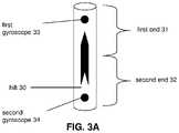
- FIG. 3Aillustrates an example of a hilt.
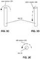
- FIG. 3Billustrates examples of rotational axes of a hilt.
- FIGS. 3C-3Eillustrate examples of rotations of a hilt.
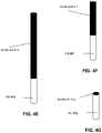
- FIGS. 4A-4Gillustrate examples of landmarks on hilts.
- FIGS. 5A-6Eillustrate examples of virtual blades augmenting the appearances of hilts.
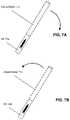
- FIGS. 7A-7Billustrate examples of virtual blade rotations.
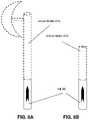
- FIGS. 8A-8Billustrate examples of changing virtual blades.
- FIG. 9illustrates an example of a virtual blade touching a virtual barrier.
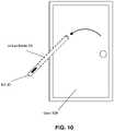
- FIG. 10illustrates an example of a virtual blade touching a door.
- FIG. 1illustrates a system 10 configured to simulate a feel of moving a virtual weapon.
- System 10may include one or more of processor 11 , display 12 , image sensor 13 , motion and orientation sensor 14 , gyroscope 15 , electronic storage 16 , bus 17 , a hilt, and/or other components.
- the hiltmay be configured to carry (e.g., attach to, support, hold, and/or otherwise carry) one or more components of system 10 .
- a position and/or an orientation of a virtual blade of the virtual weaponmay be determined.
- the virtual blademay be selected and placed within an overlay image according to the position and/or the orientation of the virtual blade.
- the overlay imagemay be displayed so that the virtual blade appears to be attached to the hilt.
- Controls for gyroscope 15may be determined based on the position and/or the orientation of the virtual blade. Gyroscope 15 may be operated in accordance with the controls for gyroscope 15 to provide resistance to changing the orientation of hilt. The resistance to changing the orientation of hilt may simulate the feel of moving the virtual weapon.
- system 10may include a speaker.
- system 10may include a haptic generator.
- Display 12may be configured to display an overlay image.
- display 12may include one or more of a head-mounted display, an optical head-mounted display, a see-through display, an optical see-through display, a video see-through display, a visor, eyeglasses, sunglasses, a smartphone, a tablet, a mobile device, a projector, and/or other displays.
- processor 11 and image sensor 13may be carried on display 12 , and the field of view of image sensor 13 may be a function of the position and the orientation of display 12 .
- Image sensor 13may be configured to generate visual output signals conveying visual information within the field of view of image sensor 13 .
- Visual informationmay include one or more of an image, a video, and/or other visual information.
- visual informationmay include one or more of an image, a video, and/or other visual information regarding the hilt.
- Image sensor 13may include one or more of a charge-coupled device sensor, an active pixel sensor, a complementary metal-oxide semiconductor sensor, an N-type metal-oxide-semiconductor sensor, and/or other image sensors.
- Motion and orientation sensor 14may be carried by the hilt. Motion and orientation sensor 14 may be configured to generate motion and/or orientation output signals conveying motion and/or orientation information of the hilt. Motion and/or orientation information of the hilt may characterize one or more motion and/or orientation of the hilt. Motion of the hilt may include one or more of movement of the hilt, change in position of the hilt, and/or other motion of the hilt at a time or over a period of time. In some implementations, motion of the hilt may include distance between display 12 and the hilt at a time or over a period of time.
- Orientation of the hiltmay include one or more of yaw, pitch, and/or roll of the hilt, change in yaw, pitch, and/or roll of the hilt, and/or other orientation of hilt at a time or over a period of time.
- motion and orientation sensor 14may include an inertial measurement unit and/or other motion and orientation sensors.
- An inertial measurement unitmay include one or more of accelerometers, gyroscopes, magnetometers, and/or other motion and orientation sensors.
- An inertial measurement unitmay include one or more of 3-DOF inertial measurement units, 6-DOF inertial measurement units, 9-DOF inertial measurement units, and/or other inertial measurement units.
- motion and orientation sensor 14may include one or more distance sensors, such as infrared distance sensors, Lidar, ultrasonic distance sensors, and/or other distance sensors.
- Gyroscope 15may be carried by the hilt.
- gyroscope 15may include a first gyroscope carried in a first portion of the hilt and a second gyroscope carried in a second portion of the hilt. The first portion and the second portion may be located in different ends of the hilt.
- FIG. 3Aillustrates hilt 30 in a form of a cylinder.
- Hilt 30includes first end 31 and second end 32 .
- Hilt 30includes a chevron marking, which points toward the end of first end 31 .
- Hilt 30includes first gyroscope 33 located in first end 31 , and second gyroscope 34 located in second end 32 .
- Other forms of hilt and other arrangements of gyroscopes carried by the hiltare contemplated.
- FIG. 3Billustrates three rotational axes on hilt 30 .
- Hilt 30includes a normal axis (yaw axis 35 a ) that is perpendicular to the plane formed by other two axes of hilt 30 .
- Hilt 30includes a lateral axis (pitch axis 36 a ) that runs along the lateral midline of hilt 30 .
- Hilt 30includes a longitudinal axis (roll axis 37 a ) that runs along the vertical midline of hilt 30 .
- FIGS. 3C-3Eillustrate examples of rotations of hilt 30 around axes shown in FIG. 3B .
- FIG. 3Cillustrates an example of rotation around yaw axis 35 a (yaw rotation 35 b ).
- FIG. 3Dillustrates an example of rotation around pitch axis 36 a (pitch rotation 36 b ).
- FIG. 3Eillustrates an example of rotation around roll axis 37 a (roll rotation 37 b ).
- a landmarkmay be carried by the hilt.
- the landmarkmay indicate a reference point for the hilt that facilitates determination of a position and/or an orientation of the virtual blade.
- the landmarkmay include an augmented reality marker, a light emitting diode, the entire shape of the hilt, one or more parts of the hilt, and/or other landmarks.
- An augmented reality markermay be two-dimensional or three-dimensional.
- an augmented reality markermay include one or more of a sticker, a label, a barcode, a quick response (QR) code, and/or other augmented reality markers.
- a hiltmay include multiples types of landmarks.
- a landmarkmay be carried by the hilt as described in U.S. patent application Ser. No. 15/001,160, entitled “SYSTEMS AND METHODS FOR AUGMENTING AN APPEARANCE OF A HILT TO SIMULATE A BLADED WEAPON,” filed Jan. 19, 2016, the foregoing being incorporated herein by reference in its entirety.
- Other types of landmarksare contemplated.
- FIGS. 4A-4Gprovide non-limiting examples of landmarks 41 on hilts 40 .
- hilt 40 aincludes landmark 41 a
- landmark 41 ais triangular in shape.
- hilt 40 bincludes landmark 41 b
- landmark 41 blooks like an upside-down exclamation mark.
- hilt 40 cincludes landmark 41 c
- landmark 41 cis a rectangular band running around hilt 40 c .
- hilt 40 dincludes landmark 41 d
- landmark 41 dlooks like long rectangles running around hilt 40 d .
- hilt 40 eincludes landmark 41 e
- landmark 41 eis a cylindrical blade attached to hilt 40 e
- hilt 40 fincludes landmark 41 f
- landmark 41 fis a short cylindrical blade attached to hilt 40 f
- hilt 40 gincludes landmark 41 g
- landmark 41 gis a rounded diffuser attached to hilt 40 g .
- Landmarks in FIGS. 4A-4Gmay include one or more light emitting diodes and/or other lighting elements. Other shapes and configurations of landmarks are contemplated.
- a hiltmay include multiples types of landmarks.
- hilt 40 cmay include landmark 41 c (shown in FIG. 4C ) on the front and landmark 41 d (shown in FIG. 4D ) on the back.
- landmark 41 cshown in FIG. 4C
- landmark 41 dshown in FIG. 4D
- Other combinations of landmarksare contemplated.
- Electronic storage 16may include electronic storage media that electronically stores information. Electronic storage 16 may store software algorithms, information determined by processor 11 , information received remotely, and/or other information that enables system 10 to function properly. For example, electronic storage 16 may store visual information (as discussed elsewhere herein), information relating to virtual blades of virtual weapons, information relating to operation of gyroscope 15 , and/or other information.
- Processor 11may be configured to provide information processing capabilities in system 10 .
- processor 11may comprise one or more of a digital processor, an analog processor, a digital circuit designed to process information, a central processing unit, a graphics processing unit, a microcontroller, an analog circuit designed to process information, a state machine, and/or other mechanisms for electronically processing information.
- Processor 11may be configured to execute one or more computer program components.
- the computer program componentsmay include one or more of position and orientation component 20 , blade effects component 21 , overlay component 22 , display component 23 , gyroscope control component 24 , and/or other components.
- Position and orientation component 20may be configured to determine a position and/or an orientation of a virtual blade of the virtual weapon based on the visual output signals and/or the motion and/or orientation output signals. When the hilt is within the field of view of image sensor 13 , position and orientation component 20 may be configured to determine a position and/or an orientation of the virtual blade based on the visual output signals conveying visual information within the field of view of image sensor 13 .
- Position and orientation component 20may detect a hilt based on the visual output signals. Position and orientation component 20 may determine a position and/or an orientation of the hilt. Position and orientation component 20 may include or retrieve information (for example, a database, etc.) that matches a detected hilt to a position and/or an orientation of a virtual blade. For example, position and orientation component 20 may determine a position of a virtual blade based on the position of the hilt, and/or an orientation of the virtual blade based on the orientation of the hilt.
- position and orientation component 20may detect hilt 30 a .
- Position and orientation component 20may determine a position and/or an orientation of hilt 30 a .
- position and orientation component 20may determine a position and/or an orientation of virtual blade 50 a for hilt 30 a .
- position and orientation component 20may detect hilt 30 b .
- Position and orientation component 20may determine a position and/or an orientation of hilt 30 b .
- position and orientation component 20may determine a position and/or an orientation of virtual blade 50 b for hilt 30 b .
- the position of virtual blade 50 a in FIG. 5Ais closer to a user than the position of virtual blade 50 b in FIG. 5B .
- the orientation of virtual blade 50 a in FIG. 5Ais vertical and the orientation of virtual blade 50 b in FIG. 5B is tilted to the right.
- position and orientation component 20may be configured to determine the position and/or the orientation of the virtual blade based on a position and/or an orientation of a landmark.
- the landmarkmay be carried by the hilt.
- the landmarkmay indicate a reference point for the hilt that facilitates determination of a position and/or an orientation (yaw, pitch, and/or roll) of the virtual blade.
- Position and orientation component 20may include or retrieve information (for example, a database, etc.) that matches a detected landmark to a position and/or an orientation of a virtual blade relative to the position and/or the orientation of the landmark.
- position and orientation component 20may determine the position of a virtual blade based on the position of a landmark, and/or the orientation of the virtual blade based on the orientation of the landmark.
- the position and/or the orientation of the virtual blademay be determined using systems and methods described in U.S. patent application Ser. No. 15/001,160, entitled “SYSTEMS AND METHODS FOR AUGMENTING AN APPEARANCE OF A HILT TO SIMULATE A BLADED WEAPON,” filed Jan. 19, 2016, incorporated supra.
- FIGS. 6A-6Eillustrate non-limiting examples of positions and orientations of virtual blades 60 determined based on positions and orientations of landmarks 41 .
- position and orientation component 20may detect landmark 41 a (shown in FIG. 6A ) and determine a position and/or an orientation of landmark 41 a .
- Position and orientation component 20may determine a position and/or an orientation of virtual blade 60 a based on the position and/or the orientation of landmark 41 a .
- Landmark 41 amay indicate the position and/or orientation of virtual blade 60 a .
- the position of virtual blade 60 amay be indicated by certain distances from landmark 41 a (e.g., the right, left, top, and/or bottom positions of virtual blade 60 a are determined by certain distances to the right, left, above, and/or below landmark 41 a ).
- the orientation of virtual blade 60 amay be indicated by the orientation of landmark 41 a (e.g., the pointed end of landmark 41 a points toward virtual blade 60 a ).
- position and orientation component 20may detect landmark 41 b (shown in FIG. 6B ) and determine a position and/or an orientation of landmark 41 b .
- Position and orientation component 20may determine a position and/or an orientation of virtual blade 60 b based on the position and/or the orientation of landmark 41 b .
- Landmark 41 bmay indicate the position and/or orientation of virtual blade 60 b .
- the position of virtual blade 60 bmay be indicated by certain distances from landmark 41 b (e.g., the right, left, top, and/or bottom positions of virtual blade 60 b are determined by certain distances to the right, left, above, and/or below landmark 41 b ).
- the orientation of virtual blade 60 bmay be indicated by the orientation of landmark 41 b (e.g., the dot-side of landmark 31 b points toward one end of virtual blade 60 b ).
- position and orientation component 20may detect both landmark 41 c (shown in FIG. 4C ) and landmark 41 d (shown in FIG. 4D ) on hilt 40 c and determine positions and/or orientations of landmark 41 c and landmark 41 d .
- Position and orientation component 20may determine a position and/or an orientation of virtual blade 60 c (shown in FIG. 6C ) based on the position(s) and/or the orientation(s) of landmark 41 c and/or landmark 41 d .
- Landmark 41 c and landmark 41 dmay indicate the position and/or orientation of virtual blade 60 c .
- the position of virtual blade 60 cmay be indicated by certain distances from landmark 41 c and/or landmark 41 d (e.g., the right, left, top, and/or bottom positions of virtual blade 60 c are determined by certain distances to the right, left, above, and/or below landmark 41 c and/or landmark 41 d ).
- the orientation of virtual blade 60 cmay be indicated by the orientation of landmark 41 c and/or landmark 41 d (e.g., the end of hilt 40 c close to landmark 41 c and/or landmark 41 d is close to the start of virtual blade 60 c , the front of virtual blade 60 c is indicated by landmark 41 c , and the back of virtual blade 60 c is indicated by landmark 41 d ).
- position and orientation component 20may detect landmark 41 e (shown in FIG. 4E ) and determine a position and/or an orientation of landmark 41 e .
- Position and orientation component 20may determine a position and/or an orientation of virtual blade 60 e (shown in FIG. 6D ) based on the position and/or the orientation of landmark 41 e .
- Landmark 41 emay indicate the position and/or orientation of virtual blade 60 e .
- the position of virtual blade 60 emay be indicated by certain distances from landmark 41 e (e.g., the right, left, top, and/or bottom positions of virtual blade 60 b are determined by certain the right, left, above, and/or bottom positions of landmark 41 e ).
- the orientation of virtual blade 60 emay be indicated by the orientation of landmark 41 e (e.g., the orientation of landmark 41 e is the orientation of virtual blade 60 e ).
- position and orientation component 20may be configured to determine the position and/or the orientation of the virtual blade based on the motion and/or orientation output signals. Position and orientation component 20 may determine changes in position and/or orientation of the hilt based on the motion and/or orientation output signals. Position and orientation component 20 may determine the position and/or the orientation of the hilt based on the changes in the position and/or the orientation of the hilt. In some implementations, position and orientation component 20 may determine the position and/or the orientation of the hilt with respect to display 12 based on systems and methods described in U.S. patent application Ser. No. 15/001,160, entitled “SYSTEMS AND METHODS FOR AUGMENTING AN APPEARANCE OF A HILT TO SIMULATE A BLADED WEAPON,” filed Jan. 19, 2016, incorporated supra.
- position and orientation component 20may be configured to determine a position and/or an orientation of a virtual blade based on the visual output signals and based on the motion and/or orientation output signals.
- position and orientation component 20may be configured to determine a position and/or an orientation of the virtual blade based on the visual output signals, and to adjust the position and/or the orientation of the virtual blade based on the motion and/or orientation output signals.
- Such a determination of the position and/or the orientation of a virtual blademay increase the accuracy of the position and/or the orientation of the virtual blade.
- position and orientation component 20may be configured to determine a position and/or an orientation of the virtual blade based on a previously determined position and/or a previously determined orientation of the virtual blade, and based on the motion and/or orientation output. For example, position and orientation component 20 may have determined a position and/or an orientation of the virtual blade, and may then determine a new position and/or a new orientation of the virtual blade based on the motion and/or orientation output signals. Such a determination of the new position and/or the new orientation of a virtual blade may allow position and orientation component 20 to avoid any latency arising from determining a position and/or an orientation of a virtual blade based on the visual output signals.
- position and orientation component 20may be configured to determine changes in a position and/or an orientation of a virtual blade.
- Changes in a position and/or an orientation of a virtual blademay include information regarding changes in a position and/or an orientation of a virtual blade at a time, over a period of time, at a location, or over a range of locations.
- changes in a position and/or an orientation of a virtual blademay include one or more information regarding change in position, direction of position change, speed of position change, acceleration of position change, change in orientation, direction of orientation change, speed of orientation change, acceleration of orientation change, and/or other information regarding changes in a position and/or an orientation of the virtual blade.
- Position and orientation component 20may determine changes in a position and/or an orientation of a virtual blade based on the visual output signals and/or the motion and orientation signals. For example, when the hilt is within the field of view of image sensor 13 , position and orientation component 20 may determine changes in a position and/or an orientation of a virtual blade based on the visual output signals. As another example, when the hilt is not within the field of view of image sensor 13 , position and orientation component 20 may determine changes in a position and/or an orientation of the hilt based on the motion and/or orientation output signals.
- position and orientation component 20may determine changes in a position and/or an orientation of a virtual blade based on the visual output signals and based on the motion and/or orientation output signals. In some implementations, position and orientation component 20 may determine changes in a position and/or an orientation of the virtual blade based on a previously determined position and/or a previously determined orientation of the virtual blade, and based on the motion and/or orientation output.
- Blade effects component 21may be configured to select a virtual blade.
- a virtual blademay be a blade of a real weapon, such as a broadsword, an axe, or a katana, or a fictional weapon, such as a lightsaber.
- blade effects component 21may be configured to select the virtual blade based on a user input received through an input device.
- An input devicemay refer to a device that allows a user to input information.
- an input devicemay include a key entry device, a touch entry device, an imaging device, a sound device, and/or other input devices.
- a user inputmay refer to one or more information provided by a user through an input device.
- a key entry devicemay include a device that allows a user to provide one or more user inputs by typing one or more of characters, numbers, and/or other symbols.
- a key entry devicemay include a separate device or a part of another device.
- a key entry devicemay include a keyboard/button coupled to processor 11 .
- a key entry devicemay include a mobile device coupled to processor 11 .
- a usermay provide one or more user inputs by typing one or more information.
- a usermay provide one or more user inputs by typing one or more of a type, shape, size, color, and/or other information about the virtual blade.
- a touch entry devicemay include a device that allows a user to provide user inputs by touching a user interface of the touch entry device.
- a touch entry devicemay include a separate device or a part of another device.
- a touch entry devicemay include a touch screen coupled to processor 11 .
- a touch entry devicemay include a mobile device coupled to processor 11 .
- a usermay provide one or more user inputs by touching one or more portions of the touch entry device corresponding to one or more information.
- a usermay provide one or more user inputs by touching one or more portions of the touch entry device corresponding to one or more of a type, shape, size, color, and/or other information about the virtual blade.
- An imaging devicemay include a device that allows a user to provide user inputs by using an image sensor of the imaging device.
- An imaging devicemay include a separate device or a part of another device.
- an imaging devicemay include an image sensor coupled to processor 11 .
- an imaging devicemay include image sensor 13 .
- an imaging devicemay include a mobile device coupled to processor 11 .
- a usermay provide one or more user inputs by directing the field of view of the imaging device to objects that include information.
- a usermay provide one or more user inputs by directing the field of view of the imaging device to a landmark, an augmented reality marker, and/or other objects that include one or more of a type, shape, size, color, and/or other information about the virtual blade.
- a sound devicemay include a device that allows a user to provide user inputs through voice and/or sounds.
- a sound devicemay include a separate device or part of another device.
- a sound devicemay include a microphone coupled to processor 11 .
- a sound devicemay include a mobile device coupled to processor 11 .
- a usermay provide one or more user input by speaking one or more information.
- a usermay provide one or more user inputs by speaking one or more of a type, shape, size, color, and/or other information about the virtual blade.
- blade effects component 21may be configured to select the virtual blade based on a landmark.
- Blade effects component 21may include or retrieve information (for example, a database, etc.) that matches a landmark to a particular virtual blade.
- the virtual blademay be selected as described in U.S. patent application Ser. No. 15/001,160, entitled “SYSTEMS AND METHODS FOR AUGMENTING AN APPEARANCE OF A HILT TO SIMULATE A BLADED WEAPON,” filed Jan. 19, 2016, incorporated supra.
- FIGS. 6A-6Eillustrate non-limiting examples of virtual blades selected by blade effects component 21 based on landmarks 41 .
- blade effects component 21may select virtual blade 60 a based on landmark 41 a .
- Virtual blade 60 ais cylindrical in shape and appears to extend outwardly from top of hilt 40 a .
- blade effects component 21may select virtual blade 60 b based on landmark 41 b .
- Virtual blade 60 bis cylindrical in shape and appears to extend outwardly from top and bottom of hilt 40 b.
- blade effects component 21may select virtual blade 60 c based on landmark 41 c and landmark 41 d .
- Virtual blade 60 cis curved and appears to extend outwardly from top of hilt 40 c .
- Virtual blade 60 ccurves towards the back of hilt 40 c , with landmark 41 d indicating the back of hilt 40 c and landmark 41 c indicating the front of hilt 40 c.
- blade effects component 21may select virtual blade 60 e based on landmark 41 e (shown in FIG. 4E ).
- Virtual blade 60 eis cylindrical in shape appears to extend outwardly from top of hilt 40 e .
- landmark 41 emay not be visible.
- blade effects component 21may select virtual blade 60 f based on landmark 41 f (shown in FIG. 4F ).
- Virtual blade 60 fis cylindrical in shape appears to extend outwardly from top of hilt 40 f .
- landmark 41 fmay not be visible.
- blade effects component 21may select virtual blade 60 e (shown in FIG. 6D ) based on landmark 41 f (shown in FIG. 4F ) or landmark 41 g (shown in FIG. 4G ).
- landmark 41 fmay not be visible.
- Virtual blade 60 emay be longer than landmark 41 f .
- landmark 41 gmay not be visible.
- Virtual blade 60 emay be larger than landmark 41 g .
- Other selections of blades based on landmarksare contemplated.
- Overlay component 22may be configured to determine an overlay image.
- the overlay imagemay include a virtual blade of a virtual weapon determined by blade effects component 21 .
- the virtual blademay be placed within the overlay image according to the position and/or the orientation of the virtual blade.
- the position and/or the orientation of the virtual blademay change how the virtual blade appears within the overlay image. For example, the position and/or the orientation of the virtual blade may change one or more of the position, the size, the shape, the tilt, the rotation, and/or other appearances of the virtual blade.
- Display component 23may be configured to effectuate displaying of an overlay image on display 12 .
- the displayingmay be effectuated so that the virtual blade appears to be attached to the hilt.
- display component 23may be configured to effectuate displaying of an overlay image within one or more of an image, a video, and/or other visual information based on the visual output signals generated by image sensor 13 .
- display component 23may be configured to effectuate displaying of an overlay image on display 12 , which allows light to be passed through display 12 in portions in which the overlay image does not contain the virtual blade.
- display 12may include one or more of an optical head-mounted display and a user of display 12 may see light from the real world as well as the overlay image.
- display component 23may be configured to change the transparency of one or more portions of display 12 .
- display component 23may change the transparency of one or more portions of display 12 corresponding to the virtual blade to block light from the real world passing through display 12 .
- Gyroscope control component 24may be configured to determine controls for gyroscope 15 based on the position and/or the orientation of the virtual blade.
- the controls for gyroscope 15may determine one or more of speed and/or direction of rotation of gyroscope 15 around one or more axis at a time, over a period of time, at a location, or over a range of locations.
- the controls for gyroscope 15may determine one or more of direction and/or speed of yaw rotation, roll rotation, and/or pitch rotation of gyroscope 15 .
- FIGS. 5A and 5Billustrate examples of virtual blade 50 in different positions and orientations. Comparing FIGS. 5A and 5B , virtual blade 50 a is closer to the user than virtual blade 50 b . Virtual blade 50 a is oriented vertically while virtual blade 50 b is tilted to the right. Gyroscope control component 24 may determine different controls for virtual blade 50 a and virtual blade 50 b .
- gyroscope control component 24may determine low speed(s) of rotation around one or more axes for gyroscope 15 based on the position and/or orientation of virtual blade 50 a , and high speed(s) of rotation around one or more axes for gyroscope 15 based on the position and/or orientation of virtual blade 50 b .
- Low speed(s) of rotation by gyroscope 15may provide low resistance to changing the orientation of hilt 30 a .
- High speed(s) of rotation by gyroscope 15may provide high resistance to changing the orientation of hilt 30 b.
- the resistance to changing the orientation of hilt 30may simulate the feel of moving a virtual weapon.
- low resistance to changing the orientation of hilt 30 amay simulate the feel of moving a virtual lightsaber held close and upright (e.g., to simulate gravity on the virtual blade).
- high resistance to changing the orientation of hilt 30 bmay simulate the feel of moving a virtual lightsaber held far and tilted (e.g., to simulate gravity on the virtual blade).
- gyroscope control component 24may be configured to determine the controls for gyroscope 15 based on changes in a position and/or an orientation of a virtual blade.
- Changes in a position and/or an orientation of a virtual blademay include information regarding changes in a position and/or an orientation of a virtual blade at a time, over a period of time, at a location, or over a range of locations.
- changes in a position and/or an orientation of a virtual blademay include one or more information regarding change in position, direction of position change, speed of position change, acceleration of position change, change in orientation, direction of orientation change, speed of orientation change, acceleration of orientation change, and/or other information regarding changes in a position and/or an orientation of the virtual blade.
- Gyroscope control component 24may determine one or more of speed and/or direction of rotation of gyroscope 15 around one or more axis based on the changes in the position and/or the orientation of the virtual blade. For example, the position and orientation of virtual blade 50 may change from the position and orientation shown in FIG. 5A to the position and orientation shown in and FIG. 5B . Based on the changes in the position and the orientation of virtual blade 50 , gyroscope control component 24 may increase the speed of rotation around one or more axes by gyroscope 15 .
- FIGS. 7A and 7Billustrate examples of rotations of virtual blade 71 .
- virtual blade 71 aattached to hilt 70 a , may be rotated downwards.
- gyroscope control component 24may determine low speed(s) of rotation around one or more axes for gyroscope 15 .
- Low speed(s) of rotation by gyroscope 15may provide low resistance to changing the orientation of hilt 70 a downwards and may simulate the feel of moving the virtual weapon downwards (e.g., to simulate downward movement assisted by gravity).
- virtual blade 71 battached to hilt 70 b , may be rotated upwards and then downwards.
- gyroscope control component 24may determine high speed(s) of rotation around one or more axes for gyroscope 15 .
- High speed(s) of rotation by gyroscope 15may provide high resistance to changing the orientation of hilt 70 b upwards and may simulate the feel of moving the virtual weapon upwards (e.g., to simulate upward movement opposed by gravity).
- gyroscope control component 24may determine low speed(s) of rotation around one or more axes for gyroscope 15 .
- Low speed(s) of rotation by gyroscope 15may provide low resistance to changing the orientation of hilt 70 b downwards and may simulate the feel of moving the virtual weapon downwards (e.g., to simulate downward movement assisted by gravity).
- system 10may be configured to determine the controls for gyroscope 15 to simulate changes in a virtual blade.
- Blade effects component 21may be configured to change the type, the shape and/or the size of the virtual blade. For example, as shown in FIGS. 8A and 8B , blade effects component 21 may change virtual blade 81 for hilt 80 .
- virtual blade 81 aappears as a blade of an axe.
- virtual blade 81 bappears as a short cylinder, simulating the top portion of the axe blade having broken off.
- Other types of changes in a virtual bladeare contemplated.
- Gyroscope control component 24may be configured to determine the controls for gyroscope 15 based on the changed type, the changed shape and/or the changed size of the virtual blade. For example, in FIG. 8A , gyroscope control component 24 may determine high speed(s) of rotation around one or more axes for gyroscope 15 . High speed(s) of rotation by gyroscope 15 may provide high resistance to changing the orientation of hilt 80 and may simulate the feel of moving a heavy virtual weapon (e.g., to simulate heavy blade of an axe). In FIG. 8B , gyroscope control component 24 may determine low speed(s) of rotation around one or more axes for gyroscope 15 . Low speed(s) of rotation by gyroscope 15 may provide low resistance to changing the orientation of hilt 80 and may simulate the feel of moving a light virtual weapon (e.g., to simulate heavy blade of an axe being broken off).
- system 10may be configured to determine the controls for gyroscope 15 to simulate interactions between the virtual blade and an object.
- An objectmay be a physical object or a virtual object.
- a physical objectmay refer to an object in the real world.
- a physical objectmay include a static object (e.g., a still door, a wall, a rock, etc.) or a dynamic object (e.g., a moving door, a moving target, etc.).
- a virtual objectmay refer to an object generated by a computing device, such as processor 11 .
- a virtual objectmay include a static object (e.g., a virtual barrier, a still virtual blade of another hilt, etc.) or a dynamic object (e.g., a moving virtual blade of another hilt, a virtual blaster fire, a virtual moving robot, etc.).
- a static objecte.g., a virtual barrier, a still virtual blade of another hilt, etc.
- a dynamic objecte.g., a moving virtual blade of another hilt, a virtual blaster fire, a virtual moving robot, etc.
- Position and orientation component 20may be configured to detect an object based on the visual output signals. Position and orientation component 20 may be configured to determine when the virtual blade touches the object. Gyroscope control component 24 may be configured to determine the controls for gyroscope 15 based on the virtual blade touching the object.
- Position and orientation component 20may determine a position and/or an orientation of the object based on the visual output signals conveying visual information within the field of view of image sensor 13 . Position and orientation component 20 may determine when the virtual blade touches the object based on the position and/or the orientation of the virtual blade, and the position and/or the orientation of the object. Other implementations to determine when the virtual blade touches the objects are contemplated.
- Gyroscope control component 24may determine controls for gyroscope 15 based on the virtual blade touching the object. Gyroscope control component 24 may determine one or more of speed and/or direction of rotation of gyroscope 15 around one or more axis based on the virtual blade touching the object. For example, FIG. 9 shows virtual blade touching virtual barrier 90 . When virtual blade 50 is touching virtual barrier 90 , gyroscope control component 24 may determine high speed(s) of rotation around one or more axes for gyroscope 15 .
- High speed(s) of rotation by gyroscope 15may provide high resistance to changing the orientation of hilt 30 and may simulate the feel of moving a virtual weapon into an object (e.g., to simulate virtual blade 50 slicing into virtual barrier 90 ).
- gyroscope control component 24may determine low speed(s) of rotation around one or more axes for gyroscope 15 .
- Low speed(s) of rotation by gyroscope 15may provide low resistance to changing the orientation of hilt 30 and may simulate the feel of moving a virtual weapon in the air.
- FIG. 10shows virtual blade 50 touching door 100 .
- virtual blade 50is pushed into door 100 and moved in a circular shape.
- gyroscope control component 24may determine high speed(s) of rotation around one or more axes for gyroscope 15 .
- High speed(s) of rotation by gyroscope 15may provide high resistance to changing the orientation of hilt 30 and may simulate the feel of moving a virtual weapon into an object (e.g., to simulate virtual blade 50 slicing into door 100 ).
- Gyroscope control component 24may be configured to effectuate operation of gyroscope 15 in accordance with the controls for gyroscope 15 .
- Gyroscope control component 24may effectuate speed and/or direction of rotation of gyroscope 15 around one or more axis.
- Gyroscope 15may be operated to provide resistance to changing the orientation of the hilt. The resistance to changing the orientation of the hilt may simulate the feel of moving the virtual weapon, as described above.
- system 10may include a speaker.
- Blade effects component 21may be configured to effectuate operation of the speaker.
- the operation of the speakermay be effectuated in response to changes in the position and/or the orientation of the virtual blade based one or more of the visual output signals and/or the motion and/or orientation output signals.
- the speakermay be operated to provide one or more audio effects.
- An audio effectmay refer to one or more information that may be observed audibly.
- An audio effectmay be static or dynamic, and may be audibly observable at a time, over a period of time, at a location, or over a range of locations.
- An audio effectmay include one or more of a sound, a music, a word, a sentence, and/or other audio effect.
- blade effects component 21may have selected a blade of a lightsaber as the virtual blade for a hilt.
- blade effects component 21may effectuate operation of the speaker to produce a buzzing/humming sound of a motionless lightsaber.
- blade effects component 21may effectuate operation of the speaker to produce a “wah” sound of a moving lightsaber.
- Blade effects component 21may be configured to change the intensity and/or length of the sound based on the movement of the virtual blade.
- blade effects component 21may be configured to effectuate operation of the speaker based on the virtual blade touching an object. For example, in FIG. 9 , blade effects component 21 may effectuate the operation of the speaker to produce a cutting sound when virtual blade 50 is pushed into virtual barrier 90 . Other types of audio effects are contemplated.
- system 10may include a haptic generator.
- Blade effects component 21may be configured to effectuate operation of the haptic generator in response to changes in the position and/or the orientation of the virtual blade based one or more of the visual output signals and/or the motion and/or orientation output signals.
- the haptic generatormay be operated to provide one or more haptic effects.
- a haptic effectmay refer to one or more information that may be observed haptically.
- a haptic effectmay be static or dynamic, and may be haptically observable at a time, over a period of time, at a location, or over a range of locations.
- a haptic effectmay include one or more of a vibration, a motion, a temperature, and/or other haptic effects.
- blade effects component 21may have selected a blade of a lightsaber as the virtual blade for a hilt. Blade effects component 21 may effectuate operation of the haptic generator to produce a light vibration of a lightsaber. Blade effects component 21 may be configured to change the intensity and/or length of the vibration based on the movement of the virtual blade.
- blade effects component 21may be configured to effectuate operation of the haptic generator based on the virtual blade touching the object. For example, in FIG. 9 , blade effects component 21 may effectuate the operation of the haptic generator to produce heat when virtual blade 50 is pushed into virtual barrier 90 . Other types of haptic effects are contemplated.
- processor 11may communicate with each other through hard-wired communication, wireless communication, or both.
- processor 11may wirelessly communicate with motion and orientation sensor 14 .
- wireless communicationmay include one or more of radio communication, Bluetooth communication, Wi-Fi communication, cellular communication, infrared communication, or other wireless communication. Other types of communications are contemplated by the present disclosure.
- processor 11is shown in FIG. 1 as a single entity, this is for illustrative purposes only. In some implementations, processor 11 may comprise a plurality of processing units. These processing units may be physically located within the same device, or processor 11 may represent processing functionality of a plurality of devices operating in coordination.
- Processor 11may be configured to execute one or more of position and orientation component 20 , blade effects component 21 , overlay component 22 , display component 23 , gyroscope control component 24 , and/or other components by software; hardware; firmware; some combination of software, hardware, and/or firmware; and/or other mechanisms for configuring processing capabilities on processor 11 .
- position and orientation component 20blade effects component 21 , overlay component 22 , display component 23 , and gyroscope control component 24 are illustrated in FIG. 1 as being co-located within a single processing unit, in implementations in which processor 11 comprises multiple processing units, one or more of position and orientation component 20 , blade effects component 21 , overlay component 22 , display component 23 and/or gyroscope control component 24 may be located remotely from the other computer program components.
- any of computer program components 20 , 21 , 22 , 23 , and/or 24may provide more or less functionality than is described.
- one or more of computer program components 20 , 21 , 22 , 23 , and/or 24may be eliminated, and some or all of its functionality may be provided by other computer program components 20 , 21 , 22 , 23 , and/or 24 .
- processor 11may be configured to execute one or more additional computer program components that may perform some or all of the functionality attributed to one or more of computer program components 20 , 21 , 22 , 23 , and/or 24 .
- Display 12is depicted in FIG. 1 as a single element, this is not intended to be limiting. Display 12 may include one or more displays in one or more locations.
- image sensor 13is depicted in FIG. 1 as a single element, this is not intended to be limiting. Image sensor 13 may include one or more image sensors in one or more locations.
- Motion and orientation sensor 14is depicted in FIG. 1 as single elements, this is not intended to be limiting. Motion and orientation sensor 14 may include one or more motion and orientation sensors in one or more locations.
- Gyroscope 15is depicted in FIG. 1 as single elements, this is not intended to be limiting. Gyroscope 15 may include one or more gyroscopes in one or more locations.
- the electronic storage media of electronic storage 16may be provided integrally (i.e., substantially non-removable) with one or more components of system 10 and/or removable storage that is connectable to one or more components of system 10 via, for example, a port (e.g., a USB port, a Firewire port, etc.) or a drive (e.g., a disk drive, etc.).
- a porte.g., a USB port, a Firewire port, etc.
- a drivee.g., a disk drive, etc.
- Electronic storage 16may include one or more of optically readable storage media (e.g., optical disks, etc.), magnetically readable storage media (e.g., magnetic tape, magnetic hard drive, floppy drive, etc.), electrical charge-based storage media (e.g., EPROM, EEPROM, RAM, etc.), solid-state storage media (e.g., flash drive, etc.), and/or other electronically readable storage media.
- Electronic storage 16may be a separate component within system 10 , or electronic storage 16 may be provided integrally with one or more other components of system 10 (e.g., processor 11 ). Although electronic storage 16 is shown in FIG. 1 as a single entity, this is for illustrative purposes only. In some implementations, electronic storage 16 may comprise a plurality of storage units. These storage units may be physically located within the same device, or electronic storage 16 may represent storage functionality of a plurality of devices operating in coordination.
- FIG. 2illustrates method 200 for simulating a feel of moving a virtual weapon.
- the operations of method 200 presented beloware intended to be illustrative. In some implementations, method 200 may be accomplished with one or more additional operations not described, and/or without one or more of the operations discussed. In some implementations, two or more of the operations may occur substantially simultaneously.
- method 200may be implemented in one or more processing devices (e.g., a digital processor, an analog processor, a digital circuit designed to process information, a central processing unit, a graphics processing unit, a microcontroller, an analog circuit designed to process information, a state machine, and/or other mechanisms for electronically processing information).
- the one or more processing devicesmay include one or more devices executing some or all of the operations of method 200 in response to instructions stored electronically on one or more electronic storage mediums.
- the one or more processing devicesmay include one or more devices configured through hardware, firmware, and/or software to be specifically designed for execution of one or more of the operations of method 200 .
- visual output signals conveying visual information within a field of view of an image sensormay be generated.
- Visual informationmay include one or more of an image, a video, and/or other visual information.
- operation 201may be performed by one or more sensors the same as or similar to image sensor 13 (shown in FIG. 1 and described herein).
- motion and/or orientation output signals conveying motion and/or orientation information of a hiltmay be generated.
- operation 202may be performed by one or more sensors the same as or similar to motion and orientation sensor 14 (shown in FIG. 1 and described herein).
- a position and/or an orientation of a virtual blade of a virtual weaponmay be determined based on the visual output signals and/or the motion and/or orientation output signals.
- operation 203may be performed by a processor component the same as or similar to position and orientation component 20 (shown in FIG. 1 and described herein).
- an overlay image comprising the virtual blade of the virtual weaponmay be determined.
- the virtual blademay be placed within the overly image according to the position and/or the orientation of the virtual blade.
- operation 204may be performed by a processor component the same as or similar to overlay component 22 (shown in FIG. 1 and described herein).
- displaying of the overlay image on a displaymay be effectuated so that the virtual blade appear to be attached to the hilt.
- operation 205may be performed by a processor component the same as or similar to display component 23 (shown in FIG. 1 and described herein).
- controls for a gyroscopemay be determined based on the position and/or the orientation of the virtual blade.
- operation 206may be performed by a processor component the same as or similar to gyroscope control component 24 (shown in FIG. 1 and described herein).
- operation of the gyroscopemay be effectuated in accordance with the controls for the gyroscope to provide resistance to changing the orientation of the hilt.
- the resistance to changing the orientation of the hiltmay simulate the feel of moving the virtual weapon.
- operation 207may be performed by a processor component the same as or similar to gyroscope control component 24 (shown in FIG. 1 and described herein).
Landscapes
- Engineering & Computer Science (AREA)
- General Engineering & Computer Science (AREA)
- Physics & Mathematics (AREA)
- Theoretical Computer Science (AREA)
- Computer Hardware Design (AREA)
- Evolutionary Computation (AREA)
- Geometry (AREA)
- General Physics & Mathematics (AREA)
- User Interface Of Digital Computer (AREA)
Abstract
Description
Claims (21)
Priority Applications (1)
| Application Number | Priority Date | Filing Date | Title |
|---|---|---|---|
| US15/001,188US11351472B2 (en) | 2016-01-19 | 2016-01-19 | Systems and methods for using a gyroscope to change the resistance of moving a virtual weapon |
Applications Claiming Priority (1)
| Application Number | Priority Date | Filing Date | Title |
|---|---|---|---|
| US15/001,188US11351472B2 (en) | 2016-01-19 | 2016-01-19 | Systems and methods for using a gyroscope to change the resistance of moving a virtual weapon |
Publications (2)
| Publication Number | Publication Date |
|---|---|
| US20170203225A1 US20170203225A1 (en) | 2017-07-20 |
| US11351472B2true US11351472B2 (en) | 2022-06-07 |
Family
ID=59315192
Family Applications (1)
| Application Number | Title | Priority Date | Filing Date |
|---|---|---|---|
| US15/001,188Active2039-11-12US11351472B2 (en) | 2016-01-19 | 2016-01-19 | Systems and methods for using a gyroscope to change the resistance of moving a virtual weapon |
Country Status (1)
| Country | Link |
|---|---|
| US (1) | US11351472B2 (en) |
Cited By (1)
| Publication number | Priority date | Publication date | Assignee | Title |
|---|---|---|---|---|
| US20210072841A1 (en)* | 2018-05-09 | 2021-03-11 | Dreamscape Immersive, Inc. | User-Selectable Tool for an Optical Tracking Virtual Reality System |
Families Citing this family (41)
| Publication number | Priority date | Publication date | Assignee | Title |
|---|---|---|---|---|
| US8020095B2 (en) | 1997-11-14 | 2011-09-13 | Immersion Corporation | Force feedback system including multi-tasking graphical host environment |
| US8947216B2 (en) | 2012-11-02 | 2015-02-03 | Immersion Corporation | Encoding dynamic haptic effects |
| US9898084B2 (en) | 2012-12-10 | 2018-02-20 | Immersion Corporation | Enhanced dynamic haptic effects |
| US9202352B2 (en) | 2013-03-11 | 2015-12-01 | Immersion Corporation | Automatic haptic effect adjustment system |
| US9092954B2 (en) | 2013-03-15 | 2015-07-28 | Immersion Corporation | Wearable haptic device |
| US10162416B2 (en) | 2013-09-06 | 2018-12-25 | Immersion Corporation | Dynamic haptic conversion system |
| US9207764B2 (en) | 2013-09-18 | 2015-12-08 | Immersion Corporation | Orientation adjustable multi-channel haptic device |
| US9213408B2 (en) | 2013-10-08 | 2015-12-15 | Immersion Corporation | Generating haptic effects while minimizing cascading |
| US9619029B2 (en) | 2013-11-14 | 2017-04-11 | Immersion Corporation | Haptic trigger control system |
| US9164587B2 (en) | 2013-11-14 | 2015-10-20 | Immersion Corporation | Haptic spatialization system |
| US10254836B2 (en) | 2014-02-21 | 2019-04-09 | Immersion Corporation | Haptic power consumption management |
| US10185396B2 (en) | 2014-11-12 | 2019-01-22 | Immersion Corporation | Haptic trigger modification system |
| US10613628B2 (en) | 2014-12-23 | 2020-04-07 | Immersion Corporation | Media driven haptics |
| US10269392B2 (en) | 2015-02-11 | 2019-04-23 | Immersion Corporation | Automated haptic effect accompaniment |
| US10216277B2 (en) | 2015-02-25 | 2019-02-26 | Immersion Corporation | Modifying haptic effects for slow motion |
| KR20160105321A (en) | 2015-02-27 | 2016-09-06 | 임머숀 코퍼레이션 | Generating actions based on a user's mood |
| KR20170139508A (en) | 2015-04-21 | 2017-12-19 | 임머숀 코퍼레이션 | Dynamic rendering of etch input |
| US10261582B2 (en) | 2015-04-28 | 2019-04-16 | Immersion Corporation | Haptic playback adjustment system |
| US10109161B2 (en) | 2015-08-21 | 2018-10-23 | Immersion Corporation | Haptic driver with attenuation |
| US9846971B2 (en) | 2016-01-19 | 2017-12-19 | Disney Enterprises, Inc. | Systems and methods for augmenting an appearance of a hilt to simulate a bladed weapon |
| US11351472B2 (en) | 2016-01-19 | 2022-06-07 | Disney Enterprises, Inc. | Systems and methods for using a gyroscope to change the resistance of moving a virtual weapon |
| US11663783B2 (en) | 2016-02-10 | 2023-05-30 | Disney Enterprises, Inc. | Systems and methods for using augmented reality with the internet of things |
| US10587834B2 (en) | 2016-03-07 | 2020-03-10 | Disney Enterprises, Inc. | Systems and methods for tracking objects for augmented reality |
| US10556175B2 (en) | 2016-06-10 | 2020-02-11 | Immersion Corporation | Rendering a haptic effect with intra-device mixing |
| US10401962B2 (en) | 2016-06-21 | 2019-09-03 | Immersion Corporation | Haptically enabled overlay for a pressure sensitive surface |
| US10210724B2 (en) | 2016-06-29 | 2019-02-19 | Immersion Corporation | Real-time patterned haptic effect generation using vibrations |
| US10147460B2 (en) | 2016-12-28 | 2018-12-04 | Immersion Corporation | Haptic effect generation for space-dependent content |
| US10564725B2 (en) | 2017-03-23 | 2020-02-18 | Immerson Corporation | Haptic effects using a high bandwidth thin actuation system |
| US10366584B2 (en) | 2017-06-05 | 2019-07-30 | Immersion Corporation | Rendering haptics with an illusion of flexible joint movement |
| US10194078B2 (en) | 2017-06-09 | 2019-01-29 | Immersion Corporation | Haptic enabled device with multi-image capturing abilities |
| US20190041987A1 (en) | 2017-08-03 | 2019-02-07 | Immersion Corporation | Haptic effect encoding and rendering system |
| US10477298B2 (en) | 2017-09-08 | 2019-11-12 | Immersion Corporation | Rendering haptics on headphones with non-audio data |
| US10583359B2 (en) | 2017-12-28 | 2020-03-10 | Immersion Corporation | Systems and methods for providing haptic effects related to touching and grasping a virtual object |
| US10481680B2 (en) | 2018-02-02 | 2019-11-19 | Disney Enterprises, Inc. | Systems and methods to provide a shared augmented reality experience |
| US10546431B2 (en) | 2018-03-29 | 2020-01-28 | Disney Enterprises, Inc. | Systems and methods to augment an appearance of physical object for an augmented reality experience |
| US10665067B2 (en) | 2018-06-15 | 2020-05-26 | Immersion Corporation | Systems and methods for integrating haptics overlay in augmented reality |
| US10974132B2 (en) | 2018-10-02 | 2021-04-13 | Disney Enterprises, Inc. | Systems and methods to provide a shared interactive experience across multiple presentation devices based on detection of one or more extraterrestrial bodies |
| FR3086870B1 (en)* | 2018-10-03 | 2021-01-15 | Groupe Ldlc | LASER SABER TYPE ACCESSORY |
| US11014008B2 (en) | 2019-03-27 | 2021-05-25 | Disney Enterprises, Inc. | Systems and methods for game profile development based on virtual and/or real activities |
| US10916061B2 (en) | 2019-04-24 | 2021-02-09 | Disney Enterprises, Inc. | Systems and methods to synchronize real-world motion of physical objects with presentation of virtual content |
| US10918949B2 (en) | 2019-07-01 | 2021-02-16 | Disney Enterprises, Inc. | Systems and methods to provide a sports-based interactive experience |
Citations (81)
| Publication number | Priority date | Publication date | Assignee | Title |
|---|---|---|---|---|
| USRE34728E (en) | 1988-12-20 | 1994-09-13 | Heartbeat Corp. | Video game difficulty level adjuster dependent upon player's aerobic activity level during exercise |
| US6152856A (en) | 1996-05-08 | 2000-11-28 | Real Vision Corporation | Real time simulation using position sensing |
| US6162123A (en) | 1997-11-25 | 2000-12-19 | Woolston; Thomas G. | Interactive electronic sword game |
| US20020024675A1 (en)* | 2000-01-28 | 2002-02-28 | Eric Foxlin | Self-referenced tracking |
| US20040002634A1 (en) | 2002-06-28 | 2004-01-01 | Nokia Corporation | System and method for interacting with a user's virtual physiological model via a mobile terminal |
| US20040077462A1 (en) | 2000-04-28 | 2004-04-22 | Brown Michael Wayne | Method for monitoring cumulative fitness activity |
| US20070126700A1 (en) | 2005-12-05 | 2007-06-07 | Cypress Semiconductor Corporation | Method and apparatus for sensing motion of a user interface mechanism using optical navigation technology |
| US20070252815A1 (en) | 2006-04-26 | 2007-11-01 | Pixart Imaging, Inc. | Interactive game apparatus and game controller used in the same |
| US20080039206A1 (en) | 2006-08-11 | 2008-02-14 | Jonathan Ackley | Interactive installation for interactive gaming |
| US20080146334A1 (en) | 2006-12-19 | 2008-06-19 | Accenture Global Services Gmbh | Multi-Player Role-Playing Lifestyle-Rewarded Health Game |
| US7402105B1 (en) | 2005-11-23 | 2008-07-22 | Robert J Hutter | Massively multiplayer educational online role playing game |
| US20080274805A1 (en) | 2007-05-02 | 2008-11-06 | Ganz, An Ontario Partnership Consisting Of 2121200 Ontario Inc. And 2121812 Ontario Inc. | Attribute building for characters in a virtual environment |
| US20090307611A1 (en) | 2008-06-09 | 2009-12-10 | Sean Riley | System and method of providing access to virtual spaces that are associated with physical analogues in the real world |
| US20090309891A1 (en) | 2008-06-12 | 2009-12-17 | Microsoft Corporation | Avatar individualized by physical characteristic |
| US20090325701A1 (en) | 2008-06-30 | 2009-12-31 | Accenture Global Services Gmbh | Gaming system |
| US7719563B2 (en) | 2003-12-11 | 2010-05-18 | Angus Richards | VTV system |
| US7765111B2 (en) | 1992-11-17 | 2010-07-27 | Health Hero Network, Inc. | Method and apparatus for remote health monitoring and providing health related information |
| US20100261526A1 (en) | 2005-05-13 | 2010-10-14 | Anderson Thomas G | Human-computer user interaction |
| US8016680B1 (en) | 2004-11-23 | 2011-09-13 | Robert J Hutter | Massively multiplayer educational online role playing game |
| US20110250962A1 (en) | 2010-04-09 | 2011-10-13 | Feiner Steven K | System and method for a 3d computer game with true vector of gravity |
| US20120050535A1 (en) | 2010-08-31 | 2012-03-01 | Gilray Densham | System and method for tracking |
| US20120254749A1 (en) | 2011-03-29 | 2012-10-04 | Archinoetics, Llc | System And Method For Controlling Life Goals |
| US20120262365A1 (en) | 2011-04-12 | 2012-10-18 | Sony Computer Entertainment, Inc. | Object tracking with projected reference patterns |
| US20120327117A1 (en) | 2011-06-23 | 2012-12-27 | Limitless Computing, Inc. | Digitally encoded marker-based augmented reality (ar) |
| US20130042296A1 (en)* | 2011-08-09 | 2013-02-14 | Ryan L. Hastings | Physical interaction with virtual objects for drm |
| US20130044128A1 (en) | 2011-08-17 | 2013-02-21 | James C. Liu | Context adaptive user interface for augmented reality display |
| US8506396B1 (en) | 2009-04-10 | 2013-08-13 | Humana Inc. | Online game to promote physical activity |
| US20130229396A1 (en) | 2012-03-05 | 2013-09-05 | Kenneth J. Huebner | Surface aware, object aware, and image aware handheld projector |
| US20130286004A1 (en) | 2012-04-27 | 2013-10-31 | Daniel J. McCulloch | Displaying a collision between real and virtual objects |
| US20140002329A1 (en) | 2012-06-29 | 2014-01-02 | Sony Computer Entertainment Inc. | Image processing device, image processing method, and image processing system |
| US20140003651A1 (en) | 2012-06-27 | 2014-01-02 | Disney Enterprises, Inc. | Electronic Devices in Local Interactions between Users |
| US20140078517A1 (en) | 2007-09-26 | 2014-03-20 | Elbit Systems Ltd. | Medical wide field of view optical tracking system |
| US20140080109A1 (en)* | 2012-09-19 | 2014-03-20 | Disney Enterprises, Inc. | Immersive storytelling environment |
| US20140104169A1 (en) | 2011-05-04 | 2014-04-17 | Eberhard Karls Universitaet Teubingen | Method for Determining the Relative Position of an Object in an Area, and Optical Input System |
| US20140116469A1 (en) | 2012-10-26 | 2014-05-01 | Sangyun KIM | Robot cleaner system and control method of the same |
| US20140160117A1 (en) | 2011-06-14 | 2014-06-12 | Youval Nehmadi | Method for translating the location, orientation and movement of a predefined object into computer generated data |
| US20150035677A1 (en) | 2013-07-31 | 2015-02-05 | Rondish Company Limited | Bed Monitor Sensor Device |
| US20150201188A1 (en) | 2014-01-15 | 2015-07-16 | Disney Enterprises, Inc, | Light-based caustic surface calibration |
| US20150243286A1 (en) | 2014-02-11 | 2015-08-27 | Disney Enterprises, Inc. | Storytelling environment: distributed immersive audio soundscape |
| US20150248785A1 (en) | 2014-03-03 | 2015-09-03 | Yahoo! Inc. | 3-dimensional augmented reality markers |
| US20160055677A1 (en) | 2014-08-25 | 2016-02-25 | Google Inc. | Methods and Systems for Augmented Reality to Display Virtual Representations of Robotic Device Actions |
| US9364746B2 (en) | 2009-02-20 | 2016-06-14 | Activision Publishing, Inc. | System and method configured to unlock content within a videogame |
| US20160189411A1 (en) | 2014-12-26 | 2016-06-30 | Nintendo Co., Ltd. | Image display system, image display apparatus, image display method, and non-transitory storage medium encoded with computer readable program |
| US20160206957A1 (en) | 2015-01-20 | 2016-07-21 | Disney Enterprises, Inc. | Tracking specific gestures relative to user movement |
| US20160247324A1 (en) | 2015-02-25 | 2016-08-25 | Brian Mullins | Augmented reality content creation |
| US20160253842A1 (en) | 2015-02-27 | 2016-09-01 | Microsoft Technology Licensing, Llc | Molding and anchoring physically constrained virtual environments to real-world environments |
| US20160260261A1 (en) | 2015-03-06 | 2016-09-08 | Illinois Tool Works Inc. | Sensor assisted head mounted displays for welding |
| US20160274662A1 (en) | 2015-03-20 | 2016-09-22 | Sony Computer Entertainment Inc. | Dynamic gloves to convey sense of touch and movement for virtual objects in hmd rendered environments |
| US20160299563A1 (en) | 2015-04-10 | 2016-10-13 | Sony Computer Entertainment Inc. | Control of Personal Space Content Presented Via Head Mounted Display |
| US20160327798A1 (en) | 2014-01-02 | 2016-11-10 | Empire Technology Development Llc | Augmented reality (ar) system |
| US20160352930A1 (en) | 2015-05-29 | 2016-12-01 | Canon Kabushiki Kaisha | Communication device wirelessly communicating with external device, control method for communication device, and storage medium |
| US20170087465A1 (en) | 2010-11-15 | 2017-03-30 | Bally Gaming, Inc. | System and method for augmented reality maintenance |
| US20170124713A1 (en) | 2015-10-30 | 2017-05-04 | Snapchat, Inc. | Image based tracking in augmented reality systems |
| US20170132841A1 (en) | 2015-09-22 | 2017-05-11 | 3D Product Imaging Inc. | Augmented reality e-commerce for home improvement |
| US20170161561A1 (en) | 2015-10-05 | 2017-06-08 | Pillar Vision, Inc. | Systems and methods for monitoring objects at sporting events |
| US20170203225A1 (en) | 2016-01-19 | 2017-07-20 | Disney Enterprises, Inc. | Systems and methods for using a gyroscope to change the resistance of moving a virtual weapon |
| US20170213387A1 (en) | 2016-01-21 | 2017-07-27 | International Business Machines Corporation | Augmented reality overlays based on an optically zoomed input |
| US20170228936A1 (en) | 2016-02-10 | 2017-08-10 | Disney Enterprises, Inc. | Systems and methods for using augmented reality with the internet of things |
| US20170257594A1 (en) | 2016-03-07 | 2017-09-07 | Disney Enterprises, Inc. | Systems and methods for tracking objects for augmented reality |
| US20170295229A1 (en) | 2016-04-08 | 2017-10-12 | Osterhout Group, Inc. | Synchronizing head-worn computers |
| US20180081439A1 (en) | 2015-04-14 | 2018-03-22 | John James Daniels | Wearable Electronic, Multi-Sensory, Human/Machine, Human/Human Interfaces |
| US9931539B1 (en) | 2017-03-14 | 2018-04-03 | Brooklyn Fitboxing International, S.L. | Integrated system for boxing and martial arts-based group competitive training and method of use the same |
| US9972138B2 (en) | 2016-01-19 | 2018-05-15 | Disney Enterprises, Inc. | Systems and methods for augmenting an appearance of a hilt to simulate a bladed weapon |
| US20180173300A1 (en) | 2016-12-19 | 2018-06-21 | Microsoft Technology Licensing, Llc | Interactive virtual objects in mixed reality environments |
| US20180190017A1 (en) | 2017-01-04 | 2018-07-05 | Daqri, Llc | Environmental Mapping System |
| US20180204362A1 (en) | 2017-01-17 | 2018-07-19 | Open Tv, Inc. | Overlay contrast control in augmented reality displays |
| US20180239144A1 (en) | 2017-02-16 | 2018-08-23 | Magic Leap, Inc. | Systems and methods for augmented reality |
| US20180295324A1 (en) | 2017-04-05 | 2018-10-11 | Facebook, Inc. | Customized graphics for video conversations |
| US20180350118A1 (en) | 2017-05-31 | 2018-12-06 | Verizon Patent And Licensing Inc | Methods and Systems for Dynamically Representing, Within A Virtual Reality Data Stream Being Presented to a User, a Proxy Object that Corresponds to an Object in the Real-World Environment of the User |
| US20180350056A1 (en) | 2017-06-01 | 2018-12-06 | Tesla, Inc. | Augmented reality application for manufacturing |
| US20180365893A1 (en) | 2017-06-16 | 2018-12-20 | Daqri, Llc | Augmented reality transportation notification system |
| CN109068161A (en) | 2018-07-25 | 2018-12-21 | 三星电子(中国)研发中心 | A kind of equipment connection method for building up and device |
| US20190019346A1 (en) | 2017-07-14 | 2019-01-17 | Glu Mobile Inc. | Systems and Methods for Competitive Scene Completion in an Application |
| US10300372B2 (en) | 2016-09-30 | 2019-05-28 | Disney Enterprises, Inc. | Virtual blaster |
| US10304251B2 (en) | 2017-06-15 | 2019-05-28 | Microsoft Technology Licensing, Llc | Virtually representing spaces and objects while maintaining physical properties |
| US20190243446A1 (en) | 2018-02-02 | 2019-08-08 | Disney Enterprises, Inc. | Systems and methods to provide a shared augmented reality experience |
| US20190304191A1 (en) | 2018-03-29 | 2019-10-03 | Disney Enterprises, Inc. | Systems and methods to augment an appearance of physical object for an augmented reality experience |
| US20190329405A1 (en) | 2018-04-25 | 2019-10-31 | Fanuc Corporation | Robot simulation device |
| US20200037144A1 (en) | 2018-07-25 | 2020-01-30 | Samsung Electronics Co., Ltd. | Method and apparatus for establishing device connection |
| US20200101372A1 (en) | 2018-10-02 | 2020-04-02 | Disney Enterprises, Inc. | Systems and methods to provide a shared interactive experience across multiple presentation devices based on detection of one or more extraterrestrial bodies |
| US20210001171A1 (en) | 2012-08-31 | 2021-01-07 | Blue Goji Llc | System and method for evaluation, detection, conditioning, and treatment of neurological functioning and conditions |
- 2016
- 2016-01-19USUS15/001,188patent/US11351472B2/enactiveActive
Patent Citations (91)
| Publication number | Priority date | Publication date | Assignee | Title |
|---|---|---|---|---|
| USRE34728E (en) | 1988-12-20 | 1994-09-13 | Heartbeat Corp. | Video game difficulty level adjuster dependent upon player's aerobic activity level during exercise |
| US7765111B2 (en) | 1992-11-17 | 2010-07-27 | Health Hero Network, Inc. | Method and apparatus for remote health monitoring and providing health related information |
| US6152856A (en) | 1996-05-08 | 2000-11-28 | Real Vision Corporation | Real time simulation using position sensing |
| US6162123A (en) | 1997-11-25 | 2000-12-19 | Woolston; Thomas G. | Interactive electronic sword game |
| US20020024675A1 (en)* | 2000-01-28 | 2002-02-28 | Eric Foxlin | Self-referenced tracking |
| US7128693B2 (en) | 2000-04-28 | 2006-10-31 | International Business Machines Corporation | Program and system for managing fitness activity across diverse exercise machines utilizing a portable computer system |
| US20040077462A1 (en) | 2000-04-28 | 2004-04-22 | Brown Michael Wayne | Method for monitoring cumulative fitness activity |
| US20040002634A1 (en) | 2002-06-28 | 2004-01-01 | Nokia Corporation | System and method for interacting with a user's virtual physiological model via a mobile terminal |
| US20050101845A1 (en) | 2002-06-28 | 2005-05-12 | Nokia Corporation | Physiological data acquisition for integration in a user's avatar via a mobile communication device |
| US6817979B2 (en) | 2002-06-28 | 2004-11-16 | Nokia Corporation | System and method for interacting with a user's virtual physiological model via a mobile terminal |
| US7719563B2 (en) | 2003-12-11 | 2010-05-18 | Angus Richards | VTV system |
| US8016680B1 (en) | 2004-11-23 | 2011-09-13 | Robert J Hutter | Massively multiplayer educational online role playing game |
| US20100261526A1 (en) | 2005-05-13 | 2010-10-14 | Anderson Thomas G | Human-computer user interaction |
| US7402105B1 (en) | 2005-11-23 | 2008-07-22 | Robert J Hutter | Massively multiplayer educational online role playing game |
| US20070126700A1 (en) | 2005-12-05 | 2007-06-07 | Cypress Semiconductor Corporation | Method and apparatus for sensing motion of a user interface mechanism using optical navigation technology |
| US20070252815A1 (en) | 2006-04-26 | 2007-11-01 | Pixart Imaging, Inc. | Interactive game apparatus and game controller used in the same |
| US20080039206A1 (en) | 2006-08-11 | 2008-02-14 | Jonathan Ackley | Interactive installation for interactive gaming |
| US20080146334A1 (en) | 2006-12-19 | 2008-06-19 | Accenture Global Services Gmbh | Multi-Player Role-Playing Lifestyle-Rewarded Health Game |
| US20080274805A1 (en) | 2007-05-02 | 2008-11-06 | Ganz, An Ontario Partnership Consisting Of 2121200 Ontario Inc. And 2121812 Ontario Inc. | Attribute building for characters in a virtual environment |
| US20140078517A1 (en) | 2007-09-26 | 2014-03-20 | Elbit Systems Ltd. | Medical wide field of view optical tracking system |
| US20090307611A1 (en) | 2008-06-09 | 2009-12-10 | Sean Riley | System and method of providing access to virtual spaces that are associated with physical analogues in the real world |
| US20090309891A1 (en) | 2008-06-12 | 2009-12-17 | Microsoft Corporation | Avatar individualized by physical characteristic |
| US8612363B2 (en) | 2008-06-12 | 2013-12-17 | Microsoft Corporation | Avatar individualized by physical characteristic |
| US8597121B2 (en) | 2008-06-30 | 2013-12-03 | Accenture Global Services Limited | Modification of avatar attributes for use in a gaming system via a moderator interface |
| US20090325701A1 (en) | 2008-06-30 | 2009-12-31 | Accenture Global Services Gmbh | Gaming system |
| US9364746B2 (en) | 2009-02-20 | 2016-06-14 | Activision Publishing, Inc. | System and method configured to unlock content within a videogame |
| US8506396B1 (en) | 2009-04-10 | 2013-08-13 | Humana Inc. | Online game to promote physical activity |
| US9101837B1 (en) | 2009-04-10 | 2015-08-11 | Humana Inc. | Online game to promote physical activity |
| US20110250962A1 (en) | 2010-04-09 | 2011-10-13 | Feiner Steven K | System and method for a 3d computer game with true vector of gravity |
| US20120050535A1 (en) | 2010-08-31 | 2012-03-01 | Gilray Densham | System and method for tracking |
| US20170087465A1 (en) | 2010-11-15 | 2017-03-30 | Bally Gaming, Inc. | System and method for augmented reality maintenance |
| US20120254749A1 (en) | 2011-03-29 | 2012-10-04 | Archinoetics, Llc | System And Method For Controlling Life Goals |
| US20120262365A1 (en) | 2011-04-12 | 2012-10-18 | Sony Computer Entertainment, Inc. | Object tracking with projected reference patterns |
| US20140104169A1 (en) | 2011-05-04 | 2014-04-17 | Eberhard Karls Universitaet Teubingen | Method for Determining the Relative Position of an Object in an Area, and Optical Input System |
| US20140160117A1 (en) | 2011-06-14 | 2014-06-12 | Youval Nehmadi | Method for translating the location, orientation and movement of a predefined object into computer generated data |
| US20120327117A1 (en) | 2011-06-23 | 2012-12-27 | Limitless Computing, Inc. | Digitally encoded marker-based augmented reality (ar) |
| US20130042296A1 (en)* | 2011-08-09 | 2013-02-14 | Ryan L. Hastings | Physical interaction with virtual objects for drm |
| US20130044128A1 (en) | 2011-08-17 | 2013-02-21 | James C. Liu | Context adaptive user interface for augmented reality display |
| US20130229396A1 (en) | 2012-03-05 | 2013-09-05 | Kenneth J. Huebner | Surface aware, object aware, and image aware handheld projector |
| US20130286004A1 (en) | 2012-04-27 | 2013-10-31 | Daniel J. McCulloch | Displaying a collision between real and virtual objects |
| US20140003651A1 (en) | 2012-06-27 | 2014-01-02 | Disney Enterprises, Inc. | Electronic Devices in Local Interactions between Users |
| US20140002329A1 (en) | 2012-06-29 | 2014-01-02 | Sony Computer Entertainment Inc. | Image processing device, image processing method, and image processing system |
| US20210001171A1 (en) | 2012-08-31 | 2021-01-07 | Blue Goji Llc | System and method for evaluation, detection, conditioning, and treatment of neurological functioning and conditions |
| US20140080109A1 (en)* | 2012-09-19 | 2014-03-20 | Disney Enterprises, Inc. | Immersive storytelling environment |
| US20140116469A1 (en) | 2012-10-26 | 2014-05-01 | Sangyun KIM | Robot cleaner system and control method of the same |
| US20150035677A1 (en) | 2013-07-31 | 2015-02-05 | Rondish Company Limited | Bed Monitor Sensor Device |
| US20160327798A1 (en) | 2014-01-02 | 2016-11-10 | Empire Technology Development Llc | Augmented reality (ar) system |
| US20150201188A1 (en) | 2014-01-15 | 2015-07-16 | Disney Enterprises, Inc, | Light-based caustic surface calibration |
| US20150243286A1 (en) | 2014-02-11 | 2015-08-27 | Disney Enterprises, Inc. | Storytelling environment: distributed immersive audio soundscape |
| US20150248785A1 (en) | 2014-03-03 | 2015-09-03 | Yahoo! Inc. | 3-dimensional augmented reality markers |
| US20160055677A1 (en) | 2014-08-25 | 2016-02-25 | Google Inc. | Methods and Systems for Augmented Reality to Display Virtual Representations of Robotic Device Actions |
| US20160189411A1 (en) | 2014-12-26 | 2016-06-30 | Nintendo Co., Ltd. | Image display system, image display apparatus, image display method, and non-transitory storage medium encoded with computer readable program |
| US20160206957A1 (en) | 2015-01-20 | 2016-07-21 | Disney Enterprises, Inc. | Tracking specific gestures relative to user movement |
| US20160247324A1 (en) | 2015-02-25 | 2016-08-25 | Brian Mullins | Augmented reality content creation |
| US20160253842A1 (en) | 2015-02-27 | 2016-09-01 | Microsoft Technology Licensing, Llc | Molding and anchoring physically constrained virtual environments to real-world environments |
| US20160260261A1 (en) | 2015-03-06 | 2016-09-08 | Illinois Tool Works Inc. | Sensor assisted head mounted displays for welding |
| US20160274662A1 (en) | 2015-03-20 | 2016-09-22 | Sony Computer Entertainment Inc. | Dynamic gloves to convey sense of touch and movement for virtual objects in hmd rendered environments |
| US20160299563A1 (en) | 2015-04-10 | 2016-10-13 | Sony Computer Entertainment Inc. | Control of Personal Space Content Presented Via Head Mounted Display |
| US20180081439A1 (en) | 2015-04-14 | 2018-03-22 | John James Daniels | Wearable Electronic, Multi-Sensory, Human/Machine, Human/Human Interfaces |
| US20160352930A1 (en) | 2015-05-29 | 2016-12-01 | Canon Kabushiki Kaisha | Communication device wirelessly communicating with external device, control method for communication device, and storage medium |
| US20170132841A1 (en) | 2015-09-22 | 2017-05-11 | 3D Product Imaging Inc. | Augmented reality e-commerce for home improvement |
| US20170161561A1 (en) | 2015-10-05 | 2017-06-08 | Pillar Vision, Inc. | Systems and methods for monitoring objects at sporting events |
| US20170124713A1 (en) | 2015-10-30 | 2017-05-04 | Snapchat, Inc. | Image based tracking in augmented reality systems |
| US10223836B2 (en) | 2016-01-19 | 2019-03-05 | Disney Enterprises, Inc. | Systems and methods for augmenting an appearance of a hilt to simulate a bladed weapon |
| US9972138B2 (en) | 2016-01-19 | 2018-05-15 | Disney Enterprises, Inc. | Systems and methods for augmenting an appearance of a hilt to simulate a bladed weapon |
| US20170203225A1 (en) | 2016-01-19 | 2017-07-20 | Disney Enterprises, Inc. | Systems and methods for using a gyroscope to change the resistance of moving a virtual weapon |
| US20170213387A1 (en) | 2016-01-21 | 2017-07-27 | International Business Machines Corporation | Augmented reality overlays based on an optically zoomed input |
| US20170228936A1 (en) | 2016-02-10 | 2017-08-10 | Disney Enterprises, Inc. | Systems and methods for using augmented reality with the internet of things |
| US20170257594A1 (en) | 2016-03-07 | 2017-09-07 | Disney Enterprises, Inc. | Systems and methods for tracking objects for augmented reality |
| US10587834B2 (en) | 2016-03-07 | 2020-03-10 | Disney Enterprises, Inc. | Systems and methods for tracking objects for augmented reality |
| US20170295229A1 (en) | 2016-04-08 | 2017-10-12 | Osterhout Group, Inc. | Synchronizing head-worn computers |
| US10300372B2 (en) | 2016-09-30 | 2019-05-28 | Disney Enterprises, Inc. | Virtual blaster |
| US20180173300A1 (en) | 2016-12-19 | 2018-06-21 | Microsoft Technology Licensing, Llc | Interactive virtual objects in mixed reality environments |
| US20180190017A1 (en) | 2017-01-04 | 2018-07-05 | Daqri, Llc | Environmental Mapping System |
| US20180204362A1 (en) | 2017-01-17 | 2018-07-19 | Open Tv, Inc. | Overlay contrast control in augmented reality displays |
| US20180239144A1 (en) | 2017-02-16 | 2018-08-23 | Magic Leap, Inc. | Systems and methods for augmented reality |
| US9931539B1 (en) | 2017-03-14 | 2018-04-03 | Brooklyn Fitboxing International, S.L. | Integrated system for boxing and martial arts-based group competitive training and method of use the same |
| US20180295324A1 (en) | 2017-04-05 | 2018-10-11 | Facebook, Inc. | Customized graphics for video conversations |
| US20180350118A1 (en) | 2017-05-31 | 2018-12-06 | Verizon Patent And Licensing Inc | Methods and Systems for Dynamically Representing, Within A Virtual Reality Data Stream Being Presented to a User, a Proxy Object that Corresponds to an Object in the Real-World Environment of the User |
| US20180350056A1 (en) | 2017-06-01 | 2018-12-06 | Tesla, Inc. | Augmented reality application for manufacturing |
| US10304251B2 (en) | 2017-06-15 | 2019-05-28 | Microsoft Technology Licensing, Llc | Virtually representing spaces and objects while maintaining physical properties |
| US20180365893A1 (en) | 2017-06-16 | 2018-12-20 | Daqri, Llc | Augmented reality transportation notification system |
| US20190019346A1 (en) | 2017-07-14 | 2019-01-17 | Glu Mobile Inc. | Systems and Methods for Competitive Scene Completion in an Application |
| US20190243446A1 (en) | 2018-02-02 | 2019-08-08 | Disney Enterprises, Inc. | Systems and methods to provide a shared augmented reality experience |
| US10481680B2 (en) | 2018-02-02 | 2019-11-19 | Disney Enterprises, Inc. | Systems and methods to provide a shared augmented reality experience |
| US20190304191A1 (en) | 2018-03-29 | 2019-10-03 | Disney Enterprises, Inc. | Systems and methods to augment an appearance of physical object for an augmented reality experience |
| US10546431B2 (en) | 2018-03-29 | 2020-01-28 | Disney Enterprises, Inc. | Systems and methods to augment an appearance of physical object for an augmented reality experience |
| US20190329405A1 (en) | 2018-04-25 | 2019-10-31 | Fanuc Corporation | Robot simulation device |
| US20200037144A1 (en) | 2018-07-25 | 2020-01-30 | Samsung Electronics Co., Ltd. | Method and apparatus for establishing device connection |
| CN109068161A (en) | 2018-07-25 | 2018-12-21 | 三星电子(中国)研发中心 | A kind of equipment connection method for building up and device |
| US20200101372A1 (en) | 2018-10-02 | 2020-04-02 | Disney Enterprises, Inc. | Systems and methods to provide a shared interactive experience across multiple presentation devices based on detection of one or more extraterrestrial bodies |
Non-Patent Citations (4)
| Title |
|---|
| Dictionary.com, Defintion of lightsaber, 2019, Dictionary.com, pp. 1-2 (Year: 2019).* |
| Hashimoto, Sunao, et al., "Touch Me: An Augmented Realtiy Based Remote Robot Manipulation", The 21st International Conference on Artificial Reality and Telexistence, Nov. 28-30, 2011, Osaka, Japan, The Virtual Relaity Society of Japan, pp. 61-66 (Year: 2011). |
| Star Wars, Lightsaber, 2020, StarWars.com, p. 1 (Year: 2020).* |
| Virtual and Augmented Reality, Oct. 2016, Citi GPS: Global Perspectives & Solutions. (128 pages). |
Cited By (2)
| Publication number | Priority date | Publication date | Assignee | Title |
|---|---|---|---|---|
| US20210072841A1 (en)* | 2018-05-09 | 2021-03-11 | Dreamscape Immersive, Inc. | User-Selectable Tool for an Optical Tracking Virtual Reality System |
| US11977688B2 (en)* | 2018-05-09 | 2024-05-07 | Dreamscape Immersive, Inc. | User-selectable tool for an optical tracking virtual reality system |
Also Published As
| Publication number | Publication date |
|---|---|
| US20170203225A1 (en) | 2017-07-20 |
Similar Documents
| Publication | Publication Date | Title |
|---|---|---|
| US11351472B2 (en) | Systems and methods for using a gyroscope to change the resistance of moving a virtual weapon | |
| US10223836B2 (en) | Systems and methods for augmenting an appearance of a hilt to simulate a bladed weapon | |
| US10587834B2 (en) | Systems and methods for tracking objects for augmented reality | |
| EP3311250B1 (en) | System and method for spawning drawing surfaces | |
| KR102334271B1 (en) | Gesture parameter tuning | |
| EP3433705B1 (en) | Displaying three-dimensional virtual objects based on field of view | |
| CN113760093B (en) | Method for object motion tracking and mixed reality system | |
| US10241566B2 (en) | Sensory feedback systems and methods for guiding users in virtual reality environments | |
| US10359858B2 (en) | Systems and methods for simulating sounds of a virtual object using procedural audio | |
| CN111373349B (en) | Method, apparatus and storage medium for navigating in augmented reality environment | |
| US20170228139A1 (en) | Systems and methods for interacting with a virtual interface | |
| US9922465B2 (en) | Systems and methods for changing a perceived speed of motion associated with a user | |
| KR20220028131A (en) | Indicating out-of-view augmented reality images | |
| US20170363867A1 (en) | Control device with holographic element | |
| US9898871B1 (en) | Systems and methods for providing augmented reality experience based on a relative position of objects | |
| US9547412B1 (en) | User interface configuration to avoid undesired movement effects | |
| US20170228936A1 (en) | Systems and methods for using augmented reality with the internet of things | |
| US20230259199A1 (en) | Selection of real-world objects using a wearable device | |
| TWI766258B (en) | Method for selecting interactive objects on display medium of device | |
| JP2017167717A (en) | Projection device, projection method, and program | |
| US12242672B1 (en) | Triggering actions based on detected motions on an artificial reality device | |
| KR102868808B1 (en) | Interactive augmented reality system | |
| KR20250150169A (en) | Interactive augmented reality system |
Legal Events
| Date | Code | Title | Description |
|---|---|---|---|
| AS | Assignment | Owner name:DISNEY ENTERPRISES, INC., CALIFORNIA Free format text:ASSIGNMENT OF ASSIGNORS INTEREST;ASSIGNOR:GOSLIN, MICHAEL P.;REEL/FRAME:037527/0532 Effective date:20160115 | |
| STPP | Information on status: patent application and granting procedure in general | Free format text:RESPONSE TO NON-FINAL OFFICE ACTION ENTERED AND FORWARDED TO EXAMINER | |
| STPP | Information on status: patent application and granting procedure in general | Free format text:FINAL REJECTION MAILED | |
| STCV | Information on status: appeal procedure | Free format text:NOTICE OF APPEAL FILED | |
| STCV | Information on status: appeal procedure | Free format text:APPEAL BRIEF (OR SUPPLEMENTAL BRIEF) ENTERED AND FORWARDED TO EXAMINER | |
| STPP | Information on status: patent application and granting procedure in general | Free format text:NON FINAL ACTION MAILED | |
| STCV | Information on status: appeal procedure | Free format text:NOTICE OF APPEAL FILED | |
| STCV | Information on status: appeal procedure | Free format text:APPEAL BRIEF (OR SUPPLEMENTAL BRIEF) ENTERED AND FORWARDED TO EXAMINER | |
| STCV | Information on status: appeal procedure | Free format text:EXAMINER'S ANSWER TO APPEAL BRIEF MAILED | |
| STCV | Information on status: appeal procedure | Free format text:APPEAL READY FOR REVIEW | |
| STCV | Information on status: appeal procedure | Free format text:ON APPEAL -- AWAITING DECISION BY THE BOARD OF APPEALS | |
| STCV | Information on status: appeal procedure | Free format text:BOARD OF APPEALS DECISION RENDERED | |
| STPP | Information on status: patent application and granting procedure in general | Free format text:NOTICE OF ALLOWANCE MAILED -- APPLICATION RECEIVED IN OFFICE OF PUBLICATIONS | |
| STPP | Information on status: patent application and granting procedure in general | Free format text:PUBLICATIONS -- ISSUE FEE PAYMENT VERIFIED | |
| STCF | Information on status: patent grant | Free format text:PATENTED CASE |