US11350995B2 - Surgical navigation systems and methods - Google Patents
Surgical navigation systems and methodsDownload PDFInfo
- Publication number
- US11350995B2 US11350995B2US15/725,791US201715725791AUS11350995B2US 11350995 B2US11350995 B2US 11350995B2US 201715725791 AUS201715725791 AUS 201715725791AUS 11350995 B2US11350995 B2US 11350995B2
- Authority
- US
- United States
- Prior art keywords
- array
- glyph
- radiographic
- spine
- markers
- Prior art date
- Legal status (The legal status is an assumption and is not a legal conclusion. Google has not performed a legal analysis and makes no representation as to the accuracy of the status listed.)
- Active, expires
Links
Images


Classifications
- A—HUMAN NECESSITIES
- A61—MEDICAL OR VETERINARY SCIENCE; HYGIENE
- A61B—DIAGNOSIS; SURGERY; IDENTIFICATION
- A61B34/00—Computer-aided surgery; Manipulators or robots specially adapted for use in surgery
- A61B34/20—Surgical navigation systems; Devices for tracking or guiding surgical instruments, e.g. for frameless stereotaxis
- A—HUMAN NECESSITIES
- A61—MEDICAL OR VETERINARY SCIENCE; HYGIENE
- A61B—DIAGNOSIS; SURGERY; IDENTIFICATION
- A61B17/00—Surgical instruments, devices or methods
- A61B17/56—Surgical instruments or methods for treatment of bones or joints; Devices specially adapted therefor
- A61B17/58—Surgical instruments or methods for treatment of bones or joints; Devices specially adapted therefor for osteosynthesis, e.g. bone plates, screws or setting implements
- A61B17/68—Internal fixation devices, including fasteners and spinal fixators, even if a part thereof projects from the skin
- A61B17/70—Spinal positioners or stabilisers, e.g. stabilisers comprising fluid filler in an implant
- A61B17/7047—Clamps comprising opposed elements which grasp one vertebra between them
- A—HUMAN NECESSITIES
- A61—MEDICAL OR VETERINARY SCIENCE; HYGIENE
- A61B—DIAGNOSIS; SURGERY; IDENTIFICATION
- A61B17/00—Surgical instruments, devices or methods
- A61B17/56—Surgical instruments or methods for treatment of bones or joints; Devices specially adapted therefor
- A61B17/58—Surgical instruments or methods for treatment of bones or joints; Devices specially adapted therefor for osteosynthesis, e.g. bone plates, screws or setting implements
- A61B17/68—Internal fixation devices, including fasteners and spinal fixators, even if a part thereof projects from the skin
- A61B17/70—Spinal positioners or stabilisers, e.g. stabilisers comprising fluid filler in an implant
- A61B17/7062—Devices acting on, attached to, or simulating the effect of, vertebral processes, vertebral facets or ribs ; Tools for such devices
- A—HUMAN NECESSITIES
- A61—MEDICAL OR VETERINARY SCIENCE; HYGIENE
- A61B—DIAGNOSIS; SURGERY; IDENTIFICATION
- A61B17/00—Surgical instruments, devices or methods
- A61B17/56—Surgical instruments or methods for treatment of bones or joints; Devices specially adapted therefor
- A61B17/58—Surgical instruments or methods for treatment of bones or joints; Devices specially adapted therefor for osteosynthesis, e.g. bone plates, screws or setting implements
- A61B17/68—Internal fixation devices, including fasteners and spinal fixators, even if a part thereof projects from the skin
- A61B17/70—Spinal positioners or stabilisers, e.g. stabilisers comprising fluid filler in an implant
- A61B17/7074—Tools specially adapted for spinal fixation operations other than for bone removal or filler handling
- A61B17/7083—Tools for guidance or insertion of tethers, rod-to-anchor connectors, rod-to-rod connectors, or longitudinal elements
- A—HUMAN NECESSITIES
- A61—MEDICAL OR VETERINARY SCIENCE; HYGIENE
- A61B—DIAGNOSIS; SURGERY; IDENTIFICATION
- A61B34/00—Computer-aided surgery; Manipulators or robots specially adapted for use in surgery
- A61B34/10—Computer-aided planning, simulation or modelling of surgical operations
- A—HUMAN NECESSITIES
- A61—MEDICAL OR VETERINARY SCIENCE; HYGIENE
- A61B—DIAGNOSIS; SURGERY; IDENTIFICATION
- A61B34/00—Computer-aided surgery; Manipulators or robots specially adapted for use in surgery
- A61B34/25—User interfaces for surgical systems
- A—HUMAN NECESSITIES
- A61—MEDICAL OR VETERINARY SCIENCE; HYGIENE
- A61B—DIAGNOSIS; SURGERY; IDENTIFICATION
- A61B5/00—Measuring for diagnostic purposes; Identification of persons
- A61B5/06—Devices, other than using radiation, for detecting or locating foreign bodies ; Determining position of diagnostic devices within or on the body of the patient
- A61B5/061—Determining position of a probe within the body employing means separate from the probe, e.g. sensing internal probe position employing impedance electrodes on the surface of the body
- A61B5/064—Determining position of a probe within the body employing means separate from the probe, e.g. sensing internal probe position employing impedance electrodes on the surface of the body using markers
- A—HUMAN NECESSITIES
- A61—MEDICAL OR VETERINARY SCIENCE; HYGIENE
- A61B—DIAGNOSIS; SURGERY; IDENTIFICATION
- A61B5/00—Measuring for diagnostic purposes; Identification of persons
- A61B5/74—Details of notification to user or communication with user or patient; User input means
- A61B5/742—Details of notification to user or communication with user or patient; User input means using visual displays
- A61B5/743—Displaying an image simultaneously with additional graphical information, e.g. symbols, charts, function plots
- A—HUMAN NECESSITIES
- A61—MEDICAL OR VETERINARY SCIENCE; HYGIENE
- A61B—DIAGNOSIS; SURGERY; IDENTIFICATION
- A61B90/00—Instruments, implements or accessories specially adapted for surgery or diagnosis and not covered by any of the groups A61B1/00 - A61B50/00, e.g. for luxation treatment or for protecting wound edges
- A61B90/36—Image-producing devices or illumination devices not otherwise provided for
- A61B90/37—Surgical systems with images on a monitor during operation
- A—HUMAN NECESSITIES
- A61—MEDICAL OR VETERINARY SCIENCE; HYGIENE
- A61B—DIAGNOSIS; SURGERY; IDENTIFICATION
- A61B90/00—Instruments, implements or accessories specially adapted for surgery or diagnosis and not covered by any of the groups A61B1/00 - A61B50/00, e.g. for luxation treatment or for protecting wound edges
- A61B90/39—Markers, e.g. radio-opaque or breast lesions markers
- A—HUMAN NECESSITIES
- A61—MEDICAL OR VETERINARY SCIENCE; HYGIENE
- A61B—DIAGNOSIS; SURGERY; IDENTIFICATION
- A61B17/00—Surgical instruments, devices or methods
- A61B17/16—Instruments for performing osteoclasis; Drills or chisels for bones; Trepans
- A61B17/17—Guides or aligning means for drills, mills, pins or wires
- A61B17/1739—Guides or aligning means for drills, mills, pins or wires specially adapted for particular parts of the body
- A61B17/1757—Guides or aligning means for drills, mills, pins or wires specially adapted for particular parts of the body for the spine
- A—HUMAN NECESSITIES
- A61—MEDICAL OR VETERINARY SCIENCE; HYGIENE
- A61B—DIAGNOSIS; SURGERY; IDENTIFICATION
- A61B17/00—Surgical instruments, devices or methods
- A61B17/56—Surgical instruments or methods for treatment of bones or joints; Devices specially adapted therefor
- A61B2017/564—Methods for bone or joint treatment
- A—HUMAN NECESSITIES
- A61—MEDICAL OR VETERINARY SCIENCE; HYGIENE
- A61B—DIAGNOSIS; SURGERY; IDENTIFICATION
- A61B34/00—Computer-aided surgery; Manipulators or robots specially adapted for use in surgery
- A61B34/10—Computer-aided planning, simulation or modelling of surgical operations
- A61B2034/101—Computer-aided simulation of surgical operations
- A61B2034/102—Modelling of surgical devices, implants or prosthesis
- A—HUMAN NECESSITIES
- A61—MEDICAL OR VETERINARY SCIENCE; HYGIENE
- A61B—DIAGNOSIS; SURGERY; IDENTIFICATION
- A61B34/00—Computer-aided surgery; Manipulators or robots specially adapted for use in surgery
- A61B34/10—Computer-aided planning, simulation or modelling of surgical operations
- A61B2034/107—Visualisation of planned trajectories or target regions
- A—HUMAN NECESSITIES
- A61—MEDICAL OR VETERINARY SCIENCE; HYGIENE
- A61B—DIAGNOSIS; SURGERY; IDENTIFICATION
- A61B34/00—Computer-aided surgery; Manipulators or robots specially adapted for use in surgery
- A61B34/20—Surgical navigation systems; Devices for tracking or guiding surgical instruments, e.g. for frameless stereotaxis
- A61B2034/2046—Tracking techniques
- A61B2034/2055—Optical tracking systems
- A61B2034/2057—Details of tracking cameras
- A—HUMAN NECESSITIES
- A61—MEDICAL OR VETERINARY SCIENCE; HYGIENE
- A61B—DIAGNOSIS; SURGERY; IDENTIFICATION
- A61B34/00—Computer-aided surgery; Manipulators or robots specially adapted for use in surgery
- A61B34/25—User interfaces for surgical systems
- A61B2034/252—User interfaces for surgical systems indicating steps of a surgical procedure
- A—HUMAN NECESSITIES
- A61—MEDICAL OR VETERINARY SCIENCE; HYGIENE
- A61B—DIAGNOSIS; SURGERY; IDENTIFICATION
- A61B34/00—Computer-aided surgery; Manipulators or robots specially adapted for use in surgery
- A61B34/25—User interfaces for surgical systems
- A61B2034/254—User interfaces for surgical systems being adapted depending on the stage of the surgical procedure
- A—HUMAN NECESSITIES
- A61—MEDICAL OR VETERINARY SCIENCE; HYGIENE
- A61B—DIAGNOSIS; SURGERY; IDENTIFICATION
- A61B34/00—Computer-aided surgery; Manipulators or robots specially adapted for use in surgery
- A61B34/25—User interfaces for surgical systems
- A61B2034/258—User interfaces for surgical systems providing specific settings for specific users
- A—HUMAN NECESSITIES
- A61—MEDICAL OR VETERINARY SCIENCE; HYGIENE
- A61B—DIAGNOSIS; SURGERY; IDENTIFICATION
- A61B90/00—Instruments, implements or accessories specially adapted for surgery or diagnosis and not covered by any of the groups A61B1/00 - A61B50/00, e.g. for luxation treatment or for protecting wound edges
- A61B90/36—Image-producing devices or illumination devices not otherwise provided for
- A61B2090/364—Correlation of different images or relation of image positions in respect to the body
- A61B2090/365—Correlation of different images or relation of image positions in respect to the body augmented reality, i.e. correlating a live optical image with another image
- A—HUMAN NECESSITIES
- A61—MEDICAL OR VETERINARY SCIENCE; HYGIENE
- A61B—DIAGNOSIS; SURGERY; IDENTIFICATION
- A61B90/00—Instruments, implements or accessories specially adapted for surgery or diagnosis and not covered by any of the groups A61B1/00 - A61B50/00, e.g. for luxation treatment or for protecting wound edges
- A61B90/36—Image-producing devices or illumination devices not otherwise provided for
- A61B90/37—Surgical systems with images on a monitor during operation
- A61B2090/371—Surgical systems with images on a monitor during operation with simultaneous use of two cameras
- A—HUMAN NECESSITIES
- A61—MEDICAL OR VETERINARY SCIENCE; HYGIENE
- A61B—DIAGNOSIS; SURGERY; IDENTIFICATION
- A61B90/00—Instruments, implements or accessories specially adapted for surgery or diagnosis and not covered by any of the groups A61B1/00 - A61B50/00, e.g. for luxation treatment or for protecting wound edges
- A61B90/36—Image-producing devices or illumination devices not otherwise provided for
- A61B90/37—Surgical systems with images on a monitor during operation
- A61B2090/372—Details of monitor hardware
- A—HUMAN NECESSITIES
- A61—MEDICAL OR VETERINARY SCIENCE; HYGIENE
- A61B—DIAGNOSIS; SURGERY; IDENTIFICATION
- A61B90/00—Instruments, implements or accessories specially adapted for surgery or diagnosis and not covered by any of the groups A61B1/00 - A61B50/00, e.g. for luxation treatment or for protecting wound edges
- A61B90/36—Image-producing devices or illumination devices not otherwise provided for
- A61B90/37—Surgical systems with images on a monitor during operation
- A61B2090/376—Surgical systems with images on a monitor during operation using X-rays, e.g. fluoroscopy
- A61B2090/3762—Surgical systems with images on a monitor during operation using X-rays, e.g. fluoroscopy using computed tomography systems [CT]
- A61B2090/3764—Surgical systems with images on a monitor during operation using X-rays, e.g. fluoroscopy using computed tomography systems [CT] with a rotating C-arm having a cone beam emitting source
- A—HUMAN NECESSITIES
- A61—MEDICAL OR VETERINARY SCIENCE; HYGIENE
- A61B—DIAGNOSIS; SURGERY; IDENTIFICATION
- A61B90/00—Instruments, implements or accessories specially adapted for surgery or diagnosis and not covered by any of the groups A61B1/00 - A61B50/00, e.g. for luxation treatment or for protecting wound edges
- A61B90/39—Markers, e.g. radio-opaque or breast lesions markers
- A61B2090/3937—Visible markers
- A—HUMAN NECESSITIES
- A61—MEDICAL OR VETERINARY SCIENCE; HYGIENE
- A61B—DIAGNOSIS; SURGERY; IDENTIFICATION
- A61B90/00—Instruments, implements or accessories specially adapted for surgery or diagnosis and not covered by any of the groups A61B1/00 - A61B50/00, e.g. for luxation treatment or for protecting wound edges
- A61B90/39—Markers, e.g. radio-opaque or breast lesions markers
- A61B2090/3966—Radiopaque markers visible in an X-ray image
- A—HUMAN NECESSITIES
- A61—MEDICAL OR VETERINARY SCIENCE; HYGIENE
- A61B—DIAGNOSIS; SURGERY; IDENTIFICATION
- A61B90/00—Instruments, implements or accessories specially adapted for surgery or diagnosis and not covered by any of the groups A61B1/00 - A61B50/00, e.g. for luxation treatment or for protecting wound edges
- A61B90/39—Markers, e.g. radio-opaque or breast lesions markers
- A61B2090/3983—Reference marker arrangements for use with image guided surgery
- A—HUMAN NECESSITIES
- A61—MEDICAL OR VETERINARY SCIENCE; HYGIENE
- A61B—DIAGNOSIS; SURGERY; IDENTIFICATION
- A61B90/00—Instruments, implements or accessories specially adapted for surgery or diagnosis and not covered by any of the groups A61B1/00 - A61B50/00, e.g. for luxation treatment or for protecting wound edges
- A61B90/39—Markers, e.g. radio-opaque or breast lesions markers
- A61B2090/3991—Markers, e.g. radio-opaque or breast lesions markers having specific anchoring means to fixate the marker to the tissue, e.g. hooks
- A—HUMAN NECESSITIES
- A61—MEDICAL OR VETERINARY SCIENCE; HYGIENE
- A61B—DIAGNOSIS; SURGERY; IDENTIFICATION
- A61B5/00—Measuring for diagnostic purposes; Identification of persons
- A61B5/48—Other medical applications
- A61B5/4887—Locating particular structures in or on the body
- A61B5/4893—Nerves
Definitions
- the present applicationpertains to spine surgery. More particularly, the present application pertains to a navigation system used to enhance spatial awareness and instrument visualization while concurrently minimizing radiation exposure. Such devices, systems, and methods for use are described.
- the spinal columnis a highly complex system of bones and connective tissues that provide support for the body and protect the delicate spinal cord and nerves.
- the spinal columnincludes a series of vertebral bodies stacked atop one another, each vertebral body including an inner or central portion of relatively weak cancellous bone and an outer portion of relatively strong cortical bone. Situated between each vertebral body is an intervertebral disc that cushions and dampens compressive forces exerted upon the spinal column.
- a vertebral canal containing the spinal cordis located behind the vertebral bodies.
- the spinehas a natural curvature (i.e., lordosis in the lumbar and cervical regions and kyphosis in the thoracic region) such that the endplates of the upper and lower vertebrae are inclined towards one another.
- spinal column disordersincluding scoliosis (abnormal lateral curvature of the spine), excess kyphosis (abnormal forward curvature of the spine), excess lordosis (abnormal backward curvature of the spine), spondylolisthesis (forward displacement of one vertebra over another), and other disorders caused by abnormalities, disease, or trauma (such as ruptured or slipped discs, degenerative disc disease, fractured vertebrae, and the like). Patients that suffer from such conditions usually experience extreme and debilitating pain, as well as diminished nerve function.
- MISMinimally invasive surgery
- 3Dthree dimensional
- Intraoperative fluoroscopymedical imaging that shows a continuous X-ray image on a monitor
- Intraoperative fluoroscopyis the current “gold standard” for surgeon visualization during minimally invasive procedures. Repeated intra-operative fluoroscopy of the patient is often required to assess the location of instruments and implants during surgery. While the x-ray exposure is generally negligible for the patient, over time and over multiple procedures on different patients, this increased exposure exposes the surgeon and operating room (OR) staff to increased health risks.
- a system for surgical navigationincludes a first array including tracking markers, the first array releasably secured with a first anatomical feature.
- the systemincludes at least one camera configured to track the array and transmit the images of the array to a computer system including a processor, wherein the computer system is configured to display a simulation of the anatomical feature on a display screen.
- the first anatomical featuremay be a vertebra.
- the first arraymay be releasably secured with the vertebra by a spine clamp or a spine pin.
- the first arraymay include markers in six degrees of freedom.
- the markersmay be hemispherical.
- the first arraymay comprise recesses, and the markers may be at least partially received in the recesses.
- the first arraymay include at least two oppositely facing surfaces, each surface having a plurality of markers. The markers may be scattered over the at least two surfaces of the first array.
- the first arraymay be a 360 degree array or a 360 degree prismatic array.
- the systemmay include a C-arm coupled with a C-arm array mount including at least one marker.
- the at least one cameramay be configured to track the at least one marker of the C-arm array mount.
- the at least one cameramay include an infrared camera and a visible light camera.
- a method of guiding a second screw based on a first screw in a first vertebra of a spine of a subjectincludes providing at least one array releasably secured with the first vertebra of the spine.
- the methodincludes providing an optical tracking system in communication with a navigation system including a computer system having a processor, wherein the optical tracking system captures images of the array and the spine and communicates the images to the computer system.
- the methodincludes tracking the insertion of the first screw into the first vertebra with the optical tracking system and communicating images of the tracked first screw to the computer system.
- the methodincludes simulating, via the computing system, a second screw at a predetermined orientation based on the images of the tracked spine and the tracked first screw.
- the methodincludes displaying the simulated second screw on a display in communication with the computer system.
- the simulated second screwmay include a simulated trajectory.
- the computer systemmay be configured to receive instructions from a user to bookmark a representation of the tracked and inserted first screw and cause the display screen to display the representation of the tracked and inserted first screw.
- the computer systemmay be configured to generate a simulated three dimensional model of the spine of the subject.
- the computer systemmay be configured to determine the vertebral levels of the spine.
- the methodmay include releasing the at least one array from the first vertebra; releasably securing the at least one array with a second vertebra of the spine; capturing images of the at least one array with the second vertebra with the optical tracking system; communicating captured images of the at least one array with the second vertebra to the computer system; tracking the insertion of a third screw into the second vertebra with the optical tracking system and communicating images of the tracked third screw to the computer system; simulating, via the computing system, a fourth screw at a predetermined orientation based on the images of the tracked spine and the tracked third screw; and displaying the simulated fourth screw on a display in communication with the computer system.
- FIG. 1illustrates a computer system according to one embodiment of the navigation system.
- FIG. 2illustrates an optical tracking system according to an embodiment of the navigation system.
- FIG. 3illustrates an optical tracking system and a mobile cart according to an embodiment of the navigation system.
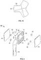
- FIG. 4Aillustrates an assembled tracker according to an embodiment of the navigation system.
- FIG. 4Bis an exploded view of the assembled tracker of FIG. 4A .
- FIG. 4Cis a cross section view of a spine pin according to an embodiment of the navigation system.
- FIG. 5is an exploded view of an array according to an embodiment of the navigation system.
- FIG. 6Aillustrates a front perspective view of an array according to one embodiment of the navigation system.
- FIG. 6Billustrates a front perspective view of an array according to another embodiment of the navigation system.
- FIG. 6Cillustrates a front perspective view of an array according to an embodiment of the navigation system.
- FIG. 6Dillustrates a front perspective view of an array according to yet another embodiment of the navigation system.
- FIG. 6Eillustrates a front perspective view of an array according to an embodiment of the navigation system.
- FIG. 6Fillustrates an exploded view of the array of FIG. 6E .
- FIG. 6Gillustrates a front perspective view of an array according to another embodiment of the navigation system.
- FIG. 6Hillustrates an exploded view of the array of FIG. 6G .
- FIG. 6Iillustrates a front perspective view of an array according to yet another embodiment of the navigation system.
- FIG. 6Jillustrates an exploded view of the array of FIG. 6I .
- FIG. 6Killustrates elevation views over 90 degree rotations of the array of FIG. 6I .
- FIG. 7illustrates a spine pin according to an embodiment of the navigation system.
- FIG. 8Aillustrates a spine pin according to another embodiment of the navigation system.
- FIG. 8Billustrates a spine pin and an array (as a tracker assembly) according to an embodiment of the navigation system.
- FIG. 8Cillustrates a spine pin and an array (as a tracker assembly) according to yet another embodiment of the navigation system.
- FIG. 8Dillustrates a front perspective view of a clamp according to an embodiment of the navigation system.
- FIG. 8Eillustrates a front perspective view of a clamp according to another embodiment of the navigation system.
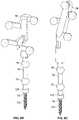
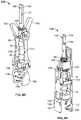
- FIGS. 9A-9Cillustrate the use of a spine tracker inserter affixing a spine pin and an array to a spinous process in accordance with an embodiment of the navigation system.
- FIG. 10illustrates arrays and spine pins removably secured with a spine of a patient.
- FIGS. 11A-11Hillustrate an instrument with an integrated 360 degree variously rotated around an axis according to an embodiment of the navigation system.
- FIG. 12Aillustrates a C-arm array mount according to an embodiment of the navigation system.
- FIG. 12Billustrates the C-arm mount array of FIG. 12A mounted to a C-arm.
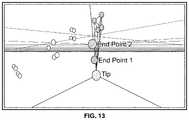
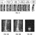
- FIG. 13illustrates calculations used to identify one or more spine pins from received images.
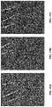
- FIGS. 14A-14Cillustrate images of a set of spine pins affixed to the spinous processes of first, second, and third vertebrae.
- FIG. 15depicts a segmentation process according to an embodiment of the navigation system.
- FIGS. 16A-16Cillustrate vertebrae segmentation from a CT model of the spine according to an embodiment of the navigation system.
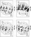
- FIGS. 17A-17Dillustrate a segmented 3D image set and various 2D DRR views of the segmented 3D image set according to an embodiment of the navigation system.
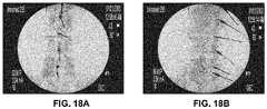
- FIGS. 18A and 18Billustrate images with a set of spine pins affixed to the spinous processes of first, second, third, fourth, fifth and sixth vertebrae captured by a C-arm according to an embodiment of the navigation system.
- FIG. 19illustrates a start-up menu on a display screen according to an embodiment of the navigation screen.
- FIG. 20illustrates a level selection menu on a display screen according to an embodiment of the navigation system.
- FIG. 21illustrates a template and surgeon profile menu on a display screen according to an embodiment of the navigation system.
- FIG. 22illustrates a setup screen menu of stored templates on a display screen according to an embodiment of the navigation system.
- FIG. 23illustrates a surgical planning screen displayed on a display screen according to an embodiment of the navigation system.
- FIG. 24illustrates another surgical planning screen displayed on a display screen according to an embodiment of the navigation system.
- FIG. 25illustrates a 2D-3D image registration menu screen displayed on a display screen according to an embodiment of the navigation system.
- FIGS. 26A-26Dillustrate a registration and calibration algorithm screen for the received images displayed on a display screen according to an embodiment of the navigation system.
- FIGS. 27A-27Dillustrate a verification screen for the resulting registration determination displayed on a display screen according to an embodiment of the navigation system.
- FIG. 28illustrates a 3D-3D image registration menu screen displayed on a display screen according to an embodiment of the navigation system.
- FIG. 29illustrates an instrument setup menu screen displayed on a display screen according to an embodiment of the navigation system.
- FIG. 30illustrates an array assignment menu screen displayed on a display screen according to an embodiment of the navigation system.
- FIGS. 31-33illustrate projected trajectory and screw screens displayed on a display screen according to an embodiment of the navigation system.
- FIG. 34illustrates a segmented vertebrae screen displayed on a display screen according to an embodiment of the navigation system.
- FIGS. 35A and 35Billustrate a bookmarked screw feature displayed on a display screen according to an embodiment of the navigation system.
- FIGS. 36A and 36Billustrate surgical plan menu screens displayed on a display screen according to an embodiment of the navigation system.
- FIGS. 37 and 38illustrate planned trajectories screens according to planned screws from pre-surgery displayed on a display screen according to another embodiment of the navigation system.
- FIG. 39illustrates a screen displaying the bookmarked screw feature displayed on a display screen according to another embodiment of the navigation system.
- FIG. 40is a flowchart that illustrates an embodiment of the navigation system.
- FIG. 41is a block diagram that illustrates an embodiment of the navigation system.
- the term “navigation”describes the ability to leverage intraoperative imaging in real-time to obtain spatial awareness between anatomical structures and instrumentation.
- the navigation systemprovides maximum surgeon visualization with minimal radiation exposure through an innovative and efficient solution during MIS and traditional open spine procedures. Specifically, the navigation system enables surgeons to perform 3D image-guided surgery with increased accuracy exposure during posterior and anterior column procedures. This provides benefits for surgeons and hospitals alike: 1) for degenerative and MIS surgeons who desire improved visualization while simultaneously reducing radiation exposure; 2) for deformity surgeons who desire real-time spinopelvic parameter assessment and anatomical orientation in complex spine procedures; and 3) for hospital administrators who desire to reduce the total cost of health care through more predictable outcomes form accurate implant placement and reduced morbidity of MIS procedures. Indeed, the system of the present disclosure provides for reduced total cost of care though facilitating more predictable outcomes, reduced OR time, reduced hospital length of stay, reduced post-op complication rates, and reduced revision operations (due to accurate and repeatable implant placement).
- the navigation systems and methods described hereinare compatible with spine procedures and the instruments and implants associated therewith.
- the navigation system and methods described hereinare compatible with open and MIS pedicle screw placements for thoracolumbar fusions, lateral interbody fusion procedures including lateral lumbar interbody fusion (XLIF), trauma procedures, maximum access surgery transforaminal lumbar interbody fusion (MAS TLIF), maximum access surgery posterior lumbar interbody fusion (MAS PLIF), lateral fixation procedures, corpectomies, anterior cervical discectomy and fusion (ACDF), and posterior cervical fusion (PCF).
- the navigation systems and methodswill integrate planning, such as the iGA platform by NuVasive, Inc., intraoperative monitoring, automated rod bending, etc. to provide a holistic view of the anatomy and foster enhanced procedural solutions.
- a navigation system 10may include one or more hardware components, one or more software components, and one or more auxiliary components.
- the navigation system 10may include a computer system 12 including a control unit 14 including at least one processor configured to execute computer executable instructions (i.e., software), and one or more display screens 16 .
- the control unit 14may be housed in a technology hub 18 having one or more locking wheels 20 disposed thereon such that the technology hub 18 may be easily positionable around the OR.
- the technology hub 18may include one or more arms 22 connecting to the display screens 16 .
- the control unit 14may be configured for executing the application software and algorithms, and communicating and interfacing with other system components associated with the navigation system 10 , such as auxiliary displays 24 , remote control devices 26 , such as tablets or phones, and mobile computing devices 28 , such as intraoperative neuromonitoring technician laptops, and cloud remote and cloud planning systems 30 .
- the computer system 12may receive universal imaging inputs, meaning that it has the ability to work with a pre-operative CT input, a pre-operative MRI input, a 3D C-arm input, or an intraoperative CT input.
- the imaging inputsmay be formatted according to industry standards, such as the Digital Imaging and Communications in Medicine (DICOM) standard, the Picture Archive and Communication System (PACS) standard, Phase Alternating Line (PAL) standard, and National Television System Committee (NTSC) standard.
- the system 12may receive the input over one or more networks (e.g., wired or wireless local area network, such as a hospital PACS) or via USB, CD, DVD, DVI, composite video, or analog video.
- networkse.g., wired or wireless local area network, such as a hospital PACS
- USBCD, DVD, DVI, composite video, or analog video.
- the present system 10employs automatic registration with intra-operative and pre-op CT images, the system 10 is configured to perform segmentation of each vertebral body through image recognition, and the system 10 is configured to register individual vertebral bodies such that the spine can be dynamically tracked during the surgical procedure.
- the one or more display screens 16may be touch screens such that they include a graphical user interface (GUI) with which the user can directly input commands by touching the screen 16 .
- GUIgraphical user interface
- the system 10offers intuitive and convenient system interaction with the software and hardware available to surgeons (and users others within the surgical field) and other hospital personnel (outside the surgical field). While various descriptions of the aspects of the present disclosure may refer to a surgeon, or surgeons, it is to be understood that the functionality of such aspects may extend to other users, as contextually appropriate, such that the term “surgeon(s)” supports the term “user(s).”
- the softwaremay be primarily controlled through the touch screen graphical user interface on the one or more display screens 16 , which controls the navigation system 10 .
- the system 10includes a secondary control through the one or more remote control devices 26 .
- the navigation system 10receives data and inputs from various other parts of the system 10 , including the 3D imaging data and optical camera(s) 34 , 36 that track the vertebrae and surgical instruments (discussed in further detail below), surgeon inputs, and processing to provide real-time navigation information to the surgeon or OR personnel.
- the surgeon/OR personnelcan interact with the navigation software from the sterile field for navigation view settings, instrument selection/calibration real-time implant planning and sizing, administrative features, and option selection.
- the softwareis controlled without interfering with other intraoperative computer-assisted modalities and the system 10 is able to easily transition between navigation modes and other modes, for example, intraoperative neuromonitoring (TOM) services, NUVAMAP O.R., and BENDINI software modes.
- TOMintraoperative neuromonitoring
- the system 10includes an optical tracking system 32 , shown in FIGS. 2 and 3 .
- the optical tracking system 32may provide real-time location of objects (e.g., one or more body locations such as vertebral bodies of the spine, and one or more instruments for use in surgery) in relationship to each other as the objects move through space.
- the optical tracking system 32may be in communication with the control unit 14 of the computer system 12 of the navigation system 10 .
- the optical tracking system 32may include one or more cameras that are infrared (IR) cameras 34 and/or visible light cameras 36 (i.e., sense and transmit data from the IR or visible light spectrums). Each camera 34 , 36 may be selected between IR and visible light modes under software control by the control unit 14 .
- IRinfrared
- visible light cameras 36i.e., sense and transmit data from the IR or visible light spectrums
- the optical tracking system 32senses (i.e., sees) the location of one or more tracking arrays 38 ( FIGS. 4A and 4B ) within the field of view of the system 32 .
- the tracking arrays 38may be positioned on one or more anatomical features 4 of a subject 2 , such as vertebral bodies of a human undergoing spinal surgery, and one or more surgical instruments 6 .
- the optical tracking system 32provides the navigation system 10 with dynamic 3D position information corresponding to the anatomical features 4 and/or the surgical instruments 6 being tracked.
- the optical tracking system 32may be configured in any suitable orientation.
- the optical tracking system 32includes a first and a second IR camera 34 flanking a first visible light camera 36 .
- the cameras 34 , 36may be discrete units or connected together by a camera base 37 .
- the cameras 34 , 36may be compact enough to be positioned within a sterile field of a surgical procedure without interfering with the procedure.
- the cameras 34 , 36may contain a high number of pixels.
- pixelis used to refer to a single scalar element of a multi-component representation (also referred to as a photosite).
- the cameras 34 , 36may capture at least 1 megapixel, at least 2 megapixels, at least 5 megapixels, at least 10 megapixels, at least 12 megapixels, at least 15 megapixels, or at least 20 megapixels.
- a thin, transparent barrier 40may be placed over the lenses 41 of the cameras 34 , 36 .
- a high pixel countenables the barrier 40 to be placed over the lenses 41 of the cameras 34 , 36 while the cameras 34 , 36 are in-use without sacrificing the accuracy of the position of the sensed tracking arrays 38 .
- the barrier 40also enables the cameras 34 , 36 to be draped and placed within the sterile field.
- the barrier 40enables the cameras 34 , 36 to be in close proximity with the tracking arrays 38 , which further allows the arrays 38 to be reduced in dimensions such that the arrays 38 are less likely to interfere with the surgical procedure being performed.
- the optical tracking system 32may be used with markers 42 disposed on one or more arrays 38 (discussed below).
- the markers 42may be small in size (e.g., 3 mm diameter or as small as technologically feasible) with a minimal tracking array footprint (less than 10 mm between markers 42 allowing for small array 38 size).
- the optical tracking system 32may track objects that have arrays 38 as the objects change orientation (e.g., rotation, yaw, roll).
- the optical tracking system 32may be positioned within the OR to minimize the potential for line-of-sight disruptions with the subject 2 for the surgeon performing the surgical procedure.
- the cameras 34 , 36may be placed on a mobile cart 44 ( FIG. 3 ) with one or more locking wheels 46 such that the cart 44 may be positioned variously by rolling the cart 44 within the OR.
- the cart 44may be placed proximate to one end of a surgical bed.
- the cart 44may comprise a base 48 for receiving the cameras 34 , 36 .
- the base 48may be lockingly adjustable, including height, longitudinally, and laterally so that the cameras 34 , 36 may be optimally positioned for the surgical procedure.
- the draped cameras 34 , 36may be configured to view the C-arm 194 , arrays 38 (including on anatomical features 4 and/or instruments 6 ) by placing one or more cameras 34 , 36 at one of the following locations: patient anchor attachment, bedrail attachment, cart attachment, an overhead boom/light attachment, or any combination thereof.
- Some embodiments of the navigation system 10include the optical tracking system 32 that allows a single (i.e., initial) set up of the cameras 34 , 36 with no additional adjustments necessary or made during a surgical procedure, thereby improving surgical workflow efficiency by eliminating the need for hospital personnel to adjust and re-adjust the cameras 34 , 36 during the operative procedure to “see” or calibrate the navigated instruments 6 or the markers 42 .
- the navigation system 10includes one or more tracking arrays 38 that can be securely disposed on the anatomical features 4 and/or the surgical instruments 6 .
- the navigation system 10tracks the tracking arrays 38 , such by information received by cameras 34 , 36 , to effectuate the navigation and tracking of anatomical features 4 and surgical instruments 6 as will be described in greater detail below.
- the navigation system 10may track the spine using tracker 50 .
- the tracker 50(i.e., the assembly of the array 38 and pin 52 ) comprises the array 38 having one or more markers 42 disposed thereon.
- the arrays 38may securely, or lockingly and releaseably, engage with a spine pin 52 .
- the markers 42may be variously positioned on the array 38 .
- the markers 42may be positioned at various points on a first surface 56 of the array 38 .
- the arrays 38may be scattered over the first surface 56 , as shown in FIGS. 4A and 4B .
- the spine pin 52may be positioned with or engage one or more anatomical feature 4 (e.g., vertebrae) by use of a spine tracker inserter 54 ( FIGS. 9A-9C ).
- navigation system 10may sense and track the position of the arrays 38 engaged with the spine pin 52 , thereby tracking the position of the vertebrae 4 with which the spine pin 52 is engaged.
- the tracker 50may have a first end 58 and an oppositely disposed second end 60 , the array 38 disposed at the first end 58 and the spine pin 52 disposed at the second end 60 .
- the spine pin 52may include a sharp tip 62 configured to engage and be removably insertable into anatomical feature 4 .
- the spine pin 52may include an axial retention feature 76 (e.g., a helical thread) proximate to the tip 62 for axially securing the pin 52 with the anatomical feature 4 .
- an axial retention feature 76e.g., a helical thread
- the tracker 50may include one or more radiographic glyph elements 78 , such as a sphere.
- the tracker 50may include a first radiographic glyph element 78 proximate to where the array 38 interfaces with the spine pin 52 , and a second radiographic glyph element 78 proximate to the axial retention feature 76 .
- the distance 80 between the radiographic glyph elements 78may be from 5 mm to 100 mm, from 15 mm to 80 mm, about 40 mm, or any value or subrange thereof.
- an array end 82 of the spine pin 52may have a tri-lobular profile (i.e., cross-section) to prevent the rotation of the pin 52 when the pin 52 is engaged with the array 38 .
- the array 38may be coupled with the spine pin 52 after the spine pin 52 is secured with the anatomical feature 4 .
- the spine pin 52may serve as a fiducial for image registration with the system 10 , allowing for registration within multiple degrees of freedom, such as at least 4 degrees of freedom, at least 5 degrees of freedom, or at least 6 degrees of freedom, as will be explained in greater detail below.
- FIG. 5illustrates an exploded view of the array 38 according to an embodiment of the system 10 .
- the array 38comprises a connecting portion 64 for securely coupling the array 38 at the first end 58 of the tracker 50 .
- the connecting portion 64is sized and dimensioned to securely couple with to a complementary surface (e.g., a reference surface) 66 of the tracker 50 .
- the array 38includes a body 68 for supporting the various components of the array 38 , such as the markers 42 and a cover 70 for protecting the markers 42 .
- the markers 42may be disposed on opposite sides (e.g., on the first surface 56 and an oppositely facing second surface 72 ) of the array 38 .
- the markers 42may be at least partially received in complementarily-shaped recesses 74 in the body 68 .
- the markers 42 and/or body 68may be provided in a sterile form such that they can be utilized within the sterile surgical field.
- the markers 42may be provided in sterile packaging.
- the protective cover 70may be clear and thin, and protect the markers 42 from being obscured from the system 10 , particularly the optical tracking system 32 , by debris such as blood from the patient undergoing surgery.
- the cover 70may be constructed of a polymer or glass, or may be a film.
- the cover 70may be polarized to limit the field of view if so desired.
- the markers 42may be reflective and hemispherical in shape, as shown in FIG. 5 , or spherical in shape.
- the hemispherical shapeoffers several advantages relative to a reflective sphere. Advantages of the hemispherical shape include the ability to be more fully recessed with recesses 74 such that the viewing angle is physically limited so that the markers 42 are not presented to the camera when other markers 42 are directly facing the cameras 34 , 36 allowing for accurate marker 42 tracking by the system 10 . Additionally, because the markers 42 are recessed, the cover 70 can be placed over the markers 42 .
- the markers 42When used in conjunction with other components of the system 10 , such as high pixel count cameras 34 , 36 , the markers 42 may be dimensioned to be about 3 mm in size. The markers 42 create a distinctive pattern around the body 68 of the array 38 such that the cameras 34 , 36 can sense and track the location and orientation of the anatomical feature 4 or an instrument 6 .
- FIGS. 6A-6Killustrate embodiments of the array 38 .
- the body 68 of the array 38is elongated and comprises a plurality of arms 84 extending from the body 68 .
- the body 68may comprise a spine pin engagement feature 88 for releasably securing the spine pin 52 .
- the array 38is removable and repositionable such that the array 38 may be positioned with the spine pin 52 or a surgical instrument 6 in either of a right handed or a left handed orientation.
- this featureallows the surgeon to reposition the array 38 away from the side where the surgical procedure is being performed such that the array 38 does not interfere, whether by view or physical obstruction, with the surgical procedure.
- This featurealso aids in the ability for the cameras 34 , 36 to see the markers 42 without, or with fewer, obstructions, as the surgeon can alternate the array 38 between left and right orientations as the surgeon progresses, for example, down the spine, allowing the cameras 34 , 36 to view multiple vertebrae levels. If line of sight due to position of the arrays 38 becomes an issue during the surgery, vertebrae that are not being operated on can have their respective array 38 removed from the pin 52 to declutter the operative area and then releasably resecured when the surgeon has moved past that location.
- the benefits of decluttering the operative areaare enormous, as the minimized footprint of the present system reduces hospital employee demand (saving money and hospital resources), and integrates with existing technologies on a single system.
- the relatively small size of the arrays 38also reduces patient and surgeon impact, allowing the surgeon to work freely and minimize OR time, which is beneficial for the patient.
- the arms 84may variously extend laterally, longitudinally, and vertically from the body 68 such that each arm 84 terminates in a different position relative to the body 68 .
- Each arm 84may include a marker 42 , such as a spherical marker 42 ( FIGS. 6A-6B ).
- the arms 84terminate to paddles 86 such that reflective markers 42 , such as adhesive reflective dots, can be disposed on the paddles 86 .
- the array 38may be a 360 degree array 38 .
- the 360 degree array 38may include the body 68 that is frustoconical, as shown in FIGS. 6E-6H .
- the frustoconical body 68may comprise one or more arms 84 that variously (vertically and around the body) extend from the body 68 to spherical markers 42 .
- the array 38may include a base 90 .
- the base 90may interface with a collar 92 by a retention mechanism 94 , such as an O-ring seal, that secures and seals the interface between the base 90 and the collar 92 .
- the collar 92may comprise one or more legs 96 , such as an oppositely disposed pair, that upwardly extend away from the collar 92 and are configured for engaging corresponding apertures (which can alternatively be recesses) 98 in the body 68 .
- the body 68may comprise a top aperture 100 that is open to an internal chamber 102 , the internal chamber 102 opens to a collar aperture 104 .
- the arms 84may extend away from the body 68 farther than the collar 92 extends from the body 68 ( FIGS. 6E-6F ).
- the 360 degree array 38may be configured to receive, or be securely and releasably coupled with, a shield 106 .
- the shield 106may extend 360 degrees around the body 68 , the arms 84 , and the markers 42 .
- the collar 92may extend away from the body 68 farther than the arms 84 extend from the body 68 ( FIGS. 6G-6H ).
- the collar 92may comprise a groove 108 extending around, or proximate to, its perimeter for releasably securing the shield 106 .
- the collar 92may include one or more guides 110 that extend from the collar aperture 104 to the groove 108 to further guide and secure the shield 106 within the groove 108 .
- a top cover 112may be releasably secured over the shield 106 opposite of the collar 92 , the top cover 112 including a groove 114 (not shown) similar to groove 108 for receiving the shield 106 .
- the 360 degree array 38may be a 360 degree prismatic array 38 .
- the body 68may be a polygon (e.g., a prism), such as a ten-sided pyramid having a profile of two opposing frustums.
- the exterior surfaces, or faces, 116 of the body 68may each have one or more pockets 118 disposed therein.
- the pockets 118may have a pocket-shaped profile (i.e., continuously curved on a first end leading to substantially straight sidewalls that lead to a flat second end opposite the continuously curved first end).
- Markers 42such as adhesive reflected dots, may be placed within the pockets 118 .
- the pocket-shaped profile of the pockets 118assists in guiding and securing the markers 42 .
- the body 68may be integrally formed with the collar 92 , with the retention mechanism 94 configured to be secured with the collar 92 .
- the body 68may be integrally formed in one or more cooperative sections, as shown in FIG. 6J .
- FIG. 6Kwhich shows the body 68 rotated 90 degrees (1, 2, 3, and 4), the pockets 118 may be in varying orientations and positions on each face 116 of the body such that no two faces 116 have the same pocket 118 position and orientation.
- thiscauses the marker 42 placement to be unique when viewing each 90 degree rotation of the body 68 and the respective faces 116 .
- some pockets 118may be toward a center 120 of the body 68 while other pockets 118 are toward distal ends 122 of the body, and pockets 118 may be rotated variously between 0 degrees and 360 degrees relative to one another.
- this configurationallows each pocket 118 may be positioned uniquely on the face 116 relative to all pockets 118 on all faces 116 , which is especially beneficial when using the array 38 with markers 42 , as each marker is in a different relative position and orientation, which allows cameras 34 , 36 to see more of the markers 42 , and sense more spatial data, when the system 10 is in-use.
- a fourth aspect of the system 10includes the spine pin 52 and/or a spinal clamp 124 .
- the spine pin 52 and the spinal clamp 124allow for secure and releasable attachment of the array 38 , connecting the array 38 with the anatomical feature 4 , such as a vertebrae, or more specifically, a spinous process.
- the spine pin 52may have distal radiographic glyph elements 126 that extend outwardly from the pin 52 by glyph arms 128 .
- the glyph arms 128may extend from the radiographic glyph elements 78 to the distal radiographic glyph elements 126 , such that the glyph arms 128 connect the radiographic glyph elements 78 and the distal radiographic glyph elements 126 .
- this configuration of glyph elements 78 , 126allows for the pin 52 to contribute to the tracking capabilities of the system 10 by functioning as radiographic fiducials.
- the pin 52may include a depth limiter 129 (e.g., an expanded circumferential body).
- the depth limiter 129functions as a physical stop when the pin 52 is being inserted into the anatomical feature 4 , such as to prevent the pin 52 from being inserted too deeply into the feature 4 and risk causing injury to the patient as a result thereof.
- the axial retention feature 76may include a helical thread, as shown. Meanwhile, the portion of the pin 52 between the axial retention feature 76 and a tip end 83 of the pin 52 may include bone thread 130 .
- the bone thread 130 and the axial retention feature 76may be a differential pitch to increase bone retention when the pin 52 is engaged with the anatomical feature 4 (e.g., a spinous process).
- the pin 52may include a tool engagement feature 131 for engaging and retaining a tool, such as the spine tracker inserter 54 (shown in FIG. 9A ) during installation of the pin 52 ( FIGS. 9B and 9C ).
- FIGS. 8B-8Cillustrate the pin 52 engaged with the array 38 .
- a spinous clamp 124is provided.
- the spinous clamp 124serves to secure the array 38 with the anatomic feature 4 by clamping onto the feature 4 and providing an interface for releasably securing the array 38 .
- the spinous clamp 124may include a central body 132 that ends from an array end 134 of the clamp 124 to a clamp end 136 of the clamp 124 .
- the clamp 124may be symmetrical, as shown in FIG. 8D , or asymmetrical, as shown in FIG. 8E .
- the clamp 124may comprise opposing first and second grasps 138 , 140 that are configured to secure the anatomical feature 4 , such as a spinous process.
- the grasps 138 , 140may be resiliently biased towards a first, closed position (as shown), and configured to translate to a second, open position by pivoting one or more wings 142 toward the central body 132 .
- the pivoting of the wings 142causes laterally disposed arms 144 to translate, transitioning the grasps 138 , 140 from the first position to the second position.
- the arms 144may be contoured, such as continuously tapering inward toward their center, such as to minimize obstructing the view of the surgical area to the surgeon.
- the grasps 138 , 140may each include a plurality of spikes 146 to increase the grip between the grasps 138 , 140 and the anatomical feature 4 .
- the clamp 124may include an array orientation feature 148 , such as a flat surface on the central body 132 , to ensure that the array 38 is correctly clocked when engaging the array 38 with the clamp 124 .
- the clamp 124may include a driver retention element 150 , such as a notch, to ensure that the clamp 124 is retained in a tool, such as the spine tracker inserter 54 , during installation of the clamp 124 on the anatomical feature 4 .
- the central body 132may include radiographic glyph elements 78 and distal radiographic glyph elements 126 .
- the clamp 124may be asymmetrical.
- the asymmetrical clamphas grasps 138 , 140 that are a first jaw 152 and a second jaw 154 , respectively.
- the first jaw 152may be mobile, and the second jaw 154 may be fixed relative to the central body 132 .
- the mobile first jaw 152may be resiliently biased in a first, closed position.
- the mobile first jaw 152may be hingedly connected with a support 156 .
- the support 156is in turn connected to a biased member 158 .
- the biased member 158may be disposed around the central body 132 and between two biasing members 160 , such as springs, that retain the biased member 158 in the first, closed position.
- the biased member 158When the biased member 158 is translated along the central body 132 , the biased member 158 translates the support 156 , which in turn causes the mobile first jaw 152 to pivot to the second, open position, converting the translation movement of the biased member 158 to pivotal movement of the first mobile jaw 152 .
- the biasing members 160may be disposed around the central body 132 .
- FIG. 10illustrates spine pins 52 coupled to arrays 38 in accordance with an embodiment of the system 10 .
- left handed and right handed arrays 38can be moved away from the operative corridor, advantageously allowing the surgeon unrestricted, or less restricted, access, while still maintaining tracking capabilities of the arrays 38 .
- the arrays 38 of the present disclosureare especially useful when coupled with instruments 6 , as the pattern of the markers 42 on the arrays 38 allow the tracking system 10 to determine the position of the array 38 , and thus the instrument 6 , in 3D space as the instrument 6 is rotated. This is especially true for axially symmetric instruments 6 that are rotated during use, as the instrument 6 itself appears unchanged as it rotates along the axis 162 .
- arrays 38have been shown to be affixed to a mating feature through the connection portion 64 of the array 38 on the complementary surface 66 of the spine pin 52 , it is contemplated that any of the arrays 38 may be adapted to be affixed to a mating feature on the distal end of the surgical instrument 6 in a similar fashion.
- FIGS. 11A-11Hillustrate the proximal end of an axially symmetric surgical instrument 6 in various rotational positions around an axis 162 according to a fifth aspect of the present disclosure.
- the instrumentcomprises a handle 164 at a handle end 166 of the instrument 6 .
- a shaft 168extends from the handle 164 to a cylindrical array 170 .
- the cylindrical array 170includes a plurality of recesses 172 .
- the recesses 172may be uniquely patterned around the cylindrical array 170 , as shown, and may be configured to at least partially receive the markers 42 . As the instrument rotates 6 (as shown in FIGS.
- the recesses 172are configured so that the 3D center of the visible marker area remains stable as the cylindrical array 170 is rotated.
- a sixth aspect of the system 10includes a C-arm array mount 174 .
- the C-arm array mount 174may be configured to attach to a C-arm 194 receiver end), such as commercially C-arms sold by GE OEC (9800 and 9990 series), Philips (Pulsera), Siemens (Arcadis), and Ziehm (Vision) which may be connected via a video cable (such as BNC cable) to the system 10 .
- the C-arm array mount 174may be constructed of a black polycarbonate glyph mount 176 operably connected to, or mounted to, a ring 178 .
- the ring 178may be constructed of, for example, aluminum.
- the mount 174may include clamps 180 , such as ring clamps, to pull a back face (not shown) of the glyph mount 176 so that the glyph mount 176 references the receiver end.
- the clamps 180may press on an external perimeter of the receiver end casting, allowing the ring 178 to be positioned radially and rotationally so that a top most screw on the receiver end is centered (e.g., aligned) with a countersunk alignment hole 182 of the C-arm mount 174 .
- the mount 174may include an assembly alignment pin 186 for guiding the assembly of the glyph mount 176 with the ring 178 .
- the array 38may be included into the array mount 174 at the back (i.e., opposite of the glyph mount 176 ) of the ring 178 .
- the array 38may include a mounting element 184 , such as a thumbscrew, to secure the array 38 to the mount 174 .
- the array 38 and the mounting element 184may be constructed of a material(s) that enable them to be autoclaveable for repeated use between patients. Also beneficially, the present design avoids the use of specialized tools for installing or adjusting the ring 178 or the array 38 .
- the C-arm array mount 174provides continuous line of sight from the array 38 to the navigation system 10 , which can track the C-arm 194 in the vertical and horizontal orientations for all operative imaging levels. While a planar optical tracking array 38 is shown in FIG. 12A , it is contemplated that the 360 degree arrays 38 and 360 degree prismatic arrays 38 may also be utilized.
- the system 10may utilize data from the sensed C-arm mount 174 , enabling the use of hospital existing C-arms 194 and a calibration tool to accurately register pre-operative CT data sets to patients positioned for surgery in the OR.
- registration platesmay be placed over the drape of the C-arm 194 so that the drape is engaged with the ring 178 .
- A/P, +25, ⁇ 25, and lateral imagesmay be taken, received by the system 10 , and the system 10 can execute the registration and calibration algorithms for the received images as will be described in greater detail below.
- the system 10includes computer executable instructions containing instructions to reconstruct 3D spine models from received imaging inputs (such as 2D and 3D medical images from pre-op and intra-op sources such as CT, CBCT, and MRI,) that are segmented into rigid bodies (e.g., vertebrae) based on tracked anatomical features 4 .
- the computer executable instructionsare configured to dynamically track and display each anatomical feature 4 in real time.
- the computer executable instructions of the system 10are configured to track and correlate the real time location of surgical tools relative to each tracked anatomical feature.
- the computer executable instructionsare configured to calculate and display a dynamic 3D spine model with streaming data of virtual tools overlaid over the displayed dynamic 3D spine model to augment direct anatomy visualization.
- the imaging input devicee.g., pre-op and intra-op sources
- the computer system 12is in communication with the touch screen display 16 , which can display data from the system 10 to the surgeon and receive input data from the system.
- the computer system 12is in communication with the optical tracking system 32 , including the IR cameras 34 and the visible light cameras 36 .
- the computer system 12may control the cameras 34 , 36 (views, IR/visible light functionality, etc.), cause the cameras 34 , 36 to capture and transmit images, and receive image data from the cameras 34 , 36 .
- the computer executable instructionsmay be configured to execute a registration step.
- registrationis used to mean the correlation of one or more reference points of a virtual 3D data set with one or more reference points of the patient's current anatomical position.
- a registration stepmay be configured to occur for each receiving image source.
- the registration stepincludes parameters regarding the physical flexibility of the patient's spine. The registration step may vary according to the received image data.
- registrationincludes image recognition of one or more spine pins and one or more image markers within two fluoro images will register each vertebrae and reconstructing a 3D model from the pre-op 3D image.
- the registrationis of an intra-op CT/CBCT, image recognition of one or more spine pins within the intra-op 3D image will register each vertebrae.
- the image datais from an MRI-CT, imagine recognition of the CT image will merge MR images to each CT segment/vertebrae.
- the instructionsmay be configured to register the 3D MRI image without any CT images.
- the computer executable instructions of the system 10may be configured to identify the spine pin 52 .
- the computer executable instructionsmay be configured to sense the spine pin 52 and use the sensed spine pin 52 to scale the intraoperative radiographic image to register patient space, image space, and navigation space.
- the pins 52may have glyph elements 78 , 126 (e.g., spheres) that have a known predetermined diameter. When imaged by the cameras 34 , 36 , each glyph element 78 , 126 has one or more characteristic identifiers in each imaging modality that can be leveraged by image recognition techniques (such as the known predetermined diameter).
- the imaged glyph elementmay have a characteristic of a halo around it that can be used to correlate the center of the radiographic halo to the center of the glyph element 78 , 126 .
- the imaged glyph element 78 , 126may be displayed as a black dot. The location of that center position may be restricted to an accuracy of a first 3D pixel (voxel).
- the addition of a second glyph element 78 , 126allows sub-voxel accuracy based on the known distance between the two glyph elements 78 , 126 and the double halo (or double dot).
- a five degree of freedom pinis generated.
- a second pin 52 having five degrees of freedommay be located in the image so that the orientation of the spine may be determined. If it is desirable to use only one spine pin 52 and resolve all 6 degrees of freedom, a 6 degree of freedom spine pin 52 can be used which has at least two glyphs 78 , 126 on a first axis and an additional glyph 78 , 126 (e.g., a distal glyph 126 ) orthogonal to the axis of the pin 52 .
- FIG. 13illustrates calculations used to identify one or more spine pins 52 in an image. As can be seen in FIG.
- FIGS. 14A-14Cillustrate a set of spine pins 52 positioned within the spinous processes of three adjacent vertebrae identified in accordance with the method described herein.
- the computer executable instructionsmay include image recognition configured to determine the geometric shape of the entire spine pin 52 .
- the computer executable instructionsmay be configured to determine a relative position for the pin(s) 52 .
- the optical tracking system 32through cameras 34 , 36 can sense the arrays 38 coupled with the pins 52 . If the pin 52 is a six degree of freedom pin 52 (e.g., has the distal glyph 126 in addition to a glyph 78 ), then only one array 38 is needed by the system for the computer executable instructions to determine the position of the pin 52 .
- the pin 52is a five degree of freedom pin 52 (e.g., does not include the distal glyph 126 )
- two pins 52 and arrays 38 coupled with the pins 52are required for the computer executable instructions to determine the directive of the spine relative to the cameras 34 , 36 .
- the optical tracking system 32may be configured to sense left/right arrays 38 that are coupled to the pins 52
- the computer executable instructionsmay be configured to calculate a relative position for each pin 52 based on the sensed arrays 38 .
- the computer executable instructionsmay be configured to compare the determined relative positions of the radiographic orientation of the pins 52 to confirm that they align within an acceptable error tolerance.
- any relative movement of the spine detected from the tracking system 32can be used to update the segmented vertebra locations in the radiographic data.
- the tracking arrays 38may have six degrees of freedom, even if the pin 52 has 5 degrees of freedom, one registration has been confirmed, all of the arrays 38 can be removed except the one that the surgeon desires to remain so that the operative area is unobstructed.
- multiple spine pins 52 and arrays 38may be left in place (i.e., connected to the anatomical feature 4 ) to show an indication of relative movement of the anatomical features 4 (individual vertebral bodies).
- the navigation system 10can detect where the top of an instrument 6 is located and, based on the determined position of the anatomical feature 4 , the system 10 can determine the most proximate vertebral body that is closest to the top, or intersecting the tip as a reference to determine the orientation of the 3D data set relative to the instrument.
- the computer executable instructionsmay be configured to perform a segmentation step.
- segmentationdescribes a process that identifies individual vertebrae within 3D image data so that the vertebrae can be separated and treated, manipulated, and displayed distinct from one another.
- the segmentation stepmay employ a segmentation algorithm that uses imaging processing and image recognition software to automate the spinal level segmentation process.
- FIG. 15depicts a segmentation process where the computer executable instructions automatically identify and extract the spine curve, then detects and identifies each individual vertebra, until they are segmented from one another.
- One or more adaptive meshesmay be applied to generate a segmented 3D model of the spine.
- Each vertebra or other anatomical feature 4can be separately colored to visibly enhance the bone-soft tissue interface, or just the margin can be colored.
- the computer executable instructions of the system 10may be configured to perform segmental tracking.
- segmental trackingrefers to the ability of the system 10 to track each vertebra that is of clinical significance.
- segmental trackingincludes a single registration even during the procedure, increased accuracy, and allowing the surgeon to continue to navigate while the spine moves during the placement of, for example, interbody implants, without losing accuracy of the tracking.
- the computer executable instructions of the system 10may be configured to perform 3D-2D image registration.
- 3D-2D image registrationsrefers to the receiving a 2D image (fluoro), calibrating the 2D image, and registering the location of the patient's anatomy to the 3D image (pre-op CT) while the patient is positioned for surgery using at least two perspectives. Using the 2D image, the 3D image can then be registered with the navigation system 10 .
- the 3D-2D image registrationmay include a step of receiving a pre-operative CT into the system 10 .
- the computer executable instructionsmay be configured to segment the vertebrae into individual levels from the CT model using a segmentation algorithm.
- FIG. 16Aillustrates a CT model of a spine
- the computer executable instructionscan extrapolate and generate, by a digitally reconstructed radiograph (DRR) algorithm, a set of 2D images based on the 3D CT model.
- DRRdigitally reconstructed radiograph
- FIG. 17Aillustrates a segmented 3D image data set.
- FIG. 17Billustrates a 2D DRR (axial view) of the 3D image data set.
- FIG. 17Cillustrates the 2D DRR (sagittal view) of the 3D image data set.
- FIG. 17Dillustrates the 2D DRR (coronal view) of the 3D data set.
- a C-arm 194which may be tracked by the navigation system by the C-arm array mount 174 , captures at least one image of at least one of the vertebral levels of interest in at least one view.
- the computer executable instructionsmay be configured to receive the at least one image. Exemplary images captured by the C-arm 194 are depicted in FIGS. 18A and 18B . In some embodiments, the registration can be verified.
- the computer executable instructionsmay search, via an imaging algorithm, each generated segmental DRR to determine a match of a 2D representation of the 3D image data set with the image of the 2D intraoperative fluoroscopic image.
- the algorithmmay determine the match by a cross correlation value (via a similarity score) that exceeds a predetermined value in two views to result in a single solution.
- a successful registrationmay show the DRR (e.g., a simulated C-arm shot) superimposed over a real C-arm image.
- Each levelmay be identified in a four shot C-arm series window and may show a green border over any images that align with 99.5% Z-score (or other predesignated level). Unregistered levels may not have a DRR associated (partial levels) to omit unnecessary information.
- the GUImay display a confirm button for each image that the surgeon can select to verify the registration.
- At least two verificationsmust be performed to progress to the navigation screen of the GUI.
- FIGS. 27A-27DFIG. 27C has failed the verification and FIGS. 27A, 27C, and 27D have passed the verification.
- the computer executable instructionsmay be configured to adjust the model position of each vertebral body from the Pre-Op CT position to the current operative patient position.
- the computer executable instructionsmay be configured to cause a 3D-2D image registration menu screen to be displayed on the display screen 16 ( FIG. 25 ).
- the computer executable instructions of the system 10may be configured to perform 3D-3D image registration.
- 3D-3D image registrationrefers to the capturing and receiving a 3D intraoperative image and importing/registering the 3D intraoperative image with the navigation system 10 .
- Spine pins 52may be inserted into the vertebral levels of interest (such as under fluoroscopic visualization). As described above, the geometry of the glyphs elements 78 , 126 of the spine pins 52 provide the computer executable instructions with the scaling parameters necessary to register the patient space, image space, and navigation space. Additionally, as the pins 52 are imaged in the intraoperative 3D image, the pins 52 (particularly the metal of the construction of the pins 52 ) serves as seed points to optimize the segmentation algorithm.
- the computer executable instructionscause the intraoperative 3D imager to capture image(s) of the vertebral levels of interest.
- the computer executable instructionsare configured to receive the intraoperative 3D image from the intraoperative 3D imager, and the image of the spine can be segmented.
- first the pins 52are segmented from bone, and next, vertebrae are segmented into individual levels from the CT model using the segmentation algorithm.
- the computer executable instructionsmay be configured to cause a 3D-3D image registration menu screen to be displayed on the display screen 16 ( FIG. 28 ).
- the computer executable instructions of the system 10may be configured to perform 3D MRI-2D image registration.
- 3D MRI-2D image registrationrefers to the capturing and receiving a 2D image (fluoro) and registering the location of the patient's anatomy (e.g., the anatomical features 4 ) with the patient is positioned for surgery using at least two different perspectives.
- the computer executable instructionsmay be configured to register, based on the 2D image, the location of the patient's anatomy.
- 3D MRI-2D image registrationdoes not require a pre-op CT and can be used in facilities that lack 3D imaging equipment.
- MRI-2D image registrationAnother benefit to MRI-2D image registration is the facilitation of soft tissue navigation, as the computer executable instructions may be configured to generate and display spatial awareness between soft tissues and instruments 6 .
- a surgeoncan visualize and locate vessels and nerve roots for procedures such as XLIF to provide safe access to a surgical target site.
- the computer executable instructionsmay be configured to cause a 3D MRI-2D image registration menu screen to be displayed on the display screen 16 .
- the computer executable instructions of the system 10may cause the display screen(s) 16 to display various workflow and visualization of the generated images utilizing the above described registrations.
- some embodiments of the systemmay include computer executable instructions that cause “wizards” (step-by-step guided instructions) to display to surgeons to walk the surgeons through navigation setup and usage.
- FIG. 19illustrates an example start-up menu screen GUI on the display screen 16 . From the selection area, the surgeon may input case-specific information. For example, the surgeon may select the anatomical region that is the subject of the surgical procedure, the levels of the surgical procedure (e.g., the level selection menu screen shown in FIG. 20 ), and the surgical approach (e.g., posterior, anterior, lateral).
- the levels of the surgical proceduree.g., the level selection menu screen shown in FIG. 20
- the surgical approache.g., posterior, anterior, lateral.
- the surgeonselected a lumbar procedure, levels L3-L5, from a lateral approach. Selecting a “start” button moves the surgeon to the next step in the workflow. As can be seen, the surgeon can also save procedures, import saved procedures, and enter “demonstration” mode for, for example, training or surgical planning purposes. The surgeon can also access settings and saved procedures through a secure login access to the cloud. It will be appreciated that any of the computer executable instructions contained herein may be in the cloud or locally stored in the navigation system 10 (such as by computer system 12 ).
- the computer executable instructionsmay retrieve stored templates and surgeon profiles, such as templates for preferred views (e.g., axial, probe's eye, frontal, coronal, sagittal, inline, etc.) to streamline initial setup of the system 10 with a patient.
- the computer executable instructionsmay cause the display screen 16 to display a menu of the templates and surgeon profiles to the surgeon and receive template and surgeon profile selections from the surgeon, as shown in FIG. 21 .
- FIG. 22illustrates a setup screen menu where stored templates for preferred views are displayed on the display screen 16 .
- the computer executable instructionsmay be configured to receive the selected templates selections from the surgeon.
- the computer executable instructionsmay be configured to enable the surgeon to load the pre-operative image data set and view, on the display screen 16 , 2D and/or 3D image data for the purposes of planning the surgical procedure.
- FIG. 23illustrates an example of a surgical planning screen displayed on the display screen 16 .
- the computer executable instructionsmay be configured to cause the display screen 16 to display a surgical planning menu where the surgeon (e.g., the surgeon or other OR personnel) can select the levels, screw types, and screw sizes for the surgical procedure.
- the computer executable instructionsmay be configured to cause the display screen 16 to display a surgical planning screen where a surgeon can access a axial, sagittal, and coronal views of the pre-operative image data set, determine one or more anatomical measurements (e.g., pedicle width, vertebral body width or vertebral body depth), and propose a surgical trajectory.
- the surgical planmay be saved for each individual vertebral body plan so the system 10 may present a 3D or C-arm view(s) of the individual vertebra body plan during the appropriate time in the surgical procedure.
- screwsmay be placed in each pedicle according to best fit (either manually via surgeon selected or automatically by the system 10 ).
- the surgical planmay be saved for each individual vertebral body plan so the system may present a 3D or C-arm view(s) of the individual vertebral body plan during the appropriate time in the surgical procedure.
- other surgical planning typesmay be incorporated into the computer executable instructions, such as NuvaMap surgical planning software by NuVasive, Inc.
- the computer executable instructionsmay be configured to cause the display screen 16 to display an instrument setup menu ( FIG. 29 ) and an array assignment menu ( FIG. 30 ).
- the computer executable instructionsmay cause the system 10 to capture one or more images via the optical tracking system 32 and automatically recognize the array(s) 38 .
- the system 10may also utilize adapters for instruments 6 , which allow the system 10 to recognize the instrument, identifying a first level describer (e.g., screwdriver for a screwdriver).
- the computer executable instructionsmay cause the display screen 16 to display a menu, such as a drop-down menu, so that the surgeon may select a final description for the instrument 6 .
- this featureallows the surgeon to continue the operative workflow and seamlessly select navigated instruments 6 .
- the computer executable instructionsmay be configured, particularly after registration and setup steps are completed, to cause representations of one or more surgical instruments to be overlaid on the 2D representation of the 3D image data set in real time.
- the representation of the instrumentcan be an engineering model (such as computer-aided design model), a wire frame model, or a simple shape (such as a cylinder, rectangular, or block).
- the computer executable instructionsmay be configured to further generate a simulated trajectory 188 (such as of a pedicle screw) based on the location of the surgical instrument with respect to the anatomy and display the simulated trajectory 188 on the 2D representation on the display screen 16 , as shown in FIGS. 31-33 . As can be seen in FIG.
- the computer executable instructionsmay be configured to cause a tool menu to display, in which various options such as system type, implant type, and screw type of the simulated trajectory 188 can be selected by the surgeon.
- the computer executable instructionscan be configured to display a simulated implant 190 (e.g., pedicle screw) based on the simulated trajectory and surgeon inputs regarding the tool menu.
- the system 10can be used to navigate the real-world implant 191 (not shown) to its intended location, preferably following the simulated trajectory 188 as depicted in FIG. 33 . While a positioning of a pedicle screw is described here, it will be appreciated that the navigation system 10 can provide navigation information for any number of instruments and implants.
- the system 10may comprise computer executable instructions configured to generate a simulated bookmarked screw 192 and cause the simulated bookmarked screw 192 to be displayed to the surgeon on the display screen 16 .
- This featureis beneficial when a surgeon desires to insert two screws into a single vertebra aligned from a particular perspective (e.g., lateral).
- the computer executable instructionsmay be configured to generate a simulated bookmarked screw to capture the final location of a first placed screw in a vertebrae.
- the simulated bookmarked screwis displayed over the DRR image such that the surgeon has a reference for alignment for placing the second screw.
- the simulated screwmay be depicted by a solid, opaque representation of a screw, an outline of a screw with a transparent body, or a line.
- the computer executable instructionsmay be configured to generate the simulated screws in views other than DRR, such as a 3D sagittal sliced view.
- FIG. 35Aillustrates a simulated bookmarked screw in DRR of spine for reference
- FIG. 35Billustrates a screw being placed over the simulated bookmarked screw.
- the system 10generates a 3D post-op simulated CT.
- the last locations of the dynamically tracked vertebrae and the final position of each placed screwmay be processed by the system 10 , via computer executable instructions, to generate a post-op 3D view of the patient.
- this 3D viewis an accurate depiction of the patient immediately following surgery, such that an additional 3D scan at the end of the surgery is not required, resulting in less radiation exposure to the patient and OR staff, and a savings of time (i.e., lower risk of morbidity and cost savings).
- the GUImay display different view of the surgical site based on surgeon preference.
- the GUImay display different views of the surgical site based on surgeon preference.
- only registered vertebral bodiesmay display and may be shown in current orientation (not pre-op CT orientation) based on registration.
- the adjacent vertebrae levelsmay be displayed in their new locations as solid engineering files, such as 3D.stl or other format files, and all may be tracked relative to the single patient reference array 38 (above operative level).
- a DICOM imagemay be navigated for only a vertebral body that is currently being worked on by the surgeon.
- FIG. 37The Axial DRR or tool view of the CT slice and Lateral DRR (either left or right half) or Sagittal tool view CT is shown in FIG. 37 .
- FIG. 38illustrates a displayed planned trajectories according to planned screws from pre-surgery, as discussed above, which may be toggled on and off by the surgeon.
- the bookmarked screw featuremay also be toggled on and off by the surgeon, shown in FIG. 39 .
- the GUImay include a “Hold New Trajectory” selection for providing the surgeon the option to adjust a new trajectory of the planned screw based on real world surgical conditions and the surgeon's professional medical judgment.
- the system 10receives images captured from more than one camera 34 , 36 such that a first camera 34 , 36 has a field of view of an operative area and a second camera 34 , 36 has a field of view of a registration apparatus (e.g., a C-arm 194 ).
- the system 10may include computer executable instructions configured to calibrate the relative position of the first camera 34 , 36 and the second camera 34 , 36 by referencing an array 38 .
- the cameras 34 , 36may be provided together, for example in the camera base 37 , or separately.
- the system 10may perform dynamic calibration when the cameras 34 , 36 are tracking in the same direction or tracking from opposite directions.
- the system 10may include a first infrared camera 34 within the sterile operative field to capture images of and track arrays 38 in communication with the spine, as discussed above.
- the system 10may include a second infrared camera 34 positioned outside of the sterile operative field which captures images of and track a registration device.
- the second infrared camera 34may capture images of and track at least one of the arrays 38 tracked by the first infrared camera 34 , but may not track all of the arrays 38 tracked by the first infrared camera 34 due to field of view obstructions.
- the system 10may receive these data and generate 3D models and display 2D representations of the 3D models on the display screen 16 .
- the system 10utilizes more than one camera 34 , 36 may be used to capture and track more than one array 38 that is connected to the anatomical feature 4 that is a single rigid segment, such as the S 1 /pelvis complex, that may be treated as a single structure.
- a first infrared camera 34may capture and track spine tracker arrays 38 while a second infrared camera 34 captures and tracks the operative corridor and an array 38 affixed to the iliac crest.
- the system 10may use the registered and segmented a single, rigid structure allowing the system to calculate an indirect correlation between cameras 34 during registration so that, while neither camera 34 needs to track a common array 38 , the two cameras 34 transmit images and data that the system 10 can receive to generate a unified 3D view of the surgical area.
- the system 10is configured to generate an augmented reality.
- the system 10may include at least three cameras 34 , 36 , where the first and second infrared cameras 34 may be used for tracking the marker arrays 42 , which may be infrared markers 42 , while the third visible light spectrum camera 36 is focused on the operative area.
- This at least three cameras 34 , 36 configurationallows computer executable instructions of the system 10 to generate an accurate portrayal of the position of the virtual tool location and tracking markers 42 by superimposing images captured by the infrared cameras 34 and the visible light spectrum camera 36 .
- This overlapping of the virtual representation and the visible elementcan be used for segmented vertebral bodies, too, when the vertebral bodies have arrays 38 connected to them.
- the surgeoncan then view the vertebral bodies and the surgical instruments from either of the infrared cameras 34 with overlap from the visible camera 36 such that system 10 can, for example, visually guide the surgeon through a predetermined surgical plan entered into the system 10 by the surgeon.
- the system 10may include a wearable camera and array assembly that can be worn by the surgeon such that the system 10 can display, for example through augmented reality glasses, a simulated vertebrae and instrument over the patient.
- the system 10is configured to use the augmented reality feature for trouble shooting problems with one or more arrays 38 .
- the system 10may be configured to display highlighted pixels in the visible light spectrum to display the position of the blocked or contaminated array 38 .
- the system 10may overlay on the highlighted pixels a symbol, such as a colored ball, of the tracked infrared position of the markers 42 of the array 38 . This troubleshooting feature enables a surgeon to understand whether a line of sight issue exists with the array 38 or whether one of the markers 42 is defective.
- the presently described navigation system 10enables calibration of the navigation system 10 without interrupting surgical work plan flow.
- the system 10can display enlarged pixels where the system 10 has determined the position of an instrument so that the surgeon can confirm that the OR conditions are calibrated with, and accurately displayed by, the simulation. If calibration is necessary, then the system 10 can use image recognition, such as by capturing and receiving images from the visible light cameras 36 , to recalibrate itself.
- the calibratingmay be motion activated, activated by, and calibrated by, the surgeon rotating the instrument 6 in view of the visible light camera 36 .
- An instrument 6may have many attachments, such as a screw driver.
- the system 10may contain computer executable instructions configured to capture and track the instrument 6 and associated screw via the cameras 34 , 36 , and calculate the diameter and length of the screw.
- the computer executable instructionsmay be configured to display a virtual representation of the appropriate screw onto the display screen 16 .
- the virtual representation of the screwmay have a color code associated with screw size, such as screw diameter and screw length for easy visual identification by the surgeon.
- the system 10may perform redundant spine tracking.
- the system 10may include more than one vertebral tracking array 38 .
- the system 10may track the movement of each of the arrays 38 , and if the relative movement of the arrays 38 exceeds a predetermined value, the surgeon can select, through the GUI, to track a secondary array 38 as a reference or reregister the vertebral body.
- the system 10tracks individual segmented vertebral bodies and displays individual movement of the vertebral bodies.
- each vertebracan be tracked by the system 10 through the spine pins 52 and arrays 38 , as discussed above, and segmented from the rest of the vertebrae.
- the system 10may include computer executable instructions that are configured to, based on the tracked and segmented vertebrae, generate and display simulated vertebrae that the surgeon can view and select in any 2D or 3D perspective moving relative to the adjacent vertebra.
- the simulated individual segmentsmay contain respective radiographic data that can be viewable when system 10 receives instructions from the surgeon to slice open the simulated segments.
- the outer shell of the simulated segmentcan be given a specific color to assist the surgeon in differentiating one vertebra from adjacent vertebra also being tracked and simulated.
- the computer executable instructionsmay be configured to display and hide a background (i.e., non-vertebral body tissues).
- the backgroundmay be displayed as a differential color from the simulated vertebrae, such as black or another contrasting color to assist the surgeon by lighting the vertebra in which the surgeon is interested.
- a deformable transform matrixcan be applied to display a simulation of how the soft tissues have stretched. If CT and MRI images have been merged, then this deformable transformation matrix can be used to highlight the soft tissues, including using further colors to highlight different tissue types.
- the computer executable instructionsare configured to receive input from a surgeon to highlight a border of a particular vertebral body. This feature is particularly advantageous for operating on osteoporotic patients, and the surgeon would benefit from this aid in discerning the border of the vertebral body.
- the system 10may be used in systems and methods for surgical planning and assessment of spinal deformity correction, as described in International Application Number PCT/US17/20491, which is incorporated by reference herein in its entirety.
- the navigation system 10can be combined with the surgical planning and assessment such that computer executable instructions of the system 10 are configured to capture and track, at the start of the surgical procedure, the positions and orientations of the vertebrae.
- the computer executable instructionsmay be configured to receive images from the cameras 34 , 36 and update spinopelvic parameters, or calculate the change in foraminal or canal volume to assess proper decompression, automatically to determine compliance with an optimized surgical plan.
- this automatic tracking and updatingeliminates the need to interrupt surgical workflow to manually capture additional C-arm images.
- the system 10may be utilized with rod bending software and machines, such as the BENDINI spinal rod bending system by NuVasive, Inc., described in U.S. Pat. No. 7,957,831 and U.S. Pat. No. 8,549,888, which are incorporated by reference herein in their entireties.
- rod bending software and machinessuch as the BENDINI spinal rod bending system by NuVasive, Inc., described in U.S. Pat. No. 7,957,831 and U.S. Pat. No. 8,549,888, which are incorporated by reference herein in their entireties.
- the present system 10streamlines the process through the reference (i.e., the arrays 38 ) affixed to more than one vertebrae, the system 10 , via the optical tracking system 32 , can capture the location, the position, and orientation of the screw when the screw was inserted into the spine.
- the system 10can be configured to generate and simulate directional information to the surgeon to facilitate navigation of the rod insertion.
- system 10provides for integrated neuromonitoring when used in conjunction with intraoperative neuromonitoring, such as the NVM5 neuromonitoring platform by NuVasive, Inc.
- intraoperative neuromonitoringsuch as the NVM5 neuromonitoring platform by NuVasive, Inc.
- Neuromonitoring platformsare set forth in, for example, U.S. Pat. Nos.
- implanted devicessuch as pedicle screws can be colored red, yellow, or green based on their proximity to the bone-soft tissue interface, such that close or breached may display the implanted devices as red, near may display the implanted devices as yellow, and an acceptable margin of distance may display the implanted devices as green.
Landscapes
- Health & Medical Sciences (AREA)
- Life Sciences & Earth Sciences (AREA)
- Surgery (AREA)
- Orthopedic Medicine & Surgery (AREA)
- Engineering & Computer Science (AREA)
- Nuclear Medicine, Radiotherapy & Molecular Imaging (AREA)
- General Health & Medical Sciences (AREA)
- Heart & Thoracic Surgery (AREA)
- Medical Informatics (AREA)
- Molecular Biology (AREA)
- Animal Behavior & Ethology (AREA)
- Public Health (AREA)
- Veterinary Medicine (AREA)
- Biomedical Technology (AREA)
- Neurology (AREA)
- Pathology (AREA)
- Robotics (AREA)
- Oral & Maxillofacial Surgery (AREA)
- Human Computer Interaction (AREA)
- Radiology & Medical Imaging (AREA)
- Physics & Mathematics (AREA)
- Biophysics (AREA)
- Gynecology & Obstetrics (AREA)
- Surgical Instruments (AREA)
- Apparatus For Radiation Diagnosis (AREA)
Abstract
Description
Claims (19)
Priority Applications (2)
| Application Number | Priority Date | Filing Date | Title |
|---|---|---|---|
| US15/725,791US11350995B2 (en) | 2016-10-05 | 2017-10-05 | Surgical navigation systems and methods |
| US17/829,906US20220361962A1 (en) | 2016-10-05 | 2022-06-01 | Surgical navigation systems and methods |
Applications Claiming Priority (3)
| Application Number | Priority Date | Filing Date | Title |
|---|---|---|---|
| US201662404761P | 2016-10-05 | 2016-10-05 | |
| US201762457610P | 2017-02-10 | 2017-02-10 | |
| US15/725,791US11350995B2 (en) | 2016-10-05 | 2017-10-05 | Surgical navigation systems and methods |
Related Child Applications (1)
| Application Number | Title | Priority Date | Filing Date |
|---|---|---|---|
| US17/829,906ContinuationUS20220361962A1 (en) | 2016-10-05 | 2022-06-01 | Surgical navigation systems and methods |
Publications (2)
| Publication Number | Publication Date |
|---|---|
| US20180092699A1 US20180092699A1 (en) | 2018-04-05 |
| US11350995B2true US11350995B2 (en) | 2022-06-07 |
Family
ID=60138189
Family Applications (2)
| Application Number | Title | Priority Date | Filing Date |
|---|---|---|---|
| US15/725,791Active2040-07-31US11350995B2 (en) | 2016-10-05 | 2017-10-05 | Surgical navigation systems and methods |
| US17/829,906PendingUS20220361962A1 (en) | 2016-10-05 | 2022-06-01 | Surgical navigation systems and methods |
Family Applications After (1)
| Application Number | Title | Priority Date | Filing Date |
|---|---|---|---|
| US17/829,906PendingUS20220361962A1 (en) | 2016-10-05 | 2022-06-01 | Surgical navigation systems and methods |
Country Status (6)
| Country | Link |
|---|---|
| US (2) | US11350995B2 (en) |
| EP (1) | EP3375399B1 (en) |
| JP (1) | JP7170631B2 (en) |
| CN (1) | CN109952070B (en) |
| AU (1) | AU2017340607B2 (en) |
| WO (1) | WO2018067794A1 (en) |
Cited By (6)
| Publication number | Priority date | Publication date | Assignee | Title |
|---|---|---|---|---|
| US20220192751A1 (en)* | 2020-12-21 | 2022-06-23 | Metal Industries Research & Development Centre | Method and system for register operating space |
| US11786313B1 (en)* | 2022-10-26 | 2023-10-17 | Ix Innovation Llc | Apparatus for robotic joint arthroscopic surgery |
| US20240050129A1 (en)* | 2022-08-12 | 2024-02-15 | Stryker European Operations Limited | External Fixation Frame Reference Bodies and Methods of Use |
| WO2024147830A1 (en) | 2023-01-03 | 2024-07-11 | Nuvasive, Inc. | Calibration for surgical navigation |
| US12226169B2 (en) | 2022-07-15 | 2025-02-18 | Globus Medical, Inc. | Registration of 3D and 2D images for surgical navigation and robotic guidance without using radiopaque fiducials in the images |
| US12354263B2 (en) | 2022-07-15 | 2025-07-08 | Globus Medical Inc. | Registration of 3D and 2D images for surgical navigation and robotic guidance without using radiopaque fiducials in the images |
Families Citing this family (122)
| Publication number | Priority date | Publication date | Assignee | Title |
|---|---|---|---|---|
| US12004905B2 (en) | 2012-06-21 | 2024-06-11 | Globus Medical, Inc. | Medical imaging systems using robotic actuators and related methods |
| US11793570B2 (en) | 2012-06-21 | 2023-10-24 | Globus Medical Inc. | Surgical robotic automation with tracking markers |
| US10758315B2 (en) | 2012-06-21 | 2020-09-01 | Globus Medical Inc. | Method and system for improving 2D-3D registration convergence |
| US11974822B2 (en) | 2012-06-21 | 2024-05-07 | Globus Medical Inc. | Method for a surveillance marker in robotic-assisted surgery |
| US11896446B2 (en) | 2012-06-21 | 2024-02-13 | Globus Medical, Inc | Surgical robotic automation with tracking markers |
| US11253327B2 (en) | 2012-06-21 | 2022-02-22 | Globus Medical, Inc. | Systems and methods for automatically changing an end-effector on a surgical robot |
| US11589771B2 (en) | 2012-06-21 | 2023-02-28 | Globus Medical Inc. | Method for recording probe movement and determining an extent of matter removed |
| US11857149B2 (en) | 2012-06-21 | 2024-01-02 | Globus Medical, Inc. | Surgical robotic systems with target trajectory deviation monitoring and related methods |
| US10624710B2 (en) | 2012-06-21 | 2020-04-21 | Globus Medical, Inc. | System and method for measuring depth of instrumentation |
| US11857266B2 (en) | 2012-06-21 | 2024-01-02 | Globus Medical, Inc. | System for a surveillance marker in robotic-assisted surgery |
| US10799298B2 (en) | 2012-06-21 | 2020-10-13 | Globus Medical Inc. | Robotic fluoroscopic navigation |
| US11864745B2 (en) | 2012-06-21 | 2024-01-09 | Globus Medical, Inc. | Surgical robotic system with retractor |
| US10874466B2 (en) | 2012-06-21 | 2020-12-29 | Globus Medical, Inc. | System and method for surgical tool insertion using multiaxis force and moment feedback |
| US11864839B2 (en) | 2012-06-21 | 2024-01-09 | Globus Medical Inc. | Methods of adjusting a virtual implant and related surgical navigation systems |
| US11963755B2 (en) | 2012-06-21 | 2024-04-23 | Globus Medical Inc. | Apparatus for recording probe movement |
| US11045267B2 (en) | 2012-06-21 | 2021-06-29 | Globus Medical, Inc. | Surgical robotic automation with tracking markers |
| US12133699B2 (en) | 2012-06-21 | 2024-11-05 | Globus Medical, Inc. | System and method for surgical tool insertion using multiaxis force and moment feedback |
| US11786324B2 (en) | 2012-06-21 | 2023-10-17 | Globus Medical, Inc. | Surgical robotic automation with tracking markers |
| US9968408B1 (en) | 2013-03-15 | 2018-05-15 | Nuvasive, Inc. | Spinal balance assessment |
| US10709509B2 (en) | 2014-06-17 | 2020-07-14 | Nuvasive, Inc. | Systems and methods for planning, performing, and assessing spinal correction during surgery |
| US10695099B2 (en) | 2015-02-13 | 2020-06-30 | Nuvasive, Inc. | Systems and methods for planning, performing, and assessing spinal correction during surgery |
| GB2536650A (en) | 2015-03-24 | 2016-09-28 | Augmedics Ltd | Method and system for combining video-based and optic-based augmented reality in a near eye display |
| EP3376987B1 (en)* | 2015-11-19 | 2020-10-28 | EOS Imaging | Method of preoperative planning to correct spine misalignment of a patient |
| US11883217B2 (en) | 2016-02-03 | 2024-01-30 | Globus Medical, Inc. | Portable medical imaging system and method |
| WO2017151949A1 (en)* | 2016-03-02 | 2017-09-08 | Nuvasive, Inc. | Systems and methods for spinal correction surgical planning |
| US11138790B2 (en) | 2016-10-14 | 2021-10-05 | Axial Medical Printing Limited | Method for generating a 3D physical model of a patient specific anatomic feature from 2D medical images |
| WO2018076109A1 (en)* | 2016-10-24 | 2018-05-03 | Torus Biomedical Solutions Inc. | Systems and methods for producing real-time calibrated stereo long radiographic views of a patient on a surgical table |
| CN110603002A (en)* | 2017-03-10 | 2019-12-20 | 拜欧米特制造有限责任公司 | Augmented reality supported knee surgery |
| EP3445048B1 (en) | 2017-08-15 | 2025-09-17 | Holo Surgical Inc. | A graphical user interface for a surgical navigation system for providing an augmented reality image during operation |
| US20190110685A1 (en)* | 2017-10-13 | 2019-04-18 | General Electric Company | Systems and methods for guided interventional procedures |
| US11357548B2 (en)* | 2017-11-09 | 2022-06-14 | Globus Medical, Inc. | Robotic rod benders and related mechanical and motor housings |
| DE102017223598B4 (en)* | 2017-12-21 | 2021-05-20 | Siemens Healthcare Gmbh | Procedure for registration when setting an orientation of an instrument and robotic system |
| US10736699B2 (en) | 2018-04-27 | 2020-08-11 | Medtronic Navigation, Inc. | System and method for a tracked procedure |
| US10555779B2 (en) | 2018-04-27 | 2020-02-11 | Medtronic Navigation, Inc. | System and method for a tracked procedure |
| US11980507B2 (en) | 2018-05-02 | 2024-05-14 | Augmedics Ltd. | Registration of a fiducial marker for an augmented reality system |
| WO2019236847A1 (en) | 2018-06-08 | 2019-12-12 | East Carolina University | Determining peripheral oxygen saturation (spo2) and hemoglobin concentration using multi-spectral laser imaging (msli) methods and systems |
| US10769443B2 (en)* | 2018-06-14 | 2020-09-08 | Sony Corporation | Dominant tool detection system for surgical videos |
| WO2019245865A1 (en) | 2018-06-19 | 2019-12-26 | Tornier, Inc. | Mixed reality indication of points at which 3d bone and implant models collide |
| EP3586785B1 (en)* | 2018-06-29 | 2024-01-17 | Globus Medical, Inc. | Surgical robotic automation with tracking markers |
| WO2020025001A1 (en) | 2018-08-01 | 2020-02-06 | Brain Navi Biotechnology Co., Ltd. | Method and system of tracking patient position in operation |
| EP3847660A2 (en)* | 2018-09-05 | 2021-07-14 | East Carolina University | Systems for detecting vascular and arterial disease in asymptomatic patients and related methods |
| EP3643268A1 (en)* | 2018-10-23 | 2020-04-29 | DePuy Ireland Unlimited Company | Surgical navigation trackers with guards |
| US11766296B2 (en) | 2018-11-26 | 2023-09-26 | Augmedics Ltd. | Tracking system for image-guided surgery |
| EP3893787B1 (en) | 2018-12-12 | 2025-09-10 | Howmedica Osteonics Corp. | Bone density modeling and orthopedic surgical planning system |
| EP3669801B1 (en)* | 2018-12-21 | 2024-03-06 | Stryker European Operations Limited | Tap marker with flexible extension and associated instruments |
| US11452566B2 (en)* | 2018-12-21 | 2022-09-27 | Intellijoint Surgical Inc. | Pre-operative planning for reorientation surgery: surface-model-free approach using simulated x-rays |
| GB201900437D0 (en)* | 2019-01-11 | 2019-02-27 | Axial Medical Printing Ltd | Axial3d big book 2 |
| JP7383027B2 (en)* | 2019-01-14 | 2023-11-17 | ニューヴェイジヴ,インコーポレイテッド | Prediction of post-operative global sagittal plane alignment based on whole body musculoskeletal model and postural optimization |
| US11911110B2 (en)* | 2019-01-30 | 2024-02-27 | Medtronic Navigation, Inc. | System and method for registration between coordinate systems and navigation of selected members |
| US11426242B2 (en)* | 2019-01-30 | 2022-08-30 | Medtronic Navigation, Inc. | System and method for registration between coordinate systems and navigation of selected members |
| TWI766253B (en)* | 2019-03-19 | 2022-06-01 | 鈦隼生物科技股份有限公司 | Method and system of determining operation pathway based on image matching |
| US11419616B2 (en) | 2019-03-22 | 2022-08-23 | Globus Medical, Inc. | System for neuronavigation registration and robotic trajectory guidance, robotic surgery, and related methods and devices |
| US11317978B2 (en) | 2019-03-22 | 2022-05-03 | Globus Medical, Inc. | System for neuronavigation registration and robotic trajectory guidance, robotic surgery, and related methods and devices |
| US20200297357A1 (en) | 2019-03-22 | 2020-09-24 | Globus Medical, Inc. | System for neuronavigation registration and robotic trajectory guidance, robotic surgery, and related methods and devices |
| US11571265B2 (en) | 2019-03-22 | 2023-02-07 | Globus Medical Inc. | System for neuronavigation registration and robotic trajectory guidance, robotic surgery, and related methods and devices |
| US11382549B2 (en) | 2019-03-22 | 2022-07-12 | Globus Medical, Inc. | System for neuronavigation registration and robotic trajectory guidance, and related methods and devices |
| US11806084B2 (en) | 2019-03-22 | 2023-11-07 | Globus Medical, Inc. | System for neuronavigation registration and robotic trajectory guidance, and related methods and devices |
| US11647889B2 (en) | 2019-03-26 | 2023-05-16 | East Carolina University | Near-infrared fluorescence imaging for blood flow and perfusion visualization and related systems and computer program products |
| EP3733112A1 (en)* | 2019-05-03 | 2020-11-04 | Globus Medical, Inc. | System for robotic trajectory guidance for navigated biopsy needle |
| US11278358B2 (en) | 2019-05-14 | 2022-03-22 | Medos International Sarl | Assembly for coupling a patient reference array to a medical implant such as a pedicle screw |
| US10806539B1 (en) | 2019-05-15 | 2020-10-20 | Medos International Sarl | Adjustable patient reference array |
| US12178666B2 (en) | 2019-07-29 | 2024-12-31 | Augmedics Ltd. | Fiducial marker |
| US11980506B2 (en)* | 2019-07-29 | 2024-05-14 | Augmedics Ltd. | Fiducial marker |
| AU2020328538A1 (en)* | 2019-08-12 | 2022-03-03 | Integrity Implants Inc. | Spinal orientation system |
| US11672607B2 (en)* | 2019-08-14 | 2023-06-13 | Warsaw Orthopedic, Inc. | Systems, devices, and methods for surgical navigation with anatomical tracking |
| US11612440B2 (en)* | 2019-09-05 | 2023-03-28 | Nuvasive, Inc. | Surgical instrument tracking devices and related methods |
| US12080021B2 (en)* | 2019-09-20 | 2024-09-03 | Brainlab Ag | Training a machine learning algorithm using digitally reconstructed radiographs |
| EP4035125A1 (en)* | 2019-09-24 | 2022-08-03 | Nuvasive, Inc. | Automatically segmenting vertebral bones in 3d medical images |
| EP4034023A2 (en)* | 2019-09-26 | 2022-08-03 | Stryker European Operations Limited | Tracker for a surgical instrument |
| CN110731817B (en)* | 2019-10-11 | 2021-04-13 | 浙江大学 | Radiationless percutaneous spine positioning method based on optical scanning automatic contour segmentation matching |
| JP7344378B2 (en)* | 2019-10-18 | 2023-09-13 | インテグリティ インプランツ インコーポレイテッド | surgical navigation system |
| WO2021095033A1 (en)* | 2019-11-12 | 2021-05-20 | Deep Health Ltd. | System, method and computer program product for improved mini-surgery use cases |
| FR3103097B1 (en)* | 2019-11-19 | 2021-11-05 | Quantum Surgical | Navigation method for positioning a medical robot |
| US11382712B2 (en) | 2019-12-22 | 2022-07-12 | Augmedics Ltd. | Mirroring in image guided surgery |
| KR102467282B1 (en)* | 2019-12-31 | 2022-11-17 | 주식회사 코어라인소프트 | System and method of interventional procedure using medical images |
| US11712305B2 (en)* | 2020-02-07 | 2023-08-01 | Medos International Sarl | Navigational arrays and related methods for use with a robotic arm |
| US12414752B2 (en)* | 2020-02-17 | 2025-09-16 | Globus Medical, Inc. | System and method of determining optimal 3-dimensional position and orientation of imaging device for imaging patient bones |
| CN111388092B (en)* | 2020-03-17 | 2023-04-07 | 京东方科技集团股份有限公司 | Positioning tracking piece, registration method, storage medium and electronic equipment |
| CN111419399A (en)* | 2020-03-17 | 2020-07-17 | 京东方科技集团股份有限公司 | Positioning tracker, identification method of positioning ball, storage medium and electronic device |
| US20210298834A1 (en)* | 2020-03-30 | 2021-09-30 | Zimmer Biomet Spine, Inc. | Non-optical navigation system for guiding trajectories |
| US11890060B2 (en) | 2020-04-29 | 2024-02-06 | Medtronic Navigation, Inc. | System and method for navigating and illustrating a procedure |
| US11816831B2 (en) | 2020-04-29 | 2023-11-14 | Medtronic Navigation, Inc. | System and method for navigating and illustrating a procedure |
| US20210346093A1 (en)* | 2020-05-06 | 2021-11-11 | Warsaw Orthopedic, Inc. | Spinal surgery system and methods of use |
| US10949986B1 (en)* | 2020-05-12 | 2021-03-16 | Proprio, Inc. | Methods and systems for imaging a scene, such as a medical scene, and tracking objects within the scene |
| CN111870344B (en)* | 2020-05-29 | 2021-06-08 | 中山大学肿瘤防治中心(中山大学附属肿瘤医院、中山大学肿瘤研究所) | Preoperative navigation method, system and terminal equipment |
| US11389252B2 (en) | 2020-06-15 | 2022-07-19 | Augmedics Ltd. | Rotating marker for image guided surgery |
| US11980426B2 (en) | 2020-08-03 | 2024-05-14 | Warsaw Orthopedic, Inc. | System and method for preliminary registration |
| US12239385B2 (en) | 2020-09-09 | 2025-03-04 | Augmedics Ltd. | Universal tool adapter |
| AU2021383765A1 (en) | 2020-11-19 | 2023-06-22 | Circinus Medical Technology Llc | Systems and methods for artificial intelligence based image analysis for placement of surgical appliance |
| US20220183800A1 (en)* | 2020-12-10 | 2022-06-16 | Milan Madhavji | Scan bodies for digital impressions and systems, indicia, and methods of using scan bodies |
| US11766299B2 (en) | 2020-12-20 | 2023-09-26 | Metal Industries Research & Development Centre | Method and system for register operating space |
| US12414821B2 (en) | 2020-12-21 | 2025-09-16 | Metal Industries Research & Development Centre | System and method for registering operating images |
| US12064186B2 (en)* | 2021-02-02 | 2024-08-20 | Circinus Medical Technology Llc | Systems and methods for simulating three-dimensional orientations of surgical hardware devices about an insertion point of an anatomy |
| CN113576665B (en)* | 2021-03-02 | 2025-05-16 | 马佐尔机器人有限公司 | Device, method and system for screw planning during surgery |
| AU2022242717A1 (en) | 2021-03-22 | 2023-09-07 | Nuvasive, Inc. | Multi-user surgical cart |
| EP4136651A1 (en)* | 2021-04-14 | 2023-02-22 | Cilag GmbH International | Mixing directly visualized with rendered elements to display blended elements and actions happening on-screen and off-screen |
| WO2022221449A1 (en) | 2021-04-14 | 2022-10-20 | Circinus Medical Technology Llc | System and method for lidar-based anatomical mapping |
| TWI785645B (en)* | 2021-06-11 | 2022-12-01 | 承鋆生醫股份有限公司 | Augmented Reality Based Surgical Assistance Method |
| EP4105887A1 (en)* | 2021-06-15 | 2022-12-21 | Stryker European Operations Limited | Technique of generating surgical information from intra-operatively and pre-operatively acquired image data |
| US12318144B2 (en)* | 2021-06-23 | 2025-06-03 | Medicrea International SA | Systems and methods for planning a patient-specific spinal correction |
| US11992274B2 (en)* | 2021-07-08 | 2024-05-28 | Medtronic Navigation, Inc. | Systems and methods for automatic oblique lateral interbody fusion (OLIF) corridor planning |
| USD1057759S1 (en)* | 2021-07-09 | 2025-01-14 | Mauna Kea Technologies | Display screen with transitional graphical user interface for medical imaging equipment |
| US12035982B2 (en)* | 2021-07-12 | 2024-07-16 | Globus Medical, Inc | Systems and methods for surgical navigation |
| CA3226288A1 (en)* | 2021-07-13 | 2023-01-19 | Proprio, Inc. | Methods and systems for displaying preoperative and intraoperative image data of a scene |
| US12150821B2 (en) | 2021-07-29 | 2024-11-26 | Augmedics Ltd. | Rotating marker and adapter for image-guided surgery |
| WO2023021448A1 (en) | 2021-08-18 | 2023-02-23 | Augmedics Ltd. | Augmented-reality surgical system using depth sensing |
| US11911115B2 (en)* | 2021-12-20 | 2024-02-27 | Globus Medical Inc. | Flat panel registration fixture and method of using same |
| US12408955B2 (en)* | 2021-12-28 | 2025-09-09 | Nuvasive, Inc. | Adapter for patient reference array and bone anchor assembly |
| WO2023154548A1 (en)* | 2022-02-14 | 2023-08-17 | Nview Medical Inc. | Surgical navigation system with distributed patient reference tracking |
| IT202200004367A1 (en)* | 2022-03-08 | 2023-09-08 | Medacta Int Sa | METHOD FOR DETERMINING INTERVERTEBRAL IMPLANT DEVICE PARAMETERS OF AN INTERVERTEBRAL IMPLANT DEVICE FOR SPINAL FUSION |
| WO2023170505A1 (en)* | 2022-03-08 | 2023-09-14 | Medacta International Sa | Method for calculating the shape of a rod of a pedicle screw system for spinal fusion |
| EP4511809A1 (en) | 2022-04-21 | 2025-02-26 | Augmedics Ltd. | Systems and methods for medical image visualization |
| IL318441A (en)* | 2022-07-18 | 2025-03-01 | Augmedics Ltd | Calibration and Registration of Pre-Operative and Intraoperative Images |
| IL319523A (en) | 2022-09-13 | 2025-05-01 | Augmedics Ltd | Augmented reality eyewear for image-guided medical intervention |
| US12433678B2 (en)* | 2022-10-10 | 2025-10-07 | Warsaw Orthopedic, Inc. | Devices, methods, and systems for assessing suitability of spinal implants |
| IT202300001146A1 (en)* | 2023-01-26 | 2024-07-26 | Citieffe Srl | SURGICAL NAVIGATION DEVICE |
| USD1091816S1 (en) | 2023-04-19 | 2025-09-02 | Stryker European Operations Limited | Surgical instrument tracker |
| WO2024226957A1 (en)* | 2023-04-28 | 2024-10-31 | Medtronic Navigation, Inc. | Method and system for positioning an imaging system |
| EP4461249A1 (en)* | 2023-05-10 | 2024-11-13 | Stryker European Operations Limited | Technique for generating an image of an anatomical element in a pose indicated by planning data |
| DE102024100680A1 (en)* | 2024-01-10 | 2025-07-10 | B. Braun New Ventures GmbH | BONE TRACKER SET, BONE TRACKING SYSTEM AND BONE TRACKING PROCEDURE |
| CN118902613B (en)* | 2024-07-18 | 2025-06-06 | 江苏省人民医院(南京医科大学第一附属医院) | Vertebral body support placement system and method based on robot navigation |
| CN119367057B (en)* | 2024-12-30 | 2025-04-08 | 北京维卓致远医疗科技股份有限公司 | Device for jointly supporting instrument and navigation instrument with device |
Citations (421)
| Publication number | Priority date | Publication date | Assignee | Title |
|---|---|---|---|---|
| US4945914A (en) | 1987-11-10 | 1990-08-07 | Allen George S | Method and apparatus for providing related images over time of a portion of the anatomy using at least four fiducial implants |
| US5383454A (en) | 1990-10-19 | 1995-01-24 | St. Louis University | System for indicating the position of a surgical probe within a head on an image of the head |
| US5389101A (en) | 1992-04-21 | 1995-02-14 | University Of Utah | Apparatus and method for photogrammetric surgical localization |
| US5603318A (en) | 1992-04-21 | 1997-02-18 | University Of Utah Research Foundation | Apparatus and method for photogrammetric surgical localization |
| US5682886A (en) | 1995-12-26 | 1997-11-04 | Musculographics Inc | Computer-assisted surgical system |
| US5799055A (en) | 1996-05-15 | 1998-08-25 | Northwestern University | Apparatus and method for planning a stereotactic surgical procedure using coordinated fluoroscopy |
| US5880976A (en) | 1997-02-21 | 1999-03-09 | Carnegie Mellon University | Apparatus and method for facilitating the implantation of artificial components in joints |
| WO1999015097A2 (en) | 1997-09-24 | 1999-04-01 | Surgical Navigation Technologies, Inc. | Percutaneous registration apparatus and method for use in computer-assisted surgical navigation |
| WO1999029253A1 (en) | 1997-12-12 | 1999-06-17 | Surgical Navigation Technologies, Inc. | Image guided spinal surgery guide, system, and method for use thereof |
| US5930384A (en) | 1995-07-03 | 1999-07-27 | Guillemaud; Regis | Process for the reconstruction of a 3D image with contrast and resolution improvements and application of said process to the production of an attentuation cartography of an object |
| US5951475A (en) | 1997-09-25 | 1999-09-14 | International Business Machines Corporation | Methods and apparatus for registering CT-scan data to multiple fluoroscopic images |
| US6025411A (en) | 1997-06-23 | 2000-02-15 | Block Drug Company, Inc. | Denture adhesive comprising a polymeric activator and methods of preparing the same |
| US6049582A (en) | 1997-12-31 | 2000-04-11 | Siemens Corporate Research, Inc. | C-arm calibration method for 3D reconstruction |
| US6151404A (en) | 1995-06-01 | 2000-11-21 | Medical Media Systems | Anatomical visualization system |
| US6190395B1 (en) | 1999-04-22 | 2001-02-20 | Surgical Navigation Technologies, Inc. | Image guided universal instrument adapter and method for use with computer-assisted image guided surgery |
| US6273896B1 (en) | 1998-04-21 | 2001-08-14 | Neutar, Llc | Removable frames for stereotactic localization |
| US6285902B1 (en) | 1999-02-10 | 2001-09-04 | Surgical Insights, Inc. | Computer assisted targeting device for use in orthopaedic surgery |
| US6289235B1 (en) | 1998-03-05 | 2001-09-11 | Wake Forest University | Method and system for creating three-dimensional images using tomosynthetic computed tomography |
| US6314310B1 (en)* | 1997-02-14 | 2001-11-06 | Biosense, Inc. | X-ray guided surgical location system with extended mapping volume |
| US20010044624A1 (en) | 2000-03-31 | 2001-11-22 | Seraj Mahmoud K. | Intraluminal visualization system with deflectable mechanism |
| US6359960B1 (en) | 1999-08-03 | 2002-03-19 | Siemens Aktiengesellschaft | Method for identifying and locating markers in a 3D volume data set |
| US6396939B1 (en) | 1998-05-28 | 2002-05-28 | Orthosoft Inc. | Method and system for segmentation of medical images |
| US6405072B1 (en) | 1991-01-28 | 2002-06-11 | Sherwood Services Ag | Apparatus and method for determining a location of an anatomical target with reference to a medical apparatus |
| DE10114910A1 (en) | 2001-03-26 | 2002-10-10 | Lb Medical Gmbh | Hand piece for guiding instrument or tool tip, especially in dentistry, has opening or raised part for engagement with marking carrier |
| US6470207B1 (en) | 1999-03-23 | 2002-10-22 | Surgical Navigation Technologies, Inc. | Navigational guidance via computer-assisted fluoroscopic imaging |
| US6490477B1 (en) | 1998-05-05 | 2002-12-03 | Koninklijke Philips Electronics N.V. | Imaging modality for image guided surgery |
| US6527443B1 (en) | 1999-04-20 | 2003-03-04 | Brainlab Ag | Process and apparatus for image guided treatment with an integration of X-ray detection and navigation system |
| US6533737B1 (en) | 1998-05-28 | 2003-03-18 | Orthosoft, Inc. | Interactive computer-assisted surgical system and method thereof |
| US6535756B1 (en) | 2000-04-07 | 2003-03-18 | Surgical Navigation Technologies, Inc. | Trajectory storage apparatus and method for surgical navigation system |
| US6533455B2 (en) | 2000-08-31 | 2003-03-18 | Siemens Aktiengesellschaft | Method for determining a coordinate transformation for use in navigating an object |
| US6556857B1 (en) | 2000-10-24 | 2003-04-29 | Sdgi Holdings, Inc. | Rotation locking driver for image guided instruments |
| US6584174B2 (en) | 2001-05-22 | 2003-06-24 | Brainlab Ag | Registering image information |
| US6606091B2 (en) | 2000-02-07 | 2003-08-12 | Siemens Corporate Research, Inc. | System for interactive 3D object extraction from slice-based medical images |
| US6609022B2 (en) | 2000-01-12 | 2003-08-19 | Brainlab Ag | Intraoperative navigation updating |
| US6608916B1 (en) | 2000-08-14 | 2003-08-19 | Siemens Corporate Research, Inc. | Automatic detection of spine axis and spine boundary in digital radiography |
| US6608917B1 (en) | 2000-08-14 | 2003-08-19 | Siemens Corporate Research, Inc. | Detection of vertebra endplates in digital radiography |
| US6640128B2 (en) | 2000-12-19 | 2003-10-28 | Brainlab Ag | Method and device for the navigation-assisted dental treatment |
| DE10306793A1 (en) | 2002-05-21 | 2003-12-04 | Plus Endoprothetik Ag Rotkreuz | Arrangement and method for the intraoperative determination of the position of a joint replacement implant |
| US6714629B2 (en) | 2000-05-09 | 2004-03-30 | Brainlab Ag | Method for registering a patient data set obtained by an imaging process in navigation-supported surgical operations by means of an x-ray image assignment |
| US6715918B2 (en) | 2001-08-21 | 2004-04-06 | Siemens Aktiengesellschaft | Calibration phantom for projection X-ray systems |
| US6725079B2 (en) | 2001-06-20 | 2004-04-20 | Odin Medical Technologies, Ltd. | Dual pointer device and method for surgical navigation |
| US20040147837A1 (en) | 2001-02-06 | 2004-07-29 | Macaulay Patrick E | Methods and apparatus for guided transluminal interventions using vessel wall penetrating catheters and other apparatus |
| US6772002B2 (en) | 2000-11-24 | 2004-08-03 | Brainlab Ag | Device and method for navigation |
| WO2004075768A2 (en)* | 2003-02-25 | 2004-09-10 | Image-Guided Neurologics, Inc. | Fiducial marker devices, tools, and methods |
| US6808526B1 (en)* | 1998-07-13 | 2004-10-26 | Sepitec Foundation | Osteosynthesis screw, especially for application by a translaminar vertebral screw |
| US6810280B2 (en) | 2001-08-23 | 2004-10-26 | Siemens Aktiengesellschaft | Method and apparatus for detecting the three-dimensional position of an examination instrument inserted into a body region |
| US20040220581A1 (en) | 2000-10-20 | 2004-11-04 | Foley Kevin T. | Methods and instruments for interbody surgical techniques |
| US20050021031A1 (en) | 1999-10-20 | 2005-01-27 | Foley Kevin T. | Instruments and methods for stabilization of bony structures |
| US6851855B2 (en) | 2002-04-10 | 2005-02-08 | Siemens Aktiengesellschaft | Registration method for navigation-guided medical interventions |
| US6873867B2 (en) | 2000-04-05 | 2005-03-29 | Brainlab Ag | Referencing or registering a patient or a patient body part in a medical navigation system by means of irradiation of light points |
| US6877239B2 (en) | 2001-09-15 | 2005-04-12 | Aesculap Ag & Co. Kg | Method and device for checking a marking element for displacement |
| US6912265B2 (en) | 2002-09-30 | 2005-06-28 | Siemens Aktiengesellschaft | Method for intraoperative generation of an updated volume data set |
| US6940941B2 (en) | 2002-02-15 | 2005-09-06 | Breakaway Imaging, Llc | Breakable gantry apparatus for multidimensional x-ray based imaging |
| US6947786B2 (en) | 2002-02-28 | 2005-09-20 | Surgical Navigation Technologies, Inc. | Method and apparatus for perspective inversion |
| US6993374B2 (en) | 2002-04-17 | 2006-01-31 | Ricardo Sasso | Instrumentation and method for mounting a surgical navigation reference device to a patient |
| US6996487B2 (en) | 2000-03-15 | 2006-02-07 | Orthosoft Inc. | Automatic calibration system for computer-aided surgical instruments |
| US20060036189A1 (en) | 1999-10-28 | 2006-02-16 | Surgical Navigational Technologies, Inc. | Surgical sensor |
| US7001045B2 (en) | 2002-06-11 | 2006-02-21 | Breakaway Imaging, Llc | Cantilevered gantry apparatus for x-ray imaging |
| US7010151B2 (en) | 2001-10-01 | 2006-03-07 | Siemens Corporate Research, Inc. | Endplate detection in digital radiography by dynamic programming using both local and global constraints |
| US7035371B2 (en) | 2004-03-22 | 2006-04-25 | Siemens Aktiengesellschaft | Method and device for medical imaging |
| US20060094958A1 (en) | 2004-10-28 | 2006-05-04 | Marquart Joel G | Method and apparatus for calibrating non-linear instruments |
| EP1669027A1 (en) | 1997-03-11 | 2006-06-14 | Aesculap AG & Co. KG | Method and device for pre-operative determination of the positional data of endoprosthetic parts |
| US7106825B2 (en) | 2002-08-21 | 2006-09-12 | Breakaway Imaging, Llc | Apparatus and method for reconstruction of volumetric images in a divergent scanning computed tomography system |
| US7108421B2 (en) | 2002-03-19 | 2006-09-19 | Breakaway Imaging, Llc | Systems and methods for imaging large field-of-view objects |
| US7123760B2 (en) | 2002-11-21 | 2006-10-17 | General Electric Company | Method and apparatus for removing obstructing structures in CT imaging |
| US7139418B2 (en) | 2000-09-25 | 2006-11-21 | Z-Kat, Inc. | Fluoroscopic registration artifact with optical and/or magnetic markers |
| US7142633B2 (en) | 2004-03-31 | 2006-11-28 | General Electric Company | Enhanced X-ray imaging system and method |
| US7149333B2 (en) | 1995-12-29 | 2006-12-12 | Medical Media Systems | Anatomical visualization and measurement system |
| US7188998B2 (en) | 2002-03-13 | 2007-03-13 | Breakaway Imaging, Llc | Systems and methods for quasi-simultaneous multi-planar x-ray imaging |
| US7197170B2 (en) | 2003-11-10 | 2007-03-27 | M2S, Inc. | Anatomical visualization and measurement system |
| US7218766B2 (en) | 2002-04-15 | 2007-05-15 | General Electric Company | Computer aided detection (CAD) for 3D digital mammography |
| US7233820B2 (en) | 2002-04-17 | 2007-06-19 | Superdimension Ltd. | Endoscope structures and techniques for navigating to a target in branched structure |
| US7275218B2 (en) | 2002-03-29 | 2007-09-25 | Depuy Products, Inc. | Method, apparatus, and program for analyzing a prosthetic device |
| US20070270866A1 (en)* | 2006-04-13 | 2007-11-22 | General Electric Company | Percutaneous Registration-and-Access Tool for Minimally Invasive Spinal Surgery |
| US20070293721A1 (en) | 2004-03-29 | 2007-12-20 | Pinhas Gilboa | Endoscope Structures And Techniques For Navigating To A Target In Branched Structure |
| EP1872737A2 (en) | 2006-06-30 | 2008-01-02 | DePuy Products, Inc. | Computer assisted orthopaedic surgery system |
| US7324660B2 (en) | 2001-08-27 | 2008-01-29 | Fujifilm Corporation | Image position matching apparatus and image processing apparatus |
| USRE40176E1 (en) | 1996-05-15 | 2008-03-25 | Northwestern University | Apparatus and method for planning a stereotactic surgical procedure using coordinated fluoroscopy |
| US20080118135A1 (en) | 2006-11-10 | 2008-05-22 | Superdimension, Ltd. | Adaptive Navigation Technique For Navigating A Catheter Through A Body Channel Or Cavity |
| WO2008064126A2 (en) | 2006-11-17 | 2008-05-29 | Smith & Nephew, Inc. | Reference frame fixator |
| US20080154125A1 (en)* | 2006-10-17 | 2008-06-26 | Christian Maier | Marker navigation system for detecting and displaying the location of marker means |
| US7409033B2 (en) | 2006-05-31 | 2008-08-05 | The Board Of Trustees Of The Leland Stanford Junior University | Tomographic reconstruction for x-ray cone-beam scan data |
| US20080200794A1 (en) | 2007-02-19 | 2008-08-21 | Robert Teichman | Multi-configuration tracknig array and related method |
| US7426256B2 (en) | 2003-03-14 | 2008-09-16 | Koninklijke Philips Electronics N.V. | Motion-corrected three-dimensional volume imaging method |
| US7427200B2 (en) | 2002-04-16 | 2008-09-23 | Noble Philip C | Computer-based training methods for surgical procedures |
| US20080255442A1 (en) | 2005-04-06 | 2008-10-16 | Alan Ashby | Registration system and method |
| US20080262342A1 (en) | 2007-03-26 | 2008-10-23 | Superdimension, Ltd. | CT-Enhanced Fluoroscopy |
| US20080287781A1 (en) | 2004-03-05 | 2008-11-20 | Depuy International Limited | Registration Methods and Apparatus |
| US20080294265A1 (en)* | 2007-05-22 | 2008-11-27 | Blaine Warkentine | Navigated placement of pelvic implant based on combined anteversion by applying ranawat's sign or via arithmetic formula |
| US7519415B2 (en) | 2003-12-19 | 2009-04-14 | Siemens Aktiengesellschaft | Method and apparatus for image support of an operative procedure implemented with a medical instrument |
| US7522779B2 (en) | 2004-06-30 | 2009-04-21 | Accuray, Inc. | Image enhancement method and system for fiducial-less tracking of treatment targets |
| US7542791B2 (en) | 2003-01-30 | 2009-06-02 | Medtronic Navigation, Inc. | Method and apparatus for preplanning a surgical procedure |
| US7561733B2 (en) | 2004-11-15 | 2009-07-14 | BrainLAG AG | Patient registration with video image assistance |
| US7567834B2 (en) | 2004-05-03 | 2009-07-28 | Medtronic Navigation, Inc. | Method and apparatus for implantation between two vertebral bodies |
| US7570791B2 (en) | 2003-04-25 | 2009-08-04 | Medtronic Navigation, Inc. | Method and apparatus for performing 2D to 3D registration |
| US20090264751A1 (en) | 2008-04-18 | 2009-10-22 | Markowitz H Toby | Determining the position of an electrode relative to an insulative cover |
| US20090264738A1 (en) | 2008-04-18 | 2009-10-22 | Markowitz H Toby | Method and apparatus for mapping a structure |
| US20090297001A1 (en) | 2008-04-18 | 2009-12-03 | Markowitz H Toby | Method And Apparatus For Mapping A Structure |
| US7634122B2 (en) | 2004-08-25 | 2009-12-15 | Brainlab Ag | Registering intraoperative scans |
| US20100030219A1 (en) | 2007-07-01 | 2010-02-04 | L.R.S. Ortho Ltd. | Orthopedic navigation system and method |
| US7660623B2 (en) | 2003-01-30 | 2010-02-09 | Medtronic Navigation, Inc. | Six degree of freedom alignment display for medical procedures |
| US20100034449A1 (en) | 2008-06-06 | 2010-02-11 | Superdimension, Ltd. | Hybrid Registration Method |
| US20100046718A1 (en)* | 2008-08-22 | 2010-02-25 | Manfred Weiser | Assigning x-ray markers to image markers imaged in the x-ray image |
| US7697972B2 (en) | 2002-11-19 | 2010-04-13 | Medtronic Navigation, Inc. | Navigation system for cardiac therapies |
| US7715605B2 (en) | 2005-09-07 | 2010-05-11 | Siemens Medical Solution Usa, Inc. | Systems and methods for computer aided detection of spinal curvature using images and angle measurements |
| US7712961B2 (en) | 2005-11-05 | 2010-05-11 | Ziehm Imaging, Gmbh | Methods and systems for improving 3D volume reconstruction from 2D X-ray images |
| US7734329B2 (en) | 2005-07-12 | 2010-06-08 | Siemens Aktiengesellschaft | Method for pre-interventional planning of a 2D fluoroscopy projection |
| US20100152571A1 (en) | 2008-12-16 | 2010-06-17 | Medtronic Navigation, Inc | Combination of electromagnetic and electropotential localization |
| US7751865B2 (en) | 2003-10-17 | 2010-07-06 | Medtronic Navigation, Inc. | Method and apparatus for surgical navigation |
| US20100172557A1 (en) | 2002-01-16 | 2010-07-08 | Alain Richard | Method and apparatus for reconstructing bone surfaces during surgery |
| US7760926B2 (en) | 2005-06-15 | 2010-07-20 | Siemens Aktiengesellschaft | Method and device for marking three-dimensional structures on two-dimensional projection images |
| US20100192961A1 (en) | 2007-11-08 | 2010-08-05 | Louis-Philippe Amiot | Trackable reference device for computer-assisted surgery |
| US7776000B2 (en) | 2004-06-30 | 2010-08-17 | Brainlab Ag | Non-invasive system for fixing navigational reference |
| US20100228117A1 (en) | 2009-03-09 | 2010-09-09 | Medtronic Navigation, Inc | System And Method For Image-Guided Navigation |
| US7797030B2 (en) | 2003-11-13 | 2010-09-14 | Medtronic, Inc. | Clinical tool for structure localization |
| US7803164B2 (en) | 2007-04-10 | 2010-09-28 | Medtronic, Inc. | Method for guiding instruments having different sizes |
| US20100249581A1 (en) | 2003-10-20 | 2010-09-30 | Mccombs Daniel L | Surgical Navigation System Component Fault Interfaces and Related Processes |
| US20100249576A1 (en) | 2009-03-27 | 2010-09-30 | Warsaw Orthopedic, Inc., An Indiana Corporation | Devices, systems, and methods of tracking anatomical features |
| US7822244B2 (en) | 2005-09-23 | 2010-10-26 | Brainlab Ag | Segmenting medical image data sets |
| US7831292B2 (en) | 2002-03-06 | 2010-11-09 | Mako Surgical Corp. | Guidance system and method for surgical procedures with improved feedback |
| US7831294B2 (en) | 2004-10-07 | 2010-11-09 | Stereotaxis, Inc. | System and method of surgical imagining with anatomical overlay for navigation of surgical devices |
| US7835561B2 (en) | 2007-05-18 | 2010-11-16 | Visiongate, Inc. | Method for image processing and reconstruction of images for optical tomography |
| US7835784B2 (en) | 2005-09-21 | 2010-11-16 | Medtronic Navigation, Inc. | Method and apparatus for positioning a reference frame |
| US7835778B2 (en) | 2003-10-16 | 2010-11-16 | Medtronic Navigation, Inc. | Method and apparatus for surgical navigation of a multiple piece construct for implantation |
| US7835497B2 (en) | 2007-02-16 | 2010-11-16 | Siemens Aktiengesellschaft | Method for automatic evaluation of scan image data records |
| US7840253B2 (en) | 2003-10-17 | 2010-11-23 | Medtronic Navigation, Inc. | Method and apparatus for surgical navigation |
| CN101904770A (en) | 2009-06-05 | 2010-12-08 | 复旦大学 | A surgical navigation system and method based on optical augmented reality technology |
| US20110004224A1 (en) | 2008-03-13 | 2011-01-06 | Daigneault Emmanuel | Tracking cas system |
| US20110015521A1 (en) | 2003-03-27 | 2011-01-20 | Boulder Innovation Group, Inc. | Means of Tracking Movement of Bodies During Medical Treatment |
| US7879045B2 (en) | 2007-04-10 | 2011-02-01 | Medtronic, Inc. | System for guiding instruments having different sizes |
| US7883545B2 (en) | 2006-09-21 | 2011-02-08 | Brainlab Ag | Method and device for determining the change in an object |
| US20110034796A1 (en)* | 2009-08-06 | 2011-02-10 | Kayan Ma | Apparatus and method for substantially immobilizing a breast for medical imaging procedure |
| US7903859B2 (en) | 2007-06-08 | 2011-03-08 | Siemens Aktiengesellschaft | Image acquisition, archiving and rendering system and method for reproducing imaging modality examination parameters used in an initial examination for use in subsequent radiological imaging |
| US7925328B2 (en) | 2003-08-28 | 2011-04-12 | Medtronic Navigation, Inc. | Method and apparatus for performing stereotactic surgery |
| US7922391B2 (en) | 2008-05-15 | 2011-04-12 | Brainlab Ag | Determining calibration information for an x-ray apparatus |
| US7957831B2 (en) | 2008-04-04 | 2011-06-07 | Isaacs Robert E | System and device for designing and forming a surgical implant |
| US7987001B2 (en) | 2007-01-25 | 2011-07-26 | Warsaw Orthopedic, Inc. | Surgical navigational and neuromonitoring instrument |
| US7995811B2 (en) | 2005-08-05 | 2011-08-09 | Siemens Aktiengesellschaft | Method for an imaging device for anatomically assigning an image generated by the imaging device, and a computer program product that is set up for carrying out such a method |
| US7995819B2 (en) | 2006-10-30 | 2011-08-09 | General Electric Company | Methods for displaying a location of a point of interest on a 3-D model of an anatomical region |
| US8005284B2 (en) | 2006-12-07 | 2011-08-23 | Kabushiki Kaisha Toshiba | Three dimensional image processing apparatus and x-ray diagnosis apparatus |
| US8010177B2 (en) | 2007-04-24 | 2011-08-30 | Medtronic, Inc. | Intraoperative image registration |
| US8010180B2 (en) | 2002-03-06 | 2011-08-30 | Mako Surgical Corp. | Haptic guidance system and method |
| US8014575B2 (en) | 2004-03-11 | 2011-09-06 | Weiss Kenneth L | Automated neuroaxis (brain and spine) imaging with iterative scan prescriptions, analysis, reconstructions, labeling, surface localization and guided intervention |
| US8018456B2 (en) | 2006-10-19 | 2011-09-13 | Brainlab Ag | Smooth gray-level based surface interpolation for an isotropic data sets |
| US8023706B2 (en) | 2006-12-07 | 2011-09-20 | Brainlab Ag | Automatically determining landmarks on anatomical structures |
| US20110237935A1 (en) | 2010-03-25 | 2011-09-29 | Medtronic, Inc. | Method and Apparatus for Guiding an External Needle to an Implantable Device |
| US8031922B2 (en) | 2006-08-22 | 2011-10-04 | Brainlab Ag | Registration of imaging data |
| US8041089B2 (en) | 2006-11-24 | 2011-10-18 | Brainlab Ag | Method and device for registering an anatomical structure using markers |
| US20110257653A1 (en) | 2010-04-14 | 2011-10-20 | Smith & Nephew, Inc. | Systems and Methods for Patient-Based Computer Assisted Surgical Procedures |
| US8046051B2 (en) | 2005-03-29 | 2011-10-25 | Koninklijke Philips Electronics N.V. | Method and apparatus for the observation of a catheter within a vessel system |
| US8050483B2 (en) | 2007-03-02 | 2011-11-01 | Siemens Aktiengesellschaft | Method for image registration processes and X-ray angiography system |
| US8055046B2 (en) | 2006-06-14 | 2011-11-08 | Brainlab Ag | Shape reconstruction using X-ray images |
| US8094906B2 (en) | 2005-03-17 | 2012-01-10 | Algotec Systems Ltd. | Bone segmentation |
| US8098909B2 (en) | 2007-08-31 | 2012-01-17 | Computerized Medical Systems, Inc. | Method and apparatus for efficient three-dimensional contouring of medical images |
| US8108025B2 (en) | 2007-04-24 | 2012-01-31 | Medtronic, Inc. | Flexible array for use in navigated surgery |
| US8104957B2 (en) | 2008-03-04 | 2012-01-31 | Brainlab Ag | Calibrating a C-arm x-ray apparatus |
| US8112292B2 (en) | 2006-04-21 | 2012-02-07 | Medtronic Navigation, Inc. | Method and apparatus for optimizing a therapy |
| US8126111B2 (en) | 2008-01-22 | 2012-02-28 | Brainlab Ag | Displaying recordings in a superimposed or oriented way |
| US8150494B2 (en) | 2007-03-29 | 2012-04-03 | Medtronic Navigation, Inc. | Apparatus for registering a physical space to image space |
| USRE43328E1 (en) | 1997-11-20 | 2012-04-24 | Medtronic Navigation, Inc | Image guided awl/tap/screwdriver |
| US8165366B2 (en) | 2007-06-29 | 2012-04-24 | Brainlab Ag | Determining correspondence object pairs for medical navigation |
| US8170310B2 (en) | 2009-02-23 | 2012-05-01 | General Electric Company | Automatic outcome analysis using radiological images |
| US8175349B2 (en) | 2006-08-16 | 2012-05-08 | Siemens Medical Solutions Usa, Inc. | System and method for segmenting vertebrae in digitized images |
| US8175365B2 (en) | 2008-04-23 | 2012-05-08 | Brainlab Ag | Method for registering a two-dimensional image data set, generated using fan-shaped imaging rays, in the medical field and a corresponding computer program product and method and system for automatically registering a body on the basis of two-dimensional image data, for use in medical navigation systems |
| US8199986B2 (en) | 2008-02-07 | 2012-06-12 | Fujifilm Corporation | Vertebra center detection apparatus using spinal-cord region detection, method and recording medium storing a program |
| US8218846B2 (en) | 2008-05-15 | 2012-07-10 | Superdimension, Ltd. | Automatic pathway and waypoint generation and navigation method |
| US8218843B2 (en) | 2007-10-01 | 2012-07-10 | Brainlab Ag | Method for registering two-dimensional image data, computer program product, navigation method for navigating a treatment apparatus in the medical field, and computational device for registering two-dimensional image data |
| US8233690B2 (en) | 2008-04-30 | 2012-07-31 | Real-Time Tomography, Llc | Dynamic tomographic image reconstruction and rendering on-demand |
| US8233963B2 (en) | 2007-02-19 | 2012-07-31 | Medtronic Navigation, Inc. | Automatic identification of tracked surgical devices using an electromagnetic localization system |
| US20120197110A1 (en) | 2011-01-28 | 2012-08-02 | Medtronic Navigation, Inc | Method and Apparatus for Image-Based Navigation |
| US20120197108A1 (en) | 2011-01-28 | 2012-08-02 | Medtronic Navigation, Inc | Method and Apparatus for Image-Based Navigation |
| US8238631B2 (en) | 2009-05-13 | 2012-08-07 | Medtronic Navigation, Inc. | System and method for automatic registration between an image and a subject |
| US8239001B2 (en) | 2003-10-17 | 2012-08-07 | Medtronic Navigation, Inc. | Method and apparatus for surgical navigation |
| US8244495B2 (en) | 2006-11-07 | 2012-08-14 | Brainlab Ag | Method and system for region of interest calibration parameter adjustment of tracking systems |
| US8244064B2 (en) | 2004-01-29 | 2012-08-14 | Siemens Aktiengesellschaft | Method for registering and merging medical image data |
| US20120220859A1 (en) | 2011-02-25 | 2012-08-30 | Louis-Philippe Amiot | Bone and tool tracking with mems in computer-assisted surgery |
| US20120221017A1 (en) | 2000-01-14 | 2012-08-30 | Bonutti Peter M | Methods for robotic arthroplasty |
| US20120232377A1 (en) | 2011-03-10 | 2012-09-13 | Nottmeier Eric W | Surgical navigation for revision surgical procedure |
| US8285023B2 (en) | 2007-08-30 | 2012-10-09 | Canon Kabushiki Kaisha | Radiation image processing apparatus and method thereof |
| US8295909B2 (en) | 2005-06-16 | 2012-10-23 | Brainlab Ag | Medical tracking system with infrared data transfer |
| US8311611B2 (en) | 2007-04-24 | 2012-11-13 | Medtronic, Inc. | Method for performing multiple registrations in a navigated procedure |
| US8320991B2 (en) | 2006-12-01 | 2012-11-27 | Medtronic Navigation Inc. | Portable electromagnetic navigation system |
| US8320992B2 (en) | 2006-10-05 | 2012-11-27 | Visionsense Ltd. | Method and system for superimposing three dimensional medical information on a three dimensional image |
| US8328793B2 (en) | 2002-12-13 | 2012-12-11 | Brainlab Ag | Device, system and method for integrating different medically applicable apparatuses |
| US8335357B2 (en) | 2005-03-04 | 2012-12-18 | Kabushiki Kaisha Toshiba | Image processing apparatus |
| US8335364B2 (en) | 2010-03-11 | 2012-12-18 | Virtual Radiologic Corporation | Anatomy labeling |
| US20120323247A1 (en) | 2011-06-16 | 2012-12-20 | Smith & Nephew, Inc. | Surgical alignment using references |
| US8340751B2 (en) | 2008-04-18 | 2012-12-25 | Medtronic, Inc. | Method and apparatus for determining tracking a virtual point defined relative to a tracked member |
| WO2012177475A1 (en) | 2011-06-22 | 2012-12-27 | Synthes Usa, Llc | Assembly for manipulating a bone comprising a position tracking system |
| US20120330135A1 (en) | 2010-03-03 | 2012-12-27 | Manuel Millahn | Method for enabling medical navigation with minimised invasiveness |
| US8374673B2 (en) | 2007-01-25 | 2013-02-12 | Warsaw Orthopedic, Inc. | Integrated surgical navigational and neuromonitoring system having automated surgical assistance and control |
| US8374678B2 (en) | 2006-02-21 | 2013-02-12 | Siemens Aktiengesellschaft | Medical apparatus with image acquisition device and position determination device combined in the medical apparatus |
| US8423124B2 (en) | 2007-05-18 | 2013-04-16 | Siemens Aktiengesellschaft | Method and system for spine visualization in 3D medical images |
| US20130102878A1 (en) | 2011-10-25 | 2013-04-25 | Medtronic Navigation, Inc. | Trackable Biopsy Needle |
| US8442622B2 (en) | 2009-11-27 | 2013-05-14 | Fujifilm Corporation | Vertebra segmentation apparatus, vertebra segmentation method, and recording medium with program for vertebra segmentation |
| US20130131505A1 (en) | 2011-10-28 | 2013-05-23 | Navident Technologies, Inc. | Surgical location monitoring system and method using skin applied fiducial reference |
| US20130131504A1 (en) | 2011-10-28 | 2013-05-23 | Navident Technologies, Inc. | Soft body automatic registration and surgical monitoring system |
| US20130137972A1 (en) | 2006-01-17 | 2013-05-30 | Donald J. Malackowski | Implantable marker for a surgical navigation system, the marker having a spike for removably securing the marker to the tissue to be tracked |
| US8463010B2 (en) | 2008-11-28 | 2013-06-11 | Fujifilm Corporation | System and method for propagation of spine labeling |
| US8463013B2 (en) | 2009-04-08 | 2013-06-11 | Kabushiki Kaisha Toshiba | X-ray diagnosis apparatus and image reconstruction processing apparatus |
| US8467852B2 (en) | 2007-04-24 | 2013-06-18 | Medtronic, Inc. | Method and apparatus for performing a navigated procedure |
| US8472691B2 (en) | 2009-03-18 | 2013-06-25 | Brainlab Ag | Method for ascertaining the position of a structure in a body |
| US8483434B2 (en) | 2009-09-21 | 2013-07-09 | Stryker Leibinger Gmbh & Co. Kg | Technique for registering image data of an object |
| US8494613B2 (en) | 2009-08-31 | 2013-07-23 | Medtronic, Inc. | Combination localization system |
| US8494242B2 (en) | 2009-04-15 | 2013-07-23 | Fujifilm Corporation | Medical image management apparatus and method, and recording medium |
| US8494614B2 (en) | 2009-08-31 | 2013-07-23 | Regents Of The University Of Minnesota | Combination localization system |
| US8503745B2 (en) | 2009-05-13 | 2013-08-06 | Medtronic Navigation, Inc. | System and method for automatic registration between an image and a subject |
| US8509502B2 (en) | 2006-11-26 | 2013-08-13 | Algotec Systems Ltd. | Spine labeling |
| US20130218216A1 (en) | 2009-05-27 | 2013-08-22 | Synthes Usa, Llc | Robotic arms |
| US8538539B2 (en) | 2004-10-07 | 2013-09-17 | Nu Vasive, Inc. | System and methods for assessing the neuromuscular pathway prior to nerve testing |
| US8548579B2 (en) | 2001-09-25 | 2013-10-01 | Nuvasive, Inc. | System and methods for performing surgical procedures and assessments |
| US8551024B2 (en) | 2009-02-04 | 2013-10-08 | Brainlab Ag | Method and device for determining a characteristic property of an anatomical structure |
| US8549888B2 (en) | 2008-04-04 | 2013-10-08 | Nuvasive, Inc. | System and device for designing and forming a surgical implant |
| US8550994B2 (en) | 2003-02-27 | 2013-10-08 | Nuvasive, Inc. | Surgical access system and related methods |
| US8556808B2 (en) | 2003-09-25 | 2013-10-15 | Nuvasive, Inc. | Surgical access system and related methods |
| US8562211B2 (en) | 2011-03-30 | 2013-10-22 | Medtronic Navigation, Inc. | System and method for off-center imaging |
| US8562521B2 (en) | 2003-01-16 | 2013-10-22 | Nuvasive, Inc. | Surgical access system and related methods |
| US8577114B2 (en) | 2005-07-01 | 2013-11-05 | Siemens Medical Solutions Usa, Inc. | Extension of truncated CT images for use with emission tomography in multimodality medical images |
| US20130303890A1 (en) | 2012-05-14 | 2013-11-14 | Intuitive Surgical Operations, Inc. | Systems And Methods For Registration Of A Medical Device Using A Reduced Search Space |
| US8591432B2 (en) | 2003-09-25 | 2013-11-26 | Nuvasive, Inc. | Surgical access system and related methods |
| US8594407B2 (en) | 2012-02-03 | 2013-11-26 | Siemens Aktiengesellschaft | Plane-by-plane iterative reconstruction for digital breast tomosynthesis |
| US20130317363A1 (en) | 2012-05-22 | 2013-11-28 | Vivant Medical, Inc. | Planning System and Navigation System for an Ablation Procedure |
| US20130317351A1 (en) | 2012-05-22 | 2013-11-28 | Vivant Medical, Inc. | Surgical Navigation System |
| US8597211B2 (en) | 2008-11-19 | 2013-12-03 | Brainlab Ag | Determination of indicator body parts and pre-indicator trajectories |
| US20130331686A1 (en) | 2010-09-21 | 2013-12-12 | Medizinische Universitaet Innsbruck | Registration device, system, kit and method for a patient registration |
| US20130345718A1 (en)* | 2007-02-16 | 2013-12-26 | Excelsius Surgical, L.L.C. | Surgical robot platform |
| US20140005527A1 (en)* | 2012-06-29 | 2014-01-02 | General Electric Company | Method and system for dynamic referencing and registration used with surgical and interventional procedures |
| US8634904B2 (en) | 2001-07-11 | 2014-01-21 | Nuvasive, Inc. | System and methods for determining nerve proximity, direction, and pathology during surgery |
| US20140024927A1 (en) | 2012-07-19 | 2014-01-23 | MRI Interventions, Inc. | Mri-guided medical interventional systems and methods |
| US8644573B2 (en) | 2011-03-08 | 2014-02-04 | General Electric Company | Tomographic processing method with a small number of projections of a contrasted object |
| US20140039517A1 (en) | 2012-08-03 | 2014-02-06 | Stryker Corporation | Navigation System for use with a Surgical Manipulator Operable in Manual or Semi-Autonomous Modes |
| US20140049629A1 (en)* | 2011-04-29 | 2014-02-20 | The Johns Hopkins University | Sytem and method for tracking and navigation |
| US20140051980A1 (en) | 2006-08-11 | 2014-02-20 | DePuy Synthes Products, LLC | Simulated Bone or Tissue Manipulation |
| US8663100B2 (en) | 2002-10-08 | 2014-03-04 | Nuvasive, Inc. | Surgical access system and related methods |
| US8672840B2 (en) | 2002-06-26 | 2014-03-18 | Nuvasive, Inc. | Surgical access system and related methods |
| US8688409B2 (en) | 2009-01-30 | 2014-04-01 | Brainlab Ag | Method for determining an arrangement of measurement points on an anatomical structure |
| US8685093B2 (en) | 2009-01-23 | 2014-04-01 | Warsaw Orthopedic, Inc. | Methods and systems for diagnosing, treating, or tracking spinal disorders |
| US8694075B2 (en) | 2009-12-21 | 2014-04-08 | General Electric Company | Intra-operative registration for navigated surgical procedures |
| US8725235B2 (en) | 2006-09-08 | 2014-05-13 | Medtronic, Inc. | Method for planning a surgical procedure |
| US8737567B2 (en) | 2011-01-27 | 2014-05-27 | Medtronic Navigation, Inc. | Image acquisition optimization |
| US8734432B2 (en) | 2008-10-21 | 2014-05-27 | Brainlab Ag | Integration of surgical instrument and display device for assisting in image-guided surgery |
| US8737708B2 (en) | 2009-05-13 | 2014-05-27 | Medtronic Navigation, Inc. | System and method for automatic registration between an image and a subject |
| US20140148692A1 (en) | 1999-10-28 | 2014-05-29 | Medtronic Navigation, Inc. | Method and Apparatus for Surgical Navigation |
| US8744819B2 (en) | 2004-11-04 | 2014-06-03 | Mako Surgical Corp. | Model-based positional estimation method |
| US8750582B2 (en) | 2010-05-06 | 2014-06-10 | Siemens Aktiengesellschaft | Method for recording and reconstructing a three-dimensional image dataset and X-ray apparatus |
| US20140171962A1 (en) | 2012-12-13 | 2014-06-19 | Mako Surgical Corp. | Registration and navigation using a three-dimensional tracking sensor |
| US8768029B2 (en) | 2010-10-20 | 2014-07-01 | Medtronic Navigation, Inc. | Selected image acquisition technique to optimize patient model construction |
| US8767910B2 (en) | 2011-06-22 | 2014-07-01 | Medtronic Navigation, Inc. | Hybrid multi-row detector and flat panel imaging system |
| US8784330B1 (en) | 2005-06-06 | 2014-07-22 | Nu Vasive, Inc. | Insulated pedicle access system and related methods |
| US8798357B2 (en) | 2012-07-09 | 2014-08-05 | Microsoft Corporation | Image-based localization |
| US8811699B2 (en) | 2010-09-22 | 2014-08-19 | Siemens Aktiengesellschaft | Detection of landmarks and key-frames in cardiac perfusion MRI using a joint spatial-temporal context model |
| US8831324B2 (en) | 2012-10-02 | 2014-09-09 | Brad L. Penenberg | Surgical method and workflow |
| US8831303B2 (en) | 2007-10-01 | 2014-09-09 | Koninklijke Philips N.V. | Detection and tracking of interventional tools |
| US8842893B2 (en) | 2010-04-30 | 2014-09-23 | Medtronic Navigation, Inc. | Method and apparatus for image-based navigation |
| US8848999B2 (en) | 2010-04-30 | 2014-09-30 | Siemens Aktiengesellschaft | Method for increasing updating rate of reconstruction of a current three-dimensional image dataset of an object during a monitoring process and X-ray device |
| US8845656B2 (en) | 2000-04-07 | 2014-09-30 | Medtronic, Inc. | Device for immobilizing a primary instrument and method therefor |
| US8886286B2 (en) | 2010-05-18 | 2014-11-11 | Siemens Aktiengesellschaft | Determining and verifying the coordinate transformation between an X-ray system and a surgery navigation system |
| US8885899B2 (en) | 2010-01-28 | 2014-11-11 | Pécsi Tudományegyetem | Method and a system for multi-dimensional visualization of the spinal column by vertebra vectors, sacrum vector, sacrum plateau vector and pelvis vector |
| US8891847B2 (en) | 2012-01-23 | 2014-11-18 | Medtronic Navigation, Inc. | Automatic implant detection from image artifacts |
| US8897514B2 (en) | 2007-07-17 | 2014-11-25 | Brainlab Ag | Imaging method for motion analysis |
| US8908918B2 (en) | 2012-11-08 | 2014-12-09 | Navigate Surgical Technologies, Inc. | System and method for determining the three-dimensional location and orientation of identification markers |
| US8908950B2 (en) | 2010-03-31 | 2014-12-09 | Siemens Aktiengesellschaft | Method for ascertaining the three-dimensional volume data, and imaging apparatus |
| US8938282B2 (en) | 2011-10-28 | 2015-01-20 | Navigate Surgical Technologies, Inc. | Surgical location monitoring system and method with automatic registration |
| US8938113B2 (en) | 2010-07-26 | 2015-01-20 | Kjaya, Llc | Adaptive visualization for direct physician use |
| US8942455B2 (en) | 2011-08-30 | 2015-01-27 | Siemens Aktiengesellschaft | 2D/3D image registration method |
| US8942450B2 (en) | 2009-12-15 | 2015-01-27 | General Electric Company | Method to process images obtained by tomography or few view tomosynthesis |
| US20150031985A1 (en) | 2013-07-25 | 2015-01-29 | Medtronic Navigation, Inc. | Method and Apparatus for Moving a Reference Device |
| US8948472B2 (en) | 2007-01-22 | 2015-02-03 | Brainlab Ag | Automated imaging device and method for registration of anatomical structures |
| US8958614B2 (en) | 2011-11-28 | 2015-02-17 | Siemens Medical Solutions Usa, Inc. | Image-based detection using hierarchical learning |
| US8971495B2 (en) | 2011-06-02 | 2015-03-03 | Medtronic Navigation, Inc. | Method and apparatus for power control in an image-based navigation system |
| US8971606B2 (en) | 2010-06-16 | 2015-03-03 | Imascap | Method for automatically identifying the contours of a predefined bone, derived methods and corresponding computer program products |
| US20150073269A1 (en) | 2013-09-06 | 2015-03-12 | Covidien Lp | System and method for light based lung visualization |
| US8992580B2 (en) | 2008-12-01 | 2015-03-31 | Mazor Robotics Ltd. | Robot guided oblique spinal stabilization |
| US20150094736A1 (en) | 2013-09-30 | 2015-04-02 | Stryker Corporation | System and Method of Controlling a Robotic System for Manipulating Anatomy of a Patient During a Surgical Procedure |
| US9002076B2 (en) | 2008-04-15 | 2015-04-07 | Medtronic, Inc. | Method and apparatus for optimal trajectory planning |
| US20150100091A1 (en)* | 2013-10-09 | 2015-04-09 | Nuvasive, Inc. | Systems and Methods for Performing Spine Surgery |
| US9020235B2 (en) | 2010-05-21 | 2015-04-28 | Siemens Medical Solutions Usa, Inc. | Systems and methods for viewing and analyzing anatomical structures |
| US20150147714A1 (en) | 2011-10-28 | 2015-05-28 | Navigate Surgical Technologies, Inc. | Surgical location monitoring system and method |
| US9044269B2 (en) | 2009-09-30 | 2015-06-02 | Brainlab Ag | Two-part medical tracking marker |
| US20150150641A1 (en) | 2011-10-28 | 2015-06-04 | Navigate Surgical Technologies, Inc. | System and method for determining the three-dimensional location and orientation of identification markers |
| US20150150692A1 (en) | 2012-06-28 | 2015-06-04 | Inertial Orthopaedic Navition Solutions Pty Ltd | Referencing apparatus and associated methods |
| US9066755B1 (en) | 2013-12-13 | 2015-06-30 | DePuy Synthes Products, Inc. | Navigable device recognition system |
| US9066751B2 (en) | 2002-04-17 | 2015-06-30 | Warsaw Orthopedic, Inc. | Instrumentation and method for mounting a surgical navigation reference device to a patient |
| US20150182296A1 (en) | 2011-10-28 | 2015-07-02 | Navigate Surgical Technologies, Inc. | System and method for real time tracking and modeling of surgical site |
| US9084888B2 (en) | 2011-11-10 | 2015-07-21 | Varian Medical Systems, Inc. | Systems and methods for segmentation of radiopaque structures in images |
| US20150209119A1 (en) | 2012-06-21 | 2015-07-30 | Globus Medical, Inc. | Dynamic reference arrays and methods of use |
| US9095375B2 (en) | 2011-01-20 | 2015-08-04 | Brainlab Ag | Method for planning positioning of a ball joint prosthesis |
| US9098912B2 (en) | 2012-01-24 | 2015-08-04 | General Electric Company | Method, system and computer readable medium for automatic segmentation of a medical image |
| US9098899B2 (en) | 2010-05-27 | 2015-08-04 | Koninklijke Philips N.V. | Determining the specific orientation of an object |
| US9105085B2 (en) | 2011-10-14 | 2015-08-11 | Siemens Medical Solutions Usa, Inc. | Methods and apparatus for aligning sets of medical imaging data |
| US9122950B2 (en) | 2013-03-01 | 2015-09-01 | Impac Medical Systems, Inc. | Method and apparatus for learning-enhanced atlas-based auto-segmentation |
| US9125680B2 (en) | 2011-04-01 | 2015-09-08 | Ecole Polytechnique Federale De Lausanne | Robotic system and method for spinal and other surgeries |
| US9135706B2 (en) | 2007-12-18 | 2015-09-15 | Koninklijke Philips N.V. | Features-based 2D-3D image registration |
| US9142020B2 (en) | 2007-11-02 | 2015-09-22 | Ecole National Superieure D'Arts Et Metiers (ENSAM) | Osteo-articular structure |
| US9138204B2 (en) | 2011-04-29 | 2015-09-22 | Medtronic Navigation, Inc. | Method and apparatus for calibrating and re-aligning an ultrasound image plane to a navigation tracker |
| US9152854B2 (en) | 2012-02-06 | 2015-10-06 | Samsung Medison Co., Ltd. | Image processing apparatus and method |
| US9161799B2 (en) | 2013-01-28 | 2015-10-20 | Warsaw Orthopedic, Inc. | Surgical implant system and method |
| US9183628B2 (en) | 2011-12-20 | 2015-11-10 | Fujifilm Corporation | Image processing apparatus, image processing method, and image processing program |
| US9196091B2 (en) | 2012-01-24 | 2015-11-24 | Kabushiki Kaisha Toshiba | Image processing method and system |
| US9198737B2 (en) | 2012-11-08 | 2015-12-01 | Navigate Surgical Technologies, Inc. | System and method for determining the three-dimensional location and orientation of identification markers |
| US9198707B2 (en) | 2013-03-15 | 2015-12-01 | Warsaw Orthopedic, Inc. | Nerve and soft tissue ablation device and method |
| US9220573B2 (en) | 2007-01-02 | 2015-12-29 | Medtronic Navigation, Inc. | System and method for tracking positions of uniform marker geometries |
| US9224204B2 (en) | 2013-03-15 | 2015-12-29 | Siemens Medical Solutions Usa, Inc. | Method and apparatus for registration of multimodal imaging data using constraints |
| US9224229B2 (en) | 2010-11-24 | 2015-12-29 | Blackford Analysis Limited | Process and apparatus for data registration |
| US9240046B2 (en) | 2012-03-05 | 2016-01-19 | Cydar Limited | Method and system to assist 2D-3D image registration |
| US9237931B2 (en) | 2011-08-22 | 2016-01-19 | Visualase, Inc. | Stereotactic access devices and methods |
| US9241657B2 (en) | 2010-06-30 | 2016-01-26 | Brainlab Ag | Medical image registration using a rigid inner body surface |
| US9241634B2 (en) | 2012-08-30 | 2016-01-26 | The Regents Of The University Of Michigan | Analytic morphomics: high speed medical image automated analysis method |
| US9256965B2 (en) | 2013-01-30 | 2016-02-09 | Impac Medical Systems, Inc. | Method and apparatus for generating a derived image using images of different types |
| US9256916B2 (en) | 2013-04-22 | 2016-02-09 | General Electric Company | Image processing method and apparatus and program |
| US9265589B2 (en) | 2007-11-06 | 2016-02-23 | Medtronic Navigation, Inc. | System and method for navigated drill guide |
| US9265463B1 (en) | 2014-12-22 | 2016-02-23 | Medical Metrics, Inc. | Methods for determining spine instability and for eliminating the impact of patient effort on stability determinations |
| US9280815B2 (en) | 2006-11-26 | 2016-03-08 | Algotec Systems Ltd. | Comparison workflow automation by registration |
| US9286688B2 (en) | 2013-08-09 | 2016-03-15 | Siemens Medical Solutions Usa, Inc. | Automatic segmentation of articulated structures |
| US9289270B2 (en) | 2007-04-24 | 2016-03-22 | Medtronic, Inc. | Method and apparatus for performing a navigated procedure |
| US9299146B2 (en) | 2011-12-20 | 2016-03-29 | Fujifilm Corporation | Image processing device, image processing method and image processing program |
| WO2016044934A1 (en) | 2014-09-24 | 2016-03-31 | 7D Surgical Inc. | Tracking marker support structure and surface registration methods employing the same for performing navigated surgical procedures |
| US9305354B2 (en) | 2010-10-08 | 2016-04-05 | Teleios S.R.L. | Apparatus and method for mapping a three-dimensional space in medical applications for diagnostic, surgical or interventional medicine purposes |
| US9311335B2 (en) | 2008-03-12 | 2016-04-12 | Medtronic Navigation, Inc. | Diffusion tensor imaging confidence analysis |
| US9317926B2 (en) | 2013-03-06 | 2016-04-19 | Siemens Aktiengesellschaft | Automatic spinal canal segmentation using cascaded random walks |
| US20160120609A1 (en) | 2009-03-10 | 2016-05-05 | Medtronic Xomed, Inc. | Navigating A Surgical Instrument |
| US20160128789A1 (en) | 2014-01-15 | 2016-05-12 | KB Medical SA | Notched apparatus for guidance of an insertable instrument along an axis during spinal surgery |
| US9367917B2 (en) | 2012-03-23 | 2016-06-14 | Elekta Ab (Publ) | Estimation of co-registration errors |
| US20160174873A1 (en) | 2014-12-22 | 2016-06-23 | Covidien Lp | Medical instrument with sensor for use in a system and method for electromagnetic navigation |
| US9401020B1 (en) | 2015-05-01 | 2016-07-26 | London Health Science Centre Research Inc | Multi-modality vertebra recognition |
| US9406122B2 (en) | 2012-03-15 | 2016-08-02 | Agfa Healthcare Nv | Method, apparatus and system for localizing a spine |
| US9406124B2 (en) | 2012-10-01 | 2016-08-02 | Agfa Healthcare Nv | Method of analyzing an image |
| US20160220320A1 (en) | 2006-02-16 | 2016-08-04 | Globus Medical, Inc. | Surgical tool systems and methods |
| US9408584B2 (en) | 2012-07-24 | 2016-08-09 | Agfa Healthcare Nv | Method, apparatus and system for automated spine labeling |
| US9418468B2 (en) | 2013-01-07 | 2016-08-16 | Centralesupelec | Method and device for elastic registration between a two-dimensional digital image and a slice of a three-dimensional volume with overlapping content |
| US9443346B2 (en) | 2013-07-23 | 2016-09-13 | Mako Surgical Corp. | Method and system for X-ray image generation |
| US9439623B2 (en) | 2012-05-22 | 2016-09-13 | Covidien Lp | Surgical planning system and navigation system |
| US20160278864A1 (en) | 2015-03-19 | 2016-09-29 | Medtronic Navigation, Inc. | Apparatus And Method For Instrument And Gesture Based Image Guided Surgery |
| US20160278875A1 (en) | 2006-02-16 | 2016-09-29 | Globus Medical, Inc. | Surgical tool systems and methods |
| US9468412B2 (en) | 2007-06-22 | 2016-10-18 | General Electric Company | System and method for accuracy verification for image based surgical navigation |
| US20160310218A1 (en) | 2015-04-24 | 2016-10-27 | Medtronic Navigation, Inc. | Direct Visualization of a Device Location |
| US9486295B2 (en) | 2006-02-21 | 2016-11-08 | Brainlab Ag | Universal image registration interface |
| US9498182B2 (en) | 2012-05-22 | 2016-11-22 | Covidien Lp | Systems and methods for planning and navigation |
| US9508149B2 (en) | 2012-05-23 | 2016-11-29 | Stryker European Holdings I, Llc | Virtual 3D overlay as reduction aid for complex fractures |
| US20160354160A1 (en) | 2015-06-03 | 2016-12-08 | Covidien Lp | Medical instrument with sensor for use in a system and method for electromagnetic navigation |
| US20160371883A1 (en) | 2015-06-19 | 2016-12-22 | Covidien Lp | Systems and methods for navigating through airways in a virtual bronchoscopy view |
| US20170007334A1 (en) | 2012-06-21 | 2017-01-12 | Globus Medical, Inc. | Robotic fluoroscopic navigation |
| US20170020630A1 (en) | 2012-06-21 | 2017-01-26 | Globus Medical, Inc. | Method and system for improving 2d-3d registration convergence |
| US20170020491A1 (en) | 2013-11-29 | 2017-01-26 | Canon Kabushiki Kaisha | Phantom used for acoustic diagnostic apparatus |
| US20170112411A1 (en) | 2015-10-27 | 2017-04-27 | Covidien Lp | Method of using lung airway carina locations to improve enb registration |
| US20170119339A1 (en) | 2012-06-21 | 2017-05-04 | Globus Medical, Inc. | Systems and methods of checking registrations for surgical systems |
| US9642560B2 (en) | 2013-04-03 | 2017-05-09 | Brainlab Ag | Method and device for determining the orientation of a co-ordinate system of an anatomical object in a global co-ordinate system |
| US9652591B2 (en) | 2013-03-13 | 2017-05-16 | Stryker Corporation | System and method for arranging objects in an operating room in preparation for surgical procedures |
| US9668820B2 (en) | 2009-08-20 | 2017-06-06 | Brainlab Ag | Integrated surgical device combining instrument, tracking system and navigation system |
| US9675424B2 (en) | 2001-06-04 | 2017-06-13 | Surgical Navigation Technologies, Inc. | Method for calibrating a navigation system |
| US20170165006A1 (en)* | 2015-12-10 | 2017-06-15 | Stryker Corporation | Tracking Devices For Use In Navigation Systems And Methods For Manufacturing The Same |
| US9681925B2 (en) | 2004-04-21 | 2017-06-20 | Siemens Medical Solutions Usa, Inc. | Method for augmented reality instrument placement using an image based navigation system |
| US20170172669A1 (en) | 2012-06-21 | 2017-06-22 | Globus Medical, Inc. | System and method for a surveillance marker in robotic-assisted surgery |
| US9697600B2 (en) | 2013-07-26 | 2017-07-04 | Brainlab Ag | Multi-modal segmentatin of image data |
| US9717898B2 (en) | 2013-05-06 | 2017-08-01 | Medtronic, Inc. | Systems and methods for implanting a medical electrical lead |
| US9717442B2 (en) | 2013-03-15 | 2017-08-01 | Medtronic Navigation, Inc. | Method and system for navigating an instrument |
| US9724165B2 (en) | 2006-05-19 | 2017-08-08 | Mako Surgical Corp. | System and method for verifying calibration of a surgical device |
| US20170311880A1 (en) | 2016-04-28 | 2017-11-02 | Medtronic Navigation, Inc. | Navigation And Local Thermometry |
| US9820818B2 (en) | 2012-08-03 | 2017-11-21 | Stryker Corporation | System and method for controlling a surgical manipulator based on implant parameters |
| US20170348061A1 (en) | 2012-06-21 | 2017-12-07 | Globus Medical, Inc. | Surgical robot platform |
| US9943369B2 (en) | 2011-03-04 | 2018-04-17 | Brainlab Ag | Fixation system for an image registration matrix |
| US9974615B2 (en) | 2011-09-28 | 2018-05-22 | Brainlab Ag | Determining a position of a medical device to be localized |
| US20180153622A1 (en) | 2015-05-29 | 2018-06-07 | Brainlab Ag | Method for Registering Articulated Anatomical Structures |
| US10016243B2 (en) | 2015-03-23 | 2018-07-10 | Justin Esterberg | Systems and methods for assisted surgical navigation |
| US20180200002A1 (en) | 2017-01-18 | 2018-07-19 | Kb Medical, Sa | Robotic navigation of robotic surgical systems |
| US20180217734A1 (en) | 2017-01-31 | 2018-08-02 | Medtronic Navigation, Inc. | Method and Apparatus for Image-Based Navigation |
| US20180228623A1 (en) | 2017-02-14 | 2018-08-16 | Warsaw Orthopedic, Inc | Surgical system and method of use |
| US10055848B2 (en) | 2013-01-29 | 2018-08-21 | Brainlab Ag | Three-dimensional image segmentation based on a two-dimensional image information |
| US20180263714A1 (en) | 2017-03-16 | 2018-09-20 | KB Medical SA | Robotic navigation of robotic surgical systems |
| US20180296283A1 (en) | 2012-06-21 | 2018-10-18 | Globus Medical, Inc. | Robotic systems providing co-registration using natural fiducials and related methods |
| US10105168B2 (en) | 2008-01-09 | 2018-10-23 | Stryker European Holdings I, Llc | Stereotactic computer assisted surgery based on three-dimensional visualization |
| US20180325608A1 (en) | 2017-05-10 | 2018-11-15 | Mako Surgical Corp. | Robotic Spine Surgery System And Methods |
| US20180333207A1 (en) | 2017-04-14 | 2018-11-22 | Stryker Corporation | Surgical systems and methods for facilitating ad-hoc intraoperative planning of surgical procedures |
| US10143839B1 (en) | 2017-07-05 | 2018-12-04 | Medtronic, Inc. | Lead navigation guidance |
| US20180367765A1 (en) | 2011-10-13 | 2018-12-20 | Brainlab Ag | Medical tracking system comprising two or more communicating sensor devices |
| US10165981B2 (en) | 2010-09-29 | 2019-01-01 | Stryker European Holdings I, Llc | Surgical navigation method |
| US10179031B2 (en) | 2013-10-28 | 2019-01-15 | Brainlab Ag | Interrelated point acquisition for navigated surgery |
| US20190021800A1 (en) | 2017-07-21 | 2019-01-24 | Globus Medical, Inc. | Robot surgical platform |
| US10191615B2 (en) | 2016-04-28 | 2019-01-29 | Medtronic Navigation, Inc. | Method and apparatus for image-based navigation |
| US20190029765A1 (en) | 2012-06-21 | 2019-01-31 | Globus Medical, Inc. | Surgical robotic systems providing transfer of registration and related methods and computer program products |
| US20190105116A1 (en) | 2012-06-21 | 2019-04-11 | Globus Medical, Inc. | Surgical robotic automation with tracking markers |
| US10297042B2 (en) | 2015-06-30 | 2019-05-21 | Brainlab Ag | Medical image fusion with reduced search space |
| US10357315B2 (en) | 2016-05-27 | 2019-07-23 | Mako Surgical Corp. | Preoperative planning and associated intraoperative registration for a surgical system |
| US10363102B2 (en) | 2011-12-30 | 2019-07-30 | Mako Surgical Corp. | Integrated surgery method |
| US20190240489A1 (en) | 2018-02-07 | 2019-08-08 | Medtronic Xomed, Inc. | Cochlear Implant Localization System |
| US20190239961A1 (en) | 2018-02-08 | 2019-08-08 | Covidien Lp | System and method for catheter detection in fluoroscopic images and updating displayed position of catheter |
| US10388066B2 (en) | 2008-02-12 | 2019-08-20 | Covidien Lp | Controlled perspective guidance method |
| US20190269467A1 (en) | 2012-06-21 | 2019-09-05 | Globus Medical, Inc. | System and method for a surveillance marker in robotic-assisted surgery |
| US10413752B2 (en) | 2015-02-09 | 2019-09-17 | Brainlab Ag | X-ray patient position monitoring |
| US20190321108A1 (en) | 2018-04-19 | 2019-10-24 | Stryker European Holdings I, Llc | Tracker for a surgical navigation system |
| US10456204B2 (en) | 2007-12-18 | 2019-10-29 | Howmedica Osteonics Corporation | Preoperatively planning an arthroplasty procedure and generating a corresponding patient specific arthroplasty resection guide |
| US20190328461A1 (en) | 2018-04-27 | 2019-10-31 | Medtronic Navigation, Inc. | System and Method for a Tracked Procedure |
| US10478254B2 (en) | 2016-05-16 | 2019-11-19 | Covidien Lp | System and method to access lung tissue |
| US20190357986A1 (en) | 2018-05-25 | 2019-11-28 | Mako Surgical Corp. | Versatile tracking arrays for a navigation system and methods of recovering registration using the same |
| US10492875B2 (en) | 2015-06-23 | 2019-12-03 | Stryker Corporation | Delivery system and method for delivering material to a target site during a medical procedure |
| US10492868B2 (en) | 2011-01-28 | 2019-12-03 | Medtronic Navigation, Inc. | Method and apparatus for image-based navigation |
| US20190374289A1 (en) | 2018-06-08 | 2019-12-12 | Stryker European Holdings I, Llc | Surgical Navigation System |
| US10512522B2 (en) | 2002-08-19 | 2019-12-24 | Medtronic Navigation, Inc. | Method and apparatus for virtual endoscopy |
| US10531925B2 (en) | 2013-01-16 | 2020-01-14 | Stryker Corporation | Navigation systems and methods for indicating and reducing line-of-sight errors |
| US10531926B2 (en) | 2016-05-23 | 2020-01-14 | Mako Surgical Corp. | Systems and methods for identifying and tracking physical objects during a robotic surgical procedure |
| US10561345B2 (en) | 2015-12-11 | 2020-02-18 | Brainlab Ag | Determination of center of rotation of a bone |
| US10575755B2 (en) | 2013-02-25 | 2020-03-03 | Stryker European Holdings I, Llc | Computer-implemented technique for calculating a position of a surgical device |
| US20200107877A1 (en) | 2018-10-05 | 2020-04-09 | Epix Therapeutics, Inc. | Lesion formation assessment and display |
| US10660711B2 (en) | 2015-02-25 | 2020-05-26 | Mako Surgical Corp. | Navigation systems and methods for reducing tracking interruptions during a surgical procedure |
| US10667864B2 (en) | 2017-04-19 | 2020-06-02 | Brainlab Ag | Inline-view determination |
| US10667868B2 (en) | 2015-12-31 | 2020-06-02 | Stryker Corporation | System and methods for performing surgery on a patient at a target site defined by a virtual object |
| US20200170723A1 (en) | 2018-12-04 | 2020-06-04 | Globus Medical, Inc. | Drill guide fixtures, cranial insertion fixtures, and related methods and robotic systems |
| US20200188033A1 (en) | 2018-12-13 | 2020-06-18 | Covidien Lp | Thoracic imaging, distance measuring, surgical awareness, and notification system and method |
| US20200188032A1 (en) | 2018-12-13 | 2020-06-18 | Covidien Lp | Thoracic imaging, distance measuring, and notification system and method |
| US20200237445A1 (en) | 2019-01-30 | 2020-07-30 | Medtronic Navigation, Inc. | System and Method for Registration Between Coordinate Systems and Navigation of Selected Members |
| US20200237444A1 (en) | 2019-01-30 | 2020-07-30 | Medtronic Navigation, Inc. | System and Method for Registration Between Coordinate Systems and Navigation of Selected Members |
| US20200297426A1 (en) | 2019-03-22 | 2020-09-24 | Globus Medical, Inc. | System for neuronavigation registration and robotic trajectory guidance, and related methods and devices |
| US20200297428A1 (en) | 2019-03-21 | 2020-09-24 | Stryker European Holdings I, Llc | Technique For Transferring A Registration Of Image Data Of A Surgical Object From One Surgical Navigation System To Another Surgical Navigation System |
| US20200297251A1 (en) | 2019-03-20 | 2020-09-24 | Stryker European Holdings I, Llc | Technique for processing patient-specific image data for computer-assisted surgical navigation |
| US20200297435A1 (en) | 2019-03-22 | 2020-09-24 | Globus Medical, Inc. | System for neuronavigation registration and robotic trajectory guidance, robotic surgery, and related methods and devices |
| US20200323654A1 (en) | 2019-04-15 | 2020-10-15 | Warsaw Orthopedic, Inc. | Spinal implant system and method |
| US20200330162A1 (en) | 2019-04-16 | 2020-10-22 | Stryker European Holdings I, Llc | Tracker For Surgical Navigation |
| US10813704B2 (en) | 2013-10-04 | 2020-10-27 | Kb Medical, Sa | Apparatus and systems for precise guidance of surgical tools |
| US20200345424A1 (en) | 2019-05-02 | 2020-11-05 | Medtronic Navigation, Inc. | Nasal Patient Tracking Device and Method of Using the Same |
| US20200345430A1 (en) | 2017-12-27 | 2020-11-05 | Mazor Robotics Ltd. | Generic depth indicator for surgical navigational tools |
| US10828113B2 (en) | 2018-06-04 | 2020-11-10 | Medtronic Navigation, Inc. | System and method for performing and evaluating a procedure |
Family Cites Families (11)
| Publication number | Priority date | Publication date | Assignee | Title |
|---|---|---|---|---|
| US20070003010A1 (en)* | 2005-04-29 | 2007-01-04 | Varian Medical Systems Technologies, Inc. | Radiation systems with imaging capability |
| US20070238982A1 (en) | 2006-03-29 | 2007-10-11 | Caylor Edward J Iii | System and method for monitoring kinematic motion of a patient |
| US8057481B2 (en)* | 2006-11-03 | 2011-11-15 | Innovative Spine, Llc | System and method for providing surgical access to a spine |
| US9320569B2 (en) | 2006-11-14 | 2016-04-26 | General Electric Company | Systems and methods for implant distance measurement |
| JP5561458B2 (en)* | 2008-03-18 | 2014-07-30 | 国立大学法人浜松医科大学 | Surgery support system |
| CN101697869B (en)* | 2009-10-19 | 2011-06-15 | 沈国芳 | Fixing scaffold for surgical guidance |
| US8758263B1 (en)* | 2009-10-31 | 2014-06-24 | Voxel Rad, Ltd. | Systems and methods for frameless image-guided biopsy and therapeutic intervention |
| US20150025548A1 (en)* | 2012-03-08 | 2015-01-22 | Neutar, Llc | Patient and Procedure Customized Fixation and Targeting Devices for Stereotactic Frames |
| US10561465B2 (en)* | 2013-10-09 | 2020-02-18 | Nuvasive, Inc. | Surgical spinal correction |
| CN103940414B (en)* | 2014-04-29 | 2016-04-27 | 中国核工业二三建设有限公司 | Orientation tool |
| CN104887327B (en)* | 2015-06-24 | 2017-03-29 | 深圳安科高技术股份有限公司 | A kind of touch sensitive registration tools and its method for registering for surgical navigational |
- 2017
- 2017-10-05AUAU2017340607Apatent/AU2017340607B2/enactiveActive
- 2017-10-05WOPCT/US2017/055299patent/WO2018067794A1/ennot_activeCeased
- 2017-10-05CNCN201780068225.2Apatent/CN109952070B/enactiveActive
- 2017-10-05JPJP2019518285Apatent/JP7170631B2/enactiveActive
- 2017-10-05USUS15/725,791patent/US11350995B2/enactiveActive
- 2017-10-05EPEP17195010.8Apatent/EP3375399B1/enactiveActive
- 2022
- 2022-06-01USUS17/829,906patent/US20220361962A1/enactivePending
Patent Citations (506)
| Publication number | Priority date | Publication date | Assignee | Title |
|---|---|---|---|---|
| US4945914A (en) | 1987-11-10 | 1990-08-07 | Allen George S | Method and apparatus for providing related images over time of a portion of the anatomy using at least four fiducial implants |
| US5211164A (en) | 1987-11-10 | 1993-05-18 | Allen George S | Method of locating a target on a portion of anatomy |
| US5383454B1 (en) | 1990-10-19 | 1996-12-31 | Univ St Louis | System for indicating the position of a surgical probe within a head on an image of the head |
| US5383454A (en) | 1990-10-19 | 1995-01-24 | St. Louis University | System for indicating the position of a surgical probe within a head on an image of the head |
| US6405072B1 (en) | 1991-01-28 | 2002-06-11 | Sherwood Services Ag | Apparatus and method for determining a location of an anatomical target with reference to a medical apparatus |
| US5603318A (en) | 1992-04-21 | 1997-02-18 | University Of Utah Research Foundation | Apparatus and method for photogrammetric surgical localization |
| US5389101A (en) | 1992-04-21 | 1995-02-14 | University Of Utah | Apparatus and method for photogrammetric surgical localization |
| US5836954A (en) | 1992-04-21 | 1998-11-17 | University Of Utah Research Foundation | Apparatus and method for photogrammetric surgical localization |
| US6801643B2 (en) | 1995-06-01 | 2004-10-05 | Medical Media Systems | Anatomical visualization system |
| US6151404A (en) | 1995-06-01 | 2000-11-21 | Medical Media Systems | Anatomical visualization system |
| US5930384A (en) | 1995-07-03 | 1999-07-27 | Guillemaud; Regis | Process for the reconstruction of a 3D image with contrast and resolution improvements and application of said process to the production of an attentuation cartography of an object |
| US5682886A (en) | 1995-12-26 | 1997-11-04 | Musculographics Inc | Computer-assisted surgical system |
| US5871018A (en) | 1995-12-26 | 1999-02-16 | Delp; Scott L. | Computer-assisted surgical method |
| US7149333B2 (en) | 1995-12-29 | 2006-12-12 | Medical Media Systems | Anatomical visualization and measurement system |
| USRE40176E1 (en) | 1996-05-15 | 2008-03-25 | Northwestern University | Apparatus and method for planning a stereotactic surgical procedure using coordinated fluoroscopy |
| US5799055A (en) | 1996-05-15 | 1998-08-25 | Northwestern University | Apparatus and method for planning a stereotactic surgical procedure using coordinated fluoroscopy |
| US6314310B1 (en)* | 1997-02-14 | 2001-11-06 | Biosense, Inc. | X-ray guided surgical location system with extended mapping volume |
| US5880976A (en) | 1997-02-21 | 1999-03-09 | Carnegie Mellon University | Apparatus and method for facilitating the implantation of artificial components in joints |
| US6002859A (en) | 1997-02-21 | 1999-12-14 | Carnegie Mellon University | Apparatus and method facilitating the implantation of artificial components in joints |
| US5995738A (en) | 1997-02-21 | 1999-11-30 | Carnegie Mellon University | Apparatus and method for facilitating the implantation of artificial components in joints |
| EP1669027A1 (en) | 1997-03-11 | 2006-06-14 | Aesculap AG & Co. KG | Method and device for pre-operative determination of the positional data of endoprosthetic parts |
| US6025411A (en) | 1997-06-23 | 2000-02-15 | Block Drug Company, Inc. | Denture adhesive comprising a polymeric activator and methods of preparing the same |
| USRE39133E1 (en) | 1997-09-24 | 2006-06-13 | Surgical Navigation Technologies, Inc. | Percutaneous registration apparatus and method for use in computer-assisted surgical navigation |
| WO1999015097A2 (en) | 1997-09-24 | 1999-04-01 | Surgical Navigation Technologies, Inc. | Percutaneous registration apparatus and method for use in computer-assisted surgical navigation |
| USRE45509E1 (en) | 1997-09-24 | 2015-05-05 | Medtronic Navigation, Inc. | Percutaneous registration apparatus and method for use in computer-assisted surgical navigation |
| US20050277832A1 (en)* | 1997-09-24 | 2005-12-15 | Foley Kevin T | Percutaneous registration apparatus and method for use in computer-assisted surgical navigation |
| USRE44305E1 (en) | 1997-09-24 | 2013-06-18 | Medtronic Navigation, Inc. | Percutaneous registration apparatus and method for use in computer-assisted surgical navigation |
| USRE42194E1 (en) | 1997-09-24 | 2011-03-01 | Medtronic Navigation, Inc. | Percutaneous registration apparatus and method for use in computer-assisted surgical navigation |
| USRE42226E1 (en) | 1997-09-24 | 2011-03-15 | Medtronic Navigation, Inc. | Percutaneous registration apparatus and method for use in computer-assisted surgical navigation |
| US5951475A (en) | 1997-09-25 | 1999-09-14 | International Business Machines Corporation | Methods and apparatus for registering CT-scan data to multiple fluoroscopic images |
| USRE45484E1 (en) | 1997-11-20 | 2015-04-21 | Medtronic Navigation, Inc. | Image guided awl/tap/screwdriver |
| USRE43328E1 (en) | 1997-11-20 | 2012-04-24 | Medtronic Navigation, Inc | Image guided awl/tap/screwdriver |
| WO1999029253A1 (en) | 1997-12-12 | 1999-06-17 | Surgical Navigation Technologies, Inc. | Image guided spinal surgery guide, system, and method for use thereof |
| US6796988B2 (en) | 1997-12-12 | 2004-09-28 | Surgical Navigation Technologies, Inc. | Image guided spinal surgery guide, system, and method for use thereof |
| US6049582A (en) | 1997-12-31 | 2000-04-11 | Siemens Corporate Research, Inc. | C-arm calibration method for 3D reconstruction |
| US6289235B1 (en) | 1998-03-05 | 2001-09-11 | Wake Forest University | Method and system for creating three-dimensional images using tomosynthetic computed tomography |
| US6810278B2 (en) | 1998-03-05 | 2004-10-26 | Wake Forest University | Method and system for creating three-dimensional images using tomosynthetic computed tomography |
| US6273896B1 (en) | 1998-04-21 | 2001-08-14 | Neutar, Llc | Removable frames for stereotactic localization |
| US6490477B1 (en) | 1998-05-05 | 2002-12-03 | Koninklijke Philips Electronics N.V. | Imaging modality for image guided surgery |
| US6533737B1 (en) | 1998-05-28 | 2003-03-18 | Orthosoft, Inc. | Interactive computer-assisted surgical system and method thereof |
| US6396939B1 (en) | 1998-05-28 | 2002-05-28 | Orthosoft Inc. | Method and system for segmentation of medical images |
| US6808526B1 (en)* | 1998-07-13 | 2004-10-26 | Sepitec Foundation | Osteosynthesis screw, especially for application by a translaminar vertebral screw |
| US6697664B2 (en) | 1999-02-10 | 2004-02-24 | Ge Medical Systems Global Technology Company, Llc | Computer assisted targeting device for use in orthopaedic surgery |
| US6285902B1 (en) | 1999-02-10 | 2001-09-04 | Surgical Insights, Inc. | Computer assisted targeting device for use in orthopaedic surgery |
| US7996064B2 (en) | 1999-03-23 | 2011-08-09 | Medtronic Navigation, Inc. | System and method for placing and determining an appropriately sized surgical implant |
| US7606613B2 (en) | 1999-03-23 | 2009-10-20 | Medtronic Navigation, Inc. | Navigational guidance via computer-assisted fluoroscopic imaging |
| US6470207B1 (en) | 1999-03-23 | 2002-10-22 | Surgical Navigation Technologies, Inc. | Navigational guidance via computer-assisted fluoroscopic imaging |
| US6527443B1 (en) | 1999-04-20 | 2003-03-04 | Brainlab Ag | Process and apparatus for image guided treatment with an integration of X-ray detection and navigation system |
| US6190395B1 (en) | 1999-04-22 | 2001-02-20 | Surgical Navigation Technologies, Inc. | Image guided universal instrument adapter and method for use with computer-assisted image guided surgery |
| US6359960B1 (en) | 1999-08-03 | 2002-03-19 | Siemens Aktiengesellschaft | Method for identifying and locating markers in a 3D volume data set |
| US20050021031A1 (en) | 1999-10-20 | 2005-01-27 | Foley Kevin T. | Instruments and methods for stabilization of bony structures |
| US20140148692A1 (en) | 1999-10-28 | 2014-05-29 | Medtronic Navigation, Inc. | Method and Apparatus for Surgical Navigation |
| US20060036189A1 (en) | 1999-10-28 | 2006-02-16 | Surgical Navigational Technologies, Inc. | Surgical sensor |
| US6609022B2 (en) | 2000-01-12 | 2003-08-19 | Brainlab Ag | Intraoperative navigation updating |
| US20120221017A1 (en) | 2000-01-14 | 2012-08-30 | Bonutti Peter M | Methods for robotic arthroplasty |
| US6606091B2 (en) | 2000-02-07 | 2003-08-12 | Siemens Corporate Research, Inc. | System for interactive 3D object extraction from slice-based medical images |
| US6996487B2 (en) | 2000-03-15 | 2006-02-07 | Orthosoft Inc. | Automatic calibration system for computer-aided surgical instruments |
| US20010044624A1 (en) | 2000-03-31 | 2001-11-22 | Seraj Mahmoud K. | Intraluminal visualization system with deflectable mechanism |
| US6873867B2 (en) | 2000-04-05 | 2005-03-29 | Brainlab Ag | Referencing or registering a patient or a patient body part in a medical navigation system by means of irradiation of light points |
| US8845656B2 (en) | 2000-04-07 | 2014-09-30 | Medtronic, Inc. | Device for immobilizing a primary instrument and method therefor |
| US7853305B2 (en) | 2000-04-07 | 2010-12-14 | Medtronic Navigation, Inc. | Trajectory storage apparatus and method for surgical navigation systems |
| US6535756B1 (en) | 2000-04-07 | 2003-03-18 | Surgical Navigation Technologies, Inc. | Trajectory storage apparatus and method for surgical navigation system |
| US6920347B2 (en) | 2000-04-07 | 2005-07-19 | Surgical Navigation Technologies, Inc. | Trajectory storage apparatus and method for surgical navigation systems |
| US8634897B2 (en) | 2000-04-07 | 2014-01-21 | Medtronic Navigation, Inc. | Trajectory storage apparatus and method for surgical navigation systems |
| US6714629B2 (en) | 2000-05-09 | 2004-03-30 | Brainlab Ag | Method for registering a patient data set obtained by an imaging process in navigation-supported surgical operations by means of an x-ray image assignment |
| US6608916B1 (en) | 2000-08-14 | 2003-08-19 | Siemens Corporate Research, Inc. | Automatic detection of spine axis and spine boundary in digital radiography |
| US6608917B1 (en) | 2000-08-14 | 2003-08-19 | Siemens Corporate Research, Inc. | Detection of vertebra endplates in digital radiography |
| US6533455B2 (en) | 2000-08-31 | 2003-03-18 | Siemens Aktiengesellschaft | Method for determining a coordinate transformation for use in navigating an object |
| US7139418B2 (en) | 2000-09-25 | 2006-11-21 | Z-Kat, Inc. | Fluoroscopic registration artifact with optical and/or magnetic markers |
| US20040220581A1 (en) | 2000-10-20 | 2004-11-04 | Foley Kevin T. | Methods and instruments for interbody surgical techniques |
| US6556857B1 (en) | 2000-10-24 | 2003-04-29 | Sdgi Holdings, Inc. | Rotation locking driver for image guided instruments |
| US6772002B2 (en) | 2000-11-24 | 2004-08-03 | Brainlab Ag | Device and method for navigation |
| US6640128B2 (en) | 2000-12-19 | 2003-10-28 | Brainlab Ag | Method and device for the navigation-assisted dental treatment |
| US20040147837A1 (en) | 2001-02-06 | 2004-07-29 | Macaulay Patrick E | Methods and apparatus for guided transluminal interventions using vessel wall penetrating catheters and other apparatus |
| DE10114910A1 (en) | 2001-03-26 | 2002-10-10 | Lb Medical Gmbh | Hand piece for guiding instrument or tool tip, especially in dentistry, has opening or raised part for engagement with marking carrier |
| US6584174B2 (en) | 2001-05-22 | 2003-06-24 | Brainlab Ag | Registering image information |
| US9675424B2 (en) | 2001-06-04 | 2017-06-13 | Surgical Navigation Technologies, Inc. | Method for calibrating a navigation system |
| US6725079B2 (en) | 2001-06-20 | 2004-04-20 | Odin Medical Technologies, Ltd. | Dual pointer device and method for surgical navigation |
| US9037250B2 (en) | 2001-07-11 | 2015-05-19 | Nuvasive, Inc. | System and methods for determining nerve proximity, direction and pathology during surgery |
| US8634904B2 (en) | 2001-07-11 | 2014-01-21 | Nuvasive, Inc. | System and methods for determining nerve proximity, direction, and pathology during surgery |
| US6715918B2 (en) | 2001-08-21 | 2004-04-06 | Siemens Aktiengesellschaft | Calibration phantom for projection X-ray systems |
| US6810280B2 (en) | 2001-08-23 | 2004-10-26 | Siemens Aktiengesellschaft | Method and apparatus for detecting the three-dimensional position of an examination instrument inserted into a body region |
| US7324660B2 (en) | 2001-08-27 | 2008-01-29 | Fujifilm Corporation | Image position matching apparatus and image processing apparatus |
| US6877239B2 (en) | 2001-09-15 | 2005-04-12 | Aesculap Ag & Co. Kg | Method and device for checking a marking element for displacement |
| US8977352B2 (en) | 2001-09-25 | 2015-03-10 | Nuvasive, Inc. | Systems and methods for performing surgical procedures and assessments |
| US8548579B2 (en) | 2001-09-25 | 2013-10-01 | Nuvasive, Inc. | System and methods for performing surgical procedures and assessments |
| US8738123B2 (en) | 2001-09-25 | 2014-05-27 | Nuvasive, Inc. | System and methods for performing surgical procedures and assessments |
| US8768450B2 (en) | 2001-09-25 | 2014-07-01 | Nuvasive, Inc. | System and methods for performing surgical procedures and assessments |
| US7010151B2 (en) | 2001-10-01 | 2006-03-07 | Siemens Corporate Research, Inc. | Endplate detection in digital radiography by dynamic programming using both local and global constraints |
| US20100172557A1 (en) | 2002-01-16 | 2010-07-08 | Alain Richard | Method and apparatus for reconstructing bone surfaces during surgery |
| US6940941B2 (en) | 2002-02-15 | 2005-09-06 | Breakaway Imaging, Llc | Breakable gantry apparatus for multidimensional x-ray based imaging |
| US6947786B2 (en) | 2002-02-28 | 2005-09-20 | Surgical Navigation Technologies, Inc. | Method and apparatus for perspective inversion |
| US7630753B2 (en) | 2002-02-28 | 2009-12-08 | Medtronic Navigation, Inc. | Method and apparatus for perspective inversion |
| US7831292B2 (en) | 2002-03-06 | 2010-11-09 | Mako Surgical Corp. | Guidance system and method for surgical procedures with improved feedback |
| US9775681B2 (en) | 2002-03-06 | 2017-10-03 | Mako Surgical Corp. | Haptic guidance system and method |
| US8010180B2 (en) | 2002-03-06 | 2011-08-30 | Mako Surgical Corp. | Haptic guidance system and method |
| US7188998B2 (en) | 2002-03-13 | 2007-03-13 | Breakaway Imaging, Llc | Systems and methods for quasi-simultaneous multi-planar x-ray imaging |
| US8678647B2 (en) | 2002-03-19 | 2014-03-25 | Medtronic Navigation, Inc. | Systems and methods for imaging large field-of-view objects |
| US7108421B2 (en) | 2002-03-19 | 2006-09-19 | Breakaway Imaging, Llc | Systems and methods for imaging large field-of-view objects |
| US7661881B2 (en) | 2002-03-19 | 2010-02-16 | Medtronic Navigation, Inc. | Systems and methods for imaging large field-of-view objects |
| US7275218B2 (en) | 2002-03-29 | 2007-09-25 | Depuy Products, Inc. | Method, apparatus, and program for analyzing a prosthetic device |
| US6851855B2 (en) | 2002-04-10 | 2005-02-08 | Siemens Aktiengesellschaft | Registration method for navigation-guided medical interventions |
| US7218766B2 (en) | 2002-04-15 | 2007-05-15 | General Electric Company | Computer aided detection (CAD) for 3D digital mammography |
| US7427200B2 (en) | 2002-04-16 | 2008-09-23 | Noble Philip C | Computer-based training methods for surgical procedures |
| US6993374B2 (en) | 2002-04-17 | 2006-01-31 | Ricardo Sasso | Instrumentation and method for mounting a surgical navigation reference device to a patient |
| US9066751B2 (en) | 2002-04-17 | 2015-06-30 | Warsaw Orthopedic, Inc. | Instrumentation and method for mounting a surgical navigation reference device to a patient |
| US7233820B2 (en) | 2002-04-17 | 2007-06-19 | Superdimension Ltd. | Endoscope structures and techniques for navigating to a target in branched structure |
| DE10306793A1 (en) | 2002-05-21 | 2003-12-04 | Plus Endoprothetik Ag Rotkreuz | Arrangement and method for the intraoperative determination of the position of a joint replacement implant |
| US7001045B2 (en) | 2002-06-11 | 2006-02-21 | Breakaway Imaging, Llc | Cantilevered gantry apparatus for x-ray imaging |
| US8708899B2 (en) | 2002-06-26 | 2014-04-29 | Nuvasive, Inc. | Surgical access system and related methods |
| US8672840B2 (en) | 2002-06-26 | 2014-03-18 | Nuvasive, Inc. | Surgical access system and related methods |
| US10512522B2 (en) | 2002-08-19 | 2019-12-24 | Medtronic Navigation, Inc. | Method and apparatus for virtual endoscopy |
| US7106825B2 (en) | 2002-08-21 | 2006-09-12 | Breakaway Imaging, Llc | Apparatus and method for reconstruction of volumetric images in a divergent scanning computed tomography system |
| US7965811B1 (en) | 2002-08-21 | 2011-06-21 | Medtronic Navigation, Inc. | Apparatus and method for reconstruction of volumetric images in a divergent scanning computed tomography system |
| US7903779B2 (en) | 2002-08-21 | 2011-03-08 | Medtronic Navigation, Inc. | Apparatus and method for reconstruction of volumetric images in a divergent scanning computed tomography system |
| US6912265B2 (en) | 2002-09-30 | 2005-06-28 | Siemens Aktiengesellschaft | Method for intraoperative generation of an updated volume data set |
| US8663100B2 (en) | 2002-10-08 | 2014-03-04 | Nuvasive, Inc. | Surgical access system and related methods |
| US8956283B2 (en) | 2002-10-08 | 2015-02-17 | Nuvasive, Inc. | Surgical access system and related methods |
| US8679006B2 (en) | 2002-10-08 | 2014-03-25 | Nuvasive, Inc. | Surgical access system and related methods |
| US7697972B2 (en) | 2002-11-19 | 2010-04-13 | Medtronic Navigation, Inc. | Navigation system for cardiac therapies |
| US7123760B2 (en) | 2002-11-21 | 2006-10-17 | General Electric Company | Method and apparatus for removing obstructing structures in CT imaging |
| US8328793B2 (en) | 2002-12-13 | 2012-12-11 | Brainlab Ag | Device, system and method for integrating different medically applicable apparatuses |
| US8562521B2 (en) | 2003-01-16 | 2013-10-22 | Nuvasive, Inc. | Surgical access system and related methods |
| US8602982B2 (en) | 2003-01-16 | 2013-12-10 | Nuvasive, Inc. | Surgical access system and related methods |
| US8747307B2 (en) | 2003-01-16 | 2014-06-10 | Nuvasive, Inc. | Surgical access system and related methods |
| US7542791B2 (en) | 2003-01-30 | 2009-06-02 | Medtronic Navigation, Inc. | Method and apparatus for preplanning a surgical procedure |
| US7974677B2 (en) | 2003-01-30 | 2011-07-05 | Medtronic Navigation, Inc. | Method and apparatus for preplanning a surgical procedure |
| US7660623B2 (en) | 2003-01-30 | 2010-02-09 | Medtronic Navigation, Inc. | Six degree of freedom alignment display for medical procedures |
| WO2004075768A2 (en)* | 2003-02-25 | 2004-09-10 | Image-Guided Neurologics, Inc. | Fiducial marker devices, tools, and methods |
| US8550994B2 (en) | 2003-02-27 | 2013-10-08 | Nuvasive, Inc. | Surgical access system and related methods |
| US8696559B2 (en) | 2003-02-27 | 2014-04-15 | Nuvasive, Inc. | Surgical access system and related methods |
| US7426256B2 (en) | 2003-03-14 | 2008-09-16 | Koninklijke Philips Electronics N.V. | Motion-corrected three-dimensional volume imaging method |
| US20110015521A1 (en) | 2003-03-27 | 2011-01-20 | Boulder Innovation Group, Inc. | Means of Tracking Movement of Bodies During Medical Treatment |
| US8705829B2 (en) | 2003-04-25 | 2014-04-22 | Medtronic Navigation, Inc. | Method and apparatus for performing 2D to 3D registration |
| US8036441B2 (en) | 2003-04-25 | 2011-10-11 | Medtronic Navigation, Inc. | Method and apparatus for performing 2D to 3D registration |
| US7570791B2 (en) | 2003-04-25 | 2009-08-04 | Medtronic Navigation, Inc. | Method and apparatus for performing 2D to 3D registration |
| US7925328B2 (en) | 2003-08-28 | 2011-04-12 | Medtronic Navigation, Inc. | Method and apparatus for performing stereotactic surgery |
| US8753271B1 (en) | 2003-09-25 | 2014-06-17 | Nuvasive, Inc. | Surgical access system and related methods |
| US8628469B2 (en) | 2003-09-25 | 2014-01-14 | Nuvasive, Inc. | Surgical access system and related methods |
| US8591432B2 (en) | 2003-09-25 | 2013-11-26 | Nuvasive, Inc. | Surgical access system and related methods |
| US8556808B2 (en) | 2003-09-25 | 2013-10-15 | Nuvasive, Inc. | Surgical access system and related methods |
| US8764649B2 (en) | 2003-09-25 | 2014-07-01 | Nuvasive, Inc. | Surgical access system and related methods |
| US8945004B2 (en) | 2003-09-25 | 2015-02-03 | Nuvasive, Inc. | Surgical access system and related methods |
| US8821396B1 (en) | 2003-09-25 | 2014-09-02 | Nuvasive, Inc. | Surgical access system and related methods |
| US8942801B2 (en) | 2003-09-25 | 2015-01-27 | Nuvasive, Inc. | Surgical access system and related methods |
| US7835778B2 (en) | 2003-10-16 | 2010-11-16 | Medtronic Navigation, Inc. | Method and apparatus for surgical navigation of a multiple piece construct for implantation |
| US7751865B2 (en) | 2003-10-17 | 2010-07-06 | Medtronic Navigation, Inc. | Method and apparatus for surgical navigation |
| US7840253B2 (en) | 2003-10-17 | 2010-11-23 | Medtronic Navigation, Inc. | Method and apparatus for surgical navigation |
| US8239001B2 (en) | 2003-10-17 | 2012-08-07 | Medtronic Navigation, Inc. | Method and apparatus for surgical navigation |
| US20100249581A1 (en) | 2003-10-20 | 2010-09-30 | Mccombs Daniel L | Surgical Navigation System Component Fault Interfaces and Related Processes |
| US7197170B2 (en) | 2003-11-10 | 2007-03-27 | M2S, Inc. | Anatomical visualization and measurement system |
| US7797030B2 (en) | 2003-11-13 | 2010-09-14 | Medtronic, Inc. | Clinical tool for structure localization |
| US7519415B2 (en) | 2003-12-19 | 2009-04-14 | Siemens Aktiengesellschaft | Method and apparatus for image support of an operative procedure implemented with a medical instrument |
| US8244064B2 (en) | 2004-01-29 | 2012-08-14 | Siemens Aktiengesellschaft | Method for registering and merging medical image data |
| US20080287781A1 (en) | 2004-03-05 | 2008-11-20 | Depuy International Limited | Registration Methods and Apparatus |
| US9196035B2 (en) | 2004-03-11 | 2015-11-24 | Kenneth L. Weiss | Computer apparatus for image creation and analysis |
| US8014575B2 (en) | 2004-03-11 | 2011-09-06 | Weiss Kenneth L | Automated neuroaxis (brain and spine) imaging with iterative scan prescriptions, analysis, reconstructions, labeling, surface localization and guided intervention |
| US8805042B2 (en) | 2004-03-11 | 2014-08-12 | Absist Llc | Composite image generation and interactive display technology |
| US7035371B2 (en) | 2004-03-22 | 2006-04-25 | Siemens Aktiengesellschaft | Method and device for medical imaging |
| US20070293721A1 (en) | 2004-03-29 | 2007-12-20 | Pinhas Gilboa | Endoscope Structures And Techniques For Navigating To A Target In Branched Structure |
| US7142633B2 (en) | 2004-03-31 | 2006-11-28 | General Electric Company | Enhanced X-ray imaging system and method |
| US9681925B2 (en) | 2004-04-21 | 2017-06-20 | Siemens Medical Solutions Usa, Inc. | Method for augmented reality instrument placement using an image based navigation system |
| US7953471B2 (en) | 2004-05-03 | 2011-05-31 | Medtronic Navigation, Inc. | Method and apparatus for implantation between two vertebral bodies |
| US7567834B2 (en) | 2004-05-03 | 2009-07-28 | Medtronic Navigation, Inc. | Method and apparatus for implantation between two vertebral bodies |
| US7776000B2 (en) | 2004-06-30 | 2010-08-17 | Brainlab Ag | Non-invasive system for fixing navigational reference |
| US7522779B2 (en) | 2004-06-30 | 2009-04-21 | Accuray, Inc. | Image enhancement method and system for fiducial-less tracking of treatment targets |
| US7634122B2 (en) | 2004-08-25 | 2009-12-15 | Brainlab Ag | Registering intraoperative scans |
| US8538539B2 (en) | 2004-10-07 | 2013-09-17 | Nu Vasive, Inc. | System and methods for assessing the neuromuscular pathway prior to nerve testing |
| US7831294B2 (en) | 2004-10-07 | 2010-11-09 | Stereotaxis, Inc. | System and method of surgical imagining with anatomical overlay for navigation of surgical devices |
| US8989866B2 (en) | 2004-10-07 | 2015-03-24 | Nuvasive, Inc. | System and methods for assessing the neuromuscular pathway prior to nerve testing |
| US20060094958A1 (en) | 2004-10-28 | 2006-05-04 | Marquart Joel G | Method and apparatus for calibrating non-linear instruments |
| US8744819B2 (en) | 2004-11-04 | 2014-06-03 | Mako Surgical Corp. | Model-based positional estimation method |
| US7561733B2 (en) | 2004-11-15 | 2009-07-14 | BrainLAG AG | Patient registration with video image assistance |
| US8335357B2 (en) | 2005-03-04 | 2012-12-18 | Kabushiki Kaisha Toshiba | Image processing apparatus |
| US8094906B2 (en) | 2005-03-17 | 2012-01-10 | Algotec Systems Ltd. | Bone segmentation |
| US8046051B2 (en) | 2005-03-29 | 2011-10-25 | Koninklijke Philips Electronics N.V. | Method and apparatus for the observation of a catheter within a vessel system |
| US20080255442A1 (en) | 2005-04-06 | 2008-10-16 | Alan Ashby | Registration system and method |
| US8784330B1 (en) | 2005-06-06 | 2014-07-22 | Nu Vasive, Inc. | Insulated pedicle access system and related methods |
| US7760926B2 (en) | 2005-06-15 | 2010-07-20 | Siemens Aktiengesellschaft | Method and device for marking three-dimensional structures on two-dimensional projection images |
| US8295909B2 (en) | 2005-06-16 | 2012-10-23 | Brainlab Ag | Medical tracking system with infrared data transfer |
| US8577114B2 (en) | 2005-07-01 | 2013-11-05 | Siemens Medical Solutions Usa, Inc. | Extension of truncated CT images for use with emission tomography in multimodality medical images |
| US7734329B2 (en) | 2005-07-12 | 2010-06-08 | Siemens Aktiengesellschaft | Method for pre-interventional planning of a 2D fluoroscopy projection |
| US7995811B2 (en) | 2005-08-05 | 2011-08-09 | Siemens Aktiengesellschaft | Method for an imaging device for anatomically assigning an image generated by the imaging device, and a computer program product that is set up for carrying out such a method |
| US7715605B2 (en) | 2005-09-07 | 2010-05-11 | Siemens Medical Solution Usa, Inc. | Systems and methods for computer aided detection of spinal curvature using images and angle measurements |
| US7835784B2 (en) | 2005-09-21 | 2010-11-16 | Medtronic Navigation, Inc. | Method and apparatus for positioning a reference frame |
| US8467851B2 (en) | 2005-09-21 | 2013-06-18 | Medtronic Navigation, Inc. | Method and apparatus for positioning a reference frame |
| US7822244B2 (en) | 2005-09-23 | 2010-10-26 | Brainlab Ag | Segmenting medical image data sets |
| US7712961B2 (en) | 2005-11-05 | 2010-05-11 | Ziehm Imaging, Gmbh | Methods and systems for improving 3D volume reconstruction from 2D X-ray images |
| US20130137972A1 (en) | 2006-01-17 | 2013-05-30 | Donald J. Malackowski | Implantable marker for a surgical navigation system, the marker having a spike for removably securing the marker to the tissue to be tracked |
| US20150025367A1 (en) | 2006-01-17 | 2015-01-22 | Stryker Corporation | Implantable marker for a surgical navigation system, the marker having a stem with a separation zone to facilitate the removal of the marker |
| US20160220320A1 (en) | 2006-02-16 | 2016-08-04 | Globus Medical, Inc. | Surgical tool systems and methods |
| US10653497B2 (en) | 2006-02-16 | 2020-05-19 | Globus Medical, Inc. | Surgical tool systems and methods |
| US20160278875A1 (en) | 2006-02-16 | 2016-09-29 | Globus Medical, Inc. | Surgical tool systems and methods |
| US20200315737A1 (en) | 2006-02-16 | 2020-10-08 | Globus Medical, Inc. | Surgical tool systems and methods |
| US9486295B2 (en) | 2006-02-21 | 2016-11-08 | Brainlab Ag | Universal image registration interface |
| US8374678B2 (en) | 2006-02-21 | 2013-02-12 | Siemens Aktiengesellschaft | Medical apparatus with image acquisition device and position determination device combined in the medical apparatus |
| US20070270866A1 (en)* | 2006-04-13 | 2007-11-22 | General Electric Company | Percutaneous Registration-and-Access Tool for Minimally Invasive Spinal Surgery |
| US8112292B2 (en) | 2006-04-21 | 2012-02-07 | Medtronic Navigation, Inc. | Method and apparatus for optimizing a therapy |
| US9724165B2 (en) | 2006-05-19 | 2017-08-08 | Mako Surgical Corp. | System and method for verifying calibration of a surgical device |
| US7409033B2 (en) | 2006-05-31 | 2008-08-05 | The Board Of Trustees Of The Leland Stanford Junior University | Tomographic reconstruction for x-ray cone-beam scan data |
| US8055046B2 (en) | 2006-06-14 | 2011-11-08 | Brainlab Ag | Shape reconstruction using X-ray images |
| US20080004516A1 (en)* | 2006-06-30 | 2008-01-03 | Disilvestro Mark R | Registration pointer and method for registering a bone of a patient to a computer assisted orthopaedic surgery system |
| EP1872737A2 (en) | 2006-06-30 | 2008-01-02 | DePuy Products, Inc. | Computer assisted orthopaedic surgery system |
| US20140051980A1 (en) | 2006-08-11 | 2014-02-20 | DePuy Synthes Products, LLC | Simulated Bone or Tissue Manipulation |
| US8175349B2 (en) | 2006-08-16 | 2012-05-08 | Siemens Medical Solutions Usa, Inc. | System and method for segmenting vertebrae in digitized images |
| US8031922B2 (en) | 2006-08-22 | 2011-10-04 | Brainlab Ag | Registration of imaging data |
| US8725235B2 (en) | 2006-09-08 | 2014-05-13 | Medtronic, Inc. | Method for planning a surgical procedure |
| US7883545B2 (en) | 2006-09-21 | 2011-02-08 | Brainlab Ag | Method and device for determining the change in an object |
| US8320992B2 (en) | 2006-10-05 | 2012-11-27 | Visionsense Ltd. | Method and system for superimposing three dimensional medical information on a three dimensional image |
| US20080154125A1 (en)* | 2006-10-17 | 2008-06-26 | Christian Maier | Marker navigation system for detecting and displaying the location of marker means |
| US8126535B2 (en) | 2006-10-17 | 2012-02-28 | Brainlab Ag | Marker navigation system for detecting and displaying the location of marker means |
| US8018456B2 (en) | 2006-10-19 | 2011-09-13 | Brainlab Ag | Smooth gray-level based surface interpolation for an isotropic data sets |
| US7995819B2 (en) | 2006-10-30 | 2011-08-09 | General Electric Company | Methods for displaying a location of a point of interest on a 3-D model of an anatomical region |
| US8244495B2 (en) | 2006-11-07 | 2012-08-14 | Brainlab Ag | Method and system for region of interest calibration parameter adjustment of tracking systems |
| US20080118135A1 (en) | 2006-11-10 | 2008-05-22 | Superdimension, Ltd. | Adaptive Navigation Technique For Navigating A Catheter Through A Body Channel Or Cavity |
| US20110004259A1 (en) | 2006-11-17 | 2011-01-06 | Smith & Nephew, Inc. | Reference frame fixator |
| WO2008064126A2 (en) | 2006-11-17 | 2008-05-29 | Smith & Nephew, Inc. | Reference frame fixator |
| US8041089B2 (en) | 2006-11-24 | 2011-10-18 | Brainlab Ag | Method and device for registering an anatomical structure using markers |
| US9280815B2 (en) | 2006-11-26 | 2016-03-08 | Algotec Systems Ltd. | Comparison workflow automation by registration |
| US8509502B2 (en) | 2006-11-26 | 2013-08-13 | Algotec Systems Ltd. | Spine labeling |
| US8320991B2 (en) | 2006-12-01 | 2012-11-27 | Medtronic Navigation Inc. | Portable electromagnetic navigation system |
| US8005284B2 (en) | 2006-12-07 | 2011-08-23 | Kabushiki Kaisha Toshiba | Three dimensional image processing apparatus and x-ray diagnosis apparatus |
| US8023706B2 (en) | 2006-12-07 | 2011-09-20 | Brainlab Ag | Automatically determining landmarks on anatomical structures |
| US9220573B2 (en) | 2007-01-02 | 2015-12-29 | Medtronic Navigation, Inc. | System and method for tracking positions of uniform marker geometries |
| US8948472B2 (en) | 2007-01-22 | 2015-02-03 | Brainlab Ag | Automated imaging device and method for registration of anatomical structures |
| US8374673B2 (en) | 2007-01-25 | 2013-02-12 | Warsaw Orthopedic, Inc. | Integrated surgical navigational and neuromonitoring system having automated surgical assistance and control |
| US7987001B2 (en) | 2007-01-25 | 2011-07-26 | Warsaw Orthopedic, Inc. | Surgical navigational and neuromonitoring instrument |
| US20130345718A1 (en)* | 2007-02-16 | 2013-12-26 | Excelsius Surgical, L.L.C. | Surgical robot platform |
| US7835497B2 (en) | 2007-02-16 | 2010-11-16 | Siemens Aktiengesellschaft | Method for automatic evaluation of scan image data records |
| US20080200794A1 (en) | 2007-02-19 | 2008-08-21 | Robert Teichman | Multi-configuration tracknig array and related method |
| US8233963B2 (en) | 2007-02-19 | 2012-07-31 | Medtronic Navigation, Inc. | Automatic identification of tracked surgical devices using an electromagnetic localization system |
| US8050483B2 (en) | 2007-03-02 | 2011-11-01 | Siemens Aktiengesellschaft | Method for image registration processes and X-ray angiography system |
| US20080262342A1 (en) | 2007-03-26 | 2008-10-23 | Superdimension, Ltd. | CT-Enhanced Fluoroscopy |
| US8548563B2 (en) | 2007-03-29 | 2013-10-01 | Medtronic Navigation, Inc. | Method for registering a physical space to image space |
| US8150494B2 (en) | 2007-03-29 | 2012-04-03 | Medtronic Navigation, Inc. | Apparatus for registering a physical space to image space |
| US7879045B2 (en) | 2007-04-10 | 2011-02-01 | Medtronic, Inc. | System for guiding instruments having different sizes |
| US7803164B2 (en) | 2007-04-10 | 2010-09-28 | Medtronic, Inc. | Method for guiding instruments having different sizes |
| US8108025B2 (en) | 2007-04-24 | 2012-01-31 | Medtronic, Inc. | Flexible array for use in navigated surgery |
| US8467852B2 (en) | 2007-04-24 | 2013-06-18 | Medtronic, Inc. | Method and apparatus for performing a navigated procedure |
| US8311611B2 (en) | 2007-04-24 | 2012-11-13 | Medtronic, Inc. | Method for performing multiple registrations in a navigated procedure |
| US8010177B2 (en) | 2007-04-24 | 2011-08-30 | Medtronic, Inc. | Intraoperative image registration |
| US9289270B2 (en) | 2007-04-24 | 2016-03-22 | Medtronic, Inc. | Method and apparatus for performing a navigated procedure |
| US7835561B2 (en) | 2007-05-18 | 2010-11-16 | Visiongate, Inc. | Method for image processing and reconstruction of images for optical tomography |
| US8423124B2 (en) | 2007-05-18 | 2013-04-16 | Siemens Aktiengesellschaft | Method and system for spine visualization in 3D medical images |
| US20080294265A1 (en)* | 2007-05-22 | 2008-11-27 | Blaine Warkentine | Navigated placement of pelvic implant based on combined anteversion by applying ranawat's sign or via arithmetic formula |
| US7903859B2 (en) | 2007-06-08 | 2011-03-08 | Siemens Aktiengesellschaft | Image acquisition, archiving and rendering system and method for reproducing imaging modality examination parameters used in an initial examination for use in subsequent radiological imaging |
| US9468412B2 (en) | 2007-06-22 | 2016-10-18 | General Electric Company | System and method for accuracy verification for image based surgical navigation |
| US8165366B2 (en) | 2007-06-29 | 2012-04-24 | Brainlab Ag | Determining correspondence object pairs for medical navigation |
| US20100030219A1 (en) | 2007-07-01 | 2010-02-04 | L.R.S. Ortho Ltd. | Orthopedic navigation system and method |
| US8897514B2 (en) | 2007-07-17 | 2014-11-25 | Brainlab Ag | Imaging method for motion analysis |
| US8285023B2 (en) | 2007-08-30 | 2012-10-09 | Canon Kabushiki Kaisha | Radiation image processing apparatus and method thereof |
| US8761484B2 (en) | 2007-08-30 | 2014-06-24 | Canon Kabushiki Kaisha | Radiation image processing apparatus and method thereof |
| US8098909B2 (en) | 2007-08-31 | 2012-01-17 | Computerized Medical Systems, Inc. | Method and apparatus for efficient three-dimensional contouring of medical images |
| US8218843B2 (en) | 2007-10-01 | 2012-07-10 | Brainlab Ag | Method for registering two-dimensional image data, computer program product, navigation method for navigating a treatment apparatus in the medical field, and computational device for registering two-dimensional image data |
| US8831303B2 (en) | 2007-10-01 | 2014-09-09 | Koninklijke Philips N.V. | Detection and tracking of interventional tools |
| US9142020B2 (en) | 2007-11-02 | 2015-09-22 | Ecole National Superieure D'Arts Et Metiers (ENSAM) | Osteo-articular structure |
| US9265589B2 (en) | 2007-11-06 | 2016-02-23 | Medtronic Navigation, Inc. | System and method for navigated drill guide |
| US20100192961A1 (en) | 2007-11-08 | 2010-08-05 | Louis-Philippe Amiot | Trackable reference device for computer-assisted surgery |
| US10456204B2 (en) | 2007-12-18 | 2019-10-29 | Howmedica Osteonics Corporation | Preoperatively planning an arthroplasty procedure and generating a corresponding patient specific arthroplasty resection guide |
| US9135706B2 (en) | 2007-12-18 | 2015-09-15 | Koninklijke Philips N.V. | Features-based 2D-3D image registration |
| US10105168B2 (en) | 2008-01-09 | 2018-10-23 | Stryker European Holdings I, Llc | Stereotactic computer assisted surgery based on three-dimensional visualization |
| US8126111B2 (en) | 2008-01-22 | 2012-02-28 | Brainlab Ag | Displaying recordings in a superimposed or oriented way |
| US8199986B2 (en) | 2008-02-07 | 2012-06-12 | Fujifilm Corporation | Vertebra center detection apparatus using spinal-cord region detection, method and recording medium storing a program |
| US10388066B2 (en) | 2008-02-12 | 2019-08-20 | Covidien Lp | Controlled perspective guidance method |
| US8104957B2 (en) | 2008-03-04 | 2012-01-31 | Brainlab Ag | Calibrating a C-arm x-ray apparatus |
| US9311335B2 (en) | 2008-03-12 | 2016-04-12 | Medtronic Navigation, Inc. | Diffusion tensor imaging confidence analysis |
| US20110004224A1 (en) | 2008-03-13 | 2011-01-06 | Daigneault Emmanuel | Tracking cas system |
| US7957831B2 (en) | 2008-04-04 | 2011-06-07 | Isaacs Robert E | System and device for designing and forming a surgical implant |
| US8549888B2 (en) | 2008-04-04 | 2013-10-08 | Nuvasive, Inc. | System and device for designing and forming a surgical implant |
| US9002076B2 (en) | 2008-04-15 | 2015-04-07 | Medtronic, Inc. | Method and apparatus for optimal trajectory planning |
| US20090264751A1 (en) | 2008-04-18 | 2009-10-22 | Markowitz H Toby | Determining the position of an electrode relative to an insulative cover |
| US8340751B2 (en) | 2008-04-18 | 2012-12-25 | Medtronic, Inc. | Method and apparatus for determining tracking a virtual point defined relative to a tracked member |
| US20090264738A1 (en) | 2008-04-18 | 2009-10-22 | Markowitz H Toby | Method and apparatus for mapping a structure |
| US20090297001A1 (en) | 2008-04-18 | 2009-12-03 | Markowitz H Toby | Method And Apparatus For Mapping A Structure |
| US8175365B2 (en) | 2008-04-23 | 2012-05-08 | Brainlab Ag | Method for registering a two-dimensional image data set, generated using fan-shaped imaging rays, in the medical field and a corresponding computer program product and method and system for automatically registering a body on the basis of two-dimensional image data, for use in medical navigation systems |
| US8233690B2 (en) | 2008-04-30 | 2012-07-31 | Real-Time Tomography, Llc | Dynamic tomographic image reconstruction and rendering on-demand |
| US8218846B2 (en) | 2008-05-15 | 2012-07-10 | Superdimension, Ltd. | Automatic pathway and waypoint generation and navigation method |
| US7922391B2 (en) | 2008-05-15 | 2011-04-12 | Brainlab Ag | Determining calibration information for an x-ray apparatus |
| US20100034449A1 (en) | 2008-06-06 | 2010-02-11 | Superdimension, Ltd. | Hybrid Registration Method |
| US20100046718A1 (en)* | 2008-08-22 | 2010-02-25 | Manfred Weiser | Assigning x-ray markers to image markers imaged in the x-ray image |
| US8104958B2 (en) | 2008-08-22 | 2012-01-31 | Brainlab Ag | Assigning X-ray markers to image markers imaged in the X-ray image |
| US8734432B2 (en) | 2008-10-21 | 2014-05-27 | Brainlab Ag | Integration of surgical instrument and display device for assisting in image-guided surgery |
| US8597211B2 (en) | 2008-11-19 | 2013-12-03 | Brainlab Ag | Determination of indicator body parts and pre-indicator trajectories |
| US8463010B2 (en) | 2008-11-28 | 2013-06-11 | Fujifilm Corporation | System and method for propagation of spine labeling |
| US8992580B2 (en) | 2008-12-01 | 2015-03-31 | Mazor Robotics Ltd. | Robot guided oblique spinal stabilization |
| US20100152571A1 (en) | 2008-12-16 | 2010-06-17 | Medtronic Navigation, Inc | Combination of electromagnetic and electropotential localization |
| US8685093B2 (en) | 2009-01-23 | 2014-04-01 | Warsaw Orthopedic, Inc. | Methods and systems for diagnosing, treating, or tracking spinal disorders |
| US8688409B2 (en) | 2009-01-30 | 2014-04-01 | Brainlab Ag | Method for determining an arrangement of measurement points on an anatomical structure |
| US8551024B2 (en) | 2009-02-04 | 2013-10-08 | Brainlab Ag | Method and device for determining a characteristic property of an anatomical structure |
| US8170310B2 (en) | 2009-02-23 | 2012-05-01 | General Electric Company | Automatic outcome analysis using radiological images |
| US20100228117A1 (en) | 2009-03-09 | 2010-09-09 | Medtronic Navigation, Inc | System And Method For Image-Guided Navigation |
| US20160120609A1 (en) | 2009-03-10 | 2016-05-05 | Medtronic Xomed, Inc. | Navigating A Surgical Instrument |
| US8472691B2 (en) | 2009-03-18 | 2013-06-25 | Brainlab Ag | Method for ascertaining the position of a structure in a body |
| US20100249576A1 (en) | 2009-03-27 | 2010-09-30 | Warsaw Orthopedic, Inc., An Indiana Corporation | Devices, systems, and methods of tracking anatomical features |
| US8463013B2 (en) | 2009-04-08 | 2013-06-11 | Kabushiki Kaisha Toshiba | X-ray diagnosis apparatus and image reconstruction processing apparatus |
| US8494242B2 (en) | 2009-04-15 | 2013-07-23 | Fujifilm Corporation | Medical image management apparatus and method, and recording medium |
| US8737708B2 (en) | 2009-05-13 | 2014-05-27 | Medtronic Navigation, Inc. | System and method for automatic registration between an image and a subject |
| US8238631B2 (en) | 2009-05-13 | 2012-08-07 | Medtronic Navigation, Inc. | System and method for automatic registration between an image and a subject |
| US8644570B2 (en) | 2009-05-13 | 2014-02-04 | Medtronic Navigation, Inc. | System and method for automatic registration between an image and a subject |
| US8503745B2 (en) | 2009-05-13 | 2013-08-06 | Medtronic Navigation, Inc. | System and method for automatic registration between an image and a subject |
| US20130218216A1 (en) | 2009-05-27 | 2013-08-22 | Synthes Usa, Llc | Robotic arms |
| CN101904770A (en) | 2009-06-05 | 2010-12-08 | 复旦大学 | A surgical navigation system and method based on optical augmented reality technology |
| US20110034796A1 (en)* | 2009-08-06 | 2011-02-10 | Kayan Ma | Apparatus and method for substantially immobilizing a breast for medical imaging procedure |
| US9668820B2 (en) | 2009-08-20 | 2017-06-06 | Brainlab Ag | Integrated surgical device combining instrument, tracking system and navigation system |
| US8494614B2 (en) | 2009-08-31 | 2013-07-23 | Regents Of The University Of Minnesota | Combination localization system |
| US8494613B2 (en) | 2009-08-31 | 2013-07-23 | Medtronic, Inc. | Combination localization system |
| US8483434B2 (en) | 2009-09-21 | 2013-07-09 | Stryker Leibinger Gmbh & Co. Kg | Technique for registering image data of an object |
| US9044269B2 (en) | 2009-09-30 | 2015-06-02 | Brainlab Ag | Two-part medical tracking marker |
| US8442622B2 (en) | 2009-11-27 | 2013-05-14 | Fujifilm Corporation | Vertebra segmentation apparatus, vertebra segmentation method, and recording medium with program for vertebra segmentation |
| US8942450B2 (en) | 2009-12-15 | 2015-01-27 | General Electric Company | Method to process images obtained by tomography or few view tomosynthesis |
| US8694075B2 (en) | 2009-12-21 | 2014-04-08 | General Electric Company | Intra-operative registration for navigated surgical procedures |
| US8885899B2 (en) | 2010-01-28 | 2014-11-11 | Pécsi Tudományegyetem | Method and a system for multi-dimensional visualization of the spinal column by vertebra vectors, sacrum vector, sacrum plateau vector and pelvis vector |
| US20120330135A1 (en) | 2010-03-03 | 2012-12-27 | Manuel Millahn | Method for enabling medical navigation with minimised invasiveness |
| US8335364B2 (en) | 2010-03-11 | 2012-12-18 | Virtual Radiologic Corporation | Anatomy labeling |
| US20110237935A1 (en) | 2010-03-25 | 2011-09-29 | Medtronic, Inc. | Method and Apparatus for Guiding an External Needle to an Implantable Device |
| US8908950B2 (en) | 2010-03-31 | 2014-12-09 | Siemens Aktiengesellschaft | Method for ascertaining the three-dimensional volume data, and imaging apparatus |
| US20110257653A1 (en) | 2010-04-14 | 2011-10-20 | Smith & Nephew, Inc. | Systems and Methods for Patient-Based Computer Assisted Surgical Procedures |
| US8848999B2 (en) | 2010-04-30 | 2014-09-30 | Siemens Aktiengesellschaft | Method for increasing updating rate of reconstruction of a current three-dimensional image dataset of an object during a monitoring process and X-ray device |
| US8842893B2 (en) | 2010-04-30 | 2014-09-23 | Medtronic Navigation, Inc. | Method and apparatus for image-based navigation |
| US9504531B2 (en) | 2010-04-30 | 2016-11-29 | Medtronic Navigation, Inc. | Method and apparatus for image-based navigation |
| US8750582B2 (en) | 2010-05-06 | 2014-06-10 | Siemens Aktiengesellschaft | Method for recording and reconstructing a three-dimensional image dataset and X-ray apparatus |
| US8886286B2 (en) | 2010-05-18 | 2014-11-11 | Siemens Aktiengesellschaft | Determining and verifying the coordinate transformation between an X-ray system and a surgery navigation system |
| US9020235B2 (en) | 2010-05-21 | 2015-04-28 | Siemens Medical Solutions Usa, Inc. | Systems and methods for viewing and analyzing anatomical structures |
| US9098899B2 (en) | 2010-05-27 | 2015-08-04 | Koninklijke Philips N.V. | Determining the specific orientation of an object |
| US8971606B2 (en) | 2010-06-16 | 2015-03-03 | Imascap | Method for automatically identifying the contours of a predefined bone, derived methods and corresponding computer program products |
| US9241657B2 (en) | 2010-06-30 | 2016-01-26 | Brainlab Ag | Medical image registration using a rigid inner body surface |
| US8938113B2 (en) | 2010-07-26 | 2015-01-20 | Kjaya, Llc | Adaptive visualization for direct physician use |
| US20130331686A1 (en) | 2010-09-21 | 2013-12-12 | Medizinische Universitaet Innsbruck | Registration device, system, kit and method for a patient registration |
| US8811699B2 (en) | 2010-09-22 | 2014-08-19 | Siemens Aktiengesellschaft | Detection of landmarks and key-frames in cardiac perfusion MRI using a joint spatial-temporal context model |
| US10165981B2 (en) | 2010-09-29 | 2019-01-01 | Stryker European Holdings I, Llc | Surgical navigation method |
| US9305354B2 (en) | 2010-10-08 | 2016-04-05 | Teleios S.R.L. | Apparatus and method for mapping a three-dimensional space in medical applications for diagnostic, surgical or interventional medicine purposes |
| US8768029B2 (en) | 2010-10-20 | 2014-07-01 | Medtronic Navigation, Inc. | Selected image acquisition technique to optimize patient model construction |
| US9224229B2 (en) | 2010-11-24 | 2015-12-29 | Blackford Analysis Limited | Process and apparatus for data registration |
| US9095375B2 (en) | 2011-01-20 | 2015-08-04 | Brainlab Ag | Method for planning positioning of a ball joint prosthesis |
| US8737567B2 (en) | 2011-01-27 | 2014-05-27 | Medtronic Navigation, Inc. | Image acquisition optimization |
| US20120197110A1 (en) | 2011-01-28 | 2012-08-02 | Medtronic Navigation, Inc | Method and Apparatus for Image-Based Navigation |
| US10492868B2 (en) | 2011-01-28 | 2019-12-03 | Medtronic Navigation, Inc. | Method and apparatus for image-based navigation |
| US20120197108A1 (en) | 2011-01-28 | 2012-08-02 | Medtronic Navigation, Inc | Method and Apparatus for Image-Based Navigation |
| US20120220859A1 (en) | 2011-02-25 | 2012-08-30 | Louis-Philippe Amiot | Bone and tool tracking with mems in computer-assisted surgery |
| US9943369B2 (en) | 2011-03-04 | 2018-04-17 | Brainlab Ag | Fixation system for an image registration matrix |
| US8644573B2 (en) | 2011-03-08 | 2014-02-04 | General Electric Company | Tomographic processing method with a small number of projections of a contrasted object |
| US20120232377A1 (en) | 2011-03-10 | 2012-09-13 | Nottmeier Eric W | Surgical navigation for revision surgical procedure |
| US8562211B2 (en) | 2011-03-30 | 2013-10-22 | Medtronic Navigation, Inc. | System and method for off-center imaging |
| US9125680B2 (en) | 2011-04-01 | 2015-09-08 | Ecole Polytechnique Federale De Lausanne | Robotic system and method for spinal and other surgeries |
| US9138204B2 (en) | 2011-04-29 | 2015-09-22 | Medtronic Navigation, Inc. | Method and apparatus for calibrating and re-aligning an ultrasound image plane to a navigation tracker |
| US20140049629A1 (en)* | 2011-04-29 | 2014-02-20 | The Johns Hopkins University | Sytem and method for tracking and navigation |
| US8971495B2 (en) | 2011-06-02 | 2015-03-03 | Medtronic Navigation, Inc. | Method and apparatus for power control in an image-based navigation system |
| JP2014524776A (en) | 2011-06-16 | 2014-09-25 | スミス アンド ネフュー インコーポレーテッド | Surgical alignment using criteria |
| US20120323247A1 (en) | 2011-06-16 | 2012-12-20 | Smith & Nephew, Inc. | Surgical alignment using references |
| WO2012173890A2 (en) | 2011-06-16 | 2012-12-20 | Smith & Nephew, Inc. | Surgical alignment using references |
| WO2012177475A1 (en) | 2011-06-22 | 2012-12-27 | Synthes Usa, Llc | Assembly for manipulating a bone comprising a position tracking system |
| US8767910B2 (en) | 2011-06-22 | 2014-07-01 | Medtronic Navigation, Inc. | Hybrid multi-row detector and flat panel imaging system |
| US20130150863A1 (en) | 2011-06-22 | 2013-06-13 | Adrian Baumgartner | Ultrasound ct registration for positioning |
| US9042513B2 (en) | 2011-06-22 | 2015-05-26 | Medtronic Navigation, Inc. | Hybrid multi-row detector and flat panel imaging system |
| US9237931B2 (en) | 2011-08-22 | 2016-01-19 | Visualase, Inc. | Stereotactic access devices and methods |
| US8942455B2 (en) | 2011-08-30 | 2015-01-27 | Siemens Aktiengesellschaft | 2D/3D image registration method |
| US9974615B2 (en) | 2011-09-28 | 2018-05-22 | Brainlab Ag | Determining a position of a medical device to be localized |
| US20180367765A1 (en) | 2011-10-13 | 2018-12-20 | Brainlab Ag | Medical tracking system comprising two or more communicating sensor devices |
| US9105085B2 (en) | 2011-10-14 | 2015-08-11 | Siemens Medical Solutions Usa, Inc. | Methods and apparatus for aligning sets of medical imaging data |
| US20130102878A1 (en) | 2011-10-25 | 2013-04-25 | Medtronic Navigation, Inc. | Trackable Biopsy Needle |
| US20150182296A1 (en) | 2011-10-28 | 2015-07-02 | Navigate Surgical Technologies, Inc. | System and method for real time tracking and modeling of surgical site |
| US8938282B2 (en) | 2011-10-28 | 2015-01-20 | Navigate Surgical Technologies, Inc. | Surgical location monitoring system and method with automatic registration |
| US20130131504A1 (en) | 2011-10-28 | 2013-05-23 | Navident Technologies, Inc. | Soft body automatic registration and surgical monitoring system |
| US20150150641A1 (en) | 2011-10-28 | 2015-06-04 | Navigate Surgical Technologies, Inc. | System and method for determining the three-dimensional location and orientation of identification markers |
| US20150147714A1 (en) | 2011-10-28 | 2015-05-28 | Navigate Surgical Technologies, Inc. | Surgical location monitoring system and method |
| US20130131505A1 (en) | 2011-10-28 | 2013-05-23 | Navident Technologies, Inc. | Surgical location monitoring system and method using skin applied fiducial reference |
| US20150132720A1 (en) | 2011-10-28 | 2015-05-14 | Navigate Surgical Technologies, Inc. | Surgical location monitoring system and method |
| US9084888B2 (en) | 2011-11-10 | 2015-07-21 | Varian Medical Systems, Inc. | Systems and methods for segmentation of radiopaque structures in images |
| US8958614B2 (en) | 2011-11-28 | 2015-02-17 | Siemens Medical Solutions Usa, Inc. | Image-based detection using hierarchical learning |
| US9183628B2 (en) | 2011-12-20 | 2015-11-10 | Fujifilm Corporation | Image processing apparatus, image processing method, and image processing program |
| US9299146B2 (en) | 2011-12-20 | 2016-03-29 | Fujifilm Corporation | Image processing device, image processing method and image processing program |
| US10363102B2 (en) | 2011-12-30 | 2019-07-30 | Mako Surgical Corp. | Integrated surgery method |
| US8891847B2 (en) | 2012-01-23 | 2014-11-18 | Medtronic Navigation, Inc. | Automatic implant detection from image artifacts |
| US9098912B2 (en) | 2012-01-24 | 2015-08-04 | General Electric Company | Method, system and computer readable medium for automatic segmentation of a medical image |
| US9196091B2 (en) | 2012-01-24 | 2015-11-24 | Kabushiki Kaisha Toshiba | Image processing method and system |
| US8594407B2 (en) | 2012-02-03 | 2013-11-26 | Siemens Aktiengesellschaft | Plane-by-plane iterative reconstruction for digital breast tomosynthesis |
| US9152854B2 (en) | 2012-02-06 | 2015-10-06 | Samsung Medison Co., Ltd. | Image processing apparatus and method |
| US9240046B2 (en) | 2012-03-05 | 2016-01-19 | Cydar Limited | Method and system to assist 2D-3D image registration |
| US9406122B2 (en) | 2012-03-15 | 2016-08-02 | Agfa Healthcare Nv | Method, apparatus and system for localizing a spine |
| US9367917B2 (en) | 2012-03-23 | 2016-06-14 | Elekta Ab (Publ) | Estimation of co-registration errors |
| US20130303890A1 (en) | 2012-05-14 | 2013-11-14 | Intuitive Surgical Operations, Inc. | Systems And Methods For Registration Of A Medical Device Using A Reduced Search Space |
| US20130317351A1 (en) | 2012-05-22 | 2013-11-28 | Vivant Medical, Inc. | Surgical Navigation System |
| US9439623B2 (en) | 2012-05-22 | 2016-09-13 | Covidien Lp | Surgical planning system and navigation system |
| US20130317363A1 (en) | 2012-05-22 | 2013-11-28 | Vivant Medical, Inc. | Planning System and Navigation System for an Ablation Procedure |
| US9498182B2 (en) | 2012-05-22 | 2016-11-22 | Covidien Lp | Systems and methods for planning and navigation |
| US9508149B2 (en) | 2012-05-23 | 2016-11-29 | Stryker European Holdings I, Llc | Virtual 3D overlay as reduction aid for complex fractures |
| US20170239003A1 (en) | 2012-06-21 | 2017-08-24 | Globus Medical, Inc. | Surgical robot platform |
| US20190274765A1 (en) | 2012-06-21 | 2019-09-12 | Globus Medical, Inc. | Robotic systems providing co-registration using natural fiducials and related methods |
| US20200323609A1 (en) | 2012-06-21 | 2020-10-15 | Globus Medical, Inc. | Method and system for improving 2d-3d registration convergence |
| US10799298B2 (en) | 2012-06-21 | 2020-10-13 | Globus Medical Inc. | Robotic fluoroscopic navigation |
| US20170231702A1 (en) | 2012-06-21 | 2017-08-17 | Globus Medical, Inc. | Surgical robot platform |
| US20170239007A1 (en) | 2012-06-21 | 2017-08-24 | Globus Medical, Inc. | Surgical robot platform |
| US20170245951A1 (en) | 2012-06-21 | 2017-08-31 | Globus Medical, Inc. | Surgical robot platform |
| US10485617B2 (en) | 2012-06-21 | 2019-11-26 | Globus Medical, Inc. | Surgical robot platform |
| US20170172669A1 (en) | 2012-06-21 | 2017-06-22 | Globus Medical, Inc. | System and method for a surveillance marker in robotic-assisted surgery |
| US20190029765A1 (en) | 2012-06-21 | 2019-01-31 | Globus Medical, Inc. | Surgical robotic systems providing transfer of registration and related methods and computer program products |
| US20190105116A1 (en) | 2012-06-21 | 2019-04-11 | Globus Medical, Inc. | Surgical robotic automation with tracking markers |
| US10758315B2 (en) | 2012-06-21 | 2020-09-01 | Globus Medical Inc. | Method and system for improving 2D-3D registration convergence |
| US20200155243A1 (en) | 2012-06-21 | 2020-05-21 | Globus Medical, Inc. | Surgical robot platform |
| US20170348061A1 (en) | 2012-06-21 | 2017-12-07 | Globus Medical, Inc. | Surgical robot platform |
| US20170119339A1 (en) | 2012-06-21 | 2017-05-04 | Globus Medical, Inc. | Systems and methods of checking registrations for surgical systems |
| US20180296283A1 (en) | 2012-06-21 | 2018-10-18 | Globus Medical, Inc. | Robotic systems providing co-registration using natural fiducials and related methods |
| US20170020630A1 (en) | 2012-06-21 | 2017-01-26 | Globus Medical, Inc. | Method and system for improving 2d-3d registration convergence |
| US20170007334A1 (en) | 2012-06-21 | 2017-01-12 | Globus Medical, Inc. | Robotic fluoroscopic navigation |
| US20190269467A1 (en) | 2012-06-21 | 2019-09-05 | Globus Medical, Inc. | System and method for a surveillance marker in robotic-assisted surgery |
| US20150209119A1 (en) | 2012-06-21 | 2015-07-30 | Globus Medical, Inc. | Dynamic reference arrays and methods of use |
| AU2013204941B2 (en) | 2012-06-28 | 2015-10-01 | Gyder Surgical Pty Ltd | A Referencing Apparatus and Associated Methods |
| US20150150692A1 (en) | 2012-06-28 | 2015-06-04 | Inertial Orthopaedic Navition Solutions Pty Ltd | Referencing apparatus and associated methods |
| US20140005527A1 (en)* | 2012-06-29 | 2014-01-02 | General Electric Company | Method and system for dynamic referencing and registration used with surgical and interventional procedures |
| US8798357B2 (en) | 2012-07-09 | 2014-08-05 | Microsoft Corporation | Image-based localization |
| US20140024927A1 (en) | 2012-07-19 | 2014-01-23 | MRI Interventions, Inc. | Mri-guided medical interventional systems and methods |
| US9408584B2 (en) | 2012-07-24 | 2016-08-09 | Agfa Healthcare Nv | Method, apparatus and system for automated spine labeling |
| US20140039517A1 (en) | 2012-08-03 | 2014-02-06 | Stryker Corporation | Navigation System for use with a Surgical Manipulator Operable in Manual or Semi-Autonomous Modes |
| US9820818B2 (en) | 2012-08-03 | 2017-11-21 | Stryker Corporation | System and method for controlling a surgical manipulator based on implant parameters |
| US9241634B2 (en) | 2012-08-30 | 2016-01-26 | The Regents Of The University Of Michigan | Analytic morphomics: high speed medical image automated analysis method |
| US9406124B2 (en) | 2012-10-01 | 2016-08-02 | Agfa Healthcare Nv | Method of analyzing an image |
| US8831324B2 (en) | 2012-10-02 | 2014-09-09 | Brad L. Penenberg | Surgical method and workflow |
| US9198737B2 (en) | 2012-11-08 | 2015-12-01 | Navigate Surgical Technologies, Inc. | System and method for determining the three-dimensional location and orientation of identification markers |
| US8908918B2 (en) | 2012-11-08 | 2014-12-09 | Navigate Surgical Technologies, Inc. | System and method for determining the three-dimensional location and orientation of identification markers |
| US20140171962A1 (en) | 2012-12-13 | 2014-06-19 | Mako Surgical Corp. | Registration and navigation using a three-dimensional tracking sensor |
| US9418468B2 (en) | 2013-01-07 | 2016-08-16 | Centralesupelec | Method and device for elastic registration between a two-dimensional digital image and a slice of a three-dimensional volume with overlapping content |
| US10531925B2 (en) | 2013-01-16 | 2020-01-14 | Stryker Corporation | Navigation systems and methods for indicating and reducing line-of-sight errors |
| US9161799B2 (en) | 2013-01-28 | 2015-10-20 | Warsaw Orthopedic, Inc. | Surgical implant system and method |
| US10055848B2 (en) | 2013-01-29 | 2018-08-21 | Brainlab Ag | Three-dimensional image segmentation based on a two-dimensional image information |
| US9256965B2 (en) | 2013-01-30 | 2016-02-09 | Impac Medical Systems, Inc. | Method and apparatus for generating a derived image using images of different types |
| US10575755B2 (en) | 2013-02-25 | 2020-03-03 | Stryker European Holdings I, Llc | Computer-implemented technique for calculating a position of a surgical device |
| US9122950B2 (en) | 2013-03-01 | 2015-09-01 | Impac Medical Systems, Inc. | Method and apparatus for learning-enhanced atlas-based auto-segmentation |
| US9317926B2 (en) | 2013-03-06 | 2016-04-19 | Siemens Aktiengesellschaft | Automatic spinal canal segmentation using cascaded random walks |
| US9652591B2 (en) | 2013-03-13 | 2017-05-16 | Stryker Corporation | System and method for arranging objects in an operating room in preparation for surgical procedures |
| US9717442B2 (en) | 2013-03-15 | 2017-08-01 | Medtronic Navigation, Inc. | Method and system for navigating an instrument |
| US9198707B2 (en) | 2013-03-15 | 2015-12-01 | Warsaw Orthopedic, Inc. | Nerve and soft tissue ablation device and method |
| US9224204B2 (en) | 2013-03-15 | 2015-12-29 | Siemens Medical Solutions Usa, Inc. | Method and apparatus for registration of multimodal imaging data using constraints |
| US9642560B2 (en) | 2013-04-03 | 2017-05-09 | Brainlab Ag | Method and device for determining the orientation of a co-ordinate system of an anatomical object in a global co-ordinate system |
| US9256916B2 (en) | 2013-04-22 | 2016-02-09 | General Electric Company | Image processing method and apparatus and program |
| US9717898B2 (en) | 2013-05-06 | 2017-08-01 | Medtronic, Inc. | Systems and methods for implanting a medical electrical lead |
| US9443346B2 (en) | 2013-07-23 | 2016-09-13 | Mako Surgical Corp. | Method and system for X-ray image generation |
| US10531814B2 (en) | 2013-07-25 | 2020-01-14 | Medtronic Navigation, Inc. | Method and apparatus for moving a reference device |
| US20150031985A1 (en) | 2013-07-25 | 2015-01-29 | Medtronic Navigation, Inc. | Method and Apparatus for Moving a Reference Device |
| US9697600B2 (en) | 2013-07-26 | 2017-07-04 | Brainlab Ag | Multi-modal segmentatin of image data |
| US9286688B2 (en) | 2013-08-09 | 2016-03-15 | Siemens Medical Solutions Usa, Inc. | Automatic segmentation of articulated structures |
| US20150073269A1 (en) | 2013-09-06 | 2015-03-12 | Covidien Lp | System and method for light based lung visualization |
| US20150094736A1 (en) | 2013-09-30 | 2015-04-02 | Stryker Corporation | System and Method of Controlling a Robotic System for Manipulating Anatomy of a Patient During a Surgical Procedure |
| US10813704B2 (en) | 2013-10-04 | 2020-10-27 | Kb Medical, Sa | Apparatus and systems for precise guidance of surgical tools |
| US20150100091A1 (en)* | 2013-10-09 | 2015-04-09 | Nuvasive, Inc. | Systems and Methods for Performing Spine Surgery |
| US10179031B2 (en) | 2013-10-28 | 2019-01-15 | Brainlab Ag | Interrelated point acquisition for navigated surgery |
| US20170020491A1 (en) | 2013-11-29 | 2017-01-26 | Canon Kabushiki Kaisha | Phantom used for acoustic diagnostic apparatus |
| US9066755B1 (en) | 2013-12-13 | 2015-06-30 | DePuy Synthes Products, Inc. | Navigable device recognition system |
| US20160128789A1 (en) | 2014-01-15 | 2016-05-12 | KB Medical SA | Notched apparatus for guidance of an insertable instrument along an axis during spinal surgery |
| WO2016044934A1 (en) | 2014-09-24 | 2016-03-31 | 7D Surgical Inc. | Tracking marker support structure and surface registration methods employing the same for performing navigated surgical procedures |
| US20160174873A1 (en) | 2014-12-22 | 2016-06-23 | Covidien Lp | Medical instrument with sensor for use in a system and method for electromagnetic navigation |
| US9265463B1 (en) | 2014-12-22 | 2016-02-23 | Medical Metrics, Inc. | Methods for determining spine instability and for eliminating the impact of patient effort on stability determinations |
| US10413752B2 (en) | 2015-02-09 | 2019-09-17 | Brainlab Ag | X-ray patient position monitoring |
| US10660711B2 (en) | 2015-02-25 | 2020-05-26 | Mako Surgical Corp. | Navigation systems and methods for reducing tracking interruptions during a surgical procedure |
| US20160278864A1 (en) | 2015-03-19 | 2016-09-29 | Medtronic Navigation, Inc. | Apparatus And Method For Instrument And Gesture Based Image Guided Surgery |
| US10016243B2 (en) | 2015-03-23 | 2018-07-10 | Justin Esterberg | Systems and methods for assisted surgical navigation |
| US20160310218A1 (en) | 2015-04-24 | 2016-10-27 | Medtronic Navigation, Inc. | Direct Visualization of a Device Location |
| US9401020B1 (en) | 2015-05-01 | 2016-07-26 | London Health Science Centre Research Inc | Multi-modality vertebra recognition |
| US20180153622A1 (en) | 2015-05-29 | 2018-06-07 | Brainlab Ag | Method for Registering Articulated Anatomical Structures |
| US20160354160A1 (en) | 2015-06-03 | 2016-12-08 | Covidien Lp | Medical instrument with sensor for use in a system and method for electromagnetic navigation |
| US20160371883A1 (en) | 2015-06-19 | 2016-12-22 | Covidien Lp | Systems and methods for navigating through airways in a virtual bronchoscopy view |
| US10492875B2 (en) | 2015-06-23 | 2019-12-03 | Stryker Corporation | Delivery system and method for delivering material to a target site during a medical procedure |
| US10297042B2 (en) | 2015-06-30 | 2019-05-21 | Brainlab Ag | Medical image fusion with reduced search space |
| US20170112411A1 (en) | 2015-10-27 | 2017-04-27 | Covidien Lp | Method of using lung airway carina locations to improve enb registration |
| US20170165006A1 (en)* | 2015-12-10 | 2017-06-15 | Stryker Corporation | Tracking Devices For Use In Navigation Systems And Methods For Manufacturing The Same |
| US10561345B2 (en) | 2015-12-11 | 2020-02-18 | Brainlab Ag | Determination of center of rotation of a bone |
| US10667868B2 (en) | 2015-12-31 | 2020-06-02 | Stryker Corporation | System and methods for performing surgery on a patient at a target site defined by a virtual object |
| US20170311880A1 (en) | 2016-04-28 | 2017-11-02 | Medtronic Navigation, Inc. | Navigation And Local Thermometry |
| US10191615B2 (en) | 2016-04-28 | 2019-01-29 | Medtronic Navigation, Inc. | Method and apparatus for image-based navigation |
| US10478254B2 (en) | 2016-05-16 | 2019-11-19 | Covidien Lp | System and method to access lung tissue |
| US10531926B2 (en) | 2016-05-23 | 2020-01-14 | Mako Surgical Corp. | Systems and methods for identifying and tracking physical objects during a robotic surgical procedure |
| US10357315B2 (en) | 2016-05-27 | 2019-07-23 | Mako Surgical Corp. | Preoperative planning and associated intraoperative registration for a surgical system |
| US20200030040A1 (en) | 2017-01-18 | 2020-01-30 | KB Medical SA | Robotic navigation of robotic surgical systems |
| US20180200002A1 (en) | 2017-01-18 | 2018-07-19 | Kb Medical, Sa | Robotic navigation of robotic surgical systems |
| US20180217734A1 (en) | 2017-01-31 | 2018-08-02 | Medtronic Navigation, Inc. | Method and Apparatus for Image-Based Navigation |
| US20180228623A1 (en) | 2017-02-14 | 2018-08-16 | Warsaw Orthopedic, Inc | Surgical system and method of use |
| US20180263714A1 (en) | 2017-03-16 | 2018-09-20 | KB Medical SA | Robotic navigation of robotic surgical systems |
| US20180333207A1 (en) | 2017-04-14 | 2018-11-22 | Stryker Corporation | Surgical systems and methods for facilitating ad-hoc intraoperative planning of surgical procedures |
| US10667864B2 (en) | 2017-04-19 | 2020-06-02 | Brainlab Ag | Inline-view determination |
| US20180325608A1 (en) | 2017-05-10 | 2018-11-15 | Mako Surgical Corp. | Robotic Spine Surgery System And Methods |
| US10143839B1 (en) | 2017-07-05 | 2018-12-04 | Medtronic, Inc. | Lead navigation guidance |
| US20200305979A1 (en) | 2017-07-21 | 2020-10-01 | Globus Medical, Inc. | Robot surgical platform |
| US20190021800A1 (en) | 2017-07-21 | 2019-01-24 | Globus Medical, Inc. | Robot surgical platform |
| US20190021795A1 (en) | 2017-07-21 | 2019-01-24 | Globus Medical, Inc. | Robot surgical platform |
| US10675094B2 (en) | 2017-07-21 | 2020-06-09 | Globus Medical Inc. | Robot surgical platform |
| US20200345430A1 (en) | 2017-12-27 | 2020-11-05 | Mazor Robotics Ltd. | Generic depth indicator for surgical navigational tools |
| US20190240489A1 (en) | 2018-02-07 | 2019-08-08 | Medtronic Xomed, Inc. | Cochlear Implant Localization System |
| US20190239961A1 (en) | 2018-02-08 | 2019-08-08 | Covidien Lp | System and method for catheter detection in fluoroscopic images and updating displayed position of catheter |
| US20190321108A1 (en) | 2018-04-19 | 2019-10-24 | Stryker European Holdings I, Llc | Tracker for a surgical navigation system |
| US20190328461A1 (en) | 2018-04-27 | 2019-10-31 | Medtronic Navigation, Inc. | System and Method for a Tracked Procedure |
| US20190357986A1 (en) | 2018-05-25 | 2019-11-28 | Mako Surgical Corp. | Versatile tracking arrays for a navigation system and methods of recovering registration using the same |
| US10828113B2 (en) | 2018-06-04 | 2020-11-10 | Medtronic Navigation, Inc. | System and method for performing and evaluating a procedure |
| US20190374289A1 (en) | 2018-06-08 | 2019-12-12 | Stryker European Holdings I, Llc | Surgical Navigation System |
| US20200107877A1 (en) | 2018-10-05 | 2020-04-09 | Epix Therapeutics, Inc. | Lesion formation assessment and display |
| US20200170723A1 (en) | 2018-12-04 | 2020-06-04 | Globus Medical, Inc. | Drill guide fixtures, cranial insertion fixtures, and related methods and robotic systems |
| US20200188033A1 (en) | 2018-12-13 | 2020-06-18 | Covidien Lp | Thoracic imaging, distance measuring, surgical awareness, and notification system and method |
| US20200188032A1 (en) | 2018-12-13 | 2020-06-18 | Covidien Lp | Thoracic imaging, distance measuring, and notification system and method |
| US20200237444A1 (en) | 2019-01-30 | 2020-07-30 | Medtronic Navigation, Inc. | System and Method for Registration Between Coordinate Systems and Navigation of Selected Members |
| US20200237445A1 (en) | 2019-01-30 | 2020-07-30 | Medtronic Navigation, Inc. | System and Method for Registration Between Coordinate Systems and Navigation of Selected Members |
| US20200297251A1 (en) | 2019-03-20 | 2020-09-24 | Stryker European Holdings I, Llc | Technique for processing patient-specific image data for computer-assisted surgical navigation |
| US20200297428A1 (en) | 2019-03-21 | 2020-09-24 | Stryker European Holdings I, Llc | Technique For Transferring A Registration Of Image Data Of A Surgical Object From One Surgical Navigation System To Another Surgical Navigation System |
| US20200297426A1 (en) | 2019-03-22 | 2020-09-24 | Globus Medical, Inc. | System for neuronavigation registration and robotic trajectory guidance, and related methods and devices |
| US20200297435A1 (en) | 2019-03-22 | 2020-09-24 | Globus Medical, Inc. | System for neuronavigation registration and robotic trajectory guidance, robotic surgery, and related methods and devices |
| US20200297427A1 (en) | 2019-03-22 | 2020-09-24 | Globus Medical, Inc. | System for neuronavigation registration and robotic trajectory guidance, and related methods and devices |
| US20200323654A1 (en) | 2019-04-15 | 2020-10-15 | Warsaw Orthopedic, Inc. | Spinal implant system and method |
| US20200330162A1 (en) | 2019-04-16 | 2020-10-22 | Stryker European Holdings I, Llc | Tracker For Surgical Navigation |
| US20200345424A1 (en) | 2019-05-02 | 2020-11-05 | Medtronic Navigation, Inc. | Nasal Patient Tracking Device and Method of Using the Same |
Non-Patent Citations (3)
| Title |
|---|
| Schlenzka et al., Computer Assisted Spine Surgery, Eur Spine J (2000) 9 (Suppl 1) : S56-S64. |
| Stryker, Integrated Spine Navigation Solution (2016). |
| Ziehm NaviPort, 3D Interface for Image-Guided Navigation, Ziehm Imaging, 280943 Sep. 2016. |
Cited By (9)
| Publication number | Priority date | Publication date | Assignee | Title |
|---|---|---|---|---|
| US20220192751A1 (en)* | 2020-12-21 | 2022-06-23 | Metal Industries Research & Development Centre | Method and system for register operating space |
| US11832895B2 (en)* | 2020-12-21 | 2023-12-05 | Metal Industries Research & Development Centre | Method and system for register operating space |
| US12226169B2 (en) | 2022-07-15 | 2025-02-18 | Globus Medical, Inc. | Registration of 3D and 2D images for surgical navigation and robotic guidance without using radiopaque fiducials in the images |
| US12354263B2 (en) | 2022-07-15 | 2025-07-08 | Globus Medical Inc. | Registration of 3D and 2D images for surgical navigation and robotic guidance without using radiopaque fiducials in the images |
| US20240050129A1 (en)* | 2022-08-12 | 2024-02-15 | Stryker European Operations Limited | External Fixation Frame Reference Bodies and Methods of Use |
| US11786313B1 (en)* | 2022-10-26 | 2023-10-17 | Ix Innovation Llc | Apparatus for robotic joint arthroscopic surgery |
| US20240138922A1 (en)* | 2022-10-26 | 2024-05-02 | Ix Innovation Llc | Apparatus for robotic joint arthroscopic surgery |
| US12213741B2 (en)* | 2022-10-26 | 2025-02-04 | Ix Innovation Llc | Apparatus for robotic joint arthroscopic surgery |
| WO2024147830A1 (en) | 2023-01-03 | 2024-07-11 | Nuvasive, Inc. | Calibration for surgical navigation |
Also Published As
| Publication number | Publication date |
|---|---|
| CN109952070A (en) | 2019-06-28 |
| EP3375399B1 (en) | 2022-05-25 |
| AU2017340607A1 (en) | 2019-05-02 |
| US20220361962A1 (en) | 2022-11-17 |
| JP2020511171A (en) | 2020-04-16 |
| WO2018067794A1 (en) | 2018-04-12 |
| AU2017340607B2 (en) | 2022-10-27 |
| US20180092699A1 (en) | 2018-04-05 |
| EP3375399A2 (en) | 2018-09-19 |
| CN109952070B (en) | 2022-02-01 |
| JP7170631B2 (en) | 2022-11-14 |
| EP3375399A3 (en) | 2018-12-26 |
Similar Documents
| Publication | Publication Date | Title |
|---|---|---|
| US20220361962A1 (en) | Surgical navigation systems and methods | |
| AU2021286300B2 (en) | Systems and methods for facilitating spine surgery | |
| Molina et al. | Augmented reality–assisted pedicle screw insertion: a cadaveric proof-of-concept study | |
| USRE49094E1 (en) | Systems and methods for performing spine surgery | |
| US20210338107A1 (en) | Systems, devices and methods for enhancing operative accuracy using inertial measurement units | |
| WO2023021450A1 (en) | Stereoscopic display and digital loupe for augmented-reality near-eye display | |
| EP4558079A2 (en) | Calibration and registration of pre-operative and intraoperative images | |
| US11969161B2 (en) | Tissue retraction system | |
| EP3906879A1 (en) | Spinal surgery system | |
| WO2018005907A1 (en) | Deformed grid based intra-operative system and method of use | |
| Freedman et al. | Stereotactic navigation in complex spinal surgery: tips and tricks | |
| WO2025153975A1 (en) | Systems and methods to facilitate augmented reality navigation and segmentation of medical images | |
| Peuchot et al. | Augmented reality in spinal surgery |
Legal Events
| Date | Code | Title | Description |
|---|---|---|---|
| FEPP | Fee payment procedure | Free format text:ENTITY STATUS SET TO UNDISCOUNTED (ORIGINAL EVENT CODE: BIG.); ENTITY STATUS OF PATENT OWNER: LARGE ENTITY | |
| STPP | Information on status: patent application and granting procedure in general | Free format text:DOCKETED NEW CASE - READY FOR EXAMINATION | |
| AS | Assignment | Owner name:BANK OF AMERICA, N.A., AS ADMINISTRATIVE AGENT, NORTH CAROLINA Free format text:SECURITY INTEREST;ASSIGNORS:NUVASIVE, INC.;NUVASIVE CLINICAL SERVICES MONITORING, INC.;NUVASIVE CLINICAL SERVICES, INC.;AND OTHERS;REEL/FRAME:052918/0595 Effective date:20200224 | |
| STPP | Information on status: patent application and granting procedure in general | Free format text:NON FINAL ACTION MAILED | |
| AS | Assignment | Owner name:NUVASIVE, INC., CALIFORNIA Free format text:ASSIGNMENT OF ASSIGNORS INTEREST;ASSIGNORS:FINLEY, ERIC;COVELL, MARK;GEIGER, D.J.;AND OTHERS;SIGNING DATES FROM 20180118 TO 20180129;REEL/FRAME:053231/0780 | |
| STPP | Information on status: patent application and granting procedure in general | Free format text:RESPONSE TO NON-FINAL OFFICE ACTION ENTERED AND FORWARDED TO EXAMINER | |
| STPP | Information on status: patent application and granting procedure in general | Free format text:NON FINAL ACTION MAILED | |
| STPP | Information on status: patent application and granting procedure in general | Free format text:RESPONSE TO NON-FINAL OFFICE ACTION ENTERED AND FORWARDED TO EXAMINER | |
| STPP | Information on status: patent application and granting procedure in general | Free format text:FINAL REJECTION MAILED | |
| STPP | Information on status: patent application and granting procedure in general | Free format text:NOTICE OF ALLOWANCE MAILED -- APPLICATION RECEIVED IN OFFICE OF PUBLICATIONS | |
| STPP | Information on status: patent application and granting procedure in general | Free format text:PUBLICATIONS -- ISSUE FEE PAYMENT VERIFIED | |
| STCF | Information on status: patent grant | Free format text:PATENTED CASE | |
| MAFP | Maintenance fee payment | Free format text:PAYMENT OF MAINTENANCE FEE, 4TH YEAR, LARGE ENTITY (ORIGINAL EVENT CODE: M1551); ENTITY STATUS OF PATENT OWNER: LARGE ENTITY Year of fee payment:4 |