US11350981B2 - Indication system for surgical device - Google Patents
Indication system for surgical deviceDownload PDFInfo
- Publication number
- US11350981B2 US11350981B2US15/824,530US201715824530AUS11350981B2US 11350981 B2US11350981 B2US 11350981B2US 201715824530 AUS201715824530 AUS 201715824530AUS 11350981 B2US11350981 B2US 11350981B2
- Authority
- US
- United States
- Prior art keywords
- conductor
- current
- active conductor
- electrosurgical instrument
- shield
- Prior art date
- Legal status (The legal status is an assumption and is not a legal conclusion. Google has not performed a legal analysis and makes no representation as to the accuracy of the status listed.)
- Active, expires
Links
- 239000004020conductorSubstances0.000claimsabstractdescription55
- 238000000034methodMethods0.000claimsabstractdescription26
- 238000005259measurementMethods0.000claimsabstractdescription14
- 239000003990capacitorSubstances0.000claimsdescription10
- 230000008878couplingEffects0.000claimsdescription7
- 238000010168coupling processMethods0.000claimsdescription7
- 238000005859coupling reactionMethods0.000claimsdescription7
- 230000000694effectsEffects0.000claimsdescription6
- 230000004044responseEffects0.000claimsdescription4
- 238000004519manufacturing processMethods0.000claimsdescription3
- 239000011159matrix materialSubstances0.000claimsdescription3
- 230000009471actionEffects0.000description4
- 238000005516engineering processMethods0.000description2
- 230000008859changeEffects0.000description1
- 239000003086colorantSubstances0.000description1
- 238000010276constructionMethods0.000description1
- 238000001514detection methodMethods0.000description1
- 238000010586diagramMethods0.000description1
- 230000006870functionEffects0.000description1
- 238000005286illuminationMethods0.000description1
- 230000007246mechanismEffects0.000description1
- 238000012986modificationMethods0.000description1
- 230000004048modificationEffects0.000description1
- 230000008569processEffects0.000description1
- 230000001681protective effectEffects0.000description1
- 239000007787solidSubstances0.000description1
- 238000006467substitution reactionMethods0.000description1
Images


Classifications
- A—HUMAN NECESSITIES
- A61—MEDICAL OR VETERINARY SCIENCE; HYGIENE
- A61B—DIAGNOSIS; SURGERY; IDENTIFICATION
- A61B18/00—Surgical instruments, devices or methods for transferring non-mechanical forms of energy to or from the body
- A61B18/04—Surgical instruments, devices or methods for transferring non-mechanical forms of energy to or from the body by heating
- A61B18/12—Surgical instruments, devices or methods for transferring non-mechanical forms of energy to or from the body by heating by passing a current through the tissue to be heated, e.g. high-frequency current
- A61B18/1206—Generators therefor
- A61B18/1233—Generators therefor with circuits for assuring patient safety
- A—HUMAN NECESSITIES
- A61—MEDICAL OR VETERINARY SCIENCE; HYGIENE
- A61B—DIAGNOSIS; SURGERY; IDENTIFICATION
- A61B18/00—Surgical instruments, devices or methods for transferring non-mechanical forms of energy to or from the body
- A61B18/04—Surgical instruments, devices or methods for transferring non-mechanical forms of energy to or from the body by heating
- A61B18/12—Surgical instruments, devices or methods for transferring non-mechanical forms of energy to or from the body by heating by passing a current through the tissue to be heated, e.g. high-frequency current
- A61B18/14—Probes or electrodes therefor
- A—HUMAN NECESSITIES
- A61—MEDICAL OR VETERINARY SCIENCE; HYGIENE
- A61B—DIAGNOSIS; SURGERY; IDENTIFICATION
- A61B18/00—Surgical instruments, devices or methods for transferring non-mechanical forms of energy to or from the body
- A61B2018/00636—Sensing and controlling the application of energy
- A61B2018/00696—Controlled or regulated parameters
- A61B2018/00702—Power or energy
- A—HUMAN NECESSITIES
- A61—MEDICAL OR VETERINARY SCIENCE; HYGIENE
- A61B—DIAGNOSIS; SURGERY; IDENTIFICATION
- A61B18/00—Surgical instruments, devices or methods for transferring non-mechanical forms of energy to or from the body
- A61B2018/00636—Sensing and controlling the application of energy
- A61B2018/00696—Controlled or regulated parameters
- A61B2018/00755—Resistance or impedance
- A—HUMAN NECESSITIES
- A61—MEDICAL OR VETERINARY SCIENCE; HYGIENE
- A61B—DIAGNOSIS; SURGERY; IDENTIFICATION
- A61B18/00—Surgical instruments, devices or methods for transferring non-mechanical forms of energy to or from the body
- A61B2018/00636—Sensing and controlling the application of energy
- A61B2018/00773—Sensed parameters
- A61B2018/00779—Power or energy
- A—HUMAN NECESSITIES
- A61—MEDICAL OR VETERINARY SCIENCE; HYGIENE
- A61B—DIAGNOSIS; SURGERY; IDENTIFICATION
- A61B18/00—Surgical instruments, devices or methods for transferring non-mechanical forms of energy to or from the body
- A61B2018/00636—Sensing and controlling the application of energy
- A61B2018/00773—Sensed parameters
- A61B2018/00827—Current
- A—HUMAN NECESSITIES
- A61—MEDICAL OR VETERINARY SCIENCE; HYGIENE
- A61B—DIAGNOSIS; SURGERY; IDENTIFICATION
- A61B18/00—Surgical instruments, devices or methods for transferring non-mechanical forms of energy to or from the body
- A61B2018/00636—Sensing and controlling the application of energy
- A61B2018/00773—Sensed parameters
- A61B2018/00875—Resistance or impedance
- A—HUMAN NECESSITIES
- A61—MEDICAL OR VETERINARY SCIENCE; HYGIENE
- A61B—DIAGNOSIS; SURGERY; IDENTIFICATION
- A61B18/00—Surgical instruments, devices or methods for transferring non-mechanical forms of energy to or from the body
- A61B2018/00636—Sensing and controlling the application of energy
- A61B2018/00773—Sensed parameters
- A61B2018/00892—Voltage
Definitions
- the present inventionrelates to a surgical device.
- the present inventionrelates to systems and methods for indicating electrical activity in a surgical device.
- An exemplary cable system for indicating an electrical measurement in an electrosurgical instrumenthas a circuit having at least one of a voltage sensor, or current sensor, and a processing device operatively coupled to the at least one active conductor.
- the exemplary systemalso has a substantially electrically non-conductive housing enclosing the circuit and a portion of at least one active conductor, and exposing a contact portion of the at least one active conductor, the at least one active conductor configured to conduct power to an electrosurgical instrument.
- the exemplary systemalso has an indicator operatively coupled to the processing device.
- An exemplary method of making a cable assembly for indicating an electrical measurement in an electrosurgical instrumentincludes providing a substantially electrically non-conductive housing.
- the exemplary methodalso includes enclosing a portion of at least one active conductor and exposing a contact portion of the at least one active conductor with the non-conductive housing, the at least one active conductor configured to conduct power to an electrosurgical instrument.
- the exemplary methodalso includes enclosing a circuit having a voltage sensor, a current sensor, and a processing device operatively coupled to the at least one active conductor with the non-conductive housing.
- the exemplary methodalso includes operatively coupling an indicator to the processing device.
- FIG. 1illustrates a schematic view of an indication system
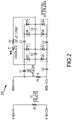
- FIG. 2illustrates a schematic view of circuitry suitable for use in the indication system in FIG. 1 ;
- FIG. 2Aillustrates a schematic view of circuitry suitable for use in the indication system in FIG. 1 ;
- FIG. 3illustrates a partially-transparent view of the indication system
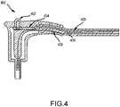
- FIG. 4illustrates a side section view of the indication system
- FIG. 5is a flowchart of a method.
- a system and method for providing an indication of an electrical measurement, wherein the system is contained substantially within a cable,is provided in some embodiments.
- the measurementmay be a magnitude of an electrosurgical current, voltage, or power in the conductors of a cable.
- An associated methodmay include processing signals transmitted by the cable.
- an electrosurgical currentmay be a shield current conducted through the cable from a minimally invasive surgical instrument or a voltage between two conductors.
- a system or methodmay simultaneously have features described in US Pat. Pub. No. 2016/0192980 A1, published Jul. 7, 2016, entitled Enhanced Control Systems Including Flexible Shielding and Support Systems for Electrosurgical Applications, the entirety of which is incorporated herein by reference and/or any one of the features described in US Pat. Pub. No. 2016/0106494 A1, published Apr. 21, 2016, entitled Multiple Parameter Fault Detection in Electrosurgical Instrument Shields, the entirety of which is incorporated herein by reference.
- an indication systemfor providing indications of any electrical measurement or activity.
- the systemmay be provided to detect and indicate that a voltage and/or a current measurement has been detected, such as in a medical instrument.
- the systemmay be contained substantially within a cable.
- the measurementmay be the magnitude of electrosurgical current, voltage, impedance or power in the conductors of a cable.
- the systemmay also involve processing of signals transmitted by the cable.
- the measurementmay be electrosurgical shield current conducted through the cable from a shielded minimally invasive instrument.
- FIG. 1it illustrates a block diagram of an indication system 100 according to some embodiments.
- the systemmay include a cable having sensors and electronics to make measurements and provide display of any electrical parameter; for example, voltage, current, power, impedance from any source, such as an electrosurgical instrument.
- the system 100may have a flexible cable 102 comprising a plurality of active conductors 104 , 106 , 108 and a plug 110 configured to couple to an electrosurgical instrument (not illustrated).
- the system 100may also have a circuit 112 having a current sensor 114 , a voltage sensor 116 , and a processing device 118 .
- the circuit 112may be configured to control a display 120 , at least a portion of which may be located external to the cable 102 and/or on or at the plug 110 .
- a non-conductive housing 122may be provided about portions of the system 100 .
- the system 100may include many types of electrical cables or may be specific only to shield currents from laparoscopic instruments.
- FIG. 2illustrates details of a circuit 200 suitable for use in the system 100 previously described herein.
- the circuit 200may be configured to cause the display 120 to illuminate when the system 100 is in a defined state of operation.
- FIG. 2Aillustrates details of a circuit 250 suitable for use in the system 100 previously described herein.
- the circuit 250may include an antenna 252 or a capacitor 254 .
- the capacitormay be an 8.3 picofarad (pF) capacitor 254 .
- the antennaserves as the capacitor 254 .
- the capacitor 254is a discrete feature of the circuite 250 .
- the system 300may include a connector assembly 302 configured to couple to a shielded electrosurgical instrument (not illustrated).
- the cable 102may have three conductors 104 , 106 , 108 configured as shield contacts 104 , 108 and an active electrode contact 106 respectively, and a plug 110 shaped and configured to couple to a shielded electrosurgical instrument.
- the display 120may be an LED and an ABS light pipe configured to shine solid green, for example, with a dominant wavelength of 525 nM when the system 300 senses protective conditions in the shielded electrosurgical instrument.
- the system 100is configured to cause the display 120 to flash a set number of times when the shielded electrosurgical instrument is first powered on and a fault current is not detected. In some embodiments, the system 100 is configured to cause the display 120 to illuminate or to change colors of illumination such from amber to green when the electrosurgical instrument is in a suitable state for safe operation.
- FIG. 4illustrates a system having an antenna. That is, the system 400 may include an indicator 402 substantially as previously described herein and a circuit board 404 having a circuit 200 , 250 such as the circuit described with reference to FIG. 2 or 2A .
- the system 400may also have one or more shield conductors 406 as previously described herein and/or as described in one of the documents incorporated herein by reference.
- the system 400may also have one or more active conductors 408 as previously described herein and/or as described in one of the documents incorporated herein by reference.
- the system 400may also have an antenna or antenna wire 410 , such as that illustrated in FIG. 4 .
- the antenna or antenna wire 410may be provided to detect capacitive energy and to create a current in the sensor.
- the antenna 410may be a length of wire, such as about 12 inches or less, or between about 3 and 9 inches, or about 6 inches, projecting into a lumen formed in a center of the cable.
- the antenna wire 410may be positioned in sufficiently close proximity to the active conductor 408 so as to cause a capacitive effect.
- capacitor 254 illustrated in FIG. 2Amay be provided by the antenna 410 and the active conductor 408 .
- the system 100may be limited to electrosurgical parameters, for example current in a bipolar applications or power in either bipolar or monopolar applications.
- the system 100may be limited to shielded monopolar applications in which the parameter of interest is shield current, or applied active voltage.
- the system 100may be powered, by one or more sources such as by a portion of power conducted within the cable, by a battery in the cable, or by an external power source, for example a source within connected equipment.
- a display providing indicationsmay be a single LED, multiple LEDs, one or more LCD elements, a segmented or dot-matrix display, or other appropriate display technology.
- the displaymay be located on a component of the cable.
- the componentmay be the plug—head that connects a laparoscopic instrument to a high-frequency energy source.
- the high-frequency energy sourcemay include a monitor for control of the energy in response to the properties of the shield current conducted from a shielded instrument.
- the measurement and display processing circuitrymay be located within a component of the cable.
- the method 500may include providing 502 a substantially electrically non-conductive housing; and enclosing 504 a portion of at least one active conductor and exposing a contact portion of the at least one active conductor with the non-conductive housing, the at least one active conductor configured to conduct power to an electrosurgical instrument.
- the method 500may include enclosing 506 a circuit having a voltage sensor, a current sensor, and a processing device operatively coupled to the at least one active conductor with the non-conductive housing; and operatively coupling 508 an indicator to the processing device.
- the methodmay include enclosing a shield current conductor with the non-conductive housing; and operatively coupling the voltage sensor, the current sensor, and the processing device to the at least one shield current conductor.
- the methodmay include configuring the system to be powered by a portion of power diverted from the at least one active conductor.
- the methodmay include positioning an antenna in sufficiently close proximity to the at least one active conductor so as to cause a capacitive effect; and operatively coupling the antenna to the circuit; and configuring at least one of the current sensor are the voltage sensor to detect capacitive energy.
- Embodiments of the inventioncan be embodied in a variety of ways.
- each of the various elements of the invention and claimsmay also be achieved in a variety of manners.
- This disclosureshould be understood to encompass each such variation, be it a variation of an embodiment of any apparatus embodiment, a method or process embodiment, or even merely a variation of any element of these.
- the words for each elementmay be expressed by equivalent apparatus terms or method terms—even if only the function or result is the same.
- the present inventionprovides, among other things, a system and method for indication of an electrical measurement, wherein the system is contained substantially within a cable.
Landscapes
- Health & Medical Sciences (AREA)
- Surgery (AREA)
- Engineering & Computer Science (AREA)
- Life Sciences & Earth Sciences (AREA)
- Biomedical Technology (AREA)
- Molecular Biology (AREA)
- Nuclear Medicine, Radiotherapy & Molecular Imaging (AREA)
- Plasma & Fusion (AREA)
- Physics & Mathematics (AREA)
- Heart & Thoracic Surgery (AREA)
- Medical Informatics (AREA)
- Otolaryngology (AREA)
- Animal Behavior & Ethology (AREA)
- General Health & Medical Sciences (AREA)
- Public Health (AREA)
- Veterinary Medicine (AREA)
- Surgical Instruments (AREA)
- Measurement And Recording Of Electrical Phenomena And Electrical Characteristics Of The Living Body (AREA)
Abstract
Description
Claims (13)
Priority Applications (2)
| Application Number | Priority Date | Filing Date | Title |
|---|---|---|---|
| US15/824,530US11350981B2 (en) | 2016-11-30 | 2017-11-28 | Indication system for surgical device |
| DE202017107245.2UDE202017107245U1 (en) | 2016-11-30 | 2017-11-29 | Display system for a surgical device |
Applications Claiming Priority (2)
| Application Number | Priority Date | Filing Date | Title |
|---|---|---|---|
| US201662428100P | 2016-11-30 | 2016-11-30 | |
| US15/824,530US11350981B2 (en) | 2016-11-30 | 2017-11-28 | Indication system for surgical device |
Publications (2)
| Publication Number | Publication Date |
|---|---|
| US20180147000A1 US20180147000A1 (en) | 2018-05-31 |
| US11350981B2true US11350981B2 (en) | 2022-06-07 |
Family
ID=61695519
Family Applications (1)
| Application Number | Title | Priority Date | Filing Date |
|---|---|---|---|
| US15/824,530Active2039-04-21US11350981B2 (en) | 2016-11-30 | 2017-11-28 | Indication system for surgical device |
Country Status (2)
| Country | Link |
|---|---|
| US (1) | US11350981B2 (en) |
| DE (1) | DE202017107245U1 (en) |
Citations (10)
| Publication number | Priority date | Publication date | Assignee | Title |
|---|---|---|---|---|
| US3642008A (en)* | 1968-09-25 | 1972-02-15 | Medical Plastics Inc | Ground electrode and test circuit |
| US5312401A (en)* | 1991-07-10 | 1994-05-17 | Electroscope, Inc. | Electrosurgical apparatus for laparoscopic and like procedures |
| US5897529A (en)* | 1997-09-05 | 1999-04-27 | Cordis Webster, Inc. | Steerable deflectable catheter having improved flexibility |
| US5936536A (en)* | 1997-04-08 | 1999-08-10 | Medicor Corporation | Electrical insulation testing device and method for electrosurgical instruments |
| US6074382A (en)* | 1997-08-29 | 2000-06-13 | Asah Medico A/S | Apparatus for tissue treatment |
| US20120283718A1 (en)* | 2011-05-06 | 2012-11-08 | Ioan Cosmescu | Light attachment device for electrosurgical pencil and electrosurgical pencil attachments |
| US8529437B2 (en) | 2008-08-06 | 2013-09-10 | Encision, Inc. | Multifunctional surgical instrument with flexible end effector tools |
| US20130317496A1 (en) | 2008-08-18 | 2013-11-28 | Encision, Inc. | Enhanced control systems including flexible shielding and support systems for electrosurgical applications |
| US9254165B2 (en) | 2007-10-26 | 2016-02-09 | Encision, Inc. | Multiple parameter fault detection in electrosurgical instrument shields |
| US20160192980A1 (en) | 2008-08-18 | 2016-07-07 | Encision Inc. | Enhanced control systems including flexible shielding and support systems for electrosurgical applications |
- 2017
- 2017-11-28USUS15/824,530patent/US11350981B2/enactiveActive
- 2017-11-29DEDE202017107245.2Upatent/DE202017107245U1/enactiveActive
Patent Citations (11)
| Publication number | Priority date | Publication date | Assignee | Title |
|---|---|---|---|---|
| US3642008A (en)* | 1968-09-25 | 1972-02-15 | Medical Plastics Inc | Ground electrode and test circuit |
| US5312401A (en)* | 1991-07-10 | 1994-05-17 | Electroscope, Inc. | Electrosurgical apparatus for laparoscopic and like procedures |
| US5936536A (en)* | 1997-04-08 | 1999-08-10 | Medicor Corporation | Electrical insulation testing device and method for electrosurgical instruments |
| US6074382A (en)* | 1997-08-29 | 2000-06-13 | Asah Medico A/S | Apparatus for tissue treatment |
| US5897529A (en)* | 1997-09-05 | 1999-04-27 | Cordis Webster, Inc. | Steerable deflectable catheter having improved flexibility |
| US9254165B2 (en) | 2007-10-26 | 2016-02-09 | Encision, Inc. | Multiple parameter fault detection in electrosurgical instrument shields |
| US20160106494A1 (en) | 2007-10-26 | 2016-04-21 | Encision Inc. | Multiple Parameter Fault Detection in Electrosurgical Instrument Shields |
| US8529437B2 (en) | 2008-08-06 | 2013-09-10 | Encision, Inc. | Multifunctional surgical instrument with flexible end effector tools |
| US20130317496A1 (en) | 2008-08-18 | 2013-11-28 | Encision, Inc. | Enhanced control systems including flexible shielding and support systems for electrosurgical applications |
| US20160192980A1 (en) | 2008-08-18 | 2016-07-07 | Encision Inc. | Enhanced control systems including flexible shielding and support systems for electrosurgical applications |
| US20120283718A1 (en)* | 2011-05-06 | 2012-11-08 | Ioan Cosmescu | Light attachment device for electrosurgical pencil and electrosurgical pencil attachments |
Also Published As
| Publication number | Publication date |
|---|---|
| DE202017107245U1 (en) | 2018-03-05 |
| US20180147000A1 (en) | 2018-05-31 |
Similar Documents
| Publication | Publication Date | Title |
|---|---|---|
| US8460284B2 (en) | Multiple parameter fault detection in electrosurgical instrument shields | |
| US9696345B2 (en) | Voltage measurement device with an insulating body | |
| JP5436383B2 (en) | EKG wiring system | |
| CN108072788B (en) | Sensor subsystem for a non-contact voltage measuring device | |
| US9689898B2 (en) | Medium or high voltage arrangement with cable connection terminal | |
| US20170074920A1 (en) | Partial discharge acquisition system comprising a capacitive coupling electric field sensor | |
| CN110488133B (en) | Detecting signal path damage in measuring bioelectric signals | |
| US10361516B2 (en) | Electrical connector plug continuity | |
| EP2286211A1 (en) | Shielded antenna for system test of a non-contact voltage detector | |
| JP2020502754A (en) | Combination of conductive element such as bushing and connector cable | |
| US8717053B2 (en) | DC-AC probe card topology | |
| WO2015009315A1 (en) | Cable detection system and method | |
| US11350981B2 (en) | Indication system for surgical device | |
| US11957473B2 (en) | ECG electrode connector and ECG cable | |
| US11642062B2 (en) | Production of electrical contact with skin | |
| US9851396B2 (en) | Instrument test arrangement | |
| CN109792111A (en) | For not terminating the electric connector of cable | |
| EP2767309B1 (en) | Defibrillator electrode identification system | |
| US20210356513A1 (en) | Testing electrode quality | |
| AU2016101062A4 (en) | A Neurological Detecting Terminal Box | |
| CN217332596U (en) | System and electronic device for detecting residual voltage of electrical consumer | |
| US20210356512A1 (en) | Detecting asymmetry in a bidirectional semiconductor device | |
| TWI481877B (en) | Probe card structure |
Legal Events
| Date | Code | Title | Description |
|---|---|---|---|
| FEPP | Fee payment procedure | Free format text:ENTITY STATUS SET TO UNDISCOUNTED (ORIGINAL EVENT CODE: BIG.); ENTITY STATUS OF PATENT OWNER: SMALL ENTITY | |
| FEPP | Fee payment procedure | Free format text:ENTITY STATUS SET TO SMALL (ORIGINAL EVENT CODE: SMAL); ENTITY STATUS OF PATENT OWNER: SMALL ENTITY | |
| STPP | Information on status: patent application and granting procedure in general | Free format text:DOCKETED NEW CASE - READY FOR EXAMINATION | |
| AS | Assignment | Owner name:ENCISION INC., COLORADO Free format text:ASSIGNMENT OF ASSIGNORS INTEREST;ASSIGNORS:BIGGS, MICHAEL JOHN;SCHREIBER, PHILIP;PETERSON, SHANE;AND OTHERS;SIGNING DATES FROM 20170310 TO 20180515;REEL/FRAME:049537/0063 | |
| STPP | Information on status: patent application and granting procedure in general | Free format text:NON FINAL ACTION MAILED | |
| STPP | Information on status: patent application and granting procedure in general | Free format text:RESPONSE TO NON-FINAL OFFICE ACTION ENTERED AND FORWARDED TO EXAMINER | |
| STPP | Information on status: patent application and granting procedure in general | Free format text:FINAL REJECTION MAILED | |
| STPP | Information on status: patent application and granting procedure in general | Free format text:DOCKETED NEW CASE - READY FOR EXAMINATION | |
| STPP | Information on status: patent application and granting procedure in general | Free format text:NON FINAL ACTION MAILED | |
| STPP | Information on status: patent application and granting procedure in general | Free format text:RESPONSE TO NON-FINAL OFFICE ACTION ENTERED AND FORWARDED TO EXAMINER | |
| STPP | Information on status: patent application and granting procedure in general | Free format text:NOTICE OF ALLOWANCE MAILED -- APPLICATION RECEIVED IN OFFICE OF PUBLICATIONS | |
| STCB | Information on status: application discontinuation | Free format text:ABANDONMENT FOR FAILURE TO CORRECT DRAWINGS/OATH/NONPUB REQUEST | |
| STPP | Information on status: patent application and granting procedure in general | Free format text:PUBLICATIONS -- ISSUE FEE PAYMENT VERIFIED | |
| STCF | Information on status: patent grant | Free format text:PATENTED CASE |