US11350970B2 - Bone fastener assembly - Google Patents
Bone fastener assemblyDownload PDFInfo
- Publication number
- US11350970B2 US11350970B2US16/389,352US201916389352AUS11350970B2US 11350970 B2US11350970 B2US 11350970B2US 201916389352 AUS201916389352 AUS 201916389352AUS 11350970 B2US11350970 B2US 11350970B2
- Authority
- US
- United States
- Prior art keywords
- screw
- head
- seat
- fastener
- axis
- Prior art date
- Legal status (The legal status is an assumption and is not a legal conclusion. Google has not performed a legal analysis and makes no representation as to the accuracy of the status listed.)
- Active, expires
Links
- 210000000988bone and boneAnatomy0.000titleclaimsabstractdescription101
- 230000000087stabilizing effectEffects0.000claimsabstractdescription13
- 230000003993interactionEffects0.000claims3
- 230000008878couplingEffects0.000claims2
- 238000010168coupling processMethods0.000claims2
- 238000005859coupling reactionMethods0.000claims2
- 230000007246mechanismEffects0.000description6
- 239000000463materialSubstances0.000description4
- 238000000034methodMethods0.000description4
- 230000004048modificationEffects0.000description4
- 238000012986modificationMethods0.000description4
- 230000000712assemblyEffects0.000description3
- 238000000429assemblyMethods0.000description3
- 230000013011matingEffects0.000description3
- 238000001356surgical procedureMethods0.000description3
- 208000002193PainDiseases0.000description2
- 230000008901benefitEffects0.000description2
- 230000008859changeEffects0.000description2
- 201000010099diseaseDiseases0.000description2
- 208000037265diseases, disorders, signs and symptomsDiseases0.000description2
- 230000000694effectsEffects0.000description2
- 239000012634fragmentSubstances0.000description2
- 230000006641stabilisationEffects0.000description2
- 238000011105stabilizationMethods0.000description2
- 206010061619DeformityDiseases0.000description1
- 208000004044HypesthesiaDiseases0.000description1
- 206010023509KyphosisDiseases0.000description1
- 206010033799ParalysisDiseases0.000description1
- 206010039203Road traffic accidentDiseases0.000description1
- 206010041591Spinal osteoarthritisDiseases0.000description1
- 208000007103SpondylolisthesisDiseases0.000description1
- 230000009471actionEffects0.000description1
- 239000000853adhesiveSubstances0.000description1
- 230000001070adhesive effectEffects0.000description1
- 230000009286beneficial effectEffects0.000description1
- 230000002146bilateral effectEffects0.000description1
- 230000008468bone growthEffects0.000description1
- 230000007850degenerationEffects0.000description1
- 230000005786degenerative changesEffects0.000description1
- 239000012530fluidSubstances0.000description1
- 230000004927fusionEffects0.000description1
- 208000034783hypoesthesiaDiseases0.000description1
- 208000014674injuryDiseases0.000description1
- 239000002184metalSubstances0.000description1
- 210000000944nerve tissueAnatomy0.000description1
- 230000000926neurological effectEffects0.000description1
- 231100000862numbnessToxicity0.000description1
- 230000000399orthopedic effectEffects0.000description1
- 238000002360preparation methodMethods0.000description1
- 238000003825pressingMethods0.000description1
- 230000008569processEffects0.000description1
- 206010039722scoliosisDiseases0.000description1
- 238000005476solderingMethods0.000description1
- 125000006850spacer groupChemical group0.000description1
- 208000005198spinal stenosisDiseases0.000description1
- 208000005801spondylosisDiseases0.000description1
- 230000008719thickeningEffects0.000description1
- 210000001519tissueAnatomy0.000description1
- 230000008733traumaEffects0.000description1
- 238000003466weldingMethods0.000description1
- 210000002517zygapophyseal jointAnatomy0.000description1
Images


Classifications
- A—HUMAN NECESSITIES
- A61—MEDICAL OR VETERINARY SCIENCE; HYGIENE
- A61B—DIAGNOSIS; SURGERY; IDENTIFICATION
- A61B17/00—Surgical instruments, devices or methods
- A61B17/56—Surgical instruments or methods for treatment of bones or joints; Devices specially adapted therefor
- A61B17/58—Surgical instruments or methods for treatment of bones or joints; Devices specially adapted therefor for osteosynthesis, e.g. bone plates, screws or setting implements
- A61B17/68—Internal fixation devices, including fasteners and spinal fixators, even if a part thereof projects from the skin
- A61B17/70—Spinal positioners or stabilisers, e.g. stabilisers comprising fluid filler in an implant
- A61B17/7001—Screws or hooks combined with longitudinal elements which do not contact vertebrae
- A61B17/7035—Screws or hooks, wherein a rod-clamping part and a bone-anchoring part can pivot relative to each other
- A61B17/7037—Screws or hooks, wherein a rod-clamping part and a bone-anchoring part can pivot relative to each other wherein pivoting is blocked when the rod is clamped
- A—HUMAN NECESSITIES
- A61—MEDICAL OR VETERINARY SCIENCE; HYGIENE
- A61B—DIAGNOSIS; SURGERY; IDENTIFICATION
- A61B17/00—Surgical instruments, devices or methods
- A61B17/56—Surgical instruments or methods for treatment of bones or joints; Devices specially adapted therefor
- A61B17/58—Surgical instruments or methods for treatment of bones or joints; Devices specially adapted therefor for osteosynthesis, e.g. bone plates, screws or setting implements
- A61B17/68—Internal fixation devices, including fasteners and spinal fixators, even if a part thereof projects from the skin
- A61B17/70—Spinal positioners or stabilisers, e.g. stabilisers comprising fluid filler in an implant
- A61B17/7001—Screws or hooks combined with longitudinal elements which do not contact vertebrae
- A61B17/7035—Screws or hooks, wherein a rod-clamping part and a bone-anchoring part can pivot relative to each other
- A61B17/7038—Screws or hooks, wherein a rod-clamping part and a bone-anchoring part can pivot relative to each other to a different extent in different directions, e.g. within one plane only
- A—HUMAN NECESSITIES
- A61—MEDICAL OR VETERINARY SCIENCE; HYGIENE
- A61B—DIAGNOSIS; SURGERY; IDENTIFICATION
- A61B17/00—Surgical instruments, devices or methods
- A61B17/56—Surgical instruments or methods for treatment of bones or joints; Devices specially adapted therefor
- A61B17/58—Surgical instruments or methods for treatment of bones or joints; Devices specially adapted therefor for osteosynthesis, e.g. bone plates, screws or setting implements
- A61B17/68—Internal fixation devices, including fasteners and spinal fixators, even if a part thereof projects from the skin
- A61B17/70—Spinal positioners or stabilisers, e.g. stabilisers comprising fluid filler in an implant
- A61B17/7001—Screws or hooks combined with longitudinal elements which do not contact vertebrae
- A61B17/7032—Screws or hooks with U-shaped head or back through which longitudinal rods pass
Definitions
- the inventionrelates to medical fixation devices and more particularly to bone fastener assemblies useful in constructs for stabilizing bones of a patient.
- a variety of orthopedic and neurological proceduresmake use of fasteners in constructs connecting one bone, or bone fragment, to another.
- connection of one vertebra of the human spine to another vertebrais a common beneficial procedure.
- the vertebrae of the human spineare arranged in a column with one vertebra on top of the next.
- An intervertebral disclies between adjacent vertebrae to transmit force between the adjacent vertebrae and provide a cushion between them. The discs allow the spine to flex and twist.
- the spinal canalmay narrow due to excessive bone growth, thickening of tissue in the canal (such as ligamentous material), or both,
- the facet joints between adjacent vertebraemay degenerate and cause localized and/or radiating pain.
- the spinemay undergo changes due to trauma from automobile accidents, falls, heavy lifting, and other activities.
- the spinemay also be malformed from birth or become malformed over time such as for example in cases of scoliosis, kyphosis, spondylosis, spondylolisthesis, and other deformities.
- spine diseaseAll of the above conditions and similar conditions are collectively, referred to herein as spine disease.
- surgeonstreat spine disease by attempting to stabilize adjacent vertebrae relative to one another and/or restore the normal, spacing between adjacent vertebrae to improve the shape of the spine and to relieve pressure on affected nerve tissue.
- Stabilizing the vertebraeis often accomplished with plates and/or rods attached to the vertebrae with fasteners such as screws such as for example pedicle screws.
- the stabilizationmay be rigid such that it eliminates motion between adjacent vertebrae and encourages bony fusion between the vertebrae or it may be dynamic to allow continued motion between the vertebrae.
- the stabilizationincludes inserting a rigid spacer made of bone, metal, or plastic into the disc space between the adjacent vertebrae and allowing the vertebrae to grow together, or fuse, into a single piece of bone.
- the present disclosureprovides a bone fastener assembly for connecting a bone to a stabilizing construct.
- the bone fastener assemblyincludes a connecting member, a fastener seat, and a bone fastener.
- the connecting memberincludes a connecting member axis, a first opening, a second opening, and a first spherical surface.
- the connecting member axisextends from a proximal end to a distal end.
- the first openingis adjacent the proximal end.
- the second openingis adjacent the distal end.
- the fastener seatincludes a first end, a second end, a passageway, and a second spherical surface.
- the passagewayextends from the first end to the second end along a seat axis.
- the second spherical surfaceis configured to slidably engage the first spherical surface.
- the bone fastenerincludes a shank and a head. The shank extends though the passageway. The head engages a head-mating surface of the fastener seat.
- the fastener seatmay be insertable through the first opening and the bone fastener may be insertable through the second opening.
- the fastener seatmay be movable from a first position to a second position. In the first position, the seat axis may be transverse to the connecting member axis after the fastener seat and bone fastener are inserted into the connecting member. In the second position, the seat axis may be parallel to the connecting member axis, and the fastener seat may engage the bone fastener and retain the bone fastener in the connecting member
- the fastener seatmay comprise an outer edge and a notch extending radially outwardly from the passageway to the outer edge to receive the bone fastener as the fastener seat is moved from the first position to the second position.
- the fastener seatmay engage the connecting member in the second position in a pivoting relationship such that the fastener seat is able to pivot in at least one vertical plane containing the connecting member axis.
- the fastener seatmay engage the connecting member in the second position in a rotating relationship about the connecting member axis.
- the bone fastenermay engage the fastener seat in pivoting relationship such that the bone fastener is able to pivot in at least one vertical plane containing the seat axis relative to the fastener seat to vary the angle between the bone fastener and the connecting member.
- the bone fastenermay be able to pivot relative to the fastener seat in only one vertical plane containing the seat axis.
- the bone fastenermay be able to pivot from a first position in which the shank and the seat axis are parallel, to a second position in which the shank is transverse to the seat axis.
- the bone fastenermay be able to pivot in only one direction from the first position.
- the fastener seatmay include an outer edge and a notch extending radially outwardly from the passageway at least partway toward the outer edge.
- the notchmay receive the bone fastener as the bone fastener pivots from the first position to the second position.
- the headmay include a third spherical surface and the fastener seat may include a complimentary mating fourth spherical surface.
- the headmay include a cylindrical surface and the fastener seat may include a complimentary mating cylindrical surface.
- the fastener seatmay include an elongated seating surface such that the bone fastener is engageable with the fastener seat in a pivoting relationship at a plurality of spaced apart locations.
- the headmay extend radially outwardly on opposite sides of the shank.
- the headmay engage the fastener seat in the second position in a pivoting relationship with one degree of rotational freedom.
- a bone fastener assemblyfor connecting a bone to a stabilizing construct.
- the bone fastener assemblyincludes a rod holder, a fastener seat, and a bone fastener.
- the rod holderincludes a first passage extending along a first axis from a proximal opening to a distal opening. The passage is partially defined by a first surface.
- the fastener seatincludes a second passage extending along a second axis from a proximal end to a distal end. The distal end is at least partially defined by a second surface configured to mate with the first surface.
- the bone fastenerincludes a shank for engaging the bone, and a head. The shank defines a fastener axis.
- the fastener seat and the bone fastenerare insertable within the rod holder.
- the fastener seatis movable along the first surface from a first position to a second position. In the first position, the second axis is transverse to the first axis after the fastener seat and bone fastener are inserted into the rod holder. In the second position, the second axis is parallel to the first axis, and the fastener seat engages the bone fastener and retains the bone fastener in the rod holder.
- FIG. 1is a perspective view of a bone fastener assembly according to the present invention
- FIG. 2is a side elevation view of the bone fastener assembly of FIG. 1 ;
- FIG. 3is a bottom plan view of the bone fastener assembly of FIG. 1 ;
- FIG. 4is an exploded perspective view of the bone fastener assembly of FIG. 1 ;
- FIG. 5is a side sectional view of the bone fastener assembly of FIG. 1 ;
- FIG. 6is a side sectional view of the bone fastener assembly of FIG. 1 ;
- FIG. 7is a side sectional view of the bone fastener assembly of FIG. 1 ;
- FIG. 8is a side sectional view of the bone fastener assembly of FIG. 1 ;
- FIG. 9is a side sectional view of the bone fastener assembly of FIG. 1 illustrating an alternative fit of the parts:
- FIG. 10is a top plan view of an alternative arrangement for the screw seat of FIG. 1 :
- FIG. 11is a partial side sectional view of the screw seat of FIG. 10 ;
- FIG. 12is a side sectional view of the screw seat of FIG. 10 ;
- FIG. 13is an exploded perspective view of another embodiment of a bone fastener assembly according to the present invention.
- FIG. 14is a partial side sectional view of the bone fastener assembly of FIG. 13 ;
- FIG. 15is a side sectional view of the bone fastener assembly of FIG. 13 ;
- FIG. 16is an exploded perspective view of another embodiment of a hone fastener assembly according to the present invention.
- FIG. 17is a side sectional view of the bone fastener assembly of FIG. 16 ;
- FIG. 18is a detail view of the side sectional view of FIG. 17 ;
- FIG. 19is an exploded perspective view of an alternative arrangement for the bone screw of FIGS. 13-17 ;
- FIG. 20is a side sectional view of the embodiment of the bone screw of FIG. 19 ;
- FIG. 21is an exploded perspective view of another embodiment of a bone fastener assembly according to the present invention.
- FIG. 22is a top sectional view of the bone fastener assembly of FIG. 21 ;
- FIG. 23is aside sectional view of the bone fastener assembly of FIG. 21 ;
- FIG. 24is an exploded perspective view of another embodiment of a bone fastener assembly according to the present invention.
- FIG. 25is side sectional view of the bone fastener assembly of FIG. 24 ;
- FIG. 26is an exploded perspective view of another embodiment of a bone fastener assembly according to the present invention.
- FIG. 27is side sectional view of the bone fastener assembly of FIG. 26 .
- Embodiments of a bone fastener assemblyinclude a bone fastener and a connecting member mounted together to permit the fastener to pivot relative to a longitudinal axis of the assembly and swivel about the longitudinal axis.
- the fastener and connecting member mountingmay be biased to permit a greater degree of pivoting of the fastener in one direction relative to the connecting member of they may be constrained to permit pivoting in only one direction.
- By biasing or selectively constraining the pivoting aspect of the fastener relative to the connecting memberboth the amount of pivoting in the preferential direction and the strength of the mounting may be increased.
- the maximum pivot position of the fastener relative to the connecting membermay be oriented independently at any swivel position about the longitudinal axis of the assembly. This arrangement is therefore geometrically comprehensive with respect to the relative orientation of the fastener and connecting member.
- the bone fastenermay include a screw, pin, nail, bolt, staple, hook, and/or any other suitable fastener for engaging a bone.
- the connecting membermay include a plate engaging stud, rod holder, and/or any other suitable member for assembling a construct for stabilizing bones of a patient.
- the mountingmay include a ball and socket, hinge, spindle, and/or other suitable mountings.
- the bone fastener assemblymay connect to a bone in any of the variety of ways known in the art and may be utilized in any of the variety of constructs known in the art to stabilize bones at any location within the body.
- FIGS. 1-3illustrate a pair of bone fastener assemblies in the form of pedicle screw assemblies 100 coupled to a spinal rod 102 in order to fix adjacent vertebrae relative to the rod 102 and thereby stabilize the vertebrae relative to one another.
- Each pedicle screw assembly 100includes a bone fastener in the form of a screw 104 , a connecting member in the form of a rod holder 106 , and a mounting in the form of a screw seat 108 ( FIG. 2 ) linking the screw 104 and rod holder 106 .
- the assemblyincludes a longitudinal axis 110 through the rod holder 106 , screw seat 108 , and screw 104 .
- the screw 104is able to pivot in at least one vertical plane containing the longitudinal axis 110 to vary the angle between the screw 104 and rod holder 106 .
- the screw seat 108permits the screw 104 to pivot to an extreme angle in a preferential direction while maintaining support and strength by retaining material that limits pivoting in other directions.
- the screw seat 108includes a notch 112 ( FIG. 3 ) that permits the screw 104 to pivot preferentially into the notch 112 . As best seen in FIG.
- the screw 104is also able to swivel about the longitudinal axis 110 in a horizontal plane transverse to the longitudinal axis 110 as the screw seat 108 rotates within the rod holder 106 .
- This combination of vertical pivoting and horizontal swivelingallows the rod holder 106 to be swiveled to any desired position independently of the position of the notch 112 and screw 104 to selectively orient the position of maximum screw pivoting.
- Various mechanisms for achieving this motionare detailed below.
- FIGS. 4-8illustrate the details of one embodiment of the pedicle screw assembly 100 of FIG. 1 .
- the pedicle screw assembly 100includes a screw 104 , a rod holder 106 , a mounting in the form of a screw seat 108 , a rod insert 114 , and a set screw 116 .
- the screw 104includes an elongated shank 118 having a tip 120 at a distal end, a head 122 at a proximal end, and a longitudinal axis 124 extending therebetween.
- a thread 126spirals around the shank such that the screw 104 may be threaded into a bone.
- the head 122may be cylindrical, conical, elliptical, spherical, and/or any other suitable shape. In the illustrative example of FIG. 4 , the head 122 is generally spherical with a lower screw seat contacting portion 128 and an upper insert contacting portion 130 .
- the rod holder 106includes a generally cylindrical body 132 having a longitudinal passageway 134 extending through the body 132 along an axis 136 from an upper or first opening 138 near a proximal end to a lower or second opening 140 near a distal end.
- the body 132defines a screw seat contacting surface 142 adjacent the lower opening 140 .
- the screw seat contacting surface 142is preferably concave and spherical and has a diameter greater than the diameter of the lower opening 140 .
- a transverse passageway 144extends through the body 132 transverse to the axis 136 for receiving the rod 102 ( FIG. 1 ).
- the transverse passageway 144is open proximally to allow the rod 102 to be placed into the rod holder 106 with a proximal to distal motion.
- the transverse passageway 144may be closed proximally such that the rod 102 must be inserted transversely through the rod holder 106 .
- a screw thread 146spirals from the upper opening 138 distally into the rod holder body 132 .
- the screw seat 108has a generally cylindrical body 148 with a lower, rod holder contacting surface 150 .
- the rod holder contacting surface 150is preferably convex and spherical such that it mates with the screw seat contacting surface 142 in relative pivoting relationship.
- a longitudinal passageway 152extends through the body 148 along an axis 154 from an upper opening 156 near a proximal end to a lower opening 158 near a distal end.
- the body 148defines a screw head seating surface 160 adjacent the lower opening 158 .
- the screw head seating surface 160is preferably concave and spherical.
- a notch 162extends radially outwardly from the longitudinal passageway 152 and is sized to receive a portion of the screw shank 118 .
- the notch 162may extend only partway through the body 148 or it may extend completely through the body as shown in FIG. 4 and as will be discussed in more detail below.
- the insert 114has a generally cylindrical body 164 extending along a longitudinal axis 166 from an upper portion 168 near a proximal end to a lower, screw head contacting surface 170 near a distal end.
- the screw head contacting surface 170preferably includes an axial hole 172 defining an annular seat 174 .
- a transverse passageway 176extends through the body 164 transverse to the axis 166 for receiving the rod 102 .
- the transverse passageway 176is open proximally to allow the rod 102 to be placed into the insert 114 with a proximal to distal motion.
- the transverse passageway 176may be closed proximally such that the rod 102 must be inserted transversely through the insert 114 .
- the bottom of the transverse passageway 176defines a rod contacting surface and is preferably concave and cylindrical.
- the set screw 116has a generally cylindrical body 178 about a longitudinal axis 180 , a thread 182 spiraling around its exterior, and a driver engaging portion 184 , in this example a multi-lobed opening.
- the set screw 116is threadably receivable in the upper opening 138 of the rod holder 106 .
- FIGS. 5 and 6Illustrate a method of assembling the components of FIG. 4 .
- the screw head 122is inserted upwardly through the lower opening 140 of the rod holder 106 .
- the screw seat 108is tipped sideways and inserted through the upper opening 138 of the rod holder 106 with the notch 162 directed toward the screw head 122 .
- the screw seat 108engages the screw seat contacting surface 142 , the screw seat 108 is tipped upright so that the notch 162 slides under the screw head 122 and receives the screw shank 118 .
- the passageway 152 and notch 162are sized to fit closely around the screw shank 118 such that the screw 104 is only allowed to pivot in the direction of the notch and not transverse to the direction of the notch.
- the screw seat 108may be positioned in the rod holder 106 and the screw 104 inserted through the upper opening 138 of the rod holder 106 and into the screw seat 108 .
- the passageway 152 through the screw seatwould need to be enlarged enough to allow the screw thread 126 to pass.
- the insert 114is placed over the screw 104 in preparation for receiving the rod 102 .
- the screw 104 , screw seat 108 , and insert 114may be assembled intraoperativey by the surgical team or they may be preassembled. Preferably the components are preassembled and locked in place to prevent disassembly in order to simplify their use in surgery.
- the rod holder 106includes a blind hole 186 defining a thin web 188 of material that is pressed inwardly to stake the insert 114 in the rod holder 106 to prevent disassembly.
- the screw 104is driven into a bone, e.g. a pedicle, at a desired angle.
- the rod holder 106is pivoted relative to the screw 104 to a desired angle with the screw 104 in the notch 162 and the rod holder 106 is swiveled relative to the screw seat 108 to a desired orientation to align the transverse passageway 144 with a desired rod orientation.
- the rod 102is then placed into the transverse passageway 144 and the set screw 116 is threaded into the rod holder 106 to press the rod 102 , insert 114 , screw 104 , screw seat 108 , and rod holder 106 together to lock the construct in the desired position.
- the screw seat 108 and insert 114are shaped to have a gap 190 between them and the screw seat 108 is relieved (as shown at 192 in FIG. 6 ) adjacent the screw shank 118 such that the screw seat 108 can pivot relative to the screw seat contacting surface 142 of the rod holder 106 and the screw shank 118 can pivot relative to the screw seat 108 .
- This in effectproduces a “double throw” action in which the screw 104 can pivot a first amount ( FIG. 7 ) until the screw shank 118 abuts the screw seat 108 and the screw seat 108 abuts the insert 114 in most directions and a farther amount ( FIG.
- the rod holder 106may be notched to allow further pivoting in the preferred direction and/or the screw seat 108 may be extended to protrude former below the rod holder 106 to provide more pivoting before the screw shank 118 abuts the rod holder 106 .
- FIGS. 10-12illustrate an alternative screw seat 200 that is generally configured like, and operates like the screw seat 108 of FIGS. 4-8 .
- screw seat 200differs from that of FIGS. 4-8 , in that it has an elongated screw head seating surface 260 that allows the screw head 122 to slide along an arc and pivot at any position on the arc.
- the elongated screw head seating surface 260may include a plurality of discrete head seating regions 261 allowing discrete ranges ( FIG. 12 ) of screw angulation by selectively engaging the screw 104 with a preferred seating region. This may be advantageous in permitting additional pivoting range to the screw 104 . It may also be advantageous in a “double throw” arrangement as shown in FIGS. 7-8 to allow the head 122 to slide relative to the seat 108 and stay centered relative to the insert 114 for improved locking.
- FIGS. 13-15illustrate the details of another embodiment of a pedicle screw assembly like that of FIG. 1 .
- the screwhas a transverse head (described more fully below) that engages the screw seat in hinge pivoting relationship.
- the transverse headin combination with the pivoting and swiveling aspects of the invention allow for a compact screw assembly presenting a low profile.
- the screw headhas a small vertical height 316 relative to a large transverse width 318 and the overall vertical dimension 320 of the rod holder and screw head assembly is small.
- the low profile nature of the present inventionis advantageous because it allows the pedicle screw assembly to be used in situations where traditional “poliyaxial” screws are not indicated because they cannot fit.
- the low profile nature of the present inventionalso provides aesthetic and comfort advantages by reducing the presence of protruding bumps under a patient's skin, especially in smaller and or thinner patients with less fleshy mass surrounding the screws.
- the transverse head arrangement of this embodimentpermits a low profile while simultaneously more positively capturing the head and increasing the mechanical strength of the assembly.
- the pedicle screw assembly 300includes a screw seat 302 , a screw 304 , an insert 306 , a rod holder 308 , a swivel ring 310 , a retaining ring 312 , and a set screw 314 .
- the screw seat 302has a generally cylindrical body 324 defining a proximally facing shoulder 326 , a rim 328 , and an undercut 329 ( FIG. 14 ).
- a longitudinal passageway 330extends through the body along an axis 332 from an upper opening 334 near a proximal end to a lower opening near a distal end.
- the bodydefines a screw head contacting surface 338 extending distally into the body 324 .
- the screw head contacting surface 338may be cylindrical, conical, elliptical, spherical, and/or any other suitable shape. In the illustrative example of FIGS.
- the screw head contacting surface 338includes bilateral cylindrical depressions formed in the body on either side of the longitudinal passageway 330 and aligned along an axis 340 transverse to the longitudinal axis 332 .
- a notch 342extends outwardly from the longitudinal passageway 330 and is sized to receive a portion of the screw 304 .
- the notch 342may extend only partway through the body 324 or it may extend completely through the body 324 as shown in FIG. 13 .
- the screw 304includes an elongated shank 350 having a tip 352 at a distal end, a head 354 at a proximal end, and a longitudinal axis 356 extending therebetween.
- a thread 358spirals around the shank 350 such that the screw 304 may be threaded into a bone.
- the headmay be cylindrical, conical, elliptical, spherical, and/or any other suitable shape to cooperatively engage head contacting surface 338 .
- the headis generally cylindrical and projects outwardly transverse to the screw shank along an axis 360 .
- the screwis generally “T”-shaped and the head 354 is sized to engage the screw head contacting surface 338 of the screw seat 302 with the axes 340 , 360 coaxially aligned such that the screw may pivot about the axes 340 , 360 with the shank 350 moving in the longitudinal passageway 330 and notch 342 .
- the insert 306has a generally cylindrical body 364 extending along a longitudinal axis 366 from an upper portion 368 near a proximal end to a lower, screw head contacting surface 370 near a distal end.
- a transverse passageway 372extends through the body transverse to the axis 366 for receiving the rod 102 .
- the transverse passageway 372is open proximally to allow the rod 102 to be placed into the insert 306 with a proximal to distal motion.
- the transverse passageway 372may be closed proximally such that the rod 102 must be inserted transversely through the insert 306 .
- the bottom of the transverse passageway 372defines a rod contacting surface 374 and is preferably concave and cylindrical.
- the bodyincludes a longitudinal rib 362 that engages a corresponding groove 363 ( FIG. 14 ) in the rod holder 308 to orient the transverse passageway 372 relative to the rod holder 308 .
- the rod holder 308includes a body 380 having a longitudinal passageway 382 extending through the body 330 along an axis 384 from an upper or first opening 386 near a proximal end to a lower or second opening 388 near a distal end.
- the lower opening 388is sized to receive the insert 306 and screw head 354 .
- the body 380defines a distally facing shoulder 390 , a rim 392 , and an undercut 393 extending into the body 380 ( FIG. 14 ).
- a transverse passageway 394extends through the body 380 transverse to the axis 384 for receiving the rod 102 .
- the transverse passageway 394is open proximally to allow the rod 102 to be placed Into the rod holder 308 with a proximal to distal motion.
- the transverse passageway 394may be closed proximally such that the rod 102 must be inserted transversely through the rod holder 308 .
- a screw thread 396spirals from the upper opening 386 distally into the rod holder body 380 .
- the body 380defines an enlarged cavity 398 for receiving the insert 306 .
- the cavity 398defines an internal distally facing shoulder 399 against which the upper portion 368 of the insert 306 abuts to trap the insert 306 in the cavity 398 between the rod holder 308 and screw seat 302 .
- the swivel ring 310includes a generally cylindrical body 400 having a longitudinal passageway 402 extending through the body 400 along an axis 404 from an upper or first opening 406 near a proximal end to a lower or second opening 408 near a distal end and defining an inner surface 410 .
- the swivel ring 310has an outer diameter and an inner diameter.
- the swivel ring 310includes an internal annular groove 412 extending into the body 400 from the inner surface 410 radially outwardly.
- the swivel ring 310is interrupted by a notch 414 so that the swivel ring 310 can be elastically deformed to change the inner and outer diameters.
- the inner diameter and annular groove 412are sized to engage the rims and undercuts of the screw seat 302 and rod holder 308 as will be explained further below.
- the retaining ring 312comprises a generally cylindrical hollow ring having an internal diameter sized to press lit around the swivel ring 310 .
- the set screw 314has a generally cylindrical body 420 about a longitudinal axis 424 , a thread 426 spiraling around its exterior, and a driver engaging portion 428 .
- the set screw 314is threadably receivable in the upper opening 386 of the rod holder 308 ,
- FIGS. 14 and 15illustrate the pedicle screw assembly 300 of FIG. 13 in cross section.
- the screw head 354is seated in the screw seat 302 .
- the insert 306is placed in the cavity 398 of the rod holder 308 and the top of the screw seat 302 is abutted with the bottom of the rod holder 308 .
- the swivel ring 310is sprung open so that it can be slipped over the rod holder 308 and screw seat 302 .
- the swivel ringis snapped into place with the rims 328 , 392 of the screw seat 302 and rod holder 308 captured in the groove 412 .
- the retaining ring 312is then pressed into place around the swivel ring 310 to prevent the swivel ring 310 from springing open and releasing the screw seat 304 and rod holder 308 .
- the screw seat 302 and rod holder 308are free to rotate relative to one another about a longitudinal axis and the screw 304 is free to pivot relative to the screw seat 302 about a transverse axis.
- the “T”-head configuration of the screw 304 and screw seat 302creates a hinge joint between them constraining the screw 304 and screw seat 302 to one degree of rotational freedom relative to one another. In the embodiment of FIGS.
- the screw shank 350abuts the side of the longitudinal passageway 330 to prevent the screw 304 from pivoting to the left in FIG. 15 .
- the screw 304can pivot freely to the right in FIG. 15 and into the notch 342 to an extreme pivot angle.
- the pivot anglecan be increases further by extending the screw seat 302 further distally to deepen the notch 342 to receive more of the screw 304 . Pivot angles of 90 degrees or more are easily obtainable with such a modification.
- the shallow screw seat of FIGS. 13-15provide for a more compact, low profile assembly.
- the screw 304is driven into a bone, e.g. a pedicle, at a desired angle.
- the rod holder 308is pivoted relative to the screw 304 to a desired angle with the screw 304 in fee notch 342 and the rod holder 308 is swiveled relative to the screw seat 302 to a desired orientation to align the transverse passageway 394 with a desired rod orientation.
- the rod 102is then placed Into the transverse passageway 394 and the set screw 314 is threaded into the rod holder 308 to press the rod 102 , insert 306 , screw 304 , screw seat 302 , and rod holder 308 together to lock the construct in the desired position.
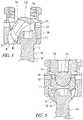
- FIGS. 16-18illustrate the details of another embodiment of a pedicle screw assembly 500 like that of FIG. 1 .
- the pedicle screw assembly 500 of FIGS. 16-18is similar to that of FIGS. 13-15 in that it includes a screw seat 502 , a “T”-shaped screw 504 , an insert 506 , a rod holder 508 , and a set screw 510 .
- the pedicle screw assembly 500 of FIGS. 16-18differs from that of FIGS. 13-15 in that instead of having a swivel ring and retaining ring to capture and hold the screw seat 502 and rod holder 508 together, the screw seat 502 and rod holder 508 snap together directly.
- the screw seat 502is in the form of a lower shell having a rim 512 and an undercut 514 and the rod holder 508 is in the form of an upper shell having a rim 516 and an undercut 518 ( FIG. 18 ).
- the screw seat 502 and rod holder 508snap together with the rim of one fitting into the undercut of the other.
- the insert 506 of the embodiment of FIGS. 16-18also differs from the insert 306 of the embodiment of FIGS. 13-15 .
- the insert 506has a cylindrical concave lower surface 520 shaped to receive the cylindrical head 522 of the screw 504 ( FIG. 16 ).
- the insert 506also has a cylindrical boss 524 ( FIG.
- FIGS. 16-18the embodiment of FIGS. 16-18 is shown with a relatively deep screw seat 502 and correspondingly deep screw receiving notch to permit high pivot angles.
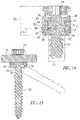
- FIGS. 19-20illustrate a screw assembly 600 that can be substituted for the screw in the embodiments of FIGS. 13-18 to permit adjustment of the direction of preferential screw pivoting independent of screw depth.
- the screw assembly 600includes a screw 602 , a separate modular “T”-head 604 , and a screw seat 603 .
- the screw 602includes an elongated shank 605 having a tip 606 at a distal end, a head 608 at a proximal end, and a longitudinal axis 610 extending therebetween.
- a thread 612spirals around the shank 605 such that the screw 602 may be threaded into a bone.
- the “T”-head 604includes a generally cylindrical body 614 oriented along a head axis 616 and a passageway 618 through the body 614 transverse to the head axis 616 .
- the “T”-head 604is preferably an assembly of two half heads that are assembled to a reduced portion of the shank 605 transverse to the longitudinal axis 610 .
- the screw head 608 and “T”-head 604can be made more compact since the passageway and screw head 608 can have a smaller diameter than the thread 612 .
- a one-piece “T”-head 604is within the scope of the invention with the diameter of the passageway 618 and head 608 sized accordingly.
- a countersunk seat 622is formed coaxially with the passageway 618 to receive the screw head 608 .
- a lower surface 624 of the screw head 608abuts the seat 622 to prevent the screw 602 from passing through the “T”-head 604 .
- the “T”-head of FIGS. 19-20optionally includes an annular groove 626 formed about the head axis 616 on each side of the body 614 . As best seen in FIG. 20 , the groove 626 captures a portion 628 of the screw seat 605 on each side to prevent the screw seat 605 from splaying open when forces are applied to the pedicle screw assembly 600 .
- FIGS. 21-23illustrate the details of another embodiment of a pedicle screw assembly 700 like that of FIG. 1
- the embodiment of FIGS. 21-23includes a screw seat 702 , a “T”-shaped screw assembly 704 , a locking ring 706 , a rod holder 708 , and a set screw 710 .
- the assembly of the screw seat 702 and rod holder 708is similar to the embodiment of FIG. 16 except that the screw seat 702 and rod holder 708 of FIG. 21 are locked with a locking ring 706 rather than snapping directly together.
- the screw seat 702includes a groove 712 and the rod holder 708 includes a groove 714 each sized to receive a portion of the locking ring 706 .
- the locking ring 706includes a notch 716 allowing it to be elastically expanded and contracted.
- the locking ring 706is first assembled onto one of the components, e.g. it can be snapped into the groove 712 in the screw seat 702 .
- the rod bolder 708is then pressed into the screw seat 702 causing the locking ring 706 to expand until the grooves 712 , 714 are aligned and the locking ring 706 contracts to reside partially in each groove 712 , 714 and lock the rod holder 708 and screw seat 702 together for relative rotation.
- the “T”-shaped screw assembly 704 of FIGS. 21-23permits orientation of the preferential screw pivot direction without changing the depth of the screw assembly 704 in the bone similar to the embodiment of FIG. 19-20 .
- the “T”-shaped screw assembly 704includes a pin 718 inserted transversely through a passageway 720 in a head 722 of a screw 723 .
- the passageway 720is rotationally enlarged about the longitudinal axis 724 so that pin 718 and screw 723 are able to rotate relative to one another about the longitudinal axis 724 .
- the screw seat 702 and pin 718can rotate about the screw 723 .
- FIGS. 21-23also differs from the other embodiments in that there is no insert and the rod 102 (not shown in FIGS. 21-23 ) bears directly on the screw head 722 .
- FIGS. 24-25illustrate the details of another embodiment of a pedicle screw assembly similar to the previous embodiments.
- the pedicle screw assembly 800includes a screw seat 802 , a “T”-shaped screw 804 , an insert 806 , a rod holder 808 , a retaining ring 810 , and a set screw (not shown).
- the rod holder 808includes a plurality of distally extending tabs 812 having inwardly directed lips 814 .
- the screw seat 802includes an annular groove 818 able to receive the lips in snap fitting relationship.
- the rod holder 808attaches to the screw seat 802 by pressing the tabs 812 over the screw seat 802 causing the tabs 812 to flex outwardly until the lips 814 engage the groove 818 allowing the tabs to snap inwardly.
- the retaining ring 810is pressed onto the rod holder 808 so that it surrounds the tabs 812 and prevents them from flexing outwardly and releasing the screw seat 802 .
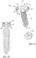
- FIGS. 26-27illustrate the details of another embodiment of a pedicle screw assembly similar to the previous embodiments.
- the pedicle screw assembly 850includes a screw seat 852 , a “T”-shaped screw 854 , a rod holder 856 , and a set screw (not shown).
- One or more plates 858are provided to attach the rod holder 856 to the screw seat 852 .
- Each platesincludes a distally extending portion 860 having an inwardly projecting lip 862 .
- the screw seat 852includes an annular groove 864 able to receive the lips 862 .
- the plateis attached to the rod holder 856 using a suitable fastening mechanism such as a screw, clip, adhesive, welding, soldering, and or other suitable fastening mechanism.
- two plates 858are inset into notches 866 formed in opposite sides of the rod holder 856 and screws 868 extend through the plates 858 and thread into the rod holder 856 to attach them to the rod holder 856
- a hone fastener assemblyand its use have been described and illustrated in detail, it is to be understood that the same is intended by way of illustration and example only and is not to be taken by way of limitation.
- the inventionhas been illustrated in the form of a pedicle screw assembly for use in assembling stabilizing constructs to connect vertebrae of the human spine.
- the bone fastener assemblymay be configured with other kinds of fasteners and connecting members to assemble other kinds of constructs to stabilize bones and bone fragments at any location in the body. Accordingly, variations in and modifications to the bone fastener assembly and its use will be apparent to those of ordinary skill in the art.
- the various illustrative embodimentsillustrate alternative configurations of various component parts such as screw seats, screws, pivot mechanisms, swivel mechanisms, and inserts among others.
- the alternative configuration of a component part in one embodimentmay be substituted for a similar component part in another embodiment.
- the screw seat shown in the embodiment of FIGS. 1-8may be readily modified with a cylindrical seat to be used with any of the “T”-head screws shown in the embodiments of FIGS. 13-27 .
- the various mechanisms illustrated for attaching the screw seat to the rod holdermay be interchanged.
- the gender of the component partsmay be reversed as is known in the art within the scope of the invention. The following claims are intended to cover all such modifications and equivalents.
Landscapes
- Health & Medical Sciences (AREA)
- Orthopedic Medicine & Surgery (AREA)
- Life Sciences & Earth Sciences (AREA)
- Neurology (AREA)
- Surgery (AREA)
- Heart & Thoracic Surgery (AREA)
- Engineering & Computer Science (AREA)
- Biomedical Technology (AREA)
- Nuclear Medicine, Radiotherapy & Molecular Imaging (AREA)
- Medical Informatics (AREA)
- Molecular Biology (AREA)
- Animal Behavior & Ethology (AREA)
- General Health & Medical Sciences (AREA)
- Public Health (AREA)
- Veterinary Medicine (AREA)
- Surgical Instruments (AREA)
Abstract
Description
Claims (15)
Priority Applications (1)
| Application Number | Priority Date | Filing Date | Title |
|---|---|---|---|
| US16/389,352US11350970B2 (en) | 2007-01-12 | 2019-04-19 | Bone fastener assembly |
Applications Claiming Priority (5)
| Application Number | Priority Date | Filing Date | Title |
|---|---|---|---|
| US88478607P | 2007-01-12 | 2007-01-12 | |
| US90989107P | 2007-04-03 | 2007-04-03 | |
| US11/972,894US8961568B2 (en) | 2007-01-12 | 2008-01-11 | Bone fastener assembly |
| US14/624,031US10307184B2 (en) | 2007-01-12 | 2015-02-17 | Bone fastener assembly |
| US16/389,352US11350970B2 (en) | 2007-01-12 | 2019-04-19 | Bone fastener assembly |
Related Parent Applications (1)
| Application Number | Title | Priority Date | Filing Date |
|---|---|---|---|
| US14/624,031ContinuationUS10307184B2 (en) | 2007-01-12 | 2015-02-17 | Bone fastener assembly |
Publications (2)
| Publication Number | Publication Date |
|---|---|
| US20190239931A1 US20190239931A1 (en) | 2019-08-08 |
| US11350970B2true US11350970B2 (en) | 2022-06-07 |
Family
ID=39636640
Family Applications (3)
| Application Number | Title | Priority Date | Filing Date |
|---|---|---|---|
| US11/972,894Active2031-12-08US8961568B2 (en) | 2007-01-12 | 2008-01-11 | Bone fastener assembly |
| US14/624,031Active2029-02-20US10307184B2 (en) | 2007-01-12 | 2015-02-17 | Bone fastener assembly |
| US16/389,352Active2028-01-29US11350970B2 (en) | 2007-01-12 | 2019-04-19 | Bone fastener assembly |
Family Applications Before (2)
| Application Number | Title | Priority Date | Filing Date |
|---|---|---|---|
| US11/972,894Active2031-12-08US8961568B2 (en) | 2007-01-12 | 2008-01-11 | Bone fastener assembly |
| US14/624,031Active2029-02-20US10307184B2 (en) | 2007-01-12 | 2015-02-17 | Bone fastener assembly |
Country Status (6)
| Country | Link |
|---|---|
| US (3) | US8961568B2 (en) |
| EP (1) | EP2124776B1 (en) |
| JP (1) | JP5263978B2 (en) |
| AU (1) | AU2008206396A1 (en) |
| CA (1) | CA2675346A1 (en) |
| WO (1) | WO2008089096A2 (en) |
Families Citing this family (71)
| Publication number | Priority date | Publication date | Assignee | Title |
|---|---|---|---|---|
| US8951290B2 (en) | 2004-08-27 | 2015-02-10 | Blackstone Medical, Inc. | Multi-axial connection system |
| US7955358B2 (en) | 2005-09-19 | 2011-06-07 | Albert Todd J | Bone screw apparatus, system and method |
| US8100946B2 (en) | 2005-11-21 | 2012-01-24 | Synthes Usa, Llc | Polyaxial bone anchors with increased angulation |
| AU2008206396A1 (en) | 2007-01-12 | 2008-07-24 | Lanx, Inc. | Bone fastener assembly |
| WO2008131084A2 (en) | 2007-04-17 | 2008-10-30 | K2M, Inc. | Minimally open interbody access retraction device and surgical method |
| US8979904B2 (en) | 2007-05-01 | 2015-03-17 | Roger P Jackson | Connecting member with tensioned cord, low profile rigid sleeve and spacer with torsion control |
| KR101503665B1 (en) | 2007-06-22 | 2015-03-18 | 이픽스 오소페딕스, 인코포레이티드 | Intramedullary rod for pivoting a fastener |
| PL2170192T3 (en) | 2007-07-20 | 2011-07-29 | Synthes Gmbh | Polyaxial bone fixation element |
| US9439681B2 (en) | 2007-07-20 | 2016-09-13 | DePuy Synthes Products, Inc. | Polyaxial bone fixation element |
| EP2211742A4 (en) | 2007-10-24 | 2012-12-19 | Nuvasive Inc | Surgical fixation system and related methods |
| US9060813B1 (en) | 2008-02-29 | 2015-06-23 | Nuvasive, Inc. | Surgical fixation system and related methods |
| EP2355725B1 (en) | 2008-09-05 | 2017-03-08 | Synthes GmbH | Bone fixation assembly |
| JP5815407B2 (en) | 2008-09-12 | 2015-11-17 | ジンテス ゲゼルシャフト ミット ベシュレンクテル ハフツング | Spinal stabilization and guided fixation system |
| KR20110081208A (en) | 2008-09-29 | 2011-07-13 | 신세스 게엠바하 | Multi-Axis Bottom-Loading Screw and Rod Assemblies |
| US10383659B2 (en)* | 2008-10-10 | 2019-08-20 | Globus Medical, Inc. | Uniplanar screw |
| US8790343B2 (en) | 2008-10-11 | 2014-07-29 | Epix Orthopaedics, Inc. | Intramedullary rod with pivotable and fixed fasteners and method for using same |
| CA2742399A1 (en) | 2008-11-03 | 2010-06-03 | Dustin M. Harvey | Uni-planar bone fixation assembly |
| KR20120013312A (en) | 2009-04-15 | 2012-02-14 | 신세스 게엠바하 | Orthodontic Connectors for Spinal Structures |
| CN103826560A (en) | 2009-06-15 | 2014-05-28 | 罗杰.P.杰克逊 | Polyaxial Bone Anchor with Socket Stem and Winged Inserts with Friction Fit Compression Collars |
| CA2764841A1 (en) | 2009-06-17 | 2010-12-23 | Synthes Usa, Llc | Revision connector for spinal constructs |
| US8298275B2 (en) | 2009-10-30 | 2012-10-30 | Warsaw Orthopedic, Inc. | Direct control spinal implant |
| US8430917B2 (en)* | 2009-10-30 | 2013-04-30 | Warsaw Orthopedic, Inc. | Bone engaging implant with adjustment saddle |
| US9044272B2 (en) | 2009-11-09 | 2015-06-02 | Ebi, Llc | Multiplanar bone anchor system |
| US8449578B2 (en)* | 2009-11-09 | 2013-05-28 | Ebi, Llc | Multiplanar bone anchor system |
| US8986349B1 (en) | 2009-11-11 | 2015-03-24 | Nuvasive, Inc. | Systems and methods for correcting spinal deformities |
| EP2555696B1 (en)* | 2010-04-08 | 2017-07-26 | Globus Medical, Inc. | Jointed rod |
| US20110257690A1 (en)* | 2010-04-20 | 2011-10-20 | Warsaw Orthopedic, Inc. | Transverse and Sagittal Adjusting Screw |
| DE102010028423B4 (en)* | 2010-04-30 | 2016-04-14 | Kilian Kraus | Pedicle screw and device for stabilizing the spine |
| US9084634B1 (en)* | 2010-07-09 | 2015-07-21 | Theken Spine, Llc | Uniplanar screw |
| GB2483531A (en)* | 2010-09-13 | 2012-03-14 | Facetmed Ltd | Spinal fixation system |
| DE102010060555A1 (en)* | 2010-11-15 | 2012-05-16 | Ulrich Gmbh & Co. Kg | pedicle screw |
| EP2457527B1 (en) | 2010-11-24 | 2014-04-16 | Biedermann Technologies GmbH & Co. KG | Polyaxial bone anchoring device with enlarged pivot angle |
| ES2436067T3 (en) | 2010-12-13 | 2013-12-26 | Biedermann Technologies Gmbh & Co. Kg | Bone anchoring device |
| US9387013B1 (en) | 2011-03-01 | 2016-07-12 | Nuvasive, Inc. | Posterior cervical fixation system |
| CN102772241A (en)* | 2011-05-11 | 2012-11-14 | 上海鼎桥生物科技有限公司 | Minimally invasive internal fixation fusion system for anterior spinal column |
| US9993269B2 (en)* | 2011-07-15 | 2018-06-12 | Globus Medical, Inc. | Orthopedic fixation devices and methods of installation thereof |
| FR2978343B1 (en)* | 2011-07-25 | 2013-08-23 | Medicrea International | ANCHORING BODY FOR VERTEBRAL OSTEOSYNTHESIS EQUIPMENT |
| EP2559391B1 (en) | 2011-08-18 | 2014-06-18 | Biedermann Technologies GmbH & Co. KG | Polyaxial bone anchoring system |
| EP2918237A1 (en)* | 2011-09-15 | 2015-09-16 | Biedermann Technologies GmbH & Co. KG | Polyaxial bone anchoring device with enlarged pivot angle |
| ES2546157T3 (en) | 2011-10-27 | 2015-09-21 | Biedermann Technologies Gmbh & Co. Kg | Wide angle polyaxial bone anchoring device |
| US9622788B2 (en) | 2011-11-02 | 2017-04-18 | Warsaw Orthopedic, Inc. | Implant assembly with a rigid interface |
| EP2604204B1 (en)* | 2011-12-13 | 2014-10-01 | Biedermann Technologies GmbH & Co. KG | Monoplanar bone anchoring device with selectable pivot plane |
| US8911479B2 (en) | 2012-01-10 | 2014-12-16 | Roger P. Jackson | Multi-start closures for open implants |
| JP6247644B2 (en) | 2012-02-08 | 2017-12-13 | エピックス オーソペディックス インコーポレイテッド | Implant insertion device having a continuously adjustable targeting assembly |
| US20130211458A1 (en) | 2012-02-13 | 2013-08-15 | Warsaw Orthopedic, Inc. | Bone fastener and methods of use |
| US10327818B2 (en) | 2012-06-18 | 2019-06-25 | Bruce Francis Hodgson | Method and apparatus for the treatment of scoliosis |
| US10123828B2 (en) | 2013-03-15 | 2018-11-13 | Epix Orthopaedics, Inc. | Implantable device with pivotable fastener and self-adjusting set screw |
| WO2014169189A1 (en)* | 2013-04-12 | 2014-10-16 | Alphatec Spine, Inc. | Uniplanar screw assembly and methods of use |
| EP2886073B1 (en)* | 2013-12-19 | 2017-05-31 | Biedermann Technologies GmbH & Co. KG | Polyaxial bone anchoring device with enlarged pivot angle |
| EP3217902B1 (en) | 2014-11-13 | 2024-04-24 | Globus Medical, Inc | Bone attachment assembly |
| CN104799931B (en)* | 2015-04-13 | 2017-07-07 | 李贵涛 | Nest mortar rail chain type replacement and fixation dynamic pedicle screw system |
| US10130395B2 (en) | 2015-08-17 | 2018-11-20 | Globus Medical, Inc. | Modular uniplanar pedicle screw assembly for use with a polyaxial bone fastener |
| US9956003B2 (en)* | 2015-09-18 | 2018-05-01 | Warsaw Orthopedic, Inc | Spinal implant system and methods of use |
| US10034691B1 (en) | 2015-12-03 | 2018-07-31 | Nuvasive, Inc. | Bone anchor |
| US20170290608A1 (en)* | 2016-01-22 | 2017-10-12 | Spinal Usa, Inc. | Spinal fixation systems and methods |
| EP4278998B1 (en) | 2016-07-29 | 2025-05-21 | Zimmer Biomet Spine, Inc. | Bone anchor housing limiter |
| US11298156B2 (en) | 2017-03-30 | 2022-04-12 | K2M, Inc. | Modular screw |
| AU2018243875B2 (en) | 2017-03-30 | 2022-05-26 | K2M, Inc. | Bone anchor apparatus and method of use thereof |
| WO2018183486A1 (en) | 2017-03-30 | 2018-10-04 | K2M, Inc. | Modular offset screw |
| KR101782455B1 (en)* | 2017-04-26 | 2017-09-28 | 박영섭 | A implant device for cervical vertebrae no.1 |
| US10820896B2 (en) | 2017-06-12 | 2020-11-03 | Globus Medical Inc. | Surgical retractor |
| US10258386B2 (en)* | 2017-06-15 | 2019-04-16 | Warsaw Orthopedic, Inc. | Spinal construct and method |
| US10610265B1 (en) | 2017-07-31 | 2020-04-07 | K2M, Inc. | Polyaxial bone screw with increased angulation |
| KR102132188B1 (en)* | 2018-04-25 | 2020-07-09 | 주식회사 멘티스로지텍 | Pedicle screw assembly capable of largely forming an angle at which a pedicle screw is bent |
| US11596449B2 (en)* | 2018-09-13 | 2023-03-07 | Roger P. Jackson | Pivotal bone anchor assembly with modular receiver and universal shank head |
| US11571244B2 (en) | 2019-05-22 | 2023-02-07 | Nuvasive, Inc. | Posterior spinal fixation screws |
| JP7282206B2 (en)* | 2019-11-29 | 2023-05-26 | 京セラ株式会社 | Internal fixed member set and internal fixed member |
| WO2021263088A1 (en) | 2020-06-26 | 2021-12-30 | K2M, Inc. | Modular head assembly |
| WO2022108875A1 (en) | 2020-11-19 | 2022-05-27 | K2M, Inc. | Modular head assembly for spinal fixation |
| US11439437B1 (en) | 2021-06-09 | 2022-09-13 | Medos International Sarl | Bottom loading bone anchor assemblies with drag retaining ring and related methods |
| CN117717404B (en)* | 2024-02-08 | 2024-05-10 | 中国人民解放军总医院第一医学中心 | Bone screw combiner and spinal stabilization system |
Citations (57)
| Publication number | Priority date | Publication date | Assignee | Title |
|---|---|---|---|---|
| US4669907A (en) | 1984-04-23 | 1987-06-02 | The Crosby Group, Inc. | Industrial swivel |
| US4813808A (en) | 1983-08-19 | 1989-03-21 | Gkn Automotive Components Inc. | Axial retaining member and method for interconnecting male and female splined members |
| US4883303A (en) | 1987-06-16 | 1989-11-28 | Sundawn Inc. | Deflector screen for motor vehicle |
| US5102412A (en)* | 1990-06-19 | 1992-04-07 | Chaim Rogozinski | System for instrumentation of the spine in the treatment of spinal deformities |
| FR2693365A1 (en) | 1992-07-13 | 1994-01-14 | Vignaud Jean Louis | Spinal instrumentation with adjustable rod. |
| FR2734471A1 (en) | 1995-05-24 | 1996-11-29 | Implants Orthopediques Toutes | Spinal fixator retaining screw |
| US5588329A (en) | 1995-02-09 | 1996-12-31 | Nedachi; Mitsuyuki | Snap together shift knob construction |
| US5591165A (en) | 1992-11-09 | 1997-01-07 | Sofamor, S.N.C. | Apparatus and method for spinal fixation and correction of spinal deformities |
| US5607426A (en) | 1995-04-13 | 1997-03-04 | Fastenletix, L.L.C. | Threaded polyaxial locking screw plate assembly |
| FR2740674A1 (en) | 1995-11-07 | 1997-05-09 | Stryker France Sa | Rod fixator for spinal surgery |
| US5645599A (en) | 1994-07-26 | 1997-07-08 | Fixano | Interspinal vertebral implant |
| US5664898A (en) | 1994-12-20 | 1997-09-09 | Femas S.R.L. | Locking ring for rotary shafts |
| US5672176A (en) | 1995-03-15 | 1997-09-30 | Biedermann; Lutz | Anchoring member |
| US5728098A (en)* | 1996-11-07 | 1998-03-17 | Sdgi Holdings, Inc. | Multi-angle bone screw assembly using shape-memory technology |
| US5810818A (en) | 1995-10-23 | 1998-09-22 | Fastenetix, Llc | Spinal hook implant having a low blade and S swivel hook |
| FR2789293A1 (en) | 1999-02-10 | 2000-08-11 | Emmanuel Bockx | Vertebral stabilising frame has pedicular screws with adjustable wedge and clamp to allow positioning of bar connector |
| WO2000076413A1 (en) | 1999-06-14 | 2000-12-21 | Scient'x | Implant for osteosynthesis device in particular of the backbone |
| US6280442B1 (en) | 1999-09-01 | 2001-08-28 | Sdgi Holdings, Inc. | Multi-axial bone screw assembly |
| US6299614B1 (en) | 1999-03-29 | 2001-10-09 | Signus Medizintechnik Gmbh | Device for stabilizing vertebra bodies of the spinal column |
| WO2001097701A1 (en) | 2000-06-22 | 2001-12-27 | Emmanuel Bockx | Device for adjustable fixing of a tie rod using at least a pedicular screw for vertebral stability |
| US6478798B1 (en) | 2001-05-17 | 2002-11-12 | Robert S. Howland | Spinal fixation apparatus and methods for use |
| US20030032957A1 (en)* | 2001-08-13 | 2003-02-13 | Mckinley Laurence M. | Vertebral alignment and fixation assembly |
| US20030073995A1 (en)* | 2001-10-15 | 2003-04-17 | Reed Gary Jack | Orthopedic stabilization device and method |
| US6626908B2 (en) | 2000-07-22 | 2003-09-30 | Corin Spinal Systems Limited | Pedicle attachment assembly |
| EP1354563A2 (en) | 2002-04-18 | 2003-10-22 | Spinal Innovations, Inc. | Screw and rod fixation assembly and device |
| US20030223805A1 (en) | 2002-05-30 | 2003-12-04 | Dura Global Technologies, Inc. | Reverse clip cap terminal connector |
| US6716214B1 (en) | 2003-06-18 | 2004-04-06 | Roger P. Jackson | Polyaxial bone screw with spline capture connection |
| US20040153077A1 (en) | 2000-11-10 | 2004-08-05 | Lutz Biedermann | Bone screw |
| US20040236330A1 (en) | 2003-05-22 | 2004-11-25 | Thomas Purcell | Variable angle spinal screw assembly |
| US20040260284A1 (en)* | 2003-06-23 | 2004-12-23 | Matthew Parker | Anti-splay pedicle screw |
| US20050049589A1 (en) | 2003-08-28 | 2005-03-03 | Jackson Roger P. | Polyaxial bone screw apparatus |
| WO2005018471A1 (en) | 2003-08-20 | 2005-03-03 | Sdgi Holdings, Inc. | Multi-axial orthopedic device and system, e.g. for spinal surgery |
| US20050187548A1 (en)* | 2004-01-13 | 2005-08-25 | Butler Michael S. | Pedicle screw constructs for spine fixation systems |
| US20050203515A1 (en)* | 2003-12-30 | 2005-09-15 | Thomas Doherty | Bone anchor assemblies |
| US20050261687A1 (en)* | 2004-04-20 | 2005-11-24 | Laszlo Garamszegi | Pedicle screw assembly |
| US6974460B2 (en) | 2001-09-14 | 2005-12-13 | Stryker Spine | Biased angulation bone fixation assembly |
| US20050277928A1 (en) | 2004-06-14 | 2005-12-15 | Boschert Paul F | Spinal implant fixation assembly |
| JP2006504505A (en) | 2002-10-30 | 2006-02-09 | スパイナル・コンセプツ・インコーポレーテッド | Insertion and method of spinal stabilization system |
| WO2006052346A2 (en) | 2004-11-10 | 2006-05-18 | Jackson Roger P | Polyaxial bone screw with discontinuously threaded capture connection |
| US20060111715A1 (en)* | 2004-02-27 | 2006-05-25 | Jackson Roger P | Dynamic stabilization assemblies, tool set and method |
| WO2006057874A2 (en) | 2004-11-23 | 2006-06-01 | Jackson Roger P | Polyaxial bone screw with multi-part shank retainer |
| US20060129149A1 (en) | 2004-04-08 | 2006-06-15 | Andrew Iott | Polyaxial screw |
| US20060241769A1 (en) | 2003-08-05 | 2006-10-26 | Southwest Research Institute | Artificial functional spinal implant unit system and method for use |
| US20060271046A1 (en) | 2004-12-30 | 2006-11-30 | Kwak Seungkyu Daniel | Facet joint replacement |
| WO2006127992A2 (en) | 2005-05-25 | 2006-11-30 | Alphaspine, Inc. | Low profile pedicle screw and rod assembly |
| US20060271047A1 (en)* | 2005-05-10 | 2006-11-30 | Jackson Roger P | Polyaxial bone screw with compound articulation |
| US7163539B2 (en) | 2004-02-27 | 2007-01-16 | Custom Spine, Inc. | Biased angle polyaxial pedicle screw assembly |
| US7186255B2 (en) | 2004-08-12 | 2007-03-06 | Atlas Spine, Inc. | Polyaxial screw |
| US7322979B2 (en)* | 2000-03-15 | 2008-01-29 | Warsaw Orthopedic, Inc. | Multidirectional pivoting bone screw and fixation system |
| WO2008089096A2 (en) | 2007-01-12 | 2008-07-24 | Lanx, Inc. | Bone fastener assembly |
| US7413386B2 (en) | 2004-04-23 | 2008-08-19 | Pilepro, Llc | Continuous connecting profile for attachment of sheet piles to supporting elements |
| US7588593B2 (en)* | 2006-04-18 | 2009-09-15 | International Spinal Innovations, Llc | Pedicle screw with vertical adjustment |
| US7641414B1 (en) | 2004-09-04 | 2010-01-05 | Joyce Jared L | Furniture and joint systems |
| US7780706B2 (en)* | 2005-04-27 | 2010-08-24 | Trinity Orthopedics, Llc | Mono-planar pedicle screw method, system and kit |
| US7896902B2 (en)* | 2006-04-05 | 2011-03-01 | Dong Myung Jeon | Multi-axial double locking bone screw assembly |
| US7951172B2 (en)* | 2005-03-04 | 2011-05-31 | Depuy Spine Sarl | Constrained motion bone screw assembly |
| US20140142634A1 (en)* | 2012-11-16 | 2014-05-22 | DePuy Synthes Products, LLC | Bone fixation assembly |
Family Cites Families (3)
| Publication number | Priority date | Publication date | Assignee | Title |
|---|---|---|---|---|
| US6954725B2 (en)* | 2000-12-12 | 2005-10-11 | Fujitsu Limited | Multi-physics analysis method, method for setting analysis conditions therefor, and storage medium |
| US7186256B2 (en)* | 2001-06-04 | 2007-03-06 | Warsaw Orthopedic, Inc. | Dynamic, modular, single-lock anterior cervical plate system having assembleable and movable segments |
| US20060271048A1 (en)* | 2005-05-12 | 2006-11-30 | Jeffery Thramann | Pedicle screw based vertebral body stabilization apparatus |
- 2008
- 2008-01-11AUAU2008206396Apatent/AU2008206396A1/ennot_activeAbandoned
- 2008-01-11USUS11/972,894patent/US8961568B2/enactiveActive
- 2008-01-11CACA002675346Apatent/CA2675346A1/ennot_activeAbandoned
- 2008-01-11EPEP08727610.1Apatent/EP2124776B1/enactiveActive
- 2008-01-11JPJP2009545712Apatent/JP5263978B2/ennot_activeExpired - Fee Related
- 2008-01-11WOPCT/US2008/050912patent/WO2008089096A2/enactiveApplication Filing
- 2015
- 2015-02-17USUS14/624,031patent/US10307184B2/enactiveActive
- 2019
- 2019-04-19USUS16/389,352patent/US11350970B2/enactiveActive
Patent Citations (66)
| Publication number | Priority date | Publication date | Assignee | Title |
|---|---|---|---|---|
| US4813808A (en) | 1983-08-19 | 1989-03-21 | Gkn Automotive Components Inc. | Axial retaining member and method for interconnecting male and female splined members |
| US4669907A (en) | 1984-04-23 | 1987-06-02 | The Crosby Group, Inc. | Industrial swivel |
| US4883303A (en) | 1987-06-16 | 1989-11-28 | Sundawn Inc. | Deflector screen for motor vehicle |
| US5102412A (en)* | 1990-06-19 | 1992-04-07 | Chaim Rogozinski | System for instrumentation of the spine in the treatment of spinal deformities |
| FR2693365A1 (en) | 1992-07-13 | 1994-01-14 | Vignaud Jean Louis | Spinal instrumentation with adjustable rod. |
| US5591165A (en) | 1992-11-09 | 1997-01-07 | Sofamor, S.N.C. | Apparatus and method for spinal fixation and correction of spinal deformities |
| US5645599A (en) | 1994-07-26 | 1997-07-08 | Fixano | Interspinal vertebral implant |
| US5664898A (en) | 1994-12-20 | 1997-09-09 | Femas S.R.L. | Locking ring for rotary shafts |
| US5588329A (en) | 1995-02-09 | 1996-12-31 | Nedachi; Mitsuyuki | Snap together shift knob construction |
| US5672176A (en) | 1995-03-15 | 1997-09-30 | Biedermann; Lutz | Anchoring member |
| US5607426A (en) | 1995-04-13 | 1997-03-04 | Fastenletix, L.L.C. | Threaded polyaxial locking screw plate assembly |
| FR2734471A1 (en) | 1995-05-24 | 1996-11-29 | Implants Orthopediques Toutes | Spinal fixator retaining screw |
| US5810818A (en) | 1995-10-23 | 1998-09-22 | Fastenetix, Llc | Spinal hook implant having a low blade and S swivel hook |
| FR2740674A1 (en) | 1995-11-07 | 1997-05-09 | Stryker France Sa | Rod fixator for spinal surgery |
| US5728098A (en)* | 1996-11-07 | 1998-03-17 | Sdgi Holdings, Inc. | Multi-angle bone screw assembly using shape-memory technology |
| US5954725A (en) | 1996-11-07 | 1999-09-21 | Sdgi Holdings, Inc. | Multi-angle bone screw assembly using shape memory technology |
| FR2789293A1 (en) | 1999-02-10 | 2000-08-11 | Emmanuel Bockx | Vertebral stabilising frame has pedicular screws with adjustable wedge and clamp to allow positioning of bar connector |
| US6299614B1 (en) | 1999-03-29 | 2001-10-09 | Signus Medizintechnik Gmbh | Device for stabilizing vertebra bodies of the spinal column |
| WO2000076413A1 (en) | 1999-06-14 | 2000-12-21 | Scient'x | Implant for osteosynthesis device in particular of the backbone |
| US6280442B1 (en) | 1999-09-01 | 2001-08-28 | Sdgi Holdings, Inc. | Multi-axial bone screw assembly |
| US7322979B2 (en)* | 2000-03-15 | 2008-01-29 | Warsaw Orthopedic, Inc. | Multidirectional pivoting bone screw and fixation system |
| WO2001097701A1 (en) | 2000-06-22 | 2001-12-27 | Emmanuel Bockx | Device for adjustable fixing of a tie rod using at least a pedicular screw for vertebral stability |
| US6626908B2 (en) | 2000-07-22 | 2003-09-30 | Corin Spinal Systems Limited | Pedicle attachment assembly |
| US20040153077A1 (en) | 2000-11-10 | 2004-08-05 | Lutz Biedermann | Bone screw |
| US6478798B1 (en) | 2001-05-17 | 2002-11-12 | Robert S. Howland | Spinal fixation apparatus and methods for use |
| US20030032957A1 (en)* | 2001-08-13 | 2003-02-13 | Mckinley Laurence M. | Vertebral alignment and fixation assembly |
| US6974460B2 (en) | 2001-09-14 | 2005-12-13 | Stryker Spine | Biased angulation bone fixation assembly |
| US20030073995A1 (en)* | 2001-10-15 | 2003-04-17 | Reed Gary Jack | Orthopedic stabilization device and method |
| EP1354563A2 (en) | 2002-04-18 | 2003-10-22 | Spinal Innovations, Inc. | Screw and rod fixation assembly and device |
| US20030223805A1 (en) | 2002-05-30 | 2003-12-04 | Dura Global Technologies, Inc. | Reverse clip cap terminal connector |
| US7559714B2 (en) | 2002-05-30 | 2009-07-14 | Dura Global Technologies, Inc. | Reverse clip cap terminal connector |
| US20060142761A1 (en) | 2002-10-30 | 2006-06-29 | Landry Michael E | Spinal stabilization systems and methods |
| JP2006504505A (en) | 2002-10-30 | 2006-02-09 | スパイナル・コンセプツ・インコーポレーテッド | Insertion and method of spinal stabilization system |
| US20040236330A1 (en) | 2003-05-22 | 2004-11-25 | Thomas Purcell | Variable angle spinal screw assembly |
| US6716214B1 (en) | 2003-06-18 | 2004-04-06 | Roger P. Jackson | Polyaxial bone screw with spline capture connection |
| US20040260284A1 (en)* | 2003-06-23 | 2004-12-23 | Matthew Parker | Anti-splay pedicle screw |
| US20060241769A1 (en) | 2003-08-05 | 2006-10-26 | Southwest Research Institute | Artificial functional spinal implant unit system and method for use |
| US20050080420A1 (en)* | 2003-08-20 | 2005-04-14 | Farris Robert A. | Multi-axial orthopedic device and system |
| WO2005018471A1 (en) | 2003-08-20 | 2005-03-03 | Sdgi Holdings, Inc. | Multi-axial orthopedic device and system, e.g. for spinal surgery |
| US20050049589A1 (en) | 2003-08-28 | 2005-03-03 | Jackson Roger P. | Polyaxial bone screw apparatus |
| US20050203515A1 (en)* | 2003-12-30 | 2005-09-15 | Thomas Doherty | Bone anchor assemblies |
| US20050187548A1 (en)* | 2004-01-13 | 2005-08-25 | Butler Michael S. | Pedicle screw constructs for spine fixation systems |
| US7163539B2 (en) | 2004-02-27 | 2007-01-16 | Custom Spine, Inc. | Biased angle polyaxial pedicle screw assembly |
| US20060111715A1 (en)* | 2004-02-27 | 2006-05-25 | Jackson Roger P | Dynamic stabilization assemblies, tool set and method |
| US20060129149A1 (en) | 2004-04-08 | 2006-06-15 | Andrew Iott | Polyaxial screw |
| US20050261687A1 (en)* | 2004-04-20 | 2005-11-24 | Laszlo Garamszegi | Pedicle screw assembly |
| US7413386B2 (en) | 2004-04-23 | 2008-08-19 | Pilepro, Llc | Continuous connecting profile for attachment of sheet piles to supporting elements |
| WO2005122929A1 (en) | 2004-06-14 | 2005-12-29 | Zimmer Spine, Inc. | Spinal implant fixation assembly |
| US20050277928A1 (en) | 2004-06-14 | 2005-12-15 | Boschert Paul F | Spinal implant fixation assembly |
| US7186255B2 (en) | 2004-08-12 | 2007-03-06 | Atlas Spine, Inc. | Polyaxial screw |
| US7641414B1 (en) | 2004-09-04 | 2010-01-05 | Joyce Jared L | Furniture and joint systems |
| WO2006052346A2 (en) | 2004-11-10 | 2006-05-18 | Jackson Roger P | Polyaxial bone screw with discontinuously threaded capture connection |
| US20060149240A1 (en)* | 2004-11-23 | 2006-07-06 | Jackson Roger P | Polyaxial bone screw with multi-part shank retainer |
| WO2006057874A2 (en) | 2004-11-23 | 2006-06-01 | Jackson Roger P | Polyaxial bone screw with multi-part shank retainer |
| US20060271046A1 (en) | 2004-12-30 | 2006-11-30 | Kwak Seungkyu Daniel | Facet joint replacement |
| US7951172B2 (en)* | 2005-03-04 | 2011-05-31 | Depuy Spine Sarl | Constrained motion bone screw assembly |
| US7780706B2 (en)* | 2005-04-27 | 2010-08-24 | Trinity Orthopedics, Llc | Mono-planar pedicle screw method, system and kit |
| US20060271047A1 (en)* | 2005-05-10 | 2006-11-30 | Jackson Roger P | Polyaxial bone screw with compound articulation |
| WO2006127992A2 (en) | 2005-05-25 | 2006-11-30 | Alphaspine, Inc. | Low profile pedicle screw and rod assembly |
| US7896902B2 (en)* | 2006-04-05 | 2011-03-01 | Dong Myung Jeon | Multi-axial double locking bone screw assembly |
| US7588593B2 (en)* | 2006-04-18 | 2009-09-15 | International Spinal Innovations, Llc | Pedicle screw with vertical adjustment |
| WO2008089096A2 (en) | 2007-01-12 | 2008-07-24 | Lanx, Inc. | Bone fastener assembly |
| US8961568B2 (en) | 2007-01-12 | 2015-02-24 | Lanx, Inc. | Bone fastener assembly |
| US20150157365A1 (en) | 2007-01-12 | 2015-06-11 | Lanx, Inc. | Bone fastener assembly |
| US10307184B2 (en) | 2007-01-12 | 2019-06-04 | Zimmer Biomet Spine, Inc. | Bone fastener assembly |
| US20140142634A1 (en)* | 2012-11-16 | 2014-05-22 | DePuy Synthes Products, LLC | Bone fixation assembly |
Non-Patent Citations (38)
Also Published As
| Publication number | Publication date |
|---|---|
| WO2008089096A2 (en) | 2008-07-24 |
| JP2010515552A (en) | 2010-05-13 |
| CA2675346A1 (en) | 2008-07-24 |
| EP2124776A4 (en) | 2012-08-08 |
| US10307184B2 (en) | 2019-06-04 |
| EP2124776B1 (en) | 2020-11-04 |
| US8961568B2 (en) | 2015-02-24 |
| US20080177260A1 (en) | 2008-07-24 |
| WO2008089096A3 (en) | 2008-10-16 |
| AU2008206396A1 (en) | 2008-07-24 |
| US20190239931A1 (en) | 2019-08-08 |
| JP5263978B2 (en) | 2013-08-14 |
| US20150157365A1 (en) | 2015-06-11 |
| EP2124776A2 (en) | 2009-12-02 |
Similar Documents
| Publication | Publication Date | Title |
|---|---|---|
| US11350970B2 (en) | Bone fastener assembly | |
| US10517646B2 (en) | Stabilizing bone using spinal fixation devices and systems | |
| US11229459B2 (en) | Polyaxial bone screw with increased angulation | |
| JP4621691B2 (en) | Pedicle screw structure for spinal fixation system | |
| US8882817B2 (en) | Spinal fixation system | |
| US8696718B2 (en) | Polyaxial screw assembly | |
| EP1222899B1 (en) | Pedicle screw assembly | |
| US8470001B2 (en) | Polyaxial screw | |
| US7947066B2 (en) | Universal transverse connector device | |
| US20040087951A1 (en) | Fastener retention system | |
| US20070219556A1 (en) | System and methods for posterior dynamic stabilization of the spine | |
| WO2010065729A2 (en) | Low profile spinal prosthesis incorporating a bone anchor having a deflectable post and a compound spinal rod |
Legal Events
| Date | Code | Title | Description |
|---|---|---|---|
| FEPP | Fee payment procedure | Free format text:ENTITY STATUS SET TO UNDISCOUNTED (ORIGINAL EVENT CODE: BIG.); ENTITY STATUS OF PATENT OWNER: LARGE ENTITY | |
| STPP | Information on status: patent application and granting procedure in general | Free format text:NON FINAL ACTION MAILED | |
| STPP | Information on status: patent application and granting procedure in general | Free format text:RESPONSE TO NON-FINAL OFFICE ACTION ENTERED AND FORWARDED TO EXAMINER | |
| STPP | Information on status: patent application and granting procedure in general | Free format text:FINAL REJECTION MAILED | |
| STPP | Information on status: patent application and granting procedure in general | Free format text:DOCKETED NEW CASE - READY FOR EXAMINATION | |
| STPP | Information on status: patent application and granting procedure in general | Free format text:NON FINAL ACTION MAILED | |
| STCV | Information on status: appeal procedure | Free format text:NOTICE OF APPEAL FILED | |
| STPP | Information on status: patent application and granting procedure in general | Free format text:RESPONSE TO NON-FINAL OFFICE ACTION ENTERED AND FORWARDED TO EXAMINER | |
| STPP | Information on status: patent application and granting procedure in general | Free format text:NOTICE OF ALLOWANCE MAILED -- APPLICATION RECEIVED IN OFFICE OF PUBLICATIONS | |
| AS | Assignment | Owner name:JPMORGAN CHASE BANK, N.A., AS ADMINISTRATIVE AGENT, NEW YORK Free format text:SECURITY INTEREST;ASSIGNORS:BIOMET 3I, LLC;EBI, LLC;ZIMMER BIOMET SPINE, INC.;AND OTHERS;REEL/FRAME:059293/0213 Effective date:20220228 | |
| STPP | Information on status: patent application and granting procedure in general | Free format text:AWAITING TC RESP, ISSUE FEE PAYMENT RECEIVED | |
| STPP | Information on status: patent application and granting procedure in general | Free format text:PUBLICATIONS -- ISSUE FEE PAYMENT VERIFIED | |
| STCF | Information on status: patent grant | Free format text:PATENTED CASE | |
| CC | Certificate of correction | ||
| AS | Assignment | Owner name:CERBERUS BUSINESS FINANCE AGENCY, LLC, NEW YORK Free format text:GRANT OF A SECURITY INTEREST -- PATENTS;ASSIGNORS:ZIMMER BIOMET SPINE, LLC;EBI, LLC;REEL/FRAME:066970/0806 Effective date:20240401 | |
| AS | Assignment | Owner name:ZIMMER BIOMET SPINE, LLC (F/K/A ZIMMER BIOMET SPINE, INC.), COLORADO Free format text:RELEASE BY SECURED PARTY;ASSIGNOR:JPMORGAN CHASE BANK, N.A.;REEL/FRAME:066973/0833 Effective date:20240401 Owner name:EBI, LLC, NEW JERSEY Free format text:RELEASE BY SECURED PARTY;ASSIGNOR:JPMORGAN CHASE BANK, N.A.;REEL/FRAME:066973/0833 Effective date:20240401 | |
| AS | Assignment | Owner name:ZIMMER BIOMET SPINE, LLC, COLORADO Free format text:CHANGE OF NAME;ASSIGNOR:ZIMMER BIOMET SPINE, INC.;REEL/FRAME:069772/0121 Effective date:20240220 Owner name:HIGHRIDGE MEDICAL, LLC, COLORADO Free format text:CHANGE OF NAME;ASSIGNOR:ZIMMER BIOMET SPINE, LLC;REEL/FRAME:069772/0248 Effective date:20240405 |