US11350959B2 - Ultrasonic transducer techniques for ultrasonic surgical instrument - Google Patents
Ultrasonic transducer techniques for ultrasonic surgical instrumentDownload PDFInfo
- Publication number
- US11350959B2 US11350959B2US15/679,940US201715679940AUS11350959B2US 11350959 B2US11350959 B2US 11350959B2US 201715679940 AUS201715679940 AUS 201715679940AUS 11350959 B2US11350959 B2US 11350959B2
- Authority
- US
- United States
- Prior art keywords
- transducer
- surgical tool
- ultrasonic
- face
- waveguide
- Prior art date
- Legal status (The legal status is an assumption and is not a legal conclusion. Google has not performed a legal analysis and makes no representation as to the accuracy of the status listed.)
- Active, expires
Links
Images


Classifications
- H—ELECTRICITY
- H10—SEMICONDUCTOR DEVICES; ELECTRIC SOLID-STATE DEVICES NOT OTHERWISE PROVIDED FOR
- H10N—ELECTRIC SOLID-STATE DEVICES NOT OTHERWISE PROVIDED FOR
- H10N30/00—Piezoelectric or electrostrictive devices
- H10N30/01—Manufacture or treatment
- H10N30/05—Manufacture of multilayered piezoelectric or electrostrictive devices, or parts thereof, e.g. by stacking piezoelectric bodies and electrodes
- H10N30/057—Manufacture of multilayered piezoelectric or electrostrictive devices, or parts thereof, e.g. by stacking piezoelectric bodies and electrodes by stacking bulk piezoelectric or electrostrictive bodies and electrodes
- B—PERFORMING OPERATIONS; TRANSPORTING
- B29—WORKING OF PLASTICS; WORKING OF SUBSTANCES IN A PLASTIC STATE IN GENERAL
- B29C—SHAPING OR JOINING OF PLASTICS; SHAPING OF MATERIAL IN A PLASTIC STATE, NOT OTHERWISE PROVIDED FOR; AFTER-TREATMENT OF THE SHAPED PRODUCTS, e.g. REPAIRING
- B29C65/00—Joining or sealing of preformed parts, e.g. welding of plastics materials; Apparatus therefor
- B29C65/48—Joining or sealing of preformed parts, e.g. welding of plastics materials; Apparatus therefor using adhesives, i.e. using supplementary joining material; solvent bonding
- B29C65/4805—Joining or sealing of preformed parts, e.g. welding of plastics materials; Apparatus therefor using adhesives, i.e. using supplementary joining material; solvent bonding characterised by the type of adhesives
- H01L41/0536—
- H01L41/083—
- H01L41/0835—
- H01L41/0986—
- H—ELECTRICITY
- H10—SEMICONDUCTOR DEVICES; ELECTRIC SOLID-STATE DEVICES NOT OTHERWISE PROVIDED FOR
- H10N—ELECTRIC SOLID-STATE DEVICES NOT OTHERWISE PROVIDED FOR
- H10N30/00—Piezoelectric or electrostrictive devices
- H10N30/20—Piezoelectric or electrostrictive devices with electrical input and mechanical output, e.g. functioning as actuators or vibrators
- H10N30/206—Piezoelectric or electrostrictive devices with electrical input and mechanical output, e.g. functioning as actuators or vibrators using only longitudinal or thickness displacement, e.g. d33 or d31 type devices
- H—ELECTRICITY
- H10—SEMICONDUCTOR DEVICES; ELECTRIC SOLID-STATE DEVICES NOT OTHERWISE PROVIDED FOR
- H10N—ELECTRIC SOLID-STATE DEVICES NOT OTHERWISE PROVIDED FOR
- H10N30/00—Piezoelectric or electrostrictive devices
- H10N30/50—Piezoelectric or electrostrictive devices having a stacked or multilayer structure
- H10N30/503—Piezoelectric or electrostrictive devices having a stacked or multilayer structure having a non-rectangular cross-section in a plane orthogonal to the stacking direction, e.g. polygonal or circular in top view
- H10N30/505—Piezoelectric or electrostrictive devices having a stacked or multilayer structure having a non-rectangular cross-section in a plane orthogonal to the stacking direction, e.g. polygonal or circular in top view the cross-section being annular
- A—HUMAN NECESSITIES
- A61—MEDICAL OR VETERINARY SCIENCE; HYGIENE
- A61B—DIAGNOSIS; SURGERY; IDENTIFICATION
- A61B17/00—Surgical instruments, devices or methods
- A61B17/00234—Surgical instruments, devices or methods for minimally invasive surgery
- A—HUMAN NECESSITIES
- A61—MEDICAL OR VETERINARY SCIENCE; HYGIENE
- A61B—DIAGNOSIS; SURGERY; IDENTIFICATION
- A61B17/00—Surgical instruments, devices or methods
- A61B17/16—Instruments for performing osteoclasis; Drills or chisels for bones; Trepans
- A61B17/1613—Component parts
- A61B17/1628—Motors; Power supplies
- A—HUMAN NECESSITIES
- A61—MEDICAL OR VETERINARY SCIENCE; HYGIENE
- A61B—DIAGNOSIS; SURGERY; IDENTIFICATION
- A61B17/00—Surgical instruments, devices or methods
- A61B17/32—Surgical cutting instruments
- A61B17/320068—Surgical cutting instruments using mechanical vibrations, e.g. ultrasonic
- A—HUMAN NECESSITIES
- A61—MEDICAL OR VETERINARY SCIENCE; HYGIENE
- A61B—DIAGNOSIS; SURGERY; IDENTIFICATION
- A61B17/00—Surgical instruments, devices or methods
- A61B2017/00017—Electrical control of surgical instruments
- A—HUMAN NECESSITIES
- A61—MEDICAL OR VETERINARY SCIENCE; HYGIENE
- A61B—DIAGNOSIS; SURGERY; IDENTIFICATION
- A61B17/00—Surgical instruments, devices or methods
- A61B2017/00367—Details of actuation of instruments, e.g. relations between pushing buttons, or the like, and activation of the tool, working tip, or the like
- A61B2017/00398—Details of actuation of instruments, e.g. relations between pushing buttons, or the like, and activation of the tool, working tip, or the like using powered actuators, e.g. stepper motors, solenoids
- A61B2017/00402—Piezo electric actuators
- A—HUMAN NECESSITIES
- A61—MEDICAL OR VETERINARY SCIENCE; HYGIENE
- A61B—DIAGNOSIS; SURGERY; IDENTIFICATION
- A61B17/00—Surgical instruments, devices or methods
- A61B2017/00477—Coupling
- A—HUMAN NECESSITIES
- A61—MEDICAL OR VETERINARY SCIENCE; HYGIENE
- A61B—DIAGNOSIS; SURGERY; IDENTIFICATION
- A61B17/00—Surgical instruments, devices or methods
- A61B2017/00526—Methods of manufacturing
- A—HUMAN NECESSITIES
- A61—MEDICAL OR VETERINARY SCIENCE; HYGIENE
- A61B—DIAGNOSIS; SURGERY; IDENTIFICATION
- A61B17/00—Surgical instruments, devices or methods
- A61B2017/00831—Material properties
- A61B2017/0088—Material properties ceramic
- A—HUMAN NECESSITIES
- A61—MEDICAL OR VETERINARY SCIENCE; HYGIENE
- A61B—DIAGNOSIS; SURGERY; IDENTIFICATION
- A61B17/00—Surgical instruments, devices or methods
- A61B17/22—Implements for squeezing-off ulcers or the like on inner organs of the body; Implements for scraping-out cavities of body organs, e.g. bones; for invasive removal or destruction of calculus using mechanical vibrations; for removing obstructions in blood vessels, not otherwise provided for
- A61B17/22004—Implements for squeezing-off ulcers or the like on inner organs of the body; Implements for scraping-out cavities of body organs, e.g. bones; for invasive removal or destruction of calculus using mechanical vibrations; for removing obstructions in blood vessels, not otherwise provided for using mechanical vibrations, e.g. ultrasonic shock waves
- A61B2017/22027—Features of transducers
- A—HUMAN NECESSITIES
- A61—MEDICAL OR VETERINARY SCIENCE; HYGIENE
- A61B—DIAGNOSIS; SURGERY; IDENTIFICATION
- A61B17/00—Surgical instruments, devices or methods
- A61B17/28—Surgical forceps
- A61B17/29—Forceps for use in minimally invasive surgery
- A61B2017/2926—Details of heads or jaws
- A61B2017/2932—Transmission of forces to jaw members
- A61B2017/2939—Details of linkages or pivot points
- A61B2017/294—Connection of actuating rod to jaw, e.g. releasable
- A—HUMAN NECESSITIES
- A61—MEDICAL OR VETERINARY SCIENCE; HYGIENE
- A61B—DIAGNOSIS; SURGERY; IDENTIFICATION
- A61B17/00—Surgical instruments, devices or methods
- A61B17/32—Surgical cutting instruments
- A61B17/320068—Surgical cutting instruments using mechanical vibrations, e.g. ultrasonic
- A61B2017/32007—Surgical cutting instruments using mechanical vibrations, e.g. ultrasonic with suction or vacuum means
- A—HUMAN NECESSITIES
- A61—MEDICAL OR VETERINARY SCIENCE; HYGIENE
- A61B—DIAGNOSIS; SURGERY; IDENTIFICATION
- A61B17/00—Surgical instruments, devices or methods
- A61B17/32—Surgical cutting instruments
- A61B17/320068—Surgical cutting instruments using mechanical vibrations, e.g. ultrasonic
- A61B2017/320072—Working tips with special features, e.g. extending parts
- A61B2017/320074—Working tips with special features, e.g. extending parts blade
- A—HUMAN NECESSITIES
- A61—MEDICAL OR VETERINARY SCIENCE; HYGIENE
- A61B—DIAGNOSIS; SURGERY; IDENTIFICATION
- A61B17/00—Surgical instruments, devices or methods
- A61B17/32—Surgical cutting instruments
- A61B17/320068—Surgical cutting instruments using mechanical vibrations, e.g. ultrasonic
- A61B2017/320082—Surgical cutting instruments using mechanical vibrations, e.g. ultrasonic for incising tissue
- A—HUMAN NECESSITIES
- A61—MEDICAL OR VETERINARY SCIENCE; HYGIENE
- A61B—DIAGNOSIS; SURGERY; IDENTIFICATION
- A61B17/00—Surgical instruments, devices or methods
- A61B17/32—Surgical cutting instruments
- A61B17/320068—Surgical cutting instruments using mechanical vibrations, e.g. ultrasonic
- A61B2017/320088—Surgical cutting instruments using mechanical vibrations, e.g. ultrasonic with acoustic insulation, e.g. elements for damping vibrations between horn and surrounding sheath
- A—HUMAN NECESSITIES
- A61—MEDICAL OR VETERINARY SCIENCE; HYGIENE
- A61B—DIAGNOSIS; SURGERY; IDENTIFICATION
- A61B17/00—Surgical instruments, devices or methods
- A61B17/32—Surgical cutting instruments
- A61B17/320068—Surgical cutting instruments using mechanical vibrations, e.g. ultrasonic
- A61B2017/320089—Surgical cutting instruments using mechanical vibrations, e.g. ultrasonic node location
- A—HUMAN NECESSITIES
- A61—MEDICAL OR VETERINARY SCIENCE; HYGIENE
- A61B—DIAGNOSIS; SURGERY; IDENTIFICATION
- A61B17/00—Surgical instruments, devices or methods
- A61B17/32—Surgical cutting instruments
- A61B17/320068—Surgical cutting instruments using mechanical vibrations, e.g. ultrasonic
- A61B2017/320098—Surgical cutting instruments using mechanical vibrations, e.g. ultrasonic with transverse or torsional motion
- A—HUMAN NECESSITIES
- A61—MEDICAL OR VETERINARY SCIENCE; HYGIENE
- A61B—DIAGNOSIS; SURGERY; IDENTIFICATION
- A61B18/00—Surgical instruments, devices or methods for transferring non-mechanical forms of energy to or from the body
- A61B2018/00315—Surgical instruments, devices or methods for transferring non-mechanical forms of energy to or from the body for treatment of particular body parts
- A61B2018/00565—Bone
- A—HUMAN NECESSITIES
- A61—MEDICAL OR VETERINARY SCIENCE; HYGIENE
- A61B—DIAGNOSIS; SURGERY; IDENTIFICATION
- A61B18/00—Surgical instruments, devices or methods for transferring non-mechanical forms of energy to or from the body
- A61B2018/00571—Surgical instruments, devices or methods for transferring non-mechanical forms of energy to or from the body for achieving a particular surgical effect
- A61B2018/00589—Coagulation
- A—HUMAN NECESSITIES
- A61—MEDICAL OR VETERINARY SCIENCE; HYGIENE
- A61B—DIAGNOSIS; SURGERY; IDENTIFICATION
- A61B18/00—Surgical instruments, devices or methods for transferring non-mechanical forms of energy to or from the body
- A61B2018/00571—Surgical instruments, devices or methods for transferring non-mechanical forms of energy to or from the body for achieving a particular surgical effect
- A61B2018/00595—Cauterization
- A—HUMAN NECESSITIES
- A61—MEDICAL OR VETERINARY SCIENCE; HYGIENE
- A61N—ELECTROTHERAPY; MAGNETOTHERAPY; RADIATION THERAPY; ULTRASOUND THERAPY
- A61N7/00—Ultrasound therapy
- A61N7/02—Localised ultrasound hyperthermia
- B—PERFORMING OPERATIONS; TRANSPORTING
- B29—WORKING OF PLASTICS; WORKING OF SUBSTANCES IN A PLASTIC STATE IN GENERAL
- B29L—INDEXING SCHEME ASSOCIATED WITH SUBCLASS B29C, RELATING TO PARTICULAR ARTICLES
- B29L2031/00—Other particular articles
- B29L2031/753—Medical equipment; Accessories therefor
- B29L2031/7546—Surgical equipment
- H—ELECTRICITY
- H10—SEMICONDUCTOR DEVICES; ELECTRIC SOLID-STATE DEVICES NOT OTHERWISE PROVIDED FOR
- H10N—ELECTRIC SOLID-STATE DEVICES NOT OTHERWISE PROVIDED FOR
- H10N30/00—Piezoelectric or electrostrictive devices
- H10N30/80—Constructional details
- H10N30/88—Mounts; Supports; Enclosures; Casings
- H10N30/886—Additional mechanical prestressing means, e.g. springs
- Y—GENERAL TAGGING OF NEW TECHNOLOGICAL DEVELOPMENTS; GENERAL TAGGING OF CROSS-SECTIONAL TECHNOLOGIES SPANNING OVER SEVERAL SECTIONS OF THE IPC; TECHNICAL SUBJECTS COVERED BY FORMER USPC CROSS-REFERENCE ART COLLECTIONS [XRACs] AND DIGESTS
- Y10—TECHNICAL SUBJECTS COVERED BY FORMER USPC
- Y10T—TECHNICAL SUBJECTS COVERED BY FORMER US CLASSIFICATION
- Y10T29/00—Metal working
- Y10T29/42—Piezoelectric device making
Definitions
- the present disclosurerelates, in general, to ultrasonic surgical instruments and more particularly to ultrasonic transducers to drive ultrasonic blades.
- Ultrasonic instrumentsincluding both hollow core and solid core instruments, are used for the safe and effective treatment of many medical conditions.
- Ultrasonic instruments, and particularly solid core ultrasonic instrumentsare advantageous because they may be used to cut and/or coagulate organic tissue using energy in the form of mechanical vibrations transmitted to a surgical end effector at ultrasonic frequencies.
- Ultrasonic vibrationswhen transmitted to organic tissue at suitable energy levels and using a suitable end effector, may be used to cut, dissect, elevate or cauterize tissue or to separate muscle tissue from bone.
- Ultrasonic instruments utilizing solid core technologyare particularly advantageous because of the amount of ultrasonic energy that may be transmitted from the ultrasonic transducer, through a waveguide, and to the surgical end effector.
- Such instrumentsmay be used for open procedures or minimally invasive procedures, such as endoscopic or laparoscopic procedures, wherein the end effector is passed through a trocar to reach the surgical site.
- ultrasonic vibrationis induced in the surgical end effector by electrically exciting a transducer, for example.
- the transducermay be constructed of one or more piezoelectric or magnetostrictive elements in the instrument hand piece. Vibrations generated by the transducer are transmitted to the surgical end effector via an ultrasonic waveguide extending from the transducer to the surgical end effector.
- the waveguide and end effectorare designed to resonate at the same frequency as the transducer. Therefore, when an end effector is attached to a transducer, the overall system frequency is the same frequency as the transducer itself.
- ⁇the radian frequency which equals 27 times the cyclic frequency, f;
- Athe zero-to-peak amplitude
- the longitudinal excursion of the end effector tipis defined as the peak-to-peak (p-t-p) amplitude, which is just twice the amplitude of the sine wave or 2 A.
- the end effectorcan comprise a blade which, owing to the longitudinal excursion, can cut and/or coagulate tissue.
- various aspectsare directed to an ultrasonic surgical instrument that comprises a transducer configured to produce vibrations along a longitudinal axis of a surgical tool at a predetermined frequency.
- the surgical toolmay include an ultrasonic blade extends along the longitudinal axis and is coupled to the transducer.
- the surgical toolincludes a body having a proximal end and a distal end, wherein the distal end is movable relative to the longitudinal axis by the vibrations produced by the transducer, and the proximal end is mechanically coupled to the transducer.
- the present disclosureprovides a method of fabricating an ultrasonic medical device comprising: machining a surgical tool from a portion of a flat metal stock, wherein the surgical tool comprises a proximal end, an end effector, and a longitudinal portion therebetween; contacting a face of a first transducer with a first face of the surgical tool, wherein the first transducer is configured to operate in a D31 mode with respect to the longitudinal portion of the surgical tool; and contacting a face of a second transducer with an opposing face of the surgical tool and opposite the first transducer, wherein the second transducer is configured to operate in a D31 mode with respect to the longitudinal portion of the surgical tool; wherein, upon activation, the first transducer and the second transducer are configured to induce a standing wave in the surgical tool; and wherein the induced standing wave comprises a node at a node location in the surgical tool and an antinode at an antinode location in the surgical tool.
- the present disclosureprovides a method of fabricating an ultrasonic medical device comprising: machining a surgical tool from a portion of a flat metal stock, wherein the surgical tool comprises a proximal end, an end effector, and a longitudinal portion therebetween; contacting a face of a first transducer with a first face of the surgical tool, wherein the first transducer is configured to operate in a D31 mode with respect to the longitudinal portion of the surgical tool; contacting a face of a second transducer with an opposing face of the surgical tool and opposite the first transducer, wherein the second transducer is configured to operate in a D31 mode with respect to the longitudinal portion of the surgical tool; and subjecting the surgical tool to one or more metalworking processes; wherein, upon activation, the first transducer and the second transducer are configured to induce a standing wave in the surgical tool; and wherein the induced standing wave comprises a node at a node location in the surgical tool and an antinode at an antinode location
- the present disclosureprovides a method of fabricating an ultrasonic medical device comprising: machining a surgical tool from a portion of a flat metal stock, wherein the surgical tool comprises a proximal end, an end effector, and a longitudinal portion therebetween; contacting a face of a first transducer with a first face of the surgical tool, wherein the first transducer is configured to operate in a D31 mode with respect to the longitudinal portion of the surgical tool; and contacting a face of a second transducer with an opposing face of the surgical tool and opposite the first transducer, wherein the second transducer is configured to operate in a D31 mode with respect to the longitudinal portion of the surgical tool; wherein, upon activation, the first transducer and the second transducer are configured to induce a standing wave in the surgical tool; wherein the induced standing wave comprises a node at a node location in the surgical tool and an antinode at an antinode location in the surgical tool; and wherein machining a surgical tool
- the present disclosureprovides a method of fabricating an ultrasonic waveguide, comprising swaging an ultrasonic waveguide shaft made of a first metal to an ultrasonic blade made of a second metal.
- the present disclosureprovides an ultrasonic medical device comprising a surgical tool comprising a transducer mounting portion (e.g., a transducer base plate) at a proximal end, an end effector at a distal end, and a waveguide disposed therebetween, the waveguide extending along a longitudinal axis, the transducer mounting portion of the surgical tool comprising a first face and a second face at the proximal end, the second face positioned opposite the first face; a first transducer comprising a body defining a face; and a second transducer comprising a body defining a face; wherein the face of the first transducer is in mechanical communication with the first face of the surgical tool and the face of the second transducer is in mechanical communication with the second face of the surgical tool opposite the first transducer; wherein the first transducer and the second transducer are configured to operate in a D31 mode with respect to the longitudinal axis of the waveguide; wherein, upon activation by an electrical
- the present disclosureprovides an ultrasonic surgical device comprising a surgical tool comprising a proximal transducer mounting portion defining a surface, a distal end effector end, and a waveguide disposed therebetween, the waveguide extending along a longitudinal axis; and a transducer in mechanical communication with the surface of the transducer mounting portion; wherein the transducer is configured to operate in a D31 mode with respect to the longitudinal axis of the waveguide; and wherein, upon activation by an electrical signal having a predetermined frequency component, the transducer is configured to induce a standing wave in the surgical tool to cause the end effector to vibrate, the standing wave having a wavelength proportional to the predetermined frequency component of the electrical signal.
- the present disclosureprovides an ultrasonic medical device comprising: a surgical tool comprising a transducer mounting portion at a proximal end, an end effector at a distal end, and a waveguide disposed therebetween, the waveguide extending along a longitudinal axis, the transducer mounting portion of the surgical tool comprising a first face and a second face at the proximal end, the second face positioned opposite the first face; a first transducer comprising a body defining a face; and a second transducer comprising a body defining a face; a third transducer comprising a body defining a face; and a fourth transducer comprising a body defining a face; wherein the face of the first transducer is in mechanical communication with the first face of the surgical tool and the face of the second transducer is in mechanical communication with the second face of the surgical tool opposite the first transducer; wherein the first transducer and the second transducer are configured to operate in a D31 mode
- various aspectsare directed to an ultrasonic surgical instrument that comprises a transducer configured to produce vibrations along a longitudinal axis of a surgical tool at a predetermined frequency.
- the surgical toolmay include an ultrasonic waveguide that extends along the longitudinal axis and is coupled to the transducer.
- the surgical toolincludes a body having a proximal end and a distal end, wherein the distal end is movable relative to the longitudinal axis by the vibrations produced by the transducer, and the proximal end is mechanically coupled to the transducer.
- an ultrasonic surgical instrumentcomprises a transducer base plate (e.g., a transducer mounting portion) comprising a first and second face; a first piezoelectric element positioned on the first face; a second piezoelectric element positioned on the second face, wherein the first and second piezoelectric element are each configured to operate in a D31 mode with respect to a longitudinal axis of a waveguide coupled to the transducer base plate, wherein the waveguide is electrically coupled to the first piezoelectric element and to the second piezoelectric element by a conductive adhesive; an electrode configured to electrically couple the first and second piezoelectric elements to an ultrasonic signal generator; and a thermal conductor configured to conduct thermal energy away from the first and second piezoelectric elements.
- a transducer base platee.g., a transducer mounting portion
- a method of fabricating an ultrasonic surgical instrumentcomprises machining a transducer base plate from a portion of a flat metal stock, wherein the transducer base plate comprises a first and second face; positioning a first piezoelectric element on the first face; positioning a second piezoelectric element on the second face, wherein the first and second piezoelectric element are each configured to operate in a D31 mode with respect to a longitudinal axis of a waveguide coupled to the transducer base plate; coupling, by a first electrically conductive adhesive, the waveguide to the first piezoelectric element and the second piezoelectric element; compressing, by an electrode, against the first and second piezoelectric elements to electrically couple the first and second piezoelectric elements to an ultrasonic signal generator; and conducting, by a thermal conductor, heat away from the first and second piezoelectric elements.
- a transducer base platecomprises a first and second face, wherein a first piezoelectric element is positioned on the first face and a second piezoelectric element is positioned on the second face, and wherein the first and second piezoelectric element are each configured to operate in a D31 mode with respect to a longitudinal axis of a waveguide coupled to the transducer base plate; a conductive adhesive to electrically couple the first and second piezoelectric elements to the waveguide; an electrode configured to electrically couple the first and second piezoelectric elements to an ultrasonic signal generator; and a thermal conductor configured to conduct heat away from the first and second piezoelectric elements.
- an ultrasonic transducer assemblycomprises a stack of a plurality of piezoelectric elements, wherein the stack is configured to operate in a D33 mode with respect to a longitudinal axis of a waveguide coupled to the transducer base plate; a compression plate to compress the stack of the plurality of piezoelectric elements to couple the stack of piezoelectric elements to a waveguide; and a compressive element for applying a compressive force against the compression plate.
- various aspectsare directed to an ultrasonic surgical instrument that comprises a transducer configured to produce vibrations along a longitudinal axis of a surgical tool at a predetermined frequency.
- the surgical toolmay include an ultrasonic waveguide that extends along the longitudinal axis and is coupled to the transducer.
- the surgical toolincludes a body having a proximal end and a distal end, wherein the distal end is movable relative to the longitudinal axis by the vibrations produced by the transducer, and the proximal end is mechanically coupled to the transducer.
- a compressed ultrasonic transducer assemblycomprises a metal housing defining an opening; at least two piezoelectric elements disposed within the opening and compressed by a compressive force, wherein the at least two piezoelectric elements are configured to work in a D33 mode; and a metal plug joined to the metal housing to close the opening and to maintain the at least two piezoelectric elements in a compressed state within the metal housing.
- an ultrasonic surgical instrumentcomprises an ultrasonic waveguide; an ultrasonic transducer mounted to the ultrasonic waveguide and configured to operated in a D31 mode, ultrasonic transducer comprising: a first ceramic piezoelectric element having a first side attached to a first side of the ultrasonic waveguide by a first bonding material; and a second ceramic piezoelectric element having a first side attached to a second side of the ultrasonic waveguide by the first bonding material, wherein the first side of the ultrasonic waveguide is opposite the second side of the ultrasonic waveguide.
- an ultrasonic surgical instrumentcomprises an ultrasonic waveguide comprising: a base portion; first and second walls extending from one side of the base portion; and first and second ledges projecting from the corresponding first and second walls, wherein a first space is defined between the first ledge and the base portion and wherein a second space is defined between the second ledge and the base portion; and an ultrasonic transducer attached to the ultrasonic waveguide, wherein the ultrasonic transducer comprises at least one piezoelectric element slidably disposed between the first and second spaces and fixed therein.
- an ultrasonic surgical instrumentcomprises an ultrasonic waveguide; and an ultrasonic transducer attached to the ultrasonic waveguide; wherein the ultrasonic waveguide comprises a tuning-fork-like frame comprising: an upper prong; and a lower prong defining a U-shaped aperture therebetween configured to receive the ultrasonic transducer therein.
- an ultrasonic surgical instrumentcomprises a waveguide comprising a distal end configured as a blade and a proximal end configured to couple to a transducer base plate; and the transducer base plate comprising a distal end coupled to the proximal end of the waveguide to define a joint at an interface between the waveguide and the transducer base plate, the transducer base plate comprising a first and second sides defining corresponding first and second flat faces, wherein the first flat face is configured to receive a first piezoelectric element and the second flat face is configured to receive a second piezoelectric element, wherein the first and second piezoelectric elements are configured to operate in a D31 mode.
- an ultrasonic waveguidecomprises a shaft comprising a proximal end and a distal end, wherein the proximal end is configured to couple to an ultrasonic transducer and the distal end defines cylindrical aperture with a flat perpendicular bottom configured to receive a proximal end of a blade; and a blade attached to the shaft, the blade comprising a distal end for treating tissue and a proximal end defining a conical male end defining a flat perpendicular bottom, wherein the conical male end defines a proximal diameter and a distal diameter, wherein the proximal diameter is larger than the distal diameter, and wherein the conical male end is received into the cylindrical aperture defined by the distal end of the shaft.
- an ultrasonic surgical instrumentcomprises an ultrasonic waveguide defining a T-shaped male connector at a proximal end; and a symmetric two-piece clamshell housing comprising: first and second T-shaped pockets configured to receive the T-shaped male connector, wherein the T-shaped pockets are press fit to the T-shaped male connector; and first and second recessed pockets configured to support first and a second piezoelectric elements, wherein the first and second piezoelectric elements are configured to operate in a D31 mode.
- various aspectsare directed to an ultrasonic surgical instrument that comprises a transducer configured to produce vibrations along a longitudinal axis of a surgical instrument at a predetermined frequency.
- the surgical instrumentmay include an ultrasonic waveguide that extends along the longitudinal axis and is coupled to the transducer.
- the surgical instrumentincludes a body having a proximal end and a distal end, wherein the distal end is movable relative to the longitudinal axis by the vibrations produced by the transducer, and the proximal end is mechanically coupled to the transducer.
- an ultrasonic surgical instrumentcomprises an end effector; a jaw movable relative to the end effector; a transducer assembly comprising at least two piezoelectric elements configured to ultrasonically oscillate the end effector; and an indicium coextensive with a portion of the jaw overlying the end effector.
- an ultrasonic surgical instrumentcomprises an end effector; a jaw movable relative to the end effector between an open position and a closed position; a transducer assembly comprising at least two piezoelectric elements configured to ultrasonically oscillate the end effector; and a cam movably connected to the jaw via a linkage; wherein in the jaw closed position, the cam is configured to extend towards a proximal end of the jaw; and wherein in the jaw open position, the cam is configured to retract.
- an ultrasonic surgical instrumentcomprises an end effector; a jaw movable relative to the end effector between an open position and a closed position; a transducer assembly comprising at least two piezoelectric elements configured to ultrasonically oscillate the end effector; a slidable member movable between a retracted position and an extended position, wherein in the slidable member extended position the slidable member is configured to contact a proximal end of the jaw; wherein the member is biased to the retracted position; and a projection, wherein in the jaw closed position the projection is configured to contact the spring-biased member, and wherein in the jaw closed position the projection is configured to move the slidable member to the extended position.
- an ultrasonic surgical instrumentcomprises a first arm; a second arm pivotably connected to the first arm; a jaw disposed at a distal end of the first arm; an end effector disposed at a distal end of the second arm; wherein the jaw is movable relative to the end effector between an open position and a closed position; a transducer assembly comprising at least two piezoelectric elements configured to ultrasonically oscillate the end effector; and a bar member extending from the second arm through the first arm at a position proximal to the jaw, the bar member comprising a curvature corresponding to a rotational arc of the first arm.
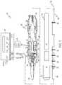
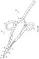
- FIG. 1illustrates an ultrasonic surgical instrument system, according to one aspect of this disclosure.
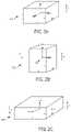
- FIGS. 2A-2Cillustrate a piezoelectric transducer, according to one aspect of this disclosure.
- FIG. 3illustrates a D31 ultrasonic transducer architecture that includes an ultrasonic waveguide and one or more piezoelectric elements fixed to the ultrasonic waveguide, according to one aspect of this disclosure.
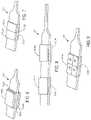
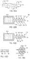
- FIG. 4Ais another perspective view of an ultrasonic medical device having a single pair of piezoelectric transducers, according to one aspect of this disclosure.
- FIG. 4Bis a perspective view of a transducer mounting portion of an ultrasonic medical device depicted in FIG. 4A , according to one aspect of this disclosure.
- FIG. 5is a plan view of a transducer mounting portion of an ultrasonic medical device depicted in FIG. 4A , according to one aspect of this disclosure.
- FIGS. 6-9are perspective views of a transducer mounting portion of an ultrasonic medical device having multiple pairs of piezoelectric transducers, according to one aspect of this disclosure.
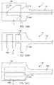
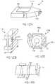
- FIGS. 10 and 11are perspective views of a transducer mounting portion of an ultrasonic medical device having a pair of piezoelectric transducers imbedded in a surgical tool, according to one aspect of this disclosure.
- FIGS. 12 and 13are perspective views of a transducer mounting portion of an ultrasonic medical device having a pair of piezoelectric transducers held by one or more securing clips, according to one aspect of this disclosure.
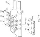
- FIG. 14is a perspective view of a transducer mounting portion of an ultrasonic medical device including mounting flanges, according to one aspect of this disclosure.
- FIG. 15is a perspective view of a transducer mounting portion of the ultrasonic medical device of FIG. 14 mounted in a housing, according to one aspect of this disclosure.
- FIG. 16is a side view the transducer mounting portion of the ultrasonic medical device of FIG. 1 mounted in a housing, according to one aspect of this disclosure, according to one aspect of this disclosure.
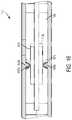
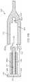
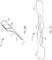
- FIGS. 17 and 18are plan views of an ultrasonic medical device having a transducer mounting portion having a form of a square or rectangular prism, according to one aspect of this disclosure.
- FIG. 19is a cross-sectional view of an ultrasonic medical device fabricated from square stock, according to one aspect of this disclosure.
- FIG. 20is a cross-sectional view of an ultrasonic medical device fabricated from round stock, according to one aspect of this disclosure.
- FIG. 21is a perspective view of an ultrasonic medical device having a transducer mounting portion having a form of a triangular prism, according to one aspect of this disclosure.
- FIGS. 22-25are cross-sectional views of a transducer mounting portion of an ultrasonic medical device in which the transducer mounting portion has a form of a triangular prism, according to one aspect of this disclosure.
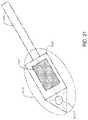
- FIGS. 26-28are perspective views of an ultrasonic medical device fabricated from round stock, according to one aspect of this disclosure.
- FIG. 29is a cross-sectional view of the transducer mounting portion of the ultrasonic medical device of FIG. 28 , according to one aspect of this disclosure.
- FIG. 30is a side view of an ultrasonic medical device fabricated from round stock, according to one aspect of this disclosure.
- FIG. 31is a cross-sectional view of the transducer mounting portion of the ultrasonic medical device of FIG. 30 , according to one aspect of this disclosure.
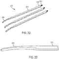
- FIG. 32is a perspective view of surgical tools for an ultrasonic medical device, according to one aspect of this disclosure.
- FIG. 33is a perspective view of an end effector of a surgical tools depicted in FIG. 32 , according to one aspect of this disclosure.
- FIG. 34is a perspective view of an ultrasonic medical device incorporating a surgical tool depicted in FIG. 32 , according to one aspect of this disclosure.
- FIG. 35is a perspective view of an ultrasonic medical device incorporating a surgical tool depicted in FIG. 32 , according to one aspect of this disclosure.
- FIG. 36is a perspective view of surgical tools during a fabrication step from flat stock, according to one aspect of this disclosure.
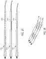
- FIG. 37is a plan view of surgical tools depicting the metal grain orientation of the surgical tools, according to one aspect of this disclosure.
- FIG. 38is a perspective view of the surgical tools depicted in FIG. 37 , according to one aspect of this disclosure.
- FIG. 39is a perspective view of additional surgical tools depicted in FIG. 37 , according to one aspect of this disclosure.
- FIG. 40is a side view of an additional fabrication step of a surgical tool, according to one aspect of this disclosure.
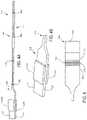
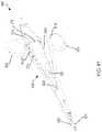
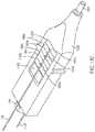
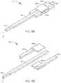
- FIG. 41is a plan view of the surgical tool depicted in FIG. 32 with a superimposed illustration of a mechanical standing wave imparted to it by an activated piezoelectric transducer, according to one aspect of this disclosure.
- FIG. 42is a side view of the surgical tool depicted in FIG. 41 , according to one aspect of this disclosure.
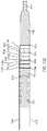
- FIG. 43is a plan view of a surgical tool configured to be displaced in a side-way manner, according to one aspect of this disclosure.
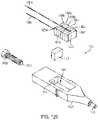
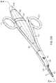
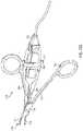
- FIGS. 44 and 45illustrate hand actuated ultrasonic medical devices, according to one aspect of this disclosure.
- FIG. 46illustrates the effector end of the hand actuated ultrasonic medical device of FIG. 45 , according to one aspect of this disclosure.
- FIG. 47illustrates a plan view of two surgical tools having female threads machined in the transducer mounting portion, according to one aspect of this disclosure.
- FIG. 48is a perspective view of a transducer mounting portion of the surgical tool of FIG. 47 mounted in an ultrasonic medical device, according to one aspect of this disclosure.
- FIGS. 49 and 50are a side view and a perspective view, respectively, of the two surgical tools of FIG. 47 mounted in the ultrasonic medical device of FIG. 48 , according to one aspect of this disclosure.
- FIG. 51is an end perspective view of the surgical device of FIG. 47 , illustrating the female threads tapped into the transducer mounting portion, according to one aspect of this disclosure.
- FIG. 52is a plan view of fabricating female threads into the transducer mounting portion of the surgical tool of FIG. 47 , according to one aspect of this disclosure.
- FIG. 53is a plan view of the female threads tapped into the transducer mounting portion of the surgical tool of FIG. 47 , according to one aspect of this disclosure.
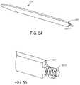
- FIG. 54is a perspective view of a surgical tool including a threaded stub at the transducer mounting portion, according to one aspect of this disclosure.
- FIG. 55is a close-up perspective view of the transducer mounting portion of the surgical tool of FIG. 54 , according to one aspect of this disclosure.
- FIG. 56is a close-up perspective view of the transducer mounting portion of a surgical tool including a threaded stub, according to one aspect of this disclosure.
- FIG. 57is a close-up perspective view of the transducer mounting portion of a surgical tool including a threaded stub and chamfers, according to one aspect of this disclosure.
- FIG. 58is a perspective view of a surgical tool having a flat blade with a straight tip, according to one aspect of this disclosure.
- FIG. 59is a perspective view of a surgical tool having a twisted flat blade with a curved and tapered tip, according to one aspect of this disclosure.
- FIGS. 60-62are plan views of surgical tools having blades with complex features, according to one aspect of this disclosure.
- FIG. 63is a perspective view of a surgical tool having a blade with a curved tip of large curvature, according to one aspect of this disclosure.
- FIG. 64is a plan view of surgical tools having blades with curved tips, according to one aspect of this disclosure.
- FIG. 65is a perspective view of a surgical tool having a transducer mounting portion with a wide and flat surface, according to one aspect of this disclosure.
- FIG. 66is a plan view of a surgical tool having a transducer mounting portion with a wide and flat surface, according to one aspect of this disclosure.
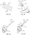
- FIG. 67is a perspective view of a transducer assembly employing a wedge configuration and configured to operate in a D33 mode of operation, according to one aspect of this disclosure.
- FIG. 68Ais a section view of the ultrasonic transducer assembly shown in FIG. 67 taken along section line 68 A- 68 A shown in FIG. 67 , according to one aspect of this disclosure.
- FIG. 68Bis a section view of the ultrasonic transducer assembly shown in FIG. 67 taken along section line 68 B- 68 B shown in FIG. 67 , according to one aspect of this disclosure.
- FIGS. 68C-68Dillustrate cross section views of the ultrasonic transducer assembly 6805 employing another wedge configuration taken along similar section lines as shown in FIGS. 68A and 68B , according to one aspect of this disclosure.
- FIG. 69is perspective view of an ultrasonic transducer assembly employing a screw to compress against the compression plate to compress and acoustically couple piezoelectric elements to an ultrasonic waveguide, according to one aspect of this disclosure.
- FIG. 70is a section view of the of the ultrasonic transducer assembly shown in FIG. 69 taken along section 70 - 70 as shown in FIG. 69 .
- FIG. 71is a perspective view of the screw, according to one aspect of this disclosure.
- FIG. 72illustrates an ultrasonic surgical instrument configured to operate in a D31 mode of operation, according to one aspect of this disclosure.
- FIG. 73is a section view of the transducer assembly comprising a first piezoelectric element positioned on a first side of the waveguide and a second piezoelectric element positioned on a second opposing side of the waveguide, according to one aspect of this disclosure.
- FIG. 74is a section view of an ultrasonic surgical instrument configured to operate in a D31 mode of operation, according to one aspect of this disclosure.
- FIG. 75is an exploded view of an ultrasonic surgical instrument configured to operate in a D31 mode of operation, according to one aspect of this disclosure.
- FIG. 76Ais a side view of an ultrasonic surgical instrument configured to operate in a D31 mode of operation, according to one aspect of this disclosure.
- FIG. 76Bis a cross sectional view of a side of the ultrasonic surgical instrument shown in FIG. 76A , according to one aspect of this disclosure.
- FIG. 77is a top view of the ultrasonic surgical instrument shown in FIG. 76A , according to one aspect of this disclosure.
- FIG. 78is a rear cross sectional view of the ultrasonic surgical instrument shown in FIG. 76A , according to one aspect of this disclosure.
- FIG. 79Ais a plan view of an electrode shim in a flat configuration, according to one aspect of this disclosure.
- FIG. 79Bis a perspective view of the electrode shim shown in FIG. 79A in a folded configuration, according to one aspect of this disclosure.
- FIGS. 80A-80Bare views of a portion of the ultrasonic surgical instrument shown in FIG. 76A with polyimide film material coating as an insulator positioned on the electrode shim, according to one aspect of this disclosure.
- FIG. 81is a perspective view of an ultrasonic surgical instrument, which is configured to operate in a D31 mode of operation, according to one aspect of this disclosure.
- FIG. 82is a perspective view of an electrode of the ultrasonic surgical instrument shown in FIG. 81 , according to one aspect of this disclosure.
- FIG. 83is a plan view of the transducer assembly of the ultrasonic surgical instrument shown in FIG. 81 including a recessed receiving portion configured to receive an electrode, according to one aspect of this disclosure.
- FIG. 84Ais a longitudinal sectional view of the transducer assembly shown in FIG. 83 , with a portion of the electrode, the molded interconnect pad, the receiving area, and a portion of the recessed receiving portion, according to one aspect of this disclosure.
- FIG. 84Bis a lateral sectional view of the transducer assembly shown in FIG. 83 , with a portion of the electrode, the molded interconnect pad, the receiving area, and the recessed receiving portion, according to one aspect of this disclosure.
- FIGS. 85A-85Cillustrate an assembly process of an electrode of the ultrasonic surgical instrument shown in FIG. 81 , into the recessed receiving portion, according to one aspect of this disclosure.
- FIGS. 86A-86Billustrate an assembly process of the transducer assembly shown in FIG. 83 , with electrodes assembled from an initial uncompressed state to a final compressed state, according to one aspect of this disclosure.
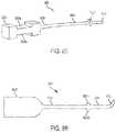
- FIG. 87shows aspects of an ultrasonic surgical instrument, which is configured to operate in a D31 mode of operation, according to one aspect of this disclosure.
- FIG. 88is a sectional view of the ultrasonic surgical instrument shown in FIG. 24 taken along section line 88 - 88 as shown in FIG. 87 , according to one aspect of this disclosure.
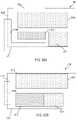
- FIG. 89is a perspective view of an upper heat sink half of the ultrasonic surgical instrument shown in FIG. 87 , according to one aspect of this disclosure.
- FIG. 90is a perspective view of an ultrasonic surgical instrument, which is configured to operate in a D31 mode of operation, according to one aspect of this disclosure.
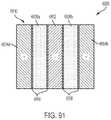
- FIG. 91illustrates a D31 ultrasonic surgical instrument that includes piezoelectric elements attached on one side to an ultrasonic waveguide by a conductive adhesive and attached on another side to electrically conductive plates by a conductive adhesive, according to one aspect of this disclosure.
- FIG. 92is a perspective view of an ultrasonic surgical instrument, which is configured to operate in a D31 mode of operation, according to one aspect of this disclosure.
- FIG. 93is a sectional view of the ultrasonic surgical instrument shown in FIG. 92 with electrically conductive electrodes configured to compress the piezoelectric elements and the ultrasonic waveguide, according to one aspect of this disclosure.
- FIG. 94Aillustrates an ultrasonic surgical instrument prior to assembly and poling, according to one aspect of this disclosure.
- FIG. 94Billustrates the ultrasonic surgical instrument of FIG. 94A prior to poling and the first and second unpoled piezoelectric elements secured to the ultrasonic waveguide in a D31 configuration, according to one aspect of this disclosure.
- FIG. 94Cillustrates the ultrasonic instrument of FIG. 94B prior to poling and the first and second unpoled piezoelectric elements secured to the ultrasonic waveguide in a D31 configuration, according to one aspect of this disclosure.
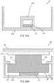
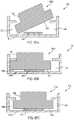
- FIGS. 95A-95Cillustrate a compressed ultrasonic transducer assembly in a D33 configuration with tuned compression, according to one aspect of this disclosure.
- FIG. 96is a perspective view of an ultrasonic surgical instrument, according to one aspect of this disclosure.
- FIG. 97is perspective view of a piezoelectric element for use with the ultrasonic surgical instrument shown in FIG. 96 , according to one aspect of this disclosure.
- FIG. 98is sectional view of the ultrasonic surgical instrument shown in FIG. 96 , according to one aspect of this disclosure.
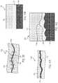
- FIG. 99illustrates an example of an adhesive bond between a metal and a metal alloy solder, according to one aspect of this disclosure.
- FIG. 100illustrates an adhesive bond between a ceramic and a metal formed by a metal alloy solder, according to one aspect of this disclosure.
- FIG. 101illustrates an example of a metallurgical/chemical bond, according to one aspect of this disclosure.
- FIG. 102is a microstructure illustration of a ceramic and metal alloy solder chemical bond, according to one aspect of this disclosure.
- FIG. 103Aillustrates an ultrasonic surgical instrument prior to assembly and poling, according to one aspect of this disclosure.
- FIG. 103Billustrates the ultrasonic surgical instrument of FIG. 103A prior to poling and the first and second unpoled piezoelectric elements secured to the ultrasonic waveguide in a D31 configuration, according to one aspect of this disclosure.
- FIG. 103Cillustrates the ultrasonic instrument of FIG. 103B prior to poling and the first and second unpoled piezoelectric elements secured to the ultrasonic waveguide in a D31 configuration, according to one aspect of this disclosure.
- FIG. 104Aillustrates an ultrasonic surgical instrument that includes an ultrasonic waveguide configured to hold piezoelectric elements using a bonding material, according to one aspect of this disclosure.
- FIG. 104Billustrates an ultrasonic surgical instrument that includes an ultrasonic waveguide configured to hold piezoelectric elements using a biasing force, according to one aspect of this disclosure.
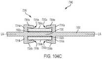
- FIG. 104Cillustrates an ultrasonic surgical instrument that includes an ultrasonic waveguide configured to hold piezoelectric elements using a combination of a bonding material and a biasing force, according to one aspect of this disclosure.
- FIG. 105illustrates an ultrasonic surgical instrument comprising an ultrasonic waveguide fixed to piezoelectric elements arranged in a D31, according to one aspect of this disclosure.
- FIG. 106illustrates the ultrasonic surgical instrument shown in FIG. 105 with a voltage V applied to the piezoelectric elements during a bonding phase, according to one aspect of this disclosure.
- FIG. 107illustrates a D31 ultrasonic surgical instrument that includes piezoelectric elements attached on one side to an ultrasonic waveguide by a conductive adhesive and attached on another side to electrically conductive plates by a conductive adhesive, according to one aspect of this disclosure.
- FIG. 108illustrates an ultrasonic surgical instrument includes a single mid-plane ultrasonic transducer and an ultrasonic waveguide with a tuning-fork-like frame according to one aspect of the present disclosure.
- FIG. 109is a sectional view of the ultrasonic surgical instrument shown in FIG. 108 with the ultrasonic transducer inserted in to the tuning-fork-like frame of the ultrasonic waveguide, according to one aspect of this disclosure.
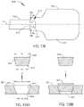
- FIGS. 110A and 110Billustrate a D33 ultrasonic transducer configuration, according to one aspect of this disclosure.
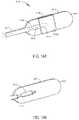
- FIG. 111illustrates a D33 ultrasonic transducer configuration, according to one aspect of this disclosure.
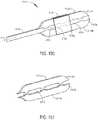
- FIG. 112illustrates a D33 ultrasonic transducer configuration, according to one aspect of this disclosure.
- FIGS. 113A-Dillustrate a D33 ultrasonic transducer configuration, according to one aspect of this disclosure.
- FIG. 114illustrates a D33 ultrasonic transducer configuration, according to one aspect of this disclosure.
- FIG. 115Aillustrates a sectional view of a D31 ultrasonic transducer configuration along line 115 A- 115 A, according to one aspect of this disclosure.
- FIG. 115Billustrates a D31 ultrasonic transducer configuration, according to one aspect of this disclosure.
- FIG. 115Cillustrates the change in shape of the housing of the D31 ultrasonic transducer configuration shown in FIGS. 115A-B , according to one aspect of this disclosure.
- FIGS. 116A-Eillustrate a D33 ultrasonic transducer configuration, according to one aspect of this disclosure.
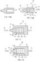
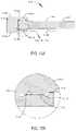
- FIG. 117Aillustrates a D33 ultrasonic transducer configuration, according to one aspect of this disclosure.
- FIG. 117Billustrates the plug of the ultrasonic transducer configuration shown in FIG. 117A , according to one aspect of this disclosure.
- FIGS. 117C-Dillustrate a method of installing the D33 ultrasonic transducer configuration shown in FIG. 117A , according to one aspect of this disclosure.
- FIG. 118illustrates a D31 ultrasonic transducer configuration, according to one aspect of this disclosure.
- FIG. 119illustrates a D31 ultrasonic transducer configuration, according to one aspect of this disclosure.
- FIGS. 120A-Billustrate a D31 ultrasonic transducer configuration, according to one aspect of this disclosure.
- FIG. 121Aillustrates a D31 ultrasonic transducer configuration, according to one aspect of this disclosure.
- FIG. 121Billustrates an exploded view of the D31 ultrasonic transducer configuration shown in FIG. 121A , according to one aspect of this disclosure.
- FIG. 121Cillustrates a D31 ultrasonic transducer configuration, according to one aspect of this disclosure.
- FIG. 121Dillustrates an exploded view of the D31 ultrasonic transducer configuration shown in FIG. 121C , according to one aspect of this disclosure.
- FIG. 122illustrates a D33 ultrasonic transducer configuration, according to one aspect of this disclosure.
- FIGS. 123A-Billustrate D31 ultrasonic transducer configurations having asymmetrically excitable piezoelectric transducer assemblies, according to one aspect of this disclosure.
- FIGS. 124A-Cillustrate D31 ultrasonic transducer configurations having asymmetrically excitable piezoelectric transducer assemblies, according to one aspect of this disclosure.
- FIGS. 125A-Billustrate a D31 ultrasonic transducer configuration wherein the piezoelectric elements are offset relative to each other, according to one aspect of this disclosure.
- FIGS. 125C-Dillustrate views of an end effector of a surgical instrument undergoing longitudinal and non-longitudinal motion, respectively, according to one aspect of this disclosure.
- FIG. 126Aillustrates a perspective view of a distal end of a waveguide of a surgical instrument having complex features, according to one aspect of this disclosure.
- FIGS. 126B-Eillustrate a process of fabricating the surgical instrument shown in FIG. 126A , according to one aspect of this disclosure.
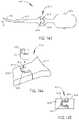
- FIG. 127Aillustrates a perspective view of a D31 ultrasonic transducer configuration configured to generate non-longitudinal motion, according to one aspect of this disclosure.
- FIG. 127Billustrates a perspective view of an electrode of the D31 ultrasonic transducer configuration shown in FIG. 127A , according to one aspect of this disclosure.
- FIG. 127Cillustrates a sectional view of the D31 ultrasonic transducer configuration shown in FIG. 127A along line 127 C- 127 C, according to one aspect of this disclosure.
- FIG. 127Dillustrates a side view of the electrode and piezoelectric transducer assembly of the D31 ultrasonic transducer configuration shown in FIG. 127A , according to one aspect of this disclosure.
- FIG. 128illustrates a perspective view of an electrical connector to an ultrasonic signal generator for a surgical instrument, according to one aspect of this disclosure.
- FIG. 129illustrates an exploded view of a D33 ultrasonic transducer configuration, according to one aspect of this disclosure.
- FIG. 130illustrates a perspective view of the D33 ultrasonic transducer configuration of FIG. 129 , according to one aspect of this disclosure.
- FIG. 131illustrates a perspective sectional view of the D33 ultrasonic transducer configuration of FIG. 129 , according to one aspect of this disclosure.
- FIG. 132illustrates a plan sectional view of the D33 ultrasonic transducer configuration of FIG. 129 , according to one aspect of this disclosure.
- FIG. 133is a side view of an ultrasonic surgical instrument configured in a D31 ultrasonic transducer architecture comprising separate ultrasonic waveguide and ultrasonic transducer base plate components shown in a coupled configuration, according to one aspect of this disclosure.
- FIG. 134Ais a section view of a jigsaw puzzle joint of the waveguide and transducer base plate components of the ultrasonic surgical instrument, according to one aspect of this disclosure.
- FIG. 134Bis a section view of a jigsaw puzzle joint of the waveguide and transducer base plate components of the ultrasonic surgical instrument, according to one aspect of this disclosure.
- FIG. 135is a side view of an ultrasonic surgical instrument configured in a D31 transducer architecture comprising separate ultrasonic waveguide and ultrasonic transducer base plate components shown in a decoupled configuration, according to one aspect of this disclosure.
- FIG. 136is an end view of the waveguide shown in FIG. 135 , according to one aspect of this disclosure.
- FIG. 137is an end view of the transducer base plate shown in FIG. 135 , according to one aspect of this disclosure.
- FIG. 138is a side view of the ultrasonic instrument shown in FIG. 135 in a coupled configuration connected at the tapered joint, according to one aspect of this disclosure.
- FIGS. 139A and 139Bare section views taken along section line 139 - 139 shown in FIG. 138 , where FIG. 139A is a section view taken prior to joining the waveguide to the transducer base plate and FIG. 139B is a section view taken after partially joining the waveguide to the transducer base plate.
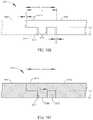
- FIG. 140is a side view of an ultrasonic surgical instrument configured in a D31 transducer architecture comprising separate ultrasonic waveguide and ultrasonic transducer base plate components shown in a coupled configuration, according to one aspect of this disclosure.
- FIG. 141is a section view of the ultrasonic surgical instrument shown in FIG. 140 taken along section line 141 - 141 shown in FIG. 140 , according to one aspect of this disclosure.
- FIG. 142is a section view of an ultrasonic surgical instrument configured in a D31 transducer architecture comprising multiple plates coupled by a thermal expansion joint, according to one aspect of this disclosure.
- FIG. 143is side view of an ultrasonic surgical instrument configured in a D31 transducer architecture comprising separate ultrasonic waveguide and ultrasonic transducer base plate shown in a coupled configuration, according to one aspect of this disclosure.
- FIG. 144is an exploded view of the C-shaped pin joint shown in FIG. 143 , according to one aspect of this disclosure.
- FIG. 145is a plan view of the C-shaped pin joint shown in FIG. 143 , according to one aspect of this disclosure.
- FIG. 146is a side view of an ultrasonic surgical instrument configured in a D31 transducer architecture comprising separate ultrasonic waveguide and ultrasonic transducer base plate components shown in a coupled configuration, according to one aspect of this disclosure.
- FIG. 147is a section view of the ultrasonic surgical instrument along section line 147 - 147 shown in FIG. 146 , according to one aspect of this disclosure.
- FIG. 148is a perspective view an ultrasonic surgical instrument configured in a D31 transducer architecture comprising separate ultrasonic waveguide and ultrasonic transducer base plate components shown in a coupled configuration, according to one aspect of this disclosure.
- FIG. 149is a perspective view the ultrasonic surgical instrument shown in FIG. 148 with the waveguide and the piezoelectric elements removed to show the cutout configured to receive a proximal portion of the waveguide, according to one aspect of this disclosure.
- FIG. 150is a perspective view of an ultrasonic surgical instrument configured in a D31 transducer architecture comprising ultrasonic waveguide and ultrasonic transducer base plate components shown in a coupled configuration, according to one aspect of this disclosure.
- FIG. 151is a perspective view of the ultrasonic surgical instrument shown in FIG. 150 with the waveguide and the piezoelectric elements removed to show the cutout configured to receive a proximal portion of the waveguide, according to one aspect of this disclosure.
- FIG. 152is a side view of an ultrasonic surgical instrument configured in a D31 transducer architecture comprising separate ultrasonic waveguide and ultrasonic transducer base plate components shown in a decoupled configuration, according to one aspect of this disclosure.
- FIG. 153is a section view of the ultrasonic surgical instrument shown in FIG. 152 with the ultrasonic waveguide rotated 90° in a decoupled configuration, according to one aspect of this disclosure.
- FIG. 154is a section view of the ultrasonic surgical instrument shown in FIG. 152 with the ultrasonic waveguide rotated 90° in a coupled configuration, according to one aspect of this disclosure.
- FIG. 155is detail view of the joint between the waveguide and the transducer base plate, according to one aspect of this disclosure.
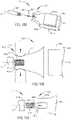
- FIG. 156is a perspective view of an ultrasonic surgical instrument configured in a D31 transducer architecture comprising separate ultrasonic waveguide and ultrasonic transducer base plate components shown in a decoupled configuration, according to one aspect of this disclosure.
- FIG. 157is a perspective view of the ultrasonic surgical instrument shown in FIG. 156 in a coupled configuration, according to one aspect of this disclosure.
- FIG. 158is a perspective view of an ultrasonic surgical instrument configured in a D31 transducer architecture comprising separate ultrasonic waveguide and ultrasonic transducer base plate components shown in a decoupled configuration, according to one aspect of this disclosure.
- FIG. 159is a side view of the threaded joint showing the threaded section of the waveguide threaded into the threaded section of the transducer base plate, according to one aspect of this disclosure.
- FIG. 160is a side view of an alternate threaded joint where the threaded section includes a rotational orientation section to provide rotary alignment about the longitudinal axis LA of the threaded section of the waveguide, according to one aspect of this disclosure.
- FIG. 161is a perspective view of an ultrasonic surgical instrument configured in a D31 transducer architecture comprising separate ultrasonic waveguide and ultrasonic transducer base plate components shown in a coupled configuration, according to one aspect of this disclosure.
- FIG. 162is an exploded view of the ultrasonic surgical instrument shown in FIG. 161 , according to one aspect of this disclosure.
- FIG. 163is a section view of the ultrasonic surgical instrument shown in FIG. 161 , according to one aspect of this disclosure.
- FIG. 164is a perspective view of an ultrasonic surgical instrument configured in a D31 transducer architecture comprising separate ultrasonic waveguide and ultrasonic transducer base plate components shown in a coupled configuration, according to one aspect of this disclosure.
- FIG. 165is an exploded view of the ultrasonic surgical instrument shown in FIG. 164 , according to one aspect of this disclosure.
- FIG. 166illustrates the waveguide flange, shown in dashed line form, and the transducer base plate flange, shown in solid line form, superimposed in a decoupled configuration, according to one aspect of this disclosure.
- FIG. 167illustrates the waveguide and the transducer base plate in a coupled configuration, according to one aspect of this disclosure.
- FIG. 168is a perspective view of an ultrasonic surgical instrument configured in a D31 transducer architecture comprising separate ultrasonic waveguide and ultrasonic transducer base plate components shown in a coupled configuration, according to one aspect of this disclosure.
- FIG. 169is an exploded view of the ultrasonic surgical instrument shown in FIG. 168 , according to one aspect of this disclosure.
- FIG. 170is a section view of a pin, according to one aspect of this disclosure.
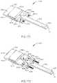
- FIG. 171is a perspective view of an ultrasonic surgical instrument configured in a D31 transducer architecture comprising separate ultrasonic waveguide and ultrasonic transducer base plate components shown in a coupled configuration, according to one aspect of this disclosure.
- FIG. 172is an exploded view of the ultrasonic surgical instrument shown in FIG. 171 , according to one aspect of this disclosure.
- FIG. 173is a perspective view of a luer lock joint suitable for coupling ultrasonic waveguide and ultrasonic transducer base plate components of a two-piece ultrasonic surgical instrument, according to one aspect of this disclosure.
- FIG. 174is a section view of the luer lock joint in a coupled configuration, according to one aspect of this disclosure.
- FIG. 175is a luer nut component of the luer lock joint shown in FIG. 173 , according to one aspect of this disclosure.
- FIG. 176is perspective view of the luer lock joint shown in FIG. 173 in a coupled configuration, according to one aspect of this disclosure.
- FIG. 177is a perspective view of an ultrasonic waveguide for an ultrasonic surgical instrument comprising an ultrasonic waveguide shaft made of one metal and coupled to an ultrasonic blade made of a dissimilar metal, according to aspect of this disclosure.
- FIG. 178is a magnified view of the coupler, according to one aspect of this disclosure.
- FIG. 179is a section view of a swaged joint between a two-piece ultrasonic tool comprising an ultrasonic waveguide shaft made of one metal and an ultrasonic blade made of a different metal, according to one aspect of his disclosure.
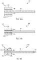
- FIG. 180is a section view of a swaged joint achieved between a two-piece ultrasonic waveguide comprising an ultrasonic waveguide shaft made of one metal and an ultrasonic blade made of a different metal, according to one aspect of his disclosure.
- FIGS. 181-184show the steps for producing the swaged joint shown in FIG. 180 , according to one aspect of this disclosure.
- FIG. 181a section view of the waveguide shaft and the ultrasonic blade shown in FIG. 180 a decoupled configuration, according to one aspect of this disclosure.
- FIG. 182a section view of a pre-assembly of the waveguide shaft and the ultrasonic blade shown in FIG. 18 in a coupled configuration prior to applying the swaging process, according to one aspect of this disclosure.
- FIG. 183a section view of the waveguide shaft and the ultrasonic blade shown in FIG. 182 a coupled after the application of the swaging process, according to one aspect of this disclosure.
- FIG. 184is a section view of joined ultrasonic waveguide showing the waveguide shaft coupled to the ultrasonic blade shown in FIG. 180 , according to one aspect of this disclosure.
- FIG. 185is a section view of a heated draw die tool, according to one aspect of this disclosure.
- FIG. 186is a detail section view of the draw die tool shown in FIG. 185 , according to one aspect of this disclosure.
- FIG. 187is a side view of a two-piece ultrasonic waveguide comprising a waveguide shaft coupled to an ultrasonic blade by a swaged joint using the swaging process described in connection with FIGS. 177-186 , according to one aspect of this disclosure.
- FIG. 188is a section view of the swaged joint formed between the waveguide shaft and the ultrasonic blade, according to one aspect of this disclosure.
- FIG. 189is a side view of the waveguide shaft shown in FIG. 188 , according to one aspect of this disclosure.
- FIG. 190is a side view of the ultrasonic blade is shown in FIG. 188 , according to one aspect of this disclosure.
- FIG. 191is a plan view of the ultrasonic blade shown in FIG. 188 , according to one aspect of this disclosure.
- FIG. 192illustrates an ultrasonic surgical instrument comprising an ultrasonic waveguide coupled to an offset ultrasonic transducer baseplate, according to one aspect of this disclosure.
- FIG. 193illustrates two metal substrates components of the ultrasonic surgical instrument shown in FIG. 192 arranged in a complementary orientation for stamping or punching, according to one aspect of this disclosure.
- FIG. 194is an ultrasonic surgical instrument configured in a D31 transducer architecture comprising separate ultrasonic waveguide and ultrasonic transducer base plate components shown in a coupled configuration, according to one aspect of this disclosure.
- FIG. 195is a side view of the ultrasonic blade, according to one aspect of this disclosure.
- FIG. 196is an exploded view of an ultrasonic surgical instrument configured in a D31 transducer architecture comprising separate ultrasonic waveguide and symmetric two-piece clamshell housing components to support ultrasonic transducer piezoelectric elements, according to one aspect of this disclosure.
- FIG. 197is an assembled view of the ultrasonic surgical instrument shown in FIG. 196 , according to one aspect of this disclosure.
- FIG. 198is a perspective view of an ultrasonic surgical instrument configured in a D31 transducer architecture comprising separate ultrasonic waveguide and a two-piece ultrasonic transducer base plate to support PZT piezoelectric elements, according to one aspect of this disclosure.
- FIG. 199is an exploded view of the ultrasonic surgical instrument shown in FIG. 198 , according to one aspect of this disclosure.
- FIG. 200illustrates a perspective view of an ultrasonic surgical instrument, according to one aspect of this disclosure.
- FIG. 201illustrates a cutaway view of the ultrasonic surgical instrument in FIG. 200 , according to one aspect of this disclosure.
- FIG. 202illustrates a cutaway view of the ultrasonic surgical instrument in FIG. 200 , wherein the ultrasonic surgical instrument is in an open position, according to one aspect of this disclosure.
- FIG. 203illustrates an exploded view of the ultrasonic surgical instrument in FIG. 200 , according to one aspect of this disclosure.
- FIG. 204illustrates a sectional view of the ultrasonic surgical instrument in FIG. 200 along line 204 - 204 , according to one aspect of this disclosure.
- FIG. 205illustrates a detail view of the jaw and end effector portions of the ultrasonic surgical instrument in FIG. 200 , according to one aspect of this disclosure.
- FIG. 206illustrates a perspective view of the distal portion of an ultrasonic surgical instrument including a curved end effector, according to one aspect of this disclosure.
- FIG. 207illustrates a side view of the distal portion of the ultrasonic surgical instrument in FIG. 206 , according to one aspect of this disclosure.
- FIG. 208illustrates a perspective view of an ultrasonic surgical instrument including a clip closure, according to one aspect of this disclosure.
- FIG. 209illustrates an elevational view of the distal portion of an ultrasonic surgical instrument configured to detect improper tissue clamping, according to one aspect of this disclosure.
- FIG. 210illustrates a side view of the ultrasonic surgical instrument in FIG. 209 , according to one aspect of this disclosure.
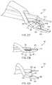
- FIG. 211illustrates a perspective view of an end portion of an ultrasonic surgical instrument incorporating a pivotable member tissue stop, wherein the pivotable member is in a stowed position, according to one aspect of this disclosure.
- FIG. 212illustrates a perspective view of the end portion of the ultrasonic surgical instrument in FIG. 211 , wherein the pivotable member is in the deployed position, according to one aspect of this disclosure.
- FIG. 213illustrates a perspective view of an ultrasonic surgical instrument incorporating a mechanical linkage tissue stop, according to one aspect of this disclosure.
- FIG. 214illustrates a side view of the ultrasonic surgical instrument in FIG. 213 in an open position, according to one aspect of this disclosure.
- FIG. 215illustrates a side view of the ultrasonic surgical instrument in FIG. 213 in a closed position, according to one aspect of this disclosure.
- FIG. 216illustrates a side view of an ultrasonic surgical instrument incorporating a deformable member tissue stop, according to one aspect of this disclosure.
- FIG. 217illustrates a side view of the ultrasonic surgical instrument in FIG. 216 in a partially clamped position, according to one aspect of this disclosure.
- FIG. 218illustrates a side view of the ultrasonic surgical instrument in FIG. 216 in a clamped position, according to one aspect of this disclosure.
- FIG. 219illustrates a perspective view of an ultrasonic surgical instrument incorporating a curved bar tissue stop, according to one aspect of this disclosure.
- FIG. 220illustrates a partial sectional view of the ultrasonic surgical instrument in FIG. 219 , according to one aspect of this disclosure.
- FIG. 221illustrates a side view of the ultrasonic surgical instrument in FIG. 219 in an open position, according to one aspect of this disclosure.
- FIG. 222illustrates a side view of the ultrasonic surgical instrument in FIG. 219 in a closed position, according to one aspect of this disclosure.
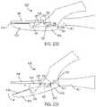
- FIG. 223illustrates a perspective view of an ultrasonic surgical instrument incorporating an end effector ring tissue stop, according to one aspect of this disclosure.
- FIG. 224illustrates a side view of one aspect of the tissue stop in FIG. 223 , according to one aspect of this disclosure.
- FIG. 225illustrates a front view of the tissue stop in FIG. 223 , according to one aspect of this disclosure.
- FIG. 226illustrates a top view of one aspect of the tissue stop in FIG. 223 , according to one aspect of this disclosure.
- FIG. 227illustrates a perspective view of an ultrasonic surgical instrument incorporating a longitudinally slidable member tissue stop, wherein the ultrasonic surgical instrument is in an open position, according to one aspect of this disclosure.
- FIG. 228illustrates a perspective view of the ultrasonic surgical instrument in FIG. 227 in a closed position, according to one aspect of this disclosure.
- FIG. 229illustrates a cutaway view of the longitudinally slidable member tissue stop in FIG. 227 , according to one aspect of this disclosure.
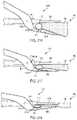
- FIG. 230illustrates a side view of an ultrasonic surgical instrument incorporating a cam-actuated member tissue stop in an open position, according to one aspect of this disclosure.
- FIG. 231illustrates a side view of the ultrasonic surgical instrument in FIG. 233 in a closed position, according to one aspect of this disclosure.
- FIG. 232illustrates a side view of an ultrasonic surgical instrument incorporating a flexible strip tissue stop, according to one aspect of this disclosure.
- FIG. 233illustrates a perspective view of the ultrasonic surgical instrument in FIG. 232 in a closed position, according to one aspect of this disclosure.
- FIG. 234illustrates a perspective view of an ultrasonic surgical instrument incorporating a flexible strip tissue stop, according to one aspect of this disclosure.
- FIG. 235illustrates a side view of the ultrasonic surgical instrument in FIG. 234 in a closed position, according to one aspect of this disclosure.
- FIG. 236illustrates a side view of the ultrasonic surgical instrument in FIG. 234 in an open position, according to one aspect of this disclosure.
- FIG. 237illustrates a perspective view of an ultrasonic surgical instrument incorporating a flexible strip tissue stop, according to one aspect of this disclosure.
- FIG. 238illustrates a side view of the ultrasonic surgical instrument in FIG. 237 in a closed position, according to one aspect of this disclosure.
- FIG. 239illustrates a side view of the ultrasonic surgical instrument in FIG. 237 in an open position, according to one aspect of this disclosure.
- ultrasonic surgical instruments and bladesfor use therewith.
- Examples of ultrasonic surgical instruments and bladesare disclosed in U.S. Pat. Nos. 5,322,055; 5,954,736; 6,309,400; 6,278,218; 6,283,981; 6,325,811; and 8,319,400, wherein the entire disclosures of which are incorporated by reference herein.
- an ultrasonic instrumentcomprising a surgical tool having an end effector such as a blade can yield a particular benefit or benefits in orthopedic procedures where it is desirable to remove cortical bone and/or tissue while controlling bleeding. Due to its cutting and coagulation characteristics, a blade of an ultrasonic surgical instrument may be useful for general soft tissue cutting and coagulation. In certain circumstances, a blade according to various aspects may be useful to simultaneously cut and hemostatically seal or cauterize tissue. A blade may be straight or curved, and useful for either open or laparoscopic applications. A blade according to various aspects may be useful in spine surgery, especially to assist in posterior access in removing muscle from bone.
- FIG. 1illustrates one aspect of an ultrasonic system 10 .
- One aspect of the ultrasonic system 10comprises an ultrasonic signal generator 12 coupled to an ultrasonic transducer 14 , a hand piece assembly 60 comprising a hand piece housing 16 , and an end effector 50 .
- the ultrasonic transducer 14which is known as a “Langevin stack,” generally includes a transduction portion 18 , a first resonator or end-bell 20 , and a second resonator or fore-bell 22 , and ancillary components.
- the ultrasonic transducer 14is preferably an integral number of one-half system wavelengths (n ⁇ /2) in length as will be described in more detail below.
- An acoustic assembly 24can include the ultrasonic transducer 14 , a mount 26 , a velocity transformer 28 , and a surface 30 .
- proximal and distalare used herein with reference to a clinician gripping the hand piece assembly 60 .
- end effector 50is distal with respect to the more proximal hand piece assembly 60 .
- spatial termssuch as “top” and “bottom” also are used herein with respect to the clinician gripping the hand piece assembly 60 .
- surgical instrumentsare used in many orientations and positions, and these terms are not intended to be limiting and absolute.
- the distal end of the end-bell 20is connected to the proximal end of the transduction portion 18
- the proximal end of the fore-bell 22is connected to the distal end of the transduction portion 18 .
- the fore-bell 22 and the end-bell 20have a length determined by a number of variables, including the thickness of the transduction portion 18 , the density and modulus of elasticity of the material used to manufacture the end-bell 20 and the fore-bell 22 , and the resonant frequency of the ultrasonic transducer 14 .
- the fore-bell 22may be tapered inwardly from its proximal end to its distal end to amplify the ultrasonic vibration amplitude of the velocity transformer 28 , or, alternately, fore-bell 22 may have no tapering.
- end-bell 20can include a threaded member extending therefrom which can be configured to be threadably engaged with a threaded aperture in fore-bell 22 .
- piezoelectric elementssuch as piezoelectric elements 32 , for example, can be compressed between end-bell 20 and fore-bell 22 when end-bell 20 and fore-bell 22 are assembled together.
- Piezoelectric elements 32may be fabricated from any suitable material, such as, for example, lead zirconate-titanate, lead meta-niobate, lead titanate, and/or any suitable piezoelectric crystal material, for example.
- transducer 14can further comprise electrodes, such as positive electrodes 34 and negative electrodes 36 , for example, which can be configured to create a voltage potential across one or more piezoelectric elements 32 .
- Each of the positive electrodes 34 , negative electrodes 36 , and the piezoelectric elements 32can comprise a bore extending through the center which can be configured to receive the threaded member of end-bell 20 .
- the positive and negative electrodes 34 and 36are electrically coupled to wires 38 and 40 , respectively, wherein the wires 38 and 40 can be encased within a cable 42 and electrically connectable to the ultrasonic signal generator 12 of the ultrasonic system 10 .
- the ultrasonic transducer 14 of the acoustic assembly 24converts the electrical signal from the ultrasonic signal generator 12 into mechanical energy that results in primarily longitudinal vibratory motion of the ultrasonic transducer 24 and the end effector 50 at ultrasonic frequencies.
- a suitable generatoris available as model number GEN11, from Ethicon Endo-Surgery, Inc., Cincinnati, Ohio. When the acoustic assembly 24 is energized, a vibratory motion standing wave is generated through the acoustic assembly 24 .
- a suitable vibrational frequency rangemay be about 20 Hz to 120 kHz and a well-suited vibrational frequency range may be about 30-70 kHz and one example operational vibrational frequency may be approximately 55.5 kHz.
- the amplitude of the vibratory motion at any point along the acoustic assembly 24may depend upon the location along the acoustic assembly 24 at which the vibratory motion is measured.
- a minimum or zero crossing in the vibratory motion standing waveis generally referred to as a node (i.e., where motion is usually minimal), and an absolute value maximum or peak in the standing wave is generally referred to as an anti-node (i.e., where motion is usually maximal).
- the distance between an anti-node and its nearest nodeis one-quarter wavelength ( ⁇ /4).
- the wires 38 and 40transmit an electrical signal from the ultrasonic signal generator 12 to the positive electrodes 34 and the negative electrodes 36 .
- the piezoelectric elements 32are energized by the electrical signal supplied from the ultrasonic signal generator 12 in response to a foot switch 44 , for example, to produce an acoustic standing wave in the acoustic assembly 24 .
- the electrical signalcauses disturbances in the piezoelectric elements 32 in the form of repeated small displacements resulting in large compression forces within the material. The repeated small displacements cause the piezoelectric elements 32 to expand and contract in a continuous manner along the axis of the voltage gradient, producing longitudinal waves of ultrasonic energy.
- the ultrasonic energy produced by transducer 14can be transmitted through the acoustic assembly 24 to the end effector 50 via an ultrasonic transmission waveguide 46 .
- the components of the acoustic assembly 24are acoustically coupled to the end effector 50 .
- the distal end of the ultrasonic transducer 14may be acoustically coupled at the surface 30 to the proximal end of the ultrasonic transmission waveguide 46 by a threaded connection such as a stud 48 .
- the components of the acoustic assembly 24can be acoustically tuned such that the length of any assembly is an integral number of one-half wavelengths (n ⁇ /2), where the wavelength ⁇ is the wavelength of a pre-selected or operating longitudinal vibration drive frequency f d of the acoustic assembly 24 , and where n is any positive integer. It is also contemplated that the acoustic assembly 24 may incorporate any suitable arrangement of acoustic elements.
- the ultrasonic end effector 50may have a length substantially equal to an integral multiple of one-half system wavelengths ( ⁇ /2).
- a distal end 52 of the ultrasonic end effector 50may be disposed at, or at least near, an antinode in order to provide the maximum, or at least nearly maximum, longitudinal excursion of the distal end.
- the distal end 52 of the ultrasonic end effector 50may be configured to move in the range of, for example, approximately 10 to 500 microns peak-to-peak and preferably in the range of approximately 30 to 150 microns at a predetermined vibrational frequency.
- the ultrasonic end effector 50may be coupled to the ultrasonic transmission waveguide 46 .
- the ultrasonic end effector 50 and the ultrasonic transmission guide 46 as illustratedare formed as a single unit construction from a material suitable for transmission of ultrasonic energy such as, for example, Ti6Al4V (an alloy of titanium including aluminum and vanadium), aluminum, stainless steel, and/or any other suitable material.
- the ultrasonic end effector 50may be separable (and of differing composition) from the ultrasonic transmission waveguide 46 , and coupled by, for example, a stud, weld, glue, quick connect, or other suitable known methods.
- the ultrasonic transmission waveguide 46may have a length substantially equal to an integral number of one-half system wavelengths ( ⁇ /2), for example.
- the ultrasonic transmission waveguide 46may be preferably fabricated from a solid core shaft constructed out of material that propagates ultrasonic energy efficiently, such as titanium alloy (i.e., Ti6Al4V) or an aluminum alloy, for example.
- the ultrasonic transmission waveguide 46comprises a proximal portion 54 and a plurality of stabilizing silicone rings or compliant supports 56 positioned at, or at least near, a plurality of nodes.
- the silicone rings 56can dampen undesirable vibration and isolate the ultrasonic energy from a sheath 58 at least partially surrounding waveguide 46 , thereby assuring the flow of ultrasonic energy in a longitudinal direction to the distal end 52 of the end effector 50 with maximum efficiency.
- the sheath 58can be coupled to the distal end of the handpiece assembly 60 .
- the sheath 58generally includes an adapter or nose cone 62 and an elongated tubular member 64 .
- the tubular member 64is attached to and/or extends from the adapter 62 and has an opening extending longitudinally therethrough.
- the sheath 58may be threaded or snapped onto the distal end of the housing 16 .
- the ultrasonic transmission waveguide 46extends through the opening of the tubular member 64 and the silicone rings 56 can contact the sidewalls of the opening and isolate the ultrasonic transmission waveguide 46 therein.
- the adapter 62 of the sheath 58is preferably constructed from Ultem®, for example, and the tubular member 64 is fabricated from stainless steel, for example.
- the ultrasonic transmission waveguide 46may have polymeric material, for example, surrounding it in order to isolate it from outside contact.
- a voltage, or power sourcecan be operably coupled with one or more of the piezoelectric elements of a transducer, wherein a voltage potential applied to each of the piezoelectric elements can cause the piezoelectric elements to expand and contract, or vibrate, in a longitudinal direction.
- the voltage potentialcan be cyclical and, in various aspects, the voltage potential can be cycled at a frequency which is the same as, or nearly the same as, the resonant frequency of the system of components comprising transducer 14 , wave guide 46 , and end effector 50 , for example.
- certain of the piezoelectric elements within the transducermay contribute more to the standing wave of longitudinal vibrations than other piezoelectric elements within the transducer.
- a longitudinal strain profilemay develop within a transducer wherein the strain profile may control, or limit, the longitudinal displacements that some of the piezoelectric elements can contribute to the standing wave of vibrations, especially when the system is being vibrated at or near its resonant frequency.
- the ultrasonic surgical instrument system 10 of FIG. 1may be recognized, in reference to the ultrasonic surgical instrument system 10 of FIG. 1 , that multiple components may be required to couple the mechanical vibrations from the piezoelectric elements 32 through the wave guide 46 to the end effector 50 .
- the additional acoustic elements comprising the acoustic assembly 24may add additional manufacturing costs, fabrication steps, and complexity to the system. Disclosed below are aspects of an ultrasonic medical device that may require fewer components, manufacturing steps, and costs than the equivalent device illustrated in FIG. 1 and as disclosed above.
- the piezoelectric elements 32are configured into a “Langevin” stack, in which the piezoelectric elements 32 and their activating electrodes 34 and 36 (together, transducer 14 ) are interleaved.
- the mechanical vibrations of the activated piezoelectric elements 32propagate along the longitudinal axis of the transducer 14 , and are coupled via the acoustic assembly 24 to the end of the waveguide 46 .
- Such a mode of operation of a piezoelectric elementis frequently described as the D33 mode of the element, especially for ceramic piezoelectric elements comprising, for example, lead zirconate-titanate, lead meta-niobate, or lead titanate.
- the D33 mode of operation of a ceramic piezoelectric elementis illustrated in FIGS. 2A-2C .
- FIG. 2Adepicts an exemplary piezoelectric element 200 fabricated from a ceramic piezoelectric material.
- a piezoelectric ceramic materialis a polycrystalline material comprising a plurality of individual microcrystalline domains. Each microcrystalline domain possesses a polarization axis along which the domain may expand or contract in response to an imposed electric field. However, in a native ceramic, the polarization axes of the microcrystalline domains are arranged randomly, so there is no net piezoelectric effect in the bulk ceramic. A net re-orientation of the polarization axes may be induced by subjecting the ceramic to a temperature above the Currie temperature of the material and placing the material in a strong electrical field.
- FIG. 2Aillustrates such a piezoelectric element 200 after being polarized along the inducing electric field axis P. While the un-polarized piezoelectric element 200 lacks any net piezoelectric axis, the polarized element 200 can be described as possessing a polarization axis, d3, parallel to the inducing field axis P direction. For completeness, an axis orthogonal to the d3 axis may be termed a d1 axis.
- the dimensions of the piezoelectric element 200are labeled as length (L), width (W), and thickness (T).
- FIGS. 2B and 2Cillustrate the mechanical deformations of a piezoelectric element 200 that may be induced by subjecting the piezoelectric element 200 to an actuating electrical field E oriented along the d3 (or P) axis.
- FIG. 2Billustrates the effect of an electric field E having the same direction as the polarization field P along the d3 axis on a piezoelectric element 205 .
- the piezoelectric element 205may deform by expanding along the d3 axis while compressing along the d1 axis.
- FIG. 2Cillustrates the effect of an electric field E having the opposing direction to the polarization field P along the d3 axis on a piezoelectric element 210 .
- the piezoelectric element 210may deform by compressing along the d3 axis, while expanding along the d1 axis. Vibrational coupling along the d3 axis during the application of an electric field along the d3 axis may be termed D33 coupling or activation using a D33 mode of a piezoelectric element.
- the transducer 14 illustrated in FIG. 1uses the D33 mode of the piezoelectric elements 32 for transmitting mechanical vibrations along the wave guide 46 to the end effector 50 .
- vibrational coupling along the d1 axis during the application of an electric field along the d3 axismay also be an effective source of mechanical vibrations.
- Such couplingmay be termed D31 coupling or activation using a D31 mode of a piezoelectric element.
- transverse expansion of piezoelectric elements 200 , 205 , 210may be mathematically modeled by the following equation:
- L, W, and Trefer to the length, width and thickness dimensions of a piezoelectric element, respectively.
- Vd 31denotes the voltage applied to a piezoelectric element operating in the D31 mode.
- the quantity of transverse expansion resulting from the D31 coupling described aboveis represented by ⁇ L (i.e., expansion of the piezoelectric element along the length dimension) and ⁇ W (i.e., expansion of the piezoelectric element along the width dimension).
- ⁇ Li.e., expansion of the piezoelectric element along the length dimension
- ⁇ Wi.e., expansion of the piezoelectric element along the width dimension
- the transverse expansion equationmodels the relationship between ⁇ L and ⁇ W and the applied voltage Vd 31 . Disclosed below are aspects of ultrasonic medical devices based on D31 activation by a piezoelectric element.
- a ultrasonic medical devicecan comprise a transducer configured to produce longitudinal vibrations, and a surgical tool having a transducer mounting portion operably coupled to the transducer, an end effector, and wave guide therebetween.
- the transducercan produce vibrations which can be transmitted to the end effector, wherein the vibrations can drive the transducer mounting portion, the wave guide, the end effector, and/or the other various components of the ultrasonic medical device at, or near, a resonant frequency.
- a longitudinal strain pattern, or longitudinal stress patterncan develop within the transducer, the wave guide, and/or the end effector, for example.
- such a longitudinal strain pattern, or longitudinal stress patterncan cause the longitudinal strain, or longitudinal stress, to vary along the length of the transducer mounting portion, wave guide, and/or end effector, in a sinusoidal, or at least substantially sinusoidal, manner.
- the longitudinal strain patterncan have maximum peaks and zero points, wherein the strain values can vary in a non-linear manner between such peaks and zero points.
- FIG. 3illustrates an ultrasonic surgical instrument 250 that includes an ultrasonic waveguide 252 attached to an ultrasonic transducer 264 by a bonding material, where the ultrasonic surgical instrument 250 is configured to operate in a D31 mode, according to one aspect of the present disclosure.
- the ultrasonic transducer 264includes first and second piezoelectric elements 254 a , 254 b attached to the ultrasonic waveguide 252 by a bonding material.
- the piezoelectric elements 254 a , 254 binclude electrically conductive plates 256 a , 256 b to electrically couple one pole of a voltage source suitable to drive the piezoelectric elements 254 a , 254 b (e.g., usually a high voltage).
- the opposite pole of the voltage sourceis electrically coupled to the ultrasonic waveguide 252 by electrically conductive joints 258 a , 258 b .
- the electrically conductive plates 256 a , 256 bare coupled to a positive pole of the voltage source and the electrically conductive joints 258 a , 258 b are electrically coupled to ground potential through the metal ultrasonic waveguide 252 .
- the ultrasonic waveguide 252is made of titanium or titanium alloy (i.e., Ti6Al4V) and the piezoelectric elements 254 a , 254 b are made of a lead zirconate titanate intermetallic inorganic compound with the chemical formula Pb[ZrxTi 1-x ]O 3 (0 ⁇ x ⁇ 1). Also called PZT, it is a ceramic perovskite material that shows a marked piezoelectric effect, meaning that the compound changes shape when an electric field is applied. It is used in a number of practical applications such as ultrasonic transducers and piezoelectric resonators PZT.
- the poling axis (P) of the piezoelectric elements 254 a , 254 bis indicated by the direction arrow 260 .
- the motion axis of the ultrasonic waveguide 252 in response to excitation of the piezoelectric elements 254 a , 245 bis shown by a motion arrow 262 at the distal end of the ultrasonic waveguide 252 generally referred to as the ultrasonic blade portion of the ultrasonic waveguide 252 .
- the motion axis 262is orthogonal to the poling axis (P) 260 .
- the bolted piezoelectric elements 32utilize electrodes 34 , 36 to create electrical contact to both sizes of each piezoelectric element 34 .
- the D31 architecture 250employs a different technique to create electrical contact to both sides of each piezoelectric element 254 a , 254 b .
- Various techniques for providing electrical contact to the piezoelectric elements 254 a , 254 binclude bonding electrical conductive elements (e.g., wires) to the free surface of each piezoelectric element 254 a , 254 b for the high potential connection and bonding each piezoelectric element 254 a , 254 b the to the ultrasonic waveguide 252 for the ground connection using solder, conductive epoxy, or other techniques described herein. Compression can be used to maintain electrical contact to the acoustic train without making a permanent connection. This can cause an increase in device thickness and should be controlled to avoid damaging the piezoelectric elements 254 a , 254 b .
- electrical conductive elementse.g., wires
- Low compressioncan damage the piezoelectric element 254 a , 254 b by a spark gap and high compression can damage the piezoelectric elements 254 a , 254 b by local mechanical wear.
- metallic spring contactsmay be employed to create electrical contact with the piezoelectric elements 254 a , 254 b .
- Other techniquesmay include foil-over-foam gaskets, conductive foam, solder. Electrical connection to both sides of the piezoelectric elements 254 a , 254 b the D31 acoustic train configuration. The electrical ground connection can be made to the metal ultrasonic waveguide 252 , which is electrically conductive, if there is electrical contact between the piezoelectric elements 254 a , 254 b and the ultrasonic waveguide 252 .
- an ultrasonic medical devicemay comprise a transducer configured to produce longitudinal vibrations, and a surgical instrument having a transducer mounting portion operably coupled to the transducer, an end effector, and wave guide therebetween.
- the transducercan produce vibrations which can be transmitted to the end effector, wherein the vibrations can drive the transducer mounting portion, the wave guide, the end effector, and/or the other various components of the ultrasonic medical device at, or near, a resonant frequency.
- a longitudinal strain pattern, or longitudinal stress patterncan develop within the transducer, the wave guide, and/or the end effector, for example.
- such a longitudinal strain pattern, or longitudinal stress patterncan cause the longitudinal strain, or longitudinal stress, to vary along the length of the transducer mounting portion, wave guide, and/or end effector, in a sinusoidal, or at least substantially sinusoidal, manner.
- the longitudinal strain patterncan have maximum peaks and zero points, wherein the strain values can vary in a non-linear manner between such peaks and zero points.
- a boltprovides compression that acoustically couples the piezoelectric elements rings to the ultrasonic waveguide.
- the D31 architecture 250employs a variety of different techniques to acoustically couple the piezoelectric elements 254 a , 254 b to the ultrasonic waveguide 252 . These techniques are disclosed hereinbelow.
- FIG. 4Aillustrates an aspect of an ultrasonic medical device 300 that incorporates one or more piezoelectric transducers 312 a,b configured to operate in a D31 mode.
- the ultrasonic medical device 300may include a surgical tool 301 having a waveguide 310 and a transducer mounting portion 320 (e.g., a transducer base plate).
- the surgical tool 301may be fabricated from sheet stock and have essentially flat faces 325 and side edges 327 orthogonal to the flat faces 325 .
- the waveguide 310may include an end effector at a distal end and a longitudinal portion connecting the end effector with the transducer mounting portion 320 (located at a proximal end of the surgical tool 301 ).
- One or more piezoelectric transducers 312 a,bmay be affixed to the transducer mounting portion 320 of the surgical tool 301 .
- the waveguide 310may also include one or more stabilizing silicone rings or compliant supports 306 positioned at, or at least near, a plurality of vibration nodes, which may dampen undesirable vibration and isolate the ultrasonic energy from a sheath at least partially surrounding the surgical tool 301 .
- a first electrodemay be electrically coupled to an exposed face of a transducer (for example 312 a ) that is opposite to the face of the transducer in mechanical communication with a face 325 of the surgical tool 301 .
- a conductive electrodefor example, a silver electrode
- conducting wiresmay then be soldered onto the conductive electrodes.
- the wiresmay be affixed to the exposed faces of the piezoelectric transducers 312 a,b by means of a conductive epoxy.
- the surgical toolmay be electrically coupled to a second electrode, thereby permitting an electric field to be imposed on the piezoelectric transducer orthogonal to a longitudinal axis of the surgical tool 301 .
- FIG. 4Bis a close-up view of the transducer mounting portion 320 of the ultrasonic medical device of FIG. 4A , illustrating the mechanical contacts that may be made between a face of each of the piezoelectric transducers 312 a,b and a face 325 of the surgical tool 301 .
- a single pair of piezoelectric transducers 312 a,bcontact the surgical tool 301 based on a face of each transducer 312 a,b contacting an opposing face of the surgical tool. It may be observed that each of the pair of piezoelectric transducers 312 a,b is positioned opposite the other. As disclosed above with respect to FIG.
- the piezoelectric transducers 312 a,bmay be activated by a power source at a predetermined frequency to induce a standing mechanical wave along the body of the surgical tool 301 .
- the standing wavemay be proportional to the predetermined frequency component of the electrical signal.
- the standing wave induced along the body of the surgical tool 301may be characterized by one or more nodes and anti-nodes.
- the standing wave nodesmay be effectively centered at one or more node locations on the surgical tool 301
- the standing wave anti-nodesmay be effectively centered at one or more anti-node locations on the surgical tool 301 .
- Each piezoelectric transducer 312 a,bmay be symmetrically disposed about a node location in the transducer mounting portion 320 of the surgical tool 301 . Such a disposition may result in each transducer 312 a, b contacting a portion of the surgical tool 301 at a location having minimal mechanical displacement during the activation of the transducers 312 a,b.
- FIG. 5illustrates a mechanism for attaching a piezoelectric transducer to the transducer mounting portion 320 of a surgical tool.
- a node location 510 of the surgical tool at the transducer mounting portion 320may be identified based on the wavelength of the standing wave induced in the surgical tool.
- An electrically conductive adhesive 520may be applied to the face 325 of the transducer mounting portion 320 centered around the node location 510 of the surgical tool.
- a high strength adhesive 530may be applied to the face 325 of the transducer mounting portion 320 near the electrically conductive adhesive 520 and somewhat distant from the node location 510 .
- the electrically conductive adhesive 520may include an electrically conductive epoxy adhesive.
- the high strength adhesive 530may include a high strength epoxy adhesive.
- the piezoelectric transducersmay operate in a D31 mode if the activating electric field is oriented orthogonal to the axis of the surgical tool.
- a first electrodemay contact the piezoelectric transducer on one face opposing the face of the transducer in contact with the surgical tool.
- the surgical toolmay form the second electrode.
- the electrically conductive adhesive 520may thus provide the piezoelectric transducer with an electrical contact with the surgical tool, while the high strength adhesive 530 may form a mechanically stable contact between the piezoelectric transducer and the surgical tool.
- FIGS. 6-9depict alternative aspects of an ultrasonic medical device including multiple pairs of piezoelectric transducers.
- FIG. 6illustrates the transducer mounting portion 320 of a surgical tool having a first pair of piezoelectric transducers 312 a,b contacting the surgical tool and each of a second pair of piezoelectric transducers 612 a,b may contact an exposed face of one of the first pair of transducer 312 a,b .
- the second pair of piezoelectric transducers 612 a,bmay have the same or smaller dimensions as the first pair 312 a,b.
- FIG. 7depicts a total of four piezoelectric transducers 712 a - d disposed as a pair of transducers 712 a,b contacting a first face of the transducer mounting portion 320 of the surgical tool and a second pair of transducer 712 c,d disposed opposite to the first pair of transducers 712 a,b and contacting an opposing face of the surgical tool.
- piezoelectric transducers 712 a and 712 cmay be disposed on one side of a node location of the transducer mounting portion 320 , while piezoelectric transducers 712 b and 712 d may be disposed adjacent to piezoelectric transducers 712 a and 712 c , respectively, and on a second side of the node location.
- a total of four piezoelectric transducers 812 a - ddisposed as a pair of transducers 812 a,b contacting a first face of the transducer mounting portion 320 of the surgical tool and a second pair of transducer 812 c,d disposed opposite to the first pair of transducers 812 a,b and contacting an opposing face of the surgical tool.
- piezoelectric transducers 812 a and 812 cmay be disposed at some distance from a node location of the transducer mounting portion 320 , while piezoelectric transducers 812 b and 812 d may be disposed symmetrically about the node location with respect to piezoelectric transducers 812 a and 812 c and at the same distance from the node location.
- piezoelectric transducers 812 a and 812 cmay be centered about a first node location of the transducer mounting portion 320
- piezoelectric transducers 812 b and 812 dmay be centered about a second node location.
- FIG. 9illustrates an aspect in which a first transducer 912 a comprises a first planar array of first transducer plates and the second transducer 912 b comprises a second planar array of second transducer plates.
- the first transducer 912 acomprises a first planar array of first transducer plates indicated by numbers 1 , 2 , 3 , and 4 .
- the second transducer 912 bcomprises a second planar array of second transducer plates (not visible in the perspective view of FIG. 9 ) indicated by numbers in parentheses ( 5 ), ( 6 ), ( 7 ), and ( 8 ).
- second transducer plate ( 5 )is disposed on an opposing side of the transducer mounting portion 320 with respect to first transducer plate 1
- second transducer plate ( 6 )is disposed on an opposing side of the transducer mounting portion 320 with respect to first transducer plate 2
- second transducer plate ( 7 )is disposed on an opposing side of the transducer mounting portion 320 with respect to first transducer plate 3
- second transducer plate ( 8 )is disposed on an opposing side of the transducer mounting portion 320 with respect to first transducer plate 4 .
- Transducer plates 1 , ( 5 ), 3 , and ( 7 )may be disposed about one side of a node location and transducer plates 2 , ( 6 ), 4 , and ( 8 ) may be disposed about an opposing side of the node location.
- the transducers or transducer plates depicted in the aspects in FIGS. 1, 3-4, 6-9may all be made of the same material.
- the transducers or transducer plates depicted in the aspects in FIGS. 1, 3-4, 6-9may be made of different materials.
- the transducers or transducer platesmay be fabricated from piezoelectric materials that differ in their respective strain constants, dielectric dissipation or dampening properties, dielectric constants, voltage sensitivities, or Currie temperatures.
- the transducers or transducer platesmay all have the same shape and size.
- transducers or transducer platesmay differ in shape, size, or both shape and size depending on their respective placements on the surgical tool or on each other.
- each transducer or transducer plate illustrated in FIGS. 1, 3-4, 6-9may be individually activated.
- each transducer or transducer platemay be activated by a separate ultrasonic signal generator in which the individual ultrasonic signal generators have a common ground in electrical communication with the surgical tool.
- each transducer or transducer platemay be activated by a separate electric signal.
- the electrical characteristics of the separate electrical signalsmay be the same, for example having the same amplitude, frequency, and phase. In alternative examples, the electrical characteristics of the separate electrical signals may differ in one or more of amplitude, frequency, and phase.
- each transducer or transducer platemay be activated by the same ultrasonic signal generator, but may be separately activatable by one or more transducer activation switches.
- Such switchesmay direct a first polarity of an ultrasonic signal to one set of transducers or transducer plates and a second polarity of the ultrasonic signal to a second set of transducers or transducer plates. It may be understood that such switches may also be used to disconnect one or more transducers or transducer plates from the ultrasonic signal generator while allowing other transducers or transducer plates to receive an ultrasonic signal from the ultrasonic signal generator.
- the surgical instrumentcan comprise a handle which can comprise one or more switches which can be configured to selectively actuate the transducers or transducer plates.
- a switchcan be moved from an off position to a first position in order to actuate a first transducer or set of transducer plates, to a second position to actuate the second transducer or set of transducer plates. It may be recognized that in an aspect such as depicted in FIG. 9 , such a switch may have multiple positions, each position configured to actuate a specified group of transducer plates.
- a handlecan comprise a first switch configured to selectively actuate a first transducer or set of transducer plates, and, in addition, a second switch configured to selectively actuate the second transducer or set of transducer plates.
- the surgeoncan select the power to be supplied to the surgical tool and/or end effector.
- transducer plates 1 , 2 , ( 5 ), and ( 6 )are activated with a first polarity ultrasonic signal while transducer plates 3 , 4 , ( 7 ), and ( 8 ) are activated with a second and opposing polarity ultrasonic signal.
- a predominantly transverse hooking motionmay be induced in the end effector if transducer plates 1 , ( 5 ), 3 , and ( 7 ) are activated with a first polarity ultrasonic signal while transducer plates 2 , ( 6 ), 4 , and ( 8 ) are activated with a second and opposing polarity ultrasonic signal.
- a predominantly torsional motionmay be induced in the end effector if transducer plates 1 , ( 7 ), 2 , and ( 8 ) are activated with a first polarity ultrasonic signal while transducer plates 3 , ( 5 ), 4 , and ( 6 ) are activated with a second and opposing polarity ultrasonic signal.
- a combination of torsional and transverse motionsmay be induced in the end effector if transducer plates 1 , ( 7 ), 4 , and ( 6 ) are activated with a first polarity ultrasonic signal while transducer plates ( 5 ), 3 , 2 , and ( 8 ) are activated with a second and opposing polarity ultrasonic signal. Additional motions may be achieved through the activation of other groups of transducer plates.
- FIGS. 10 and 11illustrate additional mechanisms by which the transducers may be affixed onto the surgical tool.
- the piezoelectric transducersmay be mounted on the transducer mounting portion 320 of a surgical tool.
- the face 325 of the surgical toolmay be machined to form a pocket in which the piezoelectric transducers may be mounted.
- the piezoelectric transducers 1012 a,bmay have a width approximately equal to the width of the surgical tool, so the pocket may be fabricated across the width of the surgical tool and may extend to the edges 1027 of the surgical tool. As illustrated in FIG.
- the piezoelectric transducers 1112 a,bmay have a width less than the width of the surgical tool, so the pocket may be fabricated within the width of the surgical tool but may not extent to the edges 1127 of the surgical tool. As illustrated in FIGS. 10 and 11 , the thickness of the surgical tool within the pocket may be less than the overall thickness of the surgical tool.
- the piezoelectric transducers ( 1012 a,b in FIGS. 10 and 1112 a,b in FIG. 11 )may be fixed within the respective pockets through the use of one or more adhesives, such as electrically conductive adhesives and/or high strength adhesives. Alternatively, the piezoelectric transducers ( 1012 a,b in FIGS. 10 and 1112 a,b in FIG.
- the interference fitsmay be accomplished by heating and cooling the surgical tool, thereby causing thermal expansion and contraction of the pocket of the surgical tool.
- the interference fitsmay also be accomplished by activating and deactivating the piezoelectric transducers, thereby causing piezoelectric expansion and contraction of the piezoelectric transducers.
- FIGS. 12 and 13illustrate further mechanisms by which the transducers may be affixed onto the surgical tool by the use of one or more clips.
- FIG. 12illustrates the use of a single clip 1210 , such as a C-clip that may compress each of the piezoelectric transducers 312 a,b against their respective faces of the transducer mounting portion 320 of the surgical tool.
- FIG. 13depicts clips 1310 a,b that may be used to apply a pre-loading compression across a longitudinal direction of the piezoelectric transducers 312 a,b .
- the piezoelectric transducers 312 a,b illustrated in FIG. 13may be affixed to the surgical tool through one or more adhesives as disclosed above (for example in FIG. 5 ).
- FIG. 14illustrates an aspect of an ultrasonic medical device adapted for mounting in a housing.
- the ultrasonic medical devicemay include a surgical tool having a transducer mounting portion 320 comprising faces (such as face 325 ) and edges such as edge 327 ).
- Piezoelectric transducers 312 a,bmay be mounted on the transducer mounting portion 320 and disposed symmetrically about a node location in the surgical tool.
- the surgical toolmay be fabricated to incorporate flanges 1410 a,b located at the node location on opposing edges 327 a,b of the surgical tool. As depicted in FIG.
- the first flange(for example 1410 a ) may extend from a first side edge 327 a of the surgical tool and the second flange (for example 1410 b ) may extend from an opposing side edge 327 b of the surgical tool, so that each of the first flange 1410 a and the second flange 1410 b may be symmetrically disposed about the node location in the surgical tool.
- an ultrasonic medical devicemay comprise a surgical tool comprising a transducer mounting portion, a waveguide, and an end effector, along with one or more piezoelectric transducers affixed thereon.
- the ultrasonic medical devicemay further comprise a housing at least partially surrounding the transducer mounting portion of the surgical tool and a sheath at least partially surrounding the waveguide and/or end effector.
- an ultrasonic medical devicecan comprise one or more piezoelectric transducers, a housing encompassing transducer mounting portion, waveguide, a sheath encompassing the waveguide, and an end effector.
- the ultrasonic medical devicecan further comprise one or more stabilizing supports which can be configured to support the waveguide and/or end effector within the sheath.
- the sheathcan comprise a handle portion and/or can be configured to be grasped, or gripped, by a surgeon such that the surgeon can accurately manipulate the ultrasonic medical device and, in particular, accurately manipulate a distal end of the end effector.
- at least a portion of the outer surface of the sheathcan comprise a roughened and/or textured surface.
- the outer surface of the sheathcan comprise a round, or at least substantially round, cross-section having a diameter of approximately 5 millimeters, approximately 10 millimeters, approximately 15 millimeters, and/or a diameter between approximately 4 millimeters and approximately 16 millimeters.
- the ultrasonic medical device of FIG. 14may be mounted in a housing as depicted in FIG. 15 .
- the transducer mounting portion 320may be mounted within a housing 1520 that includes retainers 1525 a,b , in which each retainer 1525 a,b is configured to receive one of the flanges 1410 a,b .
- Such an arrangementmay allow the surgical tool to move according to the standing wave induced therein, while being held securely in the housing 1520 at a node point that generally does not move while the piezoelectric transducers are activated.
- FIG. 16illustrates an additional aspect for securing an ultrasonic medical device within a housing.
- the housingmay include a shroud 1620 that may surround the surgical tool.
- the shroud 1620may include one or more contacts 1625 a,b configured to apply a compressive force to the piezoelectric transducers 312 a,b .
- the contacts 1625 a,bmay be designed to apply the compressive force to the piezoelectric transducers 312 a,b approximately at a node location of the surgical tool when the piezoelectric transducers 312 a,b are activated by an ultrasound generator.
- the contacts 1625 a,bmay be electrically conductive to permit power from the ultrasound generator to activate the piezoelectric transducers 312 a,b .
- the contacts 1625 a,bmay include electrically conducting surfaces 1627 a,b that directly contact the exposed surfaces of the piezoelectric transducers 312 a,b .
- the electrically conducting surfaces 1627 a,bthat may be placed in electrical communication with the ultrasound generator to conduct energy from the ultrasound generator to the piezoelectric transducers 312 a,b .
- an ultrasonic medical devicemanufactured from either round or square stock.
- Such an ultrasonic medical devicemay have a waveguide 1710 having a cylindrical or truncated conical cross section and a transducer mounting portion 1720 having a square or rectangular cross section.
- the waveguide 1710may have the form of a double wedge with appropriate tips to achieve desired tissue effect. Double-wedge horns are well known in ultrasonic welding.
- the transducer mounting portion 1720 of such an ultrasonic devicemay be described as having the form of a square or rectangular prism. While a surgical tool manufactured from flat stock may have a single pair of surfaces (see 325 of FIG. 3 ) on which the piezoelectric transducers may be mounted, a surgical tool having a transducer mounting portion 1720 having the form of a square or rectangular prism may have four surfaces on which the piezoelectric transducers 1712 a - c may be mounted (note that a fourth piezoelectric transducer, in addition to the three piezoelectric transducers 1712 a - c illustrated in FIG. 17 , may be affixed to a fourth side of the transducer mounting portion 1720 that is not shown in the view).
- the multiple piezoelectric transducersmay be affixed to the surfaces of the transducer mounting portion 1720 using adhesives as disclosed above with respect to FIG. 5 .
- a clip or band 1810may be used to secure the multiple piezoelectric transducers. It may be understood that the clip or band 1810 may be designed to incorporate electrodes to supply an electrical signal to activate the multiple piezoelectric transducers.
- FIGS. 17 and 18depict a surgical tool with a transducer mounting portion 1720 having the form of a square or rectangular prism on which each of the piezoelectric transducers 1712 a - c (including the transducer not depicted in the figures) may be mounted. It may be recognized that a piezoelectric transducer may be mounted on each of the four sides of the transducer mounting portion 1720 or only on a pair of opposing sides. Further, each of the piezoelectric transducers 1712 a - c may comprise one or more transducer plates (similar in structure as depicted in FIG. 9 ).
- the width of piezoelectric transducers 1712 a - cmay be half that of the piezoelectric transducers 312 a,b (see FIG. 3 ) that may be used on surgical tools fabricated from flat stock to preserve the total volume.
- a piezoelectric transducer, such as 1712 awas able to deliver 35 watts.
- each of the piezoelectric transducers 1712 a - cmay be activated by the same or different power supplied. If all four transducers are driven in parallel, the motion of the end effector of the surgical tool may be longitudinal (similar to the motion of a flat ultrasonic medical device comprising a surgical tool fabricated from sheet stock, as depicted in FIG. 3 ). However, if two transducers, located on opposing faces of the transducer mounting portion 1720 are driven out of phase, then a transverse motion may be produced in the end effector. If the two transducers on the other faces are driven out phase, then a transverse motion of the end effector may be produced in the opposite direction.
- each of a first pair of opposing transducersis driven at 180 degrees apart, and each of a second pair of opposing transducers is driven at 180 degrees apart and further are driven 90 degrees apart from the first pair, then an orbital motions may be produced at the end effector.
- the geometry of the waveguide 1710 and driving frequency of the transducersmay be designed to achieve a longitudinal, transverse, and orbital motion in one device.
- FIGS. 17 and 18may benefit from low-cost fabrication methods to produce a square/rectangular transducer with a relatively small cross section.
- the use of independent activation signals to the transducers having appropriate driving characteristics in frequency and phasemay result in longitudinal, transverse (in two directions) and orbital motions.
- Such an orbital motion with a hollow blademay provide improved fragmentation and skeltonization of tissue.
- multiple controllable motionsmay form the basis for dynamic steering of an end effector, which may include a light source or sensor.
- FIGS. 19 and 20depict a cross section of an ultrasonic medical device manufactured from bar stock and round stock, respectively.
- FIG. 19illustrates a medical device having a cylindrical waveguide 1910 machined from a bar stock, for example on a lathe. The un-machined portion, having a square cross-section, is retained at the transducer mounting portion 1920 of the medical device.
- a piezoelectric transducer ( 1912 a - d )may be mounted on each surface of the transducer mounting portion 1920 of the device.
- FIG. 20illustrates a medical device, comprising a transducer mounting portion 2020 having a square cross section, machined from round stock, for example by a milling machine. The un-machined portion, having a circular cross-section, is retained for the waveguide 2010 .
- a piezoelectric transducer ( 2012 a - d )may be mounted on each surface of the transducer mounting portion 2020 of the device.
- FIG. 21depicts another aspect of an ultrasonic medical device having a transducer mounting portion 2120 fabricated in the form of a triangular prism.
- a medical devicemay also include a waveguide 2110 having a round, flat, square, or other cross section as disclosed above.
- a piezoelectric transducer 2112may be affixed to each of the faces (such as face 2125 , as illustrated in FIG. 21 ).
- each transducermay be activated from a common power supply or from individual power supplies.
- the transducersmay also be activated in phase or out of phase. In one example, if all three transducers are driven in parallel, the motion of the end effector may be primarily longitudinal.
- the transducersmay be activated 120 degrees apart from each other. Such an activation may result in a rotational or torsional motion at the end effector. If two of the transducers are driven with a greater amplitude than the third (including not driving the third at all), then a mainly lateral motion may be induced in the end effector.
- each of the transducersmay be operated at a different frequency, which may result in more complex motions of the end effector.
- the current delivered to each transducermay be modulated so that one or two transducers may be activated with the other(s) off (inactivated for a period of time, and then one or two other transducers may be activated (with the first one or two transducers remaining in an off or inactivated state) after a brief rest period.
- the rest periodmay be long enough for transients to die down and drive at resonance for some time.
- the rest periodmay be between about 0.1 and 1 msec. The use of such a rest period between successive activations of the transducers may be useful for “soft” start-ups and shut downs.
- the geometry of the waveguide 2110 and driving frequency of the transducersmay be designed to achieve a longitudinal, transverse, and orbital motion in one device. It may be recognized that one-phase to three-phase converters are well known in industrial electrical systems to power motors, for example. It may also be possible to have a small converter on a circuit board that is contained in the transducer body. The 120 phase difference between the transducers may be achieved with lead- and lag-circuits from passive components.
- the ultrasonic medical device depicted in FIG. 21may be fabricated from a surgical tool having a triangular prismatic transducer mounting portion 2120 .
- a piezoelectric transducersuch as transducer 2112 , may be affixed to each of the faces 2125 of the surgical tool.
- the ultrasonic medical devicemay lack a triangular prismatic transducer mounting portion 2120 , but rather incorporate three piezoelectric transducers attached directly to each other along their neighboring length-wise edges.
- the waveguide 2110may terminate at a proximal end with a triangular frame or plate to which the three piezoelectric transducers may be affixed at their respective distal edges.
- the ultrasonic medical devicemay include a lumen 2135 disposed within the device and fabricated along a central longitudinal axis thereof.
- the lumen 2135may be used to transport a fluid, such as a cooling fluid, through the device. If the lumen 2135 extends throughout the entire length of the device, having a distal portal at a distal end of the end effector, the cooling fluid may be used to cool tissue contacting the end effector.
- the lumen 2135may be in fluid communication with a proximal vacuum source that may be used to remove fluids from the tissue at the distal end of the end effector.
- FIGS. 22-25depict a variety of aspects of an ultrasonic medical device having a triangular prismatic transducer mounting portion.
- FIG. 22is a cross-sectional view of the ultrasonic medical device illustrated in FIG. 21 . It may be observed that the transducer mounting portion 2120 has a piezoelectric transducer 2112 a - c affixed to each of the faces of the transducer mounting portion 2120 , and a central, cylindrical lumen 2135 disposed therein.
- FIG. 23for example, is a cross-sectional view of the ultrasonic medical device having a transducer mounting portion 2320 that lacks a central lumen.
- FIG. 22is a cross-sectional view of the ultrasonic medical device illustrated in FIG. 21 . It may be observed that the transducer mounting portion 2120 has a piezoelectric transducer 2112 a - c affixed to each of the faces of the transducer mounting portion 2120 , and a central, cylindrical lumen 21
- FIG. 24is a cross-sectional view of the ultrasonic medical device having a hollow triangular prismatic transducer mounting portion 2420 that has a triangular lumen 2435 .
- FIG. 25is a cross-sectional view of the ultrasonic medical device of FIG. 24 , having a hollow triangular prismatic transducer mounting portion 2420 that has a triangular lumen 2435 .
- FIG. 25also illustrates that piezoelectric transducers 2512 a - c may be mounted on the inner faces of the triangular lumen.
- a surgical toolmay include a transducer mounting portion fabricated in the form of a polygonal prism (the transducer mounting portion of the surgical tools disclosed in FIGS. 3-16 may be considered to have the form of a rectangular prism in which one set of opposing sides is much longer than the second set of opposing sides). It may be recognized that additional aspects of a surgical tool may include a transducer mounting portion having the form of a cylindrical or partially cylindrical prism.
- FIGS. 26-31are directed to aspects of an ultrasonic medical device comprising a surgical tool having a cylindrical, or partially cylindrical, transducer mounting portion.
- FIG. 26illustrates an ultrasonic medical device 2600 comprising surgical tool having a cylindrical waveguide 2610 and a transducer mounting portion 2620 having the form of a horizontal cylindrical segment formed from a pair of sectional planes parallel to the long axis of the cylinder.
- the transducer mounting portion 2620may further include a pair of parallel and opposing flat surfaces 2625 on which the piezoelectric transducers 312 a,b may be mounted as disclosed above with respect to FIG. 5 , for example.
- FIG. 27illustrates an ultrasonic medical device 2700 comprising a surgical tool having a cylindrical waveguide 2710 and a transducer mounting portion 2720 having the form of a cylindrical prism in which a pair of opposing flats 2725 a,b may be fabricated to receive the piezoelectric transducers 312 a,b .
- the piezoelectric transducers 312 a,bmay be affixed to the flats 2725 a,b by means of one or more types of adhesives.
- the piezoelectric transducers 312 a,bmay be affixed to the flats 2725 a,b by means of an interference fit.
- the interference fitsmay be accomplished by heating and cooling the surgical tool, thereby causing thermal expansion and contraction of the transducer mounting portion 2720 surrounding the flats 2725 a,b .
- the interference fitsmay also be accomplished by activating and deactivating the piezoelectric transducers, thereby causing piezoelectric expansion and contraction of the piezoelectric transducers.
- FIG. 28illustrates an ultrasonic medical device 2800 comprising a surgical tool having a cylindrical waveguide 2810 and a transducer mounting portion 2820 having the form of a cylindrical prism.
- the piezoelectric transducer 2812may have the form of a ring or a tube.
- the surgical tool 2800may be fabricated from a separate waveguide 2810 and a transducer mounting portion 2820 .
- the transducer mounting portion 2820may include a machined portion having a smaller diameter than the remaining transducer mounting portion 2820 to receive the piezoelectric transducer 2812 (see FIG. 29 ).
- An ultrasonic medical devicecomprising the surgical tool 2800 and the piezoelectric transducer 2812 , may be assembled from the waveguide 2810 , the transducer mounting portion 2820 , and the piezoelectric transducer 2812 .
- a flange portion of the waveguide 2810may be secured against an edge of the piezoelectric transducer 2812 , thereby applying longitudinal compression against the transducer.
- the waveguide 2810may include a threaded portion that may be threaded into a mating portion of the transducer mounting portion 2820 to assemble the ultrasonic medical device.
- FIG. 29illustrates a cross-sectional view of the transducer mounting portion 2820 of the ultrasonic medical device depicted in FIG. 28 , illustrating the piezoelectric transducer 2812 placed over smaller diameter machined portion 2950 of the transducer mounting portion 2820 . It may be recognized that good conduction of the mechanical vibrations created by an energized cylindrical piezoelectric transducer 2812 into the waveguide may require tight mechanical coupling between the piezoelectric transducer 2812 and the waveguide 2810 . Further, for the piezoelectric transducer 2812 to operate in a D31 mode, electrodes must form electrical contacts with the outer surface and the inner surface of the piezoelectric transducer 2812 .
- an electrode connected to a hot conductor of an ultrasound power generatormay contact an exposed surface of a transducer, while the surgical tool, contacting the opposing face of the transducer, may be in electrical contact with the neutral conductor of the ultrasound power supply.
- the piezoelectric transducer 2812may be formed from a ceramic, it may be difficult to assure that the inner surface of the piezoelectric transducer 2812 forms a good electrical contact with the machined portion 2950 of the transducer mounting portion 2820 . If a gap between the machined portion 2950 and the inner surface of the piezoelectric transducer 2812 is small (for example about 0.005 inches), the gap may be filled with a conductive epoxy 2930 and still deliver the needed power.
- a “green” (or un-fired) piezoelectric ceramic materialmay be assembled on the surgical tool and co-fired along with the surgical tool.
- the metallic portions of the ultrasonic medical devicemay be assembled with a piezoelectric ceramic that is between the green state and the fully fired state.
- FIG. 30illustrates yet another aspect of an ultrasonic medical device 3000 composed of a surgical tool having a cylindrical waveguide 3010 and a cylindrical prismatic transducer mounting portion 3020 .
- the ultrasonic medical device 3000may be distinguished from the ultrasonic medical device 2800 in that the transducer comprises a plurality of cylindrical piezoelectric plates 3012 a,b .
- Such cylindrical piezoelectric plates 3012 a,bmay be considered as being formed from longitudinal sections of a single tubular piezoelectric transducer 2812 as illustrated in FIG. 28 .
- FIG. 31is a cross-sectional view 3120 of the transducer mounting portion 3020 of the ultrasonic medical device 3000 illustrated in FIG. 30 .
- the cylindrical piezoelectric plates 3012 a,b depicted in FIG. 30comprise a ceramic material that may be difficult to machine to permit a close fit, both to each other (along their respective length-wise edges) and to the machined portion 3150 of the transducer mounting portion 3120 .
- each of the individual cylindrical piezoelectric plates 3112 a - cmay be activated independently.
- each of the individual cylindrical piezoelectric plates 3112 a - cmay be activated independently.
- FIG. 21each of the individual cylindrical piezoelectric plates 3112 a - c may be activated independently.
- the three cylindrical piezoelectric plates 3112 a - cmay be activated by piezoelectric driving signals that are 120 degrees out of phase.
- Other examples of methods for activating three cylindrical piezoelectric plates 3112 a - cmay include those disclosed above with respect to FIG. 21 .
- other examples of an ultrasonic medical device 3000may include 2, 3, 4, or more piezoelectric transducers that may be activated synchronously, asynchronously, or with a variety of ultrasound activation signals that may differ in frequency, phase, or amplitude.
- FIGS. 3-31are directed to a plurality of piezoelectric transducers positioned relative to the location of a single (for example proximal) vibrational node induced in a surgical tool, it may be recognized that transducers may similarly be positioned relative to more than one vibrational node.
- the plurality of piezoelectric transducersmay be activated by a single source of ultrasonic power or multiple sources of ultrasonic power, and may be operated synchronously or asynchronously.
- the electrical characteristics, such as frequency, amplitude, and phase, of the ultrasonic powermay be the same or may differ among all of the plurality of piezoelectric transducers.
- FIG. 32illustrates aspects of a surgical tool 3200 .
- the surgical tool 3200may be used as part of an ultrasonic system 10 as depicted in FIG. 1 .
- one or more piezoelectric transducersmay be mounted on the surgical tool 3200 to form an ultrasonic medical device, for example 300 as depicted in FIG. 3 .
- the surgical tool 3200may comprise a proximal transducer mounting portion 3220 , a distal end effector 3260 and a longitudinal portion or waveguide 3210 therebetween.
- the surgical tool 3200may also comprise an attachment boss 3280 that may permit the surgical tool 3200 to be mounted in a housing or other ultrasonic system.
- Such a surgical tool 3200may be manufactured from titanium stock or from aluminum stock although any material having appropriate mechanical and/or electrical characteristics may be used.
- FIG. 33illustrates a close-up view of the end effector 3260 and the distal end of the waveguide 3210 .
- the waveguide 3210may have a rectangular cross section as depicted in FIG. 33 although the cross section may of any polygon as may be appropriate for its use. Alternatively, the cross section may be elliptical or circular.
- the end effector 3260may be fabricated as an integral part of the surgical tool, or may comprise a separate component affixed onto the waveguide 3210 .
- the end effector 3260may have a curved shape and may curve either in a vertical or horizontal direction with respect to the longitudinal axis of the surgical tool as may be appropriate for its use.
- the end effector 3260may comprise a straight section that is bent at some angle, either vertically or horizontally, from the longitudinal axis of the surgical tool.
- the end effector 3260may comprise a more complex geometry including straight sections and curved sections, or multiple curved sections that differ in their respective radii of curvature.
- the end effector 3260may extend directly from the waveguide 3210 or the waveguide 3210 may include shoulders from which the end effector 3260 extends.
- the length and mass of a surgical toolcomprising a transducer mounting portion, a wave guide, and/or an end effector can dictate the resonant frequency of the surgical tool.
- the length of the surgical toolcan be selected such that the resonant frequency of the surgical tool is within a range of frequencies that a voltage or current source can supply to a piezoelectric transducer coupled thereto.
- a given transducer, wave guide, and/or end effectormay be required to be used together and, in the event that a different length wave guide or different end effector is needed, a different surgical tool altogether may be required.
- FIG. 34illustrates an example of a surgical tool 3200 mounted within an ultrasound medical system comprising a housing 3475 or a handle.
- the surgical tool 3200may be secured to or within the housing 3475 according to any means consistent with its function and use.
- the surgical tool 3200may be secured to the housing 3475 by means of a clamp, clip, or collet 3470 .
- such an ultrasound medical systemmay use the surgical tool 3200 alone to contact a tissue for therapeutic means.
- FIG. 35illustrates a more complex ultrasound medical system, such as an ultrasound shear 3500 , in which a surgical tool may be incorporated.
- the ultrasound shear 3500may include a surgical tool (the end effector 3260 of the surgical tool being illustrated) which may operate against an anvil 3553 .
- the anvil 3553may be moved by a movable handle 3550 .
- the movable handle 3550may be manipulated so that a tissue 3580 contacted by the anvil 3553 may be brought into contact with the end effector 3260 .
- the surgical toolmay be affixed to the ultrasound shear 3500 by means of a clamp, clip, or collet 3570 .
- an ultrasound surgical toolis based on the standing mechanical vibrational waves that may be induced therein by an associated piezoelectric transducer. Owing to various manufacturing differences, however, each surgical tool may have a slightly different resonant frequency and, as a result, each surgical tool may be tested in order to find its resonant frequency. If it is determined that the natural frequency of the surgical tool needs to be adjusted, the transducer mounting portion of the surgical tool and/or the end effector may be ground in order to adjust their length and, as a result, adjust the resonant frequency of the surgical tool. Although such manufacturing methods may be useful for their intended purposes, the process may be time consuming and/or may not provide adequate adjustability of the surgical tool. For example, in the event that too much length is ground off of a surgical tool transducer mounting portion, for example, the surgical tool typically may be thrown out and the adjustment process must be repeated with a new surgical tool. More efficient processes for fabrication of surgical tools is therefore useful.
- FIG. 36illustrates a portion of a method of fabrication of one or more surgical tools, such as surgical tool 3600 .
- Each surgical tool 3600may comprise a transducer mounting portion 3620 , an end effector 3660 , and an elongated portion or waveguide 3610 therebetween.
- the surgical tool 3600may also incorporate additional features such as a gain feature 3655 to modify the amplitude of the mechanical wave induced in the surgical tool 3600 by the activated piezoelectric transducers driving it.
- Additional featuresmay include one or more blade attachment features 3626 a,b that may be used for attaching the surgical tool to a housing or ultrasound medical system.
- the attachment features 3626 a,bmay be fabricated at one or more node locations of the surgical tool 3600 where mechanical displacement during piezoelectric activation may be minimized.
- the surgical tool 3600may be fabricated from sheet stock 3607 comprising titanium or aluminum. Titanium or other surgical tool 3600 material may be rolled, pressed, molded, or cast into sheets 3607 in a manner that creates the best material microstructure and orientation (grain) to produce efficient surgical tools 3600 .
- the surgical tools 3600may be “blanked” by way of laser machining, laser machining with tilt degree of freedom, wire EDM, conventional milling, stamping, fine blanking, or other two dimensional cutting method from the sheet 3607 .
- the surgical tools 3600may be bulk finished to round edges by way of tumbling, sand blasting, bead blasting, electropolishing, forging, coining, or other finishing methods.
- portions of the surgical tool 3600may include, for example, the exposed portion of the end effector 3660 , the proximal transducer mounting portion 3620 , surfaces or other features. Other surfaces may be untouched, or at most rough-shaped. Examples of such unfinished portions may include a portion of the surgical tool 3600 that may be contained inside a housing of a ultrasound medical system incorporating the surgical tool 3600 .
- Further fabrication stepsmay include removing material from the thickness of the part by machining, skiving, forming, coining, forging, or other methods known in the art. This additional machining may be performed on only one side or the surgical tool 3600 or on opposing sides of the surgical tool 3600 . Such additional machining to adjust the thickness of the surgical tool 3600 may be used to form a gain feature 3655 to modify the amplitude of the mechanical wave induced in the surgical tool 3600 by the activated piezoelectric transducers driving with it.
- the gain features 3655may be fabricated starting at a location proximal to an antinode and ending at a location distal to the antinode.
- the fabricated gain features 3655may incorporate regions of high mechanical gain of the waveguide 3610 thereby minimizing the part-to-part variation in gain.
- the resulting thickness of the part by removal or reductionmay yield a section of the surgical tool 3600 that is at or near the lower end of the standard sheet thickness tolerance.
- Typical thickness tolerance on sheet stock materials such as sheet titanium or aluminummay be about +/ ⁇ 0.0080 inches or +/ ⁇ 0.203 mm. This tolerance is roughly four to eight times that which may be found in ultrasonic surgical tools machined via precise turning operations (e.g., lathe, Swiss screw machine, etc.).
- the displacement gain through a waveguide 3610is related to changes in cross sectional area of the member. Therefore, large variation in the lateral aspects of a transmission member (such as thickness variation) may result in large part-to-part variation in displacement gain. Therefore, precision tuning of the displacement gain between surgical tools may be accomplished through such additional machining. It may be recognized that changes in area at or near antinodes of vibration have little to no effect on displacement gain, while changes in area at or near nodes of vibration have maximal effect on displacement gain.
- FIG. 37illustrates surgical tools 3700 a - c that may be machined according to the grain pattern of the sheet stock from which they are manufactured.
- surgical tool 3700 ais fabricated having a transverse grain pattern 3707 a , in which the longitudinal axis of the surgical tool 3700 a is oriented orthogonal to the grain direction.
- Surgical tool 3700 bis fabricated to have a longitudinal grain pattern 3707 b , in which the longitudinal axis of the surgical tool 3700 b is oriented parallel to the grain direction.
- Surgical tool 3700 cis fabricated to have the longitudinal axis of the surgical tool 3700 c oriented in another direction with respect to the grain orientation.
- the longitudinal axis of the surgical toolis oriented at an angle with respect to the grain direction to minimize stress in at least a portion of the surgical tool upon activation.
- the longitudinal axis of the surgical toolis oriented at an angle with respect to the grain direction to maximize a longitudinal deflection of the surgical tool upon activation.
- the choice of grain orientation for a surgical toolmay help maximize the end effector length by minimizing the error in perpendicularity from the centerline of the end effector to the grain direction.
- a transverse grain orientation 3707 amay result in a minimal error (theoretically zero) and maximum length for a surgical tool having a straight end effector (i.e., no curve).
- a choice of grain orientation for a surgical toolmay help minimize the end effector length by maximizing the error in perpendicularity from the centerline of end effector to the grain direction
- the choice of grain orientationmay help reduce stress if the grain orient permits increased wavelength in high stress areas
- surgical tools fabricated having longitudinal and transverse grain orientationshave demonstrated acoustic function.
- surgical tools having curved end effectors with transverse grainshave demonstrated acoustic and vessel sealing function.
- FIG. 38depicts the surgical tools 3700 a - c of FIG. 37 illustrating that the length of a surgical tool may be optimized based on the grain orientation of the metal comprising the surgical tools.
- a surgical tool 3700 a having a transverse grain 3707 amay have a longer resonance quarter wavelength by about 0.06 inches than a surgical tool 3700 b having a longitudinal grain 3707 b (when activated at 55.5 kHz). It may be understood that more precise tuning of a surgical tool may be accomplished in this manner.
- FIG. 39illustrates a surgical tool 3700 b having a longitudinal grain. Additional performance tuning may be provided by additional machining of a face of the surgical tool (as opposed to machining the edges of the tool as indicated in FIG. 36 ). Further performance tuning, for example of the displacement amplitude of the surgical tool, is depicted in FIG. 40 .
- the cross-section of the waveguide 4000optionally may be routed (milled), using a side or end mill 4043 , into an octagonal or more rounded shape using a single pass on each of two opposite sides, possibly at the same time, in order to reduce the required instrument shaft diameter.
- a variety of mechanical fabrication stepsmay be considered for optimizing the price and performance of a surgical tool.
- the surgical toolmay be manufactured at a predetermined angle with respect to the flat stock grain, thereby optimizing the length or stiffness of the resultant tool.
- Reproducibility of performance between multiple surgical tools fabricated from flat stockmay be accomplished through machining (“shaving”) small amounts of mass from the tools to overcome variability in flat stock thickness and to improve inter-tool tolerance.
- fabrication stepsmay be included to tune the mechanical displacement (or gain) of the surgical tool.
- FIGS. 41 and 42illustrate a plan ( FIG. 41 ) and edge ( FIG. 42 ) view, respectively, of a surgical tool 4100 machined to preferentially increase the mechanical displacement of an end effector 4160 .
- Surgical tool 4100as illustrated, comprises a transducer mounting portion 4120 , and end effector 4160 , and a waveguide 4110 disposed therebetween.
- indicia A and Ccorrespond to the most distal end of the end effector 4160 and the most proximal terminal end of the transducer mounting portion 4120 , respectively.
- a mechanical standing wave 4117that may be induced in the surgical tool 4100 when it vibrates due to an induced mechanical wave from a piezoelectric transducer contacting the transducer mounting portion 4120 of the surgical tool 4100 .
- the standing wave 4117may be induced in the surgical tool 4100 through the activation of one or more transducers in mechanical communication with the surgical tool 4100 by an electrical signal having a predetermined frequency component.
- the standing wave 4117may have a wavelength proportional to the predetermined frequency component of the electrical signal.
- the standing wave 4117may be effectively sinusoidal, and characterized by nodes 4119 a,b and antinodes 4118 a,b,c .
- the nodes 4119 a,bmay represent locations of the surgical tool that undergo minimal mechanical displacement
- the antinodes 4118 a,b,cmay represent locations demonstrating a maximal absolute mechanical displacement of the surgical tool 4100 .
- antinode 4118 amay be termed the proximal antinode
- antinode 4118 bmay be termed the medial antinode
- antinode 4118 cmay refer to the distal antinode.
- indicium Bmay correspond to the location of the medial antinode 4118 b .
- the medial antinode 4118 bmay be located in the surgical tool 4100 at medial antinode location 4128 .
- the amount of mechanical displacement of any portion of an activated surgical tool 4100may depend on a number of factors including the amount of power supplied to the piezoelectric transducers, the local geometry at the portion of the surgical tool 4100 and the local mass of the portion of the surgical tool 4100 .
- the mechanical displacement of a portion of an activated surgical toolmay vary inversely with mass (controlling for piezoelectric transducer power and local geometry).
- the thickness of the surgical tool 4100is decreased, thereby reducing the mass, distal to the medial antinode location 4128 . This is made clear in FIG.
- the thickness 4222 of the proximal end of the surgical tool 4100(corresponding to the tool from the medial antinode location 4128 to the proximal end of the tool at indicium C) is greater than the thickness 4223 of the distal end of the surgical tool 4100 (corresponding to the tool from the medial antinode location 4128 to the distal end of the tool at indicium A).
- the mechanical displacement of the end effector 4160 corresponding to the distal antinode 4118 cmay be greater than the displacement of the surgical tool 4100 at other antinodes, such as at antinodes 4118 a,b .
- Such a fabrication techniquemay be useful to create a surgical tool 4100 with a greater amount of mechanical displacement at the end effector 4160 than at the locations of other anti-node 4118 a,b throughout the surgical tool. 4100 .
- additional fabrication steps of a surgical toolmay include lateral or side machining, or surface machining (or a combination of the two). Fabrication methods that may be directed to machining the lateral or side surfaces of a surgical tool may result in a short and wide blade design.
- the lateral machining processesmay be used to create a curved blade tip of an end effector.
- the face of the surgical toolderived from the surface of the flat stock from which it is fabricated, may then become a clamping surface for a shear-type device.
- changes to vertical dimensionsfor example, vertical tapering
- additional processfor example, coining
- Additional features in the surgical toolmay include a vertical ribbon section to allow horizontal articulation, lateral steps in the waveguide to adjust the gain in mechanical deflection, and lateral offsets that may be used to create clearance of vertical structures.
- Fabrication methodsthat may be directed to machining the face or transverse surface may result in a long and skinny blade design.
- the transverse surface machining processesmay be used to create a vertical profile of the blade tip (for example, a vertically tapered tip).
- the machined transverse facesmay become a clamping surface for a shear-type device and the vertical machined profiles may result in an end effector having improved clamping pressure profile or any improved gripping capability, useful for clamping wet tissue.
- changes to the lateral dimensionmay be created using additional process (for example, forming).
- Additional features in the surgical toolmay include a horizontal ribbon section to allow vertical articulation, vertical steps in the waveguide to adjust the gain in mechanical deflection, and vertical offsets that may be used to create clearance of horizontal structures such as a waveguide that terminates with straight lateral structures, such as clamp arm pivot pins. Combinations of both lateral and transverse machining steps may be used to create a surgical tool having more complex geometries, for example one having a waveguide and/or end effector consisting of curve(s), or any number of centerlines.
- FIG. 43illustrates a side view of a surgical device 4300 having a waveguide 4310 and an end effector 4360 .
- the waveguide 4310may include horizontal ribbon section 4315 that may be machined using transverse machining processes as disclosed above.
- the resulting surgical device 4300is thereby configured to articulate in directions M and M′ about the horizontal ribbon section 4315 in the vertical cutting plane. Additional lateral machining may impart a vertical taper to the end effector 4360 .
- FIG. 44illustrates a hand-held ultrasound medical system 4400 incorporating a surgical tool 4405 (shown in plan view) having a transducer mounting portion 4420 , and end effector, and a waveguide 4410 therebetween.
- FIG. 4405shown in plan view
- the ultrasound medical system 4400may include a housing 4402 and a clamping actuator 4404 .
- the hand-held ultrasound medical system 4400may incorporate such electronics and power sources (such as one or more batteries) to control the activation of the surgical tool 4405 thereby allowing the ultrasound medical system 4400 to operate without requiring an external ultrasound power source.
- the waveguide 4410may include a vertical ribbon section 4415 that may be machined using lateral machining processes as disclosed above.
- the surgical tool 4405may be fabricated using lateral machining methods to form the upper and lower surface of the end effector. Vertical tapering of the end effector may require one or more additional transverse surface machining processes.
- the surgical tool 4405is thus configured to articulate about the vertical ribbon section 4415 orthogonal to the vertical cutting plane.
- a surgical toolmay be a cutting tool in which the end effector comprises a blade designed for cutting a tissue.
- the surgical toolmay become a clamping or clamping-plus-cutting tool.
- FIGS. 45 and 46illustrate hand-held ultrasound medical systems that may incorporate clamping functions.
- the ultrasound medical system 4500 depicted in FIG. 45may be a clamping device including a clamping actuator 4502 that may control the position of a clamp jaw 4553 with respect to the distal end 4505 of the surgical tool.
- the distal end 4505 of the surgical toolmay be fabricated to have a complementary shape to the clamp jaw 4553 .
- the distal end 4505may have a waveguide including an angled portion immediately proximal to a straight end effector, thereby allowing precision working at the end effector.
- FIG. 46depicts another example of an ultrasound medical system 4600 that is similarly configured for tissue clamping as opposed to tissue cutting.
- the clamp jaw 4653may have a complementary shape to the distal end 4605 of the surgical tool.
- the distal end 4605may have a curved waveguide portion immediately proximal to a straight end effector having a flat clamping surface to mate with the end of the clamp jaw 4653 .
- FIGS. 47-57are directed to mechanisms by which a surgical tool may be attached to an ultrasonic system (such as depicted in FIG. 1 ) or ultrasound medical system (such as depicted in FIGS. 34, 35, and 44-46 ), or any other medical device configured to use ultrasonic vibration to effect a therapeutic result.
- a surgical toolfor example, may be fabricated from sheet stock, although alternative examples of such a surgical tool may be fabricated from round stock or bar stock.
- Such a surgical toolmay also be a component of an ultrasonic medical device that includes one or more piezoelectric transducers affixed onto a transducer mounting portion of the surgical tool.
- FIGS. 47-53depict a surgical tool 4700 having female threads 4716 machined into a transducer mounting portion 4720 .
- FIG. 47depicts a surgical tool 4700 a fabricated from sheet stock having a thickness of about 0.100′′ and a surgical tool 4700 b fabricated from sheet stock having a thickness of about 0.125′′. Both surgical tools 4700 a,b have a 4-40 threaded hole tapped along a longitudinal axis of the surgical tools 4700 a,b . It may be noted that a component having a male thread configured to mate with the 4-40 threaded hole may have a major dimension of about 0.110′′.
- FIG. 48illustrates an assembled ultrasonic medical device 4850 including the surgical tool 4700 a , a collet, clamp or collar 4870 configured to secure the surgical tool 4700 a , and a threaded male component 4818 inserted into the female threads 4716 of the surgical tool 4700 a .
- FIG. 49illustrates a side view of an assembled ultrasonic medical device 4850 including the surgical tool 4700 b , and a collet, clamp or collar 4870 configured to secure the surgical tool 4700 b .
- FIG. 48illustrates an assembled ultrasonic medical device 4850 including the surgical tool 4700 a , a collet, clamp or collar 4870 configured to secure the surgical tool 4700 b .
- FIG. 50depicts another view of the assembled ultrasonic medical device 4850 of FIG. 48 in which the entirety of the surgical tool 4700 a is illustrated.
- FIG. 51depicts a close-up view of the transducer mounting portion 4720 of the surgical tool 4700 a illustrated in FIG. 47 .
- the female threads 5216are depicted as being formed along the inner surface of a hole tapped along a longitudinal axis of the surgical tool 4700 a .
- FIG. 52illustrates a method by which the female threads 5216 may be fabricated into the transducer mounting portion 4720 of a surgical tool such as 4700 a in which the major dimension of the corresponding male thread is larger than the thickness of the surgical tool 4700 a .
- supports 5209 a,bmay be braced against the lateral edges of the surgical tool 4700 a .
- a slotmay then be machined along the longitudinal axis of the surgical tool 4700 a in the transducer mounting portion and the female threads 5216 may be tapped. In this manner, the transducer mounting portion of the surgical tool 4700 a is not deformed during the tapping process.
- the slotmay terminate with a radius or radii at its distal termination for reducing acoustic stresses.
- the radiusmay comprise a single radius (+ in FIG. 52 ) or a double radius (++ in FIG. 53 ).
- FIGS. 54-57depict aspects of a male threaded stud or boss 3280 attached at the proximal end of a surgical tool 3200 , in which the stud or boss 3280 is coaxial with a longitudinal axis of the surgical tool 3200 .
- FIG. 54illustrates a threaded boss 3280 having male threads having a major dimension less than or equal to the width of the surgical tool 3200 .
- a portion of a proximal surface of the surgical tool 3200that is faced 5481 from the threaded boss. The portion of the proximal surface may be faced 5481 using a turning operation so that the faced portion 5481 is normal with respect to the longitudinal aspect of the surgical tool 3200 .
- FIG. 55is a close-up view of the proximal end of the surgical tool 3200 depicted in FIG. 54 .
- the threaded boss 3280is affixed to a stand-off portion of the proximal surface and raised above the faced portion 5481 of the proximal surface.
- FIG. 55also depicts the threaded boss 3280 having a male thread 5586 that possesses a major dimension greater than the width of the surgical tool 3200 .
- the male threadmay also be faced so that the portion of the male thread 5586 is reduced to the thickness of the surgical tool 3200 .
- Such faced or machined male threads 5586may be used to lock the threads during manufacturing for non-field-attachable/detachable products.
- FIG. 56depicts the proximal end of a surgical tool 3200 in which the male threads are fabricated on a boss 3280 that includes a stand-off portion 5688 that is unthreaded.
- FIG. 57depicts another example of the proximal end of a surgical tool 3200 having a threaded boss 3280 .
- edges of proximal faceinclude chamfers 5710 that may be fabricated by filleted, cutting, tumbling, or other appropriate methods. The use of such chamfers 5710 may be useful to prevent the edges of the proximal end of the surgical tool 3200 from “kick up a burr” on the face a mating portion of an ultrasonic medical system.
- FIG. 58depicts a surgical tool 5800 comprising a proximal transducer mounting portion 5802 , a distal flat blade 5808 and a longitudinal portion or waveguide 5806 therebetween.
- the distal flat blade 5808may comprise an end effector 5808 of the surgical tool 5800 .
- a fabricated surgical tool 3600 or some component thereofsuch as the end effector 3660 , may have a undesired thickness and orientation. To adjust the thickness and orientation, one or more additional manufacturing steps such as forming, machining, cutting, forging, grinding, polishing, de-burring, or tumbling may be implemented.
- the flat blade 5808may be twisted to adjust the orientation relative to a proximal feature, such as the transducer mounting portion assembly 5802 .
- the twistingmay also be used to adjust other features of the flat blade 5808 , such as curvature, offset, flex section, and thin or tapered tissue clamping sections.
- the flat blade 5808can be twisted at any point along its length.
- FIG. 59illustrates one example of a twisted flat blade 5809 with a curved and tapered tip.
- the twisted flat blade 5809is twisted for a suitable degree of rotation, such as 90 degrees, along a section of the surgical tool 5800 located between the twisted flat blade 5809 and a proximal section of the tool 5800 .
- the twisted flat blade 5809 with the curved and tapered tipdoes not require an additional manufacturing step to adjust thickness and orientation. For example, no machining operation to form the curved and tapered tip and no forming operation to form the curvature of the twisted flat blade 5809 is necessary.
- FIGS. 60-66show surgical tools 5900 each comprising a proximal transducer mounting portion 5902 , an ultrasonic blade 5904 with complex features 5908 , 5909 , 5910 , 5911 , 5912 , 5913 , 5914 , 5915 and a longitudinal portion or waveguide 5906 therebetween.
- the blade 5904may comprise an end effector 5904 of the surgical tool 5900 .
- the surgical tools 5900may be fabricated from titanium material using a metal injection molding (MIM). MIM is a net shape process for creating surgical tools with a reduction in the amount of machining required.
- MIMmetal injection molding
- MIM fabricated titanium materialmay have similar properties to wrought titanium, such as similar stiffness, density (e.g., within 4%), and speed of sound (e.g., within 3.5%).
- MIMmay be useful for fabricating ultrasonic blades with complex features. Fabricating blades with such complex features with MIM may reduce waste and cost compared to fabricating such complex blades with a conventional machining process.
- FIG. 60depicts a surgical tool 5900 comprising a MIM blade 5904 with a complex feature 5908 (i.e., internal hole 5908 in the ultrasonic blade 5904 ). The internal hole 5908 may be useful for particular surgical procedures.
- FIG. 61depicts a surgical tool 5900 comprising a MIM blade 5904 with another complex feature 5909 .
- the complex feature 5909comprises an asymmetric design, as can be seen in FIG. 61 .
- the protrusions 5920 a,bare disposed on opposing surface of the surgical tool 5900 .
- protrusion 5920 amay be disposed on a top surface of the tool 5900 and protrusion 5920 b may be disposed on a bottom surface of the tool 5900 .
- the distal end of the MIM blade 5904 comprising the asymmetric complex feature 5909can have a teeth type configuration. Such teeth type configurations may be particularly advantageous for cutting tissue in a surgical procedure.
- FIG. a teeth type configurationmay be particularly advantageous for cutting tissue in a surgical procedure.
- FIG. 62depicts a surgical tool 5900 comprising a MIM blade 5904 with a third complex feature 5910 .
- the complex feature 5910comprises a finger type configuration.
- the complex feature 5910includes three fingers or prongs and can be similar to a three pronged fork. Such finger type configurations may be particularly advantageous for gripping tissue for cutting in a surgical procedure.
- FIG. 63shows a surgical tool 5900 comprising a MIM blade 5904 with a large curved tip 5911 .
- the large curvature of the blade tip 5911protrudes in two dimensions.
- the curved blade tip 5911extends along both the x axis 5916 and they axis 5918 .
- the protrusions 5921 c,dmay form attachment features of the MIM blade 5904 .
- MIMto fabricate a blade tip with such a large curvature can result in reduced manufacturing costs and waste.
- FIG. 64shows two surgical tools 5900 comprising blades 5904 with curved tips of varying curvatures.
- the curvature of the curved blade tip 5913is greater than the curvature of the curved blade tip 5912 .
- the curved blade tip 5913 with greater curvaturecorresponds to an MIM fabricated blade 5904 while the curved blade tip 5912 with lesser curvature corresponds to a non-MIM fabricated blade 5904 .
- the blades 5904each have protrusions 5921 c,d , which may form attachment features of the blades 5904 .
- the tool 5900also has attachment features 5921 a,b .
- the surgical tool 5950shows a surgical tool 5950 with a MIM fabricated blade 5924 that is configured for use in a D31 mode, as described previously.
- the surgical tool 5950may be particularly advantageous for D31 use because the proximal transducer mounting portion 5923 comprises a square geometry with a wide and large flat surface while the blade 5924 comprises a round geometry.
- the transducer mounting portion 5923also comprises grooves 5924 a,b for receiving transducers such as transducers 312 a,b , in an interference fit.
- the interference fitmay comprise a heating process to press fit the transducers into the grooves 5924 a,b , which may be undersized.
- the MIM fabricated blade 5924has a small round blade tip 5914 for effecting cutting of tissue.
- the blade 5924also comprises a square guard 5922 .
- FIG. 66depicts a surgical tool 5950 comprising a proximal transducer mounting portion 5923 with a wide and flat surface.
- the MIM fabricated blade 5924 of the surgical tool 5950comprises a curved small round blade tip 5915 for effecting cutting of tissue.
- the blade 5924also comprises protrusions 5921 c,d , which may form attachment features of the blade 5924 .
- the devices disclosed hereincan be designed to be disposed of after a single use, or they can be designed to be used multiple times. In either case, however, the device can be reconditioned for reuse after at least one use. Reconditioning can include any combination of the steps of disassembly of the device, followed by cleaning or replacement of particular pieces, and subsequent reassembly. In particular, the device can be disassembled, and any number of the particular pieces or parts of the device can be selectively replaced or removed in any combination. Upon cleaning and/or replacement of particular parts, the device can be reassembled for subsequent use either at a reconditioning facility, or by a surgical team immediately prior to a surgical procedure.
- reconditioning of a devicecan utilize a variety of techniques for disassembly, cleaning/replacement, and reassembly. Use of such techniques, and the resulting reconditioned device, are all within the scope of the present application.
- An ultrasonic medical devicecomprising: a surgical tool comprising a transducer mounting portion at a proximal end, an end effector at a distal end, and a waveguide disposed therebetween, the waveguide extending along a longitudinal axis, the transducer mounting portion of the surgical tool comprising a first face and a second face at the proximal end, the second face positioned opposite the first face; a first transducer comprising a body defining a face; and a second transducer comprising a body defining a face; wherein the face of the first transducer is in mechanical communication with the first face of the surgical tool and the face of the second transducer is in mechanical communication with the second face of the surgical tool opposite the first transducer; wherein the first transducer and the second transducer are configured to operate in a D31 mode with respect to the longitudinal axis of the waveguide; wherein, upon activation by an electrical signal having a predetermined frequency component, the first and second transducers are configured to induce
- Example 2The ultrasonic medical device of Example 1 or Example 2, wherein the longitudinal axis of the surgical tool is oriented parallel to the grain direction.
- Example 2The ultrasonic medical device of one or more of Example 2 through Example 3, wherein the longitudinal axis of the surgical tool is oriented orthogonal to the grain direction.
- Example 7The ultrasonic medical device of Example 7, wherein a body of the second transducer is disposed symmetrically about the node location in the surgical tool.
- the ultrasonic medical device of Example 8wherein the face of the second transducer is fixed to the second face of the surgical tool with the conductive adhesive at the node location in the surgical tool and with a high strength adhesive at a location distant from the node location in the surgical tool.
- Example 7The ultrasonic medical device of one or more of Example 7 through Example 9, wherein the face of the first transducer is fixed to the first face of the surgical tool with an electrically conductive adhesive at the node location and wherein the face of the first transducer is fixed to the first face of the surgical tool with a high strength adhesive at a location away from the node location.
- Example 11The ultrasonic medical device of Example 11, wherein the third transducer is in mechanical communication with a second face of the first transducer and the fourth transducer is in mechanical communication with a second face of the second transducer.
- Example 11 through Example 14The ultrasonic medical device of one or more of Example 11 through Example 14, wherein a face of the third transducer is in mechanical communication with the first face of the surgical tool and a face of the fourth transducer is in mechanical communication with the opposing face of the surgical tool and opposite the third transducer, and wherein the third transducer is disposed along the waveguide of the surgical tool relative to the first transducer and the fourth transducer is disposed along the waveguide of the surgical tool relative to the second transducer.
- Example 15The ultrasonic medical device of Example 15, wherein the first transducer and the third transducer are disposed longitudinally symmetrically about the node location in the surgical tool and the second transducer and the fourth transducer are disposed longitudinally symmetrically about the node location in the surgical too.
- Example 16The ultrasonic medical device of Example 16, wherein the first transducer is disposed proximate to the third transducer along the waveguide and the second transducer is disposed proximate to the fourth transducer along the waveguide.
- Example 17The ultrasonic medical device of one or more of Example 1 through Example 17, wherein the first transducer comprises a first planar array of first transducer plates and the second transducer comprises a second planar array of second transducer plates, wherein each of the first transducer plates and each of the second transducer plates is independently activatable by an electrical signal having a predetermined frequency component.
- the surgical toolfurther comprises a first flange and a second flange, wherein the first flange extends from a first side of the surgical tool and the second flange extends from an opposing side of the surgical tool, wherein each of the first flange and the second flange is symmetrically disposed about a node location in the surgical tool, wherein the housing comprises a first retainer and a second retainer, and wherein the first retainer is configured to receive the first flange and the second retainer is configured to receive the second flange.
- Example 27The ultrasonic medical device of Example 27, wherein the first contact is configured to provide a compression force to the first transducer against the surgical tool and the second contact is configured to provide a compression force to the second transducer against the surgical tool.
- the ultrasonic medical device of one or more of Example 1 through Example 32further comprising a boss extending in a proximal direction from the proximal end of the surgical tool and oriented along a longitudinal axis thereof, and wherein the boss comprises a plurality of male screw threads.
- Example 33The ultrasonic medical device of Example 33, wherein a portion of the plurality of male screw threads have a major dimension less than or equal to a thickness of the surgical tool, wherein the thickness comprises a distance between the first face of the surgical tool and the second face of the surgical tool.
- a method of fabricating an ultrasonic medical devicecomprising: machining a surgical tool from a portion of a flat metal stock, wherein the surgical tool comprises a transducer mounting portion at a proximal end, an end effector at a distal end, and a waveguide disposed therebetween, the waveguide extending along a longitudinal axis, the transducer mounting portion of the surgical tool comprising a first face and a second face at the proximal end, the second face positioned opposite the first face; contacting a face of a first transducer with the first face of the surgical tool wherein the first transducer is configured to operate in a D31 mode with respect to the longitudinal axis of the waveguide; and contacting a face of a second transducer with the second face of the surgical tool opposite the first transduce, wherein the second transducer is configured to operate in a D31 mode with respect to the longitudinal axis of the waveguide; wherein, upon activation by an electrical signal having a predetermined frequency component, the first and
- machining a surgical tool from a portion of a flat metal stockcomprises machining a surgical tool comprising a metal having a grain direction oriented at an angle with respect to the longitudinal axis of the surgical tool thereby optimizing an operational characteristic of the surgical tool.
- Example 35 or Example 36wherein machining a surgical tool having a longitudinal axis oriented at an angle with respect to a grain direction of the flat metal stock comprises machining a surgical tool having a longitudinal axis oriented parallel to the grain direction of the flat metal stock.
- machining a surgical tool having a longitudinal axis oriented at an angle with respect to a grain direction of the flat metal stockcomprises machining a surgical tool having a longitudinal axis oriented orthogonal to the grain direction of the flat metal stock.
- Example 35The method of one or more of Example 35 through Example 39, further comprising subjecting the surgical tool to one or more metalworking processes.
- Example 40wherein subjecting the surgical tool to one or more metalworking processes comprises applying a metalworking process to a portion of the surgical tool proximal to the anti-node location in the surgical tool.
- Example 40 through Example 41wherein subjecting the surgical tool to one or more metalworking processes comprises removing a portion of mass of the surgical tool in a region bounded by a first anti-node location in the surgical tool and a second anti-node location in the surgical tool.
- Example 40 through Example 42wherein subjecting the surgical tool to one or more metalworking processes comprises subjecting the surgical tool to machining, skiving, coining, forming, forging, milling, end milling, chamfering, tumbling, sand blasting, bead blasting, or electropolishing, or any combination or combinations thereof.
- Example 40 through Example 43wherein subjecting the surgical tool to one or more metalworking processes comprises removing a portion of mass of the surgical tool in a section of the waveguide and bending the surgical tool in the section of the waveguide.
- Example 40 through Example 44wherein subjecting the surgical tool to one or more metalworking processes comprises machining a plurality of female screw threads into the proximal end of the surgical tool, wherein the female screw threads are oriented along a longitudinal axis thereof.
- machining a plurality of female screw threads into the proximal end of the surgical toolcomprises machining a plurality of female screw threads configured to receive a component having mating male threads that have a major dimension less than or equal to a thickness of the surgical tool, wherein the thickness comprises a distance between the first face of the surgical tool and the second face of the surgical tool.
- machining a plurality of female screw threads into the proximal end of the surgical toolcomprises machining a plurality of female screw threads configured to receive a component having mating male threads that have a major dimension greater than a thickness of the surgical tool, wherein the thickness comprises a distance between the first face of the surgical tool and the second face of the surgical tool.
- machining a surgical tool from a portion of a flat metal stockcomprises laser machining, laser machining with a tilt degree of freedom, electrical discharge machining, milling, stamping, or fine blanking.
- machining a surgical tool from a portion of a flat metal stockcomprises machining a surgical tool further comprising a first flange and a second flange, wherein the first flange extends from a first side of the surgical tool and the second flange extends from an opposing side of the surgical tool.
- machining a surgical tool from a portion of a flat metal stockcomprises machining a surgical tool further comprising a first flange and a second flange wherein each of the first flange and the second flange is symmetrically disposed about the node location in the surgical device.
- machining a surgical tool from a portion of a flat metal stockcomprises machining a surgical tool from a flat metal stock comprising aluminum or titanium.
- Example 35wherein contacting a face of a first transducer with the first face of the surgical tool comprises fixing the face of the first transducer to the first face of the surgical tool with an electrically conductive adhesive at a node location and wherein the face of the first transducer is fixed to the first face of the surgical tool with a high strength adhesive at a location away from the node location.
- Example 52wherein contacting a face of a second transducer with an opposing face of the surgical tool and opposite the first transducer comprises fixing a face of a second transducer to an opposing face of the surgical tool and opposite the first transducer with a conductive adhesive at the node location in the surgical tool and with a high strength adhesive at a location away from the node location in the surgical tool.
- An ultrasonic surgical devicecomprising: a surgical tool comprising a proximal transducer mounting portion defining a surface, a distal end effector end, and a waveguide disposed therebetween, the waveguide extending along a longitudinal axis; and a transducer in mechanical communication with the surface of the transducer mounting portion; wherein the transducer is configured to operate in a D31 mode with respect to the longitudinal axis of the waveguide; and wherein, upon activation by an electrical signal having a predetermined frequency component, the transducer is configured to induce a standing wave in the surgical tool to cause the end effector to vibrate, the standing wave having a wavelength proportional to the predetermined frequency component of the electrical signal.
- Example 54The ultrasonic surgical device of Example 54, wherein the surgical tool defines a lumen extending along the longitudinal axis.
- Example 54The ultrasonic surgical device of Example 54 or Example 55, wherein the proximal transducer mounting portion comprises a cylindrical prism.
- Example 56The ultrasonic surgical device of Example 56, wherein the waveguide has a circular cross-section
- Example 56The ultrasonic surgical device of one or more of Example 56 through Example 57, wherein the waveguide has a rectangular cross-section.
- Example 56The ultrasonic surgical device of one or more of Example 56 through Example 58, wherein the transducer defines a hollow cylindrical portion in mechanical communication with the proximal transducer mounting portion.
- Example 56The ultrasonic surgical device of one or more of Example 56 through Example 59, wherein the transducer comprises a plurality of partial cylindrical plates and wherein each of the plurality of partial cylindrical plates is in mechanical communication with the proximal transducer mounting portion.
- each of the plurality of partial cylindrical platesis independently actuatable.
- Example 63The ultrasonic surgical device of Example 63, wherein the transducer is in mechanical communication with the flat surface.
- Example 62The ultrasonic surgical device of one or more of Example 62 through Example 64, wherein the waveguide has a circular cross-section
- Example 65The ultrasonic surgical device of one or more of Example 62 through Example 65, wherein the waveguide has a rectangular cross-section.
- Example 62The ultrasonic surgical device of one or more of Example 62 through Example 66, wherein the transducer comprises a plurality of plates wherein each of the plurality of plates is in mechanical communication with one of the plurality of side surfaces.
- each of the plurality of platesis independently actuatable by an electrical signal having a predetermined frequency component.
- Example 62The ultrasonic surgical device of one or more of Example 62 through Example 68, wherein the prism is a quadrilateral prism.
- Example 62The ultrasonic surgical device of one or more of Example 62 through Example 69, wherein the prism is a triangular prism.
- Example 70The ultrasonic surgical device of Example 70, wherein the prism is a hollow triangular prism having a plurality of inner side surfaces.
- the ultrasonic surgical device of Example 71wherein the transducer comprises a plurality of rectangular plates wherein each of the plurality of rectangular plates is in mechanical communication with one of the plurality of inner side surfaces.
- FIG. 67is a perspective view of a transducer assembly 6800 configured to operate in a D33 mode of operation, according to one aspect of this disclosure.
- the transducer assembly 6800comprises transducer 6818 , piezoelectric elements 6808 a - 6808 f , a horn shaped portion 6802 , and a threaded connection such as a stud 6804 to connect to an ultrasonic waveguide.
- the transducer 6818includes piezoelectric elements 6808 a - 6808 f .
- the transducer 6800is configurable as a “Langevin” stack (e.g., with a rectangular cross section), in which the piezoelectric elements 6808 a - 6800 f and corresponding activating electrodes 6810 a - c are interleaved.
- the activating electrodes 6809 a - 6809 gcan be thin sheets of an electrically conductive metal such as, for example, aluminum, silver, gold, copper, and/or alloys thereof.
- the activating electrodes 6809 a - gare each electrically connected to an ultrasonic signal generator via the electrically conductive elements 6810 a - 6810 f .
- the electrically conductive elements 6810 a , 6810 b , 6810 cmay form a path to a pole (e.g., the positive pole) of the generator.
- the electrically conductive elements 6810 d , 6810 e , 6810 f , 6810 gmay form another path to an opposing pole (e.g., the negative pole) of the generator.
- the electrically conductive elements 6810 a - 6810 gmay be U-shaped shorting caps that appear similar to brackets. As shown in FIG. 67 , shorting caps 6810 a - 6810 c are positioned over the piezoelectric elements 6808 a - f .
- the transducer assembly 6800rather than employing a bolt to compress and acoustically couple the piezoelectric elements 6808 a - 6808 f to an ultrasonic waveguide, the transducer assembly 6800 instead employs wedges 6806 a - 6806 b to compress against a compressing plate 6816 .
- the compressing plate 6816compresses and acoustically couples the piezoelectric elements 6808 to an ultrasonic waveguide.
- Such compression of the piezoelectric elements 6808 a - 6808 fcan be useful for operation of the transducer 6800 stack.
- the compressing plate 6816may be made of an electrically conductive metal such as steel, for example.
- the wedges 6806 a , 6806 balso may be made of an electrically conductive metal such as steel, for example.
- the wedges 6806 a , 6806 bcan be machined and inserted by a suitable forming press. Additionally, the wedges 6806 a , 6806 b may be secured by a conductive bonding material or adhesive.
- the transducer assembly 6800includes flanges 6812 a , 6812 b located on opposing sides of the transducer assembly 6800 , such as a node location of the transducer assembly 6800 .
- the flanges 6812 a , 6812 bmay be configured to be received within a retainer of a housing (not shown) of an ultrasonic surgical instrument for secure attachment of the transducer assembly 6800 to the housing. Replacing the bolt with the wedges 6806 a , 6806 b can be advantageous because of easier machining and assembling of the transducer 6800 stack. Additional advantages of the wedge configuration include the ability to tune the acoustic assembly of the transducer assembly 6800 by modulating the tension in the transducer 6800 with the wedges 6806 a , 6806 b and the relatively inexpensive, simple geometric shape of the piezoelectric elements 6808 a - 6808 f.
- FIGS. 68A-68Billustrate cross section views of the ultrasonic transducer assembly 6800 employing the wedge configuration, according to one aspect of this disclosure, where FIG. 68A is a section view taken along section line 68 A- 68 A as shown in FIG. 67 and FIG. 68B is a section view taken along section line 68 B- 68 B as shown in FIG. 67 .
- the wedges 6806 a , 6806 beach have an irregular quadrilateral or tetragon shape. If the individual shapes of the wedges 6806 a , 6806 b are laterally combined, the combination has a square shape.
- the wedges 6806 a , 6806 bare configured to compress and acoustically couple the piezoelectric elements 6808 a - 6808 f to an ultrasonic waveguide through the stud 6804 .
- the rightward facing sectional view of FIG. 68Ais obtained by starting from the longitudinal axis passing through the center of the transducer assembly 6800 and continuing right in the direction of the corresponding arrow 68 A, as depicted in FIG. 67 .
- the first pair of shorting caps 6810 a - 6810 cmay be connected in an offset manner. Specifically, shorting cap 6810 c may be connected to a pole of the ultrasonic signal generator on one end and to the activating electrode 6809 b on the other end. Similarly, shorting cap 6810 a may be connected to the activating electrode 6809 b on one end and to the activating electrode 6809 d on the other end.
- Shorting cap 6810 bmay be connected to the activating electrode 6809 d on one end and to activating electrode 6809 f on the other end. Accordingly, the shorting caps 6810 a - 6810 c are configured to provide a safe means of closing the electrical circuit connecting the generator to the piezoelectric elements 6808 a - 6808 f and electrodes 6809 a - 6809 g . As can be seen in FIG. 68A , the shorting cap 6810 a is positioned on the upper side of the transducer assembly 6800 while the shorting caps 6810 b - 6810 c are positioned on the lower side of the transducer assembly 6800 .
- the leftward facing sectional view of FIG. 68Bis obtained by starting from the longitudinal axis passing through the center of the transducer assembly 6800 and continuing left in the direction of the corresponding arrow 5 B, as depicted in FIG. 67 .
- the second pair of shorting caps 6810 a - 6810 cmay be connected in an opposing offset manner.
- shorting cap 6810 gmay be connected to a pole of the ultrasonic signal generator on one end (opposing the pole that shorting cap 6810 c is connected to) and to activating electrode 6809 a on the other end.
- shorting cap 6810 dmay be connected to the activating electrode 6809 a on one end and to activating electrode 6809 c on the other end.
- Shorting cap 6810 fmay be connected to activating electrode 6809 c on one end and to activating electrode 6809 e on the other end.
- Shorting cap 6810 emay be connected to activating electrode 6809 e on one end and to activating electrode 6809 g on the other end.
- the shorting caps 6810 d - 6810 galso are configured to provide a safe means of closing the electrical circuit connecting the generator to the piezoelectric elements 6808 a - 6808 f and electrodes 6809 a - 6809 g .
- the shorting caps 6810 g and 6810 fare positioned on the lower side of the transducer assembly 6800 while the shorting caps 6810 d - 6810 e are positioned on the upper side of the transducer assembly 6800 .
- FIGS. 68C-68Dillustrate cross section views of the ultrasonic transducer assembly 6805 employing another wedge configuration taken along similar section lines as shown in FIGS. 68A and 68B , according to one aspect of this disclosure.
- the wedges 6807 a , 6807 bhave a different irregular quadrilateral or tetragon shape than the shape of the wedges 6806 a , 6806 b in FIGS. 68A-68B . If the individual shapes of the wedges 6807 a , 6807 b are longitudinally combined, the combination has a square shape.
- the wedges 6807 a , 6807 bare configured to compress and acoustically couple the piezoelectric elements 6808 a - 6808 f to an ultrasonic waveguide through the stud 6804 .
- FIG. 68Cdepicts the same configuration of shorting caps 6810 a - 6810 c as described in connection with FIG. 68A .
- FIG. 68Ddepicts the same configuration of shorting caps 6810 d - 6810 g as described in connection with FIG. 68B .
- FIG. 69is a perspective view of an ultrasonic transducer assembly 6850 similar to the ultrasonic surgical instrument 6800 according to one aspect of this disclosure, except that the transducer assembly 6850 comprises a transducer 6819 employing a screw 6852 to compress against the compression plate 6816 to compress and acoustically couple the piezoelectric elements 6808 a - 6808 f to an ultrasonic waveguide.
- FIG. 70is a section view of the ultrasonic transducer assembly 6850 taken along section line 70 - 70 as shown in FIG. 69 , according to one aspect of this disclosure. With reference now to FIGS.
- the screw 6852may be fastened into the compression plate 6816 , such as by threading the pointed point or tip 6854 (and a proximal portion of the thread) of the screw 6852 distally into the compression plate 6816 .
- the pointed tip 6854 of the screw 6852is in contact with the most proximal of the piezoelectric elements 6808 .
- a distal portion of the thread 6856 and the head 6858 of the screw 6852extend distally from the compression plate 6816 .
- FIG. 71is a perspective view of the screw 6852 , according to one aspect of this disclosure.
- FIG. 72illustrates an ultrasonic surgical instrument 6900 configured to operate in a D31 mode of operation, according to one aspect of this disclosure.
- the ultrasonic surgical instrument 6900comprises a transducer assembly 6902 and an ultrasonic waveguide 6904 .
- the transducer assembly 6902includes a horn shaped portion 6908 , piezoelectric elements 6906 a , 6906 b , and a threaded connection such as a stud 6804 to connect to the ultrasonic waveguide 6904 .
- the transducer assembly 6902is configured to create a strong mechanical bond between each of the piezoelectric elements 6906 a , 6906 b and the waveguide 6904 .
- FIG. 72illustrates an ultrasonic surgical instrument 6900 configured to operate in a D31 mode of operation, according to one aspect of this disclosure.
- the ultrasonic surgical instrument 6900comprises a transducer assembly 6902 and an ultrasonic waveguide 6904 .
- the waveguide 6904includes a first and second interior recess 6908 a , 6908 b for insertion of the piezoelectric elements 6906 a , 6906 b , respectively. As illustrated in FIG.
- the first interior recess 6908 amay extend from an interior top surface into and the second interior recess 6908 a may extend from an interior bottom surface into the waveguide 6904 , respectively.
- the depths of the first and second recess 6908 a , 6908 bmay each equal or substantially equal the heights of the piezoelectric elements 6906 a , 6906 b , respectively.
- the piezoelectric elements 6906 a , 6906 bcan be flush (i.e., level or substantially level) with the waveguide 6904 .
- the highest point or portion of the piezoelectric element 6906 ais aligned with the exterior top surface of the waveguide 6904 .
- the lowest point or portion of the piezoelectric elements 6906 bis aligned with the exterior bottom surface of the waveguide 6904 .
- each interior recess 6908 a , 6908 bis greater than the respective length of each of the piezoelectric elements 6906 a , 6906 b . Consequently, when the piezoelectric elements 6906 a , 6906 b are inserted into the respective interior recesses 6908 a , 6908 b , there are proximal and distal gap portions 6910 a , 6910 b of the recesses 6908 a , 6908 b .
- Bonding materiale.g., conductive adhesive
- Bonding materialsuch as cured epoxy adhesive 6912 a , 6912 b is applied to each of the gap portions 6910 a , 6910 b.
- the tensile strength of epoxymay be substantially greater than the shear strength of epoxy.
- the epoxy adhesive 6912 a , 6912 bmay experience a high extent of shear loading which can cause the bonds of the epoxy adhesive 6912 a , 6912 b to fail via delamination, for example.
- the epoxy adhesive 6912 a , 6912 bis loaded in a tensile configuration, which may result in a lower rate of bond failure. Therefore, advantages of the transducer configuration of FIG. 73 include a strong mechanical coupling between each of the piezoelectric elements 6906 a , 6906 b and the waveguide 6904 . In another aspect, no bonding material might be applied to the surfaces of the piezoelectric elements 6906 a , 6906 b that contact the waveguide 6904 .
- FIG. 74is a section view of an ultrasonic surgical instrument 6000 configured to operate in a D31 mode of operation, according to one aspect of this disclosure.
- the ultrasonic surgical instrument 6000includes an ultrasonic transducer 6012 attached to an ultrasonic waveguide 6014 by a bonding material.
- the ultrasonic surgical instrument 6000comprises the waveguide 6014 , first and second piezoelectric elements 6004 a , 6004 b , first and second electrically conductive elements 6006 a , 6006 b , and an overmolded housing 6010 .
- Components of the transducer 6012include the first and second piezoelectric elements 6004 a , 6004 b attached to opposing sides of the waveguide 6014 by a bonding material, such as first and second conductive adhesive 6008 a , 6008 b .
- the first and second conductive adhesive 6008 a , 6008 bcan be a conductive epoxy adhesive, for example.
- the lower surface of the piezoelectric element 6004 ais coupled to waveguide 6014 by the conductive adhesive 6008 a and the upper surface of the piezoelectric element 6004 b is coupled to waveguide 6014 by the conductive adhesive 6008 b .
- the lower and upper surfacemay be opposing.
- the overmolded housing 6010can be formed by a suitable overmolding process such a low pressure, hot melt adhesive molding process.
- the TECHNOMELT® molding process of Henkel Electronic Materials LLC of Irvine, Calif.can be used with a suitable polyamide or polyolefin to form the overmolded housing 6010 .
- the overmolded housing 6010is configured to encompass at least a portion of the ultrasonic surgical instrument 6000 .
- the overmolded housing 6010encompasses the transducer 6012 and a proximal portion of the waveguide 6014 .
- the overmolded housing 6010can ensure a durable and consistent attachment or coupling between the piezoelectric elements 6004 a , 6004 b and waveguide 6014 .
- the overmolded housing 6010may be configured to compress the first and second piezoelectric elements 6004 a , 6004 b against the waveguide 6014 or retain the elements 6004 a , 6004 b and waveguide 6014 in a friction fit. Additionally, the overmolded housing 6010 may be formed to include nonmolded portions for electrically conductive elements 6006 a , 6006 b to protrude from the overmolded housing 6010 . As illustrated in FIG. 74 , the leads 6006 a , 6006 b protrude proximally from the housing 6014 to electrically couple the first and second piezoelectric elements 6004 a , 6004 b to an ultrasonic signal generator.
- the first and second piezoelectric elements 6004 a , 6004 bare electrically coupled to a positive pole of an ultrasonic signal generator. As shown in FIG. 74 , the waveguide 6002 may taper distally.
- the piezoelectric elements 6004 a , 6004 bmay be constructed of ceramic material, such as PZT.
- the electrically conductive elements 6006 a , 6006 bmay be electrical connectors such as wires, leads, metal electrically conductive pads (e.g., Solder Mask Defined pad (SMD) or Non-Solder Mask Defined pad (NSMD)), or other suitable electrical connectors.
- SMDSolder Mask Defined pad
- NMDNon-Solder Mask Defined pad
- FIG. 75is an exploded view of an ultrasonic surgical instrument 6100 configured to operate in a D31 mode of operation, according to one aspect of this disclosure.
- the ultrasonic surgical instrument 6100comprises a plurality of plate components, including first and second electrode plates 6102 a , 6102 b , first and second piezoelectric plates 6104 a , 6104 b , transducer base plate 6106 (e.g., a transducer mounting portion), electrically conductive element such as wire loop 6112 , and a pop rivet 6114
- each of the plates 6102 a , 6102 b , 6104 a , 6104 b , 6106each comprise a grooved receiving aperture 6118 , which may be formed by a suitable machining process.
- Each of the grooved receiving apertures 6118may be configured to receive wire loop 6112 in order to electrically couple the plates 6102 a , 6102 b , 6104 a , 6104 b , 6106 .
- the wire loop 6112may be coupled to a positive pole of a voltage or energy source (e.g., an ultrasonic signal generator).
- the transducer base plate 6106may act as electrical ground for the current flowing through the wire loop 6112 .
- a connection to electrical groundcan be made through a ground wire 6110 of the transducer base plate 6106 .
- the ground wire 6110is soldered, mechanically looped, or otherwise coupled via a suitable means to the transducer base plate 6106 .
- the transducer base plate 6106comprises flanges 6108 a , 6108 b , which may be configured to be received within a retainer of a housing (not shown) of the ultrasonic surgical instrument 6100 for secure attachment of the transducer base plate 6106 to the housing.
- the pop rivet 6114is configured to be inserted through the wire loop 6112 and each of the 6102 a , 6102 b , 6104 a , 6104 b , 6106 such that the pop rivet 6114 compresses the electrode plates 6102 a , 6102 b , which in turn compress the piezoelectric plates 6104 a , 6104 b .
- the ultrasonic surgical instrument 6100may not require the use of epoxy for electrical coupling.
- the pop rivet 6114provides compression through the electrode plates 6102 a , 6102 b to electrically couple the piezoelectric plates 6104 a , 6104 b to a waveguide of the ultrasonic surgical instrument 6100 .
- Advantages of the pop rivet 6114 configurationmay include decreased assembly time, improved electrical coupling (based on the provided compression), and reduced cost (e.g., no epoxy is necessary).
- FIG. 76Ais a side view of an ultrasonic surgical instrument 6200 configured to operate in a D31 mode of operation, according to one aspect of this disclosure.
- the ultrasonic surgical instrument 6200comprises an ultrasonic waveguide 6202 , piezoelectric elements 6204 a , 6204 b , 6204 c (shown in phantom), and electrode shims 6206 a , 6206 b .
- the ultrasonic waveguide 6202comprises a recessed or “cut out” portion in which the piezoelectric element 6204 c may be inserted.
- Piezoelectric element 6204 ccan have a smaller surface area than piezoelectric elements 6204 a , 6204 b .
- the electrode shims 6206 a , 6206 bare flat electrodes which are configured to electrically couple piezoelectric elements 6204 a , 6204 b , 6204 c to each other and to a voltage or energy source (e.g., an ultrasonic signal generator).
- the electrode shim 6206 amay include three portions which each compress against a surface of the piezoelectric element 6204 a . For example, as shown in FIG.
- a portion of the electrode shim 6206 ais wrapped into (i.e., extends in a sideways direction toward an interior portion of the ultrasonic surgical instrument 6200 to contact) the piezoelectric element 6204 c inserted inside the recessed portion of the waveguide 6202 for electrical coupling of the piezoelectric elements 6204 a , 6204 b , 6204 c.
- the electrode shim 6206 bis also wrapped into (i.e., extends in a sideways direction toward an interior portion of the ultrasonic surgical instrument 6200 to contact) the piezoelectric element 6204 c or electrical coupling of the piezoelectric elements 6204 a , 6204 b , 6204 c .
- the electrode shims 6206 a , 6206 bmay be wrapped into the piezoelectric element 6204 c in opposing directions.
- the piezoelectric element 6204 acomprises a connection portion 6208 a to electrically couple to a positive pole of the energy source and the piezoelectric element 6204 b comprises a connection portion 6208 b to electrically couple to a negative pole of the energy source. Accordingly, current may flow through the electrical connection portions 6208 a , 6208 b through the piezoelectric elements 6204 a , 6204 b , 6204 c and the ultrasonic waveguide 6202 , with the ultrasonic waveguide 6202 as electrical ground.
- FIG. 76Bis a cross sectional view of a side of the ultrasonic surgical instrument 6200 , according to one aspect of this disclosure. As can be seen in FIG. 76 , an end of each of the electrode shims 6206 a , 6206 b is in contact with the piezoelectric element 6204 c . Referring now to both FIGS. 76A and 76B , electrical insulation such as plastic or polyamide insulators 6210 a , 6210 b may be used to reduce or prevent the risk of electrical shorting.
- the insulator 6210 a , 6210 bmay be positioned on either the electrode shims 6206 a , 6206 b or the waveguide 6202 such that current may flow through only a portion of the area located between one of the piezoelectric elements 6204 a , 6204 b and the waveguide 6202 .
- the piezoelectric elements 6204 a , 6204 bcan be attached to opposing sides of the waveguide 6202 by a bonding material, such as conductive epoxy adhesive.
- FIG. 77is a top view of the ultrasonic surgical instrument 6200 , according to one aspect of this disclosure.
- FIG. 77only the piezoelectric element 6204 a is visible.
- the first portion 6212 a of the electrode shim 6206 ais positioned on or wrapped into the top surface of the piezoelectric element 6204 a .
- the second portion 6212 b of the electrode shim 6206 ais positioned on a first side surface of the piezoelectric element 6204 a .
- the second portion of the other electrode shim 6206 bis positioned on a second side surface of the piezoelectric element 6204 a .
- the first and second side surfaces of the piezoelectric element 6204 aare opposing.
- the third portion (not shown) of the electrode shim 6206 aextends sideways toward the interior of the ultrasonic surgical instrument 6200 such that the third portion contacts the piezoelectric element 6204 c .
- a portion of each of the electrical insulators 6210 a , 6210 b located on opposing surfaces of the ultrasonic surgical instrument 6200may be seen in the view of FIG. 77 .
- FIG. 78is a rear cross sectional view of the ultrasonic surgical instrument 6200 , according to one aspect of this disclosure. As can be seen in FIG.
- insulator 6210 amay extend from a side surface of the piezoelectric elements 6204 a , 6204 b into an area between the waveguide 6202 and the piezoelectric element 6204 b .
- insulator 6210 bmay extend from a side surface of the piezoelectric elements 6204 a , 6204 b into an area between the waveguide 6202 and the piezoelectric element 6204 a.
- FIG. 79Ais a plan view of an electrode shim 6206 a in a flat configuration, according to one aspect of this disclosure.
- FIG. 79Bis a perspective view of the electrode shim 6206 a shown in FIG. 79A in a folded configuration, according to one aspect of this disclosure.
- the electrode shim 6206 acomprises first, second and third portions 6212 a , 6212 b , 6212 c .
- the electrode shim 6206 acomprises the connection portion 6208 a to connect to, for example, the positive pole of the energy source.
- FIG. 79Ais a plan view of an electrode shim 6206 a in a flat configuration, according to one aspect of this disclosure.
- FIG. 79Bis a perspective view of the electrode shim 6206 a shown in FIG. 79A in a folded configuration, according to one aspect of this disclosure.
- the electrode shim 6206 acomprises first, second and third portions 6212 a , 6212 b
- FIG. 79Aillustrates the electrode shim 6206 a , which may be manufactured as a flat electrode from a copper sheet and may be bent into three portions.
- the first portion 6212 acan have the same or substantially the same length L 1 as the waveguide 6202 .
- the second portion 6212 acan have the same or substantially the same length L 2 as the waveguide 6202 .
- the third portion 6212 acan have two thirds the length L 3 of the waveguide 6202 .
- the electrode shim 6206 bmay be identical or substantially similar to the electrode shim 6206 a , except that the electrode shim 6206 b is oriented in an opposing direction.
- FIG. 79Bis a perspective view of the electrode shim 6206 a in a bent configuration, according to one aspect of this disclosure.
- FIGS. 80A-80Bare views of a portion of the ultrasonic surgical instrument 6200 with polyimide film material coating, such as Kapton® polyimide film available from E. I. du Pont de Nemours and Company of Wilmington, Del., as the insulator 6210 a positioned on the electrode shim 6206 a , according to one aspect of this disclosure.
- the Kapton insulator 6210 amay be coated onto the bend between second and third portions 6212 b , 6212 c such that the Kapton insulator 6210 a is positioned between the electrode shim 6206 a and the waveguide 1602 .
- the Kapton insulator 6210 amay be applied on the second portion 6212 b such that the Kapton insulator 6210 a extends along the piezoelectric element 6204 a and waveguide 6202 .
- FIG. 81is a perspective view of an ultrasonic surgical instrument 6300 (may be referred to as a pair of ultrasonic shears or forceps), which is configured to operate in a D31 mode of operation, according to one aspect of this disclosure.
- the shears 6300comprise a first arm 6302 pivotably connected to a second arm 6304 by a fastener 6306 .
- the first arm 6302includes a jaw 6008 or clamp positioned at its distal end that is configured to cooperate with an end effector 9054 extending distally from the second arm 6304 .
- the ultrasonic surgical instrument 6300includes a transducer assembly 6312 , such as the transducer assembly 6902 .
- the transducer assembly 6312comprises a housing 6314 enclosing the first and second piezoelectric elements 6316 a , 6316 b and an ultrasonic waveguide 6320 .
- the first and second piezoelectric elements 6316 a , 6316 bare attached to opposite sides of the waveguide 6320 by a bonding material.
- the transducer 6318includes the first and second piezoelectric elements 6316 a , 6316 b .
- the transducer assembly 6312includes flanges 6322 a , 6322 b , which may be configured to be received within a retainer of the housing 6314 for secure attachment of the transducer 6318 to the housing 6314 .
- the transducer assembly 6312comprises a recessed receiving portion configured to receive an electrode for compressing the piezoelectric elements 6316 a , 6316 b.
- FIG. 82is a perspective view of such an electrode 6322 a of the ultrasonic surgical instrument 6300 , according to one aspect of this disclosure.
- the electrode 6322 acomprises a base portion 6324 and a protruding portion 6325 .
- FIG. 83is a plan view of the transducer assembly 6312 including a recessed receiving portion 6326 a configured to receive an electrode such as the electrode 6322 a , according to one aspect of this disclosure.
- the base of the recessed receiving portion 6326 a and the electrode 6322 aare visible in FIG. 83 .
- the electrode 6322 amay be positioned into a receiving area defined by the base via an interference or a geometrical fit.
- the electrode (e.g., conductive foam) 6322is configured to compress the piezoelectric element 6316 a to maintain electrical contact between the piezoelectric element 6316 a and the waveguide 6320 .
- a molded interconnect pad 6328is used to electrically couple to an electrical connector (e.g., a wire) which is connected to an ultrasonic signal generator.
- conductive bonding materialsuch as conductive grease adhesive is applied between the electrode 6322 a and piezoelectric element 6316 a for a stronger electrical connection.
- FIG. 84Ais a longitudinal sectional view of the transducer assembly 6312 which shows a portion of the electrode 6322 a , the molded interconnect pad 6328 , the receiving area 6330 , and a portion of the recessed receiving portion 6326 a , according to one aspect of this disclosure.
- the longitudinal sectional viewis obtained based on a section starting from the axis AA and continuing in the direction of the depicted corresponding arrow.
- FIG. 84Bis a lateral sectional view of the transducer assembly 6312 which shows a portion of the electrode 6322 a , the molded interconnect pad 6328 , the receiving area 6330 , and the recessed receiving portion 6326 a , according to one aspect of this disclosure.
- the lateral sectional viewis obtained based on a section starting from the axis BB and continuing in the direction of the depicted corresponding arrow.
- FIGS. 85A-85Cillustrate an assembly process of the electrode 6322 a into the recessed receiving portion 6326 a , according to one aspect of this disclosure.
- FIG. 85Ashows a side view of the electrode 6322 a positioned at an angle such that one end of the base portion 6324 is located within the receiving area 6330 and the other end of the base portion 6324 is located outside of the receiving area 6330 .
- the other end and the protruding portion 6325both protrude away from the recessed receiving portion 6326 a .
- the electrode 6322 ais not in contact with the molded interconnect pad 6328 .
- FIG. 85Ashows a side view of the electrode 6322 a positioned at an angle such that one end of the base portion 6324 is located within the receiving area 6330 and the other end of the base portion 6324 is located outside of the receiving area 6330 .
- the other end and the protruding portion 6325both protrude away from the recessed receiving portion
- the electrode 6322 atransitions from the initial angled position to a substantially flat or level position and moves in a direction towards the first side wall.
- the other end of the base portion 6324is positioned away from a second side wall and another arm 6332 (proximal to the second side wall).
- the protruding portion 6325remains protruding away from the recessed receiving portion 6326 a .
- the arms 6332extend from opposing side walls of the recessed receiving portion 6326 a .
- FIG. 85Cshows the electrode 6322 a in a final position for compressing the piezoelectric element 6316 a based on moving in an opposing direction towards the second side wall. In the final position, portions of the top sides of both ends of the base portion 6324 engage respective arms 6332 . The remaining portions of the top sides of both ends of the base portion 6324 are uncontacted. Moreover, neither end of the base portion 6324 is in contact with either of the first or second side wall. The protruding portion 6325 remains protruding away from the recessed receiving portion 6326 a . As shown in the aspects of FIGS. 85B-85C , the molded interconnect pad 6328 is electrically coupled to the electrode 6322 a.
- FIGS. 86A-86Billustrate an assembly process of the transducer assembly 6312 with electrodes 6322 a , 6322 b assembled from an initial uncompressed state to a final compressed state, relative to the piezoelectric elements 6316 a , 6316 b , according to one aspect of this disclosure.
- the transducer assembly 6312includes two electrodes 6322 a , 6322 b configured to compress the piezoelectric elements 6316 a , 6316 b , respectively.
- Each of the two electrodes 6322 a , 6322 bis inserted in the receiving areas 6330 of the recessed receiving portions 6326 a , 6326 b , as described in connection with FIGS. 85A-85C .
- the two recessed receiving portions 6326 a , 6326 b in the initial uncompressed state as shown in FIG. 86Amay be combined to form a unitary assembled component in the final compressed state. Specifically, the side walls of the recessed receiving portion 6326 a are pressed against or combined with the side walls of the recessed receiving portion 6326 b .
- FIG. 86Bshows the transducer assembly 6312 with the unitary assembled component.
- the first side walls of the two recessed receiving portions 6326 a , 6326 bcombine to form one connected side wall of the unitary assembled component.
- the second side walls of the two recessed receiving portions 6326 a , 6326 bcombine to form another connected side wall of the unitary assembled component.
- a top surface of each protruding portion 6325 of the electrodes 6322 a , 6322 bcompresses against a corresponding surface of the piezoelectric elements 6316 a , 6316 b , respectively.
- Advantages of the compressed electrode configuration of the transducer assembly 6312may include reduced assembly time, steps, and costs. Additionally, the configuration may result in an improved electrical connection between the piezoelectric elements 6316 a , 6316 b and waveguide 6320 .
- FIG. 87shows aspects of an ultrasonic surgical instrument 6400 , which is configured to operate in a D31 mode of operation, according to one aspect of this disclosure.
- the ultrasonic surgical instrument 6400may be the same as or substantially similar to the ultrasonic surgical instrument 6300 .
- the ultrasonic surgical instrument 6400includes a waveguide 6402 , piezoelectric elements 6404 a , 6404 b , heat sink 6406 a , 6406 b , and an electrical connector such as a wire 6412 .
- the heat sink 6406 a , 6406 bcomprises a metal housing with two heat sink component halves.
- the upper heat sink half 6406 amay be positioned on a top surface of the waveguide 6402 while the lower heat sink half 6406 b may be positioned on a bottom surface of the waveguide 6402 .
- the metal housingcan be made of a suitable metal, such as aluminum or steel.
- Each of the heat sink halves 6406 a , 6406 bcomprises a rib 6408 a , 6408 b , and a plurality of fins 6410 a , 6410 b .
- Suitable bonding materialsuch as conductive foam or grease 6422 a , 6422 b , may be used to thermally and electrically couple each of the ribs 6408 a , 6408 b to the piezoelectric elements 6404 a , 6404 b , respectively.
- the conductive foam or grease 6422 a , 6422 bare adhesives to securely adhere the ribs 6408 a , 6408 b to the piezoelectric elements 6404 a , 6404 b .
- thermal energy or heat generated during operation of the piezoelectric elements 6404 a , 6404 bmay be dissipated through the plurality of fins 6410 a , 6410 b .
- the heat sink 6406 a , 6406 bfunctions based on conducting heat generated from either of the piezoelectric elements 6404 a through the corresponding rib 6408 a , 6408 b and away from the ultrasonic surgical instrument 6400 via one or more of the corresponding fins 6410 a , 6410 b .
- Each of the plurality of fins 6410 a , 6410 bmay be spaced at a predetermined interval apart. Specifically, there may be a recessed space between adjacent fins 6410 a , 6410 b , except for the fins 6410 a , 6410 b located at an end of the heat sink halves 6406 a , 6406 b.
- FIG. 87is a sectional view of the ultrasonic surgical instrument 6400 taken along section line 88 - 88 as shown in FIG. 87 , according to one aspect of this disclosure.
- the upper heat sink half 6406 acomprises a receiving portion 6416 at a proximal end.
- the lower heat sink half 6406 bcomprises an inserting portion 6418 at a proximal end.
- the inserting portion 6418is configured to engage or be inserted into the receiving portion 6416 in an interference fit for coupling the lower and upper heat sink halves 6406 a , 6406 b to each other.
- a fastener device 6414such as a locking screw or pop rivet, for example, is used to secure the two heat sink halves 6406 a , 6406 b together such that the halves 6406 a , 6406 b form the unitary metal housing of the heat sink 6406 a , 6406 b.
- FIG. 89is a perspective view of the upper heat sink half 6406 a , according to one aspect of this disclosure.
- the receiving portion 6416extends in a direction towards the waveguide 6402 such that the receiving portion 6416 defines a space for the inserting portion 6418 .
- the upper heat sink half 6406 acomprises a base portion 6422 , which is interrupted by a protruding portion 6424 extending away (i.e., upwards) from the piezoelectric element 6404 a .
- the protruding portion 6424comprises the plurality of fins 6410 a , which may be mounted to or extend from the top surface of the protruding portion 6424 .
- the plurality of fins 6410 amay be spaced at a predetermined interval apart.
- the base portion 6422 and the protruding portion 6424form an interconnected component of the upper heat sink half 6406 a via an interconnecting portion.
- the rib 6408 a(not shown in FIG. 89 ) can be coupled to the bottom surface of the protruding portion and connected to the piezoelectric element 6404 a through the conductive foam or grease 6422 a , as described above.
- the lower heat sink half 6406 bmay be similar to upper heat sink half 6406 a except that the base portion of the lower heat sink half 6406 b can be interrupted by a protruding portion extending away (i.e., downwards) from the piezoelectric element 6404 b .
- the protruding portionmay comprise the plurality of fins 6410 b.
- FIG. 90is a perspective view of an ultrasonic surgical instrument 6500 , which is configured to operate in a D31 mode of operation, according to one aspect of this disclosure.
- the ultrasonic surgical instrument 6500comprises a waveguide 6502 , piezoelectric elements 6504 a , 6504 b , a conductive bridge 6506 , a heat sink 6508 , a crimp connector 6516 , and a wire 6518 .
- the piezoelectric elements 6504 a , 6504 bare positioned on opposite surfaces of the waveguide 6502 .
- the conductive bridge 6506is both thermally and electrically conductive.
- the conductive bridge 6506can be a thermal foam gasket (TFG), which is constructed from a graphite sheet over a foam core.
- TFGthermal foam gasket
- the graphite sheetcould be formed from suitable graphite material such as eGRAF® SPREADERSHIELDTM or eGRAF® HITHERMTM flexible graphite thermal interface materials (TIMs), both available from GrafTech International Holdings Inc. of Brooklyn Heights, Ohio.
- the graphite sheetmay be wrapped or positioned over a plurality of the surfaces of the foam core.
- the SPREADERSHIELDTM flexible graphitehas an in-plane thermal conductivity range of, for example, 300 to 1500 watts per meter Kelvin (W/mK).
- the foam corecan be formed from suitable thermoplastic elastomers (TPEs), such as thermoplastic polyurethanes or thermally conductive silicone gap fillers available from Stockwell Elastomerics, Inc. of Philadelphia, Pa.
- TPEsthermoplastic elastomers
- the foam coremay also be made of nickel & copper (Ni/Cu) metallized urethane conductive foam.
- the top and bottom surfaces of the conductive foamcan be made of Ni/Cu knit polyester mesh.
- the conductive bridge 6506could be a foil over foam gasket such as the SOFT-SHIELD 4000 Series electromagnetic interference (EMI) gasket (comprising a PORON1 Urethane Foam core) available from Parker Hannifin Corporation of Cleveland, Ohio, or a suitable metallized fabric over foam gasket available from Laird Technologies of Warren, Ohio.
- EMIelectromagnetic interference
- the conductive bridge 6506is configured be electrically coupled to a metal electrode shim 6508 , such as to electrically bridge or conduct signals (e.g generated by an ultrasonic signal generator) passing from the shim 6508 through the bridge 6506 to the piezoelectric element 6504 a .
- the shim 6508is configured to compress the piezoelectric element 6504 a against the waveguide 6502 .
- the shim 6508comprises two coated, electrically non-conductive portions 6512 that are interrupted by a conductive portion 6510 .
- the conductive portion 6510 of the shim 6508is configured to be positioned over the conductive bridge 6506 such that the bottom surface of the conductive portion 6510 is in electrical and thermal contact with the top surface of the conductive bridge 6506 .
- the bottom surface of the conductive bridge 6506can be positioned over piezoelectric element 6504 a .
- piezoelectric element 6504 a , conductive bridge 6506 and shim 6508are all thermally and electrically coupled to each other.
- the shim 6508operates as a heat sink and a compressive electrode for the ultrasonic surgical instrument 6500 .
- thermal energy or heat generated during operation of the piezoelectric element 6504 amay be conducted through the conductive bridge 6506 to be absorbed and dissipated by the shim 6508 heat sink.
- electrical energymay be conducted from a generator through the conductive portion 6510 of the shim 6508 and the conductive bridge 6506 to the piezoelectric element 6504 a .
- the safe operating temperature of the piezoelectric elements 6504 a , 6504 bis below 150 degrees Celsius (i.e., temperature to ensure against damage to the piezoelectric elements 6504 a , 6504 b ).
- a flange or attachment component 6514may be configured to be received within a receiving portion of the crimp connector 6516 .
- the crimp connector 6516can be electrically coupled to the wire 6518 , which can be connected to the generator.
- a second conductive bridge 6506 and shim 6508may be located below the bottom surface of the piezoelectric element 6504 b in a similar but symmetrical configuration to the configuration described above (i.e., the conductive bridge 6506 and shim 6508 located above the piezoelectric element 6504 a ).
- the top surface of the second conductive bridge 6506may be positioned below the bottom surface of the piezoelectric element 6504 b and the top surface of the second conductive portion 6510 of the second shim 6508 may be positioned below the bottom surface of the second conductive bridge 6506 .
- Advantages of the bridge and shim configuration of the ultrasonic surgical instrument 6500may include reduced costs, easier manufacture and assembly, and efficiency based on using the shim 6508 heat sink as an electrical connection.
- FIG. 91illustrates an ultrasonic surgical instrument 6600 including an ultrasonic transducer 6610 attached to an ultrasonic waveguide 6602 , by a bonding material, where the ultrasonic surgical instrument 6600 is configured to operate in a D31 mode, according to one aspect of this disclosure.
- the ultrasonic transducer 6610includes piezoelectric elements 6606 a , 6606 b attached on opposite sides of the ultrasonic waveguide 6602 by a bonding material.
- the bonding materialis a conductive adhesive 6608 .
- Conductive plates 6604 a , 6604 bare attached to the piezoelectric elements 6606 a , 6606 b , respectively, by a bonding material such as a conductive adhesive 6608 , according to one aspect of this disclosure.
- An electrical connection methodincludes soldering the piezoelectric elements 6606 a , 6606 b on one side directly to the inside surfaces of the electrically conductive plates 6604 a , 6604 b (e.g., copper plates or sheets) and on the other side to the ultrasonic waveguide 6602 .
- a conductive epoxy 6608is applied between the electrically conductive plates 6604 a , 6604 b and the free ends of the piezoelectric elements 6606 a , 6606 b .
- a conductive epoxy 6608also is applied between the fixed ends of the piezoelectric elements 6606 a , 6606 b and the ultrasonic waveguide 6602 .
- Electrically conductive elementssuch as wires may be connected to the electrically conductive plates 6606 a , 6606 b and to the ultrasonic waveguide 6602 .
- the ultrasonic waveguide 6602may be formed by stamping and electrical connection features may be added to the ultrasonic waveguide 6602 .
- the electrically conductive plates 6606 a , 6606 bmay be formed of copper sheets and assembled to female electrical connectors on a cable. Crimp connections may be stamped or formed on the ultrasonic waveguide 6602 and the electrically conductive plates 6606 a , 6606 b (e.g., copper sheets). The connections to wires may be crimped during assembly. In various aspects, the electrical connection process may include any combination of the above.
- FIG. 92is a perspective view of an ultrasonic surgical instrument 6700 , which is configured to operate in a D31 mode of operation, according to one aspect of this disclosure.
- the ultrasonic surgical instrument 6700comprises an ultrasonic waveguide 6702 , and piezoelectric elements 6704 a , 6704 b .
- the ultrasonic surgical instrument 6700includes an ultrasonic transducer 6706 that includes the piezoelectric elements 6704 a , 6704 b . As shown in FIG.
- the piezoelectric elements 6704 a , 6704 bare attached to the ultrasonic waveguide 6702 using a bonding material such as a conductive epoxy adhesive 6708 to bond the piezoelectric elements 6704 a , 6704 b to the ultrasonic waveguide 6702 .
- a bonding materialsuch as a conductive epoxy adhesive 6708 to bond the piezoelectric elements 6704 a , 6704 b to the ultrasonic waveguide 6702 .
- epoxy adhesive 6708is applied to the area between the bottom surface of the first piezoelectric element 6704 a and the top surface of the ultrasonic waveguide 6702 .
- epoxy adhesive 6708is applied to the area between the bottom surface of the ultrasonic waveguide 6702 and the top surface of the second piezoelectric element 6704 b .
- the use of the epoxy adhesive 6708creates a secure electrical connection between the piezoelectric elements 6704 a , 6704 b and the ultrasonic waveguide 6702 .
- the electrical ground connectioncan be made to the ultrasonic waveguide 6702 , which is electrically conductive.
- FIG. 92the locations of a plurality of nodes and antinodes are depicted.
- Arrow “PN” and “DN”indicate a proximal and a distal node respectively.
- Each of the arrows “AN”indicates an anti-node.
- a minimum or zero crossing in the vibratory motion standing waveis generally referred to as a node and an absolute value maximum or peak in the standing wave is generally referred to as an anti-node.
- the electrical ground connectionis made at a proximal node, which is denoted by the arrow “PN” in FIG. 92 .
- the location of the proximal nodemay be represented by a longitudinal line extending through a center portion of the piezoelectric elements 6704 a , 6704 b and ultrasonic waveguide 6702 .
- the proximal noderepresents a location of high voltage potential, which enables an electrical ground connection to be made to the ultrasonic waveguide 6702 based on the electrical contact between the piezoelectric elements 6704 a , 6704 b and the ultrasonic waveguide 6702 .
- the use of the epoxy adhesive 6708may enable the ultrasonic waveguide 6702 electrical ground connection to be made at an alternate node, such as the distal node, instead of the proximal node.
- An alternate nodemay be used because the use of the epoxy adhesive 6708 creates a secure electrical contact between the piezoelectric elements 6704 a , 6704 b and the ultrasonic waveguide 6702 .
- FIG. 93is a sectional view of the ultrasonic surgical instrument 6700 with electrically conductive electrodes 6710 configured to compress the piezoelectric elements 6704 a , 6704 b and the ultrasonic waveguide 6702 , respectively.
- the electrically conductive electrodes 6710each comprise a compliant member portion 6712 and a thin metal portion 6714 .
- two conductive electrodes 6710are positioned on each side of the ultrasonic waveguide 6702 .
- the thin metal portion 6714 of a first upper conductive electrode 6710comprises a narrow tip to compress the piezoelectric element 6704 a .
- the thin metal portion 6714 of a first lower conductive electrode 6710comprises a narrow tip to compress the piezoelectric element 6704 a .
- the thin metal portion 6714 of a second upper conductive electrode 6710comprises a narrow tip to compress the ultrasonic waveguide 6702 .
- the thin metal portion 6714 of a second lower conductive electrode 6710comprises a narrow tip to compress the ultrasonic waveguide 6702 .
- an electrical ground connectionmay be applied to the ultrasonic waveguide at the distal node. Advantages of this configuration may include reduced manufacturing complexity of the ultrasonic surgical instrument 6700 .
- FIGS. 94A-94Cillustrate an ultrasonic surgical instrument 6800 that includes an ultrasonic waveguide 6802 attached to an ultrasonic transducer 6812 by a bonding material, where the ultrasonic surgical instrument 6800 is configured to operate in a D31 mode.
- the ultrasonic transducer 6812includes first and second unpoled piezoelectric elements 6804 a , 6804 b attached to opposite sides of the ultrasonic waveguide 6802 by a bonding material.
- FIG. 94Aillustrates an ultrasonic surgical instrument 6800 prior to assembly and poling, according to one aspect of this disclosure.
- the ultrasonic surgical instrument 6800includes a metal ultrasonic waveguide 6802 (e.g., titanium/titanium alloy).
- a bonding material such as solder paste 6806is applied to one surface of a first unpoled piezoelectric element 6804 a and a second unpoled piezoelectric element 6804 b .
- the solder paste 6806is a sticky mixture of flux and tiny solder particles, and may be applied to piezoelectric elements 6804 a , 6804 b with a stainless steel or nickel stencil using a screen printing process.
- the solder paste 6806also can be applied to the piezoelectric elements 6804 a , 6804 b by a jet-printing mechanism, similar to an inkjet printer.
- the piezoelectric elements 6804 a , 6804 bproceed to a pick-and-place machine or a manual placing process for securing the piezoelectric elements 6804 a , 6804 b to the ultrasonic waveguide 6802 .
- FIG. 94Billustrates the ultrasonic surgical instrument 6800 of FIG. 94A prior to poling with the first and second unpoled piezoelectric elements 6804 a , 6804 b secured to the ultrasonic waveguide 6802 in a D31 configuration, according to one aspect of this disclosure.
- the piezoelectric elements 6804 a , 6804 bare secured to the ultrasonic waveguide 6802 using an automated or manual process.
- An insulating clampmay be employed to secure the first and second unpoled piezoelectric elements 6804 a , 6804 b prior to conveying the secured piezoelectric elements 6804 a , 6804 b and ultrasonic waveguide 6802 assembly to a reflow soldering oven. Once in the oven, the solder paste 6806 is reflowed to bond the first and second unpoled piezoelectric elements 6804 a , 6804 b to the ultrasonic waveguide 6802 .
- FIG. 94Cillustrates the ultrasonic instrument 6800 of FIG. 94B after reflow soldering and prior to poling the first and second unpoled piezoelectric elements 6804 a , 6804 b attached to the ultrasonic waveguide 6802 in a D31 configuration, according to one aspect of this disclosure.
- the solder paste 6806may be reflowed using standard surface mount technology.
- standard surface mount technologyThere are a number of techniques for reflowing the solder 6806 .
- One techniqueemploys infrared lamps and is called infrared reflow.
- Another techniqueemploys hot gas convection using either standard air or nitrogen gas.
- Another surface mount technologyemploys special fluorocarbon liquids with high boiling points which use a method called vapor phase reflow. Each method has its advantages and disadvantages.
- the entire ultrasonic instrument 6800 assemblyis poled.
- a poling processmay be carried out in an oil bath with special fixturing.
- the nature of the piezoelectric effectis closely related to the occurrence of electric dipole moments in solids. The latter may be induced for ions on crystal lattice sites with asymmetric charge surroundings as in piezoelectric elements.
- the dipole density or polarization(dimensionality (C ⁇ m/m 3 )) may be calculated for crystals by summing up the dipole moments per volume of the crystallographic unit cell.
- the dipole density Pis a vector field.
- Dipoles near each othertend to be aligned in regions called Weiss domains.
- the domainsare usually randomly oriented, but can be aligned using the process of poling (not the same as magnetic poling), a process by which a strong electric field is applied across the material, usually at elevated temperatures. Not all piezoelectric materials can be poled.
- the poling axis (P) of the piezoelectric elements 6804 a , 6804 bis indicated by the direction arrows 6808 a , 6808 b , respectively.
- the motion axis of the ultrasonic waveguide 6802 in response to excitation of the piezoelectric elements 6804 a , 6804 bis shown by the motion arrow 6810 at the distal end of the ultrasonic waveguide 6802 generally referred to as the ultrasonic blade portion of the ultrasonic waveguide 6802 .
- the motion axis 6810is orthogonal to the poling axis (P) 6808 a , 6808 b.
- the piezoelectric effectis the change of polarization P under the application of a mechanical stress. This might either be caused by a reconfiguration of the dipole-inducing surrounding or by re-orientation of molecular dipole moments under the influence of the external mechanical stress. Piezoelectricity may manifest in a variety of ways, including the variation of the polarization strength, its direction or both, with the details depending on: the orientation of P within the crystal; crystal symmetry; and the applied mechanical stress.
- the change in Pappears as a variation of surface charge density upon the crystal faces, i.e., as a variation of the electric field extending between the faces caused by a change in dipole density in the bulk. For example, a 1 cm 3 cube of quartz with 2 kN (500 lbf) of correctly applied force can produce a voltage of 12500 V.
- the devices disclosed hereincan be designed to be disposed of after a single use, or they can be designed to be used multiple times. In either case, however, the device can be reconditioned for reuse after at least one use. Reconditioning can include any combination of the steps of disassembly of the device, followed by cleaning or replacement of particular pieces, and subsequent reassembly. In particular, the device can be disassembled, and any number of the particular pieces or parts of the device can be selectively replaced or removed in any combination. Upon cleaning and/or replacement of particular parts, the device can be reassembled for subsequent use either at a reconditioning facility, or by a surgical team immediately prior to a surgical procedure.
- reconditioning of a devicecan utilize a variety of techniques for disassembly, cleaning/replacement, and reassembly. Use of such techniques, and the resulting reconditioned device, are all within the scope of the present application.
- An ultrasonic surgical instrumentcomprising: a transducer base plate comprising a first and second face; a first piezoelectric element positioned on the first face; a second piezoelectric element positioned on the second face, wherein the first and second piezoelectric element are each configured to operate in a D31 mode with respect to a longitudinal axis of a waveguide coupled to the transducer base plate, wherein the waveguide is electrically coupled to the first piezoelectric element and to the second piezoelectric element by a conductive adhesive; an electrode configured to electrically couple the first and second piezoelectric elements to an ultrasonic signal generator; and a thermal conductor configured to conduct thermal energy away from the first and second piezoelectric elements.
- Example 1The ultrasonic surgical instrument of Example 1, wherein the first piezoelectric element has a poling axis in a direction from a first side to a second side of the first piezoelectric element and the second piezoelectric element has a poling axis in a direction from a first side to a second side of the second piezoelectric element to operate in the D31 mode.
- Example 2The ultrasonic surgical instrument of Example 1 or Example 2, wherein a motion axis of the ultrasonic waveguide is orthogonal to the poling axes of the first and second piezoelectric elements.
- the ultrasonic surgical instrument of one or more of Example 1 through Example 4further comprising an electrical connector positioned at one of a plurality of nodes of the ultrasonic surgical instrument, wherein the waveguide is coupled to the electrical connector to provide an electrical ground.
- the thermal conductoris a heat sink that comprises a metal housing including at least one fin
- the metal housingcomprises two portions interconnected through the waveguide
- the at least one finis configured to conduct thermal energy away from the first and second piezoelectric elements through a rib of the heat sink.
- a method of fabricating an ultrasonic surgical instrumentcomprising: machining a transducer base plate from a portion of a flat metal stock, wherein the transducer base plate comprises a first and second face; positioning a first piezoelectric element on the first face; positioning a second piezoelectric element on the second face, wherein the first and second piezoelectric element are each configured to operate in a D31 mode with respect to a longitudinal axis of a waveguide coupled to the transducer base plate; coupling, by a first electrically conductive adhesive, the waveguide to the first piezoelectric element and the second piezoelectric element; compressing, by an electrode, against the first and second piezoelectric elements to electrically couple the first and second piezoelectric elements to an ultrasonic signal generator; and conducting, by a thermal conductor, heat away from the first and second piezoelectric elements.
- Example 9further comprising: forming a plurality of fins and a rib of the thermal conductor, wherein the conducted heat is conducted through the rib.
- Example 10further comprising: forming an interconnection between a first portion of the thermal conductor, the waveguide, and a second portion of the thermal conductor.
- Example 11The method of Example 11, wherein a first fin of the plurality of fins is positioned on the first portion, and a second fin of the plurality of fins is positioned on the second portion.
- Example 9The method of one or more Example 9 through Example 12, further comprising: applying a second electrically conductive adhesive between the electrode and the first and second piezoelectric elements.
- a transducer base platecomprising: a first and second face, wherein a first piezoelectric element is positioned on the first face and a second piezoelectric element is positioned on the second face, and wherein the first and second piezoelectric element are each configured to operate in a D31 mode with respect to a longitudinal axis of a waveguide coupled to the transducer base plate; a conductive adhesive to electrically couple the first and second piezoelectric elements to the waveguide; an electrode configured to electrically couple the first and second piezoelectric elements to an ultrasonic signal generator; and a thermal conductor configured to conduct heat away from the first and second piezoelectric elements.
- the transducer base plate of Example 14further comprising: a third piezoelectric element positioned in a recess of the waveguide; an insulator positioned on a first portion of the electrode, wherein a second portion of the electrode is configured to electrically couple the first, second, and third piezoelectric elements to the ultrasonic signal generator.
- An ultrasonic transducer assemblycomprising: a stack of a plurality of piezoelectric elements, wherein the stack is configured to operate in a D33 mode with respect to a longitudinal axis of a waveguide coupled to the transducer base plate; a compression plate to compress the stack of the plurality of piezoelectric elements to couple the stack of piezoelectric elements to a waveguide; and a compressive element for applying a compressive force against the compression plate.
- Example 19The ultrasonic transducer assembly of Example 19, wherein the compressive element is a screw fastened to the compression plate.
- Example 19The ultrasonic transducer assembly of Example 19, wherein the compressive element is a wedge element.
- FIGS. 95A-95Cillustrate a compressed ultrasonic transducer assembly 7000 in a D33 configuration with tuned compression, according to one aspect of this disclosure.
- the ultrasonic transducer assembly 7000includes one or more piezoelectric elements 7002 a , 7002 b , 7002 c , 7002 d (e.g., PZT) compressed in an opening 7014 defined by a housing 7004 or shell.
- the ultrasonic transducer assembly 7000is fully compressed, it is provided to a further assembly process, where, for example, a surface of one of the piezoelectric elements 7002 a - d in the assembly 7000 is attached to a metal ultrasonic waveguide or waveguide.
- FIG. 95Aillustrates an installation phase of the ultrasonic transducer assembly 7000 in a pre-compression state.
- One or more piezoelectric elements 7002 a - dare stacked inside the housing 7004 .
- a plug 7006is aligned with the piezoelectric elements 7002 a - d stack.
- the housing 7004 and plug 7006 elementsare made of a metal material.
- the plug 7006 and the stack of piezoelectric elements 7002 a - dare aligned with the axis of vibration LA.
- the length of the stack of piezoelectric elements 7002 a - d prior to compressionis labeled as d 0 .
- FIG. 95Billustrates an initial compression state of the compressed ultrasonic transducer assembly 7000 .
- a targeted initial force F iis applied to the plug 7006 to compress the plug 7006 onto the stack of piezoelectric elements 7002 a - d.
- FIG. 95Cillustrates a final compression state of the compressed ultrasonic transducer assembly 7000 .
- the housing 7004 and the plugare anchored together with anchors 7008 a , 7008 b while the stack of piezoelectric elements 7002 a - d is in the compressed state.
- the compressed length of the stack of piezoelectric elements 7002 a - dis labeled as d 1 , where d 1 ⁇ d 0 .
- the anchors 7008 a , 7008 bmay be any suitable element that serves to join the plug 7006 to the housing 7004 firmly in place against the piezoelectric elements 7002 a - d to maintain the stack of piezoelectric elements 7002 a - d under compression. Accordingly, the anchor 7008 a , 7008 b may be attached or secured by a joint that is formed by welding, soldering, brazing, epoxy, swaging, or any combination thereof.
- the anchor 7008 a , 7008 bmay be attached to the metal housing 7004 by threaded connection.
- the metal housing 7004 and the metal plug 7006each include a threaded end and the components are threadingly coupled.
- the metal plug 7006includes external male threads and the housing 7004 includes internal female threads to threadingly engage the male threads of the plug 7006 and the plug 7006 is screwed into the internal portion of the housing 7004 .
- the plug 7006includes internal female threads and the housing 7004 includes external male threads to threadingly engage the female threads of the plug 7006 and the plug 7006 is screwed onto the external portion of the housing 7004 .
- the inside of the plug 7006includes a boss or other protruding feature inside the plug 7006 to contact and compress the stack of piezoelectric elements 7002 a - c .
- a rotational forceis applied to the plug 7006 , which applies a compressed force to the stack of piezoelectric elements 7002 a - d as the plug 7006 is threadingly engaged with the housing 7004 .
- an ultrasonic waveguideis acoustically coupled to a first surface 7010 of the transducer assembly 7000 and in another aspect, the ultrasonic waveguide is acoustically couple to a first surface 7010 of the transducer assembly 7000 .
- the plug 7006may be a component of an ultrasonic waveguide.
- D31 acoustic coupling techniques described hereininclude low cost, low profile, ease of manufacture and assembly. Additional advantages include the ability to compress the piezoelectric elements (especially in direction of coupled strain) to provide higher efficiency and drive large loads.
- electrical contacts for electrical connectionare provided on both sides of the ceramic piezoelectric elements. An electrical ground connection can applied to the ultrasonic waveguide if there is electrical contact from the ceramic piezoelectric elements to the ultrasonic waveguide.
- low temperature acoustic coupling techniquesare employed to minimize or prevent no damage to the ceramic piezoelectric elements ( ⁇ 150° C.). Electrical connections also may be used as a heat sink. Several techniques for acoustic coupling ceramic piezoelectric elements in D31 configurations to titanium/titanium alloy ultrasonic waveguides are described hereinbelow in connection with FIGS. 96-102 .
- FIG. 96is a perspective view of an ultrasonic surgical instrument 7100 , according to one aspect of this disclosure.
- the ultrasonic surgical instrument 7100includes an ultrasonic transducer 7118 attached to an ultrasonic waveguide 7102 by a bonding material, where the ultrasonic surgical instrument 7100 is configured to operate in a D31 mode.
- FIG. 97is perspective view of a piezoelectric element 7104 for use with the ultrasonic surgical instrument 7100 shown in FIG. 96 , according to one aspect of this disclosure.
- the ultrasonic transducer 7118includes first and second piezoelectric elements 7104 a , 7104 b attached to opposite sides of the ultrasonic waveguide 7102 by a bonding material.
- the piezoelectric elements 7104 a - bmay be PZT ceramic elements attached to a metal ultrasonic waveguide 7102 using a ceramic to metal bonding technique described hereinbelow.
- FIG. 98is section view of the ultrasonic surgical instrument 7100 shown in FIG. 96 , according to one aspect of this disclosure.
- the ultrasonic surgical instrument 7100includes an ultrasonic transducer attached to an ultrasonic waveguide 7102 by a bonding material, where the ultrasonic surgical instrument 7100 is configured to operate in a D31 mode.
- the ultrasonic transducerincludes a first ceramic piezoelectric element 7104 a and a second ceramic piezoelectric element 7104 b attached to opposite sides of the ultrasonic waveguide 7102 by a bonding material.
- the bonding materialis used to attach the ceramic to metal connections to bond the ceramic piezoelectric elements 7104 a , 7104 b to the metal ultrasonic waveguide 7102 .
- FIG. 98is section view of the ultrasonic surgical instrument 7100 shown in FIG. 96 , according to one aspect of this disclosure.
- the ultrasonic surgical instrument 7100includes an ultrasonic transducer attached to an ultrasonic waveguide 7102 by
- a bottom surface of the top piezoelectric element 7104 ais attached to one side of the ultrasonic waveguide 7102 by a metal bonding material such as a metal alloy solder 7106 a .
- a bottom surface of the bottom piezoelectric element 7104 bis attached to the opposite side of the ultrasonic waveguide 7102 by a metal bonding material such as a metal alloy solder 7106 b .
- the metal alloy solder 7106 a , 7106 bmay be utilized to bond the ceramic piezoelectric elements 7104 a , 7104 b , which are made of a PZT material (i.e., Pb[ZrxTi 1-x ]O 3 ), to the metal ultrasonic waveguide 7102 , which is made of titanium or titanium alloys (i.e., Ti6Al4V), without using flux or pre-coating the piezoelectric elements 7104 a , 7104 b .
- the metal alloy soldermay be applied at temperatures below the Curie temperature of the ceramic.
- the metal alloy solder 7106 a , 7106 b jointis thermally and electrically conductive, provides a hermetic seal, and has high shear strength.
- the metal alloy solder 7106 a , 7106 bmay develop a chemical bond between the surfaces of the piezoelectric elements 7104 a , 7104 b and the ultrasonic waveguide 7102 .
- a metal bonding materialsuch as a metal alloy solder 7108 a also may be utilized to bond a thin conductive metal element 7110 a to a top surface of the top piezoelectric element 7104 a .
- a metal bonding materialsuch as a metal alloy solder 7108 b can be utilized to bond a thin conductive metal element 7110 b to a top surface of the bottom piezoelectric element 7104 b .
- the conductive metal elements 7110 a , 7110 bare suitable for making positive electrical connections via soldered wire, crimp connection, or spade connection to the piezoelectric elements 7104 a , 7104 b .
- bondingmay be performed after poling the piezoelectric elements 7104 a , 7104 b .
- the piezoelectric elements 7104 a , 7104 bmay be poled after bonding the components of the ultrasonic surgical instrument 7100 as an assembly.
- a metal bonding materialsuch as a metal alloy solder 7106 a , 7106 b , 7108 a , 7108 b suitable for ceramic to metal bonding may be obtained from S-Bond Technologies, for example.
- Active metal alloy soldersare useful for ceramic to metal bonding.
- Such solder alloysinclude active elements such as titanium and cerium added to SnAg, SnInAg, and SnBi alloys to create a solder alloy that can be reacted directly with the ceramic surfaces prior to bonding.
- Solder alloysproduce reliable, hermetic joints with all metals, including steel, stainless steels, titanium, nickel alloys, copper and aluminum alloys, for example.
- Ceramicsare generally not compatible with direct wetting processes (molten metal layers adhering) and ceramics and metals have largely different coefficients of thermal expansion (CTE).
- Solder alloysby definition melt and thus join at temperatures below 840° F. and normally closer to 480° F. (250° C.). As such, soldered joints are much better at joining ceramics to metals because the joining stresses are much lower due to solidifying from much lower temperatures than brazed joints.
- solder flux processto disrupt the oxides that form on the metal and metal coating on the ceramic as they are heated on the solder joining process.
- the metal alloy solder known under the trade name S-BONDis an active solder suitable for joining metal alloys to ceramics by directly bonding ceramic to metal, forming joints without the use flux and without precoating ceramic steps. This process eliminates multiple step coating processes and can be applied at temperatures below 400° F., preventing distortion and softening of metals and preventing ceramic fracture.
- the joints producedare hermetic, passing ⁇ 10 ⁇ 9 atm-cc/sec, strong (>5,000 psi shear), ductile, based on SnAg or SnIn alloys and thermally conductive.
- the poling axis (P) of the piezoelectric elements 7104 a , 7104 bis indicated by the direction arrows 7114 a , 7114 b , respectively.
- the motion axis of the ultrasonic waveguide 7102 in response to excitation of the piezoelectric elements 7104 a , 7104 bis shown by the motion arrow 7116 at the distal end of the ultrasonic waveguide 7102 generally referred to as the ultrasonic blade portion of the ultrasonic waveguide 7102 .
- the motion axis 7116is orthogonal to the poling axis (P) 7114 a , 7114 b.
- FIGS. 99-102illustrate section views of example metal alloy solder joints 7106 a , 7106 b , 7108 a , 7108 b suitable for ceramic to metal bonding as shown in FIG. 98 , according to one aspect of this disclosure.
- Two different processescan be used in ceramic to metal bonding.
- a “mechanically activated” joining process shown in FIGS. 99 and 100can be carried out at or near the metal alloy solder melting temperature, (e.g., 250° C. for S-Bond 220).
- FIG. 99illustrates an example of an adhesive bond 7120 formed between a metal alloy solder 7122 and a metal 7124 , according to one aspect of this disclosure.
- the bond 7120can be made by spreading, rubbing, or brushing the molten alloys onto heated surfaces and assembling “hot” in a manner such that the metal alloy solder 7122 surfaces are agitated sufficiently to break the thin oxide skins that form while molten.
- Al, Cr, or Ti atoms 7128 in the metal 7124 and Ti or Ce atoms 7130 in the metal alloy solder 7122form an adhesive bond at the interface 7126 .
- FIG. 100illustrates an example of adhesive bond 7140 between a ceramic 7142 (e.g., PZT) and a metal 7144 (e.g., titanium alloy steel) formed by a metal alloy solder 7146 .
- a ceramic 7142e.g., PZT
- a metal 7144e.g., titanium alloy steel
- metal alloy solder 7146 alloysdo bond, but the joint strengths are nominally below 3,000 psi in shear.
- Such joints on ceramics 7142 and many metals 7144are adhesive, but have no chemical bond.
- FIG. 101illustrates an example of a metallurgical/chemical bond 7150 , according to one aspect of this disclosure.
- Another metal alloy solder 7154 joining processemploys a thermally activated process, which prepares the ceramic 7152 surfaces and develops a chemical bond to the surface through reactions of the active elements in the metal alloy solder 7154 .
- These jointsstart with an elevated temperature treatment in a protective atmosphere furnace with the metal alloy solder 7154 placed on the surfaces of the ceramic 7152 to be joined.
- the active elements in the metal alloy solder 7154react with the ceramic 7152 to develop a chemical bond (e.g., Al(Ti)—Ag phases or Cu—Sn phases) at the interface 7156 between the ceramic 7152 and the metal alloy solder 7154 .
- a chemical bonde.g., Al(Ti)—Ag phases or Cu—Sn phases
- a chemical bond and a metal alloy solder 7154 layer in a subsequent joining stepprovides a much higher level of joint strength and creates high performance ceramic metal joints that are better than most brazed sapphire and ceramic to metal joints made by the multistep MoMn and plating processes.
- FIG. 102is a microstructure illustration of a ceramic 7164 (e.g., PZT) and metal alloy solder 7162 chemical bond 7160 , according to one aspect of this disclosure.
- a reaction zone 7166is formed at the ceramic 7164 to metal alloy solder 7162 interface 7168 .
- the S-Bond metal alloy solderprovides high joint shear strengths. For example, using elevated temperature S-Bond metal alloy solder metallization procedures, the shear strengths of the chemical bond 7160 at the interface 7168 can exceed 7,000 psi and are resistant to thermal cycling from 50-150° C.
- the S-Bond metal alloy solderis suitable for joining ceramic and metal surfaces without flux or plating and the process is much more tolerant of joint variations due to the high surface tension of the S-Bond metal alloy solder.
- the S-Bond metal alloy solder joining processdoes not use chemical fluxes that must be cleaned up or could etch metallic components, leaving cosmetic defects.
- the present disclosureprovides a process of acoustic coupling of ceramic piezoelectric elements (e.g., PZT) to a metal (e.g., titanium/titanium alloy) ultrasonic waveguide for use in a D31 configuration.
- the processfurther includes making electrical connections to both sides of both piezoelectric elements in the D31 acoustic train configuration.
- the processincludes soldering ceramic piezoelectric elements to a metal ultrasonic waveguide prior to poling the piezoelectric elements and then poling the assembly. Techniques for bonding ceramic to metal are described above in connection with FIGS. 99-102 .
- the processincludes securing ceramic piezoelectric elements (e.g., PZT) to a metal (e.g., titanium/titanium alloy) ultrasonic waveguide via solder paste, reflowing the solder paste to bond the piezoelectric elements to the ultrasonic waveguide, and poling the piezoelectric elements as part of the ultrasonic waveguide/piezoelectric elements assembly.
- a metale.g., titanium/titanium alloy
- FIGS. 103A-103Cillustrate an ultrasonic surgical instrument 7200 that includes an ultrasonic waveguide 7202 attached to an ultrasonic transducer 7212 by a bonding material, where the ultrasonic surgical instrument 7100 is configured to operate in a D31 mode.
- the ultrasonic transducer 7212includes first and second unpoled piezoelectric elements 7204 a , 7204 b attached to opposite sides of the ultrasonic waveguide 7202 by a bonding material.
- FIG. 103Aillustrates an ultrasonic surgical instrument 7200 prior to assembly and poling, according to one aspect of this disclosure.
- the ultrasonic surgical instrument 7200includes a metal ultrasonic waveguide 7202 (e.g., titanium/titanium alloy).
- a bonding material such as solder paste 7206is applied to one surface of a first unpoled piezoelectric element 7204 a and a second unpoled piezoelectric element 7204 b .
- the solder paste 7206is a sticky mixture of flux and tiny solder particles, and may be applied to piezoelectric elements 7204 a , 7204 b with a stainless steel or nickel stencil using a screen printing process.
- the solder paste 7206also can be applied to the piezoelectric elements 7204 a , 7204 b by a jet-printing mechanism, similar to an inkjet printer.
- the piezoelectric elements 7204 a , 7204 bproceed to a pick-and-place machine or a manual placing process for securing the piezoelectric elements 7204 a , 7204 b to the ultrasonic waveguide 7202 .
- FIG. 103Billustrates the ultrasonic surgical instrument 7200 of FIG. 103A prior to poling with the first and second unpoled piezoelectric elements 7204 a , 7204 b secured to the ultrasonic waveguide 7202 in a D31 configuration, according to one aspect of this disclosure.
- the piezoelectric elements 7204 a , 7204 bare secured to the ultrasonic waveguide 7202 using an automated or manual process.
- An insulating clampmay be employed to secure the first and second unpoled piezoelectric elements 7204 a , 7204 b prior to conveying the secured piezoelectric elements 7204 a , 7204 b and ultrasonic waveguide 7202 assembly to a reflow soldering oven. Once in the oven, the solder paste 7206 is reflowed to bond the first and second unpoled piezoelectric elements 7204 a , 7204 b to the ultrasonic waveguide 7202 .
- FIG. 103Cillustrates the ultrasonic instrument 7200 of FIG. 103B after reflow soldering and prior to poling the first and second unpoled piezoelectric elements 7204 a , 7204 b attached to the ultrasonic waveguide 7202 in a D31 configuration, according to one aspect of this disclosure.
- solder 7206There are a number of techniques for reflowing the solder 7206 .
- One techniqueemploys infrared lamps and is called infrared reflow.
- Another techniqueemploys hot gas convection using either standard air or nitrogen gas.
- Another surface mount technologyemploys special fluorocarbon liquids with high boiling points which use a method called vapor phase reflow. Each method has its advantages and disadvantages.
- the entire ultrasonic instrument 7200 assemblyis poled.
- a poling processmay be carried out in an oil bath with special fixturing.
- the nature of the piezoelectric effectis closely related to the occurrence of electric dipole moments in solids. The latter may be induced for ions on crystal lattice sites with asymmetric charge surroundings as in piezoelectric elements.
- the dipole density or polarizationmay be calculated for crystals by summing up the dipole moments per volume of the crystallographic unit cell.
- the dipole density Pis a vector field.
- Dipoles near each othertend to be aligned in regions called Weiss domains.
- the domainsare usually randomly oriented, but can be aligned using the process of poling (not the same as magnetic poling), a process by which a strong electric field is applied across the material, usually at elevated temperatures. Not all piezoelectric materials can be poled.
- the poling axis (P) of the piezoelectric elements 7204 a , 7204 bis indicated by the direction arrows 7208 a , 7208 b , respectively.
- the motion axis of the ultrasonic waveguide 7202 in response to excitation of the piezoelectric elements 7204 a , 7204 bis shown by the motion arrow 7210 at the distal end of the ultrasonic waveguide 7202 generally referred to as the ultrasonic blade portion of the ultrasonic waveguide 7202 .
- the motion axis 7210is orthogonal to the poling axis (P) 7208 a , 7208 b.
- the piezoelectric effectis the change of polarization P under the application of a mechanical stress. This might either be caused by a reconfiguration of the dipole-inducing surrounding or by re-orientation of molecular dipole moments under the influence of the external stress. Piezoelectricity may manifest in a variation of the polarization strength, its direction or both, with the details depending on: the orientation of P within the crystal; crystal symmetry; and the applied mechanical stress.
- the change in Pappears as a variation of surface charge density upon the crystal faces, i.e., as a variation of the electric field extending between the faces caused by a change in dipole density in the bulk. For example, a 1 cm 3 cube of quartz with 2 kN (500 lbf) of correctly applied force can produce a voltage of 12500 V.
- FIG. 104Aillustrates an ultrasonic surgical instrument 7300 that includes an ultrasonic transducer 7318 attached to an ultrasonic waveguide 7302 by a bonding material, where the ultrasonic surgical instrument 7300 is configured to operate in a D31 mode. As shown in FIG.
- the ultrasonic surgical instrument 7300includes an ultrasonic waveguide 7302 configured to hold piezoelectric elements 7304 a , 7304 b , according to one aspect of this disclosure.
- the ultrasonic waveguide 7302includes geometric features to hold the piezoelectric elements 7304 a , 7304 b .
- the ultrasonic waveguide 7302includes a base portion 7320 and a first set of walls 7314 a , 7316 a extending from one side of the base portion 7320 substantially perpendicular to the longitudinal axis LA.
- a second set of walls 7314 b , 7316 bextend from an opposite side of the base portion 7320 substantially perpendicular to the longitudinal axis LA.
- Ledges 7306 a , 7308 aproject from corresponding walls 7314 a , 7316 a along the longitudinal axis LA.
- Ledges 7306 b , 7308 bproject from corresponding walls 7314 b , 7316 b along the longitudinal axis LA.
- the ledges 7306 a , 7306 b , 7308 a , 7308 bextend over a base portion 7320 of the ultrasonic waveguide 7302 and are substantially parallel to the base portion 7320 .
- the first set of ledges 7306 a , 7306 b and one side of the base portion 7320define spaces 7310 a , 7310 b to receive one end of the piezoelectric elements 7304 a , 7304 b .
- the second set of ledges 7308 a , 7308 b and an opposite side of the base portion 7320define spaces 7312 a , 7312 b to receive the other end of the piezoelectric elements 7304 a , 7304 b.
- the ultrasonic transducer 7318includes first and second piezoelectric elements 7304 a , 7304 b attached to opposite sides of the base portion 7320 of the ultrasonic waveguide 7302 by a bonding material 7322 a , 7322 b such as a conductive epoxy, solder, or metal solder alloy.
- the first piezoelectric element 7304 ais slidably received in the first set of spaces 7310 a , 7312 a .
- the second piezoelectric element 7304 bis slidably received in the second set of spaces 7310 b , 7312 b.
- the piezoelectric elements 7304 a , 7304 bmay be attached to the base portion 7320 of the ultrasonic waveguide 7302 using a variety of bonding techniques and bonding materials described above in connection with FIGS. 99-102 or FIGS. 103A-103C .
- FIG. 104Billustrates an ultrasonic surgical instrument 7330 similar to the ultrasonic surgical instrument 7300 shown in FIG. 104A where the ledges 7306 a , 7306 b , 7308 a , 7308 b of the ultrasonic waveguide 7302 are biased, or bent slightly, towards the base portion 7320 of the ultrasonic waveguide 7302 to apply a holding force the piezoelectric elements 7304 a , 7304 b against the base portion 7320 of the ultrasonic waveguide 7302 .
- the ledges 7306 a , 7306 b , 7308 a , 7308 bmay be bent before or after the piezoelectric elements 7304 a , 7304 b are slidably inserted in the spaces 7310 a , 7310 b , 7312 a , 7312 b.
- FIG. 104Cillustrates an ultrasonic surgical instrument 7340 similar to the ultrasonic surgical instruments 7300 , 7330 shown in FIGS. 104A and 104B , according to one aspect of this disclosure.
- the piezoelectric elements 7304 a , 7304 bcan be attached to the ultrasonic waveguide 7302 by a combination of applying a bonding material described in connection with FIG. 104 and biasing the ledges 7306 a , 7306 b , 7308 a , 7308 b toward the base portion 7320 of the ultrasonic waveguide 7302 to apply a biasing force to the piezoelectric elements 7304 a , 7304 b as described in connection with FIG. 104B .
- FIGS. 105 and 106illustrate a technique for pre-compressing the piezoelectric elements during a bonding phase of the piezoelectric elements to the ultrasonic waveguide as discussed hereinbelow.
- FIG. 105illustrates an ultrasonic surgical instrument 7400 including an ultrasonic transducer 7412 attached to an ultrasonic waveguide 7402 by a bonding material, where the ultrasonic instrument is configure to operate in a D31 mode, according to one aspect of this disclosure.
- the ultrasonic transducer 7412includes first and second piezoelectric elements 7404 a , 7404 b .
- FIG. 106illustrates the ultrasonic surgical instrument 7400 shown in FIG. 105 with a voltage V applied to the piezoelectric elements 7404 a , 7404 b during a bonding phase, according to one aspect of this disclosure. As shown in FIG.
- the piezoelectric elements 7404 a , 7404 bare attached to the ultrasonic waveguide 7402 using a bonding material such as an epoxy adhesive 7406 to bond the piezoelectric elements 7404 a , 7404 b to the ultrasonic waveguide 7402 .
- pre-compression of the piezoelectric elements 7404 a , 7404 bmay be achieved by applying a voltage to the piezoelectric elements 7404 a , 7404 b while the epoxy 7406 is curing.
- pre-compressioncan be obtained between each piezoelectric element 7404 a , 7404 b and the ultrasonic waveguide 7402 by applying a voltage V to each piezoelectric element 7404 a , 7404 b during the epoxy 7406 curing process.
- a positive potentialmay be applied to electrical connections 7408 a , 7408 b formed on the free end of each piezoelectric element 7404 a , 7404 b and a ground potential may be applied to an electrical connection 7410 to the ultrasonic waveguide 7402 , for example.
- the voltage Vis applied to contract the piezoelectric elements 7404 a , 7404 b in the direction of the longitudinal axis LA of vibration as described in connection with FIG. 2B , for example.
- the electrical connections between the ultrasonic waveguide 7402 and the fixed end of the piezoelectric elements 7404 a , 7404 bmay be provided by a conductive epoxy 7406 .
- the piezoelectric elements 7404 a , 7404 bmay be attached to the ultrasonic waveguide 7402 using a variety of bonding materials such as the bonding materials described in connection with FIGS. 99-102 or FIGS. 103A-1030 .
- the present disclosureprovides a method for electrically connecting an energy source to the D31 electrical contacts on both sides of each piezoelectric elements (e.g., PZT plates).
- the ground connectioncan be to the ultrasonic waveguide if there is an electrical contact from the piezoelectric elements to the ultrasonic waveguide.
- the methodsare carried out at low temperature to prevent or minimize damage occurs to the piezoelectric elements ( ⁇ 150° C.).
- the electrical connectionmay be employed as heat sink.
- FIG. 107illustrates an ultrasonic surgical instrument 7500 including an ultrasonic transducer 7510 attached to an ultrasonic waveguide 7502 , by a bonding material, where the ultrasonic surgical instrument 7500 is configured to operate in a D31 mode, according to one aspect of this disclosure.
- the ultrasonic transducer 7510includes piezoelectric elements 7506 a , 7506 b attached on opposite sides of the ultrasonic waveguide 7502 by a bonding material.
- the bonding materialis a conductive adhesive 7508 .
- Conductive plates 7504 a , 7504 bare attached to the piezoelectric elements 7506 a , 7506 b , respectively, by a bonding material such as a conductive adhesive 7508 , according to one aspect of this disclosure.
- An electrical connection methodincludes soldering the piezoelectric elements 7506 a , 7506 b on side directly to the inside surfaces of the electrically conductive plates 7504 a , 7504 b (e.g., copper plates or sheets) and on the other side to the ultrasonic waveguide 7502 .
- a conductive epoxy 7508is applied between the electrically conductive plates 7504 a , 7504 b and the free ends of the piezoelectric elements 7506 a , 7506 b .
- a conductive epoxy 7508also is applied between the fixed ends of the piezoelectric elements 7506 a , 7506 b and the ultrasonic waveguide 7502 .
- Electrically conductive elementssuch as wires may be connected to the electrically conductive plates 7504 a , 7504 b and to the ultrasonic waveguide 7502 .
- the ultrasonic waveguide 7502may be formed by stamping and electrical connection features may be added to the ultrasonic waveguide 7502 .
- the electrically conductive plates 7504 a , 7504 bmay be formed of copper sheets and assembled to female electrical connectors on a cable.
- Crimp connectionsmay be stamped or formed on the ultrasonic waveguide 7502 and the electrically conductive plates 7504 a , 7504 b (e.g., copper sheets).
- the connections to wiresmay be crimped during assembly.
- the electrical connection processmay include any combination of the above.
- FIGS. 108 and 109illustrate an ultrasonic surgical instrument 7600 including an ultrasonic transducer 7624 attached to an ultrasonic waveguide 7602 by a bonding material, where the ultrasonic surgical instrument 7600 is configured to operate in a D31 mode.
- the ultrasonic surgical instrument 7600includes a single mid-plane ultrasonic transducer 7624 acoustically coupled to an ultrasonic waveguide 7602 includes a tuning-fork-like frame 7606 , according to one aspect of the present disclosure.
- the ultrasonic waveguide 7602 and the tuning-fork-like frame 7606are made of metal such as titanium or titanium alloys as described throughout this disclosure.
- the tuning-fork-like frame 7606includes an upper prong 7622 a and a lower prong 7622 b defining a U-shaped aperture 7608 therebetween to receive the ultrasonic transducer 7624 therein.
- the tuning-fork-like frame 7606 configurationconstrains top and bottom sides of the ultrasonic transducer 7624 to couple more vibratory energy into the ultrasonic waveguide 7602 .
- the single mid-plane ultrasonic transducer 7624includes a single piezoelectric element 7612 (e.g., PZT) and electrically conductive plates 7618 a , 7618 b attached to top and bottom sides of the piezoelectric element 7612 by an electrically conductive bonding material such as a conductive epoxy, solder, or metal solder alloy, for example.
- the upper prong 7622 a of the tuning-fork-like frame 7606defines an aperture 7604 to provide access for an electrical connection to the top electrically conductive plate 7618 a .
- the ultrasonic transducer 7624is slidably inserted into the U-shaped aperture 7608 in the direction of arrow 7622 and then fixed therein as shown in FIG. 109 .
- FIG. 109is a sectional view of the ultrasonic surgical instrument 7600 shown in FIG. 108 with the ultrasonic transducer 7624 inserted in to the U-shaped aperture 7608 defined by the tuning-fork-like frame 7606 of the ultrasonic waveguide 7602 , according to one aspect of this disclosure.
- a first bonding materialsuch as an electrically insulative adhesive 7614 (e.g., electrically insulative conductive epoxy) is applied either to an internal surface 7610 a of the upper prong 7622 a of the tuning-fork-like frame 7606 or the upper electrically conductive plate 7618 a , or both.
- an electrically insulative adhesive 7614e.g., electrically insulative conductive epoxy
- the electrically insulative adhesive 7614electrically isolates the tuning-fork-like frame 7606 and the ultrasonic waveguide 7602 from the upper electrically conductive element 7618 a . Also, prior to inserting the ultrasonic transducer 7624 into the U-shaped aperture 7608 , a second bonding material such as an electrically conductive adhesive 7616 (e.g., electrically conductive epoxy) is applied either to an internal surface 7610 b of a lower prong 7622 b the tuning-fork-like frame 7606 or the lower electrically conductive plate 7618 b , or both. The electrically conductive adhesive 7616 electrically couples the lower electrically conductive plate 7618 b to the tuning-fork-like frame 7606 and the ultrasonic waveguide 7602 .
- an electrically conductive adhesive 7616e.g., electrically conductive epoxy
- the electrically insulative adhesive 7614 and the electrically conductive adhesive 7616are cured to bond the ultrasonic transducer 7624 to the tuning-fork-like frame 7606 of the ultrasonic waveguide 7602 .
- One pole of an energy sourcee.g., positive
- Another pole of the energy sourcee.g., negative or ground
- the positive pole of the energy sourceis connected to the upper electrically conductive plate 7618 a and the negative pole of the energy source or ground is connected to the ultrasonic waveguide 7602 or tuning-fork-like frame 7606 .
- the negative or ground pole of the energy sourceis connected to the upper electrically conductive plate 7618 a and the positive pole of the energy source is connected to the ultrasonic waveguide 7602 or tuning-fork-like frame 7606 are contemplated by this disclosure.
- the present disclosureprovides a D33 ultrasonic transducer configuration where the metal components are joined by a swaging process.
- D33 piezoelectric elementsare located in a tuning-fork-like metal frame and compressed by a metal plug inserted in the proximal end of the frame.
- the metal plugis joined to the metal frame by a swaging process.
- Swagingis a forging process in which the dimensions of an item are altered using dies into which the item is forced. Swaging is usually a cold working process, but also may be hot worked.
- An assembly fixtureapplies a compressive force during the swaging process to leave a compressed stress in the stack. The compressive force can be measured by measuring the piezoelectric stack voltage.
- Another configurationincludes a U-frame with an opening provided on a distal end of the U-frame.
- the piezoelectric stack compressionis achieved by inserting the ultrasonic horn/waveguide (e.g., titanium or titanium alloy) into the opening and either swaging or threading the components while the piezoelectric stack is under compression.
- the framecan be made of a different material than the ultrasonic horn/waveguide, e.g., aluminum.
- FIGS. 110A and 110Billustrate a D33 ultrasonic transducer 7700 configuration, according to one aspect of this disclosure.
- a tuning fork-like metal frame 7708defining a U-shaped aperture 7702 in a proximal end of the metal frame 7708 is provided.
- the tuning fork-like metal frame 7708is made of a metal such as titanium or titanium alloy as described herein.
- a plurality of piezoelectric elements 7706 a , 7706 b , 7706 c , 7706 dare inserted into the U-shaped aperture 7702 to form a piezoelectric Langevin stack.
- a metal plug 7704is inserted in the proximal end of the tuning fork-like metal frame 7708 until the plug 7704 contacts the piezoelectric stack.
- An assembly fixtureapplies compressive forces FA 1 from a distal end and a compressive force FA 2 from a proximal end to compress the stack of piezoelectric elements 7706 a - 7706 d in the housing 7708 .
- a swaging force FSis applied to the metal plug 7704 to join the metal plug 7704 with the tuning fork-like metal frame 7708 to maintain the piezoelectric elements 7706 a - 7706 d stack under compression.
- FIG. 111illustrates a D33 ultrasonic transducer 7800 configuration, according to one aspect of this disclosure.
- the ultrasonic transducer 7800includes a U-shaped metal housing 7802 defining an U-shaped aperture where a plurality of piezoelectric elements 7804 a , 7804 b , 7804 c , 7804 d are positioned to form a Langevin stack.
- An ultrasonic horn/waveguide 7806is inserted in a distal end of the U-shaped metal housing 7802 until the plug 7806 contacts the piezoelectric elements 7804 a - 7804 d stack.
- An assembly fixtureapplies compressive forces FA 1 from a distal end and a compressive force FA 2 from a proximal end to compress the piezoelectric elements 7804 a - 7804 d in the metal housing 7802 (e.g., aluminum).
- a swaging force FSis applied to the ultrasonic horn/waveguide 7806 to join the ultrasonic horn/waveguide 7806 to the metal housing 7802 to maintain the piezoelectric elements 7804 a - 7804 d stack under compression.
- FIG. 112illustrates a D33 ultrasonic transducer 7900 configuration, according to one aspect of this disclosure.
- the ultrasonic transducer 7900includes a U-shaped metal housing 7902 defining a U-shaped aperture to receive a plurality of piezoelectric elements 7904 a , 7904 b , 7904 c , 7904 d in the form of a Langevin stack.
- the distal end of the U-shaped metal housing 7902includes female threads 7906 and an ultrasonic horn/waveguide 7910 includes male threads 7908 .
- the ultrasonic horn/waveguide 7910is threadingly engaged to the U-shaped metal housing 7902 .
- An assembly fixtureapplies compressive forces FA 1 from a distal end a compressive force FA 2 from a proximal end to compress the piezoelectric elements 7904 a - 7904 d stack in the housing 7902 .
- a threading FTis applied to the ultrasonic horn/waveguide 7910 to threadingly join the ultrasonic horn/waveguide 7910 to the housing 7902 while the piezoelectric elements 7904 a - 7904 d stack is under compression.
- FIGS. 113A-Dillustrates a D33 ultrasonic transducer 10000 configuration, according to one aspect of this disclosure.
- the ultrasonic transducer 10000includes a U-shaped metal housing 10008 defining an aperture 10002 at the proximal end thereof that is configured to receive a plurality of piezoelectric elements 10006 a - d in the form of a Langevin stack.
- a plug 10004is inserted in the proximal end of the U-shaped metal housing 10008 until it contacts the stack of piezoelectric elements 10006 a - d .
- the plug 10004can have a T-shaped configuration as depicted in FIG. 113A , rounded edges as depicted in FIG.
- An assembly fixtureapplies compressive forces FA 1 from a distal end and FA 2 from a proximal end to compress the piezoelectric elements 10006 a - d stack in the housing 10008 .
- a desired compressive forceis achieved (measured by, e.g., the voltage of the stack of piezoelectric elements 10006 a - d )
- a bond 10010is applied at the interaction points between the plug 10004 and the housing 10008 while the piezoelectric elements 10006 a - d stack is under compression.
- the assembly fixturecan maintain the compressive forces FA 1 , FA 2 until the bond 10010 is sufficiently strong to independently maintain the desired compressive force on the piezoelectric elements 10006 a - d stack.
- the bond 10010can include, e.g., an adhesive resin or complementary threading, such as is described above with respect to FIG. 112 .
- the bond 10010can also be achieved through fabrication processes, including, e.g., welding or brazing. If the process for establishing or fabricating the bond 10010 requires a temperature high enough to produce depoling in the piezoelectric elements 10006 a - d , then the ultrasonic transducer 10000 can be poled or re-poled after assembly.
- FIG. 114illustrates a D33 ultrasonic transducer 10100 configuration, according to one aspect of this disclosure.
- the ultrasonic transducer 10100includes a U-shaped metal housing 10108 defining an aperture at the distal end thereof that is configured to receive a plurality of piezoelectric elements 10106 a - d in the form of a Langevin stack.
- the proximal end 10103 of the ultrasonic waveguide 10102which defines a plug, is inserted in the distal end of the U-shaped metal housing 10108 until it contacts the stack of piezoelectric elements 10106 a - d .
- An assembly fixtureapplies compressive forces FA 1 from a distal end and FA 2 from a proximal end to compress the piezoelectric elements 10106 a - d stack in the housing 10108 .
- a desired compressive forceis achieved (measured by, e.g., the voltage of the stack of piezoelectric elements 10106 a - d )
- a bond 10104is applied at the interaction points between the ultrasonic waveguide 10102 and the housing 10108 while the piezoelectric elements 10006 a - d stack is under compression.
- the assembly fixturecan maintain the compressive forces FA 1 , FA 2 until the bond 10104 is sufficiently strong to independently maintain the desired compressive force on the piezoelectric elements 10106 a - d stack.
- the bond 10104can include, e.g., an adhesive resin or complementary threading, such as is described above with respect to FIG. 112 .
- the bond 10104can also be achieved through fabrication processes, including, e.g., welding or brazing. If the process for establishing or fabricating the bond 10104 requires a temperature high enough to produce depoling in the piezoelectric elements 10106 a - d , then the ultrasonic transducer 10100 can be poled or re-poled after assembly.
- the ultrasonic waveguide 10102can be constructed from the same metal material as the housing 10108 or a different metal material, e.g., aluminum.
- FIGS. 115A-Cillustrate a D31 ultrasonic transducer 10200 configuration, according to one aspect of this disclosure.
- the ultrasonic transducer 10200includes a housing 10202 constructed from a shape-memory alloy, a transducer base plate 10208 (e.g., transducer mounting portion) disposed within the interior of the housing 10202 , and an ultrasonic waveguide 10206 extending through a proximal aperture 10210 of the housing 10202 .
- the transducer base plate 10208comprises flat faces on opposite sides to receive piezoelectric elements.
- the shape-memory alloy from which the housing 10202 is constructedcan include, e.g., CuAlTi and NiTi alloys.
- the shape-memory alloy of the housing 10202has a default shape 10212 (i.e., a shape to which the housing 10202 returns when heated) that is smaller than the working shape of the housing 10202 (i.e., the shape at which the housing 10202 is utilized to begin assembly of the ultrasonic transducer 10200 ), as depicted in FIG. 115C .
- the default shape 10212 of the housing 10202is smaller both axially and radially from the working shape of the housing 10202 .
- the default shape 10212can be smaller in any number of dimensions as compared to the working shape of the housing 10202 .
- the dimensions of the default shape 10212are calculated to correspond to the final desired dimensions of the ultrasonic transducer 10200 wherein all of the components of the ultrasonic transducer 10200 are operably coupled.
- the housing 10202can have a variety of shapes such as, e.g., a cylindrical shape.
- the housing 10202includes a plurality of slots 10204 a , 10204 b that are configured to receive piezoelectric elements therethrough.
- the slots 10204 a , 10204 bare arranged longitudinally on the housing 10202 and each slot 10204 a , 10204 b extends along one side of the transducer base plate 10208 within the housing 10202 .
- a piezoelectric elementcan be inserted through each of the slots 10204 a , 10204 b such that each piezoelectric element is positioned on an opposing side of the transducer base plate in a D31 configuration.
- the slotscan vary in number and orientation so that the piezoelectric elements can be placed in alternative configurations within the housing 10202 , such as a D33 configuration.
- the ultrasonic transducer 10200is heated to a temperature that causes the shape-memory alloy of the housing 10202 to return to the default shape 10212 , as depicted in FIG. 115C .
- the housing 10202returns to its default shape 10212 , it exerts an axial compression force F A and a radial compression force F R on the components therein.
- One effect of the compressive forces F A , F Ris that the piezoelectric elements are brought securely into contact with the transducer base plate 10208 and held in place in a D31 configuration. The piezoelectric elements can thereafter be electrically excited to induce ultrasonic vibrations, as described above.
- a second effectis that the compressive forces F A , F R join the ultrasonic waveguide 10206 to the transducer base plate 10208 and securely hold these components in place such that ultrasonic vibrations can be transmitted through the transducer base plate 10208 to the ultrasonic waveguide 10206 .
- this aspect of the D31 ultrasonic transducer 10200can be utilized in association with, e.g., a surgical instrument. If the process for heating the shape-memory alloy of the housing 10202 requires a temperature high enough to produce depoling in the piezoelectric elements, then the ultrasonic transducer 10200 can be poled or re-poled after assembly.
- FIGS. 116A-Cillustrate a D33 ultrasonic transducer 10300 configuration, according to one aspect of this disclosure.
- the ultrasonic transducer 10300includes a U-shaped metal housing 10308 defining an aperture 10302 at the proximal end thereof that is configured to receive a plurality of piezoelectric elements 10306 a - d in the form of a Langevin stack.
- a plug 10304 ais inserted in the proximal end of the U-shaped metal housing 10308 until it contacts the stack of piezoelectric elements 10306 a - d .
- the plug 10304 aAs the plug 10304 a is inserted into the housing 10308 , threading 10312 disposed on the plug 10304 a engages complementary threading 10310 disposed on the interior surface of the housing 10308 , allowing the plug 10304 a to be securely tightened against the stack of piezoelectric elements 10306 a - d to exert a compressive force thereagainst. Once a desired compressive force is achieved (measured by, e.g., the voltage of the stack of piezoelectric elements 10306 a - d ), tightening of the plug 10304 a can be ceased. Once tightened, the engaged threading 10310 , 10312 will maintain the plug 10304 a in position.
- the piezoelectric elements 10306 a - dcan either be poled prior to assembly of the ultrasonic transducer 10300 , or the ultrasonic transducer 10300 can be poled or re-poled after assembly.
- FIG. 116Dillustrates a D33 ultrasonic transducer 10300 configuration, according to one aspect of this disclosure.
- the plug 10304 bincludes threading 10316 that engages with complementary threading 10318 of a nut 10314 .
- tightening the nut 10304 bcauses the plug 10304 b to be driven into the interior of the housing 10308 and contact the stack of piezoelectric elements 10306 a - d , exerting a compressive force thereagainst, as described above.
- the plug 10304 blacks threading that engages with internal threading of the housing 10308 .
- the ultrasonic transducer 10300can include a combination of the nut 10314 that threadably engages the plug 10304 b and the plug threading 10312 that engages with internal threading 13310 of the housing 10308 , as described above with respect to FIGS. 116A-C .
- FIG. 116Eillustrates a D33 ultrasonic transducer configuration, according to one aspect of this disclosure.
- the ultrasonic transducer 10300includes one or more fasteners 10322 a , 10322 b that are configured to extend through the housing 10308 and engage the plug 10304 c in order to maintain the plug 10304 c in position.
- the fasteners 10322 a , 10322 bcan include, e.g., screws that are configured to threadably engage the plug 10304 c .
- the fasteners 10322 a , 10322 bcan be configured to, e.g., extend longitudinally through from the distal end of the housing 10308 to the proximal end to engage the plug 10304 c .
- the plug 10304 cWhen the fasteners 10322 a , 10322 b are engaged with the plug 10304 c , tightening the fasteners 10322 a , 10322 b causes the plug 10304 c to contact the stack of piezoelectric elements 10306 a - d and exert a compressive force thereagainst, as described above.
- the plug 10304 clacks threading that engages with internal threading of the housing 10308 .
- the ultrasonic transducer 10300can include a combination of the fasteners 10322 a , 10322 b engaging the plug 10304 c and the plug threading 10312 that engages with internal threading 13310 of the housing 10308 , as described above with respect to FIGS. 116A-C .
- FIGS. 117A-Dillustrate a D33 ultrasonic transducer configuration and an assembly process thereof, according to one aspect of this disclosure.
- the ultrasonic transducer 10400includes a U-shaped metal housing 10408 defining an aperture 10402 at the proximal end thereof that is configured to receive a plurality of piezoelectric elements 10406 a - d in the form of a Langevin stack.
- the housing 10408further includes a channel 10410 extending longitudinally along each of the opposing surfaces defining the aperture 10402 .
- a plug 10404includes a pair of tabs 10412 a , 10412 b that are configured to slidably engage the channels 10410 extending along the opposing interior sides of the housing 10408 .
- the plug 10404is inserted in the proximal end of the U-shaped metal housing 10408 , along the channels 10410 , until it contacts the stack of piezoelectric elements 10406 a - d .
- an assembly fixturethen applies a compressive force F 1 to the plug 10404 to compress the piezoelectric elements 10406 a - d stack in the housing 10008 .
- a second compressive force F 2is applied to the housing 10408 while the piezoelectric elements 10406 a - d stack is under compression, as depicted in FIG. 117D .
- the compressive force F 2deforms the channels 10410 (and the tabs 10412 a , 10412 b situated therein), locking the plug 10404 in place.
- the compressive force F 2can be applied by, e.g., a punch press.
- the piezoelectric elements 10406 a - dcan either be poled prior to assembly of the ultrasonic transducer 10400 , or the ultrasonic transducer 10400 can be poled or re-poled after assembly.
- FIG. 118illustrates a D31 ultrasonic transducer 10500 configuration, according to one aspect of this disclosure.
- the ultrasonic transducer 10500includes a U-shaped metal housing 10508 defining an aperture 10502 at the proximal end thereof that is configured to receive a transducer base plate 10504 (e.g., a transducer mounting portion) that comprises flat faces on opposite sides to receive the piezoelectric elements 10506 a - b .
- the piezoelectric elements 10506 a - bcan be affixed on the transducer base plate 10504 via, e.g., epoxy layer 10518 a - b .
- the transducer base plate 10504has a generally T-shaped configuration, including a longitudinal or axial portion 10512 that terminates at a distal end 10514 and a transverse portion 10510 attached to a proximal end of the axial portion 10512 .
- the piezoelectric elements 10506 a - b and the axial portion 10512are dimensioned such that they form a press or interference fit with the interior surface(s) 10524 defining the aperture 10502 when the transducer base plate 10504 is inserted into the aperture 10502 .
- the interference fitcompresses the piezoelectric elements 10506 a - b in an axial and/or radial direction.
- the housing 10508further includes a slot 10516 that is configured to receive the distal end 10514 of the transducer base plate 10504 .
- the distal end 10514 and the slot 10516are configured to engage in a press or interference fit.
- the distal end 10514is bonded to the slot 10516 via an adhesive resin, fasteners, welding, brazing, a physical deformation joint, or another such securement method.
- the transverse portion 10510 of the transducer base plate 10504is configured to seal or plug the aperture 10502 .
- one or more surfaces 10520 a - b of the transverse portion 10510are fixed to the opposing surfaces 10522 a - b of the housing 10508 via an adhesive resin, fasteners, welding, brazing, a physical deformation joint, or another such securement method.
- the piezoelectric elements 10506 a - bcan either be poled prior to assembly of the ultrasonic transducer 10500 , or the ultrasonic transducer 10500 can be poled or re-poled after assembly.
- FIG. 119illustrates a D31 ultrasonic transducer 10600 configuration, according to one aspect of this disclosure.
- the ultrasonic transducer 10600includes a metal housing 10608 defining one or more recesses 10602 that are each configured to receive a piezoelectric element 10606 a - b therein.
- the dimensions of the recesses 10602are equal to a close tolerance to the dimensions of the piezoelectric elements 10606 a - b , such that the recesses 10602 hold the piezoelectric elements 10606 a - b fixed in place when the piezoelectric elements 10606 a - b are inserted therein.
- the metal housing 10608includes a first recess 10602 and a second recess (not shown) disposed on an opposing side from the first recess 10602 .
- Each recess 10602includes a plurality of 10610 cavities disposed along the sides thereof.
- Each cavity 10610is sized and shaped to securely receive a corresponding tab 10604 disposed along the edges of the piezoelectric elements 10606 a - b .
- the housing 10608 with the recesses 10602can be fabricated via, e.g., metal injection molding.
- the piezoelectric elements 10606 a - bcannot be inserted into the recesses 10602 under standard conditions.
- the housing 10608is heated to a temperature that causes the material from which the housing 10608 is constructed to expand and/or be rendered malleable.
- the piezoelectric elements 10606 a - bare then inserted into the recesses 10602 so that the tabs 10604 each engage a corresponding cavity 10610 .
- the assembled ultrasonic transducer 10600is then cooled.
- the ultrasonic transducer 10600is additionally compressed as it cools. As the ultrasonic transducer 10600 cools (and optionally undergoes external compression), the recesses 10602 compress around the piezoelectric elements 10606 a - b therein, causing the tabs 10604 to become secured within the cavities 10610 and thereby fixing the piezoelectric elements 10606 a - b in place.
- the piezoelectric elements 10606 a - bcan be inserted into the recesses 10602 prior to the housing 10608 being sintered because the housing 10608 shrinks during the sintering process.
- the piezoelectric elements 10606 a - bcan be inserted into the recesses 10602 after the housing 10608 has been sintered, but prior to the hot isostatic press step in the metal injection molding process as the housing 10608 shrinks during the hot isostatic press step as well.
- the piezoelectric elements 10606 a - brather than the housing 10608 , is heated to a temperature that renders the piezoelectric elements 10606 a - b able to be inserted into the recesses 10602 .
- the ultrasonic transducer 10600is then cooled as described above, with or without external compression. If the process for heating the ultrasonic transducer 10600 requires a temperature high enough to produce depoling in the piezoelectric elements 10606 a - b , then the ultrasonic transducer 10600 can be poled or re-poled after assembly.
- FIGS. 120A-Billustrate a D31 ultrasonic transducer 10700 configuration, according to one aspect of this disclosure.
- the ultrasonic transducer 10700includes a metal housing 10708 defining one or more apertures 10702 extending therethrough.
- the aperture 10702is extruded through-holes extending across the housing 10708 .
- the aperture 10702is configured to receive a piezoelectric element 10706 therein.
- the ultrasonic transducer 10700comprises a single aperture 10702 ; however, the ultrasonic transducer 10700 can include any number of apertures 10702 and corresponding piezoelectric elements 10706 .
- the dimensions of the aperture 10702are equal to a close tolerance to the dimensions of the piezoelectric element 10706 , such that the aperture 10702 holds the piezoelectric element 10706 fixed in place when the piezoelectric elements 10706 when inserted therein.
- the housing 10708 with the aperture(s) 10702can be fabricated via, e.g., metal injection molding.
- the housing 10708is heated to a temperature that causes the material from which the housing 10708 is constructed to expand and/or be rendered malleable. After the housing 10708 is heated to the appropriate temperature, the piezoelectric element 10706 is then inserted into the aperture 10702 . The assembled ultrasonic transducer 10700 is then cooled. In some aspects, the ultrasonic transducer 10700 is additionally compressed as it cools.
- the recesses 10702compress around the piezoelectric element 10706 therein, fixing the piezoelectric element 10706 in place due to frictional engagements between the surface of the piezoelectric element 10706 and the surface of the aperture 1702 .
- the piezoelectric element 10706can be inserted into the aperture 10702 prior to the housing 10708 being sintered because the housing 10708 shrinks during the sintering process.
- the piezoelectric element 10706can be inserted into the aperture 10702 after the housing 10708 has been sintered, but prior to the hot isostatic press step in the metal injection molding process as the housing 10708 shrinks during the hot isostatic press step as well.
- the piezoelectric element 10706is heated to a temperature that renders the piezoelectric element 10706 able to be inserted into the aperture 10702 .
- the process of assembling the ultrasonic transducer 10700is the same as with the aforementioned aspect. If the process for heating the ultrasonic transducer 10700 requires a temperature high enough to produce depoling in the piezoelectric elements 10706 , then the ultrasonic transducer 10700 can be poled or re-poled after assembly.
- FIGS. 121A-Dillustrate D31 ultrasonic transducer 10800 configurations, according to one aspect of this disclosure.
- the ultrasonic transducer 10800includes a transducer base plate 10802 , a plurality of piezoelectric elements 1806 a - b bonded to opposing surfaces of the transducer base plate 10802 (e.g., a transducer mounting portion) in a D31 configuration, and a compression plate 10808 a - b bonded to the exterior surface of each of the piezoelectric elements 1806 a - b .
- the various components of the ultrasonic transducer 10800can be bonded to each other by, e.g., an electrically conductive epoxy adhesive. In the aspect depicted in FIGS.
- the transducer base plate 10802 , piezoelectric elements 1806 a - b , and compression plates 10808 a - binclude a series of apertures that are configured to align with each other such that a fastener 10804 can be received therethrough when the components are secured together.
- the fastener 10804includes, e.g., a screw having a complementary nut 10810 .
- only the compression plates 10808 a - binclude a series of apertures that are configured to align with each other such that fasteners 10804 a - b can be received therethrough when the components are secured together.
- fasteners 10804 a - bcan likewise include, e.g., screws having complementary nuts 10810 a - b . Tightening the fastener(s) 10804 applies additional compressive force to the ultrasonic transducer 10800 , which can improve the performance of the ultrasonic transducer 10800 .
- the compression plates 10808 a - bare constructed from a metal material, which can aid in heat dissipation of the ultrasonic transducer 10800 .
- FIG. 122illustrates a D33 ultrasonic transducer 10900 configuration, according to one aspect of this disclosure.
- the ultrasonic transducer 10900includes a metal housing 10908 defining an open interior 10902 that is configured to receive a plurality of piezoelectric elements 10906 a - d in the form of a Langevin stack.
- the ultrasonic transducer 10900further includes a threaded plug or threaded rod 10904 extending through a threaded aperture 10912 disposed at the proximal end of the housing 10908 into the housing interior 10902 .
- the distal end 10910 thereofcontacts the stack of the piezoelectric elements 10906 a - d and applies a compressive force to compress the piezoelectric elements 10906 a - d stack in the housing 10908 .
- the threaded rod 10904will be maintained in the particular tightened position due to its engagement with the threaded aperture 10912 .
- the degree of compressive force applied by the threaded rod 10904can be adjusted by loosening or tightening the threaded rod 10904 in order to tune the frequency of the stack of piezoelectric elements 10906 a - d , without the need to disassemble the ultrasonic transducer 10900 .
- the ultrasonic transducer 10900can switch between operating frequencies according to the degree of applied compressive force on the stack of piezoelectric elements 10906 a - d .
- being able to switch between operating frequencies in the fieldcan allow for the ultrasonic transducer 10900 to adjust to tissue effects encountered by the surgical instrument or to different end effector types.
- FIGS. 123A-Billustrate D31 ultrasonic transducer 11000 configurations having multiple pairs of piezoelectric elements, according to one aspect of this disclosure.
- the ultrasonic transducer 11000includes a first transducer array 11002 a disposed on a first face of the transducer base plate 11008 (e.g., a transducer mounting portion) and a second transducer array 11002 b disposed on a second face, which opposes the first face, of the transducer base plate 11008 .
- the transducer arrays 11002 a - bare arranged in a D31 configuration.
- Each of the transducer arrays 11002 a - bincludes a first piezoelectric element 11006 a and a second piezoelectric element 11006 b arranged adjacently to each other.
- the piezoelectric elements 11006 a - bare arranged longitudinally with respect to the longitudinal axis of the transducer base plate 11008 .
- the piezoelectric elements 11006 a - bare arranged in other orientations, such as orthogonally, relative to the transducer base plate 10008 .
- the piezoelectric elements 11006 a - b of the opposing transducer arrays 11002 a - bare arranged in matching pairs.
- each of the piezoelectric elements 11006 a - b of the first transducer array 10002 ais aligned with a corresponding piezoelectric element of the second transducer array 11002 b .
- the piezoelectric elements 11006 a - bare rectangular in shape and the transducer array 11002 a is square in shape.
- the transducer array 11002 cincludes a first piezoelectric element 11006 c , a second piezoelectric element 11006 d , a third piezoelectric element 11006 e , and a fourth piezoelectric element 11006 f arranged adjacently to each other.
- the piezoelectric elements 11006 c - fare arranged symmetrically along both the x and y axes of the planar transducer array 11002 c .
- the piezoelectric elements 11006 c - fare square in shape and the transducer array 11002 c is likewise square in shape.
- the transducer arrays 11002 a - c depicted in FIGS. 123A-Bcan be utilized in combination with or in lieu of each other, or other arrays of piezoelectric elements.
- the piezoelectric elements 11006 a - f in the segmented transducer arrays 11002 a - ccan each be driven individually, thereby allowing the transducer arrays 11002 a - c to produce unbalanced vibrations.
- non-longitudinal motion of the waveguide and/or end effectoris undesired.
- segmented transducer arrays 11002 a - cthat can be selectively activated in an asymmetric or non-balanced manner can produce two desirable effects. First, if there is unwanted vibration or flexure in the surgical system, then the segmented transducer arrays 11002 a - c can be selectively activated in order to counterbalance undesired lateral vibrations and return the system to producing stable, longitudinal motion. Second, in some cases lateral or torsional movement of the end effector is desired. Therefore in these cases, the segmented transducer arrays 11002 a - c can be selectively activated in an asymmetric manner in order to induce the desired non-longitudinal movement at the end effector.
- the activation of the piezoelectric elements 11006 a - f in the transducer arrays 11002 a - ccan be controlled, e.g., by controlling the amount of electrical current applied to the individual piezoelectric elements 11006 a - f.
- FIGS. 124A-Cillustrate D31 ultrasonic transducer 11100 , 11200 , 11300 configurations having asymmetrically excitable piezoelectric transducer assemblies 11102 , 11202 , 11302 , according to one aspect of this disclosure.
- asymmetrycan be achieved by having the piezoelectric elements arranged asymmetrically relative to the longitudinal axis of the ultrasonic waveguide. In other aspects, asymmetry can be achieved by having the piezoelectric elements arranged symmetrically relative to the longitudinal axis of the ultrasonic waveguide, but selectively activatable in an asymmetric manner.
- the surgical systems incorporating the ultrasonic transducerscan be configured to interchangeably switch between the symmetric and asymmetric activation modes by reversibly activating (i.e., electrically exciting) or deactivating the individual piezoelectric elements.
- FIG. 124Aillustrates a D31 ultrasonic transducer 11100 configuration including a transducer base plate 11108 (e.g., a transducer mounting portion) comprising flat faces on opposite sides to receive piezoelectric elements 11106 a - c thereon.
- the piezoelectric elements 11106 a - care sized, shaped, and arranged asymmetrically about the longitudinal axis of the waveguide 11104 .
- the first piezoelectric element 11106 a and the third piezoelectric element 11106 care roughly triangular in shape and the second piezoelectric element 11106 b is irregular in shape.
- the first piezoelectric element 11106 a and the second piezoelectric element 11106 bare configured to generate a symmetrical vibration about the longitudinal axis of the waveguide 11104 .
- the first piezoelectric element 11106 a and the third piezoelectric element 11106 care configured to generate a symmetrical vibration about the longitudinal axis of the waveguide 11104 .
- activation of all three piezoelectric elements 11106 a - c or activation of the second piezoelectric element 11106 b and the third piezoelectric element 11106 cis configured to generate an asymmetrical vibration due to the sizes, shapes, and arrangements of the piezoelectric elements 11106 a - c.
- FIG. 124Billustrates a D31 ultrasonic transducer 11200 configuration including a transducer base plate 11208 (e.g., a transducer mounting portion) comprising flat faces on opposite sides to receive piezoelectric elements 11206 a - c thereon.
- the piezoelectric elements 11206 a - care sized, shaped, and arranged symmetrically about the longitudinal axis of the waveguide 11204 , but can be selectively activated to generate asymmetrical vibrations. Specifically, either activation of all three piezoelectric elements 11206 a - c or activation of the first piezoelectric element 11206 a and the third piezoelectric element 11206 c are configured to generate symmetrical vibrations. Conversely, activation of the second piezoelectric element 11206 b and one of the first piezoelectric element 11206 a or the third piezoelectric element 11206 c is configured to generate asymmetrical vibrations.
- FIG. 124Cillustrates a D31 ultrasonic transducer 11300 configuration including a transducer base plate 11308 (e.g., a transducer mounting portion) comprising flat faces on opposite sides to receive piezoelectric elements 11306 a - c thereon.
- the piezoelectric elements 11306 a - care sized and shaped equivalently to each other, but are arranged asymmetrically about the longitudinal axis of the waveguide 11304 .
- Activation of the first piezoelectric element 11306 a and the second piezoelectric element 11306 bis configured to generate symmetrical vibrations; however, activation of any other combination of the piezoelectric elements 11306 a - c is configured to generate asymmetrical vibrations.
- FIGS. 123A-33Care merely exemplary and a variety of other configurations of segmented ultrasonic transducer arrays configured to generate symmetrical vibrations, asymmetrical vibrations, or a combination of symmetrical vibrations or asymmetrical vibrations are contemplated.
- the descriptions of various aspects of ultrasonic transducer arrays incorporating 2, 3, and 4 piezoelectric elementsare merely exemplary. The teachings herein are likewise applicable to ultrasonic transducer arrays incorporating more than 4 piezoelectric elements.
- the piezoelectric elements of the ultrasonic transducer arraysmay be activated synchronously, asynchronously, or with a variety of ultrasound activation signals that may differ in frequency, phase, or amplitude.
- FIGS. 125A-Billustrate a D31 ultrasonic transducer 11400 configuration wherein the piezoelectric elements 11406 a - b are offset relative to each other, according to one aspect of this disclosure.
- the ultrasonic transducer 11400includes a transducer base plate 11408 (e.g., a transducer mounting portion), a first piezoelectric element 11406 a disposed on a first face of the transducer base plate 11408 , and a second piezoelectric element 11406 b disposed on a second face opposing the first face.
- the first piezoelectric element 11406 a and the second piezoelectric element 11406 bare longitudinally offset from each.
- each of the piezoelectric elements 11406 a - bare positioned at a node of the acoustic assembly on the transducer base plate 11408 .
- a nodeis a minimum or zero crossing in the vibratory motion standing wave (i.e., where motion is usually minimal). Therefore, the piezoelectric elements 11406 a - b are offset from each other by a distance equal to a one-half wavelength ( ⁇ /2) of the acoustic assembly.
- the ultrasonic transducersIn aspects of ultrasonic transducers incorporating piezoelectric elements that are arranged in an aligned manner (i.e., are not offset from each other) on the transducer base plate 11408 , the ultrasonic transducers generate half waves. Conversely, arranging the piezoelectric elements 11406 a - b such that they are offset by a one-half wavelength ( ⁇ /2) of the acoustic assembly causes the ultrasonic transducer 11400 to generate a full wave. A full wave vibratory motion can be utilized to introduce non-longitudinal motion to an end effector driven by the acoustic assembly.
- the ultrasonic transducer 11400can additionally incorporate one or more balancing features configured to balance or compensate for the bending motion or flexure mode induced by the full wave generated by the offset piezoelectric elements 11406 a - b . If additional balancing features are utilized to compensate for the offset piezoelectric elements 11406 a - b , the ultrasonic transducer 11400 induces a longitudinal motion at the end effector, as depicted in FIG. 125C . If balancing features are not utilized to compensate for the piezoelectric elements 11406 a - b , the ultrasonic transducer 11400 induces a non-longitudinal or bending motion at the end effector, as depicted in FIG. 125D . In some aspects, the balancing features can be selectively activatable, allowing a surgical instrument incorporating the ultrasonic transducer 11400 to switch between longitudinal and non-longitudinal modes for the end effector.
- any aspect of an ultrasonic transducer assembly depicted as a specific transducer architecturee.g., a D31 transducer architecture or a D33 transducer architecture
- teachings of any aspect of an ultrasonic transducer assembly depicted as a D31 transducer architectureare equally applicable to ultrasonic transducers utilizing other configurations, unless stated otherwise or if such a teaching would be in conflict with the structure of the particular transducer architecture.
- the teachings of an aspect of an ultrasonic transducer assembly depicted as a D31 transducer architecturesuch as in FIGS. 110A-114, 116A-117D, and 122
- teachings of an aspect of an ultrasonic transducer assembly depicted as a D31 transducer architectureare likewise applicable to a D33 transducer assembly, such as in FIGS. 115A-C , 118 - 121 D, and 123 A- 125 B, and vice versa (unless they would be in conflict with the structure of the particular
- FIGS. 126A-Eillustrate various views of a surgical tool 11500 including of a waveguide 11508 of a surgical instrument having complex features and a fabrication process thereof, according to one aspect of this disclosure.
- the surgical tool 11500comprises a proximal transducer base plate 11506 (e.g., a transducer mounting portion), a distal end effector 11502 , and a longitudinal portion or waveguide 11508 extending therebetween.
- the waveguide 11508further comprises a plurality of teeth 11504 disposed along its length.
- the waveguide 11508is twisted such that the teeth 11504 extend from the longitudinal axis of the waveguide 11508 at a variety of different angles, as depicted in FIG. 126E .
- the first stepis to fabricate a flat plate surgical tool 11500 comprising a plurality of teeth 11504 , as depicted in FIGS. 126B and 35D .
- the surgical tool 11500can be fabricated via a variety of manufacturing processes including, e.g., metal injection molding.
- the teeth 11504can be formed on the surgical instrument 11500 via the metal injection molding process or via, e.g., forming, machining, cutting, forging, grinding, polishing, de-burring, tumbling, or any other such manufacturing process.
- the waveguide 11508is gradually twisted, as depicted in FIG. 126C .
- the waveguide 11508can be twisted via a variety of manufacturing processes including, e.g., passing the waveguide 11508 through a series of progressive dies. The twisting may also be used to adjust various features of the waveguide 11508 , such as curvature, offset, flex section, and thin or tapered tissue clamping sections.
- the waveguide 11508can be twisted at any point along its length. In one aspect, the waveguide is twisted such that the teeth 11504 are symmetrically offset from each other (i.e., adjacent teeth 11504 are angularly separated by a fixed amount). In this aspect, the angularly symmetric teeth 11504 generate both a longitudinal motion and a torsional (i.e., non-longitudinal) motion at the end effector 11502 .
- FIGS. 127A-Dillustrate various views of a D31 ultrasonic transducer 11600 configuration configured to generate non-longitudinal motion and components thereof, according to one aspect of this disclosure.
- the ultrasonic transducer 11600includes a metal housing 11608 including a recess 11602 configured to receive a cylindrical piezoelectric element 11604 therein.
- the ultrasonic transducer 11600further comprises a cylindrical transducer support 11610 configured to support the cylindrical element 11604 thereon and a plurality of electrodes 11612 a - c arranged about the piezoelectric element 11604 .
- the electrodes 11612 a - care angularly offset from each other by a fixed amount (i.e., the electrodes 11612 a - c angularly symmetric).
- the piezoelectric element 11604can be affixed to the transducer support 11610 by, e.g., a conductive epoxy.
- the transducer support 11610can be affixed to the interior sidewalls of the recess 11602 , thereby supporting the piezoelectric element 11604 and electrodes 11612 a - c within the recess.
- each of the electrodes 11612 a - cis asymmetric or unbalanced about at least on axis (i.e., x, y, or z), thereby causing each of the electrodes 11612 a - c to have a net mass offset.
- the angularly offset electrodes 11612 a - c that are asymmetrically weightedcause the ultrasonic transducer 11600 to induce both a longitudinal motion and a torsional (i.e., non-longitudinal) motion at the end effector of the surgical instrument.
- FIG. 128illustrates a perspective view of an electrical connector 11700 to an ultrasonic signal generator for a surgical instrument, according to one aspect of this disclosure.
- Various surgical instrumentssuch as ones disclosed in U.S. Pat. No. 10,952,759 entitled “TISSUE LOADING OF A SURGICAL INSTRUMENT,” which is herein incorporated by reference in its entirety, include an electrical connector 11700 that is connectable to an ultrasonic signal generator for driving the piezoelectric elements.
- the electrical connector 11700includes a first wire 11706 a and a second wire 11706 b disposed on an interior side 11704 , which is configured to be enclosed within the housing of the surgical instrument, and a first pin 11708 a and a second pin 11708 b disposed on the exterior side 11704 that are configured to be connected to an ultrasonic signal generator.
- the first wire 11706 a and the second wire 11706 bare electrically connected to the piezoelectric elements of the ultrasonic transducer and transmit the signal generated by the ultrasonic signal generator thereto.
- the interior side 11704 of the electrical connector 11700is intended to be sealed from the surrounding environment to avoid the ingress of moisture, microbes, and other contaminants that can damage the function of the surgical instrument or otherwise be safety risks for operators and/or patients. If contaminants enter the housing of the surgical instrument, it can be desirable to have the surgical instrument generate an alarm or alert, cease functioning, or perform some other action to notify operators of the instrument that an error has occurred.
- the electrical connector 11700comprises a first conductive pathway 11712 a and a second conductive pathway 11712 b extending along the interior side 11704 of the electrical connector 11700 from the first wire 11706 a and the second wire 11706 b , respectively.
- the conductive pathways 11712 a - bcan include, e.g., soldered channels.
- the conductive pathways 11712 a - bextend towards each other, but terminate such that they are separated by a gap that is sufficiently large to prevent arcing therebetween, but small enough such that a relatively small amount of water can bridge the gap.
- the gap between the conductive pathways 11712 a - bis filled with a hydrophilic coating 11714 , as depicted in FIG. 128 .
- the geometry of the electrical connector 11700is configured to channel fluid to the gap between the conductive pathways 11712 a - b (e.g., the interior side 11704 is constructed as a curved surface with a local or global minimum situated at the gap).
- the shortcauses the surgical instrument to cease functioning. Therefore, the surgical instrument is prevented from being used if its internal housing is contaminated with moisture.
- the shortcauses the circuit of the surgical instrument to generate an error signal, which can in turn be detected and cause an alert or alarm to be generated.
- FIGS. 129-132illustrate various views of a D33 ultrasonic transducer 11800 configuration, according to one aspect of this disclosure.
- the ultrasonic transducer 11800includes a metal housing 11808 defining an open interior 11802 that is configured to receive a plurality of piezoelectric elements 11806 a - f in the form of a Langevin stack.
- the housing 11816includes a connector 11816 that is configured to receive an ultrasonic waveguide.
- the ultrasonic transducer 11800further includes a threaded plug or threaded rod 11804 extending through a threaded aperture 11814 disposed at the proximal end of the housing 11808 into the housing interior 11802 .
- the ultrasonic transducer 11800still further includes a plate 11812 situated between the stack of piezoelectric elements 11806 a - f and the distal end 11810 of the threaded rod 11804 . As the threaded rod 11804 is tightened, the distal end 11810 thereof contacts the plate 11812 and applies a compressive force to compress the piezoelectric elements 11806 a - f stack in the housing 11808 .
- the plate 11812is constructed from an electrically conductive material.
- the threaded rod 11804will be maintained in the particular tightened position due to its engagement with the threaded aperture 11814 .
- the degree of compressive force applied by the threaded rod 11804can be adjusted by loosening or tightening the threaded rod 11804 in order to tune the frequency of the stack of piezoelectric elements 11806 a - f , without the need to disassemble the ultrasonic transducer 11800 .
- the ultrasonic transducer 11800can switch between operating frequencies according to the degree of applied compressive force on the stack of piezoelectric elements 11806 a - d . When the ultrasonic transducer 11800 is utilized in conjunction with a surgical instrument, being able to switch between operating frequencies in the field can allow for the ultrasonic transducer 11800 to adjust to tissue effects encountered by the surgical instrument or to different end effector types.
- the ultrasonic transducer 11800further includes a first wire 11818 and a second wire 11820 that are electrically coupled to the stack of piezoelectric elements 11806 a - f .
- the first wire 11818can be utilized to deliver a first electrical potential and the second wire 11820 can be utilized to deliver a second electrical potential.
- the first electrical potentialis positive and the second electrical potential is ground or negative.
- connection points 11822 a - c of the first wire 11818 and the connection points 11824 a - d of the second wire 11820are attached at the junctions between the plate 11812 and each of the piezoelectric elements 11806 a - f , which may be connected by, e.g., a conductive adhesive.
- the connection points 11822 a - c of the first wire 11818 and the connection points 11824 a - d of the second wire 11820can be arranged such that they alternate with each other.
- connection points 11824 a - d of the second wire 11820can be situated at the external connection points 11824 a , 11824 d of the stack of piezoelectric elements 11806 a - f.
- the devices disclosed hereincan be designed to be disposed of after a single use, or they can be designed to be used multiple times. In either case, however, the device can be reconditioned for reuse after at least one use. Reconditioning can include any combination of the steps of disassembly of the device, followed by cleaning or replacement of particular pieces, and subsequent reassembly. In particular, the device can be disassembled, and any number of the particular pieces or parts of the device can be selectively replaced or removed in any combination. Upon cleaning and/or replacement of particular parts, the device can be reassembled for subsequent use either at a reconditioning facility, or by a surgical team immediately prior to a surgical procedure.
- reconditioning of a devicecan utilize a variety of techniques for disassembly, cleaning/replacement, and reassembly. Use of such techniques, and the resulting reconditioned device, are all within the scope of the present application.
- a compressed ultrasonic transducer assemblycomprising: a metal housing defining an opening; at least two piezoelectric elements disposed within the opening and compressed by a compressive force, wherein the at least two piezoelectric elements are configured to work in a D33 mode; and a metal plug joined to the metal housing to close the opening and to maintain the at least two piezoelectric elements in a compressed state within the metal housing.
- Example 1The compressed ultrasonic transducer assembly of Example 1, further comprising a welded joint to join the metal plug to the metal housing.
- Example 1The compressed ultrasonic transducer assembly of Example 1 or Example 2, further comprising an epoxy joint to join the metal plug to the metal housing.
- Example 3The compressed ultrasonic transducer assembly of one or more of Example 1 through Example 3, wherein the metal housing and the metal plug each comprise a threaded end and the metal housing and the metal plug are threadingly coupled.
- Example 4The compressed ultrasonic transducer assembly of one or more of Example 1 through Example 4, further comprising a swaged joint to join the metal plug to the metal housing.
- Example 5The compressed ultrasonic transducer assembly of one or more of Example 1 through Example 5, wherein the metal housing has a fork-like metal frame.
- An ultrasonic surgical instrumentcomprising: an ultrasonic waveguide; an ultrasonic transducer mounted to the ultrasonic waveguide and configured to operated in a D31 mode, ultrasonic transducer comprising: a first ceramic piezoelectric element having a first side attached to a first side of the ultrasonic waveguide by a first bonding material; and a second ceramic piezoelectric element having a first side attached to a second side of the ultrasonic waveguide by the first bonding material, wherein the first side of the ultrasonic waveguide is opposite the second side of the ultrasonic waveguide.
- the ultrasonic surgical instrument of Example 7further comprising: a first electrically conductive plate attached to a second side of the first ceramic piezoelectric element by a second bonding material; and a second electrically conductive plate attached to a second side of the second ceramic piezoelectric element by the second bonding material.
- Example 8The ultrasonic surgical instrument of one or more of Example 8 through Example 9, wherein the first bonding material is a solder bonding material and the second bonding material is a conductive epoxy bonding material.
- Example 8The ultrasonic surgical instrument of one or more of Example 8 through Example 10, wherein the solder is a metal solder alloy bonding material.
- Example 7The ultrasonic surgical instrument of one or more of Example 7 through Example 11, wherein the first bonding material is a solder bonding material.
- solder materialis a metal solder alloy bonding material.
- Example 7The ultrasonic surgical instrument of one or more of Example 7 through Example 13, wherein the first ceramic piezoelectric element has a poling axis in a direction from the first side to the second side of the first ceramic piezoelectric element and the second ceramic piezoelectric element has a poling axis in a direction from the first side to the second side of the second ceramic piezoelectric element to operate in a D31 mode.
- Example 14The ultrasonic surgical instrument of one or more of Example 14 through Example 15, wherein the first and second piezoelectric elements are unpoled prior to bonding to the respective first and second sides of the ultrasonic waveguide and are poled after the first and second piezoelectric elements are bonded to the respective first and second sides of the ultrasonic waveguide.
- An ultrasonic surgical instrumentcomprising: an ultrasonic waveguide comprising: a base portion; first and second walls extending from one side of the base portion; and first and second ledges projecting from the corresponding first and second walls, wherein a first space is defined between the first ledge and the base portion and wherein a second space is defined between the second ledge and the base portion; and an ultrasonic transducer attached to the ultrasonic waveguide, wherein the ultrasonic transducer comprises at least one piezoelectric element slidably disposed between the first and second spaces and fixed therein.
- Example 17The ultrasonic surgical instrument of Example 17, wherein the at least one piezoelectric element is attached to the base portion of the ultrasonic waveguide by a bonding material.
- Example 17The ultrasonic surgical instrument of Example 17 or Example 18, wherein the first and second ledges are biased toward the base portion of the ultrasonic waveguide to attach the at least one piezoelectric element to the base portion of the ultrasonic waveguide.
- Example 19The ultrasonic surgical instrument of one or more of Example 17 through Example 19, wherein the at least one piezoelectric element is attached to the base portion of the ultrasonic waveguide by a bonding material, and wherein the first and second ledges are biased toward the base portion of the ultrasonic waveguide to attach the at least one piezoelectric element to the base portion of the ultrasonic waveguide in combination with the bonding material.
- the ultrasonic waveguidefurther comprises third and fourth walls extending from an opposite side of the base portion; third and fourth ledges projecting from the corresponding third and fourth walls, wherein a third space is defined between the third ledge and the base portion and wherein a fourth space is defined between the fourth ledge and the base portion.
- Example 22The ultrasonic surgical instrument of Example 22, wherein the second piezoelectric element is attached to the base portion of the ultrasonic waveguide by a bonding material.
- Example 23The ultrasonic surgical instrument of one or more of Example 22 through Example 23, wherein the third and fourth ledges are biased toward the base portion of the ultrasonic waveguide to attach the second piezoelectric element to the base portion of the ultrasonic waveguide.
- Example 22The ultrasonic surgical instrument of one or more of Example 22 through Example 24, wherein the second piezoelectric element is attached to the base portion of the ultrasonic waveguide by a bonding material, and wherein the third and fourth ledges are biased toward the base portion of the ultrasonic waveguide to attach the second piezoelectric element to the base portion of the ultrasonic waveguide in combination with the bonding material.
- An ultrasonic surgical instrumentcomprising: an ultrasonic waveguide; and an ultrasonic transducer attached to the ultrasonic waveguide; wherein the ultrasonic waveguide comprises a tuning-fork-like frame comprising: an upper prong; and a lower prong defining a U-shaped aperture therebetween configured to receive the ultrasonic transducer therein.
- the ultrasonic instrument of Example 28further comprising: an electrically insulative bonding material disposed between the first electrically conductive plate and an internal surface of the upper prong; and an electrically conductive bonding material disposed between the second electrically conductive plate and an internal surface of the lower prong.
- FIG. 133is a side view of an ultrasonic surgical instrument 8000 configured in a D31 ultrasonic transducer architecture comprising separate ultrasonic waveguide 8002 and ultrasonic transducer base plate 8004 (e.g., a transducer mounting portion) components shown in a coupled configuration, according to one aspect of this disclosure.
- the ultrasonic surgical instrument 8000may comprise multiple pieces to reduce material waste and provide the ability to use alternate materials and/or manufacturing methods for the waveguide 8002 and the transducer base plate 8004 .
- the waveguide 8002 and the transducer base plate 8004are made separately from flat metal stock suitable for transmitting ultrasonic vibrations such as titanium, titanium alloy, aluminum, or aluminum alloy, for example, as described herein.
- the waveguide 8002 and the transducer base plate 8004are two separate pieces and can be made of the same material or different materials suitable for transmitting ultrasonic energy along the longitudinal axis LA.
- the ultrasonic waveguide 8002 and ultrasonic transducer base plate 8004each define mutually complementary mating geometries and are connected by a jigsaw puzzle joint 8006 .
- a proximal end of the waveguide 8002includes a connection portion to attach to the transducer base plate 8004 .
- An example of a connection portionis shown in FIGS. 134 and 134B .
- a distal end of the waveguide 8002includes an ultrasonic blade 8012 .
- the blade 8012is used to treat tissue.
- the transducer base plate 8004defines flat faces 8005 on opposite sides of the transducer base plate 8004 suitable to attach and support a PZT piezoelectric element on each flat face 8005 similar to the D31 configuration shown by way of example in FIG. 3 .
- the distal end of the transducer base plate 8004includes a connection portion that is complementary to the connection portion located on the proximal end of the waveguide 8002 .
- the connection portion of the waveguide 8002may be male, female, or flat and the connection portion of the transducer base plate 8004 may be female, male, or flat, respectively.
- the ultrasonic instrument 8000is configured to transmit ultrasonic energy to the distal end of the waveguide 8002 along the longitudinal axis LA.
- the separate waveguide 8002 and transducer base plate 8004 componentsare coupled at the jigsaw puzzle joint 8006 by plastic deformation of one or both components to enable acoustic transmission along an ultrasonic train.
- the waveguide 8002 and transducer base plate 8004 components of the ultrasonic instrument 8000may be coupled to form the jigsaw puzzle joint 8006 .
- Plastic deformation of one or both of the waveguide 8002 and transducer base plate 8004 componentscan be used to fasten the waveguide 8002 and transducer base plate 8004 components to enable transmission of ultrasonic energy along a longitudinal axis LA of the ultrasonic instrument 8000 .
- the waveguide 8002 component of the ultrasonic instrument 8000is acoustically coupled between the transducer base plate 8004 and an ultrasonic blade 8012 , or end effector, at the distal end of the waveguide 8002 .
- the transducer base plate 8004is located at a proximal end of the ultrasonic instrument 8000 and is sized and configured to mount ultrasonic transducer elements, such as, for example, PZT piezoelectric elements, on opposite faces 8005 of the transducer base plate 8004 .
- the ultrasonic blade 8012is located at a distal end of the ultrasonic instrument 8000 . In the surgical instrument 8000 illustrated in FIG.
- the nodes (N), i.e., where motion is usually minimal, and antinodes (AN), where motion is usually maximal,are indicated along the longitudinal length of the ultrasonic instrument 8000 .
- the distance between an anti-node (AN) and its nearest node (N)is one-quarter wavelength ( ⁇ /4).
- An ANis located at a distal end of the blade 8012 .
- FIG. 134Ais a section view of a jigsaw puzzle joint 8006 A of the waveguide 8002 and transducer base plate 8004 components of the ultrasonic surgical instrument 8000 , according to one aspect of this disclosure.
- a proximal end of the waveguide 8002 componentdefines a male jigsaw puzzle piece 8008 sized and configured to be received within a complementary mating female jigsaw puzzle piece 8010 defined by a distal end of the transducer base plate 8004 component.
- To make the jigsaw puzzle joint 8006 Afirst the male jigsaw puzzle piece 8008 is fitted into the female jigsaw puzzle piece 8010 to achieve a clearance fit.
- a permanent joint 8012is created by applying opposing forces F to the distal end of the second component 8004 to plastically deform the second component 8004 by an amount indicated as “d.”
- the proximal end of the waveguide 8002defines a female connection portion and the distal end of the transducer base plate 8004 defines a male connection portion.
- FIG. 134Bis a section view of a jigsaw puzzle joint 8006 B of the waveguide 8002 and transducer base plate 8004 components of the ultrasonic surgical instrument 8000 , according to one aspect of this disclosure.
- the male jigsaw puzzle piece 8008 of the waveguide 8002is sized and configured to be received within the female jigsaw puzzle piece 8010 defined at a distal portion of the transducer base plate 8004 to form an interference fit at the joint 8014 .
- the interference fitalso known as a press fit or friction fit, is fastening between two components in which the inner waveguide 8002 component is larger than the outer transducer base plate 8004 component. To achieve the interference fit, a force F is applied during assembly.
- the proximal end of the waveguide 8002defines a female connection portion and the distal end of the transducer base plate 8004 defines a male connection portion.
- FIG. 135is a side view of an ultrasonic surgical instrument 8020 configured in a D31 transducer architecture comprising separate ultrasonic waveguide 8022 and ultrasonic transducer base plate 8024 (e.g., a transducer mounting portion) components shown in a decoupled configuration, according to one aspect of this disclosure.
- FIG. 136is an end view of the waveguide 8022 shown in FIG. 135 according to one aspect of this disclosure.
- FIG. 137is an end view of the transducer base plate 8024 shown in FIG. 135 , according to one aspect of this disclosure.
- the ultrasonic surgical instrument 8020may comprise multiple pieces to reduce material waste and provide the ability to use alternate materials and/or manufacturing methods for the waveguide 8022 and the transducer base plate 8024 .
- the waveguide 8022 and the transducer base plate 8024are made separately from flat metal stock suitable for transmitting ultrasonic vibrations such as titanium, titanium alloy, aluminum, or aluminum alloy, for example, as described herein.
- the waveguide 8022 and the transducer base plate 8024are two separate pieces and can be made of the same material or different materials suitable for transmitting ultrasonic energy along the longitudinal axis LA.
- the transducer base plate 8024defines flat faces 8023 on opposite sides of the transducer base plate 8024 suitable to attach and support a PZT piezoelectric element on each flat face 8023 similar to the D31 configuration shown by way of example in FIG. 3 .
- the waveguide 8022 and transducer base plate 8024are coupled in a D31 configuration, ultrasonic vibrations generated by the PZT piezoelectric elements are transmitted along the waveguide 8022 to an ultrasonic blade at a distal end of the waveguide 8022 .
- the ultrasonic instrument 8020is configured to transmit ultrasonic energy to the distal end of the waveguide 8022 along the longitudinal axis LA.
- the waveguide 8022 and the transducer base plate 8024are made separately from flat metal stock suitable for transmitting ultrasonic vibrations such as titanium, titanium alloy, aluminum, or aluminum alloy, for example.
- the waveguide 8022 and the transducer base plate 8024define a taper through a thickness dimension and are connected by a tapered joint 8039 .
- a proximal end of the waveguide 8022defines a male connection portion 8028 sized and configured to be received within a complementary mating female connection portion 8032 .
- the male connection portion 8028defines a tapered neck 8026 and a tapered end 8038 , both tapered through the thickness of the male connection portion 8028 .
- the female connection portion 8032defines a first aperture 8030 to receive the neck portion 8026 of the waveguide 8022 and defines a second aperture 8034 to receive the tapered end 8038 of the waveguide 8022 .
- the complementary mating female connection portion 8032defines a tapered inner wall 8036 that acts as a lead-in when pressing the waveguide 8022 and the transducer base plate 8024 components together.
- the waveguide 8022is coupled to the transducer base plate 8024 to enable transmission of ultrasonic energy along a longitudinal axis LA of the ultrasonic instrument 8020 .
- the width W 1 of the bottom portion 8029 of the male connection portion 8028is wider than the width W 2 of the bottom opening 8037 defined by the tapered wall 8036 of defined by the second aperture 8034 to form an interference fit when the waveguide 8022 is press fit into the transducer base plate 8024 .
- the tapered wall 8036 through the thickness of the transducer base plate 8024may be formed by waterjet or angled laser beam.
- FIG. 138is a side view of the ultrasonic instrument 8020 shown in FIG. 135 in a coupled configuration connected at the tapered joint 8039 , according to one aspect of this disclosure.
- the waveguide 8024 and the transducer base plate 8024are made separately from flat metal stock suitable for transmitting ultrasonic vibrations such as titanium, titanium alloy, aluminum, or aluminum alloy, for example, as described herein.
- the waveguide 8022is coupled to the transducer base plate 8024 through a taper through a thickness dimension such that the tapered joint 8039 forms an interference fit.
- FIGS. 139A and 10Bare section views taken along section line 139 - 139 shown in FIG. 138 .
- FIG. 139Ais a section view taken prior to joining the waveguide 8022 to the transducer base plate 8024
- FIG. 139Bis a section view taken after partially joining the waveguide 8022 to the transducer base plate 8024 .
- the neck portion 8026 of the waveguide 8022is sized and configured to fit in a complementary mating female connection portion 8030 .
- the male connection portion 8028is sized and configured to form an interference fit when press fit into the complementary mating female connection portion 8032 .
- the top 8025 of the of the neck portion 8026has a width W 3 and the bottom 8027 has a width W 4 , where W 4 is less than W 3 to define a taper.
- the top opening 8031 of the female connection portion 8030has a width W 5 and the bottom opening 8033 has width W 6 , where W 6 is less than W 5 to define a complementary taper to receive the neck portion 8026 .
- the taperacts as a lead-in when the waveguide 8022 is press fit with the transducer base plate 8024 .
- the taperresults in a more predictable or controlled material flow when press fitting the waveguide 8022 into the transducer base plate 8024 .
- the bottom of the neck portion W 4is wider than the width W 6 of the bottom opening 8033 of the complementary mating female connection portion 8030 to form an interference fit as shown in FIG. 139B .
- the widths W 3 and W 5may be the same or, in one aspect, the width W 3 may be greater than the width W 5 .
- the tapered end 8038to achieve an interference fit with the complementary second aperture 8034 that defines a tapered inner wall 8036 .
- FIG. 140is a side view of an ultrasonic surgical instrument 8040 configured in a D31 transducer architecture comprising separate ultrasonic waveguide 8042 and ultrasonic transducer base plate 8044 (e.g., a transducer mounting portion) components shown in a coupled configuration, according to one aspect of this disclosure.
- the ultrasonic surgical instrument 8040may comprise multiple pieces to reduce material waste and provide the ability to use alternate materials and/or manufacturing methods for the waveguide 8042 and the transducer base plate 8044 .
- the waveguide 8042 and the transducer base plate 8044are made separately from flat metal stock suitable for transmitting ultrasonic vibrations such as titanium, titanium alloy, aluminum, or aluminum alloy, for example, as described herein.
- the waveguide 8042 and the transducer base plate 8044are two separate pieces.
- the waveguide 8042is configured to transmit ultrasonic energy along a longitudinal axis.
- the transducer base plate 8044 componentis sized and configured to support PZT piezoelectric elements on opposite sides of the transducer base plate 8044 .
- the waveguide 8042is made of a metal suitable for transmitting ultrasonic vibrations.
- the waveguide 8042may be made of a first metal material such as titanium, titanium alloy, aluminum, or aluminum alloy as described herein.
- the waveguide 8042 and the transducer base plate 8144maybe made of the same material. In either case, the material should be suitable for transmitting ultrasonic energy along the longitudinal axis LA.
- a proximal end of the waveguide 8042includes a connection portion to attach to the transducer base plate 8044 .
- a distal end of the waveguide 8042includes an ultrasonic blade to treat tissue.
- the transducer base plate 8044defines flat faces 8045 on opposite sides of the transducer base plate 8044 suitable to attach and support a PZT piezoelectric element on each flat face 8045 similar to the D31 configuration shown by way of example in FIG. 3 .
- the distal end of the transducer base plate 8044includes a connection portion that is complementary to the connection portion located on the proximal end of the waveguide 8002 .
- connection portion of the waveguide 8042may be male, female, or flat and the connection portion of the transducer base plate 8044 may be female, male, or flat, respectively.
- the transducer base plate 8044is made of a second metal material such as aluminum that is different from the first metal material that the waveguide 8042 is made from.
- the ultrasonic instrument 8040is configured to transmit ultrasonic energy to the distal end of the waveguide 8042 along the longitudinal axis LA.
- the waveguide 8042 and transducer base plate 8044 componentsare coupled in a D31 configuration, ultrasonic vibrations generated by the PZT piezoelectric elements are transmitted along the waveguide 8042 to an ultrasonic blade located at a distal end of the waveguide 8042 . Accordingly, ultrasonic energy is transmitted along the longitudinal axis of the waveguide 8042 . As shown in FIG. 140 , the waveguide 8042 has a width W 1 and the transducer base plate 8044 has width W 2 , where W 2 is greater than W 1 .
- the waveguide 8042may be coupled to the transducer base plate 8044 using any of the techniques described herein.
- the waveguide 8042 and transducer base plate 8044may be coupled using any of the techniques described herein, including, without limitation, a jigsaw puzzle joint, a C-shaped pin joint, a pin joint, a press fit joint, an interference joint, parallel tang joint, a screw joint, an interference flange joint, an interference pin joint, a wedge joint, a luer lock joint, a swaged joint, among other joints described herein.
- FIG. 141is a section view of the ultrasonic surgical instrument 8040 shown in FIG. 140 taken along section line 141 - 141 shown in FIG. 140 , according to one aspect of this disclosure.
- the thickness of the transducer base plate 8044 componentis greater than the thickness of the waveguide 8042 component.
- the waveguide 8042 componentdefines a thickness T 1 and the transducer base plate 8044 component defines a thickness T 2 , where T 2 is greater than T 1 .
- FIG. 142is a section view of an ultrasonic surgical instrument 8050 configured in a D31 transducer architecture comprising multiple plates coupled by a thermal expansion joint, according to one aspect of this disclosure.
- the ultrasonic surgical instrument 8050may comprise multiple pieces to reduce material waste and provide the ability to use alternate materials and/or manufacturing methods for the waveguide 8052 and the transducer base plate 8054 a , 8054 b (e.g., a transducer mounting portion).
- the waveguide 8052 and the transducer base plate 8054 a , 8054 bare made separately from flat metal stock suitable for transmitting ultrasonic vibrations such as titanium, titanium alloy, aluminum, or aluminum alloy, for example, as described herein.
- the waveguide 8052 and the transducer base plate 8054 a , 8054 bare two separate pieces.
- the ultrasonic surgical instrument 8050includes an ultrasonic waveguide 8052 and a two flange plates 8054 a , 8054 b attached to the waveguide 8052 .
- the waveguide 8052is made from small rectangular stock of metal such as titanium, titanium alloy, aluminum, or aluminum alloy suitable for transmitting ultrasonic energy.
- the two flange plates 8054 a , 8054 bare made from similar stock material or different stock materials. In either case, the material should be suitable for transmitting ultrasonic energy along the longitudinal axis LA
- the first flange plate 8054 aincludes one or more male jigsaw puzzle pieces 8056 a , 8060 a stamped in the body portion of the first flange plate 8054 a .
- the second flange plate 8054 bincludes one or more male jigsaw puzzle pieces 8058 a , 8062 a stamped in the body portion of the second flange plate 8054 b .
- One side of the waveguide 8052includes one or more female jigsaw puzzle pieces 8056 b , 8060 b stamped in a body portion of the waveguide 8052 sized and configured to mate with the corresponding male jigsaw puzzle pieces 8056 a , 8060 a .
- An opposite side of the waveguide 8052includes one or more female jigsaw puzzle pieces 8058 b , 8062 b stamped in a body portion of the waveguide 8052 sized and configured to mate with the corresponding male jigsaw puzzle pieces 8058 a , 8062 a .
- the male and female jigsaw puzzle pieces 8056 a - b , 8058 a - b , 8060 a - b , 8062 a - bare disposed on an AN section of the ultrasonic transmission waveguide 8052 .
- the ultrasonic instrument 8050is configured to transmit ultrasonic energy to the distal end of the waveguide 8052 along the longitudinal axis LA.
- the waveguide 8052 female jigsaw puzzle pieces 8056 b , 8058 b , 8060 b , 8062 bare dimensioned smaller than the corresponding dimensions of the male flange jigsaw puzzle pieces 8056 a , 8058 a , 8060 a , 8062 a .
- the flange plates 8054 a , 8054 bare nominally larger than the waveguide 8052 .
- the size mismatchprevents assembly of the waveguide 8052 to the flange plates 8054 a , 8054 b at room temperature.
- the female jigsaw puzzle pieces 8056 b , 8058 b , 8060 b , 8062 b dimensionsincrease, as shown in FIG. 142 in the expanded configuration, making it possible to mate the waveguide plate 805 and the flange plates 8054 a , 8054 b .
- the jigsaw puzzle type male and female jointscontract and achieves an interference fit between the waveguide 8052 and the flange plates 8054 a , 8054 b .
- the waveguide 8052may include male jigsaw puzzle pieces configured to mate with female jigsaw puzzle pieces formed on the flange plates 8054 a , 8054 b .
- the flange plates 8054 a , 8054 bmay be cooled or frozen to shrink the dimensions prior to mating with the waveguide 8052 .
- FIG. 143is side view of an ultrasonic surgical instrument 8070 configured in a D31 transducer architecture comprising separate ultrasonic waveguide 8072 and ultrasonic transducer base plate 8074 (e.g., a transducer mounting portion) shown in a coupled configuration, according to one aspect of this disclosure.
- the waveguide 8072is coupled to the transducer base plate 8074 by a C-shaped pin joint 8071 comprising a C-shaped pin 8078 press fit between the waveguide 8072 and the transducer base plate 8074 .
- the ultrasonic surgical instrument 8070may comprise multiple pieces to reduce material waste and provide the ability to use alternate materials and/or manufacturing methods for the waveguide 8072 and the transducer base plate 8074 .
- the waveguide 8072 and the transducer base plate 8074are made separately from flat metal stock suitable for transmitting ultrasonic vibrations such as titanium, titanium alloy, aluminum, or aluminum alloy, for example, as described herein.
- the waveguide 8072 and the transducer base plate 8074are two separate pieces and can be made of the same material or different materials suitable for transmitting ultrasonic energy along the longitudinal axis LA.
- the C-shaped pin 8078may be made of materials that are similar to or different from the materials that the waveguide 8072 or transducer base plate 8074 are made from.
- a distal end of the waveguide 8072defines an ultrasonic blade 8080 and a proximal end of the waveguide 802 defines a male jigsaw puzzle piece 8076 sized and configured to clearance fit within a complementary mating female jigsaw puzzle piece 8079 defined by a distal end of the transducer base plate 8074 .
- the transducer base plate 8074defines flat faces 8075 on opposite sides of the transducer base plate 8074 suitable to attach and support a PZT piezoelectric element on each flat face 8005 similar to the D31 configuration shown by way of example in FIG. 3 . Extending distally from the flat faces 8075 is a neck 8077 that concludes in a female jigsaw puzzle piece 8079 .
- the female jigsaw puzzle piece 8079also defines a C shape to receive a C-shaped pin 8078 .
- the ultrasonic instrument 8070is configured to transmit ultrasonic energy to the distal end of the waveguide 8072 along the longitudinal axis LA.
- FIG. 144is an exploded view and FIG. 145 is a plan view of the C-shaped pin joint 8071 shown in FIG. 143 , according to one aspect of this disclosure.
- FIG. 144shows the C-shaped pin 8078 in the process of being assembled into an aperture 8073 or gap defined between the male and female jigsaw puzzle pieces 8076 , 8079 .
- FIG. 145shows the C-shaped pin 8078 fully pressed into the aperture 8073 to achieve the C-shaped pin joint 8071 .
- the C-shaped pin 8078has an outside diameter (OD) that is slightly lager than the diameter of the female jigsaw puzzle piece 8079 and an inside diameter (ID) that is slightly smaller than the diameter of the male jigsaw puzzle piece 8076 .
- the C-shaped clip 8078is be pressed into the aperture 8073 defined between the female and male jigsaw puzzle pieces 8076 , 8079 to lock them in place.
- the thermal expansion and contraction properties of the waveguide 8072 , transducer base plate 8074 , or C-shaped pin 8078 materialsmay be exploited to achieve a tight joint 8078 at room temperature conditions under which the ultrasonic surgical instrument 8070 will be used.
- one or ore of the componentsmay be heated to achieve an easier fit to expand the size of the male and female jigsaw puzzle pieces 8076 , 8079 .
- the C-shaped pin 8078may be heated before the C-shaped pin 8078 is press fit into the aperture 8073 .
- the mated male and female jigsaw puzzle pieces 8076 , 8079may be heated before the C-shaped pin 8078 .
- the C-shaped pin 8078may be sized slightly larger than the aperture 8073 such that the C-shaped pin 8078 is chilled to contract its size prior to press fitting the C-shaped pin 8078 into the aperture 8073 . Once the temperature of C-shaped pin 8078 is warmed up to room temperature, the C-shaped pin 8078 expands and achieves a tight fit.
- the C-shaped pin 8078may be made of similar or different material to the waveguide 8072 or transducer base plate 8074 .
- the C-shaped pin 8078may be replaced by a heated liquid metal that fills the aperture 8073 to achieve the C-shaped pin joint 8071 .
- FIG. 146is a side view of an ultrasonic surgical instrument 8100 configured in a D31 transducer architecture comprising separate ultrasonic waveguide 8102 and ultrasonic transducer base plate 8104 (e.g., a transducer mounting portion) components shown in a coupled configuration, according to one aspect of this disclosure.
- the ultrasonic surgical instrument 8100may comprise multiple pieces to reduce material waste and provide the ability to use alternate materials and/or manufacturing methods for the waveguide 8102 and the transducer base plate 8104 .
- the waveguide 8102 and the transducer base plate 8104are made separately from flat metal stock suitable for transmitting ultrasonic vibrations such as titanium, titanium alloy, aluminum, or aluminum alloy, for example, as described herein.
- the waveguide 8102 and the transducer base plate 8104are two separate pieces.
- the transducer base plate 8104defines flat faces 8103 on opposite sides of the transducer base plate 8104 suitable to attach and support a PZT piezoelectric element on each flat face 8103 similar to the D31 configuration shown by way of example in FIG. 3 .
- the waveguide 8102 and the transducer base plate 8104are made separately from flat metal stock suitable for transmitting ultrasonic vibrations such as titanium, titanium alloy, aluminum, or aluminum alloy, for example, as described herein.
- the waveguide 8102 and the transducer base plate 8104may be made of the same material or different materials suitable for transmitting ultrasonic energy along the longitudinal axis.
- the ultrasonic instrument 8100is configured to transmit ultrasonic energy to the distal end of the waveguide 8102 along the longitudinal axis LA.
- FIG. 147is a section view of the ultrasonic surgical instrument 8100 along section line 147 - 147 shown in FIG. 146 , according to one aspect of this disclosure.
- the waveguide 8102is coupled to an ultrasonic transducer base plate 8104 by slidably receiving the proximal end of the waveguide 8102 into a notch 8105 defined at a distal end of the transducer base plate 8104 .
- a pin 8108is then press fit through a transverse pin opening 8106 defined by the distal end of the transducer base plate 8104 and a transverse pin opening 8109 defined by the proximal end of the waveguide 8102 .
- the transverse pin openings 8106 , 8109line up when the waveguide 8102 is inserted into the notch 8105 and is seated against a back wall 8101 of the notch 8105 .
- the diameter of the pin 8108is slightly larger than the diameter of the pin openings 8106 , 8109 such that force is required to press fit the pin 8108 into the pin openings 8106 , 8109 to achieve an interference pin joint 8107 .
- the waveguide 8102 and the transducer base plate 8104may be of similar or different materials.
- the pin 8108 , waveguide 8102 , and transducer base plate 8104may be made of similar or different materials.
- the thermal expansion and thermal contraction properties of the pin 8108 , waveguide 8102 , and transducer base plate 8104may be exploited to provide a tight fitting pin joint 8107 .
- the waveguide 8102 and transducer base plate 8104may be heated to expand the openings 8106 , 8109 prior to inserting the pin 8108 into the openings 8106 , 8109 .
- the pin 8108may be chilled prior to inserting the pin 8108 into the openings 8106 , 8109 .
- FIG. 148is a perspective view an ultrasonic surgical instrument 8110 configured in a D31 transducer architecture comprising separate ultrasonic waveguide 8112 and ultrasonic transducer base plate 8114 (e.g., a transducer mounting portion) components shown in a coupled configuration, according to one aspect of this disclosure.
- the ultrasonic surgical instrument 8110may comprise multiple pieces to reduce material waste and provide the ability to use alternate materials and/or manufacturing methods for the waveguide 8112 and the transducer base plate 8114 .
- the waveguide 8112 and the transducer base plate 8114are made separately from flat metal stock suitable for transmitting ultrasonic vibrations such as titanium, titanium alloy, aluminum, or aluminum alloy, for example, as described herein.
- the ultrasonic surgical instrument 8110is divided into a separate one-piece waveguide 8112 and a one-piece transducer base plate 8114 .
- the waveguide 8112 and the transducer base plate 8114are two separate pieces and can be made of the same material or different materials suitable for transmitting ultrasonic energy along the longitudinal axis LA.
- a proximal end of the waveguide 8112is coupled to the transducer base plate 8114 within a cutout 8115 defined by the transducer base plate 8114 (see also FIG. 149 ) to form a press fit joint.
- the transducer base plate 8114defines flat faces 8113 on opposite sides of the transducer base plate 8114 suitable to attach and support a PZT piezoelectric element 8116 a , 8116 b on each flat face 8113 similar to the D31 configuration shown by way of example in FIG. 3 .
- the waveguide 8112 and the transducer base plate 8114are made separately from flat metal stock suitable for transmitting ultrasonic vibrations such as titanium, titanium alloy, aluminum, or aluminum alloy, for example, as described herein.
- the ultrasonic instrument 8110is configured to transmit ultrasonic energy to the distal end of the waveguide 8112 along the longitudinal axis LA.
Landscapes
- Health & Medical Sciences (AREA)
- Engineering & Computer Science (AREA)
- Life Sciences & Earth Sciences (AREA)
- Surgery (AREA)
- Mechanical Engineering (AREA)
- Manufacturing & Machinery (AREA)
- Veterinary Medicine (AREA)
- Animal Behavior & Ethology (AREA)
- Biomedical Technology (AREA)
- Public Health (AREA)
- Nuclear Medicine, Radiotherapy & Molecular Imaging (AREA)
- General Health & Medical Sciences (AREA)
- Medical Informatics (AREA)
- Molecular Biology (AREA)
- Heart & Thoracic Surgery (AREA)
- Dentistry (AREA)
- Surgical Instruments (AREA)
- Radiology & Medical Imaging (AREA)
- Transducers For Ultrasonic Waves (AREA)
- Apparatuses For Generation Of Mechanical Vibrations (AREA)
Abstract
Description
d=Asin(ωt)
where:
Claims (13)
Priority Applications (2)
| Application Number | Priority Date | Filing Date | Title |
|---|---|---|---|
| US15/679,940US11350959B2 (en) | 2016-08-25 | 2017-08-17 | Ultrasonic transducer techniques for ultrasonic surgical instrument |
| US17/683,469US20220346824A1 (en) | 2016-08-25 | 2022-03-01 | Ultrasonic transducer techniques for ultrasonic surgical instrument |
Applications Claiming Priority (2)
| Application Number | Priority Date | Filing Date | Title |
|---|---|---|---|
| US201662379550P | 2016-08-25 | 2016-08-25 | |
| US15/679,940US11350959B2 (en) | 2016-08-25 | 2017-08-17 | Ultrasonic transducer techniques for ultrasonic surgical instrument |
Related Child Applications (1)
| Application Number | Title | Priority Date | Filing Date |
|---|---|---|---|
| US17/683,469ContinuationUS20220346824A1 (en) | 2016-08-25 | 2022-03-01 | Ultrasonic transducer techniques for ultrasonic surgical instrument |
Publications (2)
| Publication Number | Publication Date |
|---|---|
| US20180055529A1 US20180055529A1 (en) | 2018-03-01 |
| US11350959B2true US11350959B2 (en) | 2022-06-07 |
Family
ID=61240171
Family Applications (7)
| Application Number | Title | Priority Date | Filing Date |
|---|---|---|---|
| US15/679,952Active2038-03-05US10736649B2 (en) | 2016-08-25 | 2017-08-17 | Electrical and thermal connections for ultrasonic transducer |
| US15/679,960Active2038-04-10US10779847B2 (en) | 2016-08-25 | 2017-08-17 | Ultrasonic transducer to waveguide joining |
| US15/679,948ActiveUS10420580B2 (en) | 2016-08-25 | 2017-08-17 | Ultrasonic transducer for surgical instrument |
| US15/679,959Active2038-02-28US10828056B2 (en) | 2016-08-25 | 2017-08-17 | Ultrasonic transducer to waveguide acoustic coupling, connections, and configurations |
| US15/679,940Active2038-03-29US11350959B2 (en) | 2016-08-25 | 2017-08-17 | Ultrasonic transducer techniques for ultrasonic surgical instrument |
| US16/527,647Active2040-06-11US11925378B2 (en) | 2016-08-25 | 2019-07-31 | Ultrasonic transducer for surgical instrument |
| US17/683,469PendingUS20220346824A1 (en) | 2016-08-25 | 2022-03-01 | Ultrasonic transducer techniques for ultrasonic surgical instrument |
Family Applications Before (4)
| Application Number | Title | Priority Date | Filing Date |
|---|---|---|---|
| US15/679,952Active2038-03-05US10736649B2 (en) | 2016-08-25 | 2017-08-17 | Electrical and thermal connections for ultrasonic transducer |
| US15/679,960Active2038-04-10US10779847B2 (en) | 2016-08-25 | 2017-08-17 | Ultrasonic transducer to waveguide joining |
| US15/679,948ActiveUS10420580B2 (en) | 2016-08-25 | 2017-08-17 | Ultrasonic transducer for surgical instrument |
| US15/679,959Active2038-02-28US10828056B2 (en) | 2016-08-25 | 2017-08-17 | Ultrasonic transducer to waveguide acoustic coupling, connections, and configurations |
Family Applications After (2)
| Application Number | Title | Priority Date | Filing Date |
|---|---|---|---|
| US16/527,647Active2040-06-11US11925378B2 (en) | 2016-08-25 | 2019-07-31 | Ultrasonic transducer for surgical instrument |
| US17/683,469PendingUS20220346824A1 (en) | 2016-08-25 | 2022-03-01 | Ultrasonic transducer techniques for ultrasonic surgical instrument |
Country Status (5)
| Country | Link |
|---|---|
| US (7) | US10736649B2 (en) |
| EP (5) | EP3503825B1 (en) |
| JP (5) | JP2019528125A (en) |
| CN (3) | CN109862837B (en) |
| WO (4) | WO2018039407A1 (en) |
Cited By (42)
| Publication number | Priority date | Publication date | Assignee | Title |
|---|---|---|---|---|
| US11589932B2 (en) | 2017-12-28 | 2023-02-28 | Cilag Gmbh International | Usage and technique analysis of surgeon / staff performance against a baseline to optimize device utilization and performance for both current and future procedures |
| US11601371B2 (en) | 2017-12-28 | 2023-03-07 | Cilag Gmbh International | Surgical network determination of prioritization of communication, interaction, or processing based on system or device needs |
| US11602371B2 (en) | 2012-06-29 | 2023-03-14 | Cilag Gmbh International | Ultrasonic surgical instruments with control mechanisms |
| US11690643B2 (en) | 2007-11-30 | 2023-07-04 | Cilag Gmbh International | Ultrasonic surgical blades |
| US11701139B2 (en) | 2018-03-08 | 2023-07-18 | Cilag Gmbh International | Methods for controlling temperature in ultrasonic device |
| US11775682B2 (en) | 2017-12-28 | 2023-10-03 | Cilag Gmbh International | Data stripping method to interrogate patient records and create anonymized record |
| US11779337B2 (en) | 2017-12-28 | 2023-10-10 | Cilag Gmbh International | Method of using reinforced flexible circuits with multiple sensors to optimize performance of radio frequency devices |
| US11818052B2 (en) | 2017-12-28 | 2023-11-14 | Cilag Gmbh International | Surgical network determination of prioritization of communication, interaction, or processing based on system or device needs |
| US11903587B2 (en) | 2017-12-28 | 2024-02-20 | Cilag Gmbh International | Adjustment to the surgical stapling control based on situational awareness |
| US11925350B2 (en) | 2019-02-19 | 2024-03-12 | Cilag Gmbh International | Method for providing an authentication lockout in a surgical stapler with a replaceable cartridge |
| US11931027B2 (en) | 2018-03-28 | 2024-03-19 | Cilag Gmbh Interntional | Surgical instrument comprising an adaptive control system |
| US11937817B2 (en) | 2018-03-28 | 2024-03-26 | Cilag Gmbh International | Surgical instruments with asymmetric jaw arrangements and separate closure and firing systems |
| US11998229B2 (en) | 2005-10-14 | 2024-06-04 | Cilag Gmbh International | Ultrasonic device for cutting and coagulating |
| US12009095B2 (en) | 2017-12-28 | 2024-06-11 | Cilag Gmbh International | Real-time analysis of comprehensive cost of all instrumentation used in surgery utilizing data fluidity to track instruments through stocking and in-house processes |
| US12029506B2 (en) | 2017-12-28 | 2024-07-09 | Cilag Gmbh International | Method of cloud based data analytics for use with the hub |
| US12035983B2 (en) | 2017-10-30 | 2024-07-16 | Cilag Gmbh International | Method for producing a surgical instrument comprising a smart electrical system |
| US12035890B2 (en) | 2017-12-28 | 2024-07-16 | Cilag Gmbh International | Method of sensing particulate from smoke evacuated from a patient, adjusting the pump speed based on the sensed information, and communicating the functional parameters of the system to the hub |
| US12042168B2 (en) | 2006-01-20 | 2024-07-23 | Cilag Gmbh International | Ultrasound medical instrument having a medical ultrasonic blade |
| US12042207B2 (en) | 2017-12-28 | 2024-07-23 | Cilag Gmbh International | Estimating state of ultrasonic end effector and control system therefor |
| US12062442B2 (en) | 2017-12-28 | 2024-08-13 | Cilag Gmbh International | Method for operating surgical instrument systems |
| US12059169B2 (en) | 2017-12-28 | 2024-08-13 | Cilag Gmbh International | Controlling an ultrasonic surgical instrument according to tissue location |
| US12059218B2 (en) | 2017-10-30 | 2024-08-13 | Cilag Gmbh International | Method of hub communication with surgical instrument systems |
| US12096985B2 (en) | 2017-12-28 | 2024-09-24 | Cilag Gmbh International | Surgical network recommendations from real time analysis of procedure variables against a baseline highlighting differences from the optimal solution |
| USD1049376S1 (en) | 2016-08-16 | 2024-10-29 | Cilag Gmbh International | Surgical instrument |
| US12133773B2 (en) | 2017-12-28 | 2024-11-05 | Cilag Gmbh International | Surgical hub and modular device response adjustment based on situational awareness |
| US12133709B2 (en) | 2017-12-28 | 2024-11-05 | Cilag Gmbh International | Communication hub and storage device for storing parameters and status of a surgical device to be shared with cloud based analytics systems |
| US12137991B2 (en) | 2017-12-28 | 2024-11-12 | Cilag Gmbh International | Display arrangements for robot-assisted surgical platforms |
| US12144518B2 (en) | 2017-12-28 | 2024-11-19 | Cilag Gmbh International | Surgical systems for detecting end effector tissue distribution irregularities |
| US12193636B2 (en) | 2017-12-28 | 2025-01-14 | Cilag Gmbh International | Characterization of tissue irregularities through the use of mono-chromatic light refractivity |
| US12193766B2 (en) | 2017-12-28 | 2025-01-14 | Cilag Gmbh International | Situationally aware surgical system configured for use during a surgical procedure |
| US12220143B2 (en) | 2007-07-31 | 2025-02-11 | Cilag Gmbh International | Temperature controlled ultrasonic surgical instruments |
| US12226151B2 (en) | 2017-12-28 | 2025-02-18 | Cilag Gmbh International | Capacitive coupled return path pad with separable array elements |
| US12226166B2 (en) | 2017-12-28 | 2025-02-18 | Cilag Gmbh International | Surgical instrument with a sensing array |
| US12268900B2 (en) | 2007-07-31 | 2025-04-08 | Cilag Gmbh International | Surgical instruments |
| US12303159B2 (en) | 2018-03-08 | 2025-05-20 | Cilag Gmbh International | Methods for estimating and controlling state of ultrasonic end effector |
| US12310586B2 (en) | 2017-12-28 | 2025-05-27 | Cilag Gmbh International | Method for adaptive control schemes for surgical network control and interaction |
| US12324602B2 (en) | 2007-07-27 | 2025-06-10 | Cilag Gmbh International | Ultrasonic end effectors with increased active length |
| US12329467B2 (en) | 2017-10-30 | 2025-06-17 | Cilag Gmbh International | Method of hub communication with surgical instrument systems |
| US12383115B2 (en) | 2017-12-28 | 2025-08-12 | Cilag Gmbh International | Method for smart energy device infrastructure |
| US12383296B2 (en) | 2007-11-30 | 2025-08-12 | Cilag Gmbh International | Ultrasonic surgical instrument blades |
| US12396806B2 (en) | 2017-12-28 | 2025-08-26 | Cilag Gmbh International | Adjustment of a surgical device function based on situational awareness |
| US12433508B2 (en) | 2017-12-28 | 2025-10-07 | Cilag Gmbh International | Surgical system having a surgical instrument controlled based on comparison of sensor and database data |
Families Citing this family (182)
| Publication number | Priority date | Publication date | Assignee | Title |
|---|---|---|---|---|
| US9451968B2 (en)* | 2002-05-31 | 2016-09-27 | Vidacare LLC | Powered drivers, intraosseous devices and methods to access bone marrow |
| US10973545B2 (en) | 2002-05-31 | 2021-04-13 | Teleflex Life Sciences Limited | Powered drivers, intraosseous devices and methods to access bone marrow |
| EP2039298B1 (en) | 2002-05-31 | 2017-10-25 | Vidacare LLC | Apparatus to access bone marrow |
| US8641715B2 (en) | 2002-05-31 | 2014-02-04 | Vidacare Corporation | Manual intraosseous device |
| US11337728B2 (en) | 2002-05-31 | 2022-05-24 | Teleflex Life Sciences Limited | Powered drivers, intraosseous devices and methods to access bone marrow |
| US8668698B2 (en) | 2002-05-31 | 2014-03-11 | Vidacare Corporation | Assembly for coupling powered driver with intraosseous device |
| US10973532B2 (en) | 2002-05-31 | 2021-04-13 | Teleflex Life Sciences Limited | Powered drivers, intraosseous devices and methods to access bone marrow |
| US9504477B2 (en) | 2003-05-30 | 2016-11-29 | Vidacare LLC | Powered driver |
| US8182501B2 (en) | 2004-02-27 | 2012-05-22 | Ethicon Endo-Surgery, Inc. | Ultrasonic surgical shears and method for sealing a blood vessel using same |
| US20060079879A1 (en) | 2004-10-08 | 2006-04-13 | Faller Craig N | Actuation mechanism for use with an ultrasonic surgical instrument |
| US8944069B2 (en) | 2006-09-12 | 2015-02-03 | Vidacare Corporation | Assemblies for coupling intraosseous (IO) devices to powered drivers |
| US8911460B2 (en) | 2007-03-22 | 2014-12-16 | Ethicon Endo-Surgery, Inc. | Ultrasonic surgical instruments |
| US8142461B2 (en) | 2007-03-22 | 2012-03-27 | Ethicon Endo-Surgery, Inc. | Surgical instruments |
| US8808319B2 (en) | 2007-07-27 | 2014-08-19 | Ethicon Endo-Surgery, Inc. | Surgical instruments |
| US8430898B2 (en) | 2007-07-31 | 2013-04-30 | Ethicon Endo-Surgery, Inc. | Ultrasonic surgical instruments |
| EP2217157A2 (en) | 2007-10-05 | 2010-08-18 | Ethicon Endo-Surgery, Inc. | Ergonomic surgical instruments |
| US9700339B2 (en) | 2009-05-20 | 2017-07-11 | Ethicon Endo-Surgery, Inc. | Coupling arrangements and methods for attaching tools to ultrasonic surgical instruments |
| US8650728B2 (en) | 2009-06-24 | 2014-02-18 | Ethicon Endo-Surgery, Inc. | Method of assembling a transducer for a surgical instrument |
| US8486096B2 (en) | 2010-02-11 | 2013-07-16 | Ethicon Endo-Surgery, Inc. | Dual purpose surgical instrument for cutting and coagulating tissue |
| US8951272B2 (en) | 2010-02-11 | 2015-02-10 | Ethicon Endo-Surgery, Inc. | Seal arrangements for ultrasonically powered surgical instruments |
| US10704021B2 (en) | 2012-03-15 | 2020-07-07 | Flodesign Sonics, Inc. | Acoustic perfusion devices |
| US9458450B2 (en) | 2012-03-15 | 2016-10-04 | Flodesign Sonics, Inc. | Acoustophoretic separation technology using multi-dimensional standing waves |
| US9950282B2 (en) | 2012-03-15 | 2018-04-24 | Flodesign Sonics, Inc. | Electronic configuration and control for acoustic standing wave generation |
| US10967298B2 (en) | 2012-03-15 | 2021-04-06 | Flodesign Sonics, Inc. | Driver and control for variable impedence load |
| US11871901B2 (en) | 2012-05-20 | 2024-01-16 | Cilag Gmbh International | Method for situational awareness for surgical network or surgical network connected device capable of adjusting function based on a sensed situation or usage |
| US10226273B2 (en) | 2013-03-14 | 2019-03-12 | Ethicon Llc | Mechanical fasteners for use with surgical energy devices |
| GB2521229A (en) | 2013-12-16 | 2015-06-17 | Ethicon Endo Surgery Inc | Medical device |
| WO2015105955A1 (en) | 2014-01-08 | 2015-07-16 | Flodesign Sonics, Inc. | Acoustophoresis device with dual acoustophoretic chamber |
| US11504192B2 (en) | 2014-10-30 | 2022-11-22 | Cilag Gmbh International | Method of hub communication with surgical instrument systems |
| US11377651B2 (en) | 2016-10-19 | 2022-07-05 | Flodesign Sonics, Inc. | Cell therapy processes utilizing acoustophoresis |
| US11708572B2 (en) | 2015-04-29 | 2023-07-25 | Flodesign Sonics, Inc. | Acoustic cell separation techniques and processes |
| US11021699B2 (en) | 2015-04-29 | 2021-06-01 | FioDesign Sonics, Inc. | Separation using angled acoustic waves |
| US11020140B2 (en) | 2015-06-17 | 2021-06-01 | Cilag Gmbh International | Ultrasonic surgical blade for use with ultrasonic surgical instruments |
| US10357303B2 (en) | 2015-06-30 | 2019-07-23 | Ethicon Llc | Translatable outer tube for sealing using shielded lap chole dissector |
| US10154852B2 (en) | 2015-07-01 | 2018-12-18 | Ethicon Llc | Ultrasonic surgical blade with improved cutting and coagulation features |
| US11474085B2 (en) | 2015-07-28 | 2022-10-18 | Flodesign Sonics, Inc. | Expanded bed affinity selection |
| US11459540B2 (en) | 2015-07-28 | 2022-10-04 | Flodesign Sonics, Inc. | Expanded bed affinity selection |
| US10206691B2 (en)* | 2015-10-29 | 2019-02-19 | Medtronic Xomed, Inc. | Method and apparatus to select vibration |
| US11214789B2 (en) | 2016-05-03 | 2022-01-04 | Flodesign Sonics, Inc. | Concentration and washing of particles with acoustics |
| US11085035B2 (en) | 2016-05-03 | 2021-08-10 | Flodesign Sonics, Inc. | Therapeutic cell washing, concentration, and separation utilizing acoustophoresis |
| US10791651B2 (en) | 2016-05-31 | 2020-09-29 | Carbice Corporation | Carbon nanotube-based thermal interface materials and methods of making and using thereof |
| US10245064B2 (en)* | 2016-07-12 | 2019-04-02 | Ethicon Llc | Ultrasonic surgical instrument with piezoelectric central lumen transducer |
| US10893883B2 (en) | 2016-07-13 | 2021-01-19 | Ethicon Llc | Ultrasonic assembly for use with ultrasonic surgical instruments |
| US10842522B2 (en) | 2016-07-15 | 2020-11-24 | Ethicon Llc | Ultrasonic surgical instruments having offset blades |
| US10285723B2 (en) | 2016-08-09 | 2019-05-14 | Ethicon Llc | Ultrasonic surgical blade with improved heel portion |
| US10736649B2 (en) | 2016-08-25 | 2020-08-11 | Ethicon Llc | Electrical and thermal connections for ultrasonic transducer |
| US10952759B2 (en) | 2016-08-25 | 2021-03-23 | Ethicon Llc | Tissue loading of a surgical instrument |
| JP2020513248A (en) | 2016-10-19 | 2020-05-14 | フロデザイン ソニックス, インク.Flodesign Sonics, Inc. | Affinity cell extraction by sound |
| US10603064B2 (en) | 2016-11-28 | 2020-03-31 | Ethicon Llc | Ultrasonic transducer |
| TWI755492B (en) | 2017-03-06 | 2022-02-21 | 美商卡爾拜斯有限公司 | Carbon nanotube-based thermal interface materials and methods of making and using thereof |
| US10820920B2 (en) | 2017-07-05 | 2020-11-03 | Ethicon Llc | Reusable ultrasonic medical devices and methods of their use |
| US11911045B2 (en) | 2017-10-30 | 2024-02-27 | Cllag GmbH International | Method for operating a powered articulating multi-clip applier |
| US11026687B2 (en) | 2017-10-30 | 2021-06-08 | Cilag Gmbh International | Clip applier comprising clip advancing systems |
| US11317919B2 (en) | 2017-10-30 | 2022-05-03 | Cilag Gmbh International | Clip applier comprising a clip crimping system |
| US11925373B2 (en) | 2017-10-30 | 2024-03-12 | Cilag Gmbh International | Surgical suturing instrument comprising a non-circular needle |
| US11229436B2 (en) | 2017-10-30 | 2022-01-25 | Cilag Gmbh International | Surgical system comprising a surgical tool and a surgical hub |
| US11801098B2 (en) | 2017-10-30 | 2023-10-31 | Cilag Gmbh International | Method of hub communication with surgical instrument systems |
| US11311342B2 (en) | 2017-10-30 | 2022-04-26 | Cilag Gmbh International | Method for communicating with surgical instrument systems |
| CN111480345B (en) | 2017-12-14 | 2022-04-29 | 弗洛设计声能学公司 | Acoustophoretic system, method for operating acoustophoretic system, and method for controlling acoustic transducer and acoustic system |
| DE102017223181A1 (en)* | 2017-12-19 | 2019-06-19 | BSH Hausgeräte GmbH | Blade for an ultrasonic tool and ultrasonic tool with blade |
| US12376855B2 (en) | 2017-12-28 | 2025-08-05 | Cilag Gmbh International | Safety systems for smart powered surgical stapling |
| US11179208B2 (en) | 2017-12-28 | 2021-11-23 | Cilag Gmbh International | Cloud-based medical analytics for security and authentication trends and reactive measures |
| US10943454B2 (en) | 2017-12-28 | 2021-03-09 | Ethicon Llc | Detection and escalation of security responses of surgical instruments to increasing severity threats |
| US11464535B2 (en) | 2017-12-28 | 2022-10-11 | Cilag Gmbh International | Detection of end effector emersion in liquid |
| US11234756B2 (en) | 2017-12-28 | 2022-02-01 | Cilag Gmbh International | Powered surgical tool with predefined adjustable control algorithm for controlling end effector parameter |
| US11786245B2 (en) | 2017-12-28 | 2023-10-17 | Cilag Gmbh International | Surgical systems with prioritized data transmission capabilities |
| US12127729B2 (en) | 2017-12-28 | 2024-10-29 | Cilag Gmbh International | Method for smoke evacuation for surgical hub |
| US11056244B2 (en) | 2017-12-28 | 2021-07-06 | Cilag Gmbh International | Automated data scaling, alignment, and organizing based on predefined parameters within surgical networks |
| US11076921B2 (en) | 2017-12-28 | 2021-08-03 | Cilag Gmbh International | Adaptive control program updates for surgical hubs |
| US10966791B2 (en) | 2017-12-28 | 2021-04-06 | Ethicon Llc | Cloud-based medical analytics for medical facility segmented individualization of instrument function |
| US11659023B2 (en) | 2017-12-28 | 2023-05-23 | Cilag Gmbh International | Method of hub communication |
| US10755813B2 (en) | 2017-12-28 | 2020-08-25 | Ethicon Llc | Communication of smoke evacuation system parameters to hub or cloud in smoke evacuation module for interactive surgical platform |
| US11571234B2 (en) | 2017-12-28 | 2023-02-07 | Cilag Gmbh International | Temperature control of ultrasonic end effector and control system therefor |
| US11304745B2 (en) | 2017-12-28 | 2022-04-19 | Cilag Gmbh International | Surgical evacuation sensing and display |
| US11291495B2 (en) | 2017-12-28 | 2022-04-05 | Cilag Gmbh International | Interruption of energy due to inadvertent capacitive coupling |
| US11786251B2 (en) | 2017-12-28 | 2023-10-17 | Cilag Gmbh International | Method for adaptive control schemes for surgical network control and interaction |
| US11051876B2 (en) | 2017-12-28 | 2021-07-06 | Cilag Gmbh International | Surgical evacuation flow paths |
| US11903601B2 (en) | 2017-12-28 | 2024-02-20 | Cilag Gmbh International | Surgical instrument comprising a plurality of drive systems |
| US11529187B2 (en) | 2017-12-28 | 2022-12-20 | Cilag Gmbh International | Surgical evacuation sensor arrangements |
| US11602393B2 (en) | 2017-12-28 | 2023-03-14 | Cilag Gmbh International | Surgical evacuation sensing and generator control |
| US11069012B2 (en) | 2017-12-28 | 2021-07-20 | Cilag Gmbh International | Interactive surgical systems with condition handling of devices and data capabilities |
| US11832899B2 (en) | 2017-12-28 | 2023-12-05 | Cilag Gmbh International | Surgical systems with autonomously adjustable control programs |
| US11284936B2 (en) | 2017-12-28 | 2022-03-29 | Cilag Gmbh International | Surgical instrument having a flexible electrode |
| US11540855B2 (en) | 2017-12-28 | 2023-01-03 | Cilag Gmbh International | Controlling activation of an ultrasonic surgical instrument according to the presence of tissue |
| US10892899B2 (en) | 2017-12-28 | 2021-01-12 | Ethicon Llc | Self describing data packets generated at an issuing instrument |
| US10944728B2 (en) | 2017-12-28 | 2021-03-09 | Ethicon Llc | Interactive surgical systems with encrypted communication capabilities |
| US11696760B2 (en) | 2017-12-28 | 2023-07-11 | Cilag Gmbh International | Safety systems for smart powered surgical stapling |
| US11832840B2 (en) | 2017-12-28 | 2023-12-05 | Cilag Gmbh International | Surgical instrument having a flexible circuit |
| US10849697B2 (en) | 2017-12-28 | 2020-12-01 | Ethicon Llc | Cloud interface for coupled surgical devices |
| US11666331B2 (en) | 2017-12-28 | 2023-06-06 | Cilag Gmbh International | Systems for detecting proximity of surgical end effector to cancerous tissue |
| US11166772B2 (en) | 2017-12-28 | 2021-11-09 | Cilag Gmbh International | Surgical hub coordination of control and communication of operating room devices |
| US11896322B2 (en) | 2017-12-28 | 2024-02-13 | Cilag Gmbh International | Sensing the patient position and contact utilizing the mono-polar return pad electrode to provide situational awareness to the hub |
| US20190201039A1 (en) | 2017-12-28 | 2019-07-04 | Ethicon Llc | Situational awareness of electrosurgical systems |
| US11376002B2 (en) | 2017-12-28 | 2022-07-05 | Cilag Gmbh International | Surgical instrument cartridge sensor assemblies |
| US11317937B2 (en) | 2018-03-08 | 2022-05-03 | Cilag Gmbh International | Determining the state of an ultrasonic end effector |
| US11273001B2 (en) | 2017-12-28 | 2022-03-15 | Cilag Gmbh International | Surgical hub and modular device response adjustment based on situational awareness |
| US11857152B2 (en) | 2017-12-28 | 2024-01-02 | Cilag Gmbh International | Surgical hub spatial awareness to determine devices in operating theater |
| US11419630B2 (en) | 2017-12-28 | 2022-08-23 | Cilag Gmbh International | Surgical system distributed processing |
| US11419667B2 (en) | 2017-12-28 | 2022-08-23 | Cilag Gmbh International | Ultrasonic energy device which varies pressure applied by clamp arm to provide threshold control pressure at a cut progression location |
| US11266468B2 (en) | 2017-12-28 | 2022-03-08 | Cilag Gmbh International | Cooperative utilization of data derived from secondary sources by intelligent surgical hubs |
| US11308075B2 (en) | 2017-12-28 | 2022-04-19 | Cilag Gmbh International | Surgical network, instrument, and cloud responses based on validation of received dataset and authentication of its source and integrity |
| US11424027B2 (en) | 2017-12-28 | 2022-08-23 | Cilag Gmbh International | Method for operating surgical instrument systems |
| US10987178B2 (en) | 2017-12-28 | 2021-04-27 | Ethicon Llc | Surgical hub control arrangements |
| US11937769B2 (en) | 2017-12-28 | 2024-03-26 | Cilag Gmbh International | Method of hub communication, processing, storage and display |
| US11013563B2 (en) | 2017-12-28 | 2021-05-25 | Ethicon Llc | Drive arrangements for robot-assisted surgical platforms |
| US11253315B2 (en) | 2017-12-28 | 2022-02-22 | Cilag Gmbh International | Increasing radio frequency to create pad-less monopolar loop |
| US11998193B2 (en) | 2017-12-28 | 2024-06-04 | Cilag Gmbh International | Method for usage of the shroud as an aspect of sensing or controlling a powered surgical device, and a control algorithm to adjust its default operation |
| US11559307B2 (en) | 2017-12-28 | 2023-01-24 | Cilag Gmbh International | Method of robotic hub communication, detection, and control |
| US10695081B2 (en) | 2017-12-28 | 2020-06-30 | Ethicon Llc | Controlling a surgical instrument according to sensed closure parameters |
| US11026751B2 (en) | 2017-12-28 | 2021-06-08 | Cilag Gmbh International | Display of alignment of staple cartridge to prior linear staple line |
| US11147607B2 (en) | 2017-12-28 | 2021-10-19 | Cilag Gmbh International | Bipolar combination device that automatically adjusts pressure based on energy modality |
| US11160605B2 (en) | 2017-12-28 | 2021-11-02 | Cilag Gmbh International | Surgical evacuation sensing and motor control |
| US10932872B2 (en) | 2017-12-28 | 2021-03-02 | Ethicon Llc | Cloud-based medical analytics for linking of local usage trends with the resource acquisition behaviors of larger data set |
| US11410259B2 (en) | 2017-12-28 | 2022-08-09 | Cilag Gmbh International | Adaptive control program updates for surgical devices |
| US11576677B2 (en) | 2017-12-28 | 2023-02-14 | Cilag Gmbh International | Method of hub communication, processing, display, and cloud analytics |
| US11096693B2 (en) | 2017-12-28 | 2021-08-24 | Cilag Gmbh International | Adjustment of staple height of at least one row of staples based on the sensed tissue thickness or force in closing |
| US11100631B2 (en) | 2017-12-28 | 2021-08-24 | Cilag Gmbh International | Use of laser light and red-green-blue coloration to determine properties of back scattered light |
| US10758310B2 (en) | 2017-12-28 | 2020-09-01 | Ethicon Llc | Wireless pairing of a surgical device with another device within a sterile surgical field based on the usage and situational awareness of devices |
| US11744604B2 (en) | 2017-12-28 | 2023-09-05 | Cilag Gmbh International | Surgical instrument with a hardware-only control circuit |
| US11896443B2 (en) | 2017-12-28 | 2024-02-13 | Cilag Gmbh International | Control of a surgical system through a surgical barrier |
| US11423007B2 (en) | 2017-12-28 | 2022-08-23 | Cilag Gmbh International | Adjustment of device control programs based on stratified contextual data in addition to the data |
| US20190201112A1 (en) | 2017-12-28 | 2019-07-04 | Ethicon Llc | Computer implemented interactive surgical systems |
| US11589888B2 (en) | 2017-12-28 | 2023-02-28 | Cilag Gmbh International | Method for controlling smart energy devices |
| US11364075B2 (en) | 2017-12-28 | 2022-06-21 | Cilag Gmbh International | Radio frequency energy device for delivering combined electrical signals |
| US11678881B2 (en) | 2017-12-28 | 2023-06-20 | Cilag Gmbh International | Spatial awareness of surgical hubs in operating rooms |
| US11432885B2 (en) | 2017-12-28 | 2022-09-06 | Cilag Gmbh International | Sensing arrangements for robot-assisted surgical platforms |
| US11278281B2 (en) | 2017-12-28 | 2022-03-22 | Cilag Gmbh International | Interactive surgical system |
| US11612444B2 (en) | 2017-12-28 | 2023-03-28 | Cilag Gmbh International | Adjustment of a surgical device function based on situational awareness |
| US11969142B2 (en) | 2017-12-28 | 2024-04-30 | Cilag Gmbh International | Method of compressing tissue within a stapling device and simultaneously displaying the location of the tissue within the jaws |
| US11304720B2 (en) | 2017-12-28 | 2022-04-19 | Cilag Gmbh International | Activation of energy devices |
| US10898622B2 (en) | 2017-12-28 | 2021-01-26 | Ethicon Llc | Surgical evacuation system with a communication circuit for communication between a filter and a smoke evacuation device |
| US11446052B2 (en) | 2017-12-28 | 2022-09-20 | Cilag Gmbh International | Variation of radio frequency and ultrasonic power level in cooperation with varying clamp arm pressure to achieve predefined heat flux or power applied to tissue |
| US11246621B2 (en)* | 2018-01-29 | 2022-02-15 | Covidien Lp | Ultrasonic transducers and ultrasonic surgical instruments including the same |
| US11246617B2 (en)* | 2018-01-29 | 2022-02-15 | Covidien Lp | Compact ultrasonic transducer and ultrasonic surgical instrument including the same |
| US11259832B2 (en)* | 2018-01-29 | 2022-03-01 | Covidien Lp | Ultrasonic horn for an ultrasonic surgical instrument, ultrasonic surgical instrument including the same, and method of manufacturing an ultrasonic horn |
| US11229449B2 (en)* | 2018-02-05 | 2022-01-25 | Covidien Lp | Ultrasonic horn, ultrasonic transducer assembly, and ultrasonic surgical instrument including the same |
| EP3749236B1 (en)* | 2018-02-08 | 2021-12-22 | Woodwelding AG | System of sonotrode and guide shaft |
| US11534196B2 (en) | 2018-03-08 | 2022-12-27 | Cilag Gmbh International | Using spectroscopy to determine device use state in combo instrument |
| US11986233B2 (en) | 2018-03-08 | 2024-05-21 | Cilag Gmbh International | Adjustment of complex impedance to compensate for lost power in an articulating ultrasonic device |
| US11213294B2 (en) | 2018-03-28 | 2022-01-04 | Cilag Gmbh International | Surgical instrument comprising co-operating lockout features |
| US11207067B2 (en) | 2018-03-28 | 2021-12-28 | Cilag Gmbh International | Surgical stapling device with separate rotary driven closure and firing systems and firing member that engages both jaws while firing |
| US11219453B2 (en) | 2018-03-28 | 2022-01-11 | Cilag Gmbh International | Surgical stapling devices with cartridge compatible closure and firing lockout arrangements |
| US11471156B2 (en) | 2018-03-28 | 2022-10-18 | Cilag Gmbh International | Surgical stapling devices with improved rotary driven closure systems |
| US11096688B2 (en) | 2018-03-28 | 2021-08-24 | Cilag Gmbh International | Rotary driven firing members with different anvil and channel engagement features |
| US10973520B2 (en) | 2018-03-28 | 2021-04-13 | Ethicon Llc | Surgical staple cartridge with firing member driven camming assembly that has an onboard tissue cutting feature |
| US11278280B2 (en) | 2018-03-28 | 2022-03-22 | Cilag Gmbh International | Surgical instrument comprising a jaw closure lockout |
| IL278309B2 (en)* | 2018-04-26 | 2024-07-01 | Mectron S P A | Ultrasonic system |
| US10905454B2 (en)* | 2018-10-12 | 2021-02-02 | Santosh Kumar BEHERA | Surgical device |
| US12167205B2 (en)* | 2018-10-22 | 2024-12-10 | Cochlear Limited | Linear transducer in a flapping and bending apparatus |
| US10682059B1 (en)* | 2018-12-28 | 2020-06-16 | Endra Life Sciences Inc. | Radio frequency applicator and thermoacoustic imaging system employing the same |
| US11456518B2 (en)* | 2018-12-28 | 2022-09-27 | Endra Life Sciences Inc. | Method for manufacturing a radio frequency applicator |
| US11291450B2 (en) | 2018-12-31 | 2022-04-05 | Cilag Gmbh International | Anvil for circular surgical stapler and associated method of manufacture with MIM |
| US11103245B2 (en) | 2018-12-31 | 2021-08-31 | Cilag Gmbh International | Knife for surgical stapler and associated method of manufacture with MIM and hip |
| US11369377B2 (en) | 2019-02-19 | 2022-06-28 | Cilag Gmbh International | Surgical stapling assembly with cartridge based retainer configured to unlock a firing lockout |
| US11357503B2 (en) | 2019-02-19 | 2022-06-14 | Cilag Gmbh International | Staple cartridge retainers with frangible retention features and methods of using same |
| US11464511B2 (en) | 2019-02-19 | 2022-10-11 | Cilag Gmbh International | Surgical staple cartridges with movable authentication key arrangements |
| US11317915B2 (en) | 2019-02-19 | 2022-05-03 | Cilag Gmbh International | Universal cartridge based key feature that unlocks multiple lockout arrangements in different surgical staplers |
| WO2020179067A1 (en)* | 2019-03-07 | 2020-09-10 | オリンパス株式会社 | Endoscope optical transducer, endoscope imaging device, and endoscope |
| TWI705588B (en)* | 2019-06-12 | 2020-09-21 | 千竣科技有限公司 | Ultrasonic sensing appratus |
| USD950728S1 (en) | 2019-06-25 | 2022-05-03 | Cilag Gmbh International | Surgical staple cartridge |
| USD952144S1 (en) | 2019-06-25 | 2022-05-17 | Cilag Gmbh International | Surgical staple cartridge retainer with firing system authentication key |
| USD964564S1 (en) | 2019-06-25 | 2022-09-20 | Cilag Gmbh International | Surgical staple cartridge retainer with a closure system authentication key |
| US20210022799A1 (en)* | 2019-07-25 | 2021-01-28 | Covidien Lp | Surgical instrument including a piezo-element for adjusting a position of a mechanical component of the surgical instrument |
| JP7425865B2 (en) | 2019-09-25 | 2024-01-31 | バード・ペリフェラル・バスキュラー・インコーポレーテッド | Adjustable interface device for connecting components of a medical device |
| CN114555247B (en)* | 2019-10-10 | 2023-09-01 | 新宁研究院 | System and method for cooling ultrasound transducers and ultrasound transducer arrays |
| US11844563B2 (en)* | 2019-11-19 | 2023-12-19 | Covidien Lp | Energy-based surgical instruments incorporating cooling features |
| CN110893689A (en)* | 2019-12-23 | 2020-03-20 | 无锡安之卓医疗机器人有限公司 | Capsule endoscope, hot melting system and hot melting connection method |
| TW202131220A (en)* | 2020-02-10 | 2021-08-16 | 神盾股份有限公司 | Ultrasonic fingerprint sensing architecture |
| CN111419344B (en)* | 2020-04-29 | 2025-02-28 | 深圳市世格赛思医疗科技有限公司 | Ultrasonic transducer core and gun-type ultrasonic surgical instrument including the same |
| US12004769B2 (en) | 2020-05-20 | 2024-06-11 | Covidien Lp | Ultrasonic transducer assembly for an ultrasonic surgical instrument |
| CN111904533B (en)* | 2020-08-07 | 2021-09-14 | 常州市第一人民医院 | Ultrasonic osteotome for spinal surgery |
| EP3970654B1 (en)* | 2020-09-18 | 2025-04-02 | Ferton Holding S.A. | Tool tip, tool for dental treatment having such a tool tip |
| USD1053351S1 (en)* | 2020-10-20 | 2024-12-03 | Altair Instruments, Inc. | Multifunction microdermabrasion wand |
| USD974558S1 (en) | 2020-12-18 | 2023-01-03 | Stryker European Operations Limited | Ultrasonic knife |
| WO2022183130A1 (en)* | 2021-02-26 | 2022-09-01 | Electromechanical Engineering Associates, Inc. | Wind generator rotor connection replacement |
| WO2022187509A1 (en)* | 2021-03-03 | 2022-09-09 | Dmj Concepts, Llc | Materials for piezoelectric implants, and methods of poling materials for piezoelectric response for bone growth stimulation |
| CN115078531A (en)* | 2021-03-15 | 2022-09-20 | 北京信泰智合科技发展有限公司 | High-frequency piezoelectric transduction vibration element, high-frequency ultrasonic probe and preparation method |
| WO2023034123A1 (en)* | 2021-09-01 | 2023-03-09 | Duluth Medical Technologies, Inc. | Ultrasonic sensor superposition |
| US11992218B2 (en) | 2021-10-18 | 2024-05-28 | Cilag Gmbh International | Metal injection molded anvil for circular surgical stapler |
| EP4433260A4 (en)* | 2021-11-19 | 2025-10-15 | Raytheon Tech Corp | Method for machining a ceramic workpiece using compound vibration |
| CN114322735A (en)* | 2022-01-13 | 2022-04-12 | 江门市润宇传感器科技有限公司 | A highly sensitive sheet piezoresistive magnetostrictive transducer based on MEMS technology |
| WO2024147878A1 (en)* | 2023-01-03 | 2024-07-11 | Leadermed Group Us Corporation | Ultrasound fat cavitation equipment and method of using the same |
Citations (2282)
| Publication number | Priority date | Publication date | Assignee | Title |
|---|---|---|---|---|
| US969528A (en) | 1909-12-23 | 1910-09-06 | Reuben B Disbrow | Butter-spade. |
| US1570025A (en) | 1926-01-19 | John van doiten yottng | ||
| US1813902A (en) | 1928-01-18 | 1931-07-14 | Liebel Flarsheim Co | Electrosurgical apparatus |
| US2188497A (en) | 1936-09-24 | 1940-01-30 | Waldorf Paper Prod Co | Container and method of making the same |
| US2366274A (en) | 1942-06-03 | 1945-01-02 | Brunswick Balke Collender Co | Plastic fastening means and method of applying the same |
| US2425245A (en) | 1945-03-30 | 1947-08-05 | Conrad B Johnson | Cushion grip for air hammers and the like |
| US2442966A (en) | 1946-09-07 | 1948-06-08 | American Cystoscope Makers Inc | Electrosurgical resecting instrument |
| US2458152A (en) | 1945-04-03 | 1949-01-04 | Us Rubber Co | Plastic rivet and method of making same |
| US2510693A (en) | 1944-03-29 | 1950-06-06 | Lee B Green | Fastening member |
| US2597564A (en) | 1948-01-31 | 1952-05-20 | Kenly C Bugg | Stitch and seam opener |
| US2704333A (en) | 1951-03-15 | 1955-03-15 | Raytheon Mfg Co | Ultrasonic vibratory devices |
| US2736960A (en) | 1954-01-29 | 1956-03-06 | James A Armstrong | Razor blade knife |
| US2743726A (en) | 1953-05-28 | 1956-05-01 | Herman R Grieshaber | Surgical instrument |
| US2748967A (en) | 1952-03-19 | 1956-06-05 | William B Roach | Bottle closure |
| US2845072A (en) | 1955-06-21 | 1958-07-29 | William A Shafer | Surgical knife |
| US2849788A (en) | 1952-08-02 | 1958-09-02 | A V Roe Canada Ltd | Method and apparatus for making hollow blades |
| US2867039A (en) | 1955-02-26 | 1959-01-06 | Artur Harter K G | Electric dry shaving apparatus |
| US2874470A (en) | 1954-05-28 | 1959-02-24 | James R Richards | High frequency dental tool |
| US2990616A (en) | 1955-03-08 | 1961-07-04 | Cavitron Corp | Ultrasonic cutting tool |
| USRE25033E (en) | 1961-08-29 | Vibratory machine tool and vibratory abrasion method | ||
| US3015961A (en) | 1960-05-02 | 1962-01-09 | Sheffield Corp | Machine component |
| US3033407A (en) | 1953-07-03 | 1962-05-08 | Union Carbide Corp | Bottle closures |
| US3053124A (en) | 1959-11-16 | 1962-09-11 | Cavitron Ultrasonics Inc | Ultrasonic welding |
| US3082805A (en) | 1960-12-21 | 1963-03-26 | John H Royce | Tissue macerator |
| US3166971A (en) | 1960-11-23 | 1965-01-26 | Air Reduction | Riveting by electric discharge |
| US3322403A (en) | 1965-11-15 | 1967-05-30 | Gray Company Inc | Agitator |
| US3432691A (en) | 1966-09-15 | 1969-03-11 | Branson Instr | Oscillatory circuit for electro-acoustic converter |
| US3433226A (en) | 1965-07-21 | 1969-03-18 | Aeroprojects Inc | Vibratory catheterization apparatus and method of using |
| US3489930A (en) | 1968-07-29 | 1970-01-13 | Branson Instr | Apparatus for controlling the power supplied to an ultrasonic transducer |
| CA837241A (en) | 1970-03-17 | M. Minchenko Hildegard | Electromechanical transducer | |
| US3503396A (en) | 1967-09-21 | 1970-03-31 | American Hospital Supply Corp | Atraumatic surgical clamp |
| US3503397A (en) | 1967-09-21 | 1970-03-31 | American Hospital Supply Corp | Atraumatic surgical clamp |
| US3503398A (en) | 1965-09-10 | 1970-03-31 | American Hospital Supply Corp | Atraumatic clamp for vascular surgery |
| US3513848A (en) | 1967-12-11 | 1970-05-26 | Ultrasonic Systems | Ultrasonic suturing |
| US3514856A (en) | 1967-10-30 | 1970-06-02 | Corning Glass Works | Razor blade configuration |
| US3525912A (en) | 1966-03-28 | 1970-08-25 | Scovill Manufacturing Co | Selectable power source for a motor driven appliance |
| US3526219A (en) | 1967-07-21 | 1970-09-01 | Ultrasonic Systems | Method and apparatus for ultrasonically removing tissue from a biological organism |
| US3554198A (en) | 1967-08-04 | 1971-01-12 | Cardiac Electronics Inc | Patient-isolating circuitry for cardiac facing device |
| US3580841A (en) | 1969-07-31 | 1971-05-25 | Us Interior | Ultrathin semipermeable membrane |
| US3606682A (en) | 1967-10-30 | 1971-09-21 | Corning Glass Works | Razor blades |
| US3614484A (en) | 1970-03-25 | 1971-10-19 | Branson Instr | Ultrasonic motion adapter for a machine tool |
| US3616375A (en) | 1966-03-03 | 1971-10-26 | Inoue K | Method employing wave energy for the extraction of sulfur from petroleum and the like |
| US3629726A (en) | 1969-08-29 | 1971-12-21 | Surgical Design Corp | Oscillator and oscillator control circuit |
| US3636943A (en) | 1967-10-27 | 1972-01-25 | Ultrasonic Systems | Ultrasonic cauterization |
| US3668486A (en) | 1971-01-08 | 1972-06-06 | Crest Ultrasonics Corp | Load-sensitive generator for driving piezo-electric transducers |
| US3702948A (en) | 1972-01-07 | 1972-11-14 | Ultrasonic Systems | Ultrasonic motors and scissors |
| US3703651A (en) | 1971-07-12 | 1972-11-21 | Kollmorgen Corp | Temperature-controlled integrated circuits |
| US3776238A (en) | 1971-08-24 | 1973-12-04 | Univ California | Ophthalmic instrument |
| US3777760A (en) | 1971-09-09 | 1973-12-11 | H Essner | Surgical stick |
| US3792701A (en) | 1970-11-03 | 1974-02-19 | E Kloz | Neutralising device for urinary, ureteral and kidney pelvis caluli |
| US3805787A (en) | 1972-06-16 | 1974-04-23 | Surgical Design Corp | Ultrasonic surgical instrument |
| US3809977A (en) | 1971-02-26 | 1974-05-07 | Ultrasonic Systems | Ultrasonic kits and motor systems |
| US3830098A (en) | 1973-03-22 | 1974-08-20 | Blackstone Corp | Output monitored electromechanical devices |
| US3832776A (en) | 1972-11-24 | 1974-09-03 | H Sawyer | Electronically powered knife |
| US3854737A (en) | 1974-01-21 | 1974-12-17 | Chemprene | Combination rotary and reciprocating unitary sealing mechanism |
| DE2065681A1 (en) | 1970-04-25 | 1975-03-20 | Eduard Kloz | Compound piezo electric transducer - is for bi-directional vibration and has an angled centre junction carrying two vibrators |
| US3875945A (en) | 1973-11-02 | 1975-04-08 | Demetron Corp | Electrosurgery instrument |
| US3885438A (en) | 1972-02-04 | 1975-05-27 | Sr Rano J Harris | Automatic fluid injector |
| JPS50100891A (en) | 1973-12-21 | 1975-08-09 | ||
| US3900823A (en) | 1973-03-28 | 1975-08-19 | Nathan O Sokal | Amplifying and processing apparatus for modulated carrier signals |
| US3918442A (en) | 1973-10-10 | 1975-11-11 | Georgy Alexandrovich Nikolaev | Surgical instrument for ultrasonic joining of biological tissue |
| US3924335A (en) | 1971-02-26 | 1975-12-09 | Ultrasonic Systems | Ultrasonic dental and other instrument means and methods |
| US3946738A (en) | 1974-10-24 | 1976-03-30 | Newton David W | Leakage current cancelling circuit for use with electrosurgical instrument |
| US3955859A (en) | 1975-03-25 | 1976-05-11 | The Torrington Company | Bearing with multiple lip seal |
| US3956826A (en) | 1974-03-19 | 1976-05-18 | Cavitron Corporation | Ultrasonic device and method |
| US3989952A (en) | 1973-08-06 | 1976-11-02 | Siemens Aktiengesellschaft | Dental apparatus |
| US4005714A (en) | 1975-05-03 | 1977-02-01 | Richard Wolf Gmbh | Bipolar coagulation forceps |
| US4012647A (en) | 1974-01-31 | 1977-03-15 | Ultrasonic Systems, Inc. | Ultrasonic motors and converters |
| US4034762A (en) | 1975-08-04 | 1977-07-12 | Electro Medical Systems, Inc. | Vas cautery apparatus |
| US4057660A (en) | 1974-09-03 | 1977-11-08 | Kureha Kagaku Kogyo Kabushiki Kaisha | Method for producing thermoplastic film electric element |
| US4058126A (en) | 1973-08-02 | 1977-11-15 | Leveen Harry H | Device for the fracture of the blood vessel lining |
| US4074719A (en) | 1975-07-12 | 1978-02-21 | Kurt Semm | Method of and device for causing blood coagulation |
| US4085893A (en) | 1974-03-20 | 1978-04-25 | Durley Iii Benton A | Ultrasonic humidifiers, atomizers and the like |
| US4156187A (en) | 1977-03-15 | 1979-05-22 | Fibra-Sonics, Inc. | Device and method for measuring and indicating the true power supplied to an ultrasonic handpiece and for recording the accumulative power applied to the handpiece |
| US4167944A (en) | 1977-06-27 | 1979-09-18 | Surgical Design Corp. | Rotatable surgical cutting instrument with improved cutter blade wear |
| US4169984A (en) | 1976-11-30 | 1979-10-02 | Contract Systems Associates, Inc. | Ultrasonic probe |
| US4173725A (en) | 1977-03-07 | 1979-11-06 | Kabushiki Kaisha Toyota Chuo Kenkyusho | Piezoelectrically driven ultrasonic transducer |
| US4188927A (en) | 1978-01-12 | 1980-02-19 | Valleylab, Inc. | Multiple source electrosurgical generator |
| US4193009A (en) | 1976-01-26 | 1980-03-11 | Durley Benton A Iii | Ultrasonic piezoelectric transducer using a rubber mounting |
| US4200106A (en) | 1977-10-11 | 1980-04-29 | Dinkelkamp Henry T | Fixed arc cyclic ophthalmic surgical instrument |
| GB2032221A (en) | 1978-10-23 | 1980-04-30 | Keeler Instr Ltd | Hand Held Ultrasonic Transducer Instrument |
| US4203444A (en) | 1977-11-07 | 1980-05-20 | Dyonics, Inc. | Surgical instrument suitable for closed surgery such as of the knee |
| US4203430A (en) | 1976-12-16 | 1980-05-20 | Nagashige Takahashi | Device for controlling curvature of an end section in an endoscope |
| US4220154A (en) | 1976-12-11 | 1980-09-02 | Kurt Semm | Device for coagulating biological tissue |
| FR2454351A1 (en) | 1979-04-19 | 1980-11-14 | Mecasonic Sa | High power transducer for ultrasonic welding machine - where two half wave piezoelectric emitters are coupled together to form one wavelength |
| US4237441A (en) | 1978-12-01 | 1980-12-02 | Raychem Corporation | Low resistivity PTC compositions |
| SU850068A1 (en) | 1979-06-01 | 1981-07-30 | Всесоюзный Научно-Исследовательскийинститут Медицинского Приборостроения | Device for ultrasonic surgery |
| US4281785A (en) | 1979-12-21 | 1981-08-04 | Dayco Corporation | Stapling apparatus and method and thermoplastic stables used therewith |
| US4300083A (en) | 1977-07-05 | 1981-11-10 | Automation Devices, Inc. | Constant amplitude controller and method |
| US4302728A (en) | 1978-12-28 | 1981-11-24 | Ohtake Works Company, Ltd. | Ultrasonic wave oscillator circuit with output meter |
| WO1981003272A1 (en) | 1980-05-13 | 1981-11-26 | American Hospital Supply Corp | A multipolar electrosurgical device |
| US4304987A (en) | 1978-09-18 | 1981-12-08 | Raychem Corporation | Electrical devices comprising conductive polymer compositions |
| US4306570A (en) | 1980-08-20 | 1981-12-22 | Matthews Larry S | Counter rotating biopsy needle |
| US4314559A (en) | 1979-12-12 | 1982-02-09 | Corning Glass Works | Nonstick conductive coating |
| US4352459A (en) | 1979-11-13 | 1982-10-05 | Sono-Tek Corporation | Ultrasonic liquid atomizer having an axially-extending liquid feed passage |
| US4445063A (en) | 1982-07-26 | 1984-04-24 | Solid State Systems, Corporation | Energizing circuit for ultrasonic transducer |
| JPS5968513U (en) | 1982-10-28 | 1984-05-09 | 持田製薬株式会社 | Horn for ultrasonic scalpel |
| US4452473A (en) | 1982-07-26 | 1984-06-05 | Baxter Travenol Laboratories, Inc. | Luer connection system |
| US4463759A (en) | 1982-01-13 | 1984-08-07 | Garito Jon C | Universal finger/foot switch adaptor for tube-type electrosurgical instrument |
| JPS59141938A (en) | 1983-01-21 | 1984-08-14 | ヴエ−・ツエ−・ヘレウス・ゲゼルシヤフト・ミツト・ベシユレンクタ−・ハフツング | Retractor |
| US4491132A (en) | 1982-08-06 | 1985-01-01 | Zimmer, Inc. | Sheath and retractable surgical tool combination |
| US4492231A (en) | 1982-09-17 | 1985-01-08 | Auth David C | Non-sticking electrocautery system and forceps |
| US4494759A (en) | 1983-10-31 | 1985-01-22 | Kieffer Robert A | Seal for relatively rotatable parts |
| US4504264A (en) | 1982-09-24 | 1985-03-12 | Kelman Charles D | Apparatus for and method of removal of material using ultrasonic vibraton |
| US4512344A (en) | 1982-05-12 | 1985-04-23 | Barber Forest C | Arthroscopic surgery dissecting apparatus |
| US4526571A (en) | 1982-10-15 | 1985-07-02 | Cooper Lasersonics, Inc. | Curved ultrasonic surgical aspirator |
| US4535773A (en) | 1982-03-26 | 1985-08-20 | Inbae Yoon | Safety puncturing instrument and method |
| US4541638A (en) | 1983-11-09 | 1985-09-17 | Nipon Pillar Packing Co.. Ltd. | Emergency shaft seal device by deformation of packing ring |
| US4545926A (en) | 1980-04-21 | 1985-10-08 | Raychem Corporation | Conductive polymer compositions and devices |
| US4545374A (en) | 1982-09-03 | 1985-10-08 | Jacobson Robert E | Method and instruments for performing a percutaneous lumbar diskectomy |
| US4550870A (en) | 1983-10-13 | 1985-11-05 | Alchemia Ltd. Partnership | Stapling device |
| US4553544A (en) | 1982-09-20 | 1985-11-19 | Janome Sewing Machine Co. Ltd. | Suturing instrument for surgical operation |
| US4562838A (en) | 1981-01-23 | 1986-01-07 | Walker William S | Electrosurgery instrument |
| EP0171967A2 (en) | 1984-08-15 | 1986-02-19 | Valleylab, Inc. | Electrosurgical generator |
| US4574615A (en) | 1983-12-19 | 1986-03-11 | The Babcock & Wilcox Company | Sonic apparatus and method for detecting the presence of a gaseous substance in a closed space |
| US4582236A (en) | 1983-08-23 | 1986-04-15 | Tokuzo Hirose | Apparatus for stitching with synthetic resin staples or tacks |
| US4617927A (en) | 1984-02-29 | 1986-10-21 | Aspen Laboratories, Inc. | Electrosurgical unit |
| US4633119A (en) | 1984-07-02 | 1986-12-30 | Gould Inc. | Broadband multi-resonant longitudinal vibrator transducer |
| US4633874A (en) | 1984-10-19 | 1987-01-06 | Senmed, Inc. | Surgical stapling instrument with jaw latching mechanism and disposable staple cartridge |
| US4634420A (en) | 1984-10-31 | 1987-01-06 | United Sonics Incorporated | Apparatus and method for removing tissue mass from an organism |
| US4640279A (en) | 1985-08-08 | 1987-02-03 | Oximetrix, Inc. | Combination surgical scalpel and electrosurgical instrument |
| US4641053A (en) | 1984-08-14 | 1987-02-03 | Matsushita Seiko Co., Ltd. | Ultrasonic liquid atomizer with an improved soft start circuit |
| US4646738A (en) | 1985-12-05 | 1987-03-03 | Concept, Inc. | Rotary surgical tool |
| US4646756A (en) | 1982-10-26 | 1987-03-03 | The University Of Aberdeen | Ultra sound hyperthermia device |
| US4649919A (en) | 1985-01-23 | 1987-03-17 | Precision Surgical Instruments, Inc. | Surgical instrument |
| US4662068A (en) | 1985-11-14 | 1987-05-05 | Eli Polonsky | Suture fusing and cutting apparatus |
| US4663677A (en) | 1985-07-24 | 1987-05-05 | Iomega Corporation | Magnetic disk drive having a movable drive motor loading mechanism |
| US4674502A (en) | 1985-09-27 | 1987-06-23 | Coopervision, Inc. | Intraocular surgical instrument |
| JPS62221343A (en) | 1986-03-20 | 1987-09-29 | オリンパス光学工業株式会社 | Apparatus for incising tissue of living body |
| US4696667A (en) | 1986-03-20 | 1987-09-29 | Helmut Masch | Intravascular catheter and method |
| JPS62227343A (en) | 1986-03-28 | 1987-10-06 | オリンパス光学工業株式会社 | Ultrasonic treatment apparatus |
| US4708127A (en) | 1985-10-24 | 1987-11-24 | The Birtcher Corporation | Ultrasonic generating system with feedback control |
| US4712722A (en) | 1985-09-04 | 1987-12-15 | Eg&G, Inc. | Concurrent ultrasonic weld evaluation system |
| JPS62292153A (en) | 1986-06-13 | 1987-12-18 | オリンパス光学工業株式会社 | Ultrasonic living body tissue cutting probe |
| JPS62292154A (en) | 1986-06-13 | 1987-12-18 | オリンパス光学工業株式会社 | Ultrasonic living body tissue cutting probe |
| US4735603A (en) | 1986-09-10 | 1988-04-05 | James H. Goodson | Laser smoke evacuation system and method |
| JPS63109386A (en) | 1986-10-28 | 1988-05-14 | Honda Denshi Giken:Kk | Method for compensating temperature of ultrasonic sensor |
| US4750488A (en) | 1986-05-19 | 1988-06-14 | Sonomed Technology, Inc. | Vibration apparatus preferably for endoscopic ultrasonic aspirator |
| US4761871A (en) | 1986-11-21 | 1988-08-09 | Phillips Petroleum Company | Method of joining two thermoplastic articles |
| US4783997A (en) | 1987-02-26 | 1988-11-15 | Panametrics, Inc. | Ultrasonic transducers for high temperature applications |
| JPS63315049A (en) | 1986-11-07 | 1988-12-22 | アルコン ラボラトリーズ,インコーポレイテッド | Linear power control for ultrasonic probe having tuning reactance |
| US4808154A (en) | 1983-10-26 | 1989-02-28 | Freeman Jerre M | Phacoemulsification/irrigation and aspiration sleeve apparatus |
| US4819635A (en) | 1987-09-18 | 1989-04-11 | Henry Shapiro | Tubular microsurgery cutting apparatus |
| US4821719A (en) | 1984-12-03 | 1989-04-18 | Fogarty Thomas J | Cohesive-adhesive atraumatic clamp |
| US4827911A (en) | 1986-04-02 | 1989-05-09 | Cooper Lasersonics, Inc. | Method and apparatus for ultrasonic surgical fragmentation and removal of tissue |
| US4830462A (en) | 1987-04-10 | 1989-05-16 | Laser Industries Ltd. | Optical-fiber type power transmission device |
| US4832683A (en) | 1985-09-20 | 1989-05-23 | Sumitomo Bakellite Company Limited | Surgical instrument |
| US4836186A (en) | 1987-01-16 | 1989-06-06 | Scholz Francis J | Body compression device for patients under fluoroscopic examination |
| US4838853A (en) | 1987-02-05 | 1989-06-13 | Interventional Technologies Inc. | Apparatus for trimming meniscus |
| JPH01151452A (en) | 1987-12-09 | 1989-06-14 | Olympus Optical Co Ltd | Ultrasonic suction apparatus |
| US4844064A (en) | 1987-09-30 | 1989-07-04 | Baxter Travenol Laboratories, Inc. | Surgical cutting instrument with end and side openings |
| US4849133A (en) | 1986-10-24 | 1989-07-18 | Nippon Mektron, Ltd. | PTC compositions |
| US4850354A (en) | 1987-08-13 | 1989-07-25 | Baxter Travenol Laboratories, Inc. | Surgical cutting instrument |
| US4852578A (en) | 1986-11-13 | 1989-08-01 | The United State Of America As Represented By The Administrator Of The National Aeronautics And Space Administration | Rapidly quantifying the relative distention of a human bladder |
| JPH01198540A (en) | 1987-12-24 | 1989-08-10 | Sumitomo Bakelite Co Ltd | Excretory treatment apparatus |
| US4860745A (en) | 1986-07-17 | 1989-08-29 | Erbe Elektromedizin Gmbh | High frequency electrosurgical apparatus for thermal coagulation of biologic tissues |
| US4862890A (en) | 1988-02-29 | 1989-09-05 | Everest Medical Corporation | Electrosurgical spatula blade with ceramic substrate |
| US4865159A (en) | 1988-07-18 | 1989-09-12 | Jamison Michael V | Acoustic horn and attachment device |
| US4867157A (en) | 1987-08-13 | 1989-09-19 | Baxter Travenol Laboratories, Inc. | Surgical cutting instrument |
| US4869715A (en) | 1988-04-21 | 1989-09-26 | Sherburne Fred S | Ultrasonic cone and method of construction |
| EP0336742A2 (en) | 1988-04-08 | 1989-10-11 | Bristol-Myers Company | Method and apparatus for the calibration of electrosurgical apparatus |
| US4878493A (en) | 1983-10-28 | 1989-11-07 | Ninetronix Venture I | Hand-held diathermy apparatus |
| US4880015A (en) | 1988-06-03 | 1989-11-14 | Nierman David M | Biopsy forceps |
| EP0136855B1 (en) | 1983-09-13 | 1989-11-15 | Valleylab, Inc. | Electrosurgical generator |
| US4881550A (en) | 1987-02-18 | 1989-11-21 | Lutz Kothe | Medical instrument |
| US4896009A (en) | 1988-07-11 | 1990-01-23 | James River Corporation | Gas permeable microwave reactive package |
| US4903696A (en) | 1988-10-06 | 1990-02-27 | Everest Medical Corporation | Electrosurgical generator |
| US4910389A (en) | 1988-06-03 | 1990-03-20 | Raychem Corporation | Conductive polymer compositions |
| US4915643A (en) | 1987-10-28 | 1990-04-10 | Yazaki Corporation | Connector |
| US4920978A (en) | 1988-08-31 | 1990-05-01 | Triangle Research And Development Corporation | Method and apparatus for the endoscopic treatment of deep tumors using RF hyperthermia |
| US4922902A (en) | 1986-05-19 | 1990-05-08 | Valleylab, Inc. | Method for removing cellular material with endoscopic ultrasonic aspirator |
| JPH0271510U (en) | 1988-10-27 | 1990-05-31 | ||
| US4936842A (en) | 1987-05-08 | 1990-06-26 | Circon Corporation | Electrosurgical probe apparatus |
| DE3904558A1 (en) | 1989-02-15 | 1990-08-23 | Flachenecker Gerhard | Radio-frequency generator with automatic power control for radio-frequency surgery |
| US4954960A (en) | 1986-11-07 | 1990-09-04 | Alcon Laboratories | Linear power control for ultrasonic probe with tuned reactance |
| US4965532A (en) | 1988-06-17 | 1990-10-23 | Olympus Optical Co., Ltd. | Circuit for driving ultrasonic transducer |
| JPH02286149A (en) | 1989-04-27 | 1990-11-26 | Sumitomo Bakelite Co Ltd | Surgery operating device |
| JPH02292193A (en) | 1989-04-28 | 1990-12-03 | Toshiba Corp | Operation commanding device |
| US4978067A (en) | 1989-12-22 | 1990-12-18 | Sono-Tek Corporation | Unitary axial flow tube ultrasonic atomizer with enhanced sealing |
| US4979952A (en) | 1987-03-02 | 1990-12-25 | Olympus Optical Co., Ltd. | Ultrasonic vibration treatment apparatus |
| US4981756A (en) | 1989-03-21 | 1991-01-01 | Vac-Tec Systems, Inc. | Method for coated surgical instruments and tools |
| US4983160A (en) | 1985-09-27 | 1991-01-08 | Nestle S.A. | Rigid transparent fluid conduit for ophthalmic surgical irrigation |
| JPH0337061A (en) | 1989-07-05 | 1991-02-18 | Topcon Corp | Operation cutter |
| US5013956A (en) | 1987-07-21 | 1991-05-07 | Matsushita Electric Industrial Co., Ltd. | Lining material and ultrasonic wave driven motor using lining material |
| US5015227A (en) | 1987-09-30 | 1991-05-14 | Valleylab Inc. | Apparatus for providing enhanced tissue fragmentation and/or hemostasis |
| US5020514A (en) | 1989-07-19 | 1991-06-04 | Richard Wolf Gmbh | Endoscope for nasal surgery |
| US5026370A (en) | 1981-03-11 | 1991-06-25 | Lottick Edward A | Electrocautery instrument |
| US5026387A (en) | 1990-03-12 | 1991-06-25 | Ultracision Inc. | Method and apparatus for ultrasonic surgical cutting and hemostatis |
| US5035695A (en) | 1987-11-30 | 1991-07-30 | Jaroy Weber, Jr. | Extendable electrocautery surgery apparatus and method |
| US5042707A (en) | 1990-10-16 | 1991-08-27 | Taheri Syde A | Intravascular stapler, and method of operating same |
| US5042461A (en) | 1988-05-17 | 1991-08-27 | Sumitomo Bakelite Company Limited | Horn used in an ultrasonic surgical operating instrument |
| US5047043A (en) | 1986-03-11 | 1991-09-10 | Olympus Optical Co., Ltd. | Resecting device for living organism tissue utilizing ultrasonic vibrations |
| US5057119A (en) | 1989-12-12 | 1991-10-15 | Ultracision Inc. | Apparatus and methods for attaching and detaching an ultrasonic actuated blade/coupler and an acoustical mount therefor |
| US5059210A (en) | 1989-12-12 | 1991-10-22 | Ultracision Inc. | Apparatus and methods for attaching and detaching an ultrasonic actuated blade/coupler and an acoustical mount therefor |
| US5058570A (en) | 1986-11-27 | 1991-10-22 | Sumitomo Bakelite Company Limited | Ultrasonic surgical apparatus |
| US5061269A (en) | 1989-02-07 | 1991-10-29 | Joseph J. Berke | Surgical rongeur power grip structure and method |
| US5084052A (en) | 1989-02-09 | 1992-01-28 | Baxter International Inc. | Surgical cutting instrument with plurality of openings |
| US5088687A (en) | 1990-09-19 | 1992-02-18 | Stender Carl H | Ball valve seat for high temperature service |
| JPH0464351A (en) | 1990-07-05 | 1992-02-28 | Olympus Optical Co Ltd | Ultrasonic therapeutic apparatus |
| JPH0425707U (en) | 1990-06-21 | 1992-02-28 | ||
| JPH0430508U (en) | 1990-07-05 | 1992-03-11 | ||
| US5096532A (en) | 1990-01-10 | 1992-03-17 | Kimberly-Clark Corporation | Ultrasonic rotary horn |
| US5099840A (en) | 1988-01-20 | 1992-03-31 | Goble Nigel M | Diathermy unit |
| US5105117A (en) | 1989-10-31 | 1992-04-14 | Brother Kogyo Kabushiki Kaisha | Ultrasonic motor |
| US5104025A (en) | 1990-09-28 | 1992-04-14 | Ethicon, Inc. | Intraluminal anastomotic surgical stapler with detached anvil |
| US5106538A (en) | 1987-07-21 | 1992-04-21 | Raychem Corporation | Conductive polymer composition |
| US5108383A (en) | 1989-12-08 | 1992-04-28 | Allied-Signal Inc. | Membranes for absorbent packets |
| US5109819A (en) | 1991-03-29 | 1992-05-05 | Cummins Electronics Company, Inc. | Accelerator control system for a motor vehicle |
| US5112300A (en) | 1990-04-03 | 1992-05-12 | Alcon Surgical, Inc. | Method and apparatus for controlling ultrasonic fragmentation of body tissue |
| JPH04152942A (en) | 1990-10-17 | 1992-05-26 | Olympus Optical Co Ltd | Ultrasonic medical treating device |
| JPH04161078A (en) | 1990-10-20 | 1992-06-04 | Brother Ind Ltd | Standing wave type ultrasonic motor drive device |
| US5123903A (en) | 1989-08-10 | 1992-06-23 | Medical Products Development, Inc. | Disposable aspiration sleeve for ultrasonic lipectomy |
| US5126618A (en) | 1990-03-06 | 1992-06-30 | Brother Kogyo Kabushiki Kaisha | Longitudinal-effect type laminar piezoelectric/electrostrictive driver, and printing actuator using the driver |
| USD327872S (en) | 1990-06-06 | 1992-07-14 | Raychem Corporation | Coaxial cable connector |
| US5152762A (en) | 1990-11-16 | 1992-10-06 | Birtcher Medical Systems, Inc. | Current leakage control for electrosurgical generator |
| USD330253S (en) | 1990-10-04 | 1992-10-13 | Birtcher Medical Systems, Inc. | Electrosurgical handpiece |
| US5156633A (en) | 1990-05-10 | 1992-10-20 | Symbiosis Corporation | Maryland dissector laparoscopic instrument |
| US5156613A (en) | 1991-02-13 | 1992-10-20 | Interface Biomedical Laboratories Corp. | Collagen welding rod material for use in tissue welding |
| US5159226A (en) | 1990-07-16 | 1992-10-27 | Atlantic Richfield Company | Torsional force transducer and method of operation |
| US5160334A (en) | 1991-04-30 | 1992-11-03 | Utah Medical Products, Inc. | Electrosurgical generator and suction apparatus |
| US5162044A (en) | 1990-12-10 | 1992-11-10 | Storz Instrument Company | Phacoemulsification transducer with rotatable handle |
| US5163537A (en) | 1991-04-29 | 1992-11-17 | Simmons-Rand Company | Battery changing system for electric battery-powered vehicles |
| US5163421A (en) | 1988-01-22 | 1992-11-17 | Angiosonics, Inc. | In vivo ultrasonic system with angioplasty and ultrasonic contrast imaging |
| DE9210327U1 (en) | 1992-07-16 | 1992-11-26 | Kothe, Lutz, 7760 Radolfzell | Forceps handle for medical equipment |
| US5167619A (en) | 1989-11-17 | 1992-12-01 | Sonokineticss Group | Apparatus and method for removal of cement from bone cavities |
| US5167725A (en) | 1990-08-01 | 1992-12-01 | Ultracision, Inc. | Titanium alloy blade coupler coated with nickel-chrome for ultrasonic scalpel |
| US5172344A (en) | 1973-06-29 | 1992-12-15 | Raytheon Company | Deep submergence transducer |
| US5174276A (en) | 1988-11-18 | 1992-12-29 | Hillway Surgical Limited | Endoscope device for applying an aneurysm clip |
| US5176677A (en) | 1989-11-17 | 1993-01-05 | Sonokinetics Group | Endoscopic ultrasonic rotary electro-cauterizing aspirator |
| US5176695A (en) | 1991-07-08 | 1993-01-05 | Davinci Medical, Inc. | Surgical cutting means |
| USD332660S (en) | 1990-09-17 | 1993-01-19 | United States Surgical Corporation | Surgical clip applier |
| US5184605A (en) | 1991-01-31 | 1993-02-09 | Excel Tech Ltd. | Therapeutic ultrasound generator with radiation dose control |
| US5188102A (en) | 1990-05-11 | 1993-02-23 | Sumitomo Bakelite Company Limited | Surgical ultrasonic horn |
| US5190541A (en) | 1990-10-17 | 1993-03-02 | Boston Scientific Corporation | Surgical instrument and method |
| US5190518A (en) | 1990-10-12 | 1993-03-02 | Katsuya Takasu | Surgical device for the treatment of hyper hidrosis |
| US5196007A (en) | 1991-06-07 | 1993-03-23 | Alan Ellman | Electrosurgical handpiece with activator |
| USD334173S (en) | 1991-07-17 | 1993-03-23 | Pan-International Industrial Corp. | Plastic outer shell for a computer connector |
| CA2535467A1 (en) | 1991-10-09 | 1993-04-10 | Ethicon, Inc. | Electrosurgical device |
| JPH0595955A (en) | 1991-10-07 | 1993-04-20 | Olympus Optical Co Ltd | Ultrasonic therapeutic apparatus |
| US5205817A (en) | 1990-05-17 | 1993-04-27 | Sumitomo Bakelite Company Limited | Surgical instrument |
| US5205459A (en) | 1991-08-23 | 1993-04-27 | Ethicon, Inc. | Surgical anastomosis stapling instrument |
| US5209776A (en) | 1990-07-27 | 1993-05-11 | The Trustees Of Columbia University In The City Of New York | Tissue bonding and sealing composition and method of using the same |
| US5209719A (en) | 1990-01-23 | 1993-05-11 | Urcan Medical Ltd. | Ultrasonic recanalization system |
| WO1993008757A1 (en) | 1991-11-08 | 1993-05-13 | Ep Technologies, Inc. | Systems and methods for ablating tissue while monitoring tissue impedance |
| JPH05115490A (en) | 1991-10-25 | 1993-05-14 | Olympus Optical Co Ltd | Ultrasonic treatment device |
| US5213103A (en) | 1992-01-31 | 1993-05-25 | Acoustic Imaging Technologies Corp. | Apparatus for and method of cooling ultrasonic medical transducers by conductive heat transfer |
| US5213569A (en) | 1992-03-31 | 1993-05-25 | Davis Peter L | Tip for a tissue phacoemulsification device |
| US5214339A (en) | 1990-07-04 | 1993-05-25 | Asmo Co., Ltd. | Circuit and method of driving an ultrasonic motor to method for driving an ultrasonic motor |
| US5217460A (en) | 1991-03-22 | 1993-06-08 | Knoepfler Dennis J | Multiple purpose forceps |
| US5218529A (en) | 1990-07-30 | 1993-06-08 | University Of Georgia Research Foundation, Inc. | Neural network system and methods for analysis of organic materials and structures using spectral data |
| US5221282A (en) | 1991-05-29 | 1993-06-22 | Sonokinetics Group | Tapered tip ultrasonic aspirator |
| US5222937A (en) | 1991-01-11 | 1993-06-29 | Olympus Optical Co., Ltd. | Ultrasonic treatment apparatus |
| US5226910A (en) | 1989-07-05 | 1993-07-13 | Kabushiki Kaisha Topcon | Surgical cutter |
| US5226909A (en) | 1989-09-12 | 1993-07-13 | Devices For Vascular Intervention, Inc. | Atherectomy device having helical blade and blade guide |
| WO1993014708A1 (en) | 1992-02-03 | 1993-08-05 | Ultracision Inc. | Laparoscopic surgical apparatus and methods using ultrasonic energy |
| US5234436A (en) | 1991-07-17 | 1993-08-10 | Eaton Alexander M | Sheath structure for a surgical knife |
| US5234428A (en) | 1991-06-11 | 1993-08-10 | Kaufman David I | Disposable electrocautery/cutting instrument with integral continuous smoke evacuation |
| US5241236A (en) | 1991-04-02 | 1993-08-31 | Nec Corporation | Piezoelectric ceramic transformer being driven with thickness extensional vibration |
| US5242385A (en) | 1991-10-08 | 1993-09-07 | Surgical Design Corporation | Ultrasonic handpiece |
| US5242460A (en) | 1990-10-25 | 1993-09-07 | Devices For Vascular Intervention, Inc. | Atherectomy catheter having axially-disposed cutting edge |
| US5241968A (en) | 1990-05-10 | 1993-09-07 | Symbiosis Corporation | Single acting endoscopic instruments |
| US5254129A (en) | 1991-11-22 | 1993-10-19 | Alexander Chris B | Arthroscopic resector |
| US5258004A (en) | 1991-04-04 | 1993-11-02 | Symbiosis Corporation | Double acting, dual pivot thoracoscopic surgical lung clamps |
| US5257988A (en) | 1991-07-19 | 1993-11-02 | L'esperance Medical Technologies, Inc. | Apparatus for phacoemulsifying cataractous-lens tissue within a protected environment |
| US5258006A (en) | 1992-08-21 | 1993-11-02 | Everest Medical Corporation | Bipolar electrosurgical forceps |
| US5261922A (en) | 1992-02-20 | 1993-11-16 | Hood Larry L | Improved ultrasonic knife |
| US5264925A (en) | 1992-06-26 | 1993-11-23 | Life Surgery, Inc. | Single sensor video imaging system and method using sequential color object illumination |
| US5263957A (en) | 1990-03-12 | 1993-11-23 | Ultracision Inc. | Ultrasonic scalpel blade and methods of application |
| US5269297A (en) | 1992-02-27 | 1993-12-14 | Angiosonics Inc. | Ultrasonic transmission apparatus |
| US5275166A (en) | 1992-11-16 | 1994-01-04 | Ethicon, Inc. | Method and apparatus for performing ultrasonic assisted surgical procedures |
| US5275609A (en) | 1990-06-22 | 1994-01-04 | Vance Products Incorporated | Surgical cutting instrument |
| US5275607A (en) | 1991-09-23 | 1994-01-04 | Visionary Medical, Inc. | Intraocular surgical scissors |
| US5282817A (en) | 1992-09-08 | 1994-02-01 | Hoogeboom Thomas J | Actuating handle for multipurpose surgical instrument |
| US5282800A (en) | 1992-09-18 | 1994-02-01 | Edward Weck, Inc. | Surgical instrument |
| US5285795A (en) | 1991-09-12 | 1994-02-15 | Surgical Dynamics, Inc. | Percutaneous discectomy system having a bendable discectomy probe and a steerable cannula |
| US5289436A (en) | 1992-10-22 | 1994-02-22 | General Electric Company | Ultrasonic waveguide |
| JPH0647048A (en) | 1992-06-04 | 1994-02-22 | Olympus Optical Co Ltd | Ligature and suture device |
| US5290286A (en) | 1991-11-12 | 1994-03-01 | Everest Medical Corporation | Bipolar instrument utilizing one stationary electrode and one movable electrode |
| JPH0670938A (en) | 1992-06-26 | 1994-03-15 | Olympus Optical Co Ltd | Ultrasonic processing device |
| US5293863A (en) | 1992-05-08 | 1994-03-15 | Loma Linda University Medical Center | Bladed endoscopic retractor |
| US5300068A (en) | 1992-04-21 | 1994-04-05 | St. Jude Medical, Inc. | Electrosurgical apparatus |
| JPH06104503A (en) | 1992-09-18 | 1994-04-15 | Sharp Corp | Bimorph piezoelectric actuator |
| US5304115A (en) | 1991-01-11 | 1994-04-19 | Baxter International Inc. | Ultrasonic angioplasty device incorporating improved transmission member and ablation probe |
| US5306280A (en) | 1992-03-02 | 1994-04-26 | Ethicon, Inc. | Endoscopic suture clip applying device with heater |
| US5307976A (en) | 1991-10-18 | 1994-05-03 | Ethicon, Inc. | Linear stapling mechanism with cutting means |
| US5309927A (en) | 1992-10-22 | 1994-05-10 | Ethicon, Inc. | Circular stapler tissue retention spring method |
| US5312327A (en) | 1992-10-09 | 1994-05-17 | Symbiosis Corporation | Cautery override safety systems endoscopic electrosurgical suction-irrigation instrument |
| US5312023A (en) | 1991-10-18 | 1994-05-17 | United States Surgical Corporation | Self contained gas powered surgical apparatus |
| USD347474S (en) | 1991-10-11 | 1994-05-31 | Ethicon, Inc. | Endoscopic stapler |
| US5318563A (en) | 1992-06-04 | 1994-06-07 | Valley Forge Scientific Corporation | Bipolar RF generator |
| US5318564A (en) | 1992-05-01 | 1994-06-07 | Hemostatic Surgery Corporation | Bipolar surgical snare and methods of use |
| US5318570A (en) | 1989-01-31 | 1994-06-07 | Advanced Osseous Technologies, Inc. | Ultrasonic tool |
| US5318525A (en) | 1992-04-10 | 1994-06-07 | Medtronic Cardiorhythm | Steerable electrode catheter |
| US5318589A (en) | 1992-04-15 | 1994-06-07 | Microsurge, Inc. | Surgical instrument for endoscopic surgery |
| US5323055A (en) | 1990-08-27 | 1994-06-21 | Fujitsu Limited | Semiconductor device with buried conductor and interconnection layer |
| US5322055A (en) | 1993-01-27 | 1994-06-21 | Ultracision, Inc. | Clamp coagulator/cutting system for ultrasonic surgical instruments |
| US5324297A (en) | 1989-01-31 | 1994-06-28 | Advanced Osseous Technologies, Inc. | Ultrasonic tool connector |
| US5324299A (en) | 1992-02-03 | 1994-06-28 | Ultracision, Inc. | Ultrasonic scalpel blade and methods of application |
| US5326013A (en) | 1991-10-18 | 1994-07-05 | United States Surgical Corporation | Self contained gas powered surgical apparatus |
| DE4300307A1 (en) | 1993-01-08 | 1994-07-14 | Aesculap Ag | Surgical instrument with two jaws at shaft free end |
| US5330471A (en) | 1991-06-07 | 1994-07-19 | Hemostatic Surgery Corporation | Bi-polar electrosurgical endoscopic instruments and methods of use |
| US5330502A (en) | 1992-10-09 | 1994-07-19 | Ethicon, Inc. | Rotational endoscopic mechanism with jointed drive mechanism |
| US5339723A (en) | 1993-09-30 | 1994-08-23 | Ethicon, Inc. | Pressurized fluid actuation system for amplifying operator input force in a surgical instrument |
| US5342292A (en) | 1991-11-04 | 1994-08-30 | Baxter International Inc. | Ultrasonic ablation device adapted for guidewire passage |
| US5342359A (en) | 1993-02-05 | 1994-08-30 | Everest Medical Corporation | Bipolar coagulation device |
| US5344420A (en) | 1991-02-13 | 1994-09-06 | Applied Medical Resources Corporation | Surgical trocar |
| US5346502A (en) | 1993-04-15 | 1994-09-13 | Ultracision, Inc. | Laparoscopic ultrasonic surgical instrument and methods for manufacturing the instruments |
| US5345937A (en) | 1991-02-15 | 1994-09-13 | Raychem Corporation | Steerable cannula |
| WO1994021183A1 (en) | 1993-03-22 | 1994-09-29 | Aziz Yehia Anis | Removal of tissue |
| US5353474A (en) | 1992-05-01 | 1994-10-11 | Good Wayne T | Transferrable personalized grip for a handle assembly and method for making same |
| US5354265A (en) | 1992-12-30 | 1994-10-11 | Mackool Richard J | Fluid infusion sleeve |
| US5357423A (en) | 1993-02-22 | 1994-10-18 | Kulicke And Soffa Investments, Inc. | Apparatus and method for automatically adjusting power output of an ultrasonic generator |
| US5356064A (en) | 1991-10-18 | 1994-10-18 | United States Surgical Corporation | Apparatus and method for applying surgical staples to attach an object to body tissue |
| US5357164A (en) | 1992-06-08 | 1994-10-18 | Olympus Optical Co., Ltd. | Ultrasonic motor |
| US5358506A (en) | 1991-03-14 | 1994-10-25 | United States Surgical Corporation | Approximating apparatus for surgical jaw structure |
| US5359994A (en) | 1994-01-24 | 1994-11-01 | Welch Allyn, Inc. | Proximal steering cable adjustment |
| US5361583A (en) | 1993-09-30 | 1994-11-08 | Ethicon, Inc. | Pressurized fluid actuation system with variable force and stroke output for use in a surgical instrument |
| WO1994024949A1 (en) | 1993-04-30 | 1994-11-10 | Medical Scientific, Inc. | Impedance feedback electrosurgical system |
| US5366466A (en) | 1992-07-09 | 1994-11-22 | Unisurge, Inc. | Surgical scissors |
| US5368557A (en) | 1991-01-11 | 1994-11-29 | Baxter International Inc. | Ultrasonic ablation catheter device having multiple ultrasound transmission members |
| US5370645A (en) | 1993-04-19 | 1994-12-06 | Valleylab Inc. | Electrosurgical processor and method of use |
| US5371429A (en) | 1993-09-28 | 1994-12-06 | Misonix, Inc. | Electromechanical transducer device |
| US5372585A (en) | 1992-04-09 | 1994-12-13 | Tiefenbrun; Jonathan | Instrument and associated method for applying biologically effective composition during laparoscopic operation |
| US5374813A (en) | 1992-10-15 | 1994-12-20 | Life Surgery, Inc. | Surgical instrument recycling and tracking system |
| US5381067A (en) | 1993-03-10 | 1995-01-10 | Hewlett-Packard Company | Electrical impedance normalization for an ultrasonic transducer array |
| USD354564S (en) | 1993-06-25 | 1995-01-17 | Richard-Allan Medical Industries, Inc. | Surgical clip applier |
| US5383883A (en) | 1992-06-07 | 1995-01-24 | Wilk; Peter J. | Method for ultrasonically applying a surgical device |
| US5383874A (en) | 1991-11-08 | 1995-01-24 | Ep Technologies, Inc. | Systems for identifying catheters and monitoring their use |
| US5387207A (en) | 1991-08-12 | 1995-02-07 | The Procter & Gamble Company | Thin-unit-wet absorbent foam materials for aqueous body fluids and process for making same |
| US5387215A (en) | 1992-02-12 | 1995-02-07 | Sierra Surgical Inc. | Surgical instrument for cutting hard tissue and method of use |
| US5389098A (en) | 1992-05-19 | 1995-02-14 | Olympus Optical Co., Ltd. | Surgical device for stapling and/or fastening body tissues |
| US5391144A (en) | 1990-02-02 | 1995-02-21 | Olympus Optical Co., Ltd. | Ultrasonic treatment apparatus |
| US5394187A (en) | 1992-06-26 | 1995-02-28 | Apollo Camera, L.L.C. | Video imaging systems and method using a single interline progressive scanning sensor and sequential color object illumination |
| US5396266A (en) | 1993-06-08 | 1995-03-07 | Technical Research Associates, Inc. | Kinesthetic feedback apparatus and method |
| US5395033A (en) | 1993-05-24 | 1995-03-07 | Ethicon, Inc. | Endoscopic surgical instrument with electromagnetic sensor |
| US5395364A (en) | 1993-06-10 | 1995-03-07 | Symbiosis Corporation | Endoscopic instrument incorporating an elastomeric fluid seal |
| US5395363A (en) | 1993-06-29 | 1995-03-07 | Utah Medical Products | Diathermy coagulation and ablation apparatus and method |
| US5395312A (en) | 1991-10-18 | 1995-03-07 | Desai; Ashvin | Surgical tool |
| US5396900A (en) | 1991-04-04 | 1995-03-14 | Symbiosis Corporation | Endoscopic end effectors constructed from a combination of conductive and non-conductive materials and useful for selective endoscopic cautery |
| US5397293A (en) | 1992-11-25 | 1995-03-14 | Misonix, Inc. | Ultrasonic device with sheath and transverse motion damping |
| US5400267A (en) | 1992-12-08 | 1995-03-21 | Hemostatix Corporation | Local in-device memory feature for electrically powered medical equipment |
| US5403312A (en) | 1993-07-22 | 1995-04-04 | Ethicon, Inc. | Electrosurgical hemostatic device |
| US5406503A (en) | 1989-10-27 | 1995-04-11 | American Cyanamid Company | Control system for calibrating and driving ultrasonic transducer |
| US5408268A (en) | 1992-06-26 | 1995-04-18 | Apollo Camera, L.L.C. | Video imaging system and method using a single full frame sensor and sequential color object illumination |
| US5409453A (en) | 1992-08-12 | 1995-04-25 | Vidamed, Inc. | Steerable medical probe with stylets |
| US5411481A (en) | 1992-04-08 | 1995-05-02 | American Cyanamid Co. | Surgical purse string suturing instrument and method |
| US5413107A (en) | 1994-02-16 | 1995-05-09 | Tetrad Corporation | Ultrasonic probe having articulated structure and rotatable transducer head |
| US5417709A (en) | 1994-04-12 | 1995-05-23 | Symbiosis Corporation | Endoscopic instrument with end effectors forming suction and/or irrigation lumens |
| USD358887S (en) | 1993-12-02 | 1995-05-30 | Cobot Medical Corporation | Combined cutting and coagulating forceps |
| US5419761A (en) | 1993-08-03 | 1995-05-30 | Misonix, Inc. | Liposuction apparatus and associated method |
| US5421829A (en) | 1992-11-30 | 1995-06-06 | Valleylab Inc. | Ultrasonic surgical handpiece and an energy initiator |
| US5423844A (en) | 1993-10-22 | 1995-06-13 | Promex, Inc. | Rotary surgical cutting instrument |
| US5428504A (en) | 1992-02-18 | 1995-06-27 | Motorola, Inc. | Cooling cover for RF power devices |
| US5429131A (en) | 1994-02-25 | 1995-07-04 | The Regents Of The University Of California | Magnetized electrode tip catheter |
| JPH07185457A (en) | 1993-12-27 | 1995-07-25 | Olympus Optical Co Ltd | Supersonic wave oscillator drive circuit |
| US5438997A (en) | 1991-03-13 | 1995-08-08 | Sieben; Wayne | Intravascular imaging apparatus and methods for use and manufacture |
| US5441499A (en) | 1993-07-14 | 1995-08-15 | Dekna Elektro-U. Medizinische Apparatebau Gesellschaft Mbh | Bipolar radio-frequency surgical instrument |
| US5443463A (en) | 1992-05-01 | 1995-08-22 | Vesta Medical, Inc. | Coagulating forceps |
| US5445639A (en) | 1989-05-10 | 1995-08-29 | Spine-Tech, Inc. | Intervertebral reamer construction |
| US5445638A (en) | 1993-03-08 | 1995-08-29 | Everest Medical Corporation | Bipolar coagulation and cutting forceps |
| US5447509A (en) | 1991-01-11 | 1995-09-05 | Baxter International Inc. | Ultrasound catheter system having modulated output with feedback control |
| US5449370A (en) | 1993-05-12 | 1995-09-12 | Ethicon, Inc. | Blunt tipped ultrasonic trocar |
| US5451227A (en) | 1989-04-24 | 1995-09-19 | Michaelson; Gary K. | Thin foot plate multi bite rongeur |
| US5451220A (en) | 1994-08-15 | 1995-09-19 | Microsonic Engineering Devices Company, Inc. | Battery operated multifunction ultrasonic wire for angioplasty |
| US5456684A (en) | 1994-09-08 | 1995-10-10 | Hutchinson Technology Incorporated | Multifunctional minimally invasive surgical instrument |
| US5458598A (en) | 1993-12-02 | 1995-10-17 | Cabot Technology Corporation | Cutting and coagulating forceps |
| US5462604A (en) | 1993-02-22 | 1995-10-31 | Shibano; Yoshihide | Method of oscillating ultrasonic vibrator for ultrasonic cleaning |
| US5465895A (en) | 1994-02-03 | 1995-11-14 | Ethicon Endo-Surgery, Inc. | Surgical stapler instrument |
| JPH07299415A (en) | 1994-05-11 | 1995-11-14 | Aloka Co Ltd | Bolted ultrasonic vibration transducer |
| US5472443A (en) | 1991-06-07 | 1995-12-05 | Hemostatic Surgery Corporation | Electrosurgical apparatus employing constant voltage and methods of use |
| US5471988A (en) | 1993-12-24 | 1995-12-05 | Olympus Optical Co., Ltd. | Ultrasonic diagnosis and therapy system in which focusing point of therapeutic ultrasonic wave is locked at predetermined position within observation ultrasonic scanning range |
| US5476479A (en) | 1991-09-26 | 1995-12-19 | United States Surgical Corporation | Handle for endoscopic surgical instruments and jaw structure |
| US5478003A (en) | 1991-10-18 | 1995-12-26 | United States Surgical Corporation | Surgical apparatus |
| US5480409A (en) | 1994-05-10 | 1996-01-02 | Riza; Erol D. | Laparoscopic surgical instrument |
| US5483501A (en) | 1993-09-14 | 1996-01-09 | The Whitaker Corporation | Short distance ultrasonic distance meter |
| US5484436A (en) | 1991-06-07 | 1996-01-16 | Hemostatic Surgery Corporation | Bi-polar electrosurgical instruments and methods of making |
| US5486162A (en) | 1995-01-11 | 1996-01-23 | Fibrasonics, Inc. | Bubble control device for an ultrasonic surgical probe |
| US5486189A (en) | 1990-10-05 | 1996-01-23 | United States Surgical Corporation | Endoscopic surgical instrument |
| JPH0824266A (en) | 1994-07-20 | 1996-01-30 | Sumitomo Bakelite Co Ltd | Horn for ultrasonic operation apparatus |
| DE4434938C1 (en) | 1994-09-30 | 1996-02-01 | Jenoptik Technologie Gmbh | Tongs for laser radiation application in biological tissue |
| US5490860A (en) | 1993-12-08 | 1996-02-13 | Sofamor Danek Properties, Inc. | Portable power cutting tool |
| US5496317A (en) | 1993-05-04 | 1996-03-05 | Gyrus Medical Limited | Laparoscopic surgical instrument |
| US5496411A (en) | 1991-06-14 | 1996-03-05 | Halcro Nominees Pty. Ltd. | Ultrasonic vibration generator and use of same for cleaning objects in a volume of liquid |
| US5500216A (en) | 1993-06-18 | 1996-03-19 | Julian; Jorge V. | Topical hydrophobic composition and method |
| US5499992A (en) | 1992-06-24 | 1996-03-19 | Microsurge, Inc. | Reuseable endoscopic surgical instrument |
| US5501654A (en) | 1993-07-15 | 1996-03-26 | Ethicon, Inc. | Endoscopic instrument having articulating element |
| US5504650A (en) | 1992-05-28 | 1996-04-02 | Fujitsu Limited | Heat sink for cooling a heat producing element and application |
| US5505693A (en) | 1994-12-30 | 1996-04-09 | Mackool; Richard J. | Method and apparatus for reducing friction and heat generation by an ultrasonic device during surgery |
| EP0705571A1 (en) | 1994-10-07 | 1996-04-10 | United States Surgical Corporation | Self-contained powered surgical apparatus |
| US5507738A (en) | 1994-08-05 | 1996-04-16 | Microsonic Engineering Devices Company, Inc. | Ultrasonic vascular surgical system |
| US5509922A (en) | 1990-10-05 | 1996-04-23 | United States Surgical Corporation | Endoscopic surgical instrument |
| US5511556A (en) | 1994-04-11 | 1996-04-30 | Desantis; Stephen A. | Needle core biopsy instrument |
| US5520704A (en) | 1992-10-09 | 1996-05-28 | United States Surgical Corporation | Everting forceps with locking mechanism |
| US5522839A (en) | 1994-09-09 | 1996-06-04 | Pilling Weck Incorporated | Dissecting forceps |
| US5522832A (en) | 1993-01-26 | 1996-06-04 | Terumo Kabushiki Kaisha | Blood vessel piercing instrument |
| US5527331A (en) | 1993-10-13 | 1996-06-18 | Femrx | Method for prostatic tissue resection |
| US5527273A (en) | 1994-10-06 | 1996-06-18 | Misonix, Inc. | Ultrasonic lipectomy probe and method for manufacture |
| US5531744A (en) | 1991-11-01 | 1996-07-02 | Medical Scientific, Inc. | Alternative current pathways for bipolar surgical cutting tool |
| US5540681A (en) | 1992-04-10 | 1996-07-30 | Medtronic Cardiorhythm | Method and system for radiofrequency ablation of tissue |
| US5542916A (en) | 1992-08-12 | 1996-08-06 | Vidamed, Inc. | Dual-channel RF power delivery system |
| JPH08229050A (en) | 1994-12-22 | 1996-09-10 | Ethicon Endo Surgery Inc | Electric surgical device,electric surgical method,electric surgical processing method of tissue and electric surgical impedance feedback controller |
| US5553675A (en) | 1994-06-10 | 1996-09-10 | Minnesota Mining And Manufacturing Company | Orthopedic surgical device |
| CA2214413A1 (en) | 1995-03-15 | 1996-09-19 | Sunds Defibrator Woodhandling Oy | A method of increasing the strength of a blade, and a blade |
| US5558671A (en) | 1993-07-22 | 1996-09-24 | Yates; David C. | Impedance feedback monitor for electrosurgical instrument |
| US5562659A (en) | 1992-09-09 | 1996-10-08 | Materials Conversion Corp. | Electro-surgical instrument and method of fabrication |
| US5563179A (en) | 1995-01-10 | 1996-10-08 | The Proctor & Gamble Company | Absorbent foams made from high internal phase emulsions useful for acquiring and distributing aqueous fluids |
| US5562610A (en) | 1994-10-07 | 1996-10-08 | Fibrasonics Inc. | Needle for ultrasonic surgical probe |
| US5562609A (en) | 1994-10-07 | 1996-10-08 | Fibrasonics, Inc. | Ultrasonic surgical probe |
| US5562703A (en) | 1994-06-14 | 1996-10-08 | Desai; Ashvin H. | Endoscopic surgical instrument |
| JPH08275951A (en) | 1995-04-06 | 1996-10-22 | Olympus Optical Co Ltd | Ultrasonic dissecting and coagulating device |
| JPH08275950A (en) | 1995-04-06 | 1996-10-22 | Olympus Optical Co Ltd | Ultrasonic dissecting and coagulating device |
| US5569164A (en) | 1993-11-24 | 1996-10-29 | Delma Elektro- Und Medizinische Apparatebau Gesellschaft Mbh | Surgical laparoscopic apparatus |
| US5571121A (en) | 1995-03-28 | 1996-11-05 | Heifetz; Milton D. | Atraumatic clamp for temporary occlusion of blood vessels |
| US5573534A (en) | 1993-05-06 | 1996-11-12 | United States Surgical Corporation | Bipolar electrosurgical instruments |
| US5573424A (en) | 1995-02-09 | 1996-11-12 | Everest Medical Corporation | Apparatus for interfacing a bipolar electrosurgical instrument to a monopolar generator |
| JPH08299351A (en) | 1995-05-11 | 1996-11-19 | Olympus Optical Co Ltd | Ultrasonic discission coagulation device |
| US5575799A (en) | 1995-03-30 | 1996-11-19 | United States Surgical Corporation | Articulating surgical apparatus |
| US5577654A (en) | 1992-10-09 | 1996-11-26 | Ethicon Endo-Surgery, Inc. | Surgical instrument |
| US5582618A (en) | 1993-01-12 | 1996-12-10 | R.J. Surgical Instruments, Inc. | Surgical cutting instrument |
| WO1996039086A1 (en) | 1995-06-06 | 1996-12-12 | Valleylab Inc. | Power control for an electrosurgical generator |
| US5584830A (en) | 1994-03-30 | 1996-12-17 | Medtronic Cardiorhythm | Method and system for radiofrequency ablation of cardiac tissue |
| JPH08336545A (en) | 1995-06-13 | 1996-12-24 | Miwa Tec:Kk | Ultrasonic surgery equipment |
| US5591187A (en) | 1995-07-14 | 1997-01-07 | Dekel; Moshe | Laparoscopic tissue retrieval device and method |
| US5593414A (en) | 1993-08-25 | 1997-01-14 | Apollo Camera, L.L.C. | Method of applying a surgical ligation clip |
| US5599350A (en) | 1995-04-03 | 1997-02-04 | Ethicon Endo-Surgery, Inc. | Electrosurgical clamping device with coagulation feedback |
| US5601601A (en) | 1991-12-13 | 1997-02-11 | Unisurge Holdings, Inc. | Hand held surgical device |
| US5603773A (en) | 1993-11-16 | 1997-02-18 | Campbell; Keith S. | Method of cleaning chandeliers |
| US5607436A (en) | 1993-10-08 | 1997-03-04 | United States Surgical Corporation | Apparatus for applying surgical clips |
| US5607450A (en) | 1992-02-12 | 1997-03-04 | United States Surgical Corporation | Articulating endoscopic surgical apparatus |
| US5609573A (en) | 1996-02-28 | 1997-03-11 | Conmed Corporation | Electrosurgical suction/irrigation instrument |
| US5611813A (en) | 1992-04-15 | 1997-03-18 | Microsurge, Inc. | Surgical instrument |
| US5618492A (en) | 1994-08-23 | 1997-04-08 | Auten; Richard D. | Process for sterilizing articles and providing sterile storage environments |
| US5618307A (en) | 1995-04-03 | 1997-04-08 | Heartport, Inc. | Clamp assembly and method of use |
| US5618304A (en) | 1992-10-09 | 1997-04-08 | Innovasive Devices, Inc. | Surgical instrument |
| US5620447A (en) | 1993-01-29 | 1997-04-15 | Smith & Nephew Dyonics Inc. | Surgical instrument |
| US5624452A (en) | 1995-04-07 | 1997-04-29 | Ethicon Endo-Surgery, Inc. | Hemostatic surgical cutting or stapling instrument |
| US5626578A (en) | 1995-05-08 | 1997-05-06 | Tihon; Claude | RF valvulotome |
| US5626595A (en) | 1992-02-14 | 1997-05-06 | Automated Medical Instruments, Inc. | Automated surgical instrument |
| US5626587A (en) | 1992-10-09 | 1997-05-06 | Ethicon Endo-Surgery, Inc. | Method for operating a surgical instrument |
| US5628760A (en) | 1993-09-24 | 1997-05-13 | Nusurg Medical, Inc. | Surgical hook knife |
| US5630420A (en) | 1995-09-29 | 1997-05-20 | Ethicon Endo-Surgery, Inc. | Ultrasonic instrument for surgical applications |
| JPH09135553A (en) | 1995-09-06 | 1997-05-20 | Denso Corp | Alternator |
| US5632717A (en) | 1994-10-07 | 1997-05-27 | Yoon; Inbae | Penetrating endoscope |
| US5632432A (en) | 1994-12-19 | 1997-05-27 | Ethicon Endo-Surgery, Inc. | Surgical instrument |
| JPH09140722A (en) | 1995-11-29 | 1997-06-03 | Olympus Optical Co Ltd | Ultrasonic therapy instrument |
| US5640741A (en) | 1994-10-13 | 1997-06-24 | Ryobi Limited | Structure for handle of power tool |
| US5643301A (en) | 1995-06-07 | 1997-07-01 | General Surgical Innovations, Inc. | Cannula assembly with squeeze operated valve |
| US5647851A (en) | 1995-06-12 | 1997-07-15 | Pokras; Norman M. | Method and apparatus for vibrating an injection device |
| USD381077S (en) | 1994-10-25 | 1997-07-15 | Ethicon Endo-Surgery | Multifunctional surgical stapling instrument |
| US5647871A (en) | 1995-03-10 | 1997-07-15 | Microsurge, Inc. | Electrosurgery with cooled electrodes |
| US5649937A (en) | 1992-06-04 | 1997-07-22 | Olympus Optical Co., Ltd. | Tissue-fixing surgical device, and method of fixing tissues |
| US5649955A (en) | 1994-03-17 | 1997-07-22 | Terumo Kabushiki Kaisha | Surgical instrument |
| US5653713A (en) | 1989-04-24 | 1997-08-05 | Michelson; Gary Karlin | Surgical rongeur |
| US5658281A (en) | 1995-12-04 | 1997-08-19 | Valleylab Inc | Bipolar electrosurgical scissors and method of manufacture |
| US5662662A (en) | 1992-10-09 | 1997-09-02 | Ethicon Endo-Surgery, Inc. | Surgical instrument and method |
| US5662667A (en) | 1995-09-19 | 1997-09-02 | Ethicon Endo-Surgery, Inc. | Surgical clamping mechanism |
| US5665085A (en) | 1991-11-01 | 1997-09-09 | Medical Scientific, Inc. | Electrosurgical cutting tool |
| US5665100A (en) | 1989-12-05 | 1997-09-09 | Yoon; Inbae | Multifunctional instrument with interchangeable operating units for performing endoscopic procedures |
| US5669922A (en) | 1996-02-20 | 1997-09-23 | Hood; Larry | Ultrasonically driven blade with a radial hook that defines a circular recess |
| US5674219A (en) | 1994-10-06 | 1997-10-07 | Donaldson Company, Inc. | Electrosurgical smoke evacuator |
| US5674220A (en) | 1995-09-29 | 1997-10-07 | Ethicon Endo-Surgery, Inc. | Bipolar electrosurgical clamping device |
| US5674235A (en) | 1995-05-10 | 1997-10-07 | Ultralase Technologies International | Ultrasonic surgical cutting instrument |
| US5678568A (en) | 1993-07-27 | 1997-10-21 | Olympus Optical Co., Ltd. | System control apparatus, medical system control apparatus and image-plane display method of medical system control apparatus |
| DE29623113U1 (en) | 1996-09-18 | 1997-10-30 | Winter & Ibe Olympus | Axial handle for surgical, especially endoscopic, instruments |
| US5688270A (en) | 1993-07-22 | 1997-11-18 | Ethicon Endo-Surgery,Inc. | Electrosurgical hemostatic device with recessed and/or offset electrodes |
| US5690269A (en) | 1993-04-20 | 1997-11-25 | United States Surgical Corporation | Endoscopic stapler |
| US5693051A (en) | 1993-07-22 | 1997-12-02 | Ethicon Endo-Surgery, Inc. | Electrosurgical hemostatic device with adaptive electrodes |
| US5695510A (en) | 1992-02-20 | 1997-12-09 | Hood; Larry L. | Ultrasonic knife |
| US5694936A (en) | 1994-09-17 | 1997-12-09 | Kabushiki Kaisha Toshiba | Ultrasonic apparatus for thermotherapy with variable frequency for suppressing cavitation |
| US5700261A (en) | 1996-03-29 | 1997-12-23 | Ethicon Endo-Surgery, Inc. | Bipolar Scissors |
| US5704791A (en) | 1995-03-29 | 1998-01-06 | Gillio; Robert G. | Virtual surgery system instrument |
| US5704534A (en) | 1994-12-19 | 1998-01-06 | Ethicon Endo-Surgery, Inc. | Articulation assembly for surgical instruments |
| WO1998000069A1 (en) | 1996-07-01 | 1998-01-08 | University Of Massachusetts | Fingertip-mounted minimally invasive surgical instruments and methods of use |
| JPH105237A (en) | 1996-06-26 | 1998-01-13 | Olympus Optical Co Ltd | Ultrasonic processor |
| JPH105236A (en) | 1996-06-21 | 1998-01-13 | Olympus Optical Co Ltd | Ultrasonic treater |
| US5709680A (en) | 1993-07-22 | 1998-01-20 | Ethicon Endo-Surgery, Inc. | Electrosurgical hemostatic device |
| US5711472A (en) | 1991-10-18 | 1998-01-27 | United States Surgical Corporation | Self contained gas powered surgical apparatus |
| US5713896A (en) | 1991-11-01 | 1998-02-03 | Medical Scientific, Inc. | Impedance feedback electrosurgical system |
| US5715817A (en) | 1993-06-29 | 1998-02-10 | C.R. Bard, Inc. | Bidirectional steering catheter |
| US5717306A (en) | 1994-11-18 | 1998-02-10 | Shipp; John I. | Battery identification and power interrupt system |
| WO1998005437A1 (en) | 1996-08-01 | 1998-02-12 | Henry Kevin Ratcliff | Ultrasonic generator circuit incorporating a power oscillator and a feedback loop |
| US5720742A (en) | 1994-10-11 | 1998-02-24 | Zacharias; Jaime | Controller and actuating system for surgical instrument |
| US5720744A (en) | 1995-06-06 | 1998-02-24 | Valleylab Inc | Control system for neurosurgery |
| US5722980A (en) | 1994-02-22 | 1998-03-03 | Ferton Holding | Device for removal of calculi |
| US5728130A (en) | 1996-03-22 | 1998-03-17 | Olympus Optical Co., Ltd. | Ultrasonic trocar system |
| US5730752A (en) | 1996-10-29 | 1998-03-24 | Femrx, Inc. | Tubular surgical cutters having aspiration flow control ports |
| US5733074A (en) | 1994-12-16 | 1998-03-31 | Hilti Aktiengesellschaft | Manual tool for removing material from brittle and/or non-ductile stock |
| GB2317566A (en) | 1996-09-27 | 1998-04-01 | Smiths Industries Plc | Electrosurgery apparatus waveform generator |
| US5735848A (en) | 1993-07-22 | 1998-04-07 | Ethicon, Inc. | Electrosurgical stapling device |
| US5735875A (en) | 1990-06-28 | 1998-04-07 | Peter M. Bonutti | Surgical devices assembled using heat bondable materials |
| US5741226A (en) | 1995-06-02 | 1998-04-21 | Surgical Design Corporation | Phacoemulsification handpiece, sleeve, and tip |
| GB2318298A (en) | 1996-10-18 | 1998-04-22 | Biorem S R L | Device for exfoliating the stratum corneum of the epidermis and revitalising the skin |
| WO1998016157A1 (en) | 1996-10-17 | 1998-04-23 | Ethicon Endo-Surgery, Inc. | Methods and devices for improving blood flow to the heart of a patient |
| US5743906A (en) | 1995-01-20 | 1998-04-28 | Everest Medical Corporation | Endoscopic bipolar biopsy forceps |
| US5752973A (en) | 1994-10-18 | 1998-05-19 | Archimedes Surgical, Inc. | Endoscopic surgical gripping instrument with universal joint jaw coupler |
| US5755717A (en) | 1996-01-16 | 1998-05-26 | Ethicon Endo-Surgery, Inc. | Electrosurgical clamping device with improved coagulation feedback |
| US5762255A (en) | 1996-02-20 | 1998-06-09 | Richard-Allan Medical Industries, Inc. | Surgical instrument with improvement safety lockout mechanisms |
| US5766164A (en) | 1996-07-03 | 1998-06-16 | Eclipse Surgical Technologies, Inc. | Contiguous, branched transmyocardial revascularization (TMR) channel, method and device |
| US5772659A (en) | 1995-09-26 | 1998-06-30 | Valleylab Inc. | Electrosurgical generator power control circuit and method |
| US5776130A (en) | 1995-09-19 | 1998-07-07 | Valleylab, Inc. | Vascular tissue sealing pressure control |
| US5776155A (en) | 1996-12-23 | 1998-07-07 | Ethicon Endo-Surgery, Inc. | Methods and devices for attaching and detaching transmission components |
| US5779701A (en) | 1995-04-27 | 1998-07-14 | Symbiosis Corporation | Bipolar endoscopic surgical scissor blades and instrument incorporating the same |
| US5779130A (en) | 1994-08-05 | 1998-07-14 | United States Surgical Corporation | Self-contained powered surgical apparatus |
| US5782834A (en) | 1993-01-29 | 1998-07-21 | Smith & Nephew, Inc. | Surgical instrument |
| US5792165A (en) | 1993-07-21 | 1998-08-11 | Charles H. Klieman | Endoscopic instrument with detachable end effector |
| US5792138A (en) | 1996-02-22 | 1998-08-11 | Apollo Camera, Llc | Cordless bipolar electrocautery unit with automatic power control |
| US5792135A (en) | 1996-05-20 | 1998-08-11 | Intuitive Surgical, Inc. | Articulated surgical instrument for performing minimally invasive surgery with enhanced dexterity and sensitivity |
| US5796188A (en) | 1995-10-05 | 1998-08-18 | Xomed Surgical Products, Inc. | Battery-powered medical instrument with power booster |
| US5797959A (en) | 1995-09-21 | 1998-08-25 | United States Surgical Corporation | Surgical apparatus with articulating jaw structure |
| US5797941A (en) | 1995-02-01 | 1998-08-25 | Ethicon Endo-Surgery, Inc. | Surgical instrument with expandable cutting element |
| US5800448A (en) | 1996-07-24 | 1998-09-01 | Surgical Design Corporation | Ultrasonic surgical instrument |
| US5800432A (en) | 1995-05-01 | 1998-09-01 | Ep Technologies, Inc. | Systems and methods for actively cooling ablation electrodes using diodes |
| US5800449A (en) | 1997-03-11 | 1998-09-01 | Ethicon Endo-Surgery, Inc. | Knife shield for surgical instruments |
| US5805140A (en) | 1993-07-16 | 1998-09-08 | Immersion Corporation | High bandwidth force feedback interface using voice coils and flexures |
| US5807310A (en) | 1997-05-13 | 1998-09-15 | Nexus Medical System, Inc. Llc | Irrigation sleeve for an ultrasonic tip |
| US5808396A (en) | 1996-12-18 | 1998-09-15 | Alcon Laboratories, Inc. | System and method for tuning and controlling an ultrasonic handpiece |
| US5807393A (en) | 1992-12-22 | 1998-09-15 | Ethicon Endo-Surgery, Inc. | Surgical tissue treating device with locking mechanism |
| US5810859A (en) | 1997-02-28 | 1998-09-22 | Ethicon Endo-Surgery, Inc. | Apparatus for applying torque to an ultrasonic transmission component |
| US5810869A (en) | 1996-11-18 | 1998-09-22 | Localmed, Inc. | Methods for loading coaxial catheters |
| US5810811A (en) | 1993-07-22 | 1998-09-22 | Ethicon Endo-Surgery, Inc. | Electrosurgical hemostatic device |
| US5810828A (en) | 1997-02-13 | 1998-09-22 | Mednext, Inc. | Adjustable depth drill guide |
| US5817119A (en) | 1993-07-21 | 1998-10-06 | Charles H. Klieman | Surgical instrument for endoscopic and general surgery |
| US5817033A (en) | 1994-04-11 | 1998-10-06 | Desantis; Stephen A. | Needle core biopsy device |
| US5817084A (en) | 1993-05-14 | 1998-10-06 | Sri International | Remote center positioning device with flexible drive |
| US5817093A (en) | 1993-07-22 | 1998-10-06 | Ethicon Endo-Surgery, Inc. | Impedance feedback monitor with query electrode for electrosurgical instrument |
| US5823197A (en) | 1994-06-24 | 1998-10-20 | Somnus Medical Technologies, Inc. | Method for internal ablation of turbinates |
| US5827323A (en) | 1993-07-21 | 1998-10-27 | Charles H. Klieman | Surgical instrument for endoscopic and general surgery |
| US5828160A (en) | 1994-11-25 | 1998-10-27 | U.S. Philips Corporation | Piezoelectric transducer |
| US5833696A (en) | 1996-10-03 | 1998-11-10 | United States Surgical Corporation | Apparatus for applying surgical clips |
| JPH10295700A (en) | 1997-04-25 | 1998-11-10 | Sumitomo Bakelite Co Ltd | Surgical operation appliance |
| US5836990A (en) | 1997-09-19 | 1998-11-17 | Medtronic, Inc. | Method and apparatus for determining electrode/tissue contact |
| US5836943A (en) | 1996-08-23 | 1998-11-17 | Team Medical, L.L.C. | Electrosurgical generator |
| US5836957A (en) | 1994-12-22 | 1998-11-17 | Devices For Vascular Intervention, Inc. | Large volume atherectomy device |
| US5836909A (en) | 1996-09-13 | 1998-11-17 | Cosmescu; Ioan | Automatic fluid control system for use in open and laparoscopic laser surgery and electrosurgery and method therefor |
| US5843109A (en) | 1996-05-29 | 1998-12-01 | Allergan | Ultrasonic handpiece with multiple piezoelectric elements and heat dissipator |
| US5851212A (en) | 1997-06-11 | 1998-12-22 | Endius Incorporated | Surgical instrument |
| US5853290A (en) | 1995-11-28 | 1998-12-29 | Winston; Ronald H. | Ultrasonic tooth cleaner |
| US5853412A (en) | 1996-03-06 | 1998-12-29 | Aesculap Ag & Co. Kg | Bipolar surgical grasping instrument |
| US5858018A (en) | 1993-08-25 | 1999-01-12 | Apollo Camera, Llc | Low profile tool for applying spring action ligation clips |
| US5865361A (en) | 1997-09-23 | 1999-02-02 | United States Surgical Corporation | Surgical stapling apparatus |
| US5873873A (en) | 1997-10-10 | 1999-02-23 | Ethicon Endo-Surgery, Inc. | Ultrasonic clamp coagulator apparatus having improved clamp mechanism |
| US5873882A (en) | 1995-03-28 | 1999-02-23 | Straub Medical Ag | Catheter for detaching abnormal deposits from blood vessels in humans |
| US5878193A (en) | 1992-08-10 | 1999-03-02 | Computer Motion, Inc. | Automated endoscope system for optimal positioning |
| US5879363A (en) | 1997-03-18 | 1999-03-09 | Circuit Tree Medical, Inc. | Disposable surgical ultrasonic transducer |
| US5879364A (en) | 1996-06-03 | 1999-03-09 | Ethicon Endo-Surgery, Inc. | Internal ultrasonic tip amplifier |
| US5880668A (en) | 1995-09-29 | 1999-03-09 | Littelfuse, Inc. | Electrical devices having improved PTC polymeric compositions |
| US5883615A (en) | 1995-09-29 | 1999-03-16 | Liebel-Flarsheim Company | Foot-operated control system for a multi-function |
| US5891142A (en) | 1996-12-06 | 1999-04-06 | Eggers & Associates, Inc. | Electrosurgical forceps |
| US5893880A (en) | 1997-08-28 | 1999-04-13 | Axya Medical Inc. | Fused loop filamentous material |
| US5893835A (en) | 1997-10-10 | 1999-04-13 | Ethicon Endo-Surgery, Inc. | Ultrasonic clamp coagulator apparatus having dual rotational positioning |
| US5895412A (en) | 1995-10-11 | 1999-04-20 | Fusion Medical Technologies, Inc. | Device and method for sealing tissue |
| US5897569A (en) | 1997-04-16 | 1999-04-27 | Ethicon Endo-Surgery, Inc. | Ultrasonic generator with supervisory control circuitry |
| US5897523A (en) | 1998-04-13 | 1999-04-27 | Ethicon Endo-Surgery, Inc. | Articulating ultrasonic surgical instrument |
| WO1999020213A1 (en) | 1997-10-23 | 1999-04-29 | Arthrocare Corporation | Power supply and methods for electrosurgery in conductive fluid |
| US5903607A (en) | 1996-03-28 | 1999-05-11 | Sgs-Thomson Microelectronics S.A. | Method and device for encoding and transmitting bidirectional data from a master circuit to a slave circuit |
| JPH11128238A (en) | 1997-10-28 | 1999-05-18 | Olympus Optical Co Ltd | Ultrasonic therapy device |
| US5904681A (en) | 1997-02-10 | 1999-05-18 | Hugh S. West, Jr. | Endoscopic surgical instrument with ability to selectively remove different tissue with mechanical and electrical energy |
| WO1999023960A1 (en) | 1997-11-12 | 1999-05-20 | Isothermix Inc | Methods and apparatus for welding blood vessels |
| US5906627A (en) | 1996-03-07 | 1999-05-25 | Spaulding; Ronald Nicholas | Catheter device having a selectively flexible housing |
| US5906625A (en) | 1992-06-04 | 1999-05-25 | Olympus Optical Co., Ltd. | Tissue-fixing surgical instrument, tissue-fixing device, and method of fixing tissue |
| US5906628A (en) | 1996-06-26 | 1999-05-25 | Olympus Optical Co., Ltd. | Ultrasonic treatment instrument |
| US5910129A (en) | 1996-12-19 | 1999-06-08 | Ep Technologies, Inc. | Catheter distal assembly with pull wires |
| US5910150A (en) | 1996-12-02 | 1999-06-08 | Angiotrax, Inc. | Apparatus for performing surgery |
| US5911699A (en) | 1990-07-17 | 1999-06-15 | Aziz Yehia Anis | Removal of tissue |
| US5916229A (en) | 1996-02-07 | 1999-06-29 | Evans; Donald | Rotating needle biopsy device and method |
| US5921956A (en) | 1997-09-24 | 1999-07-13 | Smith & Nephew, Inc. | Surgical instrument |
| US5935144A (en) | 1998-04-09 | 1999-08-10 | Ethicon Endo-Surgery, Inc. | Double sealed acoustic isolation members for ultrasonic |
| US5938633A (en) | 1997-07-09 | 1999-08-17 | Ethicon Endo-Surgery, Inc. | Ultrasonic surgical devices |
| US5941887A (en) | 1996-09-03 | 1999-08-24 | Bausch & Lomb Surgical, Inc. | Sleeve for a surgical instrument |
| US5944718A (en) | 1996-03-12 | 1999-08-31 | Ethicon Endo-Surgery, Inc. | Electrosurgical instrument end effector |
| US5944737A (en) | 1997-10-10 | 1999-08-31 | Ethicon Endo-Surgery, Inc. | Ultrasonic clamp coagulator apparatus having improved waveguide support member |
| US5947984A (en) | 1997-10-10 | 1999-09-07 | Ethicon Endo-Surger, Inc. | Ultrasonic clamp coagulator apparatus having force limiting clamping mechanism |
| US5954736A (en) | 1997-10-10 | 1999-09-21 | Ethicon Endo-Surgery, Inc. | Coagulator apparatus having indexed rotational positioning |
| US5954746A (en) | 1997-10-09 | 1999-09-21 | Ethicon Endo-Surgery, Inc. | Dual cam trigger for a surgical instrument |
| US5957943A (en) | 1997-03-05 | 1999-09-28 | Ethicon Endo-Surgery, Inc. | Method and devices for increasing ultrasonic effects |
| US5957882A (en) | 1991-01-11 | 1999-09-28 | Advanced Cardiovascular Systems, Inc. | Ultrasound devices for ablating and removing obstructive matter from anatomical passageways and blood vessels |
| US5968060A (en) | 1997-02-28 | 1999-10-19 | Ethicon Endo-Surgery, Inc. | Ultrasonic interlock and method of using the same |
| US5968007A (en) | 1997-05-01 | 1999-10-19 | Sonics & Materials, Inc. | Power-limit control for ultrasonic surgical instrument |
| US5971949A (en) | 1996-08-19 | 1999-10-26 | Angiosonics Inc. | Ultrasound transmission apparatus and method of using same |
| US5974342A (en) | 1997-10-16 | 1999-10-26 | Electrologic Of America, Inc. | Electrical stimulation therapy method and apparatus |
| USD416089S (en) | 1996-04-08 | 1999-11-02 | Richard-Allan Medical Industries, Inc. | Endoscopic linear stapling and dividing surgical instrument |
| US5980510A (en) | 1997-10-10 | 1999-11-09 | Ethicon Endo-Surgery, Inc. | Ultrasonic clamp coagulator apparatus having improved clamp arm pivot mount |
| US5980546A (en) | 1998-04-13 | 1999-11-09 | Nexus Medical System, Inc. Llc | Guillotine cutter used with medical procedures |
| US5984938A (en) | 1989-12-05 | 1999-11-16 | Yoon; Inbae | Surgical instrument with jaws and movable internal scissors and method for use thereof |
| US5989275A (en) | 1997-02-28 | 1999-11-23 | Ethicon Endo-Surgery, Inc. | Damping ultrasonic transmission components |
| US5989274A (en) | 1996-10-17 | 1999-11-23 | Ethicon Endo-Surgery, Inc. | Methods and devices for improving blood flow to a heart of a patient |
| US5994855A (en) | 1998-05-07 | 1999-11-30 | Optiva Corporation | Automatic power adjustment system for introductory use of a vibrating device on a human body |
| US5993972A (en) | 1996-08-26 | 1999-11-30 | Tyndale Plains-Hunter, Ltd. | Hydrophilic and hydrophobic polyether polyurethanes and uses therefor |
| US6001120A (en) | 1995-09-07 | 1999-12-14 | Levin; John M. | Universal dissector |
| US6003517A (en) | 1998-04-30 | 1999-12-21 | Ethicon Endo-Surgery, Inc. | Method for using an electrosurgical device on lung tissue |
| US6004335A (en) | 1994-08-02 | 1999-12-21 | Ethicon Endo-Surgery, Inc. | Ultrasonic hemostatic and cutting instrument |
| US6007552A (en) | 1997-12-18 | 1999-12-28 | Minumys | Vascular clamps and surgical retractors with directional filaments for tissue engagement |
| US6013052A (en) | 1997-09-04 | 2000-01-11 | Ep Technologies, Inc. | Catheter and piston-type actuation device for use with same |
| US6024750A (en) | 1997-08-14 | 2000-02-15 | United States Surgical | Ultrasonic curved blade |
| US6024744A (en) | 1997-08-27 | 2000-02-15 | Ethicon, Inc. | Combined bipolar scissor and grasper |
| US6027515A (en) | 1999-03-02 | 2000-02-22 | Sound Surgical Technologies Llc | Pulsed ultrasonic device and method |
| US6031526A (en) | 1996-08-08 | 2000-02-29 | Apollo Camera, Llc | Voice controlled medical text and image reporting system |
| US6033375A (en) | 1997-12-23 | 2000-03-07 | Fibrasonics Inc. | Ultrasonic probe with isolated and teflon coated outer cannula |
| US6033399A (en) | 1997-04-09 | 2000-03-07 | Valleylab, Inc. | Electrosurgical generator with adaptive power control |
| US6036667A (en) | 1996-10-04 | 2000-03-14 | United States Surgical Corporation | Ultrasonic dissection and coagulation system |
| US6039734A (en) | 1995-10-24 | 2000-03-21 | Gyrus Medical Limited | Electrosurgical hand-held battery-operated instrument |
| US6048224A (en) | 1997-10-09 | 2000-04-11 | Tekonsha Engineering Company | Sealed multiple-contact electrical connector |
| US6050943A (en) | 1997-10-14 | 2000-04-18 | Guided Therapy Systems, Inc. | Imaging, therapy, and temperature monitoring ultrasonic system |
| US6050996A (en) | 1997-11-12 | 2000-04-18 | Sherwood Services Ag | Bipolar electrosurgical instrument with replaceable electrodes |
| US6051010A (en) | 1996-12-23 | 2000-04-18 | Ethicon Endo-Surgery, Inc. | Methods and devices for joining transmission components |
| US6053906A (en) | 1997-06-25 | 2000-04-25 | Olympus Optical Co., Ltd. | Ultrasonic operation apparatus |
| US6056735A (en) | 1996-04-04 | 2000-05-02 | Olympus Optical Co., Ltd. | Ultrasound treatment system |
| WO2000024330A1 (en) | 1998-10-23 | 2000-05-04 | Sherwood Services Ag | Open vessel sealing forceps with disposable electrodes |
| WO2000024322A1 (en) | 1998-10-23 | 2000-05-04 | Applied Medical Resources Corporation | Surgical grasper with inserts and method of using same |
| US6063098A (en) | 1996-12-23 | 2000-05-16 | Houser; Kevin | Articulable ultrasonic surgical apparatus |
| US6066132A (en) | 1998-06-30 | 2000-05-23 | Ethicon, Inc. | Articulating endometrial ablation device |
| US6066151A (en) | 1997-12-24 | 2000-05-23 | Olympus Optical Co., Ltd. | Ultrasonic surgical apparatus |
| JP2000139943A (en) | 1998-09-02 | 2000-05-23 | Olympus Optical Co Ltd | High-frequency treating instrument |
| US6068629A (en) | 1997-02-04 | 2000-05-30 | Medtronic, Inc. | System and methods for tissue mapping and ablation |
| US6068627A (en) | 1997-12-10 | 2000-05-30 | Valleylab, Inc. | Smart recognition apparatus and method |
| US6068647A (en) | 1997-10-10 | 2000-05-30 | Ethicon Endo-Surgery, Inc. | Ultrasonic clamp coagulator apparatus having improved clamp arm tissue pad |
| US6077285A (en) | 1998-06-29 | 2000-06-20 | Alcon Laboratories, Inc. | Torsional ultrasound handpiece |
| US6083191A (en) | 1992-02-07 | 2000-07-04 | Sherwood Services Ag | Ultrasonic surgical apparatus |
| US6086584A (en) | 1998-09-10 | 2000-07-11 | Ethicon, Inc. | Cellular sublimation probe and methods |
| US6086544A (en) | 1999-03-31 | 2000-07-11 | Ethicon Endo-Surgery, Inc. | Control apparatus for an automated surgical biopsy device |
| US6091995A (en) | 1996-11-08 | 2000-07-18 | Surx, Inc. | Devices, methods, and systems for shrinking tissues |
| US6096033A (en) | 1998-07-20 | 2000-08-01 | Tu; Hosheng | Medical device having ultrasonic ablation capability |
| JP2000210299A (en) | 1999-01-20 | 2000-08-02 | Olympus Optical Co Ltd | Surgical operation instrument |
| JP2000210296A (en) | 1999-01-25 | 2000-08-02 | Olympus Optical Co Ltd | Medical treatment tool |
| US6099550A (en) | 1989-12-05 | 2000-08-08 | Yoon; Inbae | Surgical instrument having jaws and an operating channel and method for use thereof |
| US6099483A (en) | 1995-05-12 | 2000-08-08 | Symbiosis Corporation | Jaw assembly for an endoscopic instrument |
| US6099542A (en) | 1996-03-15 | 2000-08-08 | Beth Israel Hospital Association Inc. | Catheter apparatus and methodology for generating a fistula on-demand between closely associated blood vessels at a prechosen anatomic site in-vivo |
| RU2154437C1 (en) | 1999-11-30 | 2000-08-20 | Зао "Вниимп-Вита" | Electrosurgical apparatus |
| US6110127A (en) | 1998-02-17 | 2000-08-29 | Olympus Optical, Co., Ltd. | Medical instrument for use in combination with an endoscope |
| US6109500A (en) | 1996-10-04 | 2000-08-29 | United States Surgical Corporation | Lockout mechanism for a surgical stapler |
| US6113594A (en) | 1996-07-02 | 2000-09-05 | Ethicon, Inc. | Systems, methods and apparatus for performing resection/ablation in a conductive medium |
| US6113598A (en) | 1998-02-17 | 2000-09-05 | Baker; James A. | Radiofrequency medical instrument and methods for vessel welding |
| US6117152A (en) | 1999-06-18 | 2000-09-12 | Ethicon Endo-Surgery, Inc. | Multi-function ultrasonic surgical instrument |
| US6120519A (en) | 1998-12-02 | 2000-09-19 | Weber; Paul J. | Advanced fulcrum liposuction device |
| DE20004812U1 (en) | 2000-03-16 | 2000-09-28 | Knop, Christian, Dr., 30163 Hannover | Endoscopic expanding pliers |
| USH1904H (en) | 1997-05-14 | 2000-10-03 | Ethicon Endo-Surgery, Inc. | Electrosurgical hemostatic method and device |
| US6126629A (en) | 1997-12-18 | 2000-10-03 | Bausch & Lomb Surgical, Inc. | Multiple port phaco needle |
| JP2000271145A (en) | 1999-03-24 | 2000-10-03 | Olympus Optical Co Ltd | Device and system for treatment |
| US6129740A (en) | 1989-04-24 | 2000-10-10 | Michelson; Gary Karlin | Instrument handle design |
| US6129735A (en) | 1996-06-21 | 2000-10-10 | Olympus Optical Co., Ltd. | Ultrasonic treatment appliance |
| US6132368A (en) | 1996-12-12 | 2000-10-17 | Intuitive Surgical, Inc. | Multi-component telepresence system and method |
| JP2000287987A (en) | 1999-04-01 | 2000-10-17 | Olympus Optical Co Ltd | Chargeable battery type medical treatment apparatus |
| US6132427A (en) | 1998-09-21 | 2000-10-17 | Medicor Corporation | Electrosurgical instruments |
| US6132448A (en) | 1998-06-19 | 2000-10-17 | Stryker Corporation | Endoscopic irrigated bur |
| US6139561A (en) | 1998-04-16 | 2000-10-31 | Olympus Optical Co., Ltd. | Ultrasonic medical instrument |
| US6139320A (en) | 1994-02-27 | 2000-10-31 | Hahn; Rainer | Apparatus, method and expedient materials for ultrasonic preparation of human and animal hard or soft tissues and of dental or bone replacement materials as well as object obtained thereby |
| WO2000064358A2 (en) | 1999-04-21 | 2000-11-02 | Michael John Radley Young | Surgical waveguide output configurations |
| US6142615A (en) | 1997-03-25 | 2000-11-07 | Seiko Epson Corporation | Ink-jet recording head with piezoelectric device and method for manufacturing the same |
| US6144402A (en) | 1997-07-08 | 2000-11-07 | Microtune, Inc. | Internet transaction acceleration |
| US6142994A (en) | 1994-10-07 | 2000-11-07 | Ep Technologies, Inc. | Surgical method and apparatus for positioning a diagnostic a therapeutic element within the body |
| US6147560A (en) | 1997-01-28 | 2000-11-14 | Telefonaktiebolget Lm Ericsson | Method and device relating to supervision and control of an oscillator signal |
| JP2000312682A (en) | 1999-04-30 | 2000-11-14 | Olympus Optical Co Ltd | Ultrasonic treatment tool |
| US6152902A (en) | 1997-06-03 | 2000-11-28 | Ethicon, Inc. | Method and apparatus for collecting surgical fluids |
| US6152923A (en) | 1999-04-28 | 2000-11-28 | Sherwood Services Ag | Multi-contact forceps and method of sealing, coagulating, cauterizing and/or cutting vessels and tissue |
| US6154198A (en) | 1995-01-18 | 2000-11-28 | Immersion Corporation | Force feedback interface apparatus including backlash and for generating feel sensations |
| US6156029A (en) | 1997-11-25 | 2000-12-05 | Eclipse Surgical Technologies, Inc. | Selective treatment of endocardial/myocardial boundary |
| US6159160A (en) | 1998-03-26 | 2000-12-12 | Ethicon, Inc. | System and method for controlled infusion and pressure monitoring |
| US6162208A (en) | 1997-09-11 | 2000-12-19 | Genzyme Corporation | Articulating endoscopic implant rotator surgical apparatus and method for using same |
| US6162194A (en) | 1998-05-20 | 2000-12-19 | Apollo Camera, Llc | Surgical irrigation apparatus and methods for use |
| US6165191A (en) | 1998-05-28 | 2000-12-26 | Olympus Optical Co., Ltd. | Ultrasonic treating tool |
| US6165150A (en) | 1997-12-29 | 2000-12-26 | Surgical Design Corporation | Tips for ultrasonic handpiece |
| US6174309B1 (en) | 1999-02-11 | 2001-01-16 | Medical Scientific, Inc. | Seal & cut electrosurgical instrument |
| US6174310B1 (en) | 1999-05-24 | 2001-01-16 | Kirwan Surgical Products, Inc. | Bipolar coaxial coagulator having offset connector pin |
| US6176857B1 (en) | 1997-10-22 | 2001-01-23 | Oratec Interventions, Inc. | Method and apparatus for applying thermal energy to tissue asymmetrically |
| US6179853B1 (en) | 1998-01-29 | 2001-01-30 | Hans Sachse | Oscillating bone harvesting device |
| JP2001029353A (en) | 1999-07-21 | 2001-02-06 | Olympus Optical Co Ltd | Ultrasonic treating device |
| US6183426B1 (en) | 1997-05-15 | 2001-02-06 | Matsushita Electric Works, Ltd. | Ultrasonic wave applying apparatus |
| US6187003B1 (en) | 1997-11-12 | 2001-02-13 | Sherwood Services Ag | Bipolar electrosurgical instrument for sealing vessels |
| US6190386B1 (en) | 1999-03-09 | 2001-02-20 | Everest Medical Corporation | Electrosurgical forceps with needle electrodes |
| US6193709B1 (en) | 1998-05-13 | 2001-02-27 | Olympus Optical Co., Ltd. | Ultrasonic treatment apparatus |
| JP2001057985A (en) | 1998-04-16 | 2001-03-06 | Olympus Optical Co Ltd | Ultrasonic treating tool |
| DE20021619U1 (en) | 2000-12-21 | 2001-03-08 | Neumann, Anne-Kathrin, 26605 Aurich | Surgical hand tool, in particular ultrasound scalpel |
| US6204592B1 (en) | 1999-10-12 | 2001-03-20 | Ben Hur | Ultrasonic nailing and drilling apparatus |
| US6206844B1 (en) | 1997-02-28 | 2001-03-27 | Ethicon Endo-Surgery, Inc. | Reusable ultrasonic surgical instrument with removable outer sheath |
| US6205855B1 (en) | 1996-12-10 | 2001-03-27 | Endress + Hauser Gmbh + Co. | Device for monitoring a predetermined level in a container |
| US6210402B1 (en) | 1995-11-22 | 2001-04-03 | Arthrocare Corporation | Methods for electrosurgical dermatological treatment |
| US6210403B1 (en) | 1993-10-07 | 2001-04-03 | Sherwood Services Ag | Automatic control for energy from an electrosurgical generator |
| US6210337B1 (en) | 1995-06-07 | 2001-04-03 | Atl Ultrasound Inc. | Ultrasonic endoscopic probe |
| US6214023B1 (en) | 1999-06-21 | 2001-04-10 | Ethicon Endo-Surgery, Inc. | Ultrasonic surgical instrument with removable clamp arm |
| US6217591B1 (en) | 1997-08-28 | 2001-04-17 | Axya Medical, Inc. | Suture fastening device |
| WO2001028444A1 (en) | 1999-10-15 | 2001-04-26 | Lina Medical Aps | An electrosurgical device for coagulating and for making incisions, a method of severing blood vessels and a method of coagulating and for making incisions in or severing tissue |
| US6228104B1 (en) | 1999-06-18 | 2001-05-08 | Novare Surgical Systems, Inc. | Surgical clamp having replaceable pad |
| WO2001032087A1 (en) | 1999-11-02 | 2001-05-10 | Josip Paladino | Neurosurgical endoscopic contact ultrasonic probe |
| US6231565B1 (en) | 1997-06-18 | 2001-05-15 | United States Surgical Corporation | Robotic arm DLUs for performing surgical tasks |
| US6233476B1 (en) | 1999-05-18 | 2001-05-15 | Mediguide Ltd. | Medical positioning system |
| US6238366B1 (en) | 1996-10-31 | 2001-05-29 | Ethicon, Inc. | System for fluid retention management |
| US6241724B1 (en) | 1993-10-19 | 2001-06-05 | Ep Technologies, Inc. | Systems and methods for creating lesions in body tissue using segmented electrode assemblies |
| US6245065B1 (en) | 1998-09-10 | 2001-06-12 | Scimed Life Systems, Inc. | Systems and methods for controlling power in an electrosurgical probe |
| JP2001170066A (en) | 1999-12-21 | 2001-06-26 | Olympus Optical Co Ltd | Ultrasonic treatment tool |
| US6251110B1 (en) | 1999-03-31 | 2001-06-26 | Ethicon Endo-Surgery, Inc. | Combined radio frequency and ultrasonic surgical device |
| US6252110B1 (en) | 1997-06-25 | 2001-06-26 | Nippon Shokubai Co Ltd | Methods for recovering acrylic acid |
| USD444365S1 (en) | 2001-01-31 | 2001-07-03 | Campbell Hausfeld/Scott Fetzer Company | Handheld power tool housing and handle |
| US6254623B1 (en) | 1999-06-30 | 2001-07-03 | Ethicon Endo-Surgery, Inc. | Ultrasonic clamp coagulator surgical instrument with improved blade geometry |
| US6259230B1 (en) | 1999-08-20 | 2001-07-10 | Chroma Ate Inc. | Apparatus for charging and discharging a battery device |
| US6258034B1 (en) | 1999-08-04 | 2001-07-10 | Acuson Corporation | Apodization methods and apparatus for acoustic phased array aperture for diagnostic medical ultrasound transducer |
| US6257241B1 (en) | 1999-03-31 | 2001-07-10 | Ethicon Endo-Surgery, Inc. | Method for repairing tissue defects using ultrasonic radio frequency energy |
| USD445092S1 (en) | 2000-05-24 | 2001-07-17 | Aten International Co., Ltd. | Computer-cord-connector |
| JP2001198137A (en) | 2000-01-20 | 2001-07-24 | Olympus Optical Co Ltd | Coagulating and incising system |
| USD445764S1 (en) | 2000-05-24 | 2001-07-31 | Aten International Co., Ltd. | Computer-cord-connector |
| US6267761B1 (en) | 1997-09-09 | 2001-07-31 | Sherwood Services Ag | Apparatus and method for sealing and cutting tissue |
| US20010011176A1 (en) | 1999-11-29 | 2001-08-02 | Mikhail Boukhny | Torsional ultrasound tip |
| US6270831B2 (en) | 1998-04-30 | 2001-08-07 | Medquest Products, Inc. | Method and apparatus for providing a conductive, amorphous non-stick coating |
| US6270471B1 (en) | 1997-12-23 | 2001-08-07 | Misonix Incorporated | Ultrasonic probe with isolated outer cannula |
| US6273902B1 (en) | 1999-06-18 | 2001-08-14 | Novare Surgical Systems, Inc. | Surgical clamp having replaceable pad |
| US6274963B1 (en) | 1997-04-28 | 2001-08-14 | Ethicon Endo-Surgery, Inc. | Methods and devices for controlling the vibration of ultrasonic transmission components |
| US6273852B1 (en) | 1999-06-09 | 2001-08-14 | Ethicon, Inc. | Surgical instrument and method for treating female urinary incontinence |
| DE10042606A1 (en) | 2000-08-30 | 2001-08-16 | Siemens Ag | Medical instrument has two interfitting cannulas with curvature altered by twisting by means of cog wheels, or drive mechanism. |
| US6277115B1 (en) | 1997-08-04 | 2001-08-21 | Ethicon, Inc. | Apparatus and method for treating body tissues |
| US6277117B1 (en) | 1998-10-23 | 2001-08-21 | Sherwood Services Ag | Open vessel sealing forceps with disposable electrodes |
| US6278218B1 (en) | 1999-04-15 | 2001-08-21 | Ethicon Endo-Surgery, Inc. | Apparatus and method for tuning ultrasonic transducers |
| US6283981B1 (en) | 1998-06-29 | 2001-09-04 | Ethicon Endo-Surgery | Method of balancing asymmetric ultrasonic surgical blades |
| US6287344B1 (en) | 1999-03-31 | 2001-09-11 | Ethicon Endo-Surgery, Inc. | Method for repairing tissue defects using an ultrasonic device |
| US6290575B1 (en) | 1999-03-01 | 2001-09-18 | John I. Shipp | Surgical ligation clip with increased ligating force |
| US6292700B1 (en) | 1999-09-10 | 2001-09-18 | Surx, Inc. | Endopelvic fascia treatment for incontinence |
| WO2001067970A1 (en) | 2000-03-15 | 2001-09-20 | Bioaccess, Inc. | Orthopedic medical device |
| US6293954B1 (en) | 1999-06-21 | 2001-09-25 | Novare Surgical Systems, Inc. | Surgical clamp with replaceable clamp members |
| US20010025184A1 (en) | 1999-10-05 | 2001-09-27 | Messerly Jeffrey D. | Blades with functional balance asymmetries for use with ultrasonic surgical instruments |
| US20010025183A1 (en) | 2000-02-25 | 2001-09-27 | Ramin Shahidi | Methods and apparatuses for maintaining a trajectory in sterotaxi for tracking a target inside a body |
| US20010025173A1 (en) | 1998-04-24 | 2001-09-27 | Ritchie Paul G. | Energy application system with ancillary information exchange capability, energy applicator, and methods associated therewith |
| US6299621B1 (en) | 1999-06-18 | 2001-10-09 | Novare Surgical Systems, Inc. | Surgical clamp pads with elastomer impregnated mesh |
| US20010031950A1 (en) | 1999-07-16 | 2001-10-18 | Samantha Bell | Surgical blade coatings |
| US20010032002A1 (en) | 2000-03-06 | 2001-10-18 | Mcclurken Michael E. | Fluid delivery system and controller for electrosurgical devices |
| US6306157B1 (en) | 1996-10-30 | 2001-10-23 | Ethicon, Inc. | Surgical tipping apparatus |
| US6306131B1 (en) | 1998-09-30 | 2001-10-23 | Olympus Optical Co., Ltd. | Electric medical apparatus |
| US6309400B2 (en) | 1998-06-29 | 2001-10-30 | Ethicon Endo-Surgery, Inc. | Curved ultrasonic blade having a trapezoidal cross section |
| US6311783B1 (en) | 1999-03-08 | 2001-11-06 | William Harpell | Gardening tool |
| US20010039419A1 (en) | 2000-04-27 | 2001-11-08 | Medtronic, Inc. | Vibration sensitive ablation device and method |
| CN2460047Y (en) | 2000-11-16 | 2001-11-21 | 黄健平 | Computer virtual B ultrasonic diagnostic apparatus |
| US6325799B1 (en) | 1997-04-24 | 2001-12-04 | Gyrus Medical Limited | Electrosurgical instrument |
| US6325795B1 (en) | 1996-03-12 | 2001-12-04 | Sherwood Services Ag | Replaceable accessory cord and handswitch |
| US6328751B1 (en) | 1998-06-29 | 2001-12-11 | Ethicon Endo-Surgery, Inc. | Balanced ultrasonic blade including a plurality of balance asymmetries |
| WO2001095810A2 (en) | 2000-06-14 | 2001-12-20 | Harmonia Medical Technologies, Inc. | Surgical instrument and method of using the same |
| US6332891B1 (en) | 1999-02-16 | 2001-12-25 | Stryker Corporation | System and method for performing image guided surgery |
| US6333488B1 (en) | 1999-08-30 | 2001-12-25 | General Electric Company | Method for setting up and controlling confinement media flow in laser shock peening |
| US20020002377A1 (en) | 2000-02-01 | 2002-01-03 | Cimino William W. | Aluminum ultrasonic surgical applicator and method of making such an applicator |
| US6338657B1 (en) | 2000-10-20 | 2002-01-15 | Ethicon Endo-Surgery | Hand piece connector |
| US6340878B1 (en) | 1999-10-22 | 2002-01-22 | Motorola, Inc. | Silicon equivalent PTC circuit |
| US20020016603A1 (en) | 2000-05-25 | 2002-02-07 | Wells Timothy N. | Surgical instrument with cushioned handle assembly |
| US20020019649A1 (en) | 1999-12-02 | 2002-02-14 | Smith & Nephew, Inc., Delaware Corporation | Closure device and method for tissue repair |
| US20020022836A1 (en) | 1999-03-05 | 2002-02-21 | Gyrus Medical Limited | Electrosurgery system |
| US6350269B1 (en) | 1999-03-01 | 2002-02-26 | Apollo Camera, L.L.C. | Ligation clip and clip applier |
| US6352532B1 (en) | 1999-12-14 | 2002-03-05 | Ethicon Endo-Surgery, Inc. | Active load control of ultrasonic surgical instruments |
| US20020029055A1 (en) | 1990-06-28 | 2002-03-07 | Bonutti Peter M. | Apparatus and method for tissue removal |
| RU22035U1 (en) | 2001-12-06 | 2002-03-10 | Общество с ограниченной ответственностью "Научно-производственное объединение "Каскад-НТЛ" | DEVICE FOR COAGULATION AND RESECTION OF BIOLOGICAL TISSUES |
| US6358264B2 (en) | 1996-07-24 | 2002-03-19 | Surgical Design Corporation | Surgical instruments with movable member |
| US6364888B1 (en) | 1996-09-09 | 2002-04-02 | Intuitive Surgical, Inc. | Alignment of master and slave in a minimally invasive surgical apparatus |
| US20020049551A1 (en) | 2000-10-20 | 2002-04-25 | Ethicon Endo-Surgery, Inc. | Method for differentiating between burdened and cracked ultrasonically tuned blades |
| US6379320B1 (en) | 1997-06-11 | 2002-04-30 | Institut National De La Santa Et De La Recherche Medicale I.N.S.E.R.M. | Ultrasound applicator for heating an ultrasound absorbent medium |
| US20020052595A1 (en) | 1999-10-05 | 2002-05-02 | Witt David A. | Curved clamp arm tissue pad attachment for use with ultrasonic surgical instruments |
| US6384690B1 (en) | 1997-10-10 | 2002-05-07 | Telefonaktiebolaget Lm Ericsson (Publ) | Phase locked loop control via inner and outer feedback control circuits |
| US6383194B1 (en) | 2001-02-26 | 2002-05-07 | Viswanadham Pothula | Flexible ultrasonic surgical snare |
| US6388657B1 (en) | 1997-12-31 | 2002-05-14 | Anthony James Francis Natoli | Virtual reality keyboard system and method |
| US6387094B1 (en) | 1998-10-30 | 2002-05-14 | Karl Storz Gmbh & Co. Kg | Medical instrument for dissecting tissue |
| US6387112B1 (en) | 1999-06-18 | 2002-05-14 | Novare Surgical Systems, Inc. | Surgical clamp having replaceable pad |
| US6391026B1 (en) | 1998-09-18 | 2002-05-21 | Pro Duct Health, Inc. | Methods and systems for treating breast tissue |
| USD457958S1 (en) | 2001-04-06 | 2002-05-28 | Sherwood Services Ag | Vessel sealer and divider |
| US6398779B1 (en) | 1998-10-23 | 2002-06-04 | Sherwood Services Ag | Vessel sealing system |
| US6402748B1 (en) | 1998-09-23 | 2002-06-11 | Sherwood Services Ag | Electrosurgical device having a dielectrical seal |
| US6405733B1 (en) | 2000-02-18 | 2002-06-18 | Thomas J. Fogarty | Device for accurately marking tissue |
| US20020077550A1 (en) | 1999-10-05 | 2002-06-20 | Rabiner Robert A. | Apparatus and method for treating gynecological diseases using an ultrasonic medical device operating in a transverse mode |
| US6409743B1 (en) | 1998-07-08 | 2002-06-25 | Axya Medical, Inc. | Devices and methods for securing sutures and ligatures without knots |
| US6409722B1 (en) | 1998-07-07 | 2002-06-25 | Medtronic, Inc. | Apparatus and method for creating, maintaining, and controlling a virtual electrode used for the ablation of tissue |
| USH2037H1 (en) | 1997-05-14 | 2002-07-02 | David C. Yates | Electrosurgical hemostatic device including an anvil |
| JP2002186901A (en) | 2000-12-21 | 2002-07-02 | Olympus Optical Co Ltd | Ultrasonic surgical equipment |
| US6416486B1 (en) | 1999-03-31 | 2002-07-09 | Ethicon Endo-Surgery, Inc. | Ultrasonic surgical device having an embedding surface and a coagulating surface |
| US6416525B1 (en) | 1999-06-08 | 2002-07-09 | Olympus Optical Co., Ltd. | Ultrasonic vibrator capable of infallably preventing drops of water from entering the inside of a casing of the vibrator even if autoclave sterilization without a drying process is performed |
| US6416469B1 (en) | 2000-01-26 | 2002-07-09 | Genzyme Corporation | Suture organizing and retaining device and base member for surgical retractor |
| US6419675B1 (en) | 1999-09-03 | 2002-07-16 | Conmed Corporation | Electrosurgical coagulating and cutting instrument |
| US6423082B1 (en) | 2000-03-31 | 2002-07-23 | Ethicon Endo-Surgery, Inc. | Ultrasonic surgical blade with improved cutting and coagulation features |
| US6423073B2 (en) | 1999-07-23 | 2002-07-23 | Ethicon, Inc. | Instrument for inserting graft fixation device |
| US20020099373A1 (en) | 2001-01-24 | 2002-07-25 | Schulze Dale R. | Electrosurgical instrument with closing tube for conducting rf energy and moving jaws |
| US6425906B1 (en) | 1998-01-19 | 2002-07-30 | Michael John Radley Young | Ultrasonic cutting tool |
| US6430446B1 (en) | 1995-05-05 | 2002-08-06 | Thermage, Inc. | Apparatus for tissue remodeling |
| US6428539B1 (en) | 2000-03-09 | 2002-08-06 | Origin Medsystems, Inc. | Apparatus and method for minimally invasive surgery using rotational cutting tool |
| US6428538B1 (en) | 1995-10-20 | 2002-08-06 | United States Surgical Corporation | Apparatus and method for thermal treatment of body tissue |
| US20020107446A1 (en) | 1999-10-05 | 2002-08-08 | Robert Rabiner | Ultrasonic device for tissue ablation and sheath for use therewith |
| US20020107517A1 (en) | 2001-01-26 | 2002-08-08 | Witt David A. | Electrosurgical instrument for coagulation and cutting |
| US6432118B1 (en) | 1999-10-05 | 2002-08-13 | Ethicon Endo-Surgery, Inc. | Multifunctional curved blade for use with an ultrasonic surgical instrument |
| JP2002233533A (en) | 2001-02-09 | 2002-08-20 | Olympus Optical Co Ltd | Ultrasonic treatment apparatus |
| US6436114B1 (en) | 1998-02-18 | 2002-08-20 | Storz Endoskop Gmbh | Apparatus for treating body tissue with ultrasound |
| US6440062B1 (en) | 1999-11-10 | 2002-08-27 | Asahi Kogaku Kogyo Kabushiki Kaisha | Control wire driving mechanism for use in endoscope |
| US20020120266A1 (en) | 2001-02-24 | 2002-08-29 | Csaba Truckai | Electrosurgical working end for transecting and sealing tissue |
| US6443969B1 (en) | 2000-08-15 | 2002-09-03 | Misonix, Inc. | Ultrasonic cutting blade with cooling |
| US6449006B1 (en) | 1992-06-26 | 2002-09-10 | Apollo Camera, Llc | LED illumination system for endoscopic cameras |
| JP2002263579A (en) | 2001-03-07 | 2002-09-17 | Olympus Optical Co Ltd | Ultrasonic transducer drive unit |
| US6454782B1 (en) | 1998-04-13 | 2002-09-24 | Ethicon Endo-Surgery, Inc. | Actuation mechanism for surgical instruments |
| US6454781B1 (en) | 1999-05-26 | 2002-09-24 | Ethicon Endo-Surgery, Inc. | Feedback control in an ultrasonic surgical instrument for improved tissue effects |
| US6458142B1 (en) | 1999-10-05 | 2002-10-01 | Ethicon Endo-Surgery, Inc. | Force limiting mechanism for an ultrasonic surgical instrument |
| US6458130B1 (en) | 1998-10-23 | 2002-10-01 | Sherwood Services Ag | Endoscopic bipolar electrosurgical forceps |
| US6458128B1 (en) | 2001-01-24 | 2002-10-01 | Ethicon, Inc. | Electrosurgical instrument with a longitudinal element for conducting RF energy and moving a cutting element |
| WO2002076685A1 (en) | 2001-03-24 | 2002-10-03 | Forschungszentrum Karlsruhe Gmbh | Micro-gripper |
| US6461363B1 (en) | 1997-03-10 | 2002-10-08 | Donald L. Gadberry | Surgical clips and clamps |
| US6464689B1 (en) | 1999-09-08 | 2002-10-15 | Curon Medical, Inc. | Graphical user interface for monitoring and controlling use of medical devices |
| WO2002080799A1 (en) | 2001-04-06 | 2002-10-17 | Sherwood Services Ag | Vessel sealer and divider |
| US20020156466A1 (en) | 2001-04-18 | 2002-10-24 | Olympus Optical Co., Ltd. | Surgical system |
| US6475211B2 (en) | 1997-06-17 | 2002-11-05 | Cool Laser Optics, Inc. | Method and apparatus for temperature control of biologic tissue with simultaneous irradiation |
| US6475215B1 (en) | 2000-10-12 | 2002-11-05 | Naim Erturk Tanrisever | Quantum energy surgical device and method |
| US20020165577A1 (en) | 2001-05-04 | 2002-11-07 | Ethicon Endo-Surgery, Inc. | Easily detachable ultrasonic clamping device |
| US6480796B2 (en) | 2000-10-20 | 2002-11-12 | Ethicon Endo-Surgery, Inc. | Method for improving the start up of an ultrasonic system under zero load conditions |
| JP2002330977A (en) | 2000-10-20 | 2002-11-19 | Ethicon Endo Surgery Inc | Detection circuitry for surgical handpiece system |
| US6485490B2 (en) | 1998-02-06 | 2002-11-26 | Ethicon Endo-Surgery, Inc. | RF bipolar end effector for use in electrosurgical instruments |
| US6491701B2 (en) | 1998-12-08 | 2002-12-10 | Intuitive Surgical, Inc. | Mechanical actuator interface system for robotic surgical tools |
| US6491690B1 (en) | 1997-07-18 | 2002-12-10 | Gyrus Medical Limited | Electrosurgical instrument |
| US6491708B2 (en) | 1999-04-15 | 2002-12-10 | Ethicon Endo-Surgery, Inc. | Ultrasonic transducer with improved compressive loading |
| US6497715B2 (en) | 2000-11-07 | 2002-12-24 | Miwatec Incorporated | Ultrasonic hand piece and ultrasonic horn for use with the same |
| US6498421B1 (en) | 2001-06-15 | 2002-12-24 | Amega Lab, L.L.C. | Ultrasonic drilling device with arc-shaped probe |
| US6500312B2 (en) | 1998-12-30 | 2002-12-31 | Wedeco Ag | Device and method for UV-irradiation, especially for disinfecting, flowing liquids with reduced UV-transmission |
| US6500176B1 (en) | 2000-10-23 | 2002-12-31 | Csaba Truckai | Electrosurgical systems and techniques for sealing tissue |
| US6500112B1 (en) | 1994-03-30 | 2002-12-31 | Brava, Llc | Vacuum dome with supporting rim and rim cushion |
| US6500188B2 (en) | 2001-01-29 | 2002-12-31 | Ethicon Endo-Surgery, Inc. | Ultrasonic surgical instrument with finger actuator |
| JP2003000612A (en) | 2001-06-18 | 2003-01-07 | Olympus Optical Co Ltd | Energy treating system |
| US6503248B1 (en) | 2000-10-30 | 2003-01-07 | Seedling Enterprises, Llc | Cooled, non-sticking electrosurgical devices |
| JP2003010201A (en) | 2001-06-27 | 2003-01-14 | Pentax Corp | Ultrasonic therapy equipment |
| US6506208B2 (en) | 2000-03-06 | 2003-01-14 | Robert B. Hunt | Surgical instrument |
| US20030014053A1 (en) | 1998-10-23 | 2003-01-16 | Nguyen Lap P. | Vessel sealing instrument |
| US20030014087A1 (en) | 2001-03-30 | 2003-01-16 | Neurocontrol Corporation | Systems and methods for performing prosthetic or therapeutic neuromuscular stimulation using a programmable universal external controller |
| US6511480B1 (en) | 1998-10-23 | 2003-01-28 | Sherwood Services Ag | Open vessel sealing forceps with disposable electrodes |
| US6511478B1 (en) | 2000-06-30 | 2003-01-28 | Scimed Life Systems, Inc. | Medical probe with reduced number of temperature sensor wires |
| US6511493B1 (en) | 2000-01-10 | 2003-01-28 | Hydrocision, Inc. | Liquid jet-powered surgical instruments |
| US6514267B2 (en) | 2001-03-26 | 2003-02-04 | Iep Pharmaceutical Devices Inc. | Ultrasonic scalpel |
| US6514252B2 (en) | 1998-05-01 | 2003-02-04 | Perfect Surgical Techniques, Inc. | Bipolar surgical instruments having focused electrical fields |
| US6517565B1 (en) | 1999-06-02 | 2003-02-11 | Power Medical Interventions, Inc. | Carriage assembly for controlling a steering wire steering mechanism within a flexible shaft |
| US20030036705A1 (en) | 1999-10-05 | 2003-02-20 | Omnisonics Medical Technologies, Inc. | Ultrasonic probe device having an impedance mismatch with rapid attachment and detachment means |
| US6524316B1 (en) | 1990-09-25 | 2003-02-25 | Ethicon, Inc. | Bone fastener |
| US20030040758A1 (en) | 2001-08-21 | 2003-02-27 | Yulun Wang | Robotically controlled surgical instrument, visual force-feedback |
| US6526976B1 (en) | 1994-06-17 | 2003-03-04 | Trudell Medical Limited | Nebulizing catheter system and method of use and manufacture |
| US6527736B1 (en) | 2000-10-23 | 2003-03-04 | Grieshaber & Co. Ag Schaffhausen | Device for use in ophthalmologic procedures |
| US6531846B1 (en) | 2001-05-03 | 2003-03-11 | National Semiconductor Corporation | Final discharge of a cell activated by a circuit that senses when a charging fault has occurred |
| US20030050572A1 (en) | 2001-09-07 | 2003-03-13 | Brautigam Robert T. | Specimen retrieving needle |
| US20030055443A1 (en) | 2001-06-29 | 2003-03-20 | Spotnitz Henry M. | Tripod knife for venous access |
| US6537291B2 (en) | 2000-10-20 | 2003-03-25 | Ethicon Endo-Surgery, Inc. | Method for detecting a loose blade in a hand piece connected to an ultrasonic surgical system |
| US6537272B2 (en) | 1998-07-07 | 2003-03-25 | Medtronic, Inc. | Apparatus and method for creating, maintaining, and controlling a virtual electrode used for the ablation of tissue |
| RU2201169C2 (en) | 2000-02-08 | 2003-03-27 | Санкт-Петербургская медицинская академия последипломного образования | Ultrasonic device for carrying out neurosurgical treatment |
| US6543456B1 (en) | 2002-05-31 | 2003-04-08 | Ethicon Endo-Surgery, Inc. | Method for minimally invasive surgery in the digestive system |
| US6543452B1 (en) | 2000-11-16 | 2003-04-08 | Medilyfe, Inc. | Nasal intubation device and system for intubation |
| US6544260B1 (en) | 1996-08-20 | 2003-04-08 | Oratec Interventions, Inc. | Method for treating tissue in arthroscopic environment using precooling and apparatus for same |
| JP2003116870A (en) | 2002-10-23 | 2003-04-22 | Miwatec:Kk | Ultrasonic handpiece and ultrasonic horn used for this |
| US6551309B1 (en) | 2000-09-14 | 2003-04-22 | Cryoflex, Inc. | Dual action cryoprobe and methods of using the same |
| US6554829B2 (en) | 2001-01-24 | 2003-04-29 | Ethicon, Inc. | Electrosurgical instrument with minimally invasive jaws |
| US6558376B2 (en) | 2000-06-30 | 2003-05-06 | Gregory D. Bishop | Method of use of an ultrasonic clamp and coagulation apparatus with tissue support surface |
| JP2003126110A (en) | 2001-10-24 | 2003-05-07 | Olympus Optical Co Ltd | Ultrasonic treatment equipment |
| JP2003126104A (en) | 2001-10-23 | 2003-05-07 | Olympus Optical Co Ltd | Ultrasonic incision apparatus |
| US6562035B1 (en) | 2001-04-19 | 2003-05-13 | Levin John M | Insulated surgical scissors including cauterizing tip |
| US6562059B2 (en) | 1997-03-12 | 2003-05-13 | Neomend, Inc. | Vascular sealing device with microwave antenna |
| US6562037B2 (en) | 1998-02-12 | 2003-05-13 | Boris E. Paton | Bonding of soft biological tissues by passing high frequency electric current therethrough |
| US6561983B2 (en) | 2001-01-31 | 2003-05-13 | Ethicon Endo-Surgery, Inc. | Attachments of components of ultrasonic blades or waveguides |
| US6565558B1 (en) | 1998-09-01 | 2003-05-20 | Heinz Lindenmeier | High-frequency device for generating a plasma arc for the treatment of biological tissue |
| US6569109B2 (en) | 2000-02-04 | 2003-05-27 | Olympus Optical Co., Ltd. | Ultrasonic operation apparatus for performing follow-up control of resonance frequency drive of ultrasonic oscillator by digital PLL system using DDS (direct digital synthesizer) |
| JP2003153919A (en) | 2000-10-20 | 2003-05-27 | Ethicon Endo Surgery Inc | Method for detecting transverse vibration of ultrasonic hand piece |
| US6569178B1 (en) | 1999-03-09 | 2003-05-27 | Olympus Optical Co., Ltd. | Ultrasonic coagulating/cutting apparatus |
| US6572563B2 (en) | 1999-12-22 | 2003-06-03 | Pentax Corporation | Endoscopic tissue collecting instrument |
| US6572639B1 (en) | 1998-07-31 | 2003-06-03 | Surx, Inc. | Interspersed heating/cooling to shrink tissues for incontinence |
| US6572632B2 (en) | 1999-03-01 | 2003-06-03 | Karl Storz Gmbh & Co. Kg | Instrument for cutting biological and notably human tissue |
| US6575929B2 (en) | 2000-03-14 | 2003-06-10 | Alcon Manufacturing, Ltd. | Pumping chamber for a liquefaction handpiece |
| US6575969B1 (en) | 1995-05-04 | 2003-06-10 | Sherwood Services Ag | Cool-tip radiofrequency thermosurgery electrode system for tumor ablation |
| US20030109875A1 (en) | 1999-10-22 | 2003-06-12 | Tetzlaff Philip M. | Open vessel sealing forceps with disposable electrodes |
| US20030114851A1 (en) | 2001-12-13 | 2003-06-19 | Csaba Truckai | Electrosurgical jaws for controlled application of clamping pressure |
| US20030114874A1 (en) | 2001-11-08 | 2003-06-19 | Craig H. Wayne | Ultrasonic clamp coagulator apparatus having an improved clamping end-effector |
| US6584360B2 (en) | 2000-04-27 | 2003-06-24 | Medtronic Inc. | System and method for assessing transmurality of ablation lesions |
| US6582451B1 (en) | 1999-03-16 | 2003-06-24 | The University Of Sydney | Device for use in surgery |
| US6582427B1 (en) | 1999-03-05 | 2003-06-24 | Gyrus Medical Limited | Electrosurgery system |
| US20030120306A1 (en) | 2000-04-21 | 2003-06-26 | Vascular Control System | Method and apparatus for the detection and occlusion of blood vessels |
| US6585735B1 (en) | 1998-10-23 | 2003-07-01 | Sherwood Services Ag | Endoscopic bipolar electrosurgical forceps |
| US6589239B2 (en) | 2000-02-01 | 2003-07-08 | Ashok C. Khandkar | Electrosurgical knife |
| US6588277B2 (en) | 2001-05-21 | 2003-07-08 | Ethicon Endo-Surgery | Method for detecting transverse mode vibrations in an ultrasonic hand piece/blade |
| US6589200B1 (en) | 1999-02-22 | 2003-07-08 | Ethicon Endo-Surgery, Inc. | Articulating ultrasonic surgical shears |
| US20030130675A1 (en) | 2001-12-28 | 2003-07-10 | Olympus Optical Co., Ltd. | Living tissue harvesting apparatus |
| US20030130693A1 (en) | 1999-05-18 | 2003-07-10 | Levin John M. | Laparoscopic/thorascopic insertion caps |
| USD477408S1 (en) | 2002-10-04 | 2003-07-15 | Conmed Corporation | Electrosurgical generator |
| US20030139741A1 (en) | 2000-10-31 | 2003-07-24 | Gyrus Medical Limited | Surgical instrument |
| US6599288B2 (en) | 2000-05-16 | 2003-07-29 | Atrionix, Inc. | Apparatus and method incorporating an ultrasound transducer onto a delivery member |
| DE10201569A1 (en) | 2002-01-11 | 2003-07-31 | Aesculap Ag & Co Kg | Surgical instrument, especially a bipolar shear for uses in endoscopic interventions, e.g. for hardening of soft tissue, has an improved, more reliable, cooling arrangement with a closed loop cooling channel |
| US20030144652A1 (en) | 2001-11-09 | 2003-07-31 | Baker James A. | Electrosurgical instrument |
| US20030144680A1 (en) | 2002-01-22 | 2003-07-31 | Sontra Medical, Inc. | Portable ultrasonic scalpel/cautery device |
| US6602229B2 (en) | 2001-08-24 | 2003-08-05 | Ronald G. Coss | Vibrating injection needle |
| US6602252B2 (en) | 2002-01-03 | 2003-08-05 | Starion Instruments Corporation | Combined dissecting, cauterizing, and stapling device |
| JP2003230567A (en) | 2002-02-07 | 2003-08-19 | Olympus Optical Co Ltd | Ultrasonic treating instrument |
| US20030158548A1 (en) | 2002-02-19 | 2003-08-21 | Phan Huy D. | Surgical system including clamp and apparatus for securing an energy transmission device to the clamp and method of converting a clamp into an electrophysiology device |
| US6610060B2 (en) | 1997-07-29 | 2003-08-26 | Medtronic, Inc. | Tissue sealing electrosurgery device and methods of sealing tissue |
| US6610059B1 (en) | 2002-02-25 | 2003-08-26 | Hs West Investments Llc | Endoscopic instruments and methods for improved bubble aspiration at a surgical site |
| US20030160698A1 (en) | 2002-02-26 | 2003-08-28 | Safety Syringes, Inc. | Systems and methods for tracking pharmaceuticals within a facility |
| US6616450B2 (en) | 2000-08-10 | 2003-09-09 | Kaltenbach & Voigt Gmbh & Co. | Medical and/or dental instrument with oscillatory rod |
| US20030171747A1 (en) | 1999-01-25 | 2003-09-11 | Olympus Optical Co., Ltd. | Medical treatment instrument |
| US6619529B2 (en) | 1991-10-18 | 2003-09-16 | United States Surgical Corporation | Surgical stapling apparatus |
| US6620161B2 (en) | 2001-01-24 | 2003-09-16 | Ethicon, Inc. | Electrosurgical instrument with an operational sequencing element |
| US6623444B2 (en) | 2001-03-21 | 2003-09-23 | Advanced Medical Applications, Inc. | Ultrasonic catheter drug delivery method and device |
| US6623501B2 (en) | 2000-04-05 | 2003-09-23 | Therasense, Inc. | Reusable ceramic skin-piercing device |
| US6622731B2 (en) | 2001-01-11 | 2003-09-23 | Rita Medical Systems, Inc. | Bone-treatment instrument and method |
| US6623500B1 (en) | 2000-10-20 | 2003-09-23 | Ethicon Endo-Surgery, Inc. | Ring contact for rotatable connection of switch assembly for use in a surgical system |
| US6626848B2 (en) | 2001-03-30 | 2003-09-30 | Eric M. Neuenfeldt | Method and device to reduce needle insertion force |
| US6626926B2 (en) | 2000-10-20 | 2003-09-30 | Ethicon Endo-Surgery, Inc. | Method for driving an ultrasonic system to improve acquisition of blade resonance frequency at startup |
| US6629974B2 (en) | 2000-02-22 | 2003-10-07 | Gyrus Medical Limited | Tissue treatment method |
| US6633234B2 (en) | 2000-10-20 | 2003-10-14 | Ethicon Endo-Surgery, Inc. | Method for detecting blade breakage using rate and/or impedance information |
| US6635057B2 (en) | 1999-12-02 | 2003-10-21 | Olympus Optical Co. Ltd. | Electric operation apparatus |
| US20030199794A1 (en) | 2002-04-17 | 2003-10-23 | Olympus Optical Co., Ltd. | Ultrasonic operating apparatus |
| US20030204199A1 (en) | 2002-04-30 | 2003-10-30 | Novak Theodore A. D. | Device and method for ultrasonic tissue excision with tissue selectivity |
| US20030212363A1 (en) | 2001-04-16 | 2003-11-13 | Surgicon, Inc. | Surgical irrigation apparatus and methods for use |
| US20030212392A1 (en) | 2002-05-13 | 2003-11-13 | Paul Fenton | Ultrasonic soft tissue cutting and coagulation systems having a curvilinear blade member and clamp |
| US20030212332A1 (en) | 2002-05-13 | 2003-11-13 | Paul Fenton | Disposable ultrasonic soft tissue cutting and coagulation systems |
| US20030212422A1 (en) | 2002-05-13 | 2003-11-13 | Paul Fenton | Ultrasonic soft tissue cutting and coagulation systems with movable vibrating probe and fixed receiving clamp |
| US6648883B2 (en) | 2001-04-26 | 2003-11-18 | Medtronic, Inc. | Ablation system and method of use |
| US6648839B2 (en) | 2002-02-28 | 2003-11-18 | Misonix, Incorporated | Ultrasonic medical treatment device for RF cauterization and related method |
| US6652513B2 (en) | 1995-06-07 | 2003-11-25 | Ep Technologies, Inc. | Tissue heating and ablation systems and methods which predict maximum tissue temperature |
| US6651669B1 (en) | 1999-09-07 | 2003-11-25 | Scimed Life Systems, Inc. | Systems and methods to identify and disable re-used single use devices based on cataloging catheter usage |
| JP2003339730A (en) | 2003-07-10 | 2003-12-02 | Olympus Optical Co Ltd | Ultrasonic solidifying incision apparatus |
| US6656198B2 (en) | 2001-06-01 | 2003-12-02 | Ethicon-Endo Surgery, Inc. | Trocar with reinforced obturator shaft |
| US6656177B2 (en) | 2000-10-23 | 2003-12-02 | Csaba Truckai | Electrosurgical systems and techniques for sealing tissue |
| US6656124B2 (en) | 2001-10-15 | 2003-12-02 | Vermon | Stack based multidimensional ultrasonic transducer array |
| US6656132B1 (en) | 1999-11-29 | 2003-12-02 | Pentex Corporation | Endoscopic tissue collecting instrument |
| US20030225332A1 (en) | 2002-05-31 | 2003-12-04 | Olympus Optical Co., Ltd. | Ultrasonic therapeutic apparatus |
| US6660017B2 (en) | 1998-06-29 | 2003-12-09 | Ethicon Endo-Surgery, Inc. | Balanced ultrasonic blade including a singular balance asymmetry |
| US6662127B2 (en) | 2000-10-20 | 2003-12-09 | Ethicon Endo-Surgery, Inc. | Method for detecting presence of a blade in an ultrasonic system |
| US20030229344A1 (en) | 2002-01-22 | 2003-12-11 | Dycus Sean T. | Vessel sealer and divider and method of manufacturing same |
| US6663941B2 (en) | 1997-02-03 | 2003-12-16 | Cytonix Corporation | Hydrophobic coating compositions, articles coated with said compositions, and processes for manufacturing same |
| US6666875B1 (en) | 1999-03-05 | 2003-12-23 | Olympus Optical Co., Ltd. | Surgical apparatus permitting recharge of battery-driven surgical instrument in noncontact state |
| US6666860B1 (en) | 1999-08-24 | 2003-12-23 | Olympus Optical Co., Ltd. | Electric treatment system |
| US6669690B1 (en) | 1995-04-06 | 2003-12-30 | Olympus Optical Co., Ltd. | Ultrasound treatment system |
| US6669696B2 (en) | 1999-08-27 | 2003-12-30 | Karl Storz Gmbh & Co. Kg | Bipolar medical instrument |
| US6673248B2 (en) | 2000-02-02 | 2004-01-06 | S C Trade & Consult Ab | Apparatus and method of purifying water with ozone |
| US6676660B2 (en) | 2002-01-23 | 2004-01-13 | Ethicon Endo-Surgery, Inc. | Feedback light apparatus and method for use with an electrosurgical instrument |
| US6678621B2 (en) | 2000-10-20 | 2004-01-13 | Ethicon Endo-Surgery, Inc. | Output displacement control using phase margin in an ultrasonic surgical hand piece |
| US6679899B2 (en) | 2000-10-20 | 2004-01-20 | Ethicon Endo-Surgery, Inc. | Method for detecting transverse vibrations in an ultrasonic hand piece |
| US6679875B2 (en) | 2001-02-20 | 2004-01-20 | Olympus Corporation | Medical treatment system |
| US6679882B1 (en) | 1998-06-22 | 2004-01-20 | Lina Medical Aps | Electrosurgical device for coagulating and for making incisions, a method of severing blood vessels and a method of coagulating and for making incisions in or severing tissue |
| US6682501B1 (en) | 1996-02-23 | 2004-01-27 | Gyrus Ent, L.L.C. | Submucosal tonsillectomy apparatus and method |
| US6685703B2 (en) | 2001-10-19 | 2004-02-03 | Scimed Life Systems, Inc. | Generator and probe adapter |
| US6689145B2 (en) | 1998-09-03 | 2004-02-10 | Rubicor Medical, Inc. | Excisional biopsy devices and methods |
| US6689086B1 (en) | 1994-10-27 | 2004-02-10 | Advanced Cardiovascular Systems, Inc. | Method of using a catheter for delivery of ultrasonic energy and medicament |
| US6690960B2 (en) | 2000-12-21 | 2004-02-10 | David T. Chen | Video-based surgical targeting system |
| US6689146B1 (en) | 1999-04-29 | 2004-02-10 | Stryker Corporation | Powered surgical handpiece with integrated irrigator and suction application |
| US20040030254A1 (en) | 2002-08-07 | 2004-02-12 | Eilaz Babaev | Device and method for ultrasound wound debridement |
| US20040030330A1 (en) | 2002-04-18 | 2004-02-12 | Brassell James L. | Electrosurgery systems |
| US6695782B2 (en) | 1999-10-05 | 2004-02-24 | Omnisonics Medical Technologies, Inc. | Ultrasonic probe device with rapid attachment and detachment means |
| US20040039242A1 (en) | 2002-04-02 | 2004-02-26 | Seedling Enterprises, Llc | Apparatus and methods using visible light for debilitating and/or killing microorganisms within the body |
| US6699214B2 (en) | 2000-01-19 | 2004-03-02 | Scimed Life Systems, Inc. | Shear-sensitive injectable delivery system |
| US6702821B2 (en) | 2000-01-14 | 2004-03-09 | The Bonutti 2003 Trust A | Instrumentation for minimally invasive joint replacement and methods for using same |
| US6702761B1 (en) | 2000-03-06 | 2004-03-09 | Fonar Corporation | Vibration assisted needle device |
| US20040047485A1 (en) | 2002-07-16 | 2004-03-11 | Stewart Sherrit | Folded horns for vibration actuators |
| US20040054364A1 (en) | 2002-02-08 | 2004-03-18 | Ernest Aranyi | Ultrasonic surgical instrument |
| US6712805B2 (en) | 2001-01-29 | 2004-03-30 | Ultra Sonic Tech Llc | Method and apparatus for intradermal incorporation of microparticles containing encapsulated drugs using low frequency ultrasound |
| US20040064151A1 (en) | 2002-09-27 | 2004-04-01 | Starion Instruments Corporation | Ultrasonic forceps |
| US6716215B1 (en) | 1999-10-29 | 2004-04-06 | Image-Guided Neurologics | Cranial drill with sterile barrier |
| US6719765B2 (en) | 2001-12-03 | 2004-04-13 | Bonutti 2003 Trust-A | Magnetic suturing system and method |
| US6719776B2 (en) | 2001-03-01 | 2004-04-13 | Ethicon Endo-Surgery, Inc. | Thumb pad actuator for an ultrasonic surgical instrument |
| US6719692B2 (en) | 1999-05-07 | 2004-04-13 | Aesculap Ag & Co. Kg | Rotating surgical tool |
| US6719766B1 (en) | 2000-08-24 | 2004-04-13 | Novare Surgical Systems, Inc. | Surgical clamp pads having surface overlay |
| US6723091B2 (en) | 2000-02-22 | 2004-04-20 | Gyrus Medical Limited | Tissue resurfacing |
| US6722552B2 (en) | 1999-06-30 | 2004-04-20 | Axya Medical, Inc. | Surgical stapler and method of applying plastic staples to body tissue |
| JP2004129871A (en) | 2002-10-10 | 2004-04-30 | Olympus Corp | Ultrasonic operating device |
| US6731047B2 (en) | 2000-05-23 | 2004-05-04 | Hilti Aktiengesellschaft | Device with ultrasound adapter |
| US20040087943A1 (en) | 2001-04-06 | 2004-05-06 | Dycus Sean T. | Vessel sealer an divider |
| WO2004037095A2 (en) | 2002-10-25 | 2004-05-06 | Hydrocision, Inc. | Surgical devices incorporating liquid jet assisted tissue maniputation and methods for their use |
| US6733506B1 (en) | 2000-11-16 | 2004-05-11 | Ethicon, Inc. | Apparatus and method for attaching soft tissue to bone |
| US6733498B2 (en) | 2002-02-19 | 2004-05-11 | Live Tissue Connect, Inc. | System and method for control of tissue welding |
| US20040092921A1 (en) | 2002-10-21 | 2004-05-13 | Kadziauskas Kenneth E. | System and method for pulsed ultrasonic power delivery employing cavitation effects |
| US20040092992A1 (en) | 2002-10-23 | 2004-05-13 | Kenneth Adams | Disposable battery powered rotary tissue cutting instruments and methods therefor |
| USD490059S1 (en) | 2002-09-09 | 2004-05-18 | Thermal Dynamics Corporation | Connector adapter |
| US6736813B2 (en) | 1998-01-23 | 2004-05-18 | Olympus Optical Co., Ltd. | High-frequency treatment tool |
| US20040097912A1 (en) | 2002-11-18 | 2004-05-20 | Gonnering Wayne J. | Electrosurgical generator and method with removable front panel having replaceable electrical connection sockets and illuminated receptacles |
| US20040097919A1 (en) | 2001-09-28 | 2004-05-20 | Ethicon, Inc. | Surgical device for clamping, ligating, and severing tissue |
| US20040097911A1 (en) | 2001-02-13 | 2004-05-20 | Olympus Optical Co., Ltd. | Ultrasonic operating apparartus and tool for changing tip thereof |
| US20040097996A1 (en) | 1999-10-05 | 2004-05-20 | Omnisonics Medical Technologies, Inc. | Apparatus and method of removing occlusions using an ultrasonic medical device operating in a transverse mode |
| US6739872B1 (en) | 1999-06-03 | 2004-05-25 | Arsline Sa | Security device comprising a stop member for drilling instrument used in particular in dental surgery and device pre-calibrating and storing drilling depth |
| US6740079B1 (en) | 2001-07-12 | 2004-05-25 | Neothermia Corporation | Electrosurgical generator |
| JP2004147701A (en) | 2002-10-28 | 2004-05-27 | Top:Kk | Handle structure for surgical instrument |
| US6743245B2 (en) | 1999-12-20 | 2004-06-01 | Alcon Universal Ltd. | Asynchronous method of operating microsurgical instruments |
| US6746443B1 (en) | 2000-07-27 | 2004-06-08 | Intuitive Surgical Inc. | Roll-pitch-roll surgical tool |
| US6746284B1 (en) | 2003-10-02 | 2004-06-08 | Hon Hai Precision Ind. Co., Ltd. | Electrical connector assembly having signal and power terminals |
| USD491666S1 (en) | 2003-06-03 | 2004-06-15 | Megadyne Medical Products, Inc. | Electrosurgical generator |
| US6752815B2 (en) | 2001-01-31 | 2004-06-22 | Ethicon Endo-Surgery, Inc. | Method and waveguides for changing the direction of longitudinal vibrations |
| US6752154B2 (en) | 2000-02-18 | 2004-06-22 | Thomas J. Fogarty | Device for accurately marking tissue |
| US20040122423A1 (en) | 2001-04-06 | 2004-06-24 | Dycus Sean T. | Vessel sealer and divider with non-conductive stop members |
| US20040121159A1 (en) | 2002-11-08 | 2004-06-24 | Nathan Cloud | Microtome blade coating for enhanced performance |
| US20040132383A1 (en) | 2002-08-14 | 2004-07-08 | Langford Mark A. | Fluid jet cutting system |
| US6761698B2 (en) | 2000-07-28 | 2004-07-13 | Olympus Corporation | Ultrasonic operation system |
| US6762535B2 (en) | 2001-11-07 | 2004-07-13 | Takesho Co., Ltd. | Spindle structure in ultrasonic machine and supporting horn used in the same |
| US20040138621A1 (en) | 2003-01-14 | 2004-07-15 | Jahns Scott E. | Devices and methods for interstitial injection of biologic agents into tissue |
| US6766202B2 (en) | 1999-08-30 | 2004-07-20 | Arthrocare Corp. | Systems and methods for intradermal collagen stimulation |
| JP2004209043A (en) | 2003-01-06 | 2004-07-29 | Olympus Corp | Ultrasonic treatment apparatus |
| US20040147934A1 (en) | 2002-10-18 | 2004-07-29 | Kiester P. Douglas | Oscillating, steerable, surgical burring tool and method of using the same |
| US20040147945A1 (en) | 2002-09-09 | 2004-07-29 | Gernod Fritzsch | Ultrasonic instrument |
| US6770072B1 (en) | 2001-10-22 | 2004-08-03 | Surgrx, Inc. | Electrosurgical jaw structure for controlled energy delivery |
| US6773443B2 (en) | 2000-07-31 | 2004-08-10 | Regents Of The University Of Minnesota | Method and apparatus for taking a biopsy |
| US6775575B2 (en) | 2001-02-26 | 2004-08-10 | D. Bommi Bommannan | System and method for reducing post-surgical complications |
| US6773434B2 (en) | 2001-09-18 | 2004-08-10 | Ethicon, Inc. | Combination bipolar forceps and scissors instrument |
| US6773409B2 (en) | 2001-09-19 | 2004-08-10 | Surgrx Llc | Surgical system for applying ultrasonic energy to tissue |
| US6778023B2 (en) | 2001-07-31 | 2004-08-17 | Nokia Corporation | Tunable filter and method of tuning a filter |
| US20040167508A1 (en) | 2002-02-11 | 2004-08-26 | Robert Wham | Vessel sealing system |
| US6783524B2 (en) | 2001-04-19 | 2004-08-31 | Intuitive Surgical, Inc. | Robotic surgical tool with ultrasound cauterizing and cutting instrument |
| US6786382B1 (en) | 2003-07-09 | 2004-09-07 | Ethicon Endo-Surgery, Inc. | Surgical stapling instrument incorporating an articulation joint for a firing bar track |
| US6786383B2 (en) | 2002-11-14 | 2004-09-07 | Kimberly-Clark Worldwide, Inc. | Ultrasonic horn assembly with fused stack components |
| US20040176751A1 (en) | 2002-08-14 | 2004-09-09 | Endovia Medical, Inc. | Robotic medical instrument system |
| US20040176686A1 (en) | 2002-12-23 | 2004-09-09 | Omnisonics Medical Technologies, Inc. | Apparatus and method for ultrasonic medical device with improved visibility in imaging procedures |
| US6790173B2 (en) | 2002-06-13 | 2004-09-14 | Usgi Medical, Inc. | Shape lockable apparatus and method for advancing an instrument through unsupported anatomy |
| US6789939B2 (en) | 2002-01-30 | 2004-09-14 | Infineon Technologies Ag | Temperature sensor and method for operating a temperature sensor |
| US6790216B1 (en) | 1997-10-15 | 2004-09-14 | Olympus Corporation | Ultrasonic treatment appliance |
| WO2004078051A2 (en) | 2001-08-27 | 2004-09-16 | Gyrus Medial Limited | Electrosurgical system |
| US6794027B1 (en) | 1998-08-24 | 2004-09-21 | Daikin Industries, Ltd. | Thin coating film comprising fluorine-containing polymer and method of forming same |
| US6796981B2 (en) | 1999-09-30 | 2004-09-28 | Sherwood Services Ag | Vessel sealing system |
| US20040193150A1 (en) | 1999-10-05 | 2004-09-30 | Oratec Interventions, Inc. | Surgical instrument for ablation and aspiration |
| USD496997S1 (en) | 2003-05-15 | 2004-10-05 | Sherwood Services Ag | Vessel sealer and divider |
| US6800085B2 (en) | 1997-02-28 | 2004-10-05 | Lumend, Inc. | Methods and apparatus for treating vascular occlusions |
| US20040199194A1 (en) | 2001-12-18 | 2004-10-07 | Witt David A. | Curved clamp arm tissue pad attachment for use with ultrasonic surgical instruments |
| US20040199193A1 (en) | 2003-04-07 | 2004-10-07 | Canon Kabushiki Kaisha | Vibrating knife and excision apparatus |
| US6802843B2 (en) | 2001-09-13 | 2004-10-12 | Csaba Truckai | Electrosurgical working end with resistive gradient electrodes |
| US6809508B2 (en) | 2000-10-20 | 2004-10-26 | Ethicon Endo-Surgery, Inc. | Detection circuitry for surgical handpiece system |
| US6810281B2 (en) | 2000-12-21 | 2004-10-26 | Endovia Medical, Inc. | Medical mapping system |
| US6808525B2 (en) | 2001-08-27 | 2004-10-26 | Gyrus Medical, Inc. | Bipolar electrosurgical hook probe for cutting and coagulating tissue |
| US20040215132A1 (en) | 2003-04-22 | 2004-10-28 | Inbae Yoon | Spot coagulating & occluding instrument and method of use |
| US6811842B1 (en) | 1999-06-29 | 2004-11-02 | The Procter & Gamble Company | Liquid transport member for high flux rates between two port regions |
| US6814731B2 (en) | 2002-05-20 | 2004-11-09 | Scimed Life Systems, Inc. | Methods for RF ablation using jet injection of conductive fluid |
| WO2004098426A1 (en) | 2003-04-15 | 2004-11-18 | Omnisonics Medical Technologies, Inc. | Apparatus and method for preshaped ultrasonic probe |
| US20040243147A1 (en) | 2001-07-03 | 2004-12-02 | Lipow Kenneth I. | Surgical robot and robotic controller |
| US6828712B2 (en) | 2000-09-19 | 2004-12-07 | Stmicroelectronics, S.R.L. | High-efficiency driver circuit for capacitive loads |
| US20040249374A1 (en) | 1998-10-23 | 2004-12-09 | Tetzlaff Philip M. | Vessel sealing instrument |
| US6832988B2 (en) | 2002-07-05 | 2004-12-21 | Yacmur, Ltd. | Ultrasonic cannula system |
| US20040260273A1 (en) | 2003-06-18 | 2004-12-23 | Wan Elaine Y. | Magnetic surgical instrument system |
| US20040260300A1 (en) | 2003-06-20 | 2004-12-23 | Bogomir Gorensek | Method of delivering an implant through an annular defect in an intervertebral disc |
| US6835082B2 (en) | 2002-11-18 | 2004-12-28 | Conmed Corporation | Monopolar electrosurgical multi-plug connector device and method which accepts multiple different connector plugs |
| US6835199B2 (en) | 2001-01-31 | 2004-12-28 | Rex Medical, L.P. | Apparatus and method for resectioning gastro-esophageal tissue |
| US20040267298A1 (en) | 2003-06-30 | 2004-12-30 | Sound Surgical Technologies Llc | Ultrasonic cutting and coagulation knife using transverse vibrations |
| US6840938B1 (en) | 2000-12-29 | 2005-01-11 | Intuitive Surgical, Inc. | Bipolar cauterizing instrument |
| US20050015125A1 (en) | 2003-03-14 | 2005-01-20 | Mioduski Paul C. | Hyperthermia treatment systems and methods |
| JP2005027026A (en) | 2003-07-02 | 2005-01-27 | Aisin Aw Co Ltd | Navigation system |
| US20050020967A1 (en) | 2003-07-07 | 2005-01-27 | Olympus Corporation | Ultrasonic surgical system and probe |
| US20050021065A1 (en) | 2003-07-24 | 2005-01-27 | Olympus Corporation | Ultrasonic treatment apparatus |
| US20050021078A1 (en) | 2001-09-03 | 2005-01-27 | Vleugels Michel Petronella Hubertus | Surgical instrument |
| US20050033337A1 (en) | 2003-06-17 | 2005-02-10 | Muir Stephanie J. | Hand activated ultrasonic instrument |
| US20050033278A1 (en) | 2001-09-05 | 2005-02-10 | Mcclurken Michael | Fluid assisted medical devices, fluid delivery systems and controllers for such devices, and methods |
| US6860878B2 (en) | 1998-02-24 | 2005-03-01 | Endovia Medical Inc. | Interchangeable instrument |
| US6860880B2 (en) | 1997-03-05 | 2005-03-01 | The Trustees Of Columbia University In The City Of New York | Electrothermal instrument for sealing and joining or cutting tissue |
| US6869439B2 (en) | 1996-09-19 | 2005-03-22 | United States Surgical Corporation | Ultrasonic dissector |
| JP2005074088A (en) | 2003-09-02 | 2005-03-24 | Olympus Corp | Ultrasonic treating instrument |
| US20050070800A1 (en) | 2003-09-29 | 2005-03-31 | Olympus Corporation | Ultrasonic surgical system, and abnormality detection method and abnormality detection program for ultrasonic surgical system |
| US6875220B2 (en) | 2002-12-30 | 2005-04-05 | Cybersonics, Inc. | Dual probe |
| JP2005094552A (en) | 2003-09-19 | 2005-04-07 | Olympus Corp | Ultrasonic vibrator and its manufacturing method |
| US6882439B2 (en) | 2000-10-26 | 2005-04-19 | Fuji Xerox Co., Ltd. | Printing service method, system, and printer |
| US20050085728A1 (en) | 2003-10-20 | 2005-04-21 | National Institute Of Advanced Industrial Science And Technology | Apparatus and program for estimating viscoelasticity of soft tissue using ultrasound |
| US20050090817A1 (en) | 2003-10-22 | 2005-04-28 | Scimed Life Systems, Inc. | Bendable endoscopic bipolar device |
| US6887252B1 (en) | 1996-06-21 | 2005-05-03 | Olympus Corporation | Ultrasonic treatment appliance |
| US6887221B1 (en) | 2001-12-18 | 2005-05-03 | Microsurgical Technology, Inc. | Connector for irrigation-aspiration instrument |
| US6887209B2 (en) | 2002-01-25 | 2005-05-03 | Advanced Medical Optics | Pulsed vacuum and/or flow method and apparatus for tissue removal |
| US20050096683A1 (en) | 2003-11-01 | 2005-05-05 | Medtronic, Inc. | Using thinner laminations to reduce operating temperature in a high speed hand-held surgical power tool |
| US20050099824A1 (en) | 2000-08-04 | 2005-05-12 | Color Kinetics, Inc. | Methods and systems for medical lighting |
| US6893435B2 (en) | 2000-10-31 | 2005-05-17 | Gyrus Medical Limited | Electrosurgical system |
| US6899685B2 (en) | 2003-01-24 | 2005-05-31 | Acueity, Inc. | Biopsy device |
| US6905497B2 (en) | 2001-10-22 | 2005-06-14 | Surgrx, Inc. | Jaw structure for electrosurgical instrument |
| US20050131390A1 (en) | 2002-04-25 | 2005-06-16 | Russell Heinrich | Surgical instruments including mems devices |
| US6908472B2 (en) | 2000-10-20 | 2005-06-21 | Ethicon Endo-Surgery, Inc. | Apparatus and method for altering generator functions in an ultrasonic surgical system |
| US6908466B1 (en) | 1990-06-28 | 2005-06-21 | Bonutti Ip, Llc | Surgical devices having a biodegradable material with a therapeutic agent |
| EP1543854A1 (en) | 2003-12-16 | 2005-06-22 | Novo Nordisk A/S | Vibrating injection needle and method for detecting the presence of medicament therein |
| US20050143759A1 (en) | 2003-12-30 | 2005-06-30 | Kelly William D. | Curved cutter stapler shaped for male pelvis |
| US20050143769A1 (en) | 2002-08-19 | 2005-06-30 | White Jeffrey S. | Ultrasonic dissector |
| US6913579B2 (en) | 2001-05-01 | 2005-07-05 | Surgrx, Inc. | Electrosurgical working end and method for obtaining tissue samples for biopsy |
| CN1634601A (en) | 2003-12-26 | 2005-07-06 | 吉林省中立实业有限公司 | Method for sterilizing medical appliance |
| US20050149108A1 (en) | 2003-12-17 | 2005-07-07 | Microvention, Inc. | Implant delivery and detachment system and method |
| US6915623B2 (en) | 2003-08-14 | 2005-07-12 | Ethicon, Inc. | Method for assembling a package for sutures |
| US20050165429A1 (en) | 2004-01-23 | 2005-07-28 | Peter Douglas | Surgical clamp possessing a combined parallel and scissor style clamp head |
| US6923804B2 (en) | 2001-07-12 | 2005-08-02 | Neothermia Corporation | Electrosurgical generator |
| US20050171522A1 (en) | 2004-01-30 | 2005-08-04 | Christopherson Mark A. | Transurethral needle ablation system with needle position indicator |
| US6926717B1 (en) | 2003-01-14 | 2005-08-09 | Jon C. Garito | Electrosurgical breast electrode |
| US6926712B2 (en) | 2000-03-24 | 2005-08-09 | Boston Scientific Scimed, Inc. | Clamp having at least one malleable clamp member and surgical method employing the same |
| US20050177184A1 (en) | 2004-02-09 | 2005-08-11 | Easley James C. | Torsional dissection tip |
| US6929644B2 (en) | 2001-10-22 | 2005-08-16 | Surgrx Inc. | Electrosurgical jaw structure for controlled energy delivery |
| US6929622B2 (en) | 2002-07-15 | 2005-08-16 | Lai-Wen Chian | Safety syringe cylinder |
| US6929602B2 (en) | 1998-09-28 | 2005-08-16 | Kabushiki Kaisha Toshiba | Endoscope apparatus |
| US6933656B2 (en) | 2003-02-12 | 2005-08-23 | Asmo Co., Ltd. | Ultrasonic motor having integrated electrodes and manufacturing method of the same |
| US6932876B1 (en) | 1998-09-03 | 2005-08-23 | U.I.T., L.L.C. | Ultrasonic impact machining of body surfaces to correct defects and strengthen work surfaces |
| US20050192610A1 (en) | 2004-02-27 | 2005-09-01 | Houser Kevin L. | Ultrasonic surgical shears and tissue pad for same |
| US20050188743A1 (en) | 2004-02-26 | 2005-09-01 | H. P. Intellectual Corp. | Automatic ultrasonic frequency calibration scheme |
| US20050192611A1 (en) | 2004-02-27 | 2005-09-01 | Houser Kevin L. | Ultrasonic surgical instrument, shears and tissue pad, method for sealing a blood vessel and method for transecting patient tissue |
| US6942677B2 (en) | 2003-02-26 | 2005-09-13 | Flowcardia, Inc. | Ultrasound catheter apparatus |
| USD509589S1 (en) | 2003-10-17 | 2005-09-13 | Tyco Healthcare Group, Lp | Handle for surgical instrument |
| US6942660B2 (en) | 2002-11-19 | 2005-09-13 | Conmed Corporation | Electrosurgical generator and method with multiple semi-autonomously executable functions |
| US6942676B2 (en) | 2002-03-21 | 2005-09-13 | Novare Surgical Systems, Inc. | Surgical clamp pads with deflecting elements |
| WO2005084250A2 (en) | 2004-02-27 | 2005-09-15 | Ethicon Endo-Surgery, Inc. | Ultrasonic surgical shears and tissue pad for same |
| US6945981B2 (en) | 2000-10-20 | 2005-09-20 | Ethicon-Endo Surgery, Inc. | Finger operated switch for controlling a surgical handpiece |
| US6946779B2 (en) | 2000-06-07 | 2005-09-20 | Endress & Hauser Gmbh + Co. Kg | Electromechanical transducer |
| JP2005253674A (en) | 2004-03-11 | 2005-09-22 | Olympus Corp | Ultrasonic treatment device |
| US6948503B2 (en) | 2002-11-19 | 2005-09-27 | Conmed Corporation | Electrosurgical generator and method for cross-checking output power |
| US20050222598A1 (en) | 2004-04-05 | 2005-10-06 | Manoa Medical, Inc., A Delaware Corporation | Tissue cutting device |
| US6953461B2 (en) | 2002-05-16 | 2005-10-11 | Tissuelink Medical, Inc. | Fluid-assisted medical devices, systems and methods |
| US20050228425A1 (en) | 2004-03-22 | 2005-10-13 | Alcon, Inc. | Method of controlling a surgical system based on a load on the cutting tip of a handpiece |
| US20050234484A1 (en) | 2004-02-27 | 2005-10-20 | Houser Kevin L | Ultrasonic surgical blade having transverse and longitudinal vibration |
| USD511145S1 (en) | 2000-10-20 | 2005-11-01 | Ethicon Endo-Surgery, Inc. | Hand piece switch adapter |
| US20050249667A1 (en) | 2004-03-24 | 2005-11-10 | Tuszynski Jack A | Process for treating a biological organism |
| US20050256405A1 (en) | 2004-05-17 | 2005-11-17 | Makin Inder Raj S | Ultrasound-based procedure for uterine medical treatment |
| US20050261588A1 (en) | 2004-05-21 | 2005-11-24 | Makin Inder Raj S | Ultrasound medical system |
| US20050267464A1 (en) | 2001-10-18 | 2005-12-01 | Surgrx, Inc. | Electrosurgical instrument and method of use |
| US20050273090A1 (en) | 2004-06-07 | 2005-12-08 | Tim Nieman | Methods and devices for directionally ablating tissue |
| US6974450B2 (en) | 1999-12-30 | 2005-12-13 | Pearl Technology Holdings, Llc | Face-lifting device |
| US6976844B2 (en) | 2002-04-12 | 2005-12-20 | San Diego Swiss Machining, Inc. | Ultrasonic microtube dental instruments and methods of using same |
| US6979332B2 (en) | 2003-11-04 | 2005-12-27 | Medtronic, Inc. | Surgical micro-resecting instrument with electrocautery and continuous aspiration features |
| US20050288659A1 (en) | 2004-06-22 | 2005-12-29 | Olympus Corporation | Ultrasonic surgical apparatus with treatment modes selectable |
| US6981628B2 (en) | 2003-07-09 | 2006-01-03 | Ethicon Endo-Surgery, Inc. | Surgical instrument with a lateral-moving articulation control |
| US6984220B2 (en) | 2000-04-12 | 2006-01-10 | Wuchinich David G | Longitudinal-torsional ultrasonic tissue dissection |
| US6988295B2 (en) | 2001-10-24 | 2006-01-24 | Tillim Stephen L | Handle/grip and method for designing the like |
| US6989017B2 (en) | 1998-07-27 | 2006-01-24 | Thomas J. Fogarty | Surgical clamp pad with interdigitating teeth |
| US6994708B2 (en) | 2001-04-19 | 2006-02-07 | Intuitive Surgical | Robotic tool with monopolar electro-surgical scissors |
| US6994709B2 (en) | 2001-08-30 | 2006-02-07 | Olympus Corporation | Treatment device for tissue from living tissues |
| US20060030797A1 (en) | 2004-08-03 | 2006-02-09 | Zhaoying Zhou | Ultrasonic orthopedic surgical device with compound ultrasound vibration |
| US7001335B2 (en) | 2000-12-21 | 2006-02-21 | Aisin Kiko Co., Ltd. | Ultrasonic wave generating/transmitting apparatus |
| US7000818B2 (en) | 2003-05-20 | 2006-02-21 | Ethicon, Endo-Surger, Inc. | Surgical stapling instrument having separate distinct closing and firing systems |
| US7002283B2 (en) | 2003-06-03 | 2006-02-21 | Asm Assembly Automation Ltd. | Ultrasonic transducer assembly |
| US7004951B2 (en) | 2001-10-04 | 2006-02-28 | Gibbens Group Llc | Cycling suturing and knot-tying device |
| US7011657B2 (en) | 2001-10-22 | 2006-03-14 | Surgrx, Inc. | Jaw structure for electrosurgical instrument and method of use |
| US20060058825A1 (en) | 2004-09-10 | 2006-03-16 | Aloka Co., Ltd. | Ultrasonic surgical apparatus |
| US20060063130A1 (en) | 2004-09-21 | 2006-03-23 | Discus Dental Impressions, Inc. | Dental instruments with stress relief |
| US20060064086A1 (en) | 2003-03-13 | 2006-03-23 | Darren Odom | Bipolar forceps with multiple electrode array end effector assembly |
| US7018389B2 (en) | 2000-12-11 | 2006-03-28 | Optikon 2000 S.P.A. | Emulsificated tip for oculistic surgery, particularly for phacoemulsification of cataract |
| US7018354B2 (en) | 2001-11-08 | 2006-03-28 | El Hassane Tazi | Liposuction devices and methods and surrounding aspiration systems and methods |
| US20060066181A1 (en) | 2002-05-17 | 2006-03-30 | George Bromfield | Transducer assembly |
| US20060074442A1 (en) | 2000-04-06 | 2006-04-06 | Revascular Therapeutics, Inc. | Guidewire for crossing occlusions or stenoses |
| US20060079874A1 (en) | 2004-10-08 | 2006-04-13 | Faller Craig N | Tissue pad for use with an ultrasonic surgical instrument |
| US7037306B2 (en) | 2003-06-30 | 2006-05-02 | Ethicon, Inc. | System for creating linear lesions for the treatment of atrial fibrillation |
| US20060095046A1 (en) | 2004-11-01 | 2006-05-04 | Sdgi Holdings, Inc. | Devices and methods for explantation of intervertebral disc implants |
| US7041088B2 (en) | 2002-10-11 | 2006-05-09 | Ethicon, Inc. | Medical devices having durable and lubricious polymeric coating |
| US7041083B2 (en) | 2002-02-26 | 2006-05-09 | Scimed Life Systems, Inc. | Medical catheter assembly including a removable inner sleeve and method of using the same |
| US7041102B2 (en) | 2001-10-22 | 2006-05-09 | Surgrx, Inc. | Electrosurgical working end with replaceable cartridges |
| CN1775323A (en) | 2005-09-30 | 2006-05-24 | 东北大学 | Brain nerve electrical stimulation device with remote control of motor behavior |
| US7052496B2 (en) | 2001-12-11 | 2006-05-30 | Olympus Optical Co., Ltd. | Instrument for high-frequency treatment and method of high-frequency treatment |
| US7052494B2 (en) | 2001-09-21 | 2006-05-30 | Gyrus Medical Limited | Surgical system and method |
| US7055731B2 (en) | 2003-07-09 | 2006-06-06 | Ethicon Endo-Surgery Inc. | Surgical stapling instrument incorporating a tapered firing bar for increased flexibility around the articulation joint |
| US7066895B2 (en) | 2003-06-30 | 2006-06-27 | Ethicon, Inc. | Ultrasonic radial focused transducer for pulmonary vein ablation |
| US7066936B2 (en) | 2004-06-07 | 2006-06-27 | Ethicon, Inc. | Surgical cutting and tissue vaporizing instrument |
| US7066893B2 (en) | 2002-06-06 | 2006-06-27 | Ethicon Endo-Surgery, Inc. | Biopsy method |
| US7070597B2 (en) | 2001-10-18 | 2006-07-04 | Surgrx, Inc. | Electrosurgical working end for controlled energy delivery |
| US7074219B2 (en) | 1995-03-10 | 2006-07-11 | Ethicon Endo-Surgery, Inc. | Electrosurgery with cooled electrodes |
| US7074218B2 (en) | 2003-06-30 | 2006-07-11 | Ethicon, Inc. | Multi-modality ablation device |
| US7077853B2 (en) | 2000-10-20 | 2006-07-18 | Ethicon Endo-Surgery, Inc. | Method for calculating transducer capacitance to determine transducer temperature |
| US7077039B2 (en) | 2001-11-13 | 2006-07-18 | Sd3, Llc | Detection system for power equipment |
| US7077845B2 (en) | 2003-03-11 | 2006-07-18 | Arthrex, Inc. | Surgical abrader with suction port proximal to bearing |
| US20060159731A1 (en) | 2002-06-03 | 2006-07-20 | Yissum Research Development Company Of The Hebrew University Of Jerusalem | Multi-layer collagenic article useful for wounds healing and a method for its production thereof |
| US7083619B2 (en) | 2001-10-22 | 2006-08-01 | Surgrx, Inc. | Electrosurgical instrument and method of use |
| US7083075B2 (en) | 2003-09-29 | 2006-08-01 | Ethicon Endo-Surgery, Inc. | Multi-stroke mechanism with automatic end of stroke retraction |
| US7083618B2 (en) | 2001-04-06 | 2006-08-01 | Sherwood Services Ag | Vessel sealer and divider |
| US7087054B2 (en) | 2002-10-01 | 2006-08-08 | Surgrx, Inc. | Electrosurgical instrument and method of use |
| US7090672B2 (en) | 1995-06-07 | 2006-08-15 | Arthrocare Corporation | Method for treating obstructive sleep disorder includes removing tissue from the base of tongue |
| JP2006217716A (en) | 2005-02-02 | 2006-08-17 | Olympus Corp | Ultrasonic actuator driving unit and ultrasonic actuator driving method |
| US7094235B2 (en) | 2001-04-26 | 2006-08-22 | Medtronic, Inc. | Method and apparatus for tissue ablation |
| US20060190034A1 (en) | 2004-10-25 | 2006-08-24 | Kouji Nishizawa | Surgical instrument |
| US7101373B2 (en) | 2001-04-06 | 2006-09-05 | Sherwood Services Ag | Vessel sealer and divider |
| US7101372B2 (en) | 2001-04-06 | 2006-09-05 | Sherwood Sevices Ag | Vessel sealer and divider |
| US7101378B2 (en) | 2002-08-20 | 2006-09-05 | Olympus Corporation | Surgical treatment device |
| US7101371B2 (en) | 2001-04-06 | 2006-09-05 | Dycus Sean T | Vessel sealer and divider |
| EP1698289A2 (en) | 1996-10-04 | 2006-09-06 | United States Surgical Corporation | Instrument for cutting tissue |
| US7104834B2 (en) | 2003-02-20 | 2006-09-12 | Sherwood Services Ag | System and method for connecting an electrosurgical instrument to a generator |
| US20060206100A1 (en) | 2005-03-09 | 2006-09-14 | Brasseler Usa Medical Llc | Surgical apparatus and power module for same, and a method of preparing a surgical apparatus |
| US20060206115A1 (en) | 2004-07-29 | 2006-09-14 | X-Sten | Ligament decompression kit with contrast |
| US20060211943A1 (en) | 2005-03-15 | 2006-09-21 | Crescendo Technologies, Llc | Ultrasonic blade with terminal end balance features |
| US7111769B2 (en) | 2003-07-09 | 2006-09-26 | Ethicon Endo-Surgery, Inc. | Surgical instrument incorporating an articulation mechanism having rotation about the longitudinal axis |
| US7112201B2 (en) | 2001-10-22 | 2006-09-26 | Surgrx Inc. | Electrosurgical instrument and method of use |
| US20060217729A1 (en) | 2005-03-09 | 2006-09-28 | Brasseler Usa Medical Llc | Surgical apparatus and tools for same |
| US7117034B2 (en) | 2003-06-24 | 2006-10-03 | Healthonics, Inc. | Apparatus and method for bioelectric stimulation, healing acceleration, pain relief, or pathogen devitalization |
| US20060224160A1 (en) | 2005-04-01 | 2006-10-05 | Trieu Hai H | Instruments and methods for aggressive yet continuous tissue removal |
| US7118570B2 (en) | 2001-04-06 | 2006-10-10 | Sherwood Services Ag | Vessel sealing forceps with disposable electrodes |
| US7119516B2 (en) | 2004-05-04 | 2006-10-10 | O2Micro International Limited | Cordless power tool with tool identification circuitry |
| US7118564B2 (en) | 2003-11-26 | 2006-10-10 | Ethicon Endo-Surgery, Inc. | Medical treatment system with energy delivery device for limiting reuse |
| US7125409B2 (en) | 2001-10-22 | 2006-10-24 | Surgrx, Inc. | Electrosurgical working end for controlled energy delivery |
| US7124932B2 (en) | 2004-02-25 | 2006-10-24 | Megadyne Medical Products, Inc. | Electrosurgical counter and lockout mechanism |
| JP2006288431A (en) | 2005-04-05 | 2006-10-26 | Olympus Medical Systems Corp | Ultrasonic surgical device |
| US20060241580A1 (en) | 2003-06-10 | 2006-10-26 | Neomedix Corporation | Device and methods useable for treatment of glaucoma and other surgical procedures |
| US7128720B2 (en) | 2003-06-30 | 2006-10-31 | Ethicon, Inc. | Ultrasonic finger probe |
| USD531311S1 (en) | 2004-10-06 | 2006-10-31 | Sherwood Services Ag | Pistol grip style elongated dissecting and dividing instrument |
| GB2425480A (en) | 2005-04-27 | 2006-11-01 | Sra Dev Ltd | Ultrasonic surgical tool having retro-facing cutting edge |
| JP3841627B2 (en) | 2000-08-24 | 2006-11-01 | オリンパス株式会社 | Ultrasonic coagulation and incision device |
| US20060247558A1 (en) | 2004-04-20 | 2006-11-02 | Olympus Corporation | Ultrasonic treatment apparatus |
| US7131970B2 (en) | 2003-11-19 | 2006-11-07 | Sherwood Services Ag | Open vessel sealing instrument with cutting mechanism |
| US7131983B2 (en) | 2002-01-11 | 2006-11-07 | Olympus Corporation | Ultrasonic surgical instrument |
| US7131860B2 (en) | 2003-11-20 | 2006-11-07 | Sherwood Services Ag | Connector systems for electrosurgical generator |
| US20060253050A1 (en) | 2004-09-14 | 2006-11-09 | Olympus Corporation | Ultrasonic treatment apparatus, and probe, treatment portion and large-diameter portion for ultrasonic treatment apparatus |
| US7135018B2 (en) | 2003-09-30 | 2006-11-14 | Ethicon, Inc. | Electrosurgical instrument and method for transecting an organ |
| US7135029B2 (en) | 2001-06-29 | 2006-11-14 | Makin Inder Raj S | Ultrasonic surgical instrument for intracorporeal sonodynamic therapy |
| US20060257819A1 (en) | 2005-05-16 | 2006-11-16 | Johnson Douglas B | Endodontic procedure employing simultaneous liquefaction and acoustic debridgement |
| US7137980B2 (en) | 1998-10-23 | 2006-11-21 | Sherwood Services Ag | Method and system for controlling output of RF medical generator |
| US20060264809A1 (en) | 2005-04-12 | 2006-11-23 | Hansmann Douglas R | Ultrasound catheter with cavitation promoting surface |
| US20060271030A1 (en) | 2005-04-11 | 2006-11-30 | Cierra, Inc. | Methods and apparatus to achieve a closure of a layered tissue defect |
| US20060270916A1 (en) | 2005-05-20 | 2006-11-30 | Medtronic, Inc. | Portable therapy delivery device with a removable connector board |
| US7143925B2 (en) | 2004-07-28 | 2006-12-05 | Ethicon Endo-Surgery, Inc. | Surgical instrument incorporating EAP blocking lockout mechanism |
| US7144403B2 (en) | 2003-07-29 | 2006-12-05 | Alcon, Inc. | Surgical knife |
| US7147138B2 (en) | 2004-07-28 | 2006-12-12 | Ethicon Endo-Surgery, Inc. | Surgical stapling instrument having an electroactive polymer actuated buttress deployment mechanism |
| US7153315B2 (en) | 2002-06-11 | 2006-12-26 | Boston Scientific Scimed, Inc. | Catheter balloon with ultrasonic microscalpel blades |
| US20060293656A1 (en) | 2001-10-22 | 2006-12-28 | Shadduck John H | Electrosurgical instrument and method of use |
| US7156201B2 (en) | 2004-11-04 | 2007-01-02 | Advanced Ultrasonic Solutions, Inc. | Ultrasonic rod waveguide-radiator |
| US7157058B2 (en) | 2001-07-30 | 2007-01-02 | Nano-Size Ltd. | High power ultrasonic reactor for sonochemical applications |
| US7156846B2 (en) | 2003-06-13 | 2007-01-02 | Sherwood Services Ag | Vessel sealer and divider for use with small trocars and cannulas |
| US7156853B2 (en) | 2002-12-09 | 2007-01-02 | Zimmer Kabushiki Kaisha | Measuring apparatus for total knee replacement operation |
| US7156189B1 (en) | 2004-12-01 | 2007-01-02 | The United States Of America As Represented By The Administrator Of The National Aeronautics And Space Administration | Self mountable and extractable ultrasonic/sonic anchor |
| US7160299B2 (en) | 2003-05-01 | 2007-01-09 | Sherwood Services Ag | Method of fusing biomaterials with radiofrequency energy |
| US7159750B2 (en) | 2003-06-17 | 2007-01-09 | Tyco Healtcare Group Lp | Surgical stapling device |
| US7160259B2 (en) | 2000-04-12 | 2007-01-09 | Technomed Medical Systems | Fluid manipulating system for therapy apparatus |
| US7160296B2 (en) | 2001-05-10 | 2007-01-09 | Rita Medical Systems, Inc. | Tissue ablation apparatus and method |
| US7163548B2 (en) | 2003-11-05 | 2007-01-16 | Ethicon Endo-Surgery, Inc | Ultrasonic surgical blade and instrument having a gain step |
| WO2007008710A2 (en) | 2005-07-11 | 2007-01-18 | Kyphon Inc. | Apparatus and methods of tissue removal within a spine |
| US20070016235A1 (en) | 2004-12-03 | 2007-01-18 | Kazue Tanaka | Ultrasonic surgical apparatus and method of driving ultrasonic treatment device |
| US20070016236A1 (en) | 2005-07-18 | 2007-01-18 | Crescendo Technologies, Llc | Balanced ultrasonic curved blade |
| US7169156B2 (en) | 1993-07-26 | 2007-01-30 | Innovasive Devices, Inc. | Suture grasping device |
| US7169146B2 (en) | 2003-02-14 | 2007-01-30 | Surgrx, Inc. | Electrosurgical probe and method of use |
| USD536093S1 (en) | 2004-07-15 | 2007-01-30 | Olympus Corporation | Treatment apparatus for endoscope |
| US20070032704A1 (en) | 2005-08-02 | 2007-02-08 | Marco Gandini | Retractor instruments |
| CN2868227Y (en) | 2005-10-24 | 2007-02-14 | 钟李宽 | Five-in-one cutting knife |
| US7179254B2 (en) | 2004-03-09 | 2007-02-20 | Ethicon, Inc. | High intensity ablation device |
| US7182762B2 (en) | 2003-12-30 | 2007-02-27 | Smith & Nephew, Inc. | Electrosurgical device |
| CN1922563A (en) | 2004-02-25 | 2007-02-28 | 玛格戴恩医疗产品公司 | Electrosurgical counter and locking mechanism |
| US20070055228A1 (en) | 2005-07-22 | 2007-03-08 | Berg Howard K | Ultrasonic scalpel device |
| US7189233B2 (en) | 2001-10-22 | 2007-03-13 | Surgrx, Inc. | Electrosurgical instrument |
| US20070060935A1 (en) | 2005-07-11 | 2007-03-15 | Schwardt Jeffrey D | Apparatus and methods of tissue removal within a spine |
| US20070056596A1 (en) | 2005-08-31 | 2007-03-15 | Alcon, Inc. | Pulse manipulation for controlling a phacoemulsification surgical system |
| US20070063618A1 (en) | 2005-07-25 | 2007-03-22 | Piezoinnovations | Ultrasonic transducer devices and methods of manufacture |
| US7195631B2 (en) | 2004-09-09 | 2007-03-27 | Sherwood Services Ag | Forceps with spring loaded end effector assembly |
| US20070073185A1 (en) | 2005-03-03 | 2007-03-29 | Nakao Naomi L | Needle biopsy forceps with integral sample ejector |
| US20070073341A1 (en) | 2005-07-26 | 2007-03-29 | Kms Medical Llc | Method for operating a surgical stapling and cutting device |
| US7198635B2 (en) | 2000-10-17 | 2007-04-03 | Asthmatx, Inc. | Modification of airways by application of energy |
| US20070074584A1 (en) | 2005-10-03 | 2007-04-05 | Joseph Talarico | Gentle touch surgical instrument and method of using same |
| US7204820B2 (en) | 2003-04-04 | 2007-04-17 | Ravi Nallakrishnan | Phacoemulsification needle |
| USD541418S1 (en) | 2004-10-06 | 2007-04-24 | Sherwood Services Ag | Lung sealing device |
| US7207471B2 (en) | 2002-05-10 | 2007-04-24 | Tyco Healthcare Group Lp | Electrosurgical stapling apparatus |
| US7208005B2 (en) | 2001-08-06 | 2007-04-24 | The Penn State Research Foundation | Multifunctional tool and method for minimally invasive surgery |
| US7210881B2 (en) | 2003-12-30 | 2007-05-01 | Greenberg Alex M | Sleeved stop for a drill bit |
| US7211079B2 (en) | 1997-03-05 | 2007-05-01 | The Trustees Of Columbia University In The City Of New York | Ringed forceps |
| US20070106317A1 (en) | 2005-11-09 | 2007-05-10 | Shelton Frederick E Iv | Hydraulically and electrically actuated articulation joints for surgical instruments |
| US7217269B2 (en) | 2003-10-28 | 2007-05-15 | Uab Research Foundation | Electrosurgical control system |
| US7217128B2 (en) | 2002-12-12 | 2007-05-15 | Discus Dental Impressions, Inc. | Ultrasonic dental insert having interchangeable plastic and metal tips |
| US7220951B2 (en) | 2004-04-19 | 2007-05-22 | Surgrx, Inc. | Surgical sealing surfaces and methods of use |
| US20070118115A1 (en) | 2005-11-22 | 2007-05-24 | Sherwood Services Ag | Bipolar electrosurgical sealing instrument having an improved tissue gripping device |
| US7223229B2 (en) | 2001-07-27 | 2007-05-29 | Ams Research Corporation | Surgical instruments |
| US7225964B2 (en) | 1995-08-28 | 2007-06-05 | Tyco Healthcare Group Lp | Surgical stapler |
| US7226448B2 (en) | 2001-12-04 | 2007-06-05 | Estech, Inc. (Endoscopic Technologies, Inc.) | Cardiac treatment devices and methods |
| US7229455B2 (en) | 2001-09-03 | 2007-06-12 | Olympus Corporation | Ultrasonic calculus treatment apparatus |
| US20070130771A1 (en) | 2005-12-12 | 2007-06-14 | Kimberly-Clark Worldwide, Inc. | Methods for producing ultrasonic waveguides having improved amplification |
| US7232440B2 (en) | 2003-11-17 | 2007-06-19 | Sherwood Services Ag | Bipolar forceps having monopolar extension |
| US7235071B2 (en) | 2004-02-27 | 2007-06-26 | Conmed Corporation | Gas-assisted electrosurgical accessory connector and method with improved gas sealing and biasing for maintaining a gas tight seal |
| US7235073B2 (en) | 2000-07-06 | 2007-06-26 | Ethicon Endo-Surgery, Inc. | Cooled electrosurgical forceps |
| US20070149881A1 (en) | 2005-12-22 | 2007-06-28 | Rabin Barry H | Ultrasonically Powered Medical Devices and Systems, and Methods and Uses Thereof |
| US20070156163A1 (en) | 2001-10-22 | 2007-07-05 | Owen Mumford, Ltd. | Confuser crown skin pricker |
| US7241294B2 (en) | 2003-11-19 | 2007-07-10 | Sherwood Services Ag | Pistol grip electrosurgical pencil with manual aspirator/irrigator and methods of using the same |
| US20070166663A1 (en) | 2006-01-18 | 2007-07-19 | Telles Heidi A | Cordless ultrasonic dental scaler |
| US20070173803A1 (en) | 1998-10-23 | 2007-07-26 | Wham Robert H | System and method for terminating treatment in impedance feedback algorithm |
| US20070173813A1 (en) | 2006-01-24 | 2007-07-26 | Sherwood Services Ag | System and method for tissue sealing |
| US20070173872A1 (en) | 2006-01-23 | 2007-07-26 | Ethicon Endo-Surgery, Inc. | Surgical instrument for cutting and coagulating patient tissue |
| US7251531B2 (en) | 2004-01-30 | 2007-07-31 | Ams Research Corporation | Heating method for tissue contraction |
| US7252667B2 (en) | 2003-11-19 | 2007-08-07 | Sherwood Services Ag | Open vessel sealing instrument with cutting mechanism and distal lockout |
| US20070185474A1 (en) | 2006-02-07 | 2007-08-09 | Ams Research Corporation | Laparoscopic Laser Device and Method |
| US20070191713A1 (en) | 2005-10-14 | 2007-08-16 | Eichmann Stephen E | Ultrasonic device for cutting and coagulating |
| US20070191712A1 (en) | 2006-02-15 | 2007-08-16 | Ethicon Endo-Surgery, Inc. | Method for sealing a blood vessel, a medical system and a medical instrument |
| US7258688B1 (en) | 2002-04-16 | 2007-08-21 | Baylis Medical Company Inc. | Computerized electrical signal generator |
| US20070203483A1 (en) | 2006-01-27 | 2007-08-30 | David Kim | Ablation device with lockout feature |
| US7264618B2 (en) | 2002-08-02 | 2007-09-04 | Olympus Corporation | Ultrasonic treatment apparatus |
| US20070208340A1 (en) | 2004-04-05 | 2007-09-06 | Ganz Robert A | Device and Method for Treating Tissue |
| US7267677B2 (en) | 1998-10-23 | 2007-09-11 | Sherwood Services Ag | Vessel sealing instrument |
| US7267685B2 (en) | 2000-11-16 | 2007-09-11 | Cordis Corporation | Bilateral extension prosthesis and method of delivery |
| US7269873B2 (en) | 2005-05-03 | 2007-09-18 | Ultreo, Inc. | Ultrasonic toothbrushes employing an acoustic waveguide |
| US20070219481A1 (en) | 2006-03-16 | 2007-09-20 | Eilaz Babaev | Apparatus and methods for the treatment of avian influenza with ultrasound |
| US7273483B2 (en) | 2000-10-20 | 2007-09-25 | Ethicon Endo-Surgery, Inc. | Apparatus and method for alerting generator functions in an ultrasonic surgical system |
| USD552241S1 (en) | 2005-03-10 | 2007-10-02 | Conmed Corporation | Electrosurgical generator |
| US20070232928A1 (en) | 2005-10-14 | 2007-10-04 | Wiener Eitan T | Medical ultrasound system and handpiece and methods for making and tuning |
| US20070239101A1 (en) | 2006-02-21 | 2007-10-11 | David Kellogg | Method for applying serum to a person's skin |
| US20070236213A1 (en) | 2006-03-30 | 2007-10-11 | Paden Bradley E | Telemetry method and apparatus using magnetically-driven mems resonant structure |
| US7282836B2 (en) | 2005-12-08 | 2007-10-16 | Samsung Electronics Co., Ltd. | Method and apparatus for a D33 mode piezoelectric actuator with a bending motion |
| US7282048B2 (en) | 2001-08-27 | 2007-10-16 | Gyrus Medical Limited | Electrosurgical generator and system |
| US7285895B2 (en) | 2005-03-15 | 2007-10-23 | Crescendo Technologies, Llc | Ultrasonic medical device and method |
| US20070249941A1 (en) | 2006-04-21 | 2007-10-25 | Alcon, Inc. | Method for driving an ultrasonic handpiece with a class D amplifier |
| US7287682B1 (en) | 2003-01-20 | 2007-10-30 | Hazem Ezzat | Surgical device and method |
| US20070265560A1 (en) | 2006-04-24 | 2007-11-15 | Ekos Corporation | Ultrasound Therapy System |
| US20070265616A1 (en) | 2006-05-10 | 2007-11-15 | Sherwood Services Ag | Vessel sealing instrument with optimized power density |
| US20070265613A1 (en) | 2006-05-10 | 2007-11-15 | Edelstein Peter Seth | Method and apparatus for sealing tissue |
| US7300435B2 (en) | 2003-11-21 | 2007-11-27 | Sherwood Services Ag | Automatic control system for an electrosurgical generator |
| US7300431B2 (en) | 2002-06-24 | 2007-11-27 | Arkady Veniaminovich Dubrovsky | Remote controlled device for tool rotating |
| US20070276419A1 (en) | 2006-05-26 | 2007-11-29 | Fox Hollow Technologies, Inc. | Methods and devices for rotating an active element and an energy emitter on a catheter |
| US20070275348A1 (en) | 2003-10-23 | 2007-11-29 | Lemon Ronald R | Sonic and Ultrasonic Surgical Tips |
| US7303531B2 (en) | 1998-09-03 | 2007-12-04 | Rubicor Medical, Inc. | Excisional biopsy devices and methods |
| EP1862133A1 (en) | 2006-06-02 | 2007-12-05 | Olympus Medical Systems Corp. | Ultrasonic surgical apparatus and method of driving ultrasonic treatment device |
| US20070282333A1 (en) | 2006-06-01 | 2007-12-06 | Fortson Reginald D | Ultrasonic waveguide and blade |
| US7307313B2 (en) | 2004-09-24 | 2007-12-11 | Hitachi, Ltd. | Semiconductor device including a vertical field effect transistor, having trenches, and a diode |
| US20070288055A1 (en) | 2005-05-04 | 2007-12-13 | Lee Thomas H | Tendon stripper |
| US20070287933A1 (en) | 2006-06-08 | 2007-12-13 | Chris Phan | Tissue debulking device and method of using the same |
| US7309849B2 (en) | 2003-11-19 | 2007-12-18 | Surgrx, Inc. | Polymer compositions exhibiting a PTC property and methods of fabrication |
| US7311709B2 (en) | 2001-10-22 | 2007-12-25 | Surgrx, Inc. | Electrosurgical instrument and method of use |
| KR100789356B1 (en) | 2000-04-04 | 2007-12-31 | 서키트 트리 메디컬 인코포레이티드 | Low Frequency Cataract Grinding Device |
| US7317955B2 (en) | 2003-12-12 | 2008-01-08 | Conmed Corporation | Virtual operating room integration |
| US7318832B2 (en) | 2000-10-17 | 2008-01-15 | Michael John Radley Young | Surgical tool mechanism |
| US7318831B2 (en) | 2002-07-13 | 2008-01-15 | Stryker Corporation | System and method for performing irrigated nose and throat surgery |
| US20080015575A1 (en) | 2006-07-14 | 2008-01-17 | Sherwood Services Ag | Vessel sealing instrument with pre-heated electrodes |
| US20080013809A1 (en) | 2006-07-14 | 2008-01-17 | Bracco Imaging, Spa | Methods and apparatuses for registration in image guided surgery |
| US7326236B2 (en) | 2003-12-23 | 2008-02-05 | Xtent, Inc. | Devices and methods for controlling and indicating the length of an interventional element |
| US20080033465A1 (en) | 2006-08-01 | 2008-02-07 | Baxano, Inc. | Multi-Wire Tissue Cutter |
| US20080039746A1 (en) | 2006-05-25 | 2008-02-14 | Medtronic, Inc. | Methods of using high intensity focused ultrasound to form an ablated tissue area containing a plurality of lesions |
| US7331410B2 (en) | 2002-07-03 | 2008-02-19 | Smith International, Inc. | Drill bit arcuate-shaped inserts with cutting edges and method of manufacture |
| US7337010B2 (en) | 2004-10-29 | 2008-02-26 | Medtronic, Inc. | Medical device having lithium-ion battery |
| US7335997B2 (en) | 2005-03-31 | 2008-02-26 | Ethicon Endo-Surgery, Inc. | System for controlling ultrasonic clamping and cutting instruments |
| US20080051812A1 (en) | 2006-08-01 | 2008-02-28 | Baxano, Inc. | Multi-Wire Tissue Cutter |
| US7338463B2 (en) | 2003-12-19 | 2008-03-04 | Boston Scientific Scimed, Inc. | Balloon blade sheath |
| US20080058775A1 (en) | 2006-08-29 | 2008-03-06 | Darian Alexander L | Ultrasonic debrider probe and method of use |
| US20080058845A1 (en) | 2004-06-16 | 2008-03-06 | Koh Shimizu | Ultrasonic Surgical Operation Instrument |
| US20080071269A1 (en) | 2006-09-18 | 2008-03-20 | Cytyc Corporation | Curved Endoscopic Medical Device |
| US20080077145A1 (en) | 2006-09-22 | 2008-03-27 | Searete Llc, A Limited Liability Corporation Of The State Of Delaware | Sterilizing cutting system |
| US7353068B2 (en) | 2003-08-19 | 2008-04-01 | Olympus Corporation | Control device for a medical system and control method for medical system |
| US20080082098A1 (en) | 2006-09-29 | 2008-04-03 | Kazue Tanaka | Electric processing system |
| US20080082039A1 (en) | 2006-09-29 | 2008-04-03 | Eilaz Babaev | Ultrasound Liquid Delivery Device |
| US7354440B2 (en) | 2001-10-22 | 2008-04-08 | Surgrx, Inc. | Electrosurgical instrument and method of use |
| US7357287B2 (en) | 2005-09-29 | 2008-04-15 | Ethicon Endo-Surgery, Inc. | Surgical stapling instrument having preloaded firing assistance mechanism |
| US7361172B2 (en) | 2002-06-04 | 2008-04-22 | Sound Surgical Technologies Llc | Ultrasonic device and method for tissue coagulation |
| US20080097501A1 (en) | 2006-06-22 | 2008-04-24 | Tyco Healthcare Group Lp | Ultrasonic probe deflection sensor |
| US20080097281A1 (en) | 2003-12-15 | 2008-04-24 | Sonanco, Ltd | Ultrasonic Drug-Delivery System |
| US7364577B2 (en) | 2002-02-11 | 2008-04-29 | Sherwood Services Ag | Vessel sealing system |
| US7367976B2 (en) | 2003-11-17 | 2008-05-06 | Sherwood Services Ag | Bipolar forceps having monopolar extension |
| US7371227B2 (en) | 2004-12-17 | 2008-05-13 | Ethicon Endo-Surgery, Inc. | Trocar seal assembly |
| US20080114355A1 (en) | 2006-11-09 | 2008-05-15 | Ncontact Surgical, Inc. | Vacuum coagulation probes |
| US20080114364A1 (en) | 2006-11-15 | 2008-05-15 | Aoi Medical, Inc. | Tissue cavitation device and method |
| US20080125768A1 (en) | 2006-08-09 | 2008-05-29 | Olympus Medical Systems Corp. | Relay device and ultrasonic-surgical and electrosurgical system |
| US7380696B2 (en) | 2003-05-20 | 2008-06-03 | Ethicon Endo-Surgery, Inc. | Articulating surgical stapling instrument incorporating a two-piece E-beam firing mechanism |
| US7380695B2 (en) | 2003-05-20 | 2008-06-03 | Ethicon Endo-Surgery, Inc. | Surgical stapling instrument having a single lockout mechanism for prevention of firing |
| US20080147092A1 (en) | 2006-10-23 | 2008-06-19 | Michael Rogge | Hybrid energy instrument combined with clip application capability |
| US20080147058A1 (en) | 2005-06-13 | 2008-06-19 | Horrell Robin S | Electrocautery system, provided with safe lighting during operational use |
| US7390317B2 (en) | 2002-12-02 | 2008-06-24 | Applied Medical Resources Corporation | Universal access seal |
| US20080171938A1 (en) | 2007-01-15 | 2008-07-17 | Shinya Masuda | Ultrasonic operating apparatus |
| US7403224B2 (en) | 1998-09-01 | 2008-07-22 | Virage, Inc. | Embedded metadata engines in digital capture devices |
| US20080177268A1 (en) | 2002-02-14 | 2008-07-24 | Wolfgang Daum | Minimally-Invasive Approach to Bone-Obstructed Soft Tissue |
| US7407077B2 (en) | 2004-07-28 | 2008-08-05 | Ethicon Endo-Surgery, Inc. | Electroactive polymer-based actuation mechanism for linear surgical stapler |
| US7408288B2 (en) | 2004-10-15 | 2008-08-05 | Konica Minolta Holdings, Inc. | Driving apparatus |
| US20080188755A1 (en) | 2005-04-25 | 2008-08-07 | Koninklijke Philips Electronics, N.V. | Ultrasound Transducer Assembly Having Improved Thermal Management |
| US7413123B2 (en) | 2005-04-06 | 2008-08-19 | Mallinckrodt Inc. | Systems and methods for managing information relating to medical fluids and containers therefor |
| US20080200940A1 (en) | 2007-01-16 | 2008-08-21 | Eichmann Stephen E | Ultrasonic device for cutting and coagulating |
| US7416101B2 (en) | 2006-01-31 | 2008-08-26 | Ethicon Endo-Surgery, Inc. | Motor-driven surgical cutting and fastening instrument with loading force feedback |
| US20080208108A1 (en) | 2007-02-28 | 2008-08-28 | Kenichi Kimura | Treatment apparatus for operation |
| US20080208231A1 (en) | 2006-11-13 | 2008-08-28 | Miwatec Co., Ltd | Handpiece and horn for ultrasonic surgical instrument |
| US7419490B2 (en) | 2006-07-27 | 2008-09-02 | Applied Medical Resources Corporation | Bipolar electrosurgical scissors |
| US20080214967A1 (en) | 2004-02-17 | 2008-09-04 | Ernest Aranyi | Ultrasonic surgical instrument |
| USD576725S1 (en) | 2007-06-20 | 2008-09-09 | Abbot Laboratories, Inc. | Medical device delivery handle |
| US7422139B2 (en) | 2006-01-31 | 2008-09-09 | Ethicon Endo-Surgery, Inc. | Motor-driven surgical cutting fastening instrument with tactile position feedback |
| US7422463B2 (en) | 2007-02-09 | 2008-09-09 | Ko-An Kuo | Fast coupling structure of waterproof cable connector |
| EP1972264A1 (en) | 2007-02-07 | 2008-09-24 | CODMAN & SHURTLEFF, INC. | Endoscopic instrument holder |
| US20080234709A1 (en) | 2007-03-22 | 2008-09-25 | Houser Kevin L | Ultrasonic surgical instrument and cartilage and bone shaping blades therefor |
| WO2008118709A1 (en) | 2007-03-22 | 2008-10-02 | Ethicon Endo-Surgery, Inc. | Ultrasonic surgical instrument blades |
| US20080243162A1 (en) | 2007-04-02 | 2008-10-02 | Norikiyo Shibata | Trocar |
| US7431694B2 (en) | 2003-05-16 | 2008-10-07 | Ethicon Endo-Surgery, Inc. | Method of guiding medical devices |
| US7431704B2 (en) | 2006-06-07 | 2008-10-07 | Bacoustics, Llc | Apparatus and method for the treatment of tissue with ultrasound energy by direct contact |
| USD578643S1 (en) | 2007-06-20 | 2008-10-14 | Abbott Laboratories | Medical device delivery handle |
| US7435582B2 (en) | 2002-01-30 | 2008-10-14 | Fraunhofer-Gesellschaft Zur Forderung Der Angewandten Forschung E.V. | Sample carrier for cryoconservation of biological samples |
| USD578644S1 (en) | 2007-06-20 | 2008-10-14 | Abbott Laboratories | Medical device delivery handle |
| USD578645S1 (en) | 2007-06-20 | 2008-10-14 | Abbott Laboratories | Medical device delivery handle |
| US7441684B2 (en) | 2006-08-02 | 2008-10-28 | Ethicon Endo-Surgery, Inc. | Pneumatically powered surgical cutting and fastening instrument with audible and visual feedback features |
| US7442193B2 (en) | 2003-11-20 | 2008-10-28 | Covidien Ag | Electrically conductive/insulative over-shoe for tissue fusion |
| US7442168B2 (en) | 2002-04-05 | 2008-10-28 | Misonix, Incorporated | High efficiency medical transducer with ergonomic shape and method of manufacture |
| WO2008130793A1 (en) | 2007-04-17 | 2008-10-30 | Tyco Healthcare Group Lp | Electrical connector adapter |
| US7449004B2 (en) | 2003-08-28 | 2008-11-11 | Olympus Corporation | Ultrasonic treatment device and ultrasonic treatment system |
| US20080281200A1 (en) | 2007-05-10 | 2008-11-13 | Misonix, Incorporated | Elevated coupling liquid temperature during HIFU treatment method and hardware |
| US7451904B2 (en) | 2005-09-26 | 2008-11-18 | Ethicon Endo-Surgery, Inc. | Surgical stapling instrument having end effector gripping surfaces |
| US20080287948A1 (en) | 2007-05-04 | 2008-11-20 | Gyrus Medical Limited | Electrosurgical system |
| US7455208B2 (en) | 2005-02-18 | 2008-11-25 | Ethicon Endo-Surgery, Inc. | Surgical instrument with articulating shaft with rigid firing bar supports |
| US7455641B2 (en) | 2003-07-30 | 2008-11-25 | Olympus Corporation | Ultrasonic treatment apparatus |
| US20080294051A1 (en) | 2007-05-25 | 2008-11-27 | Machiko Koshigoe | Ultrasonic operating apparatus |
| US20080300588A1 (en) | 2005-12-02 | 2008-12-04 | Koninklijke Philips Electronics, N.V. | Automating the Ablation Procedure to Minimize the Need for Manual Intervention |
| US20080296346A1 (en) | 2007-05-31 | 2008-12-04 | Shelton Iv Frederick E | Pneumatically powered surgical cutting and fastening instrument with electrical control and recording mechanisms |
| US7462181B2 (en) | 2002-06-04 | 2008-12-09 | Stanford Office Of Technology Licensing | Device and method for rapid aspiration and collection of body tissue from within an enclosed body space |
| US20080303384A1 (en)* | 2007-06-11 | 2008-12-11 | Olympus Corporation | Ultrasonic motor |
| US7464846B2 (en) | 2006-01-31 | 2008-12-16 | Ethicon Endo-Surgery, Inc. | Surgical instrument having a removable battery |
| WO2008154338A1 (en) | 2007-06-07 | 2008-12-18 | Piezo Resonance Innovations, Inc. | Eye surgical tool |
| US7473263B2 (en) | 2002-03-22 | 2009-01-06 | Gyrus Ent L.L.C. | Powered surgical apparatus, method of manufacturing powered surgical apparatus, and method of using powered surgical apparatus |
| US7472815B2 (en) | 2005-09-21 | 2009-01-06 | Ethicon Endo-Surgery, Inc. | Surgical stapling instruments with collapsible features for controlling staple height |
| US20090012516A1 (en) | 2007-06-19 | 2009-01-08 | Gyrus Medical Limited | Electrosurgical system |
| US7479160B2 (en) | 1998-10-28 | 2009-01-20 | Warsaw Orthopedic, Inc. | Interbody fusion grafts and instrumentation |
| US7479148B2 (en) | 2004-11-08 | 2009-01-20 | Crescendo Technologies, Llc | Ultrasonic shear with asymmetrical motion |
| US20090023985A1 (en) | 2007-06-14 | 2009-01-22 | Usgi Medical, Inc. | Endoluminal instrument management system |
| US7481775B2 (en) | 2005-03-04 | 2009-01-27 | Ethicon Endo-Surgery, Inc. | Biopsy device incorporating an adjustable probe sleeve |
| US7488285B2 (en) | 2003-08-28 | 2009-02-10 | Olympus Corporation | Switch control apparatus for controlling functions of a switch by displaying information relating to the switch controlling a plurality of medical devices |
| US7488319B2 (en) | 2006-07-06 | 2009-02-10 | Yates Leroy L | Resecting device |
| US20090043228A1 (en) | 2007-08-06 | 2009-02-12 | Boston Scientific Scimed, Inc. | Laser shock peening of medical devices |
| US7491201B2 (en) | 2003-05-15 | 2009-02-17 | Covidien Ag | Tissue sealer with non-conductive variable stop members and method of sealing tissue |
| US7491202B2 (en) | 2005-03-31 | 2009-02-17 | Covidien Ag | Electrosurgical forceps with slow closure sealing plates and method of sealing tissue |
| US20090048589A1 (en) | 2007-08-14 | 2009-02-19 | Tomoyuki Takashino | Treatment device and treatment method for living tissue |
| US20090048537A1 (en) | 2006-01-31 | 2009-02-19 | Angiotech Biocoatings Corp. | Lubricious coatings |
| US7494468B2 (en) | 1999-10-05 | 2009-02-24 | Omnisonics Medical Technologies, Inc. | Ultrasonic medical device operating in a transverse mode |
| US7494501B2 (en) | 2003-11-12 | 2009-02-24 | Applied Medical Resources Corporation | Overmolded grasper jaw |
| US20090054894A1 (en) | 2007-08-24 | 2009-02-26 | Chie Yachi | Surgical operating apparatus |
| US20090054889A1 (en) | 2007-08-24 | 2009-02-26 | Gyrus Medical Limited | Electrosurgical system |
| US20090054886A1 (en) | 2007-08-24 | 2009-02-26 | Chie Yachi | Surgical operating apparatus |
| US7498080B2 (en) | 2005-06-10 | 2009-03-03 | Foxconn Technology Co., Ltd. | Ferromagnetic powder for dust core |
| US7502234B2 (en) | 2006-07-12 | 2009-03-10 | Aaron Medical Industries, Inc. | Planar transformer power supply |
| US7503893B2 (en) | 2006-02-03 | 2009-03-17 | Cannuflow, Inc. | Anti-extravasation sheath and method |
| US20090076506A1 (en) | 2007-09-18 | 2009-03-19 | Surgrx, Inc. | Electrosurgical instrument and method |
| US7506790B2 (en) | 2004-07-28 | 2009-03-24 | Ethicon Endo-Surgery, Inc. | Surgical instrument incorporating an electrically actuated articulation mechanism |
| US7506791B2 (en) | 2006-09-29 | 2009-03-24 | Ethicon Endo-Surgery, Inc. | Surgical stapling instrument with mechanical mechanism for limiting maximum tissue compression |
| US20090082766A1 (en) | 2007-09-20 | 2009-03-26 | Tyco Healthcare Group Lp | Tissue Sealer and End Effector Assembly and Method of Manufacturing Same |
| US20090082716A1 (en) | 2006-10-13 | 2009-03-26 | Takayuki Akahoshi Akahoshi | Linear to Torsional Converter for Phaco Handpieces |
| US7510107B2 (en) | 2007-06-18 | 2009-03-31 | Ethicon Endo-Surgery, Inc. | Cable driven surgical stapling and cutting instrument with apparatus for preventing inadvertent cable disengagement |
| US20090088785A1 (en) | 2007-09-28 | 2009-04-02 | Shinya Masuda | Surgical operating apparatus |
| JP2009071439A (en) | 2007-09-11 | 2009-04-02 | Ngk Spark Plug Co Ltd | Ultrasonic transducer and method of producing the same |
| US7513025B2 (en) | 2004-12-28 | 2009-04-07 | The Boeing Company | Magnetic field concentrator for electromagnetic forming |
| US7517349B2 (en) | 2001-10-22 | 2009-04-14 | Vnus Medical Technologies, Inc. | Electrosurgical instrument and method |
| US7520865B2 (en) | 2002-03-28 | 2009-04-21 | Michael John Radley Young | Surgical tool mechanism |
| US7530986B2 (en) | 2001-01-08 | 2009-05-12 | Ethicon Endo-Surgery, Inc. | Laminated ultrasonic end effector |
| US7533830B1 (en) | 2007-12-28 | 2009-05-19 | Kimberly-Clark Worldwide, Inc. | Control system and method for operating an ultrasonic liquid delivery device |
| US7534243B1 (en) | 1998-08-12 | 2009-05-19 | Maquet Cardiovascular Llc | Dissection and welding of tissue |
| EP2060238A1 (en) | 2007-11-15 | 2009-05-20 | Ewald Hensler | Coagulation instrument |
| US7540871B2 (en) | 2005-08-03 | 2009-06-02 | Conmed Corporation | Integrated three-port receptacle and method for connecting hand and foot switched electrosurgical accessories |
| US7540872B2 (en) | 2004-09-21 | 2009-06-02 | Covidien Ag | Articulating bipolar electrosurgical instrument |
| US20090143800A1 (en) | 2007-12-03 | 2009-06-04 | Derek Dee Deville | Cordless Hand-Held Ultrasonic Cautery Cutting Device |
| US20090143678A1 (en) | 2001-09-04 | 2009-06-04 | Broncus Technologies, Inc. | Devices for creating passages and sensing blood vessels |
| US7543730B1 (en) | 2008-06-24 | 2009-06-09 | Tyco Healthcare Group Lp | Segmented drive member for surgical instruments |
| US7550216B2 (en) | 1999-03-03 | 2009-06-23 | Foster-Miller, Inc. | Composite solid polymer electrolyte membranes |
| USD594983S1 (en) | 2007-10-05 | 2009-06-23 | Ethicon Endo-Surgery, Inc. | Handle assembly for surgical instrument |
| US7549564B2 (en) | 2007-06-22 | 2009-06-23 | Ethicon Endo-Surgery, Inc. | Surgical stapling instrument with an articulating end effector |
| US20090163807A1 (en) | 2007-12-21 | 2009-06-25 | Sliwa John W | Finger-mounted or robot-mounted transducer device |
| US7553309B2 (en) | 2004-10-08 | 2009-06-30 | Covidien Ag | Electrosurgical system employing multiple electrodes and method thereof |
| US7559452B2 (en) | 2005-02-18 | 2009-07-14 | Ethicon Endo-Surgery, Inc. | Surgical instrument having fluid actuated opposing jaws |
| US20090182331A1 (en) | 2008-01-11 | 2009-07-16 | Live Tissue Connect, Inc. | Bipolar modular forceps cover assembly |
| US20090182332A1 (en) | 2008-01-15 | 2009-07-16 | Ethicon Endo-Surgery, Inc. | In-line electrosurgical forceps |
| US20090182322A1 (en) | 2008-01-11 | 2009-07-16 | Live Tissue Connect, Inc. | Bipolar modular forceps modular arms |
| US7563259B2 (en) | 2002-10-02 | 2009-07-21 | Olympus Corporation | Operation system |
| US7563269B2 (en) | 2003-01-06 | 2009-07-21 | Olympus Corporation | Ultrasonic treatment device |
| US7566318B2 (en) | 2003-04-11 | 2009-07-28 | Cardiac Pacemakers, Inc. | Ultrasonic subcutaneous dissection tool incorporating fluid delivery |
| US7567012B2 (en) | 2005-08-16 | 2009-07-28 | Konica Minolta Opto, Inc. | Drive unit |
| US7568603B2 (en) | 2006-01-31 | 2009-08-04 | Ethicon Endo-Surgery, Inc. | Motor-driven surgical cutting and fastening instrument with articulatable end effector |
| US7569057B2 (en) | 2003-09-11 | 2009-08-04 | Warsaw Orthopedic, Inc. | Impulsive percussion instruments for endplate preparation |
| US7572266B2 (en) | 2003-10-21 | 2009-08-11 | Young Wayne P | Clip applier tool having a discharge configuration |
| US7572268B2 (en) | 2005-10-13 | 2009-08-11 | Bacoustics, Llc | Apparatus and methods for the selective removal of tissue using combinations of ultrasonic energy and cryogenic energy |
| US7578820B2 (en) | 2003-09-02 | 2009-08-25 | Moore Jeffrey D | Devices and techniques for a minimally invasive disc space preparation and implant insertion |
| US7578166B2 (en) | 2008-01-14 | 2009-08-25 | Grant Prideco, L.P. | Acoustic transducer calibration block and method |
| US20090216157A1 (en) | 2008-02-22 | 2009-08-27 | Norihiro Yamada | Ultrasonic operating apparatus |
| US7582086B2 (en) | 2004-10-20 | 2009-09-01 | Atricure, Inc. | Surgical clamp |
| US7582084B2 (en) | 1998-09-10 | 2009-09-01 | Boston Scientific Scimed, Inc. | Systems and methods for controlling power in an electrosurgical probe |
| US7587536B2 (en) | 2006-07-28 | 2009-09-08 | Icron Technologies Corporation | Method and apparatus for distributing USB hub functions across a network |
| US7586289B2 (en) | 2006-05-23 | 2009-09-08 | Ultralife Corporation | Complete discharge device |
| US7585181B2 (en) | 2006-05-10 | 2009-09-08 | Craig Olsen | Disposable surgical connector |
| US7588177B2 (en) | 2002-10-04 | 2009-09-15 | Tyco Healthcare Group Lp | Tool assembly for surgical stapling device |
| US7594925B2 (en) | 2005-04-21 | 2009-09-29 | Asthmatx, Inc. | Control systems for delivering energy |
| US20090248021A1 (en) | 2008-03-31 | 2009-10-01 | Tyco Healthcare Group Lp | End Effector Assembly for Electrosurgical Devices and System for Using the Same |
| US7597693B2 (en) | 2003-06-13 | 2009-10-06 | Covidien Ag | Vessel sealer and divider for use with small trocars and cannulas |
| US20090254080A1 (en) | 2008-04-07 | 2009-10-08 | Satoshi Honda | Surgical operation apparatus |
| US20090254077A1 (en) | 2008-04-08 | 2009-10-08 | Tyco Healthcare Group Lp | Arc Generation in a Fluid Medium |
| US7601119B2 (en) | 2006-04-25 | 2009-10-13 | Hrayr Kamig Shahinian | Remote manipulator with eyeballs |
| EP1747761B1 (en) | 2005-07-28 | 2009-10-14 | Covidien AG | An electrode assembly with electrode cooling element for an electrosurgical instrument |
| US20090259149A1 (en) | 2008-04-15 | 2009-10-15 | Naoko Tahara | Power supply apparatus for operation |
| US7604150B2 (en) | 2007-06-22 | 2009-10-20 | Ethicon Endo-Surgery, Inc. | Surgical stapling instrument with an anti-back up mechanism |
| US20090264909A1 (en) | 2008-04-18 | 2009-10-22 | Jean Michael Beaupre | Ultrasonic shears stop pad |
| US7607557B2 (en) | 2005-11-04 | 2009-10-27 | Ethicon Endo-Surgery, Inc. | Surgical stapling instruments structured for pump-assisted delivery of medical agents |
| US7608054B2 (en) | 2002-07-22 | 2009-10-27 | Soering Gmbh | Medical treatment apparatus |
| US20090270771A1 (en) | 2005-06-01 | 2009-10-29 | Olympus Medical Systems Corp. | Surgical instrument |
| US20090270853A1 (en) | 2008-04-28 | 2009-10-29 | Chie Yachi | Surgical operating apparatus |
| US20090270899A1 (en) | 2002-07-13 | 2009-10-29 | Steven Carusillo | Surgical tool system |
| US20090270891A1 (en) | 2008-04-18 | 2009-10-29 | Jean Michael Beaupre | Balanced ultrasonic curved blade |
| US20090270812A1 (en) | 2007-04-06 | 2009-10-29 | Interlace Medical , Inc. | Access device with enhanced working channel |
| US7617961B2 (en) | 2002-10-04 | 2009-11-17 | Tyco Healthcare Group Lp | Tool assembly for surgical stapling device |
| US20090287205A1 (en) | 2008-05-16 | 2009-11-19 | Boston Scientific Scimed, Inc. | Systems and methods for preventing tissue popping caused by bubble expansion during tissue ablation |
| US7621930B2 (en) | 2006-01-20 | 2009-11-24 | Ethicon Endo-Surgery, Inc. | Ultrasound medical instrument having a medical ultrasonic blade |
| US7625370B2 (en) | 2002-02-13 | 2009-12-01 | Applied Medical Resources Corporation | Tissue fusion/welder apparatus and method |
| US20090299141A1 (en) | 2008-04-25 | 2009-12-03 | Downey Earl C | Laparoscopic Surgical Instrument |
| US7627936B2 (en) | 2006-01-23 | 2009-12-08 | Piezoinnovations | Methods of manufacture of a transducer devices actuators |
| US7628792B2 (en) | 2004-10-08 | 2009-12-08 | Covidien Ag | Bilateral foot jaws |
| US7628791B2 (en) | 2005-08-19 | 2009-12-08 | Covidien Ag | Single action tissue sealer |
| US7632269B2 (en) | 2004-01-16 | 2009-12-15 | Ethicon Endo-Surgery, Inc. | Electrosurgical instrument with replaceable cartridge |
| US7632267B2 (en) | 2005-07-06 | 2009-12-15 | Arthrocare Corporation | Fuse-electrode electrosurgical apparatus |
| JP2009297352A (en) | 2008-06-16 | 2009-12-24 | Konica Minolta Medical & Graphic Inc | Ultrasonic probe and ultrasonic diagnostic apparatus |
| US7637410B2 (en) | 2006-10-06 | 2009-12-29 | Tyco Healthcare Group Lp | Surgical instrument including a locking assembly |
| US20090327715A1 (en) | 2007-05-04 | 2009-12-31 | Smith Kevin W | System and Method for Cryptographic Identification of Interchangeable Parts |
| US7641671B2 (en) | 2004-11-22 | 2010-01-05 | Design Standards Corporation | Closing assemblies for clamping device |
| US7641653B2 (en) | 2006-05-04 | 2010-01-05 | Covidien Ag | Open vessel sealing forceps disposable handswitch |
| US20100004508A1 (en) | 2007-03-29 | 2010-01-07 | Olympus Medical Systems Corp. | Multijointed bending mechanism and multijointed medical equipment having multijointed bending mechanism |
| US7645277B2 (en) | 2000-09-22 | 2010-01-12 | Salient Surgical Technologies, Inc. | Fluid-assisted medical device |
| US7644848B2 (en) | 2006-01-31 | 2010-01-12 | Ethicon Endo-Surgery, Inc. | Electronic lockouts and surgical instrument including same |
| US7645245B2 (en) | 2002-12-04 | 2010-01-12 | Olympus Corporation | Endoscopic lithotripsy apparatus and lithotripsy method of treatment object using the apparatus |
| US7645278B2 (en) | 2006-02-22 | 2010-01-12 | Olympus Corporation | Coagulating cutter |
| JP2010009686A (en) | 2008-06-27 | 2010-01-14 | Pioneer Electronic Corp | Optical disk reading apparatus, its management information providing method, management information providing program, computer readable recording medium-recorded management information providing program, and optical disk reproduction system |
| US7648499B2 (en) | 2006-03-21 | 2010-01-19 | Covidien Ag | System and method for generating radio frequency energy |
| US20100022825A1 (en) | 2008-07-24 | 2010-01-28 | Michifumi Yoshie | Endoscopic surgical system |
| US7654431B2 (en) | 2005-02-18 | 2010-02-02 | Ethicon Endo-Surgery, Inc. | Surgical instrument with guided laterally moving articulation member |
| US20100030233A1 (en) | 2008-07-08 | 2010-02-04 | Whitman Michael P | Surgical attachment for use with a robotic surgical system |
| US7659833B2 (en) | 2005-08-02 | 2010-02-09 | Warner Thomas P | System and method for remotely controlling devices |
| US7658311B2 (en) | 2007-06-22 | 2010-02-09 | Ethicon Endo-Surgery, Inc. | Surgical stapling instrument with a geared return mechanism |
| US20100034605A1 (en) | 2005-07-08 | 2010-02-11 | Huckins Sean C | Apparatus and method thereof for drilling holes in discrete controlled increments |
| US20100036370A1 (en) | 2008-08-07 | 2010-02-11 | Al Mirel | Electrosurgical instrument jaw structure with cutting tip |
| US7662151B2 (en) | 2006-02-15 | 2010-02-16 | Boston Scientific Scimed, Inc. | Contact sensitive probes |
| US7666206B2 (en) | 2002-07-30 | 2010-02-23 | Olympus Corporation | Surgical instrument |
| US20100049180A1 (en) | 2007-10-19 | 2010-02-25 | Lockheed Martin Corporation | System and method for conditioning animal tissue using laser light |
| US7670338B2 (en) | 2002-06-06 | 2010-03-02 | Ethicon Endo-Surgery, Inc. | Device for tissue removal |
| US7670334B2 (en) | 2006-01-10 | 2010-03-02 | Ethicon Endo-Surgery, Inc. | Surgical instrument having an articulating end effector |
| US20100057118A1 (en) | 2008-09-03 | 2010-03-04 | Dietz Timothy G | Ultrasonic surgical blade |
| US7674263B2 (en) | 2005-03-04 | 2010-03-09 | Gyrus Ent, L.L.C. | Surgical instrument and method |
| US20100063525A1 (en) | 2008-09-05 | 2010-03-11 | Jean Michael Beaupre | Ultrasonic shears force limiting |
| US20100063528A1 (en) | 2008-09-05 | 2010-03-11 | Beaupre Jean Michael | Ultrasonic shears actuating mechanism |
| US7678069B1 (en) | 1995-11-22 | 2010-03-16 | Arthrocare Corporation | System for electrosurgical tissue treatment in the presence of electrically conductive fluid |
| US7678125B2 (en) | 2002-11-12 | 2010-03-16 | Apollo Camera, L.L.C. | Surgical ligation clip |
| US7682366B2 (en) | 2002-10-16 | 2010-03-23 | Olympus Corporation | Calculus manipulation apparatus |
| US7686763B2 (en) | 1998-09-18 | 2010-03-30 | University Of Washington | Use of contrast agents to increase the effectiveness of high intensity focused ultrasound therapy |
| US7686770B2 (en) | 2005-10-14 | 2010-03-30 | Microfabrica Inc. | Discrete or continuous tissue capture device and method for making |
| US7686826B2 (en) | 2003-10-30 | 2010-03-30 | Cambridge Endoscopic Devices, Inc. | Surgical instrument |
| US7688028B2 (en) | 2004-10-18 | 2010-03-30 | Black & Decker Inc. | Cordless power system |
| US20100081864A1 (en) | 2008-09-30 | 2010-04-01 | Ethicon Endo-Surgery, Inc. | Methods and devices for performing gastrectomies and gastroplasties |
| US20100081883A1 (en) | 2008-09-30 | 2010-04-01 | Ethicon Endo-Surgery, Inc. | Methods and devices for performing gastroplasties using a multiple port access device |
| US7691098B2 (en) | 2001-06-29 | 2010-04-06 | Intuitive Surgical, Inc. | Platform link wrist mechanism |
| US7691095B2 (en) | 2004-12-28 | 2010-04-06 | St. Jude Medical, Atrial Fibrillation Division, Inc. | Bi-directional steerable catheter control handle |
| US7699846B2 (en) | 2005-03-04 | 2010-04-20 | Gyrus Ent L.L.C. | Surgical instrument and method |
| US7703459B2 (en) | 2004-03-09 | 2010-04-27 | Usgi Medical, Inc. | Apparatus and methods for mapping out endoluminal gastrointestinal surgery |
| US7703653B2 (en) | 2007-09-28 | 2010-04-27 | Tyco Healthcare Group Lp | Articulation mechanism for surgical instrument |
| US20100106173A1 (en) | 2008-10-23 | 2010-04-29 | Hideto Yoshimine | Ultrasonic surgical device |
| US7708735B2 (en) | 2003-05-01 | 2010-05-04 | Covidien Ag | Incorporating rapid cooling in tissue fusion heating processes |
| US7708751B2 (en) | 2004-05-21 | 2010-05-04 | Ethicon Endo-Surgery, Inc. | MRI biopsy device |
| US7708758B2 (en) | 2006-08-16 | 2010-05-04 | Cambridge Endoscopic Devices, Inc. | Surgical instrument |
| US20100109480A1 (en) | 2006-12-29 | 2010-05-06 | Ultrazonix Dnt Ab | Method for manufacturing a membrane and object provided with such a membrane |
| US7713267B2 (en) | 2003-06-06 | 2010-05-11 | Telea Electronic Engineering S.R.L. | Electronic coagulation scalpel |
| US7714481B2 (en) | 2006-11-30 | 2010-05-11 | Olympus Medical Systems Corp. | Ultrasonic treatment apparatus |
| US7717915B2 (en) | 2005-08-19 | 2010-05-18 | Olympus Medical Systems Corporation | Ultrasonic coagulation and cutting apparatus |
| US7717312B2 (en) | 2005-06-03 | 2010-05-18 | Tyco Healthcare Group Lp | Surgical instruments employing sensors |
| US7717914B2 (en) | 2006-07-11 | 2010-05-18 | Olympus Medical Systems Corporation | Treatment device |
| US7722527B2 (en) | 2004-05-03 | 2010-05-25 | Ams Research Corporation | Surgical implants and related methods |
| US7722607B2 (en) | 2005-09-30 | 2010-05-25 | Covidien Ag | In-line vessel sealer and divider |
| US7727177B2 (en) | 2005-06-21 | 2010-06-01 | Inasurgica, Llc | Four function surgical instrument |
| US7726537B2 (en) | 2002-10-04 | 2010-06-01 | Tyco Healthcare Group Lp | Surgical stapler with universal articulation and tissue pre-clamp |
| JP2010121865A (en) | 2008-11-20 | 2010-06-03 | Yamatake Corp | System and method of managing fume hood |
| US7734476B2 (en) | 2002-09-27 | 2010-06-08 | Hill-Rom Services, Inc. | Universal communications, monitoring, tracking, and control system for a healthcare facility |
| US7738969B2 (en) | 2004-10-15 | 2010-06-15 | Baxano, Inc. | Devices and methods for selective surgical removal of tissue |
| US7740594B2 (en) | 2004-09-29 | 2010-06-22 | Ethicon Endo-Surgery, Inc. | Cutter for biopsy device |
| US20100158307A1 (en) | 2005-07-01 | 2010-06-24 | Osamu Kubota | Ultrasonic spindle system |
| US20100168741A1 (en) | 2008-12-29 | 2010-07-01 | Hideo Sanai | Surgical operation apparatus |
| US7749240B2 (en) | 2003-08-07 | 2010-07-06 | Olympus Corporation | Ultrasonic surgical system |
| US7749273B2 (en) | 1999-10-20 | 2010-07-06 | Anulex Technologies, Inc. | Method and apparatus for the treatment of the intervertebral disc annulus |
| US7751115B2 (en) | 2005-08-26 | 2010-07-06 | Lg Electronics Inc. | Electronic paper display device, manufacturing method and driving method thereof |
| US7753908B2 (en) | 2002-02-19 | 2010-07-13 | Endoscopic Technologies, Inc. (Estech) | Apparatus for securing an electrophysiology probe to a clamp |
| US7753904B2 (en) | 2006-01-31 | 2010-07-13 | Ethicon Endo-Surgery, Inc. | Endoscopic surgical instrument with a handle that can articulate with respect to the shaft |
| EP1214913B1 (en) | 2000-10-20 | 2010-07-14 | Ethicon Endo-Surgery, Inc. | Detection circuitry for surgical handpiece system |
| US20100181966A1 (en) | 2007-09-13 | 2010-07-22 | Kazuyuki Sakakibara | Battery pack |
| US20100187283A1 (en) | 2009-01-26 | 2010-07-29 | Lawrence Crainich | Method For Feeding Staples In a Low Profile Surgical Stapler |
| US7766210B2 (en) | 2006-01-31 | 2010-08-03 | Ethicon Endo-Surgery, Inc. | Motor-driven surgical cutting and fastening instrument with user feedback system |
| US7766910B2 (en) | 2006-01-24 | 2010-08-03 | Tyco Healthcare Group Lp | Vessel sealer and divider for large tissue structures |
| US7770774B2 (en) | 1995-08-28 | 2010-08-10 | Tyco Healthcare Group Lp | Surgical stapler |
| US7771444B2 (en) | 2000-12-20 | 2010-08-10 | Fox Hollow Technologies, Inc. | Methods and devices for removing material from a body lumen |
| US7770775B2 (en) | 2006-01-31 | 2010-08-10 | Ethicon Endo-Surgery, Inc. | Motor-driven surgical cutting and fastening instrument with adaptive user feedback |
| USD621503S1 (en) | 2009-04-28 | 2010-08-10 | Tyco Healthcare Group Ip | Pistol grip laparoscopic sealing and dissection device |
| US7771425B2 (en) | 2003-06-13 | 2010-08-10 | Covidien Ag | Vessel sealer and divider having a variable jaw clamping mechanism |
| US20100204721A1 (en) | 2005-03-03 | 2010-08-12 | Michael John Radley Young | Ultrasonic cutting tool |
| US7776036B2 (en) | 2003-03-13 | 2010-08-17 | Covidien Ag | Bipolar concentric electrode assembly for soft tissue fusion |
| US7778733B2 (en) | 1999-04-07 | 2010-08-17 | Intuitive Surgical Operations, Inc. | Grip strength with tactile feedback for robotic surgery |
| US7775972B2 (en) | 1998-02-24 | 2010-08-17 | Hansen Medical, Inc. | Flexible instrument |
| US7776037B2 (en) | 2006-07-07 | 2010-08-17 | Covidien Ag | System and method for controlling electrode gap during tissue sealing |
| US7780054B2 (en) | 2005-02-18 | 2010-08-24 | Ethicon Endo-Surgery, Inc. | Surgical instrument with laterally moved shaft actuator coupled to pivoting articulation joint |
| US7780593B2 (en) | 2005-06-24 | 2010-08-24 | Olympus Medical Systems Corp. | Endoscope |
| US7780663B2 (en) | 2006-09-22 | 2010-08-24 | Ethicon Endo-Surgery, Inc. | End effector coatings for electrosurgical instruments |
| US7784663B2 (en) | 2005-03-17 | 2010-08-31 | Ethicon Endo-Surgery, Inc. | Surgical stapling instrument having load sensing control circuitry |
| US7784662B2 (en) | 2005-02-18 | 2010-08-31 | Ethicon Endo-Surgery, Inc. | Surgical instrument with articulating shaft with single pivot closure and double pivot frame ground |
| US20100222752A1 (en) | 2003-05-20 | 2010-09-02 | Collins Jr James F | Ophthalmic fluid delivery system |
| US7789883B2 (en) | 2007-02-14 | 2010-09-07 | Olympus Medical Systems Corp. | Curative treatment system, curative treatment device, and treatment method for living tissue using energy |
| US20100228191A1 (en) | 2009-03-05 | 2010-09-09 | Hansen Medical, Inc. | Lockable support assembly and method |
| US7796969B2 (en) | 2001-10-10 | 2010-09-14 | Peregrine Semiconductor Corporation | Symmetrically and asymmetrically stacked transistor group RF switch |
| WO2010104755A1 (en) | 2009-03-05 | 2010-09-16 | Tyco Healthcare Group Lp | Endoscopic vessel sealer and divider having a flexible articulating shaft |
| US20100234906A1 (en) | 2009-03-16 | 2010-09-16 | Pacesetter, Inc. | System and method for controlling rate-adaptive pacing based on a cardiac force-frequency relation detected by an implantable medical device |
| US7798386B2 (en) | 2007-05-30 | 2010-09-21 | Ethicon Endo-Surgery, Inc. | Surgical instrument articulation joint cover |
| US7799020B2 (en) | 2006-10-02 | 2010-09-21 | Conmed Corporation | Near-instantaneous responsive closed loop control electrosurgical generator and method |
| US7799045B2 (en) | 2004-03-30 | 2010-09-21 | Olympus Corporation | Treatment apparatus and treatment device for surgical treatments using ultrasonic vibration |
| US7803152B2 (en) | 2003-10-03 | 2010-09-28 | Olympus Corporation | Method and apparatus for detecting a control switch for medical equipment |
| US7803156B2 (en) | 2006-03-08 | 2010-09-28 | Aragon Surgical, Inc. | Method and apparatus for surgical electrocautery |
| US7803168B2 (en) | 2004-12-09 | 2010-09-28 | The Foundry, Llc | Aortic valve repair |
| US7806891B2 (en) | 1998-11-20 | 2010-10-05 | Intuitive Surgical Operations, Inc. | Repositioning and reorientation of master/slave relationship in minimally invasive telesurgery |
| US7810693B2 (en) | 2007-05-30 | 2010-10-12 | Ethicon Endo-Surgery, Inc. | Surgical stapling and cutting instrument with articulatable end effector |
| US7811283B2 (en) | 2003-11-19 | 2010-10-12 | Covidien Ag | Open vessel sealing instrument with hourglass cutting mechanism and over-ratchet safety |
| US7815641B2 (en) | 2006-01-25 | 2010-10-19 | The Regents Of The University Of Michigan | Surgical instrument and method for use thereof |
| US7815658B2 (en) | 2004-03-30 | 2010-10-19 | Olympus Corporation | Ultrasonic treatment apparatus, method of assembling and disassembling ultrasonic treatment apparatus, and ultrasonic treatment system |
| US7819299B2 (en) | 2007-06-04 | 2010-10-26 | Ethicon Endo-Surgery, Inc. | Surgical instrument having a common trigger for actuating an end effector closing system and a staple firing system |
| US7819872B2 (en) | 2005-09-30 | 2010-10-26 | Covidien Ag | Flexible endoscopic catheter with ligasure |
| US7819819B2 (en) | 2003-02-24 | 2010-10-26 | Senorx, Inc. | Biopsy device with inner cutting member |
| US7819298B2 (en) | 2008-02-14 | 2010-10-26 | Ethicon Endo-Surgery, Inc. | Surgical stapling apparatus with control features operable with one hand |
| US20100274278A1 (en) | 2009-04-22 | 2010-10-28 | Pare Surgical, Inc. | Endoscopic tissue grasping apparatus and method |
| US20100274160A1 (en) | 2009-04-22 | 2010-10-28 | Chie Yachi | Switching structure and surgical equipment |
| US7824401B2 (en) | 2004-10-08 | 2010-11-02 | Intuitive Surgical Operations, Inc. | Robotic tool with wristed monopolar electrosurgical end effectors |
| US20100280368A1 (en) | 2007-08-27 | 2010-11-04 | Technische Universitat Munchen | Trocar tube, Trocar, Obturator and/or Rectoscope for the Transluminal Endoscopic Surgery Via Natural Body Orifices |
| USD627066S1 (en) | 2009-12-18 | 2010-11-09 | Tyco Healthcare Group Lp | Surgical instrument handle |
| US7828808B2 (en) | 2004-06-07 | 2010-11-09 | Novare Surgical Systems, Inc. | Link systems and articulation mechanisms for remote manipulation of surgical or diagnostic tools |
| US7832408B2 (en) | 2007-06-04 | 2010-11-16 | Ethicon Endo-Surgery, Inc. | Surgical instrument having a directional switching mechanism |
| US7832611B2 (en) | 2007-05-16 | 2010-11-16 | The Invention Science Fund I, Llc | Steerable surgical stapler |
| US7834484B2 (en) | 2007-07-16 | 2010-11-16 | Tyco Healthcare Group Lp | Connection cable and method for activating a voltage-controlled generator |
| US7832612B2 (en) | 2008-09-19 | 2010-11-16 | Ethicon Endo-Surgery, Inc. | Lockout arrangement for a surgical stapler |
| US7834521B2 (en) | 2006-06-13 | 2010-11-16 | Konica Minolta Medical & Graphic, Inc. | Array type ultrasound probe, manufacturing method and driving method of array type ultrasound probe |
| US7837699B2 (en) | 2004-01-13 | 2010-11-23 | Olympus Corporation | Ultrasonic treatment apparatus |
| US20100298743A1 (en) | 2009-05-20 | 2010-11-25 | Ethicon Endo-Surgery, Inc. | Thermally-activated coupling arrangements and methods for attaching tools to ultrasonic surgical instruments |
| US20100298851A1 (en)* | 2009-05-20 | 2010-11-25 | Ethicon Endo-Surgery, Inc. | Coupling arrangements and methods for attaching tools to ultrasonic surgical instruments |
| US7846161B2 (en) | 2005-09-30 | 2010-12-07 | Covidien Ag | Insulating boot for electrosurgical forceps |
| US7846159B2 (en) | 2000-11-07 | 2010-12-07 | Artemis Medical, Inc. | Tissue separating and localizing catheter assembly |
| US7846160B2 (en) | 2006-12-21 | 2010-12-07 | Cytyc Corporation | Method and apparatus for sterilization |
| US7845537B2 (en) | 2006-01-31 | 2010-12-07 | Ethicon Endo-Surgery, Inc. | Surgical instrument having recording capabilities |
| US20100312186A1 (en) | 2009-06-09 | 2010-12-09 | Vascular Technology Inc. | Soft tissue dissector |
| RU2405603C1 (en) | 2009-05-04 | 2010-12-10 | Валерий Викторович Педдер | High-amplitude acoustic system for ultrasonic surgery and therapy |
| US7854735B2 (en) | 2006-02-16 | 2010-12-21 | Ethicon Endo-Surgery, Inc. | Energy-based medical treatment system and method |
| US20100331873A1 (en) | 2009-06-30 | 2010-12-30 | Dannaher William D | Ultrasonic device for cutting and coagulating |
| US20100331742A1 (en) | 2009-06-26 | 2010-12-30 | Shinya Masuda | Surgical operating apparatus |
| US7861906B2 (en) | 2008-02-14 | 2011-01-04 | Ethicon Endo-Surgery, Inc. | Surgical stapling apparatus with articulatable components |
| US7862560B2 (en) | 2007-03-23 | 2011-01-04 | Arthrocare Corporation | Ablation apparatus having reduced nerve stimulation and related methods |
| US7867228B2 (en) | 2006-04-28 | 2011-01-11 | Ethicon Endo-Surgery, Inc. | Apparatus and method for performing an endoscopic mucosal resection |
| USD631155S1 (en) | 2010-02-23 | 2011-01-18 | Cambridge Endoscopic Devices, Inc. | Medical instrument |
| US7871423B2 (en) | 2005-04-29 | 2011-01-18 | Bovie Medical Corporation | Forceps for performing endoscopic or arthroscopic surgery |
| US7871392B2 (en) | 2006-01-12 | 2011-01-18 | Integra Lifesciences (Ireland) Ltd. | Endoscopic ultrasonic surgical aspirator for use in fluid filled cavities |
| WO2011008672A2 (en) | 2009-07-15 | 2011-01-20 | Ethicon Endo-Surgery, Inc. | Electrosurgery generator for ultrasonic surgical instruments |
| US7876030B2 (en) | 2007-09-11 | 2011-01-25 | Ngk Spark Plug Co., Ltd. | Ultrasonic transducer which is either crimped or welded during assembly |
| US7878991B2 (en) | 2006-08-25 | 2011-02-01 | Bacoustics, Llc | Portable ultrasound device for the treatment of wounds |
| US7879033B2 (en) | 2003-11-20 | 2011-02-01 | Covidien Ag | Electrosurgical pencil with advanced ES controls |
| US7879070B2 (en) | 2004-07-28 | 2011-02-01 | Ethicon Endo-Surgery, Inc. | Electroactive polymer-based actuation mechanism for grasper |
| US7879035B2 (en) | 2005-09-30 | 2011-02-01 | Covidien Ag | Insulating boot for electrosurgical forceps |
| US20110028964A1 (en) | 2009-07-28 | 2011-02-03 | Edwards Thomas R K | Electrosurgical instrument |
| US7883475B2 (en) | 2005-11-08 | 2011-02-08 | Trustees Of Boston University | Manipulators employing multiple deformable elongate members |
| US7892606B2 (en) | 2003-05-20 | 2011-02-22 | Dsm Ip Assets B.V. | Method of preparing nano-structured surface coatings and coated articles |
| US7897792B2 (en) | 2006-02-09 | 2011-03-01 | Chugai Seiyaku Kabushiki Kaisha | Coumarin derivative having antitumor activity |
| US7896875B2 (en) | 2004-07-20 | 2011-03-01 | Microline Surgical, Inc. | Battery powered electrosurgical system |
| US7901400B2 (en) | 1998-10-23 | 2011-03-08 | Covidien Ag | Method and system for controlling output of RF medical generator |
| US7901423B2 (en) | 2007-11-30 | 2011-03-08 | Ethicon Endo-Surgery, Inc. | Folded ultrasonic end effectors with increased active length |
| US7905881B2 (en) | 2006-07-04 | 2011-03-15 | Olympus Medical Systems Corp. | Surgical instrument |
| US7909824B2 (en) | 2004-06-15 | 2011-03-22 | Olympus Corporation | Energy accessory |
| US7909220B2 (en) | 2007-10-05 | 2011-03-22 | Tyco Healthcare Group Lp | Surgical stapler having an articulation mechanism |
| US7919184B2 (en) | 2006-08-21 | 2011-04-05 | Mohapatra Satish C | Hybrid nanoparticles |
| US7918848B2 (en) | 2005-03-25 | 2011-04-05 | Maquet Cardiovascular, Llc | Tissue welding and cutting apparatus and method |
| US7922651B2 (en) | 2004-11-04 | 2011-04-12 | Olympus Corporation | Ultrasonic treatment apparatus, endoscope apparatus, and treatment method |
| US7922716B2 (en) | 2003-03-27 | 2011-04-12 | Terumo Kabushiki Kaisha | Energy based devices and methods for treatment of anatomic tissue defects |
| US7922061B2 (en) | 2008-05-21 | 2011-04-12 | Ethicon Endo-Surgery, Inc. | Surgical instrument with automatically reconfigurable articulating end effector |
| US7931611B2 (en) | 2005-03-23 | 2011-04-26 | Misonix, Incorporated | Ultrasonic wound debrider probe and method of use |
| US7931649B2 (en) | 2002-10-04 | 2011-04-26 | Tyco Healthcare Group Lp | Vessel sealing instrument with electrical cutting mechanism |
| US7935114B2 (en) | 2007-02-14 | 2011-05-03 | Olympus Medical Systems Corp. | Curative treatment system, curative treatment device, and treatment method for living tissue using energy |
| USD637288S1 (en) | 2010-07-23 | 2011-05-03 | Conmed Corporation | Surgical handpiece |
| US7936203B2 (en) | 2006-02-08 | 2011-05-03 | Micron Technology, Inc. | Temperature compensation via power supply modification to produce a temperature-independent delay in an integrated circuit |
| US20110106141A1 (en) | 2009-03-24 | 2011-05-05 | Toshio Nakamura | Robot system for endoscopic treatment |
| WO2011052939A2 (en) | 2009-10-26 | 2011-05-05 | 주식회사 이턴 | Surgical instrument and adapter for single port surgery |
| WO2011060031A1 (en) | 2009-09-23 | 2011-05-19 | Intuitive Surgical Operations, Inc. | Curved cannula surgical system |
| USD638540S1 (en) | 2010-04-08 | 2011-05-24 | Terumo Kabushiki Kaisha | Manipulator system operating handle for medical use |
| US20110125151A1 (en) | 2009-11-24 | 2011-05-26 | Strauss Timo | High frequency surgical device |
| US7951095B2 (en) | 2004-05-20 | 2011-05-31 | Ethicon Endo-Surgery, Inc. | Ultrasound medical system |
| US7951165B2 (en) | 2003-08-18 | 2011-05-31 | Boston Scientific Scimed, Inc. | Endoscopic medical instrument and related methods of use |
| US7955331B2 (en) | 2004-03-12 | 2011-06-07 | Ethicon Endo-Surgery, Inc. | Electrosurgical instrument and method of use |
| US7959626B2 (en) | 2001-04-26 | 2011-06-14 | Medtronic, Inc. | Transmural ablation systems and methods |
| US7959050B2 (en) | 2005-07-26 | 2011-06-14 | Ethicon Endo-Surgery, Inc | Electrically self-powered surgical instrument with manual release |
| US7963963B2 (en) | 2002-10-30 | 2011-06-21 | Medtronic, Inc. | Electrosurgical hemostat |
| EP1946708B1 (en) | 1996-10-04 | 2011-06-22 | Tyco Healthcare Group LP | Instrument for cutting tissue |
| US7967602B2 (en) | 2008-10-07 | 2011-06-28 | John Theodore Lindquist | Pliers for forming orthodontic wires |
| US7981050B2 (en) | 1994-03-24 | 2011-07-19 | Devicor Medical Products, Inc. | Methods and devices for automated biopsy and collection of soft tissue |
| US7980443B2 (en) | 2008-02-15 | 2011-07-19 | Ethicon Endo-Surgery, Inc. | End effectors for a surgical cutting and stapling instrument |
| US7997278B2 (en) | 2005-11-23 | 2011-08-16 | Barrx Medical, Inc. | Precision ablating method |
| US7998157B2 (en) | 1996-08-15 | 2011-08-16 | Stryker Corporation | Surgical tool system with a powred handpiece and a console, the console able to provide energization signals to the handpiece in either a motor drive mode or a direct drive mode |
| JP2011160586A (en) | 2010-02-02 | 2011-08-18 | Ngk Spark Plug Co Ltd | Ultrasonic vibrator |
| US8002732B2 (en) | 2005-09-27 | 2011-08-23 | Allegiance Corporation | Medical suction and irrigation device |
| US8006358B2 (en) | 2007-01-30 | 2011-08-30 | Delphi Technologies Holding S.Arl | Method for manufacturing a piezoelectric actuator |
| US8016843B2 (en) | 2005-09-09 | 2011-09-13 | Alcon Research Ltd | Ultrasonic knife |
| US8020743B2 (en) | 2008-10-15 | 2011-09-20 | Ethicon Endo-Surgery, Inc. | Powered articulatable surgical cutting and fastening instrument with flexible drive member |
| US8025630B2 (en) | 2006-02-22 | 2011-09-27 | Olympus Medical Systems Corp. | Treatment apparatus |
| US8028885B2 (en) | 2006-05-19 | 2011-10-04 | Ethicon Endo-Surgery, Inc. | Electric surgical instrument with optimized power supply and drive |
| US8033173B2 (en) | 2005-12-12 | 2011-10-11 | Kimberly-Clark Worldwide, Inc. | Amplifying ultrasonic waveguides |
| US8038693B2 (en) | 2009-10-21 | 2011-10-18 | Tyco Healthcare Group Ip | Methods for ultrasonic tissue sensing and feedback |
| US8048011B2 (en) | 2003-10-17 | 2011-11-01 | Olympus Corporation | Ultrasonic-treatment handpiece with heat/vibration blocking structure and ultrasonic treatment apparatus using the handpiece |
| US8048070B2 (en) | 2000-03-06 | 2011-11-01 | Salient Surgical Technologies, Inc. | Fluid-assisted medical devices, systems and methods |
| US8052672B2 (en) | 2001-06-06 | 2011-11-08 | LENR Solutions, Inc. | Fat removal and nerve protection device and method |
| CN202027624U (en) | 2011-03-25 | 2011-11-09 | 薛新汶 | Ultrasonic tool used for surgery |
| US8056720B2 (en) | 2009-05-28 | 2011-11-15 | Symmetry Medical Manufacturing, Inc. | Method and system for medical instrument sterilization containers |
| US8058771B2 (en) | 2008-08-06 | 2011-11-15 | Ethicon Endo-Surgery, Inc. | Ultrasonic device for cutting and coagulating with stepped output |
| US8057468B2 (en) | 2002-12-17 | 2011-11-15 | Bovie Medical Corporation | Method to generate a plasma stream for performing electrosurgery |
| US8057498B2 (en) | 2007-11-30 | 2011-11-15 | Ethicon Endo-Surgery, Inc. | Ultrasonic surgical instrument blades |
| US20110278343A1 (en) | 2009-01-29 | 2011-11-17 | Cardica, Inc. | Clamping of Hybrid Surgical Instrument |
| US8061014B2 (en) | 2007-12-03 | 2011-11-22 | Covidien Ag | Method of assembling a cordless hand-held ultrasonic cautery cutting device |
| US20110284014A1 (en) | 2010-05-19 | 2011-11-24 | The Board Of Regents Of The University Of Texas System | Medical Devices That Include Removable Magnet Units and Related Methods |
| US8066167B2 (en) | 2009-03-23 | 2011-11-29 | Ethicon Endo-Surgery, Inc. | Circular surgical stapling instrument with anvil locking system |
| US20110291526A1 (en) | 2010-05-27 | 2011-12-01 | Innowattech Ltd. | Piezoelectric stack compression generator |
| US20110295295A1 (en) | 2006-01-31 | 2011-12-01 | Ethicon Endo-Surgery, Inc. | Robotically-controlled surgical instrument having recording capabilities |
| US8070036B1 (en) | 2007-09-06 | 2011-12-06 | Cardica, Inc | True multi-fire surgical stapler configured to fire staples of different sizes |
| US8070711B2 (en) | 2009-12-09 | 2011-12-06 | Alcon Research, Ltd. | Thermal management algorithm for phacoemulsification system |
| US8070762B2 (en) | 2007-10-22 | 2011-12-06 | Atheromed Inc. | Atherectomy devices and methods |
| US8075558B2 (en) | 2002-04-30 | 2011-12-13 | Surgrx, Inc. | Electrosurgical instrument and method |
| US20110306967A1 (en) | 2010-06-10 | 2011-12-15 | Payne Gwendolyn P | Cooling configurations for electrosurgical instruments |
| US20110313415A1 (en) | 2008-11-11 | 2011-12-22 | The Board Of Regents Of The University Of Texas System | Medical Devices, Apparatuses, Systems, and Methods |
| US8089197B2 (en) | 2008-03-11 | 2012-01-03 | Epcos Ag | Method for operating a piezoelectric element |
| US20120004655A1 (en) | 2010-06-30 | 2012-01-05 | Harrison Jay Kim | Bipolar Connector System |
| US8092475B2 (en) | 2005-04-15 | 2012-01-10 | Integra Lifesciences (Ireland) Ltd. | Ultrasonic horn for removal of hard tissue |
| US8097012B2 (en) | 2005-07-27 | 2012-01-17 | The Spectranetics Corporation | Endocardial lead removing apparatus |
| US20120016413A1 (en) | 2010-07-14 | 2012-01-19 | Ethicon Endo-Surgery, Inc. | Surgical fastening devices comprising rivets |
| US8100894B2 (en) | 2002-11-26 | 2012-01-24 | Thermal Corporation | Heat pipe for cautery surgical instrument |
| US20120022526A1 (en) | 2010-07-23 | 2012-01-26 | Ethicon Endo-Surgery, Inc. | Electrosurgical cutting and sealing instrument |
| US20120022583A1 (en) | 2010-07-23 | 2012-01-26 | Eric Sugalski | Surgical Tool with Crossbar Lever |
| US20120022519A1 (en) | 2010-07-22 | 2012-01-26 | Ethicon Endo-Surgery, Inc. | Surgical cutting and sealing instrument with controlled energy delivery |
| US8105230B2 (en) | 2007-07-09 | 2012-01-31 | Olympus Medical Systems Corp. | Medical system |
| US8105324B2 (en) | 2004-09-24 | 2012-01-31 | The Board Of Trustees Of The Leland Stanford Junior University | Methods and devices for the non-thermal, electrically-induced closure of blood vessels |
| CN102335778A (en) | 2011-08-03 | 2012-02-01 | 四川欧曼机械有限公司 | Cutting tool used for metal processing |
| US20120041358A1 (en) | 2007-09-19 | 2012-02-16 | Dieter Mann | One-Hand Device for Ophthalmic Surgery |
| US8128624B2 (en) | 2003-05-01 | 2012-03-06 | Covidien Ag | Electrosurgical instrument that directs energy delivery and protects adjacent tissue |
| US8133218B2 (en) | 2000-12-28 | 2012-03-13 | Senorx, Inc. | Electrosurgical medical system and method |
| FR2964554A1 (en) | 2010-09-13 | 2012-03-16 | Conception Des Applic Des Tech Electroniques Soc Pour | Surgical hand piece for treating e.g. mucosa, in dentistry field, has piezoelectric motor transmitting ultrasound waves to insert, and electrically insulating element i.e. distal element, provided between motor and distal part of transducer |
| US8136712B2 (en) | 2009-12-10 | 2012-03-20 | Ethicon Endo-Surgery, Inc. | Surgical stapler with discrete staple height adjustment and tactile feedback |
| US8137263B2 (en) | 2007-08-24 | 2012-03-20 | Karl Storz Endovision, Inc. | Articulating endoscope instrument |
| US20120071863A1 (en) | 2010-09-17 | 2012-03-22 | Samsung Electronics Co., Ltd. | Surgery robot system, surgery apparatus and method for providing tactile feedback |
| US8142421B2 (en) | 2001-06-29 | 2012-03-27 | Intuitive Surgical Operations Inc. | Surgical tool having positively positionable tendon-actuated multi-disk wrist joint |
| US8141762B2 (en) | 2009-10-09 | 2012-03-27 | Ethicon Endo-Surgery, Inc. | Surgical stapler comprising a staple pocket |
| US8142461B2 (en) | 2007-03-22 | 2012-03-27 | Ethicon Endo-Surgery, Inc. | Surgical instruments |
| US20120078244A1 (en) | 2010-09-24 | 2012-03-29 | Worrell Barry C | Control features for articulating surgical device |
| US8147488B2 (en) | 2007-12-28 | 2012-04-03 | Olympus Medical Systems Corp. | Surgical operating apparatus |
| WO2012044606A2 (en) | 2010-10-01 | 2012-04-05 | Ethicon Endo-Surgery, Inc. | Surgical instrument with jaw member |
| US8152801B2 (en) | 2006-12-06 | 2012-04-10 | Boston Scientific Scimed, Inc. | Tissue ablation using pulse modulated radio frequency energy |
| US8157145B2 (en) | 2007-05-31 | 2012-04-17 | Ethicon Endo-Surgery, Inc. | Pneumatically powered surgical cutting and fastening instrument with electrical feedback |
| US8161977B2 (en) | 2006-01-31 | 2012-04-24 | Ethicon Endo-Surgery, Inc. | Accessing data stored in a memory of a surgical instrument |
| US8162966B2 (en) | 2002-10-25 | 2012-04-24 | Hydrocision, Inc. | Surgical devices incorporating liquid jet assisted tissue manipulation and methods for their use |
| US20120101495A1 (en) | 2010-10-23 | 2012-04-26 | Sra Developments Limited | Ergonomic handpiece for laparoscopic and open surgery |
| US20120109186A1 (en) | 2010-10-29 | 2012-05-03 | Parrott David A | Articulating laparoscopic surgical instruments |
| US8172846B2 (en) | 2004-02-11 | 2012-05-08 | Medtronic Xomed, Inc. | Method for performing high speed surgical procedures |
| US8172870B2 (en) | 2003-06-09 | 2012-05-08 | Microline Surgical, Inc. | Ligation clip applier |
| US20120116265A1 (en) | 2010-11-05 | 2012-05-10 | Houser Kevin L | Surgical instrument with charging devices |
| US20120116222A1 (en) | 2010-06-17 | 2012-05-10 | Olympus Medical Systems Corp. | Ultrasound treatment system and method of actuating the ultrasound treatment system |
| US8177800B2 (en) | 1997-10-06 | 2012-05-15 | Inavein Llc | Methods and apparatus for removing veins |
| US8182501B2 (en) | 2004-02-27 | 2012-05-22 | Ethicon Endo-Surgery, Inc. | Ultrasonic surgical shears and method for sealing a blood vessel using same |
| WO2012066983A1 (en) | 2010-11-15 | 2012-05-24 | オリンパスメディカルシステムズ株式会社 | Ultrasound transducer, ultrasound treatment tool, ultrasound treatment device, and method for assembling ultrasound transducer |
| US8186560B2 (en) | 2007-03-15 | 2012-05-29 | Ethicon Endo-Surgery, Inc. | Surgical stapling systems and staple cartridges for deploying surgical staples with tissue compression features |
| US8187267B2 (en) | 2007-05-23 | 2012-05-29 | St. Jude Medical, Atrial Fibrillation Division, Inc. | Ablation catheter with flexible tip and methods of making the same |
| US8186877B2 (en) | 2007-12-30 | 2012-05-29 | St. Jude Medical, Atrial Fibrillation Division, Inc. | Method and system for using common subchannel to assess the operating characteristics of transducers |
| US20120136279A1 (en) | 2009-07-06 | 2012-05-31 | Olympus Medical Systems Corp. | Ultrasound surgical apparatus |
| US20120143211A1 (en) | 2010-12-02 | 2012-06-07 | Olympus Corporation | Surgical instrument and operation support system having the surgical instrument |
| US8197472B2 (en) | 2005-03-25 | 2012-06-12 | Maquet Cardiovascular, Llc | Tissue welding and cutting apparatus and method |
| USD661803S1 (en) | 2007-10-05 | 2012-06-12 | Ethicon Endo-Surgery, Inc. | User interface for a surgical instrument |
| US8197479B2 (en) | 2008-12-10 | 2012-06-12 | Tyco Healthcare Group Lp | Vessel sealer and divider |
| US8207651B2 (en) | 2009-09-16 | 2012-06-26 | Tyco Healthcare Group Lp | Low energy or minimum disturbance method for measuring frequency response functions of ultrasonic surgical devices in determining optimum operating point |
| US8210411B2 (en) | 2008-09-23 | 2012-07-03 | Ethicon Endo-Surgery, Inc. | Motor-driven surgical cutting instrument |
| US8221306B2 (en) | 2004-04-13 | 2012-07-17 | Olympus Corporation | Endoscope therapeutic device |
| US8226675B2 (en) | 2007-03-22 | 2012-07-24 | Ethicon Endo-Surgery, Inc. | Surgical instruments |
| US8226665B2 (en) | 2008-04-04 | 2012-07-24 | Tyco Healthcare Group Lp | Ultrasonic needle driver |
| US8231607B2 (en) | 2008-07-18 | 2012-07-31 | Norikata Takuma | Suction catheter and suction-catheter system |
| US8236018B2 (en) | 2008-06-19 | 2012-08-07 | Olympus Medical Systems Corp. | Ultrasonic therapeutic devices |
| US8235917B2 (en) | 2009-01-13 | 2012-08-07 | Tyco Healthcare Group Lp | Wireless electrosurgical controller |
| US8241282B2 (en) | 2006-01-24 | 2012-08-14 | Tyco Healthcare Group Lp | Vessel sealing cutting assemblies |
| US8241235B2 (en) | 2006-12-07 | 2012-08-14 | Aesculap Ag | Surgical switch mode power supply and surgical DC power tool |
| US8241271B2 (en) | 2005-06-30 | 2012-08-14 | Intuitive Surgical Operations, Inc. | Robotic surgical instruments with a fluid flow control system for irrigation, aspiration, and blowing |
| US8241283B2 (en) | 2007-09-28 | 2012-08-14 | Tyco Healthcare Group Lp | Dual durometer insulating boot for electrosurgical forceps |
| US8246642B2 (en) | 2005-12-01 | 2012-08-21 | Ethicon Endo-Surgery, Inc. | Ultrasonic medical instrument and medical instrument connection assembly |
| US8246575B2 (en) | 2008-02-26 | 2012-08-21 | Tyco Healthcare Group Lp | Flexible hollow spine with locking feature and manipulation structure |
| US8246615B2 (en) | 2009-05-19 | 2012-08-21 | Vivant Medical, Inc. | Tissue impedance measurement using a secondary frequency |
| US8246618B2 (en) | 2009-07-08 | 2012-08-21 | Tyco Healthcare Group Lp | Electrosurgical jaws with offset knife |
| US8251994B2 (en) | 2009-04-07 | 2012-08-28 | Tyco Healthcare Group Lp | Vessel sealer and divider with blade deployment alarm |
| US8252012B2 (en) | 2007-07-31 | 2012-08-28 | Ethicon Endo-Surgery, Inc. | Ultrasonic surgical instrument with modulator |
| US8257377B2 (en) | 2007-07-27 | 2012-09-04 | Ethicon Endo-Surgery, Inc. | Multiple end effectors ultrasonic surgical instruments |
| US8257387B2 (en) | 2008-08-15 | 2012-09-04 | Tyco Healthcare Group Lp | Method of transferring pressure in an articulating surgical instrument |
| US8262563B2 (en) | 2008-07-14 | 2012-09-11 | Ethicon Endo-Surgery, Inc. | Endoscopic translumenal articulatable steerable overtube |
| US8267300B2 (en) | 2009-12-30 | 2012-09-18 | Ethicon Endo-Surgery, Inc. | Dampening device for endoscopic surgical stapler |
| US8273087B2 (en) | 2008-06-19 | 2012-09-25 | Olympus Medical Systems Corp. | Ultrasonic surgical apparatus |
| US8277446B2 (en) | 2009-04-24 | 2012-10-02 | Tyco Healthcare Group Lp | Electrosurgical tissue sealer and cutter |
| US8282581B2 (en) | 2006-01-18 | 2012-10-09 | Chongqing Haifu (Hifu) Technology Co., Ltd. | Ultrasound treatment clamp |
| US8282669B2 (en) | 2009-02-24 | 2012-10-09 | Karl Storz Gmbh & Co. Kg | Medical instrument for grasping surgical suture material |
| US8287532B2 (en) | 2009-04-13 | 2012-10-16 | Biosense Webster, Inc. | Epicardial mapping and ablation catheter |
| US8287485B2 (en) | 2009-01-28 | 2012-10-16 | Olympus Medical Systems Corp. | Treatment system for surgery and control method of treatment system for surgery |
| US20120265241A1 (en) | 2011-04-12 | 2012-10-18 | Tyco Healthcare Group Lp | Surgical Forceps and Method of Manufacturing Thereof |
| US8292888B2 (en) | 2001-04-20 | 2012-10-23 | Tyco Healthcare Group Lp | Bipolar or ultrasonic surgical device |
| US8292886B2 (en) | 2009-10-06 | 2012-10-23 | Tyco Healthcare Group Lp | Apparatus, system, and method for performing an electrosurgical procedure |
| USD669993S1 (en) | 2010-09-29 | 2012-10-30 | Sound Surgical Technologies, Llc | Console for use in power assisted lipoplasty |
| US8298225B2 (en) | 2009-03-19 | 2012-10-30 | Tyco Healthcare Group Lp | System and method for return electrode monitoring |
| US8298232B2 (en) | 2006-01-24 | 2012-10-30 | Tyco Healthcare Group Lp | Endoscopic vessel sealer and divider for large tissue structures |
| US8298223B2 (en) | 2003-05-01 | 2012-10-30 | Covidien Ag | Method and system for programming and controlling an electrosurgical generator system |
| USD669992S1 (en) | 2010-05-20 | 2012-10-30 | Sound Surgical Technologies, Llc | Ultrasonic amplifier |
| US8298233B2 (en) | 2010-08-20 | 2012-10-30 | Tyco Healthcare Group Lp | Surgical instrument configured for use with interchangeable hand grips |
| US8303576B2 (en) | 1998-02-24 | 2012-11-06 | Hansen Medical, Inc. | Interchangeable surgical instrument |
| US8303583B2 (en) | 2008-05-23 | 2012-11-06 | Gyrus Medical Limited | Electrosurgical generator and system |
| US8303613B2 (en) | 2007-12-07 | 2012-11-06 | Zevex, Inc. | Ultrasonic instrument using langevin type transducers to create transverse motion |
| US8308040B2 (en) | 2007-06-22 | 2012-11-13 | Ethicon Endo-Surgery, Inc. | Surgical stapling instrument with an articulatable end effector |
| US20120296371A1 (en) | 2011-05-17 | 2012-11-22 | Tyco Healthcare Group Lp | Modular Shaft for Endoscopic Vessel Sealer and Divider |
| US8319400B2 (en) | 2009-06-24 | 2012-11-27 | Ethicon Endo-Surgery, Inc. | Ultrasonic surgical instruments |
| JP2012235658A (en) | 2011-05-09 | 2012-11-29 | Daihen Corp | Abnormality detection device and power generation system equipped with the same |
| US8323302B2 (en) | 2010-02-11 | 2012-12-04 | Ethicon Endo-Surgery, Inc. | Methods of using ultrasonically powered surgical instruments with rotatable cutting implements |
| US8323310B2 (en) | 2009-09-29 | 2012-12-04 | Covidien Lp | Vessel sealing jaw with offset sealing surface |
| US8328833B2 (en) | 2001-10-11 | 2012-12-11 | Covidien Lp | Long ultrasonic cutting blade formed of laminated smaller blades |
| US8328061B2 (en) | 2010-02-02 | 2012-12-11 | Covidien Lp | Surgical instrument for joining tissue |
| US8328834B2 (en) | 2007-10-10 | 2012-12-11 | Ethicon Endo-Surgery, Inc. | Ultrasonic device for cutting and coagulating |
| US8328761B2 (en) | 2008-09-30 | 2012-12-11 | Ethicon Endo-Surgery, Inc. | Variable surgical access device |
| US8328802B2 (en) | 2008-03-19 | 2012-12-11 | Covidien Ag | Cordless medical cauterization and cutting device |
| US8334468B2 (en) | 2008-11-06 | 2012-12-18 | Covidien Ag | Method of switching a cordless hand-held ultrasonic cautery cutting device |
| US8337407B2 (en) | 2003-12-30 | 2012-12-25 | Liposonix, Inc. | Articulating arm for medical procedures |
| US8343146B2 (en) | 2007-02-25 | 2013-01-01 | Kimberly-Clark Inc. | Methods for control of energy delivery to multiple energy delivery devices |
| US8348880B2 (en) | 2001-04-04 | 2013-01-08 | Ethicon Endo-Surgery, Inc. | Ultrasonic surgical instrument incorporating fluid management |
| US8348967B2 (en) | 2007-07-27 | 2013-01-08 | Ethicon Endo-Surgery, Inc. | Ultrasonic surgical instruments |
| EP1767164B1 (en) | 2005-09-22 | 2013-01-09 | Covidien AG | Electrode assembly for tissue fusion |
| US8357158B2 (en) | 2008-04-22 | 2013-01-22 | Covidien Lp | Jaw closure detection system |
| US8357103B2 (en) | 2003-10-14 | 2013-01-22 | Suros Surgical Systems, Inc. | Vacuum assisted biopsy needle set |
| US20130023925A1 (en) | 2011-07-20 | 2013-01-24 | Tyco Healthcare Group Lp | Articulating Surgical Apparatus |
| US20130035685A1 (en) | 2011-08-01 | 2013-02-07 | Klaus Fischer | Tissue fusion instrument, in particular a tissue fusion forceps |
| US8372064B2 (en) | 2007-11-08 | 2013-02-12 | Angiodynamics, Inc. | Articulatable device for delivering therapeutic energy to tissue |
| US8374670B2 (en) | 2010-01-22 | 2013-02-12 | Biosense Webster, Inc. | Catheter having a force sensing distal tip |
| US8377044B2 (en) | 2007-03-30 | 2013-02-19 | Ethicon Endo-Surgery, Inc. | Detachable end effectors |
| US8377059B2 (en) | 2007-11-28 | 2013-02-19 | Covidien Ag | Cordless medical cauterization and cutting device |
| US8382792B2 (en) | 2008-02-14 | 2013-02-26 | Covidien Lp | End effector assembly for electrosurgical device |
| US8382775B1 (en) | 2012-01-08 | 2013-02-26 | Vibrynt, Inc. | Methods, instruments and devices for extragastric reduction of stomach volume |
| US8382748B2 (en) | 2006-01-03 | 2013-02-26 | Donald J. Geisel | High efficiency, precision electrosurgical apparatus and method |
| US8382782B2 (en) | 2010-02-11 | 2013-02-26 | Ethicon Endo-Surgery, Inc. | Ultrasonic surgical instruments with partially rotating blade and fixed pad arrangement |
| US8388647B2 (en) | 2009-10-28 | 2013-03-05 | Covidien Lp | Apparatus for tissue sealing |
| US8388646B2 (en) | 2008-02-22 | 2013-03-05 | Covidien Lp | Monocoque jaw design |
| US8394115B2 (en) | 2006-03-22 | 2013-03-12 | Ethicon Endo-Surgery, Inc. | Composite end effector for an ultrasonic surgical instrument |
| US8397971B2 (en) | 2009-02-05 | 2013-03-19 | Ethicon Endo-Surgery, Inc. | Sterilizable surgical instrument |
| US8403945B2 (en) | 2010-02-25 | 2013-03-26 | Covidien Lp | Articulating endoscopic surgical clip applier |
| US8403926B2 (en) | 2008-06-05 | 2013-03-26 | Ethicon Endo-Surgery, Inc. | Manually articulating devices |
| US8409234B2 (en) | 2007-05-25 | 2013-04-02 | Hansen Medical, Inc. | Rotational apparatus system and method for a robotic instrument system |
| WO2013048963A2 (en) | 2011-09-30 | 2013-04-04 | Ethicon Endo-Surgery, Inc. | Laparoscopic instrument with attachable energy end effector |
| US8418073B2 (en) | 2009-03-09 | 2013-04-09 | Intuitive Surgical Operations, Inc. | User interfaces for electrosurgical tools in robotic surgical systems |
| US8414577B2 (en) | 2009-02-05 | 2013-04-09 | Ethicon Endo-Surgery, Inc. | Surgical instruments and components for use in sterile environments |
| EP2578172A2 (en) | 2011-10-03 | 2013-04-10 | Ethicon Endo-Surgery, Inc. | Surgical generator for ultrasonic and electrosurgical devices |
| US20130090576A1 (en) | 2011-10-10 | 2013-04-11 | Foster B. Stulen | Surgical instrument with ultrasonic waveguide defining a fluid lumen |
| US8419759B2 (en) | 2010-02-11 | 2013-04-16 | Ethicon Endo-Surgery, Inc. | Ultrasonic surgical instrument with comb-like tissue trimming device |
| US8423182B2 (en) | 2009-03-09 | 2013-04-16 | Intuitive Surgical Operations, Inc. | Adaptable integrated energy control system for electrosurgical tools in robotic surgical systems |
| US8425545B2 (en) | 2007-12-03 | 2013-04-23 | Covidien Ag | Cordless hand-held ultrasonic cautery cutting device and method |
| US8425161B2 (en) | 2007-10-30 | 2013-04-23 | Mitsubishi Materials Corporation | Cutting tool with detachable insert, head member and tool body of the same |
| US8425410B2 (en) | 2008-09-30 | 2013-04-23 | Ethicon Endo-Surgery, Inc. | Surgical access device with protective element |
| US8430811B2 (en) | 2008-09-30 | 2013-04-30 | Ethicon Endo-Surgery, Inc. | Multiple port surgical access device |
| US8430897B2 (en) | 2006-08-29 | 2013-04-30 | Misonix Incorporated | Ultrasonic wound debrider probe and method of use |
| US8430876B2 (en) | 2009-08-27 | 2013-04-30 | Tyco Healthcare Group Lp | Vessel sealer and divider with knife lockout |
| US8430898B2 (en) | 2007-07-31 | 2013-04-30 | Ethicon Endo-Surgery, Inc. | Ultrasonic surgical instruments |
| US20130116717A1 (en) | 2011-04-28 | 2013-05-09 | Stephen J. Balek | Ultrasonic device for cutting and coagulating |
| US8439912B2 (en) | 2010-02-26 | 2013-05-14 | Covidien Lp | De-tensioning mechanism for articulation drive cables |
| US20130123776A1 (en) | 2011-10-24 | 2013-05-16 | Ethicon Endo-Surgery, Inc. | Battery shut-off algorithm in a battery powered device |
| US8444664B2 (en) | 2011-05-16 | 2013-05-21 | Covidien Lp | Medical ultrasound instrument with articulated jaws |
| US8444637B2 (en) | 2006-12-29 | 2013-05-21 | St. Jude Medical, Atrial Filbrillation Division, Inc. | Steerable ablation device |
| US8454599B2 (en) | 2008-08-13 | 2013-06-04 | Olympus Medical Systems Corp. | Treatment apparatus and electro-surgical device |
| US8454639B2 (en) | 2002-12-30 | 2013-06-04 | Cybersonics, Inc. | Dual probe with floating inner probe |
| US8453906B2 (en) | 2010-07-14 | 2013-06-04 | Ethicon Endo-Surgery, Inc. | Surgical instruments with electrodes |
| US8460288B2 (en) | 2009-10-28 | 2013-06-11 | Olympus Corporation | Biological-tissue joining apparatus |
| US8461744B2 (en) | 2009-07-15 | 2013-06-11 | Ethicon Endo-Surgery, Inc. | Rotating transducer mount for ultrasonic surgical instruments |
| US20130158660A1 (en) | 2011-12-20 | 2013-06-20 | Richard A. Bergs | Medical Devices, Apparatuses, Systems, and Methods with Magnetic Shielding |
| US20130158659A1 (en) | 2011-12-20 | 2013-06-20 | Richard A. Bergs | Medical Devices, Apparatuses, Systems, and Methods With Configurations for Shaping Magnetic-Fields and Interactions |
| US8469981B2 (en) | 2010-02-11 | 2013-06-25 | Ethicon Endo-Surgery, Inc. | Rotatable cutting implement arrangements for ultrasonic surgical instruments |
| US8479969B2 (en) | 2007-01-10 | 2013-07-09 | Ethicon Endo-Surgery, Inc. | Drive interface for operably coupling a manipulatable surgical tool to a robot |
| US8480703B2 (en) | 2010-11-19 | 2013-07-09 | Covidien Lp | Surgical device |
| US8485970B2 (en) | 2008-09-30 | 2013-07-16 | Ethicon Endo-Surgery, Inc. | Surgical access device |
| US8485413B2 (en) | 2009-02-05 | 2013-07-16 | Ethicon Endo-Surgery, Inc. | Surgical stapling instrument comprising an articulation joint |
| US8484833B2 (en) | 2008-03-31 | 2013-07-16 | Covidien Lp | Automated assembly device to tolerate blade variation |
| US8486096B2 (en) | 2010-02-11 | 2013-07-16 | Ethicon Endo-Surgery, Inc. | Dual purpose surgical instrument for cutting and coagulating tissue |
| US8491625B2 (en) | 2010-06-02 | 2013-07-23 | Covidien Lp | Apparatus for performing an electrosurgical procedure |
| US8491578B2 (en) | 2009-04-17 | 2013-07-23 | Domain Surgical, Inc. | Inductively heated multi-mode bipolar surgical tool |
| US8496682B2 (en) | 2010-04-12 | 2013-07-30 | Ethicon Endo-Surgery, Inc. | Electrosurgical cutting and sealing instruments with cam-actuated jaws |
| USD687549S1 (en) | 2011-10-24 | 2013-08-06 | Ethicon Endo-Surgery, Inc. | Surgical instrument |
| US8509318B2 (en) | 2008-07-22 | 2013-08-13 | Stmicroelectronics (Rousset) Sas | Multiple-channel transmission over a single-wire bus |
| US8506555B2 (en) | 2006-02-03 | 2013-08-13 | The European Atomic Energy Community (Euratom) | Robotic surgical system for performing minimally invasive medical procedures |
| US8512359B2 (en) | 2001-11-30 | 2013-08-20 | Covidien Lp | Surgical device |
| US8512365B2 (en) | 2007-07-31 | 2013-08-20 | Ethicon Endo-Surgery, Inc. | Surgical instruments |
| US8512336B2 (en) | 2010-07-08 | 2013-08-20 | Covidien Lp | Optimal geometries for creating current densities in a bipolar electrode configuration |
| US8518067B2 (en) | 2010-02-12 | 2013-08-27 | Olympus Medical Systems Corp. | Ultrasonic surgical instrument |
| US8523889B2 (en) | 2007-07-27 | 2013-09-03 | Ethicon Endo-Surgery, Inc. | Ultrasonic end effectors with increased active length |
| US8529437B2 (en) | 2008-08-06 | 2013-09-10 | Encision, Inc. | Multifunctional surgical instrument with flexible end effector tools |
| US8528563B2 (en) | 2007-04-06 | 2013-09-10 | Hologic, Inc. | Systems, methods and devices for performing gynecological procedures |
| US8529565B2 (en) | 2007-01-15 | 2013-09-10 | Olympus Medical Systems Corp. | Ultrasonic operating apparatus |
| US8531064B2 (en) | 2010-02-11 | 2013-09-10 | Ethicon Endo-Surgery, Inc. | Ultrasonically powered surgical instruments with rotating cutting implement |
| US8535311B2 (en) | 2010-04-22 | 2013-09-17 | Ethicon Endo-Surgery, Inc. | Electrosurgical instrument comprising closing and firing systems |
| US8540128B2 (en) | 2007-01-11 | 2013-09-24 | Ethicon Endo-Surgery, Inc. | Surgical stapling device with a curved end effector |
| US20130253256A1 (en) | 2012-03-20 | 2013-09-26 | David B. Griffith | Apparatuses, systems, and methods for use and transport of magnetic medical devices with transport fixtures or safety cages |
| US8546996B2 (en) | 2008-08-06 | 2013-10-01 | Ethicon Endo-Surgery, Inc. | Devices and techniques for cutting and coagulating tissue |
| US8551077B2 (en) | 2008-02-29 | 2013-10-08 | Surgical Innovations Limited | Handle for a surgical instrument and surgical instrument assembly |
| US8551086B2 (en) | 2009-09-15 | 2013-10-08 | Olympus Medical Systems Corp. | Endoscopic treatment tool |
| US8562598B2 (en) | 2008-03-31 | 2013-10-22 | Applied Medical Resources Corporation | Electrosurgical system |
| US8562604B2 (en) | 2003-08-19 | 2013-10-22 | Miyuki Nishimura | Bipolar high frequency treatment device |
| US8562592B2 (en) | 2010-05-07 | 2013-10-22 | Ethicon Endo-Surgery, Inc. | Compound angle laparoscopic methods and devices |
| US20130277410A1 (en) | 2012-04-18 | 2013-10-24 | Cardica, Inc. | Safety lockout for surgical stapler |
| US8568400B2 (en) | 2009-09-23 | 2013-10-29 | Covidien Lp | Methods and apparatus for smart handset design in surgical instruments |
| US8569997B2 (en) | 2010-01-29 | 2013-10-29 | Samsung Electronics Co., Ltd. | Apparatus and method for displaying capacity and charge/discharge state of battery in portable device |
| US8568412B2 (en) | 2009-09-09 | 2013-10-29 | Covidien Lp | Apparatus and method of controlling cutting blade travel through the use of etched features |
| US8568390B2 (en) | 2011-07-20 | 2013-10-29 | Covidien Lp | Articulating surgical apparatus |
| US8573461B2 (en) | 2008-02-14 | 2013-11-05 | Ethicon Endo-Surgery, Inc. | Surgical stapling instruments with cam-driven staple deployment arrangements |
| US8574231B2 (en) | 2009-10-09 | 2013-11-05 | Ethicon Endo-Surgery, Inc. | Surgical instrument for transmitting energy to tissue comprising a movable electrode or insulator |
| US8573465B2 (en) | 2008-02-14 | 2013-11-05 | Ethicon Endo-Surgery, Inc. | Robotically-controlled surgical end effector system with rotary actuated closure systems |
| US8574253B2 (en) | 2007-04-06 | 2013-11-05 | Hologic, Inc. | Method, system and device for tissue removal |
| US20130296843A1 (en) | 2012-05-02 | 2013-11-07 | Ethicon Endo-Surgery, Inc. | Electrosurgical device for cutting and coagulating |
| US8579897B2 (en) | 2007-11-21 | 2013-11-12 | Ethicon Endo-Surgery, Inc. | Bipolar forceps |
| US8579937B2 (en) | 2002-07-31 | 2013-11-12 | Covidien Lp | Tool member cover and cover deployment device |
| US8579928B2 (en) | 2010-02-11 | 2013-11-12 | Ethicon Endo-Surgery, Inc. | Outer sheath and blade arrangements for ultrasonic surgical instruments |
| US8591459B2 (en) | 2009-12-21 | 2013-11-26 | Ethicon Endo-Surgery, Inc. | Use of biomarkers and therapeutic agents with surgical devices |
| US8597193B2 (en) | 2005-05-06 | 2013-12-03 | Vasonova, Inc. | Apparatus and method for endovascular device guiding and positioning using physiological parameters |
| US8602288B2 (en) | 2008-09-23 | 2013-12-10 | Ethicon Endo-Surgery. Inc. | Robotically-controlled motorized surgical end effector system with rotary actuated closure systems having variable actuation speeds |
| USD695407S1 (en) | 2009-10-09 | 2013-12-10 | Ethicon Endo-Surgery, Inc. | Surgical generator |
| US8602031B2 (en) | 2009-01-12 | 2013-12-10 | Hansen Medical, Inc. | Modular interfaces and drive actuation through barrier |
| US20130331873A1 (en) | 2012-06-11 | 2013-12-12 | Covidien Lp | Temperature estimation and tissue detection of an ultrasonic dissector from frequency response monitoring |
| US8608745B2 (en) | 2007-03-26 | 2013-12-17 | DePuy Synthes Products, LLC | System, apparatus, and method for cutting bone during an orthopaedic surgical procedure |
| US8610334B2 (en) | 2008-02-22 | 2013-12-17 | Piezo-Innovations | Ultrasonic torsional mode and longitudinal-torsional mode transducer |
| US8616431B2 (en) | 2007-06-04 | 2013-12-31 | Ethicon Endo-Surgery, Inc. | Shiftable drive interface for robotically-controlled surgical tool |
| USD696631S1 (en) | 2011-05-17 | 2013-12-31 | Ethicon Endo-Surgery, Inc. | Electrical connector |
| US20140005678A1 (en) | 2012-06-28 | 2014-01-02 | Ethicon Endo-Surgery, Inc. | Rotary drive arrangements for surgical instruments |
| US20140005705A1 (en) | 2012-06-29 | 2014-01-02 | Ethicon Endo-Surgery, Inc. | Surgical instruments with articulating shafts |
| US20140005702A1 (en) | 2012-06-29 | 2014-01-02 | Ethicon Endo-Surgery, Inc. | Ultrasonic surgical instruments with distally positioned transducers |
| US20140001231A1 (en) | 2012-06-28 | 2014-01-02 | Ethicon Endo-Surgery, Inc. | Firing system lockout arrangements for surgical instruments |
| US20140005718A1 (en) | 2012-06-28 | 2014-01-02 | Ethicon Endo-Surgery, Inc. | Multi-functional powered surgical device with external dissection features |
| US20140005640A1 (en) | 2012-06-28 | 2014-01-02 | Ethicon Endo-Surgery, Inc. | Surgical end effector jaw and electrode configurations |
| US8623011B2 (en) | 2009-10-09 | 2014-01-07 | Ethicon Endo-Surgery, Inc. | Magnetic surgical sled with locking arm |
| US8623044B2 (en) | 2010-04-12 | 2014-01-07 | Ethicon Endo-Surgery, Inc. | Cable actuated end-effector for a surgical instrument |
| US8623016B2 (en) | 2004-06-28 | 2014-01-07 | Erbe Elektromedizin Gmbh | Electrosurgical instrument |
| US8622274B2 (en) | 2008-02-14 | 2014-01-07 | Ethicon Endo-Surgery, Inc. | Motorized cutting and fastening instrument having control circuit for optimizing battery usage |
| US20140012299A1 (en) | 2011-03-30 | 2014-01-09 | Covidien Lp | Ultrasonic surgical instruments |
| US8628529B2 (en) | 2010-10-26 | 2014-01-14 | Ethicon Endo-Surgery, Inc. | Surgical instrument with magnetic clamping force |
| US8628534B2 (en) | 2005-02-02 | 2014-01-14 | DePuy Synthes Products, LLC | Ultrasonic cutting device |
| US20140014544A1 (en) | 2010-12-23 | 2014-01-16 | Straumann Holding Ag | Cassette for storage of medical instruments |
| US8632461B2 (en) | 2005-06-21 | 2014-01-21 | Koninklijke Philips N.V. | System, method and apparatus for navigated therapy and diagnosis |
| US8636736B2 (en) | 2008-02-14 | 2014-01-28 | Ethicon Endo-Surgery, Inc. | Motorized surgical cutting and fastening instrument |
| US8638428B2 (en) | 2010-06-01 | 2014-01-28 | Joe Denton Brown | Method and apparatus for using optical feedback to detect fiber breakdown during surgical laser procedures |
| US8640788B2 (en) | 2009-11-13 | 2014-02-04 | Intuitive Surgical Operations, Inc. | Motor interface for parallel drive shafts within an independently rotating member |
| US8641663B2 (en) | 2008-03-27 | 2014-02-04 | St. Jude Medical, Atrial Fibrillation Division, Inc. | Robotic catheter system input device |
| US8647350B2 (en) | 2009-08-11 | 2014-02-11 | Raptor Ridge, Llc | Delivery device and method for compliant tissue fasteners |
| US8652132B2 (en) | 2011-03-24 | 2014-02-18 | Olympus Medical Systems Corp. | Grasping treatment device |
| US8651230B2 (en) | 2007-07-03 | 2014-02-18 | Industrial Sonomechanics, Llc | High capacity ultrasonic reactor system |
| US8652120B2 (en) | 2007-01-10 | 2014-02-18 | Ethicon Endo-Surgery, Inc. | Surgical instrument with wireless communication between control unit and sensor transponders |
| US8652155B2 (en) | 2007-07-27 | 2014-02-18 | Ethicon Endo-Surgery, Inc. | Surgical instruments |
| US8659208B1 (en) | 2007-06-14 | 2014-02-25 | Misonix, Inc. | Waveform generator for driving electromechanical device |
| US8663262B2 (en) | 2007-12-03 | 2014-03-04 | Covidien Ag | Battery assembly for battery-powered surgical instruments |
| US8663220B2 (en) | 2009-07-15 | 2014-03-04 | Ethicon Endo-Surgery, Inc. | Ultrasonic surgical instruments |
| US8663222B2 (en) | 2010-09-07 | 2014-03-04 | Covidien Lp | Dynamic and static bipolar electrical sealing and cutting device |
| US8668710B2 (en) | 2008-05-21 | 2014-03-11 | Sra Developments Limited | Ultrasonic tissue dissector |
| US20140081299A1 (en) | 2012-09-19 | 2014-03-20 | Timothy G. Dietz | Micromachined Ultrasonic Scalpel with Embedded Piezoelectric Actuator |
| CN103668171A (en) | 2013-12-25 | 2014-03-26 | 江苏万力机械股份有限公司 | Combined treatment method for prolonging life of oversized shearing equipment tool |
| US8685016B2 (en) | 2006-01-24 | 2014-04-01 | Covidien Ag | System and method for tissue sealing |
| US8685020B2 (en) | 2010-05-17 | 2014-04-01 | Ethicon Endo-Surgery, Inc. | Surgical instruments and end effectors therefor |
| US8690582B2 (en) | 2005-09-26 | 2014-04-08 | Apple Inc. | Magnetic connector for electronic device |
| US8691268B2 (en) | 2002-12-31 | 2014-04-08 | Ultra-Sonic Technologies, L.L.C. | Transdermal delivery using encapsulated agent released by ultrasound and/or heat |
| US8695866B2 (en) | 2010-10-01 | 2014-04-15 | Ethicon Endo-Surgery, Inc. | Surgical instrument having a power control circuit |
| US8696366B2 (en) | 2012-04-03 | 2014-04-15 | Inhon International Co. Ltd. | Connector module having a male connector and a female connector each having a magnetic part, a cathode contact and an anode contact |
| US8696665B2 (en) | 2010-03-26 | 2014-04-15 | Ethicon Endo-Surgery, Inc. | Surgical cutting and sealing instrument with reduced firing force |
| US8702704B2 (en) | 2010-07-23 | 2014-04-22 | Ethicon Endo-Surgery, Inc. | Electrosurgical cutting and sealing instrument |
| US8702609B2 (en) | 2007-07-27 | 2014-04-22 | Meridian Cardiovascular Systems, Inc. | Image-guided intravascular therapy catheters |
| US8709035B2 (en) | 2010-04-12 | 2014-04-29 | Ethicon Endo-Surgery, Inc. | Electrosurgical cutting and sealing instruments with jaws having a parallel closure motion |
| US8708213B2 (en) | 2006-01-31 | 2014-04-29 | Ethicon Endo-Surgery, Inc. | Surgical instrument having a feedback system |
| US20140121569A1 (en) | 2012-10-25 | 2014-05-01 | Solta Medical, Inc. | Ultrasonically heated probe |
| US8715270B2 (en) | 2006-12-01 | 2014-05-06 | Boston Scientific Scimed, Inc. | Multi-part instrument systems and methods |
| US8715277B2 (en) | 2010-12-08 | 2014-05-06 | Ethicon Endo-Surgery, Inc. | Control of jaw compression in surgical instrument having end effector with opposing jaw members |
| US8721640B2 (en) | 2006-10-06 | 2014-05-13 | Covidien Lp | Endoscopic vessel sealer and divider having a flexible articulating shaft |
| US8721657B2 (en) | 2006-01-13 | 2014-05-13 | Olympus Medical Systems Corp. | Medical instrument |
| US20140135663A1 (en) | 2011-08-05 | 2014-05-15 | Olympus Corporation | Ultrasonic vibration device |
| US20140135804A1 (en) | 2012-11-15 | 2014-05-15 | Ethicon Endo-Surgery, Inc. | Ultrasonic and electrosurgical devices |
| US8734443B2 (en) | 2006-01-24 | 2014-05-27 | Covidien Lp | Vessel sealer and divider for large tissue structures |
| US8734476B2 (en) | 2011-10-13 | 2014-05-27 | Ethicon Endo-Surgery, Inc. | Coupling for slip ring assembly and ultrasonic transducer in surgical instrument |
| US8747351B2 (en) | 2009-08-28 | 2014-06-10 | Biosense Webster, Inc. | Catheter with multi-functional control handle having linear mechanism |
| US8747404B2 (en) | 2009-10-09 | 2014-06-10 | Ethicon Endo-Surgery, Inc. | Surgical instrument for transmitting energy to tissue comprising non-conductive grasping portions |
| US8747238B2 (en) | 2012-06-28 | 2014-06-10 | Ethicon Endo-Surgery, Inc. | Rotary drive shaft assemblies for surgical instruments with articulatable end effectors |
| US8753338B2 (en) | 2010-06-10 | 2014-06-17 | Ethicon Endo-Surgery, Inc. | Electrosurgical instrument employing a thermal management system |
| US8752749B2 (en) | 2008-02-14 | 2014-06-17 | Ethicon Endo-Surgery, Inc. | Robotically-controlled disposable motor-driven loading unit |
| US8752264B2 (en) | 2012-03-06 | 2014-06-17 | Covidien Lp | Surgical tissue sealer |
| US8758342B2 (en) | 2007-11-28 | 2014-06-24 | Covidien Ag | Cordless power-assisted medical cauterization and cutting device |
| US8764747B2 (en) | 2010-06-10 | 2014-07-01 | Ethicon Endo-Surgery, Inc. | Electrosurgical instrument comprising sequentially activated electrodes |
| US8767970B2 (en) | 2011-02-16 | 2014-07-01 | Apple Inc. | Audio panning with multi-channel surround sound decoding |
| US8771269B2 (en) | 2007-05-11 | 2014-07-08 | Medtronic Ablation Frontiers Llc | RF energy delivery system and method |
| US8770459B2 (en) | 2003-10-17 | 2014-07-08 | Covidien Lp | Surgical stapling device with independent tip rotation |
| US8771270B2 (en) | 2008-07-16 | 2014-07-08 | Intuitive Surgical Operations, Inc. | Bipolar cautery instrument |
| US20140194874A1 (en) | 2013-01-10 | 2014-07-10 | Ethicon Endo-Surgery, Inc. | Electrosurgical end effector with independent closure feature and blade |
| US20140194875A1 (en) | 2013-01-10 | 2014-07-10 | Covidien Lp | Surgical forceps |
| US8777944B2 (en) | 2007-06-29 | 2014-07-15 | Actuated Medical, Inc. | Medical tool for reduced penetration force with feedback means |
| CN103921215A (en) | 2014-04-01 | 2014-07-16 | 上海电气电站设备有限公司 | Method for removing burrs of straight slot broach |
| US8783541B2 (en) | 2003-05-20 | 2014-07-22 | Frederick E. Shelton, IV | Robotically-controlled surgical end effector system |
| US8784415B2 (en) | 2008-05-05 | 2014-07-22 | Stryker Corporation | Powered surgical tool with an isolation circuit connected between the tool power terminals and the memory internal to the tool |
| US8784418B2 (en) | 2010-11-29 | 2014-07-22 | Covidien Lp | Endoscopic surgical forceps |
| US20140207135A1 (en) | 2011-09-07 | 2014-07-24 | Olympus Winter & Ibe Gmbh | Electrosurgical instruments, electrosurgical device, and associated methods |
| US8790342B2 (en) | 2010-06-09 | 2014-07-29 | Ethicon Endo-Surgery, Inc. | Electrosurgical instrument employing pressure-variation electrodes |
| US8795327B2 (en) | 2010-07-22 | 2014-08-05 | Ethicon Endo-Surgery, Inc. | Electrosurgical instrument with separate closure and cutting members |
| US8795276B2 (en) | 2010-06-09 | 2014-08-05 | Ethicon Endo-Surgery, Inc. | Electrosurgical instrument employing a plurality of electrodes |
| US8801710B2 (en) | 2010-12-07 | 2014-08-12 | Immersion Corporation | Electrosurgical sealing tool having haptic feedback |
| US8800838B2 (en) | 2005-08-31 | 2014-08-12 | Ethicon Endo-Surgery, Inc. | Robotically-controlled cable-based surgical end effectors |
| US8801752B2 (en) | 2008-08-04 | 2014-08-12 | Covidien Lp | Articulating surgical device |
| US8814870B2 (en) | 2006-06-14 | 2014-08-26 | Misonix, Incorporated | Hook shaped ultrasonic cutting blade |
| US8814856B2 (en) | 2007-04-30 | 2014-08-26 | Medtronic, Inc. | Extension and retraction mechanism for a hand-held device |
| US8821388B2 (en) | 2007-03-29 | 2014-09-02 | Olympus Medical Systems Corp. | Multijointed bending mechanism and multijointed medical equipment having multijointed bending mechanism |
| US8827995B2 (en) | 2007-11-05 | 2014-09-09 | Erbe Elektromedizin Gmbh | Surgical instrument for sealing blood vessels |
| US8827992B2 (en) | 2010-03-26 | 2014-09-09 | Aesculap Ag | Impedance mediated control of power delivery for electrosurgery |
| US8834518B2 (en) | 2010-04-12 | 2014-09-16 | Ethicon Endo-Surgery, Inc. | Electrosurgical cutting and sealing instruments with cam-actuated jaws |
| US8834466B2 (en) | 2010-07-08 | 2014-09-16 | Ethicon Endo-Surgery, Inc. | Surgical instrument comprising an articulatable end effector |
| US8845630B2 (en) | 2007-06-15 | 2014-09-30 | Syneron Medical Ltd | Devices and methods for percutaneous energy delivery |
| US8848808B2 (en) | 2007-03-01 | 2014-09-30 | Lightfleet Corporation | Time domain symbols |
| US8845537B2 (en) | 2009-06-03 | 2014-09-30 | Olympus Medical Systems Corp. | Ultrasound operation apparatus, ultrasound operation system, and cavitation utilization method |
| US8852184B2 (en) | 2005-09-15 | 2014-10-07 | Cannuflow, Inc. | Arthroscopic surgical temperature control system |
| US8851354B2 (en) | 2009-12-24 | 2014-10-07 | Ethicon Endo-Surgery, Inc. | Surgical cutting instrument that analyzes tissue thickness |
| US8858547B2 (en) | 2009-03-05 | 2014-10-14 | Intuitive Surgical Operations, Inc. | Cut and seal instrument |
| US8862955B2 (en) | 2010-12-29 | 2014-10-14 | Stmicroelectronics S.R.L. | Apparatus for at-speed testing, in inter-domain mode, of a multi-clock-domain digital integrated circuit according to BIST or SCAN techniques |
| US8864761B2 (en) | 2010-03-10 | 2014-10-21 | Covidien Lp | System and method for determining proximity relative to a critical structure |
| US8864709B2 (en) | 2011-03-17 | 2014-10-21 | Olympus Medical Systems Corp. | Medical liquid supply device |
| US8864757B2 (en) | 2008-12-31 | 2014-10-21 | St. Jude Medical, Atrial Fibrillation Division, Inc. | System and method for measuring force and torque applied to a catheter electrode tip |
| US8864749B2 (en) | 2007-05-22 | 2014-10-21 | Olympus Corporation | Surgical instrument |
| US8870867B2 (en) | 2008-02-06 | 2014-10-28 | Aesculap Ag | Articulable electrosurgical instrument with a stabilizable articulation actuator |
| US20140323926A1 (en) | 2012-06-06 | 2014-10-30 | Olympus Medical Systems Corp. | Connection mechanism for ultrasonic-vibration generating/transmitting unit and production method for ultrasonic-vibration generating/transmitting unit |
| US8882792B2 (en) | 2009-08-14 | 2014-11-11 | Ethicon Endo-Surgery, Inc. | Ultrasonic surgical apparatus with silicon waveguide |
| US8882791B2 (en) | 2007-07-27 | 2014-11-11 | Ethicon Endo-Surgery, Inc. | Ultrasonic surgical instruments |
| US8882766B2 (en) | 2006-01-24 | 2014-11-11 | Covidien Ag | Method and system for controlling delivery of energy to divide tissue |
| US8888809B2 (en) | 2010-10-01 | 2014-11-18 | Ethicon Endo-Surgery, Inc. | Surgical instrument with jaw member |
| US8888783B2 (en) | 2004-12-02 | 2014-11-18 | Orthosonics Limited | Osteotome |
| US8888776B2 (en) | 2010-06-09 | 2014-11-18 | Ethicon Endo-Surgery, Inc. | Electrosurgical instrument employing an electrode |
| US8899462B2 (en) | 2011-10-25 | 2014-12-02 | Covidien Lp | Apparatus for endoscopic procedures |
| US8906017B2 (en) | 2007-11-13 | 2014-12-09 | Boston Scientific Scimed, Inc. | Apparatus system and method for coagulating and cutting tissue |
| US8906016B2 (en) | 2009-10-09 | 2014-12-09 | Ethicon Endo-Surgery, Inc. | Surgical instrument for transmitting energy to tissue comprising steam control paths |
| US8911460B2 (en) | 2007-03-22 | 2014-12-16 | Ethicon Endo-Surgery, Inc. | Ultrasonic surgical instruments |
| US8911438B2 (en) | 2004-08-10 | 2014-12-16 | Medtronic, Inc. | Tuna device with integrated saline reservoir |
| US20140371735A1 (en) | 2013-06-12 | 2014-12-18 | Ethicon Endo-Surgery, Inc. | Electrosurgical instrument end effector with preheating element |
| US8920421B2 (en) | 2010-11-29 | 2014-12-30 | Covidien Lp | System and method for tissue sealing |
| US8920412B2 (en) | 2008-06-30 | 2014-12-30 | Erbe Elektromedizin Gmbh | Electrosurgical generator for the treatment of a biological tissue, method for regulating an output voltage of an electrosurgical generator, and corresponding use of the electrosurgical generator |
| US8920414B2 (en) | 2004-09-10 | 2014-12-30 | Vessix Vascular, Inc. | Tuned RF energy and electrical tissue characterization for selective treatment of target tissues |
| US8926607B2 (en) | 2010-06-09 | 2015-01-06 | Ethicon Endo-Surgery, Inc. | Electrosurgical instrument employing multiple positive temperature coefficient electrodes |
| US8926608B2 (en) | 2007-09-25 | 2015-01-06 | Karl Storz Gmbh & Co. Kg | Bipolar medical instrument |
| US20150011889A1 (en) | 2013-07-08 | 2015-01-08 | Samsung Medison Co., Ltd. | Ultrasonic probe and manufacturing method thereof |
| US8936614B2 (en) | 2010-12-30 | 2015-01-20 | Covidien Lp | Combined unilateral/bilateral jaws on a surgical instrument |
| US8939974B2 (en) | 2009-10-09 | 2015-01-27 | Ethicon Endo-Surgery, Inc. | Surgical instrument comprising first and second drive systems actuatable by a common trigger mechanism |
| US8951272B2 (en) | 2010-02-11 | 2015-02-10 | Ethicon Endo-Surgery, Inc. | Seal arrangements for ultrasonically powered surgical instruments |
| US8961515B2 (en) | 2011-09-28 | 2015-02-24 | Covidien Lp | Electrosurgical instrument |
| US8961547B2 (en) | 2010-02-11 | 2015-02-24 | Ethicon Endo-Surgery, Inc. | Ultrasonic surgical instruments with moving cutting implement |
| US8968355B2 (en) | 2008-08-04 | 2015-03-03 | Covidien Lp | Articulating surgical device |
| US8968283B2 (en) | 2011-05-19 | 2015-03-03 | Covidien Lp | Ultrasound device for precise tissue sealing and blade-less cutting |
| US8968294B2 (en) | 2012-04-17 | 2015-03-03 | Covidien Lp | Single or limited use device designs |
| US8974477B2 (en) | 2008-08-29 | 2015-03-10 | Olympus Medical Systems Corp. | Ultrasonic operating apparatus |
| US8974447B2 (en) | 2011-03-24 | 2015-03-10 | Ethicon Endo-Surgery, Inc. | Energy-based scissors device |
| US8974479B2 (en) | 2011-03-30 | 2015-03-10 | Covidien Lp | Ultrasonic surgical instruments |
| US8979844B2 (en) | 2010-07-23 | 2015-03-17 | Ethicon Endo-Surgery, Inc. | Electrosurgical cutting and sealing instrument |
| US8979843B2 (en) | 2010-07-23 | 2015-03-17 | Ethicon Endo-Surgery, Inc. | Electrosurgical cutting and sealing instrument |
| US8979890B2 (en) | 2010-10-01 | 2015-03-17 | Ethicon Endo-Surgery, Inc. | Surgical instrument with jaw member |
| US20150080876A1 (en) | 2013-09-16 | 2015-03-19 | Ethoicon Endo-Surgery, Inc | Integrated systems for electrosurgical steam or smoke control |
| US8986287B2 (en) | 2011-02-14 | 2015-03-24 | Adrian E. Park | Adjustable laparoscopic instrument handle |
| US8989855B2 (en) | 2009-01-30 | 2015-03-24 | Medtronic Xomed, Inc. | Nerve monitoring during electrosurgery |
| US8989903B2 (en) | 2011-02-15 | 2015-03-24 | Intuitive Surgical Operations, Inc. | Methods and systems for indicating a clamping prediction |
| US20150083774A1 (en) | 2013-09-23 | 2015-03-26 | Ethicon Endo-Surgery, Inc. | Control features for motorized surgical stapling instrument |
| US8992526B2 (en) | 2004-08-24 | 2015-03-31 | Erbe Elektromedizin Gmbh | Surgical instrument |
| US8991678B2 (en) | 2011-11-15 | 2015-03-31 | Intuitive Surgical Operations, Inc. | Surgical instrument with stowing knife blade |
| US8992422B2 (en) | 2006-03-23 | 2015-03-31 | Ethicon Endo-Surgery, Inc. | Robotically-controlled endoscopic accessory channel |
| US9005199B2 (en) | 2010-06-10 | 2015-04-14 | Ethicon Endo-Surgery, Inc. | Heat management configurations for controlling heat dissipation from electrosurgical instruments |
| US9011471B2 (en) | 2010-11-05 | 2015-04-21 | Ethicon Endo-Surgery, Inc. | Surgical instrument with pivoting coupling to modular shaft and end effector |
| US9011437B2 (en) | 2010-07-23 | 2015-04-21 | Ethicon Endo-Surgery, Inc. | Electrosurgical cutting and sealing instrument |
| US20150112335A1 (en) | 2013-10-18 | 2015-04-23 | Ethicon Endo-Surgery, Inc. | Electrosurgical devices with fluid flow control |
| US9017355B2 (en) | 2007-12-03 | 2015-04-28 | Covidien Ag | Battery-powered hand-held ultrasonic surgical cautery cutting device |
| US9017372B2 (en) | 2010-10-01 | 2015-04-28 | Covidien Lp | Blade deployment mechanisms for surgical forceps |
| US9017326B2 (en) | 2009-07-15 | 2015-04-28 | Ethicon Endo-Surgery, Inc. | Impedance monitoring apparatus, system, and method for ultrasonic surgical instruments |
| US9023071B2 (en) | 2008-09-12 | 2015-05-05 | Ethicon Endo-Surgery, Inc. | Ultrasonic device for fingertip control |
| US9028519B2 (en) | 2008-09-23 | 2015-05-12 | Ethicon Endo-Surgery, Inc. | Motorized surgical instrument |
| US9031667B2 (en) | 2005-03-04 | 2015-05-12 | InterventionTechnology Pty Ltd | Minimal device and method for effecting hyperthermia derived anesthesia |
| US9028494B2 (en) | 2012-06-28 | 2015-05-12 | Ethicon Endo-Surgery, Inc. | Interchangeable end effector coupling arrangement |
| US9028476B2 (en) | 2011-02-03 | 2015-05-12 | Covidien Lp | Dual antenna microwave resection and ablation device, system and method of use |
| US9028397B2 (en) | 2010-05-18 | 2015-05-12 | Olympus Medical Systems Corp. | Medical apparatus |
| US9033973B2 (en) | 2011-08-30 | 2015-05-19 | Covidien Lp | System and method for DC tissue impedance sensing |
| US9035741B2 (en) | 2003-06-27 | 2015-05-19 | Stryker Corporation | Foot-operated control console for wirelessly controlling medical devices |
| US9043018B2 (en) | 2007-12-27 | 2015-05-26 | Intuitive Surgical Operations, Inc. | Medical device with orientable tip for robotically directed laser cutting and biomaterial application |
| US9039705B2 (en) | 2010-01-22 | 2015-05-26 | Olympus Medical Systems Corp. | Medical treatment apparatus and control method of medical treatment device |
| US9039690B2 (en) | 2009-09-15 | 2015-05-26 | Olympus Winter & Ibe Gmbh | Combined ultrasound and HF surgical system |
| US9044261B2 (en) | 2007-07-31 | 2015-06-02 | Ethicon Endo-Surgery, Inc. | Temperature controlled ultrasonic surgical instruments |
| US9044227B2 (en) | 2010-09-30 | 2015-06-02 | Ethicon Endo-Surgery, Inc. | Collapsible fastener cartridge |
| US9044256B2 (en) | 2010-05-19 | 2015-06-02 | Board Of Regents, The University Of Texas System | Medical devices, apparatuses, systems, and methods |
| US9044243B2 (en) | 2011-08-30 | 2015-06-02 | Ethcon Endo-Surgery, Inc. | Surgical cutting and fastening device with descendible second trigger arrangement |
| US9044245B2 (en) | 2011-01-05 | 2015-06-02 | Medtronic Ablation Frontiers Llc | Multipolarity epicardial radiofrequency ablation |
| US9050098B2 (en) | 2007-11-28 | 2015-06-09 | Covidien Ag | Cordless medical cauterization and cutting device |
| US9055961B2 (en) | 2011-02-18 | 2015-06-16 | Intuitive Surgical Operations, Inc. | Fusing and cutting surgical instrument and related methods |
| US9059547B2 (en) | 2010-05-20 | 2015-06-16 | Cook Medical Technologies Llc | Lead system for electrical devices used in medical procedures |
| US9063049B2 (en) | 2011-11-25 | 2015-06-23 | Hydro Honing Laboratories, Inc. | Apparatus and method for quantifying metal surface treatment |
| US9066723B2 (en) | 2008-04-17 | 2015-06-30 | Erbe Elektromedizin Gmbh | Bipolar clamp for HF surgery |
| US9072536B2 (en) | 2012-06-28 | 2015-07-07 | Ethicon Endo-Surgery, Inc. | Differential locking arrangements for rotary powered surgical instruments |
| US9072535B2 (en) | 2011-05-27 | 2015-07-07 | Ethicon Endo-Surgery, Inc. | Surgical stapling instruments with rotatable staple deployment arrangements |
| US9084878B2 (en) | 2011-10-26 | 2015-07-21 | Olympus Medical Systems Corp. | Ultrasound treatment instrument |
| US9084624B2 (en) | 2005-12-30 | 2015-07-21 | Intuitive Surgical Operations, Inc. | Robotic surgery system including position sensors using fiber bragg gratings |
| US9089327B2 (en) | 2010-09-24 | 2015-07-28 | Ethicon Endo-Surgery, Inc. | Surgical instrument with multi-phase trigger bias |
| US9095367B2 (en) | 2012-10-22 | 2015-08-04 | Ethicon Endo-Surgery, Inc. | Flexible harmonic waveguides/blades for surgical instruments |
| US9095362B2 (en) | 2010-11-15 | 2015-08-04 | Intutitive Surgical Operations, Inc. | Method for passively decoupling torque applied by a remote actuator into an independently rotating member |
| US9101385B2 (en) | 2012-06-28 | 2015-08-11 | Ethicon Endo-Surgery, Inc. | Electrode connections for rotary driven surgical tools |
| US9107690B2 (en) | 2007-12-03 | 2015-08-18 | Covidien Ag | Battery-powered hand-held ultrasonic surgical cautery cutting device |
| US9107684B2 (en) | 2010-03-05 | 2015-08-18 | Covidien Lp | System and method for transferring power to intrabody instruments |
| US9113940B2 (en) | 2011-01-14 | 2015-08-25 | Covidien Lp | Trigger lockout and kickback mechanism for surgical instruments |
| US9119957B2 (en) | 2002-06-28 | 2015-09-01 | Cochlear Limited | Cochlear implant system component having multiple electrode assemblies |
| US9119657B2 (en) | 2012-06-28 | 2015-09-01 | Ethicon Endo-Surgery, Inc. | Rotary actuatable closure arrangement for surgical end effector |
| US9125662B2 (en) | 2012-06-28 | 2015-09-08 | Ethicon Endo-Surgery, Inc. | Multi-axis articulating and rotating surgical tools |
| US9125722B2 (en) | 2012-02-09 | 2015-09-08 | Donald N. Schwartz | Device for the ultrasonic treatment of glaucoma having a concave tip |
| US9125667B2 (en) | 2004-09-10 | 2015-09-08 | Vessix Vascular, Inc. | System for inducing desirable temperature effects on body tissue |
| US9147965B2 (en) | 2012-09-26 | 2015-09-29 | Kc Magcon, Inc. | Magnetic-enabled connector device |
| US20150272659A1 (en) | 2014-03-27 | 2015-10-01 | Ethicon Endo-Surgery, Inc. | Two stage trigger, clamp and cut bipolar vessel sealer |
| US9149325B2 (en) | 2013-01-25 | 2015-10-06 | Ethicon Endo-Surgery, Inc. | End effector with compliant clamping jaw |
| US9149324B2 (en) | 2010-07-08 | 2015-10-06 | Ethicon Endo-Surgery, Inc. | Surgical instrument comprising an articulatable end effector |
| US20150289854A1 (en) | 2014-04-15 | 2015-10-15 | Samsung Electronics Co., Ltd. | Ultrasonic imaging apparatus |
| US9161803B2 (en) | 2010-11-05 | 2015-10-20 | Ethicon Endo-Surgery, Inc. | Motor driven electrosurgical device with mechanical and electrical feedback |
| US9168090B2 (en) | 2013-03-14 | 2015-10-27 | Ethicon Endo-Surgery, Inc. | Electrosurgical instrument with restricted trigger |
| US9168085B2 (en) | 2006-09-29 | 2015-10-27 | Baylis Medical Company Inc. | Monitoring and controlling energy delivery of an electrosurgical device |
| US9168054B2 (en) | 2009-10-09 | 2015-10-27 | Ethicon Endo-Surgery, Inc. | Surgical generator for ultrasonic and electrosurgical devices |
| US9173656B2 (en) | 2000-09-22 | 2015-11-03 | Boston Scientific Scimed, Inc. | Methods and devices for folding and securing tissue |
| US9186204B2 (en) | 2008-05-15 | 2015-11-17 | River Seiko Corporation | Endoscopic high-frequency hemostatic forceps |
| US9186199B2 (en) | 2007-07-19 | 2015-11-17 | Olympus Winter & Ibe Gmbh | High frequency surgery apparatus and method of operating same |
| US9192380B2 (en) | 2007-03-06 | 2015-11-24 | Covidien Lp | Surgical stapling apparatus |
| US9192431B2 (en) | 2010-07-23 | 2015-11-24 | Ethicon Endo-Surgery, Inc. | Electrosurgical cutting and sealing instrument |
| US9198715B2 (en) | 2007-12-18 | 2015-12-01 | Bovie Medical Corporation | Surgical apparatus with removable tool cartridge |
| US9198714B2 (en) | 2012-06-29 | 2015-12-01 | Ethicon Endo-Surgery, Inc. | Haptic feedback devices for surgical robot |
| US9204891B2 (en) | 2010-07-07 | 2015-12-08 | Carevature Medical Ltd. | Flexible surgical device for tissue removal |
| US9204923B2 (en) | 2008-07-16 | 2015-12-08 | Intuitive Surgical Operations, Inc. | Medical instrument electronically energized using drive cables |
| US9204918B2 (en) | 2011-09-28 | 2015-12-08 | RELIGN Corporation | Medical ablation system and method of use |
| US9216062B2 (en) | 2011-02-15 | 2015-12-22 | Intuitive Surgical Operations, Inc. | Seals and sealing methods for a surgical instrument having an articulated end effector actuated by a drive shaft |
| US9216050B2 (en) | 2012-05-01 | 2015-12-22 | Medtronic Ablation Frontiers Llc | Detection of microbubble formation during catheter ablation |
| US9220559B2 (en) | 2010-09-24 | 2015-12-29 | Ethicon Endo-Surgery, Inc. | Articulation joint features for articulating surgical device |
| US9220483B2 (en) | 2007-06-29 | 2015-12-29 | Actuated Medical, Inc. | Medical tool with electromechanical control and feedback |
| US9226767B2 (en) | 2012-06-29 | 2016-01-05 | Ethicon Endo-Surgery, Inc. | Closed feedback control for electrosurgical device |
| US9226766B2 (en) | 2012-04-09 | 2016-01-05 | Ethicon Endo-Surgery, Inc. | Serial communication protocol for medical device |
| US9226750B2 (en) | 2011-02-15 | 2016-01-05 | Intuitive Surgical Operations,Inc. | Methods and systems for detecting clamping or firing failure |
| US9232979B2 (en) | 2012-02-10 | 2016-01-12 | Ethicon Endo-Surgery, Inc. | Robotically controlled surgical instrument |
| US9237923B2 (en) | 2013-03-15 | 2016-01-19 | Ethicon Endo-Surgery, Inc. | Surgical instrument with partial trigger lockout |
| US9237891B2 (en) | 2005-08-31 | 2016-01-19 | Ethicon Endo-Surgery, Inc. | Robotically-controlled surgical stapling devices that produce formed staples having different lengths |
| US9237921B2 (en) | 2012-04-09 | 2016-01-19 | Ethicon Endo-Surgery, Inc. | Devices and techniques for cutting and coagulating tissue |
| US9241060B1 (en) | 2008-06-30 | 2016-01-19 | Iwao Fujisaki | Communication device |
| US9241768B2 (en) | 2008-03-27 | 2016-01-26 | St. Jude Medical, Atrial Fibrillation Division, Inc. | Intelligent input device controller for a robotic catheter system |
| US9241731B2 (en) | 2012-04-09 | 2016-01-26 | Ethicon Endo-Surgery, Inc. | Rotatable electrical connection for ultrasonic surgical instruments |
| US9241730B2 (en) | 2009-11-25 | 2016-01-26 | Eliaz Babaev | Ultrasound surgical saw |
| US9241692B2 (en) | 2010-04-28 | 2016-01-26 | Sanovas, Inc. | Pressure/vacuum actuated catheter forceps |
| US9241728B2 (en) | 2013-03-15 | 2016-01-26 | Ethicon Endo-Surgery, Inc. | Surgical instrument with multiple clamping mechanisms |
| US9247953B2 (en) | 2008-08-01 | 2016-02-02 | Syntheon, Llc | Medical ultrasonic cauterization and cutting device and method |
| JP2016022136A (en) | 2014-07-18 | 2016-02-08 | オリンパス株式会社 | Ultrasonic vibrator for treatment |
| US9254165B2 (en) | 2007-10-26 | 2016-02-09 | Encision, Inc. | Multiple parameter fault detection in electrosurgical instrument shields |
| US9254171B2 (en) | 2013-03-14 | 2016-02-09 | Ethicon Endo-Surgery, Inc. | Electrosurgical instrument with multi-stage actuator |
| US9259234B2 (en) | 2010-02-11 | 2016-02-16 | Ethicon Endo-Surgery, Llc | Ultrasonic surgical instruments with rotatable blade and hollow sheath arrangements |
| US9259265B2 (en) | 2011-07-22 | 2016-02-16 | Ethicon Endo-Surgery, Llc | Surgical instruments for tensioning tissue |
| US20160045248A1 (en) | 2006-01-24 | 2016-02-18 | Covidien Lp | System and method for tissue sealing |
| US9265973B2 (en) | 2012-06-06 | 2016-02-23 | Olympus Corporation | Ultrasonic treatment probe providing superposed lateral and longitudinal vibration |
| US9265567B2 (en) | 2008-06-30 | 2016-02-23 | Intuitive Surgical Operations, Inc. | Vessel sealing instrument with stepped jaw |
| US9265926B2 (en) | 2013-11-08 | 2016-02-23 | Ethicon Endo-Surgery, Llc | Electrosurgical devices |
| US20160051316A1 (en) | 2014-08-25 | 2016-02-25 | Ethicon Endo-Surgery, Inc. | Electrosurgical electrode mechanism |
| US9277962B2 (en) | 2010-03-26 | 2016-03-08 | Aesculap Ag | Impedance mediated control of power delivery for electrosurgery |
| US9283045B2 (en) | 2012-06-29 | 2016-03-15 | Ethicon Endo-Surgery, Llc | Surgical instruments with fluid management system |
| US9282974B2 (en) | 2012-06-28 | 2016-03-15 | Ethicon Endo-Surgery, Llc | Empty clip cartridge lockout |
| US9289256B2 (en) | 2012-06-28 | 2016-03-22 | Ethicon Endo-Surgery, Llc | Surgical end effectors having angled tissue-contacting surfaces |
| US9295514B2 (en) | 2013-08-30 | 2016-03-29 | Ethicon Endo-Surgery, Llc | Surgical devices with close quarter articulation features |
| US9307388B2 (en) | 2011-01-06 | 2016-04-05 | Samsung Electronics Co., Ltd | Method and apparatus for supporting user equipment mobility in a wireless communication system |
| US9301772B2 (en) | 2012-05-31 | 2016-04-05 | Ethicon Endo-Surgery, Llc | Loading cartridge for surgical instrument end effector |
| US9307986B2 (en) | 2013-03-01 | 2016-04-12 | Ethicon Endo-Surgery, Llc | Surgical instrument soft stop |
| US9308009B2 (en) | 2010-11-05 | 2016-04-12 | Ethicon Endo-Surgery, Llc | Surgical instrument with modular shaft and transducer |
| US9308014B2 (en) | 2006-04-11 | 2016-04-12 | Erbe Elektromedizin Gmbh | Multifunction device for endoscopic surgery |
| US9314301B2 (en) | 2011-08-01 | 2016-04-19 | Miramar Labs, Inc. | Applicator and tissue interface module for dermatological device |
| US20160114355A1 (en) | 2013-07-03 | 2016-04-28 | Olympus Corporation | Ultrasound vibration device, manufacturing method for ultrasound vibration device, and ultrasound medical apparatus |
| US9326788B2 (en) | 2012-06-29 | 2016-05-03 | Ethicon Endo-Surgery, Llc | Lockout mechanism for use with robotic electrosurgical device |
| US9326787B2 (en) | 2011-02-07 | 2016-05-03 | Olympus Corporation | Energy treatment instrument |
| US9326754B2 (en) | 2007-11-20 | 2016-05-03 | The Cleveland Clinic | Method and apparatus for tissue sampling |
| US20160121143A1 (en) | 2010-11-05 | 2016-05-05 | Ethicon Endo-Surgery, Llc | Surgical instrument with slip ring assembly to power ultrasonic transducer |
| US20160128769A1 (en) | 2014-03-11 | 2016-05-12 | Michael Rontal | Surgical device for the removal of tissue employing a vibrating beam with cold plasma sterilization |
| US9339323B2 (en) | 2005-05-12 | 2016-05-17 | Aesculap Ag | Electrocautery method and apparatus |
| US9339326B2 (en) | 2006-05-03 | 2016-05-17 | Boston Scientific Scimed, Inc. | Diamond-like carbon electrode coating |
| US9345534B2 (en) | 2010-10-04 | 2016-05-24 | Covidien Lp | Vessel sealing instrument |
| US9345900B2 (en) | 2006-06-28 | 2016-05-24 | Medtronic Ardian Luxembourg S.A.R.L. | Methods and systems for thermally-induced renal neuromodulation |
| US9351754B2 (en) | 2012-06-29 | 2016-05-31 | Ethicon Endo-Surgery, Llc | Ultrasonic surgical instruments with distally positioned jaw assemblies |
| US9352173B2 (en) | 2012-12-13 | 2016-05-31 | Olympus Corporation | Treatment device |
| US9351642B2 (en) | 2009-03-12 | 2016-05-31 | The General Hospital Corporation | Non-contact optical system, computer-accessible medium and method for measurement at least one mechanical property of tissue using coherent speckle technique(s) |
| EP2510891B1 (en) | 2011-04-15 | 2016-06-01 | Covidien AG | Battery-powered hand-held ultrasonic surgical cautery cutting device |
| US9358407B2 (en) | 2012-09-24 | 2016-06-07 | Olympus Corporation | Ultrasonic actuated unit and ultrasonic treatment device |
| US9358065B2 (en) | 2011-06-23 | 2016-06-07 | Covidien Lp | Shaped electrode bipolar resection apparatus, system and methods of use |
| US20160157927A1 (en) | 2014-12-08 | 2016-06-09 | Ethicon Endo-Surgery, Inc. | Electrode configurations for surgical instruments |
| US9370400B2 (en) | 2011-10-19 | 2016-06-21 | Ethicon Endo-Surgery, Inc. | Clip applier adapted for use with a surgical robot |
| US9370611B2 (en) | 2009-01-07 | 2016-06-21 | Med-Logics, Inc. | Tissue removal devices, systems and methods |
| US20160175029A1 (en) | 2014-12-22 | 2016-06-23 | Ethicon Endo-Surgery, Inc. | Tissue sealing and cutting instrument with locking features |
| US9375267B2 (en) | 2010-06-02 | 2016-06-28 | Covidien Lp | Apparatus for performing an electrosurgical procedure |
| US9375230B2 (en) | 2011-03-30 | 2016-06-28 | Covidien Lp | Ultrasonic surgical instruments |
| US9381058B2 (en) | 2010-11-05 | 2016-07-05 | Ethicon Endo-Surgery, Llc | Recharge system for medical devices |
| US20160199125A1 (en) | 2015-01-14 | 2016-07-14 | Gyrus Medical Limited | Electrosurgical system |
| US9393037B2 (en) | 2012-06-29 | 2016-07-19 | Ethicon Endo-Surgery, Llc | Surgical instruments with articulating shafts |
| US20160213395A1 (en) | 2015-01-28 | 2016-07-28 | Ethicon Endo-Surgery, Llc | High temperature material for use in medical devices |
| US9402680B2 (en) | 2008-05-27 | 2016-08-02 | Maquet Cardiovasular, Llc | Surgical instrument and method |
| USD763442S1 (en) | 2013-11-15 | 2016-08-09 | Ethicon Endo-Surgery, Llc | Handpiece for surgical instrument |
| US9408660B2 (en) | 2014-01-17 | 2016-08-09 | Ethicon Endo-Surgery, Llc | Device trigger dampening mechanism |
| US9408622B2 (en) | 2012-06-29 | 2016-08-09 | Ethicon Endo-Surgery, Llc | Surgical instruments with articulating shafts |
| US20160240768A1 (en) | 2013-10-28 | 2016-08-18 | Fujifilm Corporation | Piezoelectric element and method for manufacturing piezoelectric element |
| US9439668B2 (en) | 2012-04-09 | 2016-09-13 | Ethicon Endo-Surgery, Llc | Switch arrangements for ultrasonic surgical instruments |
| US9439671B2 (en) | 2013-05-02 | 2016-09-13 | Olympus Corporation | Ultrasonic treatment system |
| US20160262786A1 (en) | 2015-03-10 | 2016-09-15 | Ethicon Endo-Surgery, Llc | Surgical blades with fatigue resistant properties |
| US9445784B2 (en) | 2005-09-22 | 2016-09-20 | Boston Scientific Scimed, Inc | Intravascular ultrasound catheter |
| US9445833B2 (en) | 2013-06-07 | 2016-09-20 | Olympus Corporation | Ultrasonic probe and ultrasonic treatment apparatus |
| US20160270842A1 (en) | 2015-03-20 | 2016-09-22 | Ethicon Endo-Surgery, Llc | Electrosurgical device having controllable current paths |
| US20160270843A1 (en) | 2012-09-28 | 2016-09-22 | Ethicon Endo-Surgery, Llc | Multi-function bi-polar forceps |
| US9451967B2 (en) | 2010-11-01 | 2016-09-27 | Boston Scientific Scimed, Inc. | Tissue closure |
| US20160278848A1 (en) | 2015-03-24 | 2016-09-29 | Ethicon Endo-Surgery, Llc | Surgical instruments with firing system overload protection mechanisms |
| US9456863B2 (en) | 2013-03-11 | 2016-10-04 | Covidien Lp | Surgical instrument with switch activation control |
| US20160296270A1 (en) | 2015-04-10 | 2016-10-13 | Ethicon Endo-Surgery, Llc | Devices and methods for providing additional power to surgical devices |
| US9468498B2 (en) | 2012-12-20 | 2016-10-18 | Cook Medical Technologies Llc | Magnetic activation of monopolar and bipolar devices |
| US9486235B2 (en) | 2014-03-11 | 2016-11-08 | Michael Rontal | Surgical device employing a cantilevered beam dissector |
| CN106077718A (en) | 2016-06-14 | 2016-11-09 | 杭州电子科技大学 | A kind of rotating ultrasonic chief axis of energy quick-replaceable sound system |
| US9492187B2 (en) | 2006-03-13 | 2016-11-15 | Teleflex Medical Incorporated | Minimally invasive surgical assembly and methods |
| US9510906B2 (en) | 2013-03-15 | 2016-12-06 | Ethicon Endo-Surgery, Llc | Tissue clamping features of surgical instrument end effector |
| US9522029B2 (en) | 2008-02-14 | 2016-12-20 | Ethicon Endo-Surgery, Llc | Motorized surgical cutting and fastening instrument having handle based power source |
| US20160367281A1 (en) | 2015-06-17 | 2016-12-22 | Ethicon Endo-Surgery, Llc | Ultrasonic surgical blade for use with ultrasonic surgical instruments |
| US9526565B2 (en) | 2013-11-08 | 2016-12-27 | Ethicon Endo-Surgery, Llc | Electrosurgical devices |
| US9526564B2 (en) | 2012-10-08 | 2016-12-27 | Covidien Lp | Electric stapler device |
| US20170000541A1 (en) | 2015-06-30 | 2017-01-05 | Ethicon Endo-Surgery, Llc | Surgical instrument with user adaptable techniques |
| US9545497B2 (en) | 2008-12-12 | 2017-01-17 | Corindus, Inc. | Remote catheter procedure system |
| US9545253B2 (en) | 2010-09-24 | 2017-01-17 | Ethicon Endo-Surgery, Llc | Surgical instrument with contained dual helix actuator assembly |
| US20170014152A1 (en) | 2014-03-07 | 2017-01-19 | Nsk France | Ultrasonic surgical instrument |
| US9554854B2 (en) | 2014-03-18 | 2017-01-31 | Ethicon Endo-Surgery, Llc | Detecting short circuits in electrosurgical medical devices |
| US20170027624A1 (en) | 2014-04-11 | 2017-02-02 | Smith & Nephew, Inc. | Dmls orthopedic intramedullary device and method of manufacture |
| US9561038B2 (en) | 2012-06-28 | 2017-02-07 | Ethicon Endo-Surgery, Llc | Interchangeable clip applier |
| US20170036044A1 (en) | 2014-04-25 | 2017-02-09 | Olympus Corporation | Ultrasonic transducer and ultrasonic medical device |
| US9574644B2 (en) | 2013-05-30 | 2017-02-21 | Ethicon Endo-Surgery, Llc | Power module for use with a surgical instrument |
| US9592072B2 (en) | 2014-02-06 | 2017-03-14 | Olympus Corporation | Ultrasonic treatment apparatus |
| US9597143B2 (en) | 2010-11-05 | 2017-03-21 | Ethicon Endo-Surgery, Llc | Sterile medical instrument charging device |
| US20170086876A1 (en) | 2015-09-30 | 2017-03-30 | Ethicon Endo-Surgery, Llc | Method and apparatus for selecting operations of a surgical instrument based on user intention |
| US9610114B2 (en) | 2013-01-29 | 2017-04-04 | Ethicon Endo-Surgery, Llc | Bipolar electrosurgical hand shears |
| US9615877B2 (en) | 2011-06-17 | 2017-04-11 | Covidien Lp | Tissue sealing forceps |
| US9622729B2 (en) | 2012-10-06 | 2017-04-18 | Steerable Instruments nv | Crosstalk reducing handle for surgical articulated instruments |
| US20170105786A1 (en) | 2015-10-16 | 2017-04-20 | Ethicon Endo-Surgery, Llc | Electrode wiping surgical device |
| US9638770B2 (en) | 2004-05-21 | 2017-05-02 | Devicor Medical Products, Inc. | MRI biopsy apparatus incorporating an imageable penetrating portion |
| US20170119426A1 (en) | 2014-07-15 | 2017-05-04 | Olympus Corporation | Treatment tool |
| US9643052B2 (en) | 2008-03-03 | 2017-05-09 | Nike, Inc. | Interactive athletic equipment system |
| US9642669B2 (en) | 2008-04-01 | 2017-05-09 | Olympus Corporation | Treatment system, and treatment method for living tissue using energy |
| US20170135751A1 (en) | 2014-06-25 | 2017-05-18 | Aesculap Ag | Electrosurgical instrument and jaw part for same |
| US9662131B2 (en) | 2007-10-31 | 2017-05-30 | Karl Storz Gmbh & Co. Kg | Manipulator for medical use |
| US9668806B2 (en) | 2011-09-29 | 2017-06-06 | Covidien Lp | Surgical forceps including a removable stop member |
| US9671860B2 (en) | 2011-08-04 | 2017-06-06 | Olympus Corporation | Manipulation input device and manipulator system having the same |
| US9675375B2 (en) | 2006-03-29 | 2017-06-13 | Ethicon Llc | Ultrasonic surgical system and method |
| US9675374B2 (en) | 2014-03-24 | 2017-06-13 | Ethicon Llc | Ultrasonic forceps |
| US20170164972A1 (en) | 2015-12-10 | 2017-06-15 | Ethicon Endo-Surgery, Llc | End effector for instrument with ultrasonic and electrosurgical features |
| US9687290B2 (en) | 2012-10-02 | 2017-06-27 | Covidien Lp | Energy-based medical devices |
| US20170189096A1 (en) | 2015-12-31 | 2017-07-06 | Ethicon Endo-Surgery, Llc | Adapter for electrical surgical instruments |
| US20170189095A1 (en) | 2015-12-31 | 2017-07-06 | Ethicon Endo-Surgery, Llc | Multiple port electrical isolation technique for surgical instruments |
| US20170196586A1 (en) | 2007-11-30 | 2017-07-13 | Ethicon Llc | Ultrasonic surgical blades |
| US9707027B2 (en) | 2010-05-21 | 2017-07-18 | Ethicon Endo-Surgery, Llc | Medical device |
| US20170202609A1 (en) | 2016-01-15 | 2017-07-20 | Ethicon Endo-Surgery, Llc | Modular battery powered handheld surgical instrument with curved end effectors having asymmetric engagement between jaw and blade |
| US20170202598A1 (en) | 2001-06-12 | 2017-07-20 | Ethicon Endo-Surgery, Llc | Modular battery powered handheld surgical instrument with multiple magnetic position sensors |
| US20170202607A1 (en) | 2016-01-15 | 2017-07-20 | Ethicon Endo-Surgery, Llc | Modular battery powered handheld surgical instrument with selective application of energy based on button displacement, intensity, or local tissue characterization |
| US20170202596A1 (en) | 2016-01-15 | 2017-07-20 | Ethicon Endo-Surgery, Llc | Modular battery powered handheld surgical instrument with energy conservation techniques |
| US20170202595A1 (en) | 2016-01-15 | 2017-07-20 | Ethicon Endo-Surgery, Llc | Modular battery powered handheld surgical instrument with a plurality of control programs |
| US20170202591A1 (en) | 2016-01-15 | 2017-07-20 | Ethicon Endo-Surgery, Llc | Modular battery powered handheld surgical instrument with selective application of energy based on tissue characterization |
| US9724118B2 (en) | 2012-04-09 | 2017-08-08 | Ethicon Endo-Surgery, Llc | Techniques for cutting and coagulating tissue for ultrasonic surgical instruments |
| US9724152B2 (en) | 2011-09-02 | 2017-08-08 | Olympus Winter & Ibe Gmbh | Electrode arrangement and electrosurgical gripping instrument |
| US9737355B2 (en) | 2014-03-31 | 2017-08-22 | Ethicon Llc | Controlling impedance rise in electrosurgical medical devices |
| US9737735B2 (en) | 2009-08-14 | 2017-08-22 | Ethicon Llc | Ultrasonic surgical apparatus with silicon waveguide |
| US20170238991A1 (en) | 2016-02-22 | 2017-08-24 | Ethicon Endo-Surgery, Llc | Flexible circuits for electrosurgical instrument |
| US9757142B2 (en) | 2006-08-09 | 2017-09-12 | Olympus Corporation | Relay device and ultrasonic-surgical and electrosurgical system |
| US9757186B2 (en) | 2014-04-17 | 2017-09-12 | Ethicon Llc | Device status feedback for bipolar tissue spacer |
| US9782214B2 (en) | 2010-11-05 | 2017-10-10 | Ethicon Llc | Surgical instrument with sensor and powered control |
| US9788851B2 (en) | 2012-04-18 | 2017-10-17 | Ethicon Llc | Surgical instrument with tissue density sensing |
| US9795436B2 (en) | 2014-01-07 | 2017-10-24 | Ethicon Llc | Harvesting energy from a surgical generator |
| US9801675B2 (en) | 2012-09-24 | 2017-10-31 | Olympus Corporation | Treatment assembly, treatment device and manufacturing method of treatment device |
| US9814514B2 (en) | 2013-09-13 | 2017-11-14 | Ethicon Llc | Electrosurgical (RF) medical instruments for cutting and coagulating tissue |
| US9820768B2 (en) | 2012-06-29 | 2017-11-21 | Ethicon Llc | Ultrasonic surgical instruments with control mechanisms |
| US9820771B2 (en) | 2006-03-03 | 2017-11-21 | Axcess Instruments Inc. | Apparatus and method for minimally invasive surgery |
| US9820806B2 (en) | 2009-09-29 | 2017-11-21 | Covidien Lp | Switch assembly for electrosurgical instrument |
| US9826976B2 (en) | 2013-04-16 | 2017-11-28 | Ethicon Llc | Motor driven surgical instruments with lockable dual drive shafts |
| US9839796B2 (en) | 2014-03-03 | 2017-12-12 | Olympus Corporation | Ultrasonic treatment device and probe |
| US9839443B2 (en) | 2012-06-20 | 2017-12-12 | Stryker Corporation | Systems and methods for off-axis tissue manipulation |
| US9848937B2 (en) | 2014-12-22 | 2017-12-26 | Ethicon Llc | End effector with detectable configurations |
| US9861428B2 (en) | 2013-09-16 | 2018-01-09 | Ethicon Llc | Integrated systems for electrosurgical steam or smoke control |
| US20180014845A1 (en) | 2016-07-13 | 2018-01-18 | Ethicon Endo-Surgery, Llc | Ultrasonic assembly for use with ultrasonic surgical instruments |
| US20180014848A1 (en) | 2016-07-15 | 2018-01-18 | Ethicon Endo-Surgery, Llc | Ultrasonic surgical instruments having offset blades |
| US9872725B2 (en) | 2015-04-29 | 2018-01-23 | Ethicon Llc | RF tissue sealer with mode selection |
| US9877776B2 (en) | 2014-08-25 | 2018-01-30 | Ethicon Llc | Simultaneous I-beam and spring driven cam jaw closure mechanism |
| US9888958B2 (en) | 2011-08-18 | 2018-02-13 | Covidien Lp | Surgical forceps |
| US9901339B2 (en) | 2010-10-01 | 2018-02-27 | Covidien Lp | Tissue stop for surgical instrument |
| US20180056095A1 (en) | 2016-08-25 | 2018-03-01 | Ethicon Llc | Ultrasonic transducer to waveguide acoustic coupling, connections, and configurations |
| US20180055533A1 (en) | 2016-08-25 | 2018-03-01 | Ethicon Endo-Surgery, Llc | Ultrasonic surgical instrument with replaceable blade having identification feature |
| US9907563B2 (en) | 2013-04-08 | 2018-03-06 | Boston Scientific Scimed, Inc. | Medical systems and methods |
| US9913655B2 (en) | 2013-11-18 | 2018-03-13 | Ethicon Llc | Surgical instrument with active element and suction cage |
| US9913680B2 (en) | 2014-04-15 | 2018-03-13 | Ethicon Llc | Software algorithms for electrosurgical instruments |
| US9918736B2 (en) | 2013-09-25 | 2018-03-20 | Covidien Lp | Ultrasonic dissector and sealer |
| US20180078268A1 (en) | 2016-08-25 | 2018-03-22 | Ethicon Llc | Tissue loading of a surgical instrument |
| US9943325B2 (en) | 2013-11-26 | 2018-04-17 | Ethicon Llc | Handpiece and blade configurations for ultrasonic surgical instrument |
| US9949785B2 (en) | 2013-11-21 | 2018-04-24 | Ethicon Llc | Ultrasonic surgical instrument with electrosurgical feature |
| US20180125523A1 (en) | 2013-11-12 | 2018-05-10 | Ethicon Llc | Removable battery casing for surgical instrument |
| US20180146975A1 (en) | 2016-11-28 | 2018-05-31 | Ethicon Endo-Surgery, Llc | Ultrasonic transducer |
| US10016207B2 (en) | 2012-04-12 | 2018-07-10 | Karl Storz Se & Co. Kg | Medical manipulator |
| US10022142B2 (en) | 2001-02-08 | 2018-07-17 | Covidien Lp | Ultrasonic surgical instrument |
| US10028765B2 (en) | 2015-10-30 | 2018-07-24 | Ethicon Llc | Ultrasonic surgical instrument clamp arm with proximal nodal pad |
| US10028786B2 (en) | 2012-06-29 | 2018-07-24 | Covidien Lp | Helical connector assembly |
| US10034685B2 (en) | 2013-11-26 | 2018-07-31 | Ethicon Llc | Features to apply fluid to an ultrasonic blade of a surgical instrument |
| US10034704B2 (en) | 2015-06-30 | 2018-07-31 | Ethicon Llc | Surgical instrument with user adaptable algorithms |
| US10034684B2 (en) | 2015-06-15 | 2018-07-31 | Ethicon Llc | Apparatus and method for dissecting and coagulating tissue |
| US10039588B2 (en) | 2009-12-16 | 2018-08-07 | Covidien Lp | System and method for tissue sealing |
| US10045819B2 (en) | 2009-04-14 | 2018-08-14 | Covidien Lp | Frequency identification for microwave ablation probes |
| US10070916B2 (en) | 2013-03-11 | 2018-09-11 | Covidien Lp | Surgical instrument with system and method for springing open jaw members |
| US10085762B2 (en) | 2011-10-21 | 2018-10-02 | Ethicon Llc | Ultrasonic device for cutting and coagulating |
| US10092348B2 (en) | 2014-12-22 | 2018-10-09 | Ethicon Llc | RF tissue sealer, shear grip, trigger lock mechanism and energy activation |
| US10092350B2 (en) | 2012-01-04 | 2018-10-09 | Aesculap Ag | Electrosurgical instrument and jaw part therefor |
| US10092310B2 (en) | 2014-03-27 | 2018-10-09 | Ethicon Llc | Electrosurgical devices |
| US10111699B2 (en) | 2014-12-22 | 2018-10-30 | Ethicon Llc | RF tissue sealer, shear grip, trigger lock mechanism and energy activation |
| US10117702B2 (en) | 2015-04-10 | 2018-11-06 | Ethicon Llc | Surgical generator systems and related methods |
| US10130410B2 (en) | 2015-04-17 | 2018-11-20 | Ethicon Llc | Electrosurgical instrument including a cutting member decouplable from a cutting member trigger |
| US10154852B2 (en) | 2015-07-01 | 2018-12-18 | Ethicon Llc | Ultrasonic surgical blade with improved cutting and coagulation features |
| US10159524B2 (en) | 2014-12-22 | 2018-12-25 | Ethicon Llc | High power battery powered RF amplifier topology |
| US10172669B2 (en) | 2009-10-09 | 2019-01-08 | Ethicon Llc | Surgical instrument comprising an energy trigger lockout |
| US20190008543A1 (en) | 2017-07-05 | 2019-01-10 | Ethicon Llc | Reusable ultrasonic medical devices and methods of their use |
| US10179022B2 (en) | 2015-12-30 | 2019-01-15 | Ethicon Llc | Jaw position impedance limiter for electrosurgical instrument |
| US10182837B2 (en) | 2013-06-28 | 2019-01-22 | Misonix, Inc. | Sheath coupling member and associated instrument assembly |
| US10188385B2 (en) | 2014-12-18 | 2019-01-29 | Ethicon Llc | Surgical instrument system comprising lockable systems |
| US10194977B2 (en) | 2014-12-19 | 2019-02-05 | Gyrus Medical Limited | Electrosurgical system |
| US10194972B2 (en) | 2014-08-26 | 2019-02-05 | Ethicon Llc | Managing tissue treatment |
| US10194976B2 (en) | 2014-08-25 | 2019-02-05 | Ethicon Llc | Lockout disabling mechanism |
| US10201365B2 (en) | 2012-10-22 | 2019-02-12 | Ethicon Llc | Surgeon feedback sensing and display methods |
| US10226273B2 (en) | 2013-03-14 | 2019-03-12 | Ethicon Llc | Mechanical fasteners for use with surgical energy devices |
| US10231747B2 (en) | 2013-09-20 | 2019-03-19 | Ethicon Llc | Transducer features for ultrasonic surgical instrument |
| US20190090900A1 (en) | 2016-07-12 | 2019-03-28 | Ethicon Llc | Ultrasonic surgical instrument with piezoelectric central lumen transducer |
| US10245095B2 (en) | 2015-02-06 | 2019-04-02 | Ethicon Llc | Electrosurgical instrument with rotation and articulation mechanisms |
| US10265118B2 (en) | 2010-05-04 | 2019-04-23 | Covidien Lp | Pinion blade drive mechanism for a laparoscopic vessel dissector |
| USD847990S1 (en) | 2016-08-16 | 2019-05-07 | Ethicon Llc | Surgical instrument |
| US10285723B2 (en) | 2016-08-09 | 2019-05-14 | Ethicon Llc | Ultrasonic surgical blade with improved heel portion |
| US10285724B2 (en) | 2014-07-31 | 2019-05-14 | Ethicon Llc | Actuation mechanisms and load adjustment assemblies for surgical instruments |
| US10314638B2 (en) | 2015-04-07 | 2019-06-11 | Ethicon Llc | Articulating radio frequency (RF) tissue seal with articulating state sensing |
| US10321950B2 (en) | 2015-03-17 | 2019-06-18 | Ethicon Llc | Managing tissue treatment |
| US10342602B2 (en) | 2015-03-17 | 2019-07-09 | Ethicon Llc | Managing tissue treatment |
| US10357303B2 (en) | 2015-06-30 | 2019-07-23 | Ethicon Llc | Translatable outer tube for sealing using shielded lap chole dissector |
| US10363058B2 (en) | 2016-12-14 | 2019-07-30 | Ethicon Llc | Ultrasonic surgical instrument with transducer slip joint |
| US10368894B2 (en) | 2015-12-21 | 2019-08-06 | Ethicon Llc | Surgical instrument with variable clamping force |
| US10368892B2 (en) | 2013-11-22 | 2019-08-06 | Ethicon Llc | Features for coupling surgical instrument shaft assembly with instrument body |
| US10368957B2 (en) | 2015-12-21 | 2019-08-06 | Ethicon Llc | Ultrasonic surgical instrument with blade cleaning feature |
| US10413352B2 (en) | 2015-01-14 | 2019-09-17 | Gyrus Medical Limited | Electrosurgical instrument |
| US10420607B2 (en) | 2014-02-14 | 2019-09-24 | Arthrocare Corporation | Methods and systems related to an electrosurgical controller |
| US10426978B2 (en) | 2013-08-07 | 2019-10-01 | Olympus Corporation | Ultrasonic treatment apparatus |
| US10463421B2 (en) | 2014-03-27 | 2019-11-05 | Ethicon Llc | Two stage trigger, clamp and cut bipolar vessel sealer |
| US10470788B2 (en) | 2010-12-07 | 2019-11-12 | Misonix, Inc | Ultrasonic instrument, associated method of use and related manufacturing method |
| US10561436B2 (en) | 2017-07-31 | 2020-02-18 | Ethicon Llc | Surgical instrument use indicator |
| US10677764B2 (en) | 2012-06-11 | 2020-06-09 | Covidien Lp | Temperature estimation and tissue detection of an ultrasonic dissector from frequency response monitoring |
| US10881451B2 (en) | 2017-04-27 | 2021-01-05 | Ethicon Llc | Lead screw assembly for articulation control in surgical instrument |
| US11033292B2 (en) | 2013-12-16 | 2021-06-15 | Cilag Gmbh International | Medical device |
Family Cites Families (36)
| Publication number | Priority date | Publication date | Assignee | Title |
|---|---|---|---|---|
| JPS5687788U (en)* | 1979-12-06 | 1981-07-14 | ||
| JPS5693080U (en)* | 1979-12-20 | 1981-07-24 | ||
| US4861332A (en) | 1986-04-14 | 1989-08-29 | Ultramed Corporation | Ultrasonic probe |
| US5338292A (en) | 1989-11-06 | 1994-08-16 | Mectra Labs, Inc. | Disposable lavage with instrument shield |
| US5503616A (en) | 1991-06-10 | 1996-04-02 | Endomedical Technologies, Inc. | Collapsible access channel system |
| JPH067048A (en) | 1992-06-25 | 1994-01-18 | Masaki Ueno | Solution culture apparatus and raising seedling vessel to be used in the solution culture apparatus |
| US5820009A (en) | 1996-02-20 | 1998-10-13 | Richard-Allan Medical Industries, Inc. | Articulated surgical instrument with improved jaw closure mechanism |
| US5725536A (en) | 1996-02-20 | 1998-03-10 | Richard-Allen Medical Industries, Inc. | Articulated surgical instrument with improved articulation control mechanism |
| US6010054A (en) | 1996-02-20 | 2000-01-04 | Imagyn Medical Technologies | Linear stapling instrument with improved staple cartridge |
| US5797537A (en) | 1996-02-20 | 1998-08-25 | Richard-Allan Medical Industries, Inc. | Articulated surgical instrument with improved firing mechanism |
| US7062314B2 (en) | 1999-10-01 | 2006-06-13 | Cardiac Pacemakers, Inc. | Cardiac rhythm management device with triggered diagnostic mode |
| JP2002035002A (en)* | 2000-07-28 | 2002-02-05 | Olympus Optical Co Ltd | Ultrasonic surgical instrument |
| US7785324B2 (en) | 2005-02-25 | 2010-08-31 | Endoscopic Technologies, Inc. (Estech) | Clamp based lesion formation apparatus and methods configured to protect non-target tissue |
| US6893434B2 (en) | 2002-05-13 | 2005-05-17 | Axya Medical, Inc. | Ultrasonic soft tissue cutting and coagulation systems including a retractable grasper |
| CN101422376B (en)* | 2003-01-23 | 2012-05-23 | 株式会社日立医药 | Ultrasonic probe and ultrasonic diagnosing device |
| US20060025802A1 (en) | 2004-07-30 | 2006-02-02 | Sowers William W | Embolic coil delivery system with U-shaped fiber release mechanism |
| US7077036B1 (en) | 2004-09-23 | 2006-07-18 | James Adams | Timing gear pliers |
| US20060100616A1 (en)* | 2004-11-08 | 2006-05-11 | Crescendo Technologies, Llc | Ultrasonic device |
| JP2007177931A (en) | 2005-12-28 | 2007-07-12 | Dainatsukusu:Kk | Core plate or mating plate for clutch or brake friction plate |
| ITMI20060411A1 (en) | 2006-03-07 | 2007-09-08 | Ethicon Endo Surgery Inc | METHOD TO RECYCLING BY ENDOLUMINAL OR LAPAROSCOPIC A SAMPLE OF FABRIC FROM A ZONE IN THE BODY OF A PATIENT MEANS OF TRACTION AND KIT |
| JP2009236177A (en) | 2008-03-26 | 2009-10-15 | Nok Corp | Sealing structure |
| US20100087758A1 (en)* | 2008-10-02 | 2010-04-08 | Beaupre Jean M | Laminated ultrasonic waveguides fabricated from sheet stock |
| CN102012249B (en)* | 2009-09-07 | 2012-12-12 | 深圳万讯自控股份有限公司 | Piezoelectric type torsional wave transducer and piezoelectric transduction type magnetostrictive sensor |
| US9375255B2 (en) | 2010-11-05 | 2016-06-28 | Ethicon Endo-Surgery, Llc | Surgical instrument handpiece with resiliently biased coupling to modular shaft and end effector |
| EP2635216B1 (en) | 2010-11-05 | 2021-09-01 | Cilag GmbH International | User feedback through handpiece of surgical instrument |
| JP2014121340A (en) | 2011-03-30 | 2014-07-03 | Olympus Medical Systems Corp | Thermally incising forceps, and thermally incising forceps system |
| US20130072948A1 (en) | 2011-09-19 | 2013-03-21 | Cost Containment, Inc. | Suture passer device and suture needle |
| JP5875857B2 (en)* | 2011-12-26 | 2016-03-02 | オリンパス株式会社 | Ultrasonic vibration device and ultrasonic medical device |
| US9351753B2 (en) | 2012-01-30 | 2016-05-31 | Covidien Lp | Ultrasonic medical instrument with a curved waveguide |
| JP2014151083A (en)* | 2013-02-12 | 2014-08-25 | Olympus Corp | Ultrasonic treatment instrument |
| US9364235B2 (en) | 2013-03-14 | 2016-06-14 | C.R. Bard, Inc. | Power assist device for a surgical instrument |
| JP6192367B2 (en)* | 2013-06-04 | 2017-09-06 | オリンパス株式会社 | Ultrasonic treatment device |
| CN105451670B (en) | 2013-08-07 | 2018-09-04 | 柯惠有限合伙公司 | Surgery forceps |
| US9764166B2 (en) | 2013-09-11 | 2017-09-19 | Covidien Lp | Ultrasonic surgical instrument with cooling system |
| US10352700B2 (en) | 2014-06-27 | 2019-07-16 | Sony Corporation | Gyro sensor and electronic apparatus |
| DE102015202393A1 (en)* | 2015-02-11 | 2016-08-11 | Robert Bosch Gmbh | Sound transducer comprising a plurality of single transducers and method for its production |
- 2017
- 2017-08-17USUS15/679,952patent/US10736649B2/enactiveActive
- 2017-08-17USUS15/679,960patent/US10779847B2/enactiveActive
- 2017-08-17USUS15/679,948patent/US10420580B2/enactiveActive
- 2017-08-17USUS15/679,959patent/US10828056B2/enactiveActive
- 2017-08-17USUS15/679,940patent/US11350959B2/enactiveActive
- 2017-08-24CNCN201780066050.1Apatent/CN109862837B/enactiveActive
- 2017-08-24EPEP17784707.6Apatent/EP3503825B1/enactiveActive
- 2017-08-24WOPCT/US2017/048325patent/WO2018039407A1/ennot_activeCeased
- 2017-08-24WOPCT/US2017/048326patent/WO2018039408A1/ennot_activeCeased
- 2017-08-24WOPCT/US2017/048332patent/WO2018039410A2/ennot_activeCeased
- 2017-08-24EPEP19211437.9Apatent/EP3636179B1/enactiveActive
- 2017-08-24JPJP2019510896Apatent/JP2019528125A/enactivePending
- 2017-08-24EPEP19211565.7Apatent/EP3636180B1/enactiveActive
- 2017-08-24CNCN201780052293.XApatent/CN109843197B/enactiveActive
- 2017-08-24EPEP17761727.1Apatent/EP3503821B1/enactiveActive
- 2017-08-24JPJP2019510800Apatent/JP7019673B2/enactiveActive
- 2017-08-25JPJP2019510973Apatent/JP2019534058A/enactivePending
- 2017-08-25CNCN201780052270.9Apatent/CN110191683A/enactivePending
- 2017-08-25WOPCT/US2017/048536patent/WO2018039515A1/ennot_activeCeased
- 2017-08-25EPEP17761753.7Apatent/EP3503824B1/enactiveActive
- 2019
- 2019-07-31USUS16/527,647patent/US11925378B2/enactiveActive
- 2021
- 2021-09-16JPJP2021151059Apatent/JP7234321B2/enactiveActive
- 2021-09-29JPJP2021159083Apatent/JP7279126B2/enactiveActive
- 2022
- 2022-03-01USUS17/683,469patent/US20220346824A1/enactivePending
Patent Citations (2692)
| Publication number | Priority date | Publication date | Assignee | Title |
|---|---|---|---|---|
| USRE25033E (en) | 1961-08-29 | Vibratory machine tool and vibratory abrasion method | ||
| US1570025A (en) | 1926-01-19 | John van doiten yottng | ||
| CA837241A (en) | 1970-03-17 | M. Minchenko Hildegard | Electromechanical transducer | |
| US969528A (en) | 1909-12-23 | 1910-09-06 | Reuben B Disbrow | Butter-spade. |
| US1813902A (en) | 1928-01-18 | 1931-07-14 | Liebel Flarsheim Co | Electrosurgical apparatus |
| US2188497A (en) | 1936-09-24 | 1940-01-30 | Waldorf Paper Prod Co | Container and method of making the same |
| US2366274A (en) | 1942-06-03 | 1945-01-02 | Brunswick Balke Collender Co | Plastic fastening means and method of applying the same |
| US2510693A (en) | 1944-03-29 | 1950-06-06 | Lee B Green | Fastening member |
| US2425245A (en) | 1945-03-30 | 1947-08-05 | Conrad B Johnson | Cushion grip for air hammers and the like |
| US2458152A (en) | 1945-04-03 | 1949-01-04 | Us Rubber Co | Plastic rivet and method of making same |
| US2442966A (en) | 1946-09-07 | 1948-06-08 | American Cystoscope Makers Inc | Electrosurgical resecting instrument |
| US2597564A (en) | 1948-01-31 | 1952-05-20 | Kenly C Bugg | Stitch and seam opener |
| US2704333A (en) | 1951-03-15 | 1955-03-15 | Raytheon Mfg Co | Ultrasonic vibratory devices |
| US2748967A (en) | 1952-03-19 | 1956-06-05 | William B Roach | Bottle closure |
| US2849788A (en) | 1952-08-02 | 1958-09-02 | A V Roe Canada Ltd | Method and apparatus for making hollow blades |
| US2743726A (en) | 1953-05-28 | 1956-05-01 | Herman R Grieshaber | Surgical instrument |
| US3033407A (en) | 1953-07-03 | 1962-05-08 | Union Carbide Corp | Bottle closures |
| US2736960A (en) | 1954-01-29 | 1956-03-06 | James A Armstrong | Razor blade knife |
| US2874470A (en) | 1954-05-28 | 1959-02-24 | James R Richards | High frequency dental tool |
| US2867039A (en) | 1955-02-26 | 1959-01-06 | Artur Harter K G | Electric dry shaving apparatus |
| US2990616A (en) | 1955-03-08 | 1961-07-04 | Cavitron Corp | Ultrasonic cutting tool |
| US2845072A (en) | 1955-06-21 | 1958-07-29 | William A Shafer | Surgical knife |
| US3053124A (en) | 1959-11-16 | 1962-09-11 | Cavitron Ultrasonics Inc | Ultrasonic welding |
| US3015961A (en) | 1960-05-02 | 1962-01-09 | Sheffield Corp | Machine component |
| US3166971A (en) | 1960-11-23 | 1965-01-26 | Air Reduction | Riveting by electric discharge |
| US3082805A (en) | 1960-12-21 | 1963-03-26 | John H Royce | Tissue macerator |
| US3433226A (en) | 1965-07-21 | 1969-03-18 | Aeroprojects Inc | Vibratory catheterization apparatus and method of using |
| US3503398A (en) | 1965-09-10 | 1970-03-31 | American Hospital Supply Corp | Atraumatic clamp for vascular surgery |
| US3322403A (en) | 1965-11-15 | 1967-05-30 | Gray Company Inc | Agitator |
| US3616375A (en) | 1966-03-03 | 1971-10-26 | Inoue K | Method employing wave energy for the extraction of sulfur from petroleum and the like |
| US3525912A (en) | 1966-03-28 | 1970-08-25 | Scovill Manufacturing Co | Selectable power source for a motor driven appliance |
| US3432691A (en) | 1966-09-15 | 1969-03-11 | Branson Instr | Oscillatory circuit for electro-acoustic converter |
| US3526219A (en) | 1967-07-21 | 1970-09-01 | Ultrasonic Systems | Method and apparatus for ultrasonically removing tissue from a biological organism |
| US3554198A (en) | 1967-08-04 | 1971-01-12 | Cardiac Electronics Inc | Patient-isolating circuitry for cardiac facing device |
| US3503396A (en) | 1967-09-21 | 1970-03-31 | American Hospital Supply Corp | Atraumatic surgical clamp |
| US3503397A (en) | 1967-09-21 | 1970-03-31 | American Hospital Supply Corp | Atraumatic surgical clamp |
| US3862630A (en) | 1967-10-27 | 1975-01-28 | Ultrasonic Systems | Ultrasonic surgical methods |
| US3636943A (en) | 1967-10-27 | 1972-01-25 | Ultrasonic Systems | Ultrasonic cauterization |
| US3606682A (en) | 1967-10-30 | 1971-09-21 | Corning Glass Works | Razor blades |
| US3514856A (en) | 1967-10-30 | 1970-06-02 | Corning Glass Works | Razor blade configuration |
| US3513848A (en) | 1967-12-11 | 1970-05-26 | Ultrasonic Systems | Ultrasonic suturing |
| US3489930A (en) | 1968-07-29 | 1970-01-13 | Branson Instr | Apparatus for controlling the power supplied to an ultrasonic transducer |
| US3580841A (en) | 1969-07-31 | 1971-05-25 | Us Interior | Ultrathin semipermeable membrane |
| US3629726A (en) | 1969-08-29 | 1971-12-21 | Surgical Design Corp | Oscillator and oscillator control circuit |
| US3614484A (en) | 1970-03-25 | 1971-10-19 | Branson Instr | Ultrasonic motion adapter for a machine tool |
| DE2065681A1 (en) | 1970-04-25 | 1975-03-20 | Eduard Kloz | Compound piezo electric transducer - is for bi-directional vibration and has an angled centre junction carrying two vibrators |
| US3792701A (en) | 1970-11-03 | 1974-02-19 | E Kloz | Neutralising device for urinary, ureteral and kidney pelvis caluli |
| US3668486A (en) | 1971-01-08 | 1972-06-06 | Crest Ultrasonics Corp | Load-sensitive generator for driving piezo-electric transducers |
| US3809977A (en) | 1971-02-26 | 1974-05-07 | Ultrasonic Systems | Ultrasonic kits and motor systems |
| US3924335A (en) | 1971-02-26 | 1975-12-09 | Ultrasonic Systems | Ultrasonic dental and other instrument means and methods |
| US3703651A (en) | 1971-07-12 | 1972-11-21 | Kollmorgen Corp | Temperature-controlled integrated circuits |
| US3776238A (en) | 1971-08-24 | 1973-12-04 | Univ California | Ophthalmic instrument |
| US3777760A (en) | 1971-09-09 | 1973-12-11 | H Essner | Surgical stick |
| US3702948A (en) | 1972-01-07 | 1972-11-14 | Ultrasonic Systems | Ultrasonic motors and scissors |
| US3885438A (en) | 1972-02-04 | 1975-05-27 | Sr Rano J Harris | Automatic fluid injector |
| US3805787A (en) | 1972-06-16 | 1974-04-23 | Surgical Design Corp | Ultrasonic surgical instrument |
| US3832776A (en) | 1972-11-24 | 1974-09-03 | H Sawyer | Electronically powered knife |
| US3830098A (en) | 1973-03-22 | 1974-08-20 | Blackstone Corp | Output monitored electromechanical devices |
| US3900823A (en) | 1973-03-28 | 1975-08-19 | Nathan O Sokal | Amplifying and processing apparatus for modulated carrier signals |
| US5172344A (en) | 1973-06-29 | 1992-12-15 | Raytheon Company | Deep submergence transducer |
| US4058126A (en) | 1973-08-02 | 1977-11-15 | Leveen Harry H | Device for the fracture of the blood vessel lining |
| US3989952A (en) | 1973-08-06 | 1976-11-02 | Siemens Aktiengesellschaft | Dental apparatus |
| US3918442A (en) | 1973-10-10 | 1975-11-11 | Georgy Alexandrovich Nikolaev | Surgical instrument for ultrasonic joining of biological tissue |
| US3875945A (en) | 1973-11-02 | 1975-04-08 | Demetron Corp | Electrosurgery instrument |
| JPS50100891A (en) | 1973-12-21 | 1975-08-09 | ||
| US3854737A (en) | 1974-01-21 | 1974-12-17 | Chemprene | Combination rotary and reciprocating unitary sealing mechanism |
| US4012647A (en) | 1974-01-31 | 1977-03-15 | Ultrasonic Systems, Inc. | Ultrasonic motors and converters |
| US3956826A (en) | 1974-03-19 | 1976-05-18 | Cavitron Corporation | Ultrasonic device and method |
| US4085893A (en) | 1974-03-20 | 1978-04-25 | Durley Iii Benton A | Ultrasonic humidifiers, atomizers and the like |
| US4057660A (en) | 1974-09-03 | 1977-11-08 | Kureha Kagaku Kogyo Kabushiki Kaisha | Method for producing thermoplastic film electric element |
| US3946738A (en) | 1974-10-24 | 1976-03-30 | Newton David W | Leakage current cancelling circuit for use with electrosurgical instrument |
| US3955859A (en) | 1975-03-25 | 1976-05-11 | The Torrington Company | Bearing with multiple lip seal |
| US4005714A (en) | 1975-05-03 | 1977-02-01 | Richard Wolf Gmbh | Bipolar coagulation forceps |
| US4074719A (en) | 1975-07-12 | 1978-02-21 | Kurt Semm | Method of and device for causing blood coagulation |
| US4034762A (en) | 1975-08-04 | 1977-07-12 | Electro Medical Systems, Inc. | Vas cautery apparatus |
| US4193009A (en) | 1976-01-26 | 1980-03-11 | Durley Benton A Iii | Ultrasonic piezoelectric transducer using a rubber mounting |
| US4169984A (en) | 1976-11-30 | 1979-10-02 | Contract Systems Associates, Inc. | Ultrasonic probe |
| US4220154A (en) | 1976-12-11 | 1980-09-02 | Kurt Semm | Device for coagulating biological tissue |
| US4203430A (en) | 1976-12-16 | 1980-05-20 | Nagashige Takahashi | Device for controlling curvature of an end section in an endoscope |
| US4173725A (en) | 1977-03-07 | 1979-11-06 | Kabushiki Kaisha Toyota Chuo Kenkyusho | Piezoelectrically driven ultrasonic transducer |
| US4156187A (en) | 1977-03-15 | 1979-05-22 | Fibra-Sonics, Inc. | Device and method for measuring and indicating the true power supplied to an ultrasonic handpiece and for recording the accumulative power applied to the handpiece |
| US4167944A (en) | 1977-06-27 | 1979-09-18 | Surgical Design Corp. | Rotatable surgical cutting instrument with improved cutter blade wear |
| US4300083A (en) | 1977-07-05 | 1981-11-10 | Automation Devices, Inc. | Constant amplitude controller and method |
| US4200106A (en) | 1977-10-11 | 1980-04-29 | Dinkelkamp Henry T | Fixed arc cyclic ophthalmic surgical instrument |
| US4203444A (en) | 1977-11-07 | 1980-05-20 | Dyonics, Inc. | Surgical instrument suitable for closed surgery such as of the knee |
| US4203444B1 (en) | 1977-11-07 | 1987-07-21 | ||
| US4188927A (en) | 1978-01-12 | 1980-02-19 | Valleylab, Inc. | Multiple source electrosurgical generator |
| US4304987A (en) | 1978-09-18 | 1981-12-08 | Raychem Corporation | Electrical devices comprising conductive polymer compositions |
| GB2032221A (en) | 1978-10-23 | 1980-04-30 | Keeler Instr Ltd | Hand Held Ultrasonic Transducer Instrument |
| US4237441A (en) | 1978-12-01 | 1980-12-02 | Raychem Corporation | Low resistivity PTC compositions |
| US4302728A (en) | 1978-12-28 | 1981-11-24 | Ohtake Works Company, Ltd. | Ultrasonic wave oscillator circuit with output meter |
| FR2454351A1 (en) | 1979-04-19 | 1980-11-14 | Mecasonic Sa | High power transducer for ultrasonic welding machine - where two half wave piezoelectric emitters are coupled together to form one wavelength |
| SU850068A1 (en) | 1979-06-01 | 1981-07-30 | Всесоюзный Научно-Исследовательскийинститут Медицинского Приборостроения | Device for ultrasonic surgery |
| US4352459A (en) | 1979-11-13 | 1982-10-05 | Sono-Tek Corporation | Ultrasonic liquid atomizer having an axially-extending liquid feed passage |
| US4314559A (en) | 1979-12-12 | 1982-02-09 | Corning Glass Works | Nonstick conductive coating |
| US4281785A (en) | 1979-12-21 | 1981-08-04 | Dayco Corporation | Stapling apparatus and method and thermoplastic stables used therewith |
| US4545926A (en) | 1980-04-21 | 1985-10-08 | Raychem Corporation | Conductive polymer compositions and devices |
| WO1981003272A1 (en) | 1980-05-13 | 1981-11-26 | American Hospital Supply Corp | A multipolar electrosurgical device |
| US4306570A (en) | 1980-08-20 | 1981-12-22 | Matthews Larry S | Counter rotating biopsy needle |
| US4562838A (en) | 1981-01-23 | 1986-01-07 | Walker William S | Electrosurgery instrument |
| US5026370A (en) | 1981-03-11 | 1991-06-25 | Lottick Edward A | Electrocautery instrument |
| US4463759A (en) | 1982-01-13 | 1984-08-07 | Garito Jon C | Universal finger/foot switch adaptor for tube-type electrosurgical instrument |
| US4535773A (en) | 1982-03-26 | 1985-08-20 | Inbae Yoon | Safety puncturing instrument and method |
| US4512344A (en) | 1982-05-12 | 1985-04-23 | Barber Forest C | Arthroscopic surgery dissecting apparatus |
| US4452473A (en) | 1982-07-26 | 1984-06-05 | Baxter Travenol Laboratories, Inc. | Luer connection system |
| US4445063A (en) | 1982-07-26 | 1984-04-24 | Solid State Systems, Corporation | Energizing circuit for ultrasonic transducer |
| US4491132A (en) | 1982-08-06 | 1985-01-01 | Zimmer, Inc. | Sheath and retractable surgical tool combination |
| US4545374A (en) | 1982-09-03 | 1985-10-08 | Jacobson Robert E | Method and instruments for performing a percutaneous lumbar diskectomy |
| US4492231A (en) | 1982-09-17 | 1985-01-08 | Auth David C | Non-sticking electrocautery system and forceps |
| US4553544A (en) | 1982-09-20 | 1985-11-19 | Janome Sewing Machine Co. Ltd. | Suturing instrument for surgical operation |
| US4504264A (en) | 1982-09-24 | 1985-03-12 | Kelman Charles D | Apparatus for and method of removal of material using ultrasonic vibraton |
| US4526571A (en) | 1982-10-15 | 1985-07-02 | Cooper Lasersonics, Inc. | Curved ultrasonic surgical aspirator |
| US4646756A (en) | 1982-10-26 | 1987-03-03 | The University Of Aberdeen | Ultra sound hyperthermia device |
| JPS5968513U (en) | 1982-10-28 | 1984-05-09 | 持田製薬株式会社 | Horn for ultrasonic scalpel |
| JPS59141938A (en) | 1983-01-21 | 1984-08-14 | ヴエ−・ツエ−・ヘレウス・ゲゼルシヤフト・ミツト・ベシユレンクタ−・ハフツング | Retractor |
| US4582236A (en) | 1983-08-23 | 1986-04-15 | Tokuzo Hirose | Apparatus for stitching with synthetic resin staples or tacks |
| EP0136855B1 (en) | 1983-09-13 | 1989-11-15 | Valleylab, Inc. | Electrosurgical generator |
| US4550870A (en) | 1983-10-13 | 1985-11-05 | Alchemia Ltd. Partnership | Stapling device |
| US4808154A (en) | 1983-10-26 | 1989-02-28 | Freeman Jerre M | Phacoemulsification/irrigation and aspiration sleeve apparatus |
| US4878493A (en) | 1983-10-28 | 1989-11-07 | Ninetronix Venture I | Hand-held diathermy apparatus |
| US4494759A (en) | 1983-10-31 | 1985-01-22 | Kieffer Robert A | Seal for relatively rotatable parts |
| US4541638A (en) | 1983-11-09 | 1985-09-17 | Nipon Pillar Packing Co.. Ltd. | Emergency shaft seal device by deformation of packing ring |
| US4574615A (en) | 1983-12-19 | 1986-03-11 | The Babcock & Wilcox Company | Sonic apparatus and method for detecting the presence of a gaseous substance in a closed space |
| US4617927A (en) | 1984-02-29 | 1986-10-21 | Aspen Laboratories, Inc. | Electrosurgical unit |
| US4633119A (en) | 1984-07-02 | 1986-12-30 | Gould Inc. | Broadband multi-resonant longitudinal vibrator transducer |
| US4641053A (en) | 1984-08-14 | 1987-02-03 | Matsushita Seiko Co., Ltd. | Ultrasonic liquid atomizer with an improved soft start circuit |
| EP0171967A2 (en) | 1984-08-15 | 1986-02-19 | Valleylab, Inc. | Electrosurgical generator |
| US4633874A (en) | 1984-10-19 | 1987-01-06 | Senmed, Inc. | Surgical stapling instrument with jaw latching mechanism and disposable staple cartridge |
| US4634420A (en) | 1984-10-31 | 1987-01-06 | United Sonics Incorporated | Apparatus and method for removing tissue mass from an organism |
| US4821719A (en) | 1984-12-03 | 1989-04-18 | Fogarty Thomas J | Cohesive-adhesive atraumatic clamp |
| US4649919A (en) | 1985-01-23 | 1987-03-17 | Precision Surgical Instruments, Inc. | Surgical instrument |
| US4663677A (en) | 1985-07-24 | 1987-05-05 | Iomega Corporation | Magnetic disk drive having a movable drive motor loading mechanism |
| US4640279A (en) | 1985-08-08 | 1987-02-03 | Oximetrix, Inc. | Combination surgical scalpel and electrosurgical instrument |
| US4712722A (en) | 1985-09-04 | 1987-12-15 | Eg&G, Inc. | Concurrent ultrasonic weld evaluation system |
| US4832683A (en) | 1985-09-20 | 1989-05-23 | Sumitomo Bakellite Company Limited | Surgical instrument |
| US4674502A (en) | 1985-09-27 | 1987-06-23 | Coopervision, Inc. | Intraocular surgical instrument |
| US4983160A (en) | 1985-09-27 | 1991-01-08 | Nestle S.A. | Rigid transparent fluid conduit for ophthalmic surgical irrigation |
| US4708127A (en) | 1985-10-24 | 1987-11-24 | The Birtcher Corporation | Ultrasonic generating system with feedback control |
| US4662068A (en) | 1985-11-14 | 1987-05-05 | Eli Polonsky | Suture fusing and cutting apparatus |
| US4646738A (en) | 1985-12-05 | 1987-03-03 | Concept, Inc. | Rotary surgical tool |
| US5047043A (en) | 1986-03-11 | 1991-09-10 | Olympus Optical Co., Ltd. | Resecting device for living organism tissue utilizing ultrasonic vibrations |
| JPS62221343A (en) | 1986-03-20 | 1987-09-29 | オリンパス光学工業株式会社 | Apparatus for incising tissue of living body |
| US4696667A (en) | 1986-03-20 | 1987-09-29 | Helmut Masch | Intravascular catheter and method |
| JPS62227343A (en) | 1986-03-28 | 1987-10-06 | オリンパス光学工業株式会社 | Ultrasonic treatment apparatus |
| US4827911A (en) | 1986-04-02 | 1989-05-09 | Cooper Lasersonics, Inc. | Method and apparatus for ultrasonic surgical fragmentation and removal of tissue |
| US4922902A (en) | 1986-05-19 | 1990-05-08 | Valleylab, Inc. | Method for removing cellular material with endoscopic ultrasonic aspirator |
| US4750488A (en) | 1986-05-19 | 1988-06-14 | Sonomed Technology, Inc. | Vibration apparatus preferably for endoscopic ultrasonic aspirator |
| JPS62292154A (en) | 1986-06-13 | 1987-12-18 | オリンパス光学工業株式会社 | Ultrasonic living body tissue cutting probe |
| JPS62292153A (en) | 1986-06-13 | 1987-12-18 | オリンパス光学工業株式会社 | Ultrasonic living body tissue cutting probe |
| US4860745A (en) | 1986-07-17 | 1989-08-29 | Erbe Elektromedizin Gmbh | High frequency electrosurgical apparatus for thermal coagulation of biologic tissues |
| US4735603A (en) | 1986-09-10 | 1988-04-05 | James H. Goodson | Laser smoke evacuation system and method |
| US4849133A (en) | 1986-10-24 | 1989-07-18 | Nippon Mektron, Ltd. | PTC compositions |
| JPS63109386A (en) | 1986-10-28 | 1988-05-14 | Honda Denshi Giken:Kk | Method for compensating temperature of ultrasonic sensor |
| JPS63315049A (en) | 1986-11-07 | 1988-12-22 | アルコン ラボラトリーズ,インコーポレイテッド | Linear power control for ultrasonic probe having tuning reactance |
| US4954960A (en) | 1986-11-07 | 1990-09-04 | Alcon Laboratories | Linear power control for ultrasonic probe with tuned reactance |
| US4852578A (en) | 1986-11-13 | 1989-08-01 | The United State Of America As Represented By The Administrator Of The National Aeronautics And Space Administration | Rapidly quantifying the relative distention of a human bladder |
| US4761871A (en) | 1986-11-21 | 1988-08-09 | Phillips Petroleum Company | Method of joining two thermoplastic articles |
| US5058570A (en) | 1986-11-27 | 1991-10-22 | Sumitomo Bakelite Company Limited | Ultrasonic surgical apparatus |
| US4836186A (en) | 1987-01-16 | 1989-06-06 | Scholz Francis J | Body compression device for patients under fluoroscopic examination |
| US4838853A (en) | 1987-02-05 | 1989-06-13 | Interventional Technologies Inc. | Apparatus for trimming meniscus |
| US4881550A (en) | 1987-02-18 | 1989-11-21 | Lutz Kothe | Medical instrument |
| US4783997A (en) | 1987-02-26 | 1988-11-15 | Panametrics, Inc. | Ultrasonic transducers for high temperature applications |
| US4979952A (en) | 1987-03-02 | 1990-12-25 | Olympus Optical Co., Ltd. | Ultrasonic vibration treatment apparatus |
| US4830462A (en) | 1987-04-10 | 1989-05-16 | Laser Industries Ltd. | Optical-fiber type power transmission device |
| US4936842A (en) | 1987-05-08 | 1990-06-26 | Circon Corporation | Electrosurgical probe apparatus |
| US5013956A (en) | 1987-07-21 | 1991-05-07 | Matsushita Electric Industrial Co., Ltd. | Lining material and ultrasonic wave driven motor using lining material |
| US5106538A (en) | 1987-07-21 | 1992-04-21 | Raychem Corporation | Conductive polymer composition |
| US4867157A (en) | 1987-08-13 | 1989-09-19 | Baxter Travenol Laboratories, Inc. | Surgical cutting instrument |
| US4850354A (en) | 1987-08-13 | 1989-07-25 | Baxter Travenol Laboratories, Inc. | Surgical cutting instrument |
| US4819635A (en) | 1987-09-18 | 1989-04-11 | Henry Shapiro | Tubular microsurgery cutting apparatus |
| US4844064A (en) | 1987-09-30 | 1989-07-04 | Baxter Travenol Laboratories, Inc. | Surgical cutting instrument with end and side openings |
| US5015227A (en) | 1987-09-30 | 1991-05-14 | Valleylab Inc. | Apparatus for providing enhanced tissue fragmentation and/or hemostasis |
| US4915643A (en) | 1987-10-28 | 1990-04-10 | Yazaki Corporation | Connector |
| US5035695A (en) | 1987-11-30 | 1991-07-30 | Jaroy Weber, Jr. | Extendable electrocautery surgery apparatus and method |
| JPH01151452A (en) | 1987-12-09 | 1989-06-14 | Olympus Optical Co Ltd | Ultrasonic suction apparatus |
| JPH01198540A (en) | 1987-12-24 | 1989-08-10 | Sumitomo Bakelite Co Ltd | Excretory treatment apparatus |
| US5099840A (en) | 1988-01-20 | 1992-03-31 | Goble Nigel M | Diathermy unit |
| US5163421A (en) | 1988-01-22 | 1992-11-17 | Angiosonics, Inc. | In vivo ultrasonic system with angioplasty and ultrasonic contrast imaging |
| US4862890A (en) | 1988-02-29 | 1989-09-05 | Everest Medical Corporation | Electrosurgical spatula blade with ceramic substrate |
| EP0336742A2 (en) | 1988-04-08 | 1989-10-11 | Bristol-Myers Company | Method and apparatus for the calibration of electrosurgical apparatus |
| US4869715A (en) | 1988-04-21 | 1989-09-26 | Sherburne Fred S | Ultrasonic cone and method of construction |
| US5042461A (en) | 1988-05-17 | 1991-08-27 | Sumitomo Bakelite Company Limited | Horn used in an ultrasonic surgical operating instrument |
| US4910389A (en) | 1988-06-03 | 1990-03-20 | Raychem Corporation | Conductive polymer compositions |
| US4880015A (en) | 1988-06-03 | 1989-11-14 | Nierman David M | Biopsy forceps |
| US4965532A (en) | 1988-06-17 | 1990-10-23 | Olympus Optical Co., Ltd. | Circuit for driving ultrasonic transducer |
| US4896009A (en) | 1988-07-11 | 1990-01-23 | James River Corporation | Gas permeable microwave reactive package |
| US4865159A (en) | 1988-07-18 | 1989-09-12 | Jamison Michael V | Acoustic horn and attachment device |
| US4920978A (en) | 1988-08-31 | 1990-05-01 | Triangle Research And Development Corporation | Method and apparatus for the endoscopic treatment of deep tumors using RF hyperthermia |
| US4903696A (en) | 1988-10-06 | 1990-02-27 | Everest Medical Corporation | Electrosurgical generator |
| JPH0271510U (en) | 1988-10-27 | 1990-05-31 | ||
| US5174276A (en) | 1988-11-18 | 1992-12-29 | Hillway Surgical Limited | Endoscope device for applying an aneurysm clip |
| US5318570A (en) | 1989-01-31 | 1994-06-07 | Advanced Osseous Technologies, Inc. | Ultrasonic tool |
| US5324297A (en) | 1989-01-31 | 1994-06-28 | Advanced Osseous Technologies, Inc. | Ultrasonic tool connector |
| US5061269A (en) | 1989-02-07 | 1991-10-29 | Joseph J. Berke | Surgical rongeur power grip structure and method |
| US5084052A (en) | 1989-02-09 | 1992-01-28 | Baxter International Inc. | Surgical cutting instrument with plurality of openings |
| DE3904558A1 (en) | 1989-02-15 | 1990-08-23 | Flachenecker Gerhard | Radio-frequency generator with automatic power control for radio-frequency surgery |
| US4981756A (en) | 1989-03-21 | 1991-01-01 | Vac-Tec Systems, Inc. | Method for coated surgical instruments and tools |
| US6129740A (en) | 1989-04-24 | 2000-10-10 | Michelson; Gary Karlin | Instrument handle design |
| US5653713A (en) | 1989-04-24 | 1997-08-05 | Michelson; Gary Karlin | Surgical rongeur |
| US7014638B2 (en) | 1989-04-24 | 2006-03-21 | Gary Karlin Michelson | Stapler handle |
| US5451227A (en) | 1989-04-24 | 1995-09-19 | Michaelson; Gary K. | Thin foot plate multi bite rongeur |
| JPH02286149A (en) | 1989-04-27 | 1990-11-26 | Sumitomo Bakelite Co Ltd | Surgery operating device |
| JPH02292193A (en) | 1989-04-28 | 1990-12-03 | Toshiba Corp | Operation commanding device |
| US5445639A (en) | 1989-05-10 | 1995-08-29 | Spine-Tech, Inc. | Intervertebral reamer construction |
| US5226910A (en) | 1989-07-05 | 1993-07-13 | Kabushiki Kaisha Topcon | Surgical cutter |
| JPH0337061A (en) | 1989-07-05 | 1991-02-18 | Topcon Corp | Operation cutter |
| US5020514A (en) | 1989-07-19 | 1991-06-04 | Richard Wolf Gmbh | Endoscope for nasal surgery |
| US5123903A (en) | 1989-08-10 | 1992-06-23 | Medical Products Development, Inc. | Disposable aspiration sleeve for ultrasonic lipectomy |
| US5403334A (en) | 1989-09-12 | 1995-04-04 | Devices For Vascular Intervention, Inc. | Atherectomy device having helical blade and blade guide |
| US5226909A (en) | 1989-09-12 | 1993-07-13 | Devices For Vascular Intervention, Inc. | Atherectomy device having helical blade and blade guide |
| US5312425A (en) | 1989-09-12 | 1994-05-17 | Devices For Vascular Intervention, Inc. | Atherectomy device having helical blade and blade guide |
| US5406503A (en) | 1989-10-27 | 1995-04-11 | American Cyanamid Company | Control system for calibrating and driving ultrasonic transducer |
| US5105117A (en) | 1989-10-31 | 1992-04-14 | Brother Kogyo Kabushiki Kaisha | Ultrasonic motor |
| US5167619A (en) | 1989-11-17 | 1992-12-01 | Sonokineticss Group | Apparatus and method for removal of cement from bone cavities |
| US5176677A (en) | 1989-11-17 | 1993-01-05 | Sonokinetics Group | Endoscopic ultrasonic rotary electro-cauterizing aspirator |
| US5984938A (en) | 1989-12-05 | 1999-11-16 | Yoon; Inbae | Surgical instrument with jaws and movable internal scissors and method for use thereof |
| US5665100A (en) | 1989-12-05 | 1997-09-09 | Yoon; Inbae | Multifunctional instrument with interchangeable operating units for performing endoscopic procedures |
| US6099550A (en) | 1989-12-05 | 2000-08-08 | Yoon; Inbae | Surgical instrument having jaws and an operating channel and method for use thereof |
| US5108383A (en) | 1989-12-08 | 1992-04-28 | Allied-Signal Inc. | Membranes for absorbent packets |
| US5057119A (en) | 1989-12-12 | 1991-10-15 | Ultracision Inc. | Apparatus and methods for attaching and detaching an ultrasonic actuated blade/coupler and an acoustical mount therefor |
| US5059210A (en) | 1989-12-12 | 1991-10-22 | Ultracision Inc. | Apparatus and methods for attaching and detaching an ultrasonic actuated blade/coupler and an acoustical mount therefor |
| US4978067A (en) | 1989-12-22 | 1990-12-18 | Sono-Tek Corporation | Unitary axial flow tube ultrasonic atomizer with enhanced sealing |
| US5096532A (en) | 1990-01-10 | 1992-03-17 | Kimberly-Clark Corporation | Ultrasonic rotary horn |
| US5209719A (en) | 1990-01-23 | 1993-05-11 | Urcan Medical Ltd. | Ultrasonic recanalization system |
| US5391144A (en) | 1990-02-02 | 1995-02-21 | Olympus Optical Co., Ltd. | Ultrasonic treatment apparatus |
| US5836897A (en) | 1990-02-02 | 1998-11-17 | Olympus Optical Co., Ltd. | Ultrasonic treatment apparatus |
| US5126618A (en) | 1990-03-06 | 1992-06-30 | Brother Kogyo Kabushiki Kaisha | Longitudinal-effect type laminar piezoelectric/electrostrictive driver, and printing actuator using the driver |
| US5026387A (en) | 1990-03-12 | 1991-06-25 | Ultracision Inc. | Method and apparatus for ultrasonic surgical cutting and hemostatis |
| US5263957A (en) | 1990-03-12 | 1993-11-23 | Ultracision Inc. | Ultrasonic scalpel blade and methods of application |
| US5112300A (en) | 1990-04-03 | 1992-05-12 | Alcon Surgical, Inc. | Method and apparatus for controlling ultrasonic fragmentation of body tissue |
| US5156633A (en) | 1990-05-10 | 1992-10-20 | Symbiosis Corporation | Maryland dissector laparoscopic instrument |
| US5241968A (en) | 1990-05-10 | 1993-09-07 | Symbiosis Corporation | Single acting endoscopic instruments |
| US5188102A (en) | 1990-05-11 | 1993-02-23 | Sumitomo Bakelite Company Limited | Surgical ultrasonic horn |
| US5205817A (en) | 1990-05-17 | 1993-04-27 | Sumitomo Bakelite Company Limited | Surgical instrument |
| USD327872S (en) | 1990-06-06 | 1992-07-14 | Raychem Corporation | Coaxial cable connector |
| JPH0425707U (en) | 1990-06-21 | 1992-02-28 | ||
| US5275609A (en) | 1990-06-22 | 1994-01-04 | Vance Products Incorporated | Surgical cutting instrument |
| US5735875A (en) | 1990-06-28 | 1998-04-07 | Peter M. Bonutti | Surgical devices assembled using heat bondable materials |
| US20020029055A1 (en) | 1990-06-28 | 2002-03-07 | Bonutti Peter M. | Apparatus and method for tissue removal |
| US6908466B1 (en) | 1990-06-28 | 2005-06-21 | Bonutti Ip, Llc | Surgical devices having a biodegradable material with a therapeutic agent |
| US5214339A (en) | 1990-07-04 | 1993-05-25 | Asmo Co., Ltd. | Circuit and method of driving an ultrasonic motor to method for driving an ultrasonic motor |
| JPH0464351A (en) | 1990-07-05 | 1992-02-28 | Olympus Optical Co Ltd | Ultrasonic therapeutic apparatus |
| JPH0430508U (en) | 1990-07-05 | 1992-03-11 | ||
| US5159226A (en) | 1990-07-16 | 1992-10-27 | Atlantic Richfield Company | Torsional force transducer and method of operation |
| US5911699A (en) | 1990-07-17 | 1999-06-15 | Aziz Yehia Anis | Removal of tissue |
| US20020052617A1 (en) | 1990-07-17 | 2002-05-02 | Aziz Yehia Anis | Removal of tissue |
| US5209776A (en) | 1990-07-27 | 1993-05-11 | The Trustees Of Columbia University In The City Of New York | Tissue bonding and sealing composition and method of using the same |
| US5218529A (en) | 1990-07-30 | 1993-06-08 | University Of Georgia Research Foundation, Inc. | Neural network system and methods for analysis of organic materials and structures using spectral data |
| US5167725A (en) | 1990-08-01 | 1992-12-01 | Ultracision, Inc. | Titanium alloy blade coupler coated with nickel-chrome for ultrasonic scalpel |
| US5323055A (en) | 1990-08-27 | 1994-06-21 | Fujitsu Limited | Semiconductor device with buried conductor and interconnection layer |
| USD332660S (en) | 1990-09-17 | 1993-01-19 | United States Surgical Corporation | Surgical clip applier |
| US5088687A (en) | 1990-09-19 | 1992-02-18 | Stender Carl H | Ball valve seat for high temperature service |
| US6524316B1 (en) | 1990-09-25 | 2003-02-25 | Ethicon, Inc. | Bone fastener |
| US5104025A (en) | 1990-09-28 | 1992-04-14 | Ethicon, Inc. | Intraluminal anastomotic surgical stapler with detached anvil |
| USD330253S (en) | 1990-10-04 | 1992-10-13 | Birtcher Medical Systems, Inc. | Electrosurgical handpiece |
| US5509922A (en) | 1990-10-05 | 1996-04-23 | United States Surgical Corporation | Endoscopic surgical instrument |
| US5486189A (en) | 1990-10-05 | 1996-01-23 | United States Surgical Corporation | Endoscopic surgical instrument |
| US5190518A (en) | 1990-10-12 | 1993-03-02 | Katsuya Takasu | Surgical device for the treatment of hyper hidrosis |
| US5042707A (en) | 1990-10-16 | 1991-08-27 | Taheri Syde A | Intravascular stapler, and method of operating same |
| US5190541A (en) | 1990-10-17 | 1993-03-02 | Boston Scientific Corporation | Surgical instrument and method |
| JPH04152942A (en) | 1990-10-17 | 1992-05-26 | Olympus Optical Co Ltd | Ultrasonic medical treating device |
| JPH04161078A (en) | 1990-10-20 | 1992-06-04 | Brother Ind Ltd | Standing wave type ultrasonic motor drive device |
| US5242460A (en) | 1990-10-25 | 1993-09-07 | Devices For Vascular Intervention, Inc. | Atherectomy catheter having axially-disposed cutting edge |
| US5152762A (en) | 1990-11-16 | 1992-10-06 | Birtcher Medical Systems, Inc. | Current leakage control for electrosurgical generator |
| US5162044A (en) | 1990-12-10 | 1992-11-10 | Storz Instrument Company | Phacoemulsification transducer with rotatable handle |
| US5447509A (en) | 1991-01-11 | 1995-09-05 | Baxter International Inc. | Ultrasound catheter system having modulated output with feedback control |
| US5368557A (en) | 1991-01-11 | 1994-11-29 | Baxter International Inc. | Ultrasonic ablation catheter device having multiple ultrasound transmission members |
| US5304115A (en) | 1991-01-11 | 1994-04-19 | Baxter International Inc. | Ultrasonic angioplasty device incorporating improved transmission member and ablation probe |
| US5326342A (en) | 1991-01-11 | 1994-07-05 | Baxter International Inc. | Ultrasonic angioplasty device incorporating all ultrasound transmission member made at least partially from a superlastic metal alloy |
| US6929632B2 (en) | 1991-01-11 | 2005-08-16 | Advanced Cardiovascular Systems, Inc. | Ultrasonic devices and methods for ablating and removing obstructive matter from anatomical passageways and blood vessels |
| US5222937A (en) | 1991-01-11 | 1993-06-29 | Olympus Optical Co., Ltd. | Ultrasonic treatment apparatus |
| US5957882A (en) | 1991-01-11 | 1999-09-28 | Advanced Cardiovascular Systems, Inc. | Ultrasound devices for ablating and removing obstructive matter from anatomical passageways and blood vessels |
| US5184605A (en) | 1991-01-31 | 1993-02-09 | Excel Tech Ltd. | Therapeutic ultrasound generator with radiation dose control |
| US5344420A (en) | 1991-02-13 | 1994-09-06 | Applied Medical Resources Corporation | Surgical trocar |
| US5156613A (en) | 1991-02-13 | 1992-10-20 | Interface Biomedical Laboratories Corp. | Collagen welding rod material for use in tissue welding |
| US5345937A (en) | 1991-02-15 | 1994-09-13 | Raychem Corporation | Steerable cannula |
| US5438997A (en) | 1991-03-13 | 1995-08-08 | Sieben; Wayne | Intravascular imaging apparatus and methods for use and manufacture |
| US5358506A (en) | 1991-03-14 | 1994-10-25 | United States Surgical Corporation | Approximating apparatus for surgical jaw structure |
| US5217460A (en) | 1991-03-22 | 1993-06-08 | Knoepfler Dennis J | Multiple purpose forceps |
| US5109819A (en) | 1991-03-29 | 1992-05-05 | Cummins Electronics Company, Inc. | Accelerator control system for a motor vehicle |
| US5241236A (en) | 1991-04-02 | 1993-08-31 | Nec Corporation | Piezoelectric ceramic transformer being driven with thickness extensional vibration |
| US5258004A (en) | 1991-04-04 | 1993-11-02 | Symbiosis Corporation | Double acting, dual pivot thoracoscopic surgical lung clamps |
| US5396900A (en) | 1991-04-04 | 1995-03-14 | Symbiosis Corporation | Endoscopic end effectors constructed from a combination of conductive and non-conductive materials and useful for selective endoscopic cautery |
| US5163537A (en) | 1991-04-29 | 1992-11-17 | Simmons-Rand Company | Battery changing system for electric battery-powered vehicles |
| US5160334A (en) | 1991-04-30 | 1992-11-03 | Utah Medical Products, Inc. | Electrosurgical generator and suction apparatus |
| US5221282A (en) | 1991-05-29 | 1993-06-22 | Sonokinetics Group | Tapered tip ultrasonic aspirator |
| US5330471A (en) | 1991-06-07 | 1994-07-19 | Hemostatic Surgery Corporation | Bi-polar electrosurgical endoscopic instruments and methods of use |
| US5484436A (en) | 1991-06-07 | 1996-01-16 | Hemostatic Surgery Corporation | Bi-polar electrosurgical instruments and methods of making |
| US5472443A (en) | 1991-06-07 | 1995-12-05 | Hemostatic Surgery Corporation | Electrosurgical apparatus employing constant voltage and methods of use |
| US5196007A (en) | 1991-06-07 | 1993-03-23 | Alan Ellman | Electrosurgical handpiece with activator |
| US5234428A (en) | 1991-06-11 | 1993-08-10 | Kaufman David I | Disposable electrocautery/cutting instrument with integral continuous smoke evacuation |
| US5496411A (en) | 1991-06-14 | 1996-03-05 | Halcro Nominees Pty. Ltd. | Ultrasonic vibration generator and use of same for cleaning objects in a volume of liquid |
| US5176695A (en) | 1991-07-08 | 1993-01-05 | Davinci Medical, Inc. | Surgical cutting means |
| USD334173S (en) | 1991-07-17 | 1993-03-23 | Pan-International Industrial Corp. | Plastic outer shell for a computer connector |
| US5234436A (en) | 1991-07-17 | 1993-08-10 | Eaton Alexander M | Sheath structure for a surgical knife |
| US5257988A (en) | 1991-07-19 | 1993-11-02 | L'esperance Medical Technologies, Inc. | Apparatus for phacoemulsifying cataractous-lens tissue within a protected environment |
| US5387207A (en) | 1991-08-12 | 1995-02-07 | The Procter & Gamble Company | Thin-unit-wet absorbent foam materials for aqueous body fluids and process for making same |
| US5205459A (en) | 1991-08-23 | 1993-04-27 | Ethicon, Inc. | Surgical anastomosis stapling instrument |
| US5285945A (en) | 1991-08-23 | 1994-02-15 | Ethicon, Inc. | Surgical anastomosis stapling instrument |
| US5285795A (en) | 1991-09-12 | 1994-02-15 | Surgical Dynamics, Inc. | Percutaneous discectomy system having a bendable discectomy probe and a steerable cannula |
| US5275607A (en) | 1991-09-23 | 1994-01-04 | Visionary Medical, Inc. | Intraocular surgical scissors |
| US5476479A (en) | 1991-09-26 | 1995-12-19 | United States Surgical Corporation | Handle for endoscopic surgical instruments and jaw structure |
| JPH0595955A (en) | 1991-10-07 | 1993-04-20 | Olympus Optical Co Ltd | Ultrasonic therapeutic apparatus |
| US5242385A (en) | 1991-10-08 | 1993-09-07 | Surgical Design Corporation | Ultrasonic handpiece |
| CA2535467A1 (en) | 1991-10-09 | 1993-04-10 | Ethicon, Inc. | Electrosurgical device |
| USD347474S (en) | 1991-10-11 | 1994-05-31 | Ethicon, Inc. | Endoscopic stapler |
| US5395312A (en) | 1991-10-18 | 1995-03-07 | Desai; Ashvin | Surgical tool |
| US6619529B2 (en) | 1991-10-18 | 2003-09-16 | United States Surgical Corporation | Surgical stapling apparatus |
| US6877647B2 (en) | 1991-10-18 | 2005-04-12 | United States Surgical Corporation | Surgical stapling apparatus |
| US5312023A (en) | 1991-10-18 | 1994-05-17 | United States Surgical Corporation | Self contained gas powered surgical apparatus |
| US5307976A (en) | 1991-10-18 | 1994-05-03 | Ethicon, Inc. | Linear stapling mechanism with cutting means |
| US6644532B2 (en) | 1991-10-18 | 2003-11-11 | United States Surtical Corporation | Surgical stapling apparatus |
| US5711472A (en) | 1991-10-18 | 1998-01-27 | United States Surgical Corporation | Self contained gas powered surgical apparatus |
| US5356064A (en) | 1991-10-18 | 1994-10-18 | United States Surgical Corporation | Apparatus and method for applying surgical staples to attach an object to body tissue |
| US5326013A (en) | 1991-10-18 | 1994-07-05 | United States Surgical Corporation | Self contained gas powered surgical apparatus |
| US5478003A (en) | 1991-10-18 | 1995-12-26 | United States Surgical Corporation | Surgical apparatus |
| JPH05115490A (en) | 1991-10-25 | 1993-05-14 | Olympus Optical Co Ltd | Ultrasonic treatment device |
| US5713896A (en) | 1991-11-01 | 1998-02-03 | Medical Scientific, Inc. | Impedance feedback electrosurgical system |
| US5531744A (en) | 1991-11-01 | 1996-07-02 | Medical Scientific, Inc. | Alternative current pathways for bipolar surgical cutting tool |
| US5665085A (en) | 1991-11-01 | 1997-09-09 | Medical Scientific, Inc. | Electrosurgical cutting tool |
| US5342292A (en) | 1991-11-04 | 1994-08-30 | Baxter International Inc. | Ultrasonic ablation device adapted for guidewire passage |
| WO1993008757A1 (en) | 1991-11-08 | 1993-05-13 | Ep Technologies, Inc. | Systems and methods for ablating tissue while monitoring tissue impedance |
| US5383874A (en) | 1991-11-08 | 1995-01-24 | Ep Technologies, Inc. | Systems for identifying catheters and monitoring their use |
| US5651780A (en) | 1991-11-08 | 1997-07-29 | Ep Technologies, Inc. | Systems for identifying catheters and monitoring their use |
| US5290286A (en) | 1991-11-12 | 1994-03-01 | Everest Medical Corporation | Bipolar instrument utilizing one stationary electrode and one movable electrode |
| US5254129A (en) | 1991-11-22 | 1993-10-19 | Alexander Chris B | Arthroscopic resector |
| US5601601A (en) | 1991-12-13 | 1997-02-11 | Unisurge Holdings, Inc. | Hand held surgical device |
| US5213103A (en) | 1992-01-31 | 1993-05-25 | Acoustic Imaging Technologies Corp. | Apparatus for and method of cooling ultrasonic medical transducers by conductive heat transfer |
| US5324299A (en) | 1992-02-03 | 1994-06-28 | Ultracision, Inc. | Ultrasonic scalpel blade and methods of application |
| WO1993014708A1 (en) | 1992-02-03 | 1993-08-05 | Ultracision Inc. | Laparoscopic surgical apparatus and methods using ultrasonic energy |
| US6083191A (en) | 1992-02-07 | 2000-07-04 | Sherwood Services Ag | Ultrasonic surgical apparatus |
| US5387215A (en) | 1992-02-12 | 1995-02-07 | Sierra Surgical Inc. | Surgical instrument for cutting hard tissue and method of use |
| US5607450A (en) | 1992-02-12 | 1997-03-04 | United States Surgical Corporation | Articulating endoscopic surgical apparatus |
| US5540693A (en) | 1992-02-12 | 1996-07-30 | Sierra Surgical, Inc. | Surgical instrument for cutting hard tissue and method of use |
| US5626595A (en) | 1992-02-14 | 1997-05-06 | Automated Medical Instruments, Inc. | Automated surgical instrument |
| US5428504A (en) | 1992-02-18 | 1995-06-27 | Motorola, Inc. | Cooling cover for RF power devices |
| US5695510A (en) | 1992-02-20 | 1997-12-09 | Hood; Larry L. | Ultrasonic knife |
| US5261922A (en) | 1992-02-20 | 1993-11-16 | Hood Larry L | Improved ultrasonic knife |
| US5935143A (en) | 1992-02-20 | 1999-08-10 | Hood; Larry L. | Ultrasonic knife |
| US5269297A (en) | 1992-02-27 | 1993-12-14 | Angiosonics Inc. | Ultrasonic transmission apparatus |
| US5306280A (en) | 1992-03-02 | 1994-04-26 | Ethicon, Inc. | Endoscopic suture clip applying device with heater |
| US5213569A (en) | 1992-03-31 | 1993-05-25 | Davis Peter L | Tip for a tissue phacoemulsification device |
| US5411481A (en) | 1992-04-08 | 1995-05-02 | American Cyanamid Co. | Surgical purse string suturing instrument and method |
| US5372585A (en) | 1992-04-09 | 1994-12-13 | Tiefenbrun; Jonathan | Instrument and associated method for applying biologically effective composition during laparoscopic operation |
| US5540681A (en) | 1992-04-10 | 1996-07-30 | Medtronic Cardiorhythm | Method and system for radiofrequency ablation of tissue |
| US5318525A (en) | 1992-04-10 | 1994-06-07 | Medtronic Cardiorhythm | Steerable electrode catheter |
| US5318589A (en) | 1992-04-15 | 1994-06-07 | Microsurge, Inc. | Surgical instrument for endoscopic surgery |
| US5611813A (en) | 1992-04-15 | 1997-03-18 | Microsurge, Inc. | Surgical instrument |
| US5300068A (en) | 1992-04-21 | 1994-04-05 | St. Jude Medical, Inc. | Electrosurgical apparatus |
| US5353474A (en) | 1992-05-01 | 1994-10-11 | Good Wayne T | Transferrable personalized grip for a handle assembly and method for making same |
| US5318564A (en) | 1992-05-01 | 1994-06-07 | Hemostatic Surgery Corporation | Bipolar surgical snare and methods of use |
| US5443463A (en) | 1992-05-01 | 1995-08-22 | Vesta Medical, Inc. | Coagulating forceps |
| US5293863A (en) | 1992-05-08 | 1994-03-15 | Loma Linda University Medical Center | Bladed endoscopic retractor |
| US5389098A (en) | 1992-05-19 | 1995-02-14 | Olympus Optical Co., Ltd. | Surgical device for stapling and/or fastening body tissues |
| US5504650A (en) | 1992-05-28 | 1996-04-02 | Fujitsu Limited | Heat sink for cooling a heat producing element and application |
| US5649937A (en) | 1992-06-04 | 1997-07-22 | Olympus Optical Co., Ltd. | Tissue-fixing surgical device, and method of fixing tissues |
| JPH0647048A (en) | 1992-06-04 | 1994-02-22 | Olympus Optical Co Ltd | Ligature and suture device |
| US5906625A (en) | 1992-06-04 | 1999-05-25 | Olympus Optical Co., Ltd. | Tissue-fixing surgical instrument, tissue-fixing device, and method of fixing tissue |
| US5318563A (en) | 1992-06-04 | 1994-06-07 | Valley Forge Scientific Corporation | Bipolar RF generator |
| US5383883A (en) | 1992-06-07 | 1995-01-24 | Wilk; Peter J. | Method for ultrasonically applying a surgical device |
| US5357164A (en) | 1992-06-08 | 1994-10-18 | Olympus Optical Co., Ltd. | Ultrasonic motor |
| US5499992A (en) | 1992-06-24 | 1996-03-19 | Microsurge, Inc. | Reuseable endoscopic surgical instrument |
| US5264925A (en) | 1992-06-26 | 1993-11-23 | Life Surgery, Inc. | Single sensor video imaging system and method using sequential color object illumination |
| US5394187A (en) | 1992-06-26 | 1995-02-28 | Apollo Camera, L.L.C. | Video imaging systems and method using a single interline progressive scanning sensor and sequential color object illumination |
| JPH0670938A (en) | 1992-06-26 | 1994-03-15 | Olympus Optical Co Ltd | Ultrasonic processing device |
| US6449006B1 (en) | 1992-06-26 | 2002-09-10 | Apollo Camera, Llc | LED illumination system for endoscopic cameras |
| US5408268A (en) | 1992-06-26 | 1995-04-18 | Apollo Camera, L.L.C. | Video imaging system and method using a single full frame sensor and sequential color object illumination |
| US5366466A (en) | 1992-07-09 | 1994-11-22 | Unisurge, Inc. | Surgical scissors |
| DE9210327U1 (en) | 1992-07-16 | 1992-11-26 | Kothe, Lutz, 7760 Radolfzell | Forceps handle for medical equipment |
| US5878193A (en) | 1992-08-10 | 1999-03-02 | Computer Motion, Inc. | Automated endoscope system for optimal positioning |
| US5409453A (en) | 1992-08-12 | 1995-04-25 | Vidamed, Inc. | Steerable medical probe with stylets |
| US5542916A (en) | 1992-08-12 | 1996-08-06 | Vidamed, Inc. | Dual-channel RF power delivery system |
| US5258006A (en) | 1992-08-21 | 1993-11-02 | Everest Medical Corporation | Bipolar electrosurgical forceps |
| US5282817A (en) | 1992-09-08 | 1994-02-01 | Hoogeboom Thomas J | Actuating handle for multipurpose surgical instrument |
| US5562659A (en) | 1992-09-09 | 1996-10-08 | Materials Conversion Corp. | Electro-surgical instrument and method of fabrication |
| US5282800A (en) | 1992-09-18 | 1994-02-01 | Edward Weck, Inc. | Surgical instrument |
| JPH06104503A (en) | 1992-09-18 | 1994-04-15 | Sharp Corp | Bimorph piezoelectric actuator |
| US5618304A (en) | 1992-10-09 | 1997-04-08 | Innovasive Devices, Inc. | Surgical instrument |
| US5577654A (en) | 1992-10-09 | 1996-11-26 | Ethicon Endo-Surgery, Inc. | Surgical instrument |
| US5626587A (en) | 1992-10-09 | 1997-05-06 | Ethicon Endo-Surgery, Inc. | Method for operating a surgical instrument |
| US5662662A (en) | 1992-10-09 | 1997-09-02 | Ethicon Endo-Surgery, Inc. | Surgical instrument and method |
| US5520704A (en) | 1992-10-09 | 1996-05-28 | United States Surgical Corporation | Everting forceps with locking mechanism |
| US5330502A (en) | 1992-10-09 | 1994-07-19 | Ethicon, Inc. | Rotational endoscopic mechanism with jointed drive mechanism |
| US5312327A (en) | 1992-10-09 | 1994-05-17 | Symbiosis Corporation | Cautery override safety systems endoscopic electrosurgical suction-irrigation instrument |
| US5374813A (en) | 1992-10-15 | 1994-12-20 | Life Surgery, Inc. | Surgical instrument recycling and tracking system |
| US5309927A (en) | 1992-10-22 | 1994-05-10 | Ethicon, Inc. | Circular stapler tissue retention spring method |
| US5289436A (en) | 1992-10-22 | 1994-02-22 | General Electric Company | Ultrasonic waveguide |
| US5275166A (en) | 1992-11-16 | 1994-01-04 | Ethicon, Inc. | Method and apparatus for performing ultrasonic assisted surgical procedures |
| US5397293A (en) | 1992-11-25 | 1995-03-14 | Misonix, Inc. | Ultrasonic device with sheath and transverse motion damping |
| US5421829A (en) | 1992-11-30 | 1995-06-06 | Valleylab Inc. | Ultrasonic surgical handpiece and an energy initiator |
| US5400267A (en) | 1992-12-08 | 1995-03-21 | Hemostatix Corporation | Local in-device memory feature for electrically powered medical equipment |
| US5807393A (en) | 1992-12-22 | 1998-09-15 | Ethicon Endo-Surgery, Inc. | Surgical tissue treating device with locking mechanism |
| US5354265A (en) | 1992-12-30 | 1994-10-11 | Mackool Richard J | Fluid infusion sleeve |
| DE4300307A1 (en) | 1993-01-08 | 1994-07-14 | Aesculap Ag | Surgical instrument with two jaws at shaft free end |
| US5582618A (en) | 1993-01-12 | 1996-12-10 | R.J. Surgical Instruments, Inc. | Surgical cutting instrument |
| US5522832A (en) | 1993-01-26 | 1996-06-04 | Terumo Kabushiki Kaisha | Blood vessel piercing instrument |
| US5322055A (en) | 1993-01-27 | 1994-06-21 | Ultracision, Inc. | Clamp coagulator/cutting system for ultrasonic surgical instruments |
| US5322055B1 (en) | 1993-01-27 | 1997-10-14 | Ultracision Inc | Clamp coagulator/cutting system for ultrasonic surgical instruments |
| US5782834A (en) | 1993-01-29 | 1998-07-21 | Smith & Nephew, Inc. | Surgical instrument |
| US5620447A (en) | 1993-01-29 | 1997-04-15 | Smith & Nephew Dyonics Inc. | Surgical instrument |
| US5342359A (en) | 1993-02-05 | 1994-08-30 | Everest Medical Corporation | Bipolar coagulation device |
| US5462604A (en) | 1993-02-22 | 1995-10-31 | Shibano; Yoshihide | Method of oscillating ultrasonic vibrator for ultrasonic cleaning |
| US5357423A (en) | 1993-02-22 | 1994-10-18 | Kulicke And Soffa Investments, Inc. | Apparatus and method for automatically adjusting power output of an ultrasonic generator |
| US5445638A (en) | 1993-03-08 | 1995-08-29 | Everest Medical Corporation | Bipolar coagulation and cutting forceps |
| US5445638B1 (en) | 1993-03-08 | 1998-05-05 | Everest Medical Corp | Bipolar coagulation and cutting forceps |
| US5381067A (en) | 1993-03-10 | 1995-01-10 | Hewlett-Packard Company | Electrical impedance normalization for an ultrasonic transducer array |
| WO1994021183A1 (en) | 1993-03-22 | 1994-09-29 | Aziz Yehia Anis | Removal of tissue |
| US5346502A (en) | 1993-04-15 | 1994-09-13 | Ultracision, Inc. | Laparoscopic ultrasonic surgical instrument and methods for manufacturing the instruments |
| US5370645A (en) | 1993-04-19 | 1994-12-06 | Valleylab Inc. | Electrosurgical processor and method of use |
| US5690269A (en) | 1993-04-20 | 1997-11-25 | United States Surgical Corporation | Endoscopic stapler |
| WO1994024949A1 (en) | 1993-04-30 | 1994-11-10 | Medical Scientific, Inc. | Impedance feedback electrosurgical system |
| US5496317A (en) | 1993-05-04 | 1996-03-05 | Gyrus Medical Limited | Laparoscopic surgical instrument |
| US5573534A (en) | 1993-05-06 | 1996-11-12 | United States Surgical Corporation | Bipolar electrosurgical instruments |
| US5449370A (en) | 1993-05-12 | 1995-09-12 | Ethicon, Inc. | Blunt tipped ultrasonic trocar |
| US5817084A (en) | 1993-05-14 | 1998-10-06 | Sri International | Remote center positioning device with flexible drive |
| US5395033A (en) | 1993-05-24 | 1995-03-07 | Ethicon, Inc. | Endoscopic surgical instrument with electromagnetic sensor |
| US5396266A (en) | 1993-06-08 | 1995-03-07 | Technical Research Associates, Inc. | Kinesthetic feedback apparatus and method |
| US5395364A (en) | 1993-06-10 | 1995-03-07 | Symbiosis Corporation | Endoscopic instrument incorporating an elastomeric fluid seal |
| US5500216A (en) | 1993-06-18 | 1996-03-19 | Julian; Jorge V. | Topical hydrophobic composition and method |
| USD354564S (en) | 1993-06-25 | 1995-01-17 | Richard-Allan Medical Industries, Inc. | Surgical clip applier |
| US5395363A (en) | 1993-06-29 | 1995-03-07 | Utah Medical Products | Diathermy coagulation and ablation apparatus and method |
| US5715817A (en) | 1993-06-29 | 1998-02-10 | C.R. Bard, Inc. | Bidirectional steering catheter |
| US5441499A (en) | 1993-07-14 | 1995-08-15 | Dekna Elektro-U. Medizinische Apparatebau Gesellschaft Mbh | Bipolar radio-frequency surgical instrument |
| US5501654A (en) | 1993-07-15 | 1996-03-26 | Ethicon, Inc. | Endoscopic instrument having articulating element |
| US5805140A (en) | 1993-07-16 | 1998-09-08 | Immersion Corporation | High bandwidth force feedback interface using voice coils and flexures |
| US5929846A (en) | 1993-07-16 | 1999-07-27 | Immersion Corporation | Force feedback interface device including grounded sensor system |
| US5792165A (en) | 1993-07-21 | 1998-08-11 | Charles H. Klieman | Endoscopic instrument with detachable end effector |
| US5827323A (en) | 1993-07-21 | 1998-10-27 | Charles H. Klieman | Surgical instrument for endoscopic and general surgery |
| US5817119A (en) | 1993-07-21 | 1998-10-06 | Charles H. Klieman | Surgical instrument for endoscopic and general surgery |
| US5876401A (en) | 1993-07-22 | 1999-03-02 | Ethicon Endo Surgery, Inc. | Electrosurgical hemostatic device with adaptive electrodes |
| US5709680A (en) | 1993-07-22 | 1998-01-20 | Ethicon Endo-Surgery, Inc. | Electrosurgical hemostatic device |
| US5735848A (en) | 1993-07-22 | 1998-04-07 | Ethicon, Inc. | Electrosurgical stapling device |
| US5688270A (en) | 1993-07-22 | 1997-11-18 | Ethicon Endo-Surgery,Inc. | Electrosurgical hemostatic device with recessed and/or offset electrodes |
| US5693051A (en) | 1993-07-22 | 1997-12-02 | Ethicon Endo-Surgery, Inc. | Electrosurgical hemostatic device with adaptive electrodes |
| US5817093A (en) | 1993-07-22 | 1998-10-06 | Ethicon Endo-Surgery, Inc. | Impedance feedback monitor with query electrode for electrosurgical instrument |
| US6024741A (en) | 1993-07-22 | 2000-02-15 | Ethicon Endo-Surgery, Inc. | Surgical tissue treating device with locking mechanism |
| US5810811A (en) | 1993-07-22 | 1998-09-22 | Ethicon Endo-Surgery, Inc. | Electrosurgical hemostatic device |
| US5558671A (en) | 1993-07-22 | 1996-09-24 | Yates; David C. | Impedance feedback monitor for electrosurgical instrument |
| US5403312A (en) | 1993-07-22 | 1995-04-04 | Ethicon, Inc. | Electrosurgical hemostatic device |
| US7169156B2 (en) | 1993-07-26 | 2007-01-30 | Innovasive Devices, Inc. | Suture grasping device |
| US5678568A (en) | 1993-07-27 | 1997-10-21 | Olympus Optical Co., Ltd. | System control apparatus, medical system control apparatus and image-plane display method of medical system control apparatus |
| US5419761A (en) | 1993-08-03 | 1995-05-30 | Misonix, Inc. | Liposuction apparatus and associated method |
| US7582095B2 (en) | 1993-08-25 | 2009-09-01 | Apollo Camera, L.L.C. | Surgical ligation clip and method for use thereof |
| US5858018A (en) | 1993-08-25 | 1999-01-12 | Apollo Camera, Llc | Low profile tool for applying spring action ligation clips |
| US5593414A (en) | 1993-08-25 | 1997-01-14 | Apollo Camera, L.L.C. | Method of applying a surgical ligation clip |
| US5993465A (en) | 1993-08-25 | 1999-11-30 | Apollo Camera, Llc | Method of ligating a vessel or duct |
| US6607540B1 (en) | 1993-08-25 | 2003-08-19 | Surgicon, Inc. | Pre-clamping method |
| US5483501A (en) | 1993-09-14 | 1996-01-09 | The Whitaker Corporation | Short distance ultrasonic distance meter |
| US5628760A (en) | 1993-09-24 | 1997-05-13 | Nusurg Medical, Inc. | Surgical hook knife |
| US5371429A (en) | 1993-09-28 | 1994-12-06 | Misonix, Inc. | Electromechanical transducer device |
| US5339723A (en) | 1993-09-30 | 1994-08-23 | Ethicon, Inc. | Pressurized fluid actuation system for amplifying operator input force in a surgical instrument |
| US5361583A (en) | 1993-09-30 | 1994-11-08 | Ethicon, Inc. | Pressurized fluid actuation system with variable force and stroke output for use in a surgical instrument |
| US6210403B1 (en) | 1993-10-07 | 2001-04-03 | Sherwood Services Ag | Automatic control for energy from an electrosurgical generator |
| US5607436A (en) | 1993-10-08 | 1997-03-04 | United States Surgical Corporation | Apparatus for applying surgical clips |
| US5527331A (en) | 1993-10-13 | 1996-06-18 | Femrx | Method for prostatic tissue resection |
| US6241724B1 (en) | 1993-10-19 | 2001-06-05 | Ep Technologies, Inc. | Systems and methods for creating lesions in body tissue using segmented electrode assemblies |
| US5423844A (en) | 1993-10-22 | 1995-06-13 | Promex, Inc. | Rotary surgical cutting instrument |
| US5603773A (en) | 1993-11-16 | 1997-02-18 | Campbell; Keith S. | Method of cleaning chandeliers |
| US5569164A (en) | 1993-11-24 | 1996-10-29 | Delma Elektro- Und Medizinische Apparatebau Gesellschaft Mbh | Surgical laparoscopic apparatus |
| USD358887S (en) | 1993-12-02 | 1995-05-30 | Cobot Medical Corporation | Combined cutting and coagulating forceps |
| US5458598A (en) | 1993-12-02 | 1995-10-17 | Cabot Technology Corporation | Cutting and coagulating forceps |
| US5490860A (en) | 1993-12-08 | 1996-02-13 | Sofamor Danek Properties, Inc. | Portable power cutting tool |
| US5471988A (en) | 1993-12-24 | 1995-12-05 | Olympus Optical Co., Ltd. | Ultrasonic diagnosis and therapy system in which focusing point of therapeutic ultrasonic wave is locked at predetermined position within observation ultrasonic scanning range |
| JPH07185457A (en) | 1993-12-27 | 1995-07-25 | Olympus Optical Co Ltd | Supersonic wave oscillator drive circuit |
| US5359994A (en) | 1994-01-24 | 1994-11-01 | Welch Allyn, Inc. | Proximal steering cable adjustment |
| US5465895A (en) | 1994-02-03 | 1995-11-14 | Ethicon Endo-Surgery, Inc. | Surgical stapler instrument |
| US5413107A (en) | 1994-02-16 | 1995-05-09 | Tetrad Corporation | Ultrasonic probe having articulated structure and rotatable transducer head |
| US5722980A (en) | 1994-02-22 | 1998-03-03 | Ferton Holding | Device for removal of calculi |
| US5429131A (en) | 1994-02-25 | 1995-07-04 | The Regents Of The University Of California | Magnetized electrode tip catheter |
| US6139320A (en) | 1994-02-27 | 2000-10-31 | Hahn; Rainer | Apparatus, method and expedient materials for ultrasonic preparation of human and animal hard or soft tissues and of dental or bone replacement materials as well as object obtained thereby |
| US5649955A (en) | 1994-03-17 | 1997-07-22 | Terumo Kabushiki Kaisha | Surgical instrument |
| US7981050B2 (en) | 1994-03-24 | 2011-07-19 | Devicor Medical Products, Inc. | Methods and devices for automated biopsy and collection of soft tissue |
| US6500112B1 (en) | 1994-03-30 | 2002-12-31 | Brava, Llc | Vacuum dome with supporting rim and rim cushion |
| US5584830A (en) | 1994-03-30 | 1996-12-17 | Medtronic Cardiorhythm | Method and system for radiofrequency ablation of cardiac tissue |
| US5817033A (en) | 1994-04-11 | 1998-10-06 | Desantis; Stephen A. | Needle core biopsy device |
| US5511556A (en) | 1994-04-11 | 1996-04-30 | Desantis; Stephen A. | Needle core biopsy instrument |
| US5417709A (en) | 1994-04-12 | 1995-05-23 | Symbiosis Corporation | Endoscopic instrument with end effectors forming suction and/or irrigation lumens |
| US5480409A (en) | 1994-05-10 | 1996-01-02 | Riza; Erol D. | Laparoscopic surgical instrument |
| JPH07299415A (en) | 1994-05-11 | 1995-11-14 | Aloka Co Ltd | Bolted ultrasonic vibration transducer |
| US5553675A (en) | 1994-06-10 | 1996-09-10 | Minnesota Mining And Manufacturing Company | Orthopedic surgical device |
| US5562703A (en) | 1994-06-14 | 1996-10-08 | Desai; Ashvin H. | Endoscopic surgical instrument |
| US6526976B1 (en) | 1994-06-17 | 2003-03-04 | Trudell Medical Limited | Nebulizing catheter system and method of use and manufacture |
| US5823197A (en) | 1994-06-24 | 1998-10-20 | Somnus Medical Technologies, Inc. | Method for internal ablation of turbinates |
| JPH0824266A (en) | 1994-07-20 | 1996-01-30 | Sumitomo Bakelite Co Ltd | Horn for ultrasonic operation apparatus |
| US6004335A (en) | 1994-08-02 | 1999-12-21 | Ethicon Endo-Surgery, Inc. | Ultrasonic hemostatic and cutting instrument |
| US5507738A (en) | 1994-08-05 | 1996-04-16 | Microsonic Engineering Devices Company, Inc. | Ultrasonic vascular surgical system |
| US5779130A (en) | 1994-08-05 | 1998-07-14 | United States Surgical Corporation | Self-contained powered surgical apparatus |
| US5451220A (en) | 1994-08-15 | 1995-09-19 | Microsonic Engineering Devices Company, Inc. | Battery operated multifunction ultrasonic wire for angioplasty |
| US5618492A (en) | 1994-08-23 | 1997-04-08 | Auten; Richard D. | Process for sterilizing articles and providing sterile storage environments |
| US5456684A (en) | 1994-09-08 | 1995-10-10 | Hutchinson Technology Incorporated | Multifunctional minimally invasive surgical instrument |
| US5522839A (en) | 1994-09-09 | 1996-06-04 | Pilling Weck Incorporated | Dissecting forceps |
| US5694936A (en) | 1994-09-17 | 1997-12-09 | Kabushiki Kaisha Toshiba | Ultrasonic apparatus for thermotherapy with variable frequency for suppressing cavitation |
| DE4434938C1 (en) | 1994-09-30 | 1996-02-01 | Jenoptik Technologie Gmbh | Tongs for laser radiation application in biological tissue |
| US5674219A (en) | 1994-10-06 | 1997-10-07 | Donaldson Company, Inc. | Electrosurgical smoke evacuator |
| US5527273A (en) | 1994-10-06 | 1996-06-18 | Misonix, Inc. | Ultrasonic lipectomy probe and method for manufacture |
| US6142994A (en) | 1994-10-07 | 2000-11-07 | Ep Technologies, Inc. | Surgical method and apparatus for positioning a diagnostic a therapeutic element within the body |
| US5562609A (en) | 1994-10-07 | 1996-10-08 | Fibrasonics, Inc. | Ultrasonic surgical probe |
| US5562610A (en) | 1994-10-07 | 1996-10-08 | Fibrasonics Inc. | Needle for ultrasonic surgical probe |
| US5632717A (en) | 1994-10-07 | 1997-05-27 | Yoon; Inbae | Penetrating endoscope |
| EP0705571A1 (en) | 1994-10-07 | 1996-04-10 | United States Surgical Corporation | Self-contained powered surgical apparatus |
| US5720742A (en) | 1994-10-11 | 1998-02-24 | Zacharias; Jaime | Controller and actuating system for surgical instrument |
| US5640741A (en) | 1994-10-13 | 1997-06-24 | Ryobi Limited | Structure for handle of power tool |
| US5752973A (en) | 1994-10-18 | 1998-05-19 | Archimedes Surgical, Inc. | Endoscopic surgical gripping instrument with universal joint jaw coupler |
| USD381077S (en) | 1994-10-25 | 1997-07-15 | Ethicon Endo-Surgery | Multifunctional surgical stapling instrument |
| US6689086B1 (en) | 1994-10-27 | 2004-02-10 | Advanced Cardiovascular Systems, Inc. | Method of using a catheter for delivery of ultrasonic energy and medicament |
| US5717306A (en) | 1994-11-18 | 1998-02-10 | Shipp; John I. | Battery identification and power interrupt system |
| US5828160A (en) | 1994-11-25 | 1998-10-27 | U.S. Philips Corporation | Piezoelectric transducer |
| US5733074A (en) | 1994-12-16 | 1998-03-31 | Hilti Aktiengesellschaft | Manual tool for removing material from brittle and/or non-ductile stock |
| US5632432A (en) | 1994-12-19 | 1997-05-27 | Ethicon Endo-Surgery, Inc. | Surgical instrument |
| US5704534A (en) | 1994-12-19 | 1998-01-06 | Ethicon Endo-Surgery, Inc. | Articulation assembly for surgical instruments |
| JPH08229050A (en) | 1994-12-22 | 1996-09-10 | Ethicon Endo Surgery Inc | Electric surgical device,electric surgical method,electric surgical processing method of tissue and electric surgical impedance feedback controller |
| US5836957A (en) | 1994-12-22 | 1998-11-17 | Devices For Vascular Intervention, Inc. | Large volume atherectomy device |
| US5505693A (en) | 1994-12-30 | 1996-04-09 | Mackool; Richard J. | Method and apparatus for reducing friction and heat generation by an ultrasonic device during surgery |
| US5563179A (en) | 1995-01-10 | 1996-10-08 | The Proctor & Gamble Company | Absorbent foams made from high internal phase emulsions useful for acquiring and distributing aqueous fluids |
| US5486162A (en) | 1995-01-11 | 1996-01-23 | Fibrasonics, Inc. | Bubble control device for an ultrasonic surgical probe |
| US6154198A (en) | 1995-01-18 | 2000-11-28 | Immersion Corporation | Force feedback interface apparatus including backlash and for generating feel sensations |
| US5743906A (en) | 1995-01-20 | 1998-04-28 | Everest Medical Corporation | Endoscopic bipolar biopsy forceps |
| US5797941A (en) | 1995-02-01 | 1998-08-25 | Ethicon Endo-Surgery, Inc. | Surgical instrument with expandable cutting element |
| US5573424A (en) | 1995-02-09 | 1996-11-12 | Everest Medical Corporation | Apparatus for interfacing a bipolar electrosurgical instrument to a monopolar generator |
| US6074389A (en) | 1995-03-10 | 2000-06-13 | Seedling Enterprises, Llc | Electrosurgery with cooled electrodes |
| US7074219B2 (en) | 1995-03-10 | 2006-07-11 | Ethicon Endo-Surgery, Inc. | Electrosurgery with cooled electrodes |
| US6206876B1 (en) | 1995-03-10 | 2001-03-27 | Seedling Enterprises, Llc | Electrosurgery with cooled electrodes |
| US5647871A (en) | 1995-03-10 | 1997-07-15 | Microsurge, Inc. | Electrosurgery with cooled electrodes |
| CA2214413A1 (en) | 1995-03-15 | 1996-09-19 | Sunds Defibrator Woodhandling Oy | A method of increasing the strength of a blade, and a blade |
| US5873882A (en) | 1995-03-28 | 1999-02-23 | Straub Medical Ag | Catheter for detaching abnormal deposits from blood vessels in humans |
| US5571121A (en) | 1995-03-28 | 1996-11-05 | Heifetz; Milton D. | Atraumatic clamp for temporary occlusion of blood vessels |
| US5704791A (en) | 1995-03-29 | 1998-01-06 | Gillio; Robert G. | Virtual surgery system instrument |
| US5575799A (en) | 1995-03-30 | 1996-11-19 | United States Surgical Corporation | Articulating surgical apparatus |
| US5599350A (en) | 1995-04-03 | 1997-02-04 | Ethicon Endo-Surgery, Inc. | Electrosurgical clamping device with coagulation feedback |
| US5618307A (en) | 1995-04-03 | 1997-04-08 | Heartport, Inc. | Clamp assembly and method of use |
| JPH08275950A (en) | 1995-04-06 | 1996-10-22 | Olympus Optical Co Ltd | Ultrasonic dissecting and coagulating device |
| US6340352B1 (en) | 1995-04-06 | 2002-01-22 | Olympus Optical Co., Ltd. | Ultrasound treatment system |
| JPH08275951A (en) | 1995-04-06 | 1996-10-22 | Olympus Optical Co Ltd | Ultrasonic dissecting and coagulating device |
| US7780659B2 (en) | 1995-04-06 | 2010-08-24 | Olympus Corporation | Ultrasound treatment system |
| US6669690B1 (en) | 1995-04-06 | 2003-12-30 | Olympus Optical Co., Ltd. | Ultrasound treatment system |
| US5624452A (en) | 1995-04-07 | 1997-04-29 | Ethicon Endo-Surgery, Inc. | Hemostatic surgical cutting or stapling instrument |
| US5716366A (en) | 1995-04-07 | 1998-02-10 | Ethicon Endo-Surgery, Inc. | Hemostatic surgical cutting or stapling instrument |
| US5779701A (en) | 1995-04-27 | 1998-07-14 | Symbiosis Corporation | Bipolar endoscopic surgical scissor blades and instrument incorporating the same |
| US5800432A (en) | 1995-05-01 | 1998-09-01 | Ep Technologies, Inc. | Systems and methods for actively cooling ablation electrodes using diodes |
| US6575969B1 (en) | 1995-05-04 | 2003-06-10 | Sherwood Services Ag | Cool-tip radiofrequency thermosurgery electrode system for tumor ablation |
| US6430446B1 (en) | 1995-05-05 | 2002-08-06 | Thermage, Inc. | Apparatus for tissue remodeling |
| US5626578A (en) | 1995-05-08 | 1997-05-06 | Tihon; Claude | RF valvulotome |
| US5674235A (en) | 1995-05-10 | 1997-10-07 | Ultralase Technologies International | Ultrasonic surgical cutting instrument |
| JPH08299351A (en) | 1995-05-11 | 1996-11-19 | Olympus Optical Co Ltd | Ultrasonic discission coagulation device |
| US6099483A (en) | 1995-05-12 | 2000-08-08 | Symbiosis Corporation | Jaw assembly for an endoscopic instrument |
| US5741226A (en) | 1995-06-02 | 1998-04-21 | Surgical Design Corporation | Phacoemulsification handpiece, sleeve, and tip |
| US6299591B1 (en) | 1995-06-02 | 2001-10-09 | Surgical Design Corporation | Phacoemulsification handpiece, sleeve, and tip |
| US6159175A (en) | 1995-06-02 | 2000-12-12 | Surgical Design Corporation | Phacoemulsification handpiece, sleeve, and tip |
| WO1996039086A1 (en) | 1995-06-06 | 1996-12-12 | Valleylab Inc. | Power control for an electrosurgical generator |
| US5720744A (en) | 1995-06-06 | 1998-02-24 | Valleylab Inc | Control system for neurosurgery |
| US6652513B2 (en) | 1995-06-07 | 2003-11-25 | Ep Technologies, Inc. | Tissue heating and ablation systems and methods which predict maximum tissue temperature |
| US5643301A (en) | 1995-06-07 | 1997-07-01 | General Surgical Innovations, Inc. | Cannula assembly with squeeze operated valve |
| US7090672B2 (en) | 1995-06-07 | 2006-08-15 | Arthrocare Corporation | Method for treating obstructive sleep disorder includes removing tissue from the base of tongue |
| US6210337B1 (en) | 1995-06-07 | 2001-04-03 | Atl Ultrasound Inc. | Ultrasonic endoscopic probe |
| US5647851A (en) | 1995-06-12 | 1997-07-15 | Pokras; Norman M. | Method and apparatus for vibrating an injection device |
| JPH08336545A (en) | 1995-06-13 | 1996-12-24 | Miwa Tec:Kk | Ultrasonic surgery equipment |
| US5591187A (en) | 1995-07-14 | 1997-01-07 | Dekel; Moshe | Laparoscopic tissue retrieval device and method |
| US7770774B2 (en) | 1995-08-28 | 2010-08-10 | Tyco Healthcare Group Lp | Surgical stapler |
| US7225964B2 (en) | 1995-08-28 | 2007-06-05 | Tyco Healthcare Group Lp | Surgical stapler |
| JPH09135553A (en) | 1995-09-06 | 1997-05-20 | Denso Corp | Alternator |
| US6001120A (en) | 1995-09-07 | 1999-12-14 | Levin; John M. | Universal dissector |
| US5776130A (en) | 1995-09-19 | 1998-07-07 | Valleylab, Inc. | Vascular tissue sealing pressure control |
| US5662667A (en) | 1995-09-19 | 1997-09-02 | Ethicon Endo-Surgery, Inc. | Surgical clamping mechanism |
| US5797959A (en) | 1995-09-21 | 1998-08-25 | United States Surgical Corporation | Surgical apparatus with articulating jaw structure |
| US5772659A (en) | 1995-09-26 | 1998-06-30 | Valleylab Inc. | Electrosurgical generator power control circuit and method |
| US5883615A (en) | 1995-09-29 | 1999-03-16 | Liebel-Flarsheim Company | Foot-operated control system for a multi-function |
| US5630420A (en) | 1995-09-29 | 1997-05-20 | Ethicon Endo-Surgery, Inc. | Ultrasonic instrument for surgical applications |
| US5674220A (en) | 1995-09-29 | 1997-10-07 | Ethicon Endo-Surgery, Inc. | Bipolar electrosurgical clamping device |
| US5880668A (en) | 1995-09-29 | 1999-03-09 | Littelfuse, Inc. | Electrical devices having improved PTC polymeric compositions |
| US5796188A (en) | 1995-10-05 | 1998-08-18 | Xomed Surgical Products, Inc. | Battery-powered medical instrument with power booster |
| US5895412A (en) | 1995-10-11 | 1999-04-20 | Fusion Medical Technologies, Inc. | Device and method for sealing tissue |
| US6428538B1 (en) | 1995-10-20 | 2002-08-06 | United States Surgical Corporation | Apparatus and method for thermal treatment of body tissue |
| US6039734A (en) | 1995-10-24 | 2000-03-21 | Gyrus Medical Limited | Electrosurgical hand-held battery-operated instrument |
| US6210402B1 (en) | 1995-11-22 | 2001-04-03 | Arthrocare Corporation | Methods for electrosurgical dermatological treatment |
| US7678069B1 (en) | 1995-11-22 | 2010-03-16 | Arthrocare Corporation | System for electrosurgical tissue treatment in the presence of electrically conductive fluid |
| US5853290A (en) | 1995-11-28 | 1998-12-29 | Winston; Ronald H. | Ultrasonic tooth cleaner |
| JPH09140722A (en) | 1995-11-29 | 1997-06-03 | Olympus Optical Co Ltd | Ultrasonic therapy instrument |
| US5658281A (en) | 1995-12-04 | 1997-08-19 | Valleylab Inc | Bipolar electrosurgical scissors and method of manufacture |
| US5755717A (en) | 1996-01-16 | 1998-05-26 | Ethicon Endo-Surgery, Inc. | Electrosurgical clamping device with improved coagulation feedback |
| US5916229A (en) | 1996-02-07 | 1999-06-29 | Evans; Donald | Rotating needle biopsy device and method |
| US5669922A (en) | 1996-02-20 | 1997-09-23 | Hood; Larry | Ultrasonically driven blade with a radial hook that defines a circular recess |
| US5762255A (en) | 1996-02-20 | 1998-06-09 | Richard-Allan Medical Industries, Inc. | Surgical instrument with improvement safety lockout mechanisms |
| US5792138A (en) | 1996-02-22 | 1998-08-11 | Apollo Camera, Llc | Cordless bipolar electrocautery unit with automatic power control |
| US6682501B1 (en) | 1996-02-23 | 2004-01-27 | Gyrus Ent, L.L.C. | Submucosal tonsillectomy apparatus and method |
| US5609573A (en) | 1996-02-28 | 1997-03-11 | Conmed Corporation | Electrosurgical suction/irrigation instrument |
| US5853412A (en) | 1996-03-06 | 1998-12-29 | Aesculap Ag & Co. Kg | Bipolar surgical grasping instrument |
| US6036707A (en) | 1996-03-07 | 2000-03-14 | Devices For Vascular Intervention | Catheter device having a selectively flexible housing |
| US5906627A (en) | 1996-03-07 | 1999-05-25 | Spaulding; Ronald Nicholas | Catheter device having a selectively flexible housing |
| US5944718A (en) | 1996-03-12 | 1999-08-31 | Ethicon Endo-Surgery, Inc. | Electrosurgical instrument end effector |
| US6325795B1 (en) | 1996-03-12 | 2001-12-04 | Sherwood Services Ag | Replaceable accessory cord and handswitch |
| US6099542A (en) | 1996-03-15 | 2000-08-08 | Beth Israel Hospital Association Inc. | Catheter apparatus and methodology for generating a fistula on-demand between closely associated blood vessels at a prechosen anatomic site in-vivo |
| US5728130A (en) | 1996-03-22 | 1998-03-17 | Olympus Optical Co., Ltd. | Ultrasonic trocar system |
| US5903607A (en) | 1996-03-28 | 1999-05-11 | Sgs-Thomson Microelectronics S.A. | Method and device for encoding and transmitting bidirectional data from a master circuit to a slave circuit |
| US5700261A (en) | 1996-03-29 | 1997-12-23 | Ethicon Endo-Surgery, Inc. | Bipolar Scissors |
| US6056735A (en) | 1996-04-04 | 2000-05-02 | Olympus Optical Co., Ltd. | Ultrasound treatment system |
| USD416089S (en) | 1996-04-08 | 1999-11-02 | Richard-Allan Medical Industries, Inc. | Endoscopic linear stapling and dividing surgical instrument |
| US7780651B2 (en) | 1996-05-20 | 2010-08-24 | Intuitive Surgical Operations, Inc. | Articulated surgical instrument for performing minimally invasive surgery with enhanced dexterity and sensitivity |
| US5792135A (en) | 1996-05-20 | 1998-08-11 | Intuitive Surgical, Inc. | Articulated surgical instrument for performing minimally invasive surgery with enhanced dexterity and sensitivity |
| US5843109A (en) | 1996-05-29 | 1998-12-01 | Allergan | Ultrasonic handpiece with multiple piezoelectric elements and heat dissipator |
| US5879364A (en) | 1996-06-03 | 1999-03-09 | Ethicon Endo-Surgery, Inc. | Internal ultrasonic tip amplifier |
| JPH105236A (en) | 1996-06-21 | 1998-01-13 | Olympus Optical Co Ltd | Ultrasonic treater |
| US6129735A (en) | 1996-06-21 | 2000-10-10 | Olympus Optical Co., Ltd. | Ultrasonic treatment appliance |
| US6887252B1 (en) | 1996-06-21 | 2005-05-03 | Olympus Corporation | Ultrasonic treatment appliance |
| JPH105237A (en) | 1996-06-26 | 1998-01-13 | Olympus Optical Co Ltd | Ultrasonic processor |
| US5906628A (en) | 1996-06-26 | 1999-05-25 | Olympus Optical Co., Ltd. | Ultrasonic treatment instrument |
| WO1998000069A1 (en) | 1996-07-01 | 1998-01-08 | University Of Massachusetts | Fingertip-mounted minimally invasive surgical instruments and methods of use |
| US6113594A (en) | 1996-07-02 | 2000-09-05 | Ethicon, Inc. | Systems, methods and apparatus for performing resection/ablation in a conductive medium |
| US5766164A (en) | 1996-07-03 | 1998-06-16 | Eclipse Surgical Technologies, Inc. | Contiguous, branched transmyocardial revascularization (TMR) channel, method and device |
| US5800448A (en) | 1996-07-24 | 1998-09-01 | Surgical Design Corporation | Ultrasonic surgical instrument |
| US6358264B2 (en) | 1996-07-24 | 2002-03-19 | Surgical Design Corporation | Surgical instruments with movable member |
| WO1998005437A1 (en) | 1996-08-01 | 1998-02-12 | Henry Kevin Ratcliff | Ultrasonic generator circuit incorporating a power oscillator and a feedback loop |
| US6031526A (en) | 1996-08-08 | 2000-02-29 | Apollo Camera, Llc | Voice controlled medical text and image reporting system |
| US7998157B2 (en) | 1996-08-15 | 2011-08-16 | Stryker Corporation | Surgical tool system with a powred handpiece and a console, the console able to provide energization signals to the handpiece in either a motor drive mode or a direct drive mode |
| US5971949A (en) | 1996-08-19 | 1999-10-26 | Angiosonics Inc. | Ultrasound transmission apparatus and method of using same |
| US6544260B1 (en) | 1996-08-20 | 2003-04-08 | Oratec Interventions, Inc. | Method for treating tissue in arthroscopic environment using precooling and apparatus for same |
| US5836943A (en) | 1996-08-23 | 1998-11-17 | Team Medical, L.L.C. | Electrosurgical generator |
| US5993972A (en) | 1996-08-26 | 1999-11-30 | Tyndale Plains-Hunter, Ltd. | Hydrophilic and hydrophobic polyether polyurethanes and uses therefor |
| US5941887A (en) | 1996-09-03 | 1999-08-24 | Bausch & Lomb Surgical, Inc. | Sleeve for a surgical instrument |
| US6364888B1 (en) | 1996-09-09 | 2002-04-02 | Intuitive Surgical, Inc. | Alignment of master and slave in a minimally invasive surgical apparatus |
| US5836909A (en) | 1996-09-13 | 1998-11-17 | Cosmescu; Ioan | Automatic fluid control system for use in open and laparoscopic laser surgery and electrosurgery and method therefor |
| DE29623113U1 (en) | 1996-09-18 | 1997-10-30 | Winter & Ibe Olympus | Axial handle for surgical, especially endoscopic, instruments |
| US6869439B2 (en) | 1996-09-19 | 2005-03-22 | United States Surgical Corporation | Ultrasonic dissector |
| GB2317566A (en) | 1996-09-27 | 1998-04-01 | Smiths Industries Plc | Electrosurgery apparatus waveform generator |
| US5833696A (en) | 1996-10-03 | 1998-11-10 | United States Surgical Corporation | Apparatus for applying surgical clips |
| EP1698289A2 (en) | 1996-10-04 | 2006-09-06 | United States Surgical Corporation | Instrument for cutting tissue |
| US6063050A (en) | 1996-10-04 | 2000-05-16 | United States Surgical Corp. | Ultrasonic dissection and coagulation system |
| US6109500A (en) | 1996-10-04 | 2000-08-29 | United States Surgical Corporation | Lockout mechanism for a surgical stapler |
| US6036667A (en) | 1996-10-04 | 2000-03-14 | United States Surgical Corporation | Ultrasonic dissection and coagulation system |
| EP1946708B1 (en) | 1996-10-04 | 2011-06-22 | Tyco Healthcare Group LP | Instrument for cutting tissue |
| US5989274A (en) | 1996-10-17 | 1999-11-23 | Ethicon Endo-Surgery, Inc. | Methods and devices for improving blood flow to a heart of a patient |
| WO1998016157A1 (en) | 1996-10-17 | 1998-04-23 | Ethicon Endo-Surgery, Inc. | Methods and devices for improving blood flow to the heart of a patient |
| US6387109B1 (en) | 1996-10-17 | 2002-05-14 | Ethicon Endo-Surgery, Inc. | Methods and device for improving blood flow to heart of a patient |
| GB2318298A (en) | 1996-10-18 | 1998-04-22 | Biorem S R L | Device for exfoliating the stratum corneum of the epidermis and revitalising the skin |
| US5730752A (en) | 1996-10-29 | 1998-03-24 | Femrx, Inc. | Tubular surgical cutters having aspiration flow control ports |
| US6306157B1 (en) | 1996-10-30 | 2001-10-23 | Ethicon, Inc. | Surgical tipping apparatus |
| US6238366B1 (en) | 1996-10-31 | 2001-05-29 | Ethicon, Inc. | System for fluid retention management |
| US6091995A (en) | 1996-11-08 | 2000-07-18 | Surx, Inc. | Devices, methods, and systems for shrinking tissues |
| US5810869A (en) | 1996-11-18 | 1998-09-22 | Localmed, Inc. | Methods for loading coaxial catheters |
| US5910150A (en) | 1996-12-02 | 1999-06-08 | Angiotrax, Inc. | Apparatus for performing surgery |
| US5891142A (en) | 1996-12-06 | 1999-04-06 | Eggers & Associates, Inc. | Electrosurgical forceps |
| US6205855B1 (en) | 1996-12-10 | 2001-03-27 | Endress + Hauser Gmbh + Co. | Device for monitoring a predetermined level in a container |
| US6132368A (en) | 1996-12-12 | 2000-10-17 | Intuitive Surgical, Inc. | Multi-component telepresence system and method |
| US5808396A (en) | 1996-12-18 | 1998-09-15 | Alcon Laboratories, Inc. | System and method for tuning and controlling an ultrasonic handpiece |
| US5910129A (en) | 1996-12-19 | 1999-06-08 | Ep Technologies, Inc. | Catheter distal assembly with pull wires |
| US5776155A (en) | 1996-12-23 | 1998-07-07 | Ethicon Endo-Surgery, Inc. | Methods and devices for attaching and detaching transmission components |
| US6051010A (en) | 1996-12-23 | 2000-04-18 | Ethicon Endo-Surgery, Inc. | Methods and devices for joining transmission components |
| US6063098A (en) | 1996-12-23 | 2000-05-16 | Houser; Kevin | Articulable ultrasonic surgical apparatus |
| US6147560A (en) | 1997-01-28 | 2000-11-14 | Telefonaktiebolget Lm Ericsson | Method and device relating to supervision and control of an oscillator signal |
| US6663941B2 (en) | 1997-02-03 | 2003-12-16 | Cytonix Corporation | Hydrophobic coating compositions, articles coated with said compositions, and processes for manufacturing same |
| US6068629A (en) | 1997-02-04 | 2000-05-30 | Medtronic, Inc. | System and methods for tissue mapping and ablation |
| US5904681A (en) | 1997-02-10 | 1999-05-18 | Hugh S. West, Jr. | Endoscopic surgical instrument with ability to selectively remove different tissue with mechanical and electrical energy |
| US5810828A (en) | 1997-02-13 | 1998-09-22 | Mednext, Inc. | Adjustable depth drill guide |
| US6800085B2 (en) | 1997-02-28 | 2004-10-05 | Lumend, Inc. | Methods and apparatus for treating vascular occlusions |
| US5810859A (en) | 1997-02-28 | 1998-09-22 | Ethicon Endo-Surgery, Inc. | Apparatus for applying torque to an ultrasonic transmission component |
| US5968060A (en) | 1997-02-28 | 1999-10-19 | Ethicon Endo-Surgery, Inc. | Ultrasonic interlock and method of using the same |
| US6206844B1 (en) | 1997-02-28 | 2001-03-27 | Ethicon Endo-Surgery, Inc. | Reusable ultrasonic surgical instrument with removable outer sheath |
| US5989275A (en) | 1997-02-28 | 1999-11-23 | Ethicon Endo-Surgery, Inc. | Damping ultrasonic transmission components |
| US6860880B2 (en) | 1997-03-05 | 2005-03-01 | The Trustees Of Columbia University In The City Of New York | Electrothermal instrument for sealing and joining or cutting tissue |
| US7211079B2 (en) | 1997-03-05 | 2007-05-01 | The Trustees Of Columbia University In The City Of New York | Ringed forceps |
| US6908463B2 (en) | 1997-03-05 | 2005-06-21 | The Trustees Of Columbia University In The City Of New York | Electrothermal device for coagulating, sealing and cutting tissue during surgery |
| US5957943A (en) | 1997-03-05 | 1999-09-28 | Ethicon Endo-Surgery, Inc. | Method and devices for increasing ultrasonic effects |
| US6461363B1 (en) | 1997-03-10 | 2002-10-08 | Donald L. Gadberry | Surgical clips and clamps |
| US5800449A (en) | 1997-03-11 | 1998-09-01 | Ethicon Endo-Surgery, Inc. | Knife shield for surgical instruments |
| US6562059B2 (en) | 1997-03-12 | 2003-05-13 | Neomend, Inc. | Vascular sealing device with microwave antenna |
| US5879363A (en) | 1997-03-18 | 1999-03-09 | Circuit Tree Medical, Inc. | Disposable surgical ultrasonic transducer |
| US6142615A (en) | 1997-03-25 | 2000-11-07 | Seiko Epson Corporation | Ink-jet recording head with piezoelectric device and method for manufacturing the same |
| US6228080B1 (en) | 1997-04-09 | 2001-05-08 | Sherwood Services Ag | Electrosurgical generator with adaptive power control |
| US20080281315A1 (en) | 1997-04-09 | 2008-11-13 | David Lee Gines | Electrosurgical Generator With Adaptive Power Control |
| USRE40388E1 (en) | 1997-04-09 | 2008-06-17 | Covidien Ag | Electrosurgical generator with adaptive power control |
| US6033399A (en) | 1997-04-09 | 2000-03-07 | Valleylab, Inc. | Electrosurgical generator with adaptive power control |
| US5897569A (en) | 1997-04-16 | 1999-04-27 | Ethicon Endo-Surgery, Inc. | Ultrasonic generator with supervisory control circuitry |
| US6325799B1 (en) | 1997-04-24 | 2001-12-04 | Gyrus Medical Limited | Electrosurgical instrument |
| JPH10295700A (en) | 1997-04-25 | 1998-11-10 | Sumitomo Bakelite Co Ltd | Surgical operation appliance |
| US6274963B1 (en) | 1997-04-28 | 2001-08-14 | Ethicon Endo-Surgery, Inc. | Methods and devices for controlling the vibration of ultrasonic transmission components |
| US5968007A (en) | 1997-05-01 | 1999-10-19 | Sonics & Materials, Inc. | Power-limit control for ultrasonic surgical instrument |
| US5807310A (en) | 1997-05-13 | 1998-09-15 | Nexus Medical System, Inc. Llc | Irrigation sleeve for an ultrasonic tip |
| USH1904H (en) | 1997-05-14 | 2000-10-03 | Ethicon Endo-Surgery, Inc. | Electrosurgical hemostatic method and device |
| USH2037H1 (en) | 1997-05-14 | 2002-07-02 | David C. Yates | Electrosurgical hemostatic device including an anvil |
| US6183426B1 (en) | 1997-05-15 | 2001-02-06 | Matsushita Electric Works, Ltd. | Ultrasonic wave applying apparatus |
| US6152902A (en) | 1997-06-03 | 2000-11-28 | Ethicon, Inc. | Method and apparatus for collecting surgical fluids |
| US5851212A (en) | 1997-06-11 | 1998-12-22 | Endius Incorporated | Surgical instrument |
| US6379320B1 (en) | 1997-06-11 | 2002-04-30 | Institut National De La Santa Et De La Recherche Medicale I.N.S.E.R.M. | Ultrasound applicator for heating an ultrasound absorbent medium |
| US6475211B2 (en) | 1997-06-17 | 2002-11-05 | Cool Laser Optics, Inc. | Method and apparatus for temperature control of biologic tissue with simultaneous irradiation |
| US6231565B1 (en) | 1997-06-18 | 2001-05-15 | United States Surgical Corporation | Robotic arm DLUs for performing surgical tasks |
| US6827712B2 (en) | 1997-06-18 | 2004-12-07 | United States Surgical Corporation | Robotic arm DLUs for performing surgical tasks |
| US6252110B1 (en) | 1997-06-25 | 2001-06-26 | Nippon Shokubai Co Ltd | Methods for recovering acrylic acid |
| US6053906A (en) | 1997-06-25 | 2000-04-25 | Olympus Optical Co., Ltd. | Ultrasonic operation apparatus |
| US6144402A (en) | 1997-07-08 | 2000-11-07 | Microtune, Inc. | Internet transaction acceleration |
| US5938633A (en) | 1997-07-09 | 1999-08-17 | Ethicon Endo-Surgery, Inc. | Ultrasonic surgical devices |
| US6491690B1 (en) | 1997-07-18 | 2002-12-10 | Gyrus Medical Limited | Electrosurgical instrument |
| US6610060B2 (en) | 1997-07-29 | 2003-08-26 | Medtronic, Inc. | Tissue sealing electrosurgery device and methods of sealing tissue |
| US6277115B1 (en) | 1997-08-04 | 2001-08-21 | Ethicon, Inc. | Apparatus and method for treating body tissues |
| US6468286B2 (en) | 1997-08-14 | 2002-10-22 | The United States Surgical Corporation | Ultrasonic curved blade |
| US6682544B2 (en) | 1997-08-14 | 2004-01-27 | United States Surgical Corporation | Ultrasonic curved blade |
| US6280407B1 (en) | 1997-08-14 | 2001-08-28 | United States Surgical Corporation | Ultrasonic dissection and coagulation system |
| US20040147946A1 (en) | 1997-08-14 | 2004-07-29 | Mastri Dominick L. | Ultrasonic curved blade |
| US6024750A (en) | 1997-08-14 | 2000-02-15 | United States Surgical | Ultrasonic curved blade |
| US6206877B1 (en) | 1997-08-27 | 2001-03-27 | Ethicon, Inc. | Combined bipolar scissor and grasper and method of forming thereof |
| US6024744A (en) | 1997-08-27 | 2000-02-15 | Ethicon, Inc. | Combined bipolar scissor and grasper |
| US6217591B1 (en) | 1997-08-28 | 2001-04-17 | Axya Medical, Inc. | Suture fastening device |
| US5893880A (en) | 1997-08-28 | 1999-04-13 | Axya Medical Inc. | Fused loop filamentous material |
| US6013052A (en) | 1997-09-04 | 2000-01-11 | Ep Technologies, Inc. | Catheter and piston-type actuation device for use with same |
| US6267761B1 (en) | 1997-09-09 | 2001-07-31 | Sherwood Services Ag | Apparatus and method for sealing and cutting tissue |
| US6162208A (en) | 1997-09-11 | 2000-12-19 | Genzyme Corporation | Articulating endoscopic implant rotator surgical apparatus and method for using same |
| US5836990A (en) | 1997-09-19 | 1998-11-17 | Medtronic, Inc. | Method and apparatus for determining electrode/tissue contact |
| US5865361A (en) | 1997-09-23 | 1999-02-02 | United States Surgical Corporation | Surgical stapling apparatus |
| US5921956A (en) | 1997-09-24 | 1999-07-13 | Smith & Nephew, Inc. | Surgical instrument |
| US8177800B2 (en) | 1997-10-06 | 2012-05-15 | Inavein Llc | Methods and apparatus for removing veins |
| US6048224A (en) | 1997-10-09 | 2000-04-11 | Tekonsha Engineering Company | Sealed multiple-contact electrical connector |
| US5954746A (en) | 1997-10-09 | 1999-09-21 | Ethicon Endo-Surgery, Inc. | Dual cam trigger for a surgical instrument |
| US6443968B1 (en) | 1997-10-09 | 2002-09-03 | Ethicon Endo-Surgery, Inc. | Dual cam trigger for a surgical instrument |
| US5893835A (en) | 1997-10-10 | 1999-04-13 | Ethicon Endo-Surgery, Inc. | Ultrasonic clamp coagulator apparatus having dual rotational positioning |
| US5944737A (en) | 1997-10-10 | 1999-08-31 | Ethicon Endo-Surgery, Inc. | Ultrasonic clamp coagulator apparatus having improved waveguide support member |
| US5947984A (en) | 1997-10-10 | 1999-09-07 | Ethicon Endo-Surger, Inc. | Ultrasonic clamp coagulator apparatus having force limiting clamping mechanism |
| US5954736A (en) | 1997-10-10 | 1999-09-21 | Ethicon Endo-Surgery, Inc. | Coagulator apparatus having indexed rotational positioning |
| US6384690B1 (en) | 1997-10-10 | 2002-05-07 | Telefonaktiebolaget Lm Ericsson (Publ) | Phase locked loop control via inner and outer feedback control circuits |
| US6068647A (en) | 1997-10-10 | 2000-05-30 | Ethicon Endo-Surgery, Inc. | Ultrasonic clamp coagulator apparatus having improved clamp arm tissue pad |
| US5873873A (en) | 1997-10-10 | 1999-02-23 | Ethicon Endo-Surgery, Inc. | Ultrasonic clamp coagulator apparatus having improved clamp mechanism |
| US5980510A (en) | 1997-10-10 | 1999-11-09 | Ethicon Endo-Surgery, Inc. | Ultrasonic clamp coagulator apparatus having improved clamp arm pivot mount |
| US6050943A (en) | 1997-10-14 | 2000-04-18 | Guided Therapy Systems, Inc. | Imaging, therapy, and temperature monitoring ultrasonic system |
| US6790216B1 (en) | 1997-10-15 | 2004-09-14 | Olympus Corporation | Ultrasonic treatment appliance |
| US5974342A (en) | 1997-10-16 | 1999-10-26 | Electrologic Of America, Inc. | Electrical stimulation therapy method and apparatus |
| US6176857B1 (en) | 1997-10-22 | 2001-01-23 | Oratec Interventions, Inc. | Method and apparatus for applying thermal energy to tissue asymmetrically |
| WO1999020213A1 (en) | 1997-10-23 | 1999-04-29 | Arthrocare Corporation | Power supply and methods for electrosurgery in conductive fluid |
| JPH11128238A (en) | 1997-10-28 | 1999-05-18 | Olympus Optical Co Ltd | Ultrasonic therapy device |
| US6050996A (en) | 1997-11-12 | 2000-04-18 | Sherwood Services Ag | Bipolar electrosurgical instrument with replaceable electrodes |
| WO1999023960A1 (en) | 1997-11-12 | 1999-05-20 | Isothermix Inc | Methods and apparatus for welding blood vessels |
| US6187003B1 (en) | 1997-11-12 | 2001-02-13 | Sherwood Services Ag | Bipolar electrosurgical instrument for sealing vessels |
| US7160298B2 (en) | 1997-11-12 | 2007-01-09 | Sherwood Services Ag | Electrosurgical instrument which reduces effects to adjacent tissue structures |
| US6156029A (en) | 1997-11-25 | 2000-12-05 | Eclipse Surgical Technologies, Inc. | Selective treatment of endocardial/myocardial boundary |
| US6068627A (en) | 1997-12-10 | 2000-05-30 | Valleylab, Inc. | Smart recognition apparatus and method |
| US6402743B1 (en) | 1997-12-10 | 2002-06-11 | Sherwood Services Ag | Smart recognition apparatus and method |
| US6685701B2 (en) | 1997-12-10 | 2004-02-03 | Sherwood Services Ag | Smart recognition apparatus and method |
| US7044949B2 (en) | 1997-12-10 | 2006-05-16 | Sherwood Services Ag | Smart recognition apparatus and method |
| US6007552A (en) | 1997-12-18 | 1999-12-28 | Minumys | Vascular clamps and surgical retractors with directional filaments for tissue engagement |
| US6312445B1 (en) | 1997-12-18 | 2001-11-06 | Novare Surgical Systems, Inc. | Vascular clamps and surgical retractors with directional filaments for tissue engagement |
| US6126629A (en) | 1997-12-18 | 2000-10-03 | Bausch & Lomb Surgical, Inc. | Multiple port phaco needle |
| US20030093113A1 (en) | 1997-12-18 | 2003-05-15 | Fogarty Thomas J. | Vascular clamps and surgical retractors with directional filaments for tissue engagement |
| US6165186A (en) | 1997-12-18 | 2000-12-26 | Novare Surgical Systems, Inc. | Vascular clamps and surgical retractors with directional filaments for tissue engagement |
| US6270471B1 (en) | 1997-12-23 | 2001-08-07 | Misonix Incorporated | Ultrasonic probe with isolated outer cannula |
| US6033375A (en) | 1997-12-23 | 2000-03-07 | Fibrasonics Inc. | Ultrasonic probe with isolated and teflon coated outer cannula |
| US6066151A (en) | 1997-12-24 | 2000-05-23 | Olympus Optical Co., Ltd. | Ultrasonic surgical apparatus |
| US6165150A (en) | 1997-12-29 | 2000-12-26 | Surgical Design Corporation | Tips for ultrasonic handpiece |
| US6388657B1 (en) | 1997-12-31 | 2002-05-14 | Anthony James Francis Natoli | Virtual reality keyboard system and method |
| US6425906B1 (en) | 1998-01-19 | 2002-07-30 | Michael John Radley Young | Ultrasonic cutting tool |
| US6736813B2 (en) | 1998-01-23 | 2004-05-18 | Olympus Optical Co., Ltd. | High-frequency treatment tool |
| US6179853B1 (en) | 1998-01-29 | 2001-01-30 | Hans Sachse | Oscillating bone harvesting device |
| US6485490B2 (en) | 1998-02-06 | 2002-11-26 | Ethicon Endo-Surgery, Inc. | RF bipolar end effector for use in electrosurgical instruments |
| US6562037B2 (en) | 1998-02-12 | 2003-05-13 | Boris E. Paton | Bonding of soft biological tissues by passing high frequency electric current therethrough |
| US6110127A (en) | 1998-02-17 | 2000-08-29 | Olympus Optical, Co., Ltd. | Medical instrument for use in combination with an endoscope |
| US6113598A (en) | 1998-02-17 | 2000-09-05 | Baker; James A. | Radiofrequency medical instrument and methods for vessel welding |
| US6436114B1 (en) | 1998-02-18 | 2002-08-20 | Storz Endoskop Gmbh | Apparatus for treating body tissue with ultrasound |
| US6860878B2 (en) | 1998-02-24 | 2005-03-01 | Endovia Medical Inc. | Interchangeable instrument |
| US8303576B2 (en) | 1998-02-24 | 2012-11-06 | Hansen Medical, Inc. | Interchangeable surgical instrument |
| US7775972B2 (en) | 1998-02-24 | 2010-08-17 | Hansen Medical, Inc. | Flexible instrument |
| US6159160A (en) | 1998-03-26 | 2000-12-12 | Ethicon, Inc. | System and method for controlled infusion and pressure monitoring |
| US5935144A (en) | 1998-04-09 | 1999-08-10 | Ethicon Endo-Surgery, Inc. | Double sealed acoustic isolation members for ultrasonic |
| US5980546A (en) | 1998-04-13 | 1999-11-09 | Nexus Medical System, Inc. Llc | Guillotine cutter used with medical procedures |
| US5897523A (en) | 1998-04-13 | 1999-04-27 | Ethicon Endo-Surgery, Inc. | Articulating ultrasonic surgical instrument |
| US7135030B2 (en) | 1998-04-13 | 2006-11-14 | Ethicon Endo-Surgery, Inc. | Articulating ultrasonic surgical shears |
| US6454782B1 (en) | 1998-04-13 | 2002-09-24 | Ethicon Endo-Surgery, Inc. | Actuation mechanism for surgical instruments |
| US6090120A (en) | 1998-04-13 | 2000-07-18 | Ethicon Endo-Surgery, Inc. | Articulating ultrasonic surgical instrument |
| US6139561A (en) | 1998-04-16 | 2000-10-31 | Olympus Optical Co., Ltd. | Ultrasonic medical instrument |
| JP2001057985A (en) | 1998-04-16 | 2001-03-06 | Olympus Optical Co Ltd | Ultrasonic treating tool |
| US6425907B1 (en) | 1998-04-16 | 2002-07-30 | Olympus Optical Co., Ltd. | Ultrasonic medical instrument |
| US20010025173A1 (en) | 1998-04-24 | 2001-09-27 | Ritchie Paul G. | Energy application system with ancillary information exchange capability, energy applicator, and methods associated therewith |
| US6270831B2 (en) | 1998-04-30 | 2001-08-07 | Medquest Products, Inc. | Method and apparatus for providing a conductive, amorphous non-stick coating |
| US6003517A (en) | 1998-04-30 | 1999-12-21 | Ethicon Endo-Surgery, Inc. | Method for using an electrosurgical device on lung tissue |
| US6514252B2 (en) | 1998-05-01 | 2003-02-04 | Perfect Surgical Techniques, Inc. | Bipolar surgical instruments having focused electrical fields |
| US5994855A (en) | 1998-05-07 | 1999-11-30 | Optiva Corporation | Automatic power adjustment system for introductory use of a vibrating device on a human body |
| US6193709B1 (en) | 1998-05-13 | 2001-02-27 | Olympus Optical Co., Ltd. | Ultrasonic treatment apparatus |
| US6162194A (en) | 1998-05-20 | 2000-12-19 | Apollo Camera, Llc | Surgical irrigation apparatus and methods for use |
| US6165191A (en) | 1998-05-28 | 2000-12-26 | Olympus Optical Co., Ltd. | Ultrasonic treating tool |
| US6132448A (en) | 1998-06-19 | 2000-10-17 | Stryker Corporation | Endoscopic irrigated bur |
| US6679882B1 (en) | 1998-06-22 | 2004-01-20 | Lina Medical Aps | Electrosurgical device for coagulating and for making incisions, a method of severing blood vessels and a method of coagulating and for making incisions in or severing tissue |
| US6309400B2 (en) | 1998-06-29 | 2001-10-30 | Ethicon Endo-Surgery, Inc. | Curved ultrasonic blade having a trapezoidal cross section |
| US6077285A (en) | 1998-06-29 | 2000-06-20 | Alcon Laboratories, Inc. | Torsional ultrasound handpiece |
| US6283981B1 (en) | 1998-06-29 | 2001-09-04 | Ethicon Endo-Surgery | Method of balancing asymmetric ultrasonic surgical blades |
| US7300446B2 (en) | 1998-06-29 | 2007-11-27 | Ethicon Endo-Surgery, Inc. | Curved ultrasonic end effector |
| US6660017B2 (en) | 1998-06-29 | 2003-12-09 | Ethicon Endo-Surgery, Inc. | Balanced ultrasonic blade including a singular balance asymmetry |
| US6436115B1 (en) | 1998-06-29 | 2002-08-20 | Jean M. Beaupre | Balanced ultrasonic blade including a plurality of balance asymmetries |
| US6328751B1 (en) | 1998-06-29 | 2001-12-11 | Ethicon Endo-Surgery, Inc. | Balanced ultrasonic blade including a plurality of balance asymmetries |
| US6066132A (en) | 1998-06-30 | 2000-05-23 | Ethicon, Inc. | Articulating endometrial ablation device |
| US6849073B2 (en) | 1998-07-07 | 2005-02-01 | Medtronic, Inc. | Apparatus and method for creating, maintaining, and controlling a virtual electrode used for the ablation of tissue |
| US6537272B2 (en) | 1998-07-07 | 2003-03-25 | Medtronic, Inc. | Apparatus and method for creating, maintaining, and controlling a virtual electrode used for the ablation of tissue |
| US7169144B2 (en) | 1998-07-07 | 2007-01-30 | Medtronic, Inc. | Apparatus and method for creating, maintaining, and controlling a virtual electrode used for the ablation of tissue |
| US6409722B1 (en) | 1998-07-07 | 2002-06-25 | Medtronic, Inc. | Apparatus and method for creating, maintaining, and controlling a virtual electrode used for the ablation of tissue |
| US6409743B1 (en) | 1998-07-08 | 2002-06-25 | Axya Medical, Inc. | Devices and methods for securing sutures and ligatures without knots |
| US6096033A (en) | 1998-07-20 | 2000-08-01 | Tu; Hosheng | Medical device having ultrasonic ablation capability |
| US6989017B2 (en) | 1998-07-27 | 2006-01-24 | Thomas J. Fogarty | Surgical clamp pad with interdigitating teeth |
| US6572639B1 (en) | 1998-07-31 | 2003-06-03 | Surx, Inc. | Interspersed heating/cooling to shrink tissues for incontinence |
| US7534243B1 (en) | 1998-08-12 | 2009-05-19 | Maquet Cardiovascular Llc | Dissection and welding of tissue |
| US6794027B1 (en) | 1998-08-24 | 2004-09-21 | Daikin Industries, Ltd. | Thin coating film comprising fluorine-containing polymer and method of forming same |
| US6565558B1 (en) | 1998-09-01 | 2003-05-20 | Heinz Lindenmeier | High-frequency device for generating a plasma arc for the treatment of biological tissue |
| US7403224B2 (en) | 1998-09-01 | 2008-07-22 | Virage, Inc. | Embedded metadata engines in digital capture devices |
| JP2000139943A (en) | 1998-09-02 | 2000-05-23 | Olympus Optical Co Ltd | High-frequency treating instrument |
| US20050182339A1 (en) | 1998-09-03 | 2005-08-18 | Roberta Lee | Excisional biopsy devices and methods |
| US6932876B1 (en) | 1998-09-03 | 2005-08-23 | U.I.T., L.L.C. | Ultrasonic impact machining of body surfaces to correct defects and strengthen work surfaces |
| US6863676B2 (en) | 1998-09-03 | 2005-03-08 | Rubicor Medical, Inc. | Excisional biopsy devices and methods |
| US6689145B2 (en) | 1998-09-03 | 2004-02-10 | Rubicor Medical, Inc. | Excisional biopsy devices and methods |
| US7303531B2 (en) | 1998-09-03 | 2007-12-04 | Rubicor Medical, Inc. | Excisional biopsy devices and methods |
| US7582084B2 (en) | 1998-09-10 | 2009-09-01 | Boston Scientific Scimed, Inc. | Systems and methods for controlling power in an electrosurgical probe |
| US6245065B1 (en) | 1998-09-10 | 2001-06-12 | Scimed Life Systems, Inc. | Systems and methods for controlling power in an electrosurgical probe |
| US6086584A (en) | 1998-09-10 | 2000-07-11 | Ethicon, Inc. | Cellular sublimation probe and methods |
| US6391026B1 (en) | 1998-09-18 | 2002-05-21 | Pro Duct Health, Inc. | Methods and systems for treating breast tissue |
| US7686763B2 (en) | 1998-09-18 | 2010-03-30 | University Of Washington | Use of contrast agents to increase the effectiveness of high intensity focused ultrasound therapy |
| US6132427A (en) | 1998-09-21 | 2000-10-17 | Medicor Corporation | Electrosurgical instruments |
| US6402748B1 (en) | 1998-09-23 | 2002-06-11 | Sherwood Services Ag | Electrosurgical device having a dielectrical seal |
| US7311706B2 (en) | 1998-09-23 | 2007-12-25 | Sherwood Services Ag | Electrosurgical device having a dielectric seal |
| US6755825B2 (en) | 1998-09-23 | 2004-06-29 | Sherwood Services Ag | Electrosurgical device having a dielectric seal |
| US6929602B2 (en) | 1998-09-28 | 2005-08-16 | Kabushiki Kaisha Toshiba | Endoscope apparatus |
| US6306131B1 (en) | 1998-09-30 | 2001-10-23 | Olympus Optical Co., Ltd. | Electric medical apparatus |
| WO2000024322A1 (en) | 1998-10-23 | 2000-05-04 | Applied Medical Resources Corporation | Surgical grasper with inserts and method of using same |
| US6398779B1 (en) | 1998-10-23 | 2002-06-04 | Sherwood Services Ag | Vessel sealing system |
| US20040249374A1 (en) | 1998-10-23 | 2004-12-09 | Tetzlaff Philip M. | Vessel sealing instrument |
| WO2000024330A1 (en) | 1998-10-23 | 2000-05-04 | Sherwood Services Ag | Open vessel sealing forceps with disposable electrodes |
| US7303557B2 (en) | 1998-10-23 | 2007-12-04 | Sherwood Services Ag | Vessel sealing system |
| US7510556B2 (en) | 1998-10-23 | 2009-03-31 | Coviden Ag | Vessel sealing instrument |
| US7137980B2 (en) | 1998-10-23 | 2006-11-21 | Sherwood Services Ag | Method and system for controlling output of RF medical generator |
| US8105323B2 (en) | 1998-10-23 | 2012-01-31 | Covidien Ag | Method and system for controlling output of RF medical generator |
| US6277117B1 (en) | 1998-10-23 | 2001-08-21 | Sherwood Services Ag | Open vessel sealing forceps with disposable electrodes |
| US20070173803A1 (en) | 1998-10-23 | 2007-07-26 | Wham Robert H | System and method for terminating treatment in impedance feedback algorithm |
| US6511480B1 (en) | 1998-10-23 | 2003-01-28 | Sherwood Services Ag | Open vessel sealing forceps with disposable electrodes |
| US8591506B2 (en) | 1998-10-23 | 2013-11-26 | Covidien Ag | Vessel sealing system |
| US20030014053A1 (en) | 1998-10-23 | 2003-01-16 | Nguyen Lap P. | Vessel sealing instrument |
| US7267677B2 (en) | 1998-10-23 | 2007-09-11 | Sherwood Services Ag | Vessel sealing instrument |
| US7901400B2 (en) | 1998-10-23 | 2011-03-08 | Covidien Ag | Method and system for controlling output of RF medical generator |
| US8287528B2 (en) | 1998-10-23 | 2012-10-16 | Covidien Ag | Vessel sealing system |
| US6458130B1 (en) | 1998-10-23 | 2002-10-01 | Sherwood Services Ag | Endoscopic bipolar electrosurgical forceps |
| US9113900B2 (en) | 1998-10-23 | 2015-08-25 | Covidien Ag | Method and system for controlling output of RF medical generator |
| US6585735B1 (en) | 1998-10-23 | 2003-07-01 | Sherwood Services Ag | Endoscopic bipolar electrosurgical forceps |
| US9168089B2 (en) | 1998-10-23 | 2015-10-27 | Covidien Ag | Method and system for controlling output of RF medical generator |
| US7479160B2 (en) | 1998-10-28 | 2009-01-20 | Warsaw Orthopedic, Inc. | Interbody fusion grafts and instrumentation |
| US6387094B1 (en) | 1998-10-30 | 2002-05-14 | Karl Storz Gmbh & Co. Kg | Medical instrument for dissecting tissue |
| US7806891B2 (en) | 1998-11-20 | 2010-10-05 | Intuitive Surgical Operations, Inc. | Repositioning and reorientation of master/slave relationship in minimally invasive telesurgery |
| US6120519A (en) | 1998-12-02 | 2000-09-19 | Weber; Paul J. | Advanced fulcrum liposuction device |
| US6491701B2 (en) | 1998-12-08 | 2002-12-10 | Intuitive Surgical, Inc. | Mechanical actuator interface system for robotic surgical tools |
| US8758352B2 (en) | 1998-12-08 | 2014-06-24 | Intuitive Surgical Operations, Inc. | Mechanical actuator interface system for robotic surgical tools |
| US7524320B2 (en) | 1998-12-08 | 2009-04-28 | Intuitive Surgical, Inc. | Mechanical actuator interface system for robotic surgical tools |
| US6319221B1 (en) | 1998-12-14 | 2001-11-20 | Ethicon, Inc. | System for fluid retention management |
| US6500312B2 (en) | 1998-12-30 | 2002-12-31 | Wedeco Ag | Device and method for UV-irradiation, especially for disinfecting, flowing liquids with reduced UV-transmission |
| JP2000210299A (en) | 1999-01-20 | 2000-08-02 | Olympus Optical Co Ltd | Surgical operation instrument |
| US20030171747A1 (en) | 1999-01-25 | 2003-09-11 | Olympus Optical Co., Ltd. | Medical treatment instrument |
| US7329257B2 (en) | 1999-01-25 | 2008-02-12 | Olympus Optical Co., Ltd. | Medical treatment instrument |
| JP2000210296A (en) | 1999-01-25 | 2000-08-02 | Olympus Optical Co Ltd | Medical treatment tool |
| US6174309B1 (en) | 1999-02-11 | 2001-01-16 | Medical Scientific, Inc. | Seal & cut electrosurgical instrument |
| US6332891B1 (en) | 1999-02-16 | 2001-12-25 | Stryker Corporation | System and method for performing image guided surgery |
| US6589200B1 (en) | 1999-02-22 | 2003-07-08 | Ethicon Endo-Surgery, Inc. | Articulating ultrasonic surgical shears |
| US6290575B1 (en) | 1999-03-01 | 2001-09-18 | John I. Shipp | Surgical ligation clip with increased ligating force |
| US6652539B2 (en) | 1999-03-01 | 2003-11-25 | Surgicon, Inc. | Method for applying a ligation clip |
| US6652545B2 (en) | 1999-03-01 | 2003-11-25 | Surgicon, Inc. | Ligation clip and clip applier |
| US6350269B1 (en) | 1999-03-01 | 2002-02-26 | Apollo Camera, L.L.C. | Ligation clip and clip applier |
| US7207997B2 (en) | 1999-03-01 | 2007-04-24 | Shipp John I | Ligation clip and clip applier |
| US6572632B2 (en) | 1999-03-01 | 2003-06-03 | Karl Storz Gmbh & Co. Kg | Instrument for cutting biological and notably human tissue |
| US6391042B1 (en) | 1999-03-02 | 2002-05-21 | Sound Surgical Technologies Llc | Pulsed ultrasonic device and method |
| US6027515A (en) | 1999-03-02 | 2000-02-22 | Sound Surgical Technologies Llc | Pulsed ultrasonic device and method |
| US7550216B2 (en) | 1999-03-03 | 2009-06-23 | Foster-Miller, Inc. | Composite solid polymer electrolyte membranes |
| US6582427B1 (en) | 1999-03-05 | 2003-06-24 | Gyrus Medical Limited | Electrosurgery system |
| US6666875B1 (en) | 1999-03-05 | 2003-12-23 | Olympus Optical Co., Ltd. | Surgical apparatus permitting recharge of battery-driven surgical instrument in noncontact state |
| US20020022836A1 (en) | 1999-03-05 | 2002-02-21 | Gyrus Medical Limited | Electrosurgery system |
| US20040116952A1 (en) | 1999-03-05 | 2004-06-17 | Olympus Optical Co., Ltd. | Surgical apparatus permitting recharge of battery-driven surgical instrument in noncontact state |
| US6311783B1 (en) | 1999-03-08 | 2001-11-06 | William Harpell | Gardening tool |
| US6569178B1 (en) | 1999-03-09 | 2003-05-27 | Olympus Optical Co., Ltd. | Ultrasonic coagulating/cutting apparatus |
| US6190386B1 (en) | 1999-03-09 | 2001-02-20 | Everest Medical Corporation | Electrosurgical forceps with needle electrodes |
| US6582451B1 (en) | 1999-03-16 | 2003-06-24 | The University Of Sydney | Device for use in surgery |
| JP2000271145A (en) | 1999-03-24 | 2000-10-03 | Olympus Optical Co Ltd | Device and system for treatment |
| US6086544A (en) | 1999-03-31 | 2000-07-11 | Ethicon Endo-Surgery, Inc. | Control apparatus for an automated surgical biopsy device |
| US6287344B1 (en) | 1999-03-31 | 2001-09-11 | Ethicon Endo-Surgery, Inc. | Method for repairing tissue defects using an ultrasonic device |
| US6257241B1 (en) | 1999-03-31 | 2001-07-10 | Ethicon Endo-Surgery, Inc. | Method for repairing tissue defects using ultrasonic radio frequency energy |
| US6416486B1 (en) | 1999-03-31 | 2002-07-09 | Ethicon Endo-Surgery, Inc. | Ultrasonic surgical device having an embedding surface and a coagulating surface |
| US6251110B1 (en) | 1999-03-31 | 2001-06-26 | Ethicon Endo-Surgery, Inc. | Combined radio frequency and ultrasonic surgical device |
| JP2000287987A (en) | 1999-04-01 | 2000-10-17 | Olympus Optical Co Ltd | Chargeable battery type medical treatment apparatus |
| US7778733B2 (en) | 1999-04-07 | 2010-08-17 | Intuitive Surgical Operations, Inc. | Grip strength with tactile feedback for robotic surgery |
| US6491708B2 (en) | 1999-04-15 | 2002-12-10 | Ethicon Endo-Surgery, Inc. | Ultrasonic transducer with improved compressive loading |
| US6278218B1 (en) | 1999-04-15 | 2001-08-21 | Ethicon Endo-Surgery, Inc. | Apparatus and method for tuning ultrasonic transducers |
| WO2000064358A2 (en) | 1999-04-21 | 2000-11-02 | Michael John Radley Young | Surgical waveguide output configurations |
| US6152923A (en) | 1999-04-28 | 2000-11-28 | Sherwood Services Ag | Multi-contact forceps and method of sealing, coagulating, cauterizing and/or cutting vessels and tissue |
| US6689146B1 (en) | 1999-04-29 | 2004-02-10 | Stryker Corporation | Powered surgical handpiece with integrated irrigator and suction application |
| JP2000312682A (en) | 1999-04-30 | 2000-11-14 | Olympus Optical Co Ltd | Ultrasonic treatment tool |
| US6719692B2 (en) | 1999-05-07 | 2004-04-13 | Aesculap Ag & Co. Kg | Rotating surgical tool |
| US20030130693A1 (en) | 1999-05-18 | 2003-07-10 | Levin John M. | Laparoscopic/thorascopic insertion caps |
| US6233476B1 (en) | 1999-05-18 | 2001-05-15 | Mediguide Ltd. | Medical positioning system |
| US6174310B1 (en) | 1999-05-24 | 2001-01-16 | Kirwan Surgical Products, Inc. | Bipolar coaxial coagulator having offset connector pin |
| US7108695B2 (en) | 1999-05-26 | 2006-09-19 | Ethicon Endo-Surgery, Inc. | Feedback control in an ultrasonic surgical instrument for improved tissue effects |
| US6454781B1 (en) | 1999-05-26 | 2002-09-24 | Ethicon Endo-Surgery, Inc. | Feedback control in an ultrasonic surgical instrument for improved tissue effects |
| US6517565B1 (en) | 1999-06-02 | 2003-02-11 | Power Medical Interventions, Inc. | Carriage assembly for controlling a steering wire steering mechanism within a flexible shaft |
| US6739872B1 (en) | 1999-06-03 | 2004-05-25 | Arsline Sa | Security device comprising a stop member for drilling instrument used in particular in dental surgery and device pre-calibrating and storing drilling depth |
| US6416525B1 (en) | 1999-06-08 | 2002-07-09 | Olympus Optical Co., Ltd. | Ultrasonic vibrator capable of infallably preventing drops of water from entering the inside of a casing of the vibrator even if autoclave sterilization without a drying process is performed |
| US6273852B1 (en) | 1999-06-09 | 2001-08-14 | Ethicon, Inc. | Surgical instrument and method for treating female urinary incontinence |
| US6228104B1 (en) | 1999-06-18 | 2001-05-08 | Novare Surgical Systems, Inc. | Surgical clamp having replaceable pad |
| US6299621B1 (en) | 1999-06-18 | 2001-10-09 | Novare Surgical Systems, Inc. | Surgical clamp pads with elastomer impregnated mesh |
| US6387112B1 (en) | 1999-06-18 | 2002-05-14 | Novare Surgical Systems, Inc. | Surgical clamp having replaceable pad |
| US6117152A (en) | 1999-06-18 | 2000-09-12 | Ethicon Endo-Surgery, Inc. | Multi-function ultrasonic surgical instrument |
| US6273902B1 (en) | 1999-06-18 | 2001-08-14 | Novare Surgical Systems, Inc. | Surgical clamp having replaceable pad |
| US6214023B1 (en) | 1999-06-21 | 2001-04-10 | Ethicon Endo-Surgery, Inc. | Ultrasonic surgical instrument with removable clamp arm |
| US6293954B1 (en) | 1999-06-21 | 2001-09-25 | Novare Surgical Systems, Inc. | Surgical clamp with replaceable clamp members |
| US6811842B1 (en) | 1999-06-29 | 2004-11-02 | The Procter & Gamble Company | Liquid transport member for high flux rates between two port regions |
| US6254623B1 (en) | 1999-06-30 | 2001-07-03 | Ethicon Endo-Surgery, Inc. | Ultrasonic clamp coagulator surgical instrument with improved blade geometry |
| US6722552B2 (en) | 1999-06-30 | 2004-04-20 | Axya Medical, Inc. | Surgical stapler and method of applying plastic staples to body tissue |
| US20010031950A1 (en) | 1999-07-16 | 2001-10-18 | Samantha Bell | Surgical blade coatings |
| JP2001029353A (en) | 1999-07-21 | 2001-02-06 | Olympus Optical Co Ltd | Ultrasonic treating device |
| US6423073B2 (en) | 1999-07-23 | 2002-07-23 | Ethicon, Inc. | Instrument for inserting graft fixation device |
| US6258034B1 (en) | 1999-08-04 | 2001-07-10 | Acuson Corporation | Apodization methods and apparatus for acoustic phased array aperture for diagnostic medical ultrasound transducer |
| US6259230B1 (en) | 1999-08-20 | 2001-07-10 | Chroma Ate Inc. | Apparatus for charging and discharging a battery device |
| US6666860B1 (en) | 1999-08-24 | 2003-12-23 | Olympus Optical Co., Ltd. | Electric treatment system |
| US6669696B2 (en) | 1999-08-27 | 2003-12-30 | Karl Storz Gmbh & Co. Kg | Bipolar medical instrument |
| US6766202B2 (en) | 1999-08-30 | 2004-07-20 | Arthrocare Corp. | Systems and methods for intradermal collagen stimulation |
| US6333488B1 (en) | 1999-08-30 | 2001-12-25 | General Electric Company | Method for setting up and controlling confinement media flow in laser shock peening |
| US6419675B1 (en) | 1999-09-03 | 2002-07-16 | Conmed Corporation | Electrosurgical coagulating and cutting instrument |
| US7001382B2 (en) | 1999-09-03 | 2006-02-21 | Conmed Corporation | Electrosurgical coagulating and cutting instrument |
| US6651669B1 (en) | 1999-09-07 | 2003-11-25 | Scimed Life Systems, Inc. | Systems and methods to identify and disable re-used single use devices based on cataloging catheter usage |
| US6464689B1 (en) | 1999-09-08 | 2002-10-15 | Curon Medical, Inc. | Graphical user interface for monitoring and controlling use of medical devices |
| US6292700B1 (en) | 1999-09-10 | 2001-09-18 | Surx, Inc. | Endopelvic fascia treatment for incontinence |
| US6796981B2 (en) | 1999-09-30 | 2004-09-28 | Sherwood Services Ag | Vessel sealing system |
| US20030036705A1 (en) | 1999-10-05 | 2003-02-20 | Omnisonics Medical Technologies, Inc. | Ultrasonic probe device having an impedance mismatch with rapid attachment and detachment means |
| US6695782B2 (en) | 1999-10-05 | 2004-02-24 | Omnisonics Medical Technologies, Inc. | Ultrasonic probe device with rapid attachment and detachment means |
| US20020077550A1 (en) | 1999-10-05 | 2002-06-20 | Rabiner Robert A. | Apparatus and method for treating gynecological diseases using an ultrasonic medical device operating in a transverse mode |
| US20020002378A1 (en) | 1999-10-05 | 2002-01-03 | Messerly Jeffrey D. | Blades with functional balance asymmetries for use with ultrasonic surgical instruments |
| US6958070B2 (en) | 1999-10-05 | 2005-10-25 | Witt David A | Curved clamp arm tissue pad attachment for use with ultrasonic surgical instruments |
| US7494468B2 (en) | 1999-10-05 | 2009-02-24 | Omnisonics Medical Technologies, Inc. | Ultrasonic medical device operating in a transverse mode |
| US20010025184A1 (en) | 1999-10-05 | 2001-09-27 | Messerly Jeffrey D. | Blades with functional balance asymmetries for use with ultrasonic surgical instruments |
| US8241312B2 (en) | 1999-10-05 | 2012-08-14 | Ethicon Endo-Surgery, Inc. | Blades with functional balance asymmetries for use with ultrasonic surgical instruments |
| US6976969B2 (en) | 1999-10-05 | 2005-12-20 | Ethicon Endo-Surgery, Inc. | Blades with functional balance asymmetries for use with ultrasonic surgical instruments |
| US6432118B1 (en) | 1999-10-05 | 2002-08-13 | Ethicon Endo-Surgery, Inc. | Multifunctional curved blade for use with an ultrasonic surgical instrument |
| US6773444B2 (en) | 1999-10-05 | 2004-08-10 | Ethicon Endo-Surgery, Inc. | Blades with functional balance asymmetries for use with ultrasonic surgical instruments |
| US20040097996A1 (en) | 1999-10-05 | 2004-05-20 | Omnisonics Medical Technologies, Inc. | Apparatus and method of removing occlusions using an ultrasonic medical device operating in a transverse mode |
| US20020052595A1 (en) | 1999-10-05 | 2002-05-02 | Witt David A. | Curved clamp arm tissue pad attachment for use with ultrasonic surgical instruments |
| US7503895B2 (en) | 1999-10-05 | 2009-03-17 | Omnisonics Medical Technologies, Inc. | Ultrasonic device for tissue ablation and sheath for use therewith |
| US20120330338A1 (en) | 1999-10-05 | 2012-12-27 | Ethico Endo-Surgery, Inc. | Blades with functional balance asymmetries for use with ultrasonic surgical instruments |
| US20040193150A1 (en) | 1999-10-05 | 2004-09-30 | Oratec Interventions, Inc. | Surgical instrument for ablation and aspiration |
| US6458142B1 (en) | 1999-10-05 | 2002-10-01 | Ethicon Endo-Surgery, Inc. | Force limiting mechanism for an ultrasonic surgical instrument |
| US20020107446A1 (en) | 1999-10-05 | 2002-08-08 | Robert Rabiner | Ultrasonic device for tissue ablation and sheath for use therewith |
| US6325811B1 (en) | 1999-10-05 | 2001-12-04 | Ethicon Endo-Surgery, Inc. | Blades with functional balance asymmetries for use with ultrasonic surgical instruments |
| US6524251B2 (en) | 1999-10-05 | 2003-02-25 | Omnisonics Medical Technologies, Inc. | Ultrasonic device for tissue ablation and sheath for use therewith |
| US6204592B1 (en) | 1999-10-12 | 2001-03-20 | Ben Hur | Ultrasonic nailing and drilling apparatus |
| WO2001028444A1 (en) | 1999-10-15 | 2001-04-26 | Lina Medical Aps | An electrosurgical device for coagulating and for making incisions, a method of severing blood vessels and a method of coagulating and for making incisions in or severing tissue |
| US7749273B2 (en) | 1999-10-20 | 2010-07-06 | Anulex Technologies, Inc. | Method and apparatus for the treatment of the intervertebral disc annulus |
| US6340878B1 (en) | 1999-10-22 | 2002-01-22 | Motorola, Inc. | Silicon equivalent PTC circuit |
| US20030109875A1 (en) | 1999-10-22 | 2003-06-12 | Tetzlaff Philip M. | Open vessel sealing forceps with disposable electrodes |
| US6716215B1 (en) | 1999-10-29 | 2004-04-06 | Image-Guided Neurologics | Cranial drill with sterile barrier |
| WO2001032087A1 (en) | 1999-11-02 | 2001-05-10 | Josip Paladino | Neurosurgical endoscopic contact ultrasonic probe |
| US6440062B1 (en) | 1999-11-10 | 2002-08-27 | Asahi Kogaku Kogyo Kabushiki Kaisha | Control wire driving mechanism for use in endoscope |
| US20010011176A1 (en) | 1999-11-29 | 2001-08-02 | Mikhail Boukhny | Torsional ultrasound tip |
| US6656132B1 (en) | 1999-11-29 | 2003-12-02 | Pentex Corporation | Endoscopic tissue collecting instrument |
| RU2154437C1 (en) | 1999-11-30 | 2000-08-20 | Зао "Вниимп-Вита" | Electrosurgical apparatus |
| US6635057B2 (en) | 1999-12-02 | 2003-10-21 | Olympus Optical Co. Ltd. | Electric operation apparatus |
| US20020019649A1 (en) | 1999-12-02 | 2002-02-14 | Smith & Nephew, Inc., Delaware Corporation | Closure device and method for tissue repair |
| US6352532B1 (en) | 1999-12-14 | 2002-03-05 | Ethicon Endo-Surgery, Inc. | Active load control of ultrasonic surgical instruments |
| US6743245B2 (en) | 1999-12-20 | 2004-06-01 | Alcon Universal Ltd. | Asynchronous method of operating microsurgical instruments |
| JP2001170066A (en) | 1999-12-21 | 2001-06-26 | Olympus Optical Co Ltd | Ultrasonic treatment tool |
| US6572563B2 (en) | 1999-12-22 | 2003-06-03 | Pentax Corporation | Endoscopic tissue collecting instrument |
| US6974450B2 (en) | 1999-12-30 | 2005-12-13 | Pearl Technology Holdings, Llc | Face-lifting device |
| US6511493B1 (en) | 2000-01-10 | 2003-01-28 | Hydrocision, Inc. | Liquid jet-powered surgical instruments |
| US6669710B2 (en) | 2000-01-10 | 2003-12-30 | Hydrocision, Inc. | Liquid jet-powered surgical instruments |
| US6702821B2 (en) | 2000-01-14 | 2004-03-09 | The Bonutti 2003 Trust A | Instrumentation for minimally invasive joint replacement and methods for using same |
| US6699214B2 (en) | 2000-01-19 | 2004-03-02 | Scimed Life Systems, Inc. | Shear-sensitive injectable delivery system |
| JP2001198137A (en) | 2000-01-20 | 2001-07-24 | Olympus Optical Co Ltd | Coagulating and incising system |
| US6416469B1 (en) | 2000-01-26 | 2002-07-09 | Genzyme Corporation | Suture organizing and retaining device and base member for surgical retractor |
| US6589239B2 (en) | 2000-02-01 | 2003-07-08 | Ashok C. Khandkar | Electrosurgical knife |
| US20020002377A1 (en) | 2000-02-01 | 2002-01-03 | Cimino William W. | Aluminum ultrasonic surgical applicator and method of making such an applicator |
| US6673248B2 (en) | 2000-02-02 | 2004-01-06 | S C Trade & Consult Ab | Apparatus and method of purifying water with ozone |
| US6569109B2 (en) | 2000-02-04 | 2003-05-27 | Olympus Optical Co., Ltd. | Ultrasonic operation apparatus for performing follow-up control of resonance frequency drive of ultrasonic oscillator by digital PLL system using DDS (direct digital synthesizer) |
| RU2201169C2 (en) | 2000-02-08 | 2003-03-27 | Санкт-Петербургская медицинская академия последипломного образования | Ultrasonic device for carrying out neurosurgical treatment |
| US6752154B2 (en) | 2000-02-18 | 2004-06-22 | Thomas J. Fogarty | Device for accurately marking tissue |
| US6405733B1 (en) | 2000-02-18 | 2002-06-18 | Thomas J. Fogarty | Device for accurately marking tissue |
| US6629974B2 (en) | 2000-02-22 | 2003-10-07 | Gyrus Medical Limited | Tissue treatment method |
| US6723091B2 (en) | 2000-02-22 | 2004-04-20 | Gyrus Medical Limited | Tissue resurfacing |
| US20010025183A1 (en) | 2000-02-25 | 2001-09-27 | Ramin Shahidi | Methods and apparatuses for maintaining a trajectory in sterotaxi for tracking a target inside a body |
| US8048070B2 (en) | 2000-03-06 | 2011-11-01 | Salient Surgical Technologies, Inc. | Fluid-assisted medical devices, systems and methods |
| US20010032002A1 (en) | 2000-03-06 | 2001-10-18 | Mcclurken Michael E. | Fluid delivery system and controller for electrosurgical devices |
| US6506208B2 (en) | 2000-03-06 | 2003-01-14 | Robert B. Hunt | Surgical instrument |
| US6702761B1 (en) | 2000-03-06 | 2004-03-09 | Fonar Corporation | Vibration assisted needle device |
| US6428539B1 (en) | 2000-03-09 | 2002-08-06 | Origin Medsystems, Inc. | Apparatus and method for minimally invasive surgery using rotational cutting tool |
| US7033357B2 (en) | 2000-03-09 | 2006-04-25 | Origin Medsystems, Inc. | Apparatus and method for minimally invasive surgery using rotational cutting tool |
| US6575929B2 (en) | 2000-03-14 | 2003-06-10 | Alcon Manufacturing, Ltd. | Pumping chamber for a liquefaction handpiece |
| WO2001067970A1 (en) | 2000-03-15 | 2001-09-20 | Bioaccess, Inc. | Orthopedic medical device |
| DE20004812U1 (en) | 2000-03-16 | 2000-09-28 | Knop, Christian, Dr., 30163 Hannover | Endoscopic expanding pliers |
| US6926712B2 (en) | 2000-03-24 | 2005-08-09 | Boston Scientific Scimed, Inc. | Clamp having at least one malleable clamp member and surgical method employing the same |
| US6423082B1 (en) | 2000-03-31 | 2002-07-23 | Ethicon Endo-Surgery, Inc. | Ultrasonic surgical blade with improved cutting and coagulation features |
| US20020156493A1 (en) | 2000-03-31 | 2002-10-24 | Houser Kevin L. | Ultrasonic surgical blade with improved cutting and coagulation features |
| KR100789356B1 (en) | 2000-04-04 | 2007-12-31 | 서키트 트리 메디컬 인코포레이티드 | Low Frequency Cataract Grinding Device |
| US6623501B2 (en) | 2000-04-05 | 2003-09-23 | Therasense, Inc. | Reusable ceramic skin-piercing device |
| US20060074442A1 (en) | 2000-04-06 | 2006-04-06 | Revascular Therapeutics, Inc. | Guidewire for crossing occlusions or stenoses |
| US7762979B2 (en) | 2000-04-12 | 2010-07-27 | Wuchinich David G | Longitudinal-torsional ultrasonic tissue dissection |
| US6984220B2 (en) | 2000-04-12 | 2006-01-10 | Wuchinich David G | Longitudinal-torsional ultrasonic tissue dissection |
| US7160259B2 (en) | 2000-04-12 | 2007-01-09 | Technomed Medical Systems | Fluid manipulating system for therapy apparatus |
| US20030120306A1 (en) | 2000-04-21 | 2003-06-26 | Vascular Control System | Method and apparatus for the detection and occlusion of blood vessels |
| US6584360B2 (en) | 2000-04-27 | 2003-06-24 | Medtronic Inc. | System and method for assessing transmurality of ablation lesions |
| US20010039419A1 (en) | 2000-04-27 | 2001-11-08 | Medtronic, Inc. | Vibration sensitive ablation device and method |
| US6599288B2 (en) | 2000-05-16 | 2003-07-29 | Atrionix, Inc. | Apparatus and method incorporating an ultrasound transducer onto a delivery member |
| US6731047B2 (en) | 2000-05-23 | 2004-05-04 | Hilti Aktiengesellschaft | Device with ultrasound adapter |
| USD445092S1 (en) | 2000-05-24 | 2001-07-17 | Aten International Co., Ltd. | Computer-cord-connector |
| USD445764S1 (en) | 2000-05-24 | 2001-07-31 | Aten International Co., Ltd. | Computer-cord-connector |
| US20020016603A1 (en) | 2000-05-25 | 2002-02-07 | Wells Timothy N. | Surgical instrument with cushioned handle assembly |
| US6946779B2 (en) | 2000-06-07 | 2005-09-20 | Endress & Hauser Gmbh + Co. Kg | Electromechanical transducer |
| WO2001095810A2 (en) | 2000-06-14 | 2001-12-20 | Harmonia Medical Technologies, Inc. | Surgical instrument and method of using the same |
| US6558376B2 (en) | 2000-06-30 | 2003-05-06 | Gregory D. Bishop | Method of use of an ultrasonic clamp and coagulation apparatus with tissue support surface |
| US6511478B1 (en) | 2000-06-30 | 2003-01-28 | Scimed Life Systems, Inc. | Medical probe with reduced number of temperature sensor wires |
| US7235073B2 (en) | 2000-07-06 | 2007-06-26 | Ethicon Endo-Surgery, Inc. | Cooled electrosurgical forceps |
| US6746443B1 (en) | 2000-07-27 | 2004-06-08 | Intuitive Surgical Inc. | Roll-pitch-roll surgical tool |
| US6761698B2 (en) | 2000-07-28 | 2004-07-13 | Olympus Corporation | Ultrasonic operation system |
| US6773443B2 (en) | 2000-07-31 | 2004-08-10 | Regents Of The University Of Minnesota | Method and apparatus for taking a biopsy |
| US7335165B2 (en) | 2000-07-31 | 2008-02-26 | Regents Of The University Of Minnesota | Method and apparatus for taking a biopsy |
| US20050099824A1 (en) | 2000-08-04 | 2005-05-12 | Color Kinetics, Inc. | Methods and systems for medical lighting |
| US6616450B2 (en) | 2000-08-10 | 2003-09-09 | Kaltenbach & Voigt Gmbh & Co. | Medical and/or dental instrument with oscillatory rod |
| US6443969B1 (en) | 2000-08-15 | 2002-09-03 | Misonix, Inc. | Ultrasonic cutting blade with cooling |
| US6719766B1 (en) | 2000-08-24 | 2004-04-13 | Novare Surgical Systems, Inc. | Surgical clamp pads having surface overlay |
| JP3841627B2 (en) | 2000-08-24 | 2006-11-01 | オリンパス株式会社 | Ultrasonic coagulation and incision device |
| DE10042606A1 (en) | 2000-08-30 | 2001-08-16 | Siemens Ag | Medical instrument has two interfitting cannulas with curvature altered by twisting by means of cog wheels, or drive mechanism. |
| US6551309B1 (en) | 2000-09-14 | 2003-04-22 | Cryoflex, Inc. | Dual action cryoprobe and methods of using the same |
| US6828712B2 (en) | 2000-09-19 | 2004-12-07 | Stmicroelectronics, S.R.L. | High-efficiency driver circuit for capacitive loads |
| US9173656B2 (en) | 2000-09-22 | 2015-11-03 | Boston Scientific Scimed, Inc. | Methods and devices for folding and securing tissue |
| US7645277B2 (en) | 2000-09-22 | 2010-01-12 | Salient Surgical Technologies, Inc. | Fluid-assisted medical device |
| US6475215B1 (en) | 2000-10-12 | 2002-11-05 | Naim Erturk Tanrisever | Quantum energy surgical device and method |
| US7318832B2 (en) | 2000-10-17 | 2008-01-15 | Michael John Radley Young | Surgical tool mechanism |
| US7198635B2 (en) | 2000-10-17 | 2007-04-03 | Asthmatx, Inc. | Modification of airways by application of energy |
| US20020049551A1 (en) | 2000-10-20 | 2002-04-25 | Ethicon Endo-Surgery, Inc. | Method for differentiating between burdened and cracked ultrasonically tuned blades |
| US6977495B2 (en) | 2000-10-20 | 2005-12-20 | Ethicon Endo-Surgery, Inc. | Detection circuitry for surgical handpiece system |
| USD511145S1 (en) | 2000-10-20 | 2005-11-01 | Ethicon Endo-Surgery, Inc. | Hand piece switch adapter |
| US6945981B2 (en) | 2000-10-20 | 2005-09-20 | Ethicon-Endo Surgery, Inc. | Finger operated switch for controlling a surgical handpiece |
| EP1214913B1 (en) | 2000-10-20 | 2010-07-14 | Ethicon Endo-Surgery, Inc. | Detection circuitry for surgical handpiece system |
| US6662127B2 (en) | 2000-10-20 | 2003-12-09 | Ethicon Endo-Surgery, Inc. | Method for detecting presence of a blade in an ultrasonic system |
| US7273483B2 (en) | 2000-10-20 | 2007-09-25 | Ethicon Endo-Surgery, Inc. | Apparatus and method for alerting generator functions in an ultrasonic surgical system |
| US20090118751A1 (en) | 2000-10-20 | 2009-05-07 | Wiener Eitan T | Apparatus and method for alerting generator functions in an ultrasonic surgical system |
| US7244262B2 (en) | 2000-10-20 | 2007-07-17 | Ethicon Endo-Surgery, Inc. | Method for detecting transverse vibrations in an ultrasonic hand piece |
| US6633234B2 (en) | 2000-10-20 | 2003-10-14 | Ethicon Endo-Surgery, Inc. | Method for detecting blade breakage using rate and/or impedance information |
| JP2003153919A (en) | 2000-10-20 | 2003-05-27 | Ethicon Endo Surgery Inc | Method for detecting transverse vibration of ultrasonic hand piece |
| US6537291B2 (en) | 2000-10-20 | 2003-03-25 | Ethicon Endo-Surgery, Inc. | Method for detecting a loose blade in a hand piece connected to an ultrasonic surgical system |
| US6908472B2 (en) | 2000-10-20 | 2005-06-21 | Ethicon Endo-Surgery, Inc. | Apparatus and method for altering generator functions in an ultrasonic surgical system |
| JP2002330977A (en) | 2000-10-20 | 2002-11-19 | Ethicon Endo Surgery Inc | Detection circuitry for surgical handpiece system |
| US6623500B1 (en) | 2000-10-20 | 2003-09-23 | Ethicon Endo-Surgery, Inc. | Ring contact for rotatable connection of switch assembly for use in a surgical system |
| US6338657B1 (en) | 2000-10-20 | 2002-01-15 | Ethicon Endo-Surgery | Hand piece connector |
| US6626926B2 (en) | 2000-10-20 | 2003-09-30 | Ethicon Endo-Surgery, Inc. | Method for driving an ultrasonic system to improve acquisition of blade resonance frequency at startup |
| US7179271B2 (en) | 2000-10-20 | 2007-02-20 | Ethicon Endo-Surgery, Inc | Method for driving an ultrasonic system to improve acquisition of blade resonance frequency at startup |
| US7883465B2 (en) | 2000-10-20 | 2011-02-08 | Ethicon Endo-Surgery, Inc. | Finger operated switch for controlling a surgical handpiece |
| US7077853B2 (en) | 2000-10-20 | 2006-07-18 | Ethicon Endo-Surgery, Inc. | Method for calculating transducer capacitance to determine transducer temperature |
| US6678621B2 (en) | 2000-10-20 | 2004-01-13 | Ethicon Endo-Surgery, Inc. | Output displacement control using phase margin in an ultrasonic surgical hand piece |
| US6480796B2 (en) | 2000-10-20 | 2002-11-12 | Ethicon Endo-Surgery, Inc. | Method for improving the start up of an ultrasonic system under zero load conditions |
| US6679899B2 (en) | 2000-10-20 | 2004-01-20 | Ethicon Endo-Surgery, Inc. | Method for detecting transverse vibrations in an ultrasonic hand piece |
| US6809508B2 (en) | 2000-10-20 | 2004-10-26 | Ethicon Endo-Surgery, Inc. | Detection circuitry for surgical handpiece system |
| US6500176B1 (en) | 2000-10-23 | 2002-12-31 | Csaba Truckai | Electrosurgical systems and techniques for sealing tissue |
| US6527736B1 (en) | 2000-10-23 | 2003-03-04 | Grieshaber & Co. Ag Schaffhausen | Device for use in ophthalmologic procedures |
| US6656177B2 (en) | 2000-10-23 | 2003-12-02 | Csaba Truckai | Electrosurgical systems and techniques for sealing tissue |
| US6882439B2 (en) | 2000-10-26 | 2005-04-19 | Fuji Xerox Co., Ltd. | Printing service method, system, and printer |
| US6503248B1 (en) | 2000-10-30 | 2003-01-07 | Seedling Enterprises, Llc | Cooled, non-sticking electrosurgical devices |
| US6893435B2 (en) | 2000-10-31 | 2005-05-17 | Gyrus Medical Limited | Electrosurgical system |
| US20030139741A1 (en) | 2000-10-31 | 2003-07-24 | Gyrus Medical Limited | Surgical instrument |
| US6497715B2 (en) | 2000-11-07 | 2002-12-24 | Miwatec Incorporated | Ultrasonic hand piece and ultrasonic horn for use with the same |
| US7846159B2 (en) | 2000-11-07 | 2010-12-07 | Artemis Medical, Inc. | Tissue separating and localizing catheter assembly |
| US6543452B1 (en) | 2000-11-16 | 2003-04-08 | Medilyfe, Inc. | Nasal intubation device and system for intubation |
| US6733506B1 (en) | 2000-11-16 | 2004-05-11 | Ethicon, Inc. | Apparatus and method for attaching soft tissue to bone |
| US7267685B2 (en) | 2000-11-16 | 2007-09-11 | Cordis Corporation | Bilateral extension prosthesis and method of delivery |
| CN2460047Y (en) | 2000-11-16 | 2001-11-21 | 黄健平 | Computer virtual B ultrasonic diagnostic apparatus |
| US7018389B2 (en) | 2000-12-11 | 2006-03-28 | Optikon 2000 S.P.A. | Emulsificated tip for oculistic surgery, particularly for phacoemulsification of cataract |
| US7771444B2 (en) | 2000-12-20 | 2010-08-10 | Fox Hollow Technologies, Inc. | Methods and devices for removing material from a body lumen |
| JP2002186901A (en) | 2000-12-21 | 2002-07-02 | Olympus Optical Co Ltd | Ultrasonic surgical equipment |
| US6690960B2 (en) | 2000-12-21 | 2004-02-10 | David T. Chen | Video-based surgical targeting system |
| US7001335B2 (en) | 2000-12-21 | 2006-02-21 | Aisin Kiko Co., Ltd. | Ultrasonic wave generating/transmitting apparatus |
| DE20021619U1 (en) | 2000-12-21 | 2001-03-08 | Neumann, Anne-Kathrin, 26605 Aurich | Surgical hand tool, in particular ultrasound scalpel |
| US6810281B2 (en) | 2000-12-21 | 2004-10-26 | Endovia Medical, Inc. | Medical mapping system |
| US8133218B2 (en) | 2000-12-28 | 2012-03-13 | Senorx, Inc. | Electrosurgical medical system and method |
| US6840938B1 (en) | 2000-12-29 | 2005-01-11 | Intuitive Surgical, Inc. | Bipolar cauterizing instrument |
| US7530986B2 (en) | 2001-01-08 | 2009-05-12 | Ethicon Endo-Surgery, Inc. | Laminated ultrasonic end effector |
| US6622731B2 (en) | 2001-01-11 | 2003-09-23 | Rita Medical Systems, Inc. | Bone-treatment instrument and method |
| US6458128B1 (en) | 2001-01-24 | 2002-10-01 | Ethicon, Inc. | Electrosurgical instrument with a longitudinal element for conducting RF energy and moving a cutting element |
| US6695840B2 (en) | 2001-01-24 | 2004-02-24 | Ethicon, Inc. | Electrosurgical instrument with a longitudinal element for conducting RF energy and moving a cutting element |
| US6623482B2 (en) | 2001-01-24 | 2003-09-23 | Ethicon, Inc. | Electrosurgical instrument with minimally invasive jaws |
| US6620161B2 (en) | 2001-01-24 | 2003-09-16 | Ethicon, Inc. | Electrosurgical instrument with an operational sequencing element |
| US6773435B2 (en) | 2001-01-24 | 2004-08-10 | Ethicon, Inc. | Electrosurgical instrument with closing tube for conducting RF energy and moving jaws |
| US20020099373A1 (en) | 2001-01-24 | 2002-07-25 | Schulze Dale R. | Electrosurgical instrument with closing tube for conducting rf energy and moving jaws |
| US6554829B2 (en) | 2001-01-24 | 2003-04-29 | Ethicon, Inc. | Electrosurgical instrument with minimally invasive jaws |
| US6464702B2 (en) | 2001-01-24 | 2002-10-15 | Ethicon, Inc. | Electrosurgical instrument with closing tube for conducting RF energy and moving jaws |
| US7063699B2 (en) | 2001-01-24 | 2006-06-20 | Ethicon, Inc. | Electrosurgical instrument with minimally invasive jaws |
| US20020107517A1 (en) | 2001-01-26 | 2002-08-08 | Witt David A. | Electrosurgical instrument for coagulation and cutting |
| US6712805B2 (en) | 2001-01-29 | 2004-03-30 | Ultra Sonic Tech Llc | Method and apparatus for intradermal incorporation of microparticles containing encapsulated drugs using low frequency ultrasound |
| US6500188B2 (en) | 2001-01-29 | 2002-12-31 | Ethicon Endo-Surgery, Inc. | Ultrasonic surgical instrument with finger actuator |
| US6752815B2 (en) | 2001-01-31 | 2004-06-22 | Ethicon Endo-Surgery, Inc. | Method and waveguides for changing the direction of longitudinal vibrations |
| US6561983B2 (en) | 2001-01-31 | 2003-05-13 | Ethicon Endo-Surgery, Inc. | Attachments of components of ultrasonic blades or waveguides |
| USD444365S1 (en) | 2001-01-31 | 2001-07-03 | Campbell Hausfeld/Scott Fetzer Company | Handheld power tool housing and handle |
| US6835199B2 (en) | 2001-01-31 | 2004-12-28 | Rex Medical, L.P. | Apparatus and method for resectioning gastro-esophageal tissue |
| US10022142B2 (en) | 2001-02-08 | 2018-07-17 | Covidien Lp | Ultrasonic surgical instrument |
| JP2002233533A (en) | 2001-02-09 | 2002-08-20 | Olympus Optical Co Ltd | Ultrasonic treatment apparatus |
| US20040097911A1 (en) | 2001-02-13 | 2004-05-20 | Olympus Optical Co., Ltd. | Ultrasonic operating apparartus and tool for changing tip thereof |
| US6679875B2 (en) | 2001-02-20 | 2004-01-20 | Olympus Corporation | Medical treatment system |
| US20020120266A1 (en) | 2001-02-24 | 2002-08-29 | Csaba Truckai | Electrosurgical working end for transecting and sealing tissue |
| US6533784B2 (en) | 2001-02-24 | 2003-03-18 | Csaba Truckai | Electrosurgical working end for transecting and sealing tissue |
| US6383194B1 (en) | 2001-02-26 | 2002-05-07 | Viswanadham Pothula | Flexible ultrasonic surgical snare |
| US6775575B2 (en) | 2001-02-26 | 2004-08-10 | D. Bommi Bommannan | System and method for reducing post-surgical complications |
| US6719776B2 (en) | 2001-03-01 | 2004-04-13 | Ethicon Endo-Surgery, Inc. | Thumb pad actuator for an ultrasonic surgical instrument |
| JP2002263579A (en) | 2001-03-07 | 2002-09-17 | Olympus Optical Co Ltd | Ultrasonic transducer drive unit |
| US6623444B2 (en) | 2001-03-21 | 2003-09-23 | Advanced Medical Applications, Inc. | Ultrasonic catheter drug delivery method and device |
| WO2002076685A1 (en) | 2001-03-24 | 2002-10-03 | Forschungszentrum Karlsruhe Gmbh | Micro-gripper |
| US6514267B2 (en) | 2001-03-26 | 2003-02-04 | Iep Pharmaceutical Devices Inc. | Ultrasonic scalpel |
| US6626848B2 (en) | 2001-03-30 | 2003-09-30 | Eric M. Neuenfeldt | Method and device to reduce needle insertion force |
| US20030014087A1 (en) | 2001-03-30 | 2003-01-16 | Neurocontrol Corporation | Systems and methods for performing prosthetic or therapeutic neuromuscular stimulation using a programmable universal external controller |
| US8348880B2 (en) | 2001-04-04 | 2013-01-08 | Ethicon Endo-Surgery, Inc. | Ultrasonic surgical instrument incorporating fluid management |
| US7473253B2 (en) | 2001-04-06 | 2009-01-06 | Covidien Ag | Vessel sealer and divider with non-conductive stop members |
| US7101371B2 (en) | 2001-04-06 | 2006-09-05 | Dycus Sean T | Vessel sealer and divider |
| US20070260242A1 (en) | 2001-04-06 | 2007-11-08 | Dycus Sean T | Vessel sealer and divider |
| USD457958S1 (en) | 2001-04-06 | 2002-05-28 | Sherwood Services Ag | Vessel sealer and divider |
| US7384420B2 (en) | 2001-04-06 | 2008-06-10 | Sherwood Services Ag | Vessel sealer and divider |
| US8241284B2 (en) | 2001-04-06 | 2012-08-14 | Covidien Ag | Vessel sealer and divider with non-conductive stop members |
| US7083618B2 (en) | 2001-04-06 | 2006-08-01 | Sherwood Services Ag | Vessel sealer and divider |
| US7101373B2 (en) | 2001-04-06 | 2006-09-05 | Sherwood Services Ag | Vessel sealer and divider |
| US20040087943A1 (en) | 2001-04-06 | 2004-05-06 | Dycus Sean T. | Vessel sealer an divider |
| WO2002080799A1 (en) | 2001-04-06 | 2002-10-17 | Sherwood Services Ag | Vessel sealer and divider |
| US20040122423A1 (en) | 2001-04-06 | 2004-06-24 | Dycus Sean T. | Vessel sealer and divider with non-conductive stop members |
| US7101372B2 (en) | 2001-04-06 | 2006-09-05 | Sherwood Sevices Ag | Vessel sealer and divider |
| US7118570B2 (en) | 2001-04-06 | 2006-10-10 | Sherwood Services Ag | Vessel sealing forceps with disposable electrodes |
| US20030212363A1 (en) | 2001-04-16 | 2003-11-13 | Surgicon, Inc. | Surgical irrigation apparatus and methods for use |
| US20020156466A1 (en) | 2001-04-18 | 2002-10-24 | Olympus Optical Co., Ltd. | Surgical system |
| US7306597B2 (en) | 2001-04-19 | 2007-12-11 | Intuitive Surgical,Inc | Robotic tool with monopolar electro-surgical scissors |
| US6994708B2 (en) | 2001-04-19 | 2006-02-07 | Intuitive Surgical | Robotic tool with monopolar electro-surgical scissors |
| US6562035B1 (en) | 2001-04-19 | 2003-05-13 | Levin John M | Insulated surgical scissors including cauterizing tip |
| US20050021018A1 (en) | 2001-04-19 | 2005-01-27 | Intuitive Surgical, Inc., A Delaware Corporation | Robotic surgical tool with ultrasound cauterizing and cutting instrument |
| US6783524B2 (en) | 2001-04-19 | 2004-08-31 | Intuitive Surgical, Inc. | Robotic surgical tool with ultrasound cauterizing and cutting instrument |
| US8292888B2 (en) | 2001-04-20 | 2012-10-23 | Tyco Healthcare Group Lp | Bipolar or ultrasonic surgical device |
| US7094235B2 (en) | 2001-04-26 | 2006-08-22 | Medtronic, Inc. | Method and apparatus for tissue ablation |
| US6648883B2 (en) | 2001-04-26 | 2003-11-18 | Medtronic, Inc. | Ablation system and method of use |
| US8221415B2 (en) | 2001-04-26 | 2012-07-17 | Medtronic, Inc. | Method and apparatus for tissue ablation |
| US7959626B2 (en) | 2001-04-26 | 2011-06-14 | Medtronic, Inc. | Transmural ablation systems and methods |
| US6913579B2 (en) | 2001-05-01 | 2005-07-05 | Surgrx, Inc. | Electrosurgical working end and method for obtaining tissue samples for biopsy |
| US6531846B1 (en) | 2001-05-03 | 2003-03-11 | National Semiconductor Corporation | Final discharge of a cell activated by a circuit that senses when a charging fault has occurred |
| US20020165577A1 (en) | 2001-05-04 | 2002-11-07 | Ethicon Endo-Surgery, Inc. | Easily detachable ultrasonic clamping device |
| US7160296B2 (en) | 2001-05-10 | 2007-01-09 | Rita Medical Systems, Inc. | Tissue ablation apparatus and method |
| US6588277B2 (en) | 2001-05-21 | 2003-07-08 | Ethicon Endo-Surgery | Method for detecting transverse mode vibrations in an ultrasonic hand piece/blade |
| US6656198B2 (en) | 2001-06-01 | 2003-12-02 | Ethicon-Endo Surgery, Inc. | Trocar with reinforced obturator shaft |
| US8052672B2 (en) | 2001-06-06 | 2011-11-08 | LENR Solutions, Inc. | Fat removal and nerve protection device and method |
| US20170202598A1 (en) | 2001-06-12 | 2017-07-20 | Ethicon Endo-Surgery, Llc | Modular battery powered handheld surgical instrument with multiple magnetic position sensors |
| US20170202608A1 (en) | 2001-06-12 | 2017-07-20 | Ethicon Endo-Surgery, Llc | Modular battery powered handheld surgical instrument containing elongated multi-layered shaft |
| US6498421B1 (en) | 2001-06-15 | 2002-12-24 | Amega Lab, L.L.C. | Ultrasonic drilling device with arc-shaped probe |
| JP2003000612A (en) | 2001-06-18 | 2003-01-07 | Olympus Optical Co Ltd | Energy treating system |
| JP2003010201A (en) | 2001-06-27 | 2003-01-14 | Pentax Corp | Ultrasonic therapy equipment |
| US20030055443A1 (en) | 2001-06-29 | 2003-03-20 | Spotnitz Henry M. | Tripod knife for venous access |
| US7135029B2 (en) | 2001-06-29 | 2006-11-14 | Makin Inder Raj S | Ultrasonic surgical instrument for intracorporeal sonodynamic therapy |
| US8142421B2 (en) | 2001-06-29 | 2012-03-27 | Intuitive Surgical Operations Inc. | Surgical tool having positively positionable tendon-actuated multi-disk wrist joint |
| US7691098B2 (en) | 2001-06-29 | 2010-04-06 | Intuitive Surgical, Inc. | Platform link wrist mechanism |
| US20040243147A1 (en) | 2001-07-03 | 2004-12-02 | Lipow Kenneth I. | Surgical robot and robotic controller |
| US6740079B1 (en) | 2001-07-12 | 2004-05-25 | Neothermia Corporation | Electrosurgical generator |
| US6923804B2 (en) | 2001-07-12 | 2005-08-02 | Neothermia Corporation | Electrosurgical generator |
| US7223229B2 (en) | 2001-07-27 | 2007-05-29 | Ams Research Corporation | Surgical instruments |
| US7157058B2 (en) | 2001-07-30 | 2007-01-02 | Nano-Size Ltd. | High power ultrasonic reactor for sonochemical applications |
| US6778023B2 (en) | 2001-07-31 | 2004-08-17 | Nokia Corporation | Tunable filter and method of tuning a filter |
| US7208005B2 (en) | 2001-08-06 | 2007-04-24 | The Penn State Research Foundation | Multifunctional tool and method for minimally invasive surgery |
| US20030040758A1 (en) | 2001-08-21 | 2003-02-27 | Yulun Wang | Robotically controlled surgical instrument, visual force-feedback |
| US6602229B2 (en) | 2001-08-24 | 2003-08-05 | Ronald G. Coss | Vibrating injection needle |
| US7282048B2 (en) | 2001-08-27 | 2007-10-16 | Gyrus Medical Limited | Electrosurgical generator and system |
| WO2004078051A2 (en) | 2001-08-27 | 2004-09-16 | Gyrus Medial Limited | Electrosurgical system |
| US6808525B2 (en) | 2001-08-27 | 2004-10-26 | Gyrus Medical, Inc. | Bipolar electrosurgical hook probe for cutting and coagulating tissue |
| US6994709B2 (en) | 2001-08-30 | 2006-02-07 | Olympus Corporation | Treatment device for tissue from living tissues |
| US7300450B2 (en) | 2001-09-03 | 2007-11-27 | Vleugels Holding B.V. | Surgical instrument |
| US20050021078A1 (en) | 2001-09-03 | 2005-01-27 | Vleugels Michel Petronella Hubertus | Surgical instrument |
| US7229455B2 (en) | 2001-09-03 | 2007-06-12 | Olympus Corporation | Ultrasonic calculus treatment apparatus |
| US20090143678A1 (en) | 2001-09-04 | 2009-06-04 | Broncus Technologies, Inc. | Devices for creating passages and sensing blood vessels |
| US20050033278A1 (en) | 2001-09-05 | 2005-02-10 | Mcclurken Michael | Fluid assisted medical devices, fluid delivery systems and controllers for such devices, and methods |
| US20030050572A1 (en) | 2001-09-07 | 2003-03-13 | Brautigam Robert T. | Specimen retrieving needle |
| US6802843B2 (en) | 2001-09-13 | 2004-10-12 | Csaba Truckai | Electrosurgical working end with resistive gradient electrodes |
| US6773434B2 (en) | 2001-09-18 | 2004-08-10 | Ethicon, Inc. | Combination bipolar forceps and scissors instrument |
| US6773409B2 (en) | 2001-09-19 | 2004-08-10 | Surgrx Llc | Surgical system for applying ultrasonic energy to tissue |
| US7052494B2 (en) | 2001-09-21 | 2006-05-30 | Gyrus Medical Limited | Surgical system and method |
| US20040097919A1 (en) | 2001-09-28 | 2004-05-20 | Ethicon, Inc. | Surgical device for clamping, ligating, and severing tissue |
| US7004951B2 (en) | 2001-10-04 | 2006-02-28 | Gibbens Group Llc | Cycling suturing and knot-tying device |
| US7796969B2 (en) | 2001-10-10 | 2010-09-14 | Peregrine Semiconductor Corporation | Symmetrically and asymmetrically stacked transistor group RF switch |
| US8328833B2 (en) | 2001-10-11 | 2012-12-11 | Covidien Lp | Long ultrasonic cutting blade formed of laminated smaller blades |
| US6656124B2 (en) | 2001-10-15 | 2003-12-02 | Vermon | Stack based multidimensional ultrasonic transducer array |
| US20050267464A1 (en) | 2001-10-18 | 2005-12-01 | Surgrx, Inc. | Electrosurgical instrument and method of use |
| US7070597B2 (en) | 2001-10-18 | 2006-07-04 | Surgrx, Inc. | Electrosurgical working end for controlled energy delivery |
| US6685703B2 (en) | 2001-10-19 | 2004-02-03 | Scimed Life Systems, Inc. | Generator and probe adapter |
| US7011657B2 (en) | 2001-10-22 | 2006-03-14 | Surgrx, Inc. | Jaw structure for electrosurgical instrument and method of use |
| US7186253B2 (en) | 2001-10-22 | 2007-03-06 | Surgrx, Inc. | Electrosurgical jaw structure for controlled energy delivery |
| US7112201B2 (en) | 2001-10-22 | 2006-09-26 | Surgrx Inc. | Electrosurgical instrument and method of use |
| US7125409B2 (en) | 2001-10-22 | 2006-10-24 | Surgrx, Inc. | Electrosurgical working end for controlled energy delivery |
| US6929644B2 (en) | 2001-10-22 | 2005-08-16 | Surgrx Inc. | Electrosurgical jaw structure for controlled energy delivery |
| US6770072B1 (en) | 2001-10-22 | 2004-08-03 | Surgrx, Inc. | Electrosurgical jaw structure for controlled energy delivery |
| US7311709B2 (en) | 2001-10-22 | 2007-12-25 | Surgrx, Inc. | Electrosurgical instrument and method of use |
| US6905497B2 (en) | 2001-10-22 | 2005-06-14 | Surgrx, Inc. | Jaw structure for electrosurgical instrument |
| US7083619B2 (en) | 2001-10-22 | 2006-08-01 | Surgrx, Inc. | Electrosurgical instrument and method of use |
| US7354440B2 (en) | 2001-10-22 | 2008-04-08 | Surgrx, Inc. | Electrosurgical instrument and method of use |
| US20060293656A1 (en) | 2001-10-22 | 2006-12-28 | Shadduck John H | Electrosurgical instrument and method of use |
| US7517349B2 (en) | 2001-10-22 | 2009-04-14 | Vnus Medical Technologies, Inc. | Electrosurgical instrument and method |
| US20080147062A1 (en) | 2001-10-22 | 2008-06-19 | Surgrx, Inc. | Electrosurgical instrument and method of use |
| US7381209B2 (en) | 2001-10-22 | 2008-06-03 | Surgrx, Inc. | Electrosurgical instrument |
| US20070156163A1 (en) | 2001-10-22 | 2007-07-05 | Owen Mumford, Ltd. | Confuser crown skin pricker |
| US7981113B2 (en) | 2001-10-22 | 2011-07-19 | Surgrx, Inc. | Electrosurgical instrument |
| US7189233B2 (en) | 2001-10-22 | 2007-03-13 | Surgrx, Inc. | Electrosurgical instrument |
| US7041102B2 (en) | 2001-10-22 | 2006-05-09 | Surgrx, Inc. | Electrosurgical working end with replaceable cartridges |
| JP2003126104A (en) | 2001-10-23 | 2003-05-07 | Olympus Optical Co Ltd | Ultrasonic incision apparatus |
| JP2003126110A (en) | 2001-10-24 | 2003-05-07 | Olympus Optical Co Ltd | Ultrasonic treatment equipment |
| US6988295B2 (en) | 2001-10-24 | 2006-01-24 | Tillim Stephen L | Handle/grip and method for designing the like |
| US6762535B2 (en) | 2001-11-07 | 2004-07-13 | Takesho Co., Ltd. | Spindle structure in ultrasonic machine and supporting horn used in the same |
| US7018354B2 (en) | 2001-11-08 | 2006-03-28 | El Hassane Tazi | Liposuction devices and methods and surrounding aspiration systems and methods |
| US20060030848A1 (en) | 2001-11-08 | 2006-02-09 | Craig H W | Ultrasonic clamp coagulator apparatus having an improved clamping end-effector |
| US20030114874A1 (en) | 2001-11-08 | 2003-06-19 | Craig H. Wayne | Ultrasonic clamp coagulator apparatus having an improved clamping end-effector |
| US6926716B2 (en) | 2001-11-09 | 2005-08-09 | Surgrx Inc. | Electrosurgical instrument |
| US20030144652A1 (en) | 2001-11-09 | 2003-07-31 | Baker James A. | Electrosurgical instrument |
| US7077039B2 (en) | 2001-11-13 | 2006-07-18 | Sd3, Llc | Detection system for power equipment |
| US8512359B2 (en) | 2001-11-30 | 2013-08-20 | Covidien Lp | Surgical device |
| US6719765B2 (en) | 2001-12-03 | 2004-04-13 | Bonutti 2003 Trust-A | Magnetic suturing system and method |
| US7226448B2 (en) | 2001-12-04 | 2007-06-05 | Estech, Inc. (Endoscopic Technologies, Inc.) | Cardiac treatment devices and methods |
| RU22035U1 (en) | 2001-12-06 | 2002-03-10 | Общество с ограниченной ответственностью "Научно-производственное объединение "Каскад-НТЛ" | DEVICE FOR COAGULATION AND RESECTION OF BIOLOGICAL TISSUES |
| US7052496B2 (en) | 2001-12-11 | 2006-05-30 | Olympus Optical Co., Ltd. | Instrument for high-frequency treatment and method of high-frequency treatment |
| US20030114851A1 (en) | 2001-12-13 | 2003-06-19 | Csaba Truckai | Electrosurgical jaws for controlled application of clamping pressure |
| US6887221B1 (en) | 2001-12-18 | 2005-05-03 | Microsurgical Technology, Inc. | Connector for irrigation-aspiration instrument |
| US20040199194A1 (en) | 2001-12-18 | 2004-10-07 | Witt David A. | Curved clamp arm tissue pad attachment for use with ultrasonic surgical instruments |
| US20030130675A1 (en) | 2001-12-28 | 2003-07-10 | Olympus Optical Co., Ltd. | Living tissue harvesting apparatus |
| US6821273B2 (en) | 2002-01-03 | 2004-11-23 | Starion Instruments Corporation | Combined dissecting, cauterizing, and stapling device |
| US7396356B2 (en) | 2002-01-03 | 2008-07-08 | Starion Instruments Corporation | Combined dissecting, cauterizing, and stapling device |
| US6602252B2 (en) | 2002-01-03 | 2003-08-05 | Starion Instruments Corporation | Combined dissecting, cauterizing, and stapling device |
| DE10201569A1 (en) | 2002-01-11 | 2003-07-31 | Aesculap Ag & Co Kg | Surgical instrument, especially a bipolar shear for uses in endoscopic interventions, e.g. for hardening of soft tissue, has an improved, more reliable, cooling arrangement with a closed loop cooling channel |
| US7131983B2 (en) | 2002-01-11 | 2006-11-07 | Olympus Corporation | Ultrasonic surgical instrument |
| US20030229344A1 (en) | 2002-01-22 | 2003-12-11 | Dycus Sean T. | Vessel sealer and divider and method of manufacturing same |
| US20030144680A1 (en) | 2002-01-22 | 2003-07-31 | Sontra Medical, Inc. | Portable ultrasonic scalpel/cautery device |
| US6676660B2 (en) | 2002-01-23 | 2004-01-13 | Ethicon Endo-Surgery, Inc. | Feedback light apparatus and method for use with an electrosurgical instrument |
| US6887209B2 (en) | 2002-01-25 | 2005-05-03 | Advanced Medical Optics | Pulsed vacuum and/or flow method and apparatus for tissue removal |
| US6789939B2 (en) | 2002-01-30 | 2004-09-14 | Infineon Technologies Ag | Temperature sensor and method for operating a temperature sensor |
| US7435582B2 (en) | 2002-01-30 | 2008-10-14 | Fraunhofer-Gesellschaft Zur Forderung Der Angewandten Forschung E.V. | Sample carrier for cryoconservation of biological samples |
| JP2003230567A (en) | 2002-02-07 | 2003-08-19 | Olympus Optical Co Ltd | Ultrasonic treating instrument |
| US20040054364A1 (en) | 2002-02-08 | 2004-03-18 | Ernest Aranyi | Ultrasonic surgical instrument |
| US20040167508A1 (en) | 2002-02-11 | 2004-08-26 | Robert Wham | Vessel sealing system |
| US7364577B2 (en) | 2002-02-11 | 2008-04-29 | Sherwood Services Ag | Vessel sealing system |
| US7625370B2 (en) | 2002-02-13 | 2009-12-01 | Applied Medical Resources Corporation | Tissue fusion/welder apparatus and method |
| US20080177268A1 (en) | 2002-02-14 | 2008-07-24 | Wolfgang Daum | Minimally-Invasive Approach to Bone-Obstructed Soft Tissue |
| US20030158548A1 (en) | 2002-02-19 | 2003-08-21 | Phan Huy D. | Surgical system including clamp and apparatus for securing an energy transmission device to the clamp and method of converting a clamp into an electrophysiology device |
| US7753908B2 (en) | 2002-02-19 | 2010-07-13 | Endoscopic Technologies, Inc. (Estech) | Apparatus for securing an electrophysiology probe to a clamp |
| US6733498B2 (en) | 2002-02-19 | 2004-05-11 | Live Tissue Connect, Inc. | System and method for control of tissue welding |
| US6610059B1 (en) | 2002-02-25 | 2003-08-26 | Hs West Investments Llc | Endoscopic instruments and methods for improved bubble aspiration at a surgical site |
| US20030160698A1 (en) | 2002-02-26 | 2003-08-28 | Safety Syringes, Inc. | Systems and methods for tracking pharmaceuticals within a facility |
| US7041083B2 (en) | 2002-02-26 | 2006-05-09 | Scimed Life Systems, Inc. | Medical catheter assembly including a removable inner sleeve and method of using the same |
| US6648839B2 (en) | 2002-02-28 | 2003-11-18 | Misonix, Incorporated | Ultrasonic medical treatment device for RF cauterization and related method |
| US6942676B2 (en) | 2002-03-21 | 2005-09-13 | Novare Surgical Systems, Inc. | Surgical clamp pads with deflecting elements |
| US7473263B2 (en) | 2002-03-22 | 2009-01-06 | Gyrus Ent L.L.C. | Powered surgical apparatus, method of manufacturing powered surgical apparatus, and method of using powered surgical apparatus |
| US7520865B2 (en) | 2002-03-28 | 2009-04-21 | Michael John Radley Young | Surgical tool mechanism |
| US20040039242A1 (en) | 2002-04-02 | 2004-02-26 | Seedling Enterprises, Llc | Apparatus and methods using visible light for debilitating and/or killing microorganisms within the body |
| US7442168B2 (en) | 2002-04-05 | 2008-10-28 | Misonix, Incorporated | High efficiency medical transducer with ergonomic shape and method of manufacture |
| US6976844B2 (en) | 2002-04-12 | 2005-12-20 | San Diego Swiss Machining, Inc. | Ultrasonic microtube dental instruments and methods of using same |
| US7258688B1 (en) | 2002-04-16 | 2007-08-21 | Baylis Medical Company Inc. | Computerized electrical signal generator |
| US20030199794A1 (en) | 2002-04-17 | 2003-10-23 | Olympus Optical Co., Ltd. | Ultrasonic operating apparatus |
| US20040030330A1 (en) | 2002-04-18 | 2004-02-12 | Brassell James L. | Electrosurgery systems |
| US20050131390A1 (en) | 2002-04-25 | 2005-06-16 | Russell Heinrich | Surgical instruments including mems devices |
| US8460292B2 (en) | 2002-04-30 | 2013-06-11 | Ethicon Endo-Surgery, Inc. | Electrosurgical instrument and method |
| US20030204199A1 (en) | 2002-04-30 | 2003-10-30 | Novak Theodore A. D. | Device and method for ultrasonic tissue excision with tissue selectivity |
| US8075558B2 (en) | 2002-04-30 | 2011-12-13 | Surgrx, Inc. | Electrosurgical instrument and method |
| US7207471B2 (en) | 2002-05-10 | 2007-04-24 | Tyco Healthcare Group Lp | Electrosurgical stapling apparatus |
| US7762445B2 (en) | 2002-05-10 | 2010-07-27 | Tyco Healthcare Group Lp | Electrosurgical stapling apparatus |
| US20030212332A1 (en) | 2002-05-13 | 2003-11-13 | Paul Fenton | Disposable ultrasonic soft tissue cutting and coagulation systems |
| US20030212392A1 (en) | 2002-05-13 | 2003-11-13 | Paul Fenton | Ultrasonic soft tissue cutting and coagulation systems having a curvilinear blade member and clamp |
| US20030212422A1 (en) | 2002-05-13 | 2003-11-13 | Paul Fenton | Ultrasonic soft tissue cutting and coagulation systems with movable vibrating probe and fixed receiving clamp |
| US7976544B2 (en) | 2002-05-16 | 2011-07-12 | Salient Surgical Technologies, Inc. | Fluid-assisted medical devices, systems and methods |
| US6953461B2 (en) | 2002-05-16 | 2005-10-11 | Tissuelink Medical, Inc. | Fluid-assisted medical devices, systems and methods |
| US20060066181A1 (en) | 2002-05-17 | 2006-03-30 | George Bromfield | Transducer assembly |
| US6814731B2 (en) | 2002-05-20 | 2004-11-09 | Scimed Life Systems, Inc. | Methods for RF ablation using jet injection of conductive fluid |
| US6543456B1 (en) | 2002-05-31 | 2003-04-08 | Ethicon Endo-Surgery, Inc. | Method for minimally invasive surgery in the digestive system |
| US20030225332A1 (en) | 2002-05-31 | 2003-12-04 | Olympus Optical Co., Ltd. | Ultrasonic therapeutic apparatus |
| US20060159731A1 (en) | 2002-06-03 | 2006-07-20 | Yissum Research Development Company Of The Hebrew University Of Jerusalem | Multi-layer collagenic article useful for wounds healing and a method for its production thereof |
| US7462181B2 (en) | 2002-06-04 | 2008-12-09 | Stanford Office Of Technology Licensing | Device and method for rapid aspiration and collection of body tissue from within an enclosed body space |
| US7361172B2 (en) | 2002-06-04 | 2008-04-22 | Sound Surgical Technologies Llc | Ultrasonic device and method for tissue coagulation |
| US7066893B2 (en) | 2002-06-06 | 2006-06-27 | Ethicon Endo-Surgery, Inc. | Biopsy method |
| US7670338B2 (en) | 2002-06-06 | 2010-03-02 | Ethicon Endo-Surgery, Inc. | Device for tissue removal |
| US7153315B2 (en) | 2002-06-11 | 2006-12-26 | Boston Scientific Scimed, Inc. | Catheter balloon with ultrasonic microscalpel blades |
| US6790173B2 (en) | 2002-06-13 | 2004-09-14 | Usgi Medical, Inc. | Shape lockable apparatus and method for advancing an instrument through unsupported anatomy |
| US7300431B2 (en) | 2002-06-24 | 2007-11-27 | Arkady Veniaminovich Dubrovsky | Remote controlled device for tool rotating |
| US9119957B2 (en) | 2002-06-28 | 2015-09-01 | Cochlear Limited | Cochlear implant system component having multiple electrode assemblies |
| US7331410B2 (en) | 2002-07-03 | 2008-02-19 | Smith International, Inc. | Drill bit arcuate-shaped inserts with cutting edges and method of manufacture |
| US6832988B2 (en) | 2002-07-05 | 2004-12-21 | Yacmur, Ltd. | Ultrasonic cannula system |
| US20090270899A1 (en) | 2002-07-13 | 2009-10-29 | Steven Carusillo | Surgical tool system |
| US7318831B2 (en) | 2002-07-13 | 2008-01-15 | Stryker Corporation | System and method for performing irrigated nose and throat surgery |
| US6929622B2 (en) | 2002-07-15 | 2005-08-16 | Lai-Wen Chian | Safety syringe cylinder |
| US20040047485A1 (en) | 2002-07-16 | 2004-03-11 | Stewart Sherrit | Folded horns for vibration actuators |
| US7608054B2 (en) | 2002-07-22 | 2009-10-27 | Soering Gmbh | Medical treatment apparatus |
| US7666206B2 (en) | 2002-07-30 | 2010-02-23 | Olympus Corporation | Surgical instrument |
| US8579937B2 (en) | 2002-07-31 | 2013-11-12 | Covidien Lp | Tool member cover and cover deployment device |
| US7264618B2 (en) | 2002-08-02 | 2007-09-04 | Olympus Corporation | Ultrasonic treatment apparatus |
| US20040030254A1 (en) | 2002-08-07 | 2004-02-12 | Eilaz Babaev | Device and method for ultrasound wound debridement |
| US20040132383A1 (en) | 2002-08-14 | 2004-07-08 | Langford Mark A. | Fluid jet cutting system |
| US20040176751A1 (en) | 2002-08-14 | 2004-09-09 | Endovia Medical, Inc. | Robotic medical instrument system |
| US20050143769A1 (en) | 2002-08-19 | 2005-06-30 | White Jeffrey S. | Ultrasonic dissector |
| US7101378B2 (en) | 2002-08-20 | 2006-09-05 | Olympus Corporation | Surgical treatment device |
| USD490059S1 (en) | 2002-09-09 | 2004-05-18 | Thermal Dynamics Corporation | Connector adapter |
| US20040147945A1 (en) | 2002-09-09 | 2004-07-29 | Gernod Fritzsch | Ultrasonic instrument |
| US7734476B2 (en) | 2002-09-27 | 2010-06-08 | Hill-Rom Services, Inc. | Universal communications, monitoring, tracking, and control system for a healthcare facility |
| US20040064151A1 (en) | 2002-09-27 | 2004-04-01 | Starion Instruments Corporation | Ultrasonic forceps |
| US7087054B2 (en) | 2002-10-01 | 2006-08-08 | Surgrx, Inc. | Electrosurgical instrument and method of use |
| US7563259B2 (en) | 2002-10-02 | 2009-07-21 | Olympus Corporation | Operation system |
| US7617961B2 (en) | 2002-10-04 | 2009-11-17 | Tyco Healthcare Group Lp | Tool assembly for surgical stapling device |
| US7931649B2 (en) | 2002-10-04 | 2011-04-26 | Tyco Healthcare Group Lp | Vessel sealing instrument with electrical cutting mechanism |
| USD477408S1 (en) | 2002-10-04 | 2003-07-15 | Conmed Corporation | Electrosurgical generator |
| US7726537B2 (en) | 2002-10-04 | 2010-06-01 | Tyco Healthcare Group Lp | Surgical stapler with universal articulation and tissue pre-clamp |
| US7588177B2 (en) | 2002-10-04 | 2009-09-15 | Tyco Healthcare Group Lp | Tool assembly for surgical stapling device |
| JP2004129871A (en) | 2002-10-10 | 2004-04-30 | Olympus Corp | Ultrasonic operating device |
| US7041088B2 (en) | 2002-10-11 | 2006-05-09 | Ethicon, Inc. | Medical devices having durable and lubricious polymeric coating |
| US7682366B2 (en) | 2002-10-16 | 2010-03-23 | Olympus Corporation | Calculus manipulation apparatus |
| US20040147934A1 (en) | 2002-10-18 | 2004-07-29 | Kiester P. Douglas | Oscillating, steerable, surgical burring tool and method of using the same |
| US20040092921A1 (en) | 2002-10-21 | 2004-05-13 | Kadziauskas Kenneth E. | System and method for pulsed ultrasonic power delivery employing cavitation effects |
| US20040092992A1 (en) | 2002-10-23 | 2004-05-13 | Kenneth Adams | Disposable battery powered rotary tissue cutting instruments and methods therefor |
| JP2003116870A (en) | 2002-10-23 | 2003-04-22 | Miwatec:Kk | Ultrasonic handpiece and ultrasonic horn used for this |
| WO2004037095A2 (en) | 2002-10-25 | 2004-05-06 | Hydrocision, Inc. | Surgical devices incorporating liquid jet assisted tissue maniputation and methods for their use |
| US8162966B2 (en) | 2002-10-25 | 2012-04-24 | Hydrocision, Inc. | Surgical devices incorporating liquid jet assisted tissue manipulation and methods for their use |
| JP2004147701A (en) | 2002-10-28 | 2004-05-27 | Top:Kk | Handle structure for surgical instrument |
| US7963963B2 (en) | 2002-10-30 | 2011-06-21 | Medtronic, Inc. | Electrosurgical hemostat |
| US20040121159A1 (en) | 2002-11-08 | 2004-06-24 | Nathan Cloud | Microtome blade coating for enhanced performance |
| US7678125B2 (en) | 2002-11-12 | 2010-03-16 | Apollo Camera, L.L.C. | Surgical ligation clip |
| US6786383B2 (en) | 2002-11-14 | 2004-09-07 | Kimberly-Clark Worldwide, Inc. | Ultrasonic horn assembly with fused stack components |
| US6835082B2 (en) | 2002-11-18 | 2004-12-28 | Conmed Corporation | Monopolar electrosurgical multi-plug connector device and method which accepts multiple different connector plugs |
| US20040097912A1 (en) | 2002-11-18 | 2004-05-20 | Gonnering Wayne J. | Electrosurgical generator and method with removable front panel having replaceable electrical connection sockets and illuminated receptacles |
| US6948503B2 (en) | 2002-11-19 | 2005-09-27 | Conmed Corporation | Electrosurgical generator and method for cross-checking output power |
| US6942660B2 (en) | 2002-11-19 | 2005-09-13 | Conmed Corporation | Electrosurgical generator and method with multiple semi-autonomously executable functions |
| US7972329B2 (en) | 2002-11-19 | 2011-07-05 | Conmed Corporation | Electrosurgical generator and method for cross-checking output power |
| US8100894B2 (en) | 2002-11-26 | 2012-01-24 | Thermal Corporation | Heat pipe for cautery surgical instrument |
| US7390317B2 (en) | 2002-12-02 | 2008-06-24 | Applied Medical Resources Corporation | Universal access seal |
| US7645245B2 (en) | 2002-12-04 | 2010-01-12 | Olympus Corporation | Endoscopic lithotripsy apparatus and lithotripsy method of treatment object using the apparatus |
| US7156853B2 (en) | 2002-12-09 | 2007-01-02 | Zimmer Kabushiki Kaisha | Measuring apparatus for total knee replacement operation |
| US7217128B2 (en) | 2002-12-12 | 2007-05-15 | Discus Dental Impressions, Inc. | Ultrasonic dental insert having interchangeable plastic and metal tips |
| US8057468B2 (en) | 2002-12-17 | 2011-11-15 | Bovie Medical Corporation | Method to generate a plasma stream for performing electrosurgery |
| US20040176686A1 (en) | 2002-12-23 | 2004-09-09 | Omnisonics Medical Technologies, Inc. | Apparatus and method for ultrasonic medical device with improved visibility in imaging procedures |
| US8454639B2 (en) | 2002-12-30 | 2013-06-04 | Cybersonics, Inc. | Dual probe with floating inner probe |
| US6875220B2 (en) | 2002-12-30 | 2005-04-05 | Cybersonics, Inc. | Dual probe |
| US8691268B2 (en) | 2002-12-31 | 2014-04-08 | Ultra-Sonic Technologies, L.L.C. | Transdermal delivery using encapsulated agent released by ultrasound and/or heat |
| US7563269B2 (en) | 2003-01-06 | 2009-07-21 | Olympus Corporation | Ultrasonic treatment device |
| JP2004209043A (en) | 2003-01-06 | 2004-07-29 | Olympus Corp | Ultrasonic treatment apparatus |
| US20040138621A1 (en) | 2003-01-14 | 2004-07-15 | Jahns Scott E. | Devices and methods for interstitial injection of biologic agents into tissue |
| US6926717B1 (en) | 2003-01-14 | 2005-08-09 | Jon C. Garito | Electrosurgical breast electrode |
| US7287682B1 (en) | 2003-01-20 | 2007-10-30 | Hazem Ezzat | Surgical device and method |
| US6899685B2 (en) | 2003-01-24 | 2005-05-31 | Acueity, Inc. | Biopsy device |
| US6933656B2 (en) | 2003-02-12 | 2005-08-23 | Asmo Co., Ltd. | Ultrasonic motor having integrated electrodes and manufacturing method of the same |
| US7169146B2 (en) | 2003-02-14 | 2007-01-30 | Surgrx, Inc. | Electrosurgical probe and method of use |
| US7104834B2 (en) | 2003-02-20 | 2006-09-12 | Sherwood Services Ag | System and method for connecting an electrosurgical instrument to a generator |
| US7819819B2 (en) | 2003-02-24 | 2010-10-26 | Senorx, Inc. | Biopsy device with inner cutting member |
| US6942677B2 (en) | 2003-02-26 | 2005-09-13 | Flowcardia, Inc. | Ultrasound catheter apparatus |
| US7077845B2 (en) | 2003-03-11 | 2006-07-18 | Arthrex, Inc. | Surgical abrader with suction port proximal to bearing |
| US7776036B2 (en) | 2003-03-13 | 2010-08-17 | Covidien Ag | Bipolar concentric electrode assembly for soft tissue fusion |
| US20060064086A1 (en) | 2003-03-13 | 2006-03-23 | Darren Odom | Bipolar forceps with multiple electrode array end effector assembly |
| US8306629B2 (en) | 2003-03-14 | 2012-11-06 | Thermosurgery Technologies, Inc. | Hyperthermia treatment systems and methods |
| US20050015125A1 (en) | 2003-03-14 | 2005-01-20 | Mioduski Paul C. | Hyperthermia treatment systems and methods |
| US7922716B2 (en) | 2003-03-27 | 2011-04-12 | Terumo Kabushiki Kaisha | Energy based devices and methods for treatment of anatomic tissue defects |
| US7204820B2 (en) | 2003-04-04 | 2007-04-17 | Ravi Nallakrishnan | Phacoemulsification needle |
| US20040199193A1 (en) | 2003-04-07 | 2004-10-07 | Canon Kabushiki Kaisha | Vibrating knife and excision apparatus |
| US7566318B2 (en) | 2003-04-11 | 2009-07-28 | Cardiac Pacemakers, Inc. | Ultrasonic subcutaneous dissection tool incorporating fluid delivery |
| WO2004098426A1 (en) | 2003-04-15 | 2004-11-18 | Omnisonics Medical Technologies, Inc. | Apparatus and method for preshaped ultrasonic probe |
| US20040215132A1 (en) | 2003-04-22 | 2004-10-28 | Inbae Yoon | Spot coagulating & occluding instrument and method of use |
| US8128624B2 (en) | 2003-05-01 | 2012-03-06 | Covidien Ag | Electrosurgical instrument that directs energy delivery and protects adjacent tissue |
| US8303580B2 (en) | 2003-05-01 | 2012-11-06 | Covidien Ag | Method and system for programming and controlling an electrosurgical generator system |
| US7708735B2 (en) | 2003-05-01 | 2010-05-04 | Covidien Ag | Incorporating rapid cooling in tissue fusion heating processes |
| US7160299B2 (en) | 2003-05-01 | 2007-01-09 | Sherwood Services Ag | Method of fusing biomaterials with radiofrequency energy |
| US8298223B2 (en) | 2003-05-01 | 2012-10-30 | Covidien Ag | Method and system for programming and controlling an electrosurgical generator system |
| US7491201B2 (en) | 2003-05-15 | 2009-02-17 | Covidien Ag | Tissue sealer with non-conductive variable stop members and method of sealing tissue |
| USD496997S1 (en) | 2003-05-15 | 2004-10-05 | Sherwood Services Ag | Vessel sealer and divider |
| US7431694B2 (en) | 2003-05-16 | 2008-10-07 | Ethicon Endo-Surgery, Inc. | Method of guiding medical devices |
| US7380695B2 (en) | 2003-05-20 | 2008-06-03 | Ethicon Endo-Surgery, Inc. | Surgical stapling instrument having a single lockout mechanism for prevention of firing |
| US7380696B2 (en) | 2003-05-20 | 2008-06-03 | Ethicon Endo-Surgery, Inc. | Articulating surgical stapling instrument incorporating a two-piece E-beam firing mechanism |
| US7892606B2 (en) | 2003-05-20 | 2011-02-22 | Dsm Ip Assets B.V. | Method of preparing nano-structured surface coatings and coated articles |
| US20100222752A1 (en) | 2003-05-20 | 2010-09-02 | Collins Jr James F | Ophthalmic fluid delivery system |
| US9060770B2 (en) | 2003-05-20 | 2015-06-23 | Ethicon Endo-Surgery, Inc. | Robotically-driven surgical instrument with E-beam driver |
| US7000818B2 (en) | 2003-05-20 | 2006-02-21 | Ethicon, Endo-Surger, Inc. | Surgical stapling instrument having separate distinct closing and firing systems |
| US8783541B2 (en) | 2003-05-20 | 2014-07-22 | Frederick E. Shelton, IV | Robotically-controlled surgical end effector system |
| US7002283B2 (en) | 2003-06-03 | 2006-02-21 | Asm Assembly Automation Ltd. | Ultrasonic transducer assembly |
| USD491666S1 (en) | 2003-06-03 | 2004-06-15 | Megadyne Medical Products, Inc. | Electrosurgical generator |
| US7713267B2 (en) | 2003-06-06 | 2010-05-11 | Telea Electronic Engineering S.R.L. | Electronic coagulation scalpel |
| US8172870B2 (en) | 2003-06-09 | 2012-05-08 | Microline Surgical, Inc. | Ligation clip applier |
| US20060241580A1 (en) | 2003-06-10 | 2006-10-26 | Neomedix Corporation | Device and methods useable for treatment of glaucoma and other surgical procedures |
| US7771425B2 (en) | 2003-06-13 | 2010-08-10 | Covidien Ag | Vessel sealer and divider having a variable jaw clamping mechanism |
| US7156846B2 (en) | 2003-06-13 | 2007-01-02 | Sherwood Services Ag | Vessel sealer and divider for use with small trocars and cannulas |
| US7597693B2 (en) | 2003-06-13 | 2009-10-06 | Covidien Ag | Vessel sealer and divider for use with small trocars and cannulas |
| US20130165929A1 (en) | 2003-06-17 | 2013-06-27 | Ethicon Endo-Surgery, Inc. | Hand activated surgical instrument |
| US7159750B2 (en) | 2003-06-17 | 2007-01-09 | Tyco Healtcare Group Lp | Surgical stapling device |
| US20050033337A1 (en) | 2003-06-17 | 2005-02-10 | Muir Stephanie J. | Hand activated ultrasonic instrument |
| US7793814B2 (en) | 2003-06-17 | 2010-09-14 | Tyco Healthcare Group Lp | Surgical stapling device |
| US20110004233A1 (en) | 2003-06-17 | 2011-01-06 | Muir Stephanie J | Hand Activated Ultrasonic Instrument |
| US7721935B2 (en) | 2003-06-17 | 2010-05-25 | Tyco Healthcare Group Lp | Surgical stapling device |
| US20100222714A1 (en) | 2003-06-17 | 2010-09-02 | Muir Stephanie J | Hand activated ultrasonic instrument |
| US20120172904A1 (en) | 2003-06-17 | 2012-07-05 | Muir Stephanie J | Hand activated surgical instrument |
| US20040260273A1 (en) | 2003-06-18 | 2004-12-23 | Wan Elaine Y. | Magnetic surgical instrument system |
| US20040260300A1 (en) | 2003-06-20 | 2004-12-23 | Bogomir Gorensek | Method of delivering an implant through an annular defect in an intervertebral disc |
| US7117034B2 (en) | 2003-06-24 | 2006-10-03 | Healthonics, Inc. | Apparatus and method for bioelectric stimulation, healing acceleration, pain relief, or pathogen devitalization |
| US9035741B2 (en) | 2003-06-27 | 2015-05-19 | Stryker Corporation | Foot-operated control console for wirelessly controlling medical devices |
| US20040267298A1 (en) | 2003-06-30 | 2004-12-30 | Sound Surgical Technologies Llc | Ultrasonic cutting and coagulation knife using transverse vibrations |
| US7128720B2 (en) | 2003-06-30 | 2006-10-31 | Ethicon, Inc. | Ultrasonic finger probe |
| US7037306B2 (en) | 2003-06-30 | 2006-05-02 | Ethicon, Inc. | System for creating linear lesions for the treatment of atrial fibrillation |
| US7066895B2 (en) | 2003-06-30 | 2006-06-27 | Ethicon, Inc. | Ultrasonic radial focused transducer for pulmonary vein ablation |
| US7074218B2 (en) | 2003-06-30 | 2006-07-11 | Ethicon, Inc. | Multi-modality ablation device |
| JP2005027026A (en) | 2003-07-02 | 2005-01-27 | Aisin Aw Co Ltd | Navigation system |
| US20050020967A1 (en) | 2003-07-07 | 2005-01-27 | Olympus Corporation | Ultrasonic surgical system and probe |
| US6981628B2 (en) | 2003-07-09 | 2006-01-03 | Ethicon Endo-Surgery, Inc. | Surgical instrument with a lateral-moving articulation control |
| US7055731B2 (en) | 2003-07-09 | 2006-06-06 | Ethicon Endo-Surgery Inc. | Surgical stapling instrument incorporating a tapered firing bar for increased flexibility around the articulation joint |
| US7111769B2 (en) | 2003-07-09 | 2006-09-26 | Ethicon Endo-Surgery, Inc. | Surgical instrument incorporating an articulation mechanism having rotation about the longitudinal axis |
| US6786382B1 (en) | 2003-07-09 | 2004-09-07 | Ethicon Endo-Surgery, Inc. | Surgical stapling instrument incorporating an articulation joint for a firing bar track |
| JP2003339730A (en) | 2003-07-10 | 2003-12-02 | Olympus Optical Co Ltd | Ultrasonic solidifying incision apparatus |
| US20050021065A1 (en) | 2003-07-24 | 2005-01-27 | Olympus Corporation | Ultrasonic treatment apparatus |
| US7144403B2 (en) | 2003-07-29 | 2006-12-05 | Alcon, Inc. | Surgical knife |
| US7455641B2 (en) | 2003-07-30 | 2008-11-25 | Olympus Corporation | Ultrasonic treatment apparatus |
| US7749240B2 (en) | 2003-08-07 | 2010-07-06 | Olympus Corporation | Ultrasonic surgical system |
| US6915623B2 (en) | 2003-08-14 | 2005-07-12 | Ethicon, Inc. | Method for assembling a package for sutures |
| US7951165B2 (en) | 2003-08-18 | 2011-05-31 | Boston Scientific Scimed, Inc. | Endoscopic medical instrument and related methods of use |
| US7353068B2 (en) | 2003-08-19 | 2008-04-01 | Olympus Corporation | Control device for a medical system and control method for medical system |
| US8562604B2 (en) | 2003-08-19 | 2013-10-22 | Miyuki Nishimura | Bipolar high frequency treatment device |
| US7449004B2 (en) | 2003-08-28 | 2008-11-11 | Olympus Corporation | Ultrasonic treatment device and ultrasonic treatment system |
| US7488285B2 (en) | 2003-08-28 | 2009-02-10 | Olympus Corporation | Switch control apparatus for controlling functions of a switch by displaying information relating to the switch controlling a plurality of medical devices |
| US7578820B2 (en) | 2003-09-02 | 2009-08-25 | Moore Jeffrey D | Devices and techniques for a minimally invasive disc space preparation and implant insertion |
| JP2005074088A (en) | 2003-09-02 | 2005-03-24 | Olympus Corp | Ultrasonic treating instrument |
| US7569057B2 (en) | 2003-09-11 | 2009-08-04 | Warsaw Orthopedic, Inc. | Impulsive percussion instruments for endplate preparation |
| JP2005094552A (en) | 2003-09-19 | 2005-04-07 | Olympus Corp | Ultrasonic vibrator and its manufacturing method |
| US7083075B2 (en) | 2003-09-29 | 2006-08-01 | Ethicon Endo-Surgery, Inc. | Multi-stroke mechanism with automatic end of stroke retraction |
| US20050070800A1 (en) | 2003-09-29 | 2005-03-31 | Olympus Corporation | Ultrasonic surgical system, and abnormality detection method and abnormality detection program for ultrasonic surgical system |
| US7135018B2 (en) | 2003-09-30 | 2006-11-14 | Ethicon, Inc. | Electrosurgical instrument and method for transecting an organ |
| US6746284B1 (en) | 2003-10-02 | 2004-06-08 | Hon Hai Precision Ind. Co., Ltd. | Electrical connector assembly having signal and power terminals |
| US7803152B2 (en) | 2003-10-03 | 2010-09-28 | Olympus Corporation | Method and apparatus for detecting a control switch for medical equipment |
| US8357103B2 (en) | 2003-10-14 | 2013-01-22 | Suros Surgical Systems, Inc. | Vacuum assisted biopsy needle set |
| USD509589S1 (en) | 2003-10-17 | 2005-09-13 | Tyco Healthcare Group, Lp | Handle for surgical instrument |
| US8048011B2 (en) | 2003-10-17 | 2011-11-01 | Olympus Corporation | Ultrasonic-treatment handpiece with heat/vibration blocking structure and ultrasonic treatment apparatus using the handpiece |
| US8770459B2 (en) | 2003-10-17 | 2014-07-08 | Covidien Lp | Surgical stapling device with independent tip rotation |
| US20050085728A1 (en) | 2003-10-20 | 2005-04-21 | National Institute Of Advanced Industrial Science And Technology | Apparatus and program for estimating viscoelasticity of soft tissue using ultrasound |
| US7572266B2 (en) | 2003-10-21 | 2009-08-11 | Young Wayne P | Clip applier tool having a discharge configuration |
| US20050090817A1 (en) | 2003-10-22 | 2005-04-28 | Scimed Life Systems, Inc. | Bendable endoscopic bipolar device |
| US20070275348A1 (en) | 2003-10-23 | 2007-11-29 | Lemon Ronald R | Sonic and Ultrasonic Surgical Tips |
| US7217269B2 (en) | 2003-10-28 | 2007-05-15 | Uab Research Foundation | Electrosurgical control system |
| US7686826B2 (en) | 2003-10-30 | 2010-03-30 | Cambridge Endoscopic Devices, Inc. | Surgical instrument |
| US20050096683A1 (en) | 2003-11-01 | 2005-05-05 | Medtronic, Inc. | Using thinner laminations to reduce operating temperature in a high speed hand-held surgical power tool |
| US6979332B2 (en) | 2003-11-04 | 2005-12-27 | Medtronic, Inc. | Surgical micro-resecting instrument with electrocautery and continuous aspiration features |
| US7163548B2 (en) | 2003-11-05 | 2007-01-16 | Ethicon Endo-Surgery, Inc | Ultrasonic surgical blade and instrument having a gain step |
| US7494501B2 (en) | 2003-11-12 | 2009-02-24 | Applied Medical Resources Corporation | Overmolded grasper jaw |
| US7232440B2 (en) | 2003-11-17 | 2007-06-19 | Sherwood Services Ag | Bipolar forceps having monopolar extension |
| US7367976B2 (en) | 2003-11-17 | 2008-05-06 | Sherwood Services Ag | Bipolar forceps having monopolar extension |
| US7445621B2 (en) | 2003-11-17 | 2008-11-04 | Covidien Ag | Bipolar forceps having monopolar extension |
| US7241294B2 (en) | 2003-11-19 | 2007-07-10 | Sherwood Services Ag | Pistol grip electrosurgical pencil with manual aspirator/irrigator and methods of using the same |
| US7131970B2 (en) | 2003-11-19 | 2006-11-07 | Sherwood Services Ag | Open vessel sealing instrument with cutting mechanism |
| US7309849B2 (en) | 2003-11-19 | 2007-12-18 | Surgrx, Inc. | Polymer compositions exhibiting a PTC property and methods of fabrication |
| US8394096B2 (en) | 2003-11-19 | 2013-03-12 | Covidien Ag | Open vessel sealing instrument with cutting mechanism |
| US7252667B2 (en) | 2003-11-19 | 2007-08-07 | Sherwood Services Ag | Open vessel sealing instrument with cutting mechanism and distal lockout |
| US7811283B2 (en) | 2003-11-19 | 2010-10-12 | Covidien Ag | Open vessel sealing instrument with hourglass cutting mechanism and over-ratchet safety |
| US7879033B2 (en) | 2003-11-20 | 2011-02-01 | Covidien Ag | Electrosurgical pencil with advanced ES controls |
| US7416437B2 (en) | 2003-11-20 | 2008-08-26 | Sherwood Services Ag | Connector systems for electrosurgical generator |
| US7766693B2 (en) | 2003-11-20 | 2010-08-03 | Covidien Ag | Connector systems for electrosurgical generator |
| US7442193B2 (en) | 2003-11-20 | 2008-10-28 | Covidien Ag | Electrically conductive/insulative over-shoe for tissue fusion |
| US7131860B2 (en) | 2003-11-20 | 2006-11-07 | Sherwood Services Ag | Connector systems for electrosurgical generator |
| US7300435B2 (en) | 2003-11-21 | 2007-11-27 | Sherwood Services Ag | Automatic control system for an electrosurgical generator |
| US7118564B2 (en) | 2003-11-26 | 2006-10-10 | Ethicon Endo-Surgery, Inc. | Medical treatment system with energy delivery device for limiting reuse |
| US7317955B2 (en) | 2003-12-12 | 2008-01-08 | Conmed Corporation | Virtual operating room integration |
| US20080097281A1 (en) | 2003-12-15 | 2008-04-24 | Sonanco, Ltd | Ultrasonic Drug-Delivery System |
| EP1543854A1 (en) | 2003-12-16 | 2005-06-22 | Novo Nordisk A/S | Vibrating injection needle and method for detecting the presence of medicament therein |
| US20050149108A1 (en) | 2003-12-17 | 2005-07-07 | Microvention, Inc. | Implant delivery and detachment system and method |
| US7338463B2 (en) | 2003-12-19 | 2008-03-04 | Boston Scientific Scimed, Inc. | Balloon blade sheath |
| US7326236B2 (en) | 2003-12-23 | 2008-02-05 | Xtent, Inc. | Devices and methods for controlling and indicating the length of an interventional element |
| CN1634601A (en) | 2003-12-26 | 2005-07-06 | 吉林省中立实业有限公司 | Method for sterilizing medical appliance |
| US7210881B2 (en) | 2003-12-30 | 2007-05-01 | Greenberg Alex M | Sleeved stop for a drill bit |
| US20050143759A1 (en) | 2003-12-30 | 2005-06-30 | Kelly William D. | Curved cutter stapler shaped for male pelvis |
| US7182762B2 (en) | 2003-12-30 | 2007-02-27 | Smith & Nephew, Inc. | Electrosurgical device |
| US8337407B2 (en) | 2003-12-30 | 2012-12-25 | Liposonix, Inc. | Articulating arm for medical procedures |
| US7837699B2 (en) | 2004-01-13 | 2010-11-23 | Olympus Corporation | Ultrasonic treatment apparatus |
| US7632269B2 (en) | 2004-01-16 | 2009-12-15 | Ethicon Endo-Surgery, Inc. | Electrosurgical instrument with replaceable cartridge |
| US20050165429A1 (en) | 2004-01-23 | 2005-07-28 | Peter Douglas | Surgical clamp possessing a combined parallel and scissor style clamp head |
| US20050171522A1 (en) | 2004-01-30 | 2005-08-04 | Christopherson Mark A. | Transurethral needle ablation system with needle position indicator |
| US7251531B2 (en) | 2004-01-30 | 2007-07-31 | Ams Research Corporation | Heating method for tissue contraction |
| US20050177184A1 (en) | 2004-02-09 | 2005-08-11 | Easley James C. | Torsional dissection tip |
| US8172846B2 (en) | 2004-02-11 | 2012-05-08 | Medtronic Xomed, Inc. | Method for performing high speed surgical procedures |
| US20080214967A1 (en) | 2004-02-17 | 2008-09-04 | Ernest Aranyi | Ultrasonic surgical instrument |
| CN1922563A (en) | 2004-02-25 | 2007-02-28 | 玛格戴恩医疗产品公司 | Electrosurgical counter and locking mechanism |
| US7124932B2 (en) | 2004-02-25 | 2006-10-24 | Megadyne Medical Products, Inc. | Electrosurgical counter and lockout mechanism |
| US20050188743A1 (en) | 2004-02-26 | 2005-09-01 | H. P. Intellectual Corp. | Automatic ultrasonic frequency calibration scheme |
| WO2005084250A2 (en) | 2004-02-27 | 2005-09-15 | Ethicon Endo-Surgery, Inc. | Ultrasonic surgical shears and tissue pad for same |
| US20050192611A1 (en) | 2004-02-27 | 2005-09-01 | Houser Kevin L. | Ultrasonic surgical instrument, shears and tissue pad, method for sealing a blood vessel and method for transecting patient tissue |
| US20050234484A1 (en) | 2004-02-27 | 2005-10-20 | Houser Kevin L | Ultrasonic surgical blade having transverse and longitudinal vibration |
| US9168055B2 (en) | 2004-02-27 | 2015-10-27 | Ethicon Endo-Surgery, Inc. | Ultrasonic surgical shears and method for sealing a blood vessel using same |
| US7235071B2 (en) | 2004-02-27 | 2007-06-26 | Conmed Corporation | Gas-assisted electrosurgical accessory connector and method with improved gas sealing and biasing for maintaining a gas tight seal |
| US8460326B2 (en) | 2004-02-27 | 2013-06-11 | Ethicon Endo-Surgery, Inc. | Ultrasonic surgical shears and method for sealing a blood vessel using same |
| US8444663B2 (en) | 2004-02-27 | 2013-05-21 | Ethicon Endo-Surgery, Inc. | Ultrasonic surgical shears and tissue pad for same |
| US10874418B2 (en) | 2004-02-27 | 2020-12-29 | Ethicon Llc | Ultrasonic surgical shears and method for sealing a blood vessel using same |
| US10010341B2 (en) | 2004-02-27 | 2018-07-03 | Ethicon Llc | Ultrasonic surgical shears and method for sealing a blood vessel using same |
| US20050192610A1 (en) | 2004-02-27 | 2005-09-01 | Houser Kevin L. | Ultrasonic surgical shears and tissue pad for same |
| US20210121197A1 (en) | 2004-02-27 | 2021-04-29 | Ethicon Llc | Ultrasonic surgical shears and method for sealing a blood vessel using same |
| US8182501B2 (en) | 2004-02-27 | 2012-05-22 | Ethicon Endo-Surgery, Inc. | Ultrasonic surgical shears and method for sealing a blood vessel using same |
| US7179254B2 (en) | 2004-03-09 | 2007-02-20 | Ethicon, Inc. | High intensity ablation device |
| US7703459B2 (en) | 2004-03-09 | 2010-04-27 | Usgi Medical, Inc. | Apparatus and methods for mapping out endoluminal gastrointestinal surgery |
| JP2005253674A (en) | 2004-03-11 | 2005-09-22 | Olympus Corp | Ultrasonic treatment device |
| US7955331B2 (en) | 2004-03-12 | 2011-06-07 | Ethicon Endo-Surgery, Inc. | Electrosurgical instrument and method of use |
| US7713202B2 (en) | 2004-03-22 | 2010-05-11 | Alcon, Inc. | Method of controlling a surgical system based on a load on the cutting tip of a handpiece |
| US20050228425A1 (en) | 2004-03-22 | 2005-10-13 | Alcon, Inc. | Method of controlling a surgical system based on a load on the cutting tip of a handpiece |
| US20050249667A1 (en) | 2004-03-24 | 2005-11-10 | Tuszynski Jack A | Process for treating a biological organism |
| US7799045B2 (en) | 2004-03-30 | 2010-09-21 | Olympus Corporation | Treatment apparatus and treatment device for surgical treatments using ultrasonic vibration |
| US7815658B2 (en) | 2004-03-30 | 2010-10-19 | Olympus Corporation | Ultrasonic treatment apparatus, method of assembling and disassembling ultrasonic treatment apparatus, and ultrasonic treatment system |
| US20070208340A1 (en) | 2004-04-05 | 2007-09-06 | Ganz Robert A | Device and Method for Treating Tissue |
| US20050222598A1 (en) | 2004-04-05 | 2005-10-06 | Manoa Medical, Inc., A Delaware Corporation | Tissue cutting device |
| US8221306B2 (en) | 2004-04-13 | 2012-07-17 | Olympus Corporation | Endoscope therapeutic device |
| US7220951B2 (en) | 2004-04-19 | 2007-05-22 | Surgrx, Inc. | Surgical sealing surfaces and methods of use |
| US8075555B2 (en) | 2004-04-19 | 2011-12-13 | Surgrx, Inc. | Surgical sealing surfaces and methods of use |
| US20060247558A1 (en) | 2004-04-20 | 2006-11-02 | Olympus Corporation | Ultrasonic treatment apparatus |
| US7722527B2 (en) | 2004-05-03 | 2010-05-25 | Ams Research Corporation | Surgical implants and related methods |
| US7119516B2 (en) | 2004-05-04 | 2006-10-10 | O2Micro International Limited | Cordless power tool with tool identification circuitry |
| US20050256405A1 (en) | 2004-05-17 | 2005-11-17 | Makin Inder Raj S | Ultrasound-based procedure for uterine medical treatment |
| US7951095B2 (en) | 2004-05-20 | 2011-05-31 | Ethicon Endo-Surgery, Inc. | Ultrasound medical system |
| US7708751B2 (en) | 2004-05-21 | 2010-05-04 | Ethicon Endo-Surgery, Inc. | MRI biopsy device |
| US9638770B2 (en) | 2004-05-21 | 2017-05-02 | Devicor Medical Products, Inc. | MRI biopsy apparatus incorporating an imageable penetrating portion |
| US20050261588A1 (en) | 2004-05-21 | 2005-11-24 | Makin Inder Raj S | Ultrasound medical system |
| US20050273090A1 (en) | 2004-06-07 | 2005-12-08 | Tim Nieman | Methods and devices for directionally ablating tissue |
| US7066936B2 (en) | 2004-06-07 | 2006-06-27 | Ethicon, Inc. | Surgical cutting and tissue vaporizing instrument |
| US7828808B2 (en) | 2004-06-07 | 2010-11-09 | Novare Surgical Systems, Inc. | Link systems and articulation mechanisms for remote manipulation of surgical or diagnostic tools |
| US7909824B2 (en) | 2004-06-15 | 2011-03-22 | Olympus Corporation | Energy accessory |
| US20080058845A1 (en) | 2004-06-16 | 2008-03-06 | Koh Shimizu | Ultrasonic Surgical Operation Instrument |
| US20050288659A1 (en) | 2004-06-22 | 2005-12-29 | Olympus Corporation | Ultrasonic surgical apparatus with treatment modes selectable |
| US8623016B2 (en) | 2004-06-28 | 2014-01-07 | Erbe Elektromedizin Gmbh | Electrosurgical instrument |
| USD536093S1 (en) | 2004-07-15 | 2007-01-30 | Olympus Corporation | Treatment apparatus for endoscope |
| US7896875B2 (en) | 2004-07-20 | 2011-03-01 | Microline Surgical, Inc. | Battery powered electrosurgical system |
| US7879070B2 (en) | 2004-07-28 | 2011-02-01 | Ethicon Endo-Surgery, Inc. | Electroactive polymer-based actuation mechanism for grasper |
| US7506790B2 (en) | 2004-07-28 | 2009-03-24 | Ethicon Endo-Surgery, Inc. | Surgical instrument incorporating an electrically actuated articulation mechanism |
| US7407077B2 (en) | 2004-07-28 | 2008-08-05 | Ethicon Endo-Surgery, Inc. | Electroactive polymer-based actuation mechanism for linear surgical stapler |
| US7147138B2 (en) | 2004-07-28 | 2006-12-12 | Ethicon Endo-Surgery, Inc. | Surgical stapling instrument having an electroactive polymer actuated buttress deployment mechanism |
| US7143925B2 (en) | 2004-07-28 | 2006-12-05 | Ethicon Endo-Surgery, Inc. | Surgical instrument incorporating EAP blocking lockout mechanism |
| US20060206115A1 (en) | 2004-07-29 | 2006-09-14 | X-Sten | Ligament decompression kit with contrast |
| US20060030797A1 (en) | 2004-08-03 | 2006-02-09 | Zhaoying Zhou | Ultrasonic orthopedic surgical device with compound ultrasound vibration |
| US8911438B2 (en) | 2004-08-10 | 2014-12-16 | Medtronic, Inc. | Tuna device with integrated saline reservoir |
| US8992526B2 (en) | 2004-08-24 | 2015-03-31 | Erbe Elektromedizin Gmbh | Surgical instrument |
| US7195631B2 (en) | 2004-09-09 | 2007-03-27 | Sherwood Services Ag | Forceps with spring loaded end effector assembly |
| US9125667B2 (en) | 2004-09-10 | 2015-09-08 | Vessix Vascular, Inc. | System for inducing desirable temperature effects on body tissue |
| US8920414B2 (en) | 2004-09-10 | 2014-12-30 | Vessix Vascular, Inc. | Tuned RF energy and electrical tissue characterization for selective treatment of target tissues |
| US20060058825A1 (en) | 2004-09-10 | 2006-03-16 | Aloka Co., Ltd. | Ultrasonic surgical apparatus |
| US20060253050A1 (en) | 2004-09-14 | 2006-11-09 | Olympus Corporation | Ultrasonic treatment apparatus, and probe, treatment portion and large-diameter portion for ultrasonic treatment apparatus |
| US7540872B2 (en) | 2004-09-21 | 2009-06-02 | Covidien Ag | Articulating bipolar electrosurgical instrument |
| US20060063130A1 (en) | 2004-09-21 | 2006-03-23 | Discus Dental Impressions, Inc. | Dental instruments with stress relief |
| US7307313B2 (en) | 2004-09-24 | 2007-12-11 | Hitachi, Ltd. | Semiconductor device including a vertical field effect transistor, having trenches, and a diode |
| US8105324B2 (en) | 2004-09-24 | 2012-01-31 | The Board Of Trustees Of The Leland Stanford Junior University | Methods and devices for the non-thermal, electrically-induced closure of blood vessels |
| US7740594B2 (en) | 2004-09-29 | 2010-06-22 | Ethicon Endo-Surgery, Inc. | Cutter for biopsy device |
| USD531311S1 (en) | 2004-10-06 | 2006-10-31 | Sherwood Services Ag | Pistol grip style elongated dissecting and dividing instrument |
| USD541418S1 (en) | 2004-10-06 | 2007-04-24 | Sherwood Services Ag | Lung sealing device |
| US20060079879A1 (en) | 2004-10-08 | 2006-04-13 | Faller Craig N | Actuation mechanism for use with an ultrasonic surgical instrument |
| US7824401B2 (en) | 2004-10-08 | 2010-11-02 | Intuitive Surgical Operations, Inc. | Robotic tool with wristed monopolar electrosurgical end effectors |
| US9901359B2 (en) | 2004-10-08 | 2018-02-27 | Ethicon Llc | Actuation mechanism for use with an ultrasonic surgical instrument |
| US20200085466A1 (en) | 2004-10-08 | 2020-03-19 | Ethicon Llc | Actuation mechanism for use with an ultrasonic surgical instrument |
| US7846155B2 (en) | 2004-10-08 | 2010-12-07 | Ethicon Endo-Surgery, Inc. | Handle assembly having hand activation for use with an ultrasonic surgical instrument |
| US7628792B2 (en) | 2004-10-08 | 2009-12-08 | Covidien Ag | Bilateral foot jaws |
| US20180221049A1 (en) | 2004-10-08 | 2018-08-09 | Ethicon Llc | Actuation mechanism for use with an ultrasonic surgical instrument |
| US20200323551A1 (en) | 2004-10-08 | 2020-10-15 | Ethicon Llc | Actuation mechanism for use with an ultrasonic surgical instrument |
| US7553309B2 (en) | 2004-10-08 | 2009-06-30 | Covidien Ag | Electrosurgical system employing multiple electrodes and method thereof |
| US8715306B2 (en) | 2004-10-08 | 2014-05-06 | Ethicon Endo-Surgery Inc. | Tissue pad for use with an ultrasonic surgical instrument |
| US20090223033A1 (en) | 2004-10-08 | 2009-09-10 | Houser Kevin L | Combination tissue pad for use with an ultrasonic surgical instrument |
| US20060079877A1 (en) | 2004-10-08 | 2006-04-13 | Houser Kevin L | Feedback mechanism for use with an ultrasonic surgical instrument |
| US8057467B2 (en) | 2004-10-08 | 2011-11-15 | Ethicon Endo-Surgery, Inc. | Clamp mechanism for use with an ultrasonic surgical instrument |
| US7544200B2 (en) | 2004-10-08 | 2009-06-09 | Ethicon Endo-Surgery, Inc. | Combination tissue pad for use with an ultrasonic surgical instrument |
| US20180177521A1 (en) | 2004-10-08 | 2018-06-28 | Ethicon Llc | Actuation mechanism for use with an ultrasonic surgical instrument |
| US20060079874A1 (en) | 2004-10-08 | 2006-04-13 | Faller Craig N | Tissue pad for use with an ultrasonic surgical instrument |
| US7408288B2 (en) | 2004-10-15 | 2008-08-05 | Konica Minolta Holdings, Inc. | Driving apparatus |
| US7738969B2 (en) | 2004-10-15 | 2010-06-15 | Baxano, Inc. | Devices and methods for selective surgical removal of tissue |
| US7688028B2 (en) | 2004-10-18 | 2010-03-30 | Black & Decker Inc. | Cordless power system |
| US7582086B2 (en) | 2004-10-20 | 2009-09-01 | Atricure, Inc. | Surgical clamp |
| US20060190034A1 (en) | 2004-10-25 | 2006-08-24 | Kouji Nishizawa | Surgical instrument |
| US7337010B2 (en) | 2004-10-29 | 2008-02-26 | Medtronic, Inc. | Medical device having lithium-ion battery |
| US20060095046A1 (en) | 2004-11-01 | 2006-05-04 | Sdgi Holdings, Inc. | Devices and methods for explantation of intervertebral disc implants |
| US7156201B2 (en) | 2004-11-04 | 2007-01-02 | Advanced Ultrasonic Solutions, Inc. | Ultrasonic rod waveguide-radiator |
| US7922651B2 (en) | 2004-11-04 | 2011-04-12 | Olympus Corporation | Ultrasonic treatment apparatus, endoscope apparatus, and treatment method |
| US7479148B2 (en) | 2004-11-08 | 2009-01-20 | Crescendo Technologies, Llc | Ultrasonic shear with asymmetrical motion |
| US7641671B2 (en) | 2004-11-22 | 2010-01-05 | Design Standards Corporation | Closing assemblies for clamping device |
| US7156189B1 (en) | 2004-12-01 | 2007-01-02 | The United States Of America As Represented By The Administrator Of The National Aeronautics And Space Administration | Self mountable and extractable ultrasonic/sonic anchor |
| US8888783B2 (en) | 2004-12-02 | 2014-11-18 | Orthosonics Limited | Osteotome |
| US20070016235A1 (en) | 2004-12-03 | 2007-01-18 | Kazue Tanaka | Ultrasonic surgical apparatus and method of driving ultrasonic treatment device |
| US7803168B2 (en) | 2004-12-09 | 2010-09-28 | The Foundry, Llc | Aortic valve repair |
| US7371227B2 (en) | 2004-12-17 | 2008-05-13 | Ethicon Endo-Surgery, Inc. | Trocar seal assembly |
| US7691095B2 (en) | 2004-12-28 | 2010-04-06 | St. Jude Medical, Atrial Fibrillation Division, Inc. | Bi-directional steerable catheter control handle |
| US7513025B2 (en) | 2004-12-28 | 2009-04-07 | The Boeing Company | Magnetic field concentrator for electromagnetic forming |
| US8628534B2 (en) | 2005-02-02 | 2014-01-14 | DePuy Synthes Products, LLC | Ultrasonic cutting device |
| JP2006217716A (en) | 2005-02-02 | 2006-08-17 | Olympus Corp | Ultrasonic actuator driving unit and ultrasonic actuator driving method |
| US7559450B2 (en) | 2005-02-18 | 2009-07-14 | Ethicon Endo-Surgery, Inc. | Surgical instrument incorporating a fluid transfer controlled articulation mechanism |
| US7455208B2 (en) | 2005-02-18 | 2008-11-25 | Ethicon Endo-Surgery, Inc. | Surgical instrument with articulating shaft with rigid firing bar supports |
| US7559452B2 (en) | 2005-02-18 | 2009-07-14 | Ethicon Endo-Surgery, Inc. | Surgical instrument having fluid actuated opposing jaws |
| US7784662B2 (en) | 2005-02-18 | 2010-08-31 | Ethicon Endo-Surgery, Inc. | Surgical instrument with articulating shaft with single pivot closure and double pivot frame ground |
| US7654431B2 (en) | 2005-02-18 | 2010-02-02 | Ethicon Endo-Surgery, Inc. | Surgical instrument with guided laterally moving articulation member |
| US7780054B2 (en) | 2005-02-18 | 2010-08-24 | Ethicon Endo-Surgery, Inc. | Surgical instrument with laterally moved shaft actuator coupled to pivoting articulation joint |
| US20100204721A1 (en) | 2005-03-03 | 2010-08-12 | Michael John Radley Young | Ultrasonic cutting tool |
| US20070073185A1 (en) | 2005-03-03 | 2007-03-29 | Nakao Naomi L | Needle biopsy forceps with integral sample ejector |
| US9031667B2 (en) | 2005-03-04 | 2015-05-12 | InterventionTechnology Pty Ltd | Minimal device and method for effecting hyperthermia derived anesthesia |
| US7481775B2 (en) | 2005-03-04 | 2009-01-27 | Ethicon Endo-Surgery, Inc. | Biopsy device incorporating an adjustable probe sleeve |
| US7699846B2 (en) | 2005-03-04 | 2010-04-20 | Gyrus Ent L.L.C. | Surgical instrument and method |
| US7674263B2 (en) | 2005-03-04 | 2010-03-09 | Gyrus Ent, L.L.C. | Surgical instrument and method |
| US20060217729A1 (en) | 2005-03-09 | 2006-09-28 | Brasseler Usa Medical Llc | Surgical apparatus and tools for same |
| US20060206100A1 (en) | 2005-03-09 | 2006-09-14 | Brasseler Usa Medical Llc | Surgical apparatus and power module for same, and a method of preparing a surgical apparatus |
| USD552241S1 (en) | 2005-03-10 | 2007-10-02 | Conmed Corporation | Electrosurgical generator |
| US20060211943A1 (en) | 2005-03-15 | 2006-09-21 | Crescendo Technologies, Llc | Ultrasonic blade with terminal end balance features |
| US7285895B2 (en) | 2005-03-15 | 2007-10-23 | Crescendo Technologies, Llc | Ultrasonic medical device and method |
| US7784663B2 (en) | 2005-03-17 | 2010-08-31 | Ethicon Endo-Surgery, Inc. | Surgical stapling instrument having load sensing control circuitry |
| US7931611B2 (en) | 2005-03-23 | 2011-04-26 | Misonix, Incorporated | Ultrasonic wound debrider probe and method of use |
| US8197472B2 (en) | 2005-03-25 | 2012-06-12 | Maquet Cardiovascular, Llc | Tissue welding and cutting apparatus and method |
| US7918848B2 (en) | 2005-03-25 | 2011-04-05 | Maquet Cardiovascular, Llc | Tissue welding and cutting apparatus and method |
| US7821143B2 (en) | 2005-03-31 | 2010-10-26 | Ethicon Endo-Surgery, Inc. | System for controlling ultrasonic clamping and cutting instruments |
| US7491202B2 (en) | 2005-03-31 | 2009-02-17 | Covidien Ag | Electrosurgical forceps with slow closure sealing plates and method of sealing tissue |
| US7335997B2 (en) | 2005-03-31 | 2008-02-26 | Ethicon Endo-Surgery, Inc. | System for controlling ultrasonic clamping and cutting instruments |
| US20060224160A1 (en) | 2005-04-01 | 2006-10-05 | Trieu Hai H | Instruments and methods for aggressive yet continuous tissue removal |
| JP2006288431A (en) | 2005-04-05 | 2006-10-26 | Olympus Medical Systems Corp | Ultrasonic surgical device |
| US7413123B2 (en) | 2005-04-06 | 2008-08-19 | Mallinckrodt Inc. | Systems and methods for managing information relating to medical fluids and containers therefor |
| US20060271030A1 (en) | 2005-04-11 | 2006-11-30 | Cierra, Inc. | Methods and apparatus to achieve a closure of a layered tissue defect |
| US20060264809A1 (en) | 2005-04-12 | 2006-11-23 | Hansmann Douglas R | Ultrasound catheter with cavitation promoting surface |
| US8092475B2 (en) | 2005-04-15 | 2012-01-10 | Integra Lifesciences (Ireland) Ltd. | Ultrasonic horn for removal of hard tissue |
| US7594925B2 (en) | 2005-04-21 | 2009-09-29 | Asthmatx, Inc. | Control systems for delivering energy |
| US20080188755A1 (en) | 2005-04-25 | 2008-08-07 | Koninklijke Philips Electronics, N.V. | Ultrasound Transducer Assembly Having Improved Thermal Management |
| GB2425480A (en) | 2005-04-27 | 2006-11-01 | Sra Dev Ltd | Ultrasonic surgical tool having retro-facing cutting edge |
| US7871423B2 (en) | 2005-04-29 | 2011-01-18 | Bovie Medical Corporation | Forceps for performing endoscopic or arthroscopic surgery |
| US7269873B2 (en) | 2005-05-03 | 2007-09-18 | Ultreo, Inc. | Ultrasonic toothbrushes employing an acoustic waveguide |
| US20070288055A1 (en) | 2005-05-04 | 2007-12-13 | Lee Thomas H | Tendon stripper |
| US8597193B2 (en) | 2005-05-06 | 2013-12-03 | Vasonova, Inc. | Apparatus and method for endovascular device guiding and positioning using physiological parameters |
| US9339323B2 (en) | 2005-05-12 | 2016-05-17 | Aesculap Ag | Electrocautery method and apparatus |
| US20060257819A1 (en) | 2005-05-16 | 2006-11-16 | Johnson Douglas B | Endodontic procedure employing simultaneous liquefaction and acoustic debridgement |
| US20060270916A1 (en) | 2005-05-20 | 2006-11-30 | Medtronic, Inc. | Portable therapy delivery device with a removable connector board |
| US20090270771A1 (en) | 2005-06-01 | 2009-10-29 | Olympus Medical Systems Corp. | Surgical instrument |
| US7717312B2 (en) | 2005-06-03 | 2010-05-18 | Tyco Healthcare Group Lp | Surgical instruments employing sensors |
| US7498080B2 (en) | 2005-06-10 | 2009-03-03 | Foxconn Technology Co., Ltd. | Ferromagnetic powder for dust core |
| US20080147058A1 (en) | 2005-06-13 | 2008-06-19 | Horrell Robin S | Electrocautery system, provided with safe lighting during operational use |
| US7727177B2 (en) | 2005-06-21 | 2010-06-01 | Inasurgica, Llc | Four function surgical instrument |
| US8632461B2 (en) | 2005-06-21 | 2014-01-21 | Koninklijke Philips N.V. | System, method and apparatus for navigated therapy and diagnosis |
| US7780593B2 (en) | 2005-06-24 | 2010-08-24 | Olympus Medical Systems Corp. | Endoscope |
| US8241271B2 (en) | 2005-06-30 | 2012-08-14 | Intuitive Surgical Operations, Inc. | Robotic surgical instruments with a fluid flow control system for irrigation, aspiration, and blowing |
| US20100158307A1 (en) | 2005-07-01 | 2010-06-24 | Osamu Kubota | Ultrasonic spindle system |
| US7632267B2 (en) | 2005-07-06 | 2009-12-15 | Arthrocare Corporation | Fuse-electrode electrosurgical apparatus |
| US20100034605A1 (en) | 2005-07-08 | 2010-02-11 | Huckins Sean C | Apparatus and method thereof for drilling holes in discrete controlled increments |
| WO2007008710A2 (en) | 2005-07-11 | 2007-01-18 | Kyphon Inc. | Apparatus and methods of tissue removal within a spine |
| US20070060935A1 (en) | 2005-07-11 | 2007-03-15 | Schwardt Jeffrey D | Apparatus and methods of tissue removal within a spine |
| US20070016236A1 (en) | 2005-07-18 | 2007-01-18 | Crescendo Technologies, Llc | Balanced ultrasonic curved blade |
| US20070055228A1 (en) | 2005-07-22 | 2007-03-08 | Berg Howard K | Ultrasonic scalpel device |
| US20070063618A1 (en) | 2005-07-25 | 2007-03-22 | Piezoinnovations | Ultrasonic transducer devices and methods of manufacture |
| US7404508B2 (en) | 2005-07-26 | 2008-07-29 | Ethicon Endo-Surgery, Inc. | Surgical stapling and cutting device |
| US7959050B2 (en) | 2005-07-26 | 2011-06-14 | Ethicon Endo-Surgery, Inc | Electrically self-powered surgical instrument with manual release |
| US8579176B2 (en) | 2005-07-26 | 2013-11-12 | Ethicon Endo-Surgery, Inc. | Surgical stapling and cutting device and method for using the device |
| US20070073341A1 (en) | 2005-07-26 | 2007-03-29 | Kms Medical Llc | Method for operating a surgical stapling and cutting device |
| US8097012B2 (en) | 2005-07-27 | 2012-01-17 | The Spectranetics Corporation | Endocardial lead removing apparatus |
| EP1747761B1 (en) | 2005-07-28 | 2009-10-14 | Covidien AG | An electrode assembly with electrode cooling element for an electrosurgical instrument |
| US20070032704A1 (en) | 2005-08-02 | 2007-02-08 | Marco Gandini | Retractor instruments |
| US7659833B2 (en) | 2005-08-02 | 2010-02-09 | Warner Thomas P | System and method for remotely controlling devices |
| US7540871B2 (en) | 2005-08-03 | 2009-06-02 | Conmed Corporation | Integrated three-port receptacle and method for connecting hand and foot switched electrosurgical accessories |
| US7567012B2 (en) | 2005-08-16 | 2009-07-28 | Konica Minolta Opto, Inc. | Drive unit |
| US7628791B2 (en) | 2005-08-19 | 2009-12-08 | Covidien Ag | Single action tissue sealer |
| US8277447B2 (en) | 2005-08-19 | 2012-10-02 | Covidien Ag | Single action tissue sealer |
| US7717915B2 (en) | 2005-08-19 | 2010-05-18 | Olympus Medical Systems Corporation | Ultrasonic coagulation and cutting apparatus |
| US7751115B2 (en) | 2005-08-26 | 2010-07-06 | Lg Electronics Inc. | Electronic paper display device, manufacturing method and driving method thereof |
| US8800838B2 (en) | 2005-08-31 | 2014-08-12 | Ethicon Endo-Surgery, Inc. | Robotically-controlled cable-based surgical end effectors |
| US20070056596A1 (en) | 2005-08-31 | 2007-03-15 | Alcon, Inc. | Pulse manipulation for controlling a phacoemulsification surgical system |
| US9237891B2 (en) | 2005-08-31 | 2016-01-19 | Ethicon Endo-Surgery, Inc. | Robotically-controlled surgical stapling devices that produce formed staples having different lengths |
| US8353297B2 (en) | 2005-08-31 | 2013-01-15 | Novartis Ag | Pulse manipulation for controlling a phacoemulsification surgical system |
| US8016843B2 (en) | 2005-09-09 | 2011-09-13 | Alcon Research Ltd | Ultrasonic knife |
| US8852184B2 (en) | 2005-09-15 | 2014-10-07 | Cannuflow, Inc. | Arthroscopic surgical temperature control system |
| US7472815B2 (en) | 2005-09-21 | 2009-01-06 | Ethicon Endo-Surgery, Inc. | Surgical stapling instruments with collapsible features for controlling staple height |
| EP1767164B1 (en) | 2005-09-22 | 2013-01-09 | Covidien AG | Electrode assembly for tissue fusion |
| US9445784B2 (en) | 2005-09-22 | 2016-09-20 | Boston Scientific Scimed, Inc | Intravascular ultrasound catheter |
| US8690582B2 (en) | 2005-09-26 | 2014-04-08 | Apple Inc. | Magnetic connector for electronic device |
| US7451904B2 (en) | 2005-09-26 | 2008-11-18 | Ethicon Endo-Surgery, Inc. | Surgical stapling instrument having end effector gripping surfaces |
| US8002732B2 (en) | 2005-09-27 | 2011-08-23 | Allegiance Corporation | Medical suction and irrigation device |
| US7357287B2 (en) | 2005-09-29 | 2008-04-15 | Ethicon Endo-Surgery, Inc. | Surgical stapling instrument having preloaded firing assistance mechanism |
| US7819872B2 (en) | 2005-09-30 | 2010-10-26 | Covidien Ag | Flexible endoscopic catheter with ligasure |
| US7879035B2 (en) | 2005-09-30 | 2011-02-01 | Covidien Ag | Insulating boot for electrosurgical forceps |
| CN1775323A (en) | 2005-09-30 | 2006-05-24 | 东北大学 | Brain nerve electrical stimulation device with remote control of motor behavior |
| US7846161B2 (en) | 2005-09-30 | 2010-12-07 | Covidien Ag | Insulating boot for electrosurgical forceps |
| US7722607B2 (en) | 2005-09-30 | 2010-05-25 | Covidien Ag | In-line vessel sealer and divider |
| US20070074584A1 (en) | 2005-10-03 | 2007-04-05 | Joseph Talarico | Gentle touch surgical instrument and method of using same |
| US7572268B2 (en) | 2005-10-13 | 2009-08-11 | Bacoustics, Llc | Apparatus and methods for the selective removal of tissue using combinations of ultrasonic energy and cryogenic energy |
| US8277471B2 (en) | 2005-10-14 | 2012-10-02 | Ethicon Endo-Surgery, Inc. | Medical ultrasound system and handpiece and methods for making and tuning |
| US20070232926A1 (en) | 2005-10-14 | 2007-10-04 | Stulen Foster B | Medical ultrasound system and handpiece and methods for making and tuning |
| US20140207163A1 (en) | 2005-10-14 | 2014-07-24 | Ethicon Endo-Surgery, Inc. | Ultrasonic device for cutting and coagulating |
| US20100094323A1 (en) | 2005-10-14 | 2010-04-15 | Isaacs Karen K | Tissue pad for an ultrasonic device for cutting and coagulating |
| US20070191713A1 (en) | 2005-10-14 | 2007-08-16 | Eichmann Stephen E | Ultrasonic device for cutting and coagulating |
| US20070232928A1 (en) | 2005-10-14 | 2007-10-04 | Wiener Eitan T | Medical ultrasound system and handpiece and methods for making and tuning |
| US7686770B2 (en) | 2005-10-14 | 2010-03-30 | Microfabrica Inc. | Discrete or continuous tissue capture device and method for making |
| US8152825B2 (en) | 2005-10-14 | 2012-04-10 | Ethicon Endo-Surgery, Inc. | Medical ultrasound system and handpiece and methods for making and tuning |
| US8147508B2 (en) | 2005-10-14 | 2012-04-03 | Ethicon Endo-Surgery, Inc. | Medical ultrasound system and handpiece and methods for making and tuning |
| US8512364B2 (en) | 2005-10-14 | 2013-08-20 | Ethicon Endo-Surgery, Inc. | Medical ultrasound system and handpiece and methods for making and tuning |
| US20120078249A1 (en) | 2005-10-14 | 2012-03-29 | Eichmann Stephen E | Ultrasonic device for cutting and coagulating |
| US10856896B2 (en) | 2005-10-14 | 2020-12-08 | Ethicon Llc | Ultrasonic device for cutting and coagulating |
| CN2868227Y (en) | 2005-10-24 | 2007-02-14 | 钟李宽 | Five-in-one cutting knife |
| US7607557B2 (en) | 2005-11-04 | 2009-10-27 | Ethicon Endo-Surgery, Inc. | Surgical stapling instruments structured for pump-assisted delivery of medical agents |
| US7883475B2 (en) | 2005-11-08 | 2011-02-08 | Trustees Of Boston University | Manipulators employing multiple deformable elongate members |
| US20070106317A1 (en) | 2005-11-09 | 2007-05-10 | Shelton Frederick E Iv | Hydraulically and electrically actuated articulation joints for surgical instruments |
| US20070118115A1 (en) | 2005-11-22 | 2007-05-24 | Sherwood Services Ag | Bipolar electrosurgical sealing instrument having an improved tissue gripping device |
| US7997278B2 (en) | 2005-11-23 | 2011-08-16 | Barrx Medical, Inc. | Precision ablating method |
| US8246642B2 (en) | 2005-12-01 | 2012-08-21 | Ethicon Endo-Surgery, Inc. | Ultrasonic medical instrument and medical instrument connection assembly |
| US20080300588A1 (en) | 2005-12-02 | 2008-12-04 | Koninklijke Philips Electronics, N.V. | Automating the Ablation Procedure to Minimize the Need for Manual Intervention |
| US7282836B2 (en) | 2005-12-08 | 2007-10-16 | Samsung Electronics Co., Ltd. | Method and apparatus for a D33 mode piezoelectric actuator with a bending motion |
| US8033173B2 (en) | 2005-12-12 | 2011-10-11 | Kimberly-Clark Worldwide, Inc. | Amplifying ultrasonic waveguides |
| US20070130771A1 (en) | 2005-12-12 | 2007-06-14 | Kimberly-Clark Worldwide, Inc. | Methods for producing ultrasonic waveguides having improved amplification |
| US20070149881A1 (en) | 2005-12-22 | 2007-06-28 | Rabin Barry H | Ultrasonically Powered Medical Devices and Systems, and Methods and Uses Thereof |
| US9084624B2 (en) | 2005-12-30 | 2015-07-21 | Intuitive Surgical Operations, Inc. | Robotic surgery system including position sensors using fiber bragg gratings |
| US8382748B2 (en) | 2006-01-03 | 2013-02-26 | Donald J. Geisel | High efficiency, precision electrosurgical apparatus and method |
| US7670334B2 (en) | 2006-01-10 | 2010-03-02 | Ethicon Endo-Surgery, Inc. | Surgical instrument having an articulating end effector |
| US7871392B2 (en) | 2006-01-12 | 2011-01-18 | Integra Lifesciences (Ireland) Ltd. | Endoscopic ultrasonic surgical aspirator for use in fluid filled cavities |
| US8721657B2 (en) | 2006-01-13 | 2014-05-13 | Olympus Medical Systems Corp. | Medical instrument |
| US8282581B2 (en) | 2006-01-18 | 2012-10-09 | Chongqing Haifu (Hifu) Technology Co., Ltd. | Ultrasound treatment clamp |
| US20070166663A1 (en) | 2006-01-18 | 2007-07-19 | Telles Heidi A | Cordless ultrasonic dental scaler |
| US20100042126A1 (en) | 2006-01-20 | 2010-02-18 | Houser Kevin L | Ultrasound medical instrument having a medical ultrasonic blade |
| US20130231691A1 (en) | 2006-01-20 | 2013-09-05 | Ethicon Endo-Surgery, Inc. | Ultrasound medical instrument having a medical ultrasonic blade |
| US20210038248A1 (en) | 2006-01-20 | 2021-02-11 | Ethicon Llc | Ultrasound medical instrument having a medical ultrasonic blade |
| US10779848B2 (en) | 2006-01-20 | 2020-09-22 | Ethicon Llc | Ultrasound medical instrument having a medical ultrasonic blade |
| US7621930B2 (en) | 2006-01-20 | 2009-11-24 | Ethicon Endo-Surgery, Inc. | Ultrasound medical instrument having a medical ultrasonic blade |
| US20070173872A1 (en) | 2006-01-23 | 2007-07-26 | Ethicon Endo-Surgery, Inc. | Surgical instrument for cutting and coagulating patient tissue |
| US7627936B2 (en) | 2006-01-23 | 2009-12-08 | Piezoinnovations | Methods of manufacture of a transducer devices actuators |
| US8685016B2 (en) | 2006-01-24 | 2014-04-01 | Covidien Ag | System and method for tissue sealing |
| US20070173813A1 (en) | 2006-01-24 | 2007-07-26 | Sherwood Services Ag | System and method for tissue sealing |
| US20160045248A1 (en) | 2006-01-24 | 2016-02-18 | Covidien Lp | System and method for tissue sealing |
| US8298232B2 (en) | 2006-01-24 | 2012-10-30 | Tyco Healthcare Group Lp | Endoscopic vessel sealer and divider for large tissue structures |
| US7766910B2 (en) | 2006-01-24 | 2010-08-03 | Tyco Healthcare Group Lp | Vessel sealer and divider for large tissue structures |
| US8241282B2 (en) | 2006-01-24 | 2012-08-14 | Tyco Healthcare Group Lp | Vessel sealing cutting assemblies |
| US8734443B2 (en) | 2006-01-24 | 2014-05-27 | Covidien Lp | Vessel sealer and divider for large tissue structures |
| US8882766B2 (en) | 2006-01-24 | 2014-11-11 | Covidien Ag | Method and system for controlling delivery of energy to divide tissue |
| US7815641B2 (en) | 2006-01-25 | 2010-10-19 | The Regents Of The University Of Michigan | Surgical instrument and method for use thereof |
| US20070203483A1 (en) | 2006-01-27 | 2007-08-30 | David Kim | Ablation device with lockout feature |
| US7753904B2 (en) | 2006-01-31 | 2010-07-13 | Ethicon Endo-Surgery, Inc. | Endoscopic surgical instrument with a handle that can articulate with respect to the shaft |
| US7766210B2 (en) | 2006-01-31 | 2010-08-03 | Ethicon Endo-Surgery, Inc. | Motor-driven surgical cutting and fastening instrument with user feedback system |
| US7644848B2 (en) | 2006-01-31 | 2010-01-12 | Ethicon Endo-Surgery, Inc. | Electronic lockouts and surgical instrument including same |
| US7422139B2 (en) | 2006-01-31 | 2008-09-09 | Ethicon Endo-Surgery, Inc. | Motor-driven surgical cutting fastening instrument with tactile position feedback |
| US8708213B2 (en) | 2006-01-31 | 2014-04-29 | Ethicon Endo-Surgery, Inc. | Surgical instrument having a feedback system |
| US8844789B2 (en) | 2006-01-31 | 2014-09-30 | Ethicon Endo-Surgery, Inc. | Automated end effector component reloading system for use with a robotic system |
| US8820605B2 (en) | 2006-01-31 | 2014-09-02 | Ethicon Endo-Surgery, Inc. | Robotically-controlled surgical instruments |
| US7416101B2 (en) | 2006-01-31 | 2008-08-26 | Ethicon Endo-Surgery, Inc. | Motor-driven surgical cutting and fastening instrument with loading force feedback |
| US7464846B2 (en) | 2006-01-31 | 2008-12-16 | Ethicon Endo-Surgery, Inc. | Surgical instrument having a removable battery |
| US8161977B2 (en) | 2006-01-31 | 2012-04-24 | Ethicon Endo-Surgery, Inc. | Accessing data stored in a memory of a surgical instrument |
| US7568603B2 (en) | 2006-01-31 | 2009-08-04 | Ethicon Endo-Surgery, Inc. | Motor-driven surgical cutting and fastening instrument with articulatable end effector |
| US7770775B2 (en) | 2006-01-31 | 2010-08-10 | Ethicon Endo-Surgery, Inc. | Motor-driven surgical cutting and fastening instrument with adaptive user feedback |
| US20110290856A1 (en) | 2006-01-31 | 2011-12-01 | Ethicon Endo-Surgery, Inc. | Robotically-controlled surgical instrument with force-feedback capabilities |
| US7845537B2 (en) | 2006-01-31 | 2010-12-07 | Ethicon Endo-Surgery, Inc. | Surgical instrument having recording capabilities |
| US20090048537A1 (en) | 2006-01-31 | 2009-02-19 | Angiotech Biocoatings Corp. | Lubricious coatings |
| US20110295295A1 (en) | 2006-01-31 | 2011-12-01 | Ethicon Endo-Surgery, Inc. | Robotically-controlled surgical instrument having recording capabilities |
| US8506555B2 (en) | 2006-02-03 | 2013-08-13 | The European Atomic Energy Community (Euratom) | Robotic surgical system for performing minimally invasive medical procedures |
| US7503893B2 (en) | 2006-02-03 | 2009-03-17 | Cannuflow, Inc. | Anti-extravasation sheath and method |
| US20070185474A1 (en) | 2006-02-07 | 2007-08-09 | Ams Research Corporation | Laparoscopic Laser Device and Method |
| US7936203B2 (en) | 2006-02-08 | 2011-05-03 | Micron Technology, Inc. | Temperature compensation via power supply modification to produce a temperature-independent delay in an integrated circuit |
| US7897792B2 (en) | 2006-02-09 | 2011-03-01 | Chugai Seiyaku Kabushiki Kaisha | Coumarin derivative having antitumor activity |
| US7662151B2 (en) | 2006-02-15 | 2010-02-16 | Boston Scientific Scimed, Inc. | Contact sensitive probes |
| US20070191712A1 (en) | 2006-02-15 | 2007-08-16 | Ethicon Endo-Surgery, Inc. | Method for sealing a blood vessel, a medical system and a medical instrument |
| US7854735B2 (en) | 2006-02-16 | 2010-12-21 | Ethicon Endo-Surgery, Inc. | Energy-based medical treatment system and method |
| US20070239101A1 (en) | 2006-02-21 | 2007-10-11 | David Kellogg | Method for applying serum to a person's skin |
| US7645278B2 (en) | 2006-02-22 | 2010-01-12 | Olympus Corporation | Coagulating cutter |
| US8025630B2 (en) | 2006-02-22 | 2011-09-27 | Olympus Medical Systems Corp. | Treatment apparatus |
| US9820771B2 (en) | 2006-03-03 | 2017-11-21 | Axcess Instruments Inc. | Apparatus and method for minimally invasive surgery |
| US7803156B2 (en) | 2006-03-08 | 2010-09-28 | Aragon Surgical, Inc. | Method and apparatus for surgical electrocautery |
| US9492187B2 (en) | 2006-03-13 | 2016-11-15 | Teleflex Medical Incorporated | Minimally invasive surgical assembly and methods |
| US20070219481A1 (en) | 2006-03-16 | 2007-09-20 | Eilaz Babaev | Apparatus and methods for the treatment of avian influenza with ultrasound |
| US7648499B2 (en) | 2006-03-21 | 2010-01-19 | Covidien Ag | System and method for generating radio frequency energy |
| US8394115B2 (en) | 2006-03-22 | 2013-03-12 | Ethicon Endo-Surgery, Inc. | Composite end effector for an ultrasonic surgical instrument |
| US9301759B2 (en) | 2006-03-23 | 2016-04-05 | Ethicon Endo-Surgery, Llc | Robotically-controlled surgical instrument with selectively articulatable end effector |
| US8992422B2 (en) | 2006-03-23 | 2015-03-31 | Ethicon Endo-Surgery, Inc. | Robotically-controlled endoscopic accessory channel |
| US9675375B2 (en) | 2006-03-29 | 2017-06-13 | Ethicon Llc | Ultrasonic surgical system and method |
| US20070236213A1 (en) | 2006-03-30 | 2007-10-11 | Paden Bradley E | Telemetry method and apparatus using magnetically-driven mems resonant structure |
| US9308014B2 (en) | 2006-04-11 | 2016-04-12 | Erbe Elektromedizin Gmbh | Multifunction device for endoscopic surgery |
| US20070249941A1 (en) | 2006-04-21 | 2007-10-25 | Alcon, Inc. | Method for driving an ultrasonic handpiece with a class D amplifier |
| US20070265560A1 (en) | 2006-04-24 | 2007-11-15 | Ekos Corporation | Ultrasound Therapy System |
| US7601119B2 (en) | 2006-04-25 | 2009-10-13 | Hrayr Kamig Shahinian | Remote manipulator with eyeballs |
| US7867228B2 (en) | 2006-04-28 | 2011-01-11 | Ethicon Endo-Surgery, Inc. | Apparatus and method for performing an endoscopic mucosal resection |
| US9339326B2 (en) | 2006-05-03 | 2016-05-17 | Boston Scientific Scimed, Inc. | Diamond-like carbon electrode coating |
| US7641653B2 (en) | 2006-05-04 | 2010-01-05 | Covidien Ag | Open vessel sealing forceps disposable handswitch |
| US20070265613A1 (en) | 2006-05-10 | 2007-11-15 | Edelstein Peter Seth | Method and apparatus for sealing tissue |
| US20070265616A1 (en) | 2006-05-10 | 2007-11-15 | Sherwood Services Ag | Vessel sealing instrument with optimized power density |
| US7585181B2 (en) | 2006-05-10 | 2009-09-08 | Craig Olsen | Disposable surgical connector |
| US8028885B2 (en) | 2006-05-19 | 2011-10-04 | Ethicon Endo-Surgery, Inc. | Electric surgical instrument with optimized power supply and drive |
| US8286846B2 (en) | 2006-05-19 | 2012-10-16 | Ethicon Endo-Surgery, Inc. | Method for operating an electrical surgical instrument with optimal tissue compression |
| US7586289B2 (en) | 2006-05-23 | 2009-09-08 | Ultralife Corporation | Complete discharge device |
| US20080039746A1 (en) | 2006-05-25 | 2008-02-14 | Medtronic, Inc. | Methods of using high intensity focused ultrasound to form an ablated tissue area containing a plurality of lesions |
| US20070276419A1 (en) | 2006-05-26 | 2007-11-29 | Fox Hollow Technologies, Inc. | Methods and devices for rotating an active element and an energy emitter on a catheter |
| US8435258B2 (en) | 2006-06-01 | 2013-05-07 | Ethicon Endo-Surgery, Inc. | Mechanism for assembly of ultrasonic instrument |
| US8114104B2 (en) | 2006-06-01 | 2012-02-14 | Ethicon Endo-Surgery, Inc. | Mechanism for assembly of ultrasonic instrument |
| US20070282333A1 (en) | 2006-06-01 | 2007-12-06 | Fortson Reginald D | Ultrasonic waveguide and blade |
| US9023072B2 (en) | 2006-06-01 | 2015-05-05 | Ethicon Endo-Surgery, Inc. | Mechanism for assembly of ultrasonic instrument |
| US8366727B2 (en) | 2006-06-01 | 2013-02-05 | Ethicon Endo-Surgery, Inc. | Tissue pad ultrasonic surgical instrument |
| EP1862133A1 (en) | 2006-06-02 | 2007-12-05 | Olympus Medical Systems Corp. | Ultrasonic surgical apparatus and method of driving ultrasonic treatment device |
| US7431704B2 (en) | 2006-06-07 | 2008-10-07 | Bacoustics, Llc | Apparatus and method for the treatment of tissue with ultrasound energy by direct contact |
| US20070287933A1 (en) | 2006-06-08 | 2007-12-13 | Chris Phan | Tissue debulking device and method of using the same |
| US7834521B2 (en) | 2006-06-13 | 2010-11-16 | Konica Minolta Medical & Graphic, Inc. | Array type ultrasound probe, manufacturing method and driving method of array type ultrasound probe |
| US8814870B2 (en) | 2006-06-14 | 2014-08-26 | Misonix, Incorporated | Hook shaped ultrasonic cutting blade |
| US20080097501A1 (en) | 2006-06-22 | 2008-04-24 | Tyco Healthcare Group Lp | Ultrasonic probe deflection sensor |
| US9345900B2 (en) | 2006-06-28 | 2016-05-24 | Medtronic Ardian Luxembourg S.A.R.L. | Methods and systems for thermally-induced renal neuromodulation |
| US7905881B2 (en) | 2006-07-04 | 2011-03-15 | Olympus Medical Systems Corp. | Surgical instrument |
| US7488319B2 (en) | 2006-07-06 | 2009-02-10 | Yates Leroy L | Resecting device |
| US7776037B2 (en) | 2006-07-07 | 2010-08-17 | Covidien Ag | System and method for controlling electrode gap during tissue sealing |
| US7717914B2 (en) | 2006-07-11 | 2010-05-18 | Olympus Medical Systems Corporation | Treatment device |
| US7502234B2 (en) | 2006-07-12 | 2009-03-10 | Aaron Medical Industries, Inc. | Planar transformer power supply |
| US20080013809A1 (en) | 2006-07-14 | 2008-01-17 | Bracco Imaging, Spa | Methods and apparatuses for registration in image guided surgery |
| US20080015575A1 (en) | 2006-07-14 | 2008-01-17 | Sherwood Services Ag | Vessel sealing instrument with pre-heated electrodes |
| US7419490B2 (en) | 2006-07-27 | 2008-09-02 | Applied Medical Resources Corporation | Bipolar electrosurgical scissors |
| US7587536B2 (en) | 2006-07-28 | 2009-09-08 | Icron Technologies Corporation | Method and apparatus for distributing USB hub functions across a network |
| US20080051812A1 (en) | 2006-08-01 | 2008-02-28 | Baxano, Inc. | Multi-Wire Tissue Cutter |
| US20080033465A1 (en) | 2006-08-01 | 2008-02-07 | Baxano, Inc. | Multi-Wire Tissue Cutter |
| US7441684B2 (en) | 2006-08-02 | 2008-10-28 | Ethicon Endo-Surgery, Inc. | Pneumatically powered surgical cutting and fastening instrument with audible and visual feedback features |
| US20080125768A1 (en) | 2006-08-09 | 2008-05-29 | Olympus Medical Systems Corp. | Relay device and ultrasonic-surgical and electrosurgical system |
| US9757142B2 (en) | 2006-08-09 | 2017-09-12 | Olympus Corporation | Relay device and ultrasonic-surgical and electrosurgical system |
| US7708758B2 (en) | 2006-08-16 | 2010-05-04 | Cambridge Endoscopic Devices, Inc. | Surgical instrument |
| US7919184B2 (en) | 2006-08-21 | 2011-04-05 | Mohapatra Satish C | Hybrid nanoparticles |
| US7878991B2 (en) | 2006-08-25 | 2011-02-01 | Bacoustics, Llc | Portable ultrasound device for the treatment of wounds |
| US20080058775A1 (en) | 2006-08-29 | 2008-03-06 | Darian Alexander L | Ultrasonic debrider probe and method of use |
| US8430897B2 (en) | 2006-08-29 | 2013-04-30 | Misonix Incorporated | Ultrasonic wound debrider probe and method of use |
| US20080071269A1 (en) | 2006-09-18 | 2008-03-20 | Cytyc Corporation | Curved Endoscopic Medical Device |
| US20080077145A1 (en) | 2006-09-22 | 2008-03-27 | Searete Llc, A Limited Liability Corporation Of The State Of Delaware | Sterilizing cutting system |
| US7780663B2 (en) | 2006-09-22 | 2010-08-24 | Ethicon Endo-Surgery, Inc. | End effector coatings for electrosurgical instruments |
| US20080082039A1 (en) | 2006-09-29 | 2008-04-03 | Eilaz Babaev | Ultrasound Liquid Delivery Device |
| US7665647B2 (en) | 2006-09-29 | 2010-02-23 | Ethicon Endo-Surgery, Inc. | Surgical cutting and stapling device with closure apparatus for limiting maximum tissue compression force |
| US7506791B2 (en) | 2006-09-29 | 2009-03-24 | Ethicon Endo-Surgery, Inc. | Surgical stapling instrument with mechanical mechanism for limiting maximum tissue compression |
| US20080082098A1 (en) | 2006-09-29 | 2008-04-03 | Kazue Tanaka | Electric processing system |
| US9168085B2 (en) | 2006-09-29 | 2015-10-27 | Baylis Medical Company Inc. | Monitoring and controlling energy delivery of an electrosurgical device |
| US7799020B2 (en) | 2006-10-02 | 2010-09-21 | Conmed Corporation | Near-instantaneous responsive closed loop control electrosurgical generator and method |
| US7637410B2 (en) | 2006-10-06 | 2009-12-29 | Tyco Healthcare Group Lp | Surgical instrument including a locking assembly |
| US8721640B2 (en) | 2006-10-06 | 2014-05-13 | Covidien Lp | Endoscopic vessel sealer and divider having a flexible articulating shaft |
| US20090082716A1 (en) | 2006-10-13 | 2009-03-26 | Takayuki Akahoshi Akahoshi | Linear to Torsional Converter for Phaco Handpieces |
| US20080147092A1 (en) | 2006-10-23 | 2008-06-19 | Michael Rogge | Hybrid energy instrument combined with clip application capability |
| US20080114355A1 (en) | 2006-11-09 | 2008-05-15 | Ncontact Surgical, Inc. | Vacuum coagulation probes |
| US20080208231A1 (en) | 2006-11-13 | 2008-08-28 | Miwatec Co., Ltd | Handpiece and horn for ultrasonic surgical instrument |
| US20080114364A1 (en) | 2006-11-15 | 2008-05-15 | Aoi Medical, Inc. | Tissue cavitation device and method |
| US7714481B2 (en) | 2006-11-30 | 2010-05-11 | Olympus Medical Systems Corp. | Ultrasonic treatment apparatus |
| US8715270B2 (en) | 2006-12-01 | 2014-05-06 | Boston Scientific Scimed, Inc. | Multi-part instrument systems and methods |
| US8152801B2 (en) | 2006-12-06 | 2012-04-10 | Boston Scientific Scimed, Inc. | Tissue ablation using pulse modulated radio frequency energy |
| US8241235B2 (en) | 2006-12-07 | 2012-08-14 | Aesculap Ag | Surgical switch mode power supply and surgical DC power tool |
| US7846160B2 (en) | 2006-12-21 | 2010-12-07 | Cytyc Corporation | Method and apparatus for sterilization |
| US8444637B2 (en) | 2006-12-29 | 2013-05-21 | St. Jude Medical, Atrial Filbrillation Division, Inc. | Steerable ablation device |
| US20100109480A1 (en) | 2006-12-29 | 2010-05-06 | Ultrazonix Dnt Ab | Method for manufacturing a membrane and object provided with such a membrane |
| US8479969B2 (en) | 2007-01-10 | 2013-07-09 | Ethicon Endo-Surgery, Inc. | Drive interface for operably coupling a manipulatable surgical tool to a robot |
| US8652120B2 (en) | 2007-01-10 | 2014-02-18 | Ethicon Endo-Surgery, Inc. | Surgical instrument with wireless communication between control unit and sensor transponders |
| US8684253B2 (en) | 2007-01-10 | 2014-04-01 | Ethicon Endo-Surgery, Inc. | Surgical instrument with wireless communication between a control unit of a robotic system and remote sensor |
| US8540128B2 (en) | 2007-01-11 | 2013-09-24 | Ethicon Endo-Surgery, Inc. | Surgical stapling device with a curved end effector |
| US20080171938A1 (en) | 2007-01-15 | 2008-07-17 | Shinya Masuda | Ultrasonic operating apparatus |
| US8529565B2 (en) | 2007-01-15 | 2013-09-10 | Olympus Medical Systems Corp. | Ultrasonic operating apparatus |
| US20080200940A1 (en) | 2007-01-16 | 2008-08-21 | Eichmann Stephen E | Ultrasonic device for cutting and coagulating |
| US8006358B2 (en) | 2007-01-30 | 2011-08-30 | Delphi Technologies Holding S.Arl | Method for manufacturing a piezoelectric actuator |
| EP1972264A1 (en) | 2007-02-07 | 2008-09-24 | CODMAN & SHURTLEFF, INC. | Endoscopic instrument holder |
| US7422463B2 (en) | 2007-02-09 | 2008-09-09 | Ko-An Kuo | Fast coupling structure of waterproof cable connector |
| US7789883B2 (en) | 2007-02-14 | 2010-09-07 | Olympus Medical Systems Corp. | Curative treatment system, curative treatment device, and treatment method for living tissue using energy |
| US7935114B2 (en) | 2007-02-14 | 2011-05-03 | Olympus Medical Systems Corp. | Curative treatment system, curative treatment device, and treatment method for living tissue using energy |
| US8343146B2 (en) | 2007-02-25 | 2013-01-01 | Kimberly-Clark Inc. | Methods for control of energy delivery to multiple energy delivery devices |
| US20080208108A1 (en) | 2007-02-28 | 2008-08-28 | Kenichi Kimura | Treatment apparatus for operation |
| US8848808B2 (en) | 2007-03-01 | 2014-09-30 | Lightfleet Corporation | Time domain symbols |
| US9192380B2 (en) | 2007-03-06 | 2015-11-24 | Covidien Lp | Surgical stapling apparatus |
| US8186560B2 (en) | 2007-03-15 | 2012-05-29 | Ethicon Endo-Surgery, Inc. | Surgical stapling systems and staple cartridges for deploying surgical staples with tissue compression features |
| US9883884B2 (en) | 2007-03-22 | 2018-02-06 | Ethicon Llc | Ultrasonic surgical instruments |
| US9050124B2 (en) | 2007-03-22 | 2015-06-09 | Ethicon Endo-Surgery, Inc. | Ultrasonic surgical instrument and cartilage and bone shaping blades therefor |
| US8236019B2 (en) | 2007-03-22 | 2012-08-07 | Ethicon Endo-Surgery, Inc. | Ultrasonic surgical instrument and cartilage and bone shaping blades therefor |
| US20190133633A1 (en) | 2007-03-22 | 2019-05-09 | Ethicon Llc | Ultrasonic surgical instruments |
| US9504483B2 (en) | 2007-03-22 | 2016-11-29 | Ethicon Endo-Surgery, Llc | Surgical instruments |
| US8226675B2 (en) | 2007-03-22 | 2012-07-24 | Ethicon Endo-Surgery, Inc. | Surgical instruments |
| US20080234709A1 (en) | 2007-03-22 | 2008-09-25 | Houser Kevin L | Ultrasonic surgical instrument and cartilage and bone shaping blades therefor |
| EP2131760A1 (en) | 2007-03-22 | 2009-12-16 | Ethicon Endo-Surgery, Inc. | Ultrasonic surgical instrument blades |
| US9987033B2 (en) | 2007-03-22 | 2018-06-05 | Ethicon Llc | Ultrasonic surgical instruments |
| US20180168680A1 (en) | 2007-03-22 | 2018-06-21 | Ethicon Llc | Surgical instruments |
| US9801648B2 (en) | 2007-03-22 | 2017-10-31 | Ethicon Llc | Surgical instruments |
| US8911460B2 (en) | 2007-03-22 | 2014-12-16 | Ethicon Endo-Surgery, Inc. | Ultrasonic surgical instruments |
| US8900259B2 (en) | 2007-03-22 | 2014-12-02 | Ethicon Endo-Surgery, Inc. | Surgical instruments |
| US8142461B2 (en) | 2007-03-22 | 2012-03-27 | Ethicon Endo-Surgery, Inc. | Surgical instruments |
| WO2008118709A1 (en) | 2007-03-22 | 2008-10-02 | Ethicon Endo-Surgery, Inc. | Ultrasonic surgical instrument blades |
| US7862560B2 (en) | 2007-03-23 | 2011-01-04 | Arthrocare Corporation | Ablation apparatus having reduced nerve stimulation and related methods |
| US8608745B2 (en) | 2007-03-26 | 2013-12-17 | DePuy Synthes Products, LLC | System, apparatus, and method for cutting bone during an orthopaedic surgical procedure |
| US20100004508A1 (en) | 2007-03-29 | 2010-01-07 | Olympus Medical Systems Corp. | Multijointed bending mechanism and multijointed medical equipment having multijointed bending mechanism |
| US8821388B2 (en) | 2007-03-29 | 2014-09-02 | Olympus Medical Systems Corp. | Multijointed bending mechanism and multijointed medical equipment having multijointed bending mechanism |
| US8764735B2 (en) | 2007-03-30 | 2014-07-01 | Ethicon Endo-Surgery, Inc. | Detachable end effectors |
| US8377044B2 (en) | 2007-03-30 | 2013-02-19 | Ethicon Endo-Surgery, Inc. | Detachable end effectors |
| US20080243162A1 (en) | 2007-04-02 | 2008-10-02 | Norikiyo Shibata | Trocar |
| US8574253B2 (en) | 2007-04-06 | 2013-11-05 | Hologic, Inc. | Method, system and device for tissue removal |
| US20090270812A1 (en) | 2007-04-06 | 2009-10-29 | Interlace Medical , Inc. | Access device with enhanced working channel |
| US8528563B2 (en) | 2007-04-06 | 2013-09-10 | Hologic, Inc. | Systems, methods and devices for performing gynecological procedures |
| WO2008130793A1 (en) | 2007-04-17 | 2008-10-30 | Tyco Healthcare Group Lp | Electrical connector adapter |
| US8814856B2 (en) | 2007-04-30 | 2014-08-26 | Medtronic, Inc. | Extension and retraction mechanism for a hand-held device |
| US20080287948A1 (en) | 2007-05-04 | 2008-11-20 | Gyrus Medical Limited | Electrosurgical system |
| US20090327715A1 (en) | 2007-05-04 | 2009-12-31 | Smith Kevin W | System and Method for Cryptographic Identification of Interchangeable Parts |
| US20080281200A1 (en) | 2007-05-10 | 2008-11-13 | Misonix, Incorporated | Elevated coupling liquid temperature during HIFU treatment method and hardware |
| US8771269B2 (en) | 2007-05-11 | 2014-07-08 | Medtronic Ablation Frontiers Llc | RF energy delivery system and method |
| US7832611B2 (en) | 2007-05-16 | 2010-11-16 | The Invention Science Fund I, Llc | Steerable surgical stapler |
| US8864749B2 (en) | 2007-05-22 | 2014-10-21 | Olympus Corporation | Surgical instrument |
| US8187267B2 (en) | 2007-05-23 | 2012-05-29 | St. Jude Medical, Atrial Fibrillation Division, Inc. | Ablation catheter with flexible tip and methods of making the same |
| US8409234B2 (en) | 2007-05-25 | 2013-04-02 | Hansen Medical, Inc. | Rotational apparatus system and method for a robotic instrument system |
| US20080294051A1 (en) | 2007-05-25 | 2008-11-27 | Machiko Koshigoe | Ultrasonic operating apparatus |
| US7798386B2 (en) | 2007-05-30 | 2010-09-21 | Ethicon Endo-Surgery, Inc. | Surgical instrument articulation joint cover |
| US7810693B2 (en) | 2007-05-30 | 2010-10-12 | Ethicon Endo-Surgery, Inc. | Surgical stapling and cutting instrument with articulatable end effector |
| US8157145B2 (en) | 2007-05-31 | 2012-04-17 | Ethicon Endo-Surgery, Inc. | Pneumatically powered surgical cutting and fastening instrument with electrical feedback |
| US20080296346A1 (en) | 2007-05-31 | 2008-12-04 | Shelton Iv Frederick E | Pneumatically powered surgical cutting and fastening instrument with electrical control and recording mechanisms |
| US7819299B2 (en) | 2007-06-04 | 2010-10-26 | Ethicon Endo-Surgery, Inc. | Surgical instrument having a common trigger for actuating an end effector closing system and a staple firing system |
| US8616431B2 (en) | 2007-06-04 | 2013-12-31 | Ethicon Endo-Surgery, Inc. | Shiftable drive interface for robotically-controlled surgical tool |
| US7832408B2 (en) | 2007-06-04 | 2010-11-16 | Ethicon Endo-Surgery, Inc. | Surgical instrument having a directional switching mechanism |
| US8931682B2 (en) | 2007-06-04 | 2015-01-13 | Ethicon Endo-Surgery, Inc. | Robotically-controlled shaft based rotary drive systems for surgical instruments |
| WO2008154338A1 (en) | 2007-06-07 | 2008-12-18 | Piezo Resonance Innovations, Inc. | Eye surgical tool |
| US20090069830A1 (en)* | 2007-06-07 | 2009-03-12 | Piezo Resonance Innovations, Inc. | Eye surgical tool |
| US20080303384A1 (en)* | 2007-06-11 | 2008-12-11 | Olympus Corporation | Ultrasonic motor |
| US20090023985A1 (en) | 2007-06-14 | 2009-01-22 | Usgi Medical, Inc. | Endoluminal instrument management system |
| US8659208B1 (en) | 2007-06-14 | 2014-02-25 | Misonix, Inc. | Waveform generator for driving electromechanical device |
| US8845630B2 (en) | 2007-06-15 | 2014-09-30 | Syneron Medical Ltd | Devices and methods for percutaneous energy delivery |
| US7588176B2 (en) | 2007-06-18 | 2009-09-15 | Ethicon Endo-Surgery, Inc. | Surgical cutting instrument with improved closure system |
| US7510107B2 (en) | 2007-06-18 | 2009-03-31 | Ethicon Endo-Surgery, Inc. | Cable driven surgical stapling and cutting instrument with apparatus for preventing inadvertent cable disengagement |
| US20090012516A1 (en) | 2007-06-19 | 2009-01-08 | Gyrus Medical Limited | Electrosurgical system |
| USD576725S1 (en) | 2007-06-20 | 2008-09-09 | Abbot Laboratories, Inc. | Medical device delivery handle |
| USD578644S1 (en) | 2007-06-20 | 2008-10-14 | Abbott Laboratories | Medical device delivery handle |
| USD578643S1 (en) | 2007-06-20 | 2008-10-14 | Abbott Laboratories | Medical device delivery handle |
| USD578645S1 (en) | 2007-06-20 | 2008-10-14 | Abbott Laboratories | Medical device delivery handle |
| US7658311B2 (en) | 2007-06-22 | 2010-02-09 | Ethicon Endo-Surgery, Inc. | Surgical stapling instrument with a geared return mechanism |
| US7604150B2 (en) | 2007-06-22 | 2009-10-20 | Ethicon Endo-Surgery, Inc. | Surgical stapling instrument with an anti-back up mechanism |
| US8308040B2 (en) | 2007-06-22 | 2012-11-13 | Ethicon Endo-Surgery, Inc. | Surgical stapling instrument with an articulatable end effector |
| US7549564B2 (en) | 2007-06-22 | 2009-06-23 | Ethicon Endo-Surgery, Inc. | Surgical stapling instrument with an articulating end effector |
| US8870865B2 (en) | 2007-06-29 | 2014-10-28 | Actuated Medical, Inc. | Medical tool for reduced penetration force with feedback means |
| US9220483B2 (en) | 2007-06-29 | 2015-12-29 | Actuated Medical, Inc. | Medical tool with electromechanical control and feedback |
| US8777944B2 (en) | 2007-06-29 | 2014-07-15 | Actuated Medical, Inc. | Medical tool for reduced penetration force with feedback means |
| US8651230B2 (en) | 2007-07-03 | 2014-02-18 | Industrial Sonomechanics, Llc | High capacity ultrasonic reactor system |
| US8105230B2 (en) | 2007-07-09 | 2012-01-31 | Olympus Medical Systems Corp. | Medical system |
| US7834484B2 (en) | 2007-07-16 | 2010-11-16 | Tyco Healthcare Group Lp | Connection cable and method for activating a voltage-controlled generator |
| US9186199B2 (en) | 2007-07-19 | 2015-11-17 | Olympus Winter & Ibe Gmbh | High frequency surgery apparatus and method of operating same |
| US8652155B2 (en) | 2007-07-27 | 2014-02-18 | Ethicon Endo-Surgery, Inc. | Surgical instruments |
| US8882791B2 (en) | 2007-07-27 | 2014-11-11 | Ethicon Endo-Surgery, Inc. | Ultrasonic surgical instruments |
| US8348967B2 (en) | 2007-07-27 | 2013-01-08 | Ethicon Endo-Surgery, Inc. | Ultrasonic surgical instruments |
| US8257377B2 (en) | 2007-07-27 | 2012-09-04 | Ethicon Endo-Surgery, Inc. | Multiple end effectors ultrasonic surgical instruments |
| US8702609B2 (en) | 2007-07-27 | 2014-04-22 | Meridian Cardiovascular Systems, Inc. | Image-guided intravascular therapy catheters |
| US20180092660A1 (en) | 2007-07-27 | 2018-04-05 | Ethicon Llc | Surgical instruments |
| US10398466B2 (en) | 2007-07-27 | 2019-09-03 | Ethicon Llc | Ultrasonic end effectors with increased active length |
| US9414853B2 (en) | 2007-07-27 | 2016-08-16 | Ethicon Endo-Surgery, Llc | Ultrasonic end effectors with increased active length |
| US9913656B2 (en) | 2007-07-27 | 2018-03-13 | Ethicon Llc | Ultrasonic surgical instruments |
| US20190380733A1 (en) | 2007-07-27 | 2019-12-19 | Ethicon Llc | Ultrasonic end effectors with increased active length |
| US9220527B2 (en) | 2007-07-27 | 2015-12-29 | Ethicon Endo-Surgery, Llc | Surgical instruments |
| US9636135B2 (en) | 2007-07-27 | 2017-05-02 | Ethicon Endo-Surgery, Llc | Ultrasonic surgical instruments |
| US8808319B2 (en) | 2007-07-27 | 2014-08-19 | Ethicon Endo-Surgery, Inc. | Surgical instruments |
| US9707004B2 (en) | 2007-07-27 | 2017-07-18 | Ethicon Llc | Surgical instruments |
| US8523889B2 (en) | 2007-07-27 | 2013-09-03 | Ethicon Endo-Surgery, Inc. | Ultrasonic end effectors with increased active length |
| US20200054386A1 (en) | 2007-07-27 | 2020-02-20 | Ethicon Llc | Surgical instruments |
| US9642644B2 (en) | 2007-07-27 | 2017-05-09 | Ethicon Endo-Surgery, Llc | Surgical instruments |
| US10420579B2 (en) | 2007-07-31 | 2019-09-24 | Ethicon Llc | Surgical instruments |
| US8512365B2 (en) | 2007-07-31 | 2013-08-20 | Ethicon Endo-Surgery, Inc. | Surgical instruments |
| US9044261B2 (en) | 2007-07-31 | 2015-06-02 | Ethicon Endo-Surgery, Inc. | Temperature controlled ultrasonic surgical instruments |
| US20200054899A1 (en) | 2007-07-31 | 2020-02-20 | Ethicon Llc | Surgical instruments |
| US8252012B2 (en) | 2007-07-31 | 2012-08-28 | Ethicon Endo-Surgery, Inc. | Ultrasonic surgical instrument with modulator |
| US10426507B2 (en) | 2007-07-31 | 2019-10-01 | Ethicon Llc | Ultrasonic surgical instruments |
| US20200015798A1 (en) | 2007-07-31 | 2020-01-16 | Ethicon Llc | Ultrasonic surgical instruments |
| US8709031B2 (en) | 2007-07-31 | 2014-04-29 | Ethicon Endo-Surgery, Inc. | Methods for driving an ultrasonic surgical instrument with modulator |
| US9439669B2 (en) | 2007-07-31 | 2016-09-13 | Ethicon Endo-Surgery, Llc | Ultrasonic surgical instruments |
| US20150257780A1 (en) | 2007-07-31 | 2015-09-17 | Ethicon Endo-Surgery, Inc. | Temperature controlled ultrasonic surgical instruments |
| US8430898B2 (en) | 2007-07-31 | 2013-04-30 | Ethicon Endo-Surgery, Inc. | Ultrasonic surgical instruments |
| US9445832B2 (en) | 2007-07-31 | 2016-09-20 | Ethicon Endo-Surgery, Llc | Surgical instruments |
| US20090043228A1 (en) | 2007-08-06 | 2009-02-12 | Boston Scientific Scimed, Inc. | Laser shock peening of medical devices |
| US20090048589A1 (en) | 2007-08-14 | 2009-02-19 | Tomoyuki Takashino | Treatment device and treatment method for living tissue |
| US20090054886A1 (en) | 2007-08-24 | 2009-02-26 | Chie Yachi | Surgical operating apparatus |
| US20090054889A1 (en) | 2007-08-24 | 2009-02-26 | Gyrus Medical Limited | Electrosurgical system |
| US20090054894A1 (en) | 2007-08-24 | 2009-02-26 | Chie Yachi | Surgical operating apparatus |
| US8137263B2 (en) | 2007-08-24 | 2012-03-20 | Karl Storz Endovision, Inc. | Articulating endoscope instrument |
| US20100280368A1 (en) | 2007-08-27 | 2010-11-04 | Technische Universitat Munchen | Trocar tube, Trocar, Obturator and/or Rectoscope for the Transluminal Endoscopic Surgery Via Natural Body Orifices |
| US8070036B1 (en) | 2007-09-06 | 2011-12-06 | Cardica, Inc | True multi-fire surgical stapler configured to fire staples of different sizes |
| JP2009071439A (en) | 2007-09-11 | 2009-04-02 | Ngk Spark Plug Co Ltd | Ultrasonic transducer and method of producing the same |
| US7876030B2 (en) | 2007-09-11 | 2011-01-25 | Ngk Spark Plug Co., Ltd. | Ultrasonic transducer which is either crimped or welded during assembly |
| US20100181966A1 (en) | 2007-09-13 | 2010-07-22 | Kazuyuki Sakakibara | Battery pack |
| US20090076506A1 (en) | 2007-09-18 | 2009-03-19 | Surgrx, Inc. | Electrosurgical instrument and method |
| US20120041358A1 (en) | 2007-09-19 | 2012-02-16 | Dieter Mann | One-Hand Device for Ophthalmic Surgery |
| US20090082766A1 (en) | 2007-09-20 | 2009-03-26 | Tyco Healthcare Group Lp | Tissue Sealer and End Effector Assembly and Method of Manufacturing Same |
| US8926608B2 (en) | 2007-09-25 | 2015-01-06 | Karl Storz Gmbh & Co. Kg | Bipolar medical instrument |
| US8241283B2 (en) | 2007-09-28 | 2012-08-14 | Tyco Healthcare Group Lp | Dual durometer insulating boot for electrosurgical forceps |
| US7703653B2 (en) | 2007-09-28 | 2010-04-27 | Tyco Healthcare Group Lp | Articulation mechanism for surgical instrument |
| US20090088785A1 (en) | 2007-09-28 | 2009-04-02 | Shinya Masuda | Surgical operating apparatus |
| US8623027B2 (en) | 2007-10-05 | 2014-01-07 | Ethicon Endo-Surgery, Inc. | Ergonomic surgical instruments |
| US7909220B2 (en) | 2007-10-05 | 2011-03-22 | Tyco Healthcare Group Lp | Surgical stapler having an articulation mechanism |
| USD631965S1 (en) | 2007-10-05 | 2011-02-01 | Ethicon Endo-Surgery, Inc. | Handle assembly for surgical instrument |
| USD661802S1 (en) | 2007-10-05 | 2012-06-12 | Ethicon Endo-Surgery, Inc. | User interface for a surgical instrument |
| US9486236B2 (en) | 2007-10-05 | 2016-11-08 | Ethicon Endo-Surgery, Llc | Ergonomic surgical instruments |
| USD661804S1 (en) | 2007-10-05 | 2012-06-12 | Ethicon Endo-Surgery, Inc. | User interface for a surgical instrument |
| USD618797S1 (en) | 2007-10-05 | 2010-06-29 | Ethicon Endo-Surgery, Inc. | Handle assembly for surgical instrument |
| USD661801S1 (en) | 2007-10-05 | 2012-06-12 | Ethicon Endo-Surgery, Inc. | User interface for a surgical instrument |
| US9848902B2 (en) | 2007-10-05 | 2017-12-26 | Ethicon Llc | Ergonomic surgical instruments |
| USD594983S1 (en) | 2007-10-05 | 2009-06-23 | Ethicon Endo-Surgery, Inc. | Handle assembly for surgical instrument |
| US20180206881A1 (en) | 2007-10-05 | 2018-07-26 | Ethicon Llc | Ergonomic surgical instruments |
| USD661803S1 (en) | 2007-10-05 | 2012-06-12 | Ethicon Endo-Surgery, Inc. | User interface for a surgical instrument |
| US8328834B2 (en) | 2007-10-10 | 2012-12-11 | Ethicon Endo-Surgery, Inc. | Ultrasonic device for cutting and coagulating |
| US20100049180A1 (en) | 2007-10-19 | 2010-02-25 | Lockheed Martin Corporation | System and method for conditioning animal tissue using laser light |
| US8070762B2 (en) | 2007-10-22 | 2011-12-06 | Atheromed Inc. | Atherectomy devices and methods |
| US9254165B2 (en) | 2007-10-26 | 2016-02-09 | Encision, Inc. | Multiple parameter fault detection in electrosurgical instrument shields |
| US8425161B2 (en) | 2007-10-30 | 2013-04-23 | Mitsubishi Materials Corporation | Cutting tool with detachable insert, head member and tool body of the same |
| US9662131B2 (en) | 2007-10-31 | 2017-05-30 | Karl Storz Gmbh & Co. Kg | Manipulator for medical use |
| US8827995B2 (en) | 2007-11-05 | 2014-09-09 | Erbe Elektromedizin Gmbh | Surgical instrument for sealing blood vessels |
| US8372064B2 (en) | 2007-11-08 | 2013-02-12 | Angiodynamics, Inc. | Articulatable device for delivering therapeutic energy to tissue |
| US8906017B2 (en) | 2007-11-13 | 2014-12-09 | Boston Scientific Scimed, Inc. | Apparatus system and method for coagulating and cutting tissue |
| EP2060238A1 (en) | 2007-11-15 | 2009-05-20 | Ewald Hensler | Coagulation instrument |
| US9326754B2 (en) | 2007-11-20 | 2016-05-03 | The Cleveland Clinic | Method and apparatus for tissue sampling |
| US8579897B2 (en) | 2007-11-21 | 2013-11-12 | Ethicon Endo-Surgery, Inc. | Bipolar forceps |
| US8377059B2 (en) | 2007-11-28 | 2013-02-19 | Covidien Ag | Cordless medical cauterization and cutting device |
| US8758342B2 (en) | 2007-11-28 | 2014-06-24 | Covidien Ag | Cordless power-assisted medical cauterization and cutting device |
| US9050098B2 (en) | 2007-11-28 | 2015-06-09 | Covidien Ag | Cordless medical cauterization and cutting device |
| US10433866B2 (en) | 2007-11-30 | 2019-10-08 | Ethicon Llc | Ultrasonic surgical blades |
| US9066747B2 (en) | 2007-11-30 | 2015-06-30 | Ethicon Endo-Surgery, Inc. | Ultrasonic surgical instrument blades |
| US10245065B2 (en) | 2007-11-30 | 2019-04-02 | Ethicon Llc | Ultrasonic surgical blades |
| US10010339B2 (en) | 2007-11-30 | 2018-07-03 | Ethicon Llc | Ultrasonic surgical blades |
| US20200046401A1 (en) | 2007-11-30 | 2020-02-13 | Ethicon Llc | Ultrasonic surgical blades |
| US10433865B2 (en) | 2007-11-30 | 2019-10-08 | Ethicon Llc | Ultrasonic surgical blades |
| US20170196586A1 (en) | 2007-11-30 | 2017-07-13 | Ethicon Llc | Ultrasonic surgical blades |
| US20200015838A1 (en) | 2007-11-30 | 2020-01-16 | Ethicon Llc | Ultrasonic surgical instrument blades |
| US20190239919A1 (en) | 2007-11-30 | 2019-08-08 | Ethicon Llc | Ultrasonic surgical blades |
| US10045794B2 (en) | 2007-11-30 | 2018-08-14 | Ethicon Llc | Ultrasonic surgical blades |
| US7901423B2 (en) | 2007-11-30 | 2011-03-08 | Ethicon Endo-Surgery, Inc. | Folded ultrasonic end effectors with increased active length |
| US8591536B2 (en) | 2007-11-30 | 2013-11-26 | Ethicon Endo-Surgery, Inc. | Ultrasonic surgical instrument blades |
| US10265094B2 (en) | 2007-11-30 | 2019-04-23 | Ethicon Llc | Ultrasonic surgical blades |
| US20200085462A1 (en) | 2007-11-30 | 2020-03-19 | Ethicon Llc | Ultrasonic surgical instrument blades |
| US8182502B2 (en) | 2007-11-30 | 2012-05-22 | Ethicon Endo-Surgery, Inc. | Folded ultrasonic end effectors with increased active length |
| US10463887B2 (en) | 2007-11-30 | 2019-11-05 | Ethicon Llc | Ultrasonic surgical blades |
| US8372102B2 (en) | 2007-11-30 | 2013-02-12 | Ethicon Endo-Surgery, Inc. | Folded ultrasonic end effectors with increased active length |
| US9339289B2 (en) | 2007-11-30 | 2016-05-17 | Ehticon Endo-Surgery, LLC | Ultrasonic surgical instrument blades |
| US8057498B2 (en) | 2007-11-30 | 2011-11-15 | Ethicon Endo-Surgery, Inc. | Ultrasonic surgical instrument blades |
| US10441308B2 (en) | 2007-11-30 | 2019-10-15 | Ethicon Llc | Ultrasonic surgical instrument blades |
| US8425545B2 (en) | 2007-12-03 | 2013-04-23 | Covidien Ag | Cordless hand-held ultrasonic cautery cutting device and method |
| US20090143799A1 (en) | 2007-12-03 | 2009-06-04 | Smith Kevin W | Cordless Hand-Held Ultrasonic Cautery Cutting Device |
| US8403948B2 (en) | 2007-12-03 | 2013-03-26 | Covidien Ag | Cordless hand-held ultrasonic cautery cutting device |
| US8197502B2 (en) | 2007-12-03 | 2012-06-12 | Covidien Ag | Method of maintaining constant movement of a cutting blade on an ultrasonic waveguide |
| US8419758B2 (en) | 2007-12-03 | 2013-04-16 | Covidien Ag | Cordless hand-held ultrasonic cautery cutting device |
| US8377085B2 (en) | 2007-12-03 | 2013-02-19 | Covidien Ag | Cordless hand-held ultrasonic cautery cutting device |
| US9017355B2 (en) | 2007-12-03 | 2015-04-28 | Covidien Ag | Battery-powered hand-held ultrasonic surgical cautery cutting device |
| US8435257B2 (en) | 2007-12-03 | 2013-05-07 | Covidien Ag | Cordless hand-held ultrasonic cautery cutting device and method |
| US8236020B2 (en) | 2007-12-03 | 2012-08-07 | Covidien Ag | Cordless hand-held ultrasonic cautery cutting device |
| US8372101B2 (en) | 2007-12-03 | 2013-02-12 | Covidien Ag | Cordless hand-held ultrasonic cautery cutting device |
| US8439939B2 (en) | 2007-12-03 | 2013-05-14 | Covidien Ag | Method of powering a surgical instrument |
| US8418349B2 (en) | 2007-12-03 | 2013-04-16 | Covidien Ag | Method of assembling a cordless hand-held ultrasonic cautery cutting device |
| US8419757B2 (en) | 2007-12-03 | 2013-04-16 | Covidien Ag | Cordless hand-held ultrasonic cautery cutting device |
| US8403949B2 (en) | 2007-12-03 | 2013-03-26 | Covidien Ag | Cordless hand-held ultrasonic cautery cutting device |
| US8403950B2 (en) | 2007-12-03 | 2013-03-26 | Covidien Ag | Cordless hand-held ultrasonic cautery cutting device |
| US8444662B2 (en) | 2007-12-03 | 2013-05-21 | Covidien Lp | Cordless hand-held ultrasonic cautery cutting device |
| US8372099B2 (en) | 2007-12-03 | 2013-02-12 | Covidien Ag | Cordless hand-held ultrasonic cautery cutting device |
| US8061014B2 (en) | 2007-12-03 | 2011-11-22 | Covidien Ag | Method of assembling a cordless hand-held ultrasonic cautery cutting device |
| US8333779B2 (en) | 2007-12-03 | 2012-12-18 | Covidien Ag | Method of maintaining constant movement of a cutting blade of an ultrasonic waveguide |
| US8333778B2 (en) | 2007-12-03 | 2012-12-18 | Covidien Ag | Cordless hand-held ultrasonic cautery cutting device |
| US9107690B2 (en) | 2007-12-03 | 2015-08-18 | Covidien Ag | Battery-powered hand-held ultrasonic surgical cautery cutting device |
| US8663262B2 (en) | 2007-12-03 | 2014-03-04 | Covidien Ag | Battery assembly for battery-powered surgical instruments |
| US20090143800A1 (en) | 2007-12-03 | 2009-06-04 | Derek Dee Deville | Cordless Hand-Held Ultrasonic Cautery Cutting Device |
| US8303613B2 (en) | 2007-12-07 | 2012-11-06 | Zevex, Inc. | Ultrasonic instrument using langevin type transducers to create transverse motion |
| US9198715B2 (en) | 2007-12-18 | 2015-12-01 | Bovie Medical Corporation | Surgical apparatus with removable tool cartridge |
| US20090163807A1 (en) | 2007-12-21 | 2009-06-25 | Sliwa John W | Finger-mounted or robot-mounted transducer device |
| US9043018B2 (en) | 2007-12-27 | 2015-05-26 | Intuitive Surgical Operations, Inc. | Medical device with orientable tip for robotically directed laser cutting and biomaterial application |
| US7533830B1 (en) | 2007-12-28 | 2009-05-19 | Kimberly-Clark Worldwide, Inc. | Control system and method for operating an ultrasonic liquid delivery device |
| US8147488B2 (en) | 2007-12-28 | 2012-04-03 | Olympus Medical Systems Corp. | Surgical operating apparatus |
| US8186877B2 (en) | 2007-12-30 | 2012-05-29 | St. Jude Medical, Atrial Fibrillation Division, Inc. | Method and system for using common subchannel to assess the operating characteristics of transducers |
| US20090182322A1 (en) | 2008-01-11 | 2009-07-16 | Live Tissue Connect, Inc. | Bipolar modular forceps modular arms |
| US20090182331A1 (en) | 2008-01-11 | 2009-07-16 | Live Tissue Connect, Inc. | Bipolar modular forceps cover assembly |
| US7578166B2 (en) | 2008-01-14 | 2009-08-25 | Grant Prideco, L.P. | Acoustic transducer calibration block and method |
| US20090182332A1 (en) | 2008-01-15 | 2009-07-16 | Ethicon Endo-Surgery, Inc. | In-line electrosurgical forceps |
| US8870867B2 (en) | 2008-02-06 | 2014-10-28 | Aesculap Ag | Articulable electrosurgical instrument with a stabilizable articulation actuator |
| US8573461B2 (en) | 2008-02-14 | 2013-11-05 | Ethicon Endo-Surgery, Inc. | Surgical stapling instruments with cam-driven staple deployment arrangements |
| US9179912B2 (en) | 2008-02-14 | 2015-11-10 | Ethicon Endo-Surgery, Inc. | Robotically-controlled motorized surgical cutting and fastening instrument |
| US8573465B2 (en) | 2008-02-14 | 2013-11-05 | Ethicon Endo-Surgery, Inc. | Robotically-controlled surgical end effector system with rotary actuated closure systems |
| US8752749B2 (en) | 2008-02-14 | 2014-06-17 | Ethicon Endo-Surgery, Inc. | Robotically-controlled disposable motor-driven loading unit |
| US8622274B2 (en) | 2008-02-14 | 2014-01-07 | Ethicon Endo-Surgery, Inc. | Motorized cutting and fastening instrument having control circuit for optimizing battery usage |
| US8636736B2 (en) | 2008-02-14 | 2014-01-28 | Ethicon Endo-Surgery, Inc. | Motorized surgical cutting and fastening instrument |
| US8382792B2 (en) | 2008-02-14 | 2013-02-26 | Covidien Lp | End effector assembly for electrosurgical device |
| US7819298B2 (en) | 2008-02-14 | 2010-10-26 | Ethicon Endo-Surgery, Inc. | Surgical stapling apparatus with control features operable with one hand |
| US9522029B2 (en) | 2008-02-14 | 2016-12-20 | Ethicon Endo-Surgery, Llc | Motorized surgical cutting and fastening instrument having handle based power source |
| US7861906B2 (en) | 2008-02-14 | 2011-01-04 | Ethicon Endo-Surgery, Inc. | Surgical stapling apparatus with articulatable components |
| US7980443B2 (en) | 2008-02-15 | 2011-07-19 | Ethicon Endo-Surgery, Inc. | End effectors for a surgical cutting and stapling instrument |
| US8610334B2 (en) | 2008-02-22 | 2013-12-17 | Piezo-Innovations | Ultrasonic torsional mode and longitudinal-torsional mode transducer |
| US8388646B2 (en) | 2008-02-22 | 2013-03-05 | Covidien Lp | Monocoque jaw design |
| US20090216157A1 (en) | 2008-02-22 | 2009-08-27 | Norihiro Yamada | Ultrasonic operating apparatus |
| US8246575B2 (en) | 2008-02-26 | 2012-08-21 | Tyco Healthcare Group Lp | Flexible hollow spine with locking feature and manipulation structure |
| US8551077B2 (en) | 2008-02-29 | 2013-10-08 | Surgical Innovations Limited | Handle for a surgical instrument and surgical instrument assembly |
| US9643052B2 (en) | 2008-03-03 | 2017-05-09 | Nike, Inc. | Interactive athletic equipment system |
| US8089197B2 (en) | 2008-03-11 | 2012-01-03 | Epcos Ag | Method for operating a piezoelectric element |
| US8328802B2 (en) | 2008-03-19 | 2012-12-11 | Covidien Ag | Cordless medical cauterization and cutting device |
| US9241768B2 (en) | 2008-03-27 | 2016-01-26 | St. Jude Medical, Atrial Fibrillation Division, Inc. | Intelligent input device controller for a robotic catheter system |
| US8641663B2 (en) | 2008-03-27 | 2014-02-04 | St. Jude Medical, Atrial Fibrillation Division, Inc. | Robotic catheter system input device |
| US8562598B2 (en) | 2008-03-31 | 2013-10-22 | Applied Medical Resources Corporation | Electrosurgical system |
| US20090248021A1 (en) | 2008-03-31 | 2009-10-01 | Tyco Healthcare Group Lp | End Effector Assembly for Electrosurgical Devices and System for Using the Same |
| US8484833B2 (en) | 2008-03-31 | 2013-07-16 | Covidien Lp | Automated assembly device to tolerate blade variation |
| US9642669B2 (en) | 2008-04-01 | 2017-05-09 | Olympus Corporation | Treatment system, and treatment method for living tissue using energy |
| US8226665B2 (en) | 2008-04-04 | 2012-07-24 | Tyco Healthcare Group Lp | Ultrasonic needle driver |
| US20090254080A1 (en) | 2008-04-07 | 2009-10-08 | Satoshi Honda | Surgical operation apparatus |
| US20090254077A1 (en) | 2008-04-08 | 2009-10-08 | Tyco Healthcare Group Lp | Arc Generation in a Fluid Medium |
| US20090259149A1 (en) | 2008-04-15 | 2009-10-15 | Naoko Tahara | Power supply apparatus for operation |
| US9066723B2 (en) | 2008-04-17 | 2015-06-30 | Erbe Elektromedizin Gmbh | Bipolar clamp for HF surgery |
| US20090264909A1 (en) | 2008-04-18 | 2009-10-22 | Jean Michael Beaupre | Ultrasonic shears stop pad |
| US20090270891A1 (en) | 2008-04-18 | 2009-10-29 | Jean Michael Beaupre | Balanced ultrasonic curved blade |
| US8357158B2 (en) | 2008-04-22 | 2013-01-22 | Covidien Lp | Jaw closure detection system |
| US20090299141A1 (en) | 2008-04-25 | 2009-12-03 | Downey Earl C | Laparoscopic Surgical Instrument |
| US20090270853A1 (en) | 2008-04-28 | 2009-10-29 | Chie Yachi | Surgical operating apparatus |
| US8784415B2 (en) | 2008-05-05 | 2014-07-22 | Stryker Corporation | Powered surgical tool with an isolation circuit connected between the tool power terminals and the memory internal to the tool |
| US9186204B2 (en) | 2008-05-15 | 2015-11-17 | River Seiko Corporation | Endoscopic high-frequency hemostatic forceps |
| US20090287205A1 (en) | 2008-05-16 | 2009-11-19 | Boston Scientific Scimed, Inc. | Systems and methods for preventing tissue popping caused by bubble expansion during tissue ablation |
| US9474542B2 (en) | 2008-05-21 | 2016-10-25 | Sra Developments Ltd. | Ultrasonic transducer system |
| US7922061B2 (en) | 2008-05-21 | 2011-04-12 | Ethicon Endo-Surgery, Inc. | Surgical instrument with automatically reconfigurable articulating end effector |
| US8668710B2 (en) | 2008-05-21 | 2014-03-11 | Sra Developments Limited | Ultrasonic tissue dissector |
| US8303583B2 (en) | 2008-05-23 | 2012-11-06 | Gyrus Medical Limited | Electrosurgical generator and system |
| US9402680B2 (en) | 2008-05-27 | 2016-08-02 | Maquet Cardiovasular, Llc | Surgical instrument and method |
| US8403926B2 (en) | 2008-06-05 | 2013-03-26 | Ethicon Endo-Surgery, Inc. | Manually articulating devices |
| JP2009297352A (en) | 2008-06-16 | 2009-12-24 | Konica Minolta Medical & Graphic Inc | Ultrasonic probe and ultrasonic diagnostic apparatus |
| US8236018B2 (en) | 2008-06-19 | 2012-08-07 | Olympus Medical Systems Corp. | Ultrasonic therapeutic devices |
| US8273087B2 (en) | 2008-06-19 | 2012-09-25 | Olympus Medical Systems Corp. | Ultrasonic surgical apparatus |
| US7543730B1 (en) | 2008-06-24 | 2009-06-09 | Tyco Healthcare Group Lp | Segmented drive member for surgical instruments |
| JP2010009686A (en) | 2008-06-27 | 2010-01-14 | Pioneer Electronic Corp | Optical disk reading apparatus, its management information providing method, management information providing program, computer readable recording medium-recorded management information providing program, and optical disk reproduction system |
| US8920412B2 (en) | 2008-06-30 | 2014-12-30 | Erbe Elektromedizin Gmbh | Electrosurgical generator for the treatment of a biological tissue, method for regulating an output voltage of an electrosurgical generator, and corresponding use of the electrosurgical generator |
| US9265567B2 (en) | 2008-06-30 | 2016-02-23 | Intuitive Surgical Operations, Inc. | Vessel sealing instrument with stepped jaw |
| US9241060B1 (en) | 2008-06-30 | 2016-01-19 | Iwao Fujisaki | Communication device |
| US20100030233A1 (en) | 2008-07-08 | 2010-02-04 | Whitman Michael P | Surgical attachment for use with a robotic surgical system |
| US8262563B2 (en) | 2008-07-14 | 2012-09-11 | Ethicon Endo-Surgery, Inc. | Endoscopic translumenal articulatable steerable overtube |
| US9204923B2 (en) | 2008-07-16 | 2015-12-08 | Intuitive Surgical Operations, Inc. | Medical instrument electronically energized using drive cables |
| US8771270B2 (en) | 2008-07-16 | 2014-07-08 | Intuitive Surgical Operations, Inc. | Bipolar cautery instrument |
| US8231607B2 (en) | 2008-07-18 | 2012-07-31 | Norikata Takuma | Suction catheter and suction-catheter system |
| US8509318B2 (en) | 2008-07-22 | 2013-08-13 | Stmicroelectronics (Rousset) Sas | Multiple-channel transmission over a single-wire bus |
| US20100022825A1 (en) | 2008-07-24 | 2010-01-28 | Michifumi Yoshie | Endoscopic surgical system |
| US9247953B2 (en) | 2008-08-01 | 2016-02-02 | Syntheon, Llc | Medical ultrasonic cauterization and cutting device and method |
| US8968355B2 (en) | 2008-08-04 | 2015-03-03 | Covidien Lp | Articulating surgical device |
| US8801752B2 (en) | 2008-08-04 | 2014-08-12 | Covidien Lp | Articulating surgical device |
| US10022567B2 (en) | 2008-08-06 | 2018-07-17 | Ethicon Llc | Devices and techniques for cutting and coagulating tissue |
| US9504855B2 (en) | 2008-08-06 | 2016-11-29 | Ethicon Surgery, LLC | Devices and techniques for cutting and coagulating tissue |
| US9089360B2 (en) | 2008-08-06 | 2015-07-28 | Ethicon Endo-Surgery, Inc. | Devices and techniques for cutting and coagulating tissue |
| US9072539B2 (en) | 2008-08-06 | 2015-07-07 | Ethicon Endo-Surgery, Inc. | Devices and techniques for cutting and coagulating tissue |
| US8546996B2 (en) | 2008-08-06 | 2013-10-01 | Ethicon Endo-Surgery, Inc. | Devices and techniques for cutting and coagulating tissue |
| US8779648B2 (en) | 2008-08-06 | 2014-07-15 | Ethicon Endo-Surgery, Inc. | Ultrasonic device for cutting and coagulating with stepped output |
| US8253303B2 (en) | 2008-08-06 | 2012-08-28 | Ethicon Endo-Surgery, Inc. | Ultrasonic device for cutting and coagulating with stepped output |
| US8704425B2 (en) | 2008-08-06 | 2014-04-22 | Ethicon Endo-Surgery, Inc. | Ultrasonic device for cutting and coagulating with stepped output |
| US10335614B2 (en) | 2008-08-06 | 2019-07-02 | Ethicon Llc | Devices and techniques for cutting and coagulating tissue |
| US8529437B2 (en) | 2008-08-06 | 2013-09-10 | Encision, Inc. | Multifunctional surgical instrument with flexible end effector tools |
| US9795808B2 (en) | 2008-08-06 | 2017-10-24 | Ethicon Llc | Devices and techniques for cutting and coagulating tissue |
| US10022568B2 (en) | 2008-08-06 | 2018-07-17 | Ethicon Llc | Devices and techniques for cutting and coagulating tissue |
| US8749116B2 (en) | 2008-08-06 | 2014-06-10 | Ethicon Endo-Surgery, Inc. | Devices and techniques for cutting and coagulating tissue |
| US8058771B2 (en) | 2008-08-06 | 2011-11-15 | Ethicon Endo-Surgery, Inc. | Ultrasonic device for cutting and coagulating with stepped output |
| US20100036370A1 (en) | 2008-08-07 | 2010-02-11 | Al Mirel | Electrosurgical instrument jaw structure with cutting tip |
| US8454599B2 (en) | 2008-08-13 | 2013-06-04 | Olympus Medical Systems Corp. | Treatment apparatus and electro-surgical device |
| US8257387B2 (en) | 2008-08-15 | 2012-09-04 | Tyco Healthcare Group Lp | Method of transferring pressure in an articulating surgical instrument |
| US8974477B2 (en) | 2008-08-29 | 2015-03-10 | Olympus Medical Systems Corp. | Ultrasonic operating apparatus |
| US20100057118A1 (en) | 2008-09-03 | 2010-03-04 | Dietz Timothy G | Ultrasonic surgical blade |
| US20100063525A1 (en) | 2008-09-05 | 2010-03-11 | Jean Michael Beaupre | Ultrasonic shears force limiting |
| US20100063528A1 (en) | 2008-09-05 | 2010-03-11 | Beaupre Jean Michael | Ultrasonic shears actuating mechanism |
| US9023071B2 (en) | 2008-09-12 | 2015-05-05 | Ethicon Endo-Surgery, Inc. | Ultrasonic device for fingertip control |
| US7832612B2 (en) | 2008-09-19 | 2010-11-16 | Ethicon Endo-Surgery, Inc. | Lockout arrangement for a surgical stapler |
| US9028519B2 (en) | 2008-09-23 | 2015-05-12 | Ethicon Endo-Surgery, Inc. | Motorized surgical instrument |
| US8210411B2 (en) | 2008-09-23 | 2012-07-03 | Ethicon Endo-Surgery, Inc. | Motor-driven surgical cutting instrument |
| US9386983B2 (en) | 2008-09-23 | 2016-07-12 | Ethicon Endo-Surgery, Llc | Robotically-controlled motorized surgical instrument |
| US8602288B2 (en) | 2008-09-23 | 2013-12-10 | Ethicon Endo-Surgery. Inc. | Robotically-controlled motorized surgical end effector system with rotary actuated closure systems having variable actuation speeds |
| US8430811B2 (en) | 2008-09-30 | 2013-04-30 | Ethicon Endo-Surgery, Inc. | Multiple port surgical access device |
| US8328761B2 (en) | 2008-09-30 | 2012-12-11 | Ethicon Endo-Surgery, Inc. | Variable surgical access device |
| US20100081883A1 (en) | 2008-09-30 | 2010-04-01 | Ethicon Endo-Surgery, Inc. | Methods and devices for performing gastroplasties using a multiple port access device |
| US8425410B2 (en) | 2008-09-30 | 2013-04-23 | Ethicon Endo-Surgery, Inc. | Surgical access device with protective element |
| US20100081863A1 (en) | 2008-09-30 | 2010-04-01 | Ethicon Endo-Surgery, Inc. | Methods and devices for performing gastrectomies and gastroplasties |
| US20100081864A1 (en) | 2008-09-30 | 2010-04-01 | Ethicon Endo-Surgery, Inc. | Methods and devices for performing gastrectomies and gastroplasties |
| US8485970B2 (en) | 2008-09-30 | 2013-07-16 | Ethicon Endo-Surgery, Inc. | Surgical access device |
| US7967602B2 (en) | 2008-10-07 | 2011-06-28 | John Theodore Lindquist | Pliers for forming orthodontic wires |
| US8020743B2 (en) | 2008-10-15 | 2011-09-20 | Ethicon Endo-Surgery, Inc. | Powered articulatable surgical cutting and fastening instrument with flexible drive member |
| US20100106173A1 (en) | 2008-10-23 | 2010-04-29 | Hideto Yoshimine | Ultrasonic surgical device |
| US8334468B2 (en) | 2008-11-06 | 2012-12-18 | Covidien Ag | Method of switching a cordless hand-held ultrasonic cautery cutting device |
| US20110313415A1 (en) | 2008-11-11 | 2011-12-22 | The Board Of Regents Of The University Of Texas System | Medical Devices, Apparatuses, Systems, and Methods |
| JP2010121865A (en) | 2008-11-20 | 2010-06-03 | Yamatake Corp | System and method of managing fume hood |
| US8197479B2 (en) | 2008-12-10 | 2012-06-12 | Tyco Healthcare Group Lp | Vessel sealer and divider |
| US9545497B2 (en) | 2008-12-12 | 2017-01-17 | Corindus, Inc. | Remote catheter procedure system |
| US20100168741A1 (en) | 2008-12-29 | 2010-07-01 | Hideo Sanai | Surgical operation apparatus |
| US8864757B2 (en) | 2008-12-31 | 2014-10-21 | St. Jude Medical, Atrial Fibrillation Division, Inc. | System and method for measuring force and torque applied to a catheter electrode tip |
| US9370611B2 (en) | 2009-01-07 | 2016-06-21 | Med-Logics, Inc. | Tissue removal devices, systems and methods |
| US8602031B2 (en) | 2009-01-12 | 2013-12-10 | Hansen Medical, Inc. | Modular interfaces and drive actuation through barrier |
| US8235917B2 (en) | 2009-01-13 | 2012-08-07 | Tyco Healthcare Group Lp | Wireless electrosurgical controller |
| US20100187283A1 (en) | 2009-01-26 | 2010-07-29 | Lawrence Crainich | Method For Feeding Staples In a Low Profile Surgical Stapler |
| US8287485B2 (en) | 2009-01-28 | 2012-10-16 | Olympus Medical Systems Corp. | Treatment system for surgery and control method of treatment system for surgery |
| US20110278343A1 (en) | 2009-01-29 | 2011-11-17 | Cardica, Inc. | Clamping of Hybrid Surgical Instrument |
| US8989855B2 (en) | 2009-01-30 | 2015-03-24 | Medtronic Xomed, Inc. | Nerve monitoring during electrosurgery |
| US8397971B2 (en) | 2009-02-05 | 2013-03-19 | Ethicon Endo-Surgery, Inc. | Sterilizable surgical instrument |
| US8414577B2 (en) | 2009-02-05 | 2013-04-09 | Ethicon Endo-Surgery, Inc. | Surgical instruments and components for use in sterile environments |
| US8485413B2 (en) | 2009-02-05 | 2013-07-16 | Ethicon Endo-Surgery, Inc. | Surgical stapling instrument comprising an articulation joint |
| US8282669B2 (en) | 2009-02-24 | 2012-10-09 | Karl Storz Gmbh & Co. Kg | Medical instrument for grasping surgical suture material |
| US8858547B2 (en) | 2009-03-05 | 2014-10-14 | Intuitive Surgical Operations, Inc. | Cut and seal instrument |
| WO2010104755A1 (en) | 2009-03-05 | 2010-09-16 | Tyco Healthcare Group Lp | Endoscopic vessel sealer and divider having a flexible articulating shaft |
| US20100228191A1 (en) | 2009-03-05 | 2010-09-09 | Hansen Medical, Inc. | Lockable support assembly and method |
| US8423182B2 (en) | 2009-03-09 | 2013-04-16 | Intuitive Surgical Operations, Inc. | Adaptable integrated energy control system for electrosurgical tools in robotic surgical systems |
| US10092344B2 (en) | 2009-03-09 | 2018-10-09 | Intuitive Surgical Operations, Inc. | Surgical system with user interfaces for electrosurgical tools |
| US8418073B2 (en) | 2009-03-09 | 2013-04-09 | Intuitive Surgical Operations, Inc. | User interfaces for electrosurgical tools in robotic surgical systems |
| US9351642B2 (en) | 2009-03-12 | 2016-05-31 | The General Hospital Corporation | Non-contact optical system, computer-accessible medium and method for measurement at least one mechanical property of tissue using coherent speckle technique(s) |
| US20100234906A1 (en) | 2009-03-16 | 2010-09-16 | Pacesetter, Inc. | System and method for controlling rate-adaptive pacing based on a cardiac force-frequency relation detected by an implantable medical device |
| US8298225B2 (en) | 2009-03-19 | 2012-10-30 | Tyco Healthcare Group Lp | System and method for return electrode monitoring |
| US8066167B2 (en) | 2009-03-23 | 2011-11-29 | Ethicon Endo-Surgery, Inc. | Circular surgical stapling instrument with anvil locking system |
| US20110106141A1 (en) | 2009-03-24 | 2011-05-05 | Toshio Nakamura | Robot system for endoscopic treatment |
| US8251994B2 (en) | 2009-04-07 | 2012-08-28 | Tyco Healthcare Group Lp | Vessel sealer and divider with blade deployment alarm |
| US8287532B2 (en) | 2009-04-13 | 2012-10-16 | Biosense Webster, Inc. | Epicardial mapping and ablation catheter |
| US10045819B2 (en) | 2009-04-14 | 2018-08-14 | Covidien Lp | Frequency identification for microwave ablation probes |
| US8491578B2 (en) | 2009-04-17 | 2013-07-23 | Domain Surgical, Inc. | Inductively heated multi-mode bipolar surgical tool |
| US20100274160A1 (en) | 2009-04-22 | 2010-10-28 | Chie Yachi | Switching structure and surgical equipment |
| US20100274278A1 (en) | 2009-04-22 | 2010-10-28 | Pare Surgical, Inc. | Endoscopic tissue grasping apparatus and method |
| US8668691B2 (en) | 2009-04-24 | 2014-03-11 | Covidien Lp | Electrosurgical tissue sealer and cutter |
| US8277446B2 (en) | 2009-04-24 | 2012-10-02 | Tyco Healthcare Group Lp | Electrosurgical tissue sealer and cutter |
| USD621503S1 (en) | 2009-04-28 | 2010-08-10 | Tyco Healthcare Group Ip | Pistol grip laparoscopic sealing and dissection device |
| RU2405603C1 (en) | 2009-05-04 | 2010-12-10 | Валерий Викторович Педдер | High-amplitude acoustic system for ultrasonic surgery and therapy |
| US8246615B2 (en) | 2009-05-19 | 2012-08-21 | Vivant Medical, Inc. | Tissue impedance measurement using a secondary frequency |
| US8486057B2 (en) | 2009-05-19 | 2013-07-16 | Covidien Lp | Tissue impedance measurement using a secondary frequency |
| US9504524B2 (en) | 2009-05-19 | 2016-11-29 | Covidien Lp | Tissue impedance measurement using a secondary frequency |
| US20170209167A1 (en) | 2009-05-20 | 2017-07-27 | Ethicon Llc | Coupling arrangements and methods for attaching tools to ultrasonic surgical instruments |
| US20100298743A1 (en) | 2009-05-20 | 2010-11-25 | Ethicon Endo-Surgery, Inc. | Thermally-activated coupling arrangements and methods for attaching tools to ultrasonic surgical instruments |
| US20100298851A1 (en)* | 2009-05-20 | 2010-11-25 | Ethicon Endo-Surgery, Inc. | Coupling arrangements and methods for attaching tools to ultrasonic surgical instruments |
| US20120059289A1 (en) | 2009-05-20 | 2012-03-08 | Ethicon Endo-Surgery, Inc. | Coupling arrangements and methods for attaching tools to ultrasonic surgical instruments |
| US9700339B2 (en) | 2009-05-20 | 2017-07-11 | Ethicon Endo-Surgery, Inc. | Coupling arrangements and methods for attaching tools to ultrasonic surgical instruments |
| US8056720B2 (en) | 2009-05-28 | 2011-11-15 | Symmetry Medical Manufacturing, Inc. | Method and system for medical instrument sterilization containers |
| US8845537B2 (en) | 2009-06-03 | 2014-09-30 | Olympus Medical Systems Corp. | Ultrasound operation apparatus, ultrasound operation system, and cavitation utilization method |
| US20100312186A1 (en) | 2009-06-09 | 2010-12-09 | Vascular Technology Inc. | Soft tissue dissector |
| US8319400B2 (en) | 2009-06-24 | 2012-11-27 | Ethicon Endo-Surgery, Inc. | Ultrasonic surgical instruments |
| US8546999B2 (en) | 2009-06-24 | 2013-10-01 | Ethicon Endo-Surgery, Inc. | Housing arrangements for ultrasonic surgical instruments |
| US8754570B2 (en) | 2009-06-24 | 2014-06-17 | Ethicon Endo-Surgery, Inc. | Ultrasonic surgical instruments comprising transducer arrangements |
| US9498245B2 (en) | 2009-06-24 | 2016-11-22 | Ethicon Endo-Surgery, Llc | Ultrasonic surgical instruments |
| US8650728B2 (en) | 2009-06-24 | 2014-02-18 | Ethicon Endo-Surgery, Inc. | Method of assembling a transducer for a surgical instrument |
| US20190381340A1 (en) | 2009-06-24 | 2019-12-19 | Ethicon Llc | Ultrasonic surgical instruments |
| US20170056058A1 (en) | 2009-06-24 | 2017-03-02 | Ethicon Endo-Surgery, Llc | Ultrasonic surgical instruments |
| US8334635B2 (en) | 2009-06-24 | 2012-12-18 | Ethicon Endo-Surgery, Inc. | Transducer arrangements for ultrasonic surgical instruments |
| US8344596B2 (en) | 2009-06-24 | 2013-01-01 | Ethicon Endo-Surgery, Inc. | Transducer arrangements for ultrasonic surgical instruments |
| US20190381339A1 (en) | 2009-06-24 | 2019-12-19 | Ethicon Llc | Ultrasonic surgical instruments |
| US20100331742A1 (en) | 2009-06-26 | 2010-12-30 | Shinya Masuda | Surgical operating apparatus |
| US20100331873A1 (en) | 2009-06-30 | 2010-12-30 | Dannaher William D | Ultrasonic device for cutting and coagulating |
| US20120136279A1 (en) | 2009-07-06 | 2012-05-31 | Olympus Medical Systems Corp. | Ultrasound surgical apparatus |
| US8246618B2 (en) | 2009-07-08 | 2012-08-21 | Tyco Healthcare Group Lp | Electrosurgical jaws with offset knife |
| US8461744B2 (en) | 2009-07-15 | 2013-06-11 | Ethicon Endo-Surgery, Inc. | Rotating transducer mount for ultrasonic surgical instruments |
| US8663220B2 (en) | 2009-07-15 | 2014-03-04 | Ethicon Endo-Surgery, Inc. | Ultrasonic surgical instruments |
| US8773001B2 (en) | 2009-07-15 | 2014-07-08 | Ethicon Endo-Surgery, Inc. | Rotating transducer mount for ultrasonic surgical instruments |
| WO2011008672A2 (en) | 2009-07-15 | 2011-01-20 | Ethicon Endo-Surgery, Inc. | Electrosurgery generator for ultrasonic surgical instruments |
| US9764164B2 (en) | 2009-07-15 | 2017-09-19 | Ethicon Llc | Ultrasonic surgical instruments |
| US9017326B2 (en) | 2009-07-15 | 2015-04-28 | Ethicon Endo-Surgery, Inc. | Impedance monitoring apparatus, system, and method for ultrasonic surgical instruments |
| US20110028964A1 (en) | 2009-07-28 | 2011-02-03 | Edwards Thomas R K | Electrosurgical instrument |
| US8647350B2 (en) | 2009-08-11 | 2014-02-11 | Raptor Ridge, Llc | Delivery device and method for compliant tissue fasteners |
| US9737735B2 (en) | 2009-08-14 | 2017-08-22 | Ethicon Llc | Ultrasonic surgical apparatus with silicon waveguide |
| US8882792B2 (en) | 2009-08-14 | 2014-11-11 | Ethicon Endo-Surgery, Inc. | Ultrasonic surgical apparatus with silicon waveguide |
| US9114245B2 (en) | 2009-08-14 | 2015-08-25 | Ethicon Endo-Surgery, Inc. | Ultrasonic surgical apparatus and methods for use thereof |
| US8338726B2 (en) | 2009-08-26 | 2012-12-25 | Covidien Ag | Two-stage switch for cordless hand-held ultrasonic cautery cutting device |
| US8430876B2 (en) | 2009-08-27 | 2013-04-30 | Tyco Healthcare Group Lp | Vessel sealer and divider with knife lockout |
| US8747351B2 (en) | 2009-08-28 | 2014-06-10 | Biosense Webster, Inc. | Catheter with multi-functional control handle having linear mechanism |
| US8568412B2 (en) | 2009-09-09 | 2013-10-29 | Covidien Lp | Apparatus and method of controlling cutting blade travel through the use of etched features |
| US8551086B2 (en) | 2009-09-15 | 2013-10-08 | Olympus Medical Systems Corp. | Endoscopic treatment tool |
| US9039690B2 (en) | 2009-09-15 | 2015-05-26 | Olympus Winter & Ibe Gmbh | Combined ultrasound and HF surgical system |
| US8207651B2 (en) | 2009-09-16 | 2012-06-26 | Tyco Healthcare Group Lp | Low energy or minimum disturbance method for measuring frequency response functions of ultrasonic surgical devices in determining optimum operating point |
| WO2011060031A1 (en) | 2009-09-23 | 2011-05-19 | Intuitive Surgical Operations, Inc. | Curved cannula surgical system |
| US8568400B2 (en) | 2009-09-23 | 2013-10-29 | Covidien Lp | Methods and apparatus for smart handset design in surgical instruments |
| US8323310B2 (en) | 2009-09-29 | 2012-12-04 | Covidien Lp | Vessel sealing jaw with offset sealing surface |
| US9820806B2 (en) | 2009-09-29 | 2017-11-21 | Covidien Lp | Switch assembly for electrosurgical instrument |
| US8292886B2 (en) | 2009-10-06 | 2012-10-23 | Tyco Healthcare Group Lp | Apparatus, system, and method for performing an electrosurgical procedure |
| US8574231B2 (en) | 2009-10-09 | 2013-11-05 | Ethicon Endo-Surgery, Inc. | Surgical instrument for transmitting energy to tissue comprising a movable electrode or insulator |
| US10263171B2 (en) | 2009-10-09 | 2019-04-16 | Ethicon Llc | Surgical generator for ultrasonic and electrosurgical devices |
| US8906016B2 (en) | 2009-10-09 | 2014-12-09 | Ethicon Endo-Surgery, Inc. | Surgical instrument for transmitting energy to tissue comprising steam control paths |
| US10441345B2 (en) | 2009-10-09 | 2019-10-15 | Ethicon Llc | Surgical generator for ultrasonic and electrosurgical devices |
| USD695407S1 (en) | 2009-10-09 | 2013-12-10 | Ethicon Endo-Surgery, Inc. | Surgical generator |
| US10172669B2 (en) | 2009-10-09 | 2019-01-08 | Ethicon Llc | Surgical instrument comprising an energy trigger lockout |
| US8939974B2 (en) | 2009-10-09 | 2015-01-27 | Ethicon Endo-Surgery, Inc. | Surgical instrument comprising first and second drive systems actuatable by a common trigger mechanism |
| US8951248B2 (en) | 2009-10-09 | 2015-02-10 | Ethicon Endo-Surgery, Inc. | Surgical generator for ultrasonic and electrosurgical devices |
| US10201382B2 (en) | 2009-10-09 | 2019-02-12 | Ethicon Llc | Surgical generator for ultrasonic and electrosurgical devices |
| US8956349B2 (en) | 2009-10-09 | 2015-02-17 | Ethicon Endo-Surgery, Inc. | Surgical generator for ultrasonic and electrosurgical devices |
| US9060776B2 (en) | 2009-10-09 | 2015-06-23 | Ethicon Endo-Surgery, Inc. | Surgical generator for ultrasonic and electrosurgical devices |
| US9039695B2 (en) | 2009-10-09 | 2015-05-26 | Ethicon Endo-Surgery, Inc. | Surgical generator for ultrasonic and electrosurgical devices |
| US9060775B2 (en) | 2009-10-09 | 2015-06-23 | Ethicon Endo-Surgery, Inc. | Surgical generator for ultrasonic and electrosurgical devices |
| US9050093B2 (en) | 2009-10-09 | 2015-06-09 | Ethicon Endo-Surgery, Inc. | Surgical generator for ultrasonic and electrosurgical devices |
| US9168054B2 (en) | 2009-10-09 | 2015-10-27 | Ethicon Endo-Surgery, Inc. | Surgical generator for ultrasonic and electrosurgical devices |
| US8747404B2 (en) | 2009-10-09 | 2014-06-10 | Ethicon Endo-Surgery, Inc. | Surgical instrument for transmitting energy to tissue comprising non-conductive grasping portions |
| US9623237B2 (en) | 2009-10-09 | 2017-04-18 | Ethicon Endo-Surgery, Llc | Surgical generator for ultrasonic and electrosurgical devices |
| US8623011B2 (en) | 2009-10-09 | 2014-01-07 | Ethicon Endo-Surgery, Inc. | Magnetic surgical sled with locking arm |
| US8141762B2 (en) | 2009-10-09 | 2012-03-27 | Ethicon Endo-Surgery, Inc. | Surgical stapler comprising a staple pocket |
| US8986302B2 (en) | 2009-10-09 | 2015-03-24 | Ethicon Endo-Surgery, Inc. | Surgical generator for ultrasonic and electrosurgical devices |
| US10265117B2 (en) | 2009-10-09 | 2019-04-23 | Ethicon Llc | Surgical generator method for controlling and ultrasonic transducer waveform for ultrasonic and electrosurgical devices |
| US8535340B2 (en) | 2009-10-21 | 2013-09-17 | Covidien Lp | Methods for ultrasonic tissue sensing and feedback |
| US8535341B2 (en) | 2009-10-21 | 2013-09-17 | Covidien Lp | Methods for ultrasonic tissue sensing and feedback |
| US8038693B2 (en) | 2009-10-21 | 2011-10-18 | Tyco Healthcare Group Ip | Methods for ultrasonic tissue sensing and feedback |
| WO2011052939A2 (en) | 2009-10-26 | 2011-05-05 | 주식회사 이턴 | Surgical instrument and adapter for single port surgery |
| US8388647B2 (en) | 2009-10-28 | 2013-03-05 | Covidien Lp | Apparatus for tissue sealing |
| US8460288B2 (en) | 2009-10-28 | 2013-06-11 | Olympus Corporation | Biological-tissue joining apparatus |
| US8640788B2 (en) | 2009-11-13 | 2014-02-04 | Intuitive Surgical Operations, Inc. | Motor interface for parallel drive shafts within an independently rotating member |
| US20110125151A1 (en) | 2009-11-24 | 2011-05-26 | Strauss Timo | High frequency surgical device |
| US9241730B2 (en) | 2009-11-25 | 2016-01-26 | Eliaz Babaev | Ultrasound surgical saw |
| US8070711B2 (en) | 2009-12-09 | 2011-12-06 | Alcon Research, Ltd. | Thermal management algorithm for phacoemulsification system |
| US8136712B2 (en) | 2009-12-10 | 2012-03-20 | Ethicon Endo-Surgery, Inc. | Surgical stapler with discrete staple height adjustment and tactile feedback |
| US10039588B2 (en) | 2009-12-16 | 2018-08-07 | Covidien Lp | System and method for tissue sealing |
| USD627066S1 (en) | 2009-12-18 | 2010-11-09 | Tyco Healthcare Group Lp | Surgical instrument handle |
| US8591459B2 (en) | 2009-12-21 | 2013-11-26 | Ethicon Endo-Surgery, Inc. | Use of biomarkers and therapeutic agents with surgical devices |
| US8851354B2 (en) | 2009-12-24 | 2014-10-07 | Ethicon Endo-Surgery, Inc. | Surgical cutting instrument that analyzes tissue thickness |
| US8267300B2 (en) | 2009-12-30 | 2012-09-18 | Ethicon Endo-Surgery, Inc. | Dampening device for endoscopic surgical stapler |
| US8374670B2 (en) | 2010-01-22 | 2013-02-12 | Biosense Webster, Inc. | Catheter having a force sensing distal tip |
| US9039705B2 (en) | 2010-01-22 | 2015-05-26 | Olympus Medical Systems Corp. | Medical treatment apparatus and control method of medical treatment device |
| US8569997B2 (en) | 2010-01-29 | 2013-10-29 | Samsung Electronics Co., Ltd. | Apparatus and method for displaying capacity and charge/discharge state of battery in portable device |
| US8328061B2 (en) | 2010-02-02 | 2012-12-11 | Covidien Lp | Surgical instrument for joining tissue |
| JP2011160586A (en) | 2010-02-02 | 2011-08-18 | Ngk Spark Plug Co Ltd | Ultrasonic vibrator |
| US9962182B2 (en) | 2010-02-11 | 2018-05-08 | Ethicon Llc | Ultrasonic surgical instruments with moving cutting implement |
| US8419759B2 (en) | 2010-02-11 | 2013-04-16 | Ethicon Endo-Surgery, Inc. | Ultrasonic surgical instrument with comb-like tissue trimming device |
| US10299810B2 (en) | 2010-02-11 | 2019-05-28 | Ethicon Llc | Rotatable cutting implements with friction reducing material for ultrasonic surgical instruments |
| US8323302B2 (en) | 2010-02-11 | 2012-12-04 | Ethicon Endo-Surgery, Inc. | Methods of using ultrasonically powered surgical instruments with rotatable cutting implements |
| US8579928B2 (en) | 2010-02-11 | 2013-11-12 | Ethicon Endo-Surgery, Inc. | Outer sheath and blade arrangements for ultrasonic surgical instruments |
| US8961547B2 (en) | 2010-02-11 | 2015-02-24 | Ethicon Endo-Surgery, Inc. | Ultrasonic surgical instruments with moving cutting implement |
| US9427249B2 (en) | 2010-02-11 | 2016-08-30 | Ethicon Endo-Surgery, Llc | Rotatable cutting implements with friction reducing material for ultrasonic surgical instruments |
| US9259234B2 (en) | 2010-02-11 | 2016-02-16 | Ethicon Endo-Surgery, Llc | Ultrasonic surgical instruments with rotatable blade and hollow sheath arrangements |
| US8951272B2 (en) | 2010-02-11 | 2015-02-10 | Ethicon Endo-Surgery, Inc. | Seal arrangements for ultrasonically powered surgical instruments |
| US9649126B2 (en) | 2010-02-11 | 2017-05-16 | Ethicon Endo-Surgery, Llc | Seal arrangements for ultrasonically powered surgical instruments |
| US20180199957A1 (en) | 2010-02-11 | 2018-07-19 | Ethicon Llc | Dual purpose surgical instrument for cutting and coagulating tissue |
| US9107689B2 (en) | 2010-02-11 | 2015-08-18 | Ethicon Endo-Surgery, Inc. | Dual purpose surgical instrument for cutting and coagulating tissue |
| US8469981B2 (en) | 2010-02-11 | 2013-06-25 | Ethicon Endo-Surgery, Inc. | Rotatable cutting implement arrangements for ultrasonic surgical instruments |
| US8531064B2 (en) | 2010-02-11 | 2013-09-10 | Ethicon Endo-Surgery, Inc. | Ultrasonically powered surgical instruments with rotating cutting implement |
| US8382782B2 (en) | 2010-02-11 | 2013-02-26 | Ethicon Endo-Surgery, Inc. | Ultrasonic surgical instruments with partially rotating blade and fixed pad arrangement |
| US9848901B2 (en) | 2010-02-11 | 2017-12-26 | Ethicon Llc | Dual purpose surgical instrument for cutting and coagulating tissue |
| US20190053822A1 (en) | 2010-02-11 | 2019-02-21 | Ethicon Llc | Control systems for ultrasonically powered surgical instruments |
| US8486096B2 (en) | 2010-02-11 | 2013-07-16 | Ethicon Endo-Surgery, Inc. | Dual purpose surgical instrument for cutting and coagulating tissue |
| US20160206342A1 (en) | 2010-02-11 | 2016-07-21 | Ethicon Endo-Surgery, Llc | Ultrasonic surgical instruments with rotatable blade and hollow sheath arrangements |
| US10117667B2 (en) | 2010-02-11 | 2018-11-06 | Ethicon Llc | Control systems for ultrasonically powered surgical instruments |
| US9510850B2 (en) | 2010-02-11 | 2016-12-06 | Ethicon Endo-Surgery, Llc | Ultrasonic surgical instruments |
| US8518067B2 (en) | 2010-02-12 | 2013-08-27 | Olympus Medical Systems Corp. | Ultrasonic surgical instrument |
| USD631155S1 (en) | 2010-02-23 | 2011-01-18 | Cambridge Endoscopic Devices, Inc. | Medical instrument |
| US8403945B2 (en) | 2010-02-25 | 2013-03-26 | Covidien Lp | Articulating endoscopic surgical clip applier |
| US8439912B2 (en) | 2010-02-26 | 2013-05-14 | Covidien Lp | De-tensioning mechanism for articulation drive cables |
| US9107684B2 (en) | 2010-03-05 | 2015-08-18 | Covidien Lp | System and method for transferring power to intrabody instruments |
| US8864761B2 (en) | 2010-03-10 | 2014-10-21 | Covidien Lp | System and method for determining proximity relative to a critical structure |
| US9277962B2 (en) | 2010-03-26 | 2016-03-08 | Aesculap Ag | Impedance mediated control of power delivery for electrosurgery |
| US8696665B2 (en) | 2010-03-26 | 2014-04-15 | Ethicon Endo-Surgery, Inc. | Surgical cutting and sealing instrument with reduced firing force |
| US9375232B2 (en) | 2010-03-26 | 2016-06-28 | Ethicon Endo-Surgery, Llc | Surgical cutting and sealing instrument with reduced firing force |
| US8827992B2 (en) | 2010-03-26 | 2014-09-09 | Aesculap Ag | Impedance mediated control of power delivery for electrosurgery |
| USD638540S1 (en) | 2010-04-08 | 2011-05-24 | Terumo Kabushiki Kaisha | Manipulator system operating handle for medical use |
| US8834518B2 (en) | 2010-04-12 | 2014-09-16 | Ethicon Endo-Surgery, Inc. | Electrosurgical cutting and sealing instruments with cam-actuated jaws |
| US8496682B2 (en) | 2010-04-12 | 2013-07-30 | Ethicon Endo-Surgery, Inc. | Electrosurgical cutting and sealing instruments with cam-actuated jaws |
| US9610091B2 (en) | 2010-04-12 | 2017-04-04 | Ethicon Endo-Surgery, Llc | Electrosurgical cutting and sealing instruments with jaws having a parallel closure motion |
| US9808308B2 (en) | 2010-04-12 | 2017-11-07 | Ethicon Llc | Electrosurgical cutting and sealing instruments with cam-actuated jaws |
| US8709035B2 (en) | 2010-04-12 | 2014-04-29 | Ethicon Endo-Surgery, Inc. | Electrosurgical cutting and sealing instruments with jaws having a parallel closure motion |
| US8623044B2 (en) | 2010-04-12 | 2014-01-07 | Ethicon Endo-Surgery, Inc. | Cable actuated end-effector for a surgical instrument |
| US8535311B2 (en) | 2010-04-22 | 2013-09-17 | Ethicon Endo-Surgery, Inc. | Electrosurgical instrument comprising closing and firing systems |
| US9241692B2 (en) | 2010-04-28 | 2016-01-26 | Sanovas, Inc. | Pressure/vacuum actuated catheter forceps |
| US10265118B2 (en) | 2010-05-04 | 2019-04-23 | Covidien Lp | Pinion blade drive mechanism for a laparoscopic vessel dissector |
| US8562592B2 (en) | 2010-05-07 | 2013-10-22 | Ethicon Endo-Surgery, Inc. | Compound angle laparoscopic methods and devices |
| US8685020B2 (en) | 2010-05-17 | 2014-04-01 | Ethicon Endo-Surgery, Inc. | Surgical instruments and end effectors therefor |
| US9456864B2 (en) | 2010-05-17 | 2016-10-04 | Ethicon Endo-Surgery, Llc | Surgical instruments and end effectors therefor |
| US9028397B2 (en) | 2010-05-18 | 2015-05-12 | Olympus Medical Systems Corp. | Medical apparatus |
| US20110284014A1 (en) | 2010-05-19 | 2011-11-24 | The Board Of Regents Of The University Of Texas System | Medical Devices That Include Removable Magnet Units and Related Methods |
| US9044256B2 (en) | 2010-05-19 | 2015-06-02 | Board Of Regents, The University Of Texas System | Medical devices, apparatuses, systems, and methods |
| US9059547B2 (en) | 2010-05-20 | 2015-06-16 | Cook Medical Technologies Llc | Lead system for electrical devices used in medical procedures |
| USD669992S1 (en) | 2010-05-20 | 2012-10-30 | Sound Surgical Technologies, Llc | Ultrasonic amplifier |
| US9707027B2 (en) | 2010-05-21 | 2017-07-18 | Ethicon Endo-Surgery, Llc | Medical device |
| US20110291526A1 (en) | 2010-05-27 | 2011-12-01 | Innowattech Ltd. | Piezoelectric stack compression generator |
| US8638428B2 (en) | 2010-06-01 | 2014-01-28 | Joe Denton Brown | Method and apparatus for using optical feedback to detect fiber breakdown during surgical laser procedures |
| US8491625B2 (en) | 2010-06-02 | 2013-07-23 | Covidien Lp | Apparatus for performing an electrosurgical procedure |
| US9375267B2 (en) | 2010-06-02 | 2016-06-28 | Covidien Lp | Apparatus for performing an electrosurgical procedure |
| US8888776B2 (en) | 2010-06-09 | 2014-11-18 | Ethicon Endo-Surgery, Inc. | Electrosurgical instrument employing an electrode |
| US8926607B2 (en) | 2010-06-09 | 2015-01-06 | Ethicon Endo-Surgery, Inc. | Electrosurgical instrument employing multiple positive temperature coefficient electrodes |
| US8790342B2 (en) | 2010-06-09 | 2014-07-29 | Ethicon Endo-Surgery, Inc. | Electrosurgical instrument employing pressure-variation electrodes |
| US8795276B2 (en) | 2010-06-09 | 2014-08-05 | Ethicon Endo-Surgery, Inc. | Electrosurgical instrument employing a plurality of electrodes |
| US8764747B2 (en) | 2010-06-10 | 2014-07-01 | Ethicon Endo-Surgery, Inc. | Electrosurgical instrument comprising sequentially activated electrodes |
| US9737358B2 (en) | 2010-06-10 | 2017-08-22 | Ethicon Llc | Heat management configurations for controlling heat dissipation from electrosurgical instruments |
| US20110306967A1 (en) | 2010-06-10 | 2011-12-15 | Payne Gwendolyn P | Cooling configurations for electrosurgical instruments |
| US9005199B2 (en) | 2010-06-10 | 2015-04-14 | Ethicon Endo-Surgery, Inc. | Heat management configurations for controlling heat dissipation from electrosurgical instruments |
| US8753338B2 (en) | 2010-06-10 | 2014-06-17 | Ethicon Endo-Surgery, Inc. | Electrosurgical instrument employing a thermal management system |
| US20120116222A1 (en) | 2010-06-17 | 2012-05-10 | Olympus Medical Systems Corp. | Ultrasound treatment system and method of actuating the ultrasound treatment system |
| US20120004655A1 (en) | 2010-06-30 | 2012-01-05 | Harrison Jay Kim | Bipolar Connector System |
| US9204891B2 (en) | 2010-07-07 | 2015-12-08 | Carevature Medical Ltd. | Flexible surgical device for tissue removal |
| US8512336B2 (en) | 2010-07-08 | 2013-08-20 | Covidien Lp | Optimal geometries for creating current densities in a bipolar electrode configuration |
| US8834466B2 (en) | 2010-07-08 | 2014-09-16 | Ethicon Endo-Surgery, Inc. | Surgical instrument comprising an articulatable end effector |
| US9149324B2 (en) | 2010-07-08 | 2015-10-06 | Ethicon Endo-Surgery, Inc. | Surgical instrument comprising an articulatable end effector |
| US8453906B2 (en) | 2010-07-14 | 2013-06-04 | Ethicon Endo-Surgery, Inc. | Surgical instruments with electrodes |
| US8613383B2 (en) | 2010-07-14 | 2013-12-24 | Ethicon Endo-Surgery, Inc. | Surgical instruments with electrodes |
| US20120016413A1 (en) | 2010-07-14 | 2012-01-19 | Ethicon Endo-Surgery, Inc. | Surgical fastening devices comprising rivets |
| US10278721B2 (en) | 2010-07-22 | 2019-05-07 | Ethicon Llc | Electrosurgical instrument with separate closure and cutting members |
| US20120022519A1 (en) | 2010-07-22 | 2012-01-26 | Ethicon Endo-Surgery, Inc. | Surgical cutting and sealing instrument with controlled energy delivery |
| US8795327B2 (en) | 2010-07-22 | 2014-08-05 | Ethicon Endo-Surgery, Inc. | Electrosurgical instrument with separate closure and cutting members |
| US20120022583A1 (en) | 2010-07-23 | 2012-01-26 | Eric Sugalski | Surgical Tool with Crossbar Lever |
| US20160074108A1 (en) | 2010-07-23 | 2016-03-17 | Ethicon Endo-Surgery, Inc. | Electrosurgical cutting and sealing instrument |
| US8979843B2 (en) | 2010-07-23 | 2015-03-17 | Ethicon Endo-Surgery, Inc. | Electrosurgical cutting and sealing instrument |
| US8702704B2 (en) | 2010-07-23 | 2014-04-22 | Ethicon Endo-Surgery, Inc. | Electrosurgical cutting and sealing instrument |
| US8979844B2 (en) | 2010-07-23 | 2015-03-17 | Ethicon Endo-Surgery, Inc. | Electrosurgical cutting and sealing instrument |
| US9192431B2 (en) | 2010-07-23 | 2015-11-24 | Ethicon Endo-Surgery, Inc. | Electrosurgical cutting and sealing instrument |
| US9011437B2 (en) | 2010-07-23 | 2015-04-21 | Ethicon Endo-Surgery, Inc. | Electrosurgical cutting and sealing instrument |
| USD637288S1 (en) | 2010-07-23 | 2011-05-03 | Conmed Corporation | Surgical handpiece |
| US20120022526A1 (en) | 2010-07-23 | 2012-01-26 | Ethicon Endo-Surgery, Inc. | Electrosurgical cutting and sealing instrument |
| US8298233B2 (en) | 2010-08-20 | 2012-10-30 | Tyco Healthcare Group Lp | Surgical instrument configured for use with interchangeable hand grips |
| US8663222B2 (en) | 2010-09-07 | 2014-03-04 | Covidien Lp | Dynamic and static bipolar electrical sealing and cutting device |
| FR2964554A1 (en) | 2010-09-13 | 2012-03-16 | Conception Des Applic Des Tech Electroniques Soc Pour | Surgical hand piece for treating e.g. mucosa, in dentistry field, has piezoelectric motor transmitting ultrasound waves to insert, and electrically insulating element i.e. distal element, provided between motor and distal part of transducer |
| US20120071863A1 (en) | 2010-09-17 | 2012-03-22 | Samsung Electronics Co., Ltd. | Surgery robot system, surgery apparatus and method for providing tactile feedback |
| US9545253B2 (en) | 2010-09-24 | 2017-01-17 | Ethicon Endo-Surgery, Llc | Surgical instrument with contained dual helix actuator assembly |
| US9220559B2 (en) | 2010-09-24 | 2015-12-29 | Ethicon Endo-Surgery, Inc. | Articulation joint features for articulating surgical device |
| US9089327B2 (en) | 2010-09-24 | 2015-07-28 | Ethicon Endo-Surgery, Inc. | Surgical instrument with multi-phase trigger bias |
| US9402682B2 (en) | 2010-09-24 | 2016-08-02 | Ethicon Endo-Surgery, Llc | Articulation joint features for articulating surgical device |
| US20120078244A1 (en) | 2010-09-24 | 2012-03-29 | Worrell Barry C | Control features for articulating surgical device |
| US9877720B2 (en) | 2010-09-24 | 2018-01-30 | Ethicon Llc | Control features for articulating surgical device |
| USD669993S1 (en) | 2010-09-29 | 2012-10-30 | Sound Surgical Technologies, Llc | Console for use in power assisted lipoplasty |
| US9044227B2 (en) | 2010-09-30 | 2015-06-02 | Ethicon Endo-Surgery, Inc. | Collapsible fastener cartridge |
| US8888809B2 (en) | 2010-10-01 | 2014-11-18 | Ethicon Endo-Surgery, Inc. | Surgical instrument with jaw member |
| WO2012044606A2 (en) | 2010-10-01 | 2012-04-05 | Ethicon Endo-Surgery, Inc. | Surgical instrument with jaw member |
| US8695866B2 (en) | 2010-10-01 | 2014-04-15 | Ethicon Endo-Surgery, Inc. | Surgical instrument having a power control circuit |
| US8979890B2 (en) | 2010-10-01 | 2015-03-17 | Ethicon Endo-Surgery, Inc. | Surgical instrument with jaw member |
| US9901339B2 (en) | 2010-10-01 | 2018-02-27 | Covidien Lp | Tissue stop for surgical instrument |
| US9017372B2 (en) | 2010-10-01 | 2015-04-28 | Covidien Lp | Blade deployment mechanisms for surgical forceps |
| US9554846B2 (en) | 2010-10-01 | 2017-01-31 | Ethicon Endo-Surgery, Llc | Surgical instrument with jaw member |
| US9707030B2 (en) | 2010-10-01 | 2017-07-18 | Ethicon Endo-Surgery, Llc | Surgical instrument with jaw member |
| US9345534B2 (en) | 2010-10-04 | 2016-05-24 | Covidien Lp | Vessel sealing instrument |
| US20120101495A1 (en) | 2010-10-23 | 2012-04-26 | Sra Developments Limited | Ergonomic handpiece for laparoscopic and open surgery |
| US8628529B2 (en) | 2010-10-26 | 2014-01-14 | Ethicon Endo-Surgery, Inc. | Surgical instrument with magnetic clamping force |
| US20120109186A1 (en) | 2010-10-29 | 2012-05-03 | Parrott David A | Articulating laparoscopic surgical instruments |
| US9451967B2 (en) | 2010-11-01 | 2016-09-27 | Boston Scientific Scimed, Inc. | Tissue closure |
| US20160121143A1 (en) | 2010-11-05 | 2016-05-05 | Ethicon Endo-Surgery, Llc | Surgical instrument with slip ring assembly to power ultrasonic transducer |
| US9597143B2 (en) | 2010-11-05 | 2017-03-21 | Ethicon Endo-Surgery, Llc | Sterile medical instrument charging device |
| US9381058B2 (en) | 2010-11-05 | 2016-07-05 | Ethicon Endo-Surgery, Llc | Recharge system for medical devices |
| US9161803B2 (en) | 2010-11-05 | 2015-10-20 | Ethicon Endo-Surgery, Inc. | Motor driven electrosurgical device with mechanical and electrical feedback |
| US9308009B2 (en) | 2010-11-05 | 2016-04-12 | Ethicon Endo-Surgery, Llc | Surgical instrument with modular shaft and transducer |
| US9782214B2 (en) | 2010-11-05 | 2017-10-10 | Ethicon Llc | Surgical instrument with sensor and powered control |
| US9011471B2 (en) | 2010-11-05 | 2015-04-21 | Ethicon Endo-Surgery, Inc. | Surgical instrument with pivoting coupling to modular shaft and end effector |
| US20120116265A1 (en) | 2010-11-05 | 2012-05-10 | Houser Kevin L | Surgical instrument with charging devices |
| US9095362B2 (en) | 2010-11-15 | 2015-08-04 | Intutitive Surgical Operations, Inc. | Method for passively decoupling torque applied by a remote actuator into an independently rotating member |
| WO2012066983A1 (en) | 2010-11-15 | 2012-05-24 | オリンパスメディカルシステムズ株式会社 | Ultrasound transducer, ultrasound treatment tool, ultrasound treatment device, and method for assembling ultrasound transducer |
| US8480703B2 (en) | 2010-11-19 | 2013-07-09 | Covidien Lp | Surgical device |
| US8784418B2 (en) | 2010-11-29 | 2014-07-22 | Covidien Lp | Endoscopic surgical forceps |
| US8920421B2 (en) | 2010-11-29 | 2014-12-30 | Covidien Lp | System and method for tissue sealing |
| US20120143211A1 (en) | 2010-12-02 | 2012-06-07 | Olympus Corporation | Surgical instrument and operation support system having the surgical instrument |
| US8801710B2 (en) | 2010-12-07 | 2014-08-12 | Immersion Corporation | Electrosurgical sealing tool having haptic feedback |
| US10470788B2 (en) | 2010-12-07 | 2019-11-12 | Misonix, Inc | Ultrasonic instrument, associated method of use and related manufacturing method |
| US8715277B2 (en) | 2010-12-08 | 2014-05-06 | Ethicon Endo-Surgery, Inc. | Control of jaw compression in surgical instrument having end effector with opposing jaw members |
| US20140014544A1 (en) | 2010-12-23 | 2014-01-16 | Straumann Holding Ag | Cassette for storage of medical instruments |
| US8862955B2 (en) | 2010-12-29 | 2014-10-14 | Stmicroelectronics S.R.L. | Apparatus for at-speed testing, in inter-domain mode, of a multi-clock-domain digital integrated circuit according to BIST or SCAN techniques |
| US8936614B2 (en) | 2010-12-30 | 2015-01-20 | Covidien Lp | Combined unilateral/bilateral jaws on a surgical instrument |
| US9044245B2 (en) | 2011-01-05 | 2015-06-02 | Medtronic Ablation Frontiers Llc | Multipolarity epicardial radiofrequency ablation |
| US9307388B2 (en) | 2011-01-06 | 2016-04-05 | Samsung Electronics Co., Ltd | Method and apparatus for supporting user equipment mobility in a wireless communication system |
| US9113940B2 (en) | 2011-01-14 | 2015-08-25 | Covidien Lp | Trigger lockout and kickback mechanism for surgical instruments |
| US9028476B2 (en) | 2011-02-03 | 2015-05-12 | Covidien Lp | Dual antenna microwave resection and ablation device, system and method of use |
| US9326787B2 (en) | 2011-02-07 | 2016-05-03 | Olympus Corporation | Energy treatment instrument |
| US8986287B2 (en) | 2011-02-14 | 2015-03-24 | Adrian E. Park | Adjustable laparoscopic instrument handle |
| US9216062B2 (en) | 2011-02-15 | 2015-12-22 | Intuitive Surgical Operations, Inc. | Seals and sealing methods for a surgical instrument having an articulated end effector actuated by a drive shaft |
| US9226750B2 (en) | 2011-02-15 | 2016-01-05 | Intuitive Surgical Operations,Inc. | Methods and systems for detecting clamping or firing failure |
| US8989903B2 (en) | 2011-02-15 | 2015-03-24 | Intuitive Surgical Operations, Inc. | Methods and systems for indicating a clamping prediction |
| US8767970B2 (en) | 2011-02-16 | 2014-07-01 | Apple Inc. | Audio panning with multi-channel surround sound decoding |
| US9055961B2 (en) | 2011-02-18 | 2015-06-16 | Intuitive Surgical Operations, Inc. | Fusing and cutting surgical instrument and related methods |
| US8864709B2 (en) | 2011-03-17 | 2014-10-21 | Olympus Medical Systems Corp. | Medical liquid supply device |
| US8652132B2 (en) | 2011-03-24 | 2014-02-18 | Olympus Medical Systems Corp. | Grasping treatment device |
| US8974447B2 (en) | 2011-03-24 | 2015-03-10 | Ethicon Endo-Surgery, Inc. | Energy-based scissors device |
| CN202027624U (en) | 2011-03-25 | 2011-11-09 | 薛新汶 | Ultrasonic tool used for surgery |
| US8974479B2 (en) | 2011-03-30 | 2015-03-10 | Covidien Lp | Ultrasonic surgical instruments |
| US9375230B2 (en) | 2011-03-30 | 2016-06-28 | Covidien Lp | Ultrasonic surgical instruments |
| US20140012299A1 (en) | 2011-03-30 | 2014-01-09 | Covidien Lp | Ultrasonic surgical instruments |
| US20120265241A1 (en) | 2011-04-12 | 2012-10-18 | Tyco Healthcare Group Lp | Surgical Forceps and Method of Manufacturing Thereof |
| EP2510891B1 (en) | 2011-04-15 | 2016-06-01 | Covidien AG | Battery-powered hand-held ultrasonic surgical cautery cutting device |
| US20130116717A1 (en) | 2011-04-28 | 2013-05-09 | Stephen J. Balek | Ultrasonic device for cutting and coagulating |
| JP2012235658A (en) | 2011-05-09 | 2012-11-29 | Daihen Corp | Abnormality detection device and power generation system equipped with the same |
| US8444664B2 (en) | 2011-05-16 | 2013-05-21 | Covidien Lp | Medical ultrasound instrument with articulated jaws |
| US20120296371A1 (en) | 2011-05-17 | 2012-11-22 | Tyco Healthcare Group Lp | Modular Shaft for Endoscopic Vessel Sealer and Divider |
| USD696631S1 (en) | 2011-05-17 | 2013-12-31 | Ethicon Endo-Surgery, Inc. | Electrical connector |
| US8968283B2 (en) | 2011-05-19 | 2015-03-03 | Covidien Lp | Ultrasound device for precise tissue sealing and blade-less cutting |
| US9072535B2 (en) | 2011-05-27 | 2015-07-07 | Ethicon Endo-Surgery, Inc. | Surgical stapling instruments with rotatable staple deployment arrangements |
| US9615877B2 (en) | 2011-06-17 | 2017-04-11 | Covidien Lp | Tissue sealing forceps |
| US9358065B2 (en) | 2011-06-23 | 2016-06-07 | Covidien Lp | Shaped electrode bipolar resection apparatus, system and methods of use |
| US20130023925A1 (en) | 2011-07-20 | 2013-01-24 | Tyco Healthcare Group Lp | Articulating Surgical Apparatus |
| US8568390B2 (en) | 2011-07-20 | 2013-10-29 | Covidien Lp | Articulating surgical apparatus |
| US9259265B2 (en) | 2011-07-22 | 2016-02-16 | Ethicon Endo-Surgery, Llc | Surgical instruments for tensioning tissue |
| US10433900B2 (en) | 2011-07-22 | 2019-10-08 | Ethicon Llc | Surgical instruments for tensioning tissue |
| US20130035685A1 (en) | 2011-08-01 | 2013-02-07 | Klaus Fischer | Tissue fusion instrument, in particular a tissue fusion forceps |
| US9314301B2 (en) | 2011-08-01 | 2016-04-19 | Miramar Labs, Inc. | Applicator and tissue interface module for dermatological device |
| CN102335778A (en) | 2011-08-03 | 2012-02-01 | 四川欧曼机械有限公司 | Cutting tool used for metal processing |
| US9671860B2 (en) | 2011-08-04 | 2017-06-06 | Olympus Corporation | Manipulation input device and manipulator system having the same |
| US20140135663A1 (en) | 2011-08-05 | 2014-05-15 | Olympus Corporation | Ultrasonic vibration device |
| US9888958B2 (en) | 2011-08-18 | 2018-02-13 | Covidien Lp | Surgical forceps |
| US10166060B2 (en) | 2011-08-30 | 2019-01-01 | Ethicon Llc | Surgical instruments comprising a trigger assembly |
| US9033973B2 (en) | 2011-08-30 | 2015-05-19 | Covidien Lp | System and method for DC tissue impedance sensing |
| US9044243B2 (en) | 2011-08-30 | 2015-06-02 | Ethcon Endo-Surgery, Inc. | Surgical cutting and fastening device with descendible second trigger arrangement |
| US9724152B2 (en) | 2011-09-02 | 2017-08-08 | Olympus Winter & Ibe Gmbh | Electrode arrangement and electrosurgical gripping instrument |
| US20140207135A1 (en) | 2011-09-07 | 2014-07-24 | Olympus Winter & Ibe Gmbh | Electrosurgical instruments, electrosurgical device, and associated methods |
| US9204918B2 (en) | 2011-09-28 | 2015-12-08 | RELIGN Corporation | Medical ablation system and method of use |
| US8961515B2 (en) | 2011-09-28 | 2015-02-24 | Covidien Lp | Electrosurgical instrument |
| US9668806B2 (en) | 2011-09-29 | 2017-06-06 | Covidien Lp | Surgical forceps including a removable stop member |
| WO2013048963A2 (en) | 2011-09-30 | 2013-04-04 | Ethicon Endo-Surgery, Inc. | Laparoscopic instrument with attachable energy end effector |
| EP2578172A2 (en) | 2011-10-03 | 2013-04-10 | Ethicon Endo-Surgery, Inc. | Surgical generator for ultrasonic and electrosurgical devices |
| US20130090576A1 (en) | 2011-10-10 | 2013-04-11 | Foster B. Stulen | Surgical instrument with ultrasonic waveguide defining a fluid lumen |
| US8734476B2 (en) | 2011-10-13 | 2014-05-27 | Ethicon Endo-Surgery, Inc. | Coupling for slip ring assembly and ultrasonic transducer in surgical instrument |
| US9370400B2 (en) | 2011-10-19 | 2016-06-21 | Ethicon Endo-Surgery, Inc. | Clip applier adapted for use with a surgical robot |
| US10085762B2 (en) | 2011-10-21 | 2018-10-02 | Ethicon Llc | Ultrasonic device for cutting and coagulating |
| US9283027B2 (en) | 2011-10-24 | 2016-03-15 | Ethicon Endo-Surgery, Llc | Battery drain kill feature in a battery powered device |
| US9314292B2 (en) | 2011-10-24 | 2016-04-19 | Ethicon Endo-Surgery, Llc | Trigger lockout mechanism |
| US20130123776A1 (en) | 2011-10-24 | 2013-05-16 | Ethicon Endo-Surgery, Inc. | Battery shut-off algorithm in a battery powered device |
| US9421060B2 (en) | 2011-10-24 | 2016-08-23 | Ethicon Endo-Surgery, Llc | Litz wire battery powered device |
| US9414880B2 (en) | 2011-10-24 | 2016-08-16 | Ethicon Endo-Surgery, Llc | User interface in a battery powered device |
| US9333025B2 (en) | 2011-10-24 | 2016-05-10 | Ethicon Endo-Surgery, Llc | Battery initialization clip |
| USD687549S1 (en) | 2011-10-24 | 2013-08-06 | Ethicon Endo-Surgery, Inc. | Surgical instrument |
| US8899462B2 (en) | 2011-10-25 | 2014-12-02 | Covidien Lp | Apparatus for endoscopic procedures |
| US9084878B2 (en) | 2011-10-26 | 2015-07-21 | Olympus Medical Systems Corp. | Ultrasound treatment instrument |
| US8991678B2 (en) | 2011-11-15 | 2015-03-31 | Intuitive Surgical Operations, Inc. | Surgical instrument with stowing knife blade |
| US9063049B2 (en) | 2011-11-25 | 2015-06-23 | Hydro Honing Laboratories, Inc. | Apparatus and method for quantifying metal surface treatment |
| US20130158659A1 (en) | 2011-12-20 | 2013-06-20 | Richard A. Bergs | Medical Devices, Apparatuses, Systems, and Methods With Configurations for Shaping Magnetic-Fields and Interactions |
| US20130158660A1 (en) | 2011-12-20 | 2013-06-20 | Richard A. Bergs | Medical Devices, Apparatuses, Systems, and Methods with Magnetic Shielding |
| US10092350B2 (en) | 2012-01-04 | 2018-10-09 | Aesculap Ag | Electrosurgical instrument and jaw part therefor |
| US8382775B1 (en) | 2012-01-08 | 2013-02-26 | Vibrynt, Inc. | Methods, instruments and devices for extragastric reduction of stomach volume |
| US9125722B2 (en) | 2012-02-09 | 2015-09-08 | Donald N. Schwartz | Device for the ultrasonic treatment of glaucoma having a concave tip |
| US9232979B2 (en) | 2012-02-10 | 2016-01-12 | Ethicon Endo-Surgery, Inc. | Robotically controlled surgical instrument |
| US9925003B2 (en) | 2012-02-10 | 2018-03-27 | Ethicon Endo-Surgery, Llc | Robotically controlled surgical instrument |
| US8752264B2 (en) | 2012-03-06 | 2014-06-17 | Covidien Lp | Surgical tissue sealer |
| US20130253256A1 (en) | 2012-03-20 | 2013-09-26 | David B. Griffith | Apparatuses, systems, and methods for use and transport of magnetic medical devices with transport fixtures or safety cages |
| US8696366B2 (en) | 2012-04-03 | 2014-04-15 | Inhon International Co. Ltd. | Connector module having a male connector and a female connector each having a magnetic part, a cathode contact and an anode contact |
| US9226766B2 (en) | 2012-04-09 | 2016-01-05 | Ethicon Endo-Surgery, Inc. | Serial communication protocol for medical device |
| US9700343B2 (en) | 2012-04-09 | 2017-07-11 | Ethicon Endo-Surgery, Llc | Devices and techniques for cutting and coagulating tissue |
| US20160374709A1 (en) | 2012-04-09 | 2016-12-29 | Ethicon Endo-Surgery, Llc | Switch arrangements for ultrasonic surgical instruments |
| US9724118B2 (en) | 2012-04-09 | 2017-08-08 | Ethicon Endo-Surgery, Llc | Techniques for cutting and coagulating tissue for ultrasonic surgical instruments |
| US9237921B2 (en) | 2012-04-09 | 2016-01-19 | Ethicon Endo-Surgery, Inc. | Devices and techniques for cutting and coagulating tissue |
| US9241731B2 (en) | 2012-04-09 | 2016-01-26 | Ethicon Endo-Surgery, Inc. | Rotatable electrical connection for ultrasonic surgical instruments |
| US9439668B2 (en) | 2012-04-09 | 2016-09-13 | Ethicon Endo-Surgery, Llc | Switch arrangements for ultrasonic surgical instruments |
| US10016207B2 (en) | 2012-04-12 | 2018-07-10 | Karl Storz Se & Co. Kg | Medical manipulator |
| US8968294B2 (en) | 2012-04-17 | 2015-03-03 | Covidien Lp | Single or limited use device designs |
| US9788851B2 (en) | 2012-04-18 | 2017-10-17 | Ethicon Llc | Surgical instrument with tissue density sensing |
| US20130277410A1 (en) | 2012-04-18 | 2013-10-24 | Cardica, Inc. | Safety lockout for surgical stapler |
| US9216050B2 (en) | 2012-05-01 | 2015-12-22 | Medtronic Ablation Frontiers Llc | Detection of microbubble formation during catheter ablation |
| US20130296843A1 (en) | 2012-05-02 | 2013-11-07 | Ethicon Endo-Surgery, Inc. | Electrosurgical device for cutting and coagulating |
| US9301772B2 (en) | 2012-05-31 | 2016-04-05 | Ethicon Endo-Surgery, Llc | Loading cartridge for surgical instrument end effector |
| US9265973B2 (en) | 2012-06-06 | 2016-02-23 | Olympus Corporation | Ultrasonic treatment probe providing superposed lateral and longitudinal vibration |
| US20140323926A1 (en) | 2012-06-06 | 2014-10-30 | Olympus Medical Systems Corp. | Connection mechanism for ultrasonic-vibration generating/transmitting unit and production method for ultrasonic-vibration generating/transmitting unit |
| US20130331873A1 (en) | 2012-06-11 | 2013-12-12 | Covidien Lp | Temperature estimation and tissue detection of an ultrasonic dissector from frequency response monitoring |
| US10677764B2 (en) | 2012-06-11 | 2020-06-09 | Covidien Lp | Temperature estimation and tissue detection of an ultrasonic dissector from frequency response monitoring |
| US9839443B2 (en) | 2012-06-20 | 2017-12-12 | Stryker Corporation | Systems and methods for off-axis tissue manipulation |
| US20170105757A1 (en) | 2012-06-28 | 2017-04-20 | Ethicon Endo-Surgery, Llc | Surgical instruments with articulating shafts |
| US20140001234A1 (en) | 2012-06-28 | 2014-01-02 | Ethicon Endo-Surgery, Inc. | Coupling arrangements for attaching surgical end effectors to drive systems therefor |
| US9028494B2 (en) | 2012-06-28 | 2015-05-12 | Ethicon Endo-Surgery, Inc. | Interchangeable end effector coupling arrangement |
| US9282974B2 (en) | 2012-06-28 | 2016-03-15 | Ethicon Endo-Surgery, Llc | Empty clip cartridge lockout |
| US20140005718A1 (en) | 2012-06-28 | 2014-01-02 | Ethicon Endo-Surgery, Inc. | Multi-functional powered surgical device with external dissection features |
| US20140001231A1 (en) | 2012-06-28 | 2014-01-02 | Ethicon Endo-Surgery, Inc. | Firing system lockout arrangements for surgical instruments |
| US9364230B2 (en) | 2012-06-28 | 2016-06-14 | Ethicon Endo-Surgery, Llc | Surgical stapling instruments with rotary joint assemblies |
| US9289256B2 (en) | 2012-06-28 | 2016-03-22 | Ethicon Endo-Surgery, Llc | Surgical end effectors having angled tissue-contacting surfaces |
| US9101385B2 (en) | 2012-06-28 | 2015-08-11 | Ethicon Endo-Surgery, Inc. | Electrode connections for rotary driven surgical tools |
| US20140005640A1 (en) | 2012-06-28 | 2014-01-02 | Ethicon Endo-Surgery, Inc. | Surgical end effector jaw and electrode configurations |
| US9226751B2 (en) | 2012-06-28 | 2016-01-05 | Ethicon Endo-Surgery, Inc. | Surgical instrument system including replaceable end effectors |
| US8747238B2 (en) | 2012-06-28 | 2014-06-10 | Ethicon Endo-Surgery, Inc. | Rotary drive shaft assemblies for surgical instruments with articulatable end effectors |
| US20140005678A1 (en) | 2012-06-28 | 2014-01-02 | Ethicon Endo-Surgery, Inc. | Rotary drive arrangements for surgical instruments |
| US9408606B2 (en) | 2012-06-28 | 2016-08-09 | Ethicon Endo-Surgery, Llc | Robotically powered surgical device with manually-actuatable reversing system |
| US9649111B2 (en) | 2012-06-28 | 2017-05-16 | Ethicon Endo-Surgery, Llc | Replaceable clip cartridge for a clip applier |
| US9119657B2 (en) | 2012-06-28 | 2015-09-01 | Ethicon Endo-Surgery, Inc. | Rotary actuatable closure arrangement for surgical end effector |
| US9072536B2 (en) | 2012-06-28 | 2015-07-07 | Ethicon Endo-Surgery, Inc. | Differential locking arrangements for rotary powered surgical instruments |
| US9561038B2 (en) | 2012-06-28 | 2017-02-07 | Ethicon Endo-Surgery, Llc | Interchangeable clip applier |
| US9125662B2 (en) | 2012-06-28 | 2015-09-08 | Ethicon Endo-Surgery, Inc. | Multi-axis articulating and rotating surgical tools |
| US9204879B2 (en) | 2012-06-28 | 2015-12-08 | Ethicon Endo-Surgery, Inc. | Flexible drive member |
| US9393037B2 (en) | 2012-06-29 | 2016-07-19 | Ethicon Endo-Surgery, Llc | Surgical instruments with articulating shafts |
| US10335182B2 (en) | 2012-06-29 | 2019-07-02 | Ethicon Llc | Surgical instruments with articulating shafts |
| US20160296252A1 (en) | 2012-06-29 | 2016-10-13 | Ethicon Endo-Surgery, Llc | Surgical instruments with articulating shafts |
| US20210145531A1 (en) | 2012-06-29 | 2021-05-20 | Ethicon Llc | Ultrasonic surgical instruments with control mechanisms |
| US9737326B2 (en) | 2012-06-29 | 2017-08-22 | Ethicon Endo-Surgery, Llc | Haptic feedback devices for surgical robot |
| US9408622B2 (en) | 2012-06-29 | 2016-08-09 | Ethicon Endo-Surgery, Llc | Surgical instruments with articulating shafts |
| US10441310B2 (en) | 2012-06-29 | 2019-10-15 | Ethicon Llc | Surgical instruments with curved section |
| US20160296251A1 (en) | 2012-06-29 | 2016-10-13 | Ethicon Endo-Surgery, Llc | Surgical instruments with articulating shafts |
| US20180049767A1 (en) | 2012-06-29 | 2018-02-22 | Ethicon Llc | Ultrasonic surgical instruments with control mechanisms |
| US20170245875A1 (en) | 2012-06-29 | 2017-08-31 | Ethicon Llc | Ultrasonic surgical instruments with distally positioned transducers |
| US9326788B2 (en) | 2012-06-29 | 2016-05-03 | Ethicon Endo-Surgery, Llc | Lockout mechanism for use with robotic electrosurgical device |
| US9820768B2 (en) | 2012-06-29 | 2017-11-21 | Ethicon Llc | Ultrasonic surgical instruments with control mechanisms |
| US9283045B2 (en) | 2012-06-29 | 2016-03-15 | Ethicon Endo-Surgery, Llc | Surgical instruments with fluid management system |
| US9351754B2 (en) | 2012-06-29 | 2016-05-31 | Ethicon Endo-Surgery, Llc | Ultrasonic surgical instruments with distally positioned jaw assemblies |
| US20160346001A1 (en) | 2012-06-29 | 2016-12-01 | Ethicon Endo-Surgery, Llc | Ultrasonic surgical instruments with distally positioned jaw assemblies |
| US9713507B2 (en) | 2012-06-29 | 2017-07-25 | Ethicon Endo-Surgery, Llc | Closed feedback control for electrosurgical device |
| US10398497B2 (en) | 2012-06-29 | 2019-09-03 | Ethicon Llc | Lockout mechanism for use with robotic electrosurgical device |
| US20140005702A1 (en) | 2012-06-29 | 2014-01-02 | Ethicon Endo-Surgery, Inc. | Ultrasonic surgical instruments with distally positioned transducers |
| US9198714B2 (en) | 2012-06-29 | 2015-12-01 | Ethicon Endo-Surgery, Inc. | Haptic feedback devices for surgical robot |
| US10028786B2 (en) | 2012-06-29 | 2018-07-24 | Covidien Lp | Helical connector assembly |
| US9226767B2 (en) | 2012-06-29 | 2016-01-05 | Ethicon Endo-Surgery, Inc. | Closed feedback control for electrosurgical device |
| US20140005705A1 (en) | 2012-06-29 | 2014-01-02 | Ethicon Endo-Surgery, Inc. | Surgical instruments with articulating shafts |
| US20140081299A1 (en) | 2012-09-19 | 2014-03-20 | Timothy G. Dietz | Micromachined Ultrasonic Scalpel with Embedded Piezoelectric Actuator |
| JP2015529140A (en) | 2012-09-19 | 2015-10-05 | エシコン・エンド−サージェリィ・インコーポレイテッドEthicon Endo−Surgery,Inc. | Micromachined ultrasonic scalpel with embedded piezoelectric actuator |
| US9358407B2 (en) | 2012-09-24 | 2016-06-07 | Olympus Corporation | Ultrasonic actuated unit and ultrasonic treatment device |
| US9801675B2 (en) | 2012-09-24 | 2017-10-31 | Olympus Corporation | Treatment assembly, treatment device and manufacturing method of treatment device |
| US9147965B2 (en) | 2012-09-26 | 2015-09-29 | Kc Magcon, Inc. | Magnetic-enabled connector device |
| US9492224B2 (en) | 2012-09-28 | 2016-11-15 | EthiconEndo-Surgery, LLC | Multi-function bi-polar forceps |
| US20160270843A1 (en) | 2012-09-28 | 2016-09-22 | Ethicon Endo-Surgery, Llc | Multi-function bi-polar forceps |
| US9687290B2 (en) | 2012-10-02 | 2017-06-27 | Covidien Lp | Energy-based medical devices |
| US9622729B2 (en) | 2012-10-06 | 2017-04-18 | Steerable Instruments nv | Crosstalk reducing handle for surgical articulated instruments |
| US9526564B2 (en) | 2012-10-08 | 2016-12-27 | Covidien Lp | Electric stapler device |
| US9795405B2 (en) | 2012-10-22 | 2017-10-24 | Ethicon Llc | Surgical instrument |
| US10201365B2 (en) | 2012-10-22 | 2019-02-12 | Ethicon Llc | Surgeon feedback sensing and display methods |
| US9095367B2 (en) | 2012-10-22 | 2015-08-04 | Ethicon Endo-Surgery, Inc. | Flexible harmonic waveguides/blades for surgical instruments |
| US20140121569A1 (en) | 2012-10-25 | 2014-05-01 | Solta Medical, Inc. | Ultrasonically heated probe |
| US20150164534A1 (en) | 2012-11-15 | 2015-06-18 | Ethicon Endo-Surgery, Inc. | Ultrasonic and electrosurgical devices |
| US20150164537A1 (en) | 2012-11-15 | 2015-06-18 | Ethicon Endo-Surgery, Inc. | Ultrasonic and electrosurgical devices |
| US20150164538A1 (en) | 2012-11-15 | 2015-06-18 | Ethicon Endo-Surgery, Inc. | Ultrasonic and electrosurgical devices |
| US20150157356A1 (en) | 2012-11-15 | 2015-06-11 | Ethicon Endo-Surgery, Inc. | Ultrasonic and electrosurgical devices |
| US20150164535A1 (en) | 2012-11-15 | 2015-06-18 | Ethicon Endo-Surgery, Inc. | Ultrasonic and electrosurgical devices |
| US20150164533A1 (en) | 2012-11-15 | 2015-06-18 | Ethicon Endo-Surgery, Inc. | Ultrasonic and electrosurgical devices |
| US20150164536A1 (en) | 2012-11-15 | 2015-06-18 | Ethicon Endo-Surgery, Inc. | Ultrasonic and electrosurgical devices |
| US20140135804A1 (en) | 2012-11-15 | 2014-05-15 | Ethicon Endo-Surgery, Inc. | Ultrasonic and electrosurgical devices |
| US9352173B2 (en) | 2012-12-13 | 2016-05-31 | Olympus Corporation | Treatment device |
| US9468498B2 (en) | 2012-12-20 | 2016-10-18 | Cook Medical Technologies Llc | Magnetic activation of monopolar and bipolar devices |
| US20140194875A1 (en) | 2013-01-10 | 2014-07-10 | Covidien Lp | Surgical forceps |
| US20140194874A1 (en) | 2013-01-10 | 2014-07-10 | Ethicon Endo-Surgery, Inc. | Electrosurgical end effector with independent closure feature and blade |
| US9149325B2 (en) | 2013-01-25 | 2015-10-06 | Ethicon Endo-Surgery, Inc. | End effector with compliant clamping jaw |
| US9610114B2 (en) | 2013-01-29 | 2017-04-04 | Ethicon Endo-Surgery, Llc | Bipolar electrosurgical hand shears |
| US9307986B2 (en) | 2013-03-01 | 2016-04-12 | Ethicon Endo-Surgery, Llc | Surgical instrument soft stop |
| US10070916B2 (en) | 2013-03-11 | 2018-09-11 | Covidien Lp | Surgical instrument with system and method for springing open jaw members |
| US9456863B2 (en) | 2013-03-11 | 2016-10-04 | Covidien Lp | Surgical instrument with switch activation control |
| US9254171B2 (en) | 2013-03-14 | 2016-02-09 | Ethicon Endo-Surgery, Inc. | Electrosurgical instrument with multi-stage actuator |
| US10226273B2 (en) | 2013-03-14 | 2019-03-12 | Ethicon Llc | Mechanical fasteners for use with surgical energy devices |
| US20190262029A1 (en) | 2013-03-14 | 2019-08-29 | Ethicon Llc | Mechanical fasteners for use with surgical energy devices |
| US9168090B2 (en) | 2013-03-14 | 2015-10-27 | Ethicon Endo-Surgery, Inc. | Electrosurgical instrument with restricted trigger |
| US9241728B2 (en) | 2013-03-15 | 2016-01-26 | Ethicon Endo-Surgery, Inc. | Surgical instrument with multiple clamping mechanisms |
| US9237923B2 (en) | 2013-03-15 | 2016-01-19 | Ethicon Endo-Surgery, Inc. | Surgical instrument with partial trigger lockout |
| US9510906B2 (en) | 2013-03-15 | 2016-12-06 | Ethicon Endo-Surgery, Llc | Tissue clamping features of surgical instrument end effector |
| US9743947B2 (en) | 2013-03-15 | 2017-08-29 | Ethicon Endo-Surgery, Llc | End effector with a clamp arm assembly and blade |
| US9907563B2 (en) | 2013-04-08 | 2018-03-06 | Boston Scientific Scimed, Inc. | Medical systems and methods |
| US9826976B2 (en) | 2013-04-16 | 2017-11-28 | Ethicon Llc | Motor driven surgical instruments with lockable dual drive shafts |
| US9439671B2 (en) | 2013-05-02 | 2016-09-13 | Olympus Corporation | Ultrasonic treatment system |
| US9574644B2 (en) | 2013-05-30 | 2017-02-21 | Ethicon Endo-Surgery, Llc | Power module for use with a surgical instrument |
| US9445833B2 (en) | 2013-06-07 | 2016-09-20 | Olympus Corporation | Ultrasonic probe and ultrasonic treatment apparatus |
| US20140371735A1 (en) | 2013-06-12 | 2014-12-18 | Ethicon Endo-Surgery, Inc. | Electrosurgical instrument end effector with preheating element |
| US10182837B2 (en) | 2013-06-28 | 2019-01-22 | Misonix, Inc. | Sheath coupling member and associated instrument assembly |
| US20160114355A1 (en) | 2013-07-03 | 2016-04-28 | Olympus Corporation | Ultrasound vibration device, manufacturing method for ultrasound vibration device, and ultrasound medical apparatus |
| US20150011889A1 (en) | 2013-07-08 | 2015-01-08 | Samsung Medison Co., Ltd. | Ultrasonic probe and manufacturing method thereof |
| US10426978B2 (en) | 2013-08-07 | 2019-10-01 | Olympus Corporation | Ultrasonic treatment apparatus |
| US9295514B2 (en) | 2013-08-30 | 2016-03-29 | Ethicon Endo-Surgery, Llc | Surgical devices with close quarter articulation features |
| US9814514B2 (en) | 2013-09-13 | 2017-11-14 | Ethicon Llc | Electrosurgical (RF) medical instruments for cutting and coagulating tissue |
| US9861428B2 (en) | 2013-09-16 | 2018-01-09 | Ethicon Llc | Integrated systems for electrosurgical steam or smoke control |
| US20150080876A1 (en) | 2013-09-16 | 2015-03-19 | Ethoicon Endo-Surgery, Inc | Integrated systems for electrosurgical steam or smoke control |
| US10231747B2 (en) | 2013-09-20 | 2019-03-19 | Ethicon Llc | Transducer features for ultrasonic surgical instrument |
| US20150083774A1 (en) | 2013-09-23 | 2015-03-26 | Ethicon Endo-Surgery, Inc. | Control features for motorized surgical stapling instrument |
| US9918736B2 (en) | 2013-09-25 | 2018-03-20 | Covidien Lp | Ultrasonic dissector and sealer |
| US20150112335A1 (en) | 2013-10-18 | 2015-04-23 | Ethicon Endo-Surgery, Inc. | Electrosurgical devices with fluid flow control |
| US20160240768A1 (en) | 2013-10-28 | 2016-08-18 | Fujifilm Corporation | Piezoelectric element and method for manufacturing piezoelectric element |
| US10912603B2 (en) | 2013-11-08 | 2021-02-09 | Ethicon Llc | Electrosurgical devices |
| US9526565B2 (en) | 2013-11-08 | 2016-12-27 | Ethicon Endo-Surgery, Llc | Electrosurgical devices |
| US9265926B2 (en) | 2013-11-08 | 2016-02-23 | Ethicon Endo-Surgery, Llc | Electrosurgical devices |
| US9949788B2 (en) | 2013-11-08 | 2018-04-24 | Ethicon Endo-Surgery, Llc | Electrosurgical devices |
| US20180125523A1 (en) | 2013-11-12 | 2018-05-10 | Ethicon Llc | Removable battery casing for surgical instrument |
| USD763442S1 (en) | 2013-11-15 | 2016-08-09 | Ethicon Endo-Surgery, Llc | Handpiece for surgical instrument |
| US9913655B2 (en) | 2013-11-18 | 2018-03-13 | Ethicon Llc | Surgical instrument with active element and suction cage |
| US9949785B2 (en) | 2013-11-21 | 2018-04-24 | Ethicon Llc | Ultrasonic surgical instrument with electrosurgical feature |
| US10368892B2 (en) | 2013-11-22 | 2019-08-06 | Ethicon Llc | Features for coupling surgical instrument shaft assembly with instrument body |
| US10034685B2 (en) | 2013-11-26 | 2018-07-31 | Ethicon Llc | Features to apply fluid to an ultrasonic blade of a surgical instrument |
| US9943325B2 (en) | 2013-11-26 | 2018-04-17 | Ethicon Llc | Handpiece and blade configurations for ultrasonic surgical instrument |
| US11033292B2 (en) | 2013-12-16 | 2021-06-15 | Cilag Gmbh International | Medical device |
| CN103668171A (en) | 2013-12-25 | 2014-03-26 | 江苏万力机械股份有限公司 | Combined treatment method for prolonging life of oversized shearing equipment tool |
| US9795436B2 (en) | 2014-01-07 | 2017-10-24 | Ethicon Llc | Harvesting energy from a surgical generator |
| US9408660B2 (en) | 2014-01-17 | 2016-08-09 | Ethicon Endo-Surgery, Llc | Device trigger dampening mechanism |
| US9592072B2 (en) | 2014-02-06 | 2017-03-14 | Olympus Corporation | Ultrasonic treatment apparatus |
| US10420607B2 (en) | 2014-02-14 | 2019-09-24 | Arthrocare Corporation | Methods and systems related to an electrosurgical controller |
| US9839796B2 (en) | 2014-03-03 | 2017-12-12 | Olympus Corporation | Ultrasonic treatment device and probe |
| US20170014152A1 (en) | 2014-03-07 | 2017-01-19 | Nsk France | Ultrasonic surgical instrument |
| US9486235B2 (en) | 2014-03-11 | 2016-11-08 | Michael Rontal | Surgical device employing a cantilevered beam dissector |
| US20160128769A1 (en) | 2014-03-11 | 2016-05-12 | Michael Rontal | Surgical device for the removal of tissue employing a vibrating beam with cold plasma sterilization |
| US20170105791A1 (en) | 2014-03-18 | 2017-04-20 | Ethicon Endo-Surgery, Llc | Detecting short circuits in electrosurgical medical devices |
| US9554854B2 (en) | 2014-03-18 | 2017-01-31 | Ethicon Endo-Surgery, Llc | Detecting short circuits in electrosurgical medical devices |
| US9675374B2 (en) | 2014-03-24 | 2017-06-13 | Ethicon Llc | Ultrasonic forceps |
| US10463421B2 (en) | 2014-03-27 | 2019-11-05 | Ethicon Llc | Two stage trigger, clamp and cut bipolar vessel sealer |
| US10092310B2 (en) | 2014-03-27 | 2018-10-09 | Ethicon Llc | Electrosurgical devices |
| US20150272659A1 (en) | 2014-03-27 | 2015-10-01 | Ethicon Endo-Surgery, Inc. | Two stage trigger, clamp and cut bipolar vessel sealer |
| US9737355B2 (en) | 2014-03-31 | 2017-08-22 | Ethicon Llc | Controlling impedance rise in electrosurgical medical devices |
| CN103921215A (en) | 2014-04-01 | 2014-07-16 | 上海电气电站设备有限公司 | Method for removing burrs of straight slot broach |
| US20170027624A1 (en) | 2014-04-11 | 2017-02-02 | Smith & Nephew, Inc. | Dmls orthopedic intramedullary device and method of manufacture |
| US9913680B2 (en) | 2014-04-15 | 2018-03-13 | Ethicon Llc | Software algorithms for electrosurgical instruments |
| US20150289854A1 (en) | 2014-04-15 | 2015-10-15 | Samsung Electronics Co., Ltd. | Ultrasonic imaging apparatus |
| US9757186B2 (en) | 2014-04-17 | 2017-09-12 | Ethicon Llc | Device status feedback for bipolar tissue spacer |
| US20170036044A1 (en) | 2014-04-25 | 2017-02-09 | Olympus Corporation | Ultrasonic transducer and ultrasonic medical device |
| US20170135751A1 (en) | 2014-06-25 | 2017-05-18 | Aesculap Ag | Electrosurgical instrument and jaw part for same |
| US20170119426A1 (en) | 2014-07-15 | 2017-05-04 | Olympus Corporation | Treatment tool |
| JP2016022136A (en) | 2014-07-18 | 2016-02-08 | オリンパス株式会社 | Ultrasonic vibrator for treatment |
| US10285724B2 (en) | 2014-07-31 | 2019-05-14 | Ethicon Llc | Actuation mechanisms and load adjustment assemblies for surgical instruments |
| US9877776B2 (en) | 2014-08-25 | 2018-01-30 | Ethicon Llc | Simultaneous I-beam and spring driven cam jaw closure mechanism |
| US20160051316A1 (en) | 2014-08-25 | 2016-02-25 | Ethicon Endo-Surgery, Inc. | Electrosurgical electrode mechanism |
| US10194976B2 (en) | 2014-08-25 | 2019-02-05 | Ethicon Llc | Lockout disabling mechanism |
| US10194972B2 (en) | 2014-08-26 | 2019-02-05 | Ethicon Llc | Managing tissue treatment |
| US20160157927A1 (en) | 2014-12-08 | 2016-06-09 | Ethicon Endo-Surgery, Inc. | Electrode configurations for surgical instruments |
| US10188385B2 (en) | 2014-12-18 | 2019-01-29 | Ethicon Llc | Surgical instrument system comprising lockable systems |
| US10194977B2 (en) | 2014-12-19 | 2019-02-05 | Gyrus Medical Limited | Electrosurgical system |
| US20160175029A1 (en) | 2014-12-22 | 2016-06-23 | Ethicon Endo-Surgery, Inc. | Tissue sealing and cutting instrument with locking features |
| US10111699B2 (en) | 2014-12-22 | 2018-10-30 | Ethicon Llc | RF tissue sealer, shear grip, trigger lock mechanism and energy activation |
| US10159524B2 (en) | 2014-12-22 | 2018-12-25 | Ethicon Llc | High power battery powered RF amplifier topology |
| US9848937B2 (en) | 2014-12-22 | 2017-12-26 | Ethicon Llc | End effector with detectable configurations |
| US10092348B2 (en) | 2014-12-22 | 2018-10-09 | Ethicon Llc | RF tissue sealer, shear grip, trigger lock mechanism and energy activation |
| US10413352B2 (en) | 2015-01-14 | 2019-09-17 | Gyrus Medical Limited | Electrosurgical instrument |
| US20160199125A1 (en) | 2015-01-14 | 2016-07-14 | Gyrus Medical Limited | Electrosurgical system |
| US20160213395A1 (en) | 2015-01-28 | 2016-07-28 | Ethicon Endo-Surgery, Llc | High temperature material for use in medical devices |
| US10245095B2 (en) | 2015-02-06 | 2019-04-02 | Ethicon Llc | Electrosurgical instrument with rotation and articulation mechanisms |
| US20160262786A1 (en) | 2015-03-10 | 2016-09-15 | Ethicon Endo-Surgery, Llc | Surgical blades with fatigue resistant properties |
| US10342602B2 (en) | 2015-03-17 | 2019-07-09 | Ethicon Llc | Managing tissue treatment |
| US10321950B2 (en) | 2015-03-17 | 2019-06-18 | Ethicon Llc | Managing tissue treatment |
| US20160270842A1 (en) | 2015-03-20 | 2016-09-22 | Ethicon Endo-Surgery, Llc | Electrosurgical device having controllable current paths |
| US20160278848A1 (en) | 2015-03-24 | 2016-09-29 | Ethicon Endo-Surgery, Llc | Surgical instruments with firing system overload protection mechanisms |
| US10314638B2 (en) | 2015-04-07 | 2019-06-11 | Ethicon Llc | Articulating radio frequency (RF) tissue seal with articulating state sensing |
| US10117702B2 (en) | 2015-04-10 | 2018-11-06 | Ethicon Llc | Surgical generator systems and related methods |
| US20160296270A1 (en) | 2015-04-10 | 2016-10-13 | Ethicon Endo-Surgery, Llc | Devices and methods for providing additional power to surgical devices |
| US10130410B2 (en) | 2015-04-17 | 2018-11-20 | Ethicon Llc | Electrosurgical instrument including a cutting member decouplable from a cutting member trigger |
| US9872725B2 (en) | 2015-04-29 | 2018-01-23 | Ethicon Llc | RF tissue sealer with mode selection |
| US10034684B2 (en) | 2015-06-15 | 2018-07-31 | Ethicon Llc | Apparatus and method for dissecting and coagulating tissue |
| US20160367281A1 (en) | 2015-06-17 | 2016-12-22 | Ethicon Endo-Surgery, Llc | Ultrasonic surgical blade for use with ultrasonic surgical instruments |
| US20210315605A1 (en) | 2015-06-17 | 2021-10-14 | Cilag Gmbh International | Ultrasonic surgical blade for use with ultrasonic surgical instruments |
| US10034704B2 (en) | 2015-06-30 | 2018-07-31 | Ethicon Llc | Surgical instrument with user adaptable algorithms |
| US10357303B2 (en) | 2015-06-30 | 2019-07-23 | Ethicon Llc | Translatable outer tube for sealing using shielded lap chole dissector |
| US20170000541A1 (en) | 2015-06-30 | 2017-01-05 | Ethicon Endo-Surgery, Llc | Surgical instrument with user adaptable techniques |
| US20200008857A1 (en) | 2015-06-30 | 2020-01-09 | Ethicon Llc | Translatable outer tube for sealing using shielded lap chole dissector |
| US10154852B2 (en) | 2015-07-01 | 2018-12-18 | Ethicon Llc | Ultrasonic surgical blade with improved cutting and coagulation features |
| US10194973B2 (en) | 2015-09-30 | 2019-02-05 | Ethicon Llc | Generator for digitally generating electrical signal waveforms for electrosurgical and ultrasonic surgical instruments |
| US20170086910A1 (en) | 2015-09-30 | 2017-03-30 | Ethicon Endo-Surgery, Llc | Techniques for circuit topologies for combined generator |
| US20170086911A1 (en) | 2015-09-30 | 2017-03-30 | Ethicon Endo-Surgery, Llc | Circuits for supplying isolated direct current (dc) voltage to surgical instruments |
| US20170086909A1 (en) | 2015-09-30 | 2017-03-30 | Ethicon Endo-Surgery, Llc | Frequency agile generator for a surgical instrument |
| US20170086913A1 (en) | 2015-09-30 | 2017-03-30 | Ethicon Endo-Surgery, Llc | Protection techniques for generator for digitally generating electrosurgical and ultrasonic electrical signal waveforms |
| US20170086914A1 (en) | 2015-09-30 | 2017-03-30 | Ethicon Endo-Surgery, Llc | Techniques for operating generator for digitally generating electrical signal waveforms and surgical instruments |
| US20170086908A1 (en) | 2015-09-30 | 2017-03-30 | Ethicon Endo-Surgery, Llc | Circuit topologies for combined generator |
| US20170086912A1 (en) | 2015-09-30 | 2017-03-30 | Ethicon Endo-Surgery, Llc | Generator for digitally generating combined electrical signal waveforms for ultrasonic surgical instruments |
| US20170086876A1 (en) | 2015-09-30 | 2017-03-30 | Ethicon Endo-Surgery, Llc | Method and apparatus for selecting operations of a surgical instrument based on user intention |
| US20170105786A1 (en) | 2015-10-16 | 2017-04-20 | Ethicon Endo-Surgery, Llc | Electrode wiping surgical device |
| US10028765B2 (en) | 2015-10-30 | 2018-07-24 | Ethicon Llc | Ultrasonic surgical instrument clamp arm with proximal nodal pad |
| US20170164972A1 (en) | 2015-12-10 | 2017-06-15 | Ethicon Endo-Surgery, Llc | End effector for instrument with ultrasonic and electrosurgical features |
| US10368894B2 (en) | 2015-12-21 | 2019-08-06 | Ethicon Llc | Surgical instrument with variable clamping force |
| US10368957B2 (en) | 2015-12-21 | 2019-08-06 | Ethicon Llc | Ultrasonic surgical instrument with blade cleaning feature |
| US10179022B2 (en) | 2015-12-30 | 2019-01-15 | Ethicon Llc | Jaw position impedance limiter for electrosurgical instrument |
| US20170189096A1 (en) | 2015-12-31 | 2017-07-06 | Ethicon Endo-Surgery, Llc | Adapter for electrical surgical instruments |
| US20170189095A1 (en) | 2015-12-31 | 2017-07-06 | Ethicon Endo-Surgery, Llc | Multiple port electrical isolation technique for surgical instruments |
| US10251664B2 (en) | 2016-01-15 | 2019-04-09 | Ethicon Llc | Modular battery powered handheld surgical instrument with multi-function motor via shifting gear assembly |
| US20170202596A1 (en) | 2016-01-15 | 2017-07-20 | Ethicon Endo-Surgery, Llc | Modular battery powered handheld surgical instrument with energy conservation techniques |
| US20170202572A1 (en) | 2016-01-15 | 2017-07-20 | Ethicon Endo-Surgery, Llc | Modular battery powered handheld surgical instrument with motor drive |
| US20170202591A1 (en) | 2016-01-15 | 2017-07-20 | Ethicon Endo-Surgery, Llc | Modular battery powered handheld surgical instrument with selective application of energy based on tissue characterization |
| US20170202595A1 (en) | 2016-01-15 | 2017-07-20 | Ethicon Endo-Surgery, Llc | Modular battery powered handheld surgical instrument with a plurality of control programs |
| US10299821B2 (en) | 2016-01-15 | 2019-05-28 | Ethicon Llc | Modular battery powered handheld surgical instrument with motor control limit profile |
| US20170202605A1 (en) | 2016-01-15 | 2017-07-20 | Ethicon Endo-Surgery, Llc | Modular battery powered handheld surgical instrument and methods therefor |
| US20170202607A1 (en) | 2016-01-15 | 2017-07-20 | Ethicon Endo-Surgery, Llc | Modular battery powered handheld surgical instrument with selective application of energy based on button displacement, intensity, or local tissue characterization |
| US20170202597A1 (en) | 2016-01-15 | 2017-07-20 | Ethicon Endo-Surgery, Llc | Modular battery powered handheld surgical instrument with multistage generator circuits |
| US20170202599A1 (en) | 2016-01-15 | 2017-07-20 | Ethicon Endo-Surgery, Llc | Modular battery powered handheld surgical instrument with self-diagnosing control switches for reusable handle assembly |
| US20170207467A1 (en) | 2016-01-15 | 2017-07-20 | Ethicon Endo-Surgery, Llc | Modular battery powered handheld surgical instrument with voltage sag resistant battery pack |
| US20170202609A1 (en) | 2016-01-15 | 2017-07-20 | Ethicon Endo-Surgery, Llc | Modular battery powered handheld surgical instrument with curved end effectors having asymmetric engagement between jaw and blade |
| US20170202594A1 (en) | 2016-01-15 | 2017-07-20 | Ethicon Endo-Surgery, Llc | Modular battery powered handheld surgical instrument with motor control limits based on tissue characterization |
| US20170202592A1 (en) | 2016-01-15 | 2017-07-20 | Ethicon Endo-Surgery, Llc | Modular battery powered handheld surgical instrument with variable motor control limits |
| US20170202571A1 (en) | 2016-01-15 | 2017-07-20 | Ethicon Endo-Surgery, Llc | Modular battery powered handheld surgical instrument with reusable asymmetric handle housing |
| US20170238991A1 (en) | 2016-02-22 | 2017-08-24 | Ethicon Endo-Surgery, Llc | Flexible circuits for electrosurgical instrument |
| CN106077718A (en) | 2016-06-14 | 2016-11-09 | 杭州电子科技大学 | A kind of rotating ultrasonic chief axis of energy quick-replaceable sound system |
| US20210236157A1 (en) | 2016-07-12 | 2021-08-05 | Ethicon Llc | Ultrasonic surgical instrument with piezoelectric central lumen transducer |
| US20190090900A1 (en) | 2016-07-12 | 2019-03-28 | Ethicon Llc | Ultrasonic surgical instrument with piezoelectric central lumen transducer |
| US10245064B2 (en) | 2016-07-12 | 2019-04-02 | Ethicon Llc | Ultrasonic surgical instrument with piezoelectric central lumen transducer |
| US20180014845A1 (en) | 2016-07-13 | 2018-01-18 | Ethicon Endo-Surgery, Llc | Ultrasonic assembly for use with ultrasonic surgical instruments |
| US20180014848A1 (en) | 2016-07-15 | 2018-01-18 | Ethicon Endo-Surgery, Llc | Ultrasonic surgical instruments having offset blades |
| US20210128191A1 (en) | 2016-07-15 | 2021-05-06 | Ethicon Llc | Ultrasonic surgical instruments having offset blades |
| US10285723B2 (en) | 2016-08-09 | 2019-05-14 | Ethicon Llc | Ultrasonic surgical blade with improved heel portion |
| USD924400S1 (en) | 2016-08-16 | 2021-07-06 | Cilag Gmbh International | Surgical instrument |
| USD847990S1 (en) | 2016-08-16 | 2019-05-07 | Ethicon Llc | Surgical instrument |
| US20190350615A1 (en) | 2016-08-25 | 2019-11-21 | Ethicon Llc | Ultrasonic transducer for surgical instrument |
| US20180056095A1 (en) | 2016-08-25 | 2018-03-01 | Ethicon Llc | Ultrasonic transducer to waveguide acoustic coupling, connections, and configurations |
| US20180055532A1 (en) | 2016-08-25 | 2018-03-01 | Ethicon Llc | Ultrasonic transducer to waveguide joining |
| US20180055533A1 (en) | 2016-08-25 | 2018-03-01 | Ethicon Endo-Surgery, Llc | Ultrasonic surgical instrument with replaceable blade having identification feature |
| US20180055531A1 (en) | 2016-08-25 | 2018-03-01 | Ethicon Llc | Electrical and thermal connections for ultrasonic transducer |
| US20180078268A1 (en) | 2016-08-25 | 2018-03-22 | Ethicon Llc | Tissue loading of a surgical instrument |
| US10420580B2 (en) | 2016-08-25 | 2019-09-24 | Ethicon Llc | Ultrasonic transducer for surgical instrument |
| US20180146975A1 (en) | 2016-11-28 | 2018-05-31 | Ethicon Endo-Surgery, Llc | Ultrasonic transducer |
| US10363058B2 (en) | 2016-12-14 | 2019-07-30 | Ethicon Llc | Ultrasonic surgical instrument with transducer slip joint |
| US10881451B2 (en) | 2017-04-27 | 2021-01-05 | Ethicon Llc | Lead screw assembly for articulation control in surgical instrument |
| US20190008543A1 (en) | 2017-07-05 | 2019-01-10 | Ethicon Llc | Reusable ultrasonic medical devices and methods of their use |
| US10561436B2 (en) | 2017-07-31 | 2020-02-18 | Ethicon Llc | Surgical instrument use indicator |
Non-Patent Citations (63)
| Title |
|---|
| Arnoczky et al., "Thermal Modification of Conective Tissues: Basic Science Considerations and Clinical Implications," J. Am Acad Orthop Surg, vol. 8, No. 5, pp. 305-313 (Sep./Oct. 2000). |
| AST Products, Inc., "Principles of Video Contact Angle Analysis," 20 pages, (2006). |
| Campbell et al., "Thermal Imaging in Surgery," p. 19-3, in Medical Infrared Imaging, N. A. Diakides and J. D. Bronzino, Eds. (2008). |
| Chen et al., "Heat-Induced Changes in the Mechanics of a Collagenous Tissue: Isothermal Free Shrinkage," Transactions of the ASME, vol. 119, pp. 372-378 (Nov. 1997). |
| Chen et al., "Heat-Induced Changes in the Mechanics of a Collagenous Tissue: Isothermal, Isotonic Shrinkage," Transactions of the ASME, vol. 120, pp. 382-388 (Jun. 1998). |
| Chen et al., "Heat-induced changes in the mechanics of a collagenous tissue: pseudoelastic behavior at 37° C.," Journal of Biomechanics, 31, pp. 211-216 (1998). |
| Chen et al., "Phenomenological Evolution Equations for Heat-Induced Shrinkage of a Collagenous Tissue," IEEE Transactions on Biomedical Engineering, vol. 45, No. 10, pp. 1234-1240 (Oct. 1998). |
| Covidien 501 (k) Summary Sonicision, dated Feb. 24, 2011 (7 pages). |
| Covidien Brochure, [Value Analysis Brief], LigaSure Advance™ Pistol Grip, dated Rev. Apr. 2010 (7 pages). |
| Covidien Brochure, LigaSure Atlas™ Hand Switching Instruments, dated Dec. 2008 (2 pages). |
| Covidien Brochure, LigaSure Impact™ Instrument LF4318, dated Feb. 2013 (3 pages). |
| Covidien Brochure, The LigaSure Precise™ Instrument, dated Mar. 2011 (2 pages). |
| Covidien Brochure, The LigaSure™ 5 mm Blunt Tip Sealer/Divider Family, dated Apr. 2013 (2 pages). |
| Douglas, S.C. "Introduction to Adaptive Filter". Digital Signal Processing Handbook. Ed. Vijay K. Madisetti and Douglas B. Williams. Boca Raton: CRC Press LLC, 1999. |
| Emam, Tarek A. et al., "How Safe is High-Power Ultrasonic Dissection?," Annals of Surgery, (2003), pp. 186-191, vol. 237, No. 2, Lippincott Williams & Wilkins, Inc., Philadelphia, PA. |
| Erbe Electrosurgery VIO® 200 S, (2012), p. 7, 12 pages accessed Mar. 31, 2014 at http://www.erbe-med. com/erbe/media/Marketing materialien/85140170 ERBE EN VIO 200 S D027541. |
| F. A. Duck, "Optical Properties of Tissue Including Ultraviolet and Infrared Radiation," pp. 43-71 in Physical Properties of Tissue (1990). |
| Feil, Wolfgang, M.D., et al., "Ultrasonic Energy for Cutting, Coagulating, and Dissecting," (2005), pp. IV, 17, 21, and 23; ISBN 3-13-127521-9 (New York, NY, Thieme, New York). |
| Fowler, K.R., "A Programmable, Arbitrary Waveform Electrosurgical Device," IEEE Engineering in Medicine and Biology Society 10th Annual International Conference, pp. 1324, 1325 (1988). |
| Gerhard, Glen C., "Surgical Electrotechnology: Quo Vadis?," IEEE Transactions on Biomedical Engineering, vol. BME-31, No. 12, pp. 787-792, Dec. 1984. |
| Gibson, "Magnetic Refrigerator Successfully Tested," U.S. Department of Energy Research News, accessed online on Aug. 6, 2010 at http://www.eurekalert.org/features/doe/2001-11/dl-mrs062802.php (Nov. 1, 2001). |
| Glaser and Subak-Sharpe,Integrated Circuit Engineering, Addison-Wesley Publishing, Reading, MA (1979). (book—not attached). |
| Gooch et al., "Recommended Infection-Control Practices for Dentistry, 1993," Published: May 28, 1993; [retrieved on Aug. 23, 2008], Retrieved from the internet: URL: http//wonder.cdc.gov/wonder/prevguid/p0000191/p0000191.asp (15 pages). |
| Graff, K.F., "Elastic Wave Propagation in a Curved Sonic Transmission Line," IEEE Transactions on Sonics and Ultrasonics, SU-17(1), 1-6 (1970). |
| Harris et al., "Altered Mechanical Behavior of Epicardium Due to Isothermal Heating Under Biaxial Isotonic Loads," Journal of Biomechanical Engineering, vol. 125, pp. 381-388 (Jun. 2003). |
| Harris et al., "Kinetics of Thermal Damage to a Collagenous Membrane Under Biaxial Isotonic Loading," IEEE Transactions on Biomedical Engineering, vol. 51, No. 2, pp. 371-379 (Feb. 2004). |
| Hayashi et al., "The Effect of Thermal Heating on the Length and Histologic Properties of the Glenohumeral Joint Capsule," American Journal of Sports Medicine, vol. 25, Issue 1, 11 pages (Jan. 1997), URL: http://www.mdconsult.com/das/article/body/156183648-2/jorg=journal&source=MI&sp=1 . . . , accessed Aug. 25, 2009. |
| Henriques. F.C., "Studies in thermal injury V. The predictability and the significance of thermally induced rate processes leading to irreversible epidermal injury." Archives of Pathology, 434, pp. 489-502 (1947). |
| http://www.4-traders.com/JOHNSON-JOHNSON-4832/news/Johnson-Johnson-Ethicon-E . . . . |
| http://www.apicalinstr.com/generators.htm. |
| http://www.dotmed.eom/listing/electrosurical-unit/ethicon/ultracision-g110-/1466724. |
| http://www.medicalexpo.com/medical-manufacturer/electrosurgical-generator-6951.html. |
| http://www.megadyne.com/es_generator.php. |
| http://www.valleylab.com/product/es/generators/index.html. |
| http:/www.ethicon.com/gb-en/healthcare-professionals/products/energy-devices/capital//ge . . . . |
| https://www.kjmagnetics.com/fieldcalculator.asp, retrieved Jul. 11, 2016, backdated to Nov. 11, 2011 via https://web.archive.org/web/20111116164447/http://www.kjmagnetics.com/fieldcalculator.asp. |
| Humphrey, J.D., "Continuum Thermomechanics and the Clinical Treatment of Disease and Injury," Appl. Meeh. Rev., vol. 56, No. 2 pp. 231-260 (Mar. 2003). |
| Huston et al., "Magnetic and Magnetostrictive Properties of Cube Textured Nickel for Magnetostrictive Transducer Applications," IEEE Transactions on Magnetics, vol. 9(4), pp. 636-640 (Dec. 1973). |
| Incropera et al., Fundamentals of Heat and Mass Transfer, Wiley, New York (1990). (Book—not attached). |
| Jang, J. et al. "Neuro-fuzzy and Soft Computing." Prentice Hall, 1997, pp. 13-89, 199-293, 335-393, 453-496, 535-549. |
| Kurt Gieck & Reiner Gieck, Engineering Formulas § Z.7 (7th ed. 1997). |
| LaCourse, J.R.; Vogt, M.C.; Miller, W.T., III; Selikowitz, S.M., "Spectral Analysis Interpretation of Electrosurgical Generator Nerve and Muscle Stimulation," IEEE Transactions on Biomedical Engineering, vol. 35, No. 7, pp. 505-509, Jul. 1988. |
| Lee et al., "A multi-sample denaturation temperature tester for collagenous biomaterials," Med. Eng. Phy., vol. 17, No. 2, pp. 115-121 (Mar. 1995). |
| Leonard I. Malis, M.D., "The Value of Irrigation During Bipolar Coagulation," 1989. |
| Lim et al., "A Review of Mechanism Used in Laparoscopic Surgical Instruments," Mechanism and Machine Theory, vol. 38, pp. 1133-1147, (2003). |
| Makarov, S. N., Ochmann, M., Desinger, K., "The longitudinal vibration response of a curved fiber used for laser ultrasound surgical therapy," Journal of the Acoustical Society of America 102, 1191-1199 (1997). |
| McCarus, Steven D. M.D., "Physiologic Mechanism of the Ultrasonically Activated Scalpel," The Journal of the American Association of Gynecologic Laparoscopists; (Aug. 1996), vol. 3, No. 4., pp. 601-606 and 608. |
| Mitsui Chemicals Names DuPont™ Vespel® Business as Exclusive U.S., European Distributor of AUTUM® Thermoplastic Polyimide Resin, Feb. 24, 2003; http://www2.dupont.com/Vespel/en_US/news_events/article20030224.html. |
| Moran et al., "Thermally Induced Shrinkage of Joint Capsule," Clinical Orthopaedics and Related Research, No. 281, pp. 248-255 (Dec. 2000). |
| Morley, L. S. D., "Elastic Waves in a Naturally Curved Rod," Quarterly Journal of Mechanics and Applied Mathematics, 14: 155-172 (1961). |
| National Semiconductors Temperature Sensor Handbook—http://www.national.com/appinfo/tempsensors/files/temphb.pdf; accessed online: Apr. 1, 2011. |
| Orr et al., "Overview of Bioheat Transfer," pp. 367-384 in Optical-Thermal Response of Laser-Irradiated Tissue, A. J. Welch and M. J. C. van Gemert, eds., Plenum, New York (1995). |
| Sadiq Muhammad et al: "High-performance planar ultrasonic tool based on d31-mode piezocrystal", IEEE Transactions on Ultrasonics, Ferroelectricsand Frequency Control, IEEE, US, vol. 62, No. 3, Mar. 30, 2015 (Mar. 30, 2015), pp. 428-438, XP011574640, ISSN: 0885-3010, DOI: 10.1109/TUFFC.2014.006437. |
| SADIQ MUHAMMAD; KUANG YANG; COCHRAN SANDY; HUANG ZHIHONG: "High-performance planar ultrasonic tool based on d31-mode piezocrystal", IEEE TRANSACTIONS ON ULTRASONICS, FERROELECTRICS, AND FREQUENCY CONTROL, IEEE, USA, vol. 62, no. 3, 1 March 2015 (2015-03-01), USA, pages 428 - 438, XP011574640, ISSN: 0885-3010, DOI: 10.1109/TUFFC.2014.006437 |
| Sherrit et al., "Novel Horn Designs for Ultrasonic/Sonic Cleaning Welding, Soldering, Cutting and Drilling," Proc. SPIE Smart Structures Conference, vol. 4701, Paper No. 34, San Diego, CA, pp. 353-360, Mar. 2002. |
| Sullivan, "Cost-Constrained Selection of Strand Diameter and Number in a Litz-Wire Transformer Winding," IEEE Transactions on Power Electronics, vol. 16, No. 2, Mar. 2001, pp. 281-288. |
| Sullivan, "Optimal Choice for Number of Strands in a Litz-Wire Transformer Winding," IEEE Transactions on Power Electronics, vol. 14, No. 2, Mar. 1999, pp. 283-291. |
| Technology Overview, printed from www.harmonicscalpel.com, Internet site, website accessed on Jun. 13, 2007, (3 pages). |
| Wall et al., "Thermal modification of collagen," J Shoulder Elbow Surg, No. 8, pp. 339-344 (Jul./Aug. 1999). |
| Walsh, S. J., White, R. G., "Vibrational Power Transmission in Curved Beams," Journal of Sound and Vibration, 233(3), 455-488 (2000). |
| Weir, C.E., "Rate of shrinkage of tendon collagen-heat, entropy and free energy of activation of the shrinkage of untreated tendon. Effect of acid salt, pickle, and tannage on the activation of tendon collagen." Journal of the American Leather Chemists Association, 44, pp. 108-140 (1949). |
| Wells et al., "Altered Mechanical Behavior of Epicardium Under Isothermal Biaxial Loading," Transactions of the ASME, Journal of Biomedical Engineering, vol. 126, pp. 492-497 (Aug. 2004). |
| Wright, et al., "Time-Temperature Equivalence of Heat-Induced Changes in Cells and Proteins," Feb. 1998. ASME Journal of Biomechanical Engineering, vol. 120, pp. 22-26. |
Cited By (50)
| Publication number | Priority date | Publication date | Assignee | Title |
|---|---|---|---|---|
| US11998229B2 (en) | 2005-10-14 | 2024-06-04 | Cilag Gmbh International | Ultrasonic device for cutting and coagulating |
| US12042168B2 (en) | 2006-01-20 | 2024-07-23 | Cilag Gmbh International | Ultrasound medical instrument having a medical ultrasonic blade |
| US12324602B2 (en) | 2007-07-27 | 2025-06-10 | Cilag Gmbh International | Ultrasonic end effectors with increased active length |
| US12220143B2 (en) | 2007-07-31 | 2025-02-11 | Cilag Gmbh International | Temperature controlled ultrasonic surgical instruments |
| US12268900B2 (en) | 2007-07-31 | 2025-04-08 | Cilag Gmbh International | Surgical instruments |
| US11690643B2 (en) | 2007-11-30 | 2023-07-04 | Cilag Gmbh International | Ultrasonic surgical blades |
| US12369939B2 (en) | 2007-11-30 | 2025-07-29 | Cilag Gmbh International | Ultrasonic surgical blades |
| US12383296B2 (en) | 2007-11-30 | 2025-08-12 | Cilag Gmbh International | Ultrasonic surgical instrument blades |
| US11602371B2 (en) | 2012-06-29 | 2023-03-14 | Cilag Gmbh International | Ultrasonic surgical instruments with control mechanisms |
| USD1049376S1 (en) | 2016-08-16 | 2024-10-29 | Cilag Gmbh International | Surgical instrument |
| US12329467B2 (en) | 2017-10-30 | 2025-06-17 | Cilag Gmbh International | Method of hub communication with surgical instrument systems |
| US12059218B2 (en) | 2017-10-30 | 2024-08-13 | Cilag Gmbh International | Method of hub communication with surgical instrument systems |
| US12035983B2 (en) | 2017-10-30 | 2024-07-16 | Cilag Gmbh International | Method for producing a surgical instrument comprising a smart electrical system |
| US12226166B2 (en) | 2017-12-28 | 2025-02-18 | Cilag Gmbh International | Surgical instrument with a sensing array |
| US12133660B2 (en) | 2017-12-28 | 2024-11-05 | Cilag Gmbh International | Controlling a temperature of an ultrasonic electromechanical blade according to frequency |
| US12029506B2 (en) | 2017-12-28 | 2024-07-09 | Cilag Gmbh International | Method of cloud based data analytics for use with the hub |
| US12433508B2 (en) | 2017-12-28 | 2025-10-07 | Cilag Gmbh International | Surgical system having a surgical instrument controlled based on comparison of sensor and database data |
| US12035890B2 (en) | 2017-12-28 | 2024-07-16 | Cilag Gmbh International | Method of sensing particulate from smoke evacuated from a patient, adjusting the pump speed based on the sensed information, and communicating the functional parameters of the system to the hub |
| US12396806B2 (en) | 2017-12-28 | 2025-08-26 | Cilag Gmbh International | Adjustment of a surgical device function based on situational awareness |
| US12042207B2 (en) | 2017-12-28 | 2024-07-23 | Cilag Gmbh International | Estimating state of ultrasonic end effector and control system therefor |
| US12053159B2 (en) | 2017-12-28 | 2024-08-06 | Cilag Gmbh International | Method of sensing particulate from smoke evacuated from a patient, adjusting the pump speed based on the sensed information, and communicating the functional parameters of the system to the hub |
| US12062442B2 (en) | 2017-12-28 | 2024-08-13 | Cilag Gmbh International | Method for operating surgical instrument systems |
| US12059169B2 (en) | 2017-12-28 | 2024-08-13 | Cilag Gmbh International | Controlling an ultrasonic surgical instrument according to tissue location |
| US11601371B2 (en) | 2017-12-28 | 2023-03-07 | Cilag Gmbh International | Surgical network determination of prioritization of communication, interaction, or processing based on system or device needs |
| US12096985B2 (en) | 2017-12-28 | 2024-09-24 | Cilag Gmbh International | Surgical network recommendations from real time analysis of procedure variables against a baseline highlighting differences from the optimal solution |
| US12383115B2 (en) | 2017-12-28 | 2025-08-12 | Cilag Gmbh International | Method for smart energy device infrastructure |
| US11775682B2 (en) | 2017-12-28 | 2023-10-03 | Cilag Gmbh International | Data stripping method to interrogate patient records and create anonymized record |
| US12133773B2 (en) | 2017-12-28 | 2024-11-05 | Cilag Gmbh International | Surgical hub and modular device response adjustment based on situational awareness |
| US11779337B2 (en) | 2017-12-28 | 2023-10-10 | Cilag Gmbh International | Method of using reinforced flexible circuits with multiple sensors to optimize performance of radio frequency devices |
| US12133709B2 (en) | 2017-12-28 | 2024-11-05 | Cilag Gmbh International | Communication hub and storage device for storing parameters and status of a surgical device to be shared with cloud based analytics systems |
| US12137991B2 (en) | 2017-12-28 | 2024-11-12 | Cilag Gmbh International | Display arrangements for robot-assisted surgical platforms |
| US12144518B2 (en) | 2017-12-28 | 2024-11-19 | Cilag Gmbh International | Surgical systems for detecting end effector tissue distribution irregularities |
| US12193636B2 (en) | 2017-12-28 | 2025-01-14 | Cilag Gmbh International | Characterization of tissue irregularities through the use of mono-chromatic light refractivity |
| US12193766B2 (en) | 2017-12-28 | 2025-01-14 | Cilag Gmbh International | Situationally aware surgical system configured for use during a surgical procedure |
| US11903587B2 (en) | 2017-12-28 | 2024-02-20 | Cilag Gmbh International | Adjustment to the surgical stapling control based on situational awareness |
| US12226151B2 (en) | 2017-12-28 | 2025-02-18 | Cilag Gmbh International | Capacitive coupled return path pad with separable array elements |
| US11589932B2 (en) | 2017-12-28 | 2023-02-28 | Cilag Gmbh International | Usage and technique analysis of surgeon / staff performance against a baseline to optimize device utilization and performance for both current and future procedures |
| US12239320B2 (en) | 2017-12-28 | 2025-03-04 | Cilag Gmbh International | Method of using reinforced flexible circuits with multiple sensors to optimize performance of radio frequency devices |
| US12256995B2 (en) | 2017-12-28 | 2025-03-25 | Cilag Gmbh International | Surgical network recommendations from real time analysis of procedure variables against a baseline highlighting differences from the optimal solution |
| US11818052B2 (en) | 2017-12-28 | 2023-11-14 | Cilag Gmbh International | Surgical network determination of prioritization of communication, interaction, or processing based on system or device needs |
| US12295674B2 (en) | 2017-12-28 | 2025-05-13 | Cilag Gmbh International | Usage and technique analysis of surgeon / staff performance against a baseline to optimize device utilization and performance for both current and future procedures |
| US12009095B2 (en) | 2017-12-28 | 2024-06-11 | Cilag Gmbh International | Real-time analysis of comprehensive cost of all instrumentation used in surgery utilizing data fluidity to track instruments through stocking and in-house processes |
| US12310586B2 (en) | 2017-12-28 | 2025-05-27 | Cilag Gmbh International | Method for adaptive control schemes for surgical network control and interaction |
| US12303159B2 (en) | 2018-03-08 | 2025-05-20 | Cilag Gmbh International | Methods for estimating and controlling state of ultrasonic end effector |
| US11701139B2 (en) | 2018-03-08 | 2023-07-18 | Cilag Gmbh International | Methods for controlling temperature in ultrasonic device |
| US12121256B2 (en) | 2018-03-08 | 2024-10-22 | Cilag Gmbh International | Methods for controlling temperature in ultrasonic device |
| US11931027B2 (en) | 2018-03-28 | 2024-03-19 | Cilag Gmbh Interntional | Surgical instrument comprising an adaptive control system |
| US11937817B2 (en) | 2018-03-28 | 2024-03-26 | Cilag Gmbh International | Surgical instruments with asymmetric jaw arrangements and separate closure and firing systems |
| US11986185B2 (en) | 2018-03-28 | 2024-05-21 | Cilag Gmbh International | Methods for controlling a surgical stapler |
| US11925350B2 (en) | 2019-02-19 | 2024-03-12 | Cilag Gmbh International | Method for providing an authentication lockout in a surgical stapler with a replaceable cartridge |
Also Published As
Similar Documents
| Publication | Publication Date | Title |
|---|---|---|
| US20220346824A1 (en) | Ultrasonic transducer techniques for ultrasonic surgical instrument | |
| US10952759B2 (en) | Tissue loading of a surgical instrument | |
| WO2012066983A1 (en) | Ultrasound transducer, ultrasound treatment tool, ultrasound treatment device, and method for assembling ultrasound transducer | |
| CN102105111A (en) | Ultrasonic transducer system | |
| BR112019003619B1 (en) | ULTRASONIC TRANSDUCER SET | |
| BR112019003643B1 (en) | ULTRASONIC SURGICAL INSTRUMENT | |
| WO2019116510A1 (en) | Ultrasonic treatment tool | |
| BR112019003686B1 (en) | TRANSDUCER ASSEMBLY, ULTRASONIC SURGICAL INSTRUMENT, AND METHOD OF MANUFACTURING AN ULTRASONIC SURGICAL INSTRUMENT |
Legal Events
| Date | Code | Title | Description |
|---|---|---|---|
| STPP | Information on status: patent application and granting procedure in general | Free format text:DOCKETED NEW CASE - READY FOR EXAMINATION | |
| AS | Assignment | Owner name:STRATEGIXVISION, INC., MONTANA Free format text:ASSIGNMENT OF ASSIGNORS INTEREST;ASSIGNOR:CLEM, WILLIAM E.;REEL/FRAME:047094/0948 Effective date:20171204 Owner name:ETHICON LLC, PUERTO RICO Free format text:ASSIGNMENT OF ASSIGNORS INTEREST;ASSIGNORS:MESSERLY, JEFFREY D.;BLACK, BRIAN D.;OLSON, WILLIAM A.;AND OTHERS;SIGNING DATES FROM 20171003 TO 20171010;REEL/FRAME:047094/0851 Owner name:ETHICON LLC, PUERTO RICO Free format text:ASSIGNMENT OF ASSIGNORS INTEREST;ASSIGNOR:STRATEGIXVISION, INC.;REEL/FRAME:047095/0057 Effective date:20171204 | |
| STPP | Information on status: patent application and granting procedure in general | Free format text:NON FINAL ACTION MAILED | |
| STPP | Information on status: patent application and granting procedure in general | Free format text:RESPONSE TO NON-FINAL OFFICE ACTION ENTERED AND FORWARDED TO EXAMINER | |
| STPP | Information on status: patent application and granting procedure in general | Free format text:NON FINAL ACTION MAILED | |
| AS | Assignment | Owner name:CILAG GMBH INTERNATIONAL, SWITZERLAND Free format text:ASSIGNMENT OF ASSIGNORS INTEREST;ASSIGNOR:ETHICON LLC;REEL/FRAME:056983/0569 Effective date:20210405 | |
| STPP | Information on status: patent application and granting procedure in general | Free format text:RESPONSE TO NON-FINAL OFFICE ACTION ENTERED AND FORWARDED TO EXAMINER | |
| STPP | Information on status: patent application and granting procedure in general | Free format text:AWAITING TC RESP., ISSUE FEE NOT PAID | |
| STPP | Information on status: patent application and granting procedure in general | Free format text:NOTICE OF ALLOWANCE MAILED -- APPLICATION RECEIVED IN OFFICE OF PUBLICATIONS | |
| STPP | Information on status: patent application and granting procedure in general | Free format text:DOCKETED NEW CASE - READY FOR EXAMINATION | |
| STPP | Information on status: patent application and granting procedure in general | Free format text:NOTICE OF ALLOWANCE MAILED -- APPLICATION RECEIVED IN OFFICE OF PUBLICATIONS | |
| STPP | Information on status: patent application and granting procedure in general | Free format text:AWAITING TC RESP, ISSUE FEE PAYMENT VERIFIED | |
| STPP | Information on status: patent application and granting procedure in general | Free format text:PUBLICATIONS -- ISSUE FEE PAYMENT VERIFIED | |
| STCF | Information on status: patent grant | Free format text:PATENTED CASE |