US11350838B2 - Pressure catheter device - Google Patents
Pressure catheter deviceDownload PDFInfo
- Publication number
- US11350838B2 US11350838B2US15/456,002US201715456002AUS11350838B2US 11350838 B2US11350838 B2US 11350838B2US 201715456002 AUS201715456002 AUS 201715456002AUS 11350838 B2US11350838 B2US 11350838B2
- Authority
- US
- United States
- Prior art keywords
- pressure
- fluid
- complementary connector
- balloon
- volume
- Prior art date
- Legal status (The legal status is an assumption and is not a legal conclusion. Google has not performed a legal analysis and makes no representation as to the accuracy of the status listed.)
- Active, expires
Links
Images


Classifications
- A—HUMAN NECESSITIES
- A61—MEDICAL OR VETERINARY SCIENCE; HYGIENE
- A61B—DIAGNOSIS; SURGERY; IDENTIFICATION
- A61B5/00—Measuring for diagnostic purposes; Identification of persons
- A61B5/03—Measuring fluid pressure within the body other than blood pressure, e.g. cerebral pressure ; Measuring pressure in body tissues or organs
- A61B5/036—Measuring fluid pressure within the body other than blood pressure, e.g. cerebral pressure ; Measuring pressure in body tissues or organs by means introduced into body tracts
- A—HUMAN NECESSITIES
- A61—MEDICAL OR VETERINARY SCIENCE; HYGIENE
- A61B—DIAGNOSIS; SURGERY; IDENTIFICATION
- A61B5/00—Measuring for diagnostic purposes; Identification of persons
- A61B5/20—Measuring for diagnostic purposes; Identification of persons for measuring urological functions restricted to the evaluation of the urinary system
- A61B5/202—Assessing bladder functions, e.g. incontinence assessment
- A61B5/205—Determining bladder or urethral pressure
- A—HUMAN NECESSITIES
- A61—MEDICAL OR VETERINARY SCIENCE; HYGIENE
- A61M—DEVICES FOR INTRODUCING MEDIA INTO, OR ONTO, THE BODY; DEVICES FOR TRANSDUCING BODY MEDIA OR FOR TAKING MEDIA FROM THE BODY; DEVICES FOR PRODUCING OR ENDING SLEEP OR STUPOR
- A61M25/00—Catheters; Hollow probes
- A61M25/10—Balloon catheters
- A61M25/1018—Balloon inflating or inflation-control devices
- A61M25/10184—Means for controlling or monitoring inflation or deflation
- A—HUMAN NECESSITIES
- A61—MEDICAL OR VETERINARY SCIENCE; HYGIENE
- A61B—DIAGNOSIS; SURGERY; IDENTIFICATION
- A61B5/00—Measuring for diagnostic purposes; Identification of persons
- A61B5/68—Arrangements of detecting, measuring or recording means, e.g. sensors, in relation to patient
- A61B5/6846—Arrangements of detecting, measuring or recording means, e.g. sensors, in relation to patient specially adapted to be brought in contact with an internal body part, i.e. invasive
- A61B5/6847—Arrangements of detecting, measuring or recording means, e.g. sensors, in relation to patient specially adapted to be brought in contact with an internal body part, i.e. invasive mounted on an invasive device
- A61B5/6852—Catheters
- A61B5/6853—Catheters with a balloon
- A—HUMAN NECESSITIES
- A61—MEDICAL OR VETERINARY SCIENCE; HYGIENE
- A61M—DEVICES FOR INTRODUCING MEDIA INTO, OR ONTO, THE BODY; DEVICES FOR TRANSDUCING BODY MEDIA OR FOR TAKING MEDIA FROM THE BODY; DEVICES FOR PRODUCING OR ENDING SLEEP OR STUPOR
- A61M25/00—Catheters; Hollow probes
- A61M25/0021—Catheters; Hollow probes characterised by the form of the tubing
- A61M25/0023—Catheters; Hollow probes characterised by the form of the tubing by the form of the lumen, e.g. cross-section, variable diameter
- A61M25/0026—Multi-lumen catheters with stationary elements
- A—HUMAN NECESSITIES
- A61—MEDICAL OR VETERINARY SCIENCE; HYGIENE
- A61M—DEVICES FOR INTRODUCING MEDIA INTO, OR ONTO, THE BODY; DEVICES FOR TRANSDUCING BODY MEDIA OR FOR TAKING MEDIA FROM THE BODY; DEVICES FOR PRODUCING OR ENDING SLEEP OR STUPOR
- A61M25/00—Catheters; Hollow probes
- A61M25/10—Balloon catheters
- A61M25/1018—Balloon inflating or inflation-control devices
- A61M25/10184—Means for controlling or monitoring inflation or deflation
- A61M25/10187—Indicators for the level of inflation or deflation
- A—HUMAN NECESSITIES
- A61—MEDICAL OR VETERINARY SCIENCE; HYGIENE
- A61B—DIAGNOSIS; SURGERY; IDENTIFICATION
- A61B2562/00—Details of sensors; Constructional details of sensor housings or probes; Accessories for sensors
- A61B2562/02—Details of sensors specially adapted for in-vivo measurements
- A61B2562/0247—Pressure sensors
- A—HUMAN NECESSITIES
- A61—MEDICAL OR VETERINARY SCIENCE; HYGIENE
- A61M—DEVICES FOR INTRODUCING MEDIA INTO, OR ONTO, THE BODY; DEVICES FOR TRANSDUCING BODY MEDIA OR FOR TAKING MEDIA FROM THE BODY; DEVICES FOR PRODUCING OR ENDING SLEEP OR STUPOR
- A61M25/00—Catheters; Hollow probes
- A61M2025/0001—Catheters; Hollow probes for pressure measurement
- A61M2025/0002—Catheters; Hollow probes for pressure measurement with a pressure sensor at the distal end
- A—HUMAN NECESSITIES
- A61—MEDICAL OR VETERINARY SCIENCE; HYGIENE
- A61M—DEVICES FOR INTRODUCING MEDIA INTO, OR ONTO, THE BODY; DEVICES FOR TRANSDUCING BODY MEDIA OR FOR TAKING MEDIA FROM THE BODY; DEVICES FOR PRODUCING OR ENDING SLEEP OR STUPOR
- A61M25/00—Catheters; Hollow probes
- A61M2025/0001—Catheters; Hollow probes for pressure measurement
- A61M2025/0003—Catheters; Hollow probes for pressure measurement having an additional lumen transmitting fluid pressure to the outside for measurement
- A—HUMAN NECESSITIES
- A61—MEDICAL OR VETERINARY SCIENCE; HYGIENE
- A61M—DEVICES FOR INTRODUCING MEDIA INTO, OR ONTO, THE BODY; DEVICES FOR TRANSDUCING BODY MEDIA OR FOR TAKING MEDIA FROM THE BODY; DEVICES FOR PRODUCING OR ENDING SLEEP OR STUPOR
- A61M25/00—Catheters; Hollow probes
- A61M25/10—Balloon catheters
- A61M2025/1043—Balloon catheters with special features or adapted for special applications
- A61M2025/1079—Balloon catheters with special features or adapted for special applications having radio-opaque markers in the region of the balloon
- A—HUMAN NECESSITIES
- A61—MEDICAL OR VETERINARY SCIENCE; HYGIENE
- A61M—DEVICES FOR INTRODUCING MEDIA INTO, OR ONTO, THE BODY; DEVICES FOR TRANSDUCING BODY MEDIA OR FOR TAKING MEDIA FROM THE BODY; DEVICES FOR PRODUCING OR ENDING SLEEP OR STUPOR
- A61M2205/00—General characteristics of the apparatus
- A61M2205/32—General characteristics of the apparatus with radio-opaque indicia
- A—HUMAN NECESSITIES
- A61—MEDICAL OR VETERINARY SCIENCE; HYGIENE
- A61M—DEVICES FOR INTRODUCING MEDIA INTO, OR ONTO, THE BODY; DEVICES FOR TRANSDUCING BODY MEDIA OR FOR TAKING MEDIA FROM THE BODY; DEVICES FOR PRODUCING OR ENDING SLEEP OR STUPOR
- A61M25/00—Catheters; Hollow probes
- A61M25/10—Balloon catheters
- A61M25/1011—Multiple balloon catheters
Definitions
- Pressure catheter devicestypically include an elongate catheter having at least one gas-filled pressure monitoring lumen extending longitudinally through the catheter.
- a gas-filled membranee.g., a balloon
- the gas-filled membranecan be in fluid communication with the gas-filled pressure monitoring lumen. Changes in pressure against the gas-filled membrane may result in changes in pressure of the gas within the gas-filled pressure monitoring lumen.
- a pressure transducer connected to the proximal end of the gas-filled pressure monitoring lumencan sense and display or record the changes in pressure which can be communicated through the gas-filled pressure monitoring lumen of the catheter.
- Conventional pressure cathetersmay require a supplemental source of gas to refill the balloon due to gas diffusion out of the balloon during the procedure.
- supplemental gasallows the balloon to continue to sense pressure changes within the body of the patient.
- dead space within the lumenreduces the ability of the pressure sensor to take accurate measurements over small discrete intervals.
- this disclosureprovides a pressure-sensing catheter for detecting pressure changes within a cavity of a patient.
- the pressure-sensing cathetercomprises an elongate member comprising a proximal end, a distal end and a central lumen extending from the proximal end to the distal end. Further, the pressure-sensing catheter comprises a monitor lumen positioned within the elongate member and extending from the proximal end to the distal end.
- the pressure-sensing cathetermay have a hollow pressure-compliant member defining an interior chamber in fluid communication with the monitor lumen.
- the pressure-compliant membercan be disposed about an exterior of the elongate member, wherein the monitor lumen and the interior chamber of the pressure-compliant member define a fluid column.
- a connector apparatuscan be disposed about the proximal end and be in fluid communication with the monitor lumen, and can comprise a first complementary connector and a second complementary connector, at least one of which can be fluidly coupled to the fluid column, defined by the pressure-compliant member.
- one of the first complementary connector and the second complementary connectorcan have a pressurizing device and the other of the first complementary connector and the second complementary connector can have a bore.
- the pressurizing devicecan displace a volume of fluid located within the bore into the fluid column, wherein the ratio of the volume of displaced fluid to the volume of the fluid column ranges from about 1:2 to less than about 1:1 (e.g., about 3:4).
- the pressure cathetercan comprise a radio-opaque band circumscribing the exterior of the elongate member and being disposed within the interior chamber of the pressure-compliant member.
- a method of detecting pressure changes within a cavity of a patientcomprises the step of advancing a catheter such as those disclosed according to any embodiment herein within the cavity of a patient.
- the methodcan involve the step of displacing a volume of fluid within the connector apparatus to the fluid column, wherein the ratio of the volume of displaced fluid to the volume of the fluid column ranges from approximately 1:2 to less than about 1:1 (e.g., about 3:4).
- the methodcan comprise measuring changes to the pressure within the fluid column resulting from the contraction of tissue about the pressure compliant member.
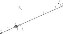
- FIG. 1is a perspective view of a catheter in accordance with a non-limiting exemplary embodiment
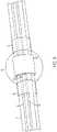
- FIG. 2is a close up perspective view of a portion of the catheter of FIG. 1 ;
- FIG. 3is a further close up perspective view of a portion of the catheter of FIG. 1 ;
- FIG. 4is a cross sectional view of a portion of the catheter of FIG. 1 ;
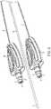
- FIG. 5is a semi-exploded perspective view of a distal end of the catheter of FIG. 1 ;
- FIG. 6is a close up perspective view of a portion of the catheter of FIG. 1 illustrating a first complementary connector according to a non-limiting exemplary embodiment
- FIG. 7is a perspective view of a second complementary connector in accordance with another non-limiting exemplary embodiment
- FIG. 8Ais a cross sectional view of a portion of a second complementary connector in accordance with a non-limiting exemplary embodiment
- FIG. 8Bis a front view of the first complementary connector of FIG. 6 connected to the second complementary connector of FIG. 7 .
- FIG. 9is a whisker-plot showing improved frequency of detection of devices in accordance with a non-limiting exemplary embodiment.
- FIG. 10is a graph showing improved pressure detection of devices in accordance with a non-limiting exemplary embodiment.
- FIG. 1is a perspective view of a catheter in accordance with a non-limiting exemplary embodiment.
- a pressure monitoring catheter 10comprising an elongate flexible fluid column catheter that is connectable to a pressure sensing apparatus by way of connector 50 .
- An elongate center arm 18extends from the proximal end 11 of the catheter 10 to a connector 19 .
- the connector 19in turn can be used to attach a syringe or other device used for the collection (e.g. aspiration) or delivery (e.g. infusion) of fluids to or from the cavity of the patient through holes 20 at the distal end 12 of the catheter 10 .
- a data/power cable or wireless transmitter(not shown) connects the pressure sensing apparatus to a processor and monitor and/or database.
- the catheter 10can be detachably attached to a cable assembly which is structured to be coupled (either wired or wirelessly) to a processor and monitor.
- the cable assemblycomprises a wired reusable assembly
- the reusable interface cable assemblyhas, at its proximal end, an electrical connector configured to be connected to a processor and a monitor.
- the proximal end of the cable assemblycomprises a wireless transmitter.
- the distal end 12 of the catheter 10comprises a soft, pliant tip 14 , which facilitates insertion of the catheter 10 into the patient.
- the soft tip 14may preferably be formed of a material pliant enough to deflect or give as the tip 14 encounters a resistive force, such as the wall of the bladder.
- the tip 14can be formed from an elongated hollow tube 15 which extends from the tip 14 at its distal end 12 to one or more connector 50 on its proximal end 11 .
- the hollow tube 15can be formed of flexible, biocompatible material, such as PVC or a polyolefin, with sufficient properties, such as wall thickness, to resist collapse under normal conditions, and sized in length to extend from within a cavity (e.g., the alimentary canal or urinary tract) of a patient to outside the body of the patient.
- a cavitye.g., the alimentary canal or urinary tract
- the hollow tube 15may range in length from 20 cm to 90 cm.
- FIG. 2is a portion of the catheter of FIG. 1 to illustrate details thereof.
- a plurality of holes or apertures 20are formed through the wall of the hollow tube 15 immediately behind the tip 14 .
- the number of holes 20may vary, however.
- the holes 20are distributed about the circumference of the outer hollow tube 15 and longitudinally about a distal end 12 of the catheter 10 to allow fluid to be aspirated or otherwise collected from the patient or infused or delivered into the patient during a procedure.
- a plurality of holes 20is provided so that if any one or more holes 20 should become clogged or blocked, other holes 20 will be available for allowing passage of fluid.
- slitssuch as slit valves may be formed through the wall of the outer hollow tube 15 to provide for infusion and/or aspiration of fluids.
- the cathetercomprises a central lumen 17 and one or more secondary lumens 30 that are disposed within the hollow tube 15 .
- the central lumen 17can be in fluid communication with holes 20 . Additionally, the central lumen 17 can also be in fluid communication with a lumen of the elongate center arm 18 (best seen in FIG. 1 ).
- the central lumen 17has a hydraulic diameter ranging from about 0.75 to about 1.75 millimeters with a non-limiting exemplary diameter of 1.1 millimeters.
- each monitor lumen 30may be interchangeably referred to as “monitor lumen.”
- each monitor lumen 30comprises one or more flexible, biocompatible materials, such as polyurethane and is integrally formed from or with the sidewall of the hollow tube 15 .
- the secondary lumen 30is sized in diameter to fit within the hollow tube 15 and to leave adequate space for passage of fluids through central lumen 17 .
- the secondary lumen 30extends from the connector 50 , (and sealed therewith), to the distal end 12 of the catheter 10 .
- the secondary lumen 30extends from the hollow tube 15 of the catheter 10 body to the connector 50 by way of a flexible extension arm 51 which is integrally formed with the elongate hollow tube 15 .
- a flaccid, pressure-compliant membere.g., a balloon
- the pressure-compliant member 40which is fluid-filled in one aspect, is structured to deflect or deform upon application of a force thereto, (e.g. an increase in pressure within the body cavity from the contraction of tissues within the body), and to expand again upon removal of the force therefrom (e.g. a subsequent decrease in pressure after a relaxation of the contracting tissues). Therefore, a particularly suitable pressure-compliant member 40 may be a medical grade balloon 40 formed of a thin-walled, flexible, low durometer material such as C-Flex® elastomer, which is relatively easily deformed with a small increase in pressure.
- the balloon 40may be formed as a substantially circular body disposed about and/or attached to an opening 46 of a secondary (or monitor) lumen 30 and/or heat-sealed at the ends 48 of the balloon 40 . While a circular shape is illustrated, other shapes may be used. Fluid (e.g., air) may occupy the interior of the secondary lumen 30 . In such cases, fluid may be at atmospheric pressure prior to use of the catheter 10 .
- the secondary lumen 30 and the balloon 40 attached to the secondary lumen 30may, therefore, form or define a fluid column which extends from inside the connector 50 to near the tip 14 of the catheter 10 .
- the fluid columnbecomes filled, or “charged,” with an additional quantity of fluid. The additional fluid charged into the fluid column partially fills the balloon 40 to a selected volume.
- the material of the balloon 40can be substantially pliant due to its thin wall and the low durometer material used in its construction, and the balloon 40 deforms easily and substantially with a given change in pressure external to the balloon 40 . Further, the balloon material may not introduce any artifacts during pressure measurements.
- the material of the balloon 40may, for example, have a Shore durometer hardness of about 30 A.
- Examples of materials for the secondary lumen 30may be C-Flex® synthetic elastomer of 1-2 millimeters wall thickness, or any other similar material having similar durability and flexibility or other material having characteristics suitable for the designs and use specified herein.
- less than 5 millimeters of mercury (Hg) of maximum external pressuremay collapse the balloon 40 when its interior is vented to atmospheric pressure, though the balloon 40 can be designed to be operable at pressure ranges ranging from 0 millimeters Hg to 200 millimeters Hg.
- the collapse of balloon 40before charging the fluid column as described, provides an accurate pressure signal.
- the balloon 40may be attached to an end of the secondary or monitor lumen 30 in any appropriate manner. However, as illustrated in FIG. 3 , the balloon 40 can be attached to the secondary lumen 30 by positioning the balloon 40 over opening 46 of the secondary lumen 30 and securing the balloon 40 about the circumference of the opposing ends 48 of the balloon 40 .
- the balloonmay be secured by laser welding, adhesive bonding, RF welding, induction welding, hot air welding, or other suitable methods for securing balloon 40 to the catheter 10 .
- the balloon 40can be positioned about the exterior of the hollow tube 15 so that the interior volume of the balloon 40 is substantially laterally aligned with the apertures or opening 46 formed through the hollow tube 15 so as to be in fluid communication with the secondary (or monitor) lumen 30 .
- the balloonis in fluid communication with the secondary lumen 30 and the charge-volume of fluid from the connector apparatus.
- a single opening 46is shown as providing fluid communication with the secondary lumen 30
- more than one openingmay be present within a single balloon 40 corresponding to a single secondary lumen 30 .
- more than one secondary lumen 30(as shown more fully in FIG. 4 ) is used as more than one sensor balloon 40 is disposed about the catheter 10 .
- Balloon 40may burst due to its relatively fragile construction if over-pressurized. Accordingly, some such exemplary embodiments provide optimal balloon diameter and fluid column pressure. Further, some exemplary embodiments of the current disclosure balance total volume of the fluid column according to the volume of fluid within the secondary (or monitor) lumen 30 , the total volume available within the balloon 40 , and the balloon charge volume.
- the balloon 40prior to placement on the catheter 10 , has a length ranging from about 8 millimeters to about 10 millimeters with one non-limiting exemplary length of about 9 millimeters.
- the length of the inflatable portion of the balloon 40can range from about 5 millimeters to about 8 millimeters with one non-limiting exemplary length of about 6 millimeters.
- the diameter of the balloon 40can range from about 5 millimeters to about 8 millimeters with one non-limiting exemplary length of about 6 millimeters and the hollow tube 15 has an outer diameter ranging from about 1.5 millimeters to about 2.5 millimeters with one non-limiting exemplary diameter of about 2 millimeters.
- a balloon diameter that is too smallmay not provide enough space between the inner wall of the balloon 40 and the outer wall of outer tube 15 to create a sufficient amount of deflectable volume to accurately measure a patient-induced pressure event (e.g., coughing, flexing of alimentary canal tissues, etc.) before the balloon 40 “bottoms out” (e.g., touches) against the outer wall of the hollow tube 15 .
- a patient-induced pressure evente.g., coughing, flexing of alimentary canal tissues, etc.
- life, maximum pressure, and accuracy of the balloonmay be a function of the separation distance between the inflated balloon 40 and the outer wall of hollow body 15 the catheter 10 .
- the balloon 40may collapse and “wrinkle” toward the catheter 10 .
- the collapsing balloon 40may wrinkle and bear upon the hollow body 15 , thus counteracting the external pressure with both internal pressure created from shrinking volume, and force applied against the hollow body 15 .
- the remaining internal forceas measured by the pressure transducer, becomes significantly lower than the actual external pressure.
- a larger balloon diameter and a smaller catheter bodycreate a larger “gap” between the wall of the balloon 40 and outside wall of the hollow tube 15 .
- oxygen moleculesimmediately begin permeation and diffusion across the balloon membrane, reducing the volume of the charged balloon immediately. While nitrogen molecules diffuse slower, and are contemplated for use as an inflation fluid herein, they too can also migrate across the balloon membrane.
- a larger gapin such cases, may not slow loss of gas, but may provide a more tolerable level of loss, thus increasing balloon life.
- the balloon 40has a maximum measurable pressure where wrinkles (i.e., collapsing surface of the balloon 40 ) touch the catheter 40 . A measure of this maximum pressure correlates with the catheter life due to loss of gas over time.
- a minimum of about 60% to 80% of the total closed system volumeneeds to be “working volume” while the other 20% to 40% of the total close system volume comprises “nonworking volume.”
- the “working volume”comprises the volume of fluid within the balloon while the “non-working volume” comprises the volume of fluid within the monitor lumen and the interstitial spaces in the connector mechanism.
- the collapsing balloon 40may wrinkle inward to accommodate both the collapsing balloon volume and the densifying of the fluid in the nonworking volume.
- the ratio of working volume to nonworking volumeis greater than 2:1 in an effort to optimize maximum balloon pressure, high-end pressure accuracy, and balloon life.
- the balloon geometry described hereinoptimizes the inward “wrinkle” of the balloon 40 so that it may not collapse on itself which may negatively affect balloon performance.
- a smaller cathetermay put constraints on the diameter of the infusion lumen.
- too large a balloon 40may be over constrained (e.g., pre-pressurized simply by its relative size within the patient) when inflated within the a body cavity (e.g., the urethra), causing overstated “resting tones” sensed without the patient “squeezing”, but in a relaxed state. Accordingly, the ratios presented herein may be considered illustrative, and balanced during practical use.
- the internal volume of the balloon 40ranges from about 90 microliters to about 120 microliters with one non-limiting exemplary volume of 100 microliters.
- the diameter of the secondary (or monitor) lumen 30ranges from about 0.15 millimeters to about 0.35 millimeters with one non-limiting exemplary diameter of 0.25 millimeters. Based on an exemplary total length of the secondary lumen 30 of 20 centimeters to 90 centimeters, the total volume of fluid within the secondary lumen 30 can range from about 25 microliters to about 40 microliters with one non-limiting exemplary volume being 32 microliters.
- a charge volume(which may correspond to the amount of fluid introduced into the fluid column) can range from about 40 microliters to about 60 microliters with a non-limiting exemplary volume of about 50 microliters.
- the total volume of the fluid (e.g., air) columnmay be defined by the volume of the secondary (or monitor) lumen 30 and the interior chamber defined by the balloon 40 (e.g., the balloon volume). Accordingly, in one aspect of the disclosure, the volume of the fluid column can range from about 115 microliters to about 160 microliters with a non-limiting exemplary volume being about 132 microliters.
- the charge volumecan refer to the total amount of fluid that is introduced into the fluid (e.g., air) column to “charge” or ready the catheter 10 for pressure measurement.
- FIGS. 6-8illustrate various portions of the catheter and a complementary connector. While FIG. 6 illustrates details of a first complementary connector 72 , FIG. 7 illustrates details of a second complementary connector 98 that can receive the first complementary connector 72 . FIG. 8A illustrates a sectional view of the second complementary connector 98 while FIG. 8B is a front view of a connected orientation of the first complementary connector and the second complementary connector.
- the first complementary connectorcan be fixedly attached to the proximal end of the elongate member and comprises an internal lumen in fluid communication with the monitor lumen.
- the second complementary connectorcan be removably connected to the first complementary connector.
- the second complementary connector 98has an internal bore or cavity 114 that is sized in internal diameter and length to frictionally receive the first complementary connector 72 (shown in FIG. 6 ) of the catheter 10 .
- the O-ring 80Upon insertion of the first complementary connector 72 in the bore 114 of the second complementary connector 98 , the O-ring 80 becomes seated against an inner wall of the internal bore 114 to form a fluid-tight fit.
- the bore 114 and charging section 122 lying between the engagement section 123 of the second complementary connector 98 and the enclosure 100 of the proximal coupler 96define an internal space 126 which contains a predetermined or selected volume of fluid (e.g., the charge volume) prior to insertion of the first complementary connector 72 into the bore 114 of second complementary connector 98 .
- a predetermined or selected volume of fluide.g., the charge volume
- the first complementary connector 72is inserted so as to act like a pressurizing device (e.g., piston or plunger) into the bore 114 of second complementary connector 98 , part of the volume of fluid contained within the internal space 126 of the bore 114 is displaced by first complementary connector 72 through the end 32 of monitor lumen 30 adding the volume of fluid to the fluid column.
- the displaced volume of fluidmay be sufficient to “charge” or partially fill the balloon 40 with an appropriate amount of fluid to expand the balloon 40 to function with desired sensitivity responsive to a given range of pressure values.
- the effective fluid volume trapped in the fluid columnis defined by the inward stroke or travel of first complementary connector 72 , and its related components, from the point at which O-ring 80 passes flutes 130 until first complementary connector 72 is fully inserted in second complementary connector 98 .
- a pressure detection device 94which, when coupled to the catheter 10 by way of connector 50 (illustrated in FIG. 6 ), interfaces with the fluid column of the catheter 10 to detect changes in pressure (e.g., urodynamic pressure).
- a proximal extremity 66 of the enclosure 100 and the open proximal end 32 of the monitor lumen 30are positioned in close proximity to the pressure detection device 94 housed within the enclosure 100 , minimizing dead space in the system.
- the pressure detection device 94may be, in a non-limiting example, a pressure transducer having a deformable diaphragm positioned toward the engagement section 123 of the second complementary connector 98 .
- Wiring 102extends from the pressure transducer through the enclosure 100 and to the proximal end of the cable 101 for communication to a processor.
- the pressure detection device 94is operable with a proximal coupler 96 structured within a second complementary connector 98 , the proximal coupler 96 being sized to receive a first complementary connector 72 (illustrated in FIG. 7 ) from connector 50 of the catheter 10 .
- the second complementary connector 98has an enclosure 100 for housing the pressure detection device therein and an end cap 104 for capping the enclosure 100 and attaching the pressure detection device 94 to a tubular cable 101 of the reusable interface cable assembly.
- a protective cover 108may also be provided on the reusable interface cable assembly sized to fit over the second complementary connector 98 .
- the balloon 40may be in a substantially deflated state. With charging, the balloon 40 becomes at least partially filled with fluid (e.g., air). Thus, depending on how much fluid is in the balloon 40 prior to charging, the balloon 40 may be anywhere from 40% to 70% filled to capacity with fluid following charging. In some examples, the balloon 40 may not be overfilled so as to reduce the chances of the structure of the balloon 40 being introduced into the signal. In other words, the flaccidity of the partially-filled working volume of balloon 40 can reduce the occurrence of aberrant effects in pressure detection due to temperature changes (for instance, from Charles's Law), or undesirable effects that may introduce signal artifacts due to the balloon wall internal forces, or external balloon compression from debris.
- fluide.g., air
- the low durometer material of the balloon 40allows the surface of the balloon 40 to deform with an increase in pressure. Therefore, a minimum of 1 millimeter Hg increase in body cavity pressure may cause deformation of the balloon 40 and, in turn, modify the pressure in the fluid column within the balloon 40 and secondary lumen 30 .
- the change in pressureis translated down the fluid column to the diaphragm of the pressure detection device (best seen in FIG. 8 ). Deflection of the diaphragm resulting from an increase in pressure can be converted to an electrical signal by the transducer and is relayed to the monitor through the cable 101 or wirelessly. Similarly, a subsequent decrease in body cavity pressure can also be relayed by subsequent expansion of the balloon 40 . While a pressure transducer has been specifically described, other means of detecting pressure changes known in the art are contemplated for use herein.
- aspects of the present disclosureprovide for wider pressure ranges.
- the larger diameter balloon 40 and outer tube 15 combinationallows the catheter 10 to measure a larger pressure range before “bottoming” out against the outside wall of the outer tube 15 .
- the balanced ratio of charge volume, secondary or monitor lumen volume, and balloon volume/geometrymay optimize the sensitivity of the system to better measure cavity pressure.
- the balancing of these elementsmay minimize damping of the pressure signal which increases the speed and resolution of the pressure measurements within the patient.
- the ratio of the volume of fluid displaced (e.g., charge volume) to the volume of the fluid (e.g., air) columnranges from about 1:2 to about 1:1 with a non-limiting exemplary range of 1:2 to 3:4.
- the charge volume of the catheter 10is approximately 1 ⁇ 2 to 3 ⁇ 4 of the volume of the fluid column.
- such embodimentsmaximize space (and/or volume of fluid) available for charging while also increasing the range of pressure measurements.
- the ratio of the longitudinal length of the balloon 40 to diameter of the balloon 40ranges from about 0.75:1 to about 1.5:1. In another aspect of the disclosure, however, the ratio of the longitudinal length of the balloon 40 to the diameter of the balloon 40 ranges from about 1:1.5 to about 1:2. The ratio of the diameter of the balloon 40 to the diameter of the outer tube 15 may also be a factor in precision operation of aspects of the disclosure. In still another aspect of the disclosure, the ratio of the diameter of the outer tube 15 and the diameter of the balloon 40 ranges from 1:2 to 1:5.
- FIGS. 9 and 10show examples of improvements of the present disclosure over prior art catheters.
- FIG. 9illustrates the test results of the operational frequency of signals detected by the pressure detection device located in the second complementary connector 98 over a course of tests.
- the test resultsdemonstrate a significantly higher operational frequency of measurements.
- the higher operational frequencyyields significantly more precise measurements of pressure as well as higher granularity or finer measurements of pressure changes. For example, a coughing event that creates contraction of tissues within the body is a “high-frequency” event that cannot be adequately detected with prior art devices.
- FIG. 10illustrates a plot of actual pressures applied to a pressure-compliant member plotted against a comparison of measured pressure and applied pressure.
- the test resultsdemonstrate the improved ability of aspects of the disclosure to measure actual pressure applied to the pressure-compliant members particularly as the amount of pressure applied increases.
- the disclosureallows for greater amounts of beginning pressures within the balloon 40 which results in a longer lasting testing time.
- a catheter marker band 105can be provided on the catheter shaft.
- the marker band 105can be a short, thin-wall tube or wire made from gold, tungsten, platinum or other dense metal and is placed on the a catheter shaft to provide high levels of visibility under fluoroscopy (radio-opacity). This can allow medical practitioners to precisely locate the catheter features deep within the body.
- the marker band 105can be made from compounding tungsten powder into a biocompatible polymer.
- useable polymersinclude high-density polyethylene, polyamides, fluoropolymers (e.g., polytetrafluoroethylene), polyolefin, and PVC.
- radiopaque materialsincluding, but without limitation, platinum iridium, gold, tantalum, platinum, tungsten carbide, and the like.
- Such examplesadvantageously eliminate multi-step forming processes used in conventional devices to create seamless small diameter tubes or wire bundles and/or specialized manufacturing equipment to secure metal bands to the polymer catheter tip so that they do not fall off during use (e.g., a medical procedure). Accordingly, such examples of the present disclosure are less costly and time consuming relative to conventional devices whereby a metal band is provided on the catheter shaft.
- tungstenis cryogenically ground to a powder having a particle size ranging from 5 to 20 ⁇ m.
- the tungsten powderis then placed in a batch mixer with polymer beads where it is heated and mixed together to form a polymer-tungsten composition.
- the resulting compositionis formed into an elongate hollow tube from which the bands 105 are cut or otherwise created.
- Tungstencreates a dense band that is radiopaque in a fluid of radiopaque contrast media such as iodine or barium.
- bands 105are customized using the same polymer specified for the catheter 10 shaft to allow heat bonding of the band 105 to the outer wall of hollow tube 15 for a more secure assembly.
- tungsten loadings within the thermoplastic polymerrange from 50% to 80% by weight to meet radio-opacity requirements.
- the compounded, heated materialis extruded into tubes that can be easily applied to the catheter 10 .
- the tungsten-polymer tubecan be placed over the exterior of the catheter 10 so that it is frictionally fit (or otherwise secured) about the exterior of the outer tube 15 .
- the interior diameter of the tungsten-polymer tubecan be configured to approximate the outer diameter of the outer tube 15 of catheter 10 .
- the tungsten-polymer tubecan be placed over the outer diameter of the outer tube 15 but within the balloon 40 (e.g., centrally within the balloon 40 ).
- the opening being surrounded by the hollow pressure compliant member, the radio opaque band 105is circumscribed on the hollow tube 15 such that the radio opaque band does not cover the opening 46 on the monitor lumen 30 . In this manner, the precise location of each “sensor” (i.e., balloon 40 ) is known to the practitioner.
- the longitudinal length of the tungsten-polymer tubecan be sized to be less than the longitudinal length of the balloon 40 as it is disposed on the catheter 10 .
- the longitudinal length of the marker band 105 formed from the tungsten-polymer tubeis less than 6 millimeters and, in one non-limiting example, has a longitudinal length of 4 millimeters.
- a plurality of marker bands 105are laser welded or otherwise secured to the outside wall of the catheter 10 on opposing sides of balloon 40 and, for example, placed over the portion of the balloon 40 that is welded to the outside wall of catheter 10 . In this manner, the location of the balloon 40 within the patient is located between the two radio-opaque markers 105 .
- the marker bands 105have a longitudinal length that ranges from 4 millimeters to 6 millimeters.
- a radiopaque cap or blunt endis formed from the composition referenced above and disposed about a distal end of the catheter 10 . The distal end of the catheter 10 is spaced a known distance from a balloon 40 on catheter 10 and therefore provides a marker within the body of the patient.
Landscapes
- Health & Medical Sciences (AREA)
- Life Sciences & Earth Sciences (AREA)
- Heart & Thoracic Surgery (AREA)
- Veterinary Medicine (AREA)
- Public Health (AREA)
- Biophysics (AREA)
- General Health & Medical Sciences (AREA)
- Engineering & Computer Science (AREA)
- Biomedical Technology (AREA)
- Animal Behavior & Ethology (AREA)
- Hematology (AREA)
- Surgery (AREA)
- Molecular Biology (AREA)
- Medical Informatics (AREA)
- Pathology (AREA)
- Physics & Mathematics (AREA)
- Pulmonology (AREA)
- Anesthesiology (AREA)
- Child & Adolescent Psychology (AREA)
- Urology & Nephrology (AREA)
- Physiology (AREA)
- Media Introduction/Drainage Providing Device (AREA)
- Measuring And Recording Apparatus For Diagnosis (AREA)
- Infusion, Injection, And Reservoir Apparatuses (AREA)
Abstract
Description
Claims (13)
Priority Applications (1)
| Application Number | Priority Date | Filing Date | Title |
|---|---|---|---|
| US15/456,002US11350838B2 (en) | 2016-03-11 | 2017-03-10 | Pressure catheter device |
Applications Claiming Priority (2)
| Application Number | Priority Date | Filing Date | Title |
|---|---|---|---|
| US201662306828P | 2016-03-11 | 2016-03-11 | |
| US15/456,002US11350838B2 (en) | 2016-03-11 | 2017-03-10 | Pressure catheter device |
Publications (2)
| Publication Number | Publication Date |
|---|---|
| US20170258345A1 US20170258345A1 (en) | 2017-09-14 |
| US11350838B2true US11350838B2 (en) | 2022-06-07 |
Family
ID=58361199
Family Applications (1)
| Application Number | Title | Priority Date | Filing Date |
|---|---|---|---|
| US15/456,002Active2039-04-09US11350838B2 (en) | 2016-03-11 | 2017-03-10 | Pressure catheter device |
Country Status (11)
| Country | Link |
|---|---|
| US (1) | US11350838B2 (en) |
| EP (1) | EP3426332B1 (en) |
| JP (1) | JP7115990B2 (en) |
| KR (1) | KR20190010535A (en) |
| CN (1) | CN109069806B (en) |
| AU (1) | AU2017229996B2 (en) |
| BR (1) | BR112018068366A2 (en) |
| CA (1) | CA3016475A1 (en) |
| IL (1) | IL261676A (en) |
| MX (1) | MX2018010906A (en) |
| WO (1) | WO2017156466A1 (en) |
Families Citing this family (15)
| Publication number | Priority date | Publication date | Assignee | Title |
|---|---|---|---|---|
| KR20190008839A (en) | 2016-03-11 | 2019-01-25 | 라보리 메디칼 테크놀로지스 코포레이션 | Pressure Catheters and Connector Devices |
| US11045128B2 (en) | 2017-06-03 | 2021-06-29 | Sentinel Medical Technologies, LLC | Catheter for monitoring intra-abdominal pressure |
| US11045143B2 (en) | 2017-06-03 | 2021-06-29 | Sentinel Medical Technologies, LLC | Catheter with connectable hub for monitoring pressure |
| US10813589B2 (en) | 2017-06-03 | 2020-10-27 | Sentinel Medical Technologies, LLC | Catheter for monitoring uterine contraction pressure |
| US11185245B2 (en) | 2017-06-03 | 2021-11-30 | Sentinel Medical Technologies, Llc. | Catheter for monitoring pressure for muscle compartment syndrome |
| US10799131B2 (en) | 2017-06-03 | 2020-10-13 | Sentinel Medical Technologies, LLC | Catheter for monitoring intrauterine pressure to protect the fallopian tubes |
| US10531834B1 (en) | 2018-07-26 | 2020-01-14 | Laborie Medical Technologies Corp. | Pressure catheter connector |
| US10893834B2 (en) | 2018-07-26 | 2021-01-19 | Laborie Medical Technologies Corp. | Charger for pressure sensing catheter |
| USD880690S1 (en) | 2018-07-26 | 2020-04-07 | Laborie Medical Technologies Corp. | Pressure catheter connector |
| AU2019311084B2 (en) | 2018-07-26 | 2024-08-08 | Laborie Medical Technologies Corp. | Pressure catheter connector and charger for pressure sensing catheter |
| US11672457B2 (en) | 2018-11-24 | 2023-06-13 | Sentinel Medical Technologies, Llc. | Catheter for monitoring pressure |
| US11219383B2 (en) | 2019-01-28 | 2022-01-11 | Laborie Medical Technologies Corp. | Radiofrequency detection and identification of pressure sensing catheters |
| US11779263B2 (en) | 2019-02-08 | 2023-10-10 | Sentinel Medical Technologies, Llc. | Catheter for monitoring intra-abdominal pressure for assessing preeclampsia |
| US11730385B2 (en) | 2019-08-08 | 2023-08-22 | Sentinel Medical Technologies, LLC | Cable for use with pressure monitoring catheters |
| US11617543B2 (en) | 2019-12-30 | 2023-04-04 | Sentinel Medical Technologies, Llc. | Catheter for monitoring pressure |
Citations (57)
| Publication number | Priority date | Publication date | Assignee | Title |
|---|---|---|---|---|
| US5135484A (en)* | 1990-05-09 | 1992-08-04 | Pioneering Technologies, Inc. | Method of removing plaque from vessels |
| JPH08173542A (en) | 1994-09-16 | 1996-07-09 | Scimed Life Syst Inc | Balloon catheter with improved pressure source |
| US5573007A (en) | 1994-08-08 | 1996-11-12 | Innerspace, Inc. | Gas column pressure monitoring catheters |
| US5647847A (en) | 1994-09-16 | 1997-07-15 | Scimed Life Systems, Inc. | Balloon catheter with improved pressure source |
| US5776116A (en) | 1983-01-24 | 1998-07-07 | Icu Medical, Inc. | Medical connector |
| US5795325A (en)* | 1991-07-16 | 1998-08-18 | Heartport, Inc. | Methods and apparatus for anchoring an occluding member |
| US6421013B1 (en) | 1999-10-04 | 2002-07-16 | Amerasia International Technology, Inc. | Tamper-resistant wireless article including an antenna |
| JP2003000718A (en) | 2001-06-18 | 2003-01-07 | Terumo Corp | Balloon-pressurizing device and medical apparatus |
| US6649829B2 (en) | 2001-05-21 | 2003-11-18 | Colder Products Company | Connector apparatus and method for connecting the same for controlling fluid dispensing |
| US6673022B1 (en)* | 1999-08-20 | 2004-01-06 | Innerspace Medical, Inc. | Gas column pressure monitoring catheters |
| US20040127813A1 (en) | 2001-12-21 | 2004-07-01 | Schwamm Lee H | Dual balloon catheter with sensor for continuous transvenous measurement of intracranial pressure |
| US6837864B1 (en)* | 1999-02-19 | 2005-01-04 | Endoscopic Technologies, Inc. | Multichannel catheter with obturator |
| US20050064223A1 (en)* | 2003-09-22 | 2005-03-24 | Bavaro Vincent Peter | Polymeric marker with high radiopacity |
| WO2005032639A1 (en) | 2003-10-01 | 2005-04-14 | Micrus Endovascular Corporation | Steerable balloon catheter |
| US20050187430A1 (en) | 2004-02-19 | 2005-08-25 | Medtronic, Inc. | Fluid charging mechanism for balloon catheter system |
| US20050215119A1 (en) | 2004-02-20 | 2005-09-29 | Hitachi Maxell, Ltd. | Adapter panel, electronic equipment, and cable connector identification system |
| WO2005107006A1 (en) | 2004-04-27 | 2005-11-10 | Colder Products Company | Antenna for radio frequency identification reader |
| JP2006142032A (en) | 2004-11-22 | 2006-06-08 | Codman & Shurtleff Inc | Ventriculostomy reservoir |
| US20060148279A1 (en) | 2004-12-06 | 2006-07-06 | Commscope Solutions Properties, Llc | Telecommunications patching system that utilizes RFID tags to detect and identify patch cord interconnections |
| JP2007504850A (en) | 2003-07-14 | 2007-03-08 | ビー アンド ディー リサーチ アンド ディベロプメント インコーポレイティッド | Connecting device for medical line |
| US20070252771A1 (en) | 2004-12-03 | 2007-11-01 | Makoto Maezawa | Electromagnetic Interference Suppressor, Antenna Device and Electronic Information Transmitting Apparatus |
| US20070273525A1 (en) | 1998-08-14 | 2007-11-29 | 3M Innovative Properties Company | Radio frequency identification systems applications |
| US20080030343A1 (en) | 2006-07-31 | 2008-02-07 | Raybuck John L | RFID ring illumination system for surgical machine |
| US7352771B2 (en) | 2002-10-08 | 2008-04-01 | Colder Products Company | Data collision detection device and method |
| US20090009290A1 (en) | 2007-07-05 | 2009-01-08 | Baxter International Inc. | Radio frequency auto-identification system |
| JP2009511149A (en) | 2005-10-14 | 2009-03-19 | エンドクロス | Balloon catheter system for treating vascular occlusion |
| WO2009055435A1 (en) | 2007-10-23 | 2009-04-30 | C. R. Bard, Inc. | Continuous intra-abdominal pressure monitoring system |
| US20090171278A1 (en)* | 2005-10-14 | 2009-07-02 | Endocross Ltd. | Balloon catheter system for treating vascular occlusions |
| JP2009529937A (en) | 2006-03-13 | 2009-08-27 | レニショウ パブリック リミテッド カンパニー | Fluid connector for fluid delivery device |
| US20090306539A1 (en)* | 2008-06-09 | 2009-12-10 | Gentera Devices, Llc | Pressure sensing catheter |
| US20100001516A1 (en) | 2008-07-03 | 2010-01-07 | Value Plastics, Inc. | Latch assembly for joining two conduits |
| US20100249723A1 (en) | 2009-03-25 | 2010-09-30 | Icu Medical, Inc. | Medical connectors and methods of use |
| US20100280451A1 (en)* | 2008-11-03 | 2010-11-04 | Atlanta Catheter Therapies, Inc. | Occlusion Perfusion Catheter |
| US7926856B2 (en) | 2007-03-02 | 2011-04-19 | Smith & Nephew, Inc. | Fluid conduit connection |
| US20110136550A1 (en) | 2008-08-18 | 2011-06-09 | Nxp B.V. | Mobile device to control a charge pad system |
| US20110210541A1 (en) | 2009-12-09 | 2011-09-01 | Value Plastics, Inc. | Button latch with integrally molded cantilever springs |
| EP1996851B1 (en) | 2006-03-13 | 2011-11-02 | Colder Products Company | Connection state sensing for coupling device |
| EP1799610B1 (en) | 2004-09-24 | 2012-11-21 | Colder Products Company | Coupler with radio frequency identification tag |
| US20130015654A1 (en) | 2011-07-11 | 2013-01-17 | Jeffrey Jay Gilham | Air-Tight Push-In and Pull-Out Connector System with Positive Latching |
| USRE44310E1 (en) | 2004-05-06 | 2013-06-25 | Colder Products Company | Connect/disconnect coupling for a container |
| US20130184612A1 (en) | 2012-01-18 | 2013-07-18 | Medspira Llc | Motility manometer priming manifold system with icon-based user interface and wireless connectivity |
| US20130268029A1 (en) | 2007-11-26 | 2013-10-10 | Micro Transponder, Inc. | Implantable Transponder Systems and Methods |
| US20130270820A1 (en) | 2012-04-17 | 2013-10-17 | Dr. Py Institute, Llc | Self closing connector |
| US20140203077A1 (en) | 2011-08-02 | 2014-07-24 | The Regents Of The University Of California | Intelligent electric vehicle charging system |
| EP1866611B1 (en) | 2005-03-17 | 2014-09-10 | Colder Products Company | Coupling device |
| US20140266775A1 (en)* | 2013-03-14 | 2014-09-18 | Clinical Innovations, Llc | Multifunction cable for use with different signal inputs |
| WO2014160300A1 (en) | 2013-03-13 | 2014-10-02 | Stimpson Philip G | A catheter assembly |
| CN104470576A (en) | 2012-07-24 | 2015-03-25 | 明讯科技有限公司 | Balloon Catheter with Enhanced Positioning Capabilities |
| US20150130408A1 (en) | 2013-11-13 | 2015-05-14 | Chiun Mai Communication Systems, Inc. | Wireless charger and charging method using same |
| US20150135502A1 (en) | 2013-10-14 | 2015-05-21 | Colder Products Company | Reagent Magazine with Motor Latch Coupler |
| US20150250974A1 (en) | 2014-03-10 | 2015-09-10 | InnerSpace Neuro Solutions, Inc. | Air Line Protection Coupling For A Catheter |
| US20160046130A1 (en) | 2014-08-14 | 2016-02-18 | Colder Products Company | Mechanical Lock-Out Mechanism for Motor Latch Coupler |
| US20160089254A1 (en)* | 2014-09-25 | 2016-03-31 | Merit Medical Systems, Inc. | Coated balloons and coated balloon assemblies and related methods of use and manufacture |
| US20160213228A1 (en)* | 2015-01-23 | 2016-07-28 | Boston Scientific Scimed, Inc. | Balloon catheter suturing systems, methods, and devices having pledgets |
| US20170021144A1 (en) | 2015-07-21 | 2017-01-26 | Atrion Medical Products, Inc. | Pressure limiting mechanism for fluid displacement and pressurizing syringe and method of assembly |
| US20170140330A1 (en) | 2015-11-12 | 2017-05-18 | Twyst LLC | User-portable container configured to inventory items using multiple readers |
| US20170259035A1 (en) | 2016-03-11 | 2017-09-14 | Laborie Medical Technologies, Corp. | Pressure catheter and connector device |
Family Cites Families (2)
| Publication number | Priority date | Publication date | Assignee | Title |
|---|---|---|---|---|
| US5695468A (en)* | 1994-09-16 | 1997-12-09 | Scimed Life Systems, Inc. | Balloon catheter with improved pressure source |
| EP2956186B1 (en)* | 2013-02-18 | 2018-09-26 | Terumo BCT, Inc. | Separating composite liquids |
- 2017
- 2017-03-10WOPCT/US2017/021924patent/WO2017156466A1/ennot_activeCeased
- 2017-03-10JPJP2018567027Apatent/JP7115990B2/enactiveActive
- 2017-03-10CACA3016475Apatent/CA3016475A1/enactivePending
- 2017-03-10USUS15/456,002patent/US11350838B2/enactiveActive
- 2017-03-10KRKR1020187029325Apatent/KR20190010535A/ennot_activeCeased
- 2017-03-10MXMX2018010906Apatent/MX2018010906A/enunknown
- 2017-03-10AUAU2017229996Apatent/AU2017229996B2/enactiveActive
- 2017-03-10CNCN201780015529.2Apatent/CN109069806B/enactiveActive
- 2017-03-10BRBR112018068366Apatent/BR112018068366A2/ennot_activeApplication Discontinuation
- 2017-03-10EPEP17712399.9Apatent/EP3426332B1/enactiveActive
- 2018
- 2018-09-06ILIL261676Apatent/IL261676A/enunknown
Patent Citations (62)
| Publication number | Priority date | Publication date | Assignee | Title |
|---|---|---|---|---|
| US5776116A (en) | 1983-01-24 | 1998-07-07 | Icu Medical, Inc. | Medical connector |
| US5135484A (en)* | 1990-05-09 | 1992-08-04 | Pioneering Technologies, Inc. | Method of removing plaque from vessels |
| US5795325A (en)* | 1991-07-16 | 1998-08-18 | Heartport, Inc. | Methods and apparatus for anchoring an occluding member |
| US5573007A (en) | 1994-08-08 | 1996-11-12 | Innerspace, Inc. | Gas column pressure monitoring catheters |
| EP0774919B1 (en) | 1994-08-08 | 2002-11-06 | Innerspace, Inc. | Gas column pressure-monitoring catheters |
| US5647847A (en) | 1994-09-16 | 1997-07-15 | Scimed Life Systems, Inc. | Balloon catheter with improved pressure source |
| JPH08173542A (en) | 1994-09-16 | 1996-07-09 | Scimed Life Syst Inc | Balloon catheter with improved pressure source |
| US20070273525A1 (en) | 1998-08-14 | 2007-11-29 | 3M Innovative Properties Company | Radio frequency identification systems applications |
| US6837864B1 (en)* | 1999-02-19 | 2005-01-04 | Endoscopic Technologies, Inc. | Multichannel catheter with obturator |
| US6673022B1 (en)* | 1999-08-20 | 2004-01-06 | Innerspace Medical, Inc. | Gas column pressure monitoring catheters |
| US6421013B1 (en) | 1999-10-04 | 2002-07-16 | Amerasia International Technology, Inc. | Tamper-resistant wireless article including an antenna |
| US6649829B2 (en) | 2001-05-21 | 2003-11-18 | Colder Products Company | Connector apparatus and method for connecting the same for controlling fluid dispensing |
| JP2003000718A (en) | 2001-06-18 | 2003-01-07 | Terumo Corp | Balloon-pressurizing device and medical apparatus |
| US20040127813A1 (en) | 2001-12-21 | 2004-07-01 | Schwamm Lee H | Dual balloon catheter with sensor for continuous transvenous measurement of intracranial pressure |
| US7352771B2 (en) | 2002-10-08 | 2008-04-01 | Colder Products Company | Data collision detection device and method |
| JP2007504850A (en) | 2003-07-14 | 2007-03-08 | ビー アンド ディー リサーチ アンド ディベロプメント インコーポレイティッド | Connecting device for medical line |
| US20050064223A1 (en)* | 2003-09-22 | 2005-03-24 | Bavaro Vincent Peter | Polymeric marker with high radiopacity |
| US20130197564A1 (en)* | 2003-10-01 | 2013-08-01 | Marc-Alan Levine | Long nose manipulatable catheter |
| CN1859942A (en) | 2003-10-01 | 2006-11-08 | 迈科洛斯血管腔内治疗公司 | Long nose manipulatable catheter |
| WO2005032639A1 (en) | 2003-10-01 | 2005-04-14 | Micrus Endovascular Corporation | Steerable balloon catheter |
| US20050187430A1 (en) | 2004-02-19 | 2005-08-25 | Medtronic, Inc. | Fluid charging mechanism for balloon catheter system |
| US20050215119A1 (en) | 2004-02-20 | 2005-09-29 | Hitachi Maxell, Ltd. | Adapter panel, electronic equipment, and cable connector identification system |
| WO2005107006A1 (en) | 2004-04-27 | 2005-11-10 | Colder Products Company | Antenna for radio frequency identification reader |
| USRE44310E1 (en) | 2004-05-06 | 2013-06-25 | Colder Products Company | Connect/disconnect coupling for a container |
| EP1799610B1 (en) | 2004-09-24 | 2012-11-21 | Colder Products Company | Coupler with radio frequency identification tag |
| JP2006142032A (en) | 2004-11-22 | 2006-06-08 | Codman & Shurtleff Inc | Ventriculostomy reservoir |
| US20070252771A1 (en) | 2004-12-03 | 2007-11-01 | Makoto Maezawa | Electromagnetic Interference Suppressor, Antenna Device and Electronic Information Transmitting Apparatus |
| US20060148279A1 (en) | 2004-12-06 | 2006-07-06 | Commscope Solutions Properties, Llc | Telecommunications patching system that utilizes RFID tags to detect and identify patch cord interconnections |
| EP1866611B1 (en) | 2005-03-17 | 2014-09-10 | Colder Products Company | Coupling device |
| JP2009511149A (en) | 2005-10-14 | 2009-03-19 | エンドクロス | Balloon catheter system for treating vascular occlusion |
| US20090171278A1 (en)* | 2005-10-14 | 2009-07-02 | Endocross Ltd. | Balloon catheter system for treating vascular occlusions |
| JP2009529937A (en) | 2006-03-13 | 2009-08-27 | レニショウ パブリック リミテッド カンパニー | Fluid connector for fluid delivery device |
| EP1996851B1 (en) | 2006-03-13 | 2011-11-02 | Colder Products Company | Connection state sensing for coupling device |
| US20080030343A1 (en) | 2006-07-31 | 2008-02-07 | Raybuck John L | RFID ring illumination system for surgical machine |
| US7926856B2 (en) | 2007-03-02 | 2011-04-19 | Smith & Nephew, Inc. | Fluid conduit connection |
| US20090009290A1 (en) | 2007-07-05 | 2009-01-08 | Baxter International Inc. | Radio frequency auto-identification system |
| WO2009055435A1 (en) | 2007-10-23 | 2009-04-30 | C. R. Bard, Inc. | Continuous intra-abdominal pressure monitoring system |
| US20100249663A1 (en)* | 2007-10-23 | 2010-09-30 | C.R. Bard, Inc. | Continuous intra-abdominal pressure monitoring system |
| US20130268029A1 (en) | 2007-11-26 | 2013-10-10 | Micro Transponder, Inc. | Implantable Transponder Systems and Methods |
| US20090306539A1 (en)* | 2008-06-09 | 2009-12-10 | Gentera Devices, Llc | Pressure sensing catheter |
| US20100001516A1 (en) | 2008-07-03 | 2010-01-07 | Value Plastics, Inc. | Latch assembly for joining two conduits |
| US20110136550A1 (en) | 2008-08-18 | 2011-06-09 | Nxp B.V. | Mobile device to control a charge pad system |
| US20100280451A1 (en)* | 2008-11-03 | 2010-11-04 | Atlanta Catheter Therapies, Inc. | Occlusion Perfusion Catheter |
| US20100249723A1 (en) | 2009-03-25 | 2010-09-30 | Icu Medical, Inc. | Medical connectors and methods of use |
| US20110210541A1 (en) | 2009-12-09 | 2011-09-01 | Value Plastics, Inc. | Button latch with integrally molded cantilever springs |
| US20130015654A1 (en) | 2011-07-11 | 2013-01-17 | Jeffrey Jay Gilham | Air-Tight Push-In and Pull-Out Connector System with Positive Latching |
| US20140203077A1 (en) | 2011-08-02 | 2014-07-24 | The Regents Of The University Of California | Intelligent electric vehicle charging system |
| US20130184612A1 (en) | 2012-01-18 | 2013-07-18 | Medspira Llc | Motility manometer priming manifold system with icon-based user interface and wireless connectivity |
| US20130270820A1 (en) | 2012-04-17 | 2013-10-17 | Dr. Py Institute, Llc | Self closing connector |
| CN104470576A (en) | 2012-07-24 | 2015-03-25 | 明讯科技有限公司 | Balloon Catheter with Enhanced Positioning Capabilities |
| US20160029912A1 (en) | 2013-03-13 | 2016-02-04 | Philip G. Stimpson | Catheter assembly |
| WO2014160300A1 (en) | 2013-03-13 | 2014-10-02 | Stimpson Philip G | A catheter assembly |
| US20140266775A1 (en)* | 2013-03-14 | 2014-09-18 | Clinical Innovations, Llc | Multifunction cable for use with different signal inputs |
| US20150135502A1 (en) | 2013-10-14 | 2015-05-21 | Colder Products Company | Reagent Magazine with Motor Latch Coupler |
| US20150130408A1 (en) | 2013-11-13 | 2015-05-14 | Chiun Mai Communication Systems, Inc. | Wireless charger and charging method using same |
| US20150250974A1 (en) | 2014-03-10 | 2015-09-10 | InnerSpace Neuro Solutions, Inc. | Air Line Protection Coupling For A Catheter |
| US20160046130A1 (en) | 2014-08-14 | 2016-02-18 | Colder Products Company | Mechanical Lock-Out Mechanism for Motor Latch Coupler |
| US20160089254A1 (en)* | 2014-09-25 | 2016-03-31 | Merit Medical Systems, Inc. | Coated balloons and coated balloon assemblies and related methods of use and manufacture |
| US20160213228A1 (en)* | 2015-01-23 | 2016-07-28 | Boston Scientific Scimed, Inc. | Balloon catheter suturing systems, methods, and devices having pledgets |
| US20170021144A1 (en) | 2015-07-21 | 2017-01-26 | Atrion Medical Products, Inc. | Pressure limiting mechanism for fluid displacement and pressurizing syringe and method of assembly |
| US20170140330A1 (en) | 2015-11-12 | 2017-05-18 | Twyst LLC | User-portable container configured to inventory items using multiple readers |
| US20170259035A1 (en) | 2016-03-11 | 2017-09-14 | Laborie Medical Technologies, Corp. | Pressure catheter and connector device |
Non-Patent Citations (5)
| Title |
|---|
| Bryce Smith, U.S. Appl. No. 15/456,062, filed Mar. 10, 2017, entitled "Pressure Catheter and Connector Device," 48 pages. |
| English Abstract for Chinese Publication No. CN 1859942 A, published Nov. 8, 2006, 1 pgs. |
| International Patent Application No. PCT/US2017/021924, International Search Report and Written Opinion dated Jul. 28, 2017, 24 pages. |
| International Patent Application No. PCT/US2017/021924, Invitation to Pay Additional Fees and Partial Search Report dated Jun. 6, 2017, 19 pages. |
| Yamashita, Noboru et al. "Preparation and characterization of gelatin sponge millispheres injectable through microcatheters", Medical Devices: Evidence and Research, 2009:2 19-25 (Year: 2009).* |
Also Published As
| Publication number | Publication date |
|---|---|
| IL261676A (en) | 2018-10-31 |
| EP3426332B1 (en) | 2025-05-07 |
| CA3016475A1 (en) | 2017-09-14 |
| MX2018010906A (en) | 2019-05-20 |
| CN109069806B (en) | 2022-04-12 |
| JP2019512367A (en) | 2019-05-16 |
| AU2017229996B2 (en) | 2021-07-01 |
| BR112018068366A2 (en) | 2019-01-15 |
| EP3426332A1 (en) | 2019-01-16 |
| EP3426332C0 (en) | 2025-05-07 |
| US20170258345A1 (en) | 2017-09-14 |
| JP7115990B2 (en) | 2022-08-09 |
| CN109069806A (en) | 2018-12-21 |
| WO2017156466A1 (en) | 2017-09-14 |
| AU2017229996A1 (en) | 2018-09-20 |
| KR20190010535A (en) | 2019-01-30 |
Similar Documents
| Publication | Publication Date | Title |
|---|---|---|
| US11350838B2 (en) | Pressure catheter device | |
| US20200359920A1 (en) | Method and apparatus for pressure measurement | |
| US10918831B2 (en) | Pressure catheter and connector device | |
| US8192368B2 (en) | Pressure sensing catheter | |
| AU2011267954B2 (en) | Diagnostic kit and method for measuring balloon dimension in vivo | |
| KR101743015B1 (en) | Enteral feeding catheter assembly incorporating an indicator | |
| CA1174925A (en) | Disc membrane catheter | |
| WO2015021065A1 (en) | Bulbous balloon with mechanical pressure regulator | |
| EP3474769B1 (en) | Pressure monitoring apparatus and a catheter for monitoring pressure in a liquid | |
| EP1423047B1 (en) | Multi-lumen, manometry catheters | |
| US20130190730A1 (en) | Catheter and catheter system | |
| JP6472487B2 (en) | Steel tube with measuring element | |
| US20130190797A1 (en) | Angioplasty pressure transducer | |
| US20060079813A1 (en) | Multifunctional catheter probe |
Legal Events
| Date | Code | Title | Description |
|---|---|---|---|
| AS | Assignment | Owner name:LABORIE MEDICAL TECHNOLOGIES, CORP., CANADA Free format text:ASSIGNMENT OF ASSIGNORS INTEREST;ASSIGNOR:SMITH, BRYCE;REEL/FRAME:041750/0502 Effective date:20170320 | |
| STPP | Information on status: patent application and granting procedure in general | Free format text:DOCKETED NEW CASE - READY FOR EXAMINATION | |
| STPP | Information on status: patent application and granting procedure in general | Free format text:NON FINAL ACTION MAILED | |
| STPP | Information on status: patent application and granting procedure in general | Free format text:RESPONSE TO NON-FINAL OFFICE ACTION ENTERED AND FORWARDED TO EXAMINER | |
| STPP | Information on status: patent application and granting procedure in general | Free format text:FINAL REJECTION MAILED | |
| STPP | Information on status: patent application and granting procedure in general | Free format text:ADVISORY ACTION MAILED | |
| AS | Assignment | Owner name:JPMORGAN CHASE BANK, N.A., AS ADMINISTRATIVE AGENT, ILLINOIS Free format text:SECURITY INTEREST;ASSIGNOR:LABORIE MEDICAL TECHNOLOGIES CORP.;REEL/FRAME:052259/0786 Effective date:20200212 | |
| STPP | Information on status: patent application and granting procedure in general | Free format text:NON FINAL ACTION MAILED | |
| STPP | Information on status: patent application and granting procedure in general | Free format text:RESPONSE TO NON-FINAL OFFICE ACTION ENTERED AND FORWARDED TO EXAMINER | |
| STPP | Information on status: patent application and granting procedure in general | Free format text:FINAL REJECTION MAILED | |
| STPP | Information on status: patent application and granting procedure in general | Free format text:ADVISORY ACTION MAILED | |
| STPP | Information on status: patent application and granting procedure in general | Free format text:NON FINAL ACTION MAILED | |
| STPP | Information on status: patent application and granting procedure in general | Free format text:RESPONSE TO NON-FINAL OFFICE ACTION ENTERED AND FORWARDED TO EXAMINER | |
| STPP | Information on status: patent application and granting procedure in general | Free format text:FINAL REJECTION MAILED | |
| STPP | Information on status: patent application and granting procedure in general | Free format text:RESPONSE AFTER FINAL ACTION FORWARDED TO EXAMINER | |
| STPP | Information on status: patent application and granting procedure in general | Free format text:AWAITING TC RESP., ISSUE FEE NOT PAID | |
| STPP | Information on status: patent application and granting procedure in general | Free format text:NOTICE OF ALLOWANCE MAILED -- APPLICATION RECEIVED IN OFFICE OF PUBLICATIONS | |
| STPP | Information on status: patent application and granting procedure in general | Free format text:PUBLICATIONS -- ISSUE FEE PAYMENT VERIFIED | |
| STPP | Information on status: patent application and granting procedure in general | Free format text:WITHDRAW FROM ISSUE AWAITING ACTION | |
| STPP | Information on status: patent application and granting procedure in general | Free format text:DOCKETED NEW CASE - READY FOR EXAMINATION | |
| STPP | Information on status: patent application and granting procedure in general | Free format text:NOTICE OF ALLOWANCE MAILED -- APPLICATION RECEIVED IN OFFICE OF PUBLICATIONS | |
| STPP | Information on status: patent application and granting procedure in general | Free format text:PUBLICATIONS -- ISSUE FEE PAYMENT VERIFIED | |
| STCF | Information on status: patent grant | Free format text:PATENTED CASE | |
| AS | Assignment | Owner name:JPMORGAN CHASE BANK, N.A., AS ADMINISTRATIVE AGENT, ILLINOIS Free format text:SECURITY INTEREST;ASSIGNORS:CLINICAL INNOVATIONS, LLC;COGENTIX MEDICAL, INC.;UROPLASTY, LLC;AND OTHERS;REEL/FRAME:066986/0500 Effective date:20240329 | |
| AS | Assignment | Owner name:LABORIE MEDICAL TECHNOLOGIES CORP., VERMONT Free format text:RELEASE BY SECURED PARTY;ASSIGNOR:JPMORGAN CHASE BANK, N.A., AS ADMINISTRATIVE AGENT;REEL/FRAME:066988/0864 Effective date:20240402 |