US11350797B2 - Touch-free dispensers - Google Patents
Touch-free dispensersDownload PDFInfo
- Publication number
- US11350797B2 US11350797B2US16/176,411US201816176411AUS11350797B2US 11350797 B2US11350797 B2US 11350797B2US 201816176411 AUS201816176411 AUS 201816176411AUS 11350797 B2US11350797 B2US 11350797B2
- Authority
- US
- United States
- Prior art keywords
- dispense
- fluid
- pulse width
- soap
- speed
- Prior art date
- Legal status (The legal status is an assumption and is not a legal conclusion. Google has not performed a legal analysis and makes no representation as to the accuracy of the status listed.)
- Active
Links
Images


Classifications
- A—HUMAN NECESSITIES
- A47—FURNITURE; DOMESTIC ARTICLES OR APPLIANCES; COFFEE MILLS; SPICE MILLS; SUCTION CLEANERS IN GENERAL
- A47K—SANITARY EQUIPMENT NOT OTHERWISE PROVIDED FOR; TOILET ACCESSORIES
- A47K5/00—Holders or dispensers for soap, toothpaste, or the like
- A47K5/06—Dispensers for soap
- A47K5/12—Dispensers for soap for liquid or pasty soap
- A47K5/1217—Electrical control means for the dispensing mechanism
- A—HUMAN NECESSITIES
- A47—FURNITURE; DOMESTIC ARTICLES OR APPLIANCES; COFFEE MILLS; SPICE MILLS; SUCTION CLEANERS IN GENERAL
- A47K—SANITARY EQUIPMENT NOT OTHERWISE PROVIDED FOR; TOILET ACCESSORIES
- A47K5/00—Holders or dispensers for soap, toothpaste, or the like
- A47K5/06—Dispensers for soap
- A47K5/12—Dispensers for soap for liquid or pasty soap
- A47K5/1202—Dispensers for soap for liquid or pasty soap dispensing dosed volume
- A47K5/1204—Dispensers for soap for liquid or pasty soap dispensing dosed volume by means of a rigid dispensing chamber and pistons
- A47K5/1207—Dispensing from the bottom of the dispenser with a vertical piston
- A—HUMAN NECESSITIES
- A47—FURNITURE; DOMESTIC ARTICLES OR APPLIANCES; COFFEE MILLS; SPICE MILLS; SUCTION CLEANERS IN GENERAL
- A47K—SANITARY EQUIPMENT NOT OTHERWISE PROVIDED FOR; TOILET ACCESSORIES
- A47K5/00—Holders or dispensers for soap, toothpaste, or the like
- A47K5/06—Dispensers for soap
- A47K5/12—Dispensers for soap for liquid or pasty soap
- A47K5/1211—Dispensers for soap for liquid or pasty soap using pressure on soap, e.g. with piston
- A—HUMAN NECESSITIES
- A47—FURNITURE; DOMESTIC ARTICLES OR APPLIANCES; COFFEE MILLS; SPICE MILLS; SUCTION CLEANERS IN GENERAL
- A47K—SANITARY EQUIPMENT NOT OTHERWISE PROVIDED FOR; TOILET ACCESSORIES
- A47K5/00—Holders or dispensers for soap, toothpaste, or the like
- A47K5/14—Foam or lather making devices
- H—ELECTRICITY
- H03—ELECTRONIC CIRCUITRY
- H03K—PULSE TECHNIQUE
- H03K7/00—Modulating pulses with a continuously-variable modulating signal
- H03K7/08—Duration or width modulation ; Duty cycle modulation
Definitions
- the present inventionrelates generally to touch free soap, sanitizer or lotion dispenser systems and more particularly to power systems for touch free dispensers.
- a liquid or foam pumpis activated by a drive actuator through a drive cycle to dispense a dose of fluid.
- the drive actuatoris powered by a direct current (DC) motor with a drive train formed of gears or other known mechanical components.
- the drive train(including the motor) strokes or spins the pump.
- the motoris typically powered by a battery.
- the power that is delivered to the motoris determined by the motor draw (or load on the motor) and the power capacity of the power source.
- Dispenserstypically use a controller or microprocessor that receives a signal from a user sensor to dispense a dose of fluid and sends a signal to a switch device (such as, for example, a power transistor or relay).
- the switch deviceconnects the power source to the motor for the duration of the actuation cycle.
- the motordraws power (or current) from the power source as it needs and the power source provides power at whatever level that it can provide. Typical dispensers do not control on the motor speed or limit power delivered from the power source.
- An exemplary dispenserincludes a housing; a receptacle for receiving a container; a container of fluid comprising soap, sanitizer or lotion; a pump in fluid communication with the container; a power source; a pump coupled to a motor and pulse width modulation circuitry in circuit communication with the power source and the motor.
- the pulse width modulation circuitryis initially set to cause a selected dose of fluid to be dispensed at a base speed.
- a sensor for detecting a parameter indicative of an actual speed of a dispense of the fluidis also included. When the actual speed of the dispense of fluid is less than the base speed or greater than the base speed, the pulse width modulation circuitry adjusts the pulse width of the voltage to cause the speed of a following dispense of fluid to be closer to the base speed.
- Another exemplary dispenserincludes a housing; a receptacle for receiving a container; a container of fluid comprising soap, sanitizer or lotion; a pump in fluid communication with the container; a power source; a motor coupled to the pump; memory for storing a stored speed of dispense; pulse width modulation circuitry in circuit communication with the power source and the motor; a sensor for sensing rotation of the pump or motor; and a processor for receiving a signal from the sensor and determining a speed of dispense for a dose of fluid.
- the processorcauses the pulse width circuitry to adjust the width of the voltage pulse applied to the motor after a preselected number of dispenses to cause a following speed of dispense to be at about the stored speed of dispense.
- Another exemplary dispenserincludes a housing; a receptacle for receiving a container; a container of fluid comprising soap, sanitizer or lotion; a pump in fluid communication with the container; a power source; a motor coupled to the pump; a processor; and pulse width modulation circuitry in circuit communication with the power source and the motor.
- the pulse width modulation circuitryis initially set to cause a selected dose of fluid to be dispensed over a selected period of time.
- a sensor for detecting a parameter indicative of selected dose of fluid being dispensedis also included.
- the processoruses the parameter indicative of a selected dose of fluid being dispensed and the time of dispense to cause the pulse width modulation circuitry to adjust the width of the voltage pulse to cause a following dispense of fluid to be dispensed over the selected period of time.
- Another exemplary dispenserincludes a housing; a receptacle for receiving a container; a container of fluid comprising soap, sanitizer or lotion; a key secured to the container.
- the keycontains data indicative of a parameter used to determine a dispense speed and dispense time.
- a reader for reading the data on the key; a processor; pulse width modulation circuitry; a motor; a pump coupled to the motor and a power sourceare included in the dispenser.
- the processorcauses the pulse width modulation circuitry to deliver a voltage to the motor having a pulse width selected as a function of the data read from the key to dispense at the desired speed for a desired dispense time.
- Another exemplary dispenserincludes a housing; a receptacle for receiving a container; a container of fluid comprising soap, sanitizer or lotion; a communication port; a processor; memory; pulse width modulation circuitry; a motor; a pump coupled to the motor; and a power source.
- the communication portis configured to receive one or more signals for setting the speed of dispense and the time of dispense.
- the processorcauses the pulse width modulation circuitry to deliver a voltage to the motor having a pulse width selected as a function of the one or more signals to dispense at the desired speed for a desired dispense time.
- Another exemplary dispenserincludes a housing; a receptacle for receiving a container; a reservoir located below the receptacle; the reservoir having an inlet; the reservoir having an outlet.
- the inlet and the outletare offset from one another.
- a pumpis included that has an inlet connected to the reservoir outlet.
- a motoris coupled to the pump and a power source are also included.
- the reservoiris filled from a refill unit that includes the container and the pump draws fluid out of the reservoir.
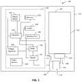
- FIG. 1is a illustrative schematic diagram of an exemplary dispenser system having a refill unit
- FIGS. 2 and 3are exemplary illustrations of pulse width modulated duty cycles
- FIG. 4is a illustrative schematic diagram of an exemplary dispenser system having a refill unit
- FIG. 5is an exemplary touch free dispenser system with a refill unit
- FIG. 6is the exemplary touch free dispenser and refill unit of FIG. 5 with the refill unit being removed from the dispenser;
- FIGS. 7 through 9are exemplary methodologies for calibrating a dispenser.
- Circuit communicationindicates a communicative relationship between devices. Direct electrical, electromagnetic and optical connections and indirect electrical, electromagnetic and optical connections are examples of circuit communication. Two devices are in circuit communication if a signal from one is received by the other, regardless of whether the signal is modified by some other device. For example, two devices separated by one or more of the following—amplifiers, filters, transformers, optoisolators, digital or analog buffers, analog integrators, other electronic circuitry, fiber optic transceivers or satellites—are in circuit communication if a signal from one is communicated to the other, even though the signal is modified by the intermediate device(s). As another example, an electromagnetic sensor is in circuit communication with a signal if it receives electromagnetic radiation from the signal. As a final example, two devices not directly connected to each other, but both capable of interfacing with a third device, such as, for example, a CPU, are in circuit communication.
- a third devicesuch as, for example, a CPU
- voltages and values representing digitized voltagesare considered to be equivalent for the purposes of this application, and thus the term “voltage” as used herein refers to either a signal, or a value in a processor representing a signal, or a value in a processor determined from a value representing a signal.
- Signalincludes, but is not limited to one or more electrical signals, analog or digital signals, one or more computer instructions, a bit or bit stream, or the like.
- Logicsynonymous with “circuit” as used herein includes, but is not limited to hardware, firmware, software and/or combinations of each to perform a function(s) or an action(s). For example, based on a desired application or needs, logic may include a software controlled microprocessor or microcontroller, discrete logic, such as an application specific integrated circuit (ASIC) or other programmed logic device. Logic may also be fully embodied as software. The circuits identified and described herein may have many different configurations to perform the desired functions.
- ASICapplication specific integrated circuit
- FIG. 1illustrates an exemplary dispenser 100 with a refill unit 110 installed therein.
- Dispenser 100includes a housing 102 .
- housing 102encloses the refill unit 110 .
- refill unit 110is partially located within hosing 102 .
- refill unit 110connects to the top of housing 102 .
- system circuitry 130Located within housing 102 is system circuitry 130 .
- System circuitry 130may be on a single circuit board or on multiple circuit boards. In addition, some of the circuitry 130 may be mounted separately, i.e. not located on a circuit board, and electrically connected to the other components as required.
- system circuitry 130includes a processor 132 , memory 133 , an optional header 134 that may be used for programming the dispenser, a power source 136 , a voltage regulator 138 , an object sensor 142 , pulse width modulation circuitry 180 , switching device 182 , optional wireless communication circuitry 140 , and a speed sensor 190 . In various embodiments, not all of these components are required.
- pulse width modulation circuitry 180may be power control circuitry.
- Pulse width modulationvaries the power delivered to the motor by varying the width of the pulse of voltage applied to the motor.
- Other power control circuitrymay include, for example, circuitry for varying the voltage or varying the current. All of the embodiments described herein with respect to pulse width modulation circuitry should also be construed to disclosing power control circuitry for performing the functions described herein with respect to pulse width modulation circuitry (and may be referred to as a communication port).
- Processor 132may be any type of processor, such as, for example, a microprocessor or microcontroller, discrete logic, such as an application specific integrated circuit (ASIC), other programmed logic devices or the like.
- Processor 132is in circuit communication with optional header 134 .
- Header 134is a circuit connection port that allows a user to connect to system circuitry 130 to program the circuitry, run diagnostics on the circuitry and/or retrieve information from the circuitry.
- Processor 132is in circuit communication with memory 133 .
- memory 133may be any type of memory, such as, for example, Random Access Memory (RAM); Read Only Memory (ROM); programmable read-only memory (PROM), electrically programmable read-only memory (EPROM), electrically erasable programmable read-only memory (EEPROM), flash, magnetic disk or tape, optically readable mediums including CD-ROM and DVD-ROM, or the like, or combinations of different types of memory.
- RAMRandom Access Memory
- ROMRead Only Memory
- PROMprogrammable read-only memory
- EPROMelectrically programmable read-only memory
- EEPROMelectrically erasable programmable read-only memory
- flashmagnetic disk or tape
- optically readable mediumsincluding CD-ROM and DVD-ROM, or the like, or combinations of different types of memory.
- the memory 133is separate from the processor 132 , and in some embodiments, the memory 133 resides on or within processor 132 .
- a power source 136such as, for example, one or more batteries, is also provided.
- the power source 136is in circuit communication with optional voltage regulator circuitry 138 .
- voltage regulator circuitry 138provides regulated power to processor 132 , object sensor 142 , wireless communication circuitry 140 .
- Optional wireless communication circuitry 140may be any type of wireless transmitting and/or receiving circuitry, such as for example, wireless RF, BlueTooth®, ANT®, infrared, or the like, configured to allow wireless communication with the dispensers disclosed herein and/or wireless programming of the dispensers disclosed herein.
- Processor 132is also in circuit communication with an optional object sensor 142 for detecting whether an object is present in the dispense area.
- Object sensor 142may be any type of passive or active object sensor, such as, for example, an infrared sensor and detector, a proximity sensor, an imaging sensor, a thermal sensor or the like.
- processor 132is in circuit communication with pulse width modulation circuitry 180 .
- Pulse width modulation circuitry 180is in circuit communication with switching device 182 .
- pulse width modulation circuitry 180 and switching device 182are combined as one circuit.
- pulse width modulation circuitry 180may be replaced with voltage adjusting circuitry (not shown), or current adjusting circuitry (not shown) that may be used to adjust the voltage or current up or down to perform the functions claimed herein.
- Switching device 182is in circuit communication with power source 136 and motor 150 .
- processor 132provides signals to pulse width modulation circuitry 180 , which cause pulse width circuitry 180 to control switching device 182 to modulate the power provided by power source 136 to drive motor 150 . More detailed descriptions of the modulated are described below.
- the switching device 182adjust the voltage and in some other alternate embodiments, switching device adjusts the current.
- Processor 132is in circuit communication with speed sensor 190 which measures speed of an element that correlates to producing an output of dispenser 100 .
- speed sensor 190determines the rotational speed of motor 150 and/or pump 116 .
- speed sensor 190may be an any type of sensor that provides a feedback signal indicative of rotation or the motor 150 and/or pump 116 .
- speed sensor 190senses revolutions of the motor 150 and/or pump 116 over a period of time, in some embodiments, speed sensor 190 senses rotational speed.
- the exemplary embodiments described hereinhave rotary pumps, however, in some embodiments, the pump is a piston pump. In the event of a piston pump, speed sensor 190 may sense linear motion of an output piston.
- speed sensor 190senses movement of the piston from point A to point B. In some embodiments, speed sensor 190 is an optical sensor. In some embodiments, speed sensor 190 senses an electric field. In some embodiments, speed sensor senses a magnetic field. In some embodiments, speed sensor 190 senses a capacitance. In some embodiments, speed sensor 190 senses an inductance. In some embodiments, speed sensor 190 senses pressure to provide a signal indicative of speed. In some embodiments, speed sensor 190 determines a speed based on one or more current wave forms. In some embodiments, speed sensor 190 may be used to determine the number of rotations of a pump or motor. In some embodiments, speed sensor 190 may be a magnetic reed.
- refill unit 110is shown inserted in the dispenser 100 of FIG. 1 .
- Refill unit 110is inserted into dispenser 100 and removed from dispenser 100 as a unit.
- Refill unit 110includes a container 112 , a closure 192 , an outlet valve (not shown) and in some embodiments, an air inlet valve (not shown) or vent valve.
- refill unit 110also includes a foamable liquid, such as, for example, a foamable soap, sanitizer, lotion, moisturizer or other liquid used for personal hygiene.
- refill unit 110is for use in a liquid dispenser, rather than a foam dispenser, and filled with liquid that is not foamed.
- pump 116is a sequentially operated multi-diaphragm pump that includes one liquid pump chamber and 3 air pump chambers. Some exemplary embodiments contain: more than one liquid pump chamber/diaphragm: more than 3 air pump chambers/diaphragms: or less than 3 air pump chambers/diaphragms. In some exemplary embodiments, a piston pump is used to pump the fluid.
- the rotation of motor 150 and pump 116are detected by speed sensor 190 .
- speed sensor 190determines revolutions of the motor 150 , on or more gears (not shown) and/or pump 116 .
- one “dose” of fluidis produced by a selected number of revolutions of the motor 150 and/or pump 116 .
- the dispenser 100is set to dispense a selected dose of fluid over a selected time period.
- the dispensermay be set to dispense a dose of fluid, e.g. 1.5 mL, in a selected time period, for example, 1.5 seconds.
- Pulse width modulation circuitry 180is set to control switching device 182 to provide a voltage having selected pulse widths to motor 150 .
- the original selected pulse widthmay be, for example, a 50% duty cycle pulse width.
- the original pulse widthsmay be selected based on original specifications, such as, for example, a fully charged power source, a new motor, a full fluid container and the like.
- the dispenser 100dispenses a selected dose of fluid
- the dispense time it takes for the motor 150 and/or pump 116 to rotate the selected number of rotations to dispense the selected dose volume of fluidis determined by the processor 132 and the dispense time and/or speed are stored in memory 133 .
- the dispense time and/or speedmay be used to adjust the pulse-width of future dispenses.
- the pulse widthmay be increased, to for example, 55%, to increase the speed of the motor which decreases the time to dispense the selected dose of fluid.
- the recalibration or resetting of the pulse-widthoccurs after each dispense event, however, preferable, the recalibration occurs periodically.
- the recalibrationoccurs after a selected number of dispenses, such as, for example, every 20 dispenses, 30 dispenses, 40 dispense, 50 dispenses, or any desired number of dispenses.
- the recalibrationoccurs after a selected time period, such as, for example, after 1 day, after 5 days, after 10 days, after 20 days, after 30 days, or the like.
- the recalibrationoccurs after a combination of the number of dispenses and a period of time. In some embodiments, the recalibration occurs randomly.
- the recalculationoccurs as a function of a parameter, such as, for example, the voltage.
- the parameteris a voltage, and if the voltage changes by a predetermined amount, such as, for example, the voltage of the power source changes by a selected threshold, e.g. drops a set amount or set percentage, the recalculation occurs.
- the parameteris a current draw. For example, if the current draw of the motor increases by a set amount or set percentage, the recalculation occurs. In some embodiments, the recalculation does not occur unless the parameter is outside the threshold on multiple dispenses in a row.
- the dispenser 100can self-adjust or auto-adjust to changes in the dispenser components, such as, for example, motor wear, efficiency, pump stiffness and wear, environmental factors and the like to allow the selected dose of fluid to be consistently dispensed within a selected parameter, such as, for example, within a set dispense time.
- the dispenser componentssuch as, for example, motor wear, efficiency, pump stiffness and wear, environmental factors and the like to allow the selected dose of fluid to be consistently dispensed within a selected parameter, such as, for example, within a set dispense time.
- FIGS. 2 and 3illustrates exemplary waveform outputs by pulse width modulation circuitry 180 and switching device 182 .
- the voltageis 5 volts and one cycle is 0.2 seconds.
- the wave form of FIG. 2represents a 25% duty cycle, which means that the motor receives voltage pulses that are approximately 0.05 seconds long at about 5 volts followed by 0.15 seconds of substantially no voltage.
- FIG. 3illustrates a waveform that represents a 50% duty cycle, which means that the motor receives voltage pulses that are approximately 0.1 seconds long at about 5 volts followed by 0.1 seconds of substantially no voltage. Any suitable duty cycle may be used in the present application. Typically, the duty cycle is greater than a 10% duty cycle.
- duty cycleapplies to the percentage of a unit that voltage is applied for. For example, a 100% duty cycle means that the voltage is constantly applied.
- a 90% duty cyclemeans that the voltage is turned on for 90% of the cycle and off for 10% of the cycle.
- a 40% duty cyclemeans that the voltage is turned on for 40% of the cycle and off for 60% of the cycle.
- the pulse width modulation circuitrymay include voltage increasing/decreasing circuitry.
- dispenser 100is a tunable dispenser.
- dispenser 100may be tailored to desired customer output or formula variations.
- the customerdesires a smaller dose of fluid; in some embodiments, the customer desires a dryer foam output; in some embodiments, the customer desires a wetter foam output.
- Dispenser 100is configured to accommodate these examples, and more.
- pump 116is a sequentially activated multi-diaphragm foam pump.
- Pump 116has three air pump diagrams and a single liquid pump diaphragm, which is shown and described in one or more of the incorporated references. Because of the interactions between the pump diaphragms, the liquid/air ratio in the foam output is not consistent as the speed of pump 116 changes. For example, if pump 116 is run at a speed that dispenses foam that contains 1.1 mL of liquid in 0.9 seconds, the foam is a wetter foam.
- the foamis a medium wetness. If pump 116 is run at a speed that dispensed foam that contains 1.1 mL of liquid in 0.5 seconds, the foam is a dry foam. Accordingly, the foam characteristics of the sequentially activated multi-diaphragm foam pump may be altered based on the speed of pump 116 .
- a usercan connect a portable programming device to header 134 and change the desired speed of motor 150 and pump 116 to tailor the foam characteristics.
- wireless communication circuitry 140may be used to set the motor speed to alter the foam characteristics.
- pulse width modulation circuitrymay be used to control the speed. Pulse width modulation varies the power delivered to the motor by varying the width of the pulse. Other power control circuitry includes circuitry for varying the voltage or varying the current may be used to control the speed. All of the embodiments described herein with respect to pulse width modulation circuitry should also be construed to disclosing power control circuitry for performing the functions described herein with respect to pulse width modulation circuitry.
- FIG. 4illustrates another exemplary dispenser 400 .
- Dispenser 400is similar to dispenser 100 and like components have the same numerical identifiers and are not re-described herein.
- Dispenser 400is an autocalibrating dispenser.
- refill unit 112includes a key 420 .
- key 420is an electronic key that can be read by reader 410 , such as, for example, an RFID device.
- key 410is a color key that can be read by reader 410 .
- key 420is a mechanical key that includes physical indicia indicative of the refill characteristics. Thus, key 420 is read either wirelessly, or through one or more sensors of the physical indicia through reader 410 .
- processor 132determines the operating parameters for dispensing fluid from refill 410 .
- refill unit 410may contain soap, concentrated soap, lotion, sanitizer or another type of fluid. Each of these different types of fluid may have different dispensing parameters or requirements. For example, if the refill unit 410 contains concentrated soap that requires a higher volume of air, dispenser 400 may operate motor 150 at a higher rate to increase air to liquid ratio of the fluid output and operate the dispenser 400 for a shorter period of time to dispense a lower volume of liquid. If the refill unit 410 includes non-concentrated soap, the dispenser may operate at a slower rate of speed for a longer time.
- the dispenser 400may operate at yet another speed for yet another length of time. Accordingly, the dispenser 400 has the ability to auto calibrate its operating characteristics, such as, for example, speed, time, volume and the like as a function of data read from key 420 . In addition, in some embodiments, the dispenser may alter the air to liquid ratio of foam outputs without changing the volume of the air or liquid pump chambers and without physically changing the compression expansion stroke of the liquid pump chamber or air pump chamber.
- FIGS. 5 and 6illustrate an exemplary embodiment of a dispenser system 500 having dispenser 501 and refill unit 550 .
- refill unit 550is inserted in dispenser 501 .
- refill unit 550is located above dispenser 501 .
- Refill unit 550includes a container 512 having a closure 552 .
- Container 512is a semi-rigid container that is designed to maintain its shape as liquid is drawn out of the container 512 and may be referred to herein as a non-collapsible container.
- vent valve 554located within closure 552 is a vent valve 554 for allowing air to flow into the container as liquid flows out to allow container 512 to maintain its shape and allow liquid to flow out of container 512 .
- Vent valve 554is selected to have a low enough cracking pressure to prevent creating a vacuum pressure that would cause container 512 to deform or collapse.
- Outlet valve 556is configured to prevent fluid form flowing out of the container 512 when container 512 is not inserted into dispenser 501 .
- outlet valve 556is a puncture valve.
- outlet valve 556is solid without an opening until it is inserted into dispenser 501 and the outlet valve 556 is punctured by liquid inlet conduit 532 when refill unit 550 is inserted into dispenser 501 .
- outlet valve 556is a slit valve, or has a small opening that is normally closed and opens when pushed over liquid inlet conduit 532 .
- the outlet valve 556may be elastomeric.
- outlet valve 556may made of rubber, silicon or the like.
- outlet valve 532includes a movable portion (not shown) and a seat (not shown) and when refill unit 550 is inserted into dispenser 501 the movable portion moves off of the seat to allow fluid to flow out of container 512 into liquid inlet 532 .
- An exemplary refill unitis shown and described in U.S. provisional patent application 62/420,927, titled DISPENSERS, REFILL UNITS, AND REUSABLE/REPLACEABLE PUMP ASSEMBLIES and filed on Nov. 11, 2016, and was filed as a PCT application No. PCT/US17/61013 on Nov. 10, 2017 and which is incorporated herein by reference in its entirety.
- Dispenser 501has a housing 502 and receptacle 610 .
- Refill unit 550fits into receptacle 610 .
- Receptacle 610includes a catch mechanism (not shown) that engages refill unit 550 and prevents refill unit 550 from being removed from receptacle 610 .
- a release mechanism(not shown) is used to remove refill unit 550 from dispenser 501 .
- Located at the bottom of receptacle 610is liquid inlet conduit 556 .
- Liquid inlet conduit 536is in fluid communications with reservoir 630 .
- Reservoir 630may be formed in part by hosing 612 .
- Housing 612includes annular projection 614 .
- Reservoir 630includes reservoir housing 632 which connects to housing 612 .
- Located at one end of reservoir hosing 632is a liquid outlet 634 that includes an optional seal 638 .
- Seal 638seals around pump inlet conduit 540 .
- Other methodsmay be used to connect conduit to reservoir housing 632 such as, for example, a welled connection.
- Reservoir liquid inlet conduit 556is off-set from reservoir liquid outlet conduit 634 .
- Reservoir 630provides a reserve of fluid when refill unit 550 is replaced. In some embodiments, the reserve of fluid helps prevent a loss of prime when refill unit 550 is replaced. In addition, in some embodiments, reservoir 630 allows flexibility for locating pump 520 and motor 510 within housing 502 . In some embodiments, the pump inlet conduit 540 may be located at multiple positions, simply by rotating reservoir housing 632 . In addition, liquid outlet 634 may be moved to different locations on reservoir housing 34 .
- Pump 520which may be any pump, such as, for example, those incorporated herein above, includes a liquid pump chamber 522 and a plurality of air pump diaphragms 524 (only one shown). Pump 520 includes a first liquid inlet valve 542 , a second liquid inlet valve 542 , a mixing chamber 546 , foaming member 548 and outlet 549 . Dispenser 500 may be operated as described in the other embodiments described or incorporated herein.
- first liquid inlet valve 542has a first cracking pressure and second inlet valve 542 has a second cracking pressure. In some embodiments, the first cracking pressure is higher than the second cracking pressure.
- Exemplary embodiments having two liquid inlet valvesare shown and described in U.S. Provisional Application Ser. No. 62/581,820 titled Double Inlet Valve for Enhanced Pump Efficiency filed on Nov. 6, 2017, which is incorporated herein by reference in its entirety.
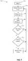
- FIG. 7is an exemplary methodology 700 for controlling a dispenser to ensure a consistent output throughout the life of the refill unit.
- the exemplary methodology 700begins at block 702 .
- a dispense eventis detected.
- the dispenserdispenses a set volume of fluid.
- the dispenseris originally calibrated to dispense a set volume of fluid in a set time. For example, the dispenser may be set to dispense 1.1 mL of fluid in 0.7 seconds.
- the pulse width modulation circuitryis initially set at a base or setpoint, such as, for example, a 25% duty cycle. In other words, if a cycle is 0.2 seconds, the pulse with modulation circuitry, set a 25%, would deliver a 0.05 second pulse of voltage to the motor out of 0.2 second cycle or time frame for the selected period of time to dispense the selected dose of fluid.
- a dispense parametersuch as, for example, the time and/or speed of the dispense event is determined at block 706 .
- other parameters indicative of the dispense time and/or dose sizeinclude, for example, dispenser voltage, current draw and the like.
- the dispense parameteris determined after a selected number of dispenses or after some other criteria is met.
- the parametersuch as, for example, time and/or speed, for the dispense is stored at block 708 .
- the parameteris compared to a threshold. If the desired parameter is number of dispenses, the methodology determines if the number of dispenses has passed a threshold number of dispenses. If the threshold is time, the methodology determines if a set period of time has passed. The parameter is updated and if the threshold has not been reached, the methodology loops to block 704 . If the threshold has been met, a determination of whether the parameter is within its acceptable limits, or within a set threshold. For example, if the parameter is speed, a determination is made as to whether the speed is within the acceptable limits or threshold. If it is, the methodology loops back to block 704 . If it is not, the width of the voltage pulse powering the motor is adjusted. In some embodiments, one or more of the above blocks are not used. In some embodiments additional blocks are used.
- the dispenseris recalibrated after every dispense and block 710 is not required. In some embodiments, the dispenser is recalibrated after 2 or more dispenses; in some embodiments, the dispenser is recalibrated after 5 dispenses; in some embodiments, the dispenser is recalibrated after 10 dispenses; in some embodiments, the dispenser is recalibrated after 15 dispenses; in some embodiments, the dispenser is recalibrated after 20 dispenses; in some embodiments, the dispenser is recalibrated after 25 dispenses; in some embodiments, the dispenser is recalibrated after 30 dispenses; in some embodiments, the dispenser is recalibrated after 35 dispenses; in some embodiments, the dispenser is recalibrated after 40 dispenses; in some embodiments, the dispenser is recalibrated after 45 dispenses or more.
- the parameteris time and in some embodiments, the recalibration occurs after a selected time period, such as, for example, after 1 day, after 5 days, after 10 days, after 20 days, after 30 days, or the like. In some embodiments, the recalibration occurs as a function of a combination of the number of dispenses and one or more periods of time. For example, the dispenser may typically recalibrate itself after 25 dispenses, however, if a set time period, such as for example 5 days has passed since the last recalibration, it may only require 10 dispenses to trigger a recalibration. In some embodiments, the dispenser may recalibrate after a selected number of dispenses or a selected time period, whichever comes first.
- FIG. 8is an exemplary methodology 800 for auto-calibrating a dispenser.
- the dispenseris able to dispense many different types of products, such as, for example, soap, concentrated soap, sanitizer, foam sanitizer, lotion and the like.
- one or more dispensing parameterssuch as, for example, amount of fluid, speed of dispense, length of dispense and the like are different for the different types of fluid.
- a fluid having one formulationmay be dispensed with different parameters based on customer preferences, such as, for example, the desire for a wetter foam or a dryer foam, or for a smaller or larger dose of fluid.
- the exemplary methodology 800begins at block 802 and at block 804 a determination is made as to whether a new refill unit has been installed in the dispenser. If no new refill has been inserted in the dispenser, the methodology loops back to block 802 . If a new refill unit has been installed in the dispenser, data is read from the refill unit at block 806 . At block 808 , the dispenser automatically calibrates the dispenser for the type of fluid in the refill unit. In some embodiments, the methodology ends after block 808 . In such and embodiment, the dispenser can only be calibrated for one type of fluid. This prevents a worker from accidently inserting the wrong type of fluid in a dispenser.
- the methodologydoes not end at block 808 but rather loops back and if a new refill unit is installed and the data read from the refill unit is different than the original refill unit, the parameters adjusted at block 808 disables the dispenser. In some embodiments, if data read from the refill unit is different than the original refill unit, the dispenser is recalibrated for the new refill unit.
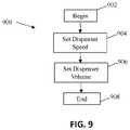
- FIG. 9is an exemplary methodology 900 for adjusting the output of a dispenser.
- the dispenseris adjusted to adjust the fluid output.
- the exemplary methodologybegins at block 902 .
- ad dispenser parametersuch as, for example, the dispenser speed may be adjusted.
- the speedmay be adjusted to, for example, adjust the wetness or dryness of a foam output. A faster speed gives a wetter foam output and a slower speed produces a dryer foam.
- the methodologymovers to block 906 and, if desired, the volume of output is adjusted.
- Other parameterssuch as, for example, time between dispenses, excessive use parameters and the like may be set.
- limiting the ability for a user to obtain many doses of fluid over a short period of timemay be desirable to prevent waste.
- excessive use parametersmay be set, to for example, prevent someone from obtaining more fluid from the dispenser over a set time.
- the parametersmay be adjusted by connecting to the header, or communication port, of the dispenser with a portable device, such as, for example, a laptop or PDA.
- the dispenser parametersare configured wirelessly, through for example, one or more networks, through the internet, or in close proximity, by for example, a blue tooth connection to a PDA, such as, for example, a smart phone.
- exemplary or representative values and rangesmay be included to assist in understanding the present disclosure; however, such values and ranges are not to be construed in a limiting sense and are intended to be critical values or ranges only if so expressly stated.
- features and conceptsmay be expressly identified herein as being inventive or forming part of an invention, such identification is not intended to be exclusive, but rather there may be inventive aspects, concepts and features that are fully described herein without being expressly identified as such or as part of a specific invention. Descriptions of exemplary methods or processes are not limited to inclusion of all steps as being required in all cases, nor is the order in which the steps are presented to be construed as required or necessary unless expressly so stated.
Landscapes
- Health & Medical Sciences (AREA)
- Public Health (AREA)
- Containers And Packaging Bodies Having A Special Means To Remove Contents (AREA)
- Control Of Positive-Displacement Pumps (AREA)
- Apparatus For Disinfection Or Sterilisation (AREA)
Abstract
Description
Claims (19)
Priority Applications (2)
| Application Number | Priority Date | Filing Date | Title |
|---|---|---|---|
| US16/176,411US11350797B2 (en) | 2017-11-06 | 2018-10-31 | Touch-free dispensers |
| US17/830,434US11819171B2 (en) | 2017-11-06 | 2022-06-02 | Touch-free dispensers |
Applications Claiming Priority (2)
| Application Number | Priority Date | Filing Date | Title |
|---|---|---|---|
| US201762581830P | 2017-11-06 | 2017-11-06 | |
| US16/176,411US11350797B2 (en) | 2017-11-06 | 2018-10-31 | Touch-free dispensers |
Related Child Applications (1)
| Application Number | Title | Priority Date | Filing Date |
|---|---|---|---|
| US17/830,434ContinuationUS11819171B2 (en) | 2017-11-06 | 2022-06-02 | Touch-free dispensers |
Publications (2)
| Publication Number | Publication Date |
|---|---|
| US20190133384A1 US20190133384A1 (en) | 2019-05-09 |
| US11350797B2true US11350797B2 (en) | 2022-06-07 |
Family
ID=64332404
Family Applications (2)
| Application Number | Title | Priority Date | Filing Date |
|---|---|---|---|
| US16/176,411ActiveUS11350797B2 (en) | 2017-11-06 | 2018-10-31 | Touch-free dispensers |
| US17/830,434ActiveUS11819171B2 (en) | 2017-11-06 | 2022-06-02 | Touch-free dispensers |
Family Applications After (1)
| Application Number | Title | Priority Date | Filing Date |
|---|---|---|---|
| US17/830,434ActiveUS11819171B2 (en) | 2017-11-06 | 2022-06-02 | Touch-free dispensers |
Country Status (6)
| Country | Link |
|---|---|
| US (2) | US11350797B2 (en) |
| EP (1) | EP3706610B1 (en) |
| JP (1) | JP7428641B2 (en) |
| AU (1) | AU2018359421B2 (en) |
| CA (1) | CA3078276A1 (en) |
| WO (1) | WO2019089756A1 (en) |
Cited By (1)
| Publication number | Priority date | Publication date | Assignee | Title |
|---|---|---|---|---|
| US20220287516A1 (en)* | 2017-11-06 | 2022-09-15 | Gojo Industries, Inc. | Touch-free dispensers |
Families Citing this family (10)
| Publication number | Priority date | Publication date | Assignee | Title |
|---|---|---|---|---|
| AU2019247230B2 (en)* | 2018-04-06 | 2023-06-01 | Gojo Industries, Inc. | Foam-at-a-distance dispensing systems |
| EP3881738B1 (en)* | 2020-03-18 | 2024-07-17 | Hans Georg Hagleitner | Method for calibrating an output quantity of a dispenser |
| EP4149335A1 (en) | 2020-05-14 | 2023-03-22 | Gojo Industries, Inc. | Dispensers and dispenser systems for securely controlling a plurality of dose sizes |
| AU2021283275A1 (en) | 2020-06-03 | 2023-02-02 | Gojo Industries, Inc. | Dispensers and dispenser systems for precisely controlled output dosing of soap or sanitizer |
| JP7674398B2 (en) | 2020-06-24 | 2025-05-09 | ゴジョ・インダストリーズ・インコーポレイテッド | DISPENSER, DISPENSER SYSTEM, AND REPLENISHMENT UNIT CONFIGURED FOR AUTONOMOUS FIRMWARE/SOFTWARE UPDATES - Patent application |
| US11304570B1 (en)* | 2021-01-22 | 2022-04-19 | Intelwrist, Llc | Multifunctional wearable fluid dispensing apparatus |
| US11641985B2 (en)* | 2021-04-13 | 2023-05-09 | Alo New York Llc | Modular fluid dispensing system |
| EP4581604A1 (en)* | 2022-09-01 | 2025-07-09 | Reckitt & Colman (Overseas) Hygiene Home Limited | A dispenser |
| WO2024077029A2 (en)* | 2022-10-07 | 2024-04-11 | Gojo Industries, Inc. | Dispensers having reduced loss of prime issues |
| US20250261807A1 (en)* | 2024-02-16 | 2025-08-21 | Machan Investments LLC | Automatic fluid dispenser |
Citations (47)
| Publication number | Priority date | Publication date | Assignee | Title |
|---|---|---|---|---|
| US4189067A (en)* | 1977-02-14 | 1980-02-19 | Lykes Pasco Packing Company, Dispenser Division | Electronic control for dispenser system |
| US4502024A (en)* | 1982-06-15 | 1985-02-26 | Tokyo Shibaura Denki Kabushiki Kaisha | Pulse-width modulation circuit |
| US5676277A (en)* | 1991-05-20 | 1997-10-14 | Ophardt; Heiner | Disposable plastic liquid pump |
| US5836482A (en)* | 1997-04-04 | 1998-11-17 | Ophardt; Hermann | Automated fluid dispenser |
| US6343724B1 (en)* | 2000-07-10 | 2002-02-05 | Hygiene Technik Inc. | Unitary one-way valve for fluid dispenser |
| US20030071058A1 (en)* | 2000-01-19 | 2003-04-17 | Hans Jorg Studer | Device for dispensing soap-solution in a dispenser |
| US20030201286A1 (en)* | 2002-04-16 | 2003-10-30 | Heiner Ophardt | Vacuum relief device |
| US20040206772A1 (en)* | 2003-04-18 | 2004-10-21 | Leifheit David H. | Bottle adapter for dispensing of cleanser from bottle used in an automated cleansing sprayer |
| US20040217137A1 (en)* | 2002-04-26 | 2004-11-04 | Heiner Ophardt | Manual or pump assist fluid dispenser |
| US20050161476A1 (en)* | 2002-04-26 | 2005-07-28 | Heiner Ophardt | One-way valve and vacuum relief device |
| US7028861B2 (en)* | 2003-12-16 | 2006-04-18 | Joseph S. Kanfer | Electronically keyed dispensing systems and related methods of installation and use |
| US20060243740A1 (en)* | 2003-03-21 | 2006-11-02 | Reynolds Aaron R | Apparatus for hands-free dispensing of a measured quantity of material |
| EP1780411A2 (en) | 2002-10-23 | 2007-05-02 | Carrier Commercial Refrigeration, Inc. | Fluid dispenser calibration system and method |
| US20070194053A1 (en)* | 2002-04-26 | 2007-08-23 | Heiner Ophardt | Fire resistant container system |
| US20070199952A1 (en)* | 2004-10-12 | 2007-08-30 | Carpenter M S | Compact spray device |
| US7303099B2 (en)* | 2005-04-22 | 2007-12-04 | Gotohti.Com Inc. | Stepped pump foam dispenser |
| US20080099515A1 (en)* | 2006-10-11 | 2008-05-01 | Nordson Corporation | Thin line conformal coating apparatus and method |
| US20090308887A1 (en)* | 2008-06-13 | 2009-12-17 | American Sterilizer Company | Fluid dispenser |
| US20120006848A1 (en)* | 2010-07-07 | 2012-01-12 | Gojo Industries, Inc. | Dispenser with automatic pump output detection system |
| USRE43288E1 (en)* | 2001-11-26 | 2012-04-03 | Emerson Electric Co. | High purity fluid delivery system |
| US20120105155A1 (en)* | 2009-06-22 | 2012-05-03 | Renesas Electronics Corporation | Pulse width modulation circuit and voltage-feedback class-d amplifier circuit |
| US8240508B2 (en)* | 2008-12-29 | 2012-08-14 | Gojo Industries, Inc. | Low cost radio frequency identification (RFID) dispensing systems |
| US20120241470A1 (en)* | 2011-03-25 | 2012-09-27 | Ultraclenz, Llc | Sanitization Dispenser Systems |
| US8292128B2 (en)* | 2008-05-06 | 2012-10-23 | Hans Georg Hagleitner | Dispenser for foamed soap |
| US20130292411A1 (en)* | 2012-05-07 | 2013-11-07 | Bobrick Washroom Equipment, Inc. | No-touch fluid dispenser and method of operating the same |
| US20140151394A1 (en)* | 2012-12-05 | 2014-06-05 | Gojo Industries, Inc | Adaptable sensorless end of stroke detection system and method |
| US8783510B2 (en)* | 2004-12-15 | 2014-07-22 | Joseph Kanfer | Electronically keyed dispensing systems and related methods utilizing near field frequency response |
| US20140203047A1 (en)* | 2013-01-23 | 2014-07-24 | Gojo Industries, Inc. | Pumps with container vents |
| US8905265B2 (en)* | 2012-02-16 | 2014-12-09 | Dispensing Dynamics International | Dispenser apparatus for dispensing liquid soap, lotion or other liquid |
| US20140367419A1 (en)* | 2013-06-14 | 2014-12-18 | Gojo Industries, Inc. | Foam cartridges, pumps, refill units and foam dispensers utilizing the same |
| US8960498B2 (en)* | 2011-07-01 | 2015-02-24 | Gojo Industries, Inc. | Touch-free dispenser with single cell operation and battery banking |
| US20150114992A1 (en)* | 2013-10-31 | 2015-04-30 | Aktiebolaget Skf | Grease gun with sensing capability and variable speed |
| US20150208877A1 (en)* | 2014-01-27 | 2015-07-30 | Gojo Industries, Inc. | Dispensers and refill units having collapsible outlet tubes |
| US20150239644A1 (en)* | 2014-02-24 | 2015-08-27 | Gojo Industries, Inc. | Vented non-collapsing containers, dispensers and refill units having vented non-collapsing containers |
| US20150268642A1 (en)* | 2012-04-25 | 2015-09-24 | Sanofi-Aventis Deutschland Gmbh | Apparatus Comprising Electromechanical Device and Motion Detector and Method for Operating Apparatus |
| US9172266B2 (en)* | 2013-02-19 | 2015-10-27 | Gojo Industries, Inc. | Power systems for touch free dispensers and refill units containing a power source |
| US20150313423A1 (en)* | 2012-08-23 | 2015-11-05 | Gojo Industries, Inc. | Horizontal pumps, refill units and foam dispensers with integral air compressors |
| US20160309967A1 (en)* | 2015-03-25 | 2016-10-27 | Gojo Industries, Inc. | Dispenser dosing based on hand size |
| US20170049276A1 (en)* | 2015-08-21 | 2017-02-23 | Gojo Industries, Inc. | Power systems for dynamically controlling a soap, sanitizer or lotion dispenser drive motor |
| US20170190558A1 (en)* | 2016-01-04 | 2017-07-06 | Fernando A. Ubidia | Motor and Pump System |
| US10079502B2 (en)* | 2012-12-11 | 2018-09-18 | Smart Wave Technologies, Inc. | Power management system for dispensers |
| US20180354777A1 (en)* | 2017-06-12 | 2018-12-13 | Gojo Industries, Inc. | Soap, sanitizer and lotion refill units management and tracking |
| US10164477B2 (en)* | 2015-10-29 | 2018-12-25 | Witricity Corporation | Controllers for wireless power systems having safety functionality |
| US20190081620A1 (en)* | 2016-01-26 | 2019-03-14 | Valeo Systemes Thermiques | Spectral spread for electric motor |
| US20190133383A1 (en)* | 2017-11-06 | 2019-05-09 | Gojo Industries, Inc. | Double inlet valve for enhanced pump efficiency |
| US20190133384A1 (en)* | 2017-11-06 | 2019-05-09 | Gojo Industries, Inc. | Touch-free dispensers |
| US20190171244A1 (en)* | 2011-10-17 | 2019-06-06 | Gojo Industries, Inc. | Hands-free dispensers with managed power consumption |
Family Cites Families (21)
| Publication number | Priority date | Publication date | Assignee | Title |
|---|---|---|---|---|
| US4238056A (en)* | 1978-03-06 | 1980-12-09 | Towlsaver, Inc. | Soap dispenser having a pivotable dispensing lever and a rotatable flow valve |
| US4241299A (en)* | 1979-04-06 | 1980-12-23 | Mine Safety Appliances Company | Control system for battery-operated pump |
| IT1130871B (en)* | 1980-01-21 | 1986-06-18 | Steiner Co Int Sa | SYSTEM FOR THE DISTRIBUTION OF LIQUID SOAP |
| US4489857A (en)* | 1982-03-22 | 1984-12-25 | Bobrick Washroom Equipment, Inc. | Liquid dispenser |
| US4756321A (en)* | 1985-11-22 | 1988-07-12 | Beta Technology, Inc. | Industrial dishwasher chemical dispenser |
| US4821925A (en)* | 1987-05-14 | 1989-04-18 | The Coca-Cola Company | Narrow, multiflavor beverage dispenser valve assembly and tower |
| US5360320A (en)* | 1992-02-27 | 1994-11-01 | Isco, Inc. | Multiple solvent delivery system |
| US5736825A (en)* | 1996-06-25 | 1998-04-07 | Allen-Bradley Company, Inc. | Method and apparatus for linearizing pulse width modulation by modifying command voltges |
| US6269837B1 (en) | 1998-11-09 | 2001-08-07 | The Procter & Gamble Company | Rechargeable dispensing system |
| US6864644B2 (en)* | 2002-11-14 | 2005-03-08 | Fyre Storm, Inc. | Method of tuning a circuit for energizing a cold cathode fluorescent lamp |
| US6912139B2 (en)* | 2002-11-14 | 2005-06-28 | Fyre Storm, Inc. | Multi-channel control methods for switched power converters |
| US7654421B2 (en)* | 2005-08-30 | 2010-02-02 | Johnsondiversey, Inc. | Automatically configurable chemical dosing apparatus for cleaning equipment |
| US7449850B2 (en)* | 2005-09-30 | 2008-11-11 | Brother Kogyo Kabushiki Kaisha | Device and method for controlling motor |
| US7905373B2 (en)* | 2006-03-06 | 2011-03-15 | Deka Products Limited Partnership | System and method for generating a drive signal |
| PL3059480T3 (en)* | 2008-07-15 | 2018-11-30 | Henkel Ag & Co. Kgaa | Metering device |
| AU2009285598B2 (en)* | 2008-08-28 | 2015-07-02 | Deka Products Limited Partnership | Product dispensing system |
| US8487563B2 (en)* | 2009-11-27 | 2013-07-16 | Denso Corporation | Drive motor control apparatus for vehicle, motor control system, method for correcting rotation angle of motor, program for performing the same, rotation detecting apparatus |
| CA2733047A1 (en)* | 2010-03-02 | 2011-09-02 | Gojo Industries, Inc. | Counter mounted dispensing system with above-counter refill unit |
| ITUB20152345A1 (en)* | 2015-07-21 | 2017-01-21 | St Microelectronics Srl | PROCEDURE FOR CHECKING ELECTRIC MOTORS, SYSTEM, ELECTRIC MOTOR AND CORRESPONDENT IT PRODUCT |
| KR101755831B1 (en)* | 2015-08-28 | 2017-07-10 | 현대자동차주식회사 | Control method of motor |
| JP6588317B2 (en) | 2015-11-27 | 2019-10-09 | 花王株式会社 | Dispenser |
- 2018
- 2018-10-31AUAU2018359421Apatent/AU2018359421B2/ennot_activeCeased
- 2018-10-31USUS16/176,411patent/US11350797B2/enactiveActive
- 2018-10-31EPEP18804479.6Apatent/EP3706610B1/enactiveActive
- 2018-10-31CACA3078276Apatent/CA3078276A1/enactivePending
- 2018-10-31WOPCT/US2018/058460patent/WO2019089756A1/ennot_activeCeased
- 2018-10-31JPJP2020524511Apatent/JP7428641B2/enactiveActive
- 2022
- 2022-06-02USUS17/830,434patent/US11819171B2/enactiveActive
Patent Citations (57)
| Publication number | Priority date | Publication date | Assignee | Title |
|---|---|---|---|---|
| US4189067A (en)* | 1977-02-14 | 1980-02-19 | Lykes Pasco Packing Company, Dispenser Division | Electronic control for dispenser system |
| US4502024A (en)* | 1982-06-15 | 1985-02-26 | Tokyo Shibaura Denki Kabushiki Kaisha | Pulse-width modulation circuit |
| US5676277A (en)* | 1991-05-20 | 1997-10-14 | Ophardt; Heiner | Disposable plastic liquid pump |
| US5836482A (en)* | 1997-04-04 | 1998-11-17 | Ophardt; Hermann | Automated fluid dispenser |
| US20030071058A1 (en)* | 2000-01-19 | 2003-04-17 | Hans Jorg Studer | Device for dispensing soap-solution in a dispenser |
| US6343724B1 (en)* | 2000-07-10 | 2002-02-05 | Hygiene Technik Inc. | Unitary one-way valve for fluid dispenser |
| USRE43288E1 (en)* | 2001-11-26 | 2012-04-03 | Emerson Electric Co. | High purity fluid delivery system |
| US6957751B2 (en)* | 2002-04-16 | 2005-10-25 | Hygiene-Technik Inc. | Vacuum relief device |
| US20030201286A1 (en)* | 2002-04-16 | 2003-10-30 | Heiner Ophardt | Vacuum relief device |
| US20050061832A1 (en)* | 2002-04-16 | 2005-03-24 | Heiner Ophardt | Vacuum relief device |
| US20070194053A1 (en)* | 2002-04-26 | 2007-08-23 | Heiner Ophardt | Fire resistant container system |
| US7198175B2 (en)* | 2002-04-26 | 2007-04-03 | Heiner Ophardt | Manual or pump assist fluid dispenser |
| US20050161476A1 (en)* | 2002-04-26 | 2005-07-28 | Heiner Ophardt | One-way valve and vacuum relief device |
| US20040217137A1 (en)* | 2002-04-26 | 2004-11-04 | Heiner Ophardt | Manual or pump assist fluid dispenser |
| EP1780411A2 (en) | 2002-10-23 | 2007-05-02 | Carrier Commercial Refrigeration, Inc. | Fluid dispenser calibration system and method |
| US7611030B2 (en)* | 2003-03-21 | 2009-11-03 | Joseph S. Kanfer | Apparatus for hands-free dispensing of a measured quantity of material |
| US20060243740A1 (en)* | 2003-03-21 | 2006-11-02 | Reynolds Aaron R | Apparatus for hands-free dispensing of a measured quantity of material |
| US20040206772A1 (en)* | 2003-04-18 | 2004-10-21 | Leifheit David H. | Bottle adapter for dispensing of cleanser from bottle used in an automated cleansing sprayer |
| US7028861B2 (en)* | 2003-12-16 | 2006-04-18 | Joseph S. Kanfer | Electronically keyed dispensing systems and related methods of installation and use |
| US20070199952A1 (en)* | 2004-10-12 | 2007-08-30 | Carpenter M S | Compact spray device |
| US8783510B2 (en)* | 2004-12-15 | 2014-07-22 | Joseph Kanfer | Electronically keyed dispensing systems and related methods utilizing near field frequency response |
| US7303099B2 (en)* | 2005-04-22 | 2007-12-04 | Gotohti.Com Inc. | Stepped pump foam dispenser |
| US20080099515A1 (en)* | 2006-10-11 | 2008-05-01 | Nordson Corporation | Thin line conformal coating apparatus and method |
| US8292128B2 (en)* | 2008-05-06 | 2012-10-23 | Hans Georg Hagleitner | Dispenser for foamed soap |
| US20090308887A1 (en)* | 2008-06-13 | 2009-12-17 | American Sterilizer Company | Fluid dispenser |
| US8240508B2 (en)* | 2008-12-29 | 2012-08-14 | Gojo Industries, Inc. | Low cost radio frequency identification (RFID) dispensing systems |
| US20120105155A1 (en)* | 2009-06-22 | 2012-05-03 | Renesas Electronics Corporation | Pulse width modulation circuit and voltage-feedback class-d amplifier circuit |
| US20150054553A1 (en)* | 2009-06-22 | 2015-02-26 | Renesas Electronics Corporation | Pulse width modulation circuit and voltage-feedback class-d amplifier circuit |
| US20120006848A1 (en)* | 2010-07-07 | 2012-01-12 | Gojo Industries, Inc. | Dispenser with automatic pump output detection system |
| US20120241470A1 (en)* | 2011-03-25 | 2012-09-27 | Ultraclenz, Llc | Sanitization Dispenser Systems |
| US8960498B2 (en)* | 2011-07-01 | 2015-02-24 | Gojo Industries, Inc. | Touch-free dispenser with single cell operation and battery banking |
| US20190171244A1 (en)* | 2011-10-17 | 2019-06-06 | Gojo Industries, Inc. | Hands-free dispensers with managed power consumption |
| US8905265B2 (en)* | 2012-02-16 | 2014-12-09 | Dispensing Dynamics International | Dispenser apparatus for dispensing liquid soap, lotion or other liquid |
| US20150268642A1 (en)* | 2012-04-25 | 2015-09-24 | Sanofi-Aventis Deutschland Gmbh | Apparatus Comprising Electromechanical Device and Motion Detector and Method for Operating Apparatus |
| US20130292411A1 (en)* | 2012-05-07 | 2013-11-07 | Bobrick Washroom Equipment, Inc. | No-touch fluid dispenser and method of operating the same |
| US20150313423A1 (en)* | 2012-08-23 | 2015-11-05 | Gojo Industries, Inc. | Horizontal pumps, refill units and foam dispensers with integral air compressors |
| US20140151394A1 (en)* | 2012-12-05 | 2014-06-05 | Gojo Industries, Inc | Adaptable sensorless end of stroke detection system and method |
| US10079502B2 (en)* | 2012-12-11 | 2018-09-18 | Smart Wave Technologies, Inc. | Power management system for dispensers |
| US20150251841A1 (en)* | 2013-01-23 | 2015-09-10 | Gojo Industries, Inc. | Pumps with container vents |
| US20140203047A1 (en)* | 2013-01-23 | 2014-07-24 | Gojo Industries, Inc. | Pumps with container vents |
| US9687120B2 (en)* | 2013-01-24 | 2017-06-27 | Dispensing Dynamics International | Apparatus for dispensing liquid soap |
| US9172266B2 (en)* | 2013-02-19 | 2015-10-27 | Gojo Industries, Inc. | Power systems for touch free dispensers and refill units containing a power source |
| US20160037976A1 (en)* | 2013-02-19 | 2016-02-11 | Gojo Industries, Inc. | Power systems for touch free dispensers and refill units containing a power source |
| US20140367419A1 (en)* | 2013-06-14 | 2014-12-18 | Gojo Industries, Inc. | Foam cartridges, pumps, refill units and foam dispensers utilizing the same |
| US20150114992A1 (en)* | 2013-10-31 | 2015-04-30 | Aktiebolaget Skf | Grease gun with sensing capability and variable speed |
| US20150208877A1 (en)* | 2014-01-27 | 2015-07-30 | Gojo Industries, Inc. | Dispensers and refill units having collapsible outlet tubes |
| US20150239644A1 (en)* | 2014-02-24 | 2015-08-27 | Gojo Industries, Inc. | Vented non-collapsing containers, dispensers and refill units having vented non-collapsing containers |
| US10160590B2 (en)* | 2014-02-24 | 2018-12-25 | Gojo Industries, Inc. | Vented non-collapsing containers, dispensers and refill units having vented non-collapsing containers |
| US20160309967A1 (en)* | 2015-03-25 | 2016-10-27 | Gojo Industries, Inc. | Dispenser dosing based on hand size |
| US10219656B2 (en)* | 2015-03-25 | 2019-03-05 | Gojo Industries, Inc. | Dispenser dosing based on hand size |
| US20170049276A1 (en)* | 2015-08-21 | 2017-02-23 | Gojo Industries, Inc. | Power systems for dynamically controlling a soap, sanitizer or lotion dispenser drive motor |
| US10164477B2 (en)* | 2015-10-29 | 2018-12-25 | Witricity Corporation | Controllers for wireless power systems having safety functionality |
| US20170190558A1 (en)* | 2016-01-04 | 2017-07-06 | Fernando A. Ubidia | Motor and Pump System |
| US20190081620A1 (en)* | 2016-01-26 | 2019-03-14 | Valeo Systemes Thermiques | Spectral spread for electric motor |
| US20180354777A1 (en)* | 2017-06-12 | 2018-12-13 | Gojo Industries, Inc. | Soap, sanitizer and lotion refill units management and tracking |
| US20190133383A1 (en)* | 2017-11-06 | 2019-05-09 | Gojo Industries, Inc. | Double inlet valve for enhanced pump efficiency |
| US20190133384A1 (en)* | 2017-11-06 | 2019-05-09 | Gojo Industries, Inc. | Touch-free dispensers |
Non-Patent Citations (2)
| Title |
|---|
| International Search Report and Written Opinion from PCT/US2018/058460 dated Mar. 26, 2019 (20 pages). |
| Invitation to Pay Additional Fees from PCT/US2018/058460 dated Jan. 30, 2019 (17 pages). |
Cited By (2)
| Publication number | Priority date | Publication date | Assignee | Title |
|---|---|---|---|---|
| US20220287516A1 (en)* | 2017-11-06 | 2022-09-15 | Gojo Industries, Inc. | Touch-free dispensers |
| US11819171B2 (en)* | 2017-11-06 | 2023-11-21 | Gojo Industries, Inc. | Touch-free dispensers |
Also Published As
| Publication number | Publication date |
|---|---|
| US20190133384A1 (en) | 2019-05-09 |
| CA3078276A1 (en) | 2019-05-09 |
| AU2018359421A1 (en) | 2020-04-23 |
| US11819171B2 (en) | 2023-11-21 |
| WO2019089756A1 (en) | 2019-05-09 |
| EP3706610A1 (en) | 2020-09-16 |
| AU2018359421B2 (en) | 2023-01-19 |
| US20220287516A1 (en) | 2022-09-15 |
| JP2021501652A (en) | 2021-01-21 |
| JP7428641B2 (en) | 2024-02-06 |
| EP3706610B1 (en) | 2023-08-16 |
Similar Documents
| Publication | Publication Date | Title |
|---|---|---|
| US11819171B2 (en) | Touch-free dispensers | |
| US11259671B2 (en) | Low cost radio frequency identification (RFID) dispensing systems | |
| US11930970B2 (en) | Dispensers and dispenser systems for precisely controlled output dosing of soap or sanitizer | |
| US20170049276A1 (en) | Power systems for dynamically controlling a soap, sanitizer or lotion dispenser drive motor | |
| JP2014529698A5 (en) | ||
| CN111936188A (en) | Systems for producing aerosols and related methods of use | |
| US20230235731A1 (en) | Fluid delivery system and method | |
| CA3183799A1 (en) | Dispensers, dispenser systems and refill units configured for autonomous firmware/software updates |
Legal Events
| Date | Code | Title | Description |
|---|---|---|---|
| FEPP | Fee payment procedure | Free format text:ENTITY STATUS SET TO UNDISCOUNTED (ORIGINAL EVENT CODE: BIG.); ENTITY STATUS OF PATENT OWNER: LARGE ENTITY | |
| AS | Assignment | Owner name:GOJO INDUSTRIES, INC., OHIO Free format text:ASSIGNMENT OF ASSIGNORS INTEREST;ASSIGNORS:MCNULTY, JOHN J.;CIAVARELLA, NICK E.;WILLIS, DANIEL M.;AND OTHERS;SIGNING DATES FROM 20180205 TO 20180208;REEL/FRAME:047452/0714 | |
| STPP | Information on status: patent application and granting procedure in general | Free format text:DOCKETED NEW CASE - READY FOR EXAMINATION | |
| STPP | Information on status: patent application and granting procedure in general | Free format text:NON FINAL ACTION MAILED | |
| STPP | Information on status: patent application and granting procedure in general | Free format text:RESPONSE TO NON-FINAL OFFICE ACTION ENTERED AND FORWARDED TO EXAMINER | |
| AS | Assignment | Owner name:PNC BANK, NATIONAL ASSOCIATION, PENNSYLVANIA Free format text:SECURITY INTEREST;ASSIGNOR:GOJO INDUSTRIES, INC.;REEL/FRAME:051228/0667 Effective date:20101029 | |
| STPP | Information on status: patent application and granting procedure in general | Free format text:FINAL REJECTION MAILED | |
| STPP | Information on status: patent application and granting procedure in general | Free format text:DOCKETED NEW CASE - READY FOR EXAMINATION | |
| STPP | Information on status: patent application and granting procedure in general | Free format text:NON FINAL ACTION MAILED | |
| STPP | Information on status: patent application and granting procedure in general | Free format text:RESPONSE TO NON-FINAL OFFICE ACTION ENTERED AND FORWARDED TO EXAMINER | |
| STPP | Information on status: patent application and granting procedure in general | Free format text:NOTICE OF ALLOWANCE MAILED -- APPLICATION RECEIVED IN OFFICE OF PUBLICATIONS | |
| STPP | Information on status: patent application and granting procedure in general | Free format text:PUBLICATIONS -- ISSUE FEE PAYMENT RECEIVED | |
| STPP | Information on status: patent application and granting procedure in general | Free format text:PUBLICATIONS -- ISSUE FEE PAYMENT VERIFIED | |
| STCF | Information on status: patent grant | Free format text:PATENTED CASE | |
| AS | Assignment | Owner name:PNC BANK, NATIONAL ASSOCIATION, PENNSYLVANIA Free format text:SECURITY INTEREST;ASSIGNOR:GOJO INDUSTRIES, INC.;REEL/FRAME:065369/0253 Effective date:20231026 | |
| AS | Assignment | Owner name:SILVER POINT FINANCE, LLC, AS COLLATERAL AGENT, CONNECTICUT Free format text:SECURITY INTEREST;ASSIGNOR:GOJO INDUSTRIES, INC.;REEL/FRAME:065382/0587 Effective date:20231026 |