US11349920B2 - Methods, devices and computer readable mediums for data synchronization - Google Patents
Methods, devices and computer readable mediums for data synchronizationDownload PDFInfo
- Publication number
- US11349920B2 US11349920B2US17/015,764US202017015764AUS11349920B2US 11349920 B2US11349920 B2US 11349920B2US 202017015764 AUS202017015764 AUS 202017015764AUS 11349920 B2US11349920 B2US 11349920B2
- Authority
- US
- United States
- Prior art keywords
- processor
- data
- cache
- rdma
- storage device
- Prior art date
- Legal status (The legal status is an assumption and is not a legal conclusion. Google has not performed a legal analysis and makes no representation as to the accuracy of the status listed.)
- Active
Links
Images


Classifications
- G—PHYSICS
- G06—COMPUTING OR CALCULATING; COUNTING
- G06F—ELECTRIC DIGITAL DATA PROCESSING
- G06F11/00—Error detection; Error correction; Monitoring
- G06F11/07—Responding to the occurrence of a fault, e.g. fault tolerance
- G06F11/14—Error detection or correction of the data by redundancy in operation
- G06F11/1402—Saving, restoring, recovering or retrying
- G06F11/1446—Point-in-time backing up or restoration of persistent data
- G06F11/1458—Management of the backup or restore process
- G06F11/1469—Backup restoration techniques
- H—ELECTRICITY
- H04—ELECTRIC COMMUNICATION TECHNIQUE
- H04L—TRANSMISSION OF DIGITAL INFORMATION, e.g. TELEGRAPHIC COMMUNICATION
- H04L67/00—Network arrangements or protocols for supporting network services or applications
- H04L67/01—Protocols
- H04L67/10—Protocols in which an application is distributed across nodes in the network
- H04L67/1095—Replication or mirroring of data, e.g. scheduling or transport for data synchronisation between network nodes
- G—PHYSICS
- G06—COMPUTING OR CALCULATING; COUNTING
- G06F—ELECTRIC DIGITAL DATA PROCESSING
- G06F11/00—Error detection; Error correction; Monitoring
- G06F11/07—Responding to the occurrence of a fault, e.g. fault tolerance
- G06F11/14—Error detection or correction of the data by redundancy in operation
- G06F11/1402—Saving, restoring, recovering or retrying
- G06F11/1446—Point-in-time backing up or restoration of persistent data
- G06F11/1458—Management of the backup or restore process
- G06F11/1464—Management of the backup or restore process for networked environments
- G—PHYSICS
- G06—COMPUTING OR CALCULATING; COUNTING
- G06F—ELECTRIC DIGITAL DATA PROCESSING
- G06F15/00—Digital computers in general; Data processing equipment in general
- G06F15/16—Combinations of two or more digital computers each having at least an arithmetic unit, a program unit and a register, e.g. for a simultaneous processing of several programs
- G06F15/163—Interprocessor communication
- G06F15/173—Interprocessor communication using an interconnection network, e.g. matrix, shuffle, pyramid, star, snowflake
- G06F15/17306—Intercommunication techniques
- G06F15/17331—Distributed shared memory [DSM], e.g. remote direct memory access [RDMA]
- G—PHYSICS
- G06—COMPUTING OR CALCULATING; COUNTING
- G06F—ELECTRIC DIGITAL DATA PROCESSING
- G06F15/00—Digital computers in general; Data processing equipment in general
- G06F15/76—Architectures of general purpose stored program computers
- H04L67/2842—
- H—ELECTRICITY
- H04—ELECTRIC COMMUNICATION TECHNIQUE
- H04L—TRANSMISSION OF DIGITAL INFORMATION, e.g. TELEGRAPHIC COMMUNICATION
- H04L67/00—Network arrangements or protocols for supporting network services or applications
- H04L67/50—Network services
- H04L67/56—Provisioning of proxy services
- H04L67/568—Storing data temporarily at an intermediate stage, e.g. caching
Definitions
- Embodiments of the present disclosuregenerally relate to the field of data storage, and more specifically relate to methods, devices and computer readable mediums for data synchronization.
- a point-to-point local bus(such as a command interface) can be utilized to exchange data among the plurality of storage processors.
- Such local busis usually built on peripheral component interconnect express (PCIe) switch fabric to implement local cache mirror through the PCIe physical interface.
- PCIeperipheral component interconnect express
- Such implementationlimits remote deployment of the plurality of storage processors.
- another potential problem of such implementationis that the point-to-point infrastructure cannot support expansion of the storage system.
- Embodiments of the present disclosureprovide methods, devices and computer readable mediums for data synchronization.
- a method of data synchronizationcomprises: in response to receiving, at a first processor, a first request to synchronize data, initiating, to a second processor, a first remote direct memory access (RDMA) operation for transmitting the data between a first cache in the first processor and a second cache in the second processor; in response to completion of the first RDMA operation, writing the data into a first persistent storage device coupled to the first processor; transmitting, to the second processor, a command to instruct the second processor to commit the data to a second persistent storage device coupled to the second processor; and detecting, from the second processor, an acknowledgement for the command, the acknowledgement indicating that the data is synchronized between the first and second processors.
- RDMAremote direct memory access
- a method of data synchronizationcomprises: in response to receiving, at a second processor and from a first processor, data transmitted via a first remote direct memory access (RDMA) operation, transmitting an acknowledgement for the first RDMA operation to the first processor; in response to receiving, from the first processor, a command for committing the data to a persistent storage device, transmitting an acknowledgement for the command to the first processor; and in response to the command, writing the data into the persistent storage device coupled to the second processor.
- RDMAremote direct memory access
- a device for data synchronizationcomprises at least one processing unit and at least one memory.
- the at least one memoryis coupled to the at least one processing unit and stores instructions for execution by the at least one processing unit.
- the instructionswhen executed by the at least one processing unit, cause the device to perform acts, the acts comprising: in response to receiving a first request to synchronize data, initiating, to a second processor, a first remote direct memory access (RDMA) operation for transmitting the data between a first cache in a first processor and a second cache in the second processor; in response to completion of the first RDMA operation, writing the data into a first persistent storage device coupled to the first processor; transmitting, to the second processor, a command to instruct the second processor to commit the data to a second persistent storage device coupled to the second processor; and detecting, from the second processor, an acknowledgement for the command, the acknowledgement indicating that the data is synchronized between the first and second processors.
- RDMAremote direct memory access
- a device for data synchronizationcomprises at least one processing unit and at least one memory.
- the at least one memoryis coupled to the at least one processing unit and stores instructions for execution by the at least one processing unit.
- the instructionswhen executed by the at least one processing unit, cause the device to perform acts, the acts comprising: in response to receiving, from a first processor, data transmitted via a first remote direct memory access (RDMA) operation, transmitting an acknowledgement for the first RDMA operation to the first processor; in response to receiving, from the first processor, a command for committing the data to a persistent storage device, transmitting an acknowledgement for the command, to the first processor; and in response to the command, writing the data into the persistent storage device coupled to a second processor.
- RDMAremote direct memory access
- a computer readable storage mediumhaving computer readable program instructions stored thereon.
- the computer readable program instructionswhen executed by a processing unit, cause the processing unit to perform the method according to the first aspect of the present disclosure.
- a computer readable storage mediumhaving computer readable program instructions stored thereon.
- the computer readable program instructionswhen executed by a processing unit, cause the processing unit to perform the method according to the second aspect of the present disclosure.
- FIG. 1illustrates an architecture diagram of a storage system 100 according to the embodiments of the present disclosure
- FIG. 2illustrates an architecture diagram of a storage system 200 according to the embodiments of the present disclosure
- FIG. 3illustrates a flowchart of a method 300 for data synchronization according to the embodiments of the present disclosure
- FIG. 4illustrates a block diagram of a device 400 for data synchronization according to the embodiments of the present disclosure
- FIG. 5illustrates a block diagram of a device 500 for data synchronization according to the embodiments of the present disclosure.
- FIG. 6illustrates a schematic block diagram of an illustrative device 600 applicable to implement embodiments of the present disclosure.
- the term “includes” and its variantsare to be read as open-ended terms that mean “includes, but is not limited to.”
- the term “or”is to be read as “and/or” unless the context clearly indicates otherwise.
- the term “based on”is to be read as “based at least in part on.”
- the term “one example embodiment” and “an example embodiment”are to be read as “at least one example embodiment.”
- the term “another embodiment”is to be read as “at least one other embodiment.” Terms “a first”, “a second” and others can denote different or identical objects. The following text may also contain other explicit or implicit definitions.
- the conventional data synchronization schemeis typically based on applications or files, which usually cannot implement the block level remote replication between different sites.
- cache mirror function constructed on the PCIe switch fabriccan be implemented.
- such implementationlimits remote deployment of the plurality of storage processors and lacks scalability.
- example embodiments of the present disclosurepropose a scheme for data synchronization, which enables interconnection of a plurality of storage processors through an Infiniband (abbreviated as “TB”) switch fabric and enables data transmission among respective caches of the plurality of storage processors by means of enhanced remote direct memory access (RDMA) operations. Therefore, the scheme enables remote data synchronization with low latency, high throughput and scalability. Moreover, it further provides a remote cache commit mechanism to further enhance reliability of remote data synchronization.
- TBInfiniband
- RDMAremote direct memory access
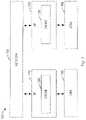
- FIG. 1illustrates an architecture diagram of a storage system 100 according to the embodiments of the present disclosure. It is to be understood that the structure and functions of the storage system 100 as shown in FIG. 1 are only for purpose of illustration, without suggesting any limitations to the scope of the present disclosure. Embodiments of the present disclosure can be embodied in different structures and/or functions.
- the storage system 100includes two storage processors (SPs, also called “storage nodes”), namely, SP 110 and SP 120 .
- SPsalso called “storage nodes”
- the SPs 110 and 120may each have one or more modules.
- the SP 110may have memories coupled thereto, such as a cache 130 .
- the cache 130can be used to store data temporarily into, for instance, a dynamic random access memory (DRAM).
- DRAMdynamic random access memory
- the SP 110can be coupled with a disk 140 and the data temporarily stored in the cache 130 can be written into the disk 140 at a proper time.
- the disk 140can be any non-volatile storage medium currently known or to be developed in the future, such as a magnetic disk, a solid state disk (SSD) or a magnetic disk array, and so on.
- the SP 120can be used to store copies of the data stored in the SP 110 , for example, so as to protect the data from disasters.
- the SP 120can be deployed close to or away from the SP 110 .
- the SPs 110 and 120can be deployed in different cities geographically.
- the SP 120can have the same structure as the SP 110 .
- the SP 120may have one or more modules including a cache 150 , and may be coupled with a disk 160 .
- the cache 150can be used to store data temporarily into, for instance, a DRAM, and the data can be written into the disk 160 at a proper time.
- the disk 160can be any non-volatile storage medium currently known or to be developed in the future, such as a magnetic disk, a solid state disk (SSD) or a magnetic disk array, and so on.
- the SPs 110 and 120can be interconnected by a network 170 .
- the network 170may be an Infiniband switch fabric, also called Infiniband network.
- the SPs 110 and 120can be connected to a switch (not shown in FIG. 1 ) in the Infiniband network 170 , respectively.
- the “Infiniband” techniquerefers to a computer network communication standard for high-performance computation with very high throughput and very low latency. Infiniband technique is generally used for interconnection among computers and/or internal components of the computer. It can also be applied for direct interconnection or switched interconnection between a server and a respective storage system. Besides, Infiniband technique can also be employed for interconnection among different storage systems.
- an “RDMA operation”refers to direct memory access from a memory of one computer (such as the cache 130 in the SP 110 ) to a memory of another computer (such as the cache 150 in the SP 120 ) without involving an operating system of either of the two computers.
- the RDMA operationenables the network adapter to transmit data directly to or from the memory, thereby achieving zero-copy data transmission. Such transmission does not require the involvement of a central processing unit (CPU), an operating system or a switch, and thus can be performed in parallel with other system operations.
- CPUcentral processing unit
- an operating system or a switchWhen an RDMA read or write operation is performed, data can be transmitted to the network directly, thereby reducing latency and improving throughput.
- RDMAcan have multiple data transmission types, such as normal data sending and receiving similar to normal Transmission Control Protocol (TCP) sockets.
- TCPTransmission Control Protocol
- the RDMA read and/or write operationenables directly placing data into a buffer of the other party relative to the initiator.
- either of the SPs 110 and 120can start the remote data synchronization operation through RDMA operations such that data is synchronized between the caches 130 and 150 .
- FIG. 2illustrates an architecture diagram of a storage system 200 according to the embodiments of the present disclosure.
- the storage system 200can be considered as a specific implementation of the storage system 100 . It is to be understood that the structure and functions of the storage system 200 as shown in FIG. 2 are only for the purpose of illustration, without suggesting any limitations to the scope of the present disclosure. Embodiments of the present disclosure can be embodied in different structures and/or functions.
- storage system 200may include a storage sub-system 201 and a storage sub-system 202 which can be interconnected via a network 270 , such as an Infiniband network.
- the storage sub-system 201 and the storage sub-system 202are mirrored by each other and used to store different copies of data, for example, to protect the data from disasters.
- the storage sub-system 202can be deployed close to or away from the storage sub-system 201 .
- the storage sub-system 201 and the storage sub-system 202can be deployed in different cities geographically.
- the storage sub-system 202can have the same structure as the storage sub-system 201 .
- the storage sub-system 201may include two SPs coupled to a shared disk 250 , namely, SPs 210 and 220 , which can be local mirrors for each other and can communicate with each other via a command interface 280 .
- the command interface 280may be, for example, an interface based on the PCIe, such that the SPs 210 and 220 can transmit commands and/or perform local data synchronization via the command interface 280 .
- the SP 201can have one or more modules.
- the SP 210may have memories coupled thereto, such as a cache 211 .
- the cache 211can be used to store data temporarily in a DRAM, for example, and the data temporarily stored in the cache 211 can be written into the shared disk 250 at a proper time.
- the SP 210may further include a host side module 212 for receiving an input/output (IO) command from a host (not shown in FIG. 2 ), processing the IO command and returning an IO acknowledgement to the host.
- IOinput/output
- the SP 210may further include a remote mirror module 213 , which may cause the SP 210 to be connected to the network 270 (such as a switch in the Infiniband network) for data synchronization with other SPs (such as SP 220 , SP 230 and/or SP 240 ) via the network 270 .
- the SP 210may further include an IB abstraction layer (Infiniband Verbs) 214 for providing RDMA function interfaces to the application.
- the IB abstraction layercan be divided into a data path and a control path, and can support management of resources for implementing the sending/receiving of the cached data.
- the SP 210may further include one or more other modules 215 .
- the one or more other modules 215may include a corresponding disk array management module, an underlying driver module and so on. It is to be understood that the structure and functions of the SP 210 as shown in FIG. 2 are only for the purpose of illustration, without suggesting any limitations to the scope of the present disclosure.
- the SPs 220 and 210can be local mirrors for each other, and thus the SP 220 may have the same structure as the SP 210 .
- the SP 220may include a cache 221 , a host side module 222 , a remote mirror module 223 , an IB abstraction layer 224 and one or more other modules 225 .
- the functions of the modules in the SP 220can be the same as that of corresponding modules in the SP 210 , which will not be repeated here.
- the storage sub-system 202as a remote mirror of the storage sub-system 201 , can have the same structure as the storage sub-system 201 .
- the SPs 230 and 240 in the storage sub-system 202can have the similar structures and functions as the SPs 210 and 220 in the storage sub-system 201 respectively, which will not repeated here for the purpose of simplification.
- Embodiments of the present disclosurewill be further described below with reference to the storage system 100 as shown in FIG. 1 and/or the storage system 200 as shown in FIG. 2 .
- embodiments of the present disclosurepropose implementing data transmission among respective memories of a plurality of storage nodes through enhanced RDMA operations via an Infiniband network.
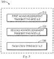
- FIG. 3illustrates a flowchart of a method 300 for data synchronization according to the embodiments of the present disclosure. Acts involved in method 300 will be described below with reference to the storage system 200 as shown in FIG. 2 . For the ease of discussion, two SPs are involved in the depiction of the method 300 . Without loss of generality, the method 300 will be described as below with reference to the SPs 210 and 230 as shown in FIG. 2 , for example. In FIG. 3 , for example, acts at the left side can be performed by the SP 210 while acts at the right side can be performed by the SP 230 .
- the SP 210 and a first processorcan used interchangeably; the cache 211 and a first cache can be used interchangeably; the SP 230 and a second processor can be used interchangeably; and the cache 231 and a second cache can be used interchangeably.
- method 300can also be implemented in the storage system 100 as shown in FIG. 1 .
- the acts at the left side in FIG. 3can be performed by one of the SPs 110 and 120 while the acts at the right side can be performed by the other of the SPs 110 and 120 .
- the method 300may include additional acts not shown and/or omit some shown acts. The scope of the present disclosure is not limited in this respect.
- the SP 210in response to receiving a first request to synchronize data, the SP 210 initiates a first RDMA operation to the SP 230 .
- the SP 210can receive, from the host and via the host side module 212 , an IO request to synchronize data.
- the first RDMA operationcan be initiated via the network 270 , such as the Infiniband network.
- the first RDMA operationcan be used to transmit data between the cache 211 in the SP 210 and the cache 231 in the SP 230 .
- the first RDMA operationcan be initiated according to steps specified in RFC5666 (“Remote Direct Memory Access Transport for Remote Procedure Call” http://tools/ietf.org/html/rfc5666) protocol.
- the first RDMA operation initiated by the SP 210may be an RDMA write operation or an RDMA read operation.
- the RDMA write/read operationcan also be called RDMA push/pull mode.
- the RDMA push modemeans that data can be pushed to the cache 231 in the SP 230 directly via an RDMA write operation.
- the RDMA pull modemeans that data can be obtained from the cache 231 in the SP 230 directly via an RDMA read operation.
- first RDMA operationwhen the initiator (for instance, the SP 210 ) initiates the first RDMA operation, data can be transmitted between the caches 211 and 231 without involvement of a CPU.
- an RDMA write operationis taken as an example of the first RDMA operation in the following depiction.
- first RDMA operationcan also be an RDMA read operation and the scope of the present disclosure is not limited in this respect.
- the above RFC5666 protocoldoes not provide a mechanism for acknowledgement.
- the SP 210upon the SP 210 initiating an RDMA write operation to the SP 230 , the SP 210 cannot learn whether data has been placed into the cache 231 in the SP 230 via the RDMA write operation.
- the other side (such as the SP 230 ) relative to the initiator (such as the SP 210 ) of the RDMA operationcan determine that whether the data transmitted via the RDMA operation is received in the cache and then transmit an acknowledgement to the initiator.
- the SP 230transmits an acknowledgement for the first RDMA operation to the SP 210 .
- the acknowledgementmay indicate that the data has been placed into the cache 231 in the SP 230 .
- the mechanism for acknowledgementcan be implemented in layers of a protocol, such as, RFC5666.
- a protocolsuch as, RFC5666.
- application programming interfaces for transmitting the acknowledgementcan be added to RFC5666.
- the SP 230may optionally not transmit the acknowledgement for the RDMA read operation to the SP 210 . In other words, in this case, block 302 can be omitted.
- blocks 301 and 302can be performed more than once until all of the data to be synchronized (also called “dirty data”) has been transmitted to respective caches.
- the SP 210may initiate, to the SP 230 , a plurality of RDMA write operations and/or a plurality of RDMA read operations.
- the SP 230can transmit to the SP 210 respective acknowledgements for the plurality of RDMA operations.
- the SP 210writes the data into a first persistent storage device coupled to the SP 210 .
- the first persistent storage devicecan be the shared disk 250 coupled with the SP 210 .
- the SP 210can determine that the first RDMA operation is completed in response to receiving from the SP 230 the acknowledgement for the first RDMA operation. In some embodiments, for example, when the first RDMA operation is an RDMA read operation, the SP 210 can determine that the first RDMA operation is completed in response to obtaining the desired data from the cache 231 in the SP 230 .
- SP 210by committing the data to the first persistent storage device, SP 210 enables all of the dirty data to be recovered (namely, replayed) in the event of a power failure or SP 210 crashing.
- the SP 210transmits a command to the SP 230 , so as to instruct the SP 230 to commit the data to a second persistent storage device coupled to SP 230 .
- the second persistent storage devicecan be the shared disk 260 coupled to the SP 230 .
- the command for committing the datacan be transmitted via a second RDMA operation.
- the SP 210can transmit an RDMA write operation to the SP 230 such that the command for committing the data is transmitted to the cache 231 in the SP 230 .
- the manner in which the SP 210 initiates the second RDMA operationis similar to the manner in which it initiates the first RDMA operation, which will be not further described in detail here.
- the SP 230transmits to the SP 210 an acknowledgement for the command.
- the SP 230can transmit to the SP 210 the acknowledgement for the RDMA write operation in a manner similar to that as shown in block 302 .
- the acknowledgementcan indicate that the command for committing the data has been placed into the cache 231 in the SP 230 for processing.
- the SP 230writes the data into the second persistent storage device coupled to the SP 230 .
- the SP 230enables all of the dirty data to be recovered (namely, replayed) in the event of a power failure or SP 230 crashing. In this manner, embodiments of the present disclosure can further improve reliability of remote data synchronization.
- the SP 210detects, from the SP 230 , the acknowledgement for the command.
- the SP 210in response to receiving the acknowledgement from the SP 230 , the SP 210 can determine that the data is synchronized between the SPs 210 and 230 . For example, the SP 210 can set a state associated with the cache 211 as “synchronized.”
- embodiments of the present disclosurecan interconnect a plurality of storage processors with an IB switch fabric, and enable data transmission among respective caches of the plurality of storage processors via enhanced RDMA operations (for example, RDMA reading/write operations with a mechanism for acknowledgement). Therefore, embodiments of the present disclosure enable remote data synchronization with low latency, high throughput and scalability. Besides, embodiments of the present disclosure can provide a remote cache commit mechanism to further enhance reliability of remote data synchronization.
- FIG. 4illustrates a block diagram of an apparatus 400 for data synchronization according to the embodiments of the present disclosure.
- the apparatus 400may comprise an RDMA operation initiating module 410 which is configured to, in response to receiving a first request to synchronize data, initiate to a second processor a first remote direct memory access (RDMA) operation for transmitting the data between a first cache in a first processor and a second cache in the second processor.
- RDMAremote direct memory access
- the apparatus 400may further comprise a data committing module 420 which is configured to, in response to completion of the first RDMA operation, write the data into a first persistent storage device coupled to the first processor.
- the apparatus 400may further comprise a command transmitting module 430 which is configured to transmit, to the second processor, a command to instruct the second processor to commit the data to a second persistent storage device coupled to the second processor.
- the apparatus 400may further comprise an acknowledgement detecting module 440 which is configured to detect, from the second processor, an acknowledgement for the command, the acknowledgement indicating that the data is synchronized between the first and second processors.
- FIG. 5illustrates a block diagram of an apparatus 500 for data synchronization according to the embodiments of the present disclosure.
- the apparatus 500may comprise a first acknowledgement transmitting module 510 which is configured to, in response to receiving, from a first processor, data transmitted via a first remote direct memory access (RDMA) operation, transmitting an acknowledgement for the first RDMA operation to the first processor.
- RDMAremote direct memory access
- the apparatus 500may further comprise a second acknowledgement transmitting module 520 which is configured to, in response to receiving, from the first processor, a command for committing the data to a persistent storage device, transmitting an acknowledgement for the command, to the first processor.
- the apparatus 500may further comprise a data committing module 530 which is configured to, in response to the command, write the data into the persistent storage device coupled to a second processor.
- modules of the apparatus 400 and/or 500are not shown in FIGS. 4 and/or 5 .
- various features as described with reference to FIGS. 1-3are likewise applicable to the apparatus 400 and/or 500 .
- respective modules in the apparatus 400 and/or 500may be hardware modules or software modules.
- the apparatus 400 and/or 500may be partially or completely implemented in software and/or firmware, e.g., implemented as a computer program product embodied on a computer readable medium.
- the apparatus 400 and/or 500may be partially or completely implemented based on hardware, for example, implemented as an integrated circuit (IC) chip or an application specific integrated circuit (ASIC), a system on chip (SOC), a field programmable gate array (FPGA) and so on.
- ICintegrated circuit
- ASICapplication specific integrated circuit
- SOCsystem on chip
- FPGAfield programmable gate array
- FIG. 6illustrates a schematic diagram of an example device 600 for implementing the embodiments of the present disclosure.
- the device 600comprises a central processing unit (CPU) 601 which can execute various appropriate actions and processing based on the computer program instructions stored in a read-only memory (ROM) 602 or the computer program instructions loaded into a random access memory (RAM) 603 from a storage unit 608 .
- the RAM 603also stores all kinds of programs and data required by operating the storage device 600 .
- CPU 601 , ROM 602 and RAM 603are connected to each other via a bus 604 to which an input/output (I/O) interface 605 is also connected.
- I/Oinput/output
- a plurality of components in the apparatus 600are connected to the I/O interface 605 , comprising: an input unit 606 , such as keyboard, mouse and the like; an output unit 607 , such as various types of displays, loudspeakers and the like; a storage unit 608 , such as magnetic disk, optical disk and the like; and a communication unit 609 , such as network card, modem, wireless communication transceiver and the like.
- the communication unit 609allows the apparatus 600 to exchange information/data with other devices through computer networks such as Internet and/or various telecommunication networks.
- each procedure and processing as described above, such as the method 200 , 300 and/or 400can be executed by the processing unit 601 .
- the method 200 , 300 and/or 400can be implemented as computer software programs, which are tangibly included in a machine-readable medium, such as the storage unit 608 .
- the computer programcan be partially or completely loaded and/or installed to the device 600 via the ROM 602 and/or the communication unit 609 .
- the computer programis loaded to the RAM 603 and executed by the CPU 601 , one or more steps of the above described method 200 , 300 and/or 400 are implemented.
- the present disclosuremay be a system, an apparatus, a device, a method, and/or a computer program product.
- the computer program productmay include a computer readable storage medium (or media) having computer readable program instructions thereon for causing a processor to carry out aspects of the present disclosure.
- the computer readable storage mediumcan be a tangible device that can retain and store instructions for use by an instruction execution device.
- the computer readable storage mediummay be, for example, but is not limited to, an electronic storage device, a magnetic storage device, an optical storage device, an electromagnetic storage device, a semiconductor storage device, or any suitable combination of the foregoing.
- a non-exhaustive list of more specific examples of the computer readable storage mediumincludes the following: a portable computer diskette, a hard disk, a random access memory (RAM), a read-only memory (ROM), an erasable programmable read-only memory (EPROM or Flash memory), a static random access memory (SRAM), a portable compact disc read-only memory (CD-ROM), a digital versatile disk (DVD), a memory stick, a floppy disk, a mechanically encoded device such as punch-cards or raised structures in a groove having instructions recorded thereon, and any suitable combination of the foregoing.
- RAMrandom access memory
- ROMread-only memory
- EPROM or Flash memoryerasable programmable read-only memory
- SRAMstatic random access memory
- CD-ROMcompact disc read-only memory
- DVDdigital versatile disk
- memory sticka floppy disk
- a mechanically encoded devicesuch as punch-cards or raised structures in a groove having instructions recorded thereon
- a computer readable storage mediumis not to be construed as being transitory signals per se, such as radio waves or other freely propagating electromagnetic waves, electromagnetic waves propagating through a waveguide or other transmission media (e.g., light pulses passing through a fiber-optic cable), or electrical signals transmitted through a wire.
- Computer readable program instructions described hereincan be downloaded to respective computing/processing devices from a computer readable storage medium or to an external computer or external storage device via a network, for example, the Internet, a local region network, a wide region network and/or a wireless network.
- the networkmay comprise copper transmission cables, optical transmission fibers, wireless transmission, routers, firewalls, switches, gateway computers and/or edge servers.
- a network adapter card or network interface in each computing/processing devicereceives computer readable program instructions from the network and forwards the computer readable program instructions for storage in a computer readable storage medium within the respective computing/processing device.
- Computer readable program instructions for carrying out operations of the present disclosuremay be assembler instructions, instruction-set-architecture (ISA) instructions, machine instructions, machine dependent instructions, microcode, firmware instructions, state-setting data, or either source code or object code written in any combination of one or more programming languages, including an object oriented programming language such as Smalltalk, C++ or the like, and conventional procedural programming languages, such as the “C” programming language or similar programming languages.
- the computer readable program instructionsmay execute entirely on the user's computer, partly on the user's computer, as a stand-alone software package, partly on the user's computer and partly on a remote computer or entirely on the remote computer or server.
- the remote computermay be connected to the user's computer through any type of network, including a local region network (LAN) or a wide region network (WAN), or the connection may be made to an external computer (for example, through the Internet using an Internet Service Provider).
- electronic circuitryincluding, for example, programmable logic circuitry, field-programmable gate arrays (FPGA), or programmable logic arrays (PLA) may execute the computer readable program instructions by utilizing state information of the computer readable program instructions to personalize the electronic circuitry, in order to perform aspects of the present disclosure.
- These computer readable program instructionsmay be provided to a processor of a general purpose computer, special purpose computer, or other programmable data processing apparatus to produce a machine, such that the instructions, which execute via the processor of the computer or other programmable data processing apparatus, create means for implementing the functions/acts specified in the flowchart and/or block diagram block or blocks.
- These computer readable program instructionsmay also be stored in a computer readable storage medium that can direct a computer, a programmable data processing apparatus, and/or other devices to function in a particular manner, such that the computer readable storage medium having instructions stored therein comprises an article of manufacture including instructions which implement aspects of the function/act specified in the flowchart and/or block diagram block or blocks.
- the computer readable program instructionsmay also be loaded onto a computer, other programmable data processing apparatus, or other device to cause a series of operational steps to be performed on the computer, other programmable apparatus or other device to produce a computer implemented process, such that the instructions which execute on the computer, other programmable apparatus, or other device implement the functions/acts specified in the flowchart and/or block diagram block or blocks.
- each block in the flowchart or block diagramsmay represent a module, snippet, or portion of code, which comprises one or more executable instructions for implementing the specified logical function(s).
- the functions noted in the blockmay occur out of the order noted in the figures. For example, two blocks shown in succession may, in fact, be executed substantially concurrently, or the blocks may sometimes be executed in the reverse order, depending upon the functionality involved.
Landscapes
- Engineering & Computer Science (AREA)
- Theoretical Computer Science (AREA)
- Computer Hardware Design (AREA)
- Physics & Mathematics (AREA)
- General Physics & Mathematics (AREA)
- General Engineering & Computer Science (AREA)
- Signal Processing (AREA)
- Computer Networks & Wireless Communication (AREA)
- Quality & Reliability (AREA)
- Mathematical Physics (AREA)
- Software Systems (AREA)
- Information Retrieval, Db Structures And Fs Structures Therefor (AREA)
- Memory System Of A Hierarchy Structure (AREA)
Abstract
Description
Claims (21)
Priority Applications (1)
| Application Number | Priority Date | Filing Date | Title |
|---|---|---|---|
| US17/015,764US11349920B2 (en) | 2017-04-17 | 2020-09-09 | Methods, devices and computer readable mediums for data synchronization |
Applications Claiming Priority (4)
| Application Number | Priority Date | Filing Date | Title |
|---|---|---|---|
| CN201710249894.1ACN108733506B (en) | 2017-04-17 | 2017-04-17 | Method, apparatus and computer readable medium for data synchronization |
| CN201710249894.1 | 2017-04-17 | ||
| US15/954,902US10812584B2 (en) | 2017-04-17 | 2018-04-17 | Methods, devices and computer readable mediums for data synchronization |
| US17/015,764US11349920B2 (en) | 2017-04-17 | 2020-09-09 | Methods, devices and computer readable mediums for data synchronization |
Related Parent Applications (1)
| Application Number | Title | Priority Date | Filing Date |
|---|---|---|---|
| US15/954,902DivisionUS10812584B2 (en) | 2017-04-17 | 2018-04-17 | Methods, devices and computer readable mediums for data synchronization |
Publications (2)
| Publication Number | Publication Date |
|---|---|
| US20200412802A1 US20200412802A1 (en) | 2020-12-31 |
| US11349920B2true US11349920B2 (en) | 2022-05-31 |
Family
ID=63790398
Family Applications (2)
| Application Number | Title | Priority Date | Filing Date |
|---|---|---|---|
| US15/954,902Active2038-07-06US10812584B2 (en) | 2017-04-17 | 2018-04-17 | Methods, devices and computer readable mediums for data synchronization |
| US17/015,764ActiveUS11349920B2 (en) | 2017-04-17 | 2020-09-09 | Methods, devices and computer readable mediums for data synchronization |
Family Applications Before (1)
| Application Number | Title | Priority Date | Filing Date |
|---|---|---|---|
| US15/954,902Active2038-07-06US10812584B2 (en) | 2017-04-17 | 2018-04-17 | Methods, devices and computer readable mediums for data synchronization |
Country Status (2)
| Country | Link |
|---|---|
| US (2) | US10812584B2 (en) |
| CN (1) | CN108733506B (en) |
Families Citing this family (23)
| Publication number | Priority date | Publication date | Assignee | Title |
|---|---|---|---|---|
| CN108388524A (en)* | 2016-12-21 | 2018-08-10 | 伊姆西Ip控股有限责任公司 | For data cached method and apparatus |
| CN108733506B (en) | 2017-04-17 | 2022-04-12 | 伊姆西Ip控股有限责任公司 | Method, apparatus and computer readable medium for data synchronization |
| US11061585B1 (en) | 2017-10-19 | 2021-07-13 | EMC IP Holding Company, LLC | Integration of NVMe device with DRAM cache system and method |
| US10521137B1 (en)* | 2017-10-31 | 2019-12-31 | EMC IP Holding Company LLC | Storage device array integration of dual-port NVMe device with DRAM cache and hostside portion of software stack system and method |
| US10783080B2 (en)* | 2018-10-29 | 2020-09-22 | Arm Limited | Cache maintenance operations in a data processing system |
| CN109597713A (en)* | 2018-11-29 | 2019-04-09 | 阿里巴巴集团控股有限公司 | Data back up method and device |
| CN109614043A (en)* | 2018-12-04 | 2019-04-12 | 郑州云海信息技术有限公司 | A data compression method, apparatus, system and computer-readable storage medium |
| US11379404B2 (en)* | 2018-12-18 | 2022-07-05 | Sap Se | Remote memory management |
| CN112148653B (en)* | 2019-06-26 | 2025-07-25 | 昆仑芯(北京)科技有限公司 | Data transmission device, data processing system, data processing method, and medium |
| CN112148644B (en)* | 2019-06-27 | 2024-05-07 | 伊姆西Ip控股有限责任公司 | Method, apparatus and computer program product for processing input/output requests |
| US20210311871A1 (en)* | 2020-04-06 | 2021-10-07 | Samsung Electronics Co., Ltd. | System and method for aggregating server memory |
| US20210374056A1 (en) | 2020-05-28 | 2021-12-02 | Samsung Electronics Co., Ltd. | Systems and methods for scalable and coherent memory devices |
| GB2597078B (en)* | 2020-07-14 | 2022-07-13 | Graphcore Ltd | Communication between host and accelerator over network |
| CN114063891B (en)* | 2020-08-07 | 2024-04-19 | 伊姆西Ip控股有限责任公司 | Method, apparatus and computer program product for managing data transmission |
| US11507294B2 (en) | 2020-10-22 | 2022-11-22 | EMC IP Holding Company LLC | Partitioning a cache for fulfilling storage commands |
| US11416441B2 (en) | 2021-01-11 | 2022-08-16 | EMC IP Holding Company LLC | RPC-less locking mechanism based on RDMA CAW for storage cluster with active-active architecture |
| US11507441B2 (en) | 2021-01-21 | 2022-11-22 | EMC IP Holding Company LLC | Asymmetric fulfillment of remote procedure calls by multi-core systems |
| CN113596085B (en)* | 2021-06-24 | 2025-03-25 | 阿里云计算有限公司 | Data processing method, system and device |
| US12099477B2 (en) | 2021-10-26 | 2024-09-24 | EMC IP Holding Company LLC | Reducing redundancy in synchronous replication of metadata with a journal log |
| CN114697372B (en)* | 2022-05-31 | 2022-09-06 | 深圳市泛联信息科技有限公司 | Data transmission processing and storage method, system and medium in distributed system |
| US12353718B1 (en) | 2024-01-10 | 2025-07-08 | Dell Products L.P. | Persistently storing a transaction log in a data storage system based on a log policy |
| CN118210449A (en)* | 2024-03-22 | 2024-06-18 | 长沙景嘉微电子股份有限公司 | Cache synchronization method, device, computer equipment and storage medium |
| CN118820170B (en)* | 2024-09-19 | 2024-12-20 | 北京壁仞科技开发有限公司 | Method for data transmission between boards, board, electronic equipment and storage medium |
Citations (44)
| Publication number | Priority date | Publication date | Assignee | Title |
|---|---|---|---|---|
| US20080109569A1 (en) | 2006-11-08 | 2008-05-08 | Sicortex, Inc | Remote DMA systems and methods for supporting synchronization of distributed processes in a multi-processor system using collective operations |
| US7409525B1 (en) | 2006-03-29 | 2008-08-05 | Emc Corporation | Implicit locks in a shared virtual memory system |
| US7475207B2 (en) | 2005-07-14 | 2009-01-06 | Emc Corporation | Maintaining write order fidelity on a multi-writer system |
| US7676628B1 (en) | 2006-03-31 | 2010-03-09 | Emc Corporation | Methods, systems, and computer program products for providing access to shared storage by computing grids and clusters with large numbers of nodes |
| US7680987B1 (en) | 2006-03-29 | 2010-03-16 | Emc Corporation | Sub-page-granular cache coherency using shared virtual memory mechanism |
| US7774645B1 (en) | 2006-03-29 | 2010-08-10 | Emc Corporation | Techniques for mirroring data within a shared virtual memory system |
| US20100211737A1 (en) | 2006-12-06 | 2010-08-19 | David Flynn | Apparatus, system, and method for data block usage information synchronization for a non-volatile storage volume |
| US20110022801A1 (en) | 2007-12-06 | 2011-01-27 | David Flynn | Apparatus, system, and method for redundant write caching |
| US8396937B1 (en)* | 2007-04-30 | 2013-03-12 | Oracle America, Inc. | Efficient hardware scheme to support cross-cluster transactional memory |
| US20130097369A1 (en) | 2010-12-13 | 2013-04-18 | Fusion-Io, Inc. | Apparatus, system, and method for auto-commit memory management |
| CN103763173A (en) | 2013-12-31 | 2014-04-30 | 华为技术有限公司 | Data transmission method and computing node |
| US20150039712A1 (en) | 2013-07-31 | 2015-02-05 | Oracle International Corporation | Direct access persistent memory shared storage |
| US9158540B1 (en) | 2011-11-14 | 2015-10-13 | Emc Corporation | Method and apparatus for offloading compute resources to a flash co-processing appliance |
| US9286261B1 (en) | 2011-11-14 | 2016-03-15 | Emc Corporation | Architecture and method for a burst buffer using flash technology |
| US20160124877A1 (en)* | 2014-11-03 | 2016-05-05 | Intel Corporation | Apparatus and Method for RDMA with Commit ACKs |
| US20160147710A1 (en) | 2014-11-21 | 2016-05-26 | International Business Machines Corporation | Providing remote, reliant and high performance pci express device in cloud computing environments |
| US9418131B1 (en) | 2013-09-24 | 2016-08-16 | Emc Corporation | Synchronization of volumes |
| US20160344834A1 (en)* | 2015-05-20 | 2016-11-24 | SanDisk Technologies, Inc. | Transaction log acceleration |
| US20170052723A1 (en)* | 2014-06-10 | 2017-02-23 | Hewlett Packard Enterprise Development Lp | Replicating data using remote direct memory access (rdma) |
| US9606870B1 (en) | 2014-03-31 | 2017-03-28 | EMC IP Holding Company LLC | Data reduction techniques in a flash-based key/value cluster storage |
| US9652568B1 (en) | 2011-11-14 | 2017-05-16 | EMC IP Holding Company LLC | Method, apparatus, and computer program product for design and selection of an I/O subsystem of a supercomputer |
| US20170329635A1 (en) | 2016-05-13 | 2017-11-16 | University Of Utah Research Foundation | Systems and methods for distributed computing |
| US9959074B1 (en) | 2016-11-29 | 2018-05-01 | EMC IP Holding Company LLC | Asynchronous in-memory data backup system |
| US20180157429A1 (en) | 2016-12-06 | 2018-06-07 | Dell Products L.P. | Seamless data migration in a clustered environment |
| US20180189193A1 (en) | 2017-01-05 | 2018-07-05 | Pure Storage, Inc. | Periodically re-encrypting user data stored on a storage device |
| US10146696B1 (en) | 2016-09-30 | 2018-12-04 | EMC IP Holding Company LLC | Data storage system with cluster virtual memory on non-cache-coherent cluster interconnect |
| US10157003B1 (en) | 2015-12-17 | 2018-12-18 | EMC IP Holding Company LLC | Storage system with distributed tiered parallel file system comprising software-defined unified memory cluster |
| US10216652B1 (en) | 2012-06-29 | 2019-02-26 | EMC IP Holding Company LLC | Split target data transfer |
| US10235064B1 (en) | 2016-12-27 | 2019-03-19 | EMC IP Holding Company LLC | Optimized data replication using special NVME protocol and running in a friendly zone of storage array |
| US10318171B1 (en) | 2012-06-29 | 2019-06-11 | EMC IP Holding Company LLC | Accessing fast memory in a data storage array |
| US10635348B2 (en) | 2016-12-21 | 2020-04-28 | EMC IP Holding Company LLC | Storage system and method for storage control |
| US10698772B2 (en) | 2018-07-17 | 2020-06-30 | EMC IP Holding Company LLC | Storage system with multiple write journals supporting synchronous replication failure recovery |
| US10705753B2 (en) | 2018-05-04 | 2020-07-07 | EMC IP Holding Company LLC | Fan-out asynchronous replication logical level caching |
| US10719238B1 (en) | 2017-10-12 | 2020-07-21 | EMC IP Holding Company LLC | Memory fabric with reliability zone comprising two or more fabric attached memory endpoints |
| US10812584B2 (en) | 2017-04-17 | 2020-10-20 | EMC IP Holding Company LLC | Methods, devices and computer readable mediums for data synchronization |
| US10860239B2 (en) | 2018-05-04 | 2020-12-08 | EMC IP Holding Company LLC | Fan-out asynchronous replication caching |
| US11010251B1 (en) | 2020-03-10 | 2021-05-18 | EMC IP Holding Company LLC | Metadata update journal destaging with preload phase for efficient metadata recovery in a distributed storage system |
| US11061618B1 (en) | 2020-02-25 | 2021-07-13 | EMC IP Holding Company LLC | Disk array enclosure configured to determine metadata page location based on metadata identifier |
| US11079961B1 (en) | 2020-02-03 | 2021-08-03 | EMC IP Holding Company LLC | Storage system with write-via-hash functionality for synchronous replication of logical storage volumes |
| US11079969B1 (en) | 2020-02-25 | 2021-08-03 | EMC IP Holding Company LLC | Disk array enclosure configured for metadata and data storage processing |
| US11093161B1 (en) | 2020-06-01 | 2021-08-17 | EMC IP Holding Company LLC | Storage system with module affinity link selection for synchronous replication of logical storage volumes |
| US11126361B1 (en) | 2020-03-16 | 2021-09-21 | EMC IP Holding Company LLC | Multi-level bucket aggregation for journal destaging in a distributed storage system |
| US11144232B2 (en) | 2020-02-21 | 2021-10-12 | EMC IP Holding Company LLC | Storage system with efficient snapshot pair creation during synchronous replication of logical storage volumes |
| US11144461B2 (en) | 2020-03-09 | 2021-10-12 | EMC IP Holding Company LLC | Bandwidth efficient access to persistent storage in a distributed storage system |
- 2017
- 2017-04-17CNCN201710249894.1Apatent/CN108733506B/enactiveActive
- 2018
- 2018-04-17USUS15/954,902patent/US10812584B2/enactiveActive
- 2020
- 2020-09-09USUS17/015,764patent/US11349920B2/enactiveActive
Patent Citations (46)
| Publication number | Priority date | Publication date | Assignee | Title |
|---|---|---|---|---|
| US7475207B2 (en) | 2005-07-14 | 2009-01-06 | Emc Corporation | Maintaining write order fidelity on a multi-writer system |
| US7409525B1 (en) | 2006-03-29 | 2008-08-05 | Emc Corporation | Implicit locks in a shared virtual memory system |
| US7680987B1 (en) | 2006-03-29 | 2010-03-16 | Emc Corporation | Sub-page-granular cache coherency using shared virtual memory mechanism |
| US7774645B1 (en) | 2006-03-29 | 2010-08-10 | Emc Corporation | Techniques for mirroring data within a shared virtual memory system |
| US7676628B1 (en) | 2006-03-31 | 2010-03-09 | Emc Corporation | Methods, systems, and computer program products for providing access to shared storage by computing grids and clusters with large numbers of nodes |
| US20080109569A1 (en) | 2006-11-08 | 2008-05-08 | Sicortex, Inc | Remote DMA systems and methods for supporting synchronization of distributed processes in a multi-processor system using collective operations |
| US20100211737A1 (en) | 2006-12-06 | 2010-08-19 | David Flynn | Apparatus, system, and method for data block usage information synchronization for a non-volatile storage volume |
| US8396937B1 (en)* | 2007-04-30 | 2013-03-12 | Oracle America, Inc. | Efficient hardware scheme to support cross-cluster transactional memory |
| US20110022801A1 (en) | 2007-12-06 | 2011-01-27 | David Flynn | Apparatus, system, and method for redundant write caching |
| US20130097369A1 (en) | 2010-12-13 | 2013-04-18 | Fusion-Io, Inc. | Apparatus, system, and method for auto-commit memory management |
| US9158540B1 (en) | 2011-11-14 | 2015-10-13 | Emc Corporation | Method and apparatus for offloading compute resources to a flash co-processing appliance |
| US9286261B1 (en) | 2011-11-14 | 2016-03-15 | Emc Corporation | Architecture and method for a burst buffer using flash technology |
| US9652568B1 (en) | 2011-11-14 | 2017-05-16 | EMC IP Holding Company LLC | Method, apparatus, and computer program product for design and selection of an I/O subsystem of a supercomputer |
| US10318171B1 (en) | 2012-06-29 | 2019-06-11 | EMC IP Holding Company LLC | Accessing fast memory in a data storage array |
| US10216652B1 (en) | 2012-06-29 | 2019-02-26 | EMC IP Holding Company LLC | Split target data transfer |
| US20150039712A1 (en) | 2013-07-31 | 2015-02-05 | Oracle International Corporation | Direct access persistent memory shared storage |
| US9418131B1 (en) | 2013-09-24 | 2016-08-16 | Emc Corporation | Synchronization of volumes |
| CN103763173A (en) | 2013-12-31 | 2014-04-30 | 华为技术有限公司 | Data transmission method and computing node |
| US9606870B1 (en) | 2014-03-31 | 2017-03-28 | EMC IP Holding Company LLC | Data reduction techniques in a flash-based key/value cluster storage |
| US10055161B1 (en) | 2014-03-31 | 2018-08-21 | EMC IP Holding Company LLC | Data reduction techniques in a flash-based key/value cluster storage |
| US10783078B1 (en) | 2014-03-31 | 2020-09-22 | EMC IP Holding Company LLC | Data reduction techniques in a flash-based key/value cluster storage |
| US20170052723A1 (en)* | 2014-06-10 | 2017-02-23 | Hewlett Packard Enterprise Development Lp | Replicating data using remote direct memory access (rdma) |
| US20160124877A1 (en)* | 2014-11-03 | 2016-05-05 | Intel Corporation | Apparatus and Method for RDMA with Commit ACKs |
| US20160147710A1 (en) | 2014-11-21 | 2016-05-26 | International Business Machines Corporation | Providing remote, reliant and high performance pci express device in cloud computing environments |
| US20160344834A1 (en)* | 2015-05-20 | 2016-11-24 | SanDisk Technologies, Inc. | Transaction log acceleration |
| US10157003B1 (en) | 2015-12-17 | 2018-12-18 | EMC IP Holding Company LLC | Storage system with distributed tiered parallel file system comprising software-defined unified memory cluster |
| US20170329635A1 (en) | 2016-05-13 | 2017-11-16 | University Of Utah Research Foundation | Systems and methods for distributed computing |
| US10146696B1 (en) | 2016-09-30 | 2018-12-04 | EMC IP Holding Company LLC | Data storage system with cluster virtual memory on non-cache-coherent cluster interconnect |
| US9959074B1 (en) | 2016-11-29 | 2018-05-01 | EMC IP Holding Company LLC | Asynchronous in-memory data backup system |
| US20180157429A1 (en) | 2016-12-06 | 2018-06-07 | Dell Products L.P. | Seamless data migration in a clustered environment |
| US10635348B2 (en) | 2016-12-21 | 2020-04-28 | EMC IP Holding Company LLC | Storage system and method for storage control |
| US10235064B1 (en) | 2016-12-27 | 2019-03-19 | EMC IP Holding Company LLC | Optimized data replication using special NVME protocol and running in a friendly zone of storage array |
| US20180189193A1 (en) | 2017-01-05 | 2018-07-05 | Pure Storage, Inc. | Periodically re-encrypting user data stored on a storage device |
| US10812584B2 (en) | 2017-04-17 | 2020-10-20 | EMC IP Holding Company LLC | Methods, devices and computer readable mediums for data synchronization |
| US10719238B1 (en) | 2017-10-12 | 2020-07-21 | EMC IP Holding Company LLC | Memory fabric with reliability zone comprising two or more fabric attached memory endpoints |
| US10860239B2 (en) | 2018-05-04 | 2020-12-08 | EMC IP Holding Company LLC | Fan-out asynchronous replication caching |
| US10705753B2 (en) | 2018-05-04 | 2020-07-07 | EMC IP Holding Company LLC | Fan-out asynchronous replication logical level caching |
| US10698772B2 (en) | 2018-07-17 | 2020-06-30 | EMC IP Holding Company LLC | Storage system with multiple write journals supporting synchronous replication failure recovery |
| US11079961B1 (en) | 2020-02-03 | 2021-08-03 | EMC IP Holding Company LLC | Storage system with write-via-hash functionality for synchronous replication of logical storage volumes |
| US11144232B2 (en) | 2020-02-21 | 2021-10-12 | EMC IP Holding Company LLC | Storage system with efficient snapshot pair creation during synchronous replication of logical storage volumes |
| US11061618B1 (en) | 2020-02-25 | 2021-07-13 | EMC IP Holding Company LLC | Disk array enclosure configured to determine metadata page location based on metadata identifier |
| US11079969B1 (en) | 2020-02-25 | 2021-08-03 | EMC IP Holding Company LLC | Disk array enclosure configured for metadata and data storage processing |
| US11144461B2 (en) | 2020-03-09 | 2021-10-12 | EMC IP Holding Company LLC | Bandwidth efficient access to persistent storage in a distributed storage system |
| US11010251B1 (en) | 2020-03-10 | 2021-05-18 | EMC IP Holding Company LLC | Metadata update journal destaging with preload phase for efficient metadata recovery in a distributed storage system |
| US11126361B1 (en) | 2020-03-16 | 2021-09-21 | EMC IP Holding Company LLC | Multi-level bucket aggregation for journal destaging in a distributed storage system |
| US11093161B1 (en) | 2020-06-01 | 2021-08-17 | EMC IP Holding Company LLC | Storage system with module affinity link selection for synchronous replication of logical storage volumes |
Also Published As
| Publication number | Publication date |
|---|---|
| US10812584B2 (en) | 2020-10-20 |
| CN108733506B (en) | 2022-04-12 |
| US20200412802A1 (en) | 2020-12-31 |
| US20180302469A1 (en) | 2018-10-18 |
| CN108733506A (en) | 2018-11-02 |
Similar Documents
| Publication | Publication Date | Title |
|---|---|---|
| US11349920B2 (en) | Methods, devices and computer readable mediums for data synchronization | |
| CN108228082B (en) | Storage system and method for storage control | |
| US11126353B2 (en) | Method and apparatus for data copy | |
| US20190163409A1 (en) | Methods and devices for writing data in a disk array in storage system | |
| US11093141B2 (en) | Method and apparatus for caching data | |
| US20160154606A1 (en) | Systems and methods for migrating data | |
| US9600378B2 (en) | Efficient mechanism to replicate data for multiple controllers | |
| US10831402B2 (en) | Method and apparatus for ensuring data consistency | |
| US10244069B1 (en) | Accelerated data storage synchronization for node fault protection in distributed storage system | |
| US10019409B2 (en) | Extending remote direct memory access operations for storage class memory access | |
| US11593216B2 (en) | Method, device, and computer program product for managing file system | |
| US10860481B2 (en) | Data recovery method, data recovery system, and computer program product | |
| US10613783B2 (en) | Techniques for managing data which is accessible by multiple storage processors | |
| US9612917B2 (en) | Systems and methods for backing up storage volumes in a storage system | |
| US11061603B1 (en) | Systems and methods for switching replication modes in a volume replication system | |
| US9892008B2 (en) | Copy-on-read process in disaster recovery | |
| US9767116B1 (en) | Optimized object status consistency within clustered file systems | |
| US9715477B2 (en) | Shared-bandwidth multiple target remote copy | |
| US10101929B2 (en) | Maintaining data consistency | |
| US11137933B2 (en) | Accelerating transaction execution across geographically dispersed clusters | |
| US10838625B2 (en) | I/O response times in data replication environments | |
| US11748314B2 (en) | Method, device and computer program product for data replication | |
| US20210097053A1 (en) | System and Method for Non-Disruptive In-Memory Certificate Management | |
| CN107566481B (en) | Method for realizing remote data copy control information transmission | |
| CN112748861A (en) | Method, electronic device and computer program product for providing information |
Legal Events
| Date | Code | Title | Description |
|---|---|---|---|
| FEPP | Fee payment procedure | Free format text:ENTITY STATUS SET TO UNDISCOUNTED (ORIGINAL EVENT CODE: BIG.); ENTITY STATUS OF PATENT OWNER: LARGE ENTITY | |
| STPP | Information on status: patent application and granting procedure in general | Free format text:DOCKETED NEW CASE - READY FOR EXAMINATION | |
| AS | Assignment | Owner name:EMC IP HOLDING COMPANY LLC, MASSACHUSETTS Free format text:ASSIGNMENT OF ASSIGNORS INTEREST;ASSIGNORS:YANG, LIFENG;GAO, JIAN;XU, XINLEI;AND OTHERS;REEL/FRAME:054138/0016 Effective date:20180409 | |
| AS | Assignment | Owner name:CREDIT SUISSE AG, CAYMAN ISLANDS BRANCH, NORTH CAROLINA Free format text:SECURITY AGREEMENT;ASSIGNORS:EMC IP HOLDING COMPANY LLC;DELL PRODUCTS L.P.;REEL/FRAME:054591/0471 Effective date:20201112 | |
| AS | Assignment | Owner name:THE BANK OF NEW YORK MELLON TRUST COMPANY, N.A., AS COLLATERAL AGENT, TEXAS Free format text:SECURITY INTEREST;ASSIGNORS:EMC IP HOLDING COMPANY LLC;DELL PRODUCTS L.P.;REEL/FRAME:054475/0609 Effective date:20201113 Owner name:THE BANK OF NEW YORK MELLON TRUST COMPANY, N.A., AS NOTES COLLATERAL AGENT, TEXAS Free format text:SECURITY INTEREST;ASSIGNORS:EMC IP HOLDING COMPANY LLC;DELL PRODUCTS L.P.;REEL/FRAME:054475/0523 Effective date:20201113 Owner name:THE BANK OF NEW YORK MELLON TRUST COMPANY, N.A., AS NOTES COLLATERAL AGENT, TEXAS Free format text:SECURITY INTEREST;ASSIGNORS:EMC IP HOLDING COMPANY LLC;DELL PRODUCTS L.P.;REEL/FRAME:054475/0434 Effective date:20201113 | |
| STPP | Information on status: patent application and granting procedure in general | Free format text:NON FINAL ACTION MAILED | |
| AS | Assignment | Owner name:EMC IP HOLDING COMPANY LLC, TEXAS Free format text:RELEASE OF SECURITY INTEREST AT REEL 054591 FRAME 0471;ASSIGNOR:CREDIT SUISSE AG, CAYMAN ISLANDS BRANCH;REEL/FRAME:058001/0463 Effective date:20211101 Owner name:DELL PRODUCTS L.P., TEXAS Free format text:RELEASE OF SECURITY INTEREST AT REEL 054591 FRAME 0471;ASSIGNOR:CREDIT SUISSE AG, CAYMAN ISLANDS BRANCH;REEL/FRAME:058001/0463 Effective date:20211101 | |
| STPP | Information on status: patent application and granting procedure in general | Free format text:RESPONSE TO NON-FINAL OFFICE ACTION ENTERED AND FORWARDED TO EXAMINER | |
| STPP | Information on status: patent application and granting procedure in general | Free format text:NOTICE OF ALLOWANCE MAILED -- APPLICATION RECEIVED IN OFFICE OF PUBLICATIONS | |
| STPP | Information on status: patent application and granting procedure in general | Free format text:PUBLICATIONS -- ISSUE FEE PAYMENT RECEIVED | |
| STPP | Information on status: patent application and granting procedure in general | Free format text:PUBLICATIONS -- ISSUE FEE PAYMENT VERIFIED | |
| STCF | Information on status: patent grant | Free format text:PATENTED CASE | |
| AS | Assignment | Owner name:DELL PRODUCTS L.P., TEXAS Free format text:RELEASE OF SECURITY INTEREST IN PATENTS PREVIOUSLY RECORDED AT REEL/FRAME (054475/0609);ASSIGNOR:THE BANK OF NEW YORK MELLON TRUST COMPANY, N.A., AS NOTES COLLATERAL AGENT;REEL/FRAME:062021/0570 Effective date:20220329 Owner name:EMC IP HOLDING COMPANY LLC, TEXAS Free format text:RELEASE OF SECURITY INTEREST IN PATENTS PREVIOUSLY RECORDED AT REEL/FRAME (054475/0609);ASSIGNOR:THE BANK OF NEW YORK MELLON TRUST COMPANY, N.A., AS NOTES COLLATERAL AGENT;REEL/FRAME:062021/0570 Effective date:20220329 Owner name:DELL PRODUCTS L.P., TEXAS Free format text:RELEASE OF SECURITY INTEREST IN PATENTS PREVIOUSLY RECORDED AT REEL/FRAME (054475/0434);ASSIGNOR:THE BANK OF NEW YORK MELLON TRUST COMPANY, N.A., AS NOTES COLLATERAL AGENT;REEL/FRAME:060332/0740 Effective date:20220329 Owner name:EMC IP HOLDING COMPANY LLC, TEXAS Free format text:RELEASE OF SECURITY INTEREST IN PATENTS PREVIOUSLY RECORDED AT REEL/FRAME (054475/0434);ASSIGNOR:THE BANK OF NEW YORK MELLON TRUST COMPANY, N.A., AS NOTES COLLATERAL AGENT;REEL/FRAME:060332/0740 Effective date:20220329 Owner name:DELL PRODUCTS L.P., TEXAS Free format text:RELEASE OF SECURITY INTEREST IN PATENTS PREVIOUSLY RECORDED AT REEL/FRAME (054475/0523);ASSIGNOR:THE BANK OF NEW YORK MELLON TRUST COMPANY, N.A., AS NOTES COLLATERAL AGENT;REEL/FRAME:060332/0664 Effective date:20220329 Owner name:EMC IP HOLDING COMPANY LLC, TEXAS Free format text:RELEASE OF SECURITY INTEREST IN PATENTS PREVIOUSLY RECORDED AT REEL/FRAME (054475/0523);ASSIGNOR:THE BANK OF NEW YORK MELLON TRUST COMPANY, N.A., AS NOTES COLLATERAL AGENT;REEL/FRAME:060332/0664 Effective date:20220329 |