US11348784B2 - Enhanced ignition in inductively coupled plasmas for workpiece processing - Google Patents
Enhanced ignition in inductively coupled plasmas for workpiece processingDownload PDFInfo
- Publication number
- US11348784B2 US11348784B2US16/547,724US201916547724AUS11348784B2US 11348784 B2US11348784 B2US 11348784B2US 201916547724 AUS201916547724 AUS 201916547724AUS 11348784 B2US11348784 B2US 11348784B2
- Authority
- US
- United States
- Prior art keywords
- plasma
- ultraviolet light
- light source
- processing apparatus
- chamber
- Prior art date
- Legal status (The legal status is an assumption and is not a legal conclusion. Google has not performed a legal analysis and makes no representation as to the accuracy of the status listed.)
- Active, expires
Links
- 238000009616inductively coupled plasmaMethods0.000title1
- 229910052751metalInorganic materials0.000claimsabstract12
- 239000002184metalSubstances0.000claimsabstract12
- 230000008878couplingEffects0.000claimsabstract8
- 238000010168coupling processMethods0.000claimsabstract8
- 238000005859coupling reactionMethods0.000claimsabstract8
- 230000001939inductive effectEffects0.000claimsabstract8
- 238000000034methodMethods0.000claimsabstract2
- XKRFYHLGVUSROY-UHFFFAOYSA-NArgonChemical compound[Ar]XKRFYHLGVUSROY-UHFFFAOYSA-N0.000claims4
- IJGRMHOSHXDMSA-UHFFFAOYSA-NAtomic nitrogenChemical compoundN#NIJGRMHOSHXDMSA-UHFFFAOYSA-N0.000claims4
- 239000011261inert gasSubstances0.000claims4
- 239000000463materialSubstances0.000claims4
- 238000010521absorption reactionMethods0.000claims2
- 229910052786argonInorganic materials0.000claims2
- QVGXLLKOCUKJST-UHFFFAOYSA-Natomic oxygenChemical compound[O]QVGXLLKOCUKJST-UHFFFAOYSA-N0.000claims2
- WUKWITHWXAAZEY-UHFFFAOYSA-Lcalcium difluorideChemical compound[F-].[F-].[Ca+2]WUKWITHWXAAZEY-UHFFFAOYSA-L0.000claims2
- 239000001307heliumSubstances0.000claims2
- 229910052734heliumInorganic materials0.000claims2
- SWQJXJOGLNCZEY-UHFFFAOYSA-Nhelium atomChemical compound[He]SWQJXJOGLNCZEY-UHFFFAOYSA-N0.000claims2
- ORUIBWPALBXDOA-UHFFFAOYSA-Lmagnesium fluorideChemical compound[F-].[F-].[Mg+2]ORUIBWPALBXDOA-UHFFFAOYSA-L0.000claims2
- 229910052757nitrogenInorganic materials0.000claims2
- 239000001301oxygenSubstances0.000claims2
- 229910052760oxygenInorganic materials0.000claims2
- 239000010453quartzSubstances0.000claims2
- 229910052594sapphireInorganic materials0.000claims2
- 239000010980sapphireSubstances0.000claims2
- VYPSYNLAJGMNEJ-UHFFFAOYSA-Nsilicon dioxideInorganic materialsO=[Si]=OVYPSYNLAJGMNEJ-UHFFFAOYSA-N0.000claims2
- 229910052724xenonInorganic materials0.000claims2
- FHNFHKCVQCLJFQ-UHFFFAOYSA-Nxenon atomChemical compound[Xe]FHNFHKCVQCLJFQ-UHFFFAOYSA-N0.000claims2
- YZCKVEUIGOORGS-OUBTZVSYSA-NDeuteriumChemical compound[2H]YZCKVEUIGOORGS-OUBTZVSYSA-N0.000claims1
- 229910052805deuteriumInorganic materials0.000claims1
- 239000007789gasSubstances0.000claims1
- 238000000926separation methodMethods0.000claims1
Images


Classifications
- H—ELECTRICITY
- H01—ELECTRIC ELEMENTS
- H01L—SEMICONDUCTOR DEVICES NOT COVERED BY CLASS H10
- H01L21/00—Processes or apparatus adapted for the manufacture or treatment of semiconductor or solid state devices or of parts thereof
- H01L21/02—Manufacture or treatment of semiconductor devices or of parts thereof
- H01L21/02104—Forming layers
- H01L21/02107—Forming insulating materials on a substrate
- H01L21/02296—Forming insulating materials on a substrate characterised by the treatment performed before or after the formation of the layer
- H01L21/02299—Forming insulating materials on a substrate characterised by the treatment performed before or after the formation of the layer pre-treatment
- H01L21/02312—Forming insulating materials on a substrate characterised by the treatment performed before or after the formation of the layer pre-treatment treatment by exposure to a gas or vapour
- H01L21/02315—Forming insulating materials on a substrate characterised by the treatment performed before or after the formation of the layer pre-treatment treatment by exposure to a gas or vapour treatment by exposure to a plasma
- H—ELECTRICITY
- H01—ELECTRIC ELEMENTS
- H01J—ELECTRIC DISCHARGE TUBES OR DISCHARGE LAMPS
- H01J37/00—Discharge tubes with provision for introducing objects or material to be exposed to the discharge, e.g. for the purpose of examination or processing thereof
- H01J37/32—Gas-filled discharge tubes
- H01J37/32009—Arrangements for generation of plasma specially adapted for examination or treatment of objects, e.g. plasma sources
- H01J37/32082—Radio frequency generated discharge
- H01J37/321—Radio frequency generated discharge the radio frequency energy being inductively coupled to the plasma
- H01J37/32119—Windows
- H—ELECTRICITY
- H01—ELECTRIC ELEMENTS
- H01J—ELECTRIC DISCHARGE TUBES OR DISCHARGE LAMPS
- H01J37/00—Discharge tubes with provision for introducing objects or material to be exposed to the discharge, e.g. for the purpose of examination or processing thereof
- H01J37/32—Gas-filled discharge tubes
- H01J37/32009—Arrangements for generation of plasma specially adapted for examination or treatment of objects, e.g. plasma sources
- H01J37/32321—Discharge generated by other radiation
- H01J37/32339—Discharge generated by other radiation using electromagnetic radiation
- H—ELECTRICITY
- H01—ELECTRIC ELEMENTS
- H01J—ELECTRIC DISCHARGE TUBES OR DISCHARGE LAMPS
- H01J37/00—Discharge tubes with provision for introducing objects or material to be exposed to the discharge, e.g. for the purpose of examination or processing thereof
- H01J37/32—Gas-filled discharge tubes
- H01J37/32431—Constructional details of the reactor
- H01J37/3244—Gas supply means
- H01J37/32449—Gas control, e.g. control of the gas flow
- H—ELECTRICITY
- H01—ELECTRIC ELEMENTS
- H01J—ELECTRIC DISCHARGE TUBES OR DISCHARGE LAMPS
- H01J37/00—Discharge tubes with provision for introducing objects or material to be exposed to the discharge, e.g. for the purpose of examination or processing thereof
- H01J37/32—Gas-filled discharge tubes
- H01J37/32431—Constructional details of the reactor
- H01J37/32458—Vessel
- H01J37/32477—Vessel characterised by the means for protecting vessels or internal parts, e.g. coatings
- H—ELECTRICITY
- H01—ELECTRIC ELEMENTS
- H01J—ELECTRIC DISCHARGE TUBES OR DISCHARGE LAMPS
- H01J37/00—Discharge tubes with provision for introducing objects or material to be exposed to the discharge, e.g. for the purpose of examination or processing thereof
- H01J37/32—Gas-filled discharge tubes
- H01J37/32431—Constructional details of the reactor
- H01J37/32623—Mechanical discharge control means
- H01J37/32651—Shields, e.g. dark space shields, Faraday shields
- H—ELECTRICITY
- H01—ELECTRIC ELEMENTS
- H01L—SEMICONDUCTOR DEVICES NOT COVERED BY CLASS H10
- H01L21/00—Processes or apparatus adapted for the manufacture or treatment of semiconductor or solid state devices or of parts thereof
- H01L21/02—Manufacture or treatment of semiconductor devices or of parts thereof
- H01L21/02104—Forming layers
- H01L21/02107—Forming insulating materials on a substrate
- H01L21/02296—Forming insulating materials on a substrate characterised by the treatment performed before or after the formation of the layer
- H01L21/02318—Forming insulating materials on a substrate characterised by the treatment performed before or after the formation of the layer post-treatment
- H01L21/02345—Forming insulating materials on a substrate characterised by the treatment performed before or after the formation of the layer post-treatment treatment by exposure to radiation, e.g. visible light
- H01L21/02348—Forming insulating materials on a substrate characterised by the treatment performed before or after the formation of the layer post-treatment treatment by exposure to radiation, e.g. visible light treatment by exposure to UV light
- H—ELECTRICITY
- H01—ELECTRIC ELEMENTS
- H01L—SEMICONDUCTOR DEVICES NOT COVERED BY CLASS H10
- H01L21/00—Processes or apparatus adapted for the manufacture or treatment of semiconductor or solid state devices or of parts thereof
- H01L21/67—Apparatus specially adapted for handling semiconductor or electric solid state devices during manufacture or treatment thereof; Apparatus specially adapted for handling wafers during manufacture or treatment of semiconductor or electric solid state devices or components ; Apparatus not specifically provided for elsewhere
- H01L21/67005—Apparatus not specifically provided for elsewhere
- H01L21/67011—Apparatus for manufacture or treatment
- H01L21/67098—Apparatus for thermal treatment
- H01L21/67115—Apparatus for thermal treatment mainly by radiation
- H—ELECTRICITY
- H01—ELECTRIC ELEMENTS
- H01L—SEMICONDUCTOR DEVICES NOT COVERED BY CLASS H10
- H01L21/00—Processes or apparatus adapted for the manufacture or treatment of semiconductor or solid state devices or of parts thereof
- H01L21/67—Apparatus specially adapted for handling semiconductor or electric solid state devices during manufacture or treatment thereof; Apparatus specially adapted for handling wafers during manufacture or treatment of semiconductor or electric solid state devices or components ; Apparatus not specifically provided for elsewhere
- H01L21/67005—Apparatus not specifically provided for elsewhere
- H01L21/67011—Apparatus for manufacture or treatment
- H01L21/67155—Apparatus for manufacturing or treating in a plurality of work-stations
- H01L21/67207—Apparatus for manufacturing or treating in a plurality of work-stations comprising a chamber adapted to a particular process
- H—ELECTRICITY
- H01—ELECTRIC ELEMENTS
- H01L—SEMICONDUCTOR DEVICES NOT COVERED BY CLASS H10
- H01L21/00—Processes or apparatus adapted for the manufacture or treatment of semiconductor or solid state devices or of parts thereof
- H01L21/02—Manufacture or treatment of semiconductor devices or of parts thereof
- H01L21/04—Manufacture or treatment of semiconductor devices or of parts thereof the devices having potential barriers, e.g. a PN junction, depletion layer or carrier concentration layer
- H01L21/18—Manufacture or treatment of semiconductor devices or of parts thereof the devices having potential barriers, e.g. a PN junction, depletion layer or carrier concentration layer the devices having semiconductor bodies comprising elements of Group IV of the Periodic Table or AIIIBV compounds with or without impurities, e.g. doping materials
- H01L21/26—Bombardment with radiation
- H01L21/263—Bombardment with radiation with high-energy radiation
- H—ELECTRICITY
- H01—ELECTRIC ELEMENTS
- H01L—SEMICONDUCTOR DEVICES NOT COVERED BY CLASS H10
- H01L21/00—Processes or apparatus adapted for the manufacture or treatment of semiconductor or solid state devices or of parts thereof
- H01L21/70—Manufacture or treatment of devices consisting of a plurality of solid state components formed in or on a common substrate or of parts thereof; Manufacture of integrated circuit devices or of parts thereof
- H01L21/71—Manufacture of specific parts of devices defined in group H01L21/70
- H01L21/76—Making of isolation regions between components
- H01L21/762—Dielectric regions, e.g. EPIC dielectric isolation, LOCOS; Trench refilling techniques, SOI technology, use of channel stoppers
- Y—GENERAL TAGGING OF NEW TECHNOLOGICAL DEVELOPMENTS; GENERAL TAGGING OF CROSS-SECTIONAL TECHNOLOGIES SPANNING OVER SEVERAL SECTIONS OF THE IPC; TECHNICAL SUBJECTS COVERED BY FORMER USPC CROSS-REFERENCE ART COLLECTIONS [XRACs] AND DIGESTS
- Y02—TECHNOLOGIES OR APPLICATIONS FOR MITIGATION OR ADAPTATION AGAINST CLIMATE CHANGE
- Y02E—REDUCTION OF GREENHOUSE GAS [GHG] EMISSIONS, RELATED TO ENERGY GENERATION, TRANSMISSION OR DISTRIBUTION
- Y02E30/00—Energy generation of nuclear origin
- Y02E30/10—Nuclear fusion reactors
Definitions
- the present disclosurerelates generally to plasma processing using a plasma source.
- Plasma processing toolscan be used in the manufacture of devices such as integrated circuits, micromechanical devices, flat panel displays, and other devices.
- Plasma processing tools used in modern plasma etch applicationsare required to provide a high plasma uniformity and a plurality of plasma controls, including independent plasma profile, plasma density, and ion energy controls.
- Plasma processing toolscan, in some cases, be required to sustain a stable plasma in a variety of process gases and under a variety of different conditions (e.g., gas flow, gas pressure, etc.).
- the plasma processing apparatusincludes a plasma chamber.
- the plasma processing apparatusincludes a dielectric wall forming at least a portion of the plasma chamber.
- the plasma processing apparatusincludes an inductive coupling element located proximate the dielectric wall.
- the plasma processing apparatusincludes an ultraviolet light source configured to emit an ultraviolet light beam onto a metal surface that faces an interior volume of the plasma chamber.
- the plasma processing apparatusincludes a controller configured to control the ultraviolet light source.
- FIG. 1depicts an example plasma processing apparatus according to example embodiments of the present disclosure
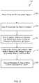
- FIG. 2depicts a flow diagram of an example method according to example embodiments of the present disclosure
- FIG. 3depicts an example plasma processing apparatus according to example embodiments of the present disclosure
- FIG. 4depicts an example plasma processing apparatus according to example embodiments of the present disclosure
- FIG. 5depicts an example plasma processing apparatus according to example embodiments of the present disclosure.
- FIG. 6depicts an example plasma processing apparatus according to example embodiments of the present disclosure.
- Example aspects of the present disclosureare directed to plasma processing apparatus and associated methods for enhancing ignition of inductively coupled plasmas, and in some embodiments electrostatically shielded inductively coupled plasmas.
- Ignition of inductively coupled plasmacan be improved with an ultraviolet light source that emits an ultraviolet light beam onto a dielectric wall and/or a metal surface at a location proximate the plasma prior to or during ignition of the plasma (e.g., from a location outside of the plasma chamber).
- less RF powercan be used to ignite (also referred to as strike) the plasma in less time, with better igniting repeatability and reducing ion bombardment of a dielectric window.
- inductive plasma sources with reduced capacitive couplingcan have substantial advantages over other inductive sources that are common in semiconductor processing.
- Such plasma sources with reduced capacitive couplingcan have: (1) reduced ion bombardment and sputtering of interior dielectric and metal walls of the plasma source; (2) reduced plasma potential and improved ion optics for extraction; (3) increased lifetime of source components and improved cleanliness due to reduced wear and roughening of inner surfaces.
- Conventional plasma sources with reduced capacitive couplingduee to electrostatic shielding, RF frequency or coil configuration
- RFradio frequency
- a smaller supplemental electrodecan be used in a processing chamber of a conventional plasma processing apparatus providing RF power until ignition is achieved.
- ignition approachescan cause sputtering of the electrode or wall adjacent the electrode resulting in contamination and/or surface roughening that can lead to particle contamination.
- an ultraviolet light sourcecan be operated to illuminate an inner wall of a plasma chamber such that a larger number (e.g., greater than about 10 4 ) of free electrons can be ejected from the illuminated wall into a gas in the plasma chamber to substantially enhance a rate of initial exponential growth of the plasma with the substantially inductive coupling of the plasma source.
- the ultraviolet light sourcecan be used to reduce and make more consistent ignition time of the plasma, even at reduced RF power levels.
- inductively coupled plasma sourcese.g., induction coil or antenna
- capacitive couplinge.g. due to presence of electrostatic shield or other feature
- one or more ultraviolet light sourcescan be mounted external to a plasma chamber for an inductively coupled plasma source such that the radiation from the ultraviolet light source(s) can illuminate an inner wall (e.g., dielectric wall and/or metal wall) of the plasma chamber.
- the wallcan have direct line of sight to the plasma chamber. For instance, there are no structures blocking a path (e.g., line of sight path) between the wall and an interior of the plasma chamber where the plasma is generated.
- the ultraviolet light source(s)can have substantial portion of its output (e.g., ultraviolet light beam) as electromagnetic radiation (EM) radiation below about 250 nanometers (nm) wavelength, down to about 100 nm wavelength.
- EMelectromagnetic radiation
- an electrostatic shieldcan be located between a dielectric wall, which forms at least a portion of the plasma chamber and the inductively coupled plasma source.
- the ultraviolet light source(s)can be located adjacent a window such that one or more ultraviolet light beams from the ultraviolet light source(s) can pass through the window to reach an inner wall of the plasma chamber.
- the windowcan have at least one of: synthetic quartz, UV-grade sapphire, magnesium fluoride (MgF 2 ) material, or calcium fluoride (CaF 2 ) material.
- a space between the ultraviolet light source(s) and the windowcan be filled with an inert gas to reduce absorption by atmospheric oxygen.
- the inert gascan include at least one of: helium, neon, argon and/or nitrogen.
- the ultraviolet light source(s)can be operated in a pulsed mode or turned on just before or during initiation of RF power introduction to an inductively coupled plasma source. Radiation from the ultraviolet light source(s) can be maintained at least until the plasma attains some minimal fraction of its ultimate density. In some embodiments, the radiation can be aimed at one or more interior wall areas that are proximate to an exterior inductively coupling element.
- an inductive plasma source of the type having superior suitability for ultra-clean semiconductor processingcan include low wall sputter and low plasma contamination.
- the disclosed inductive plasma sourcecan substantially improve reliability and speed of plasma ignition while also having superior cleanliness.
- a plasma processing apparatuscan include a plasma chamber (e.g., an evacuated vessel), a dielectric wall forming at least a portion of the plasma chamber, and an inductive coupling element (e.g., an inductive coupled plasma source, such as an induction coil or an antenna) located proximate the dielectric wall.
- the inductive coupling elementcan be connected to a supply of RF power.
- the plasma processing apparatuscan further include a controllable supply of process gas to the plasma chamber interior, and a separately controllable source of ultraviolet radiation (e.g., one or more ultraviolet light beams).
- a plasma processing apparatuscan be configured such that a substantial fraction of an ultraviolet radiation from an ultraviolet source can have a line of sight through an at least partially ultraviolet-transparent window in a plasma chamber.
- the ultraviolet radiationcan intercept at least a portion of an interior surface of the plasma chamber such that the ultraviolet radiation can be absorbed on surfaces adjacent plasma when in operation (e.g., in a plasma region).
- the ultraviolet light sourcecan have instantaneous power of several Watts or more of radiation emission during operation of which at least 1% and preferably 10% or more is in a hard-ultraviolet band, e.g., in a wavelength range of about 100 nanometers to about 350 nanometers, such as a wavelength range of about 180 nanometers to about 250 nanometers.
- the ultraviolet light sourcecan be a lamp that is separate and isolated from an inductive coupling element.
- the ultraviolet light sourcecan employ a gas or gases that produce radiation in the hard-ultraviolet band (Wavelength less than about 250 nm).
- the ultraviolet light sourcecan be turned on or the ultraviolet light source can start pulsing to illuminate a part of an interior surface of the plasma chamber, prior to or simultaneous with a turning-on of RF power to ignite a plasma in the plasma chamber. As such, reliability of ignition and growth of the plasma can be accelerated and improved.
- the inductive coupling element(e.g., an antenna for inductive coupling of RF power to plasma) can have reduced capacitive coupling to dielectric walls of the plasma chamber, and to plasma during operation.
- the inductive coupling elementcan be separated by a substantial physical gap from a dielectric portion (e.g., a dielectric wall) of the plasma chamber such that capacitive coupling of the inductive coupling element to plasma can be reduced.
- the inductive coupling elementcan be located at a distance greater than a radius of the inductive coil.
- those part(s) of the inductive coupling element that are physically closest to the dielectric portion of the plasma chambercan be grounded, or connected through a tunable reactance that can have low impedance (e.g., less than about 5 Ohms) to electrical ground.
- the plasma processing apparatuscan further include one or more pieces of conducting material that can be interposed partially or fully between the inductive coupling element and the dielectric portion of the plasma chamber.
- the one or more pieces of conducting materialcan be connected electrically, either directly or through a tunable circuit, to ground thereby forming electrostatic shielding that mitigates capacitive coupling of the inductive coupling element to the plasma.
- plasma potentialcan be reduced and energy of ions bombarding the plasma chamber wall can be reduced.
- capacitive coupling of an inductive coupling element to plasmacan be sufficiently weak so that normal plasma ignition can become unreliable or require too much time, e.g., during which electrical stresses are often large in RF power components and electric fields large near the inductive coupling element.
- This slow ignitioncan be generally the case because inductive discharges generally start in the “E” mode where capacitive coupling initiates the breakdown and then transitions to the “H” mode wherein the inductive coupling takes over sustaining the plasma as it provides the majority of power for electrons doing ionization.
- capacitive electric fieldscan be larger but more localized than the inductive electric fields.
- the plasma processing apparatuscan have various features for mitigation of capacitive coupling from the inductive coupling element to the plasma, while successfully igniting plasmas rapidly and consistently without employing much higher RF current and RF power levels to the inductive coupling element than those employed for the conventional plasma processing apparatus in steady state operation.
- ultraviolet radiation from the ultraviolet light sourcecan promote plasma ignition and growth by ejecting photo-electrons from an irradiated surface(s) into dilute gas proximate what will be a plasma region (once ignited) as RF power is applied to the inductive coupling element. These electrons can then be accelerated by electrical fields in the plasma region to cause ionization of the gas in the plasma chamber.
- a plasma-facing surface irradiated with the ultraviolet radiationcan be a part of a dielectric or metal wall of the plasma chamber.
- the dielectric or metal wallcan have substantial induction electric fields when RF power is being provided.
- the ultraviolet irradiated surfacecan be a metal surface on an interior of the plasma chamber that has a line of sight to the plasma region.
- metal surfaces that are not electrically floatingare desired since they do not charge up so as to prevent electron emission as electrons are ejected from the surface.
- the energy required for electron photo-emissionis less in conducting materials than in insulating materials since conduction band electrons require less energy to be ejected than valence band electrons from solids.
- metal wallsdo not charge-up resulting in trapping of emitted electrons as insulating materials can do.
- ultraviolet light sources for promotion of plasma ignitioncan have total instantaneous radiation output of about 1 Watt or more with output emission spectrum having at least 5% of power in the hard-ultraviolet band (e.g., in a wavelength range less than about 250 nanometers).
- Examples of such ultraviolet light sourcescan include Xenon flashlamps, Deuterium lamps, excimer lamps or other any suitable light sources that meet the above features.
- a window in the plasma chambercan be made of material transmissive of hard-ultraviolet radiation.
- the windowcan have at least one of synthetic quartz, UV-grade Sapphire, or more highly UV transmissive materials such as MgF 2 or CaF 2 .
- the windowcan be a vacuum window with atmospheric pressure gas around the ultraviolet light source.
- a space between the ultraviolet light source and the windowcan be filled with an inert gas (e.g., helium, argon, neon, and/or nitrogen) to reduce absorption by atmospheric oxygen.
- an inert gase.g., helium, argon, neon, and/or nitrogen
- the hard-ultraviolet band of the ultraviolet light sourcecan include a wavelength range that between about 115 nanometers and about 180 nm. This band can be referred to as “Vacuum Ultraviolet” (VUV), since these wavelengths are strongly absorbed by oxygen, such as in oxygen in air.
- VUVVoluum Ultraviolet
- the ultraviolet radiationcan have 10% or more its electromagnetic radiation output in a VUV part of a spectrum of the ultraviolet light source.
- the instantaneous output power in the hard-UV band at the time of plasma ignitioncan be about 0.1 Watt or more. This photon energy can be helpful because the photo-emission of an electron from an insulator requires such photon energy that it can raise a valence electron past the conduction band and into the free electron energy space.
- photon energy from the ultraviolet light sourcecan raise an electron from a conduction band to a free state.
- the photo-electron emission from the interior surface of the plasma chambercan include at least 100 electrons.
- the ultraviolet light sourcecan be pulsed with multiple very short pulses at short intervals (e.g., less than about 100 milliseconds and preferably less than 10 milliseconds). The ultraviolet light source can start pulsing prior to or just following the time of initiation of RF power supplied to the inductive coupling element.
- the ultraviolet radiation pulsescan have a frequency of at least about 100 per second so that a UV radiation pulse will occur within about 10 milliseconds after the electric field strength is capable of initiating breakdown thereby reducing the total time at high level RF power for the ignition process.
- the ultraviolet light sourcecan be a xenon arc flashlamp with an ultraviolet window or a VUV window that produces ultraviolet light in the hard-ultraviolet band or in the VUV band.
- the xenon arc flashlampcan be small (e.g., less than or about 1 inch for all dimensions).
- the xenon arc flashlampcan be a high-pressure arc lamp that can pulse up to about 300 Hertz (Hz) and operate at an average power level less than about 10 Watts.
- an arc lampcan produce strong continuum radiation down to about 100 nanometers in wavelength. In some embodiments such a small flashlamp might be positioned within the volume where the gas pressure is low and the plasma would otherwise occupy.
- Such a small flashlampmight be “plugged-in” within the plasma chamber, in some embodiments in a recessed volume embedded into a metal or dielectric structure.
- the arc lampcan have pulse energy about 100 millijoules (mJ) to produce at least about 10 15 hard-ultraviolet photons per pulse with the photoelectron efficiency of at least about 1% producing orders of magnitude of more photoelectrons than needed.
- the ultraviolet light sourcecan be a deuterium VUV lamp with MgF 2 window.
- the deuterium VUV lampcan be a high-pressure deuterium arc lamp with radiation substantially in a band at about 160 nanometers.
- the high-pressure deuterium arc lampcan be a continuous wave (CW) VUV source, not pulsed.
- CWcontinuous wave
- the ultraviolet light sourcecan be an excimer RF/pulse xenon lamp.
- the excimer xenon lampcan be a highly efficient source of about 172 nanometers radiation.
- the excimer xenon lampcan have long lifetime (e.g., longer than about 10,000 hours).
- the ultraviolet light source(s) for acceleration of plasma ignitioncan illuminate area(s) of the inner wall of the plasma chamber through a vacuum window of the plasma chamber.
- the vacuum windowcan be at least partially transparent to ultraviolet radiation.
- the vacuum windowcan be highly transmissive of ultraviolet light such as MgF 2 , CaF 2 or similar materials.
- the vacuum windowcan have materials such as “synthetic quartz” materials that have better UV transmission than natural or conventional quartz down to wavelengths of about 150 nm. Such window materials can have at least 20% transmission of ultraviolet light in a wavelength range of from about 115 nanometers to about 200 nanometers.
- the ultraviolet light sourcecan be mounted adjacent or near to the vacuum window in a vacuum wall (e.g., a dielectric part of the vacuum wall, and/or a metal part of the vacuum wall) of the plasma chamber.
- a space between the ultraviolet light source and the vacuum windowcan be purged or filled with helium or nitrogen to reduce UV loss due to absorption by atmospheric oxygen.
- ultraviolet radiation from the ultraviolet light sourcecan be incident on a surface on the inside of the plasma chamber.
- the surfacein some embodiments can be adjacent a volume with substantial induction electric field such that photoelectrons can provide a substantial density in the plasma region where the gas breakdown and plasma ignition avalanche occur.
- a threshold for plasma ignitioncan be lowered to about the same power density level as is used for sustaining the plasma, e.g., power density as much as about 70% less than the RF power for a normal plasma ignition threshold.
- the plasma processing chambercan include a smaller adjacent chamber that is separated from a plasma chamber by an ultraviolet transmissive window.
- a smaller adjacent chambercan be a sealed chamber having at least two electrodes and a high-pressure inert gas such as xenon.
- the window between the smaller adjacent chamber and the main plasma chambercan in part be made of a VUV transmissive material such as synthetic quartz. Ignition of plasma can be then facilitated by supplying appropriate pulsed DC power to the electrodes in the adjacent chamber such that plasma is rapidly struck in the adjacent chamber and produces copious VUV radiation that illuminates dielectric wall(s) and/or metal wall(s) of the plasma chamber through the window.
- the plasma processingcan include a plasma chamber, a dielectric wall forming at least a portion of the plasma chamber, an inductive coupling element located proximate the dielectric wall, an ultraviolet light source (e.g., CW lamp or pulsed lamp, such as, a xenon arc flashlamp, deuterium lamp, or an excimer RF/pulse xenon lamp) to emit an ultraviolet light beam onto a metal surface or a dielectric surface in the plasma chamber.
- the metal surface or a dielectric surfacecan emit one or more electrons into the plasma chamber when the ultraviolet light beam is incident on the metal surface or a dielectric surface.
- the plasma processing apparatuscan further include a controller to control the power to the ultraviolet light source and thereby the emission of ultraviolet light beam upon the metal surface or the dielectric surface prior to or during ignition of a plasma in a process gas by energizing the inductive coupling element with a radio frequency (RF) energy (e.g., exciting with RF energy).
- RFradio frequency
- the controllere.g., a computer, microcontroller(s), other control device(s), etc.
- the controllercan include one or more processors and one or more memory devices.
- the one or more memory devicescan store computer-readable instructions that when executed by the one or more processors cause the one or more processors to perform operations, such as turning on the ultraviolet light source to emit the ultraviolet light beam on the metal surface or the dielectric surface prior to or during ignition of a plasma, or other suitable operation.
- the plasma chambercan further include one or more reflective elements (e.g., mirrors) reflect the light beam onto the metal surface or the dielectric surface.
- the metal surface and/or dielectric surfacecan be electrically grounded.
- the ultraviolet light sourcecan emit the light beam in a wavelength range from about 100 nanometers to about 250 nanometers.
- the plasma processing apparatuscan include an electrostatic shield (e.g., a Faraday shield, or other suitable conductive materials) located between the dielectric wall and the inductive coupling element.
- the ultraviolet light beamcan pass through a vacuum window to reach the metal surface and/or dielectric surface.
- the vacuum window(e.g., synthetic quartz, UV-grade sapphire, magnesium fluoride (MgF2) material, or calcium fluoride (CaF2) material) can be at least partially transparent to the ultraviolet light beam.
- a space between the ultraviolet light source and the windowcan be filled with a gas (e.g., helium or nitrogen) to reduce absorption by atmospheric oxygen.
- the plasma chambercan be separated (e.g., by a separation grid) from a processing chamber having a workpiece support configured to support a workpiece.
- Example aspects of the present disclosureare directed to a method for igniting a plasma in a plasma processing apparatus.
- the methodcan include admitting a process gas into a plasma chamber.
- the methodcan include exciting an inductive coupling element to initiate ignition of the plasma in the process gas.
- the methodcan include emitting an ultraviolet light, via an ultraviolet light source, onto a metal surface and/or dielectric surface in the plasma chamber.
- the metal surface and/or dielectric surfacecan emit one or more electrons into the plasma chamber when the ultraviolet light beam is incident on the metal surface or a dielectric surface.
- the methodcan include energizing the inductive coupling element with a radio frequency (RF) energy to sustain the plasma in the process gas.
- RFradio frequency
- a plasma processing apparatuscan include an ultraviolet light source can be controlled to emit the ultraviolet light beam on a metal surface or on a dielectric surface prior to or during ignition of a plasma in a process gas by energizing the inductive coupling element with a radio frequency (RF) energy.
- RFradio frequency
- the plasma processing apparatuscan improve ignition of plasma with a lower RF power level and can also improve speed and reliability of plasma ignition for semiconductor wafers.
- the plasma processing apparatuscan also reduce sputtering, particle contamination, and roughening of the inner walls of the plasma chamber.
- FIG. 1depicts an example plasma processing apparatus 100 according to example embodiments of the present disclosure.
- the plasma processing apparatus 100includes a processing chamber 110 and a plasma chamber 120 that is separated from the processing chamber 110 .
- the processing chamber 110includes a substrate holder or workpiece support 112 operable to hold a workpiece 114 to be processed, such as a semiconductor wafer.
- a plasmais generated in the plasma chamber 120 (i.e., plasma generation region 170 ) by an inductively coupled plasma source 135 and desired species are channeled from the plasma chamber 120 to the surface of substrate 114 through a separation grid assembly 200 .
- the plasma chamber 120includes a dielectric side wall 122 and a ceiling 124 .
- the dielectric side wall 122 , the ceiling 124 , and the separation grid 200define a plasma chamber interior 125 .
- the dielectric side wall 122can be formed from a dielectric material, such as quartz and/or alumina.
- the inductively coupled plasma source 135can include an induction coil 130 disposed adjacent to the dielectric side wall 122 above the plasma chamber 120 .
- the induction coil 130is coupled to an RF power generator 134 through a suitable matching network 132 .
- Process gasese.g., reactant and/or carrier gases
- the plasma processing apparatus 100can include an optional grounded Faraday shield 128 to reduce capacitive coupling of the induction coil 130 to the plasma.
- the Faraday shieldneed not be directly grounded but may be grounded through a tunable reactive circuit that may be tuned to a low reactive impedance.
- the separation grid 200separates the plasma chamber 120 from the processing chamber 110 .
- the separation grid 200can be used to perform ion filtering from a mixture generated by plasma in the plasma chamber 120 to generate a filtered mixture.
- the filtered mixturecan be exposed to the workpiece 114 in the processing chamber 110 .
- ignition of inductively coupled plasmacan be improved with an ultraviolet light source that emits an ultraviolet light beam onto a dielectric wall and/or a metal surface at a location proximate the volume that will be occupied by plasma following ignition of the plasma.
- an ultraviolet light sourcethat emits an ultraviolet light beam onto a dielectric wall and/or a metal surface at a location proximate the volume that will be occupied by plasma following ignition of the plasma.
- less powercan be used to ignite the plasma with better igniting repeatability and to reduce a direct electric field ion bombardment to a dielectric window.
- the plasma processing chamber 100further includes an ultraviolet light source 160 and an ultraviolet (UV) emission assembly 162 .
- the ultraviolet light source 160is mounted external to the plasma chamber 120 for the inductively coupled plasma source 135 such that radiation from the ultraviolet light source 160 can illuminate an inner wall of the UV emission assembly 162 prior to or during ignition of the plasma.
- the ultraviolet light source 160emits one or more ultraviolet light beams 164 (e.g., in a wavelength range of about 100 nanometers to about 250 nanometers) into the plasma chamber 120 through the UV emission assembly 162 .
- the ultraviolet light source 160can be a CW lamp or a pulsed lamp. Examples of the ultraviolet light source 160 can include a xenon arc flashlamp, deuterium lamp, an excimer RF/pulse xenon lamp, or any other suitable light source that emits an ultraviolet light beam.
- the ultraviolet light source 160can be turned on or the ultraviolet light source 160 can start pulsing to illuminate a part of an interior surface of the UV emission assembly 162 , prior to or simultaneous with a turning-on of RF power 134 to ignite the plasma in the plasma chamber 120 . Radiation from the ultraviolet light source 160 can be maintained at least until the plasma attains a substantial fraction of its ultimate density. As such, reliability of ignition and growth of the plasma can be accelerated and improved.
- the ultraviolet light source 160can be pulsed with multiple rapid pulses (e.g., less than about 1 millisecond) at very short intervals (e.g., less than about 10 milliseconds).
- the ultraviolet light source 160can start pulsing prior to or just following the time of initiation of RF power 134 supplied to the inductively coupled source 135 .
- the ultraviolet radiation pulsescan have a frequency of at least about 10 per second and preferably 100 per second or more so that multiple pulses can contribute ultraviolet photons to an ignition process. As such, ultraviolet acceleration of plasma ignition can only take about 10 milliseconds.
- ultraviolet radiation from the ultraviolet light source 160can promote plasma ignition and growth by ejecting photo-electrons from an irradiated surface(s) proximate the plasma region 170 as the RF power 134 is applied to the inductively coupled plasma source 135 , as further described below.
- the irradiated surfacemay be metal or insulator material or metal with a very thin insulator surface layer.
- the plasma processing apparatus 100can include a controller that controls the ultraviolet light source 160 to emit the ultraviolet light beam.
- the controllere.g., a computer, microcontroller(s), other control device(s), etc.
- the controllercan include one or more processors and one or more memory devices.
- the one or more memory devicescan store computer-readable instructions that when executed by the one or more processors cause the one or more processors to perform operations, such as turning on the ultraviolet light source to emit the ultraviolet light beam on a metal surface or a dielectric surface prior to or during ignition of a plasma, or other suitable operation.
- the UV emission assembly 162includes one or more walls 166 , one or more reflective elements (e.g., mirrors) 168 and a vacuum window 172 .
- the structure 162may be electrically grounded so that the surfaces 166 and 174 are grounded. At least a portion of the wall(s) 166 can be metal, and/or dielectric.
- the ultraviolet light beam 164is incident on a surface 174 (e.g., a metal surface or a dielectric surface) at a location proximate the plasma, the surface 174 can emit one or more electrons into the plasma region 170 .
- an instantaneous output power of the ultraviolet light source 160 at the time of plasma ignitioncan be about 1 Watt or more.
- photon energy from the ultraviolet light source 160can raise an electron from a conduction band to a free state which typically takes less photon energy.
- the photo-electron emission from the surface 174 of the UV emission assembly 162can include at least 1000 electrons in a pulse.
- electrons emitted from the surface 174 into the volume 125can then be accelerated by electrical fields in the volume 125 to cause ionization of the gas in the plasma chamber 120 .
- the induction fieldsare much stronger near the inner surface of the dielectric vessel 122 .
- the ionizationcan then provide additional electrons that take part in “avalanche” of ionization which forms the plasma.
- a plasma-facing surface irradiated with ultraviolet radiationcan be a part of a dielectric wall of a plasma chamber, as further described in FIG. 3 .
- the dielectric wallcan have substantial induction electric fields when an RF power is being provided.
- ultraviolet irradiated surfacecan be a metal surface on an interior of a plasma chamber that has a line of sight to the volume within the vessel 122 that is close to the coil 130 , as further described in FIG. 4 .
- the ultraviolet light beam 164is reflected onto the surface 174 via a reflective element (e.g., a mirror) 168 . Electrons 176 emitted from the surface 174 pass into the plasma region 170 .
- the vacuum window 172separates the UV source 160 from the reflector 168 , the surface 174 and surface 166 that are exposed to the plasma chamber interior 125 .
- the vacuum window 172can be an ultraviolet transmissive window.
- the window 172can have at least one of: synthetic quartz, UV-grade sapphire, magnesium fluoride (MgF 2 ) material, or calcium fluoride (CaF 2 ) material.
- a space between the ultraviolet light source(s) and the windowcan be filled with a gas (e.g., helium or nitrogen) to reduce absorption by atmospheric oxygen.
- the UV emission assemblycan be a sealed chamber having at least two electrodes and a high-pressure inert gas such as xenon.
- the vacuum windowcan in part be made of a VUV transmissive material such as synthetic quartz. Ignition of plasma can be then facilitated by supplying appropriate pulsed electric power to the electrodes in the UV emission assembly such that that the UV emission assembly experiences electric breakdown and to produce copious VUV radiation that illuminates dielectric wall(s) and/or metal wall(s) of the plasma chamber.
- FIG. 2depicts a flow diagram of an example method ( 230 ) for accelerating ignition of an inductively coupled plasma according to example aspects of the present disclosure.
- the method ( 230 )can be implemented using the plasma processing apparatus 100 .
- the methods according to example aspects of the present disclosurecan be implemented using other approaches without deviating from the scope of the present disclosure.
- FIG. 2depicts steps performed in a particular order for purposes of illustration and discussion. Those of ordinary skill in the art, using the disclosures provided herein, will understand that various steps of any of the methods described herein can be omitted, expanded, performed simultaneously, rearranged, and/or modified in various ways without deviating from the scope of the present disclosure. In addition, various additional steps (not illustrated) can be performed without deviating from the scope of the present disclosure.
- the methodcan include placing a workpiece on a workpiece support.
- a workpiece 114can be placed on a workpiece support 112 in a processing chamber 110 .
- the methodcan include admitting a process gas into a plasma chamber.
- a process gascan be admitted into the plasma chamber interior 125 from the gas source 150 via the annular gas distribution channel 151 or other suitable gas introduction mechanism.
- the methodcan include emitting an ultraviolet light beam, via an ultraviolet light source, onto a metal surface and/or dielectric surface in the plasma chamber.
- the metal surface and/or dielectric surfacecan emit one or more electrons into the plasma chamber when the ultraviolet light beam is incident on the metal surface and/or dielectric surface.
- an ultraviolet light source 160can emit an ultraviolet light beam 164 that passes through a transmissive vacuum window and is reflected onto a surface 174 via a reflective element (e.g., a mirror) 168 . Electrons 176 emitted from the surface 174 pass directly into the plasma region 170 because the surface 174 has direct line of sight to the plasma region 170 and plasma chamber interior 125 .
- the methodcan include energizing or continuing to energize the inductive coupling element with a radio frequency (RF) energy to sustain the plasma in the process gas.
- RFradio frequency
- the induction coil 130can be energized with the RF power generator 134 to sustain the plasma in the process gas.
- the methodcan include exposing the workpiece to one or more species generated by the plasma. For instance, one or species generated by the plasma can be channeled from the plasma chamber 120 to surface of the workpiece 114 through the separation grid assembly 200 .
- FIG. 3depicts an example plasma processing apparatus 300 according to example embodiments of the present disclosure.
- the plasma processing apparatus 300is similar to the plasma processing apparatus 100 of FIG. 1 .
- plasma processing apparatus 300includes a processing chamber 110 and a plasma chamber 120 that is separated from the processing chamber 110 .
- Processing chamber 110includes a substrate holder or workpiece support 112 operable to hold a workpiece 114 to be processed, such as a semiconductor wafer.
- a plasmais generated in plasma chamber 120 (i.e., plasma generation region 330 ) by an inductively coupled plasma source 135 and desired species are channeled from the plasma chamber 120 to the surface of substrate 114 through a separation grid assembly 200 .
- the plasma chamber 120includes a dielectric side wall 122 and a ceiling 124 .
- the dielectric side wall 122 , ceiling 124 , and separation grid 200define a plasma chamber interior 125 .
- Dielectric side wall 122can be formed from a dielectric material, such as quartz and/or alumina.
- the inductively coupled plasma source 135can include an induction coil 130 disposed adjacent to the dielectric side wall 122 above the processing chamber 120 .
- the induction coil 130is coupled to an RF power generator 134 through a suitable matching network 132 .
- Process gasese.g., an inert gas
- the plasma processing apparatus 500can include an optional grounded Faraday shield 128 to reduce capacitive coupling of the induction coil 130 to the plasma.
- ultraviolet light source(s)can be located adjacent a window such that one or more ultraviolet light beams from the ultraviolet light source(s) can pass through the window to reach an inner wall of a plasma chamber.
- the plasma processing chamber 300further includes an ultraviolet light source 160 and a vacuum window 310 .
- the ultraviolet light source 160is mounted adjacent the vacuum window 310 such that an ultraviolet light beam 320 from the ultraviolet light source 160 passes through the window 310 to reach an interior surface 340 of the dielectric wall 122 of the plasma chamber 120 .
- the interior surface 340is proximate a plasma region 330 (or a plasma in the plasma region 330 ).
- the ultraviolet light beam 320intercepts a portion of the interior surface 340 of the plasma chamber 120 such that the ultraviolet light beam 320 is incident upon the interior surface 340 at a location adjacent plasma in operation.
- the ultraviolet light source 160can be a CW lamp or a pulsed lamp.
- Examples of the ultraviolet light source 160can include a xenon arc flashlamp, deuterium lamp, an excimer RF/pulse xenon lamp, or any other suitable light source that emits an ultraviolet light beam.
- the ultraviolet light source 160can be turned on or the ultraviolet light source 160 can start pulsing to illuminate a part of the interior surface 340 of the dielectric wall 122 , prior to or simultaneous with a turning-on of RF power 134 to ignite the plasma in the plasma chamber 120 . Radiation from the ultraviolet light source 160 can be maintained at least until the plasma attains a fraction of its ultimate density. As such, reliability of ignition and growth of the plasma can be accelerated and improved.
- the ultraviolet light source 160can be pulsed with multiple rapid pulses at very short intervals (e.g., less than 10 milliseconds).
- the ultraviolet light source 160can start pulsing prior to or just following the time of initiation of RF power 134 supplied to the inductively coupled source 135 .
- the ultraviolet radiation pulsescan have a frequency of at least about 100 and in some embodiments 500 per second so that multiple pulses can contribute ultraviolet photons to an ignition process. As such, ultraviolet acceleration can only take about 10 milliseconds.
- ultraviolet radiation from the ultraviolet light source 160can promote plasma ignition and growth by ejecting electrons from an irradiated surface(s) proximate the plasma as the RF power 134 is applied to the inductively coupled plasma source 135 .
- the ultraviolet light beam 320is incident on the interior surface 340 (e.g., a dielectric surface) at a location proximate the plasma, the surface 340 can emit one or more electrons into the plasma region 330 .
- an instantaneous output power of the ultraviolet light source 160 at the time of plasma ignitioncan be about 1 Watt or more.
- the photo-electron emission from the surface 340can include at least 5000 electrons.
- electrons emitted from the surface 340can then be accelerated by electrical fields in the plasma region 330 to cause ionization of the gas in the plasma chamber 120 .
- the ionizationcan then provide additional electrons that take part in “avalanche” of ionization which forms the plasma.
- the plasma processing apparatus 300can include a controller that controls the ultraviolet light source 160 to emit the ultraviolet light beam 320 .
- the controllere.g., a computer, microcontroller(s), other control device(s), etc.
- the controllercan include one or more processors and one or more memory devices.
- the one or more memory devicescan store computer-readable instructions that when executed by the one or more processors cause the one or more processors to perform operations, such as turning on the ultraviolet light source to emit the ultraviolet light beam on a dielectric surface prior to or during ignition of a plasma, or other suitable operation.
- the vacuum window 310can be one example embodiment of the vacuum window 172 .
- the window 310can have at least one of: synthetic quartz, UV-grade sapphire, magnesium fluoride (MgF2) material, or calcium fluoride (CaF2) material.
- a space between the ultraviolet light source 160 and the window 310can be filled with a gas (e.g., helium, nitrogen, argon, and/or nitrogen) to reduce absorption by atmospheric oxygen.
- a gase.g., helium, nitrogen, argon, and/or nitrogen
- FIG. 4depicts an example plasma processing apparatus 400 according to example embodiments of the present disclosure.
- the plasma processing apparatus 400is similar to the plasma processing apparatus 100 of FIG. 1 and the plasma processing apparatus 300 of FIG. 3 .
- plasma processing apparatus 400includes a processing chamber 110 and a plasma chamber 120 that is separated from the processing chamber 110 .
- Processing chamber 110includes a substrate holder or workpiece support 112 operable to hold a workpiece 114 to be processed, such as a semiconductor wafer.
- a plasmais generated in plasma chamber 120 (i.e., plasma generation region 420 ) by an inductively coupled plasma source 135 and desired species are channeled from the plasma chamber 120 to the surface of substrate 114 through a separation grid assembly 200 .
- the plasma chamber 120includes a dielectric side wall 122 and a ceiling 124 .
- the dielectric side wall 122 , ceiling 124 , and separation grid 200define a plasma chamber interior 125 .
- Dielectric side wall 122can be formed from a dielectric material, such as quartz, glass, alumina, silicon nitride, silicon oxynitride, aluminum nitride, aluminum oxynitride, or other high-temperature capable dielectric or combination thereof.
- the inductively coupled plasma source 135can include an induction coil 130 disposed adjacent to the dielectric side wall 122 above the plasma chamber 120 .
- the induction coil 130is coupled to an RF power generator 134 through a suitable matching network 132 .
- Process gasescan be provided to the chamber interior from gas supply 150 or other suitable gas introduction mechanism.
- gasese.g., an inert gas
- the plasma processing apparatus 500can include an optional grounded Faraday shield 128 to reduce capacitive coupling of the induction coil 130 to the plasma.
- a separation grid 200separates the plasma chamber 120 from the processing chamber 110 .
- the separation grid 200can be used to perform ion filtering from a mixture generated by plasma in the plasma chamber 120 to generate a filtered mixture.
- the filtered mixturecan be exposed to the workpiece 114 in the processing chamber.
- ultraviolet light source(s)can be located adjacent a window such that one or more ultraviolet light beams from the ultraviolet light source(s) can pass through the window to impinge on a metal surface 430 that may be of a metal structure 410 of a plasma chamber (e.g., a top cap).
- the plasma processing chamber 400further includes an ultraviolet light source 160 , a vacuum window 310 and a metal wall 410 .
- the ultraviolet light source 160is mounted adjacent the vacuum window 310 such that an ultraviolet light beam 320 from the ultraviolet light source 160 passes through the window 310 to reach an interior surface 430 of the metal wall 410 of the plasma chamber 120 .
- the interior surface 430is proximate a plasma region 420 (or a plasma in the plasma region 420 ).
- the ultraviolet light beam 320intercepts a portion of the interior surface 410 of the plasma chamber 120 such that the ultraviolet light beam 320 can pass through some part of the volume that may be occupied by plasma in operation and can also pass through some part of the evacuated volume that may not be occupied by plasma in operation.
- the ultraviolet light source 160can be a CW lamp or a pulsed lamp.
- Examples of the ultraviolet light source 160can include a xenon arc flashlamp, deuterium lamp, an excimer RF/pulse xenon lamp, or any other suitable light source that emits an ultraviolet light beam.
- the ultraviolet light source 160can be turned on or the ultraviolet light source 160 can start pulsing to illuminate a part of the interior surface 430 of the metal wall 410 , prior to or simultaneous with a turning-on of RF power 134 to ignite the plasma in the plasma chamber 120 . Radiation from the ultraviolet light source 160 can be maintained at least until the plasma attains a fraction of its ultimate density. As such, reliability of ignition and growth of the plasma can be accelerated and improved.
- the ultraviolet light source 160can be pulsed with multiple rapid pulses at very short intervals (e.g., less than 50 milliseconds and more preferably less than 10 milliseconds).
- the ultraviolet light source 160can start pulsing prior to or just following the time of initiation of RF power 134 supplied to the inductively coupled source 135 .
- the ultraviolet radiation pulsescan have a frequency of at least about 500 per second so that multiple pulses can contribute ultraviolet photons to an ignition process. As such, the total duration of ultraviolet acceleration of plasma ignition can only take about 50 milliseconds and preferably less than 10 milliseconds.
- ultraviolet radiation from the ultraviolet light source 160can promote plasma ignition and growth by ejecting electrons from an irradiated surface(s) proximate the volume that will be occupied by plasma as the RF power 134 is applied to the inductively coupled plasma source 135 .
- the ultraviolet light beam 320is incident on the interior surface 430 (e.g., a metal surface) at a location proximate where the plasma will be, the surface 430 can emit one or more electrons into the region 420 that the plasma will occupy.
- an instantaneous output power of the ultraviolet light source 160 at the time of plasma ignitioncan be about 1 Watt or more, preferably a fraction larger than 10% of which is in the hard UV band.
- the photo-electron emission from the surface 430can include at least 1000 electrons.
- electrons emitted from the surface 430can then be accelerated by electrical fields in the region 420 induced by the rf current in the induction coil to cause ionization of the gas in the plasma chamber 120 to fill the region 420 with plasma.
- the ionization of gas in this regioncan then provide additional electrons that take part in “avalanche” of ionization which forms the plasma.
- the plasma processing apparatus 400can include a controller that controls the ultraviolet light source 160 to emit the ultraviolet light beam 320 .
- the controllere.g., a computer, microcontroller(s), other control device(s), etc.
- the controllercan include one or more processors and one or more memory devices.
- the one or more memory devicescan store computer-readable instructions that when executed by the one or more processors cause the one or more processors to perform operations, such as turning on the ultraviolet light source to emit the ultraviolet light beam on a metal surface prior to or during ignition of a plasma, or other suitable operation.
- the vacuum window 310can be one embodiment of the vacuum window 172 .
- the window 310can have at least one of: synthetic quartz, UV-grade sapphire, magnesium fluoride (MgF2) material, or calcium fluoride (CaF2) material.
- a space between the ultraviolet light source 160 and the window 310can be filled with a gas (e.g., helium or nitrogen) to reduce absorption by atmospheric oxygen.
- a gase.g., helium or nitrogen
- FIG. 5depicts an example plasma processing apparatus 500 according to example embodiments of the present disclosure.
- the plasma processing apparatus 500is similar to the plasma processing apparatus 100 of FIG. 1 .
- plasma processing apparatus 500includes a processing chamber 110 and a plasma chamber 120 that is separated from the processing chamber 110 .
- Processing chamber 110includes a substrate holder or workpiece support 112 operable to hold a workpiece 114 to be processed, such as a semiconductor wafer.
- a plasmais generated in plasma chamber 120 (i.e., plasma generation region) by an inductively coupled plasma source 135 and desired species are channeled from the plasma chamber 120 to the surface of substrate 114 through a separation grid assembly 200 .
- the plasma chamber 120includes a dielectric side wall 122 and a ceiling 124 .
- the dielectric side wall 122 , ceiling 124 , and separation grid 200define a plasma chamber interior 125 .
- Dielectric side wall 122can be formed from a dielectric material, such as quartz and/or alumina or other high temperature resistant dielectrics such as ceramics.
- the inductively coupled plasma source 135can include an induction coil 130 disposed adjacent to the dielectric side wall 122 above the plasma chamber 120 .
- the induction coil 130is coupled to an RF power generator 134 through a suitable matching network 132 .
- Process gasescan be provided to the chamber interior from gas supply 150 and annular gas distribution channel 151 or other suitable gas introduction mechanism.
- the plasma processing apparatus 500can include an optional grounded Faraday shield 128 to reduce capacitive coupling of the induction coil 130 to the plasma.
- a separation grid 200separates the plasma chamber 120 from the processing chamber 110 .
- the separation grid 200can be used to perform ion filtering from a mixture generated by plasma in the plasma chamber 120 to generate a filtered mixture.
- the filtered mixturecan be exposed to the workpiece 114 in the processing chamber.
- the example plasma processing apparatus 500 of FIG. 5is operable to generate a first plasma 502 (e.g., a remote plasma) in the plasma chamber 120 and a second plasma 504 (e.g., a direct plasma) in the processing chamber 110 .
- a “remote plasma”refers to a plasma generated remotely from a workpiece, such as in a plasma chamber separated from a workpiece by a separation grid.
- a “direct plasma”refers to a plasma that is directly exposed to a workpiece, such as a plasma generated in a processing chamber having a workpiece support operable to support the workpiece.
- the plasma processing apparatus 500 of FIG. 5includes a bias source having bias electrode 510 in the workpiece support 112 .
- the bias electrode 510can be coupled to an RF power generator 514 via a suitable matching network 512 .
- a second plasma 504can be generated from a mixture in the processing chamber 110 for direct exposure to the workpiece 114 .
- the processing chamber 110can include a gas exhaust port 516 for evacuating a gas from the processing chamber 110 .
- ignition of inductively coupled plasmacan be improved with an ultraviolet light source that emits an ultraviolet light beam onto a dielectric wall and/or a metal surface at a location proximate to where the plasma will be, prior to or during ignition of the plasma.
- an ultraviolet light sourcethat emits an ultraviolet light beam onto a dielectric wall and/or a metal surface at a location proximate to where the plasma will be, prior to or during ignition of the plasma.
- less powercan be used to ignite either or both of the plasmas with better igniting repeatability and to reduce a direct electric field ion bombardment to a dielectric window.
- the plasma processing chamber 500further includes an ultraviolet light source 160 and a metal top structure 162 containing a UV transmissive window 172 .
- the ultraviolet light source 160is mounted external to the plasma chamber 120 for the inductively coupled plasma source 135 such that radiation from the ultraviolet light source 160 can illuminate an inner wall of the metal top structure 162 prior to or during ignition of the plasma.
- the ultraviolet light source 160emits one or more ultraviolet light beams 164 into the plasma chamber 120 through the UV transmissive window 172 .
- the ultraviolet light source 160can be a CW lamp or a pulsed lamp.
- Examples of the ultraviolet light source 160can include a xenon arc flashlamp, deuterium lamp, an excimer RF/pulse xenon lamp, or any other suitable light source that emits an ultraviolet light beam.
- the ultraviolet light source 160can be turned on or the ultraviolet light source 160 can start pulsing UV energy that is then transmitted through window 172 to illuminate a part of an interior surface of the metal top structure 162 , that faces the interior of the plasma chamber, prior to or simultaneous with a turning-on of RF power 134 to ignite the plasma in the plasma chamber 120 .
- Radiation from the ultraviolet light source 160can be maintained at least until the plasma attains a fraction of its ultimate density or the voltage on the inductive coupling antenna exhibits a substantial and rapid change as the plasma occupies a portion of the interior of the chamber. As such, reliability of ignition and growth of the plasma can be accelerated and improved.
- the ultraviolet light source 160can be pulsed with multiple rapid pulses at very short intervals (e.g., less than 10 milliseconds).
- the ultraviolet light source 160can start pulsing prior to or just following initiation of RF power 134 supplied to the inductively coupled source 135 .
- the ultraviolet radiation pulsescan have a frequency of at least about 100 per second so that multiple pulses can contribute ultraviolet photons to an ignition process. As such, ultraviolet-assisted ignition of the plasma can only take about 50 milliseconds or less.
- ultraviolet radiation from the ultraviolet light source 160can promote plasma ignition and growth by ejecting photo-electrons from an irradiated surface(s) proximate the region 502 that will contain plasma as the RF power 134 is applied to the inductively coupled plasma source 135 , as further described below.
- the plasma processing apparatus 500can include a controller that controls the ultraviolet light source 160 to emit the ultraviolet light beam.
- the controllere.g., a computer, microcontroller(s), other control device(s), etc.
- the controllercan include one or more processors and one or more memory devices.
- the one or more memory devicescan store computer-readable instructions that when executed by the one or more processors cause the one or more processors to perform operations, such as turning on the ultraviolet light source to emit the ultraviolet light beam on a metal surface or a dielectric surface prior to or during ignition of a plasma, or other suitable operation.
- the metal top structure 162includes one or more walls 166 , one or more reflective elements (e.g., mirrors) 168 and a vacuum window 172 .
- the structure 162is electrically grounded or may be biased negatively with respect to earth ground, particularly during the plasma ignition phase. At least a portion of the wall(s) 166 can be metal, and/or dielectric.
- a surface 174e.g., a metal surface or a dielectric surface
- an instantaneous output power of the ultraviolet (UV) light source 160 at the time of plasma ignitioncan be about 1 Watt or more.
- the wavelength of at least part of the radiationmay be less than about 250 nm, being in the hard UV band. This can be because the photo-emission of an electron from an insulator requires such photon energy that it can raise a valence electron past the conduction band and into the free electron energy space.
- photon energy from the ultraviolet light source 160can raise an electron from a conduction band to a free state.
- the photo-electron emission from the surface 174 of the UV emission assembly 162can include at least 100 electrons.
- an interior volume-facing surface irradiated with ultraviolet radiationcan be a part of a dielectric wall of a plasma chamber, as described above in FIG. 3 .
- the dielectric wallcan have substantial induction electric fields when an RF power is being provided.
- ultraviolet irradiated surfacecan be a metal surface on an interior wall of a plasma chamber that has a line of sight to a region that will contain plasma after ignition, as described above in FIG. 4 .
- the ultraviolet light beam 164is reflected onto the surface 174 via a reflective element (e.g., a mirror) 168 . Electrons 176 emitted from the surface 174 are emitted directly into the region 502 that will contain plasma after ignition.
- the vacuum window 172separates the lamp 160 from the plasma chamber interior 125 .
- the vacuum window 172can be an ultraviolet transmissive window.
- the window 172can have at least one of: synthetic quartz, UV-grade sapphire, magnesium fluoride (MgF2) material, or calcium fluoride (CaF2) material.
- a space between the ultraviolet light source(s) and the windowcan be filled with a gas (e.g., helium or nitrogen) to reduce absorption by atmospheric oxygen.
- the UV emission assemblycan be a sealed chamber having at least two electrodes and a high-pressure inert gas such as xenon.
- the vacuum windowcan in part be made of a UV transmissive material such as synthetic quartz. Ignition of plasma can be then facilitated by supplying appropriate RF power to the inductive coupling element while there is fast pulsed DC power to the electrodes in the UV emission assembly such that that the UV emission assembly can produce copious UV radiation that illuminates dielectric wall(s) and/or metal wall(s) of the plasma chamber.
- FIG. 6depicts a plasma processing apparatus 600 similar to that of FIG. 1 and FIG. 5 . More particularly, plasma processing apparatus 600 includes a processing chamber 110 and a plasma chamber 120 that is separated from the processing chamber 110 .
- Processing chamber 110includes a substrate holder or workpiece support 112 operable to hold a workpiece 114 to be processed, such as a semiconductor wafer.
- a plasmais generated in plasma chamber 120 (i.e., plasma generation region) by an inductively coupled plasma source 135 and desired gas phase species are channeled from the plasma chamber 120 to the surface of substrate 114 through a separation grid assembly 200 .
- the plasma chamber 120includes a dielectric side wall 122 and a ceiling 124 .
- the dielectric side wall 122 , ceiling 124 , and separation grid 200define a plasma chamber interior 125 .
- Dielectric side wall 122can be formed from a dielectric material, such as quartz and/or alumina.
- the inductively coupled plasma source 135can include an induction coil 130 disposed adjacent the dielectric side wall 122 about the plasma chamber 120 .
- the induction coil 130is coupled to an RF power generator 134 through a suitable matching network 132 .
- Process gase.g., an inert gas
- the plasma processing apparatus 600can include an optional grounded Faraday shield 128 to reduce capacitive coupling of the induction coil 130 to the plasma.
- a separation grid 200separates the plasma chamber 120 from the processing chamber 110 .
- the separation grid 200can be used to perform ion filtering from a mixture generated by plasma in the plasma chamber 120 to generate a filtered mixture.
- the filtered mixturecan be exposed to the workpiece 114 in the processing chamber.
- the example plasma processing apparatus 600 of FIG. 6is operable to generate a first plasma 602 (e.g., a remote plasma) in the plasma chamber 120 and a second plasma 604 (e.g., a direct plasma) in the processing chamber 110 .
- the plasma processing apparatus 600can include an angled dielectric sidewall 622 that extends from the vertical sidewall 122 associated with the remote plasma chamber 120 .
- the angled dielectric sidewall 622can form a part of the processing chamber 110 .
- a second inductive plasma source 635can be located proximate the dielectric sidewall 622 .
- the second inductive plasma source 635can include an induction coil 810 coupled to an RF generator 614 via a suitable matching network 612 .
- the induction coil 610when energized with RF energy, can induce a direct plasma 604 from a mixture in the processing chamber 110 .
- a Faraday shield 628can be disposed between the induction coil 610 and the sidewall 622 .
- the workpiece support 112can be movable in a vertical direction noted as “V.”
- the workpiece support 112can include a vertical lift 816 that can be configured to adjust a distance between the workpiece support 112 and the separation grid assembly 200 .
- the workpiece support 112can be located in a first vertical position for processing using the remote plasma 602 .
- the workpiece support 112can be in a second vertical position for processing using the direct plasma 604 .
- the first vertical positioncan be closer to the separation grid assembly 200 relative to the second vertical position.
- the plasma processing apparatus 600 of FIG. 6includes a bias source having bias electrode 510 in the workpiece support 112 .
- the bias electrode 510can be coupled to an RF power generator 514 via a suitable matching network 512 .
- the processing chamber 110can include a gas exhaust port 516 for evacuating a gas from the processing chamber 110 .
- ignition of inductively coupled plasmacan be improved with an ultraviolet light source that emits an ultraviolet light beam onto a dielectric wall and/or a metal surface at a location proximate the region wherein there will be plasma once there is ignition of the plasma.
- an ultraviolet light sourcethat emits an ultraviolet light beam onto a dielectric wall and/or a metal surface at a location proximate the region wherein there will be plasma once there is ignition of the plasma.
- less powercan be used to ignite the plasma with better igniting repeatability and to reduce a direct electric field ion bombardment to a dielectric window.
- the plasma processing chamber 600further includes an ultraviolet light source 160 and a UV emission assembly 162 .
- the ultraviolet light source 160is mounted external to the plasma chamber 120 for the inductively coupled plasma source 135 such that radiation from the ultraviolet light source 160 can illuminate an inner wall of the metal top structure 162 prior to or during ignition of the plasma.
- the ultraviolet light source 160emits one or more ultraviolet light beams 164 (e.g., in a wavelength range of about 600 nanometers to about 250 nanometers) into the plasma chamber 120 through the UV transmissive window 172 .
- the ultraviolet light source 160can be a CW lamp or a pulsed lamp.
- the ultraviolet light source 160can include a xenon arc flashlamp, deuterium lamp, an excimer RF/pulse xenon lamp, or any other suitable light source that emits an ultraviolet light beam.
- the ultraviolet light source 160can be turned on or the ultraviolet light source 160 can start pulsing to illuminate a part of an interior surface of the UV emission assembly 162 , prior to or simultaneous with a turning-on of RF power 134 to ignite the plasma in the plasma chamber 120 . Radiation from the ultraviolet light source 160 can be maintained at least until the plasma attains a substantial fraction of its ultimate density. As such, reliability of ignition and growth of the plasma can be accelerated and improved.
- the ultraviolet light source 160can be pulsed with multiple rapid pulses at very short intervals (e.g., less than 10 milliseconds).
- the ultraviolet light source 160can start pulsing prior to or just following the time of initiation of RF power 134 supplied to the inductively coupled source 135 .
- the ultraviolet radiation pulsescan have a frequency of at least about 300 per second so that multiple pulses can contribute ultraviolet photons to an ignition process. As such, in some embodiments ultraviolet assisted plasma ignition can only take about 20 milliseconds or less.
- ultraviolet radiation from the ultraviolet light source 160can promote plasma ignition and growth by ejecting photo-electrons from an irradiated surface(s) 174 proximate the chamber interior that can include the plasma region 602 as the RF power 134 is applied to the inductively coupled plasma source 135 , as further described below.
- the plasma processing apparatus 600can include a controller that controls the ultraviolet light source 160 to emit the ultraviolet light beam.
- the controllere.g., a computer, microcontroller(s), other control device(s), etc.
- the controllercan include one or more processors and one or more memory devices.
- the one or more memory devicescan store computer-readable instructions that when executed by the one or more processors cause the one or more processors to perform operations, such as turning on the ultraviolet light source to emit the ultraviolet light beam to impinge on a metal surface or a dielectric surface prior to or during ignition of a plasma, or other suitable operation.
- the UV emission assembly 162includes one or more walls 166 , one or more reflective elements (e.g., mirrors) 168 and a vacuum window 172 .
- the wall(s) 166is grounded.
- At least a portion of the top structure 162can be metal, and/or dielectric.
- a surface 174e.g., a metal surface or a dielectric surface
- an instantaneous output power of ultraviolet radiation from the light source 160 at the time of plasma ignitioncan be about 10 milliwatts and more preferably 0.1 Watt or more.
- UV radiationis employed because the photo-emission of an electron from an insulator requires such photon energy that it can raise a valence electron past the conduction band and into the free electron energy space.
- photon energy from the ultraviolet light source 160can raise an electron from a conduction band to a free state.
- the photo-electron emission from the surface 174 of the UV emission assembly 162can include at least 100 electrons.
- a plasma-facing surface irradiated with ultraviolet radiationcan be a part of a dielectric wall of a plasma chamber, as further described in FIG. 3 .
- the dielectric wallcan have substantial electric fields when an RF power is being provided to an inductive coupling antenna.
- ultraviolet irradiated surfacecan be a metal surface on an interior of a plasma chamber that has a line of sight to a region of the chamber interior that will contain plasma, as further described in FIG. 4 .
- the ultraviolet light beam 164is reflected onto the surface 174 via a reflective element (e.g., a mirror) 168 . Electrons 176 emitted from the surface 174 directly into the region 602 that will contain plasma.
- a reflective elemente.g., a mirror
- the vacuum window 172separates the UV source 160 from the plasma chamber interior 125 .
- the vacuum window 172can be an ultraviolet transmissive window.
- the window 172can have at least one of: synthetic quartz, UV-grade sapphire, magnesium fluoride (MgF2) material, or calcium fluoride (CaF2) material.
- a space between the ultraviolet light source(s) and the windowcan be filled with a gas (e.g., helium or nitrogen) to reduce UV absorption by atmospheric oxygen.
- the UV emission assemblycan be a sealed chamber having at least two electrodes and a high-pressure inert gas such as xenon.
- the vacuum windowcan in part be made of a UV transmissive material such as synthetic quartz. Ignition of plasma can be facilitated by supplying appropriate RF power to the inductive coupling antenna at the same time as supplying pulsed DC power to the electrodes in the UV emission assembly such that that the UV emission assembly can produce copious UV radiation that illuminates dielectric wall(s) and/or metal wall(s) of the plasma chamber.
Landscapes
- Engineering & Computer Science (AREA)
- Physics & Mathematics (AREA)
- Plasma & Fusion (AREA)
- Analytical Chemistry (AREA)
- Chemical & Material Sciences (AREA)
- Power Engineering (AREA)
- General Physics & Mathematics (AREA)
- Microelectronics & Electronic Packaging (AREA)
- Computer Hardware Design (AREA)
- Manufacturing & Machinery (AREA)
- Condensed Matter Physics & Semiconductors (AREA)
- Health & Medical Sciences (AREA)
- Toxicology (AREA)
- Electromagnetism (AREA)
- Drying Of Semiconductors (AREA)
- Plasma Technology (AREA)
Abstract
Description
Claims (18)
Priority Applications (9)
| Application Number | Priority Date | Filing Date | Title |
|---|---|---|---|
| US16/547,724US11348784B2 (en) | 2019-08-12 | 2019-08-22 | Enhanced ignition in inductively coupled plasmas for workpiece processing |
| EP20851516.3AEP4000088B1 (en) | 2019-08-12 | 2020-08-11 | Enhanced ignition in inductively coupled plasmas for workpiece processing |
| CN202310834203.XACN116994934A (en) | 2019-08-12 | 2020-08-11 | Enhanced ignition in inductively coupled plasma for workpiece processing |
| PCT/US2020/045757WO2021030342A1 (en) | 2019-08-12 | 2020-08-11 | Enhanced ignition in inductively coupled plasmas for workpiece processing |
| CN202080004312.3ACN112703577A (en) | 2019-08-12 | 2020-08-11 | Enhanced ignition in inductively coupled plasma for workpiece processing |
| KR1020227008110AKR102812235B1 (en) | 2019-08-12 | 2020-08-11 | Improved ignition of inductively coupled plasma for workpiece treatment |
| TW109127310ATWI877196B (en) | 2019-08-12 | 2020-08-12 | Enhanced ignition in inductively coupled plasmas for workpiece processing and method thereof |
| US17/827,198US11848204B2 (en) | 2019-08-12 | 2022-05-27 | Enhanced ignition in inductively coupled plasmas for workpiece processing |
| US18/503,681US12347677B2 (en) | 2019-08-12 | 2023-11-07 | Enhanced ignition in inductively coupled plasmas for workpiece processing |
Applications Claiming Priority (2)
| Application Number | Priority Date | Filing Date | Title |
|---|---|---|---|
| US201916537748A | 2019-08-12 | 2019-08-12 | |
| US16/547,724US11348784B2 (en) | 2019-08-12 | 2019-08-22 | Enhanced ignition in inductively coupled plasmas for workpiece processing |
Related Parent Applications (2)
| Application Number | Title | Priority Date | Filing Date |
|---|---|---|---|
| US201916537748AContinuation-In-Part | 2019-08-12 | 2019-08-12 | |
| US201916537748ADivision | 2019-08-12 | 2019-08-12 |
Related Child Applications (1)
| Application Number | Title | Priority Date | Filing Date |
|---|---|---|---|
| US17/827,198DivisionUS11848204B2 (en) | 2019-08-12 | 2022-05-27 | Enhanced ignition in inductively coupled plasmas for workpiece processing |
Publications (2)
| Publication Number | Publication Date |
|---|---|
| US20210050213A1 US20210050213A1 (en) | 2021-02-18 |
| US11348784B2true US11348784B2 (en) | 2022-05-31 |
Family
ID=74566884
Family Applications (3)
| Application Number | Title | Priority Date | Filing Date |
|---|---|---|---|
| US16/547,724Active2039-12-21US11348784B2 (en) | 2019-08-12 | 2019-08-22 | Enhanced ignition in inductively coupled plasmas for workpiece processing |
| US17/827,198ActiveUS11848204B2 (en) | 2019-08-12 | 2022-05-27 | Enhanced ignition in inductively coupled plasmas for workpiece processing |
| US18/503,681ActiveUS12347677B2 (en) | 2019-08-12 | 2023-11-07 | Enhanced ignition in inductively coupled plasmas for workpiece processing |
Family Applications After (2)
| Application Number | Title | Priority Date | Filing Date |
|---|---|---|---|
| US17/827,198ActiveUS11848204B2 (en) | 2019-08-12 | 2022-05-27 | Enhanced ignition in inductively coupled plasmas for workpiece processing |
| US18/503,681ActiveUS12347677B2 (en) | 2019-08-12 | 2023-11-07 | Enhanced ignition in inductively coupled plasmas for workpiece processing |
Country Status (6)
| Country | Link |
|---|---|
| US (3) | US11348784B2 (en) |
| EP (1) | EP4000088B1 (en) |
| KR (1) | KR102812235B1 (en) |
| CN (2) | CN116994934A (en) |
| TW (1) | TWI877196B (en) |
| WO (1) | WO2021030342A1 (en) |
Cited By (1)
| Publication number | Priority date | Publication date | Assignee | Title |
|---|---|---|---|---|
| US20220084792A1 (en)* | 2019-07-17 | 2022-03-17 | Mattson Technology, Inc. | Variable mode plasma chamber utilizing tunable plasma potential |
Families Citing this family (14)
| Publication number | Priority date | Publication date | Assignee | Title |
|---|---|---|---|---|
| US20210343506A1 (en)* | 2020-05-01 | 2021-11-04 | Mattson Technology, Inc. | Methods And Apparatus For Pulsed Inductively Coupled Plasma For Surface Treatment Processing |
| US11521834B2 (en)* | 2020-08-26 | 2022-12-06 | Tokyo Electron Limited | Plasma processing systems and methods for chemical processing a substrate |
| US20220189742A1 (en)* | 2020-12-16 | 2022-06-16 | Semes Co., Ltd. | Drying unit and apparatus for processing a substrate including a drying unit |
| US12159770B2 (en) | 2020-12-28 | 2024-12-03 | Beijing E-town Semiconductor Technology Co., Ltd. | Cooled shield for ICP source |
| US12334312B2 (en) | 2020-12-28 | 2025-06-17 | Beijing E-town Semiconductor Technology Co., Ltd. | Configurable faraday shield |
| US11658006B2 (en) | 2021-01-14 | 2023-05-23 | Applied Materials, Inc. | Plasma sources and plasma processing apparatus thereof |
| US11854770B2 (en) | 2021-01-14 | 2023-12-26 | Applied Materials, Inc. | Plasma processing with independent temperature control |
| KR102772575B1 (en)* | 2021-05-25 | 2025-02-27 | 세메스 주식회사 | Apparatus for treating substrate and method for treating substrate |
| JP7726999B2 (en)* | 2021-07-26 | 2025-08-20 | ギガフォトン株式会社 | Ultraviolet laser device and method for manufacturing electronic device |
| JPWO2023100293A1 (en)* | 2021-12-01 | 2023-06-08 | ||
| US12249488B2 (en)* | 2022-03-03 | 2025-03-11 | Applied Materials, Inc. | Plasma shaper to control ion flux distribution of plasma source |
| US12159765B2 (en)* | 2022-09-02 | 2024-12-03 | Mks Instruments, Inc. | Method and apparatus for plasma generation |
| US20240162011A1 (en)* | 2022-11-15 | 2024-05-16 | Applied Materials, Inc. | Addition of external ultraviolet light for improved plasma strike consistency |
| TW202509990A (en)* | 2023-01-22 | 2025-03-01 | 美商蘭姆研究公司 | Semiconductor processing tool with rf-transmissive dome structure and dynamic cooling system & method for manufacturing rf-transmissive dome structure |
Citations (99)
| Publication number | Priority date | Publication date | Assignee | Title |
|---|---|---|---|---|
| US4702936A (en) | 1984-09-20 | 1987-10-27 | Applied Materials Japan, Inc. | Gas-phase growth process |
| US4731255A (en) | 1984-09-26 | 1988-03-15 | Applied Materials Japan, Inc. | Gas-phase growth process and an apparatus for the same |
| US5449432A (en) | 1993-10-25 | 1995-09-12 | Applied Materials, Inc. | Method of treating a workpiece with a plasma and processing reactor having plasma igniter and inductive coupler for semiconductor fabrication |
| US5685941A (en) | 1994-06-02 | 1997-11-11 | Applied Materials, Inc. | Inductively coupled plasma reactor with top electrode for enhancing plasma ignition |
| US5696428A (en) | 1995-06-07 | 1997-12-09 | Lsi Logic Corporation | Apparatus and method using optical energy for specifying and quantitatively controlling chemically-reactive components of semiconductor processing plasma etching gas |
| US5710486A (en) | 1995-05-08 | 1998-01-20 | Applied Materials, Inc. | Inductively and multi-capacitively coupled plasma reactor |
| US5865896A (en) | 1993-08-27 | 1999-02-02 | Applied Materials, Inc. | High density plasma CVD reactor with combined inductive and capacitive coupling |
| US5959404A (en) | 1995-01-12 | 1999-09-28 | Osram Sylvania Inc. | Starting aid for metal halide lamps |
| US5986747A (en) | 1998-09-24 | 1999-11-16 | Applied Materials, Inc. | Apparatus and method for endpoint detection in non-ionizing gaseous reactor environments |
| US6098637A (en) | 1998-03-03 | 2000-08-08 | Applied Materials, Inc. | In situ cleaning of the surface inside a vacuum processing chamber |
| US6222320B1 (en) | 1999-01-20 | 2001-04-24 | Patent Truehand-Gesellschaft Fuer Elektrische Gluelampen Mbh | Metal halide lamp with a starting aid |
| US6268698B1 (en) | 1998-12-04 | 2001-07-31 | Osram Sylvania Inc. | Capacitive glow starting of high intensity discharge lamps |
| US6317514B1 (en) | 1998-09-09 | 2001-11-13 | Applied Materials, Inc. | Method and apparatus for inspection of patterned semiconductor wafers |
| US6400087B2 (en) | 2000-02-11 | 2002-06-04 | Koninklijke Philips Electronics N.V. | Unit comprising a high-pressure discharge lamp and an ignition antenna |
| US6447636B1 (en) | 2000-02-16 | 2002-09-10 | Applied Materials, Inc. | Plasma reactor with dynamic RF inductive and capacitive coupling control |
| US6566278B1 (en) | 2000-08-24 | 2003-05-20 | Applied Materials Inc. | Method for densification of CVD carbon-doped silicon oxide films through UV irradiation |
| US6614181B1 (en) | 2000-08-23 | 2003-09-02 | Applied Materials, Inc. | UV radiation source for densification of CVD carbon-doped silicon oxide films |
| US6703321B2 (en) | 2000-03-31 | 2004-03-09 | Applied Materials Inc. | Low thermal budget solution for PMD application using sacvd layer |
| US6753129B2 (en) | 2001-12-07 | 2004-06-22 | Applied Materials Inc. | Method and apparatus for modification of chemically amplified photoresist by electron beam exposure |
| US7000565B2 (en) | 2003-03-26 | 2006-02-21 | Sony Corporation | Plasma surface treatment system and plasma surface treatment method |
| US7018941B2 (en) | 2004-04-21 | 2006-03-28 | Applied Materials, Inc. | Post treatment of low k dielectric films |
| US7160671B2 (en) | 2001-06-27 | 2007-01-09 | Lam Research Corporation | Method for argon plasma induced ultraviolet light curing step for increasing silicon-containing photoresist selectivity |
| US20080063809A1 (en)* | 2006-09-08 | 2008-03-13 | Tokyo Electron Limited | Thermal processing system for curing dielectric films |
| US7497964B2 (en) | 2003-11-14 | 2009-03-03 | Tokyo Electron Limited | Plasma igniting method and substrate processing method |
| US7501355B2 (en) | 2006-06-29 | 2009-03-10 | Applied Materials, Inc. | Decreasing the etch rate of silicon nitride by carbon addition |
| US7547633B2 (en) | 2006-05-01 | 2009-06-16 | Applied Materials, Inc. | UV assisted thermal processing |
| US7566891B2 (en) | 2006-03-17 | 2009-07-28 | Applied Materials, Inc. | Apparatus and method for treating a substrate with UV radiation using primary and secondary reflectors |
| US7589336B2 (en) | 2006-03-17 | 2009-09-15 | Applied Materials, Inc. | Apparatus and method for exposing a substrate to UV radiation while monitoring deterioration of the UV source and reflectors |
| US7605008B2 (en) | 2007-04-02 | 2009-10-20 | Applied Materials, Inc. | Plasma ignition and complete faraday shielding of capacitive coupling for an inductively-coupled plasma |
| US7648927B2 (en) | 2005-06-21 | 2010-01-19 | Applied Materials, Inc. | Method for forming silicon-containing materials during a photoexcitation deposition process |
| US7651955B2 (en) | 2005-06-21 | 2010-01-26 | Applied Materials, Inc. | Method for forming silicon-containing materials during a photoexcitation deposition process |
| US7663121B2 (en) | 2005-05-09 | 2010-02-16 | Applied Materials, Inc. | High efficiency UV curing system |
| WO2010068542A1 (en) | 2008-12-12 | 2010-06-17 | Mattson Technology, Inc. | Method and apparatus for growing thin oxide films on silicon while minimizing impact on existing structures |
| US7777198B2 (en) | 2005-05-09 | 2010-08-17 | Applied Materials, Inc. | Apparatus and method for exposing a substrate to a rotating irradiance pattern of UV radiation |
| US7798096B2 (en) | 2006-05-05 | 2010-09-21 | Applied Materials, Inc. | Plasma, UV and ion/neutral assisted ALD or CVD in a batch tool |
| US7803722B2 (en) | 2007-10-22 | 2010-09-28 | Applied Materials, Inc | Methods for forming a dielectric layer within trenches |
| US7851368B2 (en) | 2005-06-28 | 2010-12-14 | Lam Research Corporation | Methods and apparatus for igniting a low pressure plasma |
| US20110097900A1 (en) | 2009-10-28 | 2011-04-28 | Lam Research Corporation | Quartz window for a degas chamber |
| US20110095207A1 (en) | 2009-10-27 | 2011-04-28 | Lam Research Corporation | Method and apparatus of halogen removal using optimal ozone and uv exposure |
| US20110097902A1 (en) | 2009-10-27 | 2011-04-28 | Lam Research Corporation | Method and apparatus of halogen removal |
| US20110104616A1 (en) | 2008-03-11 | 2011-05-05 | Lam Research Corporation | Line width roughness improvement with noble gas plasma |
| US20110146705A1 (en) | 2009-12-17 | 2011-06-23 | Lam Research Corporation | Uv lamp assembly of degas chamber having rotary shutters |
| US7982400B2 (en) | 2008-06-26 | 2011-07-19 | Marijan Kostrun | Starting aid for HID lamp |
| US7993733B2 (en) | 2008-02-20 | 2011-08-09 | Applied Materials, Inc. | Index modified coating on polymer substrate |
| US20110259268A1 (en) | 2008-03-14 | 2011-10-27 | Foad Majeed A | Method for measuring dopant concentration during plasma ion implantation |
| US20110306213A1 (en) | 2010-06-09 | 2011-12-15 | Lam Research Corporation | Ozone plenum as uv shutter or tunable uv filter for cleaning semiconductor substrates |
| US8129290B2 (en) | 2005-05-26 | 2012-03-06 | Applied Materials, Inc. | Method to increase tensile stress of silicon nitride films using a post PECVD deposition UV cure |
| US8138104B2 (en) | 2005-05-26 | 2012-03-20 | Applied Materials, Inc. | Method to increase silicon nitride tensile stress using nitrogen plasma in-situ treatment and ex-situ UV cure |
| US8216861B1 (en) | 2011-06-28 | 2012-07-10 | Applied Materials, Inc. | Dielectric recovery of plasma damaged low-k films by UV-assisted photochemical deposition |
| US8283644B2 (en) | 2008-01-08 | 2012-10-09 | Novellus Systems, Inc. | Measuring in-situ UV intensity in UV cure tool |
| US8309421B2 (en) | 2010-11-24 | 2012-11-13 | Applied Materials, Inc. | Dual-bulb lamphead control methodology |
| US8455849B2 (en) | 2010-11-30 | 2013-06-04 | Applied Materials, Inc. | Method and apparatus for modulating wafer treatment profile in UV chamber |
| US8492170B2 (en) | 2011-04-25 | 2013-07-23 | Applied Materials, Inc. | UV assisted silylation for recovery and pore sealing of damaged low K films |
| US8618734B2 (en) | 2010-07-13 | 2013-12-31 | Osram Ag | High-pressure discharge lamp with ignition aid |
| US8657961B2 (en) | 2012-04-25 | 2014-02-25 | Applied Materials, Inc. | Method for UV based silylation chamber clean |
| US8664855B2 (en) | 2010-10-08 | 2014-03-04 | Osram Ag | High-pressure discharge lamp having a capacitive ignition aid |
| US8679987B2 (en) | 2012-05-10 | 2014-03-25 | Applied Materials, Inc. | Deposition of an amorphous carbon layer with high film density and high etch selectivity |
| US8753449B2 (en) | 2012-06-25 | 2014-06-17 | Applied Materials, Inc. | Enhancement in UV curing efficiency using oxygen-doped purge for ultra low-K dielectric film |
| US8758638B2 (en) | 2011-05-10 | 2014-06-24 | Applied Materials, Inc. | Copper oxide removal techniques |
| US20140262746A1 (en) | 2013-03-14 | 2014-09-18 | Mks Instruments, Inc. | Toroidal plasma Abatement Apparatus and Method |
| US8841629B2 (en) | 2012-06-27 | 2014-09-23 | Applied Materials, Inc. | Microwave excursion detection for semiconductor processing |
| US8877659B2 (en) | 2012-07-02 | 2014-11-04 | Applied Materials, Inc. | Low-k dielectric damage repair by vapor-phase chemical exposure |
| US8911553B2 (en) | 2010-10-19 | 2014-12-16 | Applied Materials, Inc. | Quartz showerhead for nanocure UV chamber |
| US8946057B2 (en) | 2012-04-24 | 2015-02-03 | Applied Materials, Inc. | Laser and plasma etch wafer dicing using UV-curable adhesive film |
| US20150056108A1 (en) | 2013-08-23 | 2015-02-26 | Lam Research Corporation | Exhaust flow spreading baffle-riser to optimize remote plasma window clean |
| US8969177B2 (en) | 2012-06-29 | 2015-03-03 | Applied Materials, Inc. | Laser and plasma etch wafer dicing with a double sided UV-curable adhesive film |
| US9053921B2 (en) | 2011-07-28 | 2015-06-09 | Osram Gmbh | High-pressure discharge lamp having an ignition aid |
| US9058980B1 (en) | 2013-12-05 | 2015-06-16 | Applied Materials, Inc. | UV-assisted photochemical vapor deposition for damaged low K films pore sealing |
| US9153482B2 (en) | 2014-02-03 | 2015-10-06 | Lam Research Corporation | Methods and apparatus for selective deposition of cobalt in semiconductor processing |
| US20150316857A1 (en) | 2014-05-02 | 2015-11-05 | Lam Research Corporation | Plasma dry strip pretreatment to enhance ion implanted resist removal |
| US9219006B2 (en) | 2014-01-13 | 2015-12-22 | Applied Materials, Inc. | Flowable carbon film by FCVD hardware using remote plasma PECVD |
| US9252057B2 (en) | 2012-10-17 | 2016-02-02 | Applied Materials, Inc. | Laser and plasma etch wafer dicing with partial pre-curing of UV release dicing tape for film frame wafer application |
| US9252024B2 (en) | 2013-05-17 | 2016-02-02 | Applied Materials, Inc. | Deposition chambers with UV treatment and methods of use |
| US20160042943A1 (en) | 2014-08-07 | 2016-02-11 | Lam Research Corporation | Low-k dielectric film formation |
| US9364871B2 (en) | 2012-08-23 | 2016-06-14 | Applied Materials, Inc. | Method and hardware for cleaning UV chambers |
| US9502255B2 (en) | 2014-10-17 | 2016-11-22 | Lam Research Corporation | Low-k damage repair and pore sealing agents with photosensitive end groups |
| US9502263B2 (en) | 2014-12-15 | 2016-11-22 | Applied Materials, Inc. | UV assisted CVD AlN film for BEOL etch stop application |
| US9499909B2 (en) | 2013-03-15 | 2016-11-22 | Applied Materials, Inc. | Methods for photo-excitation of precursors in epitaxial processes using a rotary scanning unit |
| US9514932B2 (en) | 2012-08-08 | 2016-12-06 | Applied Materials, Inc. | Flowable carbon for semiconductor processing |
| US9570287B2 (en) | 2014-10-29 | 2017-02-14 | Applied Materials, Inc. | Flowable film curing penetration depth improvement and stress tuning |
| US9580801B2 (en) | 2014-09-04 | 2017-02-28 | Applied Materials, Inc. | Enhancing electrical property and UV compatibility of ultrathin blok barrier film |
| US9601375B2 (en) | 2015-04-27 | 2017-03-21 | Applied Materials, Inc. | UV-cure pre-treatment of carrier film for wafer dicing using hybrid laser scribing and plasma etch approach |
| US9620379B2 (en) | 2013-03-14 | 2017-04-11 | Applied Materials, Inc. | Multi-layer mask including non-photodefinable laser energy absorbing layer for substrate dicing by laser and plasma etch |
| US9659765B2 (en) | 2014-07-21 | 2017-05-23 | Applied Materials, Inc. | Enhancement of modulus and hardness for UV-cured ultra low-k dielectric films |
| US9740140B2 (en) | 2015-04-16 | 2017-08-22 | Kyocera Document Solutions Inc. | Developer stirring member and image forming apparatus |
| US9865501B2 (en) | 2013-03-06 | 2018-01-09 | Lam Research Corporation | Method and apparatus for remote plasma treatment for reducing metal oxides on a metal seed layer |
| US20180053628A1 (en)* | 2016-08-18 | 2018-02-22 | Mattson Technology, Inc. | Separation Grid for Plasma Chamber |
| US9916977B2 (en) | 2015-11-16 | 2018-03-13 | Lam Research Corporation | Low k dielectric deposition via UV driven photopolymerization |
| US9932670B2 (en) | 2009-08-27 | 2018-04-03 | Applied Materials, Inc. | Method of decontamination of process chamber after in-situ chamber clean |
| US9947576B2 (en) | 2015-07-13 | 2018-04-17 | Applied Materials, Inc. | UV-assisted material injection into porous films |
| US20180135171A1 (en) | 2016-11-14 | 2018-05-17 | Applied Materials, Inc. | Hydrogen partial pressure control in a vacuum process chamber |
| US9991129B1 (en) | 2017-05-23 | 2018-06-05 | Applied Materials, Inc. | Selective etching of amorphous silicon over epitaxial silicon |
| US10157759B2 (en) | 2015-06-15 | 2018-12-18 | Taiwan Semiconductor Manufacturing Co., Ltd. | Curing apparatus and method using the same |
| US10460936B2 (en) | 2013-12-26 | 2019-10-29 | Applied Materials, Inc. | Photo-assisted deposition of flowable films |
| US20200035445A1 (en) | 2018-07-24 | 2020-01-30 | Hitachi High-Technologies Corporation | Plasma processing apparatus and plasma processing method |
| US20200071822A1 (en) | 2018-08-31 | 2020-03-05 | Samsung Electronics Co., Ltd. | Semiconductor manufacturing apparatus having an insulating plate |
| WO2020225920A1 (en) | 2019-05-09 | 2020-11-12 | Sppテクノロジーズ株式会社 | Plasma ignition method and plasma generation device |
| CN112151364A (en) | 2020-09-27 | 2020-12-29 | 北京北方华创微电子装备有限公司 | Semiconductor reaction chamber |
| WO2021247249A1 (en) | 2020-06-02 | 2021-12-09 | Lam Research Corporation | Photoelectron assisted plasma ignition |
Family Cites Families (10)
| Publication number | Priority date | Publication date | Assignee | Title |
|---|---|---|---|---|
| US4664769A (en) | 1985-10-28 | 1987-05-12 | International Business Machines Corporation | Photoelectric enhanced plasma glow discharge system and method including radiation means |
| JP3150056B2 (en)* | 1995-10-19 | 2001-03-26 | 東京エレクトロン株式会社 | Plasma processing equipment |
| KR100466293B1 (en) | 1996-02-23 | 2005-05-17 | 가부시키가이샤 에바라 세이사꾸쇼 | Chemical vapor deposition method and deposition apparatus |
| US5911832A (en) | 1996-10-10 | 1999-06-15 | Eaton Corporation | Plasma immersion implantation with pulsed anode |
| US6569775B1 (en) | 1999-03-30 | 2003-05-27 | Applied Materials, Inc. | Method for enhancing plasma processing performance |
| JP4799748B2 (en)* | 2001-03-28 | 2011-10-26 | 忠弘 大見 | Microwave plasma process apparatus, plasma ignition method, plasma formation method, and plasma process method |
| US20110005922A1 (en)* | 2009-07-08 | 2011-01-13 | Mks Instruments, Inc. | Methods and Apparatus for Protecting Plasma Chamber Surfaces |
| US20110065276A1 (en)* | 2009-09-11 | 2011-03-17 | Applied Materials, Inc. | Apparatus and Methods for Cyclical Oxidation and Etching |
| CN108475634B (en)* | 2016-01-15 | 2022-08-12 | 玛特森技术公司 | Variable Pattern Separation Grid for Plasma Chambers |
| KR101881536B1 (en)* | 2017-02-24 | 2018-07-24 | 주식회사 뉴파워 프라즈마 | Power supply apparatus able to control output current and power supply method using the same |
- 2019
- 2019-08-22USUS16/547,724patent/US11348784B2/enactiveActive
- 2020
- 2020-08-11WOPCT/US2020/045757patent/WO2021030342A1/ennot_activeCeased
- 2020-08-11CNCN202310834203.XApatent/CN116994934A/enactivePending
- 2020-08-11EPEP20851516.3Apatent/EP4000088B1/enactiveActive
- 2020-08-11KRKR1020227008110Apatent/KR102812235B1/enactiveActive
- 2020-08-11CNCN202080004312.3Apatent/CN112703577A/enactivePending
- 2020-08-12TWTW109127310Apatent/TWI877196B/enactive
- 2022
- 2022-05-27USUS17/827,198patent/US11848204B2/enactiveActive
- 2023
- 2023-11-07USUS18/503,681patent/US12347677B2/enactiveActive
Patent Citations (120)
| Publication number | Priority date | Publication date | Assignee | Title |
|---|---|---|---|---|
| US4702936A (en) | 1984-09-20 | 1987-10-27 | Applied Materials Japan, Inc. | Gas-phase growth process |
| US4731255A (en) | 1984-09-26 | 1988-03-15 | Applied Materials Japan, Inc. | Gas-phase growth process and an apparatus for the same |
| US5865896A (en) | 1993-08-27 | 1999-02-02 | Applied Materials, Inc. | High density plasma CVD reactor with combined inductive and capacitive coupling |
| US5449432A (en) | 1993-10-25 | 1995-09-12 | Applied Materials, Inc. | Method of treating a workpiece with a plasma and processing reactor having plasma igniter and inductive coupler for semiconductor fabrication |
| US5685941A (en) | 1994-06-02 | 1997-11-11 | Applied Materials, Inc. | Inductively coupled plasma reactor with top electrode for enhancing plasma ignition |
| US5959404A (en) | 1995-01-12 | 1999-09-28 | Osram Sylvania Inc. | Starting aid for metal halide lamps |
| US5710486A (en) | 1995-05-08 | 1998-01-20 | Applied Materials, Inc. | Inductively and multi-capacitively coupled plasma reactor |
| US5696428A (en) | 1995-06-07 | 1997-12-09 | Lsi Logic Corporation | Apparatus and method using optical energy for specifying and quantitatively controlling chemically-reactive components of semiconductor processing plasma etching gas |
| US6098637A (en) | 1998-03-03 | 2000-08-08 | Applied Materials, Inc. | In situ cleaning of the surface inside a vacuum processing chamber |
| US6317514B1 (en) | 1998-09-09 | 2001-11-13 | Applied Materials, Inc. | Method and apparatus for inspection of patterned semiconductor wafers |
| US6671398B2 (en) | 1998-09-09 | 2003-12-30 | Applied Materials, Inc. | Method and apparatus for inspection of patterned semiconductor wafers |
| US5986747A (en) | 1998-09-24 | 1999-11-16 | Applied Materials, Inc. | Apparatus and method for endpoint detection in non-ionizing gaseous reactor environments |
| US6268698B1 (en) | 1998-12-04 | 2001-07-31 | Osram Sylvania Inc. | Capacitive glow starting of high intensity discharge lamps |
| US6222320B1 (en) | 1999-01-20 | 2001-04-24 | Patent Truehand-Gesellschaft Fuer Elektrische Gluelampen Mbh | Metal halide lamp with a starting aid |
| US6400087B2 (en) | 2000-02-11 | 2002-06-04 | Koninklijke Philips Electronics N.V. | Unit comprising a high-pressure discharge lamp and an ignition antenna |
| US6447636B1 (en) | 2000-02-16 | 2002-09-10 | Applied Materials, Inc. | Plasma reactor with dynamic RF inductive and capacitive coupling control |
| US6703321B2 (en) | 2000-03-31 | 2004-03-09 | Applied Materials Inc. | Low thermal budget solution for PMD application using sacvd layer |
| US6614181B1 (en) | 2000-08-23 | 2003-09-02 | Applied Materials, Inc. | UV radiation source for densification of CVD carbon-doped silicon oxide films |
| US6566278B1 (en) | 2000-08-24 | 2003-05-20 | Applied Materials Inc. | Method for densification of CVD carbon-doped silicon oxide films through UV irradiation |
| US20070072095A1 (en) | 2001-06-27 | 2007-03-29 | Lam Research Corporation | Apparatus and method for argon plasma induced ultraviolet light curing step for increasing silicon-containing photoresist selectivity |
| US7160671B2 (en) | 2001-06-27 | 2007-01-09 | Lam Research Corporation | Method for argon plasma induced ultraviolet light curing step for increasing silicon-containing photoresist selectivity |
| US6753129B2 (en) | 2001-12-07 | 2004-06-22 | Applied Materials Inc. | Method and apparatus for modification of chemically amplified photoresist by electron beam exposure |
| US7000565B2 (en) | 2003-03-26 | 2006-02-21 | Sony Corporation | Plasma surface treatment system and plasma surface treatment method |
| US7497964B2 (en) | 2003-11-14 | 2009-03-03 | Tokyo Electron Limited | Plasma igniting method and substrate processing method |
| US7018941B2 (en) | 2004-04-21 | 2006-03-28 | Applied Materials, Inc. | Post treatment of low k dielectric films |
| US7777198B2 (en) | 2005-05-09 | 2010-08-17 | Applied Materials, Inc. | Apparatus and method for exposing a substrate to a rotating irradiance pattern of UV radiation |
| US8203126B2 (en) | 2005-05-09 | 2012-06-19 | Applied Materials, Inc. | Apparatus and method for exposing a substrate to a rotating irradiance pattern of UV radiation |
| US7663121B2 (en) | 2005-05-09 | 2010-02-16 | Applied Materials, Inc. | High efficiency UV curing system |
| US8138104B2 (en) | 2005-05-26 | 2012-03-20 | Applied Materials, Inc. | Method to increase silicon nitride tensile stress using nitrogen plasma in-situ treatment and ex-situ UV cure |
| US8129290B2 (en) | 2005-05-26 | 2012-03-06 | Applied Materials, Inc. | Method to increase tensile stress of silicon nitride films using a post PECVD deposition UV cure |
| US7651955B2 (en) | 2005-06-21 | 2010-01-26 | Applied Materials, Inc. | Method for forming silicon-containing materials during a photoexcitation deposition process |
| US7648927B2 (en) | 2005-06-21 | 2010-01-19 | Applied Materials, Inc. | Method for forming silicon-containing materials during a photoexcitation deposition process |
| US8387557B2 (en) | 2005-06-21 | 2013-03-05 | Applied Materials | Method for forming silicon-containing materials during a photoexcitation deposition process |
| US7851368B2 (en) | 2005-06-28 | 2010-12-14 | Lam Research Corporation | Methods and apparatus for igniting a low pressure plasma |
| US7589336B2 (en) | 2006-03-17 | 2009-09-15 | Applied Materials, Inc. | Apparatus and method for exposing a substrate to UV radiation while monitoring deterioration of the UV source and reflectors |
| US7566891B2 (en) | 2006-03-17 | 2009-07-28 | Applied Materials, Inc. | Apparatus and method for treating a substrate with UV radiation using primary and secondary reflectors |
| US8597011B2 (en) | 2006-03-17 | 2013-12-03 | Applied Materials, Inc. | Apparatus and method for exposing a substrate to UV radiation using a reflector having both elliptical and parabolic reflective sections |
| US7909595B2 (en) | 2006-03-17 | 2011-03-22 | Applied Materials, Inc. | Apparatus and method for exposing a substrate to UV radiation using a reflector having both elliptical and parabolic reflective sections |
| US7547633B2 (en) | 2006-05-01 | 2009-06-16 | Applied Materials, Inc. | UV assisted thermal processing |
| US7798096B2 (en) | 2006-05-05 | 2010-09-21 | Applied Materials, Inc. | Plasma, UV and ion/neutral assisted ALD or CVD in a batch tool |
| US8168269B2 (en) | 2006-05-05 | 2012-05-01 | Applied Materials, Inc. | Plasma, UV and ion/neutral assisted ALD or CVD in a batch tool |
| US7501355B2 (en) | 2006-06-29 | 2009-03-10 | Applied Materials, Inc. | Decreasing the etch rate of silicon nitride by carbon addition |
| US7951730B2 (en) | 2006-06-29 | 2011-05-31 | Applied Materials, Inc. | Decreasing the etch rate of silicon nitride by carbon addition |
| US20080063809A1 (en)* | 2006-09-08 | 2008-03-13 | Tokyo Electron Limited | Thermal processing system for curing dielectric films |
| US7605008B2 (en) | 2007-04-02 | 2009-10-20 | Applied Materials, Inc. | Plasma ignition and complete faraday shielding of capacitive coupling for an inductively-coupled plasma |
| US7803722B2 (en) | 2007-10-22 | 2010-09-28 | Applied Materials, Inc | Methods for forming a dielectric layer within trenches |
| US8283644B2 (en) | 2008-01-08 | 2012-10-09 | Novellus Systems, Inc. | Measuring in-situ UV intensity in UV cure tool |
| US8679594B2 (en) | 2008-02-20 | 2014-03-25 | Applied Materials, Inc. | Index modified coating on polymer substrate |
| US7993733B2 (en) | 2008-02-20 | 2011-08-09 | Applied Materials, Inc. | Index modified coating on polymer substrate |
| US20110104616A1 (en) | 2008-03-11 | 2011-05-05 | Lam Research Corporation | Line width roughness improvement with noble gas plasma |
| US8753804B2 (en) | 2008-03-11 | 2014-06-17 | Lam Research Corporation | Line width roughness improvement with noble gas plasma |
| US9263284B2 (en) | 2008-03-11 | 2016-02-16 | Lam Research Corporation | Line width roughness improvement with noble gas plasma |
| US9466502B2 (en) | 2008-03-11 | 2016-10-11 | Lam Research Corporation | Line width roughness improvement with noble gas plasma |
| US20110259268A1 (en) | 2008-03-14 | 2011-10-27 | Foad Majeed A | Method for measuring dopant concentration during plasma ion implantation |
| US7982400B2 (en) | 2008-06-26 | 2011-07-19 | Marijan Kostrun | Starting aid for HID lamp |
| WO2010068542A1 (en) | 2008-12-12 | 2010-06-17 | Mattson Technology, Inc. | Method and apparatus for growing thin oxide films on silicon while minimizing impact on existing structures |
| US9932670B2 (en) | 2009-08-27 | 2018-04-03 | Applied Materials, Inc. | Method of decontamination of process chamber after in-situ chamber clean |
| US20110097902A1 (en) | 2009-10-27 | 2011-04-28 | Lam Research Corporation | Method and apparatus of halogen removal |
| US8232538B2 (en) | 2009-10-27 | 2012-07-31 | Lam Research Corporation | Method and apparatus of halogen removal using optimal ozone and UV exposure |
| US8525139B2 (en) | 2009-10-27 | 2013-09-03 | Lam Research Corporation | Method and apparatus of halogen removal |
| US20110095207A1 (en) | 2009-10-27 | 2011-04-28 | Lam Research Corporation | Method and apparatus of halogen removal using optimal ozone and uv exposure |
| US8603292B2 (en) | 2009-10-28 | 2013-12-10 | Lam Research Corporation | Quartz window for a degas chamber |
| US20110097900A1 (en) | 2009-10-28 | 2011-04-28 | Lam Research Corporation | Quartz window for a degas chamber |
| US20110146705A1 (en) | 2009-12-17 | 2011-06-23 | Lam Research Corporation | Uv lamp assembly of degas chamber having rotary shutters |
| US8584612B2 (en) | 2009-12-17 | 2013-11-19 | Lam Research Corporation | UV lamp assembly of degas chamber having rotary shutters |
| US8492736B2 (en) | 2010-06-09 | 2013-07-23 | Lam Research Corporation | Ozone plenum as UV shutter or tunable UV filter for cleaning semiconductor substrates |
| US8624210B2 (en) | 2010-06-09 | 2014-01-07 | Lam Research Corporation | Ozone plenum as UV shutter or tunable UV filter for cleaning semiconductor substrates |
| US20110306213A1 (en) | 2010-06-09 | 2011-12-15 | Lam Research Corporation | Ozone plenum as uv shutter or tunable uv filter for cleaning semiconductor substrates |
| US8618734B2 (en) | 2010-07-13 | 2013-12-31 | Osram Ag | High-pressure discharge lamp with ignition aid |
| US8664855B2 (en) | 2010-10-08 | 2014-03-04 | Osram Ag | High-pressure discharge lamp having a capacitive ignition aid |
| US8911553B2 (en) | 2010-10-19 | 2014-12-16 | Applied Materials, Inc. | Quartz showerhead for nanocure UV chamber |
| US8309421B2 (en) | 2010-11-24 | 2012-11-13 | Applied Materials, Inc. | Dual-bulb lamphead control methodology |
| US8455849B2 (en) | 2010-11-30 | 2013-06-04 | Applied Materials, Inc. | Method and apparatus for modulating wafer treatment profile in UV chamber |
| US8492170B2 (en) | 2011-04-25 | 2013-07-23 | Applied Materials, Inc. | UV assisted silylation for recovery and pore sealing of damaged low K films |
| US8758638B2 (en) | 2011-05-10 | 2014-06-24 | Applied Materials, Inc. | Copper oxide removal techniques |
| US8216861B1 (en) | 2011-06-28 | 2012-07-10 | Applied Materials, Inc. | Dielectric recovery of plasma damaged low-k films by UV-assisted photochemical deposition |
| US9053921B2 (en) | 2011-07-28 | 2015-06-09 | Osram Gmbh | High-pressure discharge lamp having an ignition aid |
| US8946057B2 (en) | 2012-04-24 | 2015-02-03 | Applied Materials, Inc. | Laser and plasma etch wafer dicing using UV-curable adhesive film |
| US8657961B2 (en) | 2012-04-25 | 2014-02-25 | Applied Materials, Inc. | Method for UV based silylation chamber clean |
| US8679987B2 (en) | 2012-05-10 | 2014-03-25 | Applied Materials, Inc. | Deposition of an amorphous carbon layer with high film density and high etch selectivity |
| US8753449B2 (en) | 2012-06-25 | 2014-06-17 | Applied Materials, Inc. | Enhancement in UV curing efficiency using oxygen-doped purge for ultra low-K dielectric film |
| US8841629B2 (en) | 2012-06-27 | 2014-09-23 | Applied Materials, Inc. | Microwave excursion detection for semiconductor processing |
| US8969177B2 (en) | 2012-06-29 | 2015-03-03 | Applied Materials, Inc. | Laser and plasma etch wafer dicing with a double sided UV-curable adhesive film |
| US9123532B2 (en) | 2012-07-02 | 2015-09-01 | Applied Materials, Inc. | Low-k dielectric damage repair by vapor-phase chemical exposure |
| US8877659B2 (en) | 2012-07-02 | 2014-11-04 | Applied Materials, Inc. | Low-k dielectric damage repair by vapor-phase chemical exposure |
| US9514932B2 (en) | 2012-08-08 | 2016-12-06 | Applied Materials, Inc. | Flowable carbon for semiconductor processing |
| US9364871B2 (en) | 2012-08-23 | 2016-06-14 | Applied Materials, Inc. | Method and hardware for cleaning UV chambers |
| US9506145B2 (en) | 2012-08-23 | 2016-11-29 | Applied Materials, Inc. | Method and hardware for cleaning UV chambers |
| US9252057B2 (en) | 2012-10-17 | 2016-02-02 | Applied Materials, Inc. | Laser and plasma etch wafer dicing with partial pre-curing of UV release dicing tape for film frame wafer application |
| US9865501B2 (en) | 2013-03-06 | 2018-01-09 | Lam Research Corporation | Method and apparatus for remote plasma treatment for reducing metal oxides on a metal seed layer |
| US9620379B2 (en) | 2013-03-14 | 2017-04-11 | Applied Materials, Inc. | Multi-layer mask including non-photodefinable laser energy absorbing layer for substrate dicing by laser and plasma etch |
| US20140262746A1 (en) | 2013-03-14 | 2014-09-18 | Mks Instruments, Inc. | Toroidal plasma Abatement Apparatus and Method |
| US9499909B2 (en) | 2013-03-15 | 2016-11-22 | Applied Materials, Inc. | Methods for photo-excitation of precursors in epitaxial processes using a rotary scanning unit |
| US9252024B2 (en) | 2013-05-17 | 2016-02-02 | Applied Materials, Inc. | Deposition chambers with UV treatment and methods of use |
| US9028765B2 (en) | 2013-08-23 | 2015-05-12 | Lam Research Corporation | Exhaust flow spreading baffle-riser to optimize remote plasma window clean |
| US20150056108A1 (en) | 2013-08-23 | 2015-02-26 | Lam Research Corporation | Exhaust flow spreading baffle-riser to optimize remote plasma window clean |
| US9058980B1 (en) | 2013-12-05 | 2015-06-16 | Applied Materials, Inc. | UV-assisted photochemical vapor deposition for damaged low K films pore sealing |
| US10460936B2 (en) | 2013-12-26 | 2019-10-29 | Applied Materials, Inc. | Photo-assisted deposition of flowable films |
| US9219006B2 (en) | 2014-01-13 | 2015-12-22 | Applied Materials, Inc. | Flowable carbon film by FCVD hardware using remote plasma PECVD |
| US9153482B2 (en) | 2014-02-03 | 2015-10-06 | Lam Research Corporation | Methods and apparatus for selective deposition of cobalt in semiconductor processing |
| US20150316857A1 (en) | 2014-05-02 | 2015-11-05 | Lam Research Corporation | Plasma dry strip pretreatment to enhance ion implanted resist removal |
| US9659765B2 (en) | 2014-07-21 | 2017-05-23 | Applied Materials, Inc. | Enhancement of modulus and hardness for UV-cured ultra low-k dielectric films |
| US20160042943A1 (en) | 2014-08-07 | 2016-02-11 | Lam Research Corporation | Low-k dielectric film formation |
| US9580801B2 (en) | 2014-09-04 | 2017-02-28 | Applied Materials, Inc. | Enhancing electrical property and UV compatibility of ultrathin blok barrier film |
| US9502255B2 (en) | 2014-10-17 | 2016-11-22 | Lam Research Corporation | Low-k damage repair and pore sealing agents with photosensitive end groups |
| US9570287B2 (en) | 2014-10-29 | 2017-02-14 | Applied Materials, Inc. | Flowable film curing penetration depth improvement and stress tuning |
| US9502263B2 (en) | 2014-12-15 | 2016-11-22 | Applied Materials, Inc. | UV assisted CVD AlN film for BEOL etch stop application |
| US9740140B2 (en) | 2015-04-16 | 2017-08-22 | Kyocera Document Solutions Inc. | Developer stirring member and image forming apparatus |
| US9601375B2 (en) | 2015-04-27 | 2017-03-21 | Applied Materials, Inc. | UV-cure pre-treatment of carrier film for wafer dicing using hybrid laser scribing and plasma etch approach |
| US10157759B2 (en) | 2015-06-15 | 2018-12-18 | Taiwan Semiconductor Manufacturing Co., Ltd. | Curing apparatus and method using the same |
| US9947576B2 (en) | 2015-07-13 | 2018-04-17 | Applied Materials, Inc. | UV-assisted material injection into porous films |
| US9916977B2 (en) | 2015-11-16 | 2018-03-13 | Lam Research Corporation | Low k dielectric deposition via UV driven photopolymerization |
| US20180053628A1 (en)* | 2016-08-18 | 2018-02-22 | Mattson Technology, Inc. | Separation Grid for Plasma Chamber |
| US20180135171A1 (en) | 2016-11-14 | 2018-05-17 | Applied Materials, Inc. | Hydrogen partial pressure control in a vacuum process chamber |
| US9991129B1 (en) | 2017-05-23 | 2018-06-05 | Applied Materials, Inc. | Selective etching of amorphous silicon over epitaxial silicon |
| US20200035445A1 (en) | 2018-07-24 | 2020-01-30 | Hitachi High-Technologies Corporation | Plasma processing apparatus and plasma processing method |
| US20200071822A1 (en) | 2018-08-31 | 2020-03-05 | Samsung Electronics Co., Ltd. | Semiconductor manufacturing apparatus having an insulating plate |
| WO2020225920A1 (en) | 2019-05-09 | 2020-11-12 | Sppテクノロジーズ株式会社 | Plasma ignition method and plasma generation device |
| WO2021247249A1 (en) | 2020-06-02 | 2021-12-09 | Lam Research Corporation | Photoelectron assisted plasma ignition |
| CN112151364A (en) | 2020-09-27 | 2020-12-29 | 北京北方华创微电子装备有限公司 | Semiconductor reaction chamber |
Non-Patent Citations (1)
| Title |
|---|
| International Search Report and Written Opinion for Application No. PCT/US, dated Nov. 24, 2020, 11 pages. |
Cited By (3)
| Publication number | Priority date | Publication date | Assignee | Title |
|---|---|---|---|---|
| US20220084792A1 (en)* | 2019-07-17 | 2022-03-17 | Mattson Technology, Inc. | Variable mode plasma chamber utilizing tunable plasma potential |
| US12002652B2 (en)* | 2019-07-17 | 2024-06-04 | Mattson Technology, Inc. | Variable mode plasma chamber utilizing tunable plasma potential |
| US20240297019A1 (en)* | 2019-07-17 | 2024-09-05 | Beijing E-town Semiconductor Technology Co., Ltd. | Variable Mode Plasma Chamber Utilizing Tunable Plasma Potential |
Also Published As
| Publication number | Publication date |
|---|---|
| TW202123301A (en) | 2021-06-16 |
| EP4000088A1 (en) | 2022-05-25 |
| CN116994934A (en) | 2023-11-03 |
| WO2021030342A1 (en) | 2021-02-18 |
| TWI877196B (en) | 2025-03-21 |
| US12347677B2 (en) | 2025-07-01 |
| CN112703577A (en) | 2021-04-23 |
| US20220310359A1 (en) | 2022-09-29 |
| US20240071754A1 (en) | 2024-02-29 |
| EP4000088B1 (en) | 2025-07-16 |
| US11848204B2 (en) | 2023-12-19 |
| US20210050213A1 (en) | 2021-02-18 |
| KR102812235B1 (en) | 2025-05-26 |
| EP4000088A4 (en) | 2022-09-28 |
| KR20220044346A (en) | 2022-04-07 |
Similar Documents
| Publication | Publication Date | Title |
|---|---|---|
| US12347677B2 (en) | Enhanced ignition in inductively coupled plasmas for workpiece processing | |
| US6062163A (en) | Plasma initiating assembly | |
| US7141756B2 (en) | Microwave plasma processing apparatus, plasma ignition method, plasma forming method, and plasma processing method | |
| US5838108A (en) | Method and apparatus for starting difficult to start electrodeless lamps using a field emission source | |
| JP3158236B2 (en) | Apparatus and method for igniting a plasma in a process module | |
| US20160293386A1 (en) | Energetic negative ion impact ionization plasma | |
| US5696428A (en) | Apparatus and method using optical energy for specifying and quantitatively controlling chemically-reactive components of semiconductor processing plasma etching gas | |
| EP0474244B1 (en) | Plasma processing method | |
| US20090008577A1 (en) | Conformal Doping Using High Neutral Density Plasma Implant | |
| US5057740A (en) | Photoemissive trigger for backlighted thyratron switches | |
| US10872774B2 (en) | Plasma processing apparatus and plasma processing method | |
| KR20100002115A (en) | Starting aid for hid lamp | |
| JP2006164648A (en) | Plasma igniter and device with the same mounted thereon | |
| JP2000058292A (en) | Method and device for plasma treatment | |
| Vodopyanov et al. | Extreme-ultraviolet source based on the electron-cyclotron-resonance discharge | |
| Kando et al. | Application of an antenna excited high pressure microwave discharge to compact discharge lamps | |
| JPH0831417B2 (en) | Plasma processing deposition equipment | |
| JPH06342768A (en) | Ecr surface treating apparatus and desicharge starting method thereof | |
| JPH05325807A (en) | Machining method for optical lens base unit by ion beam milling |
Legal Events
| Date | Code | Title | Description |
|---|---|---|---|
| FEPP | Fee payment procedure | Free format text:ENTITY STATUS SET TO UNDISCOUNTED (ORIGINAL EVENT CODE: BIG.); ENTITY STATUS OF PATENT OWNER: LARGE ENTITY | |
| AS | Assignment | Owner name:BEIJING E-TOWN SEMICONDUCTOR TECHNOLOGY, CO., LTD, CHINA Free format text:ASSIGNMENT OF ASSIGNORS INTEREST;ASSIGNOR:MATTSON TECHNOLOGY, INC.;REEL/FRAME:050582/0796 Effective date:20190925 Owner name:MATTSON TECHNOLOGY, INC., CALIFORNIA Free format text:ASSIGNMENT OF ASSIGNORS INTEREST;ASSIGNOR:MATTSON TECHNOLOGY, INC.;REEL/FRAME:050582/0796 Effective date:20190925 | |
| AS | Assignment | Owner name:BEIJING E-TOWN SEMICONDUCTOR TECHNOLOGY, CO., LTD, CHINA Free format text:ASSIGNMENT OF ASSIGNORS INTEREST;ASSIGNOR:MATTSON TECHNOLOGY, INC.;REEL/FRAME:050703/0582 Effective date:20190925 Owner name:MATTSON TECHNOLOGY, INC., CALIFORNIA Free format text:ASSIGNMENT OF ASSIGNORS INTEREST;ASSIGNOR:MATTSON TECHNOLOGY, INC.;REEL/FRAME:050703/0582 Effective date:20190925 Owner name:MATTSON TECHNOLOGY, INC., CALIFORNIA Free format text:ASSIGNMENT OF ASSIGNORS INTEREST;ASSIGNORS:SAVAS, STEPHEN E.;MA, SHAWMING;REEL/FRAME:050703/0291 Effective date:20191010 | |
| AS | Assignment | Owner name:MATTSON TECHNOLOGY, INC., CALIFORNIA Free format text:ASSIGNMENT OF ASSIGNORS INTEREST;ASSIGNOR:MATTSON TECHNOLOGY, INC.;REEL/FRAME:055370/0755 Effective date:20210219 Owner name:BEIJING E-TOWN SEMICONDUCTOR TECHNOLOGY CO., LTD, CHINA Free format text:ASSIGNMENT OF ASSIGNORS INTEREST;ASSIGNOR:MATTSON TECHNOLOGY, INC.;REEL/FRAME:055370/0755 Effective date:20210219 | |
| STPP | Information on status: patent application and granting procedure in general | Free format text:NON FINAL ACTION MAILED | |
| STPP | Information on status: patent application and granting procedure in general | Free format text:RESPONSE TO NON-FINAL OFFICE ACTION ENTERED AND FORWARDED TO EXAMINER | |
| STPP | Information on status: patent application and granting procedure in general | Free format text:NOTICE OF ALLOWANCE MAILED -- APPLICATION RECEIVED IN OFFICE OF PUBLICATIONS | |
| STPP | Information on status: patent application and granting procedure in general | Free format text:PUBLICATIONS -- ISSUE FEE PAYMENT VERIFIED | |
| STCF | Information on status: patent grant | Free format text:PATENTED CASE |