US11348605B1 - Writer with adaptive side gap - Google Patents
Writer with adaptive side gapDownload PDFInfo
- Publication number
- US11348605B1 US11348605B1US16/953,925US202016953925AUS11348605B1US 11348605 B1US11348605 B1US 11348605B1US 202016953925 AUS202016953925 AUS 202016953925AUS 11348605 B1US11348605 B1US 11348605B1
- Authority
- US
- United States
- Prior art keywords
- magnetic
- pmr
- magnetic recording
- writer
- recording medium
- Prior art date
- Legal status (The legal status is an assumption and is not a legal conclusion. Google has not performed a legal analysis and makes no representation as to the accuracy of the status listed.)
- Active
Links
- 230000003044adaptive effectEffects0.000titleclaimsabstractdescription9
- 239000000696magnetic materialSubstances0.000claimsabstractdescription13
- 239000000463materialSubstances0.000claimsabstractdescription12
- 230000004907fluxEffects0.000claimsdescription14
- 239000000725suspensionSubstances0.000claimsdescription8
- 230000035699permeabilityEffects0.000claimsdescription6
- 230000003287optical effectEffects0.000claimsdescription3
- 230000005855radiationEffects0.000claims6
- 239000004020conductorSubstances0.000claims5
- 230000005415magnetizationEffects0.000claims1
- 238000005728strengtheningMethods0.000claims1
- 238000013461designMethods0.000description15
- 238000004088simulationMethods0.000description8
- 239000010409thin filmSubstances0.000description4
- 229910001030Iron–nickel alloyInorganic materials0.000description2
- 230000000694effectsEffects0.000description2
- 238000013507mappingMethods0.000description2
- 238000000034methodMethods0.000description2
- 230000010287polarizationEffects0.000description2
- 230000004044responseEffects0.000description2
- 230000007704transitionEffects0.000description2
- 230000015572biosynthetic processEffects0.000description1
- 238000010276constructionMethods0.000description1
- 239000003989dielectric materialSubstances0.000description1
- 239000013013elastic materialSubstances0.000description1
- 238000005516engineering processMethods0.000description1
- 230000002708enhancing effectEffects0.000description1
- 238000003475laminationMethods0.000description1
- 230000007246mechanismEffects0.000description1
- 238000012986modificationMethods0.000description1
- 230000004048modificationEffects0.000description1
- 230000010355oscillationEffects0.000description1
- 238000012552reviewMethods0.000description1
- 238000000926separation methodMethods0.000description1
- 229910001220stainless steelInorganic materials0.000description1
- 239000010935stainless steelSubstances0.000description1
- 230000003068static effectEffects0.000description1
Images


Classifications
- G—PHYSICS
- G11—INFORMATION STORAGE
- G11B—INFORMATION STORAGE BASED ON RELATIVE MOVEMENT BETWEEN RECORD CARRIER AND TRANSDUCER
- G11B5/00—Recording by magnetisation or demagnetisation of a record carrier; Reproducing by magnetic means; Record carriers therefor
- G11B5/127—Structure or manufacture of heads, e.g. inductive
- G11B5/187—Structure or manufacture of the surface of the head in physical contact with, or immediately adjacent to the recording medium; Pole pieces; Gap features
- G11B5/23—Gap features
- G—PHYSICS
- G11—INFORMATION STORAGE
- G11B—INFORMATION STORAGE BASED ON RELATIVE MOVEMENT BETWEEN RECORD CARRIER AND TRANSDUCER
- G11B5/00—Recording by magnetisation or demagnetisation of a record carrier; Reproducing by magnetic means; Record carriers therefor
- G11B5/127—Structure or manufacture of heads, e.g. inductive
- G11B5/31—Structure or manufacture of heads, e.g. inductive using thin films
- G11B5/3109—Details
- G11B5/313—Disposition of layers
- G11B5/3143—Disposition of layers including additional layers for improving the electromagnetic transducing properties of the basic structure, e.g. for flux coupling, guiding or shielding
- G11B5/3146—Disposition of layers including additional layers for improving the electromagnetic transducing properties of the basic structure, e.g. for flux coupling, guiding or shielding magnetic layers
- G11B5/315—Shield layers on both sides of the main pole, e.g. in perpendicular magnetic heads
- G—PHYSICS
- G11—INFORMATION STORAGE
- G11B—INFORMATION STORAGE BASED ON RELATIVE MOVEMENT BETWEEN RECORD CARRIER AND TRANSDUCER
- G11B5/00—Recording by magnetisation or demagnetisation of a record carrier; Reproducing by magnetic means; Record carriers therefor
- G11B5/10—Structure or manufacture of housings or shields for heads
- G11B5/11—Shielding of head against electric or magnetic fields
- G—PHYSICS
- G11—INFORMATION STORAGE
- G11B—INFORMATION STORAGE BASED ON RELATIVE MOVEMENT BETWEEN RECORD CARRIER AND TRANSDUCER
- G11B5/00—Recording by magnetisation or demagnetisation of a record carrier; Reproducing by magnetic means; Record carriers therefor
- G11B5/127—Structure or manufacture of heads, e.g. inductive
- G11B5/31—Structure or manufacture of heads, e.g. inductive using thin films
- G11B5/3109—Details
- G11B5/313—Disposition of layers
- G11B5/3133—Disposition of layers including layers not usually being a part of the electromagnetic transducer structure and providing additional features, e.g. for improving heat radiation, reduction of power dissipation, adaptations for measurement or indication of gap depth or other properties of the structure
- G11B5/314—Disposition of layers including layers not usually being a part of the electromagnetic transducer structure and providing additional features, e.g. for improving heat radiation, reduction of power dissipation, adaptations for measurement or indication of gap depth or other properties of the structure where the layers are extra layers normally not provided in the transducing structure, e.g. optical layers
- G—PHYSICS
- G11—INFORMATION STORAGE
- G11B—INFORMATION STORAGE BASED ON RELATIVE MOVEMENT BETWEEN RECORD CARRIER AND TRANSDUCER
- G11B5/00—Recording by magnetisation or demagnetisation of a record carrier; Reproducing by magnetic means; Record carriers therefor
- G11B5/127—Structure or manufacture of heads, e.g. inductive
- G11B5/31—Structure or manufacture of heads, e.g. inductive using thin films
- G11B5/3109—Details
- G11B5/313—Disposition of layers
- G11B5/3143—Disposition of layers including additional layers for improving the electromagnetic transducing properties of the basic structure, e.g. for flux coupling, guiding or shielding
- G11B5/3146—Disposition of layers including additional layers for improving the electromagnetic transducing properties of the basic structure, e.g. for flux coupling, guiding or shielding magnetic layers
- G—PHYSICS
- G11—INFORMATION STORAGE
- G11B—INFORMATION STORAGE BASED ON RELATIVE MOVEMENT BETWEEN RECORD CARRIER AND TRANSDUCER
- G11B5/00—Recording by magnetisation or demagnetisation of a record carrier; Reproducing by magnetic means; Record carriers therefor
- G11B5/48—Disposition or mounting of heads or head supports relative to record carriers ; arrangements of heads, e.g. for scanning the record carrier to increase the relative speed
- G11B5/4806—Disposition or mounting of heads or head supports relative to record carriers ; arrangements of heads, e.g. for scanning the record carrier to increase the relative speed specially adapted for disk drive assemblies, e.g. assembly prior to operation, hard or flexible disk drives
- G11B5/4866—Disposition or mounting of heads or head supports relative to record carriers ; arrangements of heads, e.g. for scanning the record carrier to increase the relative speed specially adapted for disk drive assemblies, e.g. assembly prior to operation, hard or flexible disk drives the arm comprising an optical waveguide, e.g. for thermally-assisted recording
- G—PHYSICS
- G11—INFORMATION STORAGE
- G11B—INFORMATION STORAGE BASED ON RELATIVE MOVEMENT BETWEEN RECORD CARRIER AND TRANSDUCER
- G11B5/00—Recording by magnetisation or demagnetisation of a record carrier; Reproducing by magnetic means; Record carriers therefor
- G11B2005/0002—Special dispositions or recording techniques
- G11B2005/0005—Arrangements, methods or circuits
- G11B2005/0021—Thermally assisted recording using an auxiliary energy source for heating the recording layer locally to assist the magnetization reversal
- G—PHYSICS
- G11—INFORMATION STORAGE
- G11B—INFORMATION STORAGE BASED ON RELATIVE MOVEMENT BETWEEN RECORD CARRIER AND TRANSDUCER
- G11B5/00—Recording by magnetisation or demagnetisation of a record carrier; Reproducing by magnetic means; Record carriers therefor
- G11B2005/0002—Special dispositions or recording techniques
- G11B2005/0005—Arrangements, methods or circuits
- G11B2005/0024—Microwave assisted recording
- G—PHYSICS
- G11—INFORMATION STORAGE
- G11B—INFORMATION STORAGE BASED ON RELATIVE MOVEMENT BETWEEN RECORD CARRIER AND TRANSDUCER
- G11B5/00—Recording by magnetisation or demagnetisation of a record carrier; Reproducing by magnetic means; Record carriers therefor
- G11B5/127—Structure or manufacture of heads, e.g. inductive
- G11B5/1278—Structure or manufacture of heads, e.g. inductive specially adapted for magnetisations perpendicular to the surface of the record carrier
Definitions
- This disclosurerelates generally to a thin-film magnetic writer and particularly to the structure of the gaps surrounding the main pole (MP).
- HDDHard Disk Drive
- MPIMain Pole
- the MPis surrounded by a trailing shield (TS), a side shield (SS) and a leading shield (LS) and separated from them by gaps, typically filled with a wide range of non-magnetic materials. It is critical to optimize the gap width between the MP and these surrounding shields. Smaller gap width will enhance a shielding effect and sharpen the written bit pattern, while larger gap width can help release MP flux and promote writability. Because low frequency writing benefits more from written pattern sharpness whereas high frequency writing is hungry for writability (i.e., strength of MP field), a gap width that can adapt writing frequency is strongly desired.
- EWACerase width of an AC field
- the thin magnetic layerscan have a different frequency response than the bulky shields. In low frequency writing, the thin layers will have higher permeability and provide normal shielding. Under high frequency conditions, however, the thin layers will have lower permeability and the effective gap size will become larger. As a result, the gap structure is adaptable to varying recording conditions, MP flux release is improved and writability is enhanced.
- TAMRthermally assisted magnetic recording
- MAMRmicrowave assisted magnetic recording
- MAMRachieves an analogous result as TAMR, but with a different mechanism.
- This formcalled a spin-torque oscillator (STO) typically operates by applying a microwave frequency field to the recording media, creating a resonant precessional motion in the magnetic bits. This excess energy allows the bits to make magnetic transitions more readily, effectively reducing the coercivity of the magnetic medium.
- STOspin-torque oscillator
- the second form of MAMRwhich we will call spin-assisted writing (SAW), effectively enhances the write-field impinging directly on the media surface from the pole tip by enhancing the flux between the magnetic pole tip and the trailing shield.
- This enhancement of the field leaving the pole tipis produced by generating a counter-field to the field within the write-gap by using a spin-torque layer in combination with a flux guiding layer to produce a field that is counter to the field generated by the pole.
- a spin-torque layerin combination with a flux guiding layer to produce a field that is counter to the field generated by the pole.
- FIG. 1Cthere is shown a schematic side cross-sectional view of the distal end of the PMR write head.
- the write poleis 10
- the trailing shieldis 150
- a spin polarization layeris 170
- a flux control layeris 160 .
- the flux control layercreates a magnetic field 190 that is opposite to the gap field 180 and reduces it.
- the field emanating from the pole 10is strengthened and can cause bit reversals without the need for RF oscillations.
- FIG. 1Ais a schematic illustration of the ABS of a prior art write head showing a write gap (WG) and side gaps (SG).
- WGwrite gap
- SGside gaps
- FIG. 1Bis a schematic illustration of the ABS view of the presently disclosed write head, showing the layered construction of the side gaps.
- FIG. 1Cis a schematic illustration of main pole tip (MP), a trailing shield and a spin polarization layer and flux control layer as they would be configured for spin-assisted writing.
- FIG. 2Ais a schematic illustration of the ABS of the prior art write head of FIG. 1A showing the SG with a width of 35 nm for the purposes of a simulation.
- FIG. 2Bis a schematic illustration of the ABS of the presently disclosed write head, showing SG 1 with a width of 35 nm and SG 2 with a width of 60 nm, for the purposes of the simulation.
- FIG. 2Cis a schematic illustration of the ABS of the prior art write head of FIG. 1A showing the SG with a width of 60 nm for the purposes of the simulation.
- FIG. 3Ais a graphical plot of the simulated downtrack Hy, measured in Oersteds (Oe), of 4 different head designs.
- FIG. 3Bis a graphical plot of the simulated crosstrack Hy plot of the 4 different head designs of FIG. 3A .
- FIG. 4Ashows dynamic adjacent track erasure (ATE) mapping from the modeling result for a prior art design.
- FIG. 4Bshows dynamic adjacent track erasure (ATE) mapping from the modeling result for the presently disclosed layered design.
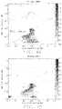
- FIG. 5schematically shows a perspective view of a head arm assembly of the present recording apparatus.
- FIG. 6schematically shows a side view of a head stack assembly of the present recording apparatus.
- FIG. 7schematically shows a plan view of the magnetic recording apparatus within which are mounted the components shown if FIGS. 5 and 6 .
- FIG. 1Athere is shown a prior art write head in an ABS view.
- the trapezoidal cross-section of the MP tip 10is separated from magnetic shield material 100 by a series of surrounding gaps that are here filled with dielectric (non-magnetic) material.
- the gapsare formed by separations between the inner edges of the side shields (SS), the trailing shield (TS) and the leading shield (LS) and outer edges of the trapezoidal cross-sectional shape of the MP.
- a write gap (WG) 20covers the trailing edge of the MP 10 and extends laterally and symmetrically over the trailing edge and terminates beyond the width of the trailing edge.
- Magnetic shield material 30 of the trailing shield (TS)covers the WG 20 .
- the downward sloping sides of the MPare each covered by side gaps (SG) 40 that are connected by a leading gap (LG) 50 .
- the side gapscontact the material of the side shields 100 (SS) and the leading gap (LG) 50 contacts the leading shield (LS) material 70 .
- the flux lines of the magnetic recording fieldemanate from the trapezoidal tip of the MP 10 , strike the recording medium (not shown) and return to the surrounding shields to complete the flux path.
- FIG. 1Bthere is shown the structure provided by the present disclosure.
- three layers of dielectric (non-magnetic) material 42 , 44 and 46 and two layers of magnetic material 62 and 64are deposited sequentially in the side gaps (SG) and leading gap (LG).
- the structurecan include a single thin magnetic layer surrounded by dielectric material (not shown), or it can include several nested magnetic layers as shown in FIG. 1B .
- the thin magnetic layersare separated from the MP and shields by a layer of dielectric 42 , 46 to decouple them from the bulkier magnetic material of the MP and shields.
- FIG. 2Athere is shown a prior art structure with a SG 40 a of 35 nm (nanometers) width that is in all respects identical to SG 40 in FIG. 1A except it is to be used in a finite element analysis, so an SG width 0f 35 nm has been assigned to it.
- the thickness of each non-magnetic layercan vary from 1 nm to 50 nm and the thickness of each magnetic layer can vary from 1 nm to 50 nm.
- FIG. 2Bthere is shown the new structure in which a single thin magnetic layer 62 of 20 nm thickness has been formed inside the two side gaps SG and the leading gap LG.
- the symbol SG 1is the gap between MP and the nearest magnetic layer and SG 2 denotes the width between the pole and side shield.
- the magnetic layer 62is separated from the MP 10 by dielectric layer 46 having a width shown as SG 1 and from side shield 100 by dielectric layer 42 . Separating the magnetic layer 62 from the shield 100 and pole 10 is required in order to decouple the magnetic layer from the bulkier magnetic shields and pole.
- FIG. 2Cshows the same prior art structure as FIG. 2A , except that the thickness of the gap 40 a in FIG. 2A is taken to be 35 nm for the purpose of a simulation, while the thickness of the gap 40 b in prior art FIG. 2C is taken to be 60 nm for the purpose of a simulation.
- FIG. 3Athere are shown simulated profiles (under static conditions) of the down-track (in ⁇ m) strength of Hy (in Oersteds) for four different simulated structures, two prior art heads with no embedded thin magnetic layer and with the dielectric thicknesses being 35 nm and 40 nm and with two of the new designs, in which the SG thickness is 35 nm and the embedded thin magnetic layer has a total Ms of 12 kG or 4 kG (kilogauss).
- the profiles shown in FIG. 3Bare for the same four heads, but now simulating their cross-track (in ⁇ m) values of Hy. Looking at the two sets of profiles, it can be seen that the new designs (with embedded layers) enhance the maximum Hy peak height, while EWAC confinement (profile width) is as good as is obtained with the prior art designs (no embedded layers). The results also demonstrate that the thin magnetic layer saturates and helps to lower the magnetic potential of the bulky side shield. As a result, for all frequency domains, writability can be gained without the loss of write bubble fringing and also improving skip track erasure.
- FIGS. 4A and 4Bthere is shown the use of dynamic modeling to show the adjacent track erasure (ATE) produced by the prior art head ( FIG. 4A ) and the head of the present design ( FIG. 4B ).
- the writing frequency used in this simulationis 1.5 GHz.
- the left side of the side shieldshows any stray field leakage, indicating that the stray field comes mainly from domain rotation during the write transitions.
- the new designshows a cleaner stray field than the prior art design ( FIG. 4A ).
- the protection of the bulky side shield by the thin magnetic layeris proved by this modeling.
- the dynamic modeling result just performeddoes not include the dynamic permeability effects in NiFe thin films.
- it has been reported(O. Acher, S. Queste and M. Ledieu, Physical Review B 68, 184414 (2003)) that the permeability of the NiFe thin film drops dramatically under a higher frequency external field.
- the dynamic behaviorwill be further influenced by this property.
- low frequency writingwill behave more like FIG. 2A and high frequency writing will behave more like FIG. 2C .
- the effective side gapis indeed adaptive to the writing frequency.
- PMRperpendicular magnetic recording
- FIGS. 5, 6 and 7there is shown the elements of a magnetic recording apparatus, such as a MAMR configured hard disk drive (HDD), through whose use the PMR writer described above will meet remaining objects of this disclosure.
- a magnetic recording apparatussuch as a MAMR configured hard disk drive (HDD)
- HDDhard disk drive
- FIG. 5shows a head gimbal assembly (HGA) 1200 that includes a slider-mounted PMR writer 1100 , the slider now providing aerodynamic support to the writer when it moves above or below an operational disk recording medium 1140 .
- HGAhead gimbal assembly
- the suspension 1220has a spring-like load beam 1230 made with a thin, corrosion-free elastic material like stainless steel.
- a flexure 1230is provided at a distal end of the load beam and a base-plate 1240 is provided at the proximal end.
- the slider mounted TAMR writer 1100is attached to the load beam 1230 at the flexure 1231 which provides the TAMR with the proper amount of freedom of motion.
- a gimbal part for maintaining the PMR read/write head at a proper levelis provided in a portion of the flexure 1231 to which the TAMR 1100 is mounted.
- a member to which the HGA 1200 is mounted to arm 1260is referred to as head arm assembly 1220 .
- the arm 1260moves the read/write head 1100 in the cross-track direction (arrow) across the medium 1140 (here, a hard disk).
- One end of the arm 1260is mounted to the base plate 1240 .
- a coil 1231 to be a part of a voice coil motor(not shown) is mounted to the other end of the arm 1260 .
- a bearing part 1233is provided to the intermediate portion of the arm 1260 .
- the arm 1260is rotatably supported by a shaft 1234 mounted to the bearing part 1233 .
- the arm 1260 and the voice coil motor that drives the arm 1260configure an actuator.
- FIG. 6 and FIG. 7there is shown a head stack assembly 1250 and a magnetic recording apparatus in which the slider-mounted TAMR writer 1100 is contained.
- the head stack assemblyis an element to which the HGA 1200 is mounted to arms of a carriage having a plurality of arms for engaging with a plurality of disks 1140 .
- the plurality of disksare mounted on a spindle 1261 .
- FIG. 5is a side view of this assembly and FIG. 6 is a plan view of the entire magnetic recording apparatus.
- the head stack assembly 1250is shown incorporated into a magnetic recording apparatus 1290 .
- the magnetic recording apparatus 1290has a plurality of magnetic recording media 1114 mounted on a spindle motor 1261 .
- Each individual recording media 1114has two TAMR elements 1100 arranged opposite to each other across the magnetic recording media 14 (shown clearly in FIG. 5 ).
- the head stack assembly 1250 and the actuatoract as a positioning device and support the PMR heads 1100 . They also position the PMR heads correctly opposite the media surface in response to electronic signals.
- the read/write headrecords information onto the surface of the magnetic media by means of the magnetic pole contained therein.
Landscapes
- Engineering & Computer Science (AREA)
- Manufacturing & Machinery (AREA)
- Physics & Mathematics (AREA)
- Electromagnetism (AREA)
- Magnetic Heads (AREA)
- Recording Or Reproducing By Magnetic Means (AREA)
Abstract
Description
This application is related to U.S. Pat. Nos. 10,522,174, 10,490,216, and 10,424,326 all of which are assigned to a common assignee and fully incorporated by reference.
This disclosure relates generally to a thin-film magnetic writer and particularly to the structure of the gaps surrounding the main pole (MP).
As Hard Disk Drive (HDD) requires higher and higher areal density capability. Both tracks per inch (TPI) and bits per inch (BPI) need to be larger. Because higher TPI requires smaller Main Pole (MP) size, the writability under high frequency writing will be a major challenge for next generation HDD writer head.
In the current writer design, the MP is surrounded by a trailing shield (TS), a side shield (SS) and a leading shield (LS) and separated from them by gaps, typically filled with a wide range of non-magnetic materials. It is critical to optimize the gap width between the MP and these surrounding shields. Smaller gap width will enhance a shielding effect and sharpen the written bit pattern, while larger gap width can help release MP flux and promote writability. Because low frequency writing benefits more from written pattern sharpness whereas high frequency writing is hungry for writability (i.e., strength of MP field), a gap width that can adapt writing frequency is strongly desired.
In this disclosure we propose a new design for the gap structure that separates the main pole (MP) from its surrounding shields. Specifically, we deposit thin layers of non-magnetic material and magnetic material sequentially on top of a normal side shield (SS) and/or leading shield (LS). Because the thin magnetic layers are decoupled from the bulky shielding material, the thin magnetic layers can help absorb the gap field and reduce bulky shield magnetic potential, while protecting against write bubble fringing and reducing erase width of an AC field (EWAC).
The thin magnetic layers can have a different frequency response than the bulky shields. In low frequency writing, the thin layers will have higher permeability and provide normal shielding. Under high frequency conditions, however, the thin layers will have lower permeability and the effective gap size will become larger. As a result, the gap structure is adaptable to varying recording conditions, MP flux release is improved and writability is enhanced.
Finally, the improved performance of the PMR writer makes it particularly well designed to operate in conjunction with thermally assisted magnetic recording (TAMR) and microwave assisted magnetic recording (MAMR). As is now well known in the art and so will not be further described herein, TAMR reduces the coercivity of a region of a recording medium on which recording is to occur by raising its temperature, typically using the optical field energy of a laser to create plasmons whose near-fields are not diffraction limited and, therefore, can be finely focused on the recording spot of the magnetic medium.
One form of MAMR achieves an analogous result as TAMR, but with a different mechanism. This form, called a spin-torque oscillator (STO), typically operates by applying a microwave frequency field to the recording media, creating a resonant precessional motion in the magnetic bits. This excess energy allows the bits to make magnetic transitions more readily, effectively reducing the coercivity of the magnetic medium.
The second form of MAMR, which we will call spin-assisted writing (SAW), effectively enhances the write-field impinging directly on the media surface from the pole tip by enhancing the flux between the magnetic pole tip and the trailing shield. This enhancement of the field leaving the pole tip is produced by generating a counter-field to the field within the write-gap by using a spin-torque layer in combination with a flux guiding layer to produce a field that is counter to the field generated by the pole. Thus, instead of giving more energy to the magnetic bits by the RF precessional field, it enhances the write field that impinges upon them by eliminating the field within the write gap. Both of these recording assist technologies will be well suited to operating along with the improved writability of the presently disclosed PMR with an adaptable gap design.
Referring toFIG. 1C , there is shown a schematic side cross-sectional view of the distal end of the PMR write head. The write pole is10, the trailing shield is150, a spin polarization layer is170, a flux control layer is160. In this figure the flux control layer creates amagnetic field 190 that is opposite to thegap field 180 and reduces it. As a result, the field emanating from thepole 10 is strengthened and can cause bit reversals without the need for RF oscillations.
Referring toFIG. 1A there is shown a prior art write head in an ABS view. The trapezoidal cross-section of theMP tip 10 is separated frommagnetic shield material 100 by a series of surrounding gaps that are here filled with dielectric (non-magnetic) material. The gaps are formed by separations between the inner edges of the side shields (SS), the trailing shield (TS) and the leading shield (LS) and outer edges of the trapezoidal cross-sectional shape of the MP.
A write gap (WG)20 covers the trailing edge of theMP 10 and extends laterally and symmetrically over the trailing edge and terminates beyond the width of the trailing edge.Magnetic shield material 30 of the trailing shield (TS) covers theWG 20. The downward sloping sides of the MP are each covered by side gaps (SG)40 that are connected by a leading gap (LG)50. The side gaps contact the material of the side shields100 (SS) and the leading gap (LG)50 contacts the leading shield (LS)material 70. During operation, the flux lines of the magnetic recording field emanate from the trapezoidal tip of theMP 10, strike the recording medium (not shown) and return to the surrounding shields to complete the flux path.
Referring to schematicFIG. 1B , there is shown the structure provided by the present disclosure. In the structure ofFIG. 1B there is shown that three layers of dielectric (non-magnetic)material magnetic material FIG. 1B . Note also that the thin magnetic layers are separated from the MP and shields by a layer ofdielectric
To demonstrate the performance of this presently disclosed structure, several simulations using magnetic modeling were carried out. Referring toFIG. 2A , there is shown a prior art structure with aSG 40aof 35 nm (nanometers) width that is in all respects identical toSG 40 inFIG. 1A except it is to be used in a finite element analysis, so an SG width 0f 35 nm has been assigned to it. We note that the thickness of each non-magnetic layer can vary from 1 nm to 50 nm and the thickness of each magnetic layer can vary from 1 nm to 50 nm.
Referring toFIG. 2B there is shown the new structure in which a single thinmagnetic layer 62 of 20 nm thickness has been formed inside the two side gaps SG and the leading gap LG. The symbol SG1 is the gap between MP and the nearest magnetic layer and SG2 denotes the width between the pole and side shield.
Themagnetic layer 62 is separated from theMP 10 bydielectric layer 46 having a width shown as SG1 and fromside shield 100 bydielectric layer 42. Separating themagnetic layer 62 from theshield 100 andpole 10 is required in order to decouple the magnetic layer from the bulkier magnetic shields and pole.
Referring toFIG. 3A , there are shown simulated profiles (under static conditions) of the down-track (in μm) strength of Hy (in Oersteds) for four different simulated structures, two prior art heads with no embedded thin magnetic layer and with the dielectric thicknesses being 35 nm and 40 nm and with two of the new designs, in which the SG thickness is 35 nm and the embedded thin magnetic layer has a total Ms of 12 kG or 4 kG (kilogauss).
The profiles shown inFIG. 3B are for the same four heads, but now simulating their cross-track (in μm) values of Hy. Looking at the two sets of profiles, it can be seen that the new designs (with embedded layers) enhance the maximum Hy peak height, while EWAC confinement (profile width) is as good as is obtained with the prior art designs (no embedded layers). The results also demonstrate that the thin magnetic layer saturates and helps to lower the magnetic potential of the bulky side shield. As a result, for all frequency domains, writability can be gained without the loss of write bubble fringing and also improving skip track erasure.
Referring toFIGS. 4A and 4B there is shown the use of dynamic modeling to show the adjacent track erasure (ATE) produced by the prior art head (FIG. 4A ) and the head of the present design (FIG. 4B ). The writing frequency used in this simulation is 1.5 GHz. In both head designs only the left side of the side shield shows any stray field leakage, indicating that the stray field comes mainly from domain rotation during the write transitions.
The new design (FIG. 4B ) shows a cleaner stray field than the prior art design (FIG. 4A ). The protection of the bulky side shield by the thin magnetic layer is proved by this modeling. It is to be noted that the dynamic modeling result just performed does not include the dynamic permeability effects in NiFe thin films. However, it has been reported (O. Acher, S. Queste and M. Ledieu, Physical Review B 68, 184414 (2003)) that the permeability of the NiFe thin film drops dramatically under a higher frequency external field. The dynamic behavior will be further influenced by this property. In a new structure like that inFIG. 2B , low frequency writing will behave more likeFIG. 2A and high frequency writing will behave more likeFIG. 2C . Thus, the effective side gap is indeed adaptive to the writing frequency. Although our simulations have been carried out based on PMR (perpendicular magnetic recording) writing, the design is equally appropriate for use in MAMR and TAMR configurations and other magnetic recording heads.
Referring now toFIGS. 5, 6 and 7 , there is shown the elements of a magnetic recording apparatus, such as a MAMR configured hard disk drive (HDD), through whose use the PMR writer described above will meet remaining objects of this disclosure.
A member to which theHGA 1200 is mounted toarm 1260 is referred to ashead arm assembly 1220. Thearm 1260 moves the read/write head 1100 in the cross-track direction (arrow) across the medium1140 (here, a hard disk). One end of thearm 1260 is mounted to thebase plate 1240. Acoil 1231 to be a part of a voice coil motor (not shown) is mounted to the other end of thearm 1260. Abearing part 1233 is provided to the intermediate portion of thearm 1260. Thearm 1260 is rotatably supported by ashaft 1234 mounted to thebearing part 1233. Thearm 1260 and the voice coil motor that drives thearm 1260 configure an actuator.
Referring next toFIG. 6 andFIG. 7 , there is shown ahead stack assembly 1250 and a magnetic recording apparatus in which the slider-mountedTAMR writer 1100 is contained. The head stack assembly is an element to which theHGA 1200 is mounted to arms of a carriage having a plurality of arms for engaging with a plurality ofdisks 1140. The plurality of disks are mounted on aspindle 1261.FIG. 5 is a side view of this assembly andFIG. 6 is a plan view of the entire magnetic recording apparatus.
Referring finally toFIG. 7 , thehead stack assembly 1250 is shown incorporated into amagnetic recording apparatus 1290. Themagnetic recording apparatus 1290 has a plurality of magnetic recording media1114 mounted on aspindle motor 1261. Each individual recording media1114 has twoTAMR elements 1100 arranged opposite to each other across the magnetic recording media14 (shown clearly inFIG. 5 ). Thehead stack assembly 1250 and the actuator (except for the write head itself) act as a positioning device and support the PMR heads1100. They also position the PMR heads correctly opposite the media surface in response to electronic signals. The read/write head records information onto the surface of the magnetic media by means of the magnetic pole contained therein.
As is finally understood by a person skilled in the art, the detailed description given above is illustrative of the present disclosure rather than limiting of the present disclosure. Revisions and modifications may be made to methods, materials, structures and dimensions employed in forming and providing a PMR writer configured for TAMR or MAMR operation having an adaptive gap structure produced by magnetic thin film laminations within dielectric, non-magnetic gap material, while still forming and providing such a structure and its method of formation in accord with the spirit and scope of the present invention as defined by the appended claims.
Claims (14)
1. A perpendicular magnetic recording (PMR) writer with adaptive gap structure comprising:
a main magnetic pole (MP) having a trapezoidal, planar, air-bearing surface (ABS) face symmetrically positioned relative to surrounding magnetic shields; wherein
said trapezoidal face has a narrow leading edge, a trailing edge that is wider than said leading edge and sloping sides connecting said trailing and leading edges; wherein,
in said ABS cross-sectional plane,
said MP face is separated from inner edges of said surrounding magnetic shields by a connected series of material-filled gaps comprising:
a write gap (WG) separating said MP trailing edge from an inner edge of a trailing shield, said WG having a lateral width exceeding said MP trailing edge width;
a leading edge gap (LG) separating said MP leading edge from an inner edge of a leading shield (LS) and
a pair of mirror-symmetrically placed side gaps (SG) separating said sloping MP sides from said side shields (SS); wherein
said two SG intersect said WG and said LG symmetrically, forming a continuous layer completely surrounding said trapezoidal face of said MP; wherein
said WG is filled uniformly with non-magnetic, non-conducting material; wherein
said two SG and said LG are filled with non-magnetic, non-conducting material in which are completely embedded N sequentially formed and nested thin layers of magnetic material that are completely surrounded by layers of said non-magnetic, non-conducting material, wherein each of said N thin layers of magnetic material is formed as three continuously connected linear edges that partially surround and are parallel to edges of said MP trapezoidal face with the exception of said WG trailing edge; whereby
said three connected linear edges of each of said N thin layers of magnetic material are parallel to respective adjacent ones of said sloping sides and said leading edge of said MP trapezoidal face, and are parallel to but separated from inner edges of said SS and LS by layers of non-magnetic, non-conducting material and do not touch adjacent magnetic layers where such layers exist, and terminate at, but do not extend into said WG non-magnetic, non-conducting material, whereby
if N is greater than 1, said N thin layers of magnetic material are nested symmetrically within each other and are open at said WG; wherein
said gap structure is adaptable to various writing frequencies as said structure comprising N thin, embedded, nested layers has higher permeability at low frequencies and lower permeability at high frequencies and writability of said PMR is enhanced by said variability.
2. The perpendicular magnetic recording (PMR) writer ofclaim 1 wherein N=1 and there is one said completely embedded layer of magnetic material and it does not touch either the MP or the surrounding shield material.
3. The perpendicular magnetic recording (PMR) writer ofclaim 2 wherein the single magnetic layer is separated from the shields and the MP by a non-magnetic, non-conducting layer of thickness between 1 nm and 50 nm adjacent to each side of said magnetic layer.
4. The perpendicular magnetic recording (PMR) writer ofclaim 1 wherein N=2 and there are two said completely embedded layers of magnetic material that are nested symmetrically within each other and wherein neither embedded layer touches the other or the magnetic material of the MP or said shields.
5. The perpendicular magnetic recording (PMR) writer ofclaim 1 wherein the thickness of each completely embedded magnetic layer is between 1 nm and 50 nm.
6. A perpendicular magnetic recording (PMR) writer configured for TAMR operation and having an adaptive gap structure, comprising:
the perpendicular magnetic recording (PMR) writer with adaptive gap structure ofclaim 1
a source of optical radiation;
a waveguide configured to carry said optical radiation to said ABS
a near-field transducer configured to couple to said waveguide and generate near-field energy at a recording spot on a magnetic recording medium
said PMR ofclaim 1 , providing a magnetic flux for recording at said spot.
7. A head-gimbal assembly, comprising:
the TAMR-configured read/write head ofclaim 6
a suspension that elastically supports said TAMR-configured read/write head,
a flexure affixed to said suspension and a load beam having one end attached to said flexure and another end attached to a base plate.
8. A HDD (Hard Disk Drive), comprising:
the head gimbal assembly ofclaim 7
a magnetic recording medium positioned opposite to said slider-mounted PMR;
a spindle motor that rotates and drives said magnetic recording medium;
a device that supports the slider and that positions said slider relative to said magnetic recording medium.
9. A perpendicular magnetic recording (PMR) writer configured for MAMR operation and having an adaptable gap structure, comprising:
the perpendicular magnetic recording (PMR) writer with adaptive gap structure ofclaim 1
a source of microwave radiation;
a transducer configured to couple to said microwave radiation and generate microwave energy in the form of resonant precessional motion of magnetic recording bits at a recording spot on a magnetic recording medium;
said PMR ofclaim 1 , providing a magnetic flux for recording at said spot.
10. A head-gimbal assembly, comprising:
the MAMR-configured read/write head ofclaim 9
a suspension that elastically supports said TAMR-configured read/write head,
a flexure affixed to said suspension and a load beam having one end attached to said flexure and another end attached to a base plate.
11. A HDD (Hard Disk Drive), comprising:
the head gimbal assembly ofclaim 10
a magnetic recording medium positioned opposite to said slider-mounted PMR;
a spindle motor that rotates and drives said magnetic recording medium;
a device that supports the slider and that positions said slider relative to said magnetic recording medium.
12. A perpendicular magnetic recording (PMR) writer configured for MAMR operation and having an adaptable gap structure, comprising:
the perpendicular magnetic recording (PMR) writer with adaptive gap structure ofclaim 1
a source of microwave radiation;
a transducer configured to couple to said microwave radiation and generate microwave energy at a recording spot on a magnetic recording medium;
the PMR ofclaim 1 further configured for spin-assisted writing wherein a spin-torque layer formed within a write gap, assists a flux guiding layer (FGL), also within said write gap, to flip a magnetization in an opposite direction to a write-gap magnetic field, thereby strengthening the magnetic field emerging from the ABS surface of the MP and returning through the trailing shield, thereby providing an enhanced magnetic flux for recording at said spot;
said PMR ofclaim 1 providing said enhanced magnetic flux.
13. A head-gimbal assembly, comprising:
the MAMR-configured read/write head ofclaim 12
a suspension that elastically supports said TAMR-configured read/write head;
a flexure affixed to said suspension and a load beam having one end attached to said flexure and another end attached to a base plate.
14. A HDD (Hard Disk Drive), comprising:
the head gimbal assembly ofclaim 13
a magnetic recording medium positioned opposite to said slider-mounted PMR;
a spindle motor that rotates and drives said magnetic recording medium;
a device that supports the slider and that positions said slider relative to said magnetic recording medium.
Priority Applications (1)
| Application Number | Priority Date | Filing Date | Title |
|---|---|---|---|
| US16/953,925US11348605B1 (en) | 2020-11-20 | 2020-11-20 | Writer with adaptive side gap |
Applications Claiming Priority (1)
| Application Number | Priority Date | Filing Date | Title |
|---|---|---|---|
| US16/953,925US11348605B1 (en) | 2020-11-20 | 2020-11-20 | Writer with adaptive side gap |
Publications (2)
| Publication Number | Publication Date |
|---|---|
| US20220165300A1 US20220165300A1 (en) | 2022-05-26 |
| US11348605B1true US11348605B1 (en) | 2022-05-31 |
Family
ID=81658516
Family Applications (1)
| Application Number | Title | Priority Date | Filing Date |
|---|---|---|---|
| US16/953,925ActiveUS11348605B1 (en) | 2020-11-20 | 2020-11-20 | Writer with adaptive side gap |
Country Status (1)
| Country | Link |
|---|---|
| US (1) | US11348605B1 (en) |
Cited By (1)
| Publication number | Priority date | Publication date | Assignee | Title |
|---|---|---|---|---|
| US12148452B1 (en) | 2023-05-10 | 2024-11-19 | Western Digital Technologies, Inc. | Current distal to media facing surface |
Citations (96)
| Publication number | Priority date | Publication date | Assignee | Title |
|---|---|---|---|---|
| US20020034043A1 (en) | 2000-09-18 | 2002-03-21 | Tomohiro Okada | Single pole type recording head and magnetic storage apparatus |
| JP2002133610A (en) | 2000-10-23 | 2002-05-10 | Hitachi Ltd | Magnetic head for perpendicular recording and magnetic disk drive equipped with the same |
| JP2002298309A (en) | 2001-01-26 | 2002-10-11 | Alps Electric Co Ltd | Magnetic head and its manufacturing method |
| US6785092B2 (en) | 2001-07-24 | 2004-08-31 | Seagate Technology Llc | White head for high anisotropy media |
| US6809899B1 (en) | 2001-08-20 | 2004-10-26 | Western Digital (Fremont), Inc. | Magnetic heads for perpendicular recording with trapezoidal pole tips |
| US20050128637A1 (en) | 2003-12-16 | 2005-06-16 | Seagate Technology Llc | Head for perpendicular recording with reduced erasure |
| US20050141137A1 (en) | 2003-12-24 | 2005-06-30 | Hitachi Global Storage Technologies Netherlands, B.V. | Magnetic recording head for perpendicular recording, fabrication process, and magnetic disk storage apparatus mounting the magnetic head |
| US6954340B2 (en) | 2001-05-23 | 2005-10-11 | Seagate Technology Llc | Perpendicular magnetic recording head with nonmagnetic write gap greater than twice side shield gap distance |
| US20060044682A1 (en) | 2004-08-31 | 2006-03-02 | Quang Le | Self aligned wrap around shield for perpendicular magnetic recording |
| US7009812B2 (en) | 2003-09-29 | 2006-03-07 | Hitachi Global Storage Technologies Netherlands B.V. | Magnetic transducer for perpendicular magnetic recording with single pole write head with trailing shield |
| US20060087765A1 (en) | 2004-10-25 | 2006-04-27 | Hitachi Global Storage Technologies | Magnetic head for perpendicular recording |
| US20070177301A1 (en) | 2006-02-02 | 2007-08-02 | Headway Technologies, Inc. | Method to make a perpendicular magnetic recording head with a side write shield |
| US20070211379A1 (en)* | 2006-03-08 | 2007-09-13 | Fujitsu Limited | Perpendicular magnetic head |
| US20080013209A1 (en) | 2006-07-12 | 2008-01-17 | Headway Technologies, Inc. | Magnetic head for perpendicular magnetic recording and method of manufacturing same |
| US20080088972A1 (en) | 2006-10-13 | 2008-04-17 | Headway Technologies, Inc. | Magnetic head for perpendicular magnetic recording and method of manufacturing same |
| US20090059426A1 (en) | 2007-09-05 | 2009-03-05 | Headway Technologies, Inc. | Magnetic head for perpendicular magnetic recording and method of manufacturing same |
| US20090080106A1 (en) | 2007-09-25 | 2009-03-26 | Kabushiki Kaisha Toshiba | Magnetic head and magnetic recording device |
| US20090128953A1 (en) | 2007-11-21 | 2009-05-21 | Ming Jiang | Perpendicular magnetic write head with stitched notched trailing shield |
| US7589600B2 (en) | 2006-10-31 | 2009-09-15 | Seagate Technology Llc | Spin oscillator device |
| US20090296275A1 (en) | 2008-06-03 | 2009-12-03 | Headway Technologies, Inc. | Thin-film magnetic head, method of manufacturing the same, head gimbal assembly, and hard disk drive |
| US7724469B2 (en) | 2006-12-06 | 2010-05-25 | Seagate Technology Llc | High frequency field assisted write device |
| US20100165517A1 (en) | 2008-12-29 | 2010-07-01 | Headway Technologies, Inc. | Magnetic head for perpendicular magnetic recording having side shield layer and method of manufacturing same |
| US7835111B2 (en) | 2007-02-15 | 2010-11-16 | Hitachi Global Storage Technologies Netherlands B.V. | Magnetic write head with upper return pole optimization for reduced trailing shield protrusion |
| US7957098B2 (en) | 2007-08-22 | 2011-06-07 | Kabushiki Kaisha Toshiba | Magnetic recording head and magnetic recording apparatus |
| US7963024B2 (en) | 2007-10-10 | 2011-06-21 | Hitachi Global Storage Technologies Netherlands B.V. | Method of manufacturing a magnetic write head for perpendicular magnetic recording |
| US7978442B2 (en) | 2007-10-03 | 2011-07-12 | Tdk Corporation | CPP device with a plurality of metal oxide templates in a confining current path (CCP) spacer |
| US7982996B2 (en) | 2009-12-07 | 2011-07-19 | Hitachi Global Storage Technologies Netherlands B.V. | Perpendicular magnetic recording write head and system with improved spin torque oscillator for microwave-assisted magnetic recording |
| US20110211271A1 (en) | 2008-11-03 | 2011-09-01 | Ka Wei Ng | Trapping electron assisted magnetic recording system and method |
| US8027110B1 (en) | 2010-07-27 | 2011-09-27 | Tdk Corporation | Apparatus for measuring magnetic field of microwave-assisted head |
| US20110279921A1 (en) | 2010-05-11 | 2011-11-17 | Headway Technologies, Inc. | CoFe/Ni Multilayer film with perpendicular anisotropy for microwave assisted magnetic recording |
| US8064244B2 (en) | 2008-03-27 | 2011-11-22 | Tdk Corporation | Thin seeded Co/Ni multilayer film with perpendicular anisotropy for spintronic device applications |
| US20120075748A1 (en)* | 2010-09-28 | 2012-03-29 | Seagate Technology Llc | Perpendicular write head with laminated side shields |
| US8154825B2 (en) | 2007-09-25 | 2012-04-10 | Kabushiki Kaisha Toshiba | Magnetic recording head and magnetic recording device |
| US20120126905A1 (en) | 2010-11-22 | 2012-05-24 | Headway Technologies, Inc. | Assisting FGL oscillations with perpendicular anisotropy for MAMR |
| US8203389B1 (en) | 2010-12-06 | 2012-06-19 | Headway Technologies, Inc. | Field tunable spin torque oscillator for RF signal generation |
| US8264792B2 (en) | 2009-05-04 | 2012-09-11 | Headway Technologies, Inc. | PMR writer device with multi-level tapered write pole |
| US8270112B2 (en) | 2007-09-25 | 2012-09-18 | Kabushiki Kaisha Toshiba | Magnetic head with spin oscillation device(s) and magnetic recording device |
| US8295008B1 (en) | 2011-07-22 | 2012-10-23 | Headway Technologies, Inc. | Magnetic head for perpendicular magnetic recording having a main pole and a shield |
| US8310787B1 (en) | 2011-09-27 | 2012-11-13 | Headway Technologies, Inc. | Thin-film magnetic head, method of manufacturing the same, head gimbal assembly, and hard disk drive |
| US20120292723A1 (en) | 2011-05-20 | 2012-11-22 | Agency For Science, Technology And Research | Magnetoresistive Device |
| US8320079B2 (en) | 2008-06-19 | 2012-11-27 | Kabushiki Kaisha Toshiba | Magnetic head assembly and magnetic recording/reproducing apparatus |
| US20130082787A1 (en) | 2011-10-03 | 2013-04-04 | Kabushiki Kaisha Toshiba | Spin injection layer robustness for microwave assisted magnetic recording |
| US8427781B1 (en) | 2012-08-08 | 2013-04-23 | Headway Technologies, Inc. | Magnetic head for perpendicular magnetic recording having a main pole and a shield |
| US8446690B2 (en) | 2009-08-17 | 2013-05-21 | HGST Netherlands B.V. | Perpendicular magnetic recording write head with spin torque oscillator for fast switching of write pole magnetization |
| US8462461B2 (en) | 2011-07-05 | 2013-06-11 | HGST Netherlands B.V. | Spin-torque oscillator (STO) with magnetically damped free layer |
| US8477452B2 (en) | 2010-12-09 | 2013-07-02 | Headway Technologies, Inc. | Magnetic head for perpendicular magnetic recording having a tapered main pole |
| US8493687B2 (en) | 2010-12-09 | 2013-07-23 | Headway Technologies, Inc. | Magnetic head for perpendicular magnetic recording with shield around main pole |
| US8582240B1 (en) | 2012-08-29 | 2013-11-12 | Headway Technologies, Inc. | Magnetic recording assisted by spin torque oscillator with a radio frequency current bias |
| US8582241B1 (en) | 2012-05-23 | 2013-11-12 | Western Digital (Fremont), Llc | Method and system for providing a magnetic transducer having a high moment bilayer magnetic seed layer for a trailing shield |
| US8604886B2 (en) | 2010-12-20 | 2013-12-10 | Intel Corporation | Spin torque oscillator having multiple fixed ferromagnetic layers or multiple free ferromagnetic layers |
| US8605386B1 (en) | 2012-07-25 | 2013-12-10 | Kabushiki Kaisha Toshiba | Magnetic recording head, head gimbal assembly with the same, and disk drive |
| US8634163B2 (en) | 2011-07-27 | 2014-01-21 | HGST Netherlands B.V. | Dual reverse microwave assisted magnetic recording (MAMR) and systems thereof |
| US8670213B1 (en)* | 2012-03-16 | 2014-03-11 | Western Digital (Fremont), Llc | Methods for tunable plating seed step coverage |
| US20140133048A1 (en) | 2012-11-13 | 2014-05-15 | HGST Netherlands B.V. | High spin-torque efficiency spin-torque oscillator (sto) with dual spin polarization layer |
| US8749919B2 (en) | 2010-12-09 | 2014-06-10 | Headway Technologies, Inc. | Magnetic head for perpendicular magnetic recording with shield around main pole |
| US20140177100A1 (en)* | 2012-12-20 | 2014-06-26 | HGST Netherlands B.V. | Mamr head with a multi-layered side gap for stable oscillation of the sto |
| US20140177092A1 (en) | 2012-12-20 | 2014-06-26 | HGST Netherlands B.V. | Mamr head adapted for high speed switching |
| US8767347B1 (en) | 2013-05-28 | 2014-07-01 | Headway Technologies, Inc. | Magnetic head for perpendicular magnetic recording having two side shields |
| US8792210B2 (en) | 2009-09-09 | 2014-07-29 | HGST Netherlands B.V. | Asymmetric writer for shingled magnetic recording |
| US20150043106A1 (en) | 2013-08-09 | 2015-02-12 | Kabushiki Kaisha Toshiba | Magnetic recording head and disk device with the same |
| US20150124347A1 (en) | 2013-11-01 | 2015-05-07 | HGST Netherlands B.V. | Magnetic head having a spin torque oscillator (sto) with a hybrid heusler field generation layer (fgl) |
| US9142228B2 (en) | 2013-10-02 | 2015-09-22 | Kabushiki Kaisha Toshiba | Magnetic recording head having narrow write gap, and disk device provided with the same |
| US20150310881A1 (en)* | 2014-04-25 | 2015-10-29 | Kabushiki Kaisha Toshiba | Magnetic recording head and magnetic recording apparatus |
| US9230571B1 (en) | 2014-08-26 | 2016-01-05 | Headway Technologies, Inc. | MgO based perpendicular spin polarizer in microwave assisted magnetic recording (MAMR) applications |
| US20160086623A1 (en) | 2014-09-23 | 2016-03-24 | HGST Netherlands B.V. | Negative-poralization spin-torque-oscillator |
| US9299367B1 (en) | 2015-07-30 | 2016-03-29 | Headway Technologies, Inc. | Perpendicular magnetic recording (PMR) writer with minimized internal flux shunting |
| US9355654B1 (en) | 2012-12-21 | 2016-05-31 | Western Digital Technologies, Inc. | Spin torque oscillator for microwave assisted magnetic recording with increased damping |
| US9355655B1 (en) | 2015-08-04 | 2016-05-31 | HGST Netherlands B.V. | Magnetic capping layer structure for a spin torque oscillator |
| US9361912B1 (en) | 2015-04-20 | 2016-06-07 | Headway Technologies, Inc. | High moment side shield design for area density improvement of perpendicular magnetic recording (PMR) writer |
| US20160218728A1 (en) | 2015-01-26 | 2016-07-28 | Carnegie Mellon University | Dual-Side Spin Transfer Spin Torque Oscillator |
| US9406317B1 (en) | 2015-08-06 | 2016-08-02 | Headway Technologies, Inc. | Perpendicular magnetic recording (PMR) write head with improved shapes of side shield and main pole |
| US9466319B1 (en) | 2015-09-08 | 2016-10-11 | Headway Technologies, Inc. | Perpendicular magnetic recording (PMR) write shield design with minimized wide adjacent track erasure (WATE) |
| US20170076742A1 (en)* | 2015-09-09 | 2017-03-16 | Headway Technologies, Inc. | Perpendicular Magnetic Recording (PMR) Writer with Hybrid Shield Layers |
| US20170133044A1 (en) | 2015-11-05 | 2017-05-11 | Headway Technologies, Inc. | Perpendicular Magnetic Recording (PMR) Writer with Improved Trailing Shield Design |
| US20170309301A1 (en) | 2016-04-26 | 2017-10-26 | Tdk Corporation | Multilayer element including base multilayer body, magnetic sensor and microwave assisted magnetic head |
| US9805745B1 (en)* | 2016-08-30 | 2017-10-31 | Kabushiki Kaisha Toshiba | Magnetic recording and reproducing device comprising a magnetic head including a trailing shield and first and second shields having alternating magnetic and nonmagnetic layers |
| US9824701B2 (en) | 2016-04-26 | 2017-11-21 | Tdk Corporation | Microwave assisted magnetic recording head with spin torque oscillator corner angle relationship, head gimbal assembly, and magnetic recording device |
| US20180075868A1 (en) | 2016-09-12 | 2018-03-15 | Kabushiki Kaisha Toshiba | Magnetic recording head and disk device having the same |
| US10032470B1 (en) | 2017-07-14 | 2018-07-24 | Tdk Corporation | Magnetic recording head with spin torque oscillator, head gimbal assembly and magnetic recording apparatus |
| US10037772B2 (en) | 2016-06-28 | 2018-07-31 | Western Digital Technologies, Inc. | Low magnetic flux density interface layer for spin torque oscillator |
| US10109302B1 (en) | 2017-07-18 | 2018-10-23 | Tdk Corporation | Magnetic recording head with spin torque oscillator, head gimbal assembly and magnetic recording apparatus |
| US10121497B1 (en) | 2017-10-12 | 2018-11-06 | Tdk Coporation | Magnetic recording head with spin torque oscillator layers satisfying width, thickness and angle relationship formulas |
| US10157632B1 (en)* | 2017-06-23 | 2018-12-18 | Western Digital Technologies, Inc. | Areal density capability improvement with spin-orbit torque based structures surrounding main pole tip |
| US10181334B1 (en)* | 2017-06-23 | 2019-01-15 | Western Digital Technologies, Inc. | Spin-orbit torque based magnetic recording |
| US10210888B1 (en)* | 2017-06-23 | 2019-02-19 | Western Digital Technologies, Inc. | Dual spin-orbit torque oscillator in magnetic recording |
| US10325618B1 (en)* | 2018-07-17 | 2019-06-18 | Headway Technologies, Inc. | Perpendicular magnetic recording (PMR) writer with one or more spin flipping elements in the gap |
| US10366714B1 (en) | 2016-04-28 | 2019-07-30 | Western Digital Technologies, Inc. | Magnetic write head for providing spin-torque-assisted write field enhancement |
| US20190244634A1 (en)* | 2017-10-09 | 2019-08-08 | Western Digital Technologies, Inc. | Spin torque layer in side gap for improved field and cross track field gradient |
| US20190259413A1 (en)* | 2017-12-19 | 2019-08-22 | Western Digital Technologies, Inc. | Mamr write head with thermal dissipation conductive guide |
| US10424326B1 (en) | 2018-11-21 | 2019-09-24 | Headway Technologies, Inc. | Magnetic flux guiding device with antiferromagnetically coupled (AFC) spin polarizer in assisted writing application |
| US10438616B2 (en) | 2015-12-24 | 2019-10-08 | Kabushiki Kaisha Toshiba | Magnetic recording head with specified thickness and saturation magnetic flux density products for STO magnetic layers |
| US10490216B1 (en) | 2018-12-04 | 2019-11-26 | Headway Technologies, Inc. | Magnetic flux guiding device with antiferromagnetically coupled (AFC) oscillator in assisted writing application |
| US10522174B1 (en) | 2018-11-21 | 2019-12-31 | Headway Technologies, Inc. | Magnetic flux guiding device with antiferromagnetically coupled (AFC) spin polarizer in assisted writing application |
| US10789976B2 (en)* | 2018-09-04 | 2020-09-29 | Kabushiki Kaisha Toshiba | Magnetic head including first and second stacked bodies and current flow arrangements and magnetic recording and reproducing device |
| US10832710B1 (en)* | 2019-09-09 | 2020-11-10 | Western Digital Technologies, Inc. | Magnetic recording devices using virtual side shields for improved areal density capability |
| US10839831B1 (en)* | 2019-12-30 | 2020-11-17 | Western Digital Technologies, Inc. | Dual writer designs with SOT and STT assisted recording |
- 2020
- 2020-11-20USUS16/953,925patent/US11348605B1/enactiveActive
Patent Citations (107)
| Publication number | Priority date | Publication date | Assignee | Title |
|---|---|---|---|---|
| US20040150910A1 (en) | 2000-09-18 | 2004-08-05 | Hitachi, Ltd. | Single pole type recording head and magnetic storage apparatus |
| US20020034043A1 (en) | 2000-09-18 | 2002-03-21 | Tomohiro Okada | Single pole type recording head and magnetic storage apparatus |
| US20060103978A1 (en) | 2000-09-18 | 2006-05-18 | Hitachi, Ltd. | Single pole type recording head with tapered edges |
| JP2002133610A (en) | 2000-10-23 | 2002-05-10 | Hitachi Ltd | Magnetic head for perpendicular recording and magnetic disk drive equipped with the same |
| JP2002298309A (en) | 2001-01-26 | 2002-10-11 | Alps Electric Co Ltd | Magnetic head and its manufacturing method |
| US6954340B2 (en) | 2001-05-23 | 2005-10-11 | Seagate Technology Llc | Perpendicular magnetic recording head with nonmagnetic write gap greater than twice side shield gap distance |
| US6785092B2 (en) | 2001-07-24 | 2004-08-31 | Seagate Technology Llc | White head for high anisotropy media |
| US6809899B1 (en) | 2001-08-20 | 2004-10-26 | Western Digital (Fremont), Inc. | Magnetic heads for perpendicular recording with trapezoidal pole tips |
| US7009812B2 (en) | 2003-09-29 | 2006-03-07 | Hitachi Global Storage Technologies Netherlands B.V. | Magnetic transducer for perpendicular magnetic recording with single pole write head with trailing shield |
| US20050128637A1 (en) | 2003-12-16 | 2005-06-16 | Seagate Technology Llc | Head for perpendicular recording with reduced erasure |
| US20050141137A1 (en) | 2003-12-24 | 2005-06-30 | Hitachi Global Storage Technologies Netherlands, B.V. | Magnetic recording head for perpendicular recording, fabrication process, and magnetic disk storage apparatus mounting the magnetic head |
| US20060044682A1 (en) | 2004-08-31 | 2006-03-02 | Quang Le | Self aligned wrap around shield for perpendicular magnetic recording |
| US20060087765A1 (en) | 2004-10-25 | 2006-04-27 | Hitachi Global Storage Technologies | Magnetic head for perpendicular recording |
| US20070177301A1 (en) | 2006-02-02 | 2007-08-02 | Headway Technologies, Inc. | Method to make a perpendicular magnetic recording head with a side write shield |
| US20070211379A1 (en)* | 2006-03-08 | 2007-09-13 | Fujitsu Limited | Perpendicular magnetic head |
| US20080013209A1 (en) | 2006-07-12 | 2008-01-17 | Headway Technologies, Inc. | Magnetic head for perpendicular magnetic recording and method of manufacturing same |
| JP2008021398A (en) | 2006-07-12 | 2008-01-31 | Headway Technologies Inc | Magnetic head for perpendicular magnetic recording, and its manufacturing method |
| US20080088972A1 (en) | 2006-10-13 | 2008-04-17 | Headway Technologies, Inc. | Magnetic head for perpendicular magnetic recording and method of manufacturing same |
| US7589600B2 (en) | 2006-10-31 | 2009-09-15 | Seagate Technology Llc | Spin oscillator device |
| US7724469B2 (en) | 2006-12-06 | 2010-05-25 | Seagate Technology Llc | High frequency field assisted write device |
| US7835111B2 (en) | 2007-02-15 | 2010-11-16 | Hitachi Global Storage Technologies Netherlands B.V. | Magnetic write head with upper return pole optimization for reduced trailing shield protrusion |
| US7957098B2 (en) | 2007-08-22 | 2011-06-07 | Kabushiki Kaisha Toshiba | Magnetic recording head and magnetic recording apparatus |
| US20090059426A1 (en) | 2007-09-05 | 2009-03-05 | Headway Technologies, Inc. | Magnetic head for perpendicular magnetic recording and method of manufacturing same |
| US8270112B2 (en) | 2007-09-25 | 2012-09-18 | Kabushiki Kaisha Toshiba | Magnetic head with spin oscillation device(s) and magnetic recording device |
| US8154825B2 (en) | 2007-09-25 | 2012-04-10 | Kabushiki Kaisha Toshiba | Magnetic recording head and magnetic recording device |
| US20090080106A1 (en) | 2007-09-25 | 2009-03-26 | Kabushiki Kaisha Toshiba | Magnetic head and magnetic recording device |
| US7978442B2 (en) | 2007-10-03 | 2011-07-12 | Tdk Corporation | CPP device with a plurality of metal oxide templates in a confining current path (CCP) spacer |
| US7963024B2 (en) | 2007-10-10 | 2011-06-21 | Hitachi Global Storage Technologies Netherlands B.V. | Method of manufacturing a magnetic write head for perpendicular magnetic recording |
| US20090128953A1 (en) | 2007-11-21 | 2009-05-21 | Ming Jiang | Perpendicular magnetic write head with stitched notched trailing shield |
| US8068312B2 (en) | 2007-11-21 | 2011-11-29 | Hitachi Global Technologies Netherlands B.V. | Perpendicular magnetic write head with stitched notched trailing shield |
| US8064244B2 (en) | 2008-03-27 | 2011-11-22 | Tdk Corporation | Thin seeded Co/Ni multilayer film with perpendicular anisotropy for spintronic device applications |
| US20090296275A1 (en) | 2008-06-03 | 2009-12-03 | Headway Technologies, Inc. | Thin-film magnetic head, method of manufacturing the same, head gimbal assembly, and hard disk drive |
| US8320079B2 (en) | 2008-06-19 | 2012-11-27 | Kabushiki Kaisha Toshiba | Magnetic head assembly and magnetic recording/reproducing apparatus |
| US20110211271A1 (en) | 2008-11-03 | 2011-09-01 | Ka Wei Ng | Trapping electron assisted magnetic recording system and method |
| US20100165517A1 (en) | 2008-12-29 | 2010-07-01 | Headway Technologies, Inc. | Magnetic head for perpendicular magnetic recording having side shield layer and method of manufacturing same |
| JP2010157303A (en) | 2008-12-29 | 2010-07-15 | Headway Technologies Inc | Magnetic head for perpendicular magnetic recording having side shield layer, and method of manufacturing the same |
| US8264792B2 (en) | 2009-05-04 | 2012-09-11 | Headway Technologies, Inc. | PMR writer device with multi-level tapered write pole |
| US8446690B2 (en) | 2009-08-17 | 2013-05-21 | HGST Netherlands B.V. | Perpendicular magnetic recording write head with spin torque oscillator for fast switching of write pole magnetization |
| US8792210B2 (en) | 2009-09-09 | 2014-07-29 | HGST Netherlands B.V. | Asymmetric writer for shingled magnetic recording |
| US7982996B2 (en) | 2009-12-07 | 2011-07-19 | Hitachi Global Storage Technologies Netherlands B.V. | Perpendicular magnetic recording write head and system with improved spin torque oscillator for microwave-assisted magnetic recording |
| US20110279921A1 (en) | 2010-05-11 | 2011-11-17 | Headway Technologies, Inc. | CoFe/Ni Multilayer film with perpendicular anisotropy for microwave assisted magnetic recording |
| US8027110B1 (en) | 2010-07-27 | 2011-09-27 | Tdk Corporation | Apparatus for measuring magnetic field of microwave-assisted head |
| US20120075748A1 (en)* | 2010-09-28 | 2012-03-29 | Seagate Technology Llc | Perpendicular write head with laminated side shields |
| US20120126905A1 (en) | 2010-11-22 | 2012-05-24 | Headway Technologies, Inc. | Assisting FGL oscillations with perpendicular anisotropy for MAMR |
| US8203389B1 (en) | 2010-12-06 | 2012-06-19 | Headway Technologies, Inc. | Field tunable spin torque oscillator for RF signal generation |
| US8477452B2 (en) | 2010-12-09 | 2013-07-02 | Headway Technologies, Inc. | Magnetic head for perpendicular magnetic recording having a tapered main pole |
| US8493687B2 (en) | 2010-12-09 | 2013-07-23 | Headway Technologies, Inc. | Magnetic head for perpendicular magnetic recording with shield around main pole |
| US8749919B2 (en) | 2010-12-09 | 2014-06-10 | Headway Technologies, Inc. | Magnetic head for perpendicular magnetic recording with shield around main pole |
| US8604886B2 (en) | 2010-12-20 | 2013-12-10 | Intel Corporation | Spin torque oscillator having multiple fixed ferromagnetic layers or multiple free ferromagnetic layers |
| US20120292723A1 (en) | 2011-05-20 | 2012-11-22 | Agency For Science, Technology And Research | Magnetoresistive Device |
| US8462461B2 (en) | 2011-07-05 | 2013-06-11 | HGST Netherlands B.V. | Spin-torque oscillator (STO) with magnetically damped free layer |
| US8295008B1 (en) | 2011-07-22 | 2012-10-23 | Headway Technologies, Inc. | Magnetic head for perpendicular magnetic recording having a main pole and a shield |
| US8634163B2 (en) | 2011-07-27 | 2014-01-21 | HGST Netherlands B.V. | Dual reverse microwave assisted magnetic recording (MAMR) and systems thereof |
| US8310787B1 (en) | 2011-09-27 | 2012-11-13 | Headway Technologies, Inc. | Thin-film magnetic head, method of manufacturing the same, head gimbal assembly, and hard disk drive |
| US20130082787A1 (en) | 2011-10-03 | 2013-04-04 | Kabushiki Kaisha Toshiba | Spin injection layer robustness for microwave assisted magnetic recording |
| US8670213B1 (en)* | 2012-03-16 | 2014-03-11 | Western Digital (Fremont), Llc | Methods for tunable plating seed step coverage |
| US8582241B1 (en) | 2012-05-23 | 2013-11-12 | Western Digital (Fremont), Llc | Method and system for providing a magnetic transducer having a high moment bilayer magnetic seed layer for a trailing shield |
| US8605386B1 (en) | 2012-07-25 | 2013-12-10 | Kabushiki Kaisha Toshiba | Magnetic recording head, head gimbal assembly with the same, and disk drive |
| US8427781B1 (en) | 2012-08-08 | 2013-04-23 | Headway Technologies, Inc. | Magnetic head for perpendicular magnetic recording having a main pole and a shield |
| US20140071562A1 (en) | 2012-08-29 | 2014-03-13 | Headway Technologies, Inc. | Magnetic Recording Assisted by Spin Torque Oscillator with a Radio Frequency Current Bias |
| US8582240B1 (en) | 2012-08-29 | 2013-11-12 | Headway Technologies, Inc. | Magnetic recording assisted by spin torque oscillator with a radio frequency current bias |
| US8755150B2 (en) | 2012-08-29 | 2014-06-17 | Headway Technologies, Inc. | Magnetic recording assisted by spin torque oscillator with a radio frequency current bias |
| US20140133048A1 (en) | 2012-11-13 | 2014-05-15 | HGST Netherlands B.V. | High spin-torque efficiency spin-torque oscillator (sto) with dual spin polarization layer |
| US20140177092A1 (en) | 2012-12-20 | 2014-06-26 | HGST Netherlands B.V. | Mamr head adapted for high speed switching |
| US20140177100A1 (en)* | 2012-12-20 | 2014-06-26 | HGST Netherlands B.V. | Mamr head with a multi-layered side gap for stable oscillation of the sto |
| US9355654B1 (en) | 2012-12-21 | 2016-05-31 | Western Digital Technologies, Inc. | Spin torque oscillator for microwave assisted magnetic recording with increased damping |
| US8767347B1 (en) | 2013-05-28 | 2014-07-01 | Headway Technologies, Inc. | Magnetic head for perpendicular magnetic recording having two side shields |
| US20150043106A1 (en) | 2013-08-09 | 2015-02-12 | Kabushiki Kaisha Toshiba | Magnetic recording head and disk device with the same |
| US9142228B2 (en) | 2013-10-02 | 2015-09-22 | Kabushiki Kaisha Toshiba | Magnetic recording head having narrow write gap, and disk device provided with the same |
| US20150124347A1 (en) | 2013-11-01 | 2015-05-07 | HGST Netherlands B.V. | Magnetic head having a spin torque oscillator (sto) with a hybrid heusler field generation layer (fgl) |
| US20150310881A1 (en)* | 2014-04-25 | 2015-10-29 | Kabushiki Kaisha Toshiba | Magnetic recording head and magnetic recording apparatus |
| US9230571B1 (en) | 2014-08-26 | 2016-01-05 | Headway Technologies, Inc. | MgO based perpendicular spin polarizer in microwave assisted magnetic recording (MAMR) applications |
| US9966091B2 (en) | 2014-08-26 | 2018-05-08 | Headway Technologies, Inc. | MgO based perpendicular spin polarizer in microwave assisted magnetic recording (MAMR) applications |
| US20160086623A1 (en) | 2014-09-23 | 2016-03-24 | HGST Netherlands B.V. | Negative-poralization spin-torque-oscillator |
| US20160218728A1 (en) | 2015-01-26 | 2016-07-28 | Carnegie Mellon University | Dual-Side Spin Transfer Spin Torque Oscillator |
| US9361912B1 (en) | 2015-04-20 | 2016-06-07 | Headway Technologies, Inc. | High moment side shield design for area density improvement of perpendicular magnetic recording (PMR) writer |
| US9299367B1 (en) | 2015-07-30 | 2016-03-29 | Headway Technologies, Inc. | Perpendicular magnetic recording (PMR) writer with minimized internal flux shunting |
| US9355655B1 (en) | 2015-08-04 | 2016-05-31 | HGST Netherlands B.V. | Magnetic capping layer structure for a spin torque oscillator |
| US9406317B1 (en) | 2015-08-06 | 2016-08-02 | Headway Technologies, Inc. | Perpendicular magnetic recording (PMR) write head with improved shapes of side shield and main pole |
| US9466319B1 (en) | 2015-09-08 | 2016-10-11 | Headway Technologies, Inc. | Perpendicular magnetic recording (PMR) write shield design with minimized wide adjacent track erasure (WATE) |
| US20170076742A1 (en)* | 2015-09-09 | 2017-03-16 | Headway Technologies, Inc. | Perpendicular Magnetic Recording (PMR) Writer with Hybrid Shield Layers |
| US20170076741A1 (en)* | 2015-09-09 | 2017-03-16 | Headway Technologies, Inc. | Perpendicular Magnetic Recording (PMR) Writer with Hybrid Shield Layers |
| US20170133044A1 (en) | 2015-11-05 | 2017-05-11 | Headway Technologies, Inc. | Perpendicular Magnetic Recording (PMR) Writer with Improved Trailing Shield Design |
| US10032469B2 (en) | 2015-11-05 | 2018-07-24 | Headway Technologies, Inc. | Perpendicular magnetic recording (PMR) writer with improved trailing shield design |
| US10438616B2 (en) | 2015-12-24 | 2019-10-08 | Kabushiki Kaisha Toshiba | Magnetic recording head with specified thickness and saturation magnetic flux density products for STO magnetic layers |
| US9824701B2 (en) | 2016-04-26 | 2017-11-21 | Tdk Corporation | Microwave assisted magnetic recording head with spin torque oscillator corner angle relationship, head gimbal assembly, and magnetic recording device |
| US9934797B2 (en) | 2016-04-26 | 2018-04-03 | Tdk Corporation | Multilayer element including base multilayer body, magnetic sensor and microwave assisted magnetic head |
| US20170309301A1 (en) | 2016-04-26 | 2017-10-26 | Tdk Corporation | Multilayer element including base multilayer body, magnetic sensor and microwave assisted magnetic head |
| US10366714B1 (en) | 2016-04-28 | 2019-07-30 | Western Digital Technologies, Inc. | Magnetic write head for providing spin-torque-assisted write field enhancement |
| US10037772B2 (en) | 2016-06-28 | 2018-07-31 | Western Digital Technologies, Inc. | Low magnetic flux density interface layer for spin torque oscillator |
| US9805745B1 (en)* | 2016-08-30 | 2017-10-31 | Kabushiki Kaisha Toshiba | Magnetic recording and reproducing device comprising a magnetic head including a trailing shield and first and second shields having alternating magnetic and nonmagnetic layers |
| US20180075868A1 (en) | 2016-09-12 | 2018-03-15 | Kabushiki Kaisha Toshiba | Magnetic recording head and disk device having the same |
| US10210888B1 (en)* | 2017-06-23 | 2019-02-19 | Western Digital Technologies, Inc. | Dual spin-orbit torque oscillator in magnetic recording |
| US10181334B1 (en)* | 2017-06-23 | 2019-01-15 | Western Digital Technologies, Inc. | Spin-orbit torque based magnetic recording |
| US10157632B1 (en)* | 2017-06-23 | 2018-12-18 | Western Digital Technologies, Inc. | Areal density capability improvement with spin-orbit torque based structures surrounding main pole tip |
| US10032470B1 (en) | 2017-07-14 | 2018-07-24 | Tdk Corporation | Magnetic recording head with spin torque oscillator, head gimbal assembly and magnetic recording apparatus |
| US10109302B1 (en) | 2017-07-18 | 2018-10-23 | Tdk Corporation | Magnetic recording head with spin torque oscillator, head gimbal assembly and magnetic recording apparatus |
| US20190244634A1 (en)* | 2017-10-09 | 2019-08-08 | Western Digital Technologies, Inc. | Spin torque layer in side gap for improved field and cross track field gradient |
| US10121497B1 (en) | 2017-10-12 | 2018-11-06 | Tdk Coporation | Magnetic recording head with spin torque oscillator layers satisfying width, thickness and angle relationship formulas |
| US20190259413A1 (en)* | 2017-12-19 | 2019-08-22 | Western Digital Technologies, Inc. | Mamr write head with thermal dissipation conductive guide |
| US10325618B1 (en)* | 2018-07-17 | 2019-06-18 | Headway Technologies, Inc. | Perpendicular magnetic recording (PMR) writer with one or more spin flipping elements in the gap |
| US10789976B2 (en)* | 2018-09-04 | 2020-09-29 | Kabushiki Kaisha Toshiba | Magnetic head including first and second stacked bodies and current flow arrangements and magnetic recording and reproducing device |
| US10424326B1 (en) | 2018-11-21 | 2019-09-24 | Headway Technologies, Inc. | Magnetic flux guiding device with antiferromagnetically coupled (AFC) spin polarizer in assisted writing application |
| US10522174B1 (en) | 2018-11-21 | 2019-12-31 | Headway Technologies, Inc. | Magnetic flux guiding device with antiferromagnetically coupled (AFC) spin polarizer in assisted writing application |
| US10490216B1 (en) | 2018-12-04 | 2019-11-26 | Headway Technologies, Inc. | Magnetic flux guiding device with antiferromagnetically coupled (AFC) oscillator in assisted writing application |
| US10832710B1 (en)* | 2019-09-09 | 2020-11-10 | Western Digital Technologies, Inc. | Magnetic recording devices using virtual side shields for improved areal density capability |
| US10839831B1 (en)* | 2019-12-30 | 2020-11-17 | Western Digital Technologies, Inc. | Dual writer designs with SOT and STT assisted recording |
Non-Patent Citations (12)
| Title |
|---|
| "High-Power Coherent Microwave Emission from Magnetic Tunnel Junction Nano-oscillators with Perpendicular Anisotropy," by Zhongming Zeng, et al., 2012 American Chemical Society, Jun. 4, 2012, vol. 6, No. 7, pp. 5115-6121. |
| "Hysteretic Behavior of the Dynamic Permeability on a Ni—Fe Thin Film," by O. Archer et al., Physical Review B, vol. 68, Issue 18, 184414 (2003), Nov. 1, 2003, pp. 1-4. |
| "Spin-Torque Oscillator Based on Magnetic Tunnel Junction with a Perpendicularly Magnetized Free Layer and In-Plane Magnetized Polarizer," by Hitoshi Kubota, et al., 2013 The Japan Society of Applied Physics, Applied Physics Express 6 (2013) 103003, Sep. 27, 2013, pp. 1-3. |
| "The Feasibility of Magnetic Recording at 10 Terabits Per Square Inch on Conventional Media," by Roger Wood et al., IEEE Transactions on Magnetics, vol. 45, No. 2, Feb. 2009, pp. 917-923. |
| Microwave Assisted Magnetic Recording, by Jian-Gang Zhu et al., IEEE Transactions on Magnetics, vol. 44, No. 1, Jan. 1, 2008, pp. 125-131. |
| Nov. 13, 2012, Office Action issued in Japanese Patent Application No. 2011-149242, with English language translation. |
| Nov. 13, 2012, Office Action issued in Japanese Patent Application No. 2011-149243, with English language translation. |
| Nov. 13, 2012, Office Action issued in Japanese Patent Application No. 2011-149244, with English language translation. |
| PTO Office Action, U.S. Appl. No. 12/964,202, Applicant: Sasaki et al., dated Nov. 28, 2012, 11 pages. |
| U.S. Notice of Allowance, U.S. Appl. No. 16/197,586, First named Inventor: Wenyu Chen, dated May 15, 2019, 16 pages. |
| U.S. Notice of Allowance, U.S. Appl. No. 16/209,151, First named Inventor: Wenyu Chen, dated Aug. 15, 2019, 17 pages. |
| U.S. Notice of Allowance, U.S. Appl. No. 16/549,139, First named Inventor: Wenyu Chen, dated Sep. 19, 2019, 8 pages. |
Cited By (1)
| Publication number | Priority date | Publication date | Assignee | Title |
|---|---|---|---|---|
| US12148452B1 (en) | 2023-05-10 | 2024-11-19 | Western Digital Technologies, Inc. | Current distal to media facing surface |
Also Published As
| Publication number | Publication date |
|---|---|
| US20220165300A1 (en) | 2022-05-26 |
Similar Documents
| Publication | Publication Date | Title |
|---|---|---|
| US8107352B1 (en) | Microwave assisted magnetic head | |
| US8988826B2 (en) | MAMR head with a multi-layered side gap for stable oscillation of the STO | |
| JP4686630B1 (en) | Magnetic head and disk device provided with the same | |
| US8634163B2 (en) | Dual reverse microwave assisted magnetic recording (MAMR) and systems thereof | |
| US9305574B1 (en) | Negative-polarization spin-torque-oscillator | |
| US7656619B1 (en) | Magnetic head sliders for disk drives having a heating element and pedestal in thick undercoat layer | |
| JP2004342210A (en) | Magnetic head for perpendicular magnetic recording and its manufacturing method, head gimbal assembly, and hard disk drive | |
| US8043515B2 (en) | Thin film magnetic head and manufacturing method thereof | |
| US20130163122A1 (en) | Magnetic head having high-frequency oscillatory elements and disk drive with the same | |
| JP2015072726A (en) | Magnetic recording head and disk device provided with the same | |
| US11056133B2 (en) | Writer with HMTS (high moment trailing shield) aligned with spin layer | |
| CN117998968A (en) | Spintronic device including dual FGL and dual SPL to reduce vertical field at write location | |
| US10891977B1 (en) | MAMR recording head with high damping trailing shield seed layer | |
| Chiu et al. | Thin-film inductive heads | |
| US11348605B1 (en) | Writer with adaptive side gap | |
| US10762919B1 (en) | Magnetic recording write head with write pole having a tapered trailing end section with negative magnetic anisotropy | |
| US10861486B1 (en) | Writer with narrower high moment trailing shield | |
| JP4044922B2 (en) | Magnetic recording head | |
| JP2015082335A (en) | Magnetic recording head and disk device provided with the same | |
| US20240379119A1 (en) | Current Distal to Media Facing Surface | |
| US10629233B1 (en) | Bumper pad design for TAMR drives | |
| US11355141B2 (en) | Writer with narrower high moment trailing shield | |
| US20250166658A1 (en) | Magnetic Recording Head with A Cross-Track Current Flow In A Low Resistance Path | |
| US7440237B2 (en) | Thin film magnetic head, head gimbal assembly, and hard disk drive | |
| JP2016219070A (en) | Magnetic recording head and disk device provided with the same |
Legal Events
| Date | Code | Title | Description |
|---|---|---|---|
| FEPP | Fee payment procedure | Free format text:ENTITY STATUS SET TO UNDISCOUNTED (ORIGINAL EVENT CODE: BIG.); ENTITY STATUS OF PATENT OWNER: LARGE ENTITY | |
| AS | Assignment | Owner name:HEADWAY TECHNOLOGIES, INC., CALIFORNIA Free format text:ASSIGNMENT OF ASSIGNORS INTEREST;ASSIGNORS:LIU, YING;TANG, YUHUI;LIU, YUE;AND OTHERS;SIGNING DATES FROM 20201103 TO 20201114;REEL/FRAME:054857/0045 | |
| STCF | Information on status: patent grant | Free format text:PATENTED CASE |