US11346177B2 - Repairable seal assemblies for oil and gas applications - Google Patents
Repairable seal assemblies for oil and gas applicationsDownload PDFInfo
- Publication number
- US11346177B2 US11346177B2US16/702,916US201916702916AUS11346177B2US 11346177 B2US11346177 B2US 11346177B2US 201916702916 AUS201916702916 AUS 201916702916AUS 11346177 B2US11346177 B2US 11346177B2
- Authority
- US
- United States
- Prior art keywords
- seal
- transitional component
- configuration
- transitional
- elongate body
- Prior art date
- Legal status (The legal status is an assumption and is not a legal conclusion. Google has not performed a legal analysis and makes no representation as to the accuracy of the status listed.)
- Active, expires
Links
Images


Classifications
- E—FIXED CONSTRUCTIONS
- E21—EARTH OR ROCK DRILLING; MINING
- E21B—EARTH OR ROCK DRILLING; OBTAINING OIL, GAS, WATER, SOLUBLE OR MELTABLE MATERIALS OR A SLURRY OF MINERALS FROM WELLS
- E21B33/00—Sealing or packing boreholes or wells
- E21B33/10—Sealing or packing boreholes or wells in the borehole
- E21B33/12—Packers; Plugs
- E21B33/1208—Packers; Plugs characterised by the construction of the sealing or packing means
- E21B33/1212—Packers; Plugs characterised by the construction of the sealing or packing means including a metal-to-metal seal element
- E—FIXED CONSTRUCTIONS
- E21—EARTH OR ROCK DRILLING; MINING
- E21B—EARTH OR ROCK DRILLING; OBTAINING OIL, GAS, WATER, SOLUBLE OR MELTABLE MATERIALS OR A SLURRY OF MINERALS FROM WELLS
- E21B33/00—Sealing or packing boreholes or wells
- E21B33/10—Sealing or packing boreholes or wells in the borehole
- E21B33/12—Packers; Plugs
- E—FIXED CONSTRUCTIONS
- E21—EARTH OR ROCK DRILLING; MINING
- E21B—EARTH OR ROCK DRILLING; OBTAINING OIL, GAS, WATER, SOLUBLE OR MELTABLE MATERIALS OR A SLURRY OF MINERALS FROM WELLS
- E21B33/00—Sealing or packing boreholes or wells
- E21B33/10—Sealing or packing boreholes or wells in the borehole
- E21B33/13—Methods or devices for cementing, for plugging holes, crevices or the like
- E21B33/138—Plastering the borehole wall; Injecting into the formation
- E—FIXED CONSTRUCTIONS
- E21—EARTH OR ROCK DRILLING; MINING
- E21B—EARTH OR ROCK DRILLING; OBTAINING OIL, GAS, WATER, SOLUBLE OR MELTABLE MATERIALS OR A SLURRY OF MINERALS FROM WELLS
- E21B36/00—Heating, cooling or insulating arrangements for boreholes or wells, e.g. for use in permafrost zones
- E—FIXED CONSTRUCTIONS
- E21—EARTH OR ROCK DRILLING; MINING
- E21B—EARTH OR ROCK DRILLING; OBTAINING OIL, GAS, WATER, SOLUBLE OR MELTABLE MATERIALS OR A SLURRY OF MINERALS FROM WELLS
- E21B47/00—Survey of boreholes or wells
Definitions
- repairable seal assembliesinstalled within completion systems at subterranean wellbores.
- Such repairable seal assembliesinclude eutectic metal alloy materials that can be employed to provide backup sealing capability in the event that seal stacks of the sealing assemblies should fail.
- a pairing of a seal assembly and a polished bore receptacle (PBR)is commonly used in oil industry completions to allow tubing movement and easy replacement of an upper completion during workover operations. If seal stacks on the seal assembly fail, then a wellbore at which the pairing is installed will have tubing to annulus communication and therefore be classified as unsafe. For example, flow of wellbore fluids into an annulus causes a pressure increase in the annulus. Such direct tubing pressure within the annulus compromises the integrity of the wellbore, as exposure to wellbore fluids accelerates corrosion. When such communication occurs, an operator may repair the wellbore to return the wellbore to a safe operating condition.
- PBRpolished bore receptacle
- seal assembliesinclude multiple seal stacks. For example, if one seal stack fails, then another seal stack can perform the sealing duty.
- a seal assemblymay experience one or more of several modes of damage, including running in hole (RIH) damage, stab-in damage, exit damage as the seal assembly is pulled out of a PBR, wear due to repeated stroking, and extrusion damage.
- RIH damageresults from a seal assembly picking up mud and other well debris prior to being located in the PBR while being run in wellbore fluids.
- Stab-in damageinvolves cutting or otherwise damaging seal assembly components during the initial process of locating (for example, aligning) and landing the seal assembly in the PBR.
- wear due to repeated strokingmay occur if the seal assembly is left in a dynamic condition, such as a condition involving a change in a temperature or pressure of the wellbore (for example, shutting in the well) that results in tubing movement.
- Extrusion damagemay result as elastomeric components of the seal assembly are extruded over the course of multiple pressure and temperature cycles, despite a design of the seal assembly (for example, a number of material types and a number of seal stacks) being matched to a duty of the wellbore.
- Conventional repair methodsdo not provide an in-situ approach. Rather, a pull tubing workover is the only repair option that is available to address a failed seal assembly.
- a seal assemblymay include a cylindrical body (e.g., a mandrel), one or more sets of elastomeric seals that surround the cylindrical body respectively at one or more first axial positions, one or more metal rings that surround the cylindrical body respectively at one or more second axial positions, and anchors that surround the cylindrical body at third axial locations between the first and second axial locations to separate the one or more metal rings from the one or more elastomeric seals.
- a cylindrical bodye.g., a mandrel
- one or more sets of elastomeric sealsthat surround the cylindrical body respectively at one or more first axial positions
- one or more metal ringsthat surround the cylindrical body respectively at one or more second axial positions
- anchorsthat surround the cylindrical body at third axial locations between the first and second axial locations to separate the one or more metal rings from the one or more elastomeric seals.
- the one or more metal ringsare made of a eutectic material (e.g., a metal alloy designed to have a relatively low melting point that is above a reservoir temperature of the wellbore).
- a eutectic materiale.g., a metal alloy designed to have a relatively low melting point that is above a reservoir temperature of the wellbore.
- the low melting pointallows the eutectic material to be easily melted without damaging the other metal components (for example, typically steel components) in the completion tubing. Accordingly, the one or more metal rings are in a solid state at relatively low temperatures and in a liquid state at temperatures above the melting point of the eutectic material.
- the one or more metal ringsare in a solid state and have an outer diameter that is less than an inner diameter of the receptacle, such that the one or more metal rings do not initially seal against the receptacle.
- the elastomeric sealshave an outer diameter that is about equal to an inner diameter of the receptacle such that the elastomeric seals seal against the receptacle initially and throughout completion and production operations carried out at the wellbore.
- Such sealingcan prevent wellbore fluids that have flowed from the downhole tube section into the receptacle from exiting the receptacle into an annular space defined between an uphole tube portion of the completion tubing and a surrounding casing.
- one or more of the elastomeric sealscan fail, such that the wellbore fluids leak out of the receptacle and into the annular space, where the wellbore fluids can compromise an integrity of the casing. In conventional sealing systems, such failure currently requires a rig operation to replace a completion to perform a repair of the sealing system.
- a heatercan be passed through the cylindrical body of the sealing assembly to melt a nearby metal ring surrounding the cylindrical body to cause the metal ring to melt into a liquid state.
- the eutectic materialflows downward along the cylindrical body, and spreads radially from the cylindrical body to the inner diameter of the receptacle.
- the eutectic materialcools from the liquid state to a solid state in which the eutectic material forms a metal ring with an outer diameter that is about equal to the inner diameter of the receptacle to effect a metal-to-metal seal between the receptacle and the cylindrical body of the sealing assembly.
- a repairable seal assembly for deployment at a wellboreincludes an elongate body, a first seal carried by the elongate body and configured to seal against an adjacent surface, and a transitional component carried by the elongate body.
- the transitional componentis adjustable from a first configuration in which the transitional component defines a gap between the transitional component and the adjacent surface to a second configuration in which the transitional component contacts the adjacent surface to form a second seal at the adjacent surface.
- Embodimentsmay provide one or more of the following features.
- the transitional componenthas an annular shape.
- the transitional componentis made of a metal alloy that has a melting point in a range of about 90° C. to about 300° C.
- the transitional componentis configured to be melted by a heater from the first configuration to the second configuration.
- the transitional componentis in a solid state in the first and second configurations, and the transitional component is in a liquid state during a transitional period that occurs between a first period in which the transitional component is in the first configuration and a second period in which the transitional component is in the second configuration.
- the transitional componenthas a melting point in a range of about 20° C. to about 200° C. above a maximum expected operational temperature at the wellbore.
- the elongate bodydefines a lumen sized to allow passage of a heater.
- the transitional componenthas a first diameter and a first length in the first configuration, and the transitional component has a second diameter and a second length in the second configuration, wherein the first diameter is less than the second diameter, and wherein the first length is greater than the second length.
- the second sealis arranged to fluidically isolate a downhole region of a pipe surrounding the repairable seal assembly within the wellbore from an uphole annulus within the pipe.
- the second sealprovides metal-to-metal sealing with the adjacent surface.
- the repairable seal assembly of claimfurther includes one or more additional first seals carried by the elongate body.
- the repairable seal assemblyfurther includes one or more additional transitional components carried by the elongate body.
- the adjacent surfaceis an inner surface provided by a receptacle sized to receive the seal assembly.
- the adjacent surfaceis an outer surface provided by a tube sized to be received within the seal assembly.
- the repairable seal assemblyincludes one or more spacers arranged to support the first seal.
- the repairable seal assemblyfurther includes two support members arranged at opposite ends of the transitional component.
- a completion system installed at a wellboreincludes a tubular component providing an interface and a repairable seal assembly positioned adjacent the interface.
- the seal assemblyincludes an elongate body, a first seal carried by the elongate body and configured to seal against the interface, and a transitional component carried by the elongate body.
- the transitional componentis adjustable from a first configuration in which the transitional component defines a gap between the transitional component and the interface to a second configuration in which the transitional component contacts the interface to form a second seal at the interface.
- Embodimentsmay provide one or more of the following features.
- the transitional componentis made of a metal alloy that has a melting point in a range of about 90° C. to about 300° C.
- the transitional componentis configured to be melted from the first configuration to the second configuration.
- the tubular componentincludes a receptacle sized to receive the repairable seal assembly, and the interface includes an inner surface of the tubular component.
- the tubular componentincludes a completion tubing sized to fit within the repairable seal assembly, and the interface includes an outer surface of the completion tubing.
- a seal assembly for deployment at a wellboreincludes an elongate body and a transitional component carried by the elongate body and being adjustable from a first configuration in which the transitional component defines a gap between the transitional component and an adjacent surface to a second configuration in which the transitional component contacts the adjacent surface to form a seal at the adjacent surface.
- a method of sealing a tubing system installed at a wellboreincludes forming a first seal between a sealing element carried by an elongate body and a surface adjacent the elongate body, determining a failure of the first seal at the surface, adjusting a transitional component carried by the elongate body from a first configuration in which the transitional component defines a gap between the transitional component and the surface to a second configuration in which the transitional component contacts the surface, and forming a second seal between the transitional component in the second configuration and the surface.
- the transitional componenthas an annular shape.
- the transitional componentis made of a metal alloy that has a melting point in a range of about 90° C. to about 300° C.
- the methodfurther includes deploying a heater to the transitional component to melt the transitional component from the first configuration to the second configuration.
- the transitional componentis in a solid state in the first and second configurations
- the methodfurther includes melting the transitional component to a liquid state during a transitional period that occurs between a first period in which the transitional component is in the first configuration and a second period in which the transitional component is in the second configuration.
- the transitional componenthas a melting point in a range of about 20° C. to about 200° C. above a maximum expected operational temperature at the wellbore.
- the transitional componenthas a first diameter and a first length in the first configuration, and the transitional component has a second diameter and a second length in the second configuration, wherein the first diameter is less than the second diameter, and wherein the first length is greater than the second length.
- the second sealis arranged to fluidically isolate a downhole region of a pipe surrounding the second seal within the wellbore from an uphole annulus within the pipe.
- the surfaceis an inner surface provided by a receptacle sized to receive a seal assembly that includes the first and second seals.
- the surfaceis an outer surface provided by a tube sized to be received within a seal assembly that includes the first and second seals.
- FIG. 1is a side cross-sectional cutaway view of an example completion tubing system including an example seal assembly.
- FIG. 3is cross-sectional view of a portion of the completion tubing system of FIG. 1 in a first condition in which a transition ring of the seal assembly of FIG. 1 defines a gap between the transition ring and a surrounding receptacle.
- FIG. 5is a flow chart illustrating an example method of sealing the completion tubing system of FIG. 1 .
- FIG. 6is a perspective cutaway view of a portion of an example seal assembly including packing elements formed of differing materials.
- FIG. 7is a side cross-sectional cutaway view of an example completion tubing system including a seal bore extension and the seal assembly of FIG. 1 .
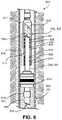
- FIG. 8is a side cross-sectional cutaway view of an example completion tubing system including an inverted seal assembly.
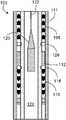
- FIG. 1illustrates a portion of an example completion tubing system 101 installed within a wellbore 103 of a rock formation 105 .
- the completion tubing system 101includes multiple casings 107 (for example, pipes cemented in place within the wellbore 103 ) that are centrally aligned within the wellbore 103 (although only one casing 107 is illustrated in FIG. 1 ).
- the completion tubing system 101further includes a completion tubing 109 positioned within the casing 107 , a polished bore receptacle (PBR) 111 extending from the completion tubing 109 , a packer 113 that secures the completion tubing 109 to the casing 107 at a fixed position, and a seal assembly 100 disposed within the PBR 111 .
- PBRpolished bore receptacle
- the packer 113seals against the casing 107 and accordingly defines an annulus 117 (for example, a substantially annular shaped volume) uphole of the packer 113 and a downhole region 115 located downhole of the packer 113 .
- Sealing of the packer 113 against the casing 107prevents any wellbore fluid 119 within the downhole region 115 of the casing 107 from flowing upward around an outer edge of the packer 113 and into the annulus 117 .
- Wellbore fluid 119 within the downhole region 115may flow into a lumen 123 of the completion tubing 109 .
- the seal assembly 100seals against an inner surface 125 of the PBR 111 to prevent any wellbore fluid 119 within the completion tubing 109 from flowing upward around an outer edge of the seal assembly 100 and into the annulus 117 .
- the PBR 111is a female completion component that is bored for receiving the seal assembly 100 and is typically made of one or more metals.
- the PBR 111may be deployed into the wellbore 103 on a deployment line 121 (for example, drill pipe or tubing).
- the seal assembly 100 and the PBR 111are run into the wellbore 103 in a single trip using shear pins that are later released.
- the PBR 111is run into the wellbore 103 on a lower completion assembly in a first trip, and the seal assembly 100 is run into the wellbore 103 (for example, stabbed into the PBR 111 ) in a subsequent, second trip.
- a pairing of the seal assembly 100 and the PBR 111are typically landed in the wellbore 103 in compression such that the seal assembly 100 does not move during normal production activities. Substantially stationary positioning of the seal assembly 100 may prevent or minimize wear of the seal assembly 100 and increase a life of the seal assembly 100 .
- a low temperature, relatively cool stimulation fluid being pumped into the wellbore 103 from the surfacecauses the completion tubing 109 to contract, such that the seal assembly 100 strokes in an uphole direction within the PBR 111 in a dynamic state.
- the PBR 111limits tensile stresses in the completion tubing 109 as compared to a fixed string that lacks a PBR.
- FIG. 2illustrates a cutaway view of the seal assembly 100 .
- the seal assembly 100is a repairable system that may be installed at wellbores at which there is no tubing movement or at wellbores at which dynamic operations are carried out.
- the seal assembly 100includes a body 102 (for example, a mandrel) that carries a seal stack 114 .
- the seal stack 114includes multiple opposing seals 104 , 106 , multiple opposing metal spacers 108 , 110 , a transition ring 112 located axially between the opposing seals 104 , 106 and opposing spacers 108 , 110 , and two anchors 118 , 128 that flank the transition ring 112 .
- the body 102 of the seal assembly 100has a generally cylindrical shape and is typically made of one or more metals.
- the body 102typically has a length in a range of about 3 meters (m) to about 8 m and typically carries a total of six to ten seal stacks 114 , although only one seal stack 114 is illustrated in FIG. 2 .
- the seal stack 114is preinstalled to the body 102 at manufacture
- a seal stack 114is designed to seal against the inner surface 125 of the PBR 111 to prevent fluid communication between the lumen 123 of the completion tubing 109 and the annulus 117 .
- the seals 104 , 106are elastomeric, v-shaped rings that are axially stacked.
- the seals 104 , 106are typically made of one or more materials, such as nitrile.
- the metal spacers 108 , 110are designed to support and maintain axial positions of the seals 104 , 106 (for example, to maintain space between the seals 104 , 106 ), but do not contribute to sealing, themselves.
- each seal stack 114 of the seal assembly 100includes three to eight seals 104 , 106 and a corresponding number of metal spacers 108 , 110 . Sizing of the seal stacks 114 of the seal assembly 100 may depend on various design parameters of the completion tubing system 101 .
- the transition ring 112is an adaptive component that provides a contingent, in situ repair mechanism that can be employed in the case that one or more of the seals 104 , 106 of the seal stack 114 should fail.
- the transition ring 112has a generally cylindrical shape and is made of a eutectic metal alloy that has a relatively low melting point that is above a maximum expected operational temperature.
- the maximum expected operational temperaturemay be a reservoir temperature of the wellbore 103 or a different temperature related to activities such as stimulation.
- the low melting pointallows the transition ring 112 to be easily melted without damaging other components (for example, typically steel components) of the completion tubing system 101 .
- the transition ring 112typically has a melting point in a range of about 90 degrees Celsius (° C.) to about 300° C., which is also in a range of about 20 degrees ° C. to about 200° C. higher than the maximum expected operational temperature.
- Example eutectic metal alloy materials from which the transition ring 112 may be madeinclude a bismuth tin (Bi—Sn) alloy or other low melting point alloys that are typically made from a combination of two or more of the metals bismuth, lead, tin, cadmium and indium.
- the transition ring 112In an initial configuration (for example, a non-operational configuration), the transition ring 112 is in a solid state and has an outer diameter that is slightly less than an inner diameter of the PBR 111 . Accordingly, the transition ring 112 defines an annular gap 126 (appearing larger than actual scale in FIG. 3 for illustration purposes) between the transition ring 112 and the inner surface 125 of the PBR 111 and does not contact the PBR 111 to seal against the PBR 111 . In the initial configuration, as shown in FIG. 2 , the outer diameter of the transition ring 112 is also less than the outer diameter of the seals 104 , 106 . The transition ring 112 is separated from the seals 104 , 106 and supported by the metal anchors 118 , 128 , which are anchored to the body 102 and also provide support for the adjacent seals 104 , 106 .
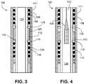
- FIG. 3illustrates a first condition in which the seal assembly 100 operates normally such that the seals 104 , 106 are intact and contact the inner surface 125 of the PBR 111 to seal against the PBR 111 .
- the transition ring 112is in the initial configuration (for example, a pre-melt configuration) in which the transition ring 112 defines the annular gap 126 between the transition ring 112 and the inner surface 125 of the PBR 111 . Therefore, the transition ring 112 does not contact the PBR 111 and accordingly does not provide any sealing capability.
- the transition ring 112has an initial length that extends from the uphole anchor 128 to the downhole anchor 118 and an initial outer diameter that is less than the inner diameter of the PBR 111 .
- FIG. 4illustrates a second condition in which one or more of the seals 104 , 106 have failed.
- the seals 104 , 106are damaged or missing from the body 102 of the seal assembly 100 in the example illustration of FIG. 4 .
- the transition ring 112can be activated to provide such sealing functionality.
- a tubing heater 120(for example, a thermite heater) is run on an electric line 122 using a casing collar locator (CCL) downhole into a lumen 124 of the body 102 and axially positioned adjacent the transition ring 112 .
- CCLcasing collar locator
- the tubing heater 120may be run on wireline. A thermite reaction is initiated at the tubing heater 120 , providing a large amount of energy to melt the transition ring 112 into a transitional configuration (for example, a melted configuration) in which the transition ring 112 is in a liquid state.
- the tubing heater 120may be heated to a temperature of about 100° C. or more above the melting point of the transition ring 112 to melt the transition ring 112 without damaging the other metal components of the completion tubing system 101 .
- the molten material of the transition ring 112has settled under the influence of gravity in a downhole direction towards the downhole anchor 118 and flows radially outward to the inner surface 125 of the PBR 111 such that a shape of the molten material (for example, in the form of an annular plug) is defined by the downhole anchor 118 and the PBR 111 .
- the tubing heater 120can be withdrawn from the seal assembly 100 to allow the molten material to cool back to a solid state and into a functional configuration in which the transition ring 112 effects a metal-to-metal seal with the inner surface 125 of the PBR to isolate the lumen 123 of the completion tube 109 and the downhole region 115 from the annulus 117 .
- the functional configuration of the transition ring 112is a permanent repair such that the wellbore 103 can safely and permanently undergo production activities with the seal assembly 100 in the repaired state, such that the need for a pull tubing workover is eliminated altogether.
- the functional configuration of the transition ring 112is a contingent repair that allows the wellbore 103 to safely undergo production activities with the seal assembly 100 in the repaired state until an upper completion workover operation can be scheduled. In either case, the functional configuration of the transition ring 112 allows production at the wellbore 103 .
- the functional configuration of the transition ring 112can also defer and reduce workover costs in that a workover can be performed at the wellbore 103 as part of a pre-scheduled campaign as opposed to as an on-demand, stand-alone workover necessitated by failure of a seal stack 114 . Accordingly, production can be maintained to meet production targets, and workover repairs can be better designed and executed. Such additional months of production can advantageously return scheduling of such workover repairs to the operator. For example, in some cases, a replace tubing workover also has remedial content to shut-off one zone and add other zones, which requires additional preparation and approval time. The functional configuration of the transition ring 112 can provide such additional time so that an optimal workover repair can be performed.
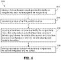
- FIG. 5is a flow chart illustrating an example method 200 of sealing a tubing system (for example, the completion tubing system 101 ) installed at a wellbore (for example, the wellbore 103 ).
- the method 200includes forming a primary seal between a sealing element (for example, a seal 104 , 106 ) carried by an elongate body (for example, the body 102 ) and a surface (for example, the inner surface 125 of the PBR 111 ) adjacent the elongate body ( 202 ).
- the method 200further includes determining a failure of the primary seal at the surface ( 204 ).
- the method 200further includes adjusting a transitional component (for example, the transition ring 112 ) carried by the elongate body from a first configuration in which the transitional component defines a gap (for example, the gap 126 ) between the transitional component and the surface to a second configuration in which the transitional component contacts the surface ( 206 ). In some embodiments, the method 200 further includes forming a secondary seal between the transitional component in the second configuration and the surface ( 208 ).
- a transitional componentfor example, the transition ring 112
- the method 200further includes forming a secondary seal between the transitional component in the second configuration and the surface ( 208 ).
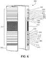
- FIG. 6illustrates a cutaway view of a seal assembly 300 that includes a seal stack 314 with intermediate, ring-shaped packing elements 309 , 311 , 313 , 315 distributed among seals 304 , 306 and metal spacers 308 , 310 , 338 , 340 .
- the seal assembly 300is otherwise substantially similar in construction and function the seal assembly 100 . Accordingly, the seal assembly 300 may be paired with the PBR 111 or with the SBR 411 discussed below with respect to FIG. 7 .
- the seal assembly 300is a repairable system that includes a body 302 (for example, a mandrel) carrying the seal stack 314 .
- the seal stack 314includes multiple opposing seals 304 , 306 , multiple opposing metal spacers 308 , 310 , 338 , 340 , the packing elements 309 , 311 , 313 , 315 , a transition ring 312 located axially between the opposing seals 304 , 306 and opposing metal spacers 308 , 310 , 338 , 340 , and two anchors 318 , 328 that flank the transition ring 312 .
- the packing elements 309 , 311 , 313 , 315are typically made of differing materials and may be arranged such that the constituent materials sequentially transition from softer to harder. The hardness transition can prevent extrusion of the seals 304 , 306 and thus help to maintain a sealing performance of the seals 304 , 306 .
- Example materials from which the packing elements 309 , 311 , 313 , 315 may be madeinclude synthetic rubber, fluoropolymer elastomer, tetrafluoroethylene (TFE), propylene, polytetrafluoroethylene (PTFE), polyphenylene sulfide, and polyether ether ketone (PEEK).
- TFEtetrafluoroethylene
- PTFEpolytetrafluoroethylene
- PEEKpolyether ether ketone
- the specific selection and arrangement of materials forming the packing elements 309 , 311 , 313 , 315may depend on one or more of various parameters at the wellbor
- a seal assemblythat is otherwise substantially similar in construction and function to either of the seal assemblies 100 , 300 may additionally include one or more debris stacks that are carried by a body of the seal assembly.
- debris stacksmay include a series of multiple, stacked annular wiper rings that wipe away debris from the body of the seal assembly.
- seal assembly 100may include multiple seal stacks 114 such that multiple transition rings 112 are pre-installed at various axial locations along a body of the seal assembly.
- the multiple transition rings 112may be activated simultaneously or at different times with a tubing heater to allow multiple attempts at repair and allow repairs to be performed at different times.
- the seal assembly 100may be paired with a seal bore extension (SBE) that is positioned downhole of the packer 113 .
- SBEseal bore extension
- FIG. 7illustrates an installation of the seal assembly 100 with such an SBE 411 .
- An example completion tubing system 401is installed within a wellbore 403 of a rock formation 405 .
- the completion tubing system 401includes multiple casings 407 that are centrally aligned within the wellbore 403 (although only one casing 407 is illustrated), a completion tubing 409 that extends from the SBE 411 , and a packer 413 that secures the completion tubing 409 to a casing 407 at a fixed position.
- the packer 413seals against the casing 407 and accordingly defines an annulus 117 uphole of the packer 113 and a downhole region 415 located downhole of the packer 413 . Sealing of the packer 413 against the casing 407 prevents any wellbore fluid 419 within the downhole region 415 of the casing 407 from flowing upward around an outer edge of the packer 413 and into the annulus 417 . Wellbore fluid 419 within the downhole region 415 may flow into a lumen 423 of the completion tubing 409 .
- the seal assembly 100seals against an inner surface 425 of the SBE 411 to prevent any wellbore fluid 419 within the completion tubing 409 from flowing upward past an outer edge of the seal assembly 100 and into the annulus 417 .
- FIG. 8illustrates such a seal assembly 500 that is provided as a tubing sealbore receptacle (TSR) (for example, an inverted PBR).
- TSRtubing sealbore receptacle
- An example completion tubing system 501is installed within a wellbore 503 of a rock formation 505 .
- the completion tubing system 501includes multiple casings 507 that are centrally aligned within the wellbore 503 (although only one casing 507 is illustrated), a packer 513 , a slick joint 539 that extends from the packer 513 in an uphole direction, and a downhole completion tubing 509 that extends from the packer 513 in a downhole direction.
- the slick joint 539has a circular outer cross-sectional shape and is machined to have a polished exterior surface.
- the slick joint 539has a specified outer diameter within a tight tolerance for sealing against an interior seal stack 514 of the seal assembly 500 .
- the packer 513secures the completion tubing 509 and the slick joint 539 to the casing 507 at a fixed position.
- the packer 513also seals against the casing 507 and accordingly defines an annulus 517 uphole of the packer 513 and a downhole region 515 located downhole of the packer 513 .
- the packer 513seals against the casing 507 to prevent any wellbore fluid 519 within the downhole region 515 of the casing 507 from flowing in an uphole direction around an outer edge of the packer 513 and into the annulus 517 .
- Wellbore fluid 519 within the downhole region 515 of the casing 507may flow into a lumen 523 of the downhole completion tubing 509 and further upward into a lumen 542 of the slick joint 539 .
- the seal assembly 500is carried on a deployment line 521 and seals against an outer surface 551 of the uphole completion tubing 539 to prevent any wellbore fluid 519 within the slick joint 539 and within a lumen 540 of the seal assembly 500 from flowing in a downhole direction out of the seal assembly 500 and into the annulus 517 .
- the seal assembly 500is a repairable system that includes a receptacle 502 (for example, an inverted receptacle) carrying an interior seal stack 514 along an inner surface 525 .
- the seal stack 514includes multiple annular components that are substantially similar in construction and function to like components of the seal assembly 100 , except that the components are located along an inner surface 525 of the receptacle 502 as opposed to an outer surface of the body 102 .
- the seal assembly 500includes multiple opposing seals 504 , 506 , multiple opposing metal spacers 508 , 510 arranged alternatively with the seals, a transition ring 512 located axially between the opposing seals 504 , 506 and opposing metal spacers 508 , 510 , and two anchors 518 , 528 that flank the transition ring 512 .
- the transition ring 512has an inner diameter that is larger than an outer diameter of the slick joint 539 such that the transition ring 512 does not contact the slick joint 539 to effect sealing in the initial configuration.
- a tubing heater carried on an electric linecan be deployed to the lumen 542 of the slick joint 539 to melt the transition ring 512 into a transitional configuration in which the molten material of the transition ring 512 is bounded by the downhole separator 518 , the outer surface 551 of the slick joint 539 , and the inner surface 525 of the receptacle 502 .
- the tubing heatercan subsequently be withdrawn from the slick joint 539 to allow the molten material to cool and solidify into a functional configuration that effects sealing with the outer surface 551 of the slick joint 539 .
- the seal stacks 114 , 314 , 514are provided on the component (for example, the bodies 102 , 302 , 502 ) that can be pulled from a wellbore, thereby enabling repair by a replace upper completion workover.
Landscapes
- Life Sciences & Earth Sciences (AREA)
- Engineering & Computer Science (AREA)
- Geology (AREA)
- Mining & Mineral Resources (AREA)
- Physics & Mathematics (AREA)
- Environmental & Geological Engineering (AREA)
- Fluid Mechanics (AREA)
- General Life Sciences & Earth Sciences (AREA)
- Geochemistry & Mineralogy (AREA)
- Geophysics (AREA)
- Gasket Seals (AREA)
- Sealing Devices (AREA)
Abstract
Description
This disclosure relates to repairable seal assemblies installed within completion systems at subterranean wellbores. Such repairable seal assemblies include eutectic metal alloy materials that can be employed to provide backup sealing capability in the event that seal stacks of the sealing assemblies should fail.
A pairing of a seal assembly and a polished bore receptacle (PBR) is commonly used in oil industry completions to allow tubing movement and easy replacement of an upper completion during workover operations. If seal stacks on the seal assembly fail, then a wellbore at which the pairing is installed will have tubing to annulus communication and therefore be classified as unsafe. For example, flow of wellbore fluids into an annulus causes a pressure increase in the annulus. Such direct tubing pressure within the annulus compromises the integrity of the wellbore, as exposure to wellbore fluids accelerates corrosion. When such communication occurs, an operator may repair the wellbore to return the wellbore to a safe operating condition. Conventional repairs require a hoist or a rig workover because the completion has to be pulled from the wellbore, and a new upper completion with a replacement seal assembly must be run in. In many cases, this requires the wellbore to be shut in and plugged to allow the annulus pressure to be bled down. In some examples, a queue time to schedule a workover is several months, or even longer for offshore platforms.
A dirty, chemically and mechanically hostile environment can hinder performance of a seal assembly, which is why seal assemblies include multiple seal stacks. For example, if one seal stack fails, then another seal stack can perform the sealing duty. A seal assembly may experience one or more of several modes of damage, including running in hole (RIH) damage, stab-in damage, exit damage as the seal assembly is pulled out of a PBR, wear due to repeated stroking, and extrusion damage. RIH damage results from a seal assembly picking up mud and other well debris prior to being located in the PBR while being run in wellbore fluids. Stab-in damage involves cutting or otherwise damaging seal assembly components during the initial process of locating (for example, aligning) and landing the seal assembly in the PBR. In some examples, wear due to repeated stroking may occur if the seal assembly is left in a dynamic condition, such as a condition involving a change in a temperature or pressure of the wellbore (for example, shutting in the well) that results in tubing movement. Extrusion damage may result as elastomeric components of the seal assembly are extruded over the course of multiple pressure and temperature cycles, despite a design of the seal assembly (for example, a number of material types and a number of seal stacks) being matched to a duty of the wellbore. Conventional repair methods do not provide an in-situ approach. Rather, a pull tubing workover is the only repair option that is available to address a failed seal assembly.
This disclosure relates to repairable seal assemblies that are designed to seal against a receptacle that is attached to and located uphole of a downhole tube section of a completion tubing within a subterranean wellbore. For example, a seal assembly may include a cylindrical body (e.g., a mandrel), one or more sets of elastomeric seals that surround the cylindrical body respectively at one or more first axial positions, one or more metal rings that surround the cylindrical body respectively at one or more second axial positions, and anchors that surround the cylindrical body at third axial locations between the first and second axial locations to separate the one or more metal rings from the one or more elastomeric seals.
The one or more metal rings are made of a eutectic material (e.g., a metal alloy designed to have a relatively low melting point that is above a reservoir temperature of the wellbore). The low melting point allows the eutectic material to be easily melted without damaging the other metal components (for example, typically steel components) in the completion tubing. Accordingly, the one or more metal rings are in a solid state at relatively low temperatures and in a liquid state at temperatures above the melting point of the eutectic material. In an initial (e.g., non-operational) configuration, the one or more metal rings are in a solid state and have an outer diameter that is less than an inner diameter of the receptacle, such that the one or more metal rings do not initially seal against the receptacle.
The elastomeric seals have an outer diameter that is about equal to an inner diameter of the receptacle such that the elastomeric seals seal against the receptacle initially and throughout completion and production operations carried out at the wellbore. Such sealing can prevent wellbore fluids that have flowed from the downhole tube section into the receptacle from exiting the receptacle into an annular space defined between an uphole tube portion of the completion tubing and a surrounding casing. In some instances, one or more of the elastomeric seals can fail, such that the wellbore fluids leak out of the receptacle and into the annular space, where the wellbore fluids can compromise an integrity of the casing. In conventional sealing systems, such failure currently requires a rig operation to replace a completion to perform a repair of the sealing system.
Once a failure has occurred at an elastomeric seal, a heater can be passed through the cylindrical body of the sealing assembly to melt a nearby metal ring surrounding the cylindrical body to cause the metal ring to melt into a liquid state. In a liquid state, the eutectic material flows downward along the cylindrical body, and spreads radially from the cylindrical body to the inner diameter of the receptacle. The eutectic material cools from the liquid state to a solid state in which the eutectic material forms a metal ring with an outer diameter that is about equal to the inner diameter of the receptacle to effect a metal-to-metal seal between the receptacle and the cylindrical body of the sealing assembly.
In one aspect, a repairable seal assembly for deployment at a wellbore includes an elongate body, a first seal carried by the elongate body and configured to seal against an adjacent surface, and a transitional component carried by the elongate body. The transitional component is adjustable from a first configuration in which the transitional component defines a gap between the transitional component and the adjacent surface to a second configuration in which the transitional component contacts the adjacent surface to form a second seal at the adjacent surface.
Embodiments may provide one or more of the following features.
In some embodiments, the transitional component has an annular shape.
In some embodiments, the transitional component is made of a metal alloy that has a melting point in a range of about 90° C. to about 300° C.
In some embodiments, the transitional component is configured to be melted by a heater from the first configuration to the second configuration.
In some embodiments, the transitional component is in a solid state in the first and second configurations, and the transitional component is in a liquid state during a transitional period that occurs between a first period in which the transitional component is in the first configuration and a second period in which the transitional component is in the second configuration.
In some embodiments, the transitional component has a melting point in a range of about 20° C. to about 200° C. above a maximum expected operational temperature at the wellbore.
In some embodiments, the elongate body defines a lumen sized to allow passage of a heater.
In some embodiments, the transitional component has a first diameter and a first length in the first configuration, and the transitional component has a second diameter and a second length in the second configuration, wherein the first diameter is less than the second diameter, and wherein the first length is greater than the second length.
In some embodiments, the second seal is arranged to fluidically isolate a downhole region of a pipe surrounding the repairable seal assembly within the wellbore from an uphole annulus within the pipe.
In some embodiments, the second seal provides metal-to-metal sealing with the adjacent surface.
In some embodiments, the repairable seal assembly of claim further includes one or more additional first seals carried by the elongate body.
In some embodiments, the repairable seal assembly further includes one or more additional transitional components carried by the elongate body.
In some embodiments, the adjacent surface is an inner surface provided by a receptacle sized to receive the seal assembly.
In some embodiments, the adjacent surface is an outer surface provided by a tube sized to be received within the seal assembly.
In some embodiments, the repairable seal assembly includes one or more spacers arranged to support the first seal.
In some embodiments, the repairable seal assembly further includes two support members arranged at opposite ends of the transitional component.
In another aspect, a completion system installed at a wellbore includes a tubular component providing an interface and a repairable seal assembly positioned adjacent the interface. The seal assembly includes an elongate body, a first seal carried by the elongate body and configured to seal against the interface, and a transitional component carried by the elongate body. The transitional component is adjustable from a first configuration in which the transitional component defines a gap between the transitional component and the interface to a second configuration in which the transitional component contacts the interface to form a second seal at the interface.
Embodiments may provide one or more of the following features.
In some embodiments, the transitional component is made of a metal alloy that has a melting point in a range of about 90° C. to about 300° C.
In some embodiments, the transitional component is configured to be melted from the first configuration to the second configuration.
In some embodiments, the tubular component includes a receptacle sized to receive the repairable seal assembly, and the interface includes an inner surface of the tubular component.
In some embodiments, the tubular component includes a completion tubing sized to fit within the repairable seal assembly, and the interface includes an outer surface of the completion tubing.
In another aspect, a seal assembly for deployment at a wellbore includes an elongate body and a transitional component carried by the elongate body and being adjustable from a first configuration in which the transitional component defines a gap between the transitional component and an adjacent surface to a second configuration in which the transitional component contacts the adjacent surface to form a seal at the adjacent surface.
In another aspect, a method of sealing a tubing system installed at a wellbore includes forming a first seal between a sealing element carried by an elongate body and a surface adjacent the elongate body, determining a failure of the first seal at the surface, adjusting a transitional component carried by the elongate body from a first configuration in which the transitional component defines a gap between the transitional component and the surface to a second configuration in which the transitional component contacts the surface, and forming a second seal between the transitional component in the second configuration and the surface.
In some embodiments, the transitional component has an annular shape.
In some embodiments, the transitional component is made of a metal alloy that has a melting point in a range of about 90° C. to about 300° C.
In some embodiments, the method further includes deploying a heater to the transitional component to melt the transitional component from the first configuration to the second configuration.
In some embodiments, the transitional component is in a solid state in the first and second configurations, and the method further includes melting the transitional component to a liquid state during a transitional period that occurs between a first period in which the transitional component is in the first configuration and a second period in which the transitional component is in the second configuration.
In some embodiments, the transitional component has a melting point in a range of about 20° C. to about 200° C. above a maximum expected operational temperature at the wellbore.
In some embodiments, the method further includes deploying a heater to a lumen of the elongate body.
In some embodiments, the transitional component has a first diameter and a first length in the first configuration, and the transitional component has a second diameter and a second length in the second configuration, wherein the first diameter is less than the second diameter, and wherein the first length is greater than the second length.
In some embodiments, the second seal is arranged to fluidically isolate a downhole region of a pipe surrounding the second seal within the wellbore from an uphole annulus within the pipe.
In some embodiments, the method further includes providing metal-to-metal sealing between the second seal and the surface.
In some embodiments, the surface is an inner surface provided by a receptacle sized to receive a seal assembly that includes the first and second seals.
In some embodiments, the surface is an outer surface provided by a tube sized to be received within a seal assembly that includes the first and second seals.
The details of one or more embodiments are set forth in the accompanying drawings and description. Other features, aspects, and advantages of the embodiments will become apparent from the description, drawings, and claims.
Thepacker 113 seals against the casing107 and accordingly defines an annulus117 (for example, a substantially annular shaped volume) uphole of thepacker 113 and a downhole region115 located downhole of thepacker 113. Sealing of thepacker 113 against the casing107 prevents any wellbore fluid119 within the downhole region115 of the casing107 from flowing upward around an outer edge of thepacker 113 and into theannulus 117. Wellbore fluid119 within the downhole region115 may flow into alumen 123 of thecompletion tubing 109. Theseal assembly 100 seals against aninner surface 125 of thePBR 111 to prevent any wellbore fluid119 within thecompletion tubing 109 from flowing upward around an outer edge of theseal assembly 100 and into theannulus 117.
ThePBR 111 is a female completion component that is bored for receiving theseal assembly 100 and is typically made of one or more metals. ThePBR 111 may be deployed into the wellbore103 on a deployment line121 (for example, drill pipe or tubing). In some examples, theseal assembly 100 and thePBR 111 are run into the wellbore103 in a single trip using shear pins that are later released. In other examples, thePBR 111 is run into the wellbore103 on a lower completion assembly in a first trip, and theseal assembly 100 is run into the wellbore103 (for example, stabbed into the PBR111) in a subsequent, second trip. A pairing of theseal assembly 100 and thePBR 111 are typically landed in the wellbore103 in compression such that theseal assembly 100 does not move during normal production activities. Substantially stationary positioning of theseal assembly 100 may prevent or minimize wear of theseal assembly 100 and increase a life of theseal assembly 100.
When stimulation activities are performed at the wellbore103, a low temperature, relatively cool stimulation fluid being pumped into the wellbore103 from the surface causes thecompletion tubing 109 to contract, such that theseal assembly 100 strokes in an uphole direction within thePBR 111 in a dynamic state. In some examples, thePBR 111 limits tensile stresses in thecompletion tubing 109 as compared to a fixed string that lacks a PBR. Once the relatively cool stimulation fluid is no longer pumped and the wellbore103 is returned to a production state, theseal assembly 100 returns to its initial landed position in a static state.
Aseal stack 114 is designed to seal against theinner surface 125 of thePBR 111 to prevent fluid communication between thelumen 123 of thecompletion tubing 109 and theannulus 117. Theseals seals metal spacers seals 104,106 (for example, to maintain space between theseals 104,106), but do not contribute to sealing, themselves. In some embodiments, eachseal stack 114 of theseal assembly 100 includes three to eightseals metal spacers seal assembly 100 may depend on various design parameters of thecompletion tubing system 101.
Thetransition ring 112 is an adaptive component that provides a contingent, in situ repair mechanism that can be employed in the case that one or more of theseals seal stack 114 should fail. Thetransition ring 112 has a generally cylindrical shape and is made of a eutectic metal alloy that has a relatively low melting point that is above a maximum expected operational temperature. The maximum expected operational temperature may be a reservoir temperature of the wellbore103 or a different temperature related to activities such as stimulation. The low melting point allows thetransition ring 112 to be easily melted without damaging other components (for example, typically steel components) of thecompletion tubing system 101. For example, thetransition ring 112 typically has a melting point in a range of about 90 degrees Celsius (° C.) to about 300° C., which is also in a range of about 20 degrees ° C. to about 200° C. higher than the maximum expected operational temperature. Example eutectic metal alloy materials from which thetransition ring 112 may be made include a bismuth tin (Bi—Sn) alloy or other low melting point alloys that are typically made from a combination of two or more of the metals bismuth, lead, tin, cadmium and indium.
In an initial configuration (for example, a non-operational configuration), thetransition ring 112 is in a solid state and has an outer diameter that is slightly less than an inner diameter of thePBR 111. Accordingly, thetransition ring 112 defines an annular gap126 (appearing larger than actual scale inFIG. 3 for illustration purposes) between thetransition ring 112 and theinner surface 125 of thePBR 111 and does not contact thePBR 111 to seal against thePBR 111. In the initial configuration, as shown inFIG. 2 , the outer diameter of thetransition ring 112 is also less than the outer diameter of theseals transition ring 112 is separated from theseals body 102 and also provide support for theadjacent seals
In contrast,FIG. 4 illustrates a second condition in which one or more of theseals seals body 102 of theseal assembly 100 in the example illustration ofFIG. 4 . Given that theseals lumen 123 of thecompletion tubing 109 from theannulus 117, thetransition ring 112 can be activated to provide such sealing functionality. In particular, a tubing heater120 (for example, a thermite heater) is run on anelectric line 122 using a casing collar locator (CCL) downhole into alumen 124 of thebody 102 and axially positioned adjacent thetransition ring 112. In some examples, thetubing heater 120 may be run on wireline. A thermite reaction is initiated at thetubing heater 120, providing a large amount of energy to melt thetransition ring 112 into a transitional configuration (for example, a melted configuration) in which thetransition ring 112 is in a liquid state. For example, thetubing heater 120 may be heated to a temperature of about 100° C. or more above the melting point of thetransition ring 112 to melt thetransition ring 112 without damaging the other metal components of thecompletion tubing system 101.
In the transitional configuration, the molten material of thetransition ring 112 has settled under the influence of gravity in a downhole direction towards thedownhole anchor 118 and flows radially outward to theinner surface 125 of thePBR 111 such that a shape of the molten material (for example, in the form of an annular plug) is defined by thedownhole anchor 118 and thePBR 111. Thetubing heater 120 can be withdrawn from theseal assembly 100 to allow the molten material to cool back to a solid state and into a functional configuration in which thetransition ring 112 effects a metal-to-metal seal with theinner surface 125 of the PBR to isolate thelumen 123 of thecompletion tube 109 and the downhole region115 from theannulus 117.
In some examples, the functional configuration of thetransition ring 112 is a permanent repair such that the wellbore103 can safely and permanently undergo production activities with theseal assembly 100 in the repaired state, such that the need for a pull tubing workover is eliminated altogether. In other examples, the functional configuration of thetransition ring 112 is a contingent repair that allows the wellbore103 to safely undergo production activities with theseal assembly 100 in the repaired state until an upper completion workover operation can be scheduled. In either case, the functional configuration of thetransition ring 112 allows production at the wellbore103.
The functional configuration of thetransition ring 112 can also defer and reduce workover costs in that a workover can be performed at the wellbore103 as part of a pre-scheduled campaign as opposed to as an on-demand, stand-alone workover necessitated by failure of aseal stack 114. Accordingly, production can be maintained to meet production targets, and workover repairs can be better designed and executed. Such additional months of production can advantageously return scheduling of such workover repairs to the operator. For example, in some cases, a replace tubing workover also has remedial content to shut-off one zone and add other zones, which requires additional preparation and approval time. The functional configuration of thetransition ring 112 can provide such additional time so that an optimal workover repair can be performed.
While theseal assembly 100 has been described and illustrated with respect to certain dimensions, sizes, shapes, arrangements, materials, andmethods 200, in some embodiments, a seal assembly that is otherwise substantially similar in construction and function to theseal assembly 100 may include one or more different dimensions, sizes, shapes, configurations, arrangements, and materials or may be utilized according to different methods. For example,FIG. 6 illustrates a cutaway view of aseal assembly 300 that includes aseal stack 314 with intermediate, ring-shapedpacking elements seals metal spacers seal assembly 300 is otherwise substantially similar in construction and function theseal assembly 100. Accordingly, theseal assembly 300 may be paired with thePBR 111 or with theSBR 411 discussed below with respect toFIG. 7 .
Accordingly, theseal assembly 300 is a repairable system that includes a body302 (for example, a mandrel) carrying theseal stack 314. Theseal stack 314 includes multiple opposingseals metal spacers elements transition ring 312 located axially between the opposingseals metal spacers anchors transition ring 312. The packingelements seals seals packing elements packing elements
In some embodiments, a seal assembly that is otherwise substantially similar in construction and function to either of theseal assemblies
As discussed above, while theseal assembly 100 has been illustrated as including oneseal stack 114, a seal assembly that is otherwise substantially similar in construction and function to theseal assembly 100 may includemultiple seal stacks 114 such that multiple transition rings112 are pre-installed at various axial locations along a body of the seal assembly. The multiple transition rings112 may be activated simultaneously or at different times with a tubing heater to allow multiple attempts at repair and allow repairs to be performed at different times.
While theseal assembly 100 has been described and illustrated with respect to thePBR 111, in some embodiments, theseal assembly 100 may be paired with a seal bore extension (SBE) that is positioned downhole of thepacker 113. For example,FIG. 7 illustrates an installation of theseal assembly 100 with such anSBE 411. An examplecompletion tubing system 401 is installed within a wellbore403 of arock formation 405. In addition to theseal assembly 100 and theSBR 411, thecompletion tubing system 401 includes multiple casings407 that are centrally aligned within the wellbore403 (although only one casing407 is illustrated), acompletion tubing 409 that extends from theSBE 411, and apacker 413 that secures thecompletion tubing 409 to a casing407 at a fixed position.
Thepacker 413 seals against the casing407 and accordingly defines anannulus 117 uphole of thepacker 113 and a downhole region415 located downhole of thepacker 413. Sealing of thepacker 413 against the casing407 prevents any wellbore fluid419 within the downhole region415 of the casing407 from flowing upward around an outer edge of thepacker 413 and into theannulus 417. Wellbore fluid419 within the downhole region415 may flow into a lumen423 of thecompletion tubing 409. As with thePBR 111, theseal assembly 100 seals against aninner surface 425 of theSBE 411 to prevent any wellbore fluid419 within thecompletion tubing 409 from flowing upward past an outer edge of theseal assembly 100 and into theannulus 417.
While theseal assembly 100 has been described and illustrated as a male completion component includingannular seals metal spacers body 102, in some embodiments, a seal assembly that is similar in function to theseal assembly 100 may be designed as a female completion component. For example,FIG. 8 illustrates such a seal assembly500 that is provided as a tubing sealbore receptacle (TSR) (for example, an inverted PBR). An examplecompletion tubing system 501 is installed within awellbore 503 of arock formation 505. In addition to the seal assembly500, thecompletion tubing system 501 includesmultiple casings 507 that are centrally aligned within the wellbore503 (although only onecasing 507 is illustrated), apacker 513, a slick joint539 that extends from thepacker 513 in an uphole direction, and adownhole completion tubing 509 that extends from thepacker 513 in a downhole direction. The slick joint539 has a circular outer cross-sectional shape and is machined to have a polished exterior surface. The slick joint539 has a specified outer diameter within a tight tolerance for sealing against aninterior seal stack 514 of the seal assembly500. Thepacker 513 secures thecompletion tubing 509 and the slick joint539 to thecasing 507 at a fixed position.
Thepacker 513 also seals against thecasing 507 and accordingly defines anannulus 517 uphole of thepacker 513 and adownhole region 515 located downhole of thepacker 513. Thepacker 513 seals against thecasing 507 to prevent anywellbore fluid 519 within thedownhole region 515 of thecasing 507 from flowing in an uphole direction around an outer edge of thepacker 513 and into theannulus 517.Wellbore fluid 519 within thedownhole region 515 of thecasing 507 may flow into alumen 523 of thedownhole completion tubing 509 and further upward into alumen 542 of the slick joint539.
The seal assembly500 is carried on a deployment line521 and seals against an outer surface551 of the uphole completion tubing539 to prevent anywellbore fluid 519 within the slick joint539 and within alumen 540 of the seal assembly500 from flowing in a downhole direction out of the seal assembly500 and into theannulus 517. The seal assembly500 is a repairable system that includes a receptacle502 (for example, an inverted receptacle) carrying aninterior seal stack 514 along aninner surface 525. Theseal stack 514 includes multiple annular components that are substantially similar in construction and function to like components of theseal assembly 100, except that the components are located along aninner surface 525 of the receptacle502 as opposed to an outer surface of thebody 102. For example, the seal assembly500 includes multiple opposingseals metal spacers transition ring 512 located axially between the opposingseals metal spacers anchors transition ring 512.
In an initial configuration, thetransition ring 512 has an inner diameter that is larger than an outer diameter of the slick joint539 such that thetransition ring 512 does not contact the slick joint539 to effect sealing in the initial configuration. Should one or more of theseals lumen 542 of the slick joint539 to melt thetransition ring 512 into a transitional configuration in which the molten material of thetransition ring 512 is bounded by thedownhole separator 518, the outer surface551 of the slick joint539, and theinner surface 525 of the receptacle502. The tubing heater can subsequently be withdrawn from the slick joint539 to allow the molten material to cool and solidify into a functional configuration that effects sealing with the outer surface551 of the slick joint539.
In all of thecompletion systems bodies
Other embodiments are also within the scope of the following claims.
Claims (21)
1. A repairable seal assembly for deployment within a completion tubing system of a wellbore, the repairable seal assembly comprising:
an elongate body;
a first seal carried by the elongate body and configured to seal against an inner surface provided by a receptacle configured to be positioned within the completion tubing system and sized to receive the seal assembly;
a transitional component carried by the elongate body and being adjustable from a first configuration in which the transitional component defines a gap between the transitional component and the inner surface to a second configuration in which the transitional component contacts the inner surface to form a second seal at the adjacent surface;
a third seal carried by the elongate body and configured to seal against the inner surface provided by the receptacle, wherein the transitional component is between the first seal and the third seal;
a first anchor secured to the elongate body at a first fixed position between the first seal and the transitional component, wherein the transitional component is supported by the first anchor in the first configuration, and wherein the first anchor provides support for the first seal; and
a second anchor secured to the elongate body at a second fixed position between the transitional component and the third seal,
wherein the first anchor and the transitional component are detached in the second configuration, and wherein the second anchor at least partially defines a size and a shape of the transitional component in the second configuration.
2. The repairable seal assembly ofclaim 1 , wherein the transitional component has an annular shape.
3. The repairable seal assembly ofclaim 1 , wherein the transitional component comprises a metal alloy that has a melting point in a range of 90° C. to 300° C.
4. The repairable seal assembly ofclaim 3 , wherein the transitional component is configured to be melted by a heater from the first configuration to the second configuration.
5. The repairable seal assembly ofclaim 4 , wherein the transitional component is in a solid state in the first and second configurations, and wherein the transitional component is in a liquid state during a transitional period that occurs between a first period in which the transitional component is in the first configuration and a second period in which the transitional component is in the second configuration.
6. The repairable seal assembly ofclaim 3 , wherein the transitional component has a melting point in a range of 20° C. to 200° C. above a maximum expected operational temperature at the wellbore.
7. The repairable seal assembly ofclaim 1 , wherein the elongate body defines a lumen sized to allow passage of a heater.
8. The repairable seal assembly ofclaim 1 , wherein the transitional component has a first diameter and a first length in the first configuration, wherein the transitional component has a second diameter and a second length in the second configuration, wherein the first diameter is less than the second diameter, and wherein the first length is greater than the second length.
9. The repairable seal assembly ofclaim 1 , wherein the second seal is arranged to fluidically isolate a downhole region of a pipe surrounding the repairable seal assembly within the wellbore from an uphole annulus within the pipe.
10. The repairable seal assembly ofclaim 1 , wherein the second seal provides metal-to-metal sealing with the inner surface.
11. The repairable seal assembly ofclaim 1 , further comprising one or more additional first seals carried by the elongate body.
12. The repairable seal assembly ofclaim 1 , further comprising one or more additional transitional components carried by the elongate body.
13. The repairable seal assembly ofclaim 1 , wherein the first seal and the third seal are further configured to seal against an outer surface provided by a tube sized to be received within the seal assembly.
14. The repairable seal assembly ofclaim 1 , further comprising one or more spacers arranged to support the first seal.
15. A completion system installed at a wellbore, the completion system comprising:
a tubular component providing an interface; and
a repairable seal assembly positioned adjacent the interface, the seal assembly comprising:
an elongate body,
a first seal carried by the elongate body and configured to seal against the interface,
a transitional component carried by the elongate body and being adjustable from a first configuration in which the transitional component defines a gap between the transitional component and the interface to a second configuration in which the transitional component contacts the interface to form a second seal at the interface,
a third seal carried by the elongate body and configured to seal against the interface, wherein the transitional component is between the first seal and the third seal,
a first anchor secured to the elongate body at a first fixed position between the first seal and the transitional component, wherein the transitional component is supported by the first anchor in the first configuration, and wherein the first anchor provides support for the first seal, and
a second anchor secured to the elongate body at a second fixed position between the transitional component and the third seal,
wherein the first anchor and the transitional component are detached in the second configuration, and wherein the second anchor at least partially defines a size and a shape of the transitional component in the second configuration.
16. The completion system ofclaim 15 , wherein the transitional component comprises a metal alloy that has a melting point in a range of 90° C. to 300° C.
17. The completion system ofclaim 16 , wherein the transitional component is configured to be melted from the first configuration to the second configuration.
18. The completion system ofclaim 15 , wherein the tubular component comprises a receptacle sized to receive the repairable seal assembly, and wherein the interface comprises an inner surface of the tubular component.
19. The completion system ofclaim 15 , wherein the tubular component comprises a completion tubing sized to fit within the repairable seal assembly, and wherein the interface comprises an outer surface of the completion tubing.
20. A method of sealing a tubing system installed at a wellbore, the method comprising:
forming a first seal between a sealing element carried by an elongate body and a surface adjacent the elongate body, wherein the elongate body carries:
a first anchor secured to the elongate body at a first fixed position between the first seal and the transitional component, wherein the transitional component is supported by the first anchor in the first configuration,
a second anchor secured to the elongate body at a second fixed position downhole of the first fixed position, wherein the transitional component is supported by the second anchor in the first configuration;
determining a failure of the first seal at the surface;
adjusting a transitional component carried by the elongate body from the first configuration in which the transitional component defines a gap between the transitional component and the surface to the second configuration in which the transitional component contacts the surface, wherein the anchor at least partially defines a size and a shape of the transitional component in the second configuration;
detaching the transitional component and the first anchor in the second configuration; and
forming a second seal between the transitional component in the second configuration and the surface.
21. A repairable seal assembly for deployment within a completion tubing system of a wellbore, the repairable seal assembly comprising:
an elongate body;
a first seal carried by the elongate body and configured to seal against an inner surface provided by a receptacle configured to be positioned within the completion tubing system and sized to receive the seal assembly;
one or more spacers arranged to support the first seal;
a transitional component carried by the elongate body and being adjustable from a first configuration in which the transitional component defines a gap between the transitional component and the inner surface to a second configuration in which the transitional component contacts the inner surface to form a second seal at the adjacent surface;
a third seal carried by the elongate body and configured to seal against the inner surface provided by the receptacle, wherein the transitional component is between the first seal and the third seal;
a first anchor secured to the elongate body at a first fixed position between the first seal and the transitional component, wherein the transitional component is supported by the first anchor in the first configuration; and
a second anchor secured to the elongate body at a second fixed position between the transitional component and the third seal,
wherein the first anchor and the transitional component are detached in the second configuration, and wherein the second anchor at least partially defines a size and a shape of the transitional component in the second configuration.
Priority Applications (3)
| Application Number | Priority Date | Filing Date | Title |
|---|---|---|---|
| US16/702,916US11346177B2 (en) | 2019-12-04 | 2019-12-04 | Repairable seal assemblies for oil and gas applications |
| PCT/US2020/062914WO2021113378A1 (en) | 2019-12-04 | 2020-12-02 | Repairable seal assemblies for oil and gas applications |
| SA522432859ASA522432859B1 (en) | 2019-12-04 | 2022-06-02 | Repairable Seal Assemblies for Oil and Gas Applications |
Applications Claiming Priority (1)
| Application Number | Priority Date | Filing Date | Title |
|---|---|---|---|
| US16/702,916US11346177B2 (en) | 2019-12-04 | 2019-12-04 | Repairable seal assemblies for oil and gas applications |
Publications (2)
| Publication Number | Publication Date |
|---|---|
| US20210172279A1 US20210172279A1 (en) | 2021-06-10 |
| US11346177B2true US11346177B2 (en) | 2022-05-31 |
Family
ID=74046163
Family Applications (1)
| Application Number | Title | Priority Date | Filing Date |
|---|---|---|---|
| US16/702,916Active2040-01-21US11346177B2 (en) | 2019-12-04 | 2019-12-04 | Repairable seal assemblies for oil and gas applications |
Country Status (3)
| Country | Link |
|---|---|
| US (1) | US11346177B2 (en) |
| SA (1) | SA522432859B1 (en) |
| WO (1) | WO2021113378A1 (en) |
Citations (87)
| Publication number | Priority date | Publication date | Assignee | Title |
|---|---|---|---|---|
| US3175618A (en) | 1961-11-06 | 1965-03-30 | Pan American Petroleum Corp | Apparatus for placing a liner in a vessel |
| US4083408A (en) | 1976-12-27 | 1978-04-11 | Brown Oil Tools, Inc. | Well completion apparatus |
| US4349781A (en) | 1980-01-07 | 1982-09-14 | The Regents Of The University Of California | Superconducting gradiometer-magnetometer array for magnetotelluric logging |
| US4526480A (en) | 1983-06-21 | 1985-07-02 | Quartztronics, Inc. | Fluid density temperature measurement apparatus and method |
| US4907763A (en) | 1987-03-31 | 1990-03-13 | The Boeing Company | Optical fiber guided tube-launched projectile system |
| US5375622A (en) | 1993-12-07 | 1994-12-27 | Houston; Reagan | Multiport valve including leakage control system, particularly for a thermal regenerative fume incinerator |
| US5613555A (en) | 1994-12-22 | 1997-03-25 | Dowell, A Division Of Schlumberger Technology Corporation | Inflatable packer with wide slat reinforcement |
| US6044906A (en) | 1995-08-04 | 2000-04-04 | Drillflex | Inflatable tubular sleeve for tubing or obturating a well or pipe |
| WO2001022041A1 (en) | 1999-09-22 | 2001-03-29 | Bechtel Bwxt Idaho, Llc | Improved method and system for measuring multiphase flow using multiple pressure differentials |
| US6273189B1 (en) | 1999-02-05 | 2001-08-14 | Halliburton Energy Services, Inc. | Downhole tractor |
| US6384389B1 (en) | 2000-03-30 | 2002-05-07 | Tesla Industries Inc. | Eutectic metal sealing method and apparatus for oil and gas wells |
| US6393363B1 (en) | 2000-06-28 | 2002-05-21 | Schlumberger Technology Corporation | Method and apparatus for the measurement of the electrical resistivity of geologic formations employing modeling data |
| US6426917B1 (en) | 1997-06-02 | 2002-07-30 | Schlumberger Technology Corporation | Reservoir monitoring through modified casing joint |
| US6474414B1 (en) | 2000-03-09 | 2002-11-05 | Texaco, Inc. | Plug for tubulars |
| US20020178805A1 (en) | 2001-05-15 | 2002-12-05 | Baker Hughes Inc. | Method and apparatus for downhole fluid characterization using flexural mechanical resonators |
| US20020178837A1 (en) | 2001-06-01 | 2002-12-05 | Brandt Robert O. | Apparatus and method for measuring fluid flow |
| WO2002099247A1 (en) | 2001-06-05 | 2002-12-12 | Shell Internationale Research Maatschappij B.V. | In-situ casting of well equipment |
| US6578638B2 (en) | 2001-08-27 | 2003-06-17 | Weatherford/Lamb, Inc. | Drillable inflatable packer & methods of use |
| US6739165B1 (en) | 2003-02-05 | 2004-05-25 | Kjt Enterprises, Inc. | Combined surface and wellbore electromagnetic measurement system and method for determining formation fluid properties |
| US20040160223A1 (en) | 2003-02-18 | 2004-08-19 | Pathfinder Energy Services, Inc. | Passive ranging techniques in borehole surveying |
| US6799633B2 (en) | 2002-06-19 | 2004-10-05 | Halliburton Energy Services, Inc. | Dockable direct mechanical actuator for downhole tools and method |
| US6831470B2 (en) | 2001-05-30 | 2004-12-14 | Schlumberger Technology Corporation | Methods and apparatus for estimating on-line water conductivity of multiphase mixtures |
| US6845819B2 (en) | 1996-07-13 | 2005-01-25 | Schlumberger Technology Corporation | Down hole tool and method |
| GB2410090A (en) | 2002-12-10 | 2005-07-20 | Schlumberger Holdings | Subsurface conductivity imaging methods |
| WO2005085909A1 (en) | 2004-02-24 | 2005-09-15 | Kjt Enterprises, Inc. | Combined surface and wellbore electromagnetic measurement system and method for determining formation fluid properties |
| US6993979B2 (en) | 2001-08-20 | 2006-02-07 | Schlumberger Technology Corporation | Multiphase mass flow meter with variable venturi nozzle |
| GB2420869A (en) | 2004-12-01 | 2006-06-07 | Pentax Corp | Lens barrel with radially retractable optical element |
| US7063143B2 (en) | 2001-11-05 | 2006-06-20 | Weatherford/Lamb. Inc. | Docking station assembly and methods for use in a wellbore |
| US7162918B2 (en) | 2001-05-15 | 2007-01-16 | Baker Hughes Incorporated | Method and apparatus for downhole fluid characterization using flexural mechanical resonators |
| US20070012437A1 (en) | 2003-07-14 | 2007-01-18 | Clingman Scott R | Inflatable packer |
| US20070075890A1 (en) | 2005-08-30 | 2007-04-05 | Jackson John R | Electromagnetic impulse survey apparatus and method utilizing a magnetic component electromagnetic antenna |
| US20070170722A1 (en) | 2006-01-24 | 2007-07-26 | Reynolds Harris A Jr | Wedge thread with sealing metal |
| US20070239402A1 (en) | 2006-04-05 | 2007-10-11 | Phase Dynamics Inc. | Hydrocarbon well test method and system |
| US7317989B2 (en) | 2001-05-15 | 2008-01-08 | Baker Hughes Incorporated | Method and apparatus for chemometric estimations of fluid density, viscosity, dielectric constant, and resistivity from mechanical resonator data |
| US20080061510A1 (en) | 2006-09-11 | 2008-03-13 | Schlumberger Technology Corporation | Forming a metal-to-metal seal in a well |
| US20080073077A1 (en) | 2004-05-28 | 2008-03-27 | Gokturk Tunc | Coiled Tubing Tractor Assembly |
| US20080289813A1 (en) | 2007-05-23 | 2008-11-27 | Schlumberger Technology Corporation | Polished bore receptacle |
| US20090039889A1 (en) | 2007-08-10 | 2009-02-12 | Schlumberger Technology Corporation | Removing effects of near surface geology from surface-to-borehole electromagnetic data |
| US20090058226A1 (en) | 2007-09-05 | 2009-03-05 | Seiko Epson Corporation | Tuning fork oscillating piece, tuning fork oscillator, and acceleration sensor |
| US7675813B2 (en) | 2003-12-10 | 2010-03-09 | Schlumberger Technology Corporation | Methods and systems for detecting arrivals of interest |
| CN201496028U (en) | 2009-07-24 | 2010-06-02 | 中国石油集团川庆钻探工程有限公司工程技术研究院 | Inner pipe series tool external inflatable casing packer |
| JP2010156172A (en) | 2008-12-30 | 2010-07-15 | Kyokado Eng Co Ltd | Injection pipe device and grouting construction method |
| US20100259268A1 (en) | 2009-04-10 | 2010-10-14 | Hong Zhang | Electromagnetic logging between a cased borehole and surface |
| US20110001482A1 (en) | 2009-03-13 | 2011-01-06 | David Alumbaugh | Electromagnetic Survey Using Naturally Occurring Electromagnetic Fields as a Source |
| US20110036569A1 (en) | 2007-07-03 | 2011-02-17 | Ronald Marshall Bass | Down-hole transmitter system, method of inducing a transient electromagnetic field in an earth formation, method of obtaining a transient electromagnetic response signal, and method of producing a hydrocarbon fluid |
| US7908930B2 (en) | 2005-09-23 | 2011-03-22 | Schlumberger Technology Corporation | Systems and methods for measuring multiphase flow in a hydrocarbon transporting pipeline |
| US7934552B2 (en) | 2005-09-08 | 2011-05-03 | Thomas La Rovere | Method and apparatus for well casing repair and plugging utilizing molten metal |
| WO2011053714A2 (en) | 2009-10-30 | 2011-05-05 | Schlumberger Canada Limited | Piezo-based downhole flow meter |
| US20110308789A1 (en) | 2008-12-02 | 2011-12-22 | Hong Zhang | Surface to borehole electromagnetic surveying using metallic well casings as electrodes |
| US20120018143A1 (en) | 2010-07-23 | 2012-01-26 | Weatherford/Lamb, Inc. | Swellable Packer Anchors |
| US8106791B2 (en) | 2007-04-13 | 2012-01-31 | Chevron U.S.A. Inc. | System and method for receiving and decoding electromagnetic transmissions within a well |
| US20120191353A1 (en) | 2007-12-07 | 2012-07-26 | Michael Wilt | Model based workflow for interpreting deep-reading electromagnetic data |
| CN102667530A (en) | 2009-10-02 | 2012-09-12 | 普拉德研究及开发股份有限公司 | Electromagnetic logging between cased borehole and surface |
| US20120293179A1 (en) | 2011-05-17 | 2012-11-22 | Saudi Arabian Oil Company | Apparatus and Method for Multi-Component Wellbore Electric Field Measurements Using Capacitive Sensors |
| WO2013005091A2 (en) | 2011-07-01 | 2013-01-10 | Schlumberger Technology B.V. | Multiphase flowmeter |
| US8392119B2 (en) | 2009-04-29 | 2013-03-05 | Schlumberger Technology Corporation | Analysis of subsurface electromagnetic data through inversion with constrained casing correction coefficients |
| US8390471B2 (en) | 2006-09-08 | 2013-03-05 | Chevron U.S.A., Inc. | Telemetry apparatus and method for monitoring a borehole |
| US20130068481A1 (en) | 2011-09-20 | 2013-03-21 | Saudi Arabian Oil Company | A Bottom Hole Assembly For Deploying An Expandable Liner In a Wellbore |
| US8521436B2 (en) | 2009-05-04 | 2013-08-27 | Agar Corporation Ltd. | Multi-phase fluid measurement apparatus and method |
| US20130255370A1 (en) | 2007-12-17 | 2013-10-03 | Schlumberger Technology Corporation | Variable Throat Venturi Flow Meter |
| US20130300419A1 (en) | 2011-01-21 | 2013-11-14 | Groundmetrics, Inc. | Methods, Systems and Apparatuses for Sensing and Measuring the Electric Field within the Earth |
| US8638103B2 (en) | 2009-04-10 | 2014-01-28 | Schlumberger Technology Corporation | Electromagnetic logging between borehole and surface |
| US8680866B2 (en) | 2011-04-20 | 2014-03-25 | Saudi Arabian Oil Company | Borehole to surface electromagnetic transmitter |
| US20140136125A1 (en) | 2010-05-04 | 2014-05-15 | Agar Corporation Ltd. | System and method for multi-phase fluid measurement |
| US8901931B2 (en) | 2009-03-13 | 2014-12-02 | Schlumberger Technology Corporation | Electromagnetic surface-to-borehole look around systems and methods of monitoring in horizontal wells |
| US20140376332A1 (en) | 2012-01-06 | 2014-12-25 | Schlumberger Technology Corporation | Optical Fiber Well Deployment for Seismic Surveying |
| US20150061684A1 (en) | 2013-08-29 | 2015-03-05 | Groundmetrics, Inc. | Borehole electric field survey with improved discrimination of subsurface features |
| WO2015047399A1 (en) | 2013-09-30 | 2015-04-02 | Schlumberger Canada Limited | Fiber optic slickline and tractor system |
| US20150101817A1 (en) | 2011-09-26 | 2015-04-16 | Matthew A. White | Sub-surface formation boundary detection using an electric-field borehole telemetry apparatus |
| US9116105B2 (en) | 2009-02-26 | 2015-08-25 | Schlumberger Technology Corporation | Water fraction measuring sensor and method having capacitance module |
| US9121237B2 (en) | 2011-07-28 | 2015-09-01 | Baker Hughes Incorporated | Methods of coating wellbore tools and components having such coatings |
| US20150369949A1 (en) | 2014-06-24 | 2015-12-24 | Schlumberger Technology Corporation | Multi-Electrode Electric Field Downhole Logging Tool |
| US20150378044A1 (en) | 2014-06-27 | 2015-12-31 | Schlumberger Technology Corporation | Magnetic Ranging To An AC Source While Rotating |
| US20160177659A1 (en) | 2013-09-06 | 2016-06-23 | Swellfix B.V. | Retrievable packer |
| US9441997B2 (en) | 2012-05-24 | 2016-09-13 | Air Products And Chemicals, Inc. | Method of, and apparatus for, measuring the physical properties of two-phase fluids |
| WO2017009671A1 (en) | 2015-07-16 | 2017-01-19 | Well-Sense Technology Limited | Wellbore devices and methods |
| US20170097441A1 (en) | 2015-10-06 | 2017-04-06 | Groundmetrics, Inc. | System and Method for Performing Distant Geophysical Survey |
| GB2544695A (en) | 2014-09-25 | 2017-05-24 | Schlumberger Technology Bv | Downhole sealing tool |
| US20170146681A1 (en) | 2015-11-25 | 2017-05-25 | Schlumberger Technology Corporation | Hybrid Electric and Magnetic Surface to Borehole and Borehole to Surface Method |
| US9708882B2 (en) | 2010-06-04 | 2017-07-18 | Bisn Oil Tools | Method and apparatus for use in well abandonment |
| US9739905B2 (en) | 2014-07-03 | 2017-08-22 | Saudi Arabian Oil Company | Electromagnetic time-lapse remote sensing of reservoir conditions |
| WO2017146593A1 (en) | 2016-02-24 | 2017-08-31 | Isealate As | Apparatus and method for lining an internal wall of a conduit |
| US10067255B2 (en) | 2015-09-04 | 2018-09-04 | Saudi Arabian Oil Company | Automatic quality control of seismic travel time |
| GB2561255A (en) | 2017-04-04 | 2018-10-10 | Bisn Tec Ltd | Improvements relating to thermally deformable annular Packers |
| US10115942B2 (en) | 2013-06-05 | 2018-10-30 | The Regents Of The University Of California | Rate-sensitive and self-releasing battery cells and battery-cell structures as structural and/or energy-absorbing vehicle components |
| US20180313193A1 (en) | 2017-05-01 | 2018-11-01 | Conocophillips Company | Metal seal for liner drilling |
| GB2562811A (en) | 2016-05-24 | 2018-11-28 | Bisn Tec Ltd | A downhole tool deployment assembly with improved heater removability and methods of employing such |
- 2019
- 2019-12-04USUS16/702,916patent/US11346177B2/enactiveActive
- 2020
- 2020-12-02WOPCT/US2020/062914patent/WO2021113378A1/ennot_activeCeased
- 2022
- 2022-06-02SASA522432859Apatent/SA522432859B1/enunknown
Patent Citations (92)
| Publication number | Priority date | Publication date | Assignee | Title |
|---|---|---|---|---|
| US3175618A (en) | 1961-11-06 | 1965-03-30 | Pan American Petroleum Corp | Apparatus for placing a liner in a vessel |
| US4083408A (en) | 1976-12-27 | 1978-04-11 | Brown Oil Tools, Inc. | Well completion apparatus |
| US4349781A (en) | 1980-01-07 | 1982-09-14 | The Regents Of The University Of California | Superconducting gradiometer-magnetometer array for magnetotelluric logging |
| US4526480A (en) | 1983-06-21 | 1985-07-02 | Quartztronics, Inc. | Fluid density temperature measurement apparatus and method |
| US4907763A (en) | 1987-03-31 | 1990-03-13 | The Boeing Company | Optical fiber guided tube-launched projectile system |
| US5375622A (en) | 1993-12-07 | 1994-12-27 | Houston; Reagan | Multiport valve including leakage control system, particularly for a thermal regenerative fume incinerator |
| US5613555A (en) | 1994-12-22 | 1997-03-25 | Dowell, A Division Of Schlumberger Technology Corporation | Inflatable packer with wide slat reinforcement |
| US6044906A (en) | 1995-08-04 | 2000-04-04 | Drillflex | Inflatable tubular sleeve for tubing or obturating a well or pipe |
| US6845819B2 (en) | 1996-07-13 | 2005-01-25 | Schlumberger Technology Corporation | Down hole tool and method |
| US6426917B1 (en) | 1997-06-02 | 2002-07-30 | Schlumberger Technology Corporation | Reservoir monitoring through modified casing joint |
| US6273189B1 (en) | 1999-02-05 | 2001-08-14 | Halliburton Energy Services, Inc. | Downhole tractor |
| WO2001022041A1 (en) | 1999-09-22 | 2001-03-29 | Bechtel Bwxt Idaho, Llc | Improved method and system for measuring multiphase flow using multiple pressure differentials |
| US6474414B1 (en) | 2000-03-09 | 2002-11-05 | Texaco, Inc. | Plug for tubulars |
| US6384389B1 (en) | 2000-03-30 | 2002-05-07 | Tesla Industries Inc. | Eutectic metal sealing method and apparatus for oil and gas wells |
| US6393363B1 (en) | 2000-06-28 | 2002-05-21 | Schlumberger Technology Corporation | Method and apparatus for the measurement of the electrical resistivity of geologic formations employing modeling data |
| US7162918B2 (en) | 2001-05-15 | 2007-01-16 | Baker Hughes Incorporated | Method and apparatus for downhole fluid characterization using flexural mechanical resonators |
| US7317989B2 (en) | 2001-05-15 | 2008-01-08 | Baker Hughes Incorporated | Method and apparatus for chemometric estimations of fluid density, viscosity, dielectric constant, and resistivity from mechanical resonator data |
| US20020178805A1 (en) | 2001-05-15 | 2002-12-05 | Baker Hughes Inc. | Method and apparatus for downhole fluid characterization using flexural mechanical resonators |
| US6938470B2 (en) | 2001-05-15 | 2005-09-06 | Baker Hughes Incorporated | Method and apparatus for downhole fluid characterization using flexural mechanical resonators |
| US6831470B2 (en) | 2001-05-30 | 2004-12-14 | Schlumberger Technology Corporation | Methods and apparatus for estimating on-line water conductivity of multiphase mixtures |
| US20020178837A1 (en) | 2001-06-01 | 2002-12-05 | Brandt Robert O. | Apparatus and method for measuring fluid flow |
| WO2002099247A1 (en) | 2001-06-05 | 2002-12-12 | Shell Internationale Research Maatschappij B.V. | In-situ casting of well equipment |
| US6993979B2 (en) | 2001-08-20 | 2006-02-07 | Schlumberger Technology Corporation | Multiphase mass flow meter with variable venturi nozzle |
| US6578638B2 (en) | 2001-08-27 | 2003-06-17 | Weatherford/Lamb, Inc. | Drillable inflatable packer & methods of use |
| US7063143B2 (en) | 2001-11-05 | 2006-06-20 | Weatherford/Lamb. Inc. | Docking station assembly and methods for use in a wellbore |
| US6799633B2 (en) | 2002-06-19 | 2004-10-05 | Halliburton Energy Services, Inc. | Dockable direct mechanical actuator for downhole tools and method |
| GB2410090A (en) | 2002-12-10 | 2005-07-20 | Schlumberger Holdings | Subsurface conductivity imaging methods |
| US6739165B1 (en) | 2003-02-05 | 2004-05-25 | Kjt Enterprises, Inc. | Combined surface and wellbore electromagnetic measurement system and method for determining formation fluid properties |
| US20040160223A1 (en) | 2003-02-18 | 2004-08-19 | Pathfinder Energy Services, Inc. | Passive ranging techniques in borehole surveying |
| US20070012437A1 (en) | 2003-07-14 | 2007-01-18 | Clingman Scott R | Inflatable packer |
| US7675813B2 (en) | 2003-12-10 | 2010-03-09 | Schlumberger Technology Corporation | Methods and systems for detecting arrivals of interest |
| WO2005085909A1 (en) | 2004-02-24 | 2005-09-15 | Kjt Enterprises, Inc. | Combined surface and wellbore electromagnetic measurement system and method for determining formation fluid properties |
| US20080073077A1 (en) | 2004-05-28 | 2008-03-27 | Gokturk Tunc | Coiled Tubing Tractor Assembly |
| GB2420869A (en) | 2004-12-01 | 2006-06-07 | Pentax Corp | Lens barrel with radially retractable optical element |
| US20070075890A1 (en) | 2005-08-30 | 2007-04-05 | Jackson John R | Electromagnetic impulse survey apparatus and method utilizing a magnetic component electromagnetic antenna |
| US7934552B2 (en) | 2005-09-08 | 2011-05-03 | Thomas La Rovere | Method and apparatus for well casing repair and plugging utilizing molten metal |
| US7908930B2 (en) | 2005-09-23 | 2011-03-22 | Schlumberger Technology Corporation | Systems and methods for measuring multiphase flow in a hydrocarbon transporting pipeline |
| US20070170722A1 (en) | 2006-01-24 | 2007-07-26 | Reynolds Harris A Jr | Wedge thread with sealing metal |
| US20070239402A1 (en) | 2006-04-05 | 2007-10-11 | Phase Dynamics Inc. | Hydrocarbon well test method and system |
| US7599803B2 (en) | 2006-04-05 | 2009-10-06 | Phase Dynamics, Inc. | Hydrocarbon well test method and system |
| US8390471B2 (en) | 2006-09-08 | 2013-03-05 | Chevron U.S.A., Inc. | Telemetry apparatus and method for monitoring a borehole |
| US20080061510A1 (en) | 2006-09-11 | 2008-03-13 | Schlumberger Technology Corporation | Forming a metal-to-metal seal in a well |
| US8106791B2 (en) | 2007-04-13 | 2012-01-31 | Chevron U.S.A. Inc. | System and method for receiving and decoding electromagnetic transmissions within a well |
| US20080289813A1 (en) | 2007-05-23 | 2008-11-27 | Schlumberger Technology Corporation | Polished bore receptacle |
| US20110036569A1 (en) | 2007-07-03 | 2011-02-17 | Ronald Marshall Bass | Down-hole transmitter system, method of inducing a transient electromagnetic field in an earth formation, method of obtaining a transient electromagnetic response signal, and method of producing a hydrocarbon fluid |
| US20090039889A1 (en) | 2007-08-10 | 2009-02-12 | Schlumberger Technology Corporation | Removing effects of near surface geology from surface-to-borehole electromagnetic data |
| US20090058226A1 (en) | 2007-09-05 | 2009-03-05 | Seiko Epson Corporation | Tuning fork oscillating piece, tuning fork oscillator, and acceleration sensor |
| US20120191353A1 (en) | 2007-12-07 | 2012-07-26 | Michael Wilt | Model based workflow for interpreting deep-reading electromagnetic data |
| US20130255370A1 (en) | 2007-12-17 | 2013-10-03 | Schlumberger Technology Corporation | Variable Throat Venturi Flow Meter |
| US20110308789A1 (en) | 2008-12-02 | 2011-12-22 | Hong Zhang | Surface to borehole electromagnetic surveying using metallic well casings as electrodes |
| JP2010156172A (en) | 2008-12-30 | 2010-07-15 | Kyokado Eng Co Ltd | Injection pipe device and grouting construction method |
| US9116105B2 (en) | 2009-02-26 | 2015-08-25 | Schlumberger Technology Corporation | Water fraction measuring sensor and method having capacitance module |
| US8947093B2 (en) | 2009-03-13 | 2015-02-03 | Schlumberger Technology Corporation | Electromagnetic survey using naturally occurring electromagnetic fields as a source |
| US8901931B2 (en) | 2009-03-13 | 2014-12-02 | Schlumberger Technology Corporation | Electromagnetic surface-to-borehole look around systems and methods of monitoring in horizontal wells |
| US20110001482A1 (en) | 2009-03-13 | 2011-01-06 | David Alumbaugh | Electromagnetic Survey Using Naturally Occurring Electromagnetic Fields as a Source |
| US20100259268A1 (en) | 2009-04-10 | 2010-10-14 | Hong Zhang | Electromagnetic logging between a cased borehole and surface |
| US8638103B2 (en) | 2009-04-10 | 2014-01-28 | Schlumberger Technology Corporation | Electromagnetic logging between borehole and surface |
| US8392119B2 (en) | 2009-04-29 | 2013-03-05 | Schlumberger Technology Corporation | Analysis of subsurface electromagnetic data through inversion with constrained casing correction coefficients |
| US8521436B2 (en) | 2009-05-04 | 2013-08-27 | Agar Corporation Ltd. | Multi-phase fluid measurement apparatus and method |
| CN201496028U (en) | 2009-07-24 | 2010-06-02 | 中国石油集团川庆钻探工程有限公司工程技术研究院 | Inner pipe series tool external inflatable casing packer |
| CN102667530A (en) | 2009-10-02 | 2012-09-12 | 普拉德研究及开发股份有限公司 | Electromagnetic logging between cased borehole and surface |
| WO2011053714A2 (en) | 2009-10-30 | 2011-05-05 | Schlumberger Canada Limited | Piezo-based downhole flow meter |
| US20140136125A1 (en) | 2010-05-04 | 2014-05-15 | Agar Corporation Ltd. | System and method for multi-phase fluid measurement |
| US9708882B2 (en) | 2010-06-04 | 2017-07-18 | Bisn Oil Tools | Method and apparatus for use in well abandonment |
| US20120018143A1 (en) | 2010-07-23 | 2012-01-26 | Weatherford/Lamb, Inc. | Swellable Packer Anchors |
| US20130300419A1 (en) | 2011-01-21 | 2013-11-14 | Groundmetrics, Inc. | Methods, Systems and Apparatuses for Sensing and Measuring the Electric Field within the Earth |
| US8680866B2 (en) | 2011-04-20 | 2014-03-25 | Saudi Arabian Oil Company | Borehole to surface electromagnetic transmitter |
| US20120293179A1 (en) | 2011-05-17 | 2012-11-22 | Saudi Arabian Oil Company | Apparatus and Method for Multi-Component Wellbore Electric Field Measurements Using Capacitive Sensors |
| US8816689B2 (en) | 2011-05-17 | 2014-08-26 | Saudi Arabian Oil Company | Apparatus and method for multi-component wellbore electric field Measurements using capacitive sensors |
| WO2013005091A2 (en) | 2011-07-01 | 2013-01-10 | Schlumberger Technology B.V. | Multiphase flowmeter |
| US9121237B2 (en) | 2011-07-28 | 2015-09-01 | Baker Hughes Incorporated | Methods of coating wellbore tools and components having such coatings |
| US20130068481A1 (en) | 2011-09-20 | 2013-03-21 | Saudi Arabian Oil Company | A Bottom Hole Assembly For Deploying An Expandable Liner In a Wellbore |
| US20150101817A1 (en) | 2011-09-26 | 2015-04-16 | Matthew A. White | Sub-surface formation boundary detection using an electric-field borehole telemetry apparatus |
| US20140376332A1 (en) | 2012-01-06 | 2014-12-25 | Schlumberger Technology Corporation | Optical Fiber Well Deployment for Seismic Surveying |
| US9441997B2 (en) | 2012-05-24 | 2016-09-13 | Air Products And Chemicals, Inc. | Method of, and apparatus for, measuring the physical properties of two-phase fluids |
| US10115942B2 (en) | 2013-06-05 | 2018-10-30 | The Regents Of The University Of California | Rate-sensitive and self-releasing battery cells and battery-cell structures as structural and/or energy-absorbing vehicle components |
| US20150061684A1 (en) | 2013-08-29 | 2015-03-05 | Groundmetrics, Inc. | Borehole electric field survey with improved discrimination of subsurface features |
| US20160177659A1 (en) | 2013-09-06 | 2016-06-23 | Swellfix B.V. | Retrievable packer |
| WO2015047399A1 (en) | 2013-09-30 | 2015-04-02 | Schlumberger Canada Limited | Fiber optic slickline and tractor system |
| US20150369949A1 (en) | 2014-06-24 | 2015-12-24 | Schlumberger Technology Corporation | Multi-Electrode Electric Field Downhole Logging Tool |
| US20150378044A1 (en) | 2014-06-27 | 2015-12-31 | Schlumberger Technology Corporation | Magnetic Ranging To An AC Source While Rotating |
| US9739905B2 (en) | 2014-07-03 | 2017-08-22 | Saudi Arabian Oil Company | Electromagnetic time-lapse remote sensing of reservoir conditions |
| US20170247971A1 (en) | 2014-09-25 | 2017-08-31 | Schlumberger Technology Corporation | Downhole sealing tool |
| GB2544695A (en) | 2014-09-25 | 2017-05-24 | Schlumberger Technology Bv | Downhole sealing tool |
| WO2017009671A1 (en) | 2015-07-16 | 2017-01-19 | Well-Sense Technology Limited | Wellbore devices and methods |
| US10067255B2 (en) | 2015-09-04 | 2018-09-04 | Saudi Arabian Oil Company | Automatic quality control of seismic travel time |
| US20170097441A1 (en) | 2015-10-06 | 2017-04-06 | Groundmetrics, Inc. | System and Method for Performing Distant Geophysical Survey |
| US20170146681A1 (en) | 2015-11-25 | 2017-05-25 | Schlumberger Technology Corporation | Hybrid Electric and Magnetic Surface to Borehole and Borehole to Surface Method |
| WO2017146593A1 (en) | 2016-02-24 | 2017-08-31 | Isealate As | Apparatus and method for lining an internal wall of a conduit |
| GB2562811A (en) | 2016-05-24 | 2018-11-28 | Bisn Tec Ltd | A downhole tool deployment assembly with improved heater removability and methods of employing such |
| GB2561255A (en) | 2017-04-04 | 2018-10-10 | Bisn Tec Ltd | Improvements relating to thermally deformable annular Packers |
| US20180313193A1 (en) | 2017-05-01 | 2018-11-01 | Conocophillips Company | Metal seal for liner drilling |
Non-Patent Citations (31)
| Title |
|---|
| Aziz et al., "Surface-to-borehole TEM for reservoir monitoring," SEG-2011-1882, Society of Exploration Geophysicists, 2011 SEG Annual Meeting, Texas, Sep. 18-23, 2011, 5 pages. |
| Colombo and McNeice, "Geophysical monitoring of waterflooding in Saudi Arabia: Methods and perspectives," SEG Annual Meeting Expanded Abstracts, SEG International Exposition and 87th Annual Meeting, Sep. 2017, 5 pages. |
| Colombo and McNeice, "Quantifying surface-to-reservoir electromagnetics for waterflood monitoring in a Saudi Arabian carbonate reservoir," Geophysics vol. 78, No. 6, Nov.-Dec. 2013, 17 pages. |
| Colombo and McNeice, "Surface to borehole CSEM for waterflood monitoring in a supergiant oilfield in Saudi Arabia: data analysis," 2018, 5 pages. |
| Colombo and Rovetta, "Geophysical joint inversion with multiple coupling operators," 88th Annual international Meeting, SEG Expanded Abstracts, 2018, 5 pages. |
| Colombo et al, "Application of pattern recognition techniques to long-term earthquake prediction in central Costa Rica," Engineering Geology 48 (1997), pp. 7-18. |
| Colombo et al., "Feasibility study of surface-to-borehole CSEM for oil-water fluid subsition in Ghawar Field," KMS Technologies—KJT Enterprises, Inc., Saudi Arabia, Geo 2010, poster, 4 pages. |
| Cox et al., "Realistic Assessment of Proppant Pack Conductivity for Material Section," SPE-84306-MS, presented at the Annual Technical Conference, Oct. 5-8, 2003, Society of Petroleum Engineers, 12 pages. |
| Dogru et al., "A next-generation parallel reservoir simulator for giant reservoirs," SPE Journal Paper 119272, presented at the Reservoir Simulation Symposium in the Woodlands, Texas, Feb. 2009, 29 pages. |
| Gillard et al., "A New Approach to Generating Fracture Conductivity," SPE-135034-MS, presented at the SPE Annual Technical Conference and Exhibition, Sep. 19-22, 2010, Society of Petroleum Engineers 14 pages. |
| Gomaa et al., "Computational Fluid Dynamics Applied to Investigate Development and Optimization of Highly Conductive Channels within the Fracture Geometry," SPE-179143-MS, Society of Petroleum Engineers, SPE Production & Operations, 32, Nov. 4, 2017, 12 pages. |
| Gomaa et al., "Improving Fracture Conductivity by Developing and Optimizing a Channels Within the Fracture Geometry: CFD Study," SPE-178982-MS, Society of Petroleum Engineers, SPE International Conference and Exhibition on Formation Damage Control, Feb. 24-26, 2016, 25 pages. |
| Gonzalez et al., "Downhole Viscosity Measurement Platform using Tuning Fork Oscillators," Copyright 2015, 4 pages. |
| Heinisch et al., "Resonant Steel Tuning Forks for precise inline viscosity and mass density measurements in harsh environments," Proceedia Engineering, vol. 87, Dec. 2014, pp. 1139-1142. |
| Kern et al., "Propping Fractures With Aluminum Particles," SPE-1573-G-PA, Journal of Per. Technology, vol. 13, No. 6, Jun. 1961, pp. 583-589, 7 pages. |
| McNeice and Colombo, "3D inversion of surface to borehole CSEM for waterflood monitoring," 2018, 4 pages. |
| Meyer et al., "Theoretical Foundation and Design Formulae for Channel and Pillar Type Propped Fractures—A Method to Increase Fracture Conductivity," SPE-170781-MS, Society of Petroleum Engineers, SPE Annual Technical Conference and Exlribition, Oct. 27-29, 2014, 25 pages. |
| Palisch et al., "Determining Realistic Fracture Conductivity and Understanding its Impact on Well Performance—Theory and Field Examples," SPE-106301-MS, Society of Petroleum Engineers, SPE Hydraulic Fracturing Technology Conference, Jan. 29-31, 2007, 13 pages. |
| PCT International Search Report and Written Opinion in International Appln. No. PCT/US2020/062914, dated Feb. 19, 2021, 14 pages. |
| Poollen et al., "Hydraulic Fracturing—FractureFlow Capacity vs Well Producity," SPE-890-G, presented at 32nd Annual Fall Meeting of Society of Petroleum Engineers, Oct. 6-9, 1957, published as Petroleum Transactions AIME vol. 213, 1958, 5 pages. |
| Raza et al., "Liquid Density Measurement using Tuning Fork," International Journal of Current Engineering and Technology, vol. 5, No. 1, Feb. 2015, 4 pages. |
| Sabbione et al, "Automatic first-breaks picking: New strategies and algorithms," Geophysics, 75(4), pp. 67-76, Jul. 2009. |
| Schmidhuber et al, "Deep learning in neural networks: An overview: Neural Networks," Elsevier, Neural Networks, vol. 61, Jan. 2015, pp. 85-117. |
| Tinsley and Williams, "A new method for providing increased fracture conductivity and improving stimulation results," SPE-4676-PA, Journal of Petroleum Technology, vol. 27, No. 11, Nov. 1975, 7 pages. |
| Vincent, "Examining Our Assumptions—Have Oversimplifications Jeopardizedour Ability to Design Optimal Fracture Treatments," SPE-119143-MS, presented at the SPE Hydraulic Fracturing Technology Conference, Jan. 19-21, 2009, 51 pages. |
| Vincent, "Five Things You Didn't Want to Know about Hydraulic Fractures," ISRM-ICHF-2013-045, presented at the International Conference for Effective and Sustainable Hydraulic Fracturing: An ISRM specialized Conference, May 20-22, 2013, 14 pages. |
| Walker et al., "Proppants, We Still Don't Need No Proppants—A Perspective of Several Operators," SPE-38611-MS, presented at the SPE Annual Technical Conference and Exhibition, Sep. 27-30, 1995, 8 pages. |
| Williams, "A new method for providing increased fracture conductivitv and improving stimulation results," SPE-4676-PA, Journal of Petroleum Technology, vol. 27, No. 11, MO 1975, (1319-1325). |
| Wilt et al., "Cross-borehole electromagnetic induction for reservoir characterization," SPE-23623-MS, 61st Annual International Meeting, SEG Expanded Abstracts, Mar. 8-11, 1991, 4 pages. |
| Wilt et al., "Crosswell electromagnetic tomography: System design consideration and field results," Geophysics, vol. 60, Mar. 1991, 4 pages. |
| Zheng et al., "Design and Theoretical Analysis of a Resonant Sensor for Liquid Density Measurement," Sensors, Jun. 8, 2012; No. 12, pp. 7905-7916. |
Also Published As
| Publication number | Publication date |
|---|---|
| WO2021113378A1 (en) | 2021-06-10 |
| US20210172279A1 (en) | 2021-06-10 |
| SA522432859B1 (en) | 2025-04-10 |
Similar Documents
| Publication | Publication Date | Title |
|---|---|---|
| US6962206B2 (en) | Packer with metal sealing element | |
| US8684096B2 (en) | Anchor assembly and method of installing anchors | |
| US8453729B2 (en) | Hydraulic setting assembly | |
| EP2888436B1 (en) | Annular safety valve sealing package | |
| AU2020204498B2 (en) | Downhole straddle assembly | |
| EP1497528B1 (en) | Split carrier annulus seal assembly for wellhead systems | |
| US10718179B2 (en) | Wellbore isolation devices and methods of use | |
| US10260298B2 (en) | Wellbore isolation devices and methods of use | |
| US7699111B2 (en) | Float collar and method | |
| US11346177B2 (en) | Repairable seal assemblies for oil and gas applications | |
| US10006267B2 (en) | Expansion cone for downhole tool | |
| US10689943B2 (en) | Wellbore isolation devices and methods of use | |
| US10240422B2 (en) | Reinforced drill pipe seal with floating backup layer | |
| US20250043645A1 (en) | Sealing assembly employing a cylindrical protective sleeve | |
| US11795778B2 (en) | Swaged in place continuous metal backup ring |
Legal Events
| Date | Code | Title | Description |
|---|---|---|---|
| AS | Assignment | Owner name:SAUDI ARABIAN OIL COMPANY, SAUDI ARABIA Free format text:ASSIGNMENT OF ASSIGNORS INTEREST;ASSIGNORS:TURNER, ROBERT JOHN;BOULDIN, BRETT W.;REEL/FRAME:051177/0580 Effective date:20191124 | |
| FEPP | Fee payment procedure | Free format text:ENTITY STATUS SET TO UNDISCOUNTED (ORIGINAL EVENT CODE: BIG.); ENTITY STATUS OF PATENT OWNER: LARGE ENTITY | |
| STPP | Information on status: patent application and granting procedure in general | Free format text:FINAL REJECTION MAILED | |
| STPP | Information on status: patent application and granting procedure in general | Free format text:DOCKETED NEW CASE - READY FOR EXAMINATION | |
| STPP | Information on status: patent application and granting procedure in general | Free format text:NON FINAL ACTION MAILED | |
| STPP | Information on status: patent application and granting procedure in general | Free format text:NOTICE OF ALLOWANCE MAILED -- APPLICATION RECEIVED IN OFFICE OF PUBLICATIONS | |
| STPP | Information on status: patent application and granting procedure in general | Free format text:PUBLICATIONS -- ISSUE FEE PAYMENT RECEIVED | |
| STPP | Information on status: patent application and granting procedure in general | Free format text:PUBLICATIONS -- ISSUE FEE PAYMENT VERIFIED | |
| STCF | Information on status: patent grant | Free format text:PATENTED CASE |