US11346088B2 - Faucet head alignment system - Google Patents
Faucet head alignment systemDownload PDFInfo
- Publication number
- US11346088B2 US11346088B2US16/549,742US201916549742AUS11346088B2US 11346088 B2US11346088 B2US 11346088B2US 201916549742 AUS201916549742 AUS 201916549742AUS 11346088 B2US11346088 B2US 11346088B2
- Authority
- US
- United States
- Prior art keywords
- alignment
- faucet
- spray head
- alignment element
- faucet body
- Prior art date
- Legal status (The legal status is an assumption and is not a legal conclusion. Google has not performed a legal analysis and makes no representation as to the accuracy of the status listed.)
- Active
Links
Images


Classifications
- E—FIXED CONSTRUCTIONS
- E03—WATER SUPPLY; SEWERAGE
- E03C—DOMESTIC PLUMBING INSTALLATIONS FOR FRESH WATER OR WASTE WATER; SINKS
- E03C1/00—Domestic plumbing installations for fresh water or waste water; Sinks
- E03C1/02—Plumbing installations for fresh water
- E03C1/04—Water-basin installations specially adapted to wash-basins or baths
- E03C1/0404—Constructional or functional features of the spout
- E—FIXED CONSTRUCTIONS
- E03—WATER SUPPLY; SEWERAGE
- E03C—DOMESTIC PLUMBING INSTALLATIONS FOR FRESH WATER OR WASTE WATER; SINKS
- E03C1/00—Domestic plumbing installations for fresh water or waste water; Sinks
- E03C1/02—Plumbing installations for fresh water
- E03C2001/028—Alignment aids for plumbing installations
- E—FIXED CONSTRUCTIONS
- E03—WATER SUPPLY; SEWERAGE
- E03C—DOMESTIC PLUMBING INSTALLATIONS FOR FRESH WATER OR WASTE WATER; SINKS
- E03C1/00—Domestic plumbing installations for fresh water or waste water; Sinks
- E03C1/02—Plumbing installations for fresh water
- E03C1/04—Water-basin installations specially adapted to wash-basins or baths
- E03C2001/0415—Water-basin installations specially adapted to wash-basins or baths having an extendable water outlet
Definitions
- Fluid dispensing devicescan be found in many different rooms of a building, including, but not limited to, bathrooms and kitchens.
- Many typical kitchen faucetsutilize pull-down functionality that allow the spray head to be detached and undocked from the faucet body. This allows the user to manipulate the spray head.
- the spray headoften utilizes a pullback system (e.g., weights on water hose) to allow for retraction of the spray head back toward a docked position with the faucet body.
- a pullback systeme.g., weights on water hose
- Faucetsare often designed to have an aesthetic look to go with a particular user style or the style of a particular room/dwelling.
- faucetscan have a variety of different finishes, shapes, etc. to allow the user to furnish a particular room to their liking.
- Some faucetsare designed with an asymmetrical spray head to achieve a particular stylistic look of the faucet when the spray head is docked with the faucet body. However, this creates a problem when re-docking the faucet head with the faucet body. If a typical pullback system is utilized, the asymmetrical head can dock with the faucet body in a variety of ways, most of which are positions that are misaligned with the faucet body. This results in an undesirable look of the faucet and destroys the aesthetic look that the faucet was designed to achieve in the first place.
- the pull-down faucethas alignment coupling to align the spray head with the faucet body when the faucet spray head returns to interface with the faucet body to ensure reliable alignment to a same position.
- a faucetin one aspect of the present disclosure, includes a faucet body that includes a first alignment element located at an outlet within the faucet body.
- the faucetincludes a faucet spray head that is positionable at the outlet of the faucet body.
- the faucet spray headincludes a second alignment element.
- the faucet spray headhas an aligned position and a plurality of misaligned positions with respect to the faucet body.
- the first and second alignment elementsform an alignment coupling.
- the alignment couplingincludes a projection and a tapered groove where at least one is movable with respect to other. When the projection is positioned at a narrowest portion of the tapered groove, the faucet spray head is in the aligned position.
- a faucetin another aspect of the present disclosure, includes a faucet body and a faucet spray head that is movable with respect to the faucet body.
- the faucetincludes a first alignment element mounted within the faucet body.
- the first alignment elementhas a first alignment feature.
- the first alignment featureincludes one of a projection and a tapered groove.
- the faucetincludes a second alignment element mounted to the faucet spray head.
- the second alignment elementhas a second alignment feature.
- the second alignment featureincludes the other of the projection and tapered groove.
- the projectionis configured to interface with walls of the tapered groove to align the faucet spray head.
- an alignment coupling for a faucetincludes a first alignment element positionable within a faucet body.
- the first alignment elementhas a first alignment feature.
- the first alignment featureincludes one of a projection and a tapered groove.
- the alignment couplingincludes a second alignment element that is movable with respect to the first alignment element.
- the second alignment elementhas a second alignment feature.
- the second alignment featureincludes the other of the projection and tapered groove.
- the tapered grooveincludes walls that extend toward each other, and the walls guide the projection to a narrowest portion of the tapered groove.
- a fluid dispensing devicein another aspect of the present disclosure, includes a body and a spray head that is movable with respect to the body.
- the fluid dispensing deviceincludes a water hose positioned within the body and connected to the spray head at a fitting.
- the fittinghas a spherical portion positioned within the spray head.
- the fluid dispensing deviceincludes a seal assembly positioned within the spray head and positioned at least partially around the spherical portion of the fitting.
- the seal assemblyincludes a holder that defines an interior seal chamber, and the seal chamber has a first end and second end.
- the seal assemblyincludes a first seal positioned around the spherical portion of the fitting and a second seal that has an opening positioned around the spherical portion of the fitting.
- the seal assemblyincludes a seal holder positioned between the first and second seals. The seal holder and second seal are interlocked to reduce relative rotation between the second seal and the seal holder.
- the seal assemblyincludes a spring positioned within the interior seal chamber. The spring is positioned between the first end of the seal chamber and the second seal.
- a fluid dispensing devicein another aspect of the present disclosure, includes a body and a spray head that is movable with respect to the body.
- the fluid dispensing deviceincludes a water hose positioned within the body and connected to the spray head at a fitting.
- the fittinghas a spherical portion positioned within the spray head.
- the fluid dispensing deviceincludes a seal assembly positioned within the spray head and positioned at least partially around the spherical portion of the fitting. The seal assembly automatically increases a sealing force around the fitting when the spray head dispenses water.
- a method of operating a fluid dispensing deviceincludes providing a body and a spray head movable with respect to the body.
- the methodincludes providing a water hose positioned within the body and connected to the spray head at a fitting.
- the fittinghas a spherical portion positioned within the spray head.
- the methodincludes providing a seal assembly positioned within the spray head and positioned at least partially around the spherical portion of the fitting.
- the methodincludes automatically increasing a sealing force around the fitting using the sealing assembly when the spray head dispenses water.
- the methodincludes automatically decreasing a sealing force around the fitting using the sealing assembly when the spray head does not dispense water.
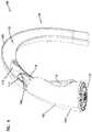
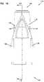
- FIG. 1illustrates a perspective view of a faucet with a spray head in an aligned position, according to one embodiment of the present disclosure.
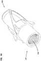
- FIG. 2illustrates a perspective view of the faucet of FIG. 1 with the spray head in an extended, misaligned position, excluding a water hose.
- FIG. 3illustrates a perspective schematic view of the faucet of FIG. 1 with the spray head in an extended, misaligned position.
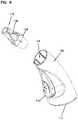
- FIG. 4illustrates a perspective schematic view of the faucet of FIG. 1 with the spray head in an extended, misaligned position.
- FIG. 5illustrates a perspective schematic view of the faucet of FIG. 1 with the spray head in the aligned position.
- FIG. 6illustrates a side cross-sectional view of the faucet of FIG. 1 with the spray head in the aligned position.
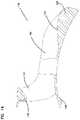
- FIG. 7illustrates a side cross-sectional view of a faucet body and a first alignment element of the faucet of FIG. 1 .
- FIG. 8illustrates a perspective view of a spray head and a second alignment element of the faucet of FIG. 1 .
- FIG. 9illustrates a perspective partially exploded view of the spray head and the second alignment element of the faucet of FIG. 1 .
- FIG. 10illustrates a perspective partially exploded view of an alignment coupling including the first and second alignment elements, according to one example of the present disclosure.
- FIG. 11illustrates a perspective view of the alignment coupling of FIG. 10 in the fully engaged position.
- FIG. 12illustrates a perspective view of the first alignment element of FIG. 10 .
- FIG. 13illustrates another perspective view of the first alignment element of FIG. 10 .
- FIG. 14illustrates a side cross-sectional view of the first alignment element of FIG. 10 .
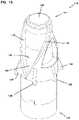
- FIG. 15illustrates a perspective view of the second alignment element of FIG. 10 .
- FIG. 16illustrates a side view of the second alignment element of FIG. 10 .
- FIG. 17illustrates a side cross-sectional view of the second alignment element of FIG. 10 .
- FIG. 18illustrates a perspective view of a second alignment element, according to one example of the present disclosure.
- FIG. 19illustrates a schematic representation of the interfacing of alignment features of the alignment coupling of FIG. 10 .
- FIG. 20illustrates another schematic representation of the interfacing of alignment features of the alignment coupling of FIG. 10 .
- FIG. 21illustrates another schematic representation of the interfacing of alignment features of the alignment coupling of FIG. 10 in the fully engaged position that corresponds with the aligned position of the spray head.
- FIG. 22illustrates a perspective exploded view of the spray head of the faucet of FIG. 1 .
- FIG. 23illustrates a perspective view of the second alignment element of the alignment coupling of FIG. 10 attached to a water hose.
- FIG. 24illustrates a side cross-sectional view of the second alignment element of the alignment coupling of FIG. 10 attached to the water hose.
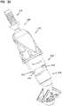
- FIG. 25illustrates a perspective view of a first alignment element, according to one example of the present disclosure.
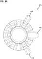
- FIG. 26illustrates a front view of the first alignment element of FIG. 25 .
- FIG. 27illustrates a perspective side cross-sectional view of the first alignment element of FIG. 25 .
- FIG. 28illustrates a perspective view of a second alignment element, according to one example of the present disclosure.
- FIG. 29illustrates a front view of the second alignment element of FIG. 29 .
- FIG. 30illustrates a perspective view of a second alignment element, a water hose fitting, and a valve component, according to one example of the present disclosure.
- FIG. 31illustrates a perspective view of the valve component separated from the second alignment element and the water hose fitting of FIG. 30 .
- FIG. 32illustrates another perspective view of the valve component of FIG. 31 .
- FIG. 33illustrates an exploded view of the second alignment element, the water hose fitting, and the valve component of FIG. 30 .
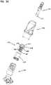
- FIG. 34illustrates a side view of the second alignment element and the water hose fitting of FIG. 30 .
- FIG. 35illustrates a cross-sectional side view of the second alignment element along line 35 - 35 of FIG. 34 .
- FIG. 36illustrates a perspective view of a portion of a seal assembly, according to one example of the present disclosure.
- FIG. 37illustrates another perspective view of the portion of the seal assembly of FIG. 36 .
- FIG. 38illustrates an exploded view of the portion of the seal assembly of FIG. 36 .
- FIG. 39illustrates a schematic perspective view of a seal assembly, according to one example of the present disclosure.
- the present disclosurerelates to a faucet that includes an alignment coupling.
- the alignment couplingensures that a spray head of the faucet reliably returns to the same orientation position when the spray head is retracted to a mated position with the faucet body.
- the alignment couplingfurther facilitates reliable complete docking of the spray head within the faucet body.
- the alignment couplingincludes alignment elements in the faucet body and adjacent the spray head that interface with one another to provide alignment movement. In some examples, at least one of the alignment elements is positioned at least partially around a water hose of the faucet.
- the alignment elementsinclude alignment features that include a corresponding projection and a groove (e.g., a v-shaped groove) so that when the groove receives the projection, the projection slides into the narrowest portion of the groove, thereby aligning the spray head with the faucet body.
- a corresponding projection and a groovee.g., a v-shaped groove
- FIG. 1shows a faucet 100 including a faucet body 102 and a faucet spray head 104 that is detachable from a faucet body outlet 106 of the faucet body 102 .
- the spray head 104is docked with the faucet body 102 .
- the spray head 104is movable away from the faucet body 102 so as to allow the user the ability to manipulate the spray head 104 during use. This is facilitated by a water hose (shown schematically in FIG. 6 ) having excess length attached to the spray head 104 and positioned within the faucet body 102 .
- the faucet 100is configured to dispense water from a water source out of a spray head outlet 112 of the spray head 104 . Further, the faucet 100 is configured to be controlled (i.e., on/off, water volume, and water temperature) via traditional methods (e.g., a handle), and/or via gesture or voice. Although the faucet 100 can be a pull-down kitchen faucet, this disclosure encompasses other types of faucets, including but not limited to, pull-out faucets. Although this disclosure will be discussed with regard to a kitchen faucet for purposes of example, the system described herein could be implemented in any type of pull-down faucet and/or a pull-out faucet, including a side auxiliary spray faucet. In some examples, the faucet 100 is a showerhead in a shower. In some examples, the faucet 100 is any fluid dispensing device that is configured to dispense fluid therefrom.
- the faucet body 102can have a variety of different shapes and sizes to provide a variety of different appearances having differing aesthetics. As shown, the faucet body 102 includes an arcuate neck 108 between the outlet 106 and the opposing end of the faucet body 102 .
- the faucet body 102can be mounted in a variety of different locations, such as, but not limited to, a countertop, a wall, a ceiling, etc. In some examples, the faucet body 102 is fixed to a location, such as near a kitchen sink.
- the spray head 104is detachable so that it can be undocked from the faucet body 102 to allow for maneuverability by the user to aim the spray head 104 .
- the spray head 104can include a user input 110 positioned thereon to allow the user to toggle characteristics of the water expelled at the spray head outlet 112 .
- the operation of the user input 110can facilitate the toggling of a valve (see FIG. 22 ) positioned within the spray head 104 .
- the user input 110can toggle characteristics of the expelled water, such as, but not limited to, volume and/or temperature.
- the user input 110is one of a button, touch sensitive surface, or the like.
- An outer profile 103 of the spray head 104can have a variety of different shapes and sizes to provide a variety of different aesthetic configurations of the faucet 100 .
- the spray head 104can be configured to have an outer profile 103 that cooperates with an outer profile 105 of the faucet body 102 .
- the spray head 104is generally asymmetrical. In other examples, the spray head 104 is generally symmetrical.
- the spray head 104has an aligned position when docked with the faucet body 102 .
- the aligned positionis a position that the spray head 104 returns to automatically every time it is docked with the faucet body 102 .
- the aligned positioncan be a variety of different positions depending on the aesthetics of the faucet 100 , as well as the particular use of the faucet 100 .
- the spray head 104has an asymmetrical outer profile and has an aligned position that aligns the outer profile of the faucet body 102 , specifically the neck 108 , with the outer profile of the spray head 104 . This allows for a consistent outer profile of the faucet 100 , including the faucet body 102 and the spray head 104 .
- the user input 110when in the aligned position, the user input 110 is positioned facing the faucet body 102 , so as to maintain a clean aesthetic from the front of the faucet 100 . In some examples, when in the aligned position, the user input 110 is positioned facing the left, right, or away from the faucet body 102 .
- the spray head 104can include weights (not shown) to alter the center of the gravity of the spray head 104 in a way to urge the spray head 104 to the aligned position.
- the weightcan be positioned at a particular side of the spray head 104 so that the weight, by way of gravity, naturally rotates the spray head 104 in a way where the weight becomes positioned at an underside of the spray head 104 when in the aligned positioned. This can be accomplished by placing the weight adjacent the spray head outlet 112 and offset of the longitudinal axis of the spray head 104 .
- FIGS. 2-5show the movement of the spray head 104 to the aligned positioned during docking. Such alignment is facilitated by an alignment coupling 114 , which includes a first alignment element 116 and a second alignment element 118 . At least one of the first alignment element 116 and the second alignment element 118 is movable with respect to the other. In the depicted example, the second alignment element 118 is movable with respect to the first alignment element 116 .
- the first and second alignment elements 116 , 118can be positioned at a variety of different locations on the faucet 100 .
- the first alignment element 116is positioned within the faucet body 102 and the second alignment element 118 is positioned adjacent the spray head 104 .
- the second alignment element 118is attached to the spray head 104 .
- the second alignment element 118is positioned around a water hose (not shown) of the faucet 100 .
- the second alignment element 118is attached to a water hose of the faucet 100 .
- the first and second alignment elements 116 , 118are integrally formed in the faucet body 102 and spray head 104 .
- the first and second alignment elements 116 , 118are separate parts from the faucet body 102 and spray head 104 .
- FIG. 2shows the spray head 104 detached from the faucet body 102 . While typically a water hose (not shown) would be connected to the spray head 104 and routed within the outlet 106 of the faucet body 102 , the water hose has been omitted for illustration purposes.
- the outlet 106allows access to a pathway 122 disposed at least partially within the faucet body 102 so that the water hose can be routed to a water source.
- FIG. 3shows the spray head 104 partially docked with the outlet 106 of the faucet body 102 .
- a cross-sectional isometric view of the faucet body 102is shown.
- the spray head 104is shown rotated along its longitudinal axis in a direction where the user input 110 is facing to a side of the faucet 100 .
- such a positionis considered a misaligned position of the spray head 104 .
- the spray head 104can include a plurality of misaligned positions. In some examples, every position that the spray head 104 has when in contact with the faucet body 102 , where the spray head 104 is not in the aligned position, is considered a misaligned position.
- the first and second alignment elements 116 , 118are shown interfacing with one another to begin an alignment motion caused by the configuration of the alignment coupling 114 .
- a pullback devicee.g., a weight, spring, reel, etc.
- the spray head 104is rotated automatically via the alignment coupling 114 toward the aligned position.
- the spray head 104is further rotated closer to the aligned position thanks to the interfacing of the first and second alignment elements 116 , 118 of the alignment coupling 114 .
- FIG. 5shows the spray head 104 positioned in the aligned position and fully docked with the faucet body 102 .
- FIG. 6shows a cross-sectional view of the faucet 100 with the spray head 104 in the aligned position.
- FIG. 6also shows a water hose 124 attached to the spray head 104 and positioned within the pathway 122 of the faucet body 102 .
- the water hose 124can be attached to the spray head in a variety of ways, including being attached to the second alignment element 118 .
- the first alignment element 116 of the alignment coupling 114includes a tongue 126 that interfaces with the hose 124 and elevates the hose 124 from a lower interior surface 120 of the pathway 122 .
- the tongue 126is configured to control an angle ⁇ of entry of the water hose 124 into the pathway 122 with respect to horizontal H.
- the angle ⁇can be altered.
- the angle ⁇is between about 30 degrees and 60 degrees with respect to horizontal H.
- the angle ⁇is 45 degrees with respect to horizontal H.
- the water hose 124can be any of a variety of different types including, but not limited to, a nylon-braided hose, a metal braided hose, a flexible hose, a coated hose, etc.
- FIG. 7shows a side view of the first alignment element 116 positioned in the outlet 106 of the faucet body 102 .
- the first alignment element 116is positioned within a portion of the neck 108 of the faucet.
- the first alignment element 116is fixed within the outlet 106 of the faucet body 102 .
- the first alignment element 116is fixed to the faucet body 102 by way of a fastener, such as, but not limited to, at least one screw, bolt, adhesive, and/or the like.
- the first alignment element 116can be integral with the faucet body 102 .
- the first alignment element 116is fixed to the faucet body 102 by way of a press fit.
- the first alignment element 116is fixed to the faucet body 102 by way of brazing, welding, or the like.
- the first alignment element 116includes a faucet body alignment portion 128 , a projection 132 , and a ring 131 .
- the faucet body alignment portion 128facilitates proper alignment of the first alignment element 116 within the outlet 106 of the faucet body 102 .
- the faucet body alignment portion 128can assist in the proper assembly of the faucet 100 , so that the first alignment element 116 is more easily correctly orientated at the outlet 106 to facilitate the desired alignment of the spray head 104 once the faucet 100 is assembled.
- the faucet body alignment portion 128is one of a projection and a recess. The faucet body alignment portion 128 is engageable with a corresponding projection or recess 130 of the faucet body 102 .
- the first alignment element 116also includes an alignment feature that includes the projection 132 positioned at a top side 121 of the pathway 122 and extending from the top side of the ring 131 of the first alignment element 116 .
- the projection 132is configured to interface with the second alignment element 118 to move the spray head 104 into the aligned positioned during docking.
- the projection 132is at a side of the first alignment element 116 opposite the tongue 126 .
- the first alignment element 116also includes the ring 131 positioned at the outlet 106 of the faucet body 102 .
- the ring 131is positioned within the faucet body 102 to encircle the pathway 122 .
- the projection 132extends radially directly inward from the ring 131 and the tongue 126 extends axially therefrom.
- the ring 131also includes the faucet body alignment portion 128 .
- FIG. 8shows the second alignment element 118 mounted to the spray head 104 .
- FIG. 9shows the second alignment element 118 spaced away from an interval cavity 134 of the spray head 104 .
- the second alignment element 118is fixed to the spray head 104 to prevent relative movement therebetween.
- the second alignment element 118is mounted adjacent to the spray head 104 .
- the second alignment element 118is positioned around the end of the water hose 124 , as shown in FIG. 6 .
- the second alignment element 118is mounted to the hose 124 .
- the second alignment element 118includes an alignment feature that includes groove 136 positioned at the periphery of the second alignment element 118 .
- the groove 136is configured to interface with the projection 132 of the first alignment element 116 so as to move the spray head 104 toward the aligned position during docking.
- the second alignment element 118also includes centering elements 138 positioned circumferentially around the exterior surface thereof.
- the centering elements 138are configured to interface with the outlet 106 of the faucet body 102 to aid in centering the spray head 104 during docking.
- the centering elements 138are configured to interface with a portion of the first alignment element 116 .
- the centering elements 138are fins, with the narrowest side of the fin being configured to interface with the faucet body 102 /first alignment element 116 first.
- FIG. 10shows a perspective view of the alignment coupling 114 when the first and second alignment elements 116 , 118 are positioned in a fully engaged position.
- FIG. 11shows the alignment coupling 114 partially exploded, and the first and second alignment elements 116 , 118 are shown spaced apart from one another.
- the second alignment element 118has a generally cylindrical outer profile shape and the first alignment element 116 has a complementary shape, such as a circular recess (e.g., the ring 131 ) for the outer profile of the second alignment element 118 to be received within.
- the relationshipcan be reversed and the first alignment element 116 can have a cylindrical shape while the second alignment element 118 has a complementary shape. It is considered within the scope of the present disclosure that the first or second alignment elements 116 , 118 can have a variety of different geometric profiles and are not limited to a cylindrical shape and corresponding complementary shape.
- the fully engaged position of the first and second alignment elements 116 , 118corresponds with the aligned position of the spray head 104 .
- a longitudinal axis S of the second alignment element 118 and a central axis B of the ring 131 of the first alignment element 116are generally aligned.
- the projection 132 of the first alignment element 116is received and positioned within the groove 136 of the second alignment element 118 when the alignment coupling 114 is in the fully engaged position.
- the second alignment element 118is configured to be positioned within at least a portion of the first alignment element 116 .
- the second alignment element 118is positioned within the ring 131 of the first alignment element 116 .
- FIGS. 12 and 13show perspective views of the first alignment element 116 .
- FIG. 14shows a side cross-sectional view.
- the first alignment element 116includes the ring 131 , where the projection 132 extends radially inward therefrom.
- the first alignment element 116also includes the tongue 126 that extends generally in an axial direction away from the ring 131 .
- the first alignment element 116includes the faucet body alignment portion 128 at a lower side of the ring 131 .
- the faucet body alignment portion 128is a projection.
- the ring 131is only a partial ring and is configured to only partially surround the pathway 122 of the outlet 106 of the faucet body 102 .
- the projection 132can extend radially inward from the ring 131 at any point on the ring 131 .
- the projection 132can extend inward from either side or from the bottom of the ring 131 , not just from the top, as shown.
- the ring 131can include a plurality of other alignment features disposed thereon such as, but not limited to, additional projections and/or grooves.
- the tongue 126can include a wall 140 that at least partially defines a ramped portion 142 .
- the tongue 126specifically the wall 140 , extends in a general axial direction away from the ring 131 .
- the first alignment element 116includes the tongue 126
- the first alignment elementdoes not have to include a tongue 126 .
- the first alignment element 116only includes an alignment feature, such as the projection 132 .
- the first alignment element 116can be constructed of a variety of different materials including, but not limited to, metal (e.g., aluminum) and plastic (e.g., Rulon, Derlin, or other like PTFE plastics).
- metale.g., aluminum
- plastice.g., Rulon, Derlin, or other like PTFE plastics.
- FIGS. 15-17show the second alignment element 118 .
- FIG. 15shows a perspective view
- FIG. 16shows a side view
- FIG. 17shows a side cross-sectional view.
- the second alignment element 118includes a first end 144 and a second end 146 .
- the first end 144is configured to be inserted into the faucet body 102 before the second end 146 .
- the first end 144is configured to receive the water hose 124 at an opening 147 .
- the second end 146is configured to be attached to a portion of the spray head 104 .
- the second alignment element 118includes a pair of grooves 136 positioned at opposite sides of the second alignment element 118 . In some examples, only a single groove 136 is utilized for alignment. Each groove 136 includes a pair of walls 148 that together define the boundaries of the groove 136 . In some examples, the groove 136 has a tapered shape defined by the walls 148 that extend toward one another from the first end 144 in a direction toward the second end 146 . In some examples, the tapered shape of the groove 136 is v-shaped. In some examples, the walls 148 extend toward one another in a generally axial direction from the first end 144 .
- the walls 148extend toward one another in a direction that is partially in the axial direction and partially in the circumferential direction.
- the groove 136is configured in a way so that immediately adjacent the first end 144 , the walls 148 are separated at a distance to define the widest portion of the groove 136 .
- the walls 148progressively narrow the groove 136 until they intersect with one another. Adjacent the point of intersection of the walls 148 , the groove 136 has its narrowest width and defines a pocket 150 .
- FIG. 17shows a cross sectional view of the second alignment element 118 .
- the second alignment element 118defines a passageway 152 that extends longitudinally through the second alignment element 118 .
- the opening 147 at the first end 144is a first opening of the passageway 152 and an opening 154 at the second end 146 is the second opening of the passageway 152 .
- the passagewayis configured to receive the water hose 124 within the opening 147 at the first end 144 .
- the passagewayis further configured to be connected at the opening 154 of the second end 146 to the spray head 104 .
- the passageway 152can include threads, a recess, a series of projections, and/or other like attachment structures to aid in attaching the water hose 124 and the spray head 104 thereto.
- the passageway 152includes internal threads 156 for attaching the water hose 124 and a series of recesses 158 at the opening 154 adjacent the second end 146 to receive corresponding projections of an attachment portion of the spray head 104 .
- the recesses 158allow for a bayonet connection between the spray head 104 and the second alignment element 118 .
- FIG. 18shows another example of a second alignment element 218 that utilizes internal threads 258 at a second end 246 to attach to the spray head 104 .
- the second alignment element 118can be constructed of a variety of different materials including, but not limited to, metal (e.g., aluminum) and plastic (e.g., Rulon, Derlin, or other like PTFE plastics).
- metale.g., aluminum
- plastice.g., Rulon, Derlin, or other like PTFE plastics.
- FIGS. 19-21show a series of schematic illustrations of an example interfacing of the first and second alignment elements 116 , 118 of the alignment coupling 114 during the docking of a spray head 104 .
- the projection 132 of the first alignment element 116is shown.
- the groove 136 of the second alignment element 118is shown approaching the projection 132 , indicated by the dashed arrow.
- the example shownis representative of the spray head 104 being re-docked to the fixed faucet body 102 having the projection 132 .
- the second alignment element 118can be fixed to the water hose 124 and the water hose 124 is fixed to the spray head 104 . Therefore, upon rotation of the water hose 124 by the second alignment element 118 , the water hose 124 rotates the spray head 104 .
- the spray head 104is in the aligned position and docked, and thus the alignment coupling 114 is in the fully engaged position. Such move is done automatically due to the shape of the groove 136 and/or the projection 132 .
- the relationship of the groove 136 and the projection 132can be reversed so that the projection 132 is positioned on the second alignment element 118 and the groove 136 is positioned on the first alignment element 116 .
- the projection 132 of the spray head 104would move within the groove 136 as the spray head 104 is being docked and automatically position itself in the pocket 150 of the groove thanks to the tapered, V-shape configuration.
- the spray head 104When in the pocket 150 , the spray head 104 would be positioned in the aligned position.
- FIG. 22shows a perspective exploded view of the spray head 104 .
- the spray head 104includes an outer housing 160 and a valve 162 positioned within the outer housing 160 .
- the valve 162is configured to alter the characteristic of the water as it is expelled from the spray head outlet 112 .
- the user input 110is configured to control the operation of the valve 162 .
- the valve 162includes an attachment portion 166 that includes a plurality of projections 168 .
- the attachment portion 166is configured to be connected to the second end 146 of the second alignment element 118 .
- the projections 168are configured to be received in the recesses 158 of the second alignment element 118 to allow for a bayonet attachment between the spray head 104 and the second alignment element 118 .
- FIGS. 23 and 24depict the water hose 124 connected to the first end 144 of the second alignment element 118 .
- the second alignment element 118is positioned around a portion the water hose 124 .
- the water hose 124includes a fitting 170 that is connected within the passageway 152 of the second alignment element 118 .
- the fitting 170is mated with the threads 156 of the second alignment element 118 .
- FIGS. 25-27show a first alignment element 316 according to another embodiment of the present disclosure.
- FIGS. 28-29show a second alignment element 318 configured to interface with the first alignment element 316 to form an alignment coupling.
- the first and second alignment elements 316 , 318are configured to have functional properties that are substantially similar to the first and second alignment elements 116 , 118 outlined above.
- the first and second alignment elements 316 , 318are also constructed out of similar material as the first and second alignment elements 116 , 118 , as described above.
- the first alignment element 316is configured to be positioned within the faucet body 102 .
- the first alignment element 316includes a pair of ramps 348 that surround a passageway 319 .
- the passageway 319is configured to receive the water hose 124 .
- the ramps 348are configured to aid in positioning a projection 332 of the second alignment element 318 .
- the ramps 348are configured to extend away from an opening 317 of the first alignment element 316 and intersect within one another at a pocket 350 . Such a configuration allows the projection 332 of the second alignment element 318 to interface with, and move along, the ramps 348 , eventually being automatically positioned at the pocket 350 .
- the spray head 104is in the aligned position.
- the second alignment element 318has a tapered outer surface 321 to ease insertion into the opening 317 of the first alignment element 316 .
- the second alignment element 318is configured to be positioned around the water hose 124 .
- the second alignment element 318is positioned adjacent the spray head 104 .
- the second alignment element 318is connected to the spray head 104 .
- the second alignment element 318includes centering elements 338 that function in a similar way to the centering elements 138 described above and aid in positioning the spray head 104 with respect to the faucet body 102 .
- the projection 332extends in a radial direction from the outer surface 321 .
- the projection 332is pin-shaped.
- FIG. 30shows a second alignment element 418 , according to another example of the present disclosure.
- the second alignment element 418is configured to interface with a first alignment element similar to the first alignment element 116 , described above. Accordingly, the second alignment element 418 is configured to have functional properties that are substantially similar second alignment elements 118 , 218 , and 318 described above.
- the second alignment element 418is constructed out of similar material as the first and second alignment elements 116 , 118 , as described above.
- the second alignment element 418is configured to be positioned around the water hose 124 , specifically connected to a water hose fitting 419 . In some examples, the second alignment element 418 is positioned adjacent the spray head 104 . In some examples, the second alignment element 418 is connected to the spray head 104 .
- FIGS. 31 and 32show the valve component 470 separated from the second alignment element 418 .
- valve component 470is a portion of a valve, similar to valve 162 , positioned within the spray head 104 .
- the valve component 470passes water from the second alignment element 418 and out of the spray head 104 .
- the valve of which the valve component 470 is a part ofis configured to alter the characteristic of the water as it is expelled from the spray head outlet 112 .
- the valve of which the valve component 470 is a part ofis configured to not alter the characteristic of the water as it is expelled from the spray head outlet 112 .
- the second alignment element 418is connected to the valve component 470 at the second end 462 .
- the second end 462is connected over the valve component 470 .
- the second end 462is connected within the valve component 470 .
- the second alignment element 418is threaded onto the valve component 470 .
- the valve componentincludes a projection, similar to the projections 168 described above, to allow for a bayonet-type connection between the second alignment element 418 and the valve component 470 .
- the second end 462is threaded onto the valve component 470 and includes at least one second alignment stop element 472 that is configured to mate with a spray head stop 474 positioned adjacent an attachment portion 466 of the valve component 470 .
- the second end 462 of the second alignment element 418includes more than one second alignment stop element 472 .
- the second alignment stop 472can be one of a projection and a recess.
- the spray head stop 474can be the other of the projection and recess from the second alignment stop 472 of the second alignment element 418 .
- the stops 472 , 474prevent incorrect assembly of the second alignment element 418 and the valve component 470 .
- the stops 472 , 474ensure consistent assembly of the second alignment element 418 and the valve component 470 because the second alignment element stop 472 bottoms out the rotation in a first direction F 1 of the second alignment element 418 with respect to the valve component 470 .
- the second alignment stop 472 and the spray head stop 474rotationally align the second alignment element 418 and the valve component 470 .
- the valve component 470is connected to the spray head 104 in a way to prevent relative rotation between the valve component 470 and the outer housing 160 of the spray head 104 .
- the second alignment element 418is aligned properly with the valve component 470 when the second alignment element 418 interacts with a first alignment element (e.g., first alignment element 116 ), the second alignment element 418 consistently properly aligns the spray head 104 with the faucet body 104 .
- a first alignment elemente.g., first alignment element 116
- the second alignment stop 472 and the spray head stop 474prevent over-tightening the second alignment element 418 with the valve component 470 .
- FIG. 33shows an exploded view of the water hose fitting 419 , the second alignment element 418 , and the valve component 470 .
- the second alignment element 418includes a seal assembly 475 positioned therein.
- the seal assembly 475includes a holder 476 , a collar 477 , a first seal 478 , a second seal 479 , a seal holder 480 , a spring 481 , and a spring cage 482 .
- the seal assembly 475is configured to aid in sealing a spherical portion 417 of the water hose fitting 419 within the second alignment element 418 .
- the water hose fitting 419is allowed to move with respect to the second alignment element 418 .
- the spherical portion 417 of the water hose fitting 419is configured to form a ball joint-like connection with the second alignment element 418 .
- the ball joint-like connection with the second alignment element 418facilitates easy swiveling of the spray head 104 with respect to the water hose 124 .
- the seal assembly 475increases the seal force on the water hose fitting 419 .
- the seal assembly 475decreases the seal force on the water hose fitting 419 . It is considered within the scope of the present disclosure that, with the use of devices inside of the spray head 104 (e.g., valves, restrictors, etc.), water pressure within the spray head 104 can be manipulated.
- the seal force on the water hose fitting 419increases when water is dispensed from the spray head 104 and decreases when water is not dispensed from the spray head 104 .
- the seal force on the water hose fitting 419decreases when water is dispensed from the spray head 104 and increases when water is not dispensed from the spray head 104 .
- FIG. 34shows a side view of the second alignment element 418 and the water hose fitting 419 mated together.
- FIG. 35shows a cross-sectional view of the second alignment element 418 and water hose fitting 419 along line 35 - 35 in FIG. 34 .
- the spherical portion 417 of the water hose fitting 419is positioned within the first end of the second alignment element 418 so that a fitting inner passage 415 of water hose fitting 419 communicates with an inner passage 483 of the second alignment element 418 .
- the holder 476is configured to be positioned within a main inner cavity 486 of the second alignment element 418 . In some examples, the holder 476 can be threaded into the main inner cavity 486 . The holder 476 is configured to aid in axially positioning the first seal 478 , the second seal 479 , the seal holder 480 , the spring 481 , and the spring cage 482 within the main inner cavity 486 . In some examples, the holder 476 includes an interior seal chamber 491 that has a first end 492 and a second end 493 . The spring 481 is positioned within the interior seal chamber 491 between first and second ends 492 , 493 of the interior seal chamber 491 .
- the spring 481is positioned between the first end 492 of the interior seal chamber 491 and the first seal 478 .
- the second seal 479 and the seal holder 480are positioned adjacent the second end 493 of the interior seal chamber 491 within the main inner cavity 486 .
- the collar 477 of the seal assembly 475surrounds a first end 484 of the spherical portion 417 of the water hose fitting 419 .
- the collar 477has a tapered aperture 485 to facilitate the insertion of the spherical portion 417 therethrough.
- the collar 477can be a rubber seal.
- the collar 477can act as a bushing between the second alignment element 418 and the water hose fitting 419 .
- the first seal 478is positioned around the spherical portion 417 of the water hose fitting 419 , immediately adjacent the seal holder 480 and the collar 477 .
- the first seal 478is positioned within the main inner cavity 486 of the second alignment element 418 .
- the main inner cavity 486houses the holder 476 , the first seal 478 , the second seal 479 , the seal holder 480 , the spring 481 , and the spring cage 482 .
- the main inner cavity 486has a consistent diameter along its length to facilitate the installation of the seal assembly 475 within the second alignment element 418 .
- the first seal 478is a rubber seal.
- the second seal 479is positioned around a second end 487 of the spherical portion 417 of the water hose fitting 419 . Specifically, the second seal 479 defines an aperture 490 that is sized and shaped to receive the second end 487 of the spherical portion 417 .
- the second seal 479is positioned immediately adjacent the seal holder 480 and the spring cage 482 .
- the second seal 479is rotationally captured by the seal holder 480 and is configured to be compressed by a force received at a first axial side 488 , opposite a second axial side 489 that faces the seal holder 480 .
- the second seal 479moves axially along a longitudinal axis X of the seal assembly 475 .
- the second seal 479does not contact the main inner cavity 486 when there is no force received at the axial side 488 .
- the aperture 490 of the second seal 479travels toward the first end 484 of the spherical portion 417 when a force is received at the axial side 488 , thereby forming a tighter seal around the spherical portion 417 , due to the spherical configuration of the spherical portion 417 of the water hose fitting 419 .
- the second seal 479is a rubber seal.
- the seal holder 480is configured to interlock and mate with the second seal 479 to prevent relative rotation between the seal holder 480 and the second seal 479 .
- the seal holder 480is of a different material than the second seal 479 .
- the seal holder 480is a rigid material, such as plastic.
- the spring 481is positioned within the interior seal chamber 491 of the holder 476 .
- the spring 481is positioned between the first end 492 of the seal chamber 491 and the second seal 479 .
- the spring 481is also positioned around a cage portion 494 of the spring cage 482 and in contact with a flange 495 of the spring cage 482 .
- the spring 481is configured to exert a predetermined force at the first axial side 488 of the second seal 479 .
- the spring 481is a compression spring.
- the spring 481can be a variety of different types of springs, for example, a helical spring, a wave spring, a conical spring, a disc spring, etc.
- the spring cage 482is configured to be movably positioned within the interior seal chamber 491 .
- the spring cage 482includes the cage portion 494 and the flange 495 .
- the seal assembly 475does not include a spring cage 482 .
- the spring cage 482is constructed of a rigid material.
- the cage portion 494is positioned inside the spring 481 and allows water to flow axially and radially through the cage portion 494 and freely within the seal chamber 491 .
- the cage portion 494is cylindrical and includes a plurality of slots 497 to allow for radial water flow therethrough. In some examples, only axial flow through the cage portion is permitted.
- the cage portion 494 and the flange 495are separate pieces. In some examples, the cage portion and flange 495 are monolithically formed.
- the flange 495is positioned between the spring 481 and the second seal 479 .
- the flange 495is generally circular and dispenses a force to the second seal 479 from the seal chamber 491 .
- the seal assembly 475only includes the flange 495 and not the cage portion 494 .
- the flange 495is a washer.
- FIGS. 36 and 37show perspective views of a portion of the seal assembly 475
- FIG. 38shows an exploded view of a portion of the seal assembly 475
- the second seal 479 and the seal holder 480interlock with one another to prevent relative rotation therebetween.
- the seal holder 480includes a plurality of projections 498 that are received by a plurality of recesses 499 of the second seal 479 . It is considered within the scope of the present disclosure that the seal holder 480 and second seal 479 can interlock with each other in a variety of ways.
- FIG. 39is a schematic depiction of the seal assembly 475 .
- Wateris indicated by arrows W.
- the water pressure within the seal chamber 491exerts a force on the spring cage 482 , thus exerting a force on the second seal 479 via the flange 495 .
- Pressurized water W within the seal chamber 491exerts a force on the second seal 479 , thereby axially moving the second seal 479 toward the first seal 478 .
- the force exerted on the second seal 479 by the pressurized water Wis in addition to the predetermined amount of force exerted by the spring 481 on the second seal 479 .
- the movement of the second seal 479 toward the first seal 478tightens the connection of the aperture 490 around the second end 487 of the spherical portion 417 of the water hose fitting 419 , thus automatically increasing the seal around the water hose fitting 419 .
- the force exerted on the second seal 479is reduced, thereby allowing the second seal 479 to move away from the first seal 478 , thus loosening the connection of the aperture 490 around the second end 487 of the spherical portion 417 of the water hose fitting 419 and automatically decreasing the seal around the water hose fitting 419 .
- the lowest force exerted on the second seal 479is the force exerted by the spring 481 .
- water Wenters the seal chamber 491 via the fitting inner passage 415 . If the spray head 104 is dispensing water, the pressurized water W travels into the seal chamber 491 , increasing the seal around the water hose fitting 491 , through the seal assembly 475 , and out of the spray head 104 . If water is not being dispensed from the spray head 104 , water W does not pass through the seal assembly 475 and minimal water pressure exists within the seal chamber 491 .
- a faucetin Example 1, includes a faucet body including a first alignment element located at an outlet within the faucet body; and a faucet spray head being positionable at the outlet of the faucet body, the faucet spray head including a second alignment element, the faucet spray head having an aligned position and a plurality of misaligned positions with respect to the faucet body.
- the first and second alignment elementsform an alignment coupling, the alignment coupling including a projection and a tapered groove, wherein at least one is movable with respect to the other, and wherein, when the projection is positioned at a narrowest portion of the tapered groove, the faucet spray head is in the aligned position.
- Example 2the faucet of Example 1 is modified in that the projection is configured to interface with walls of the tapered groove to align the faucet spray head.
- Example 3the faucet of Example 1 is modified in that the first alignment element includes a ring and a tongue, the tongue extending in an axial direction from the ring, wherein the ring includes the projection extending radially inward therefrom within the outlet of the faucet body.
- Example 4the faucet of Example 1 is modified in that the first alignment element includes a tongue surface, wherein the tongue surface extends within the faucet body from the outlet of the faucet body, and wherein the tongue surface is raised above a lower surface of the faucet body.
- Example 5the faucet of Example 1 is modified in that the second alignment element is generally cylindrical, and wherein the tapered groove has walls that extend toward one another in a generally axial direction on an outer surface of the second alignment element to form a v-shaped groove.
- Example 6the faucet of Example 1 is modified in that the alignment coupling includes at least one centering element, wherein the at least one centering element is configured to center the faucet spray head within the outlet of the faucet body.
- Example 7the faucet of Example 1 is modified in that the at least one centering element is a plurality of centering elements positioned at a periphery of the second alignment element.
- Example 8the faucet of Example 1 is modified in that the faucet body includes an arcuate neck that includes the outlet, wherein an arcuate side profile is created when the faucet spray head is in the aligned position, and wherein the arcuate side profile is interrupted when the faucet spray head is in the plurality of misaligned positions.
- Example 9the faucet of Example 1 is modified in that the alignment coupling is coupled when the first and second alignment elements are in contact with each other, and wherein the alignment coupling is decoupled when the first and second alignment element are not in contact with each other, wherein when decoupled, the faucet spray head is spaced away from the outlet of the faucet body.
- Example 10the faucet of Example 1 is modified to further include a water hose connected to the faucet spray head, wherein the second alignment element is secured around the water hose, wherein the water hose includes a pullback feature in communication therewith, and wherein the pullback feature pulls the faucet spray head toward the outlet of the faucet body.
- Example 11the faucet of Example 10 is modified in that the pullback feature is a weight attached to the water hose.
- Example 12the faucet of Example 1 is modified in that the alignment coupling is integral with the faucet body and faucet spray head.
- Example 13the faucet of Example 1 is modified in that the alignment coupling is mounted to the faucet body and faucet spray head.
- a faucetin Example 14, includes a faucet body; a faucet spray head movable with respect to the faucet body; a first alignment element mounted within the faucet body, the first alignment element having a first alignment feature, the first alignment feature including one of a projection and a tapered groove; and a second alignment element mounted to the faucet spray head, the second alignment element having a second alignment feature, the second alignment feature including the other of the projection and tapered groove.
- the projectionis configured to interface with walls of the tapered groove to align the faucet spray head.
- Example 15the faucet of Example 14 is modified in that the first alignment element includes a ring and a tongue, the tongue extending in an axial direction from the ring, wherein the ring includes the projection extending radially inward therefrom.
- Example 16the faucet of Example 14 is modified in that the first alignment element includes a tongue surface, wherein the tongue surface extends within the faucet body from the outlet of the faucet body, and wherein the tongue surface is raised above a lower surface of the faucet body.
- Example 17the faucet of Example 14 is modified in that the second alignment element is generally cylindrical, and wherein the tapered groove has walls that extend toward one another in a generally axial direction on an outer surface of the second alignment element to form a v-shaped groove.
- Example 18the faucet of Example 14 is modified in that the second alignment element includes a plurality of centering elements, wherein the plurality of centering elements is configured to center the faucet spray head within the outlet of the faucet body, and wherein the plurality of centering elements is positioned at a periphery of the second alignment element.
- an alignment coupling for a faucetincludes a first alignment element positionable within a faucet body, the first alignment element having a first alignment feature, the first alignment feature including one of a projection and a tapered groove; and a second alignment element being movable with respect to the first alignment element, the second alignment element having a second alignment feature, the second alignment feature including the other of the projection and tapered groove.
- the tapered grooveincludes walls that extend toward each other, and wherein the walls guide the projection to a narrowest portion of the tapered groove.
- Example 20the alignment coupling of Example 19 is modified in that the first alignment element includes a ring and a tongue, the tongue extending in an axial direction from the ring, wherein the ring includes the projection extending radially inward therefrom.
- Example 21the alignment coupling of Example 20 is modified in that wherein the first alignment element includes a faucet body alignment portion being at least one of a projection and a recess, wherein the faucet body alignment portion is engageable with a corresponding projection and recess of the faucet body to align the first alignment element within the faucet body.
- the first alignment elementincludes a faucet body alignment portion being at least one of a projection and a recess, wherein the faucet body alignment portion is engageable with a corresponding projection and recess of the faucet body to align the first alignment element within the faucet body.
- Example 22the alignment coupling of Example 19 is modified in that the first alignment element is positionable at an outlet of the faucet body.
- Example 23the alignment coupling of Example 19 is modified in that the second alignment element is generally cylindrical, and wherein the tapered groove has walls that extend toward one another in a generally axial direction on an outer surface of the second alignment element to form a v-shaped groove.
- Example 24the alignment coupling of Example 19 is modified in that the second alignment element is positionable adjacent the spray head.
- Example 25the alignment coupling of Example 19 is modified in that the second alignment element is connected to the spray head.
- Example 26the alignment coupling of Example 25 is modified in that the second alignment element is generally cylindrical and includes a first end and a second end, the first end is configured to interface with the first alignment element and the second end is configured to be mated with a portion of the spray head, the second end has at least one alignment stop configured to mate with a spray head stop of the spray head to prevent rotation in a first direction between the spray head and the second alignment element, and the at least one alignment stop and the spray head alignment stop include at least one projection.
- Example 27the alignment coupling of Example 26 is modified in that when the at least one alignment stop and the spray head alignment stop are mated with one another, and when the projection of the first alignment feature is positioned within the narrowest portion of the tapered groove, the spray head and faucet body are in an aligned position, wherein the faucet body includes an arcuate neck, and wherein an arcuate side profile is created when the spray head is in the aligned position with the faucet body.
- Example 28the alignment coupling of Example 26 is modified in that the spray head includes a valve component having an attachment portion that is configured to be connected to the second end of the second alignment element, wherein the spray head stop is positioned adjacent the attachment portion.
- Example 29the alignment coupling of Example 28 is modified in that the attachment portion includes threads thereon configured to be received within the second end of the second alignment element to allow for a threaded attachment between the spray head and the second alignment element.
- Example 30the alignment coupling of Example 26 is modified in that the spray head stop is disposed on a valve component of a valve of the spray head, wherein the valve is controlled via a user input positioned on the spray head.
- a fluid dispensing deviceincludes a body; a spray head movable with respect to the body; a water hose being positioned within the body and connected to the spray head at a fitting, the fitting have a spherical portion positioned within the spray head; and a seal assembly positioned within the spray head and positioned at least partially around the spherical portion of the fitting.
- the seal assemblyincludes a holder defining an interior seal chamber, the seal chamber having a first end and a second end; a first seal positioned around the spherical portion of the fitting a second seal having an opening positioned around the spherical portion of the fitting; a seal holder positioned between the first and second seals, the seal holder and second seal being interlocked to reduce relative rotation between the second seal and the seal holder; and a spring positioned within the interior seal chamber, wherein the spring is positioned between the first end of the seal chamber and the second seal.
- Example 32the fluid dispensing device of Example 31 is modified in that the flow portion of the spring cage is cylindrical.
- Example 33the fluid dispensing device of Example 31 is modified in that the flow portion of the spring cage is cylindrical.
- Example 34the fluid dispensing device of Example 31 is modified in that the seal holder and the second seal interlock with a plurality of projections and recesses.
- Example 35the fluid dispensing device of Example 31 is modified in that the holder, first seal, second seal, and seal holder are positioned within a main body recess of the spray head.
- Example 36the fluid dispensing device of Example 31 is modified in that the first seal, second seal, and seal holder are not positioned within the interior seal chamber.
- Example 37the fluid dispensing device of Example 31 is modified in that the second seal is compressible around the end portion of the spherical portion of the fitting.
- Example 38the fluid dispensing device of Example 37 is modified in that the second seal is compressible at a side facing the interior seal chamber.
- Example 39the fluid dispensing device of Example 37 is modified in that the second seal is compressible by water pressure.
- a fluid dispensing devicein Example 40, includes a body; a spray head movable with respect to the body; a water hose being positioned within the body and connected to the spray head at a fitting, the fitting have a spherical portion positioned within the spray head; and a seal assembly positioned within the spray head and positioned at least partially around the spherical portion of the fitting, wherein the seal assembly automatically increases a sealing force around the fitting when the spray head dispenses water.
- a fluid dispensing device of Example 40is further modified in that the seal assembly includes: a holder defining an interior seal chamber, the seal chamber having a first end and second end; a first seal positioned around the spherical portion of the fitting; a second seal having an opening positioned around the spherical portion of the fitting; a seal holder positioned between the first and second seals, the seal holder and second seal being interlocked to reduce relative rotation between the second seal and the seal holder; and a spring positioned within the interior seal chamber, wherein the spring is positioned between the first end of the seal chamber and the second seal.
- a method of operating a fluid dispensing deviceincludes providing a body and a spray head movable with respect to the body; providing a water hose being positioned within the body and connected to the spray head at a fitting, the fitting have a spherical portion positioned within the spray head; providing a seal assembly positioned within the spray head and positioned at least partially around the spherical portion of the fitting; automatically increasing a sealing force around the fitting using the seal assembly when the spray head dispenses water; and automatically decreasing a sealing force around the fitting using the seal assembly when the spray head does not dispense water.
Landscapes
- Health & Medical Sciences (AREA)
- Life Sciences & Earth Sciences (AREA)
- Engineering & Computer Science (AREA)
- Hydrology & Water Resources (AREA)
- Public Health (AREA)
- Water Supply & Treatment (AREA)
- Domestic Plumbing Installations (AREA)
- Nozzles (AREA)
Abstract
Description
Claims (24)
Priority Applications (4)
| Application Number | Priority Date | Filing Date | Title |
|---|---|---|---|
| US16/549,742US11346088B2 (en) | 2018-08-23 | 2019-08-23 | Faucet head alignment system |
| US16/732,880US11053670B2 (en) | 2018-08-23 | 2020-01-02 | Faucet spray head alignment system |
| US17/365,752US11859374B2 (en) | 2018-08-23 | 2021-07-01 | Faucet spray head alignment system |
| US18/514,033US12442164B2 (en) | 2023-11-20 | Faucet spray head alignment system |
Applications Claiming Priority (3)
| Application Number | Priority Date | Filing Date | Title |
|---|---|---|---|
| US201862722092P | 2018-08-23 | 2018-08-23 | |
| US201962849570P | 2019-05-17 | 2019-05-17 | |
| US16/549,742US11346088B2 (en) | 2018-08-23 | 2019-08-23 | Faucet head alignment system |
Related Child Applications (1)
| Application Number | Title | Priority Date | Filing Date |
|---|---|---|---|
| US16/732,880Continuation-In-PartUS11053670B2 (en) | 2018-08-23 | 2020-01-02 | Faucet spray head alignment system |
Publications (2)
| Publication Number | Publication Date |
|---|---|
| US20200063408A1 US20200063408A1 (en) | 2020-02-27 |
| US11346088B2true US11346088B2 (en) | 2022-05-31 |
Family
ID=67902600
Family Applications (1)
| Application Number | Title | Priority Date | Filing Date |
|---|---|---|---|
| US16/549,742ActiveUS11346088B2 (en) | 2018-08-23 | 2019-08-23 | Faucet head alignment system |
Country Status (5)
| Country | Link |
|---|---|
| US (1) | US11346088B2 (en) |
| CN (1) | CN112639227B (en) |
| CA (1) | CA3107797A1 (en) |
| MX (1) | MX2021001061A (en) |
| WO (1) | WO2020041735A1 (en) |
Families Citing this family (8)
| Publication number | Priority date | Publication date | Assignee | Title |
|---|---|---|---|---|
| US11053670B2 (en) | 2018-08-23 | 2021-07-06 | Spectrum Brands, Inc. | Faucet spray head alignment system |
| US12352021B2 (en) | 2020-05-15 | 2025-07-08 | Assa Abloy Americas Residential Inc. | Faucet having a plurality of spray patterns |
| CA3120827A1 (en)* | 2020-06-03 | 2021-12-03 | Spectrum Brands, Inc. | Slow close spray head faucet |
| KR102443768B1 (en)* | 2020-10-08 | 2022-09-16 | 주식회사 유로 | Showerhead of kichen sinkagewater faucet |
| US12312782B2 (en) | 2021-01-29 | 2025-05-27 | Kohler Co. | Slow close insert for faucets |
| US12168862B2 (en) | 2021-04-28 | 2024-12-17 | Kohler Co. | Spray head retraction assembly |
| CA3158678A1 (en) | 2021-05-12 | 2022-11-12 | Spectrum Brands, Inc. | Soft-close spray head faucet |
| US12371886B2 (en) | 2021-09-15 | 2025-07-29 | Assa Abloy Americas Residential Inc. | Faucet assembly including quick installation fastener, and method of installation of a faucet |
Citations (128)
| Publication number | Priority date | Publication date | Assignee | Title |
|---|---|---|---|---|
| US2723056A (en) | 1954-03-17 | 1955-11-08 | Alva T Smith | Dispensing container for liquids and an extensible and retractable discharge spout therefor |
| US2793057A (en) | 1953-06-25 | 1957-05-21 | Douglas Aircraft Co Inc | Magnetic hose coupling |
| GB1430250A (en) | 1973-06-30 | 1976-03-31 | Mccaig M | Magnetic couplings |
| US4002937A (en) | 1975-07-03 | 1977-01-11 | Dickey-John Corporation | Magnetic sensing device |
| US4004298A (en) | 1975-03-31 | 1977-01-25 | Sinai Hospital Of Detroit | Magnetically aligned releasable connector |
| US4253489A (en) | 1979-11-08 | 1981-03-03 | Vapor Corporation | Magnetic latch for pressure relief valve |
| US4447238A (en) | 1980-05-07 | 1984-05-08 | Instranetics, Inc. | Medical tubing holder |
| CN85201625U (en) | 1985-05-08 | 1986-02-19 | 北京市工艺美术研究所 | Earrings with the effect of magnetic therapy |
| EP0194411A2 (en) | 1985-02-14 | 1986-09-17 | Messer Griesheim Gmbh | Hose end piece with replaceable nozzle |
| US5025510A (en) | 1988-11-03 | 1991-06-25 | Basile Pauline R | Toilet having hygienic cleaning apparatus |
| US5052491A (en) | 1989-12-22 | 1991-10-01 | Mecca Incorporated Of Wyoming | Oil tool and method for controlling paraffin deposits in oil flow lines and downhole strings |
| EP0487500A1 (en) | 1990-11-23 | 1992-05-27 | Thomas Schmiedl | Actuating mechanism for change-over of the water flow from bath inlet to shower |
| JPH0510289B2 (en) | 1985-06-04 | 1993-02-09 | Oo Unto Kaa Oorenshutain Unto Kotsuperu Ag | |
| DE4230182A1 (en) | 1991-09-11 | 1993-03-18 | Reich Kg Regel & Sicherheits | Manually operated tap for low-pressure water outlet - has reed switch for control of pump operated by manual movement of magnet outside water pipe |
| US5200071A (en) | 1992-01-09 | 1993-04-06 | Quantum Systems International, Inc. | Translating magnetic field treatment device |
| JPH0593435A (en) | 1991-08-06 | 1993-04-16 | Asahi Tec Corp | Moving-up/down device for feed water device |
| JPH05148868A (en) | 1991-11-26 | 1993-06-15 | Matsushita Electric Works Ltd | Water feeding device |
| US5244002A (en) | 1991-12-18 | 1993-09-14 | Moog Controls, Inc. | Spool position indicator |
| US5348050A (en) | 1993-07-19 | 1994-09-20 | Ashton Thomas E | Magnetic fluid treatment device |
| CN2179373Y (en) | 1993-11-05 | 1994-10-12 | 杨仲科 | Magnetizer |
| US5405487A (en) | 1992-06-30 | 1995-04-11 | Cms Gilbreth Packaging Systems, Inc. | Apparatus and method for applying labels onto small cylindrical articles and web and adhesive delivery mechanism |
| EP0669285A1 (en) | 1994-01-13 | 1995-08-30 | Lg Electronics Inc. | Device for preparation of hexagonal water |
| EP0676625A2 (en) | 1994-04-08 | 1995-10-11 | Unimess Messtechnische Geräte GmbH | Device for measuring liquid levels |
| US5487370A (en) | 1994-02-02 | 1996-01-30 | Atsushi Maki | Fuel oil improvement apparatus |
| CN1125596A (en) | 1994-12-29 | 1996-07-03 | 陈根生 | Far-infrared radiation magnetic permeated ointment and its preparation method |
| US5570015A (en) | 1992-02-05 | 1996-10-29 | Mitsubishi Denki Kabushiki Kaisha | Linear positional displacement detector for detecting linear displacement of a permanent magnet as a change in direction of magnetic sensor unit |
| CN1137370A (en) | 1996-01-23 | 1996-12-11 | 刘太平 | Magnetic artificial eye |
| US5591344A (en) | 1995-02-13 | 1997-01-07 | Aksys, Ltd. | Hot water disinfection of dialysis machines, including the extracorporeal circuit thereof |
| US5611368A (en) | 1994-05-02 | 1997-03-18 | Korea Atomic Energy Research Institute | Valve having magnetic force transmission apparatus |
| US5699832A (en) | 1996-12-06 | 1997-12-23 | Moen Incorporated | Faucet water input connection |
| US5727769A (en) | 1995-05-22 | 1998-03-17 | Mks Japan, Inc. | Solenoid valve for flow rate control |
| US5771934A (en) | 1994-05-24 | 1998-06-30 | Iw Industries, Inc. | Zinc-based spray faucet hose collar weight |
| EP0866180A2 (en) | 1997-03-19 | 1998-09-23 | Inax Corporation | Structure for fixing faucet |
| US5817067A (en) | 1995-12-01 | 1998-10-06 | Tsukada Medical Research Co., Ltd. | Cap for medical appliance to be retained in human body |
| US5823229A (en) | 1996-12-06 | 1998-10-20 | Moen Incorporated | Faucet having multiple water discharges |
| US5858215A (en) | 1996-12-06 | 1999-01-12 | Moen Incorporated | Water filter containing faucet and display therefor |
| US5868939A (en) | 1993-06-08 | 1999-02-09 | Exportech Company, Inc. | Method and apparatus for breaking emulsions of immiscible liquids by magnetostatic coalescence |
| JPH11152774A (en) | 1997-09-16 | 1999-06-08 | Toto Ltd | Positional adjustment device for faucet or the like |
| US5911240A (en) | 1997-10-27 | 1999-06-15 | Kohler Co. | Self-closing solenoid operated faucet |
| US5997119A (en) | 1998-08-28 | 1999-12-07 | Eastman Kodak Company | Magnetic arrangement for printhead positioning in an image processing apparatus |
| WO2000050796A1 (en) | 1999-02-23 | 2000-08-31 | Spx Corporation | Position detection for rotary control valves |
| JP2000237752A (en) | 1999-02-17 | 2000-09-05 | Kosei:Kk | Water treatment apparatus |
| RU2168233C2 (en) | 1997-11-26 | 2001-05-27 | Вэйпор Текнолоджиз, Инк. | Cathode for spraying or electric-arc evaporation (alternatives) and device for coating or ion-beam implantation of substrates |
| WO2001043973A1 (en) | 1999-12-17 | 2001-06-21 | Universal Engraving, Inc. | Magnetic support plate for cladded steel and steel-backed polymer stamping/blocking and embossing graphic arts dies |
| JP2001205272A (en) | 2000-01-26 | 2001-07-31 | Shusuke Ikeuchi | Method and apparatus for magnetically treating fluid flowing through conduit |
| US6308446B1 (en) | 1996-01-17 | 2001-10-30 | Visual Graphic Systems Inc. | Sign system |
| JP2001311192A (en) | 2000-04-28 | 2001-11-09 | Inax Corp | Connection structure of tubular body in faucet |
| US20020017239A1 (en) | 2000-08-07 | 2002-02-14 | Sames Technologies | Device for spraying coating material comprising a nozzle |
| US6367126B1 (en) | 2000-03-23 | 2002-04-09 | Bernard Rivkin | Magnetic force eyeglass holder |
| EP1201836A2 (en) | 2000-10-24 | 2002-05-02 | Hansa Metallwerke Ag | Sanitary water tap |
| US6381830B1 (en) | 1998-09-01 | 2002-05-07 | Sumitomo Special Metals Co., Ltd. | Method for cutting rare earth alloy, method for manufacturing rare earth alloy plates and method for manufacturing rare earth alloy magnets using wire saw, and voice coil motor |
| US6467854B2 (en) | 2000-02-26 | 2002-10-22 | Wabco Gmbh & Co., Ohg | Braking pressure modulator for a trailer with electronic braking system |
| US20020160231A1 (en) | 1999-11-08 | 2002-10-31 | Schneider Jon B. | Magnetic layer with high-permeability backing |
| US6476113B1 (en) | 2000-06-07 | 2002-11-05 | Remington Products Company | Magnetically active flexible polymers |
| US6511214B1 (en) | 1999-01-06 | 2003-01-28 | Armament Systems And Procedures, Inc. | Miniature LED flashlight |
| US20030040129A1 (en) | 2001-08-20 | 2003-02-27 | Shah Haresh P. | Binding assays using magnetically immobilized arrays |
| US6594832B2 (en) | 2001-09-03 | 2003-07-22 | Jung Young Yang | Shower nozzle hanger system |
| JP2003268824A (en) | 2002-03-18 | 2003-09-25 | Toto Ltd | Faucet |
| US20040010848A1 (en) | 2002-07-16 | 2004-01-22 | Esche John C. | Pull-out faucet |
| US6684544B1 (en) | 2002-05-20 | 2004-02-03 | J.A.M. Plastics, Inc. | Magnetic card holder |
| US6705794B2 (en) | 2000-01-26 | 2004-03-16 | Fusion Specialties, Inc. | Display form having magnetically attachable parts |
| JP2004177151A (en) | 2002-11-25 | 2004-06-24 | Yaskawa Electric Corp | Dispensing device |
| US6793167B2 (en) | 1999-01-12 | 2004-09-21 | Island Oasis Cocktail Company, Inc. | Food processing apparatus including magnetic drive |
| JP2004285953A (en) | 2003-03-24 | 2004-10-14 | Toto Ltd | Hydraulic power generation unit for indoor installation |
| US6808131B2 (en) | 2002-04-04 | 2004-10-26 | Amfag S.P.A. | Pull-out kitchen sprayer |
| WO2004106245A1 (en) | 2003-05-30 | 2004-12-09 | Toyobo Engineering Co., Ltd. | Water purifier |
| US6850140B1 (en) | 2003-09-10 | 2005-02-01 | Magnetic Technologies Corporation | Layered magnets and methods for producing same |
| JP2005040783A (en) | 2003-07-10 | 2005-02-17 | Kankyo Kiki:Kk | Cooling medium flow path |
| US20050045005A1 (en) | 2003-09-03 | 2005-03-03 | Hamilton James T. | Magnetic rotary die |
| US6877172B2 (en) | 2003-01-14 | 2005-04-12 | Moen Incorporated | Docking collar for a faucet having a pullout spray head |
| US20050150556A1 (en) | 2004-01-12 | 2005-07-14 | Patrick Jonte | Multi-mode hands free automatic faucet |
| US20050189438A1 (en) | 2004-03-01 | 2005-09-01 | Amfag S.P.A. | Pull-out water sprayer |
| KR200395074Y1 (en) | 2005-06-10 | 2005-09-07 | 신권수 | structure connection a shower machine feed pipe of kitchen sink |
| WO2005110549A1 (en) | 2004-05-07 | 2005-11-24 | Newfrey Llc | Docking collar for a pull-out spray head |
| CN2786101Y (en) | 2005-04-27 | 2006-06-07 | 董银英 | Magnetized water treatment device |
| CN1807270A (en) | 2006-02-13 | 2006-07-26 | 朱澄清 | Fluid magnetization tube , magnetization device and magnetization system |
| JP2006207255A (en) | 2005-01-28 | 2006-08-10 | Kvk Corp | Hose stopper |
| US7104473B2 (en) | 2002-04-04 | 2006-09-12 | Amfag S.P.A. | Pull-out kitchen sprayer |
| US7201337B1 (en) | 2005-05-13 | 2007-04-10 | John Feola | Waste food disposer activation control apparatus |
| US7216820B2 (en) | 2003-01-23 | 2007-05-15 | Masco Corporation Of Indiana | Faucet spray head assembly |
| US7268454B2 (en) | 2003-01-17 | 2007-09-11 | Magnetic Torque International, Ltd. | Power generating systems |
| JP2007270538A (en) | 2006-03-31 | 2007-10-18 | Toto Ltd | Automatic faucet |
| CN101063498A (en) | 2006-04-27 | 2007-10-31 | 周华松 | Concealed tap |
| JP2008173537A (en) | 2007-01-16 | 2008-07-31 | Toray Ind Inc | Water purifier |
| JP2008175009A (en) | 2007-01-19 | 2008-07-31 | Inax Corp | Water discharge head pulling-out type faucet |
| WO2008107103A1 (en) | 2007-03-02 | 2008-09-12 | Hansgrohe Ag | Hand shower with a magnetic holder and shower combination having such a hand shower and a magnetizable holding surface |
| WO2009006616A1 (en) | 2007-07-03 | 2009-01-08 | Irvine Biomedical, Inc. | Magnetically guided catheter |
| JP2009028140A (en) | 2007-07-25 | 2009-02-12 | Hitachi Housetec Co Ltd | Bathroom unit |
| CN101537687A (en) | 2008-03-21 | 2009-09-23 | 厦门建霖工业有限公司 | Method for molding a plastic cement connecting piece and die used therein |
| EP2110482A1 (en) | 2008-04-15 | 2009-10-21 | Kwc Ag | Sanitary fitting comprising a sanitary tap with an extendible and retractable tube |
| US7608936B2 (en) | 2007-07-23 | 2009-10-27 | Toto Ltd. | Faucet generator |
| US7631372B2 (en) | 2005-03-14 | 2009-12-15 | Masco Corporation Of Indiana | Method and apparatus for providing strain relief of a cable |
| JP2010077732A (en) | 2008-09-26 | 2010-04-08 | Toto Ltd | Faucet device |
| US7699241B2 (en) | 2005-05-03 | 2010-04-20 | Newfrey Llc | Docking collar for a pull-out spray head |
| JP2010095947A (en) | 2008-10-17 | 2010-04-30 | Toyo Kitchen & Living Co Ltd | Faucet device |
| JP2010133131A (en) | 2008-12-03 | 2010-06-17 | Inax Corp | Automatic faucet |
| US7753079B2 (en) | 2005-06-17 | 2010-07-13 | Masco Corporation Of Indiana | Magnetic coupling for sprayheads |
| WO2010150499A1 (en) | 2009-06-25 | 2010-12-29 | 川崎重工業株式会社 | Thrust generating device |
| US7909061B2 (en) | 2005-06-17 | 2011-03-22 | Masco Corporation Of Indiana | Magnetic coupling for sprayheads |
| US20110100484A1 (en) | 2009-10-30 | 2011-05-05 | Benjamin Michael Allen | Magnetic escutcheon mounting assembly |
| CN201844111U (en) | 2010-09-10 | 2011-05-25 | 仲正企业股份有限公司 | Pull-out faucet elbow and water outlet magnetic suction hidden automatic positioning device |
| JP2011117261A (en) | 2009-11-06 | 2011-06-16 | Kakudai:Kk | Faucet |
| JP2011185907A (en) | 2010-03-11 | 2011-09-22 | Fujifilm Corp | Flow sensor |
| EP2378011A1 (en) | 2010-04-13 | 2011-10-19 | Kwc Ag | Height-adjustable sanitary fitting with a magnetic holding system |
| CN202302197U (en) | 2011-09-15 | 2012-07-04 | 深圳成霖洁具股份有限公司 | Automatic tap faucet |
| CN202432067U (en) | 2012-02-14 | 2012-09-12 | 厦门建霖工业有限公司 | Hidden type faucet |
| CN102695902A (en) | 2010-01-04 | 2012-09-26 | 印地安纳马斯科公司 | Magnetic coupling for faucet handle |
| US20120267455A1 (en) | 2011-04-22 | 2012-10-25 | Kohler Co. | Faucet |
| CN202546003U (en) | 2012-04-19 | 2012-11-21 | 厦门建霖工业有限公司 | Pull-out faucet resetting locating structure |
| CN202597891U (en) | 2012-01-13 | 2012-12-12 | 唐山 | Rotatable elbow-pipe faucet in which magnetized water flows |
| CN202691138U (en) | 2012-04-23 | 2013-01-23 | 珠海普乐美厨卫有限公司 | Novel pulling faucet for kitchen |
| EP2550938A1 (en) | 2011-07-25 | 2013-01-30 | Braun GmbH | Oral hygiene device |
| US20130026041A1 (en) | 2010-07-27 | 2013-01-31 | Huh Sung-Yeol | Universal adapter with magnetic module |
| US8413686B2 (en) | 2010-08-23 | 2013-04-09 | Chung Cheng Faucet Co., Ltd. | Faucet with retractable spout that can be positioned quickly and automatically |
| CN202927215U (en) | 2012-07-20 | 2013-05-08 | 厦门建霖工业有限公司 | Pull-out type faucet switching water outlet device |
| US20130320116A1 (en) | 2012-05-29 | 2013-12-05 | Patrick B. Jonte | Magnetic array for coupling fluid delivery components |
| US20130327853A1 (en)* | 2012-06-12 | 2013-12-12 | Grohe Ag | Faucet with guided pull-out spout |
| US20140026980A1 (en) | 2012-07-27 | 2014-01-30 | Kohler Co. | Magnetic docking faucet |
| US20140251451A1 (en) | 2013-10-29 | 2014-09-11 | Globe Union Industrial Corp. | Positioning structure of water supply hose for pull-out faucet |
| US20140291419A1 (en) | 2013-03-15 | 2014-10-02 | As Ip Holdco, Llc | Multifunction Faucet Spray Head |
| US20150013812A1 (en) | 2013-07-12 | 2015-01-15 | Amfag S.R.L. | Pull-out sprayhead and related faucet provided with enhanced reciprocal coupling system |
| US9284723B2 (en) | 2012-07-27 | 2016-03-15 | Kohler Co. | Magnetic docking faucet |
| US9315975B2 (en) | 2005-06-17 | 2016-04-19 | Delta Faucet Company | Magnetic coupling for sprayheads |
| US20160258143A1 (en) | 2015-03-06 | 2016-09-08 | Amfag S.R.L. | Pull-out sprayhead with improved magnetic coupling system |
| US9440246B2 (en) | 2012-12-10 | 2016-09-13 | Delta Faucet Company | Ratcheting hose nut for a fluid delivery device |
| US9683353B2 (en) | 2015-02-18 | 2017-06-20 | As Ip Holdco, Llc | Faucet spray head magnetic docking systems |
| EP3228763A1 (en) | 2016-04-08 | 2017-10-11 | Xiamen Solex High-Tech Industries Co., Ltd. | An extendable outlet device with mechanical guiding function |
| US20190292756A1 (en) | 2017-08-01 | 2019-09-26 | Xiamen Lota International Co., Ltd. | Pull-out faucet with magnetic docking system |
Family Cites Families (1)
| Publication number | Priority date | Publication date | Assignee | Title |
|---|---|---|---|---|
| CN205894180U (en)* | 2016-07-08 | 2017-01-18 | 北京科勒有限公司 | Pull out faucet |
- 2019
- 2019-08-23CACA3107797Apatent/CA3107797A1/enactivePending
- 2019-08-23WOPCT/US2019/047958patent/WO2020041735A1/ennot_activeCeased
- 2019-08-23USUS16/549,742patent/US11346088B2/enactiveActive
- 2019-08-23CNCN201980055538.3Apatent/CN112639227B/enactiveActive
- 2019-08-23MXMX2021001061Apatent/MX2021001061A/enunknown
Patent Citations (143)
| Publication number | Priority date | Publication date | Assignee | Title |
|---|---|---|---|---|
| US2793057A (en) | 1953-06-25 | 1957-05-21 | Douglas Aircraft Co Inc | Magnetic hose coupling |
| US2723056A (en) | 1954-03-17 | 1955-11-08 | Alva T Smith | Dispensing container for liquids and an extensible and retractable discharge spout therefor |
| GB1430250A (en) | 1973-06-30 | 1976-03-31 | Mccaig M | Magnetic couplings |
| US4004298A (en) | 1975-03-31 | 1977-01-25 | Sinai Hospital Of Detroit | Magnetically aligned releasable connector |
| US4002937A (en) | 1975-07-03 | 1977-01-11 | Dickey-John Corporation | Magnetic sensing device |
| US4253489A (en) | 1979-11-08 | 1981-03-03 | Vapor Corporation | Magnetic latch for pressure relief valve |
| US4447238A (en) | 1980-05-07 | 1984-05-08 | Instranetics, Inc. | Medical tubing holder |
| EP0194411A2 (en) | 1985-02-14 | 1986-09-17 | Messer Griesheim Gmbh | Hose end piece with replaceable nozzle |
| CN85201625U (en) | 1985-05-08 | 1986-02-19 | 北京市工艺美术研究所 | Earrings with the effect of magnetic therapy |
| JPH0510289B2 (en) | 1985-06-04 | 1993-02-09 | Oo Unto Kaa Oorenshutain Unto Kotsuperu Ag | |
| US5025510A (en) | 1988-11-03 | 1991-06-25 | Basile Pauline R | Toilet having hygienic cleaning apparatus |
| US5052491A (en) | 1989-12-22 | 1991-10-01 | Mecca Incorporated Of Wyoming | Oil tool and method for controlling paraffin deposits in oil flow lines and downhole strings |
| EP0487500A1 (en) | 1990-11-23 | 1992-05-27 | Thomas Schmiedl | Actuating mechanism for change-over of the water flow from bath inlet to shower |
| JPH0593435A (en) | 1991-08-06 | 1993-04-16 | Asahi Tec Corp | Moving-up/down device for feed water device |
| DE4230182A1 (en) | 1991-09-11 | 1993-03-18 | Reich Kg Regel & Sicherheits | Manually operated tap for low-pressure water outlet - has reed switch for control of pump operated by manual movement of magnet outside water pipe |
| JPH05148868A (en) | 1991-11-26 | 1993-06-15 | Matsushita Electric Works Ltd | Water feeding device |
| US5244002A (en) | 1991-12-18 | 1993-09-14 | Moog Controls, Inc. | Spool position indicator |
| US5200071A (en) | 1992-01-09 | 1993-04-06 | Quantum Systems International, Inc. | Translating magnetic field treatment device |
| US5570015A (en) | 1992-02-05 | 1996-10-29 | Mitsubishi Denki Kabushiki Kaisha | Linear positional displacement detector for detecting linear displacement of a permanent magnet as a change in direction of magnetic sensor unit |
| US5405487A (en) | 1992-06-30 | 1995-04-11 | Cms Gilbreth Packaging Systems, Inc. | Apparatus and method for applying labels onto small cylindrical articles and web and adhesive delivery mechanism |
| US5868939A (en) | 1993-06-08 | 1999-02-09 | Exportech Company, Inc. | Method and apparatus for breaking emulsions of immiscible liquids by magnetostatic coalescence |
| US5348050A (en) | 1993-07-19 | 1994-09-20 | Ashton Thomas E | Magnetic fluid treatment device |
| CN2179373Y (en) | 1993-11-05 | 1994-10-12 | 杨仲科 | Magnetizer |
| EP0669285A1 (en) | 1994-01-13 | 1995-08-30 | Lg Electronics Inc. | Device for preparation of hexagonal water |
| US5487370A (en) | 1994-02-02 | 1996-01-30 | Atsushi Maki | Fuel oil improvement apparatus |
| EP0676625A2 (en) | 1994-04-08 | 1995-10-11 | Unimess Messtechnische Geräte GmbH | Device for measuring liquid levels |
| US5611368A (en) | 1994-05-02 | 1997-03-18 | Korea Atomic Energy Research Institute | Valve having magnetic force transmission apparatus |
| US5771934A (en) | 1994-05-24 | 1998-06-30 | Iw Industries, Inc. | Zinc-based spray faucet hose collar weight |
| CN1125596A (en) | 1994-12-29 | 1996-07-03 | 陈根生 | Far-infrared radiation magnetic permeated ointment and its preparation method |
| US5591344A (en) | 1995-02-13 | 1997-01-07 | Aksys, Ltd. | Hot water disinfection of dialysis machines, including the extracorporeal circuit thereof |
| US5727769A (en) | 1995-05-22 | 1998-03-17 | Mks Japan, Inc. | Solenoid valve for flow rate control |
| US5817067A (en) | 1995-12-01 | 1998-10-06 | Tsukada Medical Research Co., Ltd. | Cap for medical appliance to be retained in human body |
| US6308446B1 (en) | 1996-01-17 | 2001-10-30 | Visual Graphic Systems Inc. | Sign system |
| CN1137370A (en) | 1996-01-23 | 1996-12-11 | 刘太平 | Magnetic artificial eye |
| US5858215A (en) | 1996-12-06 | 1999-01-12 | Moen Incorporated | Water filter containing faucet and display therefor |
| US5823229A (en) | 1996-12-06 | 1998-10-20 | Moen Incorporated | Faucet having multiple water discharges |
| US5699832A (en) | 1996-12-06 | 1997-12-23 | Moen Incorporated | Faucet water input connection |
| EP0866180A2 (en) | 1997-03-19 | 1998-09-23 | Inax Corporation | Structure for fixing faucet |
| JPH11152774A (en) | 1997-09-16 | 1999-06-08 | Toto Ltd | Positional adjustment device for faucet or the like |
| US5911240A (en) | 1997-10-27 | 1999-06-15 | Kohler Co. | Self-closing solenoid operated faucet |
| RU2168233C2 (en) | 1997-11-26 | 2001-05-27 | Вэйпор Текнолоджиз, Инк. | Cathode for spraying or electric-arc evaporation (alternatives) and device for coating or ion-beam implantation of substrates |
| US5997119A (en) | 1998-08-28 | 1999-12-07 | Eastman Kodak Company | Magnetic arrangement for printhead positioning in an image processing apparatus |
| US6381830B1 (en) | 1998-09-01 | 2002-05-07 | Sumitomo Special Metals Co., Ltd. | Method for cutting rare earth alloy, method for manufacturing rare earth alloy plates and method for manufacturing rare earth alloy magnets using wire saw, and voice coil motor |
| US6511214B1 (en) | 1999-01-06 | 2003-01-28 | Armament Systems And Procedures, Inc. | Miniature LED flashlight |
| US6793167B2 (en) | 1999-01-12 | 2004-09-21 | Island Oasis Cocktail Company, Inc. | Food processing apparatus including magnetic drive |
| JP2000237752A (en) | 1999-02-17 | 2000-09-05 | Kosei:Kk | Water treatment apparatus |
| WO2000050796A1 (en) | 1999-02-23 | 2000-08-31 | Spx Corporation | Position detection for rotary control valves |
| US20020160231A1 (en) | 1999-11-08 | 2002-10-31 | Schneider Jon B. | Magnetic layer with high-permeability backing |
| WO2001043973A1 (en) | 1999-12-17 | 2001-06-21 | Universal Engraving, Inc. | Magnetic support plate for cladded steel and steel-backed polymer stamping/blocking and embossing graphic arts dies |
| JP2001205272A (en) | 2000-01-26 | 2001-07-31 | Shusuke Ikeuchi | Method and apparatus for magnetically treating fluid flowing through conduit |
| US6705794B2 (en) | 2000-01-26 | 2004-03-16 | Fusion Specialties, Inc. | Display form having magnetically attachable parts |
| US6467854B2 (en) | 2000-02-26 | 2002-10-22 | Wabco Gmbh & Co., Ohg | Braking pressure modulator for a trailer with electronic braking system |
| US6367126B1 (en) | 2000-03-23 | 2002-04-09 | Bernard Rivkin | Magnetic force eyeglass holder |
| JP2001311192A (en) | 2000-04-28 | 2001-11-09 | Inax Corp | Connection structure of tubular body in faucet |
| US6476113B1 (en) | 2000-06-07 | 2002-11-05 | Remington Products Company | Magnetically active flexible polymers |
| US20020017239A1 (en) | 2000-08-07 | 2002-02-14 | Sames Technologies | Device for spraying coating material comprising a nozzle |
| EP1201836A2 (en) | 2000-10-24 | 2002-05-02 | Hansa Metallwerke Ag | Sanitary water tap |
| US20030040129A1 (en) | 2001-08-20 | 2003-02-27 | Shah Haresh P. | Binding assays using magnetically immobilized arrays |
| US6594832B2 (en) | 2001-09-03 | 2003-07-22 | Jung Young Yang | Shower nozzle hanger system |
| JP2003268824A (en) | 2002-03-18 | 2003-09-25 | Toto Ltd | Faucet |
| US7104473B2 (en) | 2002-04-04 | 2006-09-12 | Amfag S.P.A. | Pull-out kitchen sprayer |
| US6808131B2 (en) | 2002-04-04 | 2004-10-26 | Amfag S.P.A. | Pull-out kitchen sprayer |
| US6684544B1 (en) | 2002-05-20 | 2004-02-03 | J.A.M. Plastics, Inc. | Magnetic card holder |
| US6757921B2 (en) | 2002-07-16 | 2004-07-06 | Kohler Co. | Pull-out faucet |
| US20040010848A1 (en) | 2002-07-16 | 2004-01-22 | Esche John C. | Pull-out faucet |
| JP2004177151A (en) | 2002-11-25 | 2004-06-24 | Yaskawa Electric Corp | Dispensing device |
| US6877172B2 (en) | 2003-01-14 | 2005-04-12 | Moen Incorporated | Docking collar for a faucet having a pullout spray head |
| US7268454B2 (en) | 2003-01-17 | 2007-09-11 | Magnetic Torque International, Ltd. | Power generating systems |
| US7216820B2 (en) | 2003-01-23 | 2007-05-15 | Masco Corporation Of Indiana | Faucet spray head assembly |
| JP2004285953A (en) | 2003-03-24 | 2004-10-14 | Toto Ltd | Hydraulic power generation unit for indoor installation |
| WO2004106245A1 (en) | 2003-05-30 | 2004-12-09 | Toyobo Engineering Co., Ltd. | Water purifier |
| JP2005040783A (en) | 2003-07-10 | 2005-02-17 | Kankyo Kiki:Kk | Cooling medium flow path |
| US20050045005A1 (en) | 2003-09-03 | 2005-03-03 | Hamilton James T. | Magnetic rotary die |
| US6850140B1 (en) | 2003-09-10 | 2005-02-01 | Magnetic Technologies Corporation | Layered magnets and methods for producing same |
| US20050150556A1 (en) | 2004-01-12 | 2005-07-14 | Patrick Jonte | Multi-mode hands free automatic faucet |
| US20050189438A1 (en) | 2004-03-01 | 2005-09-01 | Amfag S.P.A. | Pull-out water sprayer |
| WO2005110549A1 (en) | 2004-05-07 | 2005-11-24 | Newfrey Llc | Docking collar for a pull-out spray head |
| JP2006207255A (en) | 2005-01-28 | 2006-08-10 | Kvk Corp | Hose stopper |
| US7631372B2 (en) | 2005-03-14 | 2009-12-15 | Masco Corporation Of Indiana | Method and apparatus for providing strain relief of a cable |
| CN2786101Y (en) | 2005-04-27 | 2006-06-07 | 董银英 | Magnetized water treatment device |
| US7699241B2 (en) | 2005-05-03 | 2010-04-20 | Newfrey Llc | Docking collar for a pull-out spray head |
| US7201337B1 (en) | 2005-05-13 | 2007-04-10 | John Feola | Waste food disposer activation control apparatus |
| KR200395074Y1 (en) | 2005-06-10 | 2005-09-07 | 신권수 | structure connection a shower machine feed pipe of kitchen sink |
| US9404242B2 (en) | 2005-06-17 | 2016-08-02 | Delta Faucet Company | Magnetic coupling for sprayheads |
| US10072401B2 (en) | 2005-06-17 | 2018-09-11 | Delta Faucet Company | Magnetic coupling for sprayheads |
| US7909061B2 (en) | 2005-06-17 | 2011-03-22 | Masco Corporation Of Indiana | Magnetic coupling for sprayheads |
| US9315975B2 (en) | 2005-06-17 | 2016-04-19 | Delta Faucet Company | Magnetic coupling for sprayheads |
| US7753079B2 (en) | 2005-06-17 | 2010-07-13 | Masco Corporation Of Indiana | Magnetic coupling for sprayheads |
| US8387661B2 (en) | 2005-06-17 | 2013-03-05 | Masco Corporation Of Indiana | Magnetic coupling for sprayheads |
| US10240326B2 (en) | 2005-06-17 | 2019-03-26 | Delta Faucet Company | Magnetic coupling for sprayheads |
| US8496028B2 (en) | 2005-06-17 | 2013-07-30 | Masco Corporation Of Indiana | Magnetic coupling for sprayheads |
| CN1807270A (en) | 2006-02-13 | 2006-07-26 | 朱澄清 | Fluid magnetization tube , magnetization device and magnetization system |
| JP2007270538A (en) | 2006-03-31 | 2007-10-18 | Toto Ltd | Automatic faucet |
| CN101063498A (en) | 2006-04-27 | 2007-10-31 | 周华松 | Concealed tap |
| JP2008173537A (en) | 2007-01-16 | 2008-07-31 | Toray Ind Inc | Water purifier |
| JP2008175009A (en) | 2007-01-19 | 2008-07-31 | Inax Corp | Water discharge head pulling-out type faucet |
| WO2008107103A1 (en) | 2007-03-02 | 2008-09-12 | Hansgrohe Ag | Hand shower with a magnetic holder and shower combination having such a hand shower and a magnetizable holding surface |
| WO2009006616A1 (en) | 2007-07-03 | 2009-01-08 | Irvine Biomedical, Inc. | Magnetically guided catheter |
| US7608936B2 (en) | 2007-07-23 | 2009-10-27 | Toto Ltd. | Faucet generator |
| JP2009028140A (en) | 2007-07-25 | 2009-02-12 | Hitachi Housetec Co Ltd | Bathroom unit |
| CN101537687A (en) | 2008-03-21 | 2009-09-23 | 厦门建霖工业有限公司 | Method for molding a plastic cement connecting piece and die used therein |
| EP2110482A1 (en) | 2008-04-15 | 2009-10-21 | Kwc Ag | Sanitary fitting comprising a sanitary tap with an extendible and retractable tube |
| JP2010077732A (en) | 2008-09-26 | 2010-04-08 | Toto Ltd | Faucet device |
| JP2010095947A (en) | 2008-10-17 | 2010-04-30 | Toyo Kitchen & Living Co Ltd | Faucet device |
| JP2010133131A (en) | 2008-12-03 | 2010-06-17 | Inax Corp | Automatic faucet |
| WO2010150499A1 (en) | 2009-06-25 | 2010-12-29 | 川崎重工業株式会社 | Thrust generating device |
| US20110100484A1 (en) | 2009-10-30 | 2011-05-05 | Benjamin Michael Allen | Magnetic escutcheon mounting assembly |
| JP2011117261A (en) | 2009-11-06 | 2011-06-16 | Kakudai:Kk | Faucet |
| CN102695902A (en) | 2010-01-04 | 2012-09-26 | 印地安纳马斯科公司 | Magnetic coupling for faucet handle |
| JP2011185907A (en) | 2010-03-11 | 2011-09-22 | Fujifilm Corp | Flow sensor |
| EP2378011A1 (en) | 2010-04-13 | 2011-10-19 | Kwc Ag | Height-adjustable sanitary fitting with a magnetic holding system |
| US20130026041A1 (en) | 2010-07-27 | 2013-01-31 | Huh Sung-Yeol | Universal adapter with magnetic module |
| US8413686B2 (en) | 2010-08-23 | 2013-04-09 | Chung Cheng Faucet Co., Ltd. | Faucet with retractable spout that can be positioned quickly and automatically |
| CN201844111U (en) | 2010-09-10 | 2011-05-25 | 仲正企业股份有限公司 | Pull-out faucet elbow and water outlet magnetic suction hidden automatic positioning device |
| US20120267455A1 (en) | 2011-04-22 | 2012-10-25 | Kohler Co. | Faucet |
| EP2550938A1 (en) | 2011-07-25 | 2013-01-30 | Braun GmbH | Oral hygiene device |
| CN202302197U (en) | 2011-09-15 | 2012-07-04 | 深圳成霖洁具股份有限公司 | Automatic tap faucet |
| CN202597891U (en) | 2012-01-13 | 2012-12-12 | 唐山 | Rotatable elbow-pipe faucet in which magnetized water flows |
| CN202432067U (en) | 2012-02-14 | 2012-09-12 | 厦门建霖工业有限公司 | Hidden type faucet |
| CN202546003U (en) | 2012-04-19 | 2012-11-21 | 厦门建霖工业有限公司 | Pull-out faucet resetting locating structure |
| CN202691138U (en) | 2012-04-23 | 2013-01-23 | 珠海普乐美厨卫有限公司 | Novel pulling faucet for kitchen |
| US20130320116A1 (en) | 2012-05-29 | 2013-12-05 | Patrick B. Jonte | Magnetic array for coupling fluid delivery components |
| US20130327853A1 (en)* | 2012-06-12 | 2013-12-12 | Grohe Ag | Faucet with guided pull-out spout |
| CN202927215U (en) | 2012-07-20 | 2013-05-08 | 厦门建霖工业有限公司 | Pull-out type faucet switching water outlet device |
| US20140026980A1 (en) | 2012-07-27 | 2014-01-30 | Kohler Co. | Magnetic docking faucet |
| US9181685B2 (en) | 2012-07-27 | 2015-11-10 | Kohler Co. | Magnetic docking faucet |
| US9284723B2 (en) | 2012-07-27 | 2016-03-15 | Kohler Co. | Magnetic docking faucet |
| US9657466B2 (en) | 2012-07-27 | 2017-05-23 | Kohler Co. | Magnetic docking faucet |
| US20160160482A1 (en) | 2012-07-27 | 2016-06-09 | Kohler Co. | Magnetic docking faucet |
| US10000913B2 (en) | 2012-07-27 | 2018-06-19 | Kohler Co. | Magnetic docking faucet |
| US9440246B2 (en) | 2012-12-10 | 2016-09-13 | Delta Faucet Company | Ratcheting hose nut for a fluid delivery device |
| US20140291419A1 (en) | 2013-03-15 | 2014-10-02 | As Ip Holdco, Llc | Multifunction Faucet Spray Head |
| US20150013812A1 (en) | 2013-07-12 | 2015-01-15 | Amfag S.R.L. | Pull-out sprayhead and related faucet provided with enhanced reciprocal coupling system |
| US20140251451A1 (en) | 2013-10-29 | 2014-09-11 | Globe Union Industrial Corp. | Positioning structure of water supply hose for pull-out faucet |
| US9683353B2 (en) | 2015-02-18 | 2017-06-20 | As Ip Holdco, Llc | Faucet spray head magnetic docking systems |
| US20170314241A1 (en) | 2015-02-18 | 2017-11-02 | As Ip Holdco, Llc | Faucet spray head magnetic docking systems |
| US10132064B2 (en) | 2015-02-18 | 2018-11-20 | As Ip Holdco, Llc | Faucet spray head magnetic docking systems |
| US20190071849A1 (en) | 2015-02-18 | 2019-03-07 | As Ip Holdco, Llc | Faucet spray head magnetic docking systems |
| US20160258143A1 (en) | 2015-03-06 | 2016-09-08 | Amfag S.R.L. | Pull-out sprayhead with improved magnetic coupling system |
| EP3228763A1 (en) | 2016-04-08 | 2017-10-11 | Xiamen Solex High-Tech Industries Co., Ltd. | An extendable outlet device with mechanical guiding function |
| US20170292252A1 (en)* | 2016-04-08 | 2017-10-12 | Xiamen Solex High-Tech Industries Co., Ltd. | Retractable outlet device with mechanical guiding reset function |
| US10526773B2 (en) | 2016-04-08 | 2020-01-07 | Xiamen Solex High-Tech Industries Co., Ltd. | Retractable faucet with guided mechanical reset |
| US20190292756A1 (en) | 2017-08-01 | 2019-09-26 | Xiamen Lota International Co., Ltd. | Pull-out faucet with magnetic docking system |
Non-Patent Citations (6)
| Title |
|---|
| Campbell, "Principles of a Permanent-Magnet Axial-Field D.C. Machine," Proceedings of the Institution of Electrical Engineers, vol. 121, No. 12, Dec. 1974, pp. 1489-1494. |
| International Search Report and Written Opinion for Application No. PCT/US2019/047958 dated Nov. 20, 2019. |
| Lorimer et al., "Magnetization Pattern for Increased Coupling in Magnetic Clutches," IEEE Transactions on Magnetics, vol. 33, No. 5, Sep. 1997, pp. 4239-4241. |
| Moen, Specifications for Extensa® Single Control Kitchen Faucet w/Pullout Spray, Sep. 2011. |
| Newman Tools, Inc., "Magnetic Pickup Tools," Feb. 7, 2005. |
| PCT International Search Report and Written Opinion, International Application No. PCT/US2021/012766, dated Mar. 18, 2021. |
Also Published As
| Publication number | Publication date |
|---|---|
| CN112639227A (en) | 2021-04-09 |
| MX2021001061A (en) | 2021-05-27 |
| US20200063408A1 (en) | 2020-02-27 |
| WO2020041735A1 (en) | 2020-02-27 |
| CA3107797A1 (en) | 2020-02-27 |
| CN112639227B (en) | 2023-02-28 |
Similar Documents
| Publication | Publication Date | Title |
|---|---|---|
| US11346088B2 (en) | Faucet head alignment system | |
| US11859374B2 (en) | Faucet spray head alignment system | |
| US10907329B2 (en) | Pull-out faucet with magnetic docking system | |
| US8371618B2 (en) | Hidden pivot attachment for showers and method of making same | |
| US12103021B2 (en) | Pause assembly for showerheads | |
| US12146603B2 (en) | Articulating faucet with progressive magnetic joint | |
| US10738899B2 (en) | Faucet | |
| EP2352695B1 (en) | A dispensing valve arrangement for a container | |
| US20200063407A1 (en) | Pull-out faucet with magnetic docking system | |
| US20160208946A1 (en) | Electronic plumbing fixture fitting with electronic valve having low closing force | |
| US12312782B2 (en) | Slow close insert for faucets | |
| CA3163396A1 (en) | Faucet spray head alignment system | |
| CN108700237A (en) | Multi-axis rotatable coupling element for hose or pipe | |
| US11326715B2 (en) | Snap-on faucet handle | |
| US12442164B2 (en) | Faucet spray head alignment system | |
| US11306845B2 (en) | Snap-on faucet handle | |
| US20240368864A1 (en) | Spout diverter | |
| US20240318753A1 (en) | Flow control structure of water hose joint | |
| JP4296863B2 (en) | Flow control valve | |
| CA3132301A1 (en) | Snap-on faucet handle | |
| NZ248879A (en) | One-piece one way valve made of resilient plastics material |
Legal Events
| Date | Code | Title | Description |
|---|---|---|---|
| FEPP | Fee payment procedure | Free format text:ENTITY STATUS SET TO UNDISCOUNTED (ORIGINAL EVENT CODE: BIG.); ENTITY STATUS OF PATENT OWNER: LARGE ENTITY | |
| STPP | Information on status: patent application and granting procedure in general | Free format text:DOCKETED NEW CASE - READY FOR EXAMINATION | |
| AS | Assignment | Owner name:ROYAL BANK OF CANADA, CANADA Free format text:NOTICE OF GRANT OF SECURITY INTEREST IN PATENTS;ASSIGNORS:GLOFISH LLC;SPECTRUM BRANDS, INC.;SPECTRUM BRANDS PET GROUP INC.;AND OTHERS;REEL/FRAME:053375/0416 Effective date:20200730 | |
| STPP | Information on status: patent application and granting procedure in general | Free format text:NON FINAL ACTION MAILED | |
| STPP | Information on status: patent application and granting procedure in general | Free format text:RESPONSE TO NON-FINAL OFFICE ACTION ENTERED AND FORWARDED TO EXAMINER | |
| STPP | Information on status: patent application and granting procedure in general | Free format text:FINAL REJECTION MAILED | |
| AS | Assignment | Owner name:SPECTRUM BRANDS, INC., WISCONSIN Free format text:ASSIGNMENT OF ASSIGNORS INTEREST;ASSIGNORS:TRACY, ADAM WILLIAM;ROMERO, OSCAR;BENSTEAD, EVAN;AND OTHERS;SIGNING DATES FROM 20191122 TO 20191125;REEL/FRAME:054971/0887 | |
| STPP | Information on status: patent application and granting procedure in general | Free format text:ADVISORY ACTION MAILED | |
| STPP | Information on status: patent application and granting procedure in general | Free format text:DOCKETED NEW CASE - READY FOR EXAMINATION | |
| STPP | Information on status: patent application and granting procedure in general | Free format text:NOTICE OF ALLOWANCE MAILED -- APPLICATION RECEIVED IN OFFICE OF PUBLICATIONS | |
| STPP | Information on status: patent application and granting procedure in general | Free format text:PUBLICATIONS -- ISSUE FEE PAYMENT VERIFIED | |
| STCF | Information on status: patent grant | Free format text:PATENTED CASE | |
| AS | Assignment | Owner name:SPECTRUM BRANDS, INC., WISCONSIN Free format text:RELEASE BY SECURED PARTY;ASSIGNOR:ROYAL BANK OF CANADA;REEL/FRAME:064029/0313 Effective date:20230620 | |
| AS | Assignment | Owner name:ASSA ABLOY AMERICAS RESIDENTIAL INC., CONNECTICUT Free format text:ASSIGNMENT OF ASSIGNORS INTEREST;ASSIGNOR:SPECTRUM BRANDS, INC.;REEL/FRAME:065658/0105 Effective date:20230620 |