US11344449B2 - Thermally robust laser probe assembly - Google Patents
Thermally robust laser probe assemblyDownload PDFInfo
- Publication number
- US11344449B2 US11344449B2US16/218,382US201816218382AUS11344449B2US 11344449 B2US11344449 B2US 11344449B2US 201816218382 AUS201816218382 AUS 201816218382AUS 11344449 B2US11344449 B2US 11344449B2
- Authority
- US
- United States
- Prior art keywords
- cannula
- sapphire window
- probe assembly
- cylindrical sapphire
- proximal end
- Prior art date
- Legal status (The legal status is an assumption and is not a legal conclusion. Google has not performed a legal analysis and makes no representation as to the accuracy of the status listed.)
- Active, expires
Links
Images


Classifications
- A—HUMAN NECESSITIES
- A61—MEDICAL OR VETERINARY SCIENCE; HYGIENE
- A61F—FILTERS IMPLANTABLE INTO BLOOD VESSELS; PROSTHESES; DEVICES PROVIDING PATENCY TO, OR PREVENTING COLLAPSING OF, TUBULAR STRUCTURES OF THE BODY, e.g. STENTS; ORTHOPAEDIC, NURSING OR CONTRACEPTIVE DEVICES; FOMENTATION; TREATMENT OR PROTECTION OF EYES OR EARS; BANDAGES, DRESSINGS OR ABSORBENT PADS; FIRST-AID KITS
- A61F9/00—Methods or devices for treatment of the eyes; Devices for putting in contact-lenses; Devices to correct squinting; Apparatus to guide the blind; Protective devices for the eyes, carried on the body or in the hand
- A61F9/007—Methods or devices for eye surgery
- A61F9/008—Methods or devices for eye surgery using laser
- A61F9/00821—Methods or devices for eye surgery using laser for coagulation
- A—HUMAN NECESSITIES
- A61—MEDICAL OR VETERINARY SCIENCE; HYGIENE
- A61B—DIAGNOSIS; SURGERY; IDENTIFICATION
- A61B18/00—Surgical instruments, devices or methods for transferring non-mechanical forms of energy to or from the body
- A61B18/18—Surgical instruments, devices or methods for transferring non-mechanical forms of energy to or from the body by applying electromagnetic radiation, e.g. microwaves
- A61B18/20—Surgical instruments, devices or methods for transferring non-mechanical forms of energy to or from the body by applying electromagnetic radiation, e.g. microwaves using laser
- A61B18/22—Surgical instruments, devices or methods for transferring non-mechanical forms of energy to or from the body by applying electromagnetic radiation, e.g. microwaves using laser the beam being directed along or through a flexible conduit, e.g. an optical fibre; Couplings or hand-pieces therefor
- A61B18/24—Surgical instruments, devices or methods for transferring non-mechanical forms of energy to or from the body by applying electromagnetic radiation, e.g. microwaves using laser the beam being directed along or through a flexible conduit, e.g. an optical fibre; Couplings or hand-pieces therefor with a catheter
- A—HUMAN NECESSITIES
- A61—MEDICAL OR VETERINARY SCIENCE; HYGIENE
- A61B—DIAGNOSIS; SURGERY; IDENTIFICATION
- A61B90/00—Instruments, implements or accessories specially adapted for surgery or diagnosis and not covered by any of the groups A61B1/00 - A61B50/00, e.g. for luxation treatment or for protecting wound edges
- A61B90/30—Devices for illuminating a surgical field, the devices having an interrelation with other surgical devices or with a surgical procedure
- A—HUMAN NECESSITIES
- A61—MEDICAL OR VETERINARY SCIENCE; HYGIENE
- A61F—FILTERS IMPLANTABLE INTO BLOOD VESSELS; PROSTHESES; DEVICES PROVIDING PATENCY TO, OR PREVENTING COLLAPSING OF, TUBULAR STRUCTURES OF THE BODY, e.g. STENTS; ORTHOPAEDIC, NURSING OR CONTRACEPTIVE DEVICES; FOMENTATION; TREATMENT OR PROTECTION OF EYES OR EARS; BANDAGES, DRESSINGS OR ABSORBENT PADS; FIRST-AID KITS
- A61F9/00—Methods or devices for treatment of the eyes; Devices for putting in contact-lenses; Devices to correct squinting; Apparatus to guide the blind; Protective devices for the eyes, carried on the body or in the hand
- A61F9/007—Methods or devices for eye surgery
- A61F9/008—Methods or devices for eye surgery using laser
- A61F9/00821—Methods or devices for eye surgery using laser for coagulation
- A61F9/00823—Laser features or special beam parameters therefor
- B—PERFORMING OPERATIONS; TRANSPORTING
- B05—SPRAYING OR ATOMISING IN GENERAL; APPLYING FLUENT MATERIALS TO SURFACES, IN GENERAL
- B05C—APPARATUS FOR APPLYING FLUENT MATERIALS TO SURFACES, IN GENERAL
- B05C1/00—Apparatus in which liquid or other fluent material is applied to the surface of the work by contact with a member carrying the liquid or other fluent material, e.g. a porous member loaded with a liquid to be applied as a coating
- B05C1/02—Apparatus in which liquid or other fluent material is applied to the surface of the work by contact with a member carrying the liquid or other fluent material, e.g. a porous member loaded with a liquid to be applied as a coating for applying liquid or other fluent material to separate articles
- B05C1/022—Apparatus in which liquid or other fluent material is applied to the surface of the work by contact with a member carrying the liquid or other fluent material, e.g. a porous member loaded with a liquid to be applied as a coating for applying liquid or other fluent material to separate articles to the outer surface of hollow articles
- B—PERFORMING OPERATIONS; TRANSPORTING
- B05—SPRAYING OR ATOMISING IN GENERAL; APPLYING FLUENT MATERIALS TO SURFACES, IN GENERAL
- B05C—APPARATUS FOR APPLYING FLUENT MATERIALS TO SURFACES, IN GENERAL
- B05C1/00—Apparatus in which liquid or other fluent material is applied to the surface of the work by contact with a member carrying the liquid or other fluent material, e.g. a porous member loaded with a liquid to be applied as a coating
- B05C1/02—Apparatus in which liquid or other fluent material is applied to the surface of the work by contact with a member carrying the liquid or other fluent material, e.g. a porous member loaded with a liquid to be applied as a coating for applying liquid or other fluent material to separate articles
- B05C1/027—Apparatus in which liquid or other fluent material is applied to the surface of the work by contact with a member carrying the liquid or other fluent material, e.g. a porous member loaded with a liquid to be applied as a coating for applying liquid or other fluent material to separate articles only at particular parts of the articles
- G—PHYSICS
- G02—OPTICS
- G02B—OPTICAL ELEMENTS, SYSTEMS OR APPARATUS
- G02B27/00—Optical systems or apparatus not provided for by any of the groups G02B1/00 - G02B26/00, G02B30/00
- G02B27/10—Beam splitting or combining systems
- G02B27/1086—Beam splitting or combining systems operating by diffraction only
- G—PHYSICS
- G02—OPTICS
- G02B—OPTICAL ELEMENTS, SYSTEMS OR APPARATUS
- G02B6/00—Light guides; Structural details of arrangements comprising light guides and other optical elements, e.g. couplings
- G02B6/02—Optical fibres with cladding with or without a coating
- G02B6/02033—Core or cladding made from organic material, e.g. polymeric material
- G—PHYSICS
- G02—OPTICS
- G02B—OPTICAL ELEMENTS, SYSTEMS OR APPARATUS
- G02B6/00—Light guides; Structural details of arrangements comprising light guides and other optical elements, e.g. couplings
- G02B6/24—Coupling light guides
- G02B6/36—Mechanical coupling means
- G02B6/38—Mechanical coupling means having fibre to fibre mating means
- G02B6/3807—Dismountable connectors, i.e. comprising plugs
- G02B6/3833—Details of mounting fibres in ferrules; Assembly methods; Manufacture
- G02B6/3834—Means for centering or aligning the light guide within the ferrule
- G02B6/3843—Means for centering or aligning the light guide within the ferrule with auxiliary facilities for movably aligning or adjusting the fibre within its ferrule, e.g. measuring position or eccentricity
- G—PHYSICS
- G02—OPTICS
- G02B—OPTICAL ELEMENTS, SYSTEMS OR APPARATUS
- G02B6/00—Light guides; Structural details of arrangements comprising light guides and other optical elements, e.g. couplings
- G02B6/24—Coupling light guides
- G02B6/36—Mechanical coupling means
- G02B6/38—Mechanical coupling means having fibre to fibre mating means
- G02B6/3807—Dismountable connectors, i.e. comprising plugs
- G02B6/3833—Details of mounting fibres in ferrules; Assembly methods; Manufacture
- G02B6/3851—Ferrules having keying or coding means
- G—PHYSICS
- G02—OPTICS
- G02B—OPTICAL ELEMENTS, SYSTEMS OR APPARATUS
- G02B6/00—Light guides; Structural details of arrangements comprising light guides and other optical elements, e.g. couplings
- G02B6/24—Coupling light guides
- G02B6/36—Mechanical coupling means
- G02B6/38—Mechanical coupling means having fibre to fibre mating means
- G02B6/3807—Dismountable connectors, i.e. comprising plugs
- G02B6/3873—Connectors using guide surfaces for aligning ferrule ends, e.g. tubes, sleeves, V-grooves, rods, pins, balls
- G02B6/3885—Multicore or multichannel optical connectors, i.e. one single ferrule containing more than one fibre, e.g. ribbon type
- G—PHYSICS
- G02—OPTICS
- G02B—OPTICAL ELEMENTS, SYSTEMS OR APPARATUS
- G02B6/00—Light guides; Structural details of arrangements comprising light guides and other optical elements, e.g. couplings
- G02B6/24—Coupling light guides
- G02B6/42—Coupling light guides with opto-electronic elements
- G02B6/4201—Packages, e.g. shape, construction, internal or external details
- G02B6/4204—Packages, e.g. shape, construction, internal or external details the coupling comprising intermediate optical elements, e.g. lenses, holograms
- G—PHYSICS
- G02—OPTICS
- G02B—OPTICAL ELEMENTS, SYSTEMS OR APPARATUS
- G02B6/00—Light guides; Structural details of arrangements comprising light guides and other optical elements, e.g. couplings
- G02B6/24—Coupling light guides
- G02B6/42—Coupling light guides with opto-electronic elements
- G02B6/4296—Coupling light guides with opto-electronic elements coupling with sources of high radiant energy, e.g. high power lasers, high temperature light sources
- A—HUMAN NECESSITIES
- A61—MEDICAL OR VETERINARY SCIENCE; HYGIENE
- A61B—DIAGNOSIS; SURGERY; IDENTIFICATION
- A61B18/00—Surgical instruments, devices or methods for transferring non-mechanical forms of energy to or from the body
- A61B2018/00571—Surgical instruments, devices or methods for transferring non-mechanical forms of energy to or from the body for achieving a particular surgical effect
- A61B2018/00589—Coagulation
- A—HUMAN NECESSITIES
- A61—MEDICAL OR VETERINARY SCIENCE; HYGIENE
- A61B—DIAGNOSIS; SURGERY; IDENTIFICATION
- A61B18/00—Surgical instruments, devices or methods for transferring non-mechanical forms of energy to or from the body
- A61B2018/00636—Sensing and controlling the application of energy
- A61B2018/00773—Sensed parameters
- A61B2018/00779—Power or energy
- A—HUMAN NECESSITIES
- A61—MEDICAL OR VETERINARY SCIENCE; HYGIENE
- A61B—DIAGNOSIS; SURGERY; IDENTIFICATION
- A61B18/00—Surgical instruments, devices or methods for transferring non-mechanical forms of energy to or from the body
- A61B18/18—Surgical instruments, devices or methods for transferring non-mechanical forms of energy to or from the body by applying electromagnetic radiation, e.g. microwaves
- A61B18/20—Surgical instruments, devices or methods for transferring non-mechanical forms of energy to or from the body by applying electromagnetic radiation, e.g. microwaves using laser
- A61B2018/2015—Miscellaneous features
- A61B2018/2025—Miscellaneous features with a pilot laser
- A—HUMAN NECESSITIES
- A61—MEDICAL OR VETERINARY SCIENCE; HYGIENE
- A61B—DIAGNOSIS; SURGERY; IDENTIFICATION
- A61B18/00—Surgical instruments, devices or methods for transferring non-mechanical forms of energy to or from the body
- A61B18/18—Surgical instruments, devices or methods for transferring non-mechanical forms of energy to or from the body by applying electromagnetic radiation, e.g. microwaves
- A61B18/20—Surgical instruments, devices or methods for transferring non-mechanical forms of energy to or from the body by applying electromagnetic radiation, e.g. microwaves using laser
- A61B2018/2065—Multiwave; Wavelength mixing, e.g. using four or more wavelengths
- A—HUMAN NECESSITIES
- A61—MEDICAL OR VETERINARY SCIENCE; HYGIENE
- A61B—DIAGNOSIS; SURGERY; IDENTIFICATION
- A61B18/00—Surgical instruments, devices or methods for transferring non-mechanical forms of energy to or from the body
- A61B18/18—Surgical instruments, devices or methods for transferring non-mechanical forms of energy to or from the body by applying electromagnetic radiation, e.g. microwaves
- A61B18/20—Surgical instruments, devices or methods for transferring non-mechanical forms of energy to or from the body by applying electromagnetic radiation, e.g. microwaves using laser
- A61B2018/208—Surgical instruments, devices or methods for transferring non-mechanical forms of energy to or from the body by applying electromagnetic radiation, e.g. microwaves using laser with multiple treatment beams not sharing a common path, e.g. non-axial or parallel
- A—HUMAN NECESSITIES
- A61—MEDICAL OR VETERINARY SCIENCE; HYGIENE
- A61B—DIAGNOSIS; SURGERY; IDENTIFICATION
- A61B18/00—Surgical instruments, devices or methods for transferring non-mechanical forms of energy to or from the body
- A61B18/18—Surgical instruments, devices or methods for transferring non-mechanical forms of energy to or from the body by applying electromagnetic radiation, e.g. microwaves
- A61B18/20—Surgical instruments, devices or methods for transferring non-mechanical forms of energy to or from the body by applying electromagnetic radiation, e.g. microwaves using laser
- A61B18/22—Surgical instruments, devices or methods for transferring non-mechanical forms of energy to or from the body by applying electromagnetic radiation, e.g. microwaves using laser the beam being directed along or through a flexible conduit, e.g. an optical fibre; Couplings or hand-pieces therefor
- A61B2018/2205—Characteristics of fibres
- A61B2018/2211—Plurality of fibres
- A—HUMAN NECESSITIES
- A61—MEDICAL OR VETERINARY SCIENCE; HYGIENE
- A61B—DIAGNOSIS; SURGERY; IDENTIFICATION
- A61B18/00—Surgical instruments, devices or methods for transferring non-mechanical forms of energy to or from the body
- A61B18/18—Surgical instruments, devices or methods for transferring non-mechanical forms of energy to or from the body by applying electromagnetic radiation, e.g. microwaves
- A61B18/20—Surgical instruments, devices or methods for transferring non-mechanical forms of energy to or from the body by applying electromagnetic radiation, e.g. microwaves using laser
- A61B18/22—Surgical instruments, devices or methods for transferring non-mechanical forms of energy to or from the body by applying electromagnetic radiation, e.g. microwaves using laser the beam being directed along or through a flexible conduit, e.g. an optical fibre; Couplings or hand-pieces therefor
- A61B2018/2255—Optical elements at the distal end of probe tips
- A61B2018/2266—Optical elements at the distal end of probe tips with a lens, e.g. ball tipped
- A—HUMAN NECESSITIES
- A61—MEDICAL OR VETERINARY SCIENCE; HYGIENE
- A61B—DIAGNOSIS; SURGERY; IDENTIFICATION
- A61B18/00—Surgical instruments, devices or methods for transferring non-mechanical forms of energy to or from the body
- A61B18/18—Surgical instruments, devices or methods for transferring non-mechanical forms of energy to or from the body by applying electromagnetic radiation, e.g. microwaves
- A61B18/20—Surgical instruments, devices or methods for transferring non-mechanical forms of energy to or from the body by applying electromagnetic radiation, e.g. microwaves using laser
- A61B18/22—Surgical instruments, devices or methods for transferring non-mechanical forms of energy to or from the body by applying electromagnetic radiation, e.g. microwaves using laser the beam being directed along or through a flexible conduit, e.g. an optical fibre; Couplings or hand-pieces therefor
- A61B2018/2255—Optical elements at the distal end of probe tips
- A61B2018/2294—Optical elements at the distal end of probe tips with a diffraction grating
- A—HUMAN NECESSITIES
- A61—MEDICAL OR VETERINARY SCIENCE; HYGIENE
- A61B—DIAGNOSIS; SURGERY; IDENTIFICATION
- A61B90/00—Instruments, implements or accessories specially adapted for surgery or diagnosis and not covered by any of the groups A61B1/00 - A61B50/00, e.g. for luxation treatment or for protecting wound edges
- A61B90/30—Devices for illuminating a surgical field, the devices having an interrelation with other surgical devices or with a surgical procedure
- A61B2090/306—Devices for illuminating a surgical field, the devices having an interrelation with other surgical devices or with a surgical procedure using optical fibres
- A—HUMAN NECESSITIES
- A61—MEDICAL OR VETERINARY SCIENCE; HYGIENE
- A61F—FILTERS IMPLANTABLE INTO BLOOD VESSELS; PROSTHESES; DEVICES PROVIDING PATENCY TO, OR PREVENTING COLLAPSING OF, TUBULAR STRUCTURES OF THE BODY, e.g. STENTS; ORTHOPAEDIC, NURSING OR CONTRACEPTIVE DEVICES; FOMENTATION; TREATMENT OR PROTECTION OF EYES OR EARS; BANDAGES, DRESSINGS OR ABSORBENT PADS; FIRST-AID KITS
- A61F9/00—Methods or devices for treatment of the eyes; Devices for putting in contact-lenses; Devices to correct squinting; Apparatus to guide the blind; Protective devices for the eyes, carried on the body or in the hand
- A61F9/007—Methods or devices for eye surgery
- A61F9/008—Methods or devices for eye surgery using laser
- A61F2009/00861—Methods or devices for eye surgery using laser adapted for treatment at a particular location
- A61F2009/00863—Retina
- G—PHYSICS
- G02—OPTICS
- G02B—OPTICAL ELEMENTS, SYSTEMS OR APPARATUS
- G02B6/00—Light guides; Structural details of arrangements comprising light guides and other optical elements, e.g. couplings
- G02B6/02—Optical fibres with cladding with or without a coating
- G02B6/02042—Multicore optical fibres
- G—PHYSICS
- G02—OPTICS
- G02B—OPTICAL ELEMENTS, SYSTEMS OR APPARATUS
- G02B6/00—Light guides; Structural details of arrangements comprising light guides and other optical elements, e.g. couplings
- G02B6/24—Coupling light guides
- G02B6/42—Coupling light guides with opto-electronic elements
- G02B6/4201—Packages, e.g. shape, construction, internal or external details
- G02B6/4204—Packages, e.g. shape, construction, internal or external details the coupling comprising intermediate optical elements, e.g. lenses, holograms
- G02B6/4206—Optical features
Definitions
- the present disclosurerelates generally to laser probe assemblies and more particularly to such systems used in surgery (e.g., ophthalmic surgery) and the like.
- a laser probe assemblymay be used during a number of different procedures and surgeries.
- a laser probe assemblymay be used during retinal laser surgeries in order to seal retinal tears, among other things.
- Laser lightis typically transmitted from a laser source through an optical fiber cable.
- the optical fiber cableproximally terminates in a laser connector, which connects to the laser source, and distally terminates in a probe assembly that is manipulated by the surgeon.
- a distal end of a componentrefers to the end that is closer to a patient's body, or where the laser light is emitted out of the laser probe.
- the proximal end of the componentrefers to the end that is facing away from the patient's body or in proximity to, for example, the laser source.
- the probe assemblycomprises a hand-piece coupled to a cannula that is partly inserted in a patient's eye.
- the optical fiber cablehouses an optical fiber that extends through the hand-piece and the cannula to transmit laser light onto the patient's retina.
- a lensis used to magnify and project the laser beams propagated by the optical fiber on the patient's retina for increased performance.
- the lensis placed in front of the optical fiber and is attached to the cannula.
- the optical fiber cablehouses more than one optical fiber, enabling the laser probe assembly to deliver more than one photocoagulation beam at the same time.
- the optical fiber cablemay house four optical fibers or a multi-core optical fiber.
- the cannula and the lensmay experience excessive heat when blood or other dark materials exist in front of or at least partially block or touch the tip of the cannula or the lens.
- the excessive heatis created because the laser beams propagated by the optical fibers are reflected back by the blood or the dark material onto the lens, the cannula, and/or the adhesive bonding between the lens and the cannula. This overheating and thermal run-away results in the cannula and the lens melting and also causing the lens to detach from the cannula.
- the present disclosurerelates to laser probe assemblies and more particularly to such systems used in surgery (e.g., ophthalmic surgery) and the like.
- Certain embodimentsprovide a probe assembly comprising a cannula, wherein one or more optical fibers extend at least partially through the cannula for transmitting laser light from a laser source to a target location.
- the probe assemblyfurther comprises a lens housed in the cannula and a protective component press-fitted to the distal end of the cannula, wherein the lens is positioned between the one or more optical fibers and the protective component.
- a surgical systemcomprising a laser source, and a probe assembly connected to the laser source through one or more optical fibers.
- the laser probe assemblycomprises a hand-piece connected to a cannula, the cannula comprising a distal end, wherein the one or more optical fibers extend through the hand-piece and at least partially through the cannula for transmitting laser light from the laser source to a target location.
- the laser probe assemblyalso comprises a lens housed in the cannula and a protective component press-fitted to the distal end of the cannula, wherein the lens is positioned between the one or more optical fibers and the protective component.
- FIG. 1Aillustrates an example of a probe assembly comprising a hand-piece and a cannula.
- FIG. 1Billustrates a cross-sectional view of the tip of the cannula of FIG. 1A .
- FIG. 2Aillustrates a cross-sectional view of an example protective component that is placed at the tip of a cannula, according to some embodiments.
- FIG. 2Billustrates a three-dimensional view of the protective component of FIG. 2A , according to some embodiments.
- FIG. 2Cillustrates a front view of the tip of the cannula shown in FIG. 2A , according to some embodiments.
- FIGS. 3A-3Eillustrate cross-sectional views of a number of example configurations of different shapes of lenses and protective components, according to some embodiments.
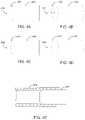
- FIG. 4Aillustrates a cross-sectional view of a protective component with a beveled end, according to some embodiments.
- FIG. 4Billustrates a three-dimensional view of the protective component of FIG. 4A , according to some embodiments.
- FIG. 4Cillustrates a cross-sectional view of a protective component with a beveled end, according to some embodiments.
- FIG. 4Dillustrates a three-dimensional view of the protective component of FIG. 4C , according to some embodiments.
- FIG. 4Eillustrates the protective component of FIG. 4A being inserted into a cannula, according to some embodiments.
- a probe assembly with a high power throughputmay experience overheating when blood contaminates the lens or blocks the laser beam such that the lens within the cannula may melt.
- a melting lensmay also detach from the cannula resulting in the probe assembly malfunctioning.
- Particular embodiments described in the present disclosuremay overcome these deficiencies by press-fitting a protective component to the distal end of cannula, wherein the lens is positioned between the one or more optical fibers and the protective component.
- FIG. 1Billustrates a cross-sectional view of the tip of cannula 104 , where lens 110 is placed for projecting beams 106 propagated by multiple optical fibers 108 extending through cannula 104 .
- Optical fibers 108represent an optical fiber array or a multi-core optical fiber.
- the aspects described hereinrelate to a protective component press-fitted to the distal end of a probe assembly's cannula.
- the protective componente.g., protective window
- the press-fitted protective componentprotects the lens by restricting movements of the lens along the cannula and/or also by preventing the lens from detaching from the cannula.
- the protective componentAs the protective component is press-fitted into the distal end of the cannula, it also prevents, minimizes, or at least reduces the amount of fluids (e.g., blood) that may leak (e.g., from the patient's body part) into the cannula during surgery.
- fluidse.g., blood
- FIG. 2Aillustrates a cross-sectional view of an example protective component 212 that is placed at the tip of cannula 104 .
- protective component 212is placed at a distal end 205 of cannula 104 while the proximal end 207 of cannula 104 is connected to a hand-piece (e.g., hand-piece 102 shown in FIG. 1A ).
- distal end 205 of cannula 104is the end that is inserted into the patient's body part, or where laser light is configured to be emitted out of probe assembly 100 .
- lens 210comprises proximal end 209 and distal end 211 .
- protective component 212comprises proximal end 215 and distal end 213 .
- protective component 212comprises an optically clear or transparent material.
- the transparent materialhas optical power and, in certain other aspects, the transparent material does not have optical power.
- Optical poweralso referred to as dioptric power, refractive power, focusing power, or convergence power
- protective component 212may comprise material that is able to tolerate high temperatures without melting.
- protective component 212may have a transition temperature in the range of 800° C. to 2000° C.
- the transparent materialinclude Sapphire, fused silica, or other glass or ceramics materials with high transition temperatures.
- protective component 212is attached to cannula 104 by way of press-fitting of component 212 into cannula 104 .
- Press-fittingalso known as interference fitting or friction fitting, is a technique for securing protective component 212 to cannula 104 , the securing being achieved by friction between protective component 212 and cannula 104 after protective component 212 is pushed into cannula 104 .
- cannula 104comprises material such as stainless steel, Nitinol (NiTi), or a Platinum-iridium alloy (Pt-lr).
- protective component 212comprises material with enough robustness or rigidity (e.g., hardness or toughness) such that press-fitting protective component 212 into cannula 104 would not result in fracturing protective component 212 , especially when cannula 104 is also made of rigid material (e.g., stainless steel).
- cannula 104may have an internal diameter that is smaller than the diameter of protective component 212 .
- FIG. 2Billustrates a three-dimensional view of protective component 212 .
- protective component 212is a cylindrical component that may be press-fitted into the cylindrical opening of cannula 104 .
- the diameter of protective component 212may be 350 ⁇ m ⁇ 5 ⁇ m, 360 ⁇ m ⁇ 5 ⁇ m, or 370 ⁇ m ⁇ 5 ⁇ m.
- the length of protective component 212may be as long as 355 ⁇ m ⁇ 25 ⁇ m.
- FIG. 2Cillustrates a front view of the tip of cannula 104 that houses protective component 212 .
- FIG. 2Dillustrates a three-dimensional view of the tip of cannula 104 .
- protective component 212partially extends outside of cannula 104 .
- protective component 212does not extend outside of cannula 104 .
- protective component 212may be flush with the outside of cannula 104 , or not extend to the outside of cannula 104 .
- a protective component(e.g., protective component 212 ) may have a cylindrical shape with distal and proximal ends that are both flat.
- the proximal end of the protective componentneed not be flat.
- the proximal end of the protective componentmay be spherical or aspheric.
- a protective component with a spherical or aspheric proximal endmay be advantageous because a spherical or aspheric proximal end may be more easily guided or inserted through the tip of a cannula during press-fitting.
- a lensplaced in cannula 104 has a cylindrical shape with distal and proximal ends that are both flat.
- An example of such a lensis a gradient-index (GRIN) lens.
- GRINgradient-index
- a spherical or aspherical lensmay be used instead, which may increase the performance and/or thermal reliability of the corresponding probe assembly.
- at least one of the proximal or distal ends of the lensis not flat.
- the proximal, distal, or both ends of the lensmay be spherical or aspherical. Note that, any of the different shapes of lenses described herein may be used in conjunction with any of the different shapes of protective components described herein.
- FIGS. 3A-3Eillustrate cross-sectional views of a number of example configurations of different shapes of lenses and protective components within cannula 104 .
- FIG. 3Aillustrates cannula 104 through which optical fibers 108 partially extend.
- lens 320At the distal end of optical fibers 108 is lens 320 , with a proximal end that is spherical and a distal end that is flat.
- Protective component 330is press-fitted into cannula 104 to be placed at the distal end of lens 320 in order to restrict lens 320 from movement along and detachment from cannula 104 .
- the spherical proximal end of lens 320steers the laser beams, which are propagated by optical fibers 108 , towards the middle of the proximal end of protective component 330 .
- FIG. 3Billustrates protective component 330 protecting lens 322 with flat proximal and distal ends.
- lens 322is a GRIN lens.
- FIG. 3Cillustrates protective component 330 protecting lens 324 with a proximal end that is flat and a distal end that is spherical.
- the patient's body parte.g., retinal surface
- FIG. 3Dillustrates protective component 330 protecting lens 326 with spherical proximal and distal ends.
- lens 326e.g., referred to as a spherical lens
- the protection provided by protective component 330allows for the use of a spherical lens, such as lens 326 .
- spherical lens 326is able to focus laser beams, which are propagated by optical fibers 108 , towards the middle of the proximal end of protective component 330 .
- FIG. 3Dillustrates protective component 330 protecting lens 326 with spherical proximal and distal ends.
- lens 326e.g., referred to as a spherical lens
- the protection provided by protective component 330allows for the use of a spherical lens, such as lens 326 .
- spherical lens 326is able to focus laser beams, which are propagated by optical fibers 108 , towards the middle of the prox
- the spherical end of protective component 330in combination with the two spherical ends of lens 326 , further helps with steering and focusing the laser beams.
- a high-softening-point spherical lensmay be able to tolerate a higher surface temperature, which may improve the thermal reliability of the probe assembly.
- FIG. 3Eillustrates protective component 332 protecting lens 322 with flat proximal and distal ends.
- Protective component 332has a proximal end that is aspherical and a distal end that is flat.
- the aspherical end of protective component 332may be molded.
- a protective component with an aspheric proximal endcan be more easily guided or inserted through the tip of cannula 104 than a spherical proximal end.
- one or more of protective components 330 - 332may possess optical power, while, in other aspects, the protective components may not have optical power.
- the distal end of the optical fiberstouches or is proximate to the proximal end of the lens while the distal end of the lens touches or is proximate to the proximal end of the protective component.
- the lens's movementis restricted by the optical fibers from the one side (e.g., proximal side) and the protective component from the other side (e.g., distal side).
- FIG. 4Aillustrates a cross-sectional view of another example shape for a protective component.
- the proximal end of protective component 430comprises beveled edges 432 and a flat surface 434 .
- protective component 430may be manufactured by beveling the edges of the proximal end of a cylindrical component.
- FIG. 4Billustrates a three-dimensional view of protective component 430 .
- Protective component 430is advantageous because the bevel-shaped proximal end of protective component 430 can be more easily guided or inserted through the tip of a cannula.
- FIG. 4Cillustrates a cross-sectional view of yet another example shape for a protective component. As shown, the proximal end of protective component 440 comprises beveled edges 442 and spherical surface 444 . FIG. 4D illustrates a three-dimensional view of protective component 440 .
- a protective componentsuch as protective component 430 or 440 , may be advantageous because the bevel-shaped proximal end of the protective component may be more easily guided or inserted through the tip of a cannula.
- Protective components 430 or 440may be used in conjunction with any of the lens configurations 320 - 326 shown in FIGS. 3A-3E .
- a cannula(e.g., cannula 104 ) may be made from flexible material (e.g., stainless steel, NiTi, Pt-lr, etc.) such that the diameter of the cannula may expand when a lens and/or a protective component with a larger diameter is inserted into the cannula.
- flexible materiale.g., stainless steel, NiTi, Pt-lr, etc.
- FIG. 4Eillustrates protective component 430 of FIG. 4A being inserted into a cannula (e.g., cannula 404 ).
- a cannulae.g., cannula 404
- the diameter of the tip of the cannulahas expanded and taken the shape of the beveled end of protective component 430 .
- using a protective component with a diameter that is larger than the diameter of the cannula in its normal stateis advantageous. This is because, in such aspects, press-fitting the protective component into the cannula eliminates, minimizes, or, at least, reduces any unfilled space or opening between the outer surface of the protective component and the inner surface of the cannula. As a result, any possibility of fluids, such as blood, leaking into the cannula through any such unfilled spaces or openings may also be reduced.
Landscapes
- Health & Medical Sciences (AREA)
- Physics & Mathematics (AREA)
- Optics & Photonics (AREA)
- Life Sciences & Earth Sciences (AREA)
- Surgery (AREA)
- Ophthalmology & Optometry (AREA)
- General Health & Medical Sciences (AREA)
- Biomedical Technology (AREA)
- Heart & Thoracic Surgery (AREA)
- Engineering & Computer Science (AREA)
- Animal Behavior & Ethology (AREA)
- Nuclear Medicine, Radiotherapy & Molecular Imaging (AREA)
- Public Health (AREA)
- Veterinary Medicine (AREA)
- General Physics & Mathematics (AREA)
- Vascular Medicine (AREA)
- Medical Informatics (AREA)
- Molecular Biology (AREA)
- Otolaryngology (AREA)
- Electromagnetism (AREA)
- Oral & Maxillofacial Surgery (AREA)
- Pathology (AREA)
- Laser Surgery Devices (AREA)
- Endoscopes (AREA)
- Dental Tools And Instruments Or Auxiliary Dental Instruments (AREA)
- Radiation-Therapy Devices (AREA)
- Optical Couplings Of Light Guides (AREA)
Abstract
Description
Claims (20)
Priority Applications (2)
| Application Number | Priority Date | Filing Date | Title |
|---|---|---|---|
| US16/218,382US11344449B2 (en) | 2017-12-12 | 2018-12-12 | Thermally robust laser probe assembly |
| US17/661,336US11844726B2 (en) | 2017-12-12 | 2022-04-29 | Thermally robust laser probe assembly |
Applications Claiming Priority (5)
| Application Number | Priority Date | Filing Date | Title |
|---|---|---|---|
| US201762597550P | 2017-12-12 | 2017-12-12 | |
| US201762598653P | 2017-12-14 | 2017-12-14 | |
| US201862622299P | 2018-01-26 | 2018-01-26 | |
| US201862630865P | 2018-02-15 | 2018-02-15 | |
| US16/218,382US11344449B2 (en) | 2017-12-12 | 2018-12-12 | Thermally robust laser probe assembly |
Related Child Applications (1)
| Application Number | Title | Priority Date | Filing Date |
|---|---|---|---|
| US17/661,336ContinuationUS11844726B2 (en) | 2017-12-12 | 2022-04-29 | Thermally robust laser probe assembly |
Publications (2)
| Publication Number | Publication Date |
|---|---|
| US20190175273A1 US20190175273A1 (en) | 2019-06-13 |
| US11344449B2true US11344449B2 (en) | 2022-05-31 |
Family
ID=65041807
Family Applications (9)
| Application Number | Title | Priority Date | Filing Date |
|---|---|---|---|
| US16/218,243AbandonedUS20190175408A1 (en) | 2017-12-12 | 2018-12-12 | Methods and systems for manufacturing a thermally robust laser probe assembly |
| US16/217,383Active2042-03-17US11771597B2 (en) | 2017-12-12 | 2018-12-12 | Multiple-input-coupled illuminated multi-spot laser probe |
| US16/218,365Active2039-02-25US11160686B2 (en) | 2017-12-12 | 2018-12-12 | Multi-core fiber for a multi-spot laser probe |
| US16/218,333Active2039-10-01US11135092B2 (en) | 2017-12-12 | 2018-12-12 | Multi-core fiber for a multi-spot laser probe |
| US16/218,382Active2039-03-13US11344449B2 (en) | 2017-12-12 | 2018-12-12 | Thermally robust laser probe assembly |
| US17/193,364PendingUS20210186758A1 (en) | 2017-12-12 | 2021-03-05 | Methods and systems for manufacturing a thermally robust laser probe assembly |
| US17/411,563Active2039-02-16US11980575B2 (en) | 2017-12-12 | 2021-08-25 | Multi-core fiber for a multi-spot laser probe |
| US17/661,336ActiveUS11844726B2 (en) | 2017-12-12 | 2022-04-29 | Thermally robust laser probe assembly |
| US18/451,033PendingUS20230390114A1 (en) | 2017-12-12 | 2023-08-16 | Multiple-input-coupled illuminated multi-spot laser probe |
Family Applications Before (4)
| Application Number | Title | Priority Date | Filing Date |
|---|---|---|---|
| US16/218,243AbandonedUS20190175408A1 (en) | 2017-12-12 | 2018-12-12 | Methods and systems for manufacturing a thermally robust laser probe assembly |
| US16/217,383Active2042-03-17US11771597B2 (en) | 2017-12-12 | 2018-12-12 | Multiple-input-coupled illuminated multi-spot laser probe |
| US16/218,365Active2039-02-25US11160686B2 (en) | 2017-12-12 | 2018-12-12 | Multi-core fiber for a multi-spot laser probe |
| US16/218,333Active2039-10-01US11135092B2 (en) | 2017-12-12 | 2018-12-12 | Multi-core fiber for a multi-spot laser probe |
Family Applications After (4)
| Application Number | Title | Priority Date | Filing Date |
|---|---|---|---|
| US17/193,364PendingUS20210186758A1 (en) | 2017-12-12 | 2021-03-05 | Methods and systems for manufacturing a thermally robust laser probe assembly |
| US17/411,563Active2039-02-16US11980575B2 (en) | 2017-12-12 | 2021-08-25 | Multi-core fiber for a multi-spot laser probe |
| US17/661,336ActiveUS11844726B2 (en) | 2017-12-12 | 2022-04-29 | Thermally robust laser probe assembly |
| US18/451,033PendingUS20230390114A1 (en) | 2017-12-12 | 2023-08-16 | Multiple-input-coupled illuminated multi-spot laser probe |
Country Status (11)
| Country | Link |
|---|---|
| US (9) | US20190175408A1 (en) |
| EP (6) | EP3723680B1 (en) |
| JP (7) | JP7344207B2 (en) |
| KR (2) | KR102729108B1 (en) |
| CN (7) | CN116270010A (en) |
| AU (6) | AU2018383137B2 (en) |
| BR (2) | BR112020011655A2 (en) |
| CA (5) | CA3084739A1 (en) |
| ES (2) | ES2946276T3 (en) |
| RU (2) | RU2770265C2 (en) |
| WO (5) | WO2019116285A1 (en) |
Cited By (2)
| Publication number | Priority date | Publication date | Assignee | Title |
|---|---|---|---|---|
| US20220249287A1 (en)* | 2017-12-12 | 2022-08-11 | Alcon Inc. | Thermally robust laser probe assembly |
| USD1089679S1 (en) | 2023-06-12 | 2025-08-19 | Alcon Inc. | Multi-spot laser probe handpiece |
Families Citing this family (39)
| Publication number | Priority date | Publication date | Assignee | Title |
|---|---|---|---|---|
| US10918522B2 (en) | 2017-06-08 | 2021-02-16 | Alcon Inc. | Photodisruption-based vitrectomy system |
| JP2021502848A (en) | 2017-11-14 | 2021-02-04 | アルコン インコーポレイティド | Multi-spot laser probe with irradiation function |
| EP4265212B1 (en) | 2017-12-12 | 2025-03-19 | Alcon Inc. | Multiple-input-coupled illuminated multi-spot laser probe |
| US11213426B2 (en) | 2017-12-12 | 2022-01-04 | Alcon Inc. | Thermally robust multi-spot laser probe |
| WO2019116283A1 (en) | 2017-12-12 | 2019-06-20 | Novartis Ag | Surgical probe with shape-memory material |
| US10758415B2 (en)* | 2018-01-17 | 2020-09-01 | Topcon Medical Systems, Inc. | Method and apparatus for using multi-clad fiber for spot size selection |
| US11471698B2 (en)* | 2018-02-23 | 2022-10-18 | Lumitex, Inc. | Tunable light source |
| US11819229B2 (en) | 2019-06-19 | 2023-11-21 | Boston Scientific Scimed, Inc. | Balloon surface photoacoustic pressure wave generation to disrupt vascular lesions |
| US11389241B2 (en) | 2019-01-15 | 2022-07-19 | Boston Scientific Scimed, Inc. | Alignment method and tools |
| US12011325B2 (en)* | 2019-04-24 | 2024-06-18 | Convergent Dental, Inc. | System and method for treatment of periodontic pockets using disposable inserts |
| CA3139801A1 (en) | 2019-06-03 | 2021-12-10 | Alcon Inc. | Aligning multi-wavelength laser beams with cores of a multi-core fiber |
| US11931297B2 (en) | 2019-06-14 | 2024-03-19 | Alcon Inc. | Glare reduction endoilluminators |
| US12402946B2 (en) | 2019-06-19 | 2025-09-02 | Boston Scientific Scimed, Inc. | Breakdown of laser pulse energy for breakup of vascular calcium |
| US11717139B2 (en) | 2019-06-19 | 2023-08-08 | Bolt Medical, Inc. | Plasma creation via nonaqueous optical breakdown of laser pulse energy for breakup of vascular calcium |
| US11660427B2 (en) | 2019-06-24 | 2023-05-30 | Boston Scientific Scimed, Inc. | Superheating system for inertial impulse generation to disrupt vascular lesions |
| US12280223B2 (en) | 2019-06-26 | 2025-04-22 | Boston Scientific Scimed, Inc. | Focusing element for plasma system to disrupt vascular lesions |
| US12102384B2 (en) | 2019-11-13 | 2024-10-01 | Bolt Medical, Inc. | Dynamic intravascular lithotripsy device with movable energy guide |
| EP4070142A1 (en) | 2019-12-04 | 2022-10-12 | Alcon Inc. | Multi-core optical fiber with reduced bubble formation |
| US12274497B2 (en) | 2019-12-18 | 2025-04-15 | Bolt Medical, Inc. | Multiplexer for laser-driven intravascular lithotripsy device |
| WO2021165791A1 (en)* | 2020-02-18 | 2021-08-26 | Alcon Inc. | Multi-spot laser probe with multiple single-core fibers |
| US11672599B2 (en) | 2020-03-09 | 2023-06-13 | Bolt Medical, Inc. | Acoustic performance monitoring system and method within intravascular lithotripsy device |
| EP3878416B1 (en)* | 2020-03-11 | 2025-10-01 | Vita Dolzan | Modular laser therapeutic device |
| US20210290286A1 (en) | 2020-03-18 | 2021-09-23 | Bolt Medical, Inc. | Optical analyzer assembly and method for intravascular lithotripsy device |
| US11707323B2 (en) | 2020-04-03 | 2023-07-25 | Bolt Medical, Inc. | Electrical analyzer assembly for intravascular lithotripsy device |
| US20210353359A1 (en)* | 2020-05-12 | 2021-11-18 | Bolt Medical, Inc. | Active alignment system and method for optimizing optical coupling of multiplexer for laser-driven intravascular lithotripsy device |
| US12295654B2 (en) | 2020-06-03 | 2025-05-13 | Boston Scientific Scimed, Inc. | System and method for maintaining balloon integrity within intravascular lithotripsy device with plasma generator |
| US12207870B2 (en) | 2020-06-15 | 2025-01-28 | Boston Scientific Scimed, Inc. | Spectroscopic tissue identification for balloon intravascular lithotripsy guidance |
| CN115835838A (en)* | 2020-06-24 | 2023-03-21 | 塞诺根有限责任公司 | Systems, methods, and devices for laser treatment of the eye |
| US20220009036A1 (en)* | 2020-07-07 | 2022-01-13 | Panasonic Intellectual Property Management Co. Ltd | Laser systems and techniques for workpiece processing utilizing optical fibers and multiple beams |
| US12016610B2 (en) | 2020-12-11 | 2024-06-25 | Bolt Medical, Inc. | Catheter system for valvuloplasty procedure |
| WO2022130123A1 (en)* | 2020-12-18 | 2022-06-23 | Alcon Inc. | Ophthalmic probe assembly with flat wall tube |
| US11672585B2 (en) | 2021-01-12 | 2023-06-13 | Bolt Medical, Inc. | Balloon assembly for valvuloplasty catheter system |
| EP4277548B1 (en) | 2021-01-12 | 2025-06-04 | Bolt Medical, Inc. | Balloon assembly for valvuloplasty catheter system |
| CA3205679A1 (en) | 2021-02-23 | 2022-09-01 | Chenguang Diao | Single fiber illuminated laser probe with high-angle illumination output |
| EP4333781A1 (en) | 2021-05-07 | 2024-03-13 | Alcon Inc. | Surgical laser system with illumination |
| US11648057B2 (en) | 2021-05-10 | 2023-05-16 | Bolt Medical, Inc. | Optical analyzer assembly with safety shutdown system for intravascular lithotripsy device |
| US11806075B2 (en) | 2021-06-07 | 2023-11-07 | Bolt Medical, Inc. | Active alignment system and method for laser optical coupling |
| US11877956B2 (en) | 2021-08-06 | 2024-01-23 | Alcon Inc. | Vitreoretinal instruments for illumination, fluid aspiration, and photocoagulation |
| US11839391B2 (en) | 2021-12-14 | 2023-12-12 | Bolt Medical, Inc. | Optical emitter housing assembly for intravascular lithotripsy device |
Citations (80)
| Publication number | Priority date | Publication date | Assignee | Title |
|---|---|---|---|---|
| US4632505A (en)* | 1983-10-11 | 1986-12-30 | The Deustsch Company Electronic Components Division | Optical fiber connector |
| WO1992008427A2 (en) | 1990-11-07 | 1992-05-29 | Premier Laser Systems, Inc. | Laser surgical probe |
| US5199431A (en) | 1985-03-22 | 1993-04-06 | Massachusetts Institute Of Technology | Optical needle for spectroscopic diagnosis |
| JPH0614936A (en) | 1992-03-10 | 1994-01-25 | Trimedyne Inc | Laser probe and handpiece and manual apparatus and device having the same |
| US5496305A (en) | 1985-03-22 | 1996-03-05 | Massachusetts Institue Of Technology | Catheter for laser angiosurgery |
| US5625638A (en) | 1993-05-28 | 1997-04-29 | Coherent, Inc. | Sealed crystalline windows for hollow laser fibers |
| US5693043A (en) | 1985-03-22 | 1997-12-02 | Massachusetts Institute Of Technology | Catheter for laser angiosurgery |
| US5921981A (en) | 1995-11-09 | 1999-07-13 | Alcon Laboratories, Inc. | Multi-spot laser surgery |
| WO2001037769A1 (en) | 1999-11-22 | 2001-05-31 | Yaakov Amitai | Treating a target with a divided laser beam |
| US20020045811A1 (en) | 1985-03-22 | 2002-04-18 | Carter Kittrell | Laser ablation process and apparatus |
| US20020193781A1 (en)* | 2001-06-14 | 2002-12-19 | Loeb Marvin P. | Devices for interstitial delivery of thermal energy into tissue and methods of use thereof |
| US20040120668A1 (en)* | 2002-12-20 | 2004-06-24 | Loeb Marvin P. | Device and method for delivery of long wavelength laser energy to a tissue site |
| US20040236183A1 (en) | 2000-08-30 | 2004-11-25 | Durell & Gitelis, Inc. | Variable view arthroscope |
| US6893432B2 (en) | 2001-03-23 | 2005-05-17 | Surgical Laser Technologies, Inc. | Light-dispersive probe |
| US20060184162A1 (en) | 2005-02-15 | 2006-08-17 | Alcon, Inc. | High throughput endo-illuminator probe |
| US7189226B2 (en) | 2003-07-28 | 2007-03-13 | Synergetics, Inc. | Coaxial illuminated laser endoscopic probe and active numerical aperture control |
| US7302142B2 (en) | 1997-03-04 | 2007-11-27 | Andromis S.A. | Method and device for assembling optical components or an optical component and a substrate |
| WO2008024848A2 (en) | 2006-08-22 | 2008-02-28 | Synergetics, Inc. | Multiple target laser probe |
| US20080051770A1 (en) | 2006-08-22 | 2008-02-28 | Synergetics, Inc. | Multiple Target Laser Probe |
| US20080177257A1 (en) | 2007-01-23 | 2008-07-24 | Smith Ronald T | Thermally robust illumination probe tip |
| US20080215041A1 (en) | 2007-03-02 | 2008-09-04 | Optical System & Research For Industry And Science Osyris Sa | Cannula/optical fibre assembly and laser instrument including said assembly |
| US20080243108A1 (en) | 2007-03-29 | 2008-10-02 | Nidek Co., Ltd. | Ophthalmic laser treatment apparatus |
| US7448995B2 (en) | 2003-06-23 | 2008-11-11 | Microvision, Inc. | Scanning endoscope |
| US7566173B2 (en) | 2007-07-09 | 2009-07-28 | Alcon, Inc. | Multi-spot ophthalmic laser probe |
| US20090270850A1 (en) | 2007-06-20 | 2009-10-29 | Tea Time Partners, L.P., Organized In Texas | Devices and methods for the ablation of tissue in the lateral direction |
| US20090287197A1 (en) | 2008-05-19 | 2009-11-19 | Hanley Brian M | Side-firing laser fiber with internal bent fiber and related methods |
| US20090287196A1 (en) | 2008-05-02 | 2009-11-19 | Zelickson Brian D | Laser energy devices and methods for soft tissue removal |
| US20100027943A1 (en) | 2008-07-29 | 2010-02-04 | Deniz K Armani | Expanded beam fiber optic connection system |
| US20100261961A1 (en) | 2006-12-21 | 2010-10-14 | Intuitive Surgical Operations, Inc. | Hermetically sealed distal sensor endoscope |
| US20110122366A1 (en) | 2009-11-24 | 2011-05-26 | Smith Ronald T | Single-fiber multi-spot laser probe for ophthalmic endoillumination |
| US20110144627A1 (en) | 2009-12-15 | 2011-06-16 | Smith Ronald T | Multi-spot laser probe |
| US20120022327A1 (en)* | 2009-03-24 | 2012-01-26 | Fujifilm Corporation | Capsule endoscope |
| US20120123399A1 (en)* | 2009-12-31 | 2012-05-17 | Laser Abrasive Technologies, Llc | Dental surgical laser with feedback mechanisms |
| US20120191078A1 (en) | 2011-01-21 | 2012-07-26 | Yadlowsky Michael J | Combined surgical endoprobe for optical coherence tomography, illumination or photocoagulation |
| JP2013048864A (en) | 2011-08-31 | 2013-03-14 | Nidek Co Ltd | Ophthalmic laser treatment device |
| US20130150839A1 (en) | 2011-12-09 | 2013-06-13 | Alcon Research, Ltd. | Devices and Methods for Reconfigurable Multispot Scanning |
| US20130178789A1 (en)* | 2003-01-29 | 2013-07-11 | Novartis Ag | Monitoring Thermal Conditions To Vary Operation of an Ultrasonic Needle Tip of a Surgical Instrument |
| US8488930B2 (en) | 2010-12-09 | 2013-07-16 | Alcon Research, Ltd. | Wavelength converting illumination probe |
| US8498506B2 (en) | 2008-08-13 | 2013-07-30 | Alcon Research, Ltd. | Preconditioned illuminator system and method |
| US8561280B2 (en) | 2011-10-20 | 2013-10-22 | Alcon Research, Ltd. | Assembling a multi-fiber multi-spot laser probe |
| US8571364B2 (en) | 2011-11-09 | 2013-10-29 | Alcon Research, Ltd. | Multi-spot laser probe with faceted optical element |
| US20140180264A1 (en) | 2012-12-21 | 2014-06-26 | Alcon Research, Ltd. | Grin fiber multi-spot laser probe |
| US8764261B2 (en) | 2009-12-10 | 2014-07-01 | Alcon Research, Ltd. | Multi-spot laser surgical probe using faceted optical elements |
| US20140194862A1 (en) | 2013-01-08 | 2014-07-10 | Alcon Research, Ltd. | Multi-spot laser probe with micro-structured faceted proximal surface |
| US20140200566A1 (en)* | 2013-01-15 | 2014-07-17 | Alcon Research, Ltd. | Multi-spot laser probe with micro-structured distal surface |
| US8903475B2 (en) | 2009-03-08 | 2014-12-02 | Oprobe, Llc | Multi-function optical probe system for medical and veterinary applications |
| US8939964B2 (en) | 2011-12-01 | 2015-01-27 | Alcon Research, Ltd. | Electrically switchable multi-spot laser probe |
| US8968347B2 (en) | 2010-08-13 | 2015-03-03 | Alcon Research, Ltd. | Dual-mode illumination for surgical instrument |
| US9055885B2 (en) | 2011-02-08 | 2015-06-16 | Alcon Research, Ltd. | White coherent laser light launched into nano fibers for surgical illumination |
| US20150212307A1 (en)* | 2014-01-30 | 2015-07-30 | Olympus Corporation | Microscope illumination apparatus, microscope, and microscope illumination method |
| US9107730B2 (en) | 2010-12-09 | 2015-08-18 | Alcon Research, Ltd. | Optical coherence tomography and illumination using common light source |
| US20150351629A1 (en) | 2014-06-06 | 2015-12-10 | Novartis Ag | Back reflection minimization for oct probes |
| US9211214B2 (en) | 2012-03-21 | 2015-12-15 | Valeant Pharmaceuticals International, Inc | Photodynamic therapy laser |
| US20150366432A1 (en) | 2014-06-19 | 2015-12-24 | Novartis Ag | Surgical Probe with Interlocking Attachment |
| US9364982B2 (en) | 2010-08-09 | 2016-06-14 | Novartis Ag | Method of manufacturing an illuminated surgical instrument |
| US20160178844A1 (en)* | 2014-12-22 | 2016-06-23 | nnovaQuartz LLC | Redirecting Electromagnetic Radiation |
| US9387040B2 (en) | 2011-08-09 | 2016-07-12 | Alcon Research, Ltd. | Multi-spot laser surgical probe using faceted optical elements |
| US9402643B2 (en) | 2008-01-15 | 2016-08-02 | Novartis Ag | Targeted illumination for surgical instrument |
| US20160299170A1 (en)* | 2013-03-29 | 2016-10-13 | Sony Corporation | Laser scanning observation device and laser scanning method |
| US20160302868A1 (en)* | 2015-04-16 | 2016-10-20 | Boston Scientific Scimed, Inc. | Methods and devices for targeted ablation of tissue |
| US20180055596A1 (en) | 2016-08-25 | 2018-03-01 | Novartis Ag | Planar illuminator for ophthalmic surgery |
| WO2018113887A2 (en) | 2016-12-20 | 2018-06-28 | 3Dintegrated Aps | A medical probe assembly |
| US10012800B2 (en) | 2016-07-13 | 2018-07-03 | Novartis Ag | Optical fiber coupling reliability |
| US10016302B2 (en) | 2014-06-19 | 2018-07-10 | Visumedics, Inc. | Diagnostic and surgical laser device utilizing a visible laser diode |
| US20180243136A1 (en) | 2017-02-28 | 2018-08-30 | Novartis Ag | Multi-fiber multi-spot laser probe with simplified tip construction |
| US20180243137A1 (en) | 2017-02-28 | 2018-08-30 | Novartis Ag | Multi-fiber multi-spot laser probe with articulating beam separation |
| US10111778B2 (en) | 2014-12-19 | 2018-10-30 | Novartis Ag | BSS-only multi-sport laser probe |
| US20180333304A1 (en) | 2017-05-16 | 2018-11-22 | Novartis Ag | Laser probe with lensed fibers for panretinal photocoagulation |
| US20180344528A1 (en) | 2017-05-30 | 2018-12-06 | Novartis Ag | Multi-fiber multi-spot laser probe with articulating beam separation |
| US20190142544A1 (en) | 2017-11-14 | 2019-05-16 | Novartis Ag | Multi-spot laser probe with illumination features |
| US20190175408A1 (en) | 2017-12-12 | 2019-06-13 | Novartis Ag | Methods and systems for manufacturing a thermally robust laser probe assembly |
| US20190175217A1 (en) | 2017-12-12 | 2019-06-13 | Novartis Ag | Surgical probe with shape-memory material |
| US20190175404A1 (en) | 2017-12-12 | 2019-06-13 | Novartis Ag | Thermally robust multi-spot laser probe |
| US20190175300A1 (en) | 2017-12-12 | 2019-06-13 | Novartis Ag | Multiple-input-coupled illuminated multi-spot laser probe |
| US20190209372A1 (en) | 2018-01-05 | 2019-07-11 | Novartis Ag | Multiple Illumination Transmission Through Optical Fiber |
| US10433718B2 (en) | 2013-03-15 | 2019-10-08 | Thomas LIOLIOS | Eye safe laser illumination in ophthalmic surgeries |
| US20190307527A1 (en) | 2018-04-09 | 2019-10-10 | Alcon Inc. | Fiber Tip Protection Integration For Cannula |
| US10441157B2 (en) | 2015-12-02 | 2019-10-15 | Novartis Ag | Optical fiber having proximal taper for ophthalmic surgical illumination |
| US20190365569A1 (en) | 2017-02-09 | 2019-12-05 | Norlase Aps | Apparatus for Photothermal Ophthalmic Treatment |
| US20200107960A1 (en) | 2018-10-05 | 2020-04-09 | Alcon Inc. | Occlusion sensing in ophthalmic laser probes |
Family Cites Families (86)
| Publication number | Priority date | Publication date | Assignee | Title |
|---|---|---|---|---|
| JPS5567702U (en)* | 1978-11-02 | 1980-05-09 | ||
| CA1279901C (en)* | 1985-03-22 | 1991-02-05 | Carter Kittrell | Catheter for laser angiosurgery |
| JPH0667389B2 (en)* | 1987-04-30 | 1994-08-31 | 松下電器産業株式会社 | Laser mess probe |
| JPH01256948A (en)* | 1988-04-06 | 1989-10-13 | Matsushita Electric Ind Co Ltd | Optical fiber probe |
| EP0355996A3 (en)* | 1988-07-21 | 1990-05-02 | Advanced Interventional Systems, Inc. | Guidance and delivery system for high-energy pulsed laser light and endoscope |
| CN1044228A (en)* | 1989-01-20 | 1990-08-01 | 苏联科学院阿·勃·明茨无线电工程科学研究所 | Optically-derived device used for optical therapeutics |
| JPH02297355A (en) | 1989-05-12 | 1990-12-07 | Topcon Corp | Laser device for therapy |
| JP2933945B2 (en)* | 1989-05-29 | 1999-08-16 | 株式会社トプコン | Laser therapy equipment |
| JPH0798050B2 (en)* | 1989-08-09 | 1995-10-25 | 株式会社トプコン | Ophthalmic laser treatment device |
| DE4014956A1 (en)* | 1990-05-10 | 1991-11-14 | Schott Glaswerke | DISTAL PROTECTIVE CAP FOR A LASER-FIBER CATHETER |
| JPH06105863A (en)* | 1992-09-18 | 1994-04-19 | Topcon Corp | Intraocular surgery device |
| JPH06242331A (en)* | 1993-02-18 | 1994-09-02 | Furukawa Electric Co Ltd:The | Quartz group optical fiber with lens and its production |
| JPH07155659A (en)* | 1993-11-30 | 1995-06-20 | Sony Corp | Method to apply liquid linearly and apparatus for method thereof |
| CN2188253Y (en)* | 1994-05-24 | 1995-01-25 | 方础股份有限公司 | semiconductor laser device |
| US6572609B1 (en)* | 1999-07-14 | 2003-06-03 | Cardiofocus, Inc. | Phototherapeutic waveguide apparatus |
| US5815626A (en)* | 1994-10-14 | 1998-09-29 | Mitsubishi Denki Kabushiki Kaisha | Optical transmission device, solid state laser device, and laser beam processing device |
| FR2730317A1 (en)* | 1995-02-03 | 1996-08-09 | Alcatel Cable Interface | OPTICAL FIBER CONNECTING MULTIFERACE, CONNECTOR USING THE SAME, AND METHOD FOR MANUFACTURING THE SAME |
| IL113674A (en) | 1995-05-09 | 1998-06-15 | Laser Ind Ltd | Side-emitting optical fibers for lasers with orientation markings |
| JPH0928715A (en)* | 1995-07-14 | 1997-02-04 | Sumitomo Electric Ind Ltd | Laser probe and laser medical device using the same |
| US5664037A (en)* | 1995-09-28 | 1997-09-02 | Corning Incorporated | Multi-neckdown fiber optic coupler |
| US5953477A (en)* | 1995-11-20 | 1999-09-14 | Visionex, Inc. | Method and apparatus for improved fiber optic light management |
| DE19744367C1 (en)* | 1997-10-08 | 1998-11-05 | Schott Glas | Simple application of thin, uniform silicone oil coating free from particles to medical cannula |
| US6043895A (en)* | 1998-11-10 | 2000-03-28 | Uop Llc | Radiation probe with flexible sleeve |
| JP2001008945A (en)* | 1999-06-28 | 2001-01-16 | Topcon Corp | Laser surgery equipment |
| JP3881508B2 (en)* | 2000-12-04 | 2007-02-14 | 株式会社ニデック | Laser therapy device |
| US6682771B2 (en)* | 2001-07-02 | 2004-01-27 | Scimed Life Systems, Inc. | Coating dispensing system and method using a solenoid head for coating medical devices |
| AU2002350398B2 (en)* | 2001-10-09 | 2007-11-22 | Crystal Fibre A/S | Hermetically sealed optical fibre with voids or holes, method of its production, and its use |
| US7762965B2 (en)* | 2001-12-10 | 2010-07-27 | Candela Corporation | Method and apparatus for vacuum-assisted light-based treatments of the skin |
| US6845193B2 (en) | 2002-05-21 | 2005-01-18 | Trimedyne, Inc. | Laser channeling devices |
| JP2005202047A (en)* | 2004-01-14 | 2005-07-28 | Hitachi Cable Ltd | Optical fiber protection boots |
| US6997868B1 (en)* | 2004-07-27 | 2006-02-14 | Martin Uram | Autoclavable endoscope |
| US7618177B2 (en)* | 2005-04-29 | 2009-11-17 | Alcon, Inc. | Multi-fiber variable intensity wide-angle illuminator |
| CN2824861Y (en)* | 2005-10-28 | 2006-10-11 | 北京光电技术研究所 | Side-emitting laser fiber structure |
| JP4963375B2 (en)* | 2005-11-02 | 2012-06-27 | 富士フイルム株式会社 | Optical device, optical member and light guide |
| US7450806B2 (en)* | 2005-11-08 | 2008-11-11 | Corning Incorporated | Microstructured optical fibers and methods |
| US8101197B2 (en)* | 2005-12-19 | 2012-01-24 | Stryker Corporation | Forming coils |
| US10098781B2 (en)* | 2006-03-24 | 2018-10-16 | Topcon Medical Laser Systems Inc. | Multi-spot optical fiber endophotocoagulation probe |
| US20070282312A1 (en)* | 2006-05-31 | 2007-12-06 | Sie Ag Surgical Instrument Engineering | Ophthalmologic apparatus |
| JP2008036536A (en)* | 2006-08-07 | 2008-02-21 | Nippon Densan Corp | Method of applying oil repellent agent solution for coating |
| CN107126182B (en)* | 2007-01-19 | 2020-06-16 | 桑尼布鲁克健康科学中心 | Scanning mechanism for imaging probe |
| US7526166B2 (en)* | 2007-01-31 | 2009-04-28 | Corning Incorporated | High numerical aperture fiber |
| CN201179110Y (en)* | 2008-04-09 | 2009-01-14 | 天津市天坤光电技术有限公司 | Beam convergence type laser side-irradiation optical fiber knife head for surgical purposes |
| JP5325485B2 (en)* | 2008-07-10 | 2013-10-23 | 株式会社トプコン | Laser surgical device |
| JP2010042182A (en)* | 2008-08-18 | 2010-02-25 | Fujifilm Corp | Laser treatment device |
| JP5372527B2 (en) | 2009-01-07 | 2013-12-18 | 株式会社ニデック | Ophthalmic laser treatment device |
| JP5184700B2 (en) | 2009-06-09 | 2013-04-17 | 株式会社フジクラ | Optical apparatus, laser irradiation apparatus, and laser treatment apparatus |
| WO2011053921A2 (en) | 2009-10-30 | 2011-05-05 | The Johns Hopkins University | Visual tracking and annotation of clinically important anatomical landmarks for surgical interventions |
| AU2011203989B2 (en) | 2010-01-08 | 2015-06-11 | Amo Development, Llc | System for modifying eye tissue and intraocular lenses |
| CN102811684B (en)* | 2010-01-22 | 2015-09-09 | 眼科医疗公司 | Device for automatic placement of scanning laser capsulorhexis |
| BR112012020778A2 (en)* | 2010-02-17 | 2016-05-03 | Alcon Res Ltd | probe |
| JP5267481B2 (en)* | 2010-02-18 | 2013-08-21 | 住友電気工業株式会社 | Multi-core optical fiber |
| US8737792B2 (en)* | 2010-03-10 | 2014-05-27 | Ofs Fitel, Llc | Multicore fibers and associated structures and techniques |
| IL205022A (en)* | 2010-04-12 | 2013-10-31 | Cleanoscope Inc | Lens protector for endoscopic devices |
| US20120099112A1 (en)* | 2010-10-25 | 2012-04-26 | Gerard Argant Alphonse | Multi-core low reflection lateral output fiber probe |
| US20120330101A1 (en)* | 2011-05-24 | 2012-12-27 | Oprobe, Llc | Scanning Endoscopic Imaging Probes and Related Methods |
| EP2527893B1 (en) | 2011-05-27 | 2013-09-04 | Draka Comteq BV | Single mode optical fiber |
| WO2012172968A1 (en)* | 2011-06-17 | 2012-12-20 | 住友電気工業株式会社 | Optical device |
| WO2013019859A1 (en)* | 2011-08-03 | 2013-02-07 | Alcon Research, Ltd. | Articulating ophthalmic surgical probe |
| WO2013031836A1 (en)* | 2011-09-01 | 2013-03-07 | コニカミノルタアドバンストレイヤー株式会社 | Coupling optical system and coupling method |
| US9700655B2 (en)* | 2011-10-14 | 2017-07-11 | Ra Medical Systems, Inc. | Small flexible liquid core catheter for laser ablation in body lumens and methods for use |
| JP5867076B2 (en)* | 2011-12-28 | 2016-02-24 | 住友電気工業株式会社 | Multi-core optical fiber |
| WO2013141112A1 (en)* | 2012-03-23 | 2013-09-26 | 住友電気工業株式会社 | Interference measuring apparatus |
| CN202886643U (en)* | 2012-08-17 | 2013-04-17 | 北京凯普林光电科技有限公司 | Optical-fiber abutting joint apparatus and medical appliance comprising the same |
| JP5956883B2 (en)* | 2012-09-13 | 2016-07-27 | 株式会社トプコン | Laser therapy device |
| US9283350B2 (en)* | 2012-12-07 | 2016-03-15 | Surmodics, Inc. | Coating apparatus and methods |
| JP6067389B2 (en)* | 2013-01-25 | 2017-01-25 | セーレン株式会社 | Moisture permeable curing sheet |
| US20170238807A9 (en)* | 2013-03-15 | 2017-08-24 | LX Medical, Inc. | Tissue imaging and image guidance in luminal anatomic structures and body cavities |
| US9844318B2 (en)* | 2013-03-26 | 2017-12-19 | Novartis Ag | Devices, systems, and methods for calibrating an OCT imaging system in a laser surgical system |
| GB2513123B (en)* | 2013-04-15 | 2015-12-02 | Lumenis Ltd | Adaptor |
| US20140363125A1 (en)* | 2013-06-06 | 2014-12-11 | Prima Electro North America, LLC | Cladding mode stripper |
| US10838155B2 (en)* | 2013-06-14 | 2020-11-17 | Chiral Photonics, Inc. | Multichannel optical coupler |
| US20150025369A1 (en) | 2013-07-17 | 2015-01-22 | Corning Incorporated | Housing for the oct probe, oct probe assembly, and a method of making such assembly |
| JP6196838B2 (en)* | 2013-08-23 | 2017-09-13 | 株式会社フジクラ | Optical fiber cable and intermediate post-branching method of optical fiber cable |
| JP6287179B2 (en)* | 2013-12-25 | 2018-03-07 | 住友電気工業株式会社 | Multi-core optical fiber and method for manufacturing multi-core optical fiber connector |
| CN203953807U (en)* | 2014-02-08 | 2014-11-26 | 张艳春 | A kind of semiconductor laser therapeutic instrument |
| US9629749B2 (en)* | 2014-02-27 | 2017-04-25 | Iridex Corporation | Illuminated treatment probe for delivering laser energy |
| CN104901148A (en)* | 2014-03-03 | 2015-09-09 | 无锡源清创业投资有限公司 | Optical fiber cladding light filtering method based on surface crystallization |
| CN106132469B (en)* | 2014-04-01 | 2019-11-15 | 泰尔茂株式会社 | Sacculus coating method |
| AU2015367283B2 (en)* | 2014-12-14 | 2021-05-20 | Alcon Inc. | Multichannel optical receivers |
| WO2016157639A1 (en)* | 2015-03-30 | 2016-10-06 | 住友電気工業株式会社 | Optical fiber leakage loss measurement method |
| US20160357007A1 (en)* | 2015-05-05 | 2016-12-08 | Eric Swanson | Fixed distal optics endoscope employing multicore fiber |
| CN105372759B (en)* | 2015-11-30 | 2018-08-31 | 武汉锐科光纤激光技术股份有限公司 | Optical fiber wet etching method for cladding light stripper |
| SG11201804738SA (en)* | 2015-12-23 | 2018-07-30 | Nkt Photonics As | Hollow core optical fiber and a laser system |
| IT201600087226A1 (en)* | 2016-08-25 | 2018-02-25 | Strand S R L | OPTICAL MULTIPLATION COMMUNICATION SYSTEM WITH FASHION DIVISION |
| CN109690886A (en)* | 2016-09-09 | 2019-04-26 | 住友电气工业株式会社 | Optical Amplifiers and Multicore Fibers |
| CN107029941B (en)* | 2016-11-01 | 2023-02-21 | 广州市景泰科技有限公司 | Line printing type micro dispensing device and method |
- 2018
- 2018-12-12CNCN202310508994.7Apatent/CN116270010A/enactivePending
- 2018-12-12RURU2020122397Apatent/RU2770265C2/enactive
- 2018-12-12AUAU2018383137Apatent/AU2018383137B2/enactiveActive
- 2018-12-12BRBR112020011655-6Apatent/BR112020011655A2/enunknown
- 2018-12-12WOPCT/IB2018/059979patent/WO2019116285A1/ennot_activeCeased
- 2018-12-12USUS16/218,243patent/US20190175408A1/ennot_activeAbandoned
- 2018-12-12KRKR1020207019351Apatent/KR102729108B1/enactiveActive
- 2018-12-12WOPCT/IB2018/059981patent/WO2019116287A1/ennot_activeCeased
- 2018-12-12USUS16/217,383patent/US11771597B2/enactiveActive
- 2018-12-12JPJP2020531766Apatent/JP7344207B2/enactiveActive
- 2018-12-12EPEP18836645.4Apatent/EP3723680B1/enactiveActive
- 2018-12-12ESES18836650Tpatent/ES2946276T3/enactiveActive
- 2018-12-12JPJP2020531706Apatent/JP7324202B2/enactiveActive
- 2018-12-12BRBR112020011628-9Apatent/BR112020011628A2/enunknown
- 2018-12-12CACA3084739Apatent/CA3084739A1/enactivePending
- 2018-12-12CACA3084311Apatent/CA3084311A1/enactivePending
- 2018-12-12CACA3084730Apatent/CA3084730A1/enactivePending
- 2018-12-12CNCN201880080457.4Apatent/CN111479533B/enactiveActive
- 2018-12-12AUAU2018383136Apatent/AU2018383136B2/enactiveActive
- 2018-12-12AUAU2018385649Apatent/AU2018385649B2/enactiveActive
- 2018-12-12CNCN201880080453.6Apatent/CN111491594B/enactiveActive
- 2018-12-12JPJP2020531726Apatent/JP7558807B2/enactiveActive
- 2018-12-12USUS16/218,365patent/US11160686B2/enactiveActive
- 2018-12-12WOPCT/IB2018/059980patent/WO2019116286A2/ennot_activeCeased
- 2018-12-12CNCN201880080560.9Apatent/CN111479534B/enactiveActive
- 2018-12-12USUS16/218,333patent/US11135092B2/enactiveActive
- 2018-12-12AUAU2018385652Apatent/AU2018385652B2/enactiveActive
- 2018-12-12CNCN202310226338.8Apatent/CN116211584A/enactivePending
- 2018-12-12CACA3084738Apatent/CA3084738A1/enactivePending
- 2018-12-12ESES18836645Tpatent/ES2973108T3/enactiveActive
- 2018-12-12EPEP18836649.6Apatent/EP3706654B1/enactiveActive
- 2018-12-12EPEP18836651.2Apatent/EP3706684B1/enactiveActive
- 2018-12-12WOPCT/IB2018/059975patent/WO2019116281A1/ennot_activeCeased
- 2018-12-12JPJP2020531700Apatent/JP7312175B2/enactiveActive
- 2018-12-12WOPCT/IB2018/059978patent/WO2019116284A1/ennot_activeCeased
- 2018-12-12CNCN201880080561.3Apatent/CN111479535B/enactiveActive
- 2018-12-12EPEP18836650.4Apatent/EP3706683B1/enactiveActive
- 2018-12-12JPJP2020531780Apatent/JP7324204B2/enactiveActive
- 2018-12-12RURU2020122402Apatent/RU2770121C2/enactive
- 2018-12-12EPEP18836648.8Apatent/EP3706682A1/enactivePending
- 2018-12-12KRKR1020207018478Apatent/KR102730390B1/enactiveActive
- 2018-12-12CNCN201880080456.XApatent/CN111511305B/enactiveActive
- 2018-12-12USUS16/218,382patent/US11344449B2/enactiveActive
- 2018-12-12CACA3084305Apatent/CA3084305A1/enactivePending
- 2018-12-12AUAU2018385653Apatent/AU2018385653B2/enactiveActive
- 2018-12-12EPEP23210414.1Apatent/EP4299028A3/enactivePending
- 2021
- 2021-03-05USUS17/193,364patent/US20210186758A1/enactivePending
- 2021-08-25USUS17/411,563patent/US11980575B2/enactiveActive
- 2022
- 2022-04-29USUS17/661,336patent/US11844726B2/enactiveActive
- 2023
- 2023-07-07JPJP2023112385Apatent/JP7556102B2/enactiveActive
- 2023-08-16USUS18/451,033patent/US20230390114A1/enactivePending
- 2023-09-08JPJP2023146060Apatent/JP2023168359A/enactivePending
- 2024
- 2024-07-10AUAU2024204749Apatent/AU2024204749A1/enactivePending
Patent Citations (91)
| Publication number | Priority date | Publication date | Assignee | Title |
|---|---|---|---|---|
| US4632505A (en)* | 1983-10-11 | 1986-12-30 | The Deustsch Company Electronic Components Division | Optical fiber connector |
| US5693043A (en) | 1985-03-22 | 1997-12-02 | Massachusetts Institute Of Technology | Catheter for laser angiosurgery |
| US5199431A (en) | 1985-03-22 | 1993-04-06 | Massachusetts Institute Of Technology | Optical needle for spectroscopic diagnosis |
| US5496305A (en) | 1985-03-22 | 1996-03-05 | Massachusetts Institue Of Technology | Catheter for laser angiosurgery |
| US20020045811A1 (en) | 1985-03-22 | 2002-04-18 | Carter Kittrell | Laser ablation process and apparatus |
| WO1992008427A2 (en) | 1990-11-07 | 1992-05-29 | Premier Laser Systems, Inc. | Laser surgical probe |
| JPH0614936A (en) | 1992-03-10 | 1994-01-25 | Trimedyne Inc | Laser probe and handpiece and manual apparatus and device having the same |
| US5625638A (en) | 1993-05-28 | 1997-04-29 | Coherent, Inc. | Sealed crystalline windows for hollow laser fibers |
| US5921981A (en) | 1995-11-09 | 1999-07-13 | Alcon Laboratories, Inc. | Multi-spot laser surgery |
| US6066128A (en) | 1995-11-09 | 2000-05-23 | Alcon Laboratories, Inc. | Multi-spot laser surgery |
| US6096028A (en) | 1995-11-09 | 2000-08-01 | Alcon Laboratories, Inc. | Multi-slot laser surgery |
| US7302142B2 (en) | 1997-03-04 | 2007-11-27 | Andromis S.A. | Method and device for assembling optical components or an optical component and a substrate |
| WO2001037769A1 (en) | 1999-11-22 | 2001-05-31 | Yaakov Amitai | Treating a target with a divided laser beam |
| US20040236183A1 (en) | 2000-08-30 | 2004-11-25 | Durell & Gitelis, Inc. | Variable view arthroscope |
| US6893432B2 (en) | 2001-03-23 | 2005-05-17 | Surgical Laser Technologies, Inc. | Light-dispersive probe |
| US20020193781A1 (en)* | 2001-06-14 | 2002-12-19 | Loeb Marvin P. | Devices for interstitial delivery of thermal energy into tissue and methods of use thereof |
| US20040120668A1 (en)* | 2002-12-20 | 2004-06-24 | Loeb Marvin P. | Device and method for delivery of long wavelength laser energy to a tissue site |
| US20130178789A1 (en)* | 2003-01-29 | 2013-07-11 | Novartis Ag | Monitoring Thermal Conditions To Vary Operation of an Ultrasonic Needle Tip of a Surgical Instrument |
| US7448995B2 (en) | 2003-06-23 | 2008-11-11 | Microvision, Inc. | Scanning endoscope |
| US7189226B2 (en) | 2003-07-28 | 2007-03-13 | Synergetics, Inc. | Coaxial illuminated laser endoscopic probe and active numerical aperture control |
| US20060184162A1 (en) | 2005-02-15 | 2006-08-17 | Alcon, Inc. | High throughput endo-illuminator probe |
| US20080051770A1 (en) | 2006-08-22 | 2008-02-28 | Synergetics, Inc. | Multiple Target Laser Probe |
| WO2008024848A2 (en) | 2006-08-22 | 2008-02-28 | Synergetics, Inc. | Multiple target laser probe |
| US20100261961A1 (en) | 2006-12-21 | 2010-10-14 | Intuitive Surgical Operations, Inc. | Hermetically sealed distal sensor endoscope |
| US20080177257A1 (en) | 2007-01-23 | 2008-07-24 | Smith Ronald T | Thermally robust illumination probe tip |
| US20080215041A1 (en) | 2007-03-02 | 2008-09-04 | Optical System & Research For Industry And Science Osyris Sa | Cannula/optical fibre assembly and laser instrument including said assembly |
| US20080243108A1 (en) | 2007-03-29 | 2008-10-02 | Nidek Co., Ltd. | Ophthalmic laser treatment apparatus |
| US20090270850A1 (en) | 2007-06-20 | 2009-10-29 | Tea Time Partners, L.P., Organized In Texas | Devices and methods for the ablation of tissue in the lateral direction |
| US7566173B2 (en) | 2007-07-09 | 2009-07-28 | Alcon, Inc. | Multi-spot ophthalmic laser probe |
| US9402643B2 (en) | 2008-01-15 | 2016-08-02 | Novartis Ag | Targeted illumination for surgical instrument |
| US20090287196A1 (en) | 2008-05-02 | 2009-11-19 | Zelickson Brian D | Laser energy devices and methods for soft tissue removal |
| US20090287197A1 (en) | 2008-05-19 | 2009-11-19 | Hanley Brian M | Side-firing laser fiber with internal bent fiber and related methods |
| US20100027943A1 (en) | 2008-07-29 | 2010-02-04 | Deniz K Armani | Expanded beam fiber optic connection system |
| US8498506B2 (en) | 2008-08-13 | 2013-07-30 | Alcon Research, Ltd. | Preconditioned illuminator system and method |
| US8903475B2 (en) | 2009-03-08 | 2014-12-02 | Oprobe, Llc | Multi-function optical probe system for medical and veterinary applications |
| US20120022327A1 (en)* | 2009-03-24 | 2012-01-26 | Fujifilm Corporation | Capsule endoscope |
| US20110122366A1 (en) | 2009-11-24 | 2011-05-26 | Smith Ronald T | Single-fiber multi-spot laser probe for ophthalmic endoillumination |
| US8398240B2 (en) | 2009-11-24 | 2013-03-19 | Alcon Research, Ltd. | Single-fiber multi-spot laser probe for ophthalmic endoillumination |
| US20140250668A1 (en) | 2009-12-10 | 2014-09-11 | Alcon Research,Ltd. | Multi-spot laser surgical probe using faceted optical elements |
| US8764261B2 (en) | 2009-12-10 | 2014-07-01 | Alcon Research, Ltd. | Multi-spot laser surgical probe using faceted optical elements |
| US20110144627A1 (en) | 2009-12-15 | 2011-06-16 | Smith Ronald T | Multi-spot laser probe |
| US8951244B2 (en) | 2009-12-15 | 2015-02-10 | Alcon Research, Ltd. | Multi-spot laser probe |
| US20120123399A1 (en)* | 2009-12-31 | 2012-05-17 | Laser Abrasive Technologies, Llc | Dental surgical laser with feedback mechanisms |
| US9364982B2 (en) | 2010-08-09 | 2016-06-14 | Novartis Ag | Method of manufacturing an illuminated surgical instrument |
| US8968347B2 (en) | 2010-08-13 | 2015-03-03 | Alcon Research, Ltd. | Dual-mode illumination for surgical instrument |
| US9107730B2 (en) | 2010-12-09 | 2015-08-18 | Alcon Research, Ltd. | Optical coherence tomography and illumination using common light source |
| US8488930B2 (en) | 2010-12-09 | 2013-07-16 | Alcon Research, Ltd. | Wavelength converting illumination probe |
| US20120191078A1 (en) | 2011-01-21 | 2012-07-26 | Yadlowsky Michael J | Combined surgical endoprobe for optical coherence tomography, illumination or photocoagulation |
| US9055885B2 (en) | 2011-02-08 | 2015-06-16 | Alcon Research, Ltd. | White coherent laser light launched into nano fibers for surgical illumination |
| US9387040B2 (en) | 2011-08-09 | 2016-07-12 | Alcon Research, Ltd. | Multi-spot laser surgical probe using faceted optical elements |
| JP2013048864A (en) | 2011-08-31 | 2013-03-14 | Nidek Co Ltd | Ophthalmic laser treatment device |
| US8561280B2 (en) | 2011-10-20 | 2013-10-22 | Alcon Research, Ltd. | Assembling a multi-fiber multi-spot laser probe |
| US8571364B2 (en) | 2011-11-09 | 2013-10-29 | Alcon Research, Ltd. | Multi-spot laser probe with faceted optical element |
| US8939964B2 (en) | 2011-12-01 | 2015-01-27 | Alcon Research, Ltd. | Electrically switchable multi-spot laser probe |
| US20130150839A1 (en) | 2011-12-09 | 2013-06-13 | Alcon Research, Ltd. | Devices and Methods for Reconfigurable Multispot Scanning |
| US9211214B2 (en) | 2012-03-21 | 2015-12-15 | Valeant Pharmaceuticals International, Inc | Photodynamic therapy laser |
| US10245181B2 (en) | 2012-12-21 | 2019-04-02 | Alcon Research, Ltd. | Grin fiber multi-spot laser probe |
| US20140180264A1 (en) | 2012-12-21 | 2014-06-26 | Alcon Research, Ltd. | Grin fiber multi-spot laser probe |
| US9308128B2 (en) | 2013-01-08 | 2016-04-12 | Novartis Ag | Multi-spot laser probe with micro-structured faceted proximal surface |
| US20140194862A1 (en) | 2013-01-08 | 2014-07-10 | Alcon Research, Ltd. | Multi-spot laser probe with micro-structured faceted proximal surface |
| US20140200566A1 (en)* | 2013-01-15 | 2014-07-17 | Alcon Research, Ltd. | Multi-spot laser probe with micro-structured distal surface |
| US10433718B2 (en) | 2013-03-15 | 2019-10-08 | Thomas LIOLIOS | Eye safe laser illumination in ophthalmic surgeries |
| US20160299170A1 (en)* | 2013-03-29 | 2016-10-13 | Sony Corporation | Laser scanning observation device and laser scanning method |
| US20150212307A1 (en)* | 2014-01-30 | 2015-07-30 | Olympus Corporation | Microscope illumination apparatus, microscope, and microscope illumination method |
| US20150351629A1 (en) | 2014-06-06 | 2015-12-10 | Novartis Ag | Back reflection minimization for oct probes |
| US20150366432A1 (en) | 2014-06-19 | 2015-12-24 | Novartis Ag | Surgical Probe with Interlocking Attachment |
| US9681793B2 (en) | 2014-06-19 | 2017-06-20 | Novartis Ag | Surgical probe with interlocking attachment |
| US10016302B2 (en) | 2014-06-19 | 2018-07-10 | Visumedics, Inc. | Diagnostic and surgical laser device utilizing a visible laser diode |
| US10111778B2 (en) | 2014-12-19 | 2018-10-30 | Novartis Ag | BSS-only multi-sport laser probe |
| US20160178844A1 (en)* | 2014-12-22 | 2016-06-23 | nnovaQuartz LLC | Redirecting Electromagnetic Radiation |
| US20160302868A1 (en)* | 2015-04-16 | 2016-10-20 | Boston Scientific Scimed, Inc. | Methods and devices for targeted ablation of tissue |
| US10441157B2 (en) | 2015-12-02 | 2019-10-15 | Novartis Ag | Optical fiber having proximal taper for ophthalmic surgical illumination |
| US10012800B2 (en) | 2016-07-13 | 2018-07-03 | Novartis Ag | Optical fiber coupling reliability |
| US20180055596A1 (en) | 2016-08-25 | 2018-03-01 | Novartis Ag | Planar illuminator for ophthalmic surgery |
| WO2018113887A2 (en) | 2016-12-20 | 2018-06-28 | 3Dintegrated Aps | A medical probe assembly |
| US20190365569A1 (en) | 2017-02-09 | 2019-12-05 | Norlase Aps | Apparatus for Photothermal Ophthalmic Treatment |
| US20180243136A1 (en) | 2017-02-28 | 2018-08-30 | Novartis Ag | Multi-fiber multi-spot laser probe with simplified tip construction |
| US20180243137A1 (en) | 2017-02-28 | 2018-08-30 | Novartis Ag | Multi-fiber multi-spot laser probe with articulating beam separation |
| US20180333304A1 (en) | 2017-05-16 | 2018-11-22 | Novartis Ag | Laser probe with lensed fibers for panretinal photocoagulation |
| US20180344528A1 (en) | 2017-05-30 | 2018-12-06 | Novartis Ag | Multi-fiber multi-spot laser probe with articulating beam separation |
| US20190142544A1 (en) | 2017-11-14 | 2019-05-16 | Novartis Ag | Multi-spot laser probe with illumination features |
| US20190175217A1 (en) | 2017-12-12 | 2019-06-13 | Novartis Ag | Surgical probe with shape-memory material |
| US20190175407A1 (en) | 2017-12-12 | 2019-06-13 | Novartis Ag | Multiple-input-coupled illuminated multi-spot laser probe |
| US20190175300A1 (en) | 2017-12-12 | 2019-06-13 | Novartis Ag | Multiple-input-coupled illuminated multi-spot laser probe |
| US20190175406A1 (en) | 2017-12-12 | 2019-06-13 | Christopher Cook | Multi-core fiber for a multi-spot laser probe |
| US20190175404A1 (en) | 2017-12-12 | 2019-06-13 | Novartis Ag | Thermally robust multi-spot laser probe |
| US20190175405A1 (en) | 2017-12-12 | 2019-06-13 | Novartis Ag | Multi-core fiber for a multi-spot laser probe |
| US20190175408A1 (en) | 2017-12-12 | 2019-06-13 | Novartis Ag | Methods and systems for manufacturing a thermally robust laser probe assembly |
| US20190209372A1 (en) | 2018-01-05 | 2019-07-11 | Novartis Ag | Multiple Illumination Transmission Through Optical Fiber |
| US20190307527A1 (en) | 2018-04-09 | 2019-10-10 | Alcon Inc. | Fiber Tip Protection Integration For Cannula |
| US20200107960A1 (en) | 2018-10-05 | 2020-04-09 | Alcon Inc. | Occlusion sensing in ophthalmic laser probes |
Non-Patent Citations (2)
| Title |
|---|
| Biron, Michel. Thermoplastic and Thermoplastic Composites. 2nd ed., William Andrew Publishing, 2013, https://www.sciencedirect.com/topics/materials-science/refractive-index (Year: 2013).* |
| Yasuhiro Koike, Yuji Sumi, and Yasuji Ohtsuka, "Spherical gradient-index sphere lens," Appl. Opt. 25, 3356-3363 (1986) (Year: 1986).* |
Cited By (3)
| Publication number | Priority date | Publication date | Assignee | Title |
|---|---|---|---|---|
| US20220249287A1 (en)* | 2017-12-12 | 2022-08-11 | Alcon Inc. | Thermally robust laser probe assembly |
| US11844726B2 (en)* | 2017-12-12 | 2023-12-19 | Alcon Inc. | Thermally robust laser probe assembly |
| USD1089679S1 (en) | 2023-06-12 | 2025-08-19 | Alcon Inc. | Multi-spot laser probe handpiece |
Also Published As
Similar Documents
| Publication | Publication Date | Title |
|---|---|---|
| US11344449B2 (en) | Thermally robust laser probe assembly | |
| US11628091B2 (en) | Multi-fiber multi-spot laser probe with simplified tip construction | |
| JP5809163B2 (en) | Multi-spot laser probe | |
| US9364982B2 (en) | Method of manufacturing an illuminated surgical instrument | |
| CN104869933B (en) | GRIN fiber optic multi-spot laser probe | |
| US11877956B2 (en) | Vitreoretinal instruments for illumination, fluid aspiration, and photocoagulation | |
| US10111778B2 (en) | BSS-only multi-sport laser probe | |
| US11213426B2 (en) | Thermally robust multi-spot laser probe |
Legal Events
| Date | Code | Title | Description |
|---|---|---|---|
| FEPP | Fee payment procedure | Free format text:ENTITY STATUS SET TO UNDISCOUNTED (ORIGINAL EVENT CODE: BIG.); ENTITY STATUS OF PATENT OWNER: LARGE ENTITY | |
| AS | Assignment | Owner name:ALCON RESEARCH, LTD., TEXAS Free format text:ASSIGNMENT OF ASSIGNORS INTEREST;ASSIGNORS:COOK, CHRISTOPHER;FARLEY, MARK HARRISON;SMITH, RONALD T.;AND OTHERS;SIGNING DATES FROM 20181129 TO 20181217;REEL/FRAME:048078/0743 Owner name:ALCON RESEARCH, LTD., TEXAS Free format text:ASSIGNMENT OF ASSIGNORS INTEREST;ASSIGNOR:PARTO, KAMBIZ;REEL/FRAME:048078/0817 Effective date:20190120 | |
| STPP | Information on status: patent application and granting procedure in general | Free format text:DOCKETED NEW CASE - READY FOR EXAMINATION | |
| AS | Assignment | Owner name:ALCON RESEARCH, LLC, TEXAS Free format text:MERGER;ASSIGNOR:ALCON RESEARCH, LTD.;REEL/FRAME:051294/0923 Effective date:20190228 | |
| AS | Assignment | Owner name:NOVARTIS AG, SWITZERLAND Free format text:CONFIRMATORY DEED OF ASSIGNMENT EFFECTIVE APRIL 8, 2019;ASSIGNOR:ALCON RESEARCH, LLC;REEL/FRAME:051365/0048 Effective date:20191210 | |
| AS | Assignment | Owner name:ALCON INC., SWITZERLAND Free format text:CONFIRMATORY DEED OF ASSIGNMENT EFFECTIVE APRIL 8, 2019;ASSIGNOR:NOVARTIS AG;REEL/FRAME:051379/0438 Effective date:20191122 | |
| STPP | Information on status: patent application and granting procedure in general | Free format text:NON FINAL ACTION MAILED | |
| STPP | Information on status: patent application and granting procedure in general | Free format text:RESPONSE TO NON-FINAL OFFICE ACTION ENTERED AND FORWARDED TO EXAMINER | |
| STPP | Information on status: patent application and granting procedure in general | Free format text:FINAL REJECTION MAILED | |
| STPP | Information on status: patent application and granting procedure in general | Free format text:DOCKETED NEW CASE - READY FOR EXAMINATION | |
| STPP | Information on status: patent application and granting procedure in general | Free format text:NON FINAL ACTION MAILED | |
| STPP | Information on status: patent application and granting procedure in general | Free format text:RESPONSE TO NON-FINAL OFFICE ACTION ENTERED AND FORWARDED TO EXAMINER | |
| STPP | Information on status: patent application and granting procedure in general | Free format text:FINAL REJECTION MAILED | |
| STCV | Information on status: appeal procedure | Free format text:NOTICE OF APPEAL FILED | |
| STCV | Information on status: appeal procedure | Free format text:APPEAL BRIEF (OR SUPPLEMENTAL BRIEF) ENTERED AND FORWARDED TO EXAMINER | |
| STPP | Information on status: patent application and granting procedure in general | Free format text:NOTICE OF ALLOWANCE MAILED -- APPLICATION RECEIVED IN OFFICE OF PUBLICATIONS | |
| STPP | Information on status: patent application and granting procedure in general | Free format text:PUBLICATIONS -- ISSUE FEE PAYMENT RECEIVED | |
| STPP | Information on status: patent application and granting procedure in general | Free format text:PUBLICATIONS -- ISSUE FEE PAYMENT VERIFIED | |
| STCF | Information on status: patent grant | Free format text:PATENTED CASE |