US11344426B2 - Corpectomy device and methods of use thereof - Google Patents
Corpectomy device and methods of use thereofDownload PDFInfo
- Publication number
- US11344426B2 US11344426B2US16/415,439US201916415439AUS11344426B2US 11344426 B2US11344426 B2US 11344426B2US 201916415439 AUS201916415439 AUS 201916415439AUS 11344426 B2US11344426 B2US 11344426B2
- Authority
- US
- United States
- Prior art keywords
- support
- end plate
- fixation device
- spinal fixation
- housing
- Prior art date
- Legal status (The legal status is an assumption and is not a legal conclusion. Google has not performed a legal analysis and makes no representation as to the accuracy of the status listed.)
- Active, expires
Links
Images


Classifications
- A—HUMAN NECESSITIES
- A61—MEDICAL OR VETERINARY SCIENCE; HYGIENE
- A61F—FILTERS IMPLANTABLE INTO BLOOD VESSELS; PROSTHESES; DEVICES PROVIDING PATENCY TO, OR PREVENTING COLLAPSING OF, TUBULAR STRUCTURES OF THE BODY, e.g. STENTS; ORTHOPAEDIC, NURSING OR CONTRACEPTIVE DEVICES; FOMENTATION; TREATMENT OR PROTECTION OF EYES OR EARS; BANDAGES, DRESSINGS OR ABSORBENT PADS; FIRST-AID KITS
- A61F2/00—Filters implantable into blood vessels; Prostheses, i.e. artificial substitutes or replacements for parts of the body; Appliances for connecting them with the body; Devices providing patency to, or preventing collapsing of, tubular structures of the body, e.g. stents
- A61F2/02—Prostheses implantable into the body
- A61F2/30—Joints
- A61F2/46—Special tools for implanting artificial joints
- A61F2/4603—Special tools for implanting artificial joints for insertion or extraction of endoprosthetic joints or of accessories thereof
- A61F2/4611—Special tools for implanting artificial joints for insertion or extraction of endoprosthetic joints or of accessories thereof of spinal prostheses
- A—HUMAN NECESSITIES
- A61—MEDICAL OR VETERINARY SCIENCE; HYGIENE
- A61F—FILTERS IMPLANTABLE INTO BLOOD VESSELS; PROSTHESES; DEVICES PROVIDING PATENCY TO, OR PREVENTING COLLAPSING OF, TUBULAR STRUCTURES OF THE BODY, e.g. STENTS; ORTHOPAEDIC, NURSING OR CONTRACEPTIVE DEVICES; FOMENTATION; TREATMENT OR PROTECTION OF EYES OR EARS; BANDAGES, DRESSINGS OR ABSORBENT PADS; FIRST-AID KITS
- A61F2/00—Filters implantable into blood vessels; Prostheses, i.e. artificial substitutes or replacements for parts of the body; Appliances for connecting them with the body; Devices providing patency to, or preventing collapsing of, tubular structures of the body, e.g. stents
- A61F2/02—Prostheses implantable into the body
- A61F2/30—Joints
- A61F2/44—Joints for the spine, e.g. vertebrae, spinal discs
- A61F2/442—Intervertebral or spinal discs, e.g. resilient
- A61F2/4425—Intervertebral or spinal discs, e.g. resilient made of articulated components
- A—HUMAN NECESSITIES
- A61—MEDICAL OR VETERINARY SCIENCE; HYGIENE
- A61F—FILTERS IMPLANTABLE INTO BLOOD VESSELS; PROSTHESES; DEVICES PROVIDING PATENCY TO, OR PREVENTING COLLAPSING OF, TUBULAR STRUCTURES OF THE BODY, e.g. STENTS; ORTHOPAEDIC, NURSING OR CONTRACEPTIVE DEVICES; FOMENTATION; TREATMENT OR PROTECTION OF EYES OR EARS; BANDAGES, DRESSINGS OR ABSORBENT PADS; FIRST-AID KITS
- A61F2/00—Filters implantable into blood vessels; Prostheses, i.e. artificial substitutes or replacements for parts of the body; Appliances for connecting them with the body; Devices providing patency to, or preventing collapsing of, tubular structures of the body, e.g. stents
- A61F2/02—Prostheses implantable into the body
- A61F2/30—Joints
- A61F2/44—Joints for the spine, e.g. vertebrae, spinal discs
- A61F2/4455—Joints for the spine, e.g. vertebrae, spinal discs for the fusion of spinal bodies, e.g. intervertebral fusion of adjacent spinal bodies, e.g. fusion cages
- A—HUMAN NECESSITIES
- A61—MEDICAL OR VETERINARY SCIENCE; HYGIENE
- A61F—FILTERS IMPLANTABLE INTO BLOOD VESSELS; PROSTHESES; DEVICES PROVIDING PATENCY TO, OR PREVENTING COLLAPSING OF, TUBULAR STRUCTURES OF THE BODY, e.g. STENTS; ORTHOPAEDIC, NURSING OR CONTRACEPTIVE DEVICES; FOMENTATION; TREATMENT OR PROTECTION OF EYES OR EARS; BANDAGES, DRESSINGS OR ABSORBENT PADS; FIRST-AID KITS
- A61F2/00—Filters implantable into blood vessels; Prostheses, i.e. artificial substitutes or replacements for parts of the body; Appliances for connecting them with the body; Devices providing patency to, or preventing collapsing of, tubular structures of the body, e.g. stents
- A61F2/02—Prostheses implantable into the body
- A61F2/30—Joints
- A61F2002/30001—Additional features of subject-matter classified in A61F2/28, A61F2/30 and subgroups thereof
- A61F2002/30316—The prosthesis having different structural features at different locations within the same prosthesis; Connections between prosthetic parts; Special structural features of bone or joint prostheses not otherwise provided for
- A61F2002/30329—Connections or couplings between prosthetic parts, e.g. between modular parts; Connecting elements
- A61F2002/30471—Connections or couplings between prosthetic parts, e.g. between modular parts; Connecting elements connected by a hinged linkage mechanism, e.g. of the single-bar or multi-bar linkage type
- A—HUMAN NECESSITIES
- A61—MEDICAL OR VETERINARY SCIENCE; HYGIENE
- A61F—FILTERS IMPLANTABLE INTO BLOOD VESSELS; PROSTHESES; DEVICES PROVIDING PATENCY TO, OR PREVENTING COLLAPSING OF, TUBULAR STRUCTURES OF THE BODY, e.g. STENTS; ORTHOPAEDIC, NURSING OR CONTRACEPTIVE DEVICES; FOMENTATION; TREATMENT OR PROTECTION OF EYES OR EARS; BANDAGES, DRESSINGS OR ABSORBENT PADS; FIRST-AID KITS
- A61F2/00—Filters implantable into blood vessels; Prostheses, i.e. artificial substitutes or replacements for parts of the body; Appliances for connecting them with the body; Devices providing patency to, or preventing collapsing of, tubular structures of the body, e.g. stents
- A61F2/02—Prostheses implantable into the body
- A61F2/30—Joints
- A61F2002/30001—Additional features of subject-matter classified in A61F2/28, A61F2/30 and subgroups thereof
- A61F2002/30316—The prosthesis having different structural features at different locations within the same prosthesis; Connections between prosthetic parts; Special structural features of bone or joint prostheses not otherwise provided for
- A61F2002/30329—Connections or couplings between prosthetic parts, e.g. between modular parts; Connecting elements
- A61F2002/30476—Connections or couplings between prosthetic parts, e.g. between modular parts; Connecting elements locked by an additional locking mechanism
- A61F2002/30507—Connections or couplings between prosthetic parts, e.g. between modular parts; Connecting elements locked by an additional locking mechanism using a threaded locking member, e.g. a locking screw or a set screw
- A—HUMAN NECESSITIES
- A61—MEDICAL OR VETERINARY SCIENCE; HYGIENE
- A61F—FILTERS IMPLANTABLE INTO BLOOD VESSELS; PROSTHESES; DEVICES PROVIDING PATENCY TO, OR PREVENTING COLLAPSING OF, TUBULAR STRUCTURES OF THE BODY, e.g. STENTS; ORTHOPAEDIC, NURSING OR CONTRACEPTIVE DEVICES; FOMENTATION; TREATMENT OR PROTECTION OF EYES OR EARS; BANDAGES, DRESSINGS OR ABSORBENT PADS; FIRST-AID KITS
- A61F2/00—Filters implantable into blood vessels; Prostheses, i.e. artificial substitutes or replacements for parts of the body; Appliances for connecting them with the body; Devices providing patency to, or preventing collapsing of, tubular structures of the body, e.g. stents
- A61F2/02—Prostheses implantable into the body
- A61F2/30—Joints
- A61F2002/30001—Additional features of subject-matter classified in A61F2/28, A61F2/30 and subgroups thereof
- A61F2002/30316—The prosthesis having different structural features at different locations within the same prosthesis; Connections between prosthetic parts; Special structural features of bone or joint prostheses not otherwise provided for
- A61F2002/30329—Connections or couplings between prosthetic parts, e.g. between modular parts; Connecting elements
- A61F2002/30518—Connections or couplings between prosthetic parts, e.g. between modular parts; Connecting elements with possibility of relative movement between the prosthetic parts
- A61F2002/30523—Connections or couplings between prosthetic parts, e.g. between modular parts; Connecting elements with possibility of relative movement between the prosthetic parts by means of meshing gear teeth
- A61F2002/30525—Worm gears
- A—HUMAN NECESSITIES
- A61—MEDICAL OR VETERINARY SCIENCE; HYGIENE
- A61F—FILTERS IMPLANTABLE INTO BLOOD VESSELS; PROSTHESES; DEVICES PROVIDING PATENCY TO, OR PREVENTING COLLAPSING OF, TUBULAR STRUCTURES OF THE BODY, e.g. STENTS; ORTHOPAEDIC, NURSING OR CONTRACEPTIVE DEVICES; FOMENTATION; TREATMENT OR PROTECTION OF EYES OR EARS; BANDAGES, DRESSINGS OR ABSORBENT PADS; FIRST-AID KITS
- A61F2/00—Filters implantable into blood vessels; Prostheses, i.e. artificial substitutes or replacements for parts of the body; Appliances for connecting them with the body; Devices providing patency to, or preventing collapsing of, tubular structures of the body, e.g. stents
- A61F2/02—Prostheses implantable into the body
- A61F2/30—Joints
- A61F2002/30001—Additional features of subject-matter classified in A61F2/28, A61F2/30 and subgroups thereof
- A61F2002/30316—The prosthesis having different structural features at different locations within the same prosthesis; Connections between prosthetic parts; Special structural features of bone or joint prostheses not otherwise provided for
- A61F2002/30535—Special structural features of bone or joint prostheses not otherwise provided for
- A61F2002/30537—Special structural features of bone or joint prostheses not otherwise provided for adjustable
- A61F2002/30538—Special structural features of bone or joint prostheses not otherwise provided for adjustable for adjusting angular orientation
- A—HUMAN NECESSITIES
- A61—MEDICAL OR VETERINARY SCIENCE; HYGIENE
- A61F—FILTERS IMPLANTABLE INTO BLOOD VESSELS; PROSTHESES; DEVICES PROVIDING PATENCY TO, OR PREVENTING COLLAPSING OF, TUBULAR STRUCTURES OF THE BODY, e.g. STENTS; ORTHOPAEDIC, NURSING OR CONTRACEPTIVE DEVICES; FOMENTATION; TREATMENT OR PROTECTION OF EYES OR EARS; BANDAGES, DRESSINGS OR ABSORBENT PADS; FIRST-AID KITS
- A61F2/00—Filters implantable into blood vessels; Prostheses, i.e. artificial substitutes or replacements for parts of the body; Appliances for connecting them with the body; Devices providing patency to, or preventing collapsing of, tubular structures of the body, e.g. stents
- A61F2/02—Prostheses implantable into the body
- A61F2/30—Joints
- A61F2002/30001—Additional features of subject-matter classified in A61F2/28, A61F2/30 and subgroups thereof
- A61F2002/30316—The prosthesis having different structural features at different locations within the same prosthesis; Connections between prosthetic parts; Special structural features of bone or joint prostheses not otherwise provided for
- A61F2002/30535—Special structural features of bone or joint prostheses not otherwise provided for
- A61F2002/30537—Special structural features of bone or joint prostheses not otherwise provided for adjustable
- A61F2002/3055—Special structural features of bone or joint prostheses not otherwise provided for adjustable for adjusting length
- A—HUMAN NECESSITIES
- A61—MEDICAL OR VETERINARY SCIENCE; HYGIENE
- A61F—FILTERS IMPLANTABLE INTO BLOOD VESSELS; PROSTHESES; DEVICES PROVIDING PATENCY TO, OR PREVENTING COLLAPSING OF, TUBULAR STRUCTURES OF THE BODY, e.g. STENTS; ORTHOPAEDIC, NURSING OR CONTRACEPTIVE DEVICES; FOMENTATION; TREATMENT OR PROTECTION OF EYES OR EARS; BANDAGES, DRESSINGS OR ABSORBENT PADS; FIRST-AID KITS
- A61F2/00—Filters implantable into blood vessels; Prostheses, i.e. artificial substitutes or replacements for parts of the body; Appliances for connecting them with the body; Devices providing patency to, or preventing collapsing of, tubular structures of the body, e.g. stents
- A61F2/02—Prostheses implantable into the body
- A61F2/30—Joints
- A61F2002/30001—Additional features of subject-matter classified in A61F2/28, A61F2/30 and subgroups thereof
- A61F2002/30316—The prosthesis having different structural features at different locations within the same prosthesis; Connections between prosthetic parts; Special structural features of bone or joint prostheses not otherwise provided for
- A61F2002/30535—Special structural features of bone or joint prostheses not otherwise provided for
- A61F2002/30601—Special structural features of bone or joint prostheses not otherwise provided for telescopic
- A—HUMAN NECESSITIES
- A61—MEDICAL OR VETERINARY SCIENCE; HYGIENE
- A61F—FILTERS IMPLANTABLE INTO BLOOD VESSELS; PROSTHESES; DEVICES PROVIDING PATENCY TO, OR PREVENTING COLLAPSING OF, TUBULAR STRUCTURES OF THE BODY, e.g. STENTS; ORTHOPAEDIC, NURSING OR CONTRACEPTIVE DEVICES; FOMENTATION; TREATMENT OR PROTECTION OF EYES OR EARS; BANDAGES, DRESSINGS OR ABSORBENT PADS; FIRST-AID KITS
- A61F2/00—Filters implantable into blood vessels; Prostheses, i.e. artificial substitutes or replacements for parts of the body; Appliances for connecting them with the body; Devices providing patency to, or preventing collapsing of, tubular structures of the body, e.g. stents
- A61F2/02—Prostheses implantable into the body
- A61F2/30—Joints
- A61F2/46—Special tools for implanting artificial joints
- A61F2/4603—Special tools for implanting artificial joints for insertion or extraction of endoprosthetic joints or of accessories thereof
- A61F2002/4615—Special tools for implanting artificial joints for insertion or extraction of endoprosthetic joints or of accessories thereof of spacers
- A—HUMAN NECESSITIES
- A61—MEDICAL OR VETERINARY SCIENCE; HYGIENE
- A61F—FILTERS IMPLANTABLE INTO BLOOD VESSELS; PROSTHESES; DEVICES PROVIDING PATENCY TO, OR PREVENTING COLLAPSING OF, TUBULAR STRUCTURES OF THE BODY, e.g. STENTS; ORTHOPAEDIC, NURSING OR CONTRACEPTIVE DEVICES; FOMENTATION; TREATMENT OR PROTECTION OF EYES OR EARS; BANDAGES, DRESSINGS OR ABSORBENT PADS; FIRST-AID KITS
- A61F2/00—Filters implantable into blood vessels; Prostheses, i.e. artificial substitutes or replacements for parts of the body; Appliances for connecting them with the body; Devices providing patency to, or preventing collapsing of, tubular structures of the body, e.g. stents
- A61F2/02—Prostheses implantable into the body
- A61F2/30—Joints
- A61F2/46—Special tools for implanting artificial joints
- A61F2/4603—Special tools for implanting artificial joints for insertion or extraction of endoprosthetic joints or of accessories thereof
- A61F2002/4625—Special tools for implanting artificial joints for insertion or extraction of endoprosthetic joints or of accessories thereof with relative movement between parts of the instrument during use
- A61F2002/4627—Special tools for implanting artificial joints for insertion or extraction of endoprosthetic joints or of accessories thereof with relative movement between parts of the instrument during use with linear motion along or rotating motion about the instrument axis or the implantation direction, e.g. telescopic, along a guiding rod, screwing inside the instrument
- A—HUMAN NECESSITIES
- A61—MEDICAL OR VETERINARY SCIENCE; HYGIENE
- A61F—FILTERS IMPLANTABLE INTO BLOOD VESSELS; PROSTHESES; DEVICES PROVIDING PATENCY TO, OR PREVENTING COLLAPSING OF, TUBULAR STRUCTURES OF THE BODY, e.g. STENTS; ORTHOPAEDIC, NURSING OR CONTRACEPTIVE DEVICES; FOMENTATION; TREATMENT OR PROTECTION OF EYES OR EARS; BANDAGES, DRESSINGS OR ABSORBENT PADS; FIRST-AID KITS
- A61F2/00—Filters implantable into blood vessels; Prostheses, i.e. artificial substitutes or replacements for parts of the body; Appliances for connecting them with the body; Devices providing patency to, or preventing collapsing of, tubular structures of the body, e.g. stents
- A61F2/02—Prostheses implantable into the body
- A61F2/30—Joints
- A61F2/46—Special tools for implanting artificial joints
- A61F2/4603—Special tools for implanting artificial joints for insertion or extraction of endoprosthetic joints or of accessories thereof
- A61F2002/4629—Special tools for implanting artificial joints for insertion or extraction of endoprosthetic joints or of accessories thereof connected to the endoprosthesis or implant via a threaded connection
Definitions
- the present disclosurerelates to an apparatus for treating spinal conditions, and more particularly, to an intervertebral implant.
- the human spineincludes thirty-three vertebrae.
- the vertebraeinterlock with one another to form a spinal column.
- Each vertebrahas a cylindrical bony body (vertebral body), two pedicles extending from the vertebral body, a lamina extending from the pedicles, two wing-like projections extending from the pedicles, a spinous process extending from the lamina, a pars interarticularis, two superior facets extending from the pedicles, and two inferior facets extending from the lamina.
- the vertebraeare separated and cushioned by thin pads of tough, resilient fiber known as inter-vertebral discs. Inter-vertebral discs provide flexibility to the spine and act as shock absorbers during activity.
- a small opening (foramen) located in each vertebraallows passage of the spinal cord.
- the spinal cordpasses through without a problem.
- nerves of the spinal cordmay get compressed and may cause back pain, leg pain, or other neurological disorders.
- disorders of the spinethat may cause misalignment of the vertebrae or constriction of the spinal canal include spinal injuries, infections, tumor formation, herniation of the inter-vertebral discs (i.e., slippage or protrusion), arthritic disorders, and scoliosis.
- surgerymay be tried to either decompress the neural elements and/or fuse adjacent vertebral segments. Decompression may involve laminectomy, discectomy, or corpectomy.
- Laminectomyinvolves the removal of part of the lamina, i.e., the bony roof of the spinal canal.
- Discectomyinvolves removal of the inter-vertebral discs.
- Corpectomyinvolves removal of the vertebral body as well as the adjacent inter-vertebral discs.
- a number of spinal surgical devicesmay be used to promote bony fusion after decompressing the spinal nerves. For instance, surgeons often replace the diseased vertebral tissue with one or more spinal cages and bone support matrix. Spinal cages support adjacent vertebral segments, while furthering spinal fusion of adjacent vertebral bodies.
- Scientists and clinicianshave developed a number of devices and methods for decompressing spinal nerves. Improvements to these methods and devices are nevertheless still possible.
- intervertebral spacer implantsused as a stand-alone device or provided in an assembly including a retention mechanism to help alleviate expulsion and movement of the implant when placed in the spine, are well known.
- implant assembliesare advantageous in providing an implant that is easier to insert in the spine.
- Intervertebral spacer implant assemblieswhich include a spacer and a plate, where the plate comprises a supplemental or alternative retention mechanism having one or more holes in the anterior end of the plate that are directed toward the superior, inferior or both end plates of adjacent vertebrae are also known in the art.
- Such implantsare used to stabilize and immobilize the spinal segments in the treatment of single or multi-level degenerative disc disease, spinal stenosis, and failed previous fusions, as well as other spine conditions.
- an spinal fixation devicethat can be secured to the spine and provide anterior column support and stabilization, while providing a maximum fusion area.
- a spinal fixation deviceincluding a housing defining a chamber and a longitudinal axis, and an end plate assembly operatively coupled with the housing.
- the end plate assemblyincludes a first end plate configured to engage a vertebral body and first and second support assemblies operatively coupled to the first end plate.
- the first support assemblyis selectively movable between a first position in which the first end plate is spaced apart from the housing and a second position in which the first end plate is adjacent the housing.
- the second support assemblyis transitionable between a first state in which the first end plate has a first angular orientation and a second state in which the first end plate has a second angular orientation.
- the first and second angular orientationsare defined with respect to the longitudinal axis.
- the first support assemblymay include a first support and a first rotatable member rotatably secured in the chamber of the housing.
- the first supportmay be rotatably coupled to the first rotatable member such that rotation of the first rotatable member causes axial displacement of the first support.
- the first supportmay include a protrusion portion pivotably coupled with the first end plate.
- the first supportmay define a slot along the longitudinal axis.
- the housingmay include a pin configured to be received in the slot of the first support to facilitate axial movement of the first support.
- the housingmay define a bore adjacent the first rotatable member.
- the housingmay include an inner wall having a ledge to inhibit axial displacement of the first rotatable member.
- the first rotatable membermay include circumferentially arranged teeth.
- the second support assemblymay include a second support and a second rotatable member rotatably secured in a passage of the first support.
- the second supportmay be rotatably coupled to the second rotatable member such that rotation of the second rotatable member causes axial displacement of the second support.
- the second supportmay include a protrusion portion operatively coupled with the first end plate.
- the protrusion portion of the second supportmay define a bore configured to receive a pin.
- the first end platemay define a slot configured to receive the pin such that axial displacement of the second support enables selective transition of the first end plate from the first angular orientation to the second angular orientation.
- the first supportmay define a locking bore adjacent the second rotatable member.
- the second rotatable membermay include circumferentially arranged teeth.
- the kitincludes a spinal fixation device and a surgical instrument.
- the spinal fixation deviceincludes a housing defining a chamber and first and second end plate assemblies.
- the first end plate assemblyis operatively coupled with the housing.
- the first end plate assemblyincludes a first end plate configured to engage a vertebral body and first and second support assemblies operatively coupled to the first end plate.
- the first support assemblyis selectively movable between a first position in which the first end plate is spaced apart from the housing and a second position in which the first end plate is adjacent the housing.
- the second support assemblyis movable between a first state in which the first end plate has a first angular orientation and a second state in which the first end plate has a second angular orientation.
- the second end plate assemblyis interchangeable with the first end plate assembly.
- the second end plate assemblyincludes a second end plate having dimensions different from the first end plate, and third and fourth support assemblies.
- the third support assemblyis selectively movable between a third position different from the first or second position of the first support assembly and a fourth position different from the first or second position of the first support assembly.
- the fourth support assemblyis movable between a third state in which the second end plate has a third angular orientation different from the first or second angular orientation of the first end plate and a fourth state in which the second end plate defines a fourth angular orientation different from the first or second angular orientation of the first end plate.
- the surgical instrumentincludes an engaging portion configured to securely engage the housing of the spinal fixation device.
- the surgical instrumentmay further includes a driver including an engaging portion having teeth configured to engage circumferentially arranged teeth of a first rotatable member of the first support assembly, such that rotation of the driver causes axial displacement of the first support of the first support assembly.
- a driverincluding an engaging portion having teeth configured to engage circumferentially arranged teeth of a first rotatable member of the first support assembly, such that rotation of the driver causes axial displacement of the first support of the first support assembly.
- the first supportmay define a bore adjacent circumferentially arranged teeth of a second rotatable member.
- the bore of the first supportmay be dimensioned to receive the engaging portion of the driver of the surgical instrument to enable engagement of the teeth of the driver and the circumferentially arranged teeth of the second rotatable member, such that rotation of the driver causes axial displacement of the second support.
- a method of spinal surgeryincluding positioning a spinal fixation device between adjacent vertebral bodies.
- the spinal fixation deviceincludes a housing and an end plate assembly operatively coupled with the housing.
- the end plate assemblyincludes a first end plate configured to engage a vertebral body and first and second support assemblies operatively coupled to the first end plate.
- the methodfurther includes adjusting a length of the spinal fixation device by transitioning the first support assembly from a first position in which the first end plate and the housing define a first distance to a second position in which the first end plate and the housing define a second distance different from the first distance; and varying an angular orientation of the first end plate with respect to a longitudinal axis defined by the spinal fixation device by transitioning the second support assembly from a first state in which the first end plate defines a first angular orientation to a second state in which the first end plate defines a second angular orientation.
- the methodmay further include securing the position of the first support assembly to maintain the length of the spinal fixation device. In addition, the method may further include securing the position of the second support assembly to maintain the angular orientation of the first end plate.
- inserting the spinal fixation devicemay include attaching a surgical insertion device to the housing.
- the methodmay further include distracting the adjacent vertebral bodies.
- adjusting the length of the spinal fixation devicemay include rotating a first rotatable member of the first support assembly to cause axial displacement of a first support coupled to the first end plate. Furthermore, varying the angular orientation of the first end plate may include rotating a second rotatable member of the second support assembly to cause axial displacement of a second support coupled to the first end plate.
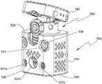
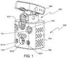
- FIG. 1is a perspective view of a spinal fixation device in accordance with an embodiment of the present disclosure
- FIG. 2is a front view of the spinal fixation device of FIG. 1 ;
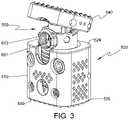
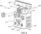
- FIGS. 3 and 4are perspective views of the spinal fixation device of FIG. 1 with a locking screw removed;
- FIG. 5is a top view of a first end plate of the spinal fixation device of FIG. 1 ;
- FIG. 6is a bottom view of a second end plate of the spinal fixation device of FIG. 1 ;
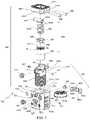
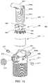
- FIG. 7is an exploded, front perspective view of the spinal fixation device of FIG. 1 with parts separated;
- FIG. 8is an exploded, rear perspective view of the spinal fixation device of FIG. 1 with parts separated;
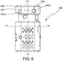
- FIG. 9is a side view of the spinal fixation device of FIG. 1 ;
- FIG. 10is a side view of the spinal fixation device of FIG. 9 illustrating angular displacement of the first end plate
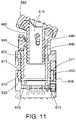
- FIG. 11is a side cross-sectional view of the spinal fixation device of FIG. 2 taken along section line 11 - 11 of FIG. 2 ;
- FIG. 12is a perspective view of a partial end plate assembly of the spinal fixation device of FIG. 1 ;
- FIG. 13is a side view of the second support assembly of FIG. 12 ;
- FIG. 14is a rear view of the second support assembly of FIG. 12 ;
- FIG. 15is an exploded, perspective view of the partial end plate assembly of FIG. 12 with parts separated;
- FIG. 16is a top view of an insertion instrument for use with the spinal fixation device of FIG. 1 ;
- FIG. 17is a top view of the insertion instrument of FIG. 16 with securing members separated from the insertion instrument;
- FIGS. 18 and 19are perspective views of the insertion instrument illustrating use with the spinal fixation device of FIG. 1 ;
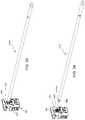
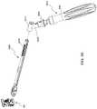
- FIGS. 20-23are perspective views of the insertion instrument of FIG. 16 and an adjusting driver illustrating use with the spinal fixation device of FIG. 1 ;
- FIGS. 24 and 25are perspective views of the adjusting driver of FIGS. 20-23 illustrating use with the spinal fixation device of FIG. 1 ;
- FIG. 26is a side view of the insertion instrument of FIG. 16 and an extension member illustrating use with the spinal fixation device of FIG. 1 ;
- FIG. 27is a perspective view of the insertion instrument of FIG. 16 and the extension member of FIG. 26 illustrating use with the spinal fixation device of FIG. 1 ;
- FIG. 28is a top view of the insertion instrument and the extension member of FIG. 27 ;
- FIG. 28Ais a cross-sectional view of the insertion instrument and the extension member of FIG. 27 taken along section line 28 A- 28 A of FIG. 28 ;
- FIG. 29is a side view of the insertion instrument of FIG. 26 and an extension member in accordance with another embodiment of the present disclosure illustrating use with the spinal fixation device of FIG. 1 ;
- FIG. 30is a perspective view of the insertion instrument and the extension member of FIG. 29 illustrating use with the spinal fixation device of FIG. 1 ;
- FIG. 31is a top view of the insertion instrument and the extension member of FIG. 30 ;
- FIG. 31Ais a cross-sectional view of the insertion instrument and the extension member of FIG. 31 taken along section line 31 A- 31 A of FIG. 31 .
- proximal and distalmay be employed interchangeably, and should be understood as referring to the portion of a structure that is closer to a clinician during proper use.
- distaland “leading” may also be employed interchangeably, and should be understood as referring to the portion of a structure that is farther from the clinician during proper use.
- cephalador “cranial” is used in this application to indicate a direction toward a patient's head, whereas the term “caudad” indicates a direction toward the patient's feet.
- the term “medial”indicates a direction toward the middle of the body of the patient
- the term “lateral”indicates a direction toward a side of the body of the patient (i.e., away from the middle of the body of the patient).
- the term “posterior”indicates a direction toward the patient's back
- the term “anterior”indicates a direction toward the patient's front.
- spinal fixation device 500configured and adapted to be positioned between vertebral bodies to support vertebral bodies and to promote spinal fusion.
- spinal fixation device 500may be inserted into the patient laterally, posteriorly, anteriorly, or obliquely.
- spinal fixation device 500may be inserted into the patient through procedures such as, e.g., posterior lumbar interbody fusion (PLIF), transforaminal lumbar interbody fusion (TLIF), lateral lumbar interbody fusion (LLIF), oblique lumbar interbody fusion (OLIF), or lateral extracavitary (LECA) procedures.
- PLIFposterior lumbar interbody fusion
- TLIFtransforaminal lumbar interbody fusion
- LLIFlateral lumbar interbody fusion
- OLIFoblique lumbar interbody fusion
- LECAextracavitary
- spinal fixation device 500includes a housing 510 and an end plate assembly 560 interchangeably coupled with housing 510 .
- End plate assembly 560includes a first end plate 540 and first and second support assemblies 660 , 680 operatively supporting first end plate 540 .
- Housing 510includes a second end plate 550 .
- First and second end plates 540 , 550are configured to engage end plates of adjacent vertebral bodies.
- first and second end plates 540 , 550are configured to engage, e.g., endplates of superior and inferior vertebral bodies, respectively.
- each of first and second end plates 540 , 550may include a plurality of pyramidal shaped spikes 533 a , 533 b (i.e., tetrahedrons) to aid in securing spinal fixation device 500 to the adjacent vertebral bodies for enhanced gripping of the vertebral bodies and minimizing movement of spinal fixation device 500 relative to the vertebral bodies.
- each of first and second end plates 540 , 550may include ridges or similar projections to aid in securing spinal fixation device 500 to the vertebral bodies.
- End plate assembly 560may be configured as a modular assembly that is interchangeably mounted in housing 510 .
- a plurality of end plate assemblies 560may be provided with varying parameters such as, e.g., footprint and lordosis, such that the clinician may selectively attach a desired end plate assembly 560 to housing 510 to meet the needs of each patient or surgical procedure being performed.
- end plate assembly 560may be tailored to achieve a desired lordosis of first end plate 540 and a desired axial spacing between housing 510 and first end plate 540 , as will be discussed hereinbelow. It is also contemplated that the desired axial spacing between first and second end plates 540 , 550 may be tailored by selecting a desired length of housing 510 and/or end plate assembly 560 .
- Spinal fixation device 500may be made of titanium, titanium alloy, stainless steel, allograft bone, autologous bone graft, polyetheretherketone (PEEK), cobalt chrome, polymeric materials, a combination thereof, or any other suitable biocompatible material.
- spinal fixation device 500may be formed of bone, or an artificial material other than bone which may be harder or stronger than bone, such as, e.g., ceramic materials.
- various parts of spinal fixation device 500such as, e.g., first and second end plates 540 , 550 , may be formed of titanium by 3D printing.
- Housing 510may include a bone growth promoting material such as, e.g., bone morphogenic protein and hydroxyapatite.
- Housing 510may define a cavity 551 to accommodate bone graft material therein. It is envisioned that bone support matrix can be placed within cavity 551 of housing 510 .
- a “bone support matrix”is a material that facilitates osteogenesis. Suitable bone support matrices can be resorbable or nonresorbable and osteoconductive or osteoinductive. Non-limiting examples of suitable bone support matrices include synthetic materials, bone morphogenic proteins (BMPs), and heterologous, homologous, or autologous bone and derivatives thereof. The bone support matrix may be radiolucent on x-rays.
- housing 510includes first and second ends 524 , 526 and an outer wall 512 extending between first and second ends 524 , 526 .
- Outer wall 512defines bores 527 a , 527 b , 527 c dimensioned to operatively engage insertion instrument 6000 ( FIGS. 18 and 19 ), as will be discussed hereinbelow.
- bores 527 a , 527 b , 527 cmay be defined in anterior or anterolateral portions of housing 510 .
- Outer wall 512may further define a slot 531 ( FIG.
- Outer wall 512further defines a bore 537 dimensioned to receive a pin 535 that slides along a slot 605 defined in first support 602 in order to guide and facilitate axial movement of first support 602 within housing 510 .
- the length of slot 605may define a range of axial displacement of first and second support assemblies 660 , 680 .
- the length of slot 605may be tailored to meet the needs of each surgical procedure.
- slot 531 and bores 525 , 537may be defined in posterior or posterolateral portions of housing 510 .
- first end 524 of housing 510defines an aperture 522 and second end 526 of housing 510 includes second end plate 550 , e.g., integrally formed, with housing 510 .
- Housing 510defines a chamber 520 configured to receive at least a portion of end plate assembly 560 through aperture 522 .
- End plate assembly 560is selectively positionable within chamber 520 .
- End plate assembly 560includes a first support assembly 660 releasably supported on a shoulder 530 ( FIG. 11 ) of housing 510 and a second support assembly 680 operatively coupled with first support assembly 660 .
- First support assembly 660includes a first support 602 , a spacer 606 , and a first rotatable member 610 rotatably supported on shoulder 530 ( FIG. 11 ) of housing 510 .
- First support 602includes a threaded portion 602 a threadably coupled to first rotatable member 610 , and a protrusion portion 604 ( FIG. 12 ) defining a bore 604 a therethrough. Bore 604 a is dimensioned to receive a pin 555 such that protrusion portion 604 is, e.g., pivotably, coupled to first end plate 540 .
- First support 602defines a passage 607 dimensioned to receive at least a portion of second support assembly 680 .
- First support 602further defines bores 609 dimensioned to receive pins 617 to operatively secure second support assembly 680 to first support 602 .
- First support 602further defines a locking bore 613 providing access to second rotatable member 690 .
- Locking bore 613is also dimensioned to receive a screw 615 to inhibit relative movement between second support assembly 680 and first support 602 .
- First rotatable member 610is positioned on shoulder 530 ( FIG. 11 ) of housing 510 through slot 531 ( FIG. 8 ) defined in, e.g., posterior or posterolateral portions, of housing 510 .
- Spacer 606is placed in slot 531 to enclose and rotatably secure first rotatable member 610 within chamber 520 of housing 510 .
- Spacer 606may act as a barrier to prevent any debris, tissue, or bone from entering any gaps that may be present between housing 510 and first rotatable member 610 . Further, spacer 606 may also inhibit debris from depositing in teeth 612 a of first rotatable member 610 .
- Spacer 606includes an arcuate surface 606 c configured to enable rotation of first rotatable member 610 .
- Spacer 606defines opposing bores 606 a configured to be aligned with bores 525 ( FIG. 8 ) defined in housing 510 to receive respective pins 527 therein to secure spacer 606 with housing 510 .
- Housing 510further includes a ledge 571 ( FIG. 11 ) such that when first rotatable member 610 is disposed on shoulder 530 of housing 510 , ledge 571 and shoulder 530 inhibit axial displacement of first rotatable member 610 within chamber 520 of housing 510 .
- first rotatable member 610causes axial displacement of first support 602 threadably coupled with inner threads 619 ( FIG. 7 ) of first rotatable member 610 .
- first support 602threadably coupled with inner threads 619 ( FIG. 7 ) of first rotatable member 610 .
- the distance between first end plate 540 and housing 510may be selectively adjusted.
- a length of spinal fixation device 500can range from about 18 mm to about 32 mm.
- the length of spinal fixation device 500may be based in part on the initial length of the device.
- the length of the spinal fixation device 500may be increased by an additional 4 mm. It is envisioned that the length of spinal fixation device 500 may be increased in any increment from about 0 mm to about 16 mm.
- second support assembly 680is operatively coupled to first end plate 540 to selectively adjust the angular orientation of first end plate 540 with respect to longitudinal axis “A-A” ( FIG. 9 ).
- second support assembly 680includes a second support 682 translatably disposed within passage 607 of first support 602 , a second spacer 686 , and a second rotatable member 690 rotatably supported within passage 607 of first support 602 .
- Second support 682includes a threaded portion 682 a threadably coupled to second rotatable member 690 , and a protrusion portion 684 defining a bore 684 a therethrough.
- Bore 684 ais dimensioned to receive pin 555 ( FIG. 8 ) such that protrusion portion 684 is coupled to first end plate 540 .
- Second support 682further defines slots 682 b dimensioned to receive respective pins 617 extending through bores 609 of first support 602 to slidably secure second support 682 with first support 602 .
- second spacer 686defines bores 689 aligned with respective slots 682 b of second support 682 and bores 609 of first support 602 such that pins 617 are received through respective bores 609 of first support 602 , bores 689 of second spacer 686 , and slots 682 b of second support 682 .
- Second spacer 686is secured with first support 602 while enabling axial displacement of second support 682 relative to first support 602 .
- Second spacer 686may act as a barrier to prevent any debris, tissue, or bone from entering any gaps that may be present between the first support 602 and second rotatable member 690 .
- spacer 686may also inhibit debris from depositing in teeth 691 of second rotatable member 690 .
- second rotatable member 690 of second support assembly 680is rotatably disposed within passage 607 of first support 602 .
- second rotatable member 690is disposed on a shoulder 612 of first support 602 .
- shoulder 612 of first support 602 and second spacer 686inhibit axial displacement of second rotatable member 690 while enabling rotation of second rotatable member 690 .
- Second rotatable member 690includes an inner wall 693 threadably coupled with threaded portion 682 a of second support 682 .
- second rotatable member 690causes axial displacement of second support 682 relative to first support 602 and housing 510 .
- Bore 684 a of protrusion portion 684 of second support 682is aligned with slot 542 b of first end plate 540 such that pin 555 is received in slot 542 b of first end plate 540 and bore 648 a of protrusion portion 684 of second support 682 .
- axial displacement of second support 682causes angular displacement of first end plate 540 .
- first end plate 540may pivot about pin 555 disposed within bore 542 a of first end plate 540 .
- Slot 542 bhas a larger dimension than pin 555 to facilitate pivoting of first end plate 540 about pin 555 in bore 542 a .
- second support assembly 680is shown to selectively adjust the angular orientation of first end plate 540 with respect to longitudinal axis “A-A” ( FIG. 9 ), it is also envisioned that second support assembly 680 may be operatively coupled to first end plate 540 to further adjust the distance between first end plate 540 and housing 510 .
- Housing 510defines an axis “X-X” ( FIG. 9 ) orthogonal to a longitudinal axis “A-A” ( FIG. 9 ) defined by outer housing 510 .
- first end plate 540may define a 0° angle with respect to axis “X-X” (i.e., a 90° angle with respect to axis “A-A”).
- Angular orientation of first end plate 540may be selectively adjustable to better align first end plate 540 with an adjacent vertebral body to more accurately align spinal fixation device 500 with the adjacent vertebral body.
- First end plate 540may be selectively adjustable in a range from about 0° to about 45° with respect to axis “X-X” (i.e., from about 90° to about 135° with respect to axis “A-A”).
- Insertion instrument 6000for use with spinal fixation device 500 to position spinal fixation device 500 between adjacent vertebral bodies.
- Insertion instrument 6000includes a handle 6010 and an elongate body 6020 extending from handle 6010 .
- Insertion instrument 6000defines a channel 6035 ( FIG. 22 ) configured to receive an adjusting driver 7500 ( FIG. 22 ).
- Elongate body 6020includes engaging portion 6032 defining bores 6037 dimensioned to be aligned with bores 527 a , 527 c ( FIG. 2 ) of housing 510 .
- Bores 6037 of engaging portion 6032are dimensioned to receive respective securing members 6039 a , 6039 b to secure insertion instrument 6000 with housing 510 .
- Securing members 6039 a , 6039 bmay be threadably coupled with respective bores 527 a , 527 c of housing 510 to securely attach spinal fixation device 500 with insertion instrument 6000 ( FIG. 19 ).
- respective securing members 6039 a , 6039 b( FIG. 17 ) are received within bores 527 a , 527 c of housing 510 , respectively.
- a driver 7000may be utilized to threadably secure securing members 6039 a , 6039 b within respective bores 527 a , 527 b . Alignment of securing members 6039 a , 6039 b with bores 527 a , 527 c provides alignment between bore 527 b of housing 510 and channel 6035 of insertion instrument 6000 .
- Adjusting driver 7500may be inserted into channel 6035 of insertion instrument 6000 to engage teeth 612 a ( FIG. 2 ) of first rotatable member 610 with an engaging portion 7520 of the adjusting driver 7500 .
- Rotation of adjusting driver 7500rotates first rotatable member 610 , causes axial displacement of first support 602 , which, in turn, causes axial displacement of first end plate 540 with respect to housing 510 .
- end plate assembly 560is selectively positionable relative to housing 510 through rotation of first rotatable member 610 .
- a length of spinal fixation device 500may be selectively tailored to, e.g., the intervertebral space.
- an engaging portion 7520 of adjusting driver 7500may be inserted into locking bore 613 of first support 602 to operatively engage teeth 691 ( FIG. 7 ) of second rotatable member 690 .
- teeth 691 of second rotatable member 690rotatably engage engaging portion 7520 of adjusting driver 7500 , which, in turn, causes axial displacement of second support 682 ( FIG. 8 ) with respect to first support 602 .
- This interactioncauses angular displacement of first end plate 540 or pivoting of first end plate 540 about bore 604 a ( FIG. 7 ) of first support 602 .
- Such a configurationenables the clinician to selectively adjust angular orientation of first end plate 540 with respect to housing 510 to achieve the desired lordosis.
- first end plate 540may be advantageously angled to provide a desired amount of lordosis tailored to the need of each patient.
- first end plate 540may be positioned substantially orthogonal to the longitudinal axis “A-A” ( FIG. 9 ) and adjacent first end 524 of housing 510 .
- first end plate 540may define an acute angle with respect to longitudinal axis “A-A” ( FIG. 10 ) and spaced apart from first end 524 of housing 510 .
- extension member 8000configured to be attached to insertion instrument 6000 to provide a handle offset from a longitudinal axis “Y” defined by insertion instrument 6000 to facilitate insertion of spinal fixation device 500 into the patient.
- extension member 8000includes an engaging portion 8010 configured to, e.g., frictionally, receive handle 6010 of insertion instrument 6000 , and a handle portion 8020 .
- Handle portion 8020extends from engaging portion 8010 such that handle portion 8020 is offset from longitudinal axis “Y-Y” of insertion instrument 6000 .
- Extension member 9000includes an engaging portion 9010 configured to receive handle 6010 of insertion instrument 6000 .
- Extension member 9000further includes a handle portion 9020 extending from engaging portion 9010 such that handle portion 9020 is offset from longitudinal axis “Y-Y” of insertion instrument 6000 .
- Handle portion 9020includes a slider 9030 ( FIG. 32 ) configured to engage notch 6050 defined in handle 6010 to further secure engaging portion 9010 with handle 6010 .
- Slider 9030is operatively coupled to collar 9040 disposed about a neck portion 9050 of handle portion 9020 such that sliding of collar 9040 transitions slider 9030 between an engaged position in which slider 9030 securely engages notch 6050 of handle 6010 and a disengaged position in which the slider 9030 is disengaged from notch 6050 of handle 6010 .
- Collar 9040may be coupled to a biasing member 9042 to bias slider 9030 towards the engaged state.
- first and second supports 602 , 682 of first support assembly 660 and second support assembly 680are selectively positioned to achieve a desired orientation of first end plate 540 and length of spinal fixation device 500 .
- Insertion instrument 6000is coupled with spinal fixation device 500 by, e.g., threadably, coupling engaging portion 6032 ( FIG. 17 ) with bores 527 a , 527 c ( FIG. 2 ) of housing 510 .
- Spinal fixation device 500is then positioned adjacent a desired intervertebral space between vertebral bodies.
- adjusting driver 7500can be inserted through channel 6035 ( FIGS. 22 and 23 ) of insertion instrument 6000 to further adjust the axial distance between first end plate 540 and housing 510 by placing engaging portion 7520 through bore 527 b defined in housing 510 such that teeth 7504 of engaging portion 7520 of adjusting driver 7500 engage teeth 612 a of first rotatable member 610 .
- rotation of adjusting driver 7500causes rotation of first rotatable member 610 , which, in turn, imparts axial translation of first support 602 .
- the clinicianmay adjust the axial distance between first end plate 540 and housing 510 , i.e., length of spinal fixation device 500 .
- Adjusting driver 7500is rotated until a desired length of spinal fixation device 500 is effected through axial movement of end plate assembly 560 .
- screws 190may be inserted into respective bores 521 , 527 b to secure the axial position of first support 602 .
- adjusting driver 7500can be inserted into locking bore 613 ( FIG. 4 ) of first support 602 to operatively engage teeth 691 ( FIG. 4 ) of second rotatable member 690 ( FIG. 7 ) to adjust the angular orientation of first end plate 540 with respect to housing 510 (i.e., axis “A-A”) to mimic or closely match the degree of curvature along the spine comprising the adjacent vertebra.
- engaging portion 7520 of adjusting driver 7500is inserted into locking bore 613 of first support 602 such that teeth 7504 of engaging portion 7520 of adjusting driver 7500 engage teeth 691 of second rotatable member 690 .
- Rotation of adjusting driver 7500causes rotation of second rotatable member 690 , which, in turn, causes axial displacement of second support 682 .
- Axial displacement of second support 682 with respect to first support 602enables the clinician to adjust the angular orientation of first end plate 540 with respect to housing 510 to achieve the desired lordosis or kyphosis. It is contemplated that the clinician may make further adjustments by alternating length adjustment and angular adjustment to achieve the desired length of spinal fixation device 500 and angular orientation of first end plate 540 .
- screw 615may be placed in locking bore 613 .
- Screw 615may be threadably secured in locking bore 613 by using driver 7000 .
- screw 615may include a boss 615 a ( FIG. 8 ) configured to be disposed between two adjacent teeth 691 of second rotatable member 690 to inhibit rotation of second rotatable member 690 .
- first end plate 540may be adjustable in the medial and lateral directions. It is to be understood, therefore, that the disclosure is not limited to those precise embodiments, and that various other changes and modifications may be effected therein by one skilled in the art without departing from the scope or spirit of the disclosure.
Landscapes
- Health & Medical Sciences (AREA)
- Engineering & Computer Science (AREA)
- Biomedical Technology (AREA)
- Orthopedic Medicine & Surgery (AREA)
- Neurology (AREA)
- Transplantation (AREA)
- Veterinary Medicine (AREA)
- General Health & Medical Sciences (AREA)
- Oral & Maxillofacial Surgery (AREA)
- Heart & Thoracic Surgery (AREA)
- Vascular Medicine (AREA)
- Life Sciences & Earth Sciences (AREA)
- Animal Behavior & Ethology (AREA)
- Cardiology (AREA)
- Public Health (AREA)
- Physical Education & Sports Medicine (AREA)
- Surgical Instruments (AREA)
- Prostheses (AREA)
- External Artificial Organs (AREA)
- Apparatus Associated With Microorganisms And Enzymes (AREA)
Abstract
Description
Claims (21)
Priority Applications (1)
| Application Number | Priority Date | Filing Date | Title |
|---|---|---|---|
| US16/415,439US11344426B2 (en) | 2015-09-18 | 2019-05-17 | Corpectomy device and methods of use thereof |
Applications Claiming Priority (3)
| Application Number | Priority Date | Filing Date | Title |
|---|---|---|---|
| US201562220274P | 2015-09-18 | 2015-09-18 | |
| US15/268,948US10327908B2 (en) | 2015-09-18 | 2016-09-19 | Corpectomy device and methods of use thereof |
| US16/415,439US11344426B2 (en) | 2015-09-18 | 2019-05-17 | Corpectomy device and methods of use thereof |
Related Parent Applications (1)
| Application Number | Title | Priority Date | Filing Date |
|---|---|---|---|
| US15/268,948ContinuationUS10327908B2 (en) | 2015-09-18 | 2016-09-19 | Corpectomy device and methods of use thereof |
Publications (2)
| Publication Number | Publication Date |
|---|---|
| US20190269523A1 US20190269523A1 (en) | 2019-09-05 |
| US11344426B2true US11344426B2 (en) | 2022-05-31 |
Family
ID=58276391
Family Applications (2)
| Application Number | Title | Priority Date | Filing Date |
|---|---|---|---|
| US15/268,948Active2037-08-16US10327908B2 (en) | 2015-09-18 | 2016-09-19 | Corpectomy device and methods of use thereof |
| US16/415,439Active2037-09-07US11344426B2 (en) | 2015-09-18 | 2019-05-17 | Corpectomy device and methods of use thereof |
Family Applications Before (1)
| Application Number | Title | Priority Date | Filing Date |
|---|---|---|---|
| US15/268,948Active2037-08-16US10327908B2 (en) | 2015-09-18 | 2016-09-19 | Corpectomy device and methods of use thereof |
Country Status (4)
| Country | Link |
|---|---|
| US (2) | US10327908B2 (en) |
| EP (1) | EP3349695B1 (en) |
| AU (2) | AU2016324333B2 (en) |
| WO (1) | WO2017049268A1 (en) |
Families Citing this family (9)
| Publication number | Priority date | Publication date | Assignee | Title |
|---|---|---|---|---|
| FR3005569B1 (en) | 2013-05-16 | 2021-09-03 | Ldr Medical | VERTEBRAL IMPLANT, VERTEBRAL IMPLANT FIXATION DEVICE AND IMPLANTATION INSTRUMENTATION |
| US11006981B2 (en) | 2017-07-07 | 2021-05-18 | K2M, Inc. | Surgical implant and methods of additive manufacturing |
| US10987229B2 (en) | 2018-02-14 | 2021-04-27 | Warsaw Orthopedic, Inc. | Spinal implant system |
| CL2019001608A1 (en)* | 2019-06-11 | 2019-09-06 | Sofia Ximena Osorio Reyes | Process for transformation of antimicrobial glazed material. |
| US11534307B2 (en) | 2019-09-16 | 2022-12-27 | K2M, Inc. | 3D printed cervical standalone implant |
| TWI768260B (en)* | 2019-11-08 | 2022-06-21 | 財團法人工業技術研究院 | Vertebra reconstruction implant |
| DE102020007873A1 (en)* | 2020-12-22 | 2022-06-23 | Taurus Gmbh & Co. Kg | HEIGHT-ADJUSTABLE IMPLANT |
| US12310855B2 (en) | 2021-09-09 | 2025-05-27 | Warsaw Orthopedic, Inc. | End cap and bone screw for use therewith |
| WO2023060127A1 (en)* | 2021-10-08 | 2023-04-13 | Seaspine, Inc. | Expandable vertebral implant |
Citations (167)
| Publication number | Priority date | Publication date | Assignee | Title |
|---|---|---|---|---|
| US251546A (en) | 1881-12-27 | Thomas a | ||
| US739461A (en) | 1901-02-20 | 1903-09-22 | Edward K Warren | Machine for manufacturing stiffening material. |
| US3402947A (en) | 1966-06-20 | 1968-09-24 | John A Donato | Connector |
| US3588023A (en) | 1968-09-16 | 1971-06-28 | Maurice Cohen | Vertically adjustable standard |
| US3893730A (en) | 1974-08-05 | 1975-07-08 | Lear Siegler Inc | Seat positioner |
| US4387926A (en) | 1981-06-26 | 1983-06-14 | Rockwell International Corporation | Seat positioner |
| US4554914A (en) | 1983-10-04 | 1985-11-26 | Kapp John P | Prosthetic vertebral body |
| SU1560184A1 (en) | 1988-07-29 | 1990-04-30 | Харьковский Научно-Исследовательский Институт Ортопедии И Травматологии Им.Проф.М.И.Ситенко | Endoprosthesis of spinal column segments |
| US4938319A (en) | 1987-11-14 | 1990-07-03 | Ernst Hans Hellmut | Linearly adjustable force transfer element with stepless inertia-sensitive blocking |
| US5053036A (en) | 1987-11-03 | 1991-10-01 | Synthes (U.S.A.) | Point contact bone compression plate |
| US5108066A (en) | 1990-04-13 | 1992-04-28 | Lundstrom Donald A | Hand releasable locking collar |
| US5236460A (en) | 1990-02-12 | 1993-08-17 | Midas Rex Pneumatic Tools, Inc. | Vertebral body prosthesis |
| US5290312A (en) | 1991-09-03 | 1994-03-01 | Alphatec | Artificial vertebral body |
| US5336223A (en) | 1993-02-04 | 1994-08-09 | Rogers Charles L | Telescoping spinal fixator |
| US5360430A (en) | 1993-07-29 | 1994-11-01 | Lin Chih I | Intervertebral locking device |
| US5458641A (en) | 1993-09-08 | 1995-10-17 | Ramirez Jimenez; Juan J. | Vertebral body prosthesis |
| US5520690A (en) | 1995-04-13 | 1996-05-28 | Errico; Joseph P. | Anterior spinal polyaxial locking screw plate assembly |
| US5547308A (en) | 1992-04-28 | 1996-08-20 | Dzus Fastener Europe Limited | Fastening device |
| US5571190A (en) | 1993-08-20 | 1996-11-05 | Heinrich Ulrich | Implant for the replacement of vertebrae and/or stabilization and fixing of the spinal column |
| US5571192A (en) | 1994-07-02 | 1996-11-05 | Heinrich Ulrich | Prosthetic vertebral implant |
| US5702455A (en) | 1996-07-03 | 1997-12-30 | Saggar; Rahul | Expandable prosthesis for spinal fusion |
| US5723013A (en) | 1995-02-06 | 1998-03-03 | Jbs S.A. | Spacer implant for substituting missing vertebrae |
| US5738685A (en) | 1993-05-18 | 1998-04-14 | Schafer Micomed Gmbh | Osteosynthesis device |
| US5776198A (en) | 1994-12-09 | 1998-07-07 | Sdgi Holdings, Inc. | Adjustable vertebral body replacement |
| WO1998046173A1 (en) | 1997-04-15 | 1998-10-22 | Synthes Ag Chur | Telescopic vertebral prosthesis |
| US5885286A (en) | 1996-09-24 | 1999-03-23 | Sdgi Holdings, Inc. | Multi-axial bone screw assembly |
| US5888014A (en) | 1997-04-14 | 1999-03-30 | Lung; Jimmy R. | Extensible lockable apparatus |
| US5901798A (en) | 1993-10-14 | 1999-05-11 | Hydril U.K. Limited | Drill pipe tubing and casing protectors |
| US5904683A (en) | 1998-07-10 | 1999-05-18 | Sulzer Spine-Tech Inc. | Anterior cervical vertebral stabilizing device |
| DE19804765A1 (en) | 1998-02-06 | 1999-08-26 | Biedermann Motech Gmbh | Placeholder with adjustable axial length |
| US5980522A (en) | 1994-07-22 | 1999-11-09 | Koros; Tibor | Expandable spinal implants |
| US5989290A (en) | 1995-05-24 | 1999-11-23 | Biedermann; Lutz | Height-adjustable artificial vertebral body |
| US6074391A (en) | 1997-06-16 | 2000-06-13 | Howmedica Gmbh | Receiving part for a retaining component of a vertebral column implant |
| US6099531A (en) | 1998-08-20 | 2000-08-08 | Bonutti; Peter M. | Changing relationship between bones |
| US6110172A (en) | 1998-07-31 | 2000-08-29 | Jackson; Roger P. | Closure system for open ended osteosynthesis apparatus |
| US6132434A (en) | 1996-11-07 | 2000-10-17 | Sdgi Holdings, Inc. | Multi-angle bone screw assembly using shape-memory technology |
| US6179514B1 (en) | 1999-05-28 | 2001-01-30 | Kun-Chia Cheng | Telescopic tube joint |
| US6183517B1 (en) | 1998-12-16 | 2001-02-06 | Loubert Suddaby | Expandable intervertebral fusion implant and applicator |
| US6193756B1 (en) | 1997-09-30 | 2001-02-27 | Sulzer Orthopaedie Ag | Tubular support body for bridging two vertebrae |
| US6193755B1 (en) | 1996-09-26 | 2001-02-27 | Howmedica Gmbh | Spinal cage assembly |
| US6235062B1 (en) | 1994-09-06 | 2001-05-22 | Finn Gramnas | Fastening device for prosthesis |
| US6241769B1 (en) | 1998-05-06 | 2001-06-05 | Cortek, Inc. | Implant for spinal fusion |
| US6254602B1 (en) | 1999-05-28 | 2001-07-03 | Sdgi Holdings, Inc. | Advanced coupling device using shape-memory technology |
| US6273888B1 (en) | 1999-05-28 | 2001-08-14 | Sdgi Holdings, Inc. | Device and method for selectively preventing the locking of a shape-memory alloy coupling system |
| US20010021851A1 (en) | 1998-07-20 | 2001-09-13 | Roland Eberlein | Fastening assembly |
| US6296665B1 (en) | 2000-03-20 | 2001-10-02 | Electro-Biology, Inc. | Method and apparatus for spinal fixation |
| US6296642B1 (en) | 1998-11-09 | 2001-10-02 | Sdgi Holdings, Inc. | Reverse angle thread for preventing splaying in medical devices |
| US6302888B1 (en) | 1999-03-19 | 2001-10-16 | Interpore Cross International | Locking dovetail and self-limiting set screw assembly for a spinal stabilization member |
| US6332895B1 (en) | 2000-03-08 | 2001-12-25 | Loubert Suddaby | Expandable intervertebral fusion implant having improved stability |
| US6342074B1 (en) | 1999-04-30 | 2002-01-29 | Nathan S. Simpson | Anterior lumbar interbody fusion implant and method for fusing adjacent vertebrae |
| US6364880B1 (en) | 1994-03-28 | 2002-04-02 | Gary Karlin Michelson | Spinal implant with bone screws |
| US6375683B1 (en) | 1997-05-02 | 2002-04-23 | Stryker France S.A. | Implant in particular for replacing a vertebral body in surgery of the spine |
| US6395034B1 (en) | 1999-11-24 | 2002-05-28 | Loubert Suddaby | Intervertebral disc prosthesis |
| US6419705B1 (en) | 1999-06-23 | 2002-07-16 | Sulzer Spine-Tech Inc. | Expandable fusion device and method |
| US6440170B1 (en) | 2000-12-04 | 2002-08-27 | Roger P. Jackson | Threaded interbody device |
| US20020128654A1 (en) | 1998-02-18 | 2002-09-12 | Steger Shon D. | Method and apparatus for bone fracture fixation |
| US20020161441A1 (en) | 1998-10-15 | 2002-10-31 | Bruno Lang | Telescopic vertebral prosthesis |
| US6500178B2 (en) | 1997-01-02 | 2002-12-31 | St. Francis Medical Technologies, Inc. | Spine distraction implant and method |
| WO2003032812A2 (en) | 2001-10-17 | 2003-04-24 | Medicinelodge, Inc. | Adjustable bone fusion implant and method |
| US6558423B1 (en) | 1999-05-05 | 2003-05-06 | Gary K. Michelson | Interbody spinal fusion implants with multi-lock for locking opposed screws |
| US20030130737A1 (en) | 2000-02-22 | 2003-07-10 | Mcgahan Thomas V. | Anterior impacted bone graft and driver instruments |
| US6610090B1 (en) | 1998-01-30 | 2003-08-26 | Königsee Implantate und Instrumente zur Ostheosynthese GmbH | Height-adjustable vertebral implant |
| US6616695B1 (en) | 1998-01-30 | 2003-09-09 | Stryker Spine | Implant for replacing a vertebra |
| US20030181980A1 (en) | 2002-03-21 | 2003-09-25 | Berry Bret M. | Vertebral body and disc space replacement devices |
| US6629998B1 (en) | 2000-08-23 | 2003-10-07 | Chih-I Lin | Intervertebral retrieval device |
| US6660038B2 (en) | 2000-03-22 | 2003-12-09 | Synthes (Usa) | Skeletal reconstruction cages |
| US6663060B1 (en) | 2002-09-26 | 2003-12-16 | Robert Wayne Gifford, Sr. | Microphone stand |
| US6716214B1 (en) | 2003-06-18 | 2004-04-06 | Roger P. Jackson | Polyaxial bone screw with spline capture connection |
| US6730088B2 (en) | 2001-08-29 | 2004-05-04 | Chung-Chun Yeh | Device for fixing spinal column under treatment |
| US6752832B2 (en) | 2000-12-27 | 2004-06-22 | Ulrich Gmbh & Co., Kg | Vertebral implant and setting tool therefor |
| US6770096B2 (en) | 1999-07-01 | 2004-08-03 | Spinevision S.A. | Interbody spinal stabilization cage and spinal stabilization method |
| US20040186569A1 (en) | 2003-03-20 | 2004-09-23 | Berry Bret M. | Height adjustable vertebral body and disc space replacement devices |
| US6827719B2 (en) | 2001-02-15 | 2004-12-07 | K2 Medical, Llc | Polyaxial pedicle screw having a rotating locking element |
| US20040247379A1 (en) | 2001-07-24 | 2004-12-09 | Pascal Guidetti | Device for locking two telescopic elongated elements |
| US6835196B2 (en) | 2001-03-27 | 2004-12-28 | Biedermann Motech Gmbh | Anchoring element |
| US6834840B1 (en) | 2000-08-01 | 2004-12-28 | Hill-Rom Services, Inc. | Medical device support assembly |
| US6837889B2 (en) | 2002-03-01 | 2005-01-04 | Endius Incorporated | Apparatus for connecting a longitudinal member to a bone portion |
| US6843791B2 (en) | 2003-01-10 | 2005-01-18 | Depuy Acromed, Inc. | Locking cap assembly for spinal fixation instrumentation |
| US6866682B1 (en) | 1999-09-02 | 2005-03-15 | Stryker Spine | Distractable corpectomy device |
| US20050060034A1 (en) | 2003-09-15 | 2005-03-17 | Sdgi Holdings, Inc. | Revisable prosthetic device |
| US6869433B2 (en) | 2001-01-12 | 2005-03-22 | Depuy Acromed, Inc. | Polyaxial screw with improved locking |
| US6869112B2 (en) | 2000-04-17 | 2005-03-22 | Pascal Guidetti | Device for locking two telescopic elongated elements |
| US20050085910A1 (en) | 2003-10-16 | 2005-04-21 | Sweeney Patrick J. | Vertebral prosthesis |
| US6884244B1 (en) | 2000-06-06 | 2005-04-26 | Roger P. Jackson | Removable medical implant closure for open headed implants |
| US6893443B2 (en) | 1999-07-07 | 2005-05-17 | Synthes (U.S.A) | Angle-adjustable bone screw and fixation device |
| US6896677B1 (en) | 2003-12-11 | 2005-05-24 | A-Spine Holding Group Corp. | Rotary device for retrieving spinal column under treatment |
| US6918911B2 (en) | 2002-03-27 | 2005-07-19 | Biedermann Motech Gmbh | Bone anchoring device for stabilizing bone segments and seat part of a bone anchoring device |
| US6945975B2 (en) | 2003-07-07 | 2005-09-20 | Aesculap, Inc. | Bone fixation assembly and method of securement |
| US20050209697A1 (en) | 2000-12-05 | 2005-09-22 | Stryker Spine | Spinal intervertebral implant adjustable in situ comprising hard pass point |
| US20050218275A1 (en) | 2004-04-06 | 2005-10-06 | Allan Keating | Stand |
| US6972019B2 (en) | 2001-01-23 | 2005-12-06 | Michelson Gary K | Interbody spinal implant with trailing end adapted to receive bone screws |
| US20050273173A1 (en) | 2003-08-05 | 2005-12-08 | Gordon Charles R | Expandable articulating intervertebral implant with cam |
| US6984234B2 (en) | 2003-04-21 | 2006-01-10 | Rsb Spine Llc | Bone plate stabilization system and method for its use |
| US20060041260A1 (en) | 2000-02-01 | 2006-02-23 | Orbay Jorge L | Fixation system with plate having holes with divergent axes and multidirectional fixators for use therethrough |
| US20060074490A1 (en) | 2004-10-01 | 2006-04-06 | Sweeney Patrick J | Vertebral prosthesis and spinal fixation system |
| US7025787B2 (en) | 2001-11-26 | 2006-04-11 | Sdgi Holdings, Inc. | Implantable joint prosthesis and associated instrumentation |
| US20060100710A1 (en) | 2003-04-28 | 2006-05-11 | Michael Gutlin | Intervertebral implant |
| US7056343B2 (en) | 2002-03-02 | 2006-06-06 | Bernd Schafer | Extendable spinal implant and extension tool |
| US20060122701A1 (en) | 2004-11-23 | 2006-06-08 | Kiester P D | Posterior lumbar interbody fusion expandable cage with lordosis and method of deploying the same |
| US20060129244A1 (en) | 2004-10-25 | 2006-06-15 | Alphaspine, Inc. | Expandable intervertebral spacer method and apparatus |
| US20060149251A1 (en) | 2004-12-22 | 2006-07-06 | Tara Ziolo | Bone fixation system |
| US20060149385A1 (en) | 2002-09-23 | 2006-07-06 | Mckay William F | Expandable spinal fusion device and methods of promoting spinal fusion |
| US7077864B2 (en) | 2002-02-12 | 2006-07-18 | Cross Medical Products, Inc. | Vertebral interbody cage with translatable locking screw |
| US20060173456A1 (en) | 2005-01-31 | 2006-08-03 | Hawkes David T | Polyaxial pedicle screw assembly |
| US7087057B2 (en) | 2003-06-27 | 2006-08-08 | Depuy Acromed, Inc. | Polyaxial bone screw |
| US7086631B2 (en) | 2004-03-03 | 2006-08-08 | Eml Technologies Llc | Quick-release telescoping tripod |
| US7094257B2 (en) | 2003-02-14 | 2006-08-22 | Zimmer Spine, Inc. | Expandable intervertebral implant cage |
| US20060200244A1 (en) | 2003-02-05 | 2006-09-07 | Richard Assaker | Vertebral replacement and distraction device for placing said implant |
| US20060212118A1 (en) | 2005-03-16 | 2006-09-21 | Abernathie Dennis L | Spinal fusion cage and method of use |
| US20060217715A1 (en) | 2005-03-24 | 2006-09-28 | Depuy Spine, Inc. | Low profile spinal tethering systems |
| US20060241770A1 (en) | 2005-04-21 | 2006-10-26 | Rhoda William S | Expandable vertebral prosthesis |
| US20060241762A1 (en) | 2003-12-11 | 2006-10-26 | Deltacor Gmbh | Height-adjustable spinal implant and operating instrument for the implant |
| US20060271047A1 (en) | 2005-05-10 | 2006-11-30 | Jackson Roger P | Polyaxial bone screw with compound articulation |
| US20060276792A1 (en) | 2005-05-25 | 2006-12-07 | Ensign Michael D | Low profile pedicle screw and rod assembly |
| US20070010887A1 (en) | 2002-03-30 | 2007-01-11 | Williams Lytton A | Intervertebral Device and Method of Use |
| US20070032871A1 (en) | 2000-02-04 | 2007-02-08 | Michelson Gary K | Expandable push-in arcuate orthopedic implant |
| US7175624B2 (en) | 2002-12-31 | 2007-02-13 | Depuy Spine, Inc. | Bone plate and screw system allowing bi-directional assembly |
| US20070073298A1 (en) | 2003-12-22 | 2007-03-29 | Florian Beutter | Bone plate |
| US20070093817A1 (en) | 2005-09-29 | 2007-04-26 | Michael Barrus | Spinal fixation system having locking and unlocking devices for use with a multi-planar, taper lock screw |
| US20070100340A1 (en) | 2005-10-27 | 2007-05-03 | Sdgi Holdings, Inc. | Intervertebral prosthetic device for spinal stabilization and method of implanting same |
| US20070106231A1 (en) | 2003-11-25 | 2007-05-10 | Snow Jeremy K | Resettable safety shield for medical needles |
| US20070162126A1 (en) | 2005-12-01 | 2007-07-12 | Sdgi Holdings, Inc. | End device for a vertebral implant |
| US20070191954A1 (en) | 2005-04-21 | 2007-08-16 | Noah Hansell | Expandable Vertebral Prosthesis |
| US20070219635A1 (en) | 2002-02-19 | 2007-09-20 | Claude Mathieu | Intervertebral implant |
| US7285134B2 (en) | 2003-10-22 | 2007-10-23 | Warsaw Orthopedic, Inc. | Vertebral body replacement implant |
| US20070250171A1 (en) | 2006-04-24 | 2007-10-25 | Sdgi Holdings, Inc. | Expandable intervertebral devices and methods of use |
| US20070255408A1 (en) | 2006-04-27 | 2007-11-01 | Sdgi Holdings, Inc. | Stabilized, adjustable expandable implant and method |
| US20070270968A1 (en) | 2004-02-10 | 2007-11-22 | Baynham Bret O | Plif opposing wedge ramp |
| US20070270964A1 (en) | 2006-04-27 | 2007-11-22 | Sdgi Holdings, Inc. | Expandable vertebral implant and methods of use |
| US20070282441A1 (en) | 2006-05-19 | 2007-12-06 | Katie Stream | Spinal Stabilization Device and Methods |
| FR2902315A1 (en) | 2006-06-20 | 2007-12-21 | Abbott Spine Sa | INTERVERTEBRAL DISTRACTABLE IMPLANT |
| WO2008005627A2 (en) | 2006-07-06 | 2008-01-10 | Lanx, Llc | Expandable spinal fusion cage |
| US7318825B2 (en) | 2003-12-22 | 2008-01-15 | Life Spine Llc | Dynamic cervical plates and cervical plate constructs |
| EP1878408A1 (en) | 2006-07-14 | 2008-01-16 | BIEDERMANN MOTECH GmbH | A spacer for insertion between two vertebrae |
| US20080021555A1 (en) | 2006-07-19 | 2008-01-24 | John White | Expandable vertebral body implants and methods of use |
| US20080114467A1 (en) | 2006-11-09 | 2008-05-15 | Warsaw Orthopedic, Inc. | Expanding Vertebral Body Implant |
| US20080125864A1 (en) | 2006-04-12 | 2008-05-29 | Spinalmotion, Inc. | Posterior Spinal Device and Method |
| US20080167720A1 (en) | 2007-01-08 | 2008-07-10 | Warsaw Orthopedic, Inc. | Expandable vertebral body replacement device |
| US20080249625A1 (en) | 2007-04-03 | 2008-10-09 | Warsaw Orthopedic, Inc. | Composite Interbody Spacer |
| US20080249624A1 (en) | 2003-12-12 | 2008-10-09 | Co.Don Ag | Method for the Production of Intervertebral Disk Cell Transplants and Their Use as Transplantation Material |
| US20080288071A1 (en) | 2006-05-16 | 2008-11-20 | Ashok Biyani | Expandable corpectomy device |
| WO2009023016A1 (en) | 2007-08-15 | 2009-02-19 | Warsaw Orthopedic, Inc. | Expandable vertebral implant and methods of use |
| US7531002B2 (en) | 2004-04-16 | 2009-05-12 | Depuy Spine, Inc. | Intervertebral disc with monitoring and adjusting capabilities |
| US7544208B1 (en) | 2004-05-03 | 2009-06-09 | Theken Spine, Llc | Adjustable corpectomy apparatus |
| US20090164019A1 (en) | 2007-11-30 | 2009-06-25 | Wen-Hsien Hsu | Adjustable vertebral spacer for artificial vertebrae |
| US7611104B1 (en) | 2007-01-29 | 2009-11-03 | Gifford Sr Robert Wayne | Stand for supporting an object |
| US20100005715A1 (en) | 2006-12-07 | 2010-01-14 | Allsop, Inc. | Adjustable garden stake |
| US7651517B2 (en) | 2002-12-31 | 2010-01-26 | Depuy Acromed, Inc. | Bone plate and resilient screw system allowing bi-directional assembly |
| US7691147B2 (en) | 2002-12-06 | 2010-04-06 | Synthes Usa, Llc | Intervertebral implant |
| US20100137919A1 (en) | 2006-12-20 | 2010-06-03 | Dietmar Wolter | Bone screw |
| US20100318092A1 (en) | 2009-06-10 | 2010-12-16 | Butler Michael S | Instruments For Installing Multi-Section Intervertebral Spinal Implants |
| US7862616B2 (en) | 2003-02-06 | 2011-01-04 | Synthes Usa, Llc | Intervertebral implant |
| US20110208248A1 (en) | 2007-10-23 | 2011-08-25 | Michael Barrus | Polyaxial screw assembly |
| US8137405B2 (en) | 2008-10-08 | 2012-03-20 | K2M, Inc. | Spinal interbody spacer |
| US8353961B2 (en) | 2008-02-07 | 2013-01-15 | K2M, Inc. | Expandable vertebral device with cam lock |
| US8377101B2 (en) | 2008-11-05 | 2013-02-19 | K2M, Inc. | Multi-planar taper lock screw with increased rod friction |
| US20130274883A1 (en) | 2012-04-13 | 2013-10-17 | Gary R. McLuen | Bone fusion device |
| US8585761B2 (en) | 2008-03-28 | 2013-11-19 | K2M, Inc. | Expandable cage with locking device |
| US8673011B2 (en) | 2008-03-28 | 2014-03-18 | K2M, Inc. | Expandable cage |
| US20140135931A1 (en) | 2012-11-15 | 2014-05-15 | DePuy Synthes Products, LLC | Endplate for a vertebral implant |
| US8801791B2 (en) | 2006-09-27 | 2014-08-12 | K2M, Inc. | Spinal interbody spacer |
| US8814919B2 (en) | 2007-10-23 | 2014-08-26 | K2M, Inc. | Posterior pedicle screw having a taper lock |
| US20140277510A1 (en) | 2013-03-15 | 2014-09-18 | Spectrum Spine Ip Holdings, Llc | Expandable vertebral body replacement device, system, and methods |
| US20140277503A1 (en) | 2013-03-14 | 2014-09-18 | K2M, Inc. | Spinal fixation device |
| US8920471B2 (en) | 2010-07-12 | 2014-12-30 | K2M, Inc. | Transverse connector |
| US20150094814A1 (en) | 2012-04-16 | 2015-04-02 | Biomet Spine, Llc | Multiple spindle adjustable interbody fusion devices and methods of use |
| EP3020375A1 (en) | 2014-11-12 | 2016-05-18 | K2M, Inc. | Spinal fixation device |
- 2016
- 2016-09-19USUS15/268,948patent/US10327908B2/enactiveActive
- 2016-09-19AUAU2016324333Apatent/AU2016324333B2/enactiveActive
- 2016-09-19EPEP16847525.9Apatent/EP3349695B1/enactiveActive
- 2016-09-19WOPCT/US2016/052433patent/WO2017049268A1/ennot_activeCeased
- 2019
- 2019-05-17USUS16/415,439patent/US11344426B2/enactiveActive
- 2021
- 2021-02-23AUAU2021201171Apatent/AU2021201171B2/enactiveActive
Patent Citations (193)
| Publication number | Priority date | Publication date | Assignee | Title |
|---|---|---|---|---|
| US251546A (en) | 1881-12-27 | Thomas a | ||
| US739461A (en) | 1901-02-20 | 1903-09-22 | Edward K Warren | Machine for manufacturing stiffening material. |
| US3402947A (en) | 1966-06-20 | 1968-09-24 | John A Donato | Connector |
| US3588023A (en) | 1968-09-16 | 1971-06-28 | Maurice Cohen | Vertically adjustable standard |
| US3893730A (en) | 1974-08-05 | 1975-07-08 | Lear Siegler Inc | Seat positioner |
| US4387926A (en) | 1981-06-26 | 1983-06-14 | Rockwell International Corporation | Seat positioner |
| US4554914A (en) | 1983-10-04 | 1985-11-26 | Kapp John P | Prosthetic vertebral body |
| US5053036A (en) | 1987-11-03 | 1991-10-01 | Synthes (U.S.A.) | Point contact bone compression plate |
| US4938319A (en) | 1987-11-14 | 1990-07-03 | Ernst Hans Hellmut | Linearly adjustable force transfer element with stepless inertia-sensitive blocking |
| SU1560184A1 (en) | 1988-07-29 | 1990-04-30 | Харьковский Научно-Исследовательский Институт Ортопедии И Травматологии Им.Проф.М.И.Ситенко | Endoprosthesis of spinal column segments |
| US5236460A (en) | 1990-02-12 | 1993-08-17 | Midas Rex Pneumatic Tools, Inc. | Vertebral body prosthesis |
| US5108066A (en) | 1990-04-13 | 1992-04-28 | Lundstrom Donald A | Hand releasable locking collar |
| US5290312A (en) | 1991-09-03 | 1994-03-01 | Alphatec | Artificial vertebral body |
| US5547308A (en) | 1992-04-28 | 1996-08-20 | Dzus Fastener Europe Limited | Fastening device |
| US5336223A (en) | 1993-02-04 | 1994-08-09 | Rogers Charles L | Telescoping spinal fixator |
| US5738685A (en) | 1993-05-18 | 1998-04-14 | Schafer Micomed Gmbh | Osteosynthesis device |
| US5360430A (en) | 1993-07-29 | 1994-11-01 | Lin Chih I | Intervertebral locking device |
| US5571190A (en) | 1993-08-20 | 1996-11-05 | Heinrich Ulrich | Implant for the replacement of vertebrae and/or stabilization and fixing of the spinal column |
| US5458641A (en) | 1993-09-08 | 1995-10-17 | Ramirez Jimenez; Juan J. | Vertebral body prosthesis |
| US5901798A (en) | 1993-10-14 | 1999-05-11 | Hydril U.K. Limited | Drill pipe tubing and casing protectors |
| US6364880B1 (en) | 1994-03-28 | 2002-04-02 | Gary Karlin Michelson | Spinal implant with bone screws |
| US5571192A (en) | 1994-07-02 | 1996-11-05 | Heinrich Ulrich | Prosthetic vertebral implant |
| US5980522A (en) | 1994-07-22 | 1999-11-09 | Koros; Tibor | Expandable spinal implants |
| US6235062B1 (en) | 1994-09-06 | 2001-05-22 | Finn Gramnas | Fastening device for prosthesis |
| US5776198A (en) | 1994-12-09 | 1998-07-07 | Sdgi Holdings, Inc. | Adjustable vertebral body replacement |
| US5723013A (en) | 1995-02-06 | 1998-03-03 | Jbs S.A. | Spacer implant for substituting missing vertebrae |
| US5520690A (en) | 1995-04-13 | 1996-05-28 | Errico; Joseph P. | Anterior spinal polyaxial locking screw plate assembly |
| US5989290A (en) | 1995-05-24 | 1999-11-23 | Biedermann; Lutz | Height-adjustable artificial vertebral body |
| US5702455A (en) | 1996-07-03 | 1997-12-30 | Saggar; Rahul | Expandable prosthesis for spinal fusion |
| US5885286A (en) | 1996-09-24 | 1999-03-23 | Sdgi Holdings, Inc. | Multi-axial bone screw assembly |
| US6193755B1 (en) | 1996-09-26 | 2001-02-27 | Howmedica Gmbh | Spinal cage assembly |
| US20020032443A1 (en) | 1996-11-07 | 2002-03-14 | Sherman Michael C. | Multi-angle bone screw assembly using shape-memory technology |
| US6132434A (en) | 1996-11-07 | 2000-10-17 | Sdgi Holdings, Inc. | Multi-angle bone screw assembly using shape-memory technology |
| US6500178B2 (en) | 1997-01-02 | 2002-12-31 | St. Francis Medical Technologies, Inc. | Spine distraction implant and method |
| US5888014A (en) | 1997-04-14 | 1999-03-30 | Lung; Jimmy R. | Extensible lockable apparatus |
| WO1998046173A1 (en) | 1997-04-15 | 1998-10-22 | Synthes Ag Chur | Telescopic vertebral prosthesis |
| US6176881B1 (en) | 1997-04-15 | 2001-01-23 | Synthes | Telescopic vertebral prosthesis |
| US6375683B1 (en) | 1997-05-02 | 2002-04-23 | Stryker France S.A. | Implant in particular for replacing a vertebral body in surgery of the spine |
| US6074391A (en) | 1997-06-16 | 2000-06-13 | Howmedica Gmbh | Receiving part for a retaining component of a vertebral column implant |
| US6193756B1 (en) | 1997-09-30 | 2001-02-27 | Sulzer Orthopaedie Ag | Tubular support body for bridging two vertebrae |
| US6908485B2 (en) | 1998-01-30 | 2005-06-21 | Stryker Spine | Implant for replacing a vertebra |
| US6616695B1 (en) | 1998-01-30 | 2003-09-09 | Stryker Spine | Implant for replacing a vertebra |
| US6610090B1 (en) | 1998-01-30 | 2003-08-26 | Königsee Implantate und Instrumente zur Ostheosynthese GmbH | Height-adjustable vertebral implant |
| US6200348B1 (en) | 1998-02-06 | 2001-03-13 | Biedermann, Motech Gmbh | Spacer with adjustable axial length |
| DE19804765A1 (en) | 1998-02-06 | 1999-08-26 | Biedermann Motech Gmbh | Placeholder with adjustable axial length |
| US7052499B2 (en) | 1998-02-18 | 2006-05-30 | Walter Lorenz Surgical, Inc. | Method and apparatus for bone fracture fixation |
| US20020128654A1 (en) | 1998-02-18 | 2002-09-12 | Steger Shon D. | Method and apparatus for bone fracture fixation |
| US6241769B1 (en) | 1998-05-06 | 2001-06-05 | Cortek, Inc. | Implant for spinal fusion |
| US5904683A (en) | 1998-07-10 | 1999-05-18 | Sulzer Spine-Tech Inc. | Anterior cervical vertebral stabilizing device |
| US7229443B2 (en) | 1998-07-20 | 2007-06-12 | Biedermann Motech Gmbh | Fastening assembly with improved handling properties |
| US20010021851A1 (en) | 1998-07-20 | 2001-09-13 | Roland Eberlein | Fastening assembly |
| US6110172A (en) | 1998-07-31 | 2000-08-29 | Jackson; Roger P. | Closure system for open ended osteosynthesis apparatus |
| US6099531A (en) | 1998-08-20 | 2000-08-08 | Bonutti; Peter M. | Changing relationship between bones |
| US7001385B2 (en) | 1998-08-20 | 2006-02-21 | Bonutti Ip, Llc | Joint spacer with compartment for orthobiologic material |
| US6423063B1 (en) | 1998-08-20 | 2002-07-23 | Peter M. Bonutti | Changing relationship between bones |
| US6524341B2 (en) | 1998-10-15 | 2003-02-25 | Synthes (Usa) | Telescopic vertebral prosthesis |
| US20020161441A1 (en) | 1998-10-15 | 2002-10-31 | Bruno Lang | Telescopic vertebral prosthesis |
| US6296642B1 (en) | 1998-11-09 | 2001-10-02 | Sdgi Holdings, Inc. | Reverse angle thread for preventing splaying in medical devices |
| US6183517B1 (en) | 1998-12-16 | 2001-02-06 | Loubert Suddaby | Expandable intervertebral fusion implant and applicator |
| US6302888B1 (en) | 1999-03-19 | 2001-10-16 | Interpore Cross International | Locking dovetail and self-limiting set screw assembly for a spinal stabilization member |
| US6342074B1 (en) | 1999-04-30 | 2002-01-29 | Nathan S. Simpson | Anterior lumbar interbody fusion implant and method for fusing adjacent vertebrae |
| US6558423B1 (en) | 1999-05-05 | 2003-05-06 | Gary K. Michelson | Interbody spinal fusion implants with multi-lock for locking opposed screws |
| US7033394B2 (en) | 1999-05-05 | 2006-04-25 | Sdgi Holdings, Inc. | Interbody spinal fusion implants with end cap for locking vertebral body penetrating members |
| US7041135B2 (en) | 1999-05-05 | 2006-05-09 | Sdgi Holdings, Inc. | Interbody spinal fusion implants with single-lock for locking opposed screws |
| US6179514B1 (en) | 1999-05-28 | 2001-01-30 | Kun-Chia Cheng | Telescopic tube joint |
| US6254602B1 (en) | 1999-05-28 | 2001-07-03 | Sdgi Holdings, Inc. | Advanced coupling device using shape-memory technology |
| US6273888B1 (en) | 1999-05-28 | 2001-08-14 | Sdgi Holdings, Inc. | Device and method for selectively preventing the locking of a shape-memory alloy coupling system |
| US6419705B1 (en) | 1999-06-23 | 2002-07-16 | Sulzer Spine-Tech Inc. | Expandable fusion device and method |
| US6830589B2 (en) | 1999-06-23 | 2004-12-14 | Zimmer Spine, Inc. | Expandable fusion device and method |
| US6770096B2 (en) | 1999-07-01 | 2004-08-03 | Spinevision S.A. | Interbody spinal stabilization cage and spinal stabilization method |
| US6893443B2 (en) | 1999-07-07 | 2005-05-17 | Synthes (U.S.A) | Angle-adjustable bone screw and fixation device |
| US6866682B1 (en) | 1999-09-02 | 2005-03-15 | Stryker Spine | Distractable corpectomy device |
| US6395034B1 (en) | 1999-11-24 | 2002-05-28 | Loubert Suddaby | Intervertebral disc prosthesis |
| US20060041260A1 (en) | 2000-02-01 | 2006-02-23 | Orbay Jorge L | Fixation system with plate having holes with divergent axes and multidirectional fixators for use therethrough |
| US20070032871A1 (en) | 2000-02-04 | 2007-02-08 | Michelson Gary K | Expandable push-in arcuate orthopedic implant |
| US20030130737A1 (en) | 2000-02-22 | 2003-07-10 | Mcgahan Thomas V. | Anterior impacted bone graft and driver instruments |
| US6332895B1 (en) | 2000-03-08 | 2001-12-25 | Loubert Suddaby | Expandable intervertebral fusion implant having improved stability |
| US6296665B1 (en) | 2000-03-20 | 2001-10-02 | Electro-Biology, Inc. | Method and apparatus for spinal fixation |
| US6660038B2 (en) | 2000-03-22 | 2003-12-09 | Synthes (Usa) | Skeletal reconstruction cages |
| US6869112B2 (en) | 2000-04-17 | 2005-03-22 | Pascal Guidetti | Device for locking two telescopic elongated elements |
| US6884244B1 (en) | 2000-06-06 | 2005-04-26 | Roger P. Jackson | Removable medical implant closure for open headed implants |
| US6834840B1 (en) | 2000-08-01 | 2004-12-28 | Hill-Rom Services, Inc. | Medical device support assembly |
| US6629998B1 (en) | 2000-08-23 | 2003-10-07 | Chih-I Lin | Intervertebral retrieval device |
| US6440170B1 (en) | 2000-12-04 | 2002-08-27 | Roger P. Jackson | Threaded interbody device |
| US7156874B2 (en) | 2000-12-05 | 2007-01-02 | Stryker Spine | Spinal intervertebral implant adjustable in situ comprising hard pass point |
| US20050209697A1 (en) | 2000-12-05 | 2005-09-22 | Stryker Spine | Spinal intervertebral implant adjustable in situ comprising hard pass point |
| US6752832B2 (en) | 2000-12-27 | 2004-06-22 | Ulrich Gmbh & Co., Kg | Vertebral implant and setting tool therefor |
| US6869433B2 (en) | 2001-01-12 | 2005-03-22 | Depuy Acromed, Inc. | Polyaxial screw with improved locking |
| US6972019B2 (en) | 2001-01-23 | 2005-12-06 | Michelson Gary K | Interbody spinal implant with trailing end adapted to receive bone screws |
| US6827719B2 (en) | 2001-02-15 | 2004-12-07 | K2 Medical, Llc | Polyaxial pedicle screw having a rotating locking element |
| US6835196B2 (en) | 2001-03-27 | 2004-12-28 | Biedermann Motech Gmbh | Anchoring element |
| US20040247379A1 (en) | 2001-07-24 | 2004-12-09 | Pascal Guidetti | Device for locking two telescopic elongated elements |
| US6730088B2 (en) | 2001-08-29 | 2004-05-04 | Chung-Chun Yeh | Device for fixing spinal column under treatment |
| US6863673B2 (en) | 2001-10-17 | 2005-03-08 | Movdice Holding, Inc. | Methods for adjustable bone fusion implants |
| WO2003032812A2 (en) | 2001-10-17 | 2003-04-24 | Medicinelodge, Inc. | Adjustable bone fusion implant and method |
| US20030130739A1 (en) | 2001-10-17 | 2003-07-10 | Medicinelodge, Inc. | Adjustable bone fusion implant and method |
| US6648917B2 (en) | 2001-10-17 | 2003-11-18 | Medicinelodge, Inc. | Adjustable bone fusion implant and method |
| US6562074B2 (en) | 2001-10-17 | 2003-05-13 | Medicinelodge, Inc. | Adjustable bone fusion implant and method |
| US6852129B2 (en) | 2001-10-17 | 2005-02-08 | Movdice Holding, Inc. | Adjustable bone fusion implant and method |
| US7025787B2 (en) | 2001-11-26 | 2006-04-11 | Sdgi Holdings, Inc. | Implantable joint prosthesis and associated instrumentation |
| US7077864B2 (en) | 2002-02-12 | 2006-07-18 | Cross Medical Products, Inc. | Vertebral interbody cage with translatable locking screw |
| US7618456B2 (en) | 2002-02-19 | 2009-11-17 | Synthes Usa, Llc | Intervertebral implant |
| US20070219635A1 (en) | 2002-02-19 | 2007-09-20 | Claude Mathieu | Intervertebral implant |
| US6837889B2 (en) | 2002-03-01 | 2005-01-04 | Endius Incorporated | Apparatus for connecting a longitudinal member to a bone portion |
| US7056343B2 (en) | 2002-03-02 | 2006-06-06 | Bernd Schafer | Extendable spinal implant and extension tool |
| US20030181980A1 (en) | 2002-03-21 | 2003-09-25 | Berry Bret M. | Vertebral body and disc space replacement devices |
| US6918911B2 (en) | 2002-03-27 | 2005-07-19 | Biedermann Motech Gmbh | Bone anchoring device for stabilizing bone segments and seat part of a bone anchoring device |
| US20070010887A1 (en) | 2002-03-30 | 2007-01-11 | Williams Lytton A | Intervertebral Device and Method of Use |
| US20060149385A1 (en) | 2002-09-23 | 2006-07-06 | Mckay William F | Expandable spinal fusion device and methods of promoting spinal fusion |
| US6663060B1 (en) | 2002-09-26 | 2003-12-16 | Robert Wayne Gifford, Sr. | Microphone stand |
| US7691147B2 (en) | 2002-12-06 | 2010-04-06 | Synthes Usa, Llc | Intervertebral implant |
| US7651517B2 (en) | 2002-12-31 | 2010-01-26 | Depuy Acromed, Inc. | Bone plate and resilient screw system allowing bi-directional assembly |
| US7175624B2 (en) | 2002-12-31 | 2007-02-13 | Depuy Spine, Inc. | Bone plate and screw system allowing bi-directional assembly |
| US6843791B2 (en) | 2003-01-10 | 2005-01-18 | Depuy Acromed, Inc. | Locking cap assembly for spinal fixation instrumentation |
| US20060200244A1 (en) | 2003-02-05 | 2006-09-07 | Richard Assaker | Vertebral replacement and distraction device for placing said implant |
| US7862616B2 (en) | 2003-02-06 | 2011-01-04 | Synthes Usa, Llc | Intervertebral implant |
| US7094257B2 (en) | 2003-02-14 | 2006-08-22 | Zimmer Spine, Inc. | Expandable intervertebral implant cage |
| US20040186569A1 (en) | 2003-03-20 | 2004-09-23 | Berry Bret M. | Height adjustable vertebral body and disc space replacement devices |
| US6984234B2 (en) | 2003-04-21 | 2006-01-10 | Rsb Spine Llc | Bone plate stabilization system and method for its use |
| US20060100710A1 (en) | 2003-04-28 | 2006-05-11 | Michael Gutlin | Intervertebral implant |
| US6716214B1 (en) | 2003-06-18 | 2004-04-06 | Roger P. Jackson | Polyaxial bone screw with spline capture connection |
| US7087057B2 (en) | 2003-06-27 | 2006-08-08 | Depuy Acromed, Inc. | Polyaxial bone screw |
| US6945975B2 (en) | 2003-07-07 | 2005-09-20 | Aesculap, Inc. | Bone fixation assembly and method of securement |
| US20050273173A1 (en) | 2003-08-05 | 2005-12-08 | Gordon Charles R | Expandable articulating intervertebral implant with cam |
| US20050060034A1 (en) | 2003-09-15 | 2005-03-17 | Sdgi Holdings, Inc. | Revisable prosthetic device |
| US20050085910A1 (en) | 2003-10-16 | 2005-04-21 | Sweeney Patrick J. | Vertebral prosthesis |
| US7285134B2 (en) | 2003-10-22 | 2007-10-23 | Warsaw Orthopedic, Inc. | Vertebral body replacement implant |
| US20070106231A1 (en) | 2003-11-25 | 2007-05-10 | Snow Jeremy K | Resettable safety shield for medical needles |
| US20060241762A1 (en) | 2003-12-11 | 2006-10-26 | Deltacor Gmbh | Height-adjustable spinal implant and operating instrument for the implant |
| US6896677B1 (en) | 2003-12-11 | 2005-05-24 | A-Spine Holding Group Corp. | Rotary device for retrieving spinal column under treatment |
| US20080249624A1 (en) | 2003-12-12 | 2008-10-09 | Co.Don Ag | Method for the Production of Intervertebral Disk Cell Transplants and Their Use as Transplantation Material |
| US20070073298A1 (en) | 2003-12-22 | 2007-03-29 | Florian Beutter | Bone plate |
| US7318825B2 (en) | 2003-12-22 | 2008-01-15 | Life Spine Llc | Dynamic cervical plates and cervical plate constructs |
| US20070270968A1 (en) | 2004-02-10 | 2007-11-22 | Baynham Bret O | Plif opposing wedge ramp |
| US7086631B2 (en) | 2004-03-03 | 2006-08-08 | Eml Technologies Llc | Quick-release telescoping tripod |
| US20050218275A1 (en) | 2004-04-06 | 2005-10-06 | Allan Keating | Stand |
| US7531002B2 (en) | 2004-04-16 | 2009-05-12 | Depuy Spine, Inc. | Intervertebral disc with monitoring and adjusting capabilities |
| US7544208B1 (en) | 2004-05-03 | 2009-06-09 | Theken Spine, Llc | Adjustable corpectomy apparatus |
| US20060074490A1 (en) | 2004-10-01 | 2006-04-06 | Sweeney Patrick J | Vertebral prosthesis and spinal fixation system |
| US20060129244A1 (en) | 2004-10-25 | 2006-06-15 | Alphaspine, Inc. | Expandable intervertebral spacer method and apparatus |
| US20060122701A1 (en) | 2004-11-23 | 2006-06-08 | Kiester P D | Posterior lumbar interbody fusion expandable cage with lordosis and method of deploying the same |
| US20060149251A1 (en) | 2004-12-22 | 2006-07-06 | Tara Ziolo | Bone fixation system |
| US7527640B2 (en) | 2004-12-22 | 2009-05-05 | Ebi, Llc | Bone fixation system |
| US20060173456A1 (en) | 2005-01-31 | 2006-08-03 | Hawkes David T | Polyaxial pedicle screw assembly |
| US7445627B2 (en) | 2005-01-31 | 2008-11-04 | Alpinespine, Llc | Polyaxial pedicle screw assembly |
| US20060212118A1 (en) | 2005-03-16 | 2006-09-21 | Abernathie Dennis L | Spinal fusion cage and method of use |
| US20060217715A1 (en) | 2005-03-24 | 2006-09-28 | Depuy Spine, Inc. | Low profile spinal tethering systems |
| US7811327B2 (en)* | 2005-04-21 | 2010-10-12 | Globus Medical Inc. | Expandable vertebral prosthesis |
| US20060241770A1 (en) | 2005-04-21 | 2006-10-26 | Rhoda William S | Expandable vertebral prosthesis |
| US20070191954A1 (en) | 2005-04-21 | 2007-08-16 | Noah Hansell | Expandable Vertebral Prosthesis |
| US20060271047A1 (en) | 2005-05-10 | 2006-11-30 | Jackson Roger P | Polyaxial bone screw with compound articulation |
| US20060276792A1 (en) | 2005-05-25 | 2006-12-07 | Ensign Michael D | Low profile pedicle screw and rod assembly |
| US20070093817A1 (en) | 2005-09-29 | 2007-04-26 | Michael Barrus | Spinal fixation system having locking and unlocking devices for use with a multi-planar, taper lock screw |
| US20070100340A1 (en) | 2005-10-27 | 2007-05-03 | Sdgi Holdings, Inc. | Intervertebral prosthetic device for spinal stabilization and method of implanting same |
| US20070162126A1 (en) | 2005-12-01 | 2007-07-12 | Sdgi Holdings, Inc. | End device for a vertebral implant |
| US20080125864A1 (en) | 2006-04-12 | 2008-05-29 | Spinalmotion, Inc. | Posterior Spinal Device and Method |
| US20070250171A1 (en) | 2006-04-24 | 2007-10-25 | Sdgi Holdings, Inc. | Expandable intervertebral devices and methods of use |
| US20070270964A1 (en) | 2006-04-27 | 2007-11-22 | Sdgi Holdings, Inc. | Expandable vertebral implant and methods of use |
| US20070255408A1 (en) | 2006-04-27 | 2007-11-01 | Sdgi Holdings, Inc. | Stabilized, adjustable expandable implant and method |
| US20080288071A1 (en) | 2006-05-16 | 2008-11-20 | Ashok Biyani | Expandable corpectomy device |
| US20070282441A1 (en) | 2006-05-19 | 2007-12-06 | Katie Stream | Spinal Stabilization Device and Methods |
| US20080009946A1 (en) | 2006-06-20 | 2008-01-10 | Stephane Douget | Distractible intervertebral implant |
| FR2902315A1 (en) | 2006-06-20 | 2007-12-21 | Abbott Spine Sa | INTERVERTEBRAL DISTRACTABLE IMPLANT |
| WO2008005627A2 (en) | 2006-07-06 | 2008-01-10 | Lanx, Llc | Expandable spinal fusion cage |
| EP1878408A1 (en) | 2006-07-14 | 2008-01-16 | BIEDERMANN MOTECH GmbH | A spacer for insertion between two vertebrae |
| US20080021555A1 (en) | 2006-07-19 | 2008-01-24 | John White | Expandable vertebral body implants and methods of use |
| US8801791B2 (en) | 2006-09-27 | 2014-08-12 | K2M, Inc. | Spinal interbody spacer |
| US20080114467A1 (en) | 2006-11-09 | 2008-05-15 | Warsaw Orthopedic, Inc. | Expanding Vertebral Body Implant |
| US20100005715A1 (en) | 2006-12-07 | 2010-01-14 | Allsop, Inc. | Adjustable garden stake |
| US20100137919A1 (en) | 2006-12-20 | 2010-06-03 | Dietmar Wolter | Bone screw |
| US20080167720A1 (en) | 2007-01-08 | 2008-07-10 | Warsaw Orthopedic, Inc. | Expandable vertebral body replacement device |
| US7611104B1 (en) | 2007-01-29 | 2009-11-03 | Gifford Sr Robert Wayne | Stand for supporting an object |
| US20080249625A1 (en) | 2007-04-03 | 2008-10-09 | Warsaw Orthopedic, Inc. | Composite Interbody Spacer |
| WO2009023016A1 (en) | 2007-08-15 | 2009-02-19 | Warsaw Orthopedic, Inc. | Expandable vertebral implant and methods of use |
| US8814919B2 (en) | 2007-10-23 | 2014-08-26 | K2M, Inc. | Posterior pedicle screw having a taper lock |
| US20110208248A1 (en) | 2007-10-23 | 2011-08-25 | Michael Barrus | Polyaxial screw assembly |
| US20090164019A1 (en) | 2007-11-30 | 2009-06-25 | Wen-Hsien Hsu | Adjustable vertebral spacer for artificial vertebrae |
| US8353961B2 (en) | 2008-02-07 | 2013-01-15 | K2M, Inc. | Expandable vertebral device with cam lock |
| US8663330B2 (en) | 2008-02-07 | 2014-03-04 | K2M, Inc. | Expandable vertebral device with ring plate |
| US8585761B2 (en) | 2008-03-28 | 2013-11-19 | K2M, Inc. | Expandable cage with locking device |
| US8673011B2 (en) | 2008-03-28 | 2014-03-18 | K2M, Inc. | Expandable cage |
| US8137405B2 (en) | 2008-10-08 | 2012-03-20 | K2M, Inc. | Spinal interbody spacer |
| US8439977B2 (en) | 2008-10-08 | 2013-05-14 | K2M, Inc. | Spinal interbody spacer |
| US8377101B2 (en) | 2008-11-05 | 2013-02-19 | K2M, Inc. | Multi-planar taper lock screw with increased rod friction |
| US20100318092A1 (en) | 2009-06-10 | 2010-12-16 | Butler Michael S | Instruments For Installing Multi-Section Intervertebral Spinal Implants |
| US8920471B2 (en) | 2010-07-12 | 2014-12-30 | K2M, Inc. | Transverse connector |
| US20130274883A1 (en) | 2012-04-13 | 2013-10-17 | Gary R. McLuen | Bone fusion device |
| US20150094814A1 (en) | 2012-04-16 | 2015-04-02 | Biomet Spine, Llc | Multiple spindle adjustable interbody fusion devices and methods of use |
| US20140135931A1 (en) | 2012-11-15 | 2014-05-15 | DePuy Synthes Products, LLC | Endplate for a vertebral implant |
| US20140277503A1 (en) | 2013-03-14 | 2014-09-18 | K2M, Inc. | Spinal fixation device |
| US20140277510A1 (en) | 2013-03-15 | 2014-09-18 | Spectrum Spine Ip Holdings, Llc | Expandable vertebral body replacement device, system, and methods |
| EP3020375A1 (en) | 2014-11-12 | 2016-05-18 | K2M, Inc. | Spinal fixation device |
| AU2015255166A1 (en) | 2014-11-12 | 2016-06-09 | K2M, Inc. | Spinal fixation device |
Non-Patent Citations (4)
| Title |
|---|
| Australian Search Report for Application No. 2016324333 dated Feb. 26, 2020, 1 page. |
| European Search Report for EP15194277 dated Feb. 23, 2016. |
| European Search Report for EP16847525 dated Apr. 2, 2019. |
| International Search Report and Written Opinion issued in corresponding PCT Application No. PCT/US2016/052433 dated Nov. 29, 2016. |
Also Published As
| Publication number | Publication date |
|---|---|
| EP3349695B1 (en) | 2020-11-18 |
| AU2021201171A1 (en) | 2021-03-11 |
| AU2016324333A1 (en) | 2018-03-29 |
| AU2021201171B2 (en) | 2022-09-01 |
| US20170079807A1 (en) | 2017-03-23 |
| EP3349695A4 (en) | 2019-05-08 |
| AU2016324333B2 (en) | 2021-03-18 |
| US20190269523A1 (en) | 2019-09-05 |
| US10327908B2 (en) | 2019-06-25 |
| EP3349695A1 (en) | 2018-07-25 |
| WO2017049268A1 (en) | 2017-03-23 |
Similar Documents
| Publication | Publication Date | Title |
|---|---|---|
| US11344426B2 (en) | Corpectomy device and methods of use thereof | |
| US11806246B2 (en) | Expandable interbody spacer | |
| US11752003B2 (en) | Expandable interbody spacer | |
| US9707096B2 (en) | Spinal fixation device | |
| US8480748B2 (en) | Lordotic expandable interbody implant and method | |
| AU2004292994B2 (en) | Expandable spinal implant | |
| US8906099B2 (en) | Expandable interbody implant and method | |
| US9211195B2 (en) | Expandable interbody implant and method | |
| US8425613B2 (en) | Expandable intervertebral implant | |
| JP2018175851A (en) | Expanding interbody implant and articulating inserter and method of use | |
| WO2004030582A2 (en) | Modular intervertebral prosthesis system | |
| US20120158062A1 (en) | Interbody spacer | |
| US11717419B2 (en) | Expandable interbody spacer | |
| US12396866B2 (en) | Expandable anterior lumbar implants |
Legal Events
| Date | Code | Title | Description |
|---|---|---|---|
| FEPP | Fee payment procedure | Free format text:ENTITY STATUS SET TO UNDISCOUNTED (ORIGINAL EVENT CODE: BIG.); ENTITY STATUS OF PATENT OWNER: LARGE ENTITY | |
| AS | Assignment | Owner name:K2M, INC., VIRGINIA Free format text:ASSIGNMENT OF ASSIGNORS INTEREST;ASSIGNORS:WALLENSTEIN, TODD;BOYD, CLINT;REEL/FRAME:049223/0270 Effective date:20170315 | |
| AS | Assignment | Owner name:K2M, INC., VIRGINIA Free format text:ASSIGNMENT OF ASSIGNORS INTEREST;ASSIGNORS:WALLENSTEIN, TODD;BOYD, CLINT;REEL/FRAME:049375/0208 Effective date:20170315 | |
| STPP | Information on status: patent application and granting procedure in general | Free format text:DOCKETED NEW CASE - READY FOR EXAMINATION | |
| STPP | Information on status: patent application and granting procedure in general | Free format text:NON FINAL ACTION COUNTED, NOT YET MAILED | |
| STPP | Information on status: patent application and granting procedure in general | Free format text:NON FINAL ACTION MAILED | |
| STPP | Information on status: patent application and granting procedure in general | Free format text:RESPONSE TO NON-FINAL OFFICE ACTION ENTERED AND FORWARDED TO EXAMINER | |
| STPP | Information on status: patent application and granting procedure in general | Free format text:FINAL REJECTION MAILED | |
| STPP | Information on status: patent application and granting procedure in general | Free format text:NOTICE OF ALLOWANCE MAILED -- APPLICATION RECEIVED IN OFFICE OF PUBLICATIONS | |
| STPP | Information on status: patent application and granting procedure in general | Free format text:PUBLICATIONS -- ISSUE FEE PAYMENT VERIFIED | |
| STCF | Information on status: patent grant | Free format text:PATENTED CASE | |
| AS | Assignment | Owner name:ANKURA TRUST COMPANY, LLC, AS COLLATERAL AGENT, CONNECTICUT Free format text:PATENT SECURITY AGREEMENT;ASSIGNORS:K2M, INC.;VB SPINE US OPCO LLC;VB SPINE LLC;REEL/FRAME:071682/0116 Effective date:20250616 | |
| AS | Assignment | Owner name:TEXAS CAPITAL BANK, AS COLLATERAL AGENT, TEXAS Free format text:SECURITY INTEREST;ASSIGNORS:K2M, INC.;VB SPINE US OPCO LLC;REEL/FRAME:072340/0397 Effective date:20250401 |