US11342079B2 - WCD system alert issuance and resolution - Google Patents
WCD system alert issuance and resolutionDownload PDFInfo
- Publication number
- US11342079B2 US11342079B2US17/207,423US202117207423AUS11342079B2US 11342079 B2US11342079 B2US 11342079B2US 202117207423 AUS202117207423 AUS 202117207423AUS 11342079 B2US11342079 B2US 11342079B2
- Authority
- US
- United States
- Prior art keywords
- event
- wcd
- processor
- patient
- alarm
- Prior art date
- Legal status (The legal status is an assumption and is not a legal conclusion. Google has not performed a legal analysis and makes no representation as to the accuracy of the status listed.)
- Active
Links
Images


Classifications
- A—HUMAN NECESSITIES
- A61—MEDICAL OR VETERINARY SCIENCE; HYGIENE
- A61N—ELECTROTHERAPY; MAGNETOTHERAPY; RADIATION THERAPY; ULTRASOUND THERAPY
- A61N1/00—Electrotherapy; Circuits therefor
- A61N1/18—Applying electric currents by contact electrodes
- A61N1/32—Applying electric currents by contact electrodes alternating or intermittent currents
- A61N1/38—Applying electric currents by contact electrodes alternating or intermittent currents for producing shock effects
- A61N1/39—Heart defibrillators
- A61N1/3904—External heart defibrillators [EHD]
- G—PHYSICS
- G16—INFORMATION AND COMMUNICATION TECHNOLOGY [ICT] SPECIALLY ADAPTED FOR SPECIFIC APPLICATION FIELDS
- G16H—HEALTHCARE INFORMATICS, i.e. INFORMATION AND COMMUNICATION TECHNOLOGY [ICT] SPECIALLY ADAPTED FOR THE HANDLING OR PROCESSING OF MEDICAL OR HEALTHCARE DATA
- G16H50/00—ICT specially adapted for medical diagnosis, medical simulation or medical data mining; ICT specially adapted for detecting, monitoring or modelling epidemics or pandemics
- G16H50/30—ICT specially adapted for medical diagnosis, medical simulation or medical data mining; ICT specially adapted for detecting, monitoring or modelling epidemics or pandemics for calculating health indices; for individual health risk assessment
- A—HUMAN NECESSITIES
- A61—MEDICAL OR VETERINARY SCIENCE; HYGIENE
- A61N—ELECTROTHERAPY; MAGNETOTHERAPY; RADIATION THERAPY; ULTRASOUND THERAPY
- A61N1/00—Electrotherapy; Circuits therefor
- A61N1/18—Applying electric currents by contact electrodes
- A61N1/32—Applying electric currents by contact electrodes alternating or intermittent currents
- A61N1/36—Applying electric currents by contact electrodes alternating or intermittent currents for stimulation
- A61N1/372—Arrangements in connection with the implantation of stimulators
- A61N1/37211—Means for communicating with stimulators
- A61N1/37252—Details of algorithms or data aspects of communication system, e.g. handshaking, transmitting specific data or segmenting data
- A61N1/37258—Alerting the patient
- A—HUMAN NECESSITIES
- A61—MEDICAL OR VETERINARY SCIENCE; HYGIENE
- A61N—ELECTROTHERAPY; MAGNETOTHERAPY; RADIATION THERAPY; ULTRASOUND THERAPY
- A61N1/00—Electrotherapy; Circuits therefor
- A61N1/18—Applying electric currents by contact electrodes
- A61N1/32—Applying electric currents by contact electrodes alternating or intermittent currents
- A61N1/38—Applying electric currents by contact electrodes alternating or intermittent currents for producing shock effects
- A61N1/39—Heart defibrillators
- A61N1/3925—Monitoring; Protecting
- A61N1/3937—Monitoring output parameters
- A61N1/3943—Monitoring output parameters for threshold determination
- A—HUMAN NECESSITIES
- A61—MEDICAL OR VETERINARY SCIENCE; HYGIENE
- A61N—ELECTROTHERAPY; MAGNETOTHERAPY; RADIATION THERAPY; ULTRASOUND THERAPY
- A61N1/00—Electrotherapy; Circuits therefor
- A61N1/18—Applying electric currents by contact electrodes
- A61N1/32—Applying electric currents by contact electrodes alternating or intermittent currents
- A61N1/38—Applying electric currents by contact electrodes alternating or intermittent currents for producing shock effects
- A61N1/39—Heart defibrillators
- A61N1/3968—Constructional arrangements, e.g. casings
- G—PHYSICS
- G08—SIGNALLING
- G08B—SIGNALLING OR CALLING SYSTEMS; ORDER TELEGRAPHS; ALARM SYSTEMS
- G08B21/00—Alarms responsive to a single specified undesired or abnormal condition and not otherwise provided for
- G08B21/02—Alarms for ensuring the safety of persons
- G08B21/04—Alarms for ensuring the safety of persons responsive to non-activity, e.g. of elderly persons
- G08B21/0438—Sensor means for detecting
- G08B21/0453—Sensor means for detecting worn on the body to detect health condition by physiological monitoring, e.g. electrocardiogram, temperature, breathing
- G—PHYSICS
- G08—SIGNALLING
- G08B—SIGNALLING OR CALLING SYSTEMS; ORDER TELEGRAPHS; ALARM SYSTEMS
- G08B25/00—Alarm systems in which the location of the alarm condition is signalled to a central station, e.g. fire or police telegraphic systems
- G08B25/01—Alarm systems in which the location of the alarm condition is signalled to a central station, e.g. fire or police telegraphic systems characterised by the transmission medium
- G08B25/08—Alarm systems in which the location of the alarm condition is signalled to a central station, e.g. fire or police telegraphic systems characterised by the transmission medium using communication transmission lines
- G—PHYSICS
- G08—SIGNALLING
- G08B—SIGNALLING OR CALLING SYSTEMS; ORDER TELEGRAPHS; ALARM SYSTEMS
- G08B25/00—Alarm systems in which the location of the alarm condition is signalled to a central station, e.g. fire or police telegraphic systems
- G08B25/01—Alarm systems in which the location of the alarm condition is signalled to a central station, e.g. fire or police telegraphic systems characterised by the transmission medium
- G08B25/10—Alarm systems in which the location of the alarm condition is signalled to a central station, e.g. fire or police telegraphic systems characterised by the transmission medium using wireless transmission systems
- A—HUMAN NECESSITIES
- A61—MEDICAL OR VETERINARY SCIENCE; HYGIENE
- A61N—ELECTROTHERAPY; MAGNETOTHERAPY; RADIATION THERAPY; ULTRASOUND THERAPY
- A61N1/00—Electrotherapy; Circuits therefor
- A61N1/02—Details
- A61N1/04—Electrodes
- A61N1/0404—Electrodes for external use
- A61N1/0408—Use-related aspects
- A61N1/046—Specially adapted for shock therapy, e.g. defibrillation
- A—HUMAN NECESSITIES
- A61—MEDICAL OR VETERINARY SCIENCE; HYGIENE
- A61N—ELECTROTHERAPY; MAGNETOTHERAPY; RADIATION THERAPY; ULTRASOUND THERAPY
- A61N1/00—Electrotherapy; Circuits therefor
- A61N1/02—Details
- A61N1/04—Electrodes
- A61N1/0404—Electrodes for external use
- A61N1/0472—Structure-related aspects
- A61N1/0484—Garment electrodes worn by the patient
- A—HUMAN NECESSITIES
- A61—MEDICAL OR VETERINARY SCIENCE; HYGIENE
- A61N—ELECTROTHERAPY; MAGNETOTHERAPY; RADIATION THERAPY; ULTRASOUND THERAPY
- A61N1/00—Electrotherapy; Circuits therefor
- A61N1/18—Applying electric currents by contact electrodes
- A61N1/32—Applying electric currents by contact electrodes alternating or intermittent currents
- A61N1/38—Applying electric currents by contact electrodes alternating or intermittent currents for producing shock effects
- A61N1/39—Heart defibrillators
- A61N1/3987—Heart defibrillators characterised by the timing or triggering of the shock
- A—HUMAN NECESSITIES
- A61—MEDICAL OR VETERINARY SCIENCE; HYGIENE
- A61N—ELECTROTHERAPY; MAGNETOTHERAPY; RADIATION THERAPY; ULTRASOUND THERAPY
- A61N1/00—Electrotherapy; Circuits therefor
- A61N1/18—Applying electric currents by contact electrodes
- A61N1/32—Applying electric currents by contact electrodes alternating or intermittent currents
- A61N1/38—Applying electric currents by contact electrodes alternating or intermittent currents for producing shock effects
- A61N1/39—Heart defibrillators
- A61N1/3993—User interfaces for automatic external defibrillators
Definitions
- Heart arrhythmiasmay reduce blood flow to various parts of the body.
- arrhythmiasresult in a Sudden Cardiac Arrest (SCA) where a person's heart suddenly and unexpectedly stops beating. If this occurs, blood may stop flowing to the brain and other vital organs. SCA can lead to death very quickly, sometimes within minutes, unless action is quickly taken.
- SCASudden Cardiac Arrest
- ICDImplantable Cardioverter Defibrillator
- ECGelectrocardiogram
- a patientmay have a period of time between being recommended for an ICD and receiving one.
- a patientmay be suited with a Wearable Cardioverter Defibrillator (“WCD”) system.
- WCDWearable Cardioverter Defibrillator
- a WCD systemis worn by the patient and includes, among other components, a defibrillator and one or more external electrodes.
- the WCDmay monitor several patient parameters, including the patient's ECG. If a potentially life-threatening arrhythmia is detected, then the defibrillator may be activated and primed to deliver an appropriate electric shock through the patient's body which also shocks the heart.
- the patientWhen a patient is given a WCD, the patient typically must interact with the system to ensure the system is functioning properly, to receive input and stats from the WCD, and to provide feedback when needed.
- the WCDmay provide alerts or status indicators to the patient.
- a WCDin one embodiment, includes a support structure configured to be worn by a patient and a processor coupled to the support structure.
- the WCDalso includes an energy storage module configured to store an electrical charge and in communication with the processor.
- the WCDalso includes a discharge circuit coupled to the energy storage module, the discharge circuit in communication with the processor and configured to discharge the stored electrical charge through a body of the patient.
- the processoris configured to detect an event at the WCD, classify the detected event, and determine an alarm onset time of the detected event based at least in part on the event classification.
- the processoris further configured to issue the alarm after the alarm onset time.
- the processoris further configured to determine if the detected event has ended.
- the processormay also determine an offset time for ceasing the issued alarm based at least in part on the end of the event and the event classification.
- detecting the event at the WCDmay include detecting the event using one of an algorithm detection, performance issue, or a combination thereof.
- classifying the eventmay include determining if the event is one of a health condition, binary event, or an indeterminate event.
- a binary eventmay be a discernable event with a singular determine factor.
- an indeterminate eventrequires analysis to determine if the condition exists.
- the processoris configured to determine a severity of the detected event.
- the onset timeis based at least in part on the determined severity of the event.
- the processormay be further configured to detect an indeterminate event using algorithm detection of performance issues.
- the onset timemay be based at least in part on physical equipment sensing for alert conditions associated with physical equipment issues.
- the onset timemay be based at least in part on electrical equipment sensing for alert conditions associated with electrical equipment issues.
- a method for determining an onset time for an alarm for a WCD systemincludes detecting an event at the WCD. The method also includes classifying the detected event. The method further includes determining an alarm onset time of the detected event based at least in part on the event classification. The method also includes issuing the alarm after the alarm onset time.
- a WCDin another embodiment, includes a support structure configured to be worn by a patient and a processor coupled to the support structure.
- the WCDalso includes an energy storage module configured to store an electrical charge and in communication with the processor.
- the WCDalso includes a discharge circuit coupled to the energy storage module, the discharge circuit in communication with the processor and configured to discharge the stored electrical charge through a body of the patient.
- the processoris configured to detect an event using one of an algorithm detection, performance issue, or a combination thereof.
- the processoris also configured to classify the detected event as one of a health condition, binary event, or an indeterminate event and determine an alarm onset time of the detected event based at least in part on the event classification.
- the processoris configured to issue the alarm after the alarm onset time, determine if the detected event has ended, and determine an offset time for ceasing the issued alarm based at least in part the end of the event and the event classification.
- FIG. 1is a diagram of a sample WCD system in accordance with the present disclosure.
- FIG. 2is a diagram of an example notification module in accordance with the present disclosure.
- FIG. 3is a block diagram of an example of a defibrillator unit of the environment shown in FIG. 1 in accordance with one example of the present disclosure.
- FIG. 4is a flow diagram illustrating an example of a method for providing notifications to the user in accordance with the present disclosure.
- FIG. 5is a flow diagram illustrating another example of a method for providing notifications to the user in accordance with the present disclosure.
- FIG. 6is a flow diagram illustrating another example of a method for providing notifications to the user in accordance with the present disclosure.
- FIG. 7is a flow diagram illustrating another example of a method for providing notifications to the user in accordance with the present disclosure.
- Wearable Cardioverter Defibrillatorsare worn by patients at risk for sudden cardiac arrest.
- the WCDmay issue alerts to inform the user of system detected events that require patient action or alert users/bystanders of detected physiological events.
- the alertsmay relate to a device status, equipment, and physiologic alerts.
- the alertsmay become bothersome, irksome, and/or ubiquitous resulting in patient annoyance. If a patient becomes frequently bothered by the WCD, the patient may cease to wear the WCD.
- the WCDmay implement a user interface design which may include delaying the issuance and resolution of alerts to allow the WCD system to confirm the existence or resolution of a condition prior to alerting the patient or ceasing the alert condition, respectively. This delay in the onset or offset of alerts may filter transient conditions and provide patient confidence that an issued alert requires attention. Likewise, the patient may gain confidence that an alert condition has been resolved.
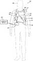
- FIG. 1illustrates a system 100 with a patient 102 wearing an example of a WCD system 104 according to embodiments described herein.
- the WCD system 104may include a support structure 110 , an external defibrillator 118 connected to defibrillation electrodes 114 , 116 , among other components.
- the support structure 110may be worn by the patient 102 .
- the support structure 110may include a vest, shirt, series of straps, or other system enabling the patient 102 to carry at least a portion of the WCD system 104 on the patient's body.
- the support structure 110may comprise a single component.
- the support structure 110may comprise a vest or shirt that properly locates the WCD system 104 on a torso 112 of the patient 102 .
- the single component support structure 110may additionally carry or couple to the various components of the WCD system 104 .
- the support structure 110may comprise multiple components.
- the support structure 110may include a first component resting on a patient's shoulders.
- the first componentmay locate a series of defibrillation electrodes 114 , 116 on the torso 112 of the patient 102 .
- a second componentmay rest more towards the patient's hips, whereby the second component may be positioned such that the patient's hips support the heavier components of the WCD system 104 .
- the heavier components of the WCD system 104may be carried via a shoulder strap or may be kept close to the patient 102 such as in a cart, bag, stroller, wheel chair, or other vehicle.
- the external defibrillator 118may be coupled to the support structure 110 or may be carried remotely from the patient 102 .
- the external defibrillator 118may be triggered to deliver an electric shock to the patient 102 when patient 102 wears WCD system 104 . For example, if certain thresholds are exceeded or met, the external defibrillator 118 may engage and deliver a shock to the patient 102 .
- the WCD system 104may defibrillate the patient 102 by delivering an electrical charge to the patient 102 through a series of electrodes 114 , 116 positioned on the torso 112 .
- the electrodes 114 , 116may be electrically coupled to the external defibrillator 118 via a series of electrode leads 120 .
- the defibrillator 118may administer an electric shock to the body of the patient 102 when the defibrillation electrodes 114 , 116 are in good electrical contact with the torso 112 of patient 102 .
- devicesproximate the electrodes 114 , 116 may emit a conductive fluid to encourage electrical contact between the patient 102 and the electrodes 114 , 116 .
- the electric shockmay be a defibrillation shock, which may go through a heart 122 of the patient 102 in an attempt to restart the heart 122 .
- the brief, strong electric pulsemay work to restart the heart 122 which may save the patient's life.
- the WCD system 104may also include either an external or internal monitoring device or some combination thereof.
- FIG. 1displays an external monitoring device 124 which may also be known as an outside monitoring device.
- the monitoring device 124may monitor at least one local parameter. Local parameters may include physical state of the patient 102 such as ECG, movement, heartrate, pulse, temperature, and the like. Local parameters may also include a parameter of the WCD 104 , environmental parameters, or the like.
- the monitoring device 124may be physically coupled to the support structure 110 or may be proximate the support structure 110 . In either location, the monitoring device 124 is communicatively coupled with other components of the WCD 104 .
- the defibrillator 118may connect with one or more external devices 126 .
- the defibrillator 118may connect to various external devices 126 such as a cloud computing network, a remote desktop, a laptop, a mobile device, or other external device using a network such as the Internet, local area networks, wide area networks, virtual private networks (VPN), other communication networks or channels, or any combination thereof.
- defibrillatormay include a screen and one or more user inputs to enable the patient to interact with the WCD system 104 .
- the patient 102may view patient data, dismiss a shock if the patient 102 is still conscious, turn off an alarm, and otherwise engage with the WCD system 104 via the defibrillator 118 .
- FIG. 2is a block diagram illustrating one example of a notification module 106 .
- the notification module 106may be communicatively coupled to the defibrillator 118 .
- the notification module 106has an event module 202 , an alert issuance module 204 , and an alert resolution module 206 .
- the event module 202may detect a system condition which may require an alert. The event module 202 may then determine a type of event, either binary or indeterminate, and then determine a severity of the event. In some instances, the event module 202 may use a combination of sources to determine the overall alert behavior including the type of alert issued, the severity of the alert, the timing of the alert, a length of the alert, and the like. For example, the event module 202 may use an algorithm determination, physical equipment sensing, electrical equipment sensing, or a combination thereof. The algorithm determination may be used for event conditions associated with algorithm detection, performance issues, or a combination thereof. Physical and electrical equipment sensing may be used for event conditions associated with either physical or electrical equipment issues.
- a binary eventmay be a distinct event with a singular determinating factor that can be ascertained without a quantitative analysis.
- the binary conditioneither exists or it does not.
- an ECG lead or ECG electrodemay be disconnected from the defibrillator, a battery may have a low charge or full charge, a defibrillator electrode may be disconnected, and the like.
- binary conditionsare conditions with discernable conditions with singular determination.
- An indeterminate eventmay include an event that requires a process or algorithm to determine if the event exists. For example, in some instances, an ECG electrode may become disconnected or not optimally attached to the patient's skin, a signal being transmitted to the defibrillator may include extra noise, or some other issue may be present with receiving an accurate and clear reading from a component of the WCD.
- the event module 202may determine if there is a potential event and the severity of the event. For example, in some embodiments, while an event may have occurred, the event may not alter or inhibit the ability of the WCD system to function. For example, if a single ECG electrode is misconnected, the event may require resolution but not necessarily immediate resolution. However, if more than one ECG electrode has become disconnected, this may necessitate prompt attention because the WCD may be unable to properly ascertain the patient's health from the remaining electrode readings. Therefore, in some embodiments, some events may require more immediate rectification.
- the event module 202may determine which WCD conditions require resolution to ensure safety and efficacy of a WCD. However, some of these alerts may cause patient frustration due to over-alerting. For example, ECG electrode sensing issues including insufficient ECG contact (analysis not possible), ECG electrodes off (analysis possible); excessive noise and defibrillator pads off may require remediation but also result in over alerting the patient.
- the event module 202may detect system information using algorithm determination associated with the algorithm detection or performance issues. In another embodiment, the event module 202 detects system information from physical equipment sensing, electrical equipment sensing, or both. In some embodiments, a combination of sources may be used to determine the status of an event and relay the information to the alert issuance module 204 , the alert resolution module 206 , or both.
- the alert issuance module 204may determine when to issue an alert, if an alert is issued, type of alert, and an urgency of the alert, among other things. For example, each event type may use a different alert onset time. In some embodiments, binary conditions may have shorter onset times than indeterminate conditions. For example, the WCD system may perform startup check when the system is booting. The onset time for startup equipment statuses may be negligible to provide immediate user feedback. A negligible onset time may enable the patient to immediately address any inaccuracies or errors in the system.
- assembly equipment statusmay be slightly delayed as the system is being assembled. A delay may enable the system to confirm the equipment is properly connected and functioning prior to alerting the patient. For example, assembly equipment status may be delayed by about 1-10 seconds.
- binary equipment statuses during operationmay have a varying length of alert issuance delay.
- equipment statusmay include if the user needs to press an alert button, if service is required, if service is needed, if the battery is critically low, if the user received treatment, and the like. These types of statuses may delay alert issuance by approximately 1-10 seconds.
- Indeterminate conditionsmay have different onset times.
- indeterminate conditionsmay include poor or not connected defibrillator pad contact, ECG electrode or wire contact issues, or the like.
- the alert issuance module 204may vary the onset time of an alert. For example, some conditions may not need immediate remediation, such as a single ECG electrode being either detached, not attached properly, or otherwise experiencing noise from one or more leads. In this example, the system may continue to operate properly, although perhaps not optimally, and therefore, immediate attention is not required but prompt attention is desired. Therefore, the alert issuance module 204 may have an onset alert of 10 to 30 minutes. In some embodiments, the alert onset time may be about 15 minutes. In further embodiments, the onset time may be between about 5 and about 10 minutes.
- the conditionmay necessitate prompt resolution.
- the WCD systemmay not be able to properly analyze the patient's health conditions or function properly or safely.
- the WCD systemmay be unable to accurately determine a health status of the patient.
- the WCDmay be unable to deliver a necessary shock to revive a patient if a health event occurs.
- the alert issuance module 204may have an alert onset time of about 10 to about 20 minutes. This predetermined time frame may vary with the severity of the event and the potential for the WCD system to properly function and treat the patient.
- the alert issuance module 204may have a zero-onset time. For example, if the WCD system detects a cardiac event or another health event, the alert may immediately issue to alert the patient to a potentially life-threatening condition.
- This alert schemeallows the WCD to provide user feedback quickly for distinct conditions while delaying user feedback for conditions that may resolve on their own without user action needed.
- the alert resolution module 206may use an “offset time” to delay the cessation of alerts. This offset time may have different durations or for different predetermined time periods based at least in part on the underlying event, the type of alarm, the duration of the initial alarm, received patient feedback, and the like.
- an alert about a detected system condition with distinct binary resultsmay have a shorter offset time.
- the offset timemay be negligible.
- a short offset timebetween about 1 and about 10 seconds, may be utilized for assembly equipment status such as the WCD being assembled. This short duration time, such as between about 1 and about 10 seconds, may also be utilized for equipment statuses during WCD operation.
- the alert resolution module 206may have a longer offset time for system conditions with indeterminate results. In some embodiments, such as excessive noise in an ECG electrode or lead, or a defibrillator electrode or lead affecting the ability of the WCD system to perform analysis, the alert resolution module 206 may have an offset time between about 1 and about 10 seconds. Other events, such as disconnected defibrillator pads, may have longer offset times between 1 second and 60 seconds. The offset time may allow the alert resolution module 206 to provide user feedback quickly for distinct resolved conditions while delaying user feedback for conditions that may not actually be fixed and require additional user action to resolve.
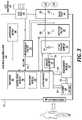
- FIG. 3is a diagram displaying various functional components of one example of a defibrillator 118 .
- the defibrillator 118may be an example of the defibrillator 118 described with reference to FIG. 1 .
- the components shown in FIG. 3may be contained within a single unit or may be separated amongst two or more units in communication with each other.
- the defibrillator 118may include a processor 302 , memory 304 , user interface 306 , defibrillation port 308 , ECG port 310 , among other components.
- the componentsare contained within a housing 312 or casing.
- the housing 312may comprise a hard shell around the components or may comprise a softer shell for increased patient comfort.
- the processor 302 , memory 304 (including software/firmware code (SW) 314 ), user interface 306 , defibrillation port 308 , ECG port 310 , transmission module 316 , measurement circuit 318 , monitoring device 320 , and energy storage module 322may communicate—directly or indirectly—with one another (e.g., via one or more buses 324 ).
- One or more buses 324may allow data communication between one or more elements and/or modules of the defibrillator 118 .
- the memory 304may include random access memory (RAM), read only memory (ROM), flash RAM, and/or other types.
- the memory 304may store computer-readable, computer-executable software/firmware code 314 including instructions that, when executed, cause the processor 302 to perform various functions (e.g., determine shock criteria, determine consciousness of patient, track patient parameters, etc.).
- the processor 302may include an intelligent hardware device, e.g., a central processing unit (CPU), a microcontroller, an application-specific integrated circuit (ASIC), etc.
- CPUcentral processing unit
- ASICapplication-specific integrated circuit
- the memory 304can contain, among other things, the Basic Input-Output system (BIOS) which may control basic hardware and/or software operations such interactions and workings of the various components of the defibrillator 118 , and in some embodiments, components external to the defibrillator 118 .
- BIOSBasic Input-Output system
- the memory 304may contain various modules to implement the workings of the defibrillator 118 and other aspects of the present disclosure.
- the defibrillator 118may include a user interface 306 .
- the user interface 306may enable the patient to view one or metrics concerning the defibrillator 118 , the WCD system as a whole, or some combination thereof.
- the user interface 306may display an ECG of the patient, a status of the defibrillator 118 , a status of a charge (e.g. a battery charge or an energy storage module), and the like.
- a chargee.g. a battery charge or an energy storage module
- the defibrillator 118may include a defibrillation port 308 .
- the defibrillation port 308may comprise a socket, opening, or electrical connection in the housing 312 .
- the defibrillation port 308may include two or more nodes 326 , 328 .
- the two or more nodes 326 , 328may accept two or more defibrillation electrodes (e.g. defibrillation electrodes 114 , 116 , FIG. 1 ).
- the nodes 326 , 328may provide an electrical connection between the defibrillation electrodes 114 , 116 and the defibrillator 118 .
- the defibrillation electrodes 114 , 116may plug into the two or more nodes 326 , 328 via one or more leads (e.g. leads 120 ), or, in some instances, the defibrillation electrodes 114 , 116 may be hardwired to the nodes 326 , 328 . Once an electrical connection is established between the defibrillation port 308 and the electrodes 114 , 116 , the defibrillator 118 may be able to deliver an electric shock to the patient.
- the defibrillator 118may include an ECG port 310 in the housing 312 .
- the ECG port 310may accept one or more ECG electrodes 330 or ECG leads.
- the ECG electrodes 330sense a patient's ECG signal.
- the ECG electrodes 330may record electrical activity generated by the heart muscle depolarization.
- the ECG electrodes 330may utilize 3-leads to 12-leads or multichannel ECG, or the like.
- the ECG electrodes 330may connect with the patient's skin.
- the defibrillator 118may include a measurement circuit 318 .
- the measurement circuit 318may be in communication with the ECG port 310 .
- the measurement circuit 318may receive physiological signals from ECG port 310 .
- the measurement circuit 318may additionally or alternatively receive physiological signals via the defibrillation port 308 when defibrillation electrodes 114 , 116 are attached to the patient.
- the measurement circuit 318may determine a patient's ECG signal from a difference in voltage between the defibrillation electrodes 114 , 116 .
- the measurement circuit 318may monitor the electrical connection between the defibrillation electrodes 114 , 116 and the skin of the patient. For example, the measurement circuit 318 can detect impedance between the electrodes 114 , 116 . In some embodiments, the detected impedance may indicate the effective resistance of an electric circuit. An impedance calculation may, at least in part, determine when the electrodes 114 , 116 have a good electrical connection with the patient's body.
- the defibrillator 118may include an internal monitoring device 320 within the housing 312 .
- the monitoring device 320may monitor at least one local parameter. Local parameters may include physical state of the patient such as ECG, movement, heartrate, pulse, temperature, and the like. Local parameters may also include a parameter of the WCD (e.g. WCD 104 ), defibrillator 118 , environmental parameters, or the like.
- a WCDmay include an internal monitoring device 320 and an external monitoring device (e.g. external monitoring device 124 ). If both monitoring devices 124 , 320 are present, the devices 124 , 320 may collaborate to parse out specific parameters depending on position, location, and other factors. For example, the external monitoring device 124 may monitor environmental parameters while the internal monitoring device 320 may monitor patient and system parameters.
- the defibrillator 118may include a power source 332 .
- the power source 332may comprise a battery or battery pack, which may be rechargeable.
- the power source 332may comprise a series of different batteries to ensure the defibrillator 118 has power.
- the power source 332may include a series of rechargeable batteries as a prime power source and a series of non-rechargeable batteries as a secondary source. If the patient is proximate an AC power source, such as when sitting down, sleeping, or the like, the power source 332 may include an AC override wherein the power source 332 draws power from the AC source.
- the defibrillator 118may include an energy storage module 322 .
- the energy storage module 322may store electrical energy in preparation or anticipation of providing a sudden discharge of electrical energy to the patient.
- the energy storage module 322may have its own power source and/or battery pack.
- the energy storage module 322may pull power from the power source 332 .
- the energy storage module 322may include one or more capacitors 334 .
- the one or more capacitors 334may store an electrical charge, which may be administered to the patient.
- the processor 302may be communicatively coupled to the energy storage module 322 to trigger the amount and timing of electrical energy to provide to the defibrillation port 308 and, subsequently, the patient.
- the defibrillator 118may include a discharge circuit 336 .
- the discharge circuit 336may control the energy stored in the energy storage module 322 .
- the discharge circuit 336may either electrical couple or decouple the energy storage module 322 to the defibrillation port 308 .
- the discharge circuit 336may be communicatively coupled to the processor 302 to control when the energy storage module 322 and the defibrillation port 308 should or should not be coupled to either administer or prevent a charge from emitting from the defibrillator 118 .
- the discharge circuit 336may include one or more switches 338 .
- the one or more switches 338may include an H-bridge.
- the defibrillator 118may include a transmission module 316 .
- the transmission module 316may establish one or more communication links with either local hardware and/or software to the WCD and defibrillator 118 or to remote hardwire separate from the WCD system.
- the transmission module 316may include one or more antennas, processors, and the like.
- the transmission module 316may communicate wirelessly via radio frequency, electromagnetics, local area networks (LAN), wide area networks (WAN), virtual private networks (VPN), RFID, Bluetooth, cellular networks, and the like.
- the transmission module 316may facilitate communication of data and commands such as patient data, episode information, therapy attempted, CPR performance, system data, environmental data, and so on.
- the processor 302may execute one or more modules.
- the processor 302may execute a detection module 340 and/or an action module 342 .
- the detection module 340may be a logic device or algorithm to determine if any thresholds are exceeded which may require action of the defibrillator 118 .
- the detection module 340may receive and interpret all the signals from the ECG port 310 , the defibrillation port 308 , the monitoring device 320 , an external monitoring device, and the like.
- the detection module 340may process the information to ensure the patient is conscious and healthy. If any parameter indicates the patient may be experiencing distress or indicating a cardiac episode, the detection module 340 may activate the action module 342 .
- the action module 342may receive data from the detection module 340 and perform a series of actions. For example, an episode may merely be a loss of batter power at the power source 332 or the energy storage module 322 , or one or more electrodes (e.g., ECG electrodes, defibrillation electrodes) may have lost connection. In such instances, the action module 342 may trigger an alert to the patient or to an outside source of the present situation. If an episode is a health risk, such as a cardiac event, the action module 342 may begin a series of steps.
- an episodemay merely be a loss of batter power at the power source 332 or the energy storage module 322 , or one or more electrodes (e.g., ECG electrodes, defibrillation electrodes) may have lost connection. In such instances, the action module 342 may trigger an alert to the patient or to an outside source of the present situation. If an episode is a health risk, such as a cardiac event, the action module 342 may begin a series of steps.
- Thismay include issuing a warning to the patient, issuing a warning to a third party, priming the energy storage module 322 for defibrillation, releasing one or more conductive fluids proximate defibrillation electrodes 114 , 116 , and the like.
- the processor 302may also execute the notification module 106 .
- the notification module 106may detect the working functions of the WCD system, categorize the type of event, and determine what alert to issue to the patient and when the alert is issued.
- the notification module 106may also determine or receive data to determine when an event has been resolved. Event resolution may cause the notification module 106 to cease an alert, issue a resolution notice, or a combination thereof.
- FIG. 4is a flow chart illustrating an example of a method 400 for WCD systems, in accordance with various aspects of the present disclosure. For clarity, the method 400 is described below with reference to aspects of one or more of the systems described herein.
- a defibrillatore.g. defibrillator 118
- a communication device coupled to the defibrillator or the WCD systemmay perform one or more of the functions described below.
- the method 400may include detecting an event at the WCD system.
- the eventmay be a system event, such as an error with the actual system and hardware or it may be a health event such as poor readings from a sensor, poor connectivity, an abnormal ECG, or the like.
- the method 400may include classifying the event. If a safety or health concern is detected, the method 400 may revert to emergency procedures such as shocking the patient. In further embodiments, the method 400 may also determine if the event is a binary event or an indeterminate event.
- a binary eventmay be a status of equipment with a distinct and finite determination such as a disconnected plug, a status of the battery, and the like.
- An indeterminate eventmay include defibrillator pad contact or lack thereof, ECG electrode contact issues or noise from a reading of one or more ECG electrodes or leads, and the like.
- An algorithmmay determine the feed from one of these sources is faulty providing a lack of ability to perform an analysis or may include noise or other errors such that, while the WCD system may still be able to analyze the data sufficiently, the event still requires correction.
- the method 400may include determining an onset time of the alert or an offset time of the alert (if the event has been resolved).
- the onset time and offset timemay depend, at least in part, on the type of detected event. For example, for confirmed physiologic conditions, the onset time may be negligible. This may include a cardiac event, an abnormal ECG, or other health concern.
- the method 400may have a small to negligible onset time for startup equipment statuses. This may enable a patient to immediately ascertain an issue or other condition with the equipment that can be quickly remedied prior the patient wearing the system. Similarly, if the WCD system is being assembled, the method 400 may slightly delay the onset of an alert to enable the patient to properly assemble the system. For example, the onset time may be between about 1 and about 10 seconds prior to alerting the patient.
- the method 400may delay the onset of alerts for binary equipment statuses.
- the alertmay include if the patient needs to press an alert button, if service is required, if the battery is critically low, if a lead or other connector became unplugged, and the like.
- the method 400may delay the onset of the alert between about 1 and about 5 seconds. Further conditions may have alerts delayed different times, such as between 0 and about 60 seconds.
- the method 400may have a longer onset time prior to issuing an alert.
- the onset timemay vary between about 1 minute and about 15 minutes, or in some embodiments, as long as 20 to even 30 minutes.
- the ability of the system to perform an analysismay correlate to a length of onset time. For example, if there is an ECG contact or excessive noise issues that affect the ability of the system to perform an analysis, the method 400 may have a shorter onset time between about 1 and about 5 minutes. If the ECG has contact issues which do not affect the ability of the system to perform an analysis, the method 400 may have a longer onset time of between about 15 and about 30 minutes.
- the systemmay determine a length of time the event is present. If the event or condition has been present for a predetermined length of time, in some embodiments between about 10 and about 20 minutes, the method 400 may then have an onset time of between about 10 and about 20 minutes.
- the offset time to delay the cessation of alertsmay closely follow the onset time.
- the offset timemay be predetermined based at least in part on the alert condition. For example, for binary events such as startup equipment status, assembly equipment status, or equipment status during operation, the offset may be between about 0 seconds and about 10 seconds. If a confirmed physiologic condition is no longer being detected, the offset time may be negligible.
- the method 400may delay the cessation of an alert by a different predetermined time period. For example, if excessive noise issues, which may affect the ability to perform an analysis, the offset time may be between about 5 and about 15 seconds.
- the method 400may include issuing the alert after the predetermined onset has passed.
- the method 400may also include ceasing the alert after a predetermined offset time period has passed.
- the method 400may provide for issuing alerts after a predetermine onset time based at least in part on the type of event detected. It should be noted that the method 400 is just one implementation and that the operations of the method 400 may be rearranged or otherwise modified such that other implementations are possible.
- FIG. 5is a flow chart illustrating an example of a method 500 for WCD systems, in accordance with various aspects of the present disclosure. For clarity, the method 500 is described below with reference to aspects of one or more of the systems described herein.
- a defibrillatore.g. defibrillator 118
- a communication device coupled to the defibrillator or the WCD systemmay perform one or more of the functions described below.
- the method 500may include detecting a binary event.
- the binary eventmay include startup equipment statuses, confirmed physiological conditions, assembly equipment statuses, equipment statuses during operation, and the like.
- the method 500proceeds to block 504 .
- the method 500may include determining a status of the WCD system.
- the statusmay include an operational status, such as whether the WCD is being assembled, booting, being disassembled, or in operation.
- the method 500may include determining an onset time.
- the onset timemay be based in part on the type of binary event and the status of the WCD system during the time period the binary event was detected. For example, if the WCD system is being assembled, the onset time may be between about 1 and about 10 seconds for equipment statuses. If the WCD system is booting, the onset time may be negligible for startup equipment statuses. If the WCD system is operational, the onset time may be between 1 and 10 seconds for operational equipment statuses. If the WCD system is operational and fully functioning and a cardiac event is detected, the onset time may be negligible. Once an onset time is determined, at block 508 , the method 500 may include issuing an alert after the predetermined onset time.
- the method 500may provide for issuing alerts after a predetermine onset time based at least in part on the type of event detected. It should be noted that the method 500 is just one implementation and that the operations of the method 500 may be rearranged or otherwise modified such that other implementations are possible.
- FIG. 6is a flow chart illustrating an example of a method 600 for WCD systems, in accordance with various aspects of the present disclosure. For clarity, the method 600 is described below with reference to aspects of one or more of the systems described herein.
- a defibrillatore.g. defibrillator 118
- a communication device coupled to the defibrillator or the WCD systemmay perform one or more of the functions described below.
- the method 600may include detecting an indeterminate event.
- the indeterminate eventsuch an issue with defibrillator pad contact, ECG contact issues, or noise issues, or the like.
- the method 600proceeds to block 604 .
- the method 600may include determining the system's ability to perform an analysis. For example, if one ECG electrode has an issue, the system may still be able to perform sufficient analysis. However, in some embodiments, if more than one ECG electrode has an issue, the system may be unable to perform a sufficient health analysis to determine a health status of the patient. In other instances, a defibrillator pad may be disconnected or misconnected resulting in the in ability for the system to deliver a shock to the patient. In other instances, the detected indeterminate event may have no effect on the ability of the system to perform an analysis.
- the method 600may include determining an onset time based at least in part on the detected event and the system's ability to perform an analysis.
- the predetermined onset timemay be between about 1 minute and about 30 minutes. In some embodiments, if the system cannot perform an analysis, such an improperly function ECG electrode, the onset time may be between about 30 seconds and about 5 minutes. In other embodiments, if the system is properly functioning, the onset time may be between about 10 minutes and about 20 minutes.
- the method 600may include issuing an alert.
- the method 600may provide for issuing alerts after a predetermine onset time based at least in part on the type of event detected. It should be noted that the method 600 is just one implementation and that the operations of the method 600 may be rearranged or otherwise modified such that other implementations are possible.
- FIG. 7is a flow chart illustrating an example of a method 700 for WCD systems, in accordance with various aspects of the present disclosure. For clarity, the method 700 is described below with reference to aspects of one or more of the systems described herein.
- a defibrillatore.g. defibrillator 118
- a communication device coupled to the defibrillator or the WCD systemmay perform one or more of the functions described below.
- the method 700may include detecting the end of an event.
- the eventmay be a binary event or an indeterminate event.
- the end of the eventmay be detected through equipment sensing or through an algorithm. For example, most binary conditions may be detected through equipment sensing.
- an end of the indeterminate eventsmay be determined through an algorithm where received information is processed and determined the system is properly functioning.
- the method 700may include determining a status of the WCD. If the WCD system is starting up, booting, or being assembled or disassembled. The system may also be in operation and functioning normally. In other embodiments, sensors or other equipment may be in proper communication within the WCD system.
- the method 700may include determining an offset time based at least in part on the initial event, the end of the event, and the status of the WCD system. For example, if the system is booting and an event was detected and ceased, the method 700 may have a negligible offset for ceasing the alarm. Similarly, if the system is being assembled, an offset time may be negligible. If confirmed physiological statuses are no longer being detected, the method 700 may have a negligible offset time. If an equipment status during operation is no longer detected, the method 700 may have about 1 to 5 seconds of offset time. If excessive noise issues from various signals are no longer detected, the method 700 may have an offset time of about 10 to about 15 seconds. In some embodiments, offset times may be longer, such as about 60 seconds to about 5 minutes, to fully determine the event has ceased. Once an offset time has been determined, at block 708 , the method 700 may include ceasing the issued alert.
- the method 700may provide for ceasing issued alerts after a predetermine onset time based at least in part on the type of event detected. It should be noted that the method 700 is just one implementation and that the operations of the method 700 may be rearranged or otherwise modified such that other implementations are possible.
- This documentmay include references to directions, such as “forward,” “rearward,” “front,” “rear,” “upward,” “downward,” “top,” “bottom,” “right hand,” “left hand,” “lateral,” “medial,” “in,” “out,” “extended,” etc. These references, and other similar references, are only to assist in helping describe and to understand the particular embodiments and are not intended to limit the present disclosure to these directions or locations.
- the present documentmay also reference quantities and numbers. Unless specifically stated, such quantities and numbers are not to be considered restrictive, but exemplary of the possible quantities or numbers associated with the present application. Also, in this regard, the present application may use the term “plurality” to reference a quantity or number. The terms “about,” “approximately,” “near,” etc., mean plus or minus 5% of the stated value. For the purposes of the present disclosure, the phrase “at least one of A, B, and C,” for example, means (A), (B), (C), (A and B), (A and C), (B and C), or (A, B, and C), including all further possible permutations when greater than three elements are listed.
Landscapes
- Health & Medical Sciences (AREA)
- Engineering & Computer Science (AREA)
- Public Health (AREA)
- General Health & Medical Sciences (AREA)
- Biomedical Technology (AREA)
- Cardiology (AREA)
- Life Sciences & Earth Sciences (AREA)
- Nuclear Medicine, Radiotherapy & Molecular Imaging (AREA)
- Radiology & Medical Imaging (AREA)
- Animal Behavior & Ethology (AREA)
- Veterinary Medicine (AREA)
- Heart & Thoracic Surgery (AREA)
- Medical Informatics (AREA)
- Emergency Management (AREA)
- Business, Economics & Management (AREA)
- Physics & Mathematics (AREA)
- General Physics & Mathematics (AREA)
- Epidemiology (AREA)
- Data Mining & Analysis (AREA)
- Databases & Information Systems (AREA)
- Pathology (AREA)
- Primary Health Care (AREA)
- Physical Education & Sports Medicine (AREA)
- Physiology (AREA)
- Pulmonology (AREA)
- Gerontology & Geriatric Medicine (AREA)
- Computer Networks & Wireless Communication (AREA)
- Biophysics (AREA)
- Electrotherapy Devices (AREA)
- Measurement And Recording Of Electrical Phenomena And Electrical Characteristics Of The Living Body (AREA)
Abstract
Description
Claims (18)
Priority Applications (3)
| Application Number | Priority Date | Filing Date | Title |
|---|---|---|---|
| US17/207,423US11342079B2 (en) | 2019-08-15 | 2021-03-19 | WCD system alert issuance and resolution |
| US17/751,285US12237087B2 (en) | 2019-08-15 | 2022-05-23 | WCD system alert issuance and resolution |
| US19/025,189US20250166841A1 (en) | 2019-08-15 | 2025-01-16 | Wcd system alert issuance and resolution |
Applications Claiming Priority (2)
| Application Number | Priority Date | Filing Date | Title |
|---|---|---|---|
| US16/542,110US10957453B2 (en) | 2019-08-15 | 2019-08-15 | WCD system alert issuance and resolution |
| US17/207,423US11342079B2 (en) | 2019-08-15 | 2021-03-19 | WCD system alert issuance and resolution |
Related Parent Applications (1)
| Application Number | Title | Priority Date | Filing Date |
|---|---|---|---|
| US16/542,110ContinuationUS10957453B2 (en) | 2019-08-15 | 2019-08-15 | WCD system alert issuance and resolution |
Related Child Applications (1)
| Application Number | Title | Priority Date | Filing Date |
|---|---|---|---|
| US17/751,285ContinuationUS12237087B2 (en) | 2019-08-15 | 2022-05-23 | WCD system alert issuance and resolution |
Publications (2)
| Publication Number | Publication Date |
|---|---|
| US20210210208A1 US20210210208A1 (en) | 2021-07-08 |
| US11342079B2true US11342079B2 (en) | 2022-05-24 |
Family
ID=68392835
Family Applications (4)
| Application Number | Title | Priority Date | Filing Date |
|---|---|---|---|
| US16/542,110ActiveUS10957453B2 (en) | 2019-08-15 | 2019-08-15 | WCD system alert issuance and resolution |
| US17/207,423ActiveUS11342079B2 (en) | 2019-08-15 | 2021-03-19 | WCD system alert issuance and resolution |
| US17/751,285Active2040-01-07US12237087B2 (en) | 2019-08-15 | 2022-05-23 | WCD system alert issuance and resolution |
| US19/025,189PendingUS20250166841A1 (en) | 2019-08-15 | 2025-01-16 | Wcd system alert issuance and resolution |
Family Applications Before (1)
| Application Number | Title | Priority Date | Filing Date |
|---|---|---|---|
| US16/542,110ActiveUS10957453B2 (en) | 2019-08-15 | 2019-08-15 | WCD system alert issuance and resolution |
Family Applications After (2)
| Application Number | Title | Priority Date | Filing Date |
|---|---|---|---|
| US17/751,285Active2040-01-07US12237087B2 (en) | 2019-08-15 | 2022-05-23 | WCD system alert issuance and resolution |
| US19/025,189PendingUS20250166841A1 (en) | 2019-08-15 | 2025-01-16 | Wcd system alert issuance and resolution |
Country Status (4)
| Country | Link |
|---|---|
| US (4) | US10957453B2 (en) |
| EP (1) | EP3777969B1 (en) |
| CN (1) | CN112386799A (en) |
| AU (1) | AU2019257354B2 (en) |
Families Citing this family (3)
| Publication number | Priority date | Publication date | Assignee | Title |
|---|---|---|---|---|
| US12300368B1 (en)* | 2019-03-07 | 2025-05-13 | West Affum Holdings Dac | Analysis and presentation of aggregated patient and device data within a system that includes a medical device |
| US12121329B2 (en) | 2019-03-08 | 2024-10-22 | West Affum Holdings Dac | Wearable vital signs monitor with selective signal acquisition |
| CN113593341A (en)* | 2021-08-02 | 2021-11-02 | 徐州医科大学 | Cardiopulmonary resuscitation teaching guidance device based on motion capture system |
Citations (136)
| Publication number | Priority date | Publication date | Assignee | Title |
|---|---|---|---|---|
| US3724355A (en) | 1970-06-12 | 1973-04-03 | K Schranz | Apparatus for processing exposed photographic film or the like |
| US4583524A (en) | 1984-11-21 | 1986-04-22 | Hutchins Donald C | Cardiopulmonary resuscitation prompting |
| US4619265A (en) | 1984-03-08 | 1986-10-28 | Physio-Control Corporation | Interactive portable defibrillator including ECG detection circuit |
| US4666432A (en) | 1985-09-13 | 1987-05-19 | Mcneish Kenneth | Catheter retaining means and method |
| US4698848A (en) | 1986-09-26 | 1987-10-13 | Buckley Mary C | Blouse for cardiac patients |
| US4928690A (en) | 1988-04-25 | 1990-05-29 | Lifecor, Inc. | Portable device for sensing cardiac function and automatically delivering electrical therapy |
| US4955381A (en) | 1988-08-26 | 1990-09-11 | Cardiotronics, Inc. | Multi-pad, multi-function electrode |
| US5078134A (en) | 1988-04-25 | 1992-01-07 | Lifecor, Inc. | Portable device for sensing cardiac function and automatically delivering electrical therapy |
| US5228449A (en) | 1991-01-22 | 1993-07-20 | Athanasios G. Christ | System and method for detecting out-of-hospital cardiac emergencies and summoning emergency assistance |
| US5348008A (en) | 1991-11-25 | 1994-09-20 | Somnus Corporation | Cardiorespiratory alert system |
| US5394892A (en) | 1990-04-02 | 1995-03-07 | K J Mellet Nominees Pty Ltd | CPR prompting apparatus |
| US5405362A (en) | 1991-04-29 | 1995-04-11 | The Board Of Regents For The University Of Texas System | Interactive external defibrillation and drug injection system |
| US5429593A (en) | 1993-12-23 | 1995-07-04 | Matory; Yvedt L. | Post-surgical, drainage accommodating, compression dressing |
| US5474574A (en) | 1992-06-24 | 1995-12-12 | Cardiac Science, Inc. | Automatic external cardioverter/defibrillator |
| US5618208A (en) | 1994-06-03 | 1997-04-08 | Siemens Medical Systems, Inc. | Fully insulated, fully shielded electrical connector arrangement |
| US5662690A (en) | 1994-12-08 | 1997-09-02 | Heartstream, Inc. | Defibrillator with training features and pause actuator |
| US5708978A (en) | 1994-08-17 | 1998-01-20 | Johnsrud; Anna C. | Medical vest |
| US5741306A (en) | 1996-05-23 | 1998-04-21 | Lifecor, Inc. | Patient-worn energy delivery apparatus |
| US5782878A (en) | 1994-12-07 | 1998-07-21 | Heartstream, Inc. | External defibrillator with communications network link |
| US5792204A (en) | 1996-05-08 | 1998-08-11 | Pacesetter, Inc. | Methods and apparatus for controlling an implantable device programmer using voice commands |
| WO1998039061A2 (en) | 1997-03-07 | 1998-09-11 | Cadent Medical Corporation | Wearable defibrillation system |
| US5902249A (en) | 1995-03-03 | 1999-05-11 | Heartstream, Inc. | Method and apparatus for detecting artifacts using common-mode signals in differential signal detectors |
| US5913685A (en) | 1996-06-24 | 1999-06-22 | Hutchins; Donald C. | CPR computer aiding |
| US5944669A (en) | 1997-11-20 | 1999-08-31 | Lifecor, Inc. | Apparatus and method for sensing cardiac function |
| US6047203A (en) | 1997-03-17 | 2000-04-04 | Nims, Inc. | Physiologic signs feedback system |
| US6065154A (en) | 1998-04-07 | 2000-05-23 | Lifecor, Inc. | Support garments for patient-worn energy delivery apparatus |
| US6108197A (en) | 1992-05-15 | 2000-08-22 | Via, Inc. | Flexible wearable computer |
| US6201992B1 (en) | 1999-04-01 | 2001-03-13 | Agilent Technologies, Inc. | Defibrillator interface capable of generating video images |
| US6263238B1 (en) | 1998-04-16 | 2001-07-17 | Survivalink Corporation | Automatic external defibrillator having a ventricular fibrillation detector |
| US6280461B1 (en) | 1996-05-23 | 2001-08-28 | Lifecor, Inc. | Patient-worn energy delivery apparatus |
| US6287328B1 (en) | 1999-04-08 | 2001-09-11 | Agilent Technologies, Inc. | Multivariable artifact assessment |
| US6319011B1 (en) | 1995-04-06 | 2001-11-20 | Michael J. Motti | Automatic training defibrillator simulator and method |
| US6334070B1 (en) | 1998-11-20 | 2001-12-25 | Medtronic Physio-Control Manufacturing Corp. | Visual and aural user interface for an automated external defibrillator |
| US6356785B1 (en) | 1997-11-06 | 2002-03-12 | Cecily Anne Snyder | External defibrillator with CPR prompts and ACLS prompts and methods of use |
| US6437083B1 (en) | 2001-12-06 | 2002-08-20 | General Electric Company | Process for preparing branched aromatic polycarbonates |
| US6450942B1 (en) | 1999-08-20 | 2002-09-17 | Cardiorest International Ltd. | Method for reducing heart loads in mammals |
| US20020181680A1 (en) | 1999-10-05 | 2002-12-05 | Marshal Linder | Data collection and system management for patient-worn medical devices |
| US6529875B1 (en) | 1996-07-11 | 2003-03-04 | Sega Enterprises Ltd. | Voice recognizer, voice recognizing method and game machine using them |
| US20030158593A1 (en) | 2002-02-19 | 2003-08-21 | Heilman Marlin S. | Cardiac garment |
| US6762917B1 (en) | 2001-06-12 | 2004-07-13 | Novx Corporation | Method of monitoring ESC levels and protective devices utilizing the method |
| US20050107833A1 (en) | 2003-11-13 | 2005-05-19 | Freeman Gary A. | Multi-path transthoracic defibrillation and cardioversion |
| US7065401B2 (en) | 2002-05-08 | 2006-06-20 | Michael Worden | Method of applying electrical signals to a patient and automatic wearable external defibrillator |
| US20060173499A1 (en) | 2005-01-31 | 2006-08-03 | Medtronic Emergency Response Systems, Inc. | System and method for using diagnostic pulses in connection with defibrillation therapy |
| DE102005060985A1 (en) | 2005-12-20 | 2007-06-28 | Oestreich, Wolfgang, Dr.med. | System for mobile monitoring of heart functions has electrodes which are connected to central administrative unit through electrical conductors and these conductors are arranged in clothing |
| US20080312709A1 (en) | 2007-06-13 | 2008-12-18 | Volpe Shane S | Wearable medical treatment device with motion/position detection |
| US20090005827A1 (en) | 2007-06-26 | 2009-01-01 | David Weintraub | Wearable defibrillator |
| US7559902B2 (en) | 2003-08-22 | 2009-07-14 | Foster-Miller, Inc. | Physiological monitoring garment |
| JP4320257B2 (en) | 2001-11-05 | 2009-08-26 | キャメロン ヘルス、 インコーポレイテッド | Flexible subcutaneous implantable defibrillator |
| US20100007413A1 (en) | 2006-11-10 | 2010-01-14 | Koninklijke Philips Electronics N.V. | Ecg electrode contact quality measurement system |
| US7753759B2 (en) | 2007-10-22 | 2010-07-13 | Tammy Pintor | Article of apparel for concealing objects |
| US20100298899A1 (en) | 2007-06-13 | 2010-11-25 | Donnelly Edward J | Wearable medical treatment device |
| US7865238B2 (en) | 2004-09-29 | 2011-01-04 | Koninklijke Philips Electronics N.V. | High-voltage module for an external defibrillator |
| US7870761B2 (en) | 2002-05-14 | 2011-01-18 | Koninklijke Philips Electronics N.V. | Garment and method for producing the same |
| US20110288604A1 (en) | 2010-05-18 | 2011-11-24 | Kaib Thomas E | Wearable therapeutic device |
| US20110288605A1 (en) | 2010-05-18 | 2011-11-24 | Zoll Medical Corporation | Wearable ambulatory medical device with multiple sensing electrodes |
| US8135462B2 (en) | 2002-08-26 | 2012-03-13 | Physio-Control, Inc. | Pulse detection using patient physiological signals |
| US20120112903A1 (en) | 2010-11-08 | 2012-05-10 | Zoll Medical Corporation | Remote medical device alarm |
| US20120150008A1 (en) | 2010-12-09 | 2012-06-14 | Kaib Thomas E | Electrode with redundant impedance reduction |
| US20120144551A1 (en) | 2010-12-09 | 2012-06-14 | Eric Guldalian | Conductive Garment |
| US20120158075A1 (en) | 2010-12-16 | 2012-06-21 | Kaib Thomas E | Water resistant wearable medical device |
| US20120191476A1 (en) | 2011-01-20 | 2012-07-26 | Reid C Shane | Systems and methods for collection, organization and display of ems information |
| US20120265265A1 (en) | 2011-04-13 | 2012-10-18 | Mehdi Razavi | Automated External Defibrillator Pad System |
| US20120283794A1 (en) | 2011-05-02 | 2012-11-08 | Kaib Thomas E | Patient-worn energy delivery apparatus and techniques for sizing same |
| US20120293323A1 (en) | 2011-03-25 | 2012-11-22 | Zoll Medical Corporation | System and method for adapting alarms in a wearable medical device |
| US20120302860A1 (en) | 2011-03-25 | 2012-11-29 | Zoll Medical Corporation | Selection of optimal channel for rate determination |
| US20120310315A1 (en) | 2009-03-17 | 2012-12-06 | Savage Walter T | Device and method for reducing patient transthoracic impedance for the purpose of delivering a therapeutic current |
| US8369944B2 (en) | 2007-06-06 | 2013-02-05 | Zoll Medical Corporation | Wearable defibrillator with audio input/output |
| US20130085538A1 (en) | 2011-09-01 | 2013-04-04 | Zoll Medical Corporation | Wearable monitoring and treatment device |
| US8527028B2 (en) | 2007-05-16 | 2013-09-03 | Medicomp, Inc. | Harness with sensors |
| US20130231711A1 (en) | 2012-03-02 | 2013-09-05 | Thomas E. Kaib | Systems and methods for configuring a wearable medical monitoring and/or treatment device |
| US20130245388A1 (en) | 2011-09-01 | 2013-09-19 | Mc10, Inc. | Electronics for detection of a condition of tissue |
| US8548557B2 (en) | 2010-08-12 | 2013-10-01 | Covidien Lp | Medical electrodes |
| US8560044B2 (en) | 2007-05-16 | 2013-10-15 | Medicomp, Inc. | Garment accessory with electrocardiogram sensors |
| US20130274565A1 (en) | 2012-04-13 | 2013-10-17 | Alois Antonin Langer | Outpatient health emergency warning system |
| US20130317852A1 (en) | 2012-05-22 | 2013-11-28 | Geneva Healthcare, LLC | Medical device information portal |
| US20130325078A1 (en) | 2012-05-31 | 2013-12-05 | Zoll Medical Corporation | Medical monitoring and treatment device with external pacing |
| US8615295B2 (en) | 2009-03-17 | 2013-12-24 | Cardiothrive, Inc. | External defibrillator |
| US20140012144A1 (en) | 2012-07-09 | 2014-01-09 | William E. Crone | Perfusion detection system |
| US20140025131A1 (en) | 2012-07-20 | 2014-01-23 | Physio-Control, Inc. | Wearable defibrillator with voice prompts and voice recognition |
| US20140046391A1 (en) | 2012-08-10 | 2014-02-13 | Physio-Control, Inc. | Wearable defibrillator system communicating via mobile communication device |
| US20140070957A1 (en) | 2012-09-11 | 2014-03-13 | Gianluigi LONGINOTTI-BUITONI | Wearable communication platform |
| US8706255B2 (en) | 2006-04-28 | 2014-04-22 | Medtronic, Inc. | Holster for charging pectorally implanted medical devices |
| US8742349B2 (en) | 2011-09-21 | 2014-06-03 | Carestream Health, Inc. | Portable radiographic detector exterior battery latch and methods for using the same |
| US20140163663A1 (en) | 2012-12-11 | 2014-06-12 | Piyush Poddar | Method and system for switching shock vectors and decreasing transthoracic impedance for cardioversion and defibrillation |
| US8904214B2 (en) | 2010-07-09 | 2014-12-02 | Zoll Medical Corporation | System and method for conserving power in a medical device |
| US20140378812A1 (en) | 2011-12-20 | 2014-12-25 | Sensible Medical Innovatons | Thoracic garment of positioning electromagnetic (em) transducers and methods of using such thoracic garment |
| US20150039053A1 (en) | 2013-06-28 | 2015-02-05 | Zoll Medical Corporation | Systems and methods of delivering therapy using an ambulatory medical device |
| WO2015056262A1 (en) | 2013-10-18 | 2015-04-23 | Healthwatch Ltd. | Independent wearable health monitoring system, adapted to interface with a treatment device |
| US20150161554A1 (en) | 2013-12-11 | 2015-06-11 | Uber Technologies, Inc. | Intelligent dispatch system for selecting service providers |
| US9084583B2 (en) | 2007-09-14 | 2015-07-21 | Medtronic Monitoring, Inc. | Medical device with automatic start-up upon contact to patient tissue |
| US9089685B2 (en) | 2013-02-25 | 2015-07-28 | West Affum Holdings Corp. | Wearable defibrillator with a multivector shock waveform |
| US9119547B2 (en) | 2005-12-20 | 2015-09-01 | Cardiac Pacemakers, Inc. | Arrhythmia discrimination based on determination of rate dependency |
| US9132267B2 (en) | 2013-03-04 | 2015-09-15 | Zoll Medical Corporation | Flexible therapy electrode system |
| US20150297135A1 (en) | 2012-11-24 | 2015-10-22 | Healthwatch Ltd. | Float loop textile electrodes and methods of knitting thereof |
| US20150297904A1 (en) | 2013-04-02 | 2015-10-22 | West Affum Holdings Corp. | Wearable cardiac defibrillator system long-term monitoring alternating patient parameters other than ecg |
| US20150328472A1 (en) | 2014-05-13 | 2015-11-19 | Physio-Control, Inc. | Wearable cardioverter defibrillator components discarding ecg signals prior to making shock/no shock determination |
| US20160004831A1 (en) | 2014-07-07 | 2016-01-07 | Zoll Medical Corporation | Medical device with natural language processor |
| WO2016007410A1 (en) | 2014-07-07 | 2016-01-14 | Zoll Medical Corporation | System and method for distinguishing a cardiac event from noise in an electrocardiogram (ecg) signal |
| US9265432B2 (en) | 2008-05-07 | 2016-02-23 | Cameron Health, Inc. | Methods and devices for accurately classifying cardiac activity |
| US20160076176A1 (en) | 2014-09-17 | 2016-03-17 | Myant Capital Partners Inc. | Seamless silhouette with engineered insulation property |
| US20160076175A1 (en) | 2014-09-11 | 2016-03-17 | Myant Capital Partners Inc. | Compression fabrics with tailored comfort |
| US20160082277A1 (en) | 2013-02-25 | 2016-03-24 | West Affum Holdings Corp. | Wearable cardioverter defibrillator (wcd) system informing patient that it is validating just-detected cardiac arrhythmia |
| US20160113581A1 (en) | 2013-06-07 | 2016-04-28 | Healthwatch Ltd. | Docking station for smart garments |
| US9345898B2 (en) | 2013-01-23 | 2016-05-24 | West Affum Holdings Corp. | Wearable cardiac defibrillator system controlling conductive fluid deployment |
| US9445719B2 (en) | 2008-12-15 | 2016-09-20 | Medtronic Monitoring, Inc. | Patient monitoring systems and methods |
| US20160283900A1 (en) | 2015-03-24 | 2016-09-29 | Zoll Medical Corporation | Low-power signaling for medical devices and medical device personnel |
| US20170014073A1 (en) | 2014-03-09 | 2017-01-19 | Healthwatch Ltd. | Elastic conductive stripe and methods of utilizing thereof |
| US20170027469A1 (en) | 2014-04-17 | 2017-02-02 | Healthwatch Ltd. | Devices and methods for obtaining workable ecg signals using dry knitted electrodes |
| US20170036066A1 (en) | 2015-08-05 | 2017-02-09 | Tony CHAHINE | Garment with stretch sensors |
| US20170040758A1 (en) | 2014-04-18 | 2017-02-09 | Healthwatch Ltd | Connector and cable assembly for smart garments |
| US9579020B2 (en) | 2007-09-14 | 2017-02-28 | Medtronic Monitoring, Inc. | Adherent cardiac monitor with advanced sensing capabilities |
| US9592403B2 (en) | 2013-02-25 | 2017-03-14 | West Affum Holdings Corp. | Wearable cardioverter defibrillator (WCD) system making shock/no shock determinations from multiple patient parameters |
| US9591983B2 (en) | 2013-06-01 | 2017-03-14 | Healthwatch Ltd. | Wearable fetal monitoring system having textile electrodes |
| US9598799B2 (en) | 2013-02-13 | 2017-03-21 | Healthwatch Ltd. | Methods for stabilizing physical dimensions and positioning of knitted electrodes of a knitted garment |
| US20170162840A1 (en) | 2011-04-28 | 2017-06-08 | Zoll Circulation, Inc. | Latch mechanism for battery retention |
| US20170319862A1 (en) | 2013-02-25 | 2017-11-09 | West Affum Holdings Corp. | Wcd system validating detected cardiac arrhythmias thoroughly so as to not sound loudly due to some quickly self-terminating cardiac arrhythmias |
| US20170367591A1 (en) | 2014-12-18 | 2017-12-28 | Koninklijke Philips N.V. | Wearable cardioverter defibrillator (wcd) apparatus and method for improved comfort and longer wear |
| US9895105B2 (en) | 2011-06-20 | 2018-02-20 | Healthwatch Ltd. | Independent non-interfering wearable health monitoring and alert system |
| US9901741B2 (en) | 2015-05-11 | 2018-02-27 | Physio-Control, Inc. | Wearable cardioverter defibrillator (WCD) system using sensor modules with reassurance code for confirmation before shock |
| US20180116537A1 (en) | 2014-07-07 | 2018-05-03 | Zoll Medical Corporation | System and Method for Distinguishing a Cardiac Event From Noise in an Electrocardiogram (ECG) Signal |
| US20180117299A1 (en) | 2016-11-03 | 2018-05-03 | West Affum Holdings Corp. | Wearable cardioverter defibrillator (wcd) system measuring patient's respiration |
| USRE46926E1 (en) | 2007-09-14 | 2018-07-03 | Medtronic Monitoring, Inc. | Adherent device with multiple physiological sensors |
| US20180184933A1 (en) | 2017-01-05 | 2018-07-05 | West Affum Holdings Corp. | Wearable cardioverter defibrillator having reduced noise prompts |
| US20180185662A1 (en) | 2017-01-05 | 2018-07-05 | West Affum Holdings Corp. | Wearable cardioverter defibrillator having adjustable alarm time |
| US20180243578A1 (en) | 2017-02-27 | 2018-08-30 | Zoll Medical Corporation | Ambulatory medical device interaction |
| US10076656B2 (en) | 2005-11-16 | 2018-09-18 | Bioness Neuromodulation Ltd. | Gait modulation system and method |
| US20180361165A1 (en) | 2007-09-20 | 2018-12-20 | Boston Scientific Neuromodulation Corporation | Apparatus and Methods for Charging an Implanted Medical Device Power Source |
| US10192387B2 (en) | 2016-10-12 | 2019-01-29 | Uber Technologies, Inc. | Facilitating direct rider driver pairing for mass egress areas |
| EP3434326A1 (en) | 2017-07-28 | 2019-01-30 | West Affum Holdings Corp. | Wearable cardioverter defibrillator (wcd) system reacting to high-amplitude ecg noise |
| US20190076666A1 (en) | 2017-09-12 | 2019-03-14 | West Affum Holdings Corp. | Wearable cardioverter defibrillator (wcd) system warning ambulatory patient by weak alerting shock |
| US20190116896A1 (en) | 2013-10-25 | 2019-04-25 | Armour Technologies, Inc. | Apparatus, system, and method for reducing head or neck trauma |
| US10307133B2 (en) | 2013-06-26 | 2019-06-04 | Zoll Medical Corporation | Therapeutic device including acoustic sensor |
| US20190321650A1 (en) | 2013-06-14 | 2019-10-24 | Cardiothrive, Inc. | Wearable multiphasic cardioverter defibrillator system and method |
| US20190329054A1 (en) | 2018-04-26 | 2019-10-31 | West Affum Holdings Corp. | Multi-sensory alarm for a wearable cardiac defibrillator |
| US10589110B2 (en) | 2010-12-10 | 2020-03-17 | Zoll Medical Corporation | Wearable therapeutic device |
| US10599814B2 (en) | 2007-09-14 | 2020-03-24 | Medtronic Monitoring, Inc. | Dynamic pairing of patients to data collection gateways |
Family Cites Families (14)
| Publication number | Priority date | Publication date | Assignee | Title |
|---|---|---|---|---|
| US3724455A (en) | 1970-06-02 | 1973-04-03 | P Unger | Cardiac warning device |
| JP4674212B2 (en) | 2003-11-26 | 2011-04-20 | カーディオネット インコーポレーテッド | Systems and methods for processing and displaying arrhythmia information to facilitate identification and treatment of cardiac arrhythmias |
| US7194300B2 (en) | 2004-01-21 | 2007-03-20 | Cardionet, Inc. | Cardiac monitoring |
| US7587237B2 (en) | 2004-02-02 | 2009-09-08 | Cardionet, Inc. | Biological signal management |
| US7099715B2 (en) | 2004-02-17 | 2006-08-29 | Cardionet, Inc. | Distributed cardiac activity monitoring with selective filtering |
| US9684767B2 (en)* | 2011-03-25 | 2017-06-20 | Zoll Medical Corporation | System and method for adapting alarms in a wearable medical device |
| WO2014035836A1 (en)* | 2012-08-25 | 2014-03-06 | Owlet Protection Enterprises Llc | Wireless infant health monitor |
| WO2015123198A1 (en)* | 2014-02-12 | 2015-08-20 | Zoll Medical Corporation | System and method for adapting alarms in a wearable medical device |
| EP3892198B1 (en)* | 2014-11-14 | 2024-03-06 | ZOLL Medical Corporation | Medical premonitory event estimation |
| EP4246530A3 (en)* | 2015-06-24 | 2023-11-08 | Cardiac Pacemakers, Inc. | Event detection using a variable threshold |
| EP3435847A1 (en)* | 2016-04-01 | 2019-02-06 | Cardiac Pacemakers, Inc. | Alert management for physiological event detection |
| US10589109B2 (en)* | 2017-04-10 | 2020-03-17 | West Affum Holdings Corp. | Wearable cardioverter defibrillator (WCD) system computing patient heart rate by multiplying ECG signals from different channels |
| CN111148544B (en)* | 2017-07-05 | 2024-03-22 | 心脏起搏器股份公司 | System and method for medical alert management |
| WO2019178524A1 (en)* | 2018-03-16 | 2019-09-19 | Zoll Medical Corporation | Monitoring physiological status based on bio-vibrational and radio frequency data analysis |
- 2019
- 2019-08-15USUS16/542,110patent/US10957453B2/enactiveActive
- 2019-10-14CNCN201910974070.XApatent/CN112386799A/enactivePending
- 2019-10-28AUAU2019257354Apatent/AU2019257354B2/enactiveActive
- 2019-10-29EPEP19206064.8Apatent/EP3777969B1/enactiveActive
- 2021
- 2021-03-19USUS17/207,423patent/US11342079B2/enactiveActive
- 2022
- 2022-05-23USUS17/751,285patent/US12237087B2/enactiveActive
- 2025
- 2025-01-16USUS19/025,189patent/US20250166841A1/enactivePending
Patent Citations (173)
| Publication number | Priority date | Publication date | Assignee | Title |
|---|---|---|---|---|
| US3724355A (en) | 1970-06-12 | 1973-04-03 | K Schranz | Apparatus for processing exposed photographic film or the like |
| US4619265A (en) | 1984-03-08 | 1986-10-28 | Physio-Control Corporation | Interactive portable defibrillator including ECG detection circuit |
| USRE34800E (en) | 1984-11-21 | 1994-11-29 | Hutchins; Donald C. | Cardiopulmonary resuscitation prompting |
| US4583524A (en) | 1984-11-21 | 1986-04-22 | Hutchins Donald C | Cardiopulmonary resuscitation prompting |
| US4666432A (en) | 1985-09-13 | 1987-05-19 | Mcneish Kenneth | Catheter retaining means and method |
| US4698848A (en) | 1986-09-26 | 1987-10-13 | Buckley Mary C | Blouse for cardiac patients |
| US4928690A (en) | 1988-04-25 | 1990-05-29 | Lifecor, Inc. | Portable device for sensing cardiac function and automatically delivering electrical therapy |
| US5078134A (en) | 1988-04-25 | 1992-01-07 | Lifecor, Inc. | Portable device for sensing cardiac function and automatically delivering electrical therapy |
| US4955381A (en) | 1988-08-26 | 1990-09-11 | Cardiotronics, Inc. | Multi-pad, multi-function electrode |
| US5394892A (en) | 1990-04-02 | 1995-03-07 | K J Mellet Nominees Pty Ltd | CPR prompting apparatus |
| US5228449A (en) | 1991-01-22 | 1993-07-20 | Athanasios G. Christ | System and method for detecting out-of-hospital cardiac emergencies and summoning emergency assistance |
| US5405362A (en) | 1991-04-29 | 1995-04-11 | The Board Of Regents For The University Of Texas System | Interactive external defibrillation and drug injection system |
| US5353793A (en) | 1991-11-25 | 1994-10-11 | Oishi-Kogyo Company | Sensor apparatus |
| US5348008A (en) | 1991-11-25 | 1994-09-20 | Somnus Corporation | Cardiorespiratory alert system |
| US6108197A (en) | 1992-05-15 | 2000-08-22 | Via, Inc. | Flexible wearable computer |
| US5474574A (en) | 1992-06-24 | 1995-12-12 | Cardiac Science, Inc. | Automatic external cardioverter/defibrillator |
| US5429593A (en) | 1993-12-23 | 1995-07-04 | Matory; Yvedt L. | Post-surgical, drainage accommodating, compression dressing |
| US5618208A (en) | 1994-06-03 | 1997-04-08 | Siemens Medical Systems, Inc. | Fully insulated, fully shielded electrical connector arrangement |
| US5708978A (en) | 1994-08-17 | 1998-01-20 | Johnsrud; Anna C. | Medical vest |
| US5782878A (en) | 1994-12-07 | 1998-07-21 | Heartstream, Inc. | External defibrillator with communications network link |
| US5662690A (en) | 1994-12-08 | 1997-09-02 | Heartstream, Inc. | Defibrillator with training features and pause actuator |
| US5902249A (en) | 1995-03-03 | 1999-05-11 | Heartstream, Inc. | Method and apparatus for detecting artifacts using common-mode signals in differential signal detectors |
| US6319011B1 (en) | 1995-04-06 | 2001-11-20 | Michael J. Motti | Automatic training defibrillator simulator and method |
| US5792204A (en) | 1996-05-08 | 1998-08-11 | Pacesetter, Inc. | Methods and apparatus for controlling an implantable device programmer using voice commands |
| US6280461B1 (en) | 1996-05-23 | 2001-08-28 | Lifecor, Inc. | Patient-worn energy delivery apparatus |
| US5741306A (en) | 1996-05-23 | 1998-04-21 | Lifecor, Inc. | Patient-worn energy delivery apparatus |
| US5913685A (en) | 1996-06-24 | 1999-06-22 | Hutchins; Donald C. | CPR computer aiding |
| US6529875B1 (en) | 1996-07-11 | 2003-03-04 | Sega Enterprises Ltd. | Voice recognizer, voice recognizing method and game machine using them |
| US6671545B2 (en) | 1997-03-07 | 2003-12-30 | Cardiac Science, Inc. | Defibrillator with controller operating in a low power mode |
| US6148233A (en) | 1997-03-07 | 2000-11-14 | Cardiac Science, Inc. | Defibrillation system having segmented electrodes |
| US6427083B1 (en) | 1997-03-07 | 2002-07-30 | Cardiac Science, Inc. | Defibrillation system |
| US6546285B1 (en) | 1997-03-07 | 2003-04-08 | Cardiac Science, Inc. | Long term wear electrode for defibrillation system |
| US6304780B1 (en) | 1997-03-07 | 2001-10-16 | Cardiac Science Inc. | External defibrillator system with diagnostic module |
| US20110022105A9 (en) | 1997-03-07 | 2011-01-27 | Owen James M | Defibrillation system |
| WO1998039061A2 (en) | 1997-03-07 | 1998-09-11 | Cadent Medical Corporation | Wearable defibrillation system |
| EP2305110B1 (en) | 1997-03-17 | 2018-04-11 | Adidas AG | Physiologic signs feedback system |
| US6047203A (en) | 1997-03-17 | 2000-04-04 | Nims, Inc. | Physiologic signs feedback system |
| US6356785B1 (en) | 1997-11-06 | 2002-03-12 | Cecily Anne Snyder | External defibrillator with CPR prompts and ACLS prompts and methods of use |
| US5944669A (en) | 1997-11-20 | 1999-08-31 | Lifecor, Inc. | Apparatus and method for sensing cardiac function |
| US6065154A (en) | 1998-04-07 | 2000-05-23 | Lifecor, Inc. | Support garments for patient-worn energy delivery apparatus |
| US6263238B1 (en) | 1998-04-16 | 2001-07-17 | Survivalink Corporation | Automatic external defibrillator having a ventricular fibrillation detector |
| US6334070B1 (en) | 1998-11-20 | 2001-12-25 | Medtronic Physio-Control Manufacturing Corp. | Visual and aural user interface for an automated external defibrillator |
| US6201992B1 (en) | 1999-04-01 | 2001-03-13 | Agilent Technologies, Inc. | Defibrillator interface capable of generating video images |
| US6287328B1 (en) | 1999-04-08 | 2001-09-11 | Agilent Technologies, Inc. | Multivariable artifact assessment |
| US6450942B1 (en) | 1999-08-20 | 2002-09-17 | Cardiorest International Ltd. | Method for reducing heart loads in mammals |
| US20020181680A1 (en) | 1999-10-05 | 2002-12-05 | Marshal Linder | Data collection and system management for patient-worn medical devices |
| US6681003B2 (en) | 1999-10-05 | 2004-01-20 | Lifecor, Inc. | Data collection and system management for patient-worn medical devices |
| US6762917B1 (en) | 2001-06-12 | 2004-07-13 | Novx Corporation | Method of monitoring ESC levels and protective devices utilizing the method |
| JP4320257B2 (en) | 2001-11-05 | 2009-08-26 | キャメロン ヘルス、 インコーポレイテッド | Flexible subcutaneous implantable defibrillator |
| US6437083B1 (en) | 2001-12-06 | 2002-08-20 | General Electric Company | Process for preparing branched aromatic polycarbonates |
| US20030158593A1 (en) | 2002-02-19 | 2003-08-21 | Heilman Marlin S. | Cardiac garment |
| US7065401B2 (en) | 2002-05-08 | 2006-06-20 | Michael Worden | Method of applying electrical signals to a patient and automatic wearable external defibrillator |
| US7870761B2 (en) | 2002-05-14 | 2011-01-18 | Koninklijke Philips Electronics N.V. | Garment and method for producing the same |
| US8135462B2 (en) | 2002-08-26 | 2012-03-13 | Physio-Control, Inc. | Pulse detection using patient physiological signals |
| US7559902B2 (en) | 2003-08-22 | 2009-07-14 | Foster-Miller, Inc. | Physiological monitoring garment |
| US20050107834A1 (en) | 2003-11-13 | 2005-05-19 | Freeman Gary A. | Multi-path transthoracic defibrillation and cardioversion |
| US20050107833A1 (en) | 2003-11-13 | 2005-05-19 | Freeman Gary A. | Multi-path transthoracic defibrillation and cardioversion |
| US7865238B2 (en) | 2004-09-29 | 2011-01-04 | Koninklijke Philips Electronics N.V. | High-voltage module for an external defibrillator |
| US20060173499A1 (en) | 2005-01-31 | 2006-08-03 | Medtronic Emergency Response Systems, Inc. | System and method for using diagnostic pulses in connection with defibrillation therapy |
| US10076656B2 (en) | 2005-11-16 | 2018-09-18 | Bioness Neuromodulation Ltd. | Gait modulation system and method |
| DE102005060985A1 (en) | 2005-12-20 | 2007-06-28 | Oestreich, Wolfgang, Dr.med. | System for mobile monitoring of heart functions has electrodes which are connected to central administrative unit through electrical conductors and these conductors are arranged in clothing |
| US9119547B2 (en) | 2005-12-20 | 2015-09-01 | Cardiac Pacemakers, Inc. | Arrhythmia discrimination based on determination of rate dependency |
| US8706255B2 (en) | 2006-04-28 | 2014-04-22 | Medtronic, Inc. | Holster for charging pectorally implanted medical devices |
| US20100007413A1 (en) | 2006-11-10 | 2010-01-14 | Koninklijke Philips Electronics N.V. | Ecg electrode contact quality measurement system |
| US8560044B2 (en) | 2007-05-16 | 2013-10-15 | Medicomp, Inc. | Garment accessory with electrocardiogram sensors |
| US8527028B2 (en) | 2007-05-16 | 2013-09-03 | Medicomp, Inc. | Harness with sensors |
| US8369944B2 (en) | 2007-06-06 | 2013-02-05 | Zoll Medical Corporation | Wearable defibrillator with audio input/output |
| US20140324112A1 (en) | 2007-06-06 | 2014-10-30 | Zoll Medical Corporation | Wearable defibrillator with audio input/output |
| US20130144355A1 (en) | 2007-06-06 | 2013-06-06 | Zoll Medical Corporation | Wearable defibrillator with audio input/output |
| US8965500B2 (en) | 2007-06-06 | 2015-02-24 | Zoll Medical Corporation | Wearable defibrillator with audio input/output |
| US8676313B2 (en) | 2007-06-13 | 2014-03-18 | Zoll Medical Corporation | Wearable medical treatment device with motion/position detection |
| US7974689B2 (en) | 2007-06-13 | 2011-07-05 | Zoll Medical Corporation | Wearable medical treatment device with motion/position detection |
| US20080312709A1 (en) | 2007-06-13 | 2008-12-18 | Volpe Shane S | Wearable medical treatment device with motion/position detection |
| US8140154B2 (en) | 2007-06-13 | 2012-03-20 | Zoll Medical Corporation | Wearable medical treatment device |
| US20100298899A1 (en) | 2007-06-13 | 2010-11-25 | Donnelly Edward J | Wearable medical treatment device |
| US20090005827A1 (en) | 2007-06-26 | 2009-01-01 | David Weintraub | Wearable defibrillator |
| US9579020B2 (en) | 2007-09-14 | 2017-02-28 | Medtronic Monitoring, Inc. | Adherent cardiac monitor with advanced sensing capabilities |
| USRE46926E1 (en) | 2007-09-14 | 2018-07-03 | Medtronic Monitoring, Inc. | Adherent device with multiple physiological sensors |
| US9084583B2 (en) | 2007-09-14 | 2015-07-21 | Medtronic Monitoring, Inc. | Medical device with automatic start-up upon contact to patient tissue |
| US10599814B2 (en) | 2007-09-14 | 2020-03-24 | Medtronic Monitoring, Inc. | Dynamic pairing of patients to data collection gateways |
| US20180361165A1 (en) | 2007-09-20 | 2018-12-20 | Boston Scientific Neuromodulation Corporation | Apparatus and Methods for Charging an Implanted Medical Device Power Source |
| US7753759B2 (en) | 2007-10-22 | 2010-07-13 | Tammy Pintor | Article of apparel for concealing objects |
| US9265432B2 (en) | 2008-05-07 | 2016-02-23 | Cameron Health, Inc. | Methods and devices for accurately classifying cardiac activity |
| US9445719B2 (en) | 2008-12-15 | 2016-09-20 | Medtronic Monitoring, Inc. | Patient monitoring systems and methods |
| US20120310315A1 (en) | 2009-03-17 | 2012-12-06 | Savage Walter T | Device and method for reducing patient transthoracic impedance for the purpose of delivering a therapeutic current |
| US8615295B2 (en) | 2009-03-17 | 2013-12-24 | Cardiothrive, Inc. | External defibrillator |
| US20110288604A1 (en) | 2010-05-18 | 2011-11-24 | Kaib Thomas E | Wearable therapeutic device |
| US20110288605A1 (en) | 2010-05-18 | 2011-11-24 | Zoll Medical Corporation | Wearable ambulatory medical device with multiple sensing electrodes |
| US9008801B2 (en) | 2010-05-18 | 2015-04-14 | Zoll Medical Corporation | Wearable therapeutic device |
| US20200155826A1 (en) | 2010-05-18 | 2020-05-21 | Zoll Medical Corporation | Wearable therapeutic device |
| WO2011146448A1 (en) | 2010-05-18 | 2011-11-24 | Zoll Medical Corporation | Wearable therapeutic device |
| US8904214B2 (en) | 2010-07-09 | 2014-12-02 | Zoll Medical Corporation | System and method for conserving power in a medical device |
| US9454219B2 (en) | 2010-07-09 | 2016-09-27 | Zoll Medical Corporation | System and method for conserving power in a medical device |
| US8548557B2 (en) | 2010-08-12 | 2013-10-01 | Covidien Lp | Medical electrodes |
| WO2012064604A1 (en) | 2010-11-08 | 2012-05-18 | Zoll Medical Corporation | Remote medical device alarm |
| US20120112903A1 (en) | 2010-11-08 | 2012-05-10 | Zoll Medical Corporation | Remote medical device alarm |
| JP5963767B2 (en) | 2010-12-09 | 2016-08-03 | ゾール メディカル コーポレイションZOLL Medical Corporation | Electrode assembly |
| US20120150008A1 (en) | 2010-12-09 | 2012-06-14 | Kaib Thomas E | Electrode with redundant impedance reduction |
| US20120144551A1 (en) | 2010-12-09 | 2012-06-14 | Eric Guldalian | Conductive Garment |
| US10589110B2 (en) | 2010-12-10 | 2020-03-17 | Zoll Medical Corporation | Wearable therapeutic device |
| US20120158075A1 (en) | 2010-12-16 | 2012-06-21 | Kaib Thomas E | Water resistant wearable medical device |
| US10463867B2 (en) | 2010-12-16 | 2019-11-05 | Zoll Medical Corporation | Water resistant wearable medical device |
| US20120191476A1 (en) | 2011-01-20 | 2012-07-26 | Reid C Shane | Systems and methods for collection, organization and display of ems information |
| US9408548B2 (en) | 2011-03-25 | 2016-08-09 | Zoll Medical Corporation | Selection of optimal channel for rate determination |
| US20170278370A1 (en) | 2011-03-25 | 2017-09-28 | Zoll Medical Corporation | System and method for adapting alarms in a wearable medical device |
| US20120293323A1 (en) | 2011-03-25 | 2012-11-22 | Zoll Medical Corporation | System and method for adapting alarms in a wearable medical device |
| US8897860B2 (en) | 2011-03-25 | 2014-11-25 | Zoll Medical Corporation | Selection of optimal channel for rate determination |
| US20120302860A1 (en) | 2011-03-25 | 2012-11-29 | Zoll Medical Corporation | Selection of optimal channel for rate determination |
| US20120265265A1 (en) | 2011-04-13 | 2012-10-18 | Mehdi Razavi | Automated External Defibrillator Pad System |
| US20170162840A1 (en) | 2011-04-28 | 2017-06-08 | Zoll Circulation, Inc. | Latch mechanism for battery retention |
| WO2012151160A1 (en) | 2011-05-02 | 2012-11-08 | Zoll Medical Corporation | Patient-worn energy delivery apparatus and techniques for sizing same |
| US20120283794A1 (en) | 2011-05-02 | 2012-11-08 | Kaib Thomas E | Patient-worn energy delivery apparatus and techniques for sizing same |
| US9895105B2 (en) | 2011-06-20 | 2018-02-20 | Healthwatch Ltd. | Independent non-interfering wearable health monitoring and alert system |
| US9131901B2 (en) | 2011-09-01 | 2015-09-15 | Zoll Medical Corporation | Wearable monitoring and treatment device |
| JP2014526282A (en) | 2011-09-01 | 2014-10-06 | ゾール メディカル コーポレイション | Wearable monitoring and treatment device |
| US20130085538A1 (en) | 2011-09-01 | 2013-04-04 | Zoll Medical Corporation | Wearable monitoring and treatment device |
| US8644925B2 (en) | 2011-09-01 | 2014-02-04 | Zoll Medical Corporation | Wearable monitoring and treatment device |
| US20130245388A1 (en) | 2011-09-01 | 2013-09-19 | Mc10, Inc. | Electronics for detection of a condition of tissue |
| US8742349B2 (en) | 2011-09-21 | 2014-06-03 | Carestream Health, Inc. | Portable radiographic detector exterior battery latch and methods for using the same |
| US20140378812A1 (en) | 2011-12-20 | 2014-12-25 | Sensible Medical Innovatons | Thoracic garment of positioning electromagnetic (em) transducers and methods of using such thoracic garment |
| US20130231711A1 (en) | 2012-03-02 | 2013-09-05 | Thomas E. Kaib | Systems and methods for configuring a wearable medical monitoring and/or treatment device |
| US9878171B2 (en) | 2012-03-02 | 2018-01-30 | Zoll Medical Corporation | Systems and methods for configuring a wearable medical monitoring and/or treatment device |
| US20130274565A1 (en) | 2012-04-13 | 2013-10-17 | Alois Antonin Langer | Outpatient health emergency warning system |
| US20130317852A1 (en) | 2012-05-22 | 2013-11-28 | Geneva Healthcare, LLC | Medical device information portal |
| US9675804B2 (en) | 2012-05-31 | 2017-06-13 | Zoll Medical Corporation | Medical monitoring and treatment device with external pacing |
| US20130325078A1 (en) | 2012-05-31 | 2013-12-05 | Zoll Medical Corporation | Medical monitoring and treatment device with external pacing |
| US20140012144A1 (en) | 2012-07-09 | 2014-01-09 | William E. Crone | Perfusion detection system |
| US20140025131A1 (en) | 2012-07-20 | 2014-01-23 | Physio-Control, Inc. | Wearable defibrillator with voice prompts and voice recognition |
| US20140046391A1 (en) | 2012-08-10 | 2014-02-13 | Physio-Control, Inc. | Wearable defibrillator system communicating via mobile communication device |
| US20140070957A1 (en) | 2012-09-11 | 2014-03-13 | Gianluigi LONGINOTTI-BUITONI | Wearable communication platform |
| US20150297135A1 (en) | 2012-11-24 | 2015-10-22 | Healthwatch Ltd. | Float loop textile electrodes and methods of knitting thereof |
| US20140163663A1 (en) | 2012-12-11 | 2014-06-12 | Piyush Poddar | Method and system for switching shock vectors and decreasing transthoracic impedance for cardioversion and defibrillation |
| US9345898B2 (en) | 2013-01-23 | 2016-05-24 | West Affum Holdings Corp. | Wearable cardiac defibrillator system controlling conductive fluid deployment |
| US9598799B2 (en) | 2013-02-13 | 2017-03-21 | Healthwatch Ltd. | Methods for stabilizing physical dimensions and positioning of knitted electrodes of a knitted garment |
| US20170319862A1 (en) | 2013-02-25 | 2017-11-09 | West Affum Holdings Corp. | Wcd system validating detected cardiac arrhythmias thoroughly so as to not sound loudly due to some quickly self-terminating cardiac arrhythmias |
| US9592403B2 (en) | 2013-02-25 | 2017-03-14 | West Affum Holdings Corp. | Wearable cardioverter defibrillator (WCD) system making shock/no shock determinations from multiple patient parameters |
| US9089685B2 (en) | 2013-02-25 | 2015-07-28 | West Affum Holdings Corp. | Wearable defibrillator with a multivector shock waveform |
| US20160082277A1 (en) | 2013-02-25 | 2016-03-24 | West Affum Holdings Corp. | Wearable cardioverter defibrillator (wcd) system informing patient that it is validating just-detected cardiac arrhythmia |
| US9132267B2 (en) | 2013-03-04 | 2015-09-15 | Zoll Medical Corporation | Flexible therapy electrode system |
| US20150297904A1 (en) | 2013-04-02 | 2015-10-22 | West Affum Holdings Corp. | Wearable cardiac defibrillator system long-term monitoring alternating patient parameters other than ecg |
| US10016613B2 (en) | 2013-04-02 | 2018-07-10 | West Affum Holdings Corp. | Wearable cardiac defibrillator system long-term monitoring alternating patient parameters other than ECG |
| US9591983B2 (en) | 2013-06-01 | 2017-03-14 | Healthwatch Ltd. | Wearable fetal monitoring system having textile electrodes |
| US20160113581A1 (en) | 2013-06-07 | 2016-04-28 | Healthwatch Ltd. | Docking station for smart garments |
| US20190321650A1 (en) | 2013-06-14 | 2019-10-24 | Cardiothrive, Inc. | Wearable multiphasic cardioverter defibrillator system and method |
| US10307133B2 (en) | 2013-06-26 | 2019-06-04 | Zoll Medical Corporation | Therapeutic device including acoustic sensor |
| US20150039053A1 (en) | 2013-06-28 | 2015-02-05 | Zoll Medical Corporation | Systems and methods of delivering therapy using an ambulatory medical device |
| WO2015056262A1 (en) | 2013-10-18 | 2015-04-23 | Healthwatch Ltd. | Independent wearable health monitoring system, adapted to interface with a treatment device |
| US20160256104A1 (en) | 2013-10-18 | 2016-09-08 | Healthwatch Ltd. | Independent wearable health monitoring system, adapted to interface with a treatment device |
| US20190116896A1 (en) | 2013-10-25 | 2019-04-25 | Armour Technologies, Inc. | Apparatus, system, and method for reducing head or neck trauma |
| US20150161554A1 (en) | 2013-12-11 | 2015-06-11 | Uber Technologies, Inc. | Intelligent dispatch system for selecting service providers |
| US20170014073A1 (en) | 2014-03-09 | 2017-01-19 | Healthwatch Ltd. | Elastic conductive stripe and methods of utilizing thereof |
| US20170027469A1 (en) | 2014-04-17 | 2017-02-02 | Healthwatch Ltd. | Devices and methods for obtaining workable ecg signals using dry knitted electrodes |
| US20170040758A1 (en) | 2014-04-18 | 2017-02-09 | Healthwatch Ltd | Connector and cable assembly for smart garments |
| US20150328472A1 (en) | 2014-05-13 | 2015-11-19 | Physio-Control, Inc. | Wearable cardioverter defibrillator components discarding ecg signals prior to making shock/no shock determination |
| US20160004831A1 (en) | 2014-07-07 | 2016-01-07 | Zoll Medical Corporation | Medical device with natural language processor |
| WO2016007410A1 (en) | 2014-07-07 | 2016-01-14 | Zoll Medical Corporation | System and method for distinguishing a cardiac event from noise in an electrocardiogram (ecg) signal |
| US20180116537A1 (en) | 2014-07-07 | 2018-05-03 | Zoll Medical Corporation | System and Method for Distinguishing a Cardiac Event From Noise in an Electrocardiogram (ECG) Signal |
| JP2017525410A (en) | 2014-07-07 | 2017-09-07 | ゾール メディカル コーポレイションZOLL Medical Corporation | System and method for distinguishing cardiac events from noise in an electrocardiogram (ECG) signal |
| US20160076175A1 (en) | 2014-09-11 | 2016-03-17 | Myant Capital Partners Inc. | Compression fabrics with tailored comfort |
| US20160076176A1 (en) | 2014-09-17 | 2016-03-17 | Myant Capital Partners Inc. | Seamless silhouette with engineered insulation property |
| US20170367591A1 (en) | 2014-12-18 | 2017-12-28 | Koninklijke Philips N.V. | Wearable cardioverter defibrillator (wcd) apparatus and method for improved comfort and longer wear |
| US20160283900A1 (en) | 2015-03-24 | 2016-09-29 | Zoll Medical Corporation | Low-power signaling for medical devices and medical device personnel |
| US9901741B2 (en) | 2015-05-11 | 2018-02-27 | Physio-Control, Inc. | Wearable cardioverter defibrillator (WCD) system using sensor modules with reassurance code for confirmation before shock |
| US20170036066A1 (en) | 2015-08-05 | 2017-02-09 | Tony CHAHINE | Garment with stretch sensors |
| US10192387B2 (en) | 2016-10-12 | 2019-01-29 | Uber Technologies, Inc. | Facilitating direct rider driver pairing for mass egress areas |
| US20180117299A1 (en) | 2016-11-03 | 2018-05-03 | West Affum Holdings Corp. | Wearable cardioverter defibrillator (wcd) system measuring patient's respiration |
| US20180184933A1 (en) | 2017-01-05 | 2018-07-05 | West Affum Holdings Corp. | Wearable cardioverter defibrillator having reduced noise prompts |
| US20180185662A1 (en) | 2017-01-05 | 2018-07-05 | West Affum Holdings Corp. | Wearable cardioverter defibrillator having adjustable alarm time |
| US20180243578A1 (en) | 2017-02-27 | 2018-08-30 | Zoll Medical Corporation | Ambulatory medical device interaction |
| US20190030352A1 (en) | 2017-07-28 | 2019-01-31 | West Affum Holdings Corp. | Wearable cardioverter defibrillator (wcd) system reacting to high-amplitude ecg noise |
| EP3434326A1 (en) | 2017-07-28 | 2019-01-30 | West Affum Holdings Corp. | Wearable cardioverter defibrillator (wcd) system reacting to high-amplitude ecg noise |
| US20190076666A1 (en) | 2017-09-12 | 2019-03-14 | West Affum Holdings Corp. | Wearable cardioverter defibrillator (wcd) system warning ambulatory patient by weak alerting shock |
| US20190329054A1 (en) | 2018-04-26 | 2019-10-31 | West Affum Holdings Corp. | Multi-sensory alarm for a wearable cardiac defibrillator |
Non-Patent Citations (8)
| Title |
|---|
| Europenan Search Report, issued in corresponding European Application No. 19206064, dated May 19, 2020, 8 pages. |
| Heartstart MRx and XL AED Algorithm—Application Note, Jul. 2001, Edition 2 Phillips Healthcare, USA. |
| International Search Report and Written Opinion for PCT Application No. PCT/US2015/051726, dated May 20, 2016, European Patent Office, Rijswijk, 11 pages. |
| Japanese Office Action for Japan Application No. 2019-187852 dated Oct. 26, 2021 with English translation provided (21 pages total). |
| Klein, H. U., Goldenberg I., & Moss, A. J., Risk Stratification for Implantable Cardioverter Defibrillator Therapy: The Role of the Wearable Cardioverter-Defibrillator, Clinical update, European Heart Jounal, May 31, 2013, pp. 1-14, doi:10.1093/eurheartj/eht167, European Society of Cardiology. |
| Lifecor LifeVest System Model WCD 3100 Operator's Manual, 2006, PN 20B0040 Rev FI, Zoll Lifecor Corporation, Pittsburgh, PA. |
| Zoll LifeVest Model 4000 Patient Manual PN 20B0047 Rev B, (C) 2009-2012. |
| Zoll, LifeVest, Proven protection from Sudden Cardiac Death, issued Mar. 27, 2018, 4 pages. Pittsburgh PA, USA. |
Also Published As
| Publication number | Publication date |
|---|---|
| US20220285033A1 (en) | 2022-09-08 |
| US10957453B2 (en) | 2021-03-23 |
| CN112386799A (en) | 2021-02-23 |
| US20210210208A1 (en) | 2021-07-08 |
| US20210050111A1 (en) | 2021-02-18 |
| AU2019257354A1 (en) | 2021-03-04 |
| EP3777969A1 (en) | 2021-02-17 |
| US20250166841A1 (en) | 2025-05-22 |
| AU2019257354B2 (en) | 2023-12-21 |
| US12237087B2 (en) | 2025-02-25 |
| EP3777969C0 (en) | 2024-02-28 |
| EP3777969B1 (en) | 2024-02-28 |
Similar Documents
| Publication | Publication Date | Title |
|---|---|---|
| US12237087B2 (en) | WCD system alert issuance and resolution | |
| US12226213B2 (en) | Electrode with redundant impedance reduction | |
| US10363410B2 (en) | Providing life support | |
| US11880792B2 (en) | WCD system prioritization of alerts based on severity and/or required timeliness of user response | |
| US20160296177A1 (en) | Cardiac arrest alert system and method | |
| US11484271B2 (en) | Alert presentation based on ancillary device conditions | |
| US20240050014A1 (en) | Method to detect noise in a wearable cardioverter defibrillator | |
| EP3957360B1 (en) | Positive system alerts | |
| US20240285219A1 (en) | Ecg characteristics assessment | |
| JP7004481B2 (en) | WCD system warning issuance and resolution | |
| US20210128003A1 (en) | Long-term heartrate trends | |
| US20220233873A1 (en) | Wcd user interface response to a change in device orientation | |
| US12337185B1 (en) | Detecting shockable polymorphic ventricular tachycardia | |
| US12226219B1 (en) | Detecting nonsustained ventricular tachycardia in a wearable cardioverter defibrillator | |
| US20250229089A1 (en) | Wcd with fixed rate demand pacing and demand pacing with intrinsic search | |
| US20230277100A1 (en) | Oximetry monitoring in a wearable medical device |
Legal Events
| Date | Code | Title | Description |
|---|---|---|---|
| FEPP | Fee payment procedure | Free format text:ENTITY STATUS SET TO UNDISCOUNTED (ORIGINAL EVENT CODE: BIG.); ENTITY STATUS OF PATENT OWNER: LARGE ENTITY | |
| STPP | Information on status: patent application and granting procedure in general | Free format text:DOCKETED NEW CASE - READY FOR EXAMINATION | |
| STPP | Information on status: patent application and granting procedure in general | Free format text:NON FINAL ACTION MAILED | |
| AS | Assignment | Owner name:WEST AFFUM HOLDINGS CORP., CAYMAN ISLANDS Free format text:ASSIGNMENT OF ASSIGNORS INTEREST;ASSIGNOR:KESTRA MEDICAL TECHNOLOGIES, INC.;REEL/FRAME:057936/0001 Effective date:20190822 Owner name:PHYSIO-CONTROL, INC., WASHINGTON Free format text:ASSIGNMENT OF ASSIGNORS INTEREST;ASSIGNOR:SAGE MEDICAL SOLUTIONS;REEL/FRAME:057935/0869 Effective date:20190821 Owner name:SAGE MEDICAL SOLUTIONS, WASHINGTON Free format text:ASSIGNMENT OF ASSIGNORS INTEREST;ASSIGNOR:BRESKE, PAMELA F.;REEL/FRAME:057935/0816 Effective date:20190809 Owner name:PHYSIO-CONTROL, INC., WASHINGTON Free format text:ASSIGNMENT OF ASSIGNORS INTEREST;ASSIGNORS:ENGMAN, ZOIE R.;FINCH, DAVID P.;SULLIVAN, JOSEPH L.;AND OTHERS;SIGNING DATES FROM 20190809 TO 20190815;REEL/FRAME:057935/0770 | |
| STPP | Information on status: patent application and granting procedure in general | Free format text:RESPONSE TO NON-FINAL OFFICE ACTION ENTERED AND FORWARDED TO EXAMINER | |
| STPP | Information on status: patent application and granting procedure in general | Free format text:NOTICE OF ALLOWANCE MAILED -- APPLICATION RECEIVED IN OFFICE OF PUBLICATIONS | |
| STPP | Information on status: patent application and granting procedure in general | Free format text:PUBLICATIONS -- ISSUE FEE PAYMENT VERIFIED | |
| STCF | Information on status: patent grant | Free format text:PATENTED CASE | |
| AS | Assignment | Owner name:WEST AFFUM HOLDINGS DESIGNATED ACTIVITY COMPANY, IRELAND Free format text:ASSIGNMENT OF ASSIGNORS INTEREST;ASSIGNOR:WEST AFFUM HOLDINGS CORP;REEL/FRAME:064232/0721 Effective date:20220427 | |
| AS | Assignment | Owner name:PERCEPTIVE CREDIT HOLDINGS IV, LP, NEW YORK Free format text:SECURITY AGREEMENT;ASSIGNOR:WEST AFFUM HOLDINGS DESIGNATED ACTIVITY COMPANY;REEL/FRAME:065116/0049 Effective date:20230929 |