US11341291B2 - Generation of tool paths for shoe assembly - Google Patents
Generation of tool paths for shoe assemblyDownload PDFInfo
- Publication number
- US11341291B2 US11341291B2US16/733,008US202016733008AUS11341291B2US 11341291 B2US11341291 B2US 11341291B2US 202016733008 AUS202016733008 AUS 202016733008AUS 11341291 B2US11341291 B2US 11341291B2
- Authority
- US
- United States
- Prior art keywords
- shoe part
- bite line
- shoe
- tool path
- dimensional
- Prior art date
- Legal status (The legal status is an assumption and is not a legal conclusion. Google has not performed a legal analysis and makes no representation as to the accuracy of the status listed.)
- Active
Links
Images


Classifications
- G—PHYSICS
- G05—CONTROLLING; REGULATING
- G05B—CONTROL OR REGULATING SYSTEMS IN GENERAL; FUNCTIONAL ELEMENTS OF SUCH SYSTEMS; MONITORING OR TESTING ARRANGEMENTS FOR SUCH SYSTEMS OR ELEMENTS
- G05B19/00—Programme-control systems
- G05B19/02—Programme-control systems electric
- G05B19/18—Numerical control [NC], i.e. automatically operating machines, in particular machine tools, e.g. in a manufacturing environment, so as to execute positioning, movement or co-ordinated operations by means of programme data in numerical form
- G05B19/4093—Numerical control [NC], i.e. automatically operating machines, in particular machine tools, e.g. in a manufacturing environment, so as to execute positioning, movement or co-ordinated operations by means of programme data in numerical form characterised by part programming, e.g. entry of geometrical information as taken from a technical drawing, combining this with machining and material information to obtain control information, named part programme, for the NC machine
- G—PHYSICS
- G06—COMPUTING OR CALCULATING; COUNTING
- G06F—ELECTRIC DIGITAL DATA PROCESSING
- G06F30/00—Computer-aided design [CAD]
- G06F30/10—Geometric CAD
- G06F30/13—Architectural design, e.g. computer-aided architectural design [CAAD] related to design of buildings, bridges, landscapes, production plants or roads
- G—PHYSICS
- G05—CONTROLLING; REGULATING
- G05B—CONTROL OR REGULATING SYSTEMS IN GENERAL; FUNCTIONAL ELEMENTS OF SUCH SYSTEMS; MONITORING OR TESTING ARRANGEMENTS FOR SUCH SYSTEMS OR ELEMENTS
- G05B19/00—Programme-control systems
- G05B19/02—Programme-control systems electric
- G05B19/18—Numerical control [NC], i.e. automatically operating machines, in particular machine tools, e.g. in a manufacturing environment, so as to execute positioning, movement or co-ordinated operations by means of programme data in numerical form
- G05B19/4097—Numerical control [NC], i.e. automatically operating machines, in particular machine tools, e.g. in a manufacturing environment, so as to execute positioning, movement or co-ordinated operations by means of programme data in numerical form characterised by using design data to control NC machines, e.g. CAD/CAM
- A—HUMAN NECESSITIES
- A43—FOOTWEAR
- A43D—MACHINES, TOOLS, EQUIPMENT OR METHODS FOR MANUFACTURING OR REPAIRING FOOTWEAR
- A43D1/00—Foot or last measuring devices; Measuring devices for shoe parts
- A43D1/08—Measuring devices for shoe parts
- A—HUMAN NECESSITIES
- A43—FOOTWEAR
- A43D—MACHINES, TOOLS, EQUIPMENT OR METHODS FOR MANUFACTURING OR REPAIRING FOOTWEAR
- A43D25/00—Devices for gluing shoe parts
- A43D25/06—Devices for gluing soles on shoe bottoms
- A—HUMAN NECESSITIES
- A43—FOOTWEAR
- A43D—MACHINES, TOOLS, EQUIPMENT OR METHODS FOR MANUFACTURING OR REPAIRING FOOTWEAR
- A43D8/00—Machines for cutting, ornamenting, marking or otherwise working up shoe part blanks
- A—HUMAN NECESSITIES
- A43—FOOTWEAR
- A43D—MACHINES, TOOLS, EQUIPMENT OR METHODS FOR MANUFACTURING OR REPAIRING FOOTWEAR
- A43D8/00—Machines for cutting, ornamenting, marking or otherwise working up shoe part blanks
- A43D8/32—Working on edges or margins
- A—HUMAN NECESSITIES
- A43—FOOTWEAR
- A43D—MACHINES, TOOLS, EQUIPMENT OR METHODS FOR MANUFACTURING OR REPAIRING FOOTWEAR
- A43D95/00—Shoe-finishing machines
- B—PERFORMING OPERATIONS; TRANSPORTING
- B25—HAND TOOLS; PORTABLE POWER-DRIVEN TOOLS; MANIPULATORS
- B25J—MANIPULATORS; CHAMBERS PROVIDED WITH MANIPULATION DEVICES
- B25J9/00—Programme-controlled manipulators
- B25J9/16—Programme controls
- B25J9/1679—Programme controls characterised by the tasks executed
- B25J9/1684—Tracking a line or surface by means of sensors
- G—PHYSICS
- G05—CONTROLLING; REGULATING
- G05B—CONTROL OR REGULATING SYSTEMS IN GENERAL; FUNCTIONAL ELEMENTS OF SUCH SYSTEMS; MONITORING OR TESTING ARRANGEMENTS FOR SUCH SYSTEMS OR ELEMENTS
- G05B2219/00—Program-control systems
- G05B2219/30—Nc systems
- G05B2219/37—Measurements
- G05B2219/37205—Compare measured, vision data with computer model, cad data
- G—PHYSICS
- G05—CONTROLLING; REGULATING
- G05B—CONTROL OR REGULATING SYSTEMS IN GENERAL; FUNCTIONAL ELEMENTS OF SUCH SYSTEMS; MONITORING OR TESTING ARRANGEMENTS FOR SUCH SYSTEMS OR ELEMENTS
- G05B2219/00—Program-control systems
- G05B2219/30—Nc systems
- G05B2219/39—Robotics, robotics to robotics hand
- G05B2219/39393—Camera detects projected image, compare with reference image, position end effector
- G—PHYSICS
- G05—CONTROLLING; REGULATING
- G05B—CONTROL OR REGULATING SYSTEMS IN GENERAL; FUNCTIONAL ELEMENTS OF SUCH SYSTEMS; MONITORING OR TESTING ARRANGEMENTS FOR SUCH SYSTEMS OR ELEMENTS
- G05B2219/00—Program-control systems
- G05B2219/30—Nc systems
- G05B2219/45—Nc applications
- G05B2219/45243—Shoe, footwear making
- G—PHYSICS
- G06—COMPUTING OR CALCULATING; COUNTING
- G06F—ELECTRIC DIGITAL DATA PROCESSING
- G06F30/00—Computer-aided design [CAD]
- G—PHYSICS
- G06—COMPUTING OR CALCULATING; COUNTING
- G06T—IMAGE DATA PROCESSING OR GENERATION, IN GENERAL
- G06T17/00—Three dimensional [3D] modelling, e.g. data description of 3D objects
- G—PHYSICS
- G06—COMPUTING OR CALCULATING; COUNTING
- G06T—IMAGE DATA PROCESSING OR GENERATION, IN GENERAL
- G06T19/00—Manipulating 3D models or images for computer graphics
- G—PHYSICS
- G06—COMPUTING OR CALCULATING; COUNTING
- G06T—IMAGE DATA PROCESSING OR GENERATION, IN GENERAL
- G06T7/00—Image analysis
- G06T7/50—Depth or shape recovery
- G06T7/521—Depth or shape recovery from laser ranging, e.g. using interferometry; from the projection of structured light
Definitions
- aspects hereofrelate to the automated manufacturing of articles of footwear. More particularly, aspects hereof relate to the generation of tool paths for the processing of parts in the automated manufacturing of shoes.
- aspects hereofgenerally relate to the automated generation of tool paths for the processing of parts during the automated manufacturing of articles of footwear. More particularly, aspects hereof relate to the generation of tool paths for the application of adhesives to a shoe upper for use in joining the shoe upper to a corresponding bottom unit or sole assembly.
- Systems and methods in accordance herewithmay be used for the generation of tool paths for tools other than adhesive applicators, such as buffers, primers, cleaners, painters, and the like. Such tools may clean, prepare, or otherwise treat a portion, but generally not all, of a shoe part. Further, systems and methods in accordance herewith may be used for generating tool paths for components beyond shoe uppers and shoe sole assemblies.
- Systems and methods in accordance herewithmay demarcate a bite line to indicate a first surface region on a shoe upper.
- a shoe uppermay be lasted and retained against a corresponding bottom unit or, more likely, a representation thereof, with a predetermined amount of force.
- Forcemay be applied to the lasted upper at one or more points using one or more mechanisms. Force may alternatively or additionally be applied to the bottom unit representation corresponding to the lasted upper.
- a bottom unitmay comprise a single item or a plurality of items, such as an outsole and a midsole layer, potentially with additional components to provide cushioning, motion control, etc.
- the amount of pressure applied to retain the lasted upper against the corresponding bottom unit representationmay vary based upon the types of materials used in both the upper and the corresponding bottom unit upon shoe assembly, the strength of the bond desired, the types of bonding material to be used, and the amount of force anticipated to be applied during the bonding process, or other considerations.
- the predetermined amount of force used to retain the lasted upper against a corresponding bottom unit representation during the demarcation of a bite linewill be the same or similar to the amount of force applied to adhere the lasted upper to the corresponding bottom unit during subsequent manufacturing steps in order for the bite line to accurately correspond to the junction point between the upper and the bottom unit after bonding.
- the demarcated bite linegenerally corresponds to the junction of the lasted upper and the bottom unit representation when retained together with the predetermined amount of force.
- the bite line thus markedmay define at least a first surface region and a second surface region on the surface of the lasted upper.
- the first surface region defined on the surface of the lasted shoe uppermay be bounded by the bite line and may correspond to the portion of the surface of the lasted shoe upper that is covered by the bottom unit representation when the lasted shoe upper is retained against the bottom unit representation with a predetermined amount of force.
- the second surface region defined by the bite linemay correspond to the portions of the surface of the lasted upper that are not covered by the bottom unit representation when the lasted upper is retained against the bottom unit representation with a predetermined amount of force.
- an adhesivemay be applied substantially within the first surface region, but not to the second surface region using one or more tool paths that may be generated using systems and methods in accordance herewith.
- a bite line marked in accordance with systems and methods hereofmay take a variety of forms.
- a bite linemay be marked by forming indicia on the lasted shoe upper while the lasted shoe upper is retained against the corresponding bottom unit representation with a predetermined amount of force.
- a pen, pencil, scribing tool that produces an indentation in the material of the upper, or any other type of markmay be used to create such a perceivable bite line.
- a perceivable bite linemay be visible to a human and/or to a computer vision system using at least one camera in the detection of the perceivable bite line.
- a perceivable bite linemay be a conditionally visible bite line.
- a fluorescent marking agentsuch as a fluorescent ink, or an Infrared (IR) marking agent, that is not perceptible to human eyes under normal lighting conditions may be used to create indicia on the lasted shoe upper to form a conditionally perceivable bite line.
- selected illuminationsuch as a black light or IR light
- conditionally visible indicia illuminated by light of an appropriate spectrummay be detected by a first camera and a second camera, images from the first and second cameras being combined to create the resulting bite line data.
- bite lines in accordance herewithmay comprise virtual bite lines that do not leave physical indicia on the lasted shoe upper.
- a stylus used in conjunction with a three-dimensional representation systemmay be moved along the junction between the lasted shoe upper and the corresponding bottom unit representation to create a virtual bite line.
- Another example of the creation of a virtual bite linemay utilize a light source projected across the lasted shoe upper, the corresponding bottom unit representation, and the junction of the lasted shoe upper and corresponding bottom unit representation. The discontinuity in the reflection of the light at the junction between the upper surface and the bottom unit surface may be used to generate a virtual bite line.
- data representing a virtual bite linemay be stored in a computer-readable media and used in accordance with aspects hereof as one measure representing the first surface region of the surface of the lasted upper which will be processed by a subsequently generated tool path.
- At least part of the surface of the lasted uppermay be scanned to generate profile data representing at least the first surface region in three dimensions.
- a light sourcemay be projected across at least a portion of the first surface region of the surface of the lasted upper after the lasted upper has been removed from the corresponding bottom unit representation.
- At least one cameramay detect the reflection of the light from the surface of the lasted upper from at least a portion of the first surface region.
- Data representing the bite linemay then be combined with the three dimensional upper surface data and used to include, exclude or otherwise regard or disregard data representing the surface of the lasted upper that is inside or outside of the first surface region, as appropriate, in generating a tool path.
- the intersection of the projected light and indicia corresponding to the bite line provided on the lasted uppermay be detected by the at-least one camera detecting the reflection of the laser from the surface of the lasted upper.
- a virtual bite linemay be compared to the three-dimensional profile data generated from detecting the reflection of the laser from the surface of the lasted upper, with data for locations on the surface of the lasted upper outside of the first surface region as defined by the virtual bite line data excluded or otherwise disregarded in generating a tool path.
- at least one cameramay be used. The use of more than one camera may provide increasingly detailed data regarding the three-dimensional surface of the lasted upper. In some examples, two cameras may be used to detect the reflected light from the surface of the lasted upper.
- Systems and methods in accordance herewithmay utilize a computing system executing computer-readable code to generate data representing the surface of the lasted upper from the three-dimensional profile data provided by at least one camera detecting the light reflected from the surface of the first surface region and/or the virtual bite line data.
- the same or a different computing systemmay execute computer executable code to perform a method to generate a tool path based upon a combination of the bite line data representing the bounds of the first surface region and the three-dimensional data representing the surface of the lasted upper within the first surface region.
- Different types of tools performing different types of processing on different types of shoes made of different types of materialsmay require different tool paths.
- the toolmay comprise a spray nozzle that applies a spray adhesive to the lasted upper for the ultimate bonding of the upper to the corresponding bottom unit.
- the tool pathmay maintain the tool head at a desired distance and/or orientation relative to the surface of the lasted upper.
- a tool pathmay maintain the spray nozzle at an orientation that will project adhesive onto the surface at a substantially perpendicular angle, such as between 80 and 100 degrees, and at a relatively constant distance, such as within one-half centimeter to two centimeters.
- the distancemay be maintained as approximately one centimeter, with a 10% variation permitted.
- the orientation relative to the surface, distance from the surface, and/or other properties of the tool pathmay be varied at different portions of the tool path, if desired.
- a tool pathmay provide processing to the perimeter of the first surface region to establish a strong bond near the edges of the bottom unit with less coverage provided within the interior of the first surface region, where bonding is less critical.
- systems and methods hereofare not limited to any particular type of tool, type of tool path, or particular tool path.
- FIG. 1is a schematic diagram illustrating an example of a lasted shoe upper and corresponding bottom unit in accordance with an aspect hereof;
- FIG. 2is a schematic diagram illustrating an example of a bite line on a lasted shoe upper in accordance with an aspect hereof;
- FIG. 3is a schematic diagram illustrating an example of scanning of the surface of a lasted shoe upper in accordance with an aspect hereof;
- FIG. 4is a top elevation view illustrating a further example of scanning the surface of a lasted shoe upper in accordance with an aspect hereof;
- FIG. 5is a top elevation view illustrating a further example of scanning the surface of a lasted shoe upper in accordance with an aspect hereof;
- FIG. 6Aillustrates an example of a tool path generated for processing the surface of a lasted shoe upper in accordance with an aspect hereof;
- FIGS. 6B-6Dillustrate examples of a tool portion having varied orientation and position arrangement for a generated tool path in accordance with aspects hereof;
- FIG. 7illustrates an example of the creation of a virtual bite line on a lasted shoe upper in accordance with an aspect hereof;
- FIG. 8is a schematic diagram illustrating an exemplary system for generating a tool path in accordance with an aspect hereof;
- FIG. 9is a schematic diagram illustrating another exemplary system for generating a tool path in accordance with an aspect hereof;
- FIG. 10is a schematic diagram illustrating another exemplary system for generating a tool path in accordance with an aspect hereof;
- FIG. 11is a flow diagram illustrating an exemplary method for treating a surface of an article of footwear in accordance with aspects hereof;
- FIG. 12is a flow diagram illustrating another exemplary method an exemplary method for treating a surface of an article of footwear in accordance with aspects hereof;
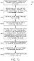
- FIG. 13is a flow diagram illustrating an exemplary method for generating a tool path in accordance with aspects hereof;
- FIG. 14is a depiction of a three-dimensional point cloud representation of a surface mapping of a lasted upper surface combined with a three-dimensional digital bite line representation, in accordance with aspects hereof;
- FIG. 15is a graphical flow diagram illustrating an exemplary method for capturing a three-dimensional surface mapping of a lasted upper and a three-dimensional digital bite line representation for use in generating a robotic tool path in accordance with aspects hereof;
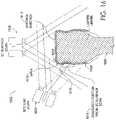
- FIG. 16is a cross sectional view of an exemplary lasted upper as captured by a bite line scanning system and a three-dimensional scanning system, in accordance with aspects hereof.
- aspects hereofprovide systems and methods for processing shoe parts and generating tool paths for processing parts in the shoe manufacturing process.
- the tool paths generatedare used in the bonding of a shoe upper to a shoe sole assembly or bottom unit.
- aspects hereofmay be used for generating other types of tool paths and for the processing of other portions of an article of footwear.
- aspects hereofmay be useful for generating tool paths to buff, clean, prime, paint, or otherwise process surfaces in the manufacturing process of soft goods such as shoes.
- a shoe uppermay comprise a large number of individual parts, often formed from different types of materials.
- the components of a shoe uppermay be joined together using a variety of adhesives, stitches, and other types of joining components.
- a shoe bottom unitmay often comprise a shoe sole assembly with multiple components.
- a shoe bottom unitmay comprise an outsole made of a relatively hard and durable material, such as rubber, that contacts the ground, floor, or other surface.
- a shoe bottom unitmay further comprise a midsole formed from a material that provides cushioning and absorbs force during normal wear and/or athletic training or performance.
- Shoe solesmay further have additional components, such as additional cushioning components (such as springs, air bags, and the like), functional components (such as motion control elements to address pronation or supination), protective elements (such as resilient plates to prevent damage to the foot from hazards on the floor or ground), and the like. While these and other components that may be present in a shoe upper and/or a shoe bottom unit are not specifically described in examples herein, such components may be present in articles of footwear manufactured using systems and methods in accordance with aspects hereof.
- additional cushioning componentssuch as springs, air bags, and the like
- functional componentssuch as motion control elements to address pronation or supination
- protective elementssuch as resilient plates to prevent damage to the foot from hazards on the floor or ground
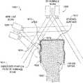
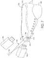
- FIG. 1an exemplary system in accordance with aspects hereof is illustrated and designated generally as reference numeral 100 .
- a shoe upper 110has been placed on a last 120 .
- the last 120may apply a predetermined amount of force, optionally in conjunction with an additional member 122 to retain the lasted upper 110 against a corresponding bottom unit or a representation 130 of a corresponding bottom unit.
- a representation 130 of a corresponding unitoften may be utilized rather than the bottom unit itself so that a single bottom unit representation 130 may be utilized to process a plurality of shoe uppers.
- a bottom unit representation 130may emulate the actual materials, size, shape, contours, etc.
- the bottom unit representation 130may be formed from a material different from that which is typically used for the bottom unit.
- a more durable and rigid materialmay form at least a portion of the bottom unit representation as the function of the bottom unit representation 130 is to provide a guide for applying a bite line marking in a repeated production process. This is in contrast to a functional purpose of the actual bottom unit, which is generally provided for impact attenuation, support, and traction, among other reasons.
- the bottom unit representation 130 and the lasted upper 110may be rotated as indicated by arrow 135 while contacted by a marking mechanism 140 having a marking tip at a junction 112 between the lasted upper 110 and the bottom unit representation 130 .
- the marking mechanism 140may comprise a marking mechanism that utilizes a conditionally visible marking agent applicable via the marking tip to apply conditionally visible indicia on the lasted upper 110 at the junction between lasted upper 110 and bottom unit representation 130 .
- the marking mechanism 140may comprise a marking mechanism with one of a fluorescent marking tip and an IR marking tip that applies fluorescent indicia or IR indicia, respectively, at the junction 112 between the lasted upper 110 and the bottom unit representation 130 to create a conditionally visible bite line observable only under lighting conditions permitting the conditionally visible indicia to be detected.
- the location of a bite line on the surface of the lasted upper 110may vary based upon the amount of force or pressure used to mate the lasted upper 110 with the corresponding bottom unit representation 130 .
- the predetermined amount of force applied by the system 100 during the marking of a conditionally visible bite line using the marking mechanism 140may be the same force applied when ultimately bonding the lasted upper 110 to the bottom unit represented by the bottom unit representation 130 , but may be different than the force applied during bonding without departing from the scope hereof.
- the amount of force to be appliedmay be adjusted to compensate for a different amount of compressibility between the materials.
- the size of the bottom unit representation 130may actually be varied from that of the bottom unit to be applied as the size may compensate for variances in compressibility, deformability, or even the thickness of the tip 142 .
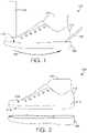
- conditionally visible bite line 210has been marked on the lasted upper 110 .
- the conditionally visible bite line 210may not be perceivable during all lighting conditions, the lighting conditions under which the conditionally visible bite line 210 is perceivable depending upon the marking agent used to mark the bite line 210 .
- the conditionally visible bite line 210may only be visible when illuminated by a UV light source (e.g., a black light), an IR light source, or another lighting source that causes the marking agent used to apply the indicia of the conditionally visible bite line 210 to be detectable.
- conditionally visible bite line 210may comprise an indicia formed from a fluorescent marking agent (e.g., ink) such that the conditionally visible bite line 210 may be perceived when illuminated using a black light.
- conditionally visible bite line 210may comprise an indicia formed from an IR marking agent such that the conditionally visible bite line 210 may be perceived when illuminated using an IR light source. Any and all such variations, and any combination thereof, are contemplated to be within the scope of aspects hereof.
- the conditionally visible bite line 210defines a first surface region 214 and a second surface region 212 on the surface of the lasted shoe upper 110 .
- the first surface region 214corresponds to the portion of the surface of the lasted upper 110 that was covered by the bottom unit representation 130 when the lasted upper 110 was retained against the corresponding bottom unit representation 130 with a predetermined amount of force.
- the second surface region 212corresponds to the portion of the surface of the lasted upper 110 that was not covered by the corresponding bottom unit representation 130 when the lasted upper 110 was pressed against the corresponding bottom unit representation 130 with the predetermined amount of force.
- any processing intended to bond the bottom unit represented by the bottom unit representation 130 to the lasted upper 110should be performed within the first surface region 214 bounded by the conditionally visible bite line 210 . Further, any processing that may change the appearance of the surface of the lasted upper 110 that is performed in the second surface region 212 may result in changes observable in the finished shoe, while processing performed within the first surface region 214 may not be ultimately observable after the shoe has been assembled by bonding the lasted upper 110 to the corresponding bottom unit represented by the bottom unit representation 130 .
- FIG. 2illustrates only one example of the location of a conditionally visible bite line 210 on the surface of a shoe upper 110 .
- the orientation, position, and configuration of a conditionally visible bite line in accordance with the present inventionmay vary greatly from that shown in the example of FIG. 2 .
- the bottom unit represented by the bottom unit representation 130may mate with the upper 110 in a fashion that extends the bottom unit 130 over a greater portion of the upper 110 , resulting in a conditionally visible bite line 210 located further from the bottom of the upper 110 (e.g., closer to a forefoot opening and/or an ankle opening).
- the entirety of the bottom unit represented by the bottom unit representation 130may be largely or entirely below the upper 110 , resulting in a conditionally visible bite line 210 that is entirely or largely on the bottom surface of the upper 110 (e.g., proximate a strobel board in a strobel construction technique).
- the extent to which a bottom unit represented by the bottom unit representation 130 extends up an upper 110 when matedmay vary along the junction of the upper 110 and bottom unit representation 130 , resulting in a conditionally visible bite line 210 that is not parallel with the bottom of the upper 110 .
- the conditionally visible bite line 210may extend farther from the bottom unit in certain areas, such as a toe region and/or a heel region.
- the bottom unitmay cover a greater portion of the upper 110 in these areas to provide structural benefits, such as abrasion resistance or improved ground-contacting surface (e.g., traction).
- the shape of the upper 110 at the junction between the upper 110 and the bottom unit representation 130may also vary from that shown in the example of FIG. 2 , meaning that the conditionally visible bite line 210 may be created on a portion of the shoe upper 110 that is flat, convex, concave, or possessing a complex three dimensional curvature.
- Systems and methods in accordance herewithmay provide and utilize conditionally visible bite lines in all of these and other configurations of a shoe upper and/or bottom unit.
- FIG. 3illustrating an exemplary three-dimensional surface scan having a light source 370 that may project a light 372 such that a reflected portion 374 reflects across a segment of at least the first surface region 214 of the surface of the lasted upper 110 and the second surface region 212 .
- a strobel 310has been joined to the upper 110 by a stitch 312 to enclose and contain the last 120 .
- the strobel 310is contained within the first surface region 214 of the lasted shoe upper 110 and, therefore, will ultimately be covered after shoe assembly.
- the lasted upper 110may use closure structures different than strobel 310 , but in many athletic shoes some type of strobel, such as the strobel 310 , are used to enclose the upper 110 to permit the insertion of the last 120 to appropriately expand the upper 110 over the last 120 .
- At least one camera 380may detect the portion 374 of the light 372 that reflects from one or more surfaces, such as a surface of the strobel 310 and a portion of the first surface region 214 extending between the strobel 310 and the bite line 210 , of the lasted upper 110 .
- a second camera 382has been provided that also detects the light from the portion 374 of the light 372 that reflects from the surface of the lasted upper 110 .
- more than one cameramay provide a greater field of view such that if a portion of a surface to be captured is obscured from a first camera having a first perspective and location, a second camera having a different perspective and location may be effective for capturing the portion of surface obscured from the view of the first camera.
- additional camerasmay be utilized to supplement image data captured from a first camera when the first camera is not conveniently located to capture all portions of a surface desired to be captured.
- the reflected portion 374extends beyond the bite line 210 such that the reflected portion may be effective for generating a surface map for portions of the lasted upper 110 beyond the conditionally visible bite line 210 into the second surface region 212 , in an exemplary aspect.
- each of the first camera 380 and the second camera 382may be utilized to detect the reflection of light from the surface of the lasted upper to develop a point cloud of the external surface(s).
- a point cloudis a collection of points in a coordinate system, such as a three-dimensional coordinate system represented by X, Y, and Z coordinates (also referred to as x y z coordinates herein), that represents points as identified on an external surface of the lasted upper.
- FIG. 14 hereinafterwill depict an exemplary point cloud representing a surface of a lasted upper in addition to a three-dimensional representation of a bite line as coordinated with the point cloud coordinates.
- images from both the first camera 380 and the second camera 382may be combined, utilizing a computing system (not shown), to generate the point cloud as a three-dimensional surface map of the lasted upper.
- the three-dimensional surface mapmay be combined and coordinated with bite line data, such as the digital bite line representation, generate a tool path for further processing of the shoe, as more fully described below.
- bite line datasuch as the digital bite line representation
- the surface scan system generating the three-dimensional surface scan and the digital bite line detection system generating the digital bite linemay be calibrated using one or more known techniques, such as a multi-planar visual calibration tool.
- the calibrationallows for the computing system to accurately merge the digital bite line data with the three-dimensional surface scan data to form a representation of the lasted upper for purpose of generating a tool path. While two cameras are described in this example for generating the three-dimensional surface map as a point cloud, it is contemplated that a single imaging source in combination with one or more structured lights may produce a useable three-dimensional surface mapping in an alternative aspect.
- the light source 370 and/or the at least one camera 380 , 382may comprise components of any surface imaging system that generates a digital representation, often utilizing computer software, based upon reflections 374 of the light 372 detected by the at least one camera 380 , 382 .
- the at least one camera 380 , 382may be comprised of one or more filters, such as longpass, shortpass, or bandbass filters to selectively capture specific or ranges of light energy to further refine the process.
- the light source 370 and the at least one camera 380 , 382may be adapted to leverage a specific band of wavelength, such as infrared and special filters receptive to infrared wavelengths.
- Other surface imaging systemssuch as systems utilizing cameras without a light source or contact systems that use one or more probes to physically engage a surface, may alternatively be used with systems and/or methods in accordance herewith.
- the light source 370may be any suitable light source that provides a defined geometrical representation at a distance from the upper 110 .
- a slit lampthat produces a focused slit-like beam of light from an otherwise unstructured light source may produce the projected light needed to specifically identify an intersection between the light and the conditionally visible bite line 210 .
- Another light source optionincludes a structured laser light source.
- a structured laser light sourceis a laser that projects a laser light in a structured light pattern, such as a line. This structured line of light may be formed by allowing light in a specific plane to fan outwardly from the source while constraining the dispersion of light in all other directions to result in a plane of light emanating from the structured laser source. When the plane of light contacts a surface, a laser line representation is formed having a focused nature and a controlled width perpendicular to the plane the light forms.
- Light source 370may comprise a laser line generator (e.g., laser micro line generator or laser macro line generator) having various features and capabilities.
- Exemplary featurescomprise an adjustable fan angle; homogenous intensity distribution; constant line width (i.e., thickness throughout whole measuring area); adjustable width; adjustable spectral range (e.g., 635 nm-980 nm); and adjustable power (e.g., up to 100 mW in the visible range and up to 105 mW in the IR range).
- light source 370may have a fan angle of 40 degrees, a line length of 180 mm, a line width (i.e., thickness) of 0.108 mm, a working distance of 245 mm, a Rayleigh Range of 12 mm, a focusing range of 205-510 mm, and a convergence of 0.7 degrees, for example.
- Various aspects of light source 370may be adjusted in coordination with shoe-part characteristics.
- a color of laser beammay be set or adjusted based on a color of a shoe part. That is, certain combinations of laser-beam color (e.g., wave length) and shoe-part color may allow the projected laser line 374 to be better recorded using at least one camera 380 , 382 . As such, the laser-beam color may be adjusted accordingly based on a shoe-part color.
- power levels of light source 370may be adjusted based on a color of the shoe part.
- a single lasermay have an adjustable power setting, such that the single laser may be adjusted based on shoe-part color.
- multiple lasers that have different power levelsmay be interchangeably utilized based on a color of the shoe part.
- multiple lasersmay be arranged at a single station.
- a high-power lasermay be utilized when projecting a beam onto a shoe part that is colored black (or is non-white).
- a low-power lasermay be utilized when projecting a beam onto a shoe part that is colored white.
- multiple lasersmay be used at the same time when a part is multi-colored.
- both a high-power laser and a low-power lasermay project respective beams onto a shoe part that is colored black and white.
- the at least one camera 380 , 382is positioned to record an image of projected laser line 374 . As such, the captured image depicts a representation of the projected laser line as it appears reflected across a portion of the lasted upper 110 .
- the data set representationsmay not be visually depicted.
- the data representationsmay merely be a mathematical expression, mathematical model, a series of coordinates, or other non-visual representations of the data that are not necessarily graphically depicted by a computing device or other means of manifesting a perceivable depiction of the data representations.
- a visual depiction of the different data representationsare depicted and described herein.
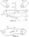
- FIG. 4one example of the scanning of at least the first surface region 214 of a lasted upper 110 using light 372 from a structured light source (e.g., a laser) is illustrated.
- a reflected portion 374 of the projected light 372is reflected by the surface of the lasted upper 110 in at least the first surface region 214 and a portion of the second surface region 212 .
- systems and methods in accordance herewithmay generate a tool path based upon the bite line data and the three-dimensional profile data (e.g., three-dimensional surface map, point cloud) of the surface of the first surface region 214 .
- surface data for the second surface region 212may also be captured and may be useable in calibrating, in an exemplary aspect, the data provided by the digital bite line and the three-dimensional surface map.
- the surface data for the second surface region 212may not be utilized in the generation of the tool path, in an exemplary aspect.
- the lasted upper 110may be moved relative to the projected light 372 , or the alternative is also contemplated such that the projected light 372 may be moved relative to the lasted upper 110 , such that at least the substantial entirety of at least the first surface region 214 of the lasted upper 110 is scanned. It is contemplated that the intersection of the reflected portion 374 of the light 372 and the bite line 210 may be detected along at least a portion of the bite line 210 , which may be used to coordinate three-dimensional surface map data with bite line data, in an exemplary aspect.
- contours of the upper 110may render portions of the bite line 210 , and thus portions of the intersection of the bite line 210 with the projected light 372 , not visible to the at least one camera 380 , 382 .
- the bite line datamay be utilized to supplement the three-dimensional profile data to extrapolate the appropriate tool path, as more fully described below and illustrated in connection with FIG. 16 hereafter.
- the portion 374 of the light 372 reflected from the surface of the lasted upper 110may intersect the bite line 210 at a first point 415 and a second point 425 .
- the segment defined by the first point 415 and the second point 425 of the portion 374 of light 372 reflected from the surface of the lasted upper 110corresponds to a segment of the surface within the first surface region 214 . It is contemplated that the length and position of such segments may be determined by a computing system after combining data obtained from the three-dimensional surface map (or based on data from the three-dimensional surface map alone) and the digital bite line to help determine a tool path.
- a representation of substantially the entire surface within the first surface region 214may be generated.
- portions of the second surface regionmay also be captured as part of the surface scan.
- the lasted upper 110may move relative to a stationary light source 370 , that the light source 370 may move relative to the lasted upper, or that both the lasted upper 110 and the light source 370 both move relative to each other to accomplish one or more of the scan discussed herein.
- whether the lasted upper 110 or the light source 370 is movedmay vary for different examples hereof.
- FIG. 4Also depicted in FIG. 4 is an alternative portion 375 of reflected light 372 .
- the portion 375is not perceived by a camera to intersect the bite line 210 .
- the bite line 210may extend on a portion of the lasted upper that is obscured from the three-dimensional surface scan components, as will be discussed in FIG. 16 . This lack of intersection highlights an exemplary aspect for which the combination of digital bite line data and the three-dimensional surface map data is used to generate a tool path.
- a resulting tool pathmay not be able to identify a bite line position for which the tool path is to be bounded.
- the components utilized in capturing the three-dimensional surface mapmay be ineffective (e.g., ineffective lighting parameters) for identifying a conditional bite line regardless if it is at the portion 374 where an intersection is able to be perceived or if it is at portion 374 where an intersection is not able to be perceived with the bite line 210 . Therefore, when the components utilized to capture the three-dimensional surface map data are not effective at capturing the conditionally visible bite line, a combination of the digital bite line data with the three-dimensional surface map data is needed to generate a tool path within determined tolerances.
- FIG. 5another example of using a light source that projects a light to scan at least the surface of the first surface region 214 of the lasted upper 110 is illustrated. While the example of FIG. 4 moves the lasted upper 110 relative to the light 372 in a linear fashion as indicated by arrow 430 , in the example of FIG. 5 , the lasted upper 110 may be rotated as indicated by arrow 530 relative to the light 372 . Accordingly, the at-least one camera may detect the reflected portion 374 of the light from the surface of the lasted upper 110 as the lasted upper 110 and/or the light source are rotated 530 relative to one another.
- intersection of the reflected portion 374 of the light and the bite line 210may be determined/detected, in an exemplary aspect; however, it is optional as a separate bite line scan may be utilized to achieve a comprehensive identification of the conditionally visible bite line location.
- a segment extending between a first intersection point 515 and a second intersection point 525may represent a small portion of the surface of the first surface region 214 .
- a plurality of such segmentsmay be obtained to provide a more complete representation of the surface region 214 in three dimensions using one or more cameras 380 , 382 .
- one or more portions of the bite line 210may be obscured from the three-dimensional surface mapping components, which illustrates a further need, in an exemplary aspect, for a separate bite line data collection. Further, as also contemplated above, the components used to capture the three-dimensional surface map data may not be adapted to capture a conditionally visible bite line, in an exemplary aspect.
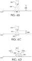
- a tool path 610may be generated to process the surface of the lasted upper 110 within the first surface region 214 bounded by the bite line 210 of the upper 110 .
- the tool path 610comprises a plurality of segments that process the perimeter of the first surface region 214 while remaining within the interior of the bite line 210 and then processes at least portions of the interior of the first surface region 214 .
- the tool path 610may further represent the orientation of a tool in three-dimensional space relative to the surface of the first surface region 214 , for example, to maintain a spray nozzle, buffer, brush, or other tool at a particular angle relative to the surface of the first surface region 214 . While a particular tool path 610 is depicted in FIG. 6A , it is contemplated that alternative tool paths may be implemented to achieve a similarly bounded coverage area.
- the tool path 610may also include information describing additional degrees of movement and control, such as nozzle angle, nozzle distance, flow rate, and the like.
- a tool path 610may further maintain a spray nozzle at a substantially perpendicular angle to the surface of the first surface region 214 , such as between 80 and 100 degrees.
- the tool path 610may comprise a relatively constant distance or a varying distance from the surface of the lasted upper 110 within the first surface region 214 .
- a brush, buffer, or other type of toolthat physically contacts the surface of the lasted upper 110 may have its position in three-dimensional space vary to maintain the tool and contact with the surface of the lasted upper 110 within the first surface region 214 .
- a tool path 610may maintain such a tool at a particular distance, such as 1.0 centimeter, or at a variety of distances based upon the degree of coverage desired, such as between 0.5 and 2.0 centimeters, for different parts of a tool path 610 .
- a spray nozzlemay be moved along the tool path 610 , the tool path 610 may maintain the spray nozzle at a first distance along the bite line 210 but at a second distance greater than the first distance within the interior of the first surface region 214 .
- the spray of adhesivemay be more precisely controlled at the shorter first distance to prevent overspray while the spray may provide less dense but more extensive coverage at the second greater distance.
- Numerous variations and different types of tool paths beyond the example tool path 610 illustrated in FIG. 6Amay be utilized without departing from the scope of aspects hereof.
- FIGS. 6B-6Dillustrate further examples of parameters that may be part of a tool path generated in accordance with aspects hereof.
- a toolmay be a spray nozzle 650 that sprays an adhesive 652 onto the surface of the first surface region 214 of a lasted shoe upper.
- a tool pathmay maintain a tool such as spray nozzle 650 at a distance and/or angle relative to the surface of a surface region 214 to be treated.
- the nozzle 650has a first distance 660 which produces a first coverage surface region 655 for the sprayed adhesive 652 .
- FIG. 6Billustrate further examples of parameters that may be part of a tool path generated in accordance with aspects hereof.
- a toolmay be a spray nozzle 650 that sprays an adhesive 652 onto the surface of the first surface region 214 of a lasted shoe upper.
- a tool pathmay maintain a tool such as spray nozzle 650 at a distance and/or angle relative to the surface of a surface region 214 to be treated.
- the nozzle 650has a second distance 662 that is shorter than the first distance 660 and that correspondingly produces a second coverage surface region 657 smaller than the first coverage surface region 655 .
- a toolsuch as the nozzle 650 may be positioned at a variety of distances beyond the first distance 660 and the second distance 662 described in the present example. Further, a tool such as a nozzle 650 may be placed at positions and/or orientations with various angles relative to the surface of the surface region 214 to be treated. For example, as shown in FIG.
- a nozzlemay be placed in a first orientation 671 at a first angle 681 perpendicular to the surface of the surface region 214 to be treated, at a second orientation 672 at a second angle 682 (obtuse in this example) relative to the surface of the surface region 214 to be treated, or at a third orientation 673 at a third angle 683 (acute in this example) relative to the surface of the surface region 214 to be treated.
- a lasted upper 110may be retained with a predetermined amount of force against a representation 130 of a corresponding bottom unit.
- a light source 730(such as a laser) may project a structured light 735 at the bite line demarcated on the lasted upper 110 .
- the demarcated bite linemay be formed with a conditionally visible marking agent, such as an IR or UV responsive ink.
- a conditionally visible marking agentsuch as an IR or UV responsive ink.
- the use of a conditionally visible agent for demarcating the bite linemay prevent aesthetically distracting remnants of a demarcated bite line from being visible on a final shoe.
- an attemptmay traditionally have been made to remove visible portions of the demarcated bite line, which may require additional resource that would not be needed when using a conditionally visible bite line.
- a first light source 730projects light 735 such that a portion 734 of the light 735 projects across at least a portion of the surface of the marked lasted upper 110 . More particularly, at least a portion 734 of light 735 from the light source 730 may reflect from at least a portion of the first surface region 214 and the second surface region 212 of the surface of the marked lasted upper 110 .
- the light source 730may be any suitable light source that provides a defined geometrical representation at a distance from the upper 110 , such as a structured light like a laser.
- the wavelength of the light 735 emitted from the light source 730renders the conditionally visible bite line 210 detectable. For instance, if the conditionally visible bite line 210 is marked utilizing an IR marking agent and the light source 730 is an IR light source emitting light 735 in the IR spectrum, the light 735 from the light source 730 will render the conditionally visible bite line 210 detectable at the intersection(s) of the light 735 and the bite line 210 , obviating the need for any additional source of light, as illustrated in current FIG. 7 . In other aspects, however, the wavelength of the light 735 emitted from the light source 730 does not render the conditionally visible bite line 210 detectable.
- conditionally visible bite line 210is marked utilizing a fluorescent marking agent and the light 375 emitted from the light source 730 is not in the UV spectrum, the conditionally visible bite line 210 will not be detectable.
- an additional lighting sourcemay be needed to render the conditionally visible bite line 210 detectable, such as a supplemental UV lamp. It is contemplated that any number of optional light sources may be implemented that provide any wavelength of light.
- At least one cameramay capture an image of the lasted upper 110 and, more particularly, an intersection 715 between the reflected portion 734 of light 735 and the conditionally visible bite line 210 .
- the at least one cameracomprises a first camera 710 and a second camera 720 , and optionally may comprise additional cameras (not shown), to capture the intersection 715 of the bite line 210 and the reflected portion 734 of the projected light 735 .
- the use of at least a first camera 710 and a second camera 720may assist in accurately locating the intersection 715 of the bite line 210 and the reflected portion 734 of the projected light 735 .
- the at least one camera 710 , 720is comprised of two cameras to leverage the benefits of stereopsis that allows a computing system to determine depth information from a pair of concurrently captured images from varied perspectives.
- the leveraging of two or more cameras from offset locationsallows a computing system to determine x y z coordinates for a given point, such as the intersection 715 .
- the intersection of the reflected light 734 and the bite line 210may be used to create a virtual bite line (i.e., a digital bite line) that aids in identifying the portion of the surface of the lasted upper 110 within the first surface region 214 that includes a bottom portion 310 of the lasted upper 110 that is to be treated, for instance, by cementing, priming, cleaning, paining, buffing, and the like.
- a virtual bite linei.e., a digital bite line
- one or more components of the bite line scanning systemmay rotate around the perimeter of the lasted upper to capture data about the perimeter of the lasted upper.
- the lasted upperis moved or rotated about the bite line scanning system to achieve a capture of data about a perimeter of the lasted upper.
- the system 800includes a bite line component 810 , a three-dimensional scanning component 820 and a tool 830 for processing a shoe part being processed.
- the bite line component 810facilitates the collection of bite line data on a shoe upper, the bite line data representing an interface between the shoe upper and a corresponding bottom unit upon assembly of the shoe.
- bite line datamay be generating utilizing a digital stylus system to trace the bite line on a shoe upper temporarily joined to a representation of a corresponding bottom unit as described in co-pending U.S.
- bite line datamay be generated by marking the bite line with physical indicia and scanning the shoe upper to determine the intersection points of the indicia and a light source, as described hereinabove with respect to FIG. 7 .
- physical indiciamay be marked with conditionally visible marking agents, for instance, fluorescent or infrared marking agents, rendering the resulting bite line indicia detectable only under specific lighting conditions.
- the bite line component 810may include at least one light source 814 for scanning and/or rendering the bite line indicia detectable, and at least one camera 812 , which may represent multiple cameras, for taking images of the points of intersection of light from the at least one light source and the conditionally visible indicia demarcating the bite line.
- a first camera and a second cameraare utilized to record images of the intersection points, the images from the two cameras being combined to generate the bite line data.
- the three-dimensional scanning component 820 of the system 800 of FIG. 8facilitates the collection of three-dimensional profile data for at least a portion of the shoe upper to be covered by the corresponding bottom unit upon assembly of the shoe.
- at least one light source 816 and at least one camera 818scan the surface of the shoe upper covering at least a portion of the surface region bounded by the bite line. Due to contours of the surface of the shoe upper, portions of the bite line, and thus portions of the shoe upper bounded by the bite line, may not be visible to at least one camera imaging the shoe upper or the at least one camera is not adapted to detect the bite line.
- the bite line data collected at the bite line component 810is combined with the three-dimensional profile data collected at the three-dimensional scanning component 820 in a computing system (not shown), to generate a tool path for further processing by the tool 830 .
- the toolmay be a variety of tools designed to clean, buff, adhere, cement, etc. during processing of the shoe.
- FIG. 8 of the system 800 for processing a shoe partis merely an example of a configuration the system 800 may take. Movement from one component of the system to another in FIG. 8 is via a conveyor belt 840 .
- the order of the components, particularly the bite line component 810 and the three-dimensional scanning component 820 , as well as the conveyance mechanismmay vary within the scope of aspects hereof.
- the shoe partsmay be conveyed from component to component utilizing one or more robots instead of or in addition to a conveyance belt.
- one or more of the components of the bite line component 810 , the three-dimensional scanning component 820 , and/or the tool 830may move to operate in multiple degrees of freedom.
- the components of the bite line component 810may move in a motion path about a shoe part.
- the motion pathmay be elliptical in nature such that at least one foci of the elliptical pattern is positioned proximate a portion of the shoe upper.
- the shoe partitself may be moved, such as rotated, relative to one or more components of the bite line component 810 .
- components of the digital bite line component 810such as the at least one camera 812 and the at least one light 814 may be moveably mounted or fixedly mounted within the digital bite line component 810 , in an exemplary aspect.
- the at least one light source 816 and at least one camera 818may be moveably mounted or fixedly mounted within the three-dimensional scanning component 820 to achieve a desired surface scan.
- FIGS. 9 and 10illustrate alternate system configurations that fall within the scope of aspects hereof.
- a system 900 of FIG. 9relies on a multi-axes robotic arm as a conveyance mechanism between the bite line component 810 and the three-dimensional scanning component 820 .
- the tool 830 in FIG. 9continues to be a multi-axial moving tool.
- the multi-axis robotic arm servicing both the bite line component 810 and the three-dimensional scanning component 820provides the degrees of movement desired to manipulate the shoe part about the various components of the bite line component 810 and the three-dimensional scanning component 820 to achieve a sufficient bite line identification and surface scan, in an exemplary aspect.
- the at least one camera 812 and light source 814may be fixedly mounted within the bite line component 810 such that the robotic arm moves the shoe part in multiple dimensions to capture the bite line representation about the perimeter of the shoe part.
- a system 1000 of FIG. 10relies on a common multi-axes robotic arm for conveyance from the bite line component 810 , the three-dimensional scanning component 820 , and the tool 830 .
- the tool 830is relatively static and processing by the tool relies on the movement offered by the multi-axes robotic arm. Therefore, it is contemplated that a variety of conveyance mechanism and tooling options may be leveraged to accomplish aspects of the present invention.
- the robotic armprovides the degree of movement necessary for each component to achieve an intended result, such as identification of a bite line and generation of a surface map. Therefore, the components of the bite line component 810 , the three-dimensional scanning component 820 , and the tool 830 may be fixedly coupled and the shoe is moved sufficiently about the components to achieve the results intended by the system, in an exemplary aspect.
- step 1110bite line data may be collected.
- Bite line data collected in step 1110may represent a virtual bite line generated using a stylus, a light source (e.g., a laser) and cameras, or any other methodology.
- step 1110may be performed by using design data, pattern data, or typical data measured when a lasted shoe upper is retained against a corresponding bottom unit (or representation thereof) to create a digital bite line without applying a lasted upper to a bottom unit, for example as shown in FIG. 1 , but step 1110 may also be performed individually for each part or set of parts to be processed.
- three-dimensional profile data representing at least a portion of the surface of a shoe upper bounded by the bite linemay be collected.
- a light source and at least one cameramay be used to generate a three-dimensional data representation, such as a point cloud, of at least a portion of the surface of a lasted upper bounded by the bite line.
- a camera alone, a contact probe, or other mechanismmay be used to generate a digital representation of the surface.
- Portions of the surface not bounded by the bite line created in step 1110may be disregarded, in exemplary aspects, in generating the representation of the surface at least within the bite line.
- step 1120may precede the step 1110 in an exemplary aspect as the order of collecting the bite line data and the surface scan data may be varied. Further, in an exemplary aspect, it is contemplated that the bite line data and the surface data may be obtained in a common operation by different or common components, in an exemplary aspect.
- the bite line data and the three-dimensional profile datamay be combined to generate a tool path for further processing of the shoe upper, which may be generated based upon the combined data.
- the tool path generated in step 1130may assure that the surface is not processed outside of the digital bite line and may further maintain a tool at a desired distance, orientation, or other status relative to the surface.
- the tool path generated in step 1130may vary at different locations along the path and within the surface region defined as bounded by the bite line.
- the tool pathmay include instructions for a robotic element to position a tool proximate various surface portions of the lasted upper, such as a bottom surface and portions of a side wall portion, in an exemplary aspect.
- the surfacemay be treated following the tool path.
- step 1140may comprise buffing the surface, spraying an adhesive onto the surface using a nozzle, etc.
- a system for processing partially assembled parts of an article of footwearincludes a marking mechanism for marking physical indicia on a shoe upper at a bite line.
- the indiciamay be marked with a conditionally visible marking agent, in an exemplary aspect.
- the systemmay then leverage a light source that projects light across at least a portion of the marked bite line at an angle non-parallel to the marked bite line.
- a first camerathat records a first series of images representing a plurality of points at which the light intersects with the marked bite line and representing the reflection of the light off of the at least part of the portion of the shoe upper to be covered by the corresponding bottom unit upon assembly of the shoe may be used.
- a second camerathat records a second series of images representing the plurality of points at which the light intersects with the marked bite line may also be used. In this example, it is the use of two cameras that provides the dimensional coordinates necessary to develop a three-dimensional representation of the bite line.
- variations in a known structured light as captured by a cameramay also be used to determine the coordinates necessary for developing a three dimensional representation, such as a point cloud of the lasted upper surface.
- a computing system that processes the first and second series of images to generate bite line datamay be integrated therein.
- the computing systemmay also use additional images or the first and second series of images to further develop a three-dimensional profile data for the shoe portion.
- the computing systemmay take bite line data and the three-dimensional profile data to generate a tool path for processing, such as an application of adhesive.
- a shoe uppermay be lasted.
- the lasting of a shoe uppermay include positioning a form within an internal cavity of the upper to provide structure and shaping.
- a sole assemblysuch as a sole or a representation of a sole, may be prepared. Preparation may include positioning the sole assembly for eventual mating to the lasted upper.
- Step 1210 and/or step 1220may combine multiple components to form an upper and/or a bottom unit.
- the lasted shoe upper and the corresponding sole assemblymay be mated with a predetermined pressure/force to result in a junction between the sole assembly and the lasted upper.
- a bite linemay be marked on the surface of the lasted shoe upper that corresponds to the termination of the mated sole assembly on the lasted shoe upper. This location of termination is a junction between the sole assembly and the lasted upper forming a guide to place the bite line.
- Step 1240may utilize a stylus, a light source (e.g., a laser) and one or more cameras, or any other system or process to mark indicia comprising a bite line or a virtual bite line, which are used to create a digital bite line representing coordinates on the lasted upper at the junction between the sole assembly and the lasted upper.
- a light sourcee.g., a laser
- a virtual bite linee.g., a digital bite line representing coordinates on the lasted upper at the junction between the sole assembly and the lasted upper.
- three-dimensional profile data representing at least the portion of the lasted shoe upper bounded by the bite linemay be generated and collected.
- the generated digital representationmay be formed from any type of input, such as a three-dimensional and/or a digital bite line scan.
- the surface region bounded by the bite line on the lasted shoe uppermay comprise a first surface region, and that first surface region may be scanned using a laser and at least one camera or other surface scanning techniques, some of which are described in examples herein.
- the bite line data and the three-dimensional profile datamay be leveraged within a computing system to generate a tool path to treat at least a portion of the lasted shoe upper that is bounded by the bite line.
- the tool pathmay be generated by software based on computer-aided design (CAD) and computer-aided manufacturing (CAM) concepts that take data from the three-dimensional profile data and the digital bite line data to determine appropriate aspects of the tool path (e.g., location, speed, angle, flow, etc.).
- CADcomputer-aided design
- CAMcomputer-aided manufacturing
- the softwareis provided information with respect to constraints associated with a desired process (e.g., application of adhesive).
- the constraintsmay include a desired coverage, applicator information, cycle time constraints, and other variable that are used in determining an appropriate tool path.
- the softwarethen may take these inputs in combination with the three-dimensional profile data and the digital bite line data to develop an appropriate tool path that satisfies the provided constraints while staying within the desired area bounded by the digital bite line data, in an exemplary aspect.
- a tool following the tool path generated in step 1260such as a multi-axis robot having an adhesive-applying tool head attached thereto.
- constraints associated with the particular tool to be usedmay be provided to the software along with constraints associated with the multi-axis robot such that the resulting tool path is specific to the particular shoe upper to be processed, the tool doing the processing, and the robot controlling and moving the tool, in an exemplary aspect.
- a further exemplary method 1300 of generating a tool path for processing a shoe upper in accordance with aspects hereofis illustrated.
- a lasted shoe uppermay be retained against a corresponding bottom unit (or representation thereof) by mating a lasted shoe upper and bottom unit with a predetermined amount of pressure.
- a bite linemay be marked on the shoe upper by creating indicia on the shoe upper.
- step 1320may apply a mark to the shoe upper at the junction of the bottom unit (or representation thereof) and the lasted shoe upper while mated with a predetermined amount of pressure.
- the amount of pressuremay be a general amount sufficient to temporarily mate the bottom unit (e.g., sole assembly) with the lasted upper. In one aspect, the amount of pressure applied may be approximately 30 kg/cm or more, for example.
- Step 1320may use an ink, a pencil, or a fluorescent, IR, or other conditionally visible material, or any other way of forming perceptible indicia on the shoe upper.
- the lasted shoe upper and the sole assemblymay be separated. Step 1330 may permit the subsequent scanning and treatment of the surface region of the lasted shoe upper that was covered by the bottom unit (or representation thereof) when the bite line was created in step 1320 .
- a light sourcee.g., a laser
- a bite line identifiersuch as a conditionally visible bite line demarcation or indicia.
- Step 1340may be performed using lighting conditions that render a conditionally visible bite line, such as a bite line using fluorescent or IR marking agent, observable using one or more cameras if a limited/conditionally visibility bite line was created in step 1320 .
- step 1350the intersections of the projected laser and the bite line may be recorded to generate bite line data that represents the perimeter of the portion of the lasted shoe upper for which a tool path will be generated to correspond to the portion of the lasted shoe upper covered by the bottom unit (or representation thereof) when the lasted shoe upper and bottom unit (or representation thereof) were mated with the predetermined amount of pressure.
- step 1360three-dimensional profile data for the lasted shoe upper may be collected (as more fully described above) and, in step 1370 , the bite line data and the three-dimensional profile data may be combined. In step 1380 a tool path may be generated within the bite line to treat the surface of the lasted shoe upper.
- FIG. 14is a depiction of a combined representation 1400 of a three-dimensional surface map (e.g., point cloud) representation 1402 of a lasted upper surface combined with a three-dimensional digital bite line representation 1404 .
- the three-dimensional surface map representation 1402is depicted as a dot pattern to represent identified points, such as cloud points.
- the three-dimensional digital bite line representation 1404is depicted as larger circular indicia. As illustrated in this exemplary aspect, the three-dimensional digital bite line representation 1404 proximate a toe region 1406 extends beyond the data represented by the three-dimensional surface map representation 1402 .
- the combination of the two representations to form a tool pathis beneficial in at least this portion of the lasted upper as a single representation alone may not provide sufficient information.
- a portion of the lasted uppermay obscure a portion of surface to be scanned based on the relative positioning of the components and the lasted upper, as will be illustrated in FIG. 16 .
- FIG. 15is a graphical flow diagram illustrating an exemplary method 1500 for capturing a three-dimensional point cloud representation of a portion of a lasted upper and a three-dimensional digital bite line representation for use in generating a robotic tool path.
- bite line datais captured.
- the capture of bite line datamay be accomplished using a variety of techniques, such as scanning a conditionally visible marking with at least one vision system and a light source.
- the conditionally visible bite linemay be formed with an IR material that is responsive to a light source, such as a laser operating in the IR spectrum.
- indiciamay be perceived by the vision system, which identifies a location of the bite line demarcation.
- the bite line datamay be captured by a stylus on a multi-axis dimensional measuring device that relies on physical contact between the multi-axis dimensional measuring device and the object to be measured, such as a lasted upper.
- Step 1504provides for the generation of a digital bite line.
- a computing systemmay convert the captured bite line data into a three-dimensional representation of points along the bite line.
- This three-dimensional representation of the bite line captured from the lasted uppermay be stored as a grouping of dimensional points that may be input into a vision system software package for eventual generation of a tool path.
- the generated digital bite linemay extend along one or more portions of the lasted upper, such as various distances along a side portion of the lasted upper and/or along different portions of the bottom (e.g., strobel board location when using a strobel construction) of the lasted upper.
- Step 1506provides for the capture of a three-dimensional surface data from a surface scan along at least a bottom portion of the lasted upper.
- one or more camerasin connection with one or more light sources that may be used in tandem to develop a three-dimensional identification of the lasted upper surface(s).
- a laser having a structured light sourcemay traverse the lasted upper bottom portion while at least one camera captures images of the lasted upper and laser light intersection.
- Step 1508generates a three-dimensional surface map of the lasted upper.
- an exemplary aspect contemplatedallows for the data captured in step 1506 to be processed by a computing system to identify a plurality of points along the scanned surface to generate a point cloud, such that the three-dimensional coordinates of points along the scanned surface may be determined relative to one another.
- a computing system adapted to operate a vision software programinterprets images captured from at least one camera to develop the three-dimensional surface scan. The computing system may use interpolation and other mathematical techniques to develop the resulting surface map such that a more comprehensive surface map is formed from a finite number of data points along the surface region scanned.
- Step 1510combines data representing the digital bite line with data representing the three-dimensional surface map to form a more complete three-dimensional model of the surface region on which a tool will traverse for further processing, such as the application of an adhesive.
- the combining of the data representationsmay be accomplished by a computing system having software adapted for combining the data representation. For example, vision software that may be implemented to align the three-dimensional surface map data with the three-dimensional digital bite line data.
- This alignmentmay be accomplished, as is known in the art, based on a previously performed calibration process that allows the computing system to align the relative coordinate positions from a first data set captured in a first physical location (e.g., the bite line scanning component) with the relative coordinate positions from a second data set captured in a second, different, physical location (e.g., surface scanning component).
- the combined and aligned data from the different data representationsis useable to develop a model of the surface region that is to be processed by a created tool path. It is contemplated that the surface region may include additional portions of the lasted upper beyond that which will be processed by the tool following the tool path.
- the data representing the digital bite line and the data representing the three-dimensional surface mapare joined into a common representation of the surface region for which a tool path will be generated.
- a visual model of the data representationsmay not occur and in an exemplary aspect will not be generated.
- the separate data representationsmay not be actually merged into a common data representation, but instead will be commonly referenced for the generation of the tool path, as provided in step 1512 .
- Step 1512generates a tool path along the lasted upper based on the combined data representation from step 1510 .
- the tool pathwill allow a multi-axis robotic-controlled tool to operate in multiple dimensions to process a portion of the lasted upper, such as applying an adhesive.
- the generated tool path for a lasted upper based on the combined data representationsextends along a bottom portion of the lasted upper as well along a sidewall portion of the lasted upper.
- the tool pathmay include additional instructions for the processing, such as application rate, speed, angle, and other characteristics that are useful in optimizing the processing step to be performed by the tool path.
- the generated tool pathmay be generated by a computing system having a program for leveraging the data representations and predetermined criteria to develop an appropriate tool path.
- the computing systemmay include one or more files describing a quantity of adhesive, preferred application rate, preferred speed, and other factors affecting the generation of a tool path for an adhesive application.
- Step 1514depicts the execution of the tool path generated at the step 1512 .
- the tool pathallows for the application of a material, such as an adhesive to the lasted upper within a surface region bounded by the digital bite line.
- additional/alternative processingmay be performed by a generated tool path that was generated based on one or more data representations provided herein.
- stitching, buffing, cutting, painting, scoring, marking, and other processes performed in the construction of a shoemay be implemented in exemplary aspects.
- the application of material along the generated tool pathmay include controlling the speed, application rate, angle, and location of an adhesive applicator.
- the generated tool pathmay be translated into actual movement by a multi-axis robot having an adhesive application system.
- An adhesive application systemmay be comprised of an application portion (e.g., spray nozzle) and the multi-axis robot functionally coupled with a computing system to process a generated tool path for spatial movement and application of an adhesive to a portion of an article of footwear.
- method 1500depicts a specific sequence of steps, it is contemplated that one or more steps may be rearranged while still effectively accomplishing a generated tool path for a subsequent processing of the lasted upper.
- the order in which the bite line data is captured (step 1502 ), generation of the digital bite line (step 1504 ), capture of a three-dimensional surface scan (step 1506 ), and the generation of a three-dimensional surface map (step 1508 )may be performed in any order and may be performed in parallel as opposed to in a serial manner as depicted.
- additional stepsmay be included as well as one or more steps may be omitted in an exemplary aspect.
- FIG. 16is a cross-sectional view 1600 of an exemplary lasted upper 1604 as captured by a bite line scanning system 1606 and a three-dimensional scanning system 1608 .
- the cross sectional view 1600illustrates how contours of the lasted upper 1604 as maintained by an exemplary last 1602 may obscure one or more portions of a surface region for which a tool path is to be generated.
- the lasted upper 1604is formed with an apex 1610 as the lasted upper 1604 transitions from a bottom surface, such as a strobel surface 1612 , to a sidewall portion.
- a portion 1614 (identified by the region having circles) of the lasted upper 1604is obscured from the field of view captured by the three-dimensional scanning system 1608 , as depicted by the dashed lines extending from at least one camera of the three-dimensional scanning system 1608 .
- a bite line 1616may be demarcated in the region 1614 that is obscured from the three-dimensional scanning system 1608 .
- a tool path to be generatedmay not have sufficient data from the three-dimensional scanning system 1608 to stay within a region defined by the bite line 1616 . Consequently, in an exemplary aspect, the bite line scanning system 1606 is relied on to capture a different perspective of the lasted upper 1604 than the three-dimensional scanning system 1608 , as depicted by the dashed lines extending outwardly from the digital bite line system 1606 representing the field of view of the digital bite line system 1606 .
- the data acquired from the digital bite line system 1606is used, in part, to define a boundary in which an interpolation techniques may be used with data from the three-dimensional scanning system 1608 to determine a surface in the obscured portion. Further, in another exemplary aspect, a data representation from the digital bite line system 1606 may be combined with data from the three-dimensional scanning system 1608 to generate a tool path including the obscured region 1614 .
- An alternative bite line 1618is also depicted within the field of view of both the three-dimensional scanning system 1608 and the digital bite line system 1606 .
- the three-dimensional scanning system 1608may not be adapted to capture to bite line data; therefore, the digital bite line system 1606 may again be relied on to generate the digital bite line data representation.
- the digital bite line system 1606may be used.
- the three-dimensional scanning system 1608 and the digital bite line system 1606are depicted together, it is contemplated that the three-dimensional scanning system 1608 may be in a first physical location that is independent from the digital bite line system 1606 such that a serial capture of data is performed at the different location. However, it is also contemplated that the three-dimensional scanning system 1608 and the digital bite line system 1606 may be positioned in a common location for data collection without transferring the lasted upper 1604 from a first location to a second location, as contemplated in FIGS. 8-10 herein.
- Methods and/or systems in accordance herewithmay use one or more computing systems executing computer-readable code retained in a computer-readable memory to perform the appropriate steps and/or to control the various components of systems in accordance with the present invention.
- Different steps in a process or method in accordance herewithmay occur at different locations and/or may be controlled by different computing systems, and different components of a system in accordance herewith may be controlled by different computing systems.
- the creation of a virtual bite linemay occur at a first station using a first computing system, while the scanning of the surface of a lasted upper to collect three-dimensional profile data may occur at a second station and may be controlled by a second computing system.
- the corresponding bottom unit (or representation thereof) that is used for marking a bite linemay be different than the bottom unit that is ultimately bonded to a given upper.
- a bite linemay be generated using the bottom unit that will ultimately be bonded to the upper, but this is not necessary.
- a representative bottom unitmay be used at a station to generate a bite line while a sole sufficiently similar at the bite line to the representative bottom unit may ultimately be bonded to the upper.
- a variation in either the bottom unit used or the amount of force used to mate a lasted upper to a corresponding bottom unitmay provide advantages in some examples of systems and methods in accordance herewith. For example, if a first amount of predetermined force will be used in bonding a lasted upper to a corresponding bottom unit, a lesser or greater second amount of force may be used to retain the lasted upper to the corresponding bottom unit for the marking of a bite line.
- a bottom unitthat comprises a compressible foam material, such as in a midsole
- the use of less pressure in mating an upper to a bottom unit to create a bite line than used in the bonding processmay permit the bite line to readily encompass all of the zone that will ultimately be covered by the sole when the sole is bonded to the lasted upper.
- a representative bottom unit that is softer or harder than the actual bottom unitmay be used to mark a bite line defining a zone that is either larger or smaller than the surface region ultimately covered by a bottom unit bonded to the upper.
Landscapes
- Engineering & Computer Science (AREA)
- Physics & Mathematics (AREA)
- General Physics & Mathematics (AREA)
- Geometry (AREA)
- Computer Hardware Design (AREA)
- Theoretical Computer Science (AREA)
- Automation & Control Theory (AREA)
- Manufacturing & Machinery (AREA)
- Human Computer Interaction (AREA)
- Architecture (AREA)
- Mathematical Optimization (AREA)
- Pure & Applied Mathematics (AREA)
- Evolutionary Computation (AREA)
- General Engineering & Computer Science (AREA)
- Mathematical Analysis (AREA)
- Civil Engineering (AREA)
- Computational Mathematics (AREA)
- Structural Engineering (AREA)
- Footwear And Its Accessory, Manufacturing Method And Apparatuses (AREA)
Abstract
Description
Claims (16)
Priority Applications (2)
| Application Number | Priority Date | Filing Date | Title |
|---|---|---|---|
| US16/733,008US11341291B2 (en) | 2011-11-18 | 2020-01-02 | Generation of tool paths for shoe assembly |
| US17/728,402US11763045B2 (en) | 2011-11-18 | 2022-04-25 | Generation of tool paths for shoe assembly |
Applications Claiming Priority (3)
| Application Number | Priority Date | Filing Date | Title |
|---|---|---|---|
| US13/299,827US8849620B2 (en) | 2011-11-18 | 2011-11-18 | Automated 3-D modeling of shoe parts |
| US14/084,365US10552551B2 (en) | 2011-11-18 | 2013-11-19 | Generation of tool paths for shore assembly |
| US16/733,008US11341291B2 (en) | 2011-11-18 | 2020-01-02 | Generation of tool paths for shoe assembly |
Related Parent Applications (1)
| Application Number | Title | Priority Date | Filing Date |
|---|---|---|---|
| US14/084,365ContinuationUS10552551B2 (en) | 2011-11-18 | 2013-11-19 | Generation of tool paths for shore assembly |
Related Child Applications (1)
| Application Number | Title | Priority Date | Filing Date |
|---|---|---|---|
| US17/728,402ContinuationUS11763045B2 (en) | 2011-11-18 | 2022-04-25 | Generation of tool paths for shoe assembly |
Publications (2)
| Publication Number | Publication Date |
|---|---|
| US20200143091A1 US20200143091A1 (en) | 2020-05-07 |
| US11341291B2true US11341291B2 (en) | 2022-05-24 |
Family
ID=50275263
Family Applications (3)
| Application Number | Title | Priority Date | Filing Date |
|---|---|---|---|
| US14/084,365Active2033-11-04US10552551B2 (en) | 2011-11-18 | 2013-11-19 | Generation of tool paths for shore assembly |
| US16/733,008ActiveUS11341291B2 (en) | 2011-11-18 | 2020-01-02 | Generation of tool paths for shoe assembly |
| US17/728,402ActiveUS11763045B2 (en) | 2011-11-18 | 2022-04-25 | Generation of tool paths for shoe assembly |
Family Applications Before (1)
| Application Number | Title | Priority Date | Filing Date |
|---|---|---|---|
| US14/084,365Active2033-11-04US10552551B2 (en) | 2011-11-18 | 2013-11-19 | Generation of tool paths for shore assembly |
Family Applications After (1)
| Application Number | Title | Priority Date | Filing Date |
|---|---|---|---|
| US17/728,402ActiveUS11763045B2 (en) | 2011-11-18 | 2022-04-25 | Generation of tool paths for shoe assembly |
Country Status (1)
| Country | Link |
|---|---|
| US (3) | US10552551B2 (en) |
Families Citing this family (40)
| Publication number | Priority date | Publication date | Assignee | Title |
|---|---|---|---|---|
| WO2012159123A2 (en) | 2011-05-19 | 2012-11-22 | Alec Rivers | Automatically guided tools |
| US9451810B2 (en) | 2011-11-18 | 2016-09-27 | Nike, Inc. | Automated identification of shoe parts |
| US8755925B2 (en) | 2011-11-18 | 2014-06-17 | Nike, Inc. | Automated identification and assembly of shoe parts |
| US10552551B2 (en)* | 2011-11-18 | 2020-02-04 | Nike, Inc. | Generation of tool paths for shore assembly |
| US8849620B2 (en) | 2011-11-18 | 2014-09-30 | Nike, Inc. | Automated 3-D modeling of shoe parts |
| US8958901B2 (en) | 2011-11-18 | 2015-02-17 | Nike, Inc. | Automated manufacturing of shoe parts |
| EP3964902B1 (en)* | 2012-04-26 | 2024-01-03 | Shaper Tools, Inc. | Systems and methods for performing a task on a material, or locating the position of a device relative to the surface of the material |
| US8966775B2 (en)* | 2012-10-09 | 2015-03-03 | Nike, Inc. | Digital bite line creation for shoe assembly |
| US9719356B2 (en)* | 2013-06-21 | 2017-08-01 | Rolls-Royce Plc | Method of finishing a blade |
| US10524544B2 (en)* | 2014-01-22 | 2020-01-07 | Nike, Inc. | Divergence detection of a shoe bite line |
| WO2016183390A1 (en) | 2015-05-13 | 2016-11-17 | Taktia Llc | Systems, methods and apparatus for guided tools |
| TWI725309B (en) | 2015-05-31 | 2021-04-21 | 荷蘭商耐克創新有限合夥公司 | Method for manufacturing shoe, method for determining position of variable parts and system for manufacturing shoe |
| DE102015224885B4 (en)* | 2015-12-10 | 2024-11-07 | Adidas Ag | Patch placement procedures and manufactured items |
| US20170172259A1 (en)* | 2015-12-17 | 2017-06-22 | Pou Chen Corporation | Multi-Axis Automatic Shoe Sole Processing Apparatus and Method of the Same |
| CN105455313A (en)* | 2016-01-19 | 2016-04-06 | 台州澜屹智能装备科技有限公司 | Double-shoe three-freedom-degree automatic gluing mechanism with synchronous gluing function |
| US10563330B2 (en) | 2016-06-08 | 2020-02-18 | One Sciences, Inc. | Methods and systems for stitching along a predetermined path |
| CN106423656B (en)* | 2016-08-11 | 2019-04-02 | 重庆大学 | Automatic spraying system and method based on cloud and images match |
| RU2748005C2 (en) | 2016-08-19 | 2021-05-18 | Шапер Тулс, Инк. | Systems, methods and device for sharing tool manufacturing and design data |
| TWI642902B (en)* | 2017-11-28 | 2018-12-01 | 寶成工業股份有限公司 | Visual detection device for roughing upper |
| TWI801808B (en)* | 2018-05-31 | 2023-05-11 | 荷蘭商耐克創新有限合夥公司 | Method for assembling a shoe upper and a sole unit and method for automated buffing on a shoe upper |
| IT201800006292A1 (en)* | 2018-06-13 | 2019-12-13 | PROCEDURE AND EQUIPMENT FOR ASSEMBLING AN ITEM OF LEATHER GOODS, IN PARTICULAR FOOTWEAR | |
| JP7414810B2 (en)* | 2018-09-10 | 2024-01-16 | ファナック アメリカ コーポレイション | Zero teaching of robot continuous path |
| KR102549130B1 (en)* | 2018-11-26 | 2023-07-03 | 제트카베 그룹 게엠베하 | Vehicle vision systems with adaptive reversing lights |
| US11172734B2 (en)* | 2018-11-28 | 2021-11-16 | Electronics And Telecommunications Research Institute | Gaging apparatus and method for automation of shoemaking process |
| TWI712988B (en) | 2019-01-23 | 2020-12-11 | 愛柏威股份有限公司 | Junction line data generation method and junction line data generation system |
| IT201900008694A1 (en)* | 2019-06-12 | 2020-12-12 | Ciucani Mocassino Machinery S R L | METHOD FOR MAKING A FOOTWEAR AND FOOTWEAR OBTAINED WITH THIS METHOD |
| US11819090B2 (en) | 2019-09-16 | 2023-11-21 | Nike, Inc. | Buffing system for footwear |
| US12114736B2 (en) | 2019-11-26 | 2024-10-15 | Asics Corporation | Shoe manufacturing system and method of controlling shoe manufacturing system |
| TWI813927B (en)* | 2020-01-06 | 2023-09-01 | 荷蘭商耐克創新有限合夥公司 | Spraying system and method for article of footwear component |
| JP7511465B2 (en)* | 2020-12-24 | 2024-07-05 | 株式会社アシックス | Shoe last making support device and shoe last making system |
| US20230273599A1 (en)* | 2021-01-18 | 2023-08-31 | Shinkawa Ltd. | Position control apparatus, position control method, position control recording medium, and bonding apparatus |
| CN113508963B (en)* | 2021-03-22 | 2022-05-27 | 泉州华中科技大学智能制造研究院 | Sole polishing method and device adopting blocking pose |
| DK181400B1 (en)* | 2021-06-23 | 2023-10-16 | Ecco Sko As | A footwear manufacturing robot system |
| CN113446961A (en)* | 2021-07-03 | 2021-09-28 | 詹镇远 | Method and equipment for determining processing track by visually scanning three-dimensional adhesive surface |
| IT202100028943A1 (en)* | 2021-11-16 | 2023-05-16 | Giovanni Vassallo | Machine for marking a sole |
| US20230165340A1 (en)* | 2021-11-26 | 2023-06-01 | Metal Industries Research & Development Centre | Method and device for extracting joint line of shoe |
| KR20250010648A (en)* | 2022-05-13 | 2025-01-21 | 메이플 어드밴스드 로보틱스 인크 | Systems and methods for surface fitting, path planning and surface treatment of objects |
| EP4365544A1 (en)* | 2022-11-07 | 2024-05-08 | Sentinelconcept - Unipessoal Lda | Surface inspection system and method |
| FR3150133B1 (en)* | 2023-06-26 | 2025-05-02 | Cetia | Method and device for separating by cutting an upper and a sole of a shoe |
| DE102023134930B3 (en) | 2023-12-13 | 2025-06-18 | Adidas Ag | Method and device for processing components of a sporting article using a robot |
Citations (235)
| Publication number | Priority date | Publication date | Assignee | Title |
|---|---|---|---|---|
| GB699299A (en) | 1950-10-07 | 1953-11-04 | British United Shoe Machinery | Improvements in or relating to the marking of shoe parts |
| US3220723A (en) | 1963-09-25 | 1965-11-30 | Control Data Corp | Suction pick up with air bearing |
| US3357091A (en) | 1965-07-21 | 1967-12-12 | Hughes Aircraft Co | Device for aligning two objects and for mounting one to the other |
| US3464102A (en) | 1967-03-10 | 1969-09-02 | Branson Instr | Solid acoustic horn with suction means |
| US3848752A (en) | 1969-09-19 | 1974-11-19 | Pilkington Brothers Ltd | Apparatus for transferring sheet material |
| US4010502A (en) | 1975-05-15 | 1977-03-08 | Circle Machine Co., Inc. | Apparatus for edge processing work and particularly non-circular work |
| US4041620A (en) | 1976-08-27 | 1977-08-16 | Shell Oil Company | Integrated shoe sole and heel |
| US4100864A (en)* | 1977-01-17 | 1978-07-18 | Usm Corporation | Automatic work guidance mechanism |
| US4131918A (en)* | 1973-09-19 | 1978-12-26 | The Shoe And Allied Trades Research Association | Providing control signals for machine operations |
| US4238524A (en)* | 1978-03-06 | 1980-12-09 | American Optical Corporation | Process for identification marking clear plastic articles |
| US4304020A (en) | 1978-09-06 | 1981-12-08 | Remy Villaret | Installation for shoe production |
| US4389064A (en) | 1980-12-05 | 1983-06-21 | S.A. Joulin Sema | Gripping device operating by suction |
| US4452057A (en) | 1981-11-13 | 1984-06-05 | Usm Corporation | Shoe machine |
| US4472783A (en) | 1980-07-21 | 1984-09-18 | Kearney & Trecker Corporation | Flexible manufacturing system |
| EP0123173A2 (en) | 1983-04-22 | 1984-10-31 | Giuseppe Anzani | Assembly line, particularly suited for the production of leather and similar goods |
| GB2140345A (en) | 1983-05-25 | 1984-11-28 | British United Shoe Machinery | Horn assembly for ultrasonic welding machine |
| CN85108140A (en) | 1984-11-06 | 1986-04-10 | 埃科莱特斯科公司 | System for moulding soles onto shoe les |
| US4639963A (en) | 1984-06-04 | 1987-02-03 | Cargill Detroit Corporation | Shoe manufacturing system |
| US4745290A (en)* | 1987-03-19 | 1988-05-17 | David Frankel | Method and apparatus for use in making custom shoes |
| US4765011A (en) | 1987-01-28 | 1988-08-23 | International Shoe Machine Corporation | Mechanism to transfer a footwear upper assembly between stations of a multi-station system |
| US4769866A (en) | 1986-11-21 | 1988-09-13 | International Shoe Machine Corporation | Multi-station system to act upon footwear upper assemblies with transfer between stations thereof |
| US4775290A (en) | 1986-03-03 | 1988-10-04 | Flow Systems, Inc. | Flexible vacuum gripper |
| US4803735A (en) | 1985-10-11 | 1989-02-07 | Hitachi, Ltd. | Method and apparatus for calculating position and orientation by combination of features of partial shapes |
| DE3817615A1 (en) | 1988-05-25 | 1989-08-24 | Daimler Benz Ag | Suction gripper |
| US4866802A (en) | 1988-04-08 | 1989-09-19 | International Shoe Machine Corporation | Roughing machine for footware upper assemblies and a system that includes the roughing machine but typically includes as well other machines ahead of and following |
| EP0348311A1 (en) | 1988-06-24 | 1989-12-27 | Centre Technique Cuir Chaussure Maroquinerie | Device for gripping isolated or adjacent flexible pieces, their manipulation and their depositing, particularly pieces of leather and the like |
| US4996012A (en) | 1988-05-04 | 1991-02-26 | Klockner Ferromatik Desma Gmbh | Process and system for molding soles on to shoe uppers |
| EP0422946A1 (en) | 1989-10-13 | 1991-04-17 | British United Shoe Machinery Limited | Digitising the surface of an irregularly shaped article, e.g. a shoe last |
| US5027281A (en)* | 1989-06-09 | 1991-06-25 | Regents Of The University Of Minnesota | Method and apparatus for scanning and recording of coordinates describing three dimensional objects of complex and unique geometry |
| US5036935A (en) | 1989-03-08 | 1991-08-06 | Kabushiki Kaisha Toyoda Jidoshokki Seisakusho | Travel control device for unmanned vehicle |
| WO1991011885A1 (en) | 1990-01-29 | 1991-08-08 | Technistar Corporation | Automated assembly and packaging system |
| DE4020358C1 (en) | 1990-06-27 | 1991-08-29 | Kloeckner Ferromatik Desma Gmbh, 7831 Malterdingen, De | Confirming correct positioning soles on shoes - comparing with model stored in video camera at work station |
| US5050919A (en) | 1987-11-06 | 1991-09-24 | Canon Kabushiki Kaisha | Hand apparatus for holding article |
| US5083518A (en)* | 1989-07-10 | 1992-01-28 | Mario Ciucani | Machine for making footwear |
| US5105564A (en) | 1988-07-19 | 1992-04-21 | Kabushiki Kaisha Tobi | Insole part for use in manufacturing shoes |
| US5135569A (en)* | 1990-08-24 | 1992-08-04 | W. R. Grace & Co.-Conn. | Ink composition containing fluorescent component and method of tagging articles therewith |
| US5148591A (en) | 1981-05-11 | 1992-09-22 | Sensor Adaptive Machines, Inc. | Vision target based assembly |
| EP0512773A1 (en)* | 1991-05-08 | 1992-11-11 | British United Shoe Machinery Limited | Apparatus for operating progressively along selected portions of shoe uppers |
| US5172326A (en)* | 1990-03-19 | 1992-12-15 | Forcam, Incorporated | Patterned web cutting method and system for operation manipulation of displayed nested templates relative to a displayed image of a patterned web |
| US5194289A (en)* | 1986-04-30 | 1993-03-16 | Butland Trust Organization | Method for labeling an object for its verification |
| US5218427A (en) | 1991-09-06 | 1993-06-08 | Koch Stephen K | Ranging system for three-dimensional object digitizing |
| US5255352A (en)* | 1989-08-03 | 1993-10-19 | Computer Design, Inc. | Mapping of two-dimensional surface detail on three-dimensional surfaces |
| US5259468A (en) | 1990-10-04 | 1993-11-09 | Amoco Corporation | Method of dynamically monitoring the orientation of a curved drilling assembly and apparatus |
| EP0572123A2 (en) | 1992-05-02 | 1993-12-01 | British United Shoe Machinery Limited | Apparatus for digitising a surface portion of a three dimensional article |
| JPH06195823A (en) | 1992-12-25 | 1994-07-15 | Sony Corp | Height adjusting mechanism for guide roller of magnetic recording and reproducing device |
| JPH06198523A (en) | 1992-12-29 | 1994-07-19 | Sony Corp | Vacuum sucking device |
| EP0610610A1 (en) | 1993-02-12 | 1994-08-17 | COMELZ S.p.A. | A method and equipment for detecting the profile of an item of footwear during manufacture |
| US5377011A (en) | 1991-09-06 | 1994-12-27 | Koch; Stephen K. | Scanning system for three-dimensional object digitizing |
| US5414617A (en) | 1993-09-21 | 1995-05-09 | Gerber Garment Technology, Inc. | Controlled zone vacuum system |
| US5427301A (en) | 1994-05-06 | 1995-06-27 | Ford Motor Company | Ultrasonic flip chip process and apparatus |
| EP0689778A1 (en) | 1994-01-20 | 1996-01-03 | Adolfo Vilar Diaz | Method and plant for the automatic fabrication of footwear |
| US5506682A (en) | 1982-02-16 | 1996-04-09 | Sensor Adaptive Machines Inc. | Robot vision using targets |
| US5608847A (en) | 1981-05-11 | 1997-03-04 | Sensor Adaptive Machines, Inc. | Vision target based assembly |
| US5609377A (en) | 1993-12-08 | 1997-03-11 | Fuji Photo Film Co., Ltd. | Vacuum chuck apparatus |
| EP0780065A1 (en) | 1995-12-18 | 1997-06-25 | Roger Blanc | Assembling device for the upper and the sole of a shoe |
| WO1997027451A1 (en) | 1996-01-23 | 1997-07-31 | Acushnet Company | Apparatus, system and method for laser measurement of an object shape |
| EP0790010A1 (en) | 1996-02-16 | 1997-08-20 | Iron Fox S.r.l. | Assembly machine for shoes |
| EP0840880A1 (en) | 1995-07-26 | 1998-05-13 | Stephen James Crampton | Scanning apparatus and method |
| US5772100A (en) | 1996-03-22 | 1998-06-30 | American Technology, Inc. | Ultrasonic welder with dynamic nodal horn support |
| WO1998030121A1 (en)* | 1997-01-08 | 1998-07-16 | Intelligent Machines Corporation | Workpiece treating apparatus and method of treating same |
| US5781951A (en) | 1994-04-18 | 1998-07-21 | F.Lli Talamonti Macchine S.N.C. | Method for applying glue to a surface of pieces of footwear and device that carries out this method |
| US5784737A (en) | 1992-08-26 | 1998-07-28 | Yoshitaka Tsuji | Folding shoes and process for manufacturing the same |
| US5819016A (en) | 1993-10-05 | 1998-10-06 | Kabushiki Kaisha Toshiba | Apparatus for modeling three dimensional information |
| US5836428A (en) | 1997-04-28 | 1998-11-17 | Rome Tool & Die Co. | Brake shoe assembly having brake lining retainer members |
| US5876550A (en) | 1988-10-05 | 1999-03-02 | Helisys, Inc. | Laminated object manufacturing apparatus and method |
| US5920395A (en) | 1993-04-22 | 1999-07-06 | Image Guided Technologies, Inc. | System for locating relative positions of objects in three dimensional space |
| WO1999055186A1 (en) | 1998-04-29 | 1999-11-04 | Officina Meccanica B.D.F. S.R.L. | Machine for the automatic processing of shoe parts |
| US6009359A (en) | 1996-09-18 | 1999-12-28 | National Research Council Of Canada | Mobile system for indoor 3-D mapping and creating virtual environments |
| ES2142239A1 (en) | 1997-08-04 | 2000-04-01 | Univ Murcia | ROBOT WITH ARTIFICIAL VISION FOR AUTOMATIC GLUEING OF SHOE SOLES. |
| US6051028A (en) | 1996-06-21 | 2000-04-18 | Texon U.K. Ltd. | Digitiser |
| US6073043A (en) | 1997-12-22 | 2000-06-06 | Cormedica Corporation | Measuring position and orientation using magnetic fields |
| WO2000036943A1 (en) | 1998-12-22 | 2000-06-29 | Reebok International Ltd. | An article of footwear and method for making the same |
| US6098313A (en) | 1991-09-26 | 2000-08-08 | Retama Technology Corporation | Shoe sole component and shoe sole component construction method |
| US6127822A (en) | 1994-01-26 | 2000-10-03 | Honda Giken Kogyo Kabushiki Kaisha | Adhesive member for forming an adhesive layer between two members and capable of detecting an internal defect in the adhesive layer |
| CN1293752A (en) | 1999-03-19 | 2001-05-02 | 松下电工株式会社 | Three-D object recognition method and pin picking system using the method |
| US20010010249A1 (en) | 1998-12-29 | 2001-08-02 | Mcnichols Patrick Sean | Machine and process for placing and bonding elastic members in a relaxed state to a moving substrate web |
| US20010020222A1 (en) | 2000-02-23 | 2001-09-06 | Lee Kun Woo | System and method for manufacturing custom-made footwear using internet |
| US6293677B1 (en)* | 1998-05-06 | 2001-09-25 | Teseo S.P.A. | Device for projecting flat articles on a working plane of a machine for automatic cutting such flat articles |
| US6301763B1 (en) | 1981-05-11 | 2001-10-16 | Great Lakes Intellectual Property Ltd. | Determining position or orientation of object in three dimensions |
| US20010042321A1 (en)* | 2000-03-16 | 2001-11-22 | Tawney John C. | Bladder with multi-stage regionalized cushioning |
| US20010045755A1 (en) | 1998-04-18 | 2001-11-29 | Schmalz Gmbh | Gripper system, in particular vacuum gripper system |
| US20020024677A1 (en)* | 2000-08-23 | 2002-02-28 | Leonard Metcalfe | Method and apparatus for scanning lumber and other objects |
| TW486614B (en) | 1999-09-21 | 2002-05-11 | Shinko Electric Co Ltd | Method and device for teaching stocking robot, and recording media |
| US20020063744A1 (en)* | 1998-10-28 | 2002-05-30 | Ronald D. Stephens | Integrated printing/scanning system using invisible ink for document tracking |
| JP2002217251A (en) | 2001-01-19 | 2002-08-02 | Murata Mfg Co Ltd | Head and device for ultrasonic bonding |
| US6438780B1 (en) | 1998-06-29 | 2002-08-27 | Ecco Sko A/S | Assembly for processing blanks |
| US20020153735A1 (en) | 2000-03-03 | 2002-10-24 | Micron Technology, Inc. | Variable-pitch pick and place device |
| US6473667B1 (en) | 2000-04-14 | 2002-10-29 | Joe Lee | Three dimension computer model full size grading system for processing a shoe model by a triangular geometry mode |
| CN1384704A (en) | 2001-04-27 | 2002-12-11 | 株式会社村田制作所 | Parts Mounting Device |
| US20020193909A1 (en) | 2001-06-04 | 2002-12-19 | Parker Robert H. | Integrated robotic cell |
| US20030038822A1 (en)* | 2001-08-14 | 2003-02-27 | Mitsubishi Electric Research Laboratories, Inc. | Method for determining image intensities of projected images to change the appearance of three-dimensional objects |
| US20030062110A1 (en) | 2001-09-28 | 2003-04-03 | Urlaub Kevin J. | Combination ultrasonic weld horn/vacuum pickup device |
| US20030110582A1 (en) | 2000-04-26 | 2003-06-19 | Giovanni Torielli | Method for handling and transferring lasts for assemblying shoes |
| US20030139848A1 (en) | 2002-01-18 | 2003-07-24 | Christopher Cifra | System and method for invoking execution of a sequence of operations that includes motion control, machine vision, and data acquisition (DAQ) functionality |
| US20030160084A1 (en) | 2002-02-25 | 2003-08-28 | Murata Manufacturing Co., Ltd. | Ultrasonic horn, and ultrasonic bonding apparatus using the ultrasonic horn |
| US20030189114A1 (en) | 2001-07-06 | 2003-10-09 | Diamicron, Inc. | Nozzles, and components thereof and methods for making the same |
| US20030231797A1 (en) | 2002-06-18 | 2003-12-18 | Pulsent Corporation, A Corporation Of The State Of California | Bit allocation process for multi-stage image compression |
| US6672576B1 (en) | 2001-12-03 | 2004-01-06 | United Defense Lp | Apparatus for and method of utilizing vacuum in machine tool operations |
| US20040022426A1 (en) | 2002-07-31 | 2004-02-05 | Kimberly-Clark Worldwide, Inc. | Apparatus and method for inspecting articles |
| US20040034963A1 (en) | 2002-08-23 | 2004-02-26 | Rogers Willie E. | Vacuum tool for vacuum cleaner |
| US6718604B1 (en) | 1999-06-22 | 2004-04-13 | Murata Manufacturing Co., Ltd. | Mounting method for electronic device elements |
| CN1505997A (en) | 2002-12-11 | 2004-06-23 | 深圳开发科技股份有限公司 | Automatic shoe sole gluing machine |
| US6765572B2 (en) | 2001-04-23 | 2004-07-20 | Koninklijke Philips Electronics N.V. | Virtual modeling by voxel-clipping shadow-cast |
| WO2004062842A1 (en) | 2003-01-03 | 2004-07-29 | Nanopierce Technologies, Inc. | Ultrasonic bonding of electrical devices |
| US6771840B1 (en)* | 2000-05-18 | 2004-08-03 | Leica Geosystems Hds, Inc. | Apparatus and method for identifying the points that lie on a surface of interest |
| US6779032B1 (en) | 1999-07-01 | 2004-08-17 | International Business Machines Corporation | Method and system for optimally selecting a Telnet 3270 server in a TCP/IP network |
| US20040172164A1 (en) | 2002-01-31 | 2004-09-02 | Babak Habibi | Method and apparatus for single image 3D vision guided robotics |
| US20040212205A1 (en) | 2003-01-30 | 2004-10-28 | Linker Frank V. | Method and apparatus for handling semiconductor wafers and interleafs |
| US6816755B2 (en) | 2002-01-31 | 2004-11-09 | Braintech Canada, Inc. | Method and apparatus for single camera 3D vision guided robotics |
| US6823763B1 (en) | 1997-05-30 | 2004-11-30 | Sara Lee Corporation | Automated garment piece cutter |
| US20050050669A1 (en) | 2003-07-22 | 2005-03-10 | Philbert Castello | Vacuum enclosure for confining and removing debris produced by tool operation |
| US6867772B2 (en) | 2001-06-11 | 2005-03-15 | Canon Kabushiki Kaisha | 3D computer modelling apparatus |
| DE10343620A1 (en) | 2003-09-20 | 2005-04-28 | Leibrock Maschinenfabrik Im Un | Device and method for determination of lateral shoe area to be processed in advance for being glued to shell-shaped sole |
| US6900450B2 (en) | 2002-03-09 | 2005-05-31 | Kimberly-Clark Worldwide, Inc. | Method and apparatus for inferring item position based on multiple data |
| EP1544800A2 (en) | 2003-12-17 | 2005-06-22 | United Technologies Corporation | CAD modeling system and method |
| US20050154485A1 (en) | 2002-08-07 | 2005-07-14 | Kimberly-Clark Worldwide, Inc. | Autosetpoint registration control system and method associated with a web converting manufacturing process |
| JP2005228150A (en) | 2004-02-13 | 2005-08-25 | Matsushita Electric Ind Co Ltd | Image matching device |
| KR20050090168A (en) | 2004-03-08 | 2005-09-13 | 권장우 | The auto-nesting apparatus with image processing |
| US6952204B2 (en) | 2001-06-11 | 2005-10-04 | Canon Kabushiki Kaisha | 3D computer modelling apparatus |
| US6979032B2 (en) | 2002-11-15 | 2005-12-27 | Fmc Technologies, Inc. | Vacuum pick-up head with vacuum supply valve |
| US20060041448A1 (en) | 2004-08-20 | 2006-02-23 | Patterson Robbie L | Number of new and unique manufacturing and assembley methods and processes to cost effectively refit and market legacy implements like "The Gilhoolie" presently names "The Wili Grip" TM |
| CN1753611A (en) | 2004-09-21 | 2006-03-29 | 重机公司 | Electronic component assembly device |
| US20060082590A1 (en) | 2004-10-14 | 2006-04-20 | Stevick Glen R | Method and apparatus for dynamic space-time imaging system |
| US20060109481A1 (en) | 2004-11-23 | 2006-05-25 | Kevin Gallup | Method and apparatus for creating cavities in packaging materials for artifacts, art objects and fragile or other valuable items |
| US7065242B2 (en) | 2000-03-28 | 2006-06-20 | Viewpoint Corporation | System and method of three-dimensional image capture and modeling |
| US20060143839A1 (en) | 2003-02-20 | 2006-07-06 | Thomas Fromme | Method for producing made-to-measure orthopaedic shoes |
| US20060155417A1 (en) | 2002-04-19 | 2006-07-13 | Armido Cremaschi | Method for grading a series of shoe lasts distributed on a series of sizes starting from a base last and shoe last so obtained |
| US7079114B1 (en) | 1998-08-21 | 2006-07-18 | Peter Smith | Interactive methods for design of automobiles |
| US20060196332A1 (en) | 2004-12-23 | 2006-09-07 | Downing Daniel R | Anvil with vacuum width adjustment |
| US20060197126A1 (en) | 2002-06-07 | 2006-09-07 | Amberwave Systems Corporation | Methods for forming structures including strained-semiconductor-on-insulator devices |
| CN1831687A (en) | 2005-03-07 | 2006-09-13 | 山形卡西欧株式会社 | Component mount method and component mount apparatus using the same |
| US20060221072A1 (en) | 2005-02-11 | 2006-10-05 | Se Shuen Y S | 3D imaging system |
| US20060266593A1 (en) | 2005-05-26 | 2006-11-30 | Cerreto Matthew R | Wheel Lock for mobility aid |
| KR100656743B1 (en) | 2005-10-12 | 2006-12-13 | 주식회사 극동기계 | Shoe upper buffing device |
| CN2865565Y (en) | 2005-12-31 | 2007-02-07 | 清华大学 | Three-dimensional shape measurement device of human foot under different loads |
| CN2877375Y (en) | 2005-09-30 | 2007-03-14 | 吴坚守 | Lineation machine for shoes making |
| US7204043B2 (en) | 2004-08-11 | 2007-04-17 | Nike, Inc. | Article of footwear with upper support assembly |
| US20070156362A1 (en) | 2006-01-03 | 2007-07-05 | D2 Investments, Llc | Systems and methods for providing a customized lower extremity product |
| US20070163147A1 (en)* | 2005-09-21 | 2007-07-19 | Cavanagh Peter R | Method for Design and Manufacture of Insoles |
| US20070228751A1 (en) | 2006-03-30 | 2007-10-04 | Viavattine Joseph J | Apparatus and method for positioning current collectors in an electrochemical cell |
| US7296834B2 (en) | 2004-10-14 | 2007-11-20 | Aidco International, Inc. | Air-powered vacuum tool for handling multiple workpieces |
| US20070290517A1 (en) | 2006-06-02 | 2007-12-20 | Smc Kabushiki Kaisha | Non-Contact Transport Apparatus |
| US20080074055A1 (en)* | 2006-09-22 | 2008-03-27 | Don Peterson | Lamp flash apparatus and method |
| CN101161151A (en) | 2007-11-08 | 2008-04-16 | 浙江理工大学 | Method and system for automatic generating shoe sole photopolymer coating track based on linear structure optical sensor |
| WO2008044943A1 (en) | 2006-10-11 | 2008-04-17 | Jewel Soft Holdings Limited | Improved 3-dimensional scanning apparatus and method |
| US20080139126A1 (en) | 2006-12-08 | 2008-06-12 | Sung-Jun Lee | Method for measuring variable bandwidth wireless channel and transmitter and receiver therefor |
| US7387627B2 (en) | 1998-10-23 | 2008-06-17 | Maquet Cardiovascular Llc | Vacuum-assisted securing apparatus for a microwave ablation instrument |
| US20080143048A1 (en)* | 2004-03-19 | 2008-06-19 | Yasushi Shigeta | Card shooter apparatus |
| US20080147219A1 (en)* | 2006-12-18 | 2008-06-19 | Jones David P | Method of Making an Article of Footwear |
| FR2911255A1 (en) | 2007-01-15 | 2008-07-18 | Marquet Et Cie Soc Par Actions | Sole's surface gluing method for footwear, involves determining three dimensional position of sole's surface in reference system by optical measurement system, and gluing part of surface using gluing element on tool-holder part of robot |
| US20080189194A1 (en) | 2006-12-22 | 2008-08-07 | Vitality, Inc. | Systems and methods for customized fitting, building and selling of footwear, and footwear assemblies formed from such methods |
| US20080192263A1 (en) | 2004-02-03 | 2008-08-14 | Stephan Wienand | Method for Determining the Position of an Object in Space |
| US20080197126A1 (en) | 2007-02-16 | 2008-08-21 | Thermal Solutions, Inc. | Inductively heated clothing |
| US7446733B1 (en) | 1998-03-27 | 2008-11-04 | Hideyoshi Horimai | Three-dimensional image display |
| CN101339640A (en) | 2008-08-27 | 2009-01-07 | 清华大学 | System and method for customizing shoes based on network platform |
| US7476289B2 (en) | 2006-06-29 | 2009-01-13 | Applied Materials, Inc. | Vacuum elastomer bonding apparatus and method |
| US7481472B2 (en) | 2005-03-15 | 2009-01-27 | Sage Automation, Inc. | Layer picking end effector system, apparatus and method |
| TW200907826A (en) | 2007-05-29 | 2009-02-16 | Cognex Corp | System and method for locating a three-dimensional object using machine vision |
| CN101388118A (en) | 2008-10-17 | 2009-03-18 | 浙江大学 | 3D Shoe Last Reconstruction Method Based on Scanning Input |
| TW200916725A (en) | 2007-08-30 | 2009-04-16 | Applied Materials Inc | Method and system for robot calibrations with a camera |
| TW200925546A (en) | 2007-09-18 | 2009-06-16 | Esoles L L C | Footbeds and a method and apparatus for producing such footbeds |
| TW200939053A (en) | 2008-03-06 | 2009-09-16 | Jung-Tang Huang | Apparatus and method for rapidly measuring 3-dimensional foot sizes from multi-images |
| US7620235B2 (en)* | 2003-10-15 | 2009-11-17 | Isis Innovation Ltd. | Device for scanning three-dimensional objects |
| US20090287452A1 (en) | 2008-05-13 | 2009-11-19 | Qinetiq Limited | Method and Apparatus for Accurate Footwear and Garment Fitting |
| CN201349600Y (en) | 2007-09-14 | 2009-11-25 | 耐克国际有限公司 | System for generating three-dimensional boot tree |
| US20090293313A1 (en)* | 2008-05-29 | 2009-12-03 | Nike, Inc. | Article of Footwear with a Marking System |
| US7657100B2 (en) | 2005-05-09 | 2010-02-02 | Like.Com | System and method for enabling image recognition and searching of images |
| WO2010014750A1 (en) | 2008-07-29 | 2010-02-04 | Zazzle.Com, Inc. | Product customization system and method |
| US20100040450A1 (en) | 2008-08-15 | 2010-02-18 | Amf Automation Technologies, Inc. | Programmable Zoned End Effector |
| WO2010034044A2 (en) | 2008-09-26 | 2010-04-01 | Stiwa Holding Gmbh | Method and system for receiving and/or processing objects |
| TW201017092A (en) | 2008-10-21 | 2010-05-01 | Univ Ishou | Three-dimensional model reconstruction method and system thereof |
| US7717482B2 (en) | 2002-11-21 | 2010-05-18 | Bridgestone Corporation | Suckingly conveying apparatus |
| US20100149178A1 (en) | 2008-12-12 | 2010-06-17 | Hitachi Plant Technologies, Ltd. | Pipe installation support apparatus |
| CN101794461A (en) | 2010-03-09 | 2010-08-04 | 深圳大学 | Three-dimensional modeling method and system |
| US20100238271A1 (en)* | 2007-07-11 | 2010-09-23 | Rene Pfeiffer | Sensing Apparatus and Method for Detecting a Three-Dimensional Physical Shape of a Body |
| CN101847173A (en) | 2010-05-31 | 2010-09-29 | 浙江理工大学 | Method of three-dimensional scanning free-shape design and plate-making and molding of clothes or accessories |
| US20100243030A1 (en) | 2009-03-27 | 2010-09-30 | Fujifilm Corporation | Substrate and positioning method thereof, photoelectric conversion device and manufacturing method and apparatus therefor, and solar cell |
| US20110000299A1 (en) | 2008-02-26 | 2011-01-06 | Kabushiki Kaisha Toshiba | Ultrasonic inspection apparatus |
| US7881896B2 (en) | 2002-02-14 | 2011-02-01 | Faro Technologies, Inc. | Portable coordinate measurement machine with integrated line laser scanner |
| US7882585B2 (en) | 2009-04-07 | 2011-02-08 | James Cheung | Footwear incorporating a light source and methods for manufacturing the same |
| EP2060348B1 (en) | 2007-11-14 | 2011-02-16 | Schunk GmbH & Co. KG Spann- und Greiftechnik | Vacuum grip for CNC machines and tool holder comprising a vacuum grip |
| US20110061265A1 (en) | 2000-03-10 | 2011-03-17 | Lyden Robert M | Custom article of footwear and method of making the same |
| DE102009042303A1 (en) | 2009-09-19 | 2011-03-24 | Legleitner, Ralf, Dipl.-Ing. | Device for processing e.g. roughening, side edges and notch weft of shaft of sports shoe, has gripper gripping shoe, where boundary line between shoe and sole is verified and corrected by machine operator |
| US20110123359A1 (en) | 2009-11-24 | 2011-05-26 | J. Schmalz Gmbh | Pneumatic vacuum generator |
| WO2011064138A1 (en) | 2009-11-24 | 2011-06-03 | J. Schmalz Gmbh | Compressed-air-operated vacuum generator or vacuum gripper |
| US20110166694A1 (en) | 2008-06-24 | 2011-07-07 | John Philip Griffits | Computer controlled object locating system |
| JP2011143497A (en) | 2010-01-13 | 2011-07-28 | Ihi Corp | Device and method for tray transfer |
| US7991576B2 (en) | 2006-09-20 | 2011-08-02 | Regents Of The University Of Minnesota | Indoor navigation system and method |
| TW201128569A (en) | 2010-02-01 | 2011-08-16 | Hon Hai Prec Ind Co Ltd | System and method for constructing triangular grids of point clouds |
| CN102157013A (en) | 2011-04-09 | 2011-08-17 | 温州大学 | System for fully automatically reconstructing foot-type three-dimensional surface from a plurality of images captured by a plurality of cameras simultaneously |
| CA2790521A1 (en) | 2010-02-24 | 2011-09-01 | Apologistics Gmbh | System and method for separating and picking articles |
| CA2791913A1 (en) | 2010-03-11 | 2011-09-15 | Salzgitter Mannesmann Line Pipe Gmbh | Method and apparatus for measurement of the profile geometry of cylindrical bodies |
| US20110232008A1 (en)* | 2008-09-26 | 2011-09-29 | Nike, Inc. | Method For Efficient And Localized Production Of Shoes |
| US8035052B2 (en) | 2008-03-26 | 2011-10-11 | De La Ballina Freres | Method and apparatus for visiometric in-line product inspection |
| US20110264138A1 (en) | 2008-05-16 | 2011-10-27 | Angiotech Pharmaceuticals, Inc. | Coded heterofunctional sutures and methods |
| US20110278870A1 (en) | 2010-05-11 | 2011-11-17 | Smc Kabushiki Kaisha | Non-contact transport apparatus |
| US20110292406A1 (en) | 2008-10-28 | 2011-12-01 | 3Shape A/S | Scanner with feedback control |
| US8107721B2 (en)* | 2008-05-29 | 2012-01-31 | Mitsubishi Electric Research Laboratories, Inc. | Method and system for determining poses of semi-specular objects |
| US20120059517A1 (en) | 2010-09-07 | 2012-03-08 | Canon Kabushiki Kaisha | Object gripping system, object gripping method, storage medium and robot system |
| US8143494B2 (en) | 2010-04-30 | 2012-03-27 | Stine Seed Farm, Inc. | Soybean cultivar 99284915 |
| US20120126554A1 (en) | 2010-06-10 | 2012-05-24 | Pioneer Hi-Bred International, Inc. | Apparatus, method and system for simultaneously picking up and releasing objects in bulk |
| US8220335B2 (en) | 2008-05-16 | 2012-07-17 | Lockheed Martin Corporation | Accurate image acquisition for structured-light system for optical shape and positional measurements |
| US8233667B2 (en) | 2004-09-07 | 2012-07-31 | Petro-Model Ehf | Apparatus and method for analysis of size, form and angularity and for compositional analysis of mineral and rock particles |
| US20120287253A1 (en) | 2010-01-13 | 2012-11-15 | Jakov Makover | Automatic vision aligned scriber |
| US20130004289A1 (en) | 2009-02-27 | 2013-01-03 | Jeffrey Douglas Gaudette | Apparatus, systems and methods for securing, loading and unloading parts using locking dunnage |
| US20130030773A1 (en) | 2011-07-29 | 2013-01-31 | Hexagon Metrology, Inc. | Coordinate measuring system data reduction |
| US20130111731A1 (en) | 2011-11-08 | 2013-05-09 | Dainippon Screen Mfg. Co., Ltd. | Assembling apparatus and method, and assembling operation program |
| US20130127192A1 (en) | 2011-11-18 | 2013-05-23 | Nike, Inc. | Hybrid Pickup Tool |
| US20130131854A1 (en)* | 2011-11-18 | 2013-05-23 | Nike, Inc. | Automated Identification And Assembly Of Shoe Parts |
| US20130131865A1 (en) | 2011-11-22 | 2013-05-23 | Disney Enterprises, Inc. | Kinematic and Dynamic Calibration Methods for Legged Robots with Force-Controlled Joints |
| US20130132038A1 (en)* | 2011-11-18 | 2013-05-23 | Nike, Inc. | Automated 3-D Modeling Of Shoe Parts |
| US20130127193A1 (en) | 2011-11-18 | 2013-05-23 | Nike, Inc. | Manufacturing Vacuum Tool |
| US20130131853A1 (en) | 2011-11-18 | 2013-05-23 | Nike, Inc. | Automated Identification Of Shoe Parts |
| US20130125319A1 (en) | 2011-11-18 | 2013-05-23 | Nike, Inc. | Automated Manufacturing Of Shoe Parts |
| US20130126067A1 (en) | 2011-11-18 | 2013-05-23 | Nike, Inc. | Multi-Functional Manufacturing Tool |
| CN103153110A (en) | 2010-08-02 | 2013-06-12 | 耐克国际有限公司 | Method of lasting an article of footwear |
| US20130174445A1 (en) | 2009-11-04 | 2013-07-11 | Footbalance System Oy | Insole and a method and a system for insole manufacture |
| US8545743B2 (en) | 2009-05-15 | 2013-10-01 | Nike, Inc. | Method of manufacturing an article of footwear with multiple hardnesses |
| US20140081441A1 (en)* | 2011-11-18 | 2014-03-20 | Nike, Inc. | Generation Of Tool Paths For Shoe Assembly |
| US20140096403A1 (en)* | 2012-10-09 | 2014-04-10 | Nike, Inc | Digital Bite Line Creation For Shoe Assembly |
| US20140196307A1 (en) | 2011-07-05 | 2014-07-17 | James Fremming | Device and related methods for coupling a shoe upper and shoe sole |
| US20150135447A1 (en)* | 2013-11-19 | 2015-05-21 | Nike, Inc. | Conditionally Visible Bite Lines For Footwear |
| US20150139555A1 (en) | 2013-11-19 | 2015-05-21 | Electronics And Telecommunications Research Institute | Shoe image retrieval apparatus and method using matching pair |
| US20150201709A1 (en)* | 2014-01-22 | 2015-07-23 | Nike, Inc. | Divergence detection of a shoe bite line |
| US20150298320A1 (en) | 2012-08-31 | 2015-10-22 | J. Schmalz Gmbh | Gripper apparatus |
| US20150320138A1 (en)* | 2012-10-22 | 2015-11-12 | Converse, Inc. | Customized Shoe Textures And Shoe Portions |
| US9339079B2 (en) | 2009-12-14 | 2016-05-17 | Adidas Ag | Shoe and sole |
| US9447532B2 (en) | 2014-01-23 | 2016-09-20 | Nike, Inc. | Automated assembly and stitching of shoe parts |
| US20170105490A1 (en)* | 2014-03-27 | 2017-04-20 | Orisol Asia Ltd. | Three-dimensional measurement system for marked line for adhering sole to upper and three-dimensional measurement method therefor |
| US20170178379A1 (en)* | 2015-12-17 | 2017-06-22 | Nike, Inc. | Image stitching for footwear component processing |
| JP6198523B2 (en) | 2013-08-28 | 2017-09-20 | 株式会社ハーマン | Temperature detection device for stove |
| US20170308066A1 (en) | 2015-05-28 | 2017-10-26 | Nike, Inc. | Assembly line article tracking system |
| US20180129185A1 (en) | 2011-11-18 | 2018-05-10 | Nike, Inc. | Automated manufacturing of shoe parts with a pickup tool |
| US10241498B1 (en)* | 2014-05-15 | 2019-03-26 | Feetz, Inc. | Customized, additive-manufactured outerwear and methods for manufacturing thereof |
| US20200234510A1 (en)* | 2019-01-23 | 2020-07-23 | Abbovi Co., Ltd. | Junction Line Data Generation Method and Junction Line Data Generation System Capable of processing Three-dimensional Component Modeling Data Automatically |
Family Cites Families (15)
| Publication number | Priority date | Publication date | Assignee | Title |
|---|---|---|---|---|
| US4315181A (en) | 1980-04-22 | 1982-02-09 | Branson Ultrasonics Corporation | Ultrasonic resonator (horn) with skewed slots |
| DE3815334A1 (en) | 1988-05-05 | 1989-11-16 | Schoen & Cie Gmbh | SHOE PRODUCTION PLANT |
| JPH0646961B2 (en) | 1991-06-24 | 1994-06-22 | リーダー株式会社 | Gluing method in shoemaking machine and glueing machine for implementing the same |
| IT1287202B1 (en) | 1996-02-16 | 1998-08-04 | Iron Fox Srl | Assembly machine for shoes - has dome rigidly coupled to lever arm which is associated with pneumatic cylinder for actuating its rotation |
| IT1298498B1 (en) | 1997-02-07 | 2000-01-10 | Alberto Peron | METHOD AND APPARATUS FOR DRAWING UP, CUTTING AND WITHDRAWAL ON CONVEYOR IN CONTINUOUS CYCLE MOVING, AUTOMATICALLY OF COMPONENT PARTS A |
| DE29716334U1 (en) | 1997-09-11 | 1999-01-21 | carat robotic innovation GmbH, 44227 Dortmund | Device for controlling a production machine with different, processing handling devices or the like. |
| US6449878B1 (en) | 2000-03-10 | 2002-09-17 | Robert M. Lyden | Article of footwear having a spring element and selectively removable components |
| US7107235B2 (en) | 2000-03-10 | 2006-09-12 | Lyden Robert M | Method of conducting business including making and selling a custom article of footwear |
| US7272254B2 (en) | 2003-07-09 | 2007-09-18 | General Electric Company | System and method for analyzing and identifying flaws in a manufactured part |
| US7543399B2 (en) | 2004-11-12 | 2009-06-09 | Nike, Inc. | Footwear including replaceable outsole members |
| FR2922640B1 (en) | 2007-10-19 | 2010-01-08 | Ct Tech Cuir Chaussure Maroqui | METHOD AND DEVICE FOR THREE-DIMENSIONAL RECONSTRUCTION OF THE INTERNAL SURFACE OF A SHOE |
| KR20090059403A (en) | 2007-12-06 | 2009-06-11 | 엘지전자 주식회사 | De-icing system in the refrigerator compartment door |
| CN102223815A (en) | 2008-09-26 | 2011-10-19 | 耐克国际有限公司 | Shoe with a flat formed shoe upper |
| US8215359B2 (en) | 2009-03-05 | 2012-07-10 | Branson Ultrasonics Corporation | Part sensing horn |
| US9204129B2 (en)* | 2010-09-15 | 2015-12-01 | Perceptron, Inc. | Non-contact sensing system having MEMS-based light source |
- 2013
- 2013-11-19USUS14/084,365patent/US10552551B2/enactiveActive
- 2020
- 2020-01-02USUS16/733,008patent/US11341291B2/enactiveActive
- 2022
- 2022-04-25USUS17/728,402patent/US11763045B2/enactiveActive
Patent Citations (271)
| Publication number | Priority date | Publication date | Assignee | Title |
|---|---|---|---|---|
| GB699299A (en) | 1950-10-07 | 1953-11-04 | British United Shoe Machinery | Improvements in or relating to the marking of shoe parts |
| US3220723A (en) | 1963-09-25 | 1965-11-30 | Control Data Corp | Suction pick up with air bearing |
| US3357091A (en) | 1965-07-21 | 1967-12-12 | Hughes Aircraft Co | Device for aligning two objects and for mounting one to the other |
| US3464102A (en) | 1967-03-10 | 1969-09-02 | Branson Instr | Solid acoustic horn with suction means |
| US3848752A (en) | 1969-09-19 | 1974-11-19 | Pilkington Brothers Ltd | Apparatus for transferring sheet material |
| US4131918A (en)* | 1973-09-19 | 1978-12-26 | The Shoe And Allied Trades Research Association | Providing control signals for machine operations |
| US4010502A (en) | 1975-05-15 | 1977-03-08 | Circle Machine Co., Inc. | Apparatus for edge processing work and particularly non-circular work |
| US4041620A (en) | 1976-08-27 | 1977-08-16 | Shell Oil Company | Integrated shoe sole and heel |
| US4100864A (en)* | 1977-01-17 | 1978-07-18 | Usm Corporation | Automatic work guidance mechanism |
| US4238524A (en)* | 1978-03-06 | 1980-12-09 | American Optical Corporation | Process for identification marking clear plastic articles |
| US4304020A (en) | 1978-09-06 | 1981-12-08 | Remy Villaret | Installation for shoe production |
| US4472783A (en) | 1980-07-21 | 1984-09-18 | Kearney & Trecker Corporation | Flexible manufacturing system |
| US4389064A (en) | 1980-12-05 | 1983-06-21 | S.A. Joulin Sema | Gripping device operating by suction |
| US6301763B1 (en) | 1981-05-11 | 2001-10-16 | Great Lakes Intellectual Property Ltd. | Determining position or orientation of object in three dimensions |
| US5148591A (en) | 1981-05-11 | 1992-09-22 | Sensor Adaptive Machines, Inc. | Vision target based assembly |
| US5608847A (en) | 1981-05-11 | 1997-03-04 | Sensor Adaptive Machines, Inc. | Vision target based assembly |
| US4452057A (en) | 1981-11-13 | 1984-06-05 | Usm Corporation | Shoe machine |
| US5506682A (en) | 1982-02-16 | 1996-04-09 | Sensor Adaptive Machines Inc. | Robot vision using targets |
| EP0123173A2 (en) | 1983-04-22 | 1984-10-31 | Giuseppe Anzani | Assembly line, particularly suited for the production of leather and similar goods |
| GB2140345A (en) | 1983-05-25 | 1984-11-28 | British United Shoe Machinery | Horn assembly for ultrasonic welding machine |
| US4639963A (en) | 1984-06-04 | 1987-02-03 | Cargill Detroit Corporation | Shoe manufacturing system |
| US4671755A (en) | 1984-11-06 | 1987-06-09 | Graae Joergen | System for moulding soles onto shoe legs |
| CN85108140A (en) | 1984-11-06 | 1986-04-10 | 埃科莱特斯科公司 | System for moulding soles onto shoe les |
| US4803735A (en) | 1985-10-11 | 1989-02-07 | Hitachi, Ltd. | Method and apparatus for calculating position and orientation by combination of features of partial shapes |
| US4775290A (en) | 1986-03-03 | 1988-10-04 | Flow Systems, Inc. | Flexible vacuum gripper |
| US5194289A (en)* | 1986-04-30 | 1993-03-16 | Butland Trust Organization | Method for labeling an object for its verification |
| US4769866A (en) | 1986-11-21 | 1988-09-13 | International Shoe Machine Corporation | Multi-station system to act upon footwear upper assemblies with transfer between stations thereof |
| US4765011A (en) | 1987-01-28 | 1988-08-23 | International Shoe Machine Corporation | Mechanism to transfer a footwear upper assembly between stations of a multi-station system |
| US4745290A (en)* | 1987-03-19 | 1988-05-17 | David Frankel | Method and apparatus for use in making custom shoes |
| US5050919A (en) | 1987-11-06 | 1991-09-24 | Canon Kabushiki Kaisha | Hand apparatus for holding article |
| US4866802A (en) | 1988-04-08 | 1989-09-19 | International Shoe Machine Corporation | Roughing machine for footware upper assemblies and a system that includes the roughing machine but typically includes as well other machines ahead of and following |
| US4996012A (en) | 1988-05-04 | 1991-02-26 | Klockner Ferromatik Desma Gmbh | Process and system for molding soles on to shoe uppers |
| DE3817615A1 (en) | 1988-05-25 | 1989-08-24 | Daimler Benz Ag | Suction gripper |
| EP0348311A1 (en) | 1988-06-24 | 1989-12-27 | Centre Technique Cuir Chaussure Maroquinerie | Device for gripping isolated or adjacent flexible pieces, their manipulation and their depositing, particularly pieces of leather and the like |
| US5105564A (en) | 1988-07-19 | 1992-04-21 | Kabushiki Kaisha Tobi | Insole part for use in manufacturing shoes |
| US5876550A (en) | 1988-10-05 | 1999-03-02 | Helisys, Inc. | Laminated object manufacturing apparatus and method |
| US5036935A (en) | 1989-03-08 | 1991-08-06 | Kabushiki Kaisha Toyoda Jidoshokki Seisakusho | Travel control device for unmanned vehicle |
| US5027281A (en)* | 1989-06-09 | 1991-06-25 | Regents Of The University Of Minnesota | Method and apparatus for scanning and recording of coordinates describing three dimensional objects of complex and unique geometry |
| US5083518A (en)* | 1989-07-10 | 1992-01-28 | Mario Ciucani | Machine for making footwear |
| US5255352A (en)* | 1989-08-03 | 1993-10-19 | Computer Design, Inc. | Mapping of two-dimensional surface detail on three-dimensional surfaces |
| EP0422946A1 (en) | 1989-10-13 | 1991-04-17 | British United Shoe Machinery Limited | Digitising the surface of an irregularly shaped article, e.g. a shoe last |
| WO1991011885A1 (en) | 1990-01-29 | 1991-08-08 | Technistar Corporation | Automated assembly and packaging system |
| US5172326A (en)* | 1990-03-19 | 1992-12-15 | Forcam, Incorporated | Patterned web cutting method and system for operation manipulation of displayed nested templates relative to a displayed image of a patterned web |
| DE4020358C1 (en) | 1990-06-27 | 1991-08-29 | Kloeckner Ferromatik Desma Gmbh, 7831 Malterdingen, De | Confirming correct positioning soles on shoes - comparing with model stored in video camera at work station |
| US5135569A (en)* | 1990-08-24 | 1992-08-04 | W. R. Grace & Co.-Conn. | Ink composition containing fluorescent component and method of tagging articles therewith |
| US5259468A (en) | 1990-10-04 | 1993-11-09 | Amoco Corporation | Method of dynamically monitoring the orientation of a curved drilling assembly and apparatus |
| EP0512773A1 (en)* | 1991-05-08 | 1992-11-11 | British United Shoe Machinery Limited | Apparatus for operating progressively along selected portions of shoe uppers |
| US5377011A (en) | 1991-09-06 | 1994-12-27 | Koch; Stephen K. | Scanning system for three-dimensional object digitizing |
| US5231470A (en) | 1991-09-06 | 1993-07-27 | Koch Stephen K | Scanning system for three-dimensional object digitizing |
| US5218427A (en) | 1991-09-06 | 1993-06-08 | Koch Stephen K | Ranging system for three-dimensional object digitizing |
| US6098313A (en) | 1991-09-26 | 2000-08-08 | Retama Technology Corporation | Shoe sole component and shoe sole component construction method |
| EP0572123A2 (en) | 1992-05-02 | 1993-12-01 | British United Shoe Machinery Limited | Apparatus for digitising a surface portion of a three dimensional article |
| US5784737A (en) | 1992-08-26 | 1998-07-28 | Yoshitaka Tsuji | Folding shoes and process for manufacturing the same |
| JPH06195823A (en) | 1992-12-25 | 1994-07-15 | Sony Corp | Height adjusting mechanism for guide roller of magnetic recording and reproducing device |
| JPH06198523A (en) | 1992-12-29 | 1994-07-19 | Sony Corp | Vacuum sucking device |
| EP0610610A1 (en) | 1993-02-12 | 1994-08-17 | COMELZ S.p.A. | A method and equipment for detecting the profile of an item of footwear during manufacture |
| US5920395A (en) | 1993-04-22 | 1999-07-06 | Image Guided Technologies, Inc. | System for locating relative positions of objects in three dimensional space |
| US5414617A (en) | 1993-09-21 | 1995-05-09 | Gerber Garment Technology, Inc. | Controlled zone vacuum system |
| US5819016A (en) | 1993-10-05 | 1998-10-06 | Kabushiki Kaisha Toshiba | Apparatus for modeling three dimensional information |
| US5609377A (en) | 1993-12-08 | 1997-03-11 | Fuji Photo Film Co., Ltd. | Vacuum chuck apparatus |
| EP0689778A1 (en) | 1994-01-20 | 1996-01-03 | Adolfo Vilar Diaz | Method and plant for the automatic fabrication of footwear |
| US6127822A (en) | 1994-01-26 | 2000-10-03 | Honda Giken Kogyo Kabushiki Kaisha | Adhesive member for forming an adhesive layer between two members and capable of detecting an internal defect in the adhesive layer |
| US5781951A (en) | 1994-04-18 | 1998-07-21 | F.Lli Talamonti Macchine S.N.C. | Method for applying glue to a surface of pieces of footwear and device that carries out this method |
| US5427301A (en) | 1994-05-06 | 1995-06-27 | Ford Motor Company | Ultrasonic flip chip process and apparatus |
| EP0840880A1 (en) | 1995-07-26 | 1998-05-13 | Stephen James Crampton | Scanning apparatus and method |
| US20030231793A1 (en) | 1995-07-26 | 2003-12-18 | Crampton Stephen James | Scanning apparatus and method |
| US6611617B1 (en) | 1995-07-26 | 2003-08-26 | Stephen James Crampton | Scanning apparatus and method |
| US5768732A (en) | 1995-12-18 | 1998-06-23 | Blanc; Roger | Device for assembling the upper and sole of a shoe |
| EP0780065A1 (en) | 1995-12-18 | 1997-06-25 | Roger Blanc | Assembling device for the upper and the sole of a shoe |
| US5671055A (en) | 1996-01-23 | 1997-09-23 | Acushnet Company | Apparatus, system and method for laser measurement of an object shape |
| WO1997027451A1 (en) | 1996-01-23 | 1997-07-31 | Acushnet Company | Apparatus, system and method for laser measurement of an object shape |
| EP0790010A1 (en) | 1996-02-16 | 1997-08-20 | Iron Fox S.r.l. | Assembly machine for shoes |
| US5772100A (en) | 1996-03-22 | 1998-06-30 | American Technology, Inc. | Ultrasonic welder with dynamic nodal horn support |
| US6051028A (en) | 1996-06-21 | 2000-04-18 | Texon U.K. Ltd. | Digitiser |
| US6009359A (en) | 1996-09-18 | 1999-12-28 | National Research Council Of Canada | Mobile system for indoor 3-D mapping and creating virtual environments |
| US5968297A (en) | 1997-01-08 | 1999-10-19 | Intelligent Machine Concepts, Llc | Workpiece treating apparatus and method of treating same |
| WO1998030121A1 (en)* | 1997-01-08 | 1998-07-16 | Intelligent Machines Corporation | Workpiece treating apparatus and method of treating same |
| US5807449A (en)* | 1997-01-08 | 1998-09-15 | Hooker; Jeffrey A. | Workpiece treating apparatus and method of treating same |
| US5836428A (en) | 1997-04-28 | 1998-11-17 | Rome Tool & Die Co. | Brake shoe assembly having brake lining retainer members |
| US6823763B1 (en) | 1997-05-30 | 2004-11-30 | Sara Lee Corporation | Automated garment piece cutter |
| ES2142239A1 (en) | 1997-08-04 | 2000-04-01 | Univ Murcia | ROBOT WITH ARTIFICIAL VISION FOR AUTOMATIC GLUEING OF SHOE SOLES. |
| US6073043A (en) | 1997-12-22 | 2000-06-06 | Cormedica Corporation | Measuring position and orientation using magnetic fields |
| US7446733B1 (en) | 1998-03-27 | 2008-11-04 | Hideyoshi Horimai | Three-dimensional image display |
| US20010045755A1 (en) | 1998-04-18 | 2001-11-29 | Schmalz Gmbh | Gripper system, in particular vacuum gripper system |
| WO1999055186A1 (en) | 1998-04-29 | 1999-11-04 | Officina Meccanica B.D.F. S.R.L. | Machine for the automatic processing of shoe parts |
| US6293677B1 (en)* | 1998-05-06 | 2001-09-25 | Teseo S.P.A. | Device for projecting flat articles on a working plane of a machine for automatic cutting such flat articles |
| US6438780B1 (en) | 1998-06-29 | 2002-08-27 | Ecco Sko A/S | Assembly for processing blanks |
| US7079114B1 (en) | 1998-08-21 | 2006-07-18 | Peter Smith | Interactive methods for design of automobiles |
| US7387627B2 (en) | 1998-10-23 | 2008-06-17 | Maquet Cardiovascular Llc | Vacuum-assisted securing apparatus for a microwave ablation instrument |
| US20020063744A1 (en)* | 1998-10-28 | 2002-05-30 | Ronald D. Stephens | Integrated printing/scanning system using invisible ink for document tracking |
| WO2000036943A1 (en) | 1998-12-22 | 2000-06-29 | Reebok International Ltd. | An article of footwear and method for making the same |
| US6533885B2 (en) | 1998-12-22 | 2003-03-18 | Reebok International Ltd. | Apparatus and method for manufacturing a shoe upper |
| US20010010249A1 (en) | 1998-12-29 | 2001-08-02 | Mcnichols Patrick Sean | Machine and process for placing and bonding elastic members in a relaxed state to a moving substrate web |
| US6721444B1 (en) | 1999-03-19 | 2004-04-13 | Matsushita Electric Works, Ltd. | 3-dimensional object recognition method and bin-picking system using the method |
| CN1293752A (en) | 1999-03-19 | 2001-05-02 | 松下电工株式会社 | Three-D object recognition method and pin picking system using the method |
| US6718604B1 (en) | 1999-06-22 | 2004-04-13 | Murata Manufacturing Co., Ltd. | Mounting method for electronic device elements |
| US6779032B1 (en) | 1999-07-01 | 2004-08-17 | International Business Machines Corporation | Method and system for optimally selecting a Telnet 3270 server in a TCP/IP network |
| TW486614B (en) | 1999-09-21 | 2002-05-11 | Shinko Electric Co Ltd | Method and device for teaching stocking robot, and recording media |
| US20010020222A1 (en) | 2000-02-23 | 2001-09-06 | Lee Kun Woo | System and method for manufacturing custom-made footwear using internet |
| US20020153735A1 (en) | 2000-03-03 | 2002-10-24 | Micron Technology, Inc. | Variable-pitch pick and place device |
| US20110061265A1 (en) | 2000-03-10 | 2011-03-17 | Lyden Robert M | Custom article of footwear and method of making the same |
| US20010042321A1 (en)* | 2000-03-16 | 2001-11-22 | Tawney John C. | Bladder with multi-stage regionalized cushioning |
| US7065242B2 (en) | 2000-03-28 | 2006-06-20 | Viewpoint Corporation | System and method of three-dimensional image capture and modeling |
| US6473667B1 (en) | 2000-04-14 | 2002-10-29 | Joe Lee | Three dimension computer model full size grading system for processing a shoe model by a triangular geometry mode |
| US20030110582A1 (en) | 2000-04-26 | 2003-06-19 | Giovanni Torielli | Method for handling and transferring lasts for assemblying shoes |
| US6771840B1 (en)* | 2000-05-18 | 2004-08-03 | Leica Geosystems Hds, Inc. | Apparatus and method for identifying the points that lie on a surface of interest |
| US20020024677A1 (en)* | 2000-08-23 | 2002-02-28 | Leonard Metcalfe | Method and apparatus for scanning lumber and other objects |
| JP2002217251A (en) | 2001-01-19 | 2002-08-02 | Murata Mfg Co Ltd | Head and device for ultrasonic bonding |
| US6765572B2 (en) | 2001-04-23 | 2004-07-20 | Koninklijke Philips Electronics N.V. | Virtual modeling by voxel-clipping shadow-cast |
| CN1384704A (en) | 2001-04-27 | 2002-12-11 | 株式会社村田制作所 | Parts Mounting Device |
| US20020193909A1 (en) | 2001-06-04 | 2002-12-19 | Parker Robert H. | Integrated robotic cell |
| US6867772B2 (en) | 2001-06-11 | 2005-03-15 | Canon Kabushiki Kaisha | 3D computer modelling apparatus |
| US6952204B2 (en) | 2001-06-11 | 2005-10-04 | Canon Kabushiki Kaisha | 3D computer modelling apparatus |
| US20030189114A1 (en) | 2001-07-06 | 2003-10-09 | Diamicron, Inc. | Nozzles, and components thereof and methods for making the same |
| US20030038822A1 (en)* | 2001-08-14 | 2003-02-27 | Mitsubishi Electric Research Laboratories, Inc. | Method for determining image intensities of projected images to change the appearance of three-dimensional objects |
| US6599381B2 (en) | 2001-09-28 | 2003-07-29 | Hewlett-Packard Development Company, L.P. | Combination ultrasonic weld horn/vacuum |
| US20030062110A1 (en) | 2001-09-28 | 2003-04-03 | Urlaub Kevin J. | Combination ultrasonic weld horn/vacuum pickup device |
| US6672576B1 (en) | 2001-12-03 | 2004-01-06 | United Defense Lp | Apparatus for and method of utilizing vacuum in machine tool operations |
| US20030139848A1 (en) | 2002-01-18 | 2003-07-24 | Christopher Cifra | System and method for invoking execution of a sequence of operations that includes motion control, machine vision, and data acquisition (DAQ) functionality |
| US6816755B2 (en) | 2002-01-31 | 2004-11-09 | Braintech Canada, Inc. | Method and apparatus for single camera 3D vision guided robotics |
| US20040172164A1 (en) | 2002-01-31 | 2004-09-02 | Babak Habibi | Method and apparatus for single image 3D vision guided robotics |
| US7881896B2 (en) | 2002-02-14 | 2011-02-01 | Faro Technologies, Inc. | Portable coordinate measurement machine with integrated line laser scanner |
| US20030160084A1 (en) | 2002-02-25 | 2003-08-28 | Murata Manufacturing Co., Ltd. | Ultrasonic horn, and ultrasonic bonding apparatus using the ultrasonic horn |
| US6900450B2 (en) | 2002-03-09 | 2005-05-31 | Kimberly-Clark Worldwide, Inc. | Method and apparatus for inferring item position based on multiple data |
| US20060155417A1 (en) | 2002-04-19 | 2006-07-13 | Armido Cremaschi | Method for grading a series of shoe lasts distributed on a series of sizes starting from a base last and shoe last so obtained |
| US20060197126A1 (en) | 2002-06-07 | 2006-09-07 | Amberwave Systems Corporation | Methods for forming structures including strained-semiconductor-on-insulator devices |
| US20030231797A1 (en) | 2002-06-18 | 2003-12-18 | Pulsent Corporation, A Corporation Of The State Of California | Bit allocation process for multi-stage image compression |
| US20040022426A1 (en) | 2002-07-31 | 2004-02-05 | Kimberly-Clark Worldwide, Inc. | Apparatus and method for inspecting articles |
| US20050154485A1 (en) | 2002-08-07 | 2005-07-14 | Kimberly-Clark Worldwide, Inc. | Autosetpoint registration control system and method associated with a web converting manufacturing process |
| US20040034963A1 (en) | 2002-08-23 | 2004-02-26 | Rogers Willie E. | Vacuum tool for vacuum cleaner |
| US6979032B2 (en) | 2002-11-15 | 2005-12-27 | Fmc Technologies, Inc. | Vacuum pick-up head with vacuum supply valve |
| US7717482B2 (en) | 2002-11-21 | 2010-05-18 | Bridgestone Corporation | Suckingly conveying apparatus |
| CN1505997A (en) | 2002-12-11 | 2004-06-23 | 深圳开发科技股份有限公司 | Automatic shoe sole gluing machine |
| WO2004062842A1 (en) | 2003-01-03 | 2004-07-29 | Nanopierce Technologies, Inc. | Ultrasonic bonding of electrical devices |
| US20040212205A1 (en) | 2003-01-30 | 2004-10-28 | Linker Frank V. | Method and apparatus for handling semiconductor wafers and interleafs |
| US20060143839A1 (en) | 2003-02-20 | 2006-07-06 | Thomas Fromme | Method for producing made-to-measure orthopaedic shoes |
| US20050050669A1 (en) | 2003-07-22 | 2005-03-10 | Philbert Castello | Vacuum enclosure for confining and removing debris produced by tool operation |
| DE10343620A1 (en) | 2003-09-20 | 2005-04-28 | Leibrock Maschinenfabrik Im Un | Device and method for determination of lateral shoe area to be processed in advance for being glued to shell-shaped sole |
| US7620235B2 (en)* | 2003-10-15 | 2009-11-17 | Isis Innovation Ltd. | Device for scanning three-dimensional objects |
| EP1544800A2 (en) | 2003-12-17 | 2005-06-22 | United Technologies Corporation | CAD modeling system and method |
| US20050135670A1 (en)* | 2003-12-17 | 2005-06-23 | Janakiraman Vaidyanathan | CAD modeling system and method |
| US20080192263A1 (en) | 2004-02-03 | 2008-08-14 | Stephan Wienand | Method for Determining the Position of an Object in Space |
| JP2005228150A (en) | 2004-02-13 | 2005-08-25 | Matsushita Electric Ind Co Ltd | Image matching device |
| KR20050090168A (en) | 2004-03-08 | 2005-09-13 | 권장우 | The auto-nesting apparatus with image processing |
| US20080143048A1 (en)* | 2004-03-19 | 2008-06-19 | Yasushi Shigeta | Card shooter apparatus |
| US7204043B2 (en) | 2004-08-11 | 2007-04-17 | Nike, Inc. | Article of footwear with upper support assembly |
| US20060041448A1 (en) | 2004-08-20 | 2006-02-23 | Patterson Robbie L | Number of new and unique manufacturing and assembley methods and processes to cost effectively refit and market legacy implements like "The Gilhoolie" presently names "The Wili Grip" TM |
| US8233667B2 (en) | 2004-09-07 | 2012-07-31 | Petro-Model Ehf | Apparatus and method for analysis of size, form and angularity and for compositional analysis of mineral and rock particles |
| CN1753611A (en) | 2004-09-21 | 2006-03-29 | 重机公司 | Electronic component assembly device |
| US20060082590A1 (en) | 2004-10-14 | 2006-04-20 | Stevick Glen R | Method and apparatus for dynamic space-time imaging system |
| US7296834B2 (en) | 2004-10-14 | 2007-11-20 | Aidco International, Inc. | Air-powered vacuum tool for handling multiple workpieces |
| US20060109481A1 (en) | 2004-11-23 | 2006-05-25 | Kevin Gallup | Method and apparatus for creating cavities in packaging materials for artifacts, art objects and fragile or other valuable items |
| US20060196332A1 (en) | 2004-12-23 | 2006-09-07 | Downing Daniel R | Anvil with vacuum width adjustment |
| US20060221072A1 (en) | 2005-02-11 | 2006-10-05 | Se Shuen Y S | 3D imaging system |
| CN1831687A (en) | 2005-03-07 | 2006-09-13 | 山形卡西欧株式会社 | Component mount method and component mount apparatus using the same |
| US7481472B2 (en) | 2005-03-15 | 2009-01-27 | Sage Automation, Inc. | Layer picking end effector system, apparatus and method |
| US7657100B2 (en) | 2005-05-09 | 2010-02-02 | Like.Com | System and method for enabling image recognition and searching of images |
| US20060266593A1 (en) | 2005-05-26 | 2006-11-30 | Cerreto Matthew R | Wheel Lock for mobility aid |
| US20070163147A1 (en)* | 2005-09-21 | 2007-07-19 | Cavanagh Peter R | Method for Design and Manufacture of Insoles |
| CN2877375Y (en) | 2005-09-30 | 2007-03-14 | 吴坚守 | Lineation machine for shoes making |
| KR100656743B1 (en) | 2005-10-12 | 2006-12-13 | 주식회사 극동기계 | Shoe upper buffing device |
| CN2865565Y (en) | 2005-12-31 | 2007-02-07 | 清华大学 | Three-dimensional shape measurement device of human foot under different loads |
| US20070156362A1 (en) | 2006-01-03 | 2007-07-05 | D2 Investments, Llc | Systems and methods for providing a customized lower extremity product |
| US20070228751A1 (en) | 2006-03-30 | 2007-10-04 | Viavattine Joseph J | Apparatus and method for positioning current collectors in an electrochemical cell |
| US20070290517A1 (en) | 2006-06-02 | 2007-12-20 | Smc Kabushiki Kaisha | Non-Contact Transport Apparatus |
| US7476289B2 (en) | 2006-06-29 | 2009-01-13 | Applied Materials, Inc. | Vacuum elastomer bonding apparatus and method |
| US7991576B2 (en) | 2006-09-20 | 2011-08-02 | Regents Of The University Of Minnesota | Indoor navigation system and method |
| US20080074055A1 (en)* | 2006-09-22 | 2008-03-27 | Don Peterson | Lamp flash apparatus and method |
| WO2008044943A1 (en) | 2006-10-11 | 2008-04-17 | Jewel Soft Holdings Limited | Improved 3-dimensional scanning apparatus and method |
| US20080139126A1 (en) | 2006-12-08 | 2008-06-12 | Sung-Jun Lee | Method for measuring variable bandwidth wireless channel and transmitter and receiver therefor |
| US20080147219A1 (en)* | 2006-12-18 | 2008-06-19 | Jones David P | Method of Making an Article of Footwear |
| US7945343B2 (en) | 2006-12-18 | 2011-05-17 | Nike, Inc. | Method of making an article of footwear |
| US20110172797A1 (en) | 2006-12-18 | 2011-07-14 | Nike, Inc. | Method of Making An Article of Footwear |
| US20080189194A1 (en) | 2006-12-22 | 2008-08-07 | Vitality, Inc. | Systems and methods for customized fitting, building and selling of footwear, and footwear assemblies formed from such methods |
| FR2911255A1 (en) | 2007-01-15 | 2008-07-18 | Marquet Et Cie Soc Par Actions | Sole's surface gluing method for footwear, involves determining three dimensional position of sole's surface in reference system by optical measurement system, and gluing part of surface using gluing element on tool-holder part of robot |
| US20080197126A1 (en) | 2007-02-16 | 2008-08-21 | Thermal Solutions, Inc. | Inductively heated clothing |
| TW200907826A (en) | 2007-05-29 | 2009-02-16 | Cognex Corp | System and method for locating a three-dimensional object using machine vision |
| US20100238271A1 (en)* | 2007-07-11 | 2010-09-23 | Rene Pfeiffer | Sensing Apparatus and Method for Detecting a Three-Dimensional Physical Shape of a Body |
| TW200916725A (en) | 2007-08-30 | 2009-04-16 | Applied Materials Inc | Method and system for robot calibrations with a camera |
| CN201349600Y (en) | 2007-09-14 | 2009-11-25 | 耐克国际有限公司 | System for generating three-dimensional boot tree |
| US8005558B2 (en) | 2007-09-14 | 2011-08-23 | Nike, Inc. | Three-dimensional design lasts for footwear |
| TW200925546A (en) | 2007-09-18 | 2009-06-16 | Esoles L L C | Footbeds and a method and apparatus for producing such footbeds |
| CN101161151A (en) | 2007-11-08 | 2008-04-16 | 浙江理工大学 | Method and system for automatic generating shoe sole photopolymer coating track based on linear structure optical sensor |
| EP2060348B1 (en) | 2007-11-14 | 2011-02-16 | Schunk GmbH & Co. KG Spann- und Greiftechnik | Vacuum grip for CNC machines and tool holder comprising a vacuum grip |
| US20110000299A1 (en) | 2008-02-26 | 2011-01-06 | Kabushiki Kaisha Toshiba | Ultrasonic inspection apparatus |
| TW200939053A (en) | 2008-03-06 | 2009-09-16 | Jung-Tang Huang | Apparatus and method for rapidly measuring 3-dimensional foot sizes from multi-images |
| US8035052B2 (en) | 2008-03-26 | 2011-10-11 | De La Ballina Freres | Method and apparatus for visiometric in-line product inspection |
| US20090287452A1 (en) | 2008-05-13 | 2009-11-19 | Qinetiq Limited | Method and Apparatus for Accurate Footwear and Garment Fitting |
| US20110264138A1 (en) | 2008-05-16 | 2011-10-27 | Angiotech Pharmaceuticals, Inc. | Coded heterofunctional sutures and methods |
| US8220335B2 (en) | 2008-05-16 | 2012-07-17 | Lockheed Martin Corporation | Accurate image acquisition for structured-light system for optical shape and positional measurements |
| US20090293313A1 (en)* | 2008-05-29 | 2009-12-03 | Nike, Inc. | Article of Footwear with a Marking System |
| US8107721B2 (en)* | 2008-05-29 | 2012-01-31 | Mitsubishi Electric Research Laboratories, Inc. | Method and system for determining poses of semi-specular objects |
| US20110166694A1 (en) | 2008-06-24 | 2011-07-07 | John Philip Griffits | Computer controlled object locating system |
| US20100036753A1 (en) | 2008-07-29 | 2010-02-11 | Zazzle.Com,Inc. | Product customization system and method |
| WO2010014750A1 (en) | 2008-07-29 | 2010-02-04 | Zazzle.Com, Inc. | Product customization system and method |
| US20100040450A1 (en) | 2008-08-15 | 2010-02-18 | Amf Automation Technologies, Inc. | Programmable Zoned End Effector |
| CN101339640A (en) | 2008-08-27 | 2009-01-07 | 清华大学 | System and method for customizing shoes based on network platform |
| US20110232008A1 (en)* | 2008-09-26 | 2011-09-29 | Nike, Inc. | Method For Efficient And Localized Production Of Shoes |
| WO2010034044A2 (en) | 2008-09-26 | 2010-04-01 | Stiwa Holding Gmbh | Method and system for receiving and/or processing objects |
| CN101388118A (en) | 2008-10-17 | 2009-03-18 | 浙江大学 | 3D Shoe Last Reconstruction Method Based on Scanning Input |
| TW201017092A (en) | 2008-10-21 | 2010-05-01 | Univ Ishou | Three-dimensional model reconstruction method and system thereof |
| US20110292406A1 (en) | 2008-10-28 | 2011-12-01 | 3Shape A/S | Scanner with feedback control |
| US20100149178A1 (en) | 2008-12-12 | 2010-06-17 | Hitachi Plant Technologies, Ltd. | Pipe installation support apparatus |
| US20130004289A1 (en) | 2009-02-27 | 2013-01-03 | Jeffrey Douglas Gaudette | Apparatus, systems and methods for securing, loading and unloading parts using locking dunnage |
| US20100243030A1 (en) | 2009-03-27 | 2010-09-30 | Fujifilm Corporation | Substrate and positioning method thereof, photoelectric conversion device and manufacturing method and apparatus therefor, and solar cell |
| US7882585B2 (en) | 2009-04-07 | 2011-02-08 | James Cheung | Footwear incorporating a light source and methods for manufacturing the same |
| US8545743B2 (en) | 2009-05-15 | 2013-10-01 | Nike, Inc. | Method of manufacturing an article of footwear with multiple hardnesses |
| DE102009042303A1 (en) | 2009-09-19 | 2011-03-24 | Legleitner, Ralf, Dipl.-Ing. | Device for processing e.g. roughening, side edges and notch weft of shaft of sports shoe, has gripper gripping shoe, where boundary line between shoe and sole is verified and corrected by machine operator |
| US20130174445A1 (en) | 2009-11-04 | 2013-07-11 | Footbalance System Oy | Insole and a method and a system for insole manufacture |
| WO2011064138A1 (en) | 2009-11-24 | 2011-06-03 | J. Schmalz Gmbh | Compressed-air-operated vacuum generator or vacuum gripper |
| US20110123359A1 (en) | 2009-11-24 | 2011-05-26 | J. Schmalz Gmbh | Pneumatic vacuum generator |
| US9339079B2 (en) | 2009-12-14 | 2016-05-17 | Adidas Ag | Shoe and sole |
| JP2011143497A (en) | 2010-01-13 | 2011-07-28 | Ihi Corp | Device and method for tray transfer |
| US20120287253A1 (en) | 2010-01-13 | 2012-11-15 | Jakov Makover | Automatic vision aligned scriber |
| TW201128569A (en) | 2010-02-01 | 2011-08-16 | Hon Hai Prec Ind Co Ltd | System and method for constructing triangular grids of point clouds |
| CA2790521A1 (en) | 2010-02-24 | 2011-09-01 | Apologistics Gmbh | System and method for separating and picking articles |
| CN101794461A (en) | 2010-03-09 | 2010-08-04 | 深圳大学 | Three-dimensional modeling method and system |
| CA2791913A1 (en) | 2010-03-11 | 2011-09-15 | Salzgitter Mannesmann Line Pipe Gmbh | Method and apparatus for measurement of the profile geometry of cylindrical bodies |
| US8143494B2 (en) | 2010-04-30 | 2012-03-27 | Stine Seed Farm, Inc. | Soybean cultivar 99284915 |
| US20110278870A1 (en) | 2010-05-11 | 2011-11-17 | Smc Kabushiki Kaisha | Non-contact transport apparatus |
| CN101847173A (en) | 2010-05-31 | 2010-09-29 | 浙江理工大学 | Method of three-dimensional scanning free-shape design and plate-making and molding of clothes or accessories |
| US20120126554A1 (en) | 2010-06-10 | 2012-05-24 | Pioneer Hi-Bred International, Inc. | Apparatus, method and system for simultaneously picking up and releasing objects in bulk |
| CN103153110A (en) | 2010-08-02 | 2013-06-12 | 耐克国际有限公司 | Method of lasting an article of footwear |
| US20120059517A1 (en) | 2010-09-07 | 2012-03-08 | Canon Kabushiki Kaisha | Object gripping system, object gripping method, storage medium and robot system |
| CN102157013A (en) | 2011-04-09 | 2011-08-17 | 温州大学 | System for fully automatically reconstructing foot-type three-dimensional surface from a plurality of images captured by a plurality of cameras simultaneously |
| US20140196307A1 (en) | 2011-07-05 | 2014-07-17 | James Fremming | Device and related methods for coupling a shoe upper and shoe sole |
| US20130030773A1 (en) | 2011-07-29 | 2013-01-31 | Hexagon Metrology, Inc. | Coordinate measuring system data reduction |
| US20130111731A1 (en) | 2011-11-08 | 2013-05-09 | Dainippon Screen Mfg. Co., Ltd. | Assembling apparatus and method, and assembling operation program |
| US8849620B2 (en)* | 2011-11-18 | 2014-09-30 | Nike, Inc. | Automated 3-D modeling of shoe parts |
| US20150261202A1 (en) | 2011-11-18 | 2015-09-17 | Nike, Inc. | Automated Manufacturing of Shoe Parts |
| US20130126067A1 (en) | 2011-11-18 | 2013-05-23 | Nike, Inc. | Multi-Functional Manufacturing Tool |
| US20130131853A1 (en) | 2011-11-18 | 2013-05-23 | Nike, Inc. | Automated Identification Of Shoe Parts |
| US20130127193A1 (en) | 2011-11-18 | 2013-05-23 | Nike, Inc. | Manufacturing Vacuum Tool |
| US20130132038A1 (en)* | 2011-11-18 | 2013-05-23 | Nike, Inc. | Automated 3-D Modeling Of Shoe Parts |
| US20140081441A1 (en)* | 2011-11-18 | 2014-03-20 | Nike, Inc. | Generation Of Tool Paths For Shoe Assembly |
| US9451810B2 (en)* | 2011-11-18 | 2016-09-27 | Nike, Inc. | Automated identification of shoe parts |
| US8755925B2 (en) | 2011-11-18 | 2014-06-17 | Nike, Inc. | Automated identification and assembly of shoe parts |
| US20180129185A1 (en) | 2011-11-18 | 2018-05-10 | Nike, Inc. | Automated manufacturing of shoe parts with a pickup tool |
| US20140237737A1 (en) | 2011-11-18 | 2014-08-28 | Nike, Inc. | Automated Identification and Assembly of Shoe Parts |
| US20130131854A1 (en)* | 2011-11-18 | 2013-05-23 | Nike, Inc. | Automated Identification And Assembly Of Shoe Parts |
| US20140362079A1 (en) | 2011-11-18 | 2014-12-11 | Nike, Inc. | Automated 3-D Modeling Of Shoe Parts |
| US8958901B2 (en) | 2011-11-18 | 2015-02-17 | Nike, Inc. | Automated manufacturing of shoe parts |
| US20130127192A1 (en) | 2011-11-18 | 2013-05-23 | Nike, Inc. | Hybrid Pickup Tool |
| US20190360797A1 (en) | 2011-11-18 | 2019-11-28 | Nike, Inc. | Automated 3-d modeling of shoe parts |
| US10393512B2 (en)* | 2011-11-18 | 2019-08-27 | Nike, Inc. | Automated 3-D modeling of shoe parts |
| US9084451B2 (en) | 2011-11-18 | 2015-07-21 | Nike, Inc. | Automated identification and assembly of shoe parts |
| US20190133258A1 (en) | 2011-11-18 | 2019-05-09 | Nike, Inc. | Automated Identification And Assembly Of Shoe Parts |
| US20160316859A1 (en) | 2011-11-18 | 2016-11-03 | Nike, Inc. | Automated identification of shoe parts |
| US20180299860A1 (en) | 2011-11-18 | 2018-10-18 | Nike, Inc. | Automated manufacturing of shoe parts |
| US20130125319A1 (en) | 2011-11-18 | 2013-05-23 | Nike, Inc. | Automated Manufacturing Of Shoe Parts |
| US20150374073A1 (en) | 2011-11-18 | 2015-12-31 | Nike, Inc. | Automated Identification And Assembly Of Shoe Parts |
| US10194716B2 (en) | 2011-11-18 | 2019-02-05 | Nike, Inc. | Automated identification and assembly of shoe parts |
| US20130131865A1 (en) | 2011-11-22 | 2013-05-23 | Disney Enterprises, Inc. | Kinematic and Dynamic Calibration Methods for Legged Robots with Force-Controlled Joints |
| US20150298320A1 (en) | 2012-08-31 | 2015-10-22 | J. Schmalz Gmbh | Gripper apparatus |
| US8966775B2 (en)* | 2012-10-09 | 2015-03-03 | Nike, Inc. | Digital bite line creation for shoe assembly |
| US20140096403A1 (en)* | 2012-10-09 | 2014-04-10 | Nike, Inc | Digital Bite Line Creation For Shoe Assembly |
| US20150320138A1 (en)* | 2012-10-22 | 2015-11-12 | Converse, Inc. | Customized Shoe Textures And Shoe Portions |
| JP6198523B2 (en) | 2013-08-28 | 2017-09-20 | 株式会社ハーマン | Temperature detection device for stove |
| US20160128434A1 (en)* | 2013-11-19 | 2016-05-12 | Nike, Inc. | Conditionally visible bite lines for footwear |
| US9668545B2 (en)* | 2013-11-19 | 2017-06-06 | Nike, Inc. | Conditionally visible bite lines for footwear |
| US9237780B2 (en)* | 2013-11-19 | 2016-01-19 | Nike, Inc. | Conditionally visible bite lines for footwear |
| US20150139555A1 (en) | 2013-11-19 | 2015-05-21 | Electronics And Telecommunications Research Institute | Shoe image retrieval apparatus and method using matching pair |
| US20150135447A1 (en)* | 2013-11-19 | 2015-05-21 | Nike, Inc. | Conditionally Visible Bite Lines For Footwear |
| US20150201709A1 (en)* | 2014-01-22 | 2015-07-23 | Nike, Inc. | Divergence detection of a shoe bite line |
| US9447532B2 (en) | 2014-01-23 | 2016-09-20 | Nike, Inc. | Automated assembly and stitching of shoe parts |
| US20170105490A1 (en)* | 2014-03-27 | 2017-04-20 | Orisol Asia Ltd. | Three-dimensional measurement system for marked line for adhering sole to upper and three-dimensional measurement method therefor |
| US10241498B1 (en)* | 2014-05-15 | 2019-03-26 | Feetz, Inc. | Customized, additive-manufactured outerwear and methods for manufacturing thereof |
| US20170308066A1 (en) | 2015-05-28 | 2017-10-26 | Nike, Inc. | Assembly line article tracking system |
| US20170178379A1 (en)* | 2015-12-17 | 2017-06-22 | Nike, Inc. | Image stitching for footwear component processing |
| US10334209B2 (en)* | 2015-12-17 | 2019-06-25 | Nike, Inc. | Image stitching for footwear component processing |
| US20200234510A1 (en)* | 2019-01-23 | 2020-07-23 | Abbovi Co., Ltd. | Junction Line Data Generation Method and Junction Line Data Generation System Capable of processing Three-dimensional Component Modeling Data Automatically |
Non-Patent Citations (35)
| Title |
|---|
| "User Manual Pages—3D Laser Scanning", David Wiki, Feb. 20, 2009, 6 pages. |
| "User Manual Pages—Frequently Asked Questions", David Wiki, Feb. 15, 2009, 3 pages. |
| Akella, S., "Robotic Manipulation for Parts Transfer and Orienting", Dec. 1996,The Robotics Institute Carnegie Mellon University Pittsburgh, Pennsylvania 15213, 1996, pp. 1-171. |
| Chuanyu Wu,"Implementation of 5-DOF Apparatus Used for Adhesive Spray and Roughing of Shoe Upper", 2008, IEEE, International Conference on Automation and Logistics Qingdao, China Sep. 2008 pp. 1408-1413 (Year: 2008).* |
| Extended European Search Report received for European Patent Application No. 19215567.9, dated Feb. 27, 2020, 5 pages. |
| Extended European Search Report received for European Patent Application No. 20164770.8, dated May 8, 2020, 9 pages. |
| Final Office Action received for U.S. Appl. No. 16/846,129, dated Sep. 28, 2021, 7 pages. |
| Hu et al., "Automatic Surface Roughing With 3D Machine Vision and Cooperative Robot Control", Robotics and Autonomous Systems, vol. 55, No. 7, Feb. 15, 2017, pp. 552-560. |
| Hu et al., "Computer Vision for Shoe Upper Profile Measurement via Upper and Sole Conformal Matching", Optics and Lasers in Engineering, vol. 45, No. 1, Jan. 2007, pp. 183-190. |
| Intention to Grant received for European Patent Application No. 18000089.5, dated Oct. 15, 2021, 8 pages. |
| Intention to Grant received for European Patent Application No. 18000172.9, dated Jul. 26, 2021, 6 pages. |
| Intention to Grant received for European Patent Application No. 18000172.9, dated Nov. 29, 2021, 8 pages. |
| Intention to Grant received for European Patent Application No. 19215567.9, dated Jan. 21, 2021, 8 pages. |
| Intention to Grant received for European Patent Application No. 20164770.8, dated Dec. 8, 2021, 8 pages. |
| J.Y. Kim, "CAD-Based Automated Robot Programming in Adhesive Spray Systems for Shoe Outsoles and Uppers", 2004, Wiley Periodicals, Journal of Robotic Systems 21(11), 625-634 (Year: 2004).* |
| Jin et al., "Detection of 3D Curve for Shoe Sole Spraying Based on Laser Triangulation Measurement", Proceedings of the IEEE International Conference on Automation and Logistics Shenyang, China, Aug. 5, 2009, pp. 865-868. |
| Nemec et al., "Automation in Shoe Assembly", Jozef Stefan Institute, Available online at: <http://conf.uni-obuda.hu/raad2006/Nemec.pdf>, 2006, 5 pages. |
| Nemec et al., "Automation of Lasting Operation in Shoe Production Industry", IEEE International Conference on Industrial Technology, vol. 1, Dec. 10-12, 2003, pp. 462-465. |
| Nemec, B. and L. Zlajpah. "Automation in Shoe Assembly." (2006). pp. 1-5 (Year: 2006).* |
| Non-Final Office Action received for U.S. Appl. No. 16/538,177, dated Jul. 26, 2021, 22 pages. |
| Non-Final Office action received for U.S. Appl. No. 16/842,379, dated Jun. 18, 2021, 9 pages. |
| Non-Final Office Action received for U.S. Appl. No. 16/846,129, dated Dec. 9, 2021, 10 pages. |
| Non-Final Office action received for U.S. Appl. No. 16/846,129, dated Jun. 8, 2021, 13 pages. |
| Notice of Allowance received for U.S. Appl. No. 15/209,323, dated Dec. 29, 2021, 7 pages. |
| Notice of Allowance received for U.S. Appl. No. 15/209,323, dated Sep. 10, 2021, 12 pages. |
| Notice of Allowance received for U.S. Appl. No. 15/940,162, dated Jan. 31, 2020, 7 pages. |
| Notice of Allowance received for U.S. Appl. No. 16/238,970, dated Feb. 6, 2020, 10 pages. |
| Notice of Allowance received for U.S. Appl. No. 16/842,379, dated Oct. 28, 2021, 5 pages. |
| Office Action received for European Patent Application No. 18000089.5, dated Oct. 30, 2020, 4 pages. |
| Office Action received for European Patent Application No. 18000172.9, dated Feb. 10, 2020, 7 pages. |
| Office Action received for European Patent Application No. 18202180.8, dated Apr. 8, 2021, 4 pages. |
| Office Action received for European Patent Application No. 19185101.3, dated Sep. 15, 2021, 5 pages. |
| Office Action received for European Patent Application No. 20164770.8, dated Mar. 18, 2021, 6 pages. |
| Yuzhen Jin et al, "Detection of 3D Curve for Shoe Sole Spraying Based on Laser Triangulation Measurement", Aug. 2009, IEEE, International Conference on Automation and Logistics Shenyang, China, pp. 865-868 (Year: 2009).* |
| Zhongxu Hu et al, "Computer vision for shoe upper profile measurement via upper and sole conformal matching", 2007, ScienceDirect, Optics and Lasers in Engineering 45 (2007) 183-190 (Year: 2007).* |
Also Published As
| Publication number | Publication date |
|---|---|
| US11763045B2 (en) | 2023-09-19 |
| US20140081441A1 (en) | 2014-03-20 |
| US20200143091A1 (en) | 2020-05-07 |
| US20220245293A1 (en) | 2022-08-04 |
| US10552551B2 (en) | 2020-02-04 |
Similar Documents
| Publication | Publication Date | Title |
|---|---|---|
| US11763045B2 (en) | Generation of tool paths for shoe assembly | |
| EP3042255B1 (en) | Generation of tool paths for shoe assembly | |
| TWI801808B (en) | Method for assembling a shoe upper and a sole unit and method for automated buffing on a shoe upper | |
| US11879719B2 (en) | Automated 3-D modeling of shoe parts | |
| CN104643407B (en) | Conditionally visible bite lines for footwear | |
| CN105595536A (en) | Automatic shoe manufacturing method based on point cloud identification technology | |
| CN104161353A (en) | Automatic glue spraying device and method for vamp |
Legal Events
| Date | Code | Title | Description |
|---|---|---|---|
| FEPP | Fee payment procedure | Free format text:ENTITY STATUS SET TO UNDISCOUNTED (ORIGINAL EVENT CODE: BIG.); ENTITY STATUS OF PATENT OWNER: LARGE ENTITY | |
| AS | Assignment | Owner name:FENG TAY ENTERPRISES CO., LTD, TAIWAN Free format text:ASSIGNMENT OF ASSIGNORS INTEREST;ASSIGNORS:CHANG, CHIH-CHI;JEAN, MING-FENG;REEL/FRAME:052407/0198 Effective date:20140522 Owner name:NIKE, INC., OREGON Free format text:ASSIGNMENT OF ASSIGNORS INTEREST;ASSIGNORS:REGAN, PATRICK CONALL;JURKOVIC, DRAGAN;SIGNING DATES FROM 20140508 TO 20140513;REEL/FRAME:052407/0108 Owner name:NIKE, INC., OREGON Free format text:ASSIGNMENT OF ASSIGNORS INTEREST;ASSIGNOR:FENG TAY ENTERPRISES CO., LTD;REEL/FRAME:052407/0277 Effective date:20140603 | |
| STPP | Information on status: patent application and granting procedure in general | Free format text:NON FINAL ACTION MAILED | |
| STPP | Information on status: patent application and granting procedure in general | Free format text:RESPONSE TO NON-FINAL OFFICE ACTION ENTERED AND FORWARDED TO EXAMINER | |
| STPP | Information on status: patent application and granting procedure in general | Free format text:FINAL REJECTION MAILED | |
| STPP | Information on status: patent application and granting procedure in general | Free format text:ADVISORY ACTION MAILED | |
| STPP | Information on status: patent application and granting procedure in general | Free format text:DOCKETED NEW CASE - READY FOR EXAMINATION | |
| STPP | Information on status: patent application and granting procedure in general | Free format text:ALLOWED -- NOTICE OF ALLOWANCE NOT YET MAILED | |
| STPP | Information on status: patent application and granting procedure in general | Free format text:NOTICE OF ALLOWANCE MAILED -- APPLICATION RECEIVED IN OFFICE OF PUBLICATIONS | |
| STPP | Information on status: patent application and granting procedure in general | Free format text:NOTICE OF ALLOWANCE MAILED -- APPLICATION RECEIVED IN OFFICE OF PUBLICATIONS | |
| STPP | Information on status: patent application and granting procedure in general | Free format text:NOTICE OF ALLOWANCE MAILED -- APPLICATION RECEIVED IN OFFICE OF PUBLICATIONS | |
| STPP | Information on status: patent application and granting procedure in general | Free format text:PUBLICATIONS -- ISSUE FEE PAYMENT VERIFIED | |
| STCF | Information on status: patent grant | Free format text:PATENTED CASE |