US11341279B2 - Management of securable computing resources - Google Patents
Management of securable computing resourcesDownload PDFInfo
- Publication number
- US11341279B2 US11341279B2US16/524,751US201916524751AUS11341279B2US 11341279 B2US11341279 B2US 11341279B2US 201916524751 AUS201916524751 AUS 201916524751AUS 11341279 B2US11341279 B2US 11341279B2
- Authority
- US
- United States
- Prior art keywords
- securable
- resources
- controller
- interface
- users
- Prior art date
- Legal status (The legal status is an assumption and is not a legal conclusion. Google has not performed a legal analysis and makes no representation as to the accuracy of the status listed.)
- Active, expires
Links
Images


Classifications
- H—ELECTRICITY
- H05—ELECTRIC TECHNIQUES NOT OTHERWISE PROVIDED FOR
- H05K—PRINTED CIRCUITS; CASINGS OR CONSTRUCTIONAL DETAILS OF ELECTRIC APPARATUS; MANUFACTURE OF ASSEMBLAGES OF ELECTRICAL COMPONENTS
- H05K7/00—Constructional details common to different types of electric apparatus
- H05K7/14—Mounting supporting structure in casing or on frame or rack
- H05K7/1485—Servers; Data center rooms, e.g. 19-inch computer racks
- H05K7/1498—Resource management, Optimisation arrangements, e.g. configuration, identification, tracking, physical location
- G—PHYSICS
- G06—COMPUTING OR CALCULATING; COUNTING
- G06F—ELECTRIC DIGITAL DATA PROCESSING
- G06F21/00—Security arrangements for protecting computers, components thereof, programs or data against unauthorised activity
- G06F21/70—Protecting specific internal or peripheral components, in which the protection of a component leads to protection of the entire computer
- G—PHYSICS
- G06—COMPUTING OR CALCULATING; COUNTING
- G06F—ELECTRIC DIGITAL DATA PROCESSING
- G06F21/00—Security arrangements for protecting computers, components thereof, programs or data against unauthorised activity
- G06F21/30—Authentication, i.e. establishing the identity or authorisation of security principals
- G06F21/305—Authentication, i.e. establishing the identity or authorisation of security principals by remotely controlling device operation
- G—PHYSICS
- G06—COMPUTING OR CALCULATING; COUNTING
- G06F—ELECTRIC DIGITAL DATA PROCESSING
- G06F21/00—Security arrangements for protecting computers, components thereof, programs or data against unauthorised activity
- G06F21/30—Authentication, i.e. establishing the identity or authorisation of security principals
- G06F21/31—User authentication
- G06F21/32—User authentication using biometric data, e.g. fingerprints, iris scans or voiceprints
- G—PHYSICS
- G06—COMPUTING OR CALCULATING; COUNTING
- G06F—ELECTRIC DIGITAL DATA PROCESSING
- G06F21/00—Security arrangements for protecting computers, components thereof, programs or data against unauthorised activity
- G06F21/30—Authentication, i.e. establishing the identity or authorisation of security principals
- G06F21/31—User authentication
- G06F21/34—User authentication involving the use of external additional devices, e.g. dongles or smart cards
- G06F21/35—User authentication involving the use of external additional devices, e.g. dongles or smart cards communicating wirelessly
- G—PHYSICS
- G06—COMPUTING OR CALCULATING; COUNTING
- G06F—ELECTRIC DIGITAL DATA PROCESSING
- G06F21/00—Security arrangements for protecting computers, components thereof, programs or data against unauthorised activity
- G06F21/70—Protecting specific internal or peripheral components, in which the protection of a component leads to protection of the entire computer
- G06F21/82—Protecting input, output or interconnection devices
- G06F21/85—Protecting input, output or interconnection devices interconnection devices, e.g. bus-connected or in-line devices
- H—ELECTRICITY
- H01—ELECTRIC ELEMENTS
- H01R—ELECTRICALLY-CONDUCTIVE CONNECTIONS; STRUCTURAL ASSOCIATIONS OF A PLURALITY OF MUTUALLY-INSULATED ELECTRICAL CONNECTING ELEMENTS; COUPLING DEVICES; CURRENT COLLECTORS
- H01R13/00—Details of coupling devices of the kinds covered by groups H01R12/70 or H01R24/00 - H01R33/00
- H01R13/62—Means for facilitating engagement or disengagement of coupling parts or for holding them in engagement
- H01R13/639—Additional means for holding or locking coupling parts together, after engagement, e.g. separate keylock, retainer strap
- H01R13/6397—Additional means for holding or locking coupling parts together, after engagement, e.g. separate keylock, retainer strap with means for preventing unauthorised use
- G—PHYSICS
- G06—COMPUTING OR CALCULATING; COUNTING
- G06F—ELECTRIC DIGITAL DATA PROCESSING
- G06F2221/00—Indexing scheme relating to security arrangements for protecting computers, components thereof, programs or data against unauthorised activity
- G06F2221/21—Indexing scheme relating to G06F21/00 and subgroups addressing additional information or applications relating to security arrangements for protecting computers, components thereof, programs or data against unauthorised activity
- G06F2221/2137—Time limited access, e.g. to a computer or data
Definitions
- the present inventiongenerally relates to computing resources and safes, and more specifically, to management of securable computing resources and safes.
- Modern cloud service providers and data centersinclude large numbers of computers and other similar components that are housed in large facilities. Within those facilities, various cables are connected to each of the computers to allow for the computers to receive power and to communicate various types of data with each other and with external devices.
- Embodiments of the present inventionare directed to a system.
- a non-limiting example of the systemincludes a securable resource, a locking element configured to assume a locked condition in which the securable resource is locked and an unlocked condition in which the securable resource is unlocked, a first controller, which is receptive of an instruction to authorize users to unlock the securable resource, and a common interface to which the first controller and additional controllers, which are independent from the first controller and one another, are tied.
- the first controlleris configured to authenticate the users and to perform operating system (OS) level control of the locking element in accordance with the instruction to authorize users and an authentication of the users by the common interface.
- OSoperating system
- Embodiments of the present inventionare directed to a system.
- a non-limiting example of the systemincludes securable resources, locking elements configured to assume locked conditions in which corresponding ones of the securable resource are locked and unlocked conditions in which the corresponding ones of the securable resource are unlocked, a first controller, which is receptive of an instruction to authorize users to unlock one or more of the securable resources, and a common interface to which the first controller and additional controllers, which are independent from the first controller and one another, are tied.
- the first controlleris configured to authenticate the users and to perform operating system (OS) level control of the locking elements in accordance with the instruction to authorize users and an authentication of the users by the common interface.
- OSoperating system
- Embodiments of the present inventionare directed to a method of operating a system.
- a non-limiting example of the methodincludes controlling locking elements to assume locked conditions whereby corresponding securable resources are locked by the locking elements, receiving an instruction to authorize users to unlock one or more of the securable resources, receiving a request from a user to unlock and thereby gain access to one or more of the securable resources, determining whether the user is authorized to unlock and thereby gain access to the one or more of the securable resources associated with the request, receiving an indication of authentication of the user from a common interface and performing OS level control of the corresponding locking elements in accordance with the user being determined to be authorized and the indication of the authentication of the user being received.
- FIG. 1illustrates a schematic illustration of a system of computing resources in accordance with embodiments of the present invention
- FIG. 2illustrates a schematic diagram of components of the computing resources of FIG. 1 in accordance with embodiments of the present invention
- FIG. 3is a schematic illustration of ports of the computing resources of FIG. 1 in accordance with embodiments of the present invention.
- FIG. 4is a perspective view of a cable and a locking element of computing resources in accordance with embodiments of the present invention.
- FIG. 5is another perspective view of the cable and the locking element of FIG. 4 in accordance with embodiments of the present invention.
- FIG. 6is an enlarged perspective view of the locking element of FIGS. 4 and 5 in accordance with embodiments of the present invention.
- FIG. 7is a flow diagram illustrating a method of operating a locking assembly of a computing resource in accordance with embodiments of the present invention.
- FIG. 8is a schematic illustration of a system of computing resources in accordance with embodiments of the present invention.
- FIG. 9is a flow diagram illustrating a method of operating the system of FIG. 8 in accordance with embodiments of the present invention.
- FIG. 10is a schematic illustration of an expansion of the system of FIG. 8 in accordance with embodiments of the present invention.
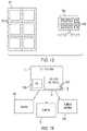
- FIG. 11is a schematic diagram of a system including a common interface in accordance with embodiments of the present invention.
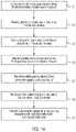
- FIG. 12is a flow diagram illustrating a method of operating a system with a common interface in accordance with embodiments of the present invention.
- FIG. 13is a schematic diagram of a system including a physical authentication interface in accordance with embodiments of the present invention.
- FIG. 14is a flow diagram illustrating a method of operating a system with a physical authentication interface in accordance with embodiments of the present invention.
- FIG. 15is a perspective view of a cable and a locking element of computing resources in accordance with embodiments of the present invention.
- FIG. 16is another perspective view of the cable and the locking element of FIG. 15 in accordance with embodiments of the present invention.
- One or more embodiments of the present inventionprovide systems and methods for controlling locks to thereby manage the plugging-in and unplugging of various types of cables and inserts into and from computing and other types of resources.
- One or more embodiments of the present inventionprovide systems and methods for management of the connections to each of the computers in modern cloud service providers and data centers or other similar securable components. This insures that the computers and the other similar securable components are operated properly and without failures.
- the system 101includes one or more computing or securable resources (hereinafter referred to as “computing resources”) 110 .
- the system 101could be provided as a cloud service, a shared data center, etc. in any case, each computing resource 110 can be provided as a safe 111 , a server 112 that is housed in a rack 113 or another similar feature.
- the safe 111can be controlled and monitored through software based mitigation systems. All requests to access the resources within the safe 111 would need to be registered and authenticated before the attempt would be approved or denied. If a user wished to unlock the safe 111 , they would need to pass proper identification, such as a finger print, PIN code, etc., to a controller which would then evaluate the information and open the lock should the user possess the correct authority.
- the computing resources 110can be, but are not required to be, arranged in rows and columns across one or more floors 114 . In each row or column, each of the computing resources 110 can be coupled to one or more cables 115 .
- the cables 115can include, but are not limited to, communication cables and power cables and can carry various signals, such as power signals, data signals, etc.
- each of the computing resources 110can include a set of drawers 201 where each drawer 201 can include a service processor (SP) 202 and one or more central processors (CPs) 203 that are communicative with the SP 202 .
- SPservice processor
- CPscentral processors
- Each SP 202 of each drawer 201can be interconnected with the SPs 202 of the other drawers 201 and each CP 203 of each drawer 201 can be communicative with memory units and can form a logical cluster alone or in combination with other CPs 203 .
- one or more of the drawers 201 of each computing resource 110can include one or more ports 301 , storage devices 302 and communications, memory or peripheral cards 303 .
- the ports 301can provide direct or indirect access to the storage devices 302 and the communications, memory and peripheral cards 303 .
- Each of the ports 301can be provided as a plug receiver 310 that a plug 320 of a cable 321 can be plugged into.
- the cable 321can be provided as one or more of a power cable, an Ethernet cable, a fiber optic cable, a telecommunications cable, etc., such that the cable 321 can effectively be plugged into the computing resource 110 .
- a computing resource 110 as described abovecan include a housing 116 that is formed to define an aperture 117 and the system 101 of FIG. 1 can further include, for each cable 321 and each computing resource 110 , a locking element 401 .
- each cable 321can include the plug 320 , a connector body 3201 and a receiving feature 3202 .
- the connector body 3201can extend outwardly and laterally from the plug 320 and the receiving feature 3202 can extend forwardly from the connector body 3201 .
- the receiving feature 3202can be formed as an elongate element with a notch 3203 (see FIG. 6 ) at a distal end thereof.
- the locking element 401includes a locking feature 410 and an actuator 420 .
- the locking feature 410is configured to assume a locked condition or an unlocked condition. In the locked condition, the locking feature 410 engages with the notch 3203 of the plug 320 of the cable 321 such that the cable 321 is locked to the computing resource 110 and cannot be unplugged. Alternatively, in the locked condition, the locking feature 410 blocks passage of the receiving feature 3202 through the aperture 117 such that the locking feature 410 effectively prevents the plug 320 of the cable 321 from being inserted into the plug receiver 310 of the computing resource 110 .
- the locking feature 410In the unlocked condition, the locking feature 410 disengages from the notch 3203 of the plug 320 of the cable 321 such that the cable 321 is unlocked from the computing resource 110 and can be unplugged. Alternatively, in the unlocked condition, the locking feature 410 permits passage of the receiving feature 3202 through the aperture 117 such that the locking feature 410 effectively permits the plug 320 of the cable 321 to be inserted into the plug receiver 310 of the computing resource 110 .
- the actuator 420is coupled to the locking feature 410 and is configured to control the locking feature 410 to assume the one of the locked and unlocked conditions.
- the actuator 420can be provided as a linear actuator or as a rotary actuator 4201 as shown in FIG. 6 .
- the rotary actuator 4201can include an output shaft 610 and a physical locking feature 620 .
- the physical locking feature 620is coupled to the output shaft 610 and includes one or more of a latch 621 that is configured for engagement with the receiving feature 3202 of the cable 321 (to either lock the cable 321 in place or to prevent insertion of the cable 321 ) and a pin configured for insertion into the receiving feature 3202 .
- the rotary actuator 4201is configured to rotate the output shaft 610 in first and second opposite directions whereby the latch 621 is rotationally moved into or out of locking and unlocking positions with respect to the notch 3203 .
- the locking feature 410 and the actuator 420can be disposed within an interior of the housing 116 . It is to be understood, however, that this is not required and that embodiments exist in which at least one of the locking feature 410 and the actuator 420 are disposed at an exterior of the housing 116 (see FIGS. 15 and 16 and accompanying text below). Where the actuator 420 is disposed within the interior of the housing 116 , the actuator 420 can be disposed on a printed circuit board (PCB) 421 . This PCB 421 can include various processing elements and can generate commands for operating the actuator 420 whereby the actuator 420 is receptive of commands from the PCB 421 .
- PCBprinted circuit board
- one or more of the SP 202 and one or more of the CPs 203 of each drawer 201 of each computing resource 110can be configured to cooperatively define or act as a controller 630 .
- the controller 630can be embodied as a generic hardware management console (HMC) 631 , a generic service element (SE) 632 or as another suitable form.
- the controller 630can be configured to define rules for users of the system 101 (see FIG. 1 ) where the rules are associated with respective IDs of each of the users and established criteria associated with each user for operating the locking elements 401 .
- the rulescan, for example, set forth times when one or more of the users of the system 101 are authorized to manipulate (i.e., unplug or plug in) one or more cables 321 relative to one or more computing resources 110 .
- the controller 630can cause locking features 410 of corresponding locking elements 401 to assume the unlocked conditions during those times. That is, the controller 630 effectively causes the locking feature 410 of each of the locking elements 401 to assume one of the locked and unlocked conditions in accordance with respective IDs of users and the criteria established for each user.
- the computing resource 110can be provided as a server in which various systems management operations are executed via the HMC 631 and the SE 632 .
- An example of such systems management operationsis configuration management. This relates to techniques, resources and tools used to initialize, configure, customize and maintain hardware, including the input/output (I/O) resources (network, storage, etc.).
- Both the HMC 631 and the SE 632can be configured with user management interfaces for a first set of users defined to the HMC 631 and a second set of user defined to the SE 632 .
- the first and second sets of usershave associated privilege levels that define what operations (or tasks) they are permitted to do with respect to the computing resource.
- a method of operating a locking assembly of a computing resourcesuch as a computing resource 110 as described herein, is provided.
- the methodincludes operations that can be executed as an OS level or higher of the computing resource 110 .
- the methodincludes determining whether an operator is authorized to manipulate a cable relative to the computing resource (block 701 ).
- the methodfurther includes commanding an actuator to cause a locking feature of a locking assembly to assume a locked condition to prevent the cable from being unplugged from or plugged into the computing resource in an event the determining indicates that the operator is unauthorized to unplug the cable from or to plug the cable into the computing resource (block 702 ).
- the methodincludes commanding the actuator to cause the locking feature of the locking assembly to assume the unlocked condition to permit the cable to be unplugged from or plugged into the computing resource in an event the determining indicates that the operator is authorized to unplug the cable from or to plug the cable into the computing resource (block 703 ).
- HMC users” and “SE users”can be defined to have rules associated to their user IDs that would lock or unlock a cable based on the “cable criteria” associated with each of them.
- an “HMC user,” admincaseycan be permitted to remove or insert cables for a certain card for a certain computing resource between certain hours of the day, Friday through Sunday.
- This “HMC user,” admincaseyis not permitted to remove or insert cables into other cards for the certain computing resource at any other time or day of the week.
- the “HMC user,” admincaseyis not permitted to remove or insert cables into any other physical port, in any other computing resource.
- a system 801can include one or more securable resources 810 , such as computing resources or a safes or some other similar elements, locking elements 820 similar to the locking element 401 described above and a controller 830 similar to the controller 630 described above.
- the controller 830is receptive of an instruction 831 to authorize users to unlock one or more of the one or more securable resources 810 .
- the controller 830is further configured to perform OS level authentication of the users and OS level control of the one or more locking elements 401 in accordance with the instruction 831 to authorize users and the OS level authentication.
- the instruction 831is received from an external communication and can be received via one or more of an access control system or service (ACSS) interface 832 and a change mode (CHMOD) interface 833 .
- the instruction 810can be one of time sensitive and condition dependent.
- the OS level authentication of the userscan be performed by the controller 830 performing one or more of fingerprint and pin code OS level authentication at fingerprint and pin code verification elements 8301 and 8302 .
- the OS level control of the one or more locking elements 82can be performed by the controller 830 whereby the controller 830 causes the one or more locking elements 820 to assume the respective unlocked conditions in accordance with a requesting user being authorized by the instruction 831 to authorize users and being authenticated by the OS level authentication by the controller 830 .
- An example of the system 801 of FIG. 8can be seen in a physical lock on a safe which is controlled and monitored through software based mitigation systems as noted above. All requests to access the resources within the safe would need to be registered and authenticated before the attempt would be approved or denied. If a user wished to unlock the safe, they would need to pass proper identification, such as a finger print, PIN code, etc., to the controlling OS which would then evaluate the information and open the lock should the user possess the correct authority.
- This notioncan be extrapolated to other physical resources as well including input/output (I/O) ports, storage devices and communication cards. An employee in a company may be granted temporary authority to add or remove devices.
- I/Oinput/output
- This authoritycan be time sensitive to limit access to only during the employee's shift or during emergencies such as a system outage or other critical situation.
- An administrator or other authorized userwould be required to authorize these users via standard interfaces in the controlling operating system such as ACSS or CHMOD. Having additional physical information protection will prevent and mitigate unauthorized access from malicious users and disgruntled employees trying to cause physical harm to a set of resources or attempting to steal information.
- a method of operating a systemsuch as the system 801 of FIG. 8 , is provided.
- the methodincludes controlling locking elements to assume locked conditions whereby corresponding securable resources are locked by the locking elements (block 901 ), receiving an instruction to authorize users to unlock one or more of the securable resources (block 902 ) and receiving a request from a user to unlock and thereby gain access to one or more of the securable resources (block 903 ).
- the methodfurther includes determining whether the user is authorized to unlock and thereby gain access to the one or more of the securable resources associated with the request (block 904 ), performing operating system (OS) level authentication of the user (block 905 ) and performing OS level control of the corresponding locking elements in accordance with the user being determined to be authorized and authenticated (block 906 ).
- OSoperating system
- the system 801 of FIG. 8can be expanded to include one or more resources, such as safes 1001 and computing resources 1002 , where each of the one or more resources includes multiple independently securable resources, such as separate interiors 1003 of the safe 1001 and one or more of power and data communication cables which are insertable into ports, storage devices or communications cards 1004 of the computing resource 1002 .
- the instruction 831 (see FIG. 8 ) for the safe 1001can relate to the locks of one or more but not necessarily all of the separate interiors 1003 and the instruction 831 (see FIG. 8 ) for the computing resource 1002 can similarly relate to one or more but not necessarily all of the various components of the computing resource 1002 .
- the system 801 of FIG. 8operates substantially similarly as described above.
- a physical access port on a securable resourcecan be guarded by physical locks and risk mitigation systems that can only be removed through the authorization of a software based system such as ACSS or CHMOD.
- a use casemay be that a communication cable needs to be replaced between a server and communications router.
- a system administratormay authorize a specific user to remove a specific cable by unlocking only the required port on the server. This will prevent accidental or malicious disconnects from healthy communications on the server as physical locks or pins will restrict access to other resources and devices interfacing with the desired server. The result is an increase in reliability and security for devices operating within a test floor or data center where configurations are constantly changing and maintenance is always ongoing.
- cloud providersare relying more and more on data centers that include a variety of tools and machines.
- Each unique tool or deviceusually requires a skilled technician or employee to manage and configure it for optimal use so customers receive reliable and secure services.
- a multitude of security measuresare often implemented to prevent unauthorized access to sensitive resources.
- Each resourceoften has unique protections in place that users must authenticate against in order to manage the system. This generally leads to redundant authentication steps and lost time as an authorized employee must start the process over from scratch as they jump between systems to perform required maintenance.
- a common interface 1101can be provided for use with the controller 630 or the controller 830 described above as well as additional controllers 1102 , which are separate and independent from the controller 630 or 830 and one another.
- the controller 630 or 830 and the additional controllers 1102are tied to the common interface 1101 and the common interface 1101 is configured to authenticate the users.
- the common interface 1101can be embodied in a hypervisor or a multiplexer and can include one or more of a graphical user interface (GUI) 1110 and a physical authentication interface 1120 that, in turn, can include one or more of an RFID badge authentication interface 1121 and a fingerprint identification device 1122 .
- GUIgraphical user interface
- the controller 630 or 830is configured to perform OS level control of locking elements in accordance with at least an authentication of the users by the common interface 1101 .
- a method of operating a systemsuch as system 101 of FIG. 1 or system 801 of FIG. 8 is provided.
- the methodincludes controlling locking elements to assume locked conditions whereby corresponding securable resources are locked by the locking elements (block 1201 ), receiving an instruction to authorize users to unlock one or more of the securable resources (block 1202 ), receiving a request from a user to unlock and thereby gain access to one or more of the securable resources (block 1203 ) and determining whether the user is authorized to unlock and thereby gain access to the one or more of the securable resources associated with the request (block 1204 ).
- the methodincludes receiving an indication of authentication of the user from a common interface (block 1205 ) and performing OS level control of the corresponding locking elements in accordance with the user being determined to be authorized and the indication of the authentication of the user being received (block 1206 ).
- the OS level authentication provided by to the common interface 1101allows an authorized user to authenticate once to gain access to all necessary resources. This will, for example, allow a system administrator to perform maintenance on cables or communication devices that interface across multiple systems within the data center. If an unauthorized or disgruntled employee attempts to access resources, physical locks and security devices will prevent them from removing or altering cables and connections across these sensitive resources. Only authorized users will be allowed to rewire and maintain devices within the data center at the discretion of a system administrator.
- a physical authentication interface 1301can be provided for use with the controller 630 or the controller 830 described above. In these or other cases, the physical authentication interface 1301 can be configured to enable or disable a capability of the controller 630 or 830 to perform the OS level authentication. In accordance with embodiments of the present invention, the physical authentication interface 1301 can include one or more of an RFID badge authentication interface 1310 and biometrics, such as a fingerprint identification device 1320 .
- a method of operating a systemsuch as system 101 of FIG. 1 or system 801 of FIG. 8 is provided.
- theincludes controlling locking elements to assume locked conditions whereby corresponding securable resources are locked by the locking elements (block 1401 ), receiving an instruction to authorize users to unlock one or more of the securable resources (block 1402 ), receiving a request from a user to unlock and thereby gain access to one or more of the securable resources (block 1403 ) and determining whether the user is authorized to unlock and thereby gain access to the one or more of the securable resources associated with the request (block 1404 ).
- the methodincludes determining whether OS level authentication capability is enabled or disabled by, for example, receiving an indication thereof from a physical authentication interface (block 1405 ), performing the OS level authentication of the user in an event the OS level authentication capability is enabled (block 1406 ) and performing OS level control of the corresponding locking elements in accordance with the user being determined to be authorized and authenticated (block 1407 ).
- each cable 321can include the plug 320 , the connector body 3201 and the receiving feature 3202 .
- the connector body 3201can extend outwardly and laterally from the plug 320 and the receiving feature 3202 can be formed as a pocket 3204 .
- the receiving feature 3202is disposed adjacent to an exterior facing surface of the housing 116 .
- the locking feature 410is configured to assume a locked condition or an unlocked condition.
- the locking feature 410engages with the pocket 3204 such that the cable 321 is locked to the computing resource 110 and cannot be unplugged (see FIG. 15 ).
- the locking feature 410blocks passage of the receiving feature 3202 such that the locking feature 410 effectively prevents the plug 320 from being inserted into the plug receiver 310 .
- the locking feature 410disengages from the pocket 3204 such that the cable 321 is unlocked from the computing resource 110 and can be unplugged (see FIG. 16 ).
- the locking feature 410permits passage of the receiving feature 3202 such that the locking feature 410 effectively permits the plug 320 to be inserted into the plug receiver 310 .
- the actuator 420is coupled to the locking feature 410 and is configured to control the locking feature 410 to assume the one of the locked and unlocked conditions.
- the actuator 420can be provided as a linear actuator or as a rotary actuator 4201 as shown in FIGS. 15 and 16 .
- the rotary actuator 4201can include an output shaft 610 that extends to an exterior of the housing 116 and a physical locking feature 620 .
- the physical locking feature 610is coupled to the output shaft 610 at the exterior of the housing 116 and is configured for engagement with the receiving feature 3202 of the cable 321 (to either lock the cable 321 in place or to prevent insertion of the cable 321 ).
- the rotary actuator 4201is configured to rotate the output shaft 610 in first and second opposite directions to be rotationally moved into or out of locking and unlocking positions with respect to the pocket 3204 .
- One or more of the methods described hereincan be implemented with any or a combination of the following technologies, which are each well known in the art: a discrete logic circuit(s) having logic gates for implementing logic functions upon data signals, an application specific integrated circuit (ASIC) having appropriate combinational logic gates, a programmable gate array(s) (PGA), a field programmable gate array (FPGA), etc.
- ASICapplication specific integrated circuit
- PGAprogrammable gate array
- FPGAfield programmable gate array
- various functions or actscan take place at a given location and/or in connection with the operation of one or more apparatuses or systems.
- a portion of a given function or actcan be performed at a first device or location, and the remainder of the function or act can be performed at one or more additional devices or locations.
- compositionscomprising, “comprising,” “includes,” “including,” “has,” “having,” “contains” or “containing,” or any other variation thereof, are intended to cover a non-exclusive inclusion.
- a composition, a mixture, process, method, article, or apparatus that comprises a list of elementsis not necessarily limited to only those elements but can include other elements not expressly listed or inherent to such composition, mixture, process, method, article, or apparatus.
- connectioncan include both an indirect “connection” and a direct “connection.”
- the present inventionmay be a system, a method, and/or a computer program product at any possible technical detail level of integration
- the computer program productmay include a computer readable storage medium (or media) having computer readable program instructions thereon for causing a processor to carry out aspects of the present invention
- the computer readable storage mediumcan be a tangible device that can retain and store instructions for use by an instruction execution device.
- the computer readable storage mediummay be, for example, but is not limited to, an electronic storage device, a magnetic storage device, an optical storage device, an electromagnetic storage device, a semiconductor storage device, or any suitable combination of the foregoing.
- a non-exhaustive list of more specific examples of the computer readable storage mediumincludes the following: a portable computer diskette, a hard disk, a random access memory (RAM), a read-only memory (ROM), an erasable programmable read-only memory (EPROM or Flash memory), a static random access memory (SRAM), a portable compact disc read-only memory (CD-ROM), a digital versatile disk (DVD), a memory stick, a floppy disk, a mechanically encoded device such as punch-cards or raised structures in a groove having instructions recorded thereon, and any suitable combination of the foregoing.
- RAMrandom access memory
- ROMread-only memory
- EPROM or Flash memoryerasable programmable read-only memory
- SRAMstatic random access memory
- CD-ROMcompact disc read-only memory
- DVDdigital versatile disk
- memory sticka floppy disk
- a mechanically encoded devicesuch as punch-cards or raised structures in a groove having instructions recorded thereon
- a computer readable storage mediumis not to be construed as being transitory signals per se, such as radio waves or other freely propagating electromagnetic waves, electromagnetic waves propagating through a waveguide or other transmission media (e.g., light pulses passing through a fiber-optic cable), or electrical signals transmitted through a wire.
- Computer readable program instructions described hereincan be downloaded to respective computing/processing devices from a computer readable storage medium or to an external computer or external storage device via a network, for example, the Internet, a local area network, a wide area network and/or a wireless network.
- the networkmay comprise copper transmission cables, optical transmission fibers, wireless transmission, routers, firewalls, switches, gateway computers and/or edge servers.
- a network adapter card or network interface in each computing/processing devicereceives computer readable program instructions from the network and forwards the computer readable program instructions for storage in a computer readable storage medium within the respective computing/processing device.
- Computer readable program instructions for carrying out operations of the present inventionmay be assembler instructions, instruction-set-architecture (ISA) instructions, machine instructions, machine dependent instructions, microcode, firmware instructions, state-setting data, configuration data for integrated circuitry, or either source code or object code written in any combination of one or more programming languages, including an object oriented programming language such as Smalltalk, C++, or the like, and procedural programming languages, such as the “C” programming language or similar programming languages.
- the computer readable program instructionsmay execute entirely on the user's computer, partly on the user's computer, as a stand-alone software package, partly on the user's computer and partly on a remote computer or entirely on the remote computer or server.
- the remote computermay be connected to the user's computer through any type of network, including a local area network (LAN) or a wide area network (WAN), or the connection may be made to an external computer (for example, through the Internet using an Internet Service Provider).
- electronic circuitryincluding, for example, programmable logic circuitry, field-programmable gate arrays (FPGA), or programmable logic arrays (PLA) may execute the computer readable program instruction by utilizing state information of the computer readable program instructions to personalize the electronic circuitry, in order to perform aspects of the present invention.
- These computer readable program instructionsmay be provided to a processor of a general purpose computer, special purpose computer, or other programmable data processing apparatus to produce a machine, such that the instructions, which execute via the processor of the computer or other programmable data processing apparatus, create means for implementing the functions/acts specified in the flowchart and/or block diagram block or blocks.
- These computer readable program instructionsmay also be stored in a computer readable storage medium that can direct a computer, a programmable data processing apparatus, and/or other devices to function in a particular manner, such that the computer readable storage medium having instructions stored therein comprises an article of manufacture including instructions which implement aspects of the function/act specified in the flowchart and/or block diagram block or blocks.
- the computer readable program instructionsmay also be loaded onto a computer, other programmable data processing apparatus, or other device to cause a series of operational steps to be performed on the computer, other programmable apparatus or other device to produce a computer implemented process, such that the instructions which execute on the computer, other programmable apparatus, or other device implement the functions/acts specified in the flowchart and/or block diagram block or blocks.
- each block in the flowchart or block diagramsmay represent a module, segment, or portion of instructions, which comprises one or more executable instructions for implementing the specified logical function(s).
- the functions noted in the blocksmay occur out of the order noted in the Figures.
- two blocks shown in successionmay, in fact, be executed substantially concurrently, or the blocks may sometimes be executed in the reverse order, depending upon the functionality involved.
Landscapes
- Engineering & Computer Science (AREA)
- Theoretical Computer Science (AREA)
- Computer Security & Cryptography (AREA)
- Computer Hardware Design (AREA)
- General Engineering & Computer Science (AREA)
- Software Systems (AREA)
- Physics & Mathematics (AREA)
- General Physics & Mathematics (AREA)
- Microelectronics & Electronic Packaging (AREA)
- Computer Networks & Wireless Communication (AREA)
- Lock And Its Accessories (AREA)
- Storage Device Security (AREA)
Abstract
Description
Claims (15)
Priority Applications (1)
| Application Number | Priority Date | Filing Date | Title |
|---|---|---|---|
| US16/524,751US11341279B2 (en) | 2019-07-29 | 2019-07-29 | Management of securable computing resources |
Applications Claiming Priority (1)
| Application Number | Priority Date | Filing Date | Title |
|---|---|---|---|
| US16/524,751US11341279B2 (en) | 2019-07-29 | 2019-07-29 | Management of securable computing resources |
Publications (2)
| Publication Number | Publication Date |
|---|---|
| US20210034786A1 US20210034786A1 (en) | 2021-02-04 |
| US11341279B2true US11341279B2 (en) | 2022-05-24 |
Family
ID=74259298
Family Applications (1)
| Application Number | Title | Priority Date | Filing Date |
|---|---|---|---|
| US16/524,751Active2040-03-09US11341279B2 (en) | 2019-07-29 | 2019-07-29 | Management of securable computing resources |
Country Status (1)
| Country | Link |
|---|---|
| US (1) | US11341279B2 (en) |
Citations (91)
| Publication number | Priority date | Publication date | Assignee | Title |
|---|---|---|---|---|
| US5021003A (en) | 1989-07-18 | 1991-06-04 | Yazaki Corporation | Apparatus for confirming fitting of electric connector |
| US5711558A (en) | 1996-08-26 | 1998-01-27 | Delco Electronics Corporation | Charger locking mechanism |
| US5865640A (en) | 1996-05-31 | 1999-02-02 | Ricoh Company, Ltd. | Apparatus having a locking mechanism that locks a connector of a peripheral device thereto |
| US6141778A (en) | 1998-06-29 | 2000-10-31 | Mci Communications Corporation | Method and apparatus for automating security functions in a computer system |
| US6175491B1 (en) | 1997-03-10 | 2001-01-16 | Samsung Electronics Co. Ltd. | Locking device and method for peripheral devices |
| US6233576B1 (en) | 1995-06-09 | 2001-05-15 | International Business Machines Corporation | Enhanced security for computer system resources with a resource access authorization control facility that creates files and provides increased granularity of resource permission |
| EP1126361A1 (en) | 2000-02-14 | 2001-08-22 | Hewlett-Packard Company, A Delaware Corporation | Electronic appliance having secured cable shroud |
| US6297963B1 (en) | 1999-09-13 | 2001-10-02 | Hewlett-Packard Company | Security docking cable for computer docking system |
| US20010032118A1 (en) | 1999-12-06 | 2001-10-18 | Carter Odie Kenneth | System, method, and computer program for managing storage and distribution of money tills |
| US6352447B1 (en) | 2000-03-24 | 2002-03-05 | Techsonic Industries, Inc. | Cable bundle connector |
| US20020098731A1 (en) | 2001-01-22 | 2002-07-25 | Helix Technology Corporation | Module and connector latch |
| WO2003005496A2 (en) | 2001-07-07 | 2003-01-16 | Robert Bosch Gmbh | Cable form connector with a bearing element for receiving a locking claw |
| US6522532B2 (en) | 2001-01-08 | 2003-02-18 | Dell Products L.P. | Cable docking system and method for a computer |
| US20030220002A1 (en) | 2002-05-24 | 2003-11-27 | Yun-Lung Chen | Connector protecting device |
| US6726294B1 (en) | 1999-03-05 | 2004-04-27 | Lista Europe Holding Ag | Cabinet locking system |
| US6768643B1 (en) | 2000-09-26 | 2004-07-27 | Hewlett-Packard Development Company, L.P. | Methods and apparatus for reducing the opportunity for accidental removal or insertion of components |
| US6783391B2 (en) | 2001-11-10 | 2004-08-31 | Agilent Technologies, Inc. | Carrier for several cable holders |
| US6832929B2 (en) | 2002-11-15 | 2004-12-21 | Western Digital Technologies, Inc. | Robust serial advanced technology attachment (SATA) PCB connector |
| US6885281B2 (en) | 2001-10-18 | 2005-04-26 | Corporate Safe Specialists, Inc. | Method and apparatus for controlling a safe having an electronic lock |
| US20060107073A1 (en) | 2004-11-12 | 2006-05-18 | International Business Machines Corporation | System and method for equipment security cable lock interface |
| US7062660B2 (en) | 2001-08-06 | 2006-06-13 | International Business Machines Corporation | Method and apparatus for controlling the performance of a file system mount operation by a user lacking superuser authority |
| US7163412B2 (en) | 2005-04-29 | 2007-01-16 | Hon Hai Precision Ind. Co., Ltd. | Cable connector assembly with an anti-disengagement device |
| EP1791225A2 (en) | 2005-11-23 | 2007-05-30 | Tektronix, Inc. | Security block for a communications connector |
| US7300300B2 (en) | 2003-11-07 | 2007-11-27 | Fci | Connector system with improved unplugging functionality |
| US20080065874A1 (en) | 2006-09-07 | 2008-03-13 | Andrew Geissler | System and method for dynamic determination of system topology in a multiple building block server system |
| US7479026B2 (en) | 2006-10-23 | 2009-01-20 | Honda Tsushin Kogyo Co., Ltd. | Cable-equipped connector |
| US7578691B2 (en) | 2006-04-29 | 2009-08-25 | Lenovo (Singapore) Pte. Ltd. | USB connector locking arrangements |
| US20090286414A1 (en) | 2008-05-19 | 2009-11-19 | Fuji Jukogyo Kabushiki Kaisha | Electric vehicle control device |
| US7757079B2 (en) | 2001-07-16 | 2010-07-13 | Research In Motion Limited | System and method for supporting multiple certificate authorities on a mobile communication device |
| US20100227493A1 (en) | 2009-03-06 | 2010-09-09 | Cisco Technology, Inc. | Interface connection management using a removable adapter for communications equipment |
| US7971156B2 (en) | 2007-01-12 | 2011-06-28 | International Business Machines Corporation | Controlling resource access based on user gesturing in a 3D captured image stream of the user |
| US20110294328A1 (en) | 2010-05-27 | 2011-12-01 | Kabushiki Kaisha Tokai Rika Denki Seisakusho | Plug locking device |
| US8087071B2 (en) | 2008-12-05 | 2011-12-27 | International Business Machines Corporation | Authentication method and system |
| US8092241B2 (en) | 2009-06-16 | 2012-01-10 | Nai-Chien Chang | Electronic type removal preventing connector |
| US20120017271A1 (en) | 2010-07-14 | 2012-01-19 | Smith Ned M | Domain-authenticated control of platform resources |
| US20120133510A1 (en) | 2010-11-30 | 2012-05-31 | Panduit Corp. | Physical infrastructure management system having an integrated cabinet |
| US8201266B2 (en) | 2008-05-21 | 2012-06-12 | International Business Machines Corporation | Security system to prevent tampering with a server blade |
| US8262402B2 (en) | 2009-04-08 | 2012-09-11 | Rwe Ag | Charging cable locking device and method for locking a cable |
| US8365182B2 (en) | 2006-10-02 | 2013-01-29 | International Business Machines Corporation | Method and system for provisioning of resources |
| US20140016902A1 (en) | 2012-07-11 | 2014-01-16 | Adc Telecommunications, Inc. | Connectors and adapters with auto-latching features |
| US8650805B1 (en) | 2010-05-17 | 2014-02-18 | Equinix, Inc. | Systems and methods for DMARC in a cage mesh design |
| WO2014089064A1 (en) | 2012-12-04 | 2014-06-12 | Amphenol Corporation | Cable connector system |
| US20140173685A1 (en)* | 2012-12-17 | 2014-06-19 | International Business Machines Corporation | Controlling modification of electronic device cabling |
| US20140168883A1 (en) | 2012-12-18 | 2014-06-19 | Nvidia Corporation | Externally latching i/o housing |
| US20140167574A1 (en) | 2011-11-08 | 2014-06-19 | S&S X-Ray Products, Inc. | Secure File Cabinet |
| US8814445B2 (en) | 2011-08-23 | 2014-08-26 | Panduit Corp. | Apparatus and method for ganged multiple optical fiber connector |
| US20140292276A1 (en) | 2011-10-25 | 2014-10-02 | Sumitomo Wiring Systems, Ltd. | Vehicle charging device |
| US8856543B2 (en) | 2010-12-29 | 2014-10-07 | Microsoft Corporation | User identification with biokinematic input |
| US20140349503A1 (en) | 2013-05-22 | 2014-11-27 | Hong Fu Jin Precision Industry (Shenzhen) Co., Ltd | Assisting apparatus for unplugging rj-45 connector |
| US20150126082A1 (en) | 2012-07-20 | 2015-05-07 | Mitsubishi Electric Corporation | Connector cover and connector connecting apparatus |
| US20150278556A1 (en)* | 2014-03-28 | 2015-10-01 | Noam Avni | Centralized security for a computing device |
| US20150357758A1 (en) | 2014-06-05 | 2015-12-10 | Chatsworth Products, Inc. | Electrical receptacle with locking feature |
| US9230380B2 (en)* | 2010-02-12 | 2016-01-05 | Digitus Biometrics, Inc. | Lockable enclosure having improved access system |
| US9256715B2 (en) | 2012-03-09 | 2016-02-09 | Dell Products L.P. | Authentication using physical interaction characteristics |
| US9285831B2 (en) | 2009-09-17 | 2016-03-15 | Henge Docks Llc | Docking station for portable electronics |
| US9337580B2 (en) | 2012-11-15 | 2016-05-10 | Temtec Fahrzeugtechnik Entwicklungsgesellschaft Mbh | Locking device for locking electrical plugs |
| CN205230061U (en) | 2015-12-22 | 2016-05-11 | 北京旷视科技有限公司 | Rack server |
| US20160196454A1 (en) | 2015-01-02 | 2016-07-07 | Hi Sec Labs LTD. | Usb security device, apparatus, method and system |
| US9436830B2 (en) | 2012-10-17 | 2016-09-06 | Sandisk Technologies Llc | Securing access of removable media devices |
| WO2016145168A1 (en) | 2015-03-10 | 2016-09-15 | Abb Technology Ag | System and method for administering physical security access to components of a process control system |
| US9460319B1 (en) | 2016-05-20 | 2016-10-04 | Foxrun Development Co., LLC | Device for securing a computer port |
| US20160299172A1 (en) | 2015-04-12 | 2016-10-13 | Keysight Technologies, Inc. | Coaxial connector locking bracket |
| US20160343185A1 (en) | 2015-05-18 | 2016-11-24 | Unikey Technologies Inc. | Wireless access control system for a door including first and second sensor based lock switching and related methods |
| US20170018878A1 (en) | 2015-05-20 | 2017-01-19 | David Coccimiglio | Locking device for one or more data ports |
| US9574375B2 (en) | 2014-11-07 | 2017-02-21 | Kevin Henderson | Electronic lock |
| US9589399B2 (en) | 2012-07-02 | 2017-03-07 | Synaptics Incorporated | Credential quality assessment engine systems and methods |
| US9627811B2 (en) | 2014-04-10 | 2017-04-18 | Cisco Technology, Inc. | Locking mechanism for cables and connectors in hazardous locations |
| US9628473B1 (en)* | 2012-04-06 | 2017-04-18 | Wayne Odom | System, method, and device for delivering communications and storing and delivering data |
| US9640898B1 (en) | 2015-02-11 | 2017-05-02 | NetSuite Inc. | System and method for efficient coupling of cabling in a multi-cable rack-mounted environment |
| US20170171164A1 (en) | 2015-12-14 | 2017-06-15 | International Business Machines Corporation | Authenticating features of virtual server system |
| US9683393B2 (en) | 2014-10-31 | 2017-06-20 | ACCO Brands Corporation | System for physically securing an electronic device |
| US9722358B1 (en) | 2016-04-21 | 2017-08-01 | Tower Manufacturing Corp | Power cord retainer |
| US9731611B2 (en) | 2013-07-23 | 2017-08-15 | Toyota Jidosha Kabushiki Kaisha | Vehicle |
| US9785250B1 (en)* | 2017-05-15 | 2017-10-10 | Newtonoid Technologies, L.L.C. | Intelligent gesture based security system and method |
| EP3236396A1 (en) | 2016-04-20 | 2017-10-25 | UAB "Eldes" | A method for calling a physical security service and paying for this service and hardware system for implementing such method |
| US20170310039A1 (en) | 2014-10-17 | 2017-10-26 | Ingenico Group | Device for securing electrical charging cables together |
| US9977888B2 (en) | 2015-12-22 | 2018-05-22 | Intel Corporation | Privacy protected input-output port control |
| CN207867508U (en) | 2018-03-06 | 2018-09-14 | 中国信息安全认证中心 | Sata port protective device |
| US10083326B2 (en) | 2014-02-06 | 2018-09-25 | Fujitsu Technology Solutions Intellectual Property Gmbh | Method of accessing a physically secured rack and computer network infrastructure |
| US10091195B2 (en) | 2016-12-31 | 2018-10-02 | Nok Nok Labs, Inc. | System and method for bootstrapping a user binding |
| US20180285285A1 (en) | 2017-03-29 | 2018-10-04 | International Business Machines Corporation | Cable lock with confidential data protection |
| US20180321661A1 (en)* | 2015-03-27 | 2018-11-08 | Rockwell Automation Technologies, Inc. | Systems and methods for virtually tagging and securing industrial equipment |
| US10132104B2 (en) | 2014-02-25 | 2018-11-20 | Schlage Lock Company Llc | Electronic lock with selectable power off function |
| US10162981B1 (en) | 2011-06-27 | 2018-12-25 | Amazon Technologies, Inc. | Content protection on an electronic device |
| US10181174B2 (en) | 2012-12-03 | 2019-01-15 | Samsung Electronics Co., Ltd. | Electronic apparatus, external apparatus and method of controlling the same |
| US20190027887A1 (en) | 2017-07-20 | 2019-01-24 | Panasonic Intellectual Property Management Co., Ltd. | Electronic device assembling apparatus and electronic device assembling method |
| US20190058289A1 (en) | 2016-02-26 | 2019-02-21 | Hirose Electric Co., Ltd. | Connector having shell and connector device |
| US10218689B2 (en) | 2015-12-14 | 2019-02-26 | International Business Machines Corporation | Extending shrouding capability of hosting system |
| US20190069436A1 (en) | 2017-08-23 | 2019-02-28 | Hewlett Packard Enterprise Development Lp | Locking mechanism of a module of a data center |
| US20190074635A1 (en) | 2017-04-25 | 2019-03-07 | 3-CI Partnership | Lockout device for preventing disconnection of cable connector |
| US20190163936A1 (en) | 2017-11-30 | 2019-05-30 | International Business Machines Corporation | Software controlled port locking mechanisms |
- 2019
- 2019-07-29USUS16/524,751patent/US11341279B2/enactiveActive
Patent Citations (93)
| Publication number | Priority date | Publication date | Assignee | Title |
|---|---|---|---|---|
| US5021003A (en) | 1989-07-18 | 1991-06-04 | Yazaki Corporation | Apparatus for confirming fitting of electric connector |
| US6233576B1 (en) | 1995-06-09 | 2001-05-15 | International Business Machines Corporation | Enhanced security for computer system resources with a resource access authorization control facility that creates files and provides increased granularity of resource permission |
| US5865640A (en) | 1996-05-31 | 1999-02-02 | Ricoh Company, Ltd. | Apparatus having a locking mechanism that locks a connector of a peripheral device thereto |
| US5711558A (en) | 1996-08-26 | 1998-01-27 | Delco Electronics Corporation | Charger locking mechanism |
| US6175491B1 (en) | 1997-03-10 | 2001-01-16 | Samsung Electronics Co. Ltd. | Locking device and method for peripheral devices |
| US6141778A (en) | 1998-06-29 | 2000-10-31 | Mci Communications Corporation | Method and apparatus for automating security functions in a computer system |
| US6726294B1 (en) | 1999-03-05 | 2004-04-27 | Lista Europe Holding Ag | Cabinet locking system |
| US6297963B1 (en) | 1999-09-13 | 2001-10-02 | Hewlett-Packard Company | Security docking cable for computer docking system |
| US20010032118A1 (en) | 1999-12-06 | 2001-10-18 | Carter Odie Kenneth | System, method, and computer program for managing storage and distribution of money tills |
| EP1126361A1 (en) | 2000-02-14 | 2001-08-22 | Hewlett-Packard Company, A Delaware Corporation | Electronic appliance having secured cable shroud |
| US6352447B1 (en) | 2000-03-24 | 2002-03-05 | Techsonic Industries, Inc. | Cable bundle connector |
| US6768643B1 (en) | 2000-09-26 | 2004-07-27 | Hewlett-Packard Development Company, L.P. | Methods and apparatus for reducing the opportunity for accidental removal or insertion of components |
| US6522532B2 (en) | 2001-01-08 | 2003-02-18 | Dell Products L.P. | Cable docking system and method for a computer |
| US20020098731A1 (en) | 2001-01-22 | 2002-07-25 | Helix Technology Corporation | Module and connector latch |
| WO2003005496A2 (en) | 2001-07-07 | 2003-01-16 | Robert Bosch Gmbh | Cable form connector with a bearing element for receiving a locking claw |
| US7757079B2 (en) | 2001-07-16 | 2010-07-13 | Research In Motion Limited | System and method for supporting multiple certificate authorities on a mobile communication device |
| US7062660B2 (en) | 2001-08-06 | 2006-06-13 | International Business Machines Corporation | Method and apparatus for controlling the performance of a file system mount operation by a user lacking superuser authority |
| US6885281B2 (en) | 2001-10-18 | 2005-04-26 | Corporate Safe Specialists, Inc. | Method and apparatus for controlling a safe having an electronic lock |
| US6783391B2 (en) | 2001-11-10 | 2004-08-31 | Agilent Technologies, Inc. | Carrier for several cable holders |
| US20030220002A1 (en) | 2002-05-24 | 2003-11-27 | Yun-Lung Chen | Connector protecting device |
| US6832929B2 (en) | 2002-11-15 | 2004-12-21 | Western Digital Technologies, Inc. | Robust serial advanced technology attachment (SATA) PCB connector |
| US7300300B2 (en) | 2003-11-07 | 2007-11-27 | Fci | Connector system with improved unplugging functionality |
| US20060107073A1 (en) | 2004-11-12 | 2006-05-18 | International Business Machines Corporation | System and method for equipment security cable lock interface |
| US7163412B2 (en) | 2005-04-29 | 2007-01-16 | Hon Hai Precision Ind. Co., Ltd. | Cable connector assembly with an anti-disengagement device |
| EP1791225A2 (en) | 2005-11-23 | 2007-05-30 | Tektronix, Inc. | Security block for a communications connector |
| US7578691B2 (en) | 2006-04-29 | 2009-08-25 | Lenovo (Singapore) Pte. Ltd. | USB connector locking arrangements |
| US20080065874A1 (en) | 2006-09-07 | 2008-03-13 | Andrew Geissler | System and method for dynamic determination of system topology in a multiple building block server system |
| US8365182B2 (en) | 2006-10-02 | 2013-01-29 | International Business Machines Corporation | Method and system for provisioning of resources |
| US7479026B2 (en) | 2006-10-23 | 2009-01-20 | Honda Tsushin Kogyo Co., Ltd. | Cable-equipped connector |
| US7971156B2 (en) | 2007-01-12 | 2011-06-28 | International Business Machines Corporation | Controlling resource access based on user gesturing in a 3D captured image stream of the user |
| US20090286414A1 (en) | 2008-05-19 | 2009-11-19 | Fuji Jukogyo Kabushiki Kaisha | Electric vehicle control device |
| US8201266B2 (en) | 2008-05-21 | 2012-06-12 | International Business Machines Corporation | Security system to prevent tampering with a server blade |
| US8087071B2 (en) | 2008-12-05 | 2011-12-27 | International Business Machines Corporation | Authentication method and system |
| US20100227493A1 (en) | 2009-03-06 | 2010-09-09 | Cisco Technology, Inc. | Interface connection management using a removable adapter for communications equipment |
| US8262402B2 (en) | 2009-04-08 | 2012-09-11 | Rwe Ag | Charging cable locking device and method for locking a cable |
| US8092241B2 (en) | 2009-06-16 | 2012-01-10 | Nai-Chien Chang | Electronic type removal preventing connector |
| US9285831B2 (en) | 2009-09-17 | 2016-03-15 | Henge Docks Llc | Docking station for portable electronics |
| US9230380B2 (en)* | 2010-02-12 | 2016-01-05 | Digitus Biometrics, Inc. | Lockable enclosure having improved access system |
| US8650805B1 (en) | 2010-05-17 | 2014-02-18 | Equinix, Inc. | Systems and methods for DMARC in a cage mesh design |
| US20110294328A1 (en) | 2010-05-27 | 2011-12-01 | Kabushiki Kaisha Tokai Rika Denki Seisakusho | Plug locking device |
| US20120017271A1 (en) | 2010-07-14 | 2012-01-19 | Smith Ned M | Domain-authenticated control of platform resources |
| US20120133510A1 (en) | 2010-11-30 | 2012-05-31 | Panduit Corp. | Physical infrastructure management system having an integrated cabinet |
| US8856543B2 (en) | 2010-12-29 | 2014-10-07 | Microsoft Corporation | User identification with biokinematic input |
| US10162981B1 (en) | 2011-06-27 | 2018-12-25 | Amazon Technologies, Inc. | Content protection on an electronic device |
| US8814445B2 (en) | 2011-08-23 | 2014-08-26 | Panduit Corp. | Apparatus and method for ganged multiple optical fiber connector |
| US20140292276A1 (en) | 2011-10-25 | 2014-10-02 | Sumitomo Wiring Systems, Ltd. | Vehicle charging device |
| US20140167574A1 (en) | 2011-11-08 | 2014-06-19 | S&S X-Ray Products, Inc. | Secure File Cabinet |
| US9256715B2 (en) | 2012-03-09 | 2016-02-09 | Dell Products L.P. | Authentication using physical interaction characteristics |
| US9628473B1 (en)* | 2012-04-06 | 2017-04-18 | Wayne Odom | System, method, and device for delivering communications and storing and delivering data |
| US9589399B2 (en) | 2012-07-02 | 2017-03-07 | Synaptics Incorporated | Credential quality assessment engine systems and methods |
| US20140016902A1 (en) | 2012-07-11 | 2014-01-16 | Adc Telecommunications, Inc. | Connectors and adapters with auto-latching features |
| US9885841B2 (en) | 2012-07-11 | 2018-02-06 | Commscope Technologies Llc | Connectors and adapters with auto-latching features |
| US20150126082A1 (en) | 2012-07-20 | 2015-05-07 | Mitsubishi Electric Corporation | Connector cover and connector connecting apparatus |
| US9436830B2 (en) | 2012-10-17 | 2016-09-06 | Sandisk Technologies Llc | Securing access of removable media devices |
| US9337580B2 (en) | 2012-11-15 | 2016-05-10 | Temtec Fahrzeugtechnik Entwicklungsgesellschaft Mbh | Locking device for locking electrical plugs |
| US10181174B2 (en) | 2012-12-03 | 2019-01-15 | Samsung Electronics Co., Ltd. | Electronic apparatus, external apparatus and method of controlling the same |
| WO2014089064A1 (en) | 2012-12-04 | 2014-06-12 | Amphenol Corporation | Cable connector system |
| US20140173685A1 (en)* | 2012-12-17 | 2014-06-19 | International Business Machines Corporation | Controlling modification of electronic device cabling |
| US20140168883A1 (en) | 2012-12-18 | 2014-06-19 | Nvidia Corporation | Externally latching i/o housing |
| US20140349503A1 (en) | 2013-05-22 | 2014-11-27 | Hong Fu Jin Precision Industry (Shenzhen) Co., Ltd | Assisting apparatus for unplugging rj-45 connector |
| US9731611B2 (en) | 2013-07-23 | 2017-08-15 | Toyota Jidosha Kabushiki Kaisha | Vehicle |
| US10083326B2 (en) | 2014-02-06 | 2018-09-25 | Fujitsu Technology Solutions Intellectual Property Gmbh | Method of accessing a physically secured rack and computer network infrastructure |
| US10132104B2 (en) | 2014-02-25 | 2018-11-20 | Schlage Lock Company Llc | Electronic lock with selectable power off function |
| US20150278556A1 (en)* | 2014-03-28 | 2015-10-01 | Noam Avni | Centralized security for a computing device |
| US9627811B2 (en) | 2014-04-10 | 2017-04-18 | Cisco Technology, Inc. | Locking mechanism for cables and connectors in hazardous locations |
| US20150357758A1 (en) | 2014-06-05 | 2015-12-10 | Chatsworth Products, Inc. | Electrical receptacle with locking feature |
| US20170310039A1 (en) | 2014-10-17 | 2017-10-26 | Ingenico Group | Device for securing electrical charging cables together |
| US9683393B2 (en) | 2014-10-31 | 2017-06-20 | ACCO Brands Corporation | System for physically securing an electronic device |
| US9574375B2 (en) | 2014-11-07 | 2017-02-21 | Kevin Henderson | Electronic lock |
| US20160196454A1 (en) | 2015-01-02 | 2016-07-07 | Hi Sec Labs LTD. | Usb security device, apparatus, method and system |
| US9640898B1 (en) | 2015-02-11 | 2017-05-02 | NetSuite Inc. | System and method for efficient coupling of cabling in a multi-cable rack-mounted environment |
| US20180012043A1 (en) | 2015-03-10 | 2018-01-11 | Abb Schweiz Ag | System and method for administering physical security access to components of a process control system |
| WO2016145168A1 (en) | 2015-03-10 | 2016-09-15 | Abb Technology Ag | System and method for administering physical security access to components of a process control system |
| US20180321661A1 (en)* | 2015-03-27 | 2018-11-08 | Rockwell Automation Technologies, Inc. | Systems and methods for virtually tagging and securing industrial equipment |
| US20160299172A1 (en) | 2015-04-12 | 2016-10-13 | Keysight Technologies, Inc. | Coaxial connector locking bracket |
| US20160343185A1 (en) | 2015-05-18 | 2016-11-24 | Unikey Technologies Inc. | Wireless access control system for a door including first and second sensor based lock switching and related methods |
| US20170018878A1 (en) | 2015-05-20 | 2017-01-19 | David Coccimiglio | Locking device for one or more data ports |
| US20170171164A1 (en) | 2015-12-14 | 2017-06-15 | International Business Machines Corporation | Authenticating features of virtual server system |
| US10218689B2 (en) | 2015-12-14 | 2019-02-26 | International Business Machines Corporation | Extending shrouding capability of hosting system |
| US9977888B2 (en) | 2015-12-22 | 2018-05-22 | Intel Corporation | Privacy protected input-output port control |
| CN205230061U (en) | 2015-12-22 | 2016-05-11 | 北京旷视科技有限公司 | Rack server |
| US20190058289A1 (en) | 2016-02-26 | 2019-02-21 | Hirose Electric Co., Ltd. | Connector having shell and connector device |
| EP3236396A1 (en) | 2016-04-20 | 2017-10-25 | UAB "Eldes" | A method for calling a physical security service and paying for this service and hardware system for implementing such method |
| US9722358B1 (en) | 2016-04-21 | 2017-08-01 | Tower Manufacturing Corp | Power cord retainer |
| US9460319B1 (en) | 2016-05-20 | 2016-10-04 | Foxrun Development Co., LLC | Device for securing a computer port |
| US10091195B2 (en) | 2016-12-31 | 2018-10-02 | Nok Nok Labs, Inc. | System and method for bootstrapping a user binding |
| US20180285285A1 (en) | 2017-03-29 | 2018-10-04 | International Business Machines Corporation | Cable lock with confidential data protection |
| US20190074635A1 (en) | 2017-04-25 | 2019-03-07 | 3-CI Partnership | Lockout device for preventing disconnection of cable connector |
| US9785250B1 (en)* | 2017-05-15 | 2017-10-10 | Newtonoid Technologies, L.L.C. | Intelligent gesture based security system and method |
| US20190027887A1 (en) | 2017-07-20 | 2019-01-24 | Panasonic Intellectual Property Management Co., Ltd. | Electronic device assembling apparatus and electronic device assembling method |
| US20190069436A1 (en) | 2017-08-23 | 2019-02-28 | Hewlett Packard Enterprise Development Lp | Locking mechanism of a module of a data center |
| US20190163936A1 (en) | 2017-11-30 | 2019-05-30 | International Business Machines Corporation | Software controlled port locking mechanisms |
| CN207867508U (en) | 2018-03-06 | 2018-09-14 | 中国信息安全认证中心 | Sata port protective device |
Non-Patent Citations (29)
| Title |
|---|
| "Design of Smart Lock Control System with Function of Active Authentication"—Cun-Bo et al, Department of Information Science and Engineering, Guilin University of Technology, Jul. 2016 https://www.atlantis-press.com/proceedings/icadme-16/25862850 (Year: 2016) (Year: 2016).* |
| "How to Secure Your Server Room"—Steven Vaughan-Nichols, Hewlett Packackard Enterprise, Oct. 1, 2018 https://www.hpe.com/us/en/insights/articles/how-to-secure-your-server-room-1809.html (Year: 2018) (Year: 2018).* |
| Andrew C.M. Hicks et al.; "Management of Securable Computing Resources", U.S. Appl. No. 16/524,716, filed Jul. 29, 2019. |
| Andrew C.M. Hicks et al.; "Management of Securable Computing Resources", U.S. Appl. No. 16/524,729, filed Jul. 29, 2019. |
| Andrew C.M. Hicks et al.; "Management of Securable Computing Resources", U.S. Appl. No. 16/524,738, filed Jul. 29, 2019. |
| Andrew C.M. Hicks et al.; "Management of Securable Computing Resources", U.S. Appl. No. 16/524,753, filed Jul. 29, 2019. |
| Andrew C.M. Hicks et al.; "Management of Securable Computing Resources", U.S. Appl. No. 16/524,756, filed Jul. 29, 2019. |
| Anonymous, "Method and Framework for Cognitive Locking, Protection and Sharing of devices", Mar. 2, 2017, 7 pages. |
| Anonymous, "Method and System for Managing Serial Attached Small Computer System Interface Cables", Feb. 20, 2013, 6 Pages. |
| Anonymous, "Method for locking operations of a portable device based on authentication via attachment cable", May 23, 2012, 6 pages. |
| Anonymous, "Superuser", 39 pages. |
| Cisco, "Catalyst 3750-X and 3560-X Switch Software Configuration Guide", Chapter 11, Configuring IEEE 802.1x Port-Based Authentication, 78 pages. |
| Giuffrida et al., "I sensed it was you: authenticating mobile users with sensor-enhanced keystroke dynamics", International Conference on Detection of Intrusions and Malware, and Vulnerability Assessment (2014), 48 pages. |
| IBM, "Hadware Management Console Operations Guide Version 2.12.0", 2012, 280 pages. |
| IBM, "Hardware Management Console Operations Guide", Mar. 2006, 198 pages. |
| IBM, "The new IBM z13 Part2: Crypto, I/O Design, Features and Functions, Parallel Sysplex and Implementation Planning", Session 16459, Mar. 3, 2015, 81 pages. |
| International Search Report and Written Opinion for International Application No. PCT/IB2020/056694; dated Nov. 3, 2020; Received Nov. 26, 2020; 9 pgs. |
| International Search Report and Written Opinion for International Application No. PCT/IB2020/056697; dated Nov. 3, 2020; Received Nov. 26, 2020; 9 pgs. |
| List of IBM Patents or Patent Applications Treated as Related; (Appendix P), Filed Jul. 30, 2019; 2 pages. |
| Motorola Inc., "Server Based Hardware (Cable Card) or Software (DCAS) Decryption With Client Devices; With Application to Networked Set Top Boxes", Jul. 3, 2007, 9 Pages. |
| NFOA, U.S. Appl. No. 16/524,716; issued May 18, 2021, pp. 39. |
| NFOA, U.S. Appl. No. 16/524,716; issued May 20, 2021, pp. 21. |
| NFOA, U.S. Appl. No. 16/524,738; issued Jun. 28, 2021, pp. 35. |
| NFOA, U.S. Appl. No. 16/524,753; issued Jun. 11, 2021, pp. 38. |
| Pinto F., "IBMz14—IBM Server Solutions", 2017, 156 pages. |
| Plooij et al., "Review of locking devices used in robotics", IEEE Robotics and Automation Magazine, vol. 22, No. 1, Mar. 2015, 13 pages. |
| Smart Light Solutions GmbH, Smart Keeper Produkt Lineup, Germany, 12 pages. |
| Souvik Paul, "Advanced Locking System", Research Gate, 2016, 11 pages. |
| TCG, "TCG PC Client Platform Physical Presence Interface Specification", 2015, 69 pages. |
Also Published As
| Publication number | Publication date |
|---|---|
| US20210034786A1 (en) | 2021-02-04 |
Similar Documents
| Publication | Publication Date | Title |
|---|---|---|
| US8635671B2 (en) | Systems and methods for a security delegate module to select appropriate security services for web applications | |
| US20100174913A1 (en) | Multi-factor authentication system for encryption key storage and method of operation therefor | |
| US9355278B2 (en) | Server chassis physical security enforcement | |
| US9948656B2 (en) | Indirect user authentication | |
| US20190169876A1 (en) | Hybrid physical and logical locking device and mechanism | |
| US20130179940A1 (en) | Protection of Safety Token Against Malware | |
| RU130429U1 (en) | TERMINAL AND PROTECTED COMPUTER SYSTEM INCLUDING TERMINAL | |
| US20240045945A1 (en) | Systems and methods for computer security | |
| US10916889B1 (en) | Management of securable computing resources | |
| US11341279B2 (en) | Management of securable computing resources | |
| US11669602B2 (en) | Management of securable computing resources | |
| US11341278B2 (en) | Management of securable computing resources | |
| US11210427B2 (en) | Management of securable computing resources | |
| US11531787B2 (en) | Management of securable computing resources | |
| US10764064B2 (en) | Non-networked device performing certificate authority functions in support of remote AAA | |
| WO2019014775A1 (en) | Biometric access security platform | |
| US11289852B2 (en) | Detecting cable movement in physical ports | |
| US20100199323A1 (en) | System for Dynamically Turning On or Off Log On Methods Used for Access to PC or Network Based Systems | |
| US12373608B2 (en) | Role-based component access control | |
| US10666439B2 (en) | Hybrid security key with physical and logical attributes | |
| EP3144841B1 (en) | System, method and device for preventing cyber attacks | |
| US20170318700A1 (en) | Tamper-resistant cover | |
| RU2648942C1 (en) | System of protection of information from unauthorized access | |
| Sun et al. | MANAGEABLE ELECTRICAL LOCK FOR SERVER CHASSIS | |
| Hölzner et al. | Managing vulnerabilities and achieving compliance for Oracle databases in a modern ERP environment |
Legal Events
| Date | Code | Title | Description |
|---|---|---|---|
| AS | Assignment | Owner name:INTERNATIONAL BUSINESS MACHINES CORPORATION, NEW YORK Free format text:ASSIGNMENT OF ASSIGNORS INTEREST;ASSIGNORS:HICKS, ANDREW C. M.;RAWLINS, RYAN THOMAS;DEROBERTIS, CHRISTOPHER V.;AND OTHERS;SIGNING DATES FROM 20190723 TO 20190726;REEL/FRAME:049890/0112 | |
| FEPP | Fee payment procedure | Free format text:ENTITY STATUS SET TO UNDISCOUNTED (ORIGINAL EVENT CODE: BIG.); ENTITY STATUS OF PATENT OWNER: LARGE ENTITY | |
| STPP | Information on status: patent application and granting procedure in general | Free format text:NON FINAL ACTION MAILED | |
| STPP | Information on status: patent application and granting procedure in general | Free format text:RESPONSE TO NON-FINAL OFFICE ACTION ENTERED AND FORWARDED TO EXAMINER | |
| STPP | Information on status: patent application and granting procedure in general | Free format text:FINAL REJECTION MAILED | |
| STPP | Information on status: patent application and granting procedure in general | Free format text:RESPONSE AFTER FINAL ACTION FORWARDED TO EXAMINER | |
| STPP | Information on status: patent application and granting procedure in general | Free format text:ADVISORY ACTION MAILED | |
| STPP | Information on status: patent application and granting procedure in general | Free format text:DOCKETED NEW CASE - READY FOR EXAMINATION | |
| STPP | Information on status: patent application and granting procedure in general | Free format text:NON FINAL ACTION MAILED | |
| STPP | Information on status: patent application and granting procedure in general | Free format text:RESPONSE TO NON-FINAL OFFICE ACTION ENTERED AND FORWARDED TO EXAMINER | |
| STPP | Information on status: patent application and granting procedure in general | Free format text:NOTICE OF ALLOWANCE MAILED -- APPLICATION RECEIVED IN OFFICE OF PUBLICATIONS | |
| STPP | Information on status: patent application and granting procedure in general | Free format text:PUBLICATIONS -- ISSUE FEE PAYMENT RECEIVED | |
| STPP | Information on status: patent application and granting procedure in general | Free format text:PUBLICATIONS -- ISSUE FEE PAYMENT VERIFIED | |
| STCF | Information on status: patent grant | Free format text:PATENTED CASE |