US11340380B2 - Raster log digitization system and method - Google Patents
Raster log digitization system and methodDownload PDFInfo
- Publication number
- US11340380B2 US11340380B2US17/164,179US202117164179AUS11340380B2US 11340380 B2US11340380 B2US 11340380B2US 202117164179 AUS202117164179 AUS 202117164179AUS 11340380 B2US11340380 B2US 11340380B2
- Authority
- US
- United States
- Prior art keywords
- log
- hydrocarbon well
- raster
- values
- digital
- Prior art date
- Legal status (The legal status is an assumption and is not a legal conclusion. Google has not performed a legal analysis and makes no representation as to the accuracy of the status listed.)
- Active
Links
- 238000000034methodMethods0.000titleabstractdescription36
- 238000005259measurementMethods0.000claimsabstractdescription60
- 238000012545processingMethods0.000claimsdescription14
- 230000005251gamma rayEffects0.000claimsdescription4
- 239000004215Carbon black (E152)Substances0.000claims68
- 229930195733hydrocarbonNatural products0.000claims68
- 150000002430hydrocarbonsChemical class0.000claims68
- 230000015572biosynthetic processEffects0.000claims2
- 238000005755formation reactionMethods0.000claims2
- 238000004891communicationMethods0.000description8
- 238000005516engineering processMethods0.000description5
- 230000006870functionEffects0.000description4
- 238000012986modificationMethods0.000description3
- 230000004048modificationEffects0.000description3
- 239000004065semiconductorSubstances0.000description3
- 238000003491arrayMethods0.000description2
- 239000002184metalSubstances0.000description2
- 229910044991metal oxideInorganic materials0.000description2
- 150000004706metal oxidesChemical class0.000description2
- 239000003921oilSubstances0.000description2
- 230000003287optical effectEffects0.000description2
- 230000002085persistent effectEffects0.000description2
- XUIMIQQOPSSXEZ-UHFFFAOYSA-NSiliconChemical compound[Si]XUIMIQQOPSSXEZ-UHFFFAOYSA-N0.000description1
- 230000003542behavioural effectEffects0.000description1
- 230000005540biological transmissionEffects0.000description1
- 230000001413cellular effectEffects0.000description1
- 230000000295complement effectEffects0.000description1
- 229920000547conjugated polymerPolymers0.000description1
- 238000011982device technologyMethods0.000description1
- 230000005669field effectEffects0.000description1
- 230000008676importEffects0.000description1
- 230000005055memory storageEffects0.000description1
- 230000001537neural effectEffects0.000description1
- 229920000642polymerPolymers0.000description1
- 238000004549pulsed laser depositionMethods0.000description1
- 238000009877renderingMethods0.000description1
- 239000011435rockSubstances0.000description1
- 229910052710siliconInorganic materials0.000description1
- 239000010703siliconSubstances0.000description1
- 238000012546transferMethods0.000description1
- 230000000007visual effectEffects0.000description1
- XLYOFNOQVPJJNP-UHFFFAOYSA-NwaterSubstancesOXLYOFNOQVPJJNP-UHFFFAOYSA-N0.000description1
Images


Classifications
- G—PHYSICS
- G01—MEASURING; TESTING
- G01V—GEOPHYSICS; GRAVITATIONAL MEASUREMENTS; DETECTING MASSES OR OBJECTS; TAGS
- G01V11/00—Prospecting or detecting by methods combining techniques covered by two or more of main groups G01V1/00 - G01V9/00
- G01V11/002—Details, e.g. power supply systems for logging instruments, transmitting or recording data, specially adapted for well logging, also if the prospecting method is irrelevant
- G—PHYSICS
- G01—MEASURING; TESTING
- G01V—GEOPHYSICS; GRAVITATIONAL MEASUREMENTS; DETECTING MASSES OR OBJECTS; TAGS
- G01V1/00—Seismology; Seismic or acoustic prospecting or detecting
- G01V1/40—Seismology; Seismic or acoustic prospecting or detecting specially adapted for well-logging
- G01V1/44—Seismology; Seismic or acoustic prospecting or detecting specially adapted for well-logging using generators and receivers in the same well
- G01V1/48—Processing data
Definitions
- the disclosurerelates generally to energy resource discovery and in particular to a system and method for processing digital well logs.
- the problemis to turn a raster log (which are basically images of graphs) into a digital curve.
- the digital curveis the preferred way to interpret geology since it is very hard to interpret the geology of the well from the images alone.
- There are millions of raster logs in existence and a technique to generate a digital curvewill allow the potential of the raster logs to be unlocked more quickly.
- the raster logsare difficult to digitize because measurements beyond the base scale are logged by wrapping around the log. For example, if a raster log is measuring gamma ray density and the measurement is mostly between 0-200 units, the raster log must handle “other” measurement values wrapping the graph around and plotting the peak on the other side of the graph. Thus, the scale on the graph is 0-200 and then 200-400 units, which makes the raster log very difficult to digitize. It is desirable to overcome this and other problems of typical raster logs.
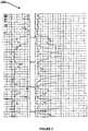
- FIG. 1illustrates a typical raster log
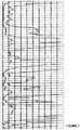
- FIG. 2illustrates a portion of the typical raster log in FIG. 1 ;
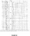
- FIG. 3illustrates a scale of the measurement, resistivity, of the curve in FIG. 2 ;
- FIG. 4illustrates a first embodiment of an example of a system for generating a digitized raster log
- FIG. 5illustrates a second embodiment of an example of a system for generating a digitized raster log
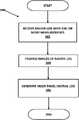
- FIG. 6illustrates an example of a method for digitized raster log generation
- FIG. 7illustrates an example of a well log with a set of measurements that wrap on the well log
- FIG. 8illustrates multiple panel tracks of the well log
- FIG. 9illustrates an example of a curve digitization on the multi-panel image generated by the system.
- FIG. 10illustrates an example of a technique for generating the multi-panel outputs of the system.
- the disclosureis particularly applicable to a raster log from an oil or gas well and it is in this context that the disclosure will be described. It will be appreciated, however, that the raster log digitization system and method may be used for other types well logs, other types of wells including water wells, and implemented using other techniques and components not specifically described below.
- the raster log digitization system and methodmay help turn well known raster logs into a novel digital curve.
- the novel digital curvemakes it easier to interpret geology shown in the raster log.
- the system and methodalso handles raster logs in which the values of the measurements captured by the raster log overlap each other (or wrap around) as described above.
- FIG. 1illustrates a typical raster log 100 and in particular a small section of a raster log.
- a full raster logis a log of measurements from various depths of a well.
- the partial well log 100 shown in FIG. 1has center numbers, 8500-8800, that represent a measured depth down a well at which one or more measurement(s) are taken. Different value of different measurements may be measured and represented on the various curves on the well log 100 .
- the well log 100may include electrical parameter measurements, resistivity parameter measurements, image parameter measurements, porosity parameter measurements, density parameter measurements, neutron porosity parameter measurements, gamma ray parameter measurements and other measurements.
- each graphis known as a track.
- the well log 100has two tracks, one on the left and one on the right.
- the track on the leftcontains multiple curves, which is common.
- the curve on the right that contains a single quantityis focused on as shown in FIG. 2 .
- FIG. 2shows the track on the right extracted from the input raster. Often the track is not straight in the input raster log image. This track has been cropped to the exact size of the track and has been straightened.
- FIG. 10illustrates an example of a technique for generating exemplary multi-panel outputs of the system.
- the digitization of the raster log component 414 described belowmay permit the user to layout a grid of reference points across the graph forming a strip of quadrilaterals down the grid. This may be done using a graphical user interface of the digitization of the raster log component 414 where points can be dropped and dragged to the correct locations as shown in FIG. 10 .
- Each horizontal linemay be labelled with a measured depth (MD) value.
- MDmeasured depth
- a process of image warping using bi-linear interpolationmay be used to create a straightened graph with MD values on a linear vertical scale. At this point the straightened image may contain multiple tracks.
- FIG. 3illustrates a scale of the measurement, resistivity, of the curve in FIG. 2 .
- the measurements of the curveare resistivity.
- the value of the measurementsranges from 0-50, 0-500 and 0-5000 ohms. This means numbers from 0-50 are represented on the main scale, numbers from 50-500 wrap back into the image and numbers from 500-5000 wrap back a second time yielding a quite complex graph as shown in FIG. 2 .
- a value of 50.001wraps back to a location approximately 10% through the image.
- This type of wrappingis the more complex case.
- the simple casewould be a scale of 0-10, 10-20. In this case wrapped curves simply start back on the right hand side. It is desirable to be able to address this wrapping of the values of the measurements since this wrapping phenomenon makes it very different to assess the measurements captured in the well log 100 .
- FIG. 4illustrates a first embodiment of an example of a system 400 for generating a digitized raster log.
- the systemmay be implemented on a single computer system as shown in FIG. 4 that may include, for example, a display device 402 and a chassis 404 that implement a digitization of the raster log system as described below.
- the digitization of the raster log systemmay be a plurality of lines of computer code that may be stored on the computer (or downloaded to the computer) and executed by one or more processor(s) of the computer.
- the digitization of the raster log systemmay be one or more hardware devices (a microcontroller, a programmable logic device (PLD), a field programmable gate array or other hardware components) that may be housed in the computer and the hardware device to implement a multi-panel digitization of the raster log.
- a microcontrollera programmable logic device (PLD), a field programmable gate array or other hardware components
- PLDprogrammable logic device
- field programmable gate arrayor other hardware components
- the chassis 404may further comprise one or more processors 406 , a persistent storage device 408 and a memory 410 that may be interconnected.
- the memorymay store a typical operating system 412 and a digitization of the raster log component 414 .
- the digitization of the raster log component 414may be implemented in software or hardware as described above so it may be executed by the processor 406 in the computer system in FIG. 4 .
- the computer system 400may also have one or more input/output devices 416 such as a mouse 418 and a keyboard 420 for example.
- the memory or persistent storagemay also store one or more well logs that may be processed by the digitization of the raster log component 414 as described below.
- the digitization of the raster log component 414may generate, in some embodiments, a multi-panel digital log as shown in the examples.
- FIG. 5illustrates a second embodiment of an example of a system 500 for generating digitized raster log.
- the systemmay have one or more computing device 502 , coupled and interconnected over a communications path 504 , to a backend component 506 that may have a multi-panel digitization of the raster log component.
- Each computing device 502such as computing device 502 A, computing device 502 B, . . . , computing device 502 N) may be a processor based device that may be used by a user to access the backend component 506 such as to upload a well log or request a multi-panel digitalization of the well log as described below.
- each computing devicemay be a smartphone device, a personal computer, a laptop computer, a tablet computer and the like.
- each computing device 102may have an application that assists the user to interact with the multi-panel digitalization of the well log.
- the applicationmay be a typical browser application, a mobile application downloaded to the computing device 102 or any other application.
- the communications path 504may be a wireless, wired or a combination of wireless and wired communications path. It may be a digital computer network, a digital cellular wireless network, a WiFi network, an Ethernet network and the like.
- the backend 506may be connected to a store 510 that may be a hardware or software storage device.
- the store 510may store one or more well logs that may be processed using the multi-panel digitalization of the well log as well as the plurality of lines of code of the multi-panel digitalization of the well log.
- the backend component 506may have a backend digitization component 508 that may further comprise an interface component 508 A that manages and generates the communications and data exchanges with each computer device 102 and a digital log component 508 B that performs the multi-panel digitization of the well log as described below.
- the multi-panel digitization of the well logmay be implemented using the digital log component 508 B.
- the digital log component 508 Bmay be implemented in hardware or software as described above.
- FIG. 6illustrates an example of a method 600 for digitized raster log generation.
- the methodmay receive a well raster log that has one or more measurements ( 602 ) and least one measurement has a set of values in which those values wrap around the well log as described above.
- the methodmay process images of the well log ( 604 ).
- the processingmay include image processing and image straightening.
- the methodautomatically generates a multi-panel digital log ( 606 .)
- the methodmay dynamically replicate the image side by side during rendering to thus generate multi-panel digital log.
- the methodmay also grey out/deemphasize off-scale images so that the off-scale/wrapped around parts may be more easily distinguishable.
- FIG. 7illustrates an example of a well log with a set of measurements that wrap on the well log as shown in red. Previous methods of log digitization would interpret on this image directly and an expert is required to really understand the way the curve wraps around and even then mistakes are easily made. Each time the curve goes off the right hand side of the image, the curve wraps back to the 10% from the left edge as shown in FIG. 7 .
- the multi-panel digitization of the well log component 508takes the track image and duplicate it side by side as shown in FIG. 8 in such a way that the curve becomes continuous across the image.
- the 0-50 part of the trackis completely shown whereas the first 10% of the 0-500 & 0-5000 is cropped off. This yields an image where the curve connects from the left hand edge of the 0-50 section to the correct point on the 0-500 section of the image.
- the scaleshows the true value of any point on the curve.
- FIG. 9shows the curve digitization on the multi-panel image. It becomes continuous and much easier to digitize. This results in a less error prone result more quickly attained. The actual value at any point in the curve can easily be seen in the generated multi-panel representation of the values of the measurements in a well log.
- the multi-panel image 900may have one or more regions 902 - 906 as shown in the example in FIG. 9 in which the values of the set of measurements in each range of measurement values appear. In the example in FIG.
- the second region 904has resistivity values between 50-500 for various depths in the well
- the third region 906has resistivity values between 500-5000 for various depths in the well.
- the background of each panelmay be colored slightly differently such as a different shade of gray as shown in FIG. 9 .
- the different shades of the backgroundare used as a visual cue for the user to know which wrap they are on when zoomed into the image.
- a person doing energy discovery work and the likeis able to more easily determine a precise value for the well for a measurement at a particular depth since the multi-panel display unwraps the values of the measurements.
- system and method disclosed hereinmay be implemented via one or more components, systems, servers, appliances, other subcomponents, or distributed between such elements.
- systemsmay include an/or involve, inter alia, components such as software modules, general-purpose CPU, RAM, etc. found in general-purpose computers.
- componentssuch as software modules, general-purpose CPU, RAM, etc. found in general-purpose computers.
- a servermay include or involve components such as CPU, RAM, etc., such as those found in general-purpose computers.
- system and method hereinmay be achieved via implementations with disparate or entirely different software, hardware and/or firmware components, beyond that set forth above.
- componentse.g., software, processing components, etc.
- computer-readable mediaassociated with or embodying the present inventions
- aspects of the innovations hereinmay be implemented consistent with numerous general purpose or special purpose computing systems or configurations.
- exemplary computing systems, environments, and/or configurationsmay include, but are not limited to: software or other components within or embodied on personal computers, servers or server computing devices such as routing/connectivity components, hand-held or laptop devices, multiprocessor systems, microprocessor-based systems, set top boxes, consumer electronic devices, network PCs, other existing computer platforms, distributed computing environments that include one or more of the above systems or devices, etc.
- aspects of the system and methodmay be achieved via or performed by logic and/or logic instructions including program modules, executed in association with such components or circuitry, for example.
- program modulesmay include routines, programs, objects, components, data structures, etc. that perform particular tasks or implement particular instructions herein.
- the inventionsmay also be practiced in the context of distributed software, computer, or circuit settings where circuitry is connected via communication buses, circuitry or links. In distributed settings, control/instructions may occur from both local and remote computer storage media including memory storage devices.
- Computer readable mediacan be any available media that is resident on, associable with, or can be accessed by such circuits and/or computing components.
- Computer readable mediamay comprise computer storage media and communication media.
- Computer storage mediaincludes volatile and nonvolatile, removable and non-removable media implemented in any method or technology for storage of information such as computer readable instructions, data structures, program modules or other data.
- Computer storage mediaincludes, but is not limited to, RAM, ROM, EEPROM, flash memory or other memory technology, CD-ROM, digital versatile disks (DVD) or other optical storage, magnetic tape, magnetic disk storage or other magnetic storage devices, or any other medium which can be used to store the desired information and can accessed by computing component.
- Communication mediamay comprise computer readable instructions, data structures, program modules and/or other components. Further, communication media may include wired media such as a wired network or direct-wired connection, however no media of any such type herein includes transitory media. Combinations of the any of the above are also included within the scope of computer readable media.
- the terms component, module, device, etc.may refer to any type of logical or functional software elements, circuits, blocks and/or processes that may be implemented in a variety of ways.
- the functions of various circuits and/or blockscan be combined with one another into any other number of modules.
- Each modulemay even be implemented as a software program stored on a tangible memory (e.g., random access memory, read only memory, CD-ROM memory, hard disk drive, etc.) to be read by a central processing unit to implement the functions of the innovations herein.
- the modulescan comprise programming instructions transmitted to a general purpose computer or to processing/graphics hardware via a transmission carrier wave.
- the modulescan be implemented as hardware logic circuitry implementing the functions encompassed by the innovations herein.
- the modulescan be implemented using special purpose instructions (SIMD instructions), field programmable logic arrays or any mix thereof which provides the desired level performance and cost.
- SIMD instructionsspecial purpose instructions
- features consistent with the disclosuremay be implemented via computer-hardware, software and/or firmware.
- the systems and methods disclosed hereinmay be embodied in various forms including, for example, a data processor, such as a computer that also includes a database, digital electronic circuitry, firmware, software, or in combinations of them.
- a data processorsuch as a computer that also includes a database
- digital electronic circuitrysuch as a computer
- firmwaresuch as a firmware
- softwaresuch as a computer
- the systems and methods disclosed hereinmay be implemented with any combination of hardware, software and/or firmware.
- the above-noted features and other aspects and principles of the innovations hereinmay be implemented in various environments.
- Such environments and related applicationsmay be specially constructed for performing the various routines, processes and/or operations according to the invention or they may include a general-purpose computer or computing platform selectively activated or reconfigured by code to provide the necessary functionality.
- the processes disclosed hereinare not inherently related to any particular computer, network, architecture, environment, or other apparatus, and may be implemented by a suitable combination of hardware, software, and/or firmware.
- various general-purpose machinesmay be used with programs written in accordance with teachings of the invention, or it may be more convenient to construct a specialized apparatus or system to perform the required methods and techniques.
- aspects of the method and system described herein, such as the logicmay also be implemented as functionality programmed into any of a variety of circuitry, including programmable logic devices (“PLDs”), such as field programmable gate arrays (“FPGAs”), programmable array logic (“PAL”) devices, electrically programmable logic and memory devices and standard cell-based devices, as well as application specific integrated circuits.
- PLDsprogrammable logic devices
- FPGAsfield programmable gate arrays
- PALprogrammable array logic
- Some other possibilities for implementing aspectsinclude: memory devices, microcontrollers with memory (such as EEPROM), embedded microprocessors, firmware, software, etc.
- aspectsmay be embodied in microprocessors having software-based circuit emulation, discrete logic (sequential and combinatorial), custom devices, fuzzy (neural) logic, quantum devices, and hybrids of any of the above device types.
- the underlying device technologiesmay be provided in a variety of component types, e.g., metal-oxide semiconductor field-effect transistor (“MOSFET”) technologies like complementary metal-oxide semiconductor (“CMOS”), bipolar technologies like emitter-coupled logic (“ECL”), polymer technologies (e.g., silicon-conjugated polymer and metal-conjugated polymer-metal structures), mixed analog and digital, and so on.
- MOSFETmetal-oxide semiconductor field-effect transistor
- CMOScomplementary metal-oxide semiconductor
- ECLemitter-coupled logic
- polymer technologiese.g., silicon-conjugated polymer and metal-conjugated polymer-metal structures
- mixed analog and digitaland so on.
- the words “comprise,” “comprising,” and the likeare to be construed in an inclusive sense as opposed to an exclusive or exhaustive sense; that is to say, in a sense of “including, but not limited to.” Words using the singular or plural number also include the plural or singular number respectively. Additionally, the words “herein,” “hereunder,” “above,” “below,” and words of similar import refer to this application as a whole and not to any particular portions of this application. When the word “or” is used in reference to a list of two or more items, that word covers all of the following interpretations of the word: any of the items in the list, all of the items in the list and any combination of the items in the list.
Landscapes
- Physics & Mathematics (AREA)
- Life Sciences & Earth Sciences (AREA)
- General Life Sciences & Earth Sciences (AREA)
- General Physics & Mathematics (AREA)
- Geophysics (AREA)
- Engineering & Computer Science (AREA)
- Acoustics & Sound (AREA)
- Environmental & Geological Engineering (AREA)
- Geology (AREA)
- Remote Sensing (AREA)
- Controls And Circuits For Display Device (AREA)
- Measurement Of Radiation (AREA)
Abstract
Description
Claims (20)
Priority Applications (1)
| Application Number | Priority Date | Filing Date | Title |
|---|---|---|---|
| US17/164,179US11340380B2 (en) | 2015-10-15 | 2021-02-01 | Raster log digitization system and method |
Applications Claiming Priority (2)
| Application Number | Priority Date | Filing Date | Title |
|---|---|---|---|
| US14/884,701US10908316B2 (en) | 2015-10-15 | 2015-10-15 | Raster log digitization system and method |
| US17/164,179US11340380B2 (en) | 2015-10-15 | 2021-02-01 | Raster log digitization system and method |
Related Parent Applications (1)
| Application Number | Title | Priority Date | Filing Date |
|---|---|---|---|
| US14/884,701ContinuationUS10908316B2 (en) | 2015-10-15 | 2015-10-15 | Raster log digitization system and method |
Publications (2)
| Publication Number | Publication Date |
|---|---|
| US20210286103A1 US20210286103A1 (en) | 2021-09-16 |
| US11340380B2true US11340380B2 (en) | 2022-05-24 |
Family
ID=58517920
Family Applications (2)
| Application Number | Title | Priority Date | Filing Date |
|---|---|---|---|
| US14/884,701Active2036-06-23US10908316B2 (en) | 2015-10-15 | 2015-10-15 | Raster log digitization system and method |
| US17/164,179ActiveUS11340380B2 (en) | 2015-10-15 | 2021-02-01 | Raster log digitization system and method |
Family Applications Before (1)
| Application Number | Title | Priority Date | Filing Date |
|---|---|---|---|
| US14/884,701Active2036-06-23US10908316B2 (en) | 2015-10-15 | 2015-10-15 | Raster log digitization system and method |
Country Status (2)
| Country | Link |
|---|---|
| US (2) | US10908316B2 (en) |
| WO (1) | WO2017066587A1 (en) |
Families Citing this family (6)
| Publication number | Priority date | Publication date | Assignee | Title |
|---|---|---|---|---|
| US10577895B2 (en) | 2012-11-20 | 2020-03-03 | Drilling Info, Inc. | Energy deposit discovery system and method |
| US10853893B2 (en) | 2013-04-17 | 2020-12-01 | Drilling Info, Inc. | System and method for automatically correlating geologic tops |
| US10459098B2 (en) | 2013-04-17 | 2019-10-29 | Drilling Info, Inc. | System and method for automatically correlating geologic tops |
| US9911210B1 (en) | 2014-12-03 | 2018-03-06 | Drilling Info, Inc. | Raster log digitization system and method |
| US10908316B2 (en) | 2015-10-15 | 2021-02-02 | Drilling Info, Inc. | Raster log digitization system and method |
| US20240212384A1 (en)* | 2022-12-27 | 2024-06-27 | Schlumberger Technology Corporation | Raster image digitization system for field data |
Citations (71)
| Publication number | Priority date | Publication date | Assignee | Title |
|---|---|---|---|---|
| US4633400A (en) | 1984-12-21 | 1986-12-30 | Conoco Inc. | Method for waveform feature extraction from seismic signals |
| US5003813A (en) | 1990-02-20 | 1991-04-02 | Hayes Separations, Inc. | Method and apparatus for monitoring storage tank leakage |
| US5056066A (en) | 1990-06-25 | 1991-10-08 | Landmark Graphics Corporation | Method for attribute tracking in seismic data |
| US5835882A (en) | 1997-01-31 | 1998-11-10 | Phillips Petroleum Company | Method for determining barriers to reservoir flow |
| US5987388A (en) | 1997-12-26 | 1999-11-16 | Atlantic Richfield Company | Automated extraction of fault surfaces from 3-D seismic prospecting data |
| US6003027A (en) | 1997-11-21 | 1999-12-14 | International Business Machines Corporation | System and method for determining confidence levels for the results of a categorization system |
| US6223126B1 (en) | 1999-10-20 | 2001-04-24 | Phillips Petroleum Company | Multi-attribute seismic waveform classification |
| US6295504B1 (en) | 1999-10-25 | 2001-09-25 | Halliburton Energy Services, Inc. | Multi-resolution graph-based clustering |
| US20020140699A1 (en) | 2000-12-22 | 2002-10-03 | Bsp Inc. | Method, system, and software for automated generation of graphs from report data |
| US20020184083A1 (en) | 2001-05-31 | 2002-12-05 | Takashi Nakano | Quality function development support method and storage medium |
| US20040015296A1 (en) | 2000-07-17 | 2004-01-22 | Emmanuel Causse | Seismic processing with general non-hyperbolic travel-time corrections |
| US20040220790A1 (en) | 2003-04-30 | 2004-11-04 | Cullick Alvin Stanley | Method and system for scenario and case decision management |
| US20040260476A1 (en) | 2003-04-10 | 2004-12-23 | Schlumberger Technology Corporation | Extrema classification |
| US20050209897A1 (en) | 2004-03-16 | 2005-09-22 | Luhr Stanley R | Builder risk assessment system |
| US6965383B2 (en)* | 2001-12-11 | 2005-11-15 | Lecroy Corporation | Scaling persistence data with interpolation |
| US20060052937A1 (en) | 2004-09-07 | 2006-03-09 | Landmark Graphics Corporation | Method, systems, and computer readable media for optimizing the correlation of well log data using dynamic programming |
| US20060075007A1 (en) | 2004-09-17 | 2006-04-06 | International Business Machines Corporation | System and method for optimizing a storage system to support full utilization of storage space |
| US7054753B1 (en) | 2003-11-14 | 2006-05-30 | Williams Ralph A | Method of locating oil and gas exploration prospects by data visualization and organization |
| US7069149B2 (en) | 2001-12-14 | 2006-06-27 | Chevron U.S.A. Inc. | Process for interpreting faults from a fault-enhanced 3-dimensional seismic attribute volume |
| CN1797039A (en) | 2004-12-29 | 2006-07-05 | 中国石油天然气集团公司 | Method for automatic tracking 3D geological horizon |
| US20060193205A1 (en) | 2005-02-12 | 2006-08-31 | Chevron U.S.A. Inc. | Method and apparatus for true relative amplitude correction of seismic data for normal moveout stretch effects |
| US20060274386A1 (en) | 2005-06-01 | 2006-12-07 | Sony Corporation | Imaging device and method of processing imaging result in imaging device |
| US20070276604A1 (en)* | 2006-05-25 | 2007-11-29 | Williams Ralph A | Method of locating oil and gas exploration prospects by data visualization and organization |
| US20080033935A1 (en) | 2006-08-04 | 2008-02-07 | Metacarta, Inc. | Systems and methods for presenting results of geographic text searches |
| US20080178148A1 (en) | 2007-01-19 | 2008-07-24 | International Business Machines Corporation | Business performance bookmarks |
| US20090043507A1 (en) | 2007-08-01 | 2009-02-12 | Austin Geomodeling, Inc. | Method and system for dynamic, three-dimensional geological interpretation and modeling |
| US7516055B2 (en) | 2004-08-20 | 2009-04-07 | Chevron U.S.A. Inc | Multiple-point statistics (MPS) simulation with enhanced computational efficiency |
| US7525349B2 (en) | 2006-08-14 | 2009-04-28 | University Of Washington | Circuit for classifying signals |
| US20090125288A1 (en) | 2005-11-26 | 2009-05-14 | The University Court Of The University Of Edinburgh | Hydrocarbon Recovery From a Hydrocarbon Reservoir |
| US20090141028A1 (en) | 2007-11-29 | 2009-06-04 | International Business Machines Corporation | Method to predict edges in a non-cumulative graph |
| US20090144032A1 (en) | 2007-11-29 | 2009-06-04 | International Business Machines Corporation | System and computer program product to predict edges in a non-cumulative graph |
| US20090157319A1 (en) | 2007-12-17 | 2009-06-18 | Landmark Graphics Corporation, A Halliburton Company | Systems and Methods for Modeling Wellbore Trajectories |
| US20090319243A1 (en)* | 2008-06-18 | 2009-12-24 | Terratek, Inc. | Heterogeneous earth models for a reservoir field |
| US20100073402A1 (en)* | 2008-09-22 | 2010-03-25 | International Business Machines Corporation | Method of automatic cropping |
| US20100125349A1 (en) | 2008-11-17 | 2010-05-20 | Landmark Graphics Corporation, A Halliburton Company | Systems and Methods for Dynamically Developing Wellbore Plans With a Reservoir Simulator |
| US20100214870A1 (en) | 2009-02-23 | 2010-08-26 | Randolph Pepper | Method and apparatus for dynamic extraction of extrema-based geometric primitives in 3d voxel volumes |
| WO2010110824A1 (en) | 2009-03-27 | 2010-09-30 | Exxonmobil Upstream Research Company | Reservoir quality characterization using heterogeneity equations with spatially-varying parameters |
| US20110002194A1 (en) | 2008-05-22 | 2011-01-06 | Matthias Imhof | Method For Geophysical and Geological Interpretation of Seismic Volumes In The Domains of Depth, Time, and Age |
| US20110011595A1 (en) | 2008-05-13 | 2011-01-20 | Hao Huang | Modeling of Hydrocarbon Reservoirs Using Design of Experiments Methods |
| US20110042098A1 (en) | 2008-05-09 | 2011-02-24 | Matthias Georg Imhof | Method For Geophysical And Stratigraphic Interpretation Using Waveform Anomalies |
| CN102066980A (en) | 2008-05-22 | 2011-05-18 | 埃克森美孚上游研究公司 | Seismic horizon skeletonization |
| US20110115787A1 (en) | 2008-04-11 | 2011-05-19 | Terraspark Geosciences, Llc | Visulation of geologic features using data representations thereof |
| US20110122136A1 (en) | 2009-11-24 | 2011-05-26 | Samsung Electronics Co., Ltd. | Method and apparatus for filtering vector object's control points |
| US20110172976A1 (en) | 2008-10-01 | 2011-07-14 | Budiman Benny S | Robust Well Trajectory Planning |
| US20110181610A1 (en) | 2009-09-10 | 2011-07-28 | Chevron U.S.A. Inc. | Method for converting a digital image into a multi-dimensional geo-referenced data structure |
| WO2011100009A1 (en) | 2010-02-12 | 2011-08-18 | Exxonmobil Upstream Research Company | Method and system for creating history-matched simulation models |
| US20110213577A1 (en)* | 2008-03-25 | 2011-09-01 | Abb Research Ltd. | Method and apparatus for analyzing waveform signals of a power system |
| US20110313743A1 (en) | 2010-06-16 | 2011-12-22 | Foroil | Method of Improving the Production of a Mature Gas or Oil Field |
| US20120080197A1 (en) | 2009-06-26 | 2012-04-05 | Dickens Thomas A | Constructing Resistivity Models From Stochastic Inversion |
| US8265879B2 (en) | 2009-04-17 | 2012-09-11 | Roche Molecular Systems, Inc. | Determination of single peak melting temperature by PCR analogy and double sigmoid equation |
| US8265876B1 (en) | 2008-11-08 | 2012-09-11 | Ihs Global Inc. | Seismic horizon autopicking using orientation vector field |
| US20130090855A1 (en) | 2011-08-26 | 2013-04-11 | John Rasmus | Methods for evaluating inflow and outflow in a subterraean wellbore |
| US20130169644A1 (en)* | 2011-08-11 | 2013-07-04 | Dexdyne Limited | Apparatus and Method for Displaying Telemetry Data |
| US20130229891A1 (en) | 2012-03-01 | 2013-09-05 | Transform Software & Services, Inc. | Method and system for image-guided fault extraction from a fault-enhanced seismic image |
| US20130262052A1 (en) | 2012-04-03 | 2013-10-03 | Jean-Laurent Mallet | System and method for generating an implicit model of geological horizons |
| US20130332131A1 (en) | 2012-06-11 | 2013-12-12 | Saudi Arabian Oil Company | System and method for producing display of petrophysical property height profile for both vertical and horizontal wellbores |
| US20140140580A1 (en) | 2012-11-04 | 2014-05-22 | Drilling Info, Inc. | System And Method For Reproducibly Extracting Consistent Horizons From Seismic Images |
| US20140142906A1 (en) | 2012-11-20 | 2014-05-22 | Drilling Info, Inc. | Energy deposit discovery system and method |
| US20140222347A1 (en) | 2012-11-03 | 2014-08-07 | Drilling Info, Inc. | Seismic Waveform Classification System And Method |
| US8826879B2 (en) | 2011-12-01 | 2014-09-09 | Hyundai Motor Company | Variable intake system for vehicle, and apparatus and method for controlling the same |
| US20140254884A1 (en) | 2013-03-11 | 2014-09-11 | Peter Adrian Spencer Elkington | Methods of and Apparatuses for Identifying Geological Characteristics in Boreholes |
| US20140262246A1 (en) | 2011-10-28 | 2014-09-18 | Zhilin Li | Method for controlling well bore pressure based on model prediction control theory and systems theory |
| US20140316706A1 (en) | 2013-04-17 | 2014-10-23 | Drilling Info, Inc. | System and method for automatically correlating geologic tops |
| US20150098627A1 (en) | 2013-10-08 | 2015-04-09 | Shin-Ju Chu Ye | Automatic Dip Picking From Wellbore Azimuthal Image Logs |
| US20150198029A1 (en) | 2012-07-13 | 2015-07-16 | Halliburton Energy Services, Inc. | Improving drill bit stability using track-set depth of cut control elements |
| US20160139282A1 (en) | 2012-12-20 | 2016-05-19 | Pavel Dimitrov | Vector Based Geophysical Modeling of Subsurface Volumes |
| US9418339B1 (en) | 2015-01-26 | 2016-08-16 | Sas Institute, Inc. | Systems and methods for time series analysis techniques utilizing count data sets |
| US20160237810A1 (en) | 2015-02-17 | 2016-08-18 | Board Of Regents, The University Of Texas System | Method and apparatus for early detection of kicks |
| US20170108614A1 (en) | 2015-10-15 | 2017-04-20 | Drillinginfo, Inc. | Raster log digitization system and method |
| US20180225778A1 (en) | 2013-04-17 | 2018-08-09 | Drilling Info, Inc. | System and method for automatically correlating geologic tops |
| US20180253873A1 (en) | 2014-12-03 | 2018-09-06 | Drilling Info, Inc. | Raster log digitization system and method |
Family Cites Families (1)
| Publication number | Priority date | Publication date | Assignee | Title |
|---|---|---|---|---|
| MX353733B (en)* | 2011-12-29 | 2018-01-26 | Schlumberger Technology Bv | In-situ characterization of formation constituents. |
- 2015
- 2015-10-15USUS14/884,701patent/US10908316B2/enactiveActive
- 2016
- 2016-10-14WOPCT/US2016/057067patent/WO2017066587A1/ennot_activeCeased
- 2021
- 2021-02-01USUS17/164,179patent/US11340380B2/enactiveActive
Patent Citations (81)
| Publication number | Priority date | Publication date | Assignee | Title |
|---|---|---|---|---|
| US4633400A (en) | 1984-12-21 | 1986-12-30 | Conoco Inc. | Method for waveform feature extraction from seismic signals |
| US5003813A (en) | 1990-02-20 | 1991-04-02 | Hayes Separations, Inc. | Method and apparatus for monitoring storage tank leakage |
| US5056066A (en) | 1990-06-25 | 1991-10-08 | Landmark Graphics Corporation | Method for attribute tracking in seismic data |
| US5835882A (en) | 1997-01-31 | 1998-11-10 | Phillips Petroleum Company | Method for determining barriers to reservoir flow |
| US6003027A (en) | 1997-11-21 | 1999-12-14 | International Business Machines Corporation | System and method for determining confidence levels for the results of a categorization system |
| US5987388A (en) | 1997-12-26 | 1999-11-16 | Atlantic Richfield Company | Automated extraction of fault surfaces from 3-D seismic prospecting data |
| US6223126B1 (en) | 1999-10-20 | 2001-04-24 | Phillips Petroleum Company | Multi-attribute seismic waveform classification |
| US6295504B1 (en) | 1999-10-25 | 2001-09-25 | Halliburton Energy Services, Inc. | Multi-resolution graph-based clustering |
| US20040015296A1 (en) | 2000-07-17 | 2004-01-22 | Emmanuel Causse | Seismic processing with general non-hyperbolic travel-time corrections |
| US20020140699A1 (en) | 2000-12-22 | 2002-10-03 | Bsp Inc. | Method, system, and software for automated generation of graphs from report data |
| US20020184083A1 (en) | 2001-05-31 | 2002-12-05 | Takashi Nakano | Quality function development support method and storage medium |
| US6965383B2 (en)* | 2001-12-11 | 2005-11-15 | Lecroy Corporation | Scaling persistence data with interpolation |
| US7069149B2 (en) | 2001-12-14 | 2006-06-27 | Chevron U.S.A. Inc. | Process for interpreting faults from a fault-enhanced 3-dimensional seismic attribute volume |
| US20040260476A1 (en) | 2003-04-10 | 2004-12-23 | Schlumberger Technology Corporation | Extrema classification |
| US20040220790A1 (en) | 2003-04-30 | 2004-11-04 | Cullick Alvin Stanley | Method and system for scenario and case decision management |
| US7054753B1 (en) | 2003-11-14 | 2006-05-30 | Williams Ralph A | Method of locating oil and gas exploration prospects by data visualization and organization |
| US20050209897A1 (en) | 2004-03-16 | 2005-09-22 | Luhr Stanley R | Builder risk assessment system |
| US7516055B2 (en) | 2004-08-20 | 2009-04-07 | Chevron U.S.A. Inc | Multiple-point statistics (MPS) simulation with enhanced computational efficiency |
| US20060052937A1 (en) | 2004-09-07 | 2006-03-09 | Landmark Graphics Corporation | Method, systems, and computer readable media for optimizing the correlation of well log data using dynamic programming |
| US20060075007A1 (en) | 2004-09-17 | 2006-04-06 | International Business Machines Corporation | System and method for optimizing a storage system to support full utilization of storage space |
| CN1797039A (en) | 2004-12-29 | 2006-07-05 | 中国石油天然气集团公司 | Method for automatic tracking 3D geological horizon |
| US20060193205A1 (en) | 2005-02-12 | 2006-08-31 | Chevron U.S.A. Inc. | Method and apparatus for true relative amplitude correction of seismic data for normal moveout stretch effects |
| US20060274386A1 (en) | 2005-06-01 | 2006-12-07 | Sony Corporation | Imaging device and method of processing imaging result in imaging device |
| US20090125288A1 (en) | 2005-11-26 | 2009-05-14 | The University Court Of The University Of Edinburgh | Hydrocarbon Recovery From a Hydrocarbon Reservoir |
| US20070276604A1 (en)* | 2006-05-25 | 2007-11-29 | Williams Ralph A | Method of locating oil and gas exploration prospects by data visualization and organization |
| US20080033935A1 (en) | 2006-08-04 | 2008-02-07 | Metacarta, Inc. | Systems and methods for presenting results of geographic text searches |
| US7525349B2 (en) | 2006-08-14 | 2009-04-28 | University Of Washington | Circuit for classifying signals |
| US20080178148A1 (en) | 2007-01-19 | 2008-07-24 | International Business Machines Corporation | Business performance bookmarks |
| US20090043507A1 (en) | 2007-08-01 | 2009-02-12 | Austin Geomodeling, Inc. | Method and system for dynamic, three-dimensional geological interpretation and modeling |
| US20090141028A1 (en) | 2007-11-29 | 2009-06-04 | International Business Machines Corporation | Method to predict edges in a non-cumulative graph |
| US20090144032A1 (en) | 2007-11-29 | 2009-06-04 | International Business Machines Corporation | System and computer program product to predict edges in a non-cumulative graph |
| US20090157319A1 (en) | 2007-12-17 | 2009-06-18 | Landmark Graphics Corporation, A Halliburton Company | Systems and Methods for Modeling Wellbore Trajectories |
| US20110213577A1 (en)* | 2008-03-25 | 2011-09-01 | Abb Research Ltd. | Method and apparatus for analyzing waveform signals of a power system |
| US20110115787A1 (en) | 2008-04-11 | 2011-05-19 | Terraspark Geosciences, Llc | Visulation of geologic features using data representations thereof |
| US20110042098A1 (en) | 2008-05-09 | 2011-02-24 | Matthias Georg Imhof | Method For Geophysical And Stratigraphic Interpretation Using Waveform Anomalies |
| US20110011595A1 (en) | 2008-05-13 | 2011-01-20 | Hao Huang | Modeling of Hydrocarbon Reservoirs Using Design of Experiments Methods |
| US20110002194A1 (en) | 2008-05-22 | 2011-01-06 | Matthias Imhof | Method For Geophysical and Geological Interpretation of Seismic Volumes In The Domains of Depth, Time, and Age |
| CN102066980A (en) | 2008-05-22 | 2011-05-18 | 埃克森美孚上游研究公司 | Seismic horizon skeletonization |
| US20090319243A1 (en)* | 2008-06-18 | 2009-12-24 | Terratek, Inc. | Heterogeneous earth models for a reservoir field |
| US20100073402A1 (en)* | 2008-09-22 | 2010-03-25 | International Business Machines Corporation | Method of automatic cropping |
| US20110172976A1 (en) | 2008-10-01 | 2011-07-14 | Budiman Benny S | Robust Well Trajectory Planning |
| US8265876B1 (en) | 2008-11-08 | 2012-09-11 | Ihs Global Inc. | Seismic horizon autopicking using orientation vector field |
| US20100125349A1 (en) | 2008-11-17 | 2010-05-20 | Landmark Graphics Corporation, A Halliburton Company | Systems and Methods for Dynamically Developing Wellbore Plans With a Reservoir Simulator |
| US20100214870A1 (en) | 2009-02-23 | 2010-08-26 | Randolph Pepper | Method and apparatus for dynamic extraction of extrema-based geometric primitives in 3d voxel volumes |
| US20120010865A1 (en) | 2009-03-27 | 2012-01-12 | Benson Gregory S | Reservoir Quality Characterization Using Heterogeneity Equations With Spatially-Varying Parameters |
| WO2010110824A1 (en) | 2009-03-27 | 2010-09-30 | Exxonmobil Upstream Research Company | Reservoir quality characterization using heterogeneity equations with spatially-varying parameters |
| US8265879B2 (en) | 2009-04-17 | 2012-09-11 | Roche Molecular Systems, Inc. | Determination of single peak melting temperature by PCR analogy and double sigmoid equation |
| US20120080197A1 (en) | 2009-06-26 | 2012-04-05 | Dickens Thomas A | Constructing Resistivity Models From Stochastic Inversion |
| US20110181610A1 (en) | 2009-09-10 | 2011-07-28 | Chevron U.S.A. Inc. | Method for converting a digital image into a multi-dimensional geo-referenced data structure |
| US20110122136A1 (en) | 2009-11-24 | 2011-05-26 | Samsung Electronics Co., Ltd. | Method and apparatus for filtering vector object's control points |
| WO2011100009A1 (en) | 2010-02-12 | 2011-08-18 | Exxonmobil Upstream Research Company | Method and system for creating history-matched simulation models |
| US20120253770A1 (en) | 2010-02-12 | 2012-10-04 | David Stern | Method and System For Creating History Matched Simulation Models |
| US20110313743A1 (en) | 2010-06-16 | 2011-12-22 | Foroil | Method of Improving the Production of a Mature Gas or Oil Field |
| US20130169644A1 (en)* | 2011-08-11 | 2013-07-04 | Dexdyne Limited | Apparatus and Method for Displaying Telemetry Data |
| US20130090855A1 (en) | 2011-08-26 | 2013-04-11 | John Rasmus | Methods for evaluating inflow and outflow in a subterraean wellbore |
| US20140262246A1 (en) | 2011-10-28 | 2014-09-18 | Zhilin Li | Method for controlling well bore pressure based on model prediction control theory and systems theory |
| US8826879B2 (en) | 2011-12-01 | 2014-09-09 | Hyundai Motor Company | Variable intake system for vehicle, and apparatus and method for controlling the same |
| US20130229891A1 (en) | 2012-03-01 | 2013-09-05 | Transform Software & Services, Inc. | Method and system for image-guided fault extraction from a fault-enhanced seismic image |
| US9618639B2 (en) | 2012-03-01 | 2017-04-11 | Drilling Info, Inc. | Method and system for image-guided fault extraction from a fault-enhanced seismic image |
| US20130262052A1 (en) | 2012-04-03 | 2013-10-03 | Jean-Laurent Mallet | System and method for generating an implicit model of geological horizons |
| US20130332131A1 (en) | 2012-06-11 | 2013-12-12 | Saudi Arabian Oil Company | System and method for producing display of petrophysical property height profile for both vertical and horizontal wellbores |
| US20150198029A1 (en) | 2012-07-13 | 2015-07-16 | Halliburton Energy Services, Inc. | Improving drill bit stability using track-set depth of cut control elements |
| US20140222347A1 (en) | 2012-11-03 | 2014-08-07 | Drilling Info, Inc. | Seismic Waveform Classification System And Method |
| US20140140580A1 (en) | 2012-11-04 | 2014-05-22 | Drilling Info, Inc. | System And Method For Reproducibly Extracting Consistent Horizons From Seismic Images |
| US9182511B2 (en) | 2012-11-04 | 2015-11-10 | Drilling Info, Inc. | System and method for reproducibly extracting consistent horizons from seismic images |
| US10577895B2 (en) | 2012-11-20 | 2020-03-03 | Drilling Info, Inc. | Energy deposit discovery system and method |
| US20200199978A1 (en) | 2012-11-20 | 2020-06-25 | Drilling Info, Inc. | Energy Deposit Discovery System and Method |
| US20140142906A1 (en) | 2012-11-20 | 2014-05-22 | Drilling Info, Inc. | Energy deposit discovery system and method |
| US20160139282A1 (en) | 2012-12-20 | 2016-05-19 | Pavel Dimitrov | Vector Based Geophysical Modeling of Subsurface Volumes |
| US20140254884A1 (en) | 2013-03-11 | 2014-09-11 | Peter Adrian Spencer Elkington | Methods of and Apparatuses for Identifying Geological Characteristics in Boreholes |
| US20180225778A1 (en) | 2013-04-17 | 2018-08-09 | Drilling Info, Inc. | System and method for automatically correlating geologic tops |
| US10459098B2 (en) | 2013-04-17 | 2019-10-29 | Drilling Info, Inc. | System and method for automatically correlating geologic tops |
| US20140316706A1 (en) | 2013-04-17 | 2014-10-23 | Drilling Info, Inc. | System and method for automatically correlating geologic tops |
| US10853893B2 (en) | 2013-04-17 | 2020-12-01 | Drilling Info, Inc. | System and method for automatically correlating geologic tops |
| US20210150638A1 (en) | 2013-04-17 | 2021-05-20 | Drilling Info, Inc. | System and Method for Automatically Correlating Geologic Tops |
| US20150098627A1 (en) | 2013-10-08 | 2015-04-09 | Shin-Ju Chu Ye | Automatic Dip Picking From Wellbore Azimuthal Image Logs |
| US20180253873A1 (en) | 2014-12-03 | 2018-09-06 | Drilling Info, Inc. | Raster log digitization system and method |
| US9418339B1 (en) | 2015-01-26 | 2016-08-16 | Sas Institute, Inc. | Systems and methods for time series analysis techniques utilizing count data sets |
| US20160237810A1 (en) | 2015-02-17 | 2016-08-18 | Board Of Regents, The University Of Texas System | Method and apparatus for early detection of kicks |
| US20170108614A1 (en) | 2015-10-15 | 2017-04-20 | Drillinginfo, Inc. | Raster log digitization system and method |
| US10908316B2 (en) | 2015-10-15 | 2021-02-02 | Drilling Info, Inc. | Raster log digitization system and method |
Non-Patent Citations (45)
| Title |
|---|
| Admasu et al., Automatic Method for Correlating Horizons Across Faults in 3d Seismic Data, Computer Vision and Pattern Recognition, 2004, CVPR 2004, Proceedings of the 2004 IEEE Computer Society Conference, vol. 1 (6 pgs.). |
| Andersen, et al.; "Seismic Waveform Classification: Techniques and Benefits," Dated Mar. 2004; pp. 26-29; ( 4 pgs.). |
| Aurnhammer et al., A Genetic Algorithm for Automated Horizon Correlation Across Faults in Seismic Images, IEEE Transactions on Evolutionary Computation, vol. 9., No. 2, Apr. 2005 (10 pgs.). |
| Brown et al., "Seismic Event Tracking by Global Path Optimization," 76th Annual International Meeting, SEG, Expanded Abstracts, 1063-1067, 2006 (4 pgs). |
| Can, Bunyamin. Probabilistic performance forecasting for unconventional reservoirs with stretched-exponential model. Diss. Texas A&M University, 2011. |
| Castro de Matos, et al. "Unsupervised Seismic Facies Analysis Using Wavelet Transform and Self-Organizing Maps" dated Dec. 13, 2006; vol. 72, No. 1, pp. P9-P21, 19 Figs.; (13 pgs.). |
| Chang et al., "NMR Characterizations of Properties of Heterogeneous Media," Research Report, Final Report; U.S. Dept. of Energy, DOE Award No. DE-AC26-99BC15202, Texas A&M University, 2005, pp. 1-151 (151 pgs.). |
| CN Office Action in Chinese Application No. 201480034483.5, dated Feb. 21, 2017, 21 pages (English translation). |
| Coleou, et al.; "Unsupervised Seismic Facies Classification: A Review and Comparison of Techniques and Implementation" dated Oct. 2003; pp. 942-953; (7 pgs.). |
| Diersen et al.; "Classification of Seismic Windows Using Artificial Neural Networks" dated 2011; pp. 1-10; (10 pgs.). |
| Dijkstra; "A Note on Two Problems in Connexion with Graphs" dated Jun. 11, 1959; pp. 269-271; (3 pgs.). |
| EP Office Action in European Patent Application No. 13856215.2, dated Nov. 15, 2017, 5 pages. |
| Forth et al., Application of Statistical Analysis to Optimize Reservoir Performance, Journal of Canadian Petroleum Technology, Sep. 1, 1997 (7 pgs.). |
| Goshtasby, "Chapter 2: Similarity and Dissimilarity Measures," Image Registration Principle, Tools and Methods, 2012, XVII, pp. 7-66 (2012). |
| Hastie et al. "Generalized additive models"—Chapter 7 Statistical Models in S eds, dated 1992 (15 pgs.). |
| Herrera, "Automated Seismic-to-well Ties?," 74th EAGE Conference & Exhibition incorporating SPE EUROPEC 2012, Jun. 1, 2012 (5 pgs.). |
| Hintze, J.L. (2007), NCSS Data Analysis User's Guide III, Reression and Curve Fitting. NCSS 2007. Retrieved from http://ncss.wpengine.netdna-cdn.com/wp-content/uploads/2012/09/NCSSUG3.pdf, pp. 1-653. |
| Hollt, et al.; "Interactive Seismic Interpretation with Piecewise Global Energy Minimization" dated Mar. 1, 2011; pp. 59-66; (8 pgs.). |
| Jeong, et al.; "A Fast Iterative Method for Eikonal Equations" dated Jul. 23, 2008; vol. 30, No. 5, pp. 2512-2534; (23 pgs.). |
| Kass et al., Snakes: Active Contour Models, International Journal of Computer Vision, 321-331, 1988 (11 pgs). |
| Keogh et al., "Derivative Dynamic Time Warping," In Proc. of the First Intl. SIAM Intl. Conf. on Data Mining, Chicago, Illinois, 11 pages (2001). |
| Lineman et al.: Well-to-Well Log Correlation Using Knowledge-Based Systems and Dynamic Depth Warping, dated Jan. 1, 1987 (Jan. 1, 1987); XP055327735, Retrieved From the Internet URL: https://dspace.mit.edu/bitstream/handle/1721.1/75091 /1987.14Lineman et al.Pdf?sequence=1 [retrieved on Dec. 9, 2016] (34 pgs.). |
| Morita et al. Extracting time-ordered pairs of similar subsequences by time warping approach, 3rd International Workshop on Mining Temporal and Sequential Data, Aug. 22, 2004 (12 Pages). |
| Mortensen et al., Interactive Segmentation with Intelligent Scissors, Graphical Models and Image Processing, 60(5):349-384 (1998) (48 pgs). |
| Muller, "Dynamic Time Warping," Information retrieval for music and motion, 2007, 69-84. |
| Ouenes, Ahmed, et al. "Practical use of neural networks in tight gas fractured reservoirs: application to the San Juan Basin." paper SPE 39965 (1998). |
| Pages from Website: http://www.neuralog.com/pages/NeuraLog.html, printed Dec. 3, 2015 (2 pgs). |
| PCT International Preliminary Report on Patentability of PCT/US13/68348; dated May 5, 2015; (5 pgs.). |
| PCT International Preliminary Report on Patentability of PCT/US13/70838; dated May 26, 2015; (6 pgs.). |
| PCT International Preliminary Report on Patentability of PCT/US14/34546; dated Oct. 7, 2014; (12 pgs.). |
| PCT International Search Report of PCT/US13/68348; dated Apr. 29, 2014; (3 pgs.). |
| PCT International Search Report of PCT/US13/68349; dated Jan. 30, 2014; (3 pgs.). |
| PCT International Search Report of PCT/US13/70838; dated Apr. 9, 2014; (3 pgs.). |
| PCT International Search Report of PCT/US14/34546; dated Sep. 22, 2014; (3 pgs.). |
| PCT Written Opinion of the International Searching Authority of PCT/US13/68348; dated Apr. 29, 2014; (5 pgs.). |
| PCT Written Opinion of the International Searching Authority of PCT/US13/68349; dated Jan. 30, 2014; (5 pgs.). |
| PCT Written Opinion of the International Searching Authority of PCT/US13/70838; dated Apr. 9, 2014; (5 pgs.). |
| PCT Written Opinion of the International Searching Authority of PCT/US14/34546; dated Sep. 22, 2014; (58 pgs.). |
| Roy, et al.; "Automatic Seismic Facies Classification with Kohonen Self Organizing Maps—a Tutorial" dated Dec. 2010; pp. 6-14; (9 pgs.). |
| Sakoe et al., "Dynamic programming algorithm optimization for spoken word," Transactions of Acoustics, Speech, and Signal Proc., vol. ASSP-26, pp. 43-49, (1978). |
| Valk et al., "Investigation of key parameters in SAGD wellbore design and operation." Journal of Canadian Petroleum Technology, vol. 46, No. 6, Jun. 2007: 49-56. |
| Welch et al. Free Form Shape Design Using Triangulated Surfaces, Computer Graphics, 28, Proc. SIGGRAPH '94, 1994 (preprint) (10 pgs). |
| Wikipedia. Wikipedia, Overfitting. Revision from Aug. 23, 2012. pp. 1-3. Retrieved from http://en.wikipedia.org/w/index.php?title=Overfitting&oldid=508784472. |
| Yang, Integrated Reservoir Description from Seismic, Well Log, to Production Data, SPE 38381 © May 18, 1997 (9 pgs.). |
| Zoraster et al., Curve Alignment for Well-to-Well Log Correlation, SPE 90471, SPE Annual Technical Conference and Exhibition, Dec. 31, 2004 (6 pgs.). |
Also Published As
| Publication number | Publication date |
|---|---|
| US20170108614A1 (en) | 2017-04-20 |
| US10908316B2 (en) | 2021-02-02 |
| WO2017066587A1 (en) | 2017-04-20 |
| US20210286103A1 (en) | 2021-09-16 |
Similar Documents
| Publication | Publication Date | Title |
|---|---|---|
| US11340380B2 (en) | Raster log digitization system and method | |
| AU2019201880B2 (en) | System and method for automatically correlating geologic tops | |
| AU2014357611B2 (en) | Digital core model construction | |
| EP3437067B1 (en) | Automated core description | |
| US10385658B2 (en) | In-situ wellbore, core and cuttings information system | |
| Jiang et al. | The impact of pore size and pore connectivity on single‐phase fluid flow in porous media | |
| US11176162B2 (en) | Visualizing changes in a multi-dimensional dataset using three-dimensional cubes | |
| CN110502985A (en) | Table recognition method, apparatus and Table recognition equipment | |
| Priori et al. | Field‐Scale Mapping of Soil Carbon Stock with Limited Sampling by Coupling Gamma‐Ray and Vis‐NIR Spectroscopy | |
| CN111079059A (en) | Page inspection method, apparatus, device, and computer-readable storage medium | |
| US20170002643A1 (en) | Stratigraphic Correlation Method And Apparatus Based on Uncertainty | |
| US10167703B2 (en) | Optimal well placement under constraints | |
| CN115146976A (en) | Method and device for selecting main geological parameters influencing evaluation of block to be surveyed | |
| Agrawal et al. | Impact of environmental parameters on forward stratigraphic modelling from uncertainty analysis; Lower Cretaceous, Abu Dhabi | |
| CN107515821B (en) | Control testing method and device | |
| US10839519B2 (en) | Techniques to improve edge detection for images | |
| CN107765318B (en) | A kind of method and device of determining geologic horizon | |
| US12405261B2 (en) | Soil depth measurement system and method | |
| CN108038934A (en) | A kind of method for inspecting, device, equipment and medium | |
| Yunsheng et al. | Integrated Workflow on Lithofacies Modeling | |
| CN120431030A (en) | Core RQD detection method and device based on contour recognition and image processing | |
| Stephenson et al. | Novel use of seismic volume interpretation for fracture detection and modeling: examples from fields in the Philippines and the Middle East | |
| CN120765600A (en) | Method, device, equipment and storage medium for determining apparent area hole rate | |
| Al-Azri et al. | An Innovative Approach to 3D Fracture Modeling | |
| Oshnyakov et al. | Evaluation of thin laminated reservoirs-hidden problems |
Legal Events
| Date | Code | Title | Description |
|---|---|---|---|
| FEPP | Fee payment procedure | Free format text:ENTITY STATUS SET TO UNDISCOUNTED (ORIGINAL EVENT CODE: BIG.); ENTITY STATUS OF PATENT OWNER: LARGE ENTITY | |
| AS | Assignment | Owner name:DRILLING INFO, INC., TEXAS Free format text:ASSIGNMENT OF ASSIGNORS INTEREST;ASSIGNOR:NEAVE, JOHN;REEL/FRAME:055117/0906 Effective date:20151221 | |
| STPP | Information on status: patent application and granting procedure in general | Free format text:DOCKETED NEW CASE - READY FOR EXAMINATION | |
| AS | Assignment | Owner name:ENVERUS, INC., TEXAS Free format text:CHANGE OF NAME;ASSIGNOR:DRILLING INFO, INC.;REEL/FRAME:057968/0816 Effective date:20210922 | |
| STPP | Information on status: patent application and granting procedure in general | Free format text:NON FINAL ACTION MAILED | |
| STPP | Information on status: patent application and granting procedure in general | Free format text:NOTICE OF ALLOWANCE MAILED -- APPLICATION RECEIVED IN OFFICE OF PUBLICATIONS | |
| STPP | Information on status: patent application and granting procedure in general | Free format text:PUBLICATIONS -- ISSUE FEE PAYMENT VERIFIED | |
| STCF | Information on status: patent grant | Free format text:PATENTED CASE | |
| AS | Assignment | Owner name:GOLUB CAPITAL MARKETS LLC, AS COLLATERAL AGENT, ILLINOIS Free format text:SECURITY INTEREST;ASSIGNOR:ENVERUS, INC.;REEL/FRAME:065943/0954 Effective date:20231222 |