US11339726B2 - Method of assembly for gas turbine fan drive gear system - Google Patents
Method of assembly for gas turbine fan drive gear systemDownload PDFInfo
- Publication number
- US11339726B2 US11339726B2US16/936,791US202016936791AUS11339726B2US 11339726 B2US11339726 B2US 11339726B2US 202016936791 AUS202016936791 AUS 202016936791AUS 11339726 B2US11339726 B2US 11339726B2
- Authority
- US
- United States
- Prior art keywords
- ring gear
- intermediate gears
- gear
- set forth
- carrier
- Prior art date
- Legal status (The legal status is an assumption and is not a legal conclusion. Google has not performed a legal analysis and makes no representation as to the accuracy of the status listed.)
- Active, expires
Links
Images


Classifications
- F—MECHANICAL ENGINEERING; LIGHTING; HEATING; WEAPONS; BLASTING
- F02—COMBUSTION ENGINES; HOT-GAS OR COMBUSTION-PRODUCT ENGINE PLANTS
- F02C—GAS-TURBINE PLANTS; AIR INTAKES FOR JET-PROPULSION PLANTS; CONTROLLING FUEL SUPPLY IN AIR-BREATHING JET-PROPULSION PLANTS
- F02C7/00—Features, components parts, details or accessories, not provided for in, or of interest apart form groups F02C1/00 - F02C6/00; Air intakes for jet-propulsion plants
- F02C7/36—Power transmission arrangements between the different shafts of the gas turbine plant, or between the gas-turbine plant and the power user
- F—MECHANICAL ENGINEERING; LIGHTING; HEATING; WEAPONS; BLASTING
- F02—COMBUSTION ENGINES; HOT-GAS OR COMBUSTION-PRODUCT ENGINE PLANTS
- F02C—GAS-TURBINE PLANTS; AIR INTAKES FOR JET-PROPULSION PLANTS; CONTROLLING FUEL SUPPLY IN AIR-BREATHING JET-PROPULSION PLANTS
- F02C3/00—Gas-turbine plants characterised by the use of combustion products as the working fluid
- F02C3/04—Gas-turbine plants characterised by the use of combustion products as the working fluid having a turbine driving a compressor
- F02C3/107—Gas-turbine plants characterised by the use of combustion products as the working fluid having a turbine driving a compressor with two or more rotors connected by power transmission
- F—MECHANICAL ENGINEERING; LIGHTING; HEATING; WEAPONS; BLASTING
- F02—COMBUSTION ENGINES; HOT-GAS OR COMBUSTION-PRODUCT ENGINE PLANTS
- F02C—GAS-TURBINE PLANTS; AIR INTAKES FOR JET-PROPULSION PLANTS; CONTROLLING FUEL SUPPLY IN AIR-BREATHING JET-PROPULSION PLANTS
- F02C7/00—Features, components parts, details or accessories, not provided for in, or of interest apart form groups F02C1/00 - F02C6/00; Air intakes for jet-propulsion plants
- F02C7/32—Arrangement, mounting, or driving, of auxiliaries
- F—MECHANICAL ENGINEERING; LIGHTING; HEATING; WEAPONS; BLASTING
- F02—COMBUSTION ENGINES; HOT-GAS OR COMBUSTION-PRODUCT ENGINE PLANTS
- F02K—JET-PROPULSION PLANTS
- F02K3/00—Plants including a gas turbine driving a compressor or a ducted fan
- F02K3/02—Plants including a gas turbine driving a compressor or a ducted fan in which part of the working fluid by-passes the turbine and combustion chamber
- F02K3/04—Plants including a gas turbine driving a compressor or a ducted fan in which part of the working fluid by-passes the turbine and combustion chamber the plant including ducted fans, i.e. fans with high volume, low pressure outputs, for augmenting the jet thrust, e.g. of double-flow type
- F02K3/06—Plants including a gas turbine driving a compressor or a ducted fan in which part of the working fluid by-passes the turbine and combustion chamber the plant including ducted fans, i.e. fans with high volume, low pressure outputs, for augmenting the jet thrust, e.g. of double-flow type with front fan
- F—MECHANICAL ENGINEERING; LIGHTING; HEATING; WEAPONS; BLASTING
- F16—ENGINEERING ELEMENTS AND UNITS; GENERAL MEASURES FOR PRODUCING AND MAINTAINING EFFECTIVE FUNCTIONING OF MACHINES OR INSTALLATIONS; THERMAL INSULATION IN GENERAL
- F16H—GEARING
- F16H1/00—Toothed gearings for conveying rotary motion
- F16H1/28—Toothed gearings for conveying rotary motion with gears having orbital motion
- F—MECHANICAL ENGINEERING; LIGHTING; HEATING; WEAPONS; BLASTING
- F16—ENGINEERING ELEMENTS AND UNITS; GENERAL MEASURES FOR PRODUCING AND MAINTAINING EFFECTIVE FUNCTIONING OF MACHINES OR INSTALLATIONS; THERMAL INSULATION IN GENERAL
- F16H—GEARING
- F16H57/00—General details of gearing
- F16H57/02—Gearboxes; Mounting gearing therein
- F16H57/023—Mounting or installation of gears or shafts in the gearboxes, e.g. methods or means for assembly
- F—MECHANICAL ENGINEERING; LIGHTING; HEATING; WEAPONS; BLASTING
- F16—ENGINEERING ELEMENTS AND UNITS; GENERAL MEASURES FOR PRODUCING AND MAINTAINING EFFECTIVE FUNCTIONING OF MACHINES OR INSTALLATIONS; THERMAL INSULATION IN GENERAL
- F16H—GEARING
- F16H57/00—General details of gearing
- F16H57/08—General details of gearing of gearings with members having orbital motion
- F16H57/082—Planet carriers
- F—MECHANICAL ENGINEERING; LIGHTING; HEATING; WEAPONS; BLASTING
- F05—INDEXING SCHEMES RELATING TO ENGINES OR PUMPS IN VARIOUS SUBCLASSES OF CLASSES F01-F04
- F05D—INDEXING SCHEME FOR ASPECTS RELATING TO NON-POSITIVE-DISPLACEMENT MACHINES OR ENGINES, GAS-TURBINES OR JET-PROPULSION PLANTS
- F05D2230/00—Manufacture
- F05D2230/60—Assembly methods
- F—MECHANICAL ENGINEERING; LIGHTING; HEATING; WEAPONS; BLASTING
- F05—INDEXING SCHEMES RELATING TO ENGINES OR PUMPS IN VARIOUS SUBCLASSES OF CLASSES F01-F04
- F05D—INDEXING SCHEME FOR ASPECTS RELATING TO NON-POSITIVE-DISPLACEMENT MACHINES OR ENGINES, GAS-TURBINES OR JET-PROPULSION PLANTS
- F05D2260/00—Function
- F05D2260/40—Transmission of power
- F05D2260/403—Transmission of power through the shape of the drive components
- F05D2260/4031—Transmission of power through the shape of the drive components as in toothed gearing
- F05D2260/40311—Transmission of power through the shape of the drive components as in toothed gearing of the epicyclical, planetary or differential type
- F—MECHANICAL ENGINEERING; LIGHTING; HEATING; WEAPONS; BLASTING
- F16—ENGINEERING ELEMENTS AND UNITS; GENERAL MEASURES FOR PRODUCING AND MAINTAINING EFFECTIVE FUNCTIONING OF MACHINES OR INSTALLATIONS; THERMAL INSULATION IN GENERAL
- F16H—GEARING
- F16H57/00—General details of gearing
- F16H57/04—Features relating to lubrication or cooling or heating
- F16H57/042—Guidance of lubricant
- F16H57/0421—Guidance of lubricant on or within the casing, e.g. shields or baffles for collecting lubricant, tubes, pipes, grooves, channels or the like
- F16H57/0423—Lubricant guiding means mounted or supported on the casing, e.g. shields or baffles for collecting lubricant, tubes or pipes
- F—MECHANICAL ENGINEERING; LIGHTING; HEATING; WEAPONS; BLASTING
- F16—ENGINEERING ELEMENTS AND UNITS; GENERAL MEASURES FOR PRODUCING AND MAINTAINING EFFECTIVE FUNCTIONING OF MACHINES OR INSTALLATIONS; THERMAL INSULATION IN GENERAL
- F16H—GEARING
- F16H57/00—General details of gearing
- F16H57/04—Features relating to lubrication or cooling or heating
- F16H57/0456—Lubrication by injection; Injection nozzles or tubes therefor
- F—MECHANICAL ENGINEERING; LIGHTING; HEATING; WEAPONS; BLASTING
- F16—ENGINEERING ELEMENTS AND UNITS; GENERAL MEASURES FOR PRODUCING AND MAINTAINING EFFECTIVE FUNCTIONING OF MACHINES OR INSTALLATIONS; THERMAL INSULATION IN GENERAL
- F16H—GEARING
- F16H57/00—General details of gearing
- F16H57/04—Features relating to lubrication or cooling or heating
- F16H57/0467—Elements of gearings to be lubricated, cooled or heated
- F16H57/0479—Gears or bearings on planet carriers
- F—MECHANICAL ENGINEERING; LIGHTING; HEATING; WEAPONS; BLASTING
- F16—ENGINEERING ELEMENTS AND UNITS; GENERAL MEASURES FOR PRODUCING AND MAINTAINING EFFECTIVE FUNCTIONING OF MACHINES OR INSTALLATIONS; THERMAL INSULATION IN GENERAL
- F16H—GEARING
- F16H57/00—General details of gearing
- F16H57/04—Features relating to lubrication or cooling or heating
- F16H57/048—Type of gearings to be lubricated, cooled or heated
- F16H57/0482—Gearings with gears having orbital motion
- F16H57/0486—Gearings with gears having orbital motion with fixed gear ratio
- Y—GENERAL TAGGING OF NEW TECHNOLOGICAL DEVELOPMENTS; GENERAL TAGGING OF CROSS-SECTIONAL TECHNOLOGIES SPANNING OVER SEVERAL SECTIONS OF THE IPC; TECHNICAL SUBJECTS COVERED BY FORMER USPC CROSS-REFERENCE ART COLLECTIONS [XRACs] AND DIGESTS
- Y02—TECHNOLOGIES OR APPLICATIONS FOR MITIGATION OR ADAPTATION AGAINST CLIMATE CHANGE
- Y02T—CLIMATE CHANGE MITIGATION TECHNOLOGIES RELATED TO TRANSPORTATION
- Y02T50/00—Aeronautics or air transport
- Y02T50/60—Efficient propulsion technologies, e.g. for aircraft
- Y—GENERAL TAGGING OF NEW TECHNOLOGICAL DEVELOPMENTS; GENERAL TAGGING OF CROSS-SECTIONAL TECHNOLOGIES SPANNING OVER SEVERAL SECTIONS OF THE IPC; TECHNICAL SUBJECTS COVERED BY FORMER USPC CROSS-REFERENCE ART COLLECTIONS [XRACs] AND DIGESTS
- Y10—TECHNICAL SUBJECTS COVERED BY FORMER USPC
- Y10T—TECHNICAL SUBJECTS COVERED BY FORMER US CLASSIFICATION
- Y10T29/00—Metal working
- Y10T29/49—Method of mechanical manufacture
- Y10T29/49462—Gear making
- Y10T29/49464—Assembling of gear into force transmitting device
Definitions
- This inventionrelates to assembling an epicyclic gear train employed to drive a turbo fan.
- Gas turbine enginesmay employ an epicyclic gear train connected to a turbine section of the engine, which is used to drive the turbo fan.
- a sun gearreceives rotational input from a turbine shaft through a compressor shaft.
- a carriersupports intermediate gears that surround and mesh with the sun gear.
- a ring gearsurrounds and meshes with the intermediate gears.
- the intermediate gearsare referred to as “star” gears and the ring gear is coupled to an output shaft that supports the turbo fan.
- the intermediate gearsare referred to as “planetary” gears and the carrier is coupled to the output shaft that supports the turbo fan.
- the housingsare typically split along a central plane, and the gear train can be assembled, with the carrier housing halves then being brought together and secured.
- the carrier housing halvesthen being brought together and secured.
- an epicyclic gear trainit is desirable for an epicyclic gear train to have a unitary carrier housing.
- a method of assembling an epicyclic gear traincomprises the steps of providing a unitary carrier having a central axis that includes spaced apart walls and circumferentially spaced connecting structure defining spaced apart apertures provided at an outer circumference of the carrier. Gear pockets are provided between the walls and extend to the apertures. A central opening is in at least one of the walls. A plurality of intermediate gears are inserted through the central opening and move the intermediate gears radially outwardly into the gear pockets to extend into the apertures. A sun gear is inserted through the central opening. The plurality of intermediate gears is moved radially inwardly to engage the sun gear.
- moving the plurality of intermediate gears radially inwardly to engage the sun gearoccurs after the sun gear is inserted through the central opening.
- journal bearingsare inserted within each of the intermediate gears after the sun gear is inserted through the central opening.
- a ring gearis subsequently placed on an outer periphery of the sun gears to engage the sun gears.
- the sun gear and the intermediate gearsare each formed as a single gear, and the ring gear is formed as a two-part gear.
- a first ring gear halfis first placed about the outer periphery of the intermediate gears, and a torque frame is then attached to the carrier.
- a second ring gear halfis mounted to the outer periphery subsequent to the torque frame being mounted to the carrier.
- the torque framehas a plurality of axially extending fingers that are received within slots in the carrier, at locations circumferentially intermediate locations of the intermediate gears.
- the first ring gear halfis moved such that it does not block radially inwardly extending apertures in a radially outer surface of the carrier. Pins are then moved into the apertures to lock the fingers within the slots, with the first ring gear half then being moved over the apertures.
- the second ring gear halfis placed on the intermediate gears subsequent to the locking of the fingers within the slots.
- a method of mounting a gear train to a torque framecomprises providing a unitary carrier having a central axis that includes spaced apart walls and circumferentially spaced connecting structure defining mounts for interconnecting the walls. Spaced apart apertures are provided between the mounts at an outer circumference of the carrier. Gear pockets are provided between the walls. Mounts extend to the apertures, and a central opening in at least one of the walls. A plurality of intermediate gears and a sun gear are inserted in the carrier. A first ring gear half is placed about the outer periphery of the intermediate gears, and attach a torque frame to the carrier.
- a second ring gear halfis then mounted to the outer periphery subsequent to the torque frame being mounted to the carrier.
- the torque framehas a plurality of axially extending fingers that are received within slots in the carrier, at locations circumferentially intermediate locations of the intermediate gears.
- the first ring gear halfis moved such that it does not block radially inwardly extending apertures in a radially outer surface of the carrier. Pins are then moved into the apertures to lock the fingers within the slots. The first ring gear half then is moved over the apertures.
- the second ring gear halfis placed on the intermediate gears subsequent to the locking of the fingers within the slots.
- the sun gear and intermediate gearsare each formed as a single gear, and the ring gear is formed.
- the sun gear and the intermediate gearshave two spaced portions.
- Each of the portionshas helical gear teeth, with the helical gear teeth on the two portions extending in opposed directions.
- the two ring gear halveseach have one direction of helical gear teeth, with the helical gear teeth on the two ring gear halves extending in opposed directions.
- journal bearingsare inserted within each of the intermediate gears prior to a first ring gear half being placed about the outer periphery of the intermediate gears, and attaching a torque frame to the carrier.
- a gear reduction for use in a gas turbine enginecomprises a unitary carrier centered on an axis and having a pair of axially spaced apart side walls, and axially extending circumferentially spaced connecting structure for connecting the pair of spaced side walls.
- a central opening, and circumferentially spaced smaller openingsare spaced radially outwardly of the central opening.
- Internal surfaces of the circumferentially spaced curved wallsdefine intermediate gear pockets, with the intermediate gear pockets extending away from the central enlarged opening for a distance greater than a diameter of intermediate gears received in the intermediate gear pockets.
- Intermediate gearsare received in the intermediate gear pockets, and secured at a position spaced radially inwardly of a radially outermost area in the intermediate gear pockets.
- the intermediate gearshave teeth engaged with teeth of a sun gear received in the central opening.
- a ring gearis received at radially outer locations such that ring gear teeth engage teeth of the intermediate gears.
- the intermediate gears and the sun gearare formed of single gear bodies.
- the ring gearis formed of two separate ring gear halves.
- the intermediate gearsare secured by bushings. Journal bearings are inserted within each of the intermediate gears.
- a torque framehas a plurality of axially extending fingers received within slots in the carrier, at locations circumferentially intermediate of locations of the intermediate gears. Pins inwardly of radially inwardly extend apertures in a radially outer surface of the carrier. The pins lock the fingers within the slot. The ring gear is received radially outwardly of the radially inwardly extending apertures.
- the sun gear and the intermediate gearshave two spaced portions.
- Each of the portionshave helical gear teeth, with the helical gear teeth on the two portions extending in opposed directions.
- the two ring gear halveseach has one direction of helical gear teeth, with the helical gear teeth on the two halves ring gear extending in opposed directions.
- FIG. 1is a partial cross-sectional view of a front portion of a gas turbine engine illustrating a turbo fan, epicyclic gear train and a compressor section.
- FIG. 2is a cross-sectional view of the epicyclic gear train shown in FIG. 1 .
- FIG. 3Ashows a unitary carrier
- FIG. 3Bis an end view of the epicyclic gear train taken along line 3 - 3 in FIG. 2 with star gears shown in an installation position.
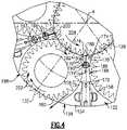
- FIG. 4is an enlarged view of a portion of the epicyclic gear train shown in FIG. 3 with a sun gear and star gears shown in phantom.
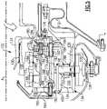
- FIG. 5is an enlarged view of a portion of the epicyclic gear train shown in FIG. 2 .
- FIG. 6shows a feature of a gear.
- FIG. 7Ashows an assembly step
- FIG. 7Bshows a subsequent assembly step
- FIG. 7Cshown another subsequent step.
- FIG. 7Dshows a torque frame
- FIG. 7Eshows a subsequent step.
- FIG. 7Fshows you another subsequent step.
- FIG. 8schematically illustrates a star gear being inserted into the carrier.
- FIG. 1schematically illustrates a gas turbine engine 20 .
- the gas turbine engine 20is disclosed herein as a two-spool turbofan that generally incorporates a fan section 22 , a compressor section 24 , a combustor section 26 and a turbine section 28 .
- Alternative enginesmight include an augmentor section (not shown) among other systems or features.
- the fan section 22drives air along a bypass flowpath B while the compressor section 24 drives air along a core flowpath C for compression and communication into the combustor section 26 then expansion through the turbine section 28 .
- FIG. 1schematically illustrates a gas turbine engine 20 .
- the gas turbine engine 20is disclosed herein as a two-spool turbofan that generally incorporates a fan section 22 , a compressor section 24 , a combustor section 26 and a turbine section 28 .
- Alternative enginesmight include an augmentor section (not shown) among other systems or features.
- the fan section 22drives air along a bypass flowpath B while the compressor section 24 drives air along
- the engine 20generally includes a low speed spool 30 and a high speed spool 32 mounted for rotation about an engine central longitudinal axis A relative to an engine static structure 36 via several bearing systems 38 . It should be understood that various bearing systems 38 at various locations may alternatively or additionally be provided.
- the low speed spool 30generally includes an inner shaft 40 that interconnects a fan 42 , a low pressure compressor 44 and a low pressure turbine 46 .
- the inner shaft 40is connected to the fan 42 through a geared architecture 48 to drive the fan 42 at a lower speed than the low speed spool 30 .
- the high speed spool 32includes an outer shaft 50 that interconnects a high pressure compressor 52 and high pressure turbine 54 .
- a combustor 56is arranged between the high pressure compressor 52 and the high pressure turbine 54 .
- a mid-turbine frame 57 of the engine static structure 36is arranged generally between the high pressure turbine 54 and the low pressure turbine 46 .
- the mid-turbine frame 57further supports bearing systems 38 in the turbine section 28 .
- the inner shaft 40 and the outer shaft 50are concentric and rotate via bearing systems 38 about the engine central longitudinal axis A which is collinear with their longitudinal axes.
- the core airflowis compressed by the low pressure compressor 44 then the high pressure compressor 52 , mixed and burned with fuel in the combustor 56 , then expanded over the high pressure turbine 54 and low pressure turbine 46 .
- the mid-turbine frame 57includes airfoils 59 which are in the core airflow path.
- the turbines 46 , 54rotationally drive the respective low speed spool 30 and high speed spool 32 in response to the expansion.
- the engine 20 in one exampleis a high-bypass geared aircraft engine.
- the engine 20 bypass ratiois greater than about six (6), with an example embodiment being greater than ten (10)
- the geared architecture 48is an epicyclic gear train, such as a planetary gear system or other gear system, with a gear reduction ratio of greater than about 2.3
- the low pressure turbine 46has a pressure ratio that is greater than about 5.
- the engine 20 bypass ratiois greater than about ten (10:1)
- the fan diameteris significantly larger than that of the low pressure compressor 44
- the low pressure turbine 46has a pressure ratio that is greater than about 5:1.
- Low pressure turbine 46 pressure ratiois pressure measured prior to inlet of low pressure turbine 46 as related to the pressure at the outlet of the low pressure turbine 46 prior to an exhaust nozzle.
- the geared architecture 48may be an epicycle gear train, such as a planetary gear system or other gear system, with a gear reduction ratio of greater than about 2.5:1. It should be understood, however, that the above parameters are only exemplary of one embodiment of a geared architecture engine.
- the fan section 22 of the engine 20is designed for a particular flight condition—typically cruise at about 0.8 Mach and about 35,000 feet.
- TSFCThrust Specific Fuel Consumption
- Low fan pressure ratiois the pressure ratio across the fan blade alone, without a Fan Exit Guide Vane (“FEGV”) system.
- the low fan pressure ratio as disclosed herein according to one non-limiting embodimentis less than about 1.45.
- Low corrected fan tip speedis the actual fan tip speed in ft/sec divided by an industry standard temperature correction of [(Tram ° R)/(518.7° R)] 0.5 .
- the “Low corrected fan tip speed” as disclosed herein according to one non-limiting embodimentis less than about 1150 ft/second.
- the geared architecture 48may be assembled as described below for gear train 122 .
- the epicyclic gear train 122is a star gear train.
- the claimed inventionalso applies to other epicyclic gear trains such as a planetary arrangement.
- the epicyclic gear train 122includes a sun gear 128 that is connected to the compressor shaft 124 , which provides rotational input, by a splined connection 130 .
- a carrier 134is fixed to the housing 112 by a torque frame 136 .
- the carrier 134supports intermediate gears (which are star gears 132 in the arrangement shown) that are coupled to the sun gear 128 by meshed interfaces 126 between the teeth of the sun and star gears 128 , 132 .
- a ring gear 138 A/Bsurrounds the carrier 134 and is coupled to the star gears 132 by meshed interfaces 144 .
- the ring gear 138 A/Bwhich provides rotational output, is secured to the turbo fan shaft 120 by connection 142 .
- Ring gear 138is actually formed by two ring gear halves 138 A and 138 B.
- the torque frame 136grounds the carrier 134 to the housing 112 .
- mounts 154have apertures 156 receiving fingers 230 of the torque frame 136 , as shown in FIGS. 2 and 5 .
- Pins 148extend through spherical bearings 146 and bushings 152 secure the fingers 230 to the carrier 134 .
- Fasteners 150retain the pins 148 to the carrier 134 .
- the carrier 134is a unitary structure manufactured from one piece for improved structural strength and rigidity, as compared with two-part housings, as shown in FIG. 3A .
- Carrier 134is centered on an axis A (see FIG. 4 ).
- the carrier 134includes axially spaced apart side walls 160 that are interconnected by the circumferentially spaced structure defining mounts 154 , which are generally wedge-shaped members, as best shown in FIG. 3B .
- the mounts 154 and side walls 160are unitary with one another. That is, these components are fixed, such as by being welded or cast as a unitary structure, before the gear train is assembled.
- the mounts 154have opposing curved surfaces (see FIG.
- the mounts 154are circumferentially spaced about the carrier 134 to provide apertures 198 through which the star gears 132 extend to engage the ring gear 138 .
- the side walls 160include holes 162 for receiving a journal bearing 164 (see FIG. 2 ) that supports each of the star gears 132 .
- Each journal bearing 164is retained within the carrier 134 by retainers 166 fastened to the side walls 160 .
- Oil baffles 168are arranged between the side walls 160 near each of the mounts 154 , best shown in FIG. 2 .
- the baffles 168include ends 172 that abut the mounts 154 , in the example shown.
- the baffles 168also include opposing curved surfaces 170 arranged in close proximity to the star gears 128 .
- the curved surfaces 158 , 170are contiguous with and adjoin one another, in the example shown, and provide gear pockets 202 that receive the star gears 132 .
- a gear pocket 204which receives the sun gear 128 , is also provided between a surface 173 on each of the baffles 168 opposite the ends 172 .
- one of the side walls 160includes holes 174 that receive fasteners 176 which secure each of the baffles 168 to the carrier 134 .
- the baffles 168include a lubrication passage provided by a primary passage 186 that fluidly communicates with a lubricant distributor 178 .
- the lubricant distributor 178is fed oil from a lubricant supply 196 .
- the baffles 168include openings 182 that receive a tube 180 extending through a hole 183 in the side wall 160 . Seals 184 seal the tube 180 to the opening 182 and lubricant distributor 178 .
- Other tubes 192 having seals 184are used to provide oil to an external spray bar 194 through another lubrication passage (spray bar passage 193 that extends through one of the baffles 168 ).
- the external spray bar 194is secured to the carrier 134 and sprays oil in the vicinity of the sun gear 128 near the splined connection 130 (shown in FIGS. 2 and 5 ).
- the primary passage 186is in communication with first and second passages 188 , 190 that spray oil on the teeth of the sun and star gears 128 , 132 .
- the first and second passages 188 , 190are arranged ninety degrees from one another.
- baffles 168With the example baffles 168 , lubricant distribution is integrated into the baffle so that separate components are eliminated.
- the baffles 168can be constructed from a different, lighter weight material than the carrier 134 .
- the example carrier 134is constructed from one piece, which improves the structural integrity of the carrier.
- a central opening 200is machined in at least one of the side walls 160 and provides the gear pocket 204 , see FIG. 4 .
- Gear pockets 202are machined between the side walls 160 and mounts 154 for each of the star gears 132 and form apertures 198 at an outer circumference of the carrier 134 .
- the star gears 132are inserted into the central opening 200 and moved radially outwardly so that they extend through the apertures 198 and are preferably in abutment with the mounts 154 (position indicated by dashed lines in FIG. 3B ). This is schematically illustrated in FIG. 8 . In this position, there is an adequate gap, t, between the teeth of adjacent star gears 132 to accommodate a width, w, of the end 172 of the baffles 168 . After the baffles 168 have been inserted, sun gear 128 can be inserted into the central opening 200 . The star gears 132 can now be moved radially inwardly to mesh with the sun gear 128 . The baffles 168 are secured to the carrier 134 using fasteners 176 . The tubes 180 , 192 can be inserted and the rest of the lubricant distribution system can be connected.
- the star gears 132are initially inserted within the central hole 200 for the sun gear.
- the star gears 136are moved radially outwardly, and the spray bars or baffles 168 are inserted.
- the sun gear 128is then inserted, and the star gears 132 may then be moved radially inwardly to engage the sun gear 128 . All of this assembly occurs with the carrier already formed as a unitary structure.
- the star gears 132have two toothed portions, 302 and 300 , which have helical gear teeth extending in opposed directions.
- a central area 304is formed between the toothed portions 302 and 300 .
- the sun gearlooks much the same.
- the two-part ring gear 138 A/B halveseach mate with one of the two gear teeth directions.
- journal bearings 164may be inserted within the star gears 132 .
- a first half of the ring gear 138 Amay be moved onto the outer periphery of the star gears 132 .
- a manifold 210may then be mounted to the gear as shown in FIG. 7C .
- the manifold 210has a fluid connection 212 which would be received within a central aperture 214 in the journal bearings 164 .
- FIG. 7Dshows a detail of a torque frame 136 .
- fingers 230extend away from a plane of the torque frame.
- the fingers 230are received within the slots 156 in the unitary carrier 134 .
- the pins 148may then be moved inwardly through the openings 220 in the mounts 154 to lock the torque frame 156 to the carriers 134 .
- the next stepis to mount the other ring gear half 138 B, completing the gear drive. At each step, all of the components are secured in some manner. An oil gutter may then be installed.
- the arrangement as set forth abovethus provides a way to assemble an epicyclic gear train within a unitary carrier housing.
- a gear trainconfigured and assembled as disclosed herein, has an improved strength and rigidity as compared with such a train having a two-part carrier housing.
Landscapes
- Engineering & Computer Science (AREA)
- General Engineering & Computer Science (AREA)
- Mechanical Engineering (AREA)
- Chemical & Material Sciences (AREA)
- Combustion & Propulsion (AREA)
- Retarders (AREA)
Abstract
Description
This application is a continuation of U.S. patent application Ser. No. 15/869,276, filed Jan. 12, 2018, which is a continuation of U.S. patent application Ser. No. 14/222,919, filed Mar. 24, 2014, now U.S. Pat. No. 9,874,150, which is a divisional of U.S. patent application Ser. No. 13/975,635, filed Aug. 26, 2013, which is a divisional of U.S. patent application Ser. No. 13/629,834, filed Sep. 28, 2012, now U.S. Pat. No. 8,667,688, which is a continuation-in-part of U.S. patent application Ser. No. 12/718,436, filed Mar. 5, 2010, now U.S. Pat. No. 8,276,275, which is a divisional application of U.S. patent application Ser. No. 11/481,112, filed on Jul. 5, 2006, now U.S. Pat. No. 7,704,178.
This invention relates to assembling an epicyclic gear train employed to drive a turbo fan.
Gas turbine engines may employ an epicyclic gear train connected to a turbine section of the engine, which is used to drive the turbo fan. In a typical epicyclic gear train, a sun gear receives rotational input from a turbine shaft through a compressor shaft. A carrier supports intermediate gears that surround and mesh with the sun gear. A ring gear surrounds and meshes with the intermediate gears. In arrangements in which the carrier is fixed against rotation, the intermediate gears are referred to as “star” gears and the ring gear is coupled to an output shaft that supports the turbo fan. In arrangements in which the ring gear is fixed against rotation, the intermediate gears are referred to as “planetary” gears and the carrier is coupled to the output shaft that supports the turbo fan.
The housings are typically split along a central plane, and the gear train can be assembled, with the carrier housing halves then being brought together and secured. For improved strength and rigidity, as compared with a two-part housing, it is desirable for an epicyclic gear train to have a unitary carrier housing.
In a featured embodiment, a method of assembling an epicyclic gear train comprises the steps of providing a unitary carrier having a central axis that includes spaced apart walls and circumferentially spaced connecting structure defining spaced apart apertures provided at an outer circumference of the carrier. Gear pockets are provided between the walls and extend to the apertures. A central opening is in at least one of the walls. A plurality of intermediate gears are inserted through the central opening and move the intermediate gears radially outwardly into the gear pockets to extend into the apertures. A sun gear is inserted through the central opening. The plurality of intermediate gears is moved radially inwardly to engage the sun gear.
In another embodiment according to the previous embodiment, moving the plurality of intermediate gears radially inwardly to engage the sun gear occurs after the sun gear is inserted through the central opening.
In another embodiment according to any of the previous embodiments, journal bearings are inserted within each of the intermediate gears after the sun gear is inserted through the central opening.
In another embodiment according to any of the previous embodiments, a ring gear is subsequently placed on an outer periphery of the sun gears to engage the sun gears.
In another embodiment according to any of the previous embodiments, the sun gear and the intermediate gears are each formed as a single gear, and the ring gear is formed as a two-part gear.
In another embodiment according to any of the previous embodiments, a first ring gear half is first placed about the outer periphery of the intermediate gears, and a torque frame is then attached to the carrier.
In another embodiment according to any of the previous embodiments, a second ring gear half is mounted to the outer periphery subsequent to the torque frame being mounted to the carrier.
In another embodiment according to any of the previous embodiments, the torque frame has a plurality of axially extending fingers that are received within slots in the carrier, at locations circumferentially intermediate locations of the intermediate gears. The first ring gear half is moved such that it does not block radially inwardly extending apertures in a radially outer surface of the carrier. Pins are then moved into the apertures to lock the fingers within the slots, with the first ring gear half then being moved over the apertures.
In another embodiment according to any of the previous embodiments, the second ring gear half is placed on the intermediate gears subsequent to the locking of the fingers within the slots.
In another featured embodiment, a method of mounting a gear train to a torque frame comprises providing a unitary carrier having a central axis that includes spaced apart walls and circumferentially spaced connecting structure defining mounts for interconnecting the walls. Spaced apart apertures are provided between the mounts at an outer circumference of the carrier. Gear pockets are provided between the walls. Mounts extend to the apertures, and a central opening in at least one of the walls. A plurality of intermediate gears and a sun gear are inserted in the carrier. A first ring gear half is placed about the outer periphery of the intermediate gears, and attach a torque frame to the carrier.
In another embodiment according to the previous embodiment, a second ring gear half is then mounted to the outer periphery subsequent to the torque frame being mounted to the carrier.
In another embodiment according to any of the previous embodiments, the torque frame has a plurality of axially extending fingers that are received within slots in the carrier, at locations circumferentially intermediate locations of the intermediate gears. The first ring gear half is moved such that it does not block radially inwardly extending apertures in a radially outer surface of the carrier. Pins are then moved into the apertures to lock the fingers within the slots. The first ring gear half then is moved over the apertures.
In another embodiment according to any of the previous embodiments, the second ring gear half is placed on the intermediate gears subsequent to the locking of the fingers within the slots.
In another embodiment according to any of the previous embodiments, the sun gear and intermediate gears are each formed as a single gear, and the ring gear is formed.
In another embodiment according to any of the previous embodiments, the sun gear and the intermediate gears have two spaced portions. Each of the portions has helical gear teeth, with the helical gear teeth on the two portions extending in opposed directions. The two ring gear halves each have one direction of helical gear teeth, with the helical gear teeth on the two ring gear halves extending in opposed directions.
In another embodiment according to any of the previous embodiments, journal bearings are inserted within each of the intermediate gears prior to a first ring gear half being placed about the outer periphery of the intermediate gears, and attaching a torque frame to the carrier.
In another featured embodiment, a gear reduction for use in a gas turbine engine comprises a unitary carrier centered on an axis and having a pair of axially spaced apart side walls, and axially extending circumferentially spaced connecting structure for connecting the pair of spaced side walls. A central opening, and circumferentially spaced smaller openings are spaced radially outwardly of the central opening. Internal surfaces of the circumferentially spaced curved walls define intermediate gear pockets, with the intermediate gear pockets extending away from the central enlarged opening for a distance greater than a diameter of intermediate gears received in the intermediate gear pockets. Intermediate gears are received in the intermediate gear pockets, and secured at a position spaced radially inwardly of a radially outermost area in the intermediate gear pockets. The intermediate gears have teeth engaged with teeth of a sun gear received in the central opening. A ring gear is received at radially outer locations such that ring gear teeth engage teeth of the intermediate gears.
In another embodiment according to the previous embodiment, the intermediate gears and the sun gear are formed of single gear bodies. The ring gear is formed of two separate ring gear halves. The intermediate gears are secured by bushings. Journal bearings are inserted within each of the intermediate gears.
In another embodiment according to any of the previous embodiments, a torque frame has a plurality of axially extending fingers received within slots in the carrier, at locations circumferentially intermediate of locations of the intermediate gears. Pins inwardly of radially inwardly extend apertures in a radially outer surface of the carrier. The pins lock the fingers within the slot. The ring gear is received radially outwardly of the radially inwardly extending apertures.
In another embodiment according to any of the previous embodiments, the sun gear and the intermediate gears have two spaced portions. Each of the portions have helical gear teeth, with the helical gear teeth on the two portions extending in opposed directions. The two ring gear halves each has one direction of helical gear teeth, with the helical gear teeth on the two halves ring gear extending in opposed directions.
These and other features of the present invention can be best understood from the following specification and drawings, the following of which is a brief description.
Theengine 20 generally includes alow speed spool 30 and ahigh speed spool 32 mounted for rotation about an engine central longitudinal axis A relative to an enginestatic structure 36 viaseveral bearing systems 38. It should be understood that various bearingsystems 38 at various locations may alternatively or additionally be provided.
Thelow speed spool 30 generally includes aninner shaft 40 that interconnects afan 42, alow pressure compressor 44 and alow pressure turbine 46. Theinner shaft 40 is connected to thefan 42 through a gearedarchitecture 48 to drive thefan 42 at a lower speed than thelow speed spool 30. Thehigh speed spool 32 includes anouter shaft 50 that interconnects ahigh pressure compressor 52 andhigh pressure turbine 54. Acombustor 56 is arranged between thehigh pressure compressor 52 and thehigh pressure turbine 54. Amid-turbine frame 57 of the enginestatic structure 36 is arranged generally between thehigh pressure turbine 54 and thelow pressure turbine 46. Themid-turbine frame 57 furthersupports bearing systems 38 in theturbine section 28. Theinner shaft 40 and theouter shaft 50 are concentric and rotate via bearingsystems 38 about the engine central longitudinal axis A which is collinear with their longitudinal axes.
The core airflow is compressed by thelow pressure compressor 44 then thehigh pressure compressor 52, mixed and burned with fuel in thecombustor 56, then expanded over thehigh pressure turbine 54 andlow pressure turbine 46. Themid-turbine frame 57 includesairfoils 59 which are in the core airflow path. Theturbines low speed spool 30 andhigh speed spool 32 in response to the expansion.
Theengine 20 in one example is a high-bypass geared aircraft engine. In a further example, theengine 20 bypass ratio is greater than about six (6), with an example embodiment being greater than ten (10), the gearedarchitecture 48 is an epicyclic gear train, such as a planetary gear system or other gear system, with a gear reduction ratio of greater than about 2.3 and thelow pressure turbine 46 has a pressure ratio that is greater than about 5. In one disclosed embodiment, theengine 20 bypass ratio is greater than about ten (10:1), the fan diameter is significantly larger than that of thelow pressure compressor 44, and thelow pressure turbine 46 has a pressure ratio that is greater than about 5:1.Low pressure turbine 46 pressure ratio is pressure measured prior to inlet oflow pressure turbine 46 as related to the pressure at the outlet of thelow pressure turbine 46 prior to an exhaust nozzle. The gearedarchitecture 48 may be an epicycle gear train, such as a planetary gear system or other gear system, with a gear reduction ratio of greater than about 2.5:1. It should be understood, however, that the above parameters are only exemplary of one embodiment of a geared architecture engine.
A significant amount of thrust is provided by the bypass flow B due to the high bypass ratio. Thefan section 22 of theengine 20 is designed for a particular flight condition—typically cruise at about 0.8 Mach and about 35,000 feet. The flight condition of 0.8 Mach and 35,000 ft, with the engine at its best fuel consumption—also known as “bucket cruise Thrust Specific Fuel Consumption (‘TSFC’)”—is the industry standard parameter of lbm of fuel being burned divided by lbf of thrust the engine produces at that minimum point. “Low fan pressure ratio” is the pressure ratio across the fan blade alone, without a Fan Exit Guide Vane (“FEGV”) system. The low fan pressure ratio as disclosed herein according to one non-limiting embodiment is less than about 1.45. “Low corrected fan tip speed” is the actual fan tip speed in ft/sec divided by an industry standard temperature correction of [(Tram ° R)/(518.7° R)]0.5. The “Low corrected fan tip speed” as disclosed herein according to one non-limiting embodiment is less than about 1150 ft/second.
The gearedarchitecture 48 may be assembled as described below forgear train 122. In the example arrangement shown, theepicyclic gear train 122 is a star gear train. Of course, the claimed invention also applies to other epicyclic gear trains such as a planetary arrangement. Referring toFIG. 2 , theepicyclic gear train 122 includes asun gear 128 that is connected to thecompressor shaft 124, which provides rotational input, by asplined connection 130. Acarrier 134 is fixed to thehousing 112 by atorque frame 136. Thecarrier 134 supports intermediate gears (which arestar gears 132 in the arrangement shown) that are coupled to thesun gear 128 bymeshed interfaces 126 between the teeth of the sun and star gears128,132. Aring gear 138A/B surrounds thecarrier 134 and is coupled to the star gears132 bymeshed interfaces 144. Thering gear 138A/B, which provides rotational output, is secured to theturbo fan shaft 120 byconnection 142.Ring gear 138 is actually formed by tworing gear halves
In one example, thetorque frame 136 grounds thecarrier 134 to thehousing 112. For example, mounts154 haveapertures 156 receivingfingers 230 of thetorque frame 136, as shown inFIGS. 2 and 5 .Pins 148 extend throughspherical bearings 146 andbushings 152 secure thefingers 230 to thecarrier 134.Fasteners 150 retain thepins 148 to thecarrier 134.
Thecarrier 134 is a unitary structure manufactured from one piece for improved structural strength and rigidity, as compared with two-part housings, as shown inFIG. 3A .Carrier 134 is centered on an axis A (seeFIG. 4 ). Thecarrier 134 includes axially spaced apartside walls 160 that are interconnected by the circumferentially spacedstructure defining mounts 154, which are generally wedge-shaped members, as best shown inFIG. 3B . Themounts 154 andside walls 160 are unitary with one another. That is, these components are fixed, such as by being welded or cast as a unitary structure, before the gear train is assembled. Themounts 154 have opposing curved surfaces (seeFIG. 3B )158 that are in close proximity to the star gears132 and generally follow the curvature of the teeth of the star gears132 so that any oil on thecurved surfaces 158 will likely find its way to the star gears132 for additional lubrication.
Themounts 154 are circumferentially spaced about thecarrier 134 to provideapertures 198 through which the star gears132 extend to engage thering gear 138. Theside walls 160 includeholes 162 for receiving a journal bearing164 (seeFIG. 2 ) that supports each of the star gears132. Each journal bearing164 is retained within thecarrier 134 byretainers 166 fastened to theside walls 160.
Oil baffles168 are arranged between theside walls 160 near each of themounts 154, best shown inFIG. 2 . Referring toFIGS. 4 and 5 , thebaffles 168 include ends172 that abut themounts 154, in the example shown. Thebaffles 168 also include opposingcurved surfaces 170 arranged in close proximity to the star gears128. Thecurved surfaces gear pockets 202 that receive the star gears132. Agear pocket 204, which receives thesun gear 128, is also provided between asurface 173 on each of thebaffles 168 opposite the ends172.
As shown inFIG. 4 , one of theside walls 160 includesholes 174 that receivefasteners 176 which secure each of thebaffles 168 to thecarrier 134. Thebaffles 168 include a lubrication passage provided by aprimary passage 186 that fluidly communicates with alubricant distributor 178. Thelubricant distributor 178 is fed oil from alubricant supply 196. In one example, thebaffles 168 includeopenings 182 that receive atube 180 extending through ahole 183 in theside wall 160.Seals 184 seal thetube 180 to theopening 182 andlubricant distributor 178.Other tubes 192 havingseals 184 are used to provide oil to anexternal spray bar 194 through another lubrication passage (spray bar passage 193 that extends through one of the baffles168). Theexternal spray bar 194 is secured to thecarrier 134 and sprays oil in the vicinity of thesun gear 128 near the splined connection130 (shown inFIGS. 2 and 5 ).
Theprimary passage 186 is in communication with first andsecond passages second passages
With the example baffles168, lubricant distribution is integrated into the baffle so that separate components are eliminated. Thebaffles 168 can be constructed from a different, lighter weight material than thecarrier 134.
Theexample carrier 134 is constructed from one piece, which improves the structural integrity of the carrier. Acentral opening 200 is machined in at least one of theside walls 160 and provides thegear pocket 204, seeFIG. 4 . Gear pockets202 are machined between theside walls 160 and mounts154 for each of the star gears132 andform apertures 198 at an outer circumference of thecarrier 134.
Returning toFIG. 3B , the star gears132 are inserted into thecentral opening 200 and moved radially outwardly so that they extend through theapertures 198 and are preferably in abutment with the mounts154 (position indicated by dashed lines inFIG. 3B ). This is schematically illustrated inFIG. 8 . In this position, there is an adequate gap, t, between the teeth of adjacent star gears132 to accommodate a width, w, of theend 172 of thebaffles 168. After thebaffles 168 have been inserted,sun gear 128 can be inserted into thecentral opening 200. The star gears132 can now be moved radially inwardly to mesh with thesun gear 128. Thebaffles 168 are secured to thecarrier 134 usingfasteners 176. Thetubes
As mentioned above, the star gears132 are initially inserted within thecentral hole 200 for the sun gear. The star gears136 are moved radially outwardly, and the spray bars or baffles168 are inserted. Thesun gear 128 is then inserted, and the star gears132 may then be moved radially inwardly to engage thesun gear 128. All of this assembly occurs with the carrier already formed as a unitary structure.
As shown inFIG. 6 , the star gears132 have two toothed portions,302 and300, which have helical gear teeth extending in opposed directions. Acentral area 304 is formed between thetoothed portions part ring gear 138A/B halves each mate with one of the two gear teeth directions.
As shown inFIG. 7A , once the sun gears128 and star gears132 are in engagement, thejournal bearings 164 may be inserted within the star gears132. After this, as shown inFIG. 7B , a first half of thering gear 138A may be moved onto the outer periphery of the star gears132. A manifold210 may then be mounted to the gear as shown inFIG. 7C . The manifold210 has a fluid connection212 which would be received within acentral aperture 214 in thejournal bearings 164.
As can be appreciated inFIG. 7E , thering gear half 138A has been moved axially such that it does not line up with theapertures 220 in the carrier, which is to receive thepin 148. Once thepin 148 has been moved inwardly to lock thefinger 230 within theslot 156, then thering gear half 138A may be moved back axially over a portion of theaperture 220.
As shown inFIG. 7F , the next step is to mount the otherring gear half 138B, completing the gear drive. At each step, all of the components are secured in some manner. An oil gutter may then be installed.
The arrangement as set forth above thus provides a way to assemble an epicyclic gear train within a unitary carrier housing. Such a gear train, configured and assembled as disclosed herein, has an improved strength and rigidity as compared with such a train having a two-part carrier housing.
Although a preferred embodiment of this invention has been disclosed, a worker of ordinary skill in this art would recognize that certain modifications would come within the scope of this invention. For that reason, the following claims should be studied to determine the true scope and content of this invention.
Claims (30)
1. A method of assembling an epicyclic gear train comprising the steps of:
providing a carrier having a central axis that includes spaced apart side walls and circumferentially spaced connecting structure defining spaced apart apertures provided at an outer circumference of the carrier, gear pockets provided between the side walls and extending to the apertures, and a central opening in at least one of the side walls;
inserting a plurality of intermediate gears through the central opening and moving the intermediate gears radially outwardly into the gear pockets to extend into the apertures;
inserting a sun gear through the central opening after the step of inserting the plurality of intermediate gears through the central opening;
moving the plurality of intermediate gears radially inwardly to engage the sun gear; and
placing a ring gear on an outer periphery of the intermediate gears to engage the intermediate gears after the step of moving the plurality of intermediate gears radially inwardly.
2. The method as set forth inclaim 1 , wherein the step of moving the plurality of intermediate gears radially inwardly occurs after the step of inserting the sun gear.
3. The method as set forth inclaim 2 , wherein the sun gear and the intermediate gears are each formed as a single gear.
4. The method as set forth inclaim 3 , further comprising providing a torque frame.
5. The method as set forth inclaim 4 , further comprising inserting journal bearings within each of the intermediate gears after the step of moving the plurality of intermediate gears radially inwardly.
6. The method as set forth inclaim 4 , wherein the torque frame has a plurality of axially extending fingers which are received within the carrier.
7. The method as set forth inclaim 6 , wherein the step of placing the ring gear on the outer periphery of the intermediate gears occurs such that the ring gear surrounds the carrier.
8. The method as set forth inclaim 7 , wherein the ring gear is formed as a two-part gear including a first ring gear half and a second ring gear half.
9. The method as set forth inclaim 8 , wherein the step of placing the ring gear on the outer periphery of the intermediate gears includes placing the first ring gear half about the outer periphery of the intermediate gears.
10. The method as set forth inclaim 9 , wherein the step of placing the ring gear on the outer periphery of the intermediate gears includes mounting the second ring gear half to the outer periphery subsequent to the step of attaching the torque frame to the carrier.
11. The method as set forth inclaim 10 , further comprising securing the ring gear to a fan shaft by a connection.
12. The method as set forth inclaim 11 , wherein the step of securing the ring gear includes securing each of the first ring gear half and the second ring gear half to the fan shaft by the connection.
13. The method as set forth inclaim 12 , wherein each of the first ring gear half and the second ring gear half includes a radially outward extending flange, and the step of securing the ring gear includes securing the flange of the first ring gear half and the flange of the second ring gear half to the fan shaft by the connection.
14. The method as set forth inclaim 10 , wherein the step of placing the ring gear on the outer periphery of the intermediate gears occurs such that the ring gear surrounds the carrier.
15. The method as set forth inclaim 14 , wherein the sun gear and the intermediate gears have two spaced portions, with each of the portions having helical gear teeth, with the helical gear teeth on the two portions extending in opposed directions, and the first and second ring gear halves each having one direction of helical gear teeth, with the helical gear teeth on the first and second ring gear halves extending in opposed directions.
16. The method as set forth inclaim 15 , wherein the carrier is a unitary carrier.
17. The method as set forth inclaim 16 , further comprising inserting a journal bearing within each of the intermediate gears.
18. The method as set forth inclaim 17 , wherein the step of inserting the journal bearing within each of the intermediate gears occurs after the step of moving the plurality of intermediate gears radially inwardly to engage the sun gear.
19. The method as set forth inclaim 7 , wherein the step of placing the ring gear on the outer periphery of the intermediate gears occurs such that the ring gear surrounds the carrier.
20. The method as set forth inclaim 19 , wherein the sun gear and the intermediate gears have two spaced portions, with each of the portions having helical gear teeth, with the helical gear teeth on the two portions extending in opposed directions, and the first and second ring gear halves each having one direction of helical gear teeth, with the helical gear teeth on the first and second ring gear halves extending in opposed directions.
21. The method as set forth inclaim 20 , wherein the gear pockets extend away from the central opening for a distance greater than a diameter of the intermediate gears, and the step of moving the plurality of intermediate gears radially inwardly includes securing the intermediate gears in the gear pockets at a position spaced radially inwardly of a radially outermost area in the gear pockets.
22. The method as set forth inclaim 20 , wherein the torque frame has a plurality of axially extending fingers which are received within the carrier.
23. The method as set forth inclaim 22 , wherein the first ring gear half is moved such that the first ring gear half does not line up with radially inwardly extending apertures in a radially outer surface of the carrier, and further comprising providing pins to lock the fingers within the carrier.
24. The method as set forth inclaim 23 , wherein the step of mounting the second ring gear half occurs subsequent to the locking of the fingers within the carrier.
25. The method as set forth inclaim 24 , wherein the gear pockets extend away from the central opening for a distance greater than a diameter of the intermediate gears, and the step of moving the plurality of intermediate gears radially inwardly includes securing the intermediate gears in the gear pockets at a position spaced radially inwardly of a radially outermost area in the gear pockets.
26. The method as set forth inclaim 25 , wherein the sun gear and the intermediate gears have two spaced portions, with each of the portions having helical gear teeth, with the helical gear teeth on the two portions extending in opposed directions, and the first and second ring gear halves each having one direction of helical gear teeth, with the helical gear teeth on the first and second ring gear halves extending in opposed directions.
27. The method as set forth inclaim 26 , further comprising securing the ring gear to a fan shaft by a connection.
28. The method as set forth inclaim 27 , wherein the step of securing the ring gear includes securing each of the first ring gear half and the second ring gear half to the fan shaft by the connection.
29. The method as set forth inclaim 28 , further comprising providing a plurality of oil baffles having lubrication passages, wherein the carrier is a unitary carrier.
30. The method as set forth inclaim 29 , wherein each of the first ring gear half and the second ring gear half includes a radially outward extending flange, and the step of securing the ring gear includes securing the flange of the first ring gear half and the flange of the second ring gear half to the fan shaft by the connection.
Priority Applications (4)
| Application Number | Priority Date | Filing Date | Title |
|---|---|---|---|
| US16/936,791US11339726B2 (en) | 2006-07-05 | 2020-07-23 | Method of assembly for gas turbine fan drive gear system |
| US17/729,129US11773787B2 (en) | 2006-07-05 | 2022-04-26 | Method of assembly for gas turbine fan drive gear system |
| US18/242,104US12168959B2 (en) | 2012-09-28 | 2023-09-05 | Gas turbine fan drive gear system |
| US18/919,600US20250043732A1 (en) | 2012-09-28 | 2024-10-18 | Method of assembly for gas turbine fan drive gear system |
Applications Claiming Priority (7)
| Application Number | Priority Date | Filing Date | Title |
|---|---|---|---|
| US11/481,112US7704178B2 (en) | 2006-07-05 | 2006-07-05 | Oil baffle for gas turbine fan drive gear system |
| US12/718,436US8276275B2 (en) | 2006-07-05 | 2010-03-05 | Method for assembling an epicyclic gear train |
| US201213975635A | 2012-08-26 | 2012-08-26 | |
| US13/629,834US8667688B2 (en) | 2006-07-05 | 2012-09-28 | Method of assembly for gas turbine fan drive gear system |
| US14/222,919US9874150B2 (en) | 2006-07-05 | 2014-03-24 | Method of assembly for gas turbine fan drive gear system |
| US15/869,276US10753285B2 (en) | 2006-07-05 | 2018-01-12 | Method of assembly for gas turbine fan drive gear system |
| US16/936,791US11339726B2 (en) | 2006-07-05 | 2020-07-23 | Method of assembly for gas turbine fan drive gear system |
Related Parent Applications (1)
| Application Number | Title | Priority Date | Filing Date |
|---|---|---|---|
| US15/869,276ContinuationUS10753285B2 (en) | 2006-07-05 | 2018-01-12 | Method of assembly for gas turbine fan drive gear system |
Related Child Applications (1)
| Application Number | Title | Priority Date | Filing Date |
|---|---|---|---|
| US17/729,129ContinuationUS11773787B2 (en) | 2006-07-05 | 2022-04-26 | Method of assembly for gas turbine fan drive gear system |
Publications (2)
| Publication Number | Publication Date |
|---|---|
| US20200355123A1 US20200355123A1 (en) | 2020-11-12 |
| US11339726B2true US11339726B2 (en) | 2022-05-24 |
Family
ID=47556163
Family Applications (7)
| Application Number | Title | Priority Date | Filing Date |
|---|---|---|---|
| US13/629,834ActiveUS8667688B2 (en) | 2006-07-05 | 2012-09-28 | Method of assembly for gas turbine fan drive gear system |
| US13/975,635ActiveUS8763251B2 (en) | 2006-07-05 | 2013-08-26 | Method of assembly for gas turbine fan drive gear system |
| US14/159,559ActiveUS8939714B1 (en) | 2006-07-05 | 2014-01-21 | Method of assembly for gas turbine fan drive gear system |
| US14/222,919Active2028-02-13US9874150B2 (en) | 2006-07-05 | 2014-03-24 | Method of assembly for gas turbine fan drive gear system |
| US15/869,276Active2026-10-31US10753285B2 (en) | 2006-07-05 | 2018-01-12 | Method of assembly for gas turbine fan drive gear system |
| US16/936,791Active2026-11-08US11339726B2 (en) | 2006-07-05 | 2020-07-23 | Method of assembly for gas turbine fan drive gear system |
| US17/729,129ActiveUS11773787B2 (en) | 2006-07-05 | 2022-04-26 | Method of assembly for gas turbine fan drive gear system |
Family Applications Before (5)
| Application Number | Title | Priority Date | Filing Date |
|---|---|---|---|
| US13/629,834ActiveUS8667688B2 (en) | 2006-07-05 | 2012-09-28 | Method of assembly for gas turbine fan drive gear system |
| US13/975,635ActiveUS8763251B2 (en) | 2006-07-05 | 2013-08-26 | Method of assembly for gas turbine fan drive gear system |
| US14/159,559ActiveUS8939714B1 (en) | 2006-07-05 | 2014-01-21 | Method of assembly for gas turbine fan drive gear system |
| US14/222,919Active2028-02-13US9874150B2 (en) | 2006-07-05 | 2014-03-24 | Method of assembly for gas turbine fan drive gear system |
| US15/869,276Active2026-10-31US10753285B2 (en) | 2006-07-05 | 2018-01-12 | Method of assembly for gas turbine fan drive gear system |
Family Applications After (1)
| Application Number | Title | Priority Date | Filing Date |
|---|---|---|---|
| US17/729,129ActiveUS11773787B2 (en) | 2006-07-05 | 2022-04-26 | Method of assembly for gas turbine fan drive gear system |
Country Status (1)
| Country | Link |
|---|---|
| US (7) | US8667688B2 (en) |
Cited By (2)
| Publication number | Priority date | Publication date | Assignee | Title |
|---|---|---|---|---|
| US20220260022A1 (en)* | 2006-07-05 | 2022-08-18 | Raytheon Technologies Corporation | Method of assembly for gas turbine fan drive gear system |
| US12168959B2 (en) | 2012-09-28 | 2024-12-17 | Rtx Corporation | Gas turbine fan drive gear system |
Families Citing this family (77)
| Publication number | Priority date | Publication date | Assignee | Title |
|---|---|---|---|---|
| US7704178B2 (en) | 2006-07-05 | 2010-04-27 | United Technologies Corporation | Oil baffle for gas turbine fan drive gear system |
| US8585538B2 (en) | 2006-07-05 | 2013-11-19 | United Technologies Corporation | Coupling system for a star gear train in a gas turbine engine |
| US8858388B2 (en) | 2006-08-15 | 2014-10-14 | United Technologies Corporation | Gas turbine engine gear train |
| US8753243B2 (en) | 2006-08-15 | 2014-06-17 | United Technologies Corporation | Ring gear mounting arrangement with oil scavenge scheme |
| US9976437B2 (en) | 2006-08-15 | 2018-05-22 | United Technologies Corporation | Epicyclic gear train |
| US10107231B2 (en) | 2006-08-15 | 2018-10-23 | United Technologies Corporation | Gas turbine engine with geared architecture |
| US8777793B2 (en) | 2011-04-27 | 2014-07-15 | United Technologies Corporation | Fan drive planetary gear system integrated carrier and torque frame |
| ITTO20111007A1 (en)* | 2011-11-03 | 2013-05-04 | Avio Spa | EPICYCLOIDAL ROTISM |
| US10400629B2 (en) | 2012-01-31 | 2019-09-03 | United Technologies Corporation | Gas turbine engine shaft bearing configuration |
| US8863491B2 (en) | 2012-01-31 | 2014-10-21 | United Technologies Corporation | Gas turbine engine shaft bearing configuration |
| US9038366B2 (en) | 2012-01-31 | 2015-05-26 | United Technologies Corporation | LPC flowpath shape with gas turbine engine shaft bearing configuration |
| US8402741B1 (en)* | 2012-01-31 | 2013-03-26 | United Technologies Corporation | Gas turbine engine shaft bearing configuration |
| DE102012012098B4 (en)* | 2012-06-18 | 2024-10-02 | Zf Friedrichshafen Ag | Casting core for producing a planetary carrier |
| US8753065B2 (en) | 2012-09-27 | 2014-06-17 | United Technologies Corporation | Method for setting a gear ratio of a fan drive gear system of a gas turbine engine |
| US8678743B1 (en)* | 2013-02-04 | 2014-03-25 | United Technologies Corporation | Method for setting a gear ratio of a fan drive gear system of a gas turbine engine |
| US10119475B2 (en)* | 2013-02-13 | 2018-11-06 | United Technologies Corporation | Gas turbine engine geared architecture |
| US9739173B2 (en)* | 2013-10-01 | 2017-08-22 | United Technologies Corporation | Gas turbine lubrication systems |
| EP3097324B2 (en) | 2014-01-20 | 2024-11-27 | RTX Corporation | Lightweight journal support pin |
| US10280843B2 (en) | 2014-03-07 | 2019-05-07 | United Technologies Corporation | Geared turbofan with integral front support and carrier |
| DE102014114043A1 (en) | 2014-09-26 | 2016-03-31 | Rolls-Royce Deutschland Ltd & Co Kg | Aero engine with a compressor device |
| US9745898B2 (en)* | 2014-12-18 | 2017-08-29 | United Technologies Corporation | Planetary gear system for turbomachine |
| US9941977B2 (en) | 2015-01-02 | 2018-04-10 | Google Llc | Data transmission between devices over audible sound |
| US20160230674A1 (en)* | 2015-02-09 | 2016-08-11 | United Technologies Corporation | Gear reduction for lower thrust geared turbofan |
| US10669946B2 (en) | 2015-06-05 | 2020-06-02 | Raytheon Technologies Corporation | Geared architecture for a gas turbine engine |
| EP3112648A1 (en)* | 2015-06-29 | 2017-01-04 | United Technologies Corporation | Gas turbine engine with geared architecture |
| GB2542338B (en)* | 2015-09-10 | 2018-11-21 | Rolls Royce Plc | Gear trains |
| FR3041730B1 (en) | 2015-09-30 | 2018-12-07 | Safran Transmission Systems | DEVICE FOR MOUNTING A CROWN OF AN EPICYCLOIDAL TRAIN |
| US10267365B2 (en)* | 2015-12-11 | 2019-04-23 | General Electric Company | Power gearbox pin arrangement |
| US10082203B2 (en)* | 2016-05-20 | 2018-09-25 | United Technologies Corporation | Low-cost epicyclic gear carrier and method of making the same |
| FR3052213B1 (en)* | 2016-06-07 | 2018-05-18 | Safran Transmission Systems | METHOD FOR ASSEMBLING A SATELLITE HOLDER |
| FR3052212B1 (en)* | 2016-06-07 | 2018-05-18 | Safran Transmission Systems | EPICYCLOIDAL OR PLANETARY REDUCER MOUNTING TOOL AND ASSOCIATED METHOD |
| US10801442B2 (en) | 2017-02-08 | 2020-10-13 | General Electric Company | Counter rotating turbine with reversing reduction gear assembly |
| US10465606B2 (en) | 2017-02-08 | 2019-11-05 | General Electric Company | Counter rotating turbine with reversing reduction gearbox |
| US10823114B2 (en) | 2017-02-08 | 2020-11-03 | General Electric Company | Counter rotating turbine with reversing reduction gearbox |
| US11174782B2 (en)* | 2017-02-10 | 2021-11-16 | Pratt & Whitney Canada Corp. | Planetary gearbox for gas turbine engine |
| FR3065773B1 (en)* | 2017-04-27 | 2020-03-06 | Safran Transmission Systems | CAGE SATELLITE HOLDER FOR AN EPICYCLOIDAL SPEED REDUCER |
| FR3069300B1 (en)* | 2017-07-20 | 2019-07-26 | Safran Transmission Systems | ASSEMBLY COMPRISING A LUBRICATING WHEEL AND LUBRICANT SPRINKLERS FOR A TURBOMACHINE EPICYCLOIDAL TRAIN SPEED REDUCER |
| DE102017008674A1 (en)* | 2017-09-15 | 2019-03-21 | Rolls-Royce Deutschland Ltd & Co Kg | planetary gear |
| US10781717B2 (en) | 2017-09-20 | 2020-09-22 | General Electric Company | Turbomachine with alternatingly spaced turbine rotor blades |
| US10823000B2 (en) | 2017-09-20 | 2020-11-03 | General Electric Company | Turbomachine with alternatingly spaced turbine rotor blades |
| US10823001B2 (en) | 2017-09-20 | 2020-11-03 | General Electric Company | Turbomachine with alternatingly spaced turbine rotor blades |
| US10738617B2 (en) | 2017-09-20 | 2020-08-11 | General Electric Company | Turbomachine with alternatingly spaced turbine rotor blades |
| US11098592B2 (en) | 2017-09-20 | 2021-08-24 | General Electric Company | Turbomachine with alternatingly spaced turbine rotor blades |
| EP3473892A1 (en)* | 2017-10-18 | 2019-04-24 | Ge Avio S.r.l. | Gearbox for a gas turbine engine |
| EP3473893B1 (en) | 2017-10-19 | 2020-06-17 | Ge Avio S.r.l. | Lubrication fluid collection in a gearbox of a gas turbine engine |
| FR3073915B1 (en)* | 2017-11-17 | 2019-10-25 | Safran Transmission Systems | TURBOMACHINE PLANETARY OR EPICYCLOIDAL TRAIN SPEED CAGE |
| US10724445B2 (en) | 2018-01-03 | 2020-07-28 | Raytheon Technologies Corporation | Method of assembly for fan drive gear system with rotating carrier |
| US10927944B2 (en) | 2018-01-26 | 2021-02-23 | Pratt & Whitney Canada Corp. | Compact, twist controlled planet carrier and epicyclic gear train having same |
| US10760677B2 (en) | 2018-01-31 | 2020-09-01 | Pratt & Whitney Canada Corp. | Epicyclic gear train with balanced carrier stiffness |
| IT201800003231A1 (en) | 2018-03-02 | 2019-09-02 | Ge Avio Srl | LUBRICANT RECOVERY SYSTEM FOR A GEAR GROUP |
| DE102018106488A1 (en)* | 2018-03-20 | 2019-09-26 | Rolls-Royce Deutschland Ltd & Co Kg | Gas turbine engine and method of introducing oil into a transmission assembly |
| DE102018106564B4 (en)* | 2018-03-20 | 2024-03-21 | Rolls-Royce Deutschland Ltd & Co Kg | Planetary gearbox, gas turbine engine with planetary gearbox and method for producing a planetary gearbox |
| DE102018106864A1 (en) | 2018-03-22 | 2019-09-26 | Rolls-Royce Deutschland Ltd & Co Kg | A method of assembling a planetary gear, a planetary carrier and an aircraft engine |
| IT201800005822A1 (en)* | 2018-05-29 | 2019-11-29 | ATTACHMENT OF A GEAR GROUP FOR A GAS TURBINE ENGINE | |
| FR3084428B1 (en) | 2018-07-26 | 2020-09-11 | Safran Trans Systems | PLANETARY OR EPICYCLOIDAL GEAR REDUCER CAGE FOR TURBOMACHINE |
| US10851886B2 (en)* | 2018-08-24 | 2020-12-01 | Magna Powertrain Of America Inc. | Power transfer assembly with planetary gearset having carrier with crack arresting features |
| FR3087841B1 (en)* | 2018-10-26 | 2020-10-23 | Safran Aircraft Engines | AIRCRAFT TURBOMACHINE EQUIPPED WITH AN ELECTRIC MACHINE |
| GB201820399D0 (en)* | 2018-12-14 | 2019-01-30 | Rolls Royce Plc | Planet carrier and method of assembling of a planet carrier |
| FR3092888B1 (en)* | 2019-02-14 | 2021-01-22 | Safran Trans Systems | LUBRICATION OF A SATELLITE CARRIER FOR A MECHANICAL TURBOMACHINE REDUCER, IN PARTICULAR OF AIRCRAFT |
| FR3092884B1 (en) | 2019-02-20 | 2022-12-16 | Safran Trans Systems | PLANETARY REDUCER ASSEMBLY FOR A TURBOMACHINE |
| US11118535B2 (en)* | 2019-03-05 | 2021-09-14 | General Electric Company | Reversing gear assembly for a turbo machine |
| DE102019108323B4 (en)* | 2019-03-29 | 2023-10-05 | Eickhoff Antriebstechnik Gmbh | Planetary gear and method for producing a planetary gear |
| DE102020115733A1 (en)* | 2019-06-22 | 2020-12-24 | Aerospace Transmission Technologies GmbH | Planetary gear carrier with an outer circumferential insertion opening for the radial supply of a sun gear and planetary gears |
| IT201900016892A1 (en) | 2019-09-20 | 2021-03-20 | Ge Avio Srl | TRAILER CARRIER FOR EPICYCLOIDAL ROTATION |
| US11391217B2 (en)* | 2019-10-03 | 2022-07-19 | Rolls-Royce Corporation | Stiffening member for epicyclical gear system housing assembly |
| US11353089B2 (en) | 2019-10-03 | 2022-06-07 | Rolls-Royce Corporation | Epicyclical gear system housing assembly |
| EP3812626A1 (en)* | 2019-10-24 | 2021-04-28 | Flender GmbH | Planetary gear, especially multiplanetary gear, for a wind power plant |
| US11643972B2 (en)* | 2020-06-15 | 2023-05-09 | Ge Avio S.R.L. | Turbomachines and epicyclic gear assemblies with symmetrical compound arrangement |
| FR3117171B1 (en)* | 2020-12-03 | 2022-10-21 | Safran | POWER TRANSMISSION SYSTEM FEATURING AN IMPROVED OIL COLLECTION GUTTER |
| US11428160B2 (en) | 2020-12-31 | 2022-08-30 | General Electric Company | Gas turbine engine with interdigitated turbine and gear assembly |
| IT202100015386A1 (en)* | 2021-06-11 | 2022-12-11 | Ge Avio Srl | TURBOMACHINES AND PLANETARY GEAR SETS WITH LUBRICATION CHANNELS |
| FR3124564B1 (en)* | 2021-06-24 | 2023-07-21 | Safran Trans Systems | SATELLITE CARRIER FOR AN AIRCRAFT TURBOMACHINE SPEED REDUCER |
| US11873767B2 (en)* | 2021-10-22 | 2024-01-16 | Ge Avio S.R.L. | Gearbox configurations for clockwise and counterclockwise propeller rotation |
| US11598407B1 (en)* | 2022-02-16 | 2023-03-07 | Pratt & Whitney Canada Corp. | Epicyclic gear train of aircraft powerplant |
| FR3139612B1 (en)* | 2022-09-09 | 2024-10-25 | Safran Trans Systems | SATELLITE CARRIER FOR A SPEED REDUCER OF AN AIRCRAFT TURBOMACHINE |
| US12104541B1 (en) | 2023-05-09 | 2024-10-01 | Pratt & Whitney Canada Corp. | Method and system for assembling a reduction gearbox |
| US12092200B1 (en)* | 2023-08-23 | 2024-09-17 | Allison Transmission, Inc. | Lubrication of a planetary gear system |
Citations (143)
| Publication number | Priority date | Publication date | Assignee | Title |
|---|---|---|---|---|
| US1276275A (en) | 1916-06-26 | 1918-08-20 | Underwood Typewriter Co | Type-writing machine. |
| US1827712A (en) | 1929-12-31 | 1931-10-13 | Draper Corp | Let-off mechanism for looms |
| US1914904A (en) | 1932-07-23 | 1933-06-20 | George H B West | Terminal post sealing structure |
| US2258792A (en) | 1941-04-12 | 1941-10-14 | Westinghouse Electric & Mfg Co | Turbine blading |
| US2591743A (en) | 1948-11-23 | 1952-04-08 | Gen Electric | Cage construction for planetary gearing |
| US2936655A (en) | 1955-11-04 | 1960-05-17 | Gen Motors Corp | Self-aligning planetary gearing |
| US2969956A (en)* | 1955-12-27 | 1961-01-31 | Licencia Talalmanyokat | Pipe joint for heat exchange devices |
| US3021731A (en) | 1951-11-10 | 1962-02-20 | Wilhelm G Stoeckicht | Planetary gear transmission |
| US3194487A (en) | 1963-06-04 | 1965-07-13 | United Aircraft Corp | Noise abatement method and apparatus |
| US3287906A (en) | 1965-07-20 | 1966-11-29 | Gen Motors Corp | Cooled gas turbine vanes |
| US3352178A (en) | 1965-11-15 | 1967-11-14 | Gen Motors Corp | Planetary gearing |
| US3412560A (en) | 1966-08-03 | 1968-11-26 | Gen Motors Corp | Jet propulsion engine with cooled combustion chamber, fuel heater, and induced air-flow |
| US3527121A (en) | 1968-08-26 | 1970-09-08 | Gen Motors Corp | Carrier |
| US3650353A (en) | 1969-02-19 | 1972-03-21 | Randle Leslie Abbott | Lubrication system for change-speed epicyclic gearing |
| US3664612A (en) | 1969-12-22 | 1972-05-23 | Boeing Co | Aircraft engine variable highlight inlet |
| US3747343A (en) | 1972-02-10 | 1973-07-24 | United Aircraft Corp | Low noise prop-fan |
| US3754484A (en) | 1971-01-08 | 1973-08-28 | Secr Defence | Gearing |
| US3765623A (en) | 1971-10-04 | 1973-10-16 | Mc Donnell Douglas Corp | Air inlet |
| US3820719A (en) | 1972-05-09 | 1974-06-28 | Rolls Royce 1971 Ltd | Gas turbine engines |
| US3843277A (en) | 1973-02-14 | 1974-10-22 | Gen Electric | Sound attenuating inlet duct |
| US3853432A (en) | 1973-08-29 | 1974-12-10 | Avco Corp | Differential gas turbine engine |
| US3857151A (en)* | 1973-10-15 | 1974-12-31 | Young Radiation Co | Method of making a radiator core |
| US3892358A (en) | 1971-03-17 | 1975-07-01 | Gen Electric | Nozzle seal |
| US3932058A (en) | 1974-06-07 | 1976-01-13 | United Technologies Corporation | Control system for variable pitch fan propulsor |
| US3935558A (en) | 1974-12-11 | 1976-01-27 | United Technologies Corporation | Surge detector for turbine engines |
| US3988889A (en) | 1974-02-25 | 1976-11-02 | General Electric Company | Cowling arrangement for a turbofan engine |
| GB1516041A (en) | 1977-02-14 | 1978-06-28 | Secr Defence | Multistage axial flow compressor stators |
| US4130872A (en) | 1975-10-10 | 1978-12-19 | The United States Of America As Represented By The Secretary Of The Air Force | Method and system of controlling a jet engine for avoiding engine surge |
| US4191244A (en)* | 1978-02-09 | 1980-03-04 | Caterpillar Tractor Co. | Modular heat exchanger with resilient mounting and sealing element |
| US4220171A (en) | 1979-05-14 | 1980-09-02 | The United States Of America As Represented By The Administrator Of The National Aeronautics And Space Administration | Curved centerline air intake for a gas turbine engine |
| GB2041090A (en) | 1979-01-31 | 1980-09-03 | Rolls Royce | By-pass gas turbine engines |
| US4240250A (en) | 1977-12-27 | 1980-12-23 | The Boeing Company | Noise reducing air inlet for gas turbine engines |
| US4271928A (en) | 1978-07-11 | 1981-06-09 | Rolls-Royce Limited | Lubricant supply device |
| US4284174A (en) | 1979-04-18 | 1981-08-18 | Avco Corporation | Emergency oil/mist system |
| US4289360A (en) | 1979-08-23 | 1981-09-15 | General Electric Company | Bearing damper system |
| US4297154A (en)* | 1979-02-09 | 1981-10-27 | National Steel Corporation | Method of manufacturing expanded reinforcing sheet material |
| US4378711A (en) | 1980-09-29 | 1983-04-05 | Caterpillar Tractor Co. | Planetary mechanism having a fluid baffle |
| US4478551A (en) | 1981-12-08 | 1984-10-23 | United Technologies Corporation | Turbine exhaust case design |
| DE3410977A1 (en) | 1984-03-16 | 1985-09-26 | BHS-Bayerische Berg-, Hütten- und Salzwerke AG, 8000 München | Epicyclic gearing |
| US4649114A (en) | 1979-10-05 | 1987-03-10 | Intermedicat Gmbh | Oxygen permeable membrane in fermenter for oxygen enrichment of broth |
| US4696156A (en) | 1986-06-03 | 1987-09-29 | United Technologies Corporation | Fuel and oil heat management system for a gas turbine engine |
| US4712868A (en)* | 1985-09-23 | 1987-12-15 | Minnesota Mining And Manufacturing Company | Expanded retroreflective sheet material |
| US4722357A (en) | 1986-04-11 | 1988-02-02 | United Technologies Corporation | Gas turbine engine nacelle |
| US4969970A (en)* | 1986-01-10 | 1990-11-13 | Uni-Charm Corporation | Apparatus for providing sanitary goods with attachment means with respect to clothing |
| US4979362A (en) | 1989-05-17 | 1990-12-25 | Sundstrand Corporation | Aircraft engine starting and emergency power generating system |
| US5058617A (en) | 1990-07-23 | 1991-10-22 | General Electric Company | Nacelle inlet for an aircraft gas turbine engine |
| US5102379A (en) | 1991-03-25 | 1992-04-07 | United Technologies Corporation | Journal bearing arrangement |
| US5141400A (en) | 1991-01-25 | 1992-08-25 | General Electric Company | Wide chord fan blade |
| JPH061889A (en) | 1992-06-18 | 1994-01-11 | Sumitomo Chem Co Ltd | Thermoplastic elastomer composition |
| US5302466A (en)* | 1991-09-04 | 1994-04-12 | The Gem City Engineering Co. | Expanded metal strip for reinforcing a resilient product |
| US5317877A (en) | 1992-08-03 | 1994-06-07 | General Electric Company | Intercooled turbine blade cooling air feed system |
| US5361580A (en) | 1993-06-18 | 1994-11-08 | General Electric Company | Gas turbine engine rotor support system |
| US5365819A (en)* | 1992-12-22 | 1994-11-22 | Prompac Industries, Inc. | Method and process for manufacturing expandable packing material |
| US5381858A (en)* | 1993-06-15 | 1995-01-17 | Fredrich; Carl | Heat exchanger and method of manufacture |
| US5391125A (en) | 1991-11-12 | 1995-02-21 | Fiat Avio S.P.A. | Epicyclic speed reducer designed for fitment to the transmission between the gas turbine and air compressor of an aircraft engine |
| US5433674A (en) | 1994-04-12 | 1995-07-18 | United Technologies Corporation | Coupling system for a planetary gear train |
| US5447411A (en) | 1993-06-10 | 1995-09-05 | Martin Marietta Corporation | Light weight fan blade containment system |
| US5461761A (en)* | 1992-11-24 | 1995-10-31 | Kuhni Ag. | Process and apparatus for the production of expanded grids |
| US5466198A (en) | 1993-06-11 | 1995-11-14 | United Technologies Corporation | Geared drive system for a bladed propulsor |
| US5472383A (en) | 1993-12-27 | 1995-12-05 | United Technologies Corporation | Lubrication system for a planetary gear train |
| US5524847A (en) | 1993-09-07 | 1996-06-11 | United Technologies Corporation | Nacelle and mounting arrangement for an aircraft engine |
| US5538079A (en)* | 1994-02-16 | 1996-07-23 | Pawlick; Daniel R. | Heat exchanger with oblong grommetted tubes and locating plates |
| US5634767A (en) | 1996-03-29 | 1997-06-03 | General Electric Company | Turbine frame having spindle mounted liner |
| EP0791383A1 (en) | 1996-02-26 | 1997-08-27 | Japan Gore-Tex, Inc. | An assembly for deaeration of liquids |
| US5677060A (en) | 1994-03-10 | 1997-10-14 | Societe Europeenne De Propulsion | Method for protecting products made of a refractory material against oxidation, and resulting protected products |
| US5778659A (en) | 1994-10-20 | 1998-07-14 | United Technologies Corporation | Variable area fan exhaust nozzle having mechanically separate sleeve and thrust reverser actuation systems |
| US5857836A (en) | 1996-09-10 | 1999-01-12 | Aerodyne Research, Inc. | Evaporatively cooled rotor for a gas turbine engine |
| US5915917A (en) | 1994-12-14 | 1999-06-29 | United Technologies Corporation | Compressor stall and surge control using airflow asymmetry measurement |
| US5975841A (en) | 1997-10-03 | 1999-11-02 | Thermal Corp. | Heat pipe cooling for turbine stators |
| US5985470A (en) | 1998-03-16 | 1999-11-16 | General Electric Company | Thermal/environmental barrier coating system for silicon-based materials |
| US6117062A (en)* | 1988-12-06 | 2000-09-12 | Alhamad; Shaikh Ghaleb Mohammad Yassin | Compositions of matter for stopping fires, explosions and oxidations of materials and build up of electrostatic charges and method and apparatus for making same |
| US6158210A (en) | 1998-12-03 | 2000-12-12 | General Electric Company | Gear driven booster |
| US6223616B1 (en) | 1999-12-22 | 2001-05-01 | United Technologies Corporation | Star gear system with lubrication circuit and lubrication method therefor |
| US6247232B1 (en)* | 1999-03-10 | 2001-06-19 | Transpro, Inc. | Method of manufacturing a welded heat exchanger with grommet construction |
| EP1142850A1 (en) | 2000-04-06 | 2001-10-10 | General Electric Company | Thermal/environmental barrier coating for silicon-containing materials |
| US6315815B1 (en) | 1999-12-16 | 2001-11-13 | United Technologies Corporation | Membrane based fuel deoxygenator |
| US6318070B1 (en) | 2000-03-03 | 2001-11-20 | United Technologies Corporation | Variable area nozzle for gas turbine engines driven by shape memory alloy actuators |
| US6368438B1 (en)* | 1998-11-05 | 2002-04-09 | Sika Corporation | Sound deadening and structural reinforcement compositions and methods of using the same |
| US6387456B1 (en) | 1999-04-15 | 2002-05-14 | General Electric Company | Silicon based substrate with environmental/thermal barrier layer |
| US6422791B1 (en) | 2000-04-04 | 2002-07-23 | Abb Vetco Gray Inc. | Riser to sleeve attachment for flexible keel joint |
| US6517341B1 (en) | 1999-02-26 | 2003-02-11 | General Electric Company | Method to prevent recession loss of silica and silicon-containing materials in combustion gas environments |
| US6607165B1 (en) | 2002-06-28 | 2003-08-19 | General Electric Company | Aircraft engine mount with single thrust link |
| US6629016B1 (en)* | 2002-03-28 | 2003-09-30 | Amerimax Diversified Products, Inc. | Apparatus and method of manufacturing expanded sheet metal |
| US6709492B1 (en) | 2003-04-04 | 2004-03-23 | United Technologies Corporation | Planar membrane deoxygenator |
| US6800186B1 (en)* | 1994-09-30 | 2004-10-05 | James L. Forand | Method and apparatus for electrochemical processing |
| US6814541B2 (en) | 2002-10-07 | 2004-11-09 | General Electric Company | Jet aircraft fan case containment design |
| US20040259679A1 (en) | 2003-04-04 | 2004-12-23 | Hispano Suiza | Flexible connection system between a planet carrier and the stationary support in a speed reduction gear train |
| US6883303B1 (en) | 2001-11-29 | 2005-04-26 | General Electric Company | Aircraft engine with inter-turbine engine frame |
| JP2005163666A (en) | 2003-12-03 | 2005-06-23 | Komatsu Ltd | Wind speed booster |
| JP2005207472A (en) | 2004-01-21 | 2005-08-04 | Nsk Ltd | Planetary mechanism power transmission device and carrier processing method thereof |
| US7021042B2 (en) | 2002-12-13 | 2006-04-04 | United Technologies Corporation | Geartrain coupling for a turbofan engine |
| US7033301B2 (en) | 2004-02-26 | 2006-04-25 | Ford Global Technologies, Llc | Planet pinion carrier assembly for Ravigneaux gearset |
| US7104918B2 (en) | 2003-07-29 | 2006-09-12 | Pratt & Whitney Canada Corp. | Compact epicyclic gear carrier |
| US7112157B2 (en) | 2003-05-27 | 2006-09-26 | A. Friedr. Flender Aktiengesellschaft | Gear unit for the drive of a rotation tube |
| US20060228206A1 (en) | 2005-04-07 | 2006-10-12 | General Electric Company | Low solidity turbofan |
| GB2426792A (en) | 2005-04-01 | 2006-12-06 | David Richard Hopkins | Fan with conical hub |
| WO2007038674A1 (en) | 2005-09-28 | 2007-04-05 | Entrotech Composites, Llc | Braid-reinforced composites and processes for their preparation |
| US7214160B2 (en) | 2003-07-29 | 2007-05-08 | Zf Friedrichshafen Ag | Planet carrier assembly |
| EP1783344A1 (en) | 2005-10-19 | 2007-05-09 | General Electric Company | Gas turbine engine assembly and methods of assembling same |
| US7219490B2 (en) | 2000-09-05 | 2007-05-22 | D-Star Engineering | Nested core gas turbine engine |
| US20080003096A1 (en) | 2006-06-29 | 2008-01-03 | United Technologies Corporation | High coverage cooling hole shape |
| EP1876338A2 (en) | 2006-07-05 | 2008-01-09 | United Technologies Corporation | Oil baffle for gas turbine fan drive gear system |
| US7328580B2 (en) | 2004-06-23 | 2008-02-12 | General Electric Company | Chevron film cooled wall |
| US7338404B2 (en) | 2005-01-28 | 2008-03-04 | Gkn Driveline International Gmbh | Drive assembly for variable torque distribution |
| US20080116009A1 (en) | 2006-11-22 | 2008-05-22 | United Technologies Corporation | Lubrication system with extended emergency operability |
| US7406849B2 (en)* | 2004-09-29 | 2008-08-05 | Nissan Motor Co., Ltd. | Preform, hydroforming method, and hydroformed product |
| US7428774B2 (en)* | 2005-05-25 | 2008-09-30 | Zephyros, Inc. | Baffle for an automotive vehicle and method of use therefor |
| US7442143B2 (en) | 2005-01-28 | 2008-10-28 | Gkn Driveline International Gmbh | Drive module for a variable torque distribution |
| US20080317588A1 (en) | 2007-06-25 | 2008-12-25 | Grabowski Zbigniew M | Managing spool bearing load using variable area flow nozzle |
| US20090056343A1 (en) | 2007-08-01 | 2009-03-05 | Suciu Gabriel L | Engine mounting configuration for a turbofan gas turbine engine |
| US20090111639A1 (en) | 2005-11-12 | 2009-04-30 | Mtu Aero Engines Gmbh | Planetary Gear |
| US7591754B2 (en) | 2006-03-22 | 2009-09-22 | United Technologies Corporation | Epicyclic gear train integral sun gear coupling design |
| US20090304518A1 (en) | 2006-07-04 | 2009-12-10 | Ihi Corporation | Turbofan engine |
| US7632064B2 (en) | 2006-09-01 | 2009-12-15 | United Technologies Corporation | Variable geometry guide vane for a gas turbine engine |
| US20090314881A1 (en) | 2008-06-02 | 2009-12-24 | Suciu Gabriel L | Engine mount system for a turbofan gas turbine engine |
| US20100035719A1 (en) | 2008-08-06 | 2010-02-11 | Sheng Bor Wang | Epicyclic gearing |
| US7662059B2 (en) | 2006-10-18 | 2010-02-16 | United Technologies Corporation | Lubrication of windmilling journal bearings |
| US20100105516A1 (en) | 2006-07-05 | 2010-04-29 | United Technologies Corporation | Coupling system for a star gear train in a gas turbine engine |
| US20100148396A1 (en) | 2007-04-17 | 2010-06-17 | General Electric Company | Methods of making articles having toughened and untoughened regions |
| US20100150702A1 (en) | 2006-07-05 | 2010-06-17 | United Technologies Corporation | Flexible shaft for gas turbine engine |
| US20100212281A1 (en) | 2009-02-26 | 2010-08-26 | United Technologies Corporation | Auxiliary pump system for fan drive gear system |
| US20100218483A1 (en) | 2009-02-27 | 2010-09-02 | United Technologies Corporation | Controlled fan stream flow bypass |
| US7806651B2 (en) | 2004-04-02 | 2010-10-05 | Mtu Aero Engines Gmbh | Method for designing a low-pressure turbine of an aircraft engine, and low-pressure turbine |
| US20100261571A1 (en) | 2008-04-17 | 2010-10-14 | Kawasaki Jukogyo Kabushiki Kaisha | Planetary reduction gear apparatus |
| US7828682B2 (en) | 2006-05-11 | 2010-11-09 | Hansen Transmissions International N.V. | Gearbox for a wind turbine |
| US20100331139A1 (en) | 2009-06-25 | 2010-12-30 | United Technologies Corporation | Epicyclic gear system with superfinished journal bearing |
| US7934301B2 (en)* | 2003-08-06 | 2011-05-03 | Shell Oil Company | Method of manufacturing expanded metal |
| US20110159797A1 (en) | 2009-12-31 | 2011-06-30 | Willem Beltman | Quiet System Cooling Using Coupled Optimization Between Integrated Micro Porous Absorbers And Rotors |
| US7984919B2 (en)* | 2009-05-18 | 2011-07-26 | Zephyros, Inc. | Structural mounting insert having a non-conductive isolator |
| US7997868B1 (en) | 2008-11-18 | 2011-08-16 | Florida Turbine Technologies, Inc. | Film cooling hole for turbine airfoil |
| US8003122B2 (en)* | 2004-03-31 | 2011-08-23 | Cordis Corporation | Device for local and/or regional delivery employing liquid formulations of therapeutic agents |
| US20110293423A1 (en) | 2010-05-28 | 2011-12-01 | General Electric Company | Articles which include chevron film cooling holes, and related processes |
| US8133929B2 (en)* | 2008-04-15 | 2012-03-13 | Sika Technology Ag | Method for incorporating long glass fibers into epoxy-based reinforcing resins |
| US8172717B2 (en) | 2011-06-08 | 2012-05-08 | General Electric Company | Compliant carrier wall for improved gearbox load sharing |
| US20120124964A1 (en) | 2007-07-27 | 2012-05-24 | Hasel Karl L | Gas turbine engine with improved fuel efficiency |
| US8202772B2 (en) | 2008-11-05 | 2012-06-19 | Ss Sc Ip, Llc | Vertical junction field effect transistors having sloped sidewalls and methods of making |
| US8205432B2 (en) | 2007-10-03 | 2012-06-26 | United Technologies Corporation | Epicyclic gear train for turbo fan engine |
| WO2012098108A1 (en) | 2011-01-17 | 2012-07-26 | Gkn Stromag Ag | Plate coupling |
| US20130102432A1 (en) | 2010-04-13 | 2013-04-25 | Kawasaki Jukogyo Kabushiki Kaisha | Planetary gear system |
| US8580058B2 (en)* | 2002-03-29 | 2013-11-12 | Zephyros, Inc. | Structurally reinforced members |
| US20140045645A1 (en) | 2006-07-05 | 2014-02-13 | United Technologies Corporation | Method of Assembly for Gas Turbine Fan Drive Gear System |
| US8747272B2 (en) | 2010-04-13 | 2014-06-10 | Kawasaki Jukogyo Kabushiki Kaisha | Planetary gear system and gear reducer |
| US8753243B2 (en) | 2006-08-15 | 2014-06-17 | United Technologies Corporation | Ring gear mounting arrangement with oil scavenge scheme |
Family Cites Families (5)
| Publication number | Priority date | Publication date | Assignee | Title |
|---|---|---|---|---|
| GB8630754D0 (en) | 1986-12-23 | 1987-02-04 | Rolls Royce Plc | Turbofan gas turbine engine |
| US4914904A (en) | 1988-11-09 | 1990-04-10 | Avco Corporation | Oil cooler for fan jet engines |
| JP2586607Y2 (en) | 1992-06-17 | 1998-12-09 | ジャトコ株式会社 | Planetary gear set |
| US6905303B2 (en) | 2003-06-30 | 2005-06-14 | General Electric Company | Methods and apparatus for assembling gas turbine engines |
| US8204453B2 (en) | 2008-08-20 | 2012-06-19 | Intel Mobile Communications GmbH | Method, apparatus and communication unit |
- 2012
- 2012-09-28USUS13/629,834patent/US8667688B2/enactiveActive
- 2013
- 2013-08-26USUS13/975,635patent/US8763251B2/enactiveActive
- 2014
- 2014-01-21USUS14/159,559patent/US8939714B1/enactiveActive
- 2014-03-24USUS14/222,919patent/US9874150B2/enactiveActive
- 2018
- 2018-01-12USUS15/869,276patent/US10753285B2/enactiveActive
- 2020
- 2020-07-23USUS16/936,791patent/US11339726B2/enactiveActive
- 2022
- 2022-04-26USUS17/729,129patent/US11773787B2/enactiveActive
Patent Citations (154)
| Publication number | Priority date | Publication date | Assignee | Title |
|---|---|---|---|---|
| US1276275A (en) | 1916-06-26 | 1918-08-20 | Underwood Typewriter Co | Type-writing machine. |
| US1827712A (en) | 1929-12-31 | 1931-10-13 | Draper Corp | Let-off mechanism for looms |
| US1914904A (en) | 1932-07-23 | 1933-06-20 | George H B West | Terminal post sealing structure |
| US2258792A (en) | 1941-04-12 | 1941-10-14 | Westinghouse Electric & Mfg Co | Turbine blading |
| US2591743A (en) | 1948-11-23 | 1952-04-08 | Gen Electric | Cage construction for planetary gearing |
| US3021731A (en) | 1951-11-10 | 1962-02-20 | Wilhelm G Stoeckicht | Planetary gear transmission |
| US2936655A (en) | 1955-11-04 | 1960-05-17 | Gen Motors Corp | Self-aligning planetary gearing |
| US2969956A (en)* | 1955-12-27 | 1961-01-31 | Licencia Talalmanyokat | Pipe joint for heat exchange devices |
| US3194487A (en) | 1963-06-04 | 1965-07-13 | United Aircraft Corp | Noise abatement method and apparatus |
| US3287906A (en) | 1965-07-20 | 1966-11-29 | Gen Motors Corp | Cooled gas turbine vanes |
| US3352178A (en) | 1965-11-15 | 1967-11-14 | Gen Motors Corp | Planetary gearing |
| US3412560A (en) | 1966-08-03 | 1968-11-26 | Gen Motors Corp | Jet propulsion engine with cooled combustion chamber, fuel heater, and induced air-flow |
| US3527121A (en) | 1968-08-26 | 1970-09-08 | Gen Motors Corp | Carrier |
| US3650353A (en) | 1969-02-19 | 1972-03-21 | Randle Leslie Abbott | Lubrication system for change-speed epicyclic gearing |
| US3664612A (en) | 1969-12-22 | 1972-05-23 | Boeing Co | Aircraft engine variable highlight inlet |
| US3754484A (en) | 1971-01-08 | 1973-08-28 | Secr Defence | Gearing |
| US3892358A (en) | 1971-03-17 | 1975-07-01 | Gen Electric | Nozzle seal |
| US3765623A (en) | 1971-10-04 | 1973-10-16 | Mc Donnell Douglas Corp | Air inlet |
| US3747343A (en) | 1972-02-10 | 1973-07-24 | United Aircraft Corp | Low noise prop-fan |
| US3820719A (en) | 1972-05-09 | 1974-06-28 | Rolls Royce 1971 Ltd | Gas turbine engines |
| US3843277A (en) | 1973-02-14 | 1974-10-22 | Gen Electric | Sound attenuating inlet duct |
| US3853432A (en) | 1973-08-29 | 1974-12-10 | Avco Corp | Differential gas turbine engine |
| US3857151A (en)* | 1973-10-15 | 1974-12-31 | Young Radiation Co | Method of making a radiator core |
| US3988889A (en) | 1974-02-25 | 1976-11-02 | General Electric Company | Cowling arrangement for a turbofan engine |
| US3932058A (en) | 1974-06-07 | 1976-01-13 | United Technologies Corporation | Control system for variable pitch fan propulsor |
| US3935558A (en) | 1974-12-11 | 1976-01-27 | United Technologies Corporation | Surge detector for turbine engines |
| US4130872A (en) | 1975-10-10 | 1978-12-19 | The United States Of America As Represented By The Secretary Of The Air Force | Method and system of controlling a jet engine for avoiding engine surge |
| GB1516041A (en) | 1977-02-14 | 1978-06-28 | Secr Defence | Multistage axial flow compressor stators |
| US4240250A (en) | 1977-12-27 | 1980-12-23 | The Boeing Company | Noise reducing air inlet for gas turbine engines |
| US4191244A (en)* | 1978-02-09 | 1980-03-04 | Caterpillar Tractor Co. | Modular heat exchanger with resilient mounting and sealing element |
| US4271928A (en) | 1978-07-11 | 1981-06-09 | Rolls-Royce Limited | Lubricant supply device |
| GB2041090A (en) | 1979-01-31 | 1980-09-03 | Rolls Royce | By-pass gas turbine engines |
| US4297154A (en)* | 1979-02-09 | 1981-10-27 | National Steel Corporation | Method of manufacturing expanded reinforcing sheet material |
| US4284174A (en) | 1979-04-18 | 1981-08-18 | Avco Corporation | Emergency oil/mist system |
| US4220171A (en) | 1979-05-14 | 1980-09-02 | The United States Of America As Represented By The Administrator Of The National Aeronautics And Space Administration | Curved centerline air intake for a gas turbine engine |
| US4289360A (en) | 1979-08-23 | 1981-09-15 | General Electric Company | Bearing damper system |
| US4649114A (en) | 1979-10-05 | 1987-03-10 | Intermedicat Gmbh | Oxygen permeable membrane in fermenter for oxygen enrichment of broth |
| US4378711A (en) | 1980-09-29 | 1983-04-05 | Caterpillar Tractor Co. | Planetary mechanism having a fluid baffle |
| US4478551A (en) | 1981-12-08 | 1984-10-23 | United Technologies Corporation | Turbine exhaust case design |
| DE3410977A1 (en) | 1984-03-16 | 1985-09-26 | BHS-Bayerische Berg-, Hütten- und Salzwerke AG, 8000 München | Epicyclic gearing |
| US4712868A (en)* | 1985-09-23 | 1987-12-15 | Minnesota Mining And Manufacturing Company | Expanded retroreflective sheet material |
| US4969970A (en)* | 1986-01-10 | 1990-11-13 | Uni-Charm Corporation | Apparatus for providing sanitary goods with attachment means with respect to clothing |
| US4722357A (en) | 1986-04-11 | 1988-02-02 | United Technologies Corporation | Gas turbine engine nacelle |
| US4696156A (en) | 1986-06-03 | 1987-09-29 | United Technologies Corporation | Fuel and oil heat management system for a gas turbine engine |
| US6117062A (en)* | 1988-12-06 | 2000-09-12 | Alhamad; Shaikh Ghaleb Mohammad Yassin | Compositions of matter for stopping fires, explosions and oxidations of materials and build up of electrostatic charges and method and apparatus for making same |
| US4979362A (en) | 1989-05-17 | 1990-12-25 | Sundstrand Corporation | Aircraft engine starting and emergency power generating system |
| US5058617A (en) | 1990-07-23 | 1991-10-22 | General Electric Company | Nacelle inlet for an aircraft gas turbine engine |
| US5141400A (en) | 1991-01-25 | 1992-08-25 | General Electric Company | Wide chord fan blade |
| US5102379A (en) | 1991-03-25 | 1992-04-07 | United Technologies Corporation | Journal bearing arrangement |
| US5302466A (en)* | 1991-09-04 | 1994-04-12 | The Gem City Engineering Co. | Expanded metal strip for reinforcing a resilient product |
| US5391125A (en) | 1991-11-12 | 1995-02-21 | Fiat Avio S.P.A. | Epicyclic speed reducer designed for fitment to the transmission between the gas turbine and air compressor of an aircraft engine |
| JPH061889A (en) | 1992-06-18 | 1994-01-11 | Sumitomo Chem Co Ltd | Thermoplastic elastomer composition |
| US5317877A (en) | 1992-08-03 | 1994-06-07 | General Electric Company | Intercooled turbine blade cooling air feed system |
| US5461761A (en)* | 1992-11-24 | 1995-10-31 | Kuhni Ag. | Process and apparatus for the production of expanded grids |
| US5365819A (en)* | 1992-12-22 | 1994-11-22 | Prompac Industries, Inc. | Method and process for manufacturing expandable packing material |
| US5365819B1 (en)* | 1992-12-22 | 1997-04-22 | Prompac Ind Inc | Method and process for manufacturing expandable packing material |
| US5447411A (en) | 1993-06-10 | 1995-09-05 | Martin Marietta Corporation | Light weight fan blade containment system |
| US5466198A (en) | 1993-06-11 | 1995-11-14 | United Technologies Corporation | Geared drive system for a bladed propulsor |
| US5381858A (en)* | 1993-06-15 | 1995-01-17 | Fredrich; Carl | Heat exchanger and method of manufacture |
| US5361580A (en) | 1993-06-18 | 1994-11-08 | General Electric Company | Gas turbine engine rotor support system |
| US5524847A (en) | 1993-09-07 | 1996-06-11 | United Technologies Corporation | Nacelle and mounting arrangement for an aircraft engine |
| US5472383A (en) | 1993-12-27 | 1995-12-05 | United Technologies Corporation | Lubrication system for a planetary gear train |
| US5538079A (en)* | 1994-02-16 | 1996-07-23 | Pawlick; Daniel R. | Heat exchanger with oblong grommetted tubes and locating plates |
| US5677060A (en) | 1994-03-10 | 1997-10-14 | Societe Europeenne De Propulsion | Method for protecting products made of a refractory material against oxidation, and resulting protected products |
| US5433674A (en) | 1994-04-12 | 1995-07-18 | United Technologies Corporation | Coupling system for a planetary gear train |
| US6800186B1 (en)* | 1994-09-30 | 2004-10-05 | James L. Forand | Method and apparatus for electrochemical processing |
| US5778659A (en) | 1994-10-20 | 1998-07-14 | United Technologies Corporation | Variable area fan exhaust nozzle having mechanically separate sleeve and thrust reverser actuation systems |
| US5915917A (en) | 1994-12-14 | 1999-06-29 | United Technologies Corporation | Compressor stall and surge control using airflow asymmetry measurement |
| EP0791383A1 (en) | 1996-02-26 | 1997-08-27 | Japan Gore-Tex, Inc. | An assembly for deaeration of liquids |
| US5634767A (en) | 1996-03-29 | 1997-06-03 | General Electric Company | Turbine frame having spindle mounted liner |
| US5857836A (en) | 1996-09-10 | 1999-01-12 | Aerodyne Research, Inc. | Evaporatively cooled rotor for a gas turbine engine |
| US5975841A (en) | 1997-10-03 | 1999-11-02 | Thermal Corp. | Heat pipe cooling for turbine stators |
| US5985470A (en) | 1998-03-16 | 1999-11-16 | General Electric Company | Thermal/environmental barrier coating system for silicon-based materials |
| US6368438B1 (en)* | 1998-11-05 | 2002-04-09 | Sika Corporation | Sound deadening and structural reinforcement compositions and methods of using the same |
| US6158210A (en) | 1998-12-03 | 2000-12-12 | General Electric Company | Gear driven booster |
| US6517341B1 (en) | 1999-02-26 | 2003-02-11 | General Electric Company | Method to prevent recession loss of silica and silicon-containing materials in combustion gas environments |
| US6247232B1 (en)* | 1999-03-10 | 2001-06-19 | Transpro, Inc. | Method of manufacturing a welded heat exchanger with grommet construction |
| US6387456B1 (en) | 1999-04-15 | 2002-05-14 | General Electric Company | Silicon based substrate with environmental/thermal barrier layer |
| US6315815B1 (en) | 1999-12-16 | 2001-11-13 | United Technologies Corporation | Membrane based fuel deoxygenator |
| JP2001208146A (en) | 1999-12-22 | 2001-08-03 | United Technol Corp <Utc> | Rotary gear train and method of lubricating gear train |
| US6223616B1 (en) | 1999-12-22 | 2001-05-01 | United Technologies Corporation | Star gear system with lubrication circuit and lubrication method therefor |
| US6318070B1 (en) | 2000-03-03 | 2001-11-20 | United Technologies Corporation | Variable area nozzle for gas turbine engines driven by shape memory alloy actuators |
| US6422791B1 (en) | 2000-04-04 | 2002-07-23 | Abb Vetco Gray Inc. | Riser to sleeve attachment for flexible keel joint |
| EP1142850A1 (en) | 2000-04-06 | 2001-10-10 | General Electric Company | Thermal/environmental barrier coating for silicon-containing materials |
| US7219490B2 (en) | 2000-09-05 | 2007-05-22 | D-Star Engineering | Nested core gas turbine engine |
| US6883303B1 (en) | 2001-11-29 | 2005-04-26 | General Electric Company | Aircraft engine with inter-turbine engine frame |
| US6629016B1 (en)* | 2002-03-28 | 2003-09-30 | Amerimax Diversified Products, Inc. | Apparatus and method of manufacturing expanded sheet metal |
| US8580058B2 (en)* | 2002-03-29 | 2013-11-12 | Zephyros, Inc. | Structurally reinforced members |
| US6607165B1 (en) | 2002-06-28 | 2003-08-19 | General Electric Company | Aircraft engine mount with single thrust link |
| US6814541B2 (en) | 2002-10-07 | 2004-11-09 | General Electric Company | Jet aircraft fan case containment design |
| US7021042B2 (en) | 2002-12-13 | 2006-04-04 | United Technologies Corporation | Geartrain coupling for a turbofan engine |
| US6709492B1 (en) | 2003-04-04 | 2004-03-23 | United Technologies Corporation | Planar membrane deoxygenator |
| US20040259679A1 (en) | 2003-04-04 | 2004-12-23 | Hispano Suiza | Flexible connection system between a planet carrier and the stationary support in a speed reduction gear train |
| US7011599B2 (en) | 2003-04-04 | 2006-03-14 | Hispano-Suiza | Flexible connection system between a planet carrier and the stationary support in a speed reduction gear train |
| US7112157B2 (en) | 2003-05-27 | 2006-09-26 | A. Friedr. Flender Aktiengesellschaft | Gear unit for the drive of a rotation tube |
| US7104918B2 (en) | 2003-07-29 | 2006-09-12 | Pratt & Whitney Canada Corp. | Compact epicyclic gear carrier |
| US7214160B2 (en) | 2003-07-29 | 2007-05-08 | Zf Friedrichshafen Ag | Planet carrier assembly |
| US7934301B2 (en)* | 2003-08-06 | 2011-05-03 | Shell Oil Company | Method of manufacturing expanded metal |
| JP2005163666A (en) | 2003-12-03 | 2005-06-23 | Komatsu Ltd | Wind speed booster |
| JP2005207472A (en) | 2004-01-21 | 2005-08-04 | Nsk Ltd | Planetary mechanism power transmission device and carrier processing method thereof |
| US7033301B2 (en) | 2004-02-26 | 2006-04-25 | Ford Global Technologies, Llc | Planet pinion carrier assembly for Ravigneaux gearset |
| US8003122B2 (en)* | 2004-03-31 | 2011-08-23 | Cordis Corporation | Device for local and/or regional delivery employing liquid formulations of therapeutic agents |
| US7806651B2 (en) | 2004-04-02 | 2010-10-05 | Mtu Aero Engines Gmbh | Method for designing a low-pressure turbine of an aircraft engine, and low-pressure turbine |
| US7328580B2 (en) | 2004-06-23 | 2008-02-12 | General Electric Company | Chevron film cooled wall |
| US7406849B2 (en)* | 2004-09-29 | 2008-08-05 | Nissan Motor Co., Ltd. | Preform, hydroforming method, and hydroformed product |
| US7338404B2 (en) | 2005-01-28 | 2008-03-04 | Gkn Driveline International Gmbh | Drive assembly for variable torque distribution |
| US7442143B2 (en) | 2005-01-28 | 2008-10-28 | Gkn Driveline International Gmbh | Drive module for a variable torque distribution |
| GB2426792A (en) | 2005-04-01 | 2006-12-06 | David Richard Hopkins | Fan with conical hub |
| US7374403B2 (en) | 2005-04-07 | 2008-05-20 | General Electric Company | Low solidity turbofan |
| US20060228206A1 (en) | 2005-04-07 | 2006-10-12 | General Electric Company | Low solidity turbofan |
| US7428774B2 (en)* | 2005-05-25 | 2008-09-30 | Zephyros, Inc. | Baffle for an automotive vehicle and method of use therefor |
| WO2007038674A1 (en) | 2005-09-28 | 2007-04-05 | Entrotech Composites, Llc | Braid-reinforced composites and processes for their preparation |
| EP1783344A1 (en) | 2005-10-19 | 2007-05-09 | General Electric Company | Gas turbine engine assembly and methods of assembling same |
| US7490460B2 (en) | 2005-10-19 | 2009-02-17 | General Electric Company | Gas turbine engine assembly and methods of assembling same |
| US20090111639A1 (en) | 2005-11-12 | 2009-04-30 | Mtu Aero Engines Gmbh | Planetary Gear |
| US7591754B2 (en) | 2006-03-22 | 2009-09-22 | United Technologies Corporation | Epicyclic gear train integral sun gear coupling design |
| US7824305B2 (en) | 2006-03-22 | 2010-11-02 | United Technologies Corporation | Integral sun gear coupling |
| US7828682B2 (en) | 2006-05-11 | 2010-11-09 | Hansen Transmissions International N.V. | Gearbox for a wind turbine |
| US20080003096A1 (en) | 2006-06-29 | 2008-01-03 | United Technologies Corporation | High coverage cooling hole shape |
| US20090304518A1 (en) | 2006-07-04 | 2009-12-10 | Ihi Corporation | Turbofan engine |
| US8763251B2 (en) | 2006-07-05 | 2014-07-01 | United Technologies Corporation | Method of assembly for gas turbine fan drive gear system |
| US7704178B2 (en)* | 2006-07-05 | 2010-04-27 | United Technologies Corporation | Oil baffle for gas turbine fan drive gear system |
| US20100105516A1 (en) | 2006-07-05 | 2010-04-29 | United Technologies Corporation | Coupling system for a star gear train in a gas turbine engine |
| US20100150702A1 (en) | 2006-07-05 | 2010-06-17 | United Technologies Corporation | Flexible shaft for gas turbine engine |
| US8667688B2 (en)* | 2006-07-05 | 2014-03-11 | United Technologies Corporation | Method of assembly for gas turbine fan drive gear system |
| US20140045645A1 (en) | 2006-07-05 | 2014-02-13 | United Technologies Corporation | Method of Assembly for Gas Turbine Fan Drive Gear System |
| US7926260B2 (en) | 2006-07-05 | 2011-04-19 | United Technologies Corporation | Flexible shaft for gas turbine engine |
| EP1876338A2 (en) | 2006-07-05 | 2008-01-09 | United Technologies Corporation | Oil baffle for gas turbine fan drive gear system |
| US9874150B2 (en) | 2006-07-05 | 2018-01-23 | United Technologies Corporation | Method of assembly for gas turbine fan drive gear system |
| US8753243B2 (en) | 2006-08-15 | 2014-06-17 | United Technologies Corporation | Ring gear mounting arrangement with oil scavenge scheme |
| US7632064B2 (en) | 2006-09-01 | 2009-12-15 | United Technologies Corporation | Variable geometry guide vane for a gas turbine engine |
| US7662059B2 (en) | 2006-10-18 | 2010-02-16 | United Technologies Corporation | Lubrication of windmilling journal bearings |
| US20080116009A1 (en) | 2006-11-22 | 2008-05-22 | United Technologies Corporation | Lubrication system with extended emergency operability |
| US20100148396A1 (en) | 2007-04-17 | 2010-06-17 | General Electric Company | Methods of making articles having toughened and untoughened regions |
| US20080317588A1 (en) | 2007-06-25 | 2008-12-25 | Grabowski Zbigniew M | Managing spool bearing load using variable area flow nozzle |
| US20120124964A1 (en) | 2007-07-27 | 2012-05-24 | Hasel Karl L | Gas turbine engine with improved fuel efficiency |
| US20090056343A1 (en) | 2007-08-01 | 2009-03-05 | Suciu Gabriel L | Engine mounting configuration for a turbofan gas turbine engine |
| US8205432B2 (en) | 2007-10-03 | 2012-06-26 | United Technologies Corporation | Epicyclic gear train for turbo fan engine |
| US8133929B2 (en)* | 2008-04-15 | 2012-03-13 | Sika Technology Ag | Method for incorporating long glass fibers into epoxy-based reinforcing resins |
| US20100261571A1 (en) | 2008-04-17 | 2010-10-14 | Kawasaki Jukogyo Kabushiki Kaisha | Planetary reduction gear apparatus |
| US20090314881A1 (en) | 2008-06-02 | 2009-12-24 | Suciu Gabriel L | Engine mount system for a turbofan gas turbine engine |
| US20100035719A1 (en) | 2008-08-06 | 2010-02-11 | Sheng Bor Wang | Epicyclic gearing |
| US8202772B2 (en) | 2008-11-05 | 2012-06-19 | Ss Sc Ip, Llc | Vertical junction field effect transistors having sloped sidewalls and methods of making |
| US7997868B1 (en) | 2008-11-18 | 2011-08-16 | Florida Turbine Technologies, Inc. | Film cooling hole for turbine airfoil |
| US20100212281A1 (en) | 2009-02-26 | 2010-08-26 | United Technologies Corporation | Auxiliary pump system for fan drive gear system |
| US20100218483A1 (en) | 2009-02-27 | 2010-09-02 | United Technologies Corporation | Controlled fan stream flow bypass |
| US7984919B2 (en)* | 2009-05-18 | 2011-07-26 | Zephyros, Inc. | Structural mounting insert having a non-conductive isolator |
| US20100331139A1 (en) | 2009-06-25 | 2010-12-30 | United Technologies Corporation | Epicyclic gear system with superfinished journal bearing |
| US20110159797A1 (en) | 2009-12-31 | 2011-06-30 | Willem Beltman | Quiet System Cooling Using Coupled Optimization Between Integrated Micro Porous Absorbers And Rotors |
| US20130102432A1 (en) | 2010-04-13 | 2013-04-25 | Kawasaki Jukogyo Kabushiki Kaisha | Planetary gear system |
| US8747272B2 (en) | 2010-04-13 | 2014-06-10 | Kawasaki Jukogyo Kabushiki Kaisha | Planetary gear system and gear reducer |
| US20110293423A1 (en) | 2010-05-28 | 2011-12-01 | General Electric Company | Articles which include chevron film cooling holes, and related processes |
| WO2012098108A1 (en) | 2011-01-17 | 2012-07-26 | Gkn Stromag Ag | Plate coupling |
| US8172717B2 (en) | 2011-06-08 | 2012-05-08 | General Electric Company | Compliant carrier wall for improved gearbox load sharing |
Non-Patent Citations (230)
| Title |
|---|
| "Civil Turbojet/Turbofan Specifications", Jet Engine Specification Database (Apr. 3, 2005). |
| "Press release. The GE90 engine. Retreived from: https://www.geaviation.com/commercial/engines/ge90-engine; https://www.geaviation.com/press-release/ge90-engine-family/ge90-115b-fan-completing-blade-testing-schedule-first-engine-test; and https://www.geaviation.com/press-release/ge90-engine-family/ge'scomposite-fan-blade-revolution-turns-20-years-old". |
| About GasTurb. Retrieved Jun. 26, 2018 from: http://gasturb.de/about-gasturb.html. |
| Adamson, A.P. (1975). Quiet Clean Short-Haul Experimental Engine (QCSEE) design rationale. Society of Automotive Engineers. Air Transportation Meeting. Hartford, CT. May 6-8, 1975. pp. 1-9. |
| Aerospace Information Report. (2008). Advanced ducted propulsor in-flight thrust determination. SAE International AIR5450 Aug. 2008. p. 1-392. |
| Agarwal, B.D and Broutman, L.J. (1990). Analysis and performance of fiber composites, 2nd Edition. John Wiley & Sons, Inc. New York: New York. pp. 1-30, 50-51, 56-58, 60-61, 64-71, 87-89, 324-329, 436-437. |
| Agma Standard (1997). Design and selection of components for enclosed gear drives, lexandria, VA: American Gear Manufacturers Association. pp. 1-48. |
| Agma Standard (1999). Flexible couplings—Mass elastic properties and other characteristics. Alexandria, VA: American Gear Manufacturers Association. pp. 1-46. |
| Agma Standard (2006). Design manual for enclosed epicyclic gear drives. Alexandria, VA: American Gear Manufacturers Association. pp. 1-104. |
| Ahmad, F. and Mizramoghadam, A.V. (1999). Single v. two stage high pressure turbine design of modern aero engines. ASME. Presented at the International Gas Turbine & Aeroengine Congress & Exhibition. Indianapolis, Indiana. Jun. 7-10, 1999. pp. 1-9. |
| Amfzketa, M., Iriarte, X., Ros, J., and Pintor, J. (2009). Dynamic model of a helical gear pair with backlash and angle0varying mesh stiffness. Multibody Dynamics 2009, ECCOMAS Thematic Conference. 2009. pp. 1-36. |
| Anderson, N.E., Loewenthal, S.H., and Black, J.D. (1984). An analytical method to predict efficiency of aircraft gearboxes. NASA Technical Memorandum prepared for the Twentieth Joint Propulsion Conference. Cincinnati, OH. Jun. 11-13, 1984. pp. 1-25. |
| Anderson, R.D. (1985). Advanced Propfan Engine Technology (APET) definition study, single and counter-rotation gearbox/pitch change mechanism design. NASA CR-168115. Jul. 1, 1985. pp 1-289. |
| Avco Lycoming Divison. ALF 502L Maintenance Manual. Apr. 1981. pp. 1-118. |
| Aviadvigatel D-110. Jane's Aero-engines, Aero-engines—Turbofan. Jun. 1, 2010. |
| Awker, R.W. (1986). Evaluation of propfan propulsion applied to general aviation. NASA CR-175020. Mar. 1, 1986. pp. 1-140. |
| Baker, R.W. (2000). Membrane technology and applications. New York, NY: McGraw-Hill. pp. 87-153. |
| Bessarabov, D.G., Jacobs, E.P., Sanderson, R.D., and Beckman, I.N. (1996). Use of nonporous polymeric flat-sheet gas-separation membranes in a membrane-liquid contactor: experimental studies. Journal of Membrane Sciences, vol. 113. 1996. pp. 275-284. |
| Bornstein, N. (1993). Oxidation of advanced intermetallic compounds. Journal de Physique IV, 1993, 03 (C9), pp. C9-367-C9-373. |
| Brennan, P.J. and Kroliczek, E.J. (1979). Heat pipe design handbook. Prepared for National Aeronautics and Space Administration by B & K Engineering, Inc. Jun. 1979 pp. 1-348. |
| Brines, G.L. (1990). The turbofan of tomorrow. Mechanical Engineering: The Journal of the American Society of Mechanical Engineers,108(8), 65-67. |
| Bucknell, R.L. (1973). Influence of fuels and lubricants on turbine engine design and performance, fuel and lubricant analyses. Final Technical Report, Mar. 1971-Mar. 1973. pp. 1-252. |
| Bunker, R.S. (2005). A review of shaped hole turbine film-cooling technology. Journal of Heat Transfer vol. 127. Apr. 2005. pp. 441-453. |
| Carney, K., Pereira, M. Revilock, and Matheny, P. (2003). Jet engine fan blade containment using two alternate geometries. 4th European LS-DYNA Users Conference. pp. 1-10. |
| Cheryan, M. (1998). Ultrafiltration and microfiltration handbook. Lancaster, PA: Tecnomic Publishing Company, Inc. pp. 171-236. |
| Ciepluch, C. (1977). Quiet clean short-haul experimental engine (QCSEE) under-the-wing (UTW) final design report. Prepared for NASA. NASA-CP-134847. Retreived from: https://ntrs.nasa.gov/archive/nasa/casi.ntrs.nasa.gov/19800075257.pdf. |
| Clarke, D.R. and Levi, C.G. (2003). Materials design for the next generation thermal barrier coatings. Annual. Rev. Mater. Res. vol. 33. 2003. pp. 383-417. |
| Cramoisi, G. Ed. (2012). Death in the Potomac: The crash of Air Florida Flight 90. Air Crash Investigations. Accident Report NTSB/AAR-82-8. p 45-47. |
| Cusick, M. (1981). Avco Lycoming's ALF 502 high bypass fan engine. Society of Automotive Engineers, inc. Business Aircraft Meeting & Exposition. Wichita, Kansas. Apr. 7-10, 1981. pp. 1-9. |
| Daggett, D.L., Brown, S.T., and Kawai, R.T. (2003). Ultra-efficient engine diameter study. NASA/CR-2003-212309. May 2003. pp. 1-52. |
| Daly, M. Ed. (2007). Jane's Aero-Engine. Issue Twenty-three. Mar. 2008. p. 707-12. |
| Daly, M. Ed. (2010). Jane's Aero-Engine. Issue Twenty-seven. Mar. 2010. p. 633-636. |
| Damerau, J. (2014) What is the mesh stiffness of gears? Screen shot of query submitted by Vahid Dabbagh, answered by Dr. Jochan Damerau, Research General Manager at Bosch Corp., Japan. Retrieved from: https://www.researchgate.net/post/What_is_the_mesh_slirtness_of_gears. |
| Darrah, S. (1987). Jet fuel deoxygenation. Interim Report for Period Mar. 1987-Jul. 1988. pp. 1-22. |
| Dassault Falcon 900EX Easy Systems Summary. Retrieved from: http://www.smartcockpit.com/docs/F900EX-Engines.pdf pp. 1-31. |
| Datasheet. CF6-80C2 high-bypass turbofan engines. Retreived from https://geaviation.com/sites/default/files/datasheet-CF6-80C2.pdf. |
| Datasheet. CFM56-5B For the Airbus A320ceo family and CFM56-7B for the Boeing 737 family. https://www.cfmaeroengines.com/. |
| Datasheet. Genx ™ high bypass turbofan engines. Retreived from: https://www.geaviation.com/sites/default/files/datasheet-genx.pdf. |
| Davies, D. and Miller, D.C. (1971). A variable pitch fan for an ultra quiet demonstrator engine. 1976 Spring Convention: Seeds for Success in Civil Aircraft Design in the Next Two Decades, pp. 1-18. |
| Davis, D.G.M. (1973). Variable-pitch fans: Progress in Britain. Flight International. Apr. 19, 1973. pp. 615-617. |
| Decker, S. and Clough, R. (2016). GE wins shot at voiding pratt patent in jet-engine clash. Bloomberg Technology. Retrieved from: https://www.bloomberg.com/news/articles/2016-06-30/ge-wins-shot-to-invalidate-pratt-airplane-engine-patent-in-u-s. |
| Declaration of Dr. Magdy Attia. In re U.S. Pat. No. 8,313,280. Executed Oct. 21, 2016. pp. 1-88. |
| Declaration of Dr. Magdy Attia. In re U.S. Pat. No. 8,517,668. Executed Dec. 8, 2016. pp. 1-81. |
| Declaration of John Eaton, Ph.D. In re U.S. Pat. No. 8,869,568. Executed Mar. 28, 2016. pp. 1-87. |
| Declaration of Reza Abhari, Ph.D. In re U.S. Pat. No. 8,844,265. Executed Jun. 28, 2016. pp. 1-91. |
| Declaration of Reza Abhari. In re U.S. Pat. No. 8,448,895. Executed Nov. 28. pp. 1-81. |
| Declaration of Reza Abhari. In re U.S. Pat. No. 8,695,920, claims 1-4, 7-14, 17 and 19. Executed Nov. 29. pp. 1-102. |
| Declaration of Reza Abhari. In re U.S. Pat. No. 8,695,920. Executed Nov. 30. pp. 1-67. |
| Defeo, A. and Kulina, M. (1977). Quiet clean short-haul experimental engine (QCSEE) main reduction gears detailed design final report. Prepared for NASA. NASA-CR-134872. Jul. 1977. pp. 1-221. |
| Dickey, T.A. and Dobak, E.R. (1972). The evolution and development status of ALF 502 turbofan engine. National Aerospace Engineering and Manufacturing Meeting. San Diego, California. Oct. 2-5, 1972. pp. 1-12. |
| Drago, R.J. (1974). Heavy-lift helicopter brings up drive ideas. Power Transmission Design. Mar. 1987. pp. 1-15. |
| Drago, R.J. and Margasahayam, R.N. (1987). Stress analysis of planet gears with integral bearings; 3D finite-element model development and test validation. 1987 MSC NASTRAN World Users Conference. Los Angeles, CA. Mar. 1987. pp. 1-14. |
| Dudley, D.W., Ed. (1954). Handbook of practical gear design. Lancaster, PA: Technomic Publishing Company, Inc. pp. 3.96-102 and 8.12-18. |
| Dudley, D.W., Ed. (1962). Gear handbook. New York, NY: McGraw-Hill. pp. 14-17 (TOC, Preface, and Index). |
| Dudley, D.W., Ed. (1962). Gear handbook. New York, NY: McGraw-Hill. pp. 3.14-18 and 12.7-12.21. |
| Dudley, D.W., Ed. (1994). Practical gear design. New York, NY: McGraw-Hill. pp. 119-124. |
| Dusick, M. (1981). Avco Lycoming's ALF 502 high bypass fan engine. Society of Automotive Engineers, inc. Business Aircraft Meeting & Exposition. Wichita, Kansas. Apr. 7-10, 1981. pp. 1-9. |
| Edkins, D.P., Hirschkron, R., and Lee, R. (1972). TF34 turbofan quiet engine study. Final Report prepared for NASA. NASA-CR-120914. Jan. 1, 1972. pp. 1-99. |
| Edwards, T. and Zabarnick, S. (1993). Supercritical fuel deposition mechanisms. Ind. Eng. Chem. Res. vol. 32. 1993. pp. 3117-22. |
| El-Sayad, A.F. (2008). Aircraft propulsion and gas turbine engines. Boca Raton, FL: CRC Press, pp. 215-219 and 855-860. |
| Extended European Search Report or Application No. EP 07252647.8 dated Jan. 25, 2011. |
| Faghri, A. (1995). Heat pipe and science technology. Washington, D.C.: Taylor & Francis, pp. 1-60. |
| Falchetti, F., Quiniou, H., and Verdier, L. (1994). Aerodynamic design and 3D Navier-Stokes analysis of a high specific flow fan. ASME. Presented at the International Gas Turbine and Aeroengine Congress and Exposition. The Hague, Netherlands. Jun. 13-16, 1994. pp. 1-10. |
| File History for United States U.S. Appl. No. 12/131,876. |
| Fledderjohn, K.R. (1983). The TFE731-5: Evolution of a decade of business jet service. SAE Technical Paper Series. Business Aircraft Meeting & Exposition. Wichita, Kansas. Apr. 12-15, 1983. pp. 1-12. |
| Frankenfeld, J.W. and Taylor, W.F. (1980). Deposit fromation from deoxygenated hydrocarbons. 4. Studies in pure compound systems. Ind. Eng. Chem., Prod. Res. Dev., vol. 19(1). 1978. pp. 65-70. |
| Garret TFE731 Turbofan Engine (CAT C). Chapter 79: Lubrciation System. TTFE731 Issue 2. 2010. pp. 1-24. |
| Gates, D. Bombardier flies at higher market. Seattle Times. Jul. 13, 2008. pp. C6. |
| Gibala, R., Ghosh, A.K., Van Aken, D.C., Srolovitz, D.J., Basu, A., Chang, H., . . . Yang, W. (1992). Mechanical behavior and interface design of MoSi2-based alloys and composites. Materials Science and Engineering, A155, 1992. pp. 147-158. |
| Gliebe, P.R. and Janardan, B.A. (2003). Ultra-high bypass engine aeroacoustic study. NASA/CR-2003-21252. GE Aircraft Engines, Cincinnati, Ohio. Oct. 2003. pp. 1-103. |
| Gliebe, P.R., Ho, P.Y., and Mani, R. (1995). UHB engine fan and broadband noise reduction study. NASA CR-198357. Jun. 1995. pp. 1-48. |
| Grady, J.E., Weir, D.S., Lamoureux, M.C., and Martinez, M.M. (2007). Engine noise research in NASA's quiet aircraft technology project. Papers from the International Symposium on Air Breathing Engines (ISABE). 2007. |
| Gray, D.E. (1978). Energy efficient engine preliminary design and integration studies. Prepared for NASA. NASA CR-135396. Nov. 1978. pp. 1-366. |
| Gray, D.E. and Gardner, W.B. (1983). Energy efficient engine program technology benefit/cost study—vol. 2. NASA CR-174766. Oct. 1983. pp. 1-118. |
| Griffiths, B. (2005). Composite fan blade containment case. Modern Machine Shop. Retrieved from: http://www.mmsonline.com/articles/composite-fan-blade-containment-case pp. 1-4. |
| Groweneweg, J.F. (1994). Fan noise research at NASA. NASA-TM-106512. Prepared for the 1994 National Conference on Noise Control Engineering. Fort Lauderdale, FL. May 1-4, 1994. pp. 1-10. |
| Groweneweg, J.F. (1994). Fan noise research at NASA. Noise-CON 94. Fort Lauderdale, FL. May 1-4, 1994. pp. 1-10. |
| Gunston, B. (Ed.) (2000). Jane's aero-engines, Issue seven. Coulsdon, Surrey, UK: Jane's Information Group Limited. pp. 510-512. |
| Guynn, M. D., Berton, J.J., Fisher, K. L., Haller, W.J., Tong, M. T., and Thurman, D.R. (2011). Refined exploration of turbofan design options for an advanced single-aisle transport. NASA/TM-2011-216883. pp. 1-27. |
| Haldenbrand, R. and Norgren, W.M. (1979). Airesearch QCGAT program [quiet clean general aviation turbofan engines]. NASA-CR-159758. pp. 1-199. |
| Hall, C.A. and Crichton, D. (2007). Engine design studies for a silent aircraft. Journal of Turbomachinery, 129, 479-487. |
| Han, J., Dutta, S., and Ekkad, S.V. (2000). Gas turbine heat transfer and cooling technology. New York, NY: Taylor & Francis, pp. 1-25, 129-157, and 160-249. |
| Haque, A. and Shamsuzzoha, M., Hussain, F., and Dean, D. (2003). S20-glass/epoxy polymer nanocomposites: Manufacturing, structures, thermal and mechanical properties. Journal of Composite Materials, 37 (20), 1821-1837. |
| Hazlett, R.N. (1991). Thermal oxidation stability of aviation turbine fuels. Philadelphia, PA: ASTM. pp. 1-163. |
| Heidelberg, L.J., and Hall, D.G. (1992). Acoustic mode measurements in the inlet of a model turbofan using a continuously rotating rake. AIAA-93-0598. 31st Aerospace Sciences Meeting. Reno, NV. Jan. 11-14, 1993. pp. 1-30. |
| Heidelberg, L.J., and Hall, D.G. (1992). Acoustic mode measurements in the inlet of a model turbofan using a continuously rotating rake. NASA-TM-105989. Prepared for the 31st Aerospace Sciences Meeting. Reno, NV. Jan. 11-14, 1993. pp. 1-30. |
| Heingartner, P., Mba, D., Brown, D. (2003). Determining power losses in the helical gear mesh; Case Study. ASME 2003 Design Engineering Technical Conferences. Chicago, IL. Sep. 2-6, 2003. pp. 1-7. |
| Hemighaus, G., Boval, T., Bacha, J., Barnes, F., Franklin, M., Gibbs, L., . . . Morris, J. (2007). Aviation fuels: Technical review. Chevron Products Company, pp. 1-94. Retrieved from: https://www.cgabusinessdesk.com/document/aviation_tech_review.pdf. |
| Hendricks, E.S. and Tong, M.T. (2012). Performance and weight estimates for an advanced open rotor engine. NASA/TM-2012-217710. pp 1-13. |
| Hess, C. (1998). Pratt & Whitney develops geared turbofan. Flug Revue 43(7). Oct. 1998. |
| Hill, P.G., Peterson, C.R. (1965). Mechanics and thermodynamics of propulsion. Addison-Wesley Publishing Company, Inc. pp. 307-308. |
| Hill, P.G., Peterson, C.R. (1992). Mechanics and thermodynamics of propulsion, 2nd Edition. Addison-Wesley Publishing Company, Inc. pp. 400-406. |
| Holcombe, V. (2003). Aero-Propulsion Technology (APT) task V low noise ADP engine definition study. NASA CR-2003-212521. Oct. 1, 2003. pp. 1-73. |
| Honeywell Learjet 31 and 35/36 TFE731-2 to 2C Engine Upgrade Program. Sep. 2005. pp. 1-4. |
| Honeywell LF502. Jane's Aero-engines, Aero-engines—Turbofan. Aug. 17, 2016. |
| Honeywell LF502. Jane's Aero-engines, Aero-engines—Turbofan. Feb. 9, 2012. |
| Honeywell LF507. Jane's Aero-engines, Aero-engines—Turbofan. Feb. 9, 2012. |
| Honeywell Sabreliner 65 TFE731-3 to -3D Engine Upgrade Program. Oct. 2005. pp. 1-4. |
| Honeywell TFE731 Pilot Tips. pp. 1-143. |
| Honeywell TFE731. Jane's Aero-engines, Aero-engines—Turbofan. Jul. 18, 2012. |
| Honeywell TFE731-5AR to -5BR Engine Conversion Program. Sep. 2005. pp. 1-4. |
| Horikoshi, S. and Serpone, N. (2013). Introduction to nanoparticles. Microwaves in nanoparticle synthesis. Wiley-VCH Verlag GmbH & Co. KGaA. pp. 1-24. |
| Howe, D.C. and Wynosky, T.A. (1985). Energy efficient engine program advanced turbofan nacelle definition study. NASA CR-174942. May 1, 1985. pp. 174. |
| Howe, D.C., and Wynosky, T.A. (1985). Energy efficient engine program advanced turbofan nacelle definition study. NASA-CR- 174942. May 1985. pp. 1-60. |
| Howe, D.C., and Wynosky, T.A. (1985). Energy efficient engine program advanced turbofan nacelle definition study. NASA-CR-174942. May 1985. University of Washington dated Dec. 13, 1990. pp. 1-14. |
| Huang, H., Sobel, D.R., and Spadaccini, L.J. (2002). Endothermic heat-sink of hydrocarbon fuels for scramjet cooling. AIAA/ASME/SAE/ASEE, Jul. 2002. pp. 1-7. |
| Hughes, C. (2002). Aerodynamic performance of scale-model turbofan outlet guide vanes designed for low noise. Prepared for the 40th Aerospace Sciences Meeting and Exhibit. Reno, NV. NASA/TM-2001-211352. Jan. 14-17, 2002 pp. 1-38. |
| Hughes, C. (2010). Geared turbofan technology. NASA Environmentally Responsible Aviation Project. Green Aviation Summit. NASA Ames Research Center. Sep. 8-9, 2010. pp. 1-8. |
| International Preliminary Report on Patentability for PCT Application No. PCT/US2013/062220, dated Apr. 9, 2015. |
| Ivchenko-Progress AI-727M. Jane's Aero-engines, Aero-engines—Turbofan. Nov. 27, 2011. |
| Ivchenko-Progress D-436. Jane's Aero-engines, Aero-engines—Turbofan. Feb. 8, 2012. |
| Ivchenko-Progress D-727. Jane's Aero-engines, Aero-engines—Turbofan. Feb. 7, 2007. |
| Jacobson, N.S. (1993). Corrosion of silicon-based ceramics in combustion environments. J. Am. Ceram. Soc. 76(1). pp. 3-28. |
| Jeng, Y.-L., Lavernia, E.J. (1994). Processing of molybdenum disilicide. J. of Mat. Sci. vol. 29. 1994. pp. 2557-2571. |
| Johnston, R.P. and Hemsworth, M.C. (1978). Energy efficient engine preliminary design and integration studies. Jun. 1, 1978. pp. 1-28. |
| Johnston, R.P., Hirschkron, R., Koch, C.C., Neitzel, R.E., and Vinson, P.W. (1978). Energy efficient engine: Preliminary design and integration study-final report. NASA CR-135444. Sep. 1978. pp. 1-401. |
| Jorgensen, P.J., Wadsworth, M.E., and Cutler, I.B. (1961). Effects of water vapor on oxidation of silicon carbide. J. Am. Ceram. Soc. 44(6). pp. 248-261. |
| Kahn, H., Tayebi, N., Ballarini, R., Mullen, R.L., Heuer, A.H. (2000). Fracture toughness of polysilicon MEMS devices. Sensors and Actuators vol. 82. 2000. pp. 274-280. |
| Kandebo, S.W. (1993). Geared-turbofan engine design targets cost, complexity. Aviation Week & Space Technology, 148(8). Start p. 32. |
| Kandebo, S.W. (1998). Geared-Turbofan engine design targets cost, complexity. Aviation Week & Space Technology, 148(8). p. 34-5. |
| Kaplan, B., Nicke, E., Voss, C. (2006), Design of a highly efficient low-noise fan for ultra-high bypass engines. Proceedings of GT2006 for ASME Turbo Expo 2006: Power for Land, Sea and Air. Barcelona, SP. May 8-11, 2006. pp. 1-10. |
| Kasuba, R. and August, R. (1984). Gear mesh stiffness and load sharing in planetary gearing. American Society of Mechanical Engineers, Design Engineering Technical Conference, Cambridge, MA. Oct. 7-10, 1984. pp. 1-6. |
| Kerrebrock, J.L. (1977). Aircraft engines and gas turbines. Cambridge, MA: The MIT Press, p. 11. |
| Knip, Jr., G. (1987). Analysis of an advanced technology subsonic turbofan incorporating revolutionary materials. NASA Technical Memorandum. May 1987. pp 1-23. |
| Kojima, Y., Usuki, A. Kawasumi, M., Okada, A., Fukushim, Y., Kurauchi, T., and Kamigaito, O. (1992). Mechanical properties of nylon 6-clay hybrid. Journal of Materials Research, 8(5), 1185-1189. |
| Kollar, L.P. and Springer, G.S. (2003). Mechanics of composite structures. Cambridge, UK: Cambridge University Press. p. 465. |
| Krantz, T.L. (1990). Experimental and analytical evaluation of efficiency of helicopter planetary stage. NASA Technical Paper. Nov. 1990. pp. 1-19. |
| Krenkel, W., Naslain, R., and Schneider, H. Eds. (2001). High temperature ceramic matrix composites pp. 224-229. Weinheim, DE: Wiley-VCH Verlag GmbH. |
| Kurzke, J. (2001). GasTurb 9: A program to calculate design and off-design performance of gas turbines. Retrieved from: https://www.scribd.com/document/92384867/GasTurb9Manual. |
| Kurzke, J. (2008). Preliminary Design, Aero-engine design: From state of the art turbofans towards innovative architectures, pp. 1-72. |
| Kurzke, J. (2009) Fundamental differences between conventional and geared turbofans. Proceedings of ASME Turbo Expo: Power for Land, Sea, and Air. 2009, Orlando, Florida, pp. 145-153. |
| Kurzke, J. (2012). GasTurb 12: Design and off-design performance of gas turbines. Retrieved from: https://www.scribd.com/document/153900429/GasTurb-12. |
| Langston, L. and Faghri, A. Heat pipe turbine vane cooling. Prepared for Advanced Turbine Systems Annual Program Review. Morgantown, West Virginia. Oct. 17-19, 1995. pp. 3-9. |
| Lau, K., Gu, C., and Hui, D. (2005). A critical review on nanotube and nanotube/nanoclay related polymer composite materials. Composites: Part B 37(2006) 425-436. |
| Leckie, F.A. and Dal Bello, D.J. (2009). Strength and stiffness of engineering systems. Mechanical Engineering Series. Springer. pp. 1-3. |
| Lee, K.N. (2000). Current status of environmental barrier coatings for Si-Based ceramics. Surface and Coatings Technology 133-134, 2000. pp. 1-7. |
| Levintan, R.M. (1975). Q-Fan demonstrator engine. Journal of Aircraft. vol. 12( 8). Aug. 1975. pp. 658-663. |
| Lewicki, D.G., Black, J.D., Savage, M., and Coy, J.J. (1985). Fatigue life analysis of a turboprop reduction gearbox. NASA Technical Memorandum. Prepared for the Design Technical Conference (ASME). Sep. 11-13, 1985. pp. 1-26. |
| Liebeck, R.H., Andrastek, D.A., Chau, J., Girvin, R., Lyon, R., Rawdon, B.K., Scott, P.W. et al. (1995). Advanced subsonic airplane design & economics studies. NASA CR-195443. Apr. 1995. pp. 1-187. |
| Lord, W.K., MacMartin, D.G., and Tillman, T.G. (2000). Flow control opportunities in gas turbine engines. American Institute of Aeronautics and Astronautics. pp. 1-15. |
| Lynwander, P. (1983). Gear drive systems: Design and application. New York, New York: Marcel Dekker, Inc. pp. 145, 355-358. |
| Macisaac, B. and Langston, R. (2011). Gas turbine propulsion systems. Chichester, West Sussex: John Wiley & Sons, Ltd. pp. 260-265. |
| Mancuso, J.R. and Corcoran, J.P. (2003). What are the differences in high performance flexible couplings for turbomachinery? Proceedings of the Thirty-Second Turbomachinery Symposium. 2003. pp. 189-207. |
| Manual. Student's Guide to Learning SolidWorks Software. Dassault Systemes—SolidWorks Corporation. pp. 1-156. |
| Matsumoto, T., Toshiro, U., Kishida, A., Tsutomu, F., Maruyama, I., and Akashi, M. (1996). Novel functional polymers: Poly (dimethylsiloxane)-polyamide multiblock copolymer. VII. Oxygen permeability of aramid-silicone membranes in a gas-membrane-liquid system. Journal of Applied Polymer Science, vol. 64(6). May 9, 1997. pp. 1153-1159. |
| Mattingly, J.D. (1996). Elements of gas turbine propulsion. New York, New York: McGraw-Hill, Inc. pp. 1-18, 60-62, 223-234, 462-479, 517-520, 757-767, and 862-864. |
| Mattingly, J.D. (1996). Elements of gas turbine propulsion. New York, New York: McGraw-Hill, Inc. pp. 1-18, 60-62, 85-87, 95-104, 121-123, 223-234, 242-245, 278-280, 303-309, 323-326, 462-479, 517-520, 563-565, 673-675, 682-685, 697-699, 703-705, 802-805, 862-864, and 923-925. |
| Mattingly, J.D. (1996). Elements of gas turbine propulsion. New York, New York: McGraw-Hill, Inc. pp. 1-18, 60-62, 85-87, 95-104, 121-123, 223-234, 242-245, 278-285, 303-309, 323-326, 462-479, 517-520, 563-565, 630-632, 668-670, 673-675, 682-685, 697-705, 726-727, 731-732, 802-805, 828-830 and appendices. |
| Mattingly, J.D. (1996). Elements of gas turbine propulsion. New York, New York: McGraw-Hill, Inc. pp. 8-15. |
| McArdle, J.G. (1979). Static test-stand performance of the YF-102 turbofan engine with several exhaust configurations for the quiet short-haul research aircraft (QSRA). Nasa Technical Paper. Nov. 1979. pp. 1-68. |
| McArdle, J.G. and Moore, A.S. (1979). Static test-stand performance of the YF-102 turobfan engine with several exhaust configurations for the Quiet Short-Haul Research Aircraft (QSRA). Prepared for NASA. NASA-TP-1556. Nov. 1979. pp. 1-68. |
| McCune, M.E. (1993). Initial test results of 40,000 horsepower fan drive gear system for advanced ducted propulsion systems. AIAA 29th Joint Conference and Exhibit. Jun. 28-30, 1993. pp. 1-10. |
| McMillian, A. (2008) Material development for fan blade containment casing. Abstract, p. 1. Conference on Engineering and Physics: Synergy for Success 2006. Journal of Physics: Conference Series vol. 105. London, UK. Oct. 5, 2006. |
| Merriam-Webster's collegiate dictionary, 10th Ed. (2001). p. 1125-1126. |
| Merriam-Webster's collegiate dictionary, 11th Ed. (2009). p. 824. |
| Meyer, A.G. (1988). Transmission development of TEXTRON Lycoming's geared fan engine. Technical Paper. Oct. 1988. pp. 1-12. |
| Middleton, P. (1971). 614: VFW's jet feederliner. Flight International, Nov. 4, 1971. p. 725, 729-732. |
| Moxon, J. How to save fuel in tomorrow's engines. Flight International. Jul. 30, 1983. 3873(124). pp. 272-273. |
| Muhlstein, C.L., Stach, E.A., and Ritchie, R.O. (2002). A reaction-layer mechanism for the delayed failure of micron-scale polycrystalline silicon structural films subjected to high-cycle fatigue loading. Acta Materialia vol. 50. 2002. pp. 3579-3595. |
| Munt, R. (1981). Aircraft technology assessment: Progress in low emissions engine. Technical Report. May 1981. pp. 1-171. |
| Nanocor Technical Data for Epoxy Nanocomposites using Nanomer 1.30E Nanoclay. Nnacor, Inc. Oct. 2004. |
| NASA Conference Publication. (1978). CTOL transport technology. NASA-CP-2036-PT-1. Jun. 1, 1978. pp. 1-531. |
| NASA Conference Publication. Quiet, powered-lift propulsion. Cleveland, Ohio. Nov. 14-15, 1978. pp. 1-420. |
| Newton, F.C., Liebeck, R.H., Mitchell, G.H., Mooiweer, M.A., Platte, M.M., Toogood, T.L., and Wright, R.A. (1986). Multiple Application Propfan Study (MAPS): Advanced tactical transport. NASA CR-175003. Mar. 1, 2986. pp. 1-101. |
| Norton, M. and Karczub, D. (2003). Fundamentals of noise and vibration analysis for engineers. Press Syndicate of the University of Cambridge. New York: New York. p. 524. |
| Oates, G.C. (Ed). (1989). Aircraft propulsion systems and technology and design. Washington, D.C.: American Institute of Aeronautics, Inc. pp. 341-344. |
| Parker, R.G. and Lin, J. (2001). Modeling, modal properties, and mesh stiffness variation instabilities of planetary gears. Prepared for NASA. NASA/CR-2001-210939. May 2001. pp. 1-111. |
| Petrovic, J.J., Castro, R.G., Vaidya, R.U., Peters, M.I., Mendoza, D., Hoover, R.C., and Gallegos, D. E. (2001). Molybdenum disilicide materials for glass melting sensor sheaths. Ceramic Engineering and Science Proceedings. vol. 22(3). 2001. pp. 59-64. |
| Product Brochure. Garrett TFE731. Allied Signal. Copyright 1987. pp. 1-24. |
| Pyrograf-III Carbon Nanofiber. Product guide. Retrieved Dec. 1, 2015 from: http://pyrografproducts.com/Merchant5/merchant.mvc?Screen=cp_nanofiber. |
| Ramsden, J.M. (Ed). (1978). The new European airliner. Flight International, 113(3590). Jan. 7, 1978. pp. 39-43. |
| Ratna, D. (2009). Handbook of thermoset resins. Shawbury, UK: iSmithers. pp. 187-216. |
| Rauch, D. (1972). Design study of an air pump and integral lift engine ALF-504 using the Lycoming 502 core. Prepare for NASA. Jul. 1972. pp. 1-182. |
| Reshotko, M., Karchmer, A., Penko, P.F. (1977). Core noise measurements on a YF-102 turbofan engine. NASA TM X-73587. Prepared for Aerospace Sciences Meeting sponsored by the American Institute of Aeronautics and Astronautics. Jan. 24-26, 2977. |
| Reynolds, C.N. (1985). Advanced prop-fan engine technology (APET) single- and counter-rotation gearbox/pitch change mechanism. Prepared for NASA. NASA CR-168114 (vol. I) Jul. 1985. pp. 1-295. |
| Riegler, C., and Bichlmaier, C. (2007). The geared turbofan technology—Opportunities, challenges and readiness status. Porceedings CEAS. Sep. 10-13, 2007. Berlin, Germany. pp. 1-12. |
| Rolls-Royce M45H. Jane's Aero-engines, Aero-engines—Turbofan. Feb. 24, 2010. |
| Roux, E. (2007). Turbofan and turbojet engines database handbook. Editions Elodie Roux. Blagnac: France. pp. 1-595. |
| Salemme, C.T. and Murphy, G.C. (1979). Metal spar/superhybrid shell composite fan blades. Prepared for NASA. NASA-CR-159594. Aug. 1979. pp. 1-127. |
| Savelle, S.A. and Garrard, G.D. (1996). Application of transient and dynamic simulations to the U.S. Army T55-L-712 helicopter engine. The American Society of Mechanical Engineers. Presented Jun. 10-13, 1996. pp. 1-8. |
| Schaefer, J.W., Sagerser, D.R., and Stakolich, E.G. (1977). Dynamics of high-bypass-engine thrust reversal using a variable-pitch fan. Technical Report prepare for NASA. NASA-TM-X-3524. May 1, 1977. pp. 1-33. |
| Seader, J.D. and Henley, E.J. (1998). Separation process principles. New York, NY: John Wiley & Sons, Inc. pp. 722-6 and 764-71. |
| Shah, D.M. (1992). MoSi2 and other silicides as high temperature structural materials. Superalloys 1992. The Minerals, Metals, & Materials Society. pp. 409-422. |
| Shorter Oxford English dictionary, 6th Edition. (2007). vol. 2, N-Z. p. 1888. |
| Silverstein, C.C., Gottschlich, J.M., and Meininger, M. The feasibility of heat pipe turbine vane cooling. Presented at the International Gas Turbine and Aeroengine Congress and Exposition, The Hague, Netherlands. Jun. 13-16, 1994.pp. 1-7. |
| Singh, A. (2005). Application of a system level model to study the planetary load sharing behavior. Jounal of Mechanical Design. vol. 127. May 2005. pp. 469-476. |
| Singh, B. (1986). Small engine component technology (SECT) study. NASA CR-175079. Mar. 1, 1986. pp. 1-102. |
| Smith-Boyd, L. and Pike, J. (1986). Expansion of epicyclic gear dynamic analysis program. Prepared for NASA. NASA CR-179563 Aug. 1986. pp. 1-98. |
| Spadaccini, L.J., and Huang, H. (2002). On-line fuel deoxygenation for coke suppression. ASME, Jun. 2002. pp. 1-7. |
| Spadaccini, L.J., Sobel, D.R., and Huang, H. (2001). Deposit formation and mitigation in aircraft fuels. Journal of Eng. For Gas Turbine and Power, vol. 123. Oct. 2001. pp. 741-746. |
| Sundaram, S.K., Hsu, J-Y., Speyer, R.F. (1994). Molten glass corrosion resistance of immersed combustion-heating tube materials in soda-lime-silicate glass. J. Am. Ceram. Soc. 77(6). pp. 1613-1623. |
| Sundaram, S.K., Hsu, J-Y., Speyer, R.F. (1995). Molten glass corrosion resistance of immersed combustion-heating tube materials in e-glass. J. Am. Ceram. Soc. 78(7). pp. 1940-1946. |
| Sutliff, D. (2005). Rotating rake turbofan duct mode measurement system. NASA TM-2005-213828. Oct. 1, 2005. pp. 1-34. |
| Suzuki, Y., Morgan, P.E.D., and Niihara, K. (1998). Improvement in mechanical properties of powder-processed MoSi2 by the addition of Sc2O3 and Y2O3. J. Am. Ceram. Soci. 81(12). pp. 3141-3149. |
| Sweetman, B. and Sutton, O. (1998). Pratt & Whitney's surprise leap. Interavia Business & Technology, 53.621, p. 25. |
| Taylor, W.F. (1974). Deposit formation from deoxygenated hydrocarbons. I. General features. Ind. Eng. Chem., Prod. Res. Develop., vol. 13(2). 1974. pp. 133-138. |
| Taylor, W.F. (1974). Deposit formation from deoxygenated hydrocarbons. II. Effect of trace sulfur compounds. Ind. Eng. Chem., Prod. Res. Dev., vol. 15(1). 1974. pp. 64-68. |
| Taylor, W.F. and Frankenfeld, J.W. (1978). Deposit fromation from deoxygenated hydrocarbons. 3. Effects of race nitrogen and oxygen compounds. Ind. Eng. Chem., Prod. Res. Dev., vol. 17(1). 1978. pp. 86-90. |
| Technical Data. Teflon. WS Hampshire Inc. Retrieved from: http://catalog.wshampshire.com/Asset/psg_teflon_ptfe.pdf. |
| Technical Report. (1975). Quiet Clean Short-haul Experimental Engine (QCSEE) UTW fan preliminary design. NASA-CR-134842. Feb. 1, 1975. pp 1-98. |
| The International Search Report and Written Opinion for International Application No. PCT/US2013/062220, dated Aug. 15, 2014. |
| The Supplementary European Search Report for EP Application No. 13865131.0, dated Apr. 26, 2016. |
| Thulin, R.D., Howe, D.C., and Singer, I.D. (1982). Energy efficient engine: High pressure turbine detailed design report. Prepared for NASA. NASA CR-165608. Received Aug. 9, 1984. pp. 1-178. |
| Trembley, Jr., H.F. (1977). Determination of effects of ambient conditions on aircraft engine emissions. ALF 502 combustor rig testing and engine verification test. Prepared for Environmental Protection Agency. Sep. 1977. pp. 1-256. |
| Trembley, Jr., H.F. (1977). Determination of effects of ambient conditions on aircraft engine emissions. Prepared for Environmental Protection Agency. Ann Arbor, Michigan. Sep. 1977 pp. 1-256. |
| Tsirlin, M., Pronin, Y.E., Florina, E.K., Mukhametov, S. Kh., Khatsernov, M.A., Yun, H.M., . . . Kroke, E. (2001). Experimental investigation of multifunctional interphase coatings on SiC fibers for non-oxide high temperature resistant CMCs. High Temperature Ceramic Matrix Composites. 4th Int'l Conf, on High Temp. Ceramic Matrix Composites. Oct. 1-3, 2001. pp. 149-156. |
| Tummers, B. (2006). DataThief III. Retreived from: https://datathief.org/DatathiefManual.pdf pp. 1-52. |
| Turbomeca Aubisque. Jane's Aero-engines, Aero-engines—Turbofan. Nov. 2, 2009. |
| Turner, M. G., Norris, A., and Veres, J.P. (2004). High-fidelity three-dimensional simulation of the GE90. NASA/TM-2004-212981. pp. 1-18. |
| Type Certificate Data Sheet No. E6NE. Department of Transportation Federal Aviation Administration. Jun. 7, 2002. pp. 1-10. |
| U.S. Department of Transportation: Federal Aviation Administration Advisory Circular. Runway overrun prevention. Dated: Nov. 6, 2007. p. 1-8 and Appendix 1 p. 1-15, Appendix 2 p. 1-6, Appendix 3 p. 1-3, and Appendix 4 p. 1-5. |
| U.S. Department of Transportation: Federal Aviation Administration Advisory Circular. Standard operating procedures for flight deck crewmembers. Dated: Feb. 27, 2003 . . . p. 1-6 and Appendices. |
| U.S. Department of Transportation: Federal Aviation Administration Type Certificate Data Sheet No. E6WE. Dated: May 9, 2000. p. 1-9. |
| Vasudevan, A.K. and Petrovic, J.J. (1992). A comparative overview of molybedenum disilicide composites. Materials Science and Engineering, A155, 1992. pp. 1-17. |
| Waters, M.H. and Schairer, E.T. (1977). Analysis of turbofan propulsion system weight and dimensions. NASA Technical Memorandum. Jan. 1977. pp. 1-65. |
| Webster, J.D., Westwood, M.E., Hayes, F.H., Day, R.J., Taylor, R., Duran, A., . . . Vogel, W.D. (1998). Oxidation protection coatings for C/SiC based on yttrium silicate. Journal of European Ceramic Society vol. 18. 1998. pp. 2345-2350. |
| Wendus, B.E., Stark, D.F., Holler, R.P., and Funkhouser, M.E. (2003). Follow-on technology requirement study for advanced subsonic transport. NASA/CR-2003-212467. pp. 1-37. |
| Whitaker, R. (1982). ALF 502: plugging the turbofan gap. Flight International, p. 237-241, Jan. 30, 1982. |
| Wie, Y.S., Collier, F.S., Wagner, R.D., Viken, J.K., and Pfenniger, W. (1992). Design of a hybrid laminar flow control engine nacelle. AIAA-92-0400. 30th Aerospace Sciences Meeting & Exhibit. Jan. 6-9, 1992. pp. 1-14. |
| Wikipedia. Stiffness. Retrieved Jun. 28, 2018 from: https://en.wikipedia.org/wiki/Stiffness. |
| Wikipedia. Torsion spring. Retreived Jun. 29, 2018 from: https://en.wikipedia.org/wiki/Torsion_spring. |
| Wilfert, G. (2008). Geared fan. Aero-Engine Design: From State of the Art Turbofans Towards Innovative Architectures, von Karman Institute for Fluid Dynamics, Belgium, Mar. 3-7, 2008. pp. 1-26. |
| Willis, W.S. (1979). Quiet clean short-haul experimental engine (QCSEE) final report. NASA/CR-159473 pp. 1-289. |
| Winn, A. (Ed). (1990). Wide Chord Fan Club. Flight International, 4217(137). May 23-29, 1990. pp. 34-38. |
| Wright, G.H. and Russell, J.G. (1990). The M.45SD-02 variable pitch geared fan engine demonstrator test and evaluation experience. Aeronautical Journal., vol. 84(836). Sep. 1980. pp. 268-277. |
| Xie, M. (2008). Intelligent engine systems: Smart case system. NASA/CR-2008-215233. pp. 1-31. |
| Xu, Y., Cheng, L., Zhang, L., Ying, H., and Zhou, W. (1999). Oxidation behavior and mechanical properties of C/SiC composites with Si—MoSi2 oxidation protection coating. J. of Mat. Sci. vol. 34. 1999. pp. 6009-6014. |
| Zalud, T. (1998). Gears put a new spin on turbofan performance. Machine Design, 70(20), p. 104. |
| Zamboni, G. and Xu, L. (2009). Fan root aerodynamics for large bypass gas turbine engines: Influence on the engine performance and 3D design. Proceedings of ASME Turbo Expo 2009: Power for Land, Sea and Air. Jun. 8-12, 2009, Orlando, Florida, USA. pp. 1-12. |
| Zhao, J.C. and Westbrook, J.H. (2003). Ultrahigh-temperature materials for jet engines. MRS Bulletin. Vol. 28(9). Sep. 2003. pp. 622-630. |
Cited By (3)
| Publication number | Priority date | Publication date | Assignee | Title |
|---|---|---|---|---|
| US20220260022A1 (en)* | 2006-07-05 | 2022-08-18 | Raytheon Technologies Corporation | Method of assembly for gas turbine fan drive gear system |
| US11773787B2 (en)* | 2006-07-05 | 2023-10-03 | Rtx Corporation | Method of assembly for gas turbine fan drive gear system |
| US12168959B2 (en) | 2012-09-28 | 2024-12-17 | Rtx Corporation | Gas turbine fan drive gear system |
Also Published As
| Publication number | Publication date |
|---|---|
| US20180135523A1 (en) | 2018-05-17 |
| US9874150B2 (en) | 2018-01-23 |
| US11773787B2 (en) | 2023-10-03 |
| US20220260022A1 (en) | 2022-08-18 |
| US20130023378A1 (en) | 2013-01-24 |
| US20140045645A1 (en) | 2014-02-13 |
| US20200355123A1 (en) | 2020-11-12 |
| US8939714B1 (en) | 2015-01-27 |
| US20140206496A1 (en) | 2014-07-24 |
| US10753285B2 (en) | 2020-08-25 |
| US8667688B2 (en) | 2014-03-11 |
| US8763251B2 (en) | 2014-07-01 |
Similar Documents
| Publication | Publication Date | Title |
|---|---|---|
| US11773787B2 (en) | Method of assembly for gas turbine fan drive gear system | |
| US12168959B2 (en) | Gas turbine fan drive gear system | |
| US11536204B2 (en) | Method of assembly for gear system with rotating carrier | |
| US11448310B2 (en) | Oil baffle for gas turbine fan drive gear system | |
| US9194255B2 (en) | Oil baffle for gas turbine fan drive gear system | |
| US9033653B2 (en) | Gas turbine engine fan drive gear system damper | |
| US20140013769A1 (en) | Mid-turbine frame with oil system mounts | |
| US20170298828A1 (en) | Gas turbine engine geared architecture axial retention arrangement | |
| US10267406B2 (en) | Inseparable machined lubricant manifold | |
| WO2014137574A1 (en) | Mid-turbine frame rod and turbine case flange |
Legal Events
| Date | Code | Title | Description |
|---|---|---|---|
| FEPP | Fee payment procedure | Free format text:ENTITY STATUS SET TO UNDISCOUNTED (ORIGINAL EVENT CODE: BIG.); ENTITY STATUS OF PATENT OWNER: LARGE ENTITY | |
| STPP | Information on status: patent application and granting procedure in general | Free format text:DOCKETED NEW CASE - READY FOR EXAMINATION | |
| STPP | Information on status: patent application and granting procedure in general | Free format text:NOTICE OF ALLOWANCE MAILED -- APPLICATION RECEIVED IN OFFICE OF PUBLICATIONS | |
| STPP | Information on status: patent application and granting procedure in general | Free format text:PUBLICATIONS -- ISSUE FEE PAYMENT VERIFIED | |
| STCF | Information on status: patent grant | Free format text:PATENTED CASE | |
| AS | Assignment | Owner name:RTX CORPORATION, CONNECTICUT Free format text:CHANGE OF NAME;ASSIGNOR:RAYTHEON TECHNOLOGIES CORPORATION;REEL/FRAME:064714/0001 Effective date:20230714 |