US11339641B2 - Method of placing distributed pressure and temperature gauges across screens - Google Patents
Method of placing distributed pressure and temperature gauges across screensDownload PDFInfo
- Publication number
- US11339641B2 US11339641B2US16/593,602US201916593602AUS11339641B2US 11339641 B2US11339641 B2US 11339641B2US 201916593602 AUS201916593602 AUS 201916593602AUS 11339641 B2US11339641 B2US 11339641B2
- Authority
- US
- United States
- Prior art keywords
- gauge
- sensing
- wellbore
- parameter
- location
- Prior art date
- Legal status (The legal status is an assumption and is not a legal conclusion. Google has not performed a legal analysis and makes no representation as to the accuracy of the status listed.)
- Active
Links
Images


Classifications
- E—FIXED CONSTRUCTIONS
- E21—EARTH OR ROCK DRILLING; MINING
- E21B—EARTH OR ROCK DRILLING; OBTAINING OIL, GAS, WATER, SOLUBLE OR MELTABLE MATERIALS OR A SLURRY OF MINERALS FROM WELLS
- E21B47/00—Survey of boreholes or wells
- E—FIXED CONSTRUCTIONS
- E21—EARTH OR ROCK DRILLING; MINING
- E21B—EARTH OR ROCK DRILLING; OBTAINING OIL, GAS, WATER, SOLUBLE OR MELTABLE MATERIALS OR A SLURRY OF MINERALS FROM WELLS
- E21B43/00—Methods or apparatus for obtaining oil, gas, water, soluble or meltable materials or a slurry of minerals from wells
- E21B43/02—Subsoil filtering
- E21B43/08—Screens or liners
- E—FIXED CONSTRUCTIONS
- E21—EARTH OR ROCK DRILLING; MINING
- E21B—EARTH OR ROCK DRILLING; OBTAINING OIL, GAS, WATER, SOLUBLE OR MELTABLE MATERIALS OR A SLURRY OF MINERALS FROM WELLS
- E21B47/00—Survey of boreholes or wells
- E21B47/06—Measuring temperature or pressure
- E—FIXED CONSTRUCTIONS
- E21—EARTH OR ROCK DRILLING; MINING
- E21B—EARTH OR ROCK DRILLING; OBTAINING OIL, GAS, WATER, SOLUBLE OR MELTABLE MATERIALS OR A SLURRY OF MINERALS FROM WELLS
- E21B47/00—Survey of boreholes or wells
- E21B47/01—Devices for supporting measuring instruments on drill bits, pipes, rods or wirelines; Protecting measuring instruments in boreholes against heat, shock, pressure or the like
- E—FIXED CONSTRUCTIONS
- E21—EARTH OR ROCK DRILLING; MINING
- E21B—EARTH OR ROCK DRILLING; OBTAINING OIL, GAS, WATER, SOLUBLE OR MELTABLE MATERIALS OR A SLURRY OF MINERALS FROM WELLS
- E21B47/00—Survey of boreholes or wells
- E21B47/06—Measuring temperature or pressure
- E21B47/07—Temperature
- E—FIXED CONSTRUCTIONS
- E21—EARTH OR ROCK DRILLING; MINING
- E21B—EARTH OR ROCK DRILLING; OBTAINING OIL, GAS, WATER, SOLUBLE OR MELTABLE MATERIALS OR A SLURRY OF MINERALS FROM WELLS
- E21B47/00—Survey of boreholes or wells
- E21B47/12—Means for transmitting measuring-signals or control signals from the well to the surface, or from the surface to the well, e.g. for logging while drilling
- E21B47/14—Means for transmitting measuring-signals or control signals from the well to the surface, or from the surface to the well, e.g. for logging while drilling using acoustic waves
- E21B47/18—Means for transmitting measuring-signals or control signals from the well to the surface, or from the surface to the well, e.g. for logging while drilling using acoustic waves through the well fluid, e.g. mud pressure pulse telemetry
Definitions
- a completion/production assemblymay be disposed within the wellbore when it is desired to produce hydrocarbons or other fluids.
- the operation of the assemblycan be affected by the operating parameters within the wellbore.
- Various sensorsmay be used to measure and or determine the relevant parameters. For example, sensors can be used in a wellbore and/or on a wellbore tubular member to measure temperature and/or pressure. The resulting sensor data can then be used to provide information about the wellbore and the production status.
- a sensing assembly for use in a wellborecomprises a wellbore component disposed in a wellbore tubular string, at least one gauge configured to sense at least one parameter, and at least one sensing link coupled to the at least one gauge.
- the at least one gaugeis disposed at a first location along the wellbore tubular string, and the sensing link is configured to provide communication of at least one parameter from a sensing point at a second location to the first location.
- the sensing pointis radially adjacent the wellbore component.
- a sensing systemcomprises a screen assembly comprising at least one filter element disposed about a portion of a wellbore tubular string, at least one gauge configured to sense at least one parameter, and at least one sensing link coupled to the at least one gauge.
- the at least one gaugeis disposed at a first location, and the sensing link is configured to provide communication of at least one parameter from a second location to the first location.
- the first locationis longitudinally separated from the second location, and the first location is not in radial alignment with the at least one filter element.
- a method of measuring at least one parameter in a wellborecomprises communicating a signal indicative of a parameter radially adjacent a filter element of a screen assembly through a sensing link, where the screen assembly comprises the filter element disposed about a wellbore tubular, and sensing the parameter using a gauge disposed at a first location. The first location is longitudinally separated from the filter element.
- FIG. 1Ais a cut-away view of an embodiment of a wellbore servicing system.
- FIG. 1Bis a cut-away view of an embodiment of a wellbore servicing system.
- FIG. 2Ais a schematic side view of an embodiment of a sensing system.
- FIG. 2Bis a schematic overhead view of an embodiment of a sensing system.
- FIG. 3is a schematic side view of an embodiment of a sensing system.
- FIG. 4Ais a schematic side view of an embodiment of a sensing system.
- FIG. 4Bis another schematic side view of an embodiment of a sensing system.
- FIG. 5Ais a schematic side view of an embodiment of a sensing system.
- FIG. 5Bis another schematic side view of an embodiment of a sensing system.
- FIG. 6is a cross-sectional view of an embodiment of a debris barrier.
- FIG. 7is a cross-sectional view of an embodiment of a debris barrier.
- FIG. 8is a cross-sectional view of an embodiment of a debris barrier.
- FIG. 9is a cross-sectional view of an embodiment of a debris barrier.
- FIGS. 10A and 10Bare views of an embodiment of a debris barrier.
- FIG. 11is a cross-sectional view of an embodiment of a gauge carrier.
- FIG. 12is a schematic side view of an embodiment of a gauge carrier.
- FIG. 13is a cross-sectional view of an embodiment of a gauge carrier.
- FIG. 14is a schematic side view of an embodiment of a gauge carrier.
- FIG. 15is a schematic cross-sectional view of an embodiment of a gauge carrier disposed in a wellbore tubular string.
- any use of any form of the terms “connect,” “engage,” “couple,” “attach,” or any other term describing an interaction between elementsis not meant to limit the interaction to direct interaction between the elements and may also include indirect interaction between the elements described.
- the terms “including” and “comprising”are used in an open-ended fashion, and thus should be interpreted to mean “including, but not limited to . . . ”. Reference to up or down will be made for purposes of description with “up,” “upper,” or “upward” meaning toward the surface of the wellbore and with “down,” “lower,” or “downward” meaning toward the terminal end of the well, regardless of the wellbore orientation.
- zonerefers to separate parts of the wellbore designated for treatment or production and may refer to an entire hydrocarbon formation or separate portions of a single formation, for example, separated by one or more zonal isolation device, such as horizontally and/or vertically spaced portions of the same formation.
- Reference to “longitudinal,” “longitudinally,” or “axially”means a direction substantially aligned with the main axis of the wellbore and/or wellbore tubular.
- Reference to “radial” or “radially”means a direction substantially aligned with a line between the main axis of the wellbore and/or wellbore tubular and the wellbore wall that is substantially normal to the main axis of the wellbore and/or wellbore tubular, though the radial direction does not have to pass through the central axis of the wellbore and/or wellbore tubular.
- Sensing devicesmay be used to sense various parameters at various locations within a wellbore.
- one or more sensorsmay be used to sense parameters within an annulus, at a packer, at the wellhead, and/or near sections of wellbore tubular members.
- the parametersmay be used to configure a production assembly and allow for the efficient and effective production and/or injection of various fluids (e.g., hydrocarbons).
- fluid productionmay generally flow from a subterranean formation through a filter, such as a production screen. Once the fluids pass through the filter, the fluids generally communicate through a passage into the production flow within the wellbore tubular.
- Various sensorscan be used near, but not over, the filter to sense parameters such as pressure and/or temperature near the filter.
- apparatuses, assemblies, and systemsthat may allow for sensors to measure parameters across and/or within various wellbore components (e.g., a housing, a coupling, a shroud, a sleeve, a packer, a filter element, etc.) that are separated from one or more gauges within the wellbore.
- various wellbore componentse.g., a housing, a coupling, a shroud, a sleeve, a packer, a filter element, etc.
- a pressure gaugemay not fit between the filter element (e.g., a screen) and the wellbore wall.
- a fluid communication linee.g., a snorkel tube
- a fluid communication linee.g., a snorkel tube
- the pressuremay be communicated through the fluid communication line from the filter element to the gauge so that the pressure may be measured.
- Any number of fluid communication linesmay be coupled to one or more gauges to provide a desired number of pressure readings over the filter element.
- the combination of the gauge and fluid communication linemay be used to measure the pressure over a component, where the pressure gauge would otherwise not fit between the filter element and the wellbore wall.
- one or more fluid communication linesmay be used to provide fluid communication with any portion of a wellbore tubular string or wellbore component.
- the fluid communication linemay be ported to the inner diameter (e.g., a central flowpath) of a wellbore tubular string to provide a pressure measurement of the fluid within the wellbore tubular, and the gauge itself may be axially distanced from the measurement point.
- the temperature of a fluid adjacent a filter of a sand screen assemblymay be measured, but the temperature gauge may not be capable of being located between the filter element and the wellbore wall.
- the temperature gaugemay then be axially separated from the filter element, and an electrical line may extend over the filter element and be coupled to a temperature sensor (e.g., a thermocouple).
- the thermocouplemay generate a voltage or other signal that can be communicated back to the temperature gauge so that the temperature can be measured at the location of the sensor.
- Any number of electric linesmay be coupled to one or more temperature gauges to provide a desired number of temperature readings over the filter element using the electrical lines. This may allow the temperature sensor to be axially separated from the filter element while still measuring the temperature over the filter element.
- any number of parametersmay be measured using a sensing system that may not be able to be located between a wellbore component and the wellbore wall.
- various gaugesmay sense a parameter such as, temperature, pressure, flow rate, compaction, stress, location, sound, fluid type, at least one seismic parameter, and/or vibration.
- the concept of remote sensingcan then be generalized to any of these types of parameters so that a sensing system may comprise a gauge and sensing link (e.g., the fluid communication line, the electrical line, a fiber optic cable, etc.) coupled to the gauge.
- the gaugemay be coupled to the sensing link to provide communication of a parameter from a second location to the first location where the gauge is located.
- the sensing linkmay be configured to communicate a parameter at or near a wellbore component to one or more gauges, for example at areas where tolerances are close and/or where the annular space would otherwise not allow a gauge to be disposed.
- the gaugemay be axially separated or spaced from a wellbore component and the sensing link may be used to extend out to the wellbore component, thereby allowing a measurement of a parameter at or near the wellbore component using a gauge disposed at a different location.
- the sensing linkmay comprise a cross-sectional area and/or shape configured to fit in a desired location, and the sensing link may provide a means of sensing one or more sensing points in radial alignment with the wellbore component.
- the sensing linkmay serve to communicate a parameter from a location at or near a wellbore component to a gauge. Due to the presence of debris within the wellbore, the sensing link can clog and/or accumulate debris that may impair its ability to communicate the parameter to the gauge. For example, the fluid communication line used with a pressure sensor may become clogged with sand or gravel used in a gravel pack that can be placed about a sand screen assembly.
- a debris barriermay protect the sensing link from debris.
- the debris barriermay be disposed at a sensing point (e.g., the point at which the parameter is to be detected and/or measured) and generally comprises a housing and a barrier element.
- the housingmay be coupled to a communication path through the sensing link and/or a communication medium disposed within the sensing link.
- the debris barriermay be configured to permit communication of a parameter between a fluid, such as production fluid, and the communication path.
- the debris barriermay also be configured to protect the communication path from debris.
- the communication pathmay be configured to communicate a parameter from the sensing point to a gauge, and the parameter may communicate along the communication path through the communication medium.
- the housing and barrier elementmay provide an entry point for the communication path and protect the communication path from debris.
- the debris barriermay be coupled to a sensing assembly such as the sensing link.
- the debris barriermay be configured to protect the sensing assembly from damage caused by debris communicating through a wellbore and/or through a fluid production system.
- the debris barriermay also protect the sensing assembly and particularly the sensing link from debris blocking a sensing element, such as a sensing element disposed on and/or near a gauge, to obtain an accurate parameter reading.
- the gaugesmay be disposed near the wellbore component or components.
- the gaugesmay be mounted between adjacent wellbore components (e.g., filter elements) to place the gauges near the locations at which the various parameters are to be detected.
- the gauges and/or a gauge carrier configured to retain the gaugesmay interrupt the flow of production fluids between the various components (e.g., between a filter element and a production sleeve, etc.).
- a gauge carriermay be used that is configured to provide for annular flow between the gauge carrier and the wellbore tubular used to produce the fluids.
- the annular flow pathmay allow the gauge carrier to be disposed between adjacent wellbore components (e.g., between a filter element and a production sleeve, etc.).
- the gauge carriermay generally comprise a housing disposed about a mandrel (e.g., a wellbore tubular), at least one flow path between the housing and mandrel, and optionally, at least one pocket for retaining a gauge.
- the gauge carriermay be configured to sealingly engage with an adjacent component (e.g., a filter element or other component) to provide a continuous annular flow path along the wellbore.
- the gauge carriermay be configured to allow a gauge to be mounted in close proximity to a wellbore component, such as production screen, without prohibiting fluid communication between the wellbore component and a production flow path disposed within the wellbore tubular.
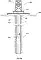
- FIG. 1Aan embodiment in which such apparatus, assemblies, and/or systems may be utilized is illustrated.
- the operating environmentgenerally comprises a drilling rig 106 that is positioned on the earth's surface 104 and extends over and around a wellbore 114 that penetrates a subterranean formation 102 for the purpose of recovering hydrocarbons.
- the wellbore 114may be drilled into the subterranean formation 102 using any suitable drilling technique.
- the wellbore 114extends substantially vertically away from the earth's surface 104 over a vertical wellbore portion 116 .
- a wellboremay be vertical, deviated at any suitable angle, horizontal, and/or curved.
- the wellboremay be a new wellbore, an existing wellbore, a straight wellbore, an extended reach wellbore, a sidetracked wellbore, a multi-lateral wellbore, and other types of wellbores for drilling and completing one or more production zones.
- the wellboremay be used for both producing wells and injection wells.
- the wellboremay be used for purposes other than or in addition to hydrocarbon production, such as uses related to geothermal energy.
- a wellbore tubular string 120 comprising a sensing assembly 200may be lowered into the subterranean formation 102 for a variety of workover or treatment procedures throughout the life of the wellbore.
- the embodiment, shown in FIG. 1illustrates the wellbore tubular 120 in the form of a production string being lowered into the subterranean formation.
- the wellbore tubular 120 comprising a sensing assembly 200is equally applicable to any type of wellbore tubular being inserted into a wellbore, including as non-limiting examples drill pipe, casing tubing, rod strings, and coiled tubing.
- the sensing assembly 200may also be used to sense at least one parameter at or near various wellbore components such as subs, workover tools, completion tools, etc.
- the wellbore tubular 120 comprising a sensing assembly 200is conveyed into the subterranean formation 102 in a conventional manner and may subsequently be secured within the wellbore 114 using any known retaining mechanisms (e.g., packers, hangers, etc.).
- the drilling rig 106comprises a derrick 108 with a rig floor 110 through which the wellbore tubular 120 extends downward from the drilling rig 106 into the wellbore 114 .
- the drilling rig 106comprises a motor driven winch and other associated equipment for extending the wellbore tubular 120 into the wellbore 114 to position the wellbore tubular 120 at a selected depth. While the operating environment depicted in FIG.
- a wellbore tubular 120 comprising the sensing assembly 200may alternatively be used in other operational environments, such as within an offshore wellbore operational environment using, for example, an offshore drilling or production platform, floating drilling or production rig, or the like.
- a vertical, deviated, or horizontal wellbore portionmay be cased and cemented and/or portions of the wellbore may be uncased.
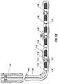
- uncased sectione.g., uncased section 140 of FIG. 1B
- a sensing assembly 200may be used on production tubing in a cased or uncased wellbore.
- FIGS. 1A and 1BAn embodiment of an operating environment in which the sensing assembly 200 may be used is shown in FIGS. 1A and 1B .
- the operating environmentmay comprise a screen assembly 118 .
- the screen assembly 118may generally comprise a filter element 117 and/or a production sleeve 119 .
- a zonal isolation device 121e.g., a packer
- the filter element 117may be configured to filter unwanted material from the subterranean formation 102 within a fluid flowing into the wellbore tubular 120 .
- the filter element 117may be disposed about the wellbore tubular 120 and can serve to limit and/or prevent the entry of sand, formation fines, and/or other particulate matter into the wellbore tubular 120 .
- the filter element 117may comprise a filter type known as “wire-wrapped,” where wire is closely wrapped helically about wellbore tubular 120 , with the spacing between each windings of wire designed to allow the passing of fluid but not of sand or other debris larger than a certain size.
- Other types of filtersmay also be used, such as sintered, mesh, pre-packed, expandable, slotted, perforated, and the like.
- filteror “filter element” as used herein is intended to include and cover all types of similar structures which are commonly used in screen assemblies and/or gravel pack well completions which permit the flow of fluids through the filter or screen while limiting and/or blocking the flow of particulates (e.g. other commercially-available screens, slotted or perforated liners or pipes; sintered-metal screens; sintered-sized, mesh screens; screened pipes; prepacked screens and/or liners; or combinations thereof).
- particulatese.g. other commercially-available screens, slotted or perforated liners or pipes; sintered-metal screens; sintered-sized, mesh screens; screened pipes; prepacked screens and/or liners; or combinations thereof.
- Production sleeves 119may be configured to selectively permit fluid communication, such as fluid communication of hydrocarbons, and/or meter the flow of fluids between the filter element 117 and a flow path, such as a central flow path, within the wellbore tubular 120 .
- Zonal isolation devices 121can isolate sections of the wellbore into different zones (as shown in FIG. 1B ) or intervals along the wellbore 114 by providing a seal between the outer wall of the wellbore 114 and the wellbore tubular 120 .
- the resulting screen assembly 118may be used alone or in combination with a gravel pack.
- a gravel packgenerally comprises gravel or sand disposed about a screen assembly within the wellbore, and the gravel pack may be configured to reduce the passage of particulates from the formation (e.g., formation sand) into the central flow path.
- the gravel packmay also be used to stabilize the formation while causing minimal impairment to well productivity. It should be understood that while the above components may form portions of a screen assembly 118 , those of ordinary skill in the art would recognize other components that may be used in a screen assembly.
- one or more screen assembliesmay be installed in the flow path between the production tubing and the perforated casing (cased) and/or the open well bore face (uncased).
- a packeris customarily set above the screen assembly to seal off the annulus in the zone where production fluids flow into the production tubing.
- the screen assemblycan be expanded towards the casing/wellbore wall and/or the annulus around the screen assembly can be packed with a relatively coarse sand (or gravel) which acts as a filter to reduce the amount of fine formation sand reaching the screen.
- the packing sandcan be pumped down the work string in a slurry of water and/or gel to fill the annulus between the screen assembly and the casing/wellbore wall.
- the sand or gravel packmay serve to support the surrounding unconsolidated formation.
- the sensing assembly and/or sensing system 200can be used to measure at least one parameter adjacent a section of a wellbore component (e.g., over or radially adjacent a filter element or screen).
- the sensing assembly and/or sensing system 200may be configured to measure a parameter at a location in a wellbore where the gauge may not fit.
- the sensing assemblymay be located at a location where it can be disposed and/or retained in a gauge carrier while a sensing link may allow for communication with a sensing point at a location at which the gauge may not fit.
- the sensing systemmay be used to detect and/or measure various parameters including, but not limited to, temperature, pressure, flow rate, compaction, stress, location, sound, fluid type, at least one seismic parameter, and/or vibration.
- the sensing assembly and/or sensing system 200may comprise at least one gauge 202 coupled to at least one sensing link 204 .
- the sensing assembly and/or sensing system 200may comprise a gauge carrier 1000 (as shown in FIG. 10 ) for retaining the gauge 202 in position about the wellbore tubular while providing for an annular flow between adjacent components (e.g., between adjacent screen sections).
- the gauge carrierwill be described in greater detail herein.
- the sensing assembly and/or sensing system 200may also comprise at least one manifold 214 coupled to one or more gauges 202 .
- the manifoldmay serve to provide communication between a plurality of gauges 202 and another communication point using a reduced number of communication channels. For example, when a control line is used to provide communication between the manifold and the surface of the wellbore, the manifold may serve to collect, convert, and/or and serialize the communication from a plurality of gauges to allow the signals from a plurality of gauges to be transmitted over a reduced number of communication lines.
- the manifold 214may be disposed between a communication component 212 and one or more gauges 202 , and the manifold 214 may serve to couple the communication component 212 to the one or more gauges 202 .
- the sensing assembly and/or sensing system 200may also comprise at least one bypass communication component 216 configured to engage a first sensing assembly and/or sensing system 200 with at least one other sensing assembly and/or sensing system 200 as well as the communication component 212 .
- the bypass communication component 216may engage with a first manifold 214 associated with the first sensing assembly and/or sensing system 200 and a second manifold 214 associated with the second sensing assembly 200 .
- the bypass communication component 216may comprise similar embodiments to the communication component 212 .
- the sensing system 200comprises at least one gauge 202 configured to sense parameter at a second location while being disposed at a first location 201 along the wellbore tubular string.
- the gauge 202may be disposed outside of the wellbore tubular in the annular region between the wellbore tubular and the wellbore wall.
- the gaugescan be configured to detect one or more parameters and provide an output signal indicative of the parameter.
- the output signalmay then be communicated to another component (e.g., a manifold, communication component, telemetry tools, etc.), and the output signal may be used downhole and/or by a surface component.
- the gaugemay be sized and/or disposed about the wellbore tubular to allow it to be disposed in the wellbore while being coupled to the wellbore tubular without being damaged during disposition within the wellbore.
- a gauge carriermay be used to retain the gauge during and/or after disposition within the wellbore.
- the gaugesmay be disposed adjacent each other about the circumference of the wellbore tubular.
- the gaugesmay be radially spaced about the circumference of the wellbore tubular.
- the plurality of gaugesmay be coupled to each other and a communication component using a manifold 214 .
- the first locationmay generally be disposed about the wellbore tubular at a location between the various components of the wellbore tubular string.
- the first locationmay be disposed between one or more components including, but not limited to, filter elements, sleeves (e.g., production sleeves), zonal isolation devices (e.g., packers, plugs, etc.), housings, couplings, shrouds, etc.
- the first location 201may be in a location that is not in radial alignment with another wellbore component other than a gauge carrier.
- the first location 201may be a location in radially alignment with only the wellbore tubular.
- the first location 201may not be in the same location as the second location 203 , for example, the first location 201 may be longitudinally spaced apart from the second location 203 .
- the gauge 202may be configured to sense temperature, pressure, flow rate, compaction, stress, location, sound, fluid type, at least one seismic parameter, and/or vibration.
- the gauge 202may comprise a temperature gauge. Any suitable gauge configured to measure temperature may be used with the sensing assembly 200 .
- the temperature gaugemay comprise a thermocouple, a resistance temperature detector (RTD), a thermistor, and/or any other means of measuring temperature.
- the temperature gauge 202may comprise a design capable of operating in temperature ranging from between about 70 degrees Fahrenheit and about 390 degrees Fahrenheit, and the temperature gauge may operate in wellbore conditions up to about 500 degrees Fahrenheit.
- the gauge 202may further comprise an accuracy rating range between about 0.02% FS and about 5.00% FS.
- the gauge 202may comprise a pressure gauge. Any suitable gauge configured to measure pressure may be used with the sensing assembly 200 .
- the pressure gaugemay comprise a piezo-resistive strain gauge, a capacitive pressure gauge, an electromagnetic pressure gauge, a piezoelectric gauge, a potentiometric gauge, a resonant gauge, a thermal gauge, an ionization gauge and/or any other means of measuring pressure.
- the gauge 202may further comprise an accuracy rating range between about 0.02% FS and about 5.00% FS.
- the gauge 202may comprise a resolution rating range between about 0.01 psi/second and about 1.00 psi/second.
- the gauge 202may comprise a design capable of operating in pressures ranging between about 10 psi and about 30,000 psi.
- the gauge 202may comprise a hermetically-sealed electron beam-welded design with an inert gas filling.
- gaugessuch as electromagnetic sensors, logging tools, various seismic sensors (e.g., a hydrophone, a single-component geophone, a multi-component geophone, a single-axis accelerometer, a multi-axis accelerometer, or any combination thereof) may also be used to detect one or more parameters within the wellbore.
- the gauge 202may comprise a permanent downhole gauge.
- the gauge 202may also comprise a quartz sensor-based design.
- the gaugemay comprise a ROCTM permanent monitoring gauge (available from Halliburton Energy Services, Inc. of Houston, Tex.). Additional suitable gauges are described in U.S. Pat. No. 7,784,350 issued Aug. 31, 2010 to Pelletier, which is incorporated herein by reference in its entirety.
- the communication component 212may be configured to enable communication from the gauge 202 to a data receiving component using various communication mechanisms.
- the communication component 212may comprise a device configured to transmit a signal from the gauge and/or the manifold to a remote location along with any communication medium used to transmit the signal.
- the communication component 212may comprise a control line configured to send a signal from a gauge 202 through at least one wire to the data receiving component.
- the communication component 212may also comprise wireless communication between a gauge 202 and a data receiving component.
- wireless communicationmay comprise sending a wireless signal, sending a wave and/or pulse through a fluid (e.g., pressure based telemetry), and/or sending a physical indicator such as a flag and/or a ball between the sensing point and the data receiving component.
- a fluide.g., pressure based telemetry
- various telemetry systemsmay be used with the sensing system described herein to convey one or more parameters between the gauge and another location in the wellbore and/or the surface.
- a fiber optic sensing systemmay be disposed with the sensing system 200 , and the communication component 212 may comprise the fiber optic sensing system.
- the fiber optic sensing systemmay be used in conjunction with a communication component 212 .
- the fiber optic sensing systemuses a glass (e.g., silica) and/or plastic fiber configured to transmit light from one end of the fiber to the other end.
- the data from the gaugemay be transmitted along the fiber to a receiver where it is converted into output data.
- the communication component 212may be disposed between at least one wellbore tubular member and the wellbore wall, or in some embodiments, the communication component 212 may be disposed within a wellbore tubular member. The communication component 212 may be disposed and retained about the wellbore tubular member over at least a portion of the length between the at least one gauge 202 to the data receiving component. In an embodiment, the communication component 212 may comprise a plurality of communication components 212 disposed in parallel and/or in series with at least one other communication component 212 . When a plurality of communication components 212 is disposed in series, the plurality of communication components 212 may comprise a bypass communication component 216 from another set of gauges or another manifold 214 .
- the data receiving componentmay receive the signal from the communication components, and the data receiving component may comprise a data storage device and/or a display.
- the data storage devicemay further comprise electronic hardware (e.g., a memory or storage device comprising a non-transitory computer readable media) to retain data.
- the data receiving componentmay comprise a device used to convert a signal to output data.
- the converting devicemay comprise hardware that converts a physical signal to output data.
- the data receiving componentmay be disposed within the wellbore, on the surface at a wellsite, at a remote location away from the wellsite, beneath the surface, and/or any combination thereof.
- an embodiment of the sensing assembly and/or sensing system 200further comprises at least one sensing link 204 configured to communicate a parameter from a second location 203 to the first location 201 at which the gauge 202 is disposed.
- the second location 203may be radially adjacent a wellbore component, and in an embodiment, the second location 203 may be radially adjacent a filter element in a screen assembly.
- the sensing linkmay be smaller than the gauge, which may allow the sensing link to be disposed at a location where the gauge 202 may not fit.
- the sensing link 204may be sized to fit in a location where the gauge 202 may not fit such as adjacent various wellbore components including, but not limited to, filter elements, sleeves, zonal isolation devices, and the like.
- the cross-section of the sensing link 204may comprise a circular, elliptical, rectangular, and/or polygonal shape.
- the sensing link 204may be configured to be disposed over at least a portion of wellbore tubular member.
- the sensing link 204may also be configured to be disposed within at least a portion of a wellbore tubular and/or provide a sensing point within at least a portion of a wellbore tubular.
- the sensing link 204may be extended from the gauge 202 in a first direction and/or a second direction along a wellbore tubular member.
- the sensing link 204may be used to sense a parameter in a plurality of directions from the gauge 202 .
- the first directionmay be generally directed downwards, and the second direction may generally be directed upwards.
- the sensing link 204may be configured to couple to and/or communicate a plurality of parameters to one or more gauges.
- a plurality of sensing links 204may be coupled to a plurality of gauges 202 .
- Each of the sensing linksmay communicate the same or different parameters, and each sensing link may have the same or different lengths.
- a plurality of sensing linksmay be used with each one having a different length to provide an array of sensing points over or adjacent a wellbore component.
- the structure of the sensing linkmay vary depending on the type of parameter being communicated between the first location 201 and second location 203 .
- the sensing link 204when the sensing link 204 is communicating a pressure from the second location 203 to the first location 201 , the sensing link 204 may comprise a component configured to provide fluid communication, and thereby fluid pressure, between the second location 203 and the first location 201 .
- the sensed signalmay be used to measure a temperature adjacent a wellbore component, and the sensing link 204 may comprise an electric line capable of communicating an output voltage from a temperature sensor (e.g., a thermocouple) from the second location 203 to the first location 201 .
- the sensing link 204may comprise a fiber optic cable or the like.
- the sensing link 204may comprise a combination of coupling elements to allow a plurality of parameters to be communicated between the second location 203 and the first location 201 .
- the sensing link 204may comprise one or more of a communication path, and/or a communication medium.
- at least one communication path 224may be configured to allow communication of a parameter from the second location 203 to the first location 201 .
- the communication path 224may be configured to communicate an electrical signal, a compression force (e.g., a pressure signal, a seismic signal, etc.), a sound wave, a light wave, and/or any other parameter.
- the communication path 224may be coupled to a debris barrier, as described in further detail herein.
- a parametermay be transmitted through a communication medium 226 configured to communicate the parameter from the sensing point 210 to the gauge.
- the communication mediummay be contained within the communication path and/or form at least a portion of the communication path.
- the communication medium 226may comprise a wire, a fluid (e.g., a liquid, grease, gel, etc.), an optical fiber, a waveguide, a thermal conductor, or any combination thereof.
- the sensing link 204may be configured to provide communication of a parameter (or a signal indicative of the parameter) between the second location and the first location.
- the second locationmay be referred to a sensing point, and in some embodiments, the sensing link may provide communication with a plurality of sensing points.
- the sensing point 210may be disposed at least at one point along the communication path 224 , for example at the end of the communication path 224 . In an embodiment, a plurality of sensing points 210 may be disposed at multiple locations along the communication path.
- a sensing assembly 200comprising a sensing link 204 is shown.
- the sensing link 204may be configured at least for sensing a parameter at the second location.
- the embodiment in FIG. 3depicts the sensing link 204 comprising a sensing point 210 and a communication path 224 .
- a communication medium 226may be disposed within the communication path 224 .
- the sensing point 210is disposed at the second location 203 .
- the embodiment in FIG. 3depicts that the sensing assembly and/or sensing system 200 comprises a gauge 202 and, optionally, a communication component 212 .
- the embodiment in FIG. 3also depicts that the sensing assembly and/or sensing system 200 may also comprise a manifold 214 and a bypass line 216 .
- the second location 203is disposed over a wellbore component comprising a filter element and the gauge 202 is disposed adjacent the filter element, but not in radial alignment with the filter element. This arrangement may allow the gauge 202 to measure a parameter radially adjacent the filter element while not being located in radial alignment with the filter element itself.
- the gauge 202may comprise at least one temperature gauge, which may be coupled to one or more temperature sensors 320 .
- the temperature sensormay be configured to detect the temperature at the sensing point 210 .
- the temperature sensormay be exposed to the wellbore, and/or any number of intervening elements (e.g., covers, housings, etc.) may be used to provide indirect exposure to the wellbore temperature.
- a plurality of temperature sensors 320may be used along the length of the sensing link 204 .
- the communication medium 226may comprise at least one communication wire (not shown) and/or a plurality of communication wires.
- the communication wiremay be used to communicate at least one signal indicative of a temperature reading from at least one sensor 320 , such as a temperature sensor, to at least one gauge 202 , such as a temperature gauge.
- the communication path 224may be configured to permit the communication of a signal indicative of a temperature reading from the second location 203 .
- the gauge 202may comprise at least one pressure gauge.
- pressure gauge 202may be configured to detect pressure at the sensing point 210 .
- the sensing point 210may allow pressure to be transmitted between the wellbore and the communication path 224 .
- the sensing pointmay be directly exposed to the wellbore, and/or any number of intervening elements (e.g., covers, housings, etc.) may be used to provide indirect exposure to the wellbore.
- a plurality of openingsmay be disposed along a portion of the sensing link 204 to provide fluid communication between the plurality of points and one or more pressure gauges 202 . As shown in FIG.
- the sensing point 210may be disposed at the end of the sensing link 204 , and/or the sensing point 210 may be disposed anywhere along the sensing link 204 .
- the communication medium 226may comprise a fluid.
- the fluidmay be used to communicate at least one signal indicative of a pressure reading from at least one sensing point to the at least one pressure gauge 202 .
- the communication path 224may be configured to permit the communication of a pressure reading from a second location 203 to the gauge 202 .
- FIG. 4Aa sensing assembly 200 comprising a plurality of sensing links 204 is shown. Similar to FIG. 3 , the sensing links 204 comprise at least one communication path 224 and communicate a parameter from at least one sensing point 210 . Furthermore, similar to other embodiments, FIG. 4A depicts a sensing assembly and/or sensing systems 200 comprising a communication component 212 . In this embodiment, multiple sensing points 210 are distributed longitudinally along a wellbore component 428 . Additionally, the sensing points 210 are located at corresponding second locations 203 that are longitudinally separated from the first location 201 .
- the sensing linksmay comprise electrical conductors included in a single bundle of wires (e.g., a multi-conductor line). Individual wire pairs may be coupled to corresponding sensors (e.g., temperature sensors) to detect the temperature at various sensing points along the sensing link. In an embodiment, the sensing points may be distributed over a wellbore component to provide distributed temperature data along the wellbore component.
- sensorse.g., temperature sensors
- At least one sensing point 210may be located within the wellbore component along which the sensing links are disposed (e.g., a filter element). In this embodiment, at least one sensing point 210 may be in radial alignment with another sensing point 210 disposed outside the wellbore component. Using this configuration, it may be possible, for example, to measure the temperature drop and/or pressure drop along the flow path of the wellbore component. Alternatively, in an embodiment, the sensing point 210 may be located within the wellbore component while not being in radial alignment with at least one other sensing point 210 .
- the wellbore componentcomprises a filter element and at least one parameter may be measured adjacent the filter element.
- a gauge 202may be disposed at a first location along a wellbore tubular member, and the gauge 202 may be configured to sense at least one parameter.
- a communication path 224configured to allow communication of at least one parameter from a second location to a first location may also be disposed along the wellbore tubular member.
- a sensing point 210may be disposed at the second location.
- At least one parametermay be sensed and/or detected at the second location, where the second location is in radially adjacent a filter element 428 . The at least one parameter may then be communicated through the communication path 224 using the communication medium 226 so that the gauge 202 may sense the parameter.
- a plurality of sensing linksmay provide communication of one or more parameters at a plurality of second locations along the filter element with the gauge 202 .
- a plurality of electric linesmay be coupled to temperature sensors at a plurality of second locations and a temperature gauge 202 at the first location. This configuration may allow a single temperature gauge to measure a plurality of temperatures.
- a plurality of sensing pointsmay communicate a plurality of pressures to one or more pressure gauges at the first location.
- the sensing linkmay comprise a communication medium 226 , which may be configured to communicate at least one parameter from a sensing point 210 to the gauge 202 .
- At least one communication componentmay be coupled to the gauge 202 , and the communication component may provide communication from the at least one gauge 202 to at least one remote location. Using the communication component 212 , at least one signal generated in response to the gauge 202 sensing at least one parameter may be transmitted to the remote location.
- the wellbore componentcomprises a filter element, and at least one sensing point 210 may be disposed within the filter element.
- a sensing point 210may be disposed outside the filter element, and/or a sensing point 210 may be disposed inside the filter element 428 .
- a sensing point 210may be in radial alignment with another sensing point 210 . Using this configuration, it may be possible, for example, to measure the pressure and/or temperature drop across the filter element 428 .
- the sensing point 210may be disposed within the filter element 428 while not being in radial alignment with at least one other sensing point 210 .
- one or more sensors 210may be placed in a housing along the length of the sensing link.
- a plurality of sensing linksmay form a bundle, and the housings may comprise sensing points coupled to one or more of the sensing links.
- temperature sensorsmay be disposed within the housings (e.g., fixedly disposed within the housings) along the length of a plurality of sensing links.
- the housingsmay be configured to retain the temperature sensors while providing thermal conduction to allow the temperature sensors to detect the temperature adjacent the housing.
- the housingmay be formed from various materials such as thermally conductive materials (e.g., various metals). The housings may then serve as discreet sensing points along the length of the sensing links.
- the use of the plurality of housingsmay provide an array of temperature sensing points along the length of the wellbore component.
- FIGS. 5A and 5Billustrate another sensing assembly 200 comprising a sensing link 204 .
- the embodiment of the sensing assembly 200 illustrated in FIGS. 5A and 5Bis similar to the sensing assembly of FIGS. 2A-3 .
- the sensing assemblymay comprise a gauge 202 coupled to a sensing link 204 to provide communication of a parameter from a second location 203 to the gauge 202 disposed at a first location.
- the sensing systemmay comprise a gauge 501 coupled to a sensing link 503 providing a sensing point within the wellbore tubular 120 .
- the sensing link 503may be used to communicate the pressure, temperature, flow rate, or any other parameter from within the wellbore tubular 120 to the gauge 501 .
- any plurality of sensing linksmay couple the gauge 501 to the wellbore tubular interior 120 . While illustrated as providing a sensing point 505 within the wellbore tubular 120 , the sensing link 503 may provide communication of a parameter between the gauge 501 and the interior of any wellbore component. For example, the sensing link 503 may provide a sensing point 505 within a production sleeve, a valve, an annular flow path, or the like. In an embodiment, the sensing point may be disposed within an annular flow path between a gauge carrier housing and a mandrel, as described in more detail herein.
- the sensing link 503may be used to communicate the pressure, temperature, flow rate, or any other parameter from within the annular flow path. It will be appreciated that the use of a gauge configured to measure one or more parameters within a wellbore tubular may be used with any of the embodiments of the sensing assembly disclosed herein.
- the sensing assembly 200may comprise a gauge 502 configured to measure a parameter at the first location.
- a sensing linkmay not be coupled to the gauge 502 .
- the gauge 502may comprises a temperature gauge, a pressure gauge, and/or any other suitable gauge for measuring a desired parameter. This configuration may allow a parameter to be measured at the first location, which may be useful in providing a parameter profile along the wellbore tubular string.
- one or more temperature gaugesmay be coupled to sensing links used to measure the temperature across one or more wellbore components at a plurality of second locations 203 (e.g., a plurality of sensing points).
- a temperature gaugemay be configured to detect the temperature at the first location.
- the combined temperature readings at the first and second locationsmay then provide a profile along the wellbore tubular.
- a pressure profilemay similarly be developed using a pressure gauge configured to detect the pressure at the first location along with one or more pressure gauges coupled to sensing links to measure the pressure at one or more second locations 203 . It will be appreciated that the use of a gauge configured to measure one or more parameters at the first location may be used with any of the embodiments of the sensing assembly disclosed herein.
- the debris barrier 522may be configured to protect a communication line (e.g., the sensing link 204 ) from debris within a wellbore.
- the debris barrier 522comprises a housing and a barrier element 530 , where the housing may be coupled to a communication path 524 .
- the debris barriermay serve as the sensing point when coupled to a sensing link 204 as described herein.
- the debris barriermay be used to reduce the amount of debris engaging any of the sensors described herein and/or any of the types of sensing links described herein.
- the debris barrier housing and the barrier elementmay be configured to shield the communication path 524 from debris within a wellbore.
- the debris barrier housingmay be coupled to communication path 524 or at least a portion of the communication path 524 .
- the debris barrier housingmay comprise one or more openings to allow the communication of the parameter to the interior of the housing.
- the barrier element 530may be used to reduce the entry of debris into the one or more openings, thereby reducing the amount of debris entering the housing.
- the debris barriermay comprise one or more openings to provide fluid communication with the wellbore, thereby allowing the pressure to be communicated to the interior of the debris barrier.
- the barrier element 530may be disposed within or adjacent the one or more openings to limit the entry of any debris into the housing.
- the debris barrier housingmay be formed from any suitable material such as a metal, a composite, a polymer, and the like.
- the barrier elementmay be configured to permit communication of at least one parameter at a second location 203 with the interior of the housing while also reducing the amount of debris entering the housing.
- the barrier elementmay comprise a plug, piston, a screen, a sleeve, a bladder, at least one opening, and/or at least one object disposed within the housing or communication path 524 .
- the debris barriermay optionally comprise a fluid communication medium within the housing. This embodiment may be useful when the parameter being measured at the sensing point includes the pressure.
- the communication mediummay be selected to limit the amount of convective currents within the housing, thereby preventing a bulk flow of fluids that may carry debris into the sensing link and/or the gauge. Any fluid having a sufficient viscosity at the wellbore operating temperatures may be used.
- the fluid communication mediummay comprise a fluid such as a gel, a grease, and/or a wax having a melting point above the wellbore operating temperatures. The fluid may then act as a semi-solid or highly viscous fluid within the housing. The fluid may allow for the transfer of a pressure force without flowing within the housing.
- One or more portsmay be provided in the sensing link and/or the housing to allow the housing and/or communication path to be filled with the fluid communication medium.
- a less viscous fluidmay be used such as hydraulic oil, an aqueous fluid, and/or wellbore fluids.
- the barrier elementmay then be used to limit the amount of debris entering the housing that could contaminate the fluid and plug the sensing link and/or gauge.
- the debris barrier 522may be coupled to the sensing link using a variety of coupling and/or engagement mechanisms.
- the debris barriermay comprise threads configured to engage corresponding threads on the sensing link. Upon engagement of the threads, a sealing engagement may be formed between the debris barrier and the sensing link.
- the debris barrier 522may engage the sensing link 204 by aligning the complimentary threads 523 and rotating the housing into engagement.
- the debris barrier 522 and the sensing link 204may be disengaged by ratcheting and/or rotating.
- Other suitable coupling mechanismsmay be used in some embodiments.
- the debris barrier 522may be welded to the sensing link 204 .
- a sensing link 204 and a debris barrier 522may be configured to communicate at least one parameter comprising pressure to a pressure gauge. Similar to other embodiments, FIG. 6 depicts that the sensing link 204 comprises at least one sensing point and at least one communication path 524 . Additionally, the at least one sensing point may be disposed at the second location 203 . FIG. 6 also depicts that the sensing link 204 may be coupled to the debris barrier 522 .
- the barrier elementmay comprise a plug 530 disposed within the housing. An opening 534 in the housing may form a seat 532 on an inner surface configured to engage the plug 530 .
- a fluidmay be disposed within the housing to retain the plug adjacent the seat 532 , and the plug 530 may be configured to prevent the communication medium 526 from leaving the communication path 524 .
- the plug 530may provide a barrier preventing debris from entering the communication path 524 through the opening 534 .
- the plug 530may comprise any geometric shape, such as, for example, a sphere, cylinder, cone, frusto-conical member, a cube, or the like.
- the seat 532may be configured so that the plug 530 may not pass through the opening 534 , and the seat 532 may therefore retain the plug 530 within the housing.
- the plug 530may remain on the seat 532 due to the viscosity of the communication medium 526 .
- one or more fluid communication pathsmay be provided between the plug and the seat.
- the seat 532may comprise grooves and/or scratches to allow fluid, or at least fluid pressure, to flow around the plug 530 situated on the seat 532 .
- the fluidmay communicate through the opening 534 when, for example, the communication medium 526 is disposed into the communication path 524 through the port 536 .
- the fluidmay be injected into the port 536 to fill the sensing link and the debris barrier.
- the port 536may then be plugged and/or sealed closed so that the communication medium 526 may not exit the communication path 524 through the port 536 .
- a gauge at a first locationmay be coupled to the debris barrier 522 disposed at a second location 203 using the sensing link.
- at least one parametermay be communicated with the opening 511 and the plug 530 situated on the seat 532 .
- the parametermay communicate through the opening 511 and the plug 530 , and through the communication path 524 .
- the parametermay travel through the communication path 524 until it reaches the gauge 202 , which may measure the parameter.
- FIG. 7another embodiment of a debris barrier 522 is shown.
- the debris barrier and sensing link 204may be configured to sense a parameter comprising pressure. Similar to other debris barriers, FIG. 7 depicts that the debris barrier 522 comprises a sensing point, a communication path 524 , and a bladder 638 .
- a plurality of sensing pointsmay be disposed about the housing.
- the sensing pointsmay comprise a plurality of openings disposed in the housing.
- the plurality of openings 511may comprise a plurality of geometric shapes, such as, for example, narrow slots, circle shapes, elliptical shapes, or any other suitable shapes.
- one or more of the sensing pointsmay have different cross-section areas depending on their intended purpose.
- the cross-sectional area of the sensing pointsmay be configured to minimize the amount to debris that may enter the communication path 524 .
- the sensing pointsmay be spaced about the circumference of the housing.
- the barrier elementmay comprise a bladder 638 disposed within the housing and in fluid communication with the sensing point and/or the exterior of the housing through the openings.
- the bladder 638may be configured to retain a communication medium 526 and transfer a force applied to an outer surface of the bladder to the communication medium 526 within the bladder.
- the bladdermay be configured to expand and/or contract in response to the application of a force to the bladder.
- a biasing elemente.g., a spring 510
- the biasing elementmay also prevent the complete collapse of the bladder due to a large pressure differential between the exterior of the debris barrier and the interior of the debris barrier and/or the loss of a fluid within the communication path.
- the bladdermay substantially prevent fluid communication between an exterior of the bladder and the interior of the bladder, thereby acting as a barrier to debris from entering the communication path. While described in terms of a bladder, other structures capable of providing a volume change to transmit a pressure force may also be used.
- the bladdermay comprise a rubber and/or metal bladder and/or a rubber and/or metal bellows.
- a gauge at a first locationmay be coupled to the debris barrier 522 disposed at a second location 203 using the sensing link.
- at least one parametermay be communicated with the openings 511 and the bladder 638 disposed within the housing.
- the parametermay communicate through the openings 511 to the bladder 638 , which may transfer the parameter to the communication path 524 .
- the parametermay travel through the communication path 524 until it reaches the gauge, which may measure the parameter.
- FIG. 8another embodiment of a debris barrier 522 is shown.
- the debris barrier 522 and sensing link 204may be configured to sense a parameter comprising pressure.
- FIG. 8depicts that the debris barrier comprises a sensing point, a communication path 524 , and a barrier element 740 .
- the at least one sensing point 510may be disposed at an end of the housing.
- FIG. 8also depicts that, in an embodiment, the debris barrier may also comprise at least one port 536 .
- the barrier elementmay comprise a piston 740 slidingly engaged within the housing.
- the piston 740may be configured to permit communication of at least one parameter to the communication path 224 .
- One or more seals 742may be disposed between the piston and the housing to provide a sealing engagement between the piston and housing and prevent fluid communication around the piston 740 and into the communication path 524 .
- the sealing engagement between the piston and the housingmay be configured to provide protection for the communication path 524 from debris within the wellbore annulus.
- the cross-section of the piston 740may comprise any suitable geometric shape.
- the piston 740may comprise at least one lip configured to engage at least one piston seat 744 . The lip may prevent the piston from passing through the opening at the sensing point.
- the at least one piston 740may be translatable within the housing, thereby allowing for the communication of the parameter, for example the pressure, through the piston to the communication medium 526 disposed in the communication path 524 .
- the parametermay be communicated through the communication path 524 until it reaches the gauge 202 .
- a communication mediummay be disposed in the communication path.
- the communication mediummay comprise a fluid capable of transmitting a parameter such as the pressure to the first location.
- the communication mediummay be disposed in the communication path using a port 536 .
- the communication mediummay be flowed into the communication path and the plug may be disposed in the port 536 to retain the communication medium in the communication path.
- a gauge at a first locationmay be coupled to the debris barrier 522 disposed at a second location 203 using the sensing link.
- at least one parametermay be communicated with the openings 511 and the piston 740 disposed within the housing.
- the parametermay communicate through the openings 511 to the piston 740 , which may be translatable in the housing and transfer the parameter to the communication path 524 .
- a communication mediumsuch as a fluid, may be disposed in the communication path, and the parameter may be transferred from the piston to the communication medium.
- the parametermay travel through the communication path 524 until it reaches the gauge 202 , which may measure the parameter.
- FIG. 9another embodiment of a debris barrier 822 is shown.
- the debris barrier 822 and sensing linkmay be configured to sense a parameter comprising pressure.
- FIG. 9depicts that the debris barrier comprises a sensing point, a communication path 524 , and barrier element.
- the barrier elementmay comprise at least one strainer 816 .
- the strainer 816may be configured to permit communication of at least one parameter through the communication path 524 .
- the strainer 816may be disposed within the housing 848 and serve to filter one or more particulates from a fluid entering the fluid communication path.
- Various suitable structuresmay be used to form the strainer 816 .
- the strainer 816may comprise a wire wrap, a mesh, a cloth, a synthetic fiber, a slotted tube, a perforated tube, and/or any other permeable material.
- the strainer 816may comprise a plurality of strainer layers, and each layer may be the same or different.
- a plurality of layersmay comprise decreasing pore sizes from the outer layer to the inner layer, which may provide a rough filter on the outer layers and a finer filter on the inner layers.
- the housing 848may comprise one or more openings to provide fluid communication from the wellbore to the strainer 816 . The openings may serve as a filter element to initially prevent large particulates from entering the debris barrier and engaging the strainer 816 .
- a gauge at a first locationmay be coupled to the debris barrier 822 disposed at a second location 203 using the sensing link.
- at least one parametermay be communicated with the openings 850 and the strainer 816 disposed within the housing 848 .
- the parametermay communicate through the openings 810 in the housing to the strainer 816 , which may filter out at least a portion of any particulates in the fluid.
- a communication mediummay be disposed in the communication path, and the parameter may be transferred from the wellbore to the communication medium through direct fluid contact passing through the strainer 816 .
- the parametermay travel through the communication path 524 until it reaches the gauge 202 , which may measure the parameter.
- the parametermay be communicated along the communication path without a bulk flow component. This may limit the amount of fluid passing through the strainer 816 , and aid in limiting the degree to which the strainer 816 may clog over time.
- FIGS. 10A and 10Banother embodiment of a debris barrier 822 is shown.
- the debris barrier 822 and sensing linkmay be configured to sense a parameter comprising pressure.
- the debris barriercomprises a portion of the sensing link, so that the debris barrier and sensing link are integrally formed.
- a plugmay be disposed in the end of the sensing link to provide a substantial barrier to fluid flow through the end of the sensing link.
- One or more openings 810may then be disposed in the sensing link adjacent the plug to provide fluid communication between the outside of the sensing link (e.g., the surrounding wellbore) and the communication path 824 .
- the plurality of openings 810may comprise a plurality of geometric shapes, such as, for example, narrow slots, circle shapes, elliptical shapes, or any other suitable shapes.
- the openings 810may be disposed around the sensing link.
- the slotsmay be disposed longitudinally along the sensing link.
- the openings 810may be configured to filter debris from the fluid communicating with the sensing link and also permit communication of at least one parameter through the communication path 824 .
- the openings 810may generally be disposed adjacent the end of the sensing link to any suitable distance away from the end. In some embodiments, the openings 810 may be disposed over the sensing link a distance representative of the area in which the pressure is to be measured.
- a gauge at a first locationmay be coupled to the debris barrier 822 disposed at a second location 203 using the sensing link.
- at least one parametermay be communicated with the openings 810 in the sensing link, which may have the plug disposed in the end thereof.
- the parametermay communicate through the openings in the sensing link, which may filter out at least a portion of any particulates in the fluid.
- a communication mediummay be disposed in the communication path, and the parameter may be transferred from the wellbore to the communication medium through direct fluid contact through the openings.
- the parametermay travel through the communication path 824 until it reaches the gauge 202 , which may measure the parameter.
- the parametermay be communicated along the communication path without a bulk flow component. This may limit the amount of fluid passing through the strainer 816 , and aid in limiting the degree to which the opening may clog over time.
- a method of protecting at least one sensing assembly and/or sensing system 200may comprise disposing at least one sensing assembly and/or sensing system 200 within a wellbore.
- a debris barrier 822may be coupled to the sensing assembly and/or sensing system 200 .
- the debris barrier communication medium 826may be disposed within the communication path 824 and/or the debris barrier using one or more ports 536 in the sensing link and/or the debris barrier.
- a parametermay then be communicated from the debris barrier, through the communication path, to a gauge.
- a gauge carriermay be used to retain one or more gauges along the wellbore tubular string.
- the gauge carriermay serve to retain and/or protect the gauge will being conveyed within the wellbore and during production.
- the gauge carrier described hereinmay also allow for an annular flow between an outer housing and a mandrel. The annular flow path may then be coupled to a corresponding annular flow path on one or more adjacent components to provide a flow path through the gauge carrier. This may allow the gauge carrier described herein to be used between adjacent components such as screens, production sleeves, and the like.
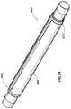
- a gauge carrier 1000may be configured to retain at least one gauge 202 about a wellbore tubular member (e.g., as shown in FIGS. 2A and 2B ).
- the gauge carrier 1000may also be configured to retain additional sensing system components or portions of the sensing system components such as the manifolds, communication components, sensing links, and/or any bypass lines.
- the gauge carrier 1000comprises a housing 1002 disposed about a mandrel 1004 , and at least one flow path 1210 (shown in FIG. 13 ) formed between the housing 1002 and the mandrel 1004 .
- the housing 1002may be configured to be disposed around a mandrel 1004 , which may be a wellbore tubular and/or be configured to engage at least one wellbore tubular member (e.g., using a threaded connection).
- the housinggenerally comprises a tubular component having a first end and second end. A flowbore extends through the housing between the first end and the second end.
- One or more pocketsmay be disposed in the housing.
- the pocketsgenerally comprise an indentation and/or opening in the housing configured to receive a gauge on the outer surface of the housing.
- the indentationmay be formed using any suitable method including milling, welding, forming, and/or cutting a hole in the housing.
- the edges of the indentation and/or holemay then be sealed to the mandrel 1004 , for example, by welding the edges to the mandrel 1004 .
- a separate componentmay be sealingly engaged within the hole to form the pocket.
- the housing, including the pocketmay substantially prevent fluid communication between the exterior of the housing 1002 and the annular region formed between the housing 1002 and the mandrel 1004 .
- the pocket 1106may engage the mandrel 1004 and be substantially sealed from the annular region formed between the housing 1002 and the mandrel 1004 .
- the pocket 1106may be formed longitudinally along the outside diameter of the gauge housing 1002 .
- a plurality of pockets 1106may be disposed about the circumference of the housing to receive one or more gauges or other components of the sensing assembly.
- the housing 1002may also comprise a channel and/or a path for the sensing links to extend from the gauge carrier to the sensing point.
- the channel and/or pathmay comprise bores through the housing 1002 and/or grooves longitudinally disposed along the housing 1002 . These channels and/or grooves may be configured to house the sensing link along the length of the housing 1002 .
- the housing 1002may be disposed about the mandrel 1004 .
- the mandrel 1004may generally comprise a tubular component having a first end and a second end.
- a flowboremay extend through the center of the mandrel 1004 to provide a fluid communication pathway between the first end and the second end.
- the flowboremay be sized to provide a desired flow area through the mandrel 1004 , and in an embodiment, the mandrel 1004 may be sized to correspond to one or more adjacent wellbore tubulars.
- the first end and/or the second endmay be coupled to adjacent wellbore tubular sections using any suitable connection mechanisms such as corresponding threads.
- annular spaceWhen disposed about the mandrel 1004 , an annular space may be defined between the inner surface of the housing and the outer surface of the mandrel.
- the annular spacemay define a flow path 1210 between the first end and the second end of the annular space, which may correspond to the first end and/or second end of the housing 1002 .
- one or more standoffs 1214may be disposed between the housing 1002 and the mandrel 1004 .
- a plurality of standoffs 1214may be engaged between the mandrel 1004 and the housing 1002 .
- the standoffs 1214may generally comprise longitudinal fins or legs extending between the housing 1002 and the mandrel 1004 .
- the one or more standoffs 1214may generally be disposed longitudinally between the housing 1002 and the mandrel 1004 , though other configurations are possible such as spiral standoffs, helical standoffs, or the like.
- the standoffs 1214may comprise spacers extending between the housing 1002 and the mandrel 1004 and may not extend along the length of the mandrel 1004 .
- the standoffsmay comprise pillar type standoff or supports, or the like.
- the standoff 1214may be configured to channel fluid through the annular space 1210 .
- the one or more standoffs 1214may be integrally formed with the housing 1002 and/or the mandrel.
- the one or more standoffs 1214may be fixedly attached to the inside diameter of the housing 1002 , for example using welds, sealants, coupling mechanisms, and/or the like.
- the gauge carrier 1000may comprise one or more covers 1008 configured to engage a pocket 1106 .
- the cover 1008may be configured to protect a gauge disposed in the pocket 1106 from debris, erosion from high rate pumping of proppant, and/or damage during installation within the wellbore annulus.
- the cover 1008may be configured to allow fluid communication between the gauge disposed in the pocket 1106 and the wellbore annulus, which may allow one or more parameters to be measured by a gauge disposed within the pocket 1106 .
- the cover 1008may be disposed over the pocket and engaged to the outside surface of the gauge housing 1002 .
- the cover 1008may be disposed within an edge disposed around the opening of the pocket 1106 , and/or the cover 1008 may be releasable or slidingly engaged with the housing over the pocket.
- the covermay be engaged with the housing using any suitable connectors including, but not limited to, fasteners such as screws, bolts, pins, rivets, welds, clips, or the like.
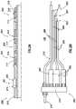
- the flow path 1210 between the housing 1002 and the mandrel 1004may be coupled to a corresponding flow path 1508 , 1510 through one or more adjacent components.
- an annular flow path 1508may extend between a filter element 1502 (e.g., a screen) and the wellbore tubular 120 over which the filter element 1502 is disposed.
- a production sleeve 1504may comprise an annular flow path 1510 between an outer housing and a wellbore tubular 120 .
- Fluid 1506may then be allowed to flow through the filter element 1502 , into the flow path 1508 between the filter element 1502 and the wellbore tubular 120 , through the annular flow path 1210 in the gauge carrier 1000 , into the flow path 1510 in the production sleeve 1504 , and enter the central flowbore within the wellbore tubular 120 .
- the housing 1002may be configured to engage one or more adjacent components 1502 , 1504 to allow the flow path 1210 to couple to one or more adjacent flow paths 1508 , 1510 in an adjacent component 1502 , 1504 .
- the housing 1002may be configured to engage a screen 1502 and/or a production sleeve 1504 , though the annular flow path 1210 may be coupled to an annular flow path on any wellbore component as described herein.
- the engagement with the adjacent component 1502 , 1504may comprise a sealing engagement so that the annular flow path 1210 is isolated from the exterior of the housing 1002 . This may provide a sealed flow path between one or more components coupled to the gauge carrier.
- the housingmay comprise a sealing sleeve 1012 disposed at least at one end of the housing 1002 .
- the sealing sleeve 1012may be configured to prevent direct fluid communication between the wellbore annulus and the flow path 1210 (shown in FIG. 13 ).
- the sealing sleeve 1012may be configured to seal the outside diameter of the housing 1002 with the outside diameter of an adjacent component (e.g., a filter element, a production sleeve, a second gauge carrier, etc.).
- an adjacent componente.g., a filter element, a production sleeve, a second gauge carrier, etc.
- complimentary ridges or threadsmay be disposed on the sealing sleeve 1012 and the tubular member.
- the sealing sleeve ridge and the tubular member ridgemay engage so that sealing sleeve 1012 may seal with the tubular member.
- the complimentary threadsmay be ratcheted over each other to engage the filter element with the housing 1002 .
- the housing 1002may engage the filter element by aligning the complimentary threads and rotating the gauge housing in the counter clockwise or clockwise direction.
- the sealing sleevemay be engaged with an adjacent component, and the sealing sleeve may be configured to be crimped to the adjacent component, thereby forming a sealing engagement with the adjacent component.
- the gauge carrier 1000may be disposed along the wellbore tubular string.
- the housingmay then be disposed adjacent another component comprising an annular flow path.
- a sealing sleevemay be positioned in engagement with the housing and the adjacent component, and a tool may engage and activate the sealing sleeve 1012 .
- an annular flow pathmay be created along the wellbore tubular between the components.
- the sealing sleeve 1012may engage an adjacent wellbore component while engaging the gauge carrier 1000 with the tubular string.
- the sealing sleeve 1012may engage the adjacent component at the same time the gauge carrier 1000 engages with tubular member.
- the complimentary threads disposed on the sealing sleeve 1012 and the outside diameter of tubular membermay be ratcheted and/or rotated into sealing engagement at the same time the gauge carrier 1000 is ratcheted and/or rotated into axial engagement with other wellbore tubular member.
- a gauge carrier 1000may be engaged with a wellbore tubular member, for example as part of a wellbore tubular string (e.g., a completion string or assembly, a production string or assembly, etc.).
- a sensing assembly and/or sensing system 200may be disposed within the gauge carrier, wherein the sensing assembly and/or sensing system 200 is configured to measure at least one parameter in a wellbore.
- a gaugemay be disposed in a pocket.
- the sensing assembly and/or the gaugemay be used to sense a parameter that is adjacent (e.g., in radial alignment with) at least one wellbore component (e.g., a filter element), within a wellbore tubular string, within an annular flow path, and/or adjacent the sensing assembly.
- a fluidmay be in fluid communication with the annular space between the housing of the gauge carrier and the mandrel about which the housing is disposed. For example, the fluid may be flowing through the annular space during the sensing of the one or more parameters.
Landscapes
- Engineering & Computer Science (AREA)
- Geology (AREA)
- Life Sciences & Earth Sciences (AREA)
- Mining & Mineral Resources (AREA)
- Physics & Mathematics (AREA)
- Environmental & Geological Engineering (AREA)
- Fluid Mechanics (AREA)
- General Life Sciences & Earth Sciences (AREA)
- Geochemistry & Mineralogy (AREA)
- Geophysics (AREA)
- Acoustics & Sound (AREA)
- Remote Sensing (AREA)
- Measuring Fluid Pressure (AREA)
- Arrangements For Transmission Of Measured Signals (AREA)
Abstract
Description
Claims (20)
Priority Applications (1)
| Application Number | Priority Date | Filing Date | Title |
|---|---|---|---|
| US16/593,602US11339641B2 (en) | 2012-09-26 | 2019-10-04 | Method of placing distributed pressure and temperature gauges across screens |
Applications Claiming Priority (3)
| Application Number | Priority Date | Filing Date | Title |
|---|---|---|---|
| PCT/US2012/057266WO2014051565A1 (en) | 2012-09-26 | 2012-09-26 | Method of placing distributed pressure gauges across screens |
| US201514425749A | 2015-03-04 | 2015-03-04 | |
| US16/593,602US11339641B2 (en) | 2012-09-26 | 2019-10-04 | Method of placing distributed pressure and temperature gauges across screens |
Related Parent Applications (2)
| Application Number | Title | Priority Date | Filing Date |
|---|---|---|---|
| US14/425,749DivisionUS10472945B2 (en) | 2012-09-26 | 2012-09-26 | Method of placing distributed pressure gauges across screens |
| PCT/US2012/057266DivisionWO2014051565A1 (en) | 2012-09-26 | 2012-09-26 | Method of placing distributed pressure gauges across screens |
Publications (2)
| Publication Number | Publication Date |
|---|---|
| US20200080413A1 US20200080413A1 (en) | 2020-03-12 |
| US11339641B2true US11339641B2 (en) | 2022-05-24 |
Family
ID=50388767
Family Applications (2)
| Application Number | Title | Priority Date | Filing Date |
|---|---|---|---|
| US14/425,749Active2034-09-13US10472945B2 (en) | 2012-09-26 | 2012-09-26 | Method of placing distributed pressure gauges across screens |
| US16/593,602ActiveUS11339641B2 (en) | 2012-09-26 | 2019-10-04 | Method of placing distributed pressure and temperature gauges across screens |
Family Applications Before (1)
| Application Number | Title | Priority Date | Filing Date |
|---|---|---|---|
| US14/425,749Active2034-09-13US10472945B2 (en) | 2012-09-26 | 2012-09-26 | Method of placing distributed pressure gauges across screens |
Country Status (7)
| Country | Link |
|---|---|
| US (2) | US10472945B2 (en) |
| EP (2) | EP4033069A1 (en) |
| AU (1) | AU2012391060B2 (en) |
| BR (2) | BR122020007387B1 (en) |
| MX (1) | MX359317B (en) |
| SG (1) | SG11201502083TA (en) |
| WO (1) | WO2014051565A1 (en) |
Cited By (1)
| Publication number | Priority date | Publication date | Assignee | Title |
|---|---|---|---|---|
| US20210372266A1 (en)* | 2020-05-29 | 2021-12-02 | Chevron U.S.A. Inc. | Gravel pack quality measurement |
Families Citing this family (6)
| Publication number | Priority date | Publication date | Assignee | Title |
|---|---|---|---|---|
| MY191383A (en) | 2012-09-26 | 2022-06-22 | Halliburton Energy Services Inc | Snorkel tube with debris barrier for electronic gauges placed on sand screens |
| US9664000B2 (en) | 2013-07-08 | 2017-05-30 | Halliburton Energy Services, Inc. | Continuously sealing telescoping joint having multiple control lines |
| US9371703B2 (en) | 2013-07-08 | 2016-06-21 | Halliburton Energy Services, Inc. | Telescoping joint with control line management assembly |
| US10392935B2 (en)* | 2016-03-24 | 2019-08-27 | Expro North Sea Limited | Monitoring systems and methods |
| US10587307B2 (en)* | 2016-06-20 | 2020-03-10 | Ge Aviation Systems, Llc | Transmission of power and communication of signals over fuel and hydraulic lines in a vehicle |
| EP4555191A1 (en)* | 2022-07-15 | 2025-05-21 | Services Pétroliers Schlumberger | Electro-mechanical actuator assembly |
Citations (132)
| Publication number | Priority date | Publication date | Assignee | Title |
|---|---|---|---|---|
| US3072188A (en)* | 1958-12-30 | 1963-01-08 | Gulf Research Development Co | Method of heating underground formations around the borehole of a well |
| US3744307A (en) | 1972-06-28 | 1973-07-10 | Geophysical Res Corp | Pressure gauge |
| US3898877A (en) | 1971-12-20 | 1975-08-12 | Sperry Sun Well Surveying Co | Method and apparatus for measuring pressure related parameters |
| US4615388A (en) | 1984-10-25 | 1986-10-07 | Shell Western E&P Inc. | Method of producing supercritical carbon dioxide from wells |
| US4628995A (en) | 1985-08-12 | 1986-12-16 | Panex Corporation | Gauge carrier |
| US4678035A (en) | 1983-07-12 | 1987-07-07 | Schlumberger Technology Corporation | Methods and apparatus for subsurface testing of well bore fluids |
| US4806928A (en) | 1987-07-16 | 1989-02-21 | Schlumberger Technology Corporation | Apparatus for electromagnetically coupling power and data signals between well bore apparatus and the surface |
| US4817437A (en) | 1987-03-04 | 1989-04-04 | Halliburton Company | Pressure communicating, fluid isolating interface |
| US4949788A (en) | 1989-11-08 | 1990-08-21 | Halliburton Company | Well completions using casing valves |
| US4979563A (en) | 1989-10-25 | 1990-12-25 | Schlumberger Technology Corporation | Offset shock mounted recorder carrier including overpressure gauge protector and balance joint |
| US5010764A (en)* | 1989-11-01 | 1991-04-30 | Marathon Oil Company | Method and apparatus for logging short radius horizontal drainholes |
| US5303773A (en) | 1991-09-17 | 1994-04-19 | Institut Francais Du Petrole | Device for monitoring a deposit for a production well |
| US5547029A (en) | 1994-09-27 | 1996-08-20 | Rubbo; Richard P. | Surface controlled reservoir analysis and management system |
| GB2301385A (en)* | 1994-02-08 | 1996-12-04 | Corpro Systems Ltd | A core barrel system |
| US5921318A (en) | 1997-04-21 | 1999-07-13 | Halliburton Energy Services, Inc. | Method and apparatus for treating multiple production zones |
| GB2341679A (en) | 1995-09-29 | 2000-03-22 | Sensor Dynamics Ltd | Apparatus for measuring pressure |
| US6116085A (en)* | 1998-06-09 | 2000-09-12 | Aec East | Instrumentation tubing string assembly for use in wellbores |
| US6230557B1 (en) | 1998-08-04 | 2001-05-15 | Schlumberger Technology Corporation | Formation pressure measurement while drilling utilizing a non-rotating sleeve |
| US6247536B1 (en) | 1998-07-14 | 2001-06-19 | Camco International Inc. | Downhole multiplexer and related methods |
| US6253857B1 (en) | 1998-11-02 | 2001-07-03 | Halliburton Energy Services, Inc. | Downhole hydraulic power source |
| US6257338B1 (en) | 1998-11-02 | 2001-07-10 | Halliburton Energy Services, Inc. | Method and apparatus for controlling fluid flow within wellbore with selectively set and unset packer assembly |
| US6257332B1 (en) | 1999-09-14 | 2001-07-10 | Halliburton Energy Services, Inc. | Well management system |
| US6279392B1 (en) | 1996-03-28 | 2001-08-28 | Snell Oil Company | Method and system for distributed well monitoring |
| US6279660B1 (en) | 1999-08-05 | 2001-08-28 | Cidra Corporation | Apparatus for optimizing production of multi-phase fluid |
| GB2360584A (en) | 2000-03-25 | 2001-09-26 | Abb Offshore Systems Ltd | Monitoring a well bore fluid filter |
| US20020020524A1 (en) | 2000-05-04 | 2002-02-21 | Halliburton Energy Services, Inc. | Expandable liner and associated methods of regulating fluid flow in a well |
| US6351987B1 (en) | 2000-04-13 | 2002-03-05 | Cidra Corporation | Fiber optic pressure sensor for DC pressure and temperature |
| US20020109080A1 (en) | 2001-02-06 | 2002-08-15 | Baker Hughes Incorporated | Wellbores utilizing fiber optic-based sensors and operating devices |
| US6446729B1 (en) | 1999-10-18 | 2002-09-10 | Schlumberger Technology Corporation | Sand control method and apparatus |
| US20020125009A1 (en) | 2000-08-03 | 2002-09-12 | Wetzel Rodney J. | Intelligent well system and method |
| US20030000700A1 (en)* | 2001-06-28 | 2003-01-02 | Hailey Travis T. | Screen assembly and method for gravel packing an interval of a wellbore |
| US6523609B1 (en) | 1999-09-07 | 2003-02-25 | Antech Limited | Borehole pressure gauge |
| US20030066652A1 (en)* | 2000-03-02 | 2003-04-10 | Stegemeier George Leo | Wireless downhole well interval inflow and injection control |
| US6554064B1 (en)* | 2000-07-13 | 2003-04-29 | Halliburton Energy Services, Inc. | Method and apparatus for a sand screen with integrated sensors |
| US20030079878A1 (en) | 2001-10-26 | 2003-05-01 | Pramann James A. | Completion system, apparatus, and method |
| US6575237B2 (en) | 1998-08-13 | 2003-06-10 | Welldynamics, Inc. | Hydraulic well control system |
| US6581455B1 (en) | 1995-03-31 | 2003-06-24 | Baker Hughes Incorporated | Modified formation testing apparatus with borehole grippers and method of formation testing |
| WO2003080993A1 (en) | 2002-03-21 | 2003-10-02 | Baker Hughes Incorporated | Method and application for open hole gravel packing |
| US6629564B1 (en) | 2000-04-11 | 2003-10-07 | Schlumberger Technology Corporation | Downhole flow meter |
| US6655452B2 (en) | 2001-09-21 | 2003-12-02 | Fred Zillinger | Downhole gauge carrier apparatus |
| US20030221829A1 (en) | 2000-12-07 | 2003-12-04 | Patel Dinesh R. | Well communication system |
| US20030226665A1 (en) | 2002-05-06 | 2003-12-11 | Kevin Jones | Multiple zone downhole intelligent flow control valve system and method for controlling commingling of flows from multiple zones |
| US20040035591A1 (en) | 2002-08-26 | 2004-02-26 | Echols Ralph H. | Fluid flow control device and method for use of same |
| US20040040707A1 (en) | 2002-08-29 | 2004-03-04 | Dusterhoft Ronald G. | Well treatment apparatus and method |
| US6712149B2 (en) | 2001-01-19 | 2004-03-30 | Schlumberger Technology Corporation | Apparatus and method for spacing out of offshore wells |
| US20040154390A1 (en)* | 2003-02-11 | 2004-08-12 | Terje Baustad | Downhole sub for instrumentation |
| US20040173363A1 (en) | 2003-03-04 | 2004-09-09 | Juan Navarro-Sorroche | Packer with integrated sensors |
| US20040173352A1 (en) | 2000-07-13 | 2004-09-09 | Mullen Bryon David | Gravel packing apparatus having an integrated sensor and method for use of same |
| US20040262011A1 (en) | 2003-03-28 | 2004-12-30 | Huckabee Paul Thomas | Surface flow controlled valve and screen |
| US20050074196A1 (en) | 2003-10-07 | 2005-04-07 | Tommy Grigsby | Gravel pack completion with fiber optic monitoring |
| US20050072564A1 (en) | 2003-10-07 | 2005-04-07 | Tommy Grigsby | Gravel pack completion with fluid loss control fiber optic wet connect |
| US6883613B2 (en)* | 2001-04-25 | 2005-04-26 | Weatherford/Lamb, Inc. | Flow control apparatus for use in a wellbore |
| US20050168349A1 (en) | 2003-03-26 | 2005-08-04 | Songrning Huang | Borehole telemetry system |
| US20050189115A1 (en)* | 2000-08-14 | 2005-09-01 | Schlumberger Technology Corporation | Subsea Intervention |
| US6942043B2 (en) | 2003-06-16 | 2005-09-13 | Baker Hughes Incorporated | Modular design for LWD/MWD collars |
| US6981553B2 (en)* | 2000-01-24 | 2006-01-03 | Shell Oil Company | Controlled downhole chemical injection |
| US6983796B2 (en) | 2000-01-05 | 2006-01-10 | Baker Hughes Incorporated | Method of providing hydraulic/fiber conduits adjacent bottom hole assemblies for multi-step completions |
| US6995352B2 (en) | 2003-01-09 | 2006-02-07 | Weatherford/Lamb, Inc. | Fiber optic based method and system for determining and controlling position of a sliding sleeve valve |
| US7062959B2 (en) | 2002-08-15 | 2006-06-20 | Schlumberger Technology Corporation | Method and apparatus for determining downhole pressures during a drilling operation |
| US20060196660A1 (en) | 2004-12-23 | 2006-09-07 | Schlumberger Technology Corporation | System and Method for Completing a Subterranean Well |
| US20060250274A1 (en)* | 2005-04-18 | 2006-11-09 | Core Laboratories Canada Ltd | Systems and methods for acquiring data in thermal recovery oil wells |
| US20070007005A1 (en) | 2005-07-08 | 2007-01-11 | Besst, Inc | Systems and methods for installation, design and operation of groundwater monitoring systems in boreholes |
| US7165892B2 (en) | 2003-10-07 | 2007-01-23 | Halliburton Energy Services, Inc. | Downhole fiber optic wet connect and gravel pack completion |
| US7228912B2 (en) | 2004-06-18 | 2007-06-12 | Schlumberger Technology Corporation | Method and system to deploy control lines |
| US20070198192A1 (en) | 2002-09-09 | 2007-08-23 | Schlumberger Technology Corporation | Systems and methods for well data compression |
| US20070227727A1 (en) | 2006-03-30 | 2007-10-04 | Schlumberger Technology Corporation | Completion System Having a Sand Control Assembly, An Inductive Coupler, and a Sensor Proximate to the Sand Control Assembly |
| US7278486B2 (en) | 2005-03-04 | 2007-10-09 | Halliburton Energy Services, Inc. | Fracturing method providing simultaneous flow back |
| US20070235185A1 (en) | 2006-03-30 | 2007-10-11 | Schlumberger Technology Corporation | Measuring a Characteristic of a Well Proximate a Region to be Gravel Packed |
| US20070235186A1 (en) | 2006-03-30 | 2007-10-11 | Jose Sierra | Pressure communication assembly external to casing with connectivity to pressure source |
| US7306043B2 (en) | 2003-10-24 | 2007-12-11 | Schlumberger Technology Corporation | System and method to control multiple tools through one control line |
| US7331223B2 (en) | 2003-01-27 | 2008-02-19 | Schlumberger Technology Corporation | Method and apparatus for fast pore pressure measurement during drilling operations |
| US7377321B2 (en) | 2004-12-14 | 2008-05-27 | Schlumberger Technology Corporation | Testing, treating, or producing a multi-zone well |
| US7389685B2 (en) | 2006-06-13 | 2008-06-24 | Honeywell International Inc. | Downhole pressure transmitter |
| US20080185144A1 (en)* | 2006-03-30 | 2008-08-07 | Schlumberger Technology Corporation | Providing an expandable sealing element having a slot to receive a sensor array |
| WO2008112331A1 (en) | 2007-03-10 | 2008-09-18 | Baker Hughes Incorporated | A unitized multi-gauge multi-circuit gauge cluster, system array and gauge carrier for permanent down-hole production tube monitoring |
| US7428932B1 (en) | 2007-06-20 | 2008-09-30 | Petroquip Energy Services, Llp | Completion system for a well |
| US20080257544A1 (en) | 2007-04-19 | 2008-10-23 | Baker Hughes Incorporated | System and Method for Crossflow Detection and Intervention in Production Wellbores |
| US7464588B2 (en) | 2005-10-14 | 2008-12-16 | Baker Hughes Incorporated | Apparatus and method for detecting fluid entering a wellbore |
| US20090066535A1 (en) | 2006-03-30 | 2009-03-12 | Schlumberger Technology Corporation | Aligning inductive couplers in a well |
| GB2452804A (en) | 2007-09-14 | 2009-03-18 | Precision Energy Services Inc | Pressure gauge comprising two axially aligned pressure sensing gauges |
| US20090188665A1 (en) | 1997-05-02 | 2009-07-30 | Baker Hughes Incorporated | Monitoring of Downhole Parameters and Tools Utilizing Fiber Optics |
| US20090260835A1 (en) | 2008-04-21 | 2009-10-22 | Malone Bradley P | System and Method for Controlling Placement and Flow at Multiple Gravel Pack Zones in a Wellbore |
| US20090283272A1 (en) | 2008-05-13 | 2009-11-19 | Baker Hughes Incorporated | Pipeless sagd system and method |
| US20090288824A1 (en) | 2007-06-11 | 2009-11-26 | Halliburton Energy Services, Inc. | Multi-zone formation fluid evaluation system and method for use of same |
| US20100038093A1 (en) | 2008-08-15 | 2010-02-18 | Schlumberger Technology Corporation | Flow control valve platform |
| US20100139909A1 (en) | 2008-12-04 | 2010-06-10 | Tirado Ricardo A | Intelligent Well Control System for Three or More Zones |
| US20100175894A1 (en) | 2009-01-14 | 2010-07-15 | Schlumberger Technology Corporation | Single trip well completion system |
| US20100193182A1 (en) | 2007-02-23 | 2010-08-05 | Warren Michael Levy | Method of optimizing production of a well |
| US20100212963A1 (en) | 2005-09-12 | 2010-08-26 | Teledrift, Inc | Measurement while drilling apparatus and method of using the same |
| US20100243270A1 (en) | 2009-03-25 | 2010-09-30 | Ingram Gary D | Method and apparatus for a packer assembly |
| WO2010135591A2 (en)* | 2009-05-20 | 2010-11-25 | Halliburton Energy Services, Inc. | Downhole sensor tool for nuclear measurements |
| US20100326654A1 (en)* | 2008-02-19 | 2010-12-30 | Teledyne Cormon Limited | Monitoring downhole production flow in an oil or gas well |
| US20110011577A1 (en) | 2008-08-29 | 2011-01-20 | Halliburton Energy Services, Inc. | Sand control screen assembly and method for use of same |
| US20110024105A1 (en) | 2009-07-31 | 2011-02-03 | Hammer Aaron C | Multi-zone Screen Isolation System with selective Control |
| US7900705B2 (en) | 2007-03-13 | 2011-03-08 | Schlumberger Technology Corporation | Flow control assembly having a fixed flow control device and an adjustable flow control device |
| US20110061862A1 (en) | 2009-09-11 | 2011-03-17 | Schlumberger Technology Corporation | Instrumented swellable element |
| US20110061875A1 (en) | 2007-01-25 | 2011-03-17 | Welldynamics, Inc. | Casing valves system for selective well stimulation and control |
| WO2011044070A2 (en) | 2009-10-06 | 2011-04-14 | Schlumberger Canada Limited | Formation testing planning and monitoring |
| US20110108287A1 (en) | 2009-02-18 | 2011-05-12 | Halliburton Energy Services, Inc. | Apparatus and Method for Controlling the Connection and Disconnection Speed of Downhole Connectors |
| US20110120726A1 (en) | 2007-08-16 | 2011-05-26 | Baker Hughes Incorporated | Multi-Position Valve for Fracturing and Sand Control and Associated Completion Methods |
| US7950461B2 (en) | 2007-11-30 | 2011-05-31 | Welldynamics, Inc. | Screened valve system for selective well stimulation and control |
| US7950454B2 (en) | 2007-07-23 | 2011-05-31 | Schlumberger Technology Corporation | Technique and system for completing a well |
| US20110132601A1 (en) | 2006-11-20 | 2011-06-09 | Halliburton Energy Services, Inc. | Multi-zone formation evaluation systems and methods |
| US7966875B2 (en) | 2002-05-17 | 2011-06-28 | Halliburton Energy Services, Inc. | Methods and apparatus for measuring formation properties |
| WO2011102839A1 (en) | 2010-02-20 | 2011-08-25 | Halliburton Energy Services, Inc. | Systems and methods of a clamp for a sample bottle assembly |
| US20110209873A1 (en) | 2010-02-18 | 2011-09-01 | Stout Gregg W | Method and apparatus for single-trip wellbore treatment |
| US20110214883A1 (en) | 2010-03-04 | 2011-09-08 | Schlumberger Technology Corporation | Large bore completions systems and method |
| US20110224942A1 (en)* | 2010-03-11 | 2011-09-15 | Kidwell John E | GPS-tracking ground heat exchanger (GHE) performance test instrumentation network supporting a plurality of wireless portable GPS-based enthalpy-based GHE performance test instrumentation systems |
| US20120024520A1 (en) | 2009-04-07 | 2012-02-02 | Halliburton Energy Services, Inc. | Well screens constructed utilizing pre-formed annular elements |
| US20120024050A1 (en)* | 2009-01-12 | 2012-02-02 | Sensor Developments As | Method And Apparatus For In-Situ Wellbore Measurements |
| US20120043079A1 (en)* | 2010-08-23 | 2012-02-23 | Schlumberger Technology Corporation | Sand control well completion method and apparatus |
| WO2012075139A2 (en) | 2010-12-03 | 2012-06-07 | Baker Hughes Incorporated | Self adaptive two dimensional least square filter for distributed sensing data |
| US8196668B2 (en) | 2006-12-18 | 2012-06-12 | Schlumberger Technology Corporation | Method and apparatus for completing a well |
| US20120181045A1 (en) | 2009-02-18 | 2012-07-19 | Halliburton Energy Services, Inc. | Apparatus and Method for Controlling the Connection and Disconnection Speed of Downhole Connectors |
| US20120181043A1 (en) | 2011-01-14 | 2012-07-19 | Dinesh Patel | Electric submersible pumping completion flow diverter system |
| US20120199346A1 (en)* | 2011-02-09 | 2012-08-09 | Dinesh Patel | Completion assembly |
| WO2012112657A2 (en) | 2011-02-16 | 2012-08-23 | Schlumberger Canada Limited | Integrated zonal contact and intelligent completion system |
| US20120222860A1 (en) | 2009-08-31 | 2012-09-06 | Halliburton Energy Services, Inc. | Selective placement of conformance treatments in multi-zone well completions |
| US8671748B2 (en) | 2011-01-06 | 2014-03-18 | Baker Hughes Incorporated | Pressure sensor with internal bellows |
| US20140083690A1 (en) | 2012-09-26 | 2014-03-27 | Halliburton Energy Services, Inc. | Multiple zone integrated intelligent well completion |
| US20140083684A1 (en) | 2012-09-26 | 2014-03-27 | Halliburton Energy Services, Inc. | Tubing conveyed multiple zone integrated intelligent well completion |
| US8689620B2 (en)* | 2010-05-11 | 2014-04-08 | Sondex Wireline Limited | Pressure balancing device |
| US20140231078A1 (en)* | 2009-07-17 | 2014-08-21 | World Energy Systems Incorporated | Method of recovering hydrocarbons from a reservoir |
| US8899339B2 (en)* | 2008-02-29 | 2014-12-02 | Exxonmobil Upstream Research Company | Systems and methods for regulating flow in a wellbore |
| US20150013970A1 (en)* | 2013-07-08 | 2015-01-15 | Halliburton Energy Services, Inc. | Sand Control Screen Assembly with Internal Control Lines |
| US20150075780A1 (en)* | 2013-08-12 | 2015-03-19 | Halliburton Energy Services, Inc. | Multi-zone completion systems and methods |
| US20150261224A1 (en)* | 2012-11-07 | 2015-09-17 | Halliburton Energy Services, Inc. | Well Fluid Exchange Flow Control |
| US20160168923A1 (en)* | 2014-06-30 | 2016-06-16 | Halliburton Energy Services, Inc. | Helical control line connector for connecting to a downhole completion receptacle |
| US20160273348A1 (en)* | 2013-11-05 | 2016-09-22 | Halliburton Energy Services, Inc. | Downhole position sensor |
| US20160290062A1 (en)* | 2014-06-30 | 2016-10-06 | Halliburton Energy Services, Inc. | Downhole expandable control line connector |
| US20170081956A1 (en)* | 2015-09-18 | 2017-03-23 | Baker Hughes Incorporated | Devices and Methods to Communicate Information from Below a Surface Cement Plug in a Plugged or Abandoned Well |
| US20200109606A1 (en)* | 2017-03-27 | 2020-04-09 | Shell Oil Company | Cable system for downhole use and method of perforating a wellbore tubular |
Family Cites Families (5)
| Publication number | Priority date | Publication date | Assignee | Title |
|---|---|---|---|---|
| US6848510B2 (en)* | 2001-01-16 | 2005-02-01 | Schlumberger Technology Corporation | Screen and method having a partial screen wrap |
| US7658083B2 (en)* | 2005-07-26 | 2010-02-09 | Ford Global Technologies, Llc | Cooling system and method for cooling a battery in a vehicle |
| US8770835B2 (en)* | 2006-10-06 | 2014-07-08 | Baker Hughes Incorporated | Apparatus and methods for estimating a characteristic of a fluid downhole using thermal properties of the fluid |
| US7784350B2 (en) | 2007-02-07 | 2010-08-31 | Halliburton Energy Services, Inc. | Downhole transducer with adjacent heater |
| US9482233B2 (en)* | 2008-05-07 | 2016-11-01 | Schlumberger Technology Corporation | Electric submersible pumping sensor device and method |
- 2012
- 2012-09-26BRBR122020007387-0Apatent/BR122020007387B1/enactiveIP Right Grant
- 2012-09-26WOPCT/US2012/057266patent/WO2014051565A1/enactiveApplication Filing
- 2012-09-26SGSG11201502083TApatent/SG11201502083TA/enunknown
- 2012-09-26EPEP22161838.2Apatent/EP4033069A1/ennot_activeWithdrawn
- 2012-09-26BRBR112015006650-0Apatent/BR112015006650B1/enactiveIP Right Grant
- 2012-09-26MXMX2015003679Apatent/MX359317B/enactiveIP Right Grant
- 2012-09-26AUAU2012391060Apatent/AU2012391060B2/enactiveActive
- 2012-09-26USUS14/425,749patent/US10472945B2/enactiveActive
- 2012-09-26EPEP12885719.0Apatent/EP2893135B1/enactiveActive
- 2019
- 2019-10-04USUS16/593,602patent/US11339641B2/enactiveActive
Patent Citations (160)
| Publication number | Priority date | Publication date | Assignee | Title |
|---|---|---|---|---|
| US3072188A (en)* | 1958-12-30 | 1963-01-08 | Gulf Research Development Co | Method of heating underground formations around the borehole of a well |
| US3898877A (en) | 1971-12-20 | 1975-08-12 | Sperry Sun Well Surveying Co | Method and apparatus for measuring pressure related parameters |
| US3744307A (en) | 1972-06-28 | 1973-07-10 | Geophysical Res Corp | Pressure gauge |
| US4678035A (en) | 1983-07-12 | 1987-07-07 | Schlumberger Technology Corporation | Methods and apparatus for subsurface testing of well bore fluids |
| US4615388A (en) | 1984-10-25 | 1986-10-07 | Shell Western E&P Inc. | Method of producing supercritical carbon dioxide from wells |
| US4628995A (en) | 1985-08-12 | 1986-12-16 | Panex Corporation | Gauge carrier |
| US4817437A (en) | 1987-03-04 | 1989-04-04 | Halliburton Company | Pressure communicating, fluid isolating interface |
| US4806928A (en) | 1987-07-16 | 1989-02-21 | Schlumberger Technology Corporation | Apparatus for electromagnetically coupling power and data signals between well bore apparatus and the surface |
| US4979563A (en) | 1989-10-25 | 1990-12-25 | Schlumberger Technology Corporation | Offset shock mounted recorder carrier including overpressure gauge protector and balance joint |
| US5010764A (en)* | 1989-11-01 | 1991-04-30 | Marathon Oil Company | Method and apparatus for logging short radius horizontal drainholes |
| US4949788A (en) | 1989-11-08 | 1990-08-21 | Halliburton Company | Well completions using casing valves |
| US5303773A (en) | 1991-09-17 | 1994-04-19 | Institut Francais Du Petrole | Device for monitoring a deposit for a production well |
| GB2301385A (en)* | 1994-02-08 | 1996-12-04 | Corpro Systems Ltd | A core barrel system |
| US5547029A (en) | 1994-09-27 | 1996-08-20 | Rubbo; Richard P. | Surface controlled reservoir analysis and management system |
| US6581455B1 (en) | 1995-03-31 | 2003-06-24 | Baker Hughes Incorporated | Modified formation testing apparatus with borehole grippers and method of formation testing |
| GB2341679A (en) | 1995-09-29 | 2000-03-22 | Sensor Dynamics Ltd | Apparatus for measuring pressure |
| US6279392B1 (en) | 1996-03-28 | 2001-08-28 | Snell Oil Company | Method and system for distributed well monitoring |
| US5921318A (en) | 1997-04-21 | 1999-07-13 | Halliburton Energy Services, Inc. | Method and apparatus for treating multiple production zones |
| US20090188665A1 (en) | 1997-05-02 | 2009-07-30 | Baker Hughes Incorporated | Monitoring of Downhole Parameters and Tools Utilizing Fiber Optics |
| US6116085A (en)* | 1998-06-09 | 2000-09-12 | Aec East | Instrumentation tubing string assembly for use in wellbores |
| US6247536B1 (en) | 1998-07-14 | 2001-06-19 | Camco International Inc. | Downhole multiplexer and related methods |
| US6230557B1 (en) | 1998-08-04 | 2001-05-15 | Schlumberger Technology Corporation | Formation pressure measurement while drilling utilizing a non-rotating sleeve |
| US6575237B2 (en) | 1998-08-13 | 2003-06-10 | Welldynamics, Inc. | Hydraulic well control system |
| US6253857B1 (en) | 1998-11-02 | 2001-07-03 | Halliburton Energy Services, Inc. | Downhole hydraulic power source |
| US6257338B1 (en) | 1998-11-02 | 2001-07-10 | Halliburton Energy Services, Inc. | Method and apparatus for controlling fluid flow within wellbore with selectively set and unset packer assembly |
| US6279660B1 (en) | 1999-08-05 | 2001-08-28 | Cidra Corporation | Apparatus for optimizing production of multi-phase fluid |
| US6523609B1 (en) | 1999-09-07 | 2003-02-25 | Antech Limited | Borehole pressure gauge |
| US6257332B1 (en) | 1999-09-14 | 2001-07-10 | Halliburton Energy Services, Inc. | Well management system |
| US6446729B1 (en) | 1999-10-18 | 2002-09-10 | Schlumberger Technology Corporation | Sand control method and apparatus |
| US6983796B2 (en) | 2000-01-05 | 2006-01-10 | Baker Hughes Incorporated | Method of providing hydraulic/fiber conduits adjacent bottom hole assemblies for multi-step completions |
| US6981553B2 (en)* | 2000-01-24 | 2006-01-03 | Shell Oil Company | Controlled downhole chemical injection |
| US7073594B2 (en)* | 2000-03-02 | 2006-07-11 | Shell Oil Company | Wireless downhole well interval inflow and injection control |
| US20030066652A1 (en)* | 2000-03-02 | 2003-04-10 | Stegemeier George Leo | Wireless downhole well interval inflow and injection control |
| GB2360584A (en) | 2000-03-25 | 2001-09-26 | Abb Offshore Systems Ltd | Monitoring a well bore fluid filter |
| US6450257B1 (en) | 2000-03-25 | 2002-09-17 | Abb Offshore Systems Limited | Monitoring fluid flow through a filter |
| US6629564B1 (en) | 2000-04-11 | 2003-10-07 | Schlumberger Technology Corporation | Downhole flow meter |
| US6351987B1 (en) | 2000-04-13 | 2002-03-05 | Cidra Corporation | Fiber optic pressure sensor for DC pressure and temperature |
| US20020020524A1 (en) | 2000-05-04 | 2002-02-21 | Halliburton Energy Services, Inc. | Expandable liner and associated methods of regulating fluid flow in a well |
| US7100690B2 (en) | 2000-07-13 | 2006-09-05 | Halliburton Energy Services, Inc. | Gravel packing apparatus having an integrated sensor and method for use of same |
| US6554064B1 (en)* | 2000-07-13 | 2003-04-29 | Halliburton Energy Services, Inc. | Method and apparatus for a sand screen with integrated sensors |
| US20040173352A1 (en) | 2000-07-13 | 2004-09-09 | Mullen Bryon David | Gravel packing apparatus having an integrated sensor and method for use of same |
| US6684951B2 (en) | 2000-07-13 | 2004-02-03 | Halliburton Energy Services, Inc. | Sand screen with integrated sensors |
| US6789621B2 (en)* | 2000-08-03 | 2004-09-14 | Schlumberger Technology Corporation | Intelligent well system and method |
| US8844627B2 (en)* | 2000-08-03 | 2014-09-30 | Schlumberger Technology Corporation | Intelligent well system and method |
| US20020125009A1 (en) | 2000-08-03 | 2002-09-12 | Wetzel Rodney J. | Intelligent well system and method |
| US20040173350A1 (en)* | 2000-08-03 | 2004-09-09 | Wetzel Rodney J. | Intelligent well system and method |
| US20130008645A1 (en)* | 2000-08-03 | 2013-01-10 | Schlumberger Technology Corporation | Intelligent Well System And Method |
| US7182134B2 (en)* | 2000-08-03 | 2007-02-27 | Schlumberger Technology Corporation | Intelligent well system and method |
| US6817410B2 (en) | 2000-08-03 | 2004-11-16 | Schlumberger Technology Corporation | Intelligent well system and method |
| US20150013976A1 (en)* | 2000-08-03 | 2015-01-15 | Schlumberger Technology Corporaton | Intelligent well system and method |
| US20050189115A1 (en)* | 2000-08-14 | 2005-09-01 | Schlumberger Technology Corporation | Subsea Intervention |
| US8091631B2 (en)* | 2000-11-03 | 2012-01-10 | Schlumberger Technology Corporation | Intelligent well system and method |
| US20050039927A1 (en)* | 2000-11-03 | 2005-02-24 | Wetzel Rodney J. | Intelligent well system and method |
| US20030221829A1 (en) | 2000-12-07 | 2003-12-04 | Patel Dinesh R. | Well communication system |
| US7222676B2 (en) | 2000-12-07 | 2007-05-29 | Schlumberger Technology Corporation | Well communication system |
| US6712149B2 (en) | 2001-01-19 | 2004-03-30 | Schlumberger Technology Corporation | Apparatus and method for spacing out of offshore wells |
| US20020109080A1 (en) | 2001-02-06 | 2002-08-15 | Baker Hughes Incorporated | Wellbores utilizing fiber optic-based sensors and operating devices |
| US6883613B2 (en)* | 2001-04-25 | 2005-04-26 | Weatherford/Lamb, Inc. | Flow control apparatus for use in a wellbore |
| US20030000700A1 (en)* | 2001-06-28 | 2003-01-02 | Hailey Travis T. | Screen assembly and method for gravel packing an interval of a wellbore |
| US6655452B2 (en) | 2001-09-21 | 2003-12-02 | Fred Zillinger | Downhole gauge carrier apparatus |
| US20050045329A1 (en)* | 2001-10-09 | 2005-03-03 | Wetzel Rodney J. | Intelligent well system and method |
| US7104324B2 (en)* | 2001-10-09 | 2006-09-12 | Schlumberger Technology Corporation | Intelligent well system and method |
| US20030079878A1 (en) | 2001-10-26 | 2003-05-01 | Pramann James A. | Completion system, apparatus, and method |
| WO2003080993A1 (en) | 2002-03-21 | 2003-10-02 | Baker Hughes Incorporated | Method and application for open hole gravel packing |
| US20030226665A1 (en) | 2002-05-06 | 2003-12-11 | Kevin Jones | Multiple zone downhole intelligent flow control valve system and method for controlling commingling of flows from multiple zones |
| US7966875B2 (en) | 2002-05-17 | 2011-06-28 | Halliburton Energy Services, Inc. | Methods and apparatus for measuring formation properties |
| US7062959B2 (en) | 2002-08-15 | 2006-06-20 | Schlumberger Technology Corporation | Method and apparatus for determining downhole pressures during a drilling operation |
| US7055598B2 (en) | 2002-08-26 | 2006-06-06 | Halliburton Energy Services, Inc. | Fluid flow control device and method for use of same |
| US20040035591A1 (en) | 2002-08-26 | 2004-02-26 | Echols Ralph H. | Fluid flow control device and method for use of same |
| US20040040707A1 (en) | 2002-08-29 | 2004-03-04 | Dusterhoft Ronald G. | Well treatment apparatus and method |
| GB2409694A (en) | 2002-08-30 | 2005-07-06 | Schlumberger Holdings | Single trip completion with packers and control line |
| US20070198192A1 (en) | 2002-09-09 | 2007-08-23 | Schlumberger Technology Corporation | Systems and methods for well data compression |
| US6995352B2 (en) | 2003-01-09 | 2006-02-07 | Weatherford/Lamb, Inc. | Fiber optic based method and system for determining and controlling position of a sliding sleeve valve |
| US7331223B2 (en) | 2003-01-27 | 2008-02-19 | Schlumberger Technology Corporation | Method and apparatus for fast pore pressure measurement during drilling operations |
| US20040154390A1 (en)* | 2003-02-11 | 2004-08-12 | Terje Baustad | Downhole sub for instrumentation |
| US20040173363A1 (en) | 2003-03-04 | 2004-09-09 | Juan Navarro-Sorroche | Packer with integrated sensors |
| US20050168349A1 (en) | 2003-03-26 | 2005-08-04 | Songrning Huang | Borehole telemetry system |
| US7273106B2 (en) | 2003-03-28 | 2007-09-25 | Shell Oil Company | Surface flow controlled valve and screen |
| US20040262011A1 (en) | 2003-03-28 | 2004-12-30 | Huckabee Paul Thomas | Surface flow controlled valve and screen |
| US6942043B2 (en) | 2003-06-16 | 2005-09-13 | Baker Hughes Incorporated | Modular design for LWD/MWD collars |
| US7165892B2 (en) | 2003-10-07 | 2007-01-23 | Halliburton Energy Services, Inc. | Downhole fiber optic wet connect and gravel pack completion |
| WO2005045174A2 (en) | 2003-10-07 | 2005-05-19 | Halliburton Energy Services, Inc. | Gravel pack completion with fiber optic monitoring |
| US20050072564A1 (en) | 2003-10-07 | 2005-04-07 | Tommy Grigsby | Gravel pack completion with fluid loss control fiber optic wet connect |
| US20050074196A1 (en) | 2003-10-07 | 2005-04-07 | Tommy Grigsby | Gravel pack completion with fiber optic monitoring |
| US7306043B2 (en) | 2003-10-24 | 2007-12-11 | Schlumberger Technology Corporation | System and method to control multiple tools through one control line |
| US7228912B2 (en) | 2004-06-18 | 2007-06-12 | Schlumberger Technology Corporation | Method and system to deploy control lines |
| US7377321B2 (en) | 2004-12-14 | 2008-05-27 | Schlumberger Technology Corporation | Testing, treating, or producing a multi-zone well |
| US20060196660A1 (en) | 2004-12-23 | 2006-09-07 | Schlumberger Technology Corporation | System and Method for Completing a Subterranean Well |
| US7278486B2 (en) | 2005-03-04 | 2007-10-09 | Halliburton Energy Services, Inc. | Fracturing method providing simultaneous flow back |
| US20060250274A1 (en)* | 2005-04-18 | 2006-11-09 | Core Laboratories Canada Ltd | Systems and methods for acquiring data in thermal recovery oil wells |
| US20070007005A1 (en) | 2005-07-08 | 2007-01-11 | Besst, Inc | Systems and methods for installation, design and operation of groundwater monitoring systems in boreholes |
| US20100212963A1 (en) | 2005-09-12 | 2010-08-26 | Teledrift, Inc | Measurement while drilling apparatus and method of using the same |
| US7464588B2 (en) | 2005-10-14 | 2008-12-16 | Baker Hughes Incorporated | Apparatus and method for detecting fluid entering a wellbore |
| US20070235185A1 (en) | 2006-03-30 | 2007-10-11 | Schlumberger Technology Corporation | Measuring a Characteristic of a Well Proximate a Region to be Gravel Packed |
| US20070227727A1 (en) | 2006-03-30 | 2007-10-04 | Schlumberger Technology Corporation | Completion System Having a Sand Control Assembly, An Inductive Coupler, and a Sensor Proximate to the Sand Control Assembly |
| US20090066535A1 (en) | 2006-03-30 | 2009-03-12 | Schlumberger Technology Corporation | Aligning inductive couplers in a well |
| US20070235186A1 (en) | 2006-03-30 | 2007-10-11 | Jose Sierra | Pressure communication assembly external to casing with connectivity to pressure source |
| US20080185144A1 (en)* | 2006-03-30 | 2008-08-07 | Schlumberger Technology Corporation | Providing an expandable sealing element having a slot to receive a sensor array |
| US7735555B2 (en) | 2006-03-30 | 2010-06-15 | Schlumberger Technology Corporation | Completion system having a sand control assembly, an inductive coupler, and a sensor proximate to the sand control assembly |
| US7389685B2 (en) | 2006-06-13 | 2008-06-24 | Honeywell International Inc. | Downhole pressure transmitter |
| US20110132601A1 (en) | 2006-11-20 | 2011-06-09 | Halliburton Energy Services, Inc. | Multi-zone formation evaluation systems and methods |
| US8196668B2 (en) | 2006-12-18 | 2012-06-12 | Schlumberger Technology Corporation | Method and apparatus for completing a well |
| US20110061875A1 (en) | 2007-01-25 | 2011-03-17 | Welldynamics, Inc. | Casing valves system for selective well stimulation and control |
| US20100193182A1 (en) | 2007-02-23 | 2010-08-05 | Warren Michael Levy | Method of optimizing production of a well |
| WO2008112331A1 (en) | 2007-03-10 | 2008-09-18 | Baker Hughes Incorporated | A unitized multi-gauge multi-circuit gauge cluster, system array and gauge carrier for permanent down-hole production tube monitoring |
| US7900705B2 (en) | 2007-03-13 | 2011-03-08 | Schlumberger Technology Corporation | Flow control assembly having a fixed flow control device and an adjustable flow control device |
| US20080257544A1 (en) | 2007-04-19 | 2008-10-23 | Baker Hughes Incorporated | System and Method for Crossflow Detection and Intervention in Production Wellbores |
| US20090288824A1 (en) | 2007-06-11 | 2009-11-26 | Halliburton Energy Services, Inc. | Multi-zone formation fluid evaluation system and method for use of same |
| US7428932B1 (en) | 2007-06-20 | 2008-09-30 | Petroquip Energy Services, Llp | Completion system for a well |
| US7950454B2 (en) | 2007-07-23 | 2011-05-31 | Schlumberger Technology Corporation | Technique and system for completing a well |
| US20110120726A1 (en) | 2007-08-16 | 2011-05-26 | Baker Hughes Incorporated | Multi-Position Valve for Fracturing and Sand Control and Associated Completion Methods |
| GB2452804A (en) | 2007-09-14 | 2009-03-18 | Precision Energy Services Inc | Pressure gauge comprising two axially aligned pressure sensing gauges |
| US7950461B2 (en) | 2007-11-30 | 2011-05-31 | Welldynamics, Inc. | Screened valve system for selective well stimulation and control |
| US20100326654A1 (en)* | 2008-02-19 | 2010-12-30 | Teledyne Cormon Limited | Monitoring downhole production flow in an oil or gas well |
| US8899339B2 (en)* | 2008-02-29 | 2014-12-02 | Exxonmobil Upstream Research Company | Systems and methods for regulating flow in a wellbore |
| US20090260835A1 (en) | 2008-04-21 | 2009-10-22 | Malone Bradley P | System and Method for Controlling Placement and Flow at Multiple Gravel Pack Zones in a Wellbore |
| US20090283272A1 (en) | 2008-05-13 | 2009-11-19 | Baker Hughes Incorporated | Pipeless sagd system and method |
| US20100038093A1 (en) | 2008-08-15 | 2010-02-18 | Schlumberger Technology Corporation | Flow control valve platform |
| US20110011577A1 (en) | 2008-08-29 | 2011-01-20 | Halliburton Energy Services, Inc. | Sand control screen assembly and method for use of same |
| US20100139909A1 (en) | 2008-12-04 | 2010-06-10 | Tirado Ricardo A | Intelligent Well Control System for Three or More Zones |
| US20120024050A1 (en)* | 2009-01-12 | 2012-02-02 | Sensor Developments As | Method And Apparatus For In-Situ Wellbore Measurements |
| US20100175894A1 (en) | 2009-01-14 | 2010-07-15 | Schlumberger Technology Corporation | Single trip well completion system |
| US20120181045A1 (en) | 2009-02-18 | 2012-07-19 | Halliburton Energy Services, Inc. | Apparatus and Method for Controlling the Connection and Disconnection Speed of Downhole Connectors |
| US20110108287A1 (en) | 2009-02-18 | 2011-05-12 | Halliburton Energy Services, Inc. | Apparatus and Method for Controlling the Connection and Disconnection Speed of Downhole Connectors |
| US8079419B2 (en) | 2009-02-18 | 2011-12-20 | Halliburton Energy Services, Inc. | Apparatus and method for controlling the connection and disconnection speed of downhole connectors |
| US8082998B2 (en) | 2009-02-18 | 2011-12-27 | Halliburton Energy Services, Inc. | Apparatus and method for controlling the connection and disconnection speed of downhole connectors |
| US20100243270A1 (en) | 2009-03-25 | 2010-09-30 | Ingram Gary D | Method and apparatus for a packer assembly |
| US20120024520A1 (en) | 2009-04-07 | 2012-02-02 | Halliburton Energy Services, Inc. | Well screens constructed utilizing pre-formed annular elements |
| WO2010135591A2 (en)* | 2009-05-20 | 2010-11-25 | Halliburton Energy Services, Inc. | Downhole sensor tool for nuclear measurements |
| US9268059B2 (en)* | 2009-05-20 | 2016-02-23 | Halliburton Energy Services, Inc. | Downhole sensor tool for logging measurements |
| US20140231078A1 (en)* | 2009-07-17 | 2014-08-21 | World Energy Systems Incorporated | Method of recovering hydrocarbons from a reservoir |
| US20110024105A1 (en) | 2009-07-31 | 2011-02-03 | Hammer Aaron C | Multi-zone Screen Isolation System with selective Control |
| US8225863B2 (en) | 2009-07-31 | 2012-07-24 | Baker Hughes Incorporated | Multi-zone screen isolation system with selective control |
| US20120222860A1 (en) | 2009-08-31 | 2012-09-06 | Halliburton Energy Services, Inc. | Selective placement of conformance treatments in multi-zone well completions |
| WO2011031447A2 (en) | 2009-09-11 | 2011-03-17 | Schlumberger Canada Limited | Instrumented swellable element |
| US20110061862A1 (en) | 2009-09-11 | 2011-03-17 | Schlumberger Technology Corporation | Instrumented swellable element |
| WO2011044070A2 (en) | 2009-10-06 | 2011-04-14 | Schlumberger Canada Limited | Formation testing planning and monitoring |
| US20110209873A1 (en) | 2010-02-18 | 2011-09-01 | Stout Gregg W | Method and apparatus for single-trip wellbore treatment |
| WO2011102839A1 (en) | 2010-02-20 | 2011-08-25 | Halliburton Energy Services, Inc. | Systems and methods of a clamp for a sample bottle assembly |
| US20110214883A1 (en) | 2010-03-04 | 2011-09-08 | Schlumberger Technology Corporation | Large bore completions systems and method |
| US20110224942A1 (en)* | 2010-03-11 | 2011-09-15 | Kidwell John E | GPS-tracking ground heat exchanger (GHE) performance test instrumentation network supporting a plurality of wireless portable GPS-based enthalpy-based GHE performance test instrumentation systems |
| US8689620B2 (en)* | 2010-05-11 | 2014-04-08 | Sondex Wireline Limited | Pressure balancing device |
| US20120043079A1 (en)* | 2010-08-23 | 2012-02-23 | Schlumberger Technology Corporation | Sand control well completion method and apparatus |
| WO2012075139A2 (en) | 2010-12-03 | 2012-06-07 | Baker Hughes Incorporated | Self adaptive two dimensional least square filter for distributed sensing data |
| US8671748B2 (en) | 2011-01-06 | 2014-03-18 | Baker Hughes Incorporated | Pressure sensor with internal bellows |
| US20120181043A1 (en) | 2011-01-14 | 2012-07-19 | Dinesh Patel | Electric submersible pumping completion flow diverter system |
| US20120199346A1 (en)* | 2011-02-09 | 2012-08-09 | Dinesh Patel | Completion assembly |
| WO2012112657A2 (en) | 2011-02-16 | 2012-08-23 | Schlumberger Canada Limited | Integrated zonal contact and intelligent completion system |
| US20120325484A1 (en) | 2011-02-16 | 2012-12-27 | Patel Dinesh R | Integrated zonal contact and intelligent completion system |
| US20140083684A1 (en) | 2012-09-26 | 2014-03-27 | Halliburton Energy Services, Inc. | Tubing conveyed multiple zone integrated intelligent well completion |
| US20140083690A1 (en) | 2012-09-26 | 2014-03-27 | Halliburton Energy Services, Inc. | Multiple zone integrated intelligent well completion |
| US20150261224A1 (en)* | 2012-11-07 | 2015-09-17 | Halliburton Energy Services, Inc. | Well Fluid Exchange Flow Control |
| US20150013970A1 (en)* | 2013-07-08 | 2015-01-15 | Halliburton Energy Services, Inc. | Sand Control Screen Assembly with Internal Control Lines |
| US20150075780A1 (en)* | 2013-08-12 | 2015-03-19 | Halliburton Energy Services, Inc. | Multi-zone completion systems and methods |
| US9103207B2 (en)* | 2013-08-12 | 2015-08-11 | Halliburton Energy Services, Inc. | Multi-zone completion systems and methods |
| US20160273348A1 (en)* | 2013-11-05 | 2016-09-22 | Halliburton Energy Services, Inc. | Downhole position sensor |
| US20160168923A1 (en)* | 2014-06-30 | 2016-06-16 | Halliburton Energy Services, Inc. | Helical control line connector for connecting to a downhole completion receptacle |
| US20160290062A1 (en)* | 2014-06-30 | 2016-10-06 | Halliburton Energy Services, Inc. | Downhole expandable control line connector |
| US20170081956A1 (en)* | 2015-09-18 | 2017-03-23 | Baker Hughes Incorporated | Devices and Methods to Communicate Information from Below a Surface Cement Plug in a Plugged or Abandoned Well |
| US20200109606A1 (en)* | 2017-03-27 | 2020-04-09 | Shell Oil Company | Cable system for downhole use and method of perforating a wellbore tubular |
Non-Patent Citations (45)
| Title |
|---|
| Extended European Search Report issued in EU application No. 12885719, dated May 3, 2016 (7 pages). |
| Halliburton Brochure entitled "Sand Control Systems, Enhanced Single Trip Multizone (ESMTZ tm) System", H06382, 2009. |
| Halliburton Energy Services, Inc. "IV Series Interval Control Valves," H06972 dated Aug. 2009, 2 pages. |
| Halliburton Energy Services, Inc. "Long Space-Out Travel Joint (LSOTJ)," H08460, dated Dec. 2011, 2 pages. |
| Halliburton Energy Services, Inc. "Scrams", H06976, Feb. 2012, 2 pages. |
| Halliburton Energy Services, Inc., "Sand Control Systems", H06382, company article dated Jul. 2009, 6 pages. |
| International Preliminary Report on Patentability issued in related PCT Application No. PCT/US2012/057266, dated Apr. 9, 2015 (9 pages). |
| International Search Report and Written Opinion issued in related PCT Application No. PCT/US2012/057266, dated Apr. 26, 2013 (10 pages). |
| Mazerov, "GOM Completions: Innovation Filling in Technology Gaps at Nearly Six Miles Under," reprinted from the May/Jun. 2009 edition of Drilling Contractor Magazine. |
| Office Action dated Apr. 10, 2014 in U.S. Appl. No. 13/918,077, 26 pages. |
| Office Action dated Apr. 15, 2014 in U.S. Appl. No. 13/913,111, 22 pages. |
| Office Action dated Apr. 2, 2014 in U.S. Appl. No. 13/896,887, 7 pages. |
| Office Action dated Apr. 30, 2014 in U.S. Appl. No. 13/988,139, 14 pages. |
| Office Action dated Dec. 20, 2013 for U.S. Appl. No. 13/950,674, 22 pages. |
| Office Action dated Feb. 10, 2014 for U.S. Appl. No. 13/913,111, 21 pages. |
| Office Action dated Jun. 19, 2014 in U.S. Appl. No. 13/979,137, 10 pages. |
| Office Action dated Mar. 12, 2014 in U.S. Appl. No. 13/950,674, 14 pages. |
| Office Action dated May 28, 2014 in U.S. Appl. No. 13/894,830, 24 pages. |
| Office Action dated May 6, 2014 in U.S. Appl. No. 13/988,099, 17 pages. |
| Office Action dated Oct. 4, 2013 in U.S. Appl. No. 13/913,111, 23 pages. |
| Office Action dated Oct. 4, 2013 in U.S. Appl. No. 13/918,077, 15 pages. |
| Office Action issued in related Australian patent application No. 2012391061, dated Nov. 23, 2015 (3 pages). |
| Office Action issued in related Australian patent application No. 2012391063, dated Nov. 28, 2015 (3 pages). |
| Office Action issued in related European application No. 12885719.0 dated Jul. 24, 2019, 5 pages. |
| Office Action issued in related European Patent Application No. 12885719.0 dated May 6, 2021, 7 pages. |
| Partial European Search Report issued in related European Application No. 12885221.7, dated Sep. 26, 2016 (8 pages). |
| Search Report and Written Opinion cited in International Appl. No. PCT/US2012/057231 dated Apr. 23, 2013. |
| Search Report and Written Opinion cited in International Appl. No. PCT/US2012/057271 dated Apr. 26, 2013. |
| Search Report and Written Opinion cited in International Appl. No. PCT/US2012/057278 dated May 8, 2013. |
| Search Report and Written Opinion cited in International Application No. PCT/US2012/057215 dated Apr. 25, 2013. |
| Search Report and Written Opinion cited in International Application No. PCT/US2012/057220 dated Apr. 8, 2013. |
| Search Report and Written Opinion cited in International Application No. PCT/US2012/057241 dated Apr. 29, 2013. |
| Search Report and Written Opinion cited in International Application No. PCT/US2012/057257 dated Apr. 23, 2013. |
| Search Report and Written Opinion cited in International Application No. PCT/US2012/057283 dated Apr. 23, 2013. |
| Search Report issued in related Brunei Application No. BN/N/2015/0032, dated Sep. 27, 2016 (21 pages). |
| Search Report issued in related Singapore Application No. 11201501843W, dated Jul. 14, 2016 (6 pages). |
| Search Report issued in related Singapore Application No. 11201502083T, dated Jul. 22, 2016 (7 pages). |
| Specification and Drawings filed Jul. 10, 2013 for U.S. Appl. No. 13/939,163, 60 pages. |
| Specification and Drawings filed Jul. 10, 2013 for U.S. Appl. No. 13/979,137, 42 pages. |
| Specification and Drawings filed Sep. 5, 2013 for U.S. Appl. No. 14/003,451, 52 pages. |
| Specification and Drawings for PCT Patent App. No. PCT/US12/57266, filed Sep. 26, 2012, 42 pages. |
| Specification and Drawings for PCT Patent App. No. PCT/US12/57271, filed Sep. 26, 2012, 40 pages. |
| Specification and Drawings for PCT Patent App. No. PCT/US12/57278, filed Sep. 26, 2012, 42 pages. |
| Specification and Drawings for U.S. Appl. No. 13/913,111, filed Jun. 7, 2013, 47 pages. |
| Specification and Drawings for U.S. Appl. No. 13/950,674, filed Jul. 25, 2013,44 pages. |
Cited By (2)
| Publication number | Priority date | Publication date | Assignee | Title |
|---|---|---|---|---|
| US20210372266A1 (en)* | 2020-05-29 | 2021-12-02 | Chevron U.S.A. Inc. | Gravel pack quality measurement |
| US12018557B2 (en)* | 2020-05-29 | 2024-06-25 | Chevron U.S.A. Inc. | Gravel pack quality measurement |
Also Published As
| Publication number | Publication date |
|---|---|
| EP2893135A1 (en) | 2015-07-15 |
| EP2893135B1 (en) | 2022-04-20 |
| US20200080413A1 (en) | 2020-03-12 |
| MX2015003679A (en) | 2015-10-22 |
| BR112015006650A2 (en) | 2017-07-04 |
| US10472945B2 (en) | 2019-11-12 |
| BR122020007387B1 (en) | 2021-09-14 |
| AU2012391060B2 (en) | 2017-02-02 |
| WO2014051565A1 (en) | 2014-04-03 |
| BR112015006650B1 (en) | 2021-08-31 |
| EP2893135A4 (en) | 2016-06-01 |
| EP4033069A1 (en) | 2022-07-27 |
| US20150211354A1 (en) | 2015-07-30 |
| AU2012391060A1 (en) | 2015-04-30 |
| SG11201502083TA (en) | 2015-04-29 |
| MX359317B (en) | 2018-09-25 |
Similar Documents
| Publication | Publication Date | Title |
|---|---|---|
| US10995580B2 (en) | Snorkel tube with debris barrier for electronic gauges placed on sand screens | |
| US11339641B2 (en) | Method of placing distributed pressure and temperature gauges across screens | |
| US9353616B2 (en) | In-line sand screen gauge carrier and sensing method | |
| US7735555B2 (en) | Completion system having a sand control assembly, an inductive coupler, and a sensor proximate to the sand control assembly | |
| US20160237803A1 (en) | System And Methodology For Monitoring In A Borehole | |
| US9598952B2 (en) | Snorkel tube with debris barrier for electronic gauges placed on sand screens | |
| GB2408529A (en) | A sand screen | |
| US20250084757A1 (en) | Distributed sensor array for well completions |
Legal Events
| Date | Code | Title | Description |
|---|---|---|---|
| AS | Assignment | Owner name:HALLIBURTON ENERGY SERVICES, INC., TEXAS Free format text:ASSIGNMENT OF ASSIGNORS INTEREST;ASSIGNORS:RICHARDS, WILLIAM MARK;FROSELL, THOMAS JULES;REEL/FRAME:050630/0017 Effective date:20120926 | |
| FEPP | Fee payment procedure | Free format text:ENTITY STATUS SET TO UNDISCOUNTED (ORIGINAL EVENT CODE: BIG.); ENTITY STATUS OF PATENT OWNER: LARGE ENTITY | |
| STPP | Information on status: patent application and granting procedure in general | Free format text:DOCKETED NEW CASE - READY FOR EXAMINATION | |
| STPP | Information on status: patent application and granting procedure in general | Free format text:NON FINAL ACTION MAILED | |
| STPP | Information on status: patent application and granting procedure in general | Free format text:FINAL REJECTION MAILED | |
| STPP | Information on status: patent application and granting procedure in general | Free format text:RESPONSE AFTER FINAL ACTION FORWARDED TO EXAMINER | |
| STPP | Information on status: patent application and granting procedure in general | Free format text:ADVISORY ACTION MAILED | |
| STPP | Information on status: patent application and granting procedure in general | Free format text:DOCKETED NEW CASE - READY FOR EXAMINATION | |
| STPP | Information on status: patent application and granting procedure in general | Free format text:NON FINAL ACTION MAILED | |
| STPP | Information on status: patent application and granting procedure in general | Free format text:RESPONSE TO NON-FINAL OFFICE ACTION ENTERED AND FORWARDED TO EXAMINER | |
| STPP | Information on status: patent application and granting procedure in general | Free format text:FINAL REJECTION MAILED | |
| STPP | Information on status: patent application and granting procedure in general | Free format text:NOTICE OF ALLOWANCE MAILED -- APPLICATION RECEIVED IN OFFICE OF PUBLICATIONS | |
| STPP | Information on status: patent application and granting procedure in general | Free format text:PUBLICATIONS -- ISSUE FEE PAYMENT VERIFIED | |
| STCF | Information on status: patent grant | Free format text:PATENTED CASE | |
| MAFP | Maintenance fee payment | Free format text:PAYMENT OF MAINTENANCE FEE, 4TH YEAR, LARGE ENTITY (ORIGINAL EVENT CODE: M1551); ENTITY STATUS OF PATENT OWNER: LARGE ENTITY Year of fee payment:4 |