US11338851B2 - Hitch assist system featuring trailer location identification - Google Patents
Hitch assist system featuring trailer location identificationDownload PDFInfo
- Publication number
- US11338851B2 US11338851B2US15/697,870US201715697870AUS11338851B2US 11338851 B2US11338851 B2US 11338851B2US 201715697870 AUS201715697870 AUS 201715697870AUS 11338851 B2US11338851 B2US 11338851B2
- Authority
- US
- United States
- Prior art keywords
- color
- controller
- assist system
- trailer
- shape
- Prior art date
- Legal status (The legal status is an assumption and is not a legal conclusion. Google has not performed a legal analysis and makes no representation as to the accuracy of the status listed.)
- Active, expires
Links
Images


Classifications
- B—PERFORMING OPERATIONS; TRANSPORTING
- B62—LAND VEHICLES FOR TRAVELLING OTHERWISE THAN ON RAILS
- B62D—MOTOR VEHICLES; TRAILERS
- B62D13/00—Steering specially adapted for trailers
- B62D13/06—Steering specially adapted for trailers for backing a normally drawn trailer
- B—PERFORMING OPERATIONS; TRANSPORTING
- B60—VEHICLES IN GENERAL
- B60Q—ARRANGEMENT OF SIGNALLING OR LIGHTING DEVICES, THE MOUNTING OR SUPPORTING THEREOF OR CIRCUITS THEREFOR, FOR VEHICLES IN GENERAL
- B60Q9/00—Arrangement or adaptation of signal devices not provided for in one of main groups B60Q1/00 - B60Q7/00, e.g. haptic signalling
- B—PERFORMING OPERATIONS; TRANSPORTING
- B60—VEHICLES IN GENERAL
- B60D—VEHICLE CONNECTIONS
- B60D1/00—Traction couplings; Hitches; Draw-gear; Towing devices
- B60D1/01—Traction couplings or hitches characterised by their type
- B—PERFORMING OPERATIONS; TRANSPORTING
- B60—VEHICLES IN GENERAL
- B60D—VEHICLE CONNECTIONS
- B60D1/00—Traction couplings; Hitches; Draw-gear; Towing devices
- B60D1/24—Traction couplings; Hitches; Draw-gear; Towing devices characterised by arrangements for particular functions
- B60D1/245—Traction couplings; Hitches; Draw-gear; Towing devices characterised by arrangements for particular functions for facilitating push back or parking of trailers
- B—PERFORMING OPERATIONS; TRANSPORTING
- B60—VEHICLES IN GENERAL
- B60D—VEHICLE CONNECTIONS
- B60D1/00—Traction couplings; Hitches; Draw-gear; Towing devices
- B60D1/24—Traction couplings; Hitches; Draw-gear; Towing devices characterised by arrangements for particular functions
- B60D1/36—Traction couplings; Hitches; Draw-gear; Towing devices characterised by arrangements for particular functions for facilitating connection, e.g. hitch catchers, visual guide means, signalling aids
- B—PERFORMING OPERATIONS; TRANSPORTING
- B60—VEHICLES IN GENERAL
- B60D—VEHICLE CONNECTIONS
- B60D1/00—Traction couplings; Hitches; Draw-gear; Towing devices
- B60D1/58—Auxiliary devices
- B60D1/62—Auxiliary devices involving supply lines, electric circuits, or the like
- B—PERFORMING OPERATIONS; TRANSPORTING
- B60—VEHICLES IN GENERAL
- B60Q—ARRANGEMENT OF SIGNALLING OR LIGHTING DEVICES, THE MOUNTING OR SUPPORTING THEREOF OR CIRCUITS THEREFOR, FOR VEHICLES IN GENERAL
- B60Q9/00—Arrangement or adaptation of signal devices not provided for in one of main groups B60Q1/00 - B60Q7/00, e.g. haptic signalling
- B60Q9/002—Arrangement or adaptation of signal devices not provided for in one of main groups B60Q1/00 - B60Q7/00, e.g. haptic signalling for parking purposes, e.g. for warning the driver that his vehicle has contacted or is about to contact an obstacle
- B60Q9/004—Arrangement or adaptation of signal devices not provided for in one of main groups B60Q1/00 - B60Q7/00, e.g. haptic signalling for parking purposes, e.g. for warning the driver that his vehicle has contacted or is about to contact an obstacle using wave sensors
- B60Q9/005—Arrangement or adaptation of signal devices not provided for in one of main groups B60Q1/00 - B60Q7/00, e.g. haptic signalling for parking purposes, e.g. for warning the driver that his vehicle has contacted or is about to contact an obstacle using wave sensors using a video camera
- B—PERFORMING OPERATIONS; TRANSPORTING
- B60—VEHICLES IN GENERAL
- B60R—VEHICLES, VEHICLE FITTINGS, OR VEHICLE PARTS, NOT OTHERWISE PROVIDED FOR
- B60R1/00—Optical viewing arrangements; Real-time viewing arrangements for drivers or passengers using optical image capturing systems, e.g. cameras or video systems specially adapted for use in or on vehicles
- B60R1/002—Optical viewing arrangements; Real-time viewing arrangements for drivers or passengers using optical image capturing systems, e.g. cameras or video systems specially adapted for use in or on vehicles specially adapted for covering the peripheral part of the vehicle, e.g. for viewing tyres, bumpers or the like
- B60R1/003—Optical viewing arrangements; Real-time viewing arrangements for drivers or passengers using optical image capturing systems, e.g. cameras or video systems specially adapted for use in or on vehicles specially adapted for covering the peripheral part of the vehicle, e.g. for viewing tyres, bumpers or the like for viewing trailer hitches
- B—PERFORMING OPERATIONS; TRANSPORTING
- B60—VEHICLES IN GENERAL
- B60W—CONJOINT CONTROL OF VEHICLE SUB-UNITS OF DIFFERENT TYPE OR DIFFERENT FUNCTION; CONTROL SYSTEMS SPECIALLY ADAPTED FOR HYBRID VEHICLES; ROAD VEHICLE DRIVE CONTROL SYSTEMS FOR PURPOSES NOT RELATED TO THE CONTROL OF A PARTICULAR SUB-UNIT
- B60W50/00—Details of control systems for road vehicle drive control not related to the control of a particular sub-unit, e.g. process diagnostic or vehicle driver interfaces
- B60W50/08—Interaction between the driver and the control system
- B60W50/14—Means for informing the driver, warning the driver or prompting a driver intervention
- B—PERFORMING OPERATIONS; TRANSPORTING
- B62—LAND VEHICLES FOR TRAVELLING OTHERWISE THAN ON RAILS
- B62D—MOTOR VEHICLES; TRAILERS
- B62D15/00—Steering not otherwise provided for
- B62D15/02—Steering position indicators ; Steering position determination; Steering aids
- B62D15/027—Parking aids, e.g. instruction means
- G—PHYSICS
- G06—COMPUTING OR CALCULATING; COUNTING
- G06T—IMAGE DATA PROCESSING OR GENERATION, IN GENERAL
- G06T2207/00—Indexing scheme for image analysis or image enhancement
- G06T2207/30—Subject of image; Context of image processing
- G06T2207/30248—Vehicle exterior or interior
- G06T2207/30252—Vehicle exterior; Vicinity of vehicle
Definitions
- the present inventiongenerally relates to systems for hitching a vehicle to a trailer, and more particularly, to hitch assist systems capable of identifying a trailer location through image processing.
- Some hitch assist systemsemploy conventional image processing methods to determine a trailer location prior to reversing the vehicle toward the trailer.
- these conventional imaging processing methodsare often complex in nature and require a significant amount of computational resources. Accordingly, there is a need for a system that is capable of identifying the trailer location in a simple manner that is less demanding from a computational aspect. The present disclosure is intended to satisfy this need.
- a hitch assist systemincludes an imager for capturing images of a rear-vehicle scene containing a trailer and a controller for processing the captured images.
- a deviceis disposed at a trailer location and has a display configured to flash a shape at a predetermined frequency and alternating in color.
- the controlleridentifies the shape in the captured images to determine the trailer location.
- a hitch assist systemincludes an imager for capturing images of a rear-vehicle scene containing a trailer and a controller for processing the captured images.
- a deviceis disposed at a trailer location proximate a hitch coupler and has a display configured to flash a circular shape at a predetermined frequency and alternating between a first and second color.
- the controlleridentifies the circular shape in the captured images to determine the trailer location.
- a methodincludes the steps of: capturing images of a rear-vehicle scene containing a trailer; processing the captured images; disposing a device at a trailer location proximate a hitch coupler and having a display configured to flash a circular shape at a predetermined frequency and alternating between a first and second color; and identifying the circular shape in the captured images to determine the trailer location.
- FIG. 1is a top perspective view of a vehicle and a trailer, the vehicle being equipped with a hitch assist system according to one embodiment;
- FIG. 2is a block diagram illustrating certain components of the hitch assist system
- FIG. 3illustrates a device at a trailer location and having a display configured to flash a pattern
- FIG. 4illustrates a flashing sequence displayed on the device shown in FIG. 3 ;
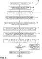
- FIG. 5is a flow chart of a method for determining the trailer location.
- the term “and/or,” when used in a list of two or more items,means that any one of the listed items can be employed by itself, or any combination of two or more of the listed items can be employed.
- the compositioncan contain A alone; B alone; C alone; A and B in combination; A and C in combination; B and C in combination; or A, B, and C in combination.
- reference numeral 10generally designates a hitch assist system for hitching a vehicle 12 to a trailer 14 .
- the vehicle 12is exemplarily embodied as a pickup truck having a truck bed 16 that is accessible via a fold down tailgate 18 .
- the vehicle 12also includes a tow hitch in the form of a hitch ball 22 extending from a drawbar 24 that is coupled to the rear of the vehicle 12 .
- the hitch ball 22is configured to be received by a hitch coupler in the form of a coupler ball socket 26 that is provided at a terminal end of a trailer tongue 28 .
- the trailer 14is exemplarily embodied as a single axle trailer having a box frame 30 with an enclosed cargo area 32 from which the tongue 28 extends longitudinally.
- the system 10includes a controller 38 in communication with an imager 40 located at the rear of the vehicle 12 .
- the imager 40may be centrally located at an upper region of the tailgate 18 such that the imager 40 is elevated relative to the drawbar 24 and the hitch ball 22 .
- the imager 40has a field of view 42 located and oriented to capture one or more images of a rear-vehicle scene that generally includes the hitch ball 22 , among other things. Images captured by the imager 40 may be processed by the controller 38 to identify a hitch coupler such as the coupler ball socket 26 .
- the controller 38may communicate with a number of proximity sensors 44 exemplarily shown as ultrasonic sensors spaced across a lower region of the vehicle tailgate 18 and configured to detect the proximity or distance of objects located rearward of the vehicle 12 .
- a positioning device 46such as a global positioning system (GPS) located on the vehicle 12 and/or the trailer 14 .
- the controller 38may communicate with an inertial system 47 including one or more gyroscopes 48 and accelerometers 49 to measure the position, orientation, direction, and/or speed of the vehicle 12 .
- the controller 38 of system 10may be further configured to communicate with a variety of vehicle equipment.
- the controller 38 of the system 10may control a power assist steering system 52 of the vehicle 12 to operate the steered wheels 53 of the vehicle 12 while the vehicle 12 is reversed toward the trailer 14 along a vehicle backup path.
- the power assist steering system 52may be an electric power-assisted steering (EPAS) system that includes an electric steering motor 54 for turning the steered wheels 53 to a steering angle based on a steering command generated by the controller 38 , whereby the steering angle may be sensed by a steering angle sensor 56 of the power assist steering system 52 and provided to the controller 38 .
- EASelectric power-assisted steering
- the steering commandmay be provided for autonomously steering the vehicle 12 during a backup maneuver and may alternatively be provided manually via a rotational position (e.g., a steering wheel angle) of a steering wheel 58 or a steering input device 60 , which may be provided to enable a driver to control or otherwise modify the desired curvature of the backing path of vehicle 12 .
- the steering input device 60may be communicatively coupled to the controller 38 in a wired or wireless manner and provides the controller 38 with information defining the desired curvature of the backing path of the vehicle 12 .
- the controller 38processes the information and generates corresponding steering commands that are supplied to the power assist steering system 52 of the vehicle 12 .
- the steering input device 60includes a rotatable knob 62 operable between a number of rotated positions that each provides an incremental change to the desired curvature of the backing path of the vehicle 12 .
- the steering wheel 58 of the vehicle 12may be mechanically coupled with the steered wheels 53 of the vehicle 12 , such that the steering wheel 58 moves in concert with steered wheels 53 via an internal torque, thereby preventing manual intervention with the steering wheel 58 during autonomous steering of the vehicle 12 .
- the power assist steering system 52may include a torque sensor 64 that senses torque (e.g., gripping and/or turning) on the steering wheel 58 that is not expected from autonomous control of the steering wheel 58 and therefore indicative of manual intervention by the driver.
- external torque applied to the steering wheel 58may serve as a signal to the controller 38 that the driver has taken manual control and for the system 10 to discontinue autonomous steering functionality.
- the controller 38 of the system 10may also communicate with a vehicle brake control system 66 of the vehicle 12 to receive vehicle speed information such as individual wheel speeds of the vehicle 12 . Additionally or alternatively, vehicle speed information may be provided to the controller 38 by a powertrain control system 68 and/or a vehicle speed sensor 70 , among other conceivable means. In some embodiments, the controller 38 may provide braking commands to the vehicle brake control system 66 , thereby allowing the system 10 to regulate the speed of the vehicle 12 during a backup maneuver of the vehicle 12 . It should be appreciated that the controller 38 may additionally or alternatively regulate the speed of the vehicle 12 via interaction with the powertrain control system 68 .
- the potential for unacceptable backup conditionscan be reduced when the vehicle 12 is backing toward the trailer 14 .
- unacceptable backup conditionsinclude, but are not limited to, a vehicle over-speed condition, sensor failure, and the like.
- the drivermay be unaware of the failure until the unacceptable backup condition is imminent or already happening. Therefore, it is disclosed herein that the controller 38 of the system 10 can generate an alert signal corresponding to a notification of an actual, impending, and/or anticipated unacceptable backup condition, and prior to driver intervention, generate a counter measure to prevent such an unacceptable backup condition.
- the controller 38may communicate with one or more devices, including a vehicle alert system 72 , which may prompt visual, auditory, and tactile warnings.
- vehicle alert system 72may prompt visual, auditory, and tactile warnings.
- vehicle brake lights 74 and vehicle emergency flashersmay provide a visual alert and a vehicle horn 76 and/or speaker 78 may provide an audible alert.
- the controller 38 and/or vehicle alert system 72may communicate with a human machine interface (HMI) 80 of the vehicle 12 .
- the HMI 80may include a touchscreen display 84 such as a center-stack mounted navigation or entertainment display capable of displaying images indicating the alert. Such an embodiment may be desirable to notify the driver of the vehicle 12 that an unacceptable backup condition is present.
- the controller 38is configured with a microprocessor 85 and/or other analog and/or digital circuitry for processing one or more logic routines stored in a memory 86 .
- the logic routinesmay include one or more operating routines 88 .
- Information from the imager 40 or other components of the system 10can be supplied to the controller 38 via a communication network of the vehicle 12 , which can include a controller area network (CAN), a local interconnect network (LIN), or other conventional protocols used in the automotive industry.
- CANcontroller area network
- LINlocal interconnect network
- the controller 38may be a stand-alone dedicated controller or may be a shared controller integrated with the imager 40 or other component of the system 10 in addition to any other conceivable onboard or off-board vehicle control systems.
- the system 10includes a device 90 disposed at a trailer location 92 and having a display 94 configured to flash a shape 96 at a predetermined frequency and alternating in color.
- the device 90is a portable electronic device such as a smartphone, tablet or the like.
- the trailer location 92includes the tongue 28 and portions thereof proximate the hitch coupler (e.g., coupler ball socket 26 ).
- the device 90may be secured to the tongue 28 via a device holder, rested on the tongue 28 using a device stand, or held near the trailer location 92 by hand, for example.
- the shape 96is exemplarily shown as a circular shape centrally located on the display 94 of the device 90 .
- the size of the shape 96is generally predetermined and the flashing of the same may be executed by a software application stored on the device 90 .
- the device 90flashes the shape 96 at the predetermined frequency such that the shape 96 alternates between a first color and a second color.
- the predetermined frequencymay correspond to 10 Hertz and the first and second color may be green and red, respectively.
- one periodcorresponds to the shape 96 alternating once between the first and second color.
- the shape 96is generally displayed at the same location for each color, it is contemplated that the shape 96 may move such that it is displayed in different locations for each respective color, if desired. Accordingly, while the shape 96 is two-dimensional in nature, the adoption of color alternation along with flashing the shape 96 in temporal fashion imparts a four-dimensional aspect to the shape 96 and enables the same to be easily identified using image processing means.
- the controller 38identifies the shape 96 in images captured by the imager 40 to determine the trailer location 92 .
- the controller 38may be programmed to detect the flashing pattern described with reference to FIG. 4 .
- the flashing patternmay be stored to the memory 86 of the controller 38 and the detection means may be provided in the one or more operating routines 88 of the controller 38 .
- a method of determining a trailer locationis shown in FIG. 5 and is exemplarily embodied as the one or more operating routines 88 of the controller 38 .
- the detection methodis exemplarily described with reference to the flashing pattern of FIG. 4 .
- the device 90is disposed at the trailer location 92 .
- the trailer location 92may include the tongue 28 and portions thereof proximate the hitch coupler.
- imagesare captured of a rear-vehicle scene containing the trailer 14 and the device 90 at the trailer location 92 . To do so, a user may be required to position the vehicle 12 such that the trailer 14 and the device 90 are within the field of view 42 of the imager 40 .
- the device 90is operated to execute the flashing pattern, that is, to flash the shape 96 at the predetermined frequency such that the shape 96 alternates between the first color and the second color as described herein.
- the captured images containing the device 90are provided to the controller 38 for image processing.
- the controller 38applies a Hough circle transform to detect one or more circular shape candidates in the captured images.
- the Hough circle transformmay be applied to each video frame and the circular shape candidates include the shape 96 and may also include other objects in the captured images having a circular shape.
- the controller 38selects only the one or more circular shape candidates having one of the first color and the second color.
- the controller 38may filter the video frames from step D to isolate only the one or more circular shape candidates having a green or red color.
- a number of the video framesare stored (e.g., to memory 86 ) containing only the one or more circular candidates having the first or second color.
- the number of video framesmay have a duration of 3-5 seconds to ensure that the video frames contain one or more periods of the flashing pattern.
- the controller 38applies a temporal Fourier transform to the stored video frames to determine frequencies of the one or more circular shape candidates having one of the first color and the second color.
- the controller 38identifies, as the shape 96 , whichever of the one or more circular shape candidates has a frequency that approximately matches the predetermined frequency (e.g., 10 Hz). If the controller 38 identifies the shape 96 at step H, the user may be prompted to confirm the identification of the shape 96 at step I. For example, the identified shape may be displayed on the touchscreen display 84 of the vehicle 12 and the user may confirm its identity by touching an assigned area of the display 84 or through other user-input means.
- the predetermined frequencye.g. 10 Hz
- the controller 38may generate at least one of an alert and troubleshooting instruction at step J.
- the controller 38may enlist the vehicle alert system 72 to instruct the user to position the vehicle 12 closer to the trailer 14 and repeat steps C-H so that the shape 96 may be identified.
- the system 10may then reverse the vehicle 12 toward the trailer location 92 .
- the reversing of the vehicle 12may occur autonomously or semi-autonomously.
- a hitch assist systemis provided herein.
- the systemadvantageously determines a trailer location by identifying a shape in captured images.
- the shapeappears in a flashing pattern displayed on a device located at the trailer location.
- This form of identificationis simple to implement and generally less demanding than other forms of trailer identification employing the use of an imager.
Landscapes
- Engineering & Computer Science (AREA)
- Mechanical Engineering (AREA)
- Transportation (AREA)
- Human Computer Interaction (AREA)
- Chemical & Material Sciences (AREA)
- Combustion & Propulsion (AREA)
- Multimedia (AREA)
- Automation & Control Theory (AREA)
- Radar, Positioning & Navigation (AREA)
- Remote Sensing (AREA)
- Image Analysis (AREA)
Abstract
Description
- the trailer location includes a trailer tongue;
- the shape includes a circular shape;
- the shape alternates between a first color and a second color;
- the first color includes green and the second color includes red;
- the controller applies a Hough circle transform to detect one or more circular shape candidates in the captured images;
- the controller selects only the one or more circular shape candidates having one of the first color and the second color;
- the controller applies a temporal Fourier transform to determine frequencies of the one or more circular shape candidates having one of the first color and the second color;
- the controller identifies, as the shape, whichever of the one or more circular shape candidates has a frequency that best matches the predetermined frequency;
- if the controller is unable to identify the shape, the controller generates at least one of an alert and troubleshooting instruction; and
- a vehicle display for showing the shape identified in the captured images and a user-input device for enabling a user to confirm the identification of the shape.
- the trailer location includes a trailer tongue and the first color and second color include red and green, respectively;
- the controller applies a Hough circle transform to detect one or more circular shape candidates in the captured images;
- the controller selects only the one or more circular shape candidates having one of the first color and the second color;
- the controller applies a temporal Fourier transform to determine frequencies of the one or more circular shape candidates having one of the first color and the second color;
- the controller identifies, as the circular shape, whichever of the one or more circular shape candidates has a frequency that best matches the predetermined frequency;
- if the controller is unable to identify the shape, the controller generates at least one of an alert and troubleshooting instruction; and
- a vehicle display for showing the shape identified in the captured images and a user-input device for enabling a user to confirm the identification of the shape.
Claims (20)
Priority Applications (3)
| Application Number | Priority Date | Filing Date | Title |
|---|---|---|---|
| US15/697,870US11338851B2 (en) | 2017-09-07 | 2017-09-07 | Hitch assist system featuring trailer location identification |
| CN201811023449.4ACN109466259B (en) | 2017-09-07 | 2018-09-03 | Hitch assist system featuring trailer position recognition |
| DE102018121715.3ADE102018121715A1 (en) | 2017-09-07 | 2018-09-05 | TRAILER CLUTCH SUPPORT SYSTEM WITH IDENTIFICATION OF A POSITION OF THE TRAILER |
Applications Claiming Priority (1)
| Application Number | Priority Date | Filing Date | Title |
|---|---|---|---|
| US15/697,870US11338851B2 (en) | 2017-09-07 | 2017-09-07 | Hitch assist system featuring trailer location identification |
Publications (2)
| Publication Number | Publication Date |
|---|---|
| US20190071123A1 US20190071123A1 (en) | 2019-03-07 |
| US11338851B2true US11338851B2 (en) | 2022-05-24 |
Family
ID=65363727
Family Applications (1)
| Application Number | Title | Priority Date | Filing Date |
|---|---|---|---|
| US15/697,870Active2039-02-24US11338851B2 (en) | 2017-09-07 | 2017-09-07 | Hitch assist system featuring trailer location identification |
Country Status (3)
| Country | Link |
|---|---|
| US (1) | US11338851B2 (en) |
| CN (1) | CN109466259B (en) |
| DE (1) | DE102018121715A1 (en) |
Cited By (2)
| Publication number | Priority date | Publication date | Assignee | Title |
|---|---|---|---|---|
| US20210384979A1 (en)* | 2020-06-03 | 2021-12-09 | Telefonaktiebolaget Lm Ericsson (Publ) | Information communication using equipment indicator lights |
| US20220250681A1 (en)* | 2021-02-05 | 2022-08-11 | Ford Global Technologies, Llc | Trailer backup assist systems and methods |
Families Citing this family (3)
| Publication number | Priority date | Publication date | Assignee | Title |
|---|---|---|---|---|
| US11731471B2 (en)* | 2018-04-27 | 2023-08-22 | Fontaine Fifth Wheel Company | Methods and systems for monitoring coupling of fifth wheels to kingpins |
| US11090990B2 (en)* | 2018-09-17 | 2021-08-17 | Ford Global Technologies, Llc | Trailer position, heading angle, and level measurement with smart device |
| US11524536B2 (en) | 2019-02-14 | 2022-12-13 | Fontaine Fifth Wheel Company | Apparatuses, systems, and methods for determining and verifying operational states of fifth wheels |
Citations (25)
| Publication number | Priority date | Publication date | Assignee | Title |
|---|---|---|---|---|
| US5526294A (en) | 1989-04-28 | 1996-06-11 | Matsushita Electric Industrial Co., Ltd. | Capacitive touch entry apparatus using drive pulse signals of different phases |
| US5880538A (en) | 1996-05-20 | 1999-03-09 | I F M Electronic Gmbh | Capacitive proximity switch circuit |
| DE102004043761A1 (en) | 2004-09-10 | 2006-03-16 | Daimlerchrysler Ag | Tow coupling monitoring method for towing vehicle, involves comparing graphic data with allowed samples and threshold values for producing assistance signals, and displaying data and signals for monitoring coupling process of coupling |
| US20060082545A1 (en) | 2004-10-20 | 2006-04-20 | Visteon Global Technologies, Inc. | Human machine interface for vehicle including proximity sensor |
| US20090271078A1 (en) | 2008-04-29 | 2009-10-29 | Mike Dickinson | System and method for identifying a trailer being towed by a vehicle |
| US20100027879A1 (en)* | 2005-08-19 | 2010-02-04 | Panasonic Corporation | Image processing method, image processing system, and image processing program |
| US20120055557A1 (en) | 2010-09-08 | 2012-03-08 | Belz Jeffrey J | Faucet including a capacitance based sensor |
| US20120069199A1 (en)* | 2010-09-17 | 2012-03-22 | Google Inc. | Moving information between computing devices |
| US20120208592A1 (en)* | 2010-11-04 | 2012-08-16 | Davis Bruce L | Smartphone-Based Methods and Systems |
| US20130024169A1 (en) | 2006-01-10 | 2013-01-24 | Guardian Industries Corp. | Moisture sensor and/or defogger with bayesian improvements, and related methods |
| US20140012465A1 (en)* | 2012-07-05 | 2014-01-09 | Uusi, Llc | Vehicle trailer connect system |
| US8971715B2 (en) | 2013-03-15 | 2015-03-03 | Jingxi Zhang | Apparatus and methods of displaying messages for electronic devices |
| US20150115571A1 (en)* | 2013-10-24 | 2015-04-30 | GM Global Technology Operations LLC | Smart tow |
| US20150253428A1 (en)* | 2013-03-15 | 2015-09-10 | Leap Motion, Inc. | Determining positional information for an object in space |
| US9219472B2 (en) | 2012-04-11 | 2015-12-22 | Ford Global Technologies, Llc | Proximity switch assembly and activation method using rate monitoring |
| US9287864B2 (en) | 2012-04-11 | 2016-03-15 | Ford Global Technologies, Llc | Proximity switch assembly and calibration method therefor |
| WO2016069498A1 (en) | 2014-10-26 | 2016-05-06 | Galileo Group, Inc. | Temporal processes for aggregating multi dimensional data collection from discrete and distributed collectors using machine-to-machine networks and smartphones to provide enhanced space-time perspective for monitoring changes using algorithmic techniques |
| US20160217662A1 (en)* | 2014-01-13 | 2016-07-28 | Alexis Ander Kashar | System and Method for Alerting a User |
| US9403413B2 (en)* | 2014-05-07 | 2016-08-02 | GM Global Technology Operations LLC | Systems and methods to assist in coupling a vehicle to a trailer |
| US20170043807A1 (en)* | 2015-08-11 | 2017-02-16 | Daniel Robert Shepard | Trailer backing up system display |
| US20170073004A1 (en)* | 2015-09-13 | 2017-03-16 | Daniel Robert Shepard | Trailer backing up system accessories |
| US9766628B1 (en)* | 2014-04-04 | 2017-09-19 | Waymo Llc | Vision-based object detection using a polar grid |
| US20170294130A1 (en)* | 2016-04-08 | 2017-10-12 | Uber Technologies, Inc. | Rider-vehicle handshake |
| US20180097884A1 (en)* | 2016-10-05 | 2018-04-05 | Dell Products L.P. | Trailer identification, inspection, and verification using a vehicle gateway |
| US20180128749A1 (en)* | 2016-11-07 | 2018-05-10 | Alarm.Com Incorporated | Automated Optical Device Monitoring |
Family Cites Families (3)
| Publication number | Priority date | Publication date | Assignee | Title |
|---|---|---|---|---|
| US8096069B2 (en)* | 2006-09-06 | 2012-01-17 | The Invention Science Fund I, Llc | Repeatably displaceable emanating element display |
| US20150097818A1 (en)* | 2013-10-03 | 2015-04-09 | Delphi Technologies, Inc. | Assembly and method to align displayed images to an overlaying applique |
| DE102014222034B4 (en)* | 2013-10-31 | 2021-03-25 | Ford Global Technologies, Llc | Method and system for monitoring placement of a target on a trailer |
- 2017
- 2017-09-07USUS15/697,870patent/US11338851B2/enactiveActive
- 2018
- 2018-09-03CNCN201811023449.4Apatent/CN109466259B/enactiveActive
- 2018-09-05DEDE102018121715.3Apatent/DE102018121715A1/enactivePending
Patent Citations (25)
| Publication number | Priority date | Publication date | Assignee | Title |
|---|---|---|---|---|
| US5526294A (en) | 1989-04-28 | 1996-06-11 | Matsushita Electric Industrial Co., Ltd. | Capacitive touch entry apparatus using drive pulse signals of different phases |
| US5880538A (en) | 1996-05-20 | 1999-03-09 | I F M Electronic Gmbh | Capacitive proximity switch circuit |
| DE102004043761A1 (en) | 2004-09-10 | 2006-03-16 | Daimlerchrysler Ag | Tow coupling monitoring method for towing vehicle, involves comparing graphic data with allowed samples and threshold values for producing assistance signals, and displaying data and signals for monitoring coupling process of coupling |
| US20060082545A1 (en) | 2004-10-20 | 2006-04-20 | Visteon Global Technologies, Inc. | Human machine interface for vehicle including proximity sensor |
| US20100027879A1 (en)* | 2005-08-19 | 2010-02-04 | Panasonic Corporation | Image processing method, image processing system, and image processing program |
| US20130024169A1 (en) | 2006-01-10 | 2013-01-24 | Guardian Industries Corp. | Moisture sensor and/or defogger with bayesian improvements, and related methods |
| US20090271078A1 (en) | 2008-04-29 | 2009-10-29 | Mike Dickinson | System and method for identifying a trailer being towed by a vehicle |
| US20120055557A1 (en) | 2010-09-08 | 2012-03-08 | Belz Jeffrey J | Faucet including a capacitance based sensor |
| US20120069199A1 (en)* | 2010-09-17 | 2012-03-22 | Google Inc. | Moving information between computing devices |
| US20120208592A1 (en)* | 2010-11-04 | 2012-08-16 | Davis Bruce L | Smartphone-Based Methods and Systems |
| US9287864B2 (en) | 2012-04-11 | 2016-03-15 | Ford Global Technologies, Llc | Proximity switch assembly and calibration method therefor |
| US9219472B2 (en) | 2012-04-11 | 2015-12-22 | Ford Global Technologies, Llc | Proximity switch assembly and activation method using rate monitoring |
| US20140012465A1 (en)* | 2012-07-05 | 2014-01-09 | Uusi, Llc | Vehicle trailer connect system |
| US8971715B2 (en) | 2013-03-15 | 2015-03-03 | Jingxi Zhang | Apparatus and methods of displaying messages for electronic devices |
| US20150253428A1 (en)* | 2013-03-15 | 2015-09-10 | Leap Motion, Inc. | Determining positional information for an object in space |
| US20150115571A1 (en)* | 2013-10-24 | 2015-04-30 | GM Global Technology Operations LLC | Smart tow |
| US20160217662A1 (en)* | 2014-01-13 | 2016-07-28 | Alexis Ander Kashar | System and Method for Alerting a User |
| US9766628B1 (en)* | 2014-04-04 | 2017-09-19 | Waymo Llc | Vision-based object detection using a polar grid |
| US9403413B2 (en)* | 2014-05-07 | 2016-08-02 | GM Global Technology Operations LLC | Systems and methods to assist in coupling a vehicle to a trailer |
| WO2016069498A1 (en) | 2014-10-26 | 2016-05-06 | Galileo Group, Inc. | Temporal processes for aggregating multi dimensional data collection from discrete and distributed collectors using machine-to-machine networks and smartphones to provide enhanced space-time perspective for monitoring changes using algorithmic techniques |
| US20170043807A1 (en)* | 2015-08-11 | 2017-02-16 | Daniel Robert Shepard | Trailer backing up system display |
| US20170073004A1 (en)* | 2015-09-13 | 2017-03-16 | Daniel Robert Shepard | Trailer backing up system accessories |
| US20170294130A1 (en)* | 2016-04-08 | 2017-10-12 | Uber Technologies, Inc. | Rider-vehicle handshake |
| US20180097884A1 (en)* | 2016-10-05 | 2018-04-05 | Dell Products L.P. | Trailer identification, inspection, and verification using a vehicle gateway |
| US20180128749A1 (en)* | 2016-11-07 | 2018-05-10 | Alarm.Com Incorporated | Automated Optical Device Monitoring |
Cited By (3)
| Publication number | Priority date | Publication date | Assignee | Title |
|---|---|---|---|---|
| US20210384979A1 (en)* | 2020-06-03 | 2021-12-09 | Telefonaktiebolaget Lm Ericsson (Publ) | Information communication using equipment indicator lights |
| US20220250681A1 (en)* | 2021-02-05 | 2022-08-11 | Ford Global Technologies, Llc | Trailer backup assist systems and methods |
| US11511801B2 (en)* | 2021-02-05 | 2022-11-29 | Ford Global Technologies, Llc | Trailer backup assist systems and methods |
Also Published As
| Publication number | Publication date |
|---|---|
| DE102018121715A1 (en) | 2019-03-07 |
| CN109466259B (en) | 2025-04-29 |
| CN109466259A (en) | 2019-03-15 |
| US20190071123A1 (en) | 2019-03-07 |
Similar Documents
| Publication | Publication Date | Title |
|---|---|---|
| US11338851B2 (en) | Hitch assist system featuring trailer location identification | |
| US9895945B2 (en) | Trailer backup assist system with hitch assist | |
| US10144417B1 (en) | Hitch assist system and method featuring a specified angle between a vehicle heading and a trailer heading at a final position | |
| US10363874B2 (en) | Hitch assist system with hitch coupler identification feature and hitch coupler height estimation | |
| US9798953B2 (en) | Template matching solution for locating trailer hitch point | |
| US9610975B1 (en) | Hitch angle detection for trailer backup assist system | |
| US9963004B2 (en) | Trailer sway warning system and method | |
| US10953711B2 (en) | Hitch assist system | |
| US9829883B1 (en) | Trailer backup assist system having remote control and user sight management | |
| US10430672B2 (en) | Hitch assist system with trailer height estimation and hitch coupler identification | |
| US10127459B2 (en) | Trailer type identification system | |
| US20170174022A1 (en) | Multi-stage solution for trailer hitch angle initialization | |
| GB2526903A (en) | Trailer backup assist system using gesture commands and method | |
| US10427716B2 (en) | Hitch assist system and method | |
| US20170174128A1 (en) | Centerline method for trailer hitch angle detection | |
| US20170174023A1 (en) | Hitch angle detection for trailer backup assist system | |
| US20180237069A1 (en) | Method for interactive control of the automatic parking of a motor vehicle by means of a mobile terminal | |
| US20170106796A1 (en) | Trailer backup assist system with hitch angle offset estimation | |
| US10802478B2 (en) | Hitch assist system and method for autonomously maneuvering a vehicle in a user-specified target travel direction | |
| US20170174130A1 (en) | Hitch angle detection for trailer backup assist system using multiple imaging devices | |
| CN110641236A (en) | Detection and response to interference between trailer coupler and hitch ball | |
| US20220144169A1 (en) | Rear-view camera system for a trailer hitch system | |
| US10427717B2 (en) | Hitch assist system with hitch coupler identification feature and hitch coupler height estimation | |
| US10913494B2 (en) | System and method for trailer height adjustment | |
| CN110641453A (en) | System for detecting and responding to trailer backup |
Legal Events
| Date | Code | Title | Description |
|---|---|---|---|
| AS | Assignment | Owner name:FORD GLOBAL TECHNOLOGIES, LLC, MICHIGAN Free format text:ASSIGNMENT OF ASSIGNORS INTEREST;ASSIGNORS:ZHANG, YI;LAVOIE, ERICK MICHAEL;REEL/FRAME:043522/0893 Effective date:20170906 | |
| FEPP | Fee payment procedure | Free format text:ENTITY STATUS SET TO UNDISCOUNTED (ORIGINAL EVENT CODE: BIG.); ENTITY STATUS OF PATENT OWNER: LARGE ENTITY | |
| STPP | Information on status: patent application and granting procedure in general | Free format text:NON FINAL ACTION MAILED | |
| STPP | Information on status: patent application and granting procedure in general | Free format text:RESPONSE TO NON-FINAL OFFICE ACTION ENTERED AND FORWARDED TO EXAMINER | |
| STPP | Information on status: patent application and granting procedure in general | Free format text:FINAL REJECTION MAILED | |
| STPP | Information on status: patent application and granting procedure in general | Free format text:DOCKETED NEW CASE - READY FOR EXAMINATION | |
| STPP | Information on status: patent application and granting procedure in general | Free format text:NON FINAL ACTION MAILED | |
| STPP | Information on status: patent application and granting procedure in general | Free format text:RESPONSE TO NON-FINAL OFFICE ACTION ENTERED AND FORWARDED TO EXAMINER | |
| STPP | Information on status: patent application and granting procedure in general | Free format text:FINAL REJECTION MAILED | |
| STPP | Information on status: patent application and granting procedure in general | Free format text:ADVISORY ACTION MAILED | |
| STCV | Information on status: appeal procedure | Free format text:NOTICE OF APPEAL FILED | |
| STCV | Information on status: appeal procedure | Free format text:APPEAL BRIEF (OR SUPPLEMENTAL BRIEF) ENTERED AND FORWARDED TO EXAMINER | |
| STCV | Information on status: appeal procedure | Free format text:EXAMINER'S ANSWER TO APPEAL BRIEF MAILED | |
| STCV | Information on status: appeal procedure | Free format text:ON APPEAL -- AWAITING DECISION BY THE BOARD OF APPEALS | |
| STCV | Information on status: appeal procedure | Free format text:BOARD OF APPEALS DECISION RENDERED | |
| STPP | Information on status: patent application and granting procedure in general | Free format text:NOTICE OF ALLOWANCE MAILED -- APPLICATION RECEIVED IN OFFICE OF PUBLICATIONS | |
| STPP | Information on status: patent application and granting procedure in general | Free format text:PUBLICATIONS -- ISSUE FEE PAYMENT VERIFIED | |
| STCF | Information on status: patent grant | Free format text:PATENTED CASE |