US11337790B2 - Systems and methods for protecting the cerebral vasculature - Google Patents
Systems and methods for protecting the cerebral vasculatureDownload PDFInfo
- Publication number
- US11337790B2 US11337790B2US15/901,819US201815901819AUS11337790B2US 11337790 B2US11337790 B2US 11337790B2US 201815901819 AUS201815901819 AUS 201815901819AUS 11337790 B2US11337790 B2US 11337790B2
- Authority
- US
- United States
- Prior art keywords
- filter
- distal
- protection system
- sheath
- artery
- Prior art date
- Legal status (The legal status is an assumption and is not a legal conclusion. Google has not performed a legal analysis and makes no representation as to the accuracy of the status listed.)
- Active, expires
Links
Images


Classifications
- A—HUMAN NECESSITIES
- A61—MEDICAL OR VETERINARY SCIENCE; HYGIENE
- A61F—FILTERS IMPLANTABLE INTO BLOOD VESSELS; PROSTHESES; DEVICES PROVIDING PATENCY TO, OR PREVENTING COLLAPSING OF, TUBULAR STRUCTURES OF THE BODY, e.g. STENTS; ORTHOPAEDIC, NURSING OR CONTRACEPTIVE DEVICES; FOMENTATION; TREATMENT OR PROTECTION OF EYES OR EARS; BANDAGES, DRESSINGS OR ABSORBENT PADS; FIRST-AID KITS
- A61F2/00—Filters implantable into blood vessels; Prostheses, i.e. artificial substitutes or replacements for parts of the body; Appliances for connecting them with the body; Devices providing patency to, or preventing collapsing of, tubular structures of the body, e.g. stents
- A61F2/01—Filters implantable into blood vessels
- A61F2/012—Multiple filtering units
- A—HUMAN NECESSITIES
- A61—MEDICAL OR VETERINARY SCIENCE; HYGIENE
- A61F—FILTERS IMPLANTABLE INTO BLOOD VESSELS; PROSTHESES; DEVICES PROVIDING PATENCY TO, OR PREVENTING COLLAPSING OF, TUBULAR STRUCTURES OF THE BODY, e.g. STENTS; ORTHOPAEDIC, NURSING OR CONTRACEPTIVE DEVICES; FOMENTATION; TREATMENT OR PROTECTION OF EYES OR EARS; BANDAGES, DRESSINGS OR ABSORBENT PADS; FIRST-AID KITS
- A61F2/00—Filters implantable into blood vessels; Prostheses, i.e. artificial substitutes or replacements for parts of the body; Appliances for connecting them with the body; Devices providing patency to, or preventing collapsing of, tubular structures of the body, e.g. stents
- A61F2/01—Filters implantable into blood vessels
- A61F2/0105—Open ended, i.e. legs gathered only at one side
- A—HUMAN NECESSITIES
- A61—MEDICAL OR VETERINARY SCIENCE; HYGIENE
- A61F—FILTERS IMPLANTABLE INTO BLOOD VESSELS; PROSTHESES; DEVICES PROVIDING PATENCY TO, OR PREVENTING COLLAPSING OF, TUBULAR STRUCTURES OF THE BODY, e.g. STENTS; ORTHOPAEDIC, NURSING OR CONTRACEPTIVE DEVICES; FOMENTATION; TREATMENT OR PROTECTION OF EYES OR EARS; BANDAGES, DRESSINGS OR ABSORBENT PADS; FIRST-AID KITS
- A61F2/00—Filters implantable into blood vessels; Prostheses, i.e. artificial substitutes or replacements for parts of the body; Appliances for connecting them with the body; Devices providing patency to, or preventing collapsing of, tubular structures of the body, e.g. stents
- A61F2/01—Filters implantable into blood vessels
- A61F2/011—Instruments for their placement or removal
- A—HUMAN NECESSITIES
- A61—MEDICAL OR VETERINARY SCIENCE; HYGIENE
- A61F—FILTERS IMPLANTABLE INTO BLOOD VESSELS; PROSTHESES; DEVICES PROVIDING PATENCY TO, OR PREVENTING COLLAPSING OF, TUBULAR STRUCTURES OF THE BODY, e.g. STENTS; ORTHOPAEDIC, NURSING OR CONTRACEPTIVE DEVICES; FOMENTATION; TREATMENT OR PROTECTION OF EYES OR EARS; BANDAGES, DRESSINGS OR ABSORBENT PADS; FIRST-AID KITS
- A61F2/00—Filters implantable into blood vessels; Prostheses, i.e. artificial substitutes or replacements for parts of the body; Appliances for connecting them with the body; Devices providing patency to, or preventing collapsing of, tubular structures of the body, e.g. stents
- A61F2/01—Filters implantable into blood vessels
- A61F2002/016—Filters implantable into blood vessels made from wire-like elements
- A—HUMAN NECESSITIES
- A61—MEDICAL OR VETERINARY SCIENCE; HYGIENE
- A61F—FILTERS IMPLANTABLE INTO BLOOD VESSELS; PROSTHESES; DEVICES PROVIDING PATENCY TO, OR PREVENTING COLLAPSING OF, TUBULAR STRUCTURES OF THE BODY, e.g. STENTS; ORTHOPAEDIC, NURSING OR CONTRACEPTIVE DEVICES; FOMENTATION; TREATMENT OR PROTECTION OF EYES OR EARS; BANDAGES, DRESSINGS OR ABSORBENT PADS; FIRST-AID KITS
- A61F2/00—Filters implantable into blood vessels; Prostheses, i.e. artificial substitutes or replacements for parts of the body; Appliances for connecting them with the body; Devices providing patency to, or preventing collapsing of, tubular structures of the body, e.g. stents
- A61F2/01—Filters implantable into blood vessels
- A61F2002/018—Filters implantable into blood vessels made from tubes or sheets of material, e.g. by etching or laser-cutting
- A—HUMAN NECESSITIES
- A61—MEDICAL OR VETERINARY SCIENCE; HYGIENE
- A61F—FILTERS IMPLANTABLE INTO BLOOD VESSELS; PROSTHESES; DEVICES PROVIDING PATENCY TO, OR PREVENTING COLLAPSING OF, TUBULAR STRUCTURES OF THE BODY, e.g. STENTS; ORTHOPAEDIC, NURSING OR CONTRACEPTIVE DEVICES; FOMENTATION; TREATMENT OR PROTECTION OF EYES OR EARS; BANDAGES, DRESSINGS OR ABSORBENT PADS; FIRST-AID KITS
- A61F2230/00—Geometry of prostheses classified in groups A61F2/00 - A61F2/26 or A61F2/82 or A61F9/00 or A61F11/00 or subgroups thereof
- A61F2230/0063—Three-dimensional shapes
- A61F2230/0093—Umbrella-shaped, e.g. mushroom-shaped
- A—HUMAN NECESSITIES
- A61—MEDICAL OR VETERINARY SCIENCE; HYGIENE
- A61M—DEVICES FOR INTRODUCING MEDIA INTO, OR ONTO, THE BODY; DEVICES FOR TRANSDUCING BODY MEDIA OR FOR TAKING MEDIA FROM THE BODY; DEVICES FOR PRODUCING OR ENDING SLEEP OR STUPOR
- A61M25/00—Catheters; Hollow probes
- A61M25/01—Introducing, guiding, advancing, emplacing or holding catheters
- A61M25/0105—Steering means as part of the catheter or advancing means; Markers for positioning
- A61M25/0133—Tip steering devices
- A61M25/0147—Tip steering devices with movable mechanical means, e.g. pull wires
Definitions
- the disclosurerelates to devices and methods for filtering body fluids such as blood and/or selectively deflecting potentially embolic particles from the body fluid.
- the devicescan be catheter-based for insertion into a vascular system of a subject.
- arteries that carry oxygenated blood to the braini.e., the right and left vertebral arteries, and the right and left common carotid arteries.
- Various procedures conducted on the human bodye.g., TAVR, aortic valve valvuloplasty, carotid artery stenting, closure of the left atrial appendage, mitral valve annuloplasty, mitral valve replacement, mitral valve repair, TEVAR, etc. can cause and/or dislodge native or foreign materials, which dislodged bodies can travel into one or more of the cerebral arteries resulting in, inter alia, stroke.
- filtering the innominate artery, right subclavian artery, right brachiocephalic artery, right common carotid artery, left vertebral artery, and left subclavian artery at aortic branch arches or at the arches of said arteriesmay be useful to prevent dislodged materials from migrating to the cerebral area.
- Thromboembolic disorderssuch as stroke, pulmonary embolism, peripheral thrombosis, atherosclerosis, and the like affect many people. These disorders are a major cause of morbidity and mortality in the United States and throughout the world. Thromboembolic events are characterized by an occlusion of a blood vessel.
- the occlusioncan be caused by a clot, which is viscoelastic or jelly-like and comprises platelets, fibrinogen, and other clotting proteins
- Percutaneous aortic valve replacement procedureshave become popular, but stroke rates related to this procedure are between two and twenty percent.
- plaque, calcium or other materialmay be dislodged from the vasculature and may travel through the carotid circulation and into the brain.
- tissue ischemiadevelops from a lack of oxygen and nutrients. The ischemia progresses to tissue infarction or cell death if the occlusion persists. Infarction does not develop or is greatly limited if the flow of blood is reestablished rapidly. Failure to reestablish blood-flow can lead to the loss of limb, angina pectoris, myocardial infarction, stroke, or even death.
- Reestablishing blood flow and removal of the thrombusis highly desirable.
- Surgical techniques and medicaments to remove or dissolve obstructing materialhave been developed, but exposing a subject to surgery may be traumatic and is best avoided when possible. Additionally, the use of certain devices carry risks such as the risk of dislodging foreign bodies, damaging the interior lining of the vessel as the catheter is being manipulated, blood thinning, etc.
- the present disclosure and its various embodimentscan provide compound systems of filters and/or deflectors for collecting and/or deflecting debris in a manner such that all four cerebral arteries are protected.
- Embodiments of the present disclosureaddresses debris, tissue, or the like, that can be dislodged during an endovascular procedure, travel into the cerebral vasculature, and embolize, leading to stroke or ischemia in an artery occluded, partially or totally, by the clot.
- TAVRtranscatheter aortic valve replacement
- stenotic material around the valvecan be dislodged during implantation of the artificial valve.
- Atheromas and calcium along and within the aorta and aortic archcan be dislodged as the TAVR catheter is advanced toward the diseased aortic valve and subsequently withdrawn after implantation is completed.
- pieces of the catheter itselfcan be stripped away during delivery and implantation.
- Embodiments of the present disclosureare intended to address these potentially devastating cerebral events by providing a delivery system comprised of filters and/or deflectors and/or a combinations thereof, to intercept this debris before it can enter any of the cerebral arteries.
- certain aspects of the disclosureare directed toward a method of preventing embolic material from entering the cerebral vasculature.
- the methodcan include introducing a protection system into an aortic arch.
- the protection systemcan include an outer sheath, a distal filter portion, and a deflector portion having a first lobe and a second lobe.
- the methodcan also include deploying the distal filter portion in a first vessel and deploying the deflector portion in the aortic arch such that the first lobe prevents debris from flowing into a second vessel and the second lobe prevents debris from flowing into a third vessel. After deploying the distal filter portion and the deflector portion, the distal filter portion is distal to the deflector portion.
- a protection system for use with the above-described methodcan include an outer sheath, an articulating distal sheath positioned radially inward of the outer sheath, a filter wire positioned radially inward of the articulating distal sheath, a distal filter portion carried by the filter wire, and a deflector portion positioned radially between the outer sheath and the articulating distal sheath in a pre-deployment configuration.
- the deflector portioncan include a first lobe configured to seal against an ostium of a second vessel and a second lobe configured to seal against an ostium of a third vessel.
- the distal filter portionis positioned distal to the deflector portion.
- Another method of preventing embolic material from entering the cerebral vasculaturecan include introducing a protection system into an aortic arch.
- the protection systemcan include an articulating distal sheath, a first or proximal filter, a second or secondary distal filter connected to the first filter by a first linking or tethering portion, and a third or distal filter connected to the second filter by a second linking or tethering portion.
- Each of the first filter, the second filter, and the third filtercan be configured to be deployed from the articulating distal sheath.
- the methodcan also include deploying the first filter in a first vessel, then deploying the second filter in a second vessel, and then deploying the third filter in a third vessel.
- a protection system for use with the above-described methodcan include an articulating distal sheath, a first or proximal filter, a second or secondary distal filter connected to the first filter by a first linking or tethering portion; and a third or distal filter connected to the second filter by a second linking or tethering portion.
- Each of the first filter, the second filter, and the third filtercan be configured to be deployed from the articulating distal sheath.
- the first tethering portioncan be sufficiently flexible to extend from the first vessel to the second vessel.
- the second tethering portioncan be sufficient flexible to extend from the second vessel to the third vessel.
- FIG. 1shows the anatomy of the aortic branch.
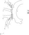
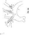
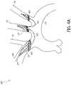
- FIG. 2shows an example protection system that uses a deflector to block the left common carotid artery.
- FIG. 2Ashows another example protection system that uses a knuckle to orient the deflector to block the left common carotid artery.
- FIGS. 2B-2Cshow the example protection system of FIG. 2A with the articulating distal sheath deflecting from a first configuration ( FIG. 2B ) to a second configuration ( FIG. 2C ).
- FIG. 2Dshows a cross-section of FIG. 2B taken through line 2 D- 2 D.
- FIG. 2Eshows an example of the difficulty associated with positioning a deflector against the vessel wall.
- FIGS. 2F-2Hshow different example methods of conforming the deflector to the vessel wall.
- FIGS. 2I-2Kschematically show the deployment of a deflector using the example shown in FIG. 2H .
- FIG. 2Lshows an example of a deflector with a dome-shaped portion.
- FIGS. 2M-2Oshow another example of a protection system that uses a deflector to block the left common carotid artery.
- FIGS. 3A-3Bshow another example of a protection system in which two filters are serially loaded into the articulating distal sheath of the first filter assembly and the distal filter is detachable.
- FIGS. 4A-4Bshow yet another example of a protection system in which the left subclavian and left common carotid filters are serially loaded into the articulating distal sheath and the aforementioned filters are tethered together.
- FIGS. 5A-5Bshows another example protection system in which the system is introduced from the femoral artery and uses a three-tethered filter device.
- FIG. 6shows another example protection system where the proximal filter is a deflector.
- FIGS. 7A-7Dshow a method of deploying an example protection system having a single continuous strand design.
- FIGS. 7E-7Gshow different cross-sections of the single continuous strand shown in FIGS. 7A-7D .
- FIGS. 8A-8Dshow another example of a filter design that can be used with any protection system described herein.
- FIGS. 8E-8Lshow another example of a filter design that can be used with any protection system described herein.
- FIG. 9Ashows another example protection system that uses detachable filters having a docking functionality.
- FIGS. 10A-10Ishow an example of an aortic filter system.
- FIGS. 11A-11Sillustrate another protection system with an alternative accessory filter that can be inserted through the right radial or brachial artery to the left subclavian artery.
- the disclosuregenerally relates to devices and methods for filtering fluids and/or deflecting debris contained within fluids, including body fluids such as blood.
- a filtering or deflecting devicecan be positioned in an artery before and/or during an endovascular procedure, for example transcatheter aortic valve implantation (TAVI) or replacement (TAVR), transcatheter mitral valve implantation or repair (TMVR), surgical aortic valve replacement (SAVR), other surgical valve repair, implantation, or replacement, cardiac ablation (e.g., ablation of the pulmonary vein to treat atrial fibrillation) using a variety of energy modalities (e.g., radio frequency (RF), energy, cryo, microwave, ultrasound), cardiac bypass surgery (e.g., open-heart, percutaneous), transthoracic graft placement around the aortic arch, valvuloplasty, etc., to inhibit or prevent embolic material such as debris, emboli, thrombi, etc. resulting from entering the cerebral vasculature.
- RF
- the devicesmay be used to trap particles in other blood vessels within a subject, and they can also be used outside of the vasculature.
- the devices described hereinare generally adapted to be delivered percutaneously to a target location within a subject, but can be delivered in any suitable way and need not be limited to minimally-invasive procedures.
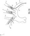
- FIG. 1is a schematic perspective view of an aortic arch 135 .
- the aortic arch 135is upstream of the left and right coronary arteries (both not shown).
- the aortic arch 135typically includes three great branch arteries: the brachiocephalic artery or innominate artery 134 , the left common carotid artery 112 , and the left subclavian artery 114 .
- the innominate artery 134branches to the right common carotid artery 110 , then the right vertebral artery 118 , and thereafter is the right subclavian artery 108 .
- the right subclavian artery 108supplies blood to, and may be directly accessed from (termed right radial access), the right arm.
- the left subclavian artery 114branches to the left vertebral artery 119 , usually in the shoulder area.
- the left subclavian artery 114supplies blood to, and may be directly accessed from (termed left radial access), the left arm.
- the aortic arch 135may be reached from the femoral artery (not shown).
- Devices and methodshave been developed to filter blood flowing to the innominate artery 134 and the left common carotid artery 112 , which provide about 90% of the blood entering the cerebral vasculature. Examples are provided in U.S. Pat. No. 9,492,264, which is incorporated herein by reference in its entirety, and most particularly with respect to disclosure directed to devices and methods for protecting aortic arch branch arteries and structures of filter devices. Certain such devices and methods leave the left subclavian artery 114 , and thus the left vertebral artery 119 , which provides about 10% of the blood entering the cerebral vasculature, exposed to potential embolic material.
- the present applicationdiscloses several single-access multi-vessel embodiments that can provide full cerebral protection with minimal arch interference.
- FIG. 2illustrates an example of a protection system 200 that can be inserted through a single access point from the right radial or brachial artery.
- the outer catheter 224may have a diameter no greater than about 7 F (0.09 inches) or no greater than about 6 F (0.08 inches). The smaller diameter reduces possible complications associated with advancing the filter assembly through the vasculature.
- the protection system 200can include a proximal filter 222 , a distal filter 206 , and a deflector 220 configured to be deployed therebetween.
- the proximal filter 222can be deployed in the brachiocephalic trunk 134 .
- the left subclavian artery 114can be cannulated with an independently steerable and positionable (e.g., rotatable and/or translatable) articulating distal sheath 232 .
- a guidewire 253can be utilized to facilitate positioning, and to interrogate (e.g., visualize and assist in positioning) the vessel during cannulation.
- a distal filter 206can be deployed, e.g., by advancing the distal filter 206 or withdrawing the articulating distal sheath 232 , in the left subclavian artery 114 .
- the mechanisms for deploying the distal filter 206 and the proximal filter 222can include features of the devices described in U.S. Pat. No. 9,492,264, which has been incorporated by reference herein.
- the articulating distal sheath 232can include a deflector 220 that can protect the ostium of the left common carotid artery 112 .
- the deflector 220can be mounted on or contained in the articulating distal sheath 232 , or the deflector 220 can be separately deployable from the articulating distal sheath 232 . Removal of the device can be accomplished as a reversal of the deployment steps into the outer catheter 124 .
- the filters 222 , 206 and the deflector 220may be deployed in any order.
- the device 200can be introduced into the left radial or brachial artery.
- a first filter 222can be deployed in the left subclavian artery 114 between the left vertebral branch 119 and the ostium of the aortic arch 135 .
- a second filter 206can be deployed in the brachiocephalic trunk 134 , and a deflector 220 can be deployed to cover the ostium of the left common carotid artery 112 .
- a protection system 200can be used to protect all three vessels.
- a distal filter 220can be configured to protect the left subclavian 114
- the proximal filter 222can be left in the brachiocephalic artery 134
- a deflector 220can be added between the distal 206 and proximal filter 222 to protect the left common carotid artery 112 .
- the mechanisms for deploying the proximal filter 222 and the distal filter 206can include any features of the filter systems described in U.S. Pat. No. 9,492,264, which is incorporated by reference herein. Unlike the protection system 200 shown in FIG.
- the protection systemcan include a knuckle 230 located between the deflector 220 and the proximal filter 222 .
- the knuckle 230is movable, maneuverable, or otherwise steerable, which can help create a tight bend to properly support and position the deflector 220 .
- the proximal filter 222can be the largest filter and deployed in the proximal location when approaching from the right radial artery. This can be followed by deployment of the deflector 220 and the distal filter 206 distal of the proximal filter 222 .
- the mechanisms to deploy the filters, to deflect the articulating sheath for cannulation, and to additionally deploy the deflectorcan utilize any of the mechanisms described in U.S. Pat. No. 9,492,264, which is incorporated by reference herein. In other methods, the deflector 220 and/or the distal filter 206 may be deployed prior to the proximal filter 222 .
- FIGS. 2B-2Dillustrate the various components of the protection system 200 shown in FIG. 2A .
- the protection system 200can optionally include a skeleton portion 233 .
- the length between the knuckle 230 and the skeleton portion 233 of the articulating distal sheath 232can be adjusted using one or more pull-wires.
- the knuckle 230 and the skeleton portion 233can be two separate components that move relative to each other or part of a single component sufficiently flexible to bend when pulled toward each other. For example, a distal end of one pull wire can be connected to the knuckle 230 and a distal end of another pull wire can be connected to the skeleton portion 233 .
- the region between the knuckle 230 and the skeleton portion 233can be foreshortened to properly position the deflector 220 against the vessel wall.
- the skeleton portion 233can be a laser cut, thin-walled tube that is designed to bend before any other portion of the articulating distal sheath 232 .
- Each end of the deflector 220may be mounted to the articulating distal sheath 232 such that the deflector 220 is free to deflect.
- the deflector 220can be rotated, translated, and/or apposed to the roof of the aortic arch 135 by pulling against either the deflected articulating distal sheath 232 or the deployed distal filter 206 .
- FIG. 2Dshows a cross section of the device through line 2 D- 2 D in FIG.
- FIG. 2Bthat shows the device 200 can include an outer sheath 224 , a core shaft 260 supporting the proximal filter 222 and positioned radially inward of the outer sheath 224 , a pull wire 261 for controlling the articulating distal sheath 232 , an inner member 232 supporting the distal filter 206 , and/or a guidewire 223 extending through the inner member 232 .
- a lumen space 263 between the outer sheath 224 and the core shaft 260can provide space for the proximal filter 222 and the deflector 220 .
- the handle 294 shown in FIGS. 2B-2Ccan include a distal filter actuator 298 .
- the distal filter actuator 298can be advanced or withdrawn to control a position of the distal filter 206 , as indicated by the arrows near the distal filter slider actuator 298 in FIG. 2C .
- the handle 294can include a port 297 for flushing fluids.
- the handle 294can include an actuation mechanism 296 for articulating the articulating distal sheath 232 (as shown by the arrows near actuation mechanism 296 ).
- the actuation mechanism 296can include a screw drive mechanism to deflect the articulating distal sheath 232 by rotating the actuation mechanism 296 .
- the screw drive mechanismcan be self-locking to prevent unintentional deflection of the articulating distal sheath 232 .
- the rear portion 293 (outlined in the dashed box) of the handle 294can be translated to move the articulating distal sheath 232 , deflector 220 , and/or distal filter 206 .
- the handle 294can include an additional flush port 297 .
- the handle 294can include an actuation mechanism 291 , for example a slider, to retract and advance the outer sheath 224 (as shown by the arrows near actuation mechanism 291 ), which releases and retrieves the proximal filter 222 .
- actuation mechanism 291for example a slider, to retract and advance the outer sheath 224 (as shown by the arrows near actuation mechanism 291 ), which releases and retrieves the proximal filter 222 .
- Each of these actuation mechanisms 298 , 296 , 291can be sequentially positioned along the handle 294 according to how the procedure is performed, but the actuation mechanisms 298 , 296 , 291 can take on different configurations or be positioned in a different order.
- a challenge with deflectorsis apposing the deflector 220 against the target vessel and avoiding interference with the index procedure.
- a forcecan be provided to conform the deflector to the vessel wall.
- the deflectorscan push off the wall opposite the target vessel location, compressing the deflector into place.
- FIGS. 2F-2Hillustrate three different methods of conforming the deflector 220 to the vessel wall. These methods can be used independently or in combination with each other.
- an articulating distal sheath 232can be used to properly orient the deflector 220 . With such an articulating sheath 232 , the left subclavian 114 can be cannulated and hooked allowing for the whole system 200 to be pulled back against the hooked distal end of the articulating distal sheath 232 .
- FIG. 2Gshows another method using a filter frame anchor 234 .
- the distal filter 206may include a filter frame anchor 234 to provide more surface area to contact the wall of the left subclavian artery 114 . This may provide a similar mechanism to the design described in FIG. 2F , allowing for the system 200 to be pulled back against the filter frame anchor 234 and pulling the intermediate section of the articulating distal sheath 232 or other sheath up against the roof of the aortic arch 135 .
- the articulating sheath 232can be actuated by pulling on a pull wire 251 that is attached to the distal end of the articulating distal sheath 232 .
- This pull wire 251is impeded off the central axis causing the sheath to deflect as the wire foreshortens.
- a similar mechanismmay be employed in the deflector itself 220 , as shown in FIG. 2H .
- the deflector's curvature and tiltmay be controlled. Further details and embodiments of such a deflector 220 with a pull wire 251 are illustrated in FIGS. 2I-2K .
- one or more pull wires 221can extend through the deflector 220 .
- the one or more pull wires 221can be fixed to a distal end of the deflector 220 .
- FIG. 2Jshows an end view of the deflector 220 . Selectively pulling the pull wires 221 will tilt the deflector 220 off-axis as shown by the dashed lines.
- FIG. 2Lillustrates a deflector design that can be used with any of the example systems described herein.
- the deflector 220self-locates based on the shape of the deflector 220 .
- the deflector 220can include a flexible dome shaped portion 239 , such as in a central region of the deflector 220 where the diameter decreases toward the apex of the dome shaped portion 239 .
- An apex of the dome shaped portion 239can have a diameter of less than or equal to half of a diameter of a base of the dome shaped portion 239 .
- a base of the dome shaped portion 239can have about a 12 mm diameter and an apex of the dome shaped portion 239 can have about a 5 mm diameter.
- the deflector 220may seal against the vessel opening rather than the area around the vessel. In addition, this may provide position location feedback when attempting to place the deflector in the correct location.
- FIGS. 2M-2Oillustrate another example protection system 200 with a deflector 220 that engages a greater surface area of a roof of the aortic arch 135 .
- the deflector 220can have one or both ends mounted to a slideable collar 270 .
- the deflector 220can be configured such that blood pressure can push the deflector 220 into the left common carotid 112 as shown in FIG. 2N .
- the slideable collar(s) 270can be coupled to one or more pull wires (not shown) to foreshorten the deflector 220 and push the deflector 220 into the left common carotid 112 as shown in FIG. 2O .
- FIGS. 3A-3Banother illustrative embodiment of a protection system 300 is shown.
- the protection system 300resembles the protection system 200 discussed above in many respects. Accordingly, numerals used to identify features of the protection system 200 are incremented by a factor of one hundred (100) to identify like features of the protection system 300 . This numbering convention generally applies to the remainder of the figures. Any component or step disclosed in any embodiment in this specification can be used in other embodiments.
- FIGS. 3A-3Billustrates yet another example protection system 300 in which two filters 306 , 320 are serially loaded into the articulating distal sheath 332 that can be delivered to the aorta 135 via an outer sheath 324 .
- the distal filter 306 and the secondary distal filter 320can be loaded in the articulating distal sheath 332 .
- the proximal filter 322can be placed in the brachiocephalic trunk 134 .
- the articulating distal sheath 332can be rotated, advanced/retracted, and/or articulated in order to allow for cannulation of a second and/or third vessel.
- the protection system 300can utilize certain features such as the articulating sheath described in U.S. Pat. No. 9,492,264, which is hereby incorporated by reference herein, to place the secondary distal filter 320 in the left common carotid artery 112 and/or the distal filter 306 in the left subclavian artery 114 .
- a first vesselcan be cannulated, preferably the left subclavian artery 114 , and the distal filter 306 can be deployed in the first vessel.
- This distal filter 306can be detached from the articulating distal sheath 332 for later retrieval.
- the tip of the articulating distal sheath 332can be withdrawn, and the second vessel, preferably the left common carotid artery 112 , can be cannulated, and a secondary distal filter 320 can be deployed in the second vessel.
- the secondary distal filter 320can be first resheathed, and then a feature 307 on the detachable distal filter 306 can be recaptured by the articulating distal sheath 332 .
- the proximal filter 322 that was placed in the brachiocephalic trunk 134can be resheathed and the protection system 300 can be removed from the body.
- the detachable distal filter 306can be placed in the left common carotid artery 112 , and the second filter 320 can be placed in the left subclavian artery 114 .
- the protection system 300can also be inserted into the body through the left radial or brachial artery.
- FIGS. 4A-4Billustrate another example protection system 400 .
- the distal filter 406 and the secondary distal filter 420can be loaded in the articulating distal sheath 432 , as shown in FIG. 4B .
- a proximal filter 422can be deployed in the brachiocephalic trunk 134 .
- the left subclavian artery 114can be cannulated with an independently steerable and positionable (e.g., rotatable and/or translatable) articulating distal sheath 432 .
- a guidewire(not shown) can be utilized to facilitate positioning and to interrogate (e.g., visualize and assist in positioning) the vessel during cannulation.
- a distal filter 406can be deployed (e.g., by advancing the distal filter 406 or withdrawing the articulating distal sheath 432 ) in the left subclavian artery 114 .
- the system 400can utilize any of the features, such as the articulating sheath 432 described in U.S. Pat. No. 9,492,264, which is hereby incorporated by reference herein.
- the distal filter 406can be placed in the left common carotid artery 112 .
- the distal filter 406can be connected to the articulating distal sheath 432 and/or the secondary distal filter 420 (still inside the tip of the articulating distal sheath 432 ) with a flexible tether 455 .
- the flexible tether 455can include a wire, an elastomeric material, nylon filament, suture, or other conformable attachment method.
- the articulating distal sheath 432can be withdrawn, and the second vessel, preferably the left common carotid artery 112 , can be cannulated, so the secondary distal filter 420 can be deployed in the second vessel.
- the slack in the tether 455may be pulled up against the vessel carina between the left common carotid artery 112 and the left subclavian 114 during deployment of the secondary distal filter 420 in the left common carotid artery 112 .
- the secondary distal filter 420can be first resheathed, and then the distal filter 406 can be resheathed by withdrawing the tether 455 in order to pull the filter 406 into the tip of the articulating distal sheath 432 .
- the proximal filter 422 that was placed in the brachiocephalic trunk 134can be resheathed and the device 400 removed from the body.
- the distal filter 406can be placed in the left common carotid artery 112 , and then the secondary distal filter 420 can be placed in the left subclavian artery 114 .
- the protection system 400can also be inserted into the body through the left radial or brachial artery.
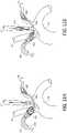
- FIGS. 5A-5Billustrate another example protection system 500 in which three sequential filters 522 , 520 , 506 can be collapsed and loaded into a common delivery sheath 532 .
- the example protection system 500is delivered through the femoral artery, the system 500 can be sized up to at least 8 Fr or greater and only uses only two access sites for the TAVR procedure.
- a pigtail catheter for the index procedurecan be integrated or incorporated into the example protection system 500 , such that the pigtail catheter and the filters 522 , 520 , 506 are delivered from the same access site.
- the pigtail cathetercan be delivered through the same sheath or introducer as the filters 522 , 520 , 506 .
- FIG. 5Aillustrates the system 500 being delivered through the femoral artery
- the system 500can also be delivered via the right arm (e.g. right radial artery) or the left arm (e.g. left radial artery).
- the sizing and orientation of the filterswould match the vessel diameters. For instance, in a femoral artery configuration, the apex of each filter shall be distal relative to the operator.
- the proximal filter 522may be delivered to the brachiocephalic artery 134 , followed in order with the secondary distal filter 520 being delivered to the left common carotid artery 112 , and the distal filter 506 being delivered to the left subclavian artery 114 .
- a diameter of each filter openingwould be approximately 8-17 mm for the brachiocephalic artery 134 , 5-11 mm for the left common carotid artery 112 , and 7-14 mm for the right subclavian artery 108 .
- the filters 522 , 520 , 506can be joined together by one or more tethering elements 555 , 557 .
- the tethering elements 555 , 557may form a continuous tether.
- each filter 522 , 520 , 506can include a filter frame supporting a filter membrane, and the tethering elements 555 , 557 may be integrated into the filter frame and run within the filter membrane of one or more filters 522 , 520 , 506 .
- the tethering elements 555 , 557may be elastomeric or elastomeric with a core that becomes axially rigid at a specified elongation.
- the tethering elements 555 , 557may comprise a wire, nylon filament, suture material, or other conformable material.
- the relative length and/or elasticityshall ensure that the tethering elements 555 , 557 have sufficient tension to draw the tethering elements 555 , 557 up against the vessel carina in order to minimize possible entanglement or interference with other procedural devices, e.g., diagnostic catheters, guidewires, TAVI delivery systems, etc.
- FIG. 6illustrates another example protection system 600 having an aortic deflector 622 .
- the deflector 622can be mounted to the catheter shaft 624 using a pull wire, tether, or other structure.
- the deflector 622can have a through-hole through which an articulating distal sheath 632 can be advanced. Deploying the distal filter 606 through the deflector 622 can be more advantageous than deploying the deflector 622 through a filter because the larger diameter catheter shaft 624 provides more support for the deflector 622 than the smaller diameter articulating distal sheath 632 .
- the deflector 622may be asymmetric with one lobe longer than the other relative with respect to the deflector through-hole.
- the deflector 622can include a first lobe configured to seal against an ostium of the left common carotid artery 112 and a second lobe configured to seal against an ostium of the brachiocephalic artery 134 .
- a length of the first lobecan be measured from the deflector through-hole to an end of the deflector 622
- a length of the second lobecan be measured from the deflector through-hole to an opposite end of the deflector 622
- the sealing perimeter of the deflector 622may have a radiopaque feature such as a Platinum-Iridium coil.
- One or more pull wirescan be used to deflect the frame member embedded in the filter membrane or attached to the sealing perimeter to properly position the deflector 622 .
- the left subclavian 114can be cannulated and a filter 606 can be deployed in the left subclavian artery 114 before the branch to the left vertebral artery 119 in order to ensure that blood flowing to the left vertebral 119 is filtered.
- the filter 606can be mounted on a filter wire 655 .
- the filter wire 655may have a guide lumen to facilitate delivery over a guidewire.
- the filter 606can be deployed by advancing the filter wire 655 or withdrawing the articulating distal sheath 632 . Once deployed, the filter 606 is distal to the deflector 622 . To remove the protection system 600 , the filter 606 can be first sheathed, and then the deflector 622 can be sheathed.
- the filter 606can be first deployed in the left subclavian artery 114 , and then the deflector element 622 can be deployed in the aortic arch 135 .
- the protection system 600can also be inserted into the body through the left radial or brachial artery.
- the deflector 622 elementcovers the left subclavian artery 114 and the left common carotid artery 112 , and the filter 606 can be deployed in the brachiocephalic artery 134 .
- FIG. 7illustrates another example protection 700 in which the device can accommodate a single, continuous strand 755 that can be fed out of the distal tip of a catheter 724 .
- the fibrous strand 755may have a pre-shaped core 758 causing three-dimensional forms 706 , 720 , 722 as the strand 755 is deployed.
- the pre-shaped core 758may be a pre-shaped nitinol wire or other material with sufficient elastic properties to fill the space and block the vessels.
- the filter elements 706 , 720 , 722may be a pre-formed fibrous elements ( FIG.
- the retrieval catheter 724 or a separate aspiration cathetermay be used to aspirate any captured debris.
- These filters 706 , 720 , 722 formed of a single continuous strand 755may be placed in the order of the left subclavian artery 114 , then left common carotid artery 112 , and finally the brachiocephalic trunk 134 . Alternatively, the order may be reversed. Alternatively, the device may be inserted in the left brachial or radial artery rather than the right.
- FIGS. 8A-8Dillustrate another filter design that can be used in any of the other embodiments described herein, but for purposes of illustration, are shown in connection with a system similar to protection system 500 .
- the filter elements 806 , 820 , 822are elongated when collapsed and axially foreshortened when deployed (see partial enlarged view in FIG. 8B ), such that the greatest cross-section area of each filter 806 , 820 , 822 is in the mid-section of the respective filter.
- This configurationmay allow for minimizing the profile of each filter, possibly minimizing the number of catheter exchanges during delivery and retrieval.
- the filtermay be formed of wire mesh, like a “Chinese finger puzzle,” formed of nitinol wire, laser cut, formed of polymer coated wire, or otherwise.
- One or more of the filters 806 , 820 , 822can be foreshortened by using a pre-shaped filter design. Additionally or alternatively, a pull wire can be attached to either end of the filter. Moving one end of the filter relative to the other end of the filter can cause the filter to foreshorten.
- the left subclavian artery 114can be cannulated, and then a distal filter 806 can be deployed in the left subclavian artery 114 .
- the distal 806 filterforeshortens upon deployment.
- the left common carotid artery 112can be cannulated, and a secondary distal filter 820 can be deployed in the left common carotid artery 112 , as shown in FIG. 8C .
- a proximal filter 822can be deployed in the brachiocephalic artery 134 , as shown in FIG. 8D .
- the proximal filter 822may have a larger deployed diameter than the distal filter 806 and/or the secondary distal filter 822 .
- Each of the filters 806 , 820 , 822can be connected together by a flexible tether 855 , 857 .
- the system 800may be deployed from the left radial or left brachial artery and the filters 806 , 820 , 822 can be deployed in reverse order.
- FIGS. 8E-8Lillustrate another variation of the design of the filters used in any of the previous embodiments described herein.
- This filter designcreates additional space in the catheter to accommodate controls for the deflector.
- the filter 888can be foreshortened using any of the techniques described above with respect to FIGS. 8A-8D .
- the filter 888can include a ring 883 that holds the filter 888 in a proper position in the vessel wall. As tension is applied to the system or the pull rod 886 is pulled back, a proximal side of the filter 888 becomes concave while the ring 883 maintains the filter 888 in the same position.
- FIGS. 8G-8Lillustrate a method of deploying the filter 888 .
- the filter 888can be positioned within the sheath 889 (see FIGS. 8G and 8L ).
- the push rod 886can be moved distally while the slotted tube 890 is kept stationary.
- the sheath 889is moved distally to reveal the filter 888 (see FIG. 8K ).
- the push rod 886can include one or more flanges 892 that can push a proximal end of the filter to foreshorten the filter 888 .
- a ring 887welded to secure the push rod 886 to the sheath 899 .
- a benefit to this approachis that upon re-sheathing the filter 888 , the sheath 899 pushes against the filter 888 from the distal side, this may collapse the filter 888 against the blood flow, ensuring that any particulate is held by the filter and moves inward toward the central lumen.
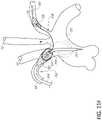
- FIG. 9Aillustrates another example protection system 900 in which a guidewires 967 can be placed into each respective vessel.
- the guidewires 967can have a distal feature that allows the filters 924 , 922 , 920 to become permanently affixed once the filters 924 , 922 , 920 and delivery catheter are advanced coaxially in an over-the-wire technique.
- the guidewires 967may have a pre-shaped element, for example nitinol, to form the span between the vessels. As shown in the figures, this design allows a bare guidewire 967 to be placed in each target location with standard guidewire placement techniques either though a guide catheter, through bare wire manipulation, etc.
- a filter 920 , 922 , 924can be introduced over its respective guidewire 967 , slid into the target location, and activated to dock the filter 920 , 922 , 924 onto the guidewire 967 . This process can be repeated for each filter 920 , 922 , 924 .
- One of the filters 920 , 922 , 924 or an additional filtercould be placed in the same way in the left subclavian artery 114 .
- FIG. 10A-10Hshows an example of an aortic filter system 1000 .
- the brainmay be protected by filtering in the ascending aorta 137 .
- This approachcan protect all three vessels to the brain with one filter 1022 deployed from a catheter 1024 .
- the catheter delivery system for the index procedurecan be accommodated by the filter 1022 so as to retain good wall apposition as the system crosses the filter 1022 .
- FIGS. 10A-10Gillustrate certain features of such an aortic filter system 1000 .
- FIG. 10Aillustrates the aortic filter system 1000 positioned in the ascending aorta 137 .
- FIG. 10Billustrates the system 1000 positioned in the ascending aorta with another procedural catheter 1045 operating in the same space.
- thiscan be accomplished by having two concentric rings of filter petals configured to be deployed from the actuation shaft 1024 —an inner ring 1053 and an outer ring 1054 .
- the inner ring 1053can be located more distal on the shaft 1040 than the outer ring 1054 such that a distal end of the outer ring 1054 extends beyond a distal end of the inner ring 1053 .
- the inner and outer rings 1053 , 1054can be attached to the shaft 1040 at the same axial position, but the outer petals can have a different length than the inner petals.
- the system 1000can also include webbing 1042 that exists between the inner and outer petals in the region of the filter 1022 where the procedural catheter 1045 is expected to extend.
- the webbing 1042can be loose, with extra material when the index procedure catheter 1045 is not present.
- the webbing 1042can have a same material as the inner and/or outer petals. However, when the procedural catheter 1045 is present, this allows for the inner petal 1053 to move toward the lumen of the filter 1022 , while still maintaining a continuous seal with the procedural catheter 1045 , as shown in FIG. 10C .
- Radiopaque markers 1052can be applied to petals help to identify where on the circumference of the filter 1022 the catheter 1045 can be accommodated (see FIG. 10F ).
- the system 1000can include a waistband 1043 that is connected to each of the outer petals 1044 near the base of the petals.
- This waistband 1043serves to draw the outer petals 1044 together when the procedural catheter 1045 pushes the waistband 1043 inward toward the central lumen of the catheter 1024 .
- This featureaids in wrapping the outside edge of the procedure catheter 1045 with the filter 1022 and tightens the webbing 1042 discussed earlier against the procedural catheter 1045 .
- the waistband 1043can be the same or different material as the inner and/or outer petals.
- the waistband 1043can be a wire mesh or polyurethane mesh.
- FIGS. 10H-10Iillustrate the shape of the inner and outer petals.
- the outer petals 1044( FIG. 10I ) that are designed to rest against the procedural catheter 1045 are profiled to accommodate the cylindrical shape of the procedural catheter 1045 , as shown in FIG. 10F .
- each outer petal 1044can include one or more scalloped or notched features 1048 on each lateral side of the petal 1044 to accommodate the procedural catheter 1045 .
- Those petals in the inner ring 1041( FIG. 10H ) can be of a different shape and much wider in the circumferential direction than the outer petals 1044 to fill gaps as the outer petals 1044 shift to accommodate the catheter 1045 . Therefore, the petals take a shape similar to those drawn in FIGS. 10C and 10G .
- FIGS. 11A-11Kshows an example protection system 1100 that can be inserted through the right radial or brachial artery. Although, the protection system 1100 can also be inserted through the left radial or brachial artery.
- the protection system 1100can include a dual filter assembly 1102 in which a first filter 1122 can be deployed in the brachiocephalic trunk 134 and a second filter 1120 can be placed in the left common carotid artery 112 .
- the dual filter assembly 1102can be arranged as disclosed in U.S. Pat. No. 9,492,264, which has been incorporated by reference herein and can be deployed utilizing the same or similar steps.
- the left subclavian artery 114can be provided with a distal accessory filter 1106 .
- a cross-section through line 11 B- 11 Bshows a proximal terminating tube 1136 of proximal filter 1122 positioned radially inward of the outer sheath 1124 , a shaft 1131 of the articulating distal sheath 1132 positioned radially inward of the proximal terminating wire or tube 1136 , and the distal filter shaft 1125 positioned radially inward of the shaft 1131 of the articulating distal sheath 1132 .
- the distal filter shaft 1125carries the secondary distal filter 1120 .
- a pull wire 1151extends in a space between the distal filter shaft 1125 and the shaft 1131 of the articulating distal sheath 1132 or through a wall of the shaft 1131 of the articulating distal sheath 1132 .
- a cross-section taken through line 11 C- 11 Cshows the articulating sheath 1132 with the pull wire 1151 extending through the wall of the articulating distal sheath 1132 and the distal filter shaft 1125 positioned radially inward of the articulating distal sheath 1132 .
- the distal accessory filter 1106is mounted on a filter wire 1125 that extends through the space 1137 between the articulating distal sheath 1132 and the distal filter shaft 1125 .
- FIG. 11Dshows a component of a distal filter accessory assembly 1138 .
- the distal filter accessory assembly 1138can include a distal filter 1106 mounted on a filter wire 1125 .
- the filter wire 1125can have a guide lumen for delivery over a guidewire 1123 .
- the filter wire 1125can be independently steerable.
- the distal filter 1106can be delivered through a filter sheath 1127 .
- the filter sheath 1127may have a pre-set curve shape or be deflectable using any features of the above-described articulating distal sheaths.
- FIG. 11Ewhen fully deployed, the filter wire 1155 can extend through a port 1156 in the articulating distal sheath 1132 .
- FIG. 11Fshows the distal filter 1106 and the proximal filter 1122 being deployed before the articulating distal sheath 1132 cannulates the left common carotid artery 112 , but in other configurations, the secondary distal filter 1120 may be deployed before the proximal filter 1122 and/or the distal filter 1106 .
- the distal accessory filter 1106can be delivered into the left subclavian artery 114 .
- the articulating sheath 1132can be delivered over the distal filter accessory assembly 1138 with the distal filter accessory assembly 1138 extending out of a port 1156 in the articulating distal sheath 1132 .
- the filter sheath 1127can be delivered through a guide catheter 1128 or include articulating features for steering, such as those described with respect to the above-described articulating distal sheaths.
- the filter sheath 1127may have a pre-set curve shape or be deflectable.
- FIGS. 11G-11Jschematically illustrate the delivery sequence for the protection system 1100 .
- the filter wire 1125is loaded into the filter sheath 1127 and into the configuration shown in FIG. 11H .
- the first filter assembly 1102is shown in its deployed configuration in FIG. 11I and its collapsed configuration in FIG. 11J .
- a guidewire 1123can be loaded into the first filter assembly 1102 .
- FIG. 11Killustrates the right radial access point 1103 and the target location 1105 .
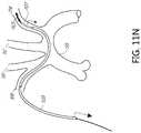
- FIGS. 11L-11Sillustrates a method of deploying the protection system 1100 .
- the left subclavian artery 114can be first accessed with an access catheter 1128 over a guidewire 1123 ( FIG. 11L ).
- the guidewire 1123can be removed ( FIG. 11M ) and the accessory filter assembly 1138 can be inserted through the access catheter 1128 .
- the accessory filter assembly 1138can be inserted without the filter sheath 1127 .
- the accessory filter sheath 1127can be retracted to deploy the filter 1106 ( FIG. 11N ) or the distal filter 1106 can be advanced distally of the filter sheath 1127 .
- the guide catheter 1128 and the accessory filter sheath 1127can then be removed, leaving the accessory filter assembly 1138 in place.
- the accessory filter assembly 1138can then be loaded into the dual filter assembly 1102 as shown in FIGS. 11O-11P with the filter wire 1125 entering a guidewire entry port 1156 .
- the dual filter assembly 1102can be loaded over an independent guidewire 1123 .
- the dual filter assembly 1102can be advanced over the independent guidewire 1123 .
- a proximal filter 1122can be deployed in the brachiocephalic trunk 134 ( FIG. 11Q ). After the proximal filter 1122 has been deployed, the independent guidewire 1123 can be retracted, the articulating sheath 1132 can be deflected, and the left common carotid artery 1112 can be cannulated with the guidewire 1123 .
- the dual filter assembly 1102can be pulled back so articulating distal sheath 1132 rests against the vessel carina ( FIG. 11R ).
- a secondary distal filter 1120can be placed in the left common carotid artery 112 , as shown in FIG. 11S .
- filter assemblieshave been described or illustrated herein as including a filter
- the filters described hereincan also be a self-expanding stent, a balloon, a deflector, or other occluding device.
- filter assemblieshave been described or illustrated herein as being introduced through a right radial or right brachial artery, the filter assemblies may alternatively be introduced through a left radial or left brachial artery. Similarly, although certain filter assemblies have been described or illustrated herein as being introduced through a left radial or left brachial artery, the filter assemblies may alternatively be introduced through a right radial or right brachial artery.
- proximal and distalshall be defined from the perspective of the protection system.
- proximalrefers to the direction of the handle portion of the delivery system and distal refers to the direction of the distal tip.
- the terms “approximately,” “about,” and “substantially” as used hereinrepresent an amount close to the stated amount that still performs a desired function or achieves a desired result.
- the terms “approximately”, “about”, and “substantially”may refer to an amount that is within less than 10% of, within less than 5% of, within less than 1% of, within less than 0.1% of, or within less than 0.01% of the stated amount.
- the methods disclosed hereinmay include certain actions taken by a practitioner; however, the methods can also include any third-party instruction of those actions, either expressly or by implication. For example, actions such as “advancing a first filter assembly” includes “instructing advancing a first filter assembly.”
Landscapes
- Health & Medical Sciences (AREA)
- Cardiology (AREA)
- Oral & Maxillofacial Surgery (AREA)
- Transplantation (AREA)
- Engineering & Computer Science (AREA)
- Biomedical Technology (AREA)
- Heart & Thoracic Surgery (AREA)
- Vascular Medicine (AREA)
- Life Sciences & Earth Sciences (AREA)
- Animal Behavior & Ethology (AREA)
- General Health & Medical Sciences (AREA)
- Public Health (AREA)
- Veterinary Medicine (AREA)
- Surgical Instruments (AREA)
Abstract
Description
Claims (20)
Priority Applications (1)
| Application Number | Priority Date | Filing Date | Title |
|---|---|---|---|
| US15/901,819US11337790B2 (en) | 2017-02-22 | 2018-02-21 | Systems and methods for protecting the cerebral vasculature |
Applications Claiming Priority (2)
| Application Number | Priority Date | Filing Date | Title |
|---|---|---|---|
| US201762462150P | 2017-02-22 | 2017-02-22 | |
| US15/901,819US11337790B2 (en) | 2017-02-22 | 2018-02-21 | Systems and methods for protecting the cerebral vasculature |
Publications (2)
| Publication Number | Publication Date |
|---|---|
| US20180235742A1 US20180235742A1 (en) | 2018-08-23 |
| US11337790B2true US11337790B2 (en) | 2022-05-24 |
Family
ID=61599596
Family Applications (1)
| Application Number | Title | Priority Date | Filing Date |
|---|---|---|---|
| US15/901,819Active2038-11-22US11337790B2 (en) | 2017-02-22 | 2018-02-21 | Systems and methods for protecting the cerebral vasculature |
Country Status (5)
| Country | Link |
|---|---|
| US (1) | US11337790B2 (en) |
| EP (2) | EP3585304B1 (en) |
| JP (1) | JP7032446B2 (en) |
| CN (1) | CN110831545B (en) |
| WO (1) | WO2018156655A1 (en) |
Families Citing this family (24)
| Publication number | Priority date | Publication date | Assignee | Title |
|---|---|---|---|---|
| US9326843B2 (en) | 2009-01-16 | 2016-05-03 | Claret Medical, Inc. | Intravascular blood filters and methods of use |
| US8974489B2 (en) | 2009-07-27 | 2015-03-10 | Claret Medical, Inc. | Dual endovascular filter and methods of use |
| US12150851B2 (en) | 2010-12-30 | 2024-11-26 | Claret Medical, Inc. | Method of isolating the cerebral circulation during a cardiac procedure |
| US9492264B2 (en) | 2010-12-30 | 2016-11-15 | Claret Medical, Inc. | Embolic protection device for protecting the cerebral vasculature |
| US10238406B2 (en) | 2013-10-21 | 2019-03-26 | Inari Medical, Inc. | Methods and apparatus for treating embolism |
| CN113796927B (en) | 2015-10-23 | 2025-03-04 | 伊纳里医疗公司 | Intravascular treatment of vascular occlusion and related devices, systems and methods |
| US11284911B2 (en)* | 2016-07-22 | 2022-03-29 | Hesham Morsi | Central clot stabilizer and manipulator |
| FI3528717T3 (en) | 2016-10-24 | 2024-08-09 | Inari Medical Inc | Devices for treating vascular occlusion |
| WO2019050765A1 (en) | 2017-09-06 | 2019-03-14 | Inari Medical, Inc. | Hemostasis valves and methods of use |
| EP3700464B1 (en) | 2017-10-27 | 2024-02-14 | Boston Scientific Scimed, Inc. | Systems for protecting the cerebral vasculature |
| US11154390B2 (en) | 2017-12-19 | 2021-10-26 | Claret Medical, Inc. | Systems for protection of the cerebral vasculature during a cardiac procedure |
| US11154314B2 (en) | 2018-01-26 | 2021-10-26 | Inari Medical, Inc. | Single insertion delivery system for treating embolism and associated systems and methods |
| US11439491B2 (en) | 2018-04-26 | 2022-09-13 | Claret Medical, Inc. | Systems and methods for protecting the cerebral vasculature |
| JP2021535778A (en) | 2018-08-21 | 2021-12-23 | ボストン サイエンティフィック サイムド, インコーポレイテッドBoston Scientific Scimed, Inc. | A system to protect the cerebrovascular system |
| JP7638273B2 (en) | 2019-10-16 | 2025-03-03 | イナリ メディカル, インコーポレイテッド | Systems, devices and methods for treating vascular obstructions |
| CN114901208A (en)* | 2019-11-01 | 2022-08-12 | 丝路医疗公司 | Systems and methods for transcatheter aortic valve therapy |
| AU2021283979A1 (en)* | 2020-06-05 | 2023-01-19 | Inari Medical, Inc. | Recapturable funnel catheters, and associated systems and methods |
| JP2022106566A (en)* | 2021-01-07 | 2022-07-20 | 株式会社東海メディカルプロダクツ | Intraluminal substance capture device |
| CN113229886B (en)* | 2021-04-16 | 2022-07-01 | 核工业总医院 | Brain protection system |
| AU2022335448A1 (en)* | 2021-08-27 | 2024-04-11 | Jacob CHMIELEWSKI | Thrombectomy capture system |
| EP4463083A1 (en) | 2022-01-11 | 2024-11-20 | Inari Medical, Inc. | Devices for removing clot material from intravascularly implanted devices, and associated systems and methods |
| CN114903647A (en)* | 2022-05-26 | 2022-08-16 | 上海以心医疗器械有限公司 | A brain protection filter assembly |
| CN115444613A (en)* | 2022-07-12 | 2022-12-09 | 上海申淇医疗科技有限公司 | Cerebral embolism protection device and system with distal cerebral embolism protection device |
| CN119587215B (en)* | 2024-11-27 | 2025-09-23 | 兰州大学第二医院 | Intracranial double-protection umbrella device |
Citations (229)
| Publication number | Priority date | Publication date | Assignee | Title |
|---|---|---|---|---|
| US3472230A (en) | 1966-12-19 | 1969-10-14 | Fogarty T J | Umbrella catheter |
| US4619246A (en) | 1984-05-23 | 1986-10-28 | William Cook, Europe A/S | Collapsible filter basket |
| US4630609A (en) | 1981-05-14 | 1986-12-23 | Thomas J. Fogarty | Dilatation catheter method and apparatus |
| US4650466A (en) | 1985-11-01 | 1987-03-17 | Angiobrade Partners | Angioplasty device |
| US4706671A (en) | 1985-05-02 | 1987-11-17 | Weinrib Harry P | Catheter with coiled tip |
| US4723549A (en) | 1986-09-18 | 1988-02-09 | Wholey Mark H | Method and apparatus for dilating blood vessels |
| US4873978A (en) | 1987-12-04 | 1989-10-17 | Robert Ginsburg | Device and method for emboli retrieval |
| US5108419A (en) | 1990-08-16 | 1992-04-28 | Evi Corporation | Endovascular filter and method for use thereof |
| US5192286A (en) | 1991-07-26 | 1993-03-09 | Regents Of The University Of California | Method and device for retrieving materials from body lumens |
| US5200248A (en) | 1990-02-20 | 1993-04-06 | The Procter & Gamble Company | Open capillary channel structures, improved process for making capillary channel structures, and extrusion die for use therein |
| US5329923A (en) | 1991-02-15 | 1994-07-19 | Lundquist Ingemar H | Torquable catheter |
| US5348545A (en) | 1990-08-21 | 1994-09-20 | Advanced Cardiovascular Systems, Inc. | Guiding catheter for the right coronary artery |
| US5381782A (en) | 1992-01-09 | 1995-01-17 | Spectrum Medsystems Corporation | Bi-directional and multi-directional miniscopes |
| US5395327A (en) | 1990-02-02 | 1995-03-07 | Ep Technologies, Inc. | Catheter steering mechanism |
| US5613980A (en) | 1994-12-22 | 1997-03-25 | Chauhan; Tusharsindhu C. | Bifurcated catheter system and method |
| US5624430A (en) | 1994-11-28 | 1997-04-29 | Eton; Darwin | Magnetic device to assist transcorporeal guidewire placement |
| US5662671A (en) | 1996-07-17 | 1997-09-02 | Embol-X, Inc. | Atherectomy device having trapping and excising means for removal of plaque from the aorta and other arteries |
| US5680873A (en) | 1995-03-02 | 1997-10-28 | Scimed Life Systems, Inc. | Braidless guide catheter |
| US5707389A (en) | 1995-06-07 | 1998-01-13 | Baxter International Inc. | Side branch occlusion catheter device having integrated endoscope for performing endoscopically visualized occlusion of the side branches of an anatomical passageway |
| US5766151A (en) | 1991-07-16 | 1998-06-16 | Heartport, Inc. | Endovascular system for arresting the heart |
| US5779716A (en) | 1995-10-06 | 1998-07-14 | Metamorphic Surgical Devices, Inc. | Device for removing solid objects from body canals, cavities and organs |
| US5814064A (en) | 1997-03-06 | 1998-09-29 | Scimed Life Systems, Inc. | Distal protection device |
| US5827324A (en) | 1997-03-06 | 1998-10-27 | Scimed Life Systems, Inc. | Distal protection device |
| US5833650A (en) | 1995-06-05 | 1998-11-10 | Percusurge, Inc. | Catheter apparatus and method for treating occluded vessels |
| US5848964A (en) | 1997-06-06 | 1998-12-15 | Samuels; Shaun Lawrence Wilkie | Temporary inflatable filter device and method of use |
| US5897529A (en) | 1997-09-05 | 1999-04-27 | Cordis Webster, Inc. | Steerable deflectable catheter having improved flexibility |
| US5897819A (en) | 1996-07-10 | 1999-04-27 | Asahi Intecc Co., Ltd. | Process of making a guide wire for a catheter |
| WO1999023976A1 (en) | 1997-11-07 | 1999-05-20 | Salviac Limited | An embolic protection device |
| US5910154A (en) | 1997-05-08 | 1999-06-08 | Embol-X, Inc. | Percutaneous catheter and guidewire having filter and medical device deployment |
| US5935139A (en) | 1996-05-03 | 1999-08-10 | Boston Scientific Corporation | System for immobilizing or manipulating an object in a tract |
| US5980555A (en) | 1995-11-07 | 1999-11-09 | Embol-X, Inc. | Method of using cannula with associated filter during cardiac surgery |
| US5989281A (en) | 1995-11-07 | 1999-11-23 | Embol-X, Inc. | Cannula with associated filter and methods of use during cardiac surgery |
| US6045547A (en) | 1998-06-15 | 2000-04-04 | Scimed Life Systems, Inc. | Semi-continuous co-extruded catheter shaft |
| US6051014A (en) | 1998-10-13 | 2000-04-18 | Embol-X, Inc. | Percutaneous filtration catheter for valve repair surgery and methods of use |
| US6080140A (en) | 1998-11-04 | 2000-06-27 | Iowa-India Investments Company, Ltd. | Integral cerebro-vascular access system |
| US6083239A (en) | 1998-11-24 | 2000-07-04 | Embol-X, Inc. | Compliant framework and methods of use |
| US6096053A (en) | 1996-05-03 | 2000-08-01 | Scimed Life Systems, Inc. | Medical retrieval basket |
| US6099534A (en) | 1997-10-01 | 2000-08-08 | Scimed Life Systems, Inc. | Releasable basket |
| US6120494A (en) | 1998-01-23 | 2000-09-19 | Medtronic, Inc. | Method of placing a cannula |
| US6126673A (en) | 1993-10-01 | 2000-10-03 | Boston Scientific Corporation | Vena cava filter |
| US6129739A (en) | 1999-07-30 | 2000-10-10 | Incept Llc | Vascular device having one or more articulation regions and methods of use |
| US6142987A (en) | 1999-08-03 | 2000-11-07 | Scimed Life Systems, Inc. | Guided filter with support wire and methods of use |
| US6146396A (en) | 1999-03-05 | 2000-11-14 | Board Of Regents, The University Of Texas System | Declotting method and apparatus |
| US6152946A (en) | 1998-03-05 | 2000-11-28 | Scimed Life Systems, Inc. | Distal protection device and method |
| US6171328B1 (en) | 1999-11-09 | 2001-01-09 | Embol-X, Inc. | Intravascular catheter filter with interlocking petal design and methods of use |
| US6179861B1 (en) | 1999-07-30 | 2001-01-30 | Incept Llc | Vascular device having one or more articulation regions and methods of use |
| US6203561B1 (en) | 1999-07-30 | 2001-03-20 | Incept Llc | Integrated vascular device having thrombectomy element and vascular filter and methods of use |
| US6214026B1 (en) | 1999-07-30 | 2001-04-10 | Incept Llc | Delivery system for a vascular device with articulation region |
| US6245088B1 (en) | 1997-07-07 | 2001-06-12 | Samuel R. Lowery | Retrievable umbrella sieve and method of use |
| US6245087B1 (en) | 1999-08-03 | 2001-06-12 | Embol-X, Inc. | Variable expansion frame system for deploying medical devices and methods of use |
| US6264663B1 (en) | 1995-10-06 | 2001-07-24 | Metamorphic Surgical Devices, Llc | Device for removing solid objects from body canals, cavities and organs including an invertable basket |
| US6277138B1 (en) | 1999-08-17 | 2001-08-21 | Scion Cardio-Vascular, Inc. | Filter for embolic material mounted on expandable frame |
| US6290710B1 (en) | 1999-12-29 | 2001-09-18 | Advanced Cardiovascular Systems, Inc. | Embolic protection device |
| WO2001067989A2 (en) | 2000-03-10 | 2001-09-20 | Don Michael T Anthony | Vascular embolism preventon device employing filters |
| US20010041858A1 (en) | 1998-01-23 | 2001-11-15 | Pinaki Ray | Methods and devices for occluding the ascending aorta and maintaining circulation of oxygenated blood in the patient when the patient's heart is arrested |
| US6325815B1 (en) | 1999-09-21 | 2001-12-04 | Microvena Corporation | Temporary vascular filter |
| US6346116B1 (en) | 1999-08-03 | 2002-02-12 | Medtronic Ave, Inc. | Distal protection device |
| US20020022858A1 (en) | 1999-07-30 | 2002-02-21 | Demond Jackson F. | Vascular device for emboli removal having suspension strut and methods of use |
| US20020026145A1 (en) | 1997-03-06 | 2002-02-28 | Bagaoisan Celso J. | Method and apparatus for emboli containment |
| US6361545B1 (en) | 1997-09-26 | 2002-03-26 | Cardeon Corporation | Perfusion filter catheter |
| US6364900B1 (en) | 1999-07-14 | 2002-04-02 | Richard R. Heuser | Embolism prevention device |
| US6371971B1 (en) | 1999-11-15 | 2002-04-16 | Scimed Life Systems, Inc. | Guidewire filter and methods of use |
| US6371970B1 (en) | 1999-07-30 | 2002-04-16 | Incept Llc | Vascular filter having articulation region and methods of use in the ascending aorta |
| DE10049812A1 (en) | 2000-10-09 | 2002-04-18 | Universitaetsklinikum Freiburg | Blood-filter consists of two filter screens placed on connecting axis with facing concave sides and operated by catheter |
| US6375628B1 (en) | 1997-03-06 | 2002-04-23 | Medtronic Percusurge, Inc. | Hollow medical wires and methods of constructing same |
| US6383205B1 (en) | 1997-09-30 | 2002-05-07 | Target Therapeutics, Inc. | Mechanical clot treatment device with distal filter |
| US6383174B1 (en) | 1997-08-05 | 2002-05-07 | Scimed Life Systems, Inc. | Detachable aneurysm neck bridge (II) |
| US20020055767A1 (en) | 2000-10-18 | 2002-05-09 | Forde Sean T. | Over-the-wire interlock attachment/detachment mechanism |
| US20020068015A1 (en) | 2000-09-26 | 2002-06-06 | Hans-Dietrich Polaschegg | Apparatus and method for control of ultrafiltration in extracorporeal treatment of blood |
| US20020077596A1 (en) | 1997-05-12 | 2002-06-20 | Embol-X, Inc. | Perfusion shunt apparatus and method |
| US20020095170A1 (en) | 2001-01-16 | 2002-07-18 | Krolik Jeff A. | Systems and methods for vascular filter retrieval |
| US20020095172A1 (en) | 1994-07-08 | 2002-07-18 | Microvena Corporation | Method and device for filtering body fluid |
| US6440120B1 (en) | 1998-09-02 | 2002-08-27 | Embol-X, Inc. | Bendable shape-retaining cannula |
| US6454799B1 (en) | 2000-04-06 | 2002-09-24 | Edwards Lifesciences Corporation | Minimally-invasive heart valves and methods of use |
| US20020165571A1 (en) | 2000-08-21 | 2002-11-07 | Stephen Hebert | Manipulatable delivery catheter for occlusive devices (ll) |
| US20020165573A1 (en) | 2001-05-01 | 2002-11-07 | Coaxia, Inc. | Devices and methods for preventing distal embolization using flow reversal and perfusion augmentation within the cerebral vasculature |
| US6517559B1 (en) | 1999-05-03 | 2003-02-11 | O'connell Paul T. | Blood filter and method for treating vascular disease |
| JP2003505216A (en) | 1999-07-30 | 2003-02-12 | インセプト エルエルシー | Vascular device for removing emboli, thrombus and foreign matter and method of use |
| US6544279B1 (en) | 2000-08-09 | 2003-04-08 | Incept, Llc | Vascular device for emboli, thrombus and foreign body removal and methods of use |
| US6558356B2 (en) | 1999-01-15 | 2003-05-06 | Coaxia, Inc. | Medical device for flow augmentation in patients with occlusive cerebrovascular disease and methods of use |
| US6589263B1 (en) | 1999-07-30 | 2003-07-08 | Incept Llc | Vascular device having one or more articulation regions and methods of use |
| US20030130684A1 (en) | 2001-12-21 | 2003-07-10 | Eamon Brady | Support frame for an embolic protection device |
| US6595983B2 (en) | 2000-12-07 | 2003-07-22 | Jan K. Voda | Guide or diagnostic catheter for right coronary artery |
| US20030144686A1 (en) | 2002-01-30 | 2003-07-31 | Embol-X, Inc. | Distal filtration devices and methods of use during aortic procedures |
| US6616679B1 (en) | 1999-07-30 | 2003-09-09 | Incept, Llc | Rapid exchange vascular device for emboli and thrombus removal and methods of use |
| US20030171770A1 (en) | 2002-03-08 | 2003-09-11 | Kusleika Richard S. | Distal protection devices having controllable wire motion |
| US6620182B1 (en) | 1999-07-30 | 2003-09-16 | Incept Llc | Vascular filter having articulation region and methods of use in the ascending aorta |
| US6620148B1 (en) | 1999-08-04 | 2003-09-16 | Scimed Life Systems, Inc. | Filter flush system and methods of use |
| JP2003290231A (en) | 2002-03-12 | 2003-10-14 | Cordis Corp | Low profile vascular filer system |
| US20030199960A1 (en) | 1991-07-15 | 2003-10-23 | Paskar Larry D. | Catheter with up-going and down-going configurations |
| US6648837B2 (en) | 1999-12-24 | 2003-11-18 | Asahi Intec., Ltd. | Medical guide wire |
| US20040002730A1 (en) | 2002-06-26 | 2004-01-01 | Denison Andy E. | Embolic filtering devices for bifurcated vessels |
| US6676682B1 (en) | 1997-05-08 | 2004-01-13 | Scimed Life Systems, Inc. | Percutaneous catheter and guidewire having filter and medical device deployment capabilities |
| US20040044360A1 (en) | 2002-09-04 | 2004-03-04 | Scimed Life Systems, Inc. | Embolic management filter design |
| US20040044350A1 (en) | 1999-04-09 | 2004-03-04 | Evalve, Inc. | Steerable access sheath and methods of use |
| US6712834B2 (en) | 1998-06-16 | 2004-03-30 | Mindguard Ltd. | Implantable blood filtering device |
| WO2004026175A1 (en) | 2002-09-19 | 2004-04-01 | Petrus Besselink | Vascular filter with improved strength and flexibility |
| US20040064092A1 (en) | 1996-05-14 | 2004-04-01 | Ross S. Tsugita | Balloon occlusion device and methods of use |
| US6719717B1 (en) | 2000-03-17 | 2004-04-13 | Advanced Research & Technology Institute, Inc. | Thrombectomy treatment system and method |
| US6726621B2 (en) | 1998-09-24 | 2004-04-27 | Scimed Life Systems, Inc. | Retrieval devices for vena cava filter |
| US6726701B2 (en) | 1999-05-07 | 2004-04-27 | Salviac Limited | Embolic protection device |
| US6726651B1 (en) | 1999-08-04 | 2004-04-27 | Cardeon Corporation | Method and apparatus for differentially perfusing a patient during cardiopulmonary bypass |
| US20040093015A1 (en) | 2002-08-01 | 2004-05-13 | Ogle Matthew F. | Embolism protection devices |
| US6740061B1 (en) | 2000-07-28 | 2004-05-25 | Ev3 Inc. | Distal protection device |
| US20040167565A1 (en) | 2003-02-24 | 2004-08-26 | Scimed Life Systems, Inc. | Embolic protection filtering device that can be adapted to be advanced over a guidewire |
| US20040193206A1 (en) | 1997-07-10 | 2004-09-30 | Brent Gerberding | Methods and devices for the treatment of aneurysms |
| US20040215167A1 (en) | 2002-08-27 | 2004-10-28 | Amir Belson | Embolic protection device |
| US20040215230A1 (en) | 2003-04-28 | 2004-10-28 | Frazier Andrew G. C. | Left atrial appendage occlusion device with active expansion |
| US20040225321A1 (en) | 2003-05-07 | 2004-11-11 | Scimed Life Systems, Inc. | Filter membrane with increased surface area |
| US6817999B2 (en) | 2002-01-03 | 2004-11-16 | Afx, Inc. | Flexible device for ablation of biological tissue |
| US20040230220A1 (en) | 2003-02-11 | 2004-11-18 | Cook Incorporated | Removable vena cava filter |
| US20040243175A1 (en) | 2001-03-12 | 2004-12-02 | Don Michael T. Anthony | Vascular obstruction removal system and method |
| US20040254602A1 (en) | 2003-03-28 | 2004-12-16 | Lehe Cathleen Von | Double ended intravascular medical device |
| US20040254601A1 (en) | 2003-06-12 | 2004-12-16 | Scimed Life Systems, Inc. | Valved embolic protection filter |
| US20050010285A1 (en) | 1999-01-27 | 2005-01-13 | Lambrecht Gregory H. | Cardiac valve procedure methods and devices |
| US6843798B2 (en) | 1999-08-27 | 2005-01-18 | Ev3 Inc. | Slideable vascular filter |
| US20050065397A1 (en) | 2003-01-15 | 2005-03-24 | Usgi Medical Inc. | Endoluminal tool deployment system |
| US20050080356A1 (en) | 2003-10-14 | 2005-04-14 | Steven Dapolito | Steerable distal protection guidewire and methods of use |
| US6881194B2 (en) | 2001-03-21 | 2005-04-19 | Asahi Intec Co., Ltd. | Wire-stranded medical hollow tube, and a medical guide wire |
| US20050085847A1 (en) | 2003-07-22 | 2005-04-21 | Galdonik Jason A. | Fiber based embolism protection device |
| US20050101987A1 (en) | 2003-11-06 | 2005-05-12 | Scimed Life Systems, Inc. | Flattened tip filter wire design |
| US6907298B2 (en) | 2002-01-09 | 2005-06-14 | Medtronic, Inc. | Method and apparatus for imparting curves in implantable elongated medical instruments |
| US6905490B2 (en) | 1998-03-13 | 2005-06-14 | Gore Enterprise Holdings, Inc. | Apparatus and methods for reducing embolization during treatment of carotid artery disease |
| US20050131449A1 (en) | 2003-12-11 | 2005-06-16 | Scimed Life Systems, Inc. | Nose rider improvement for filter exchange and methods of use |
| US20050137696A1 (en) | 2003-12-23 | 2005-06-23 | Sadra Medical | Apparatus and methods for protecting against embolization during endovascular heart valve replacement |
| US20050177132A1 (en) | 2004-02-09 | 2005-08-11 | Lentz David J. | Catheter articulation segment with alternating cuts |
| US20050209631A1 (en) | 2004-03-06 | 2005-09-22 | Galdonik Jason A | Steerable device having a corewire within a tube and combination with a functional medical component |
| US6958074B2 (en) | 2002-01-07 | 2005-10-25 | Cordis Corporation | Releasable and retrievable vascular filter system |
| WO2005118050A2 (en) | 2004-05-27 | 2005-12-15 | Lumen Biomedical, Inc. | Emboli filter export system |
| US20060015138A1 (en) | 2004-07-19 | 2006-01-19 | Michael Gertner | Emboli diverting devices created by microfabricated means |
| US20060041188A1 (en) | 2003-03-25 | 2006-02-23 | Dirusso Carlo A | Flexible endoscope |
| US20060047301A1 (en) | 2004-09-02 | 2006-03-02 | Ogle Matthew F | Emboli removal system with oxygenated flow |
| WO2006026371A1 (en) | 2004-08-27 | 2006-03-09 | Cook Incorporated | Placement of multiple intraluminal medical devices within a body vessel |
| US7011094B2 (en) | 2001-03-02 | 2006-03-14 | Emphasys Medical, Inc. | Bronchial flow control devices and methods of use |
| US20060089666A1 (en) | 2001-07-02 | 2006-04-27 | Linder Richard J | Methods, systems, and devices for deploying an embolic protection filter |
| US20060089618A1 (en) | 2004-10-21 | 2006-04-27 | Mcferran Sean | Catheter with a pre-shaped distal tip |
| US20060100662A1 (en) | 1997-03-06 | 2006-05-11 | Daniel John M K | Distal protection device and method |
| US20060100658A1 (en) | 2004-11-09 | 2006-05-11 | Hiroyuki Obana | Interventional guiding sheath system and method of use |
| US20060135961A1 (en) | 2004-12-17 | 2006-06-22 | Biocardia, Inc. | Steerable guide catheters and methods for their use |
| US20060136043A1 (en) | 2004-12-22 | 2006-06-22 | Cully Edward H | Filament-wound implantable devices |
| US20060149350A1 (en) | 2003-06-05 | 2006-07-06 | Flowmedica, Inc. | Systems and methods for performing bi-lateral interventions or diagnosis in branched body lumens |
| US20060161241A1 (en) | 2005-01-14 | 2006-07-20 | Denise Barbut | Methods and devices for treating aortic atheroma |
| US7094249B1 (en) | 1997-03-06 | 2006-08-22 | Boston Scientific Scimed, Inc. | Distal protection device and method |
| US20060200191A1 (en) | 1996-05-20 | 2006-09-07 | Gholam-Reza Zadno-Azizi | Method and apparatuses for treating an intravascular occlusion |
| US20060200047A1 (en) | 2004-03-06 | 2006-09-07 | Galdonik Jason A | Steerable device having a corewire within a tube and combination with a functional medical component |
| US7115134B2 (en) | 2002-07-22 | 2006-10-03 | Chambers Technology, Llc. | Catheter with flexible tip and shape retention |
| US20060259066A1 (en) | 2005-04-28 | 2006-11-16 | Euteneuer Charles L | Bifurcated artery filter system |
| US20070005131A1 (en) | 2005-06-13 | 2007-01-04 | Taylor David M | Heart valve delivery system |
| US7160255B2 (en) | 2001-07-12 | 2007-01-09 | Vahid Saadat | Method and device for sensing and mapping temperature profile of a hollow body organ |
| US7169165B2 (en) | 2001-01-16 | 2007-01-30 | Boston Scientific Scimed, Inc. | Rapid exchange sheath for deployment of medical devices and methods of use |
| US7169161B2 (en) | 2001-11-06 | 2007-01-30 | Possis Medical, Inc. | Guidewire having occlusive device and repeatably crimpable proximal end |
| US20070043259A1 (en) | 2000-04-03 | 2007-02-22 | Ross Jaffe | Endoscope Having a Guide Tube |
| US7182757B2 (en) | 2003-12-25 | 2007-02-27 | Asahi Intecc Co., Ltd. | Medical guide wire |
| US20070060944A1 (en) | 2005-08-18 | 2007-03-15 | Boldenow Gregory A | Tracking aspiration catheter |
| US20070088383A1 (en) | 2005-10-03 | 2007-04-19 | Cook Incorporated | Embolic protection device |
| US20070088244A1 (en) | 2005-10-18 | 2007-04-19 | Biocardia, Inc. | Bio-interventional therapeutic treatments for cardiovascular diseases |
| US7214237B2 (en) | 2001-03-12 | 2007-05-08 | Don Michael T Anthony | Vascular filter with improved strength and flexibility |
| US20070173878A1 (en) | 2006-01-25 | 2007-07-26 | Heuser Richard R | Catheter system for connecting adjacent blood vessels |
| US20070191880A1 (en) | 2004-06-25 | 2007-08-16 | Angiodynamics, Inc. | Retrievable blood clot filter |
| US20070208302A1 (en) | 2006-01-26 | 2007-09-06 | Webster Mark W | Deflection control catheters, support catheters and methods of use |
| US7278974B2 (en) | 2004-03-15 | 2007-10-09 | Asahi In Tecc Co., Ltd. | Medical guide wire |
| US20070244504A1 (en) | 2002-03-05 | 2007-10-18 | Salviac Limited | Embolic protection system |
| US7306618B2 (en) | 1999-07-30 | 2007-12-11 | Incept Llc | Vascular device for emboli and thrombi removal and methods of use |
| US7313445B2 (en) | 2002-09-26 | 2007-12-25 | Medtronic, Inc. | Medical lead with flexible distal guidewire extension |
| US7323001B2 (en) | 2003-01-30 | 2008-01-29 | Ev3 Inc. | Embolic filters with controlled pore size |
| US20080033467A1 (en) | 2006-06-08 | 2008-02-07 | Olympus Medical Systems Corp. | Calculus crushing apparatus and medical procedure using endoscope |
| US7329278B2 (en) | 1999-11-17 | 2008-02-12 | Corevalve, Inc. | Prosthetic valve for transluminal delivery |
| US20080065145A1 (en) | 2006-09-11 | 2008-03-13 | Carpenter Judith T | Embolic protection device and method of use |
| US20080086110A1 (en) | 2004-11-19 | 2008-04-10 | Galdonik Jason A | Extendable Device On An Aspiration Catheter |
| US20080125848A1 (en) | 2006-06-30 | 2008-05-29 | Kusleika Richard S | Medical devices with amorphous metals, and methods therefor |
| US20080154153A1 (en) | 2004-08-25 | 2008-06-26 | Heuser Richard R | Multiple-wire systems and methods for ablation of occlusions within blood vessels |
| US7399308B2 (en) | 1999-02-12 | 2008-07-15 | Cordis Corporation | Vascular filter system |
| US20080172066A9 (en) | 2005-07-29 | 2008-07-17 | Galdonik Jason A | Embolectomy procedures with a device comprising a polymer and devices with polymer matrices and supports |
| WO2008100790A2 (en) | 2007-02-16 | 2008-08-21 | Reverse Medical Corporation | Occlusion device and method of use |
| WO2008113857A2 (en) | 2007-03-20 | 2008-09-25 | Minvasys | Apparatus and methods for stent delivery with embolic protection |
| US20080234722A1 (en) | 2006-06-14 | 2008-09-25 | Possis Medical, Inc. | Inferior vena cava filter on guidewire |
| US20080262442A1 (en) | 2007-04-17 | 2008-10-23 | Carlin Donald B | Connectors for multi fiber optical probes |
| US20080300462A1 (en) | 2007-05-31 | 2008-12-04 | Boston Scientific Scimed, Inc. | Active controlled bending in medical devices |
| US20090024072A1 (en) | 2007-07-18 | 2009-01-22 | Enrique Criado | Methods and systems for establishing retrograde carotid arterial blood flow |
| US20090024153A1 (en) | 2001-03-12 | 2009-01-22 | Don Michael T Anthony | Vascular filter with improved strength and flexibilty |
| US7493154B2 (en) | 2002-10-23 | 2009-02-17 | Medtronic, Inc. | Methods and apparatus for locating body vessels and occlusions in body vessels |
| WO2009032834A1 (en) | 2007-09-07 | 2009-03-12 | Crusader Medical Llc | Percutaneous permanent retrievable vascular filter |
| US7559925B2 (en) | 2006-09-15 | 2009-07-14 | Acclarent Inc. | Methods and devices for facilitating visualization in a surgical environment |
| US20090198269A1 (en) | 2005-12-12 | 2009-08-06 | Ralf Hannes | Device for the Removal of Thrombi From Blood Vessels |
| US20090203962A1 (en) | 2008-02-07 | 2009-08-13 | Voyage Medical, Inc. | Stent delivery under direct visualization |
| US20090254172A1 (en) | 2008-04-03 | 2009-10-08 | Grewe David D | Self cleaning devices, systems and methods of use |
| US20090287187A1 (en) | 2008-05-07 | 2009-11-19 | Guided Delivery Systems Inc. | Deflectable guide |
| US20090326575A1 (en) | 2008-06-23 | 2009-12-31 | Galdonik Jason A | Embolic protection during percutaneous heart valve replacement and similar procedures |
| US20100004633A1 (en) | 2008-07-07 | 2010-01-07 | Voyage Medical, Inc. | Catheter control systems |
| US20100010476A1 (en) | 2008-07-14 | 2010-01-14 | Galdonik Jason A | Fiber based medical devices and aspiration catheters |
| US20100063537A1 (en) | 2006-03-10 | 2010-03-11 | Ev3 Inc. | Embolic protection systems |
| US20100106182A1 (en) | 2008-10-22 | 2010-04-29 | Patel Udayan G | Angioplasty device with embolic filter |
| US7722634B2 (en) | 2003-07-03 | 2010-05-25 | Regents Of The University Of Minnesota | Medical device and method of intravenous filtration |
| WO2010081025A1 (en) | 2009-01-09 | 2010-07-15 | Embrella Cardiovascular, Inc. | Embolic deflection device and method of use |
| US20100179585A1 (en) | 2006-09-11 | 2010-07-15 | Carpenter Judith T | Embolic deflection device |
| US20100179584A1 (en) | 2006-09-11 | 2010-07-15 | Carpenter Judith T | Methods of diverting embolic debris away from the cerebral circulation |
| US20100179647A1 (en) | 2006-09-11 | 2010-07-15 | Carpenter Judith T | Methods of reducing embolism to cerebral circulation as a consequence of an index cardiac procedure |
| US20100179583A1 (en) | 2006-09-11 | 2010-07-15 | Carpenter Judith T | Methods of deploying and retrieving an embolic diversion device |
| US20100185216A1 (en) | 2008-08-13 | 2010-07-22 | Garrison Michi E | Suture delivery device |
| WO2010083527A2 (en) | 2009-01-16 | 2010-07-22 | Claret Medical, Inc. | Intravascular blood filter |
| WO2010088520A2 (en) | 2009-01-29 | 2010-08-05 | Claret Medical, Inc. | Illuminated intravascular blood filter |
| US20100211095A1 (en) | 2006-09-11 | 2010-08-19 | Carpenter Judith T | Embolic Protection Device and Method of Use |
| US20100228280A1 (en) | 2009-03-09 | 2010-09-09 | Adam Groothuis | Methods and devices for treatment of lumenal systems |
| US20100312268A1 (en) | 2006-11-29 | 2010-12-09 | Amir Belson | Embolic protection device |
| US20100324589A1 (en) | 2006-09-11 | 2010-12-23 | Carpenter Judith T | Embolic deflection device |
| US20110022076A1 (en) | 2009-07-27 | 2011-01-27 | Lashinski Randall T | Dual Endovascular Filter and Methods of Use |
| US20110066221A1 (en) | 2007-11-15 | 2011-03-17 | Endogad Research Pty Limited | Hybrid intraluminal device |
| WO2011034718A2 (en) | 2009-09-21 | 2011-03-24 | Claret Medical, Inc. | Intravascular blood filters and methods of use |
| US7918859B2 (en) | 2006-02-13 | 2011-04-05 | Retro Vascular, Inc. | Recanalizing occluded vessels using controlled antegrade and retrograde tracking |
| US7976562B2 (en) | 2004-01-22 | 2011-07-12 | Rex Medical, L.P. | Method of removing a vein filter |
| US7998104B2 (en) | 2003-11-21 | 2011-08-16 | Silk Road Medical, Inc. | Method and apparatus for treating a carotid artery |
| US8002790B2 (en) | 1999-05-07 | 2011-08-23 | Salviac Limited | Support frame for an embolic protection device |
| US8052713B2 (en) | 1999-07-30 | 2011-11-08 | Incept, Llc | Vascular filter having articulation region and methods of use in the ascending aorta |
| US20120046739A1 (en) | 2010-04-14 | 2012-02-23 | Randolf Von Oepen | Method of delivering a medical device across a plurality of valves |
| US20120095500A1 (en) | 2010-10-14 | 2012-04-19 | Heuser Richard R | Concentric wire embolism protection device |
| US20120172916A1 (en) | 2010-12-30 | 2012-07-05 | Claret Medical, Inc. | Method of Isolating the Cerebral Circulation During a Cardiac Procedure |
| US20120203265A1 (en) | 2010-10-14 | 2012-08-09 | Heuser Richard R | Embolism protection device |
| US20130123835A1 (en) | 2011-11-14 | 2013-05-16 | Boston Scientific Scimed, Inc. | Embolic protection device and method |
| US20130131714A1 (en) | 2011-11-14 | 2013-05-23 | Boston Scientific Scimed, Inc. | Embolic protection device and methods of making the same |
| EP2658476A1 (en) | 2010-12-30 | 2013-11-06 | Claret Medical, Inc. | Intravascular blood filters and methods of use |
| US20140052170A1 (en) | 2012-08-17 | 2014-02-20 | Richard R. Heuser | Embolism protection device |
| US20140100597A1 (en) | 2012-10-09 | 2014-04-10 | Boston Scientific Scimed, Inc. | Special opening aortic embolic protection device for structural heart procedures |
| US20140282379A1 (en) | 2011-05-31 | 2014-09-18 | Accenture Global Services Limited | Computer-implemented method, system and computer program product for displaying a user interface component |
| US20150039016A1 (en) | 2012-03-09 | 2015-02-05 | Keystone Heart Ltd. | Device and method for deflecting emboli in an aorta |
| US20160058541A1 (en) | 2013-02-26 | 2016-03-03 | Medtronics, Inc. | Embolic Protection Device |
| US9326843B2 (en) | 2009-01-16 | 2016-05-03 | Claret Medical, Inc. | Intravascular blood filters and methods of use |
| US20160262864A1 (en) | 2013-10-14 | 2016-09-15 | Protembis Gmbh | Medical device for embolic protection |
| US20160310255A1 (en) | 2015-04-22 | 2016-10-27 | Claret Medical, Inc. | Vascular filters, deflectors, and methods |
| US20170202657A1 (en) | 2009-01-16 | 2017-07-20 | Claret Medical, Inc. | Intravascular blood filters and methods of use |
Family Cites Families (13)
| Publication number | Priority date | Publication date | Assignee | Title |
|---|---|---|---|---|
| IL137326A0 (en)* | 2000-07-17 | 2001-07-24 | Mind Guard Ltd | Implantable braided stroke preventing device and method of manufacturing |
| DK2537488T3 (en)* | 2008-09-04 | 2016-06-27 | Swat Medical Ab | Device for the temporary embolic protection |
| US9681967B2 (en)* | 2009-04-16 | 2017-06-20 | Cvdevices, Llc | Linked deflection devices, systems and methods for the prevention of stroke |
| EP2654958B1 (en)* | 2010-12-23 | 2016-12-21 | Eppendorf AG | Reaction container with lid |
| WO2012147800A1 (en)* | 2011-04-25 | 2012-11-01 | 東レ株式会社 | Composition for predicting sensitivity to trastuzumab therapy in breast cancer patients and method using same |
| CA2861336C (en)* | 2012-01-26 | 2020-06-16 | Endoshape, Inc. | Systems, devices, and methods for delivering a lumen occlusion device using distal and/or proximal control |
| EP2854700B1 (en)* | 2012-05-31 | 2021-07-07 | Javelin Medical Ltd. | Devices for embolic protection |
| WO2014042825A1 (en)* | 2012-09-12 | 2014-03-20 | Boston Scientific Scimed, Inc. | Fixation anchor design for an occlusion device |
| US9186238B2 (en)* | 2013-01-29 | 2015-11-17 | St. Jude Medical, Cardiology Division, Inc. | Aortic great vessel protection |
| US10973618B2 (en)* | 2013-03-01 | 2021-04-13 | St. Jude Medical, Cardiology Division, Inc. | Embolic protection device |
| US9737328B2 (en)* | 2013-03-14 | 2017-08-22 | Boston Scientific Limited | Hydrodynamic eccentrically pivoting catheter |
| US20160151145A1 (en)* | 2013-06-16 | 2016-06-02 | Pi-Cardia Ltd. | Percutaneous emboli protection sleeve |
| JP6761345B2 (en)* | 2014-01-10 | 2020-09-23 | キーストーン ハート リミテッド | Biostructure-independent deflection device |
- 2018
- 2018-02-21USUS15/901,819patent/US11337790B2/enactiveActive
- 2018-02-21JPJP2019566061Apatent/JP7032446B2/enactiveActive
- 2018-02-21EPEP18709847.0Apatent/EP3585304B1/enactiveActive
- 2018-02-21CNCN201880026449.1Apatent/CN110831545B/enactiveActive
- 2018-02-21WOPCT/US2018/019052patent/WO2018156655A1/ennot_activeCeased
- 2018-02-21EPEP22169661.0Apatent/EP4052679B1/enactiveActive
Patent Citations (320)
| Publication number | Priority date | Publication date | Assignee | Title |
|---|---|---|---|---|
| US3472230A (en) | 1966-12-19 | 1969-10-14 | Fogarty T J | Umbrella catheter |
| US4630609A (en) | 1981-05-14 | 1986-12-23 | Thomas J. Fogarty | Dilatation catheter method and apparatus |
| US4619246A (en) | 1984-05-23 | 1986-10-28 | William Cook, Europe A/S | Collapsible filter basket |
| US4706671A (en) | 1985-05-02 | 1987-11-17 | Weinrib Harry P | Catheter with coiled tip |
| US4650466A (en) | 1985-11-01 | 1987-03-17 | Angiobrade Partners | Angioplasty device |
| US4723549A (en) | 1986-09-18 | 1988-02-09 | Wholey Mark H | Method and apparatus for dilating blood vessels |
| US4873978A (en) | 1987-12-04 | 1989-10-17 | Robert Ginsburg | Device and method for emboli retrieval |
| US5395327A (en) | 1990-02-02 | 1995-03-07 | Ep Technologies, Inc. | Catheter steering mechanism |
| US5200248B1 (en) | 1990-02-20 | 1999-02-09 | Procter & Gamble | Open capillary channel structures improved process for making capillary channel structures and extrusion die for use therein |
| US5200248A (en) | 1990-02-20 | 1993-04-06 | The Procter & Gamble Company | Open capillary channel structures, improved process for making capillary channel structures, and extrusion die for use therein |
| US5108419A (en) | 1990-08-16 | 1992-04-28 | Evi Corporation | Endovascular filter and method for use thereof |
| US5348545A (en) | 1990-08-21 | 1994-09-20 | Advanced Cardiovascular Systems, Inc. | Guiding catheter for the right coronary artery |
| US5329923A (en) | 1991-02-15 | 1994-07-19 | Lundquist Ingemar H | Torquable catheter |
| US20030199960A1 (en) | 1991-07-15 | 2003-10-23 | Paskar Larry D. | Catheter with up-going and down-going configurations |
| US5766151A (en) | 1991-07-16 | 1998-06-16 | Heartport, Inc. | Endovascular system for arresting the heart |
| US5192286A (en) | 1991-07-26 | 1993-03-09 | Regents Of The University Of California | Method and device for retrieving materials from body lumens |
| US5381782A (en) | 1992-01-09 | 1995-01-17 | Spectrum Medsystems Corporation | Bi-directional and multi-directional miniscopes |
| US6126673A (en) | 1993-10-01 | 2000-10-03 | Boston Scientific Corporation | Vena cava filter |
| US20080065147A1 (en) | 1994-07-08 | 2008-03-13 | Ev3 Inc. | Method and device for filtering body fluid |
| US20020095172A1 (en) | 1994-07-08 | 2002-07-18 | Microvena Corporation | Method and device for filtering body fluid |
| US6605102B1 (en) | 1994-07-08 | 2003-08-12 | Ev3, Inc. | Intravascular trap and method of trapping particles in bodily fluids |
| US7922732B2 (en) | 1994-07-08 | 2011-04-12 | Tyco Healthcare Group Lp | Method and device for filtering body fluid |
| US6712835B2 (en) | 1994-07-08 | 2004-03-30 | Ev3 Inc. | Method and device for filtering body fluid |
| US7048752B2 (en) | 1994-07-08 | 2006-05-23 | Ev3 Inc. | Method and device for filtering body fluid |
| US5624430A (en) | 1994-11-28 | 1997-04-29 | Eton; Darwin | Magnetic device to assist transcorporeal guidewire placement |
| US5613980A (en) | 1994-12-22 | 1997-03-25 | Chauhan; Tusharsindhu C. | Bifurcated catheter system and method |
| US5680873A (en) | 1995-03-02 | 1997-10-28 | Scimed Life Systems, Inc. | Braidless guide catheter |
| US5833650A (en) | 1995-06-05 | 1998-11-10 | Percusurge, Inc. | Catheter apparatus and method for treating occluded vessels |
| US5707389A (en) | 1995-06-07 | 1998-01-13 | Baxter International Inc. | Side branch occlusion catheter device having integrated endoscope for performing endoscopically visualized occlusion of the side branches of an anatomical passageway |
| US5779716A (en) | 1995-10-06 | 1998-07-14 | Metamorphic Surgical Devices, Inc. | Device for removing solid objects from body canals, cavities and organs |
| US6264663B1 (en) | 1995-10-06 | 2001-07-24 | Metamorphic Surgical Devices, Llc | Device for removing solid objects from body canals, cavities and organs including an invertable basket |
| US5980555A (en) | 1995-11-07 | 1999-11-09 | Embol-X, Inc. | Method of using cannula with associated filter during cardiac surgery |
| US5989281A (en) | 1995-11-07 | 1999-11-23 | Embol-X, Inc. | Cannula with associated filter and methods of use during cardiac surgery |
| US6235045B1 (en) | 1995-11-07 | 2001-05-22 | Embol-X, Inc. | Cannula with associated filter and methods of use |
| US5935139A (en) | 1996-05-03 | 1999-08-10 | Boston Scientific Corporation | System for immobilizing or manipulating an object in a tract |
| US6096053A (en) | 1996-05-03 | 2000-08-01 | Scimed Life Systems, Inc. | Medical retrieval basket |
| US20040064092A1 (en) | 1996-05-14 | 2004-04-01 | Ross S. Tsugita | Balloon occlusion device and methods of use |
| US20060200191A1 (en) | 1996-05-20 | 2006-09-07 | Gholam-Reza Zadno-Azizi | Method and apparatuses for treating an intravascular occlusion |
| US5910364A (en) | 1996-07-10 | 1999-06-08 | Asahi Intecc Co., Ltd. | Guide wire and a method of making the same |
| US5897819A (en) | 1996-07-10 | 1999-04-27 | Asahi Intecc Co., Ltd. | Process of making a guide wire for a catheter |
| US6010522A (en) | 1996-07-17 | 2000-01-04 | Embol-X, Inc. | Atherectomy device having trapping and excising means for removal of plaque from the aorta and other arteries |
| US6309399B1 (en) | 1996-07-17 | 2001-10-30 | Scimed Life Systems, Inc. | Atherectomy device having trapping and excising means for removal of plaque from the aorta and other arteries |
| US6179851B1 (en) | 1996-07-17 | 2001-01-30 | Scimed Life Systems, Inc. | Guiding catheter for positioning a medical device within an artery |
| US5993469A (en) | 1996-07-17 | 1999-11-30 | Embol-X, Inc. | Guiding catheter for positioning a medical device within an artery |
| US5662671A (en) | 1996-07-17 | 1997-09-02 | Embol-X, Inc. | Atherectomy device having trapping and excising means for removal of plaque from the aorta and other arteries |
| US20020123761A1 (en) | 1996-07-17 | 2002-09-05 | Scimed Life Systems, Inc. | Methods for aortic atherectomy |
| US6375628B1 (en) | 1997-03-06 | 2002-04-23 | Medtronic Percusurge, Inc. | Hollow medical wires and methods of constructing same |
| US6001118A (en) | 1997-03-06 | 1999-12-14 | Scimed Life Systems, Inc. | Distal protection device and method |
| US6663652B2 (en) | 1997-03-06 | 2003-12-16 | John M. K. Daniel | Distal protection device and method |
| US6872216B2 (en) | 1997-03-06 | 2005-03-29 | Scimed Life Systems, Inc. | Distal protection device and method |
| US6245089B1 (en) | 1997-03-06 | 2001-06-12 | Scimed Life Systems, Inc. | Distal protection device and method |
| US5814064A (en) | 1997-03-06 | 1998-09-29 | Scimed Life Systems, Inc. | Distal protection device |
| US5827324A (en) | 1997-03-06 | 1998-10-27 | Scimed Life Systems, Inc. | Distal protection device |
| US20020026145A1 (en) | 1997-03-06 | 2002-02-28 | Bagaoisan Celso J. | Method and apparatus for emboli containment |
| US7094249B1 (en) | 1997-03-06 | 2006-08-22 | Boston Scientific Scimed, Inc. | Distal protection device and method |
| US20060100662A1 (en) | 1997-03-06 | 2006-05-11 | Daniel John M K | Distal protection device and method |
| US6676682B1 (en) | 1997-05-08 | 2004-01-13 | Scimed Life Systems, Inc. | Percutaneous catheter and guidewire having filter and medical device deployment capabilities |
| US6042598A (en) | 1997-05-08 | 2000-03-28 | Embol-X Inc. | Method of protecting a patient from embolization during cardiac surgery |
| US6027520A (en) | 1997-05-08 | 2000-02-22 | Embol-X, Inc. | Percutaneous catheter and guidewire having filter and medical device deployment capabilities |
| US5910154A (en) | 1997-05-08 | 1999-06-08 | Embol-X, Inc. | Percutaneous catheter and guidewire having filter and medical device deployment |
| US20060129180A1 (en) | 1997-05-08 | 2006-06-15 | Tsugita Ross S | Methods of protecting a patient from embolization during surgery |
| US6537297B2 (en) | 1997-05-08 | 2003-03-25 | Embol-X, Inc. | Methods of protecting a patient from embolization during surgery |
| US6270513B1 (en) | 1997-05-08 | 2001-08-07 | Embol-X, Inc. | Methods of protecting a patient from embolization during surgery |
| EP1400257A2 (en) | 1997-05-08 | 2004-03-24 | Embol-X, Inc. | Percutaneous stent deployment assembly |
| US5911734A (en) | 1997-05-08 | 1999-06-15 | Embol-X, Inc. | Percutaneous catheter and guidewire having filter and medical device deployment capabilities |
| US20020077596A1 (en) | 1997-05-12 | 2002-06-20 | Embol-X, Inc. | Perfusion shunt apparatus and method |
| US5848964A (en) | 1997-06-06 | 1998-12-15 | Samuels; Shaun Lawrence Wilkie | Temporary inflatable filter device and method of use |
| US6245088B1 (en) | 1997-07-07 | 2001-06-12 | Samuel R. Lowery | Retrievable umbrella sieve and method of use |
| US20040193206A1 (en) | 1997-07-10 | 2004-09-30 | Brent Gerberding | Methods and devices for the treatment of aneurysms |
| US6383174B1 (en) | 1997-08-05 | 2002-05-07 | Scimed Life Systems, Inc. | Detachable aneurysm neck bridge (II) |
| US5897529A (en) | 1997-09-05 | 1999-04-27 | Cordis Webster, Inc. | Steerable deflectable catheter having improved flexibility |
| US6361545B1 (en) | 1997-09-26 | 2002-03-26 | Cardeon Corporation | Perfusion filter catheter |
| US20020161394A1 (en) | 1997-09-26 | 2002-10-31 | Macoviak John A. | Aortic filter catheter |
| US6383205B1 (en) | 1997-09-30 | 2002-05-07 | Target Therapeutics, Inc. | Mechanical clot treatment device with distal filter |
| US6099534A (en) | 1997-10-01 | 2000-08-08 | Scimed Life Systems, Inc. | Releasable basket |
| WO1999023976A1 (en) | 1997-11-07 | 1999-05-20 | Salviac Limited | An embolic protection device |
| US6336934B1 (en) | 1997-11-07 | 2002-01-08 | Salviac Limited | Embolic protection device |
| US20080188884A1 (en) | 1997-11-07 | 2008-08-07 | Salviac Limited | Embolic protection device |
| US6499487B1 (en) | 1997-12-23 | 2002-12-31 | Embol-X, Inc. | Implantable cerebral protection device and methods of use |
| US6120494A (en) | 1998-01-23 | 2000-09-19 | Medtronic, Inc. | Method of placing a cannula |
| US20010041858A1 (en) | 1998-01-23 | 2001-11-15 | Pinaki Ray | Methods and devices for occluding the ascending aorta and maintaining circulation of oxygenated blood in the patient when the patient's heart is arrested |
| US6152946A (en) | 1998-03-05 | 2000-11-28 | Scimed Life Systems, Inc. | Distal protection device and method |
| US6905490B2 (en) | 1998-03-13 | 2005-06-14 | Gore Enterprise Holdings, Inc. | Apparatus and methods for reducing embolization during treatment of carotid artery disease |
| US6045547A (en) | 1998-06-15 | 2000-04-04 | Scimed Life Systems, Inc. | Semi-continuous co-extruded catheter shaft |
| US6712834B2 (en) | 1998-06-16 | 2004-03-30 | Mindguard Ltd. | Implantable blood filtering device |
| US6440120B1 (en) | 1998-09-02 | 2002-08-27 | Embol-X, Inc. | Bendable shape-retaining cannula |
| US6726621B2 (en) | 1998-09-24 | 2004-04-27 | Scimed Life Systems, Inc. | Retrieval devices for vena cava filter |
| US6287321B1 (en) | 1998-10-13 | 2001-09-11 | Embol-X, Inc. | Percutaneous filtration catheter for valve repair surgery |
| JP3535098B2 (en) | 1998-10-13 | 2004-06-07 | エドワーズ ライフサイエンシーズ コーポレイション | Percutaneous filtration catheter for valve repair surgery |
| US6051014A (en) | 1998-10-13 | 2000-04-18 | Embol-X, Inc. | Percutaneous filtration catheter for valve repair surgery and methods of use |
| US6080140A (en) | 1998-11-04 | 2000-06-27 | Iowa-India Investments Company, Ltd. | Integral cerebro-vascular access system |
| US6083239A (en) | 1998-11-24 | 2000-07-04 | Embol-X, Inc. | Compliant framework and methods of use |
| US6558356B2 (en) | 1999-01-15 | 2003-05-06 | Coaxia, Inc. | Medical device for flow augmentation in patients with occlusive cerebrovascular disease and methods of use |
| US20050010285A1 (en) | 1999-01-27 | 2005-01-13 | Lambrecht Gregory H. | Cardiac valve procedure methods and devices |
| US7399308B2 (en) | 1999-02-12 | 2008-07-15 | Cordis Corporation | Vascular filter system |
| US6146396A (en) | 1999-03-05 | 2000-11-14 | Board Of Regents, The University Of Texas System | Declotting method and apparatus |
| US20040044350A1 (en) | 1999-04-09 | 2004-03-04 | Evalve, Inc. | Steerable access sheath and methods of use |
| US6517559B1 (en) | 1999-05-03 | 2003-02-11 | O'connell Paul T. | Blood filter and method for treating vascular disease |
| US8002790B2 (en) | 1999-05-07 | 2011-08-23 | Salviac Limited | Support frame for an embolic protection device |
| US6726701B2 (en) | 1999-05-07 | 2004-04-27 | Salviac Limited | Embolic protection device |
| US6364900B1 (en) | 1999-07-14 | 2002-04-02 | Richard R. Heuser | Embolism prevention device |
| US6616679B1 (en) | 1999-07-30 | 2003-09-09 | Incept, Llc | Rapid exchange vascular device for emboli and thrombus removal and methods of use |
| US6371970B1 (en) | 1999-07-30 | 2002-04-16 | Incept Llc | Vascular filter having articulation region and methods of use in the ascending aorta |
| US6589263B1 (en) | 1999-07-30 | 2003-07-08 | Incept Llc | Vascular device having one or more articulation regions and methods of use |
| US7306618B2 (en) | 1999-07-30 | 2007-12-11 | Incept Llc | Vascular device for emboli and thrombi removal and methods of use |
| US20080058860A1 (en) | 1999-07-30 | 2008-03-06 | Incept Llc | Vascular device for emboli and thrombi removal and methods of use |
| US6129739A (en) | 1999-07-30 | 2000-10-10 | Incept Llc | Vascular device having one or more articulation regions and methods of use |
| US20020022858A1 (en) | 1999-07-30 | 2002-02-21 | Demond Jackson F. | Vascular device for emboli removal having suspension strut and methods of use |
| US7410491B2 (en) | 1999-07-30 | 2008-08-12 | Incept Llc | Vascular device for emboli, thrombus and foreign body removal and methods of use |
| US8052713B2 (en) | 1999-07-30 | 2011-11-08 | Incept, Llc | Vascular filter having articulation region and methods of use in the ascending aorta |
| US20030100919A1 (en) | 1999-07-30 | 2003-05-29 | Incept Llc | Vascular device for emboli, thrombus and foreign body removal and methods of use |
| US6620182B1 (en) | 1999-07-30 | 2003-09-16 | Incept Llc | Vascular filter having articulation region and methods of use in the ascending aorta |
| US6179861B1 (en) | 1999-07-30 | 2001-01-30 | Incept Llc | Vascular device having one or more articulation regions and methods of use |
| JP2003505216A (en) | 1999-07-30 | 2003-02-12 | インセプト エルエルシー | Vascular device for removing emboli, thrombus and foreign matter and method of use |
| US6214026B1 (en) | 1999-07-30 | 2001-04-10 | Incept Llc | Delivery system for a vascular device with articulation region |
| US6203561B1 (en) | 1999-07-30 | 2001-03-20 | Incept Llc | Integrated vascular device having thrombectomy element and vascular filter and methods of use |
| US6530939B1 (en) | 1999-07-30 | 2003-03-11 | Incept, Llc | Vascular device having articulation region and methods of use |
| US6142987A (en) | 1999-08-03 | 2000-11-07 | Scimed Life Systems, Inc. | Guided filter with support wire and methods of use |
| US6346116B1 (en) | 1999-08-03 | 2002-02-12 | Medtronic Ave, Inc. | Distal protection device |
| US6245087B1 (en) | 1999-08-03 | 2001-06-12 | Embol-X, Inc. | Variable expansion frame system for deploying medical devices and methods of use |
| US20040006370A1 (en) | 1999-08-04 | 2004-01-08 | Scimed Life Systems, Inc | Filter flush system and methods of use |
| US6620148B1 (en) | 1999-08-04 | 2003-09-16 | Scimed Life Systems, Inc. | Filter flush system and methods of use |
| US6726651B1 (en) | 1999-08-04 | 2004-04-27 | Cardeon Corporation | Method and apparatus for differentially perfusing a patient during cardiopulmonary bypass |
| US6277138B1 (en) | 1999-08-17 | 2001-08-21 | Scion Cardio-Vascular, Inc. | Filter for embolic material mounted on expandable frame |
| US6843798B2 (en) | 1999-08-27 | 2005-01-18 | Ev3 Inc. | Slideable vascular filter |
| US6325815B1 (en) | 1999-09-21 | 2001-12-04 | Microvena Corporation | Temporary vascular filter |
| US6171328B1 (en) | 1999-11-09 | 2001-01-09 | Embol-X, Inc. | Intravascular catheter filter with interlocking petal design and methods of use |
| US6371971B1 (en) | 1999-11-15 | 2002-04-16 | Scimed Life Systems, Inc. | Guidewire filter and methods of use |
| US7329278B2 (en) | 1999-11-17 | 2008-02-12 | Corevalve, Inc. | Prosthetic valve for transluminal delivery |
| US6648837B2 (en) | 1999-12-24 | 2003-11-18 | Asahi Intec., Ltd. | Medical guide wire |
| US6290710B1 (en) | 1999-12-29 | 2001-09-18 | Advanced Cardiovascular Systems, Inc. | Embolic protection device |
| US6485502B2 (en) | 2000-03-10 | 2002-11-26 | T. Anthony Don Michael | Vascular embolism prevention device employing filters |
| JP2003526451A (en) | 2000-03-10 | 2003-09-09 | ティ・アンソニー・ドン・マイケル | Vascular embolism prevention device using a filter |
| WO2001067989A2 (en) | 2000-03-10 | 2001-09-20 | Don Michael T Anthony | Vascular embolism preventon device employing filters |
| EP1253871A2 (en) | 2000-03-10 | 2002-11-06 | Anthony T. Don Michael | Vascular embolism preventon device employing filters |
| US6719717B1 (en) | 2000-03-17 | 2004-04-13 | Advanced Research & Technology Institute, Inc. | Thrombectomy treatment system and method |
| US20070043259A1 (en) | 2000-04-03 | 2007-02-22 | Ross Jaffe | Endoscope Having a Guide Tube |
| US6454799B1 (en) | 2000-04-06 | 2002-09-24 | Edwards Lifesciences Corporation | Minimally-invasive heart valves and methods of use |
| US6740061B1 (en) | 2000-07-28 | 2004-05-25 | Ev3 Inc. | Distal protection device |
| US6544279B1 (en) | 2000-08-09 | 2003-04-08 | Incept, Llc | Vascular device for emboli, thrombus and foreign body removal and methods of use |
| US20020165571A1 (en) | 2000-08-21 | 2002-11-07 | Stephen Hebert | Manipulatable delivery catheter for occlusive devices (ll) |
| US20020068015A1 (en) | 2000-09-26 | 2002-06-06 | Hans-Dietrich Polaschegg | Apparatus and method for control of ultrafiltration in extracorporeal treatment of blood |
| DE10049812A1 (en) | 2000-10-09 | 2002-04-18 | Universitaetsklinikum Freiburg | Blood-filter consists of two filter screens placed on connecting axis with facing concave sides and operated by catheter |
| US20020055767A1 (en) | 2000-10-18 | 2002-05-09 | Forde Sean T. | Over-the-wire interlock attachment/detachment mechanism |
| US6595983B2 (en) | 2000-12-07 | 2003-07-22 | Jan K. Voda | Guide or diagnostic catheter for right coronary artery |
| US7169165B2 (en) | 2001-01-16 | 2007-01-30 | Boston Scientific Scimed, Inc. | Rapid exchange sheath for deployment of medical devices and methods of use |
| US20020095170A1 (en) | 2001-01-16 | 2002-07-18 | Krolik Jeff A. | Systems and methods for vascular filter retrieval |
| US7011094B2 (en) | 2001-03-02 | 2006-03-14 | Emphasys Medical, Inc. | Bronchial flow control devices and methods of use |
| US20040243175A1 (en) | 2001-03-12 | 2004-12-02 | Don Michael T. Anthony | Vascular obstruction removal system and method |
| US7214237B2 (en) | 2001-03-12 | 2007-05-08 | Don Michael T Anthony | Vascular filter with improved strength and flexibility |
| US20090024153A1 (en) | 2001-03-12 | 2009-01-22 | Don Michael T Anthony | Vascular filter with improved strength and flexibilty |
| US6881194B2 (en) | 2001-03-21 | 2005-04-19 | Asahi Intec Co., Ltd. | Wire-stranded medical hollow tube, and a medical guide wire |
| US6830579B2 (en) | 2001-05-01 | 2004-12-14 | Coaxia, Inc. | Devices and methods for preventing distal embolization using flow reversal and perfusion augmentation within the cerebral vasculature |
| US20020165573A1 (en) | 2001-05-01 | 2002-11-07 | Coaxia, Inc. | Devices and methods for preventing distal embolization using flow reversal and perfusion augmentation within the cerebral vasculature |
| US20060089666A1 (en) | 2001-07-02 | 2006-04-27 | Linder Richard J | Methods, systems, and devices for deploying an embolic protection filter |
| US7160255B2 (en) | 2001-07-12 | 2007-01-09 | Vahid Saadat | Method and device for sensing and mapping temperature profile of a hollow body organ |
| US7169161B2 (en) | 2001-11-06 | 2007-01-30 | Possis Medical, Inc. | Guidewire having occlusive device and repeatably crimpable proximal end |
| US20030130684A1 (en) | 2001-12-21 | 2003-07-10 | Eamon Brady | Support frame for an embolic protection device |
| US6817999B2 (en) | 2002-01-03 | 2004-11-16 | Afx, Inc. | Flexible device for ablation of biological tissue |
| US6958074B2 (en) | 2002-01-07 | 2005-10-25 | Cordis Corporation | Releasable and retrievable vascular filter system |
| US6907298B2 (en) | 2002-01-09 | 2005-06-14 | Medtronic, Inc. | Method and apparatus for imparting curves in implantable elongated medical instruments |
| US20060030877A1 (en) | 2002-01-30 | 2006-02-09 | Martinez Lorraine M | Distal filtration devices and methods of use during aortic procedures |
| US20030144686A1 (en) | 2002-01-30 | 2003-07-31 | Embol-X, Inc. | Distal filtration devices and methods of use during aortic procedures |
| US20070244504A1 (en) | 2002-03-05 | 2007-10-18 | Salviac Limited | Embolic protection system |
| US20030171770A1 (en) | 2002-03-08 | 2003-09-11 | Kusleika Richard S. | Distal protection devices having controllable wire motion |
| JP2003290231A (en) | 2002-03-12 | 2003-10-14 | Cordis Corp | Low profile vascular filer system |
| US6887258B2 (en) | 2002-06-26 | 2005-05-03 | Advanced Cardiovascular Systems, Inc. | Embolic filtering devices for bifurcated vessels |
| US7572272B2 (en) | 2002-06-26 | 2009-08-11 | Advanced Cardiovascular Systems, Inc. | Embolic filtering devices for bifurcated vessels |
| US20040002730A1 (en) | 2002-06-26 | 2004-01-01 | Denison Andy E. | Embolic filtering devices for bifurcated vessels |
| US7115134B2 (en) | 2002-07-22 | 2006-10-03 | Chambers Technology, Llc. | Catheter with flexible tip and shape retention |
| US7303575B2 (en) | 2002-08-01 | 2007-12-04 | Lumen Biomedical, Inc. | Embolism protection devices |
| US20040220611A1 (en) | 2002-08-01 | 2004-11-04 | Medcity Medical Innovations, Inc. | Embolism protection devices |
| US20040093015A1 (en) | 2002-08-01 | 2004-05-13 | Ogle Matthew F. | Embolism protection devices |
| US20040215167A1 (en) | 2002-08-27 | 2004-10-28 | Amir Belson | Embolic protection device |
| US20040044360A1 (en) | 2002-09-04 | 2004-03-04 | Scimed Life Systems, Inc. | Embolic management filter design |
| JP2006500187A (en) | 2002-09-19 | 2006-01-05 | ペトルス・ベッセリンク | Vascular filter with improved strength and flexibility |
| US20060015136A1 (en) | 2002-09-19 | 2006-01-19 | Memory Metal Holland Bv | Vascular filter with improved strength and flexibility |
| WO2004026175A1 (en) | 2002-09-19 | 2004-04-01 | Petrus Besselink | Vascular filter with improved strength and flexibility |
| US7313445B2 (en) | 2002-09-26 | 2007-12-25 | Medtronic, Inc. | Medical lead with flexible distal guidewire extension |
| US7493154B2 (en) | 2002-10-23 | 2009-02-17 | Medtronic, Inc. | Methods and apparatus for locating body vessels and occlusions in body vessels |
| US20050065397A1 (en) | 2003-01-15 | 2005-03-24 | Usgi Medical Inc. | Endoluminal tool deployment system |
| US7323001B2 (en) | 2003-01-30 | 2008-01-29 | Ev3 Inc. | Embolic filters with controlled pore size |
| US20040230220A1 (en) | 2003-02-11 | 2004-11-18 | Cook Incorporated | Removable vena cava filter |
| US20040167565A1 (en) | 2003-02-24 | 2004-08-26 | Scimed Life Systems, Inc. | Embolic protection filtering device that can be adapted to be advanced over a guidewire |
| US20060041188A1 (en) | 2003-03-25 | 2006-02-23 | Dirusso Carlo A | Flexible endoscope |
| US20040254602A1 (en) | 2003-03-28 | 2004-12-16 | Lehe Cathleen Von | Double ended intravascular medical device |
| US20040215230A1 (en) | 2003-04-28 | 2004-10-28 | Frazier Andrew G. C. | Left atrial appendage occlusion device with active expansion |
| US6969396B2 (en) | 2003-05-07 | 2005-11-29 | Scimed Life Systems, Inc. | Filter membrane with increased surface area |
| US20040225321A1 (en) | 2003-05-07 | 2004-11-11 | Scimed Life Systems, Inc. | Filter membrane with increased surface area |
| US7766961B2 (en) | 2003-06-05 | 2010-08-03 | Angio Dynamics, Inc. | Systems and methods for performing bi-lateral interventions or diagnosis in branched body lumens |
| US20060149350A1 (en) | 2003-06-05 | 2006-07-06 | Flowmedica, Inc. | Systems and methods for performing bi-lateral interventions or diagnosis in branched body lumens |
| US20040254601A1 (en) | 2003-06-12 | 2004-12-16 | Scimed Life Systems, Inc. | Valved embolic protection filter |
| US7722634B2 (en) | 2003-07-03 | 2010-05-25 | Regents Of The University Of Minnesota | Medical device and method of intravenous filtration |
| US20080109088A1 (en) | 2003-07-22 | 2008-05-08 | Lumen Biomedical Inc. | Fiber based embolism protection device |
| US20050085847A1 (en) | 2003-07-22 | 2005-04-21 | Galdonik Jason A. | Fiber based embolism protection device |
| US20050080356A1 (en) | 2003-10-14 | 2005-04-14 | Steven Dapolito | Steerable distal protection guidewire and methods of use |
| US20050101987A1 (en) | 2003-11-06 | 2005-05-12 | Scimed Life Systems, Inc. | Flattened tip filter wire design |
| US7998104B2 (en) | 2003-11-21 | 2011-08-16 | Silk Road Medical, Inc. | Method and apparatus for treating a carotid artery |
| US20050131449A1 (en) | 2003-12-11 | 2005-06-16 | Scimed Life Systems, Inc. | Nose rider improvement for filter exchange and methods of use |
| US20050137696A1 (en) | 2003-12-23 | 2005-06-23 | Sadra Medical | Apparatus and methods for protecting against embolization during endovascular heart valve replacement |
| US7182757B2 (en) | 2003-12-25 | 2007-02-27 | Asahi Intecc Co., Ltd. | Medical guide wire |
| US7976562B2 (en) | 2004-01-22 | 2011-07-12 | Rex Medical, L.P. | Method of removing a vein filter |
| US20050177132A1 (en) | 2004-02-09 | 2005-08-11 | Lentz David J. | Catheter articulation segment with alternating cuts |
| US20060200047A1 (en) | 2004-03-06 | 2006-09-07 | Galdonik Jason A | Steerable device having a corewire within a tube and combination with a functional medical component |
| US8092483B2 (en) | 2004-03-06 | 2012-01-10 | Medtronic, Inc. | Steerable device having a corewire within a tube and combination with a functional medical component |
| US20050209631A1 (en) | 2004-03-06 | 2005-09-22 | Galdonik Jason A | Steerable device having a corewire within a tube and combination with a functional medical component |
| US7278974B2 (en) | 2004-03-15 | 2007-10-09 | Asahi In Tecc Co., Ltd. | Medical guide wire |
| WO2005118050A2 (en) | 2004-05-27 | 2005-12-15 | Lumen Biomedical, Inc. | Emboli filter export system |
| JP2008515463A (en) | 2004-05-27 | 2008-05-15 | ルーメン バイオメディカル,インク. | Embolic filter delivery system |
| US20050277976A1 (en) | 2004-05-27 | 2005-12-15 | Galdonik Jason A | Emboli filter export system |
| US20070191880A1 (en) | 2004-06-25 | 2007-08-16 | Angiodynamics, Inc. | Retrievable blood clot filter |
| US20060015138A1 (en) | 2004-07-19 | 2006-01-19 | Michael Gertner | Emboli diverting devices created by microfabricated means |
| US20080154153A1 (en) | 2004-08-25 | 2008-06-26 | Heuser Richard R | Multiple-wire systems and methods for ablation of occlusions within blood vessels |
| JP2008511401A (en) | 2004-08-27 | 2008-04-17 | クック インコーポレイテッド | Apparatus for arranging a plurality of intraluminal medical devices in a body cavity |
| WO2006026371A1 (en) | 2004-08-27 | 2006-03-09 | Cook Incorporated | Placement of multiple intraluminal medical devices within a body vessel |
| US20060047301A1 (en) | 2004-09-02 | 2006-03-02 | Ogle Matthew F | Emboli removal system with oxygenated flow |
| US7621904B2 (en) | 2004-10-21 | 2009-11-24 | Boston Scientific Scimed, Inc. | Catheter with a pre-shaped distal tip |
| US20060089618A1 (en) | 2004-10-21 | 2006-04-27 | Mcferran Sean | Catheter with a pre-shaped distal tip |
| US20060100658A1 (en) | 2004-11-09 | 2006-05-11 | Hiroyuki Obana | Interventional guiding sheath system and method of use |
| US20080086110A1 (en) | 2004-11-19 | 2008-04-10 | Galdonik Jason A | Extendable Device On An Aspiration Catheter |
| US20060135961A1 (en) | 2004-12-17 | 2006-06-22 | Biocardia, Inc. | Steerable guide catheters and methods for their use |
| US20060136043A1 (en) | 2004-12-22 | 2006-06-22 | Cully Edward H | Filament-wound implantable devices |
| US20060161241A1 (en) | 2005-01-14 | 2006-07-20 | Denise Barbut | Methods and devices for treating aortic atheroma |
| US20080004687A1 (en) | 2005-01-14 | 2008-01-03 | Sage Medical Technologies, Inc. | Methods and devices for treatging aortic atheroma |
| US20060259066A1 (en) | 2005-04-28 | 2006-11-16 | Euteneuer Charles L | Bifurcated artery filter system |
| US20070005131A1 (en) | 2005-06-13 | 2007-01-04 | Taylor David M | Heart valve delivery system |
| US20080172066A9 (en) | 2005-07-29 | 2008-07-17 | Galdonik Jason A | Embolectomy procedures with a device comprising a polymer and devices with polymer matrices and supports |
| US8021351B2 (en) | 2005-08-18 | 2011-09-20 | Medtronic Vascular, Inc. | Tracking aspiration catheter |
| US20070060944A1 (en) | 2005-08-18 | 2007-03-15 | Boldenow Gregory A | Tracking aspiration catheter |
| US20070088383A1 (en) | 2005-10-03 | 2007-04-19 | Cook Incorporated | Embolic protection device |
| US20070088244A1 (en) | 2005-10-18 | 2007-04-19 | Biocardia, Inc. | Bio-interventional therapeutic treatments for cardiovascular diseases |
| US20090198269A1 (en) | 2005-12-12 | 2009-08-06 | Ralf Hannes | Device for the Removal of Thrombi From Blood Vessels |
| US20070173878A1 (en) | 2006-01-25 | 2007-07-26 | Heuser Richard R | Catheter system for connecting adjacent blood vessels |
| US20070208302A1 (en) | 2006-01-26 | 2007-09-06 | Webster Mark W | Deflection control catheters, support catheters and methods of use |
| US7918859B2 (en) | 2006-02-13 | 2011-04-05 | Retro Vascular, Inc. | Recanalizing occluded vessels using controlled antegrade and retrograde tracking |
| US20100063537A1 (en) | 2006-03-10 | 2010-03-11 | Ev3 Inc. | Embolic protection systems |
| US20080033467A1 (en) | 2006-06-08 | 2008-02-07 | Olympus Medical Systems Corp. | Calculus crushing apparatus and medical procedure using endoscope |
| US20080234722A1 (en) | 2006-06-14 | 2008-09-25 | Possis Medical, Inc. | Inferior vena cava filter on guidewire |
| US20080125848A1 (en) | 2006-06-30 | 2008-05-29 | Kusleika Richard S | Medical devices with amorphous metals, and methods therefor |
| US20080065145A1 (en) | 2006-09-11 | 2008-03-13 | Carpenter Judith T | Embolic protection device and method of use |
| US20100179584A1 (en) | 2006-09-11 | 2010-07-15 | Carpenter Judith T | Methods of diverting embolic debris away from the cerebral circulation |
| US9480548B2 (en) | 2006-09-11 | 2016-11-01 | Edwards Lifesciences Ag | Embolic protection device and method of use |
| US20100324589A1 (en) | 2006-09-11 | 2010-12-23 | Carpenter Judith T | Embolic deflection device |
| US20100211095A1 (en) | 2006-09-11 | 2010-08-19 | Carpenter Judith T | Embolic Protection Device and Method of Use |
| US8460335B2 (en) | 2006-09-11 | 2013-06-11 | Embrella Cardiovascular, Inc. | Method of deflecting emboli from the cerebral circulation |
| WO2008033845A2 (en) | 2006-09-11 | 2008-03-20 | Embrella Cardiovascular, Inc. | Embolic protection device and method of use |
| US20100179583A1 (en) | 2006-09-11 | 2010-07-15 | Carpenter Judith T | Methods of deploying and retrieving an embolic diversion device |
| US20100179647A1 (en) | 2006-09-11 | 2010-07-15 | Carpenter Judith T | Methods of reducing embolism to cerebral circulation as a consequence of an index cardiac procedure |
| US20100179585A1 (en) | 2006-09-11 | 2010-07-15 | Carpenter Judith T | Embolic deflection device |
| US7559925B2 (en) | 2006-09-15 | 2009-07-14 | Acclarent Inc. | Methods and devices for facilitating visualization in a surgical environment |
| US20100312268A1 (en) | 2006-11-29 | 2010-12-09 | Amir Belson | Embolic protection device |
| WO2008100790A2 (en) | 2007-02-16 | 2008-08-21 | Reverse Medical Corporation | Occlusion device and method of use |
| WO2008113857A2 (en) | 2007-03-20 | 2008-09-25 | Minvasys | Apparatus and methods for stent delivery with embolic protection |
| US20080262442A1 (en) | 2007-04-17 | 2008-10-23 | Carlin Donald B | Connectors for multi fiber optical probes |
| US20080300462A1 (en) | 2007-05-31 | 2008-12-04 | Boston Scientific Scimed, Inc. | Active controlled bending in medical devices |
| US20090024072A1 (en) | 2007-07-18 | 2009-01-22 | Enrique Criado | Methods and systems for establishing retrograde carotid arterial blood flow |
| WO2009032834A1 (en) | 2007-09-07 | 2009-03-12 | Crusader Medical Llc | Percutaneous permanent retrievable vascular filter |
| US20090069840A1 (en) | 2007-09-07 | 2009-03-12 | Crusader Medical Llc | Percutaneous permanent retrievable vascular filter |
| US20110066221A1 (en) | 2007-11-15 | 2011-03-17 | Endogad Research Pty Limited | Hybrid intraluminal device |
| US20090203962A1 (en) | 2008-02-07 | 2009-08-13 | Voyage Medical, Inc. | Stent delivery under direct visualization |
| US20090254172A1 (en) | 2008-04-03 | 2009-10-08 | Grewe David D | Self cleaning devices, systems and methods of use |
| US20090287187A1 (en) | 2008-05-07 | 2009-11-19 | Guided Delivery Systems Inc. | Deflectable guide |
| JP2011525405A (en) | 2008-06-23 | 2011-09-22 | ルーメン・バイオメディカル・インコーポレイテッド | Embolization prevention during percutaneous heart valve replacement and similar procedures |
| US8382788B2 (en) | 2008-06-23 | 2013-02-26 | Lumen Biomedical, Inc. | Embolic protection during percutaneous heart valve replacement and similar procedures |
| EP2303384A2 (en) | 2008-06-23 | 2011-04-06 | Lumen Biomedical, Inc. | Embolic protection during percutaneous heart valve replacement and similar procedures |
| WO2010008451A2 (en) | 2008-06-23 | 2010-01-21 | Lumen Biomedical, Inc. | Embolic protection during percutaneous heart valve replacement and similar procedures |
| US20090326575A1 (en) | 2008-06-23 | 2009-12-31 | Galdonik Jason A | Embolic protection during percutaneous heart valve replacement and similar procedures |
| US20100004633A1 (en) | 2008-07-07 | 2010-01-07 | Voyage Medical, Inc. | Catheter control systems |
| US20100010476A1 (en) | 2008-07-14 | 2010-01-14 | Galdonik Jason A | Fiber based medical devices and aspiration catheters |
| US20100185216A1 (en) | 2008-08-13 | 2010-07-22 | Garrison Michi E | Suture delivery device |
| US20100106182A1 (en) | 2008-10-22 | 2010-04-29 | Patel Udayan G | Angioplasty device with embolic filter |
| WO2010081025A1 (en) | 2009-01-09 | 2010-07-15 | Embrella Cardiovascular, Inc. | Embolic deflection device and method of use |
| US20170202657A1 (en) | 2009-01-16 | 2017-07-20 | Claret Medical, Inc. | Intravascular blood filters and methods of use |
| US9636205B2 (en) | 2009-01-16 | 2017-05-02 | Claret Medical, Inc. | Intravascular blood filters and methods of use |
| EP2387427A2 (en) | 2009-01-16 | 2011-11-23 | Claret Medical, Inc. | Intravascular blood filter |
| US20130231694A1 (en) | 2009-01-16 | 2013-09-05 | Claret Medical, Inc. | Intravascular blood filter |
| WO2010083527A2 (en) | 2009-01-16 | 2010-07-22 | Claret Medical, Inc. | Intravascular blood filter |
| US8372108B2 (en) | 2009-01-16 | 2013-02-12 | Claret Medical, Inc. | Intravascular blood filter |
| US20170042658A1 (en) | 2009-01-16 | 2017-02-16 | Claret Medical, Inc. | Intravascular blood filters and methods of use |
| US9326843B2 (en) | 2009-01-16 | 2016-05-03 | Claret Medical, Inc. | Intravascular blood filters and methods of use |
| US8518073B2 (en) | 2009-01-29 | 2013-08-27 | Claret Medical, Inc. | Illuminated intravascular blood filter |
| EP2391303A2 (en) | 2009-01-29 | 2011-12-07 | Claret Medical, Inc. | Illuminated intravascular blood filter |
| WO2010088520A2 (en) | 2009-01-29 | 2010-08-05 | Claret Medical, Inc. | Illuminated intravascular blood filter |
| US20100228280A1 (en) | 2009-03-09 | 2010-09-09 | Adam Groothuis | Methods and devices for treatment of lumenal systems |
| US8974489B2 (en) | 2009-07-27 | 2015-03-10 | Claret Medical, Inc. | Dual endovascular filter and methods of use |
| US8753370B2 (en) | 2009-07-27 | 2014-06-17 | Claret Medical, Inc. | Dual endovascular filter and methods of use |
| US20110022076A1 (en) | 2009-07-27 | 2011-01-27 | Lashinski Randall T | Dual Endovascular Filter and Methods of Use |
| WO2011017103A2 (en) | 2009-07-27 | 2011-02-10 | Claret Medical, Inc. | Dual endovascular filter and methods of use |
| US20150230910A1 (en) | 2009-07-27 | 2015-08-20 | Claret Medical, Inc. | Dual endovascular filter and methods of use |
| EP2480165A2 (en) | 2009-09-21 | 2012-08-01 | Claret Medical, Inc. | Intravascular blood filters and methods of use |
| WO2011034718A2 (en) | 2009-09-21 | 2011-03-24 | Claret Medical, Inc. | Intravascular blood filters and methods of use |
| US20120046739A1 (en) | 2010-04-14 | 2012-02-23 | Randolf Von Oepen | Method of delivering a medical device across a plurality of valves |
| US20120203265A1 (en) | 2010-10-14 | 2012-08-09 | Heuser Richard R | Embolism protection device |
| US20120095500A1 (en) | 2010-10-14 | 2012-04-19 | Heuser Richard R | Concentric wire embolism protection device |
| US20140094843A1 (en) | 2010-10-14 | 2014-04-03 | Claret Medical, Inc. | Embolism protection device |
| US20120172916A1 (en) | 2010-12-30 | 2012-07-05 | Claret Medical, Inc. | Method of Isolating the Cerebral Circulation During a Cardiac Procedure |
| US9345565B2 (en) | 2010-12-30 | 2016-05-24 | Claret Medical, Inc. | Steerable dual filter cerebral protection system |
| US8876796B2 (en) | 2010-12-30 | 2014-11-04 | Claret Medical, Inc. | Method of accessing the left common carotid artery |
| US9943395B2 (en) | 2010-12-30 | 2018-04-17 | Claret Medical, Inc. | Deflectable intravascular filter |
| US20120172920A1 (en)* | 2010-12-30 | 2012-07-05 | Claret Medical, Inc. | Deflectable Intravascular Filter |
| US9055997B2 (en) | 2010-12-30 | 2015-06-16 | Claret Medical, Inc. | Method of isolating the cerebral circulation during a cardiac procedure |
| US9017364B2 (en) | 2010-12-30 | 2015-04-28 | Claret Medical, Inc. | Deflectable intravascular filter |
| US9492264B2 (en) | 2010-12-30 | 2016-11-15 | Claret Medical, Inc. | Embolic protection device for protecting the cerebral vasculature |
| US20170181834A1 (en) | 2010-12-30 | 2017-06-29 | Claret Medical, Inc. | Embolic protection device for protecting the cerebral vasculature |
| US20150335416A1 (en) | 2010-12-30 | 2015-11-26 | Claret Medical, Inc. | Method of isolating the cerebral circulation during a cardiac procedure |
| US9259306B2 (en) | 2010-12-30 | 2016-02-16 | Claret Medical, Inc. | Aortic embolic protection device |
| WO2012092377A1 (en) | 2010-12-30 | 2012-07-05 | Claret Medical, Inc. | Intravascular blood filters and methods of use |
| US20150209131A1 (en) | 2010-12-30 | 2015-07-30 | Claret Medical, Inc. | Deflectable intravascular filter |
| EP2658476A1 (en) | 2010-12-30 | 2013-11-06 | Claret Medical, Inc. | Intravascular blood filters and methods of use |
| US20140282379A1 (en) | 2011-05-31 | 2014-09-18 | Accenture Global Services Limited | Computer-implemented method, system and computer program product for displaying a user interface component |
| US20130131714A1 (en) | 2011-11-14 | 2013-05-23 | Boston Scientific Scimed, Inc. | Embolic protection device and methods of making the same |
| US20130123835A1 (en) | 2011-11-14 | 2013-05-16 | Boston Scientific Scimed, Inc. | Embolic protection device and method |
| US20150039016A1 (en) | 2012-03-09 | 2015-02-05 | Keystone Heart Ltd. | Device and method for deflecting emboli in an aorta |
| US20140052170A1 (en) | 2012-08-17 | 2014-02-20 | Richard R. Heuser | Embolism protection device |
| US20140100597A1 (en) | 2012-10-09 | 2014-04-10 | Boston Scientific Scimed, Inc. | Special opening aortic embolic protection device for structural heart procedures |
| US20160058541A1 (en) | 2013-02-26 | 2016-03-03 | Medtronics, Inc. | Embolic Protection Device |
| US20160262864A1 (en) | 2013-10-14 | 2016-09-15 | Protembis Gmbh | Medical device for embolic protection |
| US20160310255A1 (en) | 2015-04-22 | 2016-10-27 | Claret Medical, Inc. | Vascular filters, deflectors, and methods |
| US9566144B2 (en) | 2015-04-22 | 2017-02-14 | Claret Medical, Inc. | Vascular filters, deflectors, and methods |
| US20170112609A1 (en) | 2015-04-22 | 2017-04-27 | Claret Medical, Inc. | Vascular filters, deflectors, and methods |
Non-Patent Citations (3)
| Title |
|---|
| Internet Archive Wayback Machine; Fiber Innovative Technology: 4DG Fibers; downloaded from http://web.archive.org/web/20011030070010/http://fitfibers.com/4DG_Fibers.htm (Archived Oct. 30, 2001; printed on Dec. 12, 2016). |
| Internet Archive Wayback Machine; Fiber Innovative Technology: FIT Capabilities; downloaded from http://web.archive.org/web/20010217040848/http://www.fitfibers.com/capabilities.htm (Archived Feb. 17, 2001; printed on Dec. 12, 2016). |
| Internet Archive Wayback Machine; Fiber Innovative Technology: FIT Products; downloaded from http://web.archive.org/web/20010408003529/http://www.fitfibers.com/product.htm (Archived Apr. 8, 2001; printed on Dec. 12, 2016). |
Also Published As
| Publication number | Publication date |
|---|---|
| EP4052679A1 (en) | 2022-09-07 |
| EP3585304A1 (en) | 2020-01-01 |
| EP4052679B1 (en) | 2025-04-23 |
| EP3585304B1 (en) | 2022-04-27 |
| CN110831545B (en) | 2022-06-07 |
| JP7032446B2 (en) | 2022-03-08 |
| WO2018156655A1 (en) | 2018-08-30 |
| CN110831545A (en) | 2020-02-21 |
| US20180235742A1 (en) | 2018-08-23 |
| JP2020508829A (en) | 2020-03-26 |
Similar Documents
| Publication | Publication Date | Title |
|---|---|---|
| US11337790B2 (en) | Systems and methods for protecting the cerebral vasculature | |
| US20230047943A1 (en) | Vascular filters, deflectors, and methods | |
| US20220280274A1 (en) | Intravascular blood filter | |
| US8518073B2 (en) | Illuminated intravascular blood filter | |
| EP3700464B1 (en) | Systems for protecting the cerebral vasculature | |
| US11351023B2 (en) | Systems and methods for protecting the cerebral vasculature | |
| US12409022B2 (en) | Systems and methods for protecting the cerebral vasculature | |
| WO2021087480A1 (en) | Systems and methods for transcatheter aortic valve treatment |
Legal Events
| Date | Code | Title | Description |
|---|---|---|---|
| FEPP | Fee payment procedure | Free format text:ENTITY STATUS SET TO UNDISCOUNTED (ORIGINAL EVENT CODE: BIG.); ENTITY STATUS OF PATENT OWNER: LARGE ENTITY | |
| AS | Assignment | Owner name:CLARET MEDICAL, INC., CALIFORNIA Free format text:ASSIGNMENT OF ASSIGNORS INTEREST;ASSIGNORS:FIELDS, ANTONY J.;PURCELL, CAMERON PAUL;FIFER, DANIEL WAYNE;SIGNING DATES FROM 20180301 TO 20180306;REEL/FRAME:045160/0380 | |
| FEPP | Fee payment procedure | Free format text:ENTITY STATUS SET TO SMALL (ORIGINAL EVENT CODE: SMAL); ENTITY STATUS OF PATENT OWNER: LARGE ENTITY | |
| STPP | Information on status: patent application and granting procedure in general | Free format text:DOCKETED NEW CASE - READY FOR EXAMINATION | |
| FEPP | Fee payment procedure | Free format text:ENTITY STATUS SET TO UNDISCOUNTED (ORIGINAL EVENT CODE: BIG.); ENTITY STATUS OF PATENT OWNER: LARGE ENTITY | |
| AS | Assignment | Owner name:BOSTON SCIENTIFIC SCIMED, INC., MINNESOTA Free format text:NUNC PRO TUNC ASSIGNMENT;ASSIGNOR:CLARET MEDICAL, INC.;REEL/FRAME:049222/0490 Effective date:20180801 | |
| STPP | Information on status: patent application and granting procedure in general | Free format text:NON FINAL ACTION MAILED | |
| STPP | Information on status: patent application and granting procedure in general | Free format text:NON FINAL ACTION MAILED | |
| STPP | Information on status: patent application and granting procedure in general | Free format text:FINAL REJECTION MAILED | |
| STCV | Information on status: appeal procedure | Free format text:NOTICE OF APPEAL FILED | |
| STPP | Information on status: patent application and granting procedure in general | Free format text:DOCKETED NEW CASE - READY FOR EXAMINATION | |
| STPP | Information on status: patent application and granting procedure in general | Free format text:NOTICE OF ALLOWANCE MAILED -- APPLICATION RECEIVED IN OFFICE OF PUBLICATIONS | |
| STPP | Information on status: patent application and granting procedure in general | Free format text:PUBLICATIONS -- ISSUE FEE PAYMENT VERIFIED | |
| STCF | Information on status: patent grant | Free format text:PATENTED CASE |