US11334826B2 - WCD system prioritization of alerts based on severity and/or required timeliness of user response - Google Patents
WCD system prioritization of alerts based on severity and/or required timeliness of user responseDownload PDFInfo
- Publication number
- US11334826B2 US11334826B2US16/748,621US202016748621AUS11334826B2US 11334826 B2US11334826 B2US 11334826B2US 202016748621 AUS202016748621 AUS 202016748621AUS 11334826 B2US11334826 B2US 11334826B2
- Authority
- US
- United States
- Prior art keywords
- wcd
- condition
- patient
- alert
- conditions
- Prior art date
- Legal status (The legal status is an assumption and is not a legal conclusion. Google has not performed a legal analysis and makes no representation as to the accuracy of the status listed.)
- Active
Links
Images


Classifications
- G—PHYSICS
- G06—COMPUTING OR CALCULATING; COUNTING
- G06Q—INFORMATION AND COMMUNICATION TECHNOLOGY [ICT] SPECIALLY ADAPTED FOR ADMINISTRATIVE, COMMERCIAL, FINANCIAL, MANAGERIAL OR SUPERVISORY PURPOSES; SYSTEMS OR METHODS SPECIALLY ADAPTED FOR ADMINISTRATIVE, COMMERCIAL, FINANCIAL, MANAGERIAL OR SUPERVISORY PURPOSES, NOT OTHERWISE PROVIDED FOR
- G06Q10/00—Administration; Management
- G06Q10/06—Resources, workflows, human or project management; Enterprise or organisation planning; Enterprise or organisation modelling
- G06Q10/063—Operations research, analysis or management
- G06Q10/0631—Resource planning, allocation, distributing or scheduling for enterprises or organisations
- G06Q10/06315—Needs-based resource requirements planning or analysis
- G—PHYSICS
- G16—INFORMATION AND COMMUNICATION TECHNOLOGY [ICT] SPECIALLY ADAPTED FOR SPECIFIC APPLICATION FIELDS
- G16H—HEALTHCARE INFORMATICS, i.e. INFORMATION AND COMMUNICATION TECHNOLOGY [ICT] SPECIALLY ADAPTED FOR THE HANDLING OR PROCESSING OF MEDICAL OR HEALTHCARE DATA
- G16H40/00—ICT specially adapted for the management or administration of healthcare resources or facilities; ICT specially adapted for the management or operation of medical equipment or devices
- G16H40/60—ICT specially adapted for the management or administration of healthcare resources or facilities; ICT specially adapted for the management or operation of medical equipment or devices for the operation of medical equipment or devices
- G16H40/63—ICT specially adapted for the management or administration of healthcare resources or facilities; ICT specially adapted for the management or operation of medical equipment or devices for the operation of medical equipment or devices for local operation
- A—HUMAN NECESSITIES
- A61—MEDICAL OR VETERINARY SCIENCE; HYGIENE
- A61N—ELECTROTHERAPY; MAGNETOTHERAPY; RADIATION THERAPY; ULTRASOUND THERAPY
- A61N1/00—Electrotherapy; Circuits therefor
- A61N1/18—Applying electric currents by contact electrodes
- A61N1/32—Applying electric currents by contact electrodes alternating or intermittent currents
- A61N1/38—Applying electric currents by contact electrodes alternating or intermittent currents for producing shock effects
- A61N1/39—Heart defibrillators
- A61N1/3904—External heart defibrillators [EHD]
- A—HUMAN NECESSITIES
- A61—MEDICAL OR VETERINARY SCIENCE; HYGIENE
- A61N—ELECTROTHERAPY; MAGNETOTHERAPY; RADIATION THERAPY; ULTRASOUND THERAPY
- A61N1/00—Electrotherapy; Circuits therefor
- A61N1/18—Applying electric currents by contact electrodes
- A61N1/32—Applying electric currents by contact electrodes alternating or intermittent currents
- A61N1/38—Applying electric currents by contact electrodes alternating or intermittent currents for producing shock effects
- A61N1/39—Heart defibrillators
- A61N1/3925—Monitoring; Protecting
- A—HUMAN NECESSITIES
- A61—MEDICAL OR VETERINARY SCIENCE; HYGIENE
- A61N—ELECTROTHERAPY; MAGNETOTHERAPY; RADIATION THERAPY; ULTRASOUND THERAPY
- A61N1/00—Electrotherapy; Circuits therefor
- A61N1/18—Applying electric currents by contact electrodes
- A61N1/32—Applying electric currents by contact electrodes alternating or intermittent currents
- A61N1/38—Applying electric currents by contact electrodes alternating or intermittent currents for producing shock effects
- A61N1/39—Heart defibrillators
- A61N1/3968—Constructional arrangements, e.g. casings
- A—HUMAN NECESSITIES
- A61—MEDICAL OR VETERINARY SCIENCE; HYGIENE
- A61N—ELECTROTHERAPY; MAGNETOTHERAPY; RADIATION THERAPY; ULTRASOUND THERAPY
- A61N1/00—Electrotherapy; Circuits therefor
- A61N1/18—Applying electric currents by contact electrodes
- A61N1/32—Applying electric currents by contact electrodes alternating or intermittent currents
- A61N1/38—Applying electric currents by contact electrodes alternating or intermittent currents for producing shock effects
- A61N1/39—Heart defibrillators
- A61N1/3975—Power supply
- G—PHYSICS
- G06—COMPUTING OR CALCULATING; COUNTING
- G06F—ELECTRIC DIGITAL DATA PROCESSING
- G06F8/00—Arrangements for software engineering
- G06F8/10—Requirements analysis; Specification techniques
- G—PHYSICS
- G16—INFORMATION AND COMMUNICATION TECHNOLOGY [ICT] SPECIALLY ADAPTED FOR SPECIFIC APPLICATION FIELDS
- G16H—HEALTHCARE INFORMATICS, i.e. INFORMATION AND COMMUNICATION TECHNOLOGY [ICT] SPECIALLY ADAPTED FOR THE HANDLING OR PROCESSING OF MEDICAL OR HEALTHCARE DATA
- G16H20/00—ICT specially adapted for therapies or health-improving plans, e.g. for handling prescriptions, for steering therapy or for monitoring patient compliance
- G16H20/30—ICT specially adapted for therapies or health-improving plans, e.g. for handling prescriptions, for steering therapy or for monitoring patient compliance relating to physical therapies or activities, e.g. physiotherapy, acupressure or exercising
- G—PHYSICS
- G16—INFORMATION AND COMMUNICATION TECHNOLOGY [ICT] SPECIALLY ADAPTED FOR SPECIFIC APPLICATION FIELDS
- G16H—HEALTHCARE INFORMATICS, i.e. INFORMATION AND COMMUNICATION TECHNOLOGY [ICT] SPECIALLY ADAPTED FOR THE HANDLING OR PROCESSING OF MEDICAL OR HEALTHCARE DATA
- G16H50/00—ICT specially adapted for medical diagnosis, medical simulation or medical data mining; ICT specially adapted for detecting, monitoring or modelling epidemics or pandemics
- G16H50/20—ICT specially adapted for medical diagnosis, medical simulation or medical data mining; ICT specially adapted for detecting, monitoring or modelling epidemics or pandemics for computer-aided diagnosis, e.g. based on medical expert systems
- A—HUMAN NECESSITIES
- A61—MEDICAL OR VETERINARY SCIENCE; HYGIENE
- A61N—ELECTROTHERAPY; MAGNETOTHERAPY; RADIATION THERAPY; ULTRASOUND THERAPY
- A61N1/00—Electrotherapy; Circuits therefor
- A61N1/02—Details
- A61N1/04—Electrodes
- A61N1/0404—Electrodes for external use
- A61N1/0408—Use-related aspects
- A61N1/046—Specially adapted for shock therapy, e.g. defibrillation
- A—HUMAN NECESSITIES
- A61—MEDICAL OR VETERINARY SCIENCE; HYGIENE
- A61N—ELECTROTHERAPY; MAGNETOTHERAPY; RADIATION THERAPY; ULTRASOUND THERAPY
- A61N1/00—Electrotherapy; Circuits therefor
- A61N1/02—Details
- A61N1/04—Electrodes
- A61N1/0404—Electrodes for external use
- A61N1/0472—Structure-related aspects
- A61N1/0484—Garment electrodes worn by the patient
Definitions
- SCASudden Cardiac Arrest
- ICDImplantable Cardioverter Defibrillator
- a WCD systemtypically includes a harness, vest, belt, or other garment that the patient is to wear around the chest.
- the WCD systemfurther includes electronic components, such as a defibrillator and electrodes, coupled to the harness, vest, or other garment.
- the electrodesmay make good electrical contact with the patient's skin, and therefore can help sense the patient's ECG. If a shockable heart arrhythmia is detected from the ECG, then the defibrillator delivers an appropriate electric shock through the patient's chest, and thus through the heart to convert the dangerously fast rhythm and thus save their life.
- WCDwearable cardioverter defibrillator
- a wearable cardioverter defibrillator (WCD) systemincludes an electrode, a support structure configured to be worn by an ambulatory patient to maintain the sensing electrodes in contact with the patient's body, and an energy storage module configured to store a charge that can be discharged via the shocking electrodes to deliver an electric shock to the patient.
- WCDwearable cardioverter defibrillator
- the WCDfurther includes a processor programmed to detect the existence of a plurality of conditions (or categories of conditions).
- the processoris further programmed to prioritize each of the plurality of detected conditions, and to issue an alert based at least in part on the priorities of any detected conditions.
- the processormay issue only the highest priority alert while suppressing lower priority alerts until the highest priority alert has been remedied.
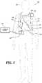
- FIG. 1is a diagram of components of a sample wearable cardioverter defibrillator (WCD) system, made according to embodiments.
- WCDwearable cardioverter defibrillator
- FIG. 2is another diagram of a sample embodiment of a WCD system that may benefit from embodiments of the present disclosure.
- FIG. 3is a block diagram showing sample components of an external defibrillator, such as the one used in the systems of FIGS. 1, and 2 and which is made according to embodiments.
- FIG. 4is a functional flow diagram generally illustrating a process for prioritizing detected conditions for a WCD system.
- FIG. 5is a table generally illustrating a condition prioritization scheme according to one embodiment of the present disclosure.
- FIG. 6is a table generally illustrating another condition prioritization scheme according to one embodiment of the present disclosure.
- Wearable Cardioverter Defibrillatorsare worn by patients at risk for sudden cardiac arrest.
- the WCDmay issue alerts to inform the user of system detected events that require patient action or alert users/bystanders of detected physiological events.
- the alertsmay relate to a device status, equipment, and physiologic alerts. If numerous, the alerts may confuse the patient as to which condition should be remedied first or at least before other conditions. If a patient becomes frequently bothered by the WCD or confused about using it, the patient may cease to wear the WCD, resulting in increased risk to the patient's health.
- Embodiments of this disclosureare directed to a wearable cardioverter defibrillator (“WCD”) system design in which a WCD implements an alert prioritization scheme to provide the patient with feedback in an order that is less likely to cause confusion.
- Different conditionse.g., device status, equipment condition, or physiologic condition
- the prioritization schemedefines what alert, if any, is presented to the user by the WCD system as a result of various conditions. Generally stated, an alert for the highest priority condition currently detected is presented to the user and maintained until that condition either changes or becomes surpassed in the prioritization scheme.
- the WCD systemmay protect a patient by electrically converting the patient's heart to a nonlethal rhythm if needed.
- Such a WCD systemmay have a number of components. These components can be provided separately as modules that can be interconnected, or can be combined with other components, and so on.
- FIG. 1depicts a patient 82 .
- Patient 82may also be referred to as a person and/or wearer, since the patient is wearing components of the WCD system.
- Patient 82is ambulatory, which means that, while wearing the wearable portion of the WCD system, patient 82 can walk around and is not necessarily bed-ridden.
- patient 82may be considered to be also a “user” of the WCD system, this is not a requirement.
- a user of the wearable cardioverter defibrillatormay also be a clinician such as a doctor, nurse, emergency medical technician (EMT) or other similarly tasked individual or group of individuals. In some cases, a user may even be a bystander.
- EMTemergency medical technician
- a WCD systemcan be configured to defibrillate the patient who is wearing the designated parts the WCD system. Defibrillating can be by the WCD system delivering an electrical charge to the patient's body in the form of an electric shock. The electric shock can be delivered in one or more pulses.
- FIG. 1also depicts components of a WCD system made according to embodiments.
- a support structure 170that is wearable by ambulatory patient 82 .
- support structure 170is configured to be worn by ambulatory patient 82 for at least several hours per day, and for at least several days, even a few months.
- support structure 170is shown only generically in FIG. 1 , and in fact partly conceptually.
- FIG. 1is provided merely to illustrate concepts about support structure 170 and is not to be construed as limiting how support structure 170 is implemented, or how it is worn.
- Support structure 170can be implemented in many different ways. For example, it can be implemented in a single component or a combination of multiple components.
- support structure 170could include a vest, a half-vest, a garment, etc. In such embodiments such items can be worn similarly to analogous articles of clothing.
- support structure 170could include a harness, one or more belts or straps, etc. In such embodiments, such items can be worn by the patient around the torso, hips, over the shoulder, etc.
- support structure 170can include a container or housing, which can even be waterproof. In such embodiments, the support structure can be worn by being attached to the patient's body by adhesive material, for example as shown and described in U.S. Pat. No.
- Support structure 170can even be implemented as described for the support structure of US Pat. App. No. US2017/0056682, which is incorporated herein by reference.
- additional components of the WCD systemcan be in the housing of a support structure instead of being attached externally to the support structure, for example as described in the US2017/0056682 document. There can be other examples.
- FIG. 1shows a sample external defibrillator 100 .
- some aspects of external defibrillator 100include a housing and an energy storage module within the housing.
- defibrillator 100is sometimes called a main electronics module.
- the energy storage modulecan be configured to store an electrical charge.
- Other componentscan cause at least some of the stored electrical charge to be discharged via electrodes through the patient, so as to deliver one or more defibrillation shocks through the patient.
- FIG. 1also shows sample defibrillation electrodes 104 , 108 , which are coupled to external defibrillator 100 via electrode leads 105 .
- Defibrillation electrodes 104 , 108can be configured to be worn by patient 82 in a number of ways.
- defibrillator 100 and defibrillation electrodes 104 , 108can be coupled to support structure 170 , directly or indirectly.
- support structure 170can be configured to be worn by ambulatory patient 82 so as to maintain at least one of electrodes 104 , 108 on the body of ambulatory patient 82 , while patient 82 is moving around, etc.
- the electrodecan be thus maintained on the body by being attached to the skin of patient 82 , simply pressed against the skin directly or through garments, etc. In some embodiments the electrode is not necessarily pressed against the skin but becomes biased that way upon sensing a condition that could merit intervention by the WCD system.
- many of the components of defibrillator 100can be considered coupled to support structure 170 directly, or indirectly via at least one of defibrillation electrodes 104 , 108 .
- defibrillator 100can administer, via electrodes 104 , 108 , a brief, strong electric pulse 111 through the body.
- Pulse 111is also known as shock, defibrillation shock, therapy, electrotherapy, therapy shock, etc. Pulse 111 is intended to go through and restart heart 85 , in an effort to save the life of patient 82 . Pulse 111 can further include one or more pacing pulses of lesser magnitude to simply pace heart 85 if needed, and so on.
- a WCD systemmay diagnose incorrectly patient 82 .
- such a WCD systemmay even administer defibrillation shock 111 as therapy to patient 82 when patient 82 does not need it, for instance when patient 82 is not having SCA, and is conscious.
- a WCD systemmay further include a divert actuator 189 that is coupled to support structure 170 and configured to be actuated by patient 82 .
- Divert actuator 189is also known as cancel switch, “I am alive” switch, “live man” switch, therapy divert switch, and so on.
- divert actuator 189is typically one more input device of an overall user interface 280 .
- divert actuator 189is a button in a stand-alone small housing 188 that has a wire 186 .
- Wire 186can, in turn, be ultimately electrically coupled with external defibrillator 100 .
- the divert actuatorcan be a lever, a switch, etc.
- the WCD systemmay further have an output device configured to output an alarm, and permit patient 82 some time to actuate divert actuator 189 responsive to the alarm. If patient 82 does that within the permitted time, then patient 82 is not shocked.
- the WCD systemmay further include a tactile output device 184 , for example within small housing 188 .
- Device 184can be configured to output a confirmation vibration, responsive to the divert actuator 189 being actuated.
- a small motorresponsive to patient 82 pushing button 189 , a small motor can rotate briefly to produce the confirmation vibration.
- the defibrillatormay decide whether to defibrillate or not based on an ECG signal of the patient. However, external defibrillator 100 may initiate defibrillation, or hold-off defibrillation, based on a variety of inputs, with the ECG signal merely being one of these inputs.
- a WCD systemcan obtain data from patient 82 .
- the WCD systemmay optionally include at least an outside monitoring device 180 .
- Device 180is called an “outside” device because it could be provided as a standalone device, for example not within the housing of defibrillator 100 .
- Device 180can be configured to sense or monitor at least one local parameter.
- a local parametercan be a parameter of patient 82 , or a parameter of the WCD system, or a parameter of the environment, as will be described later in this document.
- device 180may include one or more sensors or transducers. Each one of such sensors can be configured to sense a parameter of patient 82 , and to render an input responsive to the sensed parameter.
- the inputis quantitative, such as values of a sensed parameter; in other embodiments the input is qualitative, such as informing whether or not a threshold is crossed, and so on.
- these inputs about patient 82are also called physiological inputs and patient inputs.
- a sensorcan be construed more broadly, as encompassing many individual sensors.
- device 180is physically coupled to support structure 170 .
- device 180may be communicatively coupled with other components that are coupled to support structure 170 .
- Such communicationcan be implemented by a communication module, as will be deemed applicable by a person skilled in the art in view of this description.
- one or more of the components of the shown WCD systemmay be customized for patient 82 .
- This customizationmay include a number of aspects.
- support structure 170can be fitted to the body of patient 82 .
- baseline physiological parameters of patient 82can be measured, such as the heart rate of patient 82 while resting, while walking, motion detector outputs while walking, etc.
- the measured values of such baseline physiological parameterscan be used to customize the WCD system, in order to make its diagnoses more accurate, since patients' bodies differ from one another.
- such parameter valuescan be stored in a memory of the WCD system, and so on.
- a programming interfacecan be made according to embodiments, which receives such measured values of baseline physiological parameters. Such a programming interface may input automatically in the WCD system these, along with other data.
- FIG. 2is another diagram of components of an illustrative WCD system.
- a support structure 370includes a vest-like wearable garment.
- Support structure 370has a back side 371 and a front side 372 that closes in front of the chest of the patient.
- the WCD system of FIG. 2also includes an external defibrillator 300 .
- FIG. 3does not show any support for external defibrillator 300 , it may be attached to the support structure 370 , carried on a belt, in a purse, by a strap over the shoulder, and so on.
- Wires 305connect external defibrillator 300 to electrodes 304 , 308 , 309 .
- electrodes 304 , 308are defibrillation electrodes
- electrodes 309are ECG sensing electrodes.
- a therapy divert button 389is provided on a small housing 388 which, in turn, is connected via a cable 386 to defibrillator 300 , similarly to what was described with reference to FIG. 1 .
- Existing WCD systemsuse a large display screen facing away from the patient to convey information about the system state to the patient or to someone rendering aid.
- Existing display screensare large enough to provide information about concurrent system conditions and are in a prominent position at the front of the WCD electronics module.
- display screens on existing WCD systemsdo not allow for discrete notifications of system conditions.
- embodiments of the present disclosureuse a small display 380 and LED 381 along the outer edge of the electronics module 300 . Positioning the LED 381 along the periphery of the electronics module 300 allows the patient to discretely review system conditions and alerts without handling the electronics module 300 . Further, and in accordance with the disclosure, embodiments of the user interface design of the WCD system handle concurrent system conditions by prioritizing these conditions and providing user feedback based on those priorities.
- the WCD systemissues an alert only for the current condition having the highest priority.
- embodiments of the disclosed WCD user feedback schemeare simple and focused so the patient can easily identify and fix the most important issue as soon as possible.
- This prioritization schemeprovides at least the following benefits: (1) The user is only informed of the most relevant condition, which allows the user to take quick and decisive action without confusion, and (2) there is a 1-to-1 relationship between content presented on the WCD display 380 or LED 381 and the expected action as explained to a user in a manual or guide; e.g. the user does not need to interpret multiple symbols and figure out which condition is more important to address.
- Support structure 370is configured to be worn by the ambulatory patient to maintain electrodes 304 , 308 , 309 on a body of the patient. Indeed, back defibrillation electrodes 308 are maintained in pockets 378 . Of course, the inside of pockets 378 can be made with loose netting, so that electrodes 308 can contact the back of the patient, especially with the help of the conductive fluid that has been deployed. In addition, sensing electrodes 309 are maintained in positions that surround the patient's torso, for sensing ECG signals and/or the impedance of the patient.
- FIG. 3is a functional block diagram displaying various components of one example of a defibrillator 118 in accordance with the disclosure.
- the defibrillator 118may be an example of the defibrillator 118 described with reference to FIG. 1 .
- the components shown in FIG. 3may be contained within a single unit or may be separated amongst two or more units in communication with each other.
- the defibrillator 118may include a processor 302 , memory 304 , user interface 306 , defibrillation port 308 , ECG port 310 , among other components.
- the componentsare contained within a housing 312 or casing.
- the housing 312may comprise a hard shell around the components or may comprise a softer shell for increased patient comfort.
- the processor 302 , memory 304 (including software/firmware code (SW) 314 ), user interface 306 , defibrillation port 308 , ECG port 310 , transmission module 316 , measurement circuit 318 , monitoring device 320 , and energy storage module 322may communicate—directly or indirectly—with one another (e.g., via one or more buses 324 ).
- One or more buses 324may allow data communication between one or more elements and/or modules of the defibrillator 118 .
- the memory 304may include random access memory (RAM), read only memory (ROM), flash RAM, and/or other types.
- the memory 304may store computer-readable, computer-executable software/firmware code 314 including instructions that, when executed, cause the processor 302 to perform various functions (e.g., determine shock criteria, determine consciousness of patient, track patient parameters, etc.).
- the processor 302may include an intelligent hardware device, e.g., a central processing unit (CPU), a microcontroller, an application-specific integrated circuit (ASIC), etc.
- CPUcentral processing unit
- ASICapplication-specific integrated circuit
- the memory 304can contain, among other things, the Basic Input-Output system (BIOS) which may control basic hardware and/or software operations such as interactions and workings of the various components of the defibrillator 118 , and in some embodiments, components external to the defibrillator 118 .
- BIOSBasic Input-Output system
- the memory 304may contain various modules to implement the workings of the defibrillator 118 and other aspects of the present disclosure.
- the defibrillator 118may include a user interface 306 .
- the user interface 306may enable the patient to view one or metrics concerning the defibrillator 118 , the WCD system as a whole, or some combination thereof.
- the user interface 306may display an ECG of the patient, a status of the defibrillator 118 , a status of a charge (e.g. a battery charge or an energy storage module), an alert to bring an unsafe condition to the patient's attention, and the like.
- a chargee.g. a battery charge or an energy storage module
- the defibrillator 118may include a defibrillation port 308 .
- the defibrillation port 308may comprise a socket, opening, or electrical connection in the housing 312 .
- the defibrillation port 308may include two or more nodes 326 , 328 .
- the two or more nodes 326 , 328may accept two or more defibrillation electrodes (e.g. defibrillation electrodes 114 , 116 , FIG. 1 ).
- the nodes 326 , 328may provide an electrical connection between the defibrillation electrodes 114 , 116 and the defibrillator 118 .
- the defibrillation electrodes 114 , 116may plug into the two or more nodes 326 , 328 via one or more leads (e.g. leads 120 ), or, in some instances, the defibrillation electrodes 114 , 116 may be hardwired to the nodes 326 , 328 . Once an electrical connection is established between the defibrillation port 308 and the electrodes 114 , 116 , the defibrillator 118 may be able to deliver an electric shock to the patient.
- the defibrillator 118may include an ECG port 310 in the housing 312 .
- the ECG port 310may accept one or more ECG electrodes 330 or ECG leads.
- the ECG electrodes 330sense a patient's ECG signal.
- the ECG electrodes 330may record electrical activity generated by the heart muscle depolarization.
- the ECG electrodes 330may utilize 3-leads to 12-leads or multichannel ECG, or the like.
- the ECG electrodes 330may connect with the patient's skin.
- the defibrillator 118may include a measurement circuit 318 .
- the measurement circuit 318may be in communication with the ECG port 310 .
- the measurement circuit 318may receive physiological signals from ECG port 310 .
- the measurement circuit 318may additionally or alternatively receive physiological signals via the defibrillation port 308 when defibrillation electrodes 114 , 116 are attached to the patient.
- the measurement circuit 318may determine a patient's ECG signal from a difference in voltage between the defibrillation electrodes 114 , 116 .
- the measurement circuit 318may monitor the electrical connection between the defibrillation electrodes 114 , 116 and the skin of the patient. For example, the measurement circuit 318 can detect impedance between the electrodes 114 , 116 . In some embodiments, the detected impedance may indicate the effective resistance of an electric circuit. An impedance calculation may, at least in part, determine when the electrodes 114 , 116 have a good electrical connection with the patient's body.
- the defibrillator 118may include an internal monitoring device 320 within the housing 312 .
- the monitoring device 320may monitor at least one system parameter as well as patient physiological parameters.
- System parametersmay include a parameter of the WCD (e.g. WCD 104 ), defibrillator 118 , environmental parameters, or the like.
- the system parametermay reflect whether the WCD is being worn correctly and is in good working condition.
- Patient physiological parametersmay include the patient's ECG and its concomitant elements.
- the monitoring device 320may monitor environmental conditions, such as whether the WCD system in moving, thereby indicating that the patient is conscious and ambulatory. Other parameters may also be monitored.
- a WCDmay include an internal monitoring device 320 and an external monitoring device. If both monitoring devices are present, the devices may collaborate to parse out specific parameters depending on position, location, and other factors. For example, the external monitoring device may monitor environmental parameters while the internal monitoring device 320 may monitor patient and system parameters.
- the defibrillator 118may include a power source 332 .
- the power source 332may comprise a battery or battery pack, which may be rechargeable.
- the power source 332may comprise a series of different batteries to ensure the defibrillator 118 has power.
- the power source 332may include a series of rechargeable batteries as a prime power source and a series of non-rechargeable batteries as a secondary source. If the patient is proximate an AC power source, such as when sitting down, sleeping, or the like, the power source 332 may include an AC override wherein the power source 332 draws power from the AC source.
- the defibrillator 118may include an energy storage module 322 .
- the energy storage module 322may store electrical energy in preparation or anticipation of providing a sudden discharge of electrical energy to the patient.
- the energy storage module 322may have its own power source and/or battery pack.
- the energy storage module 322may pull power from the power source 332 .
- the energy storage module 322may include one or more capacitors 334 .
- the one or more capacitors 334may store an electrical charge, which may be administered to the patient.
- the processor 302may be communicatively coupled to the energy storage module 322 to trigger the amount and timing of electrical energy to provide to the defibrillation port 308 and, subsequently, the patient.
- the defibrillator 118may include a discharge circuit 336 .
- the discharge circuit 336may control the energy stored in the energy storage module 322 .
- the discharge circuit 336may either electrical couple or decouple the energy storage module 322 to the defibrillation port 308 .
- the discharge circuit 336may be communicatively coupled to the processor 302 to control when the energy storage module 322 and the defibrillation port 308 should or should not be coupled to either administer or prevent a charge from emitting from the defibrillator 118 .
- the discharge circuit 336may include one or more switches 338 .
- the one or more switches 338may include an H-bridge.
- the defibrillator 118may include a transmission module 316 .
- the transmission module 316may establish one or more communication links with either local hardware and/or software to the WCD and defibrillator 118 or to remote hardwire separate from the WCD system.
- the transmission module 316may include one or more antennas, processors, and the like.
- the transmission module 316may communicate wirelessly via radio frequency, electromagnetics, local area networks (LAN), wide area networks (WAN), virtual private networks (VPN), RFID, Bluetooth, cellular networks, and the like.
- the transmission module 316may facilitate communication of data and commands such as patient data, episode information, therapy attempted, CPR performance, system data, environmental data, and so on.
- the processor 302may execute one or more modules.
- the processor 302may execute a detection module 340 and/or an action module 342 .
- the detection module 340may be a logic device or algorithm to determine if any thresholds are exceeded which may require action of the defibrillator 118 .
- the detection module 340may receive and interpret all the signals from the ECG port 310 , the defibrillation port 308 , the monitoring device 320 , an external monitoring device, and the like.
- the detection module 340may process the information to ensure the patient is conscious and healthy. If any parameter indicates the patient may be experiencing distress or indicating a cardiac episode, the detection module 340 may activate the action module 342 .
- the action module 342may receive data from the detection module 340 and perform a series of actions. For example, an episode may merely be a loss of batter power at the power source 332 or the energy storage module 322 , or one or more electrodes (e.g., ECG electrodes, defibrillation electrodes) may have lost connection. In such instances, the action module 342 may trigger an alert to the patient or to an outside source of the present situation. If an episode is a health risk, such as a cardiac event, the action module 342 may begin a series of steps.
- an episodemay merely be a loss of batter power at the power source 332 or the energy storage module 322 , or one or more electrodes (e.g., ECG electrodes, defibrillation electrodes) may have lost connection. In such instances, the action module 342 may trigger an alert to the patient or to an outside source of the present situation. If an episode is a health risk, such as a cardiac event, the action module 342 may begin a series of steps.
- Thismay include issuing a warning to the patient, issuing a warning to a third party, priming the energy storage module 322 for defibrillation, releasing one or more conductive fluids proximate defibrillation electrodes 114 , 116 , and the like.
- the processor 302may also execute the notification module 106 .
- the notification module 106may detect that certain parameters reveal that the WCD system is in an unsafe condition necessitating that an alert be raised to apprise the patient of that unsafe condition.
- the notification module 106 of preferred embodimentsalso categorizes each condition, determines what alert to issue to the patient, and when the alert is issued.
- the notification module 106may also determine or receive data to determine when a condition has been remedied.
- Condition resolutionmay cause the notification module 106 to cease an alert, issue a resolution notice, or a combination thereof.
- FIG. 4is a logical flow diagram generally illustrating a process 400 for prioritizing alerts in a WCD system in accordance with the disclosure.
- the process 400monitors for a condition for which an alert is appropriate.
- a conditionmay represent either that some system parameter is outside of proper working conditions, or that some physiological condition with the patient may exist.
- each such conditionindicates that action is either required or strongly recommended to return the WCD system to a safe and operable condition.
- the term “condition”means any unsafe condition of either the WCD system or the patient for which an action is either required or strongly recommended in order to return either the WCD system or the patient to a safe working order.
- the processadds that condition to a queue of current conditions.
- the queue of current conditionsmay be empty or it may include other conditions. It is envisioned that at system startup, the queue is empty. As system startup progresses, certain conditions may be promptly revealed (e.g., “the patient is not wearing the WCD” or the like) and added to the queue. In addition, as the WCD system is worn and used, other conditions may emerge and be added to the queue.
- the process 400prioritizes each condition in the queue of current conditions.
- the prioritization scheme used to prioritize each conditionmay weigh different parameters in different ways. However, generally stated, conditions that prevent the WCD from operating in its intended manner (e.g., the WCD is not being worn or has a critically low battery) are prioritized higher than conditions which should be remedied but which will still allow the WCD to function (e.g., the WCD has a low battery but not critically low).
- a table 500illustrates one example prioritization scheme according to certain embodiments.
- This example prioritization schemeconsiders the Modes and States behavior of the WCD, the need to fix issues preventing cardiac sensing and/or treatment as soon as possible, and desire to inform the user of relevant, but not critical, system issues. Note that many of these conditions are possible concurrently. In contrast to existing systems that show multiple alerts or notifications at once, embodiments of the present disclosure only show one alert at a time to avoid confusing and/or stressing the patient. In embodiments, when multiple conditions occur, only the highest priority alert is provided, and when the patient resolves the issue, the next highest priority alert is provided, and so on.
- This example prioritizationhas some system conditions with higher priority than physiological condition, which may be counterintuitive compared to other WCD alert schemes.
- the alerts shown in FIG. 5 for priority 5 and priority 6are switched as illustrated in FIG. 6 .
- alert prioritization schemesThere are many possible prioritization schemes used in embodiments, some of which could dynamically adjust the alert prioritization during operation of the WCD. Some examples of alert prioritization schemes, which can be combined as needed, are:
- an alertis issued (step 407 ).
- the alertcan take many forms, such as a visual icon or other notification rendered on a display, such as the display 380 or LED 381 ( FIG. 2 ).
- an audible alertis also generated.
- the alert for the highest priority conditionremains active until a higher priority condition is added to the queue.
- the process 400continues monitoring these conditions (step 409 ) to constantly reassess which alert to raise for any current conditions. It will be appreciated that an important aspect of the alert prioritization schemes described above is the WCD system response to concurrent alert conditions.
- the following guidancedescribes design criteria that influence how to handle (e.g., prioritize) concurrent conditions, such as when new conditions are added to the queue.
- Physiologic Alert ProgressionIf a Physiologic Alert is Active or Playing and the WCD advances to a new Physiologic state (i.e. advancing from Initial Patient Response Delay to Therapy Imminent), the WCD shall:
- any condition(not only the highest-priority condition) has been remedied, it is removed from the queue.
- the alertmay be temporarily paused (or “snoozed”) to be dealt with later.
- the alertmay not be dismissed until the condition has in fact been remedied. In an alternative embodiment, the alert may be dismissed even though the condition has not been remedied.
- Embodiments of this disclosureovercome various problems that exist with other WCD alerting systems. For example, user confusion about what action is required due to over-informing of system condition (like flashing between system is ok and service needed or indicating system is ok with a service wrench) is reduced or eliminated.
- a WCD configured with the disclosed prioritization schemealso includes a mechanism to detect if the patient or user accidentally or mistakenly disabled an alert or alarm.
- the devicemay be configured to detect when an alarm is deactivated or disabled and monitor for subsequent actions by the patient that indicate the deactivation was not intended (e.g., monitor the patient's voice via a microphone, monitor UI inputs that indicate the patient is trying to repeat the alarm, or the like), or prompt the patient to confirm that the deactivation was intended, or if no response or an improper response is provided within a certain period of time.
- inventionsare adapted for use in WCD systems, but other embodiments can be used with other medical devices that provide alerts to the patient such as, for example, wearable vital sign monitors, Holter monitors, wearable external pacers, or other medical devices that monitor a patient, provide an alert/notification to the patient and/or a remote device, provide prompts or requests for a user (patient and/or rescuer or bystander) response, and optionally provide a therapy or treatment to the patient.
- medical devicesthat provide alerts to the patient such as, for example, wearable vital sign monitors, Holter monitors, wearable external pacers, or other medical devices that monitor a patient, provide an alert/notification to the patient and/or a remote device, provide prompts or requests for a user (patient and/or rescuer or bystander) response, and optionally provide a therapy or treatment to the patient.
- the devices and/or systems mentioned in this documentmay perform functions, processes, acts, operations, actions and/or methods. These functions, processes, acts, operations, actions and/or methods may be implemented by one or more devices that include logic circuitry.
- a single such devicecan be alternately called a computer, and so on. It may be a standalone device or computer, such as a general-purpose computer, or part of a device that has and/or can perform one or more additional functions.
- the logic circuitrymay include a processor and non-transitory computer-readable storage media, such as memories, of the type described elsewhere in this document. Often, for the sake of convenience only, it is preferred to implement and describe a program as various interconnected distinct software modules or features. These, along with data are individually and also collectively known as software. In some instances, software is combined with hardware, in a mix called firmware.
- each operationcan be performed as an affirmative act or operation of doing, or causing to happen, what is written that can take place. Such doing or causing to happen can be by the whole system or device, or just one or more components of it.
- the methods and the operationsmay be implemented in a number of ways, including using systems, devices and implementations described above.
- the order of operationsis not constrained to what is shown, and different orders may be possible according to different embodiments. Examples of such alternate orderings may include overlapping, interleaved, interrupted, reordered, incremental, preparatory, supplemental, simultaneous, reverse, or other variant orderings, unless context dictates otherwise.
- new operationsmay be added, or individual operations may be modified or deleted. The added operations can be, for example, from what is mentioned while primarily describing a different system, apparatus, device or method.
- the phrases “constructed to”, “adapted to” and/or “configured to”denote one or more actual states of construction, adaptation and/or configuration that is fundamentally tied to physical characteristics of the element or feature preceding these phrases and, as such, reach well beyond merely describing an intended use. Any such elements or features can be implemented in a number of ways, as will be apparent to a person skilled in the art after reviewing the present disclosure, beyond any examples shown in this document.
- references numeralsIn this description a single reference numeral may be used consistently to denote a single item, aspect, component, or process. Moreover, a further effort may have been made in the preparation of this description to use similar though not identical reference numerals to denote other versions or embodiments of an item, aspect, component or process that are identical or at least similar or related. Where made, such a further effort was not required, but was nevertheless made gratuitously so as to accelerate comprehension by the reader. Even where made in this document, such a further effort might not have been made completely consistently for all of the versions or embodiments that are made possible by this description. Accordingly, the description controls in defining an item, aspect, component or process, rather than its reference numeral. Any similarity in reference numerals may be used to infer a similarity in the text, but not to confuse aspects where the text or other context indicates otherwise.
Landscapes
- Health & Medical Sciences (AREA)
- Engineering & Computer Science (AREA)
- Public Health (AREA)
- Biomedical Technology (AREA)
- General Health & Medical Sciences (AREA)
- Cardiology (AREA)
- Business, Economics & Management (AREA)
- Life Sciences & Earth Sciences (AREA)
- Veterinary Medicine (AREA)
- Animal Behavior & Ethology (AREA)
- Nuclear Medicine, Radiotherapy & Molecular Imaging (AREA)
- Heart & Thoracic Surgery (AREA)
- Radiology & Medical Imaging (AREA)
- Human Resources & Organizations (AREA)
- Theoretical Computer Science (AREA)
- Medical Informatics (AREA)
- Economics (AREA)
- General Physics & Mathematics (AREA)
- Strategic Management (AREA)
- Physics & Mathematics (AREA)
- General Engineering & Computer Science (AREA)
- Entrepreneurship & Innovation (AREA)
- Epidemiology (AREA)
- Primary Health Care (AREA)
- General Business, Economics & Management (AREA)
- Operations Research (AREA)
- Game Theory and Decision Science (AREA)
- Tourism & Hospitality (AREA)
- Quality & Reliability (AREA)
- Software Systems (AREA)
- Marketing (AREA)
- Educational Administration (AREA)
- Development Economics (AREA)
- Biophysics (AREA)
- Physical Education & Sports Medicine (AREA)
- Data Mining & Analysis (AREA)
- Databases & Information Systems (AREA)
- Pathology (AREA)
- Electrotherapy Devices (AREA)
Abstract
Description
- 1. Type of Alert—Physiologic>Equipment>Device Status
- 2. Timeliness of Response Needed—Soon>sometime in the future; for example, Service Required and Service Needed require the same user action (get service) but have significantly different timeliness of response needed since Service Required means the WCD cannot deliver therapy.
- 3. Severity of No Response—Death>severe injury>harm
- 4. System Mode—Different priorities based on the current system mode; for example, prioritize alerts differently when in Holter Mode to allow for collection of data on what the system would do if an alert had not been issued.
- 5. System State—Different priorities based on the current system state; for example, prioritize alerts differently when Not Being Worn compared to Being Worn.
- 6. Sub-Category Prioritization—Different priorities based on the specific alert-causing reason; for example a prioritization scheme could be implemented to allow for a higher priority notification for Service Needed (Gel replenishment needed) than Service Needed (system component exceeded service life). An alert for Service Needed (system component exceeded expected service life) could even be prioritized lower than System Ready, No User Action Needed, which essentially turns the user-facing alert off but still logs the condition for device service or remote device management purposes.
- 7. Connected System Status—Different priorities based on the presence or absence of connected system components; for example, use different priorities if the WCD is currently connected to a portable “smart device” such as a tablet or a smartphone-like device. In some embodiments, the “smart device” is called an “Assistant” and includes wireless communication connectivity with the WCD's electronics module and can serve as a UI to the electronics module, as well as connect to a network to communicate with remote devices. For example, in some embodiments, clinicians, emergency responders, family members, monitoring services, etc. may be selectively connected to the WCD either directly or via the “Assistant” and receive information from the WCD, the user, and/or rescuers or bystanders. In some embodiments, the prioritization scheme for alerts provided to the remote devices may be different from the prioritization scheme for the user. For example, a “clinician view” may be implemented on a remotely connected device that uses a different prioritization, and in some cases displays 2 or more alerts concurrently as opposed to the single alert displayed on the WCD user's UI. In some embodiments, the clinician view may display alerts with a different timing (e.g., in real time) than the WCD's user's UI.
- 8. Time of Day—Different priorities based on time of day (see #9 below for a more likely use of this prioritization).
- 9. Time Since Entering Being Worn—Different priorities to allow for the device to acclimate to the user prior to alerting for poor contact issues.
- 10. Sleep Detection—Different priorities based on sleep detection; for example, if the defib pads are noticed to come off frequently while sleeping, this alert can be prioritized lower to prevent interrupting the patient's sleep.
- 11. User Input—Different priorities based on input from the user; for example, if the user informs the device that they are showering, the device can enter a “showering mode” in which a “Device Temporarily Not Being Worn” alert is prioritized higher than other Being Worn alerts.
- 12. Location—Different priorities based on location sensing; for example, if the device detects or the user informs the device that the user is in a “Public” setting, alerts could be prioritized to reduce or turn off the occurrence of certain alerts.
- 13. Manual—Different priorities based on manual customization on a patient-by-patient basis; for example, if a physician noticed that a patient frequently receives an alert that the physician feels does not affect the safety and efficacy of the WCD, like ECG Electrodes Off (Analysis Possible), and is concerned about patient compliance due to over-alerting, a user can program that alert to be lower priority than System Ready, No User Action Needed on the priority list, which essentially turns the user-facing alert off but still logs the condition for device service or remote device management purposes.
- i. Stop current user interface behavior of the active Alert or system condition (this includes any currently playing tactile and audio feedback).
- ii. Start the higher priority Alert or system condition behavior from the beginning.
- i. Stop current user interface behavior of the active Alert or system condition (this includes any currently playing tactile and audio feedback).
- ii. Skip any Onset Time and Initial Play Delay and start the higher priority Alert or system condition behavior.
- i. Stop current user interface behavior of the active Alert or system condition (this includes any currently playing tactile and audio feedback).
- ii. Start the Alert behavior for the current State.
- i. Not interrupt the current (higher priority) Alert.
- ii. If the lower priority condition still exists upon resolution of the current Alert, start the Alert behavior of the lower priority condition.
Claims (18)
Priority Applications (3)
| Application Number | Priority Date | Filing Date | Title |
|---|---|---|---|
| US16/748,621US11334826B2 (en) | 2019-01-18 | 2020-01-21 | WCD system prioritization of alerts based on severity and/or required timeliness of user response |
| US17/738,496US11880792B2 (en) | 2019-01-18 | 2022-05-06 | WCD system prioritization of alerts based on severity and/or required timeliness of user response |
| US18/542,417US20240119380A1 (en) | 2019-01-18 | 2023-12-15 | Wcd system prioritization of alerts based on severity and/or required timeliness of user response |
Applications Claiming Priority (2)
| Application Number | Priority Date | Filing Date | Title |
|---|---|---|---|
| US201962794335P | 2019-01-18 | 2019-01-18 | |
| US16/748,621US11334826B2 (en) | 2019-01-18 | 2020-01-21 | WCD system prioritization of alerts based on severity and/or required timeliness of user response |
Related Child Applications (1)
| Application Number | Title | Priority Date | Filing Date |
|---|---|---|---|
| US17/738,496DivisionUS11880792B2 (en) | 2019-01-18 | 2022-05-06 | WCD system prioritization of alerts based on severity and/or required timeliness of user response |
Publications (3)
| Publication Number | Publication Date |
|---|---|
| US20200230428A1 US20200230428A1 (en) | 2020-07-23 |
| US20210370079A9 US20210370079A9 (en) | 2021-12-02 |
| US11334826B2true US11334826B2 (en) | 2022-05-17 |
Family
ID=78720204
Family Applications (3)
| Application Number | Title | Priority Date | Filing Date |
|---|---|---|---|
| US16/748,621ActiveUS11334826B2 (en) | 2019-01-18 | 2020-01-21 | WCD system prioritization of alerts based on severity and/or required timeliness of user response |
| US17/738,496ActiveUS11880792B2 (en) | 2019-01-18 | 2022-05-06 | WCD system prioritization of alerts based on severity and/or required timeliness of user response |
| US18/542,417PendingUS20240119380A1 (en) | 2019-01-18 | 2023-12-15 | Wcd system prioritization of alerts based on severity and/or required timeliness of user response |
Family Applications After (2)
| Application Number | Title | Priority Date | Filing Date |
|---|---|---|---|
| US17/738,496ActiveUS11880792B2 (en) | 2019-01-18 | 2022-05-06 | WCD system prioritization of alerts based on severity and/or required timeliness of user response |
| US18/542,417PendingUS20240119380A1 (en) | 2019-01-18 | 2023-12-15 | Wcd system prioritization of alerts based on severity and/or required timeliness of user response |
Country Status (1)
| Country | Link |
|---|---|
| US (3) | US11334826B2 (en) |
Cited By (2)
| Publication number | Priority date | Publication date | Assignee | Title |
|---|---|---|---|---|
| US20220054849A1 (en)* | 2020-08-21 | 2022-02-24 | West Affum Holdings Corp. | Positive System Alerts |
| US20220261731A1 (en)* | 2019-01-18 | 2022-08-18 | West Affum Holdings Corp. | Wcd system prioritization of alerts based on severity and/or required timeliness of user response |
Families Citing this family (8)
| Publication number | Priority date | Publication date | Assignee | Title |
|---|---|---|---|---|
| US12300368B1 (en)* | 2019-03-07 | 2025-05-13 | West Affum Holdings Dac | Analysis and presentation of aggregated patient and device data within a system that includes a medical device |
| US12121329B2 (en) | 2019-03-08 | 2024-10-22 | West Affum Holdings Dac | Wearable vital signs monitor with selective signal acquisition |
| USD927545S1 (en)* | 2019-04-05 | 2021-08-10 | West Affum Holdings Corp. | Display screen or portion thereof with icon |
| USD927543S1 (en)* | 2019-04-05 | 2021-08-10 | West Affum Holdings Corp. | Display screen or portion thereof with icon |
| USD913327S1 (en) | 2019-04-05 | 2021-03-16 | West Affum Holdings Corp. | Display screen or portion thereof with icon |
| USD927544S1 (en)* | 2019-04-05 | 2021-08-10 | West Affum Holdings Corp. | Display screen or portion thereof with icon |
| CN112022107A (en)* | 2020-09-30 | 2020-12-04 | 苏州无双医疗设备有限公司 | Combined device for external cardioversion and defibrillation |
| JP7343556B2 (en)* | 2021-08-20 | 2023-09-12 | ウェスト・アファム・ホールディングス・ディーエーシー | positive system alert |
Citations (134)
| Publication number | Priority date | Publication date | Assignee | Title |
|---|---|---|---|---|
| US3724355A (en) | 1970-06-12 | 1973-04-03 | K Schranz | Apparatus for processing exposed photographic film or the like |
| US4583524A (en) | 1984-11-21 | 1986-04-22 | Hutchins Donald C | Cardiopulmonary resuscitation prompting |
| US4619265A (en) | 1984-03-08 | 1986-10-28 | Physio-Control Corporation | Interactive portable defibrillator including ECG detection circuit |
| US4666432A (en) | 1985-09-13 | 1987-05-19 | Mcneish Kenneth | Catheter retaining means and method |
| US4698848A (en) | 1986-09-26 | 1987-10-13 | Buckley Mary C | Blouse for cardiac patients |
| US4928690A (en) | 1988-04-25 | 1990-05-29 | Lifecor, Inc. | Portable device for sensing cardiac function and automatically delivering electrical therapy |
| US4955381A (en) | 1988-08-26 | 1990-09-11 | Cardiotronics, Inc. | Multi-pad, multi-function electrode |
| US5078134A (en) | 1988-04-25 | 1992-01-07 | Lifecor, Inc. | Portable device for sensing cardiac function and automatically delivering electrical therapy |
| US5228449A (en) | 1991-01-22 | 1993-07-20 | Athanasios G. Christ | System and method for detecting out-of-hospital cardiac emergencies and summoning emergency assistance |
| US5285792A (en)* | 1992-01-10 | 1994-02-15 | Physio-Control Corporation | System for producing prioritized alarm messages in a medical instrument |
| US5348008A (en) | 1991-11-25 | 1994-09-20 | Somnus Corporation | Cardiorespiratory alert system |
| US5394892A (en) | 1990-04-02 | 1995-03-07 | K J Mellet Nominees Pty Ltd | CPR prompting apparatus |
| US5405362A (en) | 1991-04-29 | 1995-04-11 | The Board Of Regents For The University Of Texas System | Interactive external defibrillation and drug injection system |
| US5429593A (en) | 1993-12-23 | 1995-07-04 | Matory; Yvedt L. | Post-surgical, drainage accommodating, compression dressing |
| US5474574A (en) | 1992-06-24 | 1995-12-12 | Cardiac Science, Inc. | Automatic external cardioverter/defibrillator |
| US5618208A (en) | 1994-06-03 | 1997-04-08 | Siemens Medical Systems, Inc. | Fully insulated, fully shielded electrical connector arrangement |
| US5662690A (en) | 1994-12-08 | 1997-09-02 | Heartstream, Inc. | Defibrillator with training features and pause actuator |
| US5708978A (en) | 1994-08-17 | 1998-01-20 | Johnsrud; Anna C. | Medical vest |
| US5741306A (en) | 1996-05-23 | 1998-04-21 | Lifecor, Inc. | Patient-worn energy delivery apparatus |
| US5782878A (en) | 1994-12-07 | 1998-07-21 | Heartstream, Inc. | External defibrillator with communications network link |
| US5792204A (en) | 1996-05-08 | 1998-08-11 | Pacesetter, Inc. | Methods and apparatus for controlling an implantable device programmer using voice commands |
| WO1998039061A2 (en) | 1997-03-07 | 1998-09-11 | Cadent Medical Corporation | Wearable defibrillation system |
| US5902249A (en) | 1995-03-03 | 1999-05-11 | Heartstream, Inc. | Method and apparatus for detecting artifacts using common-mode signals in differential signal detectors |
| US5913685A (en) | 1996-06-24 | 1999-06-22 | Hutchins; Donald C. | CPR computer aiding |
| US5944669A (en) | 1997-11-20 | 1999-08-31 | Lifecor, Inc. | Apparatus and method for sensing cardiac function |
| US6047203A (en) | 1997-03-17 | 2000-04-04 | Nims, Inc. | Physiologic signs feedback system |
| US6065154A (en) | 1998-04-07 | 2000-05-23 | Lifecor, Inc. | Support garments for patient-worn energy delivery apparatus |
| US6108197A (en) | 1992-05-15 | 2000-08-22 | Via, Inc. | Flexible wearable computer |
| US6201992B1 (en) | 1999-04-01 | 2001-03-13 | Agilent Technologies, Inc. | Defibrillator interface capable of generating video images |
| US6263238B1 (en) | 1998-04-16 | 2001-07-17 | Survivalink Corporation | Automatic external defibrillator having a ventricular fibrillation detector |
| US6280461B1 (en) | 1996-05-23 | 2001-08-28 | Lifecor, Inc. | Patient-worn energy delivery apparatus |
| US6287328B1 (en) | 1999-04-08 | 2001-09-11 | Agilent Technologies, Inc. | Multivariable artifact assessment |
| US6319011B1 (en) | 1995-04-06 | 2001-11-20 | Michael J. Motti | Automatic training defibrillator simulator and method |
| US6334070B1 (en) | 1998-11-20 | 2001-12-25 | Medtronic Physio-Control Manufacturing Corp. | Visual and aural user interface for an automated external defibrillator |
| US6356785B1 (en) | 1997-11-06 | 2002-03-12 | Cecily Anne Snyder | External defibrillator with CPR prompts and ACLS prompts and methods of use |
| US6437083B1 (en) | 2001-12-06 | 2002-08-20 | General Electric Company | Process for preparing branched aromatic polycarbonates |
| US6450942B1 (en) | 1999-08-20 | 2002-09-17 | Cardiorest International Ltd. | Method for reducing heart loads in mammals |
| US20020181680A1 (en) | 1999-10-05 | 2002-12-05 | Marshal Linder | Data collection and system management for patient-worn medical devices |
| US6529875B1 (en) | 1996-07-11 | 2003-03-04 | Sega Enterprises Ltd. | Voice recognizer, voice recognizing method and game machine using them |
| US20030158593A1 (en) | 2002-02-19 | 2003-08-21 | Heilman Marlin S. | Cardiac garment |
| US6762917B1 (en) | 2001-06-12 | 2004-07-13 | Novx Corporation | Method of monitoring ESC levels and protective devices utilizing the method |
| US20050107834A1 (en) | 2003-11-13 | 2005-05-19 | Freeman Gary A. | Multi-path transthoracic defibrillation and cardioversion |
| US7065401B2 (en) | 2002-05-08 | 2006-06-20 | Michael Worden | Method of applying electrical signals to a patient and automatic wearable external defibrillator |
| US20060173499A1 (en) | 2005-01-31 | 2006-08-03 | Medtronic Emergency Response Systems, Inc. | System and method for using diagnostic pulses in connection with defibrillation therapy |
| US20080312709A1 (en) | 2007-06-13 | 2008-12-18 | Volpe Shane S | Wearable medical treatment device with motion/position detection |
| US20090005827A1 (en) | 2007-06-26 | 2009-01-01 | David Weintraub | Wearable defibrillator |
| US7559902B2 (en) | 2003-08-22 | 2009-07-14 | Foster-Miller, Inc. | Physiological monitoring garment |
| JP4320257B2 (en) | 2001-11-05 | 2009-08-26 | キャメロン ヘルス、 インコーポレイテッド | Flexible subcutaneous implantable defibrillator |
| US20100007413A1 (en) | 2006-11-10 | 2010-01-14 | Koninklijke Philips Electronics N.V. | Ecg electrode contact quality measurement system |
| US7753759B2 (en) | 2007-10-22 | 2010-07-13 | Tammy Pintor | Article of apparel for concealing objects |
| US20100298899A1 (en) | 2007-06-13 | 2010-11-25 | Donnelly Edward J | Wearable medical treatment device |
| US7865238B2 (en) | 2004-09-29 | 2011-01-04 | Koninklijke Philips Electronics N.V. | High-voltage module for an external defibrillator |
| US7870761B2 (en) | 2002-05-14 | 2011-01-18 | Koninklijke Philips Electronics N.V. | Garment and method for producing the same |
| WO2011146448A1 (en) | 2010-05-18 | 2011-11-24 | Zoll Medical Corporation | Wearable therapeutic device |
| US20110288605A1 (en) | 2010-05-18 | 2011-11-24 | Zoll Medical Corporation | Wearable ambulatory medical device with multiple sensing electrodes |
| US8135462B2 (en) | 2002-08-26 | 2012-03-13 | Physio-Control, Inc. | Pulse detection using patient physiological signals |
| US20120112903A1 (en) | 2010-11-08 | 2012-05-10 | Zoll Medical Corporation | Remote medical device alarm |
| US20120144551A1 (en) | 2010-12-09 | 2012-06-14 | Eric Guldalian | Conductive Garment |
| US20120150008A1 (en) | 2010-12-09 | 2012-06-14 | Kaib Thomas E | Electrode with redundant impedance reduction |
| US20120158075A1 (en) | 2010-12-16 | 2012-06-21 | Kaib Thomas E | Water resistant wearable medical device |
| US20120191476A1 (en) | 2011-01-20 | 2012-07-26 | Reid C Shane | Systems and methods for collection, organization and display of ems information |
| US20120265265A1 (en) | 2011-04-13 | 2012-10-18 | Mehdi Razavi | Automated External Defibrillator Pad System |
| WO2012151160A1 (en) | 2011-05-02 | 2012-11-08 | Zoll Medical Corporation | Patient-worn energy delivery apparatus and techniques for sizing same |
| US20120293323A1 (en) | 2011-03-25 | 2012-11-22 | Zoll Medical Corporation | System and method for adapting alarms in a wearable medical device |
| US20120302860A1 (en) | 2011-03-25 | 2012-11-29 | Zoll Medical Corporation | Selection of optimal channel for rate determination |
| US20120310315A1 (en) | 2009-03-17 | 2012-12-06 | Savage Walter T | Device and method for reducing patient transthoracic impedance for the purpose of delivering a therapeutic current |
| US8369944B2 (en) | 2007-06-06 | 2013-02-05 | Zoll Medical Corporation | Wearable defibrillator with audio input/output |
| US20130085538A1 (en) | 2011-09-01 | 2013-04-04 | Zoll Medical Corporation | Wearable monitoring and treatment device |
| US8527028B2 (en) | 2007-05-16 | 2013-09-03 | Medicomp, Inc. | Harness with sensors |
| US20130231711A1 (en) | 2012-03-02 | 2013-09-05 | Thomas E. Kaib | Systems and methods for configuring a wearable medical monitoring and/or treatment device |
| US20130245388A1 (en) | 2011-09-01 | 2013-09-19 | Mc10, Inc. | Electronics for detection of a condition of tissue |
| US8548557B2 (en) | 2010-08-12 | 2013-10-01 | Covidien Lp | Medical electrodes |
| US8560044B2 (en) | 2007-05-16 | 2013-10-15 | Medicomp, Inc. | Garment accessory with electrocardiogram sensors |
| US20130274565A1 (en) | 2012-04-13 | 2013-10-17 | Alois Antonin Langer | Outpatient health emergency warning system |
| US20130317852A1 (en) | 2012-05-22 | 2013-11-28 | Geneva Healthcare, LLC | Medical device information portal |
| US20130325078A1 (en) | 2012-05-31 | 2013-12-05 | Zoll Medical Corporation | Medical monitoring and treatment device with external pacing |
| US8615295B2 (en) | 2009-03-17 | 2013-12-24 | Cardiothrive, Inc. | External defibrillator |
| US20140012144A1 (en) | 2012-07-09 | 2014-01-09 | William E. Crone | Perfusion detection system |
| US20140025131A1 (en) | 2012-07-20 | 2014-01-23 | Physio-Control, Inc. | Wearable defibrillator with voice prompts and voice recognition |
| US20140046391A1 (en) | 2012-08-10 | 2014-02-13 | Physio-Control, Inc. | Wearable defibrillator system communicating via mobile communication device |
| US20140070957A1 (en) | 2012-09-11 | 2014-03-13 | Gianluigi LONGINOTTI-BUITONI | Wearable communication platform |
| US8706255B2 (en) | 2006-04-28 | 2014-04-22 | Medtronic, Inc. | Holster for charging pectorally implanted medical devices |
| US8742349B2 (en) | 2011-09-21 | 2014-06-03 | Carestream Health, Inc. | Portable radiographic detector exterior battery latch and methods for using the same |
| US20140163663A1 (en) | 2012-12-11 | 2014-06-12 | Piyush Poddar | Method and system for switching shock vectors and decreasing transthoracic impedance for cardioversion and defibrillation |
| US8904214B2 (en) | 2010-07-09 | 2014-12-02 | Zoll Medical Corporation | System and method for conserving power in a medical device |
| US20140378812A1 (en) | 2011-12-20 | 2014-12-25 | Sensible Medical Innovatons | Thoracic garment of positioning electromagnetic (em) transducers and methods of using such thoracic garment |
| US20150039053A1 (en) | 2013-06-28 | 2015-02-05 | Zoll Medical Corporation | Systems and methods of delivering therapy using an ambulatory medical device |
| WO2015056262A1 (en) | 2013-10-18 | 2015-04-23 | Healthwatch Ltd. | Independent wearable health monitoring system, adapted to interface with a treatment device |
| US20150161554A1 (en) | 2013-12-11 | 2015-06-11 | Uber Technologies, Inc. | Intelligent dispatch system for selecting service providers |
| US9084583B2 (en) | 2007-09-14 | 2015-07-21 | Medtronic Monitoring, Inc. | Medical device with automatic start-up upon contact to patient tissue |
| US9089685B2 (en) | 2013-02-25 | 2015-07-28 | West Affum Holdings Corp. | Wearable defibrillator with a multivector shock waveform |
| US9119547B2 (en) | 2005-12-20 | 2015-09-01 | Cardiac Pacemakers, Inc. | Arrhythmia discrimination based on determination of rate dependency |
| US9132267B2 (en) | 2013-03-04 | 2015-09-15 | Zoll Medical Corporation | Flexible therapy electrode system |
| US20150297135A1 (en) | 2012-11-24 | 2015-10-22 | Healthwatch Ltd. | Float loop textile electrodes and methods of knitting thereof |
| US20150328472A1 (en) | 2014-05-13 | 2015-11-19 | Physio-Control, Inc. | Wearable cardioverter defibrillator components discarding ecg signals prior to making shock/no shock determination |
| US20160004831A1 (en) | 2014-07-07 | 2016-01-07 | Zoll Medical Corporation | Medical device with natural language processor |
| US9265432B2 (en) | 2008-05-07 | 2016-02-23 | Cameron Health, Inc. | Methods and devices for accurately classifying cardiac activity |
| US20160076175A1 (en) | 2014-09-11 | 2016-03-17 | Myant Capital Partners Inc. | Compression fabrics with tailored comfort |
| US20160076176A1 (en) | 2014-09-17 | 2016-03-17 | Myant Capital Partners Inc. | Seamless silhouette with engineered insulation property |
| US20160082277A1 (en) | 2013-02-25 | 2016-03-24 | West Affum Holdings Corp. | Wearable cardioverter defibrillator (wcd) system informing patient that it is validating just-detected cardiac arrhythmia |
| US20160113581A1 (en) | 2013-06-07 | 2016-04-28 | Healthwatch Ltd. | Docking station for smart garments |
| US9345898B2 (en) | 2013-01-23 | 2016-05-24 | West Affum Holdings Corp. | Wearable cardiac defibrillator system controlling conductive fluid deployment |
| US9445719B2 (en) | 2008-12-15 | 2016-09-20 | Medtronic Monitoring, Inc. | Patient monitoring systems and methods |
| US20160283900A1 (en) | 2015-03-24 | 2016-09-29 | Zoll Medical Corporation | Low-power signaling for medical devices and medical device personnel |
| US20160328529A1 (en)* | 2011-03-25 | 2016-11-10 | Zoll Medical Corporation | System and method for adapting alarms in a wearable medical device |
| US20170014073A1 (en) | 2014-03-09 | 2017-01-19 | Healthwatch Ltd. | Elastic conductive stripe and methods of utilizing thereof |
| US20170027469A1 (en) | 2014-04-17 | 2017-02-02 | Healthwatch Ltd. | Devices and methods for obtaining workable ecg signals using dry knitted electrodes |
| US20170036066A1 (en) | 2015-08-05 | 2017-02-09 | Tony CHAHINE | Garment with stretch sensors |
| US20170040758A1 (en) | 2014-04-18 | 2017-02-09 | Healthwatch Ltd | Connector and cable assembly for smart garments |
| US9579020B2 (en) | 2007-09-14 | 2017-02-28 | Medtronic Monitoring, Inc. | Adherent cardiac monitor with advanced sensing capabilities |
| US9592403B2 (en) | 2013-02-25 | 2017-03-14 | West Affum Holdings Corp. | Wearable cardioverter defibrillator (WCD) system making shock/no shock determinations from multiple patient parameters |
| US9598799B2 (en) | 2013-02-13 | 2017-03-21 | Healthwatch Ltd. | Methods for stabilizing physical dimensions and positioning of knitted electrodes of a knitted garment |
| US20170162840A1 (en) | 2011-04-28 | 2017-06-08 | Zoll Circulation, Inc. | Latch mechanism for battery retention |
| US20170319862A1 (en) | 2013-02-25 | 2017-11-09 | West Affum Holdings Corp. | Wcd system validating detected cardiac arrhythmias thoroughly so as to not sound loudly due to some quickly self-terminating cardiac arrhythmias |
| US20170367591A1 (en) | 2014-12-18 | 2017-12-28 | Koninklijke Philips N.V. | Wearable cardioverter defibrillator (wcd) apparatus and method for improved comfort and longer wear |
| US9895105B2 (en) | 2011-06-20 | 2018-02-20 | Healthwatch Ltd. | Independent non-interfering wearable health monitoring and alert system |
| US9901741B2 (en) | 2015-05-11 | 2018-02-27 | Physio-Control, Inc. | Wearable cardioverter defibrillator (WCD) system using sensor modules with reassurance code for confirmation before shock |
| US20180117299A1 (en) | 2016-11-03 | 2018-05-03 | West Affum Holdings Corp. | Wearable cardioverter defibrillator (wcd) system measuring patient's respiration |
| US20180116537A1 (en) | 2014-07-07 | 2018-05-03 | Zoll Medical Corporation | System and Method for Distinguishing a Cardiac Event From Noise in an Electrocardiogram (ECG) Signal |
| USRE46926E1 (en) | 2007-09-14 | 2018-07-03 | Medtronic Monitoring, Inc. | Adherent device with multiple physiological sensors |
| US20180184933A1 (en) | 2017-01-05 | 2018-07-05 | West Affum Holdings Corp. | Wearable cardioverter defibrillator having reduced noise prompts |
| US20180185662A1 (en) | 2017-01-05 | 2018-07-05 | West Affum Holdings Corp. | Wearable cardioverter defibrillator having adjustable alarm time |
| US10016613B2 (en) | 2013-04-02 | 2018-07-10 | West Affum Holdings Corp. | Wearable cardiac defibrillator system long-term monitoring alternating patient parameters other than ECG |
| US20180243578A1 (en) | 2017-02-27 | 2018-08-30 | Zoll Medical Corporation | Ambulatory medical device interaction |
| US10076656B2 (en) | 2005-11-16 | 2018-09-18 | Bioness Neuromodulation Ltd. | Gait modulation system and method |
| US20180361165A1 (en) | 2007-09-20 | 2018-12-20 | Boston Scientific Neuromodulation Corporation | Apparatus and Methods for Charging an Implanted Medical Device Power Source |
| US10192387B2 (en) | 2016-10-12 | 2019-01-29 | Uber Technologies, Inc. | Facilitating direct rider driver pairing for mass egress areas |
| US20190030352A1 (en) | 2017-07-28 | 2019-01-31 | West Affum Holdings Corp. | Wearable cardioverter defibrillator (wcd) system reacting to high-amplitude ecg noise |
| US20190076666A1 (en) | 2017-09-12 | 2019-03-14 | West Affum Holdings Corp. | Wearable cardioverter defibrillator (wcd) system warning ambulatory patient by weak alerting shock |
| US20190116896A1 (en) | 2013-10-25 | 2019-04-25 | Armour Technologies, Inc. | Apparatus, system, and method for reducing head or neck trauma |
| US10307133B2 (en) | 2013-06-26 | 2019-06-04 | Zoll Medical Corporation | Therapeutic device including acoustic sensor |
| US20190321650A1 (en) | 2013-06-14 | 2019-10-24 | Cardiothrive, Inc. | Wearable multiphasic cardioverter defibrillator system and method |
| US10589110B2 (en) | 2010-12-10 | 2020-03-17 | Zoll Medical Corporation | Wearable therapeutic device |
| US10599814B2 (en) | 2007-09-14 | 2020-03-24 | Medtronic Monitoring, Inc. | Dynamic pairing of patients to data collection gateways |
Family Cites Families (16)
| Publication number | Priority date | Publication date | Assignee | Title |
|---|---|---|---|---|
| JPS5963767A (en) | 1982-10-04 | 1984-04-11 | Oki Electric Ind Co Ltd | Semiconductor device |
| JPH04320257A (en) | 1991-04-19 | 1992-11-11 | Oji Paper Co Ltd | Support for photographic paper |
| US5332400A (en)* | 1992-12-24 | 1994-07-26 | Incontrol, Inc. | Atrial defibrillator and method for providing pre-cardioversion warning |
| US6091989A (en)* | 1998-04-08 | 2000-07-18 | Swerdlow; Charles D. | Method and apparatus for reduction of pain from electric shock therapies |
| US20050131465A1 (en)* | 2000-02-04 | 2005-06-16 | Freeman Gary A. | Integrated resuscitation |
| US7386344B2 (en)* | 2004-08-11 | 2008-06-10 | Cardiac Pacemakers, Inc. | Pacer with combined defibrillator tailored for bradycardia patients |
| US7896807B2 (en)* | 2004-10-29 | 2011-03-01 | Worcester Polytechnic Institute | Multi-channel electrophysiologic signal data acquisition system on an integrated circuit |
| DE102005060985A1 (en) | 2005-12-20 | 2007-06-28 | Oestreich, Wolfgang, Dr.med. | System for mobile monitoring of heart functions has electrodes which are connected to central administrative unit through electrical conductors and these conductors are arranged in clothing |
| EP2035086A1 (en)* | 2006-06-19 | 2009-03-18 | Koninklijke Philips Electronics N.V. | External defibrillator having an automatic operation override |
| GB0905377D0 (en)* | 2009-03-30 | 2009-05-13 | Danmedical Ltd | Medical apparatus |
| DE102012024672A1 (en)* | 2012-12-18 | 2014-06-18 | Dräger Medical GmbH | Respirator and method of operating a ventilator |
| CN106456984B (en)* | 2014-02-24 | 2019-07-09 | 元素科学公司 | External defibrillator |
| US20160074667A1 (en)* | 2014-09-12 | 2016-03-17 | West Affum Holdings Corp. | Wearable cardiac defibrillator system diagnosing differently depending on motion |
| US9833607B2 (en)* | 2014-10-30 | 2017-12-05 | West Affum Holdings Corp. | Wearable cardiac defibrillation system with flexible electrodes |
| US10322291B2 (en)* | 2015-12-04 | 2019-06-18 | West Affum Holdings Corp. | Wearable cardioverter defibrillator (WCD) system with isolated patient parameter component |
| US11334826B2 (en)* | 2019-01-18 | 2022-05-17 | West Affum Holdings Corp. | WCD system prioritization of alerts based on severity and/or required timeliness of user response |
- 2020
- 2020-01-21USUS16/748,621patent/US11334826B2/enactiveActive
- 2022
- 2022-05-06USUS17/738,496patent/US11880792B2/enactiveActive
- 2023
- 2023-12-15USUS18/542,417patent/US20240119380A1/enactivePending
Patent Citations (166)
| Publication number | Priority date | Publication date | Assignee | Title |
|---|---|---|---|---|
| US3724355A (en) | 1970-06-12 | 1973-04-03 | K Schranz | Apparatus for processing exposed photographic film or the like |
| US4619265A (en) | 1984-03-08 | 1986-10-28 | Physio-Control Corporation | Interactive portable defibrillator including ECG detection circuit |
| USRE34800E (en) | 1984-11-21 | 1994-11-29 | Hutchins; Donald C. | Cardiopulmonary resuscitation prompting |
| US4583524A (en) | 1984-11-21 | 1986-04-22 | Hutchins Donald C | Cardiopulmonary resuscitation prompting |
| US4666432A (en) | 1985-09-13 | 1987-05-19 | Mcneish Kenneth | Catheter retaining means and method |
| US4698848A (en) | 1986-09-26 | 1987-10-13 | Buckley Mary C | Blouse for cardiac patients |
| US4928690A (en) | 1988-04-25 | 1990-05-29 | Lifecor, Inc. | Portable device for sensing cardiac function and automatically delivering electrical therapy |
| US5078134A (en) | 1988-04-25 | 1992-01-07 | Lifecor, Inc. | Portable device for sensing cardiac function and automatically delivering electrical therapy |
| US4955381A (en) | 1988-08-26 | 1990-09-11 | Cardiotronics, Inc. | Multi-pad, multi-function electrode |
| US5394892A (en) | 1990-04-02 | 1995-03-07 | K J Mellet Nominees Pty Ltd | CPR prompting apparatus |
| US5228449A (en) | 1991-01-22 | 1993-07-20 | Athanasios G. Christ | System and method for detecting out-of-hospital cardiac emergencies and summoning emergency assistance |
| US5405362A (en) | 1991-04-29 | 1995-04-11 | The Board Of Regents For The University Of Texas System | Interactive external defibrillation and drug injection system |
| US5348008A (en) | 1991-11-25 | 1994-09-20 | Somnus Corporation | Cardiorespiratory alert system |
| US5353793A (en) | 1991-11-25 | 1994-10-11 | Oishi-Kogyo Company | Sensor apparatus |
| US5285792A (en)* | 1992-01-10 | 1994-02-15 | Physio-Control Corporation | System for producing prioritized alarm messages in a medical instrument |
| US6108197A (en) | 1992-05-15 | 2000-08-22 | Via, Inc. | Flexible wearable computer |
| US5474574A (en) | 1992-06-24 | 1995-12-12 | Cardiac Science, Inc. | Automatic external cardioverter/defibrillator |
| US5429593A (en) | 1993-12-23 | 1995-07-04 | Matory; Yvedt L. | Post-surgical, drainage accommodating, compression dressing |
| US5618208A (en) | 1994-06-03 | 1997-04-08 | Siemens Medical Systems, Inc. | Fully insulated, fully shielded electrical connector arrangement |
| US5708978A (en) | 1994-08-17 | 1998-01-20 | Johnsrud; Anna C. | Medical vest |
| US5782878A (en) | 1994-12-07 | 1998-07-21 | Heartstream, Inc. | External defibrillator with communications network link |
| US5662690A (en) | 1994-12-08 | 1997-09-02 | Heartstream, Inc. | Defibrillator with training features and pause actuator |
| US5902249A (en) | 1995-03-03 | 1999-05-11 | Heartstream, Inc. | Method and apparatus for detecting artifacts using common-mode signals in differential signal detectors |
| US6319011B1 (en) | 1995-04-06 | 2001-11-20 | Michael J. Motti | Automatic training defibrillator simulator and method |
| US5792204A (en) | 1996-05-08 | 1998-08-11 | Pacesetter, Inc. | Methods and apparatus for controlling an implantable device programmer using voice commands |
| US6280461B1 (en) | 1996-05-23 | 2001-08-28 | Lifecor, Inc. | Patient-worn energy delivery apparatus |
| US5741306A (en) | 1996-05-23 | 1998-04-21 | Lifecor, Inc. | Patient-worn energy delivery apparatus |
| US5913685A (en) | 1996-06-24 | 1999-06-22 | Hutchins; Donald C. | CPR computer aiding |
| US6529875B1 (en) | 1996-07-11 | 2003-03-04 | Sega Enterprises Ltd. | Voice recognizer, voice recognizing method and game machine using them |
| US6671545B2 (en) | 1997-03-07 | 2003-12-30 | Cardiac Science, Inc. | Defibrillator with controller operating in a low power mode |
| US6148233A (en) | 1997-03-07 | 2000-11-14 | Cardiac Science, Inc. | Defibrillation system having segmented electrodes |
| US6546285B1 (en) | 1997-03-07 | 2003-04-08 | Cardiac Science, Inc. | Long term wear electrode for defibrillation system |
| US20110022105A9 (en) | 1997-03-07 | 2011-01-27 | Owen James M | Defibrillation system |
| WO1998039061A2 (en) | 1997-03-07 | 1998-09-11 | Cadent Medical Corporation | Wearable defibrillation system |
| US6427083B1 (en) | 1997-03-07 | 2002-07-30 | Cardiac Science, Inc. | Defibrillation system |
| US6304780B1 (en) | 1997-03-07 | 2001-10-16 | Cardiac Science Inc. | External defibrillator system with diagnostic module |
| EP2305110A1 (en) | 1997-03-17 | 2011-04-06 | Adidas AG | Physiologic signs feedback system |
| US6047203A (en) | 1997-03-17 | 2000-04-04 | Nims, Inc. | Physiologic signs feedback system |
| US6356785B1 (en) | 1997-11-06 | 2002-03-12 | Cecily Anne Snyder | External defibrillator with CPR prompts and ACLS prompts and methods of use |
| US5944669A (en) | 1997-11-20 | 1999-08-31 | Lifecor, Inc. | Apparatus and method for sensing cardiac function |
| US6065154A (en) | 1998-04-07 | 2000-05-23 | Lifecor, Inc. | Support garments for patient-worn energy delivery apparatus |
| US6263238B1 (en) | 1998-04-16 | 2001-07-17 | Survivalink Corporation | Automatic external defibrillator having a ventricular fibrillation detector |
| US6334070B1 (en) | 1998-11-20 | 2001-12-25 | Medtronic Physio-Control Manufacturing Corp. | Visual and aural user interface for an automated external defibrillator |
| US6201992B1 (en) | 1999-04-01 | 2001-03-13 | Agilent Technologies, Inc. | Defibrillator interface capable of generating video images |
| US6287328B1 (en) | 1999-04-08 | 2001-09-11 | Agilent Technologies, Inc. | Multivariable artifact assessment |
| US6450942B1 (en) | 1999-08-20 | 2002-09-17 | Cardiorest International Ltd. | Method for reducing heart loads in mammals |
| US6681003B2 (en) | 1999-10-05 | 2004-01-20 | Lifecor, Inc. | Data collection and system management for patient-worn medical devices |
| US20020181680A1 (en) | 1999-10-05 | 2002-12-05 | Marshal Linder | Data collection and system management for patient-worn medical devices |
| US6762917B1 (en) | 2001-06-12 | 2004-07-13 | Novx Corporation | Method of monitoring ESC levels and protective devices utilizing the method |
| JP4320257B2 (en) | 2001-11-05 | 2009-08-26 | キャメロン ヘルス、 インコーポレイテッド | Flexible subcutaneous implantable defibrillator |
| US6437083B1 (en) | 2001-12-06 | 2002-08-20 | General Electric Company | Process for preparing branched aromatic polycarbonates |
| US20030158593A1 (en) | 2002-02-19 | 2003-08-21 | Heilman Marlin S. | Cardiac garment |
| US7065401B2 (en) | 2002-05-08 | 2006-06-20 | Michael Worden | Method of applying electrical signals to a patient and automatic wearable external defibrillator |
| US7870761B2 (en) | 2002-05-14 | 2011-01-18 | Koninklijke Philips Electronics N.V. | Garment and method for producing the same |
| US8135462B2 (en) | 2002-08-26 | 2012-03-13 | Physio-Control, Inc. | Pulse detection using patient physiological signals |
| US7559902B2 (en) | 2003-08-22 | 2009-07-14 | Foster-Miller, Inc. | Physiological monitoring garment |
| US20050107833A1 (en) | 2003-11-13 | 2005-05-19 | Freeman Gary A. | Multi-path transthoracic defibrillation and cardioversion |
| US20050107834A1 (en) | 2003-11-13 | 2005-05-19 | Freeman Gary A. | Multi-path transthoracic defibrillation and cardioversion |
| US7865238B2 (en) | 2004-09-29 | 2011-01-04 | Koninklijke Philips Electronics N.V. | High-voltage module for an external defibrillator |
| US20060173499A1 (en) | 2005-01-31 | 2006-08-03 | Medtronic Emergency Response Systems, Inc. | System and method for using diagnostic pulses in connection with defibrillation therapy |
| US10076656B2 (en) | 2005-11-16 | 2018-09-18 | Bioness Neuromodulation Ltd. | Gait modulation system and method |
| US9119547B2 (en) | 2005-12-20 | 2015-09-01 | Cardiac Pacemakers, Inc. | Arrhythmia discrimination based on determination of rate dependency |
| US8706255B2 (en) | 2006-04-28 | 2014-04-22 | Medtronic, Inc. | Holster for charging pectorally implanted medical devices |
| US20100007413A1 (en) | 2006-11-10 | 2010-01-14 | Koninklijke Philips Electronics N.V. | Ecg electrode contact quality measurement system |
| US8560044B2 (en) | 2007-05-16 | 2013-10-15 | Medicomp, Inc. | Garment accessory with electrocardiogram sensors |
| US8527028B2 (en) | 2007-05-16 | 2013-09-03 | Medicomp, Inc. | Harness with sensors |
| US8369944B2 (en) | 2007-06-06 | 2013-02-05 | Zoll Medical Corporation | Wearable defibrillator with audio input/output |
| US20130144355A1 (en) | 2007-06-06 | 2013-06-06 | Zoll Medical Corporation | Wearable defibrillator with audio input/output |
| US20140324112A1 (en) | 2007-06-06 | 2014-10-30 | Zoll Medical Corporation | Wearable defibrillator with audio input/output |
| US8965500B2 (en) | 2007-06-06 | 2015-02-24 | Zoll Medical Corporation | Wearable defibrillator with audio input/output |
| US20100298899A1 (en) | 2007-06-13 | 2010-11-25 | Donnelly Edward J | Wearable medical treatment device |
| US8140154B2 (en) | 2007-06-13 | 2012-03-20 | Zoll Medical Corporation | Wearable medical treatment device |
| US20080312709A1 (en) | 2007-06-13 | 2008-12-18 | Volpe Shane S | Wearable medical treatment device with motion/position detection |
| US7974689B2 (en) | 2007-06-13 | 2011-07-05 | Zoll Medical Corporation | Wearable medical treatment device with motion/position detection |
| US8676313B2 (en) | 2007-06-13 | 2014-03-18 | Zoll Medical Corporation | Wearable medical treatment device with motion/position detection |
| US20090005827A1 (en) | 2007-06-26 | 2009-01-01 | David Weintraub | Wearable defibrillator |
| USRE46926E1 (en) | 2007-09-14 | 2018-07-03 | Medtronic Monitoring, Inc. | Adherent device with multiple physiological sensors |
| US10599814B2 (en) | 2007-09-14 | 2020-03-24 | Medtronic Monitoring, Inc. | Dynamic pairing of patients to data collection gateways |
| US9084583B2 (en) | 2007-09-14 | 2015-07-21 | Medtronic Monitoring, Inc. | Medical device with automatic start-up upon contact to patient tissue |
| US9579020B2 (en) | 2007-09-14 | 2017-02-28 | Medtronic Monitoring, Inc. | Adherent cardiac monitor with advanced sensing capabilities |
| US20180361165A1 (en) | 2007-09-20 | 2018-12-20 | Boston Scientific Neuromodulation Corporation | Apparatus and Methods for Charging an Implanted Medical Device Power Source |
| US7753759B2 (en) | 2007-10-22 | 2010-07-13 | Tammy Pintor | Article of apparel for concealing objects |
| US9265432B2 (en) | 2008-05-07 | 2016-02-23 | Cameron Health, Inc. | Methods and devices for accurately classifying cardiac activity |
| US9445719B2 (en) | 2008-12-15 | 2016-09-20 | Medtronic Monitoring, Inc. | Patient monitoring systems and methods |
| US20120310315A1 (en) | 2009-03-17 | 2012-12-06 | Savage Walter T | Device and method for reducing patient transthoracic impedance for the purpose of delivering a therapeutic current |
| US8615295B2 (en) | 2009-03-17 | 2013-12-24 | Cardiothrive, Inc. | External defibrillator |
| US20110288605A1 (en) | 2010-05-18 | 2011-11-24 | Zoll Medical Corporation | Wearable ambulatory medical device with multiple sensing electrodes |
| WO2011146448A1 (en) | 2010-05-18 | 2011-11-24 | Zoll Medical Corporation | Wearable therapeutic device |
| US9008801B2 (en) | 2010-05-18 | 2015-04-14 | Zoll Medical Corporation | Wearable therapeutic device |
| US20110288604A1 (en) | 2010-05-18 | 2011-11-24 | Kaib Thomas E | Wearable therapeutic device |
| US9454219B2 (en) | 2010-07-09 | 2016-09-27 | Zoll Medical Corporation | System and method for conserving power in a medical device |
| US8904214B2 (en) | 2010-07-09 | 2014-12-02 | Zoll Medical Corporation | System and method for conserving power in a medical device |
| US8548557B2 (en) | 2010-08-12 | 2013-10-01 | Covidien Lp | Medical electrodes |
| WO2012064604A1 (en) | 2010-11-08 | 2012-05-18 | Zoll Medical Corporation | Remote medical device alarm |
| US20120112903A1 (en) | 2010-11-08 | 2012-05-10 | Zoll Medical Corporation | Remote medical device alarm |
| US20120150008A1 (en) | 2010-12-09 | 2012-06-14 | Kaib Thomas E | Electrode with redundant impedance reduction |
| US20120144551A1 (en) | 2010-12-09 | 2012-06-14 | Eric Guldalian | Conductive Garment |
| JP5963767B2 (en) | 2010-12-09 | 2016-08-03 | ゾール メディカル コーポレイションZOLL Medical Corporation | Electrode assembly |
| US10589110B2 (en) | 2010-12-10 | 2020-03-17 | Zoll Medical Corporation | Wearable therapeutic device |
| US20120158075A1 (en) | 2010-12-16 | 2012-06-21 | Kaib Thomas E | Water resistant wearable medical device |
| US10463867B2 (en) | 2010-12-16 | 2019-11-05 | Zoll Medical Corporation | Water resistant wearable medical device |
| US20120191476A1 (en) | 2011-01-20 | 2012-07-26 | Reid C Shane | Systems and methods for collection, organization and display of ems information |
| US20120293323A1 (en) | 2011-03-25 | 2012-11-22 | Zoll Medical Corporation | System and method for adapting alarms in a wearable medical device |
| US20160328529A1 (en)* | 2011-03-25 | 2016-11-10 | Zoll Medical Corporation | System and method for adapting alarms in a wearable medical device |
| US9408548B2 (en) | 2011-03-25 | 2016-08-09 | Zoll Medical Corporation | Selection of optimal channel for rate determination |
| US8897860B2 (en) | 2011-03-25 | 2014-11-25 | Zoll Medical Corporation | Selection of optimal channel for rate determination |
| US20120302860A1 (en) | 2011-03-25 | 2012-11-29 | Zoll Medical Corporation | Selection of optimal channel for rate determination |
| US20120265265A1 (en) | 2011-04-13 | 2012-10-18 | Mehdi Razavi | Automated External Defibrillator Pad System |
| US20170162840A1 (en) | 2011-04-28 | 2017-06-08 | Zoll Circulation, Inc. | Latch mechanism for battery retention |
| WO2012151160A1 (en) | 2011-05-02 | 2012-11-08 | Zoll Medical Corporation | Patient-worn energy delivery apparatus and techniques for sizing same |
| US20120283794A1 (en) | 2011-05-02 | 2012-11-08 | Kaib Thomas E | Patient-worn energy delivery apparatus and techniques for sizing same |
| US9895105B2 (en) | 2011-06-20 | 2018-02-20 | Healthwatch Ltd. | Independent non-interfering wearable health monitoring and alert system |
| JP2014526282A (en) | 2011-09-01 | 2014-10-06 | ゾール メディカル コーポレイション | Wearable monitoring and treatment device |
| US20130085538A1 (en) | 2011-09-01 | 2013-04-04 | Zoll Medical Corporation | Wearable monitoring and treatment device |
| US8644925B2 (en) | 2011-09-01 | 2014-02-04 | Zoll Medical Corporation | Wearable monitoring and treatment device |
| US9131901B2 (en) | 2011-09-01 | 2015-09-15 | Zoll Medical Corporation | Wearable monitoring and treatment device |
| US20130245388A1 (en) | 2011-09-01 | 2013-09-19 | Mc10, Inc. | Electronics for detection of a condition of tissue |
| US8742349B2 (en) | 2011-09-21 | 2014-06-03 | Carestream Health, Inc. | Portable radiographic detector exterior battery latch and methods for using the same |
| US20140378812A1 (en) | 2011-12-20 | 2014-12-25 | Sensible Medical Innovatons | Thoracic garment of positioning electromagnetic (em) transducers and methods of using such thoracic garment |
| US9878171B2 (en) | 2012-03-02 | 2018-01-30 | Zoll Medical Corporation | Systems and methods for configuring a wearable medical monitoring and/or treatment device |
| US20130231711A1 (en) | 2012-03-02 | 2013-09-05 | Thomas E. Kaib | Systems and methods for configuring a wearable medical monitoring and/or treatment device |
| US20130274565A1 (en) | 2012-04-13 | 2013-10-17 | Alois Antonin Langer | Outpatient health emergency warning system |
| US20130317852A1 (en) | 2012-05-22 | 2013-11-28 | Geneva Healthcare, LLC | Medical device information portal |
| US20130325078A1 (en) | 2012-05-31 | 2013-12-05 | Zoll Medical Corporation | Medical monitoring and treatment device with external pacing |
| US9675804B2 (en) | 2012-05-31 | 2017-06-13 | Zoll Medical Corporation | Medical monitoring and treatment device with external pacing |
| US20140012144A1 (en) | 2012-07-09 | 2014-01-09 | William E. Crone | Perfusion detection system |
| US20140025131A1 (en) | 2012-07-20 | 2014-01-23 | Physio-Control, Inc. | Wearable defibrillator with voice prompts and voice recognition |
| US20140046391A1 (en) | 2012-08-10 | 2014-02-13 | Physio-Control, Inc. | Wearable defibrillator system communicating via mobile communication device |
| US20140070957A1 (en) | 2012-09-11 | 2014-03-13 | Gianluigi LONGINOTTI-BUITONI | Wearable communication platform |
| US20150297135A1 (en) | 2012-11-24 | 2015-10-22 | Healthwatch Ltd. | Float loop textile electrodes and methods of knitting thereof |
| US20140163663A1 (en) | 2012-12-11 | 2014-06-12 | Piyush Poddar | Method and system for switching shock vectors and decreasing transthoracic impedance for cardioversion and defibrillation |
| US9345898B2 (en) | 2013-01-23 | 2016-05-24 | West Affum Holdings Corp. | Wearable cardiac defibrillator system controlling conductive fluid deployment |
| US9598799B2 (en) | 2013-02-13 | 2017-03-21 | Healthwatch Ltd. | Methods for stabilizing physical dimensions and positioning of knitted electrodes of a knitted garment |
| US20160082277A1 (en) | 2013-02-25 | 2016-03-24 | West Affum Holdings Corp. | Wearable cardioverter defibrillator (wcd) system informing patient that it is validating just-detected cardiac arrhythmia |
| US20170319862A1 (en) | 2013-02-25 | 2017-11-09 | West Affum Holdings Corp. | Wcd system validating detected cardiac arrhythmias thoroughly so as to not sound loudly due to some quickly self-terminating cardiac arrhythmias |
| US9089685B2 (en) | 2013-02-25 | 2015-07-28 | West Affum Holdings Corp. | Wearable defibrillator with a multivector shock waveform |
| US9592403B2 (en) | 2013-02-25 | 2017-03-14 | West Affum Holdings Corp. | Wearable cardioverter defibrillator (WCD) system making shock/no shock determinations from multiple patient parameters |
| US9132267B2 (en) | 2013-03-04 | 2015-09-15 | Zoll Medical Corporation | Flexible therapy electrode system |
| US10016613B2 (en) | 2013-04-02 | 2018-07-10 | West Affum Holdings Corp. | Wearable cardiac defibrillator system long-term monitoring alternating patient parameters other than ECG |
| US20160113581A1 (en) | 2013-06-07 | 2016-04-28 | Healthwatch Ltd. | Docking station for smart garments |
| US20190321650A1 (en) | 2013-06-14 | 2019-10-24 | Cardiothrive, Inc. | Wearable multiphasic cardioverter defibrillator system and method |
| US10307133B2 (en) | 2013-06-26 | 2019-06-04 | Zoll Medical Corporation | Therapeutic device including acoustic sensor |
| US20150039053A1 (en) | 2013-06-28 | 2015-02-05 | Zoll Medical Corporation | Systems and methods of delivering therapy using an ambulatory medical device |
| WO2015056262A1 (en) | 2013-10-18 | 2015-04-23 | Healthwatch Ltd. | Independent wearable health monitoring system, adapted to interface with a treatment device |
| US20160256104A1 (en) | 2013-10-18 | 2016-09-08 | Healthwatch Ltd. | Independent wearable health monitoring system, adapted to interface with a treatment device |
| US20190116896A1 (en) | 2013-10-25 | 2019-04-25 | Armour Technologies, Inc. | Apparatus, system, and method for reducing head or neck trauma |
| US20150161554A1 (en) | 2013-12-11 | 2015-06-11 | Uber Technologies, Inc. | Intelligent dispatch system for selecting service providers |
| US20170014073A1 (en) | 2014-03-09 | 2017-01-19 | Healthwatch Ltd. | Elastic conductive stripe and methods of utilizing thereof |
| US20170027469A1 (en) | 2014-04-17 | 2017-02-02 | Healthwatch Ltd. | Devices and methods for obtaining workable ecg signals using dry knitted electrodes |
| US20170040758A1 (en) | 2014-04-18 | 2017-02-09 | Healthwatch Ltd | Connector and cable assembly for smart garments |
| US20150328472A1 (en) | 2014-05-13 | 2015-11-19 | Physio-Control, Inc. | Wearable cardioverter defibrillator components discarding ecg signals prior to making shock/no shock determination |
| US20180116537A1 (en) | 2014-07-07 | 2018-05-03 | Zoll Medical Corporation | System and Method for Distinguishing a Cardiac Event From Noise in an Electrocardiogram (ECG) Signal |
| US20160004831A1 (en) | 2014-07-07 | 2016-01-07 | Zoll Medical Corporation | Medical device with natural language processor |
| US20160076175A1 (en) | 2014-09-11 | 2016-03-17 | Myant Capital Partners Inc. | Compression fabrics with tailored comfort |
| US20160076176A1 (en) | 2014-09-17 | 2016-03-17 | Myant Capital Partners Inc. | Seamless silhouette with engineered insulation property |
| US20170367591A1 (en) | 2014-12-18 | 2017-12-28 | Koninklijke Philips N.V. | Wearable cardioverter defibrillator (wcd) apparatus and method for improved comfort and longer wear |
| US20160283900A1 (en) | 2015-03-24 | 2016-09-29 | Zoll Medical Corporation | Low-power signaling for medical devices and medical device personnel |
| US9901741B2 (en) | 2015-05-11 | 2018-02-27 | Physio-Control, Inc. | Wearable cardioverter defibrillator (WCD) system using sensor modules with reassurance code for confirmation before shock |
| US20170036066A1 (en) | 2015-08-05 | 2017-02-09 | Tony CHAHINE | Garment with stretch sensors |
| US10192387B2 (en) | 2016-10-12 | 2019-01-29 | Uber Technologies, Inc. | Facilitating direct rider driver pairing for mass egress areas |
| US20180117299A1 (en) | 2016-11-03 | 2018-05-03 | West Affum Holdings Corp. | Wearable cardioverter defibrillator (wcd) system measuring patient's respiration |
| US20180185662A1 (en) | 2017-01-05 | 2018-07-05 | West Affum Holdings Corp. | Wearable cardioverter defibrillator having adjustable alarm time |
| US20180184933A1 (en) | 2017-01-05 | 2018-07-05 | West Affum Holdings Corp. | Wearable cardioverter defibrillator having reduced noise prompts |
| US20180243578A1 (en) | 2017-02-27 | 2018-08-30 | Zoll Medical Corporation | Ambulatory medical device interaction |
| US20190030352A1 (en) | 2017-07-28 | 2019-01-31 | West Affum Holdings Corp. | Wearable cardioverter defibrillator (wcd) system reacting to high-amplitude ecg noise |
| US20190076666A1 (en) | 2017-09-12 | 2019-03-14 | West Affum Holdings Corp. | Wearable cardioverter defibrillator (wcd) system warning ambulatory patient by weak alerting shock |
Non-Patent Citations (11)
| Title |
|---|
| Heartstart MRx and XL AED Algorithm—Application Note, Jul. 2001, Edition 2 Philips Healthcare, USA. |
| Heartstart MRx and XL AED Algorithm—Application Note, Jul. 2001, Edition 2 Phillips Healthcare, USA. |
| International Search Report and Written Opinion for PCT Application No. PCT/US2015/051726, dated May 20, 2016, European Patent Office, Rijswijk, 11 pages. |
| Klein, H. U., Goldenberg I., & Moss, A. J., Risk Stratification for Implantable Cardioverter Defibrillator Therapy: The Role of the Wearable Cardioverter-Defibrillator, Clinical update, European Heart Jounal, May 31, 2013, pp. 1-14, doi:10.1093/eurheartj/eht167, European Society of Cardiology. |
| Klein, H. U., Goldenberg, I., and Moss, A. J., "Risk Stratification for Implantable Cardioverter Defibrillator Therapy: The Role of the Wearable Cardioverter-Defibrillator, Clinical update," European Heart Journal, May 31, 2013, pp. 1-14, doi:10.1093/eurheartj/eht167, European Society of Cardiology. |
| Lifecor LifeVest System Model WCD 3100 Operator's Manual, 2006, PN 20B0040 Rev FI, Zoll Lifecor Corporation, Pittsburgh, PA. |
| LifeVest Model 4000 Patient Manual, Zoll, 2009, PN 20B0047 Rev B. |
| Pagan-Carlo, et al., "Encircling Overlapping Multipulse ShockWaveforms for Transthoracic Defibrillation," JACC Journals, Dec. 1998, vol. 32 Issue 7, p. 2065-2071. |
| The LifeVest Network/Patient Data Management System, Zoll, 2015, 2000503 Rev A. |
| Zoll LifeVest Model 4000 Patient Manual PN 20B0047 Rev B, (C) 2009-2012. |
| Zoll, LifeVest, Proven protection from Sudden Cardiac Death, issued Mar. 27, 2018, 4 pages. Pittsburgh PA, USA. |
Cited By (4)
| Publication number | Priority date | Publication date | Assignee | Title |
|---|---|---|---|---|
| US20220261731A1 (en)* | 2019-01-18 | 2022-08-18 | West Affum Holdings Corp. | Wcd system prioritization of alerts based on severity and/or required timeliness of user response |
| US11880792B2 (en)* | 2019-01-18 | 2024-01-23 | West Affum Holdings Dac | WCD system prioritization of alerts based on severity and/or required timeliness of user response |
| US20220054849A1 (en)* | 2020-08-21 | 2022-02-24 | West Affum Holdings Corp. | Positive System Alerts |
| US11819704B2 (en)* | 2020-08-21 | 2023-11-21 | West Affum Holdings Dac | Positive system alerts |
Also Published As
| Publication number | Publication date |
|---|---|
| US20220261731A1 (en) | 2022-08-18 |
| US20200230428A1 (en) | 2020-07-23 |
| US20240119380A1 (en) | 2024-04-11 |
| US11880792B2 (en) | 2024-01-23 |
| US20210370079A9 (en) | 2021-12-02 |
Similar Documents
| Publication | Publication Date | Title |
|---|---|---|
| US11880792B2 (en) | WCD system prioritization of alerts based on severity and/or required timeliness of user response | |
| US11207538B2 (en) | Wearable cardioverter defibrillator (WCD) system warning ambulatory patient by weak alerting shock | |
| US20230130416A1 (en) | Wearable cardioverter defibrillator (wcd) system logging events and broadcasting state changes and system status information to external clients | |
| US12226646B2 (en) | Wearable cardioverter defibrillator (WCD) system having main UI that conveys message and peripheral device that amplifies the message | |
| US20240226587A1 (en) | Wearable cardioverter defibrillator (wcd) system having wcd mode and also aed mode | |
| US11938334B2 (en) | Wearable cardioverter defibrillator (WCD) system choosing to consider ECG signals from different channels per QRS complex widths of the ECG signals | |
| US20250032808A1 (en) | Wcd with pacing analgesia | |
| EP3957360B1 (en) | Positive system alerts | |
| US20250010083A1 (en) | Managing alerts in a wcd system | |
| US20240285219A1 (en) | Ecg characteristics assessment | |
| US20240058613A1 (en) | Rhythm sensing during external pacing | |
| US12232879B2 (en) | Atrial fibrillation detection | |
| US12329973B2 (en) | Rhythm sensing during external pacing | |
| US20240165418A1 (en) | Charging and specifying a capacitor for storing charge in a wearable cardiac defibrillator (wcd) | |
| US20220192605A1 (en) | Managing cardiac risk based on physiological markers | |
| US20220240832A1 (en) | Wearable medical device with zoneless arrhythmia detection | |
| AU2021218162A1 (en) | Positive system alerts |
Legal Events
| Date | Code | Title | Description |
|---|---|---|---|
| FEPP | Fee payment procedure | Free format text:ENTITY STATUS SET TO UNDISCOUNTED (ORIGINAL EVENT CODE: BIG.); ENTITY STATUS OF PATENT OWNER: LARGE ENTITY | |
| STPP | Information on status: patent application and granting procedure in general | Free format text:APPLICATION DISPATCHED FROM PREEXAM, NOT YET DOCKETED | |
| AS | Assignment | Owner name:PHYSIO-CONTROL DEVELOPMENT CO., LLC, WASHINGTON Free format text:ASSIGNMENT OF ASSIGNORS INTEREST;ASSIGNORS:ENGMAN, ZOIE R.;BRESKE, PAMELA F.;FINCH, DAVID P.;AND OTHERS;SIGNING DATES FROM 20200522 TO 20200902;REEL/FRAME:053819/0490 | |
| AS | Assignment | Owner name:KENNEDY LEWIS MANAGEMENT LP, AS AGENT, NEW YORK Free format text:INTELLECTUAL PROPERTY SECURITY AGREEMENT;ASSIGNOR:WEST AFFUM HOLDINGS CORP.;REEL/FRAME:053910/0783 Effective date:20200924 | |
| AS | Assignment | Owner name:WEST AFFUM HOLDINGS CORP., CAYMAN ISLANDS Free format text:CHANGE OF NAME;ASSIGNOR:PHYSIO-CONTROL DEVELOPMENT CO., LLC.;REEL/FRAME:053975/0988 Effective date:20200921 | |
| STPP | Information on status: patent application and granting procedure in general | Free format text:DOCKETED NEW CASE - READY FOR EXAMINATION | |
| STPP | Information on status: patent application and granting procedure in general | Free format text:NON FINAL ACTION MAILED | |
| STPP | Information on status: patent application and granting procedure in general | Free format text:RESPONSE TO NON-FINAL OFFICE ACTION ENTERED AND FORWARDED TO EXAMINER | |
| FEPP | Fee payment procedure | Free format text:PETITION RELATED TO MAINTENANCE FEES GRANTED (ORIGINAL EVENT CODE: PTGR); ENTITY STATUS OF PATENT OWNER: LARGE ENTITY | |
| STPP | Information on status: patent application and granting procedure in general | Free format text:NON FINAL ACTION MAILED | |
| STPP | Information on status: patent application and granting procedure in general | Free format text:RESPONSE TO NON-FINAL OFFICE ACTION ENTERED AND FORWARDED TO EXAMINER | |
| STPP | Information on status: patent application and granting procedure in general | Free format text:NOTICE OF ALLOWANCE MAILED -- APPLICATION RECEIVED IN OFFICE OF PUBLICATIONS | |
| STPP | Information on status: patent application and granting procedure in general | Free format text:NOTICE OF ALLOWANCE MAILED -- APPLICATION RECEIVED IN OFFICE OF PUBLICATIONS | |
| STPP | Information on status: patent application and granting procedure in general | Free format text:DOCKETED NEW CASE - READY FOR EXAMINATION | |
| STPP | Information on status: patent application and granting procedure in general | Free format text:NOTICE OF ALLOWANCE MAILED -- APPLICATION RECEIVED IN OFFICE OF PUBLICATIONS | |
| STPP | Information on status: patent application and granting procedure in general | Free format text:PUBLICATIONS -- ISSUE FEE PAYMENT VERIFIED | |
| STCF | Information on status: patent grant | Free format text:PATENTED CASE | |
| AS | Assignment | Owner name:WEST AFFUM HOLDINGS DAC, IRELAND Free format text:ASSIGNMENT OF ASSIGNORS INTEREST;ASSIGNOR:WEST AFFUM HOLDINGS CORP.;REEL/FRAME:060389/0694 Effective date:20220427 | |
| CC | Certificate of correction | ||
| AS | Assignment | Owner name:WEST AFFUM HOLDINGS CORP., CAYMAN ISLANDS Free format text:RELEASE BY SECURED PARTY;ASSIGNOR:KENNEDY LEWIS MANAGEMENT LP.;REEL/FRAME:065107/0149 Effective date:20230929 | |
| AS | Assignment | Owner name:PERCEPTIVE CREDIT HOLDINGS IV, LP, NEW YORK Free format text:SECURITY AGREEMENT;ASSIGNOR:WEST AFFUM HOLDINGS DESIGNATED ACTIVITY COMPANY;REEL/FRAME:065116/0049 Effective date:20230929 |