US11331146B2 - Systems and methods for guiding a user during surgical planning - Google Patents
Systems and methods for guiding a user during surgical planningDownload PDFInfo
- Publication number
- US11331146B2 US11331146B2US15/894,461US201815894461AUS11331146B2US 11331146 B2US11331146 B2US 11331146B2US 201815894461 AUS201815894461 AUS 201815894461AUS 11331146 B2US11331146 B2US 11331146B2
- Authority
- US
- United States
- Prior art keywords
- user
- initial
- initial surgical
- surgical plan
- suggested actions
- Prior art date
- Legal status (The legal status is an assumption and is not a legal conclusion. Google has not performed a legal analysis and makes no representation as to the accuracy of the status listed.)
- Active, expires
Links
Images


Classifications
- A—HUMAN NECESSITIES
- A61—MEDICAL OR VETERINARY SCIENCE; HYGIENE
- A61B—DIAGNOSIS; SURGERY; IDENTIFICATION
- A61B34/00—Computer-aided surgery; Manipulators or robots specially adapted for use in surgery
- A61B34/10—Computer-aided planning, simulation or modelling of surgical operations
- A—HUMAN NECESSITIES
- A61—MEDICAL OR VETERINARY SCIENCE; HYGIENE
- A61B—DIAGNOSIS; SURGERY; IDENTIFICATION
- A61B34/00—Computer-aided surgery; Manipulators or robots specially adapted for use in surgery
- A61B34/25—User interfaces for surgical systems
- A—HUMAN NECESSITIES
- A61—MEDICAL OR VETERINARY SCIENCE; HYGIENE
- A61B—DIAGNOSIS; SURGERY; IDENTIFICATION
- A61B34/00—Computer-aided surgery; Manipulators or robots specially adapted for use in surgery
- A61B34/10—Computer-aided planning, simulation or modelling of surgical operations
- A61B2034/101—Computer-aided simulation of surgical operations
- A61B2034/102—Modelling of surgical devices, implants or prosthesis
- A61B2034/104—Modelling the effect of the tool, e.g. the effect of an implanted prosthesis or for predicting the effect of ablation or burring
- A—HUMAN NECESSITIES
- A61—MEDICAL OR VETERINARY SCIENCE; HYGIENE
- A61B—DIAGNOSIS; SURGERY; IDENTIFICATION
- A61B34/00—Computer-aided surgery; Manipulators or robots specially adapted for use in surgery
- A61B34/10—Computer-aided planning, simulation or modelling of surgical operations
- A61B2034/101—Computer-aided simulation of surgical operations
- A61B2034/105—Modelling of the patient, e.g. for ligaments or bones
- A—HUMAN NECESSITIES
- A61—MEDICAL OR VETERINARY SCIENCE; HYGIENE
- A61B—DIAGNOSIS; SURGERY; IDENTIFICATION
- A61B34/00—Computer-aided surgery; Manipulators or robots specially adapted for use in surgery
- A61B34/10—Computer-aided planning, simulation or modelling of surgical operations
- A61B2034/108—Computer aided selection or customisation of medical implants or cutting guides
- A—HUMAN NECESSITIES
- A61—MEDICAL OR VETERINARY SCIENCE; HYGIENE
- A61B—DIAGNOSIS; SURGERY; IDENTIFICATION
- A61B34/00—Computer-aided surgery; Manipulators or robots specially adapted for use in surgery
- A61B34/20—Surgical navigation systems; Devices for tracking or guiding surgical instruments, e.g. for frameless stereotaxis
- A—HUMAN NECESSITIES
- A61—MEDICAL OR VETERINARY SCIENCE; HYGIENE
- A61B—DIAGNOSIS; SURGERY; IDENTIFICATION
- A61B34/00—Computer-aided surgery; Manipulators or robots specially adapted for use in surgery
- A61B34/30—Surgical robots
Definitions
- the present inventionrelates generally to surgical planning in connection with computer-assisted surgeries. More particularly, the embodiments described herein relate to the interactions between a user and an interface of a surgical planning system.
- Planning systems for computer-assisted surgical systemsproduce surgical plans based on input information.
- the planning systemapplies an algorithm to the input information.
- input informationmay include information related to the patient's bone structure and other physical characteristics.
- the surgical plan developed by the planning systemshows where any implants, such as a femoral component and a tibial component, should be placed.
- the usere.g., a surgeon, other medical practitioner, or a technical specialist
- the usercan customize the plan based on the user's additional knowledge.
- the usermay not know how the planning system arrived at the surgical plan. In other words, the user does not understand the algorithm applied to the input information to develop the surgical plan.
- a lack of knowledge related to the underlying algorithm used by the planning systemmay make it more difficult for the user to effectively modify the surgical plan (e.g., the planned implant placement or other specifics related to the surgical plan).
- the methods described hereinguide a user during surgical planning in a manner that provides the user with information related to an initial surgical plan, thereby improving the transparency of the planning system relative to conventional planning systems.
- the methods for guiding a user described hereinallow the user to customize the initially developed surgical plan.
- the present disclosurerelates to a method for guiding a user during surgical planning.
- the methodincludes receiving input information; developing an initial surgical plan based upon the input information; and guiding a user by providing suggested actions to the user. If the user performs the suggested actions, the suggested actions lead the user to the initial surgical plan.
- the methodfurther includes providing the user with an option to deviate from one or more of the suggested actions by performing non-suggested actions, wherein deviation from one or more of the suggested actions leads to development of a final surgical plan that is different from the initial surgical plan.
- the present disclosurerelates to a system for guiding a user during surgical planning.
- the systemincludes a processing circuit configured to receive input information; apply an algorithm to the input information to develop an initial surgical plan; and display on a display device a plurality of icons in sequence, each of the plurality of icons having a distinguishing characteristic configured to alert the user to select each of the plurality of icons. If the user selects each of the plurality of icons having a distinguishing characteristic, the selections lead the user to the initial surgical plan.
- the processing circuitis further configured to customize the initial surgical plan to create a final surgical plan upon user selection of a displayed icon without a distinguishing characteristic.
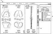
- FIG. 1Ais a representation of a display screen during a first step of guiding a user during surgical planning according to a first exemplary embodiment.
- FIG. 1Bis a representation of a display screen during a second step of guiding a user during surgical planning according to the first exemplary embodiment.
- FIG. 1Cis a representation of a display screen during a third step of guiding a user during surgical planning according to the first exemplary embodiment.
- FIG. 1Dis a representation of a display screen during a fourth step of guiding a user during surgical planning according to the first exemplary embodiment.
- FIG. 1Eis a representation of a display screen during a fifth step of guiding a user during surgical planning according to the first exemplary embodiment.
- FIG. 1Fis a representation of a display screen after completion of guiding a user during surgical planning according to the first exemplary embodiment.
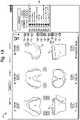
- FIG. 2Ais a representation of a display screen during a first step of guiding a user during surgical planning according to a second exemplary embodiment.
- FIG. 2Bis a representation of a display screen during a second step of guiding a user during surgical planning according to the second exemplary embodiment.
- FIG. 2Cis a representation of a display screen after completion of guiding a user during surgical planning according to the second exemplary embodiment.
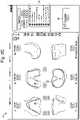
- FIG. 3Ais a representation of a display screen during a first step of guiding a user during surgical planning according to a third exemplary embodiment.
- FIG. 3Bis a representation of a display screen during a second step of guiding a user during surgical planning according to the third exemplary embodiment.
- FIG. 3Cis a representation of a display screen during a third step of guiding a user during surgical planning according to the third exemplary embodiment.
- FIG. 3Dis a representation of a display screen during a fourth step of guiding a user during surgical planning according to the third exemplary embodiment.
- FIG. 3Eis a representation of a display screen during a fifth step of guiding a user during surgical planning according to the third exemplary embodiment.
- FIG. 3Fis a representation of a display screen during a sixth step of guiding a user during surgical planning according to the third exemplary embodiment.
- FIG. 3Gis a representation of a display screen after completion of guiding a user during surgical planning according to the third exemplary embodiment.
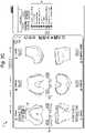
- FIG. 4Ais a representation of a display screen during a first step of guiding a user during surgical planning according to a fourth exemplary embodiment.
- FIG. 4Bis a representation of a display screen during a second step of guiding a user during surgical planning according to the fourth exemplary embodiment.
- FIG. 4Cis a representation of a display screen during a third step of guiding a user during surgical planning according to the fourth exemplary embodiment.
- FIG. 4Dis a representation of a display screen during a fourth step of guiding a user during surgical planning according to the fourth exemplary embodiment.
- FIG. 4Eis a representation of a display screen during a fifth step of guiding a user during surgical planning according to the fourth exemplary embodiment.
- FIG. 4Fis a representation of a display screen after completion of guiding a user during surgical planning according to the fourth exemplary embodiment.
- FIG. 5is a perspective view of an embodiment of a surgical system according to an exemplary embodiment.
- FIG. 6is a block diagram of a model surgical system according to an exemplary embodiment.
- FIGS. 1A-4Fprovide various representations of a user display during different exemplary embodiments described herein.
- input informationhas been received (e.g., by a surgical planning system) and an algorithm has been applied to the input information to develop an initial surgical plan.
- Input informationmay relate to the patient's bone structure or other physical characteristics.
- Imaging techniquessuch as CT, MRI, or ultrasound, may be used to obtain three-dimensional representations of the patient's anatomy, such as the representations of the femur and tibia shown in FIGS. 1A-4F .
- General surgical planning and navigationincluding haptic control and feedback, may be performed by a computerized surgical system such as that depicted in FIGS. 5 and 6 (and described below), and as described in U.S. Pat. No. 8,010,180 “Haptic Guidance System and Method” to Quaid et al., which is incorporated herein by reference in its entirety.
- FIGS. 1A-4Fprovide examples of guiding a user during surgical planning by providing a plurality of suggested actions to the user.
- the useris guided via a display screen, shown in various exemplary embodiments as graphical user interface (GUI) 2 , to perform the suggested actions.
- the suggested actionsmay correspond to steps of an algorithm used by a planning system to develop an initial surgical plan. Guiding a user in this manner allows the user to 1) learn how the initial surgical plan was developed by the planning system, and 2) customize the initial surgical plan during the user-guidance process. If the user performs the suggested actions, the suggested actions will lead the user to the initial surgical plan. However, the user has the option to deviate from one or more of the suggested actions by performing non-suggested actions. Deviation from one or more of the suggested actions leads to development of a final surgical plan that is different from the initial surgical plan.
- the GUI 2 illustrated in FIGS. 1A-4Fmay display a series of icons in sequence, each of the icons having a distinguishing characteristic intended to alert the user to select the icons. If the user selects the icons having a distinguishing characteristic, the selections will lead the user to the initial surgical plan. However, the user can customize the initial surgical plan by selecting a displayed icon without a distinguishing characteristic.
- GUI 2provides virtual representations of a femoral component 4 and a tibial component 6 on virtual models of a patient's femur and tibia, respectively. References herein to femoral component 4 and tibial component 6 are understood to be references to the virtual representations of these components as shown on a GUI 2 .
- the GUI 2also displays criteria in the form of a list 8 .
- the criteriaare related to the surgical plan shown on the current display of GUI 2 .
- Each of the criteriais associated with one or more acceptable values. Acceptable values for any particular criterion may be values below a maximum threshold, above a minimum threshold, or within a predefined range.
- Some examples of displayed criteriainclude femoral notching and sizing, femoral rotation, femoral overhang, tibial overhang and sizing, tibial rotation, tibial slope, limb alignment and joint line, extension and flexion gaps, and mid-flexion gap and stability. These criteria relate to surgical planning of a total knee arthroplasty (the example used in the exemplary embodiments of FIGS. 1A-4F ). However, the criteria may be chosen to be applicable to any planned surgical procedure.
- Each of the criteria in list 8includes a corresponding indicator 10 configured to provide the user with information related to the particular criterion.
- the information provided by indicator 10may relate to whether the corresponding criterion has an acceptable value.
- the indicators 10may be circular images configured to provide information via a display feature.
- Each indicator 10may be configured to change its display feature to convey information.
- the corresponding indicatorindicates acceptability by displaying a first display feature, such as a checkmark.
- a first display featuresuch as a checkmark.
- femoral overhang and several other criteriahave acceptable values and are therefore marked with an indicator 10 a having a first display feature (e.g., a checkmark).
- the corresponding indicatorwill display a second display feature, such as being filled in.
- the femoral notching and sizing criterion and the extension and flexion gaps criteriondo not have acceptable values. These criteria are therefore marked with a indicator 10 b having a second display feature (e.g., a filled interior). Criteria that are within a predefined range of an acceptable value may be marked with an indicator having a third display feature, such as a shaded interior.
- the tibial slope criteriais within a predefined range of an acceptable value, so the indicator 10 c associated with tibial slope has a shaded interior.
- the indicators 10 a , 10 b , and 10 ccan provide information related to the current values of the criteria in list 8 by displaying different features. Any type of display features may be utilized to convey information to a user.
- the indicators 10provide information related to changes in the values of the criteria in list 8 by changing color in connection with changes to the criteria values.
- the first, second, and third display featurescan be different colors.
- the indicators 10may change color when the user performs suggested or non-suggested actions that change one or more of the criteria.
- a change of a criterion valuemay be, for example, a change from an unacceptable value to a value within a certain range of an acceptable value.
- the corresponding indicatorindicates this change by changing from an indicator 10 b having a second color (e.g., red) to an indicator 10 c having a third color (e.g., yellow).
- a change in criterion valuemay be a change from a value within a certain range of an acceptable value to an acceptable value.
- the corresponding indicatorindicates this change by changing from an indicator 10 c having a third color (e.g., yellow) to an indicator 10 a a having a first color (e.g., green).
- GUI 2further includes a plurality of icons 12 a - 12 j .
- a usermay select (e.g., touch, mouse click, etc.) the icons to cause additional information to be displayed.
- Various types of information that may be displayed to a userinclude or relate to: 3D flex pose capture (icon 12 a ), limb alignment (icon 12 b ), gap graphs (icons 12 c and 12 h ), virtual models of implants (icon 12 d ), planned bone resections (icon 12 e ), CT scan overlay (icon 12 f ), alignment axes (icon 12 g ), trace points (icon 12 i ) and over/under hang (icon 12 j ).
- FIGS. 1A-1Fillustrate a first exemplary embodiment for guiding a user during surgical planning.
- the useris guided through steps relating to planning the placement of femoral and tibial components for a total knee arthroplasty.
- a GUI 2 during a first step of guiding a useris shown.
- the GUI 2provides a first suggested action to a user by displaying an icon having a distinguishing characteristic.
- the distinguishing characteristicis configured to alert the user to select the icon.
- icon 12 his marked with two distinguishing characteristics—an outline and a guiding arrow 14 .
- the outlinemay be shown in a specific color (e.g., pink), and the guiding arrow 14 may be shown in the same or different color.
- the distinguishing characteristic of icon 12 hguides the user to select the icon 12 h . Selecting the icon 12 h causes additional information related to gaps between femoral component 4 and tibial component 6 to be displayed in the form of bar graphs 16 , as shown in FIG. 1B .
- FIG. 1Billustrates GUI 2 during a second step of guiding a user during surgical planning.
- an expansion box 18includes a distinguishing characteristic (e.g., an outline in a specific color) to guide the user to select the expansion box 18 . Selecting the expansion box 18 causes placement arrows 19 to appear, as shown in FIG. 1C .
- the GUI 2next guides the user by suggesting how to adjust the placements of the femoral component 4 and tibial component 6 to achieve acceptable criteria values.
- the suggested action of FIG. 1Cis selecting an icon to cause a change in placement of a virtual implant (in this step, the femoral component 4 ).
- the marked arrow 20 shown in FIG. 1Cincludes a distinguishing characteristic (e.g., an outline in a specific color) to guide the user to select the marked arrow 20 .
- a distinguishing characteristice.g., an outline in a specific color
- the shift of femoral component 4caused the femoral notching and sizing criterion to have an acceptable value.
- the femoral notching and sizing criterion in FIG. 1Dis marked with an indicator 10 a having a checkmark (in contrast, a filled-in indicator 10 b corresponded to femoral notching and sizing in FIG. 1C ). Colors may also be used in the relevant indicators to provide this information. The user can therefore see a direct cause and effect between shifting the placement of femoral component 4 and the femoral notching and sizing criterion having an acceptable value.
- expansion box 18includes a distinguishing characteristic (e.g., an outline in a specific color) to guide the user to select expansion box 18 .
- Selecting expansion box 18causes placement arrows 19 to appear as shown in FIG. 1E , allowing the user to adjust the placement of a virtual implant (in this step, tibial component 6 ).
- the useris guided to adjust the posterior slope of the tibial component 6 by selecting marked arrow 24 , which includes a distinguishing characteristic.
- Selecting marked arrow 24adjusts the tibial component 6 to the placement shown in FIG. 1F .
- the change in placement or orientationmay be accomplished incrementally via several selections of arrow 24 . As shown in FIG.
- this adjustment to the posterior slope(e.g., from 2.0° to 7.0°) caused both the tibial slope criterion and extension and flexion gaps criterion to have acceptable values, as shown by their associated checked indicators 10 a .
- the GUI 2indicates that the planning of femoral and tibial component placement is complete by displaying a completion icon 26 .
- the actions suggested to the userare presented in a predetermined manner. If the user performs each suggested action of FIGS. 1A-1F (e.g., selects each of the plurality of icons having a distinguishing characteristic), the actions will lead the user to the initial surgical plan developed by applying an algorithm to input information. Thus, via GUI 2 , the user is guided through steps that, if followed, would lead the user to the initially developed surgical plan. This guidance illustrates to the user how the algorithm was applied to arrive at the initial surgical plan. The user guidance therefore provides transparency into how the initial surgical plan was developed.
- the userhas the option to deviate from one or more of the suggested actions by performing non-suggested actions, such as selecting a displayed icon without a distinguishing characteristic. Deviation from one or more of the plurality of suggested actions may lead to the development of a final surgical plan that is different from the initial surgical plan.
- the usercan customize the initial surgical plan to create a final surgical plan.
- the final surgical plancan differ from the initial surgical plan in one or more ways, such as in placement of a virtual implant, type of virtual implant, or size of virtual implant. For example, in the step shown by the GUI 2 in FIG. 1C , one way the user can customize the initial surgical plan is by selecting the arrows surrounding marked arrow 20 , which do not have distinguishing characteristics.
- Selecting an arrow other than marked arrow 20would customize the surgical plan by causing the femoral component 4 to shift to a different placement than the placement shown in FIG. 1D (which resulted from selecting marked arrow 20 ).
- the user guidancetherefore allows the user to customize the initial plan in a straightforward and intuitive manner.
- FIGS. 2A-2Cillustrate a second exemplary embodiment for guiding a user during surgical planning.
- FIG. 2Ashows GUI 2 during a first step of guiding the user and illustrates a suggested action of selecting an icon to cause a change in size of a virtual implant.
- the suggested actioncan be selecting an icon to cause a change in type of a virtual implant, such as femoral component 4 or tibial component 6 .
- the useris guided in FIG. 2A to select box 28 , which has distinguishing characteristics of an outline and a guiding arrow 14 . Selecting box 28 decreases the size of the femoral component 4 .
- FIG. 2Bthe femur size has been decreased from 6w ( FIG.
- FIG. 2Cshows how changing the size of femoral component 4 caused femoral overhang (a criterion shown in list 8 that had an unacceptable value in FIG. 2A ) to have an acceptable value (as shown by the indicator 10 a corresponding to femoral overhang in FIGS. 2B and 2C ).
- the outline 30 associated with femoral component 4 in FIG. 2Cshows the user that femoral component 4 is within the outline 30 in the medial and lateral directions. The user can use the outline 30 to evaluate whether he or she agrees with the suggested implant size.
- FIG. 2Calso includes a completion icon 26 to demonstrate the completion of user guidance.
- the user's actionse.g., selecting box 28 to decrease the size of femoral component 4
- the userhas the option during each step of the process to adjust the initial surgical plan.
- the usercould alternatively decide to shift the femoral component 4 in different directions to eliminate femoral overhang instead of making the femoral component 4 smaller.
- the usercould decide that the amount of femoral overhang shown in the step of FIG. 2A is acceptable and decide not to adjust the placement or size of femoral component 4 .
- FIGS. 3A-3Gillustrate a third exemplary embodiment for guiding a user during surgical planning.
- an indicator 10 b having a second display featurecorresponds to the extension and flexion gaps criterion, indicating that this criterion does not have an acceptable value.
- the indicatormay change color to indicate whether the associated criterion is acceptable or use other ways of indicating the same to the user.
- the exemplary embodiment of FIGS. 3A-3Gleads the user through steps to adjust the femoral component 4 and tibial component 6 in a manner that will bring the extension and flexion gaps criterion to an acceptable value.
- expansion box 18includes distinguishing characteristics of both an outline and a guiding arrow 14 to guide the user to select (e.g., touch, click on, etc.) expansion box 18 .
- placement arrows 19appear (as shown in FIG. 3B ) that will allow the user to adjust the placement of femoral component 4 .
- the marked arrow 34includes a distinguishing characteristic to guide the user to select the marked arrow 34 .
- the placement of femoral component 4shifts upward to the placement shown in FIG. 3C .
- the extension and flexion gaps criterionnow has an acceptable value (see FIG. 3C ).
- the limb alignment and joint line criterionnow has an indicator 10 c having a third display feature, communicating to the user that the limb alignment and joint line criterion no longer has an acceptable value, but is within predetermined ranges of an acceptable value. The user will next be guided to make adjustments that will bring the limb alignment and joint line criterion to an acceptable value.
- the useris guided to select marked arrow 36 , which shifts the femoral component 4 downward.
- the bar graphs 16indicate a corresponding change in the gaps between femoral component 4 and tibial component 6 .
- the limb alignment and joint line criterionis now at an acceptable value, as shown by the corresponding indicator 10 a , but the extension and flexion gaps criterion is no longer at an acceptable value, as shown by the corresponding indicator 10 b . Therefore, the planning system will guide the user to make adjustments that will bring the extension and flexion gaps criterion to an acceptable value. Accordingly, the user is guided in FIG. 3D to select marked arrow 38 .
- Selecting marked arrow 38causes the tibial component 6 to move downward to the position shown in FIG. 3E .
- the indicator corresponding to the extension and flexion gaps criterionchanges from an indicator 10 b having a second display feature to an indicator 10 a having a third display feature to indicate to the user that the previous action (adjusting the tibial component 6 ) has brought the extension and flexion gaps criterion closer to an acceptable value.
- FIG. 3Eguides the user to select expansion box 18 , which causes additional placement arrows 19 to appear, as shown in FIG. 3F .
- FIG. 3Fthe user is guided to select marked arrow 40 , which rotates the femoral component 4 to the placement shown in FIG. 3G .
- This adjustment of femoral component 4causes the extension and flexion gaps criterion to have an acceptable value, as indicated by the checked indicator 10 a corresponding to the extension and flexion gaps criterion.
- FIG. 3Gincludes a completion icon 26 .
- FIGS. 4A-4Fillustrate a fourth exemplary embodiment for guiding a user during surgical planning.
- list 8indicates that the extension and flexion gaps criterion and the mid flexion gap and stability criterion do not have acceptable values. Therefore, the embodiment of FIGS. 4A-4F will guide the user to adjust the femoral component 4 and tibial component 6 in a manner that will bring the criteria in list 8 to acceptable (or close to acceptable) values.
- icon 12 bhas been selected to display information related to limb alignment in the form of a diagram 44 .
- the useris guided in FIG. 4A to select expansion box 18 , which includes the distinguishing features of an outline and a guiding arrow 14 .
- Selecting expansion box 18causes placement arrows 19 to appear, as shown in FIG. 4B .
- FIG. 4Bthe user is guided to select marked arrow 42 .
- Selecting marked arrow 42rotates femoral component 4 from the placement shown in FIG. 4B to the placement shown in FIG. 4C .
- Diagram 44also illustrates the change in limb alignment between FIG. 4B and FIG. 4C .
- the extension and flexion gaps criterion and the mid flexion gap and stability criterionare marked with indicators 10 c having a third display feature, communicating to the user that these criteria are moving closer to acceptable values. The planning system will then guide the user to make adjustments to bring all criteria to acceptable values.
- the planning systemguides the user to select marked arrow 46 .
- Selecting marked arrow 46rotates tibial component 6 from the placement shown in FIG. 4C to the placement shown in FIG. 4D (e.g., incrementally depending upon the number of times marked arrow 46 is selected).
- the measurements related to gaps between femoral component 4 and tibial component 6are altered, as shown by the bar graphs 16 , and the tibial varus angle has been altered (e.g., from 0.0° to 1.0°).
- Diagram 44illustrates the further change in limb alignment. In FIG.
- the extension and flexion gaps criterion and the mid flexion gap and stability criterioncontinue to be marked with indicators 10 c , showing that the criteria are close, but are not yet at acceptable values. Furthermore, the limb alignment and joint line criterion is now also marked with an indicator 10 c having a third display feature. Therefore, in FIG. 4D , the user is guided to select expansion arrow 18 in order to allow the user to again adjust the placement of femoral component 4 . Selecting expansion box 18 causes additional placement arrows 19 to appear as shown in FIG. 4E .
- the useris guided to select marked arrow 48 , which rotates the femoral component 4 from the placement shown in FIG. 4E to the placement shown in FIG. 4F .
- the extension and flexion gaps criterion and the mid flexion gap and stability criterionare at acceptable values, as shown by the corresponding indicators 10 a having a first display feature (e.g., being checked).
- the limb alignment and joint line criterioncontinues to have a corresponding indicator 10 c having the third display feature showing that the criterion is close, but not yet at the desired value. Nonetheless, the planning system has arrived at the initial surgical plan created based on the input information, and FIG. 4F therefore displays a completion icon 26 .
- a surgical planis created based on input information. The user is then provided with the surgical plan without having insight into the algorithm used by the planning system to develop the surgical plan.
- a planning systemcreates an initial surgical plan based on certain input information.
- the methods described hereinguide the user through a series of steps, via GUI 2 , to lead the user to the initial surgical plan.
- the algorithm used by the planning systemtherefore becomes transparent to the user, and the user can easily see how the planning system arrived at the initial surgical plan.
- This transparencyprovides users with the opportunity to customize the initial surgical plan in a straightforward manner.
- a usermight desire to customize the surgical plan for a variety of reasons.
- the usermay have additional knowledge related to the specific patient (e.g., the patient's lifestyle or other factors that may affect the outcome of the surgical procedure), which may cause the user to want to modify the surgical plan in a particular way.
- the usermay have years of experience performing similar surgical procedures, and may wish to modify the plan in a manner that he or she knows will lead to a more successful outcome.
- the methods described hereinallow a user to more readily determine how to implement customizations by providing the user with awareness of the series of steps taken by the planning system, as well as providing the user with an opportunity to modify the surgical plan at each step.
- Another advantage of the methods described herein relative to other planning systemsis an improved user “buy in.”
- a useris simply provided with a solution (e.g., a surgical plan) and is not aware of how the system arrived at the solution.
- a solutione.g., a surgical plan
- the useris able to understand the algorithm relied on by the planning system. For example, when a user is guided according to the embodiment of FIGS. 2A-2C , the user will understand that the initial surgical plan includes a femoral component 4 with a size of “6N” in order to obtain an acceptable value for femoral overhang.
- the initial surgical planincludes a femoral component 4 with a size of “6N” in order to obtain an acceptable value for femoral overhang.
- the userwill understand that the femoral component 4 and tibial component 6 are placed to ensure acceptable values for the extension and flexion gaps criterion (as well as the other criteria in list 8 ). Because the user is provided with more knowledge regarding the algorithm applied by the surgical planning system, the user may be more comfortable relying on and implementing the surgical plan provided by the planning system.
- Another advantage of the planning systems and methods described hereinis the ability to improve the algorithm applied to input information over time by analysis of user input.
- User inputmay include, for example, any user actions, such as input of information or modifications or customizations to a surgical plan, taken in connection with surgical planning as described herein.
- the planning systemscan store data related to this user input, which can later be accessed to improve the planning system's algorithm. For example, in the exemplary embodiment of FIGS. 1A-1F , a certain placement of femoral component 4 is suggested by the planning system to achieve the initial surgical plan illustrated in FIG. 1F .
- the algorithmmight be altered to arrive automatically at the modified femoral placement when creating initial surgical plans in the future. In this manner, data obtained by evaluating user customizations can be applied to improve the planning system's algorithm.
- FIG. 5shows an embodiment of an exemplary surgical system 50 in which and for which the techniques described above can be implemented.
- the surgical system 50includes a computing system 52 , a haptic device 54 , and a tracking system 56 .
- the surgical system 50enables comprehensive, intraoperative surgical planning.
- the surgical system 50may also provide haptic guidance to a user (e.g., a surgeon) and/or limits the user's manipulation of the haptic device 54 as the user performs a surgical procedure.
- the computing system 52may include hardware and software for operation and control of the surgical system 50 .
- Such hardware and/or softwareis configured to enable the system 50 to perform the techniques described herein.
- the computing system 52includes a surgical controller 62 , a display device 64 , and an input device 66 .
- the surgical controller 62may be any known computing system but is preferably a programmable, processor-based system.
- the surgical controller 62may include a microprocessor, a hard drive, random access memory (RAM), read only memory (ROM), input/output (I/O) circuitry, and any other known computer component.
- the surgical controller 62is preferably adapted for use with various types of storage devices (persistent and removable), such as, for example, a portable drive, magnetic storage, solid state storage (e.g., a flash memory card), optical storage, and/or network/Internet storage.
- the surgical controller 62may comprise one or more computers, including, for example, a personal computer or a workstation operating under a suitable operating system and preferably includes a graphical user interface (GUI).
- GUIgraphical user interface
- the surgical controller 62includes a processing circuit 70 having a processor 72 and memory 74 .
- Processor 72can be implemented as a general purpose processor executing one or more computer programs to perform actions by operating on input data and generating output.
- the processes and logic flowscan also be performed by, and apparatus can also be implemented as, special purpose logic circuitry, e.g., an FPGA (field programmable gate array) or an ASIC (application specific integrated circuit), a group of processing components, or other suitable electronic processing components.
- a processorwill receive instructions and data from a read only memory or a random access memory or both.
- Memory 74(e.g., memory, memory unit, storage device, etc.) comprises one or more devices (e.g., RAM, ROM, Flash-memory, hard disk storage, etc.) for storing data and/or computer code for completing or facilitating the various processes described in the present application.
- Memory 74may be or include volatile memory or non-volatile memory.
- Memory 74may include database components, object code components, script components, or any other type of information structure for supporting the various activities described in the present application.
- memory 74is communicably connected to processor 72 and includes computer code for executing one or more processes described herein.
- the memory 74may contain a variety of modules, each capable of storing data and/or computer code related to specific types of functions. In one embodiment, memory 74 contains several modules related to surgical procedures, such as a planning module 740 , a navigation module 742 , a registration module 744 , and a robotic control module 746 .
- the program instructionscan be encoded on an artificially generated propagated signal, e.g., a machine-generated electrical, optical, or electromagnetic signal, that is generated to encode information for transmission to suitable receiver apparatus for execution by a data processing apparatus.
- a computer storage mediumcan be, or be included in, a computer-readable storage device, a computer-readable storage substrate, a random or serial access memory array or device, or a combination of one or more of them.
- a computer storage mediumis not a propagated signal
- a computer storage mediumcan be a source or destination of computer program instructions encoded in an artificially generated propagated signal.
- the computer storage mediumcan also be, or be included in, one or more separate components or media (e.g., multiple CDs, disks, or other storage devices). Accordingly, the computer storage medium may be tangible and non-transitory.
- a computer program(also known as a program, software, software application, script, or code) can be written in any form of programming language, including compiled or interpreted languages, declarative or procedural languages, and it can be deployed in any form, including as a stand-alone program or as a module, component, subroutine, object, or other unit suitable for use in a computing environment.
- a computer programmay, but need not, correspond to a file in a file system.
- a programcan be stored in a portion of a file that holds other programs or data (e.g., one or more scripts stored in a markup language document), in a single file dedicated to the program in question, or in multiple coordinated files (e.g., files that store one or more modules, sub programs, or portions of code).
- a computer programcan be deployed to be executed on one computer or on multiple computers that are located at one site or distributed across multiple sites and interconnected by a communication network.
- a computerwill also include, or be operatively coupled to receive data from or transfer data to, or both, one or more mass storage devices for storing data, e.g., magnetic, magneto optical disks, or optical disks.
- mass storage devicesfor storing data, e.g., magnetic, magneto optical disks, or optical disks.
- a computerneed not have such devices.
- a computercan be embedded in another device, e.g., a mobile telephone, a personal digital assistant (PDA), a mobile audio or video player, a game console, a Global Positioning System (GPS) receiver, or a portable storage device (e.g., a universal serial bus (USB) flash drive), to name just a few.
- PDApersonal digital assistant
- GPSGlobal Positioning System
- USBuniversal serial bus
- Devices suitable for storing computer program instructions and datainclude all forms of non-volatile memory, media and memory devices, including by way of example semiconductor memory devices, e.g., EPROM, EEPROM, and flash memory devices; magnetic disks, e.g., internal hard disks or removable disks; magneto optical disks; and CD ROM and DVD-ROM disks.
- semiconductor memory devicese.g., EPROM, EEPROM, and flash memory devices
- magnetic diskse.g., internal hard disks or removable disks
- magneto optical diskse.g., CD ROM and DVD-ROM disks.
- the processor and the memorycan be supplemented by, or incorporated in, special purpose logic circuitry.
- Embodiments of the subject matter described in this specificationcan be implemented in a computing system that includes a back end component, e.g., as a data server, or that includes a middleware component, e.g., an application server, or that includes a front end component, e.g., a client computer having a graphical user interface or a Web browser through which a user can interact with an embodiment of the subject matter described in this specification, or any combination of one or more such back end, middleware, or front end components.
- the components of the systemcan be interconnected by any form or medium of digital data communication, e.g., a communication network.
- Examples of communication networksinclude a local area network (“LAN”) and a wide area network (“WAN”), an inter-network (e.g., the Internet), and peer-to-peer networks (e.g., ad hoc peer-to-peer networks).
- LANlocal area network
- WANwide area network
- inter-networke.g., the Internet
- peer-to-peer networkse.g., ad hoc peer-to-peer networks.
- the surgical controller 62further includes a communication interface 76 .
- the communication interface 76 of the computing system 52is coupled to a computing device (not shown) of the haptic device 54 via an interface and to the tracking system 56 via an interface.
- the interfacescan include a physical interface and a software interface.
- the physical interface of the communication interface 76can be or include wired or wireless interfaces (e.g., jacks, antennas, transmitters, receivers, transceivers, wire terminals, etc.) for conducting data communications with external sources via a direct connection or a network connection (e.g., an Internet connection, a LAN, WAN, or WLAN connection, etc.).
- the software interfacemay be resident on the surgical controller 62 , the computing device (not shown) of the haptic device 54 , and/or the tracking system 56 .
- the surgical controller 62 and the computing device (not shown)are the same computing device.
- the softwaremay also operate on a remote server, housed in the same building as the surgical system 50 , or at an external server site.
- Computer system 52also includes display device 64 .
- the display device 64is a visual interface between the computing system 52 and the user. GUI 2 described according to the exemplary embodiments of FIGS. 1A-4F may be displayed on display device 64 .
- the display device 64is connected to the surgical controller 62 and may be any device suitable for displaying text, images, graphics, and/or other visual output.
- the display device 64may include a standard display screen (e.g., LCD, CRT, OLED, TFT, plasma, etc.), a touch screen, a wearable display (e.g., eyewear such as glasses or goggles), a projection display, a head-mounted display, a holographic display, and/or any other visual output device.
- the display device 64may be disposed on or near the surgical controller 62 (e.g., on the cart as shown in FIG. 5 ) or may be remote from the surgical controller 62 (e.g., mounted on a stand with the tracking system 56 ).
- the display device 64is preferably adjustable so that the user can position/reposition the display device 64 as needed during a surgical procedure.
- the display device 64may be disposed on an adjustable arm (not shown) or to any other location well-suited for ease of viewing by the user. As shown in FIG. 5 there may be more than one display device 64 in the surgical system 50 .
- the display device 64may be used to display any information useful for a medical procedure, such as, for example, images of anatomy generated from an image data set obtained using conventional imaging techniques, graphical models (e.g., CAD models of implants, instruments, anatomy, etc.), graphical representations of a tracked object (e.g., anatomy, tools, implants, etc.), constraint data (e.g., axes, articular surfaces, etc.), representations of implant components, digital or video images, registration information, calibration information, patient data, user data, measurement data, software menus, selection buttons, status information, and the like.
- graphical modelse.g., CAD models of implants, instruments, anatomy, etc.
- graphical representations of a tracked objecte.g., anatomy, tools, implants, etc.
- constraint datae.g., axes, articular surfaces, etc.
- the computing system 52may include an acoustic device (not shown) for providing audible feedback to the user.
- the acoustic deviceis connected to the surgical controller 62 and may be any known device for producing sound.
- the acoustic devicemay comprise speakers and a sound card, a motherboard with integrated audio support, and/or an external sound controller.
- the acoustic devicemay be adapted to convey information to the user.
- the surgical controller 62may be programmed to signal the acoustic device to produce a sound, such as a voice synthesized verbal indication “DONE,” to indicate that a step of a surgical procedure is complete.
- the acoustic devicemay be used to alert the user to a sensitive condition, such as producing a tone to indicate that a surgical cutting tool is nearing a critical portion of soft tissue.
- the input device 66is connected to the surgical controller 62 and may include any device enabling a user to provide input to a computer.
- the input device 66can be a known input device, such as a keyboard, a mouse, a trackball, a touch screen, a touch pad, voice recognition hardware, dials, switches, buttons, a trackable probe, a foot pedal, a remote control device, a scanner, a camera, a microphone, and/or a joystick.
- input device 66can allow the user to make the selections as described above to adjust the surgical plan.
- a computercan interact with a user by sending documents to and receiving documents from a device that is used by the user; for example, by sending web pages to a web browser on a user's client device in response to requests received from the web browser.
- the system 50also includes a tracking (or localizing) system 56 that is configured to determine a pose (i.e., position and orientation) of one or more objects during a surgical procedure to detect movement of the object(s).
- the tracking system 56may include a detection device that obtains a pose of an object with respect to a coordinate frame of reference of the detection device. As the object moves in the coordinate frame of reference, the detection device tracks the pose of the object to detect (or enable the surgical system 50 to determine) movement of the object.
- the computing system 52can capture data in response to movement of the tracked object or objects.
- Tracked objectsmay include, for example, tools/instruments, patient anatomy, implants/prosthetic devices, and components of the surgical system 50 .
- the surgical system 50is also able to register (or map or associate) coordinates in one space to those in another to achieve spatial alignment or correspondence (e.g., using a coordinate transformation process as is well known). Objects in physical space may be registered to any suitable coordinate system, such as a coordinate system being used by a process running on the surgical controller 62 and/or the computer device of the haptic device 54 .
- the surgical system 50is able to associate the physical anatomy, such as the patient's spine, with a representation of the anatomy (such as an image displayed on the display device 64 ). Based on tracked object and registration data, the surgical system 50 may determine, for example, a spatial relationship between the image of the anatomy and the relevant anatomy.
- Registrationmay include any known registration technique, such as, for example, image-to-image registration (e.g., monomodal registration where images of the same type or modality, such as fluoroscopic images or MR images, are registered and/or multimodal registration where images of different types or modalities, such as MRI and CT, are registered); image-to-physical space registration (e.g., image-to-patient registration where a digital data set of a patient's anatomy obtained by conventional imaging techniques is registered with the patient's actual anatomy); and/or combined image-to-image and image-to-physical-space registration (e.g., registration of preoperative CT and MM images to an intraoperative scene).
- image-to-image registratione.g., monomodal registration where images of the same type or modality, such as fluoroscopic images or MR images, are registered and/or multimodal registration where images of different types or modalities, such as MRI and CT, are registered
- image-to-physical space registratione.g., image-to-patient registration where a digital
- the computing system 52may also include a coordinate transform process for mapping (or transforming) coordinates in one space to those in another to achieve spatial alignment or correspondence.
- the surgical system 50may use the coordinate transform process to map positions of tracked objects (e.g., patient anatomy, etc.) into a coordinate system used by a process running on the computer of the haptic device and/or the surgical controller 62 .
- the coordinate transform processmay include any suitable transformation technique, such as, for example, rigid-body transformation, non-rigid transformation, affine transformation, and the like.
- the tracking system 56may be any tracking system that enables the surgical system 50 to continually determine (or track) a pose of the relevant anatomy of the patient.
- the tracking system 56may include a non-mechanical tracking system, a mechanical tracking system, or any combination of non-mechanical and mechanical tracking systems suitable for use in a surgical environment.
- the non-mechanical tracking systemmay include an optical (or visual), magnetic, radio, or acoustic tracking system.
- Such systemstypically include a detection device adapted to locate in predefined coordinate space specially recognizable trackable elements (or trackers) that are detectable by the detection device and that are either configured to be attached to the object to be tracked or are an inherent part of the object to be tracked.
- a trackable elementmay include an array of markers having a unique geometric arrangement and a known geometric relationship to the tracked object when the trackable element is attached to the tracked object.
- the known geometric relationshipmay be, for example, a predefined geometric relationship between the trackable element and an endpoint and axis of the tracked object.
- the detection devicecan recognize a particular tracked object, at least in part, from the geometry of the markers (if unique), an orientation of the axis, and a location of the endpoint within a frame of reference deduced from positions of the markers.
- the markersmay include any known marker, such as, for example, extrinsic markers (or fiducials) and/or intrinsic features of the tracked object.
- Extrinsic markersare artificial objects that are attached to the patient (e.g., markers affixed to skin, markers implanted in bone, stereotactic frames, etc.) and are designed to be visible to and accurately detectable by the detection device.
- Intrinsic featuresare salient and accurately locatable portions of the tracked object that are sufficiently defined and identifiable to function as recognizable markers (e.g., landmarks, outlines of anatomical structure, shapes, colors, or any other sufficiently recognizable visual indicator).
- the markersmay be located using any suitable detection method, such as, for example, optical, electromagnetic, radio, or acoustic methods as are well known.
- an optical tracking system having a stationary stereo camera pair sensitive to infrared radiationmay be used to track markers that emit infrared radiation either actively (such as a light emitting diode or LED) or passively (such as a spherical marker with a surface that reflects infrared radiation).
- a magnetic tracking systemmay include a stationary field generator that emits a spatially varying magnetic field sensed by small coils integrated into the tracked object.
- the haptic device 54may be the Tactile Guidance SystemTM (TGSTM) manufactured by MAKO Surgical Corp., and used to prepare the surface of the patient's bone for insertion of the spinal plate 10 .
- the haptic device 54provides haptic (or tactile) guidance to guide the surgeon during a surgical procedure.
- the haptic deviceis an interactive surgical robotic arm that holds a surgical tool (e.g., a surgical burr) and is manipulated by the surgeon to perform a procedure on the patient, such as cutting a surface of a bone in preparation for spinal plate installation. As the surgeon manipulates the robotic arm to move the tool and sculpt the bone, the haptic device 54 guides the surgeon by providing force feedback that constrains the tool from penetrating a virtual boundary.
Landscapes
- Health & Medical Sciences (AREA)
- Engineering & Computer Science (AREA)
- Surgery (AREA)
- Life Sciences & Earth Sciences (AREA)
- Animal Behavior & Ethology (AREA)
- General Health & Medical Sciences (AREA)
- Biomedical Technology (AREA)
- Heart & Thoracic Surgery (AREA)
- Medical Informatics (AREA)
- Molecular Biology (AREA)
- Nuclear Medicine, Radiotherapy & Molecular Imaging (AREA)
- Robotics (AREA)
- Public Health (AREA)
- Veterinary Medicine (AREA)
- Human Computer Interaction (AREA)
- Prostheses (AREA)
- General Engineering & Computer Science (AREA)
- Theoretical Computer Science (AREA)
- Physics & Mathematics (AREA)
- General Physics & Mathematics (AREA)
Abstract
Description
Claims (20)
Priority Applications (3)
| Application Number | Priority Date | Filing Date | Title |
|---|---|---|---|
| US15/894,461US11331146B2 (en) | 2012-12-31 | 2018-02-12 | Systems and methods for guiding a user during surgical planning |
| US17/718,749US12408985B2 (en) | 2012-12-31 | 2022-04-12 | Surgical planning guidance and learning |
| US29/834,489USD1029861S1 (en) | 2012-12-31 | 2022-04-12 | Display screen or portion thereof with graphical user interface |
Applications Claiming Priority (3)
| Application Number | Priority Date | Filing Date | Title |
|---|---|---|---|
| US201261747765P | 2012-12-31 | 2012-12-31 | |
| US14/145,619US9888967B2 (en) | 2012-12-31 | 2013-12-31 | Systems and methods for guiding a user during surgical planning |
| US15/894,461US11331146B2 (en) | 2012-12-31 | 2018-02-12 | Systems and methods for guiding a user during surgical planning |
Related Parent Applications (1)
| Application Number | Title | Priority Date | Filing Date |
|---|---|---|---|
| US14/145,619ContinuationUS9888967B2 (en) | 2012-12-31 | 2013-12-31 | Systems and methods for guiding a user during surgical planning |
Related Child Applications (2)
| Application Number | Title | Priority Date | Filing Date |
|---|---|---|---|
| US17/718,749ContinuationUS12408985B2 (en) | 2012-12-31 | 2022-04-12 | Surgical planning guidance and learning |
| US29/834,489ContinuationUSD1029861S1 (en) | 2012-12-31 | 2022-04-12 | Display screen or portion thereof with graphical user interface |
Publications (2)
| Publication Number | Publication Date |
|---|---|
| US20180161105A1 US20180161105A1 (en) | 2018-06-14 |
| US11331146B2true US11331146B2 (en) | 2022-05-17 |
Family
ID=51018806
Family Applications (4)
| Application Number | Title | Priority Date | Filing Date |
|---|---|---|---|
| US14/145,619Active2035-02-07US9888967B2 (en) | 2012-12-31 | 2013-12-31 | Systems and methods for guiding a user during surgical planning |
| US15/894,461Active2034-07-23US11331146B2 (en) | 2012-12-31 | 2018-02-12 | Systems and methods for guiding a user during surgical planning |
| US17/718,749Active2035-01-07US12408985B2 (en) | 2012-12-31 | 2022-04-12 | Surgical planning guidance and learning |
| US29/834,489ActiveUSD1029861S1 (en) | 2012-12-31 | 2022-04-12 | Display screen or portion thereof with graphical user interface |
Family Applications Before (1)
| Application Number | Title | Priority Date | Filing Date |
|---|---|---|---|
| US14/145,619Active2035-02-07US9888967B2 (en) | 2012-12-31 | 2013-12-31 | Systems and methods for guiding a user during surgical planning |
Family Applications After (2)
| Application Number | Title | Priority Date | Filing Date |
|---|---|---|---|
| US17/718,749Active2035-01-07US12408985B2 (en) | 2012-12-31 | 2022-04-12 | Surgical planning guidance and learning |
| US29/834,489ActiveUSD1029861S1 (en) | 2012-12-31 | 2022-04-12 | Display screen or portion thereof with graphical user interface |
Country Status (1)
| Country | Link |
|---|---|
| US (4) | US9888967B2 (en) |
Families Citing this family (41)
| Publication number | Priority date | Publication date | Assignee | Title |
|---|---|---|---|---|
| US8617171B2 (en) | 2007-12-18 | 2013-12-31 | Otismed Corporation | Preoperatively planning an arthroplasty procedure and generating a corresponding patient specific arthroplasty resection guide |
| US9402637B2 (en) | 2012-10-11 | 2016-08-02 | Howmedica Osteonics Corporation | Customized arthroplasty cutting guides and surgical methods using the same |
| US9888967B2 (en) | 2012-12-31 | 2018-02-13 | Mako Surgical Corp. | Systems and methods for guiding a user during surgical planning |
| US9204937B2 (en) | 2013-02-19 | 2015-12-08 | Stryker Trauma Gmbh | Software for use with deformity correction |
| US10452238B2 (en) | 2013-03-15 | 2019-10-22 | Blue Belt Technologies, Inc. | Systems and methods for determining a position for placing of a joint prosthesis |
| US20140276872A1 (en) | 2013-03-15 | 2014-09-18 | Otismed Corporation | Customized acetabular cup positioning guide and system and method of generating and employing such a guide |
| WO2015102962A1 (en) | 2013-12-30 | 2015-07-09 | Mako Surgical Corp. | Femoral component for bone conservation |
| WO2015103010A1 (en) | 2013-12-31 | 2015-07-09 | Mako Surgical Corp. | Systems and methods for preparing a proximal tibia |
| AU2014374130B2 (en) | 2013-12-31 | 2019-10-24 | Mako Surgical Corp. | Systems and methods for generating customized haptic boundaries |
| GB2529516A (en)* | 2014-06-18 | 2016-02-24 | Alfresco Software Inc | Configurable and self-optimizing business process applications |
| GB2536650A (en) | 2015-03-24 | 2016-09-28 | Augmedics Ltd | Method and system for combining video-based and optic-based augmented reality in a near eye display |
| EP3274912B1 (en)* | 2015-03-26 | 2022-05-11 | Biomet Manufacturing, LLC | System for planning and performing arthroplasty procedures using motion-capture data |
| CN104997549A (en) | 2015-08-24 | 2015-10-28 | 深圳市鑫君特智能医疗器械有限公司 | Intelligent bone drill for orthopedic robot |
| US10201320B2 (en)* | 2015-12-18 | 2019-02-12 | OrthoGrid Systems, Inc | Deformed grid based intra-operative system and method of use |
| US10251705B2 (en) | 2016-06-02 | 2019-04-09 | Stryker European Holdings I, Llc | Software for use with deformity correction |
| US11229489B2 (en)* | 2016-06-16 | 2022-01-25 | Zimmer, Inc. | Soft tissue balancing in articular surgery |
| US10136952B2 (en) | 2016-06-16 | 2018-11-27 | Zimmer, Inc. | Soft tissue balancing in articular surgery |
| EP3612127A1 (en)* | 2017-04-20 | 2020-02-26 | The Cleveland Clinic Foundation | System and method for holographic image-guided percutaneous endovascular percutaneous procedures |
| US11432877B2 (en) | 2017-08-02 | 2022-09-06 | Medtech S.A. | Surgical field camera system that only uses images from cameras with an unobstructed sight line for tracking |
| AU2018282467B2 (en)* | 2017-12-22 | 2020-02-27 | Zimmer, Inc. | Soft tissue balancing in articular surgery |
| US11980507B2 (en) | 2018-05-02 | 2024-05-14 | Augmedics Ltd. | Registration of a fiducial marker for an augmented reality system |
| US10869727B2 (en)* | 2018-05-07 | 2020-12-22 | The Cleveland Clinic Foundation | Live 3D holographic guidance and navigation for performing interventional procedures |
| WO2019245865A1 (en) | 2018-06-19 | 2019-12-26 | Tornier, Inc. | Mixed reality indication of points at which 3d bone and implant models collide |
| US10939977B2 (en) | 2018-11-26 | 2021-03-09 | Augmedics Ltd. | Positioning marker |
| US11766296B2 (en) | 2018-11-26 | 2023-09-26 | Augmedics Ltd. | Tracking system for image-guided surgery |
| US11980506B2 (en) | 2019-07-29 | 2024-05-14 | Augmedics Ltd. | Fiducial marker |
| US12178666B2 (en) | 2019-07-29 | 2024-12-31 | Augmedics Ltd. | Fiducial marker |
| US11382712B2 (en) | 2019-12-22 | 2022-07-12 | Augmedics Ltd. | Mirroring in image guided surgery |
| US11389252B2 (en) | 2020-06-15 | 2022-07-19 | Augmedics Ltd. | Rotating marker for image guided surgery |
| US12402955B2 (en) | 2020-06-29 | 2025-09-02 | Regents Of The University Of Minnesota | Extended-reality visualization of endovascular navigation |
| WO2022006717A1 (en)* | 2020-07-06 | 2022-01-13 | 深圳市鑫君特智能医疗器械有限公司 | Screw placement system and pedicle screw placement apparatus |
| US12239385B2 (en) | 2020-09-09 | 2025-03-04 | Augmedics Ltd. | Universal tool adapter |
| EP4236851A1 (en) | 2020-10-30 | 2023-09-06 | MAKO Surgical Corp. | Robotic surgical system with slingshot prevention |
| US11896445B2 (en) | 2021-07-07 | 2024-02-13 | Augmedics Ltd. | Iliac pin and adapter |
| USD1044829S1 (en) | 2021-07-29 | 2024-10-01 | Mako Surgical Corp. | Display screen or portion thereof with graphical user interface |
| US12150821B2 (en) | 2021-07-29 | 2024-11-26 | Augmedics Ltd. | Rotating marker and adapter for image-guided surgery |
| WO2023021448A1 (en) | 2021-08-18 | 2023-02-23 | Augmedics Ltd. | Augmented-reality surgical system using depth sensing |
| US12433677B2 (en)* | 2021-09-14 | 2025-10-07 | Arthrex, Inc. | Surgical planning systems and methods with postoperative feedback loops |
| EP4511809A1 (en) | 2022-04-21 | 2025-02-26 | Augmedics Ltd. | Systems and methods for medical image visualization |
| JP1741547S (en)* | 2022-08-08 | 2023-04-11 | Image for simple skeleton recognition | |
| IL319523A (en) | 2022-09-13 | 2025-05-01 | Augmedics Ltd | Augmented reality eyewear for image-guided medical intervention |
Citations (74)
| Publication number | Priority date | Publication date | Assignee | Title |
|---|---|---|---|---|
| US5445166A (en) | 1991-06-13 | 1995-08-29 | International Business Machines Corporation | System for advising a surgeon |
| US5682886A (en)* | 1995-12-26 | 1997-11-04 | Musculographics Inc | Computer-assisted surgical system |
| US5824085A (en) | 1996-09-30 | 1998-10-20 | Integrated Surgical Systems, Inc. | System and method for cavity generation for surgical planning and initial placement of a bone prosthesis |
| US6112113A (en) | 1997-07-03 | 2000-08-29 | U.S. Philips Corporation | Image-guided surgery system |
| US6198794B1 (en) | 1996-05-15 | 2001-03-06 | Northwestern University | Apparatus and method for planning a stereotactic surgical procedure using coordinated fluoroscopy |
| US6285902B1 (en) | 1999-02-10 | 2001-09-04 | Surgical Insights, Inc. | Computer assisted targeting device for use in orthopaedic surgery |
| US6358245B1 (en) | 1998-02-19 | 2002-03-19 | Curon Medical, Inc. | Graphical user interface for association with an electrode structure deployed in contact with a tissue region |
| US6450978B1 (en) | 1998-05-28 | 2002-09-17 | Orthosoft, Inc. | Interactive computer-assisted surgical system and method thereof |
| US6470207B1 (en) | 1999-03-23 | 2002-10-22 | Surgical Navigation Technologies, Inc. | Navigational guidance via computer-assisted fluoroscopic imaging |
| US20030009354A1 (en)* | 2001-06-29 | 2003-01-09 | Ohio Willow Wood Company | System, method, and computer program product for configuring and purchasing a medical device |
| US20030055679A1 (en) | 1999-04-09 | 2003-03-20 | Andrew H. Soll | Enhanced medical treatment system |
| US20040015070A1 (en) | 2001-02-05 | 2004-01-22 | Zhengrong Liang | Computer aided treatment planning |
| US20040068187A1 (en) | 2000-04-07 | 2004-04-08 | Krause Norman M. | Computer-aided orthopedic surgery |
| US6725080B2 (en) | 2000-03-01 | 2004-04-20 | Surgical Navigation Technologies, Inc. | Multiple cannula image guided tool for image guided procedures |
| US20040102866A1 (en) | 2001-01-29 | 2004-05-27 | Harris Simon James | Modelling for surgery |
| US20040169673A1 (en) | 2002-08-19 | 2004-09-02 | Orthosoft Inc. | Graphical user interface for computer-assisted surgery |
| US20050059873A1 (en) | 2003-08-26 | 2005-03-17 | Zeev Glozman | Pre-operative medical planning system and method for use thereof |
| US6969384B2 (en) | 2000-01-03 | 2005-11-29 | The Johns Hopkins University | Surgical devices and methods of use thereof for enhanced tactile perception |
| US20070023180A1 (en) | 2003-10-15 | 2007-02-01 | Behr Gmbh & Co. Kg | Multizone air conditioning system of a motor vehicle |
| US20070066917A1 (en) | 2005-09-20 | 2007-03-22 | Hodorek Robert A | Method for simulating prosthetic implant selection and placement |
| US20070078678A1 (en)* | 2005-09-30 | 2007-04-05 | Disilvestro Mark R | System and method for performing a computer assisted orthopaedic surgical procedure |
| US20070082538A1 (en) | 2003-10-27 | 2007-04-12 | Behr Gmbh & Co Kg | Connector for electrically contacting consumers |
| US20070080237A1 (en) | 2003-10-27 | 2007-04-12 | Behr France S.A.R.L. | Motor vehicle heating device comprising an additional heater |
| US20070129626A1 (en)* | 2005-11-23 | 2007-06-07 | Prakash Mahesh | Methods and systems for facilitating surgical procedures |
| US20070208234A1 (en)* | 2004-04-13 | 2007-09-06 | Bhandarkar Suchendra M | Virtual Surgical System and Methods |
| US20080004517A1 (en)* | 2006-03-29 | 2008-01-03 | University Of Georgia Research Foundation, Inc. | Virtual Surgical Systems and Methods |
| US20080058945A1 (en) | 2006-03-13 | 2008-03-06 | Mako Surgical Corp. | Prosthetic device and system and method for implanting prosthetic device |
| US20080081982A1 (en) | 2006-09-29 | 2008-04-03 | Medtronic, Inc. | Method And Apparatus For Optimizing A Computer Assisted Surgical Procedure |
| US20080262812A1 (en) | 2007-04-19 | 2008-10-23 | Mako Surgical Corp. | Implant Planning Using Captured Joint Motion Information |
| US20090043556A1 (en) | 2007-08-07 | 2009-02-12 | Axelson Stuart L | Method of and system for planning a surgery |
| US7494189B2 (en) | 2005-01-20 | 2009-02-24 | Johnson Controls Gmbh | Axial fixation device for an armrest |
| US20090089081A1 (en) | 2007-09-27 | 2009-04-02 | Said Haddad | Customized patient surgical plan |
| US20090093712A1 (en)* | 2007-10-05 | 2009-04-09 | Siemens Aktiengesellschaft | Method and device for navigating a catheter through a blockage region in a vessel |
| US7542791B2 (en) | 2003-01-30 | 2009-06-02 | Medtronic Navigation, Inc. | Method and apparatus for preplanning a surgical procedure |
| US20090171203A1 (en) | 2006-05-02 | 2009-07-02 | Ofer Avital | Cryotherapy Insertion System and Method |
| US20090254367A1 (en) | 2007-04-17 | 2009-10-08 | Biomet Manufacturing Corp. | Method and Apparatus for Manufacturing an Implant |
| US7618421B2 (en) | 2001-10-10 | 2009-11-17 | Howmedica Osteonics Corp. | Tools for femoral resection in knee surgery |
| US20100069919A1 (en) | 2008-09-16 | 2010-03-18 | Warsaw Orthopedic, Inc. | Electronic Guidance of Spinal Instrumentation |
| US20100086186A1 (en) | 2008-10-08 | 2010-04-08 | James Andrew Zug | Method and system for surgical planning |
| US20100094429A1 (en) | 2008-10-02 | 2010-04-15 | Mako Surgical Corp. | Prosthetic device for knee joint and methods of implanting and removing same |
| US20100153081A1 (en) | 2008-12-11 | 2010-06-17 | Mako Surgical Corp. | Implant planning for multiple implant components using constraints |
| US7771436B2 (en) | 2003-12-10 | 2010-08-10 | Stryker Leibinger Gmbh & Co. Kg. | Surgical navigation tracker, system and method |
| US20100217336A1 (en) | 2006-08-31 | 2010-08-26 | Catholic Healthcare West (Chw) | Computerized Planning Tool For Spine Surgery and Method and Device for Creating a Customized Guide for Implantations |
| US20100217400A1 (en) | 2009-02-24 | 2010-08-26 | Mako Surgical Corp. | Prosthetic device, method of planning bone removal for implantation of prosthetic device, and robotic system |
| USD622854S1 (en) | 2008-12-19 | 2010-08-31 | Mako Surgical Corp. | Patellofemoral implant |
| USD625415S1 (en) | 2008-12-19 | 2010-10-12 | Mako Surgical Corp. | Femoral implant |
| USD626234S1 (en) | 2009-11-24 | 2010-10-26 | Mako Surgical Corp. | Tibial implant |
| US7838231B2 (en) | 2006-04-07 | 2010-11-23 | The Regents Of The University Of Michigan | NPH6 nucleic acids and proteins |
| US7842092B2 (en) | 2006-03-14 | 2010-11-30 | Mako Surgical Corp. | Prosthetic device and system and method for implanting prosthetic device |
| US20100312094A1 (en) | 2009-06-08 | 2010-12-09 | Michael Guttman | Mri-guided surgical systems with preset scan planes |
| US20100324692A1 (en) | 2007-04-17 | 2010-12-23 | Biomet Manufacturing Corp. | Method and Apparatus for Manufacturing an Implant |
| US20110092804A1 (en) | 2006-02-27 | 2011-04-21 | Biomet Manufacturing Corp. | Patient-Specific Pre-Operative Planning |
| US20110166886A1 (en) | 2009-11-24 | 2011-07-07 | Vincent Zeringue | Bariatric Treatment Management System and Method |
| US8010180B2 (en) | 2002-03-06 | 2011-08-30 | Mako Surgical Corp. | Haptic guidance system and method |
| US20120016690A1 (en)* | 2010-07-16 | 2012-01-19 | Navya Network Inc. | Treatment related quantitative decision engine |
| US20120035464A1 (en) | 2009-04-20 | 2012-02-09 | Koninklijke Philips Electronics N.V. | Control apparatus for controlling a therapeutic apparatus |
| US20120078831A1 (en) | 2010-09-28 | 2012-03-29 | Allergan, Inc. | Breast implant surgical decision support system and method |
| US20120078254A1 (en) | 2010-09-29 | 2012-03-29 | Depuy Products, Inc. | Customized patient-specific computer controlled cutting system and method |
| US8282167B2 (en) | 2006-05-03 | 2012-10-09 | Johnson Controls Gmbh | Adjustment fitting for a motor vehicle component, and method for securing the locking effect of an adjustment fitting |
| US8475535B2 (en) | 2008-03-04 | 2013-07-02 | Mako Surgical Corp. | Multi-compartmental prosthetic device with patellar component transition |
| US20130173008A1 (en) | 2011-12-29 | 2013-07-04 | Mako Surgical Corp. | Femoral implant for preserving cruciate ligaments |
| US20130169423A1 (en) | 2011-12-29 | 2013-07-04 | Mako Surgical Corp. | Systems and methods for selectively activating haptic guide zones |
| US20130172783A1 (en) | 2011-12-29 | 2013-07-04 | Mako Surgical Corp. | Systems and Methods for Prosthetic Component Orientation |
| US20130173010A1 (en) | 2011-12-29 | 2013-07-04 | Mako Surgical Corp. | Cruciate-retaining tibial prosthesis |
| US20130211792A1 (en) | 2011-12-30 | 2013-08-15 | Mako Surgical Corp. | Systems and methods for customizing interactive haptic boundaries |
| USD692916S1 (en) | 2012-06-22 | 2013-11-05 | Mako Surgical Corp. | Display device or portion thereof with graphical user interface |
| US20130304429A1 (en) | 2011-01-26 | 2013-11-14 | Martin Haimerl | Method for planning the positioning of an implant |
| US20130317344A1 (en) | 2012-05-22 | 2013-11-28 | Mako Surgical Corp. | Soft tissue cutting instrument and method of use |
| US20140081659A1 (en) | 2012-09-17 | 2014-03-20 | Depuy Orthopaedics, Inc. | Systems and methods for surgical and interventional planning, support, post-operative follow-up, and functional recovery tracking |
| US20140180290A1 (en) | 2012-12-21 | 2014-06-26 | Mako Surgical Corp. | Systems and methods for haptic control of a surgical tool |
| US20140189508A1 (en)* | 2012-12-31 | 2014-07-03 | Mako Surgical Corp. | Systems and methods for guiding a user during surgical planning |
| US9424656B2 (en)* | 2014-05-12 | 2016-08-23 | University Of Rochester | Computer vision based method and system for evaluating and grading surgical procedures |
| US9913691B2 (en)* | 2015-08-12 | 2018-03-13 | The Cleveland Clinic Foundation | System and method for model-based surgical planning |
| US20180373416A1 (en)* | 2013-03-15 | 2018-12-27 | Smith & Nephew, Inc. | Systems and methods for determining a position for placing of a joint prosthesis |
Family Cites Families (19)
| Publication number | Priority date | Publication date | Assignee | Title |
|---|---|---|---|---|
| US7831292B2 (en)* | 2002-03-06 | 2010-11-09 | Mako Surgical Corp. | Guidance system and method for surgical procedures with improved feedback |
| US20100332248A1 (en) | 2007-10-12 | 2010-12-30 | Nobel Biocare Services Ag | Computer implemented planning and providing of mass customized bone structure |
| US20090149977A1 (en)* | 2007-11-06 | 2009-06-11 | Schendel Stephen A | Methods, systems, and computer program products for shaping medical implants directly from virtual reality models |
| CA2706356C (en) | 2008-02-20 | 2017-03-28 | Mako Surgical Corp. | Implant planning using corrected captured joint motion information |
| US8917290B2 (en) | 2011-01-31 | 2014-12-23 | Biomet Manufacturing, Llc | Digital image templating |
| WO2013116812A1 (en)* | 2012-02-03 | 2013-08-08 | Orthohub, Inc. | External fixator deformity correction systems and methods |
| US20140031664A1 (en)* | 2012-07-30 | 2014-01-30 | Mako Surgical Corp. | Radiographic imaging device |
| USD741884S1 (en)* | 2012-11-30 | 2015-10-27 | Samsung Electronics Co., Ltd. | Display screen or portion thereof with graphical user interface |
| WO2017011576A2 (en)* | 2015-07-13 | 2017-01-19 | Mako Surgical Corp. | Lower extremities leg length calculation method |
| CA165019S (en) | 2015-10-29 | 2016-07-04 | Global Medical Vr Inc | Display screen with graphical user interface |
| USD845312S1 (en) | 2017-03-13 | 2019-04-09 | Episurf Ip Management Ab | Portion of a display screen with a graphical user interface |
| KR20190124002A (en) | 2018-04-25 | 2019-11-04 | 삼성전자주식회사 | Medical imaging apparatus and controlling method of medical imaging apparatus |
| USD918258S1 (en) | 2018-10-08 | 2021-05-04 | Episurf Ip Management Ab | Display screen with epioscopy icon |
| USD890776S1 (en)* | 2018-11-21 | 2020-07-21 | General Electric Company | Display screen or portion thereof with graphical user interface |
| WO2020139711A1 (en)* | 2018-12-27 | 2020-07-02 | Mako Surgical Corp. | Systems and methods for surgical planning using soft tissue attachment points |
| US12343218B2 (en) | 2020-06-18 | 2025-07-01 | Smith & Nephew, Inc. | Methods for autoregistration of arthroscopic video images to preoperative models and devices thereof |
| JP2023545257A (en) | 2020-10-09 | 2023-10-27 | スミス アンド ネフュー インコーポレイテッド | Computer-implemented method for planning patella replacement surgery |
| US20230080908A1 (en) | 2021-09-10 | 2023-03-16 | Mako Surgical Corp. | Ligament Modeling and Balancing |
| US12239384B2 (en) | 2021-11-12 | 2025-03-04 | Exactech, Inc. | Computer-based platform for implementing an intra-operative surgical plan during a total joint arthroplasty |
- 2013
- 2013-12-31USUS14/145,619patent/US9888967B2/enactiveActive
- 2018
- 2018-02-12USUS15/894,461patent/US11331146B2/enactiveActive
- 2022
- 2022-04-12USUS17/718,749patent/US12408985B2/enactiveActive
- 2022-04-12USUS29/834,489patent/USD1029861S1/enactiveActive
Patent Citations (78)
| Publication number | Priority date | Publication date | Assignee | Title |
|---|---|---|---|---|
| US5445166A (en) | 1991-06-13 | 1995-08-29 | International Business Machines Corporation | System for advising a surgeon |
| US5682886A (en)* | 1995-12-26 | 1997-11-04 | Musculographics Inc | Computer-assisted surgical system |
| US6198794B1 (en) | 1996-05-15 | 2001-03-06 | Northwestern University | Apparatus and method for planning a stereotactic surgical procedure using coordinated fluoroscopy |
| US5824085A (en) | 1996-09-30 | 1998-10-20 | Integrated Surgical Systems, Inc. | System and method for cavity generation for surgical planning and initial placement of a bone prosthesis |
| US6112113A (en) | 1997-07-03 | 2000-08-29 | U.S. Philips Corporation | Image-guided surgery system |
| US6358245B1 (en) | 1998-02-19 | 2002-03-19 | Curon Medical, Inc. | Graphical user interface for association with an electrode structure deployed in contact with a tissue region |
| US6450978B1 (en) | 1998-05-28 | 2002-09-17 | Orthosoft, Inc. | Interactive computer-assisted surgical system and method thereof |
| US6285902B1 (en) | 1999-02-10 | 2001-09-04 | Surgical Insights, Inc. | Computer assisted targeting device for use in orthopaedic surgery |
| US6470207B1 (en) | 1999-03-23 | 2002-10-22 | Surgical Navigation Technologies, Inc. | Navigational guidance via computer-assisted fluoroscopic imaging |
| US20030055679A1 (en) | 1999-04-09 | 2003-03-20 | Andrew H. Soll | Enhanced medical treatment system |
| US6969384B2 (en) | 2000-01-03 | 2005-11-29 | The Johns Hopkins University | Surgical devices and methods of use thereof for enhanced tactile perception |
| US6725080B2 (en) | 2000-03-01 | 2004-04-20 | Surgical Navigation Technologies, Inc. | Multiple cannula image guided tool for image guided procedures |
| US20040068187A1 (en) | 2000-04-07 | 2004-04-08 | Krause Norman M. | Computer-aided orthopedic surgery |
| US20040102866A1 (en) | 2001-01-29 | 2004-05-27 | Harris Simon James | Modelling for surgery |
| US20040015070A1 (en) | 2001-02-05 | 2004-01-22 | Zhengrong Liang | Computer aided treatment planning |
| US20030009354A1 (en)* | 2001-06-29 | 2003-01-09 | Ohio Willow Wood Company | System, method, and computer program product for configuring and purchasing a medical device |
| US7618421B2 (en) | 2001-10-10 | 2009-11-17 | Howmedica Osteonics Corp. | Tools for femoral resection in knee surgery |
| US8010180B2 (en) | 2002-03-06 | 2011-08-30 | Mako Surgical Corp. | Haptic guidance system and method |
| US20040169673A1 (en) | 2002-08-19 | 2004-09-02 | Orthosoft Inc. | Graphical user interface for computer-assisted surgery |
| US7542791B2 (en) | 2003-01-30 | 2009-06-02 | Medtronic Navigation, Inc. | Method and apparatus for preplanning a surgical procedure |
| US20050059873A1 (en) | 2003-08-26 | 2005-03-17 | Zeev Glozman | Pre-operative medical planning system and method for use thereof |
| US20070023180A1 (en) | 2003-10-15 | 2007-02-01 | Behr Gmbh & Co. Kg | Multizone air conditioning system of a motor vehicle |
| US20070082538A1 (en) | 2003-10-27 | 2007-04-12 | Behr Gmbh & Co Kg | Connector for electrically contacting consumers |
| US20070080237A1 (en) | 2003-10-27 | 2007-04-12 | Behr France S.A.R.L. | Motor vehicle heating device comprising an additional heater |
| US7771436B2 (en) | 2003-12-10 | 2010-08-10 | Stryker Leibinger Gmbh & Co. Kg. | Surgical navigation tracker, system and method |
| US20070208234A1 (en)* | 2004-04-13 | 2007-09-06 | Bhandarkar Suchendra M | Virtual Surgical System and Methods |
| US7494189B2 (en) | 2005-01-20 | 2009-02-24 | Johnson Controls Gmbh | Axial fixation device for an armrest |
| US20070066917A1 (en) | 2005-09-20 | 2007-03-22 | Hodorek Robert A | Method for simulating prosthetic implant selection and placement |
| US20070078678A1 (en)* | 2005-09-30 | 2007-04-05 | Disilvestro Mark R | System and method for performing a computer assisted orthopaedic surgical procedure |
| US20070129626A1 (en)* | 2005-11-23 | 2007-06-07 | Prakash Mahesh | Methods and systems for facilitating surgical procedures |
| US20110092804A1 (en) | 2006-02-27 | 2011-04-21 | Biomet Manufacturing Corp. | Patient-Specific Pre-Operative Planning |
| US20080058945A1 (en) | 2006-03-13 | 2008-03-06 | Mako Surgical Corp. | Prosthetic device and system and method for implanting prosthetic device |
| US7842092B2 (en) | 2006-03-14 | 2010-11-30 | Mako Surgical Corp. | Prosthetic device and system and method for implanting prosthetic device |
| US20080004517A1 (en)* | 2006-03-29 | 2008-01-03 | University Of Georgia Research Foundation, Inc. | Virtual Surgical Systems and Methods |
| US7838231B2 (en) | 2006-04-07 | 2010-11-23 | The Regents Of The University Of Michigan | NPH6 nucleic acids and proteins |
| US20090171203A1 (en) | 2006-05-02 | 2009-07-02 | Ofer Avital | Cryotherapy Insertion System and Method |
| US8282167B2 (en) | 2006-05-03 | 2012-10-09 | Johnson Controls Gmbh | Adjustment fitting for a motor vehicle component, and method for securing the locking effect of an adjustment fitting |
| US20100217336A1 (en) | 2006-08-31 | 2010-08-26 | Catholic Healthcare West (Chw) | Computerized Planning Tool For Spine Surgery and Method and Device for Creating a Customized Guide for Implantations |
| US20080081982A1 (en) | 2006-09-29 | 2008-04-03 | Medtronic, Inc. | Method And Apparatus For Optimizing A Computer Assisted Surgical Procedure |
| US20090254367A1 (en) | 2007-04-17 | 2009-10-08 | Biomet Manufacturing Corp. | Method and Apparatus for Manufacturing an Implant |
| US20100324692A1 (en) | 2007-04-17 | 2010-12-23 | Biomet Manufacturing Corp. | Method and Apparatus for Manufacturing an Implant |
| US20080262812A1 (en) | 2007-04-19 | 2008-10-23 | Mako Surgical Corp. | Implant Planning Using Captured Joint Motion Information |
| US20120310617A1 (en) | 2007-04-19 | 2012-12-06 | Mako Surgical Corp. | Implant Planning for Multiple Implant Components Using Constraints |
| US8382765B2 (en)* | 2007-08-07 | 2013-02-26 | Stryker Leibinger Gmbh & Co. Kg. | Method of and system for planning a surgery |
| US20090043556A1 (en) | 2007-08-07 | 2009-02-12 | Axelson Stuart L | Method of and system for planning a surgery |
| US20090089081A1 (en) | 2007-09-27 | 2009-04-02 | Said Haddad | Customized patient surgical plan |
| US20090093712A1 (en)* | 2007-10-05 | 2009-04-09 | Siemens Aktiengesellschaft | Method and device for navigating a catheter through a blockage region in a vessel |
| US8475535B2 (en) | 2008-03-04 | 2013-07-02 | Mako Surgical Corp. | Multi-compartmental prosthetic device with patellar component transition |
| US20100069919A1 (en) | 2008-09-16 | 2010-03-18 | Warsaw Orthopedic, Inc. | Electronic Guidance of Spinal Instrumentation |
| US20100094429A1 (en) | 2008-10-02 | 2010-04-15 | Mako Surgical Corp. | Prosthetic device for knee joint and methods of implanting and removing same |
| US20100086186A1 (en) | 2008-10-08 | 2010-04-08 | James Andrew Zug | Method and system for surgical planning |
| US20100153081A1 (en) | 2008-12-11 | 2010-06-17 | Mako Surgical Corp. | Implant planning for multiple implant components using constraints |
| US20100153076A1 (en) | 2008-12-11 | 2010-06-17 | Mako Surgical Corp. | Implant planning using areas representing cartilage |
| USD625415S1 (en) | 2008-12-19 | 2010-10-12 | Mako Surgical Corp. | Femoral implant |
| USD622854S1 (en) | 2008-12-19 | 2010-08-31 | Mako Surgical Corp. | Patellofemoral implant |
| US20100217400A1 (en) | 2009-02-24 | 2010-08-26 | Mako Surgical Corp. | Prosthetic device, method of planning bone removal for implantation of prosthetic device, and robotic system |
| US20140188134A1 (en) | 2009-02-24 | 2014-07-03 | Mako Surgical Corp. | Prosthetic device, method of planning bone removal for implantation of prosthetic device, and robotic system |
| US20120035464A1 (en) | 2009-04-20 | 2012-02-09 | Koninklijke Philips Electronics N.V. | Control apparatus for controlling a therapeutic apparatus |
| US20100312094A1 (en) | 2009-06-08 | 2010-12-09 | Michael Guttman | Mri-guided surgical systems with preset scan planes |
| US20110166886A1 (en) | 2009-11-24 | 2011-07-07 | Vincent Zeringue | Bariatric Treatment Management System and Method |
| USD626234S1 (en) | 2009-11-24 | 2010-10-26 | Mako Surgical Corp. | Tibial implant |
| US20120016690A1 (en)* | 2010-07-16 | 2012-01-19 | Navya Network Inc. | Treatment related quantitative decision engine |
| US20120078831A1 (en) | 2010-09-28 | 2012-03-29 | Allergan, Inc. | Breast implant surgical decision support system and method |
| US20120078254A1 (en) | 2010-09-29 | 2012-03-29 | Depuy Products, Inc. | Customized patient-specific computer controlled cutting system and method |
| US20130304429A1 (en) | 2011-01-26 | 2013-11-14 | Martin Haimerl | Method for planning the positioning of an implant |
| US20130169423A1 (en) | 2011-12-29 | 2013-07-04 | Mako Surgical Corp. | Systems and methods for selectively activating haptic guide zones |
| US20130173010A1 (en) | 2011-12-29 | 2013-07-04 | Mako Surgical Corp. | Cruciate-retaining tibial prosthesis |
| US20130172783A1 (en) | 2011-12-29 | 2013-07-04 | Mako Surgical Corp. | Systems and Methods for Prosthetic Component Orientation |
| US20130173008A1 (en) | 2011-12-29 | 2013-07-04 | Mako Surgical Corp. | Femoral implant for preserving cruciate ligaments |
| US20130211792A1 (en) | 2011-12-30 | 2013-08-15 | Mako Surgical Corp. | Systems and methods for customizing interactive haptic boundaries |
| US20130317344A1 (en) | 2012-05-22 | 2013-11-28 | Mako Surgical Corp. | Soft tissue cutting instrument and method of use |
| USD692916S1 (en) | 2012-06-22 | 2013-11-05 | Mako Surgical Corp. | Display device or portion thereof with graphical user interface |
| US20140081659A1 (en) | 2012-09-17 | 2014-03-20 | Depuy Orthopaedics, Inc. | Systems and methods for surgical and interventional planning, support, post-operative follow-up, and functional recovery tracking |
| US20140180290A1 (en) | 2012-12-21 | 2014-06-26 | Mako Surgical Corp. | Systems and methods for haptic control of a surgical tool |
| US20140189508A1 (en)* | 2012-12-31 | 2014-07-03 | Mako Surgical Corp. | Systems and methods for guiding a user during surgical planning |
| US20180373416A1 (en)* | 2013-03-15 | 2018-12-27 | Smith & Nephew, Inc. | Systems and methods for determining a position for placing of a joint prosthesis |
| US9424656B2 (en)* | 2014-05-12 | 2016-08-23 | University Of Rochester | Computer vision based method and system for evaluating and grading surgical procedures |
| US9913691B2 (en)* | 2015-08-12 | 2018-03-13 | The Cleveland Clinic Foundation | System and method for model-based surgical planning |
Non-Patent Citations (6)
| Title |
|---|
| R. H. Taylor et al., "An overview of computer-integrated surgery at the IBM Thomas J. Watson Research Center," in IBM Journal of Research and Development, vol. 40, No. 2, pp. 163-183, Mar. 1996, doi: 10.1147/rd.402.0163. (Year: 1996).* |
| U.S. Appl. No. 29/329,712, filed Dec. 19, 2008, Otto. |
| U.S. Appl. No. 29/329,715, filed Dec. 19, 2008, Otto. |
| U.S. Appl. No. 29/466,144, filed Sep. 4, 2013, Mako Surgical Corp. |
| U.S. Appl. No. 29/466,147, filed Sep. 4, 2013, Mako Surgical Corp. |
| U.S. Appl. No. 29/466,148, filed Sep. 4, 2013, Mako Surgical Corp. |
Also Published As
| Publication number | Publication date |
|---|---|
| US20220233243A1 (en) | 2022-07-28 |
| USD1029861S1 (en) | 2024-06-04 |
| US9888967B2 (en) | 2018-02-13 |
| US20140189508A1 (en) | 2014-07-03 |
| US20180161105A1 (en) | 2018-06-14 |
| US12408985B2 (en) | 2025-09-09 |
Similar Documents
| Publication | Publication Date | Title |
|---|---|---|
| US12408985B2 (en) | Surgical planning guidance and learning | |
| US11937831B2 (en) | Systems and methods for preparing a proximal tibia | |
| AU2019257504B2 (en) | Systems and methods for implantation of spinal plate | |
| EP4003205B1 (en) | Positioning a camera for perspective sharing of a surgical site | |
| AU2019203784B2 (en) | Femoral component for bone conservation |
Legal Events
| Date | Code | Title | Description |
|---|---|---|---|
| FEPP | Fee payment procedure | Free format text:ENTITY STATUS SET TO UNDISCOUNTED (ORIGINAL EVENT CODE: BIG.); ENTITY STATUS OF PATENT OWNER: LARGE ENTITY | |
| AS | Assignment | Owner name:MAKO SURGICAL CORP., FLORIDA Free format text:ASSIGNMENT OF ASSIGNORS INTEREST;ASSIGNORS:GRANCHI, CARINNE;OTTO, JASON;COON, THOMAS M.;AND OTHERS;SIGNING DATES FROM 20150219 TO 20170104;REEL/FRAME:044907/0988 | |
| STPP | Information on status: patent application and granting procedure in general | Free format text:DOCKETED NEW CASE - READY FOR EXAMINATION | |
| STPP | Information on status: patent application and granting procedure in general | Free format text:NON FINAL ACTION MAILED | |
| STPP | Information on status: patent application and granting procedure in general | Free format text:RESPONSE TO NON-FINAL OFFICE ACTION ENTERED AND FORWARDED TO EXAMINER | |
| STPP | Information on status: patent application and granting procedure in general | Free format text:FINAL REJECTION MAILED | |
| STPP | Information on status: patent application and granting procedure in general | Free format text:DOCKETED NEW CASE - READY FOR EXAMINATION | |
| STPP | Information on status: patent application and granting procedure in general | Free format text:RESPONSE TO NON-FINAL OFFICE ACTION ENTERED AND FORWARDED TO EXAMINER | |
| STPP | Information on status: patent application and granting procedure in general | Free format text:FINAL REJECTION MAILED | |
| STPP | Information on status: patent application and granting procedure in general | Free format text:RESPONSE AFTER FINAL ACTION FORWARDED TO EXAMINER | |
| STPP | Information on status: patent application and granting procedure in general | Free format text:ADVISORY ACTION MAILED | |
| STPP | Information on status: patent application and granting procedure in general | Free format text:DOCKETED NEW CASE - READY FOR EXAMINATION | |
| STPP | Information on status: patent application and granting procedure in general | Free format text:NON FINAL ACTION MAILED | |
| STPP | Information on status: patent application and granting procedure in general | Free format text:RESPONSE TO NON-FINAL OFFICE ACTION ENTERED AND FORWARDED TO EXAMINER | |
| STPP | Information on status: patent application and granting procedure in general | Free format text:NOTICE OF ALLOWANCE MAILED -- APPLICATION RECEIVED IN OFFICE OF PUBLICATIONS | |
| STPP | Information on status: patent application and granting procedure in general | Free format text:PUBLICATIONS -- ISSUE FEE PAYMENT VERIFIED | |
| STCF | Information on status: patent grant | Free format text:PATENTED CASE |