US11331091B2 - Surgical instrument set for use during unilateral biportal endoscopy - Google Patents
Surgical instrument set for use during unilateral biportal endoscopyDownload PDFInfo
- Publication number
- US11331091B2 US11331091B2US15/879,825US201815879825AUS11331091B2US 11331091 B2US11331091 B2US 11331091B2US 201815879825 AUS201815879825 AUS 201815879825AUS 11331091 B2US11331091 B2US 11331091B2
- Authority
- US
- United States
- Prior art keywords
- bone
- muscle
- guide tube
- surgical instrument
- surgical site
- Prior art date
- Legal status (The legal status is an assumption and is not a legal conclusion. Google has not performed a legal analysis and makes no representation as to the accuracy of the status listed.)
- Active, expires
Links
- 238000001839endoscopyMethods0.000titleclaimsabstractdescription21
- FAPWRFPIFSIZLT-UHFFFAOYSA-MSodium chlorideChemical compound[Na+].[Cl-]FAPWRFPIFSIZLT-UHFFFAOYSA-M0.000claimsdescription48
- 210000000988bone and boneAnatomy0.000claimsdescription46
- 230000037361pathwayEffects0.000claimsdescription45
- 210000003205muscleAnatomy0.000claimsdescription40
- 210000005036nerveAnatomy0.000claimsdescription13
- 238000002674endoscopic surgeryMethods0.000claimsdescription10
- 230000000994depressogenic effectEffects0.000claimsdescription9
- 230000007246mechanismEffects0.000claimsdescription9
- 210000004749ligamentum flavumAnatomy0.000claimsdescription4
- 230000002457bidirectional effectEffects0.000claimsdescription2
- 239000012141concentrateSubstances0.000claims1
- 238000000034methodMethods0.000abstractdescription42
- 238000001356surgical procedureMethods0.000abstractdescription34
- 239000000523sampleSubstances0.000description25
- 210000001519tissueAnatomy0.000description18
- 230000008569processEffects0.000description14
- 238000013016dampingMethods0.000description11
- 230000000740bleeding effectEffects0.000description9
- 238000003780insertionMethods0.000description9
- 230000037431insertionEffects0.000description9
- 208000032843HemorrhageDiseases0.000description7
- 229910003460diamondInorganic materials0.000description6
- 239000010432diamondSubstances0.000description6
- 230000003902lesionEffects0.000description6
- XLYOFNOQVPJJNP-UHFFFAOYSA-NwaterSubstancesOXLYOFNOQVPJJNP-UHFFFAOYSA-N0.000description6
- 238000007599dischargingMethods0.000description4
- 210000003041ligamentAnatomy0.000description4
- 239000000463materialSubstances0.000description4
- 239000000843powderSubstances0.000description4
- 210000003491skinAnatomy0.000description4
- 210000004872soft tissueAnatomy0.000description4
- 238000013459approachMethods0.000description3
- 210000004204blood vesselAnatomy0.000description3
- 230000006378damageEffects0.000description3
- 238000003384imaging methodMethods0.000description3
- 238000005406washingMethods0.000description3
- 208000032544CicatrixDiseases0.000description2
- 206010028309Muscle haemorrhageDiseases0.000description2
- 208000029549Muscle injuryDiseases0.000description2
- 208000031481Pathologic ConstrictionDiseases0.000description2
- 230000001154acute effectEffects0.000description2
- 230000006835compressionEffects0.000description2
- 238000007906compressionMethods0.000description2
- 230000006837decompressionEffects0.000description2
- 238000010586diagramMethods0.000description2
- 230000005484gravityEffects0.000description2
- 238000010438heat treatmentMethods0.000description2
- 230000003116impacting effectEffects0.000description2
- 208000015181infectious diseaseDiseases0.000description2
- 230000033001locomotionEffects0.000description2
- 238000012544monitoring processMethods0.000description2
- 231100000241scarToxicity0.000description2
- 230000037387scarsEffects0.000description2
- 238000007790scrapingMethods0.000description2
- 239000011780sodium chlorideSubstances0.000description2
- 210000001032spinal nerveAnatomy0.000description2
- 230000036262stenosisEffects0.000description2
- 208000037804stenosisDiseases0.000description2
- 230000001225therapeutic effectEffects0.000description2
- 230000003685thermal hair damageEffects0.000description2
- 208000008558OsteophyteDiseases0.000description1
- 239000004743PolypropyleneSubstances0.000description1
- 206010072170Skin woundDiseases0.000description1
- 208000020307Spinal diseaseDiseases0.000description1
- 238000007792additionMethods0.000description1
- 210000004369bloodAnatomy0.000description1
- 239000008280bloodSubstances0.000description1
- 230000017531blood circulationEffects0.000description1
- 230000008859changeEffects0.000description1
- 238000007796conventional methodMethods0.000description1
- 230000000694effectsEffects0.000description1
- 210000002615epidermisAnatomy0.000description1
- 230000009545invasionEffects0.000description1
- 238000004519manufacturing processMethods0.000description1
- 238000012986modificationMethods0.000description1
- 230000004048modificationEffects0.000description1
- 210000001087myotubuleAnatomy0.000description1
- 239000013307optical fiberSubstances0.000description1
- 230000002093peripheral effectEffects0.000description1
- -1polypropylenePolymers0.000description1
- 229920001155polypropylenePolymers0.000description1
- 238000011084recoveryMethods0.000description1
- 238000002271resectionMethods0.000description1
- 229910001220stainless steelInorganic materials0.000description1
- 239000010935stainless steelSubstances0.000description1
- 238000006467substitution reactionMethods0.000description1
- 229920003002synthetic resinPolymers0.000description1
- 239000000057synthetic resinSubstances0.000description1
- 210000000115thoracic cavityAnatomy0.000description1
- 238000012546transferMethods0.000description1
- 210000002517zygapophyseal jointAnatomy0.000description1
Images


Classifications
- A—HUMAN NECESSITIES
- A61—MEDICAL OR VETERINARY SCIENCE; HYGIENE
- A61B—DIAGNOSIS; SURGERY; IDENTIFICATION
- A61B17/00—Surgical instruments, devices or methods
- A61B17/32—Surgical cutting instruments
- A61B17/320016—Endoscopic cutting instruments, e.g. arthroscopes, resectoscopes
- A61B17/32002—Endoscopic cutting instruments, e.g. arthroscopes, resectoscopes with continuously rotating, oscillating or reciprocating cutting instruments
- A—HUMAN NECESSITIES
- A61—MEDICAL OR VETERINARY SCIENCE; HYGIENE
- A61B—DIAGNOSIS; SURGERY; IDENTIFICATION
- A61B17/00—Surgical instruments, devices or methods
- A61B17/02—Surgical instruments, devices or methods for holding wounds open, e.g. retractors; Tractors
- A61B17/025—Joint distractors
- A—HUMAN NECESSITIES
- A61—MEDICAL OR VETERINARY SCIENCE; HYGIENE
- A61B—DIAGNOSIS; SURGERY; IDENTIFICATION
- A61B1/00—Instruments for performing medical examinations of the interior of cavities or tubes of the body by visual or photographical inspection, e.g. endoscopes; Illuminating arrangements therefor
- A61B1/00064—Constructional details of the endoscope body
- A61B1/00071—Insertion part of the endoscope body
- A61B1/0008—Insertion part of the endoscope body characterised by distal tip features
- A61B1/00091—Nozzles
- A—HUMAN NECESSITIES
- A61—MEDICAL OR VETERINARY SCIENCE; HYGIENE
- A61B—DIAGNOSIS; SURGERY; IDENTIFICATION
- A61B1/00—Instruments for performing medical examinations of the interior of cavities or tubes of the body by visual or photographical inspection, e.g. endoscopes; Illuminating arrangements therefor
- A61B1/00131—Accessories for endoscopes
- A61B1/00135—Oversleeves mounted on the endoscope prior to insertion
- A—HUMAN NECESSITIES
- A61—MEDICAL OR VETERINARY SCIENCE; HYGIENE
- A61B—DIAGNOSIS; SURGERY; IDENTIFICATION
- A61B1/00—Instruments for performing medical examinations of the interior of cavities or tubes of the body by visual or photographical inspection, e.g. endoscopes; Illuminating arrangements therefor
- A61B1/00163—Optical arrangements
- A61B1/00195—Optical arrangements with eyepieces
- A—HUMAN NECESSITIES
- A61—MEDICAL OR VETERINARY SCIENCE; HYGIENE
- A61B—DIAGNOSIS; SURGERY; IDENTIFICATION
- A61B1/00—Instruments for performing medical examinations of the interior of cavities or tubes of the body by visual or photographical inspection, e.g. endoscopes; Illuminating arrangements therefor
- A61B1/012—Instruments for performing medical examinations of the interior of cavities or tubes of the body by visual or photographical inspection, e.g. endoscopes; Illuminating arrangements therefor characterised by internal passages or accessories therefor
- A61B1/015—Control of fluid supply or evacuation
- A—HUMAN NECESSITIES
- A61—MEDICAL OR VETERINARY SCIENCE; HYGIENE
- A61B—DIAGNOSIS; SURGERY; IDENTIFICATION
- A61B1/00—Instruments for performing medical examinations of the interior of cavities or tubes of the body by visual or photographical inspection, e.g. endoscopes; Illuminating arrangements therefor
- A61B1/04—Instruments for performing medical examinations of the interior of cavities or tubes of the body by visual or photographical inspection, e.g. endoscopes; Illuminating arrangements therefor combined with photographic or television appliances
- A61B1/045—Control thereof
- A—HUMAN NECESSITIES
- A61—MEDICAL OR VETERINARY SCIENCE; HYGIENE
- A61B—DIAGNOSIS; SURGERY; IDENTIFICATION
- A61B17/00—Surgical instruments, devices or methods
- A61B17/02—Surgical instruments, devices or methods for holding wounds open, e.g. retractors; Tractors
- A—HUMAN NECESSITIES
- A61—MEDICAL OR VETERINARY SCIENCE; HYGIENE
- A61B—DIAGNOSIS; SURGERY; IDENTIFICATION
- A61B17/00—Surgical instruments, devices or methods
- A61B17/02—Surgical instruments, devices or methods for holding wounds open, e.g. retractors; Tractors
- A61B17/0206—Surgical instruments, devices or methods for holding wounds open, e.g. retractors; Tractors with antagonistic arms as supports for retractor elements
- A—HUMAN NECESSITIES
- A61—MEDICAL OR VETERINARY SCIENCE; HYGIENE
- A61B—DIAGNOSIS; SURGERY; IDENTIFICATION
- A61B17/00—Surgical instruments, devices or methods
- A61B17/16—Instruments for performing osteoclasis; Drills or chisels for bones; Trepans
- A61B17/1604—Chisels; Rongeurs; Punches; Stamps
- A61B17/1606—Chisels; Rongeurs; Punches; Stamps of forceps type, i.e. having two jaw elements moving relative to each other
- A61B17/1608—Chisels; Rongeurs; Punches; Stamps of forceps type, i.e. having two jaw elements moving relative to each other the two jaw elements being linked to two elongated shaft elements moving longitudinally relative to each other
- A—HUMAN NECESSITIES
- A61—MEDICAL OR VETERINARY SCIENCE; HYGIENE
- A61B—DIAGNOSIS; SURGERY; IDENTIFICATION
- A61B17/00—Surgical instruments, devices or methods
- A61B17/16—Instruments for performing osteoclasis; Drills or chisels for bones; Trepans
- A61B17/1613—Component parts
- A61B17/1615—Drill bits, i.e. rotating tools extending from a handpiece to contact the worked material
- A—HUMAN NECESSITIES
- A61—MEDICAL OR VETERINARY SCIENCE; HYGIENE
- A61B—DIAGNOSIS; SURGERY; IDENTIFICATION
- A61B17/00—Surgical instruments, devices or methods
- A61B17/56—Surgical instruments or methods for treatment of bones or joints; Devices specially adapted therefor
- A61B17/58—Surgical instruments or methods for treatment of bones or joints; Devices specially adapted therefor for osteosynthesis, e.g. bone plates, screws or setting implements
- A61B17/88—Osteosynthesis instruments; Methods or means for implanting or extracting internal or external fixation devices
- A61B17/8861—Apparatus for manipulating flexible wires or straps
- A—HUMAN NECESSITIES
- A61—MEDICAL OR VETERINARY SCIENCE; HYGIENE
- A61B—DIAGNOSIS; SURGERY; IDENTIFICATION
- A61B18/00—Surgical instruments, devices or methods for transferring non-mechanical forms of energy to or from the body
- A61B18/04—Surgical instruments, devices or methods for transferring non-mechanical forms of energy to or from the body by heating
- A61B18/12—Surgical instruments, devices or methods for transferring non-mechanical forms of energy to or from the body by heating by passing a current through the tissue to be heated, e.g. high-frequency current
- A61B18/14—Probes or electrodes therefor
- A—HUMAN NECESSITIES
- A61—MEDICAL OR VETERINARY SCIENCE; HYGIENE
- A61B—DIAGNOSIS; SURGERY; IDENTIFICATION
- A61B90/00—Instruments, implements or accessories specially adapted for surgery or diagnosis and not covered by any of the groups A61B1/00 - A61B50/00, e.g. for luxation treatment or for protecting wound edges
- A61B90/02—Devices for expanding tissue, e.g. skin tissue
- A—HUMAN NECESSITIES
- A61—MEDICAL OR VETERINARY SCIENCE; HYGIENE
- A61F—FILTERS IMPLANTABLE INTO BLOOD VESSELS; PROSTHESES; DEVICES PROVIDING PATENCY TO, OR PREVENTING COLLAPSING OF, TUBULAR STRUCTURES OF THE BODY, e.g. STENTS; ORTHOPAEDIC, NURSING OR CONTRACEPTIVE DEVICES; FOMENTATION; TREATMENT OR PROTECTION OF EYES OR EARS; BANDAGES, DRESSINGS OR ABSORBENT PADS; FIRST-AID KITS
- A61F2/00—Filters implantable into blood vessels; Prostheses, i.e. artificial substitutes or replacements for parts of the body; Appliances for connecting them with the body; Devices providing patency to, or preventing collapsing of, tubular structures of the body, e.g. stents
- A61F2/02—Prostheses implantable into the body
- A61F2/30—Joints
- A61F2/46—Special tools for implanting artificial joints
- A61F2/4603—Special tools for implanting artificial joints for insertion or extraction of endoprosthetic joints or of accessories thereof
- A61F2/4611—Special tools for implanting artificial joints for insertion or extraction of endoprosthetic joints or of accessories thereof of spinal prostheses
- A—HUMAN NECESSITIES
- A61—MEDICAL OR VETERINARY SCIENCE; HYGIENE
- A61F—FILTERS IMPLANTABLE INTO BLOOD VESSELS; PROSTHESES; DEVICES PROVIDING PATENCY TO, OR PREVENTING COLLAPSING OF, TUBULAR STRUCTURES OF THE BODY, e.g. STENTS; ORTHOPAEDIC, NURSING OR CONTRACEPTIVE DEVICES; FOMENTATION; TREATMENT OR PROTECTION OF EYES OR EARS; BANDAGES, DRESSINGS OR ABSORBENT PADS; FIRST-AID KITS
- A61F2/00—Filters implantable into blood vessels; Prostheses, i.e. artificial substitutes or replacements for parts of the body; Appliances for connecting them with the body; Devices providing patency to, or preventing collapsing of, tubular structures of the body, e.g. stents
- A61F2/02—Prostheses implantable into the body
- A61F2/30—Joints
- A61F2/46—Special tools for implanting artificial joints
- A61F2/4644—Preparation of bone graft, bone plugs or bone dowels, e.g. grinding or milling bone material
- A—HUMAN NECESSITIES
- A61—MEDICAL OR VETERINARY SCIENCE; HYGIENE
- A61B—DIAGNOSIS; SURGERY; IDENTIFICATION
- A61B17/00—Surgical instruments, devices or methods
- A61B17/16—Instruments for performing osteoclasis; Drills or chisels for bones; Trepans
- A61B17/1662—Instruments for performing osteoclasis; Drills or chisels for bones; Trepans for particular parts of the body
- A61B17/1671—Instruments for performing osteoclasis; Drills or chisels for bones; Trepans for particular parts of the body for the spine
- A—HUMAN NECESSITIES
- A61—MEDICAL OR VETERINARY SCIENCE; HYGIENE
- A61B—DIAGNOSIS; SURGERY; IDENTIFICATION
- A61B17/00—Surgical instruments, devices or methods
- A61B17/16—Instruments for performing osteoclasis; Drills or chisels for bones; Trepans
- A61B17/17—Guides or aligning means for drills, mills, pins or wires
- A61B17/1739—Guides or aligning means for drills, mills, pins or wires specially adapted for particular parts of the body
- A61B17/1757—Guides or aligning means for drills, mills, pins or wires specially adapted for particular parts of the body for the spine
- A—HUMAN NECESSITIES
- A61—MEDICAL OR VETERINARY SCIENCE; HYGIENE
- A61B—DIAGNOSIS; SURGERY; IDENTIFICATION
- A61B17/00—Surgical instruments, devices or methods
- A61B17/32—Surgical cutting instruments
- A61B17/3209—Incision instruments
- A61B17/3211—Surgical scalpels, knives; Accessories therefor
- A—HUMAN NECESSITIES
- A61—MEDICAL OR VETERINARY SCIENCE; HYGIENE
- A61B—DIAGNOSIS; SURGERY; IDENTIFICATION
- A61B17/00—Surgical instruments, devices or methods
- A61B17/34—Trocars; Puncturing needles
- A61B17/3417—Details of tips or shafts, e.g. grooves, expandable, bendable; Multiple coaxial sliding cannulas, e.g. for dilating
- A61B17/3421—Cannulas
- A—HUMAN NECESSITIES
- A61—MEDICAL OR VETERINARY SCIENCE; HYGIENE
- A61B—DIAGNOSIS; SURGERY; IDENTIFICATION
- A61B17/00—Surgical instruments, devices or methods
- A61B2017/0042—Surgical instruments, devices or methods with special provisions for gripping
- A61B2017/00429—Surgical instruments, devices or methods with special provisions for gripping with a roughened portion
- A—HUMAN NECESSITIES
- A61—MEDICAL OR VETERINARY SCIENCE; HYGIENE
- A61B—DIAGNOSIS; SURGERY; IDENTIFICATION
- A61B17/00—Surgical instruments, devices or methods
- A61B2017/00477—Coupling
- A—HUMAN NECESSITIES
- A61—MEDICAL OR VETERINARY SCIENCE; HYGIENE
- A61B—DIAGNOSIS; SURGERY; IDENTIFICATION
- A61B17/00—Surgical instruments, devices or methods
- A61B17/02—Surgical instruments, devices or methods for holding wounds open, e.g. retractors; Tractors
- A61B17/025—Joint distractors
- A61B2017/0256—Joint distractors for the spine
- A—HUMAN NECESSITIES
- A61—MEDICAL OR VETERINARY SCIENCE; HYGIENE
- A61B—DIAGNOSIS; SURGERY; IDENTIFICATION
- A61B17/00—Surgical instruments, devices or methods
- A61B17/16—Instruments for performing osteoclasis; Drills or chisels for bones; Trepans
- A61B2017/1602—Mills
- A—HUMAN NECESSITIES
- A61—MEDICAL OR VETERINARY SCIENCE; HYGIENE
- A61B—DIAGNOSIS; SURGERY; IDENTIFICATION
- A61B17/00—Surgical instruments, devices or methods
- A61B17/32—Surgical cutting instruments
- A61B2017/320004—Surgical cutting instruments abrasive
- A61B2017/320008—Scrapers
- A—HUMAN NECESSITIES
- A61—MEDICAL OR VETERINARY SCIENCE; HYGIENE
- A61B—DIAGNOSIS; SURGERY; IDENTIFICATION
- A61B17/00—Surgical instruments, devices or methods
- A61B17/34—Trocars; Puncturing needles
- A61B2017/348—Means for supporting the trocar against the body or retaining the trocar inside the body
- A61B2017/3482—Means for supporting the trocar against the body or retaining the trocar inside the body inside
- A61B2017/3484—Anchoring means, e.g. spreading-out umbrella-like structure
- A61B2017/3488—Fixation to inner organ or inner body tissue
- A—HUMAN NECESSITIES
- A61—MEDICAL OR VETERINARY SCIENCE; HYGIENE
- A61B—DIAGNOSIS; SURGERY; IDENTIFICATION
- A61B18/00—Surgical instruments, devices or methods for transferring non-mechanical forms of energy to or from the body
- A61B2018/00571—Surgical instruments, devices or methods for transferring non-mechanical forms of energy to or from the body for achieving a particular surgical effect
- A61B2018/00601—Cutting
- A—HUMAN NECESSITIES
- A61—MEDICAL OR VETERINARY SCIENCE; HYGIENE
- A61B—DIAGNOSIS; SURGERY; IDENTIFICATION
- A61B18/00—Surgical instruments, devices or methods for transferring non-mechanical forms of energy to or from the body
- A61B18/04—Surgical instruments, devices or methods for transferring non-mechanical forms of energy to or from the body by heating
- A61B18/12—Surgical instruments, devices or methods for transferring non-mechanical forms of energy to or from the body by heating by passing a current through the tissue to be heated, e.g. high-frequency current
- A61B18/14—Probes or electrodes therefor
- A61B2018/1495—Electrodes being detachable from a support structure
- A—HUMAN NECESSITIES
- A61—MEDICAL OR VETERINARY SCIENCE; HYGIENE
- A61B—DIAGNOSIS; SURGERY; IDENTIFICATION
- A61B90/00—Instruments, implements or accessories specially adapted for surgery or diagnosis and not covered by any of the groups A61B1/00 - A61B50/00, e.g. for luxation treatment or for protecting wound edges
- A61B90/08—Accessories or related features not otherwise provided for
- A61B2090/0801—Prevention of accidental cutting or pricking
- A61B2090/08021—Prevention of accidental cutting or pricking of the patient or his organs
- A—HUMAN NECESSITIES
- A61—MEDICAL OR VETERINARY SCIENCE; HYGIENE
- A61B—DIAGNOSIS; SURGERY; IDENTIFICATION
- A61B2217/00—General characteristics of surgical instruments
- A61B2217/002—Auxiliary appliance
- A61B2217/005—Auxiliary appliance with suction drainage system
- A—HUMAN NECESSITIES
- A61—MEDICAL OR VETERINARY SCIENCE; HYGIENE
- A61B—DIAGNOSIS; SURGERY; IDENTIFICATION
- A61B2217/00—General characteristics of surgical instruments
- A61B2217/002—Auxiliary appliance
- A61B2217/007—Auxiliary appliance with irrigation system
- A—HUMAN NECESSITIES
- A61—MEDICAL OR VETERINARY SCIENCE; HYGIENE
- A61B—DIAGNOSIS; SURGERY; IDENTIFICATION
- A61B50/00—Containers, covers, furniture or holders specially adapted for surgical or diagnostic appliances or instruments, e.g. sterile covers
- A61B50/20—Holders specially adapted for surgical or diagnostic appliances or instruments
- A—HUMAN NECESSITIES
- A61—MEDICAL OR VETERINARY SCIENCE; HYGIENE
- A61B—DIAGNOSIS; SURGERY; IDENTIFICATION
- A61B50/00—Containers, covers, furniture or holders specially adapted for surgical or diagnostic appliances or instruments, e.g. sterile covers
- A61B50/30—Containers specially adapted for packaging, protecting, dispensing, collecting or disposing of surgical or diagnostic appliances or instruments
- A61B50/33—Trays
- A—HUMAN NECESSITIES
- A61—MEDICAL OR VETERINARY SCIENCE; HYGIENE
- A61F—FILTERS IMPLANTABLE INTO BLOOD VESSELS; PROSTHESES; DEVICES PROVIDING PATENCY TO, OR PREVENTING COLLAPSING OF, TUBULAR STRUCTURES OF THE BODY, e.g. STENTS; ORTHOPAEDIC, NURSING OR CONTRACEPTIVE DEVICES; FOMENTATION; TREATMENT OR PROTECTION OF EYES OR EARS; BANDAGES, DRESSINGS OR ABSORBENT PADS; FIRST-AID KITS
- A61F2/00—Filters implantable into blood vessels; Prostheses, i.e. artificial substitutes or replacements for parts of the body; Appliances for connecting them with the body; Devices providing patency to, or preventing collapsing of, tubular structures of the body, e.g. stents
- A61F2/02—Prostheses implantable into the body
- A61F2/30—Joints
- A61F2/46—Special tools for implanting artificial joints
- A61F2002/4681—Special tools for implanting artificial joints by applying mechanical shocks, e.g. by hammering
- A—HUMAN NECESSITIES
- A61—MEDICAL OR VETERINARY SCIENCE; HYGIENE
- A61M—DEVICES FOR INTRODUCING MEDIA INTO, OR ONTO, THE BODY; DEVICES FOR TRANSDUCING BODY MEDIA OR FOR TAKING MEDIA FROM THE BODY; DEVICES FOR PRODUCING OR ENDING SLEEP OR STUPOR
- A61M29/00—Dilators with or without means for introducing media, e.g. remedies
Definitions
- the present inventionrelates generally to a method of unilateral biportal endoscopy and a surgical instrument set used in the same. More particularly, the present invention relates to a method of unilateral biportal endoscopy which separately secures a working portal for surgical instruments and an endoscopic portal for an endoscope, thereby providing a more accurate spinal surgery, and to a surgical instrument set which can be effectively applied to the method.
- the human spineconsists of seven cervical vertebrae, twelve thoracic vertebrae, five lumbar vertebrae, the sacrum formed of five fused sacral vertebrae, and the coccyx formed of four fused coccygeal vertebrae.
- Each vertebrais connected to an adjacent vertebra by a set of joints, and there is an intervertebral disc between each vertebra.
- the intervertebral disclies between adjacent vertebrae and functions to absorb and distribute the loads of the body and impact, as well as functioning to hold the vertebrae together, and functioning to separate the vertebrae from each other such that the size of the intervertebral foramen is maintained and thus the spinal nerve is not compressed.
- a conventional incisionis a method of making a large incision in a surgical site.
- the conventional incisionhas a high probability of damaging the blood vessels as well as the spinal nerves and muscles, causes a large amount of bleeding, and has a long recovery period.
- PSLDpercutaneous stenoscopic lumbar decompression
- nerve branches entrapped by fibrous adhesioncan be treated to some degree by only epidural block or epidural neurolysis in the stage of weak adhesions or mild stenosis.
- Percutaneous foraminotomyis a surgical procedure whereby an enlarging device is directly inserted into the intervertebral foramen through the patient's skin, and adhesions or bone spurs compressing nerve branches exiting the intervertebral foramen are removed and thus the pain is resolved, thereby relieving the compression applied to the blood vessels in the intervertebral foramen and improving the blood flow around nerves.
- Korean Patent No. 10-1302453 entitled “percutaneous extraforaminotomy with foraminal ligament resection and instrument tools being used for the same”is disclosed.
- a surgical method and a surgical instrument introduced in the document of the related artis used for securing a single pathway extending to a surgical site and expanding the intervertebral foramen by removing fibrous adhesion, etc. which block the intervertebral foramen, and is configured such that a trocar and a cannula that secure a pathway extending to a target point, an end mill passing through a guide hole of the cannula and having at an end thereof a blade tip, and a curette having a scraping tip inserted into the guide hole and scraping tissue inside the intervertebral foramen.
- the conventional surgical methodis performed through a single pathway, a field of vision is poor and operability of the surgical instruments is poor as well.
- the blade tipmay severely damage normal tissue or touch the blood vessels, causing internal bleeding.
- the surgical instrumentis also problematic in that a structure thereof is simple and thus operative effects other than detaching tissue at a target point and scrapping the detached tissue may not occur.
- the present inventionhas been made keeping in mind the above problems occurring in the related art, and the present invention provides a method of unilateral biportal endoscopy, which is capable of securing a clear field of vision, thereby enabling accurate identification and removal of lesion and securing high safety.
- the methodenables minimum invasion with fewer scars and less risk of muscle damage, bleeding, and infection, thereby achieving a rapid therapeutic effect.
- the present inventionprovides a surgical instrument set used in unilateral biportal endoscopy, which includes a plurality of instruments ergonomically designed to be suitable for each process step in spine surgery, thereby enabling a more efficient surgery.
- a method of unilateral biportal endoscopyincluding: firstly securing pathways for a working portal and an endoscopic portal that extend toward a surgical site in the body of a patient and are distanced from each other; secondarily securing a pathway of additionally securing an access pathway for a surgical instrument and a working space by retracting the muscle inside the secured working portal; inserting the surgical instrument required for surgery into the pathways secured by the firstly and secondarily securing the pathways; inserting an endoscope into the endoscopic portal; performing surgery using the surgical instrument inserted into the working portal while monitoring the surgical site through the endoscope; removing the surgical instrument and the endoscope after the performing the surgery; and suturing entrances of the working portal and the endoscopic portal.
- the firstly securing the pathwaysmay include: marking positions of the entrances of the working portal and the endoscopic portal on the skin of the patient; incising marking portions marked by the marking; inserting an enlarging tube into the body through an incision opened by the incising, thereby forming a pathway extending toward the surgical site; and enlarging the pathway to enlarge a diameter of the pathway by using enlarging tubes having different sizes.
- the secondarily securing the pathwaymay include: detaching the muscle from the bone at the surgical site; and retracting the muscle detached from the bone through the detaching the muscle and securing the working space.
- the methodmay further include: supplying a saline solution from outside to the surgical site and discharging materials generated at the surgical site from the body, during the performing the surgery.
- the working portal and the endoscopic portalmay be configured such that the entrances thereof are distanced from each other, and the portals may extend into the body to be close to each other such that ends thereof meet with each other at the surgical site.
- a surgical instrument set used in unilateral biportal endoscopyincluding: a plurality of enlarging tubes having different diameters and configured to form two separate passageways including a working portal and an endoscopic portal that extend to a surgical site for progression of bidirectional vertebral endoscopic surgery; a muscle detacher detaching the muscle from the bone at the surgical site by being inserted into one of the pathways secured by the enlarging tubes; a muscle retractor retracting the muscle separated from the bone by the muscle detacher and securing an additional working space; and an endoscope inserted into the body through a remaining one of the pathways secured by the enlarging tubes and capturing an image of the surgical site.
- the surgical instrument setmay further include a double ended retractor inserted into a space created by the muscle detacher and detaching the nerve root from the bone or ligamentum flavum, the double ended retractor being selectively used during the unilateral biportal endoscopic surgery.
- the surgical instrument setmay further include: as an instrument for use when an artificial disc is required to be inserted into a disc space during the unilateral biportal endoscopic surgery, a bone chip cannula provided with a collecting portion collecting and concentrating bone chips supplied from outside, and a guide tube portion connected to the collecting portion and extending in a lengthwise direction thereof, the guide tube portion guiding the bone chips to the disc in a state of reaching the surgical site through one of the pathways; and a bone chip impactor impacting on the bone chips guided to the disc space such that the bone chips are seated in the disc.
- a bone chip cannulaprovided with a collecting portion collecting and concentrating bone chips supplied from outside, and a guide tube portion connected to the collecting portion and extending in a lengthwise direction thereof, the guide tube portion guiding the bone chips to the disc in a state of reaching the surgical site through one of the pathways; and a bone chip impactor impacting on the bone chips guided to the disc space such that the bone chips are seated in the disc.
- the surgical instrument setmay further include any one of: a radiofrequency probe heating and removing a target tissue to be removed located at the surgical site after reaching the surgical site in the body through the working portal secured by the enlarging tubes; a K-punch physically detaching and removing the target tissue to be removed after reaching the surgical site in the body through the working portal; and a round drill grinding necessary bone located at the surgical site after reaching the surgical site in the body through the working portal.
- the radiofrequency probemay include: an insertion rod inserted into the body through the working portal so as to reach the surgical site; an electrode tip provided at a front end of the insertion rod and outputting radiofrequency heat by being applied with electric power from outside; and a safety protrusion formed on a surface of the electrode tip and separating the surface of the electrode tip from tissue to prevent thermal damage thereto.
- the K-punchmay include: an entry rod inserted into the body through the working portal so as to reach the surgical site and provided at a front end thereof with a retaining step portion; a slider slidably engaged with the entry rod and moving forward and backward with respect to the retaining step portion; a rotary shaft fixed to a rear side of the entry rod and rotated by manipulation of an operator to control a direction of the retaining step portion; a pushing rod fixed at a front end thereof to the slider and extending from a rear end thereof to a rear side of the rotary shaft; and a handle portion moving the pushing rod forward such that the slider is pressed and moved toward the retaining step portion.
- the round drillmay include: an outer tube having a predetermined diameter and extending in a lengthwise direction thereof, the outer tube reaching the surgical site through one of the pathways and having an inclined opening inclined at a front end thereof to have an acute angle with respect to the lengthwise direction of the outer tube; a tube holder fixed to a rear end of the outer tube; and a drill body including a burr exposed to outside of the outer tube and on which diamond powder is distributed.
- the endoscopemay be provided with: a hollow tube-shaped guide tube extending in a direction thereof so as to reach at a first end thereof the surgical site in the body through the remaining one of the pathways during use, the guide tube accommodating a probe of an endoscope camera; a saline solution guiding portion provided at a rear end of the guide tube and guiding a saline solution injected from outside into the guide tube, the saline solution guiding portion including a valve body fixed to the rear end of the guide tube and allowing the saline solution injected through an inlet to pass therethrough and move to the guide tube, and a flow control valve provided at the valve body and controlling the saline solution passing through the valve body; and an adapter portion provided at the rear end of the guide tube and guiding the probe of the endoscope camera to the guide tube.
- a damping chambermay be provided between the valve body and the guide tube, the damping chamber receiving and storing the saline solution passing through the valve body and guiding the saline solution to the guide tube.
- a plurality of valve bodiesmay be provided on an outer circumferential surface of the damping chamber such that a supply amount of the saline solution to the damping chamber is increased.
- the guide tubemay be provided on an inner circumferential surface thereof with a linear guide groove extending in the lengthwise direction of the guide tube and guiding the saline solution introduced in the guide tube in the lengthwise direction of the guide tube, such that the saline solution reaches a lens provided at a front end of the probe of the endoscope camera.
- a plurality of linear guide groovesis arranged on the inner circumferential surface of the guide tube in a circumferential direction thereof, wherein a supporting protrusion may be provided between each linear guide groove and an adjacent linear guide groove, the supporting protrusion being in contact with the probe of the endoscope camera.
- the guide tubemay be provided at a front end thereof with a projecting portion and a depressed portion that are repeatedly provided in a wave pattern in a circumferential direction of the guide tube and guide the saline solution discharged from the guide tube to flow out in a radial direction of the guide tube.
- the guide tubemay be provided with a side slit formed on a side of a front end of the guide tube and discharging the saline solution discharged from the guide tube to a side of the guide tube.
- the method of unilateral biportal endoscopyis capable of securing a clear field of vision, thereby enabling accurate identification and removal of a lesion and securing high safety.
- the methodenables minimal incision with fewer scars and less risk of muscle damage, bleeding, and infection, thereby achieving a rapid therapeutic effect.
- the surgical instrument set used in unilateral biportal endoscopyincludes a plurality of instruments ergonomically designed to be suitable for each process step in spine surgery, thereby enabling a more efficient surgery.
- FIG. 1is a view showing a basic concept of a method of unilateral biportal endoscopy
- FIGS. 2A and 2Bare views showing a tool kit shown in FIG. 1 ;
- FIGS. 3A to 3Dare perspective views showing a root retractor shown in FIG. 2A ;
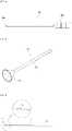
- FIG. 4is a view showing a cage guider shown in FIG. 2A ;
- FIG. 5is a perspective view showing a bone chip cannula shown in FIG. 2A ;
- FIG. 6is a view showing an osteotome shown in FIG. 2A ;
- FIG. 7is a perspective view showing a bone chip impactor shown in FIG. 2A ;
- FIGS. 8A to 8Care views showing an end plate remover shown in FIG. 2A ;
- FIG. 9is a partial perspective view showing a radiofrequency probe shown in FIG. 1 ;
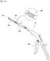
- FIG. 10is a perspective view showing a K-punch shown in FIG. 1 ;
- FIG. 11is a perspective view showing a round drill shown in FIG. 1 ;
- FIG. 12is a perspective view showing an endoscope shown in FIG. 1 ;
- FIG. 13is a cross-sectional view taken along line A-A of FIG. 12 ;
- FIG. 14is a sectional view showing a guide tube shown in FIG. 12 ;
- FIG. 15is a block diagram showing the method of unilateral biportal endoscopy according to an embodiment of the present invention.
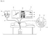
- FIG. 1is a view showing a basic concept of a method of unilateral biportal endoscopy.
- the method of unilateral biportal endoscopyis a method whereby two pathways, that is, an endoscopic portal A and a working portal B perforate a surgical site, a surgical instrument set 10 is inserted through the working portal B while an endoscope 70 is inserted through the endoscopic portal A, thereby treating the surgical site.
- the surgical instrumentmay be inserted through the endoscopic portal A while the endoscope 70 may be inserted through the working portal B.
- a saline solution 81is injected through the endoscope 70 such that the saline solution is guided to flow through the surgical site, thereby allowing the saline solution to remove residues from the surgical site.
- the used saline solutionis discharged from the body through of the working portal B.
- the endoscope 70functions to visualize an internal surgical site, as well as to guide the saline solution into the body.
- the unilateral biportal endoscopyis characterized in that the surgical instrument and the endoscope approach the surgical site through different pathways, so that a clear field of vision is obtained compared to a conventional method of forming a single incision. Having a clear field of vision is very important factor in spinal surgery.
- the surgical instrumentdoes not share a pathway with the endoscope 70 , a motion of the surgical instrument is relatively free within the pathway, thereby enabling a more efficient surgery.
- the surgical instrument set 10has a very wide range and includes a tool kit 20 including various types of small tools, a radiofrequency probe 40 , a K-punch 50 , a round drill 60 , and the endoscopes 70 .
- the components of the surgical instrument set 10are selectively used in accordance with the progress of unilateral biportal endoscopic surgery, and all are ergonomically designed.
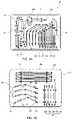
- FIGS. 2 a and 2 bare views showing the tool kit shown in FIG. 1
- FIGS. 3 a to 3 dare perspective views showing a root retractor 22 shown in FIG. 2 a
- FIGS. 4 to 8are views showing the surgical instruments included in the tool kit 20 .
- the tool kit 20includes an enlarging tube 21 for enlarging the size of the working portal B and a dilator 32 for retaining the enlarged working portal B.
- the enlarging tube 21is an instrument for enlarging the working portal B by being sequentially inserted thereinto by size in order to secure space for allowing entry of other surgical instruments to the working portal B formed at a surgical site during the unilateral biportal endoscopic surgery.
- the enlarging tubesare stepwisely inserted into the incision to enlarge the same.
- the enlarging tube 21has a hollow tube shape having different diameters and lengths.
- the enlarging tube 21is provided as six types ranging from a first enlarging tube 21 a to a sixth enlarging tube 21 f having different sizes.
- the first to sixth enlarging tubes 21 a to 21 fare selectively used as required.
- the enlarging tube 21may be provided on the outer circumferential surface thereof with a scale (not shown) marked to indicate the depth of insertion.
- the first enlarging tube 21 ahas a sharp front end and serves to enlarge the working portal B and the endoscopic portal A immediately after incision with a scalpel.
- the dilator 32is a bar instrument inserted into the working portal B to retain the working portal B secured by the enlarging tube 21 .
- the dilator 32includes a first dilator 32 a , a second dilator 32 b , a third dilator 32 c , and a fourth dilator 32 d having different sizes as shown in the drawing.
- a dilator core 32 eis used to enlarge the working portal B and the endoscopic portal A immediately after incision with a scalpel.
- the tool kit 20further includes a muscle detacher 23 , a double ended retractor 29 , a root retractor 22 , a suction tip 30 , an intradiscal irrigator 31 , a cage guider 24 , a bone chip cannula 25 , an osteotome 26 , a bone chip impactor 27 , and an end plate remover 28 .
- the muscle detacher 23is an instrument for securing an access pathway for an instrument used in the subsequent operation and a working space by detaching muscles from bones at a surgical site in a state of being inserted into the secured incision. In other words, the muscle detacher 23 is inserted between the muscle fibers of the fine muscle rather than cutting the muscle.
- the muscle detacher 23has a blade portion 23 b and a handle portion 23 a .
- the blade portion 23 bhas a soft round shape to minimize the skin wound at the surgical site.
- the double ended retractor 29is an instrument being inserted in the working space created by the muscle detacher 23 to detach the nerve root from the bone or the ligamentum flavum or to detach the muscle or ligament.
- the double ended retractor 29is configured such that the angle of tip portions 29 b provided at opposite ends thereof are variable, thereby being used for detaching and removing risk factors near the nerves or applying bone wax to a bleeding point during bone bleeding.
- the tip portion 29 bis configured such that an angle thereof is in a range of 5 to 25 degrees, and a width varies to 5.5 mm/4 mm/3 mm. The angle and width of the tip 29 b may vary.
- the double ended retractor 29is provided at a center thereof with a handle portion 29 a .
- the handle portion 29 amay be provided with a recessed groove for preventing the operator's fingers from slipping or an uneven portion having a predetermined pattern for increasing friction.
- the root retractor 22is an instrument for securing a working space and a constant water pressure in the working space by retracting the muscle and providing a pathway that guides the surgical instruments to be inserted and removed therethrough. As shown in FIGS. 3 a to 3 d , the root retractor 22 is provided at a center thereof with a first curved portion 22 a , and at an end thereof with a second curved portion 22 b.
- the first curved portion 22 ahas a curve angle of about 120 degrees, which is an ergonomically and mechanically ideal angle formed between the surgical instrument inserted and a lesion.
- the outer edge of the first curved portion 22 ahas a semi-tubular shape
- the second curved portion 22 bhas a shape curved in the same direction as the first curved portion 22 a or has a half-curved shape to hold the muscle to the nerve root.
- the opposite side of the semi-tubular shaped outer edge of the root retractor 22may serve as the pathway for insertion or removal of the surgical instruments, which detaches soft tissue such as ligaments, etc., or resects or inserts a disc.
- the root retractor 22may have a width of 4 mm/10 mm and the root retractor having a suitable size suitable according to a surgical site may be selectively used.
- the root retractor 22helps to open and close the working portal B and maintains the working space and water pressure such that an operator can see clear images of the surgical site.
- the root retractor 22serves to control compression and decompression of the nerve root to enable efficient surgery without damaging the nerve root.
- the suction tip 30is an instrument for sucking a saline solution injected for surgery or the soft tissue as well as tissue debris generated during surgery.
- a constant pressureis required within the body, and thus a constant pressure (e.g., 30 to 50 mmHg) is maintained using the suction tip 30 .
- the suction tip 30can prevent poor visibility of the surgical field from being caused due to the bone, the tissue debris, etc. during surgery.
- the suction tip 30includes a handle portion 30 a to which an outlet is connected and a curve-shaped suction pipe portion 30 b having at a front end thereof a suction hole 30 c .
- the suction pipe portion 30 bmay be configured such that a curve angle thereof is about 130 to 150 degrees, and a diameter thereof is 3 to 5 mm.
- the suction tip 30may be used for removing residue, etc. after a space for inserting artificial disc into a disc space is created, or may be used for checking a bleeding site by suctioning a bleeding portion in the peripheral corner of the disc in addition to the disc space.
- the suction tip 30can allow the surrounding debris to be discharged before and after insertion of the artificial disc without remaining within the body, and allow the washing area to be accurately ascertained while providing a sufficient field of vision, thereby enabling quick washing and washing water saving.
- the intradiscal irrigator 31includes a handle portion 31 a having a wash water inlet 31 d , and a water tube portion 31 b curved at a predetermined angle to secure a field of vision of an operator and having at a front end thereof a discharge hole 31 c .
- the water tube portion 31 bhas a curve angle of about 111 to 130 degrees. When the curve angle is less than 111 degrees, the operator's field of vision is obstructed. Additionally, when the curve angle is greater than 130 degrees, the operator's gaze must be lowered to see the discharge hole 31 c.
- the cage guider 24is an instrument for seating a cage (not shown) in the disc space.
- the cage guider 24is provided at a first end thereof with a carrying portion 24 b on which the cage is placed, and at a second end thereof with a handle portion 24 a.
- the bone chip cannula 25is an instrument for collecting the bone chips and inserting them into the cage.
- the bone chip cannula 25includes a funnel-shaped collecting portion 25 a for concentrating and collecting the bone chips supplied from the outside, and a guide tube portion 25 b connected to the collecting portion 25 a and extending in the lengthwise direction thereof, the guide tube portion 25 b guiding the bone chips to the disc in a state of reaching a surgical site.
- the osteotome 26is an instrument for cutting unnecessary bones during surgery.
- the osteotome 26is provided at a front end thereof with a cutting blade portion 26 b cutting the bone, and at an opposite end to the tip end thereof with a handle portion 26 a.
- the bone chip impactor 27is an instrument for impacting on the artificial disc inserted into the disc space or the collected bone material so as to be seated in a precise position.
- the bone chip impactor 27is provided at a front end thereof with a tip portion 27 b being in contact with a target to be impacted thereon, and at an opposite end to the tip end thereof with a handle portion 27 a.
- the end plate remover 28is an instrument for removing the end plate located between the vertebrae and the disc, and is curved at a front end thereof in a hook shape. Since the tip end of the curved end plate remover 28 has a hook shape, each approach to and removal of the end plate located between the vertebrae and the disc is possible. As shown in FIGS. 8 a , 8 b , and 8 c , the tip end of the end plate remover 28 may vary in shape.
- FIG. 9is a partial perspective view showing the radio frequency probe 40 shown in FIG. 1 .
- the radiofrequency probe 40is an instrument for heating and removing the soft tissue, disc, epidural fat, and ligaments. While a conventional radiofrequency probe is problematic in that a tip thereof where radiofrequency is generated is in direct contact with a surgical site and thus the surrounding nerve is damaged, the radiofrequency probe 40 according to the present invention has a safety protrusion (not shown) whereby no damage to normal tissue is caused.
- the radiofrequency probe 40includes an insertion rod 40 b inserted into the body so as to reach a surgical site, an electrode tip 40 a provided at a front end of the insertion rod 40 b and outputting radiofrequency heat by being applied with electric power from outside, and the safety protrusion formed on the surface of the electrode tip 40 a and separating the surface of the electrode tip 40 a from the body tissue to prevent thermal damage.
- the radiofrequency probe 40may further include an electric power wire supplying electric power to the radiofrequency probe 40 , and a discharge tube extending from the outside of a casing 40 c and discharging a saline solution in the body therefrom.
- the electrode tip 40 amay be detachably fitted into the insertion rod 40 b and includes a shield portion 40 f .
- the shield portion 40 fis a soft round-shaped member for minimizing damage to the body tissue and facilitating insertion when the electrode tip 40 a is inserted into the body.
- the shield portion 40 falso serves to block heat of plasma from being transferred to normal tissue.
- FIG. 10is a perspective view showing the K-punch 50 shown in FIG. 1 .
- the K-punch 50is an instrument for detaching and removing the bone, ligamentum flavum, soft tissue, etc. and includes an entry rod 50 a , a slider 50 c , a rotary shaft 50 d , a pushing rod 50 f , and a handle portion 50 e.
- the entry rod 50 ais a member being inserted into the body so as to reach a surgical site at a front end thereof, and is provided at the front end thereof with a retaining step portion 5 b . Further, the slider 50 c is slidably engaged with a side of the entry rod 50 a and moves forward and backward with respect to the retaining step portion 50 b . The slider 50 c is pressed and moved to the retaining step portion 50 b in a state in which a target to be removed is positioned between the retaining step portion 50 b and the slider 50 c , whereby the target to be removed is physically fixed.
- the rotary shaft 50 dis fixed to the rear side of the entry rod 50 a , and is rotated by an operator's operation as required during surgery such that the direction of the retaining step portion 50 b is controlled. As such, by provision of the rotary shaft 50 d , the handle portion 50 e is operable at a comfortable angle regardless of the position of tissue to be removed.
- the pushing rod 50 fis fixed at a front end thereof to the slider 50 c and extends from a rear end thereof to the rear side of the rotary shaft 50 d , the pushing rod being configured to move forward to press and move the slider 50 c to the retaining step portion 50 b when the handle portion 50 e is manipulated.
- FIG. 11is a perspective view showing a round drill 60 shown in FIG. 1 .
- the round drill 60serves to grind unnecessary bone parts during surgery and is used in combination with a separate handpiece (not shown).
- the round drill 60is provided with an outer tube 60 a having a predetermined diameter and extends in the lengthwise direction thereof, the outer tube 60 a having an inclined opening 60 b inclined at a front end thereof to form an acute angle (e.g., 38 degrees) with respect to the lengthwise direction of the outer tube 60 a , a tube holder 60 d fixed to a rear end of the outer tube 60 a , and a burr 60 c partially exposed to the outside of the outer tube 60 a through the inclined opening 60 b.
- an acute anglee.g. 38 degrees
- the inclined opening 60 bis provided to partially cover the burr 60 c such that the burr 60 c removes only unnecessary portions without damaging normal tissue and the nerve.
- the burr 60 cis a cutting tip on which cutting diamond powder is distributed, and types thereof may vary. For example, a round burr, a diamond burr, etc. may be used. Unlike a conventional burr used in endoscopic surgery, the diamond burr is embedded with fine diamond powder. Since fine diamond powder is distributed to serve as a cutting blade, the depth of cutting the bone can be precisely controlled and bleeding can be minimized.
- the shape of the burr 60 cmay be implemented in other shapes such as a triangular pyramid shape as well as a round shape.
- FIG. 12is a perspective view showing the endoscope 70 shown in FIG. 1
- FIG. 13is a cross-sectional view taken along line A-A of FIG. 17
- FIG. 14is a sectional view showing the guide tube 71 a shown in FIG. 17 .
- the endoscope 70includes a sheath mechanism 71 and an endoscope camera 73 .
- the endoscope camera 73is a device for identifying and capturing an image of a surgical site in the body, and includes a flexible probe 73 a extending in the lengthwise direction thereof and having an optical fiber cable therein, A lens 73 b provided at a front end of the probe 73 a , and a lens barrel 73 c provided at a rear end of the lens 73 b.
- the endoscope camera 73may further include an imaging control device for capturing and recording images, a light source connected to a guide cable for illuminating a imaging site, the guide cable for transporting light to a distal end of the endoscope 70 for emitting light to the imaging site, and an endoscope tray storing the endoscope camera 73 and facilitating movement of the endoscope camera 73 .
- the sheath mechanism 71is combined with the endoscope camera 73 to constitute a single endoscope 70 and serves to support the endoscope camera 73 during surgery whiling secure a field of vision.
- the reason why the sheath mechanism 71 is usedis that the probe 73 a of the endoscope camera is very thin and tends to be curved, and thus the lens 73 b may not be allowed to reach a target point in the body.
- Another important function of the sheath mechanism 71is to guide a saline solution to a target point.
- the sheath mechanism 71includes a guide tube 71 a , a damping chamber 71 m , a valve body 71 b , and an adapter portion 71 s.
- the guide tube 71 ais a hollow tube-shaped member that extends in the lengthwise direction thereof, and a first end thereof reaches a surgical site in the body when in use.
- the material of the guide tube 71 amay vary and may be made of, for example, stainless steel or a synthetic resin including polypropylene.
- the length of the guide tube 71 amay vary as required.
- the guide tube 71 ais inserted into the body through the portal secured by the enlarging tube 21 .
- the guide tube 71 ais provided on an inner circumferential surface thereof with a plurality of guide grooves 71 p .
- the guide grooves 71 pextend in the lengthwise direction of the guide tube 71 a and serve to guide a saline solution supplied from the outside to an outlet 71 f.
- linear protrusions 71 rare provided between the guide grooves 71 p , respectively.
- the linear protrusions 71 rare arranged in parallel with the guide grooves 71 p , and a plurality of the protrusions are arranged in parallel to form the guide grooves 71 p .
- the linear protrusions 71 r and the guide grooves 71 pare arranged in the circumferential direction of the guide tube 71 a to be distanced from each other at predetermined intervals.
- the linear protrusions 71 rare in partial contact with an outer circumferential surface of the probe 73 a inserted into a space portion 71 n of the guide tube 71 a and to thereby support the probe 73 a .
- the diameter of a virtual cylinder connecting the upper ends of the linear protrusions 71 ris greater than the diameter of the probe 73 a .
- the probe 73 acan move vertically and horizontally in the space portion 71 n and freely slide in the lengthwise direction thereof.
- the guide tube 71 ais provided at a front end thereof with a plurality of projecting portions 71 h and a plurality of depressed portions 71 g .
- the projecting portions 71 hprojects in a direction of the front end of the guide tube 71 a , that is, in a direction in which a saline solution is discharged, and the depressed portions 71 g are depressed in a direction opposite thereto.
- the projecting portions 71 h and the depressed portions 71 aare repeatedly provided in a wave pattern in the circumferential direction of the guide tube 71 a.
- the projecting portions 71 h and the depressed portions 71 aserve to guide a saline solution discharged from the guide tube 71 a to flow out in the radial direction of the guide tube 71 a .
- the saline solutionis allowed to be supplied through the depressed portions 71 a , or is imparted with directionality for securing a field of vision.
- the guide tube 71 ais provided with a side slit 71 k formed on the side of the front end of the guide tube 71 a .
- the side slit 71 kserves to control the flow direction of a saline solution. In other words, during unilateral biportal endoscopic surgery, the flow direction of the saline solution is controlled, whereby the lens 73 b is easily cleaned while the saline solution flows by gravity, thereby securing a field of vision of the endoscope 70 .
- the side slit 71 kserves as a passage for a saline solution.
- the side slit 71 kis provided to prevent a case where the depressed portions 71 a of the guide tube 71 a are clogged with tissue such as muscle Z and thus the saline solution is not efficiently discharged, and is provided to impart directionality to the saline solution to secure a field of vision.
- the saline solution introduced into the guide tube 71 ais discharged through the side slit 71 k by gravity and washes away tissue or blood of the affected area, thereby securing a field of vision.
- the adapter portion 71 sserves to maintain a position of the endoscope camera 73 with respect to the sheath mechanism 71 , and has a holder 71 d for supporting the endoscope camera 73 .
- the guide tube 71 ais open at a rear end thereof to the rear side of the holder 71 d .
- the damping chamber 71 mis a space communicating with the rear end of the guide tube 71 a , and serves to receive a saline solution supplied through an inlet 71 c and a valve body 71 b , store the same therein, and transfer the stored saline solution to the guide tube 71 a.
- damping chamber 71 mBy provision of the damping chamber 71 m , deviation in the flow rate of a saline solution supplied to the guide tube 71 a is kept as low as possible.
- a change in the flow rate of the saline solution supplied through a saline solution supply tube(reference numeral 82 in FIG. 1 ) is immediately reflected in the guide tube 71 a .
- the capacity of the damping chamber 71 mmay vary as required.
- valve bodies 71 bare provided at the periphery of the damping chamber 71 m , and each of the valve bodies 71 is provided with a flow control valve 71 e .
- the flow control valve 71 eserves to control the flow rate of a saline solution passing through the valve body 71 b and is manipulated by an operator.
- Reference numeral 71 cdenotes an inlet to which the saline solution supply tube 82 is connected.
- the saline solution having flowed through the saline solution supply tube 82reaches the affected area through the inlet 71 c via the valve body 71 b , the damping chamber 71 m , and the guide tube 71 a.
- FIG. 15is a block diagram showing the method of unilateral biportal endoscopy according to the embodiment of the present invention.
- the method of unilateral biportal endoscopyincludes a step of firstly securing pathways S 101 , a step of secondarily securing a pathway S 102 , a step of inserting an endoscope S 105 , a step of inserting a surgical instrument S 107 , a step of performing surgery S 109 , a step of removing S 111 , and a step of suturing S 113 .
- the step of firstly securing the pathways S 101is a process of forming two pathways extending toward a surgical site in the patient's body, that is, the working portal B and the endoscopic portal A, and includes marking S 101 a , incising S 101 b , enlarging tube inserting S 101 c , and pathway enlarging S 101 d.
- the marking S 101is a process of marking points at which the working portal B and the endoscopic portal A are formed on the skin on the vertebral region of a patient lying in a prone position.
- entrances through which an instrument, such as the tool kit 20 , the radiofrequency probe 40 , the K-punch 50 , or the round drill 60 from the surgical instrument set is insertedare marked.
- two marking pointsmust be distanced from each other. The marking points vary depending on the location of a surgical site. When a lesion is located in a deep position, the distance between the two marking points is increased.
- the working portal B and the endoscopic portal Aare independent pathways to each other, and are configured to meet with each other at a lesion site in the body whereas the entrances thereof are separated from each other, thereby forming substantially sides of a triangle.
- the incising S 101 bis a process of making incisions on marking portions using a scalpel, whereby the entrance through which the enlarging tube 21 is inserted is opened.
- the incision lengthmay be about 5 mm.
- the enlarging tube inserting S 101 cis a process of forming a straight pathway toward a surgical site by inserting the enlarging tube 21 into the body using the incision opened through the incising S 101 b as an entrance.
- the enlarging tube 21 used firstis the first enlarging tube 21 a having the smallest diameter.
- the pathway enlarging S 101 dis a process of enlarging the diameter of the pathway by using enlarging tubes having different sizes. For example, in a state in which the first enlarging tube 21 a is inserted into the body, the second enlarging tube 21 b is inserted thereover and then the first enlarging tube 21 a is taken out. Thereafter, the third enlarging tube 21 c is inserted over the second enlarging tube 21 c and then the second enlarging tube 21 b is taken out in such a manner that the diameter of the pathway is increased.
- the pathway enlarging S 101 dmay be applied to both the endoscopic portal A and the working portal B. Needless to say, the diameter of the working portal B through which the surgical instrument set is inserted should be relatively large.
- the endoscopic portal A and the working portal B formed through the step of firstly securing the pathways S 101are distanced from each other on the patient's epidermis but meet with each other at a surgical site in the body.
- the step of secondarily securing the pathway S 103includes muscle detaching S 103 a and muscle retracting S 103 b .
- the muscle detaching S 103 aincludes a process of detaching the muscle from the bone of a surgical site using the muscle detacher 23 described above. In other words, by inserting the muscle detacher 23 into the pathway secured through the step of firstly securing the pathways S 101 to detach the bone and muscle of the surgical site, an access pathway for the instruments used in the subsequent operation and a working space is secured.
- the muscle retracting S 103 bis a process of securing an additional working space by retracting the muscle using the root retractor 22 described above. In other words, the muscle separated from the bone is retracted through the muscle detaching S 103 a , thereby securing a sufficient working space.
- the step of inserting the surgical instrument S 107is a process of inserting the surgical instrument required for surgery through the working portal B secured through the step of secondarily securing the pathway S 103 .
- itis a process of inserting the required surgical instruments according to the progress of surgery.
- the radiofrequency probe 40 , the K-punch 50 , and the round drill 60 as well as the tool kit 20are selectively inserted through the working portal B as required.
- the step of inserting the endoscope S 105is a process of inserting the endoscope 70 through the secured endoscopic portal A.
- the sheath mechanism 71 and the lens 73 b of the endoscope camera 73which constitute the endoscope 70 , must reach a lesion site.
- the step of performing the surgery S 109is a process of performing surgery using the surgical instrument inserted into the working portal B while monitoring a surgical site through the endoscope 70 .
- the step of performing the surgery S 109is a process of actually performing treatment on a surgical site to be treated in the body. As the treatment progresses, the required surgical instruments are inserted into the body through the working portal B. Of course, a surgery status is continuously monitored through the endoscope 70 during surgery.
- saline supplying S 109 ais performed during the step of performing the surgery S 109 .
- the saline supplying 109 ais a process of supplying a saline solution supplied from the outside to a surgical site and discharging materials to be discharged generated during surgery from the body.
- the saline solutionis guided through the guide tube 71 a of the sheath mechanism 71 .
- the injected saline solutionallows debris at a surgical site and tissue removed to be discharged outside.
- the step of removing S 111is a process of removing the used surgical instrument and the endoscope 70 from the body.
- the surgical instrumentmay be removed prior to removing the endoscope 70 .
- the endoscope camera 73is used to check and identify a surgical site prior to removal thereof.
- the step of suturing S 113 of suturing the entrances of the working portal B and the endoscopic portal Ais performed, whereby surgery is completed.
Landscapes
- Health & Medical Sciences (AREA)
- Life Sciences & Earth Sciences (AREA)
- Surgery (AREA)
- Engineering & Computer Science (AREA)
- Biomedical Technology (AREA)
- Heart & Thoracic Surgery (AREA)
- Animal Behavior & Ethology (AREA)
- General Health & Medical Sciences (AREA)
- Public Health (AREA)
- Veterinary Medicine (AREA)
- Medical Informatics (AREA)
- Molecular Biology (AREA)
- Nuclear Medicine, Radiotherapy & Molecular Imaging (AREA)
- Orthopedic Medicine & Surgery (AREA)
- Physics & Mathematics (AREA)
- Pathology (AREA)
- Biophysics (AREA)
- Radiology & Medical Imaging (AREA)
- Optics & Photonics (AREA)
- Oral & Maxillofacial Surgery (AREA)
- Transplantation (AREA)
- Vascular Medicine (AREA)
- Cardiology (AREA)
- Physical Education & Sports Medicine (AREA)
- Dentistry (AREA)
- Plasma & Fusion (AREA)
- Otolaryngology (AREA)
- Dermatology (AREA)
- Neurology (AREA)
- Surgical Instruments (AREA)
Abstract
Description
Claims (4)
Priority Applications (1)
| Application Number | Priority Date | Filing Date | Title |
|---|---|---|---|
| US17/659,894US20220240916A1 (en) | 2017-11-14 | 2022-04-20 | Surgical instrument set for use during unilateral biportal endoscopy |
Applications Claiming Priority (4)
| Application Number | Priority Date | Filing Date | Title |
|---|---|---|---|
| KR10-2017-0151636 | 2017-11-14 | ||
| KR20170151636 | 2017-11-14 | ||
| KR10-2018-0008451 | 2018-01-23 | ||
| KR1020180008451AKR102121601B1 (en) | 2017-11-14 | 2018-01-23 | Surgical tool set for bi-directional vertebral endoscopic surgery |
Related Child Applications (1)
| Application Number | Title | Priority Date | Filing Date |
|---|---|---|---|
| US17/659,894DivisionUS20220240916A1 (en) | 2017-11-14 | 2022-04-20 | Surgical instrument set for use during unilateral biportal endoscopy |
Publications (2)
| Publication Number | Publication Date |
|---|---|
| US20190142408A1 US20190142408A1 (en) | 2019-05-16 |
| US11331091B2true US11331091B2 (en) | 2022-05-17 |
Family
ID=66432231
Family Applications (2)
| Application Number | Title | Priority Date | Filing Date |
|---|---|---|---|
| US15/879,825Active2039-09-10US11331091B2 (en) | 2017-11-14 | 2018-01-25 | Surgical instrument set for use during unilateral biportal endoscopy |
| US17/659,894AbandonedUS20220240916A1 (en) | 2017-11-14 | 2022-04-20 | Surgical instrument set for use during unilateral biportal endoscopy |
Family Applications After (1)
| Application Number | Title | Priority Date | Filing Date |
|---|---|---|---|
| US17/659,894AbandonedUS20220240916A1 (en) | 2017-11-14 | 2022-04-20 | Surgical instrument set for use during unilateral biportal endoscopy |
Country Status (2)
| Country | Link |
|---|---|
| US (2) | US11331091B2 (en) |
| WO (1) | WO2019098457A1 (en) |
Cited By (2)
| Publication number | Priority date | Publication date | Assignee | Title |
|---|---|---|---|---|
| US12201309B2 (en) | 2023-02-03 | 2025-01-21 | Travis Greenhalgh | Decompression system and methods of use |
| WO2025158455A1 (en)* | 2024-01-24 | 2025-07-31 | Shah Nisarg Pankaj | Stand alone unilateral biportal endoscopy cage |
Families Citing this family (11)
| Publication number | Priority date | Publication date | Assignee | Title |
|---|---|---|---|---|
| AU2012362524B2 (en) | 2011-12-30 | 2018-12-13 | Relievant Medsystems, Inc. | Systems and methods for treating back pain |
| WO2014071161A1 (en) | 2012-11-05 | 2014-05-08 | Relievant Medsystems, Inc. | System and methods for creating curved paths through bone and modulating nerves within the bone |
| US11464648B2 (en)* | 2019-09-09 | 2022-10-11 | Amplify Surgical, Inc. | Multi-portal surgical systems |
| US11678906B2 (en)* | 2019-09-09 | 2023-06-20 | Amplify Surgical, Inc. | Multi-portal surgical systems, cannulas, and related technologies |
| CN110812569A (en)* | 2019-12-12 | 2020-02-21 | 青岛大学附属医院 | Operation cavity perfusate collection components and systems |
| US12082876B1 (en) | 2020-09-28 | 2024-09-10 | Relievant Medsystems, Inc. | Introducer drill |
| EP4268150A4 (en) | 2020-12-22 | 2024-12-18 | Relievant Medsystems, Inc. | PREDICTION OF CANDIDATES FOR SPINAL NEUROMODULATION |
| CN113384362B (en)* | 2021-07-23 | 2023-01-31 | 山东省日照市人民医院 | Auxiliary device for orthopedic joint replacement surgery |
| US12433668B1 (en) | 2021-11-08 | 2025-10-07 | Relievant Medsystems, Inc. | Impedance stoppage mitigation during radiofrequency tissue ablation procedures |
| US11950770B1 (en) | 2022-12-01 | 2024-04-09 | Amplify Surgical, Inc. | Multi-portal split cannulas, endoscopic hemostatic dispensers and surgical tools |
| CN118903583B (en)* | 2024-10-10 | 2025-01-28 | 浙江工业大学 | Auxiliary suction structure for cooling medium liquid |
Citations (65)
| Publication number | Priority date | Publication date | Assignee | Title |
|---|---|---|---|---|
| US4934352A (en)* | 1982-10-22 | 1990-06-19 | Sullivan Jr Eugene M | Surgical retractor handle construction |
| US5144942A (en)* | 1991-03-21 | 1992-09-08 | United States Surgical Corporation | Endoscopic instrumentation kit and package therefor |
| US5158543A (en)* | 1990-10-30 | 1992-10-27 | Lazarus Harrison M | Laparoscopic surgical system and method |
| US5453094A (en)* | 1993-09-17 | 1995-09-26 | Minnesota Mining And Manufacturing Company | Kit assembly for use during a laparoscopic surgical procedure |
| US5472426A (en)* | 1991-09-12 | 1995-12-05 | B.E.I. Medical | Cervical discectomy instruments |
| US5741261A (en)* | 1996-06-25 | 1998-04-21 | Sdgi Holdings, Inc. | Minimally invasive spinal surgical methods and instruments |
| US5743853A (en)* | 1996-09-09 | 1998-04-28 | Lauderdale; Robert A. | Serrated S-retractor |
| US6096026A (en)* | 1997-09-22 | 2000-08-01 | Jlj Medical Devices, International, Llc | Surgical instruments for minimally invasive surgical procedures |
| US6241734B1 (en)* | 1998-08-14 | 2001-06-05 | Kyphon, Inc. | Systems and methods for placing materials into bone |
| US20020013514A1 (en)* | 2000-04-14 | 2002-01-31 | Brau Salvador A. | Surgical retractor and related surgical approach to access the anterior lumbar region |
| US6371968B1 (en)* | 1996-05-09 | 2002-04-16 | Olympus Optical Co., Ltd. | Cavity retaining tool for bone surgery, a cavity retaining tool for general surgery, an endoscopic surgery system involving the use of a cavity retaining tool, and a procedure for surgery |
| US6405863B1 (en)* | 2001-01-17 | 2002-06-18 | Avtar S. Dhindsa | Surgical instrument tray and system |
| US6412639B1 (en)* | 2000-04-28 | 2002-07-02 | Closure Medical Corporation | Medical procedure kit having medical adhesive |
| US6443990B1 (en)* | 1997-08-06 | 2002-09-03 | Synthes (U.S.A.) | Adjustable intervertebral implant |
| US20030073998A1 (en)* | 2000-08-01 | 2003-04-17 | Endius Incorporated | Method of securing vertebrae |
| US6564078B1 (en)* | 1998-12-23 | 2003-05-13 | Nuvasive, Inc. | Nerve surveillance cannula systems |
| US6582441B1 (en)* | 2000-02-24 | 2003-06-24 | Advanced Bionics Corporation | Surgical insertion tool |
| US20040078079A1 (en)* | 2002-10-21 | 2004-04-22 | Foley Kevin T. | Systems and techniques for restoring and maintaining intervertebral anatomy |
| WO2004032783A1 (en)* | 2002-09-27 | 2004-04-22 | Aesculap Ag & Co. Kg | Set of instruments for performing a surgical operation |
| US20040186356A1 (en)* | 2001-08-08 | 2004-09-23 | O'malley Michael T. | Surgical retractor and tissue stabilization device |
| US20050004593A1 (en)* | 2001-10-30 | 2005-01-06 | Depuy Spine, Inc. | Non cannulated dilators |
| US20050075578A1 (en)* | 2001-09-25 | 2005-04-07 | James Gharib | System and methods for performing surgical procedures and assessments |
| US20050203345A1 (en)* | 2005-03-03 | 2005-09-15 | Ken Yamaguchi | Articulating paddle elevator and arthroscopic method for using same |
| WO2006059189A1 (en)* | 2004-11-30 | 2006-06-08 | Atul Kumar | A system of dampening pressure pulsations caused by a positive displacement pump in endoscopic surgery |
| US20060211953A1 (en)* | 2004-10-29 | 2006-09-21 | Zannis Anthony D | Coordinate instrument set |
| US7226451B2 (en)* | 2003-08-26 | 2007-06-05 | Shluzas Alan E | Minimally invasive access device and method |
| US20070179340A1 (en)* | 2005-12-20 | 2007-08-02 | Medicept, Inc. | Method and devices for minimally invasive arthroscopic procedures |
| US20080249481A1 (en)* | 2006-12-15 | 2008-10-09 | Lawrence Crainich | Devices and Methods for Vertebrostenting |
| US20080281364A1 (en)* | 2007-05-08 | 2008-11-13 | Spineworks Medical, Inc. | Systems, devices and methods for stabilizing bone |
| US20090076551A1 (en)* | 2004-11-22 | 2009-03-19 | Petersen David A | Methods and surgical kits for minimally-invasive facet joint fusion |
| US20090156903A1 (en)* | 2007-12-17 | 2009-06-18 | Guederian Gregory A | Articulating hook elevator and arthroscopic method for using same |
| US7632284B2 (en)* | 2004-07-06 | 2009-12-15 | Tyco Healthcare Group Lp | Instrument kit and method for performing meniscal repair |
| US7657308B2 (en)* | 2003-08-05 | 2010-02-02 | Nuvasive, Inc. | System and methods for performing dynamic pedicle integrity assessments |
| US20100069974A1 (en)* | 2006-07-31 | 2010-03-18 | Ran Oren | Arthroscopic bone transplanting procedure, and medical instruments useful therein |
| US20100076502A1 (en)* | 2007-02-09 | 2010-03-25 | Alphatec Spine, Inc. | Curvilinear spinal access method and device |
| US20110046446A1 (en)* | 2009-08-20 | 2011-02-24 | Hoya Corporation | Endoscope equipped with a nozzle for cleaning its distal end |
| US20110106124A1 (en)* | 2009-06-16 | 2011-05-05 | Marc Beauchamp | Method and apparatus for arthroscopic rotator cuff repair using transosseous tunnels |
| US20130012946A1 (en)* | 2011-07-05 | 2013-01-10 | Johan Janssens | Combination of a bone drill and a sleeve |
| US8361078B2 (en)* | 2003-06-17 | 2013-01-29 | Depuy Spine, Inc. | Methods, materials and apparatus for treating bone and other tissue |
| US8454644B2 (en)* | 2005-04-06 | 2013-06-04 | Stryker Spine | Switching stick dilation method and apparatus |
| US20130267892A1 (en)* | 2012-04-05 | 2013-10-10 | Brady Woolford | Cassette for a surgical fluid management pump system |
| US8568317B1 (en)* | 2005-09-27 | 2013-10-29 | Nuvasive, Inc. | System and methods for nerve monitoring |
| US8597360B2 (en)* | 2004-11-03 | 2013-12-03 | Neuropro Technologies, Inc. | Bone fusion device |
| US20140088368A1 (en)* | 2012-01-18 | 2014-03-27 | Kwang-Tai Park | Surgical instrument, surgical mesh and surgical retraction means of the instrument, and surgical method using the instrument |
| US8690761B2 (en)* | 2008-10-07 | 2014-04-08 | Neurendo B.V. | Minimal invasive neurosurgery assembly as well as a method for neurosurgery using such a neurosurgery assembly |
| KR101441320B1 (en)* | 2014-04-07 | 2014-09-18 | 주식회사 엔도비전 | Surrical equipment set to perform spine surgery microscope of minimum invasion |
| US8894658B2 (en)* | 2009-11-10 | 2014-11-25 | Carefusion 2200, Inc. | Apparatus and method for stylet-guided vertebral augmentation |
| US8951261B2 (en)* | 2009-11-20 | 2015-02-10 | Zimmer Knee Creations, Inc. | Subchondral treatment of joint pain |
| US20150060462A1 (en)* | 2013-09-04 | 2015-03-05 | Rand Colbert | Portable neurotoxin injection tray and associated apparatus, system, and method |
| US9119646B2 (en)* | 2011-08-07 | 2015-09-01 | Zimmer Knee Creations, Inc. | Subchondral treatment to prevent the progression of osteoarthritis of the joint |
| US9138187B2 (en)* | 2011-08-07 | 2015-09-22 | Zimmer Knee Creations, Inc. | Treatment of subchondral bone by biochemical diagnosis to prevent the progression of osteoarthritis of the joint |
| US9220554B2 (en)* | 2010-02-18 | 2015-12-29 | Globus Medical, Inc. | Methods and apparatus for treating vertebral fractures |
| US20160045334A1 (en)* | 2013-03-22 | 2016-02-18 | Joimax Gmbh | Instrument set and method for inserting a cage into the intervertebral disk space between two vertebral bodies |
| US9320422B1 (en)* | 2012-12-28 | 2016-04-26 | M Vincent Makhlouf | Surgical retractor |
| US9339294B2 (en)* | 2012-09-07 | 2016-05-17 | Zimmer Knee Creations, Inc. | Instruments for controlled delivery of injectable materials into bone |
| US9522001B2 (en)* | 2012-04-12 | 2016-12-20 | Operating Room Innovations, Inc. | Surgical appliance kit and system for releasably securing a surgical appliance to a surgical field and method of assembling the surgical applicance kit |
| US9532883B2 (en)* | 2012-04-13 | 2017-01-03 | Neuropro Technologies, Inc. | Bone fusion device |
| US20170196508A1 (en)* | 2014-06-25 | 2017-07-13 | Canary Medical Inc. | Devices, systems and methods for using and monitoring spinal implants |
| US9730707B2 (en)* | 2014-08-20 | 2017-08-15 | Kyphon SÀRL | Surgical instrument with graduated markings correlating to angulation |
| US20170332886A1 (en)* | 2016-05-18 | 2017-11-23 | Techcord Co., Ltd | Spinal endoscope with novel elongate rigid tube |
| US20180008126A1 (en)* | 2016-07-06 | 2018-01-11 | Olympus Corporation | Treatment device and treatment system |
| US20180028703A1 (en)* | 2016-07-27 | 2018-02-01 | rms Surgical, Inc. | Tray for holding sterilization targets |
| US20180271574A1 (en)* | 2017-03-22 | 2018-09-27 | Benvenue Medical, Inc. | Minimal Impact Access System To Disc Space |
| US20180333222A1 (en)* | 2017-05-17 | 2018-11-22 | Lsi Solutions, Inc. | Surgical procedure kit |
| US10265099B2 (en)* | 2008-09-26 | 2019-04-23 | Relievant Medsystems, Inc. | Systems for accessing nerves within bone |
Family Cites Families (12)
| Publication number | Priority date | Publication date | Assignee | Title |
|---|---|---|---|---|
| US6929606B2 (en)* | 2001-01-29 | 2005-08-16 | Depuy Spine, Inc. | Retractor and method for spinal pedicle screw placement |
| ES2279733B1 (en)* | 2006-11-27 | 2008-08-16 | Rudolf Morgenstern Lopez | DEVICE FOR ELIMINATION OF FABRIC IN ENDOSCOPIC OPERATIONS. |
| US9380966B2 (en)* | 2007-06-22 | 2016-07-05 | Vioptix, Inc. | Tissue retractor oximeter |
| US8439929B1 (en)* | 2009-11-09 | 2013-05-14 | Nordson Corporation | Method of preparing a gel matrix for grafting to a bone |
| US8486097B2 (en)* | 2010-02-04 | 2013-07-16 | Nico Corporation | Tissue cutting device |
| KR101260228B1 (en)* | 2010-11-24 | 2013-05-03 | 주식회사 파인메딕스 | Injector for Endoscopic treatment |
| KR101302453B1 (en) | 2012-12-11 | 2013-09-02 | 박경우 | Percutaneous extraforaminotomy with foraminal ligament resection and instrument tools being used for the same |
| WO2014108730A2 (en)* | 2012-12-24 | 2014-07-17 | Novadaq Technologies Inc. | Endoluminal introducer |
| CA2924193C (en)* | 2013-09-16 | 2023-01-10 | Invuity, Inc. | Thermally controlled illumination devices |
| JP6464104B2 (en)* | 2016-01-20 | 2019-02-06 | 富士フイルム株式会社 | Endoscope connector, endoscope and endoscope system |
| KR101744459B1 (en)* | 2016-11-02 | 2017-06-07 | 박상훈 | Surgical instrument set to perform the posterior biportal endoscopic spinal surgery |
| US11191533B2 (en)* | 2017-04-23 | 2021-12-07 | Retrospine Pty Ltd | Retraction assembly for surgery |
- 2018
- 2018-01-25USUS15/879,825patent/US11331091B2/enactiveActive
- 2018-01-29WOPCT/KR2018/001243patent/WO2019098457A1/ennot_activeCeased
- 2022
- 2022-04-20USUS17/659,894patent/US20220240916A1/ennot_activeAbandoned
Patent Citations (69)
| Publication number | Priority date | Publication date | Assignee | Title |
|---|---|---|---|---|
| US4934352A (en)* | 1982-10-22 | 1990-06-19 | Sullivan Jr Eugene M | Surgical retractor handle construction |
| US5158543A (en)* | 1990-10-30 | 1992-10-27 | Lazarus Harrison M | Laparoscopic surgical system and method |
| US5144942A (en)* | 1991-03-21 | 1992-09-08 | United States Surgical Corporation | Endoscopic instrumentation kit and package therefor |
| US5315985A (en)* | 1991-03-21 | 1994-05-31 | United States Surgical Corporation | Endoscopic instrumentation kit and package therefor |
| US5472426A (en)* | 1991-09-12 | 1995-12-05 | B.E.I. Medical | Cervical discectomy instruments |
| US5453094A (en)* | 1993-09-17 | 1995-09-26 | Minnesota Mining And Manufacturing Company | Kit assembly for use during a laparoscopic surgical procedure |
| US6371968B1 (en)* | 1996-05-09 | 2002-04-16 | Olympus Optical Co., Ltd. | Cavity retaining tool for bone surgery, a cavity retaining tool for general surgery, an endoscopic surgery system involving the use of a cavity retaining tool, and a procedure for surgery |
| US5741261A (en)* | 1996-06-25 | 1998-04-21 | Sdgi Holdings, Inc. | Minimally invasive spinal surgical methods and instruments |
| US5743853A (en)* | 1996-09-09 | 1998-04-28 | Lauderdale; Robert A. | Serrated S-retractor |
| US6443990B1 (en)* | 1997-08-06 | 2002-09-03 | Synthes (U.S.A.) | Adjustable intervertebral implant |
| US6096026A (en)* | 1997-09-22 | 2000-08-01 | Jlj Medical Devices, International, Llc | Surgical instruments for minimally invasive surgical procedures |
| US6755815B2 (en)* | 1997-09-22 | 2004-06-29 | Leonard S. Schultz | Surgical instruments for minimally invasive surgical procedures |
| US6613054B2 (en)* | 1998-08-14 | 2003-09-02 | Kyphon Inc. | Systems and methods for placing materials into bone |
| US6241734B1 (en)* | 1998-08-14 | 2001-06-05 | Kyphon, Inc. | Systems and methods for placing materials into bone |
| US6564078B1 (en)* | 1998-12-23 | 2003-05-13 | Nuvasive, Inc. | Nerve surveillance cannula systems |
| US6582441B1 (en)* | 2000-02-24 | 2003-06-24 | Advanced Bionics Corporation | Surgical insertion tool |
| US20020013514A1 (en)* | 2000-04-14 | 2002-01-31 | Brau Salvador A. | Surgical retractor and related surgical approach to access the anterior lumbar region |
| US6412639B1 (en)* | 2000-04-28 | 2002-07-02 | Closure Medical Corporation | Medical procedure kit having medical adhesive |
| US20030073998A1 (en)* | 2000-08-01 | 2003-04-17 | Endius Incorporated | Method of securing vertebrae |
| US6405863B1 (en)* | 2001-01-17 | 2002-06-18 | Avtar S. Dhindsa | Surgical instrument tray and system |
| US20040186356A1 (en)* | 2001-08-08 | 2004-09-23 | O'malley Michael T. | Surgical retractor and tissue stabilization device |
| US8000782B2 (en)* | 2001-09-25 | 2011-08-16 | Nuvasive, Inc. | System and methods for performing surgical procedures and assessments |
| US20050075578A1 (en)* | 2001-09-25 | 2005-04-07 | James Gharib | System and methods for performing surgical procedures and assessments |
| US20050004593A1 (en)* | 2001-10-30 | 2005-01-06 | Depuy Spine, Inc. | Non cannulated dilators |
| WO2004032783A1 (en)* | 2002-09-27 | 2004-04-22 | Aesculap Ag & Co. Kg | Set of instruments for performing a surgical operation |
| US20040078079A1 (en)* | 2002-10-21 | 2004-04-22 | Foley Kevin T. | Systems and techniques for restoring and maintaining intervertebral anatomy |
| US8361078B2 (en)* | 2003-06-17 | 2013-01-29 | Depuy Spine, Inc. | Methods, materials and apparatus for treating bone and other tissue |
| US7657308B2 (en)* | 2003-08-05 | 2010-02-02 | Nuvasive, Inc. | System and methods for performing dynamic pedicle integrity assessments |
| US7226451B2 (en)* | 2003-08-26 | 2007-06-05 | Shluzas Alan E | Minimally invasive access device and method |
| US7632284B2 (en)* | 2004-07-06 | 2009-12-15 | Tyco Healthcare Group Lp | Instrument kit and method for performing meniscal repair |
| US20060211953A1 (en)* | 2004-10-29 | 2006-09-21 | Zannis Anthony D | Coordinate instrument set |
| US8597360B2 (en)* | 2004-11-03 | 2013-12-03 | Neuropro Technologies, Inc. | Bone fusion device |
| US20090076551A1 (en)* | 2004-11-22 | 2009-03-19 | Petersen David A | Methods and surgical kits for minimally-invasive facet joint fusion |
| WO2006059189A1 (en)* | 2004-11-30 | 2006-06-08 | Atul Kumar | A system of dampening pressure pulsations caused by a positive displacement pump in endoscopic surgery |
| US20050203345A1 (en)* | 2005-03-03 | 2005-09-15 | Ken Yamaguchi | Articulating paddle elevator and arthroscopic method for using same |
| US8454644B2 (en)* | 2005-04-06 | 2013-06-04 | Stryker Spine | Switching stick dilation method and apparatus |
| US8568317B1 (en)* | 2005-09-27 | 2013-10-29 | Nuvasive, Inc. | System and methods for nerve monitoring |
| US20070179340A1 (en)* | 2005-12-20 | 2007-08-02 | Medicept, Inc. | Method and devices for minimally invasive arthroscopic procedures |
| US20100069974A1 (en)* | 2006-07-31 | 2010-03-18 | Ran Oren | Arthroscopic bone transplanting procedure, and medical instruments useful therein |
| US20080249481A1 (en)* | 2006-12-15 | 2008-10-09 | Lawrence Crainich | Devices and Methods for Vertebrostenting |
| US20100076502A1 (en)* | 2007-02-09 | 2010-03-25 | Alphatec Spine, Inc. | Curvilinear spinal access method and device |
| US20080281364A1 (en)* | 2007-05-08 | 2008-11-13 | Spineworks Medical, Inc. | Systems, devices and methods for stabilizing bone |
| US20090156903A1 (en)* | 2007-12-17 | 2009-06-18 | Guederian Gregory A | Articulating hook elevator and arthroscopic method for using same |
| US10265099B2 (en)* | 2008-09-26 | 2019-04-23 | Relievant Medsystems, Inc. | Systems for accessing nerves within bone |
| US8690761B2 (en)* | 2008-10-07 | 2014-04-08 | Neurendo B.V. | Minimal invasive neurosurgery assembly as well as a method for neurosurgery using such a neurosurgery assembly |
| US20110106124A1 (en)* | 2009-06-16 | 2011-05-05 | Marc Beauchamp | Method and apparatus for arthroscopic rotator cuff repair using transosseous tunnels |
| US20110046446A1 (en)* | 2009-08-20 | 2011-02-24 | Hoya Corporation | Endoscope equipped with a nozzle for cleaning its distal end |
| US8894658B2 (en)* | 2009-11-10 | 2014-11-25 | Carefusion 2200, Inc. | Apparatus and method for stylet-guided vertebral augmentation |
| US8951261B2 (en)* | 2009-11-20 | 2015-02-10 | Zimmer Knee Creations, Inc. | Subchondral treatment of joint pain |
| US9220554B2 (en)* | 2010-02-18 | 2015-12-29 | Globus Medical, Inc. | Methods and apparatus for treating vertebral fractures |
| US20130012946A1 (en)* | 2011-07-05 | 2013-01-10 | Johan Janssens | Combination of a bone drill and a sleeve |
| US9119646B2 (en)* | 2011-08-07 | 2015-09-01 | Zimmer Knee Creations, Inc. | Subchondral treatment to prevent the progression of osteoarthritis of the joint |
| US9138187B2 (en)* | 2011-08-07 | 2015-09-22 | Zimmer Knee Creations, Inc. | Treatment of subchondral bone by biochemical diagnosis to prevent the progression of osteoarthritis of the joint |
| US20140088368A1 (en)* | 2012-01-18 | 2014-03-27 | Kwang-Tai Park | Surgical instrument, surgical mesh and surgical retraction means of the instrument, and surgical method using the instrument |
| US20130267892A1 (en)* | 2012-04-05 | 2013-10-10 | Brady Woolford | Cassette for a surgical fluid management pump system |
| US9522001B2 (en)* | 2012-04-12 | 2016-12-20 | Operating Room Innovations, Inc. | Surgical appliance kit and system for releasably securing a surgical appliance to a surgical field and method of assembling the surgical applicance kit |
| US9532883B2 (en)* | 2012-04-13 | 2017-01-03 | Neuropro Technologies, Inc. | Bone fusion device |
| US9339294B2 (en)* | 2012-09-07 | 2016-05-17 | Zimmer Knee Creations, Inc. | Instruments for controlled delivery of injectable materials into bone |
| US9320422B1 (en)* | 2012-12-28 | 2016-04-26 | M Vincent Makhlouf | Surgical retractor |
| US20160045334A1 (en)* | 2013-03-22 | 2016-02-18 | Joimax Gmbh | Instrument set and method for inserting a cage into the intervertebral disk space between two vertebral bodies |
| US20150060462A1 (en)* | 2013-09-04 | 2015-03-05 | Rand Colbert | Portable neurotoxin injection tray and associated apparatus, system, and method |
| KR101441320B1 (en)* | 2014-04-07 | 2014-09-18 | 주식회사 엔도비전 | Surrical equipment set to perform spine surgery microscope of minimum invasion |
| US20170196508A1 (en)* | 2014-06-25 | 2017-07-13 | Canary Medical Inc. | Devices, systems and methods for using and monitoring spinal implants |
| US9730707B2 (en)* | 2014-08-20 | 2017-08-15 | Kyphon SÀRL | Surgical instrument with graduated markings correlating to angulation |
| US20170332886A1 (en)* | 2016-05-18 | 2017-11-23 | Techcord Co., Ltd | Spinal endoscope with novel elongate rigid tube |
| US20180008126A1 (en)* | 2016-07-06 | 2018-01-11 | Olympus Corporation | Treatment device and treatment system |
| US20180028703A1 (en)* | 2016-07-27 | 2018-02-01 | rms Surgical, Inc. | Tray for holding sterilization targets |
| US20180271574A1 (en)* | 2017-03-22 | 2018-09-27 | Benvenue Medical, Inc. | Minimal Impact Access System To Disc Space |
| US20180333222A1 (en)* | 2017-05-17 | 2018-11-22 | Lsi Solutions, Inc. | Surgical procedure kit |
Cited By (2)
| Publication number | Priority date | Publication date | Assignee | Title |
|---|---|---|---|---|
| US12201309B2 (en) | 2023-02-03 | 2025-01-21 | Travis Greenhalgh | Decompression system and methods of use |
| WO2025158455A1 (en)* | 2024-01-24 | 2025-07-31 | Shah Nisarg Pankaj | Stand alone unilateral biportal endoscopy cage |
Also Published As
| Publication number | Publication date |
|---|---|
| US20190142408A1 (en) | 2019-05-16 |
| US20220240916A1 (en) | 2022-08-04 |
| WO2019098457A1 (en) | 2019-05-23 |
Similar Documents
| Publication | Publication Date | Title |
|---|---|---|
| US20220240916A1 (en) | Surgical instrument set for use during unilateral biportal endoscopy | |
| EP3711690A1 (en) | Bi-directional spine endoscope operation method and operation tool set used in same | |
| US7938830B2 (en) | Powered tissue modification devices and methods | |
| JP4276248B2 (en) | Device used for percutaneous spinal surgery | |
| US9345491B2 (en) | Flexible tissue rasp | |
| US8419653B2 (en) | Spinal access and neural localization | |
| US20190142407A1 (en) | Method of unilateral biportal endoscopy and diamond shaver used in same | |
| JP5175264B2 (en) | Apparatus and method for modifying tissue | |
| JP7719080B2 (en) | Multi-portal surgical systems, cannulas, and related technology | |
| CN101516272A (en) | Tissue debulking device and method of using the same | |
| KR20120098942A (en) | Tissue removal in the paranasal sinus and nasal cavity | |
| KR20180027540A (en) | Percutaneous System and Method for Improved Epidural Approach for Spinal Surgery | |
| CN103209650A (en) | Cannulotome | |
| US10548619B2 (en) | Selective spinal tissue removal apparatus and method | |
| KR20210008958A (en) | Surgical equipment set device for single port spinal surgery and using method thereof | |
| CN210612165U (en) | Intervertebral minimally invasive surgery instrument | |
| KR101999536B1 (en) | Bonescalpel for percutaneous endoscopicoperation | |
| CN110652334A (en) | Minimally invasive intervertebral disc treatment tool | |
| KR100674653B1 (en) | Biotissue Cutter for Percutaneous Endoscopy | |
| RU179099U1 (en) | DEVICE FOR PERCUTANEOUS VIDEO-ENDOSCOPIC INTERVENTIONS ON THE SPINE | |
| US20250195102A1 (en) | Multi-portal surgical marking guides and access instruments | |
| AU2007272427B2 (en) | Spinal access and neural localization |
Legal Events
| Date | Code | Title | Description |
|---|---|---|---|
| FEPP | Fee payment procedure | Free format text:ENTITY STATUS SET TO UNDISCOUNTED (ORIGINAL EVENT CODE: BIG.); ENTITY STATUS OF PATENT OWNER: SMALL ENTITY | |
| AS | Assignment | Owner name:ENDOVISION CO., LTD, KOREA, REPUBLIC OF Free format text:ASSIGNMENT OF ASSIGNORS INTEREST;ASSIGNORS:JUNG, MIN HO;SON, SANG-KYU;REEL/FRAME:044734/0565 Effective date:20180125 Owner name:SON, SANG-KYU, KOREA, REPUBLIC OF Free format text:ASSIGNMENT OF ASSIGNORS INTEREST;ASSIGNORS:JUNG, MIN HO;SON, SANG-KYU;REEL/FRAME:044734/0565 Effective date:20180125 Owner name:JUNG, MIN HO, KOREA, REPUBLIC OF Free format text:ASSIGNMENT OF ASSIGNORS INTEREST;ASSIGNORS:JUNG, MIN HO;SON, SANG-KYU;REEL/FRAME:044734/0565 Effective date:20180125 | |
| FEPP | Fee payment procedure | Free format text:ENTITY STATUS SET TO SMALL (ORIGINAL EVENT CODE: SMAL); ENTITY STATUS OF PATENT OWNER: SMALL ENTITY | |
| STPP | Information on status: patent application and granting procedure in general | Free format text:DOCKETED NEW CASE - READY FOR EXAMINATION | |
| STPP | Information on status: patent application and granting procedure in general | Free format text:NON FINAL ACTION MAILED | |
| STPP | Information on status: patent application and granting procedure in general | Free format text:RESPONSE TO NON-FINAL OFFICE ACTION ENTERED AND FORWARDED TO EXAMINER | |
| STPP | Information on status: patent application and granting procedure in general | Free format text:FINAL REJECTION MAILED | |
| STPP | Information on status: patent application and granting procedure in general | Free format text:RESPONSE AFTER FINAL ACTION FORWARDED TO EXAMINER | |
| STPP | Information on status: patent application and granting procedure in general | Free format text:ADVISORY ACTION MAILED | |
| STPP | Information on status: patent application and granting procedure in general | Free format text:NON FINAL ACTION MAILED | |
| STPP | Information on status: patent application and granting procedure in general | Free format text:RESPONSE TO NON-FINAL OFFICE ACTION ENTERED AND FORWARDED TO EXAMINER | |
| STPP | Information on status: patent application and granting procedure in general | Free format text:NOTICE OF ALLOWANCE MAILED -- APPLICATION RECEIVED IN OFFICE OF PUBLICATIONS | |
| STPP | Information on status: patent application and granting procedure in general | Free format text:PUBLICATIONS -- ISSUE FEE PAYMENT VERIFIED | |
| STCF | Information on status: patent grant | Free format text:PATENTED CASE |