US11331090B2 - Surgical visualization systems and related methods - Google Patents
Surgical visualization systems and related methodsDownload PDFInfo
- Publication number
- US11331090B2 US11331090B2US15/692,845US201715692845AUS11331090B2US 11331090 B2US11331090 B2US 11331090B2US 201715692845 AUS201715692845 AUS 201715692845AUS 11331090 B2US11331090 B2US 11331090B2
- Authority
- US
- United States
- Prior art keywords
- access device
- visualization
- camera module
- housing
- lens
- Prior art date
- Legal status (The legal status is an assumption and is not a legal conclusion. Google has not performed a legal analysis and makes no representation as to the accuracy of the status listed.)
- Active, expires
Links
Images


Classifications
- A—HUMAN NECESSITIES
- A61—MEDICAL OR VETERINARY SCIENCE; HYGIENE
- A61B—DIAGNOSIS; SURGERY; IDENTIFICATION
- A61B17/00—Surgical instruments, devices or methods
- A61B17/34—Trocars; Puncturing needles
- A61B17/3417—Details of tips or shafts, e.g. grooves, expandable, bendable; Multiple coaxial sliding cannulas, e.g. for dilating
- A61B17/3421—Cannulas
- A—HUMAN NECESSITIES
- A61—MEDICAL OR VETERINARY SCIENCE; HYGIENE
- A61B—DIAGNOSIS; SURGERY; IDENTIFICATION
- A61B17/00—Surgical instruments, devices or methods
- A61B17/02—Surgical instruments, devices or methods for holding wounds open, e.g. retractors; Tractors
- A61B17/0293—Surgical instruments, devices or methods for holding wounds open, e.g. retractors; Tractors with ring member to support retractor elements
- A—HUMAN NECESSITIES
- A61—MEDICAL OR VETERINARY SCIENCE; HYGIENE
- A61B—DIAGNOSIS; SURGERY; IDENTIFICATION
- A61B1/00—Instruments for performing medical examinations of the interior of cavities or tubes of the body by visual or photographical inspection, e.g. endoscopes; Illuminating arrangements therefor
- A61B1/00002—Operational features of endoscopes
- A61B1/00043—Operational features of endoscopes provided with output arrangements
- A61B1/00045—Display arrangement
- A—HUMAN NECESSITIES
- A61—MEDICAL OR VETERINARY SCIENCE; HYGIENE
- A61B—DIAGNOSIS; SURGERY; IDENTIFICATION
- A61B1/00—Instruments for performing medical examinations of the interior of cavities or tubes of the body by visual or photographical inspection, e.g. endoscopes; Illuminating arrangements therefor
- A61B1/00064—Constructional details of the endoscope body
- A61B1/00071—Insertion part of the endoscope body
- A61B1/0008—Insertion part of the endoscope body characterised by distal tip features
- A61B1/00089—Hoods
- A—HUMAN NECESSITIES
- A61—MEDICAL OR VETERINARY SCIENCE; HYGIENE
- A61B—DIAGNOSIS; SURGERY; IDENTIFICATION
- A61B1/00—Instruments for performing medical examinations of the interior of cavities or tubes of the body by visual or photographical inspection, e.g. endoscopes; Illuminating arrangements therefor
- A61B1/00064—Constructional details of the endoscope body
- A61B1/00071—Insertion part of the endoscope body
- A61B1/0008—Insertion part of the endoscope body characterised by distal tip features
- A61B1/00091—Nozzles
- A—HUMAN NECESSITIES
- A61—MEDICAL OR VETERINARY SCIENCE; HYGIENE
- A61B—DIAGNOSIS; SURGERY; IDENTIFICATION
- A61B1/00—Instruments for performing medical examinations of the interior of cavities or tubes of the body by visual or photographical inspection, e.g. endoscopes; Illuminating arrangements therefor
- A61B1/00064—Constructional details of the endoscope body
- A61B1/00071—Insertion part of the endoscope body
- A61B1/0008—Insertion part of the endoscope body characterised by distal tip features
- A61B1/00094—Suction openings
- A—HUMAN NECESSITIES
- A61—MEDICAL OR VETERINARY SCIENCE; HYGIENE
- A61B—DIAGNOSIS; SURGERY; IDENTIFICATION
- A61B1/00—Instruments for performing medical examinations of the interior of cavities or tubes of the body by visual or photographical inspection, e.g. endoscopes; Illuminating arrangements therefor
- A61B1/00064—Constructional details of the endoscope body
- A61B1/00071—Insertion part of the endoscope body
- A61B1/0008—Insertion part of the endoscope body characterised by distal tip features
- A61B1/00096—Optical elements
- A—HUMAN NECESSITIES
- A61—MEDICAL OR VETERINARY SCIENCE; HYGIENE
- A61B—DIAGNOSIS; SURGERY; IDENTIFICATION
- A61B1/00—Instruments for performing medical examinations of the interior of cavities or tubes of the body by visual or photographical inspection, e.g. endoscopes; Illuminating arrangements therefor
- A61B1/00064—Constructional details of the endoscope body
- A61B1/00103—Constructional details of the endoscope body designed for single use
- A—HUMAN NECESSITIES
- A61—MEDICAL OR VETERINARY SCIENCE; HYGIENE
- A61B—DIAGNOSIS; SURGERY; IDENTIFICATION
- A61B1/00—Instruments for performing medical examinations of the interior of cavities or tubes of the body by visual or photographical inspection, e.g. endoscopes; Illuminating arrangements therefor
- A61B1/00112—Connection or coupling means
- A61B1/00121—Connectors, fasteners and adapters, e.g. on the endoscope handle
- A61B1/00128—Connectors, fasteners and adapters, e.g. on the endoscope handle mechanical, e.g. for tubes or pipes
- A—HUMAN NECESSITIES
- A61—MEDICAL OR VETERINARY SCIENCE; HYGIENE
- A61B—DIAGNOSIS; SURGERY; IDENTIFICATION
- A61B1/00—Instruments for performing medical examinations of the interior of cavities or tubes of the body by visual or photographical inspection, e.g. endoscopes; Illuminating arrangements therefor
- A61B1/00131—Accessories for endoscopes
- A61B1/00133—Drive units for endoscopic tools inserted through or with the endoscope
- A—HUMAN NECESSITIES
- A61—MEDICAL OR VETERINARY SCIENCE; HYGIENE
- A61B—DIAGNOSIS; SURGERY; IDENTIFICATION
- A61B1/00—Instruments for performing medical examinations of the interior of cavities or tubes of the body by visual or photographical inspection, e.g. endoscopes; Illuminating arrangements therefor
- A61B1/00131—Accessories for endoscopes
- A61B1/00135—Oversleeves mounted on the endoscope prior to insertion
- A—HUMAN NECESSITIES
- A61—MEDICAL OR VETERINARY SCIENCE; HYGIENE
- A61B—DIAGNOSIS; SURGERY; IDENTIFICATION
- A61B1/00—Instruments for performing medical examinations of the interior of cavities or tubes of the body by visual or photographical inspection, e.g. endoscopes; Illuminating arrangements therefor
- A61B1/00147—Holding or positioning arrangements
- A61B1/00154—Holding or positioning arrangements using guiding arrangements for insertion
- A—HUMAN NECESSITIES
- A61—MEDICAL OR VETERINARY SCIENCE; HYGIENE
- A61B—DIAGNOSIS; SURGERY; IDENTIFICATION
- A61B1/00—Instruments for performing medical examinations of the interior of cavities or tubes of the body by visual or photographical inspection, e.g. endoscopes; Illuminating arrangements therefor
- A61B1/012—Instruments for performing medical examinations of the interior of cavities or tubes of the body by visual or photographical inspection, e.g. endoscopes; Illuminating arrangements therefor characterised by internal passages or accessories therefor
- A61B1/018—Instruments for performing medical examinations of the interior of cavities or tubes of the body by visual or photographical inspection, e.g. endoscopes; Illuminating arrangements therefor characterised by internal passages or accessories therefor for receiving instruments
- A—HUMAN NECESSITIES
- A61—MEDICAL OR VETERINARY SCIENCE; HYGIENE
- A61B—DIAGNOSIS; SURGERY; IDENTIFICATION
- A61B1/00—Instruments for performing medical examinations of the interior of cavities or tubes of the body by visual or photographical inspection, e.g. endoscopes; Illuminating arrangements therefor
- A61B1/04—Instruments for performing medical examinations of the interior of cavities or tubes of the body by visual or photographical inspection, e.g. endoscopes; Illuminating arrangements therefor combined with photographic or television appliances
- A61B1/05—Instruments for performing medical examinations of the interior of cavities or tubes of the body by visual or photographical inspection, e.g. endoscopes; Illuminating arrangements therefor combined with photographic or television appliances characterised by the image sensor, e.g. camera, being in the distal end portion
- A61B1/051—Details of CCD assembly
- A—HUMAN NECESSITIES
- A61—MEDICAL OR VETERINARY SCIENCE; HYGIENE
- A61B—DIAGNOSIS; SURGERY; IDENTIFICATION
- A61B1/00—Instruments for performing medical examinations of the interior of cavities or tubes of the body by visual or photographical inspection, e.g. endoscopes; Illuminating arrangements therefor
- A61B1/04—Instruments for performing medical examinations of the interior of cavities or tubes of the body by visual or photographical inspection, e.g. endoscopes; Illuminating arrangements therefor combined with photographic or television appliances
- A61B1/055—Instruments for performing medical examinations of the interior of cavities or tubes of the body by visual or photographical inspection, e.g. endoscopes; Illuminating arrangements therefor combined with photographic or television appliances having rod-lens arrangements
- A—HUMAN NECESSITIES
- A61—MEDICAL OR VETERINARY SCIENCE; HYGIENE
- A61B—DIAGNOSIS; SURGERY; IDENTIFICATION
- A61B1/00—Instruments for performing medical examinations of the interior of cavities or tubes of the body by visual or photographical inspection, e.g. endoscopes; Illuminating arrangements therefor
- A61B1/06—Instruments for performing medical examinations of the interior of cavities or tubes of the body by visual or photographical inspection, e.g. endoscopes; Illuminating arrangements therefor with illuminating arrangements
- A61B1/07—Instruments for performing medical examinations of the interior of cavities or tubes of the body by visual or photographical inspection, e.g. endoscopes; Illuminating arrangements therefor with illuminating arrangements using light-conductive means, e.g. optical fibres
- A—HUMAN NECESSITIES
- A61—MEDICAL OR VETERINARY SCIENCE; HYGIENE
- A61B—DIAGNOSIS; SURGERY; IDENTIFICATION
- A61B1/00—Instruments for performing medical examinations of the interior of cavities or tubes of the body by visual or photographical inspection, e.g. endoscopes; Illuminating arrangements therefor
- A61B1/12—Instruments for performing medical examinations of the interior of cavities or tubes of the body by visual or photographical inspection, e.g. endoscopes; Illuminating arrangements therefor with cooling or rinsing arrangements
- A61B1/126—Instruments for performing medical examinations of the interior of cavities or tubes of the body by visual or photographical inspection, e.g. endoscopes; Illuminating arrangements therefor with cooling or rinsing arrangements provided with means for cleaning in-use
- A—HUMAN NECESSITIES
- A61—MEDICAL OR VETERINARY SCIENCE; HYGIENE
- A61B—DIAGNOSIS; SURGERY; IDENTIFICATION
- A61B1/00—Instruments for performing medical examinations of the interior of cavities or tubes of the body by visual or photographical inspection, e.g. endoscopes; Illuminating arrangements therefor
- A61B1/233—Instruments for performing medical examinations of the interior of cavities or tubes of the body by visual or photographical inspection, e.g. endoscopes; Illuminating arrangements therefor for the nose, i.e. nasoscopes, e.g. testing of patency of Eustachian tubes
- A—HUMAN NECESSITIES
- A61—MEDICAL OR VETERINARY SCIENCE; HYGIENE
- A61B—DIAGNOSIS; SURGERY; IDENTIFICATION
- A61B1/00—Instruments for performing medical examinations of the interior of cavities or tubes of the body by visual or photographical inspection, e.g. endoscopes; Illuminating arrangements therefor
- A61B1/267—Instruments for performing medical examinations of the interior of cavities or tubes of the body by visual or photographical inspection, e.g. endoscopes; Illuminating arrangements therefor for the respiratory tract, e.g. laryngoscopes, bronchoscopes
- A61B1/2676—Bronchoscopes
- A—HUMAN NECESSITIES
- A61—MEDICAL OR VETERINARY SCIENCE; HYGIENE
- A61B—DIAGNOSIS; SURGERY; IDENTIFICATION
- A61B1/00—Instruments for performing medical examinations of the interior of cavities or tubes of the body by visual or photographical inspection, e.g. endoscopes; Illuminating arrangements therefor
- A61B1/313—Instruments for performing medical examinations of the interior of cavities or tubes of the body by visual or photographical inspection, e.g. endoscopes; Illuminating arrangements therefor for introducing through surgical openings, e.g. laparoscopes
- A61B1/3132—Instruments for performing medical examinations of the interior of cavities or tubes of the body by visual or photographical inspection, e.g. endoscopes; Illuminating arrangements therefor for introducing through surgical openings, e.g. laparoscopes for laparoscopy
- A—HUMAN NECESSITIES
- A61—MEDICAL OR VETERINARY SCIENCE; HYGIENE
- A61B—DIAGNOSIS; SURGERY; IDENTIFICATION
- A61B1/00—Instruments for performing medical examinations of the interior of cavities or tubes of the body by visual or photographical inspection, e.g. endoscopes; Illuminating arrangements therefor
- A61B1/313—Instruments for performing medical examinations of the interior of cavities or tubes of the body by visual or photographical inspection, e.g. endoscopes; Illuminating arrangements therefor for introducing through surgical openings, e.g. laparoscopes
- A61B1/3135—Instruments for performing medical examinations of the interior of cavities or tubes of the body by visual or photographical inspection, e.g. endoscopes; Illuminating arrangements therefor for introducing through surgical openings, e.g. laparoscopes for examination of the epidural or the spinal space
- A—HUMAN NECESSITIES
- A61—MEDICAL OR VETERINARY SCIENCE; HYGIENE
- A61B—DIAGNOSIS; SURGERY; IDENTIFICATION
- A61B1/00—Instruments for performing medical examinations of the interior of cavities or tubes of the body by visual or photographical inspection, e.g. endoscopes; Illuminating arrangements therefor
- A61B1/313—Instruments for performing medical examinations of the interior of cavities or tubes of the body by visual or photographical inspection, e.g. endoscopes; Illuminating arrangements therefor for introducing through surgical openings, e.g. laparoscopes
- A61B1/317—Instruments for performing medical examinations of the interior of cavities or tubes of the body by visual or photographical inspection, e.g. endoscopes; Illuminating arrangements therefor for introducing through surgical openings, e.g. laparoscopes for bones or joints, e.g. osteoscopes, arthroscopes
- A—HUMAN NECESSITIES
- A61—MEDICAL OR VETERINARY SCIENCE; HYGIENE
- A61B—DIAGNOSIS; SURGERY; IDENTIFICATION
- A61B1/00—Instruments for performing medical examinations of the interior of cavities or tubes of the body by visual or photographical inspection, e.g. endoscopes; Illuminating arrangements therefor
- A61B1/32—Devices for opening or enlarging the visual field, e.g. of a tube of the body
- A—HUMAN NECESSITIES
- A61—MEDICAL OR VETERINARY SCIENCE; HYGIENE
- A61B—DIAGNOSIS; SURGERY; IDENTIFICATION
- A61B17/00—Surgical instruments, devices or methods
- A61B17/00234—Surgical instruments, devices or methods for minimally invasive surgery
- A—HUMAN NECESSITIES
- A61—MEDICAL OR VETERINARY SCIENCE; HYGIENE
- A61B—DIAGNOSIS; SURGERY; IDENTIFICATION
- A61B17/00—Surgical instruments, devices or methods
- A61B17/02—Surgical instruments, devices or methods for holding wounds open, e.g. retractors; Tractors
- A61B17/0218—Surgical instruments, devices or methods for holding wounds open, e.g. retractors; Tractors for minimally invasive surgery
- A—HUMAN NECESSITIES
- A61—MEDICAL OR VETERINARY SCIENCE; HYGIENE
- A61B—DIAGNOSIS; SURGERY; IDENTIFICATION
- A61B17/00—Surgical instruments, devices or methods
- A61B17/02—Surgical instruments, devices or methods for holding wounds open, e.g. retractors; Tractors
- A61B17/025—Joint distractors
- A—HUMAN NECESSITIES
- A61—MEDICAL OR VETERINARY SCIENCE; HYGIENE
- A61B—DIAGNOSIS; SURGERY; IDENTIFICATION
- A61B17/00—Surgical instruments, devices or methods
- A61B17/32—Surgical cutting instruments
- A61B17/320068—Surgical cutting instruments using mechanical vibrations, e.g. ultrasonic
- A—HUMAN NECESSITIES
- A61—MEDICAL OR VETERINARY SCIENCE; HYGIENE
- A61B—DIAGNOSIS; SURGERY; IDENTIFICATION
- A61B17/00—Surgical instruments, devices or methods
- A61B17/34—Trocars; Puncturing needles
- A61B17/3417—Details of tips or shafts, e.g. grooves, expandable, bendable; Multiple coaxial sliding cannulas, e.g. for dilating
- A61B17/3421—Cannulas
- A61B17/3423—Access ports, e.g. toroid shape introducers for instruments or hands
- A—HUMAN NECESSITIES
- A61—MEDICAL OR VETERINARY SCIENCE; HYGIENE
- A61B—DIAGNOSIS; SURGERY; IDENTIFICATION
- A61B17/00—Surgical instruments, devices or methods
- A61B17/34—Trocars; Puncturing needles
- A61B17/3417—Details of tips or shafts, e.g. grooves, expandable, bendable; Multiple coaxial sliding cannulas, e.g. for dilating
- A61B17/3421—Cannulas
- A61B17/3439—Cannulas with means for changing the inner diameter of the cannula, e.g. expandable
- A—HUMAN NECESSITIES
- A61—MEDICAL OR VETERINARY SCIENCE; HYGIENE
- A61B—DIAGNOSIS; SURGERY; IDENTIFICATION
- A61B17/00—Surgical instruments, devices or methods
- A61B17/34—Trocars; Puncturing needles
- A61B17/3462—Trocars; Puncturing needles with means for changing the diameter or the orientation of the entrance port of the cannula, e.g. for use with different-sized instruments, reduction ports, adapter seals
- A—HUMAN NECESSITIES
- A61—MEDICAL OR VETERINARY SCIENCE; HYGIENE
- A61B—DIAGNOSIS; SURGERY; IDENTIFICATION
- A61B17/00—Surgical instruments, devices or methods
- A61B17/56—Surgical instruments or methods for treatment of bones or joints; Devices specially adapted therefor
- A—HUMAN NECESSITIES
- A61—MEDICAL OR VETERINARY SCIENCE; HYGIENE
- A61B—DIAGNOSIS; SURGERY; IDENTIFICATION
- A61B17/00—Surgical instruments, devices or methods
- A61B17/56—Surgical instruments or methods for treatment of bones or joints; Devices specially adapted therefor
- A61B17/58—Surgical instruments or methods for treatment of bones or joints; Devices specially adapted therefor for osteosynthesis, e.g. bone plates, screws or setting implements
- A61B17/60—Surgical instruments or methods for treatment of bones or joints; Devices specially adapted therefor for osteosynthesis, e.g. bone plates, screws or setting implements for external osteosynthesis, e.g. distractors, contractors
- A—HUMAN NECESSITIES
- A61—MEDICAL OR VETERINARY SCIENCE; HYGIENE
- A61B—DIAGNOSIS; SURGERY; IDENTIFICATION
- A61B17/00—Surgical instruments, devices or methods
- A61B17/56—Surgical instruments or methods for treatment of bones or joints; Devices specially adapted therefor
- A61B17/58—Surgical instruments or methods for treatment of bones or joints; Devices specially adapted therefor for osteosynthesis, e.g. bone plates, screws or setting implements
- A61B17/68—Internal fixation devices, including fasteners and spinal fixators, even if a part thereof projects from the skin
- A61B17/70—Spinal positioners or stabilisers, e.g. stabilisers comprising fluid filler in an implant
- A61B17/7001—Screws or hooks combined with longitudinal elements which do not contact vertebrae
- A61B17/7032—Screws or hooks with U-shaped head or back through which longitudinal rods pass
- A—HUMAN NECESSITIES
- A61—MEDICAL OR VETERINARY SCIENCE; HYGIENE
- A61B—DIAGNOSIS; SURGERY; IDENTIFICATION
- A61B17/00—Surgical instruments, devices or methods
- A61B17/56—Surgical instruments or methods for treatment of bones or joints; Devices specially adapted therefor
- A61B17/58—Surgical instruments or methods for treatment of bones or joints; Devices specially adapted therefor for osteosynthesis, e.g. bone plates, screws or setting implements
- A61B17/68—Internal fixation devices, including fasteners and spinal fixators, even if a part thereof projects from the skin
- A61B17/70—Spinal positioners or stabilisers, e.g. stabilisers comprising fluid filler in an implant
- A61B17/7074—Tools specially adapted for spinal fixation operations other than for bone removal or filler handling
- A61B17/7076—Tools specially adapted for spinal fixation operations other than for bone removal or filler handling for driving, positioning or assembling spinal clamps or bone anchors specially adapted for spinal fixation
- A61B17/7077—Tools specially adapted for spinal fixation operations other than for bone removal or filler handling for driving, positioning or assembling spinal clamps or bone anchors specially adapted for spinal fixation for moving bone anchors attached to vertebrae, thereby displacing the vertebrae
- A61B17/708—Tools specially adapted for spinal fixation operations other than for bone removal or filler handling for driving, positioning or assembling spinal clamps or bone anchors specially adapted for spinal fixation for moving bone anchors attached to vertebrae, thereby displacing the vertebrae with tubular extensions coaxially mounted on the bone anchors
- A—HUMAN NECESSITIES
- A61—MEDICAL OR VETERINARY SCIENCE; HYGIENE
- A61B—DIAGNOSIS; SURGERY; IDENTIFICATION
- A61B18/00—Surgical instruments, devices or methods for transferring non-mechanical forms of energy to or from the body
- A61B18/18—Surgical instruments, devices or methods for transferring non-mechanical forms of energy to or from the body by applying electromagnetic radiation, e.g. microwaves
- A61B18/1815—Surgical instruments, devices or methods for transferring non-mechanical forms of energy to or from the body by applying electromagnetic radiation, e.g. microwaves using microwaves
- A61B5/04001—
- A—HUMAN NECESSITIES
- A61—MEDICAL OR VETERINARY SCIENCE; HYGIENE
- A61B—DIAGNOSIS; SURGERY; IDENTIFICATION
- A61B5/00—Measuring for diagnostic purposes; Identification of persons
- A61B5/06—Devices, other than using radiation, for detecting or locating foreign bodies ; Determining position of diagnostic devices within or on the body of the patient
- A61B5/065—Determining position of the probe employing exclusively positioning means located on or in the probe, e.g. using position sensors arranged on the probe
- A61B5/068—Determining position of the probe employing exclusively positioning means located on or in the probe, e.g. using position sensors arranged on the probe using impedance sensors
- A—HUMAN NECESSITIES
- A61—MEDICAL OR VETERINARY SCIENCE; HYGIENE
- A61B—DIAGNOSIS; SURGERY; IDENTIFICATION
- A61B5/00—Measuring for diagnostic purposes; Identification of persons
- A61B5/24—Detecting, measuring or recording bioelectric or biomagnetic signals of the body or parts thereof
- A—HUMAN NECESSITIES
- A61—MEDICAL OR VETERINARY SCIENCE; HYGIENE
- A61B—DIAGNOSIS; SURGERY; IDENTIFICATION
- A61B5/00—Measuring for diagnostic purposes; Identification of persons
- A61B5/40—Detecting, measuring or recording for evaluating the nervous system
- A61B5/4029—Detecting, measuring or recording for evaluating the nervous system for evaluating the peripheral nervous systems
- A61B5/4041—Evaluating nerves condition
- A—HUMAN NECESSITIES
- A61—MEDICAL OR VETERINARY SCIENCE; HYGIENE
- A61B—DIAGNOSIS; SURGERY; IDENTIFICATION
- A61B5/00—Measuring for diagnostic purposes; Identification of persons
- A61B5/40—Detecting, measuring or recording for evaluating the nervous system
- A61B5/4058—Detecting, measuring or recording for evaluating the nervous system for evaluating the central nervous system
- A61B5/407—Evaluating the spinal cord
- A—HUMAN NECESSITIES
- A61—MEDICAL OR VETERINARY SCIENCE; HYGIENE
- A61B—DIAGNOSIS; SURGERY; IDENTIFICATION
- A61B90/00—Instruments, implements or accessories specially adapted for surgery or diagnosis and not covered by any of the groups A61B1/00 - A61B50/00, e.g. for luxation treatment or for protecting wound edges
- A61B90/03—Automatic limiting or abutting means, e.g. for safety
- A—HUMAN NECESSITIES
- A61—MEDICAL OR VETERINARY SCIENCE; HYGIENE
- A61B—DIAGNOSIS; SURGERY; IDENTIFICATION
- A61B90/00—Instruments, implements or accessories specially adapted for surgery or diagnosis and not covered by any of the groups A61B1/00 - A61B50/00, e.g. for luxation treatment or for protecting wound edges
- A61B90/36—Image-producing devices or illumination devices not otherwise provided for
- A61B90/361—Image-producing devices, e.g. surgical cameras
- A—HUMAN NECESSITIES
- A61—MEDICAL OR VETERINARY SCIENCE; HYGIENE
- A61B—DIAGNOSIS; SURGERY; IDENTIFICATION
- A61B90/00—Instruments, implements or accessories specially adapted for surgery or diagnosis and not covered by any of the groups A61B1/00 - A61B50/00, e.g. for luxation treatment or for protecting wound edges
- A61B90/50—Supports for surgical instruments, e.g. articulated arms
- A61B90/57—Accessory clamps
- A—HUMAN NECESSITIES
- A61—MEDICAL OR VETERINARY SCIENCE; HYGIENE
- A61F—FILTERS IMPLANTABLE INTO BLOOD VESSELS; PROSTHESES; DEVICES PROVIDING PATENCY TO, OR PREVENTING COLLAPSING OF, TUBULAR STRUCTURES OF THE BODY, e.g. STENTS; ORTHOPAEDIC, NURSING OR CONTRACEPTIVE DEVICES; FOMENTATION; TREATMENT OR PROTECTION OF EYES OR EARS; BANDAGES, DRESSINGS OR ABSORBENT PADS; FIRST-AID KITS
- A61F2/00—Filters implantable into blood vessels; Prostheses, i.e. artificial substitutes or replacements for parts of the body; Appliances for connecting them with the body; Devices providing patency to, or preventing collapsing of, tubular structures of the body, e.g. stents
- A61F2/02—Prostheses implantable into the body
- A61F2/30—Joints
- A61F2/44—Joints for the spine, e.g. vertebrae, spinal discs
- A61F2/4455—Joints for the spine, e.g. vertebrae, spinal discs for the fusion of spinal bodies, e.g. intervertebral fusion of adjacent spinal bodies, e.g. fusion cages
- A—HUMAN NECESSITIES
- A61—MEDICAL OR VETERINARY SCIENCE; HYGIENE
- A61F—FILTERS IMPLANTABLE INTO BLOOD VESSELS; PROSTHESES; DEVICES PROVIDING PATENCY TO, OR PREVENTING COLLAPSING OF, TUBULAR STRUCTURES OF THE BODY, e.g. STENTS; ORTHOPAEDIC, NURSING OR CONTRACEPTIVE DEVICES; FOMENTATION; TREATMENT OR PROTECTION OF EYES OR EARS; BANDAGES, DRESSINGS OR ABSORBENT PADS; FIRST-AID KITS
- A61F2/00—Filters implantable into blood vessels; Prostheses, i.e. artificial substitutes or replacements for parts of the body; Appliances for connecting them with the body; Devices providing patency to, or preventing collapsing of, tubular structures of the body, e.g. stents
- A61F2/02—Prostheses implantable into the body
- A61F2/30—Joints
- A61F2/46—Special tools for implanting artificial joints
- A61F2/4603—Special tools for implanting artificial joints for insertion or extraction of endoprosthetic joints or of accessories thereof
- A61F2/4611—Special tools for implanting artificial joints for insertion or extraction of endoprosthetic joints or of accessories thereof of spinal prostheses
- A—HUMAN NECESSITIES
- A61—MEDICAL OR VETERINARY SCIENCE; HYGIENE
- A61B—DIAGNOSIS; SURGERY; IDENTIFICATION
- A61B1/00—Instruments for performing medical examinations of the interior of cavities or tubes of the body by visual or photographical inspection, e.g. endoscopes; Illuminating arrangements therefor
- A61B1/00147—Holding or positioning arrangements
- A61B1/00149—Holding or positioning arrangements using articulated arms
- A—HUMAN NECESSITIES
- A61—MEDICAL OR VETERINARY SCIENCE; HYGIENE
- A61B—DIAGNOSIS; SURGERY; IDENTIFICATION
- A61B17/00—Surgical instruments, devices or methods
- A61B17/02—Surgical instruments, devices or methods for holding wounds open, e.g. retractors; Tractors
- A61B17/0206—Surgical instruments, devices or methods for holding wounds open, e.g. retractors; Tractors with antagonistic arms as supports for retractor elements
- A—HUMAN NECESSITIES
- A61—MEDICAL OR VETERINARY SCIENCE; HYGIENE
- A61B—DIAGNOSIS; SURGERY; IDENTIFICATION
- A61B17/00—Surgical instruments, devices or methods
- A61B17/16—Instruments for performing osteoclasis; Drills or chisels for bones; Trepans
- A61B17/1637—Hollow drills or saws producing a curved cut, e.g. cylindrical
- A—HUMAN NECESSITIES
- A61—MEDICAL OR VETERINARY SCIENCE; HYGIENE
- A61B—DIAGNOSIS; SURGERY; IDENTIFICATION
- A61B17/00—Surgical instruments, devices or methods
- A61B17/16—Instruments for performing osteoclasis; Drills or chisels for bones; Trepans
- A61B17/1662—Instruments for performing osteoclasis; Drills or chisels for bones; Trepans for particular parts of the body
- A61B17/1671—Instruments for performing osteoclasis; Drills or chisels for bones; Trepans for particular parts of the body for the spine
- A—HUMAN NECESSITIES
- A61—MEDICAL OR VETERINARY SCIENCE; HYGIENE
- A61B—DIAGNOSIS; SURGERY; IDENTIFICATION
- A61B17/00—Surgical instruments, devices or methods
- A61B17/16—Instruments for performing osteoclasis; Drills or chisels for bones; Trepans
- A61B17/17—Guides or aligning means for drills, mills, pins or wires
- A61B17/1703—Guides or aligning means for drills, mills, pins or wires using imaging means, e.g. by X-rays
- A—HUMAN NECESSITIES
- A61—MEDICAL OR VETERINARY SCIENCE; HYGIENE
- A61B—DIAGNOSIS; SURGERY; IDENTIFICATION
- A61B17/00—Surgical instruments, devices or methods
- A61B17/16—Instruments for performing osteoclasis; Drills or chisels for bones; Trepans
- A61B17/17—Guides or aligning means for drills, mills, pins or wires
- A61B17/1739—Guides or aligning means for drills, mills, pins or wires specially adapted for particular parts of the body
- A61B17/1757—Guides or aligning means for drills, mills, pins or wires specially adapted for particular parts of the body for the spine
- A—HUMAN NECESSITIES
- A61—MEDICAL OR VETERINARY SCIENCE; HYGIENE
- A61B—DIAGNOSIS; SURGERY; IDENTIFICATION
- A61B17/00—Surgical instruments, devices or methods
- A61B17/32—Surgical cutting instruments
- A61B17/320016—Endoscopic cutting instruments, e.g. arthroscopes, resectoscopes
- A—HUMAN NECESSITIES
- A61—MEDICAL OR VETERINARY SCIENCE; HYGIENE
- A61B—DIAGNOSIS; SURGERY; IDENTIFICATION
- A61B17/00—Surgical instruments, devices or methods
- A61B17/32—Surgical cutting instruments
- A61B17/3205—Excision instruments
- A61B17/32053—Punch like cutting instruments, e.g. using a cylindrical or oval knife
- A—HUMAN NECESSITIES
- A61—MEDICAL OR VETERINARY SCIENCE; HYGIENE
- A61B—DIAGNOSIS; SURGERY; IDENTIFICATION
- A61B17/00—Surgical instruments, devices or methods
- A61B17/34—Trocars; Puncturing needles
- A61B17/3403—Needle locating or guiding means
- A—HUMAN NECESSITIES
- A61—MEDICAL OR VETERINARY SCIENCE; HYGIENE
- A61B—DIAGNOSIS; SURGERY; IDENTIFICATION
- A61B17/00—Surgical instruments, devices or methods
- A61B17/56—Surgical instruments or methods for treatment of bones or joints; Devices specially adapted therefor
- A61B17/58—Surgical instruments or methods for treatment of bones or joints; Devices specially adapted therefor for osteosynthesis, e.g. bone plates, screws or setting implements
- A61B17/68—Internal fixation devices, including fasteners and spinal fixators, even if a part thereof projects from the skin
- A61B17/70—Spinal positioners or stabilisers, e.g. stabilisers comprising fluid filler in an implant
- A61B17/7074—Tools specially adapted for spinal fixation operations other than for bone removal or filler handling
- A61B17/7083—Tools for guidance or insertion of tethers, rod-to-anchor connectors, rod-to-rod connectors, or longitudinal elements
- A—HUMAN NECESSITIES
- A61—MEDICAL OR VETERINARY SCIENCE; HYGIENE
- A61B—DIAGNOSIS; SURGERY; IDENTIFICATION
- A61B17/00—Surgical instruments, devices or methods
- A61B17/00234—Surgical instruments, devices or methods for minimally invasive surgery
- A61B2017/00238—Type of minimally invasive operation
- A61B2017/00261—Discectomy
- A—HUMAN NECESSITIES
- A61—MEDICAL OR VETERINARY SCIENCE; HYGIENE
- A61B—DIAGNOSIS; SURGERY; IDENTIFICATION
- A61B17/00—Surgical instruments, devices or methods
- A61B17/00234—Surgical instruments, devices or methods for minimally invasive surgery
- A61B2017/00292—Surgical instruments, devices or methods for minimally invasive surgery mounted on or guided by flexible, e.g. catheter-like, means
- A61B2017/003—Steerable
- A61B2017/00305—Constructional details of the flexible means
- A61B2017/00314—Separate linked members
- A—HUMAN NECESSITIES
- A61—MEDICAL OR VETERINARY SCIENCE; HYGIENE
- A61B—DIAGNOSIS; SURGERY; IDENTIFICATION
- A61B17/00—Surgical instruments, devices or methods
- A61B17/00234—Surgical instruments, devices or methods for minimally invasive surgery
- A61B2017/00292—Surgical instruments, devices or methods for minimally invasive surgery mounted on or guided by flexible, e.g. catheter-like, means
- A61B2017/0034—Surgical instruments, devices or methods for minimally invasive surgery mounted on or guided by flexible, e.g. catheter-like, means adapted to be inserted through a working channel of an endoscope
- A—HUMAN NECESSITIES
- A61—MEDICAL OR VETERINARY SCIENCE; HYGIENE
- A61B—DIAGNOSIS; SURGERY; IDENTIFICATION
- A61B17/00—Surgical instruments, devices or methods
- A61B17/00234—Surgical instruments, devices or methods for minimally invasive surgery
- A61B2017/00345—Micromachines, nanomachines, microsystems
- A—HUMAN NECESSITIES
- A61—MEDICAL OR VETERINARY SCIENCE; HYGIENE
- A61B—DIAGNOSIS; SURGERY; IDENTIFICATION
- A61B17/00—Surgical instruments, devices or methods
- A61B2017/00367—Details of actuation of instruments, e.g. relations between pushing buttons, or the like, and activation of the tool, working tip, or the like
- A61B2017/00407—Ratchet means
- A—HUMAN NECESSITIES
- A61—MEDICAL OR VETERINARY SCIENCE; HYGIENE
- A61B—DIAGNOSIS; SURGERY; IDENTIFICATION
- A61B17/00—Surgical instruments, devices or methods
- A61B2017/00477—Coupling
- A—HUMAN NECESSITIES
- A61—MEDICAL OR VETERINARY SCIENCE; HYGIENE
- A61B—DIAGNOSIS; SURGERY; IDENTIFICATION
- A61B17/00—Surgical instruments, devices or methods
- A61B2017/00535—Surgical instruments, devices or methods pneumatically or hydraulically operated
- A61B2017/00557—Surgical instruments, devices or methods pneumatically or hydraulically operated inflatable
- A—HUMAN NECESSITIES
- A61—MEDICAL OR VETERINARY SCIENCE; HYGIENE
- A61B—DIAGNOSIS; SURGERY; IDENTIFICATION
- A61B17/00—Surgical instruments, devices or methods
- A61B2017/00681—Aspects not otherwise provided for
- A61B2017/00738—Aspects not otherwise provided for part of the tool being offset with respect to a main axis, e.g. for better view for the surgeon
- A—HUMAN NECESSITIES
- A61—MEDICAL OR VETERINARY SCIENCE; HYGIENE
- A61B—DIAGNOSIS; SURGERY; IDENTIFICATION
- A61B17/00—Surgical instruments, devices or methods
- A61B2017/00831—Material properties
- A—HUMAN NECESSITIES
- A61—MEDICAL OR VETERINARY SCIENCE; HYGIENE
- A61B—DIAGNOSIS; SURGERY; IDENTIFICATION
- A61B17/00—Surgical instruments, devices or methods
- A61B2017/00831—Material properties
- A61B2017/00858—Material properties high friction or non-slip
- A—HUMAN NECESSITIES
- A61—MEDICAL OR VETERINARY SCIENCE; HYGIENE
- A61B—DIAGNOSIS; SURGERY; IDENTIFICATION
- A61B17/00—Surgical instruments, devices or methods
- A61B2017/00831—Material properties
- A61B2017/00867—Material properties shape memory effect
- A61B2017/00871—Material properties shape memory effect polymeric
- A—HUMAN NECESSITIES
- A61—MEDICAL OR VETERINARY SCIENCE; HYGIENE
- A61B—DIAGNOSIS; SURGERY; IDENTIFICATION
- A61B17/00—Surgical instruments, devices or methods
- A61B2017/00831—Material properties
- A61B2017/00946—Material properties malleable
- A—HUMAN NECESSITIES
- A61—MEDICAL OR VETERINARY SCIENCE; HYGIENE
- A61B—DIAGNOSIS; SURGERY; IDENTIFICATION
- A61B17/00—Surgical instruments, devices or methods
- A61B2017/00982—General structural features
- A61B2017/00991—Telescopic means
- A—HUMAN NECESSITIES
- A61—MEDICAL OR VETERINARY SCIENCE; HYGIENE
- A61B—DIAGNOSIS; SURGERY; IDENTIFICATION
- A61B17/00—Surgical instruments, devices or methods
- A61B17/02—Surgical instruments, devices or methods for holding wounds open, e.g. retractors; Tractors
- A61B17/025—Joint distractors
- A61B2017/0256—Joint distractors for the spine
- A61B2017/0262—Joint distractors for the spine with a provision for protecting nerves
- A—HUMAN NECESSITIES
- A61—MEDICAL OR VETERINARY SCIENCE; HYGIENE
- A61B—DIAGNOSIS; SURGERY; IDENTIFICATION
- A61B17/00—Surgical instruments, devices or methods
- A61B17/16—Instruments for performing osteoclasis; Drills or chisels for bones; Trepans
- A61B2017/1602—Mills
- A—HUMAN NECESSITIES
- A61—MEDICAL OR VETERINARY SCIENCE; HYGIENE
- A61B—DIAGNOSIS; SURGERY; IDENTIFICATION
- A61B17/00—Surgical instruments, devices or methods
- A61B17/32—Surgical cutting instruments
- A61B17/320068—Surgical cutting instruments using mechanical vibrations, e.g. ultrasonic
- A61B2017/320072—Working tips with special features, e.g. extending parts
- A61B2017/320074—Working tips with special features, e.g. extending parts blade
- A61B2017/320075—Working tips with special features, e.g. extending parts blade single edge blade, e.g. for cutting
- A—HUMAN NECESSITIES
- A61—MEDICAL OR VETERINARY SCIENCE; HYGIENE
- A61B—DIAGNOSIS; SURGERY; IDENTIFICATION
- A61B17/00—Surgical instruments, devices or methods
- A61B17/34—Trocars; Puncturing needles
- A61B17/3417—Details of tips or shafts, e.g. grooves, expandable, bendable; Multiple coaxial sliding cannulas, e.g. for dilating
- A61B17/3421—Cannulas
- A61B2017/3443—Cannulas with means for adjusting the length of a cannula
- A—HUMAN NECESSITIES
- A61—MEDICAL OR VETERINARY SCIENCE; HYGIENE
- A61B—DIAGNOSIS; SURGERY; IDENTIFICATION
- A61B17/00—Surgical instruments, devices or methods
- A61B17/34—Trocars; Puncturing needles
- A61B17/3417—Details of tips or shafts, e.g. grooves, expandable, bendable; Multiple coaxial sliding cannulas, e.g. for dilating
- A61B17/3421—Cannulas
- A61B2017/3445—Cannulas used as instrument channel for multiple instruments
- A61B2017/3447—Linked multiple cannulas
- A—HUMAN NECESSITIES
- A61—MEDICAL OR VETERINARY SCIENCE; HYGIENE
- A61B—DIAGNOSIS; SURGERY; IDENTIFICATION
- A61B17/00—Surgical instruments, devices or methods
- A61B17/34—Trocars; Puncturing needles
- A61B17/3417—Details of tips or shafts, e.g. grooves, expandable, bendable; Multiple coaxial sliding cannulas, e.g. for dilating
- A61B17/3421—Cannulas
- A61B2017/345—Cannulas for introduction into a natural body opening
- A—HUMAN NECESSITIES
- A61—MEDICAL OR VETERINARY SCIENCE; HYGIENE
- A61B—DIAGNOSIS; SURGERY; IDENTIFICATION
- A61B17/00—Surgical instruments, devices or methods
- A61B17/34—Trocars; Puncturing needles
- A61B17/3417—Details of tips or shafts, e.g. grooves, expandable, bendable; Multiple coaxial sliding cannulas, e.g. for dilating
- A61B2017/3454—Details of tips
- A—HUMAN NECESSITIES
- A61—MEDICAL OR VETERINARY SCIENCE; HYGIENE
- A61B—DIAGNOSIS; SURGERY; IDENTIFICATION
- A61B17/00—Surgical instruments, devices or methods
- A61B17/34—Trocars; Puncturing needles
- A61B2017/347—Locking means, e.g. for locking instrument in cannula
- A—HUMAN NECESSITIES
- A61—MEDICAL OR VETERINARY SCIENCE; HYGIENE
- A61B—DIAGNOSIS; SURGERY; IDENTIFICATION
- A61B17/00—Surgical instruments, devices or methods
- A61B17/34—Trocars; Puncturing needles
- A61B2017/348—Means for supporting the trocar against the body or retaining the trocar inside the body
- A61B2017/3482—Means for supporting the trocar against the body or retaining the trocar inside the body inside
- A61B2017/3484—Anchoring means, e.g. spreading-out umbrella-like structure
- A61B2017/3488—Fixation to inner organ or inner body tissue
- A—HUMAN NECESSITIES
- A61—MEDICAL OR VETERINARY SCIENCE; HYGIENE
- A61B—DIAGNOSIS; SURGERY; IDENTIFICATION
- A61B17/00—Surgical instruments, devices or methods
- A61B17/56—Surgical instruments or methods for treatment of bones or joints; Devices specially adapted therefor
- A61B2017/564—Methods for bone or joint treatment
- A—HUMAN NECESSITIES
- A61—MEDICAL OR VETERINARY SCIENCE; HYGIENE
- A61B—DIAGNOSIS; SURGERY; IDENTIFICATION
- A61B18/00—Surgical instruments, devices or methods for transferring non-mechanical forms of energy to or from the body
- A61B2018/00315—Surgical instruments, devices or methods for transferring non-mechanical forms of energy to or from the body for treatment of particular body parts
- A61B2018/00339—Spine, e.g. intervertebral disc
- A—HUMAN NECESSITIES
- A61—MEDICAL OR VETERINARY SCIENCE; HYGIENE
- A61B—DIAGNOSIS; SURGERY; IDENTIFICATION
- A61B18/00—Surgical instruments, devices or methods for transferring non-mechanical forms of energy to or from the body
- A61B2018/00315—Surgical instruments, devices or methods for transferring non-mechanical forms of energy to or from the body for treatment of particular body parts
- A61B2018/00565—Bone
- A—HUMAN NECESSITIES
- A61—MEDICAL OR VETERINARY SCIENCE; HYGIENE
- A61B—DIAGNOSIS; SURGERY; IDENTIFICATION
- A61B18/00—Surgical instruments, devices or methods for transferring non-mechanical forms of energy to or from the body
- A61B2018/00571—Surgical instruments, devices or methods for transferring non-mechanical forms of energy to or from the body for achieving a particular surgical effect
- A61B2018/00577—Ablation
- A—HUMAN NECESSITIES
- A61—MEDICAL OR VETERINARY SCIENCE; HYGIENE
- A61B—DIAGNOSIS; SURGERY; IDENTIFICATION
- A61B18/00—Surgical instruments, devices or methods for transferring non-mechanical forms of energy to or from the body
- A61B18/18—Surgical instruments, devices or methods for transferring non-mechanical forms of energy to or from the body by applying electromagnetic radiation, e.g. microwaves
- A61B18/1815—Surgical instruments, devices or methods for transferring non-mechanical forms of energy to or from the body by applying electromagnetic radiation, e.g. microwaves using microwaves
- A61B2018/1861—Surgical instruments, devices or methods for transferring non-mechanical forms of energy to or from the body by applying electromagnetic radiation, e.g. microwaves using microwaves with an instrument inserted into a body lumen or cavity, e.g. a catheter
- A—HUMAN NECESSITIES
- A61—MEDICAL OR VETERINARY SCIENCE; HYGIENE
- A61B—DIAGNOSIS; SURGERY; IDENTIFICATION
- A61B18/00—Surgical instruments, devices or methods for transferring non-mechanical forms of energy to or from the body
- A61B18/18—Surgical instruments, devices or methods for transferring non-mechanical forms of energy to or from the body by applying electromagnetic radiation, e.g. microwaves
- A61B18/1815—Surgical instruments, devices or methods for transferring non-mechanical forms of energy to or from the body by applying electromagnetic radiation, e.g. microwaves using microwaves
- A61B2018/1869—Surgical instruments, devices or methods for transferring non-mechanical forms of energy to or from the body by applying electromagnetic radiation, e.g. microwaves using microwaves with an instrument interstitially inserted into the body, e.g. needles
- A—HUMAN NECESSITIES
- A61—MEDICAL OR VETERINARY SCIENCE; HYGIENE
- A61B—DIAGNOSIS; SURGERY; IDENTIFICATION
- A61B34/00—Computer-aided surgery; Manipulators or robots specially adapted for use in surgery
- A61B34/20—Surgical navigation systems; Devices for tracking or guiding surgical instruments, e.g. for frameless stereotaxis
- A61B2034/2046—Tracking techniques
- A61B2034/2055—Optical tracking systems
- A—HUMAN NECESSITIES
- A61—MEDICAL OR VETERINARY SCIENCE; HYGIENE
- A61B—DIAGNOSIS; SURGERY; IDENTIFICATION
- A61B34/00—Computer-aided surgery; Manipulators or robots specially adapted for use in surgery
- A61B34/20—Surgical navigation systems; Devices for tracking or guiding surgical instruments, e.g. for frameless stereotaxis
- A61B2034/2068—Surgical navigation systems; Devices for tracking or guiding surgical instruments, e.g. for frameless stereotaxis using pointers, e.g. pointers having reference marks for determining coordinates of body points
- A—HUMAN NECESSITIES
- A61—MEDICAL OR VETERINARY SCIENCE; HYGIENE
- A61B—DIAGNOSIS; SURGERY; IDENTIFICATION
- A61B90/00—Instruments, implements or accessories specially adapted for surgery or diagnosis and not covered by any of the groups A61B1/00 - A61B50/00, e.g. for luxation treatment or for protecting wound edges
- A61B90/03—Automatic limiting or abutting means, e.g. for safety
- A61B2090/033—Abutting means, stops, e.g. abutting on tissue or skin
- A61B2090/034—Abutting means, stops, e.g. abutting on tissue or skin abutting on parts of the device itself
- A—HUMAN NECESSITIES
- A61—MEDICAL OR VETERINARY SCIENCE; HYGIENE
- A61B—DIAGNOSIS; SURGERY; IDENTIFICATION
- A61B90/00—Instruments, implements or accessories specially adapted for surgery or diagnosis and not covered by any of the groups A61B1/00 - A61B50/00, e.g. for luxation treatment or for protecting wound edges
- A61B90/03—Automatic limiting or abutting means, e.g. for safety
- A61B2090/033—Abutting means, stops, e.g. abutting on tissue or skin
- A61B2090/036—Abutting means, stops, e.g. abutting on tissue or skin abutting on tissue or skin
- A—HUMAN NECESSITIES
- A61—MEDICAL OR VETERINARY SCIENCE; HYGIENE
- A61B—DIAGNOSIS; SURGERY; IDENTIFICATION
- A61B90/00—Instruments, implements or accessories specially adapted for surgery or diagnosis and not covered by any of the groups A61B1/00 - A61B50/00, e.g. for luxation treatment or for protecting wound edges
- A61B90/03—Automatic limiting or abutting means, e.g. for safety
- A61B2090/037—Automatic limiting or abutting means, e.g. for safety with a frangible part, e.g. by reduced diameter
- A—HUMAN NECESSITIES
- A61—MEDICAL OR VETERINARY SCIENCE; HYGIENE
- A61B—DIAGNOSIS; SURGERY; IDENTIFICATION
- A61B90/00—Instruments, implements or accessories specially adapted for surgery or diagnosis and not covered by any of the groups A61B1/00 - A61B50/00, e.g. for luxation treatment or for protecting wound edges
- A61B90/08—Accessories or related features not otherwise provided for
- A61B2090/0801—Prevention of accidental cutting or pricking
- A61B2090/08021—Prevention of accidental cutting or pricking of the patient or his organs
- A—HUMAN NECESSITIES
- A61—MEDICAL OR VETERINARY SCIENCE; HYGIENE
- A61B—DIAGNOSIS; SURGERY; IDENTIFICATION
- A61B90/00—Instruments, implements or accessories specially adapted for surgery or diagnosis and not covered by any of the groups A61B1/00 - A61B50/00, e.g. for luxation treatment or for protecting wound edges
- A61B90/30—Devices for illuminating a surgical field, the devices having an interrelation with other surgical devices or with a surgical procedure
- A61B2090/306—Devices for illuminating a surgical field, the devices having an interrelation with other surgical devices or with a surgical procedure using optical fibres
- A—HUMAN NECESSITIES
- A61—MEDICAL OR VETERINARY SCIENCE; HYGIENE
- A61B—DIAGNOSIS; SURGERY; IDENTIFICATION
- A61B90/00—Instruments, implements or accessories specially adapted for surgery or diagnosis and not covered by any of the groups A61B1/00 - A61B50/00, e.g. for luxation treatment or for protecting wound edges
- A61B90/36—Image-producing devices or illumination devices not otherwise provided for
- A61B90/37—Surgical systems with images on a monitor during operation
- A61B2090/371—Surgical systems with images on a monitor during operation with simultaneous use of two cameras
- A—HUMAN NECESSITIES
- A61—MEDICAL OR VETERINARY SCIENCE; HYGIENE
- A61B—DIAGNOSIS; SURGERY; IDENTIFICATION
- A61B90/00—Instruments, implements or accessories specially adapted for surgery or diagnosis and not covered by any of the groups A61B1/00 - A61B50/00, e.g. for luxation treatment or for protecting wound edges
- A61B90/39—Markers, e.g. radio-opaque or breast lesions markers
- A61B2090/3983—Reference marker arrangements for use with image guided surgery
- A—HUMAN NECESSITIES
- A61—MEDICAL OR VETERINARY SCIENCE; HYGIENE
- A61B—DIAGNOSIS; SURGERY; IDENTIFICATION
- A61B2218/00—Details of surgical instruments, devices or methods for transferring non-mechanical forms of energy to or from the body
- A61B2218/001—Details of surgical instruments, devices or methods for transferring non-mechanical forms of energy to or from the body having means for irrigation and/or aspiration of substances to and/or from the surgical site
- A61B2218/002—Irrigation
- A—HUMAN NECESSITIES
- A61—MEDICAL OR VETERINARY SCIENCE; HYGIENE
- A61B—DIAGNOSIS; SURGERY; IDENTIFICATION
- A61B2218/00—Details of surgical instruments, devices or methods for transferring non-mechanical forms of energy to or from the body
- A61B2218/001—Details of surgical instruments, devices or methods for transferring non-mechanical forms of energy to or from the body having means for irrigation and/or aspiration of substances to and/or from the surgical site
- A61B2218/007—Aspiration
- A—HUMAN NECESSITIES
- A61—MEDICAL OR VETERINARY SCIENCE; HYGIENE
- A61B—DIAGNOSIS; SURGERY; IDENTIFICATION
- A61B34/00—Computer-aided surgery; Manipulators or robots specially adapted for use in surgery
- A61B34/30—Surgical robots
- A—HUMAN NECESSITIES
- A61—MEDICAL OR VETERINARY SCIENCE; HYGIENE
- A61B—DIAGNOSIS; SURGERY; IDENTIFICATION
- A61B34/00—Computer-aided surgery; Manipulators or robots specially adapted for use in surgery
- A61B34/70—Manipulators specially adapted for use in surgery
- A—HUMAN NECESSITIES
- A61—MEDICAL OR VETERINARY SCIENCE; HYGIENE
- A61B—DIAGNOSIS; SURGERY; IDENTIFICATION
- A61B90/00—Instruments, implements or accessories specially adapted for surgery or diagnosis and not covered by any of the groups A61B1/00 - A61B50/00, e.g. for luxation treatment or for protecting wound edges
- A61B90/30—Devices for illuminating a surgical field, the devices having an interrelation with other surgical devices or with a surgical procedure
- A—HUMAN NECESSITIES
- A61—MEDICAL OR VETERINARY SCIENCE; HYGIENE
- A61F—FILTERS IMPLANTABLE INTO BLOOD VESSELS; PROSTHESES; DEVICES PROVIDING PATENCY TO, OR PREVENTING COLLAPSING OF, TUBULAR STRUCTURES OF THE BODY, e.g. STENTS; ORTHOPAEDIC, NURSING OR CONTRACEPTIVE DEVICES; FOMENTATION; TREATMENT OR PROTECTION OF EYES OR EARS; BANDAGES, DRESSINGS OR ABSORBENT PADS; FIRST-AID KITS
- A61F2/00—Filters implantable into blood vessels; Prostheses, i.e. artificial substitutes or replacements for parts of the body; Appliances for connecting them with the body; Devices providing patency to, or preventing collapsing of, tubular structures of the body, e.g. stents
- A61F2/02—Prostheses implantable into the body
- A61F2/30—Joints
- A61F2/46—Special tools for implanting artificial joints
- A61F2002/4635—Special tools for implanting artificial joints using minimally invasive surgery
Definitions
- Surgical visualization systems and related methodsare disclosed herein, e.g., for providing visualization during surgical procedures, including minimally-invasive spinal procedures.
- a spinal endoscopefor example, is typically used only in limited procedures, such as herniated disc repair and other pathologies that are reduced to a predictable, very small location.
- Such devicestypically require very small, specialized tools with low output force and tissue processing capabilities.
- Such devicescan require multiple human operators, with an assistant or other user holding and operating the visualization system while the surgeon uses both hands to perform the surgery.
- such devicescan have a steep learning curve, as the visualization orientation may be dictated by instrument orientation, and therefore may be constantly changing over the course of the procedure.
- Surgical visualization systems and related methodsare disclosed herein, e.g., for providing visualization during surgical procedures.
- Systems and methods hereincan be used in a wide range of surgical procedures, including spinal surgeries such as minimally-invasive fusion or discectomy procedures.
- Systems and methods hereincan include various features for enhancing end user experience, improving clinical outcomes, or reducing the invasiveness of a surgery. Exemplary features can include access port integration, hands-free operation, active and/or passive lens cleaning, adjustable camera depth, and many others.
- a surgical systemcan include an access device having a working channel and a visualization channel; and a visualization system at least partially disposed in the visualization channel, the visualization system comprising a camera module and a housing in which the camera module is mounted.
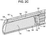
- the camera modulecan include an image sensor and a lens configured to direct reflected light onto the image sensor, the image sensor and the lens being disposed within the housing.
- the camera modulecan include an optical fiber having a distal end disposed within the housing and a proximal end in optical communication with a light source.
- the lenscan be disposed within a lens lumen of a lens barrel and the optical fiber can be disposed in an illumination lumen of the lens barrel.
- the illumination lumencan be disposed closer to the center of the access device working channel than the lens lumen.
- the lens barrelcan include a distal-facing surface that is obliquely angled relative to a central longitudinal axis of the working channel.
- the systemcan include a diffuser mounted in a recess formed in the distal-facing surface of the lens barrel over the optical fiber.
- the recesscan be crescent-shaped and can substantially follow the perimeter of the lens lumen.
- a central region of the lenscan be coated with hydrophobic coating and a peripheral region of the lens can be coated with a hydrophilic coating.
- the housingcan include a main body and a distal end cap.
- the main bodycan include a camera lumen in which the camera module is disposed and first and second fluid lumens.
- the camera lumencan be disposed centrally in the main body, between the first and second fluid lumens.
- a distal facing surface of the main body and a distal facing surface of the end capcan be obliquely angled relative to a central longitudinal axis of the working channel.
- the main bodycan have a sidewall having a concave inner surface disposed adjacent the working channel and a convex outer surface disposed opposite the inner surface.
- the inner surface of the sidewall of the main bodycan define at least a portion of an inner surface of the working channel.
- the outer surface of the sidewallcan include first and second planar regions connected by a central transition region that defines a section of a cylinder, the transition region following an outer perimeter of a camera lumen of the main body.
- the inner surfacecan be concavely curved and connected to the outer surface by first and second transition regions that define sections of respective cylinders, the first and second transition regions following the outer perimeters of first and second fluid lumens formed in the main body.
- the housingcan be formed from an inner circular tube disposed within and attached to an outer oval tube to define a camera lumen and first and second fluid lumens.
- the housingcan be formed from an inner circular tube having opposed first and second outer shells attached thereto to define a camera lumen and first and second fluid lumens.
- the end capcan include a cut-out axially aligned with a lens of the camera module and a cut-out axially aligned with an illumination system of the camera module.
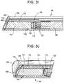
- a proximal-facing surface of the end capcan define a recess configured to direct fluid flowing out of a first fluid lumen of the housing across a lens of the camera module and into a second fluid lumen of the housing.
- the recesscan include lateral end portions axially aligned with the first and second fluid lumens and medial endportions that are open to a cut-out of the end cap.
- the systemcan include a connector assembly extending from the housing, the connector assembly including electrical and optical connections to the camera module and fluid connections to the housing.
- the connector assemblycan have an exterior shape that matches that of the housing.
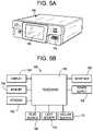
- the systemcan include a controller having an electronic display configured to display image data captured by an image sensor of the camera module.
- the visualization channelcan intersect or overlap with the working channel.
- the housing and the camera modulecan be axially-translatable relative to the access device.
- the visualization channelcan have a central longitudinal axis disposed radially outward from a central longitudinal axis of the working channel.
- the access devicecan include a mating feature configured to selectively hold the visualization system in a desired position relative to the access device.
- the mating featurecan include a locking track configured to receive a portion of the visualization system to restrict movement of the visualization system relative to the access device.
- the locking trackcan be formed in a proximal extension of the access device.
- the locking trackcan receive the visualization system in a snap-fit or friction fit.
- the mating featurecan include an adjustment track configured to receive at least a portion of the visualization system to allow movement of the visualization system relative to the access device.
- the visualization systemcan be configured such that the visualization system can be loaded into the locking track by moving it radially outward from a central longitudinal axis of the visualization channel.
- the locking trackcan be curved or obliquely angled away from a central longitudinal axis of the visualization channel.
- the visualization systemcan be configured such that the visualization system can be secured to the mating feature at any point along a connector assembly of the visualization system.
- the mating featurecan include a wheel that, when rotated, advances or retracts the visualization system relative to the access device.
- the mating featurecan include a coil spring clamp configured to selectively lock the visualization system in a fixed position relative to the access device.
- the mating featurecan include an O-ring disposed around a portion of the visualization system and a cone movably coupled to the access device, the cone being movable between a first position in which it expands the O-ring to allow movement of the visualization system relative to the access device and a second position in which the O-ring is released to clamp onto the visualization system and prevent movement of the visualization system relative to the access device.
- the systemcan include a sleeve insertable through the working channel of the access device, the sleeve having an outside diameter and a bulb movably coupled to the sleeve, the bulb being movable between a first position in which the bulb is disposed entirely within the outside diameter of the sleeve and a second position in which at least a portion of the bulb protrudes out from the outside diameter of the sleeve.
- the bulb in the second positioncan be configured to fill a void space within the access device distal to the visualization channel of the access device.
- the bulbcan include a distal-facing surface that is curved or ramped to form a gradual transition between a cylindrical dilator inserted through the sleeve and an outer surface of the access device.
- the bulbcan be movable between the first and second positions by translating the sleeve axially relative to the access device.
- the bulbcan be movable between the first and second positions by rotating the sleeve relative to the access device.
- the bulbcan be biased towards the second position.
- the access devicecan include a transition portion at a distal end thereof, the transition portion being movable between a first position in which the transition portion extends radially-inward to provide a gradual transition between a cylindrical dilator inserted through the working channel and an outer surface of the access device and a second position in which the transition portion is moved radially-outward from the first position.
- the systemcan include a dilation shaft insertable through the access device to move the transition portion to the second position.
- the transition portioncan include a plurality of flexible and resilient fingers.
- a visualization systemcan include a camera module having an image sensor and a lens; and a housing in which the camera module is disposed, the housing having a main body, first and second fluid channels, and an end cap configured to direct fluid flow through the channels across the lens of the camera module.
- the camera modulecan include an optical fiber having a distal end disposed within the housing and a proximal end in optical communication with a light source.
- the lenscan be disposed within a lens lumen of a lens barrel and the optical fiber can be disposed in an illumination lumen of the lens barrel.
- the systemcan include a diffuser mounted in a recess formed in a distal-facing surface of the lens barrel over the optical fiber. The recess can be crescent-shaped and can substantially follow the perimeter of the lens lumen.
- a central region of the lenscan be coated with a hydrophobic coating and a peripheral region of the lens can be coated with a hydrophilic coating.
- the camera modulecan be disposed centrally in the main body, between the first and second fluid channels.
- a distal facing surface of the main body and a distal facing surface of the end capcan be obliquely angled relative to a central longitudinal axis of the camera module.
- the main bodycan have an outer surface that includes first and second planar regions connected by a central transition region that defines a section of a cylinder, the transition region following an outer perimeter of a camera lumen of the main body.
- the main bodycan have an inner surface that is concavely curved and connected to the outer surface by first and second transition regions that define sections of respective cylinders, the first and second transition regions following the outer perimeters of the first and second fluid channels.
- the housingcan be formed from an inner circular tube disposed within and attached to an outer oval tube to define a camera lumen and the first and second fluid channels.
- the housingcan be formed from an inner circular tube having opposed first and second outer shells attached thereto to define a camera lumen and the first and second fluid channels.
- the end capcan include a cut-out axially aligned with the lens.
- a proximal-facing surface of the end capcan define a recess configured to direct fluid flowing out of the first fluid channel of the housing across the lens and into the second fluid channel of the housing.
- the recesscan include lateral end portions axially aligned with the first and second fluid channels and medial endportions that are open to the cut-out of the end cap.
- the systemcan include a connector assembly extending from the housing, the connector assembly including electrical and optical connections to the camera module and fluid connections to the housing.
- the connector assemblycan have an exterior shape that matches that of the housing.
- the systemcan include a controller having an electronic display configured to display image data captured by an image sensor of the camera module.
- a surgical methodcan include inserting an access device into a patient; mounting the access device to an anchor, the anchor comprising at least one of an anatomical structure of the patient and an implant implanted in the patient; inserting a camera module into the access device; adjusting a depth of the camera module relative to the access device; and securing the camera module to a mating feature of the access device to maintain the camera module at the adjusted depth.
- the anchorcan include a bone anchor implanted in a pedicle of the patient.
- the methodcan include performing a surgical procedure through the access device without using hands to hold the access device or the camera module.
- the methodcan include inserting a fusion cage through the access device and into an intervertebral disc space. Inserting the access device can include positioning a distal end of the access device in proximity to an intervertebral disc space of the patient via a TLIF approach.
- the methodcan include positioning the camera module in a relatively proximal position relative to the access device, performing a bone resection through the access device, positioning the camera module in a relatively distal position relative to the access device, and removing disc tissue through the access device.
- the methodcan include directing cleaning media through a housing in which the camera module is disposed and across a lens of the camera module. Inserting the access device can include positioning a distal end of the access device in a dry environment of the patient. Inserting the access device can include positioning a distal end of the access device in a sinus cavity of the patient. The method can include performing a laryngoscopy or a bronchoscopy using the camera module.
- FIG. 1is a perspective view of a surgical visualization system and an access device
- FIG. 2Ais a perspective view of a camera module of the system of FIG. 1 ;
- FIG. 2Bis a sectional side view of the camera module of FIG. 2A ;
- FIG. 2Cis a sectional perspective view of the camera module of FIG. 2A ;
- FIG. 3Ais a perspective view of a housing of the system of FIG. 1 , with the housing shown as transparent and with the camera module of FIG. 2A disposed therein;
- FIG. 3Bis a perspective view of the distal end of the housing and camera module of FIG. 3A ;
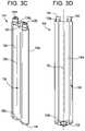
- FIG. 3Cis a perspective view of the housing of FIG. 3A ;
- FIG. 3Dis a side view of the housing of FIG. 3A ;
- FIG. 3Eis a sectional perspective view of the housing and camera module of FIG. 3A , adjacent a distal end thereof;
- FIG. 3Fis a perspective view of the distal end of the housing and camera module of FIG. 3A ;
- FIG. 3Gis a partially exploded perspective view of the housing and camera module of FIG. 3A ;
- FIG. 3His a perspective view of the housing and camera module of FIG. 3A , with an end cap of the housing shown as transparent and schematically illustrating fluid flow through the housing;
- FIG. 3Iis a sectional side view of the housing and camera module of FIG. 3A ;
- FIG. 3Jis a sectional perspective view of the housing and camera module of FIG. 3A ;
- FIG. 4Ais a perspective view of a connector assembly of the system of FIG. 1 ;
- FIG. 4Bis a sectional perspective view of the connector assembly of FIG. 4A , adjacent a distal end thereof;
- FIG. 5Ais a perspective view of a controller of the system of FIG. 1 ;
- FIG. 5Bis a schematic block diagram of the controller of FIG. 5A ;
- FIG. 6Ais a perspective view of the system of FIG. 1 disposed in an access device, with the access device shown as transparent;
- FIG. 6Bis a side view of the system and access device of FIG. 6A , with the access device shown as transparent;
- FIG. 6Cis a perspective view of the system and access device of FIG. 6A , with the system disposed in a locking track of the access device;
- FIG. 6Dis a perspective view of the system and access device of FIG. 6A , with the system disposed in an adjustment track of the access device;
- FIG. 6Eis a sectional side view of the system and access device of FIG. 6A ;
- FIG. 6Fis a sectional side view of the distal end of the system and access device of FIG. 6A ;
- FIG. 6Gis a top view of the system and access device of FIG. 6A ;
- FIG. 6His a sectional top view of the system and access device of FIG. 6A ;
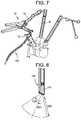
- FIG. 7is a perspective view of a surgical system, including the visualization system of FIG. 1 , in use to perform a surgical procedure on a patient's spine;
- FIG. 8is a sectional side view of the camera module of FIG. 2A , schematically illustrating viewing properties of the camera module;
- FIG. 9is a perspective view of the distal end of another exemplary housing.
- FIG. 10Ais a sectional top view of another exemplary housing
- FIG. 10Bis a sectional top view of another exemplary housing
- FIG. 11Ais a sectional perspective view of another exemplary housing
- FIG. 11Bis a perspective view of the housing of FIG. 11A ;
- FIG. 11Cis a sectional perspective view of the housing of FIG. 11A ;
- FIG. 11Dis a sectional perspective view of the housing of FIG. 11A ;
- FIG. 12Ais a sectional top view of another exemplary housing
- FIG. 12Bis an exploded and assembled view of another exemplary housing
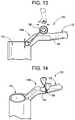
- FIG. 13is a side view of a mating feature that can be included in the access devices herein;
- FIG. 14is a perspective view of another mating feature that can be included in the access devices herein;
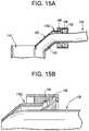
- FIG. 15Ais a sectional side view of another mating feature that can be included in the access devices herein, shown in locked state;
- FIG. 15Bis a sectional side view of the mating feature of FIG. 15A , shown in an unlocked state;
- FIG. 16Ais a perspective view of another mating feature that can be included in the access devices herein;
- FIG. 16Bis a sectional side view of the mating feature of FIG. 16A ;
- FIG. 16Cis a perspective view of the mating feature of FIG. 16A ;
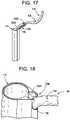
- FIG. 17is a perspective view of another mating feature that can be included in the access devices herein;
- FIG. 18is a perspective view of another mating feature that can be included in the access devices herein;
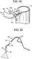
- FIG. 19is a perspective view of another mating feature that can be included in the access devices herein;
- FIG. 20is a perspective view of the system of FIG. 1 , shown with a user control;
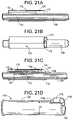
- FIG. 21Ais a sectional perspective view of an access device and a standard dilator
- FIG. 21Bis a perspective view of an access device and a dilation system
- FIG. 21Cis a sectional perspective view of the access device and dilation system of FIG. 21B ;
- FIG. 21Dis a perspective view of a sleeve of the dilation system of FIG. 21B ;
- FIG. 22Ais a proximal-facing end view of an access device and a dilation system in a first configuration
- FIG. 22Bis a proximal-facing end view of the access device and dilation system of FIG. 22A in a second configuration
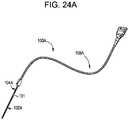
- FIG. 23Ais a perspective view of an access device
- FIG. 23Bis a sectional perspective view of the access device of FIG. 23A ;
- FIG. 23Cis a bottom view of the access device of FIG. 23A ;
- FIG. 23Dis a top view of the access device of FIG. 23A ;
- FIG. 23Eis a perspective view of a dilation shaft configured for use with the access device of FIG. 23A ;
- FIG. 23Fis a sectional perspective view of the dilation shaft of FIG. 23E inserted into the access device of FIG. 23A ;
- FIG. 23Gis a perspective view of the dilation shaft of FIG. 23E inserted into the access device of FIG. 23A ;
- FIG. 24Ais a perspective view of a visualization system
- FIG. 24Bis a perspective view of a housing, camera module, and mating feature of the visualization system of FIG. 24A ;
- FIG. 24Cis a perspective view of the mating feature of the visualization system of FIG. 24A .
- Surgical visualization systems and related methodsare disclosed herein, e.g., for providing visualization during surgical procedures.
- Systems and methods hereincan be used in a wide range of surgical procedures, including spinal surgeries such as minimally-invasive fusion or discectomy procedures.
- Systems and methods hereincan include various features for enhancing end user experience, improving clinical outcomes, or reducing the invasiveness of a surgery. Exemplary features can include access port integration, hands-free operation, active and/or passive lens cleaning, adjustable camera depth, and many others.
- the surgical visualization systems disclosed hereincan enable hands free visualization.
- a camera modulecan be mounted in an access device in a manner that eliminates the need for a surgeon, assistant, or other user to manually hold the camera in place.
- the access devicecan be secured to a support, e.g., an operating table, an anatomical anchor, or the like, eliminating the need for the user to manually hold the access port, or to hold a camera module disposed therein. Accordingly, the user's hands can be free to perform other steps of the surgery.
- the camera modulecan be separate and independent from surgical instruments used to carry out the procedure. Accordingly, the instruments with which the visualization system can be used are not restricted, and the system can be used with any of a variety of custom or off-the-shelf instruments. Such instruments can include instruments with increased size, strength, output force, and/or tissue processing capabilities.
- the visual trajectory of the cameracan be independent of instrument positioning. This can allow the camera, and/or an access device in which the camera is disposed, to remain relatively stationary as instruments are manipulated and as the procedure is carried out. The field of view of the camera can thus remain substantially fixed during the procedure, providing the user with good spatial orientation and providing a reduced learning curve as compared to other visualization systems.
- Visualization systems of the type described hereincan be integrated with an access device, can have a low-profile design, and/or can display captured images on an external monitor, reducing or eliminating these potential concerns.
- the surgical visualization systems disclosed hereincan enable adjustment of the depth of a camera within an access device.
- the camera depthcan be quickly and easily adjusted.
- the camera depthcan be adjusted with one hand in a tool-free manner.
- the ability to easily adjust camera depthcan allow visualization to be optimized for each stage of a surgical procedure in a seamless manner that does not interfere with or disrupt the surgical flow.
- the cameracan be retracted proximally when performing gross bone removal and other steps that are relatively low risk, but could cause the camera lens to become obscured with debris.
- the cameracan be advanced distally within the access device. In some cases, the camera can be advanced to protrude from the distal end of the access, e.g., to position the camera within an intervertebral disc space.
- the surgical visualization systems disclosed hereincan provide improved visualization in harsh or challenging operating environments.
- the operating environmentis dry (as compared to fluid filled cavities that exist in other surgeries where visualization systems are used) and a large amount of smoke and cutting debris can be generated during the surgery.
- the surgical visualization systems disclosed hereincan include active and/or passive features for clearing such debris from the camera lens, or for preventing such debris from blocking or sticking to the lens in the first place.
- the surgical visualization systems disclosed hereincan provide high-resolution visualization in minimally-invasive spinal procedures, such as endoscopic transforaminal lumbar interbody fusion (TLIF) procedures.
- TLIFtransforaminal lumbar interbody fusion
- the surgical visualization systems disclosed hereincan be a single-use disposable, can be easily cleanable or sterilizable, can have a low-profile, can be lightweight, can be low-cost, can have high resolution, and/or can be used in minimally-invasive surgery, e.g., spinal surgery.
- FIG. 1illustrates an exemplary surgical visualization system 100 .
- the system 100can include a camera module 102 disposed within a housing 104 .
- the housing 104can be configured for positioning at a surgical site or in proximity to a surgical site.
- the system 100can include a controller or display 106 for controlling the camera module 102 , for displaying images captured by the camera module, and so forth.
- the camera module 102 and/or the housing 104can be coupled to the controller 106 by a connector or connector assembly 108 .
- the connector assembly 108can include electrical and/or optical connections to the camera module 102 .
- the connector assembly 108can include fluid connections to the housing 104 .
- the fluid connectionscan be used to deliver material to the housing 104 , to withdraw material from the housing, or to both deliver and withdraw material from the housing, e.g., for cleaning a lens of the camera module 102 .
- the system 100can be selectively mountable to an access device 110 or other support, can be used independently, can be selectively mountable to a surgical robot or connector arm, can be insertable through a surgical instrument, or can be used in various other ways to facilitate a surgical procedure.
- the camera module 102is shown in greater detail in FIGS. 2A-2C .
- the camera module 102can include an image sensor 112 for capturing images of a field disposed in view of the image sensor, e.g., images of a surgical site.
- the image sensor 112can be configured to convert light directed onto the image sensor into an electronic signal.
- the image sensor 112can be configured to capture full color still and video images.
- the image sensor 112can be configured to capture 1080p high definition video.
- the image sensor 112can be a full-frame image sensor.
- the image sensor 112can be a charge-coupled-device (CCD) image sensor, a complementary-metal-oxide-semiconductor (CMOS) image sensor, an N-type metal-oxide-semiconductor (NMOS) image sensor, a video chip, a chip-on-tip camera, and/or can use various other image sensing technologies.
- CMOScomplementary-metal-oxide-semiconductor
- NMOSN-type metal-oxide-semiconductor
- the image sensor 112can be a monochromatic sensor having a pixel array and supporting circuitry that are sensitive to electromagnetic radiation of any wavelength. Exemplary image sensors 112 , and other features that can be included or incorporated in the camera module 102 , are disclosed in U.S.
- the camera module 102can include a lens or optical element 114 configured to direct light onto the image sensor 112 .
- the lens 114can be a static lens.
- the lens 114can be a monolithic block of optically-transparent material.
- the lens 114can be polymeric.
- the lens 114can have a fixed focal length or can have an adjustable focal length.
- the lens 114can include a mechanical shutter.
- the lens 114can include multiple optical elements movable relative to one another.
- the lens 114can include one or more motors, actuators, gears, etc. for adjusting the focal length, aperture size, shutter speed, and other parameters of the lens.
- the camera module 102can include a modular lens receiver such that a user can attach any of a variety of lenses to the camera module.
- Exemplary lenses 114can include prime lenses, normal lenses, wide-angle lenses, fisheye lenses, telephoto lenses, zoom lenses, anamorphic lenses, catadioptric lenses, lenses of varying focal lengths or varying ranges of focal lengths, etc.
- the lens 114can include a high speed autofocus.
- the lens 114can include an adjustable aperture and an adjustable shutter speed.
- the camera module 102can include an illumination system for illuminating a field of view of the image sensor 112 .
- the illumination systemcan include a digital or analog light source.
- the light sourcecan include one or more laser emitters or light-emitting diodes, an incandescent bulb, or the like.
- the light sourcecan emit light in any dithered, diffused, or collimated emission and can be controlled digitally or through analog methods or systems.
- the light sourcecan be pulsed to illuminate a surgical scene.
- the light sourcecan pulse in one or more partitions, where each partition is a pre-determined range of wavelengths of the electromagnetic spectrum that is less than the entire electromagnetic spectrum.
- the pixel array of the image sensor 112can be paired with the light source electronically, such that they are synced during operation for both receiving emissions of reflected electromagnetic radiation and for the adjustments made within the system.
- the light sourcecan be tuned to emit electromagnetic radiation.
- the light sourcecan pulse at an interval that corresponds to the operation and functionality of the pixel array.
- the light sourcecan pulse light in a plurality of electromagnetic partitions, such that the pixel array receives reflected electromagnetic energy and produces a data set that corresponds (in time) with each specific electromagnetic partition.
- the light sourcecan emit a green electromagnetic partition, a blue electromagnetic partition, and a red electromagnetic partition in any desired sequence which can be combined to form a color image.
- any color combination or any electromagnetic partitioncan be used in place of the red partition, green partition, and blue partition, such as cyan, magenta, and yellow, ultraviolet, infra-red, or any other combination, including all visible and non-visible wavelengths.
- Exemplary illumination systems, and other features that can be included or incorporated in the camera module 102are disclosed in U.S. Pat. No. 9,516,239 entitled YCBCR PULSED ILLUMINATION SCHEME IN A LIGHT DEFICIENT ENVIRONMENT; and U.S. Pat. No. 9,641,815 entitled SUPER RESOLUTION AND COLOR MOTION ARTIFACT CORRECTION IN A PULSED COLOR IMAGING SYSTEM, each of which is incorporated herein by reference.
- the light sourcecan be disposed within the housing 104 , or can be disposed remotely from the housing.
- the illumination systemcan include an optical fiber 116 having a distal end disposed within or in close proximity to the housing 104 and a proximal end in optical communication with a light source disposed remotely from the housing.
- the optical fiber 116can direct light emitted from the light source into the field of view of the image sensor 112 .
- the illumination systemcan include an optical element 118 for adjusting various illumination properties. Exemplary optical elements 118 can include diffusers, filters, and so forth.
- the camera module 102includes an optical element 118 , which is illustrated as a diffuser, disposed over the terminal distal end of an optical fiber 116 .
- the camera module 102can include a printed circuit board assembly (PCBA) 120 .
- the image sensor 112can be mounted directly to the PCBA 120 , or can be operably coupled thereto, e.g., using a connector 122 .
- the PCBA 120can include power conditioning circuitry, hardware logic, clocks, and/or other components for operating the image sensor 112 and communicating image data generated by the image sensor to the controller 106 .
- the lens barrel 124can include an outer sidewall having one or more channels or lumens formed therein.
- the lens barrel 124can include a lens lumen 126 and an illumination lumen 128 .
- the lens lumen 126can include proximal and distal ends 126 p , 126 d and a central longitudinal axis A 1 .
- the lens lumen 126can have a circular transverse cross-section.
- the lens 114can be disposed within a distal end of the lens lumen 126 .
- the image sensor 112can be positioned at or in a proximal end of the lens lumen 126 .
- the lens lumen 126can be open at its proximal and distal ends and closed along its sides as shown, or a portion or all of the lens lumen can be open to an outer sidewall of the lens barrel 124 .
- the illumination lumen 128can include proximal and distal ends 128 p , 128 d and a central longitudinal axis A 2 .
- the illumination lumen 128can have a circular transverse cross-section.
- the optical fiber 116can be disposed within the illumination lumen 128 .
- the illumination lumen 128can be open at its proximal and distal ends and closed along its sides or, as shown, a portion or all of the illumination lumen can be open to an outer sidewall of the lens barrel 124 . This can facilitate insertion of the optical fiber 116 into the lens barrel 124 during assembly, e.g., by allowing the optical fiber to be side-loaded or laterally-inserted into the illumination lumen 128 .
- the distal end of the illumination lumen 128can be curved or angled, e.g., such that it extends in a direction that is not parallel to the axis A 2 .
- This arrangementcan allow a planar distal end of a straight-cut optical fiber 116 to be oriented parallel to an angle-cut distal end of the lens barrel 124 , as shown.
- the optical fiber 116can be angle-cut to match the distal end of the lens barrel 124 .
- the lumens 126 , 128can be coaxial with one another or can be non-coaxial.
- the lumens 126 , 128can be laterally offset from each other.
- the lumens 126 , 128can be formed such that they extend parallel to one another, e.g., such that their respective central longitudinal axes A 1 , A 2 are parallel.
- the illumination lumen 128when integrated with an access device 110 , can be disposed radially-inward from the lens lumen 126 , e.g., such that the illumination lumen is disposed closer to the center of the access device working channel than the lens lumen. This can provide a more even distribution of light within the working channel of the access device 110 .
- the proximal end of the lens barrel 124can include a recess or pocket 130 .
- the image sensor 112can be disposed within the recess 130 .
- An image sensor connector 122 and/or at least a portion of the PCBA 120can be disposed within the recess 130 .
- the lens barrel 124can include an internal baffle 132 disposed between the lens 114 and the image sensor 112 .
- the baffle 132can include an aperture through which light passing through the lens 114 can be communicated to the image sensor 112 .
- the aperturecan have a fixed dimension or can be mechanically-adjustable.
- the lens barrel 124can include a distal-facing surface at a terminal distal end thereof.
- the lumens 126 , 128 of the lens barrel 124can be open to the distal-facing surface.
- the distal facing surfacecan be obliquely angled.
- the distal facing surfacecan lie substantially in a plane that is obliquely angled with respect to the central axis A 1 of the lens lumen 126 , obliquely angled with respect to the central axis A 2 of the illumination lumen 128 , and/or obliquely angled with respect to the central longitudinal axis of a working channel or access device in which the camera module 102 is disposed.
- the lens 114can be flush with the distal-facing surface as shown, or can be recessed or protruding therefrom.
- the distal-facing surfacecan include a recess 134 in which the diffuser or other optical element 118 of the illumination system can be disposed.
- the recess 134can be formed about the perimeter of the illumination lumen 128 .
- the recess 134 , and the optical element 118 disposed therein,can have a curved or crescent shape as shown.
- the recess 134can include an inner edge that follows or substantially follows the perimeter of the lens lumen 126 .
- the distal-facing surface of the lens barrel 124can be angled, in a distal-to-proximal direction, towards the center of the access device or a working channel thereof in which the camera module 102 is disposed. This can provide a better view of the surgical site for the image sensor 112 and/or a more even distribution of light within the surgical site.
- the lens barrel 124can have a transverse exterior cross-section that is oval, oblong, circular, elliptical, square, rectangular, etc.
- the camera module 102can be mounted in the housing 104 .
- the housing 104can include a main body 136 and a distal end cap 138 .
- the end cap 138can be configured to direct the fluid across the lens 114 and/or the illumination system of the camera module 102 , e.g., to clear obstructions therefrom.
- the housing 104can be rigid or flexible.
- the housing 104can be made as short as possible to facilitate positioning of the housing within an access device 110 .
- the housing 104can have a length that is less than about 60 mm.
- the housing 104can have a length of about 45 mm or that is less than about 45 mm.
- the main body 136 of the housing 104can include a proximal-facing surface 136 p , a distal-facing surface 136 d , and a sidewall 136 s connecting the proximal-facing and distal-facing surfaces.
- One or more channels or lumenscan be formed in the main body 136 .
- the main body 136can be formed by extrusion of a multi-lumen shaft.
- the main body 136can be formed by welding or otherwise attaching multiple longitudinal components to one another.
- the main body 136can include a camera lumen 140 in which the camera module 102 can be selectively mounted. At least a portion of the camera lumen 140 can be lined with or can otherwise include a metallic tube, which can provide electromagnetic shielding for the components of the camera module 102 .
- the main body 136can include one or more fluid lumens 142 .
- the main body 136includes a first fluid lumen 142 A, which can be used to convey material from a proximal end of the housing 104 to a distal end of the housing, and a second fluid lumen 142 B, which can be used to convey material from a distal end of the housing to the proximal end of the housing. While first and second fluid lumens 142 are shown, the housing 104 can include any number of fluid lumens.
- the first and second lumens 142can form part of a lens cleaning system in which cleaning fluid or media is delivered through one lumen to deliver the cleaning fluid to the distal end of the camera module 102 and suction or vacuum is applied to the other lumen to draw cleaning fluid, tissue, debris, or other material away from the camera module.
- Each of the lumens 142can include a fluid connector or coupling 144 at a proximal end thereof for establishing fluid communication between the lumens and the connector assembly 108 .
- the fluid connectors 144can be male barbed fittings that extend proximally from the proximal-facing surface 136 p of the main body 136 as shown, or can be any other type of fluid fitting or connection, such as a luer connection, a female fitting, etc.
- the lumens 140 , 142 of the housing 104can be co-axial, non-coaxial, or some lumens can be coaxial while others are non-coaxial.
- the camera lumen 140can be disposed centrally between first and second fluid lumens 142 as shown.
- the lumens 140 , 142 of the housing 104can be parallel to one another.
- the lumens 140 , 142can have various shapes.
- the lumens 140 , 142can have a transverse interior cross-section that is oval, oblong, circular, elliptical, square, rectangular, etc.
- the camera lumen 140can have an interior shape that matches the exterior shape of the camera module 102 , or the lens barrel 124 thereof.
- the distal facing surface 136 d of the main body 136can be obliquely angled.
- the distal facing surface 136 dcan lie substantially in a plane that is obliquely angled with respect to a central longitudinal axis A 3 of the housing 104 and/or obliquely angled with respect to the central longitudinal axis of a working channel or access device in which the housing is disposed.
- the distal-facing surface 136 d of the main body 136can be angled in the same manner as the distal-facing surface of the camera module 102 or lens barrel 124 .
- the distal-facing surface of the camera module 102can be flush with the distal-facing surface 136 d of the main body 136 , or can be recessed or protruding relative thereto.
- the sidewall 136 s of the housing 136can have any of a variety of shapes.
- the sidewall 136 scan have a transverse exterior cross-section that is substantially triangular, crescent shaped, circular, square, or rectangular.
- the sidewall 136 scan be cylindrical.
- the sidewall 136 scan be curved.
- the sidewall 136 scan be shaped to facilitate integration of the housing 104 with an access device 110 , e.g., to reduce or eliminate the degree to which the housing interferes with a working channel of the access device.
- the sidewall 136 scan include an inner portion 136 i that is concave.
- the inner portion 136 ican be curved.
- the inner portion 136 ican form a section of a working channel of an access device 110 , e.g., a cylindrical or elliptical working channel.
- the sidewall 136 scan include an outer portion 136 o that is convex.
- the outer portion 136 ocan be curved.
- the sidewall 136 scan include an outer portion 136 o having first and second planar regions connected by a central transition region that defines a section of a cylinder. The transition region can follow the outer perimeter of the camera lumen 140 .
- FIG. 3Ethe sidewall 136 s can include an outer portion 136 o having first and second planar regions connected by a central transition region that defines a section of a cylinder. The transition region can follow the outer perimeter of the camera lumen 140 .
- the sidewall 136 scan include an inner portion 136 i that is concavely curved and connected to the outer portion 136 o by first and second transition regions that define sections of respective cylinders.
- the first and second transition regionscan follow the outer perimeters of the fluid lumens 142 .
- the end cap 138 of the housing 104can be coupled to the distal end of the main body 136 .
- An exterior sidewall of the end cap 138can have a shape that matches that of the sidewall of the main body 136 .
- the end cap 138can include one or more cut-outs 146 formed therein.
- the end cap 138can include a first cut-out 146 A aligned with the lens 114 of the camera module 102 to allow light to pass through the end cap and into the lens.
- the end cap 138can include a second cut-out 146 B aligned with the illumination system of the camera module 102 to allow light to pass through the end cap and into the surgical site.
- the first and second cut-outs 146can be discrete cut-outs or can be contiguous as shown.
- the first and second cut-outs 146can be circular, can have a shape that matches that of the lens 114 or illumination system, or can be otherwise shaped to function as described above.
- a proximal-facing surface of the end cap 138can include one or more recesses, grooves, or channels 148 for directing fluid flow.
- the proximal-facing surface of the end cap 138can be a flat planar surface and the recesses, grooves, or channels 148 can be formed in the distal-facing surface of the main body 136 . Lateral endportions of the recesses 148 can be axially aligned with the fluid lumens 142 of the main body 136 .
- Medial endportions of the recesses 148can be open to the cut-outs 146 and/or to the distal-facing surface of the lens 114 and the illumination system.
- fluid exiting the first lumen 142 A of the main body 136can be directed by the end cap 138 across the lens 114 and the illumination system (e.g., the diffuser or optical element 118 of the illumination system) and towards the distal entrance of the second fluid lumen 142 B, e.g., along the path of the illustrated arrows. It will be appreciated that fluid can alternatively be directed in an opposite direction.
- the recesses 148can include baffles, nozzles, diverters, or other structures for tailoring the flow of fluid across the lens 114 and/or the illumination system.
- fluid flowcan be substantially contained to the interior of the end cap, e.g., without irrigating the surgical site or a working channel of an access device in which the housing 104 is mounted. Containing the fluid flow in this manner can be particularly useful in “dry environment” procedures such as a lumbar TLIF procedure. Containing the fluid flow can help limit bleeding and possible tissue damage.
- the fluidis not contained to the end cap and can be used to irrigate the surgical site and/or working channel.
- the housing 104 and/or the camera module 102can be coupled to the controller 106 via a connector or connector assembly 108 .
- An exemplary connector assembly 108is shown in FIGS. 4A-4B .
- the connector assembly 108can include one or more conductors therein.
- the connector assembly 108can include fluid conductors for delivering fluid to or from the housing 104 .
- the connector assembly 108can include optical conductors for delivering light to or from the camera module 102 .
- the connector assembly 108can include electrical conductors for communicating image data, control signals, or other information between the controller 106 and the camera module 102 .
- the conductorscan be disposed partially or entirely within an outer sheath 150 of the connector assembly 108 .
- the connector assembly 108can include a distal section 108 d and a proximal section 108 p .
- all of the conductors of the connector assembly 108can be disposed within the outer sheath 150 .
- one or more of the conductorscan exit the outer sheath 150 and can extend separately therefrom.
- the distal section 108 d of the connector assembly 108includes electrical conductors 152 A, one or more optical fibers 152 B, and first and second fluid lumens 152 C all extending through a common outer sheath 150 .
- the proximal section 108 p of the connector assembly 108is configured such that the electrical conductors 152 A and one or more optical fibers 152 B continue through the common outer sheath 150 while the first and second fluid lumens 152 C exit the outer sheath as discrete fluid tubes 154 .
- the outer sheath 150can include a mechanical connector 156 at a proximal end thereof for making optical and/or electrical connections with the controller 106 .
- the fluid tubes 154can include respective fluid fittings or connectors for making fluid connections, e.g., with a fluid reservoir and/or vacuum source of the controller 106 or separate from the controller.
- the distal section 108 d of the connector assembly 108can have an exterior shape that matches that of the housing 104 , e.g., as shown in FIG. 4B .
- the distal section 108 d of the connector assembly 108can mate with the housing 104 to define a seamless exterior transition.
- At least a portion of the connector assembly 108can be flexible or bendable.
- the distal section 108 d of the connector assembly 108can be flexible to facilitate integration of the system 100 with an access device 110 .
- FIGS. 5A-5BAn exemplary controller 106 is shown in FIGS. 5A-5B . Although an exemplary controller 106 is depicted and described herein, it will be appreciated that this is for sake of generality and convenience. In other embodiments, the controller 106 may differ in architecture and operation from that shown and described here.
- the controller 106can be a tablet computer, mobile device, smart phone, laptop computer, desktop computer, cloud-based computer, server computer, and so forth.
- the controller 106can include a processor 156 for controlling operation of the controller 106 , for example by executing embedded software, operating systems, device drivers, application programs, and so forth.
- the processor 156can be or can include one or more microprocessors, microcontrollers, ASICs, FPGAs, PICs, processors that read and interpret program instructions from internal or external memory or registers, and so forth.
- the controller 106can include a memory 158 , which can provide temporary or permanent storage for code to be executed by the processor 156 or for data that is processed by the processor.
- the memory 158can include read-only memory (ROM), flash memory, one or more varieties of random access memory (RAM), and/or a combination of memory technologies.
- the various components of the controller 106can be interconnected via any one or more separate traces, physical busses, communication lines, etc.
- the controller 106can include an interface 160 , such as a communication interface or an I/O interface.
- a communication interfacecan enable the controller 106 to communicate with remote devices (e.g., other controllers or computer systems) over a network or communications bus (e.g., a universal serial bus).
- An I/O interfacecan facilitate communication between one or more input devices, one or more output devices, and the various other components of the controller 106 .
- Exemplary input devicesinclude touch screens, mechanical buttons, keyboards, and pointing devices.
- the controller 106can include a storage device 162 , which can include any conventional medium for storing data in a non-volatile and/or non-transient manner.
- the storage device 162can include one or more hard disk drives, flash drives, USB drives, optical drives, various media disks or cards, and/or any combination thereof.
- the controller 106can include a display 164 , and can generate images to be displayed thereon.
- the display 164can be an electronic display, a vacuum fluorescent display (VFD), an organic light-emitting diode (OLED) display, or a liquid crystal display (LCD).
- the controller 106can include a power supply 166 and appropriate regulating and conditioning circuitry. Exemplary power supplies include batteries, such as polymer lithium ion batteries, or adapters for coupling the controller 106 to a DC or AC power source (e.g., a USB adapter or a wall adapter).
- the controller 106can include a fluid source 168 that can be in fluid communication with a fluid lumen 152 C of the connector assembly 108 when the connector assembly is attached to the controller 106 .
- the fluid source 168can include a reservoir of cleaning media.
- the cleaning mediacan be a flowable gas or liquid.
- the cleaning mediacan include one or more of carbon dioxide, saline, oxygen, air, water, and the like.
- the fluid source 168can include a pump or other mechanism for urging cleaning media through the connector assembly 108 and the housing 104 .
- the pumpcan be controlled by the processor 156 to execute a cleaning cycle.
- the cleaning cyclecan be executed automatically, or in response to a user instruction.
- the processor 156can detect user actuation of a button, foot pedal, or other interface element and initiate a cleaning cycle in response thereto.
- the controller 106can include a light source 170 that can be optically coupled to an optical fiber 152 B of the connector assembly 108 when the connector assembly is attached to the controller.
- exemplary light sourcesinclude light-emitting diodes (LEDs), incandescent or fluorescent bulbs, etc.
- the controller 106can include a vacuum or suction source 172 that can be in fluid communication with a fluid lumen 152 C of the connector assembly 108 when the connector assembly is attached to the controller.
- the controller 106can include an onboard vacuum pump for generating suction, or can be configured to attach to a standard hospital or operating room vacuum supply.
- the suction source 172can include a valve, regulator, or other component for adjusting the degree of suction applied to the housing 104 and/or for turning the suction on or off.
- the suction source 172can be controlled by the processor 156 , e.g., to execute a cleaning cycle.
- the cleaning cyclecan be executed automatically, or in response to a user instruction.
- the processor 156can detect user actuation of a button, foot pedal, or other interface element and initiate a cleaning cycle in response thereto.
- the controller 106can include one or more connectors 174 for mating with the connector 156 and/or the fluid couplings 154 of the connector assembly 108 . When mated, the connectors can establish electrical, optical, and/or fluid connections between the controller 106 and the connector assembly 108 . It will be appreciated that any one or more of the components above can be disposed external to the housing of the controller 106 , and/or can be separate or isolated from the controller altogether. For example, any one or more of the fluid source 168 , the light source 170 , and the suction source 172 can be external to and/or separate from the controller 106 .
- the controller 106can receive image data from the image sensor 112 .
- the image datacan be communicated via a wired or wireless connection.
- the image datacan include still image data and/or video image data.
- the controller 106can display the image data on an on-board display 164 of the controller, or on one or more external monitors or displays operably coupled to the controller.
- the image datacan be displayed to a surgeon or other user to facilitate a surgical procedure.
- the controller 106can display patient data, user interface controls for manipulating system settings, controls for capturing screen shots of displayed images, and so forth.
- controller 106can be logically described as being performed by one or more modules. It will be appreciated that such modules can be implemented in hardware, software, or a combination thereof. It will further be appreciated that, when implemented in software, modules can be part of a single program or one or more separate programs, and can be implemented in a variety of contexts (e.g., as part of an embedded software package, an operating system, a device driver, a standalone application, and/or combinations thereof). In addition, software embodying one or more modules can be stored as an executable program on one or more non-transitory computer-readable storage mediums.
- the system 100can be configured to be integrated or used with an access device.
- exemplary access devicescan include cannulas, retractors, tubes, and other structures for providing a working channel in a surgical application.
- the access devicecan define a working channel that extends from a surgical site, e.g., an intervertebral disc space or a spinal region proximate thereto, to a location outside a patient's body.
- the access devicecan include a visualization channel for receiving the housing 104 and the camera module 102 of the visualization system 100 .
- the visualization channelcan also receive at least a portion of the connector assembly 108 .
- the visualization channelcan be the same as the working channel, can be independent of the working channel, or can overlap or intersect with the working channel.
- At least a portion of the sidewall of the working channelcan be defined by an exterior surface of the housing 104 .
- the housing 104 and/or the camera module 102can be disposed off-center within the access device.
- the housing 104 and/or the camera module 102can be slidably and/or rotatably coupled to the access device.
- the housing 104 and/or the camera module 102can be axially translatable within the access device, e.g., in a proximal-distal direction, to adjust the depth of the camera module relative to the access device.
- the housing 104can be advanced distally relative to the access device to move the lens 114 and image sensor 112 closer to the surgical site.
- the housing 104can be retracted proximally relative to the access device to move the lens 114 and image sensor 112 farther from the surgical site.
- the ability to reposition the camera module 102 within the access devicecan facilitate various surgical procedures.
- the camera module 102can be positioned relatively shallow within the access device when cutting through Kambin's triangle and can then be advanced deeper within the access device when performing subsequent discectomy. In some cases, the camera module 102 can be advanced distally into the disc space.
- the ability to reposition the camera module 102can also allow the camera module to be a modular component interchangeably usable with many different types or sizes of access device, or with an adjustable-length access device.
- the access device 110can include an elongate body having proximal and distal ends.
- the access device 110can define a working channel 174 extending between the proximal and distal ends and having a central longitudinal axis A 4 .
- the working channel 174can be cylindrical.
- the working channel 174can have a circular transverse cross-section.
- the working channel 174can have a diameter in the range of about 3 mm to about 30 mm, in the range of about 10 mm to about 20 mm, and/or in the range of about 12 mm to about 15 mm.
- the working channel 174can have a diameter of about 15 mm. While a single working channel 174 is shown, the access device 110 can include any number of working channels. In use, instruments and/or implants can be disposed in, passed through, and/or inserted into the working channel 174 to perform a surgical procedure.
- the access device 110can be used to access an intervertebral disc space.
- a cutting instrumentcan be inserted through the working channel 174 to cut tissue, such as bone or disc tissue.
- An aspiration instrumentcan be inserted through the working channel 174 to aspirate material from the disc space, including excised bone or disc tissue.
- the cutting instrument and the aspiration instrumentcan be a single tool.
- An implantsuch as a fusion cage, a height and/or width expandable fusion cage, a disc prosthesis, or the like can be inserted into the disc space through the working channel 174 .
- the access device 110can define a visualization channel 176 .
- the visualization channel 176can extend between the proximal and distal ends of the access device 110 , or can extend along less than an entire length of the access device.
- the visualization channel 176can include a central longitudinal axis A 5 .
- the central axis A 5 of the visualization channel 176can be disposed radially-outward from the central axis A 4 of the working channel 174 .
- the working channel 174can have a greater transverse cross-sectional area than the visualization channel 176 .
- the visualization channel 176can be open to, or can intersect with, the working channel 174 along its length.
- the visualization channel 176can be isolated or separate from the working channel 174 .
- the visualization channel 176can have an interior transverse cross section that matches or substantially matches the exterior transverse cross-section of the housing 104 .
- an exterior surface of the housing 104can define at least a portion of the inner sidewall of the working channel 174 .
- the working channel 174can be cylindrical about the central axis A 4 and the surface of the housing 104 that faces the working channel can form a section of a cylinder centered on the axis A 4 .
- the inner sidewall of the working channel 174 and the outer surface of the housing 104can define a substantially smooth and continuous surface.
- the access device 110can include an attachment feature 180 , e.g., for attaching the access device to a support or other object.
- the attachment feature 180can be formed at a proximal end of the access device 110 .
- the access device 110can include an annular circumferential groove 180 formed in an exterior surface thereof.
- the access device 110can include a mating feature 178 for stabilizing, holding, and/or attaching the visualization system 100 to the access device.
- the mating feature 178can be a proximal extension of the access device 110 as shown.
- the mating feature 178can define one or more tracks 182 configured to receive the connector assembly 108 therein.
- the tracks 182can be open to one side such that the connector assembly 108 can be loaded laterally into the track, e.g., by moving the connector assembly away from the central axis A 5 of the visualization channel 176 .
- the connector assembly 108can be loaded into the mating feature 178 by translating the connector assembly proximally or distally relative thereto.
- One or more of the tracks 182can define a connector path that is curved or obliquely-angled away from the central axis A 5 of the visualization channel 176 .
- the track 182can have an interior transverse cross-section that matches or substantially matches the exterior transverse cross-section of the connector assembly 108 .
- the track 182can extend around the outer periphery of the connector assembly 108 .
- the track 182can extend around the connector assembly 108 to a sufficient degree that the free edges of the track interfere slightly with side-loading of the connector assembly into the track. Accordingly, slight deformation or deflection of the connector assembly 108 and/or the mating feature 178 can be required to load the connector assembly into the track 182 . This can allow the connector assembly 108 to be held securely by the mating feature 178 , e.g., by “snapping” the connector assembly into the track 182 .
- the mating feature 178can include inner and outer tracks 182 A, 182 B, e.g., as shown in FIGS. 6C, 6D, and 6G .
- the tracks 182can include interfering edges of the type described above to restrict movement of the connector assembly 108 into and out of the tracks, but to allow such movement when sufficient force is applied, e.g., when the user specifically intends to perform such movement.
- the inner track 182 Acan be axially aligned with the visualization channel 176 , or aligned therewith to a greater extent than the outer track 182 B.
- the outer track 182 Bcan be curved, obliquely angled, or otherwise axially offset from the visualization channel 176 .
- the connector assembly 108can be retained to the access device 110 , while still being able to translate proximally or distally relative to the access device with relatively little friction.
- proximal-distal translation of the connector assembly 108 relative to the access device 110can be limited or prevented, e.g., due to the curve of the connector assembly and/or due to increased friction between the connector assembly and the access device.
- the connector assembly 108can be positioned in the inner track 182 A to adjust the height of the camera module 102 relative to the access device 110 and can be positioned in the outer track 182 B to hold the camera module securely in place at a fixed height relative to the access device.
- the connector assembly 108can be secured to the mating feature 178 at any point along its length, e.g., at any point along the distal section 108 d of the connector assembly. Accordingly, the visualization system 100 can be locked to the access device 110 at any inserted depth of the camera module 102 . In addition, the visualization system 100 can be locked with the camera module 102 at a desired depth, regardless of the length of the access device 110 , the position of the mating feature 178 along the access device, etc. This can allow the visualization system 100 to be interchangeably used with any of a variety of different type or size access devices 110 .
- the ability to lock the system 100 to the mating feature 178can allow the camera module 102 to be used in a hands-free manner. In other words, the surgeon or other user does not need to manually grasp and/or hold the camera module 102 in place during use.
- the mating feature 178can provide for simple, quick, and/or one-handed depth adjustment of the camera module 102 , resulting in minimal delay and disruption to the procedure.
- the access device 110can have an exterior transverse cross section that is circular, e.g., as shown in FIG. 6G .
- the access device 110can have an exterior transverse cross section that is oblong or egg-shaped, e.g., as shown in FIG. 6H .
- the access device 110can include any of a variety of other exterior transverse cross sectional shapes.
- the access device 110can have an external diameter or dimension in the range of about 5 mm to about 30 mm, in the range of about 10 mm to about 25 mm, and/or in the range of about 15 mm to about 22 mm.
- the access device 110can have an external diameter or dimension of about 17 mm.
- the exterior surface of the access device 110can be roughened, ribbed, milled, or coated with or formed from a material having a high coefficient of friction, which can advantageously improve grip and stability with surrounding tissue when the access device is inserted into a patient.
- the lens 114 of the camera module 102when disposed in the access device 110 , can be aimed towards the central axis A 4 of the working channel 174 .
- the illumination system of the camera module 102e.g., the optical fiber 116 and/or the optical element 118 , can be aimed towards the central axis A 4 of the working channel 174 .
- the illumination systemcan be disposed radially-outward from the central axis A 4 of the working channel 174 and the lens 114 can be disposed radially-outward from the illumination system.
- FIG. 7illustrates an exemplary surgical system 10 in which the devices and methods described herein can be used, though it will be appreciated that such devices and methods can be used in various other applications instead or in addition. Further details on the system of FIG. 7 can be found in U.S. application Ser. No. 15/437,792 filed on Feb. 21, 2017, which is hereby incorporated by reference herein.
- the system 10can be used in various surgical procedures, including spinal surgeries such as microsurgical bone resection, spinal decompression, spinal fusion, and the like.
- the system 10can include any one or more of an access device 110 , a tissue retractor 12 , a pedicle post or other anchor 14 , a connector 16 , and a camera or visualization system 100 .
- the access device 110can be any of the access devices described herein.
- the visualization system 100can be any of the visualization systems described herein.
- An exemplary method of using the system 10 of FIG. 7can include any one or more of the following steps, performed in any of a variety of sequences: a) making an incision in a skin of a patient; b) percutaneously inserting through the incision an access device 110 having a substantially tubular shape (such as a tube or a multi-slotted retractor), the access device having a length adapted to extend from the incision to a border between sensitive and insensitive tissue (e.g., a superior articular process (SAP), or a lamina) in the spine of the patient; c) stabilizing the access device to an anchor 14 (e.g., a pedicle anchor) using a connector 16 ; d) inserting an access device integrated optical visualization system 100 , e.g., a visualization system of the type described herein; e) resecting a portion of the superior articular process, and/or performing a microsurgical decompression procedure; f) inserting or deploying a tissue retract
- the camera module 102can have a field-of-view (FOV), a direction of view (DOV), and a depth of field (DOF).
- the FOVcan be in the range of about 60 to about 70 degrees.
- the DOVcan be in the range of about 15 to 30 degrees.
- the DOVcan be in the range of about 20 to 25 degrees.
- the DOVcan be about 22.5 degrees.
- the DOFcan be in the range of about 7 mm to about 40 mm.
- the system 100can include active cleaning features. Active cleaning features can include application of an active force to the lens 114 , the illumination system, or other components of the camera module 102 .
- the active forcecan be or can include a fluid jet, fluid suction, mechanical or acoustic vibration, mechanical wipers, etc.
- the system 100can include passive cleaning features.
- the passive cleaning featurescan be used independently, or can augment or improve the performance of active cleaning features.
- the lens 114can have a coating applied thereto to resist or prevent adhesion of debris to the lens.
- the coatingcan be hydrophilic.
- the coatingcan be oleophilic.
- the coatingcan be hydrophobic.
- the coatingcan be oleophobic.
- the coatingcan be a pollution-repellant coating.
- the coatingcan be a gradient coating, e.g., one in which a central region of the lens has a hydrophobic coating and a peripheral region of the lens has a hydrophilic coating.
- the gradient lens coatingcan be effective to “walk” or direct fluid from the center of the lens towards the outer periphery of the lens and out of the way of the image sensor 112 .
- the fluid lumens 142 of the housing 104can each include a respective nozzle 184 disposed at a distal end thereof.
- the end cap 138 of the housing 104can be omitted in such arrangements.
- the nozzles 184can be configured to aim or direct the flow of fluid and/or suction forces towards the lens 114 or the illumination system of the camera module 102 .
- FIG. 10Aillustrates another exemplary transverse cross-section of the housing 104 .
- the fluid lumens 142can be enlarged and can be non-circular.
- the fluid lumens 142can be ear-shaped.
- the fluid lumens 142can be asymmetrical.
- FIG. 10Billustrates another exemplary transverse cross-section of the housing 104 .
- the fluid lumens 142can be crescent or banana shaped.
- the fluid lumens 142can have a convex inner sidewall that follows the outer periphery of the camera lumen 140 .
- FIGS. 11A-11Dillustrate the distal end of an alternative housing 104 having crescent-shaped fluid lumens 142 , an oval or oblong exterior transverse cross-section, and an end cap 138 with an oval or oblong central opening 146 .
- the main body 136 of the housing 104can be formed by welding or otherwise attaching multiple longitudinal components to one another.
- an inner circular tube 136 Acan be inserted into an outer oval tube 136 B to define a main body 136 having a central camera lumen 140 and first and second lateral fluid lumens 142 .
- the inner tube 136 Acan be welded, adhered, or otherwise attached and/or sealed to the outer tube 136 B.
- opposed outer shells 136 Ccan be welded or otherwise attached to an inner tube 136 A to define a main body 136 having a central camera lumen 140 and first and second lateral fluid lumens 142 .
- the outer shells 136 Ccan include respective proximal fluid couplings 144 and inner channels that connect the fluid couplings to the void spaces 142 formed between the shells and the inner tube 136 A when the components are mated to each other.
- the arrangement shown in FIG. 12Bcan advantageously allow a complex housing cross-section to be formed within one or more simple welds of the two shells 136 C to the inner tube 136 A and/or to each other.
- FIG. 13illustrates an exemplary mating feature 178 A for attaching the visualization system 100 to the access device 110 .
- the mating feature 178 Acan include a proximal extension of the access device 110 having a track 182 for guiding or holding the connector assembly 108 of the visualization system 100 .
- An actuation wheel or gear 186can be rotatably mounted over the track 182 .
- the wheel 186can be engaged with the connector assembly 108 such that rotation of the wheel advances or retracts the connector assembly relative to the access device 110 .
- the wheel 186can allow for stageless and precise depth adjustment of the camera module 102 .
- the wheel 186can include teeth, protrusions, or other surface features for enhancing user grip and/or friction between the wheel and the connector assembly 108 .
- the connector assembly 108can include teeth or ridges that can be enmeshed with the teeth of the wheel 186 .
- the wheel 186can be spring-biased into engagement with the connector assembly 108 .
- the gap between the wheel 186 and the track 182can be open to one side, e.g., to allow side-loading of the connector assembly 108 into the gap. The user can thus perform gross depth adjustment of the camera module 102 in a freehand manner, and then insert the connector assembly 108 into the gap and use the wheel 186 to achieve fine depth adjustment.
- FIG. 14illustrates an exemplary mating feature 178 B for attaching the visualization system 100 to the access device 110 .
- the mating feature 178 Bcan include a proximal extension of the access device 110 having a track 182 for guiding or holding the connector assembly 108 of the visualization system 100 .
- the mating feature 178 Bcan include a clamp 188 that can be actuated by a user to selectively grasp or selectively release the connector assembly 108 . Any of a variety of types of clamps can be used, though in the illustrated embodiment, the mating feature 178 B includes a coil spring 188 that defines a central passage through which the connector assembly 108 can be inserted.
- the spring 188can include handle levers that, when squeezed together, relax the tension of the spring and expand the diameter of the central passage to allow movement of the connector assembly 108 relative to the access device 110 .
- the tension in the spring 188can be increased to contract the diameter of the central passage and clamp down on the connector assembly 108 , thereby holding it in a fixed position relative to the access device 110 .
- FIGS. 15A-15Billustrate an exemplary mating feature 178 C for attaching the visualization system 100 to the access device 110 .
- the mating feature 178 Ccan include a proximal extension of the access device 110 having a track 182 for guiding or holding the connector assembly 108 of the visualization system 100 .
- the mating feature 178 Ccan include an O-ring 190 that defines a central passage through which the connector assembly 108 can be inserted.
- the O-ring 190can be maintained in a fixed position relative to the extension 178 C, such that when the O-ring clamps down on a connector assembly 108 inserted therethrough, the connector assembly can be maintained at a fixed position relative to the extension.
- the extension 178 Ccan include a movable button 192 with a conical or ramped bearing surface. As shown in FIG. 15B , pressing the button 192 into the extension 178 C (to the left in the drawing) can be effective to wedge the cone of the button into the O-ring 190 , thereby expanding the diameter of the O-ring and allowing movement of the connector assembly 108 relative to the extension. As shown in FIG. 15A , when the button 192 is released, a spring 194 can urge the button outward (to the right in the drawing), withdrawing the cone from the O-ring 190 to allow the O-ring diameter to contract and clamp down on the connector assembly 108 , thereby holding it in a fixed position relative to the access device 110 .
- FIGS. 16A-16Cillustrate an exemplary mating feature 178 D for attaching the visualization system 100 to the access device 110 .
- the mating feature 178 Dcan include a proximal extension of the access device 110 having a track 182 for guiding or holding the connector assembly 108 of the visualization system 100 .
- the mating feature 178 Dcan be an angled click-type fastening system of the type described above.
- the mating feature 178 Dcan be optimized for use with a connector assembly 108 having a circular exterior transverse cross-section.
- the mating feature 178 Dcan include a longitudinally-oriented adjustment track 182 A and an obliquely- or laterally-oriented locking track 182 B.
- FIG. 17illustrates an exemplary mating feature 178 E for attaching the visualization system 100 to the access device 110 .
- the mating feature 178 Ecan include a proximal extension of the access device 110 having a track 182 for guiding or holding the connector assembly 108 of the visualization system 100 .
- the mating feature 178 Ecan be an angled click-type fastening system of the type described above.
- the mating feature 178 Ecan include a longitudinally-oriented adjustment track 182 A and an obliquely- or laterally-oriented locking track 182 B.
- the locking track 182 Bcan be spaced a distance apart and radially-outward from the main body of the access device 110 by a strut or beam 196 .
- the mating feature 178 Ecan be configured to contact the connector assembly 108 only at the locking track 182 B.
- the mating feature 178 Ecan be simple to manufacture and can accommodate a gradual bend radius of the connector assembly 108 .
- FIG. 18illustrates an exemplary mating feature 178 F for attaching the visualization system 100 to the access device 110 .
- the mating feature 178 Fcan include a cut-out 198 formed in the proximal edge of the access device 110 .
- the mating feature 178 Fcan be a click-type fastening system of the type described above.
- the connector assembly 108can be positioned within a longitudinally-oriented adjustment track 182 A of the mating feature 178 F to allow depth adjustment of the camera module 102 .
- the connector assembly 108can be urged out of the adjustment track 182 A and into the cut-out 198 to apply sufficient friction to the connector assembly to limit or prevent depth adjustment of the camera module 102 .
- the cut-out 198can be U-shaped.
- the cut-out 198can be V-shaped.
- the mating feature 178 Fcan allow the connector assembly 108 to be routed away from the access device 110 at a greater angle and closer to the skin surface of the patient, reducing the overall profile of the system 100 and keeping the connector assembly out of the way of the surgeon or other user.
- FIG. 19illustrates an exemplary mating feature 178 G for attaching the visualization system 100 to the access device 110 .
- the mating feature 178 Gcan include a proximal extension of the access device 110 having a track 182 for guiding or holding the connector assembly 108 of the visualization system 100 .
- the mating feature 178 Gcan include a lid or closure cap 101 pivotably coupled thereto, e.g., via a living hinge or flexible material properties of the extension.
- the lid 101can be positioned in a closed state in which it clamps the connector assembly 108 to the extension to limit or prevent depth adjustment of the camera module 102 .
- the lid 101can be positioned in an open state in which it does not engage the connector assembly 108 , or engages the connector assembly to a lesser degree, such that the connector assembly is movable relative to the extension to adjust the depth of the camera module 102 .
- the lid 101can be retained in the closed state, e.g., via a snap-lock, click-lock, or other locking structure.
- the lid 101can include a lever 103 to facilitate release of the lid from the closed state.
- the visualization system 100can include a user control 105 .
- the user control 105can be disposed at any of a variety of locations along the visualization system 100 , e.g., along a distal portion of the connector assembly 108 as shown.
- the user control 105can be positioned within the sterile field. This can allow a surgeon or other user to actuate the control 105 directly, without having to leave the sterile field or rely on an assistant outside the sterile field.
- the control 105can be operably coupled to the camera module 102 , to the controller 106 , to the fluid source 168 , to the light source 170 , and/or to the suction source 172 .
- Actuation of the control 105can be effective to initiate a cleaning operation, to stop a cleaning operation, to capture an image, to rotate a display of images captured by the camera module 102 , to adjust a white balance of the displayed images, to adjust a brightness of the displayed images, to play or stop a recorded video, to zoom the displayed images in or out (optically and/or digitally), etc.
- the control 105can include one or more push buttons.
- the control 105can include one or more foot switches.
- the control 105can include a hand pump or syringe for directing cleaning media towards the camera module 102 .
- the control 105can include a remote control integrated into the connector assembly 108 .
- the control 105can include a remote control coupled to the controller 106 via a wired or wireless connection.
- the access devices disclosed hereincan be inserted into a patient using various dilation techniques.
- a guidewire or needlecan be inserted through a percutaneous incision in the patient.
- the guidewirecan be placed using fluoroscopic guidance, a surgical navigation system, freehand, or otherwise.
- the incisioncan be sequentially or serially dilated, for example by inserting one or more dilators over the guidewire, each having a progressively larger outside diameter.
- the access devicecan be inserted by placing the outer-most dilator into the working channel of the access device and sliding the access device distally along the dilator and into the patient.
- the one or more dilatorscan then be removed from the patient, leaving an open working channel through the access device through which the surgical procedure can be conducted.
- an access device 110can include a cylindrical working channel 174 and an offset visualization channel 176 .
- the access device 110can have a non-cylindrical exterior dimension.
- the visualization channel 176can terminate a distance apart from the distal end of the access device 110 , leaving a void space 107 within the access device distal to the visualization channel.
- a sharp transition or step 111can exist at the distal end of the access device 110 between the outer surface of the dilator and the outer surface of the access device adjacent the visualization channel 176 .
- a dilation systemcan be used to facilitate insertion of the access device 110 and dilation of tissue disposed in the path of the visualization channel 176 .
- FIGS. 21B-21Dillustrate an exemplary dilation system.
- the systemcan include a sleeve 113 with a bulb 115 movably coupled thereto.
- the bulb 115can occupy the void space 107 in the access device and provide a smooth transition 117 between the outer surface of the dilator 109 and the outer surface of the access device adjacent the visualization channel 176 . Accordingly, the bulb 115 can minimize or eliminate the above-described step 111 .
- the sleeve 113can be substantially cylindrical.
- the sleeve 113can be hollow to define a channel 119 through which a standard cylindrical dilator 109 can be inserted.
- the sleeve 113can define an outside diameter D.
- the bulb 115can be movable relative to the sleeve 113 between a first position in which the bulb is disposed entirely within the outside diameter D of the sleeve and a second position in which at least a portion of the bulb protrudes out from the outside diameter D of the sleeve.
- the bulb 115can be biased towards the second position.
- the bulb 115can be attached to or formed integrally with the sleeve 113 .
- the bulb 115can be attached to the sleeve by a spring.
- the bulb 115can be mounted at the distal end of a longitudinal leaf spring or flat spring 121 of the sleeve 113 .
- the spring 121can be an integral extension of the sleeve 113 defined between opposed longitudinal slits formed in the sleeve.
- the bulb 115can include a distal-facing surface 115 d that is ramped, curved, tapered, or otherwise configured to provide a smooth lead-in between the outside diameter of a dilator 109 disposed in the sleeve 113 and the outside diameter of the access device 110 .
- the bulb 115can include a proximal-facing surface 115 p that is ramped, curved, tapered, or otherwise configured to urge the bulb radially-inward towards the first position as the sleeve 113 is withdrawn proximally from the access device 110 .
- an incisioncan be sequentially dilated using standard cylindrical dilators, including an outermost dilator 109 .
- the sleeve 113can be loaded into the access device 110 with the bulb 115 disposed in the first, radially-inward position.
- the sleeve 113can be advanced distally relative to the access device 110 until the bulb 115 is at the depth of the void space 107 , at which point the bulb can move radially-outward to the second position under the bias of the spring 121 .
- the bulb 115can also be urged radially-outward, and maintained in that position, by insertion of a dilator 109 through the sleeve 113 .
- the access device 110 with the inserted sleeve 113can then be advanced distally over the outer-most dilator 109 .
- the distal-facing surface 115 d of the bulb 115can gently urge tissue out of the path of the access device.
- the dilators 109can be removed from the sleeve 113 by withdrawing the dilators proximally therefrom.
- the sleeve 113can also be removed from the access device 110 by withdrawing the sleeve proximally therefrom.
- the bulb 115can be urged radially-inward, e.g., by the proximal-facing surface 115 p of the bulb 115 bearing against the distal end of the visualization channel 176 , thereby moving the bulb to the first, radially-inward position to allow the sleeve to be removed from the access device.
- the sleeve 113can form a dilator having a profile at its distal end that differs from its profile at its proximal end.
- FIGS. 22A-22Billustrate another exemplary dilation system in which the sleeve 113 A is configured to rotate relative to the access device 110 about the central longitudinal axis A 4 of the working channel 174 .
- the sleeve 113 Acan have a longitudinal slit or other features for allowing the sleeve to expand and contract radially.
- the sleeve 113 Acan be radially-contracted upon insertion into the access device 110 to bias the bulb 115 A radially-outward.
- the sleeve 113 Acan be rotatable about the axis A 4 between a first position, shown in FIG.
- the bulb 115is rotationally offset from the void space 107 and thus deflected radially-inward by the inner sidewall of the working channel 174
- a second positionshown in FIG. 22B
- the bulbis rotationally aligned with the void space such that the bulb springs radially-outward to fill the void space.
- the bulb 115 AIn the first position, the bulb 115 A can be positioned such that it does not interfere with insertion or removal of the sleeve 113 A from the access device 110 .
- the bulb 115 Acan fill the void space 107 to provide a smooth transition between a dilator and the access device 110 , e.g., as described above.
- the sleeve 113 Acan form a dilator having a profile at its distal end that differs from its profile at its proximal end.
- FIGS. 23A-23Gillustrate another exemplary dilation system.
- the distal end of the access device 110 Acan include a ramped, curved, or tapered transition portion 123 that provides a smooth transition between a cylindrical dilator inserted through the working channel 174 of the access device and the outside surface of the access device adjacent the visualization channel 176 .
- the transition portion 123can be flexible or bendable.
- the transition portion 123can be movable between a first position in which the transition portion extends radially-inward to provide a smooth distal-facing dilation surface 123 d and a second position in which the transition portion is moved radially-outward from the first position so as not to obstruct the field of view of a camera module mounted in the access device 110 A.
- the transition portion 123can include one or more movable fingers 125 .
- the fingers 125can be defined by a plurality of longitudinal slits formed in the outer wall of the access device 110 A.
- the fingers 125can have resilient material properties, such that they are biased inwards towards the first position.
- the transition portion 123can be moved between the first and second positions by a dilation shaft 127 insertable through the access device 110 A.
- the dilation shaft 127can include a distal shroud 129 configured to contact and bear against the transition portion 123 as the dilation shaft is advanced distally within the access device 110 A to urge the transition portion radially outward.
- the shroud 129can form a section of a cylinder as shown.
- At least a portion of the visualization channel 176can be formed in the dilation shaft 127 .
- the dilation shaft 127can remain in place within the access device 110 when the camera module 102 is disposed in the access device and as the surgical procedure is performed.
- FIGS. 24A-24Cillustrate an auxiliary visualization system 100 A.
- the system 100 Acan be used independently, or can be used with the visualization system 100 described above.
- the system 100 Acan include a camera module 102 A, housing 104 A, and connector assembly 108 A, each of which can include any of the features of the corresponding components of the system 100 .
- the system 100 Acan be used as a freehand stylus-type or wand-type camera.
- the system 100 Acan be inserted through a working channel of an access device while the system 100 is inserted through a visualization channel of the access device.
- Both cameras 100 , 100 Acan be coupled to the same controller or display, or each can be coupled to an independent controller or display. Multiple auxiliary cameras 100 A can be used simultaneously.
- the auxiliary camera 100 Acan extend into the disc space and the primary camera 100 can remain within the access device.
- the auxiliary camera 100 Acan be attached to the access device using a mating feature 131 .
- the mating feature 131can be configured to hold or support the auxiliary camera 100 A relative to an access device.
- the mating feature 131can allow hands-free operation of the auxiliary camera 100 A.
- the mating feature 131can include a C-shaped clip or other mechanism 133 for attaching to the housing or connector assembly of the auxiliary camera 100 A.
- the mating feature 131can include any of the features described above with respect to mating features for attaching the visualization system 100 to an access device.
- the mating feature 131can include a distal clip or springy strip 135 for attaching the mating feature to the proximal rim of an access device.
- the visualization systems and/or access devices disclosed hereincan be used in any of a variety of surgical procedures.
- such systems and devicescan be used in ear, nose, and throat (ENT) surgery, sinus surgery, gastrointestinal (GI) surgery, abdominal surgery, intravascular surgery, cardiothoracic surgery, joint surgery, and so forth.
- the visualization systemcan be used, with or without an access device, as a self-cleaning endoscope for sinus surgery. Active and/or passive cleaning features of the system can reduce or eliminate the need to repeatedly withdraw the scope from the patient to clean the lens.
- the visualization systemcan be used, with or without an access device, as a self-cleaning endoscope for airway surgery (e.g., laryngoscopy, bronchoscopy, etc.).
- the visualization systemcan be used, with or without an access device, as a self-cleaning upper and/or lower GI scope.
- the visualization systemcan form a rigid endoscope with self-cleaning abilities.
- the devices disclosed hereincan be constructed from any of a variety of known materials. Exemplary materials include those which are suitable for use in surgical applications, including metals such as stainless steel, titanium, nickel, cobalt-chromium, or alloys and combinations thereof, polymers such as PEEK, ceramics, carbon fiber, and so forth.
- the various components of the devices disclosed hereincan be rigid or flexible. One or more components or portions of the device can be formed from a radiopaque material to facilitate visualization under fluoroscopy and other imaging techniques, or from a radiolucent material so as not to interfere with visualization of other structures. Exemplary radiolucent materials include carbon fiber and high-strength polymers.
- the devices and methods disclosed hereincan be used in minimally-invasive surgery and/or open surgery. While the devices and methods disclosed herein are generally described in the context of spinal surgery on a human patient, it will be appreciated that the methods and devices disclosed herein can be used in any type of surgery on a human or animal subject, in non-surgical applications, on non-living objects, and so forth.
Landscapes
- Health & Medical Sciences (AREA)
- Life Sciences & Earth Sciences (AREA)
- Surgery (AREA)
- Engineering & Computer Science (AREA)
- Biomedical Technology (AREA)
- General Health & Medical Sciences (AREA)
- Animal Behavior & Ethology (AREA)
- Veterinary Medicine (AREA)
- Public Health (AREA)
- Heart & Thoracic Surgery (AREA)
- Medical Informatics (AREA)
- Molecular Biology (AREA)
- Nuclear Medicine, Radiotherapy & Molecular Imaging (AREA)
- Pathology (AREA)
- Physics & Mathematics (AREA)
- Biophysics (AREA)
- Orthopedic Medicine & Surgery (AREA)
- Optics & Photonics (AREA)
- Radiology & Medical Imaging (AREA)
- Neurology (AREA)
- Oral & Maxillofacial Surgery (AREA)
- Neurosurgery (AREA)
- Physiology (AREA)
- Mechanical Engineering (AREA)
- Otolaryngology (AREA)
- Transplantation (AREA)
- Physical Education & Sports Medicine (AREA)
- Vascular Medicine (AREA)
- Cardiology (AREA)
- Pulmonology (AREA)
- Dentistry (AREA)
- Human Computer Interaction (AREA)
- Electromagnetism (AREA)
- Surgical Instruments (AREA)
- Endoscopes (AREA)
- Memory System Of A Hierarchy Structure (AREA)
- Aerials With Secondary Devices (AREA)
- Prostheses (AREA)
Abstract
Description
Claims (33)
Priority Applications (10)
| Application Number | Priority Date | Filing Date | Title |
|---|---|---|---|
| US15/692,845US11331090B2 (en) | 2015-09-04 | 2017-08-31 | Surgical visualization systems and related methods |
| US15/901,435US11344190B2 (en) | 2015-09-04 | 2018-02-21 | Surgical visualization systems and related methods |
| EP18764249.1AEP3749168B1 (en) | 2017-03-08 | 2018-03-08 | Surgical visualization systems |
| PCT/US2018/021449WO2018165365A2 (en) | 2017-03-08 | 2018-03-08 | Surgical visualization systems and related methods |
| AU2018231239AAU2018231239B2 (en) | 2017-03-08 | 2018-03-08 | Surgical visualization systems and related methods |
| PCT/US2018/047136WO2019050666A1 (en) | 2015-09-04 | 2018-08-21 | Multi-shield spinal access system |
| US17/192,889US11744447B2 (en) | 2015-09-04 | 2021-03-05 | Surgical visualization systems and related methods |
| US17/728,967US11950766B2 (en) | 2015-09-04 | 2022-04-25 | Surgical visualization systems and related methods |
| US17/740,305US11793546B2 (en) | 2015-09-04 | 2022-05-09 | Surgical visualization systems and related methods |
| US18/479,048US12383302B2 (en) | 2015-09-04 | 2023-09-30 | Surgical visualization systems and related methods |
Applications Claiming Priority (6)
| Application Number | Priority Date | Filing Date | Title |
|---|---|---|---|
| US201562214297P | 2015-09-04 | 2015-09-04 | |
| US15/254,877US10987129B2 (en) | 2015-09-04 | 2016-09-01 | Multi-shield spinal access system |
| US15/437,792US10874425B2 (en) | 2015-09-04 | 2017-02-21 | Multi-shield spinal access system |
| US201762468475P | 2017-03-08 | 2017-03-08 | |
| US15/692,845US11331090B2 (en) | 2015-09-04 | 2017-08-31 | Surgical visualization systems and related methods |
| US15/901,435US11344190B2 (en) | 2015-09-04 | 2018-02-21 | Surgical visualization systems and related methods |
Related Parent Applications (1)
| Application Number | Title | Priority Date | Filing Date |
|---|---|---|---|
| US15/437,792Continuation-In-PartUS10874425B2 (en) | 2015-09-04 | 2017-02-21 | Multi-shield spinal access system |
Related Child Applications (2)
| Application Number | Title | Priority Date | Filing Date |
|---|---|---|---|
| US15/901,435Continuation-In-PartUS11344190B2 (en) | 2015-09-04 | 2018-02-21 | Surgical visualization systems and related methods |
| US17/728,967ContinuationUS11950766B2 (en) | 2015-09-04 | 2022-04-25 | Surgical visualization systems and related methods |
Publications (2)
| Publication Number | Publication Date |
|---|---|
| US20180008138A1 US20180008138A1 (en) | 2018-01-11 |
| US11331090B2true US11331090B2 (en) | 2022-05-17 |
Family
ID=68172031
Family Applications (15)
| Application Number | Title | Priority Date | Filing Date |
|---|---|---|---|
| US15/254,877Active2037-02-24US10987129B2 (en) | 2015-09-04 | 2016-09-01 | Multi-shield spinal access system |
| US15/437,792Active2038-05-15US10874425B2 (en) | 2015-09-04 | 2017-02-21 | Multi-shield spinal access system |
| US15/692,845Active2036-11-17US11331090B2 (en) | 2015-09-04 | 2017-08-31 | Surgical visualization systems and related methods |
| US15/697,494Active2036-10-24US11000312B2 (en) | 2015-09-04 | 2017-09-07 | Multi-shield spinal access system |
| US15/786,923Active2036-11-07US10869659B2 (en) | 2015-09-04 | 2017-10-18 | Surgical instrument connectors and related methods |
| US15/786,858Active2036-10-25US10758220B2 (en) | 2015-09-04 | 2017-10-18 | Devices and methods for providing surgical access |
| US15/786,891Active2036-11-30US10682130B2 (en) | 2015-09-04 | 2017-10-18 | Surgical access port stabilization |
| US15/786,846ActiveUS10779810B2 (en) | 2015-09-04 | 2017-10-18 | Devices and methods for surgical retraction |
| US15/901,435Active2037-07-27US11344190B2 (en) | 2015-09-04 | 2018-02-21 | Surgical visualization systems and related methods |
| US15/931,839Active2038-01-08US11801070B2 (en) | 2015-09-04 | 2020-05-14 | Surgical access port stabilization |
| US16/985,200Active2037-08-09US11806043B2 (en) | 2015-09-04 | 2020-08-04 | Devices and methods for providing surgical access |
| US17/159,129ActiveUS11712264B2 (en) | 2015-09-04 | 2021-01-26 | Multi-shield spinal access system |
| US17/214,759Active2037-09-26US11883064B2 (en) | 2015-09-04 | 2021-03-26 | Multi-shield spinal access system |
| US17/740,305ActiveUS11793546B2 (en) | 2015-09-04 | 2022-05-09 | Surgical visualization systems and related methods |
| US18/479,048Active2036-10-02US12383302B2 (en) | 2015-09-04 | 2023-09-30 | Surgical visualization systems and related methods |
Family Applications Before (2)
| Application Number | Title | Priority Date | Filing Date |
|---|---|---|---|
| US15/254,877Active2037-02-24US10987129B2 (en) | 2015-09-04 | 2016-09-01 | Multi-shield spinal access system |
| US15/437,792Active2038-05-15US10874425B2 (en) | 2015-09-04 | 2017-02-21 | Multi-shield spinal access system |
Family Applications After (12)
| Application Number | Title | Priority Date | Filing Date |
|---|---|---|---|
| US15/697,494Active2036-10-24US11000312B2 (en) | 2015-09-04 | 2017-09-07 | Multi-shield spinal access system |
| US15/786,923Active2036-11-07US10869659B2 (en) | 2015-09-04 | 2017-10-18 | Surgical instrument connectors and related methods |
| US15/786,858Active2036-10-25US10758220B2 (en) | 2015-09-04 | 2017-10-18 | Devices and methods for providing surgical access |
| US15/786,891Active2036-11-30US10682130B2 (en) | 2015-09-04 | 2017-10-18 | Surgical access port stabilization |
| US15/786,846ActiveUS10779810B2 (en) | 2015-09-04 | 2017-10-18 | Devices and methods for surgical retraction |
| US15/901,435Active2037-07-27US11344190B2 (en) | 2015-09-04 | 2018-02-21 | Surgical visualization systems and related methods |
| US15/931,839Active2038-01-08US11801070B2 (en) | 2015-09-04 | 2020-05-14 | Surgical access port stabilization |
| US16/985,200Active2037-08-09US11806043B2 (en) | 2015-09-04 | 2020-08-04 | Devices and methods for providing surgical access |
| US17/159,129ActiveUS11712264B2 (en) | 2015-09-04 | 2021-01-26 | Multi-shield spinal access system |
| US17/214,759Active2037-09-26US11883064B2 (en) | 2015-09-04 | 2021-03-26 | Multi-shield spinal access system |
| US17/740,305ActiveUS11793546B2 (en) | 2015-09-04 | 2022-05-09 | Surgical visualization systems and related methods |
| US18/479,048Active2036-10-02US12383302B2 (en) | 2015-09-04 | 2023-09-30 | Surgical visualization systems and related methods |
Country Status (6)
| Country | Link |
|---|---|
| US (15) | US10987129B2 (en) |
| EP (6) | EP4534013A1 (en) |
| JP (1) | JP6816122B2 (en) |
| CN (3) | CN108135440A (en) |
| AU (1) | AU2018225113B2 (en) |
| WO (3) | WO2017040873A1 (en) |
Cited By (5)
| Publication number | Priority date | Publication date | Assignee | Title |
|---|---|---|---|---|
| US11672562B2 (en) | 2015-09-04 | 2023-06-13 | Medos International Sarl | Multi-shield spinal access system |
| US11712264B2 (en) | 2015-09-04 | 2023-08-01 | Medos International Sarl | Multi-shield spinal access system |
| US11744447B2 (en) | 2015-09-04 | 2023-09-05 | Medos International | Surgical visualization systems and related methods |
| US12150636B2 (en) | 2015-09-04 | 2024-11-26 | Medos International Sárl | Surgical instrument connectors and related methods |
| US12193704B2 (en) | 2015-09-04 | 2025-01-14 | Medos International Sàrl | Multi-shield spinal access system |
Families Citing this family (217)
| Publication number | Priority date | Publication date | Assignee | Title |
|---|---|---|---|---|
| DE10154163A1 (en) | 2001-11-03 | 2003-05-22 | Advanced Med Tech | Device for straightening and stabilizing the spine |
| WO2006058221A2 (en) | 2004-11-24 | 2006-06-01 | Abdou Samy M | Devices and methods for inter-vertebral orthopedic device placement |
| US8979931B2 (en) | 2006-12-08 | 2015-03-17 | DePuy Synthes Products, LLC | Nucleus replacement device and method |
| US20090088789A1 (en) | 2007-09-28 | 2009-04-02 | O'neil Michael J | Balloon With Shape Control For Spinal Procedures |
| BRPI0818608A2 (en) | 2007-10-05 | 2015-04-22 | Synthes Gmbh | Sequential directional dilatation system for dilating from a nerve of a patient's anatomy, and method for forming an access opening through a psoas muscle to a patient's spine using a dilatation system |
| US8764806B2 (en)* | 2009-12-07 | 2014-07-01 | Samy Abdou | Devices and methods for minimally invasive spinal stabilization and instrumentation |
| US9913577B2 (en) | 2010-09-28 | 2018-03-13 | Obp Medical Corporation | Speculum |
| US8845728B1 (en) | 2011-09-23 | 2014-09-30 | Samy Abdou | Spinal fixation devices and methods of use |
| US9622779B2 (en) | 2011-10-27 | 2017-04-18 | DePuy Synthes Products, Inc. | Method and devices for a sub-splenius / supra-levator scapulae surgical access technique |
| US9808232B2 (en) | 2011-11-01 | 2017-11-07 | DePuy Synthes Products, Inc. | Dilation system |
| US20130226240A1 (en) | 2012-02-22 | 2013-08-29 | Samy Abdou | Spinous process fixation devices and methods of use |
| US9265490B2 (en) | 2012-04-16 | 2016-02-23 | DePuy Synthes Products, Inc. | Detachable dilator blade |
| US9198767B2 (en) | 2012-08-28 | 2015-12-01 | Samy Abdou | Devices and methods for spinal stabilization and instrumentation |
| US9480855B2 (en) | 2012-09-26 | 2016-11-01 | DePuy Synthes Products, Inc. | NIR/red light for lateral neuroprotection |
| US9320617B2 (en) | 2012-10-22 | 2016-04-26 | Cogent Spine, LLC | Devices and methods for spinal stabilization and instrumentation |
| FR3005569B1 (en) | 2013-05-16 | 2021-09-03 | Ldr Medical | VERTEBRAL IMPLANT, VERTEBRAL IMPLANT FIXATION DEVICE AND IMPLANTATION INSTRUMENTATION |
| US10918368B2 (en) | 2014-05-28 | 2021-02-16 | Mako Surgical Corp. | Force measuring joint distraction lever |
| US12082800B2 (en) | 2014-05-28 | 2024-09-10 | Mako Surgical Corp. | Force measuring joint distraction lever |
| US11253246B2 (en)* | 2018-06-21 | 2022-02-22 | Mako Surgical Corp. | Electronic force measuring joint distraction lever and method of use thereof |
| US9980737B2 (en) | 2014-08-04 | 2018-05-29 | Medos International Sarl | Flexible transport auger |
| US10264959B2 (en) | 2014-09-09 | 2019-04-23 | Medos International Sarl | Proximal-end securement of a minimally invasive working channel |
| US10111712B2 (en) | 2014-09-09 | 2018-10-30 | Medos International Sarl | Proximal-end securement of a minimally invasive working channel |
| US9924979B2 (en) | 2014-09-09 | 2018-03-27 | Medos International Sarl | Proximal-end securement of a minimally invasive working channel |
| US9867602B2 (en) | 2015-02-05 | 2018-01-16 | Obp Medical Corporation | Illuminated surgical retractor |
| US10420538B2 (en) | 2015-02-05 | 2019-09-24 | Obp Medical Corporation | Illuminated surgical retractor |
| US10786264B2 (en) | 2015-03-31 | 2020-09-29 | Medos International Sarl | Percutaneous disc clearing device |
| US10939899B2 (en) | 2015-06-03 | 2021-03-09 | Obp Medical Corporation | End cap assembly for retractor and other medical devices |
| US10881387B2 (en) | 2015-06-03 | 2021-01-05 | Obp Medical Corporation | Retractor |
| ES2968069T3 (en) | 2015-06-03 | 2024-05-07 | Obp Surgical Corp | Retractor |
| JP2018517507A (en) | 2015-06-11 | 2018-07-05 | ハウメディカ・オステオニクス・コーポレイション | Spinal fixation targeting system and method for posterior spine surgery |
| US10278687B2 (en)* | 2015-08-18 | 2019-05-07 | Globus Medical, Inc. | Devices and systems for surgical retraction |
| US11439380B2 (en) | 2015-09-04 | 2022-09-13 | Medos International Sarl | Surgical instrument connectors and related methods |
| US10857003B1 (en) | 2015-10-14 | 2020-12-08 | Samy Abdou | Devices and methods for vertebral stabilization |
| EP3376987B1 (en)* | 2015-11-19 | 2020-10-28 | EOS Imaging | Method of preoperative planning to correct spine misalignment of a patient |
| US10299838B2 (en) | 2016-02-05 | 2019-05-28 | Medos International Sarl | Method and instruments for interbody fusion and posterior fixation through a single incision |
| US10349823B2 (en) | 2016-03-11 | 2019-07-16 | Colorado Voice Clinic, P.C. | Retractor and tip extender therefor |
| US10405875B2 (en) | 2016-05-05 | 2019-09-10 | Misonix, Incorporated | Ultrasonic surgical instrument and method for manufacturing same |
| WO2017200555A1 (en)* | 2016-05-20 | 2017-11-23 | Choicespine, Lp | Access instruments to extend a surgical working channel |
| US11413064B2 (en)* | 2016-07-01 | 2022-08-16 | Intuitive Surgical Operations, Inc. | Computer-assisted tele-operated surgery systems and methods |
| US10722621B2 (en) | 2016-07-11 | 2020-07-28 | Obp Medical Corporation | Illuminated suction device |
| GB2556616B (en)* | 2016-07-21 | 2019-09-25 | Cipher Surgical Ltd | Scope assembly |
| US10744000B1 (en) | 2016-10-25 | 2020-08-18 | Samy Abdou | Devices and methods for vertebral bone realignment |
| US10973648B1 (en) | 2016-10-25 | 2021-04-13 | Samy Abdou | Devices and methods for vertebral bone realignment |
| WO2018162647A1 (en) | 2017-03-08 | 2018-09-13 | Medos International Sarl | Surgical access port stabilization |
| WO2018165367A1 (en)* | 2017-03-08 | 2018-09-13 | Medos International Sàrl | Devices and methods for providing surgical access |
| WO2018165365A2 (en)* | 2017-03-08 | 2018-09-13 | Medos International Sàrl | Surgical visualization systems and related methods |
| USD866759S1 (en) | 2017-03-13 | 2019-11-12 | Colorado Voice Clinic, P.C. | Retractor |
| DE102017106714A1 (en)* | 2017-03-29 | 2018-10-04 | Karl Storz Se & Co. Kg | Observation instrument with optical arrangement |
| US10449006B2 (en)* | 2017-04-05 | 2019-10-22 | Warsaw Orthopedic, Inc. | Surgical instrument and method |
| US12083300B2 (en)* | 2017-04-20 | 2024-09-10 | Resnent, Llc | Endoscopic balloon dilator systems |
| US10334687B2 (en)* | 2017-04-20 | 2019-06-25 | Ngok Wing Jimmy Kwok | Multispectral switch fiber optic lighting laryngoscope |
| US20180333061A1 (en)* | 2017-05-18 | 2018-11-22 | DePuy Synthes Products, Inc. | Neural monitoring devices and methods |
| US11076745B2 (en)* | 2017-05-26 | 2021-08-03 | Covidien Lp | Bronchoscopy coupling devices |
| USD839816S1 (en)* | 2017-07-17 | 2019-02-05 | Brunswick Corporation | Dipstick |
| US10687793B2 (en) | 2017-07-18 | 2020-06-23 | Obp Medical Corporation | Minimally invasive no touch (MINT) procedure for harvesting the great saphenous vein (GSV) and venous hydrodissector and retractor for use during the MINT procedure |
| CA3015089A1 (en) | 2017-08-23 | 2019-02-23 | Memic Innovative Surgery Ltd. | Tools and methods for vaginal access |
| JP7346386B2 (en)* | 2017-09-07 | 2023-09-19 | メドス・インターナショナル・エスエイアールエル | Multi-shield spinal access system |
| US10278572B1 (en) | 2017-10-19 | 2019-05-07 | Obp Medical Corporation | Speculum |
| CN107874735B (en)* | 2017-10-25 | 2018-10-19 | 珠海康弘发展有限公司 | A kind of percutaneous spinal endoscopes in big channel suitable for fusion device under mirror |
| BR112020012744A2 (en)* | 2017-12-27 | 2020-12-01 | Ethicon Llc | fluorescence imaging in a light-deficient environment |
| US11076920B2 (en) | 2018-01-16 | 2021-08-03 | Microendoscopic Spine Institute, LLC | Instrumentation and surgical method for image-guided microendoscopic decompression |
| WO2019152523A1 (en)* | 2018-01-30 | 2019-08-08 | Rebound Therapeutics Corporation | Devices and method for access and visualization for lumbar interbody fusion (lif) |
| US10799229B2 (en) | 2018-02-20 | 2020-10-13 | Obp Medical Corporation | Illuminated medical devices |
| EP4606345A2 (en) | 2018-02-20 | 2025-08-27 | CooperSurgical, Inc. | Illuminated medical devices |
| WO2019164893A1 (en) | 2018-02-21 | 2019-08-29 | Medos International Sàrl | Surgical visualization systems and related methods |
| US11141816B2 (en)* | 2018-05-17 | 2021-10-12 | Raytheon Technologies Corporation | Nozzle cover |
| US20210077091A1 (en)* | 2018-05-29 | 2021-03-18 | Smith & Nephew, Inc. | Suture passer with locking actuator |
| JP6943341B2 (en)* | 2018-06-28 | 2021-09-29 | 株式会社村田製作所 | Vibration device and optical detection device |
| US11571205B2 (en) | 2018-07-16 | 2023-02-07 | Cilag Gmbh International | Surgical visualization feedback system |
| US11596298B2 (en)* | 2018-08-27 | 2023-03-07 | Meditrina, Inc. | Endoscope and method of use |
| CN109171888B (en)* | 2018-08-30 | 2019-05-21 | 重庆市肿瘤研究所 | A kind of visual ultrasound knife and long-range ultrasonic surgical systems for liver and gall surgical department |
| US11179248B2 (en) | 2018-10-02 | 2021-11-23 | Samy Abdou | Devices and methods for spinal implantation |
| DE102018126794A1 (en)* | 2018-10-26 | 2020-04-30 | Hoya Corporation | Endoscope head with a housing element made of a transparent material |
| US10646104B1 (en) | 2018-10-29 | 2020-05-12 | G.I. View Ltd. | Disposable endoscope |
| EP3886674A4 (en)* | 2018-11-29 | 2022-08-03 | Board of Regents, The University of Texas System | DEVICES, SYSTEMS AND METHODS FOR CLEANING AN ELONGATED INSTRUMENT SURFACE |
| WO2020123911A1 (en)* | 2018-12-13 | 2020-06-18 | Vantari Medical Llc | Navigational device to guide placment of spinal screws |
| CN113301839B (en)* | 2019-01-15 | 2025-03-14 | 波士顿科学国际有限公司 | Endoscope stabilization tool and related use method |
| US11358184B2 (en)* | 2019-01-18 | 2022-06-14 | Johnson Controls Tyco IP Holdings LLP | Sensor system having transparent window contaminant removal using vibration |
| WO2020154596A1 (en)* | 2019-01-24 | 2020-07-30 | Noah Medical Corporation | Single use devices with integrated vision capabilities |
| USD911521S1 (en) | 2019-02-19 | 2021-02-23 | Obp Medical Corporation | Handle for medical devices including surgical retractors |
| US11013530B2 (en) | 2019-03-08 | 2021-05-25 | Medos International Sarl | Surface features for device retention |
| EP4360583A3 (en)* | 2019-03-13 | 2024-07-10 | Medos International Sàrl | Spinal access system |
| US12257013B2 (en) | 2019-03-15 | 2025-03-25 | Cilag Gmbh International | Robotic surgical systems with mechanisms for scaling camera magnification according to proximity of surgical tool to tissue |
| US20240156495A1 (en)* | 2019-03-22 | 2024-05-16 | Texas Scottish Rite Hospital For Children | Hinge-Link Spinal Correction Device and Method |
| US11241252B2 (en) | 2019-03-22 | 2022-02-08 | Medos International Sarl | Skin foundation access portal |
| US11129727B2 (en) | 2019-03-29 | 2021-09-28 | Medos International Sari | Inflatable non-distracting intervertebral implants and related methods |
| US11813026B2 (en) | 2019-04-05 | 2023-11-14 | Medos International Sarl | Systems, devices, and methods for providing surgical trajectory guidance |
| USD904607S1 (en) | 2019-05-07 | 2020-12-08 | Obp Medical Corporation | Nasal retractor |
| US11278358B2 (en)* | 2019-05-14 | 2022-03-22 | Medos International Sarl | Assembly for coupling a patient reference array to a medical implant such as a pedicle screw |
| US10806539B1 (en) | 2019-05-15 | 2020-10-20 | Medos International Sarl | Adjustable patient reference array |
| US11937783B2 (en)* | 2019-05-29 | 2024-03-26 | Stryker Corporation | Systems and methods for intraoperative surgical scope cleaning |
| NL2023241B1 (en)* | 2019-05-31 | 2020-12-07 | Petrus Stegmann Johann | Intervertebral fusion cage |
| US11298242B2 (en) | 2019-06-14 | 2022-04-12 | Medos International Sarl | Biomaterial delivery device, and related systems and methods |
| US11622094B2 (en) | 2019-06-20 | 2023-04-04 | Cilag Gmbh International | Wide dynamic range using a monochrome image sensor for fluorescence imaging |
| US11877065B2 (en) | 2019-06-20 | 2024-01-16 | Cilag Gmbh International | Image rotation in an endoscopic hyperspectral imaging system |
| US11903563B2 (en) | 2019-06-20 | 2024-02-20 | Cilag Gmbh International | Offset illumination of a scene using multiple emitters in a fluorescence imaging system |
| US11457154B2 (en) | 2019-06-20 | 2022-09-27 | Cilag Gmbh International | Speckle removal in a pulsed hyperspectral, fluorescence, and laser mapping imaging system |
| US12013496B2 (en) | 2019-06-20 | 2024-06-18 | Cilag Gmbh International | Noise aware edge enhancement in a pulsed laser mapping imaging system |
| US11360028B2 (en) | 2019-06-20 | 2022-06-14 | Cilag Gmbh International | Super resolution and color motion artifact correction in a pulsed hyperspectral, fluorescence, and laser mapping imaging system |
| US11925328B2 (en) | 2019-06-20 | 2024-03-12 | Cilag Gmbh International | Noise aware edge enhancement in a pulsed hyperspectral imaging system |
| US11700995B2 (en) | 2019-06-20 | 2023-07-18 | Cilag Gmbh International | Speckle removal in a pulsed fluorescence imaging system |
| US12126887B2 (en) | 2019-06-20 | 2024-10-22 | Cilag Gmbh International | Hyperspectral and fluorescence imaging with topology laser scanning in a light deficient environment |
| US10841504B1 (en) | 2019-06-20 | 2020-11-17 | Ethicon Llc | Fluorescence imaging with minimal area monolithic image sensor |
| US11389066B2 (en) | 2019-06-20 | 2022-07-19 | Cilag Gmbh International | Noise aware edge enhancement in a pulsed hyperspectral, fluorescence, and laser mapping imaging system |
| US11516387B2 (en) | 2019-06-20 | 2022-11-29 | Cilag Gmbh International | Image synchronization without input clock and data transmission clock in a pulsed hyperspectral, fluorescence, and laser mapping imaging system |
| US11931009B2 (en) | 2019-06-20 | 2024-03-19 | Cilag Gmbh International | Offset illumination of a scene using multiple emitters in a hyperspectral imaging system |
| US11540696B2 (en) | 2019-06-20 | 2023-01-03 | Cilag Gmbh International | Noise aware edge enhancement in a pulsed fluorescence imaging system |
| US11311183B2 (en) | 2019-06-20 | 2022-04-26 | Cilag Gmbh International | Controlling integral energy of a laser pulse in a fluorescence imaging system |
| US11252326B2 (en) | 2019-06-20 | 2022-02-15 | Cilag Gmbh International | Pulsed illumination in a laser mapping imaging system |
| US10952619B2 (en) | 2019-06-20 | 2021-03-23 | Ethicon Llc | Hyperspectral and fluorescence imaging and topology laser mapping with minimal area monolithic image sensor |
| US11624830B2 (en) | 2019-06-20 | 2023-04-11 | Cilag Gmbh International | Wide dynamic range using a monochrome image sensor for laser mapping imaging |
| US11187658B2 (en) | 2019-06-20 | 2021-11-30 | Cilag Gmbh International | Fluorescence imaging with fixed pattern noise cancellation |
| US11237270B2 (en) | 2019-06-20 | 2022-02-01 | Cilag Gmbh International | Hyperspectral, fluorescence, and laser mapping imaging with fixed pattern noise cancellation |
| US11671691B2 (en) | 2019-06-20 | 2023-06-06 | Cilag Gmbh International | Image rotation in an endoscopic laser mapping imaging system |
| US11589819B2 (en) | 2019-06-20 | 2023-02-28 | Cilag Gmbh International | Offset illumination of a scene using multiple emitters in a laser mapping imaging system |
| US11944273B2 (en) | 2019-06-20 | 2024-04-02 | Cilag Gmbh International | Fluorescence videostroboscopy of vocal cords |
| US11134832B2 (en) | 2019-06-20 | 2021-10-05 | Cilag Gmbh International | Image rotation in an endoscopic hyperspectral, fluorescence, and laser mapping imaging system |
| US11898909B2 (en) | 2019-06-20 | 2024-02-13 | Cilag Gmbh International | Noise aware edge enhancement in a pulsed fluorescence imaging system |
| US11012599B2 (en) | 2019-06-20 | 2021-05-18 | Ethicon Llc | Hyperspectral imaging in a light deficient environment |
| US11758256B2 (en) | 2019-06-20 | 2023-09-12 | Cilag Gmbh International | Fluorescence imaging in a light deficient environment |
| US11674848B2 (en) | 2019-06-20 | 2023-06-13 | Cilag Gmbh International | Wide dynamic range using a monochrome image sensor for hyperspectral imaging |
| US11716543B2 (en) | 2019-06-20 | 2023-08-01 | Cilag Gmbh International | Wide dynamic range using a monochrome image sensor for fluorescence imaging |
| US11550057B2 (en) | 2019-06-20 | 2023-01-10 | Cilag Gmbh International | Offset illumination of a scene using multiple emitters in a fluorescence imaging system |
| US11633089B2 (en) | 2019-06-20 | 2023-04-25 | Cilag Gmbh International | Fluorescence imaging with minimal area monolithic image sensor |
| US12007550B2 (en) | 2019-06-20 | 2024-06-11 | Cilag Gmbh International | Driving light emissions according to a jitter specification in a spectral imaging system |
| US11793399B2 (en) | 2019-06-20 | 2023-10-24 | Cilag Gmbh International | Super resolution and color motion artifact correction in a pulsed hyperspectral imaging system |
| US12181412B2 (en) | 2019-06-20 | 2024-12-31 | Cilag Gmbh International | Minimizing image sensor input/output in a pulsed hyperspectral, fluorescence, and laser mapping imaging system |
| US11464653B2 (en)* | 2019-06-30 | 2022-10-11 | Innovasis, Inc. | Minimally invasive surgery (MIS) methods and devices |
| US11065033B2 (en) | 2019-07-02 | 2021-07-20 | Musc Foundation For Research Development | Minimally invasive subdural evacuating system |
| US12027063B2 (en)* | 2019-07-18 | 2024-07-02 | The Board Of Regents Of The University Of Texas System | Constraint device and method of training for use of laparoscopic instruments |
| EP3772317B1 (en)* | 2019-08-07 | 2023-07-12 | ETH Zürich | Endoscope |
| US11464648B2 (en)* | 2019-09-09 | 2022-10-11 | Amplify Surgical, Inc. | Multi-portal surgical systems |
| US11678906B2 (en)* | 2019-09-09 | 2023-06-20 | Amplify Surgical, Inc. | Multi-portal surgical systems, cannulas, and related technologies |
| CA3157112A1 (en)* | 2019-11-04 | 2021-05-14 | Gulf Medical Technologies | Cleaning device for surgical tool |
| US11944356B2 (en) | 2019-11-22 | 2024-04-02 | Medos International Sarl | Control member for adjusting access tube position, and related systems and methods |
| EP4065211A1 (en)* | 2019-11-27 | 2022-10-05 | Galvani Bioelectronics Limited | System and methods for laparoscopic delivery and deployment of a neural interface |
| US11759193B2 (en)* | 2019-12-20 | 2023-09-19 | Medos International Sarl | Retractor members, and related systems and methods |
| US20210196319A1 (en)* | 2019-12-29 | 2021-07-01 | Biosense Webster (Israel) Ltd | Trocar with internal camera providing tilted view angle |
| US11819242B2 (en)* | 2019-12-29 | 2023-11-21 | Biosense Webster (Israel) Ltd. | Navigated trocar with internal camera |
| US11759283B2 (en) | 2019-12-30 | 2023-09-19 | Cilag Gmbh International | Surgical systems for generating three dimensional constructs of anatomical organs and coupling identified anatomical structures thereto |
| US11832996B2 (en) | 2019-12-30 | 2023-12-05 | Cilag Gmbh International | Analyzing surgical trends by a surgical system |
| US12053223B2 (en) | 2019-12-30 | 2024-08-06 | Cilag Gmbh International | Adaptive surgical system control according to surgical smoke particulate characteristics |
| US11648060B2 (en) | 2019-12-30 | 2023-05-16 | Cilag Gmbh International | Surgical system for overlaying surgical instrument data onto a virtual three dimensional construct of an organ |
| US11219501B2 (en) | 2019-12-30 | 2022-01-11 | Cilag Gmbh International | Visualization systems using structured light |
| US12002571B2 (en) | 2019-12-30 | 2024-06-04 | Cilag Gmbh International | Dynamic surgical visualization systems |
| US11284963B2 (en) | 2019-12-30 | 2022-03-29 | Cilag Gmbh International | Method of using imaging devices in surgery |
| US11744667B2 (en)* | 2019-12-30 | 2023-09-05 | Cilag Gmbh International | Adaptive visualization by a surgical system |
| US11776144B2 (en) | 2019-12-30 | 2023-10-03 | Cilag Gmbh International | System and method for determining, adjusting, and managing resection margin about a subject tissue |
| US12207881B2 (en) | 2019-12-30 | 2025-01-28 | Cilag Gmbh International | Surgical systems correlating visualization data and powered surgical instrument data |
| US11896442B2 (en) | 2019-12-30 | 2024-02-13 | Cilag Gmbh International | Surgical systems for proposing and corroborating organ portion removals |
| US11013399B1 (en)* | 2020-01-27 | 2021-05-25 | Board Of Regents, The University Of Texas System | Wiper assembly for imaging element cleaning apparatus |
| BR212022007502U2 (en)* | 2020-01-30 | 2022-08-23 | Renato De Abreu Igor | CONSTRUCTION PROVISION APPLIED IN RIGID ENDOSCOPE FOR CLEANING THE OBJECTIVE LENS DURING THE VIDEO-SURGICAL PROCEDURE |
| US10959609B1 (en) | 2020-01-31 | 2021-03-30 | Obp Medical Corporation | Illuminated suction device |
| US10966702B1 (en) | 2020-02-25 | 2021-04-06 | Obp Medical Corporation | Illuminated dual-blade retractor |
| US12279787B2 (en) | 2020-02-27 | 2025-04-22 | Misonix, Llc | Spinal surgery method |
| US12042337B2 (en) | 2020-03-13 | 2024-07-23 | Ashish Patel | Dura shield |
| CN111227937B (en)* | 2020-03-23 | 2025-07-08 | 苏州点合医疗科技有限公司 | Matrix needle type bone surface coordinate mapper |
| USD944986S1 (en)* | 2020-03-25 | 2022-03-01 | Seffiline S.R.L. | Surgical guide |
| US20210369098A1 (en)* | 2020-05-26 | 2021-12-02 | Covidien Lp | Endoscope including a cleaning assembly |
| WO2021242544A1 (en)* | 2020-05-27 | 2021-12-02 | Rhode Island Hospital | Lumbar facetectomy guide |
| CN111493952A (en)* | 2020-05-29 | 2020-08-07 | 北京市富乐科技开发有限公司 | Intervertebral body strutting assembly and intervertebral body strutting device |
| US11317973B2 (en)* | 2020-06-09 | 2022-05-03 | Globus Medical, Inc. | Camera tracking bar for computer assisted navigation during surgery |
| CN111920488B (en)* | 2020-08-06 | 2022-03-25 | 江苏新智源医学科技有限公司 | Buckle type telescopic puncture tube assembly capable of adapting to different patients |
| CN111920484B (en)* | 2020-08-06 | 2021-12-14 | 张波 | Puncture outfit adaptable to different patients |
| CN111920491B (en)* | 2020-08-06 | 2022-04-29 | 重庆橙壹科技有限公司 | Medical cannula assembly and length adjusting method thereof |
| US11998403B2 (en) | 2020-08-17 | 2024-06-04 | Covidien Lp | Endoscope cleaning device |
| CN111938774B (en)* | 2020-08-17 | 2021-08-24 | 济南市儿童医院 | An elongated tube assembly incorporating an adaptive latch for use in surgical procedures |
| CN111887955B (en)* | 2020-08-17 | 2022-04-26 | 常州市康心医疗器械有限公司 | Elongated tube assembly containing lever lock for minimally invasive surgery |
| CN111920492B (en)* | 2020-08-17 | 2022-09-13 | 重庆橙壹科技有限公司 | An elongated tube assembly comprising three-layer tubes for rigid endoscopic surgery |
| CN113576619A (en)* | 2020-08-17 | 2021-11-02 | 重庆橙壹科技有限公司 | Cannula assembly including radial retention block for surgical procedures |
| CN111938770B (en)* | 2020-08-17 | 2022-06-14 | 辐瑞森生物科技(昆山)有限公司 | Elongated tube component containing elastic chuck for hard tube endoscopic surgery |
| US20220079618A1 (en)* | 2020-09-15 | 2022-03-17 | Covidien Lp | Trocar stabilization clamp |
| CA3195337A1 (en) | 2020-10-25 | 2022-04-28 | Dan Voic | Spinal surgery apparatus |
| WO2022094229A1 (en)* | 2020-10-30 | 2022-05-05 | Baxter International Inc. | Organ retractor |
| US12347100B2 (en) | 2020-11-19 | 2025-07-01 | Mazor Robotics Ltd. | Systems and methods for generating virtual images |
| EP4008284B1 (en) | 2020-12-02 | 2024-10-23 | Biedermann Technologies GmbH & Co. KG | Connection device for use with extension members of a bone anchor |
| US20220183722A1 (en)* | 2020-12-10 | 2022-06-16 | Sanjay Amarasinghe | Pedicle tract stabilization system |
| US11389204B2 (en)* | 2020-12-17 | 2022-07-19 | Institute For Spine & Scoliosis, P.A. | Method for improved spinal correction surgery implementing non-fusion anterior scoliosis correction techniques for release of discs |
| US12193711B2 (en)* | 2020-12-17 | 2025-01-14 | Md Antonacci Family Trust | Method for improved spinal correction surgery implementing non-fusion anterior scoliosis correction techniques |
| CN112754653B (en)* | 2021-01-15 | 2022-05-24 | 江苏省人民医院 | Laparoscope microwave needle |
| US20220265326A1 (en) | 2021-02-23 | 2022-08-25 | Nuvasive Specialized Orthopedics, Inc. | Adjustable implant, system and methods |
| US11771517B2 (en) | 2021-03-12 | 2023-10-03 | Medos International Sarl | Camera position indication systems and methods |
| US20220211263A1 (en)* | 2021-03-23 | 2022-07-07 | Axcess Instruments Inc. | Multi-piece access port imaging systems |
| US12178418B2 (en) | 2021-03-31 | 2024-12-31 | Moon Surgical Sas | Co-manipulation surgical system having a coupling mechanism removeably attachable to surgical instruments |
| WO2022208414A1 (en) | 2021-03-31 | 2022-10-06 | Moon Surgical Sas | Co-manipulation surgical system for use with surgical instruments for performing laparoscopic surgery |
| US12042241B2 (en) | 2021-03-31 | 2024-07-23 | Moon Surgical Sas | Co-manipulation surgical system having automated preset robot arm configurations |
| US12167900B2 (en) | 2021-03-31 | 2024-12-17 | Moon Surgical Sas | Co-manipulation surgical system having automated preset robot arm configurations |
| US11832909B2 (en) | 2021-03-31 | 2023-12-05 | Moon Surgical Sas | Co-manipulation surgical system having actuatable setup joints |
| US11819302B2 (en) | 2021-03-31 | 2023-11-21 | Moon Surgical Sas | Co-manipulation surgical system having user guided stage control |
| US11844583B2 (en) | 2021-03-31 | 2023-12-19 | Moon Surgical Sas | Co-manipulation surgical system having an instrument centering mode for automatic scope movements |
| US11812938B2 (en) | 2021-03-31 | 2023-11-14 | Moon Surgical Sas | Co-manipulation surgical system having a coupling mechanism removeably attachable to surgical instruments |
| US12042133B2 (en) | 2021-05-07 | 2024-07-23 | Arthrex, Inc. | System providing improved visibility for minimally invasive surgery systems |
| CN113456251A (en)* | 2021-06-30 | 2021-10-01 | 南京希麦迪医药科技有限公司 | Bayesian model-based tumor statistical analysis method and system |
| WO2023273929A1 (en)* | 2021-06-30 | 2023-01-05 | 李广成 | Fluid-assisted minimally invasive surgery visualization device |
| CN113413122A (en)* | 2021-06-30 | 2021-09-21 | 苏州梅德厚普医疗科技有限公司 | Visual device for fluid-assisted minimally invasive surgery |
| US12402905B2 (en) | 2021-08-13 | 2025-09-02 | Misonix, Llc | Serrated ultrasonic cutting blade with varied tooth pitch |
| TWI823304B (en)* | 2021-09-07 | 2023-11-21 | 陳階曉 | Medical endoscope system |
| US20230128242A1 (en)* | 2021-10-26 | 2023-04-27 | Medos International Sarl | Flexible surgical access port |
| IL313601A (en)* | 2021-12-20 | 2024-08-01 | Lem Surgical Ag | Synchronized robotic bone milling |
| US12408955B2 (en)* | 2021-12-28 | 2025-09-09 | Nuvasive, Inc. | Adapter for patient reference array and bone anchor assembly |
| US20230218284A1 (en)* | 2022-01-11 | 2023-07-13 | Ryan Park | Inflatable balloon retractor with pressure sensing and feedback capabilities for avoidance of excess applied pressure in brain surgery |
| US20230255465A1 (en)* | 2022-02-16 | 2023-08-17 | II Vandy T. Gaffney | Laryngoscope With Video Capture |
| US20240065533A1 (en)* | 2022-08-30 | 2024-02-29 | Integrated Endoscopy, Inc. | Endoscope with interchangeable cannula adapter |
| US11931011B1 (en) | 2022-09-25 | 2024-03-19 | Robert Michael Evans | Telescope maintenance devices and assemblies |
| IT202200020976A1 (en)* | 2022-10-11 | 2024-04-11 | Luciano Forino | MEDICAL DEVICE FOR PERCUTANEOUS DISCECTOMY |
| JP2024079660A (en)* | 2022-11-30 | 2024-06-11 | ニューヴェイジヴ,インコーポレイテッド | Surgical retractor systems and components |
| US11950770B1 (en) | 2022-12-01 | 2024-04-09 | Amplify Surgical, Inc. | Multi-portal split cannulas, endoscopic hemostatic dispensers and surgical tools |
| US12232790B2 (en) | 2022-12-30 | 2025-02-25 | IvyTech Design LLC | Adjustable angle orthopedic distractor, compressor, and distractor-compressor |
| US11986165B1 (en) | 2023-01-09 | 2024-05-21 | Moon Surgical Sas | Co-manipulation surgical system for use with surgical instruments for performing laparoscopic surgery while estimating hold force |
| US12370001B2 (en) | 2023-01-09 | 2025-07-29 | Moon Surgical Sas | Co-manipulation surgical system having automated user override detection |
| US11839442B1 (en) | 2023-01-09 | 2023-12-12 | Moon Surgical Sas | Co-manipulation surgical system for use with surgical instruments for performing laparoscopic surgery while estimating hold force |
| US12239307B2 (en)* | 2023-02-21 | 2025-03-04 | Jgmg Bengochea, Llc | Modular length adjustable tubular retractor and a tube breaker |
| DE102023104405A1 (en)* | 2023-02-23 | 2024-08-29 | Laser Zentrum Hannover E.V. | Endoscope and method of operation |
| WO2024220993A1 (en)* | 2023-04-21 | 2024-10-24 | The Regents Of The University Of Michigan | Laryngoscope with improved visualization |
| US12318080B2 (en) | 2023-07-21 | 2025-06-03 | Coopersurgical, Inc. | Illuminated surgical retractor capable of hand-held operation and of being mounted to a fixed frame |
| US12220110B1 (en) | 2023-09-27 | 2025-02-11 | King Faisal University | Self-fixing transparent proctoscope |
| US20250169860A1 (en)* | 2023-11-27 | 2025-05-29 | Warsaw Orthopedic, Inc. | Surgical instrument and method |
Citations (431)
| Publication number | Priority date | Publication date | Assignee | Title |
|---|---|---|---|---|
| US4318401A (en) | 1980-04-24 | 1982-03-09 | President And Fellows Of Harvard College | Percutaneous vascular access portal and catheter |
| US4573448A (en) | 1983-10-05 | 1986-03-04 | Pilling Co. | Method for decompressing herniated intervertebral discs |
| US4646738A (en) | 1985-12-05 | 1987-03-03 | Concept, Inc. | Rotary surgical tool |
| US4678459A (en) | 1984-07-23 | 1987-07-07 | E-Z-Em, Inc. | Irrigating, cutting and aspirating system for percutaneous surgery |
| US4863430A (en) | 1987-08-26 | 1989-09-05 | Surgical Dynamics, Inc. | Introduction set with flexible trocar with curved cannula |
| US4874375A (en) | 1987-04-13 | 1989-10-17 | Ellison Arthur E | Tissue retractor |
| US4888146A (en) | 1988-05-19 | 1989-12-19 | Dandeneau James V | Method and apparatus of forming extruded article |
| US5080662A (en) | 1989-11-27 | 1992-01-14 | Paul Kamaljit S | Spinal stereotaxic device and method |
| US5195541A (en) | 1991-10-18 | 1993-03-23 | Obenchain Theodore G | Method of performing laparoscopic lumbar discectomy |
| EP0537116A1 (en) | 1991-10-11 | 1993-04-14 | Mauro Caponi | Double duct surgical instrument |
| US5207213A (en) | 1991-02-01 | 1993-05-04 | Circon Corporation | Laparoscope having means for removing image impeding material from a distal lens |
| JPH05207962A (en) | 1992-01-31 | 1993-08-20 | Olympus Optical Co Ltd | Hard endoscope |
| US5285795A (en) | 1991-09-12 | 1994-02-15 | Surgical Dynamics, Inc. | Percutaneous discectomy system having a bendable discectomy probe and a steerable cannula |
| DE9415039U1 (en) | 1994-09-16 | 1994-11-03 | Kernforschungszentrum Karlsruhe Gmbh, 76133 Karlsruhe | Device for guiding surgical instruments |
| US5395317A (en) | 1991-10-30 | 1995-03-07 | Smith & Nephew Dyonics, Inc. | Unilateral biportal percutaneous surgical procedure |
| US5439464A (en) | 1993-03-09 | 1995-08-08 | Shapiro Partners Limited | Method and instruments for performing arthroscopic spinal surgery |
| US5529580A (en) | 1987-10-30 | 1996-06-25 | Olympus Optical Co., Ltd. | Surgical resecting tool |
| US5540706A (en) | 1993-01-25 | 1996-07-30 | Aust; Gilbert M. | Surgical instrument |
| WO1996029014A1 (en) | 1995-03-22 | 1996-09-26 | Evi Corporation | Intra-artery obstruction clearing apparatus and methods |
| JPH08278456A (en) | 1995-04-10 | 1996-10-22 | Toshiba Corp | Endoscope |
| US5569290A (en) | 1995-01-30 | 1996-10-29 | Paul C. McAfee | Method of and apparatus for laparoscopic or endoscopic spinal surgery using an unsealed anteriorly inserted transparent trochar |
| US5591187A (en) | 1995-07-14 | 1997-01-07 | Dekel; Moshe | Laparoscopic tissue retrieval device and method |
| US5601569A (en) | 1993-06-15 | 1997-02-11 | Pisharodi; Madhavan | Stereotactic frame and localization method |
| US5615690A (en) | 1995-02-15 | 1997-04-01 | Symbiosis Corporation | Tissue core biopsy cannula |
| US5618293A (en) | 1995-06-06 | 1997-04-08 | Smith & Nephews Dyonics, Inc. | Surgical instrument |
| US5662300A (en) | 1993-07-26 | 1997-09-02 | Michelson; Gary Karlin | Gooseneck surgical instrument holder |
| WO1997034536A2 (en) | 1996-03-22 | 1997-09-25 | Sdgi Holdings, Inc. | Devices and methods for percutaneous surgery |
| US5688222A (en) | 1995-06-02 | 1997-11-18 | Olympus Winter & Ibe Gmbh | Endoscopic instrument |
| EP0807415A2 (en) | 1996-05-09 | 1997-11-19 | Olympus Optical Co., Ltd. | A cavity retaining tool for bone surgery, a cavity retaining tool for general surgery, an endoscopic surgery system involving the use of a cavity retaining tool, and a procedure for surgery |
| US5697888A (en) | 1994-04-21 | 1997-12-16 | Olympus Optical Co., Ltd. | Endoscope apparatus having valve device for supplying water and gas |
| US5730754A (en) | 1995-01-10 | 1998-03-24 | Obenchain; Theodore G. | Nerve deflecting conduit needle and method |
| US5733242A (en) | 1996-02-07 | 1998-03-31 | Rayburn; Robert L. | Intubation system having an axially moveable memory cylinder |
| US5735792A (en) | 1992-11-25 | 1998-04-07 | Clarus Medical Systems, Inc. | Surgical instrument including viewing optics and an atraumatic probe |
| US5749602A (en) | 1995-07-31 | 1998-05-12 | Mend Technologies, Inc. | Medical device |
| US5792044A (en) | 1996-03-22 | 1998-08-11 | Danek Medical, Inc. | Devices and methods for percutaneous surgery |
| US5820623A (en) | 1995-06-20 | 1998-10-13 | Ng; Wan Sing | Articulated arm for medical procedures |
| US5885300A (en) | 1996-04-01 | 1999-03-23 | Asahi Kogaku Kogyo Kabushiki Kaisha | Guide apparatus of intervertebral implant |
| US5894369A (en) | 1996-11-15 | 1999-04-13 | Fuji Photo Optical Co., Ltd. | Lens device with anti-fogging |
| US5899425A (en) | 1997-05-02 | 1999-05-04 | Medtronic, Inc. | Adjustable supporting bracket having plural ball and socket joints |
| US5928137A (en) | 1996-05-03 | 1999-07-27 | Green; Philip S. | System and method for endoscopic imaging and endosurgery |
| US5976075A (en) | 1997-12-15 | 1999-11-02 | University Of Massachusetts | Endoscope deployment apparatus |
| DE29916026U1 (en) | 1999-09-11 | 1999-11-18 | Aesculap AG & Co. KG, 78532 Tuttlingen | Holding device for a surgical instrument |
| US5989183A (en) | 1993-07-22 | 1999-11-23 | Xomed Surgical Products, Inc. | Disposable endoscope sheath |
| US6017333A (en) | 1995-04-13 | 2000-01-25 | Bailey; Robert W. | Irrigating laparoscopic cannula |
| US6033105A (en) | 1996-11-15 | 2000-03-07 | Barker; Donald | Integrated bone cement mixing and dispensing system |
| US6053907A (en) | 1998-08-13 | 2000-04-25 | Endius Incorporated | Surgical instruments with flexible drive shaft |
| US6063021A (en) | 1998-07-31 | 2000-05-16 | Pilling Weck Incorporated | Stabilizer for surgery |
| US6110182A (en) | 1998-06-22 | 2000-08-29 | Ohio Medical Instruments Company, Inc. | Target socket |
| US6126592A (en) | 1998-09-12 | 2000-10-03 | Smith & Nephew, Inc. | Endoscope cleaning and irrigation sheath |
| US6139563A (en) | 1997-09-25 | 2000-10-31 | Allegiance Corporation | Surgical device with malleable shaft |
| US6200322B1 (en) | 1999-08-13 | 2001-03-13 | Sdgi Holdings, Inc. | Minimal exposure posterior spinal interbody instrumentation and technique |
| US6234961B1 (en) | 1998-04-15 | 2001-05-22 | Pineridge Holding Pty. Ltd. | Ball and socket interconnection and retractor assembly employing the same |
| WO2001056490A1 (en) | 2000-02-01 | 2001-08-09 | Universitair Medisch Centrum Utrecht | Supporting arm for surgical purposes |
| US6283966B1 (en) | 1999-07-07 | 2001-09-04 | Sulzer Spine-Tech Inc. | Spinal surgery tools and positioning method |
| US6286179B1 (en) | 1998-10-19 | 2001-09-11 | Donny M. Byrne | Apparatus and method for removing debris from the lens-cleaning nozzle of an endoscope |
| US6296644B1 (en) | 1998-08-26 | 2001-10-02 | Jean Saurat | Spinal instrumentation system with articulated modules |
| US6322498B1 (en) | 1996-10-04 | 2001-11-27 | University Of Florida | Imaging scope |
| WO2001089371A1 (en) | 2000-05-19 | 2001-11-29 | A.M.I. Agency For Medical Innovations Gmbh | Lens cleaning device for an endoscope |
| WO2002002016A1 (en) | 2000-06-30 | 2002-01-10 | Abbott Laboratories | Surgical support clamp |
| US20020022762A1 (en) | 2000-02-18 | 2002-02-21 | Richard Beane | Devices and methods for warming and cleaning lenses of optical surgical instruments |
| US6354992B1 (en) | 1999-11-08 | 2002-03-12 | Daniel T. Kato | Automated laparoscopic lens cleaner |
| US6357710B1 (en) | 2000-04-25 | 2002-03-19 | Steven S. Fielden | Item holding device |
| US20020035313A1 (en) | 1998-01-23 | 2002-03-21 | United States Surgical Corporation | Surgical instrument |
| US6383191B1 (en) | 2000-03-15 | 2002-05-07 | Sdgi Holdings, Inc. | Laparoscopic instrument sleeve |
| US20020091390A1 (en) | 1995-02-27 | 2002-07-11 | Michelson Gary Karlin | Methods and instrumentation for the surgical correction of human thoracic and lumbar spinal disease from the lateral aspect of the spine |
| US6447446B1 (en) | 1999-11-02 | 2002-09-10 | Medtronic Xomed, Inc. | Method and apparatus for cleaning an endoscope lens |
| US20020138020A1 (en) | 2001-03-23 | 2002-09-26 | Devonrex, Inc. | Micro-invasive breast biopsy device |
| US6468289B1 (en) | 1990-06-28 | 2002-10-22 | Peter M. Bonutti | Apparatus and method for tissue removal |
| US20020165560A1 (en) | 2001-05-02 | 2002-11-07 | Danitz David J. | Clamp having bendable shaft |
| US6520495B1 (en) | 2002-01-24 | 2003-02-18 | Christopher La Mendola | Clamping device with flexible arm |
| US20030083555A1 (en) | 2001-10-29 | 2003-05-01 | Scott Hunt | Segmented arm support system and method for stabilizing tissue |
| US20030083688A1 (en) | 2001-10-30 | 2003-05-01 | Simonson Robert E. | Configured and sized cannula |
| US6558407B1 (en) | 2000-10-24 | 2003-05-06 | Tyco Healthcare Group Lp | Breast stabilizer with instrument guide |
| US6575899B1 (en) | 1999-10-20 | 2003-06-10 | Sdgi Holdings, Inc. | Methods and instruments for endoscopic interbody surgical techniques |
| US6579281B2 (en) | 2000-10-11 | 2003-06-17 | Popcab, Llc | Instrument stabilizer for through-a-port surgery |
| US6596008B1 (en) | 1997-07-15 | 2003-07-22 | Parviz Kambin | Method and instruments for percutaneous arthroscopic disc removal, bone biopsy and fixation of the vertebral |
| DE20309079U1 (en) | 2003-06-12 | 2003-08-21 | Aesculap AG & Co. KG, 78532 Tuttlingen | Suction-rinsing trocar for surgical procedures comprises tubular shaft, optical element on the distal end of the shaft, rinsing channel with an outlet opening, suction channel with inlet opening, conveying unit and suction device |
| US20030171744A1 (en) | 2002-03-05 | 2003-09-11 | Baylis Medical Co. Inc. | Intradiscal lesioning device |
| US6626830B1 (en) | 1999-05-04 | 2003-09-30 | Cardiothoracic Systems, Inc. | Methods and devices for improved tissue stabilization |
| US20030191474A1 (en) | 2000-02-16 | 2003-10-09 | Cragg Andrew H. | Apparatus for performing a discectomy through a trans-sacral axial bore within the vertebrae of the spine |
| US6648915B2 (en) | 1999-12-23 | 2003-11-18 | John A. Sazy | Intervertebral cage and method of use |
| US6676597B2 (en) | 2001-01-13 | 2004-01-13 | Medtronic, Inc. | Method and device for organ positioning |
| US6685724B1 (en)* | 1999-08-24 | 2004-02-03 | The Penn State Research Foundation | Laparoscopic surgical instrument and method |
| US6688564B2 (en) | 2000-04-19 | 2004-02-10 | Karl Storz Gmbh & Co. Kg | Flexible tensioning device, especially for medical purposes |
| WO2004039235A2 (en) | 2002-10-25 | 2004-05-13 | Endius Incorporated | Apparatus and methods for shielding body structures during surgery |
| US20040092940A1 (en) | 2002-11-13 | 2004-05-13 | Zwirnmann Ralph Fritz | Adjustable length tap and method for drilling and tapping a bore in bone |
| US20040122446A1 (en) | 2002-12-20 | 2004-06-24 | Solar Matthew S. | Organ access device and method |
| US20040127992A1 (en) | 2002-12-31 | 2004-07-01 | Serhan Hassan A. | Annular nucleus pulposus replacement |
| US6758809B2 (en) | 2002-06-06 | 2004-07-06 | Medtronic, Inc. | Surgical tool for engagement of body tissue |
| US20040143165A1 (en) | 2000-01-21 | 2004-07-22 | Neville Alleyne | Intervertebral disc repair methods and apparatus |
| US20040158286A1 (en) | 2003-02-12 | 2004-08-12 | Daniel Roux | Hemostatic tissue clamp |
| US6808505B2 (en) | 2000-02-01 | 2004-10-26 | Kadan Jeffrey S | Diagnostic needle arthroscopy and lavage system |
| WO2004103430A2 (en) | 2003-05-19 | 2004-12-02 | Usgi Medical Inc. | Endoluminal tool deployment system |
| US20050021040A1 (en) | 2003-07-21 | 2005-01-27 | Rudolf Bertagnoli | Vertebral retainer-distracter and method of using same |
| US20050075644A1 (en) | 2003-10-02 | 2005-04-07 | Dipoto Gene | Methods and apparatuses for minimally invasive replacement of intervertebral discs |
| US20050075540A1 (en) | 2003-08-26 | 2005-04-07 | Shluzas Alan E. | Minimally invasive access device and method |
| US20050085692A1 (en) | 2003-10-17 | 2005-04-21 | Ralf Kiehn | Endoscope |
| US20050090848A1 (en) | 2003-10-22 | 2005-04-28 | Adams Kenneth M. | Angled tissue cutting instruments and method of fabricating angled tissue cutting instruments having flexible inner tubular members of tube and sleeve construction |
| US6887198B2 (en) | 2001-10-05 | 2005-05-03 | Burns P. Phillips | Gooseneck surgical retractor positioner and method of its use |
| US20050107671A1 (en) | 2003-11-17 | 2005-05-19 | Mckinley Laurence M. | Nerve root retractor and sucker |
| US20050187570A1 (en) | 2004-02-19 | 2005-08-25 | Applied Medical Resources Corporation | Embolectomy capture sheath |
| US20050192589A1 (en) | 2004-02-06 | 2005-09-01 | Douglas Raymond | Devices and methods for inserting a spinal fixation element |
| US20050256525A1 (en) | 2002-11-14 | 2005-11-17 | Brad Culbert | Dilation introducer for orthopedic surgery |
| US6983930B1 (en) | 2004-10-28 | 2006-01-10 | Christopher Louis La Mendola | Clamping device with flexible arm |
| US20060020165A1 (en) | 2004-07-26 | 2006-01-26 | Medtronic Xomed, Inc. | Disposable endoscope sheath having adjustable length |
| CN1735380A (en) | 2002-04-05 | 2006-02-15 | Sdgi控股股份有限公司 | Apparatus and methods for percutaneous tissue retraction and surgery |
| WO2006017507A2 (en) | 2004-08-03 | 2006-02-16 | Triage Medical | Telescopic percutaneous tissue dilation systems and related methods |
| US20060041270A1 (en) | 2004-05-07 | 2006-02-23 | Jay Lenker | Medical access sheath |
| US20060052671A1 (en) | 2004-09-03 | 2006-03-09 | Mccarthy Patrick M | Surgical retractor |
| US20060074445A1 (en) | 2004-09-29 | 2006-04-06 | David Gerber | Less invasive surgical system and methods |
| US20060142643A1 (en) | 2004-12-23 | 2006-06-29 | Brad Parker | Radially expanding surgical retractor |
| US20060161189A1 (en) | 2002-09-27 | 2006-07-20 | Harp Richard J | Surgical file system with a visualization instrument |
| US20060173521A1 (en) | 2005-01-31 | 2006-08-03 | Pond John D Jr | Electrically insulated surgical needle assembly |
| US7087058B2 (en) | 2000-02-16 | 2006-08-08 | Trans1, Inc. | Method and apparatus for providing posterior or anterior trans-sacral access to spinal vertebrae |
| US20060200186A1 (en) | 2005-03-04 | 2006-09-07 | Marchek Connie P | Adjustable access device for surgical procedures |
| US7104986B2 (en) | 1996-07-16 | 2006-09-12 | Arthrocare Corporation | Intervertebral disc replacement method |
| US20060206118A1 (en) | 2005-03-11 | 2006-09-14 | Kim Daniel H | Percutaneous endoscopic access tools for the spinal epidural space and related methods of treatment |
| US7137949B2 (en) | 2001-07-13 | 2006-11-21 | United States Surgical Corporation | Surgical instrument |
| US20060264895A1 (en) | 2005-05-18 | 2006-11-23 | Flanders Samuel J | System for managing glucose levels in patients with diabetes or hyperglycemia |
| US7179261B2 (en) | 2003-12-16 | 2007-02-20 | Depuy Spine, Inc. | Percutaneous access devices and bone anchor assemblies |
| US7182731B2 (en) | 2002-01-23 | 2007-02-27 | Genesee Biomedical, Inc. | Support arm for cardiac surgery |
| US20070049794A1 (en) | 2005-09-01 | 2007-03-01 | Ezc Medical Llc | Visualization stylet for medical device applications having self-contained power source |
| US20070055259A1 (en) | 2005-08-17 | 2007-03-08 | Norton Britt K | Apparatus and methods for removal of intervertebral disc tissues |
| WO2007059068A1 (en) | 2005-11-15 | 2007-05-24 | Ethicon Endo-Surgery, Inc. | Expandable suture anchor |
| US20070129634A1 (en) | 2005-10-17 | 2007-06-07 | Hickey Katherine M | Biomedical positioning and stabilization system |
| US20070149975A1 (en) | 2005-11-29 | 2007-06-28 | Oliver Dana A | Method and apparatus for removing material from an intervertebral disc space, such as in performing a nucleotomy |
| US20070162223A1 (en) | 2006-01-09 | 2007-07-12 | Thales Navigation, Inc. | Smart detour |
| US20070203396A1 (en) | 2006-02-28 | 2007-08-30 | Mccutcheon John G | Endoscopic Tool |
| US20070213716A1 (en) | 2006-02-09 | 2007-09-13 | Sdgi Holdings, Inc. | Methods and instruments for spinal derotation |
| US20070225556A1 (en) | 2006-03-23 | 2007-09-27 | Ethicon Endo-Surgery, Inc. | Disposable endoscope devices |
| US20070249899A1 (en) | 2006-04-05 | 2007-10-25 | Alexander Seifert | Deflectable tip videoarthroscope |
| US20070255100A1 (en) | 2006-01-06 | 2007-11-01 | Olympus Medical Systems Corporation | Medical method and medical system conducted percutaneous or using naturally occurring body orifice |
| US20070260113A1 (en) | 2005-01-07 | 2007-11-08 | Takashi Otawara | Endoscope insertion portion |
| US20070260120A1 (en) | 2005-01-07 | 2007-11-08 | Olympus Medical Systems Corp. | Endoscope insertion portion |
| US20070260184A1 (en) | 2006-05-04 | 2007-11-08 | Sdgi Holdings, Inc. | Retractable stylet and cannula combination |
| US20080015621A1 (en) | 1997-09-04 | 2008-01-17 | Smith & Nephew, Inc. | Surgical endoscopic cutting device and method for its use |
| US20080033251A1 (en) | 2006-06-30 | 2008-02-07 | Ali Araghi | Surgical retractor and method of use |
| US7341556B2 (en) | 2001-06-11 | 2008-03-11 | M.S. Vision Ltd. | Endoscope with cleaning optics |
| US20080064928A1 (en) | 2005-01-07 | 2008-03-13 | Olympus Medical Systems Corp. | Endoscope insertion portion |
| US20080064921A1 (en) | 2006-06-13 | 2008-03-13 | Intuitive Surgical, Inc. | Guide tube control of minimally invasive surgical instruments |
| US20080081951A1 (en) | 2006-09-29 | 2008-04-03 | Depuy Spine, Inc. | Inflatable retractor |
| US20080139879A1 (en) | 2006-04-26 | 2008-06-12 | Olson Andrew L | Methods and devices for stabilizing tissue |
| US20080147109A1 (en) | 2006-12-15 | 2008-06-19 | Parviz Kambin | Endoscopic balloon tissue dissector and retractor |
| US20080183189A1 (en) | 2007-01-25 | 2008-07-31 | Warsaw Orthopedic, Inc. | Surgical navigational and neuromonitoring instrument |
| US20080188714A1 (en) | 2007-02-07 | 2008-08-07 | Boston Scientific Scimed, Inc. | Electromechanical in-situ cleaning of optical elements |
| US20080242930A1 (en) | 2007-03-29 | 2008-10-02 | Frantz Medical Development, Ltd. | Securable cannula and method |
| WO2008121162A1 (en) | 2006-11-29 | 2008-10-09 | Mi4Spine, Llc | Disc space preparation device for spinal surgery |
| US7434325B2 (en) | 2004-07-26 | 2008-10-14 | Warsaw Orthopedic, Inc. | Systems and methods for determining optimal retractor length in minimally invasive procedures |
| US20080260342A1 (en) | 2007-04-23 | 2008-10-23 | Fujifilm Corporation | Optical probe and optical tomography apparatus |
| US20090018566A1 (en) | 2006-06-30 | 2009-01-15 | Artheromed, Inc. | Atherectomy devices, systems, and methods |
| US20090024158A1 (en) | 2007-07-16 | 2009-01-22 | Zimmer Spine, Inc. | Access Port Expander And Method |
| US7491168B2 (en) | 2003-12-18 | 2009-02-17 | Depuy Spine, Inc. | Surgical retractor systems and illuminated cannulae |
| US20090062871A1 (en) | 2007-08-27 | 2009-03-05 | Singfatt Chin | Balloon cannula system for accessing and visualizing spine and related methods |
| WO2009033207A1 (en) | 2007-09-12 | 2009-03-19 | Columna Pty Ltd | Equipment for, and a method of, removing tissue from a site in a patient's body |
| US20090105543A1 (en) | 2007-10-19 | 2009-04-23 | Miller Eric C | Endoscope Lens Cleaner |
| CN101426437A (en) | 2006-04-10 | 2009-05-06 | 华沙整形外科股份有限公司 | Methods and devices for the interconnection of bone attachment devices |
| US20090149857A1 (en) | 2004-08-03 | 2009-06-11 | Triage Medical | Telescopic Percutaneous Tissue Dilation Systems and Related Methods |
| US20090156898A1 (en) | 2006-08-30 | 2009-06-18 | Hironobu Ichimura | Distal end hood for endoscope and endoscope with hood |
| US20090187080A1 (en) | 2004-08-15 | 2009-07-23 | Kevin Seex | Distraction and retraction assemblies |
| CN201290744Y (en) | 2008-11-14 | 2009-08-19 | 解西胜 | Anesthesia spinal needle |
| WO2009108318A2 (en) | 2008-02-27 | 2009-09-03 | Ilion Medical Llc | Tools for performing less invasive orthopedic joint procedures |
| US20090240111A1 (en) | 2008-03-18 | 2009-09-24 | Joshua Kessler | Light Source and Lens Cleaner for Laparoscopic Surgery |
| US7594888B2 (en) | 2004-10-29 | 2009-09-29 | Depuy Spine, Inc. | Expandable ports and methods for minimally invasive surgery |
| US20090253964A1 (en)* | 2008-04-04 | 2009-10-08 | Shinichi Miyamoto | Endoscope, distal end cap-equipped endoscope and endoscope cleaning sheath |
| US20090253965A1 (en) | 2008-04-04 | 2009-10-08 | Shinichi Miyamoto | Endoscope, distal end cap-equipped endoscope and endoscope cleaning sheath |
| US7618431B2 (en) | 2002-09-19 | 2009-11-17 | Warsaw Orthopedic, Inc. | Oval dilator and retractor set and method |
| US20090287061A1 (en) | 2007-10-01 | 2009-11-19 | Gft Technologies | Surgical access device for minimally invasive surgery |
| US20090318765A1 (en) | 2008-06-23 | 2009-12-24 | Torii Yuuichi | Endoscope |
| US7637905B2 (en) | 2003-01-15 | 2009-12-29 | Usgi Medical, Inc. | Endoluminal tool deployment system |
| US7641659B2 (en) | 2003-03-13 | 2010-01-05 | Zimmer Spine, Inc. | Spinal access instrument |
| US20100004651A1 (en) | 2008-06-13 | 2010-01-07 | The University Of Toledo | Transpedicular access to the intervertebral disc space for discectomy, end plate preparation, and interbody fusion |
| US20100022841A1 (en) | 2008-07-22 | 2010-01-28 | Fujifilm Corporation | Endoscope optical system device and endoscope with the same |
| US20100076476A1 (en) | 2008-07-25 | 2010-03-25 | To John T | Systems and methods for cable-based tissue removal |
| US20100114147A1 (en) | 2008-10-30 | 2010-05-06 | The University Of Toledo | Directional soft tissue dilator and docking pin with integrated light source for optimization of retractor placement in minimally invasive spine surgery |
| US20100151161A1 (en) | 2005-10-05 | 2010-06-17 | Orlando Da Rolo | Flexible hollow shaft |
| US20100161060A1 (en) | 2008-12-23 | 2010-06-24 | Benvenue Medical, Inc. | Tissue Removal Tools And Methods Of Use |
| US7766313B2 (en) | 2003-11-12 | 2010-08-03 | Amarillo Hardware Company | Spring clamp system |
| US7771384B2 (en) | 2003-08-20 | 2010-08-10 | Biagio Ravo | Trocar with integral irrigation and suction tube |
| US7794469B2 (en) | 2005-11-07 | 2010-09-14 | Vanderbilt University | Adjustable universal surgical platform |
| US7794456B2 (en) | 2003-05-13 | 2010-09-14 | Arthrocare Corporation | Systems and methods for electrosurgical intervertebral disc replacement |
| WO2010111629A2 (en) | 2009-03-27 | 2010-09-30 | EndoSphere Surgical, Inc. | Cannula with integrated camera and illumination |
| US20100256446A1 (en) | 2007-05-11 | 2010-10-07 | Board Of Regents, The University Of Texas System | Medical scope carrier and scope as system and method |
| US7811303B2 (en) | 2003-08-26 | 2010-10-12 | Medicine Lodge Inc | Bodily tissue dilation systems and methods |
| US20100280325A1 (en) | 2009-04-30 | 2010-11-04 | Tamer Ibrahim | Retractors and surgical systems including the same |
| US20100286477A1 (en) | 2009-05-08 | 2010-11-11 | Ouyang Xiaolong | Internal tissue visualization system comprising a rf-shielded visualization sensor module |
| US20100284580A1 (en) | 2009-05-07 | 2010-11-11 | Ouyang Xiaolong | Tissue visualization systems and methods for using the same |
| WO2010138083A1 (en)* | 2009-05-29 | 2010-12-02 | Nanyang Technological University | Robotic system for flexible endoscopy |
| US20100312053A1 (en) | 2006-04-13 | 2010-12-09 | Larsen Dane M | Resectoscopic device and method |
| US20100317928A1 (en) | 2007-09-19 | 2010-12-16 | Ayrshire And Arran Health Board | Retractor with integrated light source |
| US20110009905A1 (en) | 2005-09-27 | 2011-01-13 | Zimmer Spine, Inc. | Methods and apparatuses for stabilizing the spine through an access device |
| US20110028791A1 (en) | 2009-07-28 | 2011-02-03 | Marino James F | Arcuate surgical guidance system and methods |
| US20110040333A1 (en) | 2001-10-30 | 2011-02-17 | Simonson Robert E | Instruments and Methods for Minimally Invasive Spine Surgery |
| US20110054507A1 (en) | 2009-04-17 | 2011-03-03 | David Batten | Devices and methods for arched roof cutters |
| US20110056500A1 (en) | 2009-09-07 | 2011-03-10 | Kyong-Min Shin | Balloon catheter for respiratory tract |
| US20110073594A1 (en) | 2009-09-29 | 2011-03-31 | Vivant Medical, Inc. | Material Fusing Apparatus, System and Method of Use |
| US7931579B2 (en) | 2003-07-29 | 2011-04-26 | Endoscopic Technologies, Inc. | Tissue positioner |
| US20110098628A1 (en) | 2007-07-25 | 2011-04-28 | Yeung Jeffrey E | Internal and external disc shunts alleviate back pain |
| US20110106261A1 (en) | 2009-10-30 | 2011-05-05 | Spinefrontier, Inc | System and method for an intervertebral implant assembly |
| US20110112588A1 (en) | 2009-11-10 | 2011-05-12 | Carefusion 207, Inc. | Systems and methods for vertebral or other bone structure height restoration and stabilization |
| US7946981B1 (en) | 2003-10-23 | 2011-05-24 | Anthony Cubb | Two-piece video laryngoscope |
| US20110125158A1 (en) | 2008-05-01 | 2011-05-26 | Ashish Dhar Diwan | Systems, methods and apparatuses for formation and insertion of tissue prostheses |
| US20110130634A1 (en) | 2009-05-20 | 2011-06-02 | Synthes Usa, Llc | Patient-mounted retraction |
| US7959564B2 (en) | 2006-07-08 | 2011-06-14 | Stephen Ritland | Pedicle seeker and retractor, and methods of use |
| US20110201888A1 (en) | 2010-02-18 | 2011-08-18 | Verner Sarah N | Medical Devices and Methods |
| US8007492B2 (en) | 2001-05-15 | 2011-08-30 | Zimmer Spine, Inc. | Cannula for receiving surgical instruments |
| US20110230965A1 (en) | 2010-03-22 | 2011-09-22 | Gerald Schell | Percutaneous arthrodesis method and system |
| US20110251597A1 (en) | 2010-04-08 | 2011-10-13 | Warsaw Orthopedic, Inc. | Neural-monitoring enabled sleeves for surgical instruments |
| US20110257478A1 (en) | 2010-04-20 | 2011-10-20 | Spinewindow Llc | Method and apparatus for performing retro peritoneal dissection |
| US8043381B2 (en) | 2007-10-29 | 2011-10-25 | Zimmer Spine, Inc. | Minimally invasive interbody device and method |
| US8062218B2 (en) | 2009-02-27 | 2011-11-22 | Warsaw Orthopedic, Inc. | Surgical access instrument |
| US20110295070A1 (en) | 2010-05-26 | 2011-12-01 | Olympus Corporation | Endoscope apparatus |
| US8079952B2 (en) | 2006-10-11 | 2011-12-20 | Olympus Medical Systems Corp | Endoscope cleaning sheath, and endoscope apparatus and endoscope comprising the cleaning sheath |
| US20110319941A1 (en) | 2008-12-01 | 2011-12-29 | Yossef Bar | Robot Guided Oblique Spinal Stabilization |
| GB2481727A (en) | 2009-10-12 | 2012-01-04 | Endoguard Ltd | Flow guide for cleaning an endoscope |
| US8092464B2 (en) | 2005-04-30 | 2012-01-10 | Warsaw Orthopedic, Inc. | Syringe devices and methods useful for delivering osteogenic material |
| US8096944B2 (en) | 2007-10-26 | 2012-01-17 | Harrel Stephen K | Air shield for videoscope imagers |
| US20120016192A1 (en) | 2010-09-20 | 2012-01-19 | Jansen Lex P | Cannulotome |
| US20120029412A1 (en) | 2010-01-02 | 2012-02-02 | Yeung Jeffrey E | Internal and external disc shunt alleviate back pain |
| US20120095296A1 (en) | 2010-10-19 | 2012-04-19 | Warsaw Orthopedic | Expandable Spinal Access Instruments and Methods of Use |
| US20120101338A1 (en) | 2010-10-20 | 2012-04-26 | O'prey Cormac | Endoscope wiper blade cleaner |
| CN102448380A (en) | 2009-04-22 | 2012-05-09 | 湖区制造公司,商用名湖区医药 | Aneurysm treatment systems, devices and methods |
| US20120111682A1 (en) | 2009-03-09 | 2012-05-10 | Jean-Luc Andre | Aerial assembly for supplying electrical power to a ground vehicle provided with an upper collecting structure |
| US20120116170A1 (en) | 2010-10-08 | 2012-05-10 | Invuity, Inc. | Method and apparatus for soft tissue retraction |
| US8202216B2 (en) | 2007-03-08 | 2012-06-19 | Warsaw Orthopedic, Inc. | Tissue retractor |
| US20120157788A1 (en) | 2010-06-14 | 2012-06-21 | Maquet Cardiovascular Llc | Surgical instruments, systems and methods of use |
| US8206357B2 (en) | 2009-03-26 | 2012-06-26 | Tyco Healthcare Group Lp | Articulating surgical portal apparatus with spring |
| US20120172664A1 (en) | 2010-12-29 | 2012-07-05 | Nellcor Puritan Bennett Llc | Multi-lumen tracheal tube with visualization device |
| US8230863B2 (en) | 2006-05-30 | 2012-07-31 | Mini-Lap Technologies, Inc. | Platform for fixing surgical instruments during surgery |
| US8236006B2 (en) | 2008-01-17 | 2012-08-07 | Life Spine, Inc. | One step entry pedicular preparation device and disc access system |
| US20120209273A1 (en) | 2010-11-15 | 2012-08-16 | Zaretzka Gary D | Tissue removal system with retention mechanism |
| EP2491848A1 (en) | 2011-02-28 | 2012-08-29 | Fujifilm Corporation | Endoscope having end nozzle |
| US20120221007A1 (en) | 2010-12-20 | 2012-08-30 | David Batten | Articulating tissue removal systems and methods |
| US20120232552A1 (en) | 2011-03-10 | 2012-09-13 | Interventional Spine, Inc. | Method and apparatus for minimally invasive insertion of intervertebral implants |
| WO2012122294A1 (en) | 2011-03-10 | 2012-09-13 | Interventional Spine, Inc. | Method and apparatus for minimally invasive insertion of intervertebral implants |
| US20120232350A1 (en) | 2009-08-31 | 2012-09-13 | Kevin Seex | Retractor blade including a flexible member for anchorage engagement |
| US8267896B2 (en) | 2009-12-18 | 2012-09-18 | Tyco Healthcare Group Lp | Surgical instrument cleaning arrangement |
| US20120259173A1 (en) | 2011-04-05 | 2012-10-11 | Nellcor Puritan Bennett Llc | Visualization device and holder for use with a tracheal tube |
| CN102727309A (en) | 2011-04-11 | 2012-10-17 | 上海优益基医疗器械有限公司 | Surgical navigation system combined with endoscope image and surgical navigation method |
| US20120265022A1 (en) | 2011-04-18 | 2012-10-18 | Tyco Healthcare Group Lp | Trocar with integrated light and/or scope optical fibers |
| US8303492B2 (en) | 2008-04-16 | 2012-11-06 | Olympus Corporation | Endoscope apparatus |
| US20120296171A1 (en) | 2011-05-10 | 2012-11-22 | Nathan Lovell | Method and Apparatus for Performing Spinal Fusion Surgery |
| US20120298820A1 (en) | 2011-05-25 | 2012-11-29 | Spiros Manolidis | Surgical tool holder |
| CN102821673A (en) | 2009-11-10 | 2012-12-12 | 纽瓦西弗公司 | Method and apparatus for performing spinal surgery |
| US20120316400A1 (en) | 2011-06-10 | 2012-12-13 | Vijayanagar R | Surgical tissue retractor |
| US8333690B2 (en) | 2008-02-15 | 2012-12-18 | Fujifilm Corporation | Endoscopic fluid feed system |
| CN102843984A (en) | 2010-04-23 | 2012-12-26 | 斯恩蒂斯有限公司 | Spine surgery instrument set and method |
| US8360970B2 (en) | 2005-06-22 | 2013-01-29 | Vycor Medical, Inc. | Surgical access instruments for use with spinal or orthopedic surgery |
| US8372131B2 (en) | 2007-07-16 | 2013-02-12 | Power Ten , LLC | Surgical site access system and deployment device for same |
| CN202740102U (en) | 2011-12-27 | 2013-02-20 | 金晓锋 | Double channel microendoscopic disectomy apparatus |
| US8382048B2 (en) | 2009-03-20 | 2013-02-26 | Aesculap Ag | Surgical holding arm and surgical holding device |
| WO2013033426A2 (en) | 2011-09-01 | 2013-03-07 | Covidien Lp | Catheter with helical drive shaft and methods of manufacture |
| US8397335B2 (en) | 2006-10-03 | 2013-03-19 | Virtual Ports Ltd. | Device and method for lens cleaning for surgical procedures |
| US8419625B2 (en) | 2010-06-18 | 2013-04-16 | Olympus Corporation | Endoscope apparatus for cleaning transparent member |
| WO2013059640A1 (en) | 2011-10-21 | 2013-04-25 | Specialty Surgical Instrumentation Inc. | Universal arm system |
| US20130103067A1 (en) | 2011-07-28 | 2013-04-25 | Myra I. L. Fabro | Discectomy devices and related methods |
| US20130103103A1 (en) | 2011-10-24 | 2013-04-25 | Warsaw Orthopedic, Inc | Surgical system methods for spinal access |
| US8435174B2 (en) | 2009-12-11 | 2013-05-07 | Ethicon Endo-Surgery, Inc. | Methods and devices for accessing a body cavity |
| WO2013074396A1 (en) | 2011-11-15 | 2013-05-23 | Trans1 Inc. | Spinal therapy lateral approach access instruments |
| US8460180B1 (en) | 2010-04-16 | 2013-06-11 | Hector Zarate | Endoscopic lens cleaner |
| US8460186B2 (en) | 2009-12-11 | 2013-06-11 | Ethicon Endo-Surgery, Inc. | Methods and devices for providing access through tissue to a surgical site |
| US8460310B2 (en) | 2004-08-04 | 2013-06-11 | Leslie Stern | Surgical base unit and retractor support mechanism |
| US20130150674A1 (en) | 2011-12-07 | 2013-06-13 | Covidien Lp | Thoracic scope port sponge cleaner |
| US20130150670A1 (en) | 2011-12-07 | 2013-06-13 | Covidien Lp | Thoracic scope port cleaner |
| US20130172674A1 (en)* | 2011-12-29 | 2013-07-04 | Cook Medical Technologies Llc | Space-optimized visualization catheter with camera train holder in a catheter with off-centered lumens |
| US20130172676A1 (en) | 2010-09-20 | 2013-07-04 | Peer Medical Ltd. | Multi-camera endoscope having fluid channels |
| US20130211202A1 (en) | 2006-03-16 | 2013-08-15 | Thompson Mis | Minimally invasive surgical acess device |
| US8535220B2 (en) | 2007-02-16 | 2013-09-17 | Robert MONDSCHEIN | Laparoscope cleaning system |
| US20130282022A1 (en) | 2012-04-18 | 2013-10-24 | Basem Fayez Yousef | Manipulator For Surgical Tools |
| US20130289399A1 (en) | 2012-04-27 | 2013-10-31 | Vertiflex, Inc. | Decompression systems and methods of using the same |
| US20130304106A1 (en) | 2005-07-25 | 2013-11-14 | Indian Wells Medical, Inc. | Steerable endoluminal punch |
| US20130303846A1 (en) | 2008-07-22 | 2013-11-14 | Trice Orthopedics, Inc. | Tissue modification devices and methods of using the same |
| US8585726B2 (en) | 2012-01-31 | 2013-11-19 | Globus Medical, Inc. | Surgical disc removal tool |
| US8602979B2 (en) | 2011-03-31 | 2013-12-10 | Fujifilm Corporation | Electronic endoscope having front-view and side-view image capturing |
| US8622894B2 (en) | 2003-04-01 | 2014-01-07 | Boston Scientific Scimed, Inc. | Articulation joint |
| US20140025121A1 (en) | 2012-07-18 | 2014-01-23 | Warsaw Orthopedic, Inc. | Systems and methods for guiding anchors for facet fixation |
| US8636655B1 (en) | 2010-01-19 | 2014-01-28 | Ronald Childs | Tissue retraction system and related methods |
| US8648932B2 (en) | 2009-08-13 | 2014-02-11 | Olive Medical Corporation | System, apparatus and methods for providing a single use imaging device for sterile environments |
| US20140066940A1 (en) | 2012-08-31 | 2014-03-06 | National Cheng Kung University | Assistant device and guiding assembly for percutaneous surgery |
| US20140074170A1 (en) | 2012-02-10 | 2014-03-13 | Herbert H. Mertens | Delivery Device With Interior Dilation Element Channel |
| US20140088367A1 (en) | 2012-09-26 | 2014-03-27 | Thomas M. DiMauro | Nir/red light for lateral neuroprotection |
| US8688186B1 (en) | 2009-02-04 | 2014-04-01 | Vioptix, Inc. | Retractor device with oximeter sensor and force sensor |
| WO2014050236A1 (en) | 2012-09-28 | 2014-04-03 | オリンパスメディカルシステムズ株式会社 | Endoscope device having cleaning mechanism |
| US8690764B2 (en) | 2010-10-20 | 2014-04-08 | Covidien Lp | Endoscope cleaner |
| US20140142584A1 (en) | 2012-11-16 | 2014-05-22 | Spinal Generations, Llc | Multichannel cannula and methods for using same |
| US20140148647A1 (en) | 2011-08-03 | 2014-05-29 | Olympus Corporation | Endoscope |
| US8740779B2 (en) | 2010-09-06 | 2014-06-03 | Fujifilm Corporation | Imaging device and method of cleaning an illumination window of the imaging device |
| US20140163319A1 (en) | 2012-07-26 | 2014-06-12 | Olive Medical Corporation | Continuous video in a light deficient environment |
| WO2014100761A2 (en) | 2012-12-20 | 2014-06-26 | Spine View, Inc. | Discectomy devices and methods |
| US8784421B2 (en) | 2004-03-03 | 2014-07-22 | Boston Scientific Scimed, Inc. | Apparatus and methods for removing vertebral bone and disc tissue |
| US20140222092A1 (en) | 2003-12-16 | 2014-08-07 | DePuy Synthes Products, LLC | Methods and Devices for Minimally Invasive Spinal Fixation Element Placement |
| US20140221749A1 (en)* | 2013-02-01 | 2014-08-07 | Deka Products Limited Partnership | Endoscope with Pannable Camera |
| US20140215736A1 (en) | 2013-02-05 | 2014-08-07 | Next Wave Surgical LLC | Minimally invasive apparatus and method for cleaning endoscope lenses |
| US8821378B2 (en) | 2006-11-27 | 2014-09-02 | Joimax Gmbh | Device and method for minimally invasive spinal intervention |
| US20140257332A1 (en) | 2013-03-06 | 2014-09-11 | Stryker Spine | Modular navigable probe |
| US20140257489A1 (en) | 2013-03-11 | 2014-09-11 | Interventional Spine, Inc. | Method and apparatus for minimally invasive insertion of intervertebral implants |
| US20140257296A1 (en) | 2013-03-11 | 2014-09-11 | Interventional Spine, Inc. | Method and apparatus for minimally invasive insertion of intervertebral implants |
| US8834507B2 (en) | 2011-05-17 | 2014-09-16 | Warsaw Orthopedic, Inc. | Dilation instruments and methods |
| US20140275799A1 (en) | 2013-03-15 | 2014-09-18 | Pro Med Instruments Gmbh | Flexible Arm and Method of Using |
| US20140276916A1 (en) | 2013-03-12 | 2014-09-18 | Prabhat K. Ahluwalia | Uterine manipulator |
| US20140261545A1 (en) | 2013-03-14 | 2014-09-18 | Acclarent, Inc. | Apparatus for wiping angled window of endoscope |
| US20140276840A1 (en) | 2013-03-15 | 2014-09-18 | DePuy Synthes Products, LLC | Tools and methods for tissue removal |
| US20140277204A1 (en) | 2013-03-14 | 2014-09-18 | Interventional Spine, Inc. | Method and apparatus for minimally invasive insertion of intervertebral implants |
| US20140275793A1 (en) | 2013-03-15 | 2014-09-18 | John Song | Minimally Invasive Retractor |
| US20140285644A1 (en) | 2013-03-15 | 2014-09-25 | Olive Medical Corporation | Image rotation using software for endoscopic applications |
| US8845734B2 (en) | 2010-09-03 | 2014-09-30 | Globus Medical, Inc. | Expandable fusion device and method of installation thereof |
| US8870753B2 (en) | 2006-04-20 | 2014-10-28 | Boston Scientific Scimed, Inc. | Imaging assembly with transparent distal cap |
| US8870756B2 (en) | 2010-10-08 | 2014-10-28 | ERBE-USA, Inc. | Hybrid apparatus for fluid supply for endoscopic irrigation and lens cleaning |
| US20140318582A1 (en) | 2013-04-26 | 2014-10-30 | Medtronic-Xomed, Inc. | Endoscope lens cleaning device |
| US8876712B2 (en) | 2009-07-29 | 2014-11-04 | Edwards Lifesciences Corporation | Intracardiac sheath stabilizer |
| US20140336764A1 (en) | 2013-05-10 | 2014-11-13 | Robert Masson | Expandable spinal fusion cage |
| US8888689B2 (en) | 2007-06-19 | 2014-11-18 | Minimally Invasive Devices, Inc. | Systems and methods for optimizing and maintaining visualization of a surgical field during the use of surgical scopes |
| US8888813B2 (en) | 2008-10-20 | 2014-11-18 | Spine View, Inc. | Retractor cannula system for accessing and visualizing spine and related methods |
| WO2014185334A1 (en) | 2013-05-16 | 2014-11-20 | アドバンストヘルスケア株式会社 | Trocar, port and surgical support system |
| US8894573B2 (en) | 2009-08-05 | 2014-11-25 | Thomas Stuart Loftus | Retractor component system and method comprising same |
| US8894653B2 (en) | 2005-07-29 | 2014-11-25 | Vertos Medical, Inc. | Percutaneous tissue excision devices and methods |
| US20140357945A1 (en) | 2013-05-30 | 2014-12-04 | Edward Duckworth | Laparoscopic Trocar with Ventriculoperitoneal Shunt Entry Port |
| US20140371763A1 (en)* | 2013-06-18 | 2014-12-18 | Wayne L. Poll | Sheath for hand-held and robotic laparoscopes |
| US20140378985A1 (en) | 2012-01-27 | 2014-12-25 | Kyphon Sarl | Anchored cannula |
| US8926502B2 (en) | 2011-03-07 | 2015-01-06 | Endochoice, Inc. | Multi camera endoscope having a side service channel |
| US8932207B2 (en) | 2008-07-10 | 2015-01-13 | Covidien Lp | Integrated multi-functional endoscopic tool |
| US20150018623A1 (en) | 2013-07-09 | 2015-01-15 | Adam Friedrich | Surgical Access Systems and Methods |
| US8936545B2 (en) | 2009-04-20 | 2015-01-20 | Spine View, Inc. | Dilator with direct visualization |
| US8936605B2 (en) | 2011-12-30 | 2015-01-20 | Blackstone Medical, Inc. | Direct vertebral rotation tool and method of using same |
| US8952312B2 (en) | 2011-05-12 | 2015-02-10 | Olive Medical Corporation | Image sensor for endoscopic use |
| US8961404B2 (en) | 2009-10-02 | 2015-02-24 | Olympus Corporation | Endoscope apparatus |
| US8972714B2 (en) | 2010-03-25 | 2015-03-03 | Olive Medical Corporation | System and method for providing a single use imaging device for medical applications |
| US20150065795A1 (en) | 2011-02-16 | 2015-03-05 | The General Hospital Corporation | Optical Coupler for an Endoscope |
| US8974381B1 (en) | 2011-04-26 | 2015-03-10 | Nuvasive, Inc. | Cervical retractor |
| US8986199B2 (en) | 2012-02-17 | 2015-03-24 | Ethicon Endo-Surgery, Inc. | Apparatus and methods for cleaning the lens of an endoscope |
| US9028522B1 (en) | 2011-11-15 | 2015-05-12 | Seaspine, Inc. | Tissue dilator and retractor system and method of use |
| US20150133727A1 (en) | 2013-11-11 | 2015-05-14 | Cross Bay Medical, Inc. | Apparatus and methods for accessing and sealing bodily vessels and cavities |
| US9050036B2 (en) | 2007-06-19 | 2015-06-09 | Minimally Invasive Devices, Inc. | Device for maintaining visualization with surgical scopes |
| US9055936B2 (en) | 2010-07-08 | 2015-06-16 | Warsaw Orthopedic, Inc. | Over dilation |
| US20150164496A1 (en) | 2006-06-06 | 2015-06-18 | Globus Medical, Inc. | Surgical retractor system |
| US9072431B2 (en) | 2009-11-13 | 2015-07-07 | Hologic, Inc. | Access system with removable outflow channel |
| US9078562B2 (en) | 2010-01-11 | 2015-07-14 | Minimally Invasive Devices, Inc. | Systems and methods for optimizing and maintaining visualization of a surgical field during the use of surgical scopes |
| US20150223671A1 (en)* | 2012-09-03 | 2015-08-13 | Meta Biomed Co., Ltd. | Catheter using optical fiber and camera |
| US20150223676A1 (en) | 2005-12-13 | 2015-08-13 | Avantis Medical Systems, Inc. | Detachable imaging device, endoscope having a detachable imaging device, and method of configuring such an endoscope |
| US20150230697A1 (en)* | 2012-09-19 | 2015-08-20 | Nanyang Technological University | Flexible master - slave robotic endoscopy system |
| US20150238073A1 (en) | 2012-06-27 | 2015-08-27 | Camplex, Inc. | Surgical visualization systems |
| US20150250377A1 (en) | 2013-05-22 | 2015-09-10 | Olympus Corporation | Endoscope system |
| US20150257746A1 (en) | 2014-03-14 | 2015-09-17 | Globus Medical, Inc. | Surgical Devices for Access to Surgical Sites |
| US20150272694A1 (en) | 2012-06-27 | 2015-10-01 | CamPlex LLC | Surgical visualization system |
| US20150313585A1 (en) | 2014-05-01 | 2015-11-05 | Blackstone Medical, Inc. | Integrated retractor-distractor system for use with modular bone screws |
| US20150313633A1 (en) | 2014-05-05 | 2015-11-05 | Rainbow Medical Ltd. | Pericardial access device |
| WO2015175635A1 (en) | 2014-05-13 | 2015-11-19 | Vycor Medical, Inc. | Guidance system mounts for surgical introducers |
| US20150335389A1 (en) | 2014-05-20 | 2015-11-26 | I. Melbourne Greenberg | Surgical tension setting system |
| US9198674B2 (en) | 2012-12-14 | 2015-12-01 | Warsaw Orthopedic, Inc. | Surgical instrument and method |
| US20150342621A1 (en) | 2014-05-29 | 2015-12-03 | Avery M. Jackson, III | Illuminated endoscopic pedicle probe with dynamic real time monitoring for proximity to nerves |
| US9211059B2 (en) | 2007-06-19 | 2015-12-15 | Minimally Invasive Devices, Inc. | Systems and methods for optimizing and maintaining visualization of a surgical field during the use of surgical scopes |
| US9216016B2 (en) | 2012-09-06 | 2015-12-22 | Medacta International Sa | Surgical device for minimally invasive spinal fusion and surgical system comprising the same |
| US9216125B2 (en) | 2011-07-22 | 2015-12-22 | Frederick H. Sklar | Surgical head holder and surgical accessories for use with same |
| US20150366552A1 (en) | 2014-06-23 | 2015-12-24 | Kyphon Sarl | Cannula with deployable anchor wire and methods of use |
| US20150374354A1 (en) | 2014-06-25 | 2015-12-31 | Spine Wave, Inc. | Minimally invasive posterolateral fusion |
| US9226647B2 (en) | 2010-09-30 | 2016-01-05 | Olympus Corporation | Endoscopic apparatus and operation control method for the same |
| US9232935B2 (en) | 2011-08-01 | 2016-01-12 | Misder, Llc | Handle for actuating a device |
| US20160015467A1 (en) | 2014-05-22 | 2016-01-21 | Invuity, Inc. | Medical device featuring cladded waveguide |
| US9247997B2 (en) | 2011-09-30 | 2016-02-02 | Ethicon Endo-Surgery, Inc. | Patient-referenced surgical support frame |
| CN105286776A (en) | 2015-11-19 | 2016-02-03 | 苏州点合医疗科技有限公司 | Panoramic spine endoscope device |
| US20160030061A1 (en) | 2014-08-04 | 2016-02-04 | DePuy Synthes Products, LLC | Flexible transport auger |
| US9265491B2 (en) | 2004-12-29 | 2016-02-23 | U.S. Spine, Inc. | Minimally-invasive portal methods for performing lumbar decompression, instrumented fusion/stabilization, and the like |
| US20160067003A1 (en) | 2014-09-09 | 2016-03-10 | DePuy Synthes Products, LLC | Proximal-End Securement of a Minimally Invasive Working Channel |
| US20160066965A1 (en) | 2014-09-09 | 2016-03-10 | DePuy Synthes Products, LLC | Proximal-End Securement of a Minimally Invasive Working Channel |
| US20160074029A1 (en) | 2014-08-13 | 2016-03-17 | Nuvasive, Inc. | Minimally disruptive retractor and associated methods for spinal surgery |
| US20160095505A1 (en) | 2013-11-22 | 2016-04-07 | Massachusetts Institute Of Technology | Instruments for minimally invasive surgical procedures |
| US20160106408A1 (en) | 2014-10-21 | 2016-04-21 | Globus Medical, Inc. | Orthopedic Tools for Implantation |
| US9320419B2 (en) | 2010-12-09 | 2016-04-26 | Endochoice Innovation Center Ltd. | Fluid channeling component of a multi-camera endoscope |
| USRE46007E1 (en) | 2004-09-30 | 2016-05-24 | Boston Scientific Scimed, Inc. | Automated control of irrigation and aspiration in a single-use endoscope |
| US20160166135A1 (en) | 2014-12-12 | 2016-06-16 | Medix3d LLC | Cleaning Device for Cleaning a Scope, Laparoscope or Microscope Used in Surgery or Other Medical Procedures and a Method of Using the Device During Surgical or Other Medical Procedures |
| US20160174814A1 (en) | 2013-08-31 | 2016-06-23 | Morena Medical Applications Ltd. | Endoscope with shared working channel |
| US20160192921A1 (en) | 2003-10-17 | 2016-07-07 | Nuvasive, Inc. | Surgical Access System and Related Methods |
| US9386971B1 (en) | 2011-08-31 | 2016-07-12 | Nuvasive, Inc. | Systems and methods for performing spine surgery |
| USRE46062E1 (en) | 2009-10-12 | 2016-07-12 | Endoguard Limited | Flow guide |
| WO2016111373A1 (en) | 2015-01-09 | 2016-07-14 | 東レ・メディカル株式会社 | Endoscope lens cleaning device, and endoscope provided with said cleaning device |
| US20160213500A1 (en) | 2015-01-22 | 2016-07-28 | Aesculap Ag | Stent retractor/distractor |
| US20160228280A1 (en) | 2015-02-05 | 2016-08-11 | Pro Med Instruments Gmbh | System and method for invasive and non-invasive head fixation |
| US20160235284A1 (en) | 2013-09-30 | 2016-08-18 | Nagase Medicals Co., Ltd. | Endoscope lens cleaner |
| WO2016131077A1 (en) | 2015-02-16 | 2016-08-25 | Eftekhar Behzad | Surgical rectractor blade with distal end formation for engaging anchor pin |
| US20160256036A1 (en) | 2015-03-06 | 2016-09-08 | Innerspace Surgical Corporation | Instrument sleeve strengthening device |
| US9462234B2 (en) | 2012-07-26 | 2016-10-04 | DePuy Synthes Products, Inc. | Camera system with minimal area monolithic CMOS image sensor |
| US20160287264A1 (en) | 2015-03-31 | 2016-10-06 | DePuy Synthes Products, Inc. | Percutaneous Disc Clearing Device |
| US20160296220A1 (en) | 2011-08-31 | 2016-10-13 | Zimmer Biomet Spine, Inc. | Lateral retractor system and methods of use |
| WO2016168673A1 (en) | 2015-04-15 | 2016-10-20 | Trustees Of Boston University | Retractable endoscopic suction tube |
| US9486296B2 (en) | 2010-07-08 | 2016-11-08 | Warsaw Orthopedic, Inc. | Surgical assembly with flexible arm |
| US20160324541A1 (en) | 2008-09-26 | 2016-11-10 | Relievant Medsystems, Inc. | Systems for accessing nerves within bone |
| US9509917B2 (en) | 2012-07-26 | 2016-11-29 | DePuy Synthes Products, Inc. | Wide dynamic range using monochromatic sensor |
| US20160345952A1 (en) | 2014-01-29 | 2016-12-01 | Spinal Usa, Inc. | Minimally invasive devices, systems and methods for treating the spine |
| US9510853B2 (en) | 2009-03-06 | 2016-12-06 | Procept Biorobotics Corporation | Tissue resection and treatment with shedding pulses |
| US9516239B2 (en) | 2012-07-26 | 2016-12-06 | DePuy Synthes Products, Inc. | YCBCR pulsed illumination scheme in a light deficient environment |
| US20160353978A1 (en) | 2015-06-02 | 2016-12-08 | GI Scientific, LLC | Conductive optical element |
| WO2016201292A1 (en) | 2015-06-11 | 2016-12-15 | Larson Jeffrey John | Spine-anchored targeting systems and methods for posterior spinal surgery |
| US9522017B2 (en) | 2010-12-03 | 2016-12-20 | Minimally Invasive Devices, Inc. | Devices, systems, and methods for performing endoscopic surgical procedures |
| US20160367294A1 (en) | 2015-06-16 | 2016-12-22 | Spine Wave, Inc. | Instrument and system for placing graft, implant and graft material for minimally invasive posterolateral fusion |
| US9526401B2 (en) | 2005-02-02 | 2016-12-27 | Intuitive Surgical Operations, Inc. | Flow reduction hood systems |
| US20170003493A1 (en) | 2014-03-21 | 2017-01-05 | Olympus Winter & Ibe Gmbh | Endoscope objective, method for cleaning an endoscope objective and for repairing an endoscope |
| US20170007226A1 (en) | 2013-11-18 | 2017-01-12 | Fehling Medical Corporation | Retractor for cranial surgery |
| WO2017006684A1 (en) | 2015-07-07 | 2017-01-12 | 株式会社カネカ | Lens cleaner for endoscope |
| US20170007294A1 (en) | 2014-03-27 | 2017-01-12 | Fujifilm Corporation | Endoscopic surgical device, treatment tool, and guide member |
| WO2017015480A1 (en) | 2015-07-21 | 2017-01-26 | GI Scientific, LLC | Endoscope accessory with angularly adjustable exit portal |
| US20170027606A1 (en) | 2015-07-31 | 2017-02-02 | Purdue Research Foundation | Systems and methods for performing a surgical procedure |
| US20170042408A1 (en) | 2015-08-11 | 2017-02-16 | Trice Medical, Inc. | Fully integrated, disposable tissue visualization device |
| US20170042411A1 (en) | 2015-02-10 | 2017-02-16 | Yoon Sik Kang | Endoscope and endoscope system comprising same |
| US9579012B2 (en) | 2009-02-06 | 2017-02-28 | Endoclear Llc | Visualized endotracheal tube placement systems |
| WO2017040873A1 (en) | 2015-09-04 | 2017-03-09 | DePuy Synthes Products, Inc. | Multi-shield spinal access system |
| US20170065287A1 (en) | 2013-04-28 | 2017-03-09 | Octavio Cesar Silva | Infrared Endoscopic Probe |
| US9603510B2 (en) | 2011-05-17 | 2017-03-28 | Mario Ammirati | Method and apparatus for delivering an endoscope via microsurgical instruments while performing microscopic surgery |
| US20170086939A1 (en) | 2009-11-10 | 2017-03-30 | Invuity, Inc. | Illuminated suction apparatus |
| US9610007B2 (en) | 2014-01-13 | 2017-04-04 | Trice Medical, Inc. | Fully integrated, disposable tissue visualization device |
| US9629521B2 (en) | 2004-10-11 | 2017-04-25 | Nitesh Ratnakar | Dual view endoscope |
| US9641815B2 (en) | 2013-03-15 | 2017-05-02 | DePuy Synthes Products, Inc. | Super resolution and color motion artifact correction in a pulsed color imaging system |
| WO2017083648A1 (en) | 2015-11-13 | 2017-05-18 | Bodner Daryl | Endoscope |
| US20170135699A1 (en) | 2015-05-27 | 2017-05-18 | University Of Maryland, Baltimore | Apparatus and Method for Placement of Device along Wall of a Body Lumen |
| US9655639B2 (en) | 2008-12-16 | 2017-05-23 | Nico Corporation | Tissue removal device for use with imaging devices in neurosurgical and spinal surgery applications |
| US9668643B2 (en) | 2011-12-29 | 2017-06-06 | Cook Medical Technologies Llc | Space-optimized visualization catheter with oblong shape |
| US9675235B2 (en) | 2005-03-21 | 2017-06-13 | Jonas V. Lieponis | Multi-purpose surgical instrument with removable component |
| US20170196549A1 (en) | 2009-12-16 | 2017-07-13 | Boston Scientific Scimed, Inc. | Substantially rigid and stable endoluminal surgical suite for treating a gastrointestinal lesion |
| US9706905B2 (en) | 2009-06-18 | 2017-07-18 | Endochoice Innovation Center Ltd. | Multi-camera endoscope |
| US20170224391A1 (en) | 2016-02-05 | 2017-08-10 | DePuy Synthes Products, Inc. | Method and instruments for interbody fusion and posterior fixation through a single incision |
| US20170245930A1 (en) | 2016-02-29 | 2017-08-31 | Covidien Lp | 90-degree interlocking geometry for introducer for facilitating deployment of microwave radiating catheter |
| US20170280969A1 (en)* | 2009-06-18 | 2017-10-05 | Endochoice, Inc. | Compact Multi-Viewing Element Endoscope System |
| US20170296038A1 (en)* | 2014-09-10 | 2017-10-19 | Intuitive Surgical Operations, Inc. | Devices, systems, and methods using mating catheter tips and tools |
| US20170311789A1 (en) | 2016-04-27 | 2017-11-02 | Csa Medical, Inc. | Vision preservation system for medical devices |
| US20180014858A1 (en) | 2016-07-13 | 2018-01-18 | Medos International Sarl | Bone anchor assemblies and related instrumentation |
| US20180249992A1 (en) | 2017-03-06 | 2018-09-06 | Thompson Surgical Instruments, Inc. | Distractor with bidirectional ratchet |
| WO2018165365A2 (en) | 2017-03-08 | 2018-09-13 | Medos International Sàrl | Surgical visualization systems and related methods |
| US20180333061A1 (en) | 2017-05-18 | 2018-11-22 | DePuy Synthes Products, Inc. | Neural monitoring devices and methods |
| US20190209154A1 (en) | 2015-09-04 | 2019-07-11 | Medos International Sarl | Multi-shield spinal access system |
| US20190216454A1 (en) | 2015-09-04 | 2019-07-18 | Medos International Sarl | Surgical instrument connectors and related methods |
| US10576231B2 (en) | 2013-03-15 | 2020-03-03 | Sanovas Intellectual Property, Llc | Imaging stylet for intubation |
| US20200367737A1 (en) | 2017-08-02 | 2020-11-26 | Nagasaki University | Rigid endoscope cover and endoscope unit |
| US20210052298A1 (en) | 2015-09-04 | 2021-02-25 | Medos International Sarl | Multi-shield spinal access system |
Family Cites Families (71)
| Publication number | Priority date | Publication date | Assignee | Title |
|---|---|---|---|---|
| US4132227A (en) | 1974-08-08 | 1979-01-02 | Winter & Ibe | Urological endoscope particularly resectoscope |
| US4807593A (en) | 1987-05-08 | 1989-02-28 | Olympus Optical Co. Ltd. | Endoscope guide tube |
| JPH0681501A (en) | 1992-09-03 | 1994-03-22 | Hitachi Zosen Corp | Garaging controller of multistoried parking area |
| US5447446A (en) | 1992-11-05 | 1995-09-05 | Thomas & Betts Corporation | Electrical connector component having secured seal |
| JPH0681501U (en) | 1993-03-16 | 1994-11-22 | 嗣郎 坂本 | Cleaning tool for rigid endoscope |
| JP3556294B2 (en) | 1994-11-01 | 2004-08-18 | オリンパス株式会社 | Endoscope |
| US6679833B2 (en) | 1996-03-22 | 2004-01-20 | Sdgi Holdings, Inc. | Devices and methods for percutaneous surgery |
| US5976146A (en) | 1997-07-11 | 1999-11-02 | Olympus Optical Co., Ltd. | Surgical operation system and method of securing working space for surgical operation in body |
| US5803904A (en) | 1997-10-28 | 1998-09-08 | Mehdizadeh; Hamid | Nerve root retractor and disc space separator |
| JPH11313795A (en) | 1998-05-01 | 1999-11-16 | Olympus Optical Co Ltd | Endoscope |
| US5951561A (en) | 1998-06-30 | 1999-09-14 | Smith & Nephew, Inc. | Minimally invasive intramedullary nail insertion instruments and method |
| US6663563B1 (en)* | 1998-10-02 | 2003-12-16 | Minnesota Scientific, Inc. | Fastening system for retractor support |
| JP2000126190A (en) | 1998-10-28 | 2000-05-09 | Suma Hisayoshi | Mounting support for surgical instruments |
| US6331157B2 (en) | 1999-04-15 | 2001-12-18 | Heartport, Inc. | Apparatus and methods for off-pump cardiac surgery |
| US7386341B2 (en) | 2000-03-13 | 2008-06-10 | Arrow International, Inc. | Instrument and method for delivery of anaesthetic drugs |
| US7001342B2 (en) | 2001-10-30 | 2006-02-21 | Movdice Holding, Inc. | Biopsy/access tool with integrated biopsy device and access cannula and use thereof |
| US20050080435A1 (en) | 2002-09-20 | 2005-04-14 | Kevin Smith | Tissue retractor and method for using the retractor |
| US8808284B2 (en)* | 2008-09-26 | 2014-08-19 | Relievant Medsystems, Inc. | Systems for navigating an instrument through bone |
| ES2236422T3 (en) | 2002-10-25 | 2005-07-16 | Brainlab Ag | APPARATUS AND PROCEDURE TO CALIBRATE AN ELEMENT. |
| EP1631185B1 (en) | 2003-04-22 | 2014-06-18 | Jorge A. Campos | Apparatus for viewing a visually obscured portion of a cavity |
| CN2659368Y (en) | 2003-07-03 | 2004-12-01 | 王海泉 | Laser therapeutic instrument with endoscope for intervertebral disk |
| US20100081875A1 (en) | 2003-07-15 | 2010-04-01 | EndoRobotics Inc. | Surgical Device For Minimal Access Surgery |
| US20050124988A1 (en) | 2003-10-06 | 2005-06-09 | Lauralan Terrill-Grisoni | Modular navigated portal |
| US20050137461A1 (en) | 2003-12-18 | 2005-06-23 | Depuy Spine, Inc. | Telescoping blade assembly and instruments for adjusting an adjustable blade |
| US7585300B2 (en) | 2003-12-19 | 2009-09-08 | Spinascope, Inc. | Dissecting high speed burr for spinal surgery |
| US7578819B2 (en) | 2005-05-16 | 2009-08-25 | Baxano, Inc. | Spinal access and neural localization |
| US7427264B2 (en) | 2005-04-22 | 2008-09-23 | Warsaw Orthopedic, Inc. | Instruments and methods for selective tissue retraction through a retractor sleeve |
| CN100411594C (en) | 2005-09-30 | 2008-08-20 | 申屠作本 | Microwound small needle-scale needling complete medical operation apparatus |
| FR2896698B1 (en) | 2006-02-02 | 2008-09-19 | Vygon Sa | NEUROSTIMULATION CATHETER AND ITS BASE |
| WO2007097034A1 (en)* | 2006-02-27 | 2007-08-30 | Olympus Medical Systems Corp. | Endoscope surgery operation instrument |
| US8114085B2 (en) | 2006-04-13 | 2012-02-14 | General Electric Company | Percutaneous registration-and-access tool for minimally invasive spinal surgery |
| EP2023811B1 (en) | 2006-05-17 | 2018-08-08 | NuVasive, Inc. | Surgical trajectory monitoring system |
| DE112008002851B4 (en) | 2007-10-24 | 2018-06-21 | Nuvasive, Inc. | Surgical pathway monitoring system and related procedures |
| US20090125032A1 (en) | 2007-11-14 | 2009-05-14 | Gutierrez Robert C | Rod removal instrument |
| JP5053904B2 (en) | 2008-03-31 | 2012-10-24 | オリンパスメディカルシステムズ株式会社 | Endoscope, endoscope with tip cap, and cleaning sheath for endoscope |
| US7828775B2 (en) | 2008-04-11 | 2010-11-09 | Tyco Healthcare Group Lp | Telescoping cannula |
| US20090264895A1 (en)* | 2008-04-22 | 2009-10-22 | Warsaw Orthopedic, Inc. | Systems and methods for implanting a bone fastener and delivering a bone filling material |
| US20100016885A1 (en) | 2008-07-21 | 2010-01-21 | Eidenschink Tracee E J | Device to close openings in body tissue |
| BRPI0917035A2 (en) | 2008-12-04 | 2019-09-24 | Pivot Medical Inc | "telescope access cannula, telescope shutter, system, method for providing an access corridor from a first off-site location to a second on-site location" |
| US8303497B2 (en) | 2009-03-23 | 2012-11-06 | International Spinal Innovations, Llc | Minimally invasive surgical retractor with an expanded field of vision |
| CN102802545A (en) | 2009-05-29 | 2012-11-28 | 阿萨卢斯医疗器械有限公司 | Laparoscopic access port and port sleeve arrangement |
| EP2590579B1 (en) | 2010-07-07 | 2019-08-28 | Carevature Medical Ltd. | Surgical device for tissue removal |
| JP5584057B2 (en) | 2010-08-30 | 2014-09-03 | 富士フイルム株式会社 | Rigid endoscope |
| US20120197320A1 (en) | 2011-01-28 | 2012-08-02 | Laser Spine Surgical Center, LLC | Foraminoplasty Device |
| US8523767B2 (en) | 2011-06-16 | 2013-09-03 | Warsaw Orthopedic, Inc. | Add-on retractor element for retractor system |
| CN202211669U (en) | 2011-09-01 | 2012-05-09 | 北京爱乐曼科技有限公司 | Spinal endoscope for foramen intervertebrale and vertebral canal |
| US10039440B2 (en)* | 2012-06-11 | 2018-08-07 | Intuitive Surgical Operations, Inc. | Systems and methods for cleaning a minimally invasive instrument |
| US20160008007A1 (en)* | 2012-07-17 | 2016-01-14 | Truminim, LLC | Percutaneous system and methods for enhanced epidural access for spine surgery |
| US11419613B2 (en) | 2012-09-11 | 2022-08-23 | Carevature Medical Ltd. | Tissue removal device |
| WO2014064698A2 (en) | 2012-10-25 | 2014-05-01 | Laryngoport Ltd. | A pre-shaped rigid port |
| US9968348B2 (en) | 2013-02-25 | 2018-05-15 | DePuy Synthes Products, Inc. | Surgical access tube |
| JP5670000B1 (en) | 2013-05-23 | 2015-02-18 | オリンパスメディカルシステムズ株式会社 | End member of medical device, endoscope cleaning sheath, and endoscope system using this endoscope cleaning sheath |
| US20160199072A1 (en) | 2013-08-19 | 2016-07-14 | Smith & Nephew, Inc. | Bone removal under direct visualization |
| DE112014004014B4 (en)* | 2013-09-03 | 2023-12-14 | Fujifilm Corporation | Endoscopic surgical device and overtube |
| EP3046486A1 (en) | 2013-09-20 | 2016-07-27 | Applied Medical Resources Corporation | Natural orifice access device |
| CN103976779B (en)* | 2014-05-30 | 2016-09-21 | 上海市东方医院 | Foramen intervertebrale lens lancing system |
| US9662002B2 (en) | 2014-07-10 | 2017-05-30 | Amendia, Inc. | Endoscopic portal protective shield assembly |
| CN107530115B (en) | 2015-02-13 | 2020-04-14 | 心脏器械股份有限公司 | Combined tunneling tool |
| WO2016154589A1 (en) | 2015-03-25 | 2016-09-29 | Camplex, Inc. | Surgical visualization systems and displays |
| EP3115004B1 (en) | 2015-07-09 | 2022-11-02 | Carevature Medical Ltd. | Abrasive cutting surgical instrument |
| US11744447B2 (en) | 2015-09-04 | 2023-09-05 | Medos International | Surgical visualization systems and related methods |
| US12150636B2 (en) | 2015-09-04 | 2024-11-26 | Medos International Sárl | Surgical instrument connectors and related methods |
| US10058350B2 (en) | 2015-09-24 | 2018-08-28 | Integrity Implants, Inc. | Access assembly for anterior and lateral spinal procedures |
| JP7037487B2 (en) | 2016-02-02 | 2022-03-16 | エースクラップ アーゲー | A device that guides the rod into the implant holder |
| ES1154983Y (en) | 2016-03-23 | 2016-07-18 | Barquero Bartolome Lajarin | NEEDLE DEVICE FOR NERVOUS LOCK |
| CN114469211A (en) | 2016-07-12 | 2022-05-13 | 莫比乌斯成像公司 | Multistage dilator and cannula system and method |
| EP3568084A4 (en) | 2017-01-11 | 2020-04-29 | Carevature Medical Ltd. | Surgical instrument with bended shaft |
| JP6969875B2 (en) | 2017-02-07 | 2021-11-24 | 株式会社Jimro | Endoscope device |
| EP3749168B1 (en) | 2017-03-08 | 2024-08-07 | Medos International Sàrl | Surgical visualization systems |
| US10881530B2 (en) | 2017-04-28 | 2021-01-05 | Warsaw Orthopedic, Inc. | Surgical instrument and method |
| US20230145965A1 (en) | 2020-04-16 | 2023-05-11 | Carevature Medical Ltd. | Tissue debulking device |
- 2016
- 2016-09-01USUS15/254,877patent/US10987129B2/enactiveActive
- 2016-09-02CNCN201680051245.4Apatent/CN108135440A/enactivePending
- 2016-09-02JPJP2018511695Apatent/JP6816122B2/enactiveActive
- 2016-09-02EPEP24190243.6Apatent/EP4534013A1/enactivePending
- 2016-09-02EPEP16843037.9Apatent/EP3344112B1/enactiveActive
- 2016-09-02EPEP20212396.4Apatent/EP3900607B1/enactiveActive
- 2016-09-02WOPCT/US2016/050022patent/WO2017040873A1/ennot_activeCeased
- 2017
- 2017-02-21USUS15/437,792patent/US10874425B2/enactiveActive
- 2017-08-31USUS15/692,845patent/US11331090B2/enactiveActive
- 2017-09-07USUS15/697,494patent/US11000312B2/enactiveActive
- 2017-10-18USUS15/786,923patent/US10869659B2/enactiveActive
- 2017-10-18USUS15/786,858patent/US10758220B2/enactiveActive
- 2017-10-18USUS15/786,891patent/US10682130B2/enactiveActive
- 2017-10-18USUS15/786,846patent/US10779810B2/enactiveActive
- 2018
- 2018-02-21WOPCT/US2018/018905patent/WO2018156550A1/ennot_activeCeased
- 2018-02-21EPEP18758290.3Apatent/EP3585241B1/enactiveActive
- 2018-02-21CNCN201880013056.7Apatent/CN110325092B/enactiveActive
- 2018-02-21EPEP24190167.7Apatent/EP4424246A3/enactivePending
- 2018-02-21USUS15/901,435patent/US11344190B2/enactiveActive
- 2018-02-21AUAU2018225113Apatent/AU2018225113B2/enactiveActive
- 2018-08-21CNCN201880058099.7Apatent/CN111278365A/enactivePending
- 2018-08-21WOPCT/US2018/047136patent/WO2019050666A1/ennot_activeCeased
- 2018-08-21EPEP18854503.2Apatent/EP3678559A4/ennot_activeWithdrawn
- 2020
- 2020-05-14USUS15/931,839patent/US11801070B2/enactiveActive
- 2020-08-04USUS16/985,200patent/US11806043B2/enactiveActive
- 2021
- 2021-01-26USUS17/159,129patent/US11712264B2/enactiveActive
- 2021-03-26USUS17/214,759patent/US11883064B2/enactiveActive
- 2022
- 2022-05-09USUS17/740,305patent/US11793546B2/enactiveActive
- 2023
- 2023-09-30USUS18/479,048patent/US12383302B2/enactiveActive
Patent Citations (500)
| Publication number | Priority date | Publication date | Assignee | Title |
|---|---|---|---|---|
| US4318401A (en) | 1980-04-24 | 1982-03-09 | President And Fellows Of Harvard College | Percutaneous vascular access portal and catheter |
| US4573448A (en) | 1983-10-05 | 1986-03-04 | Pilling Co. | Method for decompressing herniated intervertebral discs |
| US4678459A (en) | 1984-07-23 | 1987-07-07 | E-Z-Em, Inc. | Irrigating, cutting and aspirating system for percutaneous surgery |
| US4646738A (en) | 1985-12-05 | 1987-03-03 | Concept, Inc. | Rotary surgical tool |
| US4874375A (en) | 1987-04-13 | 1989-10-17 | Ellison Arthur E | Tissue retractor |
| US4863430A (en) | 1987-08-26 | 1989-09-05 | Surgical Dynamics, Inc. | Introduction set with flexible trocar with curved cannula |
| US5529580A (en) | 1987-10-30 | 1996-06-25 | Olympus Optical Co., Ltd. | Surgical resecting tool |
| US4888146A (en) | 1988-05-19 | 1989-12-19 | Dandeneau James V | Method and apparatus of forming extruded article |
| US5080662A (en) | 1989-11-27 | 1992-01-14 | Paul Kamaljit S | Spinal stereotaxic device and method |
| US6468289B1 (en) | 1990-06-28 | 2002-10-22 | Peter M. Bonutti | Apparatus and method for tissue removal |
| US5207213A (en) | 1991-02-01 | 1993-05-04 | Circon Corporation | Laparoscope having means for removing image impeding material from a distal lens |
| US5285795A (en) | 1991-09-12 | 1994-02-15 | Surgical Dynamics, Inc. | Percutaneous discectomy system having a bendable discectomy probe and a steerable cannula |
| EP0537116A1 (en) | 1991-10-11 | 1993-04-14 | Mauro Caponi | Double duct surgical instrument |
| US5195541A (en) | 1991-10-18 | 1993-03-23 | Obenchain Theodore G | Method of performing laparoscopic lumbar discectomy |
| US5395317A (en) | 1991-10-30 | 1995-03-07 | Smith & Nephew Dyonics, Inc. | Unilateral biportal percutaneous surgical procedure |
| JPH05207962A (en) | 1992-01-31 | 1993-08-20 | Olympus Optical Co Ltd | Hard endoscope |
| US5735792A (en) | 1992-11-25 | 1998-04-07 | Clarus Medical Systems, Inc. | Surgical instrument including viewing optics and an atraumatic probe |
| US5540706A (en) | 1993-01-25 | 1996-07-30 | Aust; Gilbert M. | Surgical instrument |
| US5439464A (en) | 1993-03-09 | 1995-08-08 | Shapiro Partners Limited | Method and instruments for performing arthroscopic spinal surgery |
| US5601569A (en) | 1993-06-15 | 1997-02-11 | Pisharodi; Madhavan | Stereotactic frame and localization method |
| US5989183A (en) | 1993-07-22 | 1999-11-23 | Xomed Surgical Products, Inc. | Disposable endoscope sheath |
| US5662300A (en) | 1993-07-26 | 1997-09-02 | Michelson; Gary Karlin | Gooseneck surgical instrument holder |
| US5697888A (en) | 1994-04-21 | 1997-12-16 | Olympus Optical Co., Ltd. | Endoscope apparatus having valve device for supplying water and gas |
| DE9415039U1 (en) | 1994-09-16 | 1994-11-03 | Kernforschungszentrum Karlsruhe Gmbh, 76133 Karlsruhe | Device for guiding surgical instruments |
| US5730754A (en) | 1995-01-10 | 1998-03-24 | Obenchain; Theodore G. | Nerve deflecting conduit needle and method |
| US5569290A (en) | 1995-01-30 | 1996-10-29 | Paul C. McAfee | Method of and apparatus for laparoscopic or endoscopic spinal surgery using an unsealed anteriorly inserted transparent trochar |
| US5615690A (en) | 1995-02-15 | 1997-04-01 | Symbiosis Corporation | Tissue core biopsy cannula |
| US20020091390A1 (en) | 1995-02-27 | 2002-07-11 | Michelson Gary Karlin | Methods and instrumentation for the surgical correction of human thoracic and lumbar spinal disease from the lateral aspect of the spine |
| WO1996029014A1 (en) | 1995-03-22 | 1996-09-26 | Evi Corporation | Intra-artery obstruction clearing apparatus and methods |
| JPH08278456A (en) | 1995-04-10 | 1996-10-22 | Toshiba Corp | Endoscope |
| US6017333A (en) | 1995-04-13 | 2000-01-25 | Bailey; Robert W. | Irrigating laparoscopic cannula |
| US5688222A (en) | 1995-06-02 | 1997-11-18 | Olympus Winter & Ibe Gmbh | Endoscopic instrument |
| US5618293A (en) | 1995-06-06 | 1997-04-08 | Smith & Nephews Dyonics, Inc. | Surgical instrument |
| US5820623A (en) | 1995-06-20 | 1998-10-13 | Ng; Wan Sing | Articulated arm for medical procedures |
| US5591187A (en) | 1995-07-14 | 1997-01-07 | Dekel; Moshe | Laparoscopic tissue retrieval device and method |
| US5749602A (en) | 1995-07-31 | 1998-05-12 | Mend Technologies, Inc. | Medical device |
| US5733242A (en) | 1996-02-07 | 1998-03-31 | Rayburn; Robert L. | Intubation system having an axially moveable memory cylinder |
| JP2007007438A (en) | 1996-03-22 | 2007-01-18 | Sdgi Holdings Inc | Device for use in percutaneous spine surgeries |
| US5954635A (en) | 1996-03-22 | 1999-09-21 | Sdgi Holdings Inc. | Devices and methods for percutaneous surgery |
| US6217509B1 (en) | 1996-03-22 | 2001-04-17 | Sdgi Holdings, Inc. | Devices and methods for percutaneous surgery |
| US5792044A (en) | 1996-03-22 | 1998-08-11 | Danek Medical, Inc. | Devices and methods for percutaneous surgery |
| EP0891156A1 (en) | 1996-03-22 | 1999-01-20 | SDGI Holdings, Inc. | Devices and methods for percutaneous surgery |
| WO1997034536A2 (en) | 1996-03-22 | 1997-09-25 | Sdgi Holdings, Inc. | Devices and methods for percutaneous surgery |
| US5885300A (en) | 1996-04-01 | 1999-03-23 | Asahi Kogaku Kogyo Kabushiki Kaisha | Guide apparatus of intervertebral implant |
| US5928137A (en) | 1996-05-03 | 1999-07-27 | Green; Philip S. | System and method for endoscopic imaging and endosurgery |
| EP0807415A2 (en) | 1996-05-09 | 1997-11-19 | Olympus Optical Co., Ltd. | A cavity retaining tool for bone surgery, a cavity retaining tool for general surgery, an endoscopic surgery system involving the use of a cavity retaining tool, and a procedure for surgery |
| US6371968B1 (en) | 1996-05-09 | 2002-04-16 | Olympus Optical Co., Ltd. | Cavity retaining tool for bone surgery, a cavity retaining tool for general surgery, an endoscopic surgery system involving the use of a cavity retaining tool, and a procedure for surgery |
| US7104986B2 (en) | 1996-07-16 | 2006-09-12 | Arthrocare Corporation | Intervertebral disc replacement method |
| US6322498B1 (en) | 1996-10-04 | 2001-11-27 | University Of Florida | Imaging scope |
| US6033105A (en) | 1996-11-15 | 2000-03-07 | Barker; Donald | Integrated bone cement mixing and dispensing system |
| US5894369A (en) | 1996-11-15 | 1999-04-13 | Fuji Photo Optical Co., Ltd. | Lens device with anti-fogging |
| US5899425A (en) | 1997-05-02 | 1999-05-04 | Medtronic, Inc. | Adjustable supporting bracket having plural ball and socket joints |
| US6596008B1 (en) | 1997-07-15 | 2003-07-22 | Parviz Kambin | Method and instruments for percutaneous arthroscopic disc removal, bone biopsy and fixation of the vertebral |
| US20080015621A1 (en) | 1997-09-04 | 2008-01-17 | Smith & Nephew, Inc. | Surgical endoscopic cutting device and method for its use |
| US6139563A (en) | 1997-09-25 | 2000-10-31 | Allegiance Corporation | Surgical device with malleable shaft |
| US5976075A (en) | 1997-12-15 | 1999-11-02 | University Of Massachusetts | Endoscope deployment apparatus |
| US20020035313A1 (en) | 1998-01-23 | 2002-03-21 | United States Surgical Corporation | Surgical instrument |
| US6234961B1 (en) | 1998-04-15 | 2001-05-22 | Pineridge Holding Pty. Ltd. | Ball and socket interconnection and retractor assembly employing the same |
| US6110182A (en) | 1998-06-22 | 2000-08-29 | Ohio Medical Instruments Company, Inc. | Target socket |
| US6063021A (en) | 1998-07-31 | 2000-05-16 | Pilling Weck Incorporated | Stabilizer for surgery |
| US6053907A (en) | 1998-08-13 | 2000-04-25 | Endius Incorporated | Surgical instruments with flexible drive shaft |
| US6296644B1 (en) | 1998-08-26 | 2001-10-02 | Jean Saurat | Spinal instrumentation system with articulated modules |
| US6126592A (en) | 1998-09-12 | 2000-10-03 | Smith & Nephew, Inc. | Endoscope cleaning and irrigation sheath |
| US6286179B1 (en) | 1998-10-19 | 2001-09-11 | Donny M. Byrne | Apparatus and method for removing debris from the lens-cleaning nozzle of an endoscope |
| US6626830B1 (en) | 1999-05-04 | 2003-09-30 | Cardiothoracic Systems, Inc. | Methods and devices for improved tissue stabilization |
| US6283966B1 (en) | 1999-07-07 | 2001-09-04 | Sulzer Spine-Tech Inc. | Spinal surgery tools and positioning method |
| US6200322B1 (en) | 1999-08-13 | 2001-03-13 | Sdgi Holdings, Inc. | Minimal exposure posterior spinal interbody instrumentation and technique |
| US6685724B1 (en)* | 1999-08-24 | 2004-02-03 | The Penn State Research Foundation | Laparoscopic surgical instrument and method |
| DE29916026U1 (en) | 1999-09-11 | 1999-11-18 | Aesculap AG & Co. KG, 78532 Tuttlingen | Holding device for a surgical instrument |
| US6575899B1 (en) | 1999-10-20 | 2003-06-10 | Sdgi Holdings, Inc. | Methods and instruments for endoscopic interbody surgical techniques |
| US20130030535A1 (en) | 1999-10-20 | 2013-01-31 | Warsaw Orthopedic, Inc. | Methods and instruments for endoscopic interbody surgical techniques |
| US6447446B1 (en) | 1999-11-02 | 2002-09-10 | Medtronic Xomed, Inc. | Method and apparatus for cleaning an endoscope lens |
| US6354992B1 (en) | 1999-11-08 | 2002-03-12 | Daniel T. Kato | Automated laparoscopic lens cleaner |
| US6648915B2 (en) | 1999-12-23 | 2003-11-18 | John A. Sazy | Intervertebral cage and method of use |
| US20040143165A1 (en) | 2000-01-21 | 2004-07-22 | Neville Alleyne | Intervertebral disc repair methods and apparatus |
| US6808505B2 (en) | 2000-02-01 | 2004-10-26 | Kadan Jeffrey S | Diagnostic needle arthroscopy and lavage system |
| WO2001056490A1 (en) | 2000-02-01 | 2001-08-09 | Universitair Medisch Centrum Utrecht | Supporting arm for surgical purposes |
| US7087058B2 (en) | 2000-02-16 | 2006-08-08 | Trans1, Inc. | Method and apparatus for providing posterior or anterior trans-sacral access to spinal vertebrae |
| US20030191474A1 (en) | 2000-02-16 | 2003-10-09 | Cragg Andrew H. | Apparatus for performing a discectomy through a trans-sacral axial bore within the vertebrae of the spine |
| US20020022762A1 (en) | 2000-02-18 | 2002-02-21 | Richard Beane | Devices and methods for warming and cleaning lenses of optical surgical instruments |
| US6383191B1 (en) | 2000-03-15 | 2002-05-07 | Sdgi Holdings, Inc. | Laparoscopic instrument sleeve |
| US6688564B2 (en) | 2000-04-19 | 2004-02-10 | Karl Storz Gmbh & Co. Kg | Flexible tensioning device, especially for medical purposes |
| US6357710B1 (en) | 2000-04-25 | 2002-03-19 | Steven S. Fielden | Item holding device |
| WO2001089371A1 (en) | 2000-05-19 | 2001-11-29 | A.M.I. Agency For Medical Innovations Gmbh | Lens cleaning device for an endoscope |
| WO2002002016A1 (en) | 2000-06-30 | 2002-01-10 | Abbott Laboratories | Surgical support clamp |
| US6579281B2 (en) | 2000-10-11 | 2003-06-17 | Popcab, Llc | Instrument stabilizer for through-a-port surgery |
| US6558407B1 (en) | 2000-10-24 | 2003-05-06 | Tyco Healthcare Group Lp | Breast stabilizer with instrument guide |
| US6676597B2 (en) | 2001-01-13 | 2004-01-13 | Medtronic, Inc. | Method and device for organ positioning |
| US20020138020A1 (en) | 2001-03-23 | 2002-09-26 | Devonrex, Inc. | Micro-invasive breast biopsy device |
| US7591790B2 (en) | 2001-03-23 | 2009-09-22 | Stryker Puerto Rico Limited | Micro-invasive device |
| US20020165560A1 (en) | 2001-05-02 | 2002-11-07 | Danitz David J. | Clamp having bendable shaft |
| US8007492B2 (en) | 2001-05-15 | 2011-08-30 | Zimmer Spine, Inc. | Cannula for receiving surgical instruments |
| US7341556B2 (en) | 2001-06-11 | 2008-03-11 | M.S. Vision Ltd. | Endoscope with cleaning optics |
| US7137949B2 (en) | 2001-07-13 | 2006-11-21 | United States Surgical Corporation | Surgical instrument |
| US6887198B2 (en) | 2001-10-05 | 2005-05-03 | Burns P. Phillips | Gooseneck surgical retractor positioner and method of its use |
| US20030083555A1 (en) | 2001-10-29 | 2003-05-01 | Scott Hunt | Segmented arm support system and method for stabilizing tissue |
| US20030083688A1 (en) | 2001-10-30 | 2003-05-01 | Simonson Robert E. | Configured and sized cannula |
| US20110040333A1 (en) | 2001-10-30 | 2011-02-17 | Simonson Robert E | Instruments and Methods for Minimally Invasive Spine Surgery |
| US7182731B2 (en) | 2002-01-23 | 2007-02-27 | Genesee Biomedical, Inc. | Support arm for cardiac surgery |
| US6520495B1 (en) | 2002-01-24 | 2003-02-18 | Christopher La Mendola | Clamping device with flexible arm |
| US20030171744A1 (en) | 2002-03-05 | 2003-09-11 | Baylis Medical Co. Inc. | Intradiscal lesioning device |
| CN1735380A (en) | 2002-04-05 | 2006-02-15 | Sdgi控股股份有限公司 | Apparatus and methods for percutaneous tissue retraction and surgery |
| US6758809B2 (en) | 2002-06-06 | 2004-07-06 | Medtronic, Inc. | Surgical tool for engagement of body tissue |
| US7618431B2 (en) | 2002-09-19 | 2009-11-17 | Warsaw Orthopedic, Inc. | Oval dilator and retractor set and method |
| US20060161189A1 (en) | 2002-09-27 | 2006-07-20 | Harp Richard J | Surgical file system with a visualization instrument |
| WO2004039235A2 (en) | 2002-10-25 | 2004-05-13 | Endius Incorporated | Apparatus and methods for shielding body structures during surgery |
| US7988623B2 (en) | 2002-10-25 | 2011-08-02 | Zimmer Spine, Inc. | Apparatus and methods for shielding body structures during surgery |
| US20040092940A1 (en) | 2002-11-13 | 2004-05-13 | Zwirnmann Ralph Fritz | Adjustable length tap and method for drilling and tapping a bore in bone |
| US20050256525A1 (en) | 2002-11-14 | 2005-11-17 | Brad Culbert | Dilation introducer for orthopedic surgery |
| US20040122446A1 (en) | 2002-12-20 | 2004-06-24 | Solar Matthew S. | Organ access device and method |
| US7636596B2 (en) | 2002-12-20 | 2009-12-22 | Medtronic, Inc. | Organ access device and method |
| US20040127992A1 (en) | 2002-12-31 | 2004-07-01 | Serhan Hassan A. | Annular nucleus pulposus replacement |
| US7637905B2 (en) | 2003-01-15 | 2009-12-29 | Usgi Medical, Inc. | Endoluminal tool deployment system |
| US20040158286A1 (en) | 2003-02-12 | 2004-08-12 | Daniel Roux | Hemostatic tissue clamp |
| US7641659B2 (en) | 2003-03-13 | 2010-01-05 | Zimmer Spine, Inc. | Spinal access instrument |
| US8622894B2 (en) | 2003-04-01 | 2014-01-07 | Boston Scientific Scimed, Inc. | Articulation joint |
| US7951141B2 (en) | 2003-05-13 | 2011-05-31 | Arthrocare Corporation | Systems and methods for electrosurgical intervertebral disc replacement |
| US7794456B2 (en) | 2003-05-13 | 2010-09-14 | Arthrocare Corporation | Systems and methods for electrosurgical intervertebral disc replacement |
| WO2004103430A2 (en) | 2003-05-19 | 2004-12-02 | Usgi Medical Inc. | Endoluminal tool deployment system |
| DE20309079U1 (en) | 2003-06-12 | 2003-08-21 | Aesculap AG & Co. KG, 78532 Tuttlingen | Suction-rinsing trocar for surgical procedures comprises tubular shaft, optical element on the distal end of the shaft, rinsing channel with an outlet opening, suction channel with inlet opening, conveying unit and suction device |
| US20050021040A1 (en) | 2003-07-21 | 2005-01-27 | Rudolf Bertagnoli | Vertebral retainer-distracter and method of using same |
| US7931579B2 (en) | 2003-07-29 | 2011-04-26 | Endoscopic Technologies, Inc. | Tissue positioner |
| US7771384B2 (en) | 2003-08-20 | 2010-08-10 | Biagio Ravo | Trocar with integral irrigation and suction tube |
| US20050075540A1 (en) | 2003-08-26 | 2005-04-07 | Shluzas Alan E. | Minimally invasive access device and method |
| US7811303B2 (en) | 2003-08-26 | 2010-10-12 | Medicine Lodge Inc | Bodily tissue dilation systems and methods |
| US20050075644A1 (en) | 2003-10-02 | 2005-04-07 | Dipoto Gene | Methods and apparatuses for minimally invasive replacement of intervertebral discs |
| US20160192921A1 (en) | 2003-10-17 | 2016-07-07 | Nuvasive, Inc. | Surgical Access System and Related Methods |
| US20050085692A1 (en) | 2003-10-17 | 2005-04-21 | Ralf Kiehn | Endoscope |
| US20050090848A1 (en) | 2003-10-22 | 2005-04-28 | Adams Kenneth M. | Angled tissue cutting instruments and method of fabricating angled tissue cutting instruments having flexible inner tubular members of tube and sleeve construction |
| US7946981B1 (en) | 2003-10-23 | 2011-05-24 | Anthony Cubb | Two-piece video laryngoscope |
| US7766313B2 (en) | 2003-11-12 | 2010-08-03 | Amarillo Hardware Company | Spring clamp system |
| US7226413B2 (en) | 2003-11-17 | 2007-06-05 | Aeolin Llc | Nerve root retractor and sucker |
| US20050107671A1 (en) | 2003-11-17 | 2005-05-19 | Mckinley Laurence M. | Nerve root retractor and sucker |
| US20140222092A1 (en) | 2003-12-16 | 2014-08-07 | DePuy Synthes Products, LLC | Methods and Devices for Minimally Invasive Spinal Fixation Element Placement |
| US7179261B2 (en) | 2003-12-16 | 2007-02-20 | Depuy Spine, Inc. | Percutaneous access devices and bone anchor assemblies |
| US7491168B2 (en) | 2003-12-18 | 2009-02-17 | Depuy Spine, Inc. | Surgical retractor systems and illuminated cannulae |
| US20050192589A1 (en) | 2004-02-06 | 2005-09-01 | Douglas Raymond | Devices and methods for inserting a spinal fixation element |
| US20050187570A1 (en) | 2004-02-19 | 2005-08-25 | Applied Medical Resources Corporation | Embolectomy capture sheath |
| US8784421B2 (en) | 2004-03-03 | 2014-07-22 | Boston Scientific Scimed, Inc. | Apparatus and methods for removing vertebral bone and disc tissue |
| US20060041270A1 (en) | 2004-05-07 | 2006-02-23 | Jay Lenker | Medical access sheath |
| US7434325B2 (en) | 2004-07-26 | 2008-10-14 | Warsaw Orthopedic, Inc. | Systems and methods for determining optimal retractor length in minimally invasive procedures |
| US20060020165A1 (en) | 2004-07-26 | 2006-01-26 | Medtronic Xomed, Inc. | Disposable endoscope sheath having adjustable length |
| WO2006017507A2 (en) | 2004-08-03 | 2006-02-16 | Triage Medical | Telescopic percutaneous tissue dilation systems and related methods |
| US20090149857A1 (en) | 2004-08-03 | 2009-06-11 | Triage Medical | Telescopic Percutaneous Tissue Dilation Systems and Related Methods |
| JP2008508943A (en) | 2004-08-03 | 2008-03-27 | トライエイジ メディカル | Percutaneous tissue expansion system and related methods |
| US9387313B2 (en) | 2004-08-03 | 2016-07-12 | Interventional Spine, Inc. | Telescopic percutaneous tissue dilation systems and related methods |
| US8460310B2 (en) | 2004-08-04 | 2013-06-11 | Leslie Stern | Surgical base unit and retractor support mechanism |
| US20090187080A1 (en) | 2004-08-15 | 2009-07-23 | Kevin Seex | Distraction and retraction assemblies |
| US20140194697A1 (en) | 2004-08-15 | 2014-07-10 | Kevin Seex | Distraction and retraction assembly |
| US20060052671A1 (en) | 2004-09-03 | 2006-03-09 | Mccarthy Patrick M | Surgical retractor |
| US20060074445A1 (en) | 2004-09-29 | 2006-04-06 | David Gerber | Less invasive surgical system and methods |
| USRE46007E1 (en) | 2004-09-30 | 2016-05-24 | Boston Scientific Scimed, Inc. | Automated control of irrigation and aspiration in a single-use endoscope |
| US9629521B2 (en) | 2004-10-11 | 2017-04-25 | Nitesh Ratnakar | Dual view endoscope |
| US6983930B1 (en) | 2004-10-28 | 2006-01-10 | Christopher Louis La Mendola | Clamping device with flexible arm |
| US7594888B2 (en) | 2004-10-29 | 2009-09-29 | Depuy Spine, Inc. | Expandable ports and methods for minimally invasive surgery |
| US20060142643A1 (en) | 2004-12-23 | 2006-06-29 | Brad Parker | Radially expanding surgical retractor |
| US9265491B2 (en) | 2004-12-29 | 2016-02-23 | U.S. Spine, Inc. | Minimally-invasive portal methods for performing lumbar decompression, instrumented fusion/stabilization, and the like |
| US20070260113A1 (en) | 2005-01-07 | 2007-11-08 | Takashi Otawara | Endoscope insertion portion |
| US20070260120A1 (en) | 2005-01-07 | 2007-11-08 | Olympus Medical Systems Corp. | Endoscope insertion portion |
| US8038606B2 (en) | 2005-01-07 | 2011-10-18 | Olympus Medical Systems Corp. | Endoscope insertion portion |
| US20080064928A1 (en) | 2005-01-07 | 2008-03-13 | Olympus Medical Systems Corp. | Endoscope insertion portion |
| US20060173521A1 (en) | 2005-01-31 | 2006-08-03 | Pond John D Jr | Electrically insulated surgical needle assembly |
| US9526401B2 (en) | 2005-02-02 | 2016-12-27 | Intuitive Surgical Operations, Inc. | Flow reduction hood systems |
| US20060200186A1 (en) | 2005-03-04 | 2006-09-07 | Marchek Connie P | Adjustable access device for surgical procedures |
| US20060206118A1 (en) | 2005-03-11 | 2006-09-14 | Kim Daniel H | Percutaneous endoscopic access tools for the spinal epidural space and related methods of treatment |
| US9675235B2 (en) | 2005-03-21 | 2017-06-13 | Jonas V. Lieponis | Multi-purpose surgical instrument with removable component |
| US8092464B2 (en) | 2005-04-30 | 2012-01-10 | Warsaw Orthopedic, Inc. | Syringe devices and methods useful for delivering osteogenic material |
| US20060264895A1 (en) | 2005-05-18 | 2006-11-23 | Flanders Samuel J | System for managing glucose levels in patients with diabetes or hyperglycemia |
| US8360970B2 (en) | 2005-06-22 | 2013-01-29 | Vycor Medical, Inc. | Surgical access instruments for use with spinal or orthopedic surgery |
| US20130304106A1 (en) | 2005-07-25 | 2013-11-14 | Indian Wells Medical, Inc. | Steerable endoluminal punch |
| US8894653B2 (en) | 2005-07-29 | 2014-11-25 | Vertos Medical, Inc. | Percutaneous tissue excision devices and methods |
| US20070055259A1 (en) | 2005-08-17 | 2007-03-08 | Norton Britt K | Apparatus and methods for removal of intervertebral disc tissues |
| US20070049794A1 (en) | 2005-09-01 | 2007-03-01 | Ezc Medical Llc | Visualization stylet for medical device applications having self-contained power source |
| US20110009905A1 (en) | 2005-09-27 | 2011-01-13 | Zimmer Spine, Inc. | Methods and apparatuses for stabilizing the spine through an access device |
| US20100151161A1 (en) | 2005-10-05 | 2010-06-17 | Orlando Da Rolo | Flexible hollow shaft |
| US20070129634A1 (en) | 2005-10-17 | 2007-06-07 | Hickey Katherine M | Biomedical positioning and stabilization system |
| US7794469B2 (en) | 2005-11-07 | 2010-09-14 | Vanderbilt University | Adjustable universal surgical platform |
| WO2007059068A1 (en) | 2005-11-15 | 2007-05-24 | Ethicon Endo-Surgery, Inc. | Expandable suture anchor |
| US20070149975A1 (en) | 2005-11-29 | 2007-06-28 | Oliver Dana A | Method and apparatus for removing material from an intervertebral disc space, such as in performing a nucleotomy |
| US20150223676A1 (en) | 2005-12-13 | 2015-08-13 | Avantis Medical Systems, Inc. | Detachable imaging device, endoscope having a detachable imaging device, and method of configuring such an endoscope |
| US20070255100A1 (en) | 2006-01-06 | 2007-11-01 | Olympus Medical Systems Corporation | Medical method and medical system conducted percutaneous or using naturally occurring body orifice |
| US20070162223A1 (en) | 2006-01-09 | 2007-07-12 | Thales Navigation, Inc. | Smart detour |
| US20070213716A1 (en) | 2006-02-09 | 2007-09-13 | Sdgi Holdings, Inc. | Methods and instruments for spinal derotation |
| US20070203396A1 (en) | 2006-02-28 | 2007-08-30 | Mccutcheon John G | Endoscopic Tool |
| US20130211202A1 (en) | 2006-03-16 | 2013-08-15 | Thompson Mis | Minimally invasive surgical acess device |
| US20070225556A1 (en) | 2006-03-23 | 2007-09-27 | Ethicon Endo-Surgery, Inc. | Disposable endoscope devices |
| US20070249899A1 (en) | 2006-04-05 | 2007-10-25 | Alexander Seifert | Deflectable tip videoarthroscope |
| CN101426437A (en) | 2006-04-10 | 2009-05-06 | 华沙整形外科股份有限公司 | Methods and devices for the interconnection of bone attachment devices |
| US20100312053A1 (en) | 2006-04-13 | 2010-12-09 | Larsen Dane M | Resectoscopic device and method |
| US8870753B2 (en) | 2006-04-20 | 2014-10-28 | Boston Scientific Scimed, Inc. | Imaging assembly with transparent distal cap |
| US20080139879A1 (en) | 2006-04-26 | 2008-06-12 | Olson Andrew L | Methods and devices for stabilizing tissue |
| US20070260184A1 (en) | 2006-05-04 | 2007-11-08 | Sdgi Holdings, Inc. | Retractable stylet and cannula combination |
| US8230863B2 (en) | 2006-05-30 | 2012-07-31 | Mini-Lap Technologies, Inc. | Platform for fixing surgical instruments during surgery |
| US20150164496A1 (en) | 2006-06-06 | 2015-06-18 | Globus Medical, Inc. | Surgical retractor system |
| US20080064921A1 (en) | 2006-06-13 | 2008-03-13 | Intuitive Surgical, Inc. | Guide tube control of minimally invasive surgical instruments |
| US20080033251A1 (en) | 2006-06-30 | 2008-02-07 | Ali Araghi | Surgical retractor and method of use |
| US20090018566A1 (en) | 2006-06-30 | 2009-01-15 | Artheromed, Inc. | Atherectomy devices, systems, and methods |
| US7959564B2 (en) | 2006-07-08 | 2011-06-14 | Stephen Ritland | Pedicle seeker and retractor, and methods of use |
| US20090156898A1 (en) | 2006-08-30 | 2009-06-18 | Hironobu Ichimura | Distal end hood for endoscope and endoscope with hood |
| US20080081951A1 (en) | 2006-09-29 | 2008-04-03 | Depuy Spine, Inc. | Inflatable retractor |
| US8397335B2 (en) | 2006-10-03 | 2013-03-19 | Virtual Ports Ltd. | Device and method for lens cleaning for surgical procedures |
| US8079952B2 (en) | 2006-10-11 | 2011-12-20 | Olympus Medical Systems Corp | Endoscope cleaning sheath, and endoscope apparatus and endoscope comprising the cleaning sheath |
| US8821378B2 (en) | 2006-11-27 | 2014-09-02 | Joimax Gmbh | Device and method for minimally invasive spinal intervention |
| WO2008121162A1 (en) | 2006-11-29 | 2008-10-09 | Mi4Spine, Llc | Disc space preparation device for spinal surgery |
| US20080147109A1 (en) | 2006-12-15 | 2008-06-19 | Parviz Kambin | Endoscopic balloon tissue dissector and retractor |
| US20080183189A1 (en) | 2007-01-25 | 2008-07-31 | Warsaw Orthopedic, Inc. | Surgical navigational and neuromonitoring instrument |
| US20080188714A1 (en) | 2007-02-07 | 2008-08-07 | Boston Scientific Scimed, Inc. | Electromechanical in-situ cleaning of optical elements |
| US8535220B2 (en) | 2007-02-16 | 2013-09-17 | Robert MONDSCHEIN | Laparoscope cleaning system |
| US8202216B2 (en) | 2007-03-08 | 2012-06-19 | Warsaw Orthopedic, Inc. | Tissue retractor |
| US20080242930A1 (en) | 2007-03-29 | 2008-10-02 | Frantz Medical Development, Ltd. | Securable cannula and method |
| US20080260342A1 (en) | 2007-04-23 | 2008-10-23 | Fujifilm Corporation | Optical probe and optical tomography apparatus |
| US20100256446A1 (en) | 2007-05-11 | 2010-10-07 | Board Of Regents, The University Of Texas System | Medical scope carrier and scope as system and method |
| US8888689B2 (en) | 2007-06-19 | 2014-11-18 | Minimally Invasive Devices, Inc. | Systems and methods for optimizing and maintaining visualization of a surgical field during the use of surgical scopes |
| US9211059B2 (en) | 2007-06-19 | 2015-12-15 | Minimally Invasive Devices, Inc. | Systems and methods for optimizing and maintaining visualization of a surgical field during the use of surgical scopes |
| US9050036B2 (en) | 2007-06-19 | 2015-06-09 | Minimally Invasive Devices, Inc. | Device for maintaining visualization with surgical scopes |
| US9050037B2 (en) | 2007-06-19 | 2015-06-09 | Minimally Invasive Devices, Inc. | View optimizer and stabilizer for use with surgical scopes |
| US8372131B2 (en) | 2007-07-16 | 2013-02-12 | Power Ten , LLC | Surgical site access system and deployment device for same |
| US20090024158A1 (en) | 2007-07-16 | 2009-01-22 | Zimmer Spine, Inc. | Access Port Expander And Method |
| US20110098628A1 (en) | 2007-07-25 | 2011-04-28 | Yeung Jeffrey E | Internal and external disc shunts alleviate back pain |
| US20090062871A1 (en) | 2007-08-27 | 2009-03-05 | Singfatt Chin | Balloon cannula system for accessing and visualizing spine and related methods |
| CN101815476A (en) | 2007-08-27 | 2010-08-25 | 脊柱诊察公司 | Balloon cannula system for accessing and visualizing the spine and related methods |
| WO2009033207A1 (en) | 2007-09-12 | 2009-03-19 | Columna Pty Ltd | Equipment for, and a method of, removing tissue from a site in a patient's body |
| US20100317928A1 (en) | 2007-09-19 | 2010-12-16 | Ayrshire And Arran Health Board | Retractor with integrated light source |
| US20090287061A1 (en) | 2007-10-01 | 2009-11-19 | Gft Technologies | Surgical access device for minimally invasive surgery |
| US20090105543A1 (en) | 2007-10-19 | 2009-04-23 | Miller Eric C | Endoscope Lens Cleaner |
| US8096944B2 (en) | 2007-10-26 | 2012-01-17 | Harrel Stephen K | Air shield for videoscope imagers |
| US8043381B2 (en) | 2007-10-29 | 2011-10-25 | Zimmer Spine, Inc. | Minimally invasive interbody device and method |
| US8236006B2 (en) | 2008-01-17 | 2012-08-07 | Life Spine, Inc. | One step entry pedicular preparation device and disc access system |
| US8333690B2 (en) | 2008-02-15 | 2012-12-18 | Fujifilm Corporation | Endoscopic fluid feed system |
| WO2009108318A2 (en) | 2008-02-27 | 2009-09-03 | Ilion Medical Llc | Tools for performing less invasive orthopedic joint procedures |
| JP2011512943A (en) | 2008-02-27 | 2011-04-28 | イリオン・メディカル・リミテッド・ライアビリティ・カンパニー | Tools for performing non-invasive orthopedic joint surgery |
| US20090240111A1 (en) | 2008-03-18 | 2009-09-24 | Joshua Kessler | Light Source and Lens Cleaner for Laparoscopic Surgery |
| US20090253964A1 (en)* | 2008-04-04 | 2009-10-08 | Shinichi Miyamoto | Endoscope, distal end cap-equipped endoscope and endoscope cleaning sheath |
| US20090253965A1 (en) | 2008-04-04 | 2009-10-08 | Shinichi Miyamoto | Endoscope, distal end cap-equipped endoscope and endoscope cleaning sheath |
| US8303492B2 (en) | 2008-04-16 | 2012-11-06 | Olympus Corporation | Endoscope apparatus |
| US20110125158A1 (en) | 2008-05-01 | 2011-05-26 | Ashish Dhar Diwan | Systems, methods and apparatuses for formation and insertion of tissue prostheses |
| US20150216593A1 (en) | 2008-06-13 | 2015-08-06 | The University Of Toledo | Transpedicular access to the intervertebral disc space for discectomy, end plate preparation, and interbody fusion |
| US20100004651A1 (en) | 2008-06-13 | 2010-01-07 | The University Of Toledo | Transpedicular access to the intervertebral disc space for discectomy, end plate preparation, and interbody fusion |
| US20090318765A1 (en) | 2008-06-23 | 2009-12-24 | Torii Yuuichi | Endoscope |
| US8932207B2 (en) | 2008-07-10 | 2015-01-13 | Covidien Lp | Integrated multi-functional endoscopic tool |
| US20100022841A1 (en) | 2008-07-22 | 2010-01-28 | Fujifilm Corporation | Endoscope optical system device and endoscope with the same |
| US20130303846A1 (en) | 2008-07-22 | 2013-11-14 | Trice Orthopedics, Inc. | Tissue modification devices and methods of using the same |
| US20100076476A1 (en) | 2008-07-25 | 2010-03-25 | To John T | Systems and methods for cable-based tissue removal |
| US9610095B2 (en) | 2008-08-27 | 2017-04-04 | Spine View, Inc. | Retractor cannula system for accessing and visualizing spine and related methods |
| US20160324541A1 (en) | 2008-09-26 | 2016-11-10 | Relievant Medsystems, Inc. | Systems for accessing nerves within bone |
| US8888813B2 (en) | 2008-10-20 | 2014-11-18 | Spine View, Inc. | Retractor cannula system for accessing and visualizing spine and related methods |
| US20100114147A1 (en) | 2008-10-30 | 2010-05-06 | The University Of Toledo | Directional soft tissue dilator and docking pin with integrated light source for optimization of retractor placement in minimally invasive spine surgery |
| CN201290744Y (en) | 2008-11-14 | 2009-08-19 | 解西胜 | Anesthesia spinal needle |
| US8992580B2 (en) | 2008-12-01 | 2015-03-31 | Mazor Robotics Ltd. | Robot guided oblique spinal stabilization |
| US20110319941A1 (en) | 2008-12-01 | 2011-12-29 | Yossef Bar | Robot Guided Oblique Spinal Stabilization |
| US9655639B2 (en) | 2008-12-16 | 2017-05-23 | Nico Corporation | Tissue removal device for use with imaging devices in neurosurgical and spinal surgery applications |
| US20100161060A1 (en) | 2008-12-23 | 2010-06-24 | Benvenue Medical, Inc. | Tissue Removal Tools And Methods Of Use |
| US8688186B1 (en) | 2009-02-04 | 2014-04-01 | Vioptix, Inc. | Retractor device with oximeter sensor and force sensor |
| US9579012B2 (en) | 2009-02-06 | 2017-02-28 | Endoclear Llc | Visualized endotracheal tube placement systems |
| US8062218B2 (en) | 2009-02-27 | 2011-11-22 | Warsaw Orthopedic, Inc. | Surgical access instrument |
| US9510853B2 (en) | 2009-03-06 | 2016-12-06 | Procept Biorobotics Corporation | Tissue resection and treatment with shedding pulses |
| US20120111682A1 (en) | 2009-03-09 | 2012-05-10 | Jean-Luc Andre | Aerial assembly for supplying electrical power to a ground vehicle provided with an upper collecting structure |
| US8382048B2 (en) | 2009-03-20 | 2013-02-26 | Aesculap Ag | Surgical holding arm and surgical holding device |
| US8206357B2 (en) | 2009-03-26 | 2012-06-26 | Tyco Healthcare Group Lp | Articulating surgical portal apparatus with spring |
| WO2010111629A2 (en) | 2009-03-27 | 2010-09-30 | EndoSphere Surgical, Inc. | Cannula with integrated camera and illumination |
| US20110054507A1 (en) | 2009-04-17 | 2011-03-03 | David Batten | Devices and methods for arched roof cutters |
| US8936545B2 (en) | 2009-04-20 | 2015-01-20 | Spine View, Inc. | Dilator with direct visualization |
| CN102448380A (en) | 2009-04-22 | 2012-05-09 | 湖区制造公司,商用名湖区医药 | Aneurysm treatment systems, devices and methods |
| US20100280325A1 (en) | 2009-04-30 | 2010-11-04 | Tamer Ibrahim | Retractors and surgical systems including the same |
| US20100284580A1 (en) | 2009-05-07 | 2010-11-11 | Ouyang Xiaolong | Tissue visualization systems and methods for using the same |
| US20100286477A1 (en) | 2009-05-08 | 2010-11-11 | Ouyang Xiaolong | Internal tissue visualization system comprising a rf-shielded visualization sensor module |
| CN102497828A (en) | 2009-05-20 | 2012-06-13 | 斯恩蒂斯有限公司 | Patient Installed Retractors |
| US20110130634A1 (en) | 2009-05-20 | 2011-06-02 | Synthes Usa, Llc | Patient-mounted retraction |
| WO2010138083A1 (en)* | 2009-05-29 | 2010-12-02 | Nanyang Technological University | Robotic system for flexible endoscopy |
| US9706905B2 (en) | 2009-06-18 | 2017-07-18 | Endochoice Innovation Center Ltd. | Multi-camera endoscope |
| US20170280969A1 (en)* | 2009-06-18 | 2017-10-05 | Endochoice, Inc. | Compact Multi-Viewing Element Endoscope System |
| US8721536B2 (en) | 2009-07-28 | 2014-05-13 | Trinity Orthopedics, Llc | Arcuate surgical guidance system and methods |
| US20110028791A1 (en) | 2009-07-28 | 2011-02-03 | Marino James F | Arcuate surgical guidance system and methods |
| US8876712B2 (en) | 2009-07-29 | 2014-11-04 | Edwards Lifesciences Corporation | Intracardiac sheath stabilizer |
| US8894573B2 (en) | 2009-08-05 | 2014-11-25 | Thomas Stuart Loftus | Retractor component system and method comprising same |
| US8648932B2 (en) | 2009-08-13 | 2014-02-11 | Olive Medical Corporation | System, apparatus and methods for providing a single use imaging device for sterile environments |
| US20120232350A1 (en) | 2009-08-31 | 2012-09-13 | Kevin Seex | Retractor blade including a flexible member for anchorage engagement |
| US20110056500A1 (en) | 2009-09-07 | 2011-03-10 | Kyong-Min Shin | Balloon catheter for respiratory tract |
| US20110073594A1 (en) | 2009-09-29 | 2011-03-31 | Vivant Medical, Inc. | Material Fusing Apparatus, System and Method of Use |
| US8961404B2 (en) | 2009-10-02 | 2015-02-24 | Olympus Corporation | Endoscope apparatus |
| USRE46062E1 (en) | 2009-10-12 | 2016-07-12 | Endoguard Limited | Flow guide |
| GB2481727A (en) | 2009-10-12 | 2012-01-04 | Endoguard Ltd | Flow guide for cleaning an endoscope |
| US20110106261A1 (en) | 2009-10-30 | 2011-05-05 | Spinefrontier, Inc | System and method for an intervertebral implant assembly |
| US20110112588A1 (en) | 2009-11-10 | 2011-05-12 | Carefusion 207, Inc. | Systems and methods for vertebral or other bone structure height restoration and stabilization |
| US20170105770A1 (en) | 2009-11-10 | 2017-04-20 | Nuvasive, Inc. | Method and Apparatus for Performing Spinal Surgery |
| US20170086939A1 (en) | 2009-11-10 | 2017-03-30 | Invuity, Inc. | Illuminated suction apparatus |
| US9050146B2 (en) | 2009-11-10 | 2015-06-09 | Nuvasive, Inc. | Method and apparatus for performing spinal surgery |
| CN102821673A (en) | 2009-11-10 | 2012-12-12 | 纽瓦西弗公司 | Method and apparatus for performing spinal surgery |
| US9072431B2 (en) | 2009-11-13 | 2015-07-07 | Hologic, Inc. | Access system with removable outflow channel |
| US8460186B2 (en) | 2009-12-11 | 2013-06-11 | Ethicon Endo-Surgery, Inc. | Methods and devices for providing access through tissue to a surgical site |
| US8435174B2 (en) | 2009-12-11 | 2013-05-07 | Ethicon Endo-Surgery, Inc. | Methods and devices for accessing a body cavity |
| US20170196549A1 (en) | 2009-12-16 | 2017-07-13 | Boston Scientific Scimed, Inc. | Substantially rigid and stable endoluminal surgical suite for treating a gastrointestinal lesion |
| US8267896B2 (en) | 2009-12-18 | 2012-09-18 | Tyco Healthcare Group Lp | Surgical instrument cleaning arrangement |
| US20120029412A1 (en) | 2010-01-02 | 2012-02-02 | Yeung Jeffrey E | Internal and external disc shunt alleviate back pain |
| US9078562B2 (en) | 2010-01-11 | 2015-07-14 | Minimally Invasive Devices, Inc. | Systems and methods for optimizing and maintaining visualization of a surgical field during the use of surgical scopes |
| US8636655B1 (en) | 2010-01-19 | 2014-01-28 | Ronald Childs | Tissue retraction system and related methods |
| US20110201888A1 (en) | 2010-02-18 | 2011-08-18 | Verner Sarah N | Medical Devices and Methods |
| US20110230965A1 (en) | 2010-03-22 | 2011-09-22 | Gerald Schell | Percutaneous arthrodesis method and system |
| US8972714B2 (en) | 2010-03-25 | 2015-03-03 | Olive Medical Corporation | System and method for providing a single use imaging device for medical applications |
| US20110251597A1 (en) | 2010-04-08 | 2011-10-13 | Warsaw Orthopedic, Inc. | Neural-monitoring enabled sleeves for surgical instruments |
| US8460180B1 (en) | 2010-04-16 | 2013-06-11 | Hector Zarate | Endoscopic lens cleaner |
| US20110257478A1 (en) | 2010-04-20 | 2011-10-20 | Spinewindow Llc | Method and apparatus for performing retro peritoneal dissection |
| CN102843984A (en) | 2010-04-23 | 2012-12-26 | 斯恩蒂斯有限公司 | Spine surgery instrument set and method |
| US20110295070A1 (en) | 2010-05-26 | 2011-12-01 | Olympus Corporation | Endoscope apparatus |
| US9655605B2 (en) | 2010-06-14 | 2017-05-23 | Maquet Cardiovascular Llc | Surgical instruments, systems and methods of use |
| US20120157788A1 (en) | 2010-06-14 | 2012-06-21 | Maquet Cardiovascular Llc | Surgical instruments, systems and methods of use |
| US8419625B2 (en) | 2010-06-18 | 2013-04-16 | Olympus Corporation | Endoscope apparatus for cleaning transparent member |
| US9055936B2 (en) | 2010-07-08 | 2015-06-16 | Warsaw Orthopedic, Inc. | Over dilation |
| US9486296B2 (en) | 2010-07-08 | 2016-11-08 | Warsaw Orthopedic, Inc. | Surgical assembly with flexible arm |
| US8845734B2 (en) | 2010-09-03 | 2014-09-30 | Globus Medical, Inc. | Expandable fusion device and method of installation thereof |
| US8740779B2 (en) | 2010-09-06 | 2014-06-03 | Fujifilm Corporation | Imaging device and method of cleaning an illumination window of the imaging device |
| US20120016192A1 (en) | 2010-09-20 | 2012-01-19 | Jansen Lex P | Cannulotome |
| JP2013538624A (en) | 2010-09-20 | 2013-10-17 | スパイン ビュー, インコーポレイテッド | Cannulated cutting knife |
| WO2012040239A1 (en) | 2010-09-20 | 2012-03-29 | Spine View, Inc. | Cannulotome |
| US20130172676A1 (en) | 2010-09-20 | 2013-07-04 | Peer Medical Ltd. | Multi-camera endoscope having fluid channels |
| US9226647B2 (en) | 2010-09-30 | 2016-01-05 | Olympus Corporation | Endoscopic apparatus and operation control method for the same |
| US9144374B2 (en) | 2010-10-08 | 2015-09-29 | ERBE-USA, Inc. | Hybrid apparatus for fluid supply for endoscopic irrigation and lens cleaning |
| US8870756B2 (en) | 2010-10-08 | 2014-10-28 | ERBE-USA, Inc. | Hybrid apparatus for fluid supply for endoscopic irrigation and lens cleaning |
| US20120116170A1 (en) | 2010-10-08 | 2012-05-10 | Invuity, Inc. | Method and apparatus for soft tissue retraction |
| US20150374213A1 (en) | 2010-10-08 | 2015-12-31 | ERBE-USA, Inc. | Hybrid apparatus for fluid supply for endoscopic irrigation and lens cleaning |
| US20120095296A1 (en) | 2010-10-19 | 2012-04-19 | Warsaw Orthopedic | Expandable Spinal Access Instruments and Methods of Use |
| US20120101338A1 (en) | 2010-10-20 | 2012-04-26 | O'prey Cormac | Endoscope wiper blade cleaner |
| US8690764B2 (en) | 2010-10-20 | 2014-04-08 | Covidien Lp | Endoscope cleaner |
| US20120209273A1 (en) | 2010-11-15 | 2012-08-16 | Zaretzka Gary D | Tissue removal system with retention mechanism |
| US20170156755A1 (en) | 2010-12-03 | 2017-06-08 | Wayne L. Poll | Devices, systems, and methods for performing endoscopic surgical procedures |
| US9522017B2 (en) | 2010-12-03 | 2016-12-20 | Minimally Invasive Devices, Inc. | Devices, systems, and methods for performing endoscopic surgical procedures |
| US9320419B2 (en) | 2010-12-09 | 2016-04-26 | Endochoice Innovation Center Ltd. | Fluid channeling component of a multi-camera endoscope |
| US20120221007A1 (en) | 2010-12-20 | 2012-08-30 | David Batten | Articulating tissue removal systems and methods |
| US20120172664A1 (en) | 2010-12-29 | 2012-07-05 | Nellcor Puritan Bennett Llc | Multi-lumen tracheal tube with visualization device |
| US20150065795A1 (en) | 2011-02-16 | 2015-03-05 | The General Hospital Corporation | Optical Coupler for an Endoscope |
| EP2491848A1 (en) | 2011-02-28 | 2012-08-29 | Fujifilm Corporation | Endoscope having end nozzle |
| US8926502B2 (en) | 2011-03-07 | 2015-01-06 | Endochoice, Inc. | Multi camera endoscope having a side service channel |
| JP2014517710A (en) | 2011-03-10 | 2014-07-24 | インターヴェンショナル スパイン、インコーポレイテッド | Method and apparatus for minimally invasive insertion of an intervertebral implant |
| US8518087B2 (en) | 2011-03-10 | 2013-08-27 | Interventional Spine, Inc. | Method and apparatus for minimally invasive insertion of intervertebral implants |
| US9492194B2 (en) | 2011-03-10 | 2016-11-15 | Interventional Spine, Inc. | Method and apparatus for minimally invasive insertion of intervertebral implants |
| WO2012122294A1 (en) | 2011-03-10 | 2012-09-13 | Interventional Spine, Inc. | Method and apparatus for minimally invasive insertion of intervertebral implants |
| US8852242B2 (en) | 2011-03-10 | 2014-10-07 | Interventional Spine, Inc. | Method and apparatus for minimally invasive insertion of intervertebral implants |
| US20150112398A1 (en) | 2011-03-10 | 2015-04-23 | Interventional Spine, Inc. | Method and apparatus for minimally invasive insertion of intervertebral implants |
| US20120232552A1 (en) | 2011-03-10 | 2012-09-13 | Interventional Spine, Inc. | Method and apparatus for minimally invasive insertion of intervertebral implants |
| US8602979B2 (en) | 2011-03-31 | 2013-12-10 | Fujifilm Corporation | Electronic endoscope having front-view and side-view image capturing |
| US20120259173A1 (en) | 2011-04-05 | 2012-10-11 | Nellcor Puritan Bennett Llc | Visualization device and holder for use with a tracheal tube |
| CN102727309B (en) | 2011-04-11 | 2014-11-26 | 上海优益基医疗器械有限公司 | Surgical navigation system combined with endoscope image and surgical navigation method |
| CN102727309A (en) | 2011-04-11 | 2012-10-17 | 上海优益基医疗器械有限公司 | Surgical navigation system combined with endoscope image and surgical navigation method |
| US20120265022A1 (en) | 2011-04-18 | 2012-10-18 | Tyco Healthcare Group Lp | Trocar with integrated light and/or scope optical fibers |
| US8974381B1 (en) | 2011-04-26 | 2015-03-10 | Nuvasive, Inc. | Cervical retractor |
| US9307972B2 (en) | 2011-05-10 | 2016-04-12 | Nuvasive, Inc. | Method and apparatus for performing spinal fusion surgery |
| US20120296171A1 (en) | 2011-05-10 | 2012-11-22 | Nathan Lovell | Method and Apparatus for Performing Spinal Fusion Surgery |
| US8952312B2 (en) | 2011-05-12 | 2015-02-10 | Olive Medical Corporation | Image sensor for endoscopic use |
| US9153609B2 (en) | 2011-05-12 | 2015-10-06 | Olive Medical Corporation | Image sensor with tolerance optimizing interconnects |
| US9622650B2 (en) | 2011-05-12 | 2017-04-18 | DePuy Synthes Products, Inc. | System and method for sub-column parallel digitizers for hybrid stacked image sensor using vertical interconnects |
| US9123602B2 (en) | 2011-05-12 | 2015-09-01 | Olive Medical Corporation | Pixel array area optimization using stacking scheme for hybrid image sensor with minimal vertical interconnects |
| US8834507B2 (en) | 2011-05-17 | 2014-09-16 | Warsaw Orthopedic, Inc. | Dilation instruments and methods |
| US9603510B2 (en) | 2011-05-17 | 2017-03-28 | Mario Ammirati | Method and apparatus for delivering an endoscope via microsurgical instruments while performing microscopic surgery |
| US20120298820A1 (en) | 2011-05-25 | 2012-11-29 | Spiros Manolidis | Surgical tool holder |
| US20120316400A1 (en) | 2011-06-10 | 2012-12-13 | Vijayanagar R | Surgical tissue retractor |
| US8556809B2 (en) | 2011-06-10 | 2013-10-15 | Raghavendra Rao Vijayanagar | Surgical tissue retractor |
| US9216125B2 (en) | 2011-07-22 | 2015-12-22 | Frederick H. Sklar | Surgical head holder and surgical accessories for use with same |
| US20130103067A1 (en) | 2011-07-28 | 2013-04-25 | Myra I. L. Fabro | Discectomy devices and related methods |
| US9232935B2 (en) | 2011-08-01 | 2016-01-12 | Misder, Llc | Handle for actuating a device |
| US20140148647A1 (en) | 2011-08-03 | 2014-05-29 | Olympus Corporation | Endoscope |
| US9386971B1 (en) | 2011-08-31 | 2016-07-12 | Nuvasive, Inc. | Systems and methods for performing spine surgery |
| US20160296220A1 (en) | 2011-08-31 | 2016-10-13 | Zimmer Biomet Spine, Inc. | Lateral retractor system and methods of use |
| WO2013033426A2 (en) | 2011-09-01 | 2013-03-07 | Covidien Lp | Catheter with helical drive shaft and methods of manufacture |
| US9247997B2 (en) | 2011-09-30 | 2016-02-02 | Ethicon Endo-Surgery, Inc. | Patient-referenced surgical support frame |
| WO2013059640A1 (en) | 2011-10-21 | 2013-04-25 | Specialty Surgical Instrumentation Inc. | Universal arm system |
| US20130103103A1 (en) | 2011-10-24 | 2013-04-25 | Warsaw Orthopedic, Inc | Surgical system methods for spinal access |
| JP2015500680A (en) | 2011-11-15 | 2015-01-08 | バクサノ サージカル インコーポレイテッドBaxano Surgical,Inc. | Spine treatment lateral approach access device |
| US8932360B2 (en) | 2011-11-15 | 2015-01-13 | Baxano Surgical, Inc. | Implants for spinal therapy |
| US9028522B1 (en) | 2011-11-15 | 2015-05-12 | Seaspine, Inc. | Tissue dilator and retractor system and method of use |
| WO2013074396A1 (en) | 2011-11-15 | 2013-05-23 | Trans1 Inc. | Spinal therapy lateral approach access instruments |
| US20130150670A1 (en) | 2011-12-07 | 2013-06-13 | Covidien Lp | Thoracic scope port cleaner |
| US20130150674A1 (en) | 2011-12-07 | 2013-06-13 | Covidien Lp | Thoracic scope port sponge cleaner |
| CN202740102U (en) | 2011-12-27 | 2013-02-20 | 金晓锋 | Double channel microendoscopic disectomy apparatus |
| US9668643B2 (en) | 2011-12-29 | 2017-06-06 | Cook Medical Technologies Llc | Space-optimized visualization catheter with oblong shape |
| US20130172674A1 (en)* | 2011-12-29 | 2013-07-04 | Cook Medical Technologies Llc | Space-optimized visualization catheter with camera train holder in a catheter with off-centered lumens |
| US8936605B2 (en) | 2011-12-30 | 2015-01-20 | Blackstone Medical, Inc. | Direct vertebral rotation tool and method of using same |
| US20140378985A1 (en) | 2012-01-27 | 2014-12-25 | Kyphon Sarl | Anchored cannula |
| US8585726B2 (en) | 2012-01-31 | 2013-11-19 | Globus Medical, Inc. | Surgical disc removal tool |
| US20140074170A1 (en) | 2012-02-10 | 2014-03-13 | Herbert H. Mertens | Delivery Device With Interior Dilation Element Channel |
| US8986199B2 (en) | 2012-02-17 | 2015-03-24 | Ethicon Endo-Surgery, Inc. | Apparatus and methods for cleaning the lens of an endoscope |
| US20130282022A1 (en) | 2012-04-18 | 2013-10-24 | Basem Fayez Yousef | Manipulator For Surgical Tools |
| US20130289399A1 (en) | 2012-04-27 | 2013-10-31 | Vertiflex, Inc. | Decompression systems and methods of using the same |
| US20150272694A1 (en) | 2012-06-27 | 2015-10-01 | CamPlex LLC | Surgical visualization system |
| US20150238073A1 (en) | 2012-06-27 | 2015-08-27 | Camplex, Inc. | Surgical visualization systems |
| US20140025121A1 (en) | 2012-07-18 | 2014-01-23 | Warsaw Orthopedic, Inc. | Systems and methods for guiding anchors for facet fixation |
| US9509917B2 (en) | 2012-07-26 | 2016-11-29 | DePuy Synthes Products, Inc. | Wide dynamic range using monochromatic sensor |
| US9516239B2 (en) | 2012-07-26 | 2016-12-06 | DePuy Synthes Products, Inc. | YCBCR pulsed illumination scheme in a light deficient environment |
| US9462234B2 (en) | 2012-07-26 | 2016-10-04 | DePuy Synthes Products, Inc. | Camera system with minimal area monolithic CMOS image sensor |
| US20140163319A1 (en) | 2012-07-26 | 2014-06-12 | Olive Medical Corporation | Continuous video in a light deficient environment |
| US9131948B2 (en) | 2012-08-31 | 2015-09-15 | National Cheng Kung University | Assistant device and guiding assembly for percutaneous surgery |
| US20140066940A1 (en) | 2012-08-31 | 2014-03-06 | National Cheng Kung University | Assistant device and guiding assembly for percutaneous surgery |
| US20150223671A1 (en)* | 2012-09-03 | 2015-08-13 | Meta Biomed Co., Ltd. | Catheter using optical fiber and camera |
| US9216016B2 (en) | 2012-09-06 | 2015-12-22 | Medacta International Sa | Surgical device for minimally invasive spinal fusion and surgical system comprising the same |
| US20150230697A1 (en)* | 2012-09-19 | 2015-08-20 | Nanyang Technological University | Flexible master - slave robotic endoscopy system |
| US20140088367A1 (en) | 2012-09-26 | 2014-03-27 | Thomas M. DiMauro | Nir/red light for lateral neuroprotection |
| US20150073218A1 (en) | 2012-09-28 | 2015-03-12 | Olympus Medical Systems Corp. | Endoscopic device including cleaning mechanism |
| WO2014050236A1 (en) | 2012-09-28 | 2014-04-03 | オリンパスメディカルシステムズ株式会社 | Endoscope device having cleaning mechanism |
| US20140142584A1 (en) | 2012-11-16 | 2014-05-22 | Spinal Generations, Llc | Multichannel cannula and methods for using same |
| US9198674B2 (en) | 2012-12-14 | 2015-12-01 | Warsaw Orthopedic, Inc. | Surgical instrument and method |
| US20140180321A1 (en) | 2012-12-20 | 2014-06-26 | Spine View, Inc. | Discectomy devices and methods |
| WO2014100761A2 (en) | 2012-12-20 | 2014-06-26 | Spine View, Inc. | Discectomy devices and methods |
| US20140221749A1 (en)* | 2013-02-01 | 2014-08-07 | Deka Products Limited Partnership | Endoscope with Pannable Camera |
| US20140215736A1 (en) | 2013-02-05 | 2014-08-07 | Next Wave Surgical LLC | Minimally invasive apparatus and method for cleaning endoscope lenses |
| US20140257332A1 (en) | 2013-03-06 | 2014-09-11 | Stryker Spine | Modular navigable probe |
| US9277928B2 (en) | 2013-03-11 | 2016-03-08 | Interventional Spine, Inc. | Method and apparatus for minimally invasive insertion of intervertebral implants |
| US20140257489A1 (en) | 2013-03-11 | 2014-09-11 | Interventional Spine, Inc. | Method and apparatus for minimally invasive insertion of intervertebral implants |
| US20140257296A1 (en) | 2013-03-11 | 2014-09-11 | Interventional Spine, Inc. | Method and apparatus for minimally invasive insertion of intervertebral implants |
| US20140276916A1 (en) | 2013-03-12 | 2014-09-18 | Prabhat K. Ahluwalia | Uterine manipulator |
| US20140261545A1 (en) | 2013-03-14 | 2014-09-18 | Acclarent, Inc. | Apparatus for wiping angled window of endoscope |
| US20140277204A1 (en) | 2013-03-14 | 2014-09-18 | Interventional Spine, Inc. | Method and apparatus for minimally invasive insertion of intervertebral implants |
| US10576231B2 (en) | 2013-03-15 | 2020-03-03 | Sanovas Intellectual Property, Llc | Imaging stylet for intubation |
| US20140276840A1 (en) | 2013-03-15 | 2014-09-18 | DePuy Synthes Products, LLC | Tools and methods for tissue removal |
| US9641815B2 (en) | 2013-03-15 | 2017-05-02 | DePuy Synthes Products, Inc. | Super resolution and color motion artifact correction in a pulsed color imaging system |
| US20140275799A1 (en) | 2013-03-15 | 2014-09-18 | Pro Med Instruments Gmbh | Flexible Arm and Method of Using |
| US20140285644A1 (en) | 2013-03-15 | 2014-09-25 | Olive Medical Corporation | Image rotation using software for endoscopic applications |
| US20140275793A1 (en) | 2013-03-15 | 2014-09-18 | John Song | Minimally Invasive Retractor |
| US9603610B2 (en) | 2013-03-15 | 2017-03-28 | DePuy Synthes Products, Inc. | Tools and methods for tissue removal |
| US9700378B2 (en) | 2013-04-26 | 2017-07-11 | Medtronic Xomed, Inc. | Endoscope lens cleaning device |
| US20140318582A1 (en) | 2013-04-26 | 2014-10-30 | Medtronic-Xomed, Inc. | Endoscope lens cleaning device |
| US20170065287A1 (en) | 2013-04-28 | 2017-03-09 | Octavio Cesar Silva | Infrared Endoscopic Probe |
| US20140336764A1 (en) | 2013-05-10 | 2014-11-13 | Robert Masson | Expandable spinal fusion cage |
| WO2014185334A1 (en) | 2013-05-16 | 2014-11-20 | アドバンストヘルスケア株式会社 | Trocar, port and surgical support system |
| US20150250377A1 (en) | 2013-05-22 | 2015-09-10 | Olympus Corporation | Endoscope system |
| US20140357945A1 (en) | 2013-05-30 | 2014-12-04 | Edward Duckworth | Laparoscopic Trocar with Ventriculoperitoneal Shunt Entry Port |
| US20140371763A1 (en)* | 2013-06-18 | 2014-12-18 | Wayne L. Poll | Sheath for hand-held and robotic laparoscopes |
| US20150018623A1 (en) | 2013-07-09 | 2015-01-15 | Adam Friedrich | Surgical Access Systems and Methods |
| US20160174814A1 (en) | 2013-08-31 | 2016-06-23 | Morena Medical Applications Ltd. | Endoscope with shared working channel |
| US20160235284A1 (en) | 2013-09-30 | 2016-08-18 | Nagase Medicals Co., Ltd. | Endoscope lens cleaner |
| US20150133727A1 (en) | 2013-11-11 | 2015-05-14 | Cross Bay Medical, Inc. | Apparatus and methods for accessing and sealing bodily vessels and cavities |
| US20170007226A1 (en) | 2013-11-18 | 2017-01-12 | Fehling Medical Corporation | Retractor for cranial surgery |
| US20160095505A1 (en) | 2013-11-22 | 2016-04-07 | Massachusetts Institute Of Technology | Instruments for minimally invasive surgical procedures |
| US9610007B2 (en) | 2014-01-13 | 2017-04-04 | Trice Medical, Inc. | Fully integrated, disposable tissue visualization device |
| US20160345952A1 (en) | 2014-01-29 | 2016-12-01 | Spinal Usa, Inc. | Minimally invasive devices, systems and methods for treating the spine |
| US20150257746A1 (en) | 2014-03-14 | 2015-09-17 | Globus Medical, Inc. | Surgical Devices for Access to Surgical Sites |
| US20170003493A1 (en) | 2014-03-21 | 2017-01-05 | Olympus Winter & Ibe Gmbh | Endoscope objective, method for cleaning an endoscope objective and for repairing an endoscope |
| US20170007294A1 (en) | 2014-03-27 | 2017-01-12 | Fujifilm Corporation | Endoscopic surgical device, treatment tool, and guide member |
| US9414828B2 (en) | 2014-05-01 | 2016-08-16 | Blackstone Medical, Inc. | Integrated retractor-distractor system for use with modular bone screws |
| US20150313585A1 (en) | 2014-05-01 | 2015-11-05 | Blackstone Medical, Inc. | Integrated retractor-distractor system for use with modular bone screws |
| US20150313633A1 (en) | 2014-05-05 | 2015-11-05 | Rainbow Medical Ltd. | Pericardial access device |
| WO2015175635A1 (en) | 2014-05-13 | 2015-11-19 | Vycor Medical, Inc. | Guidance system mounts for surgical introducers |
| US20150335389A1 (en) | 2014-05-20 | 2015-11-26 | I. Melbourne Greenberg | Surgical tension setting system |
| US20160015467A1 (en) | 2014-05-22 | 2016-01-21 | Invuity, Inc. | Medical device featuring cladded waveguide |
| US20150342621A1 (en) | 2014-05-29 | 2015-12-03 | Avery M. Jackson, III | Illuminated endoscopic pedicle probe with dynamic real time monitoring for proximity to nerves |
| US20150366552A1 (en) | 2014-06-23 | 2015-12-24 | Kyphon Sarl | Cannula with deployable anchor wire and methods of use |
| US20150374354A1 (en) | 2014-06-25 | 2015-12-31 | Spine Wave, Inc. | Minimally invasive posterolateral fusion |
| US20160030061A1 (en) | 2014-08-04 | 2016-02-04 | DePuy Synthes Products, LLC | Flexible transport auger |
| US20160074029A1 (en) | 2014-08-13 | 2016-03-17 | Nuvasive, Inc. | Minimally disruptive retractor and associated methods for spinal surgery |
| US20160067003A1 (en) | 2014-09-09 | 2016-03-10 | DePuy Synthes Products, LLC | Proximal-End Securement of a Minimally Invasive Working Channel |
| US20160066965A1 (en) | 2014-09-09 | 2016-03-10 | DePuy Synthes Products, LLC | Proximal-End Securement of a Minimally Invasive Working Channel |
| US20170296038A1 (en)* | 2014-09-10 | 2017-10-19 | Intuitive Surgical Operations, Inc. | Devices, systems, and methods using mating catheter tips and tools |
| US20160106408A1 (en) | 2014-10-21 | 2016-04-21 | Globus Medical, Inc. | Orthopedic Tools for Implantation |
| US20160166135A1 (en) | 2014-12-12 | 2016-06-16 | Medix3d LLC | Cleaning Device for Cleaning a Scope, Laparoscope or Microscope Used in Surgery or Other Medical Procedures and a Method of Using the Device During Surgical or Other Medical Procedures |
| WO2016111373A1 (en) | 2015-01-09 | 2016-07-14 | 東レ・メディカル株式会社 | Endoscope lens cleaning device, and endoscope provided with said cleaning device |
| US20160213500A1 (en) | 2015-01-22 | 2016-07-28 | Aesculap Ag | Stent retractor/distractor |
| US20160228280A1 (en) | 2015-02-05 | 2016-08-11 | Pro Med Instruments Gmbh | System and method for invasive and non-invasive head fixation |
| US20170042411A1 (en) | 2015-02-10 | 2017-02-16 | Yoon Sik Kang | Endoscope and endoscope system comprising same |
| WO2016131077A1 (en) | 2015-02-16 | 2016-08-25 | Eftekhar Behzad | Surgical rectractor blade with distal end formation for engaging anchor pin |
| US20160256036A1 (en) | 2015-03-06 | 2016-09-08 | Innerspace Surgical Corporation | Instrument sleeve strengthening device |
| US20160287264A1 (en) | 2015-03-31 | 2016-10-06 | DePuy Synthes Products, Inc. | Percutaneous Disc Clearing Device |
| WO2016168673A1 (en) | 2015-04-15 | 2016-10-20 | Trustees Of Boston University | Retractable endoscopic suction tube |
| US20170135699A1 (en) | 2015-05-27 | 2017-05-18 | University Of Maryland, Baltimore | Apparatus and Method for Placement of Device along Wall of a Body Lumen |
| US20160353978A1 (en) | 2015-06-02 | 2016-12-08 | GI Scientific, LLC | Conductive optical element |
| WO2016201292A1 (en) | 2015-06-11 | 2016-12-15 | Larson Jeffrey John | Spine-anchored targeting systems and methods for posterior spinal surgery |
| US20180153592A1 (en) | 2015-06-11 | 2018-06-07 | Howmedica Osteonics Corp. | Spine-anchored targeting systems and methods for posterior spinal surgery |
| US20160367294A1 (en) | 2015-06-16 | 2016-12-22 | Spine Wave, Inc. | Instrument and system for placing graft, implant and graft material for minimally invasive posterolateral fusion |
| WO2017006684A1 (en) | 2015-07-07 | 2017-01-12 | 株式会社カネカ | Lens cleaner for endoscope |
| WO2017015480A1 (en) | 2015-07-21 | 2017-01-26 | GI Scientific, LLC | Endoscope accessory with angularly adjustable exit portal |
| US20170027606A1 (en) | 2015-07-31 | 2017-02-02 | Purdue Research Foundation | Systems and methods for performing a surgical procedure |
| US20170042408A1 (en) | 2015-08-11 | 2017-02-16 | Trice Medical, Inc. | Fully integrated, disposable tissue visualization device |
| US10758220B2 (en) | 2015-09-04 | 2020-09-01 | Medos International Sarl | Devices and methods for providing surgical access |
| US20190216454A1 (en) | 2015-09-04 | 2019-07-18 | Medos International Sarl | Surgical instrument connectors and related methods |
| US10874425B2 (en) | 2015-09-04 | 2020-12-29 | Medos International Sarl | Multi-shield spinal access system |
| US20200360048A1 (en) | 2015-09-04 | 2020-11-19 | Medos International Sarl | Devices and methods for providing surgical access |
| US20170065269A1 (en) | 2015-09-04 | 2017-03-09 | DePuy Synthes Products, Inc. | Multi-Shield Spinal Access System |
| WO2017040873A1 (en) | 2015-09-04 | 2017-03-09 | DePuy Synthes Products, Inc. | Multi-shield spinal access system |
| US20170156814A1 (en) | 2015-09-04 | 2017-06-08 | Medos International Sarl | Multi-Shield Spinal Access System |
| US20180008253A1 (en) | 2015-09-04 | 2018-01-11 | Medos International Sarl | Multi-Shield Spinal Access System |
| US20180214016A1 (en) | 2015-09-04 | 2018-08-02 | Medos International Sarl | Surgical visualization systems and related methods |
| US20180098788A1 (en) | 2015-09-04 | 2018-04-12 | Medos International Sarl | Surgical access port stabilization |
| US20180098789A1 (en) | 2015-09-04 | 2018-04-12 | Medos International Sarl | Devices and methods for providing surgical access |
| US20180110506A1 (en) | 2015-09-04 | 2018-04-26 | Medos International Sarl | Surgical instrument connectors and related methods |
| US20180110503A1 (en) | 2015-09-04 | 2018-04-26 | Medos International Sarl | Devices and methods for surgical retraction |
| US20200268368A1 (en) | 2015-09-04 | 2020-08-27 | Medos International Sarl | Surgical access port stabilization |
| US10682130B2 (en) | 2015-09-04 | 2020-06-16 | Medos International Sarl | Surgical access port stabilization |
| US11000312B2 (en) | 2015-09-04 | 2021-05-11 | Medos International Sarl | Multi-shield spinal access system |
| US20190209154A1 (en) | 2015-09-04 | 2019-07-11 | Medos International Sarl | Multi-shield spinal access system |
| US10987129B2 (en) | 2015-09-04 | 2021-04-27 | Medos International Sarl | Multi-shield spinal access system |
| US20210052298A1 (en) | 2015-09-04 | 2021-02-25 | Medos International Sarl | Multi-shield spinal access system |
| US10869659B2 (en) | 2015-09-04 | 2020-12-22 | Medos International Sarl | Surgical instrument connectors and related methods |
| WO2017083648A1 (en) | 2015-11-13 | 2017-05-18 | Bodner Daryl | Endoscope |
| CN105286776A (en) | 2015-11-19 | 2016-02-03 | 苏州点合医疗科技有限公司 | Panoramic spine endoscope device |
| US20170224391A1 (en) | 2016-02-05 | 2017-08-10 | DePuy Synthes Products, Inc. | Method and instruments for interbody fusion and posterior fixation through a single incision |
| CN107126254A (en) | 2016-02-29 | 2017-09-05 | 柯惠有限合伙公司 | 90-degree interlocking geometry for guides to facilitate deployment of microwave radiation catheters |
| US20170245930A1 (en) | 2016-02-29 | 2017-08-31 | Covidien Lp | 90-degree interlocking geometry for introducer for facilitating deployment of microwave radiating catheter |
| US20170311789A1 (en) | 2016-04-27 | 2017-11-02 | Csa Medical, Inc. | Vision preservation system for medical devices |
| US20180014858A1 (en) | 2016-07-13 | 2018-01-18 | Medos International Sarl | Bone anchor assemblies and related instrumentation |
| US20180249992A1 (en) | 2017-03-06 | 2018-09-06 | Thompson Surgical Instruments, Inc. | Distractor with bidirectional ratchet |
| WO2018165365A2 (en) | 2017-03-08 | 2018-09-13 | Medos International Sàrl | Surgical visualization systems and related methods |
| US20180333061A1 (en) | 2017-05-18 | 2018-11-22 | DePuy Synthes Products, Inc. | Neural monitoring devices and methods |
| US20200367737A1 (en) | 2017-08-02 | 2020-11-26 | Nagasaki University | Rigid endoscope cover and endoscope unit |
Non-Patent Citations (33)
| Title |
|---|
| **Extended European Search Report for Application No. 16843037.9; dated Mar. 14, 2019 (8 pages). |
| **Hott, J. S., et al., "A new table-fixed retractor for anterior odontoid screw fixation: technical note," J Neurosurg (Spine 3), 2003, v. 98, pp. 118-120. |
| **International Preliminary Report on Patentability issued for Application No. PCT/US216/050022, dated Mar. 15, 2018. |
| **International Search Report and Written Opinion for Application No. PCT/US2015/043554, dated Nov. 19, 2015 (8 pages). |
| **International Search Report and Written Opinion for Application No. PCT/US2015/048485, dated Feb. 9, 2016 (16 pages). |
| **International Search Report and Written Opinion for Application No. PCT/US2015/060978, dated Feb. 15, 2016 (8 pages). |
| **International Search Report and Written Opinion for Application No. PCT/US2016/050022, dated Feb. 1, 2017 (19 pages). |
| **International Search Report for Application No. PCT/IB18/57367, dated Jan. 29, 2019, (4 pages). |
| **Invitation to Pay Additional Fees for Application No. PCT/US2016/050022, dated Nov. 3, 2016 (2 pages). |
| **Iprenburg, M, "Percutaneous Transforaminal Endoscopic Discectomy: The Thessys Method," in Lewandrowski, K., et al, Minimally Invasive Spinal Fusion Techniques, Summit Communications, 2008 pp. 65-81. |
| **Jung, K., et al., "A hands-free region-of-interest selection interface for solo surgery with a wide-angle endoscope preclinical proof of concept," Surg Endosc, 2017, v. 31, pp. 974-980. |
| **Regan, J. M. et al., "Burr Hole Washout versus Craniotomy for Chronic Subdural Hematoma: Patient Outcome and Dost Analysis," Pios One, Jan. 22, 2015, DOI:10.1371/journal.pone.0115085. |
| **Shalayev, S.G.etal, "Retrospective analysis and modifications of retractor systems for anterior odontoid screw fixation," Neurosurg Focus 16 (1):Article 14, 2004, pp. 1-4. |
| Chinese Office Action for Application No. 201880013056.7, dated Mar. 25, 2021 (15 pages). |
| Chinese Office Action for Application No. 201880013056.7, dated Oct. 26, 2021 (6 Pages). |
| Extended European Search Report for Application No. 18758290.3, dated Nov. 27, 2020 (7 pages). |
| Extended European Search Report for Application No. 18764249.1, dated Mar. 11, 2022 (8 pages). |
| Extended European Search Report for Application No. 18854503.2, dated Apr. 15, 2021 (10 pages). |
| Extended European Search Report for Application No. 19758283.6, dated Sep. 28, 2021 (8 pages). |
| Extended European Search Report for Application No. 20212396.4, dated Sep. 23, 2021 (9 pages). |
| International Search Report and Written Opinion for Application No. PCT/EP2020/056706, dated Jun. 9, 2020 (17 pages). |
| International Search Report and Written Opinion for Application No. PCT/US18/21449, dated Aug. 27, 2018 (13 pages). |
| International Search Report and Written Opinion for Application No. PCT/US18/21454, dated Jul. 3, 2018 (16 pages). |
| International Search Report and Written Opinion for Application No. PCT/US18/21466 dated Jul. 3, 2018 (8 pages). |
| International Search Report and Written Opinion for Application No. PCT/US18/47136, dated Jan. 23, 2019 (9 pages). |
| International Search Report and Written Opinion for Application No. PCT/US19/18700, dated May 3, 2019 (7 pages). |
| International Search Report and Written Opinion for Application No. PCT/US2018/018905, dated May 7, 2018 (10 pages). |
| International Search Report and Written Opinion issued for Application No. PCT/US2018/021472, dated Jul. 19, 2018. |
| Japanese Office Action issued in Appln. No. JP 2018-511695, dated May 26, 2020 (21 pages). |
| U.S. Appl. No. 15/931,839, filed May 14, 2020, Surgical Access Port Stabilization. |
| U.S. Appl. No. 16/362,497, filed Mar. 22, 2019, Surgical Instrument Connectors and Related Methods. |
| U.S. Appl. No. 17/192,889, filed Mar. 5, 2021, Surgical Visualization Systems And Related Methods. |
| U.S. Appl. No. 17/214,759, filed Mar. 26, 2021, Multi-Shield Spinal Access System. |
Cited By (12)
| Publication number | Priority date | Publication date | Assignee | Title |
|---|---|---|---|---|
| US11672562B2 (en) | 2015-09-04 | 2023-06-13 | Medos International Sarl | Multi-shield spinal access system |
| US11712264B2 (en) | 2015-09-04 | 2023-08-01 | Medos International Sarl | Multi-shield spinal access system |
| US11744447B2 (en) | 2015-09-04 | 2023-09-05 | Medos International | Surgical visualization systems and related methods |
| US11793546B2 (en) | 2015-09-04 | 2023-10-24 | Medos International Sarl | Surgical visualization systems and related methods |
| US11801070B2 (en) | 2015-09-04 | 2023-10-31 | Medos International Sarl | Surgical access port stabilization |
| US11806043B2 (en) | 2015-09-04 | 2023-11-07 | Medos International Sarl | Devices and methods for providing surgical access |
| US11883064B2 (en) | 2015-09-04 | 2024-01-30 | Medos International Sarl | Multi-shield spinal access system |
| US11950766B2 (en) | 2015-09-04 | 2024-04-09 | Medos International Sàrl | Surgical visualization systems and related methods |
| US12150636B2 (en) | 2015-09-04 | 2024-11-26 | Medos International Sárl | Surgical instrument connectors and related methods |
| US12193704B2 (en) | 2015-09-04 | 2025-01-14 | Medos International Sàrl | Multi-shield spinal access system |
| US12383302B2 (en) | 2015-09-04 | 2025-08-12 | Medos International Sàrl | Surgical visualization systems and related methods |
| US12402909B2 (en) | 2015-09-04 | 2025-09-02 | Medos International Sàrl | Multi-shield spinal access system |
Also Published As
Similar Documents
| Publication | Publication Date | Title |
|---|---|---|
| US11950766B2 (en) | Surgical visualization systems and related methods | |
| US11331090B2 (en) | Surgical visualization systems and related methods | |
| AU2018231239B2 (en) | Surgical visualization systems and related methods | |
| WO2018165365A2 (en) | Surgical visualization systems and related methods | |
| KR101971935B1 (en) | Single-use, port deployable articulating endoscope | |
| US8827899B2 (en) | Disposable endoscopic access device and portable display | |
| US9942452B2 (en) | Optoelectronic module and an imaging apparatus comprising the same | |
| JP5819962B2 (en) | Arthroscopic system | |
| EP3517018A1 (en) | Endoscopic system for optimized visualization | |
| US20140066703A1 (en) | Stereoscopic system for minimally invasive surgery visualization | |
| WO2019164893A1 (en) | Surgical visualization systems and related methods | |
| US20140066704A1 (en) | Stereoscopic method for minimally invasive surgery visualization | |
| US20230136044A1 (en) | Imaging speculum for otology |
Legal Events
| Date | Code | Title | Description |
|---|---|---|---|
| FEPP | Fee payment procedure | Free format text:ENTITY STATUS SET TO UNDISCOUNTED (ORIGINAL EVENT CODE: BIG.); ENTITY STATUS OF PATENT OWNER: LARGE ENTITY | |
| STPP | Information on status: patent application and granting procedure in general | Free format text:DOCKETED NEW CASE - READY FOR EXAMINATION | |
| AS | Assignment | Owner name:MEDICAL DEVICE BUSINESS SERVICES, INC., INDIANA Free format text:ASSIGNMENT OF ASSIGNORS INTEREST;ASSIGNOR:KANE, WILLIAM;REEL/FRAME:045119/0094 Effective date:20180215 Owner name:DEPUY SYNTHES PRODUCTS, INC., MASSACHUSETTS Free format text:ASSIGNMENT OF ASSIGNORS INTEREST;ASSIGNOR:SYNTHES GMBH;REEL/FRAME:045119/0156 Effective date:20180301 Owner name:SYNTHES GMBH, SWITZERLAND Free format text:ASSIGNMENT OF ASSIGNORS INTEREST;ASSIGNORS:ZOLLMANN, VERONIQUE CHRISTINE;THOMMEN, DANIEL;FLOCK, JUDITH;SIGNING DATES FROM 20180216 TO 20180301;REEL/FRAME:045119/0034 Owner name:DEPUY SYNTHES PRODUCTS, INC., MASSACHUSETTS Free format text:ASSIGNMENT OF ASSIGNORS INTEREST;ASSIGNOR:MEDICAL DEVICE BUSINESS SERVICES, INC.;REEL/FRAME:045119/0182 Effective date:20180301 | |
| AS | Assignment | Owner name:MEDOS INTERNATIONAL SARL, SWITZERLAND Free format text:ASSIGNMENT OF ASSIGNORS INTEREST;ASSIGNOR:DEPUY SYNTHES PRODUCTS, INC.;REEL/FRAME:045360/0028 Effective date:20180301 | |
| STPP | Information on status: patent application and granting procedure in general | Free format text:NON FINAL ACTION MAILED | |
| STPP | Information on status: patent application and granting procedure in general | Free format text:RESPONSE TO NON-FINAL OFFICE ACTION ENTERED AND FORWARDED TO EXAMINER | |
| STPP | Information on status: patent application and granting procedure in general | Free format text:DOCKETED NEW CASE - READY FOR EXAMINATION | |
| STPP | Information on status: patent application and granting procedure in general | Free format text:NON FINAL ACTION MAILED | |
| STPP | Information on status: patent application and granting procedure in general | Free format text:RESPONSE TO NON-FINAL OFFICE ACTION ENTERED AND FORWARDED TO EXAMINER | |
| STPP | Information on status: patent application and granting procedure in general | Free format text:NOTICE OF ALLOWANCE MAILED -- APPLICATION RECEIVED IN OFFICE OF PUBLICATIONS | |
| STPP | Information on status: patent application and granting procedure in general | Free format text:DOCKETED NEW CASE - READY FOR EXAMINATION | |
| STPP | Information on status: patent application and granting procedure in general | Free format text:NOTICE OF ALLOWANCE MAILED -- APPLICATION RECEIVED IN OFFICE OF PUBLICATIONS | |
| STPP | Information on status: patent application and granting procedure in general | Free format text:NOTICE OF ALLOWANCE MAILED -- APPLICATION RECEIVED IN OFFICE OF PUBLICATIONS | |
| STPP | Information on status: patent application and granting procedure in general | Free format text:PUBLICATIONS -- ISSUE FEE PAYMENT VERIFIED | |
| STCF | Information on status: patent grant | Free format text:PATENTED CASE |