US11331018B2 - System and single-channel biosensor for and method of determining analyte value - Google Patents
System and single-channel biosensor for and method of determining analyte valueDownload PDFInfo
- Publication number
- US11331018B2 US11331018B2US15/852,885US201715852885AUS11331018B2US 11331018 B2US11331018 B2US 11331018B2US 201715852885 AUS201715852885 AUS 201715852885AUS 11331018 B2US11331018 B2US 11331018B2
- Authority
- US
- United States
- Prior art keywords
- analyte
- optical signal
- dye
- lifetime
- signal
- Prior art date
- Legal status (The legal status is an assumption and is not a legal conclusion. Google has not performed a legal analysis and makes no representation as to the accuracy of the status listed.)
- Active, expires
Links
Images


Classifications
- A—HUMAN NECESSITIES
- A61—MEDICAL OR VETERINARY SCIENCE; HYGIENE
- A61B—DIAGNOSIS; SURGERY; IDENTIFICATION
- A61B5/00—Measuring for diagnostic purposes; Identification of persons
- A61B5/145—Measuring characteristics of blood in vivo, e.g. gas concentration or pH-value ; Measuring characteristics of body fluids or tissues, e.g. interstitial fluid or cerebral tissue
- A61B5/1455—Measuring characteristics of blood in vivo, e.g. gas concentration or pH-value ; Measuring characteristics of body fluids or tissues, e.g. interstitial fluid or cerebral tissue using optical sensors, e.g. spectral photometrical oximeters
- A61B5/14551—Measuring characteristics of blood in vivo, e.g. gas concentration or pH-value ; Measuring characteristics of body fluids or tissues, e.g. interstitial fluid or cerebral tissue using optical sensors, e.g. spectral photometrical oximeters for measuring blood gases
- A61B5/14556—Measuring characteristics of blood in vivo, e.g. gas concentration or pH-value ; Measuring characteristics of body fluids or tissues, e.g. interstitial fluid or cerebral tissue using optical sensors, e.g. spectral photometrical oximeters for measuring blood gases by fluorescence
- A—HUMAN NECESSITIES
- A61—MEDICAL OR VETERINARY SCIENCE; HYGIENE
- A61B—DIAGNOSIS; SURGERY; IDENTIFICATION
- A61B5/00—Measuring for diagnostic purposes; Identification of persons
- A61B5/145—Measuring characteristics of blood in vivo, e.g. gas concentration or pH-value ; Measuring characteristics of body fluids or tissues, e.g. interstitial fluid or cerebral tissue
- A61B5/14532—Measuring characteristics of blood in vivo, e.g. gas concentration or pH-value ; Measuring characteristics of body fluids or tissues, e.g. interstitial fluid or cerebral tissue for measuring glucose, e.g. by tissue impedance measurement
- A—HUMAN NECESSITIES
- A61—MEDICAL OR VETERINARY SCIENCE; HYGIENE
- A61B—DIAGNOSIS; SURGERY; IDENTIFICATION
- A61B5/00—Measuring for diagnostic purposes; Identification of persons
- A61B5/145—Measuring characteristics of blood in vivo, e.g. gas concentration or pH-value ; Measuring characteristics of body fluids or tissues, e.g. interstitial fluid or cerebral tissue
- A61B5/14539—Measuring characteristics of blood in vivo, e.g. gas concentration or pH-value ; Measuring characteristics of body fluids or tissues, e.g. interstitial fluid or cerebral tissue for measuring pH
- A—HUMAN NECESSITIES
- A61—MEDICAL OR VETERINARY SCIENCE; HYGIENE
- A61B—DIAGNOSIS; SURGERY; IDENTIFICATION
- A61B5/00—Measuring for diagnostic purposes; Identification of persons
- A61B5/145—Measuring characteristics of blood in vivo, e.g. gas concentration or pH-value ; Measuring characteristics of body fluids or tissues, e.g. interstitial fluid or cerebral tissue
- A61B5/14546—Measuring characteristics of blood in vivo, e.g. gas concentration or pH-value ; Measuring characteristics of body fluids or tissues, e.g. interstitial fluid or cerebral tissue for measuring analytes not otherwise provided for, e.g. ions, cytochromes
- A—HUMAN NECESSITIES
- A61—MEDICAL OR VETERINARY SCIENCE; HYGIENE
- A61B—DIAGNOSIS; SURGERY; IDENTIFICATION
- A61B5/00—Measuring for diagnostic purposes; Identification of persons
- A61B5/145—Measuring characteristics of blood in vivo, e.g. gas concentration or pH-value ; Measuring characteristics of body fluids or tissues, e.g. interstitial fluid or cerebral tissue
- A61B5/1455—Measuring characteristics of blood in vivo, e.g. gas concentration or pH-value ; Measuring characteristics of body fluids or tissues, e.g. interstitial fluid or cerebral tissue using optical sensors, e.g. spectral photometrical oximeters
- A61B5/1459—Measuring characteristics of blood in vivo, e.g. gas concentration or pH-value ; Measuring characteristics of body fluids or tissues, e.g. interstitial fluid or cerebral tissue using optical sensors, e.g. spectral photometrical oximeters invasive, e.g. introduced into the body by a catheter
- A—HUMAN NECESSITIES
- A61—MEDICAL OR VETERINARY SCIENCE; HYGIENE
- A61B—DIAGNOSIS; SURGERY; IDENTIFICATION
- A61B2562/00—Details of sensors; Constructional details of sensor housings or probes; Accessories for sensors
- A61B2562/02—Details of sensors specially adapted for in-vivo measurements
- A61B2562/0233—Special features of optical sensors or probes classified in A61B5/00
- A61B2562/0238—Optical sensor arrangements for performing transmission measurements on body tissue
Definitions
- the presently disclosed subject matterrelates generally to sensors for monitoring analyte levels in the body and more particularly to a system and single-channel luminescent sensor for and method of determining analyte value.
- the regular measurement of analytes in vivois desirable. It has been a long-standing objective of both medical science and the military to implant sensors inside the human body that continuously and accurately determine a quantity, concentration and/or changes in physiologic, metabolic, or fatigue status; measure the concentration of biothreat or therapeutic agents in vivo; and/or provide early detection of disease prior to the onset of symptoms. It has long been desired that such sensors and/or measurements be non-invasive and involve minimal user maintenance. Furthermore, it is desirable to achieve sensor longevity of months to years in actual user environments.
- blood glucose measurementscan be used to determine insulin dose amounts for diabetic patients. Furthermore, it has been demonstrated that in the long term care of the diabetic patient better control of the blood glucose levels can delay, if not prevent, the onset of retinopathy, circulatory problems and other degenerative diseases often associated with diabetes. Thus there is a need for reliable and accurate self-monitoring of blood glucose levels by diabetic patients.
- biosensorsexist that can be implanted in tissue.
- biosensorssuch as those shown and described in U.S. Patent Application Publication No. 2012/0265034 and U.S. Pat. No. 9,375,494, the disclosures of which are hereby incorporated by reference in their entirety, can be implanted a few millimeters under the skin.
- the intensity of a certain luminescent dyecan modulate based on the amount of analyte present, wherein the intensity of the emission light can be correlated to the analyte concentration.
- intensity-based systemscan be challenging because the detector (or reader) is subject to potential sources of error and noise that make it difficult to get an accurate analyte measurement.
- there are accuracycan be negatively affected by dynamic tissue optics between the implanted sensor and the surface of the skin, where the reader is located, varying.
- Some embodiments described hereinrelate to a sensor that includes an analyte-sensing dye and a reference dye.
- the analyte-sensing dye and the reference dyecan each be configured to be excited by a common illumination signal.
- the excitation spectrum of the analyte-sensing dye and the reference dyecan be the same, substantially the same, and/or overlapping.
- the analyte-sensing dyecan be configured to emit an analyte-dependent optical signal in the presence of an analyte.
- the intensity and/or duration of the analyte-dependent optical signalcan be modulated by a quantity and/or concentration of the analyte in the environment of the sensor.
- the reference dyecan be configured to emit an analyte-independent optical signal.
- the intensity and/or duration of the analyte-independent optical signalis not influenced by the quantity and/or concentration of the analyte.
- the analyte-dependent optical signal and the analyte-independent optical signalhave an analyte-dependent spectrum and an analyte-independent spectrum, respectfully.
- the analyte-dependent optical spectrum and the analyte-independent spectrumcan be the same, substantially the same, and/or overlapping.
- the analyte-dependent optical signalcan have a duration of lifetime that is shorter than a duration or lifetime of the analyte-independent optical signal.
- FIG. 1illustrates a block diagram of an analyte detection system for determining an analyte value using an implantable single-channel sensor and a detector device, according to an embodiment.
- FIG. 2illustrates a side view and a detail view of an embodiment of an implantable single-channel sensor.
- FIG. 3illustrates a schematic block diagram of a reader device, according to an embodiment.
- FIG. 4illustrates a schematic block diagram of a reader device, according to another embodiment.
- FIG. 5 , FIG. 6 , and FIG. 7show example plots of the emission intensity of the single-channel sensor of analyte detection system, including a short-lifetime dye and a long-lifetime dye components, according to embodiments.
- FIG. 8illustrates a flow diagram of a method of using an analyte detection system to determine an analyte value, according to an embodiment.
- FIG. 9A and FIG. 9Bshow plots of the results of certain experiments with respect to demonstrating the ratio of short-lifetime intensity to long-lifetime intensity.
- FIG. 10shows a plot of an example of the overlapping absorbance and emission spectra of a short-lifetime and long-lifetime dye.
- an analyte detection systemincludes a single-channel luminescent sensor that, in some embodiments, may be implanted in tissue (e.g., a few millimeters under the skin) in combination with a reader device that may be on the surface of the skin. Further, the analyte detection system includes processing capability for processing any information from the reader device.
- luminescenceis the emission of light as a result of the excitation of atoms by energy other than heat and includes, without limitation, chemiluminescence and fluorescence.
- a single-channel luminescent sensor ofcan include some or all of the following:
- a reader devicecan include some or all of the following:
- Some embodiments described hereinrelate to a sensor that includes an analyte-sensing dye and a reference dye.
- the analyte-sensing dye and the reference dyecan each be configured to be excited by a common illumination signal.
- the excitation spectrum of the analyte-sensing dye and the reference dyecan be the same, substantially the same, and/or overlapping.
- the analyte-sensing dyecan be configured to emit an analyte-dependent optical signal in the presence of an analyte.
- the intensity and/or duration of the analyte-dependent optical signalcan be modulated by a quantity and/or concentration of the analyte in the environment of the sensor.
- the reference dyecan be configured to emit an analyte-independent optical signal.
- the intensity and/or duration of the analyte-independent optical signalis not influenced by the quantity and/or concentration of the analyte.
- the analyte-dependent optical signal and the analyte-independent optical signalhave an analyte-dependent spectrum and an analyte-independent spectrum, respectfully.
- the analyte-dependent optical spectrum and the analyte-independent spectrumcan be the same, substantially the same, and/or overlapping.
- the analyte-dependent optical signalcan have a duration of lifetime that is shorter than a duration or lifetime of the analyte-independent optical signal.
- the readercan include a light source configured to emit an illumination signal that is configured to excite both the analyte-dependent optical signal and the analyte-independent optical signal.
- illumination signalcan have a component within the excitation spectrum of both the analyte-sensing dye and the reference dye.
- the readercan include a detector configured to detect the analyte-dependent optical signal and the analyte-independent signal that are emitted from the sensor.
- Some embodiments described hereinrelate to a method that includes illuminating a sensor with an illumination signal.
- An analyte-dependent optical signal and an analyte-independent optical signal emitted from the sensorcan be detected.
- a spectrum of the analyte-dependent optical signalcan be the same as, substantially the same as, and/or overlapping a spectrum of the analyte-independent optical signal.
- a quantity of an analytecan be determined based on a ratio of an intensity of the analyte-dependent optical signal and an intensity of the analyte-independent optical signal.
- the fluorescence lifetimeis a measure of the time a fluorophore spends in the excited state before returning to the ground state by emitting a photon.
- the lifetimes of fluorophorescan range from, for example, a few picoseconds to hundreds of microseconds.
- the lifetime of a fluorophoreis the duration of time for the fluorophore to reach 37% of the maximum (initial) intensity after the excitation signal has been removed.
- analyte detection systemdetermines an analyte value (or analyte concentration), according to an embodiment. Namely, in the method, even though the short-lifetime analyte-sensing dye and the long-lifetime reference dye in the single-channel luminescent sensor have substantially the same or at least overlapping emission spectrums, the short-lifetime analyte-sensing dye and the long-lifetime reference dye are distinguishable optically by their different lifetime characteristics (e.g., about ⁇ 50 ns lifetime vs. about ⁇ 1 ⁇ s lifetime).
- the optical signal captured by a detector devicehas both a short-lifetime component from the short-lifetime analyte-sensing dye and a long-lifetime component from the long-lifetime reference dye. Accordingly, in the presently disclosed analyte detection system, information can be captured from and/or about two different dyes using a single color (spectrum) channel by looking at short-lifetime intensity vs. long-lifetime intensity of emitted and/or detected light.
- the methodcan use a ratio of the short-lifetime intensity (SLI) of the short-lifetime analyte-sensing dye to the long-lifetime intensity (LLI) of the long-lifetime reference dye.
- This ratiois hereafter called the intensity ratio, which is SLI/LLI.
- the intensity ratiocan be used to normalize the analyte value for dynamic and tissue optics variations that occur in the tissue between the single-channel luminescent sensor and the surface of the skin where the reader device is located.
- the presently disclosed analyte detection system and methodprovide a highly quantitative analyte measurement wherein the sensitivity to variables other than the analyte is reduced or substantially eliminated as compared with conventional sensing methods.
- the analyte detection system and methodprovide an analyte measurement that has little or no sensitivity to, for example, motion artifacts (e.g., reader position), tissue artifacts (e.g., depth, pressure), oxygen artifacts (e.g., tissue oxygenation), temperature artifacts, and the like in order to make the analyte measurement more accurate.
- motion artifactse.g., reader position
- tissue artifactse.g., depth, pressure
- oxygen artifactse.g., tissue oxygenation
- temperature artifactse.g., temperature artifacts, and the like in order to make the analyte measurement more accurate.
- an advantage of the presently disclosed analyte detection system and methodis that because the short-lifetime analyte-sensing dye and the long-lifetime reference dye are in the same or at least overlapping spectrums, more accurate measurements and/or corrections are possible as compared with an analyte-sensitive dye and a reference dye that do not have the same or overlapping spectrums.
- FIG. 1is a block diagram of an example of the presently disclosed analyte detection system 100 for determining an analyte value using an implantable single-channel luminescent sensor and a detector device, according to an embodiment.
- analyte detection system 100includes a single-channel sensor 110 implanted in tissue 105 .
- single-channel sensor 110may be implanted a few millimeters (e.g., 1-10 mm) under the skin of the user.
- Analyte detection system 100also includes a reader device 130 .
- Reader device 130may be provided as a patch that can be placed on the surface of the skin (i.e., tissue 105 ) in close proximity to (e.g., over) single-channel sensor 110 .
- Reader device 130is configured to communicate with (send signals to and/or receive signals from) the single-channel sensor through the skin and/or tissue. Similarly stated, reader device 130 is not physically coupled to the single-channel sensor 110 .
- single-channel sensor 110When implanted in tissue 105 , single-channel sensor 110 is in good contact (close proximity) to capillaries and has direct access to measurements of blood and/or interstitial fluid.
- Single-channel sensor 110includes the short-lifetime analyte-sensing dye and the long-lifetime reference dye.
- the short-lifetime analyte-sensing dye in single-channel sensor 110is an analyte-specific dye sensitive to the analyte of interest (e.g., oxygen, glucose, lactate, carbon dioxide (CO 2 ), H + , OH ⁇ , etc.).
- an intensity of light emitted by the short-lifetime analyte-sensing dyecan be indicative a quantity and/or concentration of the analyte of interest.
- short-lifetime analyte-sensing dyeis a short-lifetime glucose-sensing dye.
- single-channel sensor 110is a glucose sensor.
- the absorption spectrums of the short-lifetime analyte-sensing dye and the long-lifetime reference dyeare substantially the same or at least overlapping.
- the emission spectrums of the short-lifetime analyte-sensing dye and the long-lifetime reference dyeare substantially the same or at least overlapping.
- single-channel sensor 110is capable of emitting, in response to excitation light, at least one analyte-dependent optical signal (from the short-lifetime analyte-sensing dye) and at least one analyte-independent optical signal (from the long-lifetime reference dye), wherein the analyte-dependent optical signal and the analyte-independent optical signal may be distinguishable by their different lifetime characteristics (e.g., about ⁇ 50 ns vs. about ⁇ 1 ⁇ s). More details of an example of single-channel sensor 110 are shown and described hereinbelow with reference to FIG. 2 .
- Reader device 130includes a light source (not shown) for illuminating the short-lifetime analyte-sensing dye and the long-lifetime reference dye, an optical detector device (not shown) for collecting the emission light from the short-lifetime analyte-sensing dye and the long-lifetime reference dye, and various other optical components, such as optical filters (not shown).
- the light source of reader device 130emits excitation light 122 toward single-channel sensor 110 .
- the optical detector device of reader device 130collects emission light 124 from single-channel sensor 110 . More details of examples of reader device 130 are shown and described hereinbelow with reference to FIG. 3 and FIG. 4 .
- FIG. 2is a side view and a detail view of an embodiment of the implantable single-channel sensor 110 of the presently disclosed analyte detection system 100 .
- single-channel sensor 110may be a porous or non-porous implantable sensor.
- the sensormay be tissue-integrating.
- the sensormay not be tissue-integrating.
- the single-channel sensor 110may include structural and/or functional features of tissue-integrating sensors described in U.S. Patent Publication. No. 2012/0265034, entitled “Tissue-integrating sensors,” filed on Oct. 6, 2011 (“the '034 patent publication”); the entire disclosure of which is incorporated herein by reference.
- the '034 patent publicationdescribes tissue-integrating sensors, systems including these sensors and methods of using these sensors and systems for the detection of one or more analytes.
- single-channel sensor 110includes a tissue-integrating scaffold 114 that defines a plurality of pores 116 within single-channel sensor 110 . Further, all, some, or groups of pores 116 may be interconnected.
- Tissue-integrating scaffold 114can be, for example, a hydrogel based structure that includes one or more types of analyte sensing particles and/or reference particles mixed or embedded therein. “Hydrogel” means a material that absorbs a solvent (e.g. water), undergoes rapid swelling without discernible dissolution, and maintains three-dimensional networks capable of reversible deformation.
- a solvente.g. water
- tissue-integrating scaffold 114can be embedded in the tissue-integrating scaffold 114 , as shown in Detail A of FIG. 2 .
- the tissue-integrating scaffold 114may be made up solely or primarily of the two different types of sensing moieties (e.g., sensing moieties 118 and reference moieties 120 ).
- sensing particlescan be bonded together using any suitable method (chemical, adhesive, thermal, etc.).
- the sensing particlesinclude a polymer, such as PEG-coated particles (e.g., microspheres).
- tissue-integrating scaffold 114includes a polymer that itself is composed of sensing moieties 118 and reference moieties 120 .
- the tissue-integrating scaffold 114provides good contact (close proximity) to capillaries and have direct access to measurements of interstitial fluid.
- the single-channel sensor 110constructed to promote tissue-integration and/or vascularization. Accordingly, tissue-integrating scaffold 114 and pores 116 collectively encourage capillary growth into pores 116 and into or nearby the sensing media (e.g., sensing moieties 118 and reference moieties 120 ).
- sensing moieties 118 of single-channel sensor 110may be a first type of luminescent dye (e.g., fluorescent dye), which is the short-lifetime analyte-sensing dye having a certain absorption spectrum and a certain emission spectrum.
- the sensing moieties 118are hereafter called the analyte sensing moieties 118 .
- the luminescence emission intensityvaries in dependence upon the amount, concentration and/or presence of target analyte in the body of the individual (e.g., in tissue 105 ).
- analytesthat may be detected using analyte sensing moieties 118 of single-channel sensor 110 include, but are not limited to, oxygen, reactive oxygen species, glucose, lactate, pyruvate, cortisol, creatinine, urea, sodium, magnesium, calcium, potassium, vasopressin, hormones (e.g., Luteinizing hormone), H + , OH ⁇ , CO 2 , cytokines, chemokines, eicosanoids, insulin, leptins, small molecule drugs, ethanol, myoglobin, nucleic acids (RNAs, DNAs) fragments, polypeptides, single amino acids, and the like.
- reference moieties 120 of single-channel sensor 110may be a second type of luminescent dye (e.g., fluorescent dye), which is the long-lifetime reference dye having substantially the same or at least overlapping absorption spectrum and emission spectrum as the analyte sensing moieties 118 .
- the luminescence emission intensitydoes not vary in dependence upon the amount or presence of target analyte or other chemicals in the environment containing the reference moiety.
- analyte sensing moieties 118 and reference moieties 120may be distinguishable optically by their different lifetime characteristics (e.g., about ⁇ 50 ns lifetime vs. about ⁇ 1 ⁇ s lifetime).
- analyte sensing moieties 118may be moieties that include a short-lifetime fluorescent dye, such as rosamine that has a fluorescence lifetime of from about 0.1 ns to about 500 ns or from about 0.5 ns to about 50 ns or from about 1 ns to about 5 ns; an absorption wavelength of from about 600 nm to about 950 nm or from about 600 nm to about 800 nm or from about 650 nm to about 750 nm; and an emission wavelength of from about 620 nm to about 1000 nm or from about 600 nm to about 800 nm or from about 650 nm to about 750 nm.
- a short-lifetime fluorescent dyesuch as rosamine that has a fluorescence lifetime of from about 0.1 ns to about 500 ns or from about 0.5 ns to about 50 ns or from about 1 ns to about 5 ns
- Examples of other short-lifetime fluorescent dyesinclude, but are not limited to, cyanine, hemicyanine, fluorone, oxazine, phenanthridine, rhodamine, rosamine, indolium, quinolinium, benzophenoxazine, benzopyrillium, bisindoylmaleimide, boron-dipyrromethene, boron-aza-dipyrromethene, carbopyronins, perylene, benzoxanthenium, xanthene, fluorescein, squaraine, coumarin, anthracene, tetracene, pentacene, and pyrene dye.
- the corresponding reference moieties 120may be moieties that include a long-lifetime fluorescent dye, such as chromium(III)-doped yttrium aluminum borate (Cr-YAB) that has a fluorescence lifetime of from about 1 ⁇ s to about 100 ms or from about 10 ⁇ s to about 1 ms or from about 10 ⁇ s to about 500 ⁇ s or from about 20 ⁇ s to about 300 ⁇ s; an absorption wavelength of from about 600 nm to about 950 nm or from about 600 nm to about 800 nm or from about 650 nm to about 700 nm; and an emission wavelength of from about 620 nm to about 1000 nm or from about 600 nm to about 800 nm or from about 650 nm to about 700 nm.
- Examples of other long-lifetime fluorescent dyesinclude, but are not limited to, metalloporphyrin, transition-metal ligand complex, rare earth ligand complex, transition-metal doped
- sensorscan include any number of types of sensing moieties or reference moieties.
- a sensorcan include two or more types of sensing moieties, and each sensing moiety can be configured to emit an optical signal that is dependent on a different analyte.
- Each type of sensing moietycan be paired with a type of reference moiety, or a single reference moiety can serve as a reference to multiple types of sensing moieties.
- each type of sensing moiety and/or each type of reference moietycan be configured to be excited by a single excitation spectrum and/or emit at a single emission spectrum (or overlapping emission spectrums).
- each sensing moiety/reference moiety paircan be excited by a single excitation spectrum and/or emit at a single emission spectrum (or overlapping emission spectrums), but the excitation spectrum and/or emission spectrum for different pairs of sensing moieties and reference moieties can be different.
- concentrations and/or quantum efficiencies of the selected short-lifetime analyte-sensing dye and long-lifetime reference dyeare comparable so that they both may emit at about the same intensity.
- Exemplary analyte sensing moieties 118are described in U.S. Patent App. Nos. 62/439,363 and/or 62/439,364, each entitled “Near-IR Glucose Sensors,” each filed on Dec. 27, 2016, and the entire disclosure of each of which is incorporated herein by reference.
- FIG. 3is a schematic block diagram of a of reader device 130 of the presently disclosed analyte detection system 100 , according to an embodiment.
- the processing capability of analyte detection system 100is external to reader device 130 that is located on the surface of the skin. Namely, a communications link is provided between reader device 130 , a controller 140 , and a separate computing device 150 , wherein controller 140 and/or computing device 150 may be used for processing any information from reader device 130 .
- controller 140may be a separate control board that is arranged between reader device 130 and computing device 150 .
- controller 140may be physically and/or logically coupled to or disposed within a housing of the computing device 150 , or may be disposed in a break out box or other intermediate location between the reader device 130 and computing device 150 .
- controller 140may be physically and/or logically coupled to or disposed within a housing of the reader device 130 such that reader device 130 provides a digital output.
- Controller 140includes an analog-to-digital (A/D) converter 158 .
- A/D 158is used to receive and digitize the analog output of amplifier 160 of reader device 130 .
- A/D 158can be any suitable A/D converter (e.g., a 12- or 16-bit A/D), and has a sampling rate suitable for measuring the lifetime of the long lifetime dye.
- Controller 140can have a wired or wireless connection to reader device 130 .
- Controller 140can have a wired or wireless connection to computing device 150 .
- Controller 140can be any standard controller or microprocessor device that is capable of executing (e.g., on a processor) program instructions (e.g., stored in memory). Controller 140 and/or computing device 150 can manage the overall operations of analyte detection system 100 .
- Computing device 150may be any type of computing device, such as a desktop computer, a laptop computer, a tablet device, a mobile phone, a smartphone, a smartwatch, and the like.
- Computing device 150includes a processor and a memory.
- a desktop application 152 and/or mobile app 152can reside on computing device(s) 150 (e.g., stored in memory and/or executing on a processor) and used to process information from reader device 130 .
- reader device 130includes a light source 132 , an optical detector 134 , certain optical components 136 , and a communications port 138 . Further, the analog output of optical detector 134 supplies an amplifier 160 .
- Amplifier 160may be, for example, a standard operational amplifier (OP AMP) that has (1) a bandwidth suitable to capture the output signal of optical detector 134 , and (2) an adjustable gain feature.
- reader device 130may include a power source (not shown), such as a battery. In other embodiments, controller 140 and/or computing device 150 supplies power to reader device 130 . Reader device 130 is designed to be fitted against the surface of the skin.
- Light source 132is arranged to transmit excitation light 122 from the surface of the skin, through the tissue 105 , and to single-channel sensor 110 .
- the excitation light 122 from light source 132is within the excitation wavelength range of both analyte sensing moieties 118 and reference moieties 120 . Accordingly, the fluorescent dyes of both analyte sensing moieties 118 and reference moieties 120 are excited simultaneously.
- Suitable light sourcesmay include, but are not limited to, lasers, semi-conductor lasers, light emitting diodes (LEDs), and organic LEDs.
- the light source 132may be a single light source configured to simultaneously excite both analyte sensing moieties 118 and reference moieties 120 .
- the reader device 130can include multiple light sources 132 each having the same, substantially the same, or overlapping illumination spectrums such that the multiple light sources 132 are collectively configured to excite both analyte sensing moieties 118 and reference moieties 120 simultaneously.
- Optical detector 134is configured to detect emission light 124 from analyte sensing moieties 118 and reference moieties 120 of single-channel sensor 110 and through tissue 105 .
- Optical detector 134is configured to detect emission light 124 in the emission wavelength range of both analyte sensing moieties 118 and reference moieties 120 . Accordingly, optical detector 134 detects emission light 124 from both analyte sensing moieties 118 and reference moieties 120 simultaneously.
- Suitable detectorsmay include, but are not limited to, photodiodes, complementary metal-oxide-semiconductor (CMOS) detectors, charge-coupled device (CCD) detectors, and silicon photomultipliers (SiPM).
- CMOScomplementary metal-oxide-semiconductor
- CCDcharge-coupled device
- SiPMsilicon photomultipliers
- the detector 134may be a single detector configured to detect light 124 in the emission wavelength range of both analyte sensing moieties 118 and reference moieties 120 simultaneously.
- reader device 130can include multiple detectors 134 each having substantially the same, substantially the same, or overlapping detection spectrums such that the multiple detectors 134 are collectively configured to detect light 124 in the emission wavelength range of both analyte sensing moieties 118 and reference moieties 120 simultaneously.
- Optical detector 134can be filtered (e.g., with dichroic filters, band-pass filters, or other suitable filters) such that light outside the detection spectrum of the optical detector 134 and/or the emission spectrum(s) of the analyte sensing moieties 118 and the reference moieties 120 are attenuated or blocked before reaching the optical detector 134 .
- Optical filtersare one example of optical components 136 .
- optical components 136may include any other types of components needed in reader device 130 .
- the detector 134may include a single filter operable to pass light having wavelengths within the excitation spectrum and/or the emission spectrum of the sensing moieties 118 and reference moieties 120 .
- each light source 132can be filtered such that only light within the excitation spectrum of sensing moieties 118 and reference moieties 120 is emitted from the reader device 130 while each optical detector 134 can be filtered such that only light within the emission spectrum of sensing moieties 118 and reference moieties 120 can reach optical detectors 134 .
- Communications port 138can facilitates a communications link to light source 132 optical detector 134 , and/or processor(s) and/or memory of the reader device 130 (not shown in FIG. 3 ).
- communications port 138can be a wired communications port, such as a USB port.
- the separate computing device 150may be communicatively connected to light source 132 and optical detector 134 of single-channel sensor 110 . Namely, computing device 150 may be used to activate light source 132 and to collect information from optical detector 134 , wherein optical detector 134 converts optical signals received from single-channel sensor 110 to an electrical signal output.
- Computing device 150may use desktop application 152 or mobile app 152 to process any information from single-channel sensor 110 .
- desktop application 152 or mobile app 152may include any software and/or hardware components for processing any information from single-channel sensor 110 .
- desktop application 152 or mobile app 152includes a curve-fitting algorithm 154 and a lookup table 156 .
- the optical signal (i.e., emission light 124 ) reaching the optical detector 134includes both a short-lifetime dye component and a long-lifetime dye component.
- the intensity of the short-lifetime dye componentmay be orders of magnitude greater than the intensity of the long-lifetime dye component.
- the intensity of the short-lifetime dye componentcan be 10 to 100 times greater than the intensity of the long-lifetime dye component.
- the output of optical detector 134supplies a single amplifier 160 that can process both the short-lifetime dye component and the long-lifetime dye component, which can be challenging because of the very different intensities.
- reader device 130 of analyte detection system 100includes a fast gain control feature for amplifier 160 .
- controller 140generates and sends a gain control (GC) signal to amplifier 160 .
- GCgain control
- the GC signalcan be sent simultaneously with
- FIG. 4is a schematic block diagram of an alternative embodiment of the reader device 130 and described above with reference to FIG. 1-3 .
- the processing capability of analyte detection system 100is on board reader device 1130 that is configured to be located on the surface of the skin, rather than on a separate computing device 1150 .
- Reader 1130includes a controller 1140 that includes a curve fitting algorithm 1154 , a look up table 1156 , and an A/D converter 1158 , each of which can be structurally and/or functionally similar to the controller 140 , the curve fitting algorithm 154 , the look up table 156 , and/or the A/D converter 158 , respectively, as shown and described above.
- Reader 1130further includes an amplifier 1160 , a light source 1132 , an optical detector 1134 , and optical component(s) 1136 , each of which can be structurally and/or functionally similar to the amplifier 160 , the light source 132 , the optical detector 134 , and/or optical component(s) 136 , respectively, shown and described above.
- Communications interface 1142can further be structurally and/or functionally similar to communications interface 142 shown and described above.
- reader device 1130includes a controller 1140 and a communications interface 1142 .
- controller 1140is now an onboard controller (e.g., located within a housing of reader device 1130 ) rather than a separate control board.
- Controller 1140includes A/D 1158 , which is now onboard reader device 1130 such that A/D 1158 provides a digital output directly from reader device 1130 .
- controller 1140includes any software and/or hardware components (e.g., a processor and/or a memory) for processing any information from single-channel sensor 1110 .
- curve-fitting algorithm 1154 and lookup table 1156may reside at controller 1140 of reader device 1130 rather than at the separate computing device 150 .
- controller 1140may be any standard controller or microprocessor device that is capable of executing program instructions (e.g., stored in memory). Controller 1140 manages the overall operations of single-channel sensor 110 and/or analyte detection system 100 .
- Communications interface 1142may be any wired and/or wireless communication interface for connecting to a network (not shown) and by which information may be exchanged with other devices (e.g., computing device 150 ) connected to the network.
- wired communication interfacesmay include, but are not limited to, USB ports, RS232 connectors, RJ45 connectors, Ethernet, and any combinations thereof.
- wireless communication interfacesmay include, but are not limited to, an Intranet connection, Internet, cellular networks, ISM, Bluetooth® technology, Bluetooth® Low Energy (BLE) technology, Wi-Fi, Wi-Max, IEEE 402.11 technology, ZigBee technology, Z-Wave technology, 6LoWPAN technology (i.e., IPv6 over Low Power Wireless Area Network (6LoWPAN)), ANT or ANT+ (Advanced Network Tools) technology, radio frequency (RF), Infrared Data Association (IrDA) compatible protocols, Local Area Networks (LAN), Wide Area Networks (WAN), Shared Wireless Access Protocol (SWAP), any combinations thereof, and other types of wireless networking protocols.
- communications interface 1142is Bluetooth® technology for communicating with a mobile app on a mobile device.
- curve-fitting algorithm 154 , 1154may be used to:
- an intensity ratiowhich is the ratio of the short-lifetime intensity to the long-lifetime intensity.
- the intensity ratiocan be used to normalize the analyte value for dynamic and tissue optics variations that occur in the tissue between single-channel sensor 110 and the surface of the skin where reader device 130 , 1130 is located. In so doing, an accurate analyte value can be determined, and/or
- lookup table 156 , 1156correlates the intensity ratio to an analyte value using lookup table 156 , 1156 . Accordingly, the contents of lookup table 156 , 1156 is a list of intensity ratio values and their corresponding analyte values.
- Curve-fitting algorithm 154 , 1154may calculate the intensity ratio, which is the ratio of the short-lifetime intensity to the long-lifetime intensity, using, for example, Equations 1 through 4 below, which is described in more detail hereinbelow with reference to the method of FIG. 8 .
- Short-lifetime signal intensity: I SLIP ex [ T leak +T af +T ex ⁇ SL T em ] [Equation 1]
- ⁇relates to the selected analyte die. So for different analytes, ⁇ changes.
- the transmission factors Tare those factors that are not sensitive to the presence or amount of the target analyte.
- the transmission factors Tare unitless factors.
- T leakmay be 0.01, which means that 1% of the excitation light leaks back to the detector.
- T afmay be 0.05, which means that 5% of the excitation light comes back to the detector as autofluorescence.
- Equation 2⁇ relates to the selected reference die.
- the transmission factors Tare those factors that are not sensitive to the selected reference dye.
- T ex and T emare can be the same because the short-lifetime analyte-sensing dye and long-lifetime reference dye are in the same wavelength range. Therefore, when the Intensity Ratio is calculated in Equation 4, T ex and T em cancel out.
- Short-lifetime background light: I SLIbP ex [ T leak +T af ] b [Equation 3]
- I ratio[ I SLI - I SLIb ]
- I LLI⁇ SLI ⁇ LLI
- the intensity ratiois proportional to the analyte level, which may be changing. It is desirable that the calculated analyte level be sensitive to ⁇ only. Conversely, it is not desirable that the calculated analyte level be effected by the transmission factors T. For example, the depth of tissue can change, which effects the reading, yet the intensity ratio stays the same. Accordingly, using the intensity ratio removes the sensitivity to the dynamic and tissue optics variations that occur in the tissue between single-channel sensor 110 and the surface of the skin where reader device 130 , 1130 is located.
- FIG. 5is a plot 200 of the emission intensity of single-channel sensor 110 of the presently disclosed analyte detection system 100 , wherein plot 200 indicates the combination of both the short-lifetime dye component and the long-lifetime dye component of the optical signal returned from single-channel sensor 110 .
- a curve 210indicates the emission intensity of the optical signal returned from single-channel sensor 110 , wherein the optical signal includes emission from both analyte sensing moieties 118 , which is the short-lifetime analyte-sensing dye, and reference moieties 120 , which is the long-lifetime reference dye.
- a portion 212indicates the short-lifetime dye component (e.g., about ⁇ 50 ns lifetime) of curve 210 .
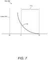
- a portion 214indicates the long-lifetime dye component (e.g., about ⁇ 1 ⁇ s lifetime) of curve 210 .
- FIG. 6shows the short-lifetime dye component only (i.e., portion 212 only) of curve 210 in plot 200 .
- FIG. 7shows the long-lifetime dye component only (i.e., portion 214 only) of curve 210 in plot 200 . Given the scale of plot 200 shown in FIG. 5 , FIG. 6 , and FIG.
- portion 212 of curve 210substantially corresponds to the period of time that light source 132 of reader device 130 is turned on, which is the period of time that both analyte sensing moieties 118 and reference moieties 120 are illuminated.
- Plot 200 of FIG. 5 , FIG. 6 , and FIG. 7shows that the decay time of the long-lifetime dye is significantly longer than the decay time of the short-lifetime dye.
- the gain of amplifier 160can be set, for example, to a pre-determined and/or dynamic low gain value (e.g., 1) at portion 212 of curve 210 , then the gain of amplifier 160 can be set to a pre-determined and/or dynamic high gain value (e.g., to 10 or 100) at portion 214 of curve 210 .
- the GC signal(not shown) switches at about t 1 .
- the GC signalswitches rapidly (e.g., about 1 ⁇ s transition time) with respect to the length of the short-lifetime dye component and the long-lifetime dye component (e.g., about 50 ⁇ s to about 200 ⁇ s).
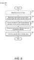
- FIG. 8is a flow diagram of a method 300 of using the presently disclosed analyte detection system 100 to determine an analyte value (e.g., analyte concentration), according to an embodiment.
- Method 300may include, but is not limited to, the following events.
- the background light with respect to single-channel sensor 110is measured.
- reader device 130can be placed on the skin at a location away from single-channel sensor 110 . Accordingly, at this location there is no short-lifetime analyte-sensing dye nor long-lifetime reference dye present. Then, light source 132 is pulsed and an optical signal is captured via optical detector 134 . Then, using this information, curve-fitting algorithm 154 may be used to calculate the short-lifetime background light according to Equation 3 above.
- reader device 130is be placed on the skin in close proximity to single-channel sensor 110 .
- the reader device 130can be placed on the surface of skin immediately above or in the vicinity of the single channel sensor 110 .
- single-channel sensor 110is illuminated by pulsing light source 132 .
- emission light 124 from analyte sensing moieties 118which is the short-lifetime analyte-sensing dye, and/or reference moieties 120 , which is the long-lifetime reference dye, is captured via optical detector 134 .
- curve-fitting algorithm 154may be used to render a waveform of the optical signal captured by optical detector 134 .
- An example of the waveformis curve 210 shown in plot 200 of FIG. 5 .
- the waveform determined at 315is processed to derive the short-lifetime intensity and the long-lifetime intensity.
- curve-fitting algorithm 154may be used derive the short-lifetime intensity according to Equation 1 above.
- curve-fitting algorithm 154may be used to derive the long-lifetime intensity according to Equation 2 above.
- the intensity ratiowhich is the ratio of the short-lifetime signal to the long-lifetime signal. For example, using curve-fitting algorithm 154 , the intensity ratio is determined according to Equation 4 above. Namely, using Equation 4, the short-lifetime background calculated at 310 is subtracted from the short-lifetime intensity calculated at 320 and then the intensity ratio is determined.
- the intensity ratiois correlated to an analyte value (e.g., an analyte concentration).
- analyte valuee.g., an analyte concentration
- curve-fitting algorithm 154may use lookup table 156 to correlate the calculated intensity ratio to an analyte value or analyte concentration.
- lookup table 156may indicate that a given intensity ratio correlates to a given glucose concentration.
- the intensity ratio calculated at 325 plus a temperature measurementcan be input to an analyte calibration lookup table based on in vitro reference data that may be used to convert the intensity ratio and the temperature to an analyte concentration.
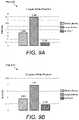
- Hydrogelswere constructed using acrylate-based monomers and a thermal initiator.
- a boronic-acid based glucose-sensitive monomeric dyewas added to the pre-polymer mix at a concentration of 0.01 mMolar.
- the dye concentrationswere selected to make the short-lifetime intensity (SLI) and long-lifetime intensity (LLI) signals comparable in order to test this technique. However, these concentrations may be tuned to increase glucose sensitivity.
- skin phantom layers(cured silicone with titanium dioxide to simulate tissue scattering) were placed on top of the analyte-sensing hydrogel.
- An optical readerwas placed on top of the skin phantom layers. Varying the skin phantom layers between the reader and the hydrogel-based sensor, was done to simulate changing tissue depth.
- excitationis performed at 630 nm and emission is collected at ⁇ 700 nm by the optical reader.
- the ratio of SLI to LLIcan provide a correction for intensity variations due to changes in signal intensity, which can be influenced by, for example the depth of tissue between the sensor and the reader.
- FIG. 10shows a plot 500 of an example of the overlapping absorbance and emission spectra of a short-lifetime and long-lifetime dye.
- the information shown in plot 500demonstrates that a single illumination source and a single common detector can be used in reader device 130 of the presently disclosed analyte detection system 100 .
- analyte detection system 100 and method 300provide a highly quantitative analyte measurement wherein the sensitivity to variables other than the analyte is reduced or substantially eliminated as compared with conventional sensing methods.
- analyte detection system 100 and method 300provide an analyte measurement that has little or no sensitivity to, for example, motion artifacts (e.g., reader position), tissue artifacts (e.g., depth, pressure), oxygen artifacts (e.g., tissue oxygenation), and the like in order to make the analyte measurement more quantitative.
- an advantage of analyte detection system 100 and method 300is that because the short-lifetime analyte-sensing dye and the long-lifetime reference dye emit in the same or overlapping spectrums, more accurate measurements are possible as compared with an analyte-sensitive dye and a reference dye that have different and/or non-overlapping spectrums.
- the term “about,” when referring to a valuecan be meant to encompass variations of, in some embodiments, ⁇ 100% in some embodiments ⁇ 50%, in some embodiments ⁇ 20%, in some embodiments ⁇ 10%, in some embodiments ⁇ 5%, in some embodiments ⁇ 1%, in some embodiments ⁇ 0.5%, and in some embodiments ⁇ 0.1% from the specified amount, as such variations are appropriate to perform the disclosed methods or employ the disclosed compositions.
- short-lifetime dye and long-lifetime dyerefer to short-lifetime dye and long-lifetime dye. It should be understood that “short” and “long” are relative descriptors used to describe the short-lifetime dye by reference to the long-lifetime dye and vice versa. Similarly stated, although some embodiments provide details of specific lifetimes of short-lifetime dyes and/or long-lifetime dyes, the terms “short” and “long” do not require that the lifetime of the respective dye be below or above any particular threshold.
- Some embodiments described hereinrefer to spectrums being the same, substantially the same, and/or overlapping. Two spectrums can be considered overlapping if, for example, a 30 nm band exists in which an intensity of each spectrum is at least 10% of the peak intensity for that spectrum.
- light emitted from a sensorcan pass through a 30 nm wide band pass filter before being received by a detector. A signal that has an intensity within that band that is at least 10% of the peak intensity for that signal can be reliably measured by the detector. Therefore, two signals have “overlapping” spectrums if a 30 nm wide band pass filter can be selected that will pass a band of each spectrum in which an intensity of each signal is at least 10% of the maximum intensity for that spectrum.
- two spectrumscan be considered “the same” if a 30 nm band exists in which an intensity of each spectrum is at least 75% of the peak intensity for that spectrum and two spectrums can be considered “substantially the same” if a 30 nm band exists in which an intensity of each spectrum is at least 50% of the peak intensity of that spectrum.
- wider or narrower band-passor other suitable filters
- spectrums of signalscan be considered to be the same, substantially the same, or overlapping if the signals can be reliably measured after passing through the filter.
- sensors described hereincan include any number of sensing moieties.
- a sensorcan include a short-lifetime glucose sensing dye, a long-lifetime reference dye associated with the short-lifetime glucose sensing dye, and a long-lifetime oxygen sensing dye without an associated reference dye.
- a long-lifetime oxygen sensing dyemay have a different emission spectrum than the short-lifetime glucose sensor and the long-lifetime reference dye.
- Some embodiments described hereinrelate to methods. It should be understood that such methods may be computer-implemented (e.g., performed by a processor executing code stored in memory). For example some methods described herein may be implemented by the computing device 150 and/or the reader device 1130 shown and described above. It should therefore be understood that devices described herein can include a processor or other module configured to store and execute program code, such as Application-Specific Integrated Circuits (ASICs), Programmable Logic Devices (PLDs), Read-Only Memory (ROM) and Random-Access Memory (RAM) devices. Devices shown and described herein can also include memory, also referred to as a non-transitory computer-readable medium.
- ASICsApplication-Specific Integrated Circuits
- PLDsProgrammable Logic Devices
- ROMRead-Only Memory
- RAMRandom-Access Memory
- non-transitory computer-readable mediainclude, but are not limited to: magnetic storage media such as hard disks, floppy disks, and magnetic tape; optical storage media such as Compact Disc/Digital Video Discs (CD/DVDs), Compact Disc-Read Only Memories (CD-ROMs), and holographic devices; magneto-optical storage media such as optical disks; carrier wave signal processing modules.
- the computer-readable mediumor processor-readable medium
- the mediais non-transitory in the sense that it does not include transitory propagating signals per se (e.g., a propagating electromagnetic wave carrying information on a transmission medium such as space or a cable).
- the mediacan store or be operable to store computer code (also can be referred to as code) that is executable by the processor to cause the computer implemented method to be performed.
Landscapes
- Health & Medical Sciences (AREA)
- Life Sciences & Earth Sciences (AREA)
- Physics & Mathematics (AREA)
- Medical Informatics (AREA)
- Surgery (AREA)
- Biophysics (AREA)
- Pathology (AREA)
- Engineering & Computer Science (AREA)
- Biomedical Technology (AREA)
- Heart & Thoracic Surgery (AREA)
- Veterinary Medicine (AREA)
- Molecular Biology (AREA)
- Optics & Photonics (AREA)
- Animal Behavior & Ethology (AREA)
- General Health & Medical Sciences (AREA)
- Public Health (AREA)
- Spectroscopy & Molecular Physics (AREA)
- Emergency Medicine (AREA)
- Investigating, Analyzing Materials By Fluorescence Or Luminescence (AREA)
- Measurement Of The Respiration, Hearing Ability, Form, And Blood Characteristics Of Living Organisms (AREA)
Abstract
Description
- (1) a short-lifetime (e.g., about ≤50 ns) analyte-sensing dye wherein the emission intensity modulates with the amount of analyte present;
- (2) a long-lifetime (e.g., about ≥1 μs) reference dye that is a non-analyte-sensing dye wherein the emission intensity does not modulate based on an analyte;
- (3) the absorption spectrums of the short-lifetime analyte-sensing dye and the long-lifetime reference are substantially the same or at least overlapping;
- (4) the short-lifetime analyte-sensing dye and the long-lifetime reference dye wherein the emission spectrums are substantially the same or at least overlapping; and/or
- (5) the short-lifetime analyte-sensing dye and the long-lifetime reference dye that are distinguishable optically by their different emission lifetime characteristics (e.g., about ≤50 ns lifetime emission vs. about ≥1 μs lifetime emission).
- (1) a single light source and/or multiple light sources that have substantially the same illumination spectrum. Namely, because the absorption spectrums of the short-lifetime analyte-sensing dye and the long-lifetime reference dye are substantially the same or at least overlapping, only one light source and/or illumination spectrum is needed for illuminating and exciting both the short-lifetime analyte-sensing dye and the long-lifetime reference dye simultaneously. By contrast, if the absorption spectrums of the short-lifetime analyte-sensing dye and the long-lifetime reference dye were not substantially the same or at least overlapping, then two light sources and/or two illumination steps would be required. Therefore, according to some embodiments described herein, a reader device of an analyte detection system avoids the requirement of a second light source, second illumination spectrum, and/or a second illumination step; and
- (2) a single detector device and/or multiple detectors operable to detect substantially the same detection spectrum. Namely, because the emission spectrums of the short-lifetime analyte-sensing dye and the long-lifetime reference dye are substantially the same or at least overlapping, only one detector device, detection spectrum, emission filter, and/or output spectrum from one or more emission filters is needed for detecting the optical signals from both the short-lifetime analyte-sensing dye and the long-lifetime reference dye simultaneously. By contrast, if the emission spectrums of the short-lifetime analyte-sensing dye and the long-lifetime reference dye were not substantially the same or were not at least overlapping, then two detector devices, detection spectrums, and/or two detection steps would be required. Therefore, according to some embodiments described herein a reader device of an analyte detection system avoids the requirement of a second detector device, detection spectrum, and/or a second detection step.
Short-lifetime signal intensity:ISLI=Pex[Tleak+Taf+TexβSLTem] [Equation 1]
- where ISLIis short-lifetime intensity;
- Pexis excitation light power (or intensity);
- Tleakis diffuse reflectance filter leakage;
- Tafis tissue autofluorescence;
- Texis excitation transmission factors;
- βSLis sensor fluorescence efficiency; and
- Temis emission transmission factors.
- where ISLIis short-lifetime intensity;
Long-lifetime signal intensity:ILLI=Pex[TexβLLTem] [Equation 2]
- where ILLIis long-lifetime intensity;
- Pexis excitation light power (or intensity);
- Texis excitation transmission factors;
- BLLis sensor fluorescence efficiency; and
- Temis emission transmission factors.
- where ILLIis long-lifetime intensity;
Short-lifetime background light:ISLIb=Pex[Tleak+Taf]b [Equation 3]
- where ISLIbis short-lifetime background intensity;
- Pexis excitation light power (or intensity);
- Tleakis diffuse reflectance filter leakage; and
- Tafis tissue autofluorescence.
[Equation 4] Intensity Ratio:
- where ISLIbis short-lifetime background intensity;
- where Iratiois intensity ratio.
Claims (20)
Priority Applications (1)
| Application Number | Priority Date | Filing Date | Title |
|---|---|---|---|
| US15/852,885US11331018B2 (en) | 2016-12-22 | 2017-12-22 | System and single-channel biosensor for and method of determining analyte value |
Applications Claiming Priority (2)
| Application Number | Priority Date | Filing Date | Title |
|---|---|---|---|
| US201662438113P | 2016-12-22 | 2016-12-22 | |
| US15/852,885US11331018B2 (en) | 2016-12-22 | 2017-12-22 | System and single-channel biosensor for and method of determining analyte value |
Publications (2)
| Publication Number | Publication Date |
|---|---|
| US20180177443A1 US20180177443A1 (en) | 2018-06-28 |
| US11331018B2true US11331018B2 (en) | 2022-05-17 |
Family
ID=62625227
Family Applications (1)
| Application Number | Title | Priority Date | Filing Date |
|---|---|---|---|
| US15/852,885Active2038-12-29US11331018B2 (en) | 2016-12-22 | 2017-12-22 | System and single-channel biosensor for and method of determining analyte value |
Country Status (2)
| Country | Link |
|---|---|
| US (1) | US11331018B2 (en) |
| WO (1) | WO2018119400A1 (en) |
Families Citing this family (3)
| Publication number | Priority date | Publication date | Assignee | Title |
|---|---|---|---|---|
| CA3012355C (en) | 2010-10-06 | 2023-05-16 | Profusa, Inc. | Tissue-integrating sensors |
| BR112019027709A2 (en) | 2017-06-29 | 2020-08-11 | Profusa, Inc. | integration sensors in multi-analyte detection fabrics |
| WO2024173432A1 (en)* | 2023-02-13 | 2024-08-22 | Intelligent Optical Systems, Inc. | Electronically and optically modular sensor system and sensing methods thereof |
Citations (212)
| Publication number | Priority date | Publication date | Assignee | Title |
|---|---|---|---|---|
| US4703756A (en) | 1986-05-06 | 1987-11-03 | The Regents Of The University Of California | Complete glucose monitoring system with an implantable, telemetered sensor module |
| US5001054A (en) | 1986-06-26 | 1991-03-19 | Becton, Dickinson And Company | Method for monitoring glucose |
| US5094958A (en) | 1990-08-30 | 1992-03-10 | Fiberchem Inc. | Method of self-compensating a fiber optic chemical sensor |
| US5161532A (en) | 1990-04-19 | 1992-11-10 | Teknekron Sensor Development Corporation | Integral interstitial fluid sensor |
| US5284140A (en) | 1992-02-11 | 1994-02-08 | Eli Lilly And Company | Acrylic copolymer membranes for biosensors |
| US5342789A (en) | 1989-12-14 | 1994-08-30 | Sensor Technologies, Inc. | Method and device for detecting and quantifying glucose in body fluids |
| US5462880A (en) | 1993-09-13 | 1995-10-31 | Optical Sensors Incorporated | Ratiometric fluorescence method to measure oxygen |
| US5512246A (en) | 1989-09-21 | 1996-04-30 | Anthony P. Russell | Method and means for detecting polyhydroxyl compounds |
| US5551422A (en) | 1992-11-09 | 1996-09-03 | Boehringer Mannheim Gmbh | Method and apparatus for analytical determination of glucose in a biological matrix |
| WO1998006406A1 (en) | 1996-08-12 | 1998-02-19 | Btg International Limited | Mannose-6-phosphate composition and its use in treating fibrotic disorders |
| US5777060A (en) | 1995-03-27 | 1998-07-07 | Minimed, Inc. | Silicon-containing biocompatible membranes |
| US5895658A (en) | 1997-09-17 | 1999-04-20 | Fossel; Eric T. | Topical delivery of L-arginine to cause tissue warming |
| US6002954A (en) | 1995-11-22 | 1999-12-14 | The Regents Of The University Of California | Detection of biological molecules using boronate-based chemical amplification and optical sensors |
| US6011984A (en) | 1995-11-22 | 2000-01-04 | Minimed Inc. | Detection of biological molecules using chemical amplification and optical sensors |
| US6013122A (en) | 1998-08-18 | 2000-01-11 | Option Technologies, Inc. | Tattoo inks |
| WO2000002048A1 (en) | 1998-07-03 | 2000-01-13 | Torsana Diabetes Diagnostics A/S | Optical sensor for in situ measurement of analytes |
| US6040194A (en) | 1989-12-14 | 2000-03-21 | Sensor Technologies, Inc. | Methods and device for detecting and quantifying substances in body fluids |
| US6175752B1 (en) | 1998-04-30 | 2001-01-16 | Therasense, Inc. | Analyte monitoring device and methods of use |
| WO2001006579A2 (en) | 1999-07-20 | 2001-01-25 | Sri International | Pre-strained electroactive polymers |
| WO2001018543A1 (en) | 1999-09-10 | 2001-03-15 | Beckman Coulter, Inc. | Minimally invasive methods for measuring analytes in vivo |
| US6212416B1 (en) | 1995-11-22 | 2001-04-03 | Good Samaritan Hospital And Medical Center | Device for monitoring changes in analyte concentration |
| US6299604B1 (en) | 1998-08-20 | 2001-10-09 | Cook Incorporated | Coated implantable medical device |
| US20020043651A1 (en) | 2000-04-04 | 2002-04-18 | Darrow Christopher B. | Fluorescent lifetime assays for non-invasive quantification of analytes such as glucose |
| US6376971B1 (en) | 1997-02-07 | 2002-04-23 | Sri International | Electroactive polymer electrodes |
| US20020048577A1 (en) | 2000-08-01 | 2002-04-25 | University Of Washington | Methods and devices to modulate the wound response |
| US6379622B1 (en) | 2001-04-11 | 2002-04-30 | Motorola, Inc. | Sensor incorporating a quantum dot as a reference |
| US20020094526A1 (en) | 2000-02-11 | 2002-07-18 | Bayley Hagan P. | Biosensor compositions and methods of use |
| US20020106314A1 (en) | 2000-03-16 | 2002-08-08 | Pelrine Ronald E. | Microlaboratory devices and methods |
| US20020151772A1 (en) | 2001-04-11 | 2002-10-17 | Motorola, Inc. | System using a portable detection device for detection of an analyte through body tissue |
| US6475750B1 (en) | 1999-05-11 | 2002-11-05 | M-Biotech, Inc. | Glucose biosensor |
| WO2002087610A1 (en) | 2001-04-30 | 2002-11-07 | Fit Biotech Oy Plc. | Medical device |
| US6485703B1 (en) | 1998-07-31 | 2002-11-26 | The Texas A&M University System | Compositions and methods for analyte detection |
| US20020193672A1 (en) | 1995-11-22 | 2002-12-19 | Walsh Joseph C. | Long wave fluorophore sensor compounds and other fluorescent sensor compounds in polymers |
| US6497729B1 (en) | 1998-11-20 | 2002-12-24 | The University Of Connecticut | Implant coating for control of tissue/implant interactions |
| US20030004554A1 (en) | 2001-04-30 | 2003-01-02 | Riff Kenneth M. | Transcutaneous monitor & method of use, using therapeutic output from an implanted medical device |
| US20030050542A1 (en) | 2000-03-08 | 2003-03-13 | Bruno Reihl | Device for in-vivo measurement of the concentration of a substance contained in a body fluid |
| US6543110B1 (en) | 1997-02-07 | 2003-04-08 | Sri International | Electroactive polymer fabrication |
| US20030088682A1 (en) | 2001-02-28 | 2003-05-08 | Hlasny Daryl J | Communication period management in a communication system |
| US6565960B2 (en) | 2000-06-01 | 2003-05-20 | Shriners Hospital Of Children | Polymer composite compositions |
| US20030099682A1 (en) | 1998-11-20 | 2003-05-29 | Francis Moussy | Apparatus and method for control of tissue/implant interactions |
| US6602678B2 (en) | 1998-09-04 | 2003-08-05 | Powderject Research Limited | Non- or minimally invasive monitoring methods |
| US6602716B1 (en) | 1997-08-01 | 2003-08-05 | Presens Precision Sensing Gmbh | Method and device for referencing fluorescence intensity signals |
| US20030153026A1 (en) | 2002-01-04 | 2003-08-14 | Javier Alarcon | Entrapped binding protein as biosensors |
| US20030171666A1 (en) | 2001-10-02 | 2003-09-11 | Alfred E. Mann Institute For Biomedical Engineering | Internal biochemical sensing device |
| US6642015B2 (en) | 2000-12-29 | 2003-11-04 | Minimed Inc. | Hydrophilic polymeric material for coating biosensors |
| US20030208166A1 (en) | 2002-05-06 | 2003-11-06 | Schwartz Anthony H. | Implantable device with free-flowing exit and uses thereof |
| US6671527B2 (en) | 2000-10-13 | 2003-12-30 | Precisense A/S | Optical sensor for in situ measurement of analytes |
| US6702857B2 (en) | 2001-07-27 | 2004-03-09 | Dexcom, Inc. | Membrane for use with implantable devices |
| US20040106951A1 (en) | 2002-11-22 | 2004-06-03 | Edman Carl Frederick | Use of electric fields to minimize rejection of implanted devices and materials |
| US20040106215A1 (en) | 2000-10-27 | 2004-06-03 | Werner Lehmann | Method and test kit for detecting analytes in a sample |
| US6750311B1 (en) | 1996-11-21 | 2004-06-15 | Minimed Inc. | Detection of biological molecules using boronate-based chemical amplification and optical sensors |
| US20040143221A1 (en) | 2002-12-27 | 2004-07-22 | Shadduck John H. | Biomedical implant for sustained agent release |
| US20040161853A1 (en) | 2003-02-13 | 2004-08-19 | Zhongping Yang | Implantable chemical sensor with rugged optical coupler |
| US20040176669A1 (en) | 1998-08-26 | 2004-09-09 | Sensors For Medicine And Science | Optical-based sensing devices |
| US6794195B2 (en) | 2000-08-04 | 2004-09-21 | Sensors For Medicine & Science, Inc. | Detection of analytes in aqueous environments |
| US20040195528A1 (en) | 2003-04-01 | 2004-10-07 | Reece Ronald N. | Ion beam incident angle detector for ion implant systems |
| US6818226B2 (en) | 1996-02-19 | 2004-11-16 | Acrux Dds Pty. Ltd. | Dermal penetration enhancers and drug delivery systems involving same |
| US20040234962A1 (en) | 2003-05-02 | 2004-11-25 | Javier Alarcon | Multicoated or multilayer entrapment matrix for protein biosensor |
| US20040258732A1 (en) | 2001-11-27 | 2004-12-23 | Yasuo Shikinami | Implant material and process for producing the same |
| US20040259270A1 (en) | 2003-06-19 | 2004-12-23 | Wolf David E. | System, device and method for exciting a sensor and detecting analyte |
| US6844023B2 (en) | 1996-12-20 | 2005-01-18 | Medtronic Minimed, Inc. | Alumina insulation for coating implantable components and other microminiature devices |
| US20050027175A1 (en) | 2003-07-31 | 2005-02-03 | Zhongping Yang | Implantable biosensor |
| US20050043606A1 (en) | 2001-09-25 | 2005-02-24 | Eliahu Pewzner | Multiparametric apparatus for monitoring multiple tissue vitality parameters |
| US20050096587A1 (en) | 2003-11-03 | 2005-05-05 | Santini John T.Jr. | Medical device for sensing glucose |
| US20050095174A1 (en) | 2003-10-31 | 2005-05-05 | Wolf David E. | Semipermeable sensors for detecting analyte |
| US20050118726A1 (en) | 2002-08-26 | 2005-06-02 | Schultz Jerome S. | System and method for detecting bioanalytes and method for producing a bioanalyte sensor |
| US20050119737A1 (en) | 2000-01-12 | 2005-06-02 | Bene Eric A. | Ocular implant and methods for making and using same |
| WO2005059037A1 (en) | 2003-12-16 | 2005-06-30 | Precisense A/S | Reagent for detecting an analyte |
| US6916660B2 (en) | 2002-05-14 | 2005-07-12 | North Carolina State University | Fluorescent sensor compounds for detecting saccharides |
| US20050154374A1 (en) | 2003-11-20 | 2005-07-14 | Angiotech International Ag | Implantable sensors and implantable pumps and anti-scarring agents |
| US6927246B2 (en) | 2001-02-15 | 2005-08-09 | Medtronic Minimed, Inc. | Polymers functionalized with fluorescent boronate motifs and methods for making them |
| CN1675547A (en) | 2002-08-27 | 2005-09-28 | 金伯利-克拉克环球有限公司 | Flow-through assay with an internal calibration system using magnetic particles |
| US20050237518A1 (en) | 2001-12-11 | 2005-10-27 | Sensors For Medicine And Science, Inc. | High performance fluorescent optical sensor |
| US20050245799A1 (en) | 2004-05-03 | 2005-11-03 | Dexcom, Inc. | Implantable analyte sensor |
| US6965791B1 (en) | 2003-03-26 | 2005-11-15 | Sorenson Medical, Inc. | Implantable biosensor system, apparatus and method |
| WO2005120631A1 (en) | 2004-06-02 | 2005-12-22 | Carl Frederick Edman | Use of electric fields to minimize rejection of implanted devices and materials |
| US20060002969A1 (en) | 2004-01-27 | 2006-01-05 | University Of Washington | Methods for reducing the foreign body reaction |
| US20060002890A1 (en) | 2004-07-05 | 2006-01-05 | Ulrich Hersel | Hydrogel formulations |
| WO2006004595A2 (en) | 2004-05-28 | 2006-01-12 | Georgia Tech Research Corporation | Methods and devices for thermal treatment |
| US6994691B2 (en) | 2002-02-27 | 2006-02-07 | Precisense A/S | Injection apparatus |
| US20060089548A1 (en) | 2004-10-23 | 2006-04-27 | Hogan Josh N | Correlation of concurrent non-invasively acquired signals |
| WO2006044972A1 (en) | 2004-10-19 | 2006-04-27 | Becton, Dickinson & Company | Methods of correcting a luminescence value, and methods of determining a corrected analyte concentration |
| US7045361B2 (en) | 2001-09-12 | 2006-05-16 | Medtronic Minimed, Inc. | Analyte sensing via acridine-based boronate biosensors |
| WO2006065266A2 (en) | 2004-04-20 | 2006-06-22 | Dendritic Nanotechnologies, Inc. | Dendritic polymers with enhanced amplification and interior functionality |
| US7067194B2 (en) | 2001-06-26 | 2006-06-27 | Accelr8 Technology Corporation | Functional surface coating |
| US20060148983A1 (en) | 2003-02-28 | 2006-07-06 | Achim Muller | Copolymers comprising biomolecules |
| US20060155179A1 (en) | 2003-02-14 | 2006-07-13 | Achim Muller | Apparatus for measuring an analyte concentration from an ocular fluid |
| US7110803B2 (en) | 1997-03-04 | 2006-09-19 | Dexcom, Inc. | Device and method for determining analyte levels |
| US7132049B2 (en) | 1999-02-25 | 2006-11-07 | Pall Corporation | Negatively charged membrane |
| US20060252976A1 (en) | 2004-05-04 | 2006-11-09 | Spencer Rosero | System and method for stimulation of biologic signals in a bio-electro-physiologic matrix |
| US7134999B2 (en) | 2003-04-04 | 2006-11-14 | Dexcom, Inc. | Optimized sensor geometry for an implantable glucose sensor |
| US20060270919A1 (en) | 2005-05-11 | 2006-11-30 | Mytek, Llc | Biomarkers sensing |
| US20060275340A1 (en) | 2003-08-13 | 2006-12-07 | Medtronic Vascular Inc. | Biocompatible controlled release coatings for medical devices and related methods |
| WO2006130461A1 (en) | 2005-05-27 | 2006-12-07 | Johnson & Johnson Consumer Companies, Inc. | Discrete patch for viral lesions |
| CN1882278A (en) | 2003-10-28 | 2006-12-20 | 薇拉莱特公司 | Use tissue fluorescence to identify a glycation end product or disease state |
| US7153265B2 (en) | 2002-04-22 | 2006-12-26 | Medtronic Minimed, Inc. | Anti-inflammatory biosensor for reduced biofouling and enhanced sensor performance |
| US20060289307A1 (en) | 2004-08-24 | 2006-12-28 | University Of South Florida | Epoxy Enhanced Polymer Membrane to Increase Durability of Biosensors |
| US20070002470A1 (en) | 2003-07-30 | 2007-01-04 | Domschke Angelika M | Reflection hologram sensor in contact lens |
| US20070004046A1 (en) | 2005-07-01 | 2007-01-04 | Platypus Technologies, Llc | Detection of analytes |
| US7162289B2 (en) | 2002-09-27 | 2007-01-09 | Medtronic Minimed, Inc. | Method and apparatus for enhancing the integrity of an implantable sensor device |
| US20070010702A1 (en) | 2003-04-08 | 2007-01-11 | Xingwu Wang | Medical device with low magnetic susceptibility |
| US20070030443A1 (en) | 2003-08-07 | 2007-02-08 | Chapoy Lawrence L | Opthalmic sensor |
| JP2007044512A (en) | 2005-08-09 | 2007-02-22 | Lifescan Inc | Kinematic fluorescence measuring band |
| US7186789B2 (en) | 2003-06-11 | 2007-03-06 | Advanced Cardiovascular Systems, Inc. | Bioabsorbable, biobeneficial polyester polymers for use in drug eluting stent coatings |
| US7192450B2 (en) | 2003-05-21 | 2007-03-20 | Dexcom, Inc. | Porous membranes for use with implantable devices |
| US7202947B2 (en) | 2001-12-19 | 2007-04-10 | Wisconsin Alumni Research Foundation | Depth-resolved fluorescence instrument with angled excitation |
| US20070093617A1 (en) | 2004-10-06 | 2007-04-26 | Advanced Cardiovascular Systems, Inc. | Blends of poly(ester amide) polymers |
| US20070105176A1 (en) | 2005-09-28 | 2007-05-10 | Ibey Bennett L | Method and apparatus for glucose monitoring |
| US7228159B2 (en) | 2001-07-10 | 2007-06-05 | Precisense A/S | Optical sensor containing particles for in situ measurement of analytes |
| US7226978B2 (en) | 2002-05-22 | 2007-06-05 | Dexcom, Inc. | Techniques to improve polyurethane membranes for implantable glucose sensors |
| WO2007065653A1 (en) | 2005-12-07 | 2007-06-14 | Precisense A/S | Flexible carbohydrate-bearing polymer |
| US20070135698A1 (en) | 2005-12-13 | 2007-06-14 | Rajiv Shah | Biosensors and methods for making and using them |
| US20070134290A1 (en) | 2002-05-20 | 2007-06-14 | Rowland Stephen M | Drug eluting implantable medical device |
| US20070244379A1 (en) | 2002-05-22 | 2007-10-18 | Robert Boock | Silicone based membranes for use in implantable glucose sensors |
| WO2007126444A2 (en) | 2005-12-28 | 2007-11-08 | Abbott Diabetes Care, Inc. | Analyte monitoring |
| US20070270675A1 (en) | 2006-05-17 | 2007-11-22 | Michael John Kane | Implantable Medical Device with Chemical Sensor and Related Methods |
| CN101087630A (en) | 2004-05-04 | 2007-12-12 | 罗切斯特大学 | Implantable bio-electro-physiologic interface matrix |
| US20080020012A1 (en) | 2006-06-22 | 2008-01-24 | Ju Young M | Collagen scaffolds, medical implants with same and methods of use |
| US20080075752A1 (en) | 2003-10-01 | 2008-03-27 | University Of Washington | Novel Porous Biomaterials |
| US20080136052A1 (en) | 1999-07-20 | 2008-06-12 | Sri International | Electroactive polymer manufacturing |
| US20080139903A1 (en) | 2006-12-08 | 2008-06-12 | Isense Corporation | Method and apparatus for insertion of a sensor using an introducer |
| US7424317B2 (en) | 1998-07-04 | 2008-09-09 | Edwards Lifesciences | Non-invasive measurement of blood analytes |
| US20080249381A1 (en) | 2004-06-14 | 2008-10-09 | Eyesense Ag | Combined Apparatus For Measuring the Blood Glucose Level From an Ocular Fluid |
| US7450980B2 (en) | 2004-03-31 | 2008-11-11 | Terumo Kabushiki Kaisha | Intracorporeal substance measuring assembly |
| WO2008141241A1 (en) | 2007-05-10 | 2008-11-20 | Glumetrics, Inc. | Equilibrium non-consuming fluorescence sensor for real time intravascular glucose measurement |
| WO2008143651A2 (en) | 2006-12-07 | 2008-11-27 | The Ohio State University Research Foundation | A system for in vivo biosensing based on the optical response of electronic polymers |
| WO2009019470A1 (en) | 2007-08-09 | 2009-02-12 | Glysure Ltd | Sensing apparatus |
| US7496392B2 (en) | 2003-11-26 | 2009-02-24 | Becton, Dickinson And Company | Fiber optic device for sensing analytes |
| US7521019B2 (en) | 2001-04-11 | 2009-04-21 | Lifescan, Inc. | Sensor device and methods for manufacture |
| US20090131773A1 (en) | 2004-12-07 | 2009-05-21 | Precisense A/S | Sensor for Detection of Carbohydrate |
| US7541598B2 (en) | 2004-07-27 | 2009-06-02 | Precisense A/S | Method and apparatus for measuring the phase shift induced in a light signal by a sample |
| WO2009087373A1 (en) | 2008-01-08 | 2009-07-16 | Glysure Ltd | Surface functionalisation of plastic optical fibre |
| US20090187084A1 (en) | 2004-12-07 | 2009-07-23 | Precisence A/S | Flexible Carbohydrate-Bearing Polymer |
| US7567347B2 (en) | 2003-12-23 | 2009-07-28 | Precisense A/S | Fluorometers |
| WO2009106805A1 (en) | 2008-02-26 | 2009-09-03 | Glysure Ltd | Fibre optic sensor |
| US20090221891A1 (en) | 2004-05-19 | 2009-09-03 | Yihua Yu | Optical sensor for in vivo detection of analyte |
| US20090270953A1 (en) | 2008-04-23 | 2009-10-29 | Ecker Robert M | Optical Device |
| US7653424B2 (en) | 2001-04-27 | 2010-01-26 | Eyesense Ag | Apparatus for measuring blood glucose concentrations |
| US20100081906A1 (en) | 2008-09-30 | 2010-04-01 | Abbott Diabetes Care, Inc. | Analyte Sensor Sensitivity Attenuation Mitigation |
| US20100113901A1 (en) | 2008-10-24 | 2010-05-06 | Jin Zhang | Contact lens integrated with a biosensor for the detection of glucose and other components in tears |
| US20100123121A1 (en) | 2008-03-18 | 2010-05-20 | Taylor Geoff W | Thyristor Radiation Detector Array and Applications Thereof |
| US20100160749A1 (en) | 2008-12-24 | 2010-06-24 | Glusense Ltd. | Implantable optical glucose sensing |
| US20100202966A1 (en) | 2006-03-28 | 2010-08-12 | Yossi Gross | Implantable Sensor |
| US20100240975A1 (en) | 2003-08-22 | 2010-09-23 | Dexcom, Inc. | Systems and methods for replacing signal artifacts in a glucose sensor data stream |
| US20100249548A1 (en) | 2007-01-17 | 2010-09-30 | Eyesense Ag | Ocular sensor for the detection of an analyte in eye water |
| WO2010116142A2 (en) | 2009-04-09 | 2010-10-14 | Glysure Ltd | Fluorophore and fluorescent sensor compound containing same |
| WO2010133831A1 (en) | 2009-05-18 | 2010-11-25 | Glysure Ltd | Glucose sensor calibration |
| US20100303772A1 (en) | 2009-06-01 | 2010-12-02 | Profusa, Inc. | Method and system for directing a localized biological response to an implant |
| US20110028806A1 (en) | 2009-07-29 | 2011-02-03 | Sean Merritt | Reflectance calibration of fluorescence-based glucose measurements |
| US20110036994A1 (en) | 2007-09-04 | 2011-02-17 | Cameron Frayling | Apparatus and method |
| EP1937136B1 (en) | 2005-09-23 | 2011-06-22 | Medtronic MiniMed, Inc. | Sensor with layered electrodes |
| WO2011101627A2 (en) | 2010-02-19 | 2011-08-25 | Glysure Ltd | Fluorescence measurement |
| WO2011101625A1 (en) | 2010-02-19 | 2011-08-25 | Glysure Ltd | Subcutaneous glucose sensor |
| WO2011101626A1 (en) | 2010-02-16 | 2011-08-25 | Glysure Ltd | Barrier layer for glusose sensor |
| WO2011101628A1 (en) | 2010-02-19 | 2011-08-25 | Glysure Ltd | Intravascular glucose sensor |
| WO2011101624A1 (en) | 2010-02-19 | 2011-08-25 | Glysure Ltd | Indicator system for fibre optic sensor |
| US8008088B2 (en) | 2003-12-24 | 2011-08-30 | Masimo Laboratories, Inc. | SMMR (small molecule metabolite reporters) for use as in vivo glucose biosensors |
| US20110224514A1 (en) | 2008-10-02 | 2011-09-15 | Eyesense Ag | Implantable Sensor Element |
| US20110230835A1 (en) | 2008-10-02 | 2011-09-22 | Eyesense Ag | Implantation Device For Metabolite Sensors |
| US8057041B2 (en) | 2006-07-24 | 2011-11-15 | Eyesense Ag | Apparatus for measuring an analyte in an eye fluid |
| US20110306511A1 (en) | 2008-12-29 | 2011-12-15 | Sqi Diagnostics Systems Inc. | Methods for multiplex analyte detection and quantification |
| US20120123276A1 (en) | 2010-11-16 | 2012-05-17 | Assaf Govari | Catheter with optical contact sensing |
| US20120140094A1 (en) | 2010-12-06 | 2012-06-07 | Primesense Ltd. | Pattern projection and imaging using lens arrays |
| US8206622B2 (en) | 2004-02-23 | 2012-06-26 | Eyesense Ag | Process for production of ionically crosslinked polysaccharide microspheres |
| US20120172692A1 (en) | 2011-01-05 | 2012-07-05 | Janet Tamada | Sensing Fluid Concentration for Continuous Glucose Monitoring |
| US20120179014A1 (en) | 1997-03-04 | 2012-07-12 | Dexcom, Inc. | Device and method for determining analyte levels |
| US20120186581A1 (en) | 2004-02-26 | 2012-07-26 | DexCom,Inc. | Integrated delivery device for continuous glucose sensor |
| US20120245445A1 (en) | 2011-03-21 | 2012-09-27 | Michael Darryl Black | Glucose Monitoring System |
| US20120258551A1 (en) | 2009-10-26 | 2012-10-11 | Eyesense Ag | Stabilization of bio-sensors for in vivo applications |
| US20120265034A1 (en) | 2010-10-06 | 2012-10-18 | Wisniewski Natalie A | Tissue-integrating sensors |
| US20120283538A1 (en) | 2011-05-06 | 2012-11-08 | Medtronic Minimed, Inc. | Method and apparatus for continuous analyte monitoring |
| US8346363B2 (en) | 1999-03-05 | 2013-01-01 | Metacure Limited | Blood glucose level control |
| US8346337B2 (en) | 1998-04-30 | 2013-01-01 | Abbott Diabetes Care Inc. | Analyte monitoring device and methods of use |
| US20130006069A1 (en) | 2011-06-30 | 2013-01-03 | Glusense, Ltd | Implantable optical glucose sensing |
| US20130022648A1 (en) | 2009-11-25 | 2013-01-24 | Healionics Corporation | Granules of porous biocompatible materials |
| US8368556B2 (en) | 2009-04-29 | 2013-02-05 | Abbott Diabetes Care Inc. | Method and system for providing data communication in continuous glucose monitoring and management system |
| US8372423B2 (en) | 2009-11-25 | 2013-02-12 | Healionics Corporation | Implantable medical devices having microporous surface layers and method for reducing foreign body response to the same |
| US8372630B2 (en) | 2006-07-20 | 2013-02-12 | Kabushiki Kaisha Toshiba | Optical glucose sensor chip and method of manufacturing the same |
| US8382700B2 (en) | 2007-10-23 | 2013-02-26 | Sensile Pat Ag | Medical device for glucose monitoring or regulation |
| US20130060105A1 (en) | 2011-09-06 | 2013-03-07 | Medtronic Minimed, Inc. | Orthogonally Redundant Sensor Systems and Methods |
| US8423114B2 (en) | 2006-10-04 | 2013-04-16 | Dexcom, Inc. | Dual electrode system for a continuous analyte sensor |
| EP2517619B1 (en) | 2011-04-27 | 2013-05-22 | Istar Medical | Improvements in or relating to glaucoma management and treatment |
| US8465425B2 (en) | 1998-04-30 | 2013-06-18 | Abbott Diabetes Care Inc. | Analyte monitoring device and methods of use |
| US20130158413A1 (en) | 2011-12-15 | 2013-06-20 | Nellcor Puritan Bennett Llc | Optical measurement of physiological blood parameters |
| US20130172699A1 (en) | 2011-12-29 | 2013-07-04 | Wellsense, Inc. | Analyte sensor with extended range of detection |
| US8483793B2 (en) | 2003-12-05 | 2013-07-09 | Dexcom, Inc. | Dual electrode system for a continuous analyte sensor |
| US20130211212A1 (en) | 2012-02-09 | 2013-08-15 | Robert Bosch Gmbh | Determining the blood sugar level in a patient by using an implantable sensor and an electrical functional adhesive bandage |
| US20130211213A1 (en) | 2012-02-10 | 2013-08-15 | Senseonics, Incorporated | Digital asic sensor platform |
| US8512245B2 (en) | 2008-04-17 | 2013-08-20 | Glumetrics, Inc. | Sensor for percutaneous intravascular deployment without an indwelling cannula |
| US20130213110A1 (en) | 2011-08-15 | 2013-08-22 | Biorasis Incorporated | Control of biofouling in implantable biosensors |
| US8527025B1 (en) | 1997-03-04 | 2013-09-03 | Dexcom, Inc. | Device and method for determining analyte levels |
| US20130229660A1 (en) | 2012-01-20 | 2013-09-05 | The Curators Of The University Of Missouri | Total Internal Reflection Photoacoustic Spectroscopy |
| WO2013132400A1 (en) | 2012-03-08 | 2013-09-12 | Koninklijke Philips N.V. | Apparatus for determining a property of a tissue |
| US8535262B2 (en) | 2007-11-21 | 2013-09-17 | Glumetrics, Inc. | Use of an equilibrium intravascular sensor to achieve tight glycemic control |
| US8543354B2 (en) | 2010-06-23 | 2013-09-24 | Medtronic Minimed, Inc. | Glucose sensor signal stability analysis |
| US8543182B2 (en) | 2003-12-18 | 2013-09-24 | Metronom Health, Inc. | Implantable biosensor and methods of use thereof |
| US8579879B2 (en) | 2010-02-19 | 2013-11-12 | Medtronic Minimed, Inc. | Closed-loop glucose control startup |
| US20130302908A1 (en) | 2006-04-20 | 2013-11-14 | Becton, Dickinson And Company | Thermostable Proteins and Methods Making and Using Thereof |
| US20130311103A1 (en) | 2005-12-30 | 2013-11-21 | Medtronic Minimed, Inc. | System and Method for Determining the Point of Hydration and Proper Time to Apply Potential to a Glucose Sensor |
| US20130313130A1 (en) | 2012-05-25 | 2013-11-28 | Medtronic Minimed, Inc. | Foldover sensors and methods for making and using them |
| US20130337468A1 (en) | 2010-12-17 | 2013-12-19 | Eyesense Ag | Competitive biosensor having elevated sensitivity |
| US8622903B2 (en) | 2002-12-31 | 2014-01-07 | Abbott Diabetes Care Inc. | Continuous glucose monitoring system and methods of use |
| US8628471B2 (en) | 2003-01-02 | 2014-01-14 | Cardiac Pacemakers, Inc. | System and method for predicting patient health within a patient management system |
| US8647271B2 (en) | 2007-05-24 | 2014-02-11 | Eyesense Ag | Hydrogel implant for sensing metabolites in body tissue |
| US8666471B2 (en) | 2010-03-17 | 2014-03-04 | The Board Of Trustees Of The University Of Illinois | Implantable biomedical devices on bioresorbable substrates |
| US20140148596A1 (en) | 2010-04-07 | 2014-05-29 | Cornell University | Covalent Organic Frameworks and Methods of Making Same |
| US20140275869A1 (en) | 2013-03-14 | 2014-09-18 | Profusa, Inc. | Method and device for correcting optical signals |
| US20140357964A1 (en) | 2010-05-27 | 2014-12-04 | Profusa, Inc. | Tissue-integrating electronic apparatus |
| US20140364707A1 (en) | 2013-06-06 | 2014-12-11 | Gregory J. Kintz | Apparatus and methods for detecting optical signals from implanted sensors |
| US8940544B2 (en) | 2010-02-08 | 2015-01-27 | Medtronic Minimed, Inc. | Antioxidant protection of a chemical sensor |
| US9244064B2 (en) | 2010-12-17 | 2016-01-26 | Eyesense Ag | Use of hydrogels for biosensors having elevated sensitivity |
| US20160374556A1 (en) | 2015-06-25 | 2016-12-29 | Profusa, Inc. | Transcutaneous reader for use with implantable analyte sensors |
- 2017
- 2017-12-22WOPCT/US2017/068201patent/WO2018119400A1/ennot_activeCeased
- 2017-12-22USUS15/852,885patent/US11331018B2/enactiveActive
Patent Citations (276)
| Publication number | Priority date | Publication date | Assignee | Title |
|---|---|---|---|---|
| US4703756A (en) | 1986-05-06 | 1987-11-03 | The Regents Of The University Of California | Complete glucose monitoring system with an implantable, telemetered sensor module |
| US5001054A (en) | 1986-06-26 | 1991-03-19 | Becton, Dickinson And Company | Method for monitoring glucose |
| US5512246A (en) | 1989-09-21 | 1996-04-30 | Anthony P. Russell | Method and means for detecting polyhydroxyl compounds |
| US6040194A (en) | 1989-12-14 | 2000-03-21 | Sensor Technologies, Inc. | Methods and device for detecting and quantifying substances in body fluids |
| US5342789A (en) | 1989-12-14 | 1994-08-30 | Sensor Technologies, Inc. | Method and device for detecting and quantifying glucose in body fluids |
| US5161532A (en) | 1990-04-19 | 1992-11-10 | Teknekron Sensor Development Corporation | Integral interstitial fluid sensor |
| US5094958A (en) | 1990-08-30 | 1992-03-10 | Fiberchem Inc. | Method of self-compensating a fiber optic chemical sensor |
| US5284140A (en) | 1992-02-11 | 1994-02-08 | Eli Lilly And Company | Acrylic copolymer membranes for biosensors |
| US5551422A (en) | 1992-11-09 | 1996-09-03 | Boehringer Mannheim Gmbh | Method and apparatus for analytical determination of glucose in a biological matrix |
| US5462880A (en) | 1993-09-13 | 1995-10-31 | Optical Sensors Incorporated | Ratiometric fluorescence method to measure oxygen |
| US5777060A (en) | 1995-03-27 | 1998-07-07 | Minimed, Inc. | Silicon-containing biocompatible membranes |
| US6002954A (en) | 1995-11-22 | 1999-12-14 | The Regents Of The University Of California | Detection of biological molecules using boronate-based chemical amplification and optical sensors |
| US6212416B1 (en) | 1995-11-22 | 2001-04-03 | Good Samaritan Hospital And Medical Center | Device for monitoring changes in analyte concentration |
| US6011984A (en) | 1995-11-22 | 2000-01-04 | Minimed Inc. | Detection of biological molecules using chemical amplification and optical sensors |
| US6804544B2 (en) | 1995-11-22 | 2004-10-12 | Minimed, Inc. | Detection of biological molecules using chemical amplification and optical sensors |
| US6766183B2 (en) | 1995-11-22 | 2004-07-20 | Medtronic Minimed, Inc. | Long wave fluorophore sensor compounds and other fluorescent sensor compounds in polymers |
| US20020193672A1 (en) | 1995-11-22 | 2002-12-19 | Walsh Joseph C. | Long wave fluorophore sensor compounds and other fluorescent sensor compounds in polymers |
| US6319540B1 (en) | 1995-11-22 | 2001-11-20 | Minimed Inc. | Detection of biological molecules using chemical amplification and optical sensors |
| US6818226B2 (en) | 1996-02-19 | 2004-11-16 | Acrux Dds Pty. Ltd. | Dermal penetration enhancers and drug delivery systems involving same |
| WO1998006406A1 (en) | 1996-08-12 | 1998-02-19 | Btg International Limited | Mannose-6-phosphate composition and its use in treating fibrotic disorders |
| US6750311B1 (en) | 1996-11-21 | 2004-06-15 | Minimed Inc. | Detection of biological molecules using boronate-based chemical amplification and optical sensors |
| US6844023B2 (en) | 1996-12-20 | 2005-01-18 | Medtronic Minimed, Inc. | Alumina insulation for coating implantable components and other microminiature devices |
| US20020050769A1 (en) | 1997-02-07 | 2002-05-02 | Sri International | Electroactive polymer electrodes |
| US6543110B1 (en) | 1997-02-07 | 2003-04-08 | Sri International | Electroactive polymer fabrication |
| US6583533B2 (en) | 1997-02-07 | 2003-06-24 | Sri International | Electroactive polymer electrodes |
| US6376971B1 (en) | 1997-02-07 | 2002-04-23 | Sri International | Electroactive polymer electrodes |
| US20130310666A1 (en) | 1997-03-04 | 2013-11-21 | Dexcom, Inc. | Device and method for determining analyte levels |
| US7110803B2 (en) | 1997-03-04 | 2006-09-19 | Dexcom, Inc. | Device and method for determining analyte levels |
| US8527025B1 (en) | 1997-03-04 | 2013-09-03 | Dexcom, Inc. | Device and method for determining analyte levels |
| US8527026B2 (en) | 1997-03-04 | 2013-09-03 | Dexcom, Inc. | Device and method for determining analyte levels |
| US20120179014A1 (en) | 1997-03-04 | 2012-07-12 | Dexcom, Inc. | Device and method for determining analyte levels |
| US6602716B1 (en) | 1997-08-01 | 2003-08-05 | Presens Precision Sensing Gmbh | Method and device for referencing fluorescence intensity signals |
| US5895658A (en) | 1997-09-17 | 1999-04-20 | Fossel; Eric T. | Topical delivery of L-arginine to cause tissue warming |
| US7869853B1 (en) | 1998-04-30 | 2011-01-11 | Abbott Diabetes Care Inc. | Analyte monitoring device and methods of use |
| US8346337B2 (en) | 1998-04-30 | 2013-01-01 | Abbott Diabetes Care Inc. | Analyte monitoring device and methods of use |
| US8465425B2 (en) | 1998-04-30 | 2013-06-18 | Abbott Diabetes Care Inc. | Analyte monitoring device and methods of use |
| US6565509B1 (en) | 1998-04-30 | 2003-05-20 | Therasense, Inc. | Analyte monitoring device and methods of use |
| US6175752B1 (en) | 1998-04-30 | 2001-01-16 | Therasense, Inc. | Analyte monitoring device and methods of use |
| WO2000002048A1 (en) | 1998-07-03 | 2000-01-13 | Torsana Diabetes Diagnostics A/S | Optical sensor for in situ measurement of analytes |
| US7424317B2 (en) | 1998-07-04 | 2008-09-09 | Edwards Lifesciences | Non-invasive measurement of blood analytes |
| US20090005663A1 (en) | 1998-07-04 | 2009-01-01 | Edwards Lifesciences Corporation | Non-invasive measurement of blood analytes |
| US6485703B1 (en) | 1998-07-31 | 2002-11-26 | The Texas A&M University System | Compositions and methods for analyte detection |
| US6013122A (en) | 1998-08-18 | 2000-01-11 | Option Technologies, Inc. | Tattoo inks |
| US6299604B1 (en) | 1998-08-20 | 2001-10-09 | Cook Incorporated | Coated implantable medical device |
| US20040176669A1 (en) | 1998-08-26 | 2004-09-09 | Sensors For Medicine And Science | Optical-based sensing devices |
| US6602678B2 (en) | 1998-09-04 | 2003-08-05 | Powderject Research Limited | Non- or minimally invasive monitoring methods |
| US20030099682A1 (en) | 1998-11-20 | 2003-05-29 | Francis Moussy | Apparatus and method for control of tissue/implant interactions |
| US6497729B1 (en) | 1998-11-20 | 2002-12-24 | The University Of Connecticut | Implant coating for control of tissue/implant interactions |
| US7132049B2 (en) | 1999-02-25 | 2006-11-07 | Pall Corporation | Negatively charged membrane |
| US8346363B2 (en) | 1999-03-05 | 2013-01-01 | Metacure Limited | Blood glucose level control |
| US6475750B1 (en) | 1999-05-11 | 2002-11-05 | M-Biotech, Inc. | Glucose biosensor |
| US20080191585A1 (en) | 1999-07-20 | 2008-08-14 | Sri International | Electroactive polymer electrodes |
| WO2001006579A2 (en) | 1999-07-20 | 2001-01-25 | Sri International | Pre-strained electroactive polymers |
| US20080136052A1 (en) | 1999-07-20 | 2008-06-12 | Sri International | Electroactive polymer manufacturing |
| US8508109B2 (en) | 1999-07-20 | 2013-08-13 | Sri International | Electroactive polymer manufacturing |
| US20110155307A1 (en) | 1999-07-20 | 2011-06-30 | Sri International | Electroactive polymer manufacturing |
| US7468575B2 (en) | 1999-07-20 | 2008-12-23 | Sri International | Electroactive polymer electrodes |
| US7923064B2 (en) | 1999-07-20 | 2011-04-12 | Sri International | Electroactive polymer manufacturing |
| US20110154641A1 (en) | 1999-07-20 | 2011-06-30 | Sri International | Electroactive polymer manufacturing |
| WO2001018543A1 (en) | 1999-09-10 | 2001-03-15 | Beckman Coulter, Inc. | Minimally invasive methods for measuring analytes in vivo |
| US20050119737A1 (en) | 2000-01-12 | 2005-06-02 | Bene Eric A. | Ocular implant and methods for making and using same |
| US20020094526A1 (en) | 2000-02-11 | 2002-07-18 | Bayley Hagan P. | Biosensor compositions and methods of use |
| US20030050542A1 (en) | 2000-03-08 | 2003-03-13 | Bruno Reihl | Device for in-vivo measurement of the concentration of a substance contained in a body fluid |
| US20020106314A1 (en) | 2000-03-16 | 2002-08-08 | Pelrine Ronald E. | Microlaboratory devices and methods |
| US6858184B2 (en) | 2000-03-16 | 2005-02-22 | Sri International | Microlaboratory devices and methods |
| US20020043651A1 (en) | 2000-04-04 | 2002-04-18 | Darrow Christopher B. | Fluorescent lifetime assays for non-invasive quantification of analytes such as glucose |
| US6821530B2 (en) | 2000-06-01 | 2004-11-23 | Shriners Hospitals For Children | Polymer composite compositions |
| US6565960B2 (en) | 2000-06-01 | 2003-05-20 | Shriners Hospital Of Children | Polymer composite compositions |
| US20020048577A1 (en) | 2000-08-01 | 2002-04-25 | University Of Washington | Methods and devices to modulate the wound response |
| US7939332B2 (en) | 2000-08-04 | 2011-05-10 | Sensors For Medicine And Science, Inc. | Detection of analytes in aqueous environments |
| US6794195B2 (en) | 2000-08-04 | 2004-09-21 | Sensors For Medicine & Science, Inc. | Detection of analytes in aqueous environments |
| US7060503B2 (en) | 2000-08-04 | 2006-06-13 | Sensors For Medicine And Science, Inc. | Detection of Analytes in aqueous environments |
| US6671527B2 (en) | 2000-10-13 | 2003-12-30 | Precisense A/S | Optical sensor for in situ measurement of analytes |
| US20040106215A1 (en) | 2000-10-27 | 2004-06-03 | Werner Lehmann | Method and test kit for detecting analytes in a sample |
| US6642015B2 (en) | 2000-12-29 | 2003-11-04 | Minimed Inc. | Hydrophilic polymeric material for coating biosensors |
| US6927246B2 (en) | 2001-02-15 | 2005-08-09 | Medtronic Minimed, Inc. | Polymers functionalized with fluorescent boronate motifs and methods for making them |
| US20030088682A1 (en) | 2001-02-28 | 2003-05-08 | Hlasny Daryl J | Communication period management in a communication system |
| US7521019B2 (en) | 2001-04-11 | 2009-04-21 | Lifescan, Inc. | Sensor device and methods for manufacture |
| US6379622B1 (en) | 2001-04-11 | 2002-04-30 | Motorola, Inc. | Sensor incorporating a quantum dot as a reference |
| US20020151772A1 (en) | 2001-04-11 | 2002-10-17 | Motorola, Inc. | System using a portable detection device for detection of an analyte through body tissue |
| US20100185066A1 (en) | 2001-04-27 | 2010-07-22 | Eyesense Ag | Apparatus for measuring blood glucose concentrations |
| US7653424B2 (en) | 2001-04-27 | 2010-01-26 | Eyesense Ag | Apparatus for measuring blood glucose concentrations |
| JP2004537344A (en) | 2001-04-30 | 2004-12-16 | フィット バイオテク オーワイ ピーエルシー. | Medical equipment |
| WO2002087610A1 (en) | 2001-04-30 | 2002-11-07 | Fit Biotech Oy Plc. | Medical device |
| US20050182389A1 (en) | 2001-04-30 | 2005-08-18 | Medtronic, Inc | Implantable medical device and patch system and method of use |
| US20030004554A1 (en) | 2001-04-30 | 2003-01-02 | Riff Kenneth M. | Transcutaneous monitor & method of use, using therapeutic output from an implanted medical device |
| US7067194B2 (en) | 2001-06-26 | 2006-06-27 | Accelr8 Technology Corporation | Functional surface coating |
| US7228159B2 (en) | 2001-07-10 | 2007-06-05 | Precisense A/S | Optical sensor containing particles for in situ measurement of analytes |
| US6702857B2 (en) | 2001-07-27 | 2004-03-09 | Dexcom, Inc. | Membrane for use with implantable devices |
| US7045361B2 (en) | 2001-09-12 | 2006-05-16 | Medtronic Minimed, Inc. | Analyte sensing via acridine-based boronate biosensors |
| US20050043606A1 (en) | 2001-09-25 | 2005-02-24 | Eliahu Pewzner | Multiparametric apparatus for monitoring multiple tissue vitality parameters |
| US20030171666A1 (en) | 2001-10-02 | 2003-09-11 | Alfred E. Mann Institute For Biomedical Engineering | Internal biochemical sensing device |
| US20040258732A1 (en) | 2001-11-27 | 2004-12-23 | Yasuo Shikinami | Implant material and process for producing the same |
| US20050237518A1 (en) | 2001-12-11 | 2005-10-27 | Sensors For Medicine And Science, Inc. | High performance fluorescent optical sensor |
| US7202947B2 (en) | 2001-12-19 | 2007-04-10 | Wisconsin Alumni Research Foundation | Depth-resolved fluorescence instrument with angled excitation |
| US7629172B2 (en) | 2002-01-04 | 2009-12-08 | Becton, Dickinson And Company | Entrapped binding protein as biosensors |
| US20030153026A1 (en) | 2002-01-04 | 2003-08-14 | Javier Alarcon | Entrapped binding protein as biosensors |
| US6994691B2 (en) | 2002-02-27 | 2006-02-07 | Precisense A/S | Injection apparatus |
| US7153265B2 (en) | 2002-04-22 | 2006-12-26 | Medtronic Minimed, Inc. | Anti-inflammatory biosensor for reduced biofouling and enhanced sensor performance |
| US20030208166A1 (en) | 2002-05-06 | 2003-11-06 | Schwartz Anthony H. | Implantable device with free-flowing exit and uses thereof |
| US6916660B2 (en) | 2002-05-14 | 2005-07-12 | North Carolina State University | Fluorescent sensor compounds for detecting saccharides |
| US20070134290A1 (en) | 2002-05-20 | 2007-06-14 | Rowland Stephen M | Drug eluting implantable medical device |
| US20070244379A1 (en) | 2002-05-22 | 2007-10-18 | Robert Boock | Silicone based membranes for use in implantable glucose sensors |
| US20130310670A1 (en) | 2002-05-22 | 2013-11-21 | Dexcom, Inc. | Silicone based membranes for use in implantable glucose sensors |
| US7226978B2 (en) | 2002-05-22 | 2007-06-05 | Dexcom, Inc. | Techniques to improve polyurethane membranes for implantable glucose sensors |
| US20130030273A1 (en) | 2002-05-22 | 2013-01-31 | Dexcom, Inc. | Techniques to improve polyurethane membranes for implantable glucose sensors |
| US8543184B2 (en) | 2002-05-22 | 2013-09-24 | Dexcom, Inc. | Silicone based membranes for use in implantable glucose sensors |
| US20050118726A1 (en) | 2002-08-26 | 2005-06-02 | Schultz Jerome S. | System and method for detecting bioanalytes and method for producing a bioanalyte sensor |
| CN1675547A (en) | 2002-08-27 | 2005-09-28 | 金伯利-克拉克环球有限公司 | Flow-through assay with an internal calibration system using magnetic particles |
| US7162289B2 (en) | 2002-09-27 | 2007-01-09 | Medtronic Minimed, Inc. | Method and apparatus for enhancing the integrity of an implantable sensor device |
| US20040106951A1 (en) | 2002-11-22 | 2004-06-03 | Edman Carl Frederick | Use of electric fields to minimize rejection of implanted devices and materials |
| US20040143221A1 (en) | 2002-12-27 | 2004-07-22 | Shadduck John H. | Biomedical implant for sustained agent release |
| US8622903B2 (en) | 2002-12-31 | 2014-01-07 | Abbott Diabetes Care Inc. | Continuous glucose monitoring system and methods of use |
| US8628471B2 (en) | 2003-01-02 | 2014-01-14 | Cardiac Pacemakers, Inc. | System and method for predicting patient health within a patient management system |
| US20040161853A1 (en) | 2003-02-13 | 2004-08-19 | Zhongping Yang | Implantable chemical sensor with rugged optical coupler |
| US7406345B2 (en) | 2003-02-14 | 2008-07-29 | Eyesense Ag | Apparatus for measuring an analyte concentration from an ocular fluid |
| US20060155179A1 (en) | 2003-02-14 | 2006-07-13 | Achim Muller | Apparatus for measuring an analyte concentration from an ocular fluid |
| US20060148983A1 (en) | 2003-02-28 | 2006-07-06 | Achim Muller | Copolymers comprising biomolecules |
| US7772286B2 (en) | 2003-02-28 | 2010-08-10 | Eyesense Ag | Polyvinyl alcohol copolymers comprising biomolecules |
| US6965791B1 (en) | 2003-03-26 | 2005-11-15 | Sorenson Medical, Inc. | Implantable biosensor system, apparatus and method |
| US20040195528A1 (en) | 2003-04-01 | 2004-10-07 | Reece Ronald N. | Ion beam incident angle detector for ion implant systems |
| US7134999B2 (en) | 2003-04-04 | 2006-11-14 | Dexcom, Inc. | Optimized sensor geometry for an implantable glucose sensor |
| US20070010702A1 (en) | 2003-04-08 | 2007-01-11 | Xingwu Wang | Medical device with low magnetic susceptibility |
| US20040234962A1 (en) | 2003-05-02 | 2004-11-25 | Javier Alarcon | Multicoated or multilayer entrapment matrix for protein biosensor |
| US7192450B2 (en) | 2003-05-21 | 2007-03-20 | Dexcom, Inc. | Porous membranes for use with implantable devices |
| US7186789B2 (en) | 2003-06-11 | 2007-03-06 | Advanced Cardiovascular Systems, Inc. | Bioabsorbable, biobeneficial polyester polymers for use in drug eluting stent coatings |
| US20040259270A1 (en) | 2003-06-19 | 2004-12-23 | Wolf David E. | System, device and method for exciting a sensor and detecting analyte |
| US7927519B2 (en) | 2003-07-30 | 2011-04-19 | Eyesense Ag | Reflection hologram sensor in contact lens |
| US20070002470A1 (en) | 2003-07-30 | 2007-01-04 | Domschke Angelika M | Reflection hologram sensor in contact lens |
| US20050027175A1 (en) | 2003-07-31 | 2005-02-03 | Zhongping Yang | Implantable biosensor |
| US8131333B2 (en) | 2003-08-07 | 2012-03-06 | Eyesense Ag | Ophthalmic sensor |
| US20070030443A1 (en) | 2003-08-07 | 2007-02-08 | Chapoy Lawrence L | Opthalmic sensor |
| US20060275340A1 (en) | 2003-08-13 | 2006-12-07 | Medtronic Vascular Inc. | Biocompatible controlled release coatings for medical devices and related methods |
| US20100240975A1 (en) | 2003-08-22 | 2010-09-23 | Dexcom, Inc. | Systems and methods for replacing signal artifacts in a glucose sensor data stream |
| US7972628B2 (en) | 2003-10-01 | 2011-07-05 | University Of Washington | Porous biomaterials |
| US8318193B2 (en) | 2003-10-01 | 2012-11-27 | University Of Washington | Crosslinked porous biomaterials |
| US20080075752A1 (en) | 2003-10-01 | 2008-03-27 | University Of Washington | Novel Porous Biomaterials |
| CN1882278A (en) | 2003-10-28 | 2006-12-20 | 薇拉莱特公司 | Use tissue fluorescence to identify a glycation end product or disease state |
| US20050095174A1 (en) | 2003-10-31 | 2005-05-05 | Wolf David E. | Semipermeable sensors for detecting analyte |
| US20050096587A1 (en) | 2003-11-03 | 2005-05-05 | Santini John T.Jr. | Medical device for sensing glucose |
| US20050154374A1 (en) | 2003-11-20 | 2005-07-14 | Angiotech International Ag | Implantable sensors and implantable pumps and anti-scarring agents |
| US7496392B2 (en) | 2003-11-26 | 2009-02-24 | Becton, Dickinson And Company | Fiber optic device for sensing analytes |
| US8483793B2 (en) | 2003-12-05 | 2013-07-09 | Dexcom, Inc. | Dual electrode system for a continuous analyte sensor |
| USRE44695E1 (en) | 2003-12-05 | 2014-01-07 | Dexcom, Inc. | Dual electrode system for a continuous analyte sensor |
| WO2005059037A1 (en) | 2003-12-16 | 2005-06-30 | Precisense A/S | Reagent for detecting an analyte |
| US8543182B2 (en) | 2003-12-18 | 2013-09-24 | Metronom Health, Inc. | Implantable biosensor and methods of use thereof |
| US7567347B2 (en) | 2003-12-23 | 2009-07-28 | Precisense A/S | Fluorometers |
| US8008088B2 (en) | 2003-12-24 | 2011-08-30 | Masimo Laboratories, Inc. | SMMR (small molecule metabolite reporters) for use as in vivo glucose biosensors |
| US20060002969A1 (en) | 2004-01-27 | 2006-01-05 | University Of Washington | Methods for reducing the foreign body reaction |
| US8206622B2 (en) | 2004-02-23 | 2012-06-26 | Eyesense Ag | Process for production of ionically crosslinked polysaccharide microspheres |
| US20120186581A1 (en) | 2004-02-26 | 2012-07-26 | DexCom,Inc. | Integrated delivery device for continuous glucose sensor |
| US20120190953A1 (en) | 2004-02-26 | 2012-07-26 | Dexcom, Inc. | Integrated delivery device for continuous glucose sensor |
| US20120220979A1 (en) | 2004-02-26 | 2012-08-30 | Dexcom, Inc. | Integrated delivery device for continuous glucose sensor |
| US20120191063A1 (en) | 2004-02-26 | 2012-07-26 | Dexcom, Inc. | Integrated delivery device for continuous glucose sensor |
| US8460231B2 (en) | 2004-02-26 | 2013-06-11 | Dexcom, Inc. | Integrated delivery device for continuous glucose sensor |
| US20120215201A1 (en) | 2004-02-26 | 2012-08-23 | Dexcom, Inc. | Integrated delivery device for continuous glucose sensor |
| US20120296311A1 (en) | 2004-02-26 | 2012-11-22 | Dexcom, Inc. | Integrated delivery device for continuous glucose sensor |
| US20120238852A1 (en) | 2004-02-26 | 2012-09-20 | Dexcom, Inc. | Integrated delivery device for continuous glucose sensor |
| US7450980B2 (en) | 2004-03-31 | 2008-11-11 | Terumo Kabushiki Kaisha | Intracorporeal substance measuring assembly |
| WO2006065266A2 (en) | 2004-04-20 | 2006-06-22 | Dendritic Nanotechnologies, Inc. | Dendritic polymers with enhanced amplification and interior functionality |
| US20050245799A1 (en) | 2004-05-03 | 2005-11-03 | Dexcom, Inc. | Implantable analyte sensor |
| US8024020B2 (en) | 2004-05-04 | 2011-09-20 | University Of Rochester | System and method for stimulation of biologic signals in a bio-electro-physiologic matrix |
| CN101087630A (en) | 2004-05-04 | 2007-12-12 | 罗切斯特大学 | Implantable bio-electro-physiologic interface matrix |
| US20060252976A1 (en) | 2004-05-04 | 2006-11-09 | Spencer Rosero | System and method for stimulation of biologic signals in a bio-electro-physiologic matrix |
| US20090221891A1 (en) | 2004-05-19 | 2009-09-03 | Yihua Yu | Optical sensor for in vivo detection of analyte |
| WO2006004595A2 (en) | 2004-05-28 | 2006-01-12 | Georgia Tech Research Corporation | Methods and devices for thermal treatment |
| WO2005120631A1 (en) | 2004-06-02 | 2005-12-22 | Carl Frederick Edman | Use of electric fields to minimize rejection of implanted devices and materials |
| US20080249381A1 (en) | 2004-06-14 | 2008-10-09 | Eyesense Ag | Combined Apparatus For Measuring the Blood Glucose Level From an Ocular Fluid |
| US20060002890A1 (en) | 2004-07-05 | 2006-01-05 | Ulrich Hersel | Hydrogel formulations |
| US7541598B2 (en) | 2004-07-27 | 2009-06-02 | Precisense A/S | Method and apparatus for measuring the phase shift induced in a light signal by a sample |
| US20060289307A1 (en) | 2004-08-24 | 2006-12-28 | University Of South Florida | Epoxy Enhanced Polymer Membrane to Increase Durability of Biosensors |
| US20070093617A1 (en) | 2004-10-06 | 2007-04-26 | Advanced Cardiovascular Systems, Inc. | Blends of poly(ester amide) polymers |
| WO2006044972A1 (en) | 2004-10-19 | 2006-04-27 | Becton, Dickinson & Company | Methods of correcting a luminescence value, and methods of determining a corrected analyte concentration |
| US20060089548A1 (en) | 2004-10-23 | 2006-04-27 | Hogan Josh N | Correlation of concurrent non-invasively acquired signals |
| US20090131773A1 (en) | 2004-12-07 | 2009-05-21 | Precisense A/S | Sensor for Detection of Carbohydrate |
| US20090187084A1 (en) | 2004-12-07 | 2009-07-23 | Precisence A/S | Flexible Carbohydrate-Bearing Polymer |
| US20060270919A1 (en) | 2005-05-11 | 2006-11-30 | Mytek, Llc | Biomarkers sensing |
| JP2008541881A (en) | 2005-05-27 | 2008-11-27 | ジョンソン・アンド・ジョンソン・コンシューマー・カンパニーズ・インコーポレイテッド | Isolated patches for viral diseases |
| WO2006130461A1 (en) | 2005-05-27 | 2006-12-07 | Johnson & Johnson Consumer Companies, Inc. | Discrete patch for viral lesions |
| US20070004046A1 (en) | 2005-07-01 | 2007-01-04 | Platypus Technologies, Llc | Detection of analytes |
| JP2007044512A (en) | 2005-08-09 | 2007-02-22 | Lifescan Inc | Kinematic fluorescence measuring band |
| EP1937136B1 (en) | 2005-09-23 | 2011-06-22 | Medtronic MiniMed, Inc. | Sensor with layered electrodes |
| US20070105176A1 (en) | 2005-09-28 | 2007-05-10 | Ibey Bennett L | Method and apparatus for glucose monitoring |
| US7704704B2 (en) | 2005-09-28 | 2010-04-27 | The Texas A&M University System | Implantable system for glucose monitoring using fluorescence quenching |
| US20100222657A1 (en) | 2005-09-28 | 2010-09-02 | The Texas A&M University System | Method for glucose monitoring using fluorescence quenching |
| US8088595B2 (en) | 2005-09-28 | 2012-01-03 | The Texas A&M University System | Method for glucose monitoring using fluorescence quenching |
| WO2007065653A1 (en) | 2005-12-07 | 2007-06-14 | Precisense A/S | Flexible carbohydrate-bearing polymer |
| US20070135698A1 (en) | 2005-12-13 | 2007-06-14 | Rajiv Shah | Biosensors and methods for making and using them |
| WO2007126444A2 (en) | 2005-12-28 | 2007-11-08 | Abbott Diabetes Care, Inc. | Analyte monitoring |
| US8608924B2 (en) | 2005-12-30 | 2013-12-17 | Medtronic Minimed, Inc. | System and method for determining the point of hydration and proper time to apply potential to a glucose sensor |
| US20130311103A1 (en) | 2005-12-30 | 2013-11-21 | Medtronic Minimed, Inc. | System and Method for Determining the Point of Hydration and Proper Time to Apply Potential to a Glucose Sensor |
| US20100202966A1 (en) | 2006-03-28 | 2010-08-12 | Yossi Gross | Implantable Sensor |
| US20130302908A1 (en) | 2006-04-20 | 2013-11-14 | Becton, Dickinson And Company | Thermostable Proteins and Methods Making and Using Thereof |
| US8623639B2 (en) | 2006-04-20 | 2014-01-07 | Becton, Dickinson And Company | Thermostable proteins and methods of making and using thereof |
| US20070270675A1 (en) | 2006-05-17 | 2007-11-22 | Michael John Kane | Implantable Medical Device with Chemical Sensor and Related Methods |
| WO2008105791A2 (en) | 2006-06-22 | 2008-09-04 | University Of South Florida | Collagen scaffolds, medical implants with same and methods of use |
| US20080020012A1 (en) | 2006-06-22 | 2008-01-24 | Ju Young M | Collagen scaffolds, medical implants with same and methods of use |
| US8372630B2 (en) | 2006-07-20 | 2013-02-12 | Kabushiki Kaisha Toshiba | Optical glucose sensor chip and method of manufacturing the same |
| US8452363B2 (en) | 2006-07-24 | 2013-05-28 | Eyesense Ag | Device for measuring an analyte in an eye fluid |
| US8057041B2 (en) | 2006-07-24 | 2011-11-15 | Eyesense Ag | Apparatus for measuring an analyte in an eye fluid |
| US8423114B2 (en) | 2006-10-04 | 2013-04-16 | Dexcom, Inc. | Dual electrode system for a continuous analyte sensor |
| US20130231542A1 (en) | 2006-10-04 | 2013-09-05 | Dexcom, Inc. | Dual electrode system for a continuous analyte sensor |
| WO2008143651A2 (en) | 2006-12-07 | 2008-11-27 | The Ohio State University Research Foundation | A system for in vivo biosensing based on the optical response of electronic polymers |
| US20100324383A1 (en) | 2006-12-07 | 2010-12-23 | Epstein Arthur J | System for In Vivo Biosensing Based on the Optical Response of Electronic Polymers |
| US20080139903A1 (en) | 2006-12-08 | 2008-06-12 | Isense Corporation | Method and apparatus for insertion of a sensor using an introducer |
| US20100249548A1 (en) | 2007-01-17 | 2010-09-30 | Eyesense Ag | Ocular sensor for the detection of an analyte in eye water |
| US8452361B2 (en) | 2007-01-17 | 2013-05-28 | Eyesense Ag | Ocular sensor for the detection of an analyte in eye water |
| WO2008141241A1 (en) | 2007-05-10 | 2008-11-20 | Glumetrics, Inc. | Equilibrium non-consuming fluorescence sensor for real time intravascular glucose measurement |
| US8647271B2 (en) | 2007-05-24 | 2014-02-11 | Eyesense Ag | Hydrogel implant for sensing metabolites in body tissue |
| US20100305413A1 (en) | 2007-08-09 | 2010-12-02 | William Paterson | Sensing apparatus |
| WO2009019470A1 (en) | 2007-08-09 | 2009-02-12 | Glysure Ltd | Sensing apparatus |
| US20110036994A1 (en) | 2007-09-04 | 2011-02-17 | Cameron Frayling | Apparatus and method |
| US8382700B2 (en) | 2007-10-23 | 2013-02-26 | Sensile Pat Ag | Medical device for glucose monitoring or regulation |
| US8535262B2 (en) | 2007-11-21 | 2013-09-17 | Glumetrics, Inc. | Use of an equilibrium intravascular sensor to achieve tight glycemic control |
| WO2009087373A1 (en) | 2008-01-08 | 2009-07-16 | Glysure Ltd | Surface functionalisation of plastic optical fibre |
| WO2009106805A1 (en) | 2008-02-26 | 2009-09-03 | Glysure Ltd | Fibre optic sensor |
| US20100123121A1 (en) | 2008-03-18 | 2010-05-20 | Taylor Geoff W | Thyristor Radiation Detector Array and Applications Thereof |
| US8512245B2 (en) | 2008-04-17 | 2013-08-20 | Glumetrics, Inc. | Sensor for percutaneous intravascular deployment without an indwelling cannula |
| US20090270953A1 (en) | 2008-04-23 | 2009-10-29 | Ecker Robert M | Optical Device |
| US20100081906A1 (en) | 2008-09-30 | 2010-04-01 | Abbott Diabetes Care, Inc. | Analyte Sensor Sensitivity Attenuation Mitigation |
| US20110230835A1 (en) | 2008-10-02 | 2011-09-22 | Eyesense Ag | Implantation Device For Metabolite Sensors |
| US20110224514A1 (en) | 2008-10-02 | 2011-09-15 | Eyesense Ag | Implantable Sensor Element |
| US9826926B2 (en) | 2008-10-02 | 2017-11-28 | Eyesense Ag | Implantable sensor element |
| US8385998B2 (en) | 2008-10-24 | 2013-02-26 | Jin Zhang | Contact lens integrated with a biosensor for the detection of glucose and other components in tears |
| US20100113901A1 (en) | 2008-10-24 | 2010-05-06 | Jin Zhang | Contact lens integrated with a biosensor for the detection of glucose and other components in tears |
| US20100160749A1 (en) | 2008-12-24 | 2010-06-24 | Glusense Ltd. | Implantable optical glucose sensing |
| US20110306511A1 (en) | 2008-12-29 | 2011-12-15 | Sqi Diagnostics Systems Inc. | Methods for multiplex analyte detection and quantification |
| WO2010116142A2 (en) | 2009-04-09 | 2010-10-14 | Glysure Ltd | Fluorophore and fluorescent sensor compound containing same |
| US8368556B2 (en) | 2009-04-29 | 2013-02-05 | Abbott Diabetes Care Inc. | Method and system for providing data communication in continuous glucose monitoring and management system |
| WO2010133831A1 (en) | 2009-05-18 | 2010-11-25 | Glysure Ltd | Glucose sensor calibration |
| US20170087376A1 (en) | 2009-06-01 | 2017-03-30 | Profusa, Inc. | Method and system for directing a localized biological response to an implant |
| US20100303772A1 (en) | 2009-06-01 | 2010-12-02 | Profusa, Inc. | Method and system for directing a localized biological response to an implant |
| US20110028806A1 (en) | 2009-07-29 | 2011-02-03 | Sean Merritt | Reflectance calibration of fluorescence-based glucose measurements |
| US20120258551A1 (en) | 2009-10-26 | 2012-10-11 | Eyesense Ag | Stabilization of bio-sensors for in vivo applications |
| US8945942B2 (en) | 2009-10-26 | 2015-02-03 | Eyesense Ag | Stabilization of bio-sensors for in vivo applications |
| US8647393B2 (en) | 2009-11-25 | 2014-02-11 | Healionics Corporation | Implantable medical devices having microporous surface layers and method for reducing foreign body response to the same |
| US8372423B2 (en) | 2009-11-25 | 2013-02-12 | Healionics Corporation | Implantable medical devices having microporous surface layers and method for reducing foreign body response to the same |
| US8927022B2 (en) | 2009-11-25 | 2015-01-06 | Healionics Corporation | Granules of porous biocompatible materials |
| US20130022648A1 (en) | 2009-11-25 | 2013-01-24 | Healionics Corporation | Granules of porous biocompatible materials |
| US8940544B2 (en) | 2010-02-08 | 2015-01-27 | Medtronic Minimed, Inc. | Antioxidant protection of a chemical sensor |
| WO2011101626A1 (en) | 2010-02-16 | 2011-08-25 | Glysure Ltd | Barrier layer for glusose sensor |
| WO2011101628A1 (en) | 2010-02-19 | 2011-08-25 | Glysure Ltd | Intravascular glucose sensor |
| WO2011101625A1 (en) | 2010-02-19 | 2011-08-25 | Glysure Ltd | Subcutaneous glucose sensor |
| US8579879B2 (en) | 2010-02-19 | 2013-11-12 | Medtronic Minimed, Inc. | Closed-loop glucose control startup |
| WO2011101627A2 (en) | 2010-02-19 | 2011-08-25 | Glysure Ltd | Fluorescence measurement |
| WO2011101624A1 (en) | 2010-02-19 | 2011-08-25 | Glysure Ltd | Indicator system for fibre optic sensor |
| US8666471B2 (en) | 2010-03-17 | 2014-03-04 | The Board Of Trustees Of The University Of Illinois | Implantable biomedical devices on bioresorbable substrates |
| US20140148596A1 (en) | 2010-04-07 | 2014-05-29 | Cornell University | Covalent Organic Frameworks and Methods of Making Same |
| US20140357964A1 (en) | 2010-05-27 | 2014-12-04 | Profusa, Inc. | Tissue-integrating electronic apparatus |
| US20140000338A1 (en) | 2010-06-23 | 2014-01-02 | Medtronic Minimed, Inc. | Glucose sensor signal stability analysis |
| US8543354B2 (en) | 2010-06-23 | 2013-09-24 | Medtronic Minimed, Inc. | Glucose sensor signal stability analysis |
| US20120265034A1 (en) | 2010-10-06 | 2012-10-18 | Wisniewski Natalie A | Tissue-integrating sensors |
| US20160213288A1 (en) | 2010-10-06 | 2016-07-28 | Profusa, Inc. | Tissue-integrating sensors |
| US20170325722A1 (en) | 2010-10-06 | 2017-11-16 | Profusa, Inc. | Tissue-integrating sensors |
| US20120123276A1 (en) | 2010-11-16 | 2012-05-17 | Assaf Govari | Catheter with optical contact sensing |
| US20120140094A1 (en) | 2010-12-06 | 2012-06-07 | Primesense Ltd. | Pattern projection and imaging using lens arrays |
| US9244064B2 (en) | 2010-12-17 | 2016-01-26 | Eyesense Ag | Use of hydrogels for biosensors having elevated sensitivity |
| US20130337468A1 (en) | 2010-12-17 | 2013-12-19 | Eyesense Ag | Competitive biosensor having elevated sensitivity |
| US20120172692A1 (en) | 2011-01-05 | 2012-07-05 | Janet Tamada | Sensing Fluid Concentration for Continuous Glucose Monitoring |
| US20120245445A1 (en) | 2011-03-21 | 2012-09-27 | Michael Darryl Black | Glucose Monitoring System |
| EP2517619B1 (en) | 2011-04-27 | 2013-05-22 | Istar Medical | Improvements in or relating to glaucoma management and treatment |
| US20120283538A1 (en) | 2011-05-06 | 2012-11-08 | Medtronic Minimed, Inc. | Method and apparatus for continuous analyte monitoring |
| US20130006069A1 (en) | 2011-06-30 | 2013-01-03 | Glusense, Ltd | Implantable optical glucose sensing |
| US20130213110A1 (en) | 2011-08-15 | 2013-08-22 | Biorasis Incorporated | Control of biofouling in implantable biosensors |
| US20130060105A1 (en) | 2011-09-06 | 2013-03-07 | Medtronic Minimed, Inc. | Orthogonally Redundant Sensor Systems and Methods |
| US20130158413A1 (en) | 2011-12-15 | 2013-06-20 | Nellcor Puritan Bennett Llc | Optical measurement of physiological blood parameters |
| US20130172699A1 (en) | 2011-12-29 | 2013-07-04 | Wellsense, Inc. | Analyte sensor with extended range of detection |
| US20130229660A1 (en) | 2012-01-20 | 2013-09-05 | The Curators Of The University Of Missouri | Total Internal Reflection Photoacoustic Spectroscopy |
| US20130211212A1 (en) | 2012-02-09 | 2013-08-15 | Robert Bosch Gmbh | Determining the blood sugar level in a patient by using an implantable sensor and an electrical functional adhesive bandage |
| US20130211213A1 (en) | 2012-02-10 | 2013-08-15 | Senseonics, Incorporated | Digital asic sensor platform |
| WO2013132400A1 (en) | 2012-03-08 | 2013-09-12 | Koninklijke Philips N.V. | Apparatus for determining a property of a tissue |
| US20130313130A1 (en) | 2012-05-25 | 2013-11-28 | Medtronic Minimed, Inc. | Foldover sensors and methods for making and using them |
| US20140275869A1 (en) | 2013-03-14 | 2014-09-18 | Profusa, Inc. | Method and device for correcting optical signals |
| US20140364707A1 (en) | 2013-06-06 | 2014-12-11 | Gregory J. Kintz | Apparatus and methods for detecting optical signals from implanted sensors |
| US20200008716A1 (en) | 2013-06-06 | 2020-01-09 | Profusa, Inc. | Apparatus and methods for detecting optical signals from implanted sensors |
| US20160374556A1 (en) | 2015-06-25 | 2016-12-29 | Profusa, Inc. | Transcutaneous reader for use with implantable analyte sensors |
Non-Patent Citations (61)
Also Published As
| Publication number | Publication date |
|---|---|
| US20180177443A1 (en) | 2018-06-28 |
| WO2018119400A1 (en) | 2018-06-28 |
Similar Documents
| Publication | Publication Date | Title |
|---|---|---|
| US12059254B2 (en) | Method and device for correcting optical signals | |
| CN106999118B (en) | Analyte sensing device | |
| US11331018B2 (en) | System and single-channel biosensor for and method of determining analyte value | |
| AU5798896A (en) | A method and apparatus to perform trans-cutaneous analyte monitoring | |
| EP3099232B1 (en) | System and method for photoluminescence detection | |
| JP2020128998A (en) | System and method for dynamically calibrating and measuring analyte concentration in a diabetes management monitor | |
| US12232870B2 (en) | Systems and methods of optical transcutaneous oxygenation monitoring | |
| CN120314275A (en) | Nanoprobe and portable detection device for detection of propofol in serum | |
| HK40037847A (en) | Method and device for correcting optical signals | |
| WO2020240258A1 (en) | Compact device for non-invasive measurement of markers in physiological fluids |
Legal Events
| Date | Code | Title | Description |
|---|---|---|---|
| FEPP | Fee payment procedure | Free format text:ENTITY STATUS SET TO UNDISCOUNTED (ORIGINAL EVENT CODE: BIG.); ENTITY STATUS OF PATENT OWNER: SMALL ENTITY | |
| AS | Assignment | Owner name:PROFUSA, INC., CALIFORNIA Free format text:ASSIGNMENT OF ASSIGNORS INTEREST;ASSIGNORS:RICE, BRAD;GAMSEY, SOYA;MCMILLAN, WILLIAM A.;REEL/FRAME:044525/0397 Effective date:20171220 | |
| FEPP | Fee payment procedure | Free format text:ENTITY STATUS SET TO SMALL (ORIGINAL EVENT CODE: SMAL); ENTITY STATUS OF PATENT OWNER: SMALL ENTITY | |
| STPP | Information on status: patent application and granting procedure in general | Free format text:DOCKETED NEW CASE - READY FOR EXAMINATION | |
| STPP | Information on status: patent application and granting procedure in general | Free format text:NON FINAL ACTION MAILED | |
| STPP | Information on status: patent application and granting procedure in general | Free format text:NON FINAL ACTION MAILED | |
| STPP | Information on status: patent application and granting procedure in general | Free format text:FINAL REJECTION MAILED | |
| STPP | Information on status: patent application and granting procedure in general | Free format text:DOCKETED NEW CASE - READY FOR EXAMINATION | |
| STPP | Information on status: patent application and granting procedure in general | Free format text:NOTICE OF ALLOWANCE MAILED -- APPLICATION RECEIVED IN OFFICE OF PUBLICATIONS | |
| STPP | Information on status: patent application and granting procedure in general | Free format text:AWAITING TC RESP., ISSUE FEE NOT PAID | |
| STPP | Information on status: patent application and granting procedure in general | Free format text:NOTICE OF ALLOWANCE MAILED -- APPLICATION RECEIVED IN OFFICE OF PUBLICATIONS | |
| STPP | Information on status: patent application and granting procedure in general | Free format text:PUBLICATIONS -- ISSUE FEE PAYMENT VERIFIED | |
| STCF | Information on status: patent grant | Free format text:PATENTED CASE | |
| AS | Assignment | Owner name:ASCENT PARTNERS FUND, LLC, FLORIDA Free format text:LIEN;ASSIGNOR:PROFUSA, INC.;REEL/FRAME:071773/0828 Effective date:20250711 |