US11328623B2 - System and method for using wearable technology in manufacturing and maintenance - Google Patents
System and method for using wearable technology in manufacturing and maintenanceDownload PDFInfo
- Publication number
- US11328623B2 US11328623B2US15/664,693US201715664693AUS11328623B2US 11328623 B2US11328623 B2US 11328623B2US 201715664693 AUS201715664693 AUS 201715664693AUS 11328623 B2US11328623 B2US 11328623B2
- Authority
- US
- United States
- Prior art keywords
- wearable device
- sensor
- tool
- display
- computing device
- Prior art date
- Legal status (The legal status is an assumption and is not a legal conclusion. Google has not performed a legal analysis and makes no representation as to the accuracy of the status listed.)
- Active, expires
Links
Images


Classifications
- G—PHYSICS
- G09—EDUCATION; CRYPTOGRAPHY; DISPLAY; ADVERTISING; SEALS
- G09B—EDUCATIONAL OR DEMONSTRATION APPLIANCES; APPLIANCES FOR TEACHING, OR COMMUNICATING WITH, THE BLIND, DEAF OR MUTE; MODELS; PLANETARIA; GLOBES; MAPS; DIAGRAMS
- G09B19/00—Teaching not covered by other main groups of this subclass
- G09B19/24—Use of tools
- G—PHYSICS
- G01—MEASURING; TESTING
- G01L—MEASURING FORCE, STRESS, TORQUE, WORK, MECHANICAL POWER, MECHANICAL EFFICIENCY, OR FLUID PRESSURE
- G01L5/00—Apparatus for, or methods of, measuring force, work, mechanical power, or torque, specially adapted for specific purposes
- G01L5/0028—Force sensors associated with force applying means
- G01L5/0042—Force sensors associated with force applying means applying a torque
- G—PHYSICS
- G01—MEASURING; TESTING
- G01L—MEASURING FORCE, STRESS, TORQUE, WORK, MECHANICAL POWER, MECHANICAL EFFICIENCY, OR FLUID PRESSURE
- G01L5/00—Apparatus for, or methods of, measuring force, work, mechanical power, or torque, specially adapted for specific purposes
- G01L5/24—Apparatus for, or methods of, measuring force, work, mechanical power, or torque, specially adapted for specific purposes for determining value of torque or twisting moment for tightening a nut or other member which is similarly stressed
- G—PHYSICS
- G06—COMPUTING OR CALCULATING; COUNTING
- G06F—ELECTRIC DIGITAL DATA PROCESSING
- G06F1/00—Details not covered by groups G06F3/00 - G06F13/00 and G06F21/00
- G06F1/16—Constructional details or arrangements
- G06F1/1613—Constructional details or arrangements for portable computers
- G06F1/163—Wearable computers, e.g. on a belt
- G—PHYSICS
- G06—COMPUTING OR CALCULATING; COUNTING
- G06F—ELECTRIC DIGITAL DATA PROCESSING
- G06F3/00—Input arrangements for transferring data to be processed into a form capable of being handled by the computer; Output arrangements for transferring data from processing unit to output unit, e.g. interface arrangements
- G06F3/01—Input arrangements or combined input and output arrangements for interaction between user and computer
- G06F3/011—Arrangements for interaction with the human body, e.g. for user immersion in virtual reality
- G—PHYSICS
- G09—EDUCATION; CRYPTOGRAPHY; DISPLAY; ADVERTISING; SEALS
- G09B—EDUCATIONAL OR DEMONSTRATION APPLIANCES; APPLIANCES FOR TEACHING, OR COMMUNICATING WITH, THE BLIND, DEAF OR MUTE; MODELS; PLANETARIA; GLOBES; MAPS; DIAGRAMS
- G09B5/00—Electrically-operated educational appliances
- G09B5/06—Electrically-operated educational appliances with both visual and audible presentation of the material to be studied
- G09B5/065—Combinations of audio and video presentations, e.g. videotapes, videodiscs, television systems
Definitions
- This inventionrelates generally to manufacturing, assembly or disassembly, and maintenance, and more particularly to apparatus and methods for the use of wearable devices in manufacturing and maintenance.
- Manufacturing and maintenance processes for complex machinessuch as gas turbine engines often involves a series of assembly operations, which may involve putting two or more components together (literally “assembly”), as well as separating components (“disassembly”). For example, numerous components may be assembled to a machine using different types of fasteners and joints.
- At least one of these problemsis addressed by a system and method of using a wearable device to present instructions to a worker and to automatically document the completion of tasks based on signals from sensor-enabled tools.
- a toolincluding a sensor
- a wearable deviceincluding a display
- the computing deviceis programmed to: a. provide visual instructions on the display of the wearable device; b. monitor an input from the sensor; and c. in response to the input from the sensor: i. provide feedback to the user through the display, indicating a status of an operation of the tool; and ii. store a record of the status of the operation of the tool.
- a method for assembling a machineincludes: using a wearable device including a display to display instructions to a user; using a tool including a sensor to perform an assembly operation on a component which forms a part of the machine; and using a computing device: monitoring an input from the sensor; and in response to the input from the sensor: displaying feedback to the user on the display of the wearable device, indicating a status of the assembly operation; and storing a record of the status of the assembly operation.
- FIG. 1is a diagrammatic view of an assembly system incorporating a wearable device
- FIG. 2is a schematic view showing a machine prior to beginning an assembly operation, showing a display of the wearable device of FIG. 1 superimposed thereupon;
- FIG. 3is a schematic view showing the machine of FIG. 2 during the performance of the assembly operation, showing a display of the wearable device superimposed thereupon;
- FIG. 4is a schematic view showing the machine of FIG. 2 during completion of the assembly operation, showing a display of the wearable device superimposed thereupon;
- FIG. 5is a schematic view showing a photograph taken by the wearable device of FIG. 1 upon completion of the assembly operation shown in FIGS. 2-4 .
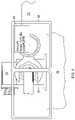
- FIG. 1illustrates schematically a wearable-integrated assembly system 10 for manufacturing, maintenance, or repair of a machine 12 .
- machinerefers broadly to any assembly of two or more components into a larger unit which performs a defined function.
- the term “machine”may refer to a complete device or a subassembly which is incorporated into a larger device.
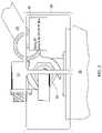
- the machine 12includes a fluid pressure sensor 14 mounted to a frame 16 .
- a fluid conduit 18is connected to the fluid pressure sensor using a conventional threaded fitting 20 , e.g. an AN818 coupling nut, conventionally referred to as a “B-nut”.
- the fluid pressure sensor 14further includes an electrical connector 22 for connection to a wiring harness (not shown). It will be understood that proper assembly of the machine 12 for a leak-free seal requires that the threaded fitting 20 must be threaded onto a mating part and then torqued to establish an appropriate preload. Numerous methods are available for determining an appropriate preload. One common method involves measuring the torque applied to the threaded fitting 20 by a tool such as a torque wrench, described below.
- machine 12is merely one example of an assembly of two or more components, and that the concepts described herein may be used for any type of assembly.
- Other examplesinclude but are not limited to fluid fittings that do not have a sensor, mechanical parts connected with bolts, nuts, or other fasteners, etc.
- the system 10generally includes one or more sensor-equipped tools 24 , one or more wearable devices 26 , a computing device 28 , and a database 30 . Each of these components will be described in more detail below.
- the tool 24may be any tool which includes at least one sensor which is capable of generating a signal representative of a condition of the workpiece or the tool.
- parameters that may be sensedinclude, for example, force, pressure, torque, velocity, acceleration, orientation, and/or displacement.
- use of the tool 24 in an assembly operation of a machine componentcauses the tool 24 to generate a signal which may then be used to determine if an operation is complete.
- the tool 24comprises a torque wrench having a set of jaws 32 sized to fit a fastener or fitting (a crow's-foot extension is shown), and also including an internal sensor such as a strain gauge (not shown) configured to measure the amount of torque applied through the jaws 32 .
- the torque wrenchfurther comprises a transceiver (not shown) operable to transmit a signal generated by the sensor to an outside device such as the illustrated receiver base 34 . This type of torque wrench and the associated receiver base 34 are commercially available.
- the wearable device 26include includes any device which may be held or bodily worn by a human user, which includes one or more processors to execute programmed instructions and one or more output devices to communicate information and/or status to the user.
- the wearable device 26may include one or more displays configured to be located in the field of view of the human user when the device is worn.
- the wearable device 26comprises a pair of “smart glasses” comprising a frame 38 which incorporate a display 40 (e.g. an LED monitor) operable to display information input to the wearable device 26 .
- the wearable device 26may incorporate lenses 42 which may be protective, vision corrective, or both.
- the wearable device 26may also incorporate a camera 44 for taking and storing digital photographs.
- the wearable device 26may optionally incorporate means for scanning informational codes, such as scanning software associated with the camera 44 , a separate scanner, a near-field communications chip for communicating with RFID tags, or a similar device.
- the wearable device 26may further include communications means such as a user-facing camera and/or a microphone.
- the wearable device 26may further include means for accepting user instructions such as one or more switches, touch screen interfaces, a voice recognition interface, or remote interface to a separate controlling device such as a portable computing device (e.g. “smartphone”) or conventional computer.
- a portable computing devicee.g. “smartphone”
- smart glassesare commercially available.
- a suitable deviceis the GOOGLE GLASS product.
- the computing device 28is operable to execute one or more software applications which perform functions such as receiving information from the tool 24 , receiving control inputs and data from the wearable device 26 , sending data to the wearable device 26 , and retrieving and/or storing information from one or more databases.
- the computing device 28takes the form of a conventional laptop computer, which is operably connected to the wearable device 26 , the tool 24 , and the database 30 through a data network using a conventional router 46 (wired or wireless).
- the database 30is located in a remote location and at least some of the network comprises a wide area network 48 such as the Internet.
- the computing device 28could be incorporated into the tool 24 , into the wearable device 26 , or into a remote or distributed computing environment including one or more remote computing devices 50 coupled to the system 10 through the wide area network 48 . If a remote computing device 50 is used, it will be understood that data from the tool 24 and the wearable device 26 could be passed to the remote computing device 50 through the wide area network 48 , and information and instructions could be passed from the remote computing device 50 back to the wearable device 26 .
- the system 10may be configured to retrieve documentation from a storage location such as the database 30 and to display the documentation in a predefined format on the display 40 of the wearable device 26 .
- the wearable device 26would display high-level work instructions to the mechanic in a predefined format, with particular emphasis on measured values, such as torque values.
- the instructionscould be, for example, in the form of a task list or in a series of sequential menus.
- the system 10may be configured to receive since or information from the tool 24 such as torque values.
- the computing device 28may be programmed, for example, to act upon real-time torque values to trigger system functions, to store torque values for archival purposes, or a combination of both.
- the system 10may be configured to command the wearable device 26 to take one or more digital photographs based on manual or automated triggers.
- the system 10may be configured to store information from the wearable device 26 such as photographs, display information, or a combination of photographs and display information. For example, this information could be stored in the database 30 .
- the system 10may be configured to retrieve supplemental information from a storage location such as the database 30 and to display the documentation in a predefined format on the display 40 of the wearable device 26 .
- supplemental informationcould include training or demonstration videos or animations (optionally including audio information), pictures, or schematics designed to aid the worker with performing complex tasks or learning new tasks.
- the system 10may be configured to implement two-way communication (including audio, video, or both) through the wearable device 26 .
- voice or video conferencingmay be implemented between the worker and support personnel at a remote location.
- an “assembly process”may also involve disconnecting components from each other.
- the workerbegins by accessing work instructions.
- the wearable device 26may be used to scan indicia such as a barcode or quick response (“QR”) code printed in paper documentation or posted near the work area which provides a link to database 30 or other suitable storage location from which the computing device 28 can load a high-level version of the assembly procedures, torque values, and other reference information or visuals.
- QRquick response
- the workercould manually use the controls of the wearable device 26 to access the work instructions, for example by downloading a procedure from the database 30 .
- FIG. 2illustrates the beginning of an operation to tighten the fitting 20 described above to the pressure sensor 14 using a torque wrench, with a view through the wearable device 26 superimposed thereupon. Initially, it can be seen that the display 40 identifies the fitting and informs the worker that it must be torqued to a specific value (20 to 25 foot-pounds in this example).
- the workercan access stored videos, animations, and images as necessary for reference.
- the workercan audio or video call engineers and share video to address questions or issues encountered. If necessary, the mechanic can still reference separate printed work instructions.
- the system 10receives information from the tool 24 .
- This informationcan be used to provide updated information to the worker, or to trigger automated system functions.
- FIG. 3illustrates a subsequent part of the operation to tighten the fitting 20 described above, with a view through the wearable device 26 superimposed thereupon.
- the display 40shows the instantaneous value of the applied torque, which in this case is 17 foot-pounds, a value outside of the acceptable final torque range.
- the systemmay be programmed to provide a first set of cues or indicia when the operation is incomplete.
- the display 40shows a symbol such as an “X” character which may be displayed using a format indicating noncompliance or incompleteness.
- the Xmay be displayed in a red-colored font.
- FIG. 4illustrates completion of the operation to tighten the fitting 20 described above, with a view through the wearable device 26 superimposed thereupon.
- the display 40shows the instantaneous value of the applied torque, which in this case is 23 foot-pounds, a value within the acceptable final torque range.
- the systemmay be programmed to provide a second set of cues or indicia when the operation is finished.
- the display 40shows a symbol such as a checkmark for the word “COMPLETE” which may be displayed using a format indicating compliance or completeness. For example, the word “COMPLETE” may be displayed in a green-colored font.
- system 10may be configured to document the operation automatically.
- system 10may be configured to automatically log sensor values generated by the tool 24 , or to trigger the wearable device 26 to take and store one or more digital photographs.
- the camera 44would be triggered to take a photograph 52 showing the fully-torqued fitting 20 , and the tool 24 , with the information from the display 40 showing the completed operation and final torque value combined with in the image.
- the photograph 52serves as a record and to document the number of items torqued.
- Various methodsmay be used to organize the photographs 52 . For example, they may be stored using unique filenames that identify the operation or component documented therein, or they may be identified and cross-referenced in a database.
- any sensor values or photographs 52could be stored locally, for example using device memory, for possible later transfer to a network or other storage.
- the method described hereinhas several advantages over the prior art. In particular, it provides instructions, documentation, and support to a worker without the worker having to leave the working space. It also provides automated documentation of process completion and avoids human error in assuring completion of all operations in an assembly process.
- the system and method described abovecan also be used for training.
- a mock-up machinecan be provided and a worker can practice performed the procedures using the guidance and feedback from the system as described above. This would be especially useful for workers performing a particular procedure for the first time, to avoid inevitable learning mistakes occurring on expensive components.
Landscapes
- Engineering & Computer Science (AREA)
- Physics & Mathematics (AREA)
- General Physics & Mathematics (AREA)
- Theoretical Computer Science (AREA)
- Business, Economics & Management (AREA)
- General Engineering & Computer Science (AREA)
- Educational Administration (AREA)
- Educational Technology (AREA)
- Human Computer Interaction (AREA)
- Computer Hardware Design (AREA)
- Entrepreneurship & Innovation (AREA)
- Multimedia (AREA)
- Chemical & Material Sciences (AREA)
- Analytical Chemistry (AREA)
- General Factory Administration (AREA)
Abstract
Description
Claims (14)
Priority Applications (1)
| Application Number | Priority Date | Filing Date | Title |
|---|---|---|---|
| US15/664,693US11328623B2 (en) | 2017-07-31 | 2017-07-31 | System and method for using wearable technology in manufacturing and maintenance |
Applications Claiming Priority (1)
| Application Number | Priority Date | Filing Date | Title |
|---|---|---|---|
| US15/664,693US11328623B2 (en) | 2017-07-31 | 2017-07-31 | System and method for using wearable technology in manufacturing and maintenance |
Publications (2)
| Publication Number | Publication Date |
|---|---|
| US20190035305A1 US20190035305A1 (en) | 2019-01-31 |
| US11328623B2true US11328623B2 (en) | 2022-05-10 |
Family
ID=65038147
Family Applications (1)
| Application Number | Title | Priority Date | Filing Date |
|---|---|---|---|
| US15/664,693Active2038-12-22US11328623B2 (en) | 2017-07-31 | 2017-07-31 | System and method for using wearable technology in manufacturing and maintenance |
Country Status (1)
| Country | Link |
|---|---|
| US (1) | US11328623B2 (en) |
Families Citing this family (7)
| Publication number | Priority date | Publication date | Assignee | Title |
|---|---|---|---|---|
| US11328623B2 (en)* | 2017-07-31 | 2022-05-10 | General Electric Company | System and method for using wearable technology in manufacturing and maintenance |
| US20190340954A1 (en)* | 2018-05-01 | 2019-11-07 | Illinois Tool Works Inc. | Portable user interface for a welding type system |
| US11330094B2 (en)* | 2019-03-29 | 2022-05-10 | Snap Inc. | Eyewear with customizable notifications |
| SE2051359A1 (en)* | 2020-11-20 | 2022-05-21 | Wiretronic Ab | Method and system for compliance determination |
| TW202307620A (en) | 2021-04-14 | 2023-02-16 | 美商蘭姆研究公司 | Control of semiconductor manufacturing equipment in mixed reality environments |
| US20230089436A1 (en)* | 2021-09-17 | 2023-03-23 | International Business Machines Corporation | Assembly and disassembly validation of machined components |
| US11721232B2 (en) | 2021-10-05 | 2023-08-08 | Teadit N.A., Inc. | Flange and gasket assembly training simulator |
Citations (39)
| Publication number | Priority date | Publication date | Assignee | Title |
|---|---|---|---|---|
| US6574672B1 (en) | 1999-03-29 | 2003-06-03 | Siemens Dematic Postal Automation, L.P. | System, apparatus and method for providing a portable customizable maintenance support computer communications system |
| US20080314204A1 (en)* | 2006-03-01 | 2008-12-25 | Fujitsu Limited | Screw tightening apparatus |
| US20080314162A1 (en)* | 2006-03-01 | 2008-12-25 | Fujitsu Limited | Torque measurement apparatus |
| US20080314197A1 (en)* | 2006-03-01 | 2008-12-25 | Fujitsu Limited | Screw tightening apparatus |
| US20080314206A1 (en)* | 2006-03-01 | 2008-12-25 | Fujitsu Limited | Screw tightening control system and screw tightening control method |
| US20090005910A1 (en)* | 2006-03-01 | 2009-01-01 | Fujitsu Limited | Synchronization control system |
| US7805114B1 (en) | 2002-07-17 | 2010-09-28 | Bath Iron Works Corporation | In situ re-configurable wireless communications system (IRCWCS) |
| US20100315329A1 (en)* | 2009-06-12 | 2010-12-16 | Southwest Research Institute | Wearable workspace |
| US20120122062A1 (en)* | 2010-11-16 | 2012-05-17 | Electronics And Telecommunications Research Institute | Reconfigurable platform management apparatus forvirtual reality-based training simulator |
| US20120206335A1 (en)* | 2010-02-28 | 2012-08-16 | Osterhout Group, Inc. | Ar glasses with event, sensor, and user action based direct control of external devices with feedback |
| US20130189657A1 (en)* | 2008-08-21 | 2013-07-25 | Matthew Wayne WALLACE | Virtual reality gtaw and pipe welding simulator and setup |
| US20130196296A1 (en)* | 2008-08-21 | 2013-08-01 | Carl Peters | Tablet-based welding simulator |
| US8773330B2 (en) | 2009-06-25 | 2014-07-08 | The Boeing Company | Method and apparatus for a virtual mission control station |
| US20140327762A1 (en) | 2013-05-06 | 2014-11-06 | Pruftechnik Dieter Busch Ag | Device for determining the location of mechanical elements |
| US20140354529A1 (en)* | 2013-05-28 | 2014-12-04 | The Boeing Company | Tracking a user to support tasks performed on complex-system components |
| US20150309563A1 (en)* | 2013-09-17 | 2015-10-29 | Medibotics Llc | Motion Recognition Clothing [TM] with Flexible Electromagnetic, Light, or Sonic Energy Pathways |
| US9223494B1 (en) | 2012-07-27 | 2015-12-29 | Rockwell Collins, Inc. | User interfaces for wearable computers |
| US20160012750A1 (en)* | 2008-08-21 | 2016-01-14 | Lincoln Global, Inc. | Welding simulator |
| US20160057511A1 (en)* | 2014-08-25 | 2016-02-25 | Daqri, Llc | Remote sensor access and queuing |
| US20160130018A1 (en) | 2014-11-12 | 2016-05-12 | Honeywell International Inc. | Context based content display in a wearable device |
| US20160132424A1 (en)* | 2013-06-28 | 2016-05-12 | Hewlett-Packard Development Company, L.P. | Simulating sensors |
| US9369760B2 (en) | 2011-12-29 | 2016-06-14 | Kopin Corporation | Wireless hands-free computing head mounted video eyewear for local/remote diagnosis and repair |
| US20160171861A1 (en)* | 2014-12-15 | 2016-06-16 | Autodesk, Inc. | Smart tools and workspaces for do-it-yourself tasks |
| US20160171772A1 (en)* | 2013-07-08 | 2016-06-16 | Ops Solutions Llc | Eyewear operational guide system and method |
| US20160178466A1 (en)* | 2014-12-23 | 2016-06-23 | Aztech Engineering Inc. | Machines and methods for evaluating prevailing torque threaded fasteners |
| US20160288236A1 (en)* | 2015-04-02 | 2016-10-06 | Illinois Tool Works Inc. | Systems and methods for tracking weld training arc parameters |
| US20160307459A1 (en)* | 2015-04-20 | 2016-10-20 | NSF International | Computer-implemented techniques for interactively training users to perform food quality, food safety, and workplace safety tasks |
| US20160338644A1 (en)* | 2013-09-17 | 2016-11-24 | Medibotics Llc | Smart Clothing for Ambulatory Human Motion Capture |
| US20160364699A1 (en)* | 2013-08-29 | 2016-12-15 | Modustri Llc | Detection system |
| US20170004827A1 (en)* | 2015-06-30 | 2017-01-05 | Siemens Energy, Inc. | Data Collection and Reporting System and Method |
| US20170042730A1 (en)* | 2015-08-14 | 2017-02-16 | The Johns Hopkins University | Surgical system providing hands-free control of a surgical tool |
| US20170046977A1 (en)* | 2015-08-12 | 2017-02-16 | Illinois Tool Works Inc. | Welding training system interface |
| US20170249417A1 (en)* | 2016-02-29 | 2017-08-31 | JumpStartCSR, Inc. | System, Method and Device for Designing, Manufacturing, and Monitoring Custom Human-Interfacing Devices |
| US20170300133A1 (en)* | 2014-12-18 | 2017-10-19 | Hewlett-Packard Development Company, L.P. | Wearable computing device |
| US20170352282A1 (en)* | 2016-06-03 | 2017-12-07 | International Business Machines Corporation | Image-based feedback for assembly instructions |
| US20180181810A1 (en)* | 2016-12-23 | 2018-06-28 | Realwear, Incorporated | Hands-free contextually aware object interaction for wearable display |
| US20180237056A1 (en)* | 2017-02-17 | 2018-08-23 | Ford Global Technologies, Llc | Methods and apparatus for determining kinetic friction in electromechanical steering actuators |
| US20190035305A1 (en)* | 2017-07-31 | 2019-01-31 | General Electric Company | System and method for using wearable technology in manufacturing and maintenance |
| US20200166990A1 (en)* | 2017-06-12 | 2020-05-28 | Michele Franzese | Device and methodology for the interaction through gestures and movements of human limbs and fingers |
- 2017
- 2017-07-31USUS15/664,693patent/US11328623B2/enactiveActive
Patent Citations (42)
| Publication number | Priority date | Publication date | Assignee | Title |
|---|---|---|---|---|
| US6574672B1 (en) | 1999-03-29 | 2003-06-03 | Siemens Dematic Postal Automation, L.P. | System, apparatus and method for providing a portable customizable maintenance support computer communications system |
| US7805114B1 (en) | 2002-07-17 | 2010-09-28 | Bath Iron Works Corporation | In situ re-configurable wireless communications system (IRCWCS) |
| US20090005910A1 (en)* | 2006-03-01 | 2009-01-01 | Fujitsu Limited | Synchronization control system |
| US20080314197A1 (en)* | 2006-03-01 | 2008-12-25 | Fujitsu Limited | Screw tightening apparatus |
| US20080314206A1 (en)* | 2006-03-01 | 2008-12-25 | Fujitsu Limited | Screw tightening control system and screw tightening control method |
| US20080314204A1 (en)* | 2006-03-01 | 2008-12-25 | Fujitsu Limited | Screw tightening apparatus |
| US20080314162A1 (en)* | 2006-03-01 | 2008-12-25 | Fujitsu Limited | Torque measurement apparatus |
| US20130196296A1 (en)* | 2008-08-21 | 2013-08-01 | Carl Peters | Tablet-based welding simulator |
| US20160012750A1 (en)* | 2008-08-21 | 2016-01-14 | Lincoln Global, Inc. | Welding simulator |
| US9330575B2 (en) | 2008-08-21 | 2016-05-03 | Lincoln Global, Inc. | Tablet-based welding simulator |
| US20130189657A1 (en)* | 2008-08-21 | 2013-07-25 | Matthew Wayne WALLACE | Virtual reality gtaw and pipe welding simulator and setup |
| US20100315329A1 (en)* | 2009-06-12 | 2010-12-16 | Southwest Research Institute | Wearable workspace |
| US8773330B2 (en) | 2009-06-25 | 2014-07-08 | The Boeing Company | Method and apparatus for a virtual mission control station |
| US20120206335A1 (en)* | 2010-02-28 | 2012-08-16 | Osterhout Group, Inc. | Ar glasses with event, sensor, and user action based direct control of external devices with feedback |
| US20120122062A1 (en)* | 2010-11-16 | 2012-05-17 | Electronics And Telecommunications Research Institute | Reconfigurable platform management apparatus forvirtual reality-based training simulator |
| US9369760B2 (en) | 2011-12-29 | 2016-06-14 | Kopin Corporation | Wireless hands-free computing head mounted video eyewear for local/remote diagnosis and repair |
| US9223494B1 (en) | 2012-07-27 | 2015-12-29 | Rockwell Collins, Inc. | User interfaces for wearable computers |
| US20140327762A1 (en) | 2013-05-06 | 2014-11-06 | Pruftechnik Dieter Busch Ag | Device for determining the location of mechanical elements |
| US20140354529A1 (en)* | 2013-05-28 | 2014-12-04 | The Boeing Company | Tracking a user to support tasks performed on complex-system components |
| US20160132424A1 (en)* | 2013-06-28 | 2016-05-12 | Hewlett-Packard Development Company, L.P. | Simulating sensors |
| US20160171772A1 (en)* | 2013-07-08 | 2016-06-16 | Ops Solutions Llc | Eyewear operational guide system and method |
| US20160364699A1 (en)* | 2013-08-29 | 2016-12-15 | Modustri Llc | Detection system |
| US20160338644A1 (en)* | 2013-09-17 | 2016-11-24 | Medibotics Llc | Smart Clothing for Ambulatory Human Motion Capture |
| US20150309563A1 (en)* | 2013-09-17 | 2015-10-29 | Medibotics Llc | Motion Recognition Clothing [TM] with Flexible Electromagnetic, Light, or Sonic Energy Pathways |
| US20160057511A1 (en)* | 2014-08-25 | 2016-02-25 | Daqri, Llc | Remote sensor access and queuing |
| US20160130018A1 (en) | 2014-11-12 | 2016-05-12 | Honeywell International Inc. | Context based content display in a wearable device |
| US9611055B2 (en) | 2014-11-12 | 2017-04-04 | Honeywell International Inc. | Context based content display in a wearable device |
| US20160171861A1 (en)* | 2014-12-15 | 2016-06-16 | Autodesk, Inc. | Smart tools and workspaces for do-it-yourself tasks |
| US20160171778A1 (en)* | 2014-12-15 | 2016-06-16 | Autodesk, Inc. | Smart tools and workspaces for do-it-yourself tasks |
| US20170300133A1 (en)* | 2014-12-18 | 2017-10-19 | Hewlett-Packard Development Company, L.P. | Wearable computing device |
| US20160178466A1 (en)* | 2014-12-23 | 2016-06-23 | Aztech Engineering Inc. | Machines and methods for evaluating prevailing torque threaded fasteners |
| US20160288236A1 (en)* | 2015-04-02 | 2016-10-06 | Illinois Tool Works Inc. | Systems and methods for tracking weld training arc parameters |
| US20160307459A1 (en)* | 2015-04-20 | 2016-10-20 | NSF International | Computer-implemented techniques for interactively training users to perform food quality, food safety, and workplace safety tasks |
| US20170004827A1 (en)* | 2015-06-30 | 2017-01-05 | Siemens Energy, Inc. | Data Collection and Reporting System and Method |
| US20170046977A1 (en)* | 2015-08-12 | 2017-02-16 | Illinois Tool Works Inc. | Welding training system interface |
| US20170042730A1 (en)* | 2015-08-14 | 2017-02-16 | The Johns Hopkins University | Surgical system providing hands-free control of a surgical tool |
| US20170249417A1 (en)* | 2016-02-29 | 2017-08-31 | JumpStartCSR, Inc. | System, Method and Device for Designing, Manufacturing, and Monitoring Custom Human-Interfacing Devices |
| US20170352282A1 (en)* | 2016-06-03 | 2017-12-07 | International Business Machines Corporation | Image-based feedback for assembly instructions |
| US20180181810A1 (en)* | 2016-12-23 | 2018-06-28 | Realwear, Incorporated | Hands-free contextually aware object interaction for wearable display |
| US20180237056A1 (en)* | 2017-02-17 | 2018-08-23 | Ford Global Technologies, Llc | Methods and apparatus for determining kinetic friction in electromechanical steering actuators |
| US20200166990A1 (en)* | 2017-06-12 | 2020-05-28 | Michele Franzese | Device and methodology for the interaction through gestures and movements of human limbs and fingers |
| US20190035305A1 (en)* | 2017-07-31 | 2019-01-31 | General Electric Company | System and method for using wearable technology in manufacturing and maintenance |
Also Published As
| Publication number | Publication date |
|---|---|
| US20190035305A1 (en) | 2019-01-31 |
Similar Documents
| Publication | Publication Date | Title |
|---|---|---|
| US11328623B2 (en) | System and method for using wearable technology in manufacturing and maintenance | |
| CN108228345B (en) | System and method for interactive cognitive task assistance | |
| US7103506B2 (en) | System and method for object-oriented marking and associating information with selected technological components | |
| US7814122B2 (en) | System and method for documentation processing with multi-layered structuring of information | |
| US9589390B2 (en) | Wire harness assembly | |
| US20180307045A1 (en) | Maintenance support device and maintenance support system for factory equipment | |
| EP3076253B1 (en) | Systems and methods for presenting an augmented reality | |
| CN106340217A (en) | Augmented reality technology based manufacturing equipment intelligent system and its implementation method | |
| JP4981779B2 (en) | Portable computers in process control environments. | |
| JP2002538541A (en) | System and method utilizing enhanced reality-based technology to contextually assist professional workers with remote experts | |
| EP3944201B1 (en) | Maintenance assistance system, maintenance assistance method, and program | |
| JP2006172462A (en) | Communication method and communication system | |
| JP2020503577A (en) | Manual work place unit, remote data processing device, manual work place operation system, manual work place operation method, and manual work place providing method | |
| CN112470180A (en) | Work support system and work support method | |
| KR101876856B1 (en) | Maintenance system and its control method using augmented reality | |
| US20180099413A1 (en) | Robot system and maintenance method for tracking information of module | |
| KR20200014574A (en) | Vision-based Monitoring Device and System for CNC Machine Tools | |
| CN110751734A (en) | Mixed reality assistant system suitable for job site | |
| JP2008217608A (en) | Industrial machine remote monitoring system and method | |
| CN115168928A (en) | Intelligent window system of machine tool and construction method | |
| WO2021250631A1 (en) | System and method for manufacturing and maintenance | |
| JP2003263475A (en) | Pump inspection work support system | |
| US7802143B2 (en) | Testing system and testing method thereof | |
| DE102015209896B3 (en) | Determination of the robot following angles and selection of a robot with the help of a camera | |
| US11480940B2 (en) | Control system |
Legal Events
| Date | Code | Title | Description |
|---|---|---|---|
| AS | Assignment | Owner name:GENERAL ELECTRIC COMPANY, NEW YORK Free format text:ASSIGNMENT OF ASSIGNORS INTEREST;ASSIGNORS:ROBERTSON, TED LEWIS;ILSE, ERIC ARTHUR;GEYMAN, MATTHEW;AND OTHERS;REEL/FRAME:043147/0194 Effective date:20170731 | |
| STPP | Information on status: patent application and granting procedure in general | Free format text:DOCKETED NEW CASE - READY FOR EXAMINATION | |
| STPP | Information on status: patent application and granting procedure in general | Free format text:NON FINAL ACTION MAILED | |
| STPP | Information on status: patent application and granting procedure in general | Free format text:RESPONSE TO NON-FINAL OFFICE ACTION ENTERED AND FORWARDED TO EXAMINER | |
| STPP | Information on status: patent application and granting procedure in general | Free format text:FINAL REJECTION MAILED | |
| STPP | Information on status: patent application and granting procedure in general | Free format text:ADVISORY ACTION MAILED | |
| STPP | Information on status: patent application and granting procedure in general | Free format text:NON FINAL ACTION MAILED | |
| STPP | Information on status: patent application and granting procedure in general | Free format text:RESPONSE TO NON-FINAL OFFICE ACTION ENTERED AND FORWARDED TO EXAMINER | |
| STPP | Information on status: patent application and granting procedure in general | Free format text:FINAL REJECTION MAILED | |
| STPP | Information on status: patent application and granting procedure in general | Free format text:RESPONSE AFTER FINAL ACTION FORWARDED TO EXAMINER | |
| STPP | Information on status: patent application and granting procedure in general | Free format text:ADVISORY ACTION MAILED | |
| STPP | Information on status: patent application and granting procedure in general | Free format text:DOCKETED NEW CASE - READY FOR EXAMINATION | |
| STPP | Information on status: patent application and granting procedure in general | Free format text:NOTICE OF ALLOWANCE MAILED -- APPLICATION RECEIVED IN OFFICE OF PUBLICATIONS | |
| STPP | Information on status: patent application and granting procedure in general | Free format text:PUBLICATIONS -- ISSUE FEE PAYMENT VERIFIED | |
| STCF | Information on status: patent grant | Free format text:PATENTED CASE |