US11327262B2 - Fiber termination enclosure with modular plate assemblies - Google Patents
Fiber termination enclosure with modular plate assembliesDownload PDFInfo
- Publication number
- US11327262B2 US11327262B2US17/188,477US202117188477AUS11327262B2US 11327262 B2US11327262 B2US 11327262B2US 202117188477 AUS202117188477 AUS 202117188477AUS 11327262 B2US11327262 B2US 11327262B2
- Authority
- US
- United States
- Prior art keywords
- cable
- enclosure
- enclosure system
- plate
- fiber
- Prior art date
- Legal status (The legal status is an assumption and is not a legal conclusion. Google has not performed a legal analysis and makes no representation as to the accuracy of the status listed.)
- Active
Links
Images


Classifications
- G—PHYSICS
- G02—OPTICS
- G02B—OPTICAL ELEMENTS, SYSTEMS OR APPARATUS
- G02B6/00—Light guides; Structural details of arrangements comprising light guides and other optical elements, e.g. couplings
- G02B6/44—Mechanical structures for providing tensile strength and external protection for fibres, e.g. optical transmission cables
- G02B6/4439—Auxiliary devices
- G02B6/444—Systems or boxes with surplus lengths
- G02B6/4441—Boxes
- G02B6/445—Boxes with lateral pivoting cover
- G—PHYSICS
- G02—OPTICS
- G02B—OPTICAL ELEMENTS, SYSTEMS OR APPARATUS
- G02B6/00—Light guides; Structural details of arrangements comprising light guides and other optical elements, e.g. couplings
- G02B6/24—Coupling light guides
- G02B6/36—Mechanical coupling means
- G02B6/38—Mechanical coupling means having fibre to fibre mating means
- G02B6/3807—Dismountable connectors, i.e. comprising plugs
- G02B6/3897—Connectors fixed to housings, casing, frames or circuit boards
- G—PHYSICS
- G02—OPTICS
- G02B—OPTICAL ELEMENTS, SYSTEMS OR APPARATUS
- G02B6/00—Light guides; Structural details of arrangements comprising light guides and other optical elements, e.g. couplings
- G02B6/44—Mechanical structures for providing tensile strength and external protection for fibres, e.g. optical transmission cables
- G02B6/4439—Auxiliary devices
- G02B6/444—Systems or boxes with surplus lengths
- G02B6/4441—Boxes
- G—PHYSICS
- G02—OPTICS
- G02B—OPTICAL ELEMENTS, SYSTEMS OR APPARATUS
- G02B6/00—Light guides; Structural details of arrangements comprising light guides and other optical elements, e.g. couplings
- G02B6/44—Mechanical structures for providing tensile strength and external protection for fibres, e.g. optical transmission cables
- G02B6/4439—Auxiliary devices
- G02B6/444—Systems or boxes with surplus lengths
- G02B6/4452—Distribution frames
- G02B6/44524—Distribution frames with frame parts or auxiliary devices mounted on the frame and collectively not covering a whole width of the frame or rack
- G—PHYSICS
- G02—OPTICS
- G02B—OPTICAL ELEMENTS, SYSTEMS OR APPARATUS
- G02B6/00—Light guides; Structural details of arrangements comprising light guides and other optical elements, e.g. couplings
- G02B6/44—Mechanical structures for providing tensile strength and external protection for fibres, e.g. optical transmission cables
- G02B6/4439—Auxiliary devices
- G02B6/444—Systems or boxes with surplus lengths
- G02B6/44528—Patch-cords; Connector arrangements in the system or in the box
- G—PHYSICS
- G02—OPTICS
- G02B—OPTICAL ELEMENTS, SYSTEMS OR APPARATUS
- G02B6/00—Light guides; Structural details of arrangements comprising light guides and other optical elements, e.g. couplings
- G02B6/44—Mechanical structures for providing tensile strength and external protection for fibres, e.g. optical transmission cables
- G02B6/4439—Auxiliary devices
- G02B6/4457—Bobbins; Reels
- G—PHYSICS
- G02—OPTICS
- G02B—OPTICAL ELEMENTS, SYSTEMS OR APPARATUS
- G02B6/00—Light guides; Structural details of arrangements comprising light guides and other optical elements, e.g. couplings
- G02B6/44—Mechanical structures for providing tensile strength and external protection for fibres, e.g. optical transmission cables
- G02B6/4439—Auxiliary devices
- G02B6/4471—Terminating devices ; Cable clamps
- G—PHYSICS
- G02—OPTICS
- G02B—OPTICAL ELEMENTS, SYSTEMS OR APPARATUS
- G02B6/00—Light guides; Structural details of arrangements comprising light guides and other optical elements, e.g. couplings
- G02B6/44—Mechanical structures for providing tensile strength and external protection for fibres, e.g. optical transmission cables
- G02B6/4479—Manufacturing methods of optical cables
- H—ELECTRICITY
- H02—GENERATION; CONVERSION OR DISTRIBUTION OF ELECTRIC POWER
- H02G—INSTALLATION OF ELECTRIC CABLES OR LINES, OR OF COMBINED OPTICAL AND ELECTRIC CABLES OR LINES
- H02G3/00—Installations of electric cables or lines or protective tubing therefor in or on buildings, equivalent structures or vehicles
- H02G3/02—Details
- H02G3/08—Distribution boxes; Connection or junction boxes
- Y—GENERAL TAGGING OF NEW TECHNOLOGICAL DEVELOPMENTS; GENERAL TAGGING OF CROSS-SECTIONAL TECHNOLOGIES SPANNING OVER SEVERAL SECTIONS OF THE IPC; TECHNICAL SUBJECTS COVERED BY FORMER USPC CROSS-REFERENCE ART COLLECTIONS [XRACs] AND DIGESTS
- Y10—TECHNICAL SUBJECTS COVERED BY FORMER USPC
- Y10T—TECHNICAL SUBJECTS COVERED BY FORMER US CLASSIFICATION
- Y10T29/00—Metal working
- Y10T29/49—Method of mechanical manufacture
- Y10T29/49826—Assembling or joining
Definitions
- the present disclosurerelates to fiber optic enclosure, and more particularly, to a fiber optic enclosure with cable payout.
- Fiber optic networksare being extended in more and more areas (e.g., multiple dwelling units, apartments, condominiums, businesses, distributed antenna systems, cell towers, rural areas, single family residences). This growth has been particularly notable in the area of wireless communications, e.g., cellular, personal communication services (PCS) and other mobile radio systems.
- PCSpersonal communication services
- System design flexibilitycan include the ability to efficiently provide different varying fiber optic cable lengths and the ability to efficiently provide fiber optic enclosures having interior components customized to meet a given customer's needs.
- the fiber optic enclosureincludes an enclosure housing that is adapted to optically connect incoming fibers to outgoing fibers.
- One or more modular plate assembliesmay be mounted within an interior of the enclosure to customize the fiber optic enclosure.
- certain types of modular plate assembliesinclude termination adapter arrangements. In accordance with some aspects of the disclosure, certain types of modular plate assemblies include splice trays arrangements. In accordance with some aspects of the disclosure, certain types of modular plate assemblies include cable spool arrangements.
- modular cable port arrangementsmay be disposed at the enclosure housing.
- various types of modular cable port arrangementscan be selectively mounted at the enclosure housing.
- a cable spool arrangementis connected to an interior of the enclosure to rotate relative to the enclosure.
- One or more fiber cablesmay be paid out from the enclosure by pulling one end of the fiber cable through a cable port to unwind the fiber cable from the cable spool arrangement.
- one or more adaptersmay be disposed on the cable spool arrangement to rotate in unison with the cable spool arrangement.
- the termination adaptersare disposed on a stand-off mount element that is spaced from the cable spool arrangement, but configured to rotate in unison with the cable spool arrangement.
- FIG. 1is a schematic diagram of a fiber termination enclosure having an example mounting assembly disposed therein in accordance with the principles of the present disclosure
- FIG. 2is a front, top perspective view of an example fiber termination enclosure including an enclosure configured in accordance with the principles of the present disclosure and shown with a door in a closed position;
- FIG. 3is a front, bottom perspective view of the example fiber termination enclosure of FIG. 2 in which two cable port modules are visible;
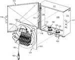
- FIG. 4is a front, top perspective view of the example fiber termination enclosure of FIG. 2 shown with the door in the open position and a cable spool mounting assembly exploded from the interior of the enclosure;
- FIG. 5is a schematic diagram of the fiber termination enclosure of FIG. 4 configured in accordance with the principles of the present disclosure
- FIG. 6is a front, top perspective view of the example fiber termination enclosure of FIG. 4 in which with the cable spool mounting assembly is exploded to show various example components of the cable spool mounting assembly including a mounting plate, a cable spool arrangement, and a stand-off mount element;
- FIG. 7is a front, top perspective view of the example fiber termination enclosure of FIG. 6 shown with the cable spool mounting assembly installed within the interior of the enclosure housing;
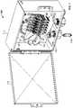
- FIG. 8is a front, top perspective view of the example fiber termination enclosure of FIG. 2 shown with an example splice tray reel mounting assembly installed within the interior of the enclosure housing;
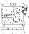
- FIG. 9is a front, top perspective view of the example fiber termination enclosure of FIG. 2 shown with an example termination panel mounting assembly installed within the interior of the enclosure housing;
- FIG. 10is a front, top perspective view of the example fiber termination enclosure of FIG. 9 shown with an example cover disposed over the cable spool mounting assembly;
- FIG. 11is a front, top perspective view of the example fiber termination enclosure of FIG. 2 shown with the door in the open position, an example sliding adapter mounting assembly disposed within the interior of the enclosure, and an example drop-in plate mounting assembly exploded from the interior of the enclosure;
- FIG. 12is a front, top perspective view of the example fiber termination enclosure of FIG. 11 shown with the example drop-in plate mounting assembly disposed within the interior of the enclosure and partially cabled;
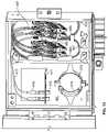
- FIG. 13is a front, top perspective view of the example fiber termination enclosure of FIG. 12 shown with cabling extending between the example drop-in plate mounting assembly and the example sliding adapter mounting assembly;
- FIG. 14is a front, top perspective view of the example fiber termination enclosure of FIG. 2 shown with an example splice tray mounting assembly and an example sliding adapter mounting assembly disposed within the interior of the enclosure housing;
- FIG. 15is a front, top perspective view of the example fiber termination enclosure of FIG. 14 shown with an example cover disposed over the splice tray mounting assembly;
- FIG. 16is a schematic representation of a telecommunications network having exemplary features of aspects in accordance with the principles of the present disclosure.
- FIG. 1is a schematic diagram of an example fiber optic enclosure 100 .
- the fiber optic enclosure 100includes a housing, generally designated 110 , at which telecommunications cables (e.g., optical and/or electrical cables) can be optically coupled and/or stored.
- One or more modular plate assemblies 120may be mounted within the interior of the enclosure housing 110 .
- Each modular plate assembly 120includes a mounting plate 121 that is configured to mount to the enclosure housing 110 in a stationary configuration.
- Each modular plate assembly 120includes a coupling arrangement 170 at which one or more optical fibers 182 of at least a first fiber cable 180 are optically coupled to optical fibers 192 of at least a second fiber cable 190 .
- the fiber cables 180 , 190enter the enclosure housing 110 through cable ports 101 .
- the enclosure housing 110is deployed by securing the enclosure housing 110 to a mounting location (e.g., a wall, a pole, etc.).
- a mounting locatione.g., a wall, a pole, etc.
- the enclosure housing 110has brackets disposed on the top and bottom walls 111 , 112 .
- the enclosure housing 110may have brackets disposed on other walls to secure the enclosure housing 110 to the mounting location.
- the enclosure housing 110is adapted to be otherwise secured to a mounting location.
- FIGS. 2-4illustrate one example enclosure housing 110 having a top wall 111 , a bottom wall 112 ( FIG. 3 ), a first side wall 113 , a second side wall 114 ( FIG. 4 ), and a rear wall 115 ( FIG. 4 ) defining an interior.
- the enclosure housing 110also defines an open front 116 that provides access to the interior of the enclosure housing 110 (see FIG. 4 ).
- At least one cover 118is coupled to the enclosure housing 110 to selectively close the open front 116 of the enclosure housing 110 .
- the cover 118is pivotally coupled to the enclosure housing 110 using one or more hinges 103 disposed on one of the side walls 113 , 114 (see FIG. 4 ).
- the hinge 103allows the cover 118 to selectively pivot between a closed position (shown in FIG. 2 ) and an open position (shown in FIG. 4 ).
- the cover 118can be held closed using locking flanges 117 , 119 ( FIG. 4 ).
- the enclosure housing 110is molded from a plastic material.
- the enclosure housing 110is molded from a plastic material.
- the enclosure housing 110is molded from a metal material.
- the enclosure housing 110defines one or more cable ports 101 ( FIG. 1 ) at which cables 180 , 190 may enter and exit the interior of the enclosure housing 110 .
- the cable ports 101are disposed at the bottom wall 112 of the enclosure housing 110 . In other implementations, however, the cable ports 101 may be disposed elsewhere on the enclosure housing 110 , such as at the top wall 111 , the rear wall 115 , or one of the side walls 113 , 114 .
- the enclosure housing 110is configured to receive one or more cable port modules 150 at the cable ports 101 (e.g., see FIGS. 3 and 4 ).
- the cable ports 101may define openings 155 ( FIG. 4 ) in one or more walls 111 - 115 of the enclosure housing 110 at which the cable port modules 150 may be received.
- Each cable port module 150receives one or more cables 180 , 190 .
- a first cable port module 150may receive one or more service cables and a second cable port module 150 may receive one or more subscriber cables.
- the same cable port module 150may receive both service cables and subscriber cables.
- the enclosure housing 110may receive an even greater number of cable port modules 150 , each of which may receive service cables and/or subscriber cables.
- a variety of cable port modules 150may be configured to fit at the same opening 155 , thereby enabling a user to select which of the cable port modules 150 to mount at the opening 155 .
- the cable port modules 150may be removably mounted to the enclosure housing at the openings 155 , thereby enabling a user to switch which cable port modules 150 are mounted at any particular enclosure housing 110 .
- Each of the cable port modules 150 , 150 ′includes a port panel 151 configured to be mounted at an opening 155 defined in an enclosure housing 110 .
- the port panel 151may define one or more openings 152 through which fasteners (e.g., screws, bolts, etc.) may extend to secure the port panel 151 to one of the walls 111 - 115 of the enclosure housing 110 .
- fastenerse.g., screws, bolts, etc.
- One or more grommetsextend through the port panel 151 .
- Each grommetenables one or more cables 180 , 190 or fibers to enter the enclosure housing 110 while inhibiting the ingress of environmental contaminants, such as water, dirt, and rodents.
- a first example cable port module 150includes a first type of grommet 153 and a second type of grommet 154 .
- the second type of grommet 154is larger than the first type of grommet 153 .
- a cable 180 to be dispensedextends through the smaller grommet 153 .
- a second example cable port module 150 ′includes only the second type of grommet 154 extending through the port panel 151 .
- Other implementationsmay include still other types of cable port modules, each having its own configuration of grommets.
- the mounting plates 121 of the modular plate assemblies 120are adapted and configured to be mounted to the rear wall 115 of the enclosure housing 110 .
- the rear wall 115defines one or more openings through which fasteners may extend to secure a mounting plate 121 to the rear wall 115 .
- the rear wall 115may include one or more pegs over which the mounting plate 121 may be pressed.
- one or more panel fastening structurescan be attached, secured, or mounted to the rear wall 115 .
- the rear wall 115may include one or more pems 194 that are pressed into the rear wall 115 (see FIG. 4 ).
- the pems 194are sized and configured to be inserted through openings 122 defined in the mounting plate 121 .
- the pems 194define threaded passages that are configured to receive fasteners that secure the mounting plate 121 to the rear wall 115 , or can be exterior threaded shanks.
- the mounting plates 121 of the modular plate assemblies 120extend over a majority of the area of the rear wall 115 .
- a mounting plate 121has a rectangular shape (e.g., see FIG. 4 ).
- a mounting plate 121may define one or more cutouts 329 or otherwise have a non-rectangular shape (e.g., see FIGS. 9-12 ).
- the mounting plates 121 of the modular plate assemblies 120may extend over only a portion of the area of the rear wall 115 .
- of the mounting plates 121may be configured to extend over about half of the area of the rear wall 115 (e.g., see FIGS. 11-14 ).
- FIGS. 4-7illustrate a first implementation of a modular plate assembly 120 that includes a cable spool arrangement 130 ( FIG. 6 ) that is rotationally mounted to the modular plate assembly 120 .
- the cable spool arrangement 130includes a first storage area 102 , a second storage area 104 , and a termination region 108 .
- the termination region 108is spaced from the second storage area 104 , which is spaced from the first storage area 102 .
- the termination region 108is spaced forwardly of the second storage region 104 , which is spaced forwardly of the first storage region 102 (e.g., see FIG. 4 ).
- the second storage area 104forms part of a protected fiber management region 106 at which optical fibers can be separated out from optical cables.
- Fibers 192 of the second fiber cable 190are routed to the termination region 108 .
- the first fiber cable 180is routed to the first storage area 102 of the cable spool arrangement 130 . From the first storage area 102 , the first fiber cable 180 is routed to the second storage area 104 .
- the first fiber cable 180is broken out into individual optical fibers 182 at the protected fiber management region 106 .
- the fibers 182are routed to the termination region 108 at which the optical fibers 184 are connected to optical fibers 192 of the second fiber cable 190 .
- the fiber optic enclosure 100provides an enclosure from which lengths of a cable (e.g., a distribution cable) 180 can be dispensed following the mounting of the fiber optic enclosure 100 to a mounting location.
- the distribution cable 180is dispensed from the fiber optic enclosure 100 by pulling on an end (e.g., a connectorized end) 185 of the cable 180 (see FIGS. 4 and 7 ).
- the cable spool arrangement 130rotates about an axis relative to the stationary mounting plate 121 of the fiber optic enclosure 100 .
- the fiber optic enclosure 100can store this residual length.
- the cable spool mounting assembly 120includes a mounting plate 121 and a cable spool arrangement 130 .
- the mounting plate 121includes a first side 124 and an opposite second side 123 .
- the mounting plate 121is adapted for stationary mounting to the rear wall 115 of the housing enclosure.
- the second side 123 of the mounting plate 121is configured to be mounted to an interior surface of the rear wall 115 so that the mounting plate 121 is disposed within the interior of the housing enclosure 110 .
- the mounting plate 121defines one or more fastener openings 122 that are disposed to align with fastener openings provided on the rear wall 115 of the housing enclosure 110 .
- Certain types of mounting plates 121extend along substantially the entire rear wall 115 of the enclosure housing 110 .
- the cable spool arrangement 130includes a drum 131 extending between first and second support flanges 132 , 133 to form a first cable spool 134 .
- the first cable spool 134defines the first storage region 102 ( FIG. 5 ).
- the cable spool arrangement 130also includes a termination region 108 ( FIG. 5 ).
- a protected fiber management region 106( FIG. 5 ) is defined between the first storage region 102 and the termination region 108 .
- the cable spool arrangement 130includes a stand-off mounting assembly 140 , at which the termination region 108 ( FIG. 5 ) is disposed as will be described in more detail herein.
- the protected fiber management region 106( FIG. 5 ) is defined between the stand-off mounting assembly 140 and one of the first cable spool 134 (e.g., see FIG. 4 ).
- the drum portion 131 of the first cable spool 134is generally cylindrical in shape.
- the drum portion 131includes a first end portion that couples to the first support flange 132 and an oppositely disposed second end portion that couples to the second support flange 133 .
- the support flanges 132 , 133which are generally parallel to each other, are configured to rotate with the drum 131 .
- An outer surface of the drum 131 and inner surfaces of the support flanges 132 , 133define the first storage region 102 ( FIG. 5 ) within which optical fibers or cables (e.g., distribution cable 180 ) may be coiled.
- the drum portion 131has a sufficient diameter to provide bend radius protection to optical fibers wound around the fiber spool 134 .
- the drum portion 131defines a central bore that extends through the drum portion 131 .
- the central boreis adapted to receive a spindle 129 ( FIG. 6 ).
- the spindle 129extends through the bore in the drum 131 and secures to the second side 123 of the mounting plate 121 .
- the mounting plate 121defines openings 125 at which the spindle 129 is fastened to the mounting plate 121 .
- the first cable spool 134is configured to rotate about the spindle 129 relative to the mounting plate 121 .
- the support flanges 132 , 133are sized and shaped to retain the optical fibers wound around the drum 131 in the first storage region 102 .
- the support flanges 132 , 133are generally circular.
- the support flanges 132 , 133have a sufficient diameter to cover a majority of a surface area of the mounting plate 121 . In other implementations, however, one or both of the support flanges 132 , 133 may have a smaller diameter.
- the cable spool arrangement 130is configured to be releasably locked in a rotationally fixed position relative to the mounting plate 121 .
- the mounting plate 121includes a forwardly extending flange 126 that is configured to extend past the support flanges 132 , 133 of the drum 131 to interact with the front of the cable spool arrangement 130 (see FIG. 6 ).
- the forwardly extending flange 126defines an opening 127 .
- the second flange 133 of the cable spool 134defines an opening 136 that is disposed to align with the opening 127 of the forwardly extending flange 126 when the cable spool arrangement 130 is disposed in one rotational position.
- the opening 136is defined in a tab 135 that extends outwardly from the generally annular circumference of the second support flange 133 .
- a fastener 128may be inserted through the openings 136 , 127 to lock the cable spool arrangement 130 in the rotationally fixed position.
- the second support flange 133 of the cable spool 134defines an aperture 139 through which optical fibers or cables (e.g., distribution cable 180 ) may pass between the first storage area 102 and the front of the cable spool 134 .
- the cablespass through aperture 139 from the first storage region 102 to the protected fiber management region 106 .
- the aperture 139is located directly adjacent to the protected fiber management region 106 and allows cables from inside the first storage region 102 of the spool to be routed from the drum surface 131 to the protected storage region 106 .
- the protected fiber management region 106( FIG. 5 ) provides a mounting location for a fan out arrangement.
- the fan out arrangementincludes one or more fan outs 138 disposed between the back side of the stand-off 140 and the front side of the cable spool 134 (see FIG. 4 ).
- the fan outs 138may be disposed on the front side of the second support flange 133 of the cable spool 134 . Accordingly, the fan outs 138 rotate with the cable spool 134 .
- the cable 180 wrapped around the supplemental spool region 104can be routed to one of the fan outs 138 where individual optical fiber are broken out to form individual fiber optic pigtails 182 .
- the pigtails 182have ends connectorized by fiber optic connectors that are inserted into the fiber optic adapters 147 at the termination field 108 (see FIG. 4 ). Fiber optic connectors corresponding to fibers 192 of subscriber cables 190 also may be inserted into the adapters 147 to provide optical connections between the subscriber cables 190 and the cables 180 routed from the first cable spool 134 .
- the protected fiber management region 106also can include bend radius protectors 137 attached to the front spool flange 133 ( FIG. 6 ).
- the bend radius protector 137can form a supplemental spooling region 104 where cables routed from drum 131 through aperture 139 can be wrapped/spooled to provide cable storage and cable management.
- the pigtails 182also may be wrapped/spooled around the bend radius limiters 137 .
- the supplemental spooling regionprovides strain relief to the cables (e.g., distribution cables) 180 . Axial loads applied to the outside end 185 of the cables 180 will be transferred through the cable 180 to the wrapped portions of the cable 180 .
- a stand-off mount element 140may be coupled to the front of the first cable spool 134 .
- the stand-off mount element 140may be secured to the second support flange 133 of the first cable spool 134 so that the stand-off mount element 140 unitarily rotates with the first cable spool 134 .
- the stand-off mount element 140provides a front plate 141 where optical components (e.g., fiber optic adapters, splitters, splice trays, spools, bend radius protector, etc.) can be mounted.
- fiber optic adapters 147may form a termination region 108 on the front plate 141 .
- Cable management structures (e.g., bend radius limiters, spools, etc.) 148also may be provided on the stand-off plate 141 .
- two opposing bend radius limiters 148form a fiber spool on the stand-off plate 141 .
- one or more legs 142extend rearwardly from the stand-off plate 141 of the stand-off mount element 140 .
- Each leg 142defines an opening 143 configured to receive a peg 145 or fastener to secure the feet 143 to the front support flange 133 of the cable spool 134 .
- the stand-off mount element 140includes four legs 142 . In other implementations, however, the stand-off mount element 140 may include greater or fewer legs 142 . In still other implementations, the legs 142 may be unitary with the cable spool 134 and secure to the stand-off plate 141 .
- the stand-off plate 141is forwardly offset from the front side of the spool flange 133 , thereby forming the protected fiber management region 106 between the front side of the first cable spool 134 and back side of the stand-off mount element 140 (e.g., see FIG. 4 ).
- the separated fibers 184 in the protected fiber management region 106are routed around the bend radius limiters 137 or other management structures on the front of the cable spool 134 to the stand-off mount element 140 .
- the separated fibers 184have connectorized ends that plug into first ports of termination adapters 147 disposed at the stand-off plate 141 .
- Components disposed on the stand-off mount element 140are spaced forwardly of the cable spool 134 . Accordingly, the fiber optic adapters 147 are disposed on a different layer or plane than the fan outs 138 , which are disposed on a different layer or plane than the first cable spool 134 . In certain implementations, the fan outs 138 are disposed on the same layer or plane as the bend radius limiters 137 .
- the spacing between the cable spool layer and the stand-off layerenhances slack storage of optical fibers routed through the protected fiber management region 106 . In some implementations, the spacing between the cable spool layer and the stand-off layer inhibits over-bending of the fibers when routed between the fan out arrangements 138 and the fiber optic adapters 147 .
- the termination adapters 147are included in one or more termination modules 146 .
- the adapter modules 146are sliding adapter modules. Similar sliding adapter modules have been described in commonly owned U.S. Pat. Nos. 5,497,444; 5,717,810; 6,591,051; and 7,416,349, the disclosures of which are hereby incorporated by reference.
- the stand-off mount element 140includes six sliding adapter modules 146 , each holding four fiber optic adapters 147 .
- the stand-off mount element 140may include greater or fewer sliding adapter modules 146 holding greater or fewer termination adapters 147 .
- sufficient slack length of the separated fibers 182is left between the fan out arrangement 138 and the adapters 147 to accommodate the sliding movement of the sliding adapter modules 146 .
- the cable spool arrangement 130may be precabled at the factory or manufacturing center with one or more optical fibers or cables 180 .
- one or more multi-fiber cables 180may be wound around the storage area 102 of the cable spool 134 .
- the multi-fiber cables 180may be precabled to pass through the aperture 139 to the fan out arrangement 138 disposed in the protected fiber management region 106 (e.g., see FIGS. 4 and 7 ).
- the fan out arrangement 138separates the cables 180 into pigtails 182 .
- the fan out arrangement 138also upjackets the fibers 182 .
- the cable spool arrangement 130may be cabled with the one or more multi-fiber cables 180 after the enclosure housing 110 is deployed.
- the precabled cable spool mounting assembly 120is mounted within the enclosure housing 110 .
- the mounting plate 121is secured to a rear wall 115 of the enclosure housing 110 .
- the second ends of the multi-fiber cables 180may be routed through one of the cable ports so that the second ends are disposed outside of the enclosure housing 110 .
- the second ends of the one or more precabled multi-fiber cables 180may be terminated at one or more multi-fiber connectors 185 .
- the second end of a precabled multi-fiber cable 180is separated into two or more connectorized optical fibers (jacketed or unjacketed).
- the second ends of the multi-fiber cables 180are configured to be spliced to one or more optical fiber cables.
- a usermay pull on the second ends to dispense the stored length of cable 180 from the cable spool arrangement 130 .
- a usermay pull a second end of a cable 180 to a fiber distribution hub, drop terminal, or other network connection. Because the adapters 147 rotate in unison with the cable spool arrangement 130 , the second end of each multi-fiber cable 180 may be paid out without interfering with the cabling of the first ends of the multi-fiber cable 180 .
- the fastener 128may be inserted through aligned openings 135 , 128 to secure the cable spool arrangement 130 in a fixed rotational position relative to the mounting plate 121 .
- additional optical fiber cablesmay be routed into the enclosure housing 110 to secure to second ports of the termination adapters 147 .
- the additional optical fiber cablesmay be routed into the enclosure through one or more cable ports defined in the enclosure housing 110 .
- the termination adapters 147are configured to align and optically couple connectors terminating the additional optical cables with the connectorized ends of the multi-fiber cable 180 plugged into the first ports of the adapters 147 .
- FIG. 8illustrates a second example modular plate assembly 220 implemented as a second example cable spool mounting assembly 120 for mounting within the enclosure housing 110 .
- the second cable spool mounting assembly 220includes a rectangular mounting plate 221 that extends over a majority of the rear wall 115 .
- a cable spool arrangement 241is disposed on the mounting plate 221 and is configured to rotate relative to the mounting plate 221 (e.g., about a spindle). Since the mounting plate 221 is configured to remain stationary on the rear wall 115 , the cable spool arrangement 241 is configured to rotate relative to the enclosure housing 110 .
- the cable spool arrangement 241defines a storage area including a drum about which optical fibers or cables (e.g. of a multi-fiber distribution cable 180 ) may be coiled.
- the drumhas a sufficient diameter to provide bend radius protection to optical fibers wound around the fiber spool arrangement 241 .
- Rotating the cable spool arrangement 241dispenses or retracts the optical fibers or cables wound around the drum.
- the cable spool arrangement 241may be locked in a rotational orientation relative to the mounting plate 221 .
- one or more splice trays 242are disposed on the cable spool arrangement 241 .
- Each splice tray 242is configured to optically couple together two or more optical fibers.
- each splice tray 242may optically couple together at least one optical fiber of the distribution cable 180 and at least one optical fiber of a subscriber cable 190 ( FIG. 1 ).
- Certain types of splice tray 242may be pivoted between open and closed positions to provide access to the splices contained therein.
- the splice trays 242are stacked upon each other so that a bottom of the stack extends over the cable spool arrangement 241 and a top of the stack faces the open front 116 of the enclosure housing 110 .
- One or more fiber management structuresmay be disposed on the cable spool arrangement 241 .
- one or more bend radius limiters 243are disposed on a front of the cable spool arrangement 241 .
- four bend radius limitersare disposed at a top, bottom, and sides of the cable spool arrangement 241 .
- the cable spool arrangement 241also defines one or more channels 244 through which optical fibers or cables can pass between the storage area of the cable spool arrangement 241 and the splice trays 242 .
- the cable spool arrangement 241defines four openings 244 spaced between the bend radius limiters 243 .
- the second cable spool mounting assembly 220may be precabled at the factory or manufacturing center with one or more distribution cables 180 .
- the one or more distribution cables 180may be wound around the drum in the storage area of the second cable spool arrangement 241 .
- the first end of each distribution cable fibermay be routed through one of the openings 244 in the cable spool arrangement 241 , around one or more of the bend radius limiters 243 , and into one of the splice trays 242 disposed at a front of the cable spool arrangement 241 (e.g., see FIG. 8 ).
- the precabled second cable spool mounting assembly 220is mounted within the enclosure housing 110 to deploy the one or more distribution cables 180 .
- the mounting plate 221is secured to the rear wall 115 of the enclosure housing 110 as described above.
- the second ends 185 of the distribution cables 180may be routed out of the housing 110 through one of the cable port modules 101 so that the second ends 185 are disposed outside of the enclosure housing 110 (e.g., see FIG. 8 ).
- Additional optical fiber cablese.g., subscriber cables 190 of FIG. 1
- Unconnectorized ends of the subscriber cable fibersmay be optically coupled to the first ends of the service cable fibers at the splice trays 242 .
- each subscriber cable fibermay be routed from the respective cable port module 101 to the respective splice tray 242 (e.g., either directly or after being wound around some of the bend radius limiters 243 of the second cable spool mounting assembly 220 .
- FIGS. 9 and 10illustrate a third example modular plate assembly 120 implemented as a termination panel mounting assembly 320 .
- the termination panel mounting assembly 320includes a mounting plate 321 that is sized to extend over a majority of the rear wall 115 of the enclosure housing 110 .
- the mounting plate 321has a height that extends over a majority of a height of the rear wall 115 and the mounting plate 321 has a width that extends over a majority of a width of the rear wall 115 .
- the mounting plate 321defines one or more apertures 322 or pems that facilitate connection to the rear wall 115 .
- mounting plates 321define one or more cutouts 329 .
- the mounting plate 321defines a cutout 329 at an upper, right corner of the mounting plate 321 , thereby resulting in an L-shaped mounting panel 321 .
- the mounting plate 321may have other configurations.
- a termination plate 351is coupled to the mounting plate 321 .
- the termination plate 351is a bent portion of the mounting plate 321 .
- the termination plate 351is a separate piece that attaches to the mounting plate 321 (e.g., via snap-fit connection, latches, fasteners, etc.).
- the termination plate 351extends vertically with a first side facing the first side wall 113 and a second side facing the second side wall 114 of the enclosure housing 110 .
- the termination plate 351has a first side that faces the rear wall 115 and a second side that faces the open front 116 of the enclosure housing 110 .
- Each termination adapter 352has a first port and a second port.
- the first portfaces the first side wall 113 and the second port faces the second side wall 114 of the enclosure housing 110 .
- the adapter portsmay face the rear wall 115 and open front 116 of the enclosure housing 110 .
- the adapters 352 and the termination plate 351may be oriented at any desired angle relative to the mounting plate 321 .
- adapter dust caps 353may be provided at the adapter ports.
- one or more cable management structuresmay be provided on the termination plate 351 or mounting plate 321 .
- four bend radius limiters 354are disposed on a front of the mounting plate 321 .
- the bend radius limiters 354are configured to form two fiber spools.
- the bend radius limiters 354form a first fiber spool located between the termination plate 351 and the first side wall 113 of the housing 110 and a second fiber spool located between the termination plate 351 and the second side wall 114 of the housing 110 .
- the bend radius limiters 354are located substantially below the termination plate 351 .
- the same or other types of cable management structuresmay be disposed in different configurations.
- one or more optical fiber cablesmay be routed into the enclosure housing 110 (e.g., through one or more port modules 101 ). Connectorized ends of the distribution cables may be secured to the first ports of the termination adapters 352 . Additional optical fiber cables (e.g., subscriber cables 190 ) also may be routed into the enclosure housing 110 (e.g., through the same or other port modules 101 ). Connectorized ends of the subscriber cables may be secured to the second ports of the termination adapters 352 , which align and optically couple together the connectorized ends of the subscriber cables with the connectorized ends of the service cables.
- optical fiber cablese.g., distribution cables 180
- Connectorized ends of the distribution cablesmay be secured to the first ports of the termination adapters 352 .
- Additional optical fiber cablese.g., subscriber cables 190
- Connectorized ends of the subscriber cablesmay be secured to the second ports of the termination adapters 352 , which align and optically couple together the connectorized ends of the subscriber cables with the connectorized ends of
- a cover 330may be positioned within the enclosure housing 110 to enclose or otherwise inhibit access to at least a portion of the optical components location within the enclosure housing 110 (see FIG. 10 ).
- the cover 330extends from one of the side walls 113 , 114 to the termination plate 351 to block access to at least some of the fiber connectors plugged into one side of the termination adapters 352 .
- the cover 330extends from the second side wall 114 to the termination plate 351 to block access to any cables (e.g., service cables) entering the enclosure housing 110 through the left cable ports 101 , while allowing access to the cables (e.g., subscriber cables) entering the enclosure housing 110 through the right cable ports 101 .
- the cover 330may extend across the entire termination panel mounting assembly 320 .
- the cover 330includes a front plate 366 and a side plate 367 forming an L-shaped flange.
- the front plate 366extends from the second side wall 114 of the enclosure to the termination plate 351 , thereby covering the bend radius limiters 354 located to the left of the termination plate 351 .
- the front plate 366also blocks access to the second ports of the adapters 352 from the open front 116 of the enclosure housing 110 .
- the side plate 367extends downwardly from the termination plate 351 to inhibit access to the second side of the termination plate 351 from the right side of the enclosure housing interior.
- the cover 330may include two side plates and be located at a central portion of the enclosure interior.
- the cover 330may include a planar panel that extends across the open front 116 of the enclosure housing 110 .
- the cover 330defines one or more finger holes 368 by which the cover 330 may be installed and/or removed from the enclosure housing 110 .
- the front plate 366 of the cover 330defines two finger holes 368 .
- the cover 330may include a handle or other structure to facilitate manipulation of the cover 330 .
- the cover 330may be secured in place by a lock arrangement 369 .
- FIGS. 11-13illustrate fourth and fifth example modular plate assemblies 120 implemented as an example drop-in plate mounting assembly 400 and an example sliding adapter mounting assembly 450 , respectively.
- the fourth and fifth modular plate assemblies 400 , 450each extend over only a portion of the rear wall 115 .
- each of the fourth and fifth modular plate assemblies 400 , 450includes a mounting plate 401 , 451 that has a height that extends substantially over a height of the rear wall 115 and a width that extends over less than half of the rear wall 115 .
- the mounting plate 401 , 451is rectangular.
- the mounting plate 401 , 451is generally rectangular with notched corners.
- the mounting plate 401 , 451defines one or more apertures 402 , 452 through which fasteners extend to secure the mount plate 401 , 451 to the enclosure housing 110 .
- the drop-in plate assembly 400includes a drop-in plate 411 defining one or more holes 412 at which adapters 413 may be secured.
- the drop-in plate 411is formed from a bent portion of the mounting plate 401 .
- the drop-in plate 411is attached to the mounting plate 401 .
- the drop-in plate 411extends generally horizontally (i.e., parallel with the top wall 111 and bottom wall 112 of the enclosure housing 110 ). In other implementations, the drop-in plate 411 may be angled relative to the top and bottom walls 111 , 112 .
- the adapters 413are snap-fit or press-fit into the holes 412 of the drop-in plate 411 .
- the adapters 413are configured to receive and align multi-fiber (MPO) connectors.
- MPOmulti-fiber
- the adapters 413are configured to receive and align hardened multi-fiber adapters (HMFOCs).
- HMFOCshardened multi-fiber adapters
- the adapters 413are configured to receive and align single optical connectors (e.g., LC-connectors, SC-connectors, ST-connectors, FC-connectors, etc.).
- the drop-in plate assembly 400includes fiber management structures to facilitate routing optical fibers or cable between the adapters 413 and other components within the enclosure housing 110 .
- the drop-in plate assembly 400may include bend radius limiters extending forwardly from the mounting plate 401 .
- smaller bend radius limiters 414are disposed above the drop-in plate 411 and larger bend radius limiters 415 are disposed below the drop-in plate 411 .
- the larger bend radius limiters 415form a slack storage spool.
- the example sliding adapter mounting assembly 450includes at least one sliding adapter module 461 .
- Each sliding adapter module 461includes a plurality of adapters that are slideably mounted to rails.
- each sliding adapter module 461includes a row of six adapters.
- the example sliding adapter mounting assembly 450includes a first group of two sliding adapter modules 461 spaced from another group of two sliding adapter modules 461 . In other implementations, however, the example sliding adapter mounting assembly 450 may greater or fewer groups each having greater or fewer sliding adapter modules 461 .
- the sliding adapter modules 461are configured to slide generally horizontally in a forward-rearward direction relative to the enclosure housing 110 . In certain implementations, the sliding adapter modules 461 slide at an angle (e.g., at least partially in an upward-downward direction). In the example shown, the adapter modules 461 are oriented so that ports of the adapter modules 461 face towards the upper and lower walls 111 , 112 of the enclosure housing 110 . In other implementations, the adapter modules 461 may be oriented to face the side walls 113 , 114 of the enclosure housing 110 .
- the example sliding adapter mounting assembly 450also includes a fanout arrangement 462 including one or more fanouts. Each fanout separates optical fibers from a multi-fiber cable.
- the fanout arrangement 462is disposed between the two groups of adapter modules 461 . In other implementations, the fanout arrangement 462 may be disposed elsewhere on the mounting panel 401 . In certain implementations, two or more fanouts are stacked together so that a bottom of the stack abuts the mounting panel 401 and a top of the stack faces the open front 116 of the enclosure housing 110 .
- the example sliding adapter mounting assembly 450also includes fiber management structures to facilitate routing optical fibers or cables from the sliding adapter modules 461 to other components within the enclosure housing 110 .
- the sliding adapter mounting assembly 450may include one or more bend radius limiters 463 ( FIG. 11 ).
- each group of adapter modules 461has two corresponding bend radius limiters 463 at a bottom of the mounting panel 401 and at least one bend radius limiter 463 at a top of the mounting panel 451 .
- the mounting panel 451also may include guide flanges 464 ( FIG. 11 ) that facilitates retaining optical fibers or cables within the area of the mounting panel 451 .
- the mounting panel 451defines a guide flange 464 on each side of the mounting panel 451 .
- each guide flange 464is bent forwardly from the mounting panel 451 .
- each guide flange 464may be a separately attached piece.
- each guide flange 464extends vertically to inhibit the fibers from spilling into the rest of the enclosure interior.
- the mounting panel 451includes retaining flanges 465 defining a guide channel through which one or more fibers or cables may be routed.
- the retaining flanges 465include a first portion extending forwardly of the mounting plate and a second portion that extends across the fibers disposed in the channel.
- each retaining flange 465may have an L-shaped cross-section.
- the mounting panel 451 of FIG. 13also includes another type of guide flange 466 is T-shaped. The guide flange 466 is disposed between the two groups of sliding adapter modules 461 .
- the sliding adapter mounting assembly 450may be precabled at the factory or manufacturing center with one or more intermediate fibers 467 .
- Some example intermediate fibers 467each include a single optical fiber. First ends of the intermediate fibers 467 are connectorized and plugged into first ports of the sliding adapter modules 461 . Second ends of the intermediate fibers 467 are joined at a fanout arrangement 462 to form one or more multi-fiber cables 417 .
- the second ends of the multi-fiber cables 417are connectorized (e.g., see optical connectors 418 of FIG. 13 ). In other implementations, the second ends of the multi-fiber cables 417 are unconnectorized.
- the separate intermediate fibers 467are routed around from the sliding adapter modules 461 and around the fiber management structures (e.g., bend radius limiters 463 and/or any of flanges 464 - 466 ). In certain implementations, sufficient slack length of the separated fibers 467 is left between the fanout arrangement 462 and the adapter modules 461 to accommodate the sliding movement of the sliding adapter modules 461 . In other implementations, however, the sliding adapter mounting assembly 450 may be cabled after the enclosure housing 110 is deployed. As shown in FIG.
- the connectors 418 terminating the multi-fiber cables 417may be plugged into the first ports of the adapters 418 of the drop-in plate assembly 400 when both the drop-in plate assembly 400 and the sliding adapter mounting assembly 450 are disposed within the enclosure housing 110 .
- a first set of additional optical fiber cablesmay be routed into the enclosure housing 110 (e.g., through one or more ports 101 ). Connectorized ends of the first set of optical fiber cables 180 may be plugged into the second ports of the adapters 413 at the drop-in plate assembly 400 .
- a second set of additional optical fiber cablese.g., subscriber cables 190
- Connectorized ends of the second set of optical fiber cables 190may be secured to second ports of the sliding adapter modules 461 . Accordingly, optical signals carried by the first group of optical fibers 182 may be passed to the multi-fiber cables 417 via the drop-in adapters 413 and then to the second group of optical fibers 192 via the sliding adapter modules 461 .
- FIG. 14illustrates a sixth example modular plate assemblies 120 implemented as an example splice tray mounting assembly 500 .
- the splice tray mounting assembly 500extends over only a portion of the rear wall 115 .
- the splice tray mounting assembly 500includes a mounting plate 501 that has a height that extends substantially over a height of the rear wall 115 and a width that extends over less than half of the rear wall 115 .
- the mounting plate 501is rectangular.
- the mounting plate 501is generally rectangular with notched corners.
- the mounting plate 501has notched sides.
- the mounting plate 501defines one or more apertures 502 through which fasteners extend to secure the mount plate 501 to the enclosure housing 110 .
- one or more splice trays 511are disposed on the mounting plate 501 .
- Each splice tray 511is configured to optically couple together two or more optical fibers.
- each splice tray 511may optically couple together at least one optical fiber of a service cable and at least one optical fiber of a subscriber cable or an intermediate fiber.
- Certain types of splice trays 511may be pivoted between open and closed positions to provide access to the splices contained therein.
- the splice trays 511are stacked upon each other so that a bottom of the stack extends over the mounting plate 501 and a top of the stack faces the open front 116 of the enclosure housing 110 .
- One or more support members 503may aid in securing the splice tray 511 to the mounting plate 501 .
- a support member 503is illustrated as at least one flange bent forwardly from the mounting late 501 at one side of the splice tray 511 .
- One or more fiber management structuresmay be disposed on the mounting plate 501 about the splice tray arrangement 511 .
- one or more bend radius limiters 512are disposed on a front of the mounting plate 501 .
- four bend radius limiters 512are disposed at four corners of the splice tray arrangement 511 .
- greater or fewer bend radius limiters 512may be disposed in other configurations.
- two or more optical fibersmay be spliced at the splice trays 511 .
- one or more optical fiber cablese.g., service cables
- One or more additional optical fiber cablese.g., subscriber cables
- unconnectorized ends of both groups of optical fiber cablesare coupled together at the splice trays 511 .
- the splice tray mounting assembly 500is disposed within the enclosure housing 110 with the sliding adapter mounting assembly 450 .
- the splice trays 511are configured to optically couple together unconnectorized ends of a first group of optical fibers (e.g., from one or more service cables) to unconnectorized ends of intermediate fibers 467 plugged into the sliding adapter modules 461 of the sliding adapter mounting assembly 450 .
- an example cover 600may be positioned within the enclosure housing 110 to enclose or otherwise inhibit access to at least a portion of the optical components location within the enclosure housing 110 .
- the cover 600extends from one of the side walls 113 , 114 to an intermediate portion of the enclosure interior to block access to at least some of the fiber optical connectors disposed within the enclosure interior.
- the cover 600extends from the second side wall 114 to cover the drop-in mounting assembly 400 . Accordingly, the cover 600 blocks access to the drop-in adapters 413 and to any fiber optic connectors plugged into the drop-in adapters 413 .
- the cover 600may extend across both the drop-in mounting assembly 400 and the sliding adapter module assembly 450 . In still other implementations, the cover 600 may extend across the splice tray mounting assembly 500 .
- the cover 600includes a front plate 601 and a side plate 602 forming a generally L-shaped flange.
- the front plate 601extends from one side of the mounting plate 401 of the drop-in mounting assembly 400 (or plate 501 of splice tray assembly 500 ) to the opposite side of the mounting plate 401 .
- the front plate 601also extends a majority of the distance between the top wall 111 and the bottom wall 112 .
- the side plate 602extends from the front plate 601 to the rear wall 115 of the enclosure housing 110 .
- the side plate 602defines an opening, cutout, or other routing channel 603 through which optical fibers may be routed between the interior spaced enclosed by the cover 600 and the interior space accessible through the open front 116 of the enclosure housing 110 .
- the cover 600may include two side plates and be located at a central portion of the enclosure interior.
- the cover 600may include a planar panel that extends across the open front 116 of the enclosure housing 110 .
- the cover 600defines one or more finger holes 604 by which the cover 600 may be installed and/or removed from the enclosure housing 110 .
- the front panel 601 of the cover 600defines two finger holes 604 .
- the cover 600may include a handle or other structure to facilitate manipulation of the cover 600 .
- the cover 600may be secured in place by a lock arrangement 605 .
- implementations of the fiber termination enclosure 100 disclosed abovemay be used in cell site applications.
- certain implementations 992 of the fiber termination enclosure 100may be mounted to a top of a cellular tower or in a hut at a base of a cellular tower.
- FIG. 16is a schematic representation of one example telecommunications network 910 utilizing such a cell site application.
- the telecommunications network 910is a cellular network 910 .
- the cellular network 910includes a cell site 912 , a demarcation point 914 , a backhaul 916 and a core network 918 .
- the cell site 912creates an area of telecommunications coverage (i.e., a cell) in the cellular network 910 .
- the cell site 912includes a tower or mast 920 and a hut 922 that is in communication with the tower 920 .
- the cell site 912includes a hut 922 that is in communication with an antenna or a plurality of antenna.
- the tower 920includes a base portion 924 and an oppositely disposed top portion 926 .
- the base portion 924is rigidly fixed at a mounting location.
- the top portion 926 of the tower 920may include an antenna.
- the remote transceiver 928may be integrated into the antenna.
- the top portion 926includes a remote transceiver 928 (e.g., a remote radio head).
- the remote transceiver 928is adapted to transmit and receive signals to and from devices (e.g., mobile phones, smart-phones, devices with wireless internet connectivity, etc.) of subscribers to the cellular network 910 .
- the top portion 926 of the tower 920includes multiple remote transceivers.
- some of the remote transceiversare backup remote transceivers.
- the top portion 926 of the tower 920further includes a multi-service terminal 930 . Terminal that are suitable for use as the multi-service terminal 930 of the present disclosure have been described in U.S. Pat. Nos. 7,292,763 and 7,512,304, the disclosures of which are hereby incorporated by reference in their entirety.
- the fiber optic cable 952 from the multi-service terminal 930is routed to an enclosure 992 at the hut 922 .
- the fiber optic cable 952includes a first end 962 and an oppositely disposed second end 964 .
- the first end 962includes a plurality of connectors that are engaged to the inner ports of the fiber optic adapters of the multi-service terminal 930 .
- the second end 964includes a multi-fiber connector that is adapted for engagement to one of the first and second multi-fiber connectors of the enclosure 992 .
- a jumper cable 966provides communication between the enclosure 992 and the base transceiver station 990 .
- the jumper cable 966includes a first end 968 and an oppositely disposed second end 970 .
- the first end 968is connected to the enclosure 992 while the second end 970 is connected to the base transceiver station 990 .
- the first end 968includes a plurality of connectors that are engaged with the second side 924 of the fiber optic adapters 920 of the enclosure 992 .
- the second end 970 of the jumper cable 966includes a multi-fiber connector that is engaged to the base transceiver station 990 .
- the second end 970includes a plurality of connectors that is engaged to the base transceiver station 990 .
- the base transceiver station 990is in communication with a telecommunications equipment rack 980 through a multi-fiber patch cable 982 .
- the telecommunications equipment rack 980is disposed in the hut 922 .
- the telecommunications equipment rack 980includes any one or more of a power distribution unit, a fiber distribution unit, a transport switch, a mobile router, a media converter, an Ethernet panel, a DSX panel, protection and a battery.
- the telecommunications equipment rack 980is in communication with the demarcation point 914 .
- the demarcation point 914is in communication with the backhaul 916 , which is in communication with the core network 918 .
- the fiber termination enclosure disclosed abovemay be used with other applications.
- some fiber termination enclosuresmay be installed at facilities, such as multiple dwelling units, apartments, condominiums, businesses, etc., to provide a subscriber access point to the fiber optic network.
- Other fiber termination enclosuresmay be installed on towers located on top of high rise buildings or other tall structures.
- Various implementations of fiber termination enclosuresmay be installed at walls, H-frame racks, and poles.
Landscapes
- Physics & Mathematics (AREA)
- General Physics & Mathematics (AREA)
- Optics & Photonics (AREA)
- Engineering & Computer Science (AREA)
- Manufacturing & Machinery (AREA)
- Architecture (AREA)
- Civil Engineering (AREA)
- Structural Engineering (AREA)
- Light Guides In General And Applications Therefor (AREA)
- Mechanical Coupling Of Light Guides (AREA)
Abstract
Description
Claims (20)
Priority Applications (4)
| Application Number | Priority Date | Filing Date | Title |
|---|---|---|---|
| US17/188,477US11327262B2 (en) | 2011-06-24 | 2021-03-01 | Fiber termination enclosure with modular plate assemblies |
| US17/740,180US11624884B2 (en) | 2011-06-24 | 2022-05-09 | Fiber termination enclosure with modular plate assemblies |
| US18/298,088US11988883B2 (en) | 2011-06-24 | 2023-04-10 | Fiber termination enclosure with modular plate assemblies |
| US18/639,296US20240295710A1 (en) | 2011-06-24 | 2024-04-18 | Fiber termination enclosure with modular plate assemblies |
Applications Claiming Priority (11)
| Application Number | Priority Date | Filing Date | Title |
|---|---|---|---|
| US201161500764P | 2011-06-24 | 2011-06-24 | |
| US201161500769P | 2011-06-24 | 2011-06-24 | |
| US201161507263P | 2011-07-13 | 2011-07-13 | |
| US201161507270P | 2011-07-13 | 2011-07-13 | |
| PCT/US2012/043827WO2012178070A2 (en) | 2011-06-24 | 2012-06-22 | Fiber termination enclosure with modular plate assemblies |
| US14/979,803US9423584B2 (en) | 2011-06-24 | 2015-12-28 | Fiber termination enclosure with modular plate assemblies |
| US15/243,143US9678293B2 (en) | 2011-06-24 | 2016-08-22 | Fiber termination enclosure with modular plate assemblies |
| US15/615,999US10401584B2 (en) | 2011-06-24 | 2017-06-07 | Fiber termination enclosure with modular plate assemblies |
| US16/134,187US10502916B2 (en) | 2011-06-24 | 2018-09-18 | Fiber termination enclosure with modular plate assemblies |
| US16/707,246US10935744B2 (en) | 2011-06-24 | 2019-12-09 | Fiber termination enclosure with modular plate assemblies |
| US17/188,477US11327262B2 (en) | 2011-06-24 | 2021-03-01 | Fiber termination enclosure with modular plate assemblies |
Related Parent Applications (1)
| Application Number | Title | Priority Date | Filing Date |
|---|---|---|---|
| US16/707,246ContinuationUS10935744B2 (en) | 2011-06-24 | 2019-12-09 | Fiber termination enclosure with modular plate assemblies |
Related Child Applications (1)
| Application Number | Title | Priority Date | Filing Date |
|---|---|---|---|
| US17/740,180ContinuationUS11624884B2 (en) | 2011-06-24 | 2022-05-09 | Fiber termination enclosure with modular plate assemblies |
Publications (2)
| Publication Number | Publication Date |
|---|---|
| US20210255407A1 US20210255407A1 (en) | 2021-08-19 |
| US11327262B2true US11327262B2 (en) | 2022-05-10 |
Family
ID=47423243
Family Applications (11)
| Application Number | Title | Priority Date | Filing Date |
|---|---|---|---|
| US14/127,851ActiveUS9223106B2 (en) | 2011-06-24 | 2012-06-22 | Fiber termination enclosure with modular plate assemblies |
| US14/979,803ActiveUS9423584B2 (en) | 2011-06-24 | 2015-12-28 | Fiber termination enclosure with modular plate assemblies |
| US15/243,143Expired - Fee RelatedUS9678293B2 (en) | 2011-06-24 | 2016-08-22 | Fiber termination enclosure with modular plate assemblies |
| US15/615,999ActiveUS10401584B2 (en) | 2011-06-24 | 2017-06-07 | Fiber termination enclosure with modular plate assemblies |
| US15/875,756ActiveUS10371914B2 (en) | 2011-06-24 | 2018-01-19 | Fiber termination enclosure with modular plate assemblies |
| US16/134,187ActiveUS10502916B2 (en) | 2011-06-24 | 2018-09-18 | Fiber termination enclosure with modular plate assemblies |
| US16/707,246Expired - Fee RelatedUS10935744B2 (en) | 2011-06-24 | 2019-12-09 | Fiber termination enclosure with modular plate assemblies |
| US17/188,477ActiveUS11327262B2 (en) | 2011-06-24 | 2021-03-01 | Fiber termination enclosure with modular plate assemblies |
| US17/740,180ActiveUS11624884B2 (en) | 2011-06-24 | 2022-05-09 | Fiber termination enclosure with modular plate assemblies |
| US18/298,088ActiveUS11988883B2 (en) | 2011-06-24 | 2023-04-10 | Fiber termination enclosure with modular plate assemblies |
| US18/639,296PendingUS20240295710A1 (en) | 2011-06-24 | 2024-04-18 | Fiber termination enclosure with modular plate assemblies |
Family Applications Before (7)
| Application Number | Title | Priority Date | Filing Date |
|---|---|---|---|
| US14/127,851ActiveUS9223106B2 (en) | 2011-06-24 | 2012-06-22 | Fiber termination enclosure with modular plate assemblies |
| US14/979,803ActiveUS9423584B2 (en) | 2011-06-24 | 2015-12-28 | Fiber termination enclosure with modular plate assemblies |
| US15/243,143Expired - Fee RelatedUS9678293B2 (en) | 2011-06-24 | 2016-08-22 | Fiber termination enclosure with modular plate assemblies |
| US15/615,999ActiveUS10401584B2 (en) | 2011-06-24 | 2017-06-07 | Fiber termination enclosure with modular plate assemblies |
| US15/875,756ActiveUS10371914B2 (en) | 2011-06-24 | 2018-01-19 | Fiber termination enclosure with modular plate assemblies |
| US16/134,187ActiveUS10502916B2 (en) | 2011-06-24 | 2018-09-18 | Fiber termination enclosure with modular plate assemblies |
| US16/707,246Expired - Fee RelatedUS10935744B2 (en) | 2011-06-24 | 2019-12-09 | Fiber termination enclosure with modular plate assemblies |
Family Applications After (3)
| Application Number | Title | Priority Date | Filing Date |
|---|---|---|---|
| US17/740,180ActiveUS11624884B2 (en) | 2011-06-24 | 2022-05-09 | Fiber termination enclosure with modular plate assemblies |
| US18/298,088ActiveUS11988883B2 (en) | 2011-06-24 | 2023-04-10 | Fiber termination enclosure with modular plate assemblies |
| US18/639,296PendingUS20240295710A1 (en) | 2011-06-24 | 2024-04-18 | Fiber termination enclosure with modular plate assemblies |
Country Status (4)
| Country | Link |
|---|---|
| US (11) | US9223106B2 (en) |
| AU (2) | AU2012272693B2 (en) |
| CA (1) | CA2877896C (en) |
| WO (1) | WO2012178070A2 (en) |
Cited By (1)
| Publication number | Priority date | Publication date | Assignee | Title |
|---|---|---|---|---|
| US20220373754A1 (en)* | 2011-06-24 | 2022-11-24 | Commscope Technologies Llc | Fiber termination enclosure with modular plate assemblies |
Families Citing this family (90)
| Publication number | Priority date | Publication date | Assignee | Title |
|---|---|---|---|---|
| US7715679B2 (en) | 2007-05-07 | 2010-05-11 | Adc Telecommunications, Inc. | Fiber optic enclosure with external cable spool |
| US7756379B2 (en) | 2007-08-06 | 2010-07-13 | Adc Telecommunications, Inc. | Fiber optic enclosure with internal cable spool |
| US11251608B2 (en) | 2010-07-13 | 2022-02-15 | Raycap S.A. | Overvoltage protection system for wireless communication systems |
| US9146376B2 (en)* | 2011-10-07 | 2015-09-29 | Adc Telecommunications, Inc. | Rack and chassis for fiber optic sliding adapter modules |
| BR112015000048A2 (en) | 2012-07-02 | 2017-06-27 | Tyco Electronics Raychem Bvba | reusable enclosure |
| ES1141660Y (en) | 2012-12-19 | 2015-10-14 | Tyco Electronics Raychem Bvba | Distribution device with incrementally added dividers |
| US20150268434A1 (en)* | 2013-02-06 | 2015-09-24 | Corning Optical Communications LLC | Fiber optic multiport |
| US20140219621A1 (en)* | 2013-02-06 | 2014-08-07 | Corning Cable Systems Llc | Fiber optic multiport |
| US10276990B2 (en)* | 2013-03-13 | 2019-04-30 | Commscope Technologies Llc | Telecommunications assembly with patch cord storage |
| US9198308B2 (en)* | 2013-03-14 | 2015-11-24 | Hubbell Incorporated | Metro cell aggregator enclosure |
| US20150093088A1 (en)* | 2013-09-30 | 2015-04-02 | Optema Technology Limited | Fiber Optic Terminal Assemblies |
| US9575274B2 (en)* | 2014-02-25 | 2017-02-21 | Commscope Technologies Llc | Fiber management structure having a splice tray with modular elements |
| FR3019313A1 (en)* | 2014-03-27 | 2015-10-02 | Orange | OPTICAL SOCKET WITH PRECONNECTED CABLE FEEDER |
| AU2015276109B2 (en) | 2014-06-17 | 2020-11-19 | Adc Czech Republic, S.R.O. | Cable distribution system |
| WO2016007488A1 (en)* | 2014-07-10 | 2016-01-14 | Corning Optical Communications LLC | Optical fiber distribution hub with fiber routing structures |
| US9442266B2 (en) | 2014-09-11 | 2016-09-13 | Commscope Technologies Llc | Fiber optic enclosure for retrofitting pedestals in the field |
| US20170371120A1 (en)* | 2015-01-15 | 2017-12-28 | Afl Telecommunications Llc | Wall-mountable optical fiber distribution terminal assembly |
| BR112017017259A2 (en)* | 2015-02-18 | 2018-04-17 | Adc Communications | fast scrolling indexing terminal layout |
| US10031306B2 (en)* | 2015-02-27 | 2018-07-24 | Opterna Technology Limited | Fiber distribution assemblies |
| EP3326016B1 (en)* | 2015-07-23 | 2022-09-07 | Commscope Technologies LLC | Cable spool re-orientation device for a wall box |
| US10802237B2 (en) | 2015-11-03 | 2020-10-13 | Raycap S.A. | Fiber optic cable management system |
| US9971119B2 (en)* | 2015-11-03 | 2018-05-15 | Raycap Intellectual Property Ltd. | Modular fiber optic cable splitter |
| US9664871B1 (en)* | 2015-11-19 | 2017-05-30 | Corning Optical Communications LLC | Fiber optic drawer tray having rotatable spool for deployment of fiber optic cable, and related components, systems, and methods |
| US10606009B2 (en) | 2015-12-01 | 2020-03-31 | CommScope Connectivity Belgium BVBA | Cable distribution system with fan out devices |
| EP3408701B1 (en) | 2016-01-28 | 2023-04-26 | CommScope Connectivity Belgium BVBA | Modular telecommunications enclosure |
| US10788641B2 (en)* | 2016-02-12 | 2020-09-29 | Ppc Broadband, Inc. | Cable spool and storage |
| US10359590B2 (en) | 2016-04-04 | 2019-07-23 | Opterna Technology Limited | Fiber optic cable deployment assemblies, systems, and methods |
| CN112180529B (en)* | 2016-05-23 | 2023-03-10 | 康普连通比利时私人有限公司 | Optical terminal package with reinforced self-supporting tether |
| US11073670B2 (en) | 2016-08-12 | 2021-07-27 | Corning Optical Communications LLC | Device and method for sealing multiport splitters |
| CN108463756A (en)* | 2016-08-31 | 2018-08-28 | Ofs菲特尔有限责任公司 | Multi fiber optical distribution cable for corridor installation |
| EP3542198A1 (en)* | 2016-11-15 | 2019-09-25 | CommScope Connectivity Belgium BVBA | Optical and power network for modular equipment |
| CN206147157U (en)* | 2016-11-15 | 2017-05-03 | 浙江超前通信设备有限公司 | Optical Splice Closure |
| WO2018136812A1 (en) | 2017-01-20 | 2018-07-26 | Raycap S.A. | Power transmission system for wireless communication systems |
| US10048451B1 (en)* | 2017-02-10 | 2018-08-14 | Hewlett Packard Enterprise Development Lp | Optical connectors with positions |
| JP6910456B2 (en)* | 2017-02-28 | 2021-07-28 | 華為技術有限公司Huawei Technologies Co.,Ltd. | Fiber access terminal |
| US11668890B2 (en) | 2017-06-28 | 2023-06-06 | Corning Research & Development Corporation | Multiports and other devices having optical connection ports with securing features and methods of making the same |
| US12271040B2 (en) | 2017-06-28 | 2025-04-08 | Corning Research & Development Corporation | Fiber optic extender ports, assemblies and methods of making the same |
| US11187859B2 (en) | 2017-06-28 | 2021-11-30 | Corning Research & Development Corporation | Fiber optic connectors and methods of making the same |
| US10359577B2 (en) | 2017-06-28 | 2019-07-23 | Corning Research & Development Corporation | Multiports and optical connectors with rotationally discrete locking and keying features |
| CN111051945B (en) | 2017-06-28 | 2023-12-29 | 康宁研究与开发公司 | Compact fiber optic connector, cable assembly and method of making the same |
| US11300746B2 (en) | 2017-06-28 | 2022-04-12 | Corning Research & Development Corporation | Fiber optic port module inserts, assemblies and methods of making the same |
| WO2019008069A1 (en) | 2017-07-07 | 2019-01-10 | CommScope Connectivity Belgium BVBA | Fiber optic tray |
| US20190072738A1 (en)* | 2017-08-10 | 2019-03-07 | Optical Cable Corporation | Modular Fiber Optic Cabling Infrastructure System |
| DK3681822T3 (en) | 2017-09-11 | 2024-02-05 | Ppc Broadband Inc | Coil cabinet |
| JP2021505966A (en) | 2017-12-12 | 2021-02-18 | フェニックス コンタクト ゲーエムベーハー ウント コムパニー カーゲー | Splice distributor with splice compartment |
| EP3537198B1 (en)* | 2018-03-05 | 2020-11-25 | Corning Research & Development Corporation | Fibre-optic cable fanout |
| US10886716B2 (en)* | 2018-06-27 | 2021-01-05 | Metra Electronics Corporation | Expanded two-gang electrical box |
| EP3830622A4 (en)* | 2018-08-01 | 2022-05-04 | CommScope Technologies LLC | OUTPUT BRANCH DISTRIBUTION BOX WITH ISOLATED FIBER CHAMBER |
| US10971928B2 (en) | 2018-08-28 | 2021-04-06 | Raycap Ip Assets Ltd | Integrated overvoltage protection and monitoring system |
| US11061196B2 (en) | 2018-10-16 | 2021-07-13 | CommScope Connectivity Belgium BVBA | Enclosure with restricted access region |
| EP3867982A4 (en)* | 2018-10-19 | 2022-07-13 | CommScope Technologies LLC | TELECOMMUNICATIONS TERMINAL WITH BREAK CORD |
| US10641967B1 (en) | 2018-11-16 | 2020-05-05 | Corning Research & Development Corporation | Multiport assemblies including a modular adapter support array |
| US10768382B2 (en) | 2018-11-29 | 2020-09-08 | Corning Research & Development Corporation | Multiport assemblies including access apertures and a release tool |
| PT3903136T (en) | 2018-12-28 | 2024-12-05 | Corning Res & Dev Corp | Multiport assemblies including mounting features or dust plugs |
| US11249269B2 (en)* | 2019-02-28 | 2022-02-15 | Commscope Technologies Llc | Multi-level optical cassette |
| TWI853904B (en)* | 2019-03-21 | 2024-09-01 | 美商Ppc寬頻股份有限公司 | Multi-fiber reel and adapter assembly |
| US11160187B1 (en)* | 2019-04-30 | 2021-10-26 | Facebook, Inc. | Container caddy for computer network transceivers |
| US11745974B2 (en)* | 2019-05-10 | 2023-09-05 | Commscope Technologies Llc | Wound cable holder with improved cable deployment control |
| WO2020242847A1 (en) | 2019-05-31 | 2020-12-03 | Corning Research & Development Corporation | Multiports and other devices having optical connection ports with sliding actuators and methods of making the same |
| WO2021011386A1 (en)* | 2019-07-12 | 2021-01-21 | Commscope Technologies Llc | Cable fixation assembly and method with floating cable support |
| US11294133B2 (en) | 2019-07-31 | 2022-04-05 | Corning Research & Development Corporation | Fiber optic networks using multiports and cable assemblies with cable-to-connector orientation |
| WO2021055532A1 (en) | 2019-09-17 | 2021-03-25 | US Conec, Ltd | Ferrule push |
| US11677164B2 (en) | 2019-09-25 | 2023-06-13 | Raycap Ip Assets Ltd | Hybrid antenna distribution unit |
| US11487073B2 (en) | 2019-09-30 | 2022-11-01 | Corning Research & Development Corporation | Cable input devices having an integrated locking feature and assemblies using the cable input devices |
| EP3805827B1 (en) | 2019-10-07 | 2025-07-30 | Corning Research & Development Corporation | Fiber optic terminals and fiber optic networks having variable ratio couplers |
| CA3159108A1 (en) | 2019-10-28 | 2021-12-23 | Opterna Am, Inc. | Terminal system assemblies with breakout/adapter modules |
| US11827490B2 (en)* | 2019-10-29 | 2023-11-28 | Hubbell Incorporated | Plenum rated cord reel assemblies |
| US11650388B2 (en) | 2019-11-14 | 2023-05-16 | Corning Research & Development Corporation | Fiber optic networks having a self-supporting optical terminal and methods of installing the optical terminal |
| US12210196B2 (en) | 2019-12-13 | 2025-01-28 | Us Conec Ltd. | Cover for a fiber optic ferrule and ferrule push |
| US11536921B2 (en) | 2020-02-11 | 2022-12-27 | Corning Research & Development Corporation | Fiber optic terminals having one or more loopback assemblies |
| US12022245B2 (en) | 2020-06-30 | 2024-06-25 | Go!Foton Holdings, Inc. | Easy access patch panel |
| US11228819B1 (en)* | 2020-06-30 | 2022-01-18 | Go!Foton Holdings, Inc. | Easy access patch panel |
| US11415767B2 (en)* | 2020-07-22 | 2022-08-16 | Clearfield, Inc. | Fiber optics deploy reel |
| EP4189454A4 (en)* | 2020-07-28 | 2024-08-21 | CommScope Technologies LLC | HYBRID CABLE MANAGEMENT DEVICE |
| WO2022035862A1 (en)* | 2020-08-14 | 2022-02-17 | Commscope Technologies Llc | Optical fiber management trays with interchangeable and adjustable fiber loop guides |
| US11604320B2 (en) | 2020-09-30 | 2023-03-14 | Corning Research & Development Corporation | Connector assemblies for telecommunication enclosures |
| AU2021368055A1 (en) | 2020-10-30 | 2023-06-08 | Corning Research & Development Corporation | Female fiber optic connectors having a rocker latch arm and methods of making the same |
| US11994722B2 (en) | 2020-11-30 | 2024-05-28 | Corning Research & Development Corporation | Fiber optic adapter assemblies including an adapter housing and a locking housing |
| US11880076B2 (en) | 2020-11-30 | 2024-01-23 | Corning Research & Development Corporation | Fiber optic adapter assemblies including a conversion housing and a release housing |
| US11686913B2 (en) | 2020-11-30 | 2023-06-27 | Corning Research & Development Corporation | Fiber optic cable assemblies and connector assemblies having a crimp ring and crimp body and methods of fabricating the same |
| US11927810B2 (en) | 2020-11-30 | 2024-03-12 | Corning Research & Development Corporation | Fiber optic adapter assemblies including a conversion housing and a release member |
| EP4285172A1 (en)* | 2021-01-29 | 2023-12-06 | Telefonaktiebolaget LM Ericsson (publ) | Optical device mounting assemblies |
| US11947167B2 (en) | 2021-05-26 | 2024-04-02 | Corning Research & Development Corporation | Fiber optic terminals and tools and methods for adjusting a split ratio of a fiber optic terminal |
| WO2023115036A1 (en)* | 2021-12-17 | 2023-06-22 | Commscope Technologies Llc | Telecommunications enclosure mounting system |
| US12237134B2 (en) | 2021-12-28 | 2025-02-25 | Raycap Ip Assets Ltd | Circuit protection for hybrid antenna distribution units |
| US12216319B2 (en)* | 2022-02-15 | 2025-02-04 | Google Llc | Easily accessible fiber optic panel assembly |
| EP4594801A1 (en)* | 2022-09-27 | 2025-08-06 | AFL Telecommunications LLC | Fiber optic closure |
| CN115980704B (en)* | 2022-12-26 | 2025-08-08 | 武汉万集光电技术有限公司 | Multi-line lidar |
| US20240219667A1 (en)* | 2022-12-30 | 2024-07-04 | Ppc Broadband, Inc. | Fiber distribution enclosure having a second enclosure therein and structurally configured to maintain the second enclosure in a raised position so as to provide enhanced access to the second enclosure |
| WO2024233316A1 (en)* | 2023-05-05 | 2024-11-14 | Ppc Broadband, Inc. | Cable access terminal configured to permit access to a component in the terminal and prevent access to another component in the terminal |
Citations (347)
| Publication number | Priority date | Publication date | Assignee | Title |
|---|---|---|---|---|
| US1276825A (en) | 1916-07-21 | 1918-08-27 | David Swope | Automatic take-up attachment for portable-telephone conductors. |
| US1442999A (en) | 1921-03-03 | 1923-01-23 | Boyle Rudolph Boardman | Automatic reel for electric devices |
| US1446410A (en) | 1922-03-31 | 1923-02-20 | Bennett Sandy Boyd | Winding reel |
| US1474580A (en) | 1923-02-19 | 1923-11-20 | George L Clark | Electric-wiring machine |
| USRE20995E (en) | 1939-02-07 | beasley | ||
| US2282156A (en) | 1941-02-14 | 1942-05-05 | Edwin J Benes | Fishing reel spool |
| US2502496A (en) | 1944-09-30 | 1950-04-04 | George D Wickman | Equalizer for ground conductors |
| US2521226A (en) | 1946-09-07 | 1950-09-05 | Hugo F Keller | Electric cord reel |
| US2727703A (en) | 1952-11-15 | 1955-12-20 | Robert N Bonnett | Insert for coreless roll of wire |
| US2767426A (en) | 1953-05-13 | 1956-10-23 | Edward L Grupp | Sash balance |
| US3131729A (en) | 1959-12-04 | 1964-05-05 | Sulzer Ag | Weft thread supply system for looms for weaving |
| US3346705A (en) | 1964-02-28 | 1967-10-10 | Robert E Breidenthal | Electric cord reel apparatus |
| US3433579A (en) | 1965-03-29 | 1969-03-18 | Ace M Runnion | Sterilizer cabinet |
| US3612424A (en) | 1970-03-27 | 1971-10-12 | Visual Graphics Corp | Storage and dispensing magazine for rolled strips of light sensitized material |
| US3657491A (en) | 1970-05-28 | 1972-04-18 | Illinois Tool Works | Cord reel |
| US3667417A (en) | 1970-04-24 | 1972-06-06 | Us Navy | Messenger buoy recovery device |
| US3837448A (en) | 1972-12-15 | 1974-09-24 | L Hagstrom | Line cord caddy |
| US3920308A (en) | 1974-04-01 | 1975-11-18 | Harry C Murray | Ready stored power cord |
| US3940086A (en) | 1973-11-23 | 1976-02-24 | Stoquelet Michel R A | Reel for a cable |
| US3983977A (en) | 1975-11-19 | 1976-10-05 | Crabb Virgil R | Electric extension cord reel |
| US4053118A (en) | 1976-05-21 | 1977-10-11 | Swing-Shift Mfg. Co. | Reversible reel unit |
| US4081258A (en) | 1976-05-12 | 1978-03-28 | International Telephone And Telegraph Corporation | Method for using on line optic fiber loss monitor |
| US4143746A (en) | 1978-01-30 | 1979-03-13 | Lowery A J | Hand reel |
| US4201278A (en) | 1978-08-02 | 1980-05-06 | db Systems Ltd. | Portable electrical cable interconnection assembly |
| US4384688A (en) | 1981-05-26 | 1983-05-24 | Warren F. B. Lindsley | Self-storing cord and hose reel assemblies |
| US4470558A (en) | 1982-06-16 | 1984-09-11 | Lear Siegler, Inc. | Retractable clothesline device |
| US4520239A (en) | 1982-09-30 | 1985-05-28 | Cable Electric Products, Inc. | Electrical cord reel and storage system |
| FR2566997A1 (en) | 1984-07-03 | 1986-01-10 | Reden Karl | Fishing line reel with external spool |
| US4587801A (en) | 1984-05-30 | 1986-05-13 | Societe Anonyme De Telecommunications | System for rotationally slaving an optical fiber feeding and dispensing device in a cabling line |
| US4635875A (en) | 1984-01-19 | 1987-01-13 | Apple Merrill K | Cable pulling device |
| US4657140A (en) | 1985-12-18 | 1987-04-14 | The United States Of America As Represented By The Secretary Of The Air Force | Fiber optic cable storage device |
| US4666237A (en) | 1983-01-27 | 1987-05-19 | British Telecommunications Public Limited Company | Optical fibre terminations and methods of and apparatus for making optical fibre terminations |
| US4767073A (en) | 1984-09-10 | 1988-08-30 | Malzacher Fred H | Cable spooling system |
| JPH01123203A (en) | 1987-11-09 | 1989-05-16 | Furukawa Electric Co Ltd:The | Optical cable connecting box for wiring in room |
| US4869437A (en) | 1987-07-16 | 1989-09-26 | Sms Schloemann-Siemag Aktiengesellschaft | Wire coiling apparatus with a recovery device for a coiled wire reel |
| US4883337A (en) | 1988-08-29 | 1989-11-28 | The Charles Stark Draper Laboratory, Inc. | Low strain optical fiber coil |
| US4913369A (en) | 1989-06-02 | 1990-04-03 | Welch Allyn, Inc. | Reel for borescope insertion tube |
| US4940859A (en) | 1989-07-24 | 1990-07-10 | Daniel Peterson | Telephone cord take-up reel assembly |
| US4939798A (en) | 1988-10-17 | 1990-07-10 | Last Harry J | Leading edge and track slider system for an automatic swimming pool cover |
| US4953194A (en) | 1989-09-22 | 1990-08-28 | Network Devices, Incorporated | Automated documentation system for a communications network |
| US4953810A (en) | 1990-02-08 | 1990-09-04 | Stadig Allen L | Holder and dispenser for a coiled article |
| US4968929A (en) | 1987-04-18 | 1990-11-06 | Heidelberger Druckmaschinen Ag | Plug connector coding system for electric cables |
| US4978310A (en) | 1989-01-17 | 1990-12-18 | Hosiden Electronics Co., Ltd. | Electrical jack connector |
| GB2236398A (en) | 1989-09-29 | 1991-04-03 | James Alexander Carter | Self documenting patch panel |
| US5016554A (en) | 1990-03-29 | 1991-05-21 | Romar Technologies, Inc. | Line storage reel for boat fenders, respectively, boat fenders equipped with line storage reels |
| US5052940A (en) | 1990-05-11 | 1991-10-01 | Rit-Rad Interconnection Technologies Ltd. | Hermaphroditic self-shorting electrical connector |
| US5066256A (en) | 1989-02-17 | 1991-11-19 | Ward Sr Robert B | Buoy and releasing system for ships in distress |
| US5066149A (en) | 1990-09-11 | 1991-11-19 | Adc Telecommunications, Inc. | Splice tray with slack take-up |
| US5071211A (en) | 1988-12-20 | 1991-12-10 | Northern Telecom Limited | Connector holders and distribution frame and connector holder assemblies for optical cable |
| US5074863A (en) | 1990-10-12 | 1991-12-24 | Dines Lenna V | Disposable retractable surgical instrument |
| US5100221A (en) | 1990-01-22 | 1992-03-31 | Porta Systems Corp. | Optical fiber cable distribution frame and support |
| US5107532A (en) | 1989-09-22 | 1992-04-21 | Cable Management International, Inc. | Automated documentation system for a communications network |
| US5161988A (en) | 1991-02-13 | 1992-11-10 | Rit Technologies Ltd. | Patching panel |
| US5166970A (en) | 1991-06-10 | 1992-11-24 | Ward Timothy K | Multi-conductor identifier with voice communication capability |
| US5167001A (en) | 1991-09-03 | 1992-11-24 | Northern Telecom Limited | Optical fiber storage and connector tray and shelf and tray assembly |
| US5172841A (en) | 1991-05-28 | 1992-12-22 | Leonard Friedman | Cord dispensing apparatus |
| US5185843A (en) | 1992-01-28 | 1993-02-09 | At&T Bell Laboratories | Restoration kit for communications cable |
| US5214730A (en) | 1991-05-13 | 1993-05-25 | Nippon Telegraph And Telephone Corporation | Multifiber optical connector plug with low reflection and low insertion loss |
| US5222164A (en) | 1992-08-27 | 1993-06-22 | International Business Machines Corporation | Electrically isolated optical connector identification system |
| US5246377A (en) | 1991-07-09 | 1993-09-21 | The Furukawa Electric Co., Ltd. | Apparatus for electrically connecting a rotary connector and a wiring harness |
| US5265187A (en) | 1992-10-28 | 1993-11-23 | Northern Telecom Limited | Distribution frame and optical connector holder combination |
| US5265815A (en) | 1992-06-17 | 1993-11-30 | The United States Of America As Represented By The Secretary Of The Army | Multi-cable storage and retrieval device |
| US5280861A (en) | 1992-11-25 | 1994-01-25 | Lippert Pintlepin Mfg. Inc. | Spool assembly for pintle |
| DE4226368A1 (en) | 1992-08-09 | 1994-02-10 | Suhner Elektronik Gmbh | Transmission path for systems equipped with fiber optic cables |
| US5305405A (en) | 1993-02-25 | 1994-04-19 | Adc Telecommunications, Inc. | Patch cord |
| US5310356A (en) | 1992-02-20 | 1994-05-10 | The Furukawa Electric Co., Ltd. | Transmission device used between two relatively rotatable components |
| US5317663A (en) | 1993-05-20 | 1994-05-31 | Adc Telecommunications, Inc. | One-piece SC adapter |
| US5326040A (en) | 1993-04-23 | 1994-07-05 | Fairchild Space And Defense Corporation | Sphere and cable deployer |
| US5335874A (en) | 1992-11-20 | 1994-08-09 | Siecor Corporation | Connectorized optical fiber cable reel |
| US5353367A (en) | 1993-11-29 | 1994-10-04 | Northern Telecom Limited | Distribution frame and optical connector holder combination |
| US5394503A (en) | 1993-10-08 | 1995-02-28 | Data Switch Corporation | Optical fiber connection monitoring apparatus, patch panel control system and method of using same |
| US5393249A (en) | 1993-06-30 | 1995-02-28 | Adc Telecommunications, Inc. | Rear cross connect DSX system |
| US5413494A (en) | 1992-10-05 | 1995-05-09 | Adc Telecommunications, Inc. | Jack module assembly |
| US5418334A (en) | 1993-08-04 | 1995-05-23 | Williams; Kenyon D. | Relative position tracer lamp indicator |
| US5419717A (en) | 1994-08-15 | 1995-05-30 | The Whitaker Corporation | Hybrid connector between optics and edge card |
| US5434944A (en) | 1991-06-18 | 1995-07-18 | British Telecommunications Public Limited Company | Optical fibre connection equipment |
| US5448015A (en) | 1991-12-30 | 1995-09-05 | Societe Anonyme Dite Alcatel Cit | Support and Guide device for cables carrying elcetrical or light signals |
| US5448675A (en) | 1994-06-09 | 1995-09-05 | At&T Ipm Corp. | Telecommunications distribution frame with tracing |
| US5467062A (en) | 1992-04-02 | 1995-11-14 | Adc Telecommunications, Inc. | Miniature coax jack module |
| US5473715A (en) | 1994-05-03 | 1995-12-05 | Methode Electronics, Inc. | Hybrid fiber optic/electrical connector |
| US5483467A (en) | 1992-06-10 | 1996-01-09 | Rit Technologies, Ltd. | Patching panel scanner |
| US5490229A (en) | 1993-12-08 | 1996-02-06 | At&T Ipm Corp. | Slidably mounted optical fiber distribution tray |
| US5494234A (en) | 1994-02-08 | 1996-02-27 | Fairchild Space And Defense Corporation | Multiple spheres and cable deployer |
| US5494446A (en) | 1994-01-05 | 1996-02-27 | Delucia; Eugene | Receptacle mounted, retractable, extension cord |
| US5497444A (en) | 1994-01-21 | 1996-03-05 | Adc Telecommunications, Inc. | High-density fiber distribution frame |
| US5519275A (en) | 1994-03-18 | 1996-05-21 | Coleman Powermate, Inc. | Electric machine with a transformer having a rotating component |
| US5522561A (en) | 1992-06-03 | 1996-06-04 | The United States Of America As Represented By The Secretary Of The Navy | Fiber optic cable payout system |
| US5528453A (en) | 1994-08-05 | 1996-06-18 | Video Express Systems, Inc. | Video recording traveling cart |
| US5544836A (en) | 1994-06-03 | 1996-08-13 | Lloyds International Trust | Extensible and self-retractable cable device |
| US5551545A (en) | 1994-03-18 | 1996-09-03 | Gelfman; Stanley | Automatic deployment and retrieval tethering system |
| US5613030A (en) | 1995-05-15 | 1997-03-18 | The Whitaker Corporation | High density fiber optic interconnection enclosure |
| US5638481A (en) | 1995-09-26 | 1997-06-10 | Lucent Technologies Inc. | Flush mounted outlet |
| US5657412A (en) | 1995-02-02 | 1997-08-12 | France Telecom, Establissement Autonome De Droit Public | Splice case for fibre optic cables |
| JPH09236709A (en) | 1996-02-28 | 1997-09-09 | Fujikura Ltd | Optical branch module |
| US5685741A (en) | 1996-06-27 | 1997-11-11 | Adc Telecommunications, Inc. | On demand plug-in jack card and monitor frame |
| US5703990A (en) | 1996-03-14 | 1997-12-30 | Lucent Technologies Inc. | Apparatus for housing a linearized optical fiber amplifier |
| US5709347A (en) | 1995-07-24 | 1998-01-20 | Alcatel Kabel Ag & Co | Device for electromagnetically braking and clutching a spool |
| US5712942A (en) | 1996-05-13 | 1998-01-27 | Lucent Technologies Inc. | Optical communications system having distributed intelligence |
| US5718397A (en) | 1996-12-23 | 1998-02-17 | Sonoco Products Company, Inc. | Reel having concentric flange supports |
| US5734774A (en) | 1995-11-30 | 1998-03-31 | Lucent Technologies Inc. | Outdoor electronics cabinet |
| US5749148A (en) | 1993-12-22 | 1998-05-12 | The Toro Company | Filament trimmer head |
| US5773757A (en) | 1996-08-12 | 1998-06-30 | Pembroke Properties, Inc. | Retractable electrical power cord apparatus |
| US5787219A (en) | 1996-03-20 | 1998-07-28 | Siemens Aktiengesellschaft | Cable closure |
| US5821510A (en) | 1994-12-22 | 1998-10-13 | Lucent Technologies Inc. | Labeling and tracing system for jumper used in an exchange |
| US5854824A (en) | 1994-09-04 | 1998-12-29 | Rit Technologies Ltd. | Connectivity scanner |
| JPH1187006A (en) | 1997-09-08 | 1999-03-30 | Furukawa Electric Co Ltd:The | Rotating connector |
| US5915640A (en) | 1996-02-14 | 1999-06-29 | Innoessentials International B.V. | Reel for storing surplus cable |
| US5957401A (en) | 1998-06-23 | 1999-09-28 | O'donnell; Patricia Sessum | Device for storing a string of lights |
| US5987203A (en) | 1997-10-09 | 1999-11-16 | Lucent Technologies Inc. | Distribution module for optical couplings |
| US5987207A (en) | 1997-06-27 | 1999-11-16 | Siecor Corporation | Fiber organizer |
| US5992787A (en) | 1997-02-06 | 1999-11-30 | Burke; Donald D. | Cord reel and storage device |
| US6002331A (en) | 1998-07-20 | 1999-12-14 | Laor; Herzel | Method and apparatus for identifying and tracking connections of communication lines |
| JPH11349230A (en) | 1998-06-09 | 1999-12-21 | Hitachi Cable Ltd | Optical cable reel and optical cable temporary mounting method using the same |
| US6035032A (en) | 1998-03-19 | 2000-03-07 | Lucent Technologies Inc. | Multi-layered foldable cross connect field |
| US6077108A (en) | 1997-12-31 | 2000-06-20 | Krone Gmbh | Patch panel with retractable patch cord |
| US6095837A (en) | 1996-08-30 | 2000-08-01 | Berg Technology, Inc. | Electrical connector with integral sensor device |
| US6116961A (en) | 1998-11-12 | 2000-09-12 | Adc Telecommunications, Inc. | Jack assembly |
| US6135254A (en) | 1998-12-09 | 2000-10-24 | Liao; Sheng Hsin | Electric wire reel |
| US6160946A (en) | 1998-07-27 | 2000-12-12 | Adc Telecommunications, Inc. | Outside plant fiber distribution apparatus and method |
| US6176559B1 (en) | 1998-02-02 | 2001-01-23 | 500 Group Inc. | Rolling containers assembly |
| US6215938B1 (en) | 1998-09-21 | 2001-04-10 | Adc Telecommunications, Inc. | Fiber optic cabinet and tray |
| US6222975B1 (en) | 1998-12-11 | 2001-04-24 | Lucent Technologies, Inc. | System and method for detecting and reporting the use of optical fibers in fiber optic cables |
| US6222908B1 (en) | 1999-09-23 | 2001-04-24 | Avaya Technology Corp. | Method and device for identifying a specific patch cord connector as it is introduced into, or removed from, a telecommunications patch system |
| US6220413B1 (en) | 1999-10-19 | 2001-04-24 | Siecor Operations, Llc | Retractable cable reel |
| US6220762B1 (en) | 1999-02-05 | 2001-04-24 | The Furukawa Electric Co., Ltd. | Collective connection structure of a plurality of optical connectors, optical connector arraying member, and adapter |
| US6223675B1 (en) | 1999-09-20 | 2001-05-01 | Coflexip, S.A. | Underwater power and data relay |
| US6234830B1 (en) | 1999-02-10 | 2001-05-22 | Avaya Technology Corp. | Tracing interface module for patch cords in a telecommunications system |
| US6238235B1 (en) | 1999-05-10 | 2001-05-29 | Rit Technologies Ltd. | Cable organizer |
| EP1107031A1 (en) | 1999-12-07 | 2001-06-13 | Molex Incorporated | Alignment system for mating connectors |
| US6285293B1 (en) | 1999-02-10 | 2001-09-04 | Avaya Technology Corp. | System and method for addressing and tracing patch cords in a dedicated telecommunications system |
| US6286777B1 (en) | 1999-01-21 | 2001-09-11 | Stringliner Company | Extension cord storage and dispensing system |
| US6300877B1 (en) | 2000-03-10 | 2001-10-09 | Adc Telecommunications, Inc. | DSX baytracer illuminator |
| US6315598B1 (en) | 2000-02-01 | 2001-11-13 | Adc Telecommunications, Inc. | Outlet box with cable management spool |
| US20010048044A1 (en) | 2000-05-30 | 2001-12-06 | Sumitomo Wiring Systems, Ltd. | Cable reel structure |
| US6330148B1 (en) | 1999-01-13 | 2001-12-11 | Lg. Philips Lcd Co., Ltd. | Flat panel display module for computer |
| US6330307B1 (en) | 1999-02-10 | 2001-12-11 | Avaya Technology Corp. | Display panel overlay structure and method for tracing interface modules in a telecommunications patch system |
| US20020003186A1 (en) | 2000-07-06 | 2002-01-10 | Hinds Cecil R. | Cable unwinding system and method |
| US6350148B1 (en) | 1999-02-10 | 2002-02-26 | Avaya Technology Corp. | Method and device for detecting the presence of a patch cord connector in a telecommunications patch system |
| US6349893B1 (en) | 2000-02-01 | 2002-02-26 | Avaya Technology Corp. | Retractable fiber slack storage device |
| US20020023984A1 (en) | 2000-08-31 | 2002-02-28 | J. L. Clark, Inc. | Three piece spool |
| US20020023814A1 (en) | 2000-02-29 | 2002-02-28 | Andrew Poutiatine | Daul retractable cord device with sliding electrical connector |
| US6361360B1 (en) | 2000-09-26 | 2002-03-26 | Agilent Technologies, Inc. | Expandable strain relief for flexible cable-like members |
| US6367347B1 (en) | 1998-08-04 | 2002-04-09 | Sram Deutschland Gmbh | Switch for bicycle speed-changing gear |
| US20020083538A1 (en) | 2001-01-02 | 2002-07-04 | Silverman Lee H. | Drain cleaning apparatus with remotely adjustable feed control |
| US6421322B1 (en) | 1997-11-17 | 2002-07-16 | Adc Telecommunications, Inc. | System and method for electronically identifying connections of a cross-connect system |
| US6419175B1 (en) | 2001-02-08 | 2002-07-16 | Vulcan Spring & Manufacturing Company | Retractor having a swivel attachment component |
| US6424710B1 (en) | 1999-02-10 | 2002-07-23 | Avaya Technology Corp. | Method and device for detecting the presence of a patch cord connector in a telecommunications patch system using passive detection sensors |
| US6433274B1 (en) | 2000-01-06 | 2002-08-13 | Mobility Electronic, Inc. | Power converter device |
| US20020126980A1 (en) | 2000-09-21 | 2002-09-12 | Adc Telecommunications, Inc. | Cable storage cartridge |
| US6456768B1 (en) | 2000-10-18 | 2002-09-24 | Fitel Usa Corp. | Optical fiber cable tracing system |
| US20020164121A1 (en) | 2001-03-15 | 2002-11-07 | 3M Innovative Properties Company | Wide-bandwidth chirped fiber bragg gratings with low delay ripple amplitude |
| US20020171002A1 (en) | 2001-05-21 | 2002-11-21 | Lake Restoration, Inc. | Retractable fence having a line dispenser |
| USD466479S1 (en) | 2000-05-25 | 2002-12-03 | Krone Gmbh | RJ style plug |
| US6499861B1 (en) | 1999-09-23 | 2002-12-31 | Avaya Technology Corp. | Illuminated patch cord connector ports for use in a telecommunications patch closet having patch cord tracing capabilities |
| US6511009B1 (en) | 2000-06-09 | 2003-01-28 | Cisco Technology, Inc. | Fiber optic cable spool |
| US6511231B2 (en) | 2000-12-27 | 2003-01-28 | Fitel Usa Corp. | Optical connector receptacle having switching capability |
| US6522826B2 (en) | 2001-05-11 | 2003-02-18 | Fibersense Technology Corporation | System and method of winding a fog coil |
| US6522737B1 (en) | 1999-02-10 | 2003-02-18 | Avaya Technology Corp. | System and method of operation for a telecommunications patch system |
| US20030037480A1 (en) | 2001-08-22 | 2003-02-27 | Davis Scott B. | Method and apparatus for dispensing filament such as tippet fishing line |
| US20030042348A1 (en) | 2001-08-10 | 2003-03-06 | Hammerhead Industries | Retracting tether for cell phones, pagers & PDA's |
| US6533216B1 (en) | 1998-12-30 | 2003-03-18 | Corning Incorporated | System and methods for providing under-wrap access to optical fiber wound onto spools |
| JP2003114339A (en) | 2001-10-04 | 2003-04-18 | Mitsubishi Electric Corp | Fiber take-up storage reel and fiber take-up storage method |
| US6554484B2 (en) | 2000-12-27 | 2003-04-29 | Fitel Usa Corp. | Optical connector receptacle having switching capability |
| US6574586B1 (en) | 1999-04-06 | 2003-06-03 | Itracs Corporation | System for monitoring connection pattern of data ports |
| US6591051B2 (en) | 2001-11-16 | 2003-07-08 | Adc Telecommunications, Inc. | Fiber termination block with angled slide |
| US20030142817A1 (en) | 2002-01-31 | 2003-07-31 | Liao Sheng Hsin | Earphone cable-receiving device with power recharge function |
| US6616080B1 (en) | 1999-04-28 | 2003-09-09 | Speculative Product Design, Inc. | Retractable cord device |
| US6626697B1 (en) | 2002-11-07 | 2003-09-30 | Tyco Electronics Corp. | Network connection sensing assembly |
| US6648520B2 (en) | 2001-09-28 | 2003-11-18 | Corning Cable Systems Llc | Fiber optic plug |
| US20030230667A1 (en) | 2002-06-18 | 2003-12-18 | Gary Ganster | Device and method for storing electric cable and electric cable components |
| US6669129B1 (en) | 2001-08-31 | 2003-12-30 | Stocker Yale, Inc. | Fiber optic cable winding tool |
| US6684179B1 (en) | 1999-04-06 | 2004-01-27 | Itracs Corporation | System for monitoring connection pattern of data ports |
| US20040052498A1 (en) | 2002-09-13 | 2004-03-18 | Colombo Bruce A. | Adapter systems for dynamically updating information related to a network and methods for developing the adapter systems |
| DE10244304B3 (en) | 2002-09-23 | 2004-03-18 | Data-Complex E.K. | Arrangement for monitoring patch panels at distributor points in data networks has patch cables that can be plugged into connections in patch fields with plugs, each fitted with a transponder |
| US6711339B2 (en) | 2002-05-31 | 2004-03-23 | Adc Telecommunications, Inc. | Fiber management module with cable storage |
| US6715619B2 (en) | 2002-07-22 | 2004-04-06 | Adc Telecommunications, Inc. | Fiber management drawer and patch panel |
| US20040065443A1 (en) | 2002-10-06 | 2004-04-08 | Weatherford/Lamb Inc. | Apparatus and method for transporting, deploying, and retrieving arrays having nodes interconnected by sections of cable |
| US6721484B1 (en) | 2002-09-27 | 2004-04-13 | Corning Cable Systems Llc | Fiber optic network interface device |
| US20040084271A1 (en) | 2002-10-31 | 2004-05-06 | George Woodruff | Portable light reel system |
| US6743044B2 (en) | 2002-08-14 | 2004-06-01 | Adc Telecommunications, Inc. | Cross-connect jumper assembly having tracer lamp |
| US6745971B1 (en) | 2000-09-20 | 2004-06-08 | Toby K. Renzoni | Spooling device for an optical fiber jumper cable |
| US6760530B1 (en) | 2000-06-09 | 2004-07-06 | Cisco Technology, Inc. | Fiber cable connector clip |
| US20040170369A1 (en) | 2003-02-28 | 2004-09-02 | Pons Sean M. | Retractable optical fiber assembly |
| US6793408B2 (en) | 2002-12-31 | 2004-09-21 | Intel Corporation | Module interface with optical and electrical interconnects |
| US6802735B2 (en) | 2002-06-18 | 2004-10-12 | Tyco Electronics Corporation | Receptacle and plug interconnect module with integral sensor contacts |
| US20040200332A1 (en) | 2003-04-09 | 2004-10-14 | Chen Hsi Tang | Cable receiving or storing device |
| US20040209505A1 (en) | 2003-04-16 | 2004-10-21 | The Furukawa Electric Co., Ltd. | Rotary connector having an integral fuse |
| US6808116B1 (en) | 2002-05-29 | 2004-10-26 | At&T Corp. | Fiber jumpers with data storage method and apparatus |
| US6814624B2 (en) | 2002-11-22 | 2004-11-09 | Adc Telecommunications, Inc. | Telecommunications jack assembly |
| US6819854B1 (en) | 2003-06-02 | 2004-11-16 | Moog Components Group Inc. | Fiber optic rotary flex |
| US20040240807A1 (en) | 2001-05-30 | 2004-12-02 | Franz-Friedrich Frohlich | Optical distribution device and light waveguide connector cable |
| US20040244430A1 (en) | 2003-06-05 | 2004-12-09 | Sheehy James J. | Yarn feeding system |
| US20040258384A1 (en) | 2000-01-24 | 2004-12-23 | Adc Telecommunications, Inc. | Cable management panel with sliding drawer |
| US6845207B2 (en) | 2001-02-12 | 2005-01-18 | Fiber Optic Network Solutions Corp. | Optical fiber enclosure system |
| US6850685B2 (en) | 2002-03-27 | 2005-02-01 | Adc Telecommunications, Inc. | Termination panel with pivoting bulkhead and cable management |
| US6856748B1 (en) | 2003-09-30 | 2005-02-15 | Corning Cable Systems Llc | Interconnection enclosure having a connector port and preterminated optical connector |
| JP2005073365A (en) | 2003-08-22 | 2005-03-17 | Matsushita Electric Works Ltd | Floor wiring device |
| US20050062881A1 (en) | 2002-12-30 | 2005-03-24 | Vincenzo Caci | Housing |
| US6885799B2 (en) | 2002-12-17 | 2005-04-26 | Samsung Electronics Co. Ltd. | Optical ribbon fiber including strength members |
| US20050103515A1 (en) | 2003-11-14 | 2005-05-19 | Fuller Denise E. | Fiber optic cable enclosure |
| US6901200B2 (en) | 2000-12-22 | 2005-05-31 | Fiber Optic Network Solutions, Inc. | Module and housing for optical fiber distribution and DWDM equipment |
| US20050128769A1 (en) | 2003-12-16 | 2005-06-16 | 3M Innovative Properties | Task lighting system |
| US20050145522A1 (en) | 2003-12-24 | 2005-07-07 | Bloodworth Stephen G. | Fiber optic drop cable slack storage receptacle |
| US6932517B2 (en) | 2000-10-27 | 2005-08-23 | Ethicon Endo-Surgery, Inc. | Connector incorporating a contact pad surface on a plane parallel to a longitudinal axis |
| US20050185910A1 (en) | 2003-09-08 | 2005-08-25 | Adc Telecommunications, Inc. | Fiber optic cable and furcation module |
| US20050184186A1 (en) | 2004-02-20 | 2005-08-25 | Chung Haap Tsoi | Retractable cable winder |
| US6937725B2 (en) | 2001-12-07 | 2005-08-30 | Sheng Hsin Liao | Short wire length wire-winding box |
| US6944387B2 (en) | 2001-04-30 | 2005-09-13 | Telect, Inc. | Fiber optic connector tray system |
| JP2005249858A (en) | 2004-03-01 | 2005-09-15 | Oki Electric Ind Co Ltd | Cable support |
| USD510068S1 (en) | 2002-03-11 | 2005-09-27 | Rit Technologies Ltd | Patch panel for communication equipment |
| US20050213920A1 (en) | 2004-02-20 | 2005-09-29 | Matsushita Electric Works, Ltd. | Wiring device for optical fiber |
| US6961675B2 (en) | 2000-03-14 | 2005-11-01 | Itracs Corporation | System for monitoring connection pattern of data ports |
| US20050247136A1 (en) | 2004-05-07 | 2005-11-10 | Cross Joseph A | Wireline extensometer |
| US20050258411A1 (en) | 2002-07-09 | 2005-11-24 | Markus Zeitler | Appliance for introducing flex into a cable sheath for the subsequent introduction of an electric cable |
| US20050258203A1 (en) | 2004-05-20 | 2005-11-24 | Weaver William W | Retractable tether device for hand tools |
| US6971895B2 (en) | 2002-11-15 | 2005-12-06 | Tokyo Communication Equipment Mfg Co., Ltd. | Connector adapter with memory function unit |
| US6976867B2 (en) | 2002-11-07 | 2005-12-20 | Tyco Electronics Amp Espana, S.A. | Network connection sensing assembly |
| US20060028198A1 (en) | 2004-07-23 | 2006-02-09 | Paul Hoopengarner | Electrical meter with retractable leads |
| US6997410B1 (en) | 2004-09-08 | 2006-02-14 | Kui-Hsien Huang | Positioning device for a reel |
| US7000863B2 (en) | 2003-09-29 | 2006-02-21 | Lucent Technologies Inc. | Method and apparatus for operational low-stress optical fiber storage |
| US20060045458A1 (en) | 2004-08-26 | 2006-03-02 | Koji Sasaki | Holder and structure for organizing excess length |
| US7011538B2 (en) | 2004-06-02 | 2006-03-14 | Elementech International Co., Ltd. | Dual input charger with cable storing mechanism |
| US20060054760A1 (en) | 2004-09-13 | 2006-03-16 | Murry Daniel L | Device for holding decorative string lights |
| US7017721B1 (en) | 2004-09-29 | 2006-03-28 | Plantronics, Inc. | Cable winding device with clocked keycap and revolving electrical switch |
| US7050041B1 (en) | 2000-10-30 | 2006-05-23 | Hewlett-Packard Development Company, L.P. | Pointing device with a cable storage winding mechanism |
| US7052281B1 (en) | 2004-09-29 | 2006-05-30 | Plantronics, Inc. | Cable winding device with direct cable to electrical component connection |
| CN1799296A (en) | 2003-05-30 | 2006-07-05 | Adc电信股份有限公司 | Fiber optic distribution frame with rotating tray |
| US20060148279A1 (en) | 2004-12-06 | 2006-07-06 | Commscope Solutions Properties, Llc | Telecommunications patching system that utilizes RFID tags to detect and identify patch cord interconnections |
| US7077710B2 (en) | 2001-03-21 | 2006-07-18 | Rit Technologies Ltd. | Patch panel |
| US20060160395A1 (en) | 2004-12-21 | 2006-07-20 | Commscope Solutions Properties, Llc | Methods, systems and computer program products for connecting and monitoring network equipment in a telecommunications system |
| US7081808B2 (en) | 2002-09-13 | 2006-07-25 | Fitel Usa Corp. | Self-registration systems and methods for dynamically updating information related to a network |
| US20060163403A1 (en) | 2005-01-04 | 2006-07-27 | Dickson Richard M | Spincast fishing reel with top-mounted quick-change line spool |
| US20060169856A1 (en) | 2005-02-01 | 2006-08-03 | Adc Telecommunications, Inc. | Fiber optic adapter including removable mount |
| US20060183362A1 (en) | 2006-04-07 | 2006-08-17 | Julian Mullaney | Coiled cable products and methods of forming the same |
| US20060187696A1 (en) | 2002-06-10 | 2006-08-24 | Comarco Wireless Technologies, Inc. | Cradle for receiving an adapter |
| US20060185953A1 (en) | 2003-04-11 | 2006-08-24 | Ipalco B.V. | Construction kit for a spring-driven cable drum |
| US20060186255A1 (en) | 2005-02-22 | 2006-08-24 | Rooker Jeffrey F | Cord storage reel with built-in plug and receptacle panel |
| US20060210230A1 (en) | 2005-03-16 | 2006-09-21 | Fiber Optic Cable Storage, Inc. | Fiber optic storing and dispensing apparatus |
| US7112090B2 (en) | 2003-05-14 | 2006-09-26 | Panduit Corp. | High density keystone jack patch panel |
| US7123810B2 (en) | 2004-05-04 | 2006-10-17 | Bellsouth Intellectual Property Corporation | Optical fiber connectors with identification circuits and distribution terminals that communicate therewith |
| US20060231672A1 (en) | 2005-04-15 | 2006-10-19 | E5 Products, Inc. | Electrician's caddy |
| US7139461B2 (en) | 1999-03-01 | 2006-11-21 | Adc Telecommunications, Inc. | Optical fiber distribution frame with outside plant enclosure |
| US20060264094A1 (en) | 2005-05-17 | 2006-11-23 | Young Eric D | Electric adapter organizer |
| US7142764B2 (en) | 2003-03-20 | 2006-11-28 | Tyco Electronics Corporation | Optical fiber interconnect cabinets, termination modules and fiber connectivity management for the same |
| US20060266605A1 (en) | 2005-05-31 | 2006-11-30 | Caamano Ramon A | Reel and reel housing |
| US20060280418A1 (en) | 2005-06-13 | 2006-12-14 | William Mahoney | Fiber optic cable enclosure assembly with slide out tray |
| US7153142B2 (en) | 2002-11-11 | 2006-12-26 | Rit Technologies Ltd. | Retrofit kit for interconnect cabling system |
| US7165728B2 (en) | 2004-04-02 | 2007-01-23 | Stratos International, Inc. | Radio frequency identification for transfer of component information in fiber optic testing |
| US20070023559A1 (en) | 2005-07-26 | 2007-02-01 | James Scapillato | Electronic device case |
| US20070025675A1 (en) | 2005-07-27 | 2007-02-01 | Anne Kramer | Fiber optic adapter module |
| US20070036506A1 (en) | 2004-08-09 | 2007-02-15 | Anthony Kewitsch | Fiber Optic Rotary Coupling and Devices |
| US7193422B2 (en) | 2004-01-20 | 2007-03-20 | The Siemon Company | Patch panel system |
| US7210858B2 (en) | 2002-01-15 | 2007-05-01 | Tokyo Communications Equipment Co., Ltd. | Optical connector with memory function |
| US20070096538A1 (en) | 2004-01-16 | 2007-05-03 | Timo Niemi | Arrangement for data transmission in mine, and cable reel |
| US20070108333A1 (en) | 2005-11-15 | 2007-05-17 | Yoshisuke Kuramoto | Miniature cord reel |
| JP2007121609A (en) | 2005-10-27 | 2007-05-17 | Japan Recom Ltd | Termination board in optical cable connection closure |
| US7220144B1 (en) | 2000-02-01 | 2007-05-22 | Adc Telecommunications, Inc. | Multimedia outlet box |
| US7226217B1 (en) | 2005-11-18 | 2007-06-05 | Stratos International, Inc. | Transceiver/fiber optic connector adaptor with patch cord ID reading capability |
| US7234944B2 (en) | 2005-08-26 | 2007-06-26 | Panduit Corp. | Patch field documentation and revision systems |
| US20070165995A1 (en) | 2005-08-30 | 2007-07-19 | Randy Reagan | Fiber distribution hub with modular termination blocks |
| US20070176045A1 (en) | 2006-01-18 | 2007-08-02 | Chi-Wen Chen | Reel device for winding an electrical cable thereon |
| US20070189691A1 (en) | 2006-02-13 | 2007-08-16 | Michael Barth | Fiber distribution hub with swing frame and modular termination panels |
| US20070237470A1 (en) | 2006-04-10 | 2007-10-11 | Aronson Lewis B | Active optical cable with electrical connector |
| US7292763B2 (en) | 2004-03-08 | 2007-11-06 | Adc Telecommunications, Inc. | Fiber access terminal |
| US7297018B2 (en) | 2004-11-03 | 2007-11-20 | Panduit Corp. | Method and apparatus for patch panel patch cord documentation and revision |
| US7312715B2 (en) | 2003-07-31 | 2007-12-25 | Rit Technologies Ltd. | Management of large scale cabling systems |
| US7315224B2 (en) | 2001-08-23 | 2008-01-01 | Rit Technologies Ltd. | High data rate interconnecting device |
| USD559186S1 (en) | 2004-09-20 | 2008-01-08 | Rit Technologies Ltd. | High-density patch panel |
| US20080008436A1 (en) | 2003-11-17 | 2008-01-10 | Fiber Optics Network Solutions Corp. | Hinged parking in fiber distribution hubs |
| US20080013909A1 (en) | 2006-07-14 | 2008-01-17 | Tenvera, Inc. | Modular Optical Fiber Network Interface |
| US20080011990A1 (en) | 2006-07-14 | 2008-01-17 | Tenvera, Inc. | Installation of Fiber Optic Cables |
| US20080013893A1 (en) | 2006-07-14 | 2008-01-17 | Tenvera, Inc. | Optical Fiber Ferrule and Ferrule Receiver, and Method for Manufacturing the Same |
| US20080011514A1 (en) | 2006-07-14 | 2008-01-17 | Tenvera, Inc. | Optical Fiber Distribution Apparatus and Method |
| US20080035778A1 (en) | 2006-08-14 | 2008-02-14 | Alpha Security Products, Inc. | Swivel recoiler |
| US20080037945A1 (en) | 2006-08-09 | 2008-02-14 | Jeff Gniadek | Cable payout systems and methods |
| US7352289B1 (en) | 2003-09-11 | 2008-04-01 | Sun Microsystems, Inc. | System and method for detecting the connection state of a network cable connector |
| US20080093187A1 (en) | 2006-10-23 | 2008-04-24 | Reginald Roberts | Reel for maintaining fiber optic cable assemblies |
| US7364108B2 (en) | 2004-05-14 | 2008-04-29 | Mu-Joong Kim | Connection structure and reel |
| US20080100467A1 (en) | 2006-10-31 | 2008-05-01 | Downie John D | Radio frequency identification of component connections |
| US7370106B2 (en) | 2000-11-22 | 2008-05-06 | Panduit Corp. | Network revision system with local system ports |
| US7369739B2 (en) | 2005-08-08 | 2008-05-06 | Fiber Optic Protection Systems, Inc. | Fiber optic cable protective apparatus |
| US20080131132A1 (en) | 2006-12-01 | 2008-06-05 | Solheid James J | Network interface device |
| US20080145013A1 (en) | 2006-12-13 | 2008-06-19 | Alejandro Raigoza Escoto | High density fiber optic hardware |
| US7400814B1 (en) | 2007-01-13 | 2008-07-15 | Furukawa Electric North America, Inc. | Wall-mountable optical fiber and cable management apparatus |
| US7406242B1 (en) | 2007-11-16 | 2008-07-29 | Tyco Electronics Co., Ltd. | Interconnect enclosures for optical fibers including cross-connect modules and methods for using the same |
| US20080199139A1 (en) | 2005-07-29 | 2008-08-21 | Afl Telecommunications Llc | Storage Device for Use in Fiber Optic Communication Systems and Method of Using the Same |
| US20080218947A1 (en) | 2007-03-08 | 2008-09-11 | Tellabs Vienna, Inc. | Method and apparatus of integration for primary and secondary power with addition of fiber storage for use in FTTx deployments |
| US20080236209A1 (en) | 2007-03-28 | 2008-10-02 | Checkpoint Systems, Inc. | Cable wrap security device |
| US20080292261A1 (en) | 2007-05-07 | 2008-11-27 | Kowalczyk Scott C | Fiber optic enclosure with external cable spool |
| US20080315030A1 (en) | 2007-06-22 | 2008-12-25 | Furukawa Electric North America, Inc. | Fiber optic rapid spooling tool |
| US7477829B2 (en) | 2006-04-27 | 2009-01-13 | Multilink, Inc. | Slack cable storage box |
| US7479032B2 (en) | 2006-10-10 | 2009-01-20 | Adc Gmbh | Upgradeable telecommunications patch panel and method of upgrading same |
| US20090060441A1 (en) | 2007-09-05 | 2009-03-05 | Kowalczyk Scott C | Fiber optic enclosure with tear-away spool |
| US20090074370A1 (en) | 2007-08-06 | 2009-03-19 | Adc Telecommunications, Inc. | Fiber optic enclosure with internal cable spool |
| US7512304B2 (en) | 2007-03-23 | 2009-03-31 | Adc Telecommunications, Inc. | Drop terminal with anchor block for retaining a stub cable |
| US7519000B2 (en) | 2002-01-30 | 2009-04-14 | Panduit Corp. | Systems and methods for managing a network |
| US20090098763A1 (en) | 2007-10-08 | 2009-04-16 | The Siemon Company | Contacts For Use In Monitoring Connection Patterns In Data Ports |
| US20090097846A1 (en) | 2006-12-14 | 2009-04-16 | David Robert Kozischek | RFID Systems and Methods for Optical Fiber Network Deployment and Maintenance |
| US7534137B2 (en) | 2006-02-14 | 2009-05-19 | Panduit Corp. | Method and apparatus for patch panel patch cord documentation and revision |
| US7546018B2 (en) | 2007-01-13 | 2009-06-09 | Ofs Fitel, Llc | Fiber optic cabling for multi-dwelling unit (MDU) and commercial building deployments |
| US7552872B2 (en) | 2006-06-21 | 2009-06-30 | Opnext Japan, Inc. | Reader/writer, optical transceiver module, and cable system |
| US20090166404A1 (en) | 2008-01-02 | 2009-07-02 | Commscope, Inc. Of North Carolina | Intelligent MPO-to-MPO Patch Panels Having Connectivity Tracking Capabilities and Related Methods |
| US20090190894A1 (en) | 2007-11-16 | 2009-07-30 | Adc Telecommunications, Inc. | Edge Protector for Fiber Optic Cable Routing |
| US7570861B2 (en) | 2007-01-19 | 2009-08-04 | Adc Telecommunications, Inc. | Adapter panel with lateral sliding adapter arrays |
| US7591667B2 (en) | 2005-03-04 | 2009-09-22 | Tyco Electronics Amp Espana Sa | Network connection sensing assembly |
| US20090257726A1 (en) | 2008-04-11 | 2009-10-15 | Tim Redmann | Fiber management panel |
| US20090317047A1 (en) | 2008-06-19 | 2009-12-24 | Adc Telecommunications, Inc. | Methods and systems for distributing fiber optic telecommunications services to local area |
| WO2010001400A1 (en) | 2008-07-02 | 2010-01-07 | Rit Technologies Ltd. | System and method for monitoring physical layer connectivity |
| US20100054680A1 (en) | 2008-08-27 | 2010-03-04 | Lochkovic Gregory A | Optical fiber assemblies for fiber to the subscriber applications |
| US20100054682A1 (en) | 2008-08-29 | 2010-03-04 | Cooke Terry L | Independently Translatable Modules and Fiber Optic Equipment Trays in Fiber Optic Equipment |
| US20100054684A1 (en) | 2008-08-29 | 2010-03-04 | Cooke Terry L | Rear-Slidable Extension in a Fiber Optic Equipment Tray |
| US7676136B2 (en) | 2008-06-26 | 2010-03-09 | Emerson Network Power, Energy Systems, North America, Inc. | Fiber distribution hubs with patch and splice enclosures |
| US20100074587A1 (en) | 2008-09-16 | 2010-03-25 | Todd Loeffelholz | Modular fiber optic enclosure with external cable spool |
| US7697811B2 (en) | 2008-09-08 | 2010-04-13 | Ortronics, Inc. | Horizontal fiber optic patching assembly |
| US20100166376A1 (en) | 2008-12-31 | 2010-07-01 | Nair K R Suresh | System for an internal rotating storage spool combined with top and bottom cable access in a fiber distribution terminal |
| US7751672B2 (en) | 2007-10-31 | 2010-07-06 | Adc Telecommunications, Inc. | Low profile fiber distribution hub |
| WO2010081186A1 (en) | 2009-01-19 | 2010-07-22 | Adc Gmbh | Telecommunications connector |
| US20100211664A1 (en) | 2009-02-13 | 2010-08-19 | Adc Telecommunications, Inc. | Aggregation of physical layer information related to a network |
| US7809234B2 (en) | 2004-06-18 | 2010-10-05 | Adc Telecommunications, Inc. | Telecommunications cabinet with connector storage |
| US7811119B2 (en) | 2005-11-18 | 2010-10-12 | Panduit Corp. | Smart cable provisioning for a patch cord management system |
| WO2010121639A1 (en) | 2009-04-22 | 2010-10-28 | Adc Gmbh | Method and arrangement for identifying at least one object |
| US20100322583A1 (en) | 2009-06-19 | 2010-12-23 | Cooke Terry L | High Density and Bandwidth Fiber Optic Apparatuses and Related Equipment and Methods |
| US7869426B2 (en) | 2006-03-22 | 2011-01-11 | Adc Gmbh | Intelligent patching system and method |
| US7872738B2 (en) | 2005-08-22 | 2011-01-18 | Tyco Electronics Subsea Communications Llc | System and method for monitoring an optical communication system |
| US20110024544A1 (en) | 2009-07-30 | 2011-02-03 | Mark Smrha | Locking spool for telecommunications cable and method |
| US7885505B2 (en) | 2007-10-22 | 2011-02-08 | Adc Telecommunications, Inc. | Wavelength division multiplexing module |
| US20110044599A1 (en) | 2009-07-21 | 2011-02-24 | Adc Telecommunications, Inc. | Rapid universal rack mount enclosure |
| US20110092100A1 (en) | 2009-10-16 | 2011-04-21 | Adc Telecommunications, Inc. | Managed connectivity in electrical systems and methods thereof |
| US20110103761A1 (en) | 2009-09-23 | 2011-05-05 | Adc Telecommunications, Inc. | Fiber Distribution Hub with Internal Cable Spool |
| US20110158598A1 (en) | 2009-11-25 | 2011-06-30 | Adc Telecommunications, Inc. | Methods, Systems and Devices for Providing Fiber-to-the-Desktop |
| US20110222829A1 (en) | 2010-03-11 | 2011-09-15 | Todd Loeffelholz | Fiber optic enclosure with internal cable spool assembly |
| US20110242735A1 (en) | 2006-02-13 | 2011-10-06 | Adc Telecommunications, Inc. | Fiber distribution hub with outside accessible grounding terminals |
| US20110317974A1 (en) | 2010-06-23 | 2011-12-29 | Adc Telecommunications, Inc. | Telecommunications Assembly |
| US20120063735A1 (en) | 2008-12-31 | 2012-03-15 | Opterna Am, Inc. | Fiber Distribution Terminals |
| US8157582B2 (en) | 2009-04-02 | 2012-04-17 | The Siemon Company | Telecommunications patch panel |
| US20120230644A1 (en) | 2011-03-07 | 2012-09-13 | Tyco Electronics Corporation | Fiber optic splice enclosures having interchangeable endplate assemblies and methods including the same |
| US20130094828A1 (en) | 2010-06-18 | 2013-04-18 | Adc Communications (Shanghai) Co., Ltd. | Fiber optic distribution terminal and method of deploying fiber distribution cable |
| US20130129295A1 (en) | 2011-11-21 | 2013-05-23 | Opterna Am, Inc. | Fiber Optic Collector and Terminal Assemblies |
| US20130170810A1 (en) | 2011-08-24 | 2013-07-04 | Timothy G. Badar | Fiber Management Panel |
| US20130242866A1 (en) | 2012-03-19 | 2013-09-19 | Industrial Technology Research Institute | Method for device to device communication and base station and user equipment using the same |
| US8929706B2 (en) | 2009-08-31 | 2015-01-06 | Cisco Technology, Inc. | Fiber optic cable storage enclosure |
| US20150063770A1 (en) | 2011-09-16 | 2015-03-05 | Adc Telecommunications, Inc. | Fiber optic cable packaging management |
| US20150093088A1 (en) | 2013-09-30 | 2015-04-02 | Optema Technology Limited | Fiber Optic Terminal Assemblies |
| US9042700B2 (en) | 2010-08-02 | 2015-05-26 | Adc Telecommunications, Inc. | Cable spool assembly |
| US9078287B2 (en) | 2010-04-14 | 2015-07-07 | Adc Telecommunications, Inc. | Fiber to the antenna |
| US9106981B2 (en) | 2011-10-03 | 2015-08-11 | Tyco Electronics Uk Ltd | Aggregation enclosure for elevated, outdoor locations |
| US9223106B2 (en) | 2011-06-24 | 2015-12-29 | Commscope Technologies Llc | Fiber termination enclosure with modular plate assemblies |
Family Cites Families (8)
| Publication number | Priority date | Publication date | Assignee | Title |
|---|---|---|---|---|
| US4800588A (en)* | 1985-08-07 | 1989-01-24 | Gte Products Corporation | Telephone network interface system |
| US8965898B2 (en) | 1998-11-20 | 2015-02-24 | Intheplay, Inc. | Optimizations for live event, real-time, 3D object tracking |
| US6661961B1 (en)* | 2000-11-01 | 2003-12-09 | Tyco Electronics Corporation | Fiber low profile network interface device |
| WO2005057037A1 (en) | 2003-12-09 | 2005-06-23 | Litens Automotive Partnership | Spring travel limitor for overrunning decoupler |
| US20060153362A1 (en)* | 2005-01-13 | 2006-07-13 | Bloodworth Stephen G | Network interface device for fiber optic communications network |
| US8718436B2 (en)* | 2010-08-30 | 2014-05-06 | Corning Cable Systems Llc | Methods, apparatuses for providing secure fiber optic connections |
| US8944267B2 (en) | 2011-03-29 | 2015-02-03 | Ppc Broadband, Inc. | Configurable enclosure |
| US10359590B2 (en) | 2016-04-04 | 2019-07-23 | Opterna Technology Limited | Fiber optic cable deployment assemblies, systems, and methods |
- 2012
- 2012-06-22CACA2877896Apatent/CA2877896C/enactiveActive
- 2012-06-22USUS14/127,851patent/US9223106B2/enactiveActive
- 2012-06-22AUAU2012272693Apatent/AU2012272693B2/enactiveActive
- 2012-06-22WOPCT/US2012/043827patent/WO2012178070A2/enactiveApplication Filing
- 2015
- 2015-10-01AUAU2015234353Apatent/AU2015234353B2/ennot_activeCeased
- 2015-12-28USUS14/979,803patent/US9423584B2/enactiveActive
- 2016
- 2016-08-22USUS15/243,143patent/US9678293B2/ennot_activeExpired - Fee Related
- 2017
- 2017-06-07USUS15/615,999patent/US10401584B2/enactiveActive
- 2018
- 2018-01-19USUS15/875,756patent/US10371914B2/enactiveActive
- 2018-09-18USUS16/134,187patent/US10502916B2/enactiveActive
- 2019
- 2019-12-09USUS16/707,246patent/US10935744B2/ennot_activeExpired - Fee Related
- 2021
- 2021-03-01USUS17/188,477patent/US11327262B2/enactiveActive
- 2022
- 2022-05-09USUS17/740,180patent/US11624884B2/enactiveActive
- 2023
- 2023-04-10USUS18/298,088patent/US11988883B2/enactiveActive
- 2024
- 2024-04-18USUS18/639,296patent/US20240295710A1/enactivePending
Patent Citations (423)
| Publication number | Priority date | Publication date | Assignee | Title |
|---|---|---|---|---|
| USRE20995E (en) | 1939-02-07 | beasley | ||
| US1276825A (en) | 1916-07-21 | 1918-08-27 | David Swope | Automatic take-up attachment for portable-telephone conductors. |
| US1442999A (en) | 1921-03-03 | 1923-01-23 | Boyle Rudolph Boardman | Automatic reel for electric devices |
| US1446410A (en) | 1922-03-31 | 1923-02-20 | Bennett Sandy Boyd | Winding reel |
| US1474580A (en) | 1923-02-19 | 1923-11-20 | George L Clark | Electric-wiring machine |
| US2282156A (en) | 1941-02-14 | 1942-05-05 | Edwin J Benes | Fishing reel spool |
| US2502496A (en) | 1944-09-30 | 1950-04-04 | George D Wickman | Equalizer for ground conductors |
| US2521226A (en) | 1946-09-07 | 1950-09-05 | Hugo F Keller | Electric cord reel |
| US2727703A (en) | 1952-11-15 | 1955-12-20 | Robert N Bonnett | Insert for coreless roll of wire |
| US2767426A (en) | 1953-05-13 | 1956-10-23 | Edward L Grupp | Sash balance |
| US3131729A (en) | 1959-12-04 | 1964-05-05 | Sulzer Ag | Weft thread supply system for looms for weaving |
| US3346705A (en) | 1964-02-28 | 1967-10-10 | Robert E Breidenthal | Electric cord reel apparatus |
| US3433579A (en) | 1965-03-29 | 1969-03-18 | Ace M Runnion | Sterilizer cabinet |
| US3612424A (en) | 1970-03-27 | 1971-10-12 | Visual Graphics Corp | Storage and dispensing magazine for rolled strips of light sensitized material |
| US3667417A (en) | 1970-04-24 | 1972-06-06 | Us Navy | Messenger buoy recovery device |
| US3657491A (en) | 1970-05-28 | 1972-04-18 | Illinois Tool Works | Cord reel |
| US3837448A (en) | 1972-12-15 | 1974-09-24 | L Hagstrom | Line cord caddy |
| US3940086A (en) | 1973-11-23 | 1976-02-24 | Stoquelet Michel R A | Reel for a cable |
| US3920308A (en) | 1974-04-01 | 1975-11-18 | Harry C Murray | Ready stored power cord |
| US3983977A (en) | 1975-11-19 | 1976-10-05 | Crabb Virgil R | Electric extension cord reel |
| US4081258A (en) | 1976-05-12 | 1978-03-28 | International Telephone And Telegraph Corporation | Method for using on line optic fiber loss monitor |
| US4053118A (en) | 1976-05-21 | 1977-10-11 | Swing-Shift Mfg. Co. | Reversible reel unit |
| US4143746A (en) | 1978-01-30 | 1979-03-13 | Lowery A J | Hand reel |
| US4201278A (en) | 1978-08-02 | 1980-05-06 | db Systems Ltd. | Portable electrical cable interconnection assembly |
| US4384688A (en) | 1981-05-26 | 1983-05-24 | Warren F. B. Lindsley | Self-storing cord and hose reel assemblies |
| US4470558A (en) | 1982-06-16 | 1984-09-11 | Lear Siegler, Inc. | Retractable clothesline device |
| US4520239A (en) | 1982-09-30 | 1985-05-28 | Cable Electric Products, Inc. | Electrical cord reel and storage system |
| US4666237A (en) | 1983-01-27 | 1987-05-19 | British Telecommunications Public Limited Company | Optical fibre terminations and methods of and apparatus for making optical fibre terminations |
| US4635875A (en) | 1984-01-19 | 1987-01-13 | Apple Merrill K | Cable pulling device |
| US4587801A (en) | 1984-05-30 | 1986-05-13 | Societe Anonyme De Telecommunications | System for rotationally slaving an optical fiber feeding and dispensing device in a cabling line |
| FR2566997A1 (en) | 1984-07-03 | 1986-01-10 | Reden Karl | Fishing line reel with external spool |
| US4767073A (en) | 1984-09-10 | 1988-08-30 | Malzacher Fred H | Cable spooling system |
| US4657140A (en) | 1985-12-18 | 1987-04-14 | The United States Of America As Represented By The Secretary Of The Air Force | Fiber optic cable storage device |
| US4968929A (en) | 1987-04-18 | 1990-11-06 | Heidelberger Druckmaschinen Ag | Plug connector coding system for electric cables |
| US4869437A (en) | 1987-07-16 | 1989-09-26 | Sms Schloemann-Siemag Aktiengesellschaft | Wire coiling apparatus with a recovery device for a coiled wire reel |
| JPH01123203A (en) | 1987-11-09 | 1989-05-16 | Furukawa Electric Co Ltd:The | Optical cable connecting box for wiring in room |
| US4883337A (en) | 1988-08-29 | 1989-11-28 | The Charles Stark Draper Laboratory, Inc. | Low strain optical fiber coil |
| US4939798A (en) | 1988-10-17 | 1990-07-10 | Last Harry J | Leading edge and track slider system for an automatic swimming pool cover |
| US5071211A (en) | 1988-12-20 | 1991-12-10 | Northern Telecom Limited | Connector holders and distribution frame and connector holder assemblies for optical cable |
| US4978310A (en) | 1989-01-17 | 1990-12-18 | Hosiden Electronics Co., Ltd. | Electrical jack connector |
| US5066256A (en) | 1989-02-17 | 1991-11-19 | Ward Sr Robert B | Buoy and releasing system for ships in distress |
| US4913369A (en) | 1989-06-02 | 1990-04-03 | Welch Allyn, Inc. | Reel for borescope insertion tube |
| US4940859A (en) | 1989-07-24 | 1990-07-10 | Daniel Peterson | Telephone cord take-up reel assembly |
| US4953194A (en) | 1989-09-22 | 1990-08-28 | Network Devices, Incorporated | Automated documentation system for a communications network |
| US5107532A (en) | 1989-09-22 | 1992-04-21 | Cable Management International, Inc. | Automated documentation system for a communications network |
| GB2236398A (en) | 1989-09-29 | 1991-04-03 | James Alexander Carter | Self documenting patch panel |
| US5100221A (en) | 1990-01-22 | 1992-03-31 | Porta Systems Corp. | Optical fiber cable distribution frame and support |
| US4953810A (en) | 1990-02-08 | 1990-09-04 | Stadig Allen L | Holder and dispenser for a coiled article |
| US5016554A (en) | 1990-03-29 | 1991-05-21 | Romar Technologies, Inc. | Line storage reel for boat fenders, respectively, boat fenders equipped with line storage reels |
| US5052940A (en) | 1990-05-11 | 1991-10-01 | Rit-Rad Interconnection Technologies Ltd. | Hermaphroditic self-shorting electrical connector |
| US5066149A (en) | 1990-09-11 | 1991-11-19 | Adc Telecommunications, Inc. | Splice tray with slack take-up |
| US5074863A (en) | 1990-10-12 | 1991-12-24 | Dines Lenna V | Disposable retractable surgical instrument |
| US5161988A (en) | 1991-02-13 | 1992-11-10 | Rit Technologies Ltd. | Patching panel |
| US5214730A (en) | 1991-05-13 | 1993-05-25 | Nippon Telegraph And Telephone Corporation | Multifiber optical connector plug with low reflection and low insertion loss |
| US5172841A (en) | 1991-05-28 | 1992-12-22 | Leonard Friedman | Cord dispensing apparatus |
| US5166970A (en) | 1991-06-10 | 1992-11-24 | Ward Timothy K | Multi-conductor identifier with voice communication capability |
| US5434944A (en) | 1991-06-18 | 1995-07-18 | British Telecommunications Public Limited Company | Optical fibre connection equipment |
| US5246377A (en) | 1991-07-09 | 1993-09-21 | The Furukawa Electric Co., Ltd. | Apparatus for electrically connecting a rotary connector and a wiring harness |
| US5167001A (en) | 1991-09-03 | 1992-11-24 | Northern Telecom Limited | Optical fiber storage and connector tray and shelf and tray assembly |
| US5448015A (en) | 1991-12-30 | 1995-09-05 | Societe Anonyme Dite Alcatel Cit | Support and Guide device for cables carrying elcetrical or light signals |
| US5185843A (en) | 1992-01-28 | 1993-02-09 | At&T Bell Laboratories | Restoration kit for communications cable |
| US5310356A (en) | 1992-02-20 | 1994-05-10 | The Furukawa Electric Co., Ltd. | Transmission device used between two relatively rotatable components |
| US5467062A (en) | 1992-04-02 | 1995-11-14 | Adc Telecommunications, Inc. | Miniature coax jack module |
| US5522561A (en) | 1992-06-03 | 1996-06-04 | The United States Of America As Represented By The Secretary Of The Navy | Fiber optic cable payout system |
| US5483467A (en) | 1992-06-10 | 1996-01-09 | Rit Technologies, Ltd. | Patching panel scanner |
| US5265815A (en) | 1992-06-17 | 1993-11-30 | The United States Of America As Represented By The Secretary Of The Army | Multi-cable storage and retrieval device |
| DE4226368A1 (en) | 1992-08-09 | 1994-02-10 | Suhner Elektronik Gmbh | Transmission path for systems equipped with fiber optic cables |
| US5222164A (en) | 1992-08-27 | 1993-06-22 | International Business Machines Corporation | Electrically isolated optical connector identification system |
| US5413494A (en) | 1992-10-05 | 1995-05-09 | Adc Telecommunications, Inc. | Jack module assembly |
| US5265187A (en) | 1992-10-28 | 1993-11-23 | Northern Telecom Limited | Distribution frame and optical connector holder combination |
| US5335874A (en) | 1992-11-20 | 1994-08-09 | Siecor Corporation | Connectorized optical fiber cable reel |
| US5280861A (en) | 1992-11-25 | 1994-01-25 | Lippert Pintlepin Mfg. Inc. | Spool assembly for pintle |
| US5305405A (en) | 1993-02-25 | 1994-04-19 | Adc Telecommunications, Inc. | Patch cord |
| US5326040A (en) | 1993-04-23 | 1994-07-05 | Fairchild Space And Defense Corporation | Sphere and cable deployer |
| US5317663A (en) | 1993-05-20 | 1994-05-31 | Adc Telecommunications, Inc. | One-piece SC adapter |
| US5393249A (en) | 1993-06-30 | 1995-02-28 | Adc Telecommunications, Inc. | Rear cross connect DSX system |
| US5418334A (en) | 1993-08-04 | 1995-05-23 | Williams; Kenyon D. | Relative position tracer lamp indicator |
| US5394503A (en) | 1993-10-08 | 1995-02-28 | Data Switch Corporation | Optical fiber connection monitoring apparatus, patch panel control system and method of using same |
| US5353367A (en) | 1993-11-29 | 1994-10-04 | Northern Telecom Limited | Distribution frame and optical connector holder combination |
| US5490229A (en) | 1993-12-08 | 1996-02-06 | At&T Ipm Corp. | Slidably mounted optical fiber distribution tray |
| US5749148A (en) | 1993-12-22 | 1998-05-12 | The Toro Company | Filament trimmer head |
| US5494446A (en) | 1994-01-05 | 1996-02-27 | Delucia; Eugene | Receptacle mounted, retractable, extension cord |
| US5717810A (en) | 1994-01-21 | 1998-02-10 | Adc Telecommunications, Inc. | High-density fiber distribution frame |
| US5497444A (en) | 1994-01-21 | 1996-03-05 | Adc Telecommunications, Inc. | High-density fiber distribution frame |
| US5494234A (en) | 1994-02-08 | 1996-02-27 | Fairchild Space And Defense Corporation | Multiple spheres and cable deployer |
| US5551545A (en) | 1994-03-18 | 1996-09-03 | Gelfman; Stanley | Automatic deployment and retrieval tethering system |
| US5519275A (en) | 1994-03-18 | 1996-05-21 | Coleman Powermate, Inc. | Electric machine with a transformer having a rotating component |
| US5473715A (en) | 1994-05-03 | 1995-12-05 | Methode Electronics, Inc. | Hybrid fiber optic/electrical connector |
| US5544836A (en) | 1994-06-03 | 1996-08-13 | Lloyds International Trust | Extensible and self-retractable cable device |
| US5448675A (en) | 1994-06-09 | 1995-09-05 | At&T Ipm Corp. | Telecommunications distribution frame with tracing |
| US5528453A (en) | 1994-08-05 | 1996-06-18 | Video Express Systems, Inc. | Video recording traveling cart |
| US5419717A (en) | 1994-08-15 | 1995-05-30 | The Whitaker Corporation | Hybrid connector between optics and edge card |
| US5854824A (en) | 1994-09-04 | 1998-12-29 | Rit Technologies Ltd. | Connectivity scanner |
| US5821510A (en) | 1994-12-22 | 1998-10-13 | Lucent Technologies Inc. | Labeling and tracing system for jumper used in an exchange |
| US5657412A (en) | 1995-02-02 | 1997-08-12 | France Telecom, Establissement Autonome De Droit Public | Splice case for fibre optic cables |
| US5613030A (en) | 1995-05-15 | 1997-03-18 | The Whitaker Corporation | High density fiber optic interconnection enclosure |
| US5709347A (en) | 1995-07-24 | 1998-01-20 | Alcatel Kabel Ag & Co | Device for electromagnetically braking and clutching a spool |
| US5638481A (en) | 1995-09-26 | 1997-06-10 | Lucent Technologies Inc. | Flush mounted outlet |
| US5734774A (en) | 1995-11-30 | 1998-03-31 | Lucent Technologies Inc. | Outdoor electronics cabinet |
| US5915640A (en) | 1996-02-14 | 1999-06-29 | Innoessentials International B.V. | Reel for storing surplus cable |
| JPH09236709A (en) | 1996-02-28 | 1997-09-09 | Fujikura Ltd | Optical branch module |
| US5703990A (en) | 1996-03-14 | 1997-12-30 | Lucent Technologies Inc. | Apparatus for housing a linearized optical fiber amplifier |
| US5787219A (en) | 1996-03-20 | 1998-07-28 | Siemens Aktiengesellschaft | Cable closure |
| US5712942A (en) | 1996-05-13 | 1998-01-27 | Lucent Technologies Inc. | Optical communications system having distributed intelligence |
| US5685741A (en) | 1996-06-27 | 1997-11-11 | Adc Telecommunications, Inc. | On demand plug-in jack card and monitor frame |
| US5773757A (en) | 1996-08-12 | 1998-06-30 | Pembroke Properties, Inc. | Retractable electrical power cord apparatus |
| US6095837A (en) | 1996-08-30 | 2000-08-01 | Berg Technology, Inc. | Electrical connector with integral sensor device |
| US5718397A (en) | 1996-12-23 | 1998-02-17 | Sonoco Products Company, Inc. | Reel having concentric flange supports |
| US5992787A (en) | 1997-02-06 | 1999-11-30 | Burke; Donald D. | Cord reel and storage device |
| US5987207A (en) | 1997-06-27 | 1999-11-16 | Siecor Corporation | Fiber organizer |
| JPH1187006A (en) | 1997-09-08 | 1999-03-30 | Furukawa Electric Co Ltd:The | Rotating connector |
| US5987203A (en) | 1997-10-09 | 1999-11-16 | Lucent Technologies Inc. | Distribution module for optical couplings |
| US6421322B1 (en) | 1997-11-17 | 2002-07-16 | Adc Telecommunications, Inc. | System and method for electronically identifying connections of a cross-connect system |
| US6077108A (en) | 1997-12-31 | 2000-06-20 | Krone Gmbh | Patch panel with retractable patch cord |
| US6176559B1 (en) | 1998-02-02 | 2001-01-23 | 500 Group Inc. | Rolling containers assembly |
| US6035032A (en) | 1998-03-19 | 2000-03-07 | Lucent Technologies Inc. | Multi-layered foldable cross connect field |
| JPH11349230A (en) | 1998-06-09 | 1999-12-21 | Hitachi Cable Ltd | Optical cable reel and optical cable temporary mounting method using the same |
| US5957401A (en) | 1998-06-23 | 1999-09-28 | O'donnell; Patricia Sessum | Device for storing a string of lights |
| US6002331A (en) | 1998-07-20 | 1999-12-14 | Laor; Herzel | Method and apparatus for identifying and tracking connections of communication lines |
| US6160946A (en) | 1998-07-27 | 2000-12-12 | Adc Telecommunications, Inc. | Outside plant fiber distribution apparatus and method |
| US6367347B1 (en) | 1998-08-04 | 2002-04-09 | Sram Deutschland Gmbh | Switch for bicycle speed-changing gear |
| US6215938B1 (en) | 1998-09-21 | 2001-04-10 | Adc Telecommunications, Inc. | Fiber optic cabinet and tray |
| US6116961A (en) | 1998-11-12 | 2000-09-12 | Adc Telecommunications, Inc. | Jack assembly |
| US6135254A (en) | 1998-12-09 | 2000-10-24 | Liao; Sheng Hsin | Electric wire reel |
| US6222975B1 (en) | 1998-12-11 | 2001-04-24 | Lucent Technologies, Inc. | System and method for detecting and reporting the use of optical fibers in fiber optic cables |
| US6533216B1 (en) | 1998-12-30 | 2003-03-18 | Corning Incorporated | System and methods for providing under-wrap access to optical fiber wound onto spools |
| US6330148B1 (en) | 1999-01-13 | 2001-12-11 | Lg. Philips Lcd Co., Ltd. | Flat panel display module for computer |
| US6286777B1 (en) | 1999-01-21 | 2001-09-11 | Stringliner Company | Extension cord storage and dispensing system |
| US6220762B1 (en) | 1999-02-05 | 2001-04-24 | The Furukawa Electric Co., Ltd. | Collective connection structure of a plurality of optical connectors, optical connector arraying member, and adapter |
| US6350148B1 (en) | 1999-02-10 | 2002-02-26 | Avaya Technology Corp. | Method and device for detecting the presence of a patch cord connector in a telecommunications patch system |
| US6285293B1 (en) | 1999-02-10 | 2001-09-04 | Avaya Technology Corp. | System and method for addressing and tracing patch cords in a dedicated telecommunications system |
| US6424710B1 (en) | 1999-02-10 | 2002-07-23 | Avaya Technology Corp. | Method and device for detecting the presence of a patch cord connector in a telecommunications patch system using passive detection sensors |
| US6234830B1 (en) | 1999-02-10 | 2001-05-22 | Avaya Technology Corp. | Tracing interface module for patch cords in a telecommunications system |
| US6330307B1 (en) | 1999-02-10 | 2001-12-11 | Avaya Technology Corp. | Display panel overlay structure and method for tracing interface modules in a telecommunications patch system |
| US6522737B1 (en) | 1999-02-10 | 2003-02-18 | Avaya Technology Corp. | System and method of operation for a telecommunications patch system |
| US7139461B2 (en) | 1999-03-01 | 2006-11-21 | Adc Telecommunications, Inc. | Optical fiber distribution frame with outside plant enclosure |
| US6574586B1 (en) | 1999-04-06 | 2003-06-03 | Itracs Corporation | System for monitoring connection pattern of data ports |
| US6725177B2 (en) | 1999-04-06 | 2004-04-20 | Itracs Corporation | System for monitoring connection pattern of data ports |
| US6684179B1 (en) | 1999-04-06 | 2004-01-27 | Itracs Corporation | System for monitoring connection pattern of data ports |
| US6616080B1 (en) | 1999-04-28 | 2003-09-09 | Speculative Product Design, Inc. | Retractable cord device |
| US6238235B1 (en) | 1999-05-10 | 2001-05-29 | Rit Technologies Ltd. | Cable organizer |
| US6223675B1 (en) | 1999-09-20 | 2001-05-01 | Coflexip, S.A. | Underwater power and data relay |
| US6222908B1 (en) | 1999-09-23 | 2001-04-24 | Avaya Technology Corp. | Method and device for identifying a specific patch cord connector as it is introduced into, or removed from, a telecommunications patch system |
| US6499861B1 (en) | 1999-09-23 | 2002-12-31 | Avaya Technology Corp. | Illuminated patch cord connector ports for use in a telecommunications patch closet having patch cord tracing capabilities |
| US20010019002A1 (en) | 1999-10-19 | 2001-09-06 | Walters Mark D. | Retractable cable reel |
| US6220413B1 (en) | 1999-10-19 | 2001-04-24 | Siecor Operations, Llc | Retractable cable reel |
| EP1107031A1 (en) | 1999-12-07 | 2001-06-13 | Molex Incorporated | Alignment system for mating connectors |
| US6433274B1 (en) | 2000-01-06 | 2002-08-13 | Mobility Electronic, Inc. | Power converter device |
| US20040258384A1 (en) | 2000-01-24 | 2004-12-23 | Adc Telecommunications, Inc. | Cable management panel with sliding drawer |
| US7220144B1 (en) | 2000-02-01 | 2007-05-22 | Adc Telecommunications, Inc. | Multimedia outlet box |
| US6315598B1 (en) | 2000-02-01 | 2001-11-13 | Adc Telecommunications, Inc. | Outlet box with cable management spool |
| US6349893B1 (en) | 2000-02-01 | 2002-02-26 | Avaya Technology Corp. | Retractable fiber slack storage device |
| US20020023814A1 (en) | 2000-02-29 | 2002-02-28 | Andrew Poutiatine | Daul retractable cord device with sliding electrical connector |
| US6300877B1 (en) | 2000-03-10 | 2001-10-09 | Adc Telecommunications, Inc. | DSX baytracer illuminator |
| US6636152B2 (en) | 2000-03-10 | 2003-10-21 | Adc Telecommunications, Inc. | DSX illuminator |
| US6961675B2 (en) | 2000-03-14 | 2005-11-01 | Itracs Corporation | System for monitoring connection pattern of data ports |
| USD466479S1 (en) | 2000-05-25 | 2002-12-03 | Krone Gmbh | RJ style plug |
| US6494396B2 (en) | 2000-05-30 | 2002-12-17 | Sumitomo Wiring Systems, Ltd. | Cable reel structure |
| US20010048044A1 (en) | 2000-05-30 | 2001-12-06 | Sumitomo Wiring Systems, Ltd. | Cable reel structure |
| US6760530B1 (en) | 2000-06-09 | 2004-07-06 | Cisco Technology, Inc. | Fiber cable connector clip |
| US6511009B1 (en) | 2000-06-09 | 2003-01-28 | Cisco Technology, Inc. | Fiber optic cable spool |
| US7533841B1 (en) | 2000-06-09 | 2009-05-19 | Cisco Technology, Inc. | Fiber optic cable spool |
| US6554221B2 (en) | 2000-07-06 | 2003-04-29 | Cecil R. Hinds | Cable unwinding system and method |
| US20020003186A1 (en) | 2000-07-06 | 2002-01-10 | Hinds Cecil R. | Cable unwinding system and method |
| US20020023984A1 (en) | 2000-08-31 | 2002-02-28 | J. L. Clark, Inc. | Three piece spool |
| US6745971B1 (en) | 2000-09-20 | 2004-06-08 | Toby K. Renzoni | Spooling device for an optical fiber jumper cable |
| US20020126980A1 (en) | 2000-09-21 | 2002-09-12 | Adc Telecommunications, Inc. | Cable storage cartridge |
| US6643443B2 (en) | 2000-09-21 | 2003-11-04 | Adc Telecommunications, Inc. | Cable storage cartridge |
| US6361360B1 (en) | 2000-09-26 | 2002-03-26 | Agilent Technologies, Inc. | Expandable strain relief for flexible cable-like members |
| US6456768B1 (en) | 2000-10-18 | 2002-09-24 | Fitel Usa Corp. | Optical fiber cable tracing system |
| US6932517B2 (en) | 2000-10-27 | 2005-08-23 | Ethicon Endo-Surgery, Inc. | Connector incorporating a contact pad surface on a plane parallel to a longitudinal axis |
| US7050041B1 (en) | 2000-10-30 | 2006-05-23 | Hewlett-Packard Development Company, L.P. | Pointing device with a cable storage winding mechanism |
| US7370106B2 (en) | 2000-11-22 | 2008-05-06 | Panduit Corp. | Network revision system with local system ports |
| US6901200B2 (en) | 2000-12-22 | 2005-05-31 | Fiber Optic Network Solutions, Inc. | Module and housing for optical fiber distribution and DWDM equipment |
| US6511231B2 (en) | 2000-12-27 | 2003-01-28 | Fitel Usa Corp. | Optical connector receptacle having switching capability |
| US6554484B2 (en) | 2000-12-27 | 2003-04-29 | Fitel Usa Corp. | Optical connector receptacle having switching capability |
| US20020083538A1 (en) | 2001-01-02 | 2002-07-04 | Silverman Lee H. | Drain cleaning apparatus with remotely adjustable feed control |
| US6419175B1 (en) | 2001-02-08 | 2002-07-16 | Vulcan Spring & Manufacturing Company | Retractor having a swivel attachment component |
| US6845207B2 (en) | 2001-02-12 | 2005-01-18 | Fiber Optic Network Solutions Corp. | Optical fiber enclosure system |
| US20020164121A1 (en) | 2001-03-15 | 2002-11-07 | 3M Innovative Properties Company | Wide-bandwidth chirped fiber bragg gratings with low delay ripple amplitude |
| US7077710B2 (en) | 2001-03-21 | 2006-07-18 | Rit Technologies Ltd. | Patch panel |
| US6944387B2 (en) | 2001-04-30 | 2005-09-13 | Telect, Inc. | Fiber optic connector tray system |
| US6522826B2 (en) | 2001-05-11 | 2003-02-18 | Fibersense Technology Corporation | System and method of winding a fog coil |
| US20020171002A1 (en) | 2001-05-21 | 2002-11-21 | Lake Restoration, Inc. | Retractable fence having a line dispenser |
| US7027704B2 (en) | 2001-05-30 | 2006-04-11 | Ccs Technology, Inc. | Optical distribution device and light waveguide connector cable |
| US20040240807A1 (en) | 2001-05-30 | 2004-12-02 | Franz-Friedrich Frohlich | Optical distribution device and light waveguide connector cable |
| US20030042348A1 (en) | 2001-08-10 | 2003-03-06 | Hammerhead Industries | Retracting tether for cell phones, pagers & PDA's |
| US20030037480A1 (en) | 2001-08-22 | 2003-02-27 | Davis Scott B. | Method and apparatus for dispensing filament such as tippet fishing line |
| US7315224B2 (en) | 2001-08-23 | 2008-01-01 | Rit Technologies Ltd. | High data rate interconnecting device |
| US6669129B1 (en) | 2001-08-31 | 2003-12-30 | Stocker Yale, Inc. | Fiber optic cable winding tool |
| US6648520B2 (en) | 2001-09-28 | 2003-11-18 | Corning Cable Systems Llc | Fiber optic plug |
| JP2003114339A (en) | 2001-10-04 | 2003-04-18 | Mitsubishi Electric Corp | Fiber take-up storage reel and fiber take-up storage method |
| US6591051B2 (en) | 2001-11-16 | 2003-07-08 | Adc Telecommunications, Inc. | Fiber termination block with angled slide |
| US6937725B2 (en) | 2001-12-07 | 2005-08-30 | Sheng Hsin Liao | Short wire length wire-winding box |
| US7210858B2 (en) | 2002-01-15 | 2007-05-01 | Tokyo Communications Equipment Co., Ltd. | Optical connector with memory function |
| US7519000B2 (en) | 2002-01-30 | 2009-04-14 | Panduit Corp. | Systems and methods for managing a network |
| US20030142817A1 (en) | 2002-01-31 | 2003-07-31 | Liao Sheng Hsin | Earphone cable-receiving device with power recharge function |
| USD510068S1 (en) | 2002-03-11 | 2005-09-27 | Rit Technologies Ltd | Patch panel for communication equipment |
| US6850685B2 (en) | 2002-03-27 | 2005-02-01 | Adc Telecommunications, Inc. | Termination panel with pivoting bulkhead and cable management |
| US6808116B1 (en) | 2002-05-29 | 2004-10-26 | At&T Corp. | Fiber jumpers with data storage method and apparatus |
| US6711339B2 (en) | 2002-05-31 | 2004-03-23 | Adc Telecommunications, Inc. | Fiber management module with cable storage |
| US20060187696A1 (en) | 2002-06-10 | 2006-08-24 | Comarco Wireless Technologies, Inc. | Cradle for receiving an adapter |
| US6948680B2 (en) | 2002-06-18 | 2005-09-27 | Andrew Corporation | Device and method for storing electric cable and electric cable components |
| US6802735B2 (en) | 2002-06-18 | 2004-10-12 | Tyco Electronics Corporation | Receptacle and plug interconnect module with integral sensor contacts |
| US20030230667A1 (en) | 2002-06-18 | 2003-12-18 | Gary Ganster | Device and method for storing electric cable and electric cable components |
| US20050258411A1 (en) | 2002-07-09 | 2005-11-24 | Markus Zeitler | Appliance for introducing flex into a cable sheath for the subsequent introduction of an electric cable |
| US6715619B2 (en) | 2002-07-22 | 2004-04-06 | Adc Telecommunications, Inc. | Fiber management drawer and patch panel |
| US6905363B2 (en) | 2002-08-14 | 2005-06-14 | Adc Telecommunications, Inc. | Cross-connect jumper assembly having tracer lamp |
| US6743044B2 (en) | 2002-08-14 | 2004-06-01 | Adc Telecommunications, Inc. | Cross-connect jumper assembly having tracer lamp |
| US6898368B2 (en) | 2002-09-13 | 2005-05-24 | Fitel Usa Corp. | Adapter systems for dynamically updating information related to a network and methods for developing the adapter systems |
| US7081808B2 (en) | 2002-09-13 | 2006-07-25 | Fitel Usa Corp. | Self-registration systems and methods for dynamically updating information related to a network |
| US20040052498A1 (en) | 2002-09-13 | 2004-03-18 | Colombo Bruce A. | Adapter systems for dynamically updating information related to a network and methods for developing the adapter systems |
| DE10244304B3 (en) | 2002-09-23 | 2004-03-18 | Data-Complex E.K. | Arrangement for monitoring patch panels at distributor points in data networks has patch cables that can be plugged into connections in patch fields with plugs, each fitted with a transponder |
| US6721484B1 (en) | 2002-09-27 | 2004-04-13 | Corning Cable Systems Llc | Fiber optic network interface device |
| US7036601B2 (en) | 2002-10-06 | 2006-05-02 | Weatherford/Lamb, Inc. | Apparatus and method for transporting, deploying, and retrieving arrays having nodes interconnected by sections of cable |
| US20040065443A1 (en) | 2002-10-06 | 2004-04-08 | Weatherford/Lamb Inc. | Apparatus and method for transporting, deploying, and retrieving arrays having nodes interconnected by sections of cable |
| US6758314B2 (en) | 2002-10-31 | 2004-07-06 | George Woodruff | Portable light reel system |
| US20040084271A1 (en) | 2002-10-31 | 2004-05-06 | George Woodruff | Portable light reel system |
| US6626697B1 (en) | 2002-11-07 | 2003-09-30 | Tyco Electronics Corp. | Network connection sensing assembly |
| US6976867B2 (en) | 2002-11-07 | 2005-12-20 | Tyco Electronics Amp Espana, S.A. | Network connection sensing assembly |
| US7153142B2 (en) | 2002-11-11 | 2006-12-26 | Rit Technologies Ltd. | Retrofit kit for interconnect cabling system |
| US6971895B2 (en) | 2002-11-15 | 2005-12-06 | Tokyo Communication Equipment Mfg Co., Ltd. | Connector adapter with memory function unit |
| US6814624B2 (en) | 2002-11-22 | 2004-11-09 | Adc Telecommunications, Inc. | Telecommunications jack assembly |
| US6885799B2 (en) | 2002-12-17 | 2005-04-26 | Samsung Electronics Co. Ltd. | Optical ribbon fiber including strength members |
| US20050062881A1 (en) | 2002-12-30 | 2005-03-24 | Vincenzo Caci | Housing |
| US6793408B2 (en) | 2002-12-31 | 2004-09-21 | Intel Corporation | Module interface with optical and electrical interconnects |
| US20040170369A1 (en) | 2003-02-28 | 2004-09-02 | Pons Sean M. | Retractable optical fiber assembly |
| US6915058B2 (en) | 2003-02-28 | 2005-07-05 | Corning Cable Systems Llc | Retractable optical fiber assembly |
| US7298952B2 (en) | 2003-03-20 | 2007-11-20 | Tyco Electronics Corporation | Optical fiber interconnect cabinets, termination modules and fiber connectivity management for the same |
| US7142764B2 (en) | 2003-03-20 | 2006-11-28 | Tyco Electronics Corporation | Optical fiber interconnect cabinets, termination modules and fiber connectivity management for the same |
| US20040200332A1 (en) | 2003-04-09 | 2004-10-14 | Chen Hsi Tang | Cable receiving or storing device |
| US20060185953A1 (en) | 2003-04-11 | 2006-08-24 | Ipalco B.V. | Construction kit for a spring-driven cable drum |
| US20040209505A1 (en) | 2003-04-16 | 2004-10-21 | The Furukawa Electric Co., Ltd. | Rotary connector having an integral fuse |
| US7112090B2 (en) | 2003-05-14 | 2006-09-26 | Panduit Corp. | High density keystone jack patch panel |
| CN1799296A (en) | 2003-05-30 | 2006-07-05 | Adc电信股份有限公司 | Fiber optic distribution frame with rotating tray |
| US6819854B1 (en) | 2003-06-02 | 2004-11-16 | Moog Components Group Inc. | Fiber optic rotary flex |
| US20040244430A1 (en) | 2003-06-05 | 2004-12-09 | Sheehy James J. | Yarn feeding system |
| US6834517B1 (en) | 2003-06-05 | 2004-12-28 | Precision Products Co. Inc. | Yarn feeding system |
| US7312715B2 (en) | 2003-07-31 | 2007-12-25 | Rit Technologies Ltd. | Management of large scale cabling systems |
| JP2005073365A (en) | 2003-08-22 | 2005-03-17 | Matsushita Electric Works Ltd | Floor wiring device |
| US20050185910A1 (en) | 2003-09-08 | 2005-08-25 | Adc Telecommunications, Inc. | Fiber optic cable and furcation module |
| US7352289B1 (en) | 2003-09-11 | 2008-04-01 | Sun Microsystems, Inc. | System and method for detecting the connection state of a network cable connector |
| US7000863B2 (en) | 2003-09-29 | 2006-02-21 | Lucent Technologies Inc. | Method and apparatus for operational low-stress optical fiber storage |
| US6856748B1 (en) | 2003-09-30 | 2005-02-15 | Corning Cable Systems Llc | Interconnection enclosure having a connector port and preterminated optical connector |
| US6933441B2 (en) | 2003-11-14 | 2005-08-23 | Denise E. Fuller | Fiber optic cable enclosure |
| US20050103515A1 (en) | 2003-11-14 | 2005-05-19 | Fuller Denise E. | Fiber optic cable enclosure |
| US20080008436A1 (en) | 2003-11-17 | 2008-01-10 | Fiber Optics Network Solutions Corp. | Hinged parking in fiber distribution hubs |
| US20050128769A1 (en) | 2003-12-16 | 2005-06-16 | 3M Innovative Properties | Task lighting system |
| US20050145522A1 (en) | 2003-12-24 | 2005-07-07 | Bloodworth Stephen G. | Fiber optic drop cable slack storage receptacle |
| US7346253B2 (en) | 2003-12-24 | 2008-03-18 | Corning Cable Systems Llc | Fiber optic drop cable slack storage receptacle |
| US20070096538A1 (en) | 2004-01-16 | 2007-05-03 | Timo Niemi | Arrangement for data transmission in mine, and cable reel |
| US7193422B2 (en) | 2004-01-20 | 2007-03-20 | The Siemon Company | Patch panel system |
| US20050213920A1 (en) | 2004-02-20 | 2005-09-29 | Matsushita Electric Works, Ltd. | Wiring device for optical fiber |
| US20050184186A1 (en) | 2004-02-20 | 2005-08-25 | Chung Haap Tsoi | Retractable cable winder |
| US7016590B2 (en) | 2004-02-20 | 2006-03-21 | Matsushita Electric Works, Ltd. | Wiring device for optical fiber |
| JP2005249858A (en) | 2004-03-01 | 2005-09-15 | Oki Electric Ind Co Ltd | Cable support |
| US7397997B2 (en) | 2004-03-08 | 2008-07-08 | Adc Telecommunications, Inc. | Fiber access terminal |
| US7292763B2 (en) | 2004-03-08 | 2007-11-06 | Adc Telecommunications, Inc. | Fiber access terminal |
| US7165728B2 (en) | 2004-04-02 | 2007-01-23 | Stratos International, Inc. | Radio frequency identification for transfer of component information in fiber optic testing |
| US7123810B2 (en) | 2004-05-04 | 2006-10-17 | Bellsouth Intellectual Property Corporation | Optical fiber connectors with identification circuits and distribution terminals that communicate therewith |
| US20050247136A1 (en) | 2004-05-07 | 2005-11-10 | Cross Joseph A | Wireline extensometer |
| US7364108B2 (en) | 2004-05-14 | 2008-04-29 | Mu-Joong Kim | Connection structure and reel |
| US20050258203A1 (en) | 2004-05-20 | 2005-11-24 | Weaver William W | Retractable tether device for hand tools |
| US7011538B2 (en) | 2004-06-02 | 2006-03-14 | Elementech International Co., Ltd. | Dual input charger with cable storing mechanism |
| US7809234B2 (en) | 2004-06-18 | 2010-10-05 | Adc Telecommunications, Inc. | Telecommunications cabinet with connector storage |
| US20060028198A1 (en) | 2004-07-23 | 2006-02-09 | Paul Hoopengarner | Electrical meter with retractable leads |
| US7315681B2 (en) | 2004-08-09 | 2008-01-01 | Anthony Kewitsch | Fiber optic rotary coupling and devices |
| US20070036506A1 (en) | 2004-08-09 | 2007-02-15 | Anthony Kewitsch | Fiber Optic Rotary Coupling and Devices |
| US20060045458A1 (en) | 2004-08-26 | 2006-03-02 | Koji Sasaki | Holder and structure for organizing excess length |
| US6997410B1 (en) | 2004-09-08 | 2006-02-14 | Kui-Hsien Huang | Positioning device for a reel |
| US7306101B2 (en) | 2004-09-13 | 2007-12-11 | Murry Daniel L | Device for holding decorative string lights |
| US20060054760A1 (en) | 2004-09-13 | 2006-03-16 | Murry Daniel L | Device for holding decorative string lights |
| USD559186S1 (en) | 2004-09-20 | 2008-01-08 | Rit Technologies Ltd. | High-density patch panel |
| US7052281B1 (en) | 2004-09-29 | 2006-05-30 | Plantronics, Inc. | Cable winding device with direct cable to electrical component connection |
| US7017721B1 (en) | 2004-09-29 | 2006-03-28 | Plantronics, Inc. | Cable winding device with clocked keycap and revolving electrical switch |
| US7297018B2 (en) | 2004-11-03 | 2007-11-20 | Panduit Corp. | Method and apparatus for patch panel patch cord documentation and revision |
| US20060148279A1 (en) | 2004-12-06 | 2006-07-06 | Commscope Solutions Properties, Llc | Telecommunications patching system that utilizes RFID tags to detect and identify patch cord interconnections |
| US20060160395A1 (en) | 2004-12-21 | 2006-07-20 | Commscope Solutions Properties, Llc | Methods, systems and computer program products for connecting and monitoring network equipment in a telecommunications system |
| US20060163403A1 (en) | 2005-01-04 | 2006-07-27 | Dickson Richard M | Spincast fishing reel with top-mounted quick-change line spool |
| US20060169856A1 (en) | 2005-02-01 | 2006-08-03 | Adc Telecommunications, Inc. | Fiber optic adapter including removable mount |
| US20060186255A1 (en) | 2005-02-22 | 2006-08-24 | Rooker Jeffrey F | Cord storage reel with built-in plug and receptacle panel |
| US7591667B2 (en) | 2005-03-04 | 2009-09-22 | Tyco Electronics Amp Espana Sa | Network connection sensing assembly |
| US20060210230A1 (en) | 2005-03-16 | 2006-09-21 | Fiber Optic Cable Storage, Inc. | Fiber optic storing and dispensing apparatus |
| US20080116312A1 (en) | 2005-04-15 | 2008-05-22 | E5 Products, Inc | Wire dispensing system |
| US20060231672A1 (en) | 2005-04-15 | 2006-10-19 | E5 Products, Inc. | Electrician's caddy |
| US20060264094A1 (en) | 2005-05-17 | 2006-11-23 | Young Eric D | Electric adapter organizer |
| US20090057085A1 (en) | 2005-05-31 | 2009-03-05 | Great Stuff, Inc. | Reel and reel housing |
| US20060266605A1 (en) | 2005-05-31 | 2006-11-30 | Caamano Ramon A | Reel and reel housing |
| US7711233B2 (en) | 2005-06-13 | 2010-05-04 | Scientific-Atlanta, Inc. | Fiber optic cable enclosure assembly with slide out tray |
| US20060280418A1 (en) | 2005-06-13 | 2006-12-14 | William Mahoney | Fiber optic cable enclosure assembly with slide out tray |
| US20070023559A1 (en) | 2005-07-26 | 2007-02-01 | James Scapillato | Electronic device case |
| US7416349B2 (en) | 2005-07-27 | 2008-08-26 | Adc Telecommunications, Inc. | Fiber optic adapter module |
| US20070025675A1 (en) | 2005-07-27 | 2007-02-01 | Anne Kramer | Fiber optic adapter module |
| US20080199139A1 (en) | 2005-07-29 | 2008-08-21 | Afl Telecommunications Llc | Storage Device for Use in Fiber Optic Communication Systems and Method of Using the Same |
| US7369739B2 (en) | 2005-08-08 | 2008-05-06 | Fiber Optic Protection Systems, Inc. | Fiber optic cable protective apparatus |
| US7872738B2 (en) | 2005-08-22 | 2011-01-18 | Tyco Electronics Subsea Communications Llc | System and method for monitoring an optical communication system |
| US7234944B2 (en) | 2005-08-26 | 2007-06-26 | Panduit Corp. | Patch field documentation and revision systems |
| US20070165995A1 (en) | 2005-08-30 | 2007-07-19 | Randy Reagan | Fiber distribution hub with modular termination blocks |
| JP2007121609A (en) | 2005-10-27 | 2007-05-17 | Japan Recom Ltd | Termination board in optical cable connection closure |
| US20070108333A1 (en) | 2005-11-15 | 2007-05-17 | Yoshisuke Kuramoto | Miniature cord reel |
| US7811119B2 (en) | 2005-11-18 | 2010-10-12 | Panduit Corp. | Smart cable provisioning for a patch cord management system |
| US7226217B1 (en) | 2005-11-18 | 2007-06-05 | Stratos International, Inc. | Transceiver/fiber optic connector adaptor with patch cord ID reading capability |
| US20070176045A1 (en) | 2006-01-18 | 2007-08-02 | Chi-Wen Chen | Reel device for winding an electrical cable thereon |
| US20110242735A1 (en) | 2006-02-13 | 2011-10-06 | Adc Telecommunications, Inc. | Fiber distribution hub with outside accessible grounding terminals |
| US20070189691A1 (en) | 2006-02-13 | 2007-08-16 | Michael Barth | Fiber distribution hub with swing frame and modular termination panels |
| US7534137B2 (en) | 2006-02-14 | 2009-05-19 | Panduit Corp. | Method and apparatus for patch panel patch cord documentation and revision |
| US7869426B2 (en) | 2006-03-22 | 2011-01-11 | Adc Gmbh | Intelligent patching system and method |
| US20060183362A1 (en) | 2006-04-07 | 2006-08-17 | Julian Mullaney | Coiled cable products and methods of forming the same |
| US20070237470A1 (en) | 2006-04-10 | 2007-10-11 | Aronson Lewis B | Active optical cable with electrical connector |
| US7477829B2 (en) | 2006-04-27 | 2009-01-13 | Multilink, Inc. | Slack cable storage box |
| US7552872B2 (en) | 2006-06-21 | 2009-06-30 | Opnext Japan, Inc. | Reader/writer, optical transceiver module, and cable system |
| US20080013893A1 (en) | 2006-07-14 | 2008-01-17 | Tenvera, Inc. | Optical Fiber Ferrule and Ferrule Receiver, and Method for Manufacturing the Same |
| US20080011514A1 (en) | 2006-07-14 | 2008-01-17 | Tenvera, Inc. | Optical Fiber Distribution Apparatus and Method |
| US20080011990A1 (en) | 2006-07-14 | 2008-01-17 | Tenvera, Inc. | Installation of Fiber Optic Cables |
| US20080013909A1 (en) | 2006-07-14 | 2008-01-17 | Tenvera, Inc. | Modular Optical Fiber Network Interface |
| US20080037945A1 (en) | 2006-08-09 | 2008-02-14 | Jeff Gniadek | Cable payout systems and methods |
| US20080035778A1 (en) | 2006-08-14 | 2008-02-14 | Alpha Security Products, Inc. | Swivel recoiler |
| US7479032B2 (en) | 2006-10-10 | 2009-01-20 | Adc Gmbh | Upgradeable telecommunications patch panel and method of upgrading same |
| US20090215310A1 (en) | 2006-10-10 | 2009-08-27 | Adc Gmbh | Upgradeable telecommunications patch panel and method of upgrading same |
| US20080093187A1 (en) | 2006-10-23 | 2008-04-24 | Reginald Roberts | Reel for maintaining fiber optic cable assemblies |
| US20080100467A1 (en) | 2006-10-31 | 2008-05-01 | Downie John D | Radio frequency identification of component connections |
| US20080131132A1 (en) | 2006-12-01 | 2008-06-05 | Solheid James J | Network interface device |
| US20080145013A1 (en) | 2006-12-13 | 2008-06-19 | Alejandro Raigoza Escoto | High density fiber optic hardware |
| US20090097846A1 (en) | 2006-12-14 | 2009-04-16 | David Robert Kozischek | RFID Systems and Methods for Optical Fiber Network Deployment and Maintenance |
| USRE45153E1 (en) | 2007-01-13 | 2014-09-23 | Adc Telecommunications, Inc. | Fiber optic cable distribution box |
| US7522806B2 (en) | 2007-01-13 | 2009-04-21 | Ofs Fitel, Llc | Fiber optic cable distribution box |
| US20080170831A1 (en) | 2007-01-13 | 2008-07-17 | Furukawa Electric North America, Inc., | Wall-mountable optical fiber and cable management apparatus |
| US7400814B1 (en) | 2007-01-13 | 2008-07-15 | Furukawa Electric North America, Inc. | Wall-mountable optical fiber and cable management apparatus |
| US7546018B2 (en) | 2007-01-13 | 2009-06-09 | Ofs Fitel, Llc | Fiber optic cabling for multi-dwelling unit (MDU) and commercial building deployments |
| US7570861B2 (en) | 2007-01-19 | 2009-08-04 | Adc Telecommunications, Inc. | Adapter panel with lateral sliding adapter arrays |
| US20080218947A1 (en) | 2007-03-08 | 2008-09-11 | Tellabs Vienna, Inc. | Method and apparatus of integration for primary and secondary power with addition of fiber storage for use in FTTx deployments |
| US7512304B2 (en) | 2007-03-23 | 2009-03-31 | Adc Telecommunications, Inc. | Drop terminal with anchor block for retaining a stub cable |
| US20110094274A1 (en) | 2007-03-28 | 2011-04-28 | Checkpoint Systems, Inc. | Cable wrap security device |
| US20080236209A1 (en) | 2007-03-28 | 2008-10-02 | Checkpoint Systems, Inc. | Cable wrap security device |
| US20100090830A1 (en) | 2007-03-28 | 2010-04-15 | Checkpoint Systems, Inc. | Cable wrap security device |
| US20080292261A1 (en) | 2007-05-07 | 2008-11-27 | Kowalczyk Scott C | Fiber optic enclosure with external cable spool |
| US7715679B2 (en) | 2007-05-07 | 2010-05-11 | Adc Telecommunications, Inc. | Fiber optic enclosure with external cable spool |
| US8131126B2 (en) | 2007-05-07 | 2012-03-06 | Adc Telecommunications, Inc. | Fiber optic enclosure with external cable spool |
| US8380035B2 (en) | 2007-05-07 | 2013-02-19 | Adc Telecommunications, Inc. | Fiber optic enclosure with external cable spool |
| US20130170811A1 (en) | 2007-05-07 | 2013-07-04 | Adc Telecommunications, Inc. | Fiber optic enclosure with external cable spool |
| US9057860B2 (en) | 2007-05-07 | 2015-06-16 | Adc Telecommunications, Inc. | Fiber optic enclosure with external cable spool |
| US7748660B2 (en) | 2007-06-22 | 2010-07-06 | Ofs Fitel, Llc | Fiber optic rapid spooling tool |
| US20080315030A1 (en) | 2007-06-22 | 2008-12-25 | Furukawa Electric North America, Inc. | Fiber optic rapid spooling tool |
| EP2618195A2 (en) | 2007-08-06 | 2013-07-24 | ADC Telecommunications, Inc. | Method of paying out a fiber optic cable from a fiber optic enclosure with internal cable spool |
| US7756379B2 (en) | 2007-08-06 | 2010-07-13 | Adc Telecommunications, Inc. | Fiber optic enclosure with internal cable spool |
| US20150177472A1 (en) | 2007-08-06 | 2015-06-25 | Adc Telecommunications, Inc. | Fiber optic enclosure with internal cable spool |
| WO2009048680A1 (en) | 2007-08-06 | 2009-04-16 | Adc Telecommunications, Inc. | Fiber optic enclosure with internal cable spool |
| US8494333B2 (en) | 2007-08-06 | 2013-07-23 | Adc Telecommunications, Inc. | Dispensing cable from an internal cable spool of a fiber optic enclosure |
| US9261666B2 (en) | 2007-08-06 | 2016-02-16 | Commscope Technologies Llc | Fiber optic enclosure with internal cable spool |
| US8705929B2 (en) | 2007-08-06 | 2014-04-22 | Adc Telecommunications, Inc. | Fiber optic enclosure with internal cable spool |
| US20140010513A1 (en) | 2007-08-06 | 2014-01-09 | Adc Telecommunications, Inc. | Fiber optic enclosure with internal cable spool |
| US9606319B2 (en) | 2007-08-06 | 2017-03-28 | Commscope Technologies Llc | Fiber optic enclosure with internal cable spool |
| US8189984B2 (en) | 2007-08-06 | 2012-05-29 | Adc Telecommunications, Inc. | Fiber optic enclosure with internal cable spool |
| US20170199344A1 (en) | 2007-08-06 | 2017-07-13 | Commscope Technologies Llc | Fiber optic enclosure with internal cable spool |
| US8891931B2 (en) | 2007-08-06 | 2014-11-18 | Adc Telecommunications, Inc. | Fiber optic enclosure with internal cable spool |
| US7894701B2 (en) | 2007-08-06 | 2011-02-22 | Adc Telecommunications, Inc. | Fiber optic enclosure with internal cable spool |
| US20090074370A1 (en) | 2007-08-06 | 2009-03-19 | Adc Telecommunications, Inc. | Fiber optic enclosure with internal cable spool |
| US8774588B2 (en) | 2007-09-05 | 2014-07-08 | Adc Telecommunications, Inc. | Fiber optic enclosure with tear-away spool |
| US8229267B2 (en) | 2007-09-05 | 2012-07-24 | Adc Telecommunications, Inc. | Fiber optic enclosure with tear-away spool |
| US20140376871A1 (en) | 2007-09-05 | 2014-12-25 | Adc Telecommunications, Inc. | Fiber optic enclosure with tear-away spool |
| US7869682B2 (en) | 2007-09-05 | 2011-01-11 | Adc Telecommunications, Inc. | Fiber optic enclosure with tear-away spool |
| US20090060441A1 (en) | 2007-09-05 | 2009-03-05 | Kowalczyk Scott C | Fiber optic enclosure with tear-away spool |
| US20140010512A1 (en) | 2007-09-05 | 2014-01-09 | Adc Telecommunications, Inc. | Fiber optic enclosure with tear-away spool |
| US8494334B2 (en) | 2007-09-05 | 2013-07-23 | Adc Telecommunications, Inc. | Fiber optic enclosure with tear-away spool |
| US20090098763A1 (en) | 2007-10-08 | 2009-04-16 | The Siemon Company | Contacts For Use In Monitoring Connection Patterns In Data Ports |
| US7885505B2 (en) | 2007-10-22 | 2011-02-08 | Adc Telecommunications, Inc. | Wavelength division multiplexing module |
| US7751672B2 (en) | 2007-10-31 | 2010-07-06 | Adc Telecommunications, Inc. | Low profile fiber distribution hub |
| US20090190894A1 (en) | 2007-11-16 | 2009-07-30 | Adc Telecommunications, Inc. | Edge Protector for Fiber Optic Cable Routing |
| US7406242B1 (en) | 2007-11-16 | 2008-07-29 | Tyco Electronics Co., Ltd. | Interconnect enclosures for optical fibers including cross-connect modules and methods for using the same |
| US20090166404A1 (en) | 2008-01-02 | 2009-07-02 | Commscope, Inc. Of North Carolina | Intelligent MPO-to-MPO Patch Panels Having Connectivity Tracking Capabilities and Related Methods |
| US20090257726A1 (en) | 2008-04-11 | 2009-10-15 | Tim Redmann | Fiber management panel |
| US20090317047A1 (en) | 2008-06-19 | 2009-12-24 | Adc Telecommunications, Inc. | Methods and systems for distributing fiber optic telecommunications services to local area |
| US8254740B2 (en) | 2008-06-19 | 2012-08-28 | Adc Telecommunications, Inc. | Methods and systems for distributing fiber optic telecommunications services to local area |
| US7676136B2 (en) | 2008-06-26 | 2010-03-09 | Emerson Network Power, Energy Systems, North America, Inc. | Fiber distribution hubs with patch and splice enclosures |
| WO2010001400A1 (en) | 2008-07-02 | 2010-01-07 | Rit Technologies Ltd. | System and method for monitoring physical layer connectivity |
| US20100054680A1 (en) | 2008-08-27 | 2010-03-04 | Lochkovic Gregory A | Optical fiber assemblies for fiber to the subscriber applications |
| US8326107B2 (en) | 2008-08-29 | 2012-12-04 | Corning Cable Systems Llc | Rear-slidable extension in a fiber optic equipment tray |
| US20100054684A1 (en) | 2008-08-29 | 2010-03-04 | Cooke Terry L | Rear-Slidable Extension in a Fiber Optic Equipment Tray |
| US20100054682A1 (en) | 2008-08-29 | 2010-03-04 | Cooke Terry L | Independently Translatable Modules and Fiber Optic Equipment Trays in Fiber Optic Equipment |
| US7697811B2 (en) | 2008-09-08 | 2010-04-13 | Ortronics, Inc. | Horizontal fiber optic patching assembly |
| US20100074587A1 (en) | 2008-09-16 | 2010-03-25 | Todd Loeffelholz | Modular fiber optic enclosure with external cable spool |
| US8265447B2 (en) | 2008-09-16 | 2012-09-11 | Adc Telecommunications, Inc. | Modular fiber optic enclosure with external cable spool |
| US20120063735A1 (en) | 2008-12-31 | 2012-03-15 | Opterna Am, Inc. | Fiber Distribution Terminals |
| US8437596B2 (en) | 2008-12-31 | 2013-05-07 | Opterna Technology Limited | System for an internal rotating storage spool combined with top and bottom cable access in a fiber distribution terminal |
| US20100166376A1 (en) | 2008-12-31 | 2010-07-01 | Nair K R Suresh | System for an internal rotating storage spool combined with top and bottom cable access in a fiber distribution terminal |
| US8081857B2 (en) | 2008-12-31 | 2011-12-20 | Opterna Am, Inc. | System for an internal rotating storage spool combined with top and bottom cable access in a fiber distribution terminal |
| WO2010081186A1 (en) | 2009-01-19 | 2010-07-22 | Adc Gmbh | Telecommunications connector |
| US20100211697A1 (en) | 2009-02-13 | 2010-08-19 | Adc Telecommunications, Inc. | Managed connectivity devices, systems, and methods |
| US20100211665A1 (en) | 2009-02-13 | 2010-08-19 | Adc Telecommunications, Inc. | Network management systems for use with physical layer information |
| US20100211664A1 (en) | 2009-02-13 | 2010-08-19 | Adc Telecommunications, Inc. | Aggregation of physical layer information related to a network |
| US20100215049A1 (en) | 2009-02-13 | 2010-08-26 | Adc Telecommunications, Inc. | Inter-networking devices for use with physical layer information |
| US8157582B2 (en) | 2009-04-02 | 2012-04-17 | The Siemon Company | Telecommunications patch panel |
| WO2010121639A1 (en) | 2009-04-22 | 2010-10-28 | Adc Gmbh | Method and arrangement for identifying at least one object |
| US20100322583A1 (en) | 2009-06-19 | 2010-12-23 | Cooke Terry L | High Density and Bandwidth Fiber Optic Apparatuses and Related Equipment and Methods |
| US20110044599A1 (en) | 2009-07-21 | 2011-02-24 | Adc Telecommunications, Inc. | Rapid universal rack mount enclosure |
| US8422847B2 (en) | 2009-07-21 | 2013-04-16 | Adc Telecommunications, Inc. | Rapid universal rack mount enclosure |
| US20110024544A1 (en) | 2009-07-30 | 2011-02-03 | Mark Smrha | Locking spool for telecommunications cable and method |
| US8929706B2 (en) | 2009-08-31 | 2015-01-06 | Cisco Technology, Inc. | Fiber optic cable storage enclosure |
| US20110103761A1 (en) | 2009-09-23 | 2011-05-05 | Adc Telecommunications, Inc. | Fiber Distribution Hub with Internal Cable Spool |
| US20110092100A1 (en) | 2009-10-16 | 2011-04-21 | Adc Telecommunications, Inc. | Managed connectivity in electrical systems and methods thereof |
| US20110158598A1 (en) | 2009-11-25 | 2011-06-30 | Adc Telecommunications, Inc. | Methods, Systems and Devices for Providing Fiber-to-the-Desktop |
| US20110222829A1 (en) | 2010-03-11 | 2011-09-15 | Todd Loeffelholz | Fiber optic enclosure with internal cable spool assembly |
| US9078287B2 (en) | 2010-04-14 | 2015-07-07 | Adc Telecommunications, Inc. | Fiber to the antenna |
| US9261663B2 (en) | 2010-06-18 | 2016-02-16 | Adc Communications (Shanghai) Co., Ltd. | Fiber optic distribution terminal and method of deploying fiber distribution cable |
| US20130094828A1 (en) | 2010-06-18 | 2013-04-18 | Adc Communications (Shanghai) Co., Ltd. | Fiber optic distribution terminal and method of deploying fiber distribution cable |
| US8938147B2 (en) | 2010-06-23 | 2015-01-20 | Adc Telecommunications, Inc. | Telecommunications assembly |
| US8565572B2 (en) | 2010-06-23 | 2013-10-22 | Adc Telecommunications, Inc. | Telecommunications assembly |
| US9341802B2 (en) | 2010-06-23 | 2016-05-17 | Commscope Technologies Llc | Telecommunications assembly |
| US9170392B2 (en) | 2010-06-23 | 2015-10-27 | Tyco Electronics Services Gmbh | Telecommunications assembly |
| US20110317974A1 (en) | 2010-06-23 | 2011-12-29 | Adc Telecommunications, Inc. | Telecommunications Assembly |
| US9042700B2 (en) | 2010-08-02 | 2015-05-26 | Adc Telecommunications, Inc. | Cable spool assembly |
| US20120230644A1 (en) | 2011-03-07 | 2012-09-13 | Tyco Electronics Corporation | Fiber optic splice enclosures having interchangeable endplate assemblies and methods including the same |
| US9223106B2 (en) | 2011-06-24 | 2015-12-29 | Commscope Technologies Llc | Fiber termination enclosure with modular plate assemblies |
| US9423584B2 (en) | 2011-06-24 | 2016-08-23 | Commscope Technologies Llc | Fiber termination enclosure with modular plate assemblies |
| US9678293B2 (en) | 2011-06-24 | 2017-06-13 | Commscope Technologies Llc | Fiber termination enclosure with modular plate assemblies |
| US20170336587A1 (en) | 2011-06-24 | 2017-11-23 | Commscope Technologies Llc | Fiber termination enclosure with modular plate assemblies |
| US10371914B2 (en)* | 2011-06-24 | 2019-08-06 | Commscope Technologies Llc | Fiber termination enclosure with modular plate assemblies |
| US20130170810A1 (en) | 2011-08-24 | 2013-07-04 | Timothy G. Badar | Fiber Management Panel |
| US20150063770A1 (en) | 2011-09-16 | 2015-03-05 | Adc Telecommunications, Inc. | Fiber optic cable packaging management |
| US9106981B2 (en) | 2011-10-03 | 2015-08-11 | Tyco Electronics Uk Ltd | Aggregation enclosure for elevated, outdoor locations |
| US20130129295A1 (en) | 2011-11-21 | 2013-05-23 | Opterna Am, Inc. | Fiber Optic Collector and Terminal Assemblies |
| US20130242866A1 (en) | 2012-03-19 | 2013-09-19 | Industrial Technology Research Institute | Method for device to device communication and base station and user equipment using the same |
| US20150093088A1 (en) | 2013-09-30 | 2015-04-02 | Optema Technology Limited | Fiber Optic Terminal Assemblies |
Non-Patent Citations (89)
| Title |
|---|
| 7 Inch Modules, ADC Telecommunications, Inc, © 1998, "7 Inch Connector Module with IFC", pp. 127. |
| Answer, CommScope Technologies LLC v. Clearfield, Inc., Case No. 0:17-cv-00307-PJS-BRT, 27 pages (Apr. 24, 2017). |
| Australian Examination Report for Application No. 2015205930; dated Jul. 13, 2016; 4 pages. |
| Australian Office Action (Appln. No. 2008247361), dated Nov. 8, 2013. |
| Avaya's Enhanced Systimax® iPatch System Enables IT Managers to Optimise Network Efficiency and Cut Downtime, Press Release, May 20, 2003, obtained from http://www.avaya.com/usa/about-avaya/newsroom/news-releases/2003/pr-030520 on Jan. 7, 2009. |
| Commscope's Response to Clearfield's Second Revised Invalidity Claim Charts and Disclosure, Civil Action No. 17-cv-00307-PJS-BRT, 105 pages (Jan. 19, 2018). |
| Complaint Exhibit G, CommScope Technologies LLC v. Clearfield, Inc., Case No. 0:17-cv-00307-PJS-BRT, 3 pages (Jan. 31, 2017). |
| Complaint Exhibit H, CommScope Technologies LLC v. Clearfield, Inc., Case No. 0:17-cv-00307-PJS-BRT, 3 pages (Jan. 31, 2017). |
| Complaint relating to Civil Action No. 1:11cv-735 (GBL-IDD), ADC Telecommunications, Inc v. Opterna Am, Inc. filed Jul. 12, 2011 (5 pages). |
| Complaint relating to Civil Action No. 5:11-cv-02509-JS, ADC Telecommunications, Inc v. Opterna Am, Inc. filed Apr. 11, 2011 (14 pages). |
| Complaint, CommScope Technologies LLC v. Clearfield, Inc., Case No. 0:17-cv-00307, 77 pages (Jan. 31, 2017). |
| Defendant Clearfield Inc.'s Invalidity Claim Chart Exhibit 10, CommScope Technologies LLC v. Clearfield, Inc., Case No. 0:17-cv-00307-PJS-BRT, 36 pages (Oct. 6, 2017). |
| Defendant Clearfield Inc.'s Invalidity Claim Chart Exhibit 11, CommScope Technologies LLC v. Clearfield, Inc., Case No. 0:17-cv-00307-PJS-BRT, 60 pages (Oct. 6, 2017). |
| Defendant Clearfield Inc.'s Invalidity Claim Chart Table D, CommScope Technologies LLC v. Clearfield, Inc., Case No. 0:17-cv-00307-PJS-BRT, 7 pages (Oct. 6, 2017). |
| Defendant Clearfield Inc.'s Invalidity Claim Chart Table E, CommScope Technologies LLC v. Clearfield, Inc., Case No. 0:17-cv-00307-PJS-BRT, 7 pages (Oct. 6, 2017). |
| Defendant Clearfield Inc.'s Preliminary Invalidity Claim Charts and Disclosures, CommScope Technologies LLC v. Clearfield, Inc., Case No. 0:17-cv-00307-PJS-BRT, 62 pages (Oct. 6, 2017). |
| Defendant Clearfield Inc.'s Revised Invalidity Claim Chart Exhibit 10, CommScope Technologies LLC v. Clearfield, Inc., Case No. 0:17-cv-00307-PJS-BRT, 38 pages (Dec. 11, 2017). |
| Defendant Clearfield Inc.'s Revised Invalidity Claim Chart Exhibit 11, CommScope Technologies LLC v. Clearfield, Inc., Case No. 0:17-cv-00307-PJS-BRT, 39 pages (Dec. 11, 2017). |
| Defendant Clearfield Inc.'s Revised Invalidity Claim Chart Table D, CommScope Technologies LLC v. Clearfield, Inc., Case No. 0:17-cv-00307-PJS-BRT, 7 pages (Dec. 11, 2017). |
| Defendant Clearfield Inc.'s Revised Invalidity Claim Chart Table E, CommScope Technologies LLC v. Clearfield, Inc., Case No. 0:17-cv-00307-PJS-BRT, 6 pages (Dec. 11, 2017). |
| Defendant Clearfield Inc.'s Revised Preliminary Invalidity Claim Charts and Disclosures, Civil Action No. 17-cv-00307-PJS-BRT, 51 pages (Dec. 11, 2017). |
| Defendant Clearfield Inc.'s Second Revised Preliminary Invalidity Claim Charts and Disclosures, Civil Action No. 17-cv-00307-PJS-BRT, 65 pages (Jan. 12, 2018). |
| Description of Admitted Prior Art, 30 pages. |
| European Search Report for Application No. 13163032.9 dated Jul. 4, 2013. |
| European Search Report for Application No. 15182271.5 dated Dec. 2, 2015. |
| Ex. 2001—Declaration of Casimer DeCusatis in Support of Patent Owner's Preliminary Response, Case IPR2017-02122. |
| Ex. 2002—Office Action dated Jun. 19, 2009 in connection with U.S. Appl. No. 12/182,705. |
| Ex. 2003—Response to Jun. 19, 2009 Office Action in connection with U.S. Appl. No. 12/182,705. |
| Ex. 2004—U.S. Patent Application Publication No. 2006/021 0230 ("Kline"). |
| Ex. 2005—Excerpts from the Merriam-Webster's Collegiate Dictionary (Tenth Edition) (2000). |
| Ex. 2006—Excerpts from the New Oxford American Dictionary (Third Edition) (2010). |
| Exhibit 10 to Second Revised Preliminary Invalidity Claim Charts and Disclosures, Civil Action No. 17-cv-00307-PJS-BRT, 43 pages (Jan. 12, 2018). |
| Exhibit 11 to Second Revised Preliminary Invalidity Claim Charts and Disclosures, Civil Action No. 17-cv-00307-PJS-BRT, 47 pages (Jan. 12, 2018). |
| Exhibit J to Second Revised Preliminary Invalidity Claim Charts and Disclosures, Civil Action No. 17-cv -00307-PJS-BRT, 21 pages (Jan. 19, 2018). |
| Exhibit K to Second Revised Preliminary Invalidity Claim Charts and Disclosures, Civil Action No. 17-cv-00307-PJS-BRT, 19 pages (Jan. 19, 2018). |
| F3DF Modules, ADC Telecommunications, Inc. © 1995, "Individual 12-Pack Assemblies", pp. 90. |
| Fiber Cable Management Products, Third Edition, ADC Telecommunications, Inc., © 1995, 1998. |
| Fiber Distribution Frame, Pre-Terminated Rear Load Connector Module, Installation Instructions, ADC Telecommunications, Inc., © 2000. |
| Fiber Main Distribution Frame (FMDF), Fiber Terminal Block, Installation Instructions, ADC Telecommunications, Inc., © 2001. |
| Fiber Panel Products, Second Edition, ADC Telecommunications, Inc., © 1994, 1996. |
| Fiber Panel Products—Cable Management Tray Panels, ADC Telecommunications, Inc., © 1994, 1996 "72 Fiber Distribution Module (FDM) with Intrafacility Fiber Cable", pp. 56. |
| FL2000 Products, ADC Telecommunications, Inc., © 1994, 1996, "Rack Mount Panel with Intrafacility Fiber Cable", pp. 16. |
| FL2000 Products, ADC Telecommunications, Inc., © 1994, 1996. |
| FL2000 Products—Preconfigured Panels, ADC Telecommunications, Inc., © 2000 "Rack or Cabinet Mount Termination Panel with Multifiber Cable", pp. 13. |
| IFC Style Frame Modules, ADC Telecommunications, Inc., © 1995, "Connector Module Equipped with IFC", pp. 27. |
| Intelligent patching systems carving out a ‘large ’ niche, Cabling Installation & Maintenance, vol. 12, Issue 7, Jul. 2004 (5 pages). |
| IntelliMAC: The intelligent way to make Moves, Adds or Changes! NORDX/CDT © 2003 (6 pages). |
| Inter Partes Review Case No. IPR2017-02122, Ex. 1003—Declaration of Dr. Michael Lebby, 141 pages (Sep. 15, 2017). |
| Inter Partes Review Case No. IPR2017-02122, Ex. 1004—U.S. Pat. No. 6,220,413 B1. |
| Inter Partes Review Case No. IPR2017-02122, Ex. 1005—U.S. Pat. No. 6,933,441 B2. |
| Inter Partes Review Case No. IPR2017-02122, Ex. 1006—U.S. Pat. No. 4,201,278. |
| Inter Partes Review Case No. IPR2017-02122, Ex. 1007—Prosecution History of U.S. Appl. No. 12/182,705, filed Jul. 30, 2008., 332 pages. |
| Inter Partes Review Case No. IPR2017-02122, Ex. 1008—PCT Patent No. WO 2009/048680 A1. |
| Inter Partes Review Case No. IPR2017-02122, Ex. 1009—European Patent No. 2 618 195 A2. |
| Inter Partes Review Case No. IPR2017-02122, Ex. 1010—File Wrapper of EP App. No. 13163032.9, downloaded from European Patent Office on Aug. 10, 2017, 222 pages. |
| Inter Partes Review Case No. IPR2017-02122, Ex. 1011—U.S. Pat. No. 4,657,140. |
| Inter Partes Review Case No. IPR2017-02122, Ex. 1012—USConec MTP® Brand Connectors Data Sheet (© 2014), 2 pages. |
| Inter Partes Review Case No. IPR2017-02122, Ex. 1013—Katsuki Suematsu et al., "Super Low-Loss, Super High-Density Multi-Fiber Optical Connectors," Furukawa Review (n. 23), 2003 ("Suematsu"). |
| Inter Partes Review Case No. IPR2017-02122, Ex. 1014—U.S. Pat. No. 6,885,799 B2. |
| International Search Report and Written Opinion for PCT/US2008/062764 dated Aug. 8, 2008. |
| International Search Report and Written Opinion for PCT/US2008/072218 dated Mar. 18, 2009. |
| International Search Report and Written Opinion for PCT/US2008/075196 dated Nov. 18, 2008. |
| International Search Report and Written Opinion for PCT/US2010/052872 dated Jan. 12, 2011. |
| International Search Report and Written Opinion for PCT/US2011/041605 dated Feb. 24, 2012. |
| International Search Report for International Application No. PCT/US2012/043827 dated Dec. 28, 2012 (2 pages). |
| Joint Status Report Exhibit A, CommScope Technologies LLC v. Clearfield, Inc., Case No. 0:17-cv-00307-PJS-BRT, 33 pages (Feb. 9, 2018). |
| Joint Status Report Exhibit B, CommScope Technologies LLC v. Clearfield, Inc., Case No. 0:17-cv-00307-PJS-BRT, 21 pages (Feb. 9, 2018). |
| Joint Status Report, CommScope Technologies LLC v. Clearfield, Inc., Case No. 0:17-cv-00307-PJS-BRT, 11 pages (Feb. 9, 2018. |
| Meredith, L., "Managers missing point of intelligent patching," Daa Center News, Jun. 21, 2005, obtained Dec. 2, 2008 from http://searchdatacenter.techtarget.com/news/article/0,289142,sid80_gcil099991,00.html. |
| Next Generation Frame (NGF), Product Family Ordering Guide, ADC Telecommunications, Inc., © 1996, 1999, 2000, "Fiber Termination Blocks (FTB) Preterminated", pp. 8. |
| Next Generation Frame (NGF), Product Family Ordering Guide, ADC Telecommunications, Inc., © 1996, 1999, 2000. |
| Next Generation Frames—Fiber Termination Blocks, ADC Telecommunication, Inc., © 1998, "Fiber Termination Blocks (FTB) Preterminated" pp. 6. |
| Notice of Allowance for U.S. Appl. No. 13/924,191 dated Dec. 3, 2013. |
| Ohtsuki, F. et al., "Design of Optical Connectors with ID Modules," Electronics and Communications in Japan, Part 1, vol. 77, No. 2, pp. 94-105 (Feb. 1994). |
| Opterna AM's MultiOpt® line of FTTX products, Product Index, Opertna AM, Inc., 16 pages (Copyright 2011). |
| Order of Dismissal, CommScope Technologies LLC v. Clearfield, Inc., Case No. 0:17-cv-00307-PJS-BRT, 1 page (Feb. 20, 2018). |
| Petition for Inter Partes Review of U.S. Pat. No. 8,705,929, Clearfield Inc. v. CommScope Technologies LLC, Case No. IPR2017-02122, 67 pages (Sep. 15, 2017). |
| Plaintiff CommScope Technologies LLC's Memorandum in Support of Motion to Compel Discovery, CommScope Technologies LLC v. Clearfield, Inc., Case No. 0:17-cv-00307-PJS-BRT, 21 pages (Oct. 9, 2017). |
| Plaintiff CommScope Technologies LLC's Response to Defendant's First Set of Interrogatories to Plaintiff (Nos. 1-15), CommScope Technologies LLC v. Clearfield, Inc., Case No. 0:17-cv-00307-PJS-BRT, 26 pages (Oct. 9, 2017). |
| Plaintiff CommScope Technologies LLC's Supplemental Response to Defendant's Interrogatory No. 2, CommScope Technologies LLC v. Clearfield, Inc., Case No. 0:17-cv-00307-PJS-BRT, 5 pages (Oct. 9, 2017). |
| Plaintiff CommScope's Initial Claim Charts including Exhibits J and K, CommScope Technologies LLC v. Clearfield, Inc., Case No. 0:17-cv-00307-PJS-BRT, 28 pages (Oct. 9, 2017). |
| Plaintiff's Notice of Dismissal relating to Civil Action No. 5:11-cv-02509-JS, ADC Telecommunications, Inc v. Opterna Am, Inc. filed Jul. 12, 2011 (1 page). |
| Preliminary Response by Patent Owner Under 37 C.F.R. § 42.107, Case IPR2017-02122, Paper No. 6, 71 pages (Dec. 22, 2017). |
| Stipulation of Dismissal, CommScope Technologies LLC v. Clearfield, Inc., Case No. 0:17-cv-00307-PJS-BRT, 2 pages (Feb. 19, 2018). |
| Supplemental Notice of Allowability for U.S. Appl. No. 13/924,191 dated Mar. 10, 2014. |
| Supplemental Notice of Allowability for U.S. Appl. No. 13/924,191 dated Mar. 14, 2014. |
| Systimax® iPatch System Wins Platinum Network of the Year Award, Press Release, Jan. 30, 2003, obtained from http://www.avaya.com/usa/about-avaya/newsroom/news-releases/2003/pr-030130a on Jan. 7, 2009. |
| TrueNet; TFP Series Rack Mount Fiber Panels, Spec Sheet; May 2008; 8 pages. |
| Value-Added Module System, ADC Telecommunications, Inc., © 1993, 1194, 1998, " 12-Pack Module Assemblies", pp. 30-31. |
Cited By (3)
| Publication number | Priority date | Publication date | Assignee | Title |
|---|---|---|---|---|
| US20220373754A1 (en)* | 2011-06-24 | 2022-11-24 | Commscope Technologies Llc | Fiber termination enclosure with modular plate assemblies |
| US11624884B2 (en)* | 2011-06-24 | 2023-04-11 | Commscope Technologies Llc | Fiber termination enclosure with modular plate assemblies |
| US11988883B2 (en) | 2011-06-24 | 2024-05-21 | Commscope Technologies Llc | Fiber termination enclosure with modular plate assemblies |
Also Published As
| Publication number | Publication date |
|---|---|
| US20230358981A1 (en) | 2023-11-09 |
| US20200192042A1 (en) | 2020-06-18 |
| US9678293B2 (en) | 2017-06-13 |
| US10401584B2 (en) | 2019-09-03 |
| US9223106B2 (en) | 2015-12-29 |
| NZ618893A (en) | 2015-06-26 |
| US10935744B2 (en) | 2021-03-02 |
| US20190018210A1 (en) | 2019-01-17 |
| US20170045699A1 (en) | 2017-02-16 |
| WO2012178070A2 (en) | 2012-12-27 |
| AU2015234353B2 (en) | 2017-08-24 |
| AU2015234353A1 (en) | 2015-10-29 |
| WO2012178070A3 (en) | 2013-02-28 |
| US11988883B2 (en) | 2024-05-21 |
| AU2012272693A1 (en) | 2014-02-06 |
| US20140219622A1 (en) | 2014-08-07 |
| US20220373754A1 (en) | 2022-11-24 |
| US10371914B2 (en) | 2019-08-06 |
| US10502916B2 (en) | 2019-12-10 |
| US20210255407A1 (en) | 2021-08-19 |
| US20240295710A1 (en) | 2024-09-05 |
| CA2877896C (en) | 2020-07-21 |
| US9423584B2 (en) | 2016-08-23 |
| AU2012272693B2 (en) | 2015-11-05 |
| US11624884B2 (en) | 2023-04-11 |
| US20170336587A1 (en) | 2017-11-23 |
| US20180143386A1 (en) | 2018-05-24 |
| US20160109671A1 (en) | 2016-04-21 |
| CA2877896A1 (en) | 2012-12-27 |
Similar Documents
| Publication | Publication Date | Title |
|---|---|---|
| US11327262B2 (en) | Fiber termination enclosure with modular plate assemblies | |
| US10852488B2 (en) | Methods and systems for distributing fiber optic telecommunications services to local area | |
| NZ618893B2 (en) | Fiber termination enclosure with modular plate assemblies |
Legal Events
| Date | Code | Title | Description |
|---|---|---|---|
| FEPP | Fee payment procedure | Free format text:ENTITY STATUS SET TO UNDISCOUNTED (ORIGINAL EVENT CODE: BIG.); ENTITY STATUS OF PATENT OWNER: LARGE ENTITY | |
| STPP | Information on status: patent application and granting procedure in general | Free format text:DOCKETED NEW CASE - READY FOR EXAMINATION | |
| STPP | Information on status: patent application and granting procedure in general | Free format text:NON FINAL ACTION MAILED | |
| AS | Assignment | Owner name:JPMORGAN CHASE BANK, N.A., NEW YORK Free format text:ABL SECURITY AGREEMENT;ASSIGNORS:ARRIS ENTERPRISES LLC;COMMSCOPE TECHNOLOGIES LLC;COMMSCOPE, INC. OF NORTH CAROLINA;REEL/FRAME:058843/0712 Effective date:20211112 Owner name:JPMORGAN CHASE BANK, N.A., NEW YORK Free format text:TERM LOAN SECURITY AGREEMENT;ASSIGNORS:ARRIS ENTERPRISES LLC;COMMSCOPE TECHNOLOGIES LLC;COMMSCOPE, INC. OF NORTH CAROLINA;REEL/FRAME:058875/0449 Effective date:20211112 | |
| AS | Assignment | Owner name:WILMINGTON TRUST, DELAWARE Free format text:SECURITY INTEREST;ASSIGNORS:ARRIS SOLUTIONS, INC.;ARRIS ENTERPRISES LLC;COMMSCOPE TECHNOLOGIES LLC;AND OTHERS;REEL/FRAME:060752/0001 Effective date:20211115 | |
| STPP | Information on status: patent application and granting procedure in general | Free format text:RESPONSE TO NON-FINAL OFFICE ACTION ENTERED AND FORWARDED TO EXAMINER | |
| STPP | Information on status: patent application and granting procedure in general | Free format text:NOTICE OF ALLOWANCE MAILED -- APPLICATION RECEIVED IN OFFICE OF PUBLICATIONS | |
| STPP | Information on status: patent application and granting procedure in general | Free format text:PUBLICATIONS -- ISSUE FEE PAYMENT VERIFIED | |
| STCF | Information on status: patent grant | Free format text:PATENTED CASE | |
| AS | Assignment | Owner name:APOLLO ADMINISTRATIVE AGENCY LLC, NEW YORK Free format text:SECURITY INTEREST;ASSIGNORS:ARRIS ENTERPRISES LLC;COMMSCOPE TECHNOLOGIES LLC;COMMSCOPE INC., OF NORTH CAROLINA;AND OTHERS;REEL/FRAME:069889/0114 Effective date:20241217 | |
| AS | Assignment | Owner name:COMMSCOPE TECHNOLOGIES LLC, NORTH CAROLINA Free format text:RELEASE OF SECURITY INTEREST AT REEL/FRAME 058875/0449;ASSIGNOR:JPMORGAN CHASE BANK, N.A., AS COLLATERAL AGENT;REEL/FRAME:069743/0057 Effective date:20241217 Owner name:COMMSCOPE, INC. OF NORTH CAROLINA, NORTH CAROLINA Free format text:RELEASE OF SECURITY INTEREST AT REEL/FRAME 058875/0449;ASSIGNOR:JPMORGAN CHASE BANK, N.A., AS COLLATERAL AGENT;REEL/FRAME:069743/0057 Effective date:20241217 Owner name:ARRIS ENTERPRISES LLC (F/K/A ARRIS ENTERPRISES, INC.), NORTH CAROLINA Free format text:RELEASE OF SECURITY INTEREST AT REEL/FRAME 058875/0449;ASSIGNOR:JPMORGAN CHASE BANK, N.A., AS COLLATERAL AGENT;REEL/FRAME:069743/0057 Effective date:20241217 |