US11327142B2 - Systems and methods for locating and tracking radio frequency transmitters - Google Patents
Systems and methods for locating and tracking radio frequency transmittersDownload PDFInfo
- Publication number
- US11327142B2 US11327142B2US16/834,491US202016834491AUS11327142B2US 11327142 B2US11327142 B2US 11327142B2US 202016834491 AUS202016834491 AUS 202016834491AUS 11327142 B2US11327142 B2US 11327142B2
- Authority
- US
- United States
- Prior art keywords
- frequency
- signal strength
- carrier
- peak signal
- carrier frequency
- Prior art date
- Legal status (The legal status is an assumption and is not a legal conclusion. Google has not performed a legal analysis and makes no representation as to the accuracy of the status listed.)
- Active
Links
- 238000000034methodMethods0.000titleclaimsabstractdescription39
- 230000004044responseEffects0.000claimsdescription7
- 238000004891communicationMethods0.000abstractdescription15
- 230000008901benefitEffects0.000description4
- 230000036316preloadEffects0.000description3
- 238000001228spectrumMethods0.000description3
- 238000013500data storageMethods0.000description2
- 230000001419dependent effectEffects0.000description2
- 238000010586diagramMethods0.000description2
- 238000012986modificationMethods0.000description2
- 230000004048modificationEffects0.000description2
- 101150049278US20 geneProteins0.000description1
- 239000000969carrierSubstances0.000description1
- 238000007796conventional methodMethods0.000description1
- 230000007423decreaseEffects0.000description1
- 230000000694effectsEffects0.000description1
- 230000035515penetrationEffects0.000description1
- 238000012545processingMethods0.000description1
- 238000012546transferMethods0.000description1
Images


Classifications
- G—PHYSICS
- G01—MEASURING; TESTING
- G01S—RADIO DIRECTION-FINDING; RADIO NAVIGATION; DETERMINING DISTANCE OR VELOCITY BY USE OF RADIO WAVES; LOCATING OR PRESENCE-DETECTING BY USE OF THE REFLECTION OR RERADIATION OF RADIO WAVES; ANALOGOUS ARRANGEMENTS USING OTHER WAVES
- G01S3/00—Direction-finders for determining the direction from which infrasonic, sonic, ultrasonic, or electromagnetic waves, or particle emission, not having a directional significance, are being received
- G01S3/02—Direction-finders for determining the direction from which infrasonic, sonic, ultrasonic, or electromagnetic waves, or particle emission, not having a directional significance, are being received using radio waves
- G01S3/14—Systems for determining direction or deviation from predetermined direction
- G01S3/46—Systems for determining direction or deviation from predetermined direction using antennas spaced apart and measuring phase or time difference between signals therefrom, i.e. path-difference systems
- G01S3/48—Systems for determining direction or deviation from predetermined direction using antennas spaced apart and measuring phase or time difference between signals therefrom, i.e. path-difference systems the waves arriving at the antennas being continuous or intermittent and the phase difference of signals derived therefrom being measured
- G—PHYSICS
- G01—MEASURING; TESTING
- G01S—RADIO DIRECTION-FINDING; RADIO NAVIGATION; DETERMINING DISTANCE OR VELOCITY BY USE OF RADIO WAVES; LOCATING OR PRESENCE-DETECTING BY USE OF THE REFLECTION OR RERADIATION OF RADIO WAVES; ANALOGOUS ARRANGEMENTS USING OTHER WAVES
- G01S3/00—Direction-finders for determining the direction from which infrasonic, sonic, ultrasonic, or electromagnetic waves, or particle emission, not having a directional significance, are being received
- G01S3/02—Direction-finders for determining the direction from which infrasonic, sonic, ultrasonic, or electromagnetic waves, or particle emission, not having a directional significance, are being received using radio waves
- G01S3/04—Details
- G01S3/043—Receivers
Definitions
- the present disclosureis directed to systems and methods for locating and tracking a radio frequency transmitter using a phased array antenna system.
- Radio frequency (RF) communication linksare increasingly being used to transfer information and to control devices.
- a number of emerging communication systemsincluding but not limited to 5G communications systems, make use of relatively short wavelength, high-frequency signals, in order to support ever increasing data rates.
- the wavelengths of such signalshave poor penetration characteristics, making them problematic when used in urban environments, indoors, and in other environments in which a direct line of sight between a base station and a remote device is not consistently available.
- phased array antennaswhich are capable of forming beams having a high amount of gain directed in a desired direction, and further of steering the beam.
- phased array antennasare capable of supporting multiple beams simultaneously.
- determining an angle of arrivalcan be used to point a beam toward a remote communication node in order to increase the signal to noise ratio (SNR) of communications.
- SNRsignal to noise ratio
- tracking the location of a remote device that is moving relative to the base stationis a requirement for ensuring that desired signal strength is maintained.
- a single communication channelis transmitted using several different frequencies or a span of frequencies, in order to reduce interference and crosstalk.
- This type of arrangementcan be problematic for a phased array antenna, because the actual pointing location of a beam produced by a phased array antenna varies with frequency. Moreover, this effect increases as the scan angle relative to the plane of the phased array antenna increases. Therefore, accurately directing a beam of a phased array antenna in such systems, particularly at large scan angles, is problematic.
- a phased array antenna systemthat utilizes various characteristics and properties of phased array antenna architectures to enable the location tracking of the transmitting source. Specifically, the slope difference between the observed amplitude of a received signal at different frequency points can be characterized to determine the required tracking update, even if the corrected pointing location is not within the measured frequency range.
- Methods in accordance with embodiments of the present disclosureinclude receiving a signal at a phased array antenna while a first phase taper is applied.
- a signal strength for each of a plurality of carrier frequencies included in the signal, or across a range of frequencies encompassed by the signal,is determined.
- a slope or slopes described by the strength of the signalscan be used in selecting a revised or second phase taper to be applied.
- Embodiments of the present disclosurealso can include determining a bearing to a signal source or transmitter based on the determined signal strengths and the applied phase taper.
- Systems in accordance with embodiments of the present disclosureinclude a phased array antenna system having a phased array antenna, a feed network, a transceiver, a processor, and memory.
- the memorycan store application programming that can be executed by the processor.
- the application programmingcan operate to determine the signal strengths of a plurality of carrier frequencies received at the array antenna while a first phase taper is applied.
- the application programmingcan further operate to apply a second phase taper in place of the first phase taper in response to a determination that an amplitude of the signal at a center frequency is less than the amplitudes of signals on either side of the signal at the center frequency, or in response to a determination that the slopes described by the amplitudes of the signals on either side of the center frequency amplitude are asymmetrical.
- a slope or slopes described by the strength of the signalcan be applied to select a second phase taper.
- the second phase tapermay be one of a plurality of phase tapers stored as part of a table in the memory.
- the taper applied to accurately point the beam for a selected frequency at the transmittercan be used to determine a bearing to the transmitter.
- FIG. 1depicts a scenario in which a remote device is moving relative to a base station
- FIG. 2is a block diagram depicting an example of a phased array antenna system that can be operated in accordance with embodiments of the present disclosure to communicate with a remote device and to determine a location of the remote device;
- FIGS. 3A-Cillustrate variations in scan location of a phased array antenna for signals at different frequencies
- FIG. 4illustrates an idealized signal transmitted using multiple different frequencies
- FIG. 5illustrates the amplitudes of a signal transmitted using multiple different frequencies as received by a phased array antenna that is correctly pointed at the transmitter;
- FIG. 6illustrates the amplitudes of a signal transmitted using multiple different frequencies as received by a phased array antenna that is incorrectly pointed at the transmitter
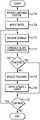
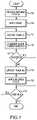
- FIG. 7is a flowchart depicting aspects of a process for correctly pointing a phased array antenna in accordance with embodiments of the present disclosure.
- Embodiments of the present disclosureprovide systems and methods for locating and tracking a transmitter relative to a phased array antenna. More particularly, embodiments of the present disclosure consider the slope of the frequency spectrum amplitudes for multiple frequencies associated with a signal from a transmitter in order to correctly point a beam of the phased array at the transmitter.
- Communication systemsoften utilize a number of different carrier frequencies in order to transmit a signal.
- Other communication systemsoperate over a span or range of frequencies.
- antennas capable of forming highly directional beamssuch as a phased array antenna, can be used to advantage.
- directional beam patternsrequire accurate pointing of the beam.
- tracking the location of the transmitter as it moves relative to the base stationis necessary. For example, as depicted in FIG.
- a transmitter 104 provided as part of a remote device 108moves relative to a base station 112 incorporating a phased array antenna or antenna system 116 having an antenna array 200 from a first location 120 a at time T 1 to a second location 120 b at time T 2 , it is necessary to adjust the direction of the beam 124 produced by the phased array antenna system 116 to ensure desired levels of gain. For instance, by applying a first signal or phase taper at time T 1 a first beam 124 a directed in a first direction can be formed, and by applying a second phase or signal taper at time T 2 a second beam 124 b directed in a second direction can be formed.
- FIG. 2is a functional block diagram depicting components of a phased array antenna system 116 that can be operated to communicate with a transmitter 104 provided as part of a remote device 108 and to determine a location of the remote device 108 relative to the base station 112 in accordance with embodiments of the present disclosure.
- the phased array antenna system 116includes an antenna array 200 having a number of rows and columns of antenna elements 204 .
- the spacing between antenna elements 204 in a row directionis different than the spacing between antenna elements 204 in a column direction.
- a feed network 208connects the antenna elements 204 to a transceiver 212 .
- the feed network 208can include phase shifters, amplifiers, switches, or other devices.
- the transceiver 212can operate to receive, transmit, or transmit and receive radio frequency signals. More particularly, the transceiver 212 can modulate or demodulate one or more RF carrier signals. As can be appreciated by one of skill in the art after consideration of the present disclosure, by controlling a phase delay, amplitude, or other parameters of individual antenna elements 204 , the direction of the beam 124 produced by the phased array antenna system 116 can be controlled in elevation and azimuth.
- the antenna system 116can additionally include a processor 216 and memory and/or data storage 220 , hereinafter referred to simply as memory 220 .
- the processor 216can include a general purpose programmable processor, field programmable gate array (FPGA), controller, or other device or devices alone or in combination.
- the processor 216can operate in connection with the memory 220 to execute application programing or instructions.
- the memory 220can include volatile and nonvolatile memory or data storage, such as RAM, SDRAM, solid-state memory, hard disk drives, or the like, alone or in various combinations.
- the memory 220can store application instructions 224 , including instructions for adjusting a pointing of a beam produced by the array 200 in a desired direction, and in particular towards a transmitter 104 .
- the memorycan also store reference information, such as a preload table or other tables 226 containing operational parameters that can be applied by the phased array antenna system 116 to point a beam 124 produced by the phased array antenna system 116 in a selected direction for a selected frequency.
- reference informationsuch as a preload table or other tables 226 containing operational parameters that can be applied by the phased array antenna system 116 to point a beam 124 produced by the phased array antenna system 116 in a selected direction for a selected frequency.
- the antenna array 200 , the feed network 208 , and the transceiver 212provide multiple-input multiple-output capabilities.
- MIMO capabilitiesare not included, as they are not required when embodiments of the present disclosure are applied to systems operating at multiple frequencies or that are modulated over a range of frequencies.
- the beam 124 produced by a phased array antenna system 116can be pointed by varying parameters of the signals provided to the antenna elements 204 included in the array 200 .
- this pointingis frequency dependent. Accordingly, phased array antennas experience beam pointing errors, such that the pointing of a beam 124 produced by an antenna array 200 for a first frequency is different than the pointing of the beam produced by the antenna array 200 for a second frequency, where parameters other than frequency are held constant. This is depicted in FIGS. 3A-C , which illustrate the variation in scan location relative to an antenna array 200 for signals emanating from a single remote transmitter 104 , but having or spanning a number of different frequencies.
- FIG. 3Adepicts an example of the signal strength and location of a signal received at an antenna array 200 of the antenna system 116 .
- the scan location for the antenna array 200is controlled such that the beam 124 produced by phased array antenna system 116 is pointed at an azimuth of 85° and an elevation of 55° for a signal at a second frequency
- the scan location for a signal at a first frequencyis centered at an azimuth of 90° and an elevation of 60°.
- the location of the strongest signal for the second frequencycorresponds to the pointing direction of the phased array antenna system 116 for that second frequency, in this example an azimuth of 85° and an elevation of 55°.
- FIG. 3Adepicts an example of the signal strength and location of a signal received at an antenna array 200 of the antenna system 116 .
- FIG. 4illustrates an idealized signal transmitted using multiple different frequencies, for example as part of an orthogonal frequency-division multiplexing (OFDM) signal. As shown in the figure, the amplitude of the signals for each of the different carrier wavelengths in this idealized scenario is the same.
- OFDMorthogonal frequency-division multiplexing
- FIG. 5illustrates the amplitudes of a signal transmitted using multiple different components or frequencies as received by a phased array antenna system 116 that is correctly pointed at the transmitter 104 for one of the multiple frequencies.
- a normalized representative OFDM signalwill exhibit non-equal peak amplitudes for the different carrier frequency components of the OFDM signal.
- the maximum peak amplitudecorresponds to a peak amplitude of carrier B 504 .
- the peak amplitude of carrier A 508 and the peak amplitude of carrier B 512are less than the peak amplitude of carrier B 504 . These differences in the peak amplitudes for signals at different frequencies are a result of the inability of a phased array antenna system 116 to be scanned at the same location for multiple frequencies at the same time instance. However, it is also apparent that the peak amplitudes of the carriers are symmetric across the signal bandwidth. Accordingly, the slopes described by the peak signal strengths 508 and 512 on either side of the maximum peak signal strength (i.e. the signal strength of the signal at the center carrier frequency, here carrier B) 504 are equal.
- the peak signal strength of carrier A 508 and the peak signal strength of carrier C 512have the same signal strength, and carrier B has a peak signal strength that is greater than any other carrier.
- carrier Amay have a frequency that is less than a frequency of carrier B, and carrier B may have a frequency that is less than carrier C.
- the phased array antenna 112is correctly tracked to the target transmitter 104 in a first dimension.
- the beam 124is correctly pointed at the transmitter in at least a first dimension. The accuracy of the tracking in a second dimension can be determined through the slope characteristics of the measured waveform.
- the rate of frequency roll-offis dependent on scan angle. Therefore, provided the spacing of antenna elements 204 in the x-dimension is different than the spacing of antenna elements 204 in the y-dimension, the slope (i.e. the derivative) of the roll-off is different in each dimension. Accordingly, the direction the beam 124 needs to move in to correct or improve the pointing can be determined in at least most pointing angles relative to the array 200 . Provided the angle to the transmitter 104 is not the same relative to the rows and columns of antenna elements 204 , the dimension in which the pointing of the beam 124 needs to be adjusted can even be determined in an array 200 with equal spacing between elements in the x and y dimensions.
- FIG. 6illustrates the amplitudes of a signal transmitted using multiple different frequencies as received by a phased array antenna system 116 that is incorrectly pointed at the transmitter 104 .
- the carrier frequencies of the signalscan be the same as in the example of FIG. 5 .
- the peak or maximum signal strength of carrier A 608is less than the maximum signal strength of carrier B, which is less than the maximum signal strength of carrier C 612 .
- the slope difference between the maximum amplitudes 604 , 608 , and 612 for the different frequenciescan be characterized to determine the required tracking update, even if the correct pointing location is not within the measured frequency range.
- the amplitudes of the signalsdescribe slopes that are asymmetric across the signal bandwidth, or that are all positive or all negative.
- the beam 124is also incorrectly pointed where the center frequency peak amplitude is less than the peak amplitudes of one of the other frequencies.
- the characteristics of the slope or slopes of the peak amplitudes across the frequency spectrum of the signal bandwidthprovides information regarding the amount and direction in which the antenna system 116 beam 124 must be scanned to correctly track the signal transmitter 104 .
- This tracking techniquecan be applied to any 2-D linear array. More particularly, the actual pointing location can be determined using the array information. For example, the following array factor equations can be utilized:
- FIG. 7is a flowchart depicting aspects of a process for correctly pointing a phased array antenna in accordance with embodiments of the present disclosure.
- a phased array antenna system 116is provided.
- the phased array antenna system 116includes a plurality of antenna elements 204 disposed in an array 200 with known dimensions and spacing.
- a phase taperis applied, for example by controlling phase shifters, amplifiers, switches, or other elements provided as part of the feed network 208 and connected to the phased array antenna system 116 , to point a beam of the phased array antenna system 116 at a first location, for at least a first frequency.
- the parameters for controlling the components or elements of the feed network 208can be obtained from a preload table 226 . While the phased array antenna system 116 is pointed in the first direction for the first frequency, a signal that includes signal components having different carrier frequencies are received (step 712 ). In accordance with embodiments of the present disclosure, the received signal includes at least three different carrier frequencies. The different signal components can be sequenced in time. Alternatively, a signal simultaneously spanning a range of carrier frequencies, or a signal modulated such that it spans a range of frequencies, can be used. The slope characteristics of the peak amplitudes of the measured waveforms for the signal components at the different carrier frequencies are then considered (step 716 ).
- the location of a maximum peak amplitude and the angle of each of the slopes described by the peak amplitudes on either side of the maximum peak amplitudecan be determined.
- the peak amplitudescan be determined from received signal strength indication (RSSI), power, or other metrics.
- RSSIreceived signal strength indication
- the slope characteristicsi.e.
- the derivatives) of the measured waveformcan be used to determine the accuracy of the beam 124 pointing in the second dimension.
- the absolute values of the angles of the slopes produced by the peak amplitudes of the signals on either side of a maximum peak signalare equal (e.g. the slope of the peak amplitudes on a first side of the maximum signal amplitude is +10° and the slope on a second side of the maximum signal amplitude is ⁇ 10°)
- the beam 124is accurately pointed in at least one dimension.
- the absolute values of the slope angles of the peak amplitudes on either side of the maximum signal amplitudeare within some predetermined angular range of one another of a peak signal are within some predetermined range of one another (e.g.
- the beam 124is accurately pointed in at least one dimension.
- embodiments of the present disclosurecan evaluate the pointing of the beam 124 in two dimensions (e.g. in azimuth and elevation).
- the signals from rows of antenna elements 204 within the array 200can be evaluated for determining the pointing of the beam 124 in a first dimension
- the signals from columns of antenna elements 204 within the array 200can be evaluated for determining the pointing of the beam 124 in a second dimension.
- the phase taper used to achieve that pointingcan be applied to determine a bearing or direction to the transmitter 104 .
- the required tracking or beam 124 pointing updatecan be determined from the slope difference between the different frequency points from the received signals (step 724 ).
- Parameters applied to the feed network 208 to update the beam 124 pointingcan be obtained from a preload table 226 .
- the parameters applied in order to update the beam pointingcan be calculated.
- the relative characteristics of the slopes described by the peak amplitudescan be considered to select a set of taper parameters or a beam pointing direction that is likely to more accurately point the beam 124 .
- a new set of taper parameterscan be selected randomly or pseudo-randomly.
- the taper parameters associated with the updated pointing directioncan then be applied (step 728 ). After applying a tracking update, or if the beam is determined to be properly centered or aligned, a determination can be made as to whether the tracking operation should continue (step 732 ). If operation should be continued, the process can return to step 712 . Alternatively, the process can end.
- embodiments of the present disclosureleverage the frequency offset inherent in phased array antennas to solve a key problem affecting various systems.
- embodiments of the present disclosurecan provide improved angular resolution as the frequency spread of signals associated with a particular system increases. Accordingly, in systems where accurate pointing of a beam 124 is generally more important to the operation of the system, the performance of the pointing techniques disclosed herein increases.
- embodiments of the present disclosurecan provide increased tracking signal quality as the scan angle increases. Accordingly, embodiments of the present disclosure provide good performance in critical operating conditions.
- the processing power required by embodiments of the present disclosurecan be less than that required by other systems.
- implementationdoes not require guess and check methods, and can be applied at low signal-to-noise ratios without significant decreases in accuracy.
- Examples of systems in which embodiments of the present disclosure can be appliedinclude, but are not limited to, 5G communication systems, other mmWave systems, Ku, K, Ka, Q, and W band systems, including but not limited to satellite communications systems.
- an antenna system 116 as disclosed hereincan be included in a communication system (e.g. a 5G communication system) base station.
- a communication systeme.g. a 5G communication system
- the associated signalsinclude multiple carrier frequencies or a range of frequencies
- other embodimentscan operate in connection with a signal utilizing a single carrier frequency, provided the antenna system 116 has multiple input multiple output (MIMO) capabilities.
- MIMOmultiple input multiple output
Landscapes
- Physics & Mathematics (AREA)
- Engineering & Computer Science (AREA)
- General Physics & Mathematics (AREA)
- Radar, Positioning & Navigation (AREA)
- Remote Sensing (AREA)
- Variable-Direction Aerials And Aerial Arrays (AREA)
Abstract
Description
where Eqn. 1 is the well-known array factor equation, and Eqn. 2 is the well-known 1D pointing equation.
Claims (20)
Priority Applications (1)
| Application Number | Priority Date | Filing Date | Title |
|---|---|---|---|
| US16/834,491US11327142B2 (en) | 2019-03-29 | 2020-03-30 | Systems and methods for locating and tracking radio frequency transmitters |
Applications Claiming Priority (3)
| Application Number | Priority Date | Filing Date | Title |
|---|---|---|---|
| US201962826086P | 2019-03-29 | 2019-03-29 | |
| PCT/US2020/025395WO2020205591A1 (en) | 2019-03-29 | 2020-03-27 | Systems and methods for locating and tracking radio frequency transmitters |
| US16/834,491US11327142B2 (en) | 2019-03-29 | 2020-03-30 | Systems and methods for locating and tracking radio frequency transmitters |
Related Parent Applications (1)
| Application Number | Title | Priority Date | Filing Date |
|---|---|---|---|
| PCT/US2020/025395ContinuationWO2020205591A1 (en) | 2019-03-29 | 2020-03-27 | Systems and methods for locating and tracking radio frequency transmitters |
Publications (2)
| Publication Number | Publication Date |
|---|---|
| US20200309892A1 US20200309892A1 (en) | 2020-10-01 |
| US11327142B2true US11327142B2 (en) | 2022-05-10 |
Family
ID=72606042
Family Applications (1)
| Application Number | Title | Priority Date | Filing Date |
|---|---|---|---|
| US16/834,491ActiveUS11327142B2 (en) | 2019-03-29 | 2020-03-30 | Systems and methods for locating and tracking radio frequency transmitters |
Country Status (1)
| Country | Link |
|---|---|
| US (1) | US11327142B2 (en) |
Families Citing this family (2)
| Publication number | Priority date | Publication date | Assignee | Title |
|---|---|---|---|---|
| US11169240B1 (en) | 2018-11-30 | 2021-11-09 | Ball Aerospace & Technologies Corp. | Systems and methods for determining an angle of arrival of a signal at a planar array antenna |
| US11671850B1 (en)* | 2021-03-16 | 2023-06-06 | Ast & Science, Llc | Adaptive taper selection for beamforming |
Citations (64)
| Publication number | Priority date | Publication date | Assignee | Title |
|---|---|---|---|---|
| US20010029185A1 (en) | 1998-10-08 | 2001-10-11 | Harris Corporation | Geolocation of cellular phone using supervisory audio tone transmitted from single base station |
| US20020067315A1 (en) | 1999-08-16 | 2002-06-06 | Waldemar Kunysz | Aperture coupled slot array antenna |
| US20020126042A1 (en) | 2000-06-06 | 2002-09-12 | Hughes Electronics Corporation | Micro cell architecture for mobile user tracking communication system |
| US20020175859A1 (en) | 2001-05-17 | 2002-11-28 | Newberg Irwin L. | Phased array antenna system with virtual time delay beam steering |
| US20020180639A1 (en) | 2001-02-15 | 2002-12-05 | Rickett Bryan Stephen | Beam steering in sub-arrayed antennae |
| US20030020666A1 (en) | 2001-06-29 | 2003-01-30 | Peter John Wright | Conformal phased array antenna |
| US20030161261A1 (en) | 2002-02-26 | 2003-08-28 | Alcatel | Link restoration in a fixed wireless transmission network |
| US20030206132A1 (en) | 2002-05-01 | 2003-11-06 | Phelan H. Richard | All digital phased array using space/time cascaded processing |
| US20030236096A1 (en) | 2002-06-24 | 2003-12-25 | Toru Yamazaki | Mobile station controlling antenna directionality |
| US20040085933A1 (en) | 2002-11-04 | 2004-05-06 | Tia Mobile, Inc. | Satellite antenna system employing electronic elevation control for signal acquisition and tracking |
| US20050099356A1 (en) | 2003-11-06 | 2005-05-12 | Harris Corporation | Multiband radially distributed graded phased array antenna and associated methods |
| US20050099354A1 (en) | 2003-11-06 | 2005-05-12 | Harris Corporation | Multiband radially distributed phased array antenna with a sloping ground plane and associated methods |
| US20050146476A1 (en) | 2004-01-07 | 2005-07-07 | Wang James J. | Vehicle mounted satellite antenna system with in-motion tracking using beam forming |
| US20050164744A1 (en) | 2004-01-28 | 2005-07-28 | Du Toit Nicolaas D. | Apparatus and method operable in a wireless local area network incorporating tunable dielectric capacitors embodied within an inteligent adaptive antenna |
| US20050285785A1 (en) | 2004-06-10 | 2005-12-29 | Harris Corporation, Corporation Of The State Of Delaware | Communications system including phased array antenna providing nulling and related methods |
| US20060114164A1 (en) | 2004-11-29 | 2006-06-01 | Elta Systems Ltd. | Phased array planar antenna and a method thereof |
| US20060145921A1 (en) | 2004-12-30 | 2006-07-06 | Microsoft Corporation | Electronically steerable sector antenna |
| US7098848B2 (en) | 2004-10-12 | 2006-08-29 | The Aerospace Corporation | Phased array antenna intermodulation suppression beam smearing method |
| US20070097006A1 (en) | 2005-02-09 | 2007-05-03 | Pinyon Technologies, Inc. | High gain steerable phased-array antenna |
| US20070293150A1 (en) | 2004-06-18 | 2007-12-20 | Toyon Research Corporation | Compact antenna system for polarization sensitive null steering and direction-finding |
| US20080117105A1 (en) | 2006-11-20 | 2008-05-22 | The Boeing Company | Phased array antenna beam tracking with difference patterns |
| US20080278394A1 (en) | 2007-04-30 | 2008-11-13 | Smiths Specialty Engineering | Low profile quasi-optic phased array antenna |
| US20090002165A1 (en) | 2007-06-28 | 2009-01-01 | Micron Technology, Inc. | Method and system of determining a location characteristic of a rfid tag |
| US20090102704A1 (en) | 2007-09-20 | 2009-04-23 | Takashi Fujimura | Synthetic aperture radar, compact polarimetric sar processing method and program |
| US20090167605A1 (en) | 2006-06-09 | 2009-07-02 | Qinetiq Limited | Phased Array Antenna System with Two Dimensional Scanning |
| US20090189823A1 (en) | 2008-01-24 | 2009-07-30 | United States Of America As Represented By The Secretary Of The Navy | Electronically Steered Phased Array Blade Antenna Assembly |
| US20090273533A1 (en) | 2008-05-05 | 2009-11-05 | Pinyon Technologies, Inc. | High Gain Steerable Phased-Array Antenna with Selectable Characteristics |
| US20100052975A1 (en) | 2007-08-09 | 2010-03-04 | Beam Networks Ltd. | Compact active phased array antenna for radars |
| US20100097290A1 (en) | 2006-12-27 | 2010-04-22 | Thales | Reconfigurable Radiant Array Antenna |
| US20100253574A1 (en) | 2009-04-02 | 2010-10-07 | Mizutani Fumihiko | Weather radar and weather observation method |
| US20110156694A1 (en) | 2008-09-05 | 2011-06-30 | Nxp B.V. | Apparatus for feeding antenna elements and method therefor |
| US20110285576A1 (en) | 2007-01-25 | 2011-11-24 | Lynam Niall R | Forward facing sensing system for a vehicle |
| US20110309981A1 (en) | 2008-10-30 | 2011-12-22 | Nederlandse Organisatie Voor Toegepast- Natuurwetenschappelijk Onderzoek Tno | Combined direction finder and radar system, method and computer program product |
| US20120280861A1 (en) | 2009-12-21 | 2012-11-08 | Shuya Kishimoto | Radio communication apparatus, transmitter, and radio communication method |
| US20130027250A1 (en) | 2011-06-16 | 2013-01-31 | Huawei Technologies Co., Ltd. | Method and apparatus for aligning phased array antenna, and phased array antenna |
| US20130099987A1 (en) | 2008-03-05 | 2013-04-25 | Laurent Desclos | Multi-function array for access point and mobile wireless systems |
| US20130163705A1 (en) | 2010-06-23 | 2013-06-27 | Astrium Limited | Antenna |
| US20140035694A1 (en) | 2011-07-27 | 2014-02-06 | Mitsubishi Heavy Industries Ltd | Phased array antenna and phase control method therefor |
| US20140313073A1 (en) | 2013-03-15 | 2014-10-23 | Carlo Dinallo | Method and apparatus for establishing communications with a satellite |
| US20150077290A1 (en) | 2013-09-16 | 2015-03-19 | The Boeing Company | Systems and methods for interference geolocation and mitigation using a phased array receiving antenna |
| US20160021650A1 (en) | 2014-07-17 | 2016-01-21 | Blue Danube Systems, Inc. | Method for adaptive beam placement in wireless systems |
| US20160091601A1 (en) | 2014-09-30 | 2016-03-31 | Lawrence J. Karr | Holonomically constrained (tethered) spin-around locator |
| US20160226141A1 (en) | 2015-02-02 | 2016-08-04 | Xmw Inc. | Structure of expandable multi-mode phased-array antenna |
| US20160238699A1 (en) | 2015-02-13 | 2016-08-18 | Airmar Technology Corporation | Acoustic Transducer Element |
| US20170077576A1 (en) | 2014-05-07 | 2017-03-16 | Nidec Elesys Corporation | Waveguide |
| US20170223749A1 (en) | 2016-02-02 | 2017-08-03 | The Johns Hopkins University | Apparatus and Method for Establishing and Maintaining a Communications Link |
| US20170293074A1 (en) | 2016-04-08 | 2017-10-12 | Korea Advanced Institute Of Science And Technology | Photonic radiator for radiating light wave to free space |
| US20170346195A1 (en) | 2016-05-31 | 2017-11-30 | Panasonic Intellectual Property Management Co., Ltd. | Antenna module |
| US20180013210A1 (en) | 2016-07-07 | 2018-01-11 | Elta Systems Ltd. | System and method for operating conformal antenna |
| US20180038935A1 (en) | 2015-03-31 | 2018-02-08 | Mitsubishi Heavy Industries Mechatronics Systems, Ltd. | Radio wave arrival angle detection device, vehicle detection system, radio wave arrival angle detection method, and vehicle erroneous detection prevention method |
| US20180085091A1 (en) | 2016-09-26 | 2018-03-29 | Seiko Epson Corporation | Ultrasonic measurement device, and method of controlling ultrasonic measurement device |
| US20180108964A1 (en) | 2016-10-17 | 2018-04-19 | The Regents Of The University Of California | Integrated antennas and phased arrays with mode-free electromagnetic bandgap materials |
| US20180115062A1 (en) | 2014-04-21 | 2018-04-26 | Maxtena | Phased array antenna pointing direction estimation and control |
| US20180128910A1 (en) | 2013-04-29 | 2018-05-10 | Greina Technologies, Inc. | Personal radar |
| US20180192298A1 (en) | 2016-12-31 | 2018-07-05 | Hughes Network Systems, Llc | Method and system for orienting a phased array antenna |
| US20180246390A1 (en) | 2015-11-17 | 2018-08-30 | Korea Advanced Institute Of Science And Technology | Nanophotonic radiators with tunable grating structures for photonic phased array antenna |
| US20180356705A1 (en) | 2015-11-17 | 2018-12-13 | Korea Advanced Institute Of Science And Technology | Nanophotonic radiator using grid structure for application to photonic phased-array antenna |
| US20180375722A1 (en) | 2017-06-22 | 2018-12-27 | Maple Microsystems Inc. | Methods and systems for forming a wireless sensor network |
| US20190020107A1 (en) | 2017-01-30 | 2019-01-17 | Verizon Patent And Licensing Inc. | Optically controlled meta-material phased array antenna system |
| EP3443704A2 (en) | 2016-05-13 | 2019-02-20 | Telefonaktiebolaget LM Ericsson (PUBL) | Multiplexing of subframes with different subcarrier spacings |
| US20190237869A1 (en) | 2017-06-09 | 2019-08-01 | Mitsubishi Electric Corporation | Phased array antenna |
| US20190326664A1 (en) | 2018-04-18 | 2019-10-24 | Tubis Technology Inc. | Compact Combiner for Phased-Array Antenna Beamformer |
| US20190348761A1 (en) | 2018-05-14 | 2019-11-14 | Viasat, Inc. | Phased array antenna system |
| US20190369200A1 (en) | 2016-12-22 | 2019-12-05 | Universidad De Chile | Radiovision device |
- 2020
- 2020-03-30USUS16/834,491patent/US11327142B2/enactiveActive
Patent Citations (66)
| Publication number | Priority date | Publication date | Assignee | Title |
|---|---|---|---|---|
| US20010029185A1 (en) | 1998-10-08 | 2001-10-11 | Harris Corporation | Geolocation of cellular phone using supervisory audio tone transmitted from single base station |
| US20020067315A1 (en) | 1999-08-16 | 2002-06-06 | Waldemar Kunysz | Aperture coupled slot array antenna |
| US20020126042A1 (en) | 2000-06-06 | 2002-09-12 | Hughes Electronics Corporation | Micro cell architecture for mobile user tracking communication system |
| US20020180639A1 (en) | 2001-02-15 | 2002-12-05 | Rickett Bryan Stephen | Beam steering in sub-arrayed antennae |
| US20020175859A1 (en) | 2001-05-17 | 2002-11-28 | Newberg Irwin L. | Phased array antenna system with virtual time delay beam steering |
| US20030020666A1 (en) | 2001-06-29 | 2003-01-30 | Peter John Wright | Conformal phased array antenna |
| US20030161261A1 (en) | 2002-02-26 | 2003-08-28 | Alcatel | Link restoration in a fixed wireless transmission network |
| US20030206132A1 (en) | 2002-05-01 | 2003-11-06 | Phelan H. Richard | All digital phased array using space/time cascaded processing |
| US20030236096A1 (en) | 2002-06-24 | 2003-12-25 | Toru Yamazaki | Mobile station controlling antenna directionality |
| US20040085933A1 (en) | 2002-11-04 | 2004-05-06 | Tia Mobile, Inc. | Satellite antenna system employing electronic elevation control for signal acquisition and tracking |
| US20050099356A1 (en) | 2003-11-06 | 2005-05-12 | Harris Corporation | Multiband radially distributed graded phased array antenna and associated methods |
| US20050099354A1 (en) | 2003-11-06 | 2005-05-12 | Harris Corporation | Multiband radially distributed phased array antenna with a sloping ground plane and associated methods |
| US20050146476A1 (en) | 2004-01-07 | 2005-07-07 | Wang James J. | Vehicle mounted satellite antenna system with in-motion tracking using beam forming |
| US20050164744A1 (en) | 2004-01-28 | 2005-07-28 | Du Toit Nicolaas D. | Apparatus and method operable in a wireless local area network incorporating tunable dielectric capacitors embodied within an inteligent adaptive antenna |
| US20050285785A1 (en) | 2004-06-10 | 2005-12-29 | Harris Corporation, Corporation Of The State Of Delaware | Communications system including phased array antenna providing nulling and related methods |
| US20070293150A1 (en) | 2004-06-18 | 2007-12-20 | Toyon Research Corporation | Compact antenna system for polarization sensitive null steering and direction-finding |
| US7098848B2 (en) | 2004-10-12 | 2006-08-29 | The Aerospace Corporation | Phased array antenna intermodulation suppression beam smearing method |
| US20060114164A1 (en) | 2004-11-29 | 2006-06-01 | Elta Systems Ltd. | Phased array planar antenna and a method thereof |
| US20060145921A1 (en) | 2004-12-30 | 2006-07-06 | Microsoft Corporation | Electronically steerable sector antenna |
| US20070097006A1 (en) | 2005-02-09 | 2007-05-03 | Pinyon Technologies, Inc. | High gain steerable phased-array antenna |
| US20090167605A1 (en) | 2006-06-09 | 2009-07-02 | Qinetiq Limited | Phased Array Antenna System with Two Dimensional Scanning |
| US20080117105A1 (en) | 2006-11-20 | 2008-05-22 | The Boeing Company | Phased array antenna beam tracking with difference patterns |
| US20100097290A1 (en) | 2006-12-27 | 2010-04-22 | Thales | Reconfigurable Radiant Array Antenna |
| US20110285576A1 (en) | 2007-01-25 | 2011-11-24 | Lynam Niall R | Forward facing sensing system for a vehicle |
| US20080278394A1 (en) | 2007-04-30 | 2008-11-13 | Smiths Specialty Engineering | Low profile quasi-optic phased array antenna |
| US20090002165A1 (en) | 2007-06-28 | 2009-01-01 | Micron Technology, Inc. | Method and system of determining a location characteristic of a rfid tag |
| US20100052975A1 (en) | 2007-08-09 | 2010-03-04 | Beam Networks Ltd. | Compact active phased array antenna for radars |
| US20090102704A1 (en) | 2007-09-20 | 2009-04-23 | Takashi Fujimura | Synthetic aperture radar, compact polarimetric sar processing method and program |
| US20090189823A1 (en) | 2008-01-24 | 2009-07-30 | United States Of America As Represented By The Secretary Of The Navy | Electronically Steered Phased Array Blade Antenna Assembly |
| US20140184454A1 (en) | 2008-03-05 | 2014-07-03 | Ethertronics, Inc. | Multi-function array for access point and mobile wireless systems |
| US20130099987A1 (en) | 2008-03-05 | 2013-04-25 | Laurent Desclos | Multi-function array for access point and mobile wireless systems |
| US20090273533A1 (en) | 2008-05-05 | 2009-11-05 | Pinyon Technologies, Inc. | High Gain Steerable Phased-Array Antenna with Selectable Characteristics |
| US20110156694A1 (en) | 2008-09-05 | 2011-06-30 | Nxp B.V. | Apparatus for feeding antenna elements and method therefor |
| US20110309981A1 (en) | 2008-10-30 | 2011-12-22 | Nederlandse Organisatie Voor Toegepast- Natuurwetenschappelijk Onderzoek Tno | Combined direction finder and radar system, method and computer program product |
| US20100253574A1 (en) | 2009-04-02 | 2010-10-07 | Mizutani Fumihiko | Weather radar and weather observation method |
| US20120280861A1 (en) | 2009-12-21 | 2012-11-08 | Shuya Kishimoto | Radio communication apparatus, transmitter, and radio communication method |
| US20130163705A1 (en) | 2010-06-23 | 2013-06-27 | Astrium Limited | Antenna |
| US20130027250A1 (en) | 2011-06-16 | 2013-01-31 | Huawei Technologies Co., Ltd. | Method and apparatus for aligning phased array antenna, and phased array antenna |
| US20140035694A1 (en) | 2011-07-27 | 2014-02-06 | Mitsubishi Heavy Industries Ltd | Phased array antenna and phase control method therefor |
| US20140313073A1 (en) | 2013-03-15 | 2014-10-23 | Carlo Dinallo | Method and apparatus for establishing communications with a satellite |
| US20180048382A1 (en) | 2013-03-15 | 2018-02-15 | Maxtena, Inc. | Method and apparatus for establishing communications with a satellite |
| US20180128910A1 (en) | 2013-04-29 | 2018-05-10 | Greina Technologies, Inc. | Personal radar |
| US20150077290A1 (en) | 2013-09-16 | 2015-03-19 | The Boeing Company | Systems and methods for interference geolocation and mitigation using a phased array receiving antenna |
| US20180115062A1 (en) | 2014-04-21 | 2018-04-26 | Maxtena | Phased array antenna pointing direction estimation and control |
| US20170077576A1 (en) | 2014-05-07 | 2017-03-16 | Nidec Elesys Corporation | Waveguide |
| US20160021650A1 (en) | 2014-07-17 | 2016-01-21 | Blue Danube Systems, Inc. | Method for adaptive beam placement in wireless systems |
| US20160091601A1 (en) | 2014-09-30 | 2016-03-31 | Lawrence J. Karr | Holonomically constrained (tethered) spin-around locator |
| US20160226141A1 (en) | 2015-02-02 | 2016-08-04 | Xmw Inc. | Structure of expandable multi-mode phased-array antenna |
| US20160238699A1 (en) | 2015-02-13 | 2016-08-18 | Airmar Technology Corporation | Acoustic Transducer Element |
| US20180038935A1 (en) | 2015-03-31 | 2018-02-08 | Mitsubishi Heavy Industries Mechatronics Systems, Ltd. | Radio wave arrival angle detection device, vehicle detection system, radio wave arrival angle detection method, and vehicle erroneous detection prevention method |
| US20180356705A1 (en) | 2015-11-17 | 2018-12-13 | Korea Advanced Institute Of Science And Technology | Nanophotonic radiator using grid structure for application to photonic phased-array antenna |
| US20180246390A1 (en) | 2015-11-17 | 2018-08-30 | Korea Advanced Institute Of Science And Technology | Nanophotonic radiators with tunable grating structures for photonic phased array antenna |
| US20170223749A1 (en) | 2016-02-02 | 2017-08-03 | The Johns Hopkins University | Apparatus and Method for Establishing and Maintaining a Communications Link |
| US20170293074A1 (en) | 2016-04-08 | 2017-10-12 | Korea Advanced Institute Of Science And Technology | Photonic radiator for radiating light wave to free space |
| EP3443704A2 (en) | 2016-05-13 | 2019-02-20 | Telefonaktiebolaget LM Ericsson (PUBL) | Multiplexing of subframes with different subcarrier spacings |
| US20170346195A1 (en) | 2016-05-31 | 2017-11-30 | Panasonic Intellectual Property Management Co., Ltd. | Antenna module |
| US20180013210A1 (en) | 2016-07-07 | 2018-01-11 | Elta Systems Ltd. | System and method for operating conformal antenna |
| US20180085091A1 (en) | 2016-09-26 | 2018-03-29 | Seiko Epson Corporation | Ultrasonic measurement device, and method of controlling ultrasonic measurement device |
| US20180108964A1 (en) | 2016-10-17 | 2018-04-19 | The Regents Of The University Of California | Integrated antennas and phased arrays with mode-free electromagnetic bandgap materials |
| US20190369200A1 (en) | 2016-12-22 | 2019-12-05 | Universidad De Chile | Radiovision device |
| US20180192298A1 (en) | 2016-12-31 | 2018-07-05 | Hughes Network Systems, Llc | Method and system for orienting a phased array antenna |
| US20190020107A1 (en) | 2017-01-30 | 2019-01-17 | Verizon Patent And Licensing Inc. | Optically controlled meta-material phased array antenna system |
| US20190237869A1 (en) | 2017-06-09 | 2019-08-01 | Mitsubishi Electric Corporation | Phased array antenna |
| US20180375722A1 (en) | 2017-06-22 | 2018-12-27 | Maple Microsystems Inc. | Methods and systems for forming a wireless sensor network |
| US20190326664A1 (en) | 2018-04-18 | 2019-10-24 | Tubis Technology Inc. | Compact Combiner for Phased-Array Antenna Beamformer |
| US20190348761A1 (en) | 2018-05-14 | 2019-11-14 | Viasat, Inc. | Phased array antenna system |
Non-Patent Citations (2)
| Title |
|---|
| International Preliminary Report on Patentability for International (PCT) Patent Application No. PCT/US2020/025395, dated Oct. 14, 2021 13 pages. |
| International Search Report and Written Opinion for International (PCT) Patent Application No. PCT/US2020/025395, dated Jun. 8, 2020 16 pages. |
Also Published As
| Publication number | Publication date |
|---|---|
| US20200309892A1 (en) | 2020-10-01 |
Similar Documents
| Publication | Publication Date | Title |
|---|---|---|
| US6339399B1 (en) | Antenna array calibration | |
| US20170332249A1 (en) | Methods and Apparatus for Generating Beam Pattern with Wider Beam Width in Phased Antenna Array | |
| US10320540B2 (en) | Method and apparatus for generating reference signal in analog/digital mixed BF system | |
| US10771142B2 (en) | System and method for hierarchal beamforming and rank adaptation for hybrid antenna architecture | |
| AU691295B2 (en) | Antenna array calibration | |
| US9155097B2 (en) | Methods and arrangements for beam refinement in a wireless network | |
| US10951272B2 (en) | Systems, methods and devices for beam selection in a wireless communication system | |
| US9577737B2 (en) | Antenna apparatus and method for beam forming thereof | |
| US7664533B2 (en) | Method and apparatus for a multi-beam antenna system | |
| US7312750B2 (en) | Adaptive beam-forming system using hierarchical weight banks for antenna array in wireless communication system | |
| US10270509B2 (en) | Training beam transmission method, apparatus, and system | |
| US9065520B2 (en) | Transmission method and related base station | |
| US11327142B2 (en) | Systems and methods for locating and tracking radio frequency transmitters | |
| US10039011B2 (en) | Polarization beamforming communication method and apparatus | |
| CN112234343B (en) | An active phased array vehicle-mounted antenna system suitable for high-speed rail | |
| US10009073B2 (en) | System for acquiring channel knowledge and method thereof | |
| US20210066798A1 (en) | RF Lens Device for Improving Directivity of Antenna Array, and Transmitting and Receiving Antenna System Comprising Same | |
| US20230246348A1 (en) | Apparatus for processing radio frequency signals, network element for a wireless communications system, and user equipment for a wireless communications system | |
| WO2020205591A1 (en) | Systems and methods for locating and tracking radio frequency transmitters | |
| Ghunney et al. | Impact of wrong beam selection on beam pair scanning method for user discovery in mmwave systems | |
| McKinnis et al. | Figures of merit for active antenna enabled 5G communication networks | |
| Adams | Beam tagging for control of adaptive transmitting arrays | |
| Sousa et al. | Beam Squinting Compensation: An NCR-Assisted Scenario | |
| Shin et al. | Grid-Free Beam Management for 6G Millimeter-Wave Communications |
Legal Events
| Date | Code | Title | Description |
|---|---|---|---|
| FEPP | Fee payment procedure | Free format text:ENTITY STATUS SET TO UNDISCOUNTED (ORIGINAL EVENT CODE: BIG.); ENTITY STATUS OF PATENT OWNER: LARGE ENTITY | |
| STPP | Information on status: patent application and granting procedure in general | Free format text:DOCKETED NEW CASE - READY FOR EXAMINATION | |
| STPP | Information on status: patent application and granting procedure in general | Free format text:NON FINAL ACTION MAILED | |
| STPP | Information on status: patent application and granting procedure in general | Free format text:RESPONSE TO NON-FINAL OFFICE ACTION ENTERED AND FORWARDED TO EXAMINER | |
| STPP | Information on status: patent application and granting procedure in general | Free format text:NON FINAL ACTION MAILED | |
| AS | Assignment | Owner name:BALL AEROSPACE & TECHNOLOGIES CORP., COLORADO Free format text:ASSIGNMENT OF ASSIGNORS INTEREST;ASSIGNOR:MIERS, ZACHARY T.;REEL/FRAME:057530/0560 Effective date:20200401 | |
| STPP | Information on status: patent application and granting procedure in general | Free format text:RESPONSE TO NON-FINAL OFFICE ACTION ENTERED AND FORWARDED TO EXAMINER | |
| STPP | Information on status: patent application and granting procedure in general | Free format text:NOTICE OF ALLOWANCE MAILED -- APPLICATION RECEIVED IN OFFICE OF PUBLICATIONS | |
| STPP | Information on status: patent application and granting procedure in general | Free format text:PUBLICATIONS -- ISSUE FEE PAYMENT VERIFIED | |
| STCF | Information on status: patent grant | Free format text:PATENTED CASE | |
| CC | Certificate of correction | ||
| AS | Assignment | Owner name:BAE SYSTEMS SPACE & MISSION SYSTEMS INC., COLORADO Free format text:CHANGE OF NAME;ASSIGNOR:BALL AEROSPACE & TECHNOLOGIES CORP.;REEL/FRAME:067134/0901 Effective date:20240223 |