US11326975B2 - Method of sensing leaking gas - Google Patents
Method of sensing leaking gasDownload PDFInfo
- Publication number
- US11326975B2 US11326975B2US16/943,758US202016943758AUS11326975B2US 11326975 B2US11326975 B2US 11326975B2US 202016943758 AUS202016943758 AUS 202016943758AUS 11326975 B2US11326975 B2US 11326975B2
- Authority
- US
- United States
- Prior art keywords
- liquid
- gas
- injection port
- leaking
- bubbles
- Prior art date
- Legal status (The legal status is an assumption and is not a legal conclusion. Google has not performed a legal analysis and makes no representation as to the accuracy of the status listed.)
- Active
Links
- 238000000034methodMethods0.000titleclaimsabstractdescription22
- 239000007788liquidSubstances0.000claimsabstractdescription89
- 238000002347injectionMethods0.000claimsabstractdescription19
- 239000007924injectionSubstances0.000claimsabstractdescription19
- 238000005086pumpingMethods0.000claimsdescription4
- 238000002604ultrasonographyMethods0.000claimsdescription2
- 239000007789gasSubstances0.000description68
- 238000012544monitoring processMethods0.000description13
- 238000001514detection methodMethods0.000description4
- 238000005516engineering processMethods0.000description3
- 238000007667floatingMethods0.000description3
- 230000001276controlling effectEffects0.000description2
- 230000000694effectsEffects0.000description2
- 238000010438heat treatmentMethods0.000description2
- VNWKTOKETHGBQD-UHFFFAOYSA-NmethaneChemical compoundCVNWKTOKETHGBQD-UHFFFAOYSA-N0.000description2
- 230000007613environmental effectEffects0.000description1
- 239000003345natural gasSubstances0.000description1
- 230000000149penetrating effectEffects0.000description1
- 230000001105regulatory effectEffects0.000description1
- 239000002904solventSubstances0.000description1
- 231100000331toxicToxicity0.000description1
- 230000002588toxic effectEffects0.000description1
- XLYOFNOQVPJJNP-UHFFFAOYSA-NwaterSubstancesOXLYOFNOQVPJJNP-UHFFFAOYSA-N0.000description1
Images


Classifications
- G—PHYSICS
- G01—MEASURING; TESTING
- G01F—MEASURING VOLUME, VOLUME FLOW, MASS FLOW OR LIQUID LEVEL; METERING BY VOLUME
- G01F1/00—Measuring the volume flow or mass flow of fluid or fluent solid material wherein the fluid passes through a meter in a continuous flow
- G—PHYSICS
- G01—MEASURING; TESTING
- G01M—TESTING STATIC OR DYNAMIC BALANCE OF MACHINES OR STRUCTURES; TESTING OF STRUCTURES OR APPARATUS, NOT OTHERWISE PROVIDED FOR
- G01M3/00—Investigating fluid-tightness of structures
- G01M3/02—Investigating fluid-tightness of structures by using fluid or vacuum
- G01M3/26—Investigating fluid-tightness of structures by using fluid or vacuum by measuring rate of loss or gain of fluid, e.g. by pressure-responsive devices, by flow detectors
- G—PHYSICS
- G01—MEASURING; TESTING
- G01M—TESTING STATIC OR DYNAMIC BALANCE OF MACHINES OR STRUCTURES; TESTING OF STRUCTURES OR APPARATUS, NOT OTHERWISE PROVIDED FOR
- G01M3/00—Investigating fluid-tightness of structures
- G01M3/02—Investigating fluid-tightness of structures by using fluid or vacuum
- G01M3/04—Investigating fluid-tightness of structures by using fluid or vacuum by detecting the presence of fluid at the leakage point
- G01M3/06—Investigating fluid-tightness of structures by using fluid or vacuum by detecting the presence of fluid at the leakage point by observing bubbles in a liquid pool
- G—PHYSICS
- G01—MEASURING; TESTING
- G01N—INVESTIGATING OR ANALYSING MATERIALS BY DETERMINING THEIR CHEMICAL OR PHYSICAL PROPERTIES
- G01N15/00—Investigating characteristics of particles; Investigating permeability, pore-volume or surface-area of porous materials
- G01N15/02—Investigating particle size or size distribution
- G01N15/0205—Investigating particle size or size distribution by optical means
- G—PHYSICS
- G01—MEASURING; TESTING
- G01V—GEOPHYSICS; GRAVITATIONAL MEASUREMENTS; DETECTING MASSES OR OBJECTS; TAGS
- G01V1/00—Seismology; Seismic or acoustic prospecting or detecting
- G—PHYSICS
- G01—MEASURING; TESTING
- G01V—GEOPHYSICS; GRAVITATIONAL MEASUREMENTS; DETECTING MASSES OR OBJECTS; TAGS
- G01V8/00—Prospecting or detecting by optical means
- G01V8/10—Detecting, e.g. by using light barriers
Definitions
- the present inventionrelates to a gas detection technology, and more particularly to a method of sensing leaking gas.
- process gasin industrial equipment, such as heat exchange, boilers, heat treatment, natural gas, or exhaust gas treatment.
- the process gasmostly has a specific pressure, and is constructed using structural elements, such as pipes or cabins for diversion or storage.
- the purpose of the present inventionis to provide a gas leakage sensing technology, in particular to guide the leakage gas dissolved in a liquid to generate bubbles, and further to monitor the actual situation of bubble generation to achieve more sensitive and precise gas leakage detection.
- the present inventionprovides a method of sensing leaking gas comprising the following steps:
- step S 1controlling the height of a gas injection port in the liquid away from the liquid surface to guide the leaking gas into the liquid through the gas injection port to generate bubbles;
- step S 2detecting a flow rate of bubbles generated in the liquid.
- the height of the gas injection port from the liquid levelis regulated so that the vent pressure of the leaking gas is greater than the liquid pressure.
- the flow rate of bubbles generated in the liquidis detected between the gas injection port and the liquid surface.
- the flow rate of bubbles generated in the liquidis detected by an ultrasound sensor.
- the flow rate of bubbles generated in the liquidis optically detected.
- the present inventionhas the advantage that the leaking gas is introduced into the liquid to generate bubbles, which can completely convert the leaking gas into a plurality of bubbles of the same volume to float up in the liquid, and through the monitoring of the bubbles, it is more sensitive and accurate to calculate the resulting data of leakage gas flow.
- the technical effectthat by sensing the size, amount of generated bubbles, and floating frequency of the bubbles generated in the liquid, the flow rate and volume of the leaking gas are obtained to improve the accuracy of sensing the leaking gas.
- FIG. 1is a flowchart of steps of the gas leakage sensing method of the present invention.
- FIG. 2is a configuration sectional view of the first embodiment of the present invention.
- FIG. 3is a configuration sectional view of the second embodiment of the present invention.
- FIG. 4is a configuration sectional view of the third embodiment of the present invention.
- a method of sensing leaking gascomprising the following steps:
- step S 1controlling the height of a gas injection port in the liquid away from the liquid surface to guide the leaking gas into the liquid through the gas injection port to generate bubbles;
- step S 2detecting a flow rate of bubbles generated in the liquid.
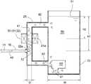
- the role of the gas conduit 10is to guide the leaking gas 40 of an industrial equipment, which may be a heat exchange equipment with a process gas, a boiler, a heat treatment equipment, a gas equipment or an exhaust gas treatment equipment.
- an industrial equipmentwhich may be a heat exchange equipment with a process gas, a boiler, a heat treatment equipment, a gas equipment or an exhaust gas treatment equipment.
- the gas conduit 10for guiding leaking gas 40 at the locations where gas is easily leaked, such as a conduit connector, a cover connector, etc. of the diversion pipeline or the gas storage tank of the diversion process gas to prevent process gases from leaking into the atmosphere. Therefore, the gas conduit 10 has a gas inlet end 11 that receives the leaking gas 40 and a gas injection port 12 that discharges the leaking gas 40 .
- the liquid storage tank 20may be surrounded by a transparent or opaque tank wall structure so that the liquid storage tank 20 communicates with the atmosphere and is filled with a liquid 50 .
- the liquid surface 51 of the liquid 50may be formed in the liquid storage tank 20 .
- the liquid 50may be water or other oil or solvent that does not affect the generation and floating of the gas bubbles 41 .
- the liquid surface 51 of the liquid 50may also be formed in other liquid tanks or diversion pipeline communicating with the liquid storage tank 20 .
- the gas injection port 12 of the gas conduit 10must be implanted in the liquid 50 of the liquid storage tank 20 in order to guide the leaking gas 40 to generate bubbles 41 in the liquid 50 of the liquid storage tank 20 .
- a monitoring part 21is formed on the tank wall of the liquid storage tank 20 .
- the monitoring part 21is located at a place for assembling or disposing the bubble sensing component 30 , and the monitoring part 21 is away from the liquid surface.
- the height h 1 of the gas injection port 12 from the liquid surface 51must be larger than the height h 2 of the monitoring part 21 from the liquid surface 51 (that is, h 1 >h 2 ).
- the monitoring part 21is located at a relatively higher liquid surface from the lower gas injection port 12 so that the bubble sensing component 30 on the monitoring part 21 can conveniently continuously monitor whether bubbles 41 are generated in the liquid 50 and detect how much the size, amount and frequency of the bubbles generated.
- step S 2detecting a flow rate of bubbles generated in the liquid.
- the bubble sensing component 30may be an ultrasonic sensor 31 or a vision device 32 equipped with a charge coupled device (CCD). These bubble sensing components 30 can be easily arranged on the monitoring part 21 of the tank wall of the liquid storage tank 20 by assembling means such as locking, sticking or buckling.
- the bubble sensing component 30is an ultrasonic sensor 31
- the monitoring part 21may be transparent or opaque.
- the ultrasonic sensor 31generates the ultrasonic waves to penetrate the transparent or opaque monitoring part 21 (formed by the tank wall of the liquid storage tank 20 ) in order to sense the bubbles 41 in the liquid 50 of the liquid storage tank 20 .
- the monitoring part 21must be transparent so that the vision device 32 can see through the transparent monitoring part 21 (formed by the tank wall of the liquid storage tank 20 ) to see through the bubbles 41 in the liquid 50 of the liquid tank 20 .
- a communicating hole 22can be formed in the tank wall of the liquid storage tank 20 , and the communicating hole 22 must be lower than the liquid surface 51 in order to facilitate that the gas injection port 12 provided with the gas conduit 10 can be connected to the communicating hole 22 and then implanted into the liquid 50 , so that the gas conduit 10 can achieve the role of guiding the leaking gas 40 to generate the bubbles 41 in the liquid 50 of the liquid storage tank 20 . Except for these, the remaining implementation details are the same as those of the above first embodiment.
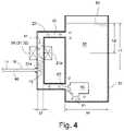
- FIG. 4disclose a third embodiment of the present invention. It is described that the tank wall of the liquid storage tank 20 is also forked or connected with a manifold 23 , which is used for flow guidance.
- the liquid 50 in the liquid storage tank 20enters so that the level of the manifold 23 can be lower than that of the liquid surface 51 .
- the diameter D of the manifold 23may be smaller than the width W of the liquid storage tank (that is, D ⁇ W), and both ends of the manifold 23 can be connected to the liquid storage tank 20 so that the liquid 50 can flow in the manifold 23 .
- the communicating hole 22 a in the second embodimentcan be formed in this third embodiment.
- the communicating hole 22 aOn the tank wall of the manifold 23 , and the communicating hole 22 a must also be located at a lower level than that the liquid surface 51 , so that the gas injection port 12 of the gas conduit 10 is connected to the communicating hole 22 a and then implanted in the liquid 50 .
- the monitoring part 21 a in the first and second embodiments described aboveis located on the pipe wall of the manifold 23 in this embodiment with the other remaining implementation details are the same as those in the above embodiment.
- a liquid pumping motor 60is disposed in the liquid 50 of the liquid storage tank 20 , and the liquid pumping motor 60 has a liquid intake 61 and a liquid drain 62 .
- the liquid intake 61captures liquid in the liquid 50 , and is connected to or adjacent to the corresponding communicating hole 22 or 22 a through the liquid drain 62 so as to drive the high-pressure liquid 50 into the manifold 23 to prevent the generation of insufficient vacuum or liquid volume in the liquid 50 in the manifold 23 to affect the generation of bubbles 41 .
- the present inventionrelies on the ultrasonic penetrating sensing ability and charge-coupled device (CCD) recognition ability to detect the generation of bubbles 41 in the liquid 50 , and the size of the bubbles 41 .
- CCDcharge-coupled device
- Both the quantity and the floating frequencycan produce a sharp and accurate detection effect, and the above-mentioned bubble sensing component 30 is also convenient for transmitting the signal of the detected bubbles to the corresponding signal control unit, thereby accurately obtaining the flow rate of the leaking gas 40 and volume and other data. It can be seen that this invention is a fully implementable technology in the industry.
Landscapes
- Physics & Mathematics (AREA)
- General Physics & Mathematics (AREA)
- Life Sciences & Earth Sciences (AREA)
- Chemical & Material Sciences (AREA)
- General Health & Medical Sciences (AREA)
- Immunology (AREA)
- Dispersion Chemistry (AREA)
- Health & Medical Sciences (AREA)
- Analytical Chemistry (AREA)
- Biochemistry (AREA)
- General Life Sciences & Earth Sciences (AREA)
- Geophysics (AREA)
- Pathology (AREA)
- Engineering & Computer Science (AREA)
- Acoustics & Sound (AREA)
- Environmental & Geological Engineering (AREA)
- Geology (AREA)
- Remote Sensing (AREA)
- Fluid Mechanics (AREA)
- Examining Or Testing Airtightness (AREA)
Abstract
Description
The present invention relates to a gas detection technology, and more particularly to a method of sensing leaking gas.
Generally, for example, there is a process gas in industrial equipment, such as heat exchange, boilers, heat treatment, natural gas, or exhaust gas treatment. The process gas mostly has a specific pressure, and is constructed using structural elements, such as pipes or cabins for diversion or storage.
Due to the existence of industrial equipment with process gas, after a period of use, the phenomenon of process gas leakage is often prone to affect the availability of such industrial equipment. If the leaking process gas is toxic, the damages to the environment, human health and even safety will pose a considerable threat. Therefore, once the process gas in such industrial equipment leaks, it must be immediately detected to protect the equipment's availability, environmental hygiene and public safety.
It is also known that today there are industrial equipment for process gas. Most of the time, gas measuring sensors, gas flow meters and other measuring elements are installed in gas diversion pipes or gas storage compartments to detect whether process gas leaks or to measure leaking flow, leaking volume, etc. However, since the volume of the gas is usually compressible, it is difficult to obtain the accuracy of the detection of the data, such as the flow rate and volume, when the small flow gas leaks in the prior art, and it is urgent to improve.
In view of this, the purpose of the present invention is to provide a gas leakage sensing technology, in particular to guide the leakage gas dissolved in a liquid to generate bubbles, and further to monitor the actual situation of bubble generation to achieve more sensitive and precise gas leakage detection.
To this end, the present invention provides a method of sensing leaking gas comprising the following steps:
step S1: controlling the height of a gas injection port in the liquid away from the liquid surface to guide the leaking gas into the liquid through the gas injection port to generate bubbles; and
step S2: detecting a flow rate of bubbles generated in the liquid.
In another implementation of the present invention, the height of the gas injection port from the liquid level is regulated so that the vent pressure of the leaking gas is greater than the liquid pressure.
In another implementation of the present invention, the flow rate of bubbles generated in the liquid is detected between the gas injection port and the liquid surface.
According to the present invention, the flow rate of bubbles generated in the liquid is detected by an ultrasound sensor.
In the above implementation of the present invention, the flow rate of bubbles generated in the liquid is optically detected.
According to the above technical means, the present invention has the advantage that the leaking gas is introduced into the liquid to generate bubbles, which can completely convert the leaking gas into a plurality of bubbles of the same volume to float up in the liquid, and through the monitoring of the bubbles, it is more sensitive and accurate to calculate the resulting data of leakage gas flow.
According to the above structural configuration means of the present invention, the technical effect that by sensing the size, amount of generated bubbles, and floating frequency of the bubbles generated in the liquid, the flow rate and volume of the leaking gas are obtained to improve the accuracy of sensing the leaking gas.
In addition, related technical details on which the present invention can be implemented will be described in subsequent implementations and drawings.
In order to fully explain the feasibility of the gas leakage sensing method provided by the present invention. First, referring toFIGS. 1-4 , a method of sensing leaking gas comprising the following steps:
step S1: controlling the height of a gas injection port in the liquid away from the liquid surface to guide the leaking gas into the liquid through the gas injection port to generate bubbles; and
step S2: detecting a flow rate of bubbles generated in the liquid.
The role of thegas conduit 10 is to guide the leakinggas 40 of an industrial equipment, which may be a heat exchange equipment with a process gas, a boiler, a heat treatment equipment, a gas equipment or an exhaust gas treatment equipment. According to common knowledge, in order to prevent process gas leakage, such industrial equipment usually installs thegas conduit 10 for guiding leakinggas 40 at the locations where gas is easily leaked, such as a conduit connector, a cover connector, etc. of the diversion pipeline or the gas storage tank of the diversion process gas to prevent process gases from leaking into the atmosphere. Therefore, thegas conduit 10 has agas inlet end 11 that receives the leakinggas 40 and agas injection port 12 that discharges the leakinggas 40.
Theliquid storage tank 20 may be surrounded by a transparent or opaque tank wall structure so that theliquid storage tank 20 communicates with the atmosphere and is filled with a liquid50. Theliquid surface 51 of the liquid50 may be formed in theliquid storage tank 20. The liquid50 may be water or other oil or solvent that does not affect the generation and floating of the gas bubbles41. In different implementations of the embodiments, theliquid surface 51 of the liquid50 may also be formed in other liquid tanks or diversion pipeline communicating with theliquid storage tank 20. Thegas injection port 12 of thegas conduit 10 must be implanted in the liquid50 of theliquid storage tank 20 in order to guide the leakinggas 40 to generatebubbles 41 in the liquid50 of theliquid storage tank 20.
Furthermore, amonitoring part 21 is formed on the tank wall of theliquid storage tank 20. In essence, themonitoring part 21 is located at a place for assembling or disposing the bubble sensing component30, and themonitoring part 21 is away from the liquid surface. The height h1 of thegas injection port 12 from theliquid surface 51 must be larger than the height h2 of themonitoring part 21 from the liquid surface51 (that is, h1>h2). In other words, themonitoring part 21 is located at a relatively higher liquid surface from the lowergas injection port 12 so that the bubble sensing component30 on themonitoring part 21 can conveniently continuously monitor whetherbubbles 41 are generated in the liquid50 and detect how much the size, amount and frequency of the bubbles generated.
In the invention, step S2: detecting a flow rate of bubbles generated in the liquid. In the implementation of the first embodiment shown inFIG. 1-4 , the bubble sensing component30 may be an ultrasonic sensor31 or a vision device32 equipped with a charge coupled device (CCD). These bubble sensing components30 can be easily arranged on themonitoring part 21 of the tank wall of theliquid storage tank 20 by assembling means such as locking, sticking or buckling. When the bubble sensing component30 is an ultrasonic sensor31, themonitoring part 21 may be transparent or opaque. The ultrasonic sensor31 generates the ultrasonic waves to penetrate the transparent or opaque monitoring part21 (formed by the tank wall of the liquid storage tank20) in order to sense thebubbles 41 in the liquid50 of theliquid storage tank 20. In addition, when the bubble sensing component30 is a vision device32, themonitoring part 21 must be transparent so that the vision device32 can see through the transparent monitoring part21 (formed by the tank wall of the liquid storage tank20) to see through thebubbles 41 in the liquid50 of theliquid tank 20.
Please refer to refer toFIG. 3 to disclose a second embodiment of the present invention. It is demonstrated that a communicatinghole 22 can be formed in the tank wall of theliquid storage tank 20, and the communicatinghole 22 must be lower than theliquid surface 51 in order to facilitate that thegas injection port 12 provided with thegas conduit 10 can be connected to the communicatinghole 22 and then implanted into the liquid50, so that thegas conduit 10 can achieve the role of guiding the leakinggas 40 to generate thebubbles 41 in the liquid50 of theliquid storage tank 20. Except for these, the remaining implementation details are the same as those of the above first embodiment.
Please refer toFIG. 4 to disclose a third embodiment of the present invention. It is described that the tank wall of theliquid storage tank 20 is also forked or connected with a manifold23, which is used for flow guidance. The liquid50 in theliquid storage tank 20 enters so that the level of the manifold23 can be lower than that of theliquid surface 51. In addition, the diameter D of the manifold23 may be smaller than the width W of the liquid storage tank (that is, D<W), and both ends of the manifold23 can be connected to theliquid storage tank 20 so that the liquid50 can flow in themanifold 23. The communicatinghole 22ain the second embodiment can be formed in this third embodiment. On the tank wall of the manifold23, and the communicatinghole 22amust also be located at a lower level than that theliquid surface 51, so that thegas injection port 12 of thegas conduit 10 is connected to the communicatinghole 22aand then implanted in the liquid50. Themonitoring part 21ain the first and second embodiments described above is located on the pipe wall of the manifold23 in this embodiment with the other remaining implementation details are the same as those in the above embodiment.
Referring toFIG. 4 again, in the third embodiment described above, aliquid pumping motor 60 is disposed in the liquid50 of theliquid storage tank 20, and theliquid pumping motor 60 has aliquid intake 61 and aliquid drain 62. Theliquid intake 61 captures liquid in the liquid50, and is connected to or adjacent to the corresponding communicatinghole liquid drain 62 so as to drive the high-pressure liquid 50 into the manifold23 to prevent the generation of insufficient vacuum or liquid volume in the liquid50 in the manifold23 to affect the generation ofbubbles 41.
To sum up, the present invention relies on the ultrasonic penetrating sensing ability and charge-coupled device (CCD) recognition ability to detect the generation ofbubbles 41 in the liquid50, and the size of thebubbles 41. Both the quantity and the floating frequency can produce a sharp and accurate detection effect, and the above-mentioned bubble sensing component30 is also convenient for transmitting the signal of the detected bubbles to the corresponding signal control unit, thereby accurately obtaining the flow rate of the leakinggas 40 and volume and other data. It can be seen that this invention is a fully implementable technology in the industry.
The above embodiments merely demonstrate the preferred embodiments of the present invention, but they cannot be understood as a limitation on the scope of the patents of the present invention. Therefore, the present invention shall be subject to the content of the claims defined in the scope of the patent application.
Claims (3)
1. A method of sensing leaking gas comprising the following steps:
step S1: determining a height of a gas injection port away from the liquid surface in a liquid storage tank such that a vent pressure of the leaking gas is greater than the liquid pressure, the gas injection port connecting to a manifold extending from a side wall of the liquid storage tank, a pumping motor pumping the liquid into the manifold towards the gas injection port, and the leaking gas being guided into the liquid through the gas injection port to generate bubbles; and
step S2: detecting a flow rate of bubbles generated in the liquid between the gas injection port and the liquid surface.
2. The method of sensing leaking gas according toclaim 1 , wherein the flow rate of bubbles generated in the liquid is detected by an ultrasound sensor.
3. The method of sensing leaking gas according toclaim 1 , wherein the flow rate of bubbles generated in the liquid is optically detected.
Applications Claiming Priority (4)
| Application Number | Priority Date | Filing Date | Title |
|---|---|---|---|
| TW109202442UTWM599905U (en) | 2020-03-05 | 2020-03-05 | Gas leakage sensing device |
| TW109202442 | 2020-03-05 | ||
| TW109121857 | 2020-06-29 | ||
| TW109121857ATWI815020B (en) | 2020-06-29 | 2020-06-29 | Method of sensing leaking gas |
Publications (2)
| Publication Number | Publication Date |
|---|---|
| US20210278306A1 US20210278306A1 (en) | 2021-09-09 |
| US11326975B2true US11326975B2 (en) | 2022-05-10 |
Family
ID=77524433
Family Applications (1)
| Application Number | Title | Priority Date | Filing Date |
|---|---|---|---|
| US16/943,758ActiveUS11326975B2 (en) | 2020-03-05 | 2020-07-30 | Method of sensing leaking gas |
Country Status (2)
| Country | Link |
|---|---|
| US (1) | US11326975B2 (en) |
| CN (1) | CN113358162B (en) |
Families Citing this family (1)
| Publication number | Priority date | Publication date | Assignee | Title |
|---|---|---|---|---|
| CN114459694B (en)* | 2022-01-18 | 2023-11-17 | 安徽伊法拉电气股份有限公司 | Detection equipment for drop-out type insulating protective cover |
Citations (47)
| Publication number | Priority date | Publication date | Assignee | Title |
|---|---|---|---|---|
| US1959863A (en)* | 1931-12-04 | 1934-05-22 | Frederick G Griss | Leak detector for gas transmission lines |
| GB752250A (en)* | 1954-03-05 | 1956-07-11 | North Western Gas Board | Improvements relating to means for detecting gas leaks |
| US2967450A (en)* | 1957-01-30 | 1961-01-10 | Standard Oil Co | Optical bubble flowmeter |
| US3103910A (en)* | 1961-10-30 | 1963-09-17 | Richard S Smith | Leak testing apparatus |
| US3114257A (en)* | 1959-03-09 | 1963-12-17 | Western Electric Co | Apparatus for sensing the flow of a substance through a liquid medium |
| US3221540A (en)* | 1963-08-12 | 1965-12-07 | Leggitt S H Co | Mechanical device |
| US3342062A (en)* | 1965-01-25 | 1967-09-19 | Seek A Leak Inc | Leak testing apparatus |
| US3516284A (en)* | 1968-06-19 | 1970-06-23 | Nasa | Leak detector |
| US3583435A (en)* | 1969-09-08 | 1971-06-08 | Buster D Stewart | Leak detector valve assembly |
| US3813922A (en)* | 1972-03-15 | 1974-06-04 | Gould Inc | Air leak detector |
| USRE29330E (en)* | 1969-09-08 | 1977-08-02 | Rosan Enterprises | Leak detector valve assembly |
| US4068522A (en)* | 1976-06-08 | 1978-01-17 | Hartwell Corporation | Gas leak detector |
| US4077427A (en)* | 1976-09-09 | 1978-03-07 | Rosan Enterprises | Leak detector valve assembly |
| US4320653A (en)* | 1979-07-13 | 1982-03-23 | Arthur Pfeiffer-Vakuumtechnik Wetzlar Gmbh | Method of and apparatus for measuring the rate of leak |
| JPS58123439A (en)* | 1982-01-20 | 1983-07-22 | Hitachi Ltd | Detector for bubble leak |
| US4419883A (en)* | 1982-03-01 | 1983-12-13 | Gelston Ii N E | Leak detector |
| JPS5977329A (en)* | 1982-10-25 | 1984-05-02 | Mitsubishi Electric Corp | Automatic gross leak test equipment |
| US4453399A (en)* | 1982-02-01 | 1984-06-12 | Cliffside Pipelayers, A Division Of Banister Continental Ltd. | Leak detector |
| JPS6063438A (en)* | 1983-09-17 | 1985-04-11 | Nichiei Boeki Kk | Method and device for leak detection |
| US4524608A (en)* | 1983-12-05 | 1985-06-25 | Bellefeuille David T | Gas leak meter |
| US4862733A (en)* | 1987-01-16 | 1989-09-05 | Hyfantis Jr George J | Method and apparatus for detecting leaks in a liquid-containing tank |
| US4885931A (en)* | 1988-03-14 | 1989-12-12 | Horner John A | System for detecting leaks in underground fuel tanks and the like |
| USH1045H (en)* | 1990-11-19 | 1992-05-05 | The United States Of America As Represented By The Secretary Of The Army | Air bubble leak detection test device |
| US5337597A (en)* | 1991-06-20 | 1994-08-16 | Expertek | Bubble emission volume quantifier |
| US5471867A (en)* | 1992-08-11 | 1995-12-05 | Tanknology Corporation International | Inventory reconciliation for above ground storage tanks |
| US5524682A (en)* | 1994-08-15 | 1996-06-11 | Amonson; Alan | Method and apparatus for filling a tank with a predetermined weight of liquid |
| US5636547A (en)* | 1994-11-29 | 1997-06-10 | Ferrofluidics Corporation | Liquid level monitoring system having ferrofluid pressure sensor |
| US5650561A (en)* | 1995-03-13 | 1997-07-22 | Pulse Electronics, Inc. | Diagnostic device for determining the pneumatic health of a bubble-type fuel measuring system |
| US5661228A (en)* | 1996-02-13 | 1997-08-26 | Young; Wen S. | Liquid pressure and level sensing instruments |
| US5922943A (en)* | 1996-06-14 | 1999-07-13 | Environmental Fuel Systems, Inc. | Storage system leak detection system and method |
| US6003363A (en)* | 1998-09-18 | 1999-12-21 | Fastest, Inc. | Leak detection apparatus and method |
| US6035700A (en)* | 1997-10-10 | 2000-03-14 | Apv Corporation | Method of leak testing an assembled plate type heat exchanger |
| US6568282B1 (en)* | 1999-02-26 | 2003-05-27 | United States Filter Corporation | Method and apparatus for evaluating a membrane |
| US20030140697A1 (en)* | 2000-10-24 | 2003-07-31 | Van Ee William J. | Liquid depth sensing system |
| US6601449B1 (en)* | 2001-05-24 | 2003-08-05 | Derrick A. Jones | Self-regulating bubble tube assembly |
| US6854320B2 (en)* | 2003-07-07 | 2005-02-15 | Jimmy Wolford | Method and apparatus for storage tank leak detection |
| US20050160794A1 (en)* | 2004-01-26 | 2005-07-28 | Sonntag Donald W. | Apparatus and method for container leakage testing |
| JP2007047056A (en)* | 2005-08-11 | 2007-02-22 | Nakamichi Tekko Kk | Ultrasonic leak position detector |
| US20070161901A1 (en)* | 2003-05-28 | 2007-07-12 | Yasushi Takeda | Bubble generator for use in doppler ultrasonic flowmeter and doppler ultrasonic flowmeter |
| US7448256B2 (en)* | 2003-12-05 | 2008-11-11 | Sensistor Technologies Ab | System and method for determining the leakproofness of an object |
| US7739901B2 (en)* | 2004-07-07 | 2010-06-22 | Mass Technology Corporation | System and method for detecting and quantifying changes in the mass content of liquid storage containers |
| US20110132076A1 (en)* | 2008-08-11 | 2011-06-09 | Robert Brockmann | Production of a clean gas, in particular for testing a pressurized construction component for leaks |
| US8261593B1 (en)* | 2009-10-02 | 2012-09-11 | Leon Sanders | Leak detector for heat exchanger |
| US8468876B2 (en)* | 2009-02-23 | 2013-06-25 | Mass Technology Corporation | Method and apparatus for leak detection in horizontal cylindrical storage tanks |
| GB2493366B (en)* | 2011-08-02 | 2017-05-03 | Naxys As | Underwater detection apparatus |
| RU2631083C1 (en)* | 2016-04-20 | 2017-09-18 | Федеральное государственное бюджетное образовательное учреждение высшего образования "Оренбургский государственный университет" | Method of testing products for sealing |
| US20190323943A1 (en)* | 2016-05-20 | 2019-10-24 | Particle Measuring Systems, Inc. | Automatic power control liquid particle counter with flow and bubble detection systems |
Family Cites Families (6)
| Publication number | Priority date | Publication date | Assignee | Title |
|---|---|---|---|---|
| DE3725052A1 (en)* | 1987-07-29 | 1989-02-09 | Bayerische Motoren Werke Ag | Method and device for determining the amount of leakage air in injection valves |
| US5237856A (en)* | 1991-06-20 | 1993-08-24 | Expertek, Inc. | Bubble emission volume quantifier |
| TW591215B (en)* | 2003-01-15 | 2004-06-11 | Ya-Ching Jung | Flow-rate detector for minute gas flow |
| CN1952639A (en)* | 2006-11-08 | 2007-04-25 | 浙江大学 | Automatic bubble counting system based on photoelectric technology |
| CN100590391C (en)* | 2008-05-28 | 2010-02-17 | 苏州大学 | Battery internal gas measuring device |
| CN202393425U (en)* | 2011-09-07 | 2012-08-22 | 中国船舶重工集团公司第七0四研究所 | Photoelectric gas micro-flow bubble flowmeter |
- 2020
- 2020-07-13CNCN202010666757.XApatent/CN113358162B/enactiveActive
- 2020-07-30USUS16/943,758patent/US11326975B2/enactiveActive
Patent Citations (48)
| Publication number | Priority date | Publication date | Assignee | Title |
|---|---|---|---|---|
| US1959863A (en)* | 1931-12-04 | 1934-05-22 | Frederick G Griss | Leak detector for gas transmission lines |
| GB752250A (en)* | 1954-03-05 | 1956-07-11 | North Western Gas Board | Improvements relating to means for detecting gas leaks |
| US2967450A (en)* | 1957-01-30 | 1961-01-10 | Standard Oil Co | Optical bubble flowmeter |
| US3114257A (en)* | 1959-03-09 | 1963-12-17 | Western Electric Co | Apparatus for sensing the flow of a substance through a liquid medium |
| US3103910A (en)* | 1961-10-30 | 1963-09-17 | Richard S Smith | Leak testing apparatus |
| US3221540A (en)* | 1963-08-12 | 1965-12-07 | Leggitt S H Co | Mechanical device |
| US3342062A (en)* | 1965-01-25 | 1967-09-19 | Seek A Leak Inc | Leak testing apparatus |
| US3516284A (en)* | 1968-06-19 | 1970-06-23 | Nasa | Leak detector |
| US3583435A (en)* | 1969-09-08 | 1971-06-08 | Buster D Stewart | Leak detector valve assembly |
| USRE29330E (en)* | 1969-09-08 | 1977-08-02 | Rosan Enterprises | Leak detector valve assembly |
| US3813922A (en)* | 1972-03-15 | 1974-06-04 | Gould Inc | Air leak detector |
| US4068522A (en)* | 1976-06-08 | 1978-01-17 | Hartwell Corporation | Gas leak detector |
| US4077427A (en)* | 1976-09-09 | 1978-03-07 | Rosan Enterprises | Leak detector valve assembly |
| US4320653A (en)* | 1979-07-13 | 1982-03-23 | Arthur Pfeiffer-Vakuumtechnik Wetzlar Gmbh | Method of and apparatus for measuring the rate of leak |
| JPS58123439A (en)* | 1982-01-20 | 1983-07-22 | Hitachi Ltd | Detector for bubble leak |
| US4453399A (en)* | 1982-02-01 | 1984-06-12 | Cliffside Pipelayers, A Division Of Banister Continental Ltd. | Leak detector |
| US4419883A (en)* | 1982-03-01 | 1983-12-13 | Gelston Ii N E | Leak detector |
| JPS5977329A (en)* | 1982-10-25 | 1984-05-02 | Mitsubishi Electric Corp | Automatic gross leak test equipment |
| JPS6063438A (en)* | 1983-09-17 | 1985-04-11 | Nichiei Boeki Kk | Method and device for leak detection |
| US4524608A (en)* | 1983-12-05 | 1985-06-25 | Bellefeuille David T | Gas leak meter |
| US4862733A (en)* | 1987-01-16 | 1989-09-05 | Hyfantis Jr George J | Method and apparatus for detecting leaks in a liquid-containing tank |
| US4885931A (en)* | 1988-03-14 | 1989-12-12 | Horner John A | System for detecting leaks in underground fuel tanks and the like |
| USH1045H (en)* | 1990-11-19 | 1992-05-05 | The United States Of America As Represented By The Secretary Of The Army | Air bubble leak detection test device |
| US5337597A (en)* | 1991-06-20 | 1994-08-16 | Expertek | Bubble emission volume quantifier |
| US5471867A (en)* | 1992-08-11 | 1995-12-05 | Tanknology Corporation International | Inventory reconciliation for above ground storage tanks |
| US5524682A (en)* | 1994-08-15 | 1996-06-11 | Amonson; Alan | Method and apparatus for filling a tank with a predetermined weight of liquid |
| US5636547A (en)* | 1994-11-29 | 1997-06-10 | Ferrofluidics Corporation | Liquid level monitoring system having ferrofluid pressure sensor |
| US5650561A (en)* | 1995-03-13 | 1997-07-22 | Pulse Electronics, Inc. | Diagnostic device for determining the pneumatic health of a bubble-type fuel measuring system |
| US5661228A (en)* | 1996-02-13 | 1997-08-26 | Young; Wen S. | Liquid pressure and level sensing instruments |
| US5922943A (en)* | 1996-06-14 | 1999-07-13 | Environmental Fuel Systems, Inc. | Storage system leak detection system and method |
| US6035700A (en)* | 1997-10-10 | 2000-03-14 | Apv Corporation | Method of leak testing an assembled plate type heat exchanger |
| US6003363A (en)* | 1998-09-18 | 1999-12-21 | Fastest, Inc. | Leak detection apparatus and method |
| US6568282B1 (en)* | 1999-02-26 | 2003-05-27 | United States Filter Corporation | Method and apparatus for evaluating a membrane |
| US20030140697A1 (en)* | 2000-10-24 | 2003-07-31 | Van Ee William J. | Liquid depth sensing system |
| US6601449B1 (en)* | 2001-05-24 | 2003-08-05 | Derrick A. Jones | Self-regulating bubble tube assembly |
| US20070161901A1 (en)* | 2003-05-28 | 2007-07-12 | Yasushi Takeda | Bubble generator for use in doppler ultrasonic flowmeter and doppler ultrasonic flowmeter |
| US7415893B2 (en)* | 2003-05-28 | 2008-08-26 | The Tokyo Electric Power Company, Incorporated | Bubble generator for use in doppler ultrasonic flowmeter and doppler ultrasonic flowmeter |
| US6854320B2 (en)* | 2003-07-07 | 2005-02-15 | Jimmy Wolford | Method and apparatus for storage tank leak detection |
| US7448256B2 (en)* | 2003-12-05 | 2008-11-11 | Sensistor Technologies Ab | System and method for determining the leakproofness of an object |
| US20050160794A1 (en)* | 2004-01-26 | 2005-07-28 | Sonntag Donald W. | Apparatus and method for container leakage testing |
| US7739901B2 (en)* | 2004-07-07 | 2010-06-22 | Mass Technology Corporation | System and method for detecting and quantifying changes in the mass content of liquid storage containers |
| JP2007047056A (en)* | 2005-08-11 | 2007-02-22 | Nakamichi Tekko Kk | Ultrasonic leak position detector |
| US20110132076A1 (en)* | 2008-08-11 | 2011-06-09 | Robert Brockmann | Production of a clean gas, in particular for testing a pressurized construction component for leaks |
| US8468876B2 (en)* | 2009-02-23 | 2013-06-25 | Mass Technology Corporation | Method and apparatus for leak detection in horizontal cylindrical storage tanks |
| US8261593B1 (en)* | 2009-10-02 | 2012-09-11 | Leon Sanders | Leak detector for heat exchanger |
| GB2493366B (en)* | 2011-08-02 | 2017-05-03 | Naxys As | Underwater detection apparatus |
| RU2631083C1 (en)* | 2016-04-20 | 2017-09-18 | Федеральное государственное бюджетное образовательное учреждение высшего образования "Оренбургский государственный университет" | Method of testing products for sealing |
| US20190323943A1 (en)* | 2016-05-20 | 2019-10-24 | Particle Measuring Systems, Inc. | Automatic power control liquid particle counter with flow and bubble detection systems |
Also Published As
| Publication number | Publication date |
|---|---|
| CN113358162B (en) | 2025-01-17 |
| CN113358162A (en) | 2021-09-07 |
| US20210278306A1 (en) | 2021-09-09 |
Similar Documents
| Publication | Publication Date | Title |
|---|---|---|
| KR960008291A (en) | Fluid leak position detection device and detection method in pipeline | |
| US11125641B1 (en) | Gas leakage sensing device | |
| CN103968256A (en) | Method for detecting leakage of pipeline of tank farm | |
| US11326975B2 (en) | Method of sensing leaking gas | |
| KR101104882B1 (en) | Leak Detection Method for High Temperature Fluid Pipelines and Connections | |
| BR112019022524A2 (en) | DEPTH PRECISION SENSOR | |
| TWI743827B (en) | Bubble propelling method in liquid pipe and bubble screening propeller | |
| CN208206239U (en) | A kind of ultrasonic water level measuring arrangement | |
| TWI815020B (en) | Method of sensing leaking gas | |
| TWI718963B (en) | Air bubble detection device for preventing air plugs in liquid pipe | |
| CN111413043A (en) | Device and method for detecting sealing performance of sealing element | |
| TW202146874A (en) | Bubble screening device in liquid pipe | |
| US5767393A (en) | Apparatus and method for detecting leaks in tanks | |
| CN211877316U (en) | Device for detecting sealing performance of sealing element | |
| CN107726054A (en) | A kind of gate valve leak detection apparatus and pipe-line system | |
| KR101379934B1 (en) | Apparatus and method for measuring the thickness of the scale in a pipe | |
| EA011326B1 (en) | Method and device for determining location and value of leakage flow rate of radioactive substance from a pressurized container | |
| JP4336236B2 (en) | Tank leak detection device | |
| JP4257396B2 (en) | Underground tank leak test equipment | |
| ATE269536T1 (en) | METHOD AND DEVICE FOR CHECKING AND/OR MEASURING THE TIGHTNESS OF PIPES OR CONTAINERS | |
| KR20190078038A (en) | Leak detecting system for underground storage tank | |
| RU25222U1 (en) | DEVICE FOR DETECTING LEAKAGE LIQUIDS FROM HORIZONTAL UNDERGROUND UNDERGROUND RESERVOIR | |
| CN218865216U (en) | Water level measuring device for soft water tank | |
| CN114739580B (en) | System and method for monitoring air leakage of negative pressure system through drainage pipeline | |
| RU2246709C1 (en) | Sensing pipe for determining concentration profile |
Legal Events
| Date | Code | Title | Description |
|---|---|---|---|
| AS | Assignment | Owner name:MAS AUTOMATION CORP., TAIWAN Free format text:ASSIGNMENT OF ASSIGNORS INTEREST;ASSIGNORS:LU, CHIN-CHENG;LI, CHENG-MIN;LIN, PEI-CHIH;REEL/FRAME:053359/0186 Effective date:20200727 | |
| FEPP | Fee payment procedure | Free format text:ENTITY STATUS SET TO UNDISCOUNTED (ORIGINAL EVENT CODE: BIG.); ENTITY STATUS OF PATENT OWNER: SMALL ENTITY | |
| FEPP | Fee payment procedure | Free format text:ENTITY STATUS SET TO SMALL (ORIGINAL EVENT CODE: SMAL); ENTITY STATUS OF PATENT OWNER: SMALL ENTITY | |
| STPP | Information on status: patent application and granting procedure in general | Free format text:NON FINAL ACTION MAILED | |
| STPP | Information on status: patent application and granting procedure in general | Free format text:FINAL REJECTION MAILED | |
| STPP | Information on status: patent application and granting procedure in general | Free format text:DOCKETED NEW CASE - READY FOR EXAMINATION | |
| STPP | Information on status: patent application and granting procedure in general | Free format text:NOTICE OF ALLOWANCE MAILED -- APPLICATION RECEIVED IN OFFICE OF PUBLICATIONS | |
| STPP | Information on status: patent application and granting procedure in general | Free format text:PUBLICATIONS -- ISSUE FEE PAYMENT VERIFIED | |
| STCF | Information on status: patent grant | Free format text:PATENTED CASE |