US11326805B2 - Control method for air conditioning system - Google Patents
Control method for air conditioning systemDownload PDFInfo
- Publication number
- US11326805B2 US11326805B2US16/813,184US202016813184AUS11326805B2US 11326805 B2US11326805 B2US 11326805B2US 202016813184 AUS202016813184 AUS 202016813184AUS 11326805 B2US11326805 B2US 11326805B2
- Authority
- US
- United States
- Prior art keywords
- heat exchange
- load
- change rate
- temperature change
- compressors
- Prior art date
- Legal status (The legal status is an assumption and is not a legal conclusion. Google has not performed a legal analysis and makes no representation as to the accuracy of the status listed.)
- Active, expires
Links
Images
Classifications
- F—MECHANICAL ENGINEERING; LIGHTING; HEATING; WEAPONS; BLASTING
- F25—REFRIGERATION OR COOLING; COMBINED HEATING AND REFRIGERATION SYSTEMS; HEAT PUMP SYSTEMS; MANUFACTURE OR STORAGE OF ICE; LIQUEFACTION SOLIDIFICATION OF GASES
- F25B—REFRIGERATION MACHINES, PLANTS OR SYSTEMS; COMBINED HEATING AND REFRIGERATION SYSTEMS; HEAT PUMP SYSTEMS
- F25B13/00—Compression machines, plants or systems, with reversible cycle
- F—MECHANICAL ENGINEERING; LIGHTING; HEATING; WEAPONS; BLASTING
- F24—HEATING; RANGES; VENTILATING
- F24F—AIR-CONDITIONING; AIR-HUMIDIFICATION; VENTILATION; USE OF AIR CURRENTS FOR SCREENING
- F24F11/00—Control or safety arrangements
- F24F11/62—Control or safety arrangements characterised by the type of control or by internal processing, e.g. using fuzzy logic, adaptive control or estimation of values
- F24F11/63—Electronic processing
- F24F11/64—Electronic processing using pre-stored data
- F—MECHANICAL ENGINEERING; LIGHTING; HEATING; WEAPONS; BLASTING
- F24—HEATING; RANGES; VENTILATING
- F24F—AIR-CONDITIONING; AIR-HUMIDIFICATION; VENTILATION; USE OF AIR CURRENTS FOR SCREENING
- F24F11/00—Control or safety arrangements
- F24F11/50—Control or safety arrangements characterised by user interfaces or communication
- F24F11/61—Control or safety arrangements characterised by user interfaces or communication using timers
- F—MECHANICAL ENGINEERING; LIGHTING; HEATING; WEAPONS; BLASTING
- F24—HEATING; RANGES; VENTILATING
- F24F—AIR-CONDITIONING; AIR-HUMIDIFICATION; VENTILATION; USE OF AIR CURRENTS FOR SCREENING
- F24F11/00—Control or safety arrangements
- F24F11/62—Control or safety arrangements characterised by the type of control or by internal processing, e.g. using fuzzy logic, adaptive control or estimation of values
- F24F11/63—Electronic processing
- F—MECHANICAL ENGINEERING; LIGHTING; HEATING; WEAPONS; BLASTING
- F24—HEATING; RANGES; VENTILATING
- F24F—AIR-CONDITIONING; AIR-HUMIDIFICATION; VENTILATION; USE OF AIR CURRENTS FOR SCREENING
- F24F11/00—Control or safety arrangements
- F24F11/70—Control systems characterised by their outputs; Constructional details thereof
- F24F11/72—Control systems characterised by their outputs; Constructional details thereof for controlling the supply of treated air, e.g. its pressure
- F24F11/74—Control systems characterised by their outputs; Constructional details thereof for controlling the supply of treated air, e.g. its pressure for controlling air flow rate or air velocity
- F—MECHANICAL ENGINEERING; LIGHTING; HEATING; WEAPONS; BLASTING
- F24—HEATING; RANGES; VENTILATING
- F24F—AIR-CONDITIONING; AIR-HUMIDIFICATION; VENTILATION; USE OF AIR CURRENTS FOR SCREENING
- F24F11/00—Control or safety arrangements
- F24F11/70—Control systems characterised by their outputs; Constructional details thereof
- F24F11/80—Control systems characterised by their outputs; Constructional details thereof for controlling the temperature of the supplied air
- F24F11/83—Control systems characterised by their outputs; Constructional details thereof for controlling the temperature of the supplied air by controlling the supply of heat-exchange fluids to heat-exchangers
- F24F11/84—Control systems characterised by their outputs; Constructional details thereof for controlling the temperature of the supplied air by controlling the supply of heat-exchange fluids to heat-exchangers using valves
- F—MECHANICAL ENGINEERING; LIGHTING; HEATING; WEAPONS; BLASTING
- F24—HEATING; RANGES; VENTILATING
- F24F—AIR-CONDITIONING; AIR-HUMIDIFICATION; VENTILATION; USE OF AIR CURRENTS FOR SCREENING
- F24F11/00—Control or safety arrangements
- F24F11/70—Control systems characterised by their outputs; Constructional details thereof
- F24F11/80—Control systems characterised by their outputs; Constructional details thereof for controlling the temperature of the supplied air
- F24F11/86—Control systems characterised by their outputs; Constructional details thereof for controlling the temperature of the supplied air by controlling compressors within refrigeration or heat pump circuits
- F—MECHANICAL ENGINEERING; LIGHTING; HEATING; WEAPONS; BLASTING
- F24—HEATING; RANGES; VENTILATING
- F24F—AIR-CONDITIONING; AIR-HUMIDIFICATION; VENTILATION; USE OF AIR CURRENTS FOR SCREENING
- F24F3/00—Air-conditioning systems in which conditioned primary air is supplied from one or more central stations to distributing units in the rooms or spaces where it may receive secondary treatment; Apparatus specially designed for such systems
- F24F3/12—Air-conditioning systems in which conditioned primary air is supplied from one or more central stations to distributing units in the rooms or spaces where it may receive secondary treatment; Apparatus specially designed for such systems characterised by the treatment of the air otherwise than by heating and cooling
- F24F3/14—Air-conditioning systems in which conditioned primary air is supplied from one or more central stations to distributing units in the rooms or spaces where it may receive secondary treatment; Apparatus specially designed for such systems characterised by the treatment of the air otherwise than by heating and cooling by humidification; by dehumidification
- F24F3/153—Air-conditioning systems in which conditioned primary air is supplied from one or more central stations to distributing units in the rooms or spaces where it may receive secondary treatment; Apparatus specially designed for such systems characterised by the treatment of the air otherwise than by heating and cooling by humidification; by dehumidification with subsequent heating, i.e. with the air, given the required humidity in the central station, passing a heating element to achieve the required temperature
- F—MECHANICAL ENGINEERING; LIGHTING; HEATING; WEAPONS; BLASTING
- F25—REFRIGERATION OR COOLING; COMBINED HEATING AND REFRIGERATION SYSTEMS; HEAT PUMP SYSTEMS; MANUFACTURE OR STORAGE OF ICE; LIQUEFACTION SOLIDIFICATION OF GASES
- F25B—REFRIGERATION MACHINES, PLANTS OR SYSTEMS; COMBINED HEATING AND REFRIGERATION SYSTEMS; HEAT PUMP SYSTEMS
- F25B49/00—Arrangement or mounting of control or safety devices
- F25B49/02—Arrangement or mounting of control or safety devices for compression type machines, plants or systems
- F25B49/022—Compressor control arrangements
- F—MECHANICAL ENGINEERING; LIGHTING; HEATING; WEAPONS; BLASTING
- F25—REFRIGERATION OR COOLING; COMBINED HEATING AND REFRIGERATION SYSTEMS; HEAT PUMP SYSTEMS; MANUFACTURE OR STORAGE OF ICE; LIQUEFACTION SOLIDIFICATION OF GASES
- F25B—REFRIGERATION MACHINES, PLANTS OR SYSTEMS; COMBINED HEATING AND REFRIGERATION SYSTEMS; HEAT PUMP SYSTEMS
- F25B9/00—Compression machines, plants or systems, in which the refrigerant is air or other gas of low boiling point
- F25B9/08—Compression machines, plants or systems, in which the refrigerant is air or other gas of low boiling point using ejectors
- F—MECHANICAL ENGINEERING; LIGHTING; HEATING; WEAPONS; BLASTING
- F24—HEATING; RANGES; VENTILATING
- F24F—AIR-CONDITIONING; AIR-HUMIDIFICATION; VENTILATION; USE OF AIR CURRENTS FOR SCREENING
- F24F2140/00—Control inputs relating to system states
- F24F2140/10—Pressure
- F—MECHANICAL ENGINEERING; LIGHTING; HEATING; WEAPONS; BLASTING
- F24—HEATING; RANGES; VENTILATING
- F24F—AIR-CONDITIONING; AIR-HUMIDIFICATION; VENTILATION; USE OF AIR CURRENTS FOR SCREENING
- F24F2140/00—Control inputs relating to system states
- F24F2140/10—Pressure
- F24F2140/12—Heat-exchange fluid pressure
- F—MECHANICAL ENGINEERING; LIGHTING; HEATING; WEAPONS; BLASTING
- F24—HEATING; RANGES; VENTILATING
- F24F—AIR-CONDITIONING; AIR-HUMIDIFICATION; VENTILATION; USE OF AIR CURRENTS FOR SCREENING
- F24F2140/00—Control inputs relating to system states
- F24F2140/20—Heat-exchange fluid temperature
- F—MECHANICAL ENGINEERING; LIGHTING; HEATING; WEAPONS; BLASTING
- F24—HEATING; RANGES; VENTILATING
- F24F—AIR-CONDITIONING; AIR-HUMIDIFICATION; VENTILATION; USE OF AIR CURRENTS FOR SCREENING
- F24F2140/00—Control inputs relating to system states
- F24F2140/50—Load
- F—MECHANICAL ENGINEERING; LIGHTING; HEATING; WEAPONS; BLASTING
- F25—REFRIGERATION OR COOLING; COMBINED HEATING AND REFRIGERATION SYSTEMS; HEAT PUMP SYSTEMS; MANUFACTURE OR STORAGE OF ICE; LIQUEFACTION SOLIDIFICATION OF GASES
- F25B—REFRIGERATION MACHINES, PLANTS OR SYSTEMS; COMBINED HEATING AND REFRIGERATION SYSTEMS; HEAT PUMP SYSTEMS
- F25B2400/00—General features or devices for refrigeration machines, plants or systems, combined heating and refrigeration systems or heat-pump systems, i.e. not limited to a particular subgroup of F25B
- F25B2400/07—Details of compressors or related parts
- F25B2400/075—Details of compressors or related parts with parallel compressors
- F—MECHANICAL ENGINEERING; LIGHTING; HEATING; WEAPONS; BLASTING
- F25—REFRIGERATION OR COOLING; COMBINED HEATING AND REFRIGERATION SYSTEMS; HEAT PUMP SYSTEMS; MANUFACTURE OR STORAGE OF ICE; LIQUEFACTION SOLIDIFICATION OF GASES
- F25B—REFRIGERATION MACHINES, PLANTS OR SYSTEMS; COMBINED HEATING AND REFRIGERATION SYSTEMS; HEAT PUMP SYSTEMS
- F25B2600/00—Control issues
- F25B2600/02—Compressor control
- F25B2600/025—Compressor control by controlling speed
- F25B2600/0251—Compressor control by controlling speed with on-off operation
- F—MECHANICAL ENGINEERING; LIGHTING; HEATING; WEAPONS; BLASTING
- F25—REFRIGERATION OR COOLING; COMBINED HEATING AND REFRIGERATION SYSTEMS; HEAT PUMP SYSTEMS; MANUFACTURE OR STORAGE OF ICE; LIQUEFACTION SOLIDIFICATION OF GASES
- F25B—REFRIGERATION MACHINES, PLANTS OR SYSTEMS; COMBINED HEATING AND REFRIGERATION SYSTEMS; HEAT PUMP SYSTEMS
- F25B2600/00—Control issues
- F25B2600/02—Compressor control
- F25B2600/025—Compressor control by controlling speed
- F25B2600/0253—Compressor control by controlling speed with variable speed
- Y—GENERAL TAGGING OF NEW TECHNOLOGICAL DEVELOPMENTS; GENERAL TAGGING OF CROSS-SECTIONAL TECHNOLOGIES SPANNING OVER SEVERAL SECTIONS OF THE IPC; TECHNICAL SUBJECTS COVERED BY FORMER USPC CROSS-REFERENCE ART COLLECTIONS [XRACs] AND DIGESTS
- Y02—TECHNOLOGIES OR APPLICATIONS FOR MITIGATION OR ADAPTATION AGAINST CLIMATE CHANGE
- Y02B—CLIMATE CHANGE MITIGATION TECHNOLOGIES RELATED TO BUILDINGS, e.g. HOUSING, HOUSE APPLIANCES OR RELATED END-USER APPLICATIONS
- Y02B30/00—Energy efficient heating, ventilation or air conditioning [HVAC]
- Y02B30/70—Efficient control or regulation technologies, e.g. for control of refrigerant flow, motor or heating
Definitions
- the present disclosurerelates to the field of heat exchange, and in particular to an air conditioning system and a control method for the air conditioning system.
- multiple sets of parallel componentsare typically used in large air conditioning systems in commercial applications for better partial-load regulation ability and better operating efficiency.
- theymay be embodied as a plurality of parallel heat exchange units at the end of indoor air, etc.; or they may also be embodied as a plurality of parallel compressors and/or a plurality of parallel injectors at an outdoor cooling/heating end.
- the outdoor cooling/heating end of the air conditioning systemis not required to operate under full load, and only part of the compressors or injectors are required to operate to meet the load and achieve maximum efficiency.
- how to specifically determine the supply and demand relationship between these parallel components, and how to specifically coordinate these parallel components to achieve stable on-demand cooling/heating and improved energy efficiencyare problems that need to be addressed.
- the present disclosureprovides an air conditioning system and a control method for the air conditioning system, thereby effectively solving or at least alleviating one or more of the above problems in the prior art and problems in other aspects.
- a control method for an air conditioning systemincluding a compressor and/or an injector, and the control method including: S100, acquiring an actual cooling/heating capacity output by the air conditioning system, and acquiring an actual temperature change rate of an indoor heat exchange unit; S200, automatically learning a heat exchange load characteristic curve of the indoor heat exchange unit based on the actual cooling/heating capacity and the temperature change rate; S300, acquiring a steady state load and/or a desired load of the indoor heat exchange unit based on the heat exchange load characteristic curve, wherein the steady state load is the actual cooling/heating capacity corresponding to the point where the temperature change rate on the heat exchange load characteristic curve is 0, and the desired load is the actual cooling/heating capacity corresponding to the point where the temperature change rate on the heat exchange load characteristic curve is a desired temperature change rate; and S400, adjusting the number of operating compressors and rotational speeds of compressors, and/or adjusting the number
- the desired temperature change rateis acquired based on an actual temperature of the indoor heat exchange unit, a desired temperature set by a customer, and a desired adjustment time set by the customer.
- the actual cooling/heating capacity output by the air conditioning systemis acquired based at least on an actual flow rate output by the compressor, a temperature and/or pressure of a refrigerant delivered to the indoor heat exchange unit, and a temperature and/or pressure of the refrigerant returned from the indoor heat exchange unit.
- the actual cooling/heating capacity output by the air conditioning systemis also correlated to a ratio of mass entrainments of the injectors.
- the actual flow rate output by the compressoris acquired based on a rotational speed of the compressor, inlet pressure and/or inlet temperature, and outlet pressure and/or outlet temperature.
- the actual flow rate output by the compressoris acquired based on a flow meter.
- the actual flow rate output by the compressoris acquired based on opening degrees of throttling elements at individual indoor heat exchange units and differences between their upstream and downstream pressures.
- the number of operating compressorsis adjusted to the minimum when the steady state load and/or the desired load are satisfied.
- the rotational speeds of all operating compressorsare adjusted to be the same if the steady state load and/or the desired load are satisfied.
- the steady state load and/or the desired loadare satisfied by automatically turning on/turning off a minimum number of operating fixed frequency compressors.
- the number of operating injectorsis adjusted to the minimum when the steady state load and/or the desired load are satisfied.
- the method of acquiring the heat exchange load characteristic curve through automatically learning as described in S200includes one or more of function fitting, constructing an artificial neural network and constructing a support vector machine model.
- an air conditioning systemwhich includes: a controller configured to perform the control method as described above.
- the air conditioning systemis a refrigeration system or a heat pump system.
- the air conditioning systemfurther includes: an injector disposed in a refrigerant circuit of the air conditioning system.
- the steady load and/or the desired loadare acquired by automatically learning a heat exchange load characteristic curve, and based on this, the number of operating compressors and rotational speeds of compressors are adjusted, and/or the number of operating injectors and opening degrees of injectors are adjusted. In this way, it is ensured that the air conditioning system can stably output a cooling/heating capacity to meet the load requirements of the indoor heat exchange units, guaranteeing a stable, coordinated and efficient operation of the system.
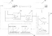
- FIG. 1is a schematic control diagram of an air conditioning system according to the present disclosure.
- the air conditioning system proposed by the present disclosuredoes not narrowly refer to an air conditioner in the industry which is used in a building and equipped with an outdoor cooling/heating unit and an indoor heat exchange unit. Rather, it should be considered as a kind of thermodynamic system with air conditioning function, which is driven by various types of power sources (for example, electric power) to exchange heat with the air at a position to be adjusted, by means of a phase change of the refrigerant in the system.
- HVACHeating Ventilating & Air Conditioning
- the air conditioning systemwhen used in a Heating Ventilating & Air Conditioning (HVAC) system in a building, it may be a refrigeration system with a cooling-only function (only cooling) or a heat pump system with both cooling and heating functions.
- HVACHeating Ventilating & Air Conditioning
- the air conditioning systemwhen used in the field of cold chain, it may be a transport refrigeration system or a refrigeration/freezing system.
- control method for an air conditioning systemincludes at least the following steps.
- S100is executed to acquire an actual cooling/heating capacity output by the air conditioning system, and to acquire an actual temperature change rate of an indoor heat exchange unit.
- This stepis intended to acquire the operational data required for capacity evaluation or prediction for subsequent evaluation or prediction work. It should be noted that the operational data can be acquired in a direct way or in an indirect way. Various factors such as acquisition cost, acquisition accuracy, and application scenes may be taken into consideration for the selection of specific manner Several parameter acquisition ways are provided exemplarily herein for reference.
- the actual cooling/heating capacity output by the air conditioning systemmay be acquired based at least on an actual flow rate output by the compressor, a temperature and/or pressure of a refrigerant delivered to the indoor heat exchange unit, and a temperature and/or pressure of the refrigerant returned from the indoor heat exchange unit.
- injectorsalso referred to as ejectors
- the refrigerant fluid output by the compressorsince the refrigerant fluid output by the compressor generates an entrainment action through high-pressure nozzles of the injectors to suction the fluid from the outlet of the indoor heat exchange unit, the concept of a ratio of mass entrainments of the injectors in the art should also be introduced.
- the actual cooling/heating capacity output by the air conditioning systemis also correlated to the ratio of mass entrainments of the injectors.
- the ratio of mass entrainments of the injectorscan be acquired from an injector high pressure, and pressures and/or temperatures at an air inlet and an outlet.
- the parameters required to acquire the actual cooling/heating capacity output by the air conditioning systemsome of them can be directly acquired by existing sensors with mature technologies and suitable cost, such as pressure sensor, temperature sensor, speed sensor and the like.
- the actual flow rate output by the compressoron one hand, it is indeed possible to directly use a flow meter to acquire the value, but the current high-precision flow meter involves a high cost. Therefore, it is also conceivable to use a combination of indirect measurement with calculation to acquire the flow rate.
- the actual flow rate output by the compressorcan be acquired based on the rotational speed of the compressor, inlet pressure and/or temperature, and outlet pressure and/or temperature.
- S200is executed to automatically learn a heat exchange load characteristic curve of the indoor heat exchange unit based on the actual cooling/heating capacity and the temperature change rate.
- This stepis intended to acquire reference parameters required for capacity evaluation or prediction for performing subsequent evaluation or prediction work.
- the automatic learning processcan include one or more of function fitting, constructing an artificial neural network and constructing a support vector machine model.
- a curve fitting methodcan be employed to automatically learn the heat exchange load characteristic curve of the indoor heat exchange unit.
- the actual cooling/heating capacities output by the system at a plurality of time points and the temperature change rates at the time pointsare acquired and reflected in a coordinate interval, and thereby a linear function associated with a plurality of points is acquired by fitting.
- S300can be executed for application. That is, the steady state load or the desired load of the indoor heat exchange unit is acquired based on the heat exchange load characteristic curve.
- the steady state loadis the actual cooling/heating capacity corresponding to the point where the temperature change rate on the heat exchange load characteristic curve is 0. That is, according to the current system output, when this time point is reached, the temperature change at the indoor heat exchange unit in the system tends to be stable, and the point value reflected on the heat exchange load characteristic curve is the actual cooling/heating capacity of the system.
- the desired loadis the actual cooling/heating capacity corresponding to the point where the temperature change rate on the heat exchange load characteristic curve is a desired temperature change rate.
- the steady state load of the system and the desired load of the system based on the user's desired temperature change rateare not the same.
- the indoor air temperature changetends to be stable, it may be 1° C. away from the user's preset desired temperature, that is, the actual cooling/heating capacity of the system is insufficient to meet the actual needs of the user at this point, and the system output needs to be increased to eliminate this 1° C. temperature deviation.
- a desired load greater than the steady state loadis required to drive the current temperature to dynamically approach the desired temperature to eliminate the temperature deviation.
- a desired load less than the steady state loadmay also be required to eliminate the temperature deviation.
- This stepis intended to dynamically know about the current state of the system and evaluate whether it is necessary to increase or decrease the system's output capacity so that it becomes closer to the preset target value.
- the desired temperature change rateis related to an actual temperature of the indoor heat exchange unit, a desired temperature set by the customer, and a desired adjustment time set by the customer. For example, if the desired temperature differs greatly from the actual temperature, and/or the desired adjustment time set by the customer is shorter, there is a larger desired temperature change rate, and correspondingly a larger actual cooling/heating capacity is required to be output. Conversely, if the desired temperature differs from the actual temperature by a small amount, and/or the desired adjustment time set by the customer is longer, there is a smaller desired temperature change rate, and correspondingly only a smaller actual cooling/heating capacity is required to be output.
- S400may be executed according to the above result, and the number of operating compressors and rotational speeds of compressors, and/or the number of operating injectors and opening degrees of injectors are adjusted, based on the steady state load and/or the desired load.
- the adjustment of the compressorapplies to any air conditioning system; the corresponding adjustment of the injector only applies to an air conditioning system having this component, which is typically a large differential pressure system, such as a supercritical system or a partial subcritical system.
- the steady load and/or the desired loadare acquired by automatically learning a heat exchange load characteristic curve, and based on this, the number of operating compressors and rotational speeds of compressors are adjusted, and/or the number of operating injectors and opening degrees of injectors are adjusted. In this way, it is ensured that the air conditioning system can stably output a cooling/heating capacity to meet the load requirements of the indoor heat exchange units, guaranteeing a stable, coordinated and efficient operation of the system.
- step S400 of the present disclosureAlthough on-demand coordination of compressors or injectors is mentioned in step S400 of the present disclosure, it is still highly likely that there are multiple ways of coordination in a case that the steady state load and/or the desired load are satisfied. In this situation, the following modifications can be further made to optimize the step.
- the number of operating compressorsis adjusted to the minimum when the steady state load and/or the desired load are satisfied.
- the required steady-state load or the desired loadis 50 kW
- there are a plurality of schemes of turning on the compressors that can satisfy the requiremente.g., the 50 kW compressor turning on alone; or the 30 kW and the 20 kW compressors turning on at the same time.
- the higher priority of turning on the compressorsis the former, since when fewer compressors are turned on, the corresponding control is simpler and the operation is more reliable.
- the rotational speeds of all operating compressorsare adjusted to be the same if the steady state load and/or the desired load are satisfied.
- the required steady-state load or the desired loadis 30 kW
- there are a plurality of schemes of turning on the compressors that can satisfy the requiremente.g., turning on two 20 kW compressors with one compressor outputting 20 kW, and the other one outputting 10 kW, or turning on two compressors at the same time, each outputting 15 kW.
- the higher priority of turning on the compressorsis the latter, which makes it easier to control the compressor.
- the steady state load and/or the desired loadare satisfied by automatically turning on/closing a minimum number of operating fixed frequency compressors.
- the required steady state load or the desired loadis 90 kW
- there are a plurality of schemes of turning on the compressors that can satisfy the requiremente.g., turning on the 50 kW and 40 kW compressors at the same time; or turning on the 50 kW, 30 kW, and 20 kW compressors at the same time (if the desired load cannot be exactly satisfied, using a compressor turning on scheme with a rated output capacity slightly larger than the desired load is considered); or turning on the 40 kW, 30 kW and 20 kW compressors at the same time.
- the higher priority of turning on the compressorsis the first mode, since when fewer compressors are turned on, the corresponding control is simpler and the operation is more reliable.
- the automatic turning on/turning offis used to control it within a specific range around the set value.
- the temperature change ratecontinues to increase, and the desired load acquired by the corresponding calculation is continuously reduced.
- the desired load acquired by the corresponding calculationis continuously reduced.
- one of the fixed frequency compressors that have been turned oncan be automatically turned off, and the other two fixed frequency compressors keep being turned on.
- an embodiment of an air conditioning systemis further provided herein. It can be either a refrigeration system or a heat pump system.
- the outdoor cooling/heating unit 100 and the indoor heat exchange unit 200 as well as the specific condensing component, the evaporating component, the throttling components, the compressors, and the like contained thereinmay be conventional mature components.
- the controller thereofshould be capable of being configured to perform the control method according to any of the foregoing embodiments or combinations thereof.
- the controllermay have at least some of the functional entities such as a flow rate evaluation module 310 configured to calculate and estimate a flow rate, a capacity evaluation module 320 configured to calculate and estimate an actual output capacity, a load evaluation and prediction module 330 configured to calculate and estimate an actual output load and a desired output load, and a coordination control module 340 configured to coordinatingly control the compressors or injectors based on the evaluation results.
- a flow rate evaluation module 310configured to calculate and estimate a flow rate
- a capacity evaluation module 320configured to calculate and estimate an actual output capacity
- a load evaluation and prediction module 330configured to calculate and estimate an actual output load and a desired output load
- a coordination control module 340configured to coordinatingly control the compressors or injectors based on the evaluation results.
- the controllershould also be associated with a pressure sensor, a temperature sensor or a speed sensor at a specific position in the system to acquire the parameters required to perform the calculation and estimation process.
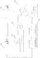
- the flow rate evaluation module 310 of the controller of the air conditioning systemacquires a mass flow of the refrigerant output from the compressor at this point.
- the speed curves SPD 1 , SPD 2 , etc.can be determined at the factory, and based on the difference Pres.Lift between the inlet and outlet pressures of the compressor from the sensor, the mass flow m of the refrigerant output from the compressor can be acquired.
- the capacity evaluation module 320 of the controlleracquires the inlet and outlet enthalpy difference ⁇ h of the indoor heat exchange unit based on the temperature and/or pressure of refrigerant delivered to the indoor heat exchange unit from the sensors, and on the temperature and/or pressure of refrigerant returned from the indoor heat exchange unit from the sensors, and then in combination with the mass flow m acquired in the previous step, the capacity evaluation module 320 calculates the actual cooling capacity Cap.
- the resulting Caphas to be multiplied by the ratio of mass entrainments of the injectors.
- the ratio of mass entrainments of the injectorscan be estimated from an injector high pressure in the system, and refrigerant temperatures and pressures at the air inlet and the outlet. Furthermore, the load evaluation and prediction module 330 of the controller automatically learns the heat exchange load characteristic curve from the calculated actual output capacity and the temperature change rate acquired at the refrigeration unit such as a freezer at this point. According to the FIGURE, the desired cooling load “Demand Cap” should be greater than the actual cooling capacity at this point, which means that the actual cooling capacity of the current system is not enough to meet the set demand, and the output of the cooling capacity needs to be further increased. After acquiring the aforementioned evaluation results, the coordination control module 340 of the controller performs coordinated control of the respective compressors and/or injectors.
- the smaller-sized No. 1 injector(shown in solid line in the FIGURE) is opened first until it is tuned to the maximum opening degree. If the current load demand still cannot be met, the larger-sized No. 2 injector (shown in dashed line in the FIGURE) is opened and the No. 1 injector is temporarily closed. If the No. 2 injector is still slowly adjusted from 0 opening degree while the No. 1 injector is closed, the load of the system will suddenly drop from the load at the full opening degree of the No. 1 injector to the load at the initial small opening degree of the No. 2 injector, and a large shock may be caused. In this example, since the rated flow rate of the No. 1 injector is half that of the No.
- the No. 2 injectoris opened from the half opening degree. As the load continues to increase, the opening degree of the No. 2 injector continues to increase until it is opened to the maximum opening degree, and if the current load demand still cannot be met, then at the same time of keeping the maximum opening degree of No. 2 injector, No. 1 injector is opened again and its opening degree is gradually increased until the maximum adjustable range of the injectors of the system is reached.
- the compressor operating strategies of the systemcan also be adjusted individually or simultaneously. First, the variable frequency compressor (shown in solid line in the FIGURE) in the system is turned on first until it is tuned to the maximum speed and the current cooling capacity output still cannot be met.
- controllers described above for performing the aforementioned methodmay involve several functional entities that do not necessarily have to correspond to physically or logically independent entities. These functional entities may also be implemented in software, or implemented in one or more hardware modules or integrated circuits, or implemented in different processing devices and/or microcontroller devices.
Landscapes
- Engineering & Computer Science (AREA)
- Mechanical Engineering (AREA)
- General Engineering & Computer Science (AREA)
- Combustion & Propulsion (AREA)
- Physics & Mathematics (AREA)
- Chemical & Material Sciences (AREA)
- Thermal Sciences (AREA)
- Signal Processing (AREA)
- Fuzzy Systems (AREA)
- Mathematical Physics (AREA)
- Fluid Mechanics (AREA)
- Human Computer Interaction (AREA)
- Air Conditioning Control Device (AREA)
Abstract
Description
Claims (12)
Applications Claiming Priority (2)
| Application Number | Priority Date | Filing Date | Title |
|---|---|---|---|
| CN201910198195.8 | 2019-03-15 | ||
| CN201910198195.8ACN111692721B (en) | 2019-03-15 | 2019-03-15 | Control method for air conditioning system |
Publications (2)
| Publication Number | Publication Date |
|---|---|
| US20200292200A1 US20200292200A1 (en) | 2020-09-17 |
| US11326805B2true US11326805B2 (en) | 2022-05-10 |
Family
ID=69844560
Family Applications (1)
| Application Number | Title | Priority Date | Filing Date |
|---|---|---|---|
| US16/813,184Active2040-07-01US11326805B2 (en) | 2019-03-15 | 2020-03-09 | Control method for air conditioning system |
Country Status (4)
| Country | Link |
|---|---|
| US (1) | US11326805B2 (en) |
| EP (1) | EP3708925B1 (en) |
| CN (1) | CN111692721B (en) |
| DK (1) | DK3708925T3 (en) |
Cited By (1)
| Publication number | Priority date | Publication date | Assignee | Title |
|---|---|---|---|---|
| US11454409B2 (en)* | 2019-03-15 | 2022-09-27 | Carrier Corporation | Failure detection method for air conditioning system |
Families Citing this family (14)
| Publication number | Priority date | Publication date | Assignee | Title |
|---|---|---|---|---|
| CN112254310A (en)* | 2020-10-10 | 2021-01-22 | 广州市夸特电气自动化有限公司 | Digital intelligent fresh air valve and control method thereof |
| CN112460772B (en)* | 2020-11-30 | 2021-12-14 | 珠海格力电器股份有限公司 | Air conditioning unit multistage refrigeration method and device, computer equipment and storage medium |
| CN114623562B (en)* | 2020-12-08 | 2024-05-07 | 广东美的暖通设备有限公司 | Air conditioning equipment, control method and control device thereof |
| CN113177321B (en)* | 2021-05-10 | 2022-10-04 | 合肥工业大学 | A Modeling Method of Air Conditioning Load Based on Dynamic Process of Heat Exchange |
| CN113280524B (en)* | 2021-05-31 | 2022-06-10 | 哈尔滨工业大学 | A large temperature difference heat exchange system provided with multiple ejectors |
| CN115540245B (en)* | 2021-06-30 | 2025-09-30 | 美的集团股份有限公司 | Air conditioning refrigeration control method, air conditioner and computer readable storage medium |
| CN113432187B (en)* | 2021-07-08 | 2022-04-19 | 宁波奥克斯电气股份有限公司 | Control method of multi-split air conditioning system and related device |
| JP2023023475A (en)* | 2021-08-05 | 2023-02-16 | ダイキン工業株式会社 | refrigeration cycle equipment |
| US20230247795A1 (en)* | 2022-01-28 | 2023-08-03 | The Research Foundation For The State University Of New York | Regenerative preheater for phase change cooling applications |
| US11879661B2 (en)* | 2022-02-17 | 2024-01-23 | Lennox Industries Inc. | Dynamic temperature control for a heating, ventilation, and air conditioning system |
| CN115289732B (en)* | 2022-07-04 | 2023-11-21 | 广东纽恩泰新能源科技发展有限公司 | Heat pump system control method and device, electronic equipment and storage medium |
| CN115993042B (en)* | 2022-12-14 | 2024-04-05 | 广东美的白色家电技术创新中心有限公司 | Control method and control device for refrigeration appliance, refrigeration appliance and storage medium |
| CN117219904B (en)* | 2023-08-31 | 2024-04-30 | 南方电网调峰调频(广东)储能科技有限公司 | Refrigeration control method, device and system of liquid cooling system and storage medium |
| CN119146539B (en)* | 2024-11-14 | 2025-04-04 | 珠海格力电器股份有限公司 | Air conditioner control method and device and air conditioner system |
Citations (68)
| Publication number | Priority date | Publication date | Assignee | Title |
|---|---|---|---|---|
| US4338791A (en)* | 1980-10-14 | 1982-07-13 | General Electric Company | Microcomputer control for heat pump system |
| JPS57129360A (en) | 1981-02-04 | 1982-08-11 | Sharp Kk | Refrigeration cycle |
| JPH0634188A (en) | 1992-07-21 | 1994-02-08 | Fujitsu General Ltd | Controller for air-conditioning machine |
| US5440891A (en)* | 1994-01-26 | 1995-08-15 | Hindmon, Jr.; James O. | Fuzzy logic based controller for cooling and refrigerating systems |
| US5586444A (en) | 1995-04-25 | 1996-12-24 | Tyler Refrigeration | Control for commercial refrigeration system |
| US6332327B1 (en) | 2000-03-14 | 2001-12-25 | Hussmann Corporation | Distributed intelligence control for commercial refrigeration |
| US6577962B1 (en) | 2000-09-28 | 2003-06-10 | Silicon Energy, Inc. | System and method for forecasting energy usage load |
| EP1342961A1 (en) | 2002-03-05 | 2003-09-10 | Lg Electronics Inc. | Method of controlling heating operation in an air conditioner |
| CN1745282A (en) | 2002-12-09 | 2006-03-08 | 哈德逊技术公司 | Method and apparatus for optimizing refrigeration systems |
| WO2006095571A1 (en)* | 2005-03-08 | 2006-09-14 | Hoshizaki Denki Kabushiki Kaisha | Refrigerator |
| US7206670B2 (en) | 2002-04-01 | 2007-04-17 | Battelle Memorial Institute | Energy management system for controlling energy supplied to a set of customer buildings |
| US7225171B2 (en) | 2001-10-16 | 2007-05-29 | Hitachi, Ltd. | Air conditioning equipment operation system and air conditioning equipment designing support system |
| US20070227161A1 (en) | 2004-02-12 | 2007-10-04 | Whirlpool Corporation | Refrigerator and a Method for Controlling Variable Cooling Capacity Thereof |
| US7305282B2 (en) | 2003-05-13 | 2007-12-04 | Siemens Power Transmission & Distribution, Inc. | Very short term load prediction in an energy management system |
| US7451017B2 (en) | 2005-01-26 | 2008-11-11 | Siemens Building Technologies, Inc. | Energy and cost savings calculation system |
| US7489990B2 (en) | 2006-07-17 | 2009-02-10 | Fehr Stephen L | Systems and methods for calculating and predicting near term production cost, incremental heat rate, capacity and emissions of electric generation power plants based on current operating and, optionally, atmospheric conditions |
| CN101389908A (en) | 2006-12-22 | 2009-03-18 | 大金工业株式会社 | Air conditioner management device |
| US7757505B2 (en) | 2006-11-02 | 2010-07-20 | Hussmann Corporation | Predictive capacity systems and methods for commercial refrigeration |
| US7814758B2 (en) | 2006-04-03 | 2010-10-19 | Computer Process Controls, Inc. | Refrigeration system controller and method |
| US7873442B2 (en) | 2002-05-20 | 2011-01-18 | The Energy Authority, Inc. | System and method for managing and optimizing power use |
| US7905103B2 (en) | 2004-09-30 | 2011-03-15 | Danfoss A/S | Model prediction controlled refrigeration system |
| CN101995072A (en) | 2009-08-05 | 2011-03-30 | 株式会社日立制作所 | Customer energy management system |
| US7991512B2 (en) | 2007-08-28 | 2011-08-02 | General Electric Company | Hybrid robust predictive optimization method of power system dispatch |
| US8065098B2 (en) | 2008-12-12 | 2011-11-22 | Schneider Electric USA, Inc. | Progressive humidity filter for load data forecasting |
| US20120210736A1 (en)* | 2011-02-17 | 2012-08-23 | Rocky Research | Cascade floating intermediate temperature heat pump system |
| US8392031B2 (en) | 2011-02-28 | 2013-03-05 | General Electric Company | System and method for load forecasting |
| CN102969720A (en) | 2012-11-01 | 2013-03-13 | 北京交通大学 | Load dynamic control and analysis method capable of being applied in smart power grids |
| US8406935B2 (en) | 2008-09-25 | 2013-03-26 | Korea Electric Power Corporation | Load forecasting analysis system for calculating customer baseline load |
| CN103003643A (en) | 2010-07-23 | 2013-03-27 | 开利公司 | Ejector cycle refrigerant separator |
| US8543248B2 (en) | 2009-03-02 | 2013-09-24 | Kabushiki Kaisha Toshiba | System for managing energy at loads |
| US8600571B2 (en) | 2008-06-19 | 2013-12-03 | Honeywell International Inc. | Energy optimization system |
| US8653968B2 (en) | 2009-12-23 | 2014-02-18 | Pulse Energy Inc. | Systems and methods for predictive building energy monitoring |
| US8705359B2 (en) | 2006-03-13 | 2014-04-22 | Comcast Cable Holdings, Llc | Tool for predicting capacity demands on an electronic system |
| US8706309B2 (en) | 2010-04-10 | 2014-04-22 | Schweitzer Engineering Laboratories Inc | Systems and method for obtaining a load model and related parameters based on load dynamics |
| US8880226B2 (en) | 2011-05-17 | 2014-11-04 | Honeywell International Inc. | System and method to predict optimized energy consumption |
| US9002531B2 (en) | 2012-09-28 | 2015-04-07 | Sharp Laboratories Of America, Inc. | System and method for predictive peak load management via integrated load management |
| WO2015079506A1 (en)* | 2013-11-26 | 2015-06-04 | 三菱電機株式会社 | Air-conditioning control device |
| CN104807143A (en) | 2015-05-14 | 2015-07-29 | 南通大学 | Active demand strategy based on energy-friendly air conditioner load side |
| US20150295402A1 (en) | 2012-12-07 | 2015-10-15 | Battelle Memorial Institute | Method and system for using demand side resources to provide frequency regulation using a dynamic allocation of energy resources |
| US20160042377A1 (en) | 2010-09-30 | 2016-02-11 | Robert Bosch Gmbh | Adaptive Load Management: A System for Incorporating Customer Electrical Demand Information for Demand and Supply Side Energy Management |
| US9261864B2 (en) | 2010-10-14 | 2016-02-16 | Siemens Aktiengesellschaft | Method and device for producing a state signal |
| US9261863B2 (en) | 2012-01-23 | 2016-02-16 | Earth Networks, Inc. | Optimizing and controlling the energy consumption of a building |
| US20160109147A1 (en)* | 2013-06-17 | 2016-04-21 | Mitsubishi Electric Corporation | Air-conditioning system control device and air-conditioning system control method |
| US20160124451A1 (en) | 2013-06-04 | 2016-05-05 | Kyocera Corporation | Power management method and power management device |
| US9335747B2 (en) | 2009-10-23 | 2016-05-10 | Viridity Energy, Inc. | System and method for energy management |
| US20160252266A1 (en)* | 2015-02-27 | 2016-09-01 | Mitsubishi Electric Corporation | System and method for controlling an hvac unit based on thermostat signals |
| CN106016534A (en)* | 2016-05-23 | 2016-10-12 | 合肥工业大学 | Compound air conditioning system with natural cooling function |
| CN106051969A (en)* | 2016-05-23 | 2016-10-26 | 合肥工业大学 | Control method of combined type air-conditioning system with natural cooling function |
| US9535474B2 (en) | 2012-03-22 | 2017-01-03 | Kabushiki Kaisha Toshiba | Renewable energy management using weighted load patterns |
| US20170003150A1 (en) | 2015-06-30 | 2017-01-05 | Johnson Controls Technology Company | Systems and methods for determining flow rate using differential pressure measurements |
| US9564757B2 (en) | 2013-07-08 | 2017-02-07 | Eaton Corporation | Method and apparatus for optimizing a hybrid power system with respect to long-term characteristics by online optimization, and real-time forecasts, prediction or processing |
| US9576327B2 (en) | 2013-06-06 | 2017-02-21 | International Business Machines Corporation | Managing time-substitutable electricity usage using dynamic controls |
| US9639904B2 (en) | 2012-12-11 | 2017-05-02 | Opterra Energy Services, Inc. | Systems and methods for minimizing energy costs for a power consumption system that has access to off-grid resources |
| CN106786622A (en) | 2017-02-10 | 2017-05-31 | 云南电网有限责任公司电力科学研究院 | A kind of method and system based on Demand-side electric cost differentiation control rate of load condensate |
| CN106786551A (en) | 2017-01-17 | 2017-05-31 | 深圳尚沃电力有限公司 | Load group towards power supply and demand balance participates in the control method and its system of scheduling |
| CN106907828A (en)* | 2017-02-21 | 2017-06-30 | 国网山东省电力公司电力科学研究院 | A Decentralized Modulation Method of Response Frequency of Air Conditioning Load Group |
| CN107093902A (en) | 2017-06-27 | 2017-08-25 | 南方电网科学研究院有限责任公司 | Power load regulation and control method and system |
| US9810442B2 (en) | 2013-03-15 | 2017-11-07 | Google Inc. | Controlling an HVAC system in association with a demand-response event with an intelligent network-connected thermostat |
| US20170336119A1 (en) | 2014-11-14 | 2017-11-23 | Carrier Corporation | On board chiller capacity calculation |
| CN107482638A (en) | 2017-07-21 | 2017-12-15 | 杭州电子科技大学 | Multi-objective dynamic optimal dispatching method for combined cooling, heating and power microgrid |
| US20180073790A1 (en) | 2015-06-30 | 2018-03-15 | Emerson Climate Technologies Retail Solutions, Inc . | Energy Management For Refrigeration Systems |
| CN107940693A (en) | 2017-11-14 | 2018-04-20 | 珠海格力电器股份有限公司 | Air conditioner load regulation control method and device |
| WO2018080446A1 (en) | 2016-10-25 | 2018-05-03 | Ecoer Inc. | A variable speed compressor based ac system and control method |
| CN108981219A (en)* | 2018-06-11 | 2018-12-11 | 陈燕燕 | A kind of control method of full-time energy-efficient frequency conversion water heating heat pump |
| US10175681B2 (en) | 2014-05-01 | 2019-01-08 | Johnson Controls Technology Company | High level central plant optimization |
| US20190309970A1 (en)* | 2018-04-10 | 2019-10-10 | Lg Electronics Inc. | Air-conditioner based on parameter learning using artificial intelligence, cloud server, and method of operating and controlling thereof |
| US20210041121A1 (en)* | 2018-02-02 | 2021-02-11 | Lg Electronics Inc. | Air-conditioner based on parameter learning using artificial intelligence, cloud server, and method of operating and controlling thereof |
| US20210123622A1 (en)* | 2016-02-12 | 2021-04-29 | Goodman Manufacturing Company LP | Systems and methods for controlling rate of change of air temperature in a building |
Family Cites Families (7)
| Publication number | Priority date | Publication date | Assignee | Title |
|---|---|---|---|---|
| JP3170392B2 (en)* | 1993-07-28 | 2001-05-28 | 川崎重工業株式会社 | Operating method and apparatus for district cooling device |
| JPH1194327A (en)* | 1997-09-18 | 1999-04-09 | Matsushita Seiko Co Ltd | Controller for air conditioner |
| CN101603751B (en)* | 2009-07-15 | 2013-07-10 | 北京科技大学 | Variable frequency energy-saving control method for refrigeration system |
| CN103486692B (en)* | 2013-09-17 | 2015-10-28 | 青岛海信日立空调系统有限公司 | The method of load self-adapting variable-frequency multi-connection type heat pump and control compressor frequency |
| JP6271316B2 (en)* | 2014-03-27 | 2018-01-31 | 荏原冷熱システム株式会社 | Heat source equipment |
| CN104019520B (en)* | 2014-05-20 | 2017-01-18 | 天津大学 | Data drive control method for minimum energy consumption of refrigerating system on basis of SPSA |
| CN104236023B (en)* | 2014-10-16 | 2017-02-15 | 珠海格力电器股份有限公司 | Load control method and device |
- 2019
- 2019-03-15CNCN201910198195.8Apatent/CN111692721B/enactiveActive
- 2020
- 2020-03-09USUS16/813,184patent/US11326805B2/enactiveActive
- 2020-03-13EPEP20163103.3Apatent/EP3708925B1/enactiveActive
- 2020-03-13DKDK20163103.3Tpatent/DK3708925T3/enactive
Patent Citations (69)
| Publication number | Priority date | Publication date | Assignee | Title |
|---|---|---|---|---|
| US4338791A (en)* | 1980-10-14 | 1982-07-13 | General Electric Company | Microcomputer control for heat pump system |
| JPS57129360A (en) | 1981-02-04 | 1982-08-11 | Sharp Kk | Refrigeration cycle |
| JPH0634188A (en) | 1992-07-21 | 1994-02-08 | Fujitsu General Ltd | Controller for air-conditioning machine |
| US5440891A (en)* | 1994-01-26 | 1995-08-15 | Hindmon, Jr.; James O. | Fuzzy logic based controller for cooling and refrigerating systems |
| US5586444A (en) | 1995-04-25 | 1996-12-24 | Tyler Refrigeration | Control for commercial refrigeration system |
| US6332327B1 (en) | 2000-03-14 | 2001-12-25 | Hussmann Corporation | Distributed intelligence control for commercial refrigeration |
| US6577962B1 (en) | 2000-09-28 | 2003-06-10 | Silicon Energy, Inc. | System and method for forecasting energy usage load |
| US7225171B2 (en) | 2001-10-16 | 2007-05-29 | Hitachi, Ltd. | Air conditioning equipment operation system and air conditioning equipment designing support system |
| EP1342961A1 (en) | 2002-03-05 | 2003-09-10 | Lg Electronics Inc. | Method of controlling heating operation in an air conditioner |
| US7206670B2 (en) | 2002-04-01 | 2007-04-17 | Battelle Memorial Institute | Energy management system for controlling energy supplied to a set of customer buildings |
| US7873442B2 (en) | 2002-05-20 | 2011-01-18 | The Energy Authority, Inc. | System and method for managing and optimizing power use |
| CN1745282A (en) | 2002-12-09 | 2006-03-08 | 哈德逊技术公司 | Method and apparatus for optimizing refrigeration systems |
| US7305282B2 (en) | 2003-05-13 | 2007-12-04 | Siemens Power Transmission & Distribution, Inc. | Very short term load prediction in an energy management system |
| US20070227161A1 (en) | 2004-02-12 | 2007-10-04 | Whirlpool Corporation | Refrigerator and a Method for Controlling Variable Cooling Capacity Thereof |
| US7905103B2 (en) | 2004-09-30 | 2011-03-15 | Danfoss A/S | Model prediction controlled refrigeration system |
| US7451017B2 (en) | 2005-01-26 | 2008-11-11 | Siemens Building Technologies, Inc. | Energy and cost savings calculation system |
| WO2006095571A1 (en)* | 2005-03-08 | 2006-09-14 | Hoshizaki Denki Kabushiki Kaisha | Refrigerator |
| US8705359B2 (en) | 2006-03-13 | 2014-04-22 | Comcast Cable Holdings, Llc | Tool for predicting capacity demands on an electronic system |
| US7814758B2 (en) | 2006-04-03 | 2010-10-19 | Computer Process Controls, Inc. | Refrigeration system controller and method |
| US7489990B2 (en) | 2006-07-17 | 2009-02-10 | Fehr Stephen L | Systems and methods for calculating and predicting near term production cost, incremental heat rate, capacity and emissions of electric generation power plants based on current operating and, optionally, atmospheric conditions |
| US7757505B2 (en) | 2006-11-02 | 2010-07-20 | Hussmann Corporation | Predictive capacity systems and methods for commercial refrigeration |
| CN101389908A (en) | 2006-12-22 | 2009-03-18 | 大金工业株式会社 | Air conditioner management device |
| US7991512B2 (en) | 2007-08-28 | 2011-08-02 | General Electric Company | Hybrid robust predictive optimization method of power system dispatch |
| US8600571B2 (en) | 2008-06-19 | 2013-12-03 | Honeywell International Inc. | Energy optimization system |
| US8406935B2 (en) | 2008-09-25 | 2013-03-26 | Korea Electric Power Corporation | Load forecasting analysis system for calculating customer baseline load |
| US8065098B2 (en) | 2008-12-12 | 2011-11-22 | Schneider Electric USA, Inc. | Progressive humidity filter for load data forecasting |
| US8543248B2 (en) | 2009-03-02 | 2013-09-24 | Kabushiki Kaisha Toshiba | System for managing energy at loads |
| CN101995072A (en) | 2009-08-05 | 2011-03-30 | 株式会社日立制作所 | Customer energy management system |
| US9335747B2 (en) | 2009-10-23 | 2016-05-10 | Viridity Energy, Inc. | System and method for energy management |
| US8653968B2 (en) | 2009-12-23 | 2014-02-18 | Pulse Energy Inc. | Systems and methods for predictive building energy monitoring |
| US8706309B2 (en) | 2010-04-10 | 2014-04-22 | Schweitzer Engineering Laboratories Inc | Systems and method for obtaining a load model and related parameters based on load dynamics |
| CN103003643A (en) | 2010-07-23 | 2013-03-27 | 开利公司 | Ejector cycle refrigerant separator |
| CN103003643B (en) | 2010-07-23 | 2015-12-16 | 开利公司 | Ejector cycle refrigerant separator |
| US20160042377A1 (en) | 2010-09-30 | 2016-02-11 | Robert Bosch Gmbh | Adaptive Load Management: A System for Incorporating Customer Electrical Demand Information for Demand and Supply Side Energy Management |
| US9261864B2 (en) | 2010-10-14 | 2016-02-16 | Siemens Aktiengesellschaft | Method and device for producing a state signal |
| US20120210736A1 (en)* | 2011-02-17 | 2012-08-23 | Rocky Research | Cascade floating intermediate temperature heat pump system |
| US8392031B2 (en) | 2011-02-28 | 2013-03-05 | General Electric Company | System and method for load forecasting |
| US8880226B2 (en) | 2011-05-17 | 2014-11-04 | Honeywell International Inc. | System and method to predict optimized energy consumption |
| US9261863B2 (en) | 2012-01-23 | 2016-02-16 | Earth Networks, Inc. | Optimizing and controlling the energy consumption of a building |
| US9535474B2 (en) | 2012-03-22 | 2017-01-03 | Kabushiki Kaisha Toshiba | Renewable energy management using weighted load patterns |
| US9002531B2 (en) | 2012-09-28 | 2015-04-07 | Sharp Laboratories Of America, Inc. | System and method for predictive peak load management via integrated load management |
| CN102969720A (en) | 2012-11-01 | 2013-03-13 | 北京交通大学 | Load dynamic control and analysis method capable of being applied in smart power grids |
| US20150295402A1 (en) | 2012-12-07 | 2015-10-15 | Battelle Memorial Institute | Method and system for using demand side resources to provide frequency regulation using a dynamic allocation of energy resources |
| US9639904B2 (en) | 2012-12-11 | 2017-05-02 | Opterra Energy Services, Inc. | Systems and methods for minimizing energy costs for a power consumption system that has access to off-grid resources |
| US9810442B2 (en) | 2013-03-15 | 2017-11-07 | Google Inc. | Controlling an HVAC system in association with a demand-response event with an intelligent network-connected thermostat |
| US20160124451A1 (en) | 2013-06-04 | 2016-05-05 | Kyocera Corporation | Power management method and power management device |
| US9576327B2 (en) | 2013-06-06 | 2017-02-21 | International Business Machines Corporation | Managing time-substitutable electricity usage using dynamic controls |
| US20160109147A1 (en)* | 2013-06-17 | 2016-04-21 | Mitsubishi Electric Corporation | Air-conditioning system control device and air-conditioning system control method |
| US9564757B2 (en) | 2013-07-08 | 2017-02-07 | Eaton Corporation | Method and apparatus for optimizing a hybrid power system with respect to long-term characteristics by online optimization, and real-time forecasts, prediction or processing |
| WO2015079506A1 (en)* | 2013-11-26 | 2015-06-04 | 三菱電機株式会社 | Air-conditioning control device |
| US10175681B2 (en) | 2014-05-01 | 2019-01-08 | Johnson Controls Technology Company | High level central plant optimization |
| US20170336119A1 (en) | 2014-11-14 | 2017-11-23 | Carrier Corporation | On board chiller capacity calculation |
| US20160252266A1 (en)* | 2015-02-27 | 2016-09-01 | Mitsubishi Electric Corporation | System and method for controlling an hvac unit based on thermostat signals |
| CN104807143A (en) | 2015-05-14 | 2015-07-29 | 南通大学 | Active demand strategy based on energy-friendly air conditioner load side |
| US20170003150A1 (en) | 2015-06-30 | 2017-01-05 | Johnson Controls Technology Company | Systems and methods for determining flow rate using differential pressure measurements |
| US20180073790A1 (en) | 2015-06-30 | 2018-03-15 | Emerson Climate Technologies Retail Solutions, Inc . | Energy Management For Refrigeration Systems |
| US20210123622A1 (en)* | 2016-02-12 | 2021-04-29 | Goodman Manufacturing Company LP | Systems and methods for controlling rate of change of air temperature in a building |
| CN106016534A (en)* | 2016-05-23 | 2016-10-12 | 合肥工业大学 | Compound air conditioning system with natural cooling function |
| CN106051969A (en)* | 2016-05-23 | 2016-10-26 | 合肥工业大学 | Control method of combined type air-conditioning system with natural cooling function |
| WO2018080446A1 (en) | 2016-10-25 | 2018-05-03 | Ecoer Inc. | A variable speed compressor based ac system and control method |
| CN106786551A (en) | 2017-01-17 | 2017-05-31 | 深圳尚沃电力有限公司 | Load group towards power supply and demand balance participates in the control method and its system of scheduling |
| CN106786622A (en) | 2017-02-10 | 2017-05-31 | 云南电网有限责任公司电力科学研究院 | A kind of method and system based on Demand-side electric cost differentiation control rate of load condensate |
| CN106907828A (en)* | 2017-02-21 | 2017-06-30 | 国网山东省电力公司电力科学研究院 | A Decentralized Modulation Method of Response Frequency of Air Conditioning Load Group |
| CN107093902A (en) | 2017-06-27 | 2017-08-25 | 南方电网科学研究院有限责任公司 | Power load regulation and control method and system |
| CN107482638A (en) | 2017-07-21 | 2017-12-15 | 杭州电子科技大学 | Multi-objective dynamic optimal dispatching method for combined cooling, heating and power microgrid |
| CN107940693A (en) | 2017-11-14 | 2018-04-20 | 珠海格力电器股份有限公司 | Air conditioner load regulation control method and device |
| US20210041121A1 (en)* | 2018-02-02 | 2021-02-11 | Lg Electronics Inc. | Air-conditioner based on parameter learning using artificial intelligence, cloud server, and method of operating and controlling thereof |
| US20190309970A1 (en)* | 2018-04-10 | 2019-10-10 | Lg Electronics Inc. | Air-conditioner based on parameter learning using artificial intelligence, cloud server, and method of operating and controlling thereof |
| CN108981219A (en)* | 2018-06-11 | 2018-12-11 | 陈燕燕 | A kind of control method of full-time energy-efficient frequency conversion water heating heat pump |
Non-Patent Citations (5)
| Title |
|---|
| Ben-Nakhi, et al., "Cooling load prediction for buildings using general regression neural networks", Envery Conversion and Management, 2004, 16 pages. |
| Carrillo, J.A. Exposito et al., "Thermodynamic Comparison of Ejector Cooling Cycle. Ejector Characterisation by Means o Entrainment Ratio and Compression Efficiency", International Journal of Refrigeration, Elsevier, Amsterdam, NL, vol. 74, Nov. 18, 2016, pp. 371-384. |
| European Search Report for Application No. 20163103.3; dated Jul. 29, 2020; 8 Pages. |
| Ge, Y T, et al., "Mathematical modelling of supermarket refrigeration systems for design, energy prediction and control", Mathematical modelling of supermarket refrigeration systems, 2000, pp. 101-113. |
| Yao, Ye, et al., "Hourly cooling load prediction by a combined forecasting model based on Analytic Hierarchy Process", International Journal of Thermal Sciences, 2004, 12 pages. |
Cited By (1)
| Publication number | Priority date | Publication date | Assignee | Title |
|---|---|---|---|---|
| US11454409B2 (en)* | 2019-03-15 | 2022-09-27 | Carrier Corporation | Failure detection method for air conditioning system |
Also Published As
| Publication number | Publication date |
|---|---|
| CN111692721A (en) | 2020-09-22 |
| US20200292200A1 (en) | 2020-09-17 |
| CN111692721B (en) | 2023-09-22 |
| EP3708925B1 (en) | 2023-04-26 |
| DK3708925T3 (en) | 2023-05-15 |
| EP3708925A1 (en) | 2020-09-16 |
Similar Documents
| Publication | Publication Date | Title |
|---|---|---|
| US11326805B2 (en) | Control method for air conditioning system | |
| US10527321B2 (en) | Demand flow for air cooled chillers | |
| CN110094857B (en) | Control method and device of air conditioner electronic expansion valve, computer product and air conditioner | |
| US9182154B2 (en) | Adaptive control of vapor compression system | |
| US8484990B2 (en) | Optimization of air cooled chiller system operation | |
| KR101639174B1 (en) | Air conditioner and method for operating the same | |
| US5150581A (en) | Head pressure controller for air conditioning and refrigeration systems | |
| CN112665112B (en) | Air conditioner, control method thereof and readable storage medium | |
| US8826680B2 (en) | Pressure ratio unload logic for a compressor | |
| US20130274948A1 (en) | Heat source system and method for controlling the number of operated devices in heat source system | |
| CN105588256B (en) | A kind of control method and device of VRF Air Conditioning System | |
| CN110513903B (en) | Control method of refrigeration cycle system | |
| US11137164B2 (en) | Control systems and methods for heat pump systems | |
| US10941951B2 (en) | Systems and methods for temperature and humidity control | |
| AU2018432700B2 (en) | Air-conditioning apparatus and air-conditioning method | |
| CN104006445A (en) | Multi-connected air conditioner and control method thereof | |
| CN104913459A (en) | Cooling air condition coolant flux real-time control method and apparatus thereof | |
| CN110195920A (en) | A kind of heat-exchange system and its control method and air conditioner | |
| CN114576812A (en) | Variable flow control method and system for water supply temperature time-varying cold water system | |
| CN116857840A (en) | Ultra-high temperature water heating device and intelligent control method thereof | |
| EP1725816B1 (en) | Multi-variable control of refrigerant systems | |
| JP5931774B2 (en) | Turbo chiller maximum load factor calculation device and method, heat source system and number control method thereof | |
| EP3719418A1 (en) | Electronic expansion valve, heat exchange system and method for controlling electronic expansion valve | |
| CN212081426U (en) | Air conditioner capable of accurately controlling air supply temperature | |
| US20230064936A1 (en) | Method of operating a heat pump system |
Legal Events
| Date | Code | Title | Description |
|---|---|---|---|
| FEPP | Fee payment procedure | Free format text:ENTITY STATUS SET TO UNDISCOUNTED (ORIGINAL EVENT CODE: BIG.); ENTITY STATUS OF PATENT OWNER: LARGE ENTITY | |
| STPP | Information on status: patent application and granting procedure in general | Free format text:APPLICATION DISPATCHED FROM PREEXAM, NOT YET DOCKETED | |
| STPP | Information on status: patent application and granting procedure in general | Free format text:DOCKETED NEW CASE - READY FOR EXAMINATION | |
| STPP | Information on status: patent application and granting procedure in general | Free format text:NON FINAL ACTION MAILED | |
| STPP | Information on status: patent application and granting procedure in general | Free format text:RESPONSE TO NON-FINAL OFFICE ACTION ENTERED AND FORWARDED TO EXAMINER | |
| STPP | Information on status: patent application and granting procedure in general | Free format text:NOTICE OF ALLOWANCE MAILED -- APPLICATION RECEIVED IN OFFICE OF PUBLICATIONS | |
| AS | Assignment | Owner name:UNITED TECHNOLOGIES RESEARCH CENTER (CHINA) LTD., CHINA Free format text:ASSIGNMENT OF ASSIGNORS INTEREST;ASSIGNORS:LI, SHENG;WU, XINYU;SIGNING DATES FROM 20190622 TO 20190717;REEL/FRAME:058936/0313 | |
| AS | Assignment | Owner name:CARRIER CORPORATION, FLORIDA Free format text:ASSIGNMENT OF ASSIGNORS INTEREST;ASSIGNOR:RAYTHEON TECHNOLOGIES CORPORATION;REEL/FRAME:058967/0625 Effective date:20200715 Owner name:RAYTHEON TECHNOLOGIES CORPORATION, MASSACHUSETTS Free format text:ASSIGNMENT OF ASSIGNORS INTEREST;ASSIGNOR:UNITED TECHNOLOGIES RESEARCH CENTER (CHINA) LTD.;REEL/FRAME:058967/0622 Effective date:20190906 | |
| STPP | Information on status: patent application and granting procedure in general | Free format text:PUBLICATIONS -- ISSUE FEE PAYMENT RECEIVED | |
| STPP | Information on status: patent application and granting procedure in general | Free format text:PUBLICATIONS -- ISSUE FEE PAYMENT VERIFIED | |
| STCF | Information on status: patent grant | Free format text:PATENTED CASE |