US11324906B2 - Acoustic guided suction systems, devices, and methods - Google Patents
Acoustic guided suction systems, devices, and methodsDownload PDFInfo
- Publication number
- US11324906B2 US11324906B2US16/054,734US201816054734AUS11324906B2US 11324906 B2US11324906 B2US 11324906B2US 201816054734 AUS201816054734 AUS 201816054734AUS 11324906 B2US11324906 B2US 11324906B2
- Authority
- US
- United States
- Prior art keywords
- tube
- obstruction
- tip
- suction
- suction catheter
- Prior art date
- Legal status (The legal status is an assumption and is not a legal conclusion. Google has not performed a legal analysis and makes no representation as to the accuracy of the status listed.)
- Active, expires
Links
Images


Classifications
- A—HUMAN NECESSITIES
- A61—MEDICAL OR VETERINARY SCIENCE; HYGIENE
- A61M—DEVICES FOR INTRODUCING MEDIA INTO, OR ONTO, THE BODY; DEVICES FOR TRANSDUCING BODY MEDIA OR FOR TAKING MEDIA FROM THE BODY; DEVICES FOR PRODUCING OR ENDING SLEEP OR STUPOR
- A61M16/00—Devices for influencing the respiratory system of patients by gas treatment, e.g. ventilators; Tracheal tubes
- A61M16/04—Tracheal tubes
- A61M16/0463—Tracheal tubes combined with suction tubes, catheters or the like; Outside connections
- A—HUMAN NECESSITIES
- A61—MEDICAL OR VETERINARY SCIENCE; HYGIENE
- A61B—DIAGNOSIS; SURGERY; IDENTIFICATION
- A61B5/00—Measuring for diagnostic purposes; Identification of persons
- A61B5/0048—Detecting, measuring or recording by applying mechanical forces or stimuli
- A61B5/0051—Detecting, measuring or recording by applying mechanical forces or stimuli by applying vibrations
- A—HUMAN NECESSITIES
- A61—MEDICAL OR VETERINARY SCIENCE; HYGIENE
- A61B—DIAGNOSIS; SURGERY; IDENTIFICATION
- A61B5/00—Measuring for diagnostic purposes; Identification of persons
- A61B5/08—Measuring devices for evaluating the respiratory organs
- A—HUMAN NECESSITIES
- A61—MEDICAL OR VETERINARY SCIENCE; HYGIENE
- A61B—DIAGNOSIS; SURGERY; IDENTIFICATION
- A61B5/00—Measuring for diagnostic purposes; Identification of persons
- A61B5/68—Arrangements of detecting, measuring or recording means, e.g. sensors, in relation to patient
- A61B5/6846—Arrangements of detecting, measuring or recording means, e.g. sensors, in relation to patient specially adapted to be brought in contact with an internal body part, i.e. invasive
- A61B5/6847—Arrangements of detecting, measuring or recording means, e.g. sensors, in relation to patient specially adapted to be brought in contact with an internal body part, i.e. invasive mounted on an invasive device
- A61B5/6852—Catheters
- A—HUMAN NECESSITIES
- A61—MEDICAL OR VETERINARY SCIENCE; HYGIENE
- A61B—DIAGNOSIS; SURGERY; IDENTIFICATION
- A61B8/00—Diagnosis using ultrasonic, sonic or infrasonic waves
- A61B8/12—Diagnosis using ultrasonic, sonic or infrasonic waves in body cavities or body tracts, e.g. by using catheters
- A—HUMAN NECESSITIES
- A61—MEDICAL OR VETERINARY SCIENCE; HYGIENE
- A61B—DIAGNOSIS; SURGERY; IDENTIFICATION
- A61B8/00—Diagnosis using ultrasonic, sonic or infrasonic waves
- A61B8/44—Constructional features of the ultrasonic, sonic or infrasonic diagnostic device
- A61B8/4444—Constructional features of the ultrasonic, sonic or infrasonic diagnostic device related to the probe
- A61B8/445—Details of catheter construction
- A—HUMAN NECESSITIES
- A61—MEDICAL OR VETERINARY SCIENCE; HYGIENE
- A61M—DEVICES FOR INTRODUCING MEDIA INTO, OR ONTO, THE BODY; DEVICES FOR TRANSDUCING BODY MEDIA OR FOR TAKING MEDIA FROM THE BODY; DEVICES FOR PRODUCING OR ENDING SLEEP OR STUPOR
- A61M16/00—Devices for influencing the respiratory system of patients by gas treatment, e.g. ventilators; Tracheal tubes
- A61M16/021—Devices for influencing the respiratory system of patients by gas treatment, e.g. ventilators; Tracheal tubes operated by electrical means
- A61M16/022—Control means therefor
- A61M16/024—Control means therefor including calculation means, e.g. using a processor
- A—HUMAN NECESSITIES
- A61—MEDICAL OR VETERINARY SCIENCE; HYGIENE
- A61M—DEVICES FOR INTRODUCING MEDIA INTO, OR ONTO, THE BODY; DEVICES FOR TRANSDUCING BODY MEDIA OR FOR TAKING MEDIA FROM THE BODY; DEVICES FOR PRODUCING OR ENDING SLEEP OR STUPOR
- A61M16/00—Devices for influencing the respiratory system of patients by gas treatment, e.g. ventilators; Tracheal tubes
- A61M16/04—Tracheal tubes
- A61M16/0475—Tracheal tubes having openings in the tube
- A61M16/0477—Tracheal tubes having openings in the tube with incorporated means for delivering or removing fluids
- A—HUMAN NECESSITIES
- A61—MEDICAL OR VETERINARY SCIENCE; HYGIENE
- A61B—DIAGNOSIS; SURGERY; IDENTIFICATION
- A61B5/00—Measuring for diagnostic purposes; Identification of persons
- A61B5/74—Details of notification to user or communication with user or patient; User input means
- A61B5/746—Alarms related to a physiological condition, e.g. details of setting alarm thresholds or avoiding false alarms
- A—HUMAN NECESSITIES
- A61—MEDICAL OR VETERINARY SCIENCE; HYGIENE
- A61M—DEVICES FOR INTRODUCING MEDIA INTO, OR ONTO, THE BODY; DEVICES FOR TRANSDUCING BODY MEDIA OR FOR TAKING MEDIA FROM THE BODY; DEVICES FOR PRODUCING OR ENDING SLEEP OR STUPOR
- A61M16/00—Devices for influencing the respiratory system of patients by gas treatment, e.g. ventilators; Tracheal tubes
- A61M16/0003—Accessories therefor, e.g. sensors, vibrators, negative pressure
- A61M16/0006—Accessories therefor, e.g. sensors, vibrators, negative pressure with means for creating vibrations in patients' airways
- A—HUMAN NECESSITIES
- A61—MEDICAL OR VETERINARY SCIENCE; HYGIENE
- A61M—DEVICES FOR INTRODUCING MEDIA INTO, OR ONTO, THE BODY; DEVICES FOR TRANSDUCING BODY MEDIA OR FOR TAKING MEDIA FROM THE BODY; DEVICES FOR PRODUCING OR ENDING SLEEP OR STUPOR
- A61M16/00—Devices for influencing the respiratory system of patients by gas treatment, e.g. ventilators; Tracheal tubes
- A61M16/0003—Accessories therefor, e.g. sensors, vibrators, negative pressure
- A61M2016/0027—Accessories therefor, e.g. sensors, vibrators, negative pressure pressure meter
- A—HUMAN NECESSITIES
- A61—MEDICAL OR VETERINARY SCIENCE; HYGIENE
- A61M—DEVICES FOR INTRODUCING MEDIA INTO, OR ONTO, THE BODY; DEVICES FOR TRANSDUCING BODY MEDIA OR FOR TAKING MEDIA FROM THE BODY; DEVICES FOR PRODUCING OR ENDING SLEEP OR STUPOR
- A61M2205/00—General characteristics of the apparatus
- A61M2205/33—Controlling, regulating or measuring
- A61M2205/3375—Acoustical, e.g. ultrasonic, measuring means
- A—HUMAN NECESSITIES
- A61—MEDICAL OR VETERINARY SCIENCE; HYGIENE
- A61M—DEVICES FOR INTRODUCING MEDIA INTO, OR ONTO, THE BODY; DEVICES FOR TRANSDUCING BODY MEDIA OR FOR TAKING MEDIA FROM THE BODY; DEVICES FOR PRODUCING OR ENDING SLEEP OR STUPOR
- A61M2205/00—General characteristics of the apparatus
- A61M2205/50—General characteristics of the apparatus with microprocessors or computers
- A61M2205/502—User interfaces, e.g. screens or keyboards
- A—HUMAN NECESSITIES
- A61—MEDICAL OR VETERINARY SCIENCE; HYGIENE
- A61M—DEVICES FOR INTRODUCING MEDIA INTO, OR ONTO, THE BODY; DEVICES FOR TRANSDUCING BODY MEDIA OR FOR TAKING MEDIA FROM THE BODY; DEVICES FOR PRODUCING OR ENDING SLEEP OR STUPOR
- A61M2209/00—Ancillary equipment
- A61M2209/10—Equipment for cleaning
- A—HUMAN NECESSITIES
- A61—MEDICAL OR VETERINARY SCIENCE; HYGIENE
- A61M—DEVICES FOR INTRODUCING MEDIA INTO, OR ONTO, THE BODY; DEVICES FOR TRANSDUCING BODY MEDIA OR FOR TAKING MEDIA FROM THE BODY; DEVICES FOR PRODUCING OR ENDING SLEEP OR STUPOR
- A61M2230/00—Measuring parameters of the user
- A61M2230/005—Parameter used as control input for the apparatus
Definitions
- the present disclosureis generally related to a system and method for use of acoustic reflectometry information for locating and removing obstructions from ventilation systems, such as from within an endotracheal tube.
- an endotracheal tubealso called an artificial airway, endotracheal tube, or ETT
- ETTendotracheal tube
- Complications with endotracheal tubesinclude endotracheal tube obstruction wherein lung secretions or other substances block the tube, the tube kinks in the patient's upper airway, or the patient bites excessively on the tube.
- acoustic guided suction and removal of obstructions from within a tubesuch as an ETT.
- a method for guiding suction of an obstructionmay include emitting sound waves from a sound generator into a tube, detecting returning acoustic reflections with at least one sound receiver, analyzing, using a processor, timings and amplitudes of the returning acoustic reflections to determine a location and size of an obstruction within the tube and a location of a tip of a suction catheter, and guiding the suction catheter to the obstruction.
- the methodmay also include fluidically coupling the suction catheter to a vacuum source and removing at least a portion of the obstruction by suctioning the obstruction.
- the methodmay also include withdrawing the suction catheter from the tube and analyzing, using a processor, timings and amplitudes of the second returning acoustic reflections to determine whether the obstruction has been removed.
- the methodmay also include repeating the guiding, fluidically coupling, and removing, steps if the obstruction was determined to not have been removed.
- the methodmay further include indicating that the suction catheter tip is at the obstruction. Guiding may include indicating a relative position of the obstruction and the catheter tube on a display.
- the methodmay include sending the location and degree of obstruction to a suction controller, wherein the suction controller advances the suction catheter to the obstruction.
- the methodmay include determining the suction catheter tip is at the obstruction and indicating that suction may begin when the suction catheter tip is determined to be at the obstruction.
- the methodmay also include analyzing, using a processor, timings and amplitudes of the returning acoustic reflections over a plurality of quiet periods to determine an increase in tube resistance and indicating a recommendation of suctioning based on the increase in tube resistance.
- the methodmay also include sending the location and degree of obstruction to a suction controller, wherein the suction controller advances the suction catheter to the obstruction.
- the methodmay include determining by using at least one microphone to detect suction sounds from the suction tube, a duration of suctioning.
- a system for guiding suction of an obstructionmay include a sound generator to emit sound waves into a tube, at least one sound receiver to detect returning acoustic reflections, and a reflectometry device having at least one processor and a memory that is accessible to the processor for analyzing timings and amplitudes of the returning acoustic reflections to determine a location and size of an obstruction within the tube and the location of a tip of a suction catheter and guiding the suction catheter to the obstruction
- the systemmay also include a display and guiding the suction catheter to the obstruction may include displaying relative positions of the suction catheter and the obstruction.
- the reflectometry devicemay further causes fluidic coupling of the suction catheter to a vacuum source.
- the systemmay also include a suction controller configured to advance and withdrawing the suction catheter from the tube.
- the reflectometry devicemay be configured to indicate that the suction catheter tip is at the obstruction when the analysis of the timings and amplitudes of the returning acoustic reflections to indicate that the location of the tip of the suction catheter is at the location of the obstruction.
- the guidingmay include indicating a relative position of the obstruction and the catheter tube on a display.
- the reflectometry devicemay be configured to send the location and degree of obstruction to a suction controller and the suction controller is configured to advance the suction catheter to the obstruction.
- the reflectometry device and suction controller of the systemmay be together configured to determine the suction catheter tip is at the obstruction and indicate that suction may begin when the suction catheter tip is determined to be at the obstruction.
- the reflectometry device of the systemmay be configured to analyze timings and amplitudes of the returning acoustic reflections over a plurality of quiet periods to determine an increase in tube resistance and indicate a recommendation of suctioning based on the increase in tube resistance.
- the reflectometry device of the systemmay be configured to send the location and degree of obstruction to a suction controller, wherein the suction controller advances the suction catheter to the obstruction.
- the reflectometry device of the systemmay be configured to measure a duration of suctioning by using at least one microphone to detect suction sounds from the suction tube.
- FIG. 1is a diagrammatical view illustrating proper insertion of an endotracheal tube (“ETT”) into a trachea of a human body and a suction catheter inserted into the ETT;
- ETTendotracheal tube
- FIG. 2is a diagrammatical view of sound waves and acoustic reflections traveling within the ETT;
- FIG. 3is a diagrammatical view of the sound waves and respective echo signals (i.e., acoustic reflections) after encountering changes in cross-sectional area in a tube;
- FIG. 4is a diagrammatical view illustrating relationships between cross-sectional area, amplitude, and time delay of an acoustic reflectometry system inserted into the lower airways;
- FIG. 5is a diagrammatical view of a device of the system having a display, a processor and a memory that is accessible to the processor;
- FIG. 6is a diagrammatical view of an adapter of the system that inserts into the breathing circuit between the ventilator hose and the ETT;
- FIG. 7Ais a diagrammatical view illustrating an obstruction and a suction catheter in a tube of an acoustic reflectometry system
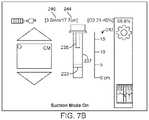
- FIG. 7Bis an illustration of a display showing an obstruction and a suction catheter in an tube according to one or more embodiments herein;
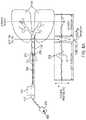
- FIG. 8Ais a diagrammatical view illustrating suction of an obstruction in a tube of an acoustic reflectometry system
- FIG. 8Bis an illustration of a display showing the suction of an obstruction and a suction catheter in a tube of an acoustic reflectometry system according to one or more embodiments herein;
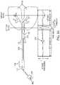
- FIG. 9Ais a diagrammatical view illustrating a suction catheter within an unobstructed tube of an acoustic reflectometry system.
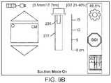
- FIG. 9Bis an illustration of a display showing a suction catheter within the unobstructed tube of an acoustic reflectometry system according to one or more embodiments herein.
- An acoustic reflectometry system's sound wavesmonitor the artificial airway, alerting clinicians in real time of ETT obstructions or situations that may lead to ETT obstructions.
- the acoustic reflectometry systemuses principles similar to sonar, the acoustic reflectometry system emits a sound signal into the ETT and records the returning echoes that arise from cross-sectional area discontinuities within the tube and patient airways.
- the timing and amplitude of these echoesare analyzed by the system to non-invasively estimate the degree and location of obstructions within the ETT and airways.
- the systemanalyzes the timing and amplitude of echoes that come from within the ETT to estimate the location and size of obstructions. This may help clinicians identify an obstruction that forms in the endotracheal tube so it can be removed before the patient is harmed. It may also help the clinician differentiate patient biting or tube kinking from lung secretion buildup by noting the reported location of the obstruction.
- An acoustic reflectometry systemconsists of an adapter connected to the proximal end of an ETT and to a monitor. Embedded inside the adapter is a sound generator such as a miniature speaker, for example, and at least one receiver such as a microphone array, for example. With these components, the system employs acoustic reflectometry by emitting sound waves from the speaker into an intubated ETT, detecting the returning acoustic reflections, or echoes, with the microphones, and then examining the echo timings and amplitudes to infer characteristics of the ETT and airway. The system's algorithms analyze the echo signal and provide information about the size of the passageway around the ETT tip, location and size of ETT obstructions, and relative movement of the ETT tip within the trachea.
- the microphone arrayallows the system to determine the direction from which echoes arrive.
- the systemcan selectively filter all echoes that arise from devices on the ventilator side of the adapter, such as closed-circuit suction catheters, Y-connectors, ETCO2 sensors, and filters, for example. This selective filtering allows the system to obtain an echo waveform from the ETT and airways that is free of ventilator circuit echoes.
- the human airwaysare a network of bifurcating branches starting at the trachea and ending at the alveoli—the small sacs where the oxygen and carbon dioxide exchange takes place.
- An interesting property of the airwaysis that even though the cross-sectional area of each individual segment decreases as the branching depth increases, the total cross-sectional area (arrived at by adding up the cross-sectional areas of all parallel segments) undergoes a rapid increase after several generations of airway branching. In other words, the airways behave acoustically like a horn with a bell at the end, and sound waves traveling down the airways will be reflected at the bell.
- the negative pressure wave from this bell-shaped regionis used by the system as a reference to which changes in ETT tip position are tracked. The bell begins around the 6th branching generation (approximately 5 cm past the carina in adults).
- the acoustic reflectometry systemWhile a majority of medical devices that use acoustics operate in the ultrasonic frequency range, the acoustic reflectometry system operates in an audible range below 20 kHz to ensure planar wave behavior within the ETT and airways. Since the sounds typically found in the ventilator circuit—such as respiratory sounds, secretion sounds, or cuff leak sounds—can potentially interfere with the echo signals used by the system, a series of advanced data collection algorithms are used to obtain a clean echo signal during ventilation.
- the acoustic reflectometry systemWhen connected to a patient, the acoustic reflectometry system collects a majority of its measurements during the quiet period of ventilation between end expiration and inspiration. As a result, the acoustic reflectometry system monitor provides updates to the ETT status approximately every patient breath, depending on the level of noise present between breaths. For cases where excessive noise interferes with acoustical measurements such that the ETT status is not updating, the acoustic reflectometry system gives the clinician the option to listen directly to the adapter microphones via the monitor speaker. This assists the clinician in determining the interfering noise source so they can rectify it if possible. Examples of interfering noise sources may include: a leaky ETT cuff, secretions in the airway and/or ETT, a high respiratory rate, a nebulizer, or patient coughing.
- FIGS. 1 and 2illustrate proper insertion of an ETT 102 into the trachea 104 .
- the acoustic reflectometry system adapter 110couples in-line between the ETT 102 and the ventilator hose 112 as shown in FIG. 1 .
- the acoustic reflectometry system's sound wavesmonitor the artificial airway and patient airways, alerting clinicians in real time of situations that may lead to unplanned extubations, ETT obstructions, endobronchial intubation, or esophageal intubation.
- the adapter 110is connected by a cord 114 (or wirelessly) to a device 122 (see FIG. 5 ) to analyze signals from the system.
- a suction controller 200 and a suction tube 202which is also referred to as a catheter, are also shown in FIG. 1 .
- the suction controller 200 and suction tube 202may aid in removing obstructions from the ETT 102 .
- the suction controller 200may be connected to the device 122 .
- the systemuses principles similar to sonar as the acoustic reflectometry system sends a sound signal 116 into the ETT 102 and records the returning echoes 118 that arise from within the tube 102 and patient airways. The timing and amplitude of these echoes 118 are analyzed by the system to detect obstructions 120 .
- a fraction of its energyreflects each time it meets with a change in cross-sectional area. If it encounters a decrease in cross-sectional area (see FIG. 3( a ) ), a positive pressure wave is reflected. This shows up as a positive deflection in the echo signal. If the sound wave encounters an increase in cross-sectional area (see FIG. 3( b ) ), a negative pressure wave is reflected. This shows up as a negative deflection in the echo signal.
- the delay time of each echoidentifies the distance from the microphone to the changing area that caused the echo.
- the amplitude of each echoidentifies the approximate amount of area change.
- FIG. 4shows an intubated ETT (top) with its corresponding echo signal, as recorded by the acoustic reflectometry system (bottom).
- the pressure amplitudeis represented on Y-axis and the time delay is represented on X-axis.
- an arrowdenotes the corresponding region in the ETT and airways from which that echo arises.
- the first echois a positive deflection (positive pressure) indicating a cross-sectional area decrease. This corresponds to the decrease in the nozzle's diameter from 9 mm to 8 mm.
- the second echois a positive deflection immediately followed by a negative deflection, indicating a cross-sectional area decrease and then an increase. This echo could be from a small obstruction in the ETT, from a kink in the ETT, or from a patient biting on the ETT. If the echo amplitude were larger, this would correspond to a larger obstruction (a larger constriction of the ETT lumen).
- the acoustic reflectometry systemestimates the obstruction size from the echo amplitude and the obstruction location from the echo delay time.
- the third echois a negative deflection indicating a cross-sectional area increase.
- This echoreferred to as the ETT tip echo
- a negative deflection echoindicates that the ETT is located in a passageway that has a larger cross-sectional area than the ETT. This would be the case for an ETT that is in the trachea. If this echo were to change to a positive deflection, it would indicate that the ETT is located in a passageway that has a smaller cross-sectional area than the ETT. This may correspond to an ETT that is in the esophagus or bronchus or that it is clogged at the tip, for example, from mucus.
- the last echoarises from the bell shaped region in the lower airways.
- the acoustic reflectometry systemtracks the time delay of this airway echo, estimating relative changes in the distance between the ETT tip and the airway echo region. For example, if the time delay between the ETT tip echo and the airway echo is decreasing (airway echo moving to the left), then this indicates that the ETT tip is getting closer to the airway echo region or that the ETT is migrating down the trachea.
- the acoustic reflectometry systemincludes a device 122 that is a handheld, portable device with a display 124 that provides information about the endotracheal tube position, obstruction, and movement.
- the device 122has at least one processor and a memory that is accessible to the processor and may store instructions that when executed by the processor cause the system to carry out any of the steps or processes described herein.
- the device 122may include circuitry for sending, receiving and processing audio signals from the acoustic reflectometry system adapter 110 via cable 114 . As explained below, the acoustic reflectometry system interprets the signals received from the patient's airway and provides feedback to the clinician through intuitive text and graphics.
- the device 122may also include circuitry for sending, receiving and processing signals to or from the suction system 200 .
- ventilators and other devicesmay be obtaining information that may be gleaned from airway monitoring devices such as the acoustic reflectometry system disclosed herein and using this data and new algorithm to improve prior art ventilator functionality as described below.
- P TRACHEAis the estimated tracheal pressure
- P AWis the measured mean airway pressure at the Y-piece
- ⁇ P TUBEis the estimated pressure drop across ETT
- R TUBEis the estimated ETT resistance (pressure differential across tube)
- Flowis the measured airway flow.
- Obstructions within the ETTmay present a significant obstacle to the flow of air through the tube.
- the estimated ETT resistancemay therefore be improved by using ETT monitoring data that can detect obstructions within the ETT, thereby allowing the calculation of tube resistance as a function the ETT internal diameter and the size and location of one or more obstructions within the ETT.
- the acoustic reflectometry systemcan detect the whole obstruction profile within the ETT from the proximal end to the distal end and an effective tube diameter can be calculated based upon this data. The more accurate tube diameter measurement will allow for a more accurate estimate of the ETT tube resistance, and hence a more accurate estimate of trachea pressure.
- the acoustic reflectometry systemcan monitor the ETT resistance and the presence of obstructions within the ETT over time and, based on an increase in ETT resistance or the presence of obstructions within the ETT, or both, may indicate that the ETT should be suctioned to clear obstructions.
- the indicationmay be, for example, a visual or audio indication, such as a flashing light or alarm.
- a recommendation for suctioning the ETTcan be generated based upon the value and optionally the trend of the artificial airway resistance as measured by the acoustic reflectometry system.
- the acoustic measurement devicemay also provide feedback regarding the state of the ETT obstruction and the suction process to aid a medical professional during the suction process or to automate the suction process.
- FIGS. 7 a , 7 b , 8 a , 8 b , 9 a , and 9 bdepict a process and system for clearing ETT obstructions using suction. The upper portion of FIGS.
- FIGS. 7 a , 8 a , and 9 ashow a diagram of an airway, including the trachea 104 and lungs 108 along with portions of an acoustic reflectometry system, including an ETT 102 , an adapter 110 , and a ventilator hose connector 112 that may be connected to a ventilator, and a suction system, including a suction tube 202 that is inserted within the ETT and a suction controller 200 .
- the system shown in FIGS. 7 a , 7 b , 8 a , 8 b , 9 a , and 9 bmay be used for both automated and manual suctioning of obstructions, as discussed herein.
- the suction controller 200may include valves, motors, positioning measuring devices and other means for controlling the insertion and retraction of the suction tube 202 from the ETT and the volume and pressure of suction provided by the suction tube.
- the suction controller 200may include an encoder and actuator for inserting the suction tube into the ETT and measuring the insertion distance of the tube in the ETT.
- the suction controller 200may also include valves 203 or pressure regulators to turn the suction flow to the suction tube on and off and to regulate the suction pressure.
- the valves 203 or pressure regulatorsmay fluidically couple and decouple the suction tube to a suction source or vacuum source, such as a vacuum pump or vacuum lines within a hospital room.
- FIGS. 7 a , 8 a , and 9 ashow a display of the echo waveform arising from within the ETT and patient airway over time.
- the displaymay include an indication of the locations of the echoes within the ETT and patient airway.
- the display shown in FIGS. 7 a , 8 a , and 9 ainclude a ETT window showing the echo from the ETT, a ETT tip window showing the echo at or proximate the ETT tip, and an airway window that shows the echo from the airway.
- an attenuation compensation scaling factorsuch as time gain compensation, may be applied to each sample within the digitized echo signal to remove the effects of the sound attenuation.
- an obstruction 220is shown in the ETT 102 .
- a positive echo 230 in the ETT window of the displayindicates the location and degree of the obstruction 220 .
- the location, such as the distance within the ETT, and the degree of obstruction, such as percent of the ETT obstructed or the equivalent diameter of the ETT at the obstruction,may also be indicated numerically on a display, such as depicted at the bottom of FIG. 7A .
- a negative echo 234 in the ETT window of the displayindicates the location of the suction tip 204 within the ETT.
- the location, such as the distance within the ETTmay also be indicated numerically.
- the obstruction 220may also be indicated on the display with a display object, such as an icon. For example, a rectangular icon 231 graphically represents the location of the obstruction 220 .
- the acoustic reflectometry systemmay also include an alternate or additional display, such as the display shown in FIG. 7B .
- This displayincludes a graphical representation 237 of the ETT 102 , along with a graphical representation 235 of the suction tube 202 and a graphical representation 233 of the obstruction 220 .
- the displaymay also include objects such as a distance scale 242 along the length of the ETT 233 to aid in communicating the relative positions of the ETT 102 , suction tube 202 , and obstruction 220 .
- the displaymay also include other features, such as an indication of ETT internal diameter 246 and ETT length 244 .
- the location and degree of the obstruction 220 in the ETT 102 and the location of the suction tube tip 204may be determined by the acoustic reflectometry system and sent to the suction system 200 for use in guiding the suction tube 202 and controlling the suction process. In some embodiments, the location and degree of the obstruction is determined simultaneously with the location of the suction tube and/or suction tube tip.
- the acoustic reflectometry systemmay determine the location and degree of the obstruction 220 and then send the location and degree of the obstruction 220 to the suction controller 200 which may advance the suction tube 202 into the ETT 102 until the suction tube tip 204 is at the obstruction 220 , as shown in FIG. 8A .
- the acoustic reflectometry systemindicates the location and degree of the obstruction 220 on the display.
- a medical processionalmay refer to such an indication when performing manual suctioning, for example as they insert the suction tube into the ETT 102 and approach the obstruction 220 .
- FIG. 8Ashows the system at a stage in the suctioning process wherein the suction tube tip 204 is at the location of the obstruction 220 .
- the acoustic reflectometry systemmay indicate that the suction tube tip 204 is at the location of the obstruction with an increased positive echo 232 , rather than a negative echo followed by a positive echo, as shown in FIG. 7A . This occurs because, when the suction tube tip 204 is at the location of the obstruction, the tube tip 204 and obstruction 220 appear as a larger obstruction.
- the tube tip 204 and the obstruction 220may be such that the entire ETT is obstructed when the tube tip 204 is at the obstruction 220 .
- the echomay include a large positive echo at the location of the obstruction 220 and tube tip 204 .
- the obstruction 220may also be indicated with an icon, such as the obstruction icon 231 .
- the acoustic reflectometry systemmay also show the positions of the suction tube 202 and obstruction 220 on an additional or alternative display, such as that shown in FIG. 8B .
- the graphical representation 235 of the suction tube 202is at the location of the graphical representation 233 of the obstruction 220 , indicating that the tip 204 of suction tube 202 is at the location of the obstruction 220 .
- the systemmay indicate that suction should begin.
- the displaymay include an indication that suction should begin, at which point the medical processional may apply suction pressure and flow to the suction tube 202 which may suck the obstruction out of the ETT.
- the acoustic reflectometry systemmay output a signal to the suction system 200 .
- the suction system 200may couple the suction tube 202 to a suction or vacuum source to suck the obstruction out of the ETT, such as by actuating a valve 203 or pressure regulator.
- the suction tube 202may be decoupled from the vacuum or suction source and then withdrawn or partially withdrawn from the ETT, for example, as shown in FIG. 9A .
- FIG. 9Ashows the system at a stage in the suctioning process wherein the suction tube tip 204 is withdrawn from the previous location of the now removed obstruction 220 .
- the acoustic reflectometry devicemay show the status of the ETT and any obstructions therein.
- the displayshows a negative echo 234 that indicates the location of the suction tube tip 204 . If the acoustic reflectometry device indicates that an obstruction is still present or moved, for example as shown in FIG. 7A , then the suction tube 202 may be advanced into the ETT 102 to the location of the obstruction and the suction process may be repeated.
- the suction tube 202may be withdrawn from the ETT.
- the acoustic reflectometry devicemay also evaluate suction performance based on an estimated ETT resistance that may be determined from the location and size of the remaining obstruction.
- the alternative or additional display shown in FIG. 9Bshows a graphical representation of the suction tube 235 and a graphical representation 237 of the unobstructed ETT 102 .
- the acoustic reflectometry devicemay indicate that suction has been adequately performed and can stop.
- the suction controller 200may retract the suction tube 202 from the ETT.
- the medical professionalmay manually withdraw the suction tube 202 from the ETT.
- the acoustic reflectometry devicemay continue to monitor the airway for proper breathing function and the ETT for obstructions.
- the acoustic measurement devicemay take pre-suctioning and post-suctioning measurements for tube resistance which may be analyzed and used as a basis for a message that indicates that the suctioning effort was successful or not completely successful. This, in turn, could alert the caregiver, such as a medical professional, to dried secretions that are not removed by regular suctioning and might be an indication for ETT replacement, increased humidification, or other interventions such as use of a “tube rescue” device which scrapes mucus debris from walls of the ETT lumen.
- the acoustic reflectometry devicetimes how long the caregiver applied suction to the ETT during a single pass of the suction tube 202 .
- the suction timemay be determined by using at least one microphone within the adapter 110 to detect the suction sounds from the suction tube tip 204 and using a timer within the device 122 to time the suctioning duration.
- the device 122may report the running timer value in seconds on the device display 124 during suctioning, as represented by box 239 in FIG. 5 . This timer may be used to train medical professionals to apply suctioning for an adequate duration to help improve the effectiveness of suctioning.
Landscapes
- Health & Medical Sciences (AREA)
- Life Sciences & Earth Sciences (AREA)
- Veterinary Medicine (AREA)
- Biomedical Technology (AREA)
- Heart & Thoracic Surgery (AREA)
- Pulmonology (AREA)
- Animal Behavior & Ethology (AREA)
- General Health & Medical Sciences (AREA)
- Public Health (AREA)
- Engineering & Computer Science (AREA)
- Emergency Medicine (AREA)
- Anesthesiology (AREA)
- Hematology (AREA)
- Physics & Mathematics (AREA)
- Biophysics (AREA)
- Pathology (AREA)
- Medical Informatics (AREA)
- Molecular Biology (AREA)
- Surgery (AREA)
- Nuclear Medicine, Radiotherapy & Molecular Imaging (AREA)
- Radiology & Medical Imaging (AREA)
- Physiology (AREA)
- Media Introduction/Drainage Providing Device (AREA)
- External Artificial Organs (AREA)
Abstract
Description
PTRACHEA=PAW−ΔPTUBE
ΔPTUBE=RTUBE×Flow
where PTRACHEAis the estimated tracheal pressure, PAWis the measured mean airway pressure at the Y-piece, ΔPTUBEis the estimated pressure drop across ETT, RTUBEis the estimated ETT resistance (pressure differential across tube), and Flow is the measured airway flow.
Claims (20)
Priority Applications (2)
| Application Number | Priority Date | Filing Date | Title |
|---|---|---|---|
| US16/054,734US11324906B2 (en) | 2017-08-04 | 2018-08-03 | Acoustic guided suction systems, devices, and methods |
| US17/713,801US12377234B2 (en) | 2017-08-04 | 2022-04-05 | Acoustic guided suction systems, devices, and methods |
Applications Claiming Priority (2)
| Application Number | Priority Date | Filing Date | Title |
|---|---|---|---|
| US201762541491P | 2017-08-04 | 2017-08-04 | |
| US16/054,734US11324906B2 (en) | 2017-08-04 | 2018-08-03 | Acoustic guided suction systems, devices, and methods |
Related Child Applications (1)
| Application Number | Title | Priority Date | Filing Date |
|---|---|---|---|
| US17/713,801ContinuationUS12377234B2 (en) | 2017-08-04 | 2022-04-05 | Acoustic guided suction systems, devices, and methods |
Publications (2)
| Publication Number | Publication Date |
|---|---|
| US20190038862A1 US20190038862A1 (en) | 2019-02-07 |
| US11324906B2true US11324906B2 (en) | 2022-05-10 |
Family
ID=65232033
Family Applications (2)
| Application Number | Title | Priority Date | Filing Date |
|---|---|---|---|
| US16/054,734Active2039-07-10US11324906B2 (en) | 2017-08-04 | 2018-08-03 | Acoustic guided suction systems, devices, and methods |
| US17/713,801Active2039-04-03US12377234B2 (en) | 2017-08-04 | 2022-04-05 | Acoustic guided suction systems, devices, and methods |
Family Applications After (1)
| Application Number | Title | Priority Date | Filing Date |
|---|---|---|---|
| US17/713,801Active2039-04-03US12377234B2 (en) | 2017-08-04 | 2022-04-05 | Acoustic guided suction systems, devices, and methods |
Country Status (3)
| Country | Link |
|---|---|
| US (2) | US11324906B2 (en) |
| EP (1) | EP3661437B1 (en) |
| WO (1) | WO2019028420A1 (en) |
Cited By (1)
| Publication number | Priority date | Publication date | Assignee | Title |
|---|---|---|---|---|
| US20220226591A1 (en)* | 2017-08-04 | 2022-07-21 | Covidien Lp | Acoustic guided suction systems, devices, and methods |
Families Citing this family (7)
| Publication number | Priority date | Publication date | Assignee | Title |
|---|---|---|---|---|
| US9707363B2 (en) | 2012-03-29 | 2017-07-18 | Sonarmed Inc. | System and method for use of acoustic reflectometry information in ventilation devices |
| AU2016238177B2 (en) | 2015-03-26 | 2021-02-18 | Covidien Lp | Improved acoustical guidance and monitoring system |
| EP3463061B1 (en) | 2016-05-31 | 2021-04-07 | Sonarmed Inc. | Acoustic reflectometry device in catheters |
| US11890415B2 (en) | 2020-04-13 | 2024-02-06 | Covidien Lp | Airway management systems for pulmonary disorder treatment |
| US12220544B2 (en)* | 2020-07-31 | 2025-02-11 | Avent, Inc. | Airway detection using ultrasound |
| CN116099091A (en)* | 2023-02-13 | 2023-05-12 | 中国人民解放军北部战区总医院 | Video endotracheal tube and monitoring method with acoustic monitoring function |
| WO2025158355A1 (en)* | 2024-01-25 | 2025-07-31 | Covidien Lp | Acoustic reflectometry for clinical condition determination |
Citations (84)
| Publication number | Priority date | Publication date | Assignee | Title |
|---|---|---|---|---|
| US2209944A (en) | 1939-09-25 | 1940-07-30 | Cranford P Walker | Method of measuring location of obstructions in deep wells |
| US4207874A (en) | 1978-03-27 | 1980-06-17 | Choy Daniel S J | Laser tunnelling device |
| US4344436A (en)* | 1980-01-16 | 1982-08-17 | Yukio Kubota | Device for determining location of the tip of catheter |
| US4501273A (en) | 1982-09-30 | 1985-02-26 | Mcginnis Gerald E | Endotracheal tube with pressure controlled inflatable cuff |
| US4630606A (en) | 1983-07-29 | 1986-12-23 | Dragerwerk Ag | Device for determining and evaluating the pressure in a balloon sleeve of a closed tracheal tube |
| US4697593A (en) | 1984-06-26 | 1987-10-06 | Evans John M | Method and apparatus for measuring blood oxygen levels |
| US4700396A (en) | 1983-01-14 | 1987-10-13 | Bolin Gustav G A | Sound-wave receiving appliance |
| US5445244A (en)* | 1993-04-23 | 1995-08-29 | Kone Oy | System for forming the jambs for the landing doors of an elevator |
| US5445144A (en)* | 1993-12-16 | 1995-08-29 | Purdue Research Foundation | Apparatus and method for acoustically guiding, positioning, and monitoring a tube within a body |
| US5575310A (en) | 1986-03-04 | 1996-11-19 | Deka Products Limited Partnership | Flow control system with volume-measuring system using a resonatable mass |
| US5655518A (en) | 1995-08-22 | 1997-08-12 | Burden; Brant S. | Coupling device for a stethoscope and an endotracheal tube |
| US5666960A (en) | 1991-12-17 | 1997-09-16 | Hood Laboratories | Acoustic imaging |
| US5823965A (en) | 1994-11-15 | 1998-10-20 | Rhinometrics A/S | Device for reflectometric examination and measurement of cavities |
| US5853005A (en) | 1996-05-02 | 1998-12-29 | The United States Of America As Represented By The Secretary Of The Army | Acoustic monitoring system |
| US20010004893A1 (en) | 1995-12-08 | 2001-06-28 | Biondi James W. | System for automatically weaning a patient from a ventilator, and method thereof |
| US6257234B1 (en) | 1998-08-21 | 2001-07-10 | Respironics, Inc. | Apparatus and method for determining respiratory mechanics of a patient and for controlling a ventilator based thereon |
| EP1166813A2 (en) | 2000-06-29 | 2002-01-02 | Siemens-Elema AB | Method and arrangement for evaluating effective flow resistance of a patient breathing circuit |
| US20020016610A1 (en) | 1999-03-29 | 2002-02-07 | Hovanes Michael E. | System and method for controlling pressure in a surgical tourniquet |
| US6390091B1 (en) | 1999-02-03 | 2002-05-21 | University Of Florida | Method and apparatus for controlling a medical ventilator |
| US6443907B1 (en) | 2000-10-06 | 2002-09-03 | Biomedical Acoustic Research, Inc. | Acoustic detection of respiratory conditions |
| US20030034035A1 (en) | 2001-08-14 | 2003-02-20 | Alfred E.Mann Institute For Biomedical Engineering At The University Of Southern California | Determining endotracheal tube placement using acoustic reflectometry |
| US6629527B1 (en) | 1991-10-17 | 2003-10-07 | Respironics, Inc. | Sleep apnea treatment apparatus |
| US6705319B1 (en) | 2000-05-26 | 2004-03-16 | Purdue Research Foundation | Miniature acoustical guidance and monitoring system for tube or catheter placement |
| US6761693B1 (en) | 1999-11-02 | 2004-07-13 | Rhinometrics A/S | Device and method for detecting opening of passage in bodily cavity |
| US20050005935A1 (en) | 2001-09-18 | 2005-01-13 | Gradon Lewis George | Respiratory apparatus and methods of respiratory treatment |
| US20060070624A1 (en) | 2004-10-01 | 2006-04-06 | Ric Investments, Llc | Method and apparatus for treating cheyne-stokes respiration |
| US20060070623A1 (en) | 2000-04-20 | 2006-04-06 | Wilkinson Malcolm H | Method and apparatus for determining a bodily characteristic or condition |
| US20060081255A1 (en) | 2004-04-02 | 2006-04-20 | Michael Miller | Ultrasonic placement and monitoring of an endotracheal tube |
| US20060107962A1 (en) | 2004-09-03 | 2006-05-25 | Ward Kevin R | Prevention of ventilator associated pneumonia (VAP) |
| US20070137652A1 (en) | 2005-12-16 | 2007-06-21 | University Of Medicine And Dentistry Of New Jersey | System and method for transcutaneous monitoring of endotracheal tube placement |
| US20070257788A1 (en) | 2006-05-08 | 2007-11-08 | Ihc Health Services, Inc. | Device alert system and method |
| US7347824B2 (en) | 2000-04-20 | 2008-03-25 | Pulmosonix Pty Ltd. | Method and apparatus for determining conditions of biological tissues |
| US20080078390A1 (en) | 2006-09-29 | 2008-04-03 | Nellcor Puritan Bennett Incorporated | Providing predetermined groups of trending parameters for display in a breathing assistance system |
| US20080078248A1 (en) | 2006-09-29 | 2008-04-03 | Nellcor Puritan Bennett Incorporated | Systems and Methods for Providing Noise Leveling in a Breathing Assistance System |
| US20090025728A1 (en) | 2007-03-19 | 2009-01-29 | Lungport Corporation C/O Rodney Perkins And Associates | Methods and systems for monitoring breathing tube movement |
| US20090082676A1 (en) | 2007-09-21 | 2009-03-26 | Baxter International Inc. | Acoustic access disconnect detection system |
| US20090099479A1 (en) | 2007-10-02 | 2009-04-16 | The Board Of Regents Of The University Of Texas Syatem | Digital endotracheal tube sound acquisition and localization device |
| US20090120439A1 (en) | 2007-11-08 | 2009-05-14 | Fred Goebel | Method of triggering a ventilator |
| US20090187164A1 (en) | 2006-05-03 | 2009-07-23 | Rowe Philip S | Nasogastric tube placement and monitoring system |
| US20090229611A1 (en) | 2008-03-10 | 2009-09-17 | Martin Anatole D | Automated Inspiratory Muscle Training for Patients Receiving Mechanical Ventilation |
| US20090229605A1 (en) | 2005-08-24 | 2009-09-17 | Hospitech Respiration Ltd. | Ajustment of endotracheal tube cuff filling |
| WO2009149351A1 (en) | 2008-06-06 | 2009-12-10 | Nellcor Puritan Bennett Llc | Systems and methods for determining patient effort and/or respiratory parameters in a ventilation system |
| US20090301601A1 (en) | 2006-02-13 | 2009-12-10 | Enerson Jon R | Apparatus and Method for Using Tetrazine-Based Energetic Material |
| US20090318805A1 (en) | 2008-06-20 | 2009-12-24 | University Of Southern California | Breathing circuit with embedded acoustic reflectometer |
| US7691070B2 (en) | 2001-11-29 | 2010-04-06 | Cristina Madrignani | Apparatus for monitoring the presence of secretions in the respiratory system of a patient |
| US7708697B2 (en) | 2000-04-20 | 2010-05-04 | Pulmosonix Pty Ltd | Method and apparatus for determining conditions of biological tissues |
| US20100252048A1 (en) | 2007-09-17 | 2010-10-07 | Peter Young | Apparatus and method for monitoring an airway device such as an endotracheal tube |
| US20100261996A1 (en) | 2009-04-08 | 2010-10-14 | Nellcor Puritan Bennett Llc | Medical device and technique for using same |
| WO2010141415A1 (en) | 2009-06-03 | 2010-12-09 | Nellcor Puritan Bennett Llc | Trachea pressure determination method and device |
| US20110030694A1 (en) | 2009-08-05 | 2011-02-10 | Anesthetech Inc. | System and method for imaging endotracheal tube placement and measuring airway occlusion cuff pressure |
| US7891354B2 (en) | 2006-09-29 | 2011-02-22 | Nellcor Puritan Bennett Llc | Systems and methods for providing active noise control in a breathing assistance system |
| US20110087123A9 (en) | 2006-10-16 | 2011-04-14 | Choncholas Gary J | Method and apparatus for airway compensation control |
| US20110154241A1 (en) | 2009-12-18 | 2011-06-23 | Nellcor Puritan Bennett Llc | Visual Indication Of Alarms On A Ventilator Graphical User Interface |
| US20110197888A1 (en) | 2008-10-24 | 2011-08-18 | Hospitech Respiration Ltd. Matalon Center Building Wing-A 3rd floor | Method and system for ventilation |
| US20110197885A1 (en) | 2008-04-18 | 2011-08-18 | Breathe Technologies ,Inc. | Methods and devices for sensing respiration and controlling ventilator functions |
| US20110313689A1 (en)* | 2009-02-11 | 2011-12-22 | Resmed Limited | Acoustic detection for respiratory treatment apparatus |
| US8152751B2 (en) | 2007-02-09 | 2012-04-10 | Baxter International Inc. | Acoustic access disconnection systems and methods |
| US20120132211A1 (en) | 2007-05-02 | 2012-05-31 | Earlysense Ltd. | Monitoring endotracheal intubation |
| US20120232411A1 (en) | 2009-11-09 | 2012-09-13 | Swisstom Ag | Pressure measuring system, pressure measuring sensor assembly and a method of measuring a pressure |
| US20120259208A1 (en)* | 2011-04-08 | 2012-10-11 | Salient Surgical Technologies, Inc. | Catheter Systems and Methods of Use |
| US8394031B2 (en) | 2000-10-06 | 2013-03-12 | Biomedical Acoustic Research, Corp. | Acoustic detection of endotracheal tube location |
| US20130098363A1 (en) | 2010-04-30 | 2013-04-25 | Vito Forte | Endotracheal cuff pressure regulation circuit and method |
| US8522787B2 (en) | 2009-07-29 | 2013-09-03 | Covidien Lp | Ultrasound-based tracheal tube placement device and method |
| US20130228171A1 (en) | 2012-03-05 | 2013-09-05 | Sonarmed, Inc. | Leak detection system and method for tube or catheter placement |
| WO2013149138A1 (en) | 2012-03-29 | 2013-10-03 | Sonarmed, Inc. | System and method for use of acoustic reflectometry information in ventilation devices |
| US20130255691A1 (en)* | 2012-03-29 | 2013-10-03 | Sonarmed, Inc. | System and Method for Use of Acoustic Reflectometry Information in Ventilation Devices |
| US20130281885A1 (en) | 2010-12-13 | 2013-10-24 | Case Western Reserve University | Device with external pressure sensors for enhancing patient care and methods of using same |
| US8608658B2 (en) | 2002-01-04 | 2013-12-17 | Nxstage Medical, Inc. | Method and apparatus for machine error detection by combining multiple sensor inputs |
| US8611984B2 (en) | 2009-04-08 | 2013-12-17 | Covidien Lp | Locatable catheter |
| US20140051989A1 (en) | 2011-04-19 | 2014-02-20 | Drexel University | Devices adapted for ultrasound location in patients and method of use |
| US20140058253A1 (en) | 2011-04-29 | 2014-02-27 | Board Of Regents Of The University Of Texas System | Methods and Apparatus for Optoacoustic Guidance and Confirmation of Placement of Indwelling Medical Apparatus |
| US20140155720A1 (en) | 2009-10-02 | 2014-06-05 | Medtronic Xomed, Inc. | Endotracheal tube apparatus |
| US20140150782A1 (en) | 2012-12-04 | 2014-06-05 | Endoclear Llc | Closed suction cleaning devices, systems and methods |
| US8764725B2 (en) | 2004-02-09 | 2014-07-01 | Covidien Lp | Directional anchoring mechanism, method and applications thereof |
| US20140249428A1 (en) | 2010-10-01 | 2014-09-04 | Angiodynamics, Inc. | Method for locating a catheter tip using audio detection |
| US8844534B2 (en) | 2009-06-30 | 2014-09-30 | Covidien Lp | Tracheal tube with lumen for tracheal pressure measurement and technique for using the same |
| US8905029B2 (en) | 2008-09-29 | 2014-12-09 | Covidien Lp | Airway system with carbon dioxide sensor for determining tracheal cuff inflation and technique for using the same |
| US20140366874A1 (en) | 2012-01-03 | 2014-12-18 | Hospitech Respiration Ltd. | System and method for controlling and monitoring flow in an endotracheal tube |
| US20160045698A1 (en)* | 2014-08-14 | 2016-02-18 | Jagdish Chaturvedi | Systems for automatically removing fluid from multiple regions of a respiratory tract |
| US9364180B2 (en) | 2009-06-05 | 2016-06-14 | Resmed Limited | Methods and devices for the detection of hypopnoea |
| WO2016154607A1 (en) | 2015-03-26 | 2016-09-29 | Sonarmed, Inc. | Improved acoustical guidance and monitoring system |
| US20170340522A1 (en) | 2016-05-31 | 2017-11-30 | Sonarmed Inc. | Acoustic reflectometry device in catheters |
| US20190105113A1 (en)* | 2016-03-31 | 2019-04-11 | Koninklijke Philips N.V. | Image guided robotic system for tumor aspiration |
| US20200237977A1 (en)* | 2017-03-17 | 2020-07-30 | Irras Ab | Fluid Exchange System and Related Methods |
Family Cites Families (2)
| Publication number | Priority date | Publication date | Assignee | Title |
|---|---|---|---|---|
| WO2019028420A1 (en)* | 2017-08-04 | 2019-02-07 | Sonarmed Inc. | Acoustic guided suction systems, devices, and methods |
| US11890415B2 (en) | 2020-04-13 | 2024-02-06 | Covidien Lp | Airway management systems for pulmonary disorder treatment |
- 2018
- 2018-08-03WOPCT/US2018/045258patent/WO2019028420A1/ennot_activeCeased
- 2018-08-03EPEP18841702.6Apatent/EP3661437B1/enactiveActive
- 2018-08-03USUS16/054,734patent/US11324906B2/enactiveActive
- 2022
- 2022-04-05USUS17/713,801patent/US12377234B2/enactiveActive
Patent Citations (96)
| Publication number | Priority date | Publication date | Assignee | Title |
|---|---|---|---|---|
| US2209944A (en) | 1939-09-25 | 1940-07-30 | Cranford P Walker | Method of measuring location of obstructions in deep wells |
| US4207874A (en) | 1978-03-27 | 1980-06-17 | Choy Daniel S J | Laser tunnelling device |
| US4344436A (en)* | 1980-01-16 | 1982-08-17 | Yukio Kubota | Device for determining location of the tip of catheter |
| US4501273A (en) | 1982-09-30 | 1985-02-26 | Mcginnis Gerald E | Endotracheal tube with pressure controlled inflatable cuff |
| US4700396A (en) | 1983-01-14 | 1987-10-13 | Bolin Gustav G A | Sound-wave receiving appliance |
| US4630606A (en) | 1983-07-29 | 1986-12-23 | Dragerwerk Ag | Device for determining and evaluating the pressure in a balloon sleeve of a closed tracheal tube |
| US4697593A (en) | 1984-06-26 | 1987-10-06 | Evans John M | Method and apparatus for measuring blood oxygen levels |
| US5575310A (en) | 1986-03-04 | 1996-11-19 | Deka Products Limited Partnership | Flow control system with volume-measuring system using a resonatable mass |
| US6629527B1 (en) | 1991-10-17 | 2003-10-07 | Respironics, Inc. | Sleep apnea treatment apparatus |
| US5666960A (en) | 1991-12-17 | 1997-09-16 | Hood Laboratories | Acoustic imaging |
| US5445244A (en)* | 1993-04-23 | 1995-08-29 | Kone Oy | System for forming the jambs for the landing doors of an elevator |
| US5445144A (en)* | 1993-12-16 | 1995-08-29 | Purdue Research Foundation | Apparatus and method for acoustically guiding, positioning, and monitoring a tube within a body |
| US5823965A (en) | 1994-11-15 | 1998-10-20 | Rhinometrics A/S | Device for reflectometric examination and measurement of cavities |
| US5655518A (en) | 1995-08-22 | 1997-08-12 | Burden; Brant S. | Coupling device for a stethoscope and an endotracheal tube |
| US20010004893A1 (en) | 1995-12-08 | 2001-06-28 | Biondi James W. | System for automatically weaning a patient from a ventilator, and method thereof |
| US5853005A (en) | 1996-05-02 | 1998-12-29 | The United States Of America As Represented By The Secretary Of The Army | Acoustic monitoring system |
| US6257234B1 (en) | 1998-08-21 | 2001-07-10 | Respironics, Inc. | Apparatus and method for determining respiratory mechanics of a patient and for controlling a ventilator based thereon |
| US6390091B1 (en) | 1999-02-03 | 2002-05-21 | University Of Florida | Method and apparatus for controlling a medical ventilator |
| US20020016610A1 (en) | 1999-03-29 | 2002-02-07 | Hovanes Michael E. | System and method for controlling pressure in a surgical tourniquet |
| US6761693B1 (en) | 1999-11-02 | 2004-07-13 | Rhinometrics A/S | Device and method for detecting opening of passage in bodily cavity |
| US7850618B2 (en) | 2000-04-20 | 2010-12-14 | Pulmosonix Pty Ltd. | Method and apparatus for determining conditions of biological tissues |
| US20060070623A1 (en) | 2000-04-20 | 2006-04-06 | Wilkinson Malcolm H | Method and apparatus for determining a bodily characteristic or condition |
| US7347824B2 (en) | 2000-04-20 | 2008-03-25 | Pulmosonix Pty Ltd. | Method and apparatus for determining conditions of biological tissues |
| US7708697B2 (en) | 2000-04-20 | 2010-05-04 | Pulmosonix Pty Ltd | Method and apparatus for determining conditions of biological tissues |
| US6705319B1 (en) | 2000-05-26 | 2004-03-16 | Purdue Research Foundation | Miniature acoustical guidance and monitoring system for tube or catheter placement |
| EP1166813A2 (en) | 2000-06-29 | 2002-01-02 | Siemens-Elema AB | Method and arrangement for evaluating effective flow resistance of a patient breathing circuit |
| US6443907B1 (en) | 2000-10-06 | 2002-09-03 | Biomedical Acoustic Research, Inc. | Acoustic detection of respiratory conditions |
| US8394031B2 (en) | 2000-10-06 | 2013-03-12 | Biomedical Acoustic Research, Corp. | Acoustic detection of endotracheal tube location |
| US20030034035A1 (en) | 2001-08-14 | 2003-02-20 | Alfred E.Mann Institute For Biomedical Engineering At The University Of Southern California | Determining endotracheal tube placement using acoustic reflectometry |
| US20050005935A1 (en) | 2001-09-18 | 2005-01-13 | Gradon Lewis George | Respiratory apparatus and methods of respiratory treatment |
| US7691070B2 (en) | 2001-11-29 | 2010-04-06 | Cristina Madrignani | Apparatus for monitoring the presence of secretions in the respiratory system of a patient |
| US8608658B2 (en) | 2002-01-04 | 2013-12-17 | Nxstage Medical, Inc. | Method and apparatus for machine error detection by combining multiple sensor inputs |
| US8764725B2 (en) | 2004-02-09 | 2014-07-01 | Covidien Lp | Directional anchoring mechanism, method and applications thereof |
| US20060081255A1 (en) | 2004-04-02 | 2006-04-20 | Michael Miller | Ultrasonic placement and monitoring of an endotracheal tube |
| US20060107962A1 (en) | 2004-09-03 | 2006-05-25 | Ward Kevin R | Prevention of ventilator associated pneumonia (VAP) |
| US20060070624A1 (en) | 2004-10-01 | 2006-04-06 | Ric Investments, Llc | Method and apparatus for treating cheyne-stokes respiration |
| US8424529B2 (en) | 2005-08-24 | 2013-04-23 | Hospitech Respiration Ltd. | Adjustment of endotracheal tube cuff filling |
| US10780238B2 (en) | 2005-08-24 | 2020-09-22 | Hospitech Respiration Ltd. | Method of detecting endotracheal tube misplacement |
| US20090229605A1 (en) | 2005-08-24 | 2009-09-17 | Hospitech Respiration Ltd. | Ajustment of endotracheal tube cuff filling |
| US20070137652A1 (en) | 2005-12-16 | 2007-06-21 | University Of Medicine And Dentistry Of New Jersey | System and method for transcutaneous monitoring of endotracheal tube placement |
| US20090301601A1 (en) | 2006-02-13 | 2009-12-10 | Enerson Jon R | Apparatus and Method for Using Tetrazine-Based Energetic Material |
| US20090187164A1 (en) | 2006-05-03 | 2009-07-23 | Rowe Philip S | Nasogastric tube placement and monitoring system |
| US20070257788A1 (en) | 2006-05-08 | 2007-11-08 | Ihc Health Services, Inc. | Device alert system and method |
| US20080078390A1 (en) | 2006-09-29 | 2008-04-03 | Nellcor Puritan Bennett Incorporated | Providing predetermined groups of trending parameters for display in a breathing assistance system |
| US20080078248A1 (en) | 2006-09-29 | 2008-04-03 | Nellcor Puritan Bennett Incorporated | Systems and Methods for Providing Noise Leveling in a Breathing Assistance System |
| US7891354B2 (en) | 2006-09-29 | 2011-02-22 | Nellcor Puritan Bennett Llc | Systems and methods for providing active noise control in a breathing assistance system |
| US20110087123A9 (en) | 2006-10-16 | 2011-04-14 | Choncholas Gary J | Method and apparatus for airway compensation control |
| US8152751B2 (en) | 2007-02-09 | 2012-04-10 | Baxter International Inc. | Acoustic access disconnection systems and methods |
| US20090025728A1 (en) | 2007-03-19 | 2009-01-29 | Lungport Corporation C/O Rodney Perkins And Associates | Methods and systems for monitoring breathing tube movement |
| US20120132211A1 (en) | 2007-05-02 | 2012-05-31 | Earlysense Ltd. | Monitoring endotracheal intubation |
| US20100252048A1 (en) | 2007-09-17 | 2010-10-07 | Peter Young | Apparatus and method for monitoring an airway device such as an endotracheal tube |
| US20090082676A1 (en) | 2007-09-21 | 2009-03-26 | Baxter International Inc. | Acoustic access disconnect detection system |
| US8038629B2 (en) | 2007-10-02 | 2011-10-18 | Board Of Regents, The University Of Texas System | Digital endotracheal tube sound acquisition and localization device |
| US20090099479A1 (en) | 2007-10-02 | 2009-04-16 | The Board Of Regents Of The University Of Texas Syatem | Digital endotracheal tube sound acquisition and localization device |
| US20090120439A1 (en) | 2007-11-08 | 2009-05-14 | Fred Goebel | Method of triggering a ventilator |
| US20090229611A1 (en) | 2008-03-10 | 2009-09-17 | Martin Anatole D | Automated Inspiratory Muscle Training for Patients Receiving Mechanical Ventilation |
| US20110197885A1 (en) | 2008-04-18 | 2011-08-18 | Breathe Technologies ,Inc. | Methods and devices for sensing respiration and controlling ventilator functions |
| WO2009149351A1 (en) | 2008-06-06 | 2009-12-10 | Nellcor Puritan Bennett Llc | Systems and methods for determining patient effort and/or respiratory parameters in a ventilation system |
| US20090318805A1 (en) | 2008-06-20 | 2009-12-24 | University Of Southern California | Breathing circuit with embedded acoustic reflectometer |
| US8905029B2 (en) | 2008-09-29 | 2014-12-09 | Covidien Lp | Airway system with carbon dioxide sensor for determining tracheal cuff inflation and technique for using the same |
| US20110197888A1 (en) | 2008-10-24 | 2011-08-18 | Hospitech Respiration Ltd. Matalon Center Building Wing-A 3rd floor | Method and system for ventilation |
| US20110313689A1 (en)* | 2009-02-11 | 2011-12-22 | Resmed Limited | Acoustic detection for respiratory treatment apparatus |
| US20100261996A1 (en) | 2009-04-08 | 2010-10-14 | Nellcor Puritan Bennett Llc | Medical device and technique for using same |
| US8611984B2 (en) | 2009-04-08 | 2013-12-17 | Covidien Lp | Locatable catheter |
| US8280489B2 (en) | 2009-04-08 | 2012-10-02 | Nellcor Puritan Bennett Llc | Method and system for determining placement of a tracheal tube in a subject |
| WO2010141415A1 (en) | 2009-06-03 | 2010-12-09 | Nellcor Puritan Bennett Llc | Trachea pressure determination method and device |
| US9364180B2 (en) | 2009-06-05 | 2016-06-14 | Resmed Limited | Methods and devices for the detection of hypopnoea |
| US8844534B2 (en) | 2009-06-30 | 2014-09-30 | Covidien Lp | Tracheal tube with lumen for tracheal pressure measurement and technique for using the same |
| US8522787B2 (en) | 2009-07-29 | 2013-09-03 | Covidien Lp | Ultrasound-based tracheal tube placement device and method |
| US8371303B2 (en) | 2009-08-05 | 2013-02-12 | Anesthetech Inc. | System and method for imaging endotracheal tube placement and measuring airway occlusion cuff pressure |
| US20110030694A1 (en) | 2009-08-05 | 2011-02-10 | Anesthetech Inc. | System and method for imaging endotracheal tube placement and measuring airway occlusion cuff pressure |
| US20140155720A1 (en) | 2009-10-02 | 2014-06-05 | Medtronic Xomed, Inc. | Endotracheal tube apparatus |
| US20120232411A1 (en) | 2009-11-09 | 2012-09-13 | Swisstom Ag | Pressure measuring system, pressure measuring sensor assembly and a method of measuring a pressure |
| US20110154241A1 (en) | 2009-12-18 | 2011-06-23 | Nellcor Puritan Bennett Llc | Visual Indication Of Alarms On A Ventilator Graphical User Interface |
| US20130098363A1 (en) | 2010-04-30 | 2013-04-25 | Vito Forte | Endotracheal cuff pressure regulation circuit and method |
| US20140249428A1 (en) | 2010-10-01 | 2014-09-04 | Angiodynamics, Inc. | Method for locating a catheter tip using audio detection |
| US20130281885A1 (en) | 2010-12-13 | 2013-10-24 | Case Western Reserve University | Device with external pressure sensors for enhancing patient care and methods of using same |
| US20120259208A1 (en)* | 2011-04-08 | 2012-10-11 | Salient Surgical Technologies, Inc. | Catheter Systems and Methods of Use |
| US20140051989A1 (en) | 2011-04-19 | 2014-02-20 | Drexel University | Devices adapted for ultrasound location in patients and method of use |
| US20140058253A1 (en) | 2011-04-29 | 2014-02-27 | Board Of Regents Of The University Of Texas System | Methods and Apparatus for Optoacoustic Guidance and Confirmation of Placement of Indwelling Medical Apparatus |
| US20140366874A1 (en) | 2012-01-03 | 2014-12-18 | Hospitech Respiration Ltd. | System and method for controlling and monitoring flow in an endotracheal tube |
| US20130228171A1 (en) | 2012-03-05 | 2013-09-05 | Sonarmed, Inc. | Leak detection system and method for tube or catheter placement |
| US20170043110A1 (en) | 2012-03-05 | 2017-02-16 | Sonarmed, Inc. | Leak detection system and method for tube or catheter placement |
| WO2013134166A1 (en) | 2012-03-05 | 2013-09-12 | Sonarmed, Inc. | Leak detection system and method for tube or catheter placement |
| US9498590B2 (en) | 2012-03-05 | 2016-11-22 | Sonarmed, Inc. | Leak detection system and method for tube or catheter placement |
| US20130255691A1 (en)* | 2012-03-29 | 2013-10-03 | Sonarmed, Inc. | System and Method for Use of Acoustic Reflectometry Information in Ventilation Devices |
| US9707363B2 (en) | 2012-03-29 | 2017-07-18 | Sonarmed Inc. | System and method for use of acoustic reflectometry information in ventilation devices |
| US20170281887A1 (en) | 2012-03-29 | 2017-10-05 | Sonarmed Inc. | System and method for use of acoustic reflectometry information in ventilation devices |
| WO2013149138A1 (en) | 2012-03-29 | 2013-10-03 | Sonarmed, Inc. | System and method for use of acoustic reflectometry information in ventilation devices |
| US20140150782A1 (en) | 2012-12-04 | 2014-06-05 | Endoclear Llc | Closed suction cleaning devices, systems and methods |
| US20160045698A1 (en)* | 2014-08-14 | 2016-02-18 | Jagdish Chaturvedi | Systems for automatically removing fluid from multiple regions of a respiratory tract |
| WO2016154607A1 (en) | 2015-03-26 | 2016-09-29 | Sonarmed, Inc. | Improved acoustical guidance and monitoring system |
| US20160279366A1 (en) | 2015-03-26 | 2016-09-29 | Sonarmed, Inc. | Acoustical guidance and monitoring system |
| US20190105113A1 (en)* | 2016-03-31 | 2019-04-11 | Koninklijke Philips N.V. | Image guided robotic system for tumor aspiration |
| US20170340522A1 (en) | 2016-05-31 | 2017-11-30 | Sonarmed Inc. | Acoustic reflectometry device in catheters |
| US20200237977A1 (en)* | 2017-03-17 | 2020-07-30 | Irras Ab | Fluid Exchange System and Related Methods |
Non-Patent Citations (21)
Cited By (2)
| Publication number | Priority date | Publication date | Assignee | Title |
|---|---|---|---|---|
| US20220226591A1 (en)* | 2017-08-04 | 2022-07-21 | Covidien Lp | Acoustic guided suction systems, devices, and methods |
| US12377234B2 (en)* | 2017-08-04 | 2025-08-05 | Covidien Lp | Acoustic guided suction systems, devices, and methods |
Also Published As
| Publication number | Publication date |
|---|---|
| US20220226591A1 (en) | 2022-07-21 |
| US20190038862A1 (en) | 2019-02-07 |
| WO2019028420A1 (en) | 2019-02-07 |
| US12377234B2 (en) | 2025-08-05 |
| EP3661437A4 (en) | 2021-06-02 |
| EP3661437B1 (en) | 2023-09-27 |
| EP3661437A1 (en) | 2020-06-10 |
Similar Documents
| Publication | Publication Date | Title |
|---|---|---|
| US12377234B2 (en) | Acoustic guided suction systems, devices, and methods | |
| US11696993B2 (en) | System and method for use of acoustic reflectometry information in ventilation devices | |
| EP2830497B1 (en) | System for use of acoustic reflectometry information in ventilation devices | |
| US6705319B1 (en) | Miniature acoustical guidance and monitoring system for tube or catheter placement | |
| US5445144A (en) | Apparatus and method for acoustically guiding, positioning, and monitoring a tube within a body | |
| US12144924B2 (en) | Acoustic detection for respiratory treatment apparatus | |
| US10071214B2 (en) | Leak detection system and method for tube or catheter placement | |
| US20030034035A1 (en) | Determining endotracheal tube placement using acoustic reflectometry | |
| JP5299978B2 (en) | Tracheal tube maintenance system | |
| US5620004A (en) | Airway indicator device | |
| CN118079165B (en) | Visual tracheal catheter with acoustic monitoring function and monitoring method | |
| CN111939412B (en) | Airway management device with sight glass and monitoring function | |
| US20230320675A1 (en) | Identification and display of airway collapse | |
| WO2023194902A1 (en) | Identification and display of airway collapse | |
| Juan et al. | Miniature acoustic guidance system for endotracheal tubes | |
| Mansfield et al. | Acoustic method to quantitatively assess the position and patency of infant endotracheal tubes: preliminary results in rabbits | |
| US20250169791A1 (en) | Device for measuring obstruction of tracheostomy tube, trachea, and bronchus of patient with tracheostomy tube | |
| Juan et al. | In-line acoustic system to position and monitor infant-sized endotracheal tubes | |
| US20250242120A1 (en) | Clinical data correlation with acoustic reflectometry data | |
| CN116831524A (en) | Tracheal catheter with sputum suction function and sputum suction method | |
| JPS6034381B2 (en) | Endobronchial detection device |
Legal Events
| Date | Code | Title | Description |
|---|---|---|---|
| FEPP | Fee payment procedure | Free format text:ENTITY STATUS SET TO UNDISCOUNTED (ORIGINAL EVENT CODE: BIG.); ENTITY STATUS OF PATENT OWNER: LARGE ENTITY | |
| FEPP | Fee payment procedure | Free format text:ENTITY STATUS SET TO SMALL (ORIGINAL EVENT CODE: SMAL); ENTITY STATUS OF PATENT OWNER: LARGE ENTITY | |
| STPP | Information on status: patent application and granting procedure in general | Free format text:DOCKETED NEW CASE - READY FOR EXAMINATION | |
| AS | Assignment | Owner name:SONARMED INC., INDIANA Free format text:ASSIGNMENT OF ASSIGNORS INTEREST;ASSIGNOR:MANSFIELD, JEFFREY;REEL/FRAME:048194/0475 Effective date:20190130 | |
| AS | Assignment | Owner name:UNITED STATES SURGICAL CORPORATION, MINNESOTA Free format text:SECURITY INTEREST;ASSIGNOR:SONARMED INC.;REEL/FRAME:048647/0559 Effective date:20190319 | |
| STPP | Information on status: patent application and granting procedure in general | Free format text:NON FINAL ACTION MAILED | |
| STPP | Information on status: patent application and granting procedure in general | Free format text:RESPONSE TO NON-FINAL OFFICE ACTION ENTERED AND FORWARDED TO EXAMINER | |
| STPP | Information on status: patent application and granting procedure in general | Free format text:FINAL REJECTION MAILED | |
| STPP | Information on status: patent application and granting procedure in general | Free format text:DOCKETED NEW CASE - READY FOR EXAMINATION | |
| STPP | Information on status: patent application and granting procedure in general | Free format text:NON FINAL ACTION MAILED | |
| STPP | Information on status: patent application and granting procedure in general | Free format text:RESPONSE TO NON-FINAL OFFICE ACTION ENTERED AND FORWARDED TO EXAMINER | |
| AS | Assignment | Owner name:COVIDIEN LP, MASSACHUSETTS Free format text:ASSIGNMENT OF ASSIGNORS INTEREST;ASSIGNOR:SONARMED INC.;REEL/FRAME:058338/0666 Effective date:20211123 | |
| AS | Assignment | Owner name:COVIDIEN LP, MASSACHUSETTS Free format text:CORRECTIVE ASSIGNMENT TO CORRECT THE APPLICATION NUMBER 16/858,329 PREVIOUSLY RECORDED AT REEL: 058338 FRAME: 0666. ASSIGNOR(S) HEREBY CONFIRMS THE ASSIGNMENT;ASSIGNOR:SONARMED INC.;REEL/FRAME:058574/0750 Effective date:20211123 | |
| STPP | Information on status: patent application and granting procedure in general | Free format text:NOTICE OF ALLOWANCE MAILED -- APPLICATION RECEIVED IN OFFICE OF PUBLICATIONS | |
| FEPP | Fee payment procedure | Free format text:ENTITY STATUS SET TO UNDISCOUNTED (ORIGINAL EVENT CODE: BIG.); ENTITY STATUS OF PATENT OWNER: LARGE ENTITY | |
| STPP | Information on status: patent application and granting procedure in general | Free format text:PUBLICATIONS -- ISSUE FEE PAYMENT VERIFIED | |
| STCF | Information on status: patent grant | Free format text:PATENTED CASE | |
| MAFP | Maintenance fee payment | Free format text:PAYMENT OF MAINTENANCE FEE, 4TH YEAR, LARGE ENTITY (ORIGINAL EVENT CODE: M1551); ENTITY STATUS OF PATENT OWNER: LARGE ENTITY Year of fee payment:4 |