US11324882B2 - Protective case for an auto-injector - Google Patents
Protective case for an auto-injectorDownload PDFInfo
- Publication number
- US11324882B2 US11324882B2US16/567,656US201916567656AUS11324882B2US 11324882 B2US11324882 B2US 11324882B2US 201916567656 AUS201916567656 AUS 201916567656AUS 11324882 B2US11324882 B2US 11324882B2
- Authority
- US
- United States
- Prior art keywords
- auto
- case
- injector
- protective case
- enclosure
- Prior art date
- Legal status (The legal status is an assumption and is not a legal conclusion. Google has not performed a legal analysis and makes no representation as to the accuracy of the status listed.)
- Active
Links
Images


Classifications
- A—HUMAN NECESSITIES
- A61—MEDICAL OR VETERINARY SCIENCE; HYGIENE
- A61M—DEVICES FOR INTRODUCING MEDIA INTO, OR ONTO, THE BODY; DEVICES FOR TRANSDUCING BODY MEDIA OR FOR TAKING MEDIA FROM THE BODY; DEVICES FOR PRODUCING OR ENDING SLEEP OR STUPOR
- A61M5/00—Devices for bringing media into the body in a subcutaneous, intra-vascular or intramuscular way; Accessories therefor, e.g. filling or cleaning devices, arm-rests
- A61M5/14—Infusion devices, e.g. infusing by gravity; Blood infusion; Accessories therefor
- A61M5/142—Pressure infusion, e.g. using pumps
- A61M5/14244—Pressure infusion, e.g. using pumps adapted to be carried by the patient, e.g. portable on the body
- A61M5/14248—Pressure infusion, e.g. using pumps adapted to be carried by the patient, e.g. portable on the body of the skin patch type
- A—HUMAN NECESSITIES
- A47—FURNITURE; DOMESTIC ARTICLES OR APPLIANCES; COFFEE MILLS; SPICE MILLS; SUCTION CLEANERS IN GENERAL
- A47J—KITCHEN EQUIPMENT; COFFEE MILLS; SPICE MILLS; APPARATUS FOR MAKING BEVERAGES
- A47J41/00—Thermally-insulated vessels, e.g. flasks, jugs, jars
- A47J41/02—Vacuum-jacket vessels, e.g. vacuum bottles
- A—HUMAN NECESSITIES
- A61—MEDICAL OR VETERINARY SCIENCE; HYGIENE
- A61M—DEVICES FOR INTRODUCING MEDIA INTO, OR ONTO, THE BODY; DEVICES FOR TRANSDUCING BODY MEDIA OR FOR TAKING MEDIA FROM THE BODY; DEVICES FOR PRODUCING OR ENDING SLEEP OR STUPOR
- A61M5/00—Devices for bringing media into the body in a subcutaneous, intra-vascular or intramuscular way; Accessories therefor, e.g. filling or cleaning devices, arm-rests
- A61M5/002—Packages specially adapted therefor, e.g. for syringes or needles, kits for diabetics
- A—HUMAN NECESSITIES
- A61—MEDICAL OR VETERINARY SCIENCE; HYGIENE
- A61M—DEVICES FOR INTRODUCING MEDIA INTO, OR ONTO, THE BODY; DEVICES FOR TRANSDUCING BODY MEDIA OR FOR TAKING MEDIA FROM THE BODY; DEVICES FOR PRODUCING OR ENDING SLEEP OR STUPOR
- A61M5/00—Devices for bringing media into the body in a subcutaneous, intra-vascular or intramuscular way; Accessories therefor, e.g. filling or cleaning devices, arm-rests
- A61M5/178—Syringes
- A61M5/20—Automatic syringes, e.g. with automatically actuated piston rod, with automatic needle injection, filling automatically
- A—HUMAN NECESSITIES
- A61—MEDICAL OR VETERINARY SCIENCE; HYGIENE
- A61M—DEVICES FOR INTRODUCING MEDIA INTO, OR ONTO, THE BODY; DEVICES FOR TRANSDUCING BODY MEDIA OR FOR TAKING MEDIA FROM THE BODY; DEVICES FOR PRODUCING OR ENDING SLEEP OR STUPOR
- A61M5/00—Devices for bringing media into the body in a subcutaneous, intra-vascular or intramuscular way; Accessories therefor, e.g. filling or cleaning devices, arm-rests
- A61M5/178—Syringes
- A61M5/31—Details
- A61M5/32—Needles; Details of needles pertaining to their connection with syringe or hub; Accessories for bringing the needle into, or holding the needle on, the body; Devices for protection of needles
- A61M5/3287—Accessories for bringing the needle into the body; Automatic needle insertion
- A—HUMAN NECESSITIES
- A61—MEDICAL OR VETERINARY SCIENCE; HYGIENE
- A61M—DEVICES FOR INTRODUCING MEDIA INTO, OR ONTO, THE BODY; DEVICES FOR TRANSDUCING BODY MEDIA OR FOR TAKING MEDIA FROM THE BODY; DEVICES FOR PRODUCING OR ENDING SLEEP OR STUPOR
- A61M5/00—Devices for bringing media into the body in a subcutaneous, intra-vascular or intramuscular way; Accessories therefor, e.g. filling or cleaning devices, arm-rests
- A61M5/14—Infusion devices, e.g. infusing by gravity; Blood infusion; Accessories therefor
- A61M5/142—Pressure infusion, e.g. using pumps
- A61M5/14244—Pressure infusion, e.g. using pumps adapted to be carried by the patient, e.g. portable on the body
- A61M5/14248—Pressure infusion, e.g. using pumps adapted to be carried by the patient, e.g. portable on the body of the skin patch type
- A61M2005/14252—Pressure infusion, e.g. using pumps adapted to be carried by the patient, e.g. portable on the body of the skin patch type with needle insertion means
- A—HUMAN NECESSITIES
- A61—MEDICAL OR VETERINARY SCIENCE; HYGIENE
- A61M—DEVICES FOR INTRODUCING MEDIA INTO, OR ONTO, THE BODY; DEVICES FOR TRANSDUCING BODY MEDIA OR FOR TAKING MEDIA FROM THE BODY; DEVICES FOR PRODUCING OR ENDING SLEEP OR STUPOR
- A61M5/00—Devices for bringing media into the body in a subcutaneous, intra-vascular or intramuscular way; Accessories therefor, e.g. filling or cleaning devices, arm-rests
- A61M5/14—Infusion devices, e.g. infusing by gravity; Blood infusion; Accessories therefor
- A61M5/142—Pressure infusion, e.g. using pumps
- A61M5/14244—Pressure infusion, e.g. using pumps adapted to be carried by the patient, e.g. portable on the body
- A61M5/14248—Pressure infusion, e.g. using pumps adapted to be carried by the patient, e.g. portable on the body of the skin patch type
- A61M2005/1426—Pressure infusion, e.g. using pumps adapted to be carried by the patient, e.g. portable on the body of the skin patch type with means for preventing access to the needle after use
- A—HUMAN NECESSITIES
- A61—MEDICAL OR VETERINARY SCIENCE; HYGIENE
- A61M—DEVICES FOR INTRODUCING MEDIA INTO, OR ONTO, THE BODY; DEVICES FOR TRANSDUCING BODY MEDIA OR FOR TAKING MEDIA FROM THE BODY; DEVICES FOR PRODUCING OR ENDING SLEEP OR STUPOR
- A61M5/00—Devices for bringing media into the body in a subcutaneous, intra-vascular or intramuscular way; Accessories therefor, e.g. filling or cleaning devices, arm-rests
- A61M5/178—Syringes
- A61M5/20—Automatic syringes, e.g. with automatically actuated piston rod, with automatic needle injection, filling automatically
- A61M2005/2006—Having specific accessories
- A—HUMAN NECESSITIES
- A61—MEDICAL OR VETERINARY SCIENCE; HYGIENE
- A61M—DEVICES FOR INTRODUCING MEDIA INTO, OR ONTO, THE BODY; DEVICES FOR TRANSDUCING BODY MEDIA OR FOR TAKING MEDIA FROM THE BODY; DEVICES FOR PRODUCING OR ENDING SLEEP OR STUPOR
- A61M2209/00—Ancillary equipment
- A61M2209/06—Packaging for specific medical equipment
Definitions
- various embodiments of this inventionrelate to protective cases for drug or biological delivery devices and, specifically, to protective cases forming a vacuum sealed chamber that provides thermal isolation for the enclosed device.
- the auto-injector marketis growing rapidly through an increase in prescriptions, along with new indications for use. Patients are actively seeking solutions to address the anxiety associated with the existing pain points of using protective cases, including poor portability, unwanted attention, and temperature susceptibility.
- the auto-injector casecan be portable, adaptable, and low-profile.
- the auto-injector casecan also increase the time a patient can maintain their auto-injector device in an adverse climate, as compared to a device without the case. Further re, the auto-injector case can allow the patient to prioritize their needs and determine which configuration of the protective case is best for them.
- Embodiments of the casemay include cases that can be rigid or flexible in nature.
- the casing materialmay be metal, thermoplastic (TP), thermoplastic elastomer (TPE), fiber reinforced composite, ceramic, or combination of materials to provide physical and/or thermal protection for the device.
- the caseis substantially symmetrical about a horizontal plane and may be uniform about a central axis.
- the casemay be configured in such a means that it is adaptable to everyday use items, and can be attached, whether molded or not, to different cases or objects to increase portability.
- certain embodimentsmay allow the user to carry a single device or multiple devices.
- Certain rigid embodiments of the casemay contain two vacuum sealed chambers forming an enclosure around the device, to provide thermal protection.
- the protective casemay consist of upper and lower portions of equal or unequal proportions which when mated together form a sealed enclosure.
- the lower portionmay include a double wall, forming a lower vacuum chamber in between, and a lower sidewall flange, where the lower vacuum chamber extends within at least a portion of the lower sidewall flange.
- the upper portionmay include a double wall forming an upper vacuum chamber therebetween and an upper sidewall flange, where the upper vacuum chamber extends within at least a portion of the upper sidewall flange.
- each of the vacuum chambersmay be set to reduce the rate of, heat transfer and outlined in the parameter table shown in FIG. 133 .
- an embodiment of the protective casemay provide a lower rate of heat transfer between the internal chamber and the external environment or vice versa.
- an embodimentmay contain an additional passive means of reducing the rate of heat transferred to or from the device.
- the internal sealed chambermay contain an additional thermal barrier to improve the insulating properties.
- the additional thermal barriermay consist of a TP, thermoplastic elastomer (TPE), open or closed cell foam layer or combinations of such, which may or may not be one complete piece but consists of multiple pieces that may interlock when the two halves of the case are mated together forming a substantially sealed barrier.
- the additional thermal barriermay prevent direct contact with the disposed device and the internal cavity wall further limiting the rate of heat transfer.
- the TP, TPE, or open or closed cell foam piecesay be affixed to the housing through various means including adhesive, mechanical means, or form molded to the housing.
- the additional insulating barriermay further consist of at least one of a lower insulating barrier disposed about an interior perimeter of the lower sidewall flange and an upper insulating barrier disposed about an interior perimeter of the upper sidewall flange.
- the internal surfaces of the vacuum chambermay be polished or coated with a reflective layer to reduce the heat transfer through radiation.
- the coating applied to both surfaces, or at minimum one surface, of the sealed vacuum chambermay act as a reinforcement or aid in the structural integrity of the rigid case in addition to providing a reflective barrier.
- the casemay have an exterior layer or coating consisting of a metal, TP, TPE, fiber reinforced composite, ceramic, or open or closed cell foam or a combination of such materials to aid in thermally insulating the case and disposed device.
- the proposed embodiments of the rigid and elastic casesmay provide a means of securing the device in a stable manner to eliminate or reduce any motion of the device relative to the case due to external loading or vibration.
- the method of which the case may secure the devicecan provide a means to aid in the placement of the device for orientation as well as aid in the removal of the device.
- the method of which the barrier on the internal chamber of the casemay provide an insulating means, it may further assist in securing and stabilizing the device.
- the insulation barriermay form a cavity that releasably receives portion ref the device and can provide the user with accessibility to remove the device from the case.
- the casemay include a lower stabilizing element disposed within the lower portion and/or an upper stabilizing element disposed within the upper portion to support the auto-injector disposed in the interior cavity.
- the stabilizing elementcan include a material including a closed cell polymer foam, an open cell polymer foam, rubber, TP, TPE, and/or combinations thereof.
- the harrier materialmay be chosen such that its properties aid in thermally isolating the device as well as aid in damping induced vibrations.
- embodimentsmay be configured to protect more than one device as well as hold dissimilar devices if deemed necessary.
- the configuration of holding multiple devicesis not limited to a horizontal or vertical layout of stacking, but instead allows for the best optimized method of storing the devices while maintaining a relatively low-profile case.
- the sidewall flanges of the upper and lower portions of the thermally protective casemay overlap axially, radially and/or circumferentially to provide an adequately sealed joint.
- the sealed enclosuremay be formed by several different configurations of mates between the upper and lower portion, some of which may include a friction fit, a threaded connection, etc.
- Embodiments which contain a threaded connection to facilitate the joint between the two halvesmay provide threads on either corresponding half such that the threads are concealed when connected.
- the thermal barrier affixed to the inner housingsmay provide the bond between the two halves of the case. Additionally, when the lower portion and the upper portion are mated together, the interior of the enclosure may be thermally isolated as well as substantially watertight.
- Embodiments of the rigid casemay provide a watertight/water-resistant seal to protect the device from exposure to water or other fluids.
- the watertight/water-resistant connection between the upper and lower halves of the sealed enclosuremay be facilitated by means of a gasket of suitable material, or through the addition of a coating or separate material applied at the joint interface.
- An embodiment of the auto-injector casemay consist of an ergonomic shape such that it fits easily into an individual's hand and the contours of the case may provide adequate surface area for proper handling. Furthermore, the embodiment may contain an external coating or layering applied to the case.
- the exterior layer or coatingmay consist of a metal, TP, TPE, fiber reinforced composite, ceramic, or open or closed cell foam, or a combination of such materials.
- the external coatingmay provide the following functionalities; shock absorbing, textured to aid in handling or gripping of the case, contoured surface profiles to aid in handling or gripping, thermal insulation for the device, degradation protection from environmental effects, and structural support for the case integrity.
- the casecan further include an external surface including an embossed surface, a ribbed surface, a grip, and/or combinations thereof.
- the insulation barriermay protrude radially from the case to provide a user interface for device removal.
- the coating or layeringmay provide a means of applying a label to the external surface of the case.
- Examples of the proposed case for an auto-injectorinclude, but are not limited to, embodiments that may provide a means of attachment to everyday items such as keychains, lanyards, wrist straps, cell phones, bikes, etc. Additionally, certain embodiments may include the use of a combination of rigid and elastic cases to provide more accessibility or portability.
- the attachment mechanismsmay include, but are not limited to; a strap, a clip, a pin, a clamp, a mount, a tab forming an eyelet, an adhesive layer, and/or combinations thereof. The method of which the embodiment may provide or allow for a means of attachment between the protective case with a user or object.
- the protective caseforms a second cavity for receiving a second device (e.g., a cell phone and/or a second auto-injector device).
- a second devicee.g., a cell phone and/or a second auto-injector device.
- the second cavitycircumscribes at least a portion of the device or auto-injector device.
- the casemay have an internal power source to allow certain functionalities of the case while storing the device.
- the casemay provide audible instructions relating to the contained device for performing an injection or the stored condition of the device.
- the casemay provide connectivity to everyday smart devices for additional functionality. Certain embodiments may allow for the user to monitor the temperature, and location of the case. Additional, the connected case may allow the user to see if other auto-injector devices are nearby. Additional embodiments may contact emergency responders or next of kin once the auto-injector device has been removed from the case.
- the casemay also provide a display and/or interface for inspection of the case and internal conditions.
- the casemay also provide a means of detecting excessive vibrations or impacts while storing the device. Furthermore, information about the case and contained auto-injector device may be monitored remotely by the manufacturer.
- embodiments of the inventionare of a protective case for an auto-injector device, for which the case may be rigid, elastic or combination of the two.
- the methodcan include the following: (I) a protective case forming a cavity that releasably receives at least a portion of the auto-injector device; (II) the protective case which may contain a lower portion including a double wall forming a lower vacuum chamber therebetween and a lower sidewall flange, where the lower vacuum chamber extends within at least a portion of the lower sidewall flange; and a mating upper portion including a double wall forming an upper vacuum chamber therebetween and an upper sidewall flange, where the upper vacuum chamber extends within at least a portion of the upper sidewall flange; (III) mating the sidewall flanges on the lower and upper portions to form a substantially sealed thermally isolated and or watertight/water-resistant interior cavity for the auto-injector; (IV) and providing a means of attachment for the case to common everyday objects.
- embodiments of the inventionfeature a protective case for enclosing a compact auto-injector used for delivering a medicament dose.
- the protective casecan include a lower portion including a double wall forming a lower vacuum chamber therebetween and a lower sidewall flange, where the lower vacuum chamber extends within at least a portion of the lower sidewall flange; and a mating upper portion including a double wall forming an upper vacuum chamber therebetween and an upper sidewall flange, where the upper vacuum chamber extends within at least a portion of the upper sidewall flange, such that when the lower portion and the upper portion are mated, the lower and upper sidewall flanges overlap to fore a substantially sealed thermally isolated interior cavity for receiving the auto-injector.
- the caseis substantially symmetrical about a horizontal plane.
- the casecan also be substantially uniform about a central vertical is.
- the pressure in each of the lower vacuum chamber and the upper vacuumchamp less than about 0.1 torr.
- the lower portion and the upper portioncan be disk shaped.
- the lower sidewall flange and the upper sidewall flangeoverlap axially, radially, and/or circumferentially.
- the protective casealso includes a lower insulating ring disposed about an interior perimeter of the lower sidewall flange and/or an upper insulating ring disposed about an interior perimeter of the upper sidewall flange.
- the insulating ringcan include various materials including, for example, a closed cell polymer foam, an open cell polymer foam, rubber, TP, TPE, and/or combinations thereof.
- the protective casealso includes a lower stabilizing element disposed within the lower portion and/or an upper stabilizing element disposed within the upper portion to support the auto-injector when disposed in the interior cavity.
- the stabilizing elementcan include various materials including, for example, a closed cell polymer foam, an open cell polymer foam, rubber, TP, TPE, and/or combinations thereof.
- the protective caseitself can include various materials including, for example a metal, a polymer, a composite material, a ceramic, and/or combinations thereof.
- the protective casealso includes an attachment device to facilitate a user carrying the case.
- the attachment devicecan include an adjustable elastic strap, a non-elastic strap, a wrist strap, a wrist band, a clip, a tether, a necklace, a pin, a clamp, a mount, a tab forming an eyelet, an adhesive layer, a hand grip surface, and/or combinations thereof.
- the protective caseis further characterized by an absence of active thermal control of the interior cavity. In some configurations, when the lower portion and the upper portion are mated, the substantially sealed thermally isolated interior cavity is at least one of substantially watertight and substantially water resistant.
- the protective casecan also include an external surface that includes a coating, an embossed surface, a ribbed surface, a grip, and/or combinations thereof.
- the protective caseincludes a reflective coating disposed on an interior surface of the lower vacuum chamber and the upper vacuum chamber.
- the interior cavitymay be adapted to receive multiple auto-injectors.
- embodiments of the inventionfeature a method of thermally isolating a compact auto-injector containing a medicament dose from ambient environmental temperatures.
- the methodcan include the steps of providing a protective case that includes (i) a lower portion including a double wall forming a lower vacuum chamber therebetween and a lower sidewall flange, where the lower vacuum chamber extends within at least a portion of the lower sidewall flange, and (ii) a mating upper portion including a double wall forming an upper vacuum chamber therebetween and an upper sidewall flange, where the upper vacuum chamber extends within at least a portion of the upper sidewall flange; placing the auto-injector into an interior cavity portion formed by at least one of the lower portion and the upper portion; and mating the lower and upper sidewall flanges in overlapping relation to form a substantially sealed thermally isolated interior cavity for the auto-injector.
- the methodcan also include providing an attachment device to associate the protective case with a user.
- the attachment devicecan include an adjustable elastic strap, a non-elastic strap, a wrist strap, a wrist band, a clip, a tether, a necklace, a pin, a clamp, a mount, a tab forming an eyelet, an adhesive layer, a hand grip surface, and/or combinations thereof.
- the methodis further characterized by an absence of actively thermally controlling the interior cavity.
- embodiments of the inventionfeature an apparatus for associating an auto-injector device with a user.
- the apparatuscan include a protective case forming a cavity for releasably receiving at least a portion of the auto-injector device, and an attachment device coupled to the protective case.
- the protective caseforms a second cavity for receiving a second device.
- the second devicecan include a cell phone and/or a second auto-injector device.
- the cavitycircumscribes at least a portion of the auto-injector device.
- the attachment devicecan include an adjustable elastic strap, a non-elastic strap, a wrist strap, a wrist band, a clip, a tether, a necklace, a pin, a clamp, a mount, a tab forming an eyelet, an adhesive layer, a hand grip surface, and/or combinations thereof.
- embodiments of the inventionfeature a method for associating an auto-injector device with a user.
- the methodcan include the steps of providing a protective case forming a cavity for releasably receiving at least a portion of the auto-injector device, and providing an attachment device adapted to be coupled to the protective case.
- the protective caseforms a second cavity for receiving a second device.
- the second devicecan include a cell phone and/or a second auto-injector device.
- the cavitycircumscribes at least a portion of the auto-injector device.
- the attachment devicecan include an adjustable elastic strap, a non-elastic strap, a wrist strap, a wrist band, a clip, a tether, a necklace, a pin, a clamp, a mount, a tab forming an eyelet, an adhesive layer, a hand grip surface, and/or combinations thereof.
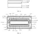
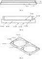
- FIG. 1is a depiction of existing low aspect ratio auto-injectors, as well as an example high aspect ratio auto-injector, according to one embodiment
- FIGS. 2-15are schematic views of a vacuum sealed protective case with IoT (internet of things) functionality for a high aspect ratio auto-injector, according to example embodiments;
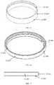
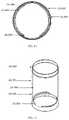
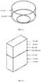
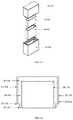
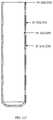
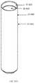
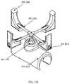
- FIGS. 16-58are schematic views of a vacuum sealed protective case for carrying a single high aspect ratio auto-injector, according to example embodiments.
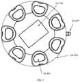
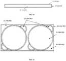
- FIGS. 59-69are schematic views of a vacuum sealed protective case for carrying multiple high aspect ratio auto-injectors, according to example embodiments.
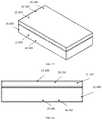
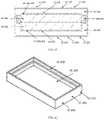
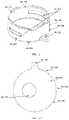
- FIGS. 70-97are schematic views of a vacuum sealed protective case for carrying a low aspect ratio auto-injector, according to example embodiments.
- FIGS. 98-126are schematic views of a non-vacuum sealed protective case for carrying a high aspect ratio auto-injector and for carrying a low aspect ratio auto-injector, according to example embodiments;
- FIGS. 127-132are schematic views of a non-vacuum sealed protective case for carrying a high aspect ratio auto-injector and for carrying a low aspect ratio auto-injector, that can pair with another protective case or be a stand-alone protective case, according to example embodiments;
- FIG. 133is a table showing exemplary properties for protective cases.
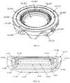
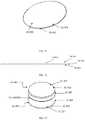
- the protective case ( 1 A, 1 B, 1 C, 1 D, 1 E)can be constructed of a rigid material of the following compositions: metal, TP, TPE, fiber reinforced composite, ceramic, or a combination of these materials.
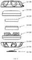
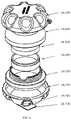
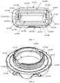
- the protective caseis composed of an upper half ( 1 A- 400 , 1 B- 100 , 1 C- 100 , 1 D- 100 , 1 E- 100 ) and a lower half ( 1 A- 300 , 1 B- 200 , 1 C- 200 , 1 D- 200 , 1 E- 200 ), that when mated together form an enclosure ( 1 A, 1 B, 1 C, 1 D, 1 E) that is substantially sealed that can provide insulation to the enclosed auto-injector and may be watertight.
- the upper half ( 1 A- 400 , 1 B- 100 , 1 C- 100 , 1 D- 100 , 1 E- 100 ) and the lower half ( 1 A- 300 , 1 B- 200 , 1 C- 200 , 1 D- 200 , 1 E- 200 ) of the protective casecan be composed of a rigid inner and outer wall ( 1 A- 305 , 1 A- 404 , 1 B- 103 , 1 B- 202 , 1 C- 103 , 1 C- 104 , 1 C- 203 , 1 C- 204 , 1 D- 102 , 1 D- 202 , 1 E- 102 , 1 E- 202 ) that form the sealed vacuum chamber ( 1 A- 301 , 1 A- 401 , 1 B- 101 , 1 B- 201 , 1 C- 101 , 1 C- 201 , 1 D- 101 , 1 D- 201 , 1 E- 101 , 1 E- 201 ).
- the two vacuum sealed halvesinsulate the disposed auto-injector to limit the heat transfer between the internal chamber and the outside environment.
- the sealed vacuum chambersare extended to the furthest point ( 1 A- 307 , 1 A- 406 , 1 B- 105 , 1 B- 204 , 1 C- 106 , 1 C- 206 , 1 E- 106 , 1 E- 206 ) at the joints of the two halves to maximize the insulating properties of the case and limit thermal bridging to the interior of the device.
- connection between the upper half ( 1 A- 400 , 1 B- 100 , 1 C- 100 , 1 D- 100 , 1 E- 100 ) and lower half ( 1 A- 300 , 1 B- 200 , 1 C- 200 , 1 D- 200 , 1 E- 200 )may be a threaded connection ( 1 A- 302 , 1 A- 402 , 1 B- 102 , 1 B- 503 ), a friction fit ( 1 C- 102 , 1 C- 202 , 1 E- 106 , 1 E- 206 ), or any other variation ( 1 D- 302 , 1 D- 402 ) that may provide a sealed connection.
- the joint between the two halvesmay provide a watertight connection in certain embodiments may utilize a gasket ( 1 B- 300 ). Furthermore, the watertight/water-resistant connection may be facilitated through the addition of a coating or separate material applied at the joint interface ( 1 A- 303 , 1 A- 403 ).
- the joint between the upper half ( 1 A- 400 , 1 B- 100 , 1 C- 100 , 1 D- 100 , 1 E- 100 ) and the lower half ( 1 A- 300 , 1 B- 200 , 1 C- 200 , 1 D- 200 , 1 E- 200 )may be facilitated by the thermal barrier ( 1 A- 500 , 1 A- 600 , 1 B- 400 , 1 B- 500 , 1 C- 300 , 1 C- 400 , 1 D- 300 , 1 D- 400 , 1 E- 300 , 1 E- 400 ) affixed to the interior of the housing.
- the thermal barrier1 A- 500 , 1 A- 600 , 1 B- 400 , 1 B- 500 , 1 C- 300 , 1 C- 400 , 1 D- 300 , 1 D- 400 , 1 E- 300 , 1 E- 400
- the thermal barriermay be affixed to the housing ( 1 A- 306 , 1 A- 405 , 1 B- 104 , 1 B- 203 , 1 C- 105 , 1 C- 205 , 1 D- 103 , 1 D- 203 , 1 E- 103 , 1 E- 203 ) through adhesive, mechanical means, or form molded ( 1 A- 501 , 1 A- 601 , 1 B- 401 , 1 B- 501 , 1 C- 301 , 1 C- 401 , 1 D- 301 , 1 D- 401 , 1 E- 301 , 1 E- 401 ).
- the sealed connectionmay be performed via a threaded connection on the insulation sleeve ( 1 B- 503 ) and a corresponding threaded connection on the inside of the top housing ( 1 B- 102 ), such that the threads are concealed once the housings are mated together.
- the casemay provide additional thermal insulation through a thermal barrier ( 1 A- 500 , 1 A- 600 , 1 B- 400 , 1 B- 500 , 1 C- 300 , 1 C- 400 , 1 D- 300 , 1 D- 400 , 1 E- 300 , 1 E- 400 ) to improve the insulating properties.
- a thermal barrier1 A- 500 , 1 A- 600 , 1 B- 400 , 1 B- 500 , 1 C- 300 , 1 C- 400 , 1 D- 300 , 1 D- 400 , 1 E- 300 , 1 E- 400
- the additional thermal barrier( 1 A- 500 , 1 A- 600 , 1 B- 400 , 1 B- 500 , 1 C- 300 , 1 C- 400 , 1 D- 300 , 1 D- 400 , 1 E- 300 , 1 E- 400 ) may consist of a TP, TPE, open or closed cell foam layer or combinations of such, which may or may not be one complete piece but can include multiple pieces that may interlock ( 1 A- 503 , 1 A- 603 , 1 B- 402 , 1 B- 502 , 1 C- 302 , 1 C- 402 , 1 D- 302 , 1 D- 402 , 1 E- 302 , 1 E- 402 ) when the two halves of the case are mated together, forming a substantially sealed barrier.
- the device enclosuremay be lined with an insulating sleeve ( 1 A- 500 , 1 A- 600 , 1 B- 400 , 1 B- 500 , 1 C- 300 , 1 C- 400 , 1 D- 300 , 1 D- 400 , 1 E- 300 , 1 E- 400 ) formed of one or two pieces, which interlock through stepped ledges or interference fits ( 1 A- 503 , 1 A- 603 , 1 B- 402 , 1 B- 502 , 1 C- 302 , 1 C- 402 , 1 D- 302 , 1 D- 402 , 1 E- 302 , 1 E- 402 ).
- an insulating sleeve1 A- 500 , 1 A- 600 , 1 B- 400 , 1 B- 500 , 1 C- 300 , 1 C- 400 , 1 D- 300 , 1 D- 400 , 1 E- 300 , 1 E- 400
- the insulation barriersform a well or cradle ( 1 A- 502 , 1 A- 602 , 1 B- 403 , 1 B- 505 , 1 C- 503 , 1 D- 303 , 1 D- 403 , 1 E- 303 , 1 E- 403 ) for stabilizing the device and may dampen any relative motion between the device and the protective case ( 1 A, 1 B, 1 C, 1 D, 1 E).
- the insulation barrier and the stabilizing cradlemay be two separate components ( 1 C- 500 ).
- the material selection for the insulation sleeve and cradlewill be such that it minimizes the thermal conductivity and maximizes vibration damping.
- the thermal barrier(s)may protrude from the joint between the upper half ( 1 A- 400 , 1 B- 100 , 1 C- 100 , 1 D- 100 , 1 E- 100 ) and the lower half ( 1 A- 300 , 1 B- 200 , 1 C- 200 , 1 D- 200 , 1 E- 200 ) and provide an interface for the user to separate the halves ( 1 D- 304 , 1 D- 404 ).
- the insulation barriermay also form a cavity that releasably receives ( 1 B- 504 , 1 E- 304 , 1 E- 404 ) at least a portion of the auto-injector device and provides access for the user to remove the device from the case ( 1 A- 304 ).
- the insulation barrier or rigid upper or lower halvesmay provide a means of orientation for the device to be stored and as such removed.
- certain embodimentsmay be configured to protect more than one device ( 1 E) as well as hold dissimilar devices if deemed necessary.
- the configuration of holding multiple devicesis not limited to a horizontal or vertical layout of stacking, but instead allows for the best optimized method of storing the devices while maintaining a relatively low-profile case.
- the internal surfaces of the vacuum sealed chambersmay be polished or lined with a reflective coating, or similar means to reduce the heat transfer by radiation ( 1 A- 308 , 1 A- 407 , 1 B- 107 , 1 B- 206 , 1 C- 108 , 1 C- 208 , 1 D- 105 , 1 D- 205 , 1 E- 105 , 1 E- 205 ).
- some embodimentsmay contain an exterior coating ( 1 A- 100 , 1 A- 200 , 1 B- 106 , 1 B- 205 , 1 C- 107 , 1 C- 207 , 1 D- 104 , 1 D- 204 , 1 E- 104 , 1 E- 204 ) or applied layer(s) of dissimilar material or combination of the two, to increase the insulating value of the exterior wall.
- the exterior coating( 1 A- 100 , 1 A- 200 , 1 B- 106 , 1 B- 205 , 1 C- 107 , 1 C- 207 , 1 D- 104 , 1 D- 204 , 1 E- 104 , 1 E- 204 ) or applied layer of dissimilar material or a combination of the two, to the provide a texture or profile to the case to assist the user in handling ( 1 A- 101 , 1 A- 201 ).
- This exterior coating or layer(s) of dissimilar material or combination of suchmay perform the following functionalities; improve the ergonomics of the case, aid in reducing the induced vibrations from external loading, contribute case aesthetics, provide structural support, provide labeling 1 A- 102 ) etc.
- embodiments of the casemay provide a power source ( 1 A- 701 ) to assist in monitoring the conditions of the case both internal and external, and providing connectivity of the case with other smart devices.
- the casemay provide the user with an interface ( 1 A- 700 ) for monitoring internal device cavity and external conditions to better maintain the enclosed device.
- the casecan provide a means of physically attaching to other external objects ( 1 A- 104 ).
- certain embodiments ainclude the use of a combination of rigid and elastic cases ( 3 H) to provide improved accessibility or portability.
- the combination of the rigid and elastic casesmay provide a means to affix the case or combination of cases to such everyday items like a backpack, lanyard, bike, keys, etc.
- the attachment mechanismmay include a wrist strap, a wrist band, a clip, a tether, a necklace, a pin, a clamp, a mount, a tab forming an eyelet, an adhesive layer, a hand grip surface, and/or combinations thereof.
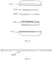
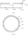
- the protective casecan be constructed of a rigid material of the following compositions metal, TP, TPE, fiber reinforced composite, ceramic, or combination of such materials;
- the protective caseis composed of an upper half ( 2 A- 100 , 2 B- 100 ) and a lower half ( 2 A- 200 , 2 B- 200 ), that when mated together form an enclosure ( 2 A, 2 B) that is substantially sealed that can provide insulation to the enclosed auto-injector and may be watertight/water-resistant;
- the upper half ( 2 A- 100 , 2 B- 100 ) and the lower half ( 2 A- 200 , 2 B- 200 ) of the protective case ( 2 A, 2 B)are composed of a rigid inner and outer wall ( 2 A- 103 , 2 A- 104 , 2 A- 203 , 2 A- 204 , 2 B- 103 , 2 B- 203 ) that form the sealed
- the casemay be composed of two sealed vacuum chambers ( 2 A- 101 , 2 A- 201 , 2 B- 101 , 2 B- 201 ) of proportional or nonproportional size.
- the vacuum sealed chamberis composed of two parts ( 2 A- 103 , 2 A- 104 , 2 A- 203 , and 2 A- 204 ).
- connection between the upper and lower halvesmay be a threaded connection, a frictional interference fit ( 2 A- 102 , 2 A- 202 , 2 B- 102 , 2 B- 202 ), or any other variation that may provide a sealed connection.
- the joint between the two halvesmay provide a watertight/water-resistant connection and in certain embodiments may utilize a gasket. Furthermore, the watertight/water-resistant connection may be facilitated through the addition of a coating or separate material applied at the joint interface.
- the joint between the upper half ( 2 A- 100 , 2 B- 100 ) and the lower half ( 2 A- 200 , 2 B- 200 )may be facilitated by the thermal barrier ( 2 A- 300 , 2 A- 400 , 2 B- 300 , 2 B- 400 ) affixed to the interior of the housing.
- the thermal barriermay be affixed to the housing ( 2 A- 105 , 2 A- 205 , 2 B- 104 , 2 B- 204 ) through an adhesive, mechanical means, or form molded ( 2 A- 301 , 2 A- 401 , 2 B- 301 , 2 B- 401 ).
- the sealed connectionmay be performed via a threaded connection on the insulation sleeve and a corresponding threaded connection on the inner top housing, such that the threads are concealed once the housings are mated together.
- the connectionmay be performed using a friction fit or interference connection ( 2 A- 302 , 2 A- 402 , 2 B- 302 , 2 B- 402 ).
- the casemay provide additional thermal insulation through a thermal barrier to aid in the insulating properties ( 2 A- 300 , 2 A- 400 , 2 B- 300 , 2 B- 400 ).
- the additional thermal barriermay consist of a TP, TPE, open or closed cell foam layer or combinations of such, which may or may not be one complete piece, but consists of multiple pieces that may interlock ( 2 A- 302 , 2 A- 402 , 2 B- 302 , 2 B- 402 ) when the two halves of the case are mated together, forming a substantially sealed barrier.
- the device enclosuremay be fined with an insulating sleeve ( 2 A- 300 , 2 A- 400 , 2 B- 300 , 2 B- 400 ) formed of one or two pieces, that interlock through stepped ledges or interference fits ( 2 A- 302 , 2 A- 402 , 2 B- 302 , 2 B- 402 ).
- the insulation barriersform a well or cradle ( 2 A- 303 , 2 A- 403 , 2 B- 303 , 2 B- 403 ) for stabilizing the device and dampen any relative motion between the device and the protective case.
- the insulation barrier and the stabilizing cradlemay be two separate components.
- the material selection for the insulation sleeve and cradlewill be such that it minimizes the thermal conductivity and maximizes the shock absorption properties.
- the thermal barrier(s)may protrude from the joint between the upper and lower halves and provide an interface for the user to separate the halves.
- the insulation barriermay also form a cavity that releasably receives at least a portion of the auto-injector device and provides access for the user to remove the device from the case.
- the insulation barrier or rigid upper or lower halvesmay provide a means of orientation ( 2 A- 304 , 2 A- 404 ) for the device to be stored and as such removed.
- certain embodimentsmay be configured to protect more than one device as well as hold dissimilar devices if deemed necessary.
- the configuration of holding multiple devicesis not limited to a horizontal or vertical layout of stacking. The configuration allows for the method of storing multiple auto-injector devices while maintaining a low-profile case.
- the internal surfaces of the vacuum sealed chambersmay be polished or lined with a reflective coating ( 2 A- 108 , 2 A- 208 , 2 B- 107 , 2 B- 207 ), or similar means to reduce the heat transfer through radiation.
- some embodimentsmay contain an exterior coating or applied layer(s) of dissimilar material or combination of the two, to increase the insulating value of the exterior wall ( 2 A- 107 , 2 A- 207 , 2 B- 106 , 2 B- 206 ).
- the exterior coating or exterior layer of dissimilar material or combinations of the two, to the exteriormay provide a texture ( 2 A- 107 , 2 A- 207 , 2 B- 106 , 2 B- 206 ) or profile to the case to assist the user in handling or gripping.
- This exterior coating or layer(s) of dissimilar material or combination of suchmay perform the following functionalities; increase the ergonomics of the case, aid in reducing the induced vibrations from external loading, assisting in case aesthetics, provide structural support, provide labeling, etc.
- embodiments of the casemay provide a power source to assist in monitoring the conditions of the internal device cavity and external environment and providing connectivity of the case with other smart devices.
- the casemay provide the user with an interface for monitoring internal device cavity and external conditions to better maintain the enclosed device.
- the casecan provide a means of physically attaching the case to other external objects.
- certain embodimentsmay include the use of a combination of rigid and elastic cases to provide a more accessible or portable means ( 3 H).
- the combination of the rigid and elastic casesmay provide a means to affix the case or combination of cases to such everyday items like a backpack, lanyard, bike, keys, etc.
- the attachment mechanismmay include a wrist strap, a wrist band, a clip, a tether, a necklace, a pin, a clamp, a mount, a tab forming an eyelet, an adhesive layer, a hand grip surface, and/or combinations thereof.
- Embodiments of a protective casemay not be required to possess thermally insulating properties ( 3 A, 3 B, 3 C, 3 D, 3 E, 3 F, 3 G, 3 H), but rather provide physical protection and a means of increased portability for an auto-injector.
- the protective casemay form a cavity ( 3 A- 100 , 3 B- 100 , 3 B- 101 , 3 C- 100 , 3 D- 100 , 3 E- 100 , 3 F- 303 , 3 F- 403 , 3 G- 201 , 3 H- 100 ) that releasably receives at least a portion of the auto-injector device.
- 98-132include but are not limited to different cases which may attach ( 3 A- 102 , 3 B- 103 , 3 C- 101 , 3 C- 103 , 3 D- 101 , 3 D- 103 , 3 E- 104 , 3 E- 105 , 3 E- 106 , 3 G- 102 , 3 H- 103 ) to everyday objects and allow for the auto-injector to be in close proximity to the user wherever they are.
- the protective casesmay provide a manner of protection by damping any incurred forces or vibrations through material selections.
- Embodiments of a non-vacuum sealed casemay be constructed of a metal, TP, TPE, fiber reinforced composite, ceramic, or combinations of similar materials.
- Certain embodimentsmay also provide a watertight/water-resistant or water-repellant enclosure ( 3 F- 101 , 3 F- 201 ) around the device and may facilitate this watertight/water-resistant seal by means of a gasket or through the addition of a coating or separate material applied at the joint interface.
- a watertight/water-resistant or water-repellant enclosure3 F- 101 , 3 F- 201 .
- Certain embodiments of a protective casemay provide a means of attaching the case to common everyday objects or similarly other protective cases ( 3 A- 102 , 3 B- 103 , 3 C- 101 , 3 C- 103 , 3 D- 101 , 3 D- 103 , 3 E- 104 , 3 E- 105 , 3 E- 106 , 3 G- 102 , 3 H- 103 ).
- the attachment mechanismsmay include but are not limited to; a strap ( 3 E- 106 ), a clip, a pin, a clamp, a mount ( 3 H- 103 ), a tab forming an eyelet ( 3 A- 102 , 3 B- 103 , 3 G- 102 ), an adhesive layer ( 3 A- 103 , 3 B- 103 ), and/or combinations thereof.
- One embodiment for the casemay contain an eyelet ( 3 A- 102 , 3 B- 103 , 3 G- 102 ) or similar geometry to provide a means of fastening the case to another object.
- the eyelet ( 3 A- 102 , 3 B- 103 , 3 G- 102 ) or similar featuremay be formed through a molded, adhered, or formed feature on the protective case.
- the casemay provide a molded or formed strap ( 3 E- 106 ) or a similar feature.
- the strap ( 3 E- 106 )may provide a means of adjustment to accommodate a desired circumference. This may be accomplished by of adjustment holes ( 3 E- 104 ), the adjustment holes may be fixed by means of a buckle ( 3 E- 105 ) or similar manner to fasten the case.
- the protective case for the auto-injectormay have an adhesive ( 3 A- 103 , 3 G- 103 ) applied to one surface for fixating the case to another object.
- one embodiment of the protective case for containing an auto-injectormay allow for the integration of a cell phone, or similar electronic device, for better adaptation and meshing with the user's daily routine (ex: 3 C- 101 , 3 C- 103 , 3 D- 101 , 3 D- 103 ) Further embodiments may be adapted to store one or more devices ( 3 B- 101 , 3 D- 100 ).
- the casemay, hold a single device or multiple devices whether similar form or not.
- the configuration of holding multiple devicesis not limited to a horizontal or vertical layout, but the best optimized method of storing the devices while maintaining as low a profile case as possible.
- Certain embodimentsmay provide a textured or contoured exterior surface ( 3 A- 105 , 3 B- 105 , 3 C- 105 , 3 D- 105 , 3 E- 103 , 3 F- 104 , 3 F- 204 , 3 G- 202 , 3 G- 105 ) by means of a coating or applying additional materials, or molded features, or a combination of such.
- the external coating or textured surfacemay be accomplished by layering materials ( 3 G).
- the exterior surface texture or contoursmay aid in increasing the ergonomics or handling of the case, or likewise in assisting the user in removing the auto-injector ( 3 G- 106 ).
- this exterior coating or layer(s) of dissimilar material or combination of suchmay perform the following functionalities; increase the ergonomics of the case, aid in reducing the induced vibrations from external loading, assisting in case aesthetics, provide structural support, provide labeling ( 3 G- 302 ), etc.
- these casesmay provide a means to be able to accommodate the auto-injector alone or incorporate other protective cases in combination as well (vacuum sealed or not) ( 3 H- 100 , 3 H- 101 , 3 H- 104 , 3 H- 105 ).
- Embodiments of certain protective casesmay present themselves with a feature to allow for the mounting and joining to other cases. Adjustments for securing various sized auto-injectors and cases may be accomplished through, but not limited to, clips straps ( 3 E- 106 ), molded features ( 33 - 106 , 3 H- 103 ), or other suitable means which can securely fasten one to the other.
- Certain embodiments of the casemay provide a power source to assist n monitoring the conditions of the case both internal and external as well as the connectivity of the case with other smart devices.
- the casemay provide the user with an interface for monitoring internal and external conditions to better maintain the enclosed device.
- each numerical value presented hereinis contemplated to represent a minimum value or a maximum value in a range for a corresponding parameter. Accordingly, when added to the claims, the numerical value provides express support for claiming the range, which may lie above or below the numerical value, in accordance with the teachings herein. Every value between the minimum value and the maximum value within each numerical range presented herein (including in the charts shown in the figures), is contemplated and expressly supported herein, subject to the number of significant digits expressed in each particular range. Absent express inclusion in the claims, each numerical value presented herein is not to be considered limiting in any regard.
Landscapes
- Health & Medical Sciences (AREA)
- Engineering & Computer Science (AREA)
- Public Health (AREA)
- Veterinary Medicine (AREA)
- Biomedical Technology (AREA)
- Heart & Thoracic Surgery (AREA)
- Hematology (AREA)
- Life Sciences & Earth Sciences (AREA)
- Animal Behavior & Ethology (AREA)
- General Health & Medical Sciences (AREA)
- Vascular Medicine (AREA)
- Anesthesiology (AREA)
- Diabetes (AREA)
- Physics & Mathematics (AREA)
- Thermal Sciences (AREA)
- Food Science & Technology (AREA)
- Dermatology (AREA)
- Purses, Travelling Bags, Baskets, Or Suitcases (AREA)
- Infusion, Injection, And Reservoir Apparatuses (AREA)
- Thermotherapy And Cooling Therapy Devices (AREA)
Abstract
Description
- Proposed herein is a protective case adapted for both low and high aspect ratio auto-injectors. As depicted in
FIG. 1 , the aspect ratio is calculated by dividing the width by the height. The width of the device is measured as the smallest straight-line length on the injection surface of the device that is in contact with a patient's skin during injection (parallel to the injection surface). The height is defined as the largest straight-line length of the device away from the skin during injection (perpendicular to the injection surface). As used herein, the term “low aspect ratio” refers to an aspect ratio in which width/height is less than or equal to 1 and the term “high aspect ratio” refers to an aspect ratio in which width/height is greater than 1. With reference toFIG. 1 , a few example Aspect Ratio calculations are provided. For the Pen Form Factor, the width is 0.5 inches and the height is 6 inches; therefore, the aspect ratio is 0.5/6=0.083. For the Rectangular Form Factor, the width is 2 inches and the height is 3 inches; therefore, the aspect ratio is 2/3=0.67. For the Disc Form Factor, the width is 2 inches and the height is 0.5 inches; therefore, the aspect ratio is 2/0.5=4. See the ranges for the low and high aspect ratios in the parameter table shown inFIG. 133 .
- Proposed herein is a protective case adapted for both low and high aspect ratio auto-injectors. As depicted in
- Embodiments of the protective case may contain a housing which receives the auto-injector (3A-100,3B-100,3B-101,3C-100,3D-100,3E-100,3F-303,3F-403,3G-201,3H-100) and may stabilize the auto-injector by means of a feature molded or formed into the housing (ex: a ridge, lip, etc.) (3A-101,3B-102,3C-102,3D-102,3E-101,3G-101,3H-100). The ridge maintains constant communication between the device and the housing at all times until removed for use. Furthermore, the geometry of the housing may be such that once the device is disposed within, the housing is placed under a state of stress and as such maintains constant communication with the device (3C-104). The housing may or may not enclose all sides of the auto-injector (3A-106,3B-106,3C-106,3D-104,3E-102,3F-303,3F-403,3G-201,3H-100) whilst providing a means to easily and rapidly remove in times of need (3G-106). In addition, the ridge, lip, etc. (3H-104), of the housing ensures that any external vibrations will not allow the auto-injector to become separated from the housing (3A-100,3B-100,3B-101,3C-100,3D-100,3E-100,3F-303,3F-403,3G-201,3H-100). One embodiment (3G) may contain multiple materials to provide a layering effect to protect and conceal the device. In certain embodiments the housing may provide a means of orienting the device during storage using molded or formed shoulders or other similar features. In certain embodiments the housing may also be adjustable to accommodate different sized auto-injectors (3H).
- Additionally, embodiments of the case may provide a way of moving the auto-injector relative to the point of fixation (3H-103). This relative movement may be facilitated by but not limited to a ball joint and receiver (3H-102). The ability to move the auto-injector relative to the fixation point may allow the user better access and improved ergonomics for handling and accessibility.
| REFERENCE | ||
| NUMERAL | NAME | DESCRIPTION |
| 1A | VACUUM CASE (W/EXTERNAL GRIP | COMPLETE PART |
| SURFACE) | ||
| 1A-100 | TOP GRIP SURFACE | COMPLETE PART |
| 1A-101 | TOP GRIP SURFACE | USER INTERFACE (FINGER SCALLOPS) |
| 1A-102 | TOP GRIP SURFACE | LABEL (EMBOSSED WRITING) |
| 1A-103 | TOP GRIP SURFACE | SEALING EDGE |
| 1A-104 | TOP GRIP SURFACE | EXTERNAL ATTACHMENT |
| MECHANISM | ||
| 1A-200 | BOTTOM GRIP SURFACE | COMPLETE PART |
| 1A-201 | BOTTOM GRIP SURFACE | USER INTERFACE (FINGER SCALLOPS) |
| 1A-202 | BOTTOM GRIP SURFACE | IOT INTERFACE AND POWER SOURCE |
| HOUSING/CAVITY | ||
| 1A-203 | BOTTOM GRIP SURFACE | SEALING EDGE |
| 1A-300 | BOTTOM HALF OF ENCLOSURE/CASE | COMPLETE PART |
| 1A-301 | BOTTOM HALF OF ENCLOSURE/CASE | SEALED VACUUM CHAMBER |
| 1A-302 | BOTTOM HALF OF ENCLOSURE/CASE | THREADED CONNECTION |
| 1A-303 | BOTTOM HALF OF ENCLOSURE/CASE | WATER-RESISTANT COATING ON |
| SEALING INTERFACE | ||
| 1A-304 | BOTTOM HALF OF ENCLOSURE/CASE | SCALLOPS FOR DEVICE REMOVAL |
| 1A-305 | BOTTOM HALF OF ENCLOSURE/CASE | RIGID HOUSING FOR FORMING THE |
| VACUUM CHAMBER | ||
| 1A-306 | BOTTOM HALF OF ENCLOSURE/CASE | INTERFACE BETWEEN INSULATION |
| BARRIER AND BOTTOM HOUSING | ||
| 1A-307 | BOTTOM HALF OF ENCLOSURE/CASE | SEALING EDGE |
| 1A-308 | BOTTOM HALF OF ENCLOSURE/CASE | POLISHED SURFACE OR REFLECTIVE |
| COATED SURFACE INSIDE VACUUM | ||
| CHAMBER | ||
| 1A-400 | TOP HALF OF ENCLOSURE/CASE | COMPLETE PART |
| 1A-401 | TOP HALF OF ENCLOSURE/CASE | SEALED VACUUM CHAMBER |
| 1A-402 | TOP HALF OF ENCLOSURE/CASE | THREADED CONNECTION |
| 1A-403 | TOP HALF OF ENCLOSURE/CASE | WATER-RESISTANT COATING ON |
| SEALING INTERFACE | ||
| 1A-404 | TOP HALF OF ENCLOSURE/CASE | RIGID HOUSING FOR FORMING THE |
| VACUUM CHAMBER | ||
| 1A-405 | TOP HALF OF ENCLOSURE/CASE | INTERFACE BETWEEN INSULATION |
| BARRIER AND TOP HOUSING | ||
| 1A-406 | TOP HALF OF ENCLOSURE/CASE | SEALING EDGE |
| 1A-407 | TOP HALF OF ENCLOSURE/CASE | POLISHED SURFACE OR REFLECTIVE |
| COATED SURFACE INSIDE VACUUM | ||
| CHAMBER | ||
| 1A-500 | TOP INSULATION BARRIER | COMPLETE PART |
| 1A-501 | TOP INSULATION BARRIER | INTERFACE BETWEEN INSULATION |
| BARRIER AND TOP HOUSING | ||
| 1A-502 | TOP INSULATION BARRIER | STABILIZING SHOULDER FOR FIXING |
| DEVICE | ||
| 1A-503 | TOP INSULATION BARRIER | SEALING INTERFACE WITH |
| COORESPONDING INSULATION | ||
| BARRIER | ||
| 1A-600 | BOTTOM INSULATION BARRIER | COMPLETE PART |
| 1A-601 | BOTTOM INSULATION BARRIER | INTERFACE BETWEEN INSULATION |
| BARRIER AND BOTTOM HOUSING | ||
| 1A-602 | BOTTOM INSULATION BARRIER | STABILIZING SHOULDER FOR FIXING |
| DEVICE | ||
| 1A-603 | BOTTOM INSULATION BARRIER | SEALING INTERFACE WITH |
| COORESPONDING INSULATION | ||
| BARRIER | ||
| 1A-700 | ELECTRONIC DISPLAY & POWER | DISPLAY SCREEN AND USER |
| SOURCE | INTERFACE | |
| 1A-701 | ELECTRONIC DISPLAY & POWER | POWER SOURCE |
| SOURCE | ||
| 1B | VACUUM CASE (WITH GASKET & | COMPLETE PART |
| THREADS ON INSULATION BARRIER) | ||
| 1B-100 | TOP HALF OF ENCLOSURE/CASE | COMPLETE PART |
| 1B-101 | TOP HALF OF ENCLOSURE/CASE | SEALED VACUUM CHAMBER |
| 1B-102 | TOP HALF OF ENCLOSURE/CASE | THREADED CONNECTION |
| 1B-103 | TOP HALF OF ENCLOSURE/CASE | RIGID HOUSING FOR FORMING THE |
| VACUUM CHAMBER | ||
| 1B-104 | TOP HALF OF ENCLOSURE/CASE | INTERFACE BETWEEN INSULATION |
| BARRIER AND TOP HOUSING | ||
| 1B-105 | TOP HALF OF ENCLOSURE/CASE | SEALING EDGE |
| 1B-106 | TOP HALF OF ENCLOSURE/CASE | EXTERIOR TEXTURED OR COATED |
| SURFACE | ||
| 1B-107 | TOP HALF OF ENCLOSURE/CASE | POLISHED SURFACE OR REFLECTIVE |
| COATED SURFACE INSIDE VACUUM | ||
| CHAMBER | ||
| 1B-200 | BOTTOM HALF OF ENCLOSURE/CASE | COMPLETE PART |
| 1B-201 | BOTTOM HALF OF ENCLOSURE/CASE | SEALED VACUUM CHAMBER |
| 1B-202 | BOTTOM HALF OF ENCLOSURE/CASE | RIGID HOUSING FOR FORMING THE |
| VACUUM CHAMBER | ||
| 1B-203 | BOTTOM HALF OF ENCLOSURE/CASE | INTERFACE BETWEEN INSULATION |
| BARRIER AND BOTTOM HOUSING | ||
| 1B-204 | BOTTOM HALF OF ENCLOSURE/CASE | SEALING EDGE |
| 1B-205 | BOTTOM HALF OF ENCLOSURE/CASE | EXTERIOR TEXTURED OR COATED |
| SURFACE | ||
| 1B-206 | BOTTOM HALF OF ENCLOSURE/CASE | POLISHED SURFACE OR REFLECTIVE |
| COATED SURFACE INSIDE VACUUM | ||
| CHAMBER | ||
| 1B-300 | GASKET FOR WATERTIGHT/WATER- | COMPLETE PART |
| RESISTANT SEAL | ||
| 1B-400 | TOP INSULATION BARRIER | COMPLETE PART |
| 1B-401 | TOP INSULATION BARRIER | INTERFACE BETWEEN INSULATION |
| BARRIER AND TOP HOUSING | ||
| 1B-402 | TOP INSULATION BARRIER | SEALING INTERFACE WITH |
| COORESPONDING INSULATION | ||
| BARRIER | ||
| 1B-403 | TOP INSULATION BARRIER | DEVICE CONTACT SURFACE |
| 1B-500 | BOTTOM INSULATION BARRIER | COMPLETE PART |
| 1B-501 | BOTTOM INSULATION BARRIER | INTERFACE BETWEEN INSULATION |
| BARRIER AND BOTTOM HOUSING | ||
| 1B-502 | BOTTOM INSULATION BARRIER | SEALING INTERFACE WITH |
| COORESPONDING INSULATION | ||
| BARRIER | ||
| 1B-503 | BOTTOM INSULATION BARRIER | THREADED CONNECTION |
| 1B-504 | BOTTOM INSULATION BARRIER | SCALLOPS FOR DEVICE REMOVAL |
| 1B-505 | BOTTOM INSULATION BARRIER | DEVICE CONTACT SURFACE |
| 1C | VACUUM CASE (W/SEPARATE | COMPLETE PART |
| DAMPING COMPONENT FOR DEVICE | ||
| CRADLE) | ||
| 1C-100 | TOP HALF OF ENCLOSURE/CASE | COMPLETE PART |
| 1C-101 | TOP HALF OF ENCLOSURE/CASE | SEALED VACUUM CHAMBER |
| 1C-102 | TOP HALF OF ENCLOSURE/CASE | FRICTION/INTERFERENCE |
| CONNECTION FOR BOTTOM HALF OF | ||
| ENCLOSURE/CASE | ||
| 1C-103 | TOP HALF OF ENCLOSURE/CASE | RIGID HOUSING #1 FOR FORMING |
| THE VACUUM CHAMBER | ||
| 1C-104 | TOP HALF OF ENCLOSURE/CASE | RIGID HOUSING #2 FOR FORMING |
| THE VACUUM CHAMBER | ||
| 1C-105 | TOP HALF OF ENCLOSURE/CASE | INTERFACE BETWEEN INSULATION |
| BARRIER/STABILIZER AND TOP | ||
| HOUSING | ||
| 1C-106 | TOP HALF OF ENCLOSURE/CASE | SEALING EDGE |
| 1C-107 | TOP HALF OF ENCLOSURE/CASE | EXTERIOR TEXTURED OR COATED |
| SURFACE | ||
| 1C-108 | TOP HALF OF ENCLOSURE/CASE | POLISHED SURFACE OR REFLECTIVE |
| COATED SURFACE INSIDE VACUUM | ||
| CHAMBER | ||
| 1C-200 | BOTTOM HALF OF ENCLOSURE/CASE | COMPLETE PART |
| 1C-201 | BOTTOM HALF OF ENCLOSURE/CASE | SEALED VACUUM CHAMBER |
| 1C-202 | BOTTOM HALF OF ENCLOSURE/CASE | FRICTION/INTERFERENCE |
| CONNECTION FOR TOP HALF OF | ||
| ENCLOSURE/CASE | ||
| 1C-203 | BOTTOM HALF OF ENCLOSURE/CASE | RIGID HOUSING #1 FOR FORMING |
| THE VACUUM CHAMBER | ||
| 1C-204 | BOTTOM HALF OF ENCLOSURE/CASE | RIGID HOUSING #2 FOR FORMING |
| THE VACUUM CHAMBER | ||
| 1C-205 | BOTTOM HALF OF ENCLOSURE/CASE | INTERFACE BETWEEN INSULATION |
| BARRIER/STABILIZER AND BOTTOM | ||
| HOUSING | ||
| 1C-206 | BOTTOM HALF OF ENCLOSURE/CASE | SEALING EDGE |
| 1C-207 | BOTTOM HALF OF ENCLOSURE/CASE | EXTERIOR TEXTURED OR COATED |
| SURFACE | ||
| 1C-208 | BOTTOM HALF OF ENCLOSURE/CASE | POLISHED SURFACE OR REFLECTIVE |
| COATED SURFACE INSIDE VACUUM | ||
| CHAMBER | ||
| 1C-300 | TOP INSULATION BARRIER | COMPLETE PART |
| 1C-301 | TOP INSULATION BARRIER | INTERFACE BETWEEN INSULATION |
| BARRIER AND TOP HOUSING | ||
| 1C-302 | TOP INSULATION BARRIER | SEALING INTERFACE WITH |
| COORESPONDING INSULATION | ||
| BARRIER | ||
| 1C-400 | BOTTOM INSULATION BARRIER | COMPLETE PART |
| 1C-401 | BOTTOM INSULATION BARRIER | INTERFACE BETWEEN INSULATION |
| BARRIER AND BOTTOM HOUSING | ||
| 1C-402 | BOTTOM INSULATION BARRIER | SEALING INTERFACE WITH |
| COORESPONDING INSULATION | ||
| BARRIER | ||
| 1C-500 | STABILIZATION/SHOCK ABSORBING | COMPLETE PART |
| COMPONENT | ||
| 1C-501 | STABILIZATION/SHOCK ABSORBING | INTERFACE WITH INSULATION |
| COMPONENT | BARRIER | |
| 1C-502 | STABILIZATION/SHOCK ABSORBING | INTERFACE WITH SURFACE OF |
| COMPONENT | UPPER/LOWER HALF OF | |
| ENCLOSURE/CASE | ||
| 1C-503 | STABILIZATION/SHOCK ABSORBING | DEVICE CRADDLE |
| COMPONENT | ||
| 1D | VACUUM CASE (INSULATION BARRIER | COMPLETE PART |
| PROVIDES USER WITH INTERFACE) | ||
| 1D-100 | TOP HALF OF ENCLOSURE/CASE | COMPLETE PART |
| 1D-101 | TOP HALF OF ENCLOSURE/CASE | SEALED VACUUM CHAMBER |
| 1D-102 | TOP HALF OF ENCLOSURE/CASE | RIGID HOUSING FOR FORMING THE |
| VACUUM CHAMBER | ||
| 1D-103 | TOP HALF OF ENCLOSURE/CASE | INTERFACE BETWEEN INSULATION |
| BARRIER AND TOP HOUSING | ||
| 1D-104 | TOP HALF OF ENCLOSURE/CASE | EXTERIOR TEXTURED OR COATED |
| SURFACE | ||
| 1D-105 | TOP HALF OF ENCLOSURE/CASE | POLISHED SURFACE OR REFLECTIVE |
| COATED SURFACE INSIDE VACUUM | ||
| CHAMBER | ||
| 1D-200 | BOTTOM HALF OF ENCLOSURE/CASE | COMPLETE PART |
| 1D-201 | BOTTOM HALF OF ENCLOSURE/CASE | SEALED VACUUM CHAMBER |
| 1D-202 | BOTTOM HALF OF ENCLOSURE/CASE | RIGID HOUSING FOR FORMING THE |
| VACUUM CHAMBER | ||
| 1D-203 | BOTTOM HALF OF ENCLOSURE/CASE | INTERFACE BETWEEN INSULATION |
| BARRIER AND BOTTOM HOUSING | ||
| 1D-204 | BOTTOM HALF OF ENCLOSURE/CASE | EXTERIOR TEXTURED OR COATED |
| SURFACE | ||
| 1D-205 | BOTTOM HALF OF ENCLOSURE/CASE | POLISHED SURFACE OR REFLECTIVE |
| COATED SURFACE INSIDE VACUUM | ||
| CHAMBER | ||
| 1D-300 | TOP INSULATION BARRIER | COMPLETE PART |
| 1D-301 | TOP INSULATION BARRIER | INTERFACE BETWEEN INSULATION |
| BARRIER AND TOP HOUSING | ||
| 1D-302 | TOP INSULATION BARRIER | SEALING INTERFACE WITH |
| COORESPONDING INSULATION | ||
| BARRIER | ||
| 1D-303 | TOP INSULATION BARRIER | AUTO-INJECTOR CONTACT SURFACE |
| 1D-304 | TOP INSULATION BARRIER | EXTERIOR USER INTERFACE |
| 1D-400 | BOTTOM INSULATION BARRIER | COMPLETE PART |
| 1D-401 | BOTTOM INSULATION BARRIER | INTERFACE BETWEEN INSULATION |
| BARRIER AND BOTTOM HOUSING | ||
| 1D-402 | BOTTOM INSULATION BARRIER | SEALING INTERFACE WITH |
| COORESPONDING INSULATION | ||
| BARRIER | ||
| 1D-403 | BOTTOM INSULATION BARRIER | AUTO-INJECTOR CONTACT SURFACE |
| 1D-404 | BOTTOM INSULATION BARRIER | EXTERIOR USER INTERFACE |
| 1E | VACUUM CASE (FOR HOLDING | COMPLETE PART |
| MULTIPLE AUTO-INJECTORS) | ||
| 1E-100 | TOP HALF OF ENCLOSURE/CASE | COMPLETE PART |
| 1E-101 | TOP HALF OF ENCLOSURE/CASE | SEALED VACUUM CHAMBER |
| 1E-102 | TOP HALF OF ENCLOSURE/CASE | RIGID HOUSING FOR FORMING THE |
| VACUUM CHAMBER | ||
| 1E-103 | TOP HALF OF ENCLOSURE/CASE | INTERFACE BETWEEN INSULATION |
| BARRIER AND TOP HOUSING | ||
| 1E-104 | TOP HALF OF ENCLOSURE/CASE | EXTERIOR TEXTURED OR COATED |
| SURFACE | ||
| 1E-105 | TOP HALF OF ENCLOSURE/CASE | POLISHED SURFACE OR REFLECTIVE |
| COATED SURFACE INSIDE VACUUM | ||
| CHAMBER | ||
| 1E-106 | TOP HALF OF ENCLOSURE/CASE | FRICTION/INTERFERENCE |
| CONNECTION FOR BOTTOM HALF OF | ||
| ENCLOSURE/CASE | ||
| 1E-200 | BOTTOM HALF OF ENCLOSURE/CASE | COMPLETE PART |
| 1E-201 | BOTTOM HALF OF ENCLOSURE/CASE | SEALED VACUUM CHAMBER |
| 1E-202 | BOTTOM HALF OF ENCLOSURE/CASE | RIGID HOUSING FOR FORMING THE |
| VACUUM CHAMBER | ||
| 1E-203 | BOTTOM HALF OF ENCLOSURE/CASE | INTERFACE BETWEEN INSULATION |
| BARRIER AND BOTTOM HOUSING | ||
| 1E-204 | BOTTOM HALF OF ENCLOSURE/CASE | EXTERIOR TEXTURED OR COATED |
| SURFACE | ||
| 1E-205 | BOTTOM HALF OF ENCLOSURE/CASE | POLISHED SURFACE OR REFLECTIVE |
| COATED SURFACE INSIDE VACUUM | ||
| CHAMBER | ||
| 1E-206 | BOTTOM HALF OF ENCLOSURE/CASE | FRICTION/INTERFERENCE |
| CONNECTION FOR BOTTOM HALF OF | ||
| ENCLOSURE/CASE | ||
| 1E-300 | TOP INSULATION BARRIER | COMPLETE PART |
| 1E-301 | TOP INSULATION BARRIER | INTERFACE BETWEEN INSULATION |
| BARRIER AND TOP HOUSING | ||
| 1E-302 | TOP INSULATION BARRIER | SEALING INTERFACE WITH |
| COORESPONDING INSULATION | ||
| BARRIER | ||
| 1E-303 | TOP INSULATION BARRIER | AUTO-INJECTOR CONTACT SURFACE |
| 1E-304 | TOP INSULATION BARRIER | SCALLOPS FOR DEVICE REMOVAL |
| 1E-400 | BOTTOM INSULATION BARRIER | COMPLETE PART |
| 1E-401 | BOTTOM INSULATION BARRIER | INTERFACE BETWEEN INSULATION |
| BARRIER AND BOTTOM HOUSING | ||
| 1E-402 | BOTTOM INSULATION BARRIER | SEALING INTERFACE WITH |
| COORESPONDING INSULATION | ||
| BARRIER | ||
| 1E-403 | BOTTOM INSULATION BARRIER | AUTO-INJECTOR CONTACT SURFACE |
| 1E-404 | BOTTOM INSULATION BARRIER | SCALLOPS FOR DEVICE REMOVAL |
| 2A | VACUUM CASE (AUTO-INJECTORS W/ | COMPLETE PART |
| PEN FORM FACTOR) | ||
| 2A-100 | TOP HALF OF ENCLOSURE/CASE | COMPLETE PART |
| 2A-101 | TOP HALF OF ENCLOSURE/CASE | SEALED VACUUM CHAMBER |
| 2A-102 | TOP HALF OF ENCLOSURE/CASE | FRICTION/INTERFERENCE |
| CONNECTION FOR BOTTOM HALF OF | ||
| ENCLOSURE/CASE | ||
| 2A-103 | TOP HALF OF ENCLOSURE/CASE | RIGID HOUSING #1 FOR FORMING |
| THE VACUUM CHAMBER | ||
| 2A-104 | TOP HALF OF ENCLOSURE/CASE | RIGID HOUSING #2 FOR FORMING |
| THE VACUUM CHAMBER | ||
| 2A-105 | TOP HALF OF ENCLOSURE/CASE | INTERFACE BETWEEN INSULATION |
| BARRIER AND TOP HOUSING | ||
| 2A-106 | TOP HALF OF ENCLOSURE/CASE | SEALING EDGE |
| 2A-107 | TOP HALF OF ENCLOSURE/CASE | EXTERIOR TEXTURED OR COATED |
| SURFACE | ||
| 2A-108 | TOP HALF OF ENCLOSURE/CASE | POLISHED SURFACE OR REFLECTIVE |
| COATED SURFACE INSIDE VACUUM | ||
| CHAMBER | ||
| 2A-200 | BOTTOM HALF OF ENCLOSURE/CASE | COMPLETE PART |
| 2A-201 | BOTTOM HALF OF ENCLOSURE/CASE | SEALED VACUUM CHAMBER |
| 2A-202 | BOTTOM HALF OF ENCLOSURE/CASE | FRICTION/INTERFERENCE |
| CONNECTION FOR BOTTOM HALF OF | ||
| ENCLOSURE/CASE | ||
| 2A-203 | BOTTOM HALF OF ENCLOSURE/CASE | RIGID HOUSING #1 FOR FORMING |
| THE VACUUM CHAMBER | ||
| 2A-204 | BOTTOM HALF OF ENCLOSURE/CASE | RIGID HOUSING #2 FOR FORMING |
| THE VACUUM CHAMBER | ||
| 2A-205 | BOTTOM HALF OF ENCLOSURE/CASE | INTERFACE BETWEEN INSULATION |
| BARRIER AND BOTTOM HOUSING | ||
| 2A-206 | BOTTOM HALF OF ENCLOSURE/CASE | SEALING EDGE |
| 2A-207 | BOTTOM HALF OF ENCLOSURE/CASE | EXTERIOR TEXTURED OR COATED |
| SURFACE | ||
| 2A-208 | BOTTOM HALF OF ENCLOSURE/CASE | POLISHED SURFACE OR REFLECTIVE |
| COATED SURFACE INSIDE VACUUM | ||
| CHAMBER | ||
| 2A-300 | TOP INSULATION BARRIER | COMPLETE PART |
| 2A-301 | TOP INSULATION BARRIER | INTERFACE BETWEEN INSULATION |
| BARRIER AND TOP HOUSING | ||
| 2A-302 | TOP INSULATION BARRIER | SEALING INTERFACE WITH |
| COORESPONDING INSULATION | ||
| BARRIER | ||
| 2A-303 | TOP INSULATION BARRIER | AUTO-INJECTOR CONTACT SURFACE |
| 2A-304 | TOP INSULATION BARRIER | AUTO-INJECTOR ORIENTATION CUT- |
| OUT | ||
| 2A-400 | BOTTOM INSULATION BARRIER | COMPLETE PART |
| 2A-401 | BOTTOM INSULATION BARRIER | INTERFACE BETWEEN INSULATION |
| BARRIER AND BOTTOM HOUSING | ||
| 2A-402 | BOTTOM INSULATION BARRIER | SEALING INTERFACE WITH |
| COORESPONDING INSULATION | ||
| BARRIER | ||
| 2A-403 | BOTTOM INSULATION BARRIER | AUTO-INJECTOR CONTACT SURFACE |
| 2A-404 | BOTTOM INSULATION BARRIER | AUTO-INJECTOR ORIENTATION CUT- |
| OUT | ||
| 2B | VACUUM CASE (AUTO-INJECTORS W/ | COMPLETE PART |
| RECTANGULAR FORM FACTOR) | ||
| 2B-100 | TOP HALF OF ENCLOSURE/CASE | COMPLETE PART |
| 2B-101 | TOP HALF OF ENCLOSURE/CASE | SEALED VACUUM CHAMBER |
| 2B-102 | TOP HALF OF ENCLOSURE/CASE | FRICTION/INTERFERENCE |
| CONNECTION FOR BOTTOM HALF OF | ||
| ENCLOSURE/CASE | ||
| 2B-103 | TOP HALF OF ENCLOSURE/CASE | RIGID HOUSING FOR FORMING THE |
| VACUUM CHAMBER | ||
| 2B-104 | TOP HALF OF ENCLOSURE/CASE | INTERFACE BETWEEN INSULATION |
| BARRIER AND BOTTOM HOUSING | ||
| 2B-105 | TOP HALF OF ENCLOSURE/CASE | SEALING EDGE |
| 2B-106 | TOP HALF OF ENCLOSURE/CASE | EXTERIOR TEXTURED OR COATED |
| SURFACE | ||
| 2B-107 | TOP HALF OF ENCLOSURE/CASE | POLISHED SURFACE OR REFLECTIVE |
| COATED SURFACE INSIDE VACUUM | ||
| CHAMBER | ||
| 2B-200 | BOTTOM HALF OF ENCLOSURE/CASE | COMPLETE PART |
| 2B-201 | BOTTOM HALF OF ENCLOSURE/CASE | SEALED VACUUM CHAMBER |
| 2B-202 | BOTTOM HALF OF ENCLOSURE/CASE | FRICTION/INTERFERENCE |
| CONNECTION FOR BOTTOM HALF OF | ||
| ENCLOSURE/CASE | ||
| 2B-203 | BOTTOM HALF OF ENCLOSURE/CASE | RIGID HOUSING FOR FORMING THE |
| VACUUM CHAMBER | ||
| 2B-204 | BOTTOM HALF OF ENCLOSURE/CASE | INTERFACE BETWEEN INSULATION |
| BARRIER AND BOTTOM HOUSING | ||
| 2B-205 | BOTTOM HALF OF ENCLOSURE/CASE | SEALING EDGE |
| 2B-206 | BOTTOM HALF OF ENCLOSURE/CASE | EXTERIOR TEXTURED OR COATED |
| SURFACE | ||
| 2B-207 | BOTTOM HALF OF ENCLOSURE/CASE | POLISHED SURFACE OR REFLECTIVE |
| COATED SURFACE INSIDE VACUUM | ||
| CHAMBER | ||
| 2B-300 | TOP INSULATION BARRIER | COMPLETE PART |
| 2B-301 | TOP INSULATION BARRIER | INTERFACE BETWEEN INSULATION |
| BARRIER AND TOP HOUSING | ||
| 2B-302 | TOP INSULATION BARRIER | SEALING INTERFACE WITH |
| COORESPONDING INSULATION | ||
| BARRIER | ||
| 2B-303 | TOP INSULATION BARRIER | AUTO-INJECTOR CONTACT SURFACE |
| 2B-400 | BOTTOM INSULATION BARRIER | COMPLETE PART |
| 2B-401 | BOTTOM INSULATION BARRIER | INTERFACE BETWEEN INSULATION |
| BARRIER AND BOTTOM HOUSING | ||
| 2B-402 | BOTTOM INSULATION BARRIER | SEALING INTERFACE WITH |
| COORESPONDING INSULATION | ||
| BARRIER | ||
| 2B-403 | BOTTOM INSULATION BARRIER | AUTO-INJECTOR CONTACT SURFACE |
| 3A | TP/TPE CASE (FOR HOLDING 1 AUTO- | COMPLETE PART |
| INJECTOR WITH ATTACHMENT MEANS) | ||
| 3A-100 | TP/TPE CASE (FOR HOLDING 1 AUTO- | HOUSING |
| INJECTOR WITH ATTACHMENT MEANS) | ||
| 3A-101 | TP/TPE CASE (FOR HOLDING 1 AUTO- | LIP OR RESTRICTING FEATURE FOR |
| INJECTOR WITH ATTACHMENT MEANS) | SECURING AUTO-INJECTOR | |
| 3A-102 | TP/TPE CASE (FOR HOLDING 1 AUTO- | EXTERNAL ATTACHMENT |
| INJECTOR WITH ATTACHMENT MEANS) | MECHANISM | |
| 3A-103 | TP/TPE CASE (FOR HOLDING 1 AUTO- | BOTTOM SURFACE FOR ADDITION |
| INJECTOR WITH ATTACHMENT MEANS) | FIXATING (EX: ADHESIVE) | |
| 3A-104 | TP/TPE CASE (FOR HOLDING 1 AUTO- | PERIMETER WALL |
| INJECTOR WITH ATTACHMENT MEANS) | ||
| 3A-105 | TP/TPE CASE (FOR HOLDING 1 AUTO- | EXTERNAL SURFACE FOR |
| INJECTOR WITH ATTACHMENT MEANS) | LABELING/EMBOSING/TEXTURING/ | |
| COATING | ||
| 3A-106 | TP/TPE CASE (FOR HOLDING 1 AUTO- | AUTO-INJECTOR CONTACT SURFACE |
| INJECTOR WITH ATTACHMENT MEANS) | ||
| 3B | TP/TPE CASE (FOR HOLDING MULTIPLE | COMPLETE PART |
| AUTO-INJECTORS WITH ATTACHMENT | ||
| MEANS) | ||
| 3B-100 | TP/TPE CASE (FOR HOLDING MULTIPLE | HOUSING #1 |
| AUTO-INJECTORS WITH ATTACHMENT | ||
| MEANS) | ||
| 3B-101 | TP/TPE CASE (FOR HOLDING MULTIPLE | HOUSING #2 |
| AUTO-INJECTORS WITH ATTACHMENT | ||
| MEANS) | ||
| 3B-102 | TP/TPE CASE (FOR HOLDING MULTIPLE | LIP OR RESTRICTING FEATURE FOR |
| AUTO-INJECTORS WITH ATTACHMENT | SECURING AUTO-INJECTOR | |
| MEANS) | ||
| 3B-103 | TP/TPE CASE (FOR HOLDING MULTIPLE | EXTERNAL ATTACHMENT |
| AUTO-INJECTORS WITH ATTACHMENT | MECHANISM | |
| MEANS) | ||
| 3B-104 | TP/TPE CASE (FOR HOLDING MULTIPLE | PERIMETER WALL |
| AUTO-INJECTORS WITH ATTACHMENT | ||
| MEANS) | ||
| 3B-105 | TP/TPE CASE (FOR HOLDING MULTIPLE | EXTERNAL SURFACE FOR |
| AUTO-INJECTORS WITH ATTACHMENT | LABELING/EMBOSING/TEXTURING/ | |
| MEANS) | COATING | |
| 3B-106 | TP/TPE CASE (FOR HOLDING MULTIPLE | AUTO-INJECTOR CONTACT SURFACE |
| AUTO-INJECTORS WITH ATTACHMENT | ||
| MEANS) | ||
| 3C | TP/TPE CASE (FOR HOLDING 1 AUTO- | COMPLETE PART |
| INJECTOR ADAPTED FOR ATTACHMENT | ||
| ON A SECONDARY DEVICE EX: CELL | ||
| PHONE) | ||
| 3C-100 | TP/TPE CASE (FOR HOLDING 1 AUTO- | HOUSING FOR AUTO-INJECTOR |
| INJECTOR ADAPTED FOR ATTACHMENT | ||
| ON A CELL PHONE) | ||
| 3C-101 | TP/TPE CASE (FOR HOLDING 1 AUTO- | HOUSING FOR SECONDARY DEVICE |
| INJECTOR ADAPTED FOR ATTACHMENT | (EX: CELL PHONE) | |
| ON A CELL PHONE) | ||
| 3C-102 | TP/TPE CASE (FOR HOLDING 1 AUTO- | RESTRAINING FEATURE FOR THE |
| INJECTOR ADAPTED FOR ATTACHMENT | AUTO-INJECTOR | |
| ON A CELL PHONE) | ||
| 3C-103 | TP/TPE CASE (FOR HOLDING 1 AUTO- | RESTRAINING FEATURE FOR THE |
| INJECTOR ADAPTED FOR ATTACHMENT | SECONDARY DEVICE | |
| ON A CELL PHONE) | ||
| 3C-104 | TP/TPE CASE (FOR HOLDING 1 AUTO- | CONTACT/BRACING SURFACE FOR |
| INJECTOR ADAPTED FOR ATTACHMENT | THE AUTO-INJECTOR | |
| ON A CELL PHONE) | ||
| 3C-105 | TP/TPE CASE (FOR HOLDING 1 AUTO- | EXTERNAL SURFACE FOR |
| INJECTOR ADAPTED FOR ATTACHMENT | LABELING/EMBOSING/TEXTURING/ | |
| ON A CELL PHONE) | COATING | |
| 3C-106 | TP/TPE CASE (FOR HOLDING 1 AUTO- | HOUSING FOR LOW ASPECT RATION |
| INJECTOR ADAPTED FOR ATTACHMENT | AUTO-INJECTOR | |
| ON A CELL PHONE) | ||
| 3D | TP/TPE CASE (FOR HOLDING MULTIPLE | COMPLETE PART |
| AUTO-INJECTORS WITH ATTACHMENT | ||
| MEANS) | ||
| 3D-100 | TP/TPE CASE (FOR HOLDING MULTIPLE | HOUSING FOR AUTO-INJECTOR |
| AUTO-INJECTORS WITH ATTACHMENT | ||
| MEANS) | ||
| 3D-101 | TP/TPE CASE (FOR HOLDING MULTIPLE | HOUSING FOR SECONDARY DEVICE |
| AUTO-INJECTORS WITH ATTACHMENT | (EX: CELL PHONE) | |
| MEANS) | ||
| 3D-102 | TP/TPE CASE (FOR HOLDING MULTIPLE | RESTRAINING FEATURE FOR THE |
| AUTO-INJECTORS WITH ATTACHMENT | AUTO-INJECTOR | |
| MEANS) | ||
| 3D-103 | TP/TPE CASE (FOR HOLDING MULTIPLE | RESTRAINING FEATURE FOR THE |
| AUTO-INJECTORS WITH ATTACHMENT | SECONDARY DEVICE | |
| MEANS) | ||
| 3D-104 | TP/TPE CASE (FOR HOLDING MULTIPLE | CONTACT/BRACING SURFACE FOR |
| AUTO-INJECTORS WITH ATTACHMENT | THE AUTO-INJECTOR | |
| MEANS) | ||
| 3D-105 | TP/TPE CASE (FOR HOLDING MULTIPLE | EXTERNAL SURFACE FOR |
| AUTO-INJECTORS WITH ATTACHMENT | LABELING/EMBOSING/TEXTURING/ | |
| MEANS) | COATING | |
| 3E | TP/TPE ADJUSTABLE STRAP CASE | COMPLETE PART |
| 3E-100 | TP/TPE ADJUSTABLE STRAP CASE | HOUSING FOR AUTO-INJECTOR |
| 3E-101 | TP/TPE ADJUSTABLE STRAP CASE | RESTRAINING FEATURE FOR THE |
| AUTO-INJECTOR | ||
| 3E-102 | TP/TPE ADJUSTABLE STRAP CASE | CONTACT/BRACING SURFACE FOR |
| THE AUTO-INJECTOR | ||
| 3E-103 | TP/TPE ADJUSTABLE STRAP CASE | EXTERNAL SURFACE FOR |
| LABELING/EMBOSING/TEXTURING/ | ||
| COATING | ||
| 3E-104 | TP/TPE ADJUSTABLE STRAP CASE | ADJUSTABLE HOLES |
| 3E-105 | TP/TPE ADJUSTABLE STRAP CASE | FASTENING MECHANISM (EX: |
| BUCKEL) | ||
| 3E-106 | TP/TPE ADJUSTABLE STRAP CASE | ATTACHMENST STRAPS FOR |
| SECURING CASE | ||
| 3F | RIGID NON-VACUUM CASE WITH LINER | COMPLETE PART |
| 3F-100 | TOP HALF OF ENCLOSURE/CASE | FRICTION/INTERFERENCE/THREADED |
| CONNECTION FOR BOTTOM HALF OF | ||
| ENCLOSURE/CASE | ||
| 3F-101 | TOP HALF OF ENCLOSURE/CASE | UPPER RIGID HOUSING FOR |
| FORMING THE CASE/ENCLOSURE | ||
| 3F-102 | TOP HALF OF ENCLOSURE/CASE | INTERFACE BETWEEN |
| LINER/BARRIER AND UPPER | ||
| HOUSING | ||
| 3F-103 | TOP HALF OF ENCLOSURE/CASE | SEALING EDGE |
| 3F-104 | TOP HALF OF ENCLOSURE/CASE | EXTERIOR TEXTURED OR COATED |
| SURFACE | ||
| 3F-200 | BOTTOM HALF OF ENCLOSURE/CASE | FRICTION/INTERFERENCE/THREADED |
| CONNECTION FOR BOTTOM HALF OF | ||
| ENCLOSURE/CASE | ||
| 3F-201 | BOTTOM HALF OF ENCLOSURE/CASE | LOWER RIGID HOUSING FOR |
| FORMING THE CASE/ENCLOSURE | ||
| 3F-202 | BOTTOM HALF OF ENCLOSURE/CASE | INTERFACE BETWEEN |
| LINER/BARRIER AND BOTTOM | ||
| HOUSING | ||
| 3F-203 | BOTTOM HALF OF ENCLOSURE/CASE | SEALING EDGE |
| 3F-204 | BOTTOM HALF OF ENCLOSURE/CASE | EXTERIOR TEXTURED OR COATED |
| SURFACE | ||
| 3F-300 | UPPER LINER/BARRIER | COMPLETE PART |
| 3F-301 | UPPER LINER/BARRIER | INTERFACE BETWEEN |
| LINER/BARRIER AND TOP HOUSING | ||
| 3F-302 | UPPER LINER/BARRIER | SEALING INTERFACE WITH |
| COORESPONDING LINER/BARRIER | ||
| 3F-303 | UPPER LINER/BARRIER | AUTO-INJECTOR CONTACT SURFACE |
| 3F-304 | UPPER LINER/BARRIER | AUTO-INJECTOR ORIENTATION CUT- |
| OUT | ||
| 3F-400 | LOWER LINER/BARRIER | COMPLETE PART |
| 3F-401 | LOWER LINER/BARRIER | INTERFACE BETWEEN |
| LINER/BARRIER AND BOTTOM | ||
| HOUSING | ||
| 3F-402 | LOWER LINER/BARRIER | SEALING INTERFACE WITH |
| COORESPONDING INSULATION | ||
| BARRIER | ||
| 3F-403 | LOWER LINER/BARRIER | AUTO-INJECTOR CONTACT SURFACE |
| 3F-404 | LOWER LINER/BARRIER | AUTO-INJECTOR ORIENTATION CUT- |
| OUT | ||
| 3G | TP/TPE CASE (FOR HOLDING 1 OR | COMPLETE PART |
| MORE AUTO-INJECTORS WITH LINER) | ||
| 3G-100 | TP/TPE CASE (FOR HOLDING 1 OR | EXTERNAL HOUSING |
| MORE AUTO-INJECTORS WITH LINER) | ||
| 3G-101 | TP/TPE CASE (FOR HOLDING 1 OR | RESTRICTING FEATURE FOR |
| MORE AUTO-INJECTORS WITH LINER) | SECURING AUTO-INJECTOR AND | |
| INNER LINER | ||
| 3G-102 | TP/TPE CASE (FOR HOLDING 1 OR | EXTERNAL ATTACHMENT |
| MORE AUTO-INJECTORS WITH LINER) | MECHANISM | |
| 3G-103 | TP/TPE CASE (FOR HOLDING 1 OR | BOTTOM SURFACE FOR ADDITION |
| MORE AUTO-INJECTORS WITH LINER) | FIXATING (EX: ADHESIVE) | |
| 3G-104 | TP/TPE CASE (FOR HOLDING 1 OR | PERIMETER WALL |
| MORE AUTO-INJECTORS WITH LINER) | ||
| 3G-105 | TP/TPE CASE (FOR HOLDING 1 OR | EXTERNAL SURFACE FOR |
| MORE AUTO-INJECTORS WITH LINER) | LABELING/EMBOSING/TEXTURING/ | |
| COATING | ||
| 3G-106 | TP/TPE CASE (FOR HOLDING 1 OR | FEATURE FOR AUTO-INJECTOR EASE |
| MORE AUTO-INJECTORS WITH LINER) | OF REMOVAL | |
| 3G-107 | TP/TPE CASE (FOR HOLDING 1 OR | CUT-OUT(S) FOR LINER |
| MORE AUTO-INJECTORS WITH LINER) | LABEL/EMBOSS/FEATURE | |
| 3G-200 | TP/TPE CASE (FOR HOLDING 1 OR | COMPLETE PART |
| MORE AUTO-INJECTORS WITH LINER) | ||
| 3G-201 | TP/TPE CASE (FOR HOLDING 1 OR | HOUSING FOR AUTO-INJECTOR |
| MORE AUTO-INJECTORS WITH LINER) | ||
| 3G-202 | TP/TPE CASE (FOR HOLDING 1 OR | SURFACE FOR |
| MORE AUTO-INJECTORS WITH LINER) | LABELING/EMBOSING/TEXTURING/ | |
| COATING | ||
| 3G-203 | TP/TPE CASE (FOR HOLDING 1 OR | INTERFACE SURFACE WITH |
| MORE AUTO-INJECTORS WITH LINER) | EXTERNAL SURFACE | |
| 3H | ADJUSTABLE PROTECTIVE CASE | COMPLETE PART |
| 3H-100 | ADJUSTABLE PROTECTIVE CASE | ADJUSTABLE FEATURE FOR HOLDING |
| AUTO-INJECTOR OR ADDITIONAL | ||
| PROTECTIVE CASE | ||
| 3H-101 | ADJUSTABLE PROTECTIVE CASE | RESTRICTING/SECURING FEATURE |
| 3H-102 | ADJUSTABLE PROTECTIVE CASE | AUTO-INJECTOR POSITION |
| ADJUSTMENT FEATURE (EX: BALL | ||
| JOINT) | ||
| 3H-103 | ADJUSTABLE PROTECTIVE CASE | EXTERNAL MOUNTING FEATURE |
| 3H-104 | ADJUSTABLE PROTECTIVE CASE | INTERFACE BETWEEN AUTO- |
| INJECTOR/CASE AND | ||
| SECURING/RESTRICTING FEATURE | ||
| 3H-105 | ADJUSTABLE PROTECTIVE CASE | SUPPORT FEATURE FOR HOLDING |
| AUTO-INJECTOR | ||
Claims (27)
Priority Applications (2)
| Application Number | Priority Date | Filing Date | Title |
|---|---|---|---|
| US16/567,656US11324882B2 (en) | 2017-10-05 | 2019-09-11 | Protective case for an auto-injector |
| US17/715,317US20220296808A1 (en) | 2017-10-05 | 2022-04-07 | Protective case for an auto-injector |
Applications Claiming Priority (4)
| Application Number | Priority Date | Filing Date | Title |
|---|---|---|---|
| US201762568567P | 2017-10-05 | 2017-10-05 | |
| US201762574405P | 2017-10-19 | 2017-10-19 | |
| US16/152,934US10441714B2 (en) | 2017-10-05 | 2018-10-05 | Protective case for an auto-injector |
| US16/567,656US11324882B2 (en) | 2017-10-05 | 2019-09-11 | Protective case for an auto-injector |
Related Parent Applications (1)
| Application Number | Title | Priority Date | Filing Date |
|---|---|---|---|
| US16/152,934DivisionUS10441714B2 (en) | 2017-10-05 | 2018-10-05 | Protective case for an auto-injector |
Related Child Applications (1)
| Application Number | Title | Priority Date | Filing Date |
|---|---|---|---|
| US17/715,317ContinuationUS20220296808A1 (en) | 2017-10-05 | 2022-04-07 | Protective case for an auto-injector |
Publications (2)
| Publication Number | Publication Date |
|---|---|
| US20200016330A1 US20200016330A1 (en) | 2020-01-16 |
| US11324882B2true US11324882B2 (en) | 2022-05-10 |
Family
ID=64110031
Family Applications (3)
| Application Number | Title | Priority Date | Filing Date |
|---|---|---|---|
| US16/152,934ActiveUS10441714B2 (en) | 2017-10-05 | 2018-10-05 | Protective case for an auto-injector |
| US16/567,656ActiveUS11324882B2 (en) | 2017-10-05 | 2019-09-11 | Protective case for an auto-injector |
| US17/715,317PendingUS20220296808A1 (en) | 2017-10-05 | 2022-04-07 | Protective case for an auto-injector |
Family Applications Before (1)
| Application Number | Title | Priority Date | Filing Date |
|---|---|---|---|
| US16/152,934ActiveUS10441714B2 (en) | 2017-10-05 | 2018-10-05 | Protective case for an auto-injector |
Family Applications After (1)
| Application Number | Title | Priority Date | Filing Date |
|---|---|---|---|
| US17/715,317PendingUS20220296808A1 (en) | 2017-10-05 | 2022-04-07 | Protective case for an auto-injector |
Country Status (2)
| Country | Link |
|---|---|
| US (3) | US10441714B2 (en) |
| WO (1) | WO2019071129A1 (en) |
Families Citing this family (5)
| Publication number | Priority date | Publication date | Assignee | Title |
|---|---|---|---|---|
| EP1762259B2 (en) | 2005-09-12 | 2025-01-01 | Unomedical A/S | Inserter for an infusion set with a first and second spring units |
| WO2012123274A1 (en) | 2011-03-14 | 2012-09-20 | Unomedical A/S | Inserter system with transport protection |
| CA2952167C (en) | 2014-06-13 | 2023-06-13 | Aterica Inc. | System and device for management of medication delivery devices |
| US20200376199A1 (en)* | 2018-03-22 | 2020-12-03 | Daniel Harris Orol | Auto-injection device |
| US11458292B2 (en) | 2019-05-20 | 2022-10-04 | Unomedical A/S | Rotatable infusion device and methods thereof |
Citations (119)
| Publication number | Priority date | Publication date | Assignee | Title |
|---|---|---|---|---|
| US1560375A (en) | 1924-09-23 | 1925-11-03 | Blackman Arthur Edward | Temperature-maintaining vessel |
| US3074541A (en) | 1959-10-13 | 1963-01-22 | Brunswick Corp | Medicinal vial and needle assembly |
| US3193126A (en) | 1962-10-25 | 1965-07-06 | Aladdin Ind Inc | Vacuum bottle having filler with closure mounting ring cemented thereto |
| US4287943A (en) | 1978-07-05 | 1981-09-08 | Shimano Industrial Company, Limited | Heat insulating box |
| US4429793A (en) | 1982-05-13 | 1984-02-07 | Ehmann Corporation | Diabetic traveling case |
| US4573581A (en) | 1983-07-18 | 1986-03-04 | Network Medical Containers Pty, Ltd. | Environmentally controlled medication container |
| US4738364A (en) | 1987-03-24 | 1988-04-19 | Medicool, Inc. | Portable medicine protector |
| US4767039A (en)* | 1984-11-09 | 1988-08-30 | Jacober Jeffrey M | Backpack and insulated container |
| US4898582A (en)* | 1988-08-09 | 1990-02-06 | Pharmetrix Corporation | Portable infusion device assembly |
| US5015235A (en) | 1987-02-20 | 1991-05-14 | National Carpet Equipment, Inc. | Syringe needle combination |
| US5361603A (en) | 1992-05-22 | 1994-11-08 | Merritt Munson Carolann | Insulative carrying case |
| US5390791A (en) | 1993-10-18 | 1995-02-21 | Medicool, Inc. | Temperature controlled medecine carrier |
| US5405012A (en) | 1993-10-13 | 1995-04-11 | Purisys Inc. | Insulated container for transporting temperature sensitive analytical samples |
| US5658259A (en) | 1995-10-19 | 1997-08-19 | Meridian Medical Technologies, Inc. | Dental cartridge assembly auto-injector with protective needle cover |
| WO1997039787A1 (en) | 1996-04-24 | 1997-10-30 | Novo Nordisk A/S | Injection needle |
| US5714217A (en) | 1993-02-17 | 1998-02-03 | E. Khashoggi Industries | Sealable liquid-tight containers comprised of coated hydraulically settable materials |
| US5785688A (en)* | 1996-05-07 | 1998-07-28 | Ceramatec, Inc. | Fluid delivery apparatus and method |
| US5858001A (en) | 1995-12-11 | 1999-01-12 | Elan Medical Technologies Limited | Cartridge-based drug delivery device |
| US5860957A (en)* | 1997-02-07 | 1999-01-19 | Sarcos, Inc. | Multipathway electronically-controlled drug delivery system |
| US5921962A (en)* | 1995-10-11 | 1999-07-13 | Science Incorporated | Fluid delivery device with flow indicator and rate control |
| US5950827A (en) | 1998-10-08 | 1999-09-14 | Odom; Jeffrey L. | Injector pen storage case |
| US5957895A (en)* | 1998-02-20 | 1999-09-28 | Becton Dickinson And Company | Low-profile automatic injection device with self-emptying reservoir |
| US5983661A (en) | 1997-11-28 | 1999-11-16 | Wiesman; Jon P. | Container arrangement and method for transporting equine semen |
| US5997501A (en)* | 1993-11-18 | 1999-12-07 | Elan Corporation, Plc | Intradermal drug delivery device |
| US6086562A (en) | 1997-10-27 | 2000-07-11 | Sarcos, Inc. | Disposable automatic injection device |
| US6336340B1 (en) | 1998-08-31 | 2002-01-08 | Ralph Henry Laby | Storage container for storage of temperature sensitive materials during transport |
| US20020022798A1 (en)* | 2000-08-18 | 2002-02-21 | Connelly Robert I. | Constant rate fluid delivery device with selectable flow rate and titratable bolus button |
| US6405556B1 (en) | 2000-10-27 | 2002-06-18 | Frederick S. Bucholz | Insulated container |
| US20020091357A1 (en) | 2000-10-13 | 2002-07-11 | Trautman Joseph C. | Microprotrusion member retainer for impact applicator |
| US20020139708A1 (en)* | 2001-03-29 | 2002-10-03 | Kj Innovations Llc | Accessable medicinal dosage carrier |
| DE19725203C2 (en) | 1997-06-14 | 2002-10-10 | Sanacorp Pharmahandel Ag | Cooler |
| US6508391B2 (en) | 2001-05-02 | 2003-01-21 | Patricia A. Gilbert | Medical storage pouch |
| US6530900B1 (en)* | 1997-05-06 | 2003-03-11 | Elan Pharma International Limited | Drug delivery device |
| US6595362B2 (en) | 2000-05-12 | 2003-07-22 | Lindon Products Inc. | Cases for medication delivery devices |
| US6605067B1 (en) | 1998-11-20 | 2003-08-12 | Novo Nordisk A/S | Injection needle |
| US6699234B2 (en)* | 2001-03-16 | 2004-03-02 | Show-Way Yeh | Light, thin, and flexible medication infusion apparatuses attachable to user's skin |
| US20040116866A1 (en)* | 2002-12-17 | 2004-06-17 | William Gorman | Skin attachment apparatus and method for patient infusion device |
| US6781522B2 (en)* | 2001-08-22 | 2004-08-24 | Kivalo, Inc. | Portable storage case for housing a medical monitoring device and an associated method for communicating therewith |
| US6780426B2 (en) | 1995-07-28 | 2004-08-24 | Zars, Inc. | Method and apparatus for improved heat controlled administration of pharmaceuticals |
| US20040211806A1 (en) | 2003-04-28 | 2004-10-28 | Ardoth Wilkerson | Epinephrine (EpiPen) carrier |
| US6935133B2 (en) | 2002-11-13 | 2005-08-30 | Estelle Keeter | Temperature control case for medicines |
| US20050222539A1 (en) | 2004-03-30 | 2005-10-06 | Pediamed Pharmaceuticals, Inc. | Automatic injection device |
| US20050247558A1 (en)* | 2002-07-17 | 2005-11-10 | Anex Deon S | Electrokinetic delivery systems, devices and methods |
| US20050279664A1 (en) | 2002-11-25 | 2005-12-22 | Edgar Hommann | Device for temporarily retaining a protective needle cap of an injection apparatus |
| US6984222B1 (en) | 1996-11-12 | 2006-01-10 | Medrad, Inc. | Plunger systems |
| US7047983B2 (en) | 2002-03-27 | 2006-05-23 | Manougian Katherine J | Protected containers |
| WO2007051563A1 (en) | 2005-11-02 | 2007-05-10 | Prosthesica Ag | Implantable infusion device with advanceable and retractable needle |
| US20070125677A1 (en) | 2005-12-06 | 2007-06-07 | Neil Oronsky | Thermal and/or light protective container assemblies and their methods of use |
| US7434686B2 (en) | 2004-12-10 | 2008-10-14 | Michael Prindle | Auto-injector storage and dispensing system |
| US20080295833A1 (en) | 2007-05-16 | 2008-12-04 | Boehringer Ingelheim International Gmbh | Dispensing device |
| WO2009062510A1 (en) | 2007-11-12 | 2009-05-22 | Bang & Olufsen Medicom A/S | Auto injector with automatic needle retraction |
| US7597196B2 (en) | 2006-06-08 | 2009-10-06 | Phyllis Langone | Insulated medication carrying case |
| US7686786B2 (en) | 2004-10-21 | 2010-03-30 | Novo Nordiks A/S | Dial-down mechanism for wind-up pen |
| US20100137832A1 (en)* | 2008-11-25 | 2010-06-03 | Meridian Medical Technologies, Inc. | Auto-Injector Apparatus |
| US20100187270A1 (en) | 2009-01-26 | 2010-07-29 | Gregory Puglisi | Transportable, surface-mounting system for an auto-injection case |
| US20100270315A1 (en) | 2009-04-25 | 2010-10-28 | Davis Joanne | Portable Container For Thermally Sensitive Material |
| US20100282762A1 (en) | 2009-05-11 | 2010-11-11 | Larry Wendall Leonard | Mobile Insulin Storage Cooler (MISC) |
| WO2011012849A1 (en) | 2009-07-28 | 2011-02-03 | Ucb Pharma S.A. | Injector |
| US20110083445A1 (en) | 2009-10-08 | 2011-04-14 | Power*Otg Incorporated | Portable medical container with active temperature control |
| US20110276027A1 (en) | 2010-05-04 | 2011-11-10 | Corium International, Inc. | Applicators for microneedles |
| US8137314B2 (en) | 2006-08-23 | 2012-03-20 | Medtronic Minimed, Inc. | Infusion medium delivery device and method with compressible or curved reservoir or conduit |
| US8152771B2 (en) | 2001-09-27 | 2012-04-10 | Unomedical A/S | Injector device for placing a subcutaneous infusion set |
| WO2012058192A1 (en) | 2010-10-26 | 2012-05-03 | 7944942 Canada Inc. | Automatic medication injection device |
| US20120191102A1 (en) | 2009-09-29 | 2012-07-26 | Terumo Kabushiki Kaisha | Medicine injection device and method |
| US8298173B2 (en) | 2006-06-09 | 2012-10-30 | Bates Nigel Robert | Particle cassettes |
| US8323250B2 (en) | 2007-04-30 | 2012-12-04 | Medtronic Minimed, Inc. | Adhesive patch systems and methods |
| US20120310175A1 (en) | 2009-12-16 | 2012-12-06 | Lionel Vedrine | Self-injection device |
| US20130110046A1 (en)* | 2010-06-11 | 2013-05-02 | Britannia Pharmaceuticals Limited | Apparatus and case for infusion equipment |
| US8517988B2 (en) | 2008-12-19 | 2013-08-27 | Sanofi-Aventis Deutschland Gmbh | Motor mechanism for a drug delivery device and drug delivery device |
| WO2013147440A1 (en) | 2012-03-28 | 2013-10-03 | (주)이화프레지니우스카비 | Drug injection device |
| US20140088508A1 (en) | 2012-09-24 | 2014-03-27 | Patrick Ryan | Drug-delivery devices with integrated needle-insertion mechanism |
| US8684968B2 (en) | 2006-12-29 | 2014-04-01 | Aktivpak, Inc. | Hypodermic drug delivery reservoir and apparatus |
| US20140090997A1 (en) | 2011-05-11 | 2014-04-03 | Sanofi-Aventis Deutschland Gmbh | Needle assembly storage device |
| WO2014072993A2 (en) | 2012-11-08 | 2014-05-15 | Rathore Jai Hind | Folded- plunger auto-retractable disposable syringe |
| US20140138402A1 (en) | 2012-11-19 | 2014-05-22 | Ryan Warren | Insulated fluid dispensing system |
| US20140142507A1 (en) | 2012-05-04 | 2014-05-22 | Charles K. Armes | Electromechanical Manipulating Device for Medical Needle and Syringe with Sensory Biofeedback and Pain Suppression Capability |
| US8734396B2 (en) | 2008-10-24 | 2014-05-27 | Roche Diagnostics International Ag | Flexible medicine reservoir with an internal reservoir port |
| US8753310B2 (en) | 2004-09-10 | 2014-06-17 | Becton, Dickinson And Company | Reconstituting infusion device |
| US20140166528A1 (en) | 2011-08-10 | 2014-06-19 | Debiotech S.A. | Container for storing a drug such as insulin |
| US20140309591A1 (en) | 2011-12-15 | 2014-10-16 | Shl Group Ab | Auto-Injection Device |
| US8932254B2 (en) | 2008-09-02 | 2015-01-13 | Owen Mumford Limited | Syringe safety shields and autoinjector |
| US9072838B2 (en) | 2011-03-24 | 2015-07-07 | Shl Group Ab | Medicament delivery device |
| US9096364B2 (en) | 2012-01-30 | 2015-08-04 | Western New England University | Container for a medical device |
| US9168337B2 (en) | 2012-10-22 | 2015-10-27 | Seiko Epson Corporation | Fluid injecting apparatus |
| US9174002B2 (en) | 2004-12-30 | 2015-11-03 | Byeong S. Chang | Method for storing and delivering a drug |
| US20150314117A1 (en) | 2012-12-21 | 2015-11-05 | Hisamitsu Pharmaceutical Co., Inc. | Applicator |
| US20150343151A1 (en) | 2012-12-21 | 2015-12-03 | Novo Nordisk A/S | State Changing Appliance for a Drug Delivery Device |
| US9220837B2 (en) | 2007-03-19 | 2015-12-29 | Insuline Medical Ltd. | Method and device for drug delivery |
| US9227023B2 (en) | 2012-03-01 | 2016-01-05 | Joseph Wayne Kraft | Device for the rapid injection of local anesthesia through a pleurality of needles |
| US20160030284A1 (en) | 2014-08-04 | 2016-02-04 | Genentech, Inc. | Apparatus and methods for sealing a medicament within a medical delivery device |
| US20160038689A1 (en) | 2013-03-15 | 2016-02-11 | Amgen Inc. | Body contour adaptable autoinjector device |
| US20160082189A1 (en) | 2010-04-21 | 2016-03-24 | Abbvie Biotechnology Ltd | Wearable automatic injection device for controlled delivery of therapeutic agents |
| WO2016055505A1 (en) | 2014-10-08 | 2016-04-14 | Novo Nordisk A/S | A torsion spring for an injection device and an injection device comprising such torsion spring |
| US20160175524A1 (en) | 2012-10-18 | 2016-06-23 | Sanofi-Aventis Deutschland Gmbh | Auto-injector |
| US9381294B2 (en) | 2012-06-17 | 2016-07-05 | Ulrike H. M. Ziegner | Auto-injector case |
| US9408984B2 (en) | 2009-09-15 | 2016-08-09 | Becton, Dickinson And Company | Self-injection device |
| US20160237752A1 (en) | 2013-09-17 | 2016-08-18 | Tenax Energy Solutions, LLC | Subsurface drilling tool |
| US20160287791A1 (en) | 2013-11-15 | 2016-10-06 | Carebay Europe Ltd | Medicament Delivery Device |
| US20160296710A1 (en) | 2013-09-03 | 2016-10-13 | Sanofi | Drive assembly for a drug delivery device and drug delivery device comprising a drive assembly |
| US9480792B2 (en) | 2010-11-30 | 2016-11-01 | Becton, Dickinson And Company | Ballistic microneedle infusion device |
| US9486616B2 (en) | 2002-03-11 | 2016-11-08 | Nitto Denko Corporation | Transdermal integrated actuator device, methods of making and using same |
| US9533105B2 (en) | 2003-03-03 | 2017-01-03 | Sanofi-Aventis Deutschland Gmbh | Drive mechanisms suitable for use in drug delivery devices |
| US20170056579A1 (en) | 2014-05-14 | 2017-03-02 | Meamedical Ag | Spindle device for a piston of a reservoir with medicament fluid |
| US9590683B2 (en) | 2014-03-03 | 2017-03-07 | Alexander N. Greiner | Medical device case |
| US9597450B2 (en) | 2003-07-22 | 2017-03-21 | Becton, Dickinson And Company | Patch-like infusion device |
| WO2017072333A1 (en) | 2015-10-28 | 2017-05-04 | Nne Pharmaplan A/S | Single-use auto-injector |
| WO2017083622A1 (en) | 2015-11-13 | 2017-05-18 | Bayer Healthcare Llc | Nested syringe assembly |
| US20170143896A1 (en) | 2007-12-27 | 2017-05-25 | Medtronic Minimed, Inc. | Reservoir pressure equalization systems and methods |
| US20170143900A1 (en) | 2015-11-25 | 2017-05-25 | Robert Rioux | Wearable medication delivery device |
| US20170175859A1 (en) | 2014-02-17 | 2017-06-22 | Novo Nordisk A/S | Telescopic Drive Arrangement with Oldham Coupling |
| WO2017118681A1 (en) | 2016-01-06 | 2017-07-13 | Sanofi-Aventis Deutschland Gmbh | Medicament container and method for producing same |
| US9707156B2 (en) | 2013-05-16 | 2017-07-18 | Sandy Wengreen | Storage systems and methods for medicines |
| US20170209643A1 (en) | 2009-09-11 | 2017-07-27 | Roche Diagnostics International Ag | Micro-fluidic chambers for use in liquid medicament delivery systems |
| US9750892B2 (en) | 2010-12-31 | 2017-09-05 | Novo Nordisk A/S | Medical injection device |
| US20170312433A1 (en)* | 2005-02-01 | 2017-11-02 | Kaleo, Inc. | Devices, systems, and methods for medicament delivery |
| US9925333B2 (en) | 2013-06-18 | 2018-03-27 | Enable Injections, Inc. | Vial transfer and injection apparatus and method |
| US20180214636A1 (en)* | 2017-02-02 | 2018-08-02 | Picolife Technologies, Llc | Smart Cartridge System For Containing And Releasing Medicament With Pumping Mechanism And Compressible Reservoir |
| US10045597B2 (en)* | 2012-03-06 | 2018-08-14 | Debbie Joanne Caruth | Medication carrying case |
| US20190060569A1 (en)* | 2017-08-30 | 2019-02-28 | Pirouette Medical LLC | Compact auto-injector |
Family Cites Families (29)
| Publication number | Priority date | Publication date | Assignee | Title |
|---|---|---|---|---|
| US5107649A (en)* | 1988-04-15 | 1992-04-28 | Midwest Research Institute | Compact vacuum insulation embodiments |
| US5371687A (en)* | 1992-11-20 | 1994-12-06 | Boehringer Mannheim Corporation | Glucose test data acquisition and management system |
| US5934099A (en)* | 1997-07-28 | 1999-08-10 | Tcp/Reliable Inc. | Temperature controlled container |
| JP4194754B2 (en)* | 1998-01-12 | 2008-12-10 | モルソエ,クラウス | Syringe |
| US6047752A (en)* | 1998-04-21 | 2000-04-11 | Southwick; Linda S. | Handbag system |
| US7180735B2 (en)* | 2001-11-19 | 2007-02-20 | Otter Products, Llc | Protective enclosure and watertight adapter for an interactive flat-panel controlled device |
| ES2772853T3 (en)* | 2004-04-30 | 2020-07-08 | Becton Dickinson Co | Systems and procedures for administering a medical regimen |
| US7905352B2 (en)* | 2004-12-06 | 2011-03-15 | Washington Biotech Corporation | Kits containing medicine injection devices and containers |
| US7823598B2 (en)* | 2006-10-05 | 2010-11-02 | Stern Ari K | Portable apparatus for charging and cleaning hearing aid device |
| JP4245061B2 (en)* | 2007-03-27 | 2009-03-25 | サーモス株式会社 | Metal insulation container |
| US7823394B2 (en)* | 2007-11-02 | 2010-11-02 | Reflect Scientific, Inc. | Thermal insulation technique for ultra low temperature cryogenic processor |
| US7875022B2 (en)* | 2007-12-12 | 2011-01-25 | Asante Solutions, Inc. | Portable infusion pump and media player |
| USD758712S1 (en)* | 2010-10-04 | 2016-06-14 | Raymond O. Ladegast | Portable medication cooling device |
| US10253918B2 (en)* | 2010-12-21 | 2019-04-09 | Savsu Technologies Llc | Insulated storage and transportation containers |
| CA2784865A1 (en)* | 2011-08-20 | 2013-02-20 | James C. Cordray | Vending backpack |
| TWI540083B (en)* | 2012-12-13 | 2016-07-01 | 皇冠金屬工業股份有限公司 | Beverage container having a latch mechanism that prevents the upper cover from being removed |
| US9494285B2 (en)* | 2013-01-13 | 2016-11-15 | Mag Instrument, Inc | Lighting devices |
| TWM462243U (en)* | 2013-03-25 | 2013-09-21 | hong-ru Liu | Vacuum heat-insulating lid |
| US9877894B2 (en)* | 2013-05-16 | 2018-01-30 | Sandy Wengreen | Storage systems and methods for medicines |
| US9452876B2 (en)* | 2013-12-10 | 2016-09-27 | Thermotwist Inc. | Thermal container |
| GB2523726A (en)* | 2013-12-13 | 2015-09-09 | Peli Biothermal Ltd | Thermally insulated package |
| US9592180B2 (en)* | 2014-01-30 | 2017-03-14 | Pharmaceutical Design, Llc | Method and device for treating allergic reactions and difficult-to-manage respiratory diseases |
| WO2016040360A1 (en)* | 2014-09-09 | 2016-03-17 | Byeong Seon Chang | Solution delivery device and method |
| US9676522B1 (en)* | 2015-01-09 | 2017-06-13 | Robert M. Stovall | Portable cooler with contoured bottom |
| RU2732830C2 (en)* | 2015-11-30 | 2020-09-23 | Санофи-Авентис Дойчланд Гмбх | Packing unit |
| JP6706962B2 (en)* | 2016-04-13 | 2020-06-10 | サーモス株式会社 | Insulation container |
| WO2017205854A2 (en)* | 2016-05-26 | 2017-11-30 | Ahmad Mohammad Sharaz | Self-ice making/self heating hybrid food and beverage storage chest |
| JP6881710B2 (en)* | 2017-03-28 | 2021-06-02 | 国立研究開発法人宇宙航空研究開発機構 | Insulation container and heat and cold insulation device using it |
| US10722427B2 (en)* | 2018-03-29 | 2020-07-28 | Simon Charles Cantor | Hermetically sealable case for medical device and medicine |
- 2018
- 2018-10-05USUS16/152,934patent/US10441714B2/enactiveActive
- 2018-10-05WOPCT/US2018/054615patent/WO2019071129A1/ennot_activeCeased
- 2019
- 2019-09-11USUS16/567,656patent/US11324882B2/enactiveActive
- 2022
- 2022-04-07USUS17/715,317patent/US20220296808A1/enactivePending
Patent Citations (120)
| Publication number | Priority date | Publication date | Assignee | Title |
|---|---|---|---|---|
| US1560375A (en) | 1924-09-23 | 1925-11-03 | Blackman Arthur Edward | Temperature-maintaining vessel |
| US3074541A (en) | 1959-10-13 | 1963-01-22 | Brunswick Corp | Medicinal vial and needle assembly |
| US3193126A (en) | 1962-10-25 | 1965-07-06 | Aladdin Ind Inc | Vacuum bottle having filler with closure mounting ring cemented thereto |
| US4287943A (en) | 1978-07-05 | 1981-09-08 | Shimano Industrial Company, Limited | Heat insulating box |
| US4429793A (en) | 1982-05-13 | 1984-02-07 | Ehmann Corporation | Diabetic traveling case |
| US4573581A (en) | 1983-07-18 | 1986-03-04 | Network Medical Containers Pty, Ltd. | Environmentally controlled medication container |
| US4767039A (en)* | 1984-11-09 | 1988-08-30 | Jacober Jeffrey M | Backpack and insulated container |
| US5015235A (en) | 1987-02-20 | 1991-05-14 | National Carpet Equipment, Inc. | Syringe needle combination |
| US4738364A (en) | 1987-03-24 | 1988-04-19 | Medicool, Inc. | Portable medicine protector |
| US4898582A (en)* | 1988-08-09 | 1990-02-06 | Pharmetrix Corporation | Portable infusion device assembly |
| US5361603A (en) | 1992-05-22 | 1994-11-08 | Merritt Munson Carolann | Insulative carrying case |
| US5714217A (en) | 1993-02-17 | 1998-02-03 | E. Khashoggi Industries | Sealable liquid-tight containers comprised of coated hydraulically settable materials |
| US5405012A (en) | 1993-10-13 | 1995-04-11 | Purisys Inc. | Insulated container for transporting temperature sensitive analytical samples |
| US5390791A (en) | 1993-10-18 | 1995-02-21 | Medicool, Inc. | Temperature controlled medecine carrier |
| US5997501A (en)* | 1993-11-18 | 1999-12-07 | Elan Corporation, Plc | Intradermal drug delivery device |
| US6780426B2 (en) | 1995-07-28 | 2004-08-24 | Zars, Inc. | Method and apparatus for improved heat controlled administration of pharmaceuticals |
| US5921962A (en)* | 1995-10-11 | 1999-07-13 | Science Incorporated | Fluid delivery device with flow indicator and rate control |
| US5658259A (en) | 1995-10-19 | 1997-08-19 | Meridian Medical Technologies, Inc. | Dental cartridge assembly auto-injector with protective needle cover |
| US5858001A (en) | 1995-12-11 | 1999-01-12 | Elan Medical Technologies Limited | Cartridge-based drug delivery device |
| WO1997039787A1 (en) | 1996-04-24 | 1997-10-30 | Novo Nordisk A/S | Injection needle |
| US5785688A (en)* | 1996-05-07 | 1998-07-28 | Ceramatec, Inc. | Fluid delivery apparatus and method |
| US6984222B1 (en) | 1996-11-12 | 2006-01-10 | Medrad, Inc. | Plunger systems |
| US5860957A (en)* | 1997-02-07 | 1999-01-19 | Sarcos, Inc. | Multipathway electronically-controlled drug delivery system |
| US6530900B1 (en)* | 1997-05-06 | 2003-03-11 | Elan Pharma International Limited | Drug delivery device |
| DE19725203C2 (en) | 1997-06-14 | 2002-10-10 | Sanacorp Pharmahandel Ag | Cooler |
| US6086562A (en) | 1997-10-27 | 2000-07-11 | Sarcos, Inc. | Disposable automatic injection device |
| US5983661A (en) | 1997-11-28 | 1999-11-16 | Wiesman; Jon P. | Container arrangement and method for transporting equine semen |
| US5957895A (en)* | 1998-02-20 | 1999-09-28 | Becton Dickinson And Company | Low-profile automatic injection device with self-emptying reservoir |
| US6336340B1 (en) | 1998-08-31 | 2002-01-08 | Ralph Henry Laby | Storage container for storage of temperature sensitive materials during transport |
| US5950827A (en) | 1998-10-08 | 1999-09-14 | Odom; Jeffrey L. | Injector pen storage case |
| US6605067B1 (en) | 1998-11-20 | 2003-08-12 | Novo Nordisk A/S | Injection needle |
| US6595362B2 (en) | 2000-05-12 | 2003-07-22 | Lindon Products Inc. | Cases for medication delivery devices |
| US20020022798A1 (en)* | 2000-08-18 | 2002-02-21 | Connelly Robert I. | Constant rate fluid delivery device with selectable flow rate and titratable bolus button |
| US20020091357A1 (en) | 2000-10-13 | 2002-07-11 | Trautman Joseph C. | Microprotrusion member retainer for impact applicator |
| US6405556B1 (en) | 2000-10-27 | 2002-06-18 | Frederick S. Bucholz | Insulated container |
| US6699234B2 (en)* | 2001-03-16 | 2004-03-02 | Show-Way Yeh | Light, thin, and flexible medication infusion apparatuses attachable to user's skin |
| US20020139708A1 (en)* | 2001-03-29 | 2002-10-03 | Kj Innovations Llc | Accessable medicinal dosage carrier |
| US6508391B2 (en) | 2001-05-02 | 2003-01-21 | Patricia A. Gilbert | Medical storage pouch |
| US6781522B2 (en)* | 2001-08-22 | 2004-08-24 | Kivalo, Inc. | Portable storage case for housing a medical monitoring device and an associated method for communicating therewith |
| US8152771B2 (en) | 2001-09-27 | 2012-04-10 | Unomedical A/S | Injector device for placing a subcutaneous infusion set |
| US9486616B2 (en) | 2002-03-11 | 2016-11-08 | Nitto Denko Corporation | Transdermal integrated actuator device, methods of making and using same |
| US7047983B2 (en) | 2002-03-27 | 2006-05-23 | Manougian Katherine J | Protected containers |
| US20050247558A1 (en)* | 2002-07-17 | 2005-11-10 | Anex Deon S | Electrokinetic delivery systems, devices and methods |
| US6935133B2 (en) | 2002-11-13 | 2005-08-30 | Estelle Keeter | Temperature control case for medicines |
| US20050279664A1 (en) | 2002-11-25 | 2005-12-22 | Edgar Hommann | Device for temporarily retaining a protective needle cap of an injection apparatus |
| US20040116866A1 (en)* | 2002-12-17 | 2004-06-17 | William Gorman | Skin attachment apparatus and method for patient infusion device |
| US9533105B2 (en) | 2003-03-03 | 2017-01-03 | Sanofi-Aventis Deutschland Gmbh | Drive mechanisms suitable for use in drug delivery devices |
| US20040211806A1 (en) | 2003-04-28 | 2004-10-28 | Ardoth Wilkerson | Epinephrine (EpiPen) carrier |
| US9597450B2 (en) | 2003-07-22 | 2017-03-21 | Becton, Dickinson And Company | Patch-like infusion device |
| US20050222539A1 (en) | 2004-03-30 | 2005-10-06 | Pediamed Pharmaceuticals, Inc. | Automatic injection device |
| US8753310B2 (en) | 2004-09-10 | 2014-06-17 | Becton, Dickinson And Company | Reconstituting infusion device |
| US7686786B2 (en) | 2004-10-21 | 2010-03-30 | Novo Nordiks A/S | Dial-down mechanism for wind-up pen |
| US7434686B2 (en) | 2004-12-10 | 2008-10-14 | Michael Prindle | Auto-injector storage and dispensing system |
| US9174002B2 (en) | 2004-12-30 | 2015-11-03 | Byeong S. Chang | Method for storing and delivering a drug |
| US20170312433A1 (en)* | 2005-02-01 | 2017-11-02 | Kaleo, Inc. | Devices, systems, and methods for medicament delivery |
| WO2007051563A1 (en) | 2005-11-02 | 2007-05-10 | Prosthesica Ag | Implantable infusion device with advanceable and retractable needle |
| US20070125677A1 (en) | 2005-12-06 | 2007-06-07 | Neil Oronsky | Thermal and/or light protective container assemblies and their methods of use |
| US7597196B2 (en) | 2006-06-08 | 2009-10-06 | Phyllis Langone | Insulated medication carrying case |
| US8298173B2 (en) | 2006-06-09 | 2012-10-30 | Bates Nigel Robert | Particle cassettes |
| US8137314B2 (en) | 2006-08-23 | 2012-03-20 | Medtronic Minimed, Inc. | Infusion medium delivery device and method with compressible or curved reservoir or conduit |
| US8684968B2 (en) | 2006-12-29 | 2014-04-01 | Aktivpak, Inc. | Hypodermic drug delivery reservoir and apparatus |
| US9220837B2 (en) | 2007-03-19 | 2015-12-29 | Insuline Medical Ltd. | Method and device for drug delivery |
| US8323250B2 (en) | 2007-04-30 | 2012-12-04 | Medtronic Minimed, Inc. | Adhesive patch systems and methods |
| US20080295833A1 (en) | 2007-05-16 | 2008-12-04 | Boehringer Ingelheim International Gmbh | Dispensing device |
| WO2009062510A1 (en) | 2007-11-12 | 2009-05-22 | Bang & Olufsen Medicom A/S | Auto injector with automatic needle retraction |
| US20170143896A1 (en) | 2007-12-27 | 2017-05-25 | Medtronic Minimed, Inc. | Reservoir pressure equalization systems and methods |
| US8932254B2 (en) | 2008-09-02 | 2015-01-13 | Owen Mumford Limited | Syringe safety shields and autoinjector |
| US8734396B2 (en) | 2008-10-24 | 2014-05-27 | Roche Diagnostics International Ag | Flexible medicine reservoir with an internal reservoir port |
| US20100137832A1 (en)* | 2008-11-25 | 2010-06-03 | Meridian Medical Technologies, Inc. | Auto-Injector Apparatus |
| US8517988B2 (en) | 2008-12-19 | 2013-08-27 | Sanofi-Aventis Deutschland Gmbh | Motor mechanism for a drug delivery device and drug delivery device |
| US20100187270A1 (en) | 2009-01-26 | 2010-07-29 | Gregory Puglisi | Transportable, surface-mounting system for an auto-injection case |
| US20100270315A1 (en) | 2009-04-25 | 2010-10-28 | Davis Joanne | Portable Container For Thermally Sensitive Material |
| US20100282762A1 (en) | 2009-05-11 | 2010-11-11 | Larry Wendall Leonard | Mobile Insulin Storage Cooler (MISC) |
| WO2011012849A1 (en) | 2009-07-28 | 2011-02-03 | Ucb Pharma S.A. | Injector |
| US20170209643A1 (en) | 2009-09-11 | 2017-07-27 | Roche Diagnostics International Ag | Micro-fluidic chambers for use in liquid medicament delivery systems |
| US9408984B2 (en) | 2009-09-15 | 2016-08-09 | Becton, Dickinson And Company | Self-injection device |
| US20120191102A1 (en) | 2009-09-29 | 2012-07-26 | Terumo Kabushiki Kaisha | Medicine injection device and method |
| US20110083445A1 (en) | 2009-10-08 | 2011-04-14 | Power*Otg Incorporated | Portable medical container with active temperature control |
| US20120310175A1 (en) | 2009-12-16 | 2012-12-06 | Lionel Vedrine | Self-injection device |
| US20160082189A1 (en) | 2010-04-21 | 2016-03-24 | Abbvie Biotechnology Ltd | Wearable automatic injection device for controlled delivery of therapeutic agents |
| US20110276027A1 (en) | 2010-05-04 | 2011-11-10 | Corium International, Inc. | Applicators for microneedles |
| US20130110046A1 (en)* | 2010-06-11 | 2013-05-02 | Britannia Pharmaceuticals Limited | Apparatus and case for infusion equipment |
| WO2012058192A1 (en) | 2010-10-26 | 2012-05-03 | 7944942 Canada Inc. | Automatic medication injection device |
| US9480792B2 (en) | 2010-11-30 | 2016-11-01 | Becton, Dickinson And Company | Ballistic microneedle infusion device |
| US9750892B2 (en) | 2010-12-31 | 2017-09-05 | Novo Nordisk A/S | Medical injection device |
| US9072838B2 (en) | 2011-03-24 | 2015-07-07 | Shl Group Ab | Medicament delivery device |
| US20140090997A1 (en) | 2011-05-11 | 2014-04-03 | Sanofi-Aventis Deutschland Gmbh | Needle assembly storage device |
| US20140166528A1 (en) | 2011-08-10 | 2014-06-19 | Debiotech S.A. | Container for storing a drug such as insulin |
| US20140309591A1 (en) | 2011-12-15 | 2014-10-16 | Shl Group Ab | Auto-Injection Device |
| US9096364B2 (en) | 2012-01-30 | 2015-08-04 | Western New England University | Container for a medical device |
| US9227023B2 (en) | 2012-03-01 | 2016-01-05 | Joseph Wayne Kraft | Device for the rapid injection of local anesthesia through a pleurality of needles |
| US10045597B2 (en)* | 2012-03-06 | 2018-08-14 | Debbie Joanne Caruth | Medication carrying case |
| WO2013147440A1 (en) | 2012-03-28 | 2013-10-03 | (주)이화프레지니우스카비 | Drug injection device |
| US20140142507A1 (en) | 2012-05-04 | 2014-05-22 | Charles K. Armes | Electromechanical Manipulating Device for Medical Needle and Syringe with Sensory Biofeedback and Pain Suppression Capability |
| US9381294B2 (en) | 2012-06-17 | 2016-07-05 | Ulrike H. M. Ziegner | Auto-injector case |
| US20140088508A1 (en) | 2012-09-24 | 2014-03-27 | Patrick Ryan | Drug-delivery devices with integrated needle-insertion mechanism |
| US20160175524A1 (en) | 2012-10-18 | 2016-06-23 | Sanofi-Aventis Deutschland Gmbh | Auto-injector |
| US9168337B2 (en) | 2012-10-22 | 2015-10-27 | Seiko Epson Corporation | Fluid injecting apparatus |
| WO2014072993A3 (en) | 2012-11-08 | 2014-07-03 | Rathore Jai Hind | Folded- plunger auto-retractable disposable syringe |
| WO2014072993A2 (en) | 2012-11-08 | 2014-05-15 | Rathore Jai Hind | Folded- plunger auto-retractable disposable syringe |
| US20140138402A1 (en) | 2012-11-19 | 2014-05-22 | Ryan Warren | Insulated fluid dispensing system |
| US20150343151A1 (en) | 2012-12-21 | 2015-12-03 | Novo Nordisk A/S | State Changing Appliance for a Drug Delivery Device |
| US20150314117A1 (en) | 2012-12-21 | 2015-11-05 | Hisamitsu Pharmaceutical Co., Inc. | Applicator |
| US20160038689A1 (en) | 2013-03-15 | 2016-02-11 | Amgen Inc. | Body contour adaptable autoinjector device |
| US9707156B2 (en) | 2013-05-16 | 2017-07-18 | Sandy Wengreen | Storage systems and methods for medicines |
| US9925333B2 (en) | 2013-06-18 | 2018-03-27 | Enable Injections, Inc. | Vial transfer and injection apparatus and method |
| US20160296710A1 (en) | 2013-09-03 | 2016-10-13 | Sanofi | Drive assembly for a drug delivery device and drug delivery device comprising a drive assembly |
| US20160237752A1 (en) | 2013-09-17 | 2016-08-18 | Tenax Energy Solutions, LLC | Subsurface drilling tool |
| US20160287791A1 (en) | 2013-11-15 | 2016-10-06 | Carebay Europe Ltd | Medicament Delivery Device |
| US20170175859A1 (en) | 2014-02-17 | 2017-06-22 | Novo Nordisk A/S | Telescopic Drive Arrangement with Oldham Coupling |
| US9590683B2 (en) | 2014-03-03 | 2017-03-07 | Alexander N. Greiner | Medical device case |
| US20170056579A1 (en) | 2014-05-14 | 2017-03-02 | Meamedical Ag | Spindle device for a piston of a reservoir with medicament fluid |
| US20160030284A1 (en) | 2014-08-04 | 2016-02-04 | Genentech, Inc. | Apparatus and methods for sealing a medicament within a medical delivery device |
| WO2016055505A1 (en) | 2014-10-08 | 2016-04-14 | Novo Nordisk A/S | A torsion spring for an injection device and an injection device comprising such torsion spring |
| WO2017072333A1 (en) | 2015-10-28 | 2017-05-04 | Nne Pharmaplan A/S | Single-use auto-injector |
| WO2017083622A1 (en) | 2015-11-13 | 2017-05-18 | Bayer Healthcare Llc | Nested syringe assembly |
| US20170143900A1 (en) | 2015-11-25 | 2017-05-25 | Robert Rioux | Wearable medication delivery device |
| WO2017118681A1 (en) | 2016-01-06 | 2017-07-13 | Sanofi-Aventis Deutschland Gmbh | Medicament container and method for producing same |
| US20180214636A1 (en)* | 2017-02-02 | 2018-08-02 | Picolife Technologies, Llc | Smart Cartridge System For Containing And Releasing Medicament With Pumping Mechanism And Compressible Reservoir |
| US20190060569A1 (en)* | 2017-08-30 | 2019-02-28 | Pirouette Medical LLC | Compact auto-injector |
Non-Patent Citations (4)
| Title |
|---|
| <https://www.linkedin.com/pulse/epibracelet-a-wearable-portable-fashionable-automatic-langan-m-d-/>. |
| http://www.enableinjections.com/_(Last Accessed Apr. 8, 2017). |
| International Search Report and Written Opinion issued for PCT/US2018/054615, dated Jan. 28, 2019. |
| MedBuddy—Insulated Premium Medical Case for EpiPen, Inhaler, First Aid Kit, et. (HTTPS://MedBuddyUsa.com/ Last Accessed Sep. 20, 2019). |
Also Published As
| Publication number | Publication date |
|---|---|
| US10441714B2 (en) | 2019-10-15 |
| US20190105442A1 (en) | 2019-04-11 |
| WO2019071129A1 (en) | 2019-04-11 |
| US20220296808A1 (en) | 2022-09-22 |
| US20200016330A1 (en) | 2020-01-16 |
Similar Documents
| Publication | Publication Date | Title |
|---|---|---|
| US11324882B2 (en) | Protective case for an auto-injector | |
| US9144168B2 (en) | Appendage-mounted display apparatus | |
| US12119415B2 (en) | Portable power case | |
| US10588820B2 (en) | Storage systems and methods for medicines | |
| ES2729240T3 (en) | Battery compartments for a portable electronic device | |
| US6508391B2 (en) | Medical storage pouch | |
| KR102707429B1 (en) | Electronic device including a waterproof structure | |
| CN103282717B (en) | temperature-stabilized storage system | |
| US20150333302A1 (en) | Flexible band or strap with integrated battery | |
| US20160262979A1 (en) | Storage systems and methods for medicines | |
| US9408446B2 (en) | Case for a portable electronic device | |
| US20130300141A1 (en) | Carrying aid equipped with thumbhole and button snap fastener to permit transporting and swiveling of a portable touch screen device | |
| US8240530B2 (en) | Electronic accessory carrier | |
| US20230063813A1 (en) | Ambulatory Blood Pressure Cuff | |
| WO2011097040A1 (en) | Temperature-stabilized storage systems | |
| US20110083445A1 (en) | Portable medical container with active temperature control | |
| US20140270738A1 (en) | Intravenous Fluid Warming Device | |
| US20200229577A1 (en) | Apparatus for carrying electronic device | |
| KR101995868B1 (en) | Bracelet with pill storage structure | |
| US10368620B2 (en) | Protective cases for mobile devices | |
| JP2013019965A (en) | Camera support device | |
| US20110009931A1 (en) | Cooling pack device | |
| KR101511953B1 (en) | Tablet Case | |
| US20170194994A1 (en) | Hands Free Mobile Wristlet System | |
| KR101409592B1 (en) | Ringer's solution holder with rotating acceptance |
Legal Events
| Date | Code | Title | Description |
|---|---|---|---|
| FEPP | Fee payment procedure | Free format text:ENTITY STATUS SET TO UNDISCOUNTED (ORIGINAL EVENT CODE: BIG.); ENTITY STATUS OF PATENT OWNER: SMALL ENTITY | |
| AS | Assignment | Owner name:PIROUETTE MEDICAL LLC, NEW HAMPSHIRE Free format text:ASSIGNMENT OF ASSIGNORS INTEREST;ASSIGNORS:KAPAS, ELIJAH;KANE, MATTHEW;CULLINANE, CONOR;REEL/FRAME:050445/0729 Effective date:20171026 | |
| FEPP | Fee payment procedure | Free format text:ENTITY STATUS SET TO SMALL (ORIGINAL EVENT CODE: SMAL); ENTITY STATUS OF PATENT OWNER: SMALL ENTITY | |
| STPP | Information on status: patent application and granting procedure in general | Free format text:DOCKETED NEW CASE - READY FOR EXAMINATION | |
| STPP | Information on status: patent application and granting procedure in general | Free format text:NON FINAL ACTION MAILED | |
| STPP | Information on status: patent application and granting procedure in general | Free format text:RESPONSE TO NON-FINAL OFFICE ACTION ENTERED AND FORWARDED TO EXAMINER | |
| STPP | Information on status: patent application and granting procedure in general | Free format text:FINAL REJECTION MAILED | |
| STPP | Information on status: patent application and granting procedure in general | Free format text:RESPONSE AFTER FINAL ACTION FORWARDED TO EXAMINER | |
| STPP | Information on status: patent application and granting procedure in general | Free format text:ADVISORY ACTION MAILED | |
| AS | Assignment | Owner name:PIROUETTE MEDICAL INC, MASSACHUSETTS Free format text:CHANGE OF NAME;ASSIGNOR:PIROUETTE MEDICAL LLC;REEL/FRAME:058028/0312 Effective date:20210524 | |
| STPP | Information on status: patent application and granting procedure in general | Free format text:DOCKETED NEW CASE - READY FOR EXAMINATION | |
| STPP | Information on status: patent application and granting procedure in general | Free format text:NOTICE OF ALLOWANCE MAILED -- APPLICATION RECEIVED IN OFFICE OF PUBLICATIONS | |
| STPP | Information on status: patent application and granting procedure in general | Free format text:PUBLICATIONS -- ISSUE FEE PAYMENT RECEIVED | |
| STPP | Information on status: patent application and granting procedure in general | Free format text:PUBLICATIONS -- ISSUE FEE PAYMENT VERIFIED | |
| STCF | Information on status: patent grant | Free format text:PATENTED CASE | |
| AS | Assignment | Owner name:PIROUETTE PHARMA INC., NEW HAMPSHIRE Free format text:CHANGE OF NAME;ASSIGNOR:PIROUETTE MEDICAL INC.;REEL/FRAME:070495/0254 Effective date:20250117 |