US11324554B2 - Floating electromagnetic field generator system and method of controlling the same - Google Patents
Floating electromagnetic field generator system and method of controlling the sameDownload PDFInfo
- Publication number
- US11324554B2 US11324554B2US15/438,589US201715438589AUS11324554B2US 11324554 B2US11324554 B2US 11324554B2US 201715438589 AUS201715438589 AUS 201715438589AUS 11324554 B2US11324554 B2US 11324554B2
- Authority
- US
- United States
- Prior art keywords
- arm
- field generator
- surgical
- bed
- surgical bed
- Prior art date
- Legal status (The legal status is an assumption and is not a legal conclusion. Google has not performed a legal analysis and makes no representation as to the accuracy of the status listed.)
- Active, expires
Links
- 230000005672electromagnetic fieldEffects0.000titleclaimsabstractdescription51
- 238000000034methodMethods0.000titleabstractdescription12
- 238000005452bendingMethods0.000claimsdescription25
- 230000000284resting effectEffects0.000claims1
- 238000001356surgical procedureMethods0.000description17
- 230000003213activating effectEffects0.000description12
- 239000013598vectorSubstances0.000description12
- 230000004913activationEffects0.000description11
- 238000003384imaging methodMethods0.000description9
- 230000003993interactionEffects0.000description8
- 238000002594fluoroscopyMethods0.000description7
- 230000008901benefitEffects0.000description6
- 125000006850spacer groupChemical group0.000description6
- 230000004044responseEffects0.000description5
- 238000010586diagramMethods0.000description4
- 239000000463materialSubstances0.000description4
- 238000004891communicationMethods0.000description3
- 238000013461designMethods0.000description3
- 230000000694effectsEffects0.000description3
- 239000007787solidSubstances0.000description3
- 230000009286beneficial effectEffects0.000description2
- 230000008859changeEffects0.000description2
- 230000002452interceptive effectEffects0.000description2
- 230000008569processEffects0.000description2
- 238000004513sizingMethods0.000description2
- 229920000049Carbon (fiber)Polymers0.000description1
- 230000002411adverseEffects0.000description1
- 210000000436anusAnatomy0.000description1
- 238000003491arrayMethods0.000description1
- 239000004917carbon fiberSubstances0.000description1
- 239000002800charge carrierSubstances0.000description1
- 230000001351cycling effectEffects0.000description1
- 230000007812deficiencyEffects0.000description1
- 230000001419dependent effectEffects0.000description1
- 239000003814drugSubstances0.000description1
- 238000001839endoscopyMethods0.000description1
- 125000001153fluoro groupChemical groupF*0.000description1
- 210000004013groinAnatomy0.000description1
- 230000010354integrationEffects0.000description1
- 230000001788irregularEffects0.000description1
- 238000004519manufacturing processMethods0.000description1
- 238000005259measurementMethods0.000description1
- VNWKTOKETHGBQD-UHFFFAOYSA-NmethaneChemical compoundCVNWKTOKETHGBQD-UHFFFAOYSA-N0.000description1
- 238000012986modificationMethods0.000description1
- 230000004048modificationEffects0.000description1
- 230000037361pathwayEffects0.000description1
- 230000009467reductionEffects0.000description1
- 239000011347resinSubstances0.000description1
- 229920005989resinPolymers0.000description1
- 238000012552reviewMethods0.000description1
- 239000000523sampleSubstances0.000description1
- 239000004065semiconductorSubstances0.000description1
- 230000035945sensitivityEffects0.000description1
- 229910001220stainless steelInorganic materials0.000description1
- 239000010935stainless steelSubstances0.000description1
- 230000003068static effectEffects0.000description1
- 239000004616structural foamSubstances0.000description1
- 238000006467substitution reactionMethods0.000description1
- 230000007704transitionEffects0.000description1
- 230000000007visual effectEffects0.000description1
Images


Classifications
- A—HUMAN NECESSITIES
- A61—MEDICAL OR VETERINARY SCIENCE; HYGIENE
- A61B—DIAGNOSIS; SURGERY; IDENTIFICATION
- A61B34/00—Computer-aided surgery; Manipulators or robots specially adapted for use in surgery
- A61B34/20—Surgical navigation systems; Devices for tracking or guiding surgical instruments, e.g. for frameless stereotaxis
- A—HUMAN NECESSITIES
- A61—MEDICAL OR VETERINARY SCIENCE; HYGIENE
- A61G—TRANSPORT, PERSONAL CONVEYANCES, OR ACCOMMODATION SPECIALLY ADAPTED FOR PATIENTS OR DISABLED PERSONS; OPERATING TABLES OR CHAIRS; CHAIRS FOR DENTISTRY; FUNERAL DEVICES
- A61G13/00—Operating tables; Auxiliary appliances therefor
- A61G13/10—Parts, details or accessories
- A61G13/107—Supply appliances
- A—HUMAN NECESSITIES
- A61—MEDICAL OR VETERINARY SCIENCE; HYGIENE
- A61G—TRANSPORT, PERSONAL CONVEYANCES, OR ACCOMMODATION SPECIALLY ADAPTED FOR PATIENTS OR DISABLED PERSONS; OPERATING TABLES OR CHAIRS; CHAIRS FOR DENTISTRY; FUNERAL DEVICES
- A61G13/00—Operating tables; Auxiliary appliances therefor
- A61G13/02—Adjustable operating tables; Controls therefor
- A61G13/08—Adjustable operating tables; Controls therefor the table being divided into different adjustable sections
- A—HUMAN NECESSITIES
- A61—MEDICAL OR VETERINARY SCIENCE; HYGIENE
- A61G—TRANSPORT, PERSONAL CONVEYANCES, OR ACCOMMODATION SPECIALLY ADAPTED FOR PATIENTS OR DISABLED PERSONS; OPERATING TABLES OR CHAIRS; CHAIRS FOR DENTISTRY; FUNERAL DEVICES
- A61G13/00—Operating tables; Auxiliary appliances therefor
- A61G13/10—Parts, details or accessories
- A61G13/12—Rests specially adapted therefor; Arrangements of patient-supporting surfaces
- A61G13/1205—Rests specially adapted therefor; Arrangements of patient-supporting surfaces for specific parts of the body
- A61G13/1235—Arms
- A—HUMAN NECESSITIES
- A61—MEDICAL OR VETERINARY SCIENCE; HYGIENE
- A61B—DIAGNOSIS; SURGERY; IDENTIFICATION
- A61B34/00—Computer-aided surgery; Manipulators or robots specially adapted for use in surgery
- A61B34/20—Surgical navigation systems; Devices for tracking or guiding surgical instruments, e.g. for frameless stereotaxis
- A61B2034/2046—Tracking techniques
- A61B2034/2051—Electromagnetic tracking systems
- A—HUMAN NECESSITIES
- A61—MEDICAL OR VETERINARY SCIENCE; HYGIENE
- A61B—DIAGNOSIS; SURGERY; IDENTIFICATION
- A61B90/00—Instruments, implements or accessories specially adapted for surgery or diagnosis and not covered by any of the groups A61B1/00 - A61B50/00, e.g. for luxation treatment or for protecting wound edges
- A61B90/36—Image-producing devices or illumination devices not otherwise provided for
- A61B90/37—Surgical systems with images on a monitor during operation
- A61B2090/376—Surgical systems with images on a monitor during operation using X-rays, e.g. fluoroscopy
Definitions
- the field of the present applicationpertains to medical devices. More particularly, the field of the invention pertains to an electromagnetic tracking surgical system and a method of controlling the same.
- a surgical proceduremay be performed on a patient using one or more surgical tools when the patient is placed on a surgical bed.
- the surgical toolsmay include endoscopes, catheters, ureteroscopes, or other similar devices.
- Endoscopyis a widely-used, minimally invasive technique for both imaging and delivering therapeutics to anatomical locations within the human body.
- a flexible endoscopeis used to deliver tools to an operative site inside the body—e.g., through small incisions or a natural orifice in the body—where a surgical procedure is to be performed.
- Endoscopesmay have imaging, lighting and steering capabilities at the distal end of a flexible shaft enabling navigation of non-linear lumens or pathways.
- the floating EM field generator systemmay be used to support and/or develop arms disposed next to a surgical bed so as to prevent distortion of a field generator system due to bending of the surgical bed.
- the placement of field generator coils within or adjacent to a surgical bedmay be used for tracking surgical tools.
- a sensor associated with a surgical toolinteracts with an EM field generated by the field generator coils, the interactions may be measured to determine a location of the surgical tool.
- the determination of a location of the surgical toolis based on a calibration of the field generator coils within an initial position. If the position of the field generator coils is altered, however, such as due to bending of the surgical bed, the interactions of the surgical tool sensor with the resulting EM field may result in measurements that do not correctly reflect the location of the surgical tool.
- structuresare provided that fully or partially decouple arms used to embed field generator coils from a surgical bed. In this way, disturbances that occur at the surgical bed, such as bending, may be partially or fully prevented from affecting the EM field generator system.
- two arms that are adjacent to a surgical bedmay be used to embed field generator coils.
- the armsmay be supported using a brace portion. Additionally, the arms may be partially decoupled from the surgical bed so as to prevent, or partially prevent, the bending of the surgical bed from affecting the position of the arms.
- a base connector that connects two hinged arms, that are adjacent to a surgical bedmay rest against a base portion that is even with or below a level of a surgical bed.
- the base connector of the hinged armsmay be in contact with the base portion independent of the placement or bending of the adjacent surgical bed.
- the armsmay be decoupled from the surgical bed so as to prevent, or partially prevent, the bending of the surgical bed from affecting the position of the arms.
- an intermediate connector that connects two hinged arms, that are adjacent to a surgical bedmay rest against a base portion that is even with or below a level of a surgical bed.
- the intermediate connector of the hinged armsmay be in contact with the base portion independent of the placement or bending of the adjacent surgical bed.
- the armsmay be decoupled from the surgical bed so as to prevent, or partially prevent, the bending of the surgical bed from affecting the position of the arms.
- a floating electromagnetic field generator systemcomprising a surgical bed portion.
- the systemalso comprises a brace component disposed within the surgical bed portion. Additionally, the system comprises a first arm that is attached to the brace component. The first arm may be positioned adjacent to the surgical bed portion. Additionally, the first arm may have at least one field generator coil embedded therein.
- the systemalso comprises a second arm that is attached to the brace component. The second arm may be positioned adjacent to the surgical bed portion. Additionally, the second arm may have at least one field generator coil embedded therein. The second arm may be positioned parallel to the first arm.
- the brace componentis a circular brace component.
- the first and the second armare independent of movement the surgical bed portion. In further embodiments, the first and the second arm are independent of bending of the surgical bed portion.
- the first arm and the second armare attached to the brace component using a hinge. In some embodiments, the first arm and the second arm are additionally attached using a connecting component. In further embodiments, the connecting component is a base connecting component. In additional further embodiments, the connecting component is an intermediate connecting component. In some embodiments, the intermediate connecting component has a width of three inches. In some embodiments, the intermediate connecting component has a width of five inches. In some embodiments, the intermediate connecting component has a width of between three inches and five inches.
- a floating electromagnetic field generator systemcomprising a first surgical bed portion that is connected to, and movable with respect to, a second bed portion.
- the systemalso comprises a brace component connected to the first surgical bed portion. Additionally, the system comprises a first arm that is attached to the brace component. The first arm may be positioned adjacent to the surgical bed portion, and the first arm having at least one field generator coil connected thereto.
- the systemalso comprises a second arm that is attached to the brace component. The second arm may be positioned adjacent to the surgical bed portion. Additionally, the second arm may have at least one field generator coil connected thereto.
- the first and second armare partially independent of movement of the surgical bed portion. In some embodiments, the first and second arm are independent of movement of the surgical bed portion. In further embodiments, the first and the second arm are independent of bending of the surgical bed portion.
- each of the first arm and second armhave a plurality of field generator coils connected thereto. Additionally, in some embodiments, each of the first arm and the second arm has a plurality of field generator coils detachably attached thereto.
- the systemcomprises a surgical bed portion.
- the systemalso comprises a brace component disposed within the surgical bed portion.
- the systemcomprises a first hinged arm that is attached to the brace component, the first hinged arm positioned adjacent to the surgical bed portion, and the first hinged arm having at least one field generator coil embedded therein.
- the systemalso comprises a second hinged arm that is attached to the brace component, the second hinged arm positioned adjacent to the surgical bed portion, and the second hinged arm having at least one field generator coil embedded therein, the second hinged arm positioned parallel to the first hinged arm.
- the systemcomprises a base connecting component that connects the first hinged arm and the second hinged arm.
- the base connecting componentis at a same level as the surgical bed. In some embodiments, the base connecting component is below the surgical bed. In some embodiments, the first and the second arm are independent of movement the surgical bed portion. In some embodiments, the first and the second arm are independent of bending of the surgical bed portion.
- a further aspect of the inventionprovides a floating electromagnetic field generator system.
- the systemcomprises a surgical bed portion.
- the systemalso comprises a brace component disposed within the surgical bed portion.
- the systemcomprises a first arm that is attached to the brace component, the first arm positioned adjacent to the surgical bed portion, and the first arm having at least one field generator coil embedded therein.
- the systemfurther comprises a second arm that is attached to the brace component, the second arm positioned adjacent to the surgical bed portion, and the second arm having at least one field generator coil embedded therein, wherein the second arm is connected to the first arm using an intermediate connecting component.
- the intermediate connecting componentis at a same level as the surgical bed. In some embodiments, the intermediate connecting component is below the surgical bed.
- the first arm and the second armare attached to the brace component using a hinge. In some embodiments, each of the first arm and second arm have a plurality of field generator coils connected thereto. In further embodiments, each of the first and second arm have a plurality of field generator coils detachably attached thereto. Additionally, in some embodiments, each of the first arm and the second arm have a plurality of field generator coils embedded within.
- FIG. 1illustrates a perspective view of a surgical bed system having arms for embedding electromagnetic field generator coils, in accordance with some embodiments
- FIG. 2illustrates an overhead view of a surgical bed system having rigid arms for embedding electromagnetic field generator coils, in accordance with some embodiments
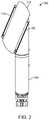
- FIG. 3illustrates a swivel-top portion of a surgical bed system having rigidly placed arms for embedding electromagnetic field generator coils, in accordance with some embodiments
- FIG. 4illustrates an exploded view of a swivel-top portion of a surgical bed system having rigidly placed arms for embedding electromagnetic field generator coils, in accordance with some embodiments
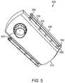
- FIG. 5illustrates a perspective view of underneath a swivel-top portion of a surgical bed system having rigidly placed arms with electromagnetic field generator coils embedded therein, in accordance with some embodiments;
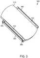
- FIG. 6illustrates a side view of a first position of a swivel-top portion of a surgical bed system having rigidly placed arms for embedding electromagnetic field generator coils, in accordance with some embodiments
- FIG. 7illustrates a side view of a second position of a swivel-top portion of a surgical bed system having rigidly placed arms for embedding electromagnetic field generator coils, in accordance with some embodiments
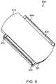
- FIG. 8illustrates a swivel-top portion of a surgical bed system having hinged arms for embedding electromagnetic field generator coils, in accordance with some embodiments
- FIG. 9illustrates an exploded view of a swivel-top portion of a surgical bed system having hinged arms for embedding electromagnetic field generator coils, in accordance with some embodiments
- FIG. 10illustrates a perspective view of underneath a swivel-top portion of a surgical bed system having hinged arms for embedding electromagnetic field generator coils, in accordance with some embodiments
- FIG. 11illustrates a side view of a first position of a swivel-top portion of a surgical bed system having hinged arms for embedding electromagnetic field generator coils, in accordance with some embodiments;
- FIG. 12illustrates a side view of a second position of a swivel-top portion of a surgical bed system having hinged arms for embedding electromagnetic field generator coils, in accordance with some embodiments;
- FIG. 13illustrates a perspective view of a surgical bed system having arms for embedding electromagnetic field generator coils, the arms connected using a median brace, in accordance with some embodiments;
- FIG. 14illustrates an overhead view of a surgical bed system having arms connected using a median brace for embedding electromagnetic field generator coils, in accordance with some embodiments
- FIG. 15illustrates a swivel-top portion of a surgical bed system having arms for embedding electromagnetic field generator coils, the arms connected using a median brace, in accordance with some embodiments;
- FIG. 16illustrates an exploded view of a swivel-top portion of a surgical bed system having arms for embedding electromagnetic field generator coils, the arms connected using a median brace, in accordance with some embodiments;
- FIG. 17illustrates a perspective view of underneath a swivel-top portion of a surgical bed system having arms with electromagnetic field generator coils embedded therein, the arms connected using a median brace, in accordance with some embodiments;
- FIG. 18illustrates a side view of a first position of a swivel-top portion of a surgical bed system having arms for embedding electromagnetic field generator coils, the arms connected using a median brace, in accordance with some embodiments;
- FIG. 19illustrates a side view of a second position of a swivel-top portion of a surgical bed system having arms for embedding electromagnetic field generator coils, the arms connected using a median brace, in accordance with some embodiments;
- FIG. 20illustrates a schematic of a floating electromagnetic (EM) field generator system that generates a single field, in accordance with some embodiments
- FIG. 21illustrates a schematic of a floating electromagnetic (EM) field generator system that generates multiple fields, in accordance with some embodiments
- FIG. 22illustrates a block diagram of a closed-loop control EM tracking surgical system, in accordance with some embodiments
- FIG. 23illustrates a schematic circuit diagram of an EM tracking surgical system, in accordance with some embodiments.
- FIG. 24illustrates schematic layouts of field generator coils and working volumes within an EM tracking surgical system, in accordance with some embodiments
- FIG. 25illustrates selective activation of field generator coils and working volumes as a surgical tool comprising a position sensor moves within an EM tracking surgical system, in accordance with some embodiments
- FIG. 26illustrates selective activation of field generator coils and working volumes as a surgical tool comprising a plurality of position sensors moves within an EM tracking surgical system, in accordance with some embodiments
- FIG. 27illustrates schematic views of an EM tracking surgical system having reconfigurable bed portions, in accordance with some embodiments
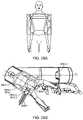
- FIGS. 28A and 28Billustrate sizing of a reconfigurable bed portion of an EM tracking surgical system based on exemplary dimensions of a human torso, in accordance with some embodiments
- FIG. 29illustrates a reconfigurable bed portion of an EM tracking surgical system, in accordance with some embodiments.
- FIG. 30illustrates dimensions and locations of field generator coils on a reconfigurable bed portion of an EM tracking surgical system, in accordance with some embodiments
- FIG. 31illustrates an estimated length of a working volume based on the dimensions of a reconfigurable bed portion of an EM tracking surgical system, in accordance with some embodiments.
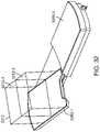
- FIG. 32illustrates an exemplary working volume above a reconfigurable bed portion of an EM tracking surgical system, in accordance with some embodiments.
- the floating EM field generator systemmay comprise arms.
- the arms that are next to a surgical bedmay have EM field generator coils embedded therein.
- the EM field generator coilsmay be used to generate an EM field over at least a portion of the surgical bed.
- the armsmay be within a structure that is independent, or at least partially independent, from weight-bearing portions of the surgical bed.
- floating EM field generator systemsmay be used to decouple the orientation of field generator coils from bending that may occur on a surgical bed.
- an EM field generatormay be used as one navigational component of a surgical tool tracking system that includes visual component and/or a fluoroscopic component. Additionally, systems provided that utilize three navigational components may be more accurate in tracking a surgical tool than navigational systems that only use one or two navigational components.
- a sensor associated with a surgical toolmay be tracked based on interactions of the sensor with an electromagnetic field.
- a sensor associated with a surgical toolmay be tracked when voltage is induced within a sensor coil that is placed within the electromagnetic field.
- the system providedmay be used for alternating current (AC) EM tracking.
- the systemmay be used for direct current (DC) EM tracking.
- the electromagnetic fieldmay be calibrated having a predetermined precision along a length of a surgical bed in the system. Small variations in position can be detected based on the sensor interaction with the electromagnetic field.
- the positional variationscan have a spatial resolution of less than about 10 mm, 9 mm, 8 mm, 7 mm, 6 mm, 5 mm, 4 mm, 3 mm, 2 mm, or 1 mm. In some cases, the spatial resolution may be greater than about 10 mm.
- the systemmay comprise a plurality of field generator coils embedded within arms that are associated with a surgical bed.
- the arms having the field generator coils embedded withinmay be disposed with respect to the surgical bed.
- the field generator coils embedded within the armsmay be placed with respect to, but decoupled from, the surgical bed. In this way, the field generator coils within the arms may be protected, or partially protected, from disturbances from the surgical bed.
- Each field generator coil, or subset of field generator coilsmay be configured to generate a magnetic field within a control volume.
- the control volumemay be static. Alternatively, the control volume may be capable of changing dynamically (e.g., time-variable).
- the systemmay further comprise a position sensor disposed on a portion of the surgical tool. The position sensor may be configured to generate a sensor signal in response to the magnetic field when the position sensor is located inside the control volume. Additionally, the system may comprise an EM system controller configured to selectively activate one or more of the subsets of field generator coils based on the sensor signal. Further, the system may also comprise a plurality of calibration files that correspond to each individual configuration of activated coils.
- a physicianmay need to know the spatial information of an endoscope relative to the patient's body, using the surgical bed as a datum.
- the spatial informationmay include a spatial position and/or orientation of the endoscope in a three-dimensional coordinate system.
- One or more sensorsmay be attached to the endoscope to determine the spatial information.
- the sensorsmay include electromagnetic (EM) sensors configured to detect the spatial information of the endoscope, as well as movement of the endoscope, within the environment of the surgical bed.
- the EM sensorsmay be used in conjunction with a set of field generator coils that are disposed at or next to the surgical bed.
- the field generator coilsmay be configured to produce a calibrated (known) electromagnetic (EM) field over a working volume above and close to the surgical bed.
- the working volumemay be defined as a three-dimensional space above the surgical bed where a portion of the patient's body is located.
- a region of interest on the patient's bodye.g., where a surgical procedure is to be performed
- electrical signalse.g., voltages
- the spatial information and/or movement of the endoscopecan be determined by analyzing the electrical signals.
- a flat configuration of field generator coilsmay be placed in a surgical bed directly under a patient.
- a box configuration of field generator coilsmay be placed externally on a side of the surgical bed or positioned above/over the patient.
- a window configuration of field generator coilsmay be positioned under the surgical bed or under the patient.
- each of the above configurationshas certain deficiencies.
- use of fluoroscopymay be limited in the flat configuration because the generator coils constitute radio-opaque objects/regions that can obstruct fluoroscopic imaging (e.g., X-ray imaging).
- the box configurationmay interfere with a physician's access to a patient since the coils are placed externally on the side of the surgical bed or positioned above/over the patient.
- the positioning of coils under the surgical bedmay result in mechanical and/or electromagnetic interference with other devices (e.g., motors for actuating the bed, linear actuator drives, radio-frequency (RF) circuits, etc.) that are also disposed under the surgical bed.
- the positioning of coils under the patientmay require an overall thickness of the bed to be increased, which results in larger form factor and higher manufacturing costs.
- Additional drawbacks of one or more of the above coil configurationsmay include limited range of use.
- the field generators in the above configurationstypically generate a working volume of about 0.5 m ⁇ 0.5 m ⁇ 0.5 m, which is often insufficient to encompass a length or a width of a patient's body.
- the surgical proceduremay involve different parts of the patient's body that are spaced outside of the typical 0.5 m ⁇ 0.5 m ⁇ 0.5 m working volume. In those instances, movement of the coils around the surgical bed may be required, which may increase the mechanical complexity of the system and interfere with the physician's access to the patient.
- a floating electromagnetic (EM) field generator system for tracking a surgical toolmay be provided in accordance with another aspect of the invention.
- the systemmay comprise a plurality of subsets of field generator coils embedded within arms that are disposed with respect to a surgical bed. Each subset of field generator coils may be configured to generate a magnetic field within a control volume. A central portion of the surgical bed may be fluoroscopically transparent.
- the systemmay also comprise a position sensor disposed on a portion of the surgical tool. The position sensor may be configured to generate a sensor signal in response to the magnetic field when the position sensor is located inside the control volume.
- the systemmay further comprise an EM system controller configured to activate one or more of the subsets of field generator coils.
- a floating electromagnetic field generator surgical systemin which field generator coils are embedded within arms of a surgical bed system.
- the field generator coilsare placed in arms that are decoupled from movement and/or weight bearing on a bed portion of the surgical bed system.
- the arms containing the field generator coilsmay stay rigid.
- the armsmay be movable while keeping in steady position relative to each other.
- field generator coils within arms of the surgical bed systemmay be relatively stable independent of a weight of a patient on a bed portion of the surgical bed system.
- field generator coilsin the disclosed configurations allows for unobstructed use of fluoroscopic imaging, and allows a physician to easily access the patient during a surgical procedure. Unlike some conventional systems, the field generator coils in the disclosed EM tracking surgical systems do not interfere with the physician's access to the patient.
- the integration of thick field generator coils within arms of the surgical bed systemmay also help to make beds thicker, which may allow for swivel to occur.
- the disclosed configurations of field generator coils as embedded in arms of the surgical bed systemalso allow a plurality of EM fields to be selectively activated within different working volumes above the surgical bed.
- the selective activation of EM fields within the different working volumescan prevent interfering EM fields from being generated, and can reduce EM interference between the field generator coils and other devices. Reduction in EM interference can improve the accuracy and sensitivity with which a surgical tool (e.g., an endoscope having one or more EM sensors) can be tracked within the different working volumes above the surgical bed.
- a surgical toole.g., an endoscope having one or more EM sensors
- the disclosed configurations of field generator coilscan extend the range of use of the system by a physician, since the working volumes can be configured to extend along a length of the surgical bed or in other configurations, depending on the requirements and complexity of the surgical procedure.
- tracking of a surgical toolcan be facilitated by activating different subsets of field generator coils.
- different subsets of field generator coilsmay be activated depending on the location of the surgical procedure relative to the surgical bed.
- coils outside of the active subset(s) of field generator coilsare inactive, thereby preventing interfering EM fields from being generated.
- the working volumes above adjacent subsets of field generator coilsmay overlap so as to form a continuous global working volume along the length of the surgical bed.
- the calibration filesneeds to be swapped for each configuration.
- FIG. 1illustrates a perspective view of a surgical bed system having arms for embedding electromagnetic field generators, in accordance with some embodiments.
- FIG. 1illustrates a surgical bed 100 positioned on a base component 105 .
- Surgical bed 100may have a first portion 110 and a second portion 120 , the first portion 110 having arms 115 that may be used to embed field generator coils (not shown).
- arms 115may be connected and structurally supported using a brace component.
- the brace componentmay help to support the arms so as to prevent bending and/or twisting of the arms when disturbances may occur further down the surgical bed.
- disturbancesmay occur in the surgical bed due to bending of the surgical bed due to the weight of a patient, hanging equipment, physician interaction, etc.
- bending and/or twisting of the armsmay modify the EM field that is generated using field generator coils, thereby making the tracking of a surgical tool within the EM field less accurate. As such, decoupling the bending moment and/or lessening disruption of the surgical bed from the field generator coils embedded in arms of the surgical bed may improve accuracy of a tracking system that utilizes the EM field generated by the floating EM field generator system.
- FIG. 2illustrates an overhead view of a surgical bed system of FIG. 1 having rigid arms for embedding electromagnetic field generators, in accordance with some embodiments.
- surgical bed system 100as shown in FIG. 2 illustrates another view of first portion 110 , second portion 120 , and arms 115 as presented in FIG. 1 .
- arms 115may be placed in rows that are parallel with respect to one another.
- registrationoccurs when arms 115 may be at different levels with respect to one another and relative to the patient. At times when registration is off, the device can still perform as expected.
- registrationmay be done with arms 115 at various positions relative to the patient. However, if the coils are displaced from their relative positions with respect to one another at the time of device calibration, the device may not perform as expected.
- FIG. 3illustrates a swivel-top portion 300 of a surgical bed system having rigidly placed arms for embedding electromagnetic field generator coils, in accordance with some embodiments.
- the swivel topprovides the ability to swivel the torso portion of the platform away from the longitudinal axis, allowing for positioning the patient's groin over the side of the platform so that open access is provided for the surgical arms.
- FIG. 3illustrates a bed component 310 , a brace (not shown), arms 330 , bed rails 340 , and securing components 350 .
- the position of arms 330 relative to one anotheris maintained based on rigidly connecting arms 330 to a base structure, such as a brace.
- the bracemay be made from a stainless steel bearing block embedded into structural foam and firmly rooted in place with resin, and/or may be completely encapsulated in Carbon Fiber. In some examples, this is the stiffest point of the bed that can be approximated to have zero deflection.
- FIG. 4illustrates an exploded view of a swivel-top portion of a surgical bed system having rigidly placed arms for embedding electromagnetic field generator coils, in accordance with some embodiments.
- FIG. 4illustrates an exploded view of a swivel-top portion 300 as seen in FIG. 3 .
- FIG. 4illustrates a bed component 310 , a brace 320 , arms 330 , bed rails 340 , and securing components 350 .
- FIG. 4illustrates spacers 355 .
- arms 330may individually be attached to brace 320 .
- brace 320 and arms 330may be formed from a single component.
- arms 330may be used to embed one or more field generator coils (not shown).
- arms 330may be decoupled from bed 310 so as to allow bed 310 to bend without placing a direct pressure on arms 330 .
- bed 310may bend due to the weight of a patient. The weight of the patient may also affect brace 320 .
- the structure of brace 320may be reinforced by the brace material and/or the circular component of the brace 320 so as to prevent bending within arms 330 attached to brace 320 .
- arms 330may be moved in a direction associated with the surgical bed in response to the weight of a patient.
- the rigid material of arms 330 and/or brace 320may be used to keep the arms 330 rigid even as they are displaced through space. In this way, arms 330 may move downwards, but may have a rigid structure with respect to one another.
- FIG. 5illustrates a perspective view of underneath a swivel-top portion of a surgical bed system having rigidly placed arms with electromagnetic field generator coils embedded therein, in accordance with some embodiments.
- FIG. 5illustrates an exploded view of a swivel-top portion 300 as seen in FIG. 3 .
- FIG. 5illustrates a bed component 310 , a brace 320 , arms 330 , bed rails 340 , securing components 350 , and spacers 355 .
- FIG. 5illustrates field generator coils 360 .
- field generator coils 360may be placed at an equal distance apart from one another.
- field generator coils 360may be placed at unequal distances from one another. In some examples, the distance between field generator coils 360 may be due to design of the arms 330 . As seen in FIG. 5 , field generator coils 360 may be embedded in arms 330 and, as such, may be placed with respect to bed component 310 based on a placement of arms 330 with respect to bed component 310 .
- FIG. 6illustrates a side view of a first position of a swivel-top portion 300 of a surgical bed system having rigidly placed arms for embedding electromagnetic field generator coils, in accordance with some embodiments.
- FIG. 7illustrates a side view of a second position of a swivel-top portion of a surgical bed system having rigidly placed arms for embedding electromagnetic field generator coils, in accordance with some embodiments.
- arms 330may stay stable.
- arms 330may stay rigid independent of the movement and/or bending of bed component based on the bracing of arms 330 using brace 320 .
- FIG. 8illustrates a swivel-top portion 800 of a surgical bed system having hinged arms for embedding electromagnetic field generator coils, in accordance with some embodiments.
- FIG. 8illustrates a bed component 810 , a brace (not shown), arms 830 , bed rails 840 , and securing components 850 .
- the position of arms 830 relative to one anotheris maintained based on connecting arms 830 to a base structure 820 , as well as connecting arms 830 using a base connecting component 825 .
- base connecting component 825the arms' hinge-like movement of arms 830 may be equal such that the arms 830 maintain their position with respect to each other.
- the characteristics of a field generated using field generator coils within the arms 830may also be stabilized.
- FIG. 9illustrates an exploded view of a swivel-top portion of a surgical bed system having hinged arms for embedding electromagnetic field generator coils, in accordance with some embodiments.
- FIG. 9illustrates an exploded view of a swivel-top portion 800 as seen in FIG. 8 .
- FIG. 9illustrates a bed component 810 , a brace 820 , a base connecting component 825 , arms 830 , bed rails 840 , and securing components 850 .
- FIG. 9illustrates spacers 855 .
- FIG. 10illustrates a perspective view of underneath a swivel-top portion 800 of a surgical bed system having hinged arms for embedding electromagnetic field generator coils, in accordance with some embodiments.
- FIG. 10illustrates a bed component 810 , a brace 820 , a base connecting component 825 , arms 830 , bed rails 840 , securing components 850 , and spacers 855 .
- FIG. 10illustrates field generator coils 860 (e.g., within arms 830 ). As seen in FIG. 10 , field generator coils may be placed at an equal distance apart from one another. In other examples, field generator coils may be placed at unequal distances from one another.
- the distance between field generator coilsmay be due to design of the arms, such as arms 830 .
- the distance between the field generator coilsmay be based on a surgical procedure to be performed.
- field generator coilsmay be embedded in arms 830 and, as such, may be placed with respect to bed component 810 based on a placement of arms 830 with respect to bed component 810 .
- FIG. 11illustrates a side view of a first position of a swivel-top portion 800 of a surgical bed system having hinged arms for embedding electromagnetic field generator coils, in accordance with some embodiments.
- FIG. 12illustrates a side view of a second position of a swivel-top portion of a surgical bed system having hinged arms for embedding electromagnetic field generator coils, in accordance with some embodiments.
- arms 830may stay stable at a position that is lower or level with bed component 810 . Either way, arms 830 may stay in a same position independent of movement of bed portion 810 .
- arms 830 and base connecting component 825may rest against a further support, such as a base, to further support arms 830 and base connecting component 825 .
- FIG. 13illustrates a perspective view of a surgical bed system having arms for embedding electromagnetic field generator coils, the arms connected using a median brace, in accordance with some embodiments.
- FIG. 13illustrates a surgical bed 1300 positioned on a base component 1305 .
- Surgical bed 1300may have a first portion 1310 and a second portion 1320 , the first portion 1310 having arms 1315 that may be used to embed field generator coils (not shown).
- arms 1315may be connected and structurally supported using an intermediate brace component 1330 .
- FIG. 14illustrates an overhead view of a surgical bed system having arms connected using a median brace for embedding electromagnetic field generator coils, in accordance with some embodiments.
- surgical bed 1300 as shown in FIG. 14illustrates another view of first portion 1310 , second portion 1320 , and arms 1315 as presented in FIG. 13 .
- arms 1315may be placed in rows that are parallel with respect to one another.
- arms 1315are attached using an intermediate brace component 1330 .
- the structural support of arms 1315 using an intermediate brace component 1330may be used to prevent bending of arms 1315 when a patient is on bed 1300 .
- FIG. 15illustrates a swivel-top portion 1500 of a surgical bed system having arms for embedding electromagnetic field generator coils, the arms connected using a median brace, in accordance with some embodiments.
- FIG. 15illustrates a bed component 1510 , arms 1530 , intermediate brace component 1535 , bed rails 1540 , and securing components 1550 .
- the position of arms 1530 relative to one anotheris maintained based on rigidly connecting arms 1530 to intermediate brace component 1535 .
- intermediate brace component 1535may have a band that is three inches wide.
- the band of intermediate brace component 1535is less than three inches wide, and in some examples, the band of intermediate brace component 1535 is more than three inches wide. In examples, the band of intermediate brace component 1535 may be less than an inch; may be an inch; may be 1.5 inches; may be 2 inches; may be 2.5 inches; may be 3 inches; may be 3.5 inches; may be 4 inches; may be 4.5 inches; may be 5 inches; or may be more than 5 inches.
- FIG. 16illustrates an exploded view of a swivel-top portion of a surgical bed system having arms for embedding electromagnetic field generator coils, the arms connected using a median brace, in accordance with some embodiments.
- FIG. 16illustrates an exploded view of a swivel-top portion 1500 as seen in FIG. 15 .
- FIG. 16illustrates a bed component 1510 , circular brace component 1520 , arms 1530 , intermediate brace component 1535 , bed rails 1540 , and securing components 1550 .
- FIG. 16illustrates spacers 1555 .
- arms 1530may be joined through their attachment to intermediate brace component 1535 . Additionally, arms 1530 may be joined to another, circular base component 1520 within bed component 1510 . In examples, circular brace component 1520 , arms 1530 , and intermediate brace component 1535 may be formed from a single component. In additional examples, arms 1530 may be used to embed one or more field generator coils (not shown). Further, arms 1530 may be decoupled from bed component 1510 so as to allow bed component 1510 to bend without placing a direct pressure on arms 1530 . In examples, bed component 1510 may bend due to the weight of a patient.
- the weight of the patientmay also affect circular brace component 1520 and/or intermediate brace component 1535 , but the structure of circular brace component 1520 and/or intermediate brace component 1535 may be reinforced by the brace material and/or the shape of the brace component so as to prevent bending within arms 1530 attached to brace components 1520 and/or 1535 .
- arms 1530may be moved in a direction associated with the surgical bed in response to the weight of a patient.
- the rigid material of circular brace component 1520 , arms 1530 , and/or intermediate brace component 1535may be used to keep the arms 1530 rigid even as they are displaced through space. In this way, arms 1530 may move downwards, but may have a rigid structure with respect to one another.
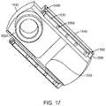
- FIG. 17illustrates a perspective view of underneath a swivel-top portion of a surgical bed system having arms with electromagnetic field generator coils embedded therein, the arms connected using a median brace, in accordance with some embodiments.
- FIG. 17illustrates a bed component 1510 , a brace 1520 , arms 1530 , an intermediate brace component 1535 , bed rails 1540 , securing components 1550 , and spacers 1555 .
- FIG. 17illustrates field generator coils 1560 .
- field generator coils 1560may be placed at an equal distance apart from one another. In other examples, field generator coils 1560 may be placed at unequal distances from one another.
- the distance between field generator coils 1560may be due to design of the arms 1530 . In some examples, the distance between the field generator coils 1560 may be based on a surgical procedure to be performed. As seen in FIG. 17 , field generator coils 1560 may be embedded in arms 1530 and, as such, may be placed with respect to bed component 1510 based on a placement of arms 1530 with respect to bed component 1510 .
- FIG. 18illustrates a side view of a first position of a swivel-top portion of a surgical bed system having arms for embedding electromagnetic field generator coils, the arms connected using a median brace, in accordance with some embodiments.
- FIG. 19illustrates a side view of a second position of a swivel-top portion of a surgical bed system having arms for embedding electromagnetic field generator coils, the arms connected using a median brace, in accordance with some embodiments.
- FIGS. 18 and 19as bed component 1510 moves downwards from a first position to a second position, arms 1530 may stay stable.
- arms 1530may stay rigid independent of the movement and/or bending of surgical bed 1510 based on the bracing of arms 1530 using circular brace component (not shown) and intermediate brace component (not shown).
- FIGS. 18 and 19illustrate securing components 1550 .
- FIG. 20illustrates a schematic of a floating EM field generator system 2000 that generates a single field 2012 , in accordance with some embodiments.
- the floating EM field generator system 2000may also comprise a surgical bed 2002 that rests on a base 2001 , a plurality of field generator coils 2003 , an EM system controller 2008 , a switch module 2010 , and a position sensor 2016 .
- the surgical bed 2002may be configured to support a patient. A physician may perform a surgical procedure on the patient while the patient is placed on the surgical bed 2002 .
- the surgical bed 2002may comprise multiple sections that are movable relative to one another. In those embodiments, the patient's body can be moved into different positions by moving different sections of the surgical bed 2002 relative to one another.
- the surgical bed 2002may be formed monolithically as a single rigid structure.
- the plurality of field generator coils 2003may be embedded or integrated within arms 2014 associated with the surgical bed 2002 .
- the plurality of field generator coils 2003may be embedded within arms (not shown) associated with the surgical bed 2002 in two rows. The rows may extend parallel to each other along the edge of the surgical bed 2002 .
- the field generator coils 2003constitute radio-opaque objects/regions. Accordingly, the placement of the field generator coils 2003 within arms next to surgical bed 2002 can allow unobstructed use of fluoroscopy to image the patient's body during a surgical procedure.
- a plurality of working volumes 2112may be generated using subsets of field generator coils 2104 . This is shown in FIG. 21 , which illustrates a schematic of a floating EM field generator system that generates multiple fields, in accordance with some embodiments. As seen in FIG. 21 , the plurality of working volumes 2112 may include a first working volume 2102 - 1 , a second working volume 2102 - 2 , and a third working volume 2102 - 3 . Each working volume 2112 may be associated with a subset of field generator coils, and may be disposed directly above the respective subset of field generator coils.
- first working volume 2102 - 1may be disposed directly above the first subset of field generator coils 2104 - 1
- the second working volume 2102 - 2may be disposed directly above the second subset of field generator coils 2104 - 2
- third working volume 2102 - 3may be disposed directly above the third subset of field generator coils 2104 - 3 .
- the plurality of field generator coils 2003may include, and can be grouped into, subsets as field generator coils 2104 .
- the field generator coils 2003may include a first subset of field generator coils 2104 - 1 , a second subset of field generator coils 2104 - 2 , and a third subset of field generator coils 2104 - 3 .
- three subsetsare illustrated in FIG. 21 , it should be noted that the invention is not limited thereto, and that any number of subsets of field generator coils may be contemplated. In examples, 2, 3, 4, 5, 6, 7, 8, 9, 10, or more than 10 subsets of field generator coils may be used.
- Each subset of field generator coils 2104may comprise a number of field generator coils.
- each subset of field generator coils 2104 - 1 , 2104 - 2 , and 2104 - 3may comprise six, ten, or six field generator coils, respectively.
- each subset of field generator coilsneed not be limited to six field generator coils.
- a subset of field generator coilsmay comprise more than six field generator coils.
- a subset of field generator coilsmay comprise 7, 8, 9, 10, 11, 12, 13, 14, 15, 16, 17, 18, 19, 20, 25, 30, 35, 40, or more than 40 field generator coils.
- a subset of field generator coilsmay comprise six or less generator coils.
- a subset of field generator coilsmay comprise 1, 2, 3, 4, 5, or 6 field generator coils.
- different subsets of field generator coilsmay comprise different numbers of field generator coils. Any number of field generator coils within each subset, and between different subsets, may be contemplated.
- the field generator coils within each subsetmay be fixed in place relative to one another.
- the field generator coilsmay be spaced apart by a predetermined distance and/or at a predefined pitch along the edges of the surgical bed 2002 .
- the field generator coilsmay be nominally fixed relative to the surgical bed 2002 in a global coordinate system. Any portion of the surgical bed 2002 may serve as an origin of the global coordinate system.
- a datum point that lies substantially above a center portion of the surgical bed 2002may serve as the origin of the global coordinate system.
- the positions of the field generator coilsmay be defined relative to the datum point.
- the EM system controller 2008may be configured to provide electrical current pulses to the field generator coils 2003 to generate an EM field over the respective working volume 2112 above each subset of field generator coils 2104 .
- the EM system controller 2008can selectively activate (power on) different subsets of field generator coils 2104 to generate EM fields in different working volumes 2112 by controlling one or more switches in the switch module 2010 .
- Electrical current pulsesmay be provided from the EM system controller 2008 to the different subsets of field generator coils 2104 via one or more switches in the switch module 2010 .
- the switchesmay include electronic switches such as power MOSFETs, solid state relays, power transistors, and/or insulated gate bipolar transistors (IGBTs). Different types of electronic switches may be provided for controlling current to a subset of field generator coils.
- An electronic switchmay utilize solid state electronics to control current flow.
- an electronic switchmay have no moving parts and/or may not utilize an electro-mechanical device (e.g., traditional relays or switches with moving parts).
- electrons or other charge carriers of the electronic switchmay be confined to a solid state device.
- the electronic switchmay optionally have a binary state (e.g., switched-on or switched-off).
- the electronic switchesmay be used to control current flow to the subsets of field generator coils. The operation of switches to selectively activate one or more subsets of field generator coils is described with reference to FIG. 23 , below.
- the EM system controller 2008can control the switches to activate: (1) the first subset of field generator coils 2104 - 1 to generate an EM field in the first working volume 2102 - 1 , (2) the second subset of field generator coils 2104 - 2 to generate an EM field in the second working volume 2102 - 2 , and/or (3) the third subset of field generator coils 2104 - 3 to generate an EM field in the third working volume 2102 - 3 .
- the subsets of field generator coilsmay be activated simultaneously. In some examples, the subsets of field generator coils may be activated sequentially.
- the EM system controller 2008can simultaneously activate all three subsets of field generator coils 2104 to create three separate EM fields in the respective working volumes 2112 .
- the EM system controller 2008can sequentially activate the first, second, and third subsets of field generator coils 2104 - 1 , 2104 - 2 , and 2104 - 3 to sequentially generate EM fields in the first, second, and third working volumes 2102 - 1 , 2102 - 2 , and 2102 - 3 .
- the EM system controller 2008can be configured to activate one or more subsets of field generator coils without activating one or more other subsets of field generator coils. For example, in some embodiments, the EM system controller 2008 can activate only the first subset of field generator coils 2104 - 1 without activating the second and third subsets of field generator coils 2104 - 2 and 2104 - 3 . Similarly, the EM system controller 2008 can activate only the second subset of field generator coils 2104 - 2 without activating the first and third subsets of field generator coils 2104 - 1 and 2104 - 3 .
- the EM system controller 2008can activate only the third subset of field generator coils 2104 - 3 without activating the first and second subsets of field generator coils 2104 - 1 and 2104 - 2 . In some cases, the EM system controller 2008 can activate the first and second subsets of field generator coils 2104 - 1 and 2104 - 2 without activating the third subset of field generator coils 2104 - 3 . In other cases, the EM system controller 2008 can activate the second and third subsets of field generator coils 2104 - 2 and 2104 - 3 without activating the first subset of field generator coils 2104 - 1 .
- the EM system controller 108can activate the first and third subsets of field generator coils 2104 - 1 and 2104 - 3 without activating the second subset of field generator coils 2104 - 2 . Additional combinations (of the activation) of different subsets of field generator coils may be contemplated.
- the EM system controller 2008can sequentially activate the first, second, and third subsets of field generator coils 2104 - 1 , 2104 - 2 , and 2104 - 3 .
- all three subsets of field generator coilsmay continue to be powered on after they have been sequentially activated.
- the first subset of field generator coils 2104 - 1may continue to be powered on after the second subset of field generator coils 2104 - 2 has been activated.
- the first and second subsets of field generator coils 2104 - 1 and 2104 - 2may continue to be powered on after the third subset of field generator coils 2104 - 3 has been activated.
- the first subset of field generator coils 2104 - 1may be powered off after the second subset of field generator coils 2104 - 2 has been activated, and the second subset of field generator coils 2104 - 2 may be powered off after the third subset of field generator coils 2104 - 3 has been activated.
- the EM system controller 2008may be located on the surgical bed 2002 , for example on a base configured to support the surgical bed 2002 . In some embodiments, the EM system controller 2008 may be located remotely from the surgical bed 2002 . For example, the EM system controller 2008 may be disposed in a remote server that is in communication with the subsets of field generator coils 2004 and the switch module 2010 . The EM system controller 2008 may be software and/or hardware components included with the server.
- the servercan have one or more processors and at least one memory for storing program instructions.
- the processor(s)can be a single or multiple microprocessors, field programmable gate arrays (FPGAs), or digital signal processors (DSPs) capable of executing particular sets of instructions.
- Computer-readable instructionscan be stored on a tangible non-transitory computer-readable medium, such as a flexible disk, a hard disk, a CD-ROM (compact disk-read only memory), and MO (magneto-optical), a DVD-ROM (digital versatile disk-read only memory), a DVD RAM (digital versatile disk-random access memory), or a semiconductor memory.
- a tangible non-transitory computer-readable mediumsuch as a flexible disk, a hard disk, a CD-ROM (compact disk-read only memory), and MO (magneto-optical), a DVD-ROM (digital versatile disk-read only memory), a DVD RAM (digital versatile disk-random access memory), or a semiconductor memory.
- the program instructionscan be implemented in hardware components or combinations of hardware and software such as, for example, ASICs, special purpose computers, or general purpose computers.
- the EM system controller 2008may also be provided at any other type of external device (e.g., a remote controller for controlling the surgical bed 2002 and/or a surgical tool, any movable object or non-movable object, etc.). In some instances, the EM system controller 2008 may be distributed on a cloud computing infrastructure. The EM system controller 2008 may reside in different locations where the EM system controller 2008 is capable of controlling the switch module 2010 and selectively activating one or more subsets of field generator coils 2004 based on the spatial information of the position sensor 2016 .
- the position sensor 2016may be disposed in or on a portion of a surgical tool.
- the position sensor 2016may be disposed at a distal end of the surgical tool.
- surgical toolsmay include endoscopes, catheters, ureteroscopes, forceps, different types of scopes, or other similar devices or surgical accessories.
- a position sensorsuch as position sensor 2016
- Position sensor 2016may be configured to generate an electrical signal (voltage or current signal) in response to EM fields generated field generator coils.
- Position sensor 2016may be an EM sensor. As position sensor 2016 moves within a control volume 2012 , the interaction of the position sensor 2016 with the EM field within the control volume 2012 may cause electrical signals to be generated. The electrical signals may vary as the position sensor 2016 moves between different locations within a control volume 2012 . Additionally, electrical signals may vary as the position sensor 2016 moves between different control volumes.
- the EM system controller 2008may be configured to receive electrical signals from the position sensor 2016 . Additionally, the EM system controller 2008 may analyze the signals to compute a local position of the sensor 2016 .
- the local position of the sensor 2016may be computed relative to a local coordinate system.
- the local coordinate systemmay be defined at an active set of field generator coils corresponding to the control volume 2012 in which the position sensor 2016 is located.
- the EM system controller 2008may be further configured to compute a global position of the sensor 2016 relative to a global coordinate system.
- the global coordinate systemmay be defined at the surgical bed 2002 (e.g., above a center portion of the surgical bed 2002 ).
- the global position of the sensor 2016may be computed based on: (1) the local position of the sensor 2016 within the control volume 2012 above an active set of field generator coils, and (2) the position of the active set of field generator coils relative to the surgical bed 2002 .
- the global position of the sensor 2016may be used to determine a position of a surgical tool relative to a patient on the surgical bed 2002 .
- the EM system controller 2008may be configured to control the switch module 2010 based on one or more inputs.
- the control of the switch module 2010 , and the selective activation of one or more field generator coils,may be manual and/or automatic.
- the EM system controller 2008may control the switch module 2010 based on a user input corresponding to a selection of a region (or working volume 2112 ) of the surgical bed 2002 where tracking of a surgical tool is desired. For example, a physician may plan to perform a surgical procedure on a patient in a region within the first working volume 2112 - 1 . Accordingly, the physician or the physician's assistant may provide an input to the EM system controller 2008 to activate the first subset of field generator coils 2104 - 1 , so that movement of the surgical tool can be tracked within the first control volume via the position sensor 2016 .
- the EM system controller 2008may control the switch module 2010 based on an initialization input.
- the initialization inputmay cause the EM system controller 2008 to control the switch module 2010 to sequentially activate (cycle through) the subsets of field generator coils 2104 , so as to determine: (1) whether the position sensor 2016 is present in any of the control volumes 2112 , (2) in which control volume 2112 the position sensor 2016 is located if the position sensor 2016 is detected, and (3) the position of the sensor 2016 within the detected control volume 2112 .
- the EM system controller 2008can control the switch module 2010 to activate the subset of field generator coils 2104 corresponding to the control volume 2112 in which the position sensor 2016 is located, without activating the other subsets of field generator coils.
- the local position of the sensor 2016 relative to the local coordinate system of the working volume 2112 (where the sensor 2016 is located)may be determined.
- the local position of the sensor 2016may be determined based on a distance between the sensor 2016 and a reference point in the local coordinate system.
- the reference pointmay lie anywhere in the local coordinate system.
- the reference pointmay be at an origin of the local coordinate system.
- One or more subsets of field generator coils 2104may be activated based on the distance between the sensor 2016 and the reference point.
- the reference pointis an origin of a local coordinate system that is defined at a center of a control volume 2112
- the position sensor 2016is located at or near the reference point
- only the subset of field generator coils corresponding to that control volume 2112may be activated.
- adjacent subsets of field generator coils 2104 corresponding to both control volumes 2112may be activated.
- the local coordinate systemneed not be defined at the center of a control volume 2112 . In some other instances, the local coordinate system may be defined near an edge or corner of a control volume 2112 . Any placement of the reference point and/or the local coordinate system within a control volume 2112 may be contemplated.
- the local position of the sensor 2016may be determined based on distances between the sensor 2016 and a plurality of reference points in different local coordinate systems.
- the different local coordinate systemsmay lie in different control volumes 2012 .
- the EM system controller 2008may be configured to determine a minimum distance from those distances, and activate a subset of field generator coils 2104 corresponding to the control volume 2012 based on the minimum distance.
- the EM system controller 2008may be configured to track the position and/or movement of the sensor 2016 within a control volume 2112 corresponding to an active subset of field generator coils 2104 . As the position sensor 2016 moves between adjacent control volumes 2112 , different subsets of field generator coils 2104 may be selectively activated to ensure that the sensor 2016 is continuously tracked, while at the same time reducing EM field interference effects.
- FIG. 22illustrates a block diagram of a closed-loop control EM tracking surgical system, in accordance with some embodiments.
- a closed-loop control EM tracking surgical system 2200may comprise an EM system controller 2208 , a plurality of subsets of field generator coils 1 through n, represented as 2204 , and a position sensor 2216 operably connected via a feedback loop 2207 .
- Any number (n) of subsets of field generator coils 2204may be contemplated, and may depend in part on the strength of each subset of field generator coils 2204 and/or a size (e.g., length and width) of a surgical bed (e.g., surgical bed 102 of FIG. 1 ).
- a surgical toolmay be automatically controlled using one or more robotic arms that are in operable communication with the EM system controller 2208 .
- the EM system controller 2208may be configured to track and control the position and/or movement of the surgical tool, and selectively activate one or more subsets of field generator coils 2204 , based on positional and speed feedback of the position sensor 2216 as the sensor 2216 moves between different control volumes (e.g., control volumes 2112 of FIG. 21 ).
- an inputmay be initially provided to the EM tracking surgical system 2200 .
- the inputmay comprise a desired position and/or speed of a surgical tool.
- the position and/or speed of the surgical toolmay be controlled using the one or more robotic arms.
- the EM system controller 2208may be configured to activate one or more subsets of field generator coils 2204 , and to determine a control volume (e.g., control volume 2012 of FIG. 20 ) in which the position sensor 2216 is located. Once the control volume has been determined, the subset of field generator coils 2204 corresponding to that control volume may be activated while the other subsets of field generator coils 2204 may be powered off.
- the selective activation of different subsets of field generator coils 2204can reduce EM field interference effects.
- the position and/or movement of the sensor 2216may be determined based on the interaction of the sensor 2216 with the EM field within the control volume.
- the actual position and/or speed of the surgical toolmay be determined based on the position and/or movement of the sensor 2216 , and may be compared against the input to determine an amount of deviation ⁇ (if any) from the desired position and/or speed of the surgical tool.
- the EM system controller 2208may be configured to adjust the actual position and/or speed of the surgical tool (via the one or more robotic arms) based on the amount of deviation.
- FIG. 23illustrates a schematic circuit diagram of an EM tracking surgical system, in accordance with some embodiments.
- an EM tracking surgical system 2300may comprise a plurality of subsets of field generator coils 2304 - 1 , 2304 - 2 , and 2304 - 3 electrically connected to a power supply 2318 .
- An EM system controller 2308may be in operable communication with a plurality of switches K 1 , K 2 , and K 3 and a position sensor 2316 .
- the plurality of switches K 1 , K 2 , and K 3may be located in a switch module (e.g., switch module 2010 of FIG. 20 ).
- the EM system controller 2308may be configured to selectively activate one or more subsets of field generator coils 2304 , either simultaneously, sequentially, or in a round-robin configuration, based on a position and/or movement of the position sensor 2316 within and/or between adjacent control volumes (e.g., control volumes 2112 of FIG. 21 ).
- the EM system controller 2308may be configured to control one or more switches to selectively activate one or more subsets of field generator coils 2304 .
- the EM system controller 2308may selectively activate the first subset of field generator coils 2304 - 1 by closing the switch K 1 .
- the EM system controller 2308may selectively activate the second subset of field generator coils 2304 - 2 by closing the switch K 2 .
- the EM system controller 2308may selectively activate the third subset of field generator coils 104 - 3 by closing the switch K 3 .
- the EM system controller 2308may simultaneously activate two or more subsets of field generator coils 2304 .
- the EM system controller 2308may simultaneously activate the first and second subsets of field generator coils 2304 - 1 and 2304 - 2 by closing the switches K 1 and K 2 .
- the EM system controller 2308may simultaneously activate the first and third subsets of field generator coils 2304 - 1 and 2304 - 3 by closing the switches K 1 and K 3 .
- the EM system controller 2308may simultaneously activate the second and third subsets of field generator coils 2304 - 2 and 2304 - 3 by closing the switches K 2 and K 3 .
- the EM system controller 2308may simultaneously activate the first, second, and third subsets of field generator coils 2304 - 1 , 2304 - 2 , and/or 2304 - 3 by simultaneously closing the switches K 1 , K 2 , and/or K 3 , respectively.
- the EM system controller 2308may sequentially close the switches K 1 , K 2 , and/or K 3 .
- the EM system controller 2308may close the switches K 1 , K 2 , and/or K 3 in alternating manner.
- the EM system controller 2308may close the switches K 1 , K 2 , and/or K 3 at a same frequency or at different frequencies.
- the EM system controller 2308may close/open the switches K 1 , K 2 , and/or K 3 for different lengths of time, so as to activate or power off the subsets of field generator coils 2304 for different lengths of time.
- FIG. 24illustrates schematic layouts of field generator coils and working volumes within an EM tracking surgical system, in accordance with some embodiments.
- Part A of FIG. 24illustrates a schematic side view of a portion of an EM tracking surgical system 2400
- Part B of FIG. 24illustrates a schematic top view of the portion of the system 2400 .
- a first subset of field generator coils 2404 - 1 and a second subset of field generator coils 2404 - 2may be embedded along a length portion of a surgical bed 2402 .
- a first working volume 2412 - 1may be defined above the first subset of field generator coils 2404 - 1
- a second working volume 2412 - 2may be defined above the second subset of field generator coils 2404 - 2 .
- the dimensions of the first working volume 2412 - 1may be given by a length L 1 , a width W, and a height H.
- the dimensions of the second working volume 2412 - 2may be given by a length L 2 , a width W, and a height H.
- the lengths L 1 and L 2may be substantially the same. In other embodiments, the lengths L 1 and L 2 may be different. For example, in some instances, the length L 1 may be less than the length L 2 . In other instances, the length L 1 may be greater than the length L 2 . In some alternative embodiments (not shown), the widths of the first and second working volumes 2412 may be different. Optionally, the heights of the first and second working volumes 2412 may be different.
- Each working volume 2412may comprise a sub-volume threshold located within each working volume.
- the sub-volume thresholdis located at a boundary between overlapping working volumes.
- the sub-volume thresholdmay correspond to a transition zone as the sensor moves between overlapping working volumes.
- the first working volume 2412 - 1may comprise a first sub-volume threshold 2413 - 1
- the second working volume 2412 - 2may comprise a second sub-volume threshold 2413 - 2
- the first sub-volume threshold 2413 - 1may have a length L 1 ′
- the second sub-volume threshold 2413 - 2may have a length L 2 ′.
- the lengths L 1 ′ and L 2 ′may be substantially the same.
- the lengths L 1 ′ and L 2 ′may be different.
- the widths of the first and second sub-volume thresholdsmay be the same, and the heights of the first and second sub-volume thresholds may be the same. In some alternative embodiments (not shown), the widths of the first and second sub-volume thresholds may be different. Optionally, the heights of the first and second sub-volume thresholds may be different.
- Each working volume 2412may further comprise a de-bounce threshold located within each sub-volume threshold.
- the first working volume 2412 - 1may comprise a first de-bounce threshold 2415 - 1
- the second working volume 2412 - 2may comprise a second de-bounce threshold 2415 - 2 .
- the second working volumemay be activated once the sensor leaves the first de-bounce threshold and enters the second de-bounce threshold.
- the first working volumemay be activated once the sensor leaves the second de-bounce threshold and enters the first de-bounce threshold.
- the de-bounce thresholdsmay serve as “de-bouncing switches” for determining which working volume is to be activated.
- the first de-bounce threshold 2415 - 1may have a length L 1 ′′
- the second de-bounce threshold 2415 - 2may have a length L 2 ′′.
- the lengths L 1 ′′ and L 2 ′′may be substantially the same.
- the lengths L 1 ′′ and L 2 ′′may be different.
- the widths of the first and second de-bounce thresholdsmay be the same, and the heights of the first and second de-bounce thresholds may be the same.
- the widths of the first and second de-bounce thresholdsmay be different.
- the heights of the first and second de-bounce thresholdsmay be different.
- the first and second working volumesmay overlap so as to form a first overlapping working volume 2414 - 1 disposed at a boundary between the first and second subsets of field generator coils 2404 - 1 and 2404 - 2 .
- the first and second working volumes 2412 - 1 and 2412 - 2may overlap by various amounts.
- the first and second working volumes 2412 - 1 and 2412 - 2may overlap by 1%, 2%, 5%, 10%, 15%, 20%, 25%, 30%, or more than 30%.
- the first and second working volumes 2412 - 1 and 2412 - 2may be configured to overlap such that a position sensor can be accurately tracked and controlled near the boundaries of the control volumes 2412 , and as a position sensor moves between adjacent working volumes 2412 .
- the first overlapping working volume 2414 - 1may have a length U 1 , a width W, and a height H.
- Each subset of field generator coils 2404may comprise a number of field generator coils 2403 .
- the number of field generator coils 2403 in the subsetsmay be same or different.
- each subset of field generator coils 2404may comprise eight field generator coils 2403 .
- the field generator coils 2403may be disposed along the edges of the surgical bed 2402 in two parallel rows 2406 .
- the field generator coils 2403may be spaced apart from one another along each row 2406 , at a pitch p in the Y-direction. Laterally opposite field generator coils 2403 in the two rows 2406 may be spaced apart by a distance d from each other in the X-direction.
- the field generator coils 2403 in the subsets 2404may be spaced in a configuration that allows an EM field of a predetermined strength to substantially extend over each working volume 2412 .
- FIG. 25illustrates the selective activation of field generator coils and working volumes as a surgical tool comprising a position sensor moves within an EM tracking surgical system, in accordance with some embodiments.
- Parts A, B, C, and D of FIG. 25illustrate schematic top views of a portion of an EM tracking surgical system 2500 .
- a position sensor 2516may be disposed at a distal end of a surgical tool 2517 .
- the surgical toolsmay include endoscopes, catheters, ureteroscopes, or other similar devices.
- the surgical tool 2517may be positioned such that the position sensor 2516 is located at position A.
- Position Amay be a point within a first working volume 2512 - 1 above a first subset of field generator coils 2504 - 1 .
- An EM system controllere.g., EM system controller 2508
- the EM system controllermay detect that the position sensor 2516 is within the first working volume 2512 - 1 but outside of a first overlapping working volume 2514 - 1 .
- the first overlapping working volume 2514 - 1may be an overlapping region between the first and second working volumes 2512 - 1 and 2512 - 2 . Accordingly, the EM system controller may selectively activate the first subset of field generator coils 2504 - 1 without activating the second subset of field generator coils 2504 - 2 .
- the first working volume 2512 - 1may become an active working volume, as indicated by the shaded region over the first working volume 2512 - 1 .
- Position Bmay be a point that lies within the first working volume 2512 - 1 and the first overlapping working volume 2514 - 1 . Since position B lies near the boundary of the first working volume 2512 - 1 , the EM system controller may activate the second subset of field generator coils 2504 - 2 in addition to the first subset of field generator coils 2504 - 1 , to ensure that the position sensor 2516 can be accurately tracked near the boundary between adjacent working volumes 2512 .
- the first and second working volumes 2512 - 1 and 2512 - 2become active working volumes, as indicated by the shaded regions over the first and second working volumes 2512 - 1 and 2512 - 2 .
- the surgical tool 2517may move to a different location, such that the position sensor 2516 may move to position C shown in part C of FIG. 25 .
- Position Cmay be another point in the first overlapping working volume 2514 - 1 .
- position Cmay lie within the second working volume 2512 - 2 . Since position C lies near the boundary of the second working volume 2512 - 2 , the EM system controller may continue to activate both the first and second subsets 2512 , to ensure that the position sensor 2516 can be accurately tracked near the boundary between adjacent working volumes 2512 .
- the surgical tool 2517may move to a different location, such that the position sensor 2516 may move to position D shown in part D of FIG. 25 .
- the EM system controllermay detect that the position sensor 2516 is within the second working volume 2512 - 2 but outside of the first overlapping working volume 2514 - 1 . Accordingly, the EM system controller may continue to activate the second subset of field generator coils 2504 - 2 , but power off the first subset of field generator coils 2504 - 1 .
- FIG. 26illustrates selective activation of field generator coils and working volumes as a surgical tool comprising a plurality of position sensors moves within an EM tracking surgical system, in accordance with some embodiments.
- Parts A, B, and C of FIG. 26illustrate schematic top views of a portion of an EM tracking surgical system 2600 .
- the embodiment of FIG. 26has similarities to the embodiment of FIG. 25 .
- a surgical tool 2617may be a flexible probe or shaft capable of twisting and bending about different directions. Additionally, the surgical tool 2617 may comprise a plurality of position sensors 2616 that include position sensors 2616 - 1 , 2616 - 2 , 2616 - 3 , 2616 - 4 , and 2616 - 5 .
- a position sensor 2616 - 1may be disposed at a distal end of the surgical tool 2617
- a plurality of position sensors 2616 - 2 , 2616 - 3 , 2616 - 4 , and 2616 - 5may be spaced apart along a length of the surgical tool 2617 .
- the position/orientation/shape of the surgical tool 2617can be determined through use of an EM field, which may be important during a surgical procedure as the tool 2617 is being inserted into a patient's body.
- the position/orientation/shape of the surgical tool 2617 that is obtained by an EM system controllercan be mapped onto the fluoroscopic image of the patient's body in real-time as the surgical procedure is being performed.
- the EM tracking surgical system 2600may comprise three working volumes 2612 : a first working volume 2612 - 1 , a second working volume 2612 - 2 , and a third working volume 2612 - 3 .
- 4, 5, 6, 7, 8, 9, 10, or more than 10 working volumes 2612may be provided.
- the position sensors 2616 - 1 , 2616 - 2 , 2616 - 3 , 2616 - 4 , and 2616 - 5may be located at positions A 1 , A 2 , A 3 , A 4 , and A 5 , respectively.
- Positions A 1 , A 2 , and A 3may lie within the first working volume 2612 - 1 above a first subset of field generator coils 2604 - 1 .
- Positions A 4 and A 5may lie outside of the first working volume 2612 - 1 and/or any working volume.
- An EM system controllere.g., EM system controller 2008 of FIG.
- the EM system controllermay detect that the position sensors 2616 - 1 , 2616 - 2 , and 2616 - 3 are within the first working volume 2612 - 1 , and not in the second and third working volumes 2612 - 2 and 2612 - 3 . Additionally, the EM system controller may detect that the position sensors 2616 - 1 , 2616 - 2 , and 2616 - 3 are within the first working volume 2612 - 1 outside of a first overlapping working volume 2614 - 1 . Accordingly, the EM system controller may selectively activate the first subset of field generator coils 2604 - 1 without activating the second subset of field generator coils 2604 - 2 .
- the surgical tool 2617may move from the position shown in part A to the position shown in part B of FIG. 26 .
- the position sensors 2616 - 1 , 2616 - 2 , 2616 - 3 , 2616 - 4 , and 2616 - 5may be located at positions B 1 , B 2 , B 3 , B 4 , and B 5 , respectively.
- Position B 1may be a point that lies within the second working volume 2612 - 2 outside of the first overlapping working volume 2614 - 1 .
- Position B 2may be a point that lies within the second working volume 2612 - 2 and the first overlapping working volume 2614 - 1 .
- Position B 3may be a point that lies within the first working volume 2612 - 1 and the first overlapping working volume 2614 - 1 .
- Positions B 4 and B 5may be different points that lie within the first working volume 2612 - 1 outside of the first overlapping working volume 2614 - 1 .
- the EM system controllermay activate the second subset of field generator coils 2604 - 2 in addition to the first subset of field generator coils 2604 - 1 , to ensure that the position sensor 2616 can be accurately tracked within the first and the second working volumes 2612 - 1 and 2612 - 2 .
- the surgical tool 2617may move from the position shown in part B to the position shown in part C of FIG. 26 .
- the position sensors 2616 - 1 , 2616 - 2 , 2616 - 3 , 2616 - 4 , and 2616 - 5may be located at positions C 1 , C 2 , C 3 , C 4 , and C 5 , respectively.
- Positions C 1 and C 2may be different points that lie within the third working volume 2612 - 3 outside of a second overlapping working volume 2614 - 2 .
- Position C 3may be a point that lies within the third working volume 2612 - 3 and the second overlapping working volume 2614 - 2 .
- Positions C 4 and C 5may be different points that lie within the second working volume 2612 - 2 outside of the second overlapping working volume 2614 - 2 . None of the positions C 1 -C 5 lies within the first working volume 2612 - 1 and/or the first overlapping working volume 2614 - 1 . Accordingly, the EM system controller may activate the third subset of field generator coils 2604 - 3 in addition to the second subset of field generator coils 2604 - 2 , to ensure that the position sensor 2616 can be accurately tracked within the second and the third working volumes. Additionally, the EM system controller may power off the first subset of field generator coils 2604 - 1 since none of the position sensors 2616 lies within the first working volume 2612 - 1 .
- FIG. 27illustrates the tracking of a surgical tool having a plurality of position sensors
- the EM systemcan also be used to track a plurality of surgical tools having a plurality of position sensors.
- Each surgical toolmay have one or multiple position sensors.
- FIG. 27illustrates schematic views of an EM tracking surgical system having reconfigurable bed portions, in accordance with some embodiments.
- Part A of FIG. 27illustrates a side view of a portion of a floating EM field generator system 2700 when a surgical bed is in a first position.
- Part B of FIG. 27illustrates the side view of the system 2700 when the surgical bed is in a second position.
- a surgical bed 2702may comprise reconfigurable bed portions that can move relative to each other.
- the surgical bed 2702may comprise a first bed portion 2702 - 1 and a second bed portion 2702 - 2 connected at a hinge 2724 that allows the bed portions to move (e.g., rotate and/or slide) relative to each other.
- a first subset of field generator coils 2704 - 1may be embedded along a length of a first arm portion 2702 - 1 .
- a second subset of field generator coils 2704 - 2may be embedded along a length of the second arm portion 2702 - 2 . Accordingly, the first and second subsets of field generator coils 2704 may be embedded along a length of arm portions that are adjacent to the surgical bed 2702 .
- a first working volume 2712 - 1may be defined above the first subset of field generator coils 2704 - 1
- a second working volume 2712 - 2may be defined above the second subset of field generator coils 2704 - 2 , similar to the embodiment previously described in FIG. 24 .
- the dimensions and/or size of the first and second working volumes 2712 - 1 and 2712 - 2may be the same.
- the dimensions and/or size of the first and second working volumes 2712 - 1 and 2712 - 2may be different.
- the first and second working volumesmay overlap so as to form a first overlapping working volume 2714 - 1 disposed at a boundary between the first and second subsets of field generator coils 2704 - 1 and 2704 - 2 .
- the first and second working volumes 2712 - 1 and 2712 - 2may be configured to overlap by various amounts.
- the first and second working volumes 2712 - 1 and 2712 - 2may be configured to overlap by 1%, 2%, 5%, 10%, 15%, 20%, 25%, 30%, or more than 30%.
- the first and second working volumes 2712 - 1 and 2712 - 2may be configured to overlap such that one or more position sensors, such as position sensors 2716 discussed above, can be accurately tracked and controlled near the boundaries of the control volumes 2712 , and as the position sensor(s) 2716 moves between adjacent working volumes 2712 .
- Each subset of field generator coils 2704may comprise a number of field generator coils 2703 .
- the number of field generator coils 2703 in the subsets 2704may be same or different.
- each subset of field generator coils 2704may comprise eight field generator coils 2703 , for example similar to the embodiment previously described in FIG. 24 .
- the field generator coils 2703may be disposed along the edges of the surgical bed 2702 in two parallel rows (not shown in FIG. 27 ).
- the field generator coils 2703may be spaced apart from one another along each row (e.g., at a pitch p in the Y-direction).
- Laterally opposite field generator coils 2703 in the two rowsmay be spaced apart (e.g., by a distance d) from each other in the X-direction.
- the field generator coils 2703 in the subsets 2704may be spaced in a configuration that allows an EM field of a predetermined strength to substantially extend over each working volume 2712 .
- a global coordinate system 2720may be defined above a center portion of the surgical bed 2702 .
- the global coordinate system 2720may be defined above a boundary line between the first bed portion 2702 - 1 and the second bed portion 2702 - 2 .
- An origin of the global coordinate system 2720may lie above the center portion of the surgical bed 2702 along the Z-direction.
- the origin of the global coordinate system 2720may also lie at a predetermined location above the hinge 2724 when the surgical bed is in the position shown in part A of FIG. 27 .
- the origin of the global coordinate system 2720may serve as a datum point from which the positions of a patient's body, the subsets of field generator coils 2704 , and the working volume 2712 may be defined.
- a first local coordinate system 2722 - 1may be defined above a center portion of the first bed portion 2702 - 1 .
- a second local coordinate system 2722 - 2may be defined above a center portion of the second bed portion 2702 - 2 .
- the first local coordinate system 2722 - 1may or may not have an origin that lies at a center portion of the first working volume 2712 - 1 .
- the second local coordinate system 2722 - 2may or may not have an origin that lies at a center portion of the second working volume 2712 - 2 .
- the origin of the first local coordinate system 2722 - 1may lie below the center portion of the first working volume 2712 - 1 , and in close proximity to the first bed portion 2702 - 1 .
- the origin of the second local coordinate system 2722 - 2may lie below the center portion of the second working volume 2712 - 2 , and in close proximity to the second bed portion 2702 - 2 .
- Vectorsmay be defined between the global coordinate system 2720 and the local coordinate systems 2722 - 1 and 2722 - 2 .
- a vector T 1may be defined from the origin of the first local coordinate system 2722 - 1 to the origin to the global coordinate system 2720 .
- a vector T 2may be defined from the origin of the second local coordinate system 2722 - 2 to the origin to the global coordinate system 2720 .
- another vector(not shown) may be defined from the origin of the first local coordinate system 2722 - 1 to the origin of the second local coordinate system 2722 - 2 .
- the vectors T 1 and T 2may be used to define the spatial relationship between the first working volume 2712 - 1 and the second working volume 2712 - 2 .
- the vectors T 1 and T 2may be used to define the spatial relationship between the first and second working volumes 2712 - 1 and 2712 - 2 relative to the datum point (origin of the global coordinate system 2720 ) as the first and second bed portions 2702 - 1 and 2702 - 2 move relative to each other.
- the first bed portion 2702 - 1 and the second bed portion 2702 - 2may initially lie on a same horizontal plane extending along the Y-axis direction.
- the first and second bed portions 2702 - 1 and 2702 - 2may be configured to move relative to each other.
- the first bed portion 2702 - 1may rotate by an angle ⁇ in a clockwise direction about an X-axis extending through the hinge 2724 .
- the first bed portion 2702 - 1may be rotated, for example, to lower or raise a portion of a patient's body that is supported by the first bed portion 2702 - 1 .
- the first control volume 2712 - 1may also rotate by the angle ⁇ in a clockwise direction about the X-axis. As shown in part B of FIG. 27 , it may be observed that the origin of the first local coordinates system 2722 - 1 has shifted to a new location. Accordingly, a new vector T 1 ′ may be defined from the shifted origin of the first local coordinates system 2722 - 1 to the origin of the global coordinates system 2720 , whereby the vector T 1 ′ is different from the vector T 1 .
- the vectors T 1 ′ and T 2may be used to define the spatial relationship between the first and second working volumes 2712 - 1 and 2712 - 2 relative to the datum point (origin of the global coordinate system 2720 ) after the first bed portion 2702 - 1 has moved relative to the second bed portion 2702 - 2 .
- part B of FIG. 27illustrates movement of the first bed portion 2702 - 1 relative to the second bed portion 2702 - 2
- the movement between the bed portionsis not limited thereto.
- the second bed portion 2702 - 2may move relative to the first bed portion 2702 - 1 .
- the first and second bed portions 2702 - 1 and 2702 - 2may simultaneously move relative to each other such that the origins of the first and second local coordinate systems shift to different locations.
- the relative movement between the bed portions 2702 - 1 and 2702 - 2may comprise a rotational motion, a translational motion, and/or a combination of rotational and translational motion, about one or more axes. Accordingly, relative movement of the bed portions 2702 - 1 and 2702 - 2 in one or more degrees of freedom (e.g., six degrees of freedom) may be contemplated.
- a position, shape, and/or size of the overlapping working volume 2714 between adjacent working volumesmay change when the bed portions move relative to each other.
- a center (or centroid) of the first overlapping working volume 2714 - 1may be located at the origin of the global coordinates system 2720 .
- the first overlapping working volume 2714 - 1may have a regular shape (e.g., defined by a length U 1 , width W, and height H, similar to the embodiment previously shown in FIG. 24 ).
- the position, shape, and/or size of the first overlapping working volume 2714 - 1may change.
- the first overlapping working volume 2714 - 1may transform to overlapping working volume 2714 - 1 ′ having an irregular shape (e.g., having a trapezoidal-like profile as viewed from a side of the overlapping working volume 2714 - 1 ′).
- the origin of the global coordinates system 2720remains unchanged by the relative rotation of the bed portions. Unlike part A of FIG.
- the center (or centroid) of the overlapping working volume 2714 - 1 ′is not located at the origin of the global coordinates system 2720 after the rotation. Instead, the center (or centroid) of the overlapping working volume 2714 - 1 ′ may be offset from the origin of the global coordinates system 2720 by a vector T 3 after the rotation.
- FIGS. 28A and 28Billustrate sizing of a reconfigurable bed portion of an EM tracking surgical system based on exemplary dimensions of a human torso, in accordance with some embodiments.
- FIG. 28Aillustrates exemplary dimensions of a human torso and a working volume that is defined based on those exemplary dimensions.
- FIG. 28Billustrates a schematic view of a patient who is placed on a reconfigurable bed portion of an EM tracking surgical system.
- FIG. 28Aillustrates exemplary dimensions of a human torso.
- a length of a longest human torso(as measured from neck to anus) may be about 32.9 inches, and a width of the human torso may be about 13 inches.
- a working volume of each subset of field generator coilsmay be defined based on those dimensions.
- the first bed portion 2802 - 1may be rotated relative to the second bed portion 2802 - 2 , such that the patient's body is rotated an angle ⁇ relative to a longitudinal axis Y 1 extending longitudinally along the second bed portion 2802 - 2 .
- a first working volume 2812 - 1 and a second working volume 2812 - 2may be associated with the first subset of field generator coils 2804 - 1 and the second subset of field generator coils 2804 - 2 , respectively.
- the first working volume 2812 - 1may be a cylinder.
- the diameter of the cylindermay be about 5′′, 6′′, 7′′, 8′′, 9′′, 10′′, 11′′, 12′′, 13′′, 14′′, 15′′, 16′′ 17′′, 18′′, 19′′, 20′′, 21′′, 22′′, 23′′, 24′′, 25′′, or greater than 25′′.
- the height of the cylindermay be about 5′′, 6′′, 7′′, 8′′, 9′′, 10′′, 11′′, 12′′, 13′′, 14′′, 15′′, 16′′ 17′′, 18′′, 19′′, 20′′, 21′′, 22′′, 23′′, 24′′, 25′′, or greater than 25′′.
- a cylindermay have a minimum diameter and height of about 5′′ ⁇ 5′′.
- a cylindermay have a maximum distance and height of about 25′′ ⁇ 25′′.
- each of the diameter and height of a cylindermay be less than 5′′, or greater than 25′′.
- the first working volume 2812 - 1may be a cuboid.
- the length of the cuboidmay be about 5′′, 6′′, 7′′, 8′′, 9′′, 10′′, 11′′, 12′′, 13′′, 14′′, 15′′, 16′′ 17′′, 18′′, 19′′, 20′′, 21′′, 22′′, 23′′, 24′′, 25′′, or greater than 25′′.
- the width of the cuboidmay be about 5′′, 6′′, 7′′, 8′′, 9′′, 10′′, 11′′, 12′′, 13′′, 14′′, 15′′, 16′′ 17′′, 18′′, 19′′, 20′′, 21′′, 22′′, 23′′, 24′′, 25′′, or greater than 25′′.
- the height of the cuboidmay be about 5′′, 6′′, 7′′, 8′′, 9′′, 10′′, 11′′, 12′′, 13′′, 14′′, 15′′, 16′′ 17′′, 18′′, 19′′, 20′′, 21′′, 22′′, 23′′, 24′′, 25′′ or greater than 25′′.
- a cuboidmay have a minimum length, width, and height of about 5′′ ⁇ 5′′ ⁇ 5′′.
- a cuboidmay have a maximum length, width, and height of about 25′′ ⁇ 25′′ ⁇ 25′′.
- each of the length, width, and height of a cuboidmay be less than 5′′, or greater than 25′′.
- the second working volume 2812 - 2may or may not have the same shape and/or dimensions as the first working volume 2812 - 1 . Any shape and/or dimensions for the first and second working volumes may be contemplated.
- a fluoroscopic imaging system 2828may be placed above the patient's body.
- the fluoroscopic imaging system 2828may be placed within or above the second working volume 2812 - 2 .
- the fluoroscopic imaging system 2828may be supported by a mechanical arm 2828 - 1 extending towards and/or over the first bed portion 2802 - 1 .
- the fluoroscopic imaging system 2828may be used to capture fluoroscopic images of the patient's body within the second working volume 2812 - 2 .
- a central portion of the surgical bedmay be free enough of effects from the field generates such that fluoroscopy can be used with little or no obstruction.
- FIG. 29illustrates a reconfigurable bed portion of an EM tracking surgical system, in accordance with some embodiments.
- a surgical bed 2902may comprise a first bed portion 2902 - 1 and a second bed portion 2902 - 2 that may be disposed on a base 2905 .
- the first bed portion 2902 - 1may be operably connected to a hinge 2924 that allows the first bed portion 2902 - 1 to move (e.g., rotate and/or translate) relative to the second bed portion 2902 - 2 .
- a first bed portion 2902 - 1may have a length l and a width w.
- the length lmay be about 29.5 inches
- the width wmay be about 18.5 inches.
- a cutout 2930may be formed at an end of first bed portion 2902 - 1 , so as to prevent mechanical interference as the first bed portion 2902 - 1 moves relative to the second bed portion 2902 - 2 .
- the cutout 2930may have a trapezoidal shape, and may be offset by a distances from an edge portion of the first bed portion 2902 - 1 .
- the first bed portion 2902 - 1may further include two arms 2906 that are adjacent to the surgical bed. As previously described, by placing a plurality of field generator coils within arms 2906 adjacent to the surgical bed 2902 (e.g., the first bed portion 2902 - 1 ), unobstructed use of fluoroscopy can be achieved to image at least a portion of a patient's body.
- Each row 2906may have a width of t that is associated with an area of fluoro obstruction. In some embodiments, the width t may be less than or equal to about 2 inches. It should be noted that rows 2906 constitute areas of fluoroscopy obstruction, since the field generator coils are radio-opaque.
- FIG. 30illustrates the dimensions and locations of field generator coils on a reconfigurable bed portion of an EM tracking surgical system, in accordance with some embodiments.
- a reconfigurable bed portion 3002 - 1 of a surgical bedmay have a length l′ and a width w′.
- the length 1 ′may be about 18.1 inches
- the width w′may be about 21.8 inches.
- the bed portion 3002 - 1may further include two parallel rows 3006 on its edges.
- the two parallel rowsmay comprise arms that are adjacent to the surgical bed.
- the armsmay be decoupled from the surgical bed such that weight of a patient that bends a surgical bed may not adversely affect the placement of field generator coils within arms adjacent to the surgical bed.
- Each row 3006may have a width of t′. In some embodiments, the width t′ may be less than or equal to about 3.025 inches.
- the two parallel rows 3006may be separated by a distance wl. In some embodiments, the distance wl may be about 15.75 inches. Additionally, rows 3006 may constitute areas of fluoroscopy obstruction, since the field generator coils are radio-opaque.
- end portions 3015 of the bed portion 3002 - 1may correspond to regions where adjacent working volumes overlap.
- the end portions 114may be separated by a distance U 2 .
- the distance U 2may be about 14.5 inches.
- FIG. 31illustrates an estimated length of a working volume based on the dimensions of a reconfigurable bed portion of an EM tracking surgical system, in accordance with some embodiments.
- a distance from an edge of a hinge bearing 3124 to an edge of a cutout 3130 of a first bed portion 3102 - 1may be denoted by l1.
- the distance l1may be indicative of a length of a total working volume above the first bed portion 3102 - 1 . In some embodiments, the distance l1 may be about 26.5 inches.
- FIG. 31also illustrates first bed portion 3102 - 1 angled with respect to second bed portion 3102 - 2 .
- FIG. 32illustrates an exemplary working volume above a reconfigurable bed portion of an EM tracking surgical system, in accordance with some embodiments.
- a total working volume 3212may be defined above a first bed portion 3202 - 1 of a surgical bed 3202 .
- first bed portion 3202 - 1is shown angled with respect to second bed portion 3202 - 2 .
- the total working volume 3212may comprise a first working volume 3212 - 1 and a second working volume 3212 - 2 .
- the total working volume 3212may have a length L T , a width W, and a height H.
- the length LTmay be about 31 inches
- the width Wmay be about 19 inches
- the height Hmay be about 19.7 inches. It should be noted that the invention is not limited thereto, and that any dimensions of the total working volume may be contemplated.
- the first working volume 3212 - 1 and the second working volume 3212 - 2may overlap, which can help to minimize deadzones (places where a position sensor cannot be tracked, either due to a weak EM field or EM interference).
- a and/or Bencompasses one or more of A or B, and combinations thereof such as A and B. It will be understood that although the terms “first,” “second,” “third” etc. may be used herein to describe various elements, components, regions and/or sections, these elements, components, regions and/or sections should not be limited by these terms. These terms are merely used to distinguish one element, component, region or section from another element, component, region or section. Thus, a first element, component, region or section discussed below could be termed a second element, component, region or section without departing from the teachings of the present invention.
- relative termssuch as “lower” or “bottom” and “upper” or “top” may be used herein to describe one element's relationship to other elements as illustrated in the figures. It will be understood that relative terms are intended to encompass different orientations of the elements in addition to the orientation depicted in the figures. For example, if the element in one of the figures is turned over, elements described as being on the “lower” side of other elements would then be oriented on the “upper” side of the other elements. The exemplary term “lower” can, therefore, encompass both an orientation of “lower” and “upper,” depending upon the particular orientation of the figure.
Landscapes
- Health & Medical Sciences (AREA)
- Engineering & Computer Science (AREA)
- Life Sciences & Earth Sciences (AREA)
- Biomedical Technology (AREA)
- Animal Behavior & Ethology (AREA)
- General Health & Medical Sciences (AREA)
- Public Health (AREA)
- Veterinary Medicine (AREA)
- Surgery (AREA)
- Nuclear Medicine, Radiotherapy & Molecular Imaging (AREA)
- Robotics (AREA)
- Heart & Thoracic Surgery (AREA)
- Medical Informatics (AREA)
- Molecular Biology (AREA)
- Accommodation For Nursing Or Treatment Tables (AREA)
- Surgical Instruments (AREA)
Abstract
Description
Claims (20)
Priority Applications (2)
| Application Number | Priority Date | Filing Date | Title |
|---|---|---|---|
| US15/438,589US11324554B2 (en) | 2016-04-08 | 2017-02-21 | Floating electromagnetic field generator system and method of controlling the same |
| US17/738,703US12310673B2 (en) | 2016-04-08 | 2022-05-06 | Floating electromagnetic field generator system and method of controlling the same |
Applications Claiming Priority (2)
| Application Number | Priority Date | Filing Date | Title |
|---|---|---|---|
| US201662320193P | 2016-04-08 | 2016-04-08 | |
| US15/438,589US11324554B2 (en) | 2016-04-08 | 2017-02-21 | Floating electromagnetic field generator system and method of controlling the same |
Related Child Applications (1)
| Application Number | Title | Priority Date | Filing Date |
|---|---|---|---|
| US17/738,703ContinuationUS12310673B2 (en) | 2016-04-08 | 2022-05-06 | Floating electromagnetic field generator system and method of controlling the same |
Publications (2)
| Publication Number | Publication Date |
|---|---|
| US20170290631A1 US20170290631A1 (en) | 2017-10-12 |
| US11324554B2true US11324554B2 (en) | 2022-05-10 |
Family
ID=59999735
Family Applications (2)
| Application Number | Title | Priority Date | Filing Date |
|---|---|---|---|
| US15/438,589Active2038-02-05US11324554B2 (en) | 2016-04-08 | 2017-02-21 | Floating electromagnetic field generator system and method of controlling the same |
| US17/738,703Active2038-02-16US12310673B2 (en) | 2016-04-08 | 2022-05-06 | Floating electromagnetic field generator system and method of controlling the same |
Family Applications After (1)
| Application Number | Title | Priority Date | Filing Date |
|---|---|---|---|
| US17/738,703Active2038-02-16US12310673B2 (en) | 2016-04-08 | 2022-05-06 | Floating electromagnetic field generator system and method of controlling the same |
Country Status (1)
| Country | Link |
|---|---|
| US (2) | US11324554B2 (en) |
Cited By (1)
| Publication number | Priority date | Publication date | Assignee | Title |
|---|---|---|---|---|
| US11992275B2 (en) | 2020-08-26 | 2024-05-28 | Auris Health, Inc. | Robotically controllable field generators for detecting distortions |
Families Citing this family (174)
| Publication number | Priority date | Publication date | Assignee | Title |
|---|---|---|---|---|
| US8414505B1 (en) | 2001-02-15 | 2013-04-09 | Hansen Medical, Inc. | Catheter driver system |
| WO2005087128A1 (en) | 2004-03-05 | 2005-09-22 | Hansen Medical, Inc. | Robotic catheter system |
| JP2009500086A (en) | 2005-07-01 | 2009-01-08 | ハンセン メディカル,インク. | Robotic guide catheter system |
| US12290277B2 (en) | 2007-01-02 | 2025-05-06 | Aquabeam, Llc | Tissue resection with pressure sensing |
| US9232959B2 (en) | 2007-01-02 | 2016-01-12 | Aquabeam, Llc | Multi fluid tissue resection methods and devices |
| ES2769535T3 (en) | 2008-03-06 | 2020-06-26 | Aquabeam Llc | Tissue ablation and cauterization with optical energy carried in a fluid stream |
| US9254123B2 (en) | 2009-04-29 | 2016-02-09 | Hansen Medical, Inc. | Flexible and steerable elongate instruments with shape control and support elements |
| US8672837B2 (en) | 2010-06-24 | 2014-03-18 | Hansen Medical, Inc. | Methods and devices for controlling a shapeable medical device |
| US20120071752A1 (en) | 2010-09-17 | 2012-03-22 | Sewell Christopher M | User interface and method for operating a robotic medical system |
| US20120191079A1 (en) | 2011-01-20 | 2012-07-26 | Hansen Medical, Inc. | System and method for endoluminal and translumenal therapy |
| US20130030363A1 (en) | 2011-07-29 | 2013-01-31 | Hansen Medical, Inc. | Systems and methods utilizing shape sensing fibers |
| US10238837B2 (en) | 2011-10-14 | 2019-03-26 | Intuitive Surgical Operations, Inc. | Catheters with control modes for interchangeable probes |
| US20130303944A1 (en) | 2012-05-14 | 2013-11-14 | Intuitive Surgical Operations, Inc. | Off-axis electromagnetic sensor |
| US9387048B2 (en) | 2011-10-14 | 2016-07-12 | Intuitive Surgical Operations, Inc. | Catheter sensor systems |
| US9452276B2 (en) | 2011-10-14 | 2016-09-27 | Intuitive Surgical Operations, Inc. | Catheter with removable vision probe |
| EP3351196A1 (en) | 2012-02-29 | 2018-07-25 | Procept Biorobotics Corporation | Automated image-guided tissue resection and treatment |
| US10383765B2 (en) | 2012-04-24 | 2019-08-20 | Auris Health, Inc. | Apparatus and method for a global coordinate system for use in robotic surgery |
| US20130317519A1 (en) | 2012-05-25 | 2013-11-28 | Hansen Medical, Inc. | Low friction instrument driver interface for robotic systems |
| US20140148673A1 (en) | 2012-11-28 | 2014-05-29 | Hansen Medical, Inc. | Method of anchoring pullwire directly articulatable region in catheter |
| US10231867B2 (en) | 2013-01-18 | 2019-03-19 | Auris Health, Inc. | Method, apparatus and system for a water jet |
| US9668814B2 (en) | 2013-03-07 | 2017-06-06 | Hansen Medical, Inc. | Infinitely rotatable tool with finite rotating drive shafts |
| US10080576B2 (en) | 2013-03-08 | 2018-09-25 | Auris Health, Inc. | Method, apparatus, and a system for facilitating bending of an instrument in a surgical or medical robotic environment |
| US10149720B2 (en) | 2013-03-08 | 2018-12-11 | Auris Health, Inc. | Method, apparatus, and a system for facilitating bending of an instrument in a surgical or medical robotic environment |
| US9057600B2 (en) | 2013-03-13 | 2015-06-16 | Hansen Medical, Inc. | Reducing incremental measurement sensor error |
| US9566414B2 (en) | 2013-03-13 | 2017-02-14 | Hansen Medical, Inc. | Integrated catheter and guide wire controller |
| US11213363B2 (en) | 2013-03-14 | 2022-01-04 | Auris Health, Inc. | Catheter tension sensing |
| US9173713B2 (en) | 2013-03-14 | 2015-11-03 | Hansen Medical, Inc. | Torque-based catheter articulation |
| US20140277334A1 (en) | 2013-03-14 | 2014-09-18 | Hansen Medical, Inc. | Active drives for robotic catheter manipulators |
| US9326822B2 (en) | 2013-03-14 | 2016-05-03 | Hansen Medical, Inc. | Active drives for robotic catheter manipulators |
| US9498601B2 (en) | 2013-03-14 | 2016-11-22 | Hansen Medical, Inc. | Catheter tension sensing |
| US10849702B2 (en) | 2013-03-15 | 2020-12-01 | Auris Health, Inc. | User input devices for controlling manipulation of guidewires and catheters |
| US10376672B2 (en) | 2013-03-15 | 2019-08-13 | Auris Health, Inc. | Catheter insertion system and method of fabrication |
| US9283046B2 (en) | 2013-03-15 | 2016-03-15 | Hansen Medical, Inc. | User interface for active drive apparatus with finite range of motion |
| US20140276936A1 (en) | 2013-03-15 | 2014-09-18 | Hansen Medical, Inc. | Active drive mechanism for simultaneous rotation and translation |
| US9629595B2 (en) | 2013-03-15 | 2017-04-25 | Hansen Medical, Inc. | Systems and methods for localizing, tracking and/or controlling medical instruments |
| US9408669B2 (en) | 2013-03-15 | 2016-08-09 | Hansen Medical, Inc. | Active drive mechanism with finite range of motion |
| US9271663B2 (en) | 2013-03-15 | 2016-03-01 | Hansen Medical, Inc. | Flexible instrument localization from both remote and elongation sensors |
| US20140276647A1 (en) | 2013-03-15 | 2014-09-18 | Hansen Medical, Inc. | Vascular remote catheter manipulator |
| US9014851B2 (en) | 2013-03-15 | 2015-04-21 | Hansen Medical, Inc. | Systems and methods for tracking robotically controlled medical instruments |
| US9452018B2 (en) | 2013-03-15 | 2016-09-27 | Hansen Medical, Inc. | Rotational support for an elongate member |
| US11020016B2 (en) | 2013-05-30 | 2021-06-01 | Auris Health, Inc. | System and method for displaying anatomy and devices on a movable display |
| WO2014201165A1 (en) | 2013-06-11 | 2014-12-18 | Auris Surgical Robotics, Inc. | System for robotic assisted cataract surgery |
| US10426661B2 (en) | 2013-08-13 | 2019-10-01 | Auris Health, Inc. | Method and apparatus for laser assisted cataract surgery |
| EP3060157B1 (en) | 2013-10-24 | 2019-12-11 | Auris Health, Inc. | System for robotic-assisted endolumenal surgery |
| EP3243476B1 (en) | 2014-03-24 | 2019-11-06 | Auris Health, Inc. | Systems and devices for catheter driving instinctiveness |
| US10046140B2 (en) | 2014-04-21 | 2018-08-14 | Hansen Medical, Inc. | Devices, systems, and methods for controlling active drive systems |
| US10569052B2 (en) | 2014-05-15 | 2020-02-25 | Auris Health, Inc. | Anti-buckling mechanisms for catheters |
| US9561083B2 (en) | 2014-07-01 | 2017-02-07 | Auris Surgical Robotics, Inc. | Articulating flexible endoscopic tool with roll capabilities |
| US10792464B2 (en) | 2014-07-01 | 2020-10-06 | Auris Health, Inc. | Tool and method for using surgical endoscope with spiral lumens |
| US9744335B2 (en) | 2014-07-01 | 2017-08-29 | Auris Surgical Robotics, Inc. | Apparatuses and methods for monitoring tendons of steerable catheters |
| US10159533B2 (en) | 2014-07-01 | 2018-12-25 | Auris Health, Inc. | Surgical system with configurable rail-mounted mechanical arms |
| EP3200718A4 (en) | 2014-09-30 | 2018-04-25 | Auris Surgical Robotics, Inc | Configurable robotic surgical system with virtual rail and flexible endoscope |
| US10499999B2 (en) | 2014-10-09 | 2019-12-10 | Auris Health, Inc. | Systems and methods for aligning an elongate member with an access site |
| US10314463B2 (en) | 2014-10-24 | 2019-06-11 | Auris Health, Inc. | Automated endoscope calibration |
| US11819636B2 (en) | 2015-03-30 | 2023-11-21 | Auris Health, Inc. | Endoscope pull wire electrical circuit |
| US20160287279A1 (en) | 2015-04-01 | 2016-10-06 | Auris Surgical Robotics, Inc. | Microsurgical tool for robotic applications |
| WO2016164824A1 (en) | 2015-04-09 | 2016-10-13 | Auris Surgical Robotics, Inc. | Surgical system with configurable rail-mounted mechanical arms |
| US9622827B2 (en) | 2015-05-15 | 2017-04-18 | Auris Surgical Robotics, Inc. | Surgical robotics system |
| CN108348133B (en) | 2015-09-09 | 2020-11-13 | 奥瑞斯健康公司 | Instrument Manipulators for Surgical Robotic Systems |
| JP6824967B2 (en) | 2015-09-18 | 2021-02-03 | オーリス ヘルス インコーポレイテッド | Tubular net navigation |
| US9949749B2 (en) | 2015-10-30 | 2018-04-24 | Auris Surgical Robotics, Inc. | Object capture with a basket |
| US9955986B2 (en) | 2015-10-30 | 2018-05-01 | Auris Surgical Robotics, Inc. | Basket apparatus |
| US10231793B2 (en) | 2015-10-30 | 2019-03-19 | Auris Health, Inc. | Object removal through a percutaneous suction tube |
| US10143526B2 (en) | 2015-11-30 | 2018-12-04 | Auris Health, Inc. | Robot-assisted driving systems and methods |
| US10932861B2 (en) | 2016-01-14 | 2021-03-02 | Auris Health, Inc. | Electromagnetic tracking surgical system and method of controlling the same |
| US10932691B2 (en) | 2016-01-26 | 2021-03-02 | Auris Health, Inc. | Surgical tools having electromagnetic tracking components |
| US11324554B2 (en) | 2016-04-08 | 2022-05-10 | Auris Health, Inc. | Floating electromagnetic field generator system and method of controlling the same |
| US10454347B2 (en) | 2016-04-29 | 2019-10-22 | Auris Health, Inc. | Compact height torque sensing articulation axis assembly |
| US10849550B2 (en) | 2016-06-03 | 2020-12-01 | RoboDiagnostics LLC | Robotic joint testing apparatus and coordinate systems for joint evaluation and testing |
| US11037464B2 (en) | 2016-07-21 | 2021-06-15 | Auris Health, Inc. | System with emulator movement tracking for controlling medical devices |
| US10463439B2 (en) | 2016-08-26 | 2019-11-05 | Auris Health, Inc. | Steerable catheter with shaft load distributions |
| US11241559B2 (en) | 2016-08-29 | 2022-02-08 | Auris Health, Inc. | Active drive for guidewire manipulation |
| KR20230096148A (en) | 2016-08-31 | 2023-06-29 | 아우리스 헬스, 인코포레이티드 | Length conservative surgical instrument |
| US9931025B1 (en)* | 2016-09-30 | 2018-04-03 | Auris Surgical Robotics, Inc. | Automated calibration of endoscopes with pull wires |
| US10136959B2 (en) | 2016-12-28 | 2018-11-27 | Auris Health, Inc. | Endolumenal object sizing |
| US10244926B2 (en) | 2016-12-28 | 2019-04-02 | Auris Health, Inc. | Detecting endolumenal buckling of flexible instruments |
| US10543048B2 (en) | 2016-12-28 | 2020-01-28 | Auris Health, Inc. | Flexible instrument insertion using an adaptive insertion force threshold |
| CN108934160B (en) | 2017-03-28 | 2021-08-31 | 奥瑞斯健康公司 | Shaft actuating handle |
| WO2018183727A1 (en) | 2017-03-31 | 2018-10-04 | Auris Health, Inc. | Robotic systems for navigation of luminal networks that compensate for physiological noise |
| US10285574B2 (en) | 2017-04-07 | 2019-05-14 | Auris Health, Inc. | Superelastic medical instrument |
| EP3606400B1 (en) | 2017-04-07 | 2022-03-09 | Auris Health, Inc. | Patient introducer alignment |
| KR102643758B1 (en) | 2017-05-12 | 2024-03-08 | 아우리스 헬스, 인코포레이티드 | Biopsy devices and systems |
| KR102576296B1 (en) | 2017-05-17 | 2023-09-08 | 아우리스 헬스, 인코포레이티드 | Interchangeable working channels |
| US10022192B1 (en) | 2017-06-23 | 2018-07-17 | Auris Health, Inc. | Automatically-initialized robotic systems for navigation of luminal networks |
| US11026758B2 (en) | 2017-06-28 | 2021-06-08 | Auris Health, Inc. | Medical robotics systems implementing axis constraints during actuation of one or more motorized joints |
| US10299870B2 (en) | 2017-06-28 | 2019-05-28 | Auris Health, Inc. | Instrument insertion compensation |
| CN116725667A (en) | 2017-06-28 | 2023-09-12 | 奥瑞斯健康公司 | System for providing positioning information and method for positioning an instrument within an anatomical structure |
| WO2019005696A1 (en) | 2017-06-28 | 2019-01-03 | Auris Health, Inc. | Electromagnetic distortion detection |
| US10426559B2 (en) | 2017-06-30 | 2019-10-01 | Auris Health, Inc. | Systems and methods for medical instrument compression compensation |
| US10464209B2 (en) | 2017-10-05 | 2019-11-05 | Auris Health, Inc. | Robotic system with indication of boundary for robotic arm |
| US10016900B1 (en) | 2017-10-10 | 2018-07-10 | Auris Health, Inc. | Surgical robotic arm admittance control |
| US10145747B1 (en) | 2017-10-10 | 2018-12-04 | Auris Health, Inc. | Detection of undesirable forces on a surgical robotic arm |
| US11058493B2 (en) | 2017-10-13 | 2021-07-13 | Auris Health, Inc. | Robotic system configured for navigation path tracing |
| US10555778B2 (en) | 2017-10-13 | 2020-02-11 | Auris Health, Inc. | Image-based branch detection and mapping for navigation |
| EP3684282B1 (en) | 2017-12-06 | 2024-02-21 | Auris Health, Inc. | Systems to correct for uncommanded instrument roll |
| WO2019113391A1 (en) | 2017-12-08 | 2019-06-13 | Auris Health, Inc. | System and method for medical instrument navigation and targeting |
| JP7208237B2 (en) | 2017-12-08 | 2023-01-18 | オーリス ヘルス インコーポレイテッド | Systems and medical devices for performing medical procedures |
| CN111770736A (en) | 2017-12-11 | 2020-10-13 | 奥瑞斯健康公司 | Systems and methods for instrument-based insertion architectures |
| US11510736B2 (en) | 2017-12-14 | 2022-11-29 | Auris Health, Inc. | System and method for estimating instrument location |
| WO2019125964A1 (en) | 2017-12-18 | 2019-06-27 | Auris Health, Inc. | Methods and systems for instrument tracking and navigation within luminal networks |
| USD901694S1 (en) | 2018-01-17 | 2020-11-10 | Auris Health, Inc. | Instrument handle |
| EP3740150A4 (en) | 2018-01-17 | 2021-11-03 | Auris Health, Inc. | SURGICAL ROBOTIC SYSTEMS WITH IMPROVED ROBOTIC ARMS |
| USD932628S1 (en) | 2018-01-17 | 2021-10-05 | Auris Health, Inc. | Instrument cart |
| KR102264368B1 (en) | 2018-01-17 | 2021-06-17 | 아우리스 헬스, 인코포레이티드 | Surgical platform with adjustable arm support |
| USD901018S1 (en) | 2018-01-17 | 2020-11-03 | Auris Health, Inc. | Controller |
| USD873878S1 (en) | 2018-01-17 | 2020-01-28 | Auris Health, Inc. | Robotic arm |
| USD924410S1 (en) | 2018-01-17 | 2021-07-06 | Auris Health, Inc. | Instrument tower |
| KR20240118200A (en) | 2018-02-13 | 2024-08-02 | 아우리스 헬스, 인코포레이티드 | System and method for driving medical instrument |
| JP7225259B2 (en) | 2018-03-28 | 2023-02-20 | オーリス ヘルス インコーポレイテッド | Systems and methods for indicating probable location of instruments |
| WO2019191144A1 (en) | 2018-03-28 | 2019-10-03 | Auris Health, Inc. | Systems and methods for registration of location sensors |
| CN117017505A (en) | 2018-03-28 | 2023-11-10 | 奥瑞斯健康公司 | Composite instrument and robotic system |
| US11179213B2 (en) | 2018-05-18 | 2021-11-23 | Auris Health, Inc. | Controllers for robotically-enabled teleoperated systems |
| US10905499B2 (en) | 2018-05-30 | 2021-02-02 | Auris Health, Inc. | Systems and methods for location sensor-based branch prediction |
| KR102567087B1 (en) | 2018-05-31 | 2023-08-17 | 아우리스 헬스, 인코포레이티드 | Robotic systems and methods for navigation of luminal networks detecting physiological noise |
| JP7371026B2 (en) | 2018-05-31 | 2023-10-30 | オーリス ヘルス インコーポレイテッド | Path-based navigation of tubular networks |
| MX2020012904A (en) | 2018-05-31 | 2021-02-26 | Auris Health Inc | Image-based airway analysis and mapping. |
| JP7267309B2 (en) | 2018-06-07 | 2023-05-01 | オーリス ヘルス インコーポレイテッド | Robotic medical system with high-strength instruments |
| KR102712920B1 (en) | 2018-06-27 | 2024-10-07 | 아우리스 헬스, 인코포레이티드 | Alignment and attachment systems for medical devices |
| WO2020005370A1 (en) | 2018-06-27 | 2020-01-02 | Auris Health, Inc. | Systems and techniques for providing multiple perspectives during medical procedures |
| JP7391886B2 (en) | 2018-06-28 | 2023-12-05 | オーリス ヘルス インコーポレイテッド | Medical system incorporating pulley sharing |
| CN110680662B (en)* | 2018-07-04 | 2022-06-24 | 王辉山 | Magnetic field generator backup pad convenient to installation |
| WO2020033318A1 (en) | 2018-08-07 | 2020-02-13 | Auris Health, Inc. | Combining strain-based shape sensing with catheter control |
| WO2020036685A1 (en) | 2018-08-15 | 2020-02-20 | Auris Health, Inc. | Medical instruments for tissue cauterization |
| WO2020036686A1 (en) | 2018-08-17 | 2020-02-20 | Auris Health, Inc. | Bipolar medical instrument |
| CN113164184B (en) | 2018-08-24 | 2024-06-14 | 奥瑞斯健康公司 | Medical instrument capable of being controlled manually and robotically |
| JP7427654B2 (en) | 2018-09-17 | 2024-02-05 | オーリス ヘルス インコーポレイテッド | Systems and methods for performing associated medical procedures |
| CN112770689B (en) | 2018-09-26 | 2024-07-19 | 奥瑞斯健康公司 | Systems and instruments for suction and irrigation |
| CN112804933B (en) | 2018-09-26 | 2024-10-18 | 奥瑞斯健康公司 | Articulating medical device |
| CN112804959B (en) | 2018-09-28 | 2025-01-28 | 奥瑞斯健康公司 | Robotic systems and methods for accompanying endoscopic and percutaneous medical procedures |
| KR102852843B1 (en) | 2018-09-28 | 2025-09-03 | 아우리스 헬스, 인코포레이티드 | System and method for docking medical devices |
| WO2020069080A1 (en) | 2018-09-28 | 2020-04-02 | Auris Health, Inc. | Devices, systems, and methods for manually and robotically driving medical instruments |
| US11576738B2 (en) | 2018-10-08 | 2023-02-14 | Auris Health, Inc. | Systems and instruments for tissue sealing |
| US11123142B2 (en) | 2018-12-06 | 2021-09-21 | Biosense Webster (Israel) Ltd. | Quick registration of coordinate systems for robotic surgery |
| US11254009B2 (en) | 2018-12-20 | 2022-02-22 | Auris Health, Inc. | Systems and methods for robotic arm alignment and docking |
| WO2020131529A1 (en) | 2018-12-20 | 2020-06-25 | Auris Health, Inc. | Shielding for wristed instruments |
| WO2020139973A1 (en) | 2018-12-28 | 2020-07-02 | Auris Health, Inc. | Medical instrument with articulable segment |
| CN113226202B (en) | 2018-12-28 | 2024-12-03 | 奥瑞斯健康公司 | Percutaneous sheath and method for robotic medical system |
| EP3883492B1 (en) | 2019-01-25 | 2025-05-21 | Auris Health, Inc. | Vessel sealer with heating capabilities |
| US11857277B2 (en) | 2019-02-08 | 2024-01-02 | Auris Health, Inc. | Robotically controlled clot manipulation and removal |
| CN113453642B (en) | 2019-02-22 | 2025-06-03 | 奥瑞斯健康公司 | Surgical platform with motorized arm for adjustable arm support |
| US10945904B2 (en) | 2019-03-08 | 2021-03-16 | Auris Health, Inc. | Tilt mechanisms for medical systems and applications |
| WO2020197671A1 (en) | 2019-03-22 | 2020-10-01 | Auris Health, Inc. | Systems and methods for aligning inputs on medical instruments |
| EP3908201B1 (en) | 2019-03-25 | 2024-04-24 | Auris Health, Inc. | Instruments for medical stapling |
| US11617627B2 (en) | 2019-03-29 | 2023-04-04 | Auris Health, Inc. | Systems and methods for optical strain sensing in medical instruments |
| EP3952779A4 (en) | 2019-04-08 | 2023-01-18 | Auris Health, Inc. | SYSTEMS, PROCESSES AND WORKFLOW FOR CONCURRENT PROCEEDINGS |
| CN114126529A (en) | 2019-06-25 | 2022-03-01 | 奥瑞斯健康公司 | Medical instrument including a wrist with hybrid redirecting surfaces |
| US12023119B2 (en) | 2019-06-26 | 2024-07-02 | Auris Health, Inc. | Systems and methods for robotic arm alignment and docking |
| WO2020263629A1 (en) | 2019-06-27 | 2020-12-30 | Auris Health, Inc. | Systems and methods for a medical clip applier |
| WO2020263949A1 (en) | 2019-06-28 | 2020-12-30 | Auris Health, Inc. | Medical instruments including wrists with hybrid redirect surfaces |
| WO2020264418A1 (en) | 2019-06-28 | 2020-12-30 | Auris Health, Inc. | Console overlay and methods of using same |
| USD975275S1 (en) | 2019-08-15 | 2023-01-10 | Auris Health, Inc. | Handle for a medical instrument |
| WO2021028883A1 (en) | 2019-08-15 | 2021-02-18 | Auris Health, Inc. | Medical device having multiple bending sections |
| US11272995B2 (en) | 2019-08-15 | 2022-03-15 | Auris Health, Inc. | Axial motion drive devices, systems, and methods for a robotic medical system |
| USD978348S1 (en) | 2019-08-15 | 2023-02-14 | Auris Health, Inc. | Drive device for a medical instrument |
| US11896330B2 (en) | 2019-08-15 | 2024-02-13 | Auris Health, Inc. | Robotic medical system having multiple medical instruments |
| US11147633B2 (en) | 2019-08-30 | 2021-10-19 | Auris Health, Inc. | Instrument image reliability systems and methods |
| US11207141B2 (en) | 2019-08-30 | 2021-12-28 | Auris Health, Inc. | Systems and methods for weight-based registration of location sensors |
| EP4025921A4 (en) | 2019-09-03 | 2023-09-06 | Auris Health, Inc. | DETECTION AND COMPENSATION OF ELECTROMAGNETIC DISTORTION |
| CN114375182A (en) | 2019-09-10 | 2022-04-19 | 奥瑞斯健康公司 | System and method for kinematic optimization using shared robot degrees of freedom |
| WO2021059100A1 (en) | 2019-09-26 | 2021-04-01 | Auris Health, Inc. | Systems and methods for collision avoidance using object models |
| US10959792B1 (en) | 2019-09-26 | 2021-03-30 | Auris Health, Inc. | Systems and methods for collision detection and avoidance |
| US11737845B2 (en) | 2019-09-30 | 2023-08-29 | Auris Inc. | Medical instrument with a capstan |
| US11737835B2 (en) | 2019-10-29 | 2023-08-29 | Auris Health, Inc. | Braid-reinforced insulation sheath |
| CN114727850A (en) | 2019-11-21 | 2022-07-08 | 奥瑞斯健康公司 | Systems and methods for draping surgical systems |
| EP4084721B1 (en) | 2019-12-31 | 2025-10-01 | Auris Health, Inc. | Anatomical feature identification and targeting |
| WO2021137109A1 (en) | 2019-12-31 | 2021-07-08 | Auris Health, Inc. | Alignment techniques for percutaneous access |
| EP4084724A4 (en) | 2019-12-31 | 2023-12-27 | Auris Health, Inc. | ADVANCED BASKET DRIVE MODE |
| CN114901188A (en) | 2019-12-31 | 2022-08-12 | 奥瑞斯健康公司 | Dynamic pulley system |
| WO2021137108A1 (en) | 2019-12-31 | 2021-07-08 | Auris Health, Inc. | Alignment interfaces for percutaneous access |
| US11737663B2 (en) | 2020-03-30 | 2023-08-29 | Auris Health, Inc. | Target anatomical feature localization |
| US12370002B2 (en) | 2020-03-30 | 2025-07-29 | Auris Health, Inc. | Workspace optimization for robotic surgery |
| CN115802975A (en) | 2020-06-29 | 2023-03-14 | 奥瑞斯健康公司 | System and method for detecting contact between a connecting rod and an external object |
| US11357586B2 (en) | 2020-06-30 | 2022-06-14 | Auris Health, Inc. | Systems and methods for saturated robotic movement |
| CN115734765A (en) | 2020-06-30 | 2023-03-03 | 奥瑞斯健康公司 | Robotic medical system with crash proximity indicator |
Citations (194)
| Publication number | Priority date | Publication date | Assignee | Title |
|---|---|---|---|---|
| US1011038A (en)* | 1911-03-11 | 1911-12-05 | Harry L Davenport | Surgical operating-table. |
| US3428307A (en)* | 1964-11-06 | 1969-02-18 | Philips Corp | Adjustable couches |
| US3620210A (en)* | 1969-03-21 | 1971-11-16 | Paramount Health Equip Corp | Sacroiliac rotator |
| US3751028A (en)* | 1971-07-22 | 1973-08-07 | Siemens Ag | Supporting table for patients |
| US4173228A (en) | 1977-05-16 | 1979-11-06 | Applied Medical Devices | Catheter locating device |
| US5253647A (en) | 1990-04-13 | 1993-10-19 | Olympus Optical Co., Ltd. | Insertion position and orientation state pickup for endoscope |
| US5318025A (en)* | 1992-04-01 | 1994-06-07 | General Electric Company | Tracking system to monitor the position and orientation of a device using multiplexed magnetic resonance detection |
| US5429132A (en) | 1990-08-24 | 1995-07-04 | Imperial College Of Science Technology And Medicine | Probe system |
| US5558091A (en)* | 1993-10-06 | 1996-09-24 | Biosense, Inc. | Magnetic determination of position and orientation |
| US5727553A (en) | 1996-03-25 | 1998-03-17 | Saad; Saad A. | Catheter with integral electromagnetic location identification device |
| US5913168A (en) | 1995-06-16 | 1999-06-15 | France Telecom | Method of controlling handover in a multicellular radio communications network, and speed estimation methods relating thereto |
| US6004271A (en) | 1998-05-07 | 1999-12-21 | Boston Scientific Corporation | Combined motor drive and automated longitudinal position translator for ultrasonic imaging system |
| US6253770B1 (en) | 1996-02-15 | 2001-07-03 | Biosense, Inc. | Catheter with lumen |
| US20010009976A1 (en) | 1997-09-26 | 2001-07-26 | Ep Technologies, Inc. | Systems for recording use of structures deployed in association with heart tissue |
| US20010029366A1 (en) | 1993-10-15 | 2001-10-11 | Swanson David K. | Composite structures and methods for ablating tissue to form complex lesion patterns in the treatment of cardiac conditions and the like |
| US6310573B1 (en) | 1997-06-18 | 2001-10-30 | Telefonaktiebolaget Lm Ericsson (Publ) | Velocity calculation |
| US20010047133A1 (en) | 1998-08-02 | 2001-11-29 | Super Dimension Ltd. | Imaging device with magnetically permeable compensator |
| US20020065455A1 (en) | 1995-01-24 | 2002-05-30 | Shlomo Ben-Haim | Medical diagnosis, treatment and imaging systems |
| US20020087169A1 (en) | 1998-02-24 | 2002-07-04 | Brock David L. | Flexible instrument |
| US20020095730A1 (en)* | 2000-07-21 | 2002-07-25 | Adil Al-Kassim | Tabletop for radiation therapy and diagnostic imaging |
| US20020167313A1 (en) | 2001-05-11 | 2002-11-14 | Taimisto Miriam H. | Method and apparatus for improved sensor accuracy |
| US20020177789A1 (en) | 2001-05-06 | 2002-11-28 | Ferry Steven J. | System and methods for advancing a catheter |
| US6530913B1 (en) | 1997-04-04 | 2003-03-11 | Jeffrey Giba | Steerable catheter |
| US20030052785A1 (en) | 2001-09-14 | 2003-03-20 | Margo Gisselberg | Miniature resonating marker assembly |
| US6544230B1 (en) | 1998-03-31 | 2003-04-08 | Transvascular, Inc. | Catheters, systems and methods for percutaneous in situ arterio-venous bypass |
| US20030074011A1 (en) | 1998-09-24 | 2003-04-17 | Super Dimension Ltd. | System and method of recording and displaying in context of an image a location of at least one point-of-interest in a body during an intra-body medical procedure |
| US6572535B2 (en) | 2001-03-12 | 2003-06-03 | Olympus Optical Co., Ltd. | Endoscope |
| US20030129750A1 (en) | 1998-02-05 | 2003-07-10 | Yitzhack Schwartz | Homing of donor cells to a target zone in tissue using active therapeutics or substances |
| US20030135204A1 (en) | 2001-02-15 | 2003-07-17 | Endo Via Medical, Inc. | Robotically controlled medical instrument with a flexible section |
| US6610007B2 (en) | 2000-04-03 | 2003-08-26 | Neoguide Systems, Inc. | Steerable segmented endoscope and method of insertion |
| US6636757B1 (en) | 2001-06-04 | 2003-10-21 | Surgical Navigation Technologies, Inc. | Method and apparatus for electromagnetic navigation of a surgical probe near a metal object |
| US6669709B1 (en) | 1996-03-15 | 2003-12-30 | Transvascular, Inc. | Catheter apparatus and methodology for generating a fistula on-demand between closely associated blood vessels at a pre-chosen anatomic site in-vivo |
| US20040162487A1 (en) | 2002-11-29 | 2004-08-19 | Klaus Klingenbeck-Regn | Medical examination and/or treatment system |
| US20040162480A1 (en)* | 2002-11-28 | 2004-08-19 | Esaote S.P.A. | Combination magnetic resonance imaging apparatus and patient table |
| US20040176751A1 (en) | 2002-08-14 | 2004-09-09 | Endovia Medical, Inc. | Robotic medical instrument system |
| US20040172757A1 (en)* | 2002-11-26 | 2004-09-09 | Baskar Somasundaram | Multiconfiguration braking system |
| US20040193146A1 (en) | 2001-02-15 | 2004-09-30 | Endo Via Medical, Inc. | Robotically controlled surgical instruments |
| US20040199072A1 (en)* | 2003-04-01 | 2004-10-07 | Stacy Sprouse | Integrated electromagnetic navigation and patient positioning device |
| US20040220461A1 (en) | 2003-04-29 | 2004-11-04 | Yitzhack Schwartz | Transseptal facilitation using sheath with electrode arrangement |
| US6905460B2 (en) | 1996-02-20 | 2005-06-14 | Intuitive Surgical, Inc. | Method and apparatus for performing minimally invasive surgical procedures |
| US20050143944A1 (en) | 2003-12-21 | 2005-06-30 | Automotive Systems Laboratory, Inc. | Magnetic sensor |
| US20050182295A1 (en) | 2003-12-12 | 2005-08-18 | University Of Washington | Catheterscope 3D guidance and interface system |
| US20050197767A1 (en) | 2004-02-05 | 2005-09-08 | Nortrup Edward H. | Smart answering machine |
| US6944492B1 (en)* | 2001-10-01 | 2005-09-13 | Fonar Corporation | Patient bed support for an open MRI system |
| US20060116571A1 (en) | 2004-12-01 | 2006-06-01 | Siemens Aktiengesellschaft | Guidewire for vascular catheters |
| US20060185091A1 (en)* | 2005-02-22 | 2006-08-24 | Jackson Roger P | Modular multi-articulated patient support system |
| US20060241397A1 (en) | 2005-02-22 | 2006-10-26 | Assaf Govari | Reference pad for position sensing |
| US20070016007A1 (en) | 2005-07-15 | 2007-01-18 | Assaf Govari | Hybrid magnetic-based and impedance-based position sensing |
| US20070025527A1 (en)* | 2005-07-21 | 2007-02-01 | Mario Eichenseer | Computed tomography apparatus and patient positioning table therefor allowing rotation of the patient support plate |
| US20070049797A1 (en) | 2004-03-19 | 2007-03-01 | Olympus Corporation | Double-balloon endoscope system |
| US20070060879A1 (en) | 2001-02-15 | 2007-03-15 | Hansen Medical, Inc. | Coaxial catheter system |
| US20070208252A1 (en) | 2004-04-21 | 2007-09-06 | Acclarent, Inc. | Systems and methods for performing image guided procedures within the ear, nose, throat and paranasal sinuses |
| US20070244388A1 (en) | 2004-12-17 | 2007-10-18 | Ryoji Sato | Position Detection System, Guidance System, Position Detection Method, Medical Device, and Medical Magnetic-Induction and Position-Detection System |
| US7371210B2 (en) | 1998-02-24 | 2008-05-13 | Hansen Medical, Inc. | Flexible instrument |
| US20080195109A1 (en)* | 2007-02-13 | 2008-08-14 | Hunter Mark W | Navigated cut guide for total knee reconstruction |
| US20080245946A1 (en) | 2007-02-02 | 2008-10-09 | Hansen Medical, Inc. | Mounting support assembly for suspending a medical instrument driver above an operating table |
| US20080300592A1 (en) | 2001-02-15 | 2008-12-04 | Hansen Medical, Inc. | Catheter driver system |
| US20090054884A1 (en) | 1997-09-11 | 2009-02-26 | Farley Brian E | Method of ligating hollow anatomical structures |
| US20090064413A1 (en)* | 2007-09-06 | 2009-03-12 | Orbital Therapy Llc | Patient support system for full access prone position breast radiotherapy |
| US20090126113A1 (en)* | 2007-09-13 | 2009-05-21 | Thomas Hejkal | Rotatable Surgery Table |
| US20090139030A1 (en)* | 2007-11-30 | 2009-06-04 | Cyberknife Center Of Philadelphia, Llc | Patient alignment device |
| US20100016757A1 (en) | 2008-07-10 | 2010-01-21 | Superdimension, Ltd. | Integrated Multi-Functional Endoscopic Tool |
| US7789874B2 (en) | 2005-05-03 | 2010-09-07 | Hansen Medical, Inc. | Support assembly for robotic catheter system |
| US20100324412A1 (en) | 2009-06-22 | 2010-12-23 | Assaf Govari | Catheter with obliquely-oriented coils |
| US20100319121A1 (en)* | 2009-06-19 | 2010-12-23 | Jeff Polomsky | Maneuverable patient transfer device |
| US20110066029A1 (en) | 2009-09-11 | 2011-03-17 | Medtronic, Inc. | Electromagnetic Medical Device |
| US20120053453A1 (en) | 2009-05-13 | 2012-03-01 | Rainer Graumann | Medical navigation system |
| US20120158011A1 (en) | 2010-12-16 | 2012-06-21 | Sandhu Kulbir S | Proximity sensor interface in a robotic catheter system |
| US20120172712A1 (en) | 2010-12-29 | 2012-07-05 | Bar-Tal Meir | Respiratory effect reduction in catheter position sensing |
| US20120174317A1 (en)* | 2004-04-06 | 2012-07-12 | Saracen Michael J | Robotic arm for patient positioning assembly |
| US8302221B1 (en)* | 2009-03-03 | 2012-11-06 | Pivot Assist, Llc | Medical assist device with lift seat |
| US20130162775A1 (en) | 2011-11-29 | 2013-06-27 | Harald Baumann | Apparatus and method for endoscopic 3D data Collection |
| US8505137B1 (en)* | 2008-01-22 | 2013-08-13 | Artec Imaging, Llc | Equine CT table |
| US20140033432A1 (en)* | 2012-07-31 | 2014-02-06 | Varian Medical Systems Uk Limited | Patient positioning and support systems |
| US20140142591A1 (en) | 2012-04-24 | 2014-05-22 | Auris Surgical Robotics, Inc. | Method, apparatus and a system for robotic assisted surgery |
| US20140276391A1 (en) | 2013-03-15 | 2014-09-18 | Hansen Medical, Inc. | Catheter insertion system and method of fabrication |
| US20140277334A1 (en) | 2013-03-14 | 2014-09-18 | Hansen Medical, Inc. | Active drives for robotic catheter manipulators |
| US20140276647A1 (en) | 2013-03-15 | 2014-09-18 | Hansen Medical, Inc. | Vascular remote catheter manipulator |
| US20140277333A1 (en) | 2013-03-14 | 2014-09-18 | Hansen Medical, Inc. | Active drives for robotic catheter manipulators |
| US20140276935A1 (en) | 2013-03-15 | 2014-09-18 | Hansen Medical, Inc. | Rotational support for an elongate member |
| US20140275985A1 (en)* | 2013-03-15 | 2014-09-18 | Hansen Medical, Inc. | Systems and methods for localizing, tracking and/or controlling medical instruments |
| US20140309649A1 (en) | 2013-01-18 | 2014-10-16 | Auris Surgical Robotics, Inc. | Method, apparatus and system for a water jet |
| US20140350387A1 (en)* | 2011-05-12 | 2014-11-27 | The Johns Hopkins University | Electromagnetic tracking system and methods of using same |
| US20140357984A1 (en) | 2013-05-30 | 2014-12-04 | Translucent Medical, Inc. | System and method for displaying anatomy and devices on a movable display |
| US20140364870A1 (en) | 2013-06-11 | 2014-12-11 | Auris Surgical Robotics, Inc. | Method, apparatus, and a system for robotic assisted cataract surgery |
| US20140379000A1 (en) | 2013-03-08 | 2014-12-25 | Auris Surgical Robotics, Inc. | Method, apparatus, and a system forfacilitating bending of an instrument in asurgical or medical robotic environment |
| US20150026889A1 (en)* | 2012-04-13 | 2015-01-29 | Stille Ab | Surgical tables |
| US20150051592A1 (en) | 2013-08-13 | 2015-02-19 | Auris Surgical Robotics, Inc. | Method and apparatus for laser assisted cataract surgery |
| US20150047125A1 (en)* | 2013-08-13 | 2015-02-19 | Samsung Electronics Co., Ltd. | Apparatus for capturing medical image and method of adjusting table thereof |
| US20150101442A1 (en) | 2013-03-08 | 2015-04-16 | Auris Surgical Robotics, Inc. | Method, apparatus, and a system for facilitating bending of an instrument in a surgical or medical robotic environment |
| US20150119638A1 (en) | 2013-10-24 | 2015-04-30 | Auris Surgical Robotics, Inc. | Instrument device manipulator with tension sensing apparatus |
| US20150335480A1 (en) | 2012-04-24 | 2015-11-26 | Auris Surgical Robotics, Inc. | Apparatus and method for a global coordinate system for use in robotic surgery |
| US20160000627A1 (en)* | 2014-07-07 | 2016-01-07 | Roger P. Jackson | Single and dual column patient positioning and support structure |
| US20160001038A1 (en) | 2014-07-01 | 2016-01-07 | Auris Surgical Robotics, Inc. | Tool and method for using surgical endoscope with spiral lumens |
| US9301726B2 (en)* | 2014-05-02 | 2016-04-05 | Wisconsin Alumni Research Foundation | CT machine for multi-angle scanning of stationary patients |
| US20160100896A1 (en) | 2014-10-09 | 2016-04-14 | Hansen Medical, Inc. | Systems and methods for aligning an elongate member with an access site |
| US9314306B2 (en) | 2010-09-17 | 2016-04-19 | Hansen Medical, Inc. | Systems and methods for manipulating an elongate member |
| US9408669B2 (en) | 2013-03-15 | 2016-08-09 | Hansen Medical, Inc. | Active drive mechanism with finite range of motion |
| US20160270865A1 (en) | 2014-07-01 | 2016-09-22 | Auris Surgical Robotics, Inc. | Reusable catheter with disposable balloon attachment and tapered tip |
| US20160287279A1 (en) | 2015-04-01 | 2016-10-06 | Auris Surgical Robotics, Inc. | Microsurgical tool for robotic applications |
| US20160296294A1 (en) | 2014-07-01 | 2016-10-13 | Auris Surgical Robotics, Inc. | Surgical system with configurable rail-mounted mechanical arms |
| US9504604B2 (en) | 2011-12-16 | 2016-11-29 | Auris Surgical Robotics, Inc. | Lithotripsy eye treatment |
| US20160374541A1 (en) | 2014-10-24 | 2016-12-29 | Auris Surgical Robotics, Inc. | Automated endoscope calibration |
| US20170007337A1 (en) | 2014-07-01 | 2017-01-12 | Auris Surgical Robotics, Inc. | Driver-mounted torque sensing mechanism |
| US9561083B2 (en) | 2014-07-01 | 2017-02-07 | Auris Surgical Robotics, Inc. | Articulating flexible endoscopic tool with roll capabilities |
| US20170065364A1 (en) | 2013-10-24 | 2017-03-09 | Auris Surgical Robotics, Inc. | Instrument device manipulator with roll mechanism |
| US9622827B2 (en) | 2015-05-15 | 2017-04-18 | Auris Surgical Robotics, Inc. | Surgical robotics system |
| US20170119481A1 (en) | 2015-10-30 | 2017-05-04 | Auris Surgical Robotics, Inc. | Process for percutaneous operations |
| US20170202627A1 (en) | 2016-01-14 | 2017-07-20 | Auris Surgical Robotics, Inc. | Electromagnetic tracking surgical system and method of controlling the same |
| US20170209073A1 (en) | 2016-01-26 | 2017-07-27 | Auris Surgical Robotics, Inc. | Surgical tools having electromagnetic tracking components |
| US20170215978A1 (en) | 2004-03-05 | 2017-08-03 | Hansen Medical, Inc. | Robotic catheter system |
| US9727963B2 (en) | 2015-09-18 | 2017-08-08 | Auris Surgical Robotics, Inc. | Navigation of tubular networks |
| US9737371B2 (en) | 2014-09-30 | 2017-08-22 | Auris Surgical Robotics, Inc. | Configurable robotic surgical system with virtual rail and flexible endoscope |
| US9744335B2 (en) | 2014-07-01 | 2017-08-29 | Auris Surgical Robotics, Inc. | Apparatuses and methods for monitoring tendons of steerable catheters |
| US20170290631A1 (en) | 2016-04-08 | 2017-10-12 | Auris Surgical Robotics, Inc. | Floating electromagnetic field generator system and method of controlling the same |
| US9788910B2 (en) | 2014-07-01 | 2017-10-17 | Auris Surgical Robotics, Inc. | Instrument-mounted tension sensing mechanism for robotically-driven medical instruments |
| US9818681B2 (en) | 2014-12-25 | 2017-11-14 | Shinko Electric Industries Co., Ltd. | Wiring substrate |
| US20170367782A1 (en) | 2015-09-09 | 2017-12-28 | Auris Surgical Robotics, Inc. | Instrument device manipulator with back-mounted tool attachment mechanism |
| US9867635B2 (en) | 2013-03-08 | 2018-01-16 | Auris Surgical Robotics, Inc. | Method, apparatus and system for a water jet |
| US20180025666A1 (en) | 2016-07-21 | 2018-01-25 | Auris Surgical Robotics, Inc. | System with emulator movement tracking for controlling medical devices |
| US9918681B2 (en) | 2011-09-16 | 2018-03-20 | Auris Surgical Robotics, Inc. | System and method for virtually tracking a surgical tool on a movable display |
| US9931025B1 (en) | 2016-09-30 | 2018-04-03 | Auris Surgical Robotics, Inc. | Automated calibration of endoscopes with pull wires |
| US9949749B2 (en) | 2015-10-30 | 2018-04-24 | Auris Surgical Robotics, Inc. | Object capture with a basket |
| US9955986B2 (en) | 2015-10-30 | 2018-05-01 | Auris Surgical Robotics, Inc. | Basket apparatus |
| US9962228B2 (en) | 2016-08-31 | 2018-05-08 | Auris Surgical Robotics, Inc. | Length conservative surgical instrument |
| US9974501B2 (en) | 2011-01-28 | 2018-05-22 | Medtronic Navigation, Inc. | Method and apparatus for image-based navigation |
| US20180177556A1 (en) | 2016-12-28 | 2018-06-28 | Auris Surgical Robotics, Inc. | Flexible instrument insertion using an adaptive insertion force threshold |
| US10016900B1 (en) | 2017-10-10 | 2018-07-10 | Auris Health, Inc. | Surgical robotic arm admittance control |
| US10022192B1 (en) | 2017-06-23 | 2018-07-17 | Auris Health, Inc. | Automatically-initialized robotic systems for navigation of luminal networks |
| US20180279852A1 (en) | 2017-03-31 | 2018-10-04 | Auris Health, Inc. | Robotic systems for navigation of luminal networks that compensate for physiological noise |
| US20180280660A1 (en) | 2017-03-28 | 2018-10-04 | Auris Health, Inc. | Shaft actuating handle |
| US20180289431A1 (en) | 2017-04-07 | 2018-10-11 | Auris Health, Inc. | Patient introducer alignment |
| US20180325499A1 (en) | 2017-05-12 | 2018-11-15 | Auris Health, Inc. | Biopsy apparatus and system |
| US20180333044A1 (en) | 2017-05-17 | 2018-11-22 | Auris Health, Inc. | Exchangeable working channel |
| US10136959B2 (en) | 2016-12-28 | 2018-11-27 | Auris Health, Inc. | Endolumenal object sizing |
| US10145747B1 (en) | 2017-10-10 | 2018-12-04 | Auris Health, Inc. | Detection of undesirable forces on a surgical robotic arm |
| US20190000559A1 (en) | 2017-06-28 | 2019-01-03 | Auris Health, Inc. | Electromagnetic field generator alignment |
| US20190000560A1 (en) | 2017-06-28 | 2019-01-03 | Auris Health, Inc. | Electromagnetic distortion detection |
| US20190000566A1 (en) | 2017-06-30 | 2019-01-03 | Auris Health, Inc. | Systems and methods for medical instrument compression compensation |
| US20190000576A1 (en) | 2017-06-28 | 2019-01-03 | Auris Health, Inc. | Medical robotics systems implementing axis constraints during actuation of one or more motorized joints |
| US20190083183A1 (en) | 2015-04-09 | 2019-03-21 | Auris Health, Inc. | Surgical system with configurable rail-mounted mechanical arms |
| US10244926B2 (en) | 2016-12-28 | 2019-04-02 | Auris Health, Inc. | Detecting endolumenal buckling of flexible instruments |
| US20190105776A1 (en) | 2017-10-05 | 2019-04-11 | Auris Health, Inc. | Robotic system with indication of boundary for robotic arm |
| US20190110843A1 (en) | 2017-10-13 | 2019-04-18 | Auris Health, Inc. | Image-based branch detection and mapping for navigation |
| US20190110839A1 (en) | 2017-10-13 | 2019-04-18 | Auris Health, Inc. | Robotic system configured for navigation path tracing |
| US10285574B2 (en) | 2017-04-07 | 2019-05-14 | Auris Health, Inc. | Superelastic medical instrument |
| US10299870B2 (en) | 2017-06-28 | 2019-05-28 | Auris Health, Inc. | Instrument insertion compensation |
| US20190167366A1 (en) | 2017-12-06 | 2019-06-06 | Auris Health, Inc. | Systems and methods to correct for uncommanded instrument roll |
| US20190175287A1 (en) | 2017-12-11 | 2019-06-13 | Auris Health, Inc. | Systems and methods for instrument based insertion architectures |
| US20190175799A1 (en) | 2017-12-08 | 2019-06-13 | Auris Health, Inc. | Directed fluidics |
| US20190175062A1 (en) | 2017-12-08 | 2019-06-13 | Auris Health, Inc. | System and method for medical instrument navigation and targeting |
| US20190183587A1 (en) | 2017-12-18 | 2019-06-20 | Auris Health, Inc. | Methods and systems for instrument tracking and navigation within luminal networks |
| US20190183585A1 (en) | 2017-12-14 | 2019-06-20 | Auris Health, Inc. | System and method for estimating instrument location |
| US20190216576A1 (en) | 2018-01-17 | 2019-07-18 | Auris Health, Inc. | Surgical platform with adjustable arm supports |
| US20190246882A1 (en) | 2018-02-13 | 2019-08-15 | Auris Health, Inc. | System and method for driving medical instrument |
| US20190269468A1 (en) | 2018-03-01 | 2019-09-05 | Auris Health, Inc. | Methods and systems for mapping and navigation |
| US20190298160A1 (en) | 2018-03-28 | 2019-10-03 | Auris Health, Inc. | Systems and methods for displaying estimated location of instrument |
| US20190298465A1 (en) | 2018-03-29 | 2019-10-03 | Auris Health, Inc. | Robotically-enabled medical systems with multifunction end effectors having rotational offsets |
| US20190298460A1 (en) | 2018-03-28 | 2019-10-03 | Auris Health, Inc. | Medical instruments with variable bending stiffness profiles |
| US20190365479A1 (en) | 2018-05-30 | 2019-12-05 | Auris Health, Inc. | Systems and methods for location sensor-based branch prediction |
| US20190365486A1 (en) | 2018-05-31 | 2019-12-05 | Auris Health, Inc. | Path-based navigation of tubular networks |
| US20190365209A1 (en) | 2018-05-31 | 2019-12-05 | Auris Health, Inc. | Robotic systems and methods for navigation of luminal network that detect physiological noise |
| US20190375383A1 (en) | 2018-06-06 | 2019-12-12 | Sensata Technologies, Inc. | Electromechanical braking connector |
| US20190374297A1 (en) | 2018-06-07 | 2019-12-12 | Auris Health, Inc. | Robotic medical systems with high force instruments |
| US20190380787A1 (en) | 2018-05-31 | 2019-12-19 | Auris Health, Inc. | Image-based airway analysis and mapping |
| US20200000533A1 (en) | 2018-06-28 | 2020-01-02 | Auris Health, Inc. | Medical systems incorporating pulley sharing |
| US10524866B2 (en) | 2018-03-28 | 2020-01-07 | Auris Health, Inc. | Systems and methods for registration of location sensors |
| US20200046434A1 (en) | 2018-08-07 | 2020-02-13 | Auris Health, Inc. | Combining strain-based shape sensing with catheter control |
| US20200054408A1 (en) | 2018-08-15 | 2020-02-20 | Auris Health, Inc. | Medical instruments for tissue cauterization |
| US20200060516A1 (en) | 2018-08-24 | 2020-02-27 | Auris Health, Inc. | Manually and robotically controllable medical instruments |
| US20200085516A1 (en) | 2018-09-17 | 2020-03-19 | Auris Health, Inc. | Systems and methods for concomitant medical procedures |
| US20200093549A1 (en) | 2018-09-26 | 2020-03-26 | Auris Health, Inc. | Systems and instruments for suction and irrigation |
| US20200093554A1 (en) | 2018-09-26 | 2020-03-26 | Auris Health, Inc. | Articulating medical instruments |
| US20200100853A1 (en) | 2018-09-28 | 2020-04-02 | Auris Health, Inc. | Systems and methods for docking medical instruments |
| US20200100855A1 (en) | 2018-09-28 | 2020-04-02 | Auris Health, Inc. | Robotic systems and methods for concomitant endoscopic and percutaneous medical procedures |
| US20200100845A1 (en) | 2018-09-28 | 2020-04-02 | Auris Health, Inc. | Devices, systems, and methods for manually and robotically driving medical instruments |
| US20200107894A1 (en) | 2018-10-08 | 2020-04-09 | Auris Health, Inc. | Systems and instruments for tissue sealing |
| US10617374B2 (en)* | 2011-01-28 | 2020-04-14 | Medtronic Navigation, Inc. | Method and apparatus for image-based navigation |
| US10639114B2 (en) | 2018-08-17 | 2020-05-05 | Auris Health, Inc. | Bipolar medical instrument |
| US10646279B2 (en)* | 2013-04-12 | 2020-05-12 | Koninklijke Philips N.V. | Imaging apparatus for brachytherapy or biopsy |
| US10667875B2 (en) | 2018-06-27 | 2020-06-02 | Auris Health, Inc. | Systems and techniques for providing multiple perspectives during medical procedures |
| US10677910B2 (en)* | 2013-11-14 | 2020-06-09 | Technische Universiteit Eindhoven | System for locating an object using an antenna array with partially overlapping coils |
| US20200197112A1 (en) | 2018-12-20 | 2020-06-25 | Auris Health, Inc. | Shielding for wristed instruments |
| US20200206472A1 (en) | 2018-12-28 | 2020-07-02 | Auris Health, Inc. | Percutaneous sheath for robotic medical systems and methods |
| US10702346B2 (en)* | 2014-07-15 | 2020-07-07 | Koninklijke Philips N.V. | Image integration and robotic endoscope control in X-ray suite |
| US10722140B2 (en)* | 2014-07-03 | 2020-07-28 | St. Jude Medical International Holding S.À R.L. | Localized magnetic field generator |
| US20200268460A1 (en) | 2019-02-22 | 2020-08-27 | Auris Health, Inc. | Surgical platform with motorized arms for adjustable arm supports |
| US20200281787A1 (en) | 2019-03-08 | 2020-09-10 | Auris Health, Inc. | Tilt mechanisms for medical systems and applications |
| US20200297437A1 (en) | 2019-03-22 | 2020-09-24 | Auris Health, Inc. | Systems and methods for aligning inputs on medical instruments |
| US20200297444A1 (en) | 2019-03-21 | 2020-09-24 | The Board Of Trustees Of The Leland Stanford Junior University | Systems and methods for localization based on machine learning |
| US20200305983A1 (en) | 2019-03-29 | 2020-10-01 | Auris Health, Inc. | Systems and methods for optical strain sensing in medical instruments |
| US20200305989A1 (en) | 2019-03-25 | 2020-10-01 | Auris Health, Inc. | Systems and methods for medical stapling |
| US20200315723A1 (en) | 2019-04-08 | 2020-10-08 | Auris Health, Inc. | Systems, methods, and workflows for concomitant procedures |
| US10820954B2 (en) | 2018-06-27 | 2020-11-03 | Auris Health, Inc. | Alignment and attachment systems for medical instruments |
Family Cites Families (1)
| Publication number | Priority date | Publication date | Assignee | Title |
|---|---|---|---|---|
| US5592939A (en)* | 1995-06-14 | 1997-01-14 | Martinelli; Michael A. | Method and system for navigating a catheter probe |
- 2017
- 2017-02-21USUS15/438,589patent/US11324554B2/enactiveActive
- 2022
- 2022-05-06USUS17/738,703patent/US12310673B2/enactiveActive
Patent Citations (276)
| Publication number | Priority date | Publication date | Assignee | Title |
|---|---|---|---|---|
| US1011038A (en)* | 1911-03-11 | 1911-12-05 | Harry L Davenport | Surgical operating-table. |
| US3428307A (en)* | 1964-11-06 | 1969-02-18 | Philips Corp | Adjustable couches |
| US3620210A (en)* | 1969-03-21 | 1971-11-16 | Paramount Health Equip Corp | Sacroiliac rotator |
| US3751028A (en)* | 1971-07-22 | 1973-08-07 | Siemens Ag | Supporting table for patients |
| US4173228A (en) | 1977-05-16 | 1979-11-06 | Applied Medical Devices | Catheter locating device |
| US5253647A (en) | 1990-04-13 | 1993-10-19 | Olympus Optical Co., Ltd. | Insertion position and orientation state pickup for endoscope |
| US5429132A (en) | 1990-08-24 | 1995-07-04 | Imperial College Of Science Technology And Medicine | Probe system |
| US5318025A (en)* | 1992-04-01 | 1994-06-07 | General Electric Company | Tracking system to monitor the position and orientation of a device using multiplexed magnetic resonance detection |
| US5558091A (en)* | 1993-10-06 | 1996-09-24 | Biosense, Inc. | Magnetic determination of position and orientation |
| US20010029366A1 (en) | 1993-10-15 | 2001-10-11 | Swanson David K. | Composite structures and methods for ablating tissue to form complex lesion patterns in the treatment of cardiac conditions and the like |
| US6690963B2 (en) | 1995-01-24 | 2004-02-10 | Biosense, Inc. | System for determining the location and orientation of an invasive medical instrument |
| US20020065455A1 (en) | 1995-01-24 | 2002-05-30 | Shlomo Ben-Haim | Medical diagnosis, treatment and imaging systems |
| US5913168A (en) | 1995-06-16 | 1999-06-15 | France Telecom | Method of controlling handover in a multicellular radio communications network, and speed estimation methods relating thereto |
| US6253770B1 (en) | 1996-02-15 | 2001-07-03 | Biosense, Inc. | Catheter with lumen |
| US6905460B2 (en) | 1996-02-20 | 2005-06-14 | Intuitive Surgical, Inc. | Method and apparatus for performing minimally invasive surgical procedures |
| US6669709B1 (en) | 1996-03-15 | 2003-12-30 | Transvascular, Inc. | Catheter apparatus and methodology for generating a fistula on-demand between closely associated blood vessels at a pre-chosen anatomic site in-vivo |
| US5727553A (en) | 1996-03-25 | 1998-03-17 | Saad; Saad A. | Catheter with integral electromagnetic location identification device |
| US6530913B1 (en) | 1997-04-04 | 2003-03-11 | Jeffrey Giba | Steerable catheter |
| US6310573B1 (en) | 1997-06-18 | 2001-10-30 | Telefonaktiebolaget Lm Ericsson (Publ) | Velocity calculation |
| US20090054884A1 (en) | 1997-09-11 | 2009-02-26 | Farley Brian E | Method of ligating hollow anatomical structures |
| US20010009976A1 (en) | 1997-09-26 | 2001-07-26 | Ep Technologies, Inc. | Systems for recording use of structures deployed in association with heart tissue |
| US20030129750A1 (en) | 1998-02-05 | 2003-07-10 | Yitzhack Schwartz | Homing of donor cells to a target zone in tissue using active therapeutics or substances |
| US20020087169A1 (en) | 1998-02-24 | 2002-07-04 | Brock David L. | Flexible instrument |
| US7371210B2 (en) | 1998-02-24 | 2008-05-13 | Hansen Medical, Inc. | Flexible instrument |
| US6544230B1 (en) | 1998-03-31 | 2003-04-08 | Transvascular, Inc. | Catheters, systems and methods for percutaneous in situ arterio-venous bypass |
| US6004271A (en) | 1998-05-07 | 1999-12-21 | Boston Scientific Corporation | Combined motor drive and automated longitudinal position translator for ultrasonic imaging system |
| US6593884B1 (en) | 1998-08-02 | 2003-07-15 | Super Dimension Ltd. | Intrabody navigation system for medical applications |
| US20010047133A1 (en) | 1998-08-02 | 2001-11-29 | Super Dimension Ltd. | Imaging device with magnetically permeable compensator |
| US20030074011A1 (en) | 1998-09-24 | 2003-04-17 | Super Dimension Ltd. | System and method of recording and displaying in context of an image a location of at least one point-of-interest in a body during an intra-body medical procedure |
| US6610007B2 (en) | 2000-04-03 | 2003-08-26 | Neoguide Systems, Inc. | Steerable segmented endoscope and method of insertion |
| US6904630B2 (en)* | 2000-07-21 | 2005-06-14 | Siemens Medical Solutions Usa, Inc. | Tabletop for radiation therapy and diagnostic imaging |
| US20020095730A1 (en)* | 2000-07-21 | 2002-07-25 | Adil Al-Kassim | Tabletop for radiation therapy and diagnostic imaging |
| US20030135204A1 (en) | 2001-02-15 | 2003-07-17 | Endo Via Medical, Inc. | Robotically controlled medical instrument with a flexible section |
| US20070060879A1 (en) | 2001-02-15 | 2007-03-15 | Hansen Medical, Inc. | Coaxial catheter system |
| US20080300592A1 (en) | 2001-02-15 | 2008-12-04 | Hansen Medical, Inc. | Catheter driver system |
| US20040193146A1 (en) | 2001-02-15 | 2004-09-30 | Endo Via Medical, Inc. | Robotically controlled surgical instruments |
| US6572535B2 (en) | 2001-03-12 | 2003-06-03 | Olympus Optical Co., Ltd. | Endoscope |
| US20020177789A1 (en) | 2001-05-06 | 2002-11-28 | Ferry Steven J. | System and methods for advancing a catheter |
| US20020167313A1 (en) | 2001-05-11 | 2002-11-14 | Taimisto Miriam H. | Method and apparatus for improved sensor accuracy |
| US6636757B1 (en) | 2001-06-04 | 2003-10-21 | Surgical Navigation Technologies, Inc. | Method and apparatus for electromagnetic navigation of a surgical probe near a metal object |
| US20030052785A1 (en) | 2001-09-14 | 2003-03-20 | Margo Gisselberg | Miniature resonating marker assembly |
| US6944492B1 (en)* | 2001-10-01 | 2005-09-13 | Fonar Corporation | Patient bed support for an open MRI system |
| US20040176751A1 (en) | 2002-08-14 | 2004-09-09 | Endovia Medical, Inc. | Robotic medical instrument system |
| US20040172757A1 (en)* | 2002-11-26 | 2004-09-09 | Baskar Somasundaram | Multiconfiguration braking system |
| US20040162480A1 (en)* | 2002-11-28 | 2004-08-19 | Esaote S.P.A. | Combination magnetic resonance imaging apparatus and patient table |
| US20040162487A1 (en) | 2002-11-29 | 2004-08-19 | Klaus Klingenbeck-Regn | Medical examination and/or treatment system |
| US20040199072A1 (en)* | 2003-04-01 | 2004-10-07 | Stacy Sprouse | Integrated electromagnetic navigation and patient positioning device |
| US20040220461A1 (en) | 2003-04-29 | 2004-11-04 | Yitzhack Schwartz | Transseptal facilitation using sheath with electrode arrangement |
| US9226687B2 (en) | 2003-12-12 | 2016-01-05 | University Of Washington | Catheterscope 3D guidance and interface system |
| US20130158346A1 (en) | 2003-12-12 | 2013-06-20 | University Of Washington | Catheterscope 3D Guidance and Interface System |
| US20050182295A1 (en) | 2003-12-12 | 2005-08-18 | University Of Washington | Catheterscope 3D guidance and interface system |
| US20050143944A1 (en) | 2003-12-21 | 2005-06-30 | Automotive Systems Laboratory, Inc. | Magnetic sensor |
| US20050197767A1 (en) | 2004-02-05 | 2005-09-08 | Nortrup Edward H. | Smart answering machine |
| US20170215978A1 (en) | 2004-03-05 | 2017-08-03 | Hansen Medical, Inc. | Robotic catheter system |
| US20070049797A1 (en) | 2004-03-19 | 2007-03-01 | Olympus Corporation | Double-balloon endoscope system |
| US20120174317A1 (en)* | 2004-04-06 | 2012-07-12 | Saracen Michael J | Robotic arm for patient positioning assembly |
| US20070208252A1 (en) | 2004-04-21 | 2007-09-06 | Acclarent, Inc. | Systems and methods for performing image guided procedures within the ear, nose, throat and paranasal sinuses |
| US20060116571A1 (en) | 2004-12-01 | 2006-06-01 | Siemens Aktiengesellschaft | Guidewire for vascular catheters |
| US20070244388A1 (en) | 2004-12-17 | 2007-10-18 | Ryoji Sato | Position Detection System, Guidance System, Position Detection Method, Medical Device, and Medical Magnetic-Induction and Position-Detection System |
| US20060241397A1 (en) | 2005-02-22 | 2006-10-26 | Assaf Govari | Reference pad for position sensing |
| US20060185091A1 (en)* | 2005-02-22 | 2006-08-24 | Jackson Roger P | Modular multi-articulated patient support system |
| US8968333B2 (en) | 2005-05-03 | 2015-03-03 | Hansen Medical, Inc. | Support assembly for robotic catheter system |
| US7789874B2 (en) | 2005-05-03 | 2010-09-07 | Hansen Medical, Inc. | Support assembly for robotic catheter system |
| US20070016007A1 (en) | 2005-07-15 | 2007-01-18 | Assaf Govari | Hybrid magnetic-based and impedance-based position sensing |
| US20070025527A1 (en)* | 2005-07-21 | 2007-02-01 | Mario Eichenseer | Computed tomography apparatus and patient positioning table therefor allowing rotation of the patient support plate |
| US20120241576A1 (en) | 2007-02-02 | 2012-09-27 | Hansen Medical, Inc. | Mounting support assembly for suspending a medical instrument driver above an operating table |
| US9566201B2 (en) | 2007-02-02 | 2017-02-14 | Hansen Medical, Inc. | Mounting support assembly for suspending a medical instrument driver above an operating table |
| US8146874B2 (en) | 2007-02-02 | 2012-04-03 | Hansen Medical, Inc. | Mounting support assembly for suspending a medical instrument driver above an operating table |
| US20080245946A1 (en) | 2007-02-02 | 2008-10-09 | Hansen Medical, Inc. | Mounting support assembly for suspending a medical instrument driver above an operating table |
| US20080195109A1 (en)* | 2007-02-13 | 2008-08-14 | Hunter Mark W | Navigated cut guide for total knee reconstruction |
| US20090064413A1 (en)* | 2007-09-06 | 2009-03-12 | Orbital Therapy Llc | Patient support system for full access prone position breast radiotherapy |
| US20090126113A1 (en)* | 2007-09-13 | 2009-05-21 | Thomas Hejkal | Rotatable Surgery Table |
| US20090139030A1 (en)* | 2007-11-30 | 2009-06-04 | Cyberknife Center Of Philadelphia, Llc | Patient alignment device |
| US8505137B1 (en)* | 2008-01-22 | 2013-08-13 | Artec Imaging, Llc | Equine CT table |
| US8932207B2 (en) | 2008-07-10 | 2015-01-13 | Covidien Lp | Integrated multi-functional endoscopic tool |
| US20100016757A1 (en) | 2008-07-10 | 2010-01-21 | Superdimension, Ltd. | Integrated Multi-Functional Endoscopic Tool |
| US8302221B1 (en)* | 2009-03-03 | 2012-11-06 | Pivot Assist, Llc | Medical assist device with lift seat |
| US20120053453A1 (en) | 2009-05-13 | 2012-03-01 | Rainer Graumann | Medical navigation system |
| US20100319121A1 (en)* | 2009-06-19 | 2010-12-23 | Jeff Polomsky | Maneuverable patient transfer device |
| US20100324412A1 (en) | 2009-06-22 | 2010-12-23 | Assaf Govari | Catheter with obliquely-oriented coils |
| US8706193B2 (en) | 2009-06-22 | 2014-04-22 | Biosense Webster, Inc. | Catheter with obliquely-oriented coils |
| US20110066029A1 (en) | 2009-09-11 | 2011-03-17 | Medtronic, Inc. | Electromagnetic Medical Device |
| US9314306B2 (en) | 2010-09-17 | 2016-04-19 | Hansen Medical, Inc. | Systems and methods for manipulating an elongate member |
| US20120158011A1 (en) | 2010-12-16 | 2012-06-21 | Sandhu Kulbir S | Proximity sensor interface in a robotic catheter system |
| US20120172712A1 (en) | 2010-12-29 | 2012-07-05 | Bar-Tal Meir | Respiratory effect reduction in catheter position sensing |
| US9974501B2 (en) | 2011-01-28 | 2018-05-22 | Medtronic Navigation, Inc. | Method and apparatus for image-based navigation |
| US10617374B2 (en)* | 2011-01-28 | 2020-04-14 | Medtronic Navigation, Inc. | Method and apparatus for image-based navigation |
| US20140350387A1 (en)* | 2011-05-12 | 2014-11-27 | The Johns Hopkins University | Electromagnetic tracking system and methods of using same |
| US9918681B2 (en) | 2011-09-16 | 2018-03-20 | Auris Surgical Robotics, Inc. | System and method for virtually tracking a surgical tool on a movable display |
| US20130162775A1 (en) | 2011-11-29 | 2013-06-27 | Harald Baumann | Apparatus and method for endoscopic 3D data Collection |
| US9504604B2 (en) | 2011-12-16 | 2016-11-29 | Auris Surgical Robotics, Inc. | Lithotripsy eye treatment |
| US20150026889A1 (en)* | 2012-04-13 | 2015-01-29 | Stille Ab | Surgical tables |
| US20150335480A1 (en) | 2012-04-24 | 2015-11-26 | Auris Surgical Robotics, Inc. | Apparatus and method for a global coordinate system for use in robotic surgery |
| US20140142591A1 (en) | 2012-04-24 | 2014-05-22 | Auris Surgical Robotics, Inc. | Method, apparatus and a system for robotic assisted surgery |
| US20140033432A1 (en)* | 2012-07-31 | 2014-02-06 | Varian Medical Systems Uk Limited | Patient positioning and support systems |
| US20190151148A1 (en) | 2013-01-18 | 2019-05-23 | Auris Health, Inc. | Method, apparatus and system for a water jet |
| US20140309649A1 (en) | 2013-01-18 | 2014-10-16 | Auris Surgical Robotics, Inc. | Method, apparatus and system for a water jet |
| US10231867B2 (en) | 2013-01-18 | 2019-03-19 | Auris Health, Inc. | Method, apparatus and system for a water jet |
| US20180360435A1 (en) | 2013-03-08 | 2018-12-20 | Auris Health, Inc. | Method, apparatus, and system for facilitating bending of an instrument in a surgical or medical robotic environment |
| US20150101442A1 (en) | 2013-03-08 | 2015-04-16 | Auris Surgical Robotics, Inc. | Method, apparatus, and a system for facilitating bending of an instrument in a surgical or medical robotic environment |
| US20140379000A1 (en) | 2013-03-08 | 2014-12-25 | Auris Surgical Robotics, Inc. | Method, apparatus, and a system forfacilitating bending of an instrument in asurgical or medical robotic environment |
| US9867635B2 (en) | 2013-03-08 | 2018-01-16 | Auris Surgical Robotics, Inc. | Method, apparatus and system for a water jet |
| US20140277334A1 (en) | 2013-03-14 | 2014-09-18 | Hansen Medical, Inc. | Active drives for robotic catheter manipulators |
| US20160354582A1 (en) | 2013-03-14 | 2016-12-08 | Hansen Medical, Inc. | Active drives for robotic catheter manipulators |
| US20140277333A1 (en) | 2013-03-14 | 2014-09-18 | Hansen Medical, Inc. | Active drives for robotic catheter manipulators |
| US20160235946A1 (en) | 2013-03-14 | 2016-08-18 | Hansen Medical, Inc. | Active drive for robotic catheter manipulators |
| US9326822B2 (en) | 2013-03-14 | 2016-05-03 | Hansen Medical, Inc. | Active drives for robotic catheter manipulators |
| US20140276935A1 (en) | 2013-03-15 | 2014-09-18 | Hansen Medical, Inc. | Rotational support for an elongate member |
| US20170007343A1 (en) | 2013-03-15 | 2017-01-12 | Hansen Medical, Inc. | Rotational support for an elongate member |
| US20140276391A1 (en) | 2013-03-15 | 2014-09-18 | Hansen Medical, Inc. | Catheter insertion system and method of fabrication |
| US9408669B2 (en) | 2013-03-15 | 2016-08-09 | Hansen Medical, Inc. | Active drive mechanism with finite range of motion |
| US20140276647A1 (en) | 2013-03-15 | 2014-09-18 | Hansen Medical, Inc. | Vascular remote catheter manipulator |
| US20140275985A1 (en)* | 2013-03-15 | 2014-09-18 | Hansen Medical, Inc. | Systems and methods for localizing, tracking and/or controlling medical instruments |
| US9452018B2 (en) | 2013-03-15 | 2016-09-27 | Hansen Medical, Inc. | Rotational support for an elongate member |
| US20160338785A1 (en) | 2013-03-15 | 2016-11-24 | Hansen Medical, Inc. | Active drive mechanism with finite range of motion |
| US20170105804A1 (en) | 2013-03-15 | 2017-04-20 | Hansen Medical, Inc. | Vascular remote catheter manipulator |
| US10646279B2 (en)* | 2013-04-12 | 2020-05-12 | Koninklijke Philips N.V. | Imaging apparatus for brachytherapy or biopsy |
| US20140357984A1 (en) | 2013-05-30 | 2014-12-04 | Translucent Medical, Inc. | System and method for displaying anatomy and devices on a movable display |
| US20140364870A1 (en) | 2013-06-11 | 2014-12-11 | Auris Surgical Robotics, Inc. | Method, apparatus, and a system for robotic assisted cataract surgery |
| US20200360183A1 (en) | 2013-06-11 | 2020-11-19 | Auris Health, Inc. | Method, apparatus, and a system for robotic assisted surgery |
| US20150051592A1 (en) | 2013-08-13 | 2015-02-19 | Auris Surgical Robotics, Inc. | Method and apparatus for laser assisted cataract surgery |
| US20200121502A1 (en) | 2013-08-13 | 2020-04-23 | Auris Health, Inc. | Method and apparatus for laser assisted cataract surgery |
| US20150047125A1 (en)* | 2013-08-13 | 2015-02-19 | Samsung Electronics Co., Ltd. | Apparatus for capturing medical image and method of adjusting table thereof |
| US9763741B2 (en) | 2013-10-24 | 2017-09-19 | Auris Surgical Robotics, Inc. | System for robotic-assisted endolumenal surgery and related methods |
| US9713509B2 (en) | 2013-10-24 | 2017-07-25 | Auris Surgical Robotics, Inc. | Instrument device manipulator with back-mounted tool attachment mechanism |
| US20170065365A1 (en) | 2013-10-24 | 2017-03-09 | Auris Surgical Robotics, Inc. | Instrument Device Manipulator with Surgical Tool De-Articulation |
| US9844412B2 (en) | 2013-10-24 | 2017-12-19 | Auris Surgical Robotics, Inc. | Methods and apparatus for constructing endoscopic device with helical lumen design |
| US20150164596A1 (en) | 2013-10-24 | 2015-06-18 | Auris Surgical Robotics, Inc. | Endoscopic device with double-helical lumen design |
| US20150164594A1 (en) | 2013-10-24 | 2015-06-18 | Auris Surgical Robotics, Inc. | Endoscopic device with helical lumen design |
| US20150119638A1 (en) | 2013-10-24 | 2015-04-30 | Auris Surgical Robotics, Inc. | Instrument device manipulator with tension sensing apparatus |
| US20190223974A1 (en) | 2013-10-24 | 2019-07-25 | Auris Health, Inc. | Endoscopic device with helical lumen design |
| US9737373B2 (en) | 2013-10-24 | 2017-08-22 | Auris Surgical Robotics, Inc. | Instrument device manipulator and surgical drape |
| US20190336238A1 (en) | 2013-10-24 | 2019-11-07 | Auris Health, Inc. | Instrument device manipulator with tension sensing apparatus |
| US20170065364A1 (en) | 2013-10-24 | 2017-03-09 | Auris Surgical Robotics, Inc. | Instrument device manipulator with roll mechanism |
| US10677910B2 (en)* | 2013-11-14 | 2020-06-09 | Technische Universiteit Eindhoven | System for locating an object using an antenna array with partially overlapping coils |
| US9301726B2 (en)* | 2014-05-02 | 2016-04-05 | Wisconsin Alumni Research Foundation | CT machine for multi-angle scanning of stationary patients |
| US20160001038A1 (en) | 2014-07-01 | 2016-01-07 | Auris Surgical Robotics, Inc. | Tool and method for using surgical endoscope with spiral lumens |
| US20170333679A1 (en) | 2014-07-01 | 2017-11-23 | Auris Surgical Robotics, Inc. | Apparatuses and methods for monitoring tendons of steerable catheters |
| US20170100199A1 (en) | 2014-07-01 | 2017-04-13 | Auris Surgical Robotics, Inc. | Articulating flexible endoscopic tool with roll capabilities |
| US20160296294A1 (en) | 2014-07-01 | 2016-10-13 | Auris Surgical Robotics, Inc. | Surgical system with configurable rail-mounted mechanical arms |
| US20190380797A1 (en) | 2014-07-01 | 2019-12-19 | Auris Health, Inc. | Medical instrument having translatable spool |
| US9744335B2 (en) | 2014-07-01 | 2017-08-29 | Auris Surgical Robotics, Inc. | Apparatuses and methods for monitoring tendons of steerable catheters |
| US20170007337A1 (en) | 2014-07-01 | 2017-01-12 | Auris Surgical Robotics, Inc. | Driver-mounted torque sensing mechanism |
| US20200101264A1 (en) | 2014-07-01 | 2020-04-02 | Auris Health, Inc. | Apparatuses and methods for monitoring tendons of steerable catheters |
| US9788910B2 (en) | 2014-07-01 | 2017-10-17 | Auris Surgical Robotics, Inc. | Instrument-mounted tension sensing mechanism for robotically-driven medical instruments |
| US20160270865A1 (en) | 2014-07-01 | 2016-09-22 | Auris Surgical Robotics, Inc. | Reusable catheter with disposable balloon attachment and tapered tip |
| US9561083B2 (en) | 2014-07-01 | 2017-02-07 | Auris Surgical Robotics, Inc. | Articulating flexible endoscopic tool with roll capabilities |
| US10722140B2 (en)* | 2014-07-03 | 2020-07-28 | St. Jude Medical International Holding S.À R.L. | Localized magnetic field generator |
| US20160000627A1 (en)* | 2014-07-07 | 2016-01-07 | Roger P. Jackson | Single and dual column patient positioning and support structure |
| US10702346B2 (en)* | 2014-07-15 | 2020-07-07 | Koninklijke Philips N.V. | Image integration and robotic endoscope control in X-ray suite |
| US9737371B2 (en) | 2014-09-30 | 2017-08-22 | Auris Surgical Robotics, Inc. | Configurable robotic surgical system with virtual rail and flexible endoscope |
| US20170340396A1 (en) | 2014-09-30 | 2017-11-30 | Auris Surgical Robotics, Inc. | Configurable robotic surgical system with virtual rail and flexible endoscope |
| US20200261172A1 (en) | 2014-09-30 | 2020-08-20 | Auris Health, Inc. | Configurable robotic surgical system with virtual rail and flexible endoscope |
| US20160100896A1 (en) | 2014-10-09 | 2016-04-14 | Hansen Medical, Inc. | Systems and methods for aligning an elongate member with an access site |
| US20160374541A1 (en) | 2014-10-24 | 2016-12-29 | Auris Surgical Robotics, Inc. | Automated endoscope calibration |
| US9818681B2 (en) | 2014-12-25 | 2017-11-14 | Shinko Electric Industries Co., Ltd. | Wiring substrate |
| US20160287279A1 (en) | 2015-04-01 | 2016-10-06 | Auris Surgical Robotics, Inc. | Microsurgical tool for robotic applications |
| US20170165011A1 (en) | 2015-04-01 | 2017-06-15 | Auris Surgical Robotics, Inc. | Microsurgical tool for robotic applications |
| US20200315717A1 (en) | 2015-04-01 | 2020-10-08 | Auris Health, Inc. | Microsurgical tool for robotic applications |
| US20190083183A1 (en) | 2015-04-09 | 2019-03-21 | Auris Health, Inc. | Surgical system with configurable rail-mounted mechanical arms |
| US20200323596A1 (en) | 2015-04-09 | 2020-10-15 | Auris Health, Inc. | Surgical system with configurable rail-mounted mechanical arms |
| US20200188043A1 (en) | 2015-05-15 | 2020-06-18 | Auris Health, Inc. | Surgical robotics system |
| US20170172673A1 (en) | 2015-05-15 | 2017-06-22 | Auris Surgical Robotics, Inc. | Surgical robotics system |
| US9622827B2 (en) | 2015-05-15 | 2017-04-18 | Auris Surgical Robotics, Inc. | Surgical robotics system |
| US9636184B2 (en) | 2015-05-15 | 2017-05-02 | Auris Surgical Robotics, Inc. | Swivel bed for a surgical robotics system |
| US20190290109A1 (en) | 2015-06-26 | 2019-09-26 | Auris Health, Inc. | Automated endoscope calibration |
| US20180271616A1 (en) | 2015-09-09 | 2018-09-27 | Auris Health, Inc. | Instrument device manipulator with roll mechanism |
| US20170367782A1 (en) | 2015-09-09 | 2017-12-28 | Auris Surgical Robotics, Inc. | Instrument device manipulator with back-mounted tool attachment mechanism |
| US20170365055A1 (en) | 2015-09-18 | 2017-12-21 | Auris Surgical Robotics, Inc. | Navigation of tubular networks |
| US9727963B2 (en) | 2015-09-18 | 2017-08-08 | Auris Surgical Robotics, Inc. | Navigation of tubular networks |
| US20190228525A1 (en) | 2015-09-18 | 2019-07-25 | Auris Health, Inc. | Navigation of tubular networks |
| US10482599B2 (en) | 2015-09-18 | 2019-11-19 | Auris Health, Inc. | Navigation of tubular networks |
| US20170119413A1 (en) | 2015-10-30 | 2017-05-04 | Auris Surgical Robotics, Inc. | Object removal through a percutaneous suction tube |
| US9949749B2 (en) | 2015-10-30 | 2018-04-24 | Auris Surgical Robotics, Inc. | Object capture with a basket |
| US20200330167A1 (en) | 2015-10-30 | 2020-10-22 | Auris Health, Inc. | Process for percutaneous operations |
| US9955986B2 (en) | 2015-10-30 | 2018-05-01 | Auris Surgical Robotics, Inc. | Basket apparatus |
| US20170119481A1 (en) | 2015-10-30 | 2017-05-04 | Auris Surgical Robotics, Inc. | Process for percutaneous operations |
| US20190274764A1 (en) | 2015-10-30 | 2019-09-12 | Auris Health, Inc. | Object removal through a percutaneous suction tube |
| US10231793B2 (en) | 2015-10-30 | 2019-03-19 | Auris Health, Inc. | Object removal through a percutaneous suction tube |
| US20180221038A1 (en) | 2015-10-30 | 2018-08-09 | Auris Health, Inc. | Object capture with a basket |
| US20180221039A1 (en) | 2015-10-30 | 2018-08-09 | Auris Health, Inc. | Basket apparatus |
| US20170202627A1 (en) | 2016-01-14 | 2017-07-20 | Auris Surgical Robotics, Inc. | Electromagnetic tracking surgical system and method of controlling the same |
| US20170209073A1 (en) | 2016-01-26 | 2017-07-27 | Auris Surgical Robotics, Inc. | Surgical tools having electromagnetic tracking components |
| US20170290631A1 (en) | 2016-04-08 | 2017-10-12 | Auris Surgical Robotics, Inc. | Floating electromagnetic field generator system and method of controlling the same |
| US20180025666A1 (en) | 2016-07-21 | 2018-01-25 | Auris Surgical Robotics, Inc. | System with emulator movement tracking for controlling medical devices |
| US9962228B2 (en) | 2016-08-31 | 2018-05-08 | Auris Surgical Robotics, Inc. | Length conservative surgical instrument |
| US20180250083A1 (en) | 2016-08-31 | 2018-09-06 | Auris Health, Inc. | Length conservative surgical instrument |
| US20200305992A1 (en) | 2016-08-31 | 2020-10-01 | Auris Health, Inc. | Length conservative surgical instrument |
| US9931025B1 (en) | 2016-09-30 | 2018-04-03 | Auris Surgical Robotics, Inc. | Automated calibration of endoscopes with pull wires |
| US20180214011A1 (en) | 2016-09-30 | 2018-08-02 | Auris Health, Inc. | Automated calibration of surgical instruments with pull wires |
| US20190365201A1 (en) | 2016-12-28 | 2019-12-05 | Auris Health, Inc. | Detecting endolumenal buckling of flexible instruments |
| US10136959B2 (en) | 2016-12-28 | 2018-11-27 | Auris Health, Inc. | Endolumenal object sizing |
| US20180177556A1 (en) | 2016-12-28 | 2018-06-28 | Auris Surgical Robotics, Inc. | Flexible instrument insertion using an adaptive insertion force threshold |
| US10244926B2 (en) | 2016-12-28 | 2019-04-02 | Auris Health, Inc. | Detecting endolumenal buckling of flexible instruments |
| US20190175009A1 (en) | 2016-12-28 | 2019-06-13 | Auris Health, Inc. | Endolumenal object sizing |
| US20200268459A1 (en) | 2016-12-28 | 2020-08-27 | Auris Health, Inc. | Flexible instrument insertion using an adaptive insertion force threshold |
| US20180280660A1 (en) | 2017-03-28 | 2018-10-04 | Auris Health, Inc. | Shaft actuating handle |
| US20180279852A1 (en) | 2017-03-31 | 2018-10-04 | Auris Health, Inc. | Robotic systems for navigation of luminal networks that compensate for physiological noise |
| US20200367726A1 (en) | 2017-04-07 | 2020-11-26 | Auris Health, Inc. | Superelastic medical instrument |
| US10285574B2 (en) | 2017-04-07 | 2019-05-14 | Auris Health, Inc. | Superelastic medical instrument |
| US20190328213A1 (en) | 2017-04-07 | 2019-10-31 | Auris Health, Inc. | Superelastic medical instrument |
| US20180289431A1 (en) | 2017-04-07 | 2018-10-11 | Auris Health, Inc. | Patient introducer alignment |
| US20180325499A1 (en) | 2017-05-12 | 2018-11-15 | Auris Health, Inc. | Biopsy apparatus and system |
| US20200345216A1 (en) | 2017-05-17 | 2020-11-05 | Auris Health, Inc. | Exchangeable working channel |
| US20180333044A1 (en) | 2017-05-17 | 2018-11-22 | Auris Health, Inc. | Exchangeable working channel |
| US10022192B1 (en) | 2017-06-23 | 2018-07-17 | Auris Health, Inc. | Automatically-initialized robotic systems for navigation of luminal networks |
| US20190216548A1 (en) | 2017-06-23 | 2019-07-18 | Auris Health, Inc. | Robotic systems for determining a roll of a medical device in luminal networks |
| US10159532B1 (en) | 2017-06-23 | 2018-12-25 | Auris Health, Inc. | Robotic systems for determining a roll of a medical device in luminal networks |
| US20190000576A1 (en) | 2017-06-28 | 2019-01-03 | Auris Health, Inc. | Medical robotics systems implementing axis constraints during actuation of one or more motorized joints |
| US20190000559A1 (en) | 2017-06-28 | 2019-01-03 | Auris Health, Inc. | Electromagnetic field generator alignment |
| US20190000560A1 (en) | 2017-06-28 | 2019-01-03 | Auris Health, Inc. | Electromagnetic distortion detection |
| US20190262086A1 (en) | 2017-06-28 | 2019-08-29 | Auris Health, Inc. | Instrument insertion compensation |
| US10299870B2 (en) | 2017-06-28 | 2019-05-28 | Auris Health, Inc. | Instrument insertion compensation |
| US20190000566A1 (en) | 2017-06-30 | 2019-01-03 | Auris Health, Inc. | Systems and methods for medical instrument compression compensation |
| US20200038123A1 (en) | 2017-06-30 | 2020-02-06 | Auris Health, Inc. | Systems and methods for medical instrument compression compensation |
| US20200171660A1 (en) | 2017-10-05 | 2020-06-04 | Auris Health, Inc. | Robotic system with indication of boundary for robotic arm |
| US20190105776A1 (en) | 2017-10-05 | 2019-04-11 | Auris Health, Inc. | Robotic system with indication of boundary for robotic arm |
| US20200217733A1 (en) | 2017-10-10 | 2020-07-09 | Auris Health, Inc. | Detection of undesirable forces on a robotic manipulator |
| US20190105785A1 (en) | 2017-10-10 | 2019-04-11 | Auris Health, Inc. | Surgical robotic arm admittance control |
| US10145747B1 (en) | 2017-10-10 | 2018-12-04 | Auris Health, Inc. | Detection of undesirable forces on a surgical robotic arm |
| US10016900B1 (en) | 2017-10-10 | 2018-07-10 | Auris Health, Inc. | Surgical robotic arm admittance control |
| US20190107454A1 (en) | 2017-10-10 | 2019-04-11 | Auris Health, Inc. | Detection of misalignment of robotic arms |
| US20200039086A1 (en) | 2017-10-10 | 2020-02-06 | Auris Health, Inc. | Surgical robotic arm admittance control |
| US20190110839A1 (en) | 2017-10-13 | 2019-04-18 | Auris Health, Inc. | Robotic system configured for navigation path tracing |
| US20190110843A1 (en) | 2017-10-13 | 2019-04-18 | Auris Health, Inc. | Image-based branch detection and mapping for navigation |
| US20200170720A1 (en) | 2017-10-13 | 2020-06-04 | Auris Health, Inc. | Image-based branch detection and mapping for navigation |
| US20190167366A1 (en) | 2017-12-06 | 2019-06-06 | Auris Health, Inc. | Systems and methods to correct for uncommanded instrument roll |
| US20190175799A1 (en) | 2017-12-08 | 2019-06-13 | Auris Health, Inc. | Directed fluidics |
| US20190175062A1 (en) | 2017-12-08 | 2019-06-13 | Auris Health, Inc. | System and method for medical instrument navigation and targeting |
| US20200022767A1 (en) | 2017-12-11 | 2020-01-23 | Auris Health, Inc. | Systems and methods for instrument based insertion architectures |
| US20190175287A1 (en) | 2017-12-11 | 2019-06-13 | Auris Health, Inc. | Systems and methods for instrument based insertion architectures |
| US20190183585A1 (en) | 2017-12-14 | 2019-06-20 | Auris Health, Inc. | System and method for estimating instrument location |
| US20190183587A1 (en) | 2017-12-18 | 2019-06-20 | Auris Health, Inc. | Methods and systems for instrument tracking and navigation within luminal networks |
| US20190216576A1 (en) | 2018-01-17 | 2019-07-18 | Auris Health, Inc. | Surgical platform with adjustable arm supports |
| US20200146769A1 (en) | 2018-01-17 | 2020-05-14 | Auris Health, Inc. | Surgical platform with adjustable arm supports |
| US10517692B2 (en) | 2018-01-17 | 2019-12-31 | Auris Health, Inc. | Surgical platform with adjustable arm supports |
| US20190246882A1 (en) | 2018-02-13 | 2019-08-15 | Auris Health, Inc. | System and method for driving medical instrument |
| US20200352420A1 (en) | 2018-02-13 | 2020-11-12 | Auris Health, Inc. | System and method for driving medical instrument |
| US20190269468A1 (en) | 2018-03-01 | 2019-09-05 | Auris Health, Inc. | Methods and systems for mapping and navigation |
| US10524866B2 (en) | 2018-03-28 | 2020-01-07 | Auris Health, Inc. | Systems and methods for registration of location sensors |
| US20190298460A1 (en) | 2018-03-28 | 2019-10-03 | Auris Health, Inc. | Medical instruments with variable bending stiffness profiles |
| US20190298160A1 (en) | 2018-03-28 | 2019-10-03 | Auris Health, Inc. | Systems and methods for displaying estimated location of instrument |
| US20190298465A1 (en) | 2018-03-29 | 2019-10-03 | Auris Health, Inc. | Robotically-enabled medical systems with multifunction end effectors having rotational offsets |
| US20190365479A1 (en) | 2018-05-30 | 2019-12-05 | Auris Health, Inc. | Systems and methods for location sensor-based branch prediction |
| US20190365486A1 (en) | 2018-05-31 | 2019-12-05 | Auris Health, Inc. | Path-based navigation of tubular networks |
| US20190380787A1 (en) | 2018-05-31 | 2019-12-19 | Auris Health, Inc. | Image-based airway analysis and mapping |
| US20190365209A1 (en) | 2018-05-31 | 2019-12-05 | Auris Health, Inc. | Robotic systems and methods for navigation of luminal network that detect physiological noise |
| US20190375383A1 (en) | 2018-06-06 | 2019-12-12 | Sensata Technologies, Inc. | Electromechanical braking connector |
| US20190374297A1 (en) | 2018-06-07 | 2019-12-12 | Auris Health, Inc. | Robotic medical systems with high force instruments |
| US20200375678A1 (en) | 2018-06-07 | 2020-12-03 | Auris Health, Inc. | Robotic medical systems with high force instruments |
| US20200237458A1 (en) | 2018-06-27 | 2020-07-30 | Auris Health, Inc. | Systems and techniques for providing multiple perspectives during medical procedures |
| US10820954B2 (en) | 2018-06-27 | 2020-11-03 | Auris Health, Inc. | Alignment and attachment systems for medical instruments |
| US10667875B2 (en) | 2018-06-27 | 2020-06-02 | Auris Health, Inc. | Systems and techniques for providing multiple perspectives during medical procedures |
| US20200000533A1 (en) | 2018-06-28 | 2020-01-02 | Auris Health, Inc. | Medical systems incorporating pulley sharing |
| US20200046434A1 (en) | 2018-08-07 | 2020-02-13 | Auris Health, Inc. | Combining strain-based shape sensing with catheter control |
| US20200054408A1 (en) | 2018-08-15 | 2020-02-20 | Auris Health, Inc. | Medical instruments for tissue cauterization |
| US20200222134A1 (en) | 2018-08-17 | 2020-07-16 | Auris Health, Inc. | Medical instrument with mechanical interlock |
| US10639114B2 (en) | 2018-08-17 | 2020-05-05 | Auris Health, Inc. | Bipolar medical instrument |
| US20200060516A1 (en) | 2018-08-24 | 2020-02-27 | Auris Health, Inc. | Manually and robotically controllable medical instruments |
| US20200085516A1 (en) | 2018-09-17 | 2020-03-19 | Auris Health, Inc. | Systems and methods for concomitant medical procedures |
| US20200093549A1 (en) | 2018-09-26 | 2020-03-26 | Auris Health, Inc. | Systems and instruments for suction and irrigation |
| US20200093554A1 (en) | 2018-09-26 | 2020-03-26 | Auris Health, Inc. | Articulating medical instruments |
| US20200367981A1 (en) | 2018-09-28 | 2020-11-26 | Auris Health, Inc. | Systems and methods for docking medical instruments |
| US20200100853A1 (en) | 2018-09-28 | 2020-04-02 | Auris Health, Inc. | Systems and methods for docking medical instruments |
| US20200100855A1 (en) | 2018-09-28 | 2020-04-02 | Auris Health, Inc. | Robotic systems and methods for concomitant endoscopic and percutaneous medical procedures |
| US20200100845A1 (en) | 2018-09-28 | 2020-04-02 | Auris Health, Inc. | Devices, systems, and methods for manually and robotically driving medical instruments |
| US20200107894A1 (en) | 2018-10-08 | 2020-04-09 | Auris Health, Inc. | Systems and instruments for tissue sealing |
| US20200197112A1 (en) | 2018-12-20 | 2020-06-25 | Auris Health, Inc. | Shielding for wristed instruments |
| US20200206472A1 (en) | 2018-12-28 | 2020-07-02 | Auris Health, Inc. | Percutaneous sheath for robotic medical systems and methods |
| US20200268460A1 (en) | 2019-02-22 | 2020-08-27 | Auris Health, Inc. | Surgical platform with motorized arms for adjustable arm supports |
| US20200281787A1 (en) | 2019-03-08 | 2020-09-10 | Auris Health, Inc. | Tilt mechanisms for medical systems and applications |
| US20200297444A1 (en) | 2019-03-21 | 2020-09-24 | The Board Of Trustees Of The Leland Stanford Junior University | Systems and methods for localization based on machine learning |
| US20200297437A1 (en) | 2019-03-22 | 2020-09-24 | Auris Health, Inc. | Systems and methods for aligning inputs on medical instruments |
| US20200305989A1 (en) | 2019-03-25 | 2020-10-01 | Auris Health, Inc. | Systems and methods for medical stapling |
| US20200305983A1 (en) | 2019-03-29 | 2020-10-01 | Auris Health, Inc. | Systems and methods for optical strain sensing in medical instruments |
| US20200315723A1 (en) | 2019-04-08 | 2020-10-08 | Auris Health, Inc. | Systems, methods, and workflows for concomitant procedures |
Cited By (3)
| Publication number | Priority date | Publication date | Assignee | Title |
|---|---|---|---|---|
| US11992275B2 (en) | 2020-08-26 | 2024-05-28 | Auris Health, Inc. | Robotically controllable field generators for detecting distortions |
| US12178521B2 (en) | 2020-08-26 | 2024-12-31 | Auris Health, Inc. | Robotically controllable field generators for registering multiple coordinate frames |
| US12232819B2 (en) | 2020-08-26 | 2025-02-25 | Auris Health, Inc. | Robotically controllable field generators for tracking an medical instrument |
Also Published As
| Publication number | Publication date |
|---|---|
| US12310673B2 (en) | 2025-05-27 |
| US20170290631A1 (en) | 2017-10-12 |
| US20220331015A1 (en) | 2022-10-20 |
Similar Documents
| Publication | Publication Date | Title |
|---|---|---|
| US12310673B2 (en) | Floating electromagnetic field generator system and method of controlling the same | |
| US11911113B2 (en) | Electromagnetic tracking surgical system and method of controlling the same | |
| US12064229B2 (en) | Surgical tools having electromagnetic tracking components | |
| US20180289574A1 (en) | Robotized bed | |
| US20130303878A1 (en) | System and method to estimate location and orientation of an object | |
| US7873402B2 (en) | System and method for radar-assisted catheter guidance and control | |
| CN110652359B (en) | Surgical robot system | |
| JP2007301375A (en) | Low-profile location pad | |
| CN101888807B (en) | Irrigated ablation catheter having magnetic tip for magnetic field control and guidance | |
| JP7005585B2 (en) | Magnetostriction detection and correction in magnetic positioning systems | |
| US20040019447A1 (en) | Apparatus and method for catheter guidance control and imaging | |
| US20130006100A1 (en) | Method and apparatus for controlling catheter positioning and orientation | |
| US20020091314A1 (en) | Method for breath compensation in radiation therapy | |
| WO2015164171A1 (en) | System and method for processing navigational sensor data | |
| EP3114995B1 (en) | Fluoro-invisible location pad structure for cardiac procedures | |
| KR20020008762A (en) | Electromagnetic position single axis system | |
| JP6979049B2 (en) | Robot systems and related methods that provide co-registration using natural standards | |
| US20180280223A1 (en) | Robotized bed, and intraoperative mri system | |
| CN103099630A (en) | Locating method of target organ in tumor radiotherapy | |
| US20170007155A1 (en) | Fluoro-invisible location pad structure for cardiac procedures | |
| EP3569145B1 (en) | A calibration jig for a catheter comprising a position sensor | |
| US11839461B2 (en) | Localized magnetic field transmitter |
Legal Events
| Date | Code | Title | Description |
|---|---|---|---|
| AS | Assignment | Owner name:AURIS SURGICAL ROBOTICS, INC., CALIFORNIA Free format text:ASSIGNMENT OF ASSIGNORS INTEREST;ASSIGNORS:LEE, JASON;SRAMEK, CHRISTOPHER;MINTZ, DAVID S.;AND OTHERS;SIGNING DATES FROM 20170511 TO 20170518;REEL/FRAME:043208/0287 | |
| FEPP | Fee payment procedure | Free format text:ENTITY STATUS SET TO SMALL (ORIGINAL EVENT CODE: SMAL); ENTITY STATUS OF PATENT OWNER: LARGE ENTITY | |
| AS | Assignment | Owner name:AURIS HEALTH, INC., CALIFORNIA Free format text:CHANGE OF NAME;ASSIGNOR:AURIS SURGICAL ROBOTICS, INC.;REEL/FRAME:048154/0343 Effective date:20180316 | |
| STPP | Information on status: patent application and granting procedure in general | Free format text:NON FINAL ACTION MAILED | |
| STPP | Information on status: patent application and granting procedure in general | Free format text:RESPONSE TO NON-FINAL OFFICE ACTION ENTERED AND FORWARDED TO EXAMINER | |
| STPP | Information on status: patent application and granting procedure in general | Free format text:FINAL REJECTION MAILED | |
| STPP | Information on status: patent application and granting procedure in general | Free format text:ADVISORY ACTION MAILED | |
| STPP | Information on status: patent application and granting procedure in general | Free format text:RESPONSE AFTER FINAL ACTION FORWARDED TO EXAMINER | |
| STPP | Information on status: patent application and granting procedure in general | Free format text:ADVISORY ACTION MAILED | |
| STPP | Information on status: patent application and granting procedure in general | Free format text:DOCKETED NEW CASE - READY FOR EXAMINATION | |
| STPP | Information on status: patent application and granting procedure in general | Free format text:NON FINAL ACTION MAILED | |
| STPP | Information on status: patent application and granting procedure in general | Free format text:RESPONSE TO NON-FINAL OFFICE ACTION ENTERED AND FORWARDED TO EXAMINER | |
| STPP | Information on status: patent application and granting procedure in general | Free format text:RESPONSE AFTER FINAL ACTION FORWARDED TO EXAMINER | |
| STPP | Information on status: patent application and granting procedure in general | Free format text:DOCKETED NEW CASE - READY FOR EXAMINATION | |
| STPP | Information on status: patent application and granting procedure in general | Free format text:NON FINAL ACTION MAILED | |
| STPP | Information on status: patent application and granting procedure in general | Free format text:RESPONSE TO NON-FINAL OFFICE ACTION ENTERED AND FORWARDED TO EXAMINER | |
| STPP | Information on status: patent application and granting procedure in general | Free format text:FINAL REJECTION MAILED | |
| STPP | Information on status: patent application and granting procedure in general | Free format text:RESPONSE AFTER FINAL ACTION FORWARDED TO EXAMINER | |
| STPP | Information on status: patent application and granting procedure in general | Free format text:NOTICE OF ALLOWANCE MAILED -- APPLICATION RECEIVED IN OFFICE OF PUBLICATIONS | |
| FEPP | Fee payment procedure | Free format text:ENTITY STATUS SET TO UNDISCOUNTED (ORIGINAL EVENT CODE: BIG.); ENTITY STATUS OF PATENT OWNER: LARGE ENTITY | |
| STPP | Information on status: patent application and granting procedure in general | Free format text:PUBLICATIONS -- ISSUE FEE PAYMENT VERIFIED | |
| STCF | Information on status: patent grant | Free format text:PATENTED CASE |