US11324553B2 - Side fire optical fiber for high power applications - Google Patents
Side fire optical fiber for high power applicationsDownload PDFInfo
- Publication number
- US11324553B2 US11324553B2US11/592,598US59259806AUS11324553B2US 11324553 B2US11324553 B2US 11324553B2US 59259806 AUS59259806 AUS 59259806AUS 11324553 B2US11324553 B2US 11324553B2
- Authority
- US
- United States
- Prior art keywords
- cladding
- optical fiber
- capillary tube
- core
- laser
- Prior art date
- Legal status (The legal status is an assumption and is not a legal conclusion. Google has not performed a legal analysis and makes no representation as to the accuracy of the status listed.)
- Active, expires
Links
Images

Classifications
- A—HUMAN NECESSITIES
- A61—MEDICAL OR VETERINARY SCIENCE; HYGIENE
- A61B—DIAGNOSIS; SURGERY; IDENTIFICATION
- A61B18/00—Surgical instruments, devices or methods for transferring non-mechanical forms of energy to or from the body
- A61B18/18—Surgical instruments, devices or methods for transferring non-mechanical forms of energy to or from the body by applying electromagnetic radiation, e.g. microwaves
- A61B18/20—Surgical instruments, devices or methods for transferring non-mechanical forms of energy to or from the body by applying electromagnetic radiation, e.g. microwaves using laser
- A61B18/22—Surgical instruments, devices or methods for transferring non-mechanical forms of energy to or from the body by applying electromagnetic radiation, e.g. microwaves using laser the beam being directed along or through a flexible conduit, e.g. an optical fibre; Couplings or hand-pieces therefor
- A—HUMAN NECESSITIES
- A61—MEDICAL OR VETERINARY SCIENCE; HYGIENE
- A61B—DIAGNOSIS; SURGERY; IDENTIFICATION
- A61B18/00—Surgical instruments, devices or methods for transferring non-mechanical forms of energy to or from the body
- A61B18/18—Surgical instruments, devices or methods for transferring non-mechanical forms of energy to or from the body by applying electromagnetic radiation, e.g. microwaves
- A61B18/20—Surgical instruments, devices or methods for transferring non-mechanical forms of energy to or from the body by applying electromagnetic radiation, e.g. microwaves using laser
- G—PHYSICS
- G02—OPTICS
- G02B—OPTICAL ELEMENTS, SYSTEMS OR APPARATUS
- G02B6/00—Light guides; Structural details of arrangements comprising light guides and other optical elements, e.g. couplings
- G02B6/02—Optical fibres with cladding with or without a coating
- G02B6/028—Optical fibres with cladding with or without a coating with core or cladding having graded refractive index
- G02B6/0283—Graded index region external to the central core segment, e.g. sloping layer or triangular or trapezoidal layer
- G—PHYSICS
- G02—OPTICS
- G02B—OPTICAL ELEMENTS, SYSTEMS OR APPARATUS
- G02B6/00—Light guides; Structural details of arrangements comprising light guides and other optical elements, e.g. couplings
- G02B6/02—Optical fibres with cladding with or without a coating
- G02B6/036—Optical fibres with cladding with or without a coating core or cladding comprising multiple layers
- G02B6/03616—Optical fibres characterised both by the number of different refractive index layers around the central core segment, i.e. around the innermost high index core layer, and their relative refractive index difference
- G02B6/03622—Optical fibres characterised both by the number of different refractive index layers around the central core segment, i.e. around the innermost high index core layer, and their relative refractive index difference having 2 layers only
- G02B6/03627—Optical fibres characterised both by the number of different refractive index layers around the central core segment, i.e. around the innermost high index core layer, and their relative refractive index difference having 2 layers only arranged - +
- A—HUMAN NECESSITIES
- A61—MEDICAL OR VETERINARY SCIENCE; HYGIENE
- A61B—DIAGNOSIS; SURGERY; IDENTIFICATION
- A61B18/00—Surgical instruments, devices or methods for transferring non-mechanical forms of energy to or from the body
- A61B18/18—Surgical instruments, devices or methods for transferring non-mechanical forms of energy to or from the body by applying electromagnetic radiation, e.g. microwaves
- A61B18/20—Surgical instruments, devices or methods for transferring non-mechanical forms of energy to or from the body by applying electromagnetic radiation, e.g. microwaves using laser
- A61B18/22—Surgical instruments, devices or methods for transferring non-mechanical forms of energy to or from the body by applying electromagnetic radiation, e.g. microwaves using laser the beam being directed along or through a flexible conduit, e.g. an optical fibre; Couplings or hand-pieces therefor
- A61B2018/2244—Features of optical fibre cables, e.g. claddings
- A—HUMAN NECESSITIES
- A61—MEDICAL OR VETERINARY SCIENCE; HYGIENE
- A61B—DIAGNOSIS; SURGERY; IDENTIFICATION
- A61B18/00—Surgical instruments, devices or methods for transferring non-mechanical forms of energy to or from the body
- A61B18/18—Surgical instruments, devices or methods for transferring non-mechanical forms of energy to or from the body by applying electromagnetic radiation, e.g. microwaves
- A61B18/20—Surgical instruments, devices or methods for transferring non-mechanical forms of energy to or from the body by applying electromagnetic radiation, e.g. microwaves using laser
- A61B18/22—Surgical instruments, devices or methods for transferring non-mechanical forms of energy to or from the body by applying electromagnetic radiation, e.g. microwaves using laser the beam being directed along or through a flexible conduit, e.g. an optical fibre; Couplings or hand-pieces therefor
- A61B2018/2255—Optical elements at the distal end of probe tips
- A61B2018/2272—Optical elements at the distal end of probe tips with reflective or refractive surfaces for deflecting the beam
- A61B2018/2277—Optical elements at the distal end of probe tips with reflective or refractive surfaces for deflecting the beam with refractive surfaces
- G—PHYSICS
- G02—OPTICS
- G02B—OPTICAL ELEMENTS, SYSTEMS OR APPARATUS
- G02B6/00—Light guides; Structural details of arrangements comprising light guides and other optical elements, e.g. couplings
- G02B6/24—Coupling light guides
- G02B6/26—Optical coupling means
- G02B6/262—Optical details of coupling light into, or out of, or between fibre ends, e.g. special fibre end shapes or associated optical elements
Definitions
- the present inventionrelates generally to the field of the medical treatment using laser energy, and, further, relates to the transmission of high power laser energy over an optical fiber through an side-firing output end modified according to the present invention, and, more specifically, relates to the medical treatment of benign prostate hyperplasia with a side fire optical fiber tip.
- Benign prostatic hyperplasiaor “enlarged prostate” refers to the non-cancerous (benign) growth of the prostate gland. While BPH is the most common prostate problem in men over 50 years of age, benign growth of the prostate begins with microscopic nodules around 25 years of age but rarely produces symptoms before a man reaches age 40. It is estimated that 6.3 million men in the United States alone have BPH and the disease is responsible for 6.4 million doctor visits and more than 400,000 hospitalizations per year.
- Testosteronelikely has a role in BPH as it is continually produced throughout a man's lifetime and is a precursor to dihydrotestosterone (DHT) which induces rapid growth of the prostate gland during puberty and early adulthood.
- DHTdihydrotestosterone
- the prostate glandis approximately the size of a walnut and remains at this size until a man reaches his mid-forties. At this point the prostate begins a second period of growth which for many men often leads to BPH later in life.
- LUTSlower urinary tract symptoms
- Obstructive symptoms such as intermittent flow or hesitancy before urinatingcan severely reduce the volume of urine being eliminated from the body. If left untreated, acute urine retention can lead to other serious complications such as bladder stones, urinary tract infections, incontinence, and, in rare cases, bladder damage, kidney damage. These complications are more prevalent in older men who are also taking anti-arrhythmic drugs or anti-hypertensive (non-diuretic) medications. In addition to the physical problems associated with BPH, many men also experience anxiety and a reduced quality of life.
- Transurethral resection of the prostateis the standard surgical procedure, although there are a number of other surgical approaches available as well.
- Other less invasive surgical methodsinclude: transurethral incision of the prostate (TUIP), transurethral microwave thermotherapy (TUMT), transurethral electro vaporization (TUVP), transurethral needle ablation (TUNA), and laser surgery.
- Laser approaches currently in use for the treatment of BPHutilize a single wavelength of light to eliminate excess prostate tissue via ablation or by inducing coagulation necrosis.
- laser surgeries for BPHused the Holmium:YAG laser in combination with the Nd:YAG laser in a treatment method called Combination Endoscopic Laser Prostatectomy (CELAP) being a two step process where the Holmium laser was used to create the channel through the prostate and the Nd laser was used for coagulation. It was further determined that the Nd laser was unnecessary if the Holmium laser was defocused for coagulation purposes.
- CELAPCombination Endoscopic Laser Prostatectomy
- the Holmium laserwas used to create a channel in the prostate by vaporizing the tissue after which, the Nd:YAG laser was used to further eliminate tissue via coagulation.
- CELAPhas been replaced by newer, single-wavelength laser methods which are still being evaluated for long-term efficacy.
- Holmium Laser Enucleation of the Prostate or HoLEPis a laser ablation technique in which a 2140 nm Ho:YAG laser is used to remove whole lobes from the prostate.
- HoLEPuses a bare optical fiber which is brought into direct contact with the target tissue. Enucleation occurs when the vapor bubbles that form in front of the fiber bombard the target tissue and tear it apart. Special morcellators or other extraction techniques are needed to remove tissue debris from the area.
- the efficacy of the HoLEP proceduredepends upon maintaining very close contact between the fiber and the tissue to be removed. As a result, it is possible to perforate the prostate during the procedure and many surgeons avoid using HoLEP because of the difficulty in learning and maintaining proficiency in the technique.
- KTPpotassium-titanyl-phosphate laser
- U.S. Pat. No. 4,740,047 to Hitachi Cable et al.discusses the disadvantages of a side fire fiber where the fiber is placed in a transparent tubular member.
- the several disadvantagesare an air layer between the fiber and the tubular member resulting in leaking beams, multiple reflections, breakage of the tip, and in the use of this fiber tip in a front-view type of endoscope.
- the irradiation probe shownhas a lateral beaming fiber with conventional cladding with an air space about the tip.
- the tubular memberis attached to the fiber by means of several coatings of plastic material for the purpose of reducing direct external forces on the fiber.
- anti-reflective coatingsare applied to the external surface of the tubular member in flat areas on the tubular member.
- the present inventionreduces or eliminates these problems.
- U.S. Pat. No. 5,292,320 to Brown et al.discloses another side firing output end having multiple side fire surfaces within the fiber core and is incorporated by reference.
- the fiber corehas a plurality of grooves as well as a slanted end surface for reflecting laser energy in a lateral manner.
- the coreis glued into the end cap. Under high power laser operations, for example, 50 W or greater, this output end fails.
- U.S. Pat. No. 5,437,660 to Johnson et al.discloses a device for treating the body with a side fire feature thereon and is incorporated by reference.
- An end cap having a reflective surface thereinis attached over the end of the fiber.
- U.S. Pat. No. 5,509,917 to Cecchetti et al.discloses a lateral beaming laser tip having a transparent quartz cap about the output end of the optical fiber therein and is incorporated by reference.
- the tiphas an extended section of optical core placed into the cap with an air gap about the core.
- the capis shown having various focusing means for the laser radiation reflected off of the slanted end surface of the optical core. This laser tip is very complex to manufacture and to achieve the very same structures each time.
- U.S. Pat. No. 6,554,824 to Davenport et al.discloses a treatment means for a prostrate gland also having a side fire feature as noted in figures and is incorporated by reference. The actual construction of the tip is not disclosed.
- U.S. Pat. No. 6,802,838 to Loeb et al.discloses another side fire laser fiber enclosed within a tube with circulating fluid thereabout and is incorporated by reference. As noted the tube being the cap is placed over the bared distal end portion of the optical fiber by thermal fusion or to a buffer coat and vinyl cladding thereof by an adhesive.
- the present inventionprovides an optical fiber treatment system for high power laser transmission to an area of medical treatment.
- a side fire optical fiber tip for use in high power laser applications having outputs of greater than or equal to 50 Wattsis a key to the system.
- Embodimentsare particularly appropriate for the medical treatment of benign prostate hyperplasia (BPH) with a side fire optical fiber tip using a Holmium:YAG laser or a high power diode laser. Such procedures can be done with only local anesthesia.
- a predetermined length of an output tip on the distal end of the optical fiber of the present inventionis formed with an optical fiber core and cladding layer of preselected thickness wherein the cladding to core diameter ratio is at least as great as 1.2.
- a side fire surfaceis formed on the distal end of the core/clad output end.
- a pure silica capillary tubeis fused to the predetermined length of exposed cladding where the outermost cladding is also pure silica to reduce thermal mismatch during the fusion process.
- the refractive index at the fusing interface of the tube to the claddingmatched, and bubbles or gaps eliminated or prevented, it is possible to substantially eliminate Fresnel reflection losses at this interface.
- the outer surface area where the laser energy is exiting from the tubemay be heat treated with a laser to increase durability for high power laser energy transmission in fluid environments. Germanium-doped silica as well as pure silica can be used as fiber core material.
- FIG. 1illustrates by block diagram of a medical laser device using the present invention in the treatment of BPH.
- FIG. 2illustrates an optical fiber having an output end being a fiber core with one cladding layer with a side fire surface thereon.
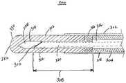
- FIG. 3illustrates by cross sectional view an optical fiber output tip of the present invention.
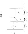
- FIG. 4illustrates, by way of example, the index of refractions of the core, clad and tube sections of the present invention.
- the present inventiondescribes an optical fiber having a side fire tip that is useful for high power laser beam transmission through an optical fiber.
- the side fire tipis used in medical treatment and has high reliability.
- the present inventionprovides a side fire optical tip for high power lasers, in particular, having outputs of greater than or equal to 50 Watts to about 300 Watts.
- the present inventionis particularly appropriate for the medical treatment of benign prostate hyperplasia (BPH) with a side fire optical fiber tip with a Holmium:YAG laser.
- BPHbenign prostate hyperplasia
- FIG. 1is a block diagram depicting one embodiment of medical laser device 100 in accord with the present invention.
- Device 100includes one laser source.
- the preferred laser for the present inventionis a Holmium:YAG laser, but other laser sources may be included such as a 980 nm laser.
- Laser source 102outputs radiation into optical fiber 112 .
- Connector 108takes the input from optical fiber 112 and outputs the laser energy into output optical fiber 106 that delivers the radiation into output end 114 .
- Device 100further includes control device 116 where the operational parameters are input. These operational parameters would include power, duration, repetition rate, and continuous or pulse mode, energy density, etc., for the laser therein.
- Output end 114is shown within prostrate gland 118 .
- a suitable catheter or endoscope deviceis used to place output end 114 with attached optical fiber 106 in the urethra up to the area of the surrounding prostrate tissue of concern. Further other devices may be included in the catheter such as viewing means, irrigating means, cooling means, etc.
- output end 114irradiates the target area with a preselected pattern of pulses and energy densities. Treatment can also involve a semi-continuous irradiation for each position to be treated, or with a turning of the side firing fiber probe to circumferentially treat a larger section. In preferred embodiments, these patterns of pulses and energy result in the ablation of prostatic tissue as well as coagulation of underlying tissues to substantially eliminate blood loss beyond the removed tissue and with minimal thermal damage to deeper and surrounding tissue.
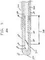
- FIG. 2depicts side fire optical fiber 200 with an output end 210 that may be used in the method of the present invention.
- Output end 210has side fire surface 220 that is slanted at a given angle to the axis of optical fiber 202 .
- a reflective coatingmay or may not be included on the surface 220 .
- a predetermined length of optical fiber 200has outer protective layer 206 removed to leave cladding layer 208 and core as shown.
- cladding layer 208is composed of low OH, pure silica.
- Cladding materialis originally deposited by a preferred method of plasma enhanced deposition on an outer surface of core material to make a preform(not shown) which is drawn to produce optical fiber 200 .
- capillary tube 312( FIG. 3 ) is fused to cladding layer 208 as will be disclosed hereinafter.
- FIG. 3illustrates optical fiber output tip 300 having a side fire feature.
- Optical fiber 302being of conventional design has a protective or buffer layer 304 removed to leave cladding layer 306 on output end 308 .
- side fire surface 310is formed and is of conventional design.
- the slant angle itselfmay range from 30 to 50 degrees as is conventional. Due to the diameter of the optical fiber, multi-mode reflections at side fire surface 310 provide an output beam that is somewhat projecting forward and is spreading out as it leaves output tip 300 at a range of angles, typically 70-100 degrees from the fiber axis.
- a reflective layermay be formed thereon, as is known in the optical arts.
- capillary tube 312Onto output end 308 , capillary tube 312 having inside hole 314 being of close fit about output end 308 is fused to outer most surface region of clad layer 306 .
- a void 228is formed in the capillary tube between the side fire surface 310 and the capillary tube 312 .
- a CO 2 lasermay be used to fuse tube 312 to output end 308 . This fusing process, is performed in such a way that bubbles or air gaps do not exist between the clad layer 306 and tube 312 .
- Bonding section 316secures tube 312 to protective layer 304 of optical fiber 302 to prevent undue strain on output end 308 .
- Shrink tube 318further protects the output tip 300 and is placed over section of tube 312 , bonding section 316 and optical fiber 302 .
- Core 320 in the output section 308is composed of silica having an index of refraction of n 1 ; clad layer 306 is also composed of silica and has an index of refraction of n 2 which at the interface with the core is less than n 1 , but increases toward the outward edge of the cladding to a value equal to pure silica.
- FIG. 4shows a relationship between the indexes of refraction in the different sections of the output end 308 .
- the core material 320can be pure silica or a Germanium doped silica.
- the cladding material 306would be a fluorine-doped silica.
- the cladding materialcould be pure silica too.
- the claddingwould have a uniform refractive index across its thickness that would match the refractive index the tubing material 312 as the tube is also pure silica as noted throughout this specification.
- Capillary tube 312is also composed of silica and has an index of refraction of n 3 .
- the silica at the outer edge of clad layer 306 and in tube 312is preferably pure silica, that is having the same refractive index, n 3 .
- clad layer 306when it is a fluorine-doped silica, the amount of fluorine is reduced so that at the fusing interface, clad layer is low OH, pure silica, and has essentially the same index of refraction as tube 312 , also composed of low OH, pure silica.
- the thermal behavior of the two facing surfacesshall be as equivalent as possible.
- Matching refractive indicesis one measure to achieve this equivalence. Since glass is a viscous liquid its manufacturing process can also affect its thermodynamic properties, thus in a further embodiment, the manufacturing process of the tube can be made essentially the same as the outer surface layer of the cladding. That is, the thermal history of the outermost layer of the cladding is substantially equivalent to the thermal history of the inner surface of the tube.
- a more robust side firing distal endcan be produced by further processing.
- the laser energy output areabeing surface 322 , is heat treated to create a more durable surface to high power laser energy and for mechanical properties.
- Surface 322may be heat treated by a laser beam such as a CO 2 laser provides.
- Sealed end section 330is a distal section of capillary tube 312 .
- the distal sectionis heated and closed to form sealed end section 330 .
- Front tip 332is rounded.
- a medical laser with a maximum average power of 100 Watts and having an output wavelength of 2150 nmcan be used in the treatment of BPH. Lasing can be performed using a 550 ⁇ m core with cladding layer 306 of 715 ⁇ m diameter, with a cladding to core ratio of 1.3.
- Optical fiber 302has a diameter of 1950 ⁇ m, for example.
- Optical fiber output tip 300can be positioned close to the target tissues such as a prostrate gland by a rigid endoscope, for example, with water as an irrigant to further cool the tip and help remove material as it is ablated, or degraded during high power operation.
- Preferred embodimentsmay also be used to transmit high power laser energy from diode lasers operating at 980 nm or 1460 nm with power levels from 50 to about 250 Watts.
- diode lasersoperating at 980 nm or 1460 nm with power levels from 50 to about 250 Watts.
- fibers of similar sizeto that described above various medical treatments including treatment of BPH can be done very effectively, quickly and without requiring more than local anesthesia for the patient.
- optical fiber 106delivers laser energy from laser source 102 to a handpiece, endoscope, or similar instrument for positioning the fiber's distal output end 114 in close proximity, in direct contact with, or inside/within the target tissue. It is preferred that the handpiece, endoscope, or similar instrument have sufficient channels to accommodate the flow and removal of irrigant and/or debris from the treatment site, endoscopic instruments, aspirators, light guides, image guides, or other sensor and/or detection means. Benefits from using, for example, a 980 nm diode laser, instead of a Ho:YAG laser, are somewhat greater depth penetration, photocoagulation leading to a substantially blood free operating area.
Landscapes
- Physics & Mathematics (AREA)
- Health & Medical Sciences (AREA)
- Optics & Photonics (AREA)
- Surgery (AREA)
- Life Sciences & Earth Sciences (AREA)
- General Physics & Mathematics (AREA)
- Heart & Thoracic Surgery (AREA)
- Animal Behavior & Ethology (AREA)
- Engineering & Computer Science (AREA)
- Biomedical Technology (AREA)
- Nuclear Medicine, Radiotherapy & Molecular Imaging (AREA)
- Medical Informatics (AREA)
- Molecular Biology (AREA)
- Otolaryngology (AREA)
- General Health & Medical Sciences (AREA)
- Public Health (AREA)
- Veterinary Medicine (AREA)
- Electromagnetism (AREA)
- Laser Surgery Devices (AREA)
- Radiation-Therapy Devices (AREA)
Abstract
Description
Claims (11)
Priority Applications (3)
| Application Number | Priority Date | Filing Date | Title |
|---|---|---|---|
| US11/592,598US11324553B2 (en) | 2005-11-10 | 2006-11-03 | Side fire optical fiber for high power applications |
| PCT/US2006/043647WO2007058891A2 (en) | 2005-11-10 | 2006-11-09 | Side fire optical fiber for high power applications |
| EP20060837246EP1948058B1 (en) | 2005-11-10 | 2006-11-09 | Side fire optical fiber for high power applications |
Applications Claiming Priority (2)
| Application Number | Priority Date | Filing Date | Title |
|---|---|---|---|
| US73610705P | 2005-11-10 | 2005-11-10 | |
| US11/592,598US11324553B2 (en) | 2005-11-10 | 2006-11-03 | Side fire optical fiber for high power applications |
Publications (2)
| Publication Number | Publication Date |
|---|---|
| US20070106286A1 US20070106286A1 (en) | 2007-05-10 |
| US11324553B2true US11324553B2 (en) | 2022-05-10 |
Family
ID=38004805
Family Applications (1)
| Application Number | Title | Priority Date | Filing Date |
|---|---|---|---|
| US11/592,598Active2033-12-01US11324553B2 (en) | 2005-11-10 | 2006-11-03 | Side fire optical fiber for high power applications |
Country Status (3)
| Country | Link |
|---|---|
| US (1) | US11324553B2 (en) |
| EP (1) | EP1948058B1 (en) |
| WO (1) | WO2007058891A2 (en) |
Families Citing this family (30)
| Publication number | Priority date | Publication date | Assignee | Title |
|---|---|---|---|---|
| EP2134282B1 (en)* | 2002-07-10 | 2019-05-22 | AngioDynamics, Inc. | Device for endovascular treatment for causing closure of a blood vessel |
| WO2008073263A1 (en)* | 2006-12-07 | 2008-06-19 | Ams Research Corporation | Side fire optical device for laterally redirecting high power electromagnetic energy |
| US7507038B2 (en)* | 2007-04-03 | 2009-03-24 | Mitsubishi Cable Industries, Ltd. | Optical fiber/glass tube fusion-spliced structure, optical fiber assembly including the structure, and glass tube used in the structure |
| DE202007008378U1 (en)* | 2007-06-15 | 2007-08-23 | Ceramoptec Gmbh | Urological diode laser systems with glass fiber application system |
| US8758225B2 (en)* | 2007-07-26 | 2014-06-24 | Biolitec Pharma Marketing Ltd | Adapter for endoscopes and related method |
| US9693826B2 (en) | 2008-02-28 | 2017-07-04 | Biolitec Unternehmensbeteiligungs Ii Ag | Endoluminal laser ablation device and method for treating veins |
| US8425500B2 (en)* | 2008-05-19 | 2013-04-23 | Boston Scientific Scimed, Inc. | Method and apparatus for protecting capillary of laser fiber during insertion and reducing metal cap degradation |
| US20090326525A1 (en)* | 2008-06-26 | 2009-12-31 | Jessica Hixon | Laser fiber capillary apparatus and method |
| WO2010014224A2 (en)* | 2008-07-28 | 2010-02-04 | Xintec Corporation | Multi-wavelength laser and method for contact ablation of tissue |
| US8899844B2 (en)* | 2008-12-01 | 2014-12-02 | Ams Research Corporation | Optical device |
| CN102264434B (en)* | 2008-12-02 | 2016-02-03 | 拜欧利泰克投资二代公司 | The medical procedure of induced with laser steam/plasma-mediated and device |
| US8827991B2 (en)* | 2009-04-09 | 2014-09-09 | Biolitec Pharma Marketing Ltd | Medical laser treatment device and method utilizing total reflection induced by radiation |
| US20110196356A1 (en)* | 2009-09-15 | 2011-08-11 | Ceramoptec Industries Inc. | Ablative/coagulative urological treatment device and method |
| WO2011062894A2 (en)* | 2009-11-18 | 2011-05-26 | Boston Scientific Scimed, Inc. | Methods and apparatus related to a distal end of a side-fire optical fiber having multiple capillary components |
| EP2501318B1 (en)* | 2009-11-18 | 2020-08-26 | Boston Scientific Scimed, Inc. | Methods and apparatus related to a side -fire member having a doped silica component |
| US20110166562A1 (en)* | 2010-01-04 | 2011-07-07 | Ceramoptec Industries, Inc. | High Durability Side Fire Optical Fiber for High Power Applications |
| US8724941B2 (en)* | 2010-02-22 | 2014-05-13 | Boston Scientific Scimed, Inc. | Methods and apparatus related to a side-fire optical fiber having a robust distal end portion |
| US20120071867A1 (en)* | 2010-03-18 | 2012-03-22 | Metalase, Inc. | Diode laser systems and methods for endoscopic treatment of tissue |
| US8731351B2 (en) | 2010-05-03 | 2014-05-20 | Boston Scientific Scimed, Inc. | Side fire laser assembly |
| US8781275B2 (en) | 2010-07-27 | 2014-07-15 | Boston Scientific Scimed, Inc. | Laser assembly with shock absorber |
| US20140126876A1 (en)* | 2012-11-05 | 2014-05-08 | Ofs Fitel, Llc | Cap for optical fiber |
| CN103605204B (en)* | 2013-12-04 | 2015-09-02 | 中南大学 | Parallel low light loss backlight hot industry endoscope |
| CN104207845A (en)* | 2014-09-05 | 2014-12-17 | 北京泰恒金光伟业光电科技有限公司 | Pulse laser therapeutic apparatus for prostatitis |
| US9488782B2 (en) | 2014-12-22 | 2016-11-08 | InnovaQuartz LLC | Redirecting electromagnetic radiation |
| US9323005B1 (en) | 2014-12-22 | 2016-04-26 | InnovaQuartz LLC | Redirecting electromagnetic radiation |
| US11826097B2 (en) | 2015-11-18 | 2023-11-28 | Cyclone Biosciences, Llc | Forming radial emissions from optical fibers |
| US10092356B2 (en) | 2015-11-18 | 2018-10-09 | InnovaQuartz LLC | Radial emissions from optical fibers |
| US9618700B1 (en) | 2015-12-03 | 2017-04-11 | InnovaQuartz LLC | Orthogonal output optical fiber |
| US9662173B1 (en) | 2015-12-24 | 2017-05-30 | Cyclone Biosciences LLC | Lateral delivery device with active cooling |
| WO2018031450A1 (en) | 2016-08-12 | 2018-02-15 | Boston Scientific Scimed, Inc. | Methods for fusing a fiber termination |
Citations (30)
| Publication number | Priority date | Publication date | Assignee | Title |
|---|---|---|---|---|
| US4698084A (en)* | 1985-04-19 | 1987-10-06 | U.S. Philips Corporation | Method of manufacturing a passive fiber optic component |
| US4740047A (en) | 1985-03-26 | 1988-04-26 | Hatachi Cable, Ltd. | Fiber for lateral beaming of laser beam |
| JPH0363377A (en) | 1989-07-31 | 1991-03-19 | Asmo Co Ltd | Power window device |
| US5033304A (en)* | 1989-04-27 | 1991-07-23 | Industrial Quality, Inc. | Method and apparatus for laser ultrasonic characterization of coated fibers |
| US5164945A (en)* | 1991-07-01 | 1992-11-17 | Laser Centers Of America, Inc. | Laser device with intermediate refraction index layer for reduced fresnel losses |
| US5257989A (en)* | 1990-02-07 | 1993-11-02 | Coherent, Inc. | Contact laser delivery probe |
| US5292320A (en) | 1992-07-06 | 1994-03-08 | Ceramoptec, Inc. | Radial medical laser delivery device |
| US5349590A (en)* | 1992-04-10 | 1994-09-20 | Premier Laser Systems, Inc. | Medical laser apparatus for delivering high power infrared light |
| US5428699A (en) | 1993-07-02 | 1995-06-27 | Laserscope | Probe having optical fiber for laterally directing laser beam |
| US5437660A (en) | 1991-12-30 | 1995-08-01 | Trimedyne, Inc. | Tissue ablation and a lateral-lasing fiber optic device therefor |
| US5470330A (en)* | 1984-12-07 | 1995-11-28 | Advanced Interventional Systems, Inc. | Guidance and delivery system for high-energy pulsed laser light |
| US5509917A (en) | 1994-06-28 | 1996-04-23 | Ceramoptec Industries, Inc. | Lensed caps for radial medical laser delivery devices |
| US5562657A (en)* | 1994-09-19 | 1996-10-08 | Griffin; Stephen E. | Side fire laser catheter method and apparatus |
| US5638483A (en)* | 1995-05-09 | 1997-06-10 | Laser Industries, Ltd. | Side-emitting optical fibers for lasers with orientation markings |
| US5772657A (en)* | 1995-04-24 | 1998-06-30 | Coherent, Inc. | Side firing fiber optic laser probe |
| US5991486A (en)* | 1996-11-19 | 1999-11-23 | Cselt- Centro Studi E Laboratori Telecomunicazioni S.P.A. | Active single mode optical fibres and method for their fabrication |
| US6222970B1 (en)* | 1995-11-20 | 2001-04-24 | Cirrex Corp. | Methods and apparatus for filtering an optical fiber |
| US20020031320A1 (en)* | 2000-08-28 | 2002-03-14 | Sumitomo Electric Industries, Ltd. | Optical fiber, method of making optical fiber preform, and method of making optical fiber |
| US20020094159A1 (en)* | 2000-11-28 | 2002-07-18 | Lew Goldberg | Optical fiber amplifiers and lasers and optical pumping devices therefor and methods of fabricating same |
| US20020097970A1 (en)* | 1999-01-18 | 2002-07-25 | Sumitomo Electric Industries, Inc. | Optical fiber and method of manufacturing the same |
| US20030024276A1 (en)* | 2001-05-30 | 2003-02-06 | 3M Innovative Properties Company | Method of manufacture of an optical waveguide article including a fluorine-containing zone |
| US6535671B1 (en)* | 2000-02-29 | 2003-03-18 | Eigenlight Corporation | Optical fiber tap with integral reflecting surface and method of making same |
| US6554824B2 (en) | 2000-12-15 | 2003-04-29 | Laserscope | Methods for laser treatment of soft tissue |
| US20030103747A1 (en)* | 2001-11-30 | 2003-06-05 | Jeong-Sik Cho | Wide band dispersion-controlled fiber |
| US20040114892A1 (en)* | 2002-12-11 | 2004-06-17 | Chiang Kin Seng | Optical fiber |
| US20040156401A1 (en)* | 2003-01-27 | 2004-08-12 | Ceramoptec Industries, Inc. | Multi-clad optical fiber lasers and their manufacture |
| US6802838B2 (en) | 2002-04-22 | 2004-10-12 | Trimedyne, Inc. | Devices and methods for directed, interstitial ablation of tissue |
| US20050232571A1 (en)* | 2002-06-10 | 2005-10-20 | Heinz Fabian | Jacket tube made of synthetically produced quartz glass and optical fibres produced using said jacket tube |
| US20060239625A1 (en)* | 2002-05-17 | 2006-10-26 | Sumitomo Electric Industries, Ltd. | Optical fiber bundle and method for manufacturing thereof |
| US7447409B2 (en) | 2006-01-30 | 2008-11-04 | Ams Research Corporation | Sleeved optical fiber for reduced lateral loss and method for making the same |
Family Cites Families (1)
| Publication number | Priority date | Publication date | Assignee | Title |
|---|---|---|---|---|
| JP4240612B2 (en)* | 1998-12-02 | 2009-03-18 | 住友電気工業株式会社 | Dispersion compensation module |
- 2006
- 2006-11-03USUS11/592,598patent/US11324553B2/enactiveActive
- 2006-11-09WOPCT/US2006/043647patent/WO2007058891A2/enactiveApplication Filing
- 2006-11-09EPEP20060837246patent/EP1948058B1/enactiveActive
Patent Citations (30)
| Publication number | Priority date | Publication date | Assignee | Title |
|---|---|---|---|---|
| US5470330A (en)* | 1984-12-07 | 1995-11-28 | Advanced Interventional Systems, Inc. | Guidance and delivery system for high-energy pulsed laser light |
| US4740047A (en) | 1985-03-26 | 1988-04-26 | Hatachi Cable, Ltd. | Fiber for lateral beaming of laser beam |
| US4698084A (en)* | 1985-04-19 | 1987-10-06 | U.S. Philips Corporation | Method of manufacturing a passive fiber optic component |
| US5033304A (en)* | 1989-04-27 | 1991-07-23 | Industrial Quality, Inc. | Method and apparatus for laser ultrasonic characterization of coated fibers |
| JPH0363377A (en) | 1989-07-31 | 1991-03-19 | Asmo Co Ltd | Power window device |
| US5257989A (en)* | 1990-02-07 | 1993-11-02 | Coherent, Inc. | Contact laser delivery probe |
| US5164945A (en)* | 1991-07-01 | 1992-11-17 | Laser Centers Of America, Inc. | Laser device with intermediate refraction index layer for reduced fresnel losses |
| US5437660A (en) | 1991-12-30 | 1995-08-01 | Trimedyne, Inc. | Tissue ablation and a lateral-lasing fiber optic device therefor |
| US5349590A (en)* | 1992-04-10 | 1994-09-20 | Premier Laser Systems, Inc. | Medical laser apparatus for delivering high power infrared light |
| US5292320A (en) | 1992-07-06 | 1994-03-08 | Ceramoptec, Inc. | Radial medical laser delivery device |
| US5428699A (en) | 1993-07-02 | 1995-06-27 | Laserscope | Probe having optical fiber for laterally directing laser beam |
| US5509917A (en) | 1994-06-28 | 1996-04-23 | Ceramoptec Industries, Inc. | Lensed caps for radial medical laser delivery devices |
| US5562657A (en)* | 1994-09-19 | 1996-10-08 | Griffin; Stephen E. | Side fire laser catheter method and apparatus |
| US5772657A (en)* | 1995-04-24 | 1998-06-30 | Coherent, Inc. | Side firing fiber optic laser probe |
| US5638483A (en)* | 1995-05-09 | 1997-06-10 | Laser Industries, Ltd. | Side-emitting optical fibers for lasers with orientation markings |
| US6222970B1 (en)* | 1995-11-20 | 2001-04-24 | Cirrex Corp. | Methods and apparatus for filtering an optical fiber |
| US5991486A (en)* | 1996-11-19 | 1999-11-23 | Cselt- Centro Studi E Laboratori Telecomunicazioni S.P.A. | Active single mode optical fibres and method for their fabrication |
| US20020097970A1 (en)* | 1999-01-18 | 2002-07-25 | Sumitomo Electric Industries, Inc. | Optical fiber and method of manufacturing the same |
| US6535671B1 (en)* | 2000-02-29 | 2003-03-18 | Eigenlight Corporation | Optical fiber tap with integral reflecting surface and method of making same |
| US20020031320A1 (en)* | 2000-08-28 | 2002-03-14 | Sumitomo Electric Industries, Ltd. | Optical fiber, method of making optical fiber preform, and method of making optical fiber |
| US20020094159A1 (en)* | 2000-11-28 | 2002-07-18 | Lew Goldberg | Optical fiber amplifiers and lasers and optical pumping devices therefor and methods of fabricating same |
| US6554824B2 (en) | 2000-12-15 | 2003-04-29 | Laserscope | Methods for laser treatment of soft tissue |
| US20030024276A1 (en)* | 2001-05-30 | 2003-02-06 | 3M Innovative Properties Company | Method of manufacture of an optical waveguide article including a fluorine-containing zone |
| US20030103747A1 (en)* | 2001-11-30 | 2003-06-05 | Jeong-Sik Cho | Wide band dispersion-controlled fiber |
| US6802838B2 (en) | 2002-04-22 | 2004-10-12 | Trimedyne, Inc. | Devices and methods for directed, interstitial ablation of tissue |
| US20060239625A1 (en)* | 2002-05-17 | 2006-10-26 | Sumitomo Electric Industries, Ltd. | Optical fiber bundle and method for manufacturing thereof |
| US20050232571A1 (en)* | 2002-06-10 | 2005-10-20 | Heinz Fabian | Jacket tube made of synthetically produced quartz glass and optical fibres produced using said jacket tube |
| US20040114892A1 (en)* | 2002-12-11 | 2004-06-17 | Chiang Kin Seng | Optical fiber |
| US20040156401A1 (en)* | 2003-01-27 | 2004-08-12 | Ceramoptec Industries, Inc. | Multi-clad optical fiber lasers and their manufacture |
| US7447409B2 (en) | 2006-01-30 | 2008-11-04 | Ams Research Corporation | Sleeved optical fiber for reduced lateral loss and method for making the same |
Non-Patent Citations (2)
| Title |
|---|
| Kawakami S., Nishida S., Characteristics of a doubly clad optical fiber with a low-index inner cladding, Quantum Electronics, IEEE Journal of, Dec. 1974, vol. 10, Issue 12, p. 880.* |
| Kuo et al., "Holmium Laser Enucleation of the Prostate (HoLEP): A Technical Update" Jun. 6, 2003, World Journal of Surgical Oncology, I :6 (pp. 1-9).* |
Also Published As
| Publication number | Publication date |
|---|---|
| EP1948058A4 (en) | 2010-07-07 |
| EP1948058B1 (en) | 2015-05-06 |
| US20070106286A1 (en) | 2007-05-10 |
| WO2007058891A3 (en) | 2008-01-31 |
| WO2007058891A2 (en) | 2007-05-24 |
| EP1948058A2 (en) | 2008-07-30 |
Similar Documents
| Publication | Publication Date | Title |
|---|---|---|
| US11324553B2 (en) | Side fire optical fiber for high power applications | |
| US8876810B2 (en) | Benign prostatic hyperplasia treatment method and device | |
| CA2775431C (en) | Twister fiber optic systems and their use in medical applications | |
| US9050118B2 (en) | Method and apparatus for protecting capillary of laser fiber during insertion and reducing metal cap degradation | |
| US8529561B2 (en) | Lateral laser fiber for high average power and peak pulse energy | |
| US9788898B2 (en) | Methods and apparatus related to a side-fire assembly that has an optical grating | |
| JP6016133B2 (en) | Method and apparatus for side firing members having doped silica components | |
| US20180214211A1 (en) | Side-firing laser fiber with protective tip and related methods | |
| US20110166562A1 (en) | High Durability Side Fire Optical Fiber for High Power Applications | |
| US9289262B2 (en) | Dielectric coatings for laser fiber and related methods | |
| US9888964B2 (en) | Side-firing laser fiber with glass fused reflector and capillary and related methods | |
| US20090326525A1 (en) | Laser fiber capillary apparatus and method | |
| US9810844B2 (en) | Methods and apparatus related to a side-fire optical fiber having a robust distal end portion |
Legal Events
| Date | Code | Title | Description |
|---|---|---|---|
| AS | Assignment | Owner name:CERAMOPTEC INDUSTRIES, INC., MASSACHUSETTS Free format text:ASSIGNMENT OF ASSIGNORS INTEREST;ASSIGNORS:HARSCHACK, ALEXANDER;NEUBERGER, WOLFGANG;MORAN, KELLY;SIGNING DATES FROM 20051102 TO 20051107;REEL/FRAME:018525/0422 Owner name:CERAMOPTEC INDUSTRIES, INC., MASSACHUSETTS Free format text:ASSIGNMENT OF ASSIGNORS INTEREST;ASSIGNORS:HARSCHACK, ALEXANDER;NEUBERGER, WOLFGANG;MORAN, KELLY;REEL/FRAME:018525/0422;SIGNING DATES FROM 20051102 TO 20051107 | |
| AS | Assignment | Owner name:BIOLITEC PHARMA MARKETING LTD., MALAYSIA Free format text:ASSIGNMENT OF ASSIGNORS INTEREST;ASSIGNOR:BIOLITEC, INC.;REEL/FRAME:022482/0944 Effective date:20090331 Owner name:BIOLITEC, INC., MASSACHUSETTS Free format text:ASSIGNMENT OF ASSIGNORS INTEREST;ASSIGNOR:CERAMOPTEC INDUSTRIES, INC.;REEL/FRAME:022482/0956 Effective date:20090330 Owner name:BIOLITEC PHARMA MARKETING LTD.,MALAYSIA Free format text:ASSIGNMENT OF ASSIGNORS INTEREST;ASSIGNOR:BIOLITEC, INC.;REEL/FRAME:022482/0944 Effective date:20090331 Owner name:BIOLITEC, INC.,MASSACHUSETTS Free format text:ASSIGNMENT OF ASSIGNORS INTEREST;ASSIGNOR:CERAMOPTEC INDUSTRIES, INC.;REEL/FRAME:022482/0956 Effective date:20090330 | |
| AS | Assignment | Owner name:BIOLITEC UNTERNEHMENSBETEILIGUNGS II AG, AUSTRIA Free format text:ASSIGNMENT OF ASSIGNORS INTEREST;ASSIGNOR:BIOLITEC PHARMA MARKETING LTD.;REEL/FRAME:041182/0578 Effective date:20160308 | |
| STPP | Information on status: patent application and granting procedure in general | Free format text:RESPONSE TO NON-FINAL OFFICE ACTION ENTERED AND FORWARDED TO EXAMINER | |
| STPP | Information on status: patent application and granting procedure in general | Free format text:FINAL REJECTION MAILED | |
| STPP | Information on status: patent application and granting procedure in general | Free format text:NOTICE OF ALLOWANCE MAILED -- APPLICATION RECEIVED IN OFFICE OF PUBLICATIONS | |
| STCB | Information on status: application discontinuation | Free format text:ABANDONED -- FAILURE TO PAY ISSUE FEE | |
| STPP | Information on status: patent application and granting procedure in general | Free format text:NOTICE OF ALLOWANCE MAILED -- APPLICATION RECEIVED IN OFFICE OF PUBLICATIONS | |
| STPP | Information on status: patent application and granting procedure in general | Free format text:PUBLICATIONS -- ISSUE FEE PAYMENT VERIFIED | |
| STCF | Information on status: patent grant | Free format text:PATENTED CASE |